Embed Size (px)
Citation preview
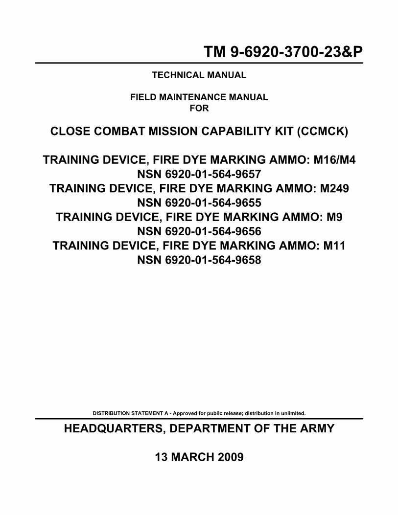
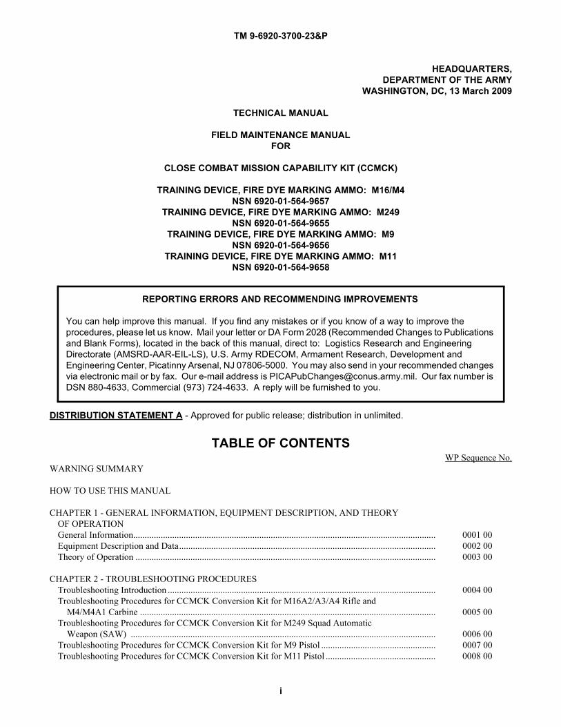
TM 9-6920-3700-23&PTECHNICAL MANUAL
FIELD MAINTENANCE MANUALFOR
CLOSE COMBAT MISSION CAPABILITY KIT (CCMCK)
TRAINING DEVICE, FIRE DYE MARKING AMMO: M16/M4NSN 6920-01-564-9657
TRAINING DEVICE, FIRE DYE MARKING AMMO: M249NSN 6920-01-564-9655
TRAINING DEVICE, FIRE DYE MARKING AMMO: M9NSN 6920-01-564-9656
TRAINING DEVICE, FIRE DYE MARKING AMMO: M11NSN 6920-01-564-9658
DISTRIBUTION STATEMENT A - Approved for public release; distribution in unlimited.
HEADQUARTERS, DEPARTMENT OF THE ARMY
13 MARCH 2009


TM 9-6920-3700-23&P
WARNING SUMMARY
a
Care must be taken when installing and removing spring-loaded parts. Safety goggles must be worn to prevent injury to eyes.

This Page Intentionally Left Blank
b
TM 9-6920-3700-23&P
TM 9-6920-3700-23&P
A
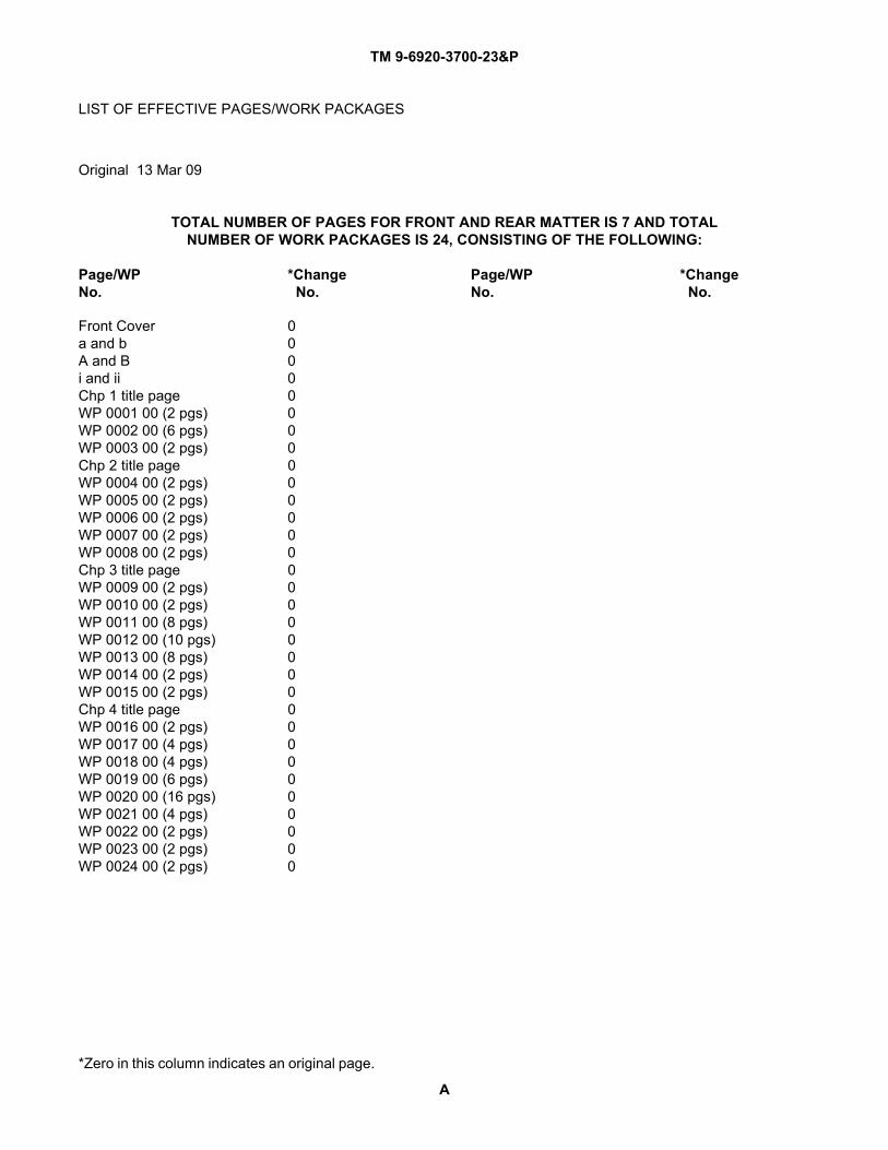
*Zero in this column indicates an original page.
LIST OF EFFECTIVE PAGES/WORK PACKAGES
TOTAL NUMBER OF PAGES FOR FRONT AND REAR MATTER IS 7 AND TOTALNUMBER OF WORK PACKAGES IS 24, CONSISTING OF THE FOLLOWING:
Page/WP *Change Page/WP *ChangeNo. No. No. No.
Original 13 Mar 09
Front Cover 0a and b 0A and B 0i and ii 0Chp 1 title page 0WP 0001 00 (2 pgs) 0WP 0002 00 (6 pgs) 0WP 0003 00 (2 pgs) 0Chp 2 title page 0WP 0004 00 (2 pgs) 0WP 0005 00 (2 pgs) 0WP 0006 00 (2 pgs) 0WP 0007 00 (2 pgs) 0WP 0008 00 (2 pgs) 0Chp 3 title page 0WP 0009 00 (2 pgs) 0WP 0010 00 (2 pgs) 0WP 0011 00 (8 pgs) 0WP 0012 00 (10 pgs) 0WP 0013 00 (8 pgs) 0WP 0014 00 (2 pgs) 0WP 0015 00 (2 pgs) 0Chp 4 title page 0WP 0016 00 (2 pgs) 0WP 0017 00 (4 pgs) 0WP 0018 00 (4 pgs) 0WP 0019 00 (6 pgs) 0WP 0020 00 (16 pgs) 0WP 0021 00 (4 pgs) 0WP 0022 00 (2 pgs) 0WP 0023 00 (2 pgs) 0WP 0024 00 (2 pgs) 0

This Page Intentionally Left Blank
B
TM 9-6920-3700-23&P
TM 9-6920-3700-23&P
i
HEADQUARTERS,DEPARTMENT OF THE ARMY
WASHINGTON, DC, 13 March 2009
TECHNICAL MANUAL
FIELD MAINTENANCE MANUALFOR
CLOSE COMBAT MISSION CAPABILITY KIT (CCMCK)
TRAINING DEVICE, FIRE DYE MARKING AMMO: M16/M4NSN 6920-01-564-9657
TRAINING DEVICE, FIRE DYE MARKING AMMO: M249NSN 6920-01-564-9655
TRAINING DEVICE, FIRE DYE MARKING AMMO: M9NSN 6920-01-564-9656
TRAINING DEVICE, FIRE DYE MARKING AMMO: M11NSN 6920-01-564-9658
DISTRIBUTION STATEMENT A - Approved for public release; distribution in unlimited.
TABLE OF CONTENTSWP Sequence No.
WARNING SUMMARY
HOW TO USE THIS MANUAL
CHAPTER 1 - GENERAL INFORMATION, EQUIPMENT DESCRIPTION, AND THEORY OF OPERATIONGeneral Information.................................................................................................................................... 0001 00Equipment Description and Data................................................................................................................ 0002 00Theory of Operation ................................................................................................................................... 0003 00
CHAPTER 2 - TROUBLESHOOTING PROCEDURESTroubleshooting Introduction ..................................................................................................................... 0004 00Troubleshooting Procedures for CCMCK Conversion Kit for M16A2/A3/A4 Rifle and M4/M4A1 Carbine ................................................................................................................................. 0005 00Troubleshooting Procedures for CCMCK Conversion Kit for M249 Squad Automatic Weapon (SAW) ..................................................................................................................................... 0006 00Troubleshooting Procedures for CCMCK Conversion Kit for M9 Pistol .................................................. 0007 00Troubleshooting Procedures for CCMCK Conversion Kit for M11 Pistol ................................................ 0008 00
REPORTING ERRORS AND RECOMMENDING IMPROVEMENTS
You can help improve this manual. If you find any mistakes or if you know of a way to improve the procedures, please let us know. Mail your letter or DA Form 2028 (Recommended Changes to Publications and Blank Forms), located in the back of this manual, direct to: Logistics Research and Engineering Directorate (AMSRD-AAR-EIL-LS), U.S. Army RDECOM, Armament Research, Development and Engineering Center, Picatinny Arsenal, NJ 07806-5000. You may also send in your recommended changes via electronic mail or by fax. Our e-mail address is [email protected]. Our fax number is DSN 880-4633, Commercial (973) 724-4633. A reply will be furnished to you.
TM 9-6920-3700-23&P
ii
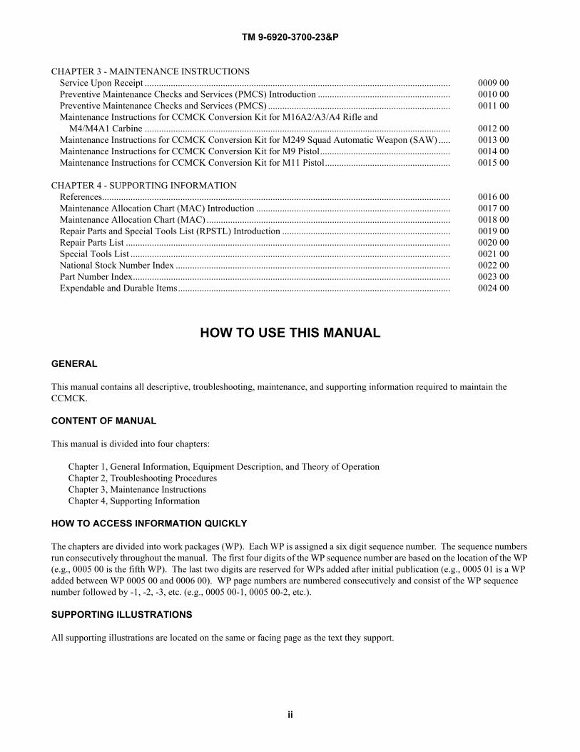
CHAPTER 3 - MAINTENANCE INSTRUCTIONSService Upon Receipt ................................................................................................................................. 0009 00Preventive Maintenance Checks and Services (PMCS) Introduction ........................................................ 0010 00Preventive Maintenance Checks and Services (PMCS) ............................................................................. 0011 00Maintenance Instructions for CCMCK Conversion Kit for M16A2/A3/A4 Rifle and M4/M4A1 Carbine ................................................................................................................................. 0012 00Maintenance Instructions for CCMCK Conversion Kit for M249 Squad Automatic Weapon (SAW) ..... 0013 00Maintenance Instructions for CCMCK Conversion Kit for M9 Pistol....................................................... 0014 00Maintenance Instructions for CCMCK Conversion Kit for M11 Pistol..................................................... 0015 00
CHAPTER 4 - SUPPORTING INFORMATIONReferences................................................................................................................................................... 0016 00Maintenance Allocation Chart (MAC) Introduction .................................................................................. 0017 00Maintenance Allocation Chart (MAC) ....................................................................................................... 0018 00Repair Parts and Special Tools List (RPSTL) Introduction ....................................................................... 0019 00Repair Parts List ......................................................................................................................................... 0020 00Special Tools List ....................................................................................................................................... 0021 00National Stock Number Index .................................................................................................................... 0022 00Part Number Index...................................................................................................................................... 0023 00Expendable and Durable Items................................................................................................................... 0024 00
HOW TO USE THIS MANUAL
GENERAL
This manual contains all descriptive, troubleshooting, maintenance, and supporting information required to maintain the CCMCK.
CONTENT OF MANUAL
This manual is divided into four chapters:
Chapter 1, General Information, Equipment Description, and Theory of OperationChapter 2, Troubleshooting ProceduresChapter 3, Maintenance InstructionsChapter 4, Supporting Information
HOW TO ACCESS INFORMATION QUICKLY
The chapters are divided into work packages (WP). Each WP is assigned a six digit sequence number. The sequence numbers run consecutively throughout the manual. The first four digits of the WP sequence number are based on the location of the WP (e.g., 0005 00 is the fifth WP). The last two digits are reserved for WPs added after initial publication (e.g., 0005 01 is a WP added between WP 0005 00 and 0006 00). WP page numbers are numbered consecutively and consist of the WP sequence number followed by -1, -2, -3, etc. (e.g., 0005 00-1, 0005 00-2, etc.).
SUPPORTING ILLUSTRATIONS
All supporting illustrations are located on the same or facing page as the text they support.
CHAPTER 1
GENERAL INFORMATION, EQUIPMENT DESCRIPTION,AND THEORY OF OPERATION
FORCLOSE COMBAT MISSION CAPABILITY KIT (CCMCK)
TM 9-6920-3700-23&P

TM 9-6920-3700-23&P 0001 00
0001 00-1
FIELD MAINTENANCE
CLOSE COMBAT MISSION CAPABILITY KIT (CCMCK)
GENERAL INFORMATION
SCOPE
This Technical Manual covers Field Maintenance procedures for the Close Combat Mission Capability Kit (CCMCK) Weapon Conversion System.
Type of Manual: Field Maintenance.
Model Number(s) and Equipment Name(s): Training Device, Fire Dye Marking Ammo: M16/M4Training Device, Fire Dye Marking Ammo: M249Training Device, Fire Dye Marking Ammo: M9 Training Device, Fire Dye Marking Ammo: M11
Purpose of Equipment: The CCMCK Weapon Conversion System allows Force-On-Force close combat training by temporar-ily converting service weapons (M16A2/M16A3/M16A4 Rifle, M4/M4A1 Carbine, M249 Squad Automatic Weapon (SAW) and M9 and M11 Pistols) to fire low-velocity marking ammunition. CCMCK ammunition includes 5.56mm Bulk marking ammunition for the M16A2/M16A3/M16A4 Rifle and M4/M4A1 Carbine, 5.56mm Linked marking ammunition for the M249 SAW, and 9mm marking ammunition for the M9 and M11 Pistols. Marking ammunition, manufactured in red, blue, and yellow, is loaded into the magazines of the converted weapon in the same manner as service ammunition. Once loaded, the weapon cycles and functions the same as service ammunition and marks the target with minimal hazard to personnel wearing appropriate safety equipment. The system allows normal weapon employment cues such as aiming, firing, Force-On-Force training, and interactive live-fire scenario task and mission execution.
MAINTENANCE FORMS, RECORDS, AND REPORTS
Department of the Army forms and procedures used for equipment maintenance will be those prescribed by (as applicable) DA PAM 750-8, The Army Maintenance Management System (TAMMS) Users Manual, or AR 700-138, Army Logistics Readiness and Sustainability. Accidents involving injury to personnel or damage to material will be reported on DA Form 285 (U.S. Army Accident Report) in accordance with AR 385-10, The Army Safety Program. Explosives and ammunition mal-functions will be reported in accordance with AR 75-1, Malfunctions Involving Ammunition and Explosives.
REPORTING EQUIPMENT IMPROVEMENT RECOMMENDATIONS (EIR)
If your CCMCK needs improvement, let us know. Send us an EIR. You, the user, are the only one who can tell us what you don’t like about your equipment. Let us know why you don’t like the design or performance. If you have Internet access, the easiest and fastest way to report problems or suggestions is to go to https://aeps.ria.army.mil/aepspublic.cfm (scroll down and choose the “Submit Quality Deficiency Report” bar). The Internet form lets you choose to submit an Equipment Improvement Recommendation (EIR), a Product Quality Deficiency Report (PQDR) or a Warranty Claim Action (WCA). You may also submit your information using an SF 368 (Product Quality Deficiency Report). You can send your SF 368 via e-mail, regular mail, or facsimile using the addresses/facsimile numbers specified in DA PAM 750-8, The Army Maintenance Management System (TAMMS) Users Manual. We will send you a reply.
TM 9-6920-3700-23&P 0001 00
0001 00-2
CORROSION PREVENTION AND CONTROL (CPC)
Corrosion Prevention and Control (CPC) of Army materiel is a continuing concern. It is important that any corrosion prob-lems with this item be reported so that the problem can be corrected and improvements can be made to prevent the problem in future items.
Corrosion specifically occurs with metals. It is an electrochemical process that causes the degradation of metals. It is com-monly caused by exposure to moisture, acids, bases, or salts. An example is the rusting of iron. Corrosion damage in metals can be seen, depending on the metal, as tarnishing, pitting, fogging, surface residue, and/or cracking.
Plastics, composites, and rubbers can also degrade. Degradation is caused by thermal (heat), oxidation (oxygen), solvation (solvents), or photolytic (light, typically UV) processes. The most common exposures are excessive heat or light. Damage from these processes will appear as cracking, softening, swelling, and/or breaking.
SF 368 (Product Quality Deficiency Report) should be submitted to the address specified in DA PAM 750-8, The Army Main-tenance Management System (TAMMS) Users Manual.
PREPARATION FOR STORAGE OR SHIPMENT
All CCMCK Weapon Conversion Kits must be clean and serviceable prior to storage or shipment.
Any unused CCMCK 5.56mm marking ammunition must be repacked with the tip UP to prevent marking compound from coming out.
LIST OF ABBREVIATIONS/ACRONYMS
SAFETY, CARE, AND HANDLING
Use CCMCK only in accordance with instructions. Observe all warnings and cautions in this manual.
Personnel using CCMCK marking ammunition are required to follow good personal hygiene practices, (i.e., hand washing, cleaning of contaminated clothing and equipment) following exposure/contamination with marking compounds. Seek medical care in the event of acute eye contamination, skin irritation, or ingestion of marking compound.
All CCMCK Weapon Conversion Kits have built-in safety features that will not allow service ammunition to be fired.
Load only authorized CCMCK marking ammunition in weapons that have been configured with the appropriate CCMCK Weapon Conversion Kit. Equipment damage is possible if marking ammunition is interchanged.
CCMCK conversion kits and safety equipment must be cleaned before turn-in IAW procedures outlined in TM 9-6920-3700-10.
Converting the weapon to use CCMCK marking ammunition does not cause any undue effects or degradation of the normal service components, its overall longevity or the general function of the weapon.
Abbreviation/Acronym DefinitionCCMCK Close Combat Mission Capability KitCLP Cleaner, Lubricant and PreservativeCPC Corrosion Prevention ControlDA Department of the ArmyEIR Equipment Improvement Recommendation IAW In accordance withPQDR Product Quality Deficiency ReportSAW Squad Automatic WeaponTAMMS The Army Maintenance Management SystemTM Technical ManualWCA Warranty Claim Action
TM 9-6920-3700-23&P 0002 00
0002 00-1
FIELD MAINTENANCE
CLOSE COMBAT MISSION CAPABILITY KIT (CCMCK)
EQUIPMENT DESCRIPTION AND DATA
EQUIPMENT CHARACTERISTICS, CAPABILITIES, AND FEATURES
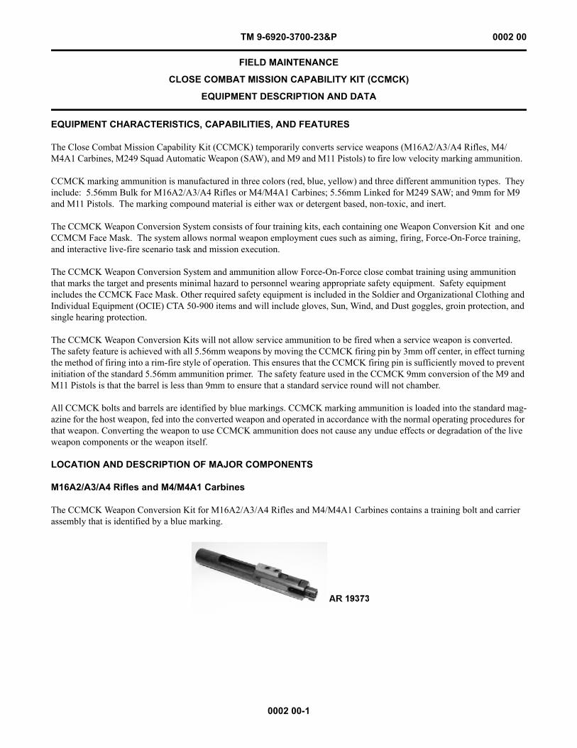
The Close Combat Mission Capability Kit (CCMCK) temporarily converts service weapons (M16A2/A3/A4 Rifles, M4/M4A1 Carbines, M249 Squad Automatic Weapon (SAW), and M9 and M11 Pistols) to fire low velocity marking ammunition.
CCMCK marking ammunition is manufactured in three colors (red, blue, yellow) and three different ammunition types. They include: 5.56mm Bulk for M16A2/A3/A4 Rifles or M4/M4A1 Carbines; 5.56mm Linked for M249 SAW; and 9mm for M9 and M11 Pistols. The marking compound material is either wax or detergent based, non-toxic, and inert.
The CCMCK Weapon Conversion System consists of four training kits, each containing one Weapon Conversion Kit and one CCMCM Face Mask. The system allows normal weapon employment cues such as aiming, firing, Force-On-Force training, and interactive live-fire scenario task and mission execution.
The CCMCK Weapon Conversion System and ammunition allow Force-On-Force close combat training using ammunition that marks the target and presents minimal hazard to personnel wearing appropriate safety equipment. Safety equipment includes the CCMCK Face Mask. Other required safety equipment is included in the Soldier and Organizational Clothing and Individual Equipment (OCIE) CTA 50-900 items and will include gloves, Sun, Wind, and Dust goggles, groin protection, and single hearing protection.
The CCMCK Weapon Conversion Kits will not allow service ammunition to be fired when a service weapon is converted. The safety feature is achieved with all 5.56mm weapons by moving the CCMCK firing pin by 3mm off center, in effect turning the method of firing into a rim-fire style of operation. This ensures that the CCMCK firing pin is sufficiently moved to prevent initiation of the standard 5.56mm ammunition primer. The safety feature used in the CCMCK 9mm conversion of the M9 and M11 Pistols is that the barrel is less than 9mm to ensure that a standard service round will not chamber.
All CCMCK bolts and barrels are identified by blue markings. CCMCK marking ammunition is loaded into the standard mag-azine for the host weapon, fed into the converted weapon and operated in accordance with the normal operating procedures for that weapon. Converting the weapon to use CCMCK ammunition does not cause any undue effects or degradation of the live weapon components or the weapon itself.
LOCATION AND DESCRIPTION OF MAJOR COMPONENTS
M16A2/A3/A4 Rifles and M4/M4A1 Carbines
The CCMCK Weapon Conversion Kit for M16A2/A3/A4 Rifles and M4/M4A1 Carbines contains a training bolt and carrier assembly that is identified by a blue marking.
TM 9-6920-3700-23&P 0002 00
0002 00-2
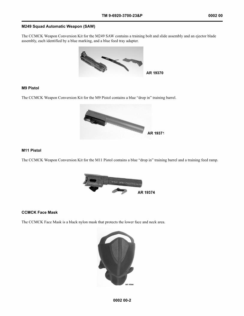
M249 Squad Automatic Weapon (SAW)
The CCMCK Weapon Conversion Kit for the M249 SAW contains a training bolt and slide assembly and an ejector blade assembly, each identified by a blue marking, and a blue feed tray adapter.
M9 Pistol
The CCMCK Weapon Conversion Kit for the M9 Pistol contains a blue “drop in” training barrel.
M11 Pistol
The CCMCK Weapon Conversion Kit for the M11 Pistol contains a blue “drop in” training barrel and a training feed ramp.
CCMCK Face Mask
The CCMCK Face Mask is a black nylon mask that protects the lower face and neck area.
TM 9-6920-3700-23&P 0002 00
0002 00-3
EQUIPMENT DATA
CCMCK Training Kit for M16A2/M16A3/M16A4 Rifles and M4/M4A1 Carbines:Consisting of ............................................................................ One (1) CCMCK Weapon Conversion Kit and one (1)
CCMCK Face MaskNSN ................................................................................... 6920-01-564-9657Training device number (DVC) ............................................... 07-164
CCMCK Weapon Conversion Kit for M16A2/M16A3/M16A4 Rifles and M4/M4A1 Carbines:
Consisting of ........................................................................ Training bolt and carrier assembly with a blue markingNSN ................................................................................... 1005-99-132-2616Ammunition used................................................................. 5.56mm Bulk marking ammunition in three colors
Cartridge, 5.56mm, Practice: M1042, Bulk, Blue ............ NSN 1305-01-536-5822; P/N 13008767-1Cartridge, 5.56mm, Practice: M1042, Bulk, Red ............. NSN 1305-01-536-5827; P/N 13008767-2Cartridge, 5.56mm, Practice: M1042, Bulk, Yellow ........ NSN 1305-01-536-5829; P/N 13008767-3Cartridge case ................................................................... Metallic telescopic case with rimfire primerProjectile:
Material ......................................................................... Plastic, aluminum, and marking compoundColor.............................................................................. Silver base with translucent cupWeight ........................................................................... 6.95 gr
Marking compound........................................................... Non-toxic, inert, wax-based compound in colors of red, blue, and yellow
Shelf life ........................................................................... 24 months from date of manufacture with proper storageRecommended storage...................................................... Cool and dry environment (approx 70oF)
Temperature Limits:Firing:
Lower limit .................................................................... +32oF (0oC)Upper limit .................................................................... +120oF (+49oC)
Storage:Lower limit .................................................................... -40oF (-40oC)Upper limit .................................................................... +145oF (+63oC)
Packing Data:Packing ............................................................................. 1800 cartridges per wirebound box; 30 cartridges per carton;
30 cartons per M2A1 container; two M2A1 containers per wirebound box
Wirebound Box for M2A1:Dimensions.................................................................... 14.44 x 12.53 x 8.13 in.Weight ........................................................................... 7.5 lb
Shipping and Storage Data:UN number ....................................................................... 0012DOD hazard class/division/SCG ...................................... 1.4SDOT class ......................................................................... CDOT designation............................................................... SMALL ARMS AMMUNITIONDODAC:
Cartridge, 5.56mm, Practice: M1042, Bulk, Blue......... 1305-AB09Cartridge, 5.56mm, Practice: M1042, Bulk, Red.......... 1305-AB10Cartridge, 5.56mm, Practice: M1042, Bulk, Yellow..... 1305-AB11
TM 9-6920-3700-23&P 0002 00
0002 00-4
CCMCK Training Kit for M249 Squad Automatic Weapon (SAW):Consisting of ............................................................................ One (1) CCMCK Weapon Conversion Kit and one (1)
CCMCK Face MaskNSN ................................................................................... 6920-01-564-9655Training device number (DVC) ............................................... 07-165
CCMCK Weapon Conversion Kit for M249 Squad Automatic Weapon (SAW):Consisting of ....................................................................... Training bolt and slide assembly and an ejector blade
assembly, each with blue marking, and blue feed tray adapter
NSN ................................................................................... 1005-99-848-0609Ammunition used................................................................. 5.56mm Linked marking ammunition in three colors
Cartridge, 5.56mm, Practice: M1071, Linked, Blue ........ NSN 1305-01-537-1521; P/N 13008770-1Cartridge, 5.56mm, Practice: M1071, Linked, Red.......... NSN 1305-01-537-1522; P/N 13008770-2Cartridge, 5.56mm, Practice: M1071, Linked, Yellow..... NSN 1305-01-536-9289; P/N 13008770-3Cartridge case ................................................................... Metallic telescopic case with rimfire primer
Projectile:Material ......................................................................... Plastic, aluminum, and marking compoundColor.............................................................................. Silver base with translucent cupWeight ........................................................................... 6.95 gr
Marking compound........................................................... Non-toxic, inert, wax-based compound in colors of red, blue, and yellow
Velocity ............................................................................. 467.63 ft/secShelf life ........................................................................... 24 months from date of manufacture with proper storageRecommended storage...................................................... Cool and dry environment (approx 70oF)
Temperature Limits:Firing:
Lower limit .................................................................... +32oF (0oC)Upper limit .................................................................... +120oF (+49oC)
Storage:Lower limit .................................................................... -40oF (-40oC)Upper limit .................................................................... +145oF (+63oC)
Packing Data:Packing ............................................................................. 2400 cartridges per wirebound box; 100 cartridges per belt,
M27; 1 belt per M249 container; 12 containers per PA108 box; 2 PA108 boxes per wirebound box
Wirebound Box for PA108:Dimensions ....................................................................... 17.0 x 13.37 x 9.37 in.Weight............................................................................... 6.0 lb
Shipping and Storage Data:UN identification number ................................................. 0012DOD hazard class/division/SCG ...................................... 1.4SDOT class ......................................................................... CDOT designation............................................................... SMALL ARMS AMMUNITIONDODAC:
Cartridge, 5.56mm, Practice: M1071, Linked, Blue ..... 1305-AB16Cartridge, 5.56mm, Practice: M1071, Linked, Red ...... 1305-AB17Cartridge, 5.56mm, Practice: M1071, Linked,
Yellow........................................................................ 1305-AB15
TM 9-6920-3700-23&P 0002 00
0002 00-5
CCMCK Training Kit for M9/M11 Pistol:Consisting of ............................................................................ One (1) CCMCK Weapon Conversion Kit and one (1)
CCMCK Face MaskNSN:
M9 ................................................................................... 6920-01-564-9656M11 ................................................................................... 6920-01-564-9658
Training Device Number (DVC):M9 ................................................................................... 07-162M11 ................................................................................... 07-163CCMCK Weapon Conversion Kit for M9/M11 Pistols:Consisting of ........................................................................ Blue training barrel (M9)
Blue training barrel and training feed ramp (M11)NSN:
M9 ................................................................................... 1005-20-003-2362M11................................................................................... 1005-20-003-2361
Ammunition used................................................................. 9mm marking ammunition in three colorsCartridge, 9mm, Practice: M1041, Blue........................... NSN 1305-01-536-7721; P/N 13008817-1Cartridge, 9mm, Practice: M1041, Red ............................ NSN 1305-01-536-7722; P/N 13008817-2Cartridge, 9mm, Practice: M1041, Yellow ....................... NSN 1305-01-536-7720; P/N 13008817-3Cartridge case ................................................................... Brass with polymer sabot and polymer projectile filled with
marking compoundProjectile:
Material ......................................................................... Polypropylene and marking compoundColor.............................................................................. Marking compound (blue, red, or yellow)Weight ........................................................................... 7.25 gr
Marking compound........................................................... Non-toxic, inert, water-soluble, detergent-based compound in colors of red, blue, and yellow
Marking cartridges per magazine ..................................... Maximum of 10 or lessVelocity:
M9 ................................................................................. 574.80 ft/secM11................................................................................ 491.06 ft/sec
Shelf life ........................................................................... 24 months from date of manufacture with proper storageRecommended storage...................................................... Cool and dry environment (approx 70oF)
Temperature Limits:Firing:
Lower limit .................................................................... -25°F (-32°C)Upper limit .................................................................... +120°F (+49°C)
Storage:Lower limit .................................................................... -40°F (-40°C)Upper limit .................................................................... +145°F (+63°C)
Packing Data:Packing ............................................................................. 2000 cartridges per wirebound box; 50 cartridges per carton;
20 cartons per M2A1 container; two (2) M2A1 containers per wirebound box
Wirebound for M2A1:Dimensions.................................................................... 14.44 x 12.53 x 8.13 in.Weight ........................................................................... 7.5 lb
Shipping and Storage Data:UN identification number ................................................. 0012DOD hazard class/division/SCG ...................................... 1.4SDOT class ......................................................................... CDOT designation............................................................... SMALL ARMS AMMUNITION

TM 9-6920-3700-23&P 0002 00
0002 00-6
DODAC:Cartridge, 9mm, Practice: M1041, Blue ....................... 1305-AB13Cartridge, 9mm, Practice: M1041, Red......................... 1305-AB14Cartridge, 9mm, Practice: M1041, Yellow.................... 1305-AB12
CCMCK Face Mask:NSN ................................................................................... 8415-99-359-9160
TM 9-6920-3700-23&P 0003 00
0003 00-1
FIELD MAINTENANCE
CLOSE COMBAT MISSION CAPABILITY KIT (CCMCK)
THEORY OF OPERATION
CCMCK
For the M16A2/M16A3/M16A4 Rifle and M4/M4A1 Carbine, the service bolt assembly is replaced with a CCMCK training bolt assembly to allow the firing of CCMCK marking ammunition. For the M249 Squad Automatic Weapon (SAW), the ser-vice bolt assembly and ejector blade assembly are replaced with CCMCK training bolt assembly and ejector blade assembly to allow the firing of CCMCK marking ammunition. The CCMCK M249 kit also contains a training feed tray adapter. In the M9 and M11, the service barrel is replaced with a training barrel assembly. The M11 kit also contains a feed ramp.
The 5.56mm CCMCK marking cartridge consists of a two-piece cartridge case (front section, back section), and an aluminum projectile. The cartridge case contains a rimfire primer with a plastic ball in the back section of the cartridge and an additional primer in the front section. Upon functioning, the rear primer propels the plastic ball forward where it initiates the primer in the front section of the cartridge case. The rear primer also propels the back section rearward which cycles the operating group of the weapon. The functioning of the primer in the front section propels the projectile. The projectile consists of an alumi-num projectile body, a metal applicator ball, and a plastic cover that contains the marking compound. Upon impact, the metal applicator ball pushes the marking compound out through the plastic cover marking the target.
The 9mm CCMCK marking cartridge consists of a two-piece cartridge case (front section, back section), a primer, a small quantity of propellant, and a plastic projectile. Upon functioning, the primer ignites the propellant which propels the plastic projectile from the weapon. The projectile is designed to “mushroom” upon impact and force the marking compound out of the projectile, and mark the target. Cycling of the weapon occurs because the back section of the cartridge case telescopes to slide rearward, allowing the weapon to function in a straight blow-back action.

This Page Intentionally Left Blank
0003 00-2
TM 9-6920-3700-23&P 0003 00
CHAPTER 2
TROUBLESHOOTING PROCEDURESFOR
CLOSE COMBAT MISSION CAPABILITY KIT (CCMCK)
TM 9-6920-3700-23&P

TM 9-6920-3700-23&P 0004 00
0004 00-1
FIELD MAINTENANCE
CLOSE COMBAT MISSION CAPABILITY KIT (CCMCK)
TROUBLESHOOTING INTRODUCTION
TROUBLESHOOTING INTRODUCTION
The troubleshooting work packages contain tables listing the malfunctions, tests or inspections, and corrective actions required to return the CCMCK to normal operation. Perform the steps in the order they appear in the tables.
Each work package is headed by an initial setup. This setup outlines what is needed as well as certain conditions which must be met before starting the task. DON’T START A TASK UNTIL:
You understand the task.You understand what you are to do.You understand what is needed to do the work.You have the things you need.
This manual cannot list all malfunctions that may occur, or all tests or inspections and corrective actions. If a malfunction is not listed or is not corrected by listed corrective actions, notify your supervisor.

This Page Intentionally Left Blank
0004 00-2
TM 9-6920-3700-23&P 0004 00
TM 9-6920-3700-23&P 0005 00
0005 00-1
FIELD MAINTENANCE
CLOSE COMBAT MISSION CAPABILITY KIT (CCMCK)
(NSN 6920-01-564-9657, PN 13021072)
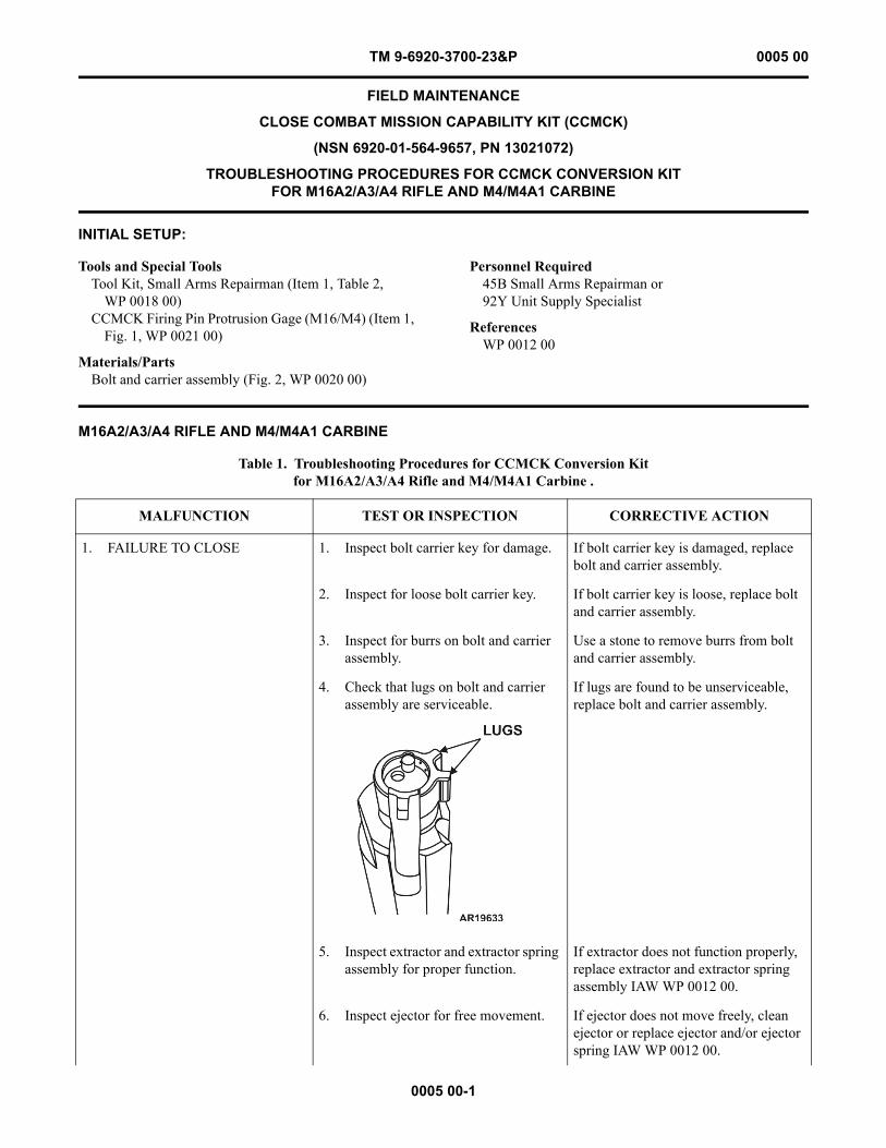
TROUBLESHOOTING PROCEDURES FOR CCMCK CONVERSION KIT FOR M16A2/A3/A4 RIFLE AND M4/M4A1 CARBINE
INITIAL SETUP:
M16A2/A3/A4 RIFLE AND M4/M4A1 CARBINE
Tools and Special ToolsTool Kit, Small Arms Repairman (Item 1, Table 2,
WP 0018 00)CCMCK Firing Pin Protrusion Gage (M16/M4) (Item 1,
Fig. 1, WP 0021 00)
Materials/PartsBolt and carrier assembly (Fig. 2, WP 0020 00)
Personnel Required45B Small Arms Repairman or92Y Unit Supply Specialist
ReferencesWP 0012 00
Table 1. Troubleshooting Procedures for CCMCK Conversion Kit for M16A2/A3/A4 Rifle and M4/M4A1 Carbine .
MALFUNCTION TEST OR INSPECTION CORRECTIVE ACTION
1. FAILURE TO CLOSE 1. Inspect bolt carrier key for damage. If bolt carrier key is damaged, replace bolt and carrier assembly.
2. Inspect for loose bolt carrier key. If bolt carrier key is loose, replace bolt and carrier assembly.
3. Inspect for burrs on bolt and carrier assembly.
Use a stone to remove burrs from bolt and carrier assembly.
4. Check that lugs on bolt and carrier assembly are serviceable.
If lugs are found to be unserviceable, replace bolt and carrier assembly.
5. Inspect extractor and extractor spring assembly for proper function.
If extractor does not function properly, replace extractor and extractor spring assembly IAW WP 0012 00.
6. Inspect ejector for free movement. If ejector does not move freely, clean ejector or replace ejector and/or ejector spring IAW WP 0012 00.
TM 9-6920-3700-23&P 0005 00
0005 00-2
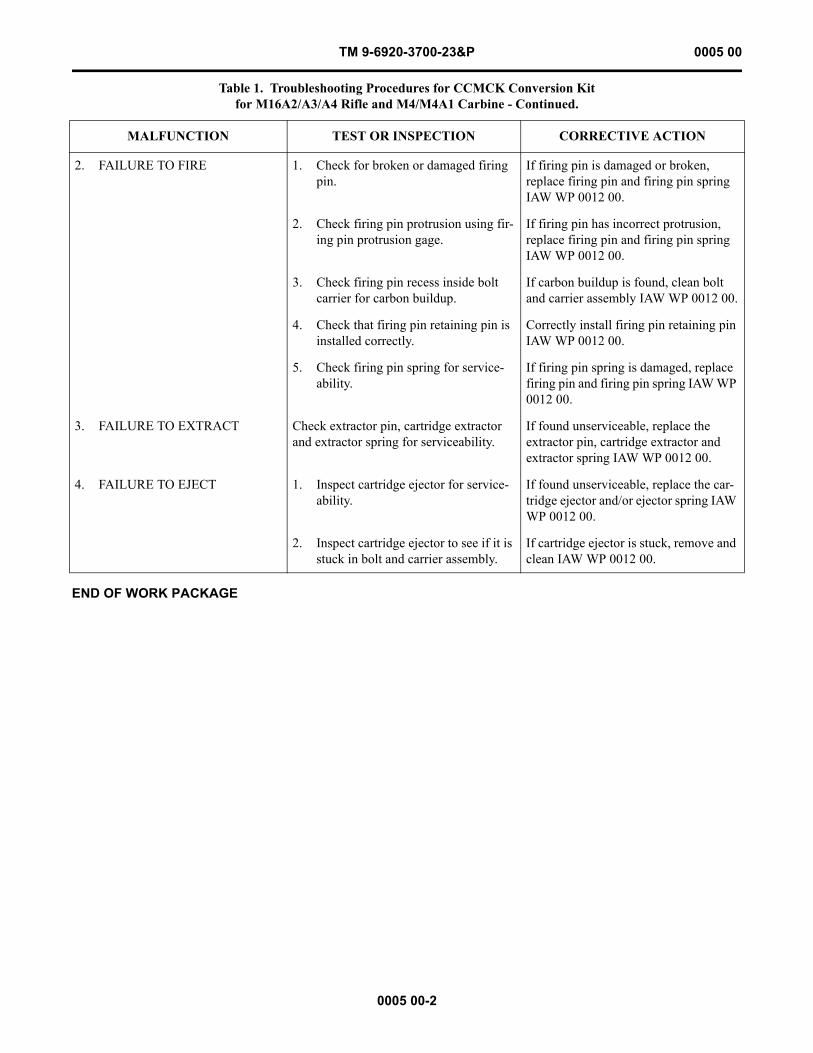
END OF WORK PACKAGE
2. FAILURE TO FIRE 1. Check for broken or damaged firing pin.
If firing pin is damaged or broken, replace firing pin and firing pin spring IAW WP 0012 00.
2. Check firing pin protrusion using fir-ing pin protrusion gage.
If firing pin has incorrect protrusion, replace firing pin and firing pin spring IAW WP 0012 00.
3. Check firing pin recess inside bolt carrier for carbon buildup.
If carbon buildup is found, clean bolt and carrier assembly IAW WP 0012 00.
4. Check that firing pin retaining pin is installed correctly.
Correctly install firing pin retaining pin IAW WP 0012 00.
5. Check firing pin spring for service-ability.
If firing pin spring is damaged, replace firing pin and firing pin spring IAW WP 0012 00.
3. FAILURE TO EXTRACT Check extractor pin, cartridge extractor and extractor spring for serviceability.
If found unserviceable, replace the extractor pin, cartridge extractor and extractor spring IAW WP 0012 00.
4. FAILURE TO EJECT 1. Inspect cartridge ejector for service-ability.
If found unserviceable, replace the car-tridge ejector and/or ejector spring IAW WP 0012 00.
2. Inspect cartridge ejector to see if it is stuck in bolt and carrier assembly.
If cartridge ejector is stuck, remove and clean IAW WP 0012 00.
Table 1. Troubleshooting Procedures for CCMCK Conversion Kit for M16A2/A3/A4 Rifle and M4/M4A1 Carbine - Continued.
MALFUNCTION TEST OR INSPECTION CORRECTIVE ACTION
TM 9-6920-3700-23&P 0006 00
0006 00-1
FIELD MAINTENANCE
CLOSE COMBAT MISSION CAPABILITY KIT (CCMCK)
(NSN 6920-01-564-9655, PN 13021071)
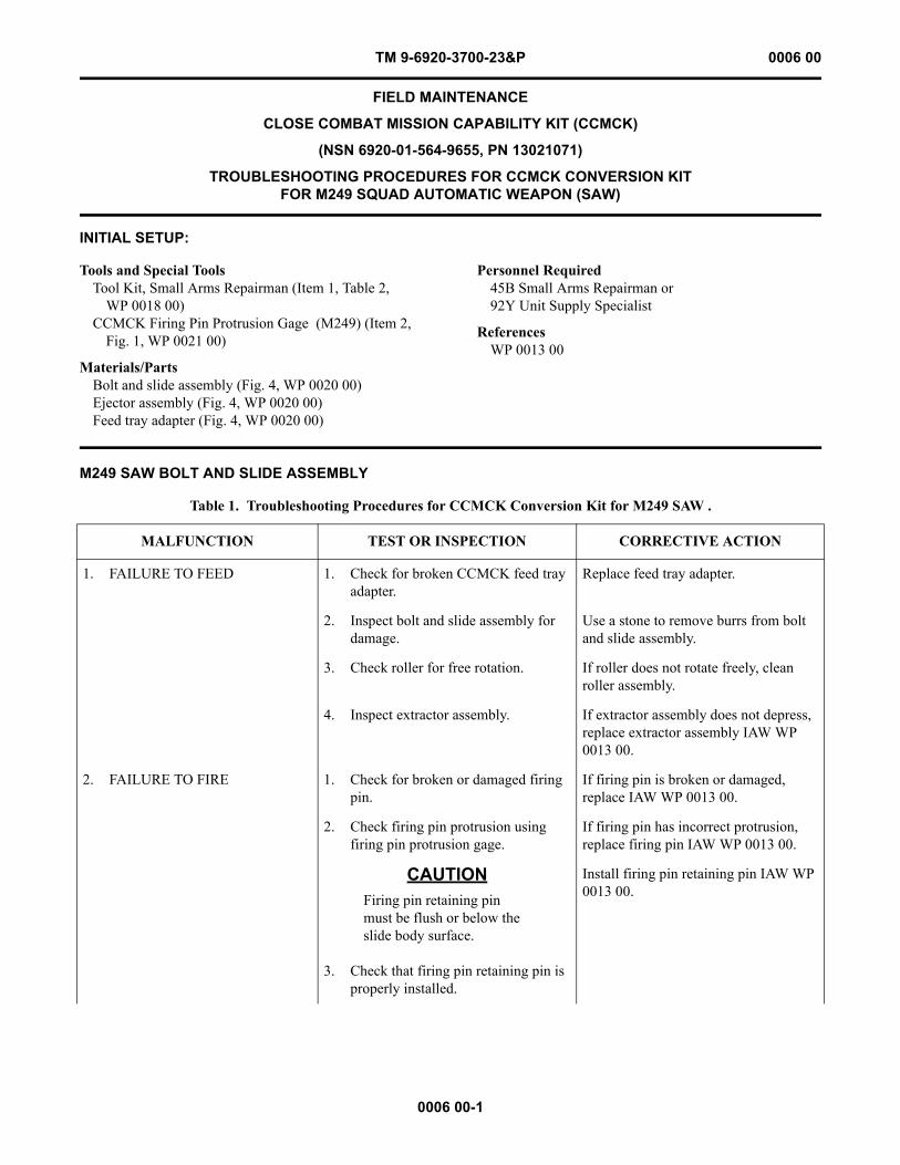
TROUBLESHOOTING PROCEDURES FOR CCMCK CONVERSION KIT FOR M249 SQUAD AUTOMATIC WEAPON (SAW)
INITIAL SETUP:
M249 SAW BOLT AND SLIDE ASSEMBLY
Tools and Special ToolsTool Kit, Small Arms Repairman (Item 1, Table 2,
WP 0018 00)CCMCK Firing Pin Protrusion Gage (M249) (Item 2,
Fig. 1, WP 0021 00)
Materials/PartsBolt and slide assembly (Fig. 4, WP 0020 00)Ejector assembly (Fig. 4, WP 0020 00)Feed tray adapter (Fig. 4, WP 0020 00)
Personnel Required45B Small Arms Repairman or92Y Unit Supply Specialist
ReferencesWP 0013 00
Table 1. Troubleshooting Procedures for CCMCK Conversion Kit for M249 SAW .
MALFUNCTION TEST OR INSPECTION CORRECTIVE ACTION
1. FAILURE TO FEED 1. Check for broken CCMCK feed tray adapter.
Replace feed tray adapter.
2. Inspect bolt and slide assembly for damage.
Use a stone to remove burrs from bolt and slide assembly.
3. Check roller for free rotation. If roller does not rotate freely, clean roller assembly.
4. Inspect extractor assembly. If extractor assembly does not depress, replace extractor assembly IAW WP 0013 00.
2. FAILURE TO FIRE 1. Check for broken or damaged firing pin.
If firing pin is broken or damaged, replace IAW WP 0013 00.
2. Check firing pin protrusion using firing pin protrusion gage.
If firing pin has incorrect protrusion, replace firing pin IAW WP 0013 00.
CAUTIONFiring pin retaining pin must be flush or below the slide body surface.
3. Check that firing pin retaining pin is properly installed.
Install firing pin retaining pin IAW WP 0013 00.
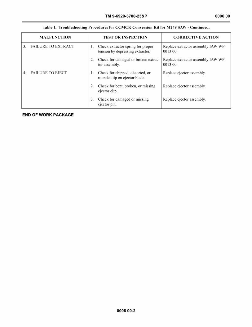
TM 9-6920-3700-23&P 0006 00
0006 00-2
END OF WORK PACKAGE
3. FAILURE TO EXTRACT 1. Check extractor spring for proper tension by depressing extractor.
Replace extractor assembly IAW WP 0013 00.
2. Check for damaged or broken extrac-tor assembly.
Replace extractor assembly IAW WP 0013 00.
4. FAILURE TO EJECT 1. Check for chipped, distorted, or rounded tip on ejector blade.
Replace ejector assembly.
2. Check for bent, broken, or missing ejector clip.
Replace ejector assembly.
3. Check for damaged or missing ejector pin.
Replace ejector assembly.
Table 1. Troubleshooting Procedures for CCMCK Conversion Kit for M249 SAW - Continued.
MALFUNCTION TEST OR INSPECTION CORRECTIVE ACTION
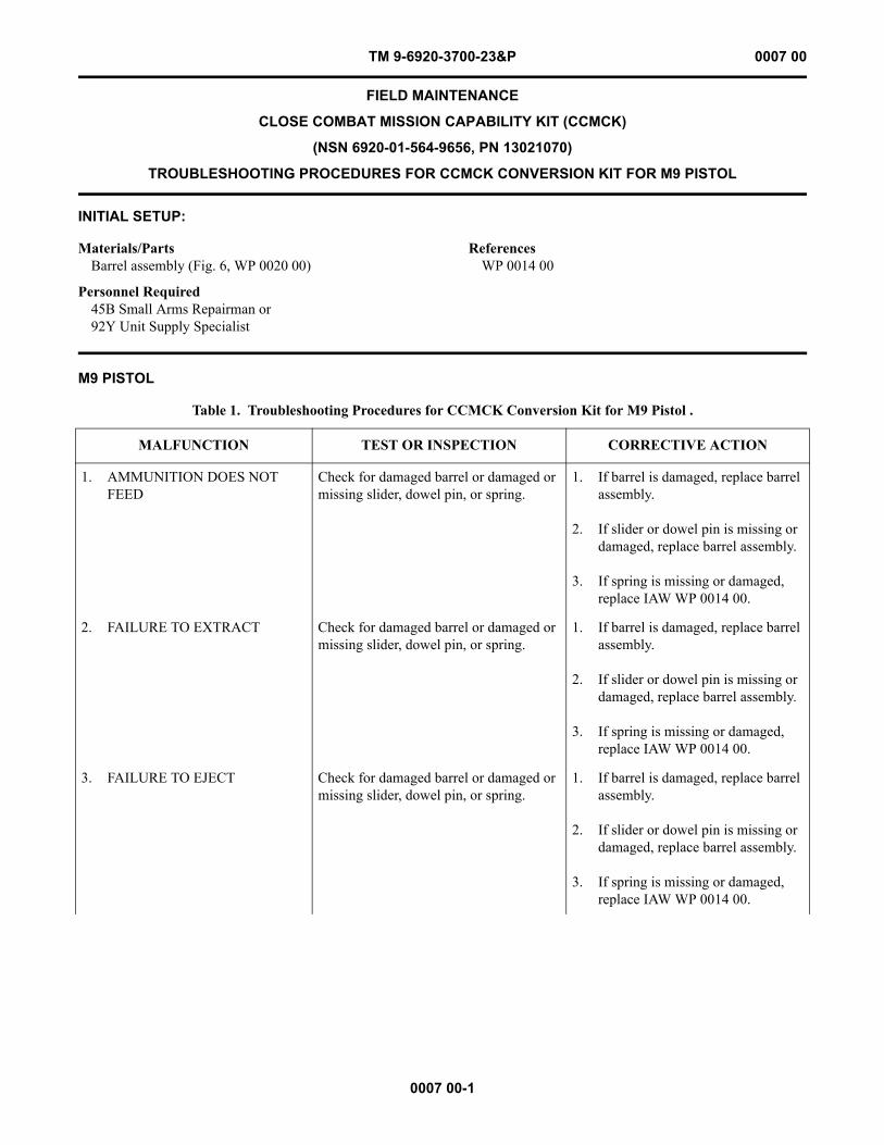
TM 9-6920-3700-23&P 0007 00
0007 00-1
FIELD MAINTENANCE
CLOSE COMBAT MISSION CAPABILITY KIT (CCMCK)
(NSN 6920-01-564-9656, PN 13021070)
TROUBLESHOOTING PROCEDURES FOR CCMCK CONVERSION KIT FOR M9 PISTOL
INITIAL SETUP:
M9 PISTOL
Materials/PartsBarrel assembly (Fig. 6, WP 0020 00)
Personnel Required45B Small Arms Repairman or92Y Unit Supply Specialist
ReferencesWP 0014 00
Table 1. Troubleshooting Procedures for CCMCK Conversion Kit for M9 Pistol .
MALFUNCTION TEST OR INSPECTION CORRECTIVE ACTION
1. AMMUNITION DOES NOT FEED
Check for damaged barrel or damaged or missing slider, dowel pin, or spring.
1. If barrel is damaged, replace barrel assembly.
2. If slider or dowel pin is missing or damaged, replace barrel assembly.
3. If spring is missing or damaged, replace IAW WP 0014 00.
2. FAILURE TO EXTRACT Check for damaged barrel or damaged or missing slider, dowel pin, or spring.
1. If barrel is damaged, replace barrel assembly.
2. If slider or dowel pin is missing or damaged, replace barrel assembly.
3. If spring is missing or damaged, replace IAW WP 0014 00.
3. FAILURE TO EJECT Check for damaged barrel or damaged or missing slider, dowel pin, or spring.
1. If barrel is damaged, replace barrel assembly.
2. If slider or dowel pin is missing or damaged, replace barrel assembly.
3. If spring is missing or damaged, replace IAW WP 0014 00.
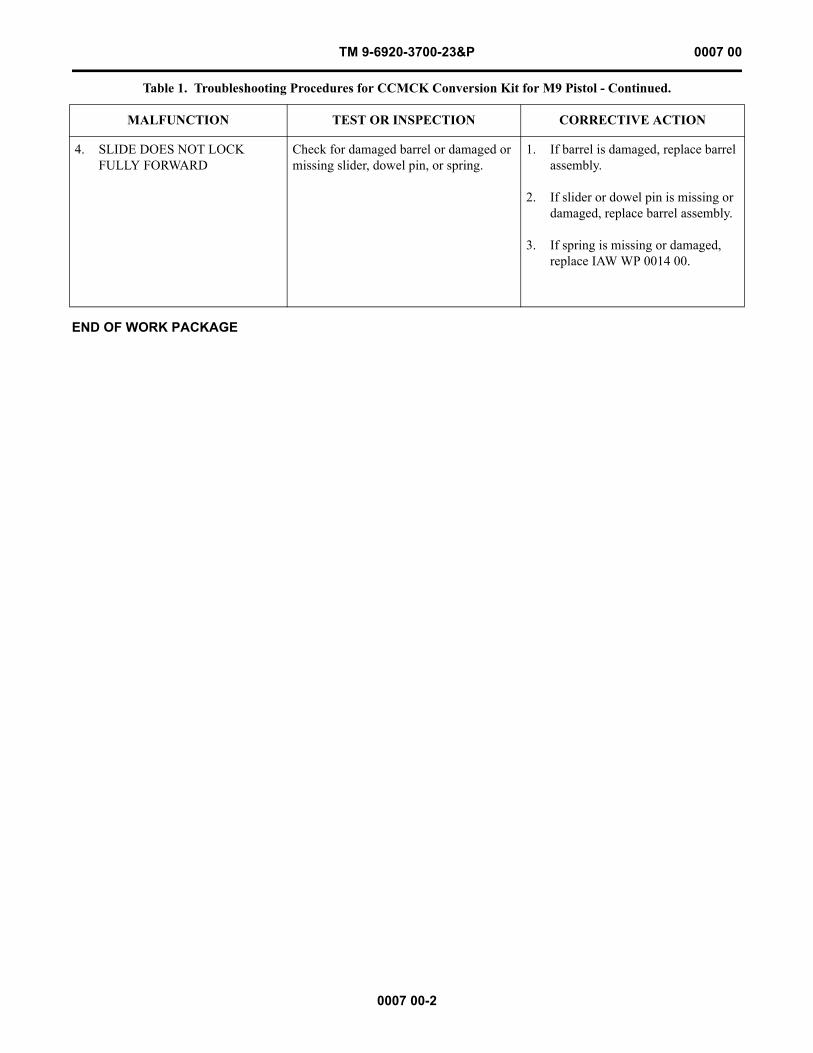
TM 9-6920-3700-23&P 0007 00
0007 00-2
END OF WORK PACKAGE
4. SLIDE DOES NOT LOCK FULLY FORWARD
Check for damaged barrel or damaged or missing slider, dowel pin, or spring.
1. If barrel is damaged, replace barrel assembly.
2. If slider or dowel pin is missing or damaged, replace barrel assembly.
3. If spring is missing or damaged, replace IAW WP 0014 00.
Table 1. Troubleshooting Procedures for CCMCK Conversion Kit for M9 Pistol - Continued.
MALFUNCTION TEST OR INSPECTION CORRECTIVE ACTION
TM 9-6920-3700-23&P 0008 00
0008 00-1
FIELD MAINTENANCE
CLOSE COMBAT MISSION CAPABILITY KIT (CCMCK)
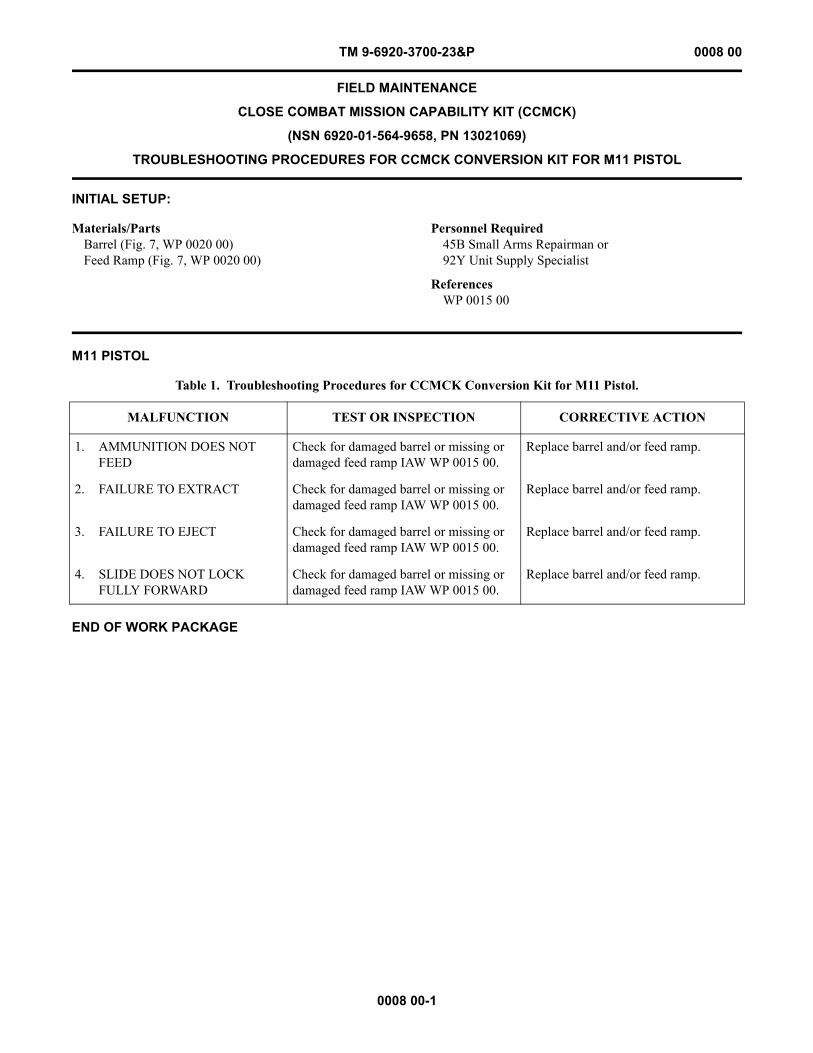
(NSN 6920-01-564-9658, PN 13021069)
TROUBLESHOOTING PROCEDURES FOR CCMCK CONVERSION KIT FOR M11 PISTOL
INITIAL SETUP:
M11 PISTOL
END OF WORK PACKAGE
Materials/PartsBarrel (Fig. 7, WP 0020 00)Feed Ramp (Fig. 7, WP 0020 00)
Personnel Required45B Small Arms Repairman or92Y Unit Supply Specialist
ReferencesWP 0015 00
Table 1. Troubleshooting Procedures for CCMCK Conversion Kit for M11 Pistol.
MALFUNCTION TEST OR INSPECTION CORRECTIVE ACTION
1. AMMUNITION DOES NOT FEED
Check for damaged barrel or missing or damaged feed ramp IAW WP 0015 00.
Replace barrel and/or feed ramp.
2. FAILURE TO EXTRACT Check for damaged barrel or missing or damaged feed ramp IAW WP 0015 00.
Replace barrel and/or feed ramp.
3. FAILURE TO EJECT Check for damaged barrel or missing or damaged feed ramp IAW WP 0015 00.
Replace barrel and/or feed ramp.
4. SLIDE DOES NOT LOCK FULLY FORWARD
Check for damaged barrel or missing or damaged feed ramp IAW WP 0015 00.
Replace barrel and/or feed ramp.

This Page Intentionally Left Blank
0008 00-2
TM 9-6920-3700-23&P 0008 00
CHAPTER 3
MAINTENANCE INSTRUCTIONSFOR
CLOSE COMBAT MISSION CAPABILITY KIT (CCMCK)
TM 9-6920-3700-23&P

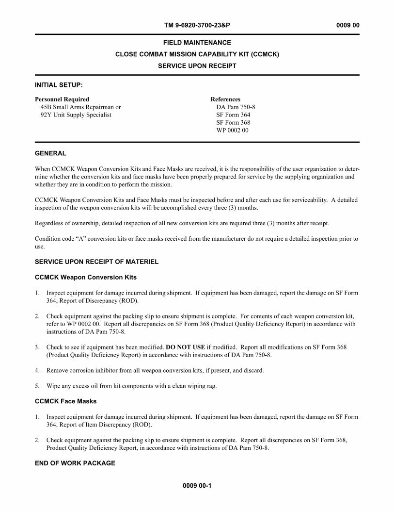
TM 9-6920-3700-23&P 0009 00
0009 00-1
FIELD MAINTENANCE
CLOSE COMBAT MISSION CAPABILITY KIT (CCMCK)
SERVICE UPON RECEIPT
INITIAL SETUP:
GENERAL
When CCMCK Weapon Conversion Kits and Face Masks are received, it is the responsibility of the user organization to deter-mine whether the conversion kits and face masks have been properly prepared for service by the supplying organization and whether they are in condition to perform the mission.
CCMCK Weapon Conversion Kits and Face Masks must be inspected before and after each use for serviceability. A detailed inspection of the weapon conversion kits will be accomplished every three (3) months.
Regardless of ownership, detailed inspection of all new conversion kits are required three (3) months after receipt.
Condition code “A” conversion kits or face masks received from the manufacturer do not require a detailed inspection prior to use.
SERVICE UPON RECEIPT OF MATERIEL
CCMCK Weapon Conversion Kits
1. Inspect equipment for damage incurred during shipment. If equipment has been damaged, report the damage on SF Form 364, Report of Discrepancy (ROD).
2. Check equipment against the packing slip to ensure shipment is complete. For contents of each weapon conversion kit, refer to WP 0002 00. Report all discrepancies on SF Form 368 (Product Quality Deficiency Report) in accordance with instructions of DA Pam 750-8.
3. Check to see if equipment has been modified. DO NOT USE if modified. Report all modifications on SF Form 368 (Product Quality Deficiency Report) in accordance with instructions of DA Pam 750-8.
4. Remove corrosion inhibitor from all weapon conversion kits, if present, and discard.
5. Wipe any excess oil from kit components with a clean wiping rag.
CCMCK Face Masks
1. Inspect equipment for damage incurred during shipment. If equipment has been damaged, report the damage on SF Form 364, Report of Item Discrepancy (ROD).
2. Check equipment against the packing slip to ensure shipment is complete. Report all discrepancies on SF Form 368, Product Quality Deficiency Report, in accordance with instructions of DA Pam 750-8.
END OF WORK PACKAGE
Personnel Required45B Small Arms Repairman or92Y Unit Supply Specialist
ReferencesDA Pam 750-8SF Form 364SF Form 368WP 0002 00

This Page Intentionally Left Blank
0009 00-2
TM 9-6920-3700-23&P 0009 00
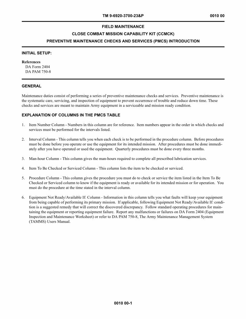
TM 9-6920-3700-23&P 0010 00
0010 00-1
FIELD MAINTENANCE
CLOSE COMBAT MISSION CAPABILITY KIT (CCMCK)
PREVENTIVE MAINTENANCE CHECKS AND SERVICES (PMCS) INTRODUCTION
INITIAL SETUP:
GENERAL
Maintenance duties consist of performing a series of preventive maintenance checks and services. Preventive maintenance is the systematic care, servicing, and inspection of equipment to prevent occurrence of trouble and reduce down time. These checks and services are meant to maintain Army equipment in a serviceable and mission ready condition.
EXPLANATION OF COLUMNS IN THE PMCS TABLE
1. Item Number Column - Numbers in this column are for reference. Item numbers appear in the order in which checks and services must be performed for the intervals listed.
2. Interval Column - This column tells you when each check is to be performed in the procedure column. Before procedures must be done before you operate or use the equipment for its intended mission. After procedures must be done immedi-ately after you have operated or used the equipment. Quarterly procedures must be done every three months.
3. Man-hour Column - This column gives the man-hours required to complete all prescribed lubrication services.
4. Item To Be Checked or Serviced Column - This column lists the item to be checked or serviced.
5. Procedure Column - This column gives the procedure you must do to check or service the item listed in the Item To Be Checked or Serviced column to know if the equipment is ready or available for its intended mission or for operation. You must do the procedure at the time stated in the interval column.
6. Equipment Not Ready/Available If: Column - Information in this column tells you what faults will keep your equipment from being capable of performing its primary mission. If applicable, following Equipment Not Ready/Available If: condi-tion is a suggested remedy that will correct the discovered discrepancy. Follow standard operating procedures for main-taining the equipment or reporting equipment failure. Report any malfunctions or failures on DA Form 2404 (Equipment Inspection and Maintenance Worksheet) or refer to DA PAM 750-8, The Army Maintenance Management System (TAMMS) Users Manual.
ReferencesDA Form 2404DA PAM 750-8

This Page Intentionally Left Blank
0010 00-2
TM 9-6920-3700-23&P 0010 00
TM 9-6920-3700-23&P 0011 00
0011 00-1
FIELD MAINTENANCE
CLOSE COMBAT MISSION CAPABILITY KIT (CCMCK)
PREVENTIVE MAINTENANCE CHECKS AND SERVICES (PMCS)
INITIAL SETUP:
PREVENTIVE MAINTENANCE CHECKS AND SERVICES FOR CLOSE COMBAT MISSION CAPABILITY KIT (CCMCK)
Tools and Special ToolsCCMCK Firing Pin Protrusion Gage (M16/M4) (Item 1,
Fig. 1, WP 0021 00)CCMCK Firing Pin Protrusion Gage (M249) (Item 2,
Fig. 1, WP 0021 00)Tool Kit, Small Arms Repairman (Item 1, Table 2,
WP 0018 00)
Materials/PartsCleaner, Lubricant and Preservative (CLP)
(Item 1, WP 0024 00)Rag, wiping (Item 2, WP 0024 00)
Personnel Required45B Small Arms Repairman or92Y Unit Supply Specialist
ReferencesWP 0012 00WP 0013 00WP 0014 00WP 0015 00
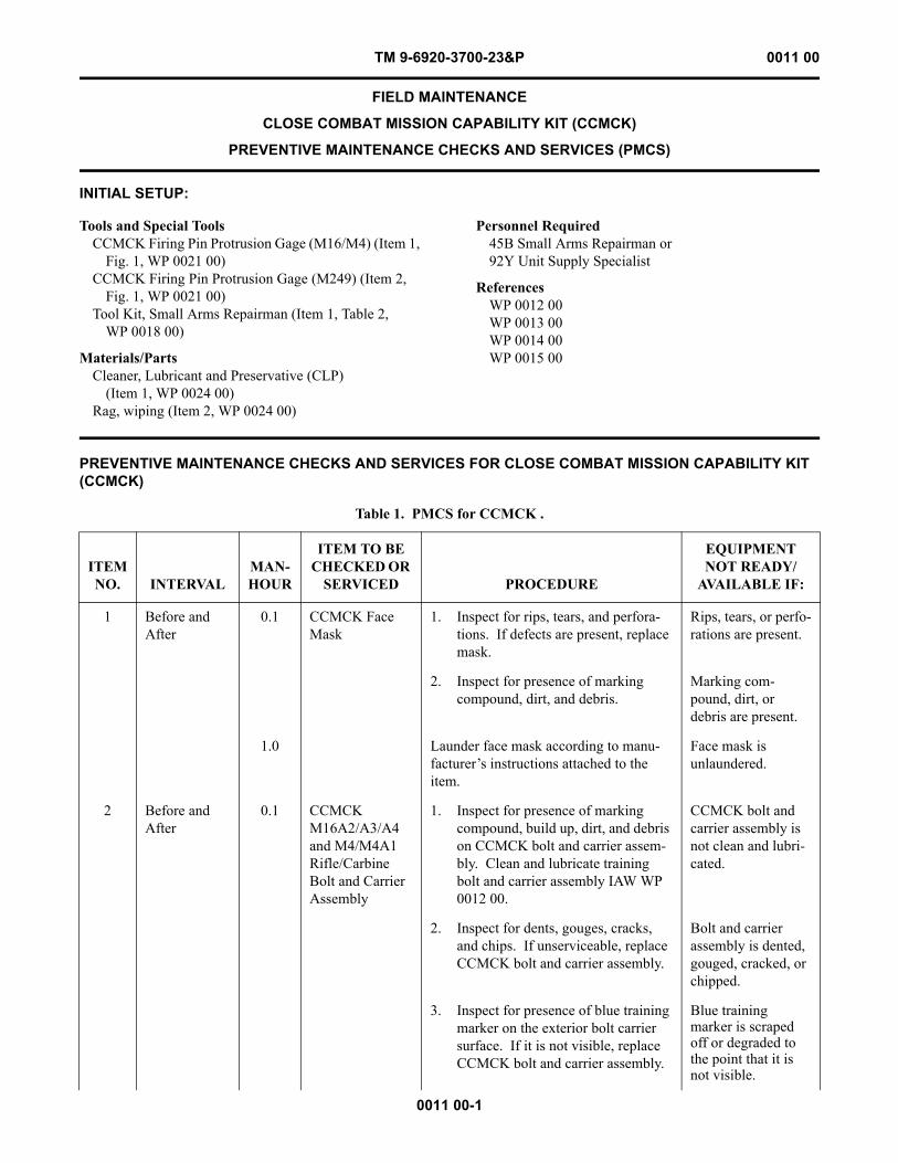
Table 1. PMCS for CCMCK .
ITEM NO. INTERVAL
MAN-HOUR
ITEM TO BE CHECKED OR
SERVICED PROCEDURE
EQUIPMENT NOT READY/
AVAILABLE IF:
1 Before and After
0.1 CCMCK Face Mask
1. Inspect for rips, tears, and perfora-tions. If defects are present, replace mask.
Rips, tears, or perfo-rations are present.
2. Inspect for presence of marking compound, dirt, and debris.
Marking com-pound, dirt, or debris are present.
1.0 Launder face mask according to manu-facturer’s instructions attached to the item.
Face mask is unlaundered.
2 Before and After
0.1 CCMCK M16A2/A3/A4 and M4/M4A1 Rifle/Carbine Bolt and Carrier Assembly
1. Inspect for presence of marking compound, build up, dirt, and debris on CCMCK bolt and carrier assem-bly. Clean and lubricate training bolt and carrier assembly IAW WP 0012 00.
CCMCK bolt and carrier assembly is not clean and lubri-cated.
2. Inspect for dents, gouges, cracks, and chips. If unserviceable, replace CCMCK bolt and carrier assembly.
Bolt and carrier assembly is dented, gouged, cracked, or chipped.
3. Inspect for presence of blue training marker on the exterior bolt carrier surface. If it is not visible, replace CCMCK bolt and carrier assembly.
Blue training marker is scraped off or degraded to the point that it is not visible.
TM 9-6920-3700-23&P 0011 00
0011 00-2
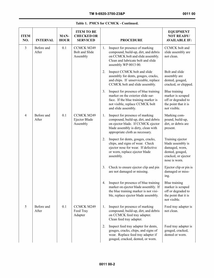
3 Before and After
0.1 CCMCK M249 Bolt and Slide Assembly
1. Inspect for presence of marking compound, build-up, dirt, and debris on CCMCK bolt and slide assembly. Clean and lubricate bolt and slide assembly WP 0013 00.
CCMCK bolt and slide assembly are not clean.
2. Inspect CCMCK bolt and slide assembly for dents, gouges, cracks, and chips. If unserviceable, replace CCMCK bolt and slide assembly.
Bolt and slide assembly are dented, gouged, cracked, or chipped.
3. Inspect for presence of blue training marker on the exterior slide sur-face. If the blue training marker is not visible, replace CCMCK bolt and slide assembly.
Blue training marker is scraped off or degraded to the point that it is not visible.
4 Before and After
0.1 CCMCK M249 Ejector Blade Assembly
1. Inspect for presence of marking compound, build-up, dirt, and debris on ejector blade. If CCMCK ejector blade assembly is dirty, clean with appropriate cloth as necessary.
Marking com-pound, build-up, dirt, or debris are present.
2. Inspect for dents, gouges, cracks, chips, and signs of wear. Check ejector nose for wear. If defective or worn, replace ejector blade assembly.
Training ejector blade assembly is damaged, worn, dented, gouged, cracked, or ejector nose is worn.
3. Check to ensure ejector clip and pin are not damaged or missing.
Ejector clip or pin is damaged or miss-ing.
4. Inspect for presence of blue training marker on ejector blade assembly. If the blue training marker is not visi-ble, replace ejector blade assembly.
Blue training marker is scraped off or degraded to the point that it is not visible.
5 Before and After
0.1 CCMCK M249 Feed Tray Adapter
1. Inspect for presence of marking compound, build-up, dirt, and debris on CCMCK feed tray adapter. Clean feed tray adapter.
Feed tray adapter is not clean.
2. Inspect feed tray adapter for dents, gouges, cracks, chips, and signs of wear. Replace feed tray adapter if gouged, cracked, dented, or worn.
Feed tray adapter is gouged, cracked, dented or worn.
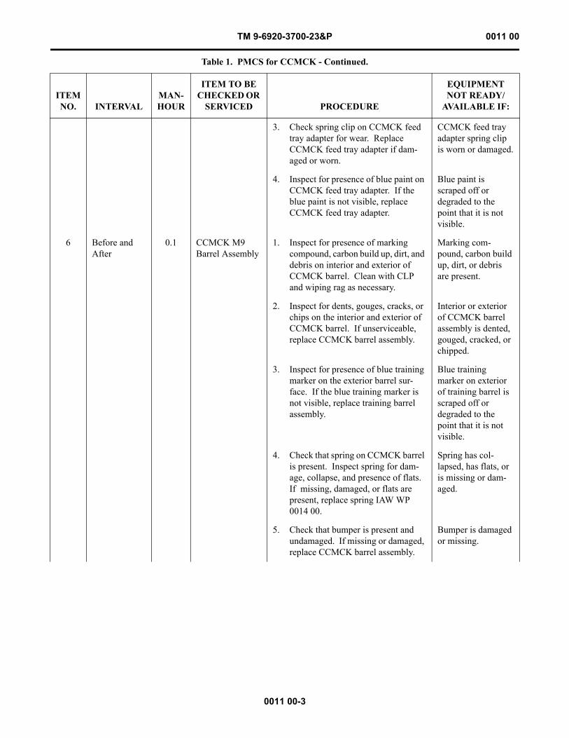
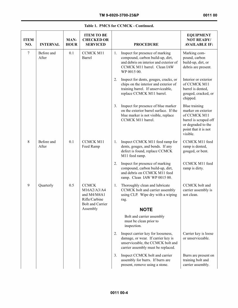
Table 1. PMCS for CCMCK - Continued.
ITEM NO. INTERVAL
MAN-HOUR
ITEM TO BE CHECKED OR
SERVICED PROCEDURE
EQUIPMENT NOT READY/
AVAILABLE IF:
TM 9-6920-3700-23&P 0011 00
0011 00-3
3. Check spring clip on CCMCK feed tray adapter for wear. Replace CCMCK feed tray adapter if dam-aged or worn.
CCMCK feed tray adapter spring clip is worn or damaged.
4. Inspect for presence of blue paint on CCMCK feed tray adapter. If the blue paint is not visible, replace CCMCK feed tray adapter.
Blue paint is scraped off or degraded to the point that it is not visible.
6 Before and After
0.1 CCMCK M9 Barrel Assembly
1. Inspect for presence of marking compound, carbon build up, dirt, and debris on interior and exterior of CCMCK barrel. Clean with CLP and wiping rag as necessary.
Marking com-pound, carbon build up, dirt, or debris are present.
2. Inspect for dents, gouges, cracks, or chips on the interior and exterior of CCMCK barrel. If unserviceable, replace CCMCK barrel assembly.
Interior or exterior of CCMCK barrel assembly is dented, gouged, cracked, or chipped.
3. Inspect for presence of blue training marker on the exterior barrel sur-face. If the blue training marker is not visible, replace training barrel assembly.
Blue training marker on exterior of training barrel is scraped off or degraded to the point that it is not visible.
4. Check that spring on CCMCK barrel is present. Inspect spring for dam-age, collapse, and presence of flats. If missing, damaged, or flats are present, replace spring IAW WP 0014 00.
Spring has col-lapsed, has flats, or is missing or dam-aged.
5. Check that bumper is present and undamaged. If missing or damaged, replace CCMCK barrel assembly.
Bumper is damaged or missing.
Table 1. PMCS for CCMCK - Continued.
ITEM NO. INTERVAL
MAN-HOUR
ITEM TO BE CHECKED OR
SERVICED PROCEDURE
EQUIPMENT NOT READY/
AVAILABLE IF:
TM 9-6920-3700-23&P 0011 00
0011 00-4
7 Before and After
0.1 CCMCK M11 Barrel
1. Inspect for presence of marking compound, carbon build-up, dirt, and debris on interior and exterior of CCMCK M11 barrel. Clean IAW WP 0015 00.
Marking com-pound, carbon build-up, dirt, or debris are present.
2. Inspect for dents, gouges, cracks, or chips on the interior and exterior of training barrel. If unserviceable, replace CCMCK M11 barrel.
Interior or exterior of CCMCK M11 barrel is dented, gouged, cracked, or chipped.
3. Inspect for presence of blue marker on the exterior barrel surface. If the blue marker is not visible, replace CCMCK M11 barrel.
Blue training marker on exterior of CCMCK M11 barrel is scraped off or degraded to the point that it is not visible.
8 Before and After
0.1 CCMCK M11 Feed Ramp
1. Inspect CCMCK M11 feed ramp for dents, gouges, and bends. If any defect is found, replace CCMCK M11 feed ramp.
CCMCK M11 feed ramp is dented, gouged, or bent.
2. Inspect for presence of marking compound, carbon build-up, dirt, and debris on CCMCK M11 feed ramp. Clean IAW WP 0015 00.
CCMCK M11 feed ramp is dirty.
9 Quarterly 0.5 CCMCK M16A2/A3/A4 and M4/M4A1 Rifle/Carbine Bolt and Carrier Assembly
1. Thoroughly clean and lubricate CCMCK bolt and carrier assembly using CLP. Wipe dry with a wiping rag.
NOTEBolt and carrier assembly must be clean prior to inspection.
CCMCK bolt and carrier assembly is not clean.
2. Inspect carrier key for looseness, damage, or wear. If carrier key is unserviceable, the CCMCK bolt and carrier assembly must be replaced.
Carrier key is loose or unserviceable.
3. Inspect CCMCK bolt and carrier assembly for burrs. If burrs are present, remove using a stone.
Burrs are present on training bolt and carrier assembly.
Table 1. PMCS for CCMCK - Continued.
ITEM NO. INTERVAL
MAN-HOUR
ITEM TO BE CHECKED OR
SERVICED PROCEDURE
EQUIPMENT NOT READY/
AVAILABLE IF:
TM 9-6920-3700-23&P 0011 00
0011 00-5
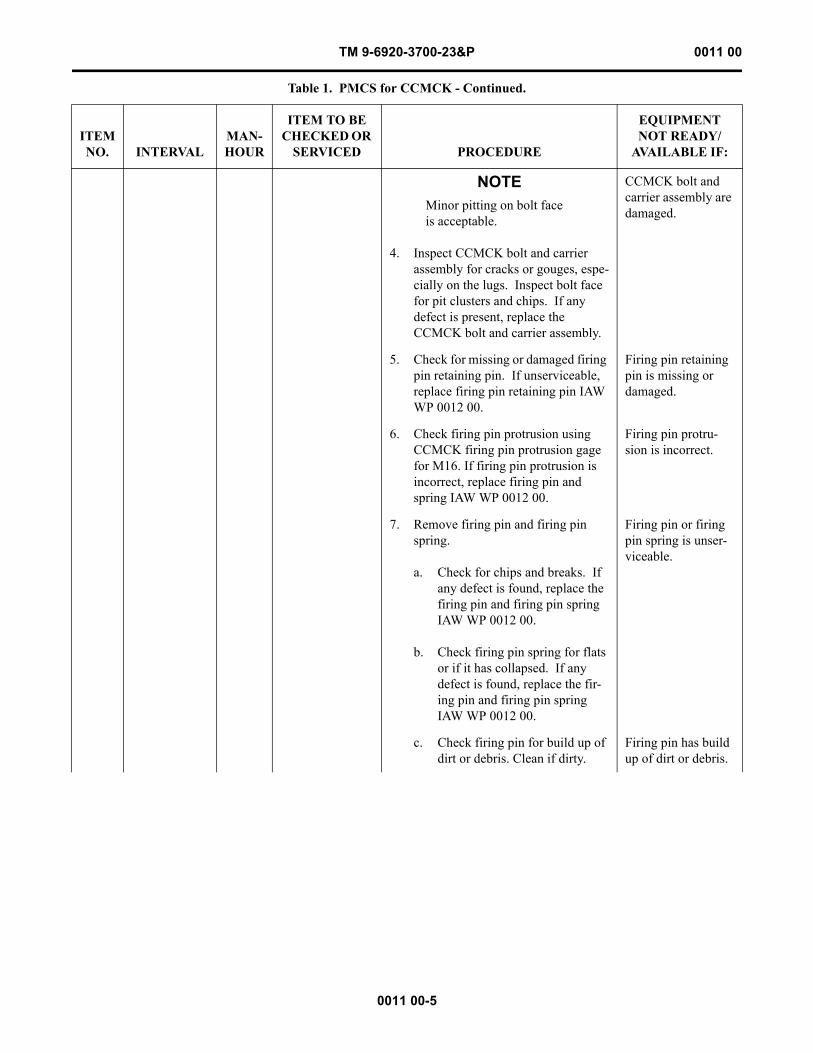
NOTEMinor pitting on bolt face is acceptable.
4. Inspect CCMCK bolt and carrier assembly for cracks or gouges, espe-cially on the lugs. Inspect bolt face for pit clusters and chips. If any defect is present, replace the CCMCK bolt and carrier assembly.
CCMCK bolt and carrier assembly are damaged.
5. Check for missing or damaged firing pin retaining pin. If unserviceable, replace firing pin retaining pin IAW WP 0012 00.
Firing pin retaining pin is missing or damaged.
6. Check firing pin protrusion using CCMCK firing pin protrusion gage for M16. If firing pin protrusion is incorrect, replace firing pin and spring IAW WP 0012 00.
Firing pin protru-sion is incorrect.
7. Remove firing pin and firing pin spring.
a. Check for chips and breaks. If any defect is found, replace the firing pin and firing pin spring IAW WP 0012 00.
b. Check firing pin spring for flats or if it has collapsed. If any defect is found, replace the fir-ing pin and firing pin spring IAW WP 0012 00.
Firing pin or firing pin spring is unser-viceable.
c. Check firing pin for build up of dirt or debris. Clean if dirty.
Firing pin has build up of dirt or debris.
Table 1. PMCS for CCMCK - Continued.
ITEM NO. INTERVAL
MAN-HOUR
ITEM TO BE CHECKED OR
SERVICED PROCEDURE
EQUIPMENT NOT READY/
AVAILABLE IF:
TM 9-6920-3700-23&P 0011 00
0011 00-6
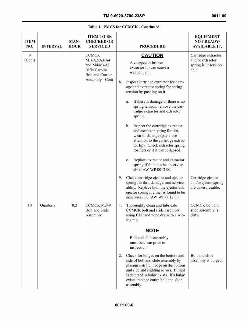
9(Cont)
CCMCK M16A2/A3/A4 and M4/M4A1 Rifle/Carbine Bolt and Carrier Assembly - Cont
CAUTIONA chipped or broken extractor lip can cause a weapon jam.
8. Inspect cartridge extractor for dam-age and extractor spring for spring tension by pushing on it.
a. If there is damage or there is no spring tension, remove the car-tridge extractor and extractor spring.
b. Inspect the cartridge extractor and extractor spring for dirt, wear or damage (pay close attention to the cartridge extrac-tor lip). Check extractor spring for flats or if it has collapsed.
c. Replace extractor and extractor spring if found to be unservice-able IAW WP 0012 00.
Cartridge extractor and/or extractor spring is unservice-able.
9. Check cartridge ejector and ejector spring for dirt, damage, and service-ablity. Replace both the ejector and ejector spring if either is found to be unserviceable IAW WP 0012 00.
Cartridge ejector and/or ejector spring are unserviceable.
10 Quarterly 0.2 CCMCK M249 Bolt and Slide Assembly
1. Thoroughly clean and lubricate CCMCK bolt and slide assembly using CLP and wipe dry with a wip-ing rag.
NOTEBolt and slide assembly must be clean prior to inspection.
CCMCK bolt and slide assembly is dirty.
2. Check for bulges on the bottom and side of bolt and slide assembly by placing a straight edge on the bottom and side and sighting across. If light is detected, a bulge exists. If a bulge exists, replace entire bolt and slide assembly.
Bolt and slide assembly is bulged.
Table 1. PMCS for CCMCK - Continued.
ITEM NO. INTERVAL
MAN-HOUR
ITEM TO BE CHECKED OR
SERVICED PROCEDURE
EQUIPMENT NOT READY/
AVAILABLE IF:
TM 9-6920-3700-23&P 0011 00
0011 00-7
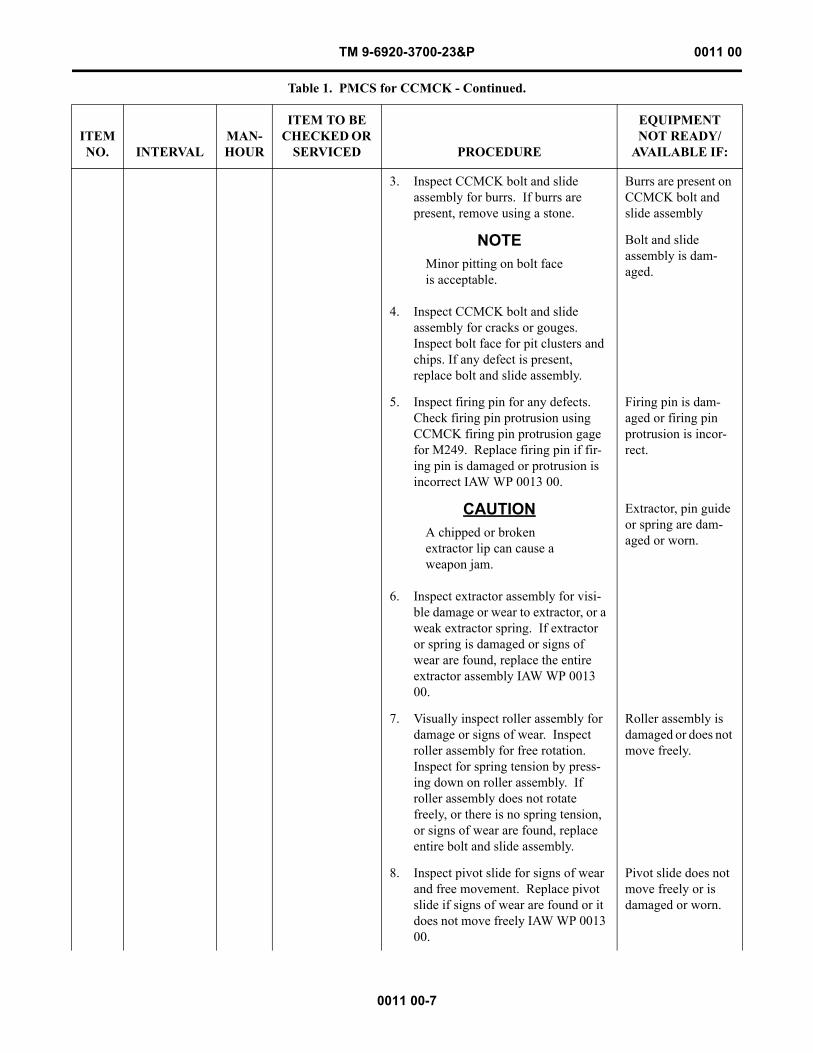
3. Inspect CCMCK bolt and slide assembly for burrs. If burrs are present, remove using a stone.
Burrs are present on CCMCK bolt and slide assembly
NOTEMinor pitting on bolt face is acceptable.
4. Inspect CCMCK bolt and slide assembly for cracks or gouges. Inspect bolt face for pit clusters and chips. If any defect is present, replace bolt and slide assembly.
Bolt and slide assembly is dam-aged.
5. Inspect firing pin for any defects. Check firing pin protrusion using CCMCK firing pin protrusion gage for M249. Replace firing pin if fir-ing pin is damaged or protrusion is incorrect IAW WP 0013 00.
Firing pin is dam-aged or firing pin protrusion is incor-rect.
CAUTIONA chipped or broken extractor lip can cause a weapon jam.
6. Inspect extractor assembly for visi-ble damage or wear to extractor, or a weak extractor spring. If extractor or spring is damaged or signs of wear are found, replace the entire extractor assembly IAW WP 0013 00.
Extractor, pin guide or spring are dam-aged or worn.
7. Visually inspect roller assembly for damage or signs of wear. Inspect roller assembly for free rotation. Inspect for spring tension by press-ing down on roller assembly. If roller assembly does not rotate freely, or there is no spring tension, or signs of wear are found, replace entire bolt and slide assembly.
Roller assembly is damaged or does not move freely.
8. Inspect pivot slide for signs of wear and free movement. Replace pivot slide if signs of wear are found or it does not move freely IAW WP 0013 00.
Pivot slide does not move freely or is damaged or worn.
Table 1. PMCS for CCMCK - Continued.
ITEM NO. INTERVAL
MAN-HOUR
ITEM TO BE CHECKED OR
SERVICED PROCEDURE
EQUIPMENT NOT READY/
AVAILABLE IF:
TM 9-6920-3700-23&P 0011 00
0011 00-8
END OF WORK PACKAGE
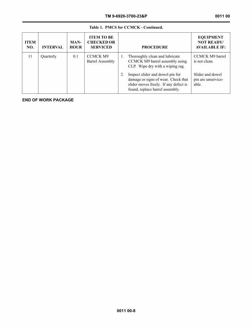
11 Quarterly 0.1 CCMCK M9 Barrel Assembly
1. Thoroughly clean and lubricate CCMCK M9 barrel assembly using CLP. Wipe dry with a wiping rag.
CCMCK M9 barrel is not clean.
2. Inspect slider and dowel pin for damage or signs of wear. Check that slider moves freely. If any defect is found, replace barrel assembly.
Slider and dowel pin are unservice-able.
Table 1. PMCS for CCMCK - Continued.
ITEM NO. INTERVAL
MAN-HOUR
ITEM TO BE CHECKED OR
SERVICED PROCEDURE
EQUIPMENT NOT READY/
AVAILABLE IF:
TM 9-6920-3700-23&P 0012 00
0012 00-1
FIELD MAINTENANCE
CLOSE COMBAT MISSION CAPABILITY KIT (CCMCK)
(NSN 6920-01-564-9657, PN 13021072)
MAINTENANCE INSTRUCTIONS FOR CCMCK CONVERSION KIT FOR M16A2/A3/A4 RIFLES AND M4/M4A1 CARBINES
INITIAL SETUP:
CCMCK M16A2/A3/A4 RIFLE AND M4/M4A1 CARBINE TRAINING BOLT AND BOLT CARRIER ASSEMBLY
This work package covers cleaning and inspection of the bolt and bolt carrier key and cleaning, inspection, and disassembly/reassembly of the cartridge extractor, cartridge ejector, and firing pin.
WARNINGCare must be taken when installing and removing spring-loaded parts. Safety goggles must be worn to prevent injury to eyes.
BOLT AND BOLT CARRIER KEY
Cleaning
Remove dirt and corrosion from bolt and carrier assembly using a wiping rag dampened with CLP.
Tools and Special ToolsCCMCK Firing Pin Protrusion Gage (M16/M4) (Item 1,
Fig. 1, WP 0021 00)Tool Kit, Small Arms Repairman (Item 1, Table 2,
WP 0018 00)
Materials/PartsBolt and carrier assembly (Fig. 2, WP 0020 00)Cartridge ejector (Fig. 2, WP 0020 00)Cartridge extractor (Fig. 2, WP 0020 00)Cleaner, Lubricant and Preservative (CLP) (Item 1,
WP 0024 00)Ejector retaining pin (Fig. 2, WP 0020 00)
Materials/Parts - continuedEjector spring (Fig. 2, WP 0020 00)Extractor retaining pin (Fig. 2, WP 0020 00)Extractor spring assembly (Fig. 2, WP 0020 00)Firing pin assembly (Fig. 2, WP 0020 00)Firing pin retaining pin (Fig. 2, WP 0020 00)Goggles, safetyRag, wiping (Item 2, WP 0024 00)
Personnel Required45B Small Arms Repairman or92Y Unit Supply Specialist
TM 9-6920-3700-23&P 0012 00
0012 00-2
Inspection
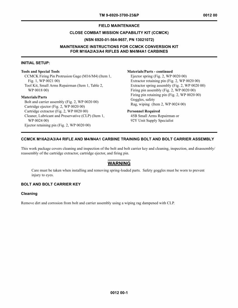
1. Inspect bolt and bolt carrier key for dents, distortion, looseness, damage or wear.
2. If bolt or bolt carrier key is damaged or worn to the point of being unserviceable, replace the entire bolt carrier assembly.
3. Check bolt carrier key to ensure it is not loose.
4. If bolt carrier key is loose, replace entire bolt and carrier assembly.
CARTRIDGE EXTRACTOR
Cleaning
Remove dirt and corrosion from bolt and carrier assembly using a rag dampened with CLP.
Inspection
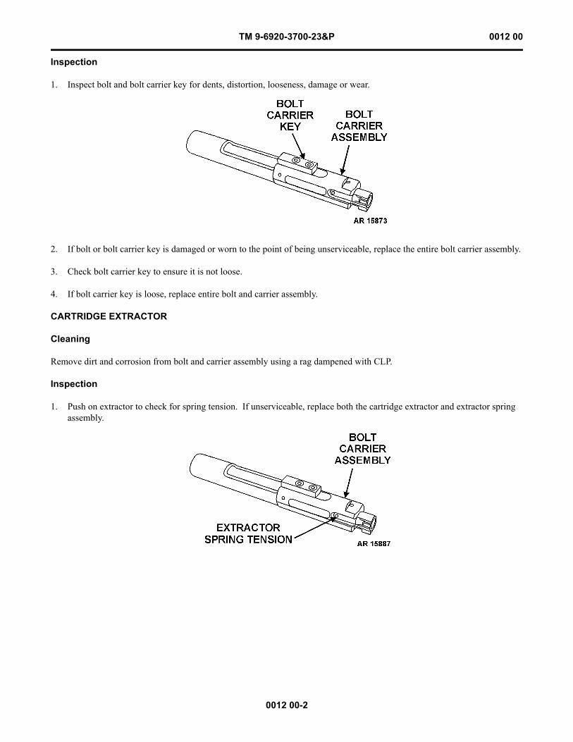
1. Push on extractor to check for spring tension. If unserviceable, replace both the cartridge extractor and extractor spring assembly.
TM 9-6920-3700-23&P 0012 00
0012 00-3
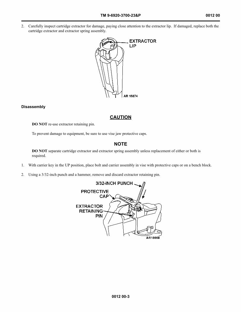
2. Carefully inspect cartridge extractor for damage, paying close attention to the extractor lip. If damaged, replace both the cartridge extractor and extractor spring assembly.
Disassembly
CAUTIONDO NOT re-use extractor retaining pin.
To prevent damage to equipment, be sure to use vise jaw protective caps.
NOTEDO NOT separate cartridge extractor and extractor spring assembly unless replacement of either or both is required.
1. With carrier key in the UP position, place bolt and carrier assembly in vise with protective caps or on a bench block.
2. Using a 3/32-inch punch and a hammer, remove and discard extractor retaining pin.
TM 9-6920-3700-23&P 0012 00
0012 00-4
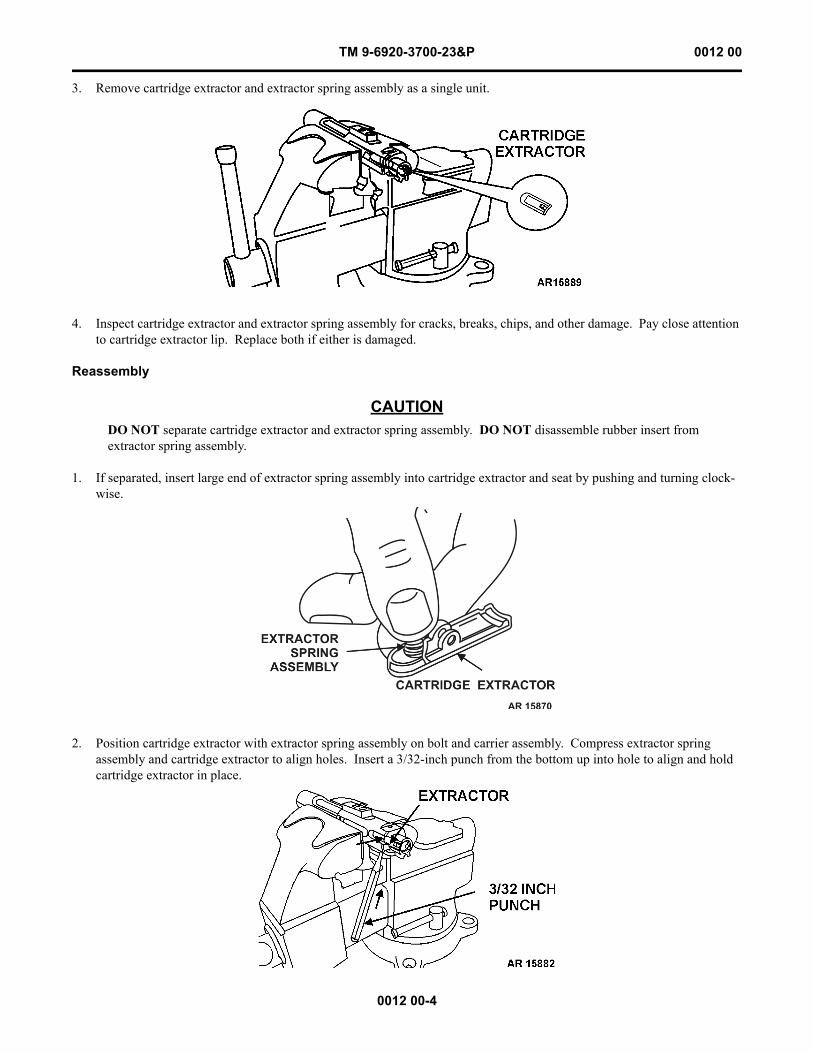
3. Remove cartridge extractor and extractor spring assembly as a single unit.
4. Inspect cartridge extractor and extractor spring assembly for cracks, breaks, chips, and other damage. Pay close attention to cartridge extractor lip. Replace both if either is damaged.
Reassembly
CAUTIONDO NOT separate cartridge extractor and extractor spring assembly. DO NOT disassemble rubber insert from extractor spring assembly.
1. If separated, insert large end of extractor spring assembly into cartridge extractor and seat by pushing and turning clock-wise.
2. Position cartridge extractor with extractor spring assembly on bolt and carrier assembly. Compress extractor spring assembly and cartridge extractor to align holes. Insert a 3/32-inch punch from the bottom up into hole to align and hold cartridge extractor in place.
TM 9-6920-3700-23&P 0012 00
0012 00-5
3. Install new extractor retaining pin from the top and, using a punch larger than 3/32-inch and a hammer, drive the bottom 3/32-inch aligning punch out. Use 3/32-inch punch to seat extractor retaining pin until flush with surface.
4. Check for proper function of cartridge extractor.
CARTRIDGE EJECTOR
Cleaning
Remove dirt and corrosion from bolt and carrier assembly using a rag dampened with CLP.
Inspection
1. Inspect cartridge ejector for dirt, damage or serviceability.
2. Inspect cartridge ejector spring for spring tension by pushing on ejector.
3. If the cartridge ejector and ejector spring are unserviceable, disassemble and inspect.
TM 9-6920-3700-23&P 0012 00
0012 00-6
Disassembly
WARNINGCare must be taken when installing and removing spring-loaded parts. Safety goggles must be worn to prevent injury to eyes.
CAUTIONTo prevent damage to equipment, use vise jaw protective caps.
1. With carrier key in the UP position, place bolt and carrier assembly in vise with protective caps or on a bench block.
CAUTIONDO NOT re-use ejector retaining pin.
2. Using a 1/16-inch punch and a hammer, remove and discard ejector retaining pin.
3. Carefully remove punch and be ready to catch cartridge ejector and ejector spring to prevent loss.
4. Inspect cartridge ejector and ejector spring for cracks, breaks, chips or other damage. Replace if any damage is found.
TM 9-6920-3700-23&P 0012 00
0012 00-7
Reassembly
1. Reinstall ejector spring.
2. Install cartridge ejector by aligning groove on cartridge ejector so that the new ejector retaining pin can be installed.
3. Using a 3/8-inch punch, compress and hold cartridge ejector and ejector spring. Insert a 1/16-inch punch from the bottom up into hole to align and hold cartridge ejector in place.
4. Install new ejector retaining pin from the top and, using a punch larger than 1/16-inch punch and a hammer, drive the bot-tom 1/16-inch aligning punch out. Use 1/16-inch punch to seat ejector retaining pin until flush with surface.
5. Check for proper function of cartridge ejector.
TM 9-6920-3700-23&P 0012 00
0012 00-8
FIRING PIN
Cleaning
Remove dirt and corrosion for bolt and carrier assembly using a rag dampened with CLP.
Inspection
1. Inspect firing pin for damage or serviceability.
2. Inspect firing pin spring for spring tension by pushing on back of firing pin with finger.
3. With firing pin fully compressed, use firing pin protrusion gage to test protrusion.
4. If firing pin or firing pin spring is unserviceable, replace both.
Disassembly
CAUTIONDO NOT spread or close legs of firing pin retaining pin.
1. With bolt and carrier assembly in UP position, use finger to fully compress and hold firing pin.
2. Remove firing pin retaining pin and set aside.
TM 9-6920-3700-23&P 0012 00
0012 00-9
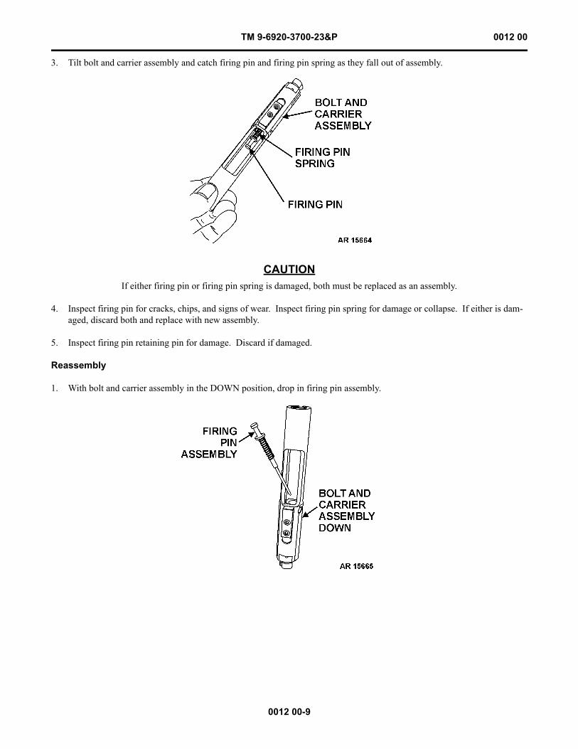
3. Tilt bolt and carrier assembly and catch firing pin and firing pin spring as they fall out of assembly.
CAUTIONIf either firing pin or firing pin spring is damaged, both must be replaced as an assembly.
4. Inspect firing pin for cracks, chips, and signs of wear. Inspect firing pin spring for damage or collapse. If either is dam-aged, discard both and replace with new assembly.
5. Inspect firing pin retaining pin for damage. Discard if damaged.
Reassembly
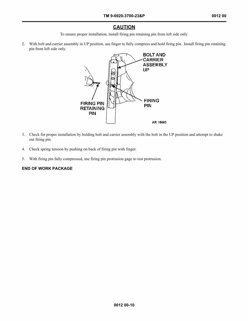
1. With bolt and carrier assembly in the DOWN position, drop in firing pin assembly.
TM 9-6920-3700-23&P 0012 00
0012 00-10
CAUTIONTo ensure proper installation, install firing pin retaining pin from left side only.
2. With bolt and carrier assembly in UP position, use finger to fully compress and hold firing pin. Install firing pin retaining pin from left side only.
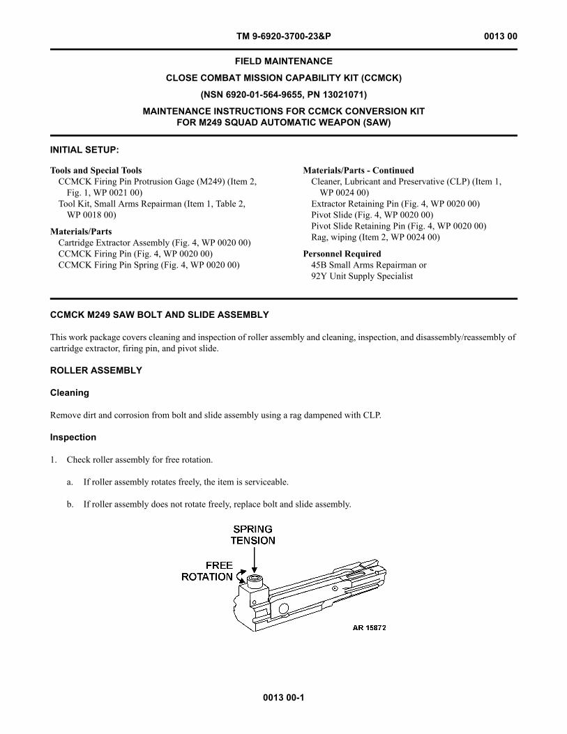
3. Check for proper installation by holding bolt and carrier assembly with the bolt in the UP position and attempt to shake out firing pin.
4. Check spring tension by pushing on back of firing pin with finger.
5. With firing pin fully compressed, use firing pin protrusion gage to test protrusion.
END OF WORK PACKAGE
TM 9-6920-3700-23&P 0013 00
0013 00-1
FIELD MAINTENANCE
CLOSE COMBAT MISSION CAPABILITY KIT (CCMCK)
(NSN 6920-01-564-9655, PN 13021071)
MAINTENANCE INSTRUCTIONS FOR CCMCK CONVERSION KIT FOR M249 SQUAD AUTOMATIC WEAPON (SAW)
INITIAL SETUP:
CCMCK M249 SAW BOLT AND SLIDE ASSEMBLY
This work package covers cleaning and inspection of roller assembly and cleaning, inspection, and disassembly/reassembly of cartridge extractor, firing pin, and pivot slide.
ROLLER ASSEMBLY
Cleaning
Remove dirt and corrosion from bolt and slide assembly using a rag dampened with CLP.
Inspection
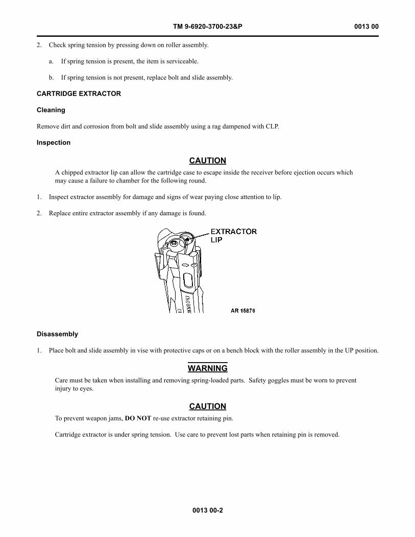
1. Check roller assembly for free rotation.
a. If roller assembly rotates freely, the item is serviceable.
b. If roller assembly does not rotate freely, replace bolt and slide assembly.
Tools and Special ToolsCCMCK Firing Pin Protrusion Gage (M249) (Item 2,
Fig. 1, WP 0021 00)Tool Kit, Small Arms Repairman (Item 1, Table 2,
WP 0018 00)
Materials/PartsCartridge Extractor Assembly (Fig. 4, WP 0020 00)CCMCK Firing Pin (Fig. 4, WP 0020 00)CCMCK Firing Pin Spring (Fig. 4, WP 0020 00)
Materials/Parts - ContinuedCleaner, Lubricant and Preservative (CLP) (Item 1,
WP 0024 00)Extractor Retaining Pin (Fig. 4, WP 0020 00)Pivot Slide (Fig. 4, WP 0020 00)Pivot Slide Retaining Pin (Fig. 4, WP 0020 00)Rag, wiping (Item 2, WP 0024 00)
Personnel Required45B Small Arms Repairman or92Y Unit Supply Specialist
TM 9-6920-3700-23&P 0013 00
0013 00-2
2. Check spring tension by pressing down on roller assembly.
a. If spring tension is present, the item is serviceable.
b. If spring tension is not present, replace bolt and slide assembly.
CARTRIDGE EXTRACTOR
Cleaning
Remove dirt and corrosion from bolt and slide assembly using a rag dampened with CLP.
Inspection
CAUTIONA chipped extractor lip can allow the cartridge case to escape inside the receiver before ejection occurs which may cause a failure to chamber for the following round.
1. Inspect extractor assembly for damage and signs of wear paying close attention to lip.
2. Replace entire extractor assembly if any damage is found.
Disassembly
1. Place bolt and slide assembly in vise with protective caps or on a bench block with the roller assembly in the UP position.
WARNINGCare must be taken when installing and removing spring-loaded parts. Safety goggles must be worn to prevent injury to eyes.
CAUTIONTo prevent weapon jams, DO NOT re-use extractor retaining pin.
Cartridge extractor is under spring tension. Use care to prevent lost parts when retaining pin is removed.
TM 9-6920-3700-23&P 0013 00
0013 00-3
2. Using 1/8-inch punch and a hammer, remove and discard extractor retaining pin.
CAUTIONIf any component of the cartridge extractor assembly is found defective, replace the entire cartridge extractor assembly.
3. Remove cartridge extractor assembly (pin guide, extractor spring and cartridge extractor).
4. Inspect cartridge extractor, pin guide, and cartridge extractor spring for cracks, breaks, chips or other damage. Pay close attention to cartridge extractor lip. Replace entire extractor assembly if any part is unserviceable.
TM 9-6920-3700-23&P 0013 00
0013 00-4
Reassembly
CAUTIONEnsure pin guide is fully inserted in extractor spring and rounded end of pin guide is properly seated in extractor.
1. Place extractor spring on pin guide. Place rounded end of pin guide with spring inside cartridge extractor.
2. Place cartridge extractor assembly into hole in bolt and slide assembly and align slot with hole for extractor pin.
3. Using thumb, compress cartridge extractor and insert 1/8-inch punch from bottom to align and hold cartridge extractor in place.
CAUTIONTo prevent weapon jams, DO NOT re-use extractor retaining pin.
4. Using a punch larger than 1/8-inch and a hammer, install new extractor retaining pin from the top, driving the bottom 1/8-inch punch out. Use 1/8-inch punch to seat extractor retaining pin until flush with surface of bolt and slide assembly.
5. Check for free movement of cartridge extractor.
TM 9-6920-3700-23&P 0013 00
0013 00-5
FIRING PIN
Cleaning
Remove dirt and corrosion from bolt and slide assembly using a rag dampened with CLP.
Inspection
1. Inspect firing pin nib for damage or defects. Replace firing pin if damage or defect is found.
NOTEFiring pin is fixed and should not have excessive movement.
2. Inspect for looseness of firing pin. Replace firing pin if loose.
3. Inspect firing pin protrusion using firing pin protrusion gage. Replace firing pin if protrusion is incorrect.
Disassembly
1. Place bolt and slide assembly in vise with protective caps or on a bench block with roller assembly in the DOWN position.
2. Using 1/16-inch punch and a hammer, remove and discard firing pin retaining pin.
TM 9-6920-3700-23&P 0013 00
0013 00-6
3. Remove firing pin and discard. For easy removal, insert a 1/16-inch punch in sight hole at rear of firing pin to push firing pin out.
Reassembly
1. Fully insert new firing pin in bolt and slide assembly.
CAUTIONTo prevent weapon jams, DO NOT re-use firing pin retaining pin.
2. Using a 1/16-inch punch and a hammer, install new firing pin retaining pin until flush with surface.
PIVOT SLIDE
Cleaning
Remove dirt and corrosion from bolt and slide assembly using a rag dampened with CLP.
Inspection
1. Inspect pivot slide for cracks, wear, and free movement.
TM 9-6920-3700-23&P 0013 00
0013 00-7
2. Replace pivot slide if it is worn, cracked or does not move freely.
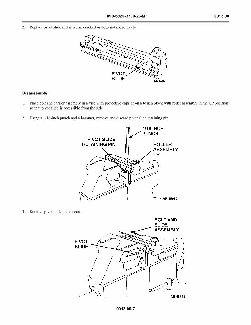
Disassembly
1. Place bolt and carrier assembly in a vise with protective caps or on a bench block with roller assembly in the UP position so that pivot slide is accessible from the side.
2. Using a 1/16-inch punch and a hammer, remove and discard pivot slide retaining pin.
3. Remove pivot slide and discard.
TM 9-6920-3700-23&P 0013 00
0013 00-8
Reassembly
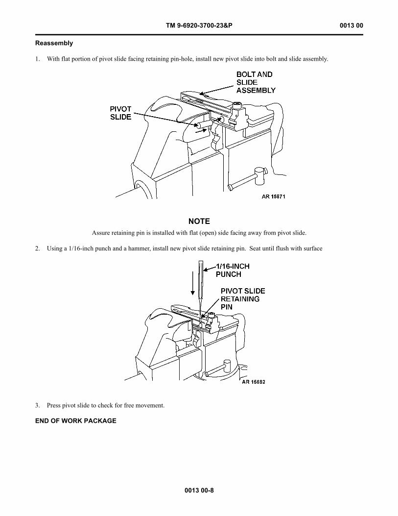
1. With flat portion of pivot slide facing retaining pin-hole, install new pivot slide into bolt and slide assembly.
NOTEAssure retaining pin is installed with flat (open) side facing away from pivot slide.
2. Using a 1/16-inch punch and a hammer, install new pivot slide retaining pin. Seat until flush with surface
3. Press pivot slide to check for free movement.
END OF WORK PACKAGE
TM 9-6920-3700-23&P 0014 00
0014 00-1
FIELD MAINTENANCE
CLOSE COMBAT MISSION CAPABILITY KIT (CCMCK)
(NSN 6920-01-564-9656, PN 13021070)
MAINTENANCE INSTRUCTIONS FOR CCMCK CONVERSION KIT FOR M9 PISTOL
INITIAL SETUP:
M9 PISTOL
This work package covers cleaning, inspection, disassembly/reassembly of spring and cleaning and inspection of slider and dowel pin.
SPRING
Cleaning
Remove dirt and corrosion from barrel assembly using a rag dampened with CLP.
Inspection
Visually inspect spring for defects and spring tension by compressing slider. Replace spring if damaged or collapsed.
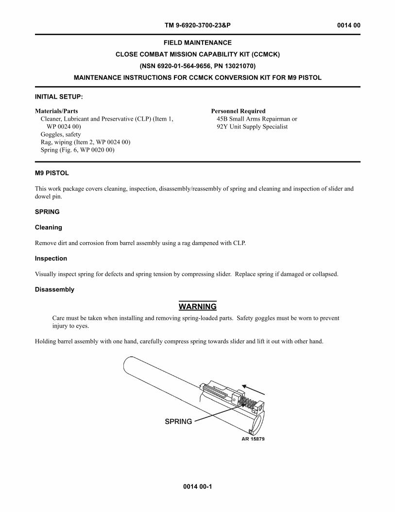
Disassembly
WARNINGCare must be taken when installing and removing spring-loaded parts. Safety goggles must be worn to prevent injury to eyes.
Holding barrel assembly with one hand, carefully compress spring towards slider and lift it out with other hand.
Materials/PartsCleaner, Lubricant and Preservative (CLP) (Item 1,
WP 0024 00)Goggles, safetyRag, wiping (Item 2, WP 0024 00)Spring (Fig. 6, WP 0020 00)
Personnel Required45B Small Arms Repairman or92Y Unit Supply Specialist
TM 9-6920-3700-23&P 0014 00
0014 00-2
Reassembly
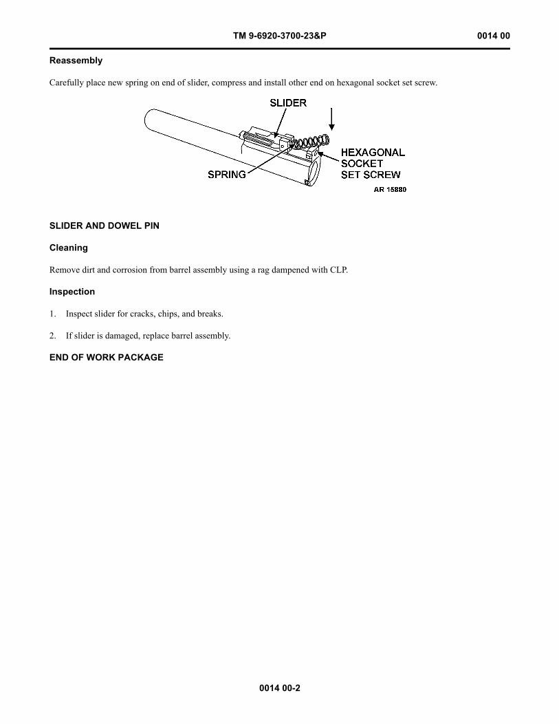
Carefully place new spring on end of slider, compress and install other end on hexagonal socket set screw.
SLIDER AND DOWEL PIN
Cleaning
Remove dirt and corrosion from barrel assembly using a rag dampened with CLP.
Inspection
1. Inspect slider for cracks, chips, and breaks.
2. If slider is damaged, replace barrel assembly.
END OF WORK PACKAGE
TM 9-6920-3700-23&P 0015 00
0015 00-1
FIELD MAINTENANCE
CLOSE COMBAT MISSION CAPABILITY KIT (CCMCK)
(NSN 6920-01-564-9658, PN 13021069)
MAINTENANCE INSTRUCTIONS FOR CCMCK CONVERSION KIT FOR M11 PISTOL
INITIAL SETUP:
M11 PISTOL
This work package covers cleaning and inspection of CCMCK training barrel and feed ramp.
TRAINING BARREL AND FEED RAMP
Cleaning
Remove dirt and corrosion from barrel assembly using a rag dampened with CLP.
Inspection
1. Inspect training barrel for cracks, chips, and breaks. Replace if damaged.
2. Inspect feed ramp for damage. Replace if damaged.
END OF WORK PACKAGE
Materials/PartsBarrel, Pistol (Fig. 7, WP 0020 00)Cleaner, Lubricant and Preservative (CLP) (Item 1,
WP 0024 00)Feed Ramp (Fig. 7, WP 0020 00)Rag, wiping (Item 2, WP 0024 00)
Personnel Required45B Small Arms Repairman or92Y Unit Supply Specialist

This Page Intentionally Left Blank
0015 00-2
TM 9-6920-3700-23&P 0015 00
CHAPTER 4
SUPPORTING INFORMATIONFOR
CLOSE COMBAT MISSION CAPABILITY KIT (CCMCK)
TM 9-6920-3700-23&P

TM 9-6920-3700-23&P 0016 00
0016 00-1
FIELD MAINTENANCE
CLOSE COMBAT MISSION CAPABILITY KIT (CCMCK)
REFERENCES
SCOPE
This work package lists all Army regulations, forms, pamphlets, and technical manuals referenced in this manual.
ARMY REGULATIONS
AR 75-1 Malfunctions Involving Ammunition and Explosives
AR 385-10 The Army Safety Program
FORMS
DA Form 285 U.S. Army Accident Report
DA Form 2028 Recommended Changes to Publications and Blank Forms
DA Form 2404 Equipment Inspection and Maintenance Worksheet
SF Form 364 Report of Discrepancy (ROD)
SF Form 368 Product Quality Deficiency Report
PAMPHLETS
DA Pam 25-30 Consolidated Index of Army Publications and Forms
DA Pam 750-8 The Army Maintenance Management System (TAMMS) Users Manual
TECHNICAL MANUALS
TM 9-6920-3700-10 Operator’s Manual for Close Combat Mission Capability Kit (CCMCK), Training Device, Fire Dye Marking Ammo: M16/M4; Training Device, Fire Dye Marking Ammo: M249; Training Device, Fire Dye Marking Ammo: M9; Training Device, Fire Dye Marking Ammo: M11

This Page Intentionally Left Blank
0016 00-2
TM 9-6920-3700-23&P 0016 00
TM 9-6920-3700-23&P 0017 00
0017 00-1
FIELD MAINTENANCE
CLOSE COMBAT MISSION CAPABILITY KIT (CCMCK)
MAINTENANCE ALLOCATION CHART (MAC) INTRODUCTION
INTRODUCTION
The Army Maintenance System MAC
This introduction provides a general explanation of all maintenance and repair functions authorized at the two maintenance levels under the Two-Level Maintenance System concept.
The MAC (immediately following the introduction) designates overall authority and responsibility for the performance of maintenance functions on the identified end item or component. The application of the maintenance functions to the end item or component shall be consistent with the capacities and capabilities of the designated maintenance levels, which are shown on the MAC in column (4) as:
Field - includes two subcolumns, Crew (C) and Maintainer (F).Sustainment - includes two subcolumns, Below Depot (H) and Depot (D).
The maintenance to be performed at field and sustainment levels is described as follows:
1. Crew Maintenance. The responsibility of a using organization to perform maintenance on its assigned equipment. It nor-mally consists of inspecting, servicing, lubricating, adjusting, and replacing parts, minor assemblies, and subassemblies. The replace function for this level of maintenance is indicated by the letter “C” in the third position of the SMR code. A “C” appearing in the fourth position of the SMR code indicates complete repair is possible at the crew maintenance level.
2. Maintainer Maintenance. Maintenance accomplished on a component, accessory, assembly, subassembly, plug-in unit, or other portion either on the system or after it is removed. The replace function for this level of maintenance is indicated by the letter “F” appearing in the third position of the SMR code. An “F” appearing in the fourth position of the SMR code indicates complete repair is possible at the field maintenance level. Items are returned to the user after maintenance is performed at this level.
3. Below Depot Sustainment. Maintenance accomplished on a component, accessory, assembly, subassembly, plug-in unit, or other portion either on the system or after it is removed. The replace function for this level of maintenance is indicated by the letter “H” appearing in the third position of the SMR code. An “H” appearing in the fourth position of the SMR code indi-cates complete repair is possible at the below depot sustainment maintenance level. Items are returned to the supply system after maintenance is performed at this level.
4. Depot Sustainment. Maintenance accomplished on a component, accessory, assembly, subassembly, plug-in unit, or other portion either on the system or after it is removed. The replace function for this level of maintenance is indicated by the letter “D” or “K” appearing in the third position of the SMR code. Depot sustainment maintenance can be performed by either depot personnel or contractor personnel. A “D” or “K” appearing in the fourth position of the SMR code indicates complete repair is possible at the depot sustainment maintenance level. Items are returned to the supply systems after maintenance is performed at this level.
The tools and test equipment requirements table (immediately following the MAC) list the tools and test equipment (both spe-cial tools and common tool sets) required for each maintenance function as referenced from the MAC.
The remarks table (immediately following the tools and test equipment requirements) contains supplemental instructions and explanatory notes for a particular maintenance function.
TM 9-6920-3700-23&P 0017 00
0017 00-2
Maintenance Functions
Maintenance functions are limited to and defined as follows:
1. Inspect. To determine the serviceability of an item by comparing its physical, mechanical, and/or electrical characteristics with established standards through examination (e.g., by sight, sound, or feel). This includes scheduled inspection and gag-ings and evaluation of cannon tubes.
2. Test. To verify serviceability by measuring the mechanical, pneumatic, hydraulic, or electrical characteristics of an item and comparing those characteristics with prescribed standards on a scheduled basis, i.e., load testing of lift devices and hydro-static testing of pressure hoses.
3. Service. Operations required periodically to keep an item in proper operating condition; e.g., to clean (includes decon-taminate, when required), to preserve, to drain, to paint, or to replenish fuel, lubricants, chemical fluids, or gases. This includes scheduled exercising and purging of recoil mechanisms. The following are examples of service functions:
a. Unpack. To remove from packing box for service or when required for performance of maintenance operations.
b. Repack. To return item to packing box after service and other maintenance operations.
c. Clean. To rid the item of contamination.
d. Touch Up. To spot paint scratched or blistered surfaces.
e. Mark. To restore obliterated identification.
4. Adjust. To maintain or regulate, within prescribed limits, by bringing into proper position, or by setting the operating characteristics to specified parameters.
5. Align. To adjust specified variable elements of an item to bring about optimum or desired performance.
6. Calibrate. To determine and cause corrections to be made or to be adjusted on instruments of test, measuring, and diag-nostic equipment used in precision measurement. Consists of comparisons of two instruments, one of which is a certified stan-dard of known accuracy, to detect and adjust any discrepancy in the accuracy of the instrument being compared.
7. Remove/Install. To remove and install the same item when required to perform service or other maintenance functions. Install may be the act of emplacing, seating, or fixing into position a spare, repair part, or module (component or assembly) in a manner to allow the proper functioning of an equipment or system.
8. Paint (ammunition only). To prepare and spray color coats of paint so that the ammunition can be identified and pro-tected. The color indicating primary use is applied, preferably, to the entire exterior surface as the background color of the item. Other markings are to be repainted as original so as to retain proper ammunition identification.
9. Replace. To remove an unserviceable item and install a serviceable counterpart in its place. “Replace” is authorized by the MAC and assigned maintenance level is shown as the third position code of the Source, Maintenance and Recoverability (SMR) code.
10. Repair. The application of maintenance services, including fault location/troubleshooting, removal/installation, disassem-bly/assembly procedures, and maintenance actions to identify troubles and restore serviceability to an item by correcting spe-cific damage, fault, malfunction, or failure in a part, subassembly, module (component or assembly), end item, or system.
TM 9-6920-3700-23&P 0017 00
0017 00-3
NOTEThe following definitions are applicable to the “repair” maintenance function:
Services. Inspect, test, service, adjust, align, calibrate, and/or replace.
Fault Location/Troubleshooting. The process of investigating and detecting the cause of equipment malfunction-ing; the act of isolating a fault within a system or Unit Under Test (UUT).
Disassembly/Assembly. The step-by-step breakdown (taking apart) of a spare/functional group coded item to the level of its least component, that is assigned as SMR code for the level of maintenance under consideration (i.e., identified as maintenance significant).
Actions. Welding, grinding, riveting, straightening, facing, machining, and/or resurfacing.
11. Overhaul. That maintenance effort (service/action) prescribed to restore an item to a completely serviceable/operational condition as required by maintenance standards in appropriate technical publications. Overhaul is normally the highest degree of maintenance performed by the Army. Overhaul does not normally return an item to like new condition.
12. Rebuild. Consists of those services/actions necessary for the restoration of unserviceable equipment to a like new condi-tion in accordance with original manufacturing standards. Rebuild is the highest degree of material maintenance applied to Army equipment. The rebuild operation includes the act of returning to zero those age measurements (e.g., hours/miles) con-sidered in classifying Army equipment/components.
Explanation of Columns in the MAC
Column (1) - Group Number. Column (1) lists Functional Group Code (FGC) numbers, the purpose of which is to identify maintenance significant components, assemblies, subassemblies, and modules with the Next Higher Assembly (NHA).
Column (2) - Component/Assembly. Column (2) contains the item names of components, assemblies, subassemblies, and modules for which maintenance is authorized.
Column (3) - Maintenance Function. Column (3) lists the functions to be performed on the item listed in column (2). (For a detailed explanation of these functions refer to “Maintenance Functions” outlined above.)
Column (4) - Maintenance Level. Column (4) specifies each level of maintenance authorized to perform each function listed in column (3), by indicating work time required (expressed as manhours in whole hours or decimals) in the appropriate subcol-umn. This work time figure represents the active time required to perform that maintenance function at the indicated level of maintenance. If the number or complexity of the tasks within the listed maintenance function varies at different maintenance levels, appropriate work time figures are to be shown for each level. The work time figure represents the average time required to restore an item (assembly, subassembly, component, module, end item, or system) to a serviceable condition under typical field operating conditions. This time includes preparation time (including any necessary disassembly/assembly time), troubleshooting/fault location time, and quality assurance time in addition to the time required to perform the specific tasks identified for the maintenance functions authorized in the MAC. The symbol designations for the various maintenance levels are as follows:
Field:C - Crew maintenanceF - Maintainer maintenance
Sustainment:L - Specialized Repair Activity (SRA)H - Below Depot maintenanceD - Depot maintenance
TM 9-6920-3700-23&P 0017 00
0017 00-4
NOTEThe “L” maintenance level is not included in column (4) of the MAC. Functions to this level of maintenance are identified by a work time figure in the “H” column of column (4), and an associated reference code is used in the REMARKS column (6). This code is keyed to the remarks and the SRA complete repair application is explained there.
Column (5) - Tools and Equipment Reference Code. Column (5) specifies, by code, those common tool sets (not individual tools), common Test, Measurement and Diagnostic Equipment (TMDE), and special tools, special TMDE and special support equipment required to perform the designated function. Codes are keyed to the entries in the tools and test equipment table.
Column (6) - Remarks Code. When applicable, this column contains a letter code, in alphabetical order, which is keyed to the remarks table entries.
Explanation of Columns in the Tools and Test Equipment Requirements
Column (1) - Tool or Test Equipment Reference Code. The tool or test equipment reference code correlates with a code used in column (5) of the MAC.
Column (2) - Maintenance Level. The lowest level of maintenance authorized to use the tool or test equipment.
Column (3) - Nomenclature. Name or identification of the tool or test equipment.
Column (4) - National Stock Number (NSN). The NSN of the tool or test equipment.
Column (5) - Tool Number. The manufacturer’s part number.
Explanation of Columns in the Remarks
Column (1) - Remarks Code. The code recorded in column (6) of the MAC.
Column (2) - Remarks. This column lists information pertinent to the maintenance function being performed as indicated in the MAC.
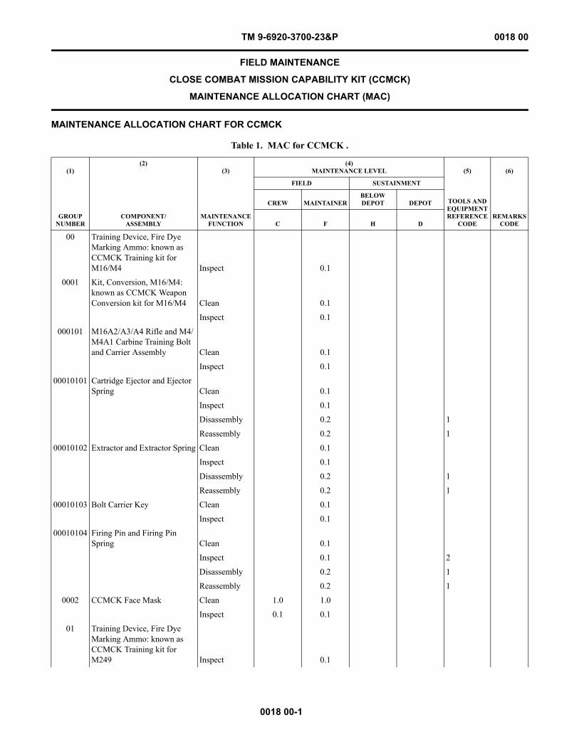
TM 9-6920-3700-23&P 0018 00
0018 00-1
FIELD MAINTENANCE
CLOSE COMBAT MISSION CAPABILITY KIT (CCMCK)
MAINTENANCE ALLOCATION CHART (MAC)
MAINTENANCE ALLOCATION CHART FOR CCMCK
Table 1. MAC for CCMCK .
(1)
GROUP NUMBER
(2)
COMPONENT/ASSEMBLY
(3)
MAINTENANCE FUNCTION
(4)MAINTENANCE LEVEL (5)
TOOLS AND EQUIPMENTREFERENCE
CODE
(6)
REMARKSCODE
FIELD SUSTAINMENT
CREW MAINTAINERBELOWDEPOT DEPOT
C F H D
00 Training Device, Fire Dye Marking Ammo: known as CCMCK Training kit for M16/M4 Inspect 0.1
0001 Kit, Conversion, M16/M4: known as CCMCK Weapon Conversion kit for M16/M4 Clean 0.1
Inspect 0.1
000101 M16A2/A3/A4 Rifle and M4/M4A1 Carbine Training Bolt and Carrier Assembly Clean 0.1
Inspect 0.1
00010101 Cartridge Ejector and Ejector Spring Clean 0.1
Inspect 0.1
Disassembly 0.2 1
Reassembly 0.2 1
00010102 Extractor and Extractor Spring Clean 0.1
Inspect 0.1
Disassembly 0.2 1
Reassembly 0.2 1
00010103 Bolt Carrier Key Clean 0.1
Inspect 0.1
00010104 Firing Pin and Firing Pin Spring Clean 0.1
Inspect 0.1 2
Disassembly 0.2 1
Reassembly 0.2 1
0002 CCMCK Face Mask Clean 1.0 1.0
Inspect 0.1 0.1
01 Training Device, Fire Dye Marking Ammo: known as CCMCK Training kit for M249 Inspect 0.1
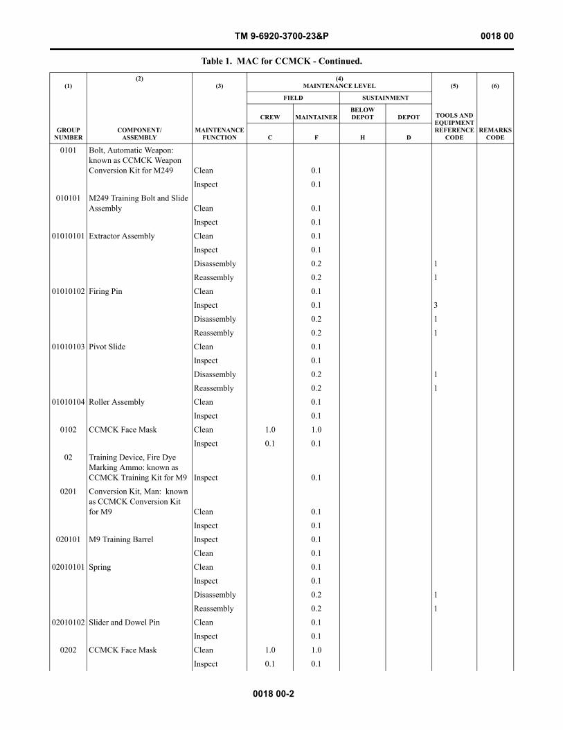
TM 9-6920-3700-23&P 0018 00
0018 00-2
0101 Bolt, Automatic Weapon: known as CCMCK Weapon Conversion Kit for M249 Clean 0.1
Inspect 0.1
010101 M249 Training Bolt and Slide Assembly Clean 0.1
Inspect 0.1
01010101 Extractor Assembly Clean 0.1
Inspect 0.1
Disassembly 0.2 1
Reassembly 0.2 1
01010102 Firing Pin Clean 0.1
Inspect 0.1 3
Disassembly 0.2 1
Reassembly 0.2 1
01010103 Pivot Slide Clean 0.1
Inspect 0.1
Disassembly 0.2 1
Reassembly 0.2 1
01010104 Roller Assembly Clean 0.1
Inspect 0.1
0102 CCMCK Face Mask Clean 1.0 1.0
Inspect 0.1 0.1
02 Training Device, Fire Dye Marking Ammo: known as CCMCK Training Kit for M9 Inspect 0.1
0201 Conversion Kit, Man: known as CCMCK Conversion Kit for M9 Clean 0.1
Inspect 0.1
020101 M9 Training Barrel Inspect 0.1
Clean 0.1
02010101 Spring Clean 0.1
Inspect 0.1
Disassembly 0.2 1
Reassembly 0.2 1
02010102 Slider and Dowel Pin Clean 0.1
Inspect 0.1
0202 CCMCK Face Mask Clean 1.0 1.0
Inspect 0.1 0.1
Table 1. MAC for CCMCK - Continued.
(1)
GROUP NUMBER
(2)
COMPONENT/ASSEMBLY
(3)
MAINTENANCE FUNCTION
(4)MAINTENANCE LEVEL (5)
TOOLS AND EQUIPMENTREFERENCE
CODE
(6)
REMARKSCODE
FIELD SUSTAINMENT
CREW MAINTAINERBELOWDEPOT DEPOT
C F H D
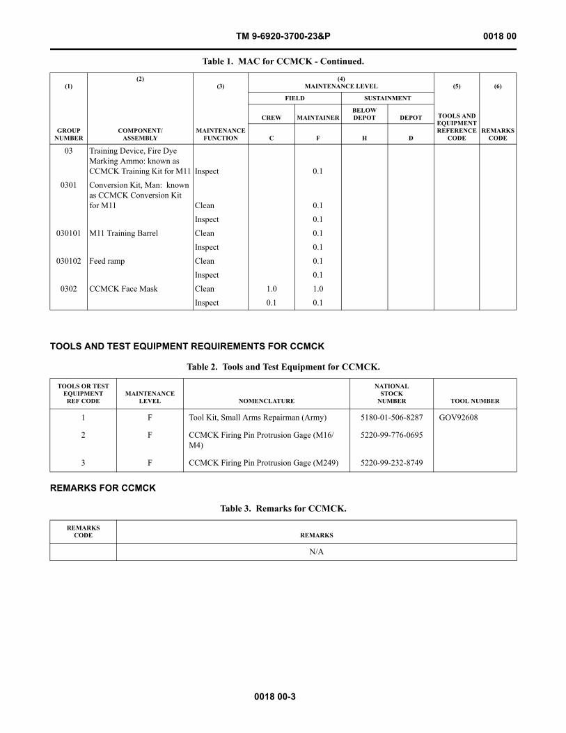
TM 9-6920-3700-23&P 0018 00
0018 00-3
TOOLS AND TEST EQUIPMENT REQUIREMENTS FOR CCMCK
REMARKS FOR CCMCK
03 Training Device, Fire Dye Marking Ammo: known as CCMCK Training Kit for M11 Inspect 0.1
0301 Conversion Kit, Man: known as CCMCK Conversion Kit for M11 Clean 0.1
Inspect 0.1
030101 M11 Training Barrel Clean 0.1
Inspect 0.1
030102 Feed ramp Clean 0.1
Inspect 0.1
0302 CCMCK Face Mask Clean 1.0 1.0
Inspect 0.1 0.1
Table 2. Tools and Test Equipment for CCMCK.
TOOLS OR TEST EQUIPMENT
REF CODEMAINTENANCE
LEVEL NOMENCLATURE
NATIONALSTOCK
NUMBER TOOL NUMBER
1 F Tool Kit, Small Arms Repairman (Army) 5180-01-506-8287 GOV92608
2 F CCMCK Firing Pin Protrusion Gage (M16/M4)
5220-99-776-0695
3 F CCMCK Firing Pin Protrusion Gage (M249) 5220-99-232-8749
Table 3. Remarks for CCMCK.
REMARKSCODE REMARKS
N/A
Table 1. MAC for CCMCK - Continued.
(1)
GROUP NUMBER
(2)
COMPONENT/ASSEMBLY
(3)
MAINTENANCE FUNCTION
(4)MAINTENANCE LEVEL (5)
TOOLS AND EQUIPMENTREFERENCE
CODE
(6)
REMARKSCODE
FIELD SUSTAINMENT
CREW MAINTAINERBELOWDEPOT DEPOT
C F H D

This Page Intentionally Left Blank
0018 00-4
TM 9-6920-3700-23&P 0018 00

TM 9-6920-3700-23&P 0019 00
FIELD MAINTENANCE
CLOSE COMBAT MISSION CAPABILITY KIT (CCMCK)
REPAIR PARTS AND SPECIAL TOOLS LIST (RPSTL) INTRODUCTION
0019 00-1
SCOPE
This RPSTL lists and authorizes spares and repair parts; special tools; special test, measurement, and diagnostic equipment (TMDE); and other special support equipment required for performance of field maintenance of the Close Combat Mission Capability Kit (CCMCK). It authorizes the requisitioning, issue, and disposition of spares, repair parts, and special tools as indicated by the source, maintenance, and recoverability (SMR) codes.
GENERAL
In addition to the Introduction work package, this RPSTL is divided into the following work packages.
1. Repair Parts List Work Packages. Work packages containing lists of spares and repair parts authorized by this RPSTL for use in the performance of maintenance. These work packages also include parts which must be removed for replacement of the authorized parts. Parts lists are composed of functional groups in ascending alphanumeric sequence, with the parts in each group listed in ascending figure and item number sequence. Sending units, brackets, filters, and bolts are listed with the com-ponent they mount on. Bulk materials are listed by item name in FIG. BULK at the end of the work packages. Repair parts kits are listed separately in their own functional group and work package. Repair parts kits are listed at the end of the individ-ual work packages. Items listed are shown on the associated illustrations.
2. Special Tools List Work Packages. Work packages containing lists of special tools, special TMDE, and special support equipment authorized by this RPSTL (as indicated by Basis of Issue (BOI) information in the DESCRIPTION AND USABLE ON CODE (UOC) column). Tools that are components of common tool sets and/or Class VII are not listed.
3. Cross-Reference Indexes Work Packages. There are two cross-reference indexes work packages in this RPSTL: the National Stock Number (NSN) Index work package and the Part Number (P/N) Index work package. The National Stock Number Index work package refers you to the figure and item number. The Part Number Index work package refers you to the figure and item number.
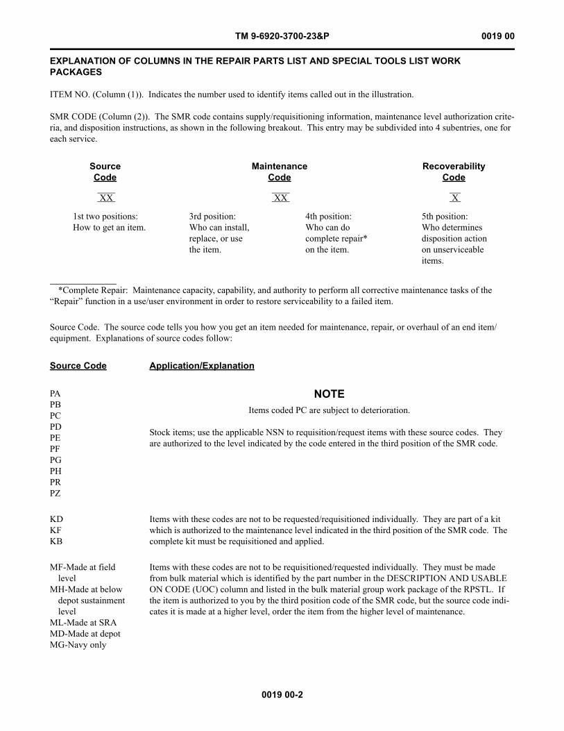
TM 9-6920-3700-23&P 0019 00
0019 00-2
EXPLANATION OF COLUMNS IN THE REPAIR PARTS LIST AND SPECIAL TOOLS LIST WORK PACKAGES
ITEM NO. (Column (1)). Indicates the number used to identify items called out in the illustration.
SMR CODE (Column (2)). The SMR code contains supply/requisitioning information, maintenance level authorization crite-ria, and disposition instructions, as shown in the following breakout. This entry may be subdivided into 4 subentries, one for each service.
Source Code. The source code tells you how you get an item needed for maintenance, repair, or overhaul of an end item/equipment. Explanations of source codes follow:
SourceCode
MaintenanceCode
RecoverabilityCode
XX XX X
1st two positions:How to get an item.
3rd position:Who can install,replace, or usethe item.
4th position:Who can docomplete repair*on the item.
5th position:Who determinesdisposition actionon unserviceableitems.
*Complete Repair: Maintenance capacity, capability, and authority to perform all corrective maintenance tasks of the “Repair” function in a use/user environment in order to restore serviceability to a failed item.
Source Code Application/Explanation
PAPBPCPDPEPFPGPHPRPZ
NOTEItems coded PC are subject to deterioration.
Stock items; use the applicable NSN to requisition/request items with these source codes. They are authorized to the level indicated by the code entered in the third position of the SMR code.
KDKFKB
Items with these codes are not to be requested/requisitioned individually. They are part of a kit which is authorized to the maintenance level indicated in the third position of the SMR code. The complete kit must be requisitioned and applied.
MF-Made at field level
MH-Made at below depot sustainment level
ML-Made at SRAMD-Made at depotMG-Navy only
Items with these codes are not to be requisitioned/requested individually. They must be made from bulk material which is identified by the part number in the DESCRIPTION AND USABLE ON CODE (UOC) column and listed in the bulk material group work package of the RPSTL. If the item is authorized to you by the third position code of the SMR code, but the source code indi-cates it is made at a higher level, order the item from the higher level of maintenance.
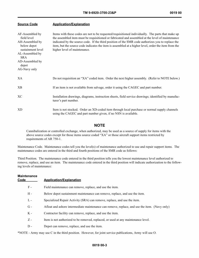
TM 9-6920-3700-23&P 0019 00
0019 00-3
NOTECannibalization or controlled exchange, when authorized, may be used as a source of supply for items with the above source codes except for those items source coded “XA” or those aircraft support items restricted by requirements of AR 750-1.
Maintenance Code. Maintenance codes tell you the level(s) of maintenance authorized to use and repair support items. The maintenance codes are entered in the third and fourth positions of the SMR code as follows:
Third Position. The maintenance code entered in the third position tells you the lowest maintenance level authorized to remove, replace, and use an item. The maintenance code entered in the third position will indicate authorization to the follow-ing levels of maintenance:
AF-Assembled by field level
AH-Assembled by below depotsustainment level
AL-Assembled by SRA
AD-Assembled by depot
AG-Navy only
Items with these codes are not to be requested/requisitioned individually. The parts that make up the assembled item must be requisitioned or fabricated and assembled at the level of maintenance indicated by the source code. If the third position of the SMR code authorizes you to replace the item, but the source code indicates the item is assembled at a higher level, order the item from the higher level of maintenance.
XA Do not requisition an “XA” coded item. Order the next higher assembly. (Refer to NOTE below.)
XB If an item is not available from salvage, order it using the CAGEC and part number.
XC Installation drawings, diagrams, instruction sheets, field service drawings; identified by manufac-turer’s part number.
XD Item is not stocked. Order an XD-coded item through local purchase or normal supply channels using the CAGEC and part number given, if no NSN is available.
MaintenanceCode Application/Explanation
F - Field maintenance can remove, replace, and use the item.
H - Below depot sustainment maintenance can remove, replace, and use the item.
L - Specialized Repair Activity (SRA) can remove, replace, and use the item.
G - Afloat and ashore intermediate maintenance can remove, replace, and use the item. (Navy only)
K - Contractor facility can remove, replace, and use the item.
Z - Item is not authorized to be removed, replaced, or used at any maintenance level.
D - Depot can remove, replace, and use the item.
*NOTE - Army may use C in the third position. However, for joint service publications, Army will use O.
Source Code Application/Explanation
TM 9-6920-3700-23&P 0019 00
0019 00-4
Fourth Position. The maintenance code entered in the fourth position tells you whether or not the item is to be repaired and identifies the lowest maintenance level with the capability to do complete repair (perform all authorized repair functions).
NOTESome limited repair may be done on the item at a lower level of maintenance, if authorized by the Maintenance Allocation Chart (MAC) and SMR codes.
Recoverability Code. Recoverability codes are assigned to items to indicate the disposition action on unserviceable items. The recoverability code is shown in the fifth position of the SMR code as follows:
MaintenanceCode Application/Explanation
F - Field is the lowest level that can do complete repair of the item.
H - Below depot sustainment is the lowest level that can do complete repair of the item.
L - SRA is the lowest level that can do complete repair of the item.
D - Depot is the lowest level that can do complete repair of the item.
Z - Nonreparable. No repair is authorized.
G - Both afloat and ashore intermediate levels are capable of complete repair of item. (Navy only)
K - Complete repair is done at contractor facility.
Z - Nonreparable. No repair is authorized.
B - No repair is authorized. No parts or special tools are authorized for maintenance of “B” coded item. However, the item may be reconditioned by adjusting, lubricating, etc., at the user level.
RecoverabilityCode Application/Explanation
Z - Nonreparable item. When unserviceable, condemn and dispose of the item at the level of maintenance shown in the third position of the SMR code.
F - Reparable item. When uneconomically reparable, condemn and dispose of the item at the field level.
H - Reparable item. When uneconomically repairable, condemn and dispose of the item at the below depot sustainment level.
D - Reparable item. When beyond lower level repair capability, return to depot. Condemnation and disposal of item are not authorized below depot level.
L - Reparable item. Condemnation and disposal not authorized below SRA.
A - Item requires special handling or condemnation procedures because of specific reasons (such as precious metal content, high dollar value, critical material, or hazardous material). Refer to appropriate manuals/directives for specific instructions.
G - Field level reparable item. Condemn and dispose at either afloat or ashore intermediate levels. (Navy only)
K - Reparable item. Condemnation and disposal to be performed at contractor facility.
TM 9-6920-3700-23&P 0019 00
0019 00-5
NSN (Column (3)). The NSN for the item is listed in this column.
CAGEC (Column (4)). The Commercial and Government Entity Code (CAGEC) is a five-digit code which is used to identify the manufacturer, distributor, or Government agency/activity that supplies the item.
PART NUMBER (Column (5)). Indicates the primary number used by the manufacturer (individual, company, firm, corpora-tion, or Government activity), which controls the design and characteristics of the item by means of its engineering drawings, specifications, standards, and inspection requirements to identify an item or range of items.
NOTEWhen you use an NSN to requisition an item, the item you receive may have a different part number from the number listed.
DESCRIPTION AND USABLE ON CODE (UOC) (Column (6)). This column includes the following information:
1. The federal item name, and when required a minimum description to identify the item.
2. Part numbers of bulk materials are referenced in this column in the line entry to be manufactured or fabricated.
3. Hardness Critical Item (HCI). A support item that provides the equipment with special protection from electromagnetic pulse (EMP) damage during a nuclear attack.
4. The statement END OF FIGURE appears just below the last item description in column (6) for a given figure in both the repair parts list and special tools list work packages.
QTY (Column (7)). The QTY (quantity per figure) column indicates the quantity of the item used in the breakout shown on the illustration/figure, which is prepared for a functional group, subfunctional group, or an assembly. A “V” appearing in this column instead of a quantity indicates that the quantity is variable and quantity may change from application to application.
EXPLANATION OF CROSS-REFERENCE INDEXES WORK PACKAGES FORMAT AND COLUMNS
1. National Stock Number (NSN) Index Work Package. NSN’s in this index are listed in National Item Identification Num-ber (NIIN) sequence.
STOCK NUMBER Column. This column lists the NSN in NIIN sequence. The NIIN consists of the last nine digits of the NSN. When using this column to locate an item, ignore the first four digits of the NSN. However, the complete NSN should be used when ordering items by stock number.
For example, if the NSN is 5385-01-574-1476, the NIIN is 01-574-1476.
FIG. Column. This column lists the number of the figure where the item is identified/located. The figures are in numerical order in the repair parts list and special tools list work packages.
ITEM Column. The item number identifies the item associated with the figure listed in the adjacent FIG. column. This item is also identified by the NSN listed on the same line.
2. Part Number (P/N) Index Work Package. Part numbers in this index are listed in ascending alphanumeric sequence (ver-tical arrangement of letter and number combinations which places the first letter or digit of each group in order “A” through “Z,” followed by the numbers “0” through “9” and each following letter or digit in like order).
PART NUMBER Column. Indicates the part number assigned to the item.
FIG. Column. This column lists the number of the figure where the item is identified/located in the repair parts list and special tools list work packages.
TM 9-6920-3700-23&P 0019 00
0019 00-6
ITEM Column. The item number is the number assigned to the item as it appears in the figure referenced in the adjacent figure number column.
REFERENCE DESIGNATOR Column. Indicates the reference designator assigned to the item.
FIG. Column. This column lists the number of the figure where the item is identified/located in the repair parts list or special tools list work package.
ITEM Column. The item number is the number assigned to the item as it appears in the figure referenced in the adjacent figure number column.
HOW TO LOCATE REPAIR PARTS
1. When NSNs or Part Numbers Are Not Known.
First. Using the table of contents, determine the assembly group to which the item belongs. This is necessary since figures are prepared for assembly groups and subassembly groups, and lists are divided into the same groups.
Second. Find the figure covering the functional group or the subfunctional group to which the item belongs.
Third. Identify the item on the figure and note the number(s).
Fourth. Look in the repair parts list work packages for the figure and item numbers. The NSNs and part numbers are on the same line as the associated item numbers.
2. When NSN Is Known.
First. If you have the NSN, look in the STOCK NUMBER column of the NSN index work package. The NSN is arranged in NIIN sequence. Note the figure and item number next to the NSN.
Second. Turn to the figure and locate the item number. Verify that the item is the one you are looking for.
3. When Part Number Is Known.
First. If you have the part number and not the NSN, look in the PART NUMBER column of the part number index work pack-age. Identify the figure and item number.
Second. Look up the item on the figure in the applicable repair parts list work package.

TM 9-6920-3700-23&P 0020 00
FIELD MAINTENANCE
CLOSE COMBAT MISSION CAPABILITY KIT (CCMCK)
REPAIR PARTS LIST
NOTEBefore proceeding with Repair Parts List, see Introduction to RPSTL (WP 0019 00).
0020 00-1
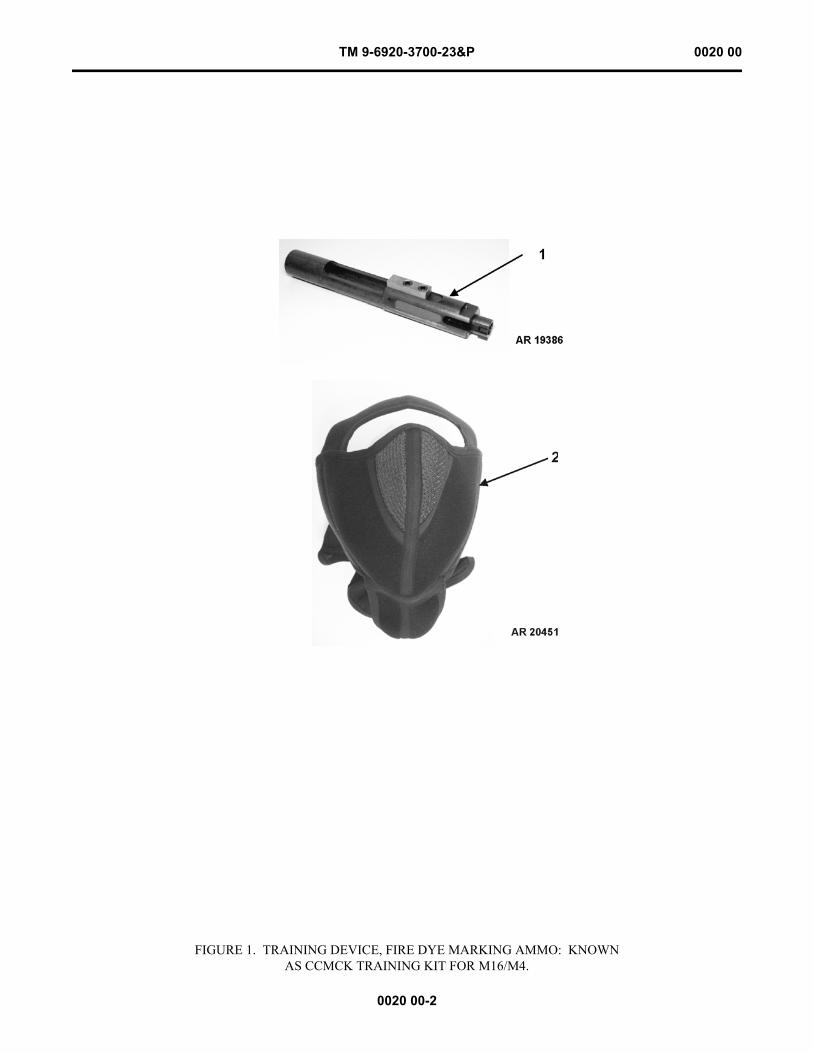
TM 9-6920-3700-23&P 0020 00
0020 00-2
FIGURE 1. TRAINING DEVICE, FIRE DYE MARKING AMMO: KNOWNAS CCMCK TRAINING KIT FOR M16/M4.
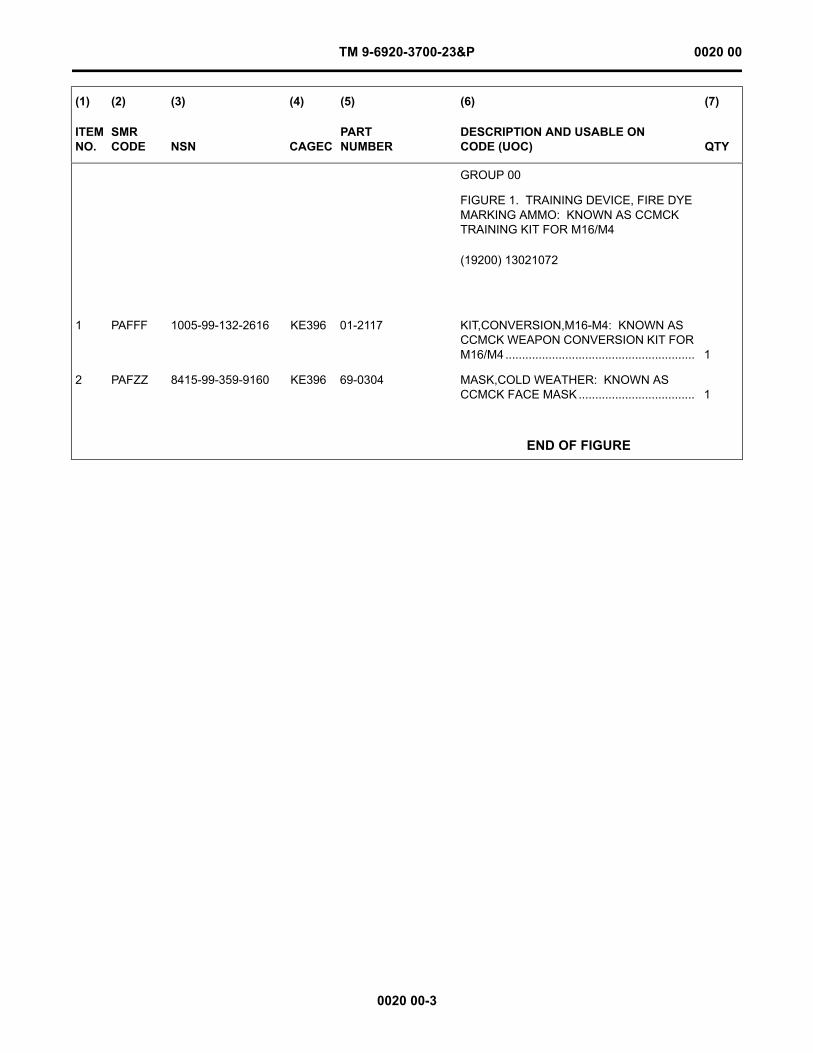
TM 9-6920-3700-23&P 0020 00
0020 00-3
(1) (2) (3) (4) (5) (6) (7)
ITEM NO.
SMR CODE NSN CAGEC
PARTNUMBER
DESCRIPTION AND USABLE ON CODE (UOC) QTY
GROUP 00
FIGURE 1. TRAINING DEVICE, FIRE DYE MARKING AMMO: KNOWN AS CCMCK TRAINING KIT FOR M16/M4
(19200) 13021072
1 PAFFF 1005-99-132-2616 KE396 01-2117 KIT,CONVERSION,M16-M4: KNOWN AS CCMCK WEAPON CONVERSION KIT FOR M16/M4 ......................................................... 1
2 PAFZZ 8415-99-359-9160 KE396 69-0304 MASK,COLD WEATHER: KNOWN AS CCMCK FACE MASK ................................... 1
END OF FIGURE
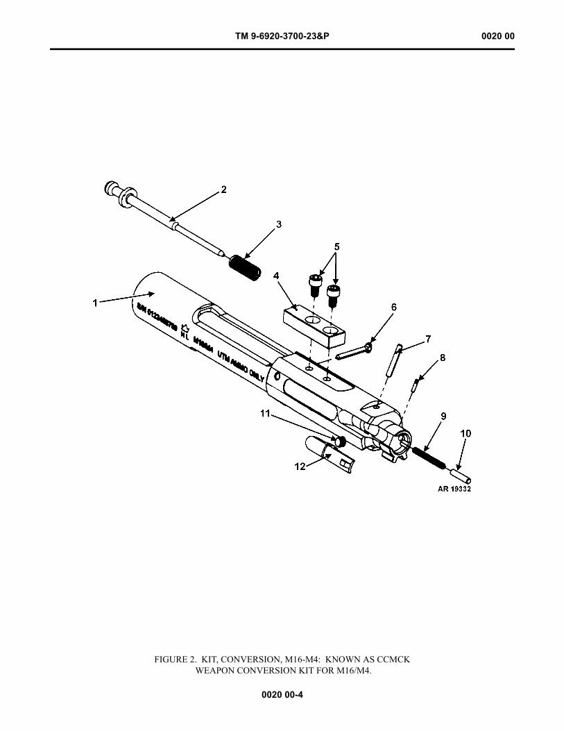
TM 9-6920-3700-23&P 0020 00
0020 00-4
FIGURE 2. KIT, CONVERSION, M16-M4: KNOWN AS CCMCK WEAPON CONVERSION KIT FOR M16/M4.
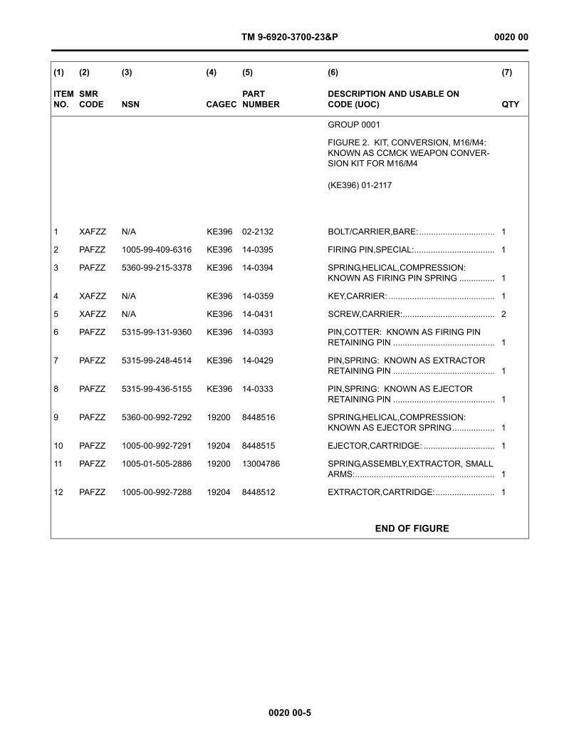
TM 9-6920-3700-23&P 0020 00
0020 00-5
(1) (2) (3) (4) (5) (6) (7)
ITEM NO.
SMR CODE NSN CAGEC
PARTNUMBER
DESCRIPTION AND USABLE ON CODE (UOC) QTY
GROUP 0001
FIGURE 2. KIT, CONVERSION, M16/M4: KNOWN AS CCMCK WEAPON CONVER-SION KIT FOR M16/M4
(KE396) 01-2117
1 XAFZZ N/A KE396 02-2132 BOLT/CARRIER,BARE:................................ 1
2 PAFZZ 1005-99-409-6316 KE396 14-0395 FIRING PIN,SPECIAL:.................................. 1
3 PAFZZ 5360-99-215-3378 KE396 14-0394 SPRING,HELICAL,COMPRESSION: KNOWN AS FIRING PIN SPRING ............... 1
4 XAFZZ N/A KE396 14-0359 KEY,CARRIER: ............................................. 1
5 XAFZZ N/A KE396 14-0431 SCREW,CARRIER:....................................... 2
6 PAFZZ 5315-99-131-9360 KE396 14-0393 PIN,COTTER: KNOWN AS FIRING PIN RETAINING PIN ........................................... 1
7 PAFZZ 5315-99-248-4514 KE396 14-0429 PIN,SPRING: KNOWN AS EXTRACTOR RETAINING PIN ........................................... 1
8 PAFZZ 5315-99-436-5155 KE396 14-0333 PIN,SPRING: KNOWN AS EJECTOR RETAINING PIN ........................................... 1
9 PAFZZ 5360-00-992-7292 19200 8448516 SPRING,HELICAL,COMPRESSION: KNOWN AS EJECTOR SPRING.................. 1
10 PAFZZ 1005-00-992-7291 19204 8448515 EJECTOR,CARTRIDGE: .............................. 1
11 PAFZZ 1005-01-505-2886 19200 13004786 SPRING,ASSEMBLY,EXTRACTOR, SMALL ARMS:........................................................... 1
12 PAFZZ 1005-00-992-7288 19204 8448512 EXTRACTOR,CARTRIDGE:......................... 1
END OF FIGURE
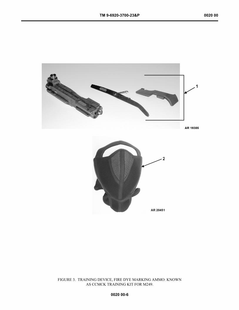
TM 9-6920-3700-23&P 0020 00
0020 00-6
FIGURE 3. TRAINING DEVICE, FIRE DYE MARKING AMMO: KNOWNAS CCMCK TRAINING KIT FOR M249.

TM 9-6920-3700-23&P 0020 00
0020 00-7
(1) (2) (3) (4) (5) (6) (7)
ITEM NO.
SMR CODE NSN CAGEC
PARTNUMBER
DESCRIPTION AND USABLE ON CODE (UOC) QTY
GROUP 01
FIGURE 3. TRAINING DEVICE, FIRE DYE MARKING AMMO: KNOWN AS CCMCK TRAINING KIT FOR M249
(19200) 13021071
1 PAFFF 1005-99-848-0609 KE396 01-2010 BOLT,AUTOMATIC WEAPON: KNOWN AS CCMCK WEAPON CONVERSION KIT FOR M249 ............................................................. 1
2 PAFZZ 8415-99-359-9160 KE396 69-0304 MASK,COLD WEATHER: KNOWN AS CCMCK FACE MASK ................................... 1
END OF FIGURE
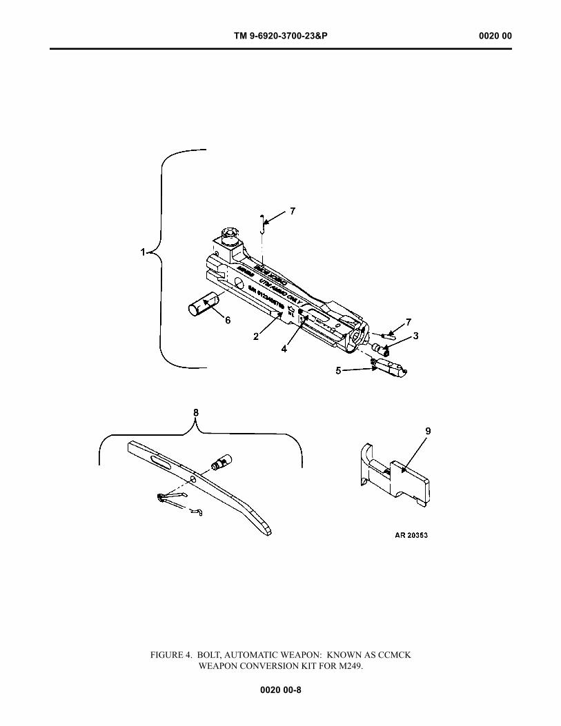
TM 9-6920-3700-23&P 0020 00
0020 00-8
FIGURE 4. BOLT, AUTOMATIC WEAPON: KNOWN AS CCMCK WEAPON CONVERSION KIT FOR M249.
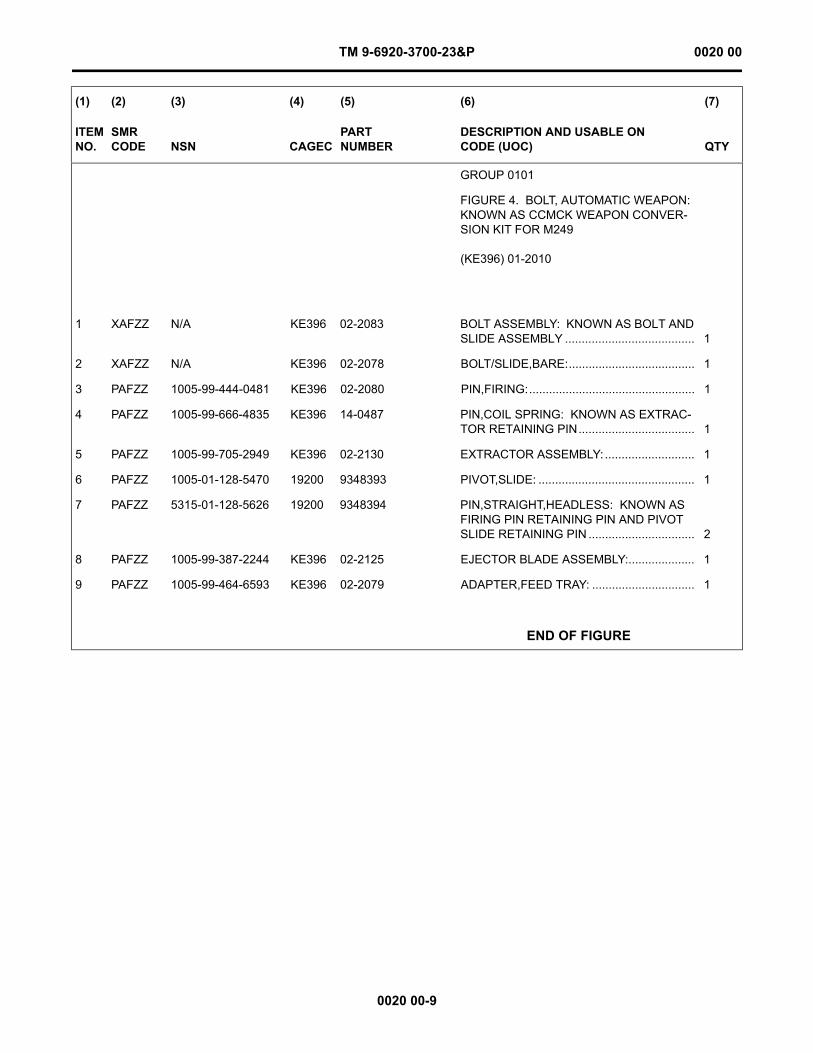
TM 9-6920-3700-23&P 0020 00
0020 00-9
(1) (2) (3) (4) (5) (6) (7)
ITEM NO.
SMR CODE NSN CAGEC
PARTNUMBER
DESCRIPTION AND USABLE ON CODE (UOC) QTY
GROUP 0101
FIGURE 4. BOLT, AUTOMATIC WEAPON: KNOWN AS CCMCK WEAPON CONVER-SION KIT FOR M249
(KE396) 01-2010
1 XAFZZ N/A KE396 02-2083 BOLT ASSEMBLY: KNOWN AS BOLT AND SLIDE ASSEMBLY ....................................... 1
2 XAFZZ N/A KE396 02-2078 BOLT/SLIDE,BARE:...................................... 1
3 PAFZZ 1005-99-444-0481 KE396 02-2080 PIN,FIRING:.................................................. 1
4 PAFZZ 1005-99-666-4835 KE396 14-0487 PIN,COIL SPRING: KNOWN AS EXTRAC-TOR RETAINING PIN................................... 1
5 PAFZZ 1005-99-705-2949 KE396 02-2130 EXTRACTOR ASSEMBLY: ........................... 1
6 PAFZZ 1005-01-128-5470 19200 9348393 PIVOT,SLIDE: ............................................... 1
7 PAFZZ 5315-01-128-5626 19200 9348394 PIN,STRAIGHT,HEADLESS: KNOWN AS FIRING PIN RETAINING PIN AND PIVOT SLIDE RETAINING PIN ................................ 2
8 PAFZZ 1005-99-387-2244 KE396 02-2125 EJECTOR BLADE ASSEMBLY:.................... 1
9 PAFZZ 1005-99-464-6593 KE396 02-2079 ADAPTER,FEED TRAY: ............................... 1
END OF FIGURE
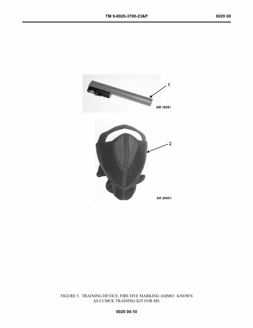
TM 9-6920-3700-23&P 0020 00
0020 00-10
FIGURE 5. TRAINING DEVICE, FIRE DYE MARKING AMMO: KNOWNAS CCMCK TRAINING KIT FOR M9.

TM 9-6920-3700-23&P 0020 00
0020 00-11
(1) (2) (3) (4) (5) (6) (7)
ITEM NO.
SMR CODE NSN CAGEC
PARTNUMBER
DESCRIPTION AND USABLE ON CODE (UOC) QTY
GROUP 02
FIGURE 5. TRAINING DEVICE, FIRE DYE MARKING AMMO: KNOWN AS CCMCK TRAINING KIT FOR M9
(19200) 13021070
1 PAFFF 1005-20-003-2362 35921 5309420 CONVERSION KIT,MAN: KNOWN AS CCMCK WEAPON CONVERSION KIT FOR M9................................................................. 1
2 PAFZZ 8415-99-359-9160 KE396 69-0304 MASK,COLD WEATHER: KNOWN AS CCMCK FACE MASK ................................... 1
END OF FIGURE
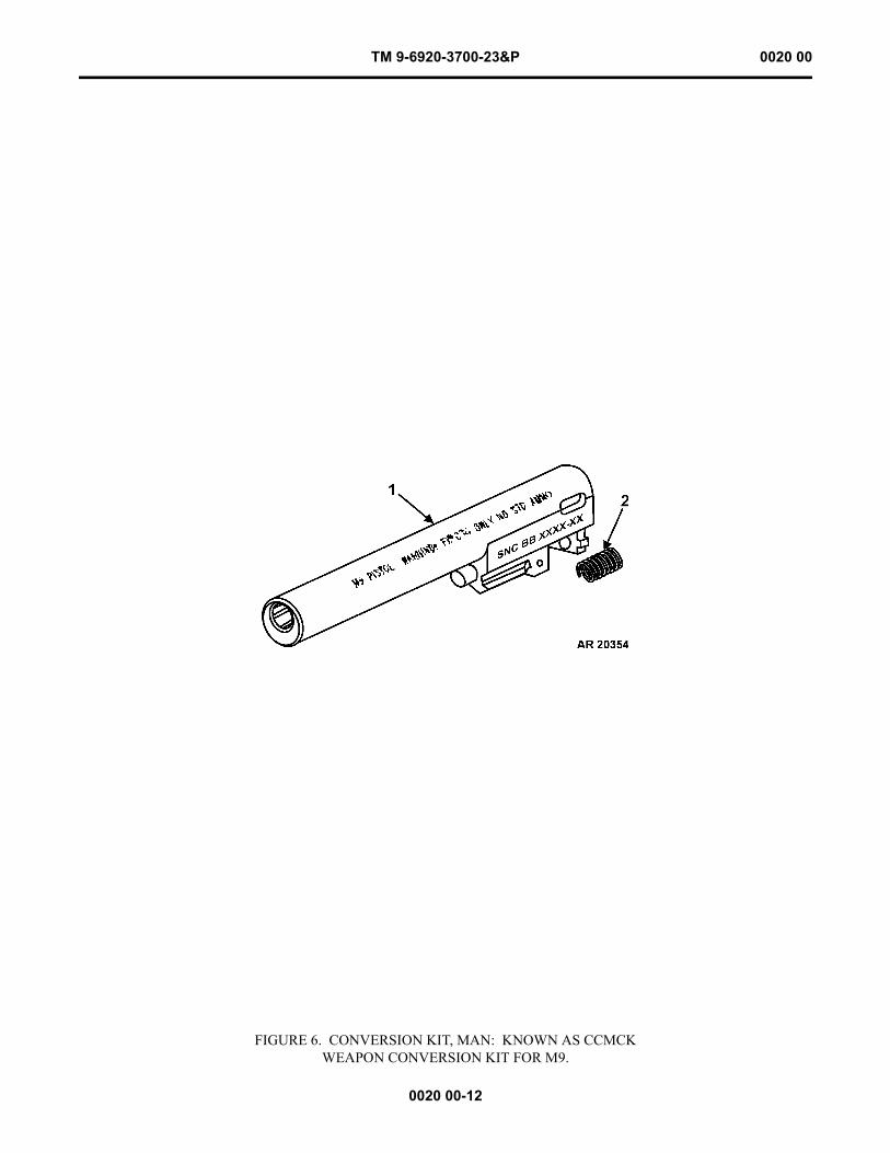
TM 9-6920-3700-23&P 0020 00
0020 00-12
FIGURE 6. CONVERSION KIT, MAN: KNOWN AS CCMCKWEAPON CONVERSION KIT FOR M9.
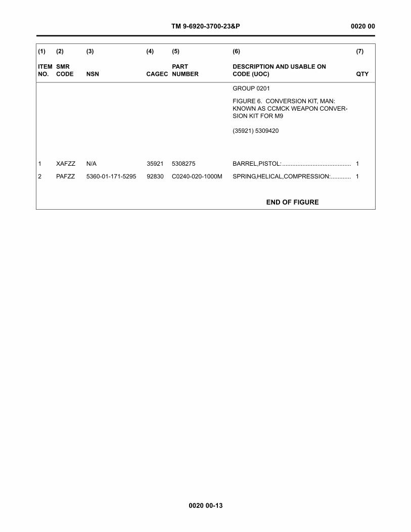
TM 9-6920-3700-23&P 0020 00
0020 00-13
(1) (2) (3) (4) (5) (6) (7)
ITEM NO.
SMR CODE NSN CAGEC
PARTNUMBER
DESCRIPTION AND USABLE ON CODE (UOC) QTY
GROUP 0201
FIGURE 6. CONVERSION KIT, MAN: KNOWN AS CCMCK WEAPON CONVER-SION KIT FOR M9
(35921) 5309420
1 XAFZZ N/A 35921 5308275 BARREL,PISTOL:......................................... 1
2 PAFZZ 5360-01-171-5295 92830 C0240-020-1000M SPRING,HELICAL,COMPRESSION:............ 1
END OF FIGURE
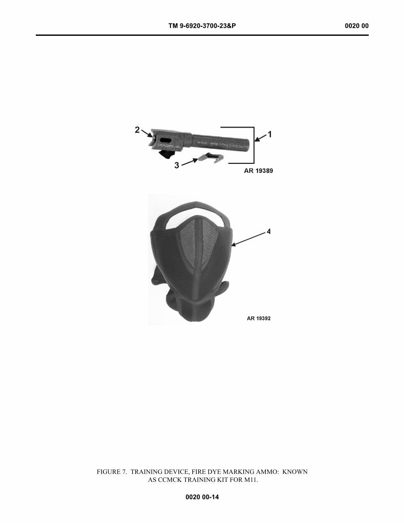
TM 9-6920-3700-23&P 0020 00
0020 00-14
FIGURE 7. TRAINING DEVICE, FIRE DYE MARKING AMMO: KNOWN AS CCMCK TRAINING KIT FOR M11.
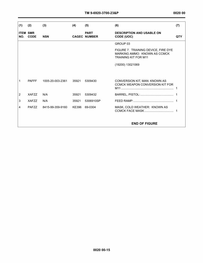
TM 9-6920-3700-23&P 0020 00
0020 00-15
(1) (2) (3) (4) (5) (6) (7)
ITEM NO.
SMR CODE NSN CAGEC
PARTNUMBER
DESCRIPTION AND USABLE ON CODE (UOC) QTY
GROUP 03
FIGURE 7. TRAINING DEVICE, FIRE DYE MARKING AMMO: KNOWN AS CCMCK TRAINING KIT FOR M11
(19200) 13021069
1 PAFFF 1005-20-003-2361 35921 5309430 CONVERSION KIT, MAN: KNOWN AS CCMCK WEAPON CONVERSION KIT FOR M11 ............................................................... 1
2 XAFZZ N/A 35921 5309432 BARREL, PISTOL:........................................ 1
3 XAFZZ N/A 35921 5306910SP FEED RAMP: ................................................ 1
4 PAFZZ 8415-99-359-9160 KE396 69-0304 MASK, COLD WEATHER: KNOWN AS CCMCK FACE MASK ................................... 1
END OF FIGURE

This Page Intentionally Left Blank
0020 00-16
TM 9-6920-3700-23&P 0020 00

TM 9-6920-3700-23&P 0021 00
FIELD MAINTENANCE
CLOSE COMBAT MISSION CAPABILITY KIT (CCMCK)
SPECIAL TOOLS LIST
NOTEBefore proceeding with Special Tools List, see Introduction to RPSTL (WP 0019 00).
0021 00-1
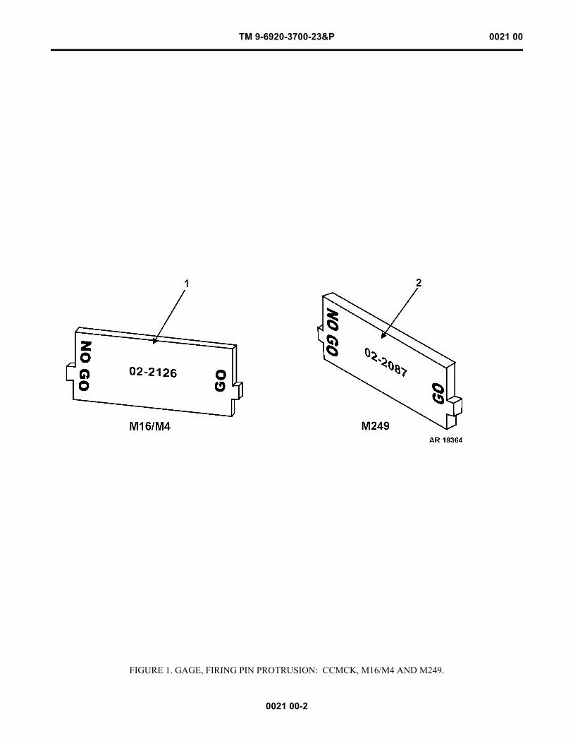
TM 9-6920-3700-23&P 0021 00
0021 00-2
FIGURE 1. GAGE, FIRING PIN PROTRUSION: CCMCK, M16/M4 AND M249.
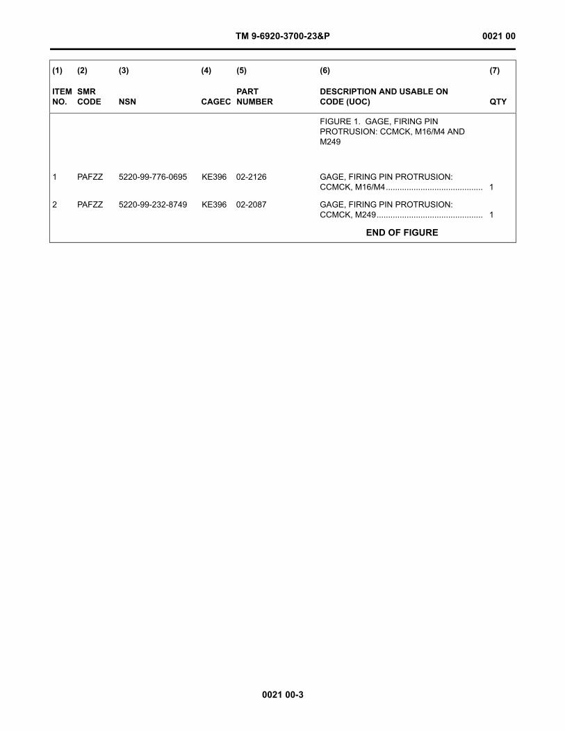
TM 9-6920-3700-23&P 0021 00
0021 00-3
(1) (2) (3) (4) (5) (6) (7)
ITEM NO.
SMR CODE NSN CAGEC
PARTNUMBER
DESCRIPTION AND USABLE ON CODE (UOC) QTY
FIGURE 1. GAGE, FIRING PIN PROTRUSION: CCMCK, M16/M4 AND M249
1 PAFZZ 5220-99-776-0695 KE396 02-2126 GAGE, FIRING PIN PROTRUSION: CCMCK, M16/M4.......................................... 1
2 PAFZZ 5220-99-232-8749 KE396 02-2087 GAGE, FIRING PIN PROTRUSION: CCMCK, M249.............................................. 1
END OF FIGURE

This Page Intentionally Left Blank
0021 00-4
TM 9-6920-3700-23&P 0021 00
TM 9-6920-3700-23&P 0022 00
FIELD MAINTENANCE
CLOSE COMBAT MISSION CAPABILITY KIT (CCMCK)
NATIONAL STOCK NUMBER INDEX
NOTEBefore proceeding with National Stock Number Index, see Introduction to RPSTL (WP 0019 00).
0022 00-1
STOCK NUMBER FIG. ITEM STOCK NUMBER FIG. ITEM
1005-00-992-7288 2 121005-00-992-7291 2 105360-00-992-7292 2 91005-01-128-5470 4 65315-01-128-5626 4 75360-01-171-5295 6 21005-01-505-2886 2 111005-20-003-2361 7 11005-20-003-2362 5 15315-99-131-9360 2 61005-99-132-2616 1 15360-99-215-3378 2 35315-99-248-4514 2 7
8415-99-359-9160 1 23 25 27 4
1005-99-387-2244 4 81005-99-409-6316 2 25315-99-436-5155 2 81005-99-444-0481 4 31005-99-464-6593 4 91005-99-666-4835 4 41005-99-705-2949 4 51005-99-848-0609 3 1

This Page Intentionally Left Blank
0022 00-2
TM 9-6920-3700-23&P 0022 00
TM 9-6920-3700-23&P 0023 00
FIELD MAINTENANCE
CLOSE COMBAT MISSION CAPABILITY KIT (CCMCK)
PART NUMBER INDEX
NOTEBefore proceeding with Part Number Index, see Introduction to RPSTL (WP 0019 00).
0023 00-1
PART NUMBER FIG. ITEM PART NUMBER FIG. ITEM
C0240-020-1000M 6 201-2010 3 101-2117 1 102-2078 4 202-2079 4 902-2080 4 302-2083 4 102-2125 4 802-2130 4 502-2132 2 113004786 2 1114-0333 2 814-0359 2 414-0393 2 614-0394 2 314-0395 2 214-0429 2 7
14-0431 2 514-0487 4 45306910SP 7 35308275 6 15309420 5 15309430 7 15309432 7 269-0304 1 2
3 25 27 4
8448512 2 128448515 2 108448516 2 99348393 4 69348394 4 7

This Page Intentionally Left Blank
0023 00-2
TM 9-6920-3700-23&P 0023 00
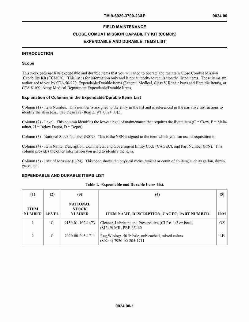
TM 9-6920-3700-23&P 0024 00
0024 00-1
FIELD MAINTENANCE
CLOSE COMBAT MISSION CAPABILITY KIT (CCMCK)
EXPENDABLE AND DURABLE ITEMS LIST
INTRODUCTION
Scope
This work package lists expendable and durable items that you will need to operate and maintain Close Combat Mission Capability Kit (CCMCK). This list is for information only and is not authority to requisition the listed items. These items are authorized to you by CTA 50-970, Expendable/Durable Items (Except: Medical, Class V, Repair Parts and Heraldic Items), or CTA 8-100, Army Medical Department Expendable/Durable Items.
Explanation of Columns in the Expendable/Durable Items List
Column (1) - Item Number. This number is assigned to the entry in the list and is referenced in the narrative instructions to identify the item (e.g., Use clean rag (Item 2, WP 0024 00).).
Column (2) - Level. This column identifies the lowest level of maintenance that requires the listed item (C = Crew, F = Main-tainer, H = Below Depot, D = Depot).
Column (3) - National Stock Number (NSN). This is the NSN assigned to the item which you can use to requisition it.
Column (4) - Item Name, Description, Commercial and Government Entity Code (CAGEC), and Part Number (P/N). This column provides the other information you need to identify the item.
Column (5) - Unit of Measure (U/M). This code shows the physical measurement or count of an item, such as gallon, dozen, gross, etc.
EXPENDABLE AND DURABLE ITEMS LIST
Table 1. Expendable and Durable Items List.
(1) (2) (3) (4) (5)
ITEM NUMBER LEVEL
NATIONAL STOCK
NUMBER ITEM NAME, DESCRIPTION, CAGEC, PART NUMBER U/M
1 C 9150-01-102-1473 Cleaner, Lubricant and Preservative (CLP): 1/2 oz bottle(81349) MIL-PRF-63460
OZ
2 C 7920-00-205-1711 Rag,Wiping: 50 lb bale, unbleached, mixed colors (80244) 7920-00-205-1711
LB

This Page Intentionally Left Blank
0024 00-2
TM 9-6920-3700-23&P 0024 00
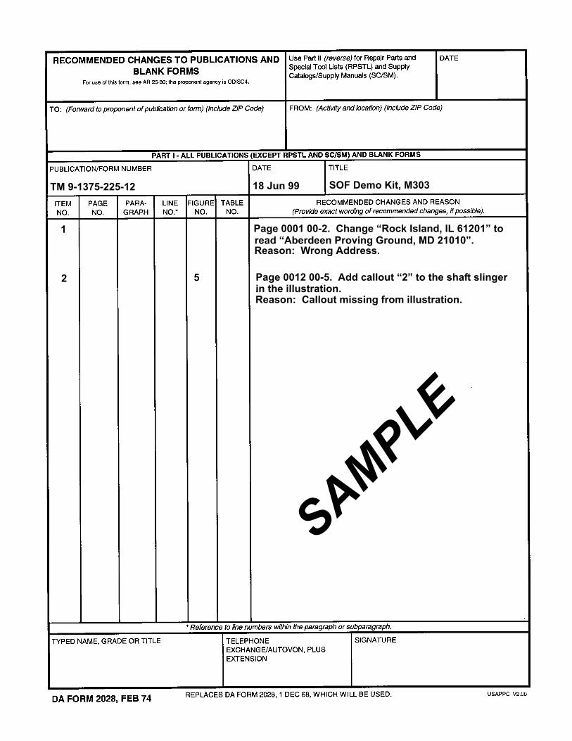
TM 9-1375-225-12 18 Jun 99 SOF Demo Kit, M303
Page 0012 00-5. Add callout “2” to the shaft slinger
Reason: Callout missing from illustration.
Page 0001 00-2. Change “Rock Island, IL 61201” to read “Aberdeen Proving Ground, MD 21010”.Reason: Wrong Address.
SAMPLE
1
2 5.in the illustration.

This Page Intentionally Left Blank

LRED (AMSRD-AAR-EIL-LS)
Picatinny Arsenal, NJ 07806-5000U.S. Army RDECOM, ARDEC
TM 9-6920-3700-23&P 13 Mar 09 Field Maintenance Manual for CCMCK
LRED (AMSRD-AAR-EIL-LS)
Picatinny Arsenal, NJ 07806-5000U.S. Army RDECOM, ARDEC
LRED (AMSRD-AAR-EIL-LS)
Picatinny Arsenal, NJ 07806-5000U.S. Army RDECOM, ARDEC
TM 9-6920-3700-23&P 13 Mar 09 Field Maintenance Manual for CCMCK

LRED (AMSRD-AAR-EIL-LS)
Picatinny Arsenal, NJ 07806-5000U.S. Army RDECOM, ARDEC

LRED (AMSRD-AAR-EIL-LS)
Picatinny Arsenal, NJ 07806-5000U.S. Army RDECOM, ARDEC
TM 9-6920-3700-23&P 13 Mar 09 Field Maintenance Manual for CCMCK

LRED (AMSRD-AAR-EIL-LS)
Picatinny Arsenal, NJ 07806-5000U.S. Army RDECOM, ARDEC
0906201
By Order of the Secretary of the Army:
GEORGE W. CASEY, JR. General, United States Army
Chief of StaffOfficial:
JOYCE E. MORROW Administrative Assistant to the
Secretary of the Army
DISTRIBUTION: To be distributed in accordance with the initial distribution number (IDN) 401254 requirements for TM 9-6920-3700-23&P.
TM 9-6920-3700-23&P


PIN: 085409-000

This fine document...
Was brought to you by me:
Liberated Manuals -- free army and government manuals
Why do I do it? I am tired of sleazy CD-ROM sellers, who take publicly available information, slap “watermarks” and other junk on it, and sell it. Those masters of search engine manipulation make sure that their sites that sell free information, come up first in search engines. They did not create it... They did not even scan it... Why should they get your money? Why are not letting you give those free manuals to your friends?
I am setting this document FREE. This document was made by the US Government and is NOT protected by Copyright. Feel free to share, republish, sell and so on.
I am not asking you for donations, fees or handouts. If you can, please provide a link to liberatedmanuals.com, so that free manuals come up first in search engines:
<A HREF=http://www.liberatedmanuals.com/>Free Military and Government Manuals</A>
– SincerelyIgor Chudovhttp://igor.chudov.com/
– Chicago Machinery Movers