Embed Size (px)
Citation preview
TM 9-3444-203-10D E P A R T M E N T O F T H E A R M Y T E C H N I C A L M A N U A L
PRESS,
O P E R A T O R ’ S M A N U A L
ARBOR, HAND OPERATED
( A C C O E Q U I P M E N T D I V I S I O N O F
AMERICAN CHAIN AND CABLE CO.
MODELS P-994 AND P-995)
(344-449-7295)
This copy is a reprint which includes current
p a g e s f r o m C h a n g e s 1 .
H E A D Q U A R T E R S , D E P A R T M E N T O F T H E A R M Y
OCTOBER 1964
HEADQUARTERSDEPARTMENT OF THE ARMY
WASHINGTON , D. C., 15 October 1964
TM 9-3444-203-10, is published for the use of all concerned.
By Order of the Secretary of the Army:
Official:J. C. LAMBERT,Major General, United States Army,The Adjutant General.
HAROLD K. JOHNSON,General, United States Army,Chief of Stuff.
Distribution:Active Army:
DCSLOG (1) Armies (3) exceptCNGB (1) Seventh USA (5)TSG (1) EUSA (5)CofEngrs (2) Div (2)COfSptS (2) Ft Monmouth (8)CofT (1) Ft Belvoir (2)CC-E (1) USATSCH (1)USCONARC (3) USAATC (1)USAMC (12) WSMR (2)USASMC (6) Brooklyn Army Tm1 (1)USAWECOM (75) Army Dep (2) exceptUSAMUCOM (5) LXAD (1)ARADCOM (2) Arsenals (1) exceptARADCOM Rgn (2) Detroit (5)LOGCOMD (3) APG (1)OS Maj Cored (1) except JUSMMAT (1)
USARAL (2) USACOMZEUR (1)USARSO (7) Units org under fol TOE:
OS Base Cored (2) 55-158 (2)NG: State AG (3); units---same as active Army except allowance is one copy to each unit.USAR: None.For explanation of abbreviations used, see AR 320-50.
AGO 6191A
Change
No. 1
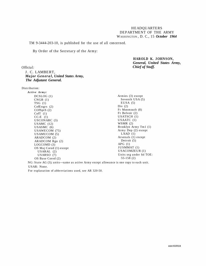
TM 9-3444-203-10C 1
HEADQUARTERSDEPARTMENT OF THE ARMY
Washington, D.C., 9 April 1973
Operator’s Manual,PRESS, ARBOR, HAND OPERATED(ACCO EQUIPMENT DIVISION OF
AMERICAN CHAIN AND CABLE CO.MODELS P-994 AND P-995)
(3444-449-7295)
This change is current as of 23 February 1973
‘I’M 9-3444-203-10, 15 October 1964, is changed as follows:
Page 1. (Added)L This change identifies the type of catalog maintenance action taken in connection with the updating ofpreviously published data.
Page 6. Add the following paragraph after page 6 and before page 7, as page 8.1.1. PARTS INCLUDED WITH END ITEM: Parts included with end item and considered a componentor part of the item configuration are listed on the following table. The part numbers listed are for(ACCO EQUIPMENT DIVISION OF AMERICAN CHAIN AND CABLE CO. MODELS P-994 and P-995).
Pages 7 and 8. APPENDIX is rescinded.
Part
ANVIL.ANVILANVILLEAF SPRING:RIVETER BASE ASSEMBLY:
RIVET SET (TOOL):RIVET SET (TOOL):RIVET SET (TOOL):RIVET SET (TOOL):RIVET SET (TOOL):WRENCH, PACKING NUT:
Part No.
(056379097)(05637:9095)(05637:11284)(05637:10416)(ISSUED AS COMPONENTOF MAJOR ITEM)(05637:9091)(05637:9092)(05637:9093)(05637:9094)(05637:9351)(O5637:X-1O495)
1
By Order of the Secretary of the Army:
Official:
VERNE L. BOWERSMajor General, United States Army,The Adjutant General.
Distribution:Active Army:
DSCLOG (3)CNGB (1)TSG (1)COE (5)Dir of Trans (1)ACSC-E (1)CONARC (2)ARADCOM (2)ARADCOM Rgn (2)LOGCOMD (2)AMC (5)WECOM (10)MUCOM (2)AVSCOM (2)OS Maj Cored (2)Armies (3) except
Seventh USA (5)
C R E I G H T O N W . A B R A M S ,General, United States ArmyChief of Staff.
Eighth USA (5)Corps (2)Instl (2) except
Ft Monmouth (5)APG (1)AD (2) except
TEAD (16)USATSCH (1)USAATC (1)Arsenals (1) except
Detroit (5)JUSMMAT (1)USACOMZEUR (1)Brooklyn Army Tml (1)Ft Knox FLDMS (10)4th USASA Fld Sta (1)Units org under fol TOE:
55-158 (2)
ARNG: Stage AG (3); Units--Same as Active Army, except allowance is one (1) copy of each.USAR: None.For explanation of abbreviations used, see AR 310-50.
2
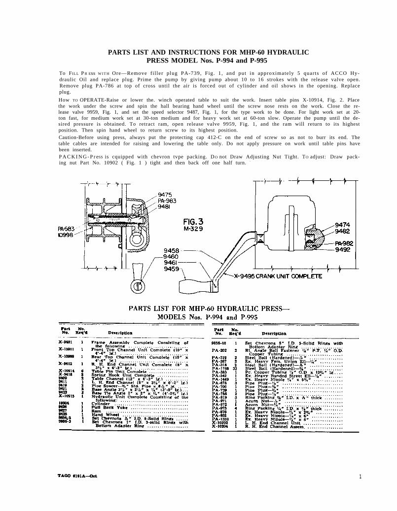
FIG. 3
PARTS LIST AND INSTRUCTIONS FOR MHP-60 HYDRAULICPRESS MODEL Nos. P-994 and P-995
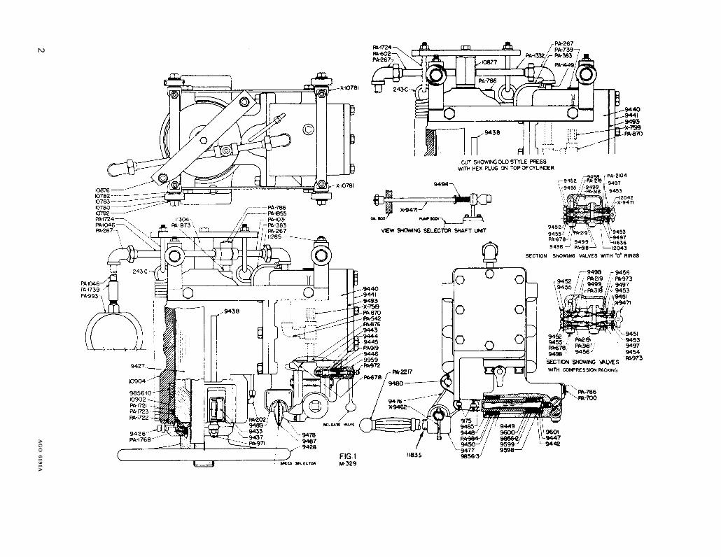
To FILL P R Ess W I T H Ore—Remove f i l ler plug PA-739, Fig. 1, and put in approximately 5 quarts of ACCO Hy-draulic Oil and replace plug. Prime the pump by giving pump about 10 to 16 strokes with the release valve open.Remove plug PA-786 at top of cross until the air is forced out of cylinder and oil shows in the opening. Replaceplug.
How TO OPERATE-Raise or lower the. winch operated table to suit the work. Insert table pins X-10914, Fig. 2. Placethe work under the screw and spin the hall bearing hand wheel until the screw nose rests on the work. Close the re-lease valve 9959, Fig. 1, and set the speed selector 9487, Fig. 1, for the type work to be done. For light work set at 20-ton fast, for medium work set at 30-ton medium and for heavy work set at 60-ton slow. Operate the pump until the de-sired pressure is obtained. To retract ram, open release valve 9959, Fig. 1, and the ram will return to its highestposition. Then spin hand wheel to return screw to its highest position.Caution-Before using press, always put the protecting cap 412-C on the end of screw so as not to burr its end. Thetable cables are intended for raising and lowering the table only. Do not apply pressure on work until table pins havebeen inserted.P A C K I N G - P r eSS is cquipped with chevron tvpe packing. DO not Draw Adjusting Nut Tight. TO adjust: Draw pack-ing nut Part No. 10902 ( Fig. 1 ) tight and then back off one half turn. -
1
FIG
. 1
2A
GO
6191A
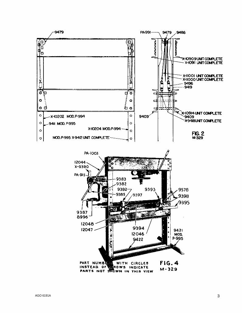
FIG. 4
FIG. 2
AGO 6191A 3
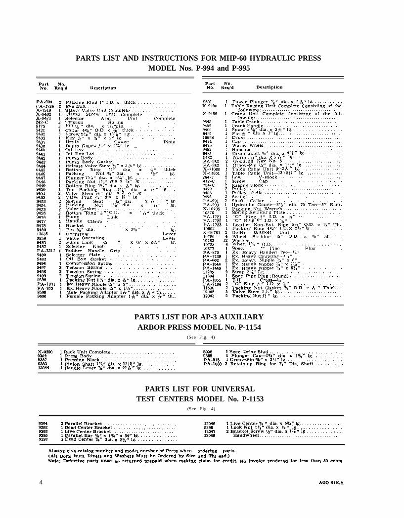
PARTS LIST AND INSTRUCTIONS FOR MHP-60 HYDRAULIC PRESSMODEL Nos. P-994 and P-995
Part No.No. Req’d Description
PartNo. Req'd Description
PA-984PA- 1724X-7519X-9462X-9471243-C9175
94329433943794389440944194429443
944594469447944894499450945194529453945494559456947694779478
Packing Ring 1’” I.D. x thick . . . . . . . . . . . . .Eye BoIt . . . . . . . . . . . . . . . . . . . . . . . . . . . . . . .Safety Valve Unit Complete . . . . . . . . . . . . . . .Clamp Screw Unit Complete . . . . .Selector Arm Unit CompleteT<
9601X-9406
x-9495
1’1
Power Plunger %“ dia. x5&” lg. . . . . . . . . . . .Table Raising Unit Complete Consisting of the
following: . . . . . . . . . . . . . . . . . . . . . . . . . . . . . . . . . . .Crank Unit Complete Consisting of the fol-
lowing: . . . . . . . . . . . . . . . . . . . . . . . . . . . . . . . . . . . . . .Table Crank . . . . . . . . . . . . . . . . . . . . . . . . . . . . . . . . . .Crank Handle . . . . . . . . . . . . . . . . . . . . . . . . . . . . . . . . .Spmdle %“ dia. x3&” lg. . . . . . . . . . . . . . . . .P1n +2 “ dia. xl’’ lg. . . . . . . . . . . . . . . . . . . . . . . . . . .
9546945994609461109989474
1111
enslOn Spring . .dia. xll,i”l. . . . . . .F).D. X ?a” thick . . . . . . . . . . .
pi” ;~ f,Collar 43,8” 0Screw 2?& ’’dia. xl3?b “lg . . . . . . . . . . . . . . . . . . .Key &,’ X !,fi” X 2“ lg. . . . . .De~th Gauze Plate
oii BOx .“::. .’: . . . . . . . . . . . . . . . . . . . . . . . .OiP(Pump Body GasketRelease Valve Stem ?6” x 31%” lg . . . . . . . . . . . . .Bottom Ring ?6” dia. x A“ thickPacking Nut?i’’dia. x !.i’’ lg.Plunger l? L,;
!11Debth Gau~e 1,4” x 9?A” IE7. 9475
9492!14R1
1 Housing . .Drum Shaft %“ dia. xWorm I:,k” dia. x 5 I% “WoodruffGrocw-Pin ?i” dia.Table Cable Unit 9Table Cable Unit—LOW V-BlockScrew Cap . .Rais]ng Block . . . . . . . . . . . .~lle,v . . . . . . . . . .
...,4)k”lg.
. . . . . . . . . . . . . . . .lg. . . . . . . . . . . . . . . . .. . . ,,
ilk30x Lid . . . . . . . . . . . . . . . . . . . . . . . . . .IJmp BodY . . . . . . . . . . . . . . . . . . . . . . . . . . . . .
dia. x 6i,’4° lg. . . . . . . . . . . .dia. x?k’’!g . . . . . . . . . . . . . . . .Pack~;g N;t I:&” c
Bottom Ring 1S6” dia. x q}” lg. . . . . . . . . . .‘rem Packing Rmg-l?i” dia. .x f%” lg.. .Valve Stem &” diaValve Plug ?i’’dia. x +} ’’lg. . . . . . . . . .Spring Seat ]J’’dia. x& ’’lg.Packine Nut I,i’’dia. x ii” M.
. . . . . . . . . ,,. . . . . . . .
. . . . . . . . . . . . . . . . . . . . . .u11ey!2° dia. . . . . . . . . . . . . . . . . . . . . . . . . . . . . . . . . .ax2+ ’’lg. . . . . . . .
Spring . . . . . .Shaft Collar . . . . . . . . . . .Hydraulic C,aug&-3]5° dia. 70 Ton-5° Ram.PackingNutWrench . . . . . . . . . . . . . . . . . . . . . . . . . .Spring Retalnlng Plate . . . . . . . . . . . . . . . . . . .“’O” Ring 5“ I.D. x ],L” ... .,... .“0,< Ring 6>, I.D. x 18’! . .Leather Non-Ext. Rinq 51,2” O.D. x ?6” Th..Packing Ring 4?i” I.D. x236” lg . . . . . . . . . . . . . .Roller Bracket Unit . . . . . .Wheel Bushing ‘!s” O.D, x ?6” lg. . .Washer . . .Wheel l,?!+ ’’O.D. . . . . . . . . . . . . . . . . . . . . . . . .sDec. Pipe Plug .Ex. Heavy Banded Te+l,<”Ex. Heavy Coupbn<-1 i“ .Ex. Heavy NiDple li” x 6“Ex. Heavy Nipple ~,k” x 71,k” .Ex. Heavv Nipple Ii” x 5?1” . . . . . . . .Strau8%’’ Lg. . . . . . . . . . . . . . . . . . . . . . . . . . . . . . . . .Suet. Pipe Plug (Round) . . . . . . . . . . . . . . . . . . .E.H. Cross--?i” . . .“’O’’ Ring &’’D.x. x +“ . . . . . . . . . . . . . . . .Packine Nut Gasket ?i” O.D. x A “ Thick. .Valve Stem 2&” lg. . . . . . . . . . . . . . . . . . . . . . . . . . .Packing Nut $} ’’lg. . . . . . . . . . . . . . . . . . . . . . . . . . .
Valve Ga:ket ~ . . . . . . . . . . . . . . . . . . . . . . . . . . . . . . . . .Bottom R]ng +,” O.D. X ,L.’’tb1ck .Pump Link . .Handle Clamp . . . . . . . . . . . .Bracket . . . . . . . . . . . .
‘dia, x3?!a’’ lg.rig Lever>Derating LeverLink :f. ” x7~’’x2\k’f lg.
elector Knob . . . . . . . .ubber Handle Grip . . . . . . . .
_electOr Plate . . . . . . . . . . . . . . . .Oil Box Gasket . . . . . . . . . . . . .C0m9ressi0n Spring . . . . . . . . . . . . . . . .Tension Spring . . . . . . . . . . . . . . . .Tens:on .%ming . . . . . . . . . . . . . . . . . . . .Tension Sorinc . . . . . . . . . . . . . . . . . . . . . . . . . . . . . . . .
94801 la35995994656487PA-2217
Pin ?6”ODeratiValve (Pumo 1S(RISG
107J72
19489949394W9497949894999598PA-1031PA-8739599
Packing N“ut l?k” dia. x ~“ lg. . . . . . . . . . . . . . .Ex. Heavy Niuple ?h’’x3° . . . . . . . . . . . . . . . . . . .Ex. Heavy NipDle\l)pxl?~* . . . . . . . . . . . . . . . . .Male Packing Adapter 1&” dia. x & “ th... . . .Female Packing Adapter 1&” dia. x h” th.. 12043
PARTS LIST FOR AP-3 AUXILIARYARBOR PRESS MODEL No. P-1154
(See Fig. 4)
X-9390 1 Rack Unit Complete . . . . . . . . . . . . . . . . . . . . . . .9382
89961 Press Bodv . . . . . . . . . . . . . . . . . . . . . .
1 S~c. Drive Stud . . . . . . . . . . . . . . . . . . . . . . . . . . . . . .
9387938s 1 Plunger Cap-1?6° dia. x 1?2” lg. . . . . . . .
1 Pressinfl Block . . . . . . . . . . . . . . . . . . . . . .9383
PA-9151 Pinion Shaft 1%” dia. x 12+1” lg. . . . . . . . . . .
1 Groov-Ptn %“ x2>$” lg. . . . . . . . . . . . . . . . . . . . . .PA-1OO3 2 Retaining Ring for ?k” Dia. Shaft
12044 1 Handle Lever ?k” dia. x 27%” lg. . . . . . . . . . . .. . . . . . . .
PARTS LIST FOR UNIVERSALTEST CENTERS MODEL No. P-1153
(See Fig. 4)
9394 2 Parallel Bracket . . . . . . . . . . . . . . . . . . . . . . . . . . . . . .9392
120461 Dead Center Bracket . . . . . . . . . . . . . . . . . . . . . . . . .
1 Live Center 7!! ’’dia, x5?i” lg. . . . . . . . . . . . . . . . .
93939396
1 Live Center Bracket . . . . . . . . . . . . . . . . . . . . . . . . . .1 Lock Nutl\h’’ dia. x?> ’’lg.. . . . . . . . . . . . . . . . .
939512047
1 Parallel Bar?llfl xl?k/J x54$’ lg. . . . . . . . . . . . . . .2 Bracket Screw ?2” dia. x 1{*” lg . . . . . . . . . . . . . .
939712048
1 Dead Center %”dia. x2?i” lg. . . . . . . . . . . . . . . .Handwheel . . . . . . . . . . . . . . . . . . . . . . . . . . . . . . . . . . . .
Always give catalog number and mode] nwnber of press when ~rderi~g pa~t.q.(All Bolts Nuts, Rivets and Washers Must be Ordered by Size and Thl cad.)Nok: Defective pafi~ m~t be returned prepaid when making claim for credit. NO invoice rendered fOr lees than 60 Cents.
4 AGO 6191A
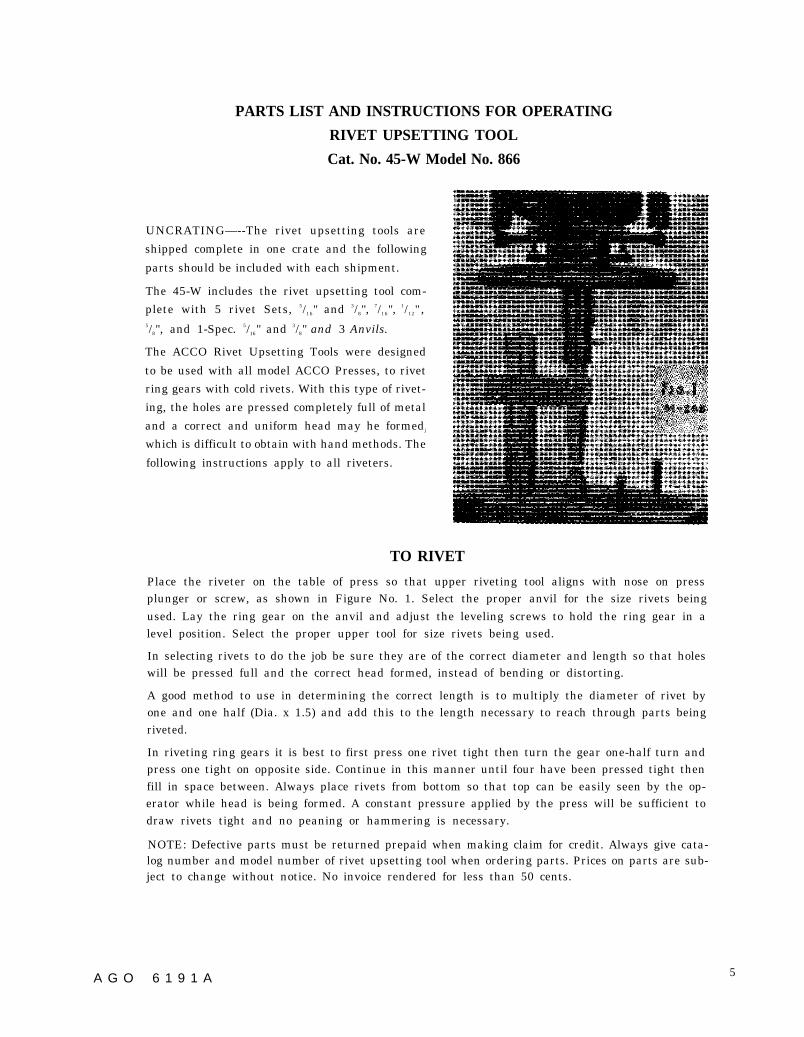
FIG.1
PARTS LIST AND INSTRUCTIONS FOR OPERATING
RIVET UPSETTING TOOL
Cat. No. 45-W Model No. 866
UNCRATING—--The rivet upsetting tools are
shipped complete in one crate and the following
parts should be included with each shipment.
The 45-W includes the rivet upsetting tool com-
plete with 5 rivet Sets, 5/16" and 3/8", 7/16",
1/12" ,5/8", and 1-Spec. 5/16" and 3/8" and 3 Anvils.
The ACCO Rivet Upsetting Tools were designed
to be used with all model ACCO Presses, to rivet
ring gears with cold rivets. With this type of rivet-
ing, the holes are pressed completely full of metal
and a correct and uniform head may he formedj
which is difficult to obtain with hand methods. The
following instructions apply to all riveters.
TO RIVET
Place the riveter on the table of press so that upper riveting tool aligns with nose on pressplunger or screw, as shown in Figure No. 1. Select the proper anvil for the size rivets beingused. Lay the ring gear on the anvil and adjust the leveling screws to hold the ring gear in alevel position. Select the proper upper tool for size rivets being used.
In selecting rivets to do the job be sure they are of the correct diameter and length so that holeswill be pressed full and the correct head formed, instead of bending or distorting.
A good method to use in determining the correct length is to multiply the diameter of rivet byone and one half (Dia. x 1.5) and add this to the length necessary to reach through parts beingriveted.
In riveting ring gears it is best to first press one rivet tight then turn the gear one-half turn andpress one tight on opposite side. Continue in this manner until four have been pressed tight thenfill in space between. Always place rivets from bottom so that top can be easily seen by the op-erator while head is being formed. A constant pressure applied by the press will be sufficient todraw rivets tight and no peaning or hammering is necessary.
NOTE: Defective parts must be returned prepaid when making claim for credit. Always give cata-log number and model number of rivet upsetting tool when ordering parts. Prices on parts are sub-ject to change without notice. No invoice rendered for less than 50 cents.
A G O 6 1 9 1 A 5
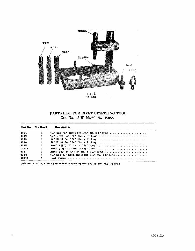
FIG.2
6 AGO 6191A
APPENDIX IBASIC ISSUE ITEMS LIST
Section I.
1. GeneralThis appendix is a list of basic issue items.
It is composed of those items which make upthe major end item of equipment and the opera-tor’s tools and equipment that are issued withthe equipment and are required for stockage.
2. Requisition NotesWhen requisitioning a C source (local pro-
curement) item identified only by a manufac-turer’s part number, it is mandatory that thefollowing information be furnished the supplyof f icer :
a. Manufacturer’s code number (5 digit num-ber preceding the colon in the descriptive col-umn).
b. Manufacturer’s part number (the number,and sometimes letters, following the colon, (1)above). Dashes, commas, or other marks mustbe included exactly as listed.
c. Nomenclature exactly as listed herein, in-cluding dimensions if necessary.
d. Name of manufacturer of end item (fromcover of TM or manufacturer’s name plate).
e. Federal stock number of end item (fromTM).
f. Manufacturer’s model number (from TMor name/data plate, preferably name/dataplate).
g. Manufacturer’s serial number (fromname/data plate).
h. Any other information such as type, framenumber, and electrical characteristic, if ap-plicable.
i. If DD Form 1848 is used, fill in all blocksexcept 4, 6, 6, and Remarks field, in accordancewith AR 725-50. Complete form as follows:
(1) In blocks 4, 6, and 6, list manufac-turer’s code and manufacturer’s part
AGO 6191A
PREFACEnumber (as listed in description col-umn) .
(2) In Remarks field, list noun name (re-pair part), end item application (FSNof end item), manufacturer, modelnumber (end item), serial number(end item), and any other pertinentinformation such as frame number,type, etc.
3. Explanation of Columnsa. Source, Maintenance, and Recoverbility
Code (Col. 1).(1) Material numerical code (col. 1a).
This column indicates the responsiblecommodity command for the materiel.The commodity command responsiblefor supply of items in this list is:
Code Type material9 Ordnance materiel
(2) Source (col. lb). This column indi-cates the selection status and sourcefor the listed item. Source code usedin this list is:
Codec Obtain through local procurement.
If not obtainable from local pro-Curement, requistion through nor-mal supply channels with a supporting statement of nonavail-ability from local procurement.
(3) Maintenance level (col. 1c). This col-umn indicates the category of main-tenance authorized to install the listeditem. Maintenance level code used inthis list is:
Code ExplanationO/C Operator or crew maintenance.
7
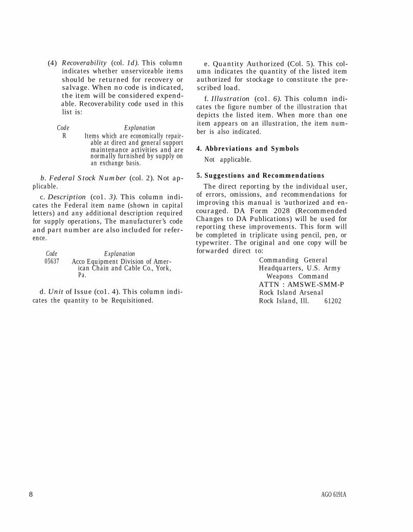
(4) Recoverability (col. 1d). This columnindicates whether unserviceable itemsshould be returned for recovery orsalvage. When no code is indicated,the item will be considered expend-able. Recoverability code used in thislist is:
Code ExplanationR Items which are economically repair-
able at direct and general supportmaintenance activities and arenormally furnished by supply onan exchange basis.
b. Federal Stock Number (col. 2). Not ap-plicable.
c. Description (co1. 3). This column indi-cates the Federal item name (shown in capitalletters) and any additional description requiredfor supply operations, The manufacturer’s codeand part number are also included for refer-ence.
Code Explanation05637 Acco Equipment Division of Amer-
ican Chain and Cable Co., York,Pa.
d. Unit of Issue (co1. 4). This column indi-cates the quantity to be Requisitioned.
e. Quantity Authorized (Col. 5). This col-umn indicates the quantity of the listed itemauthorized for stockage to constitute the pre-scribed load.
f. Illustration (co1. 6). This column indi-cates the figure number of the illustration thatdepicts the listed item. When more than oneitem appears on an illustration, the item num-ber is also indicated.
4. Abbreviations and SymbolsNot applicable.
5. Suggestions and RecommendationsThe direct reporting by the individual user,
of errors, omissions, and recommendations forimproving this manual is ‘authorized and en-couraged. DA Form 2028 (RecommendedChanges to DA Publications) will be used forreporting these improvements. This form willbe completed in triplicate using pencil, pen, ortypewriter. The original and one copy will beforwarded direct to:
Commanding GeneralHeadquarters, U.S. Army
Weapons CommandATTN : AMSWE-SMM-PRock Island ArsenalRock Island, Ill. 61202
8 AGO 6191A
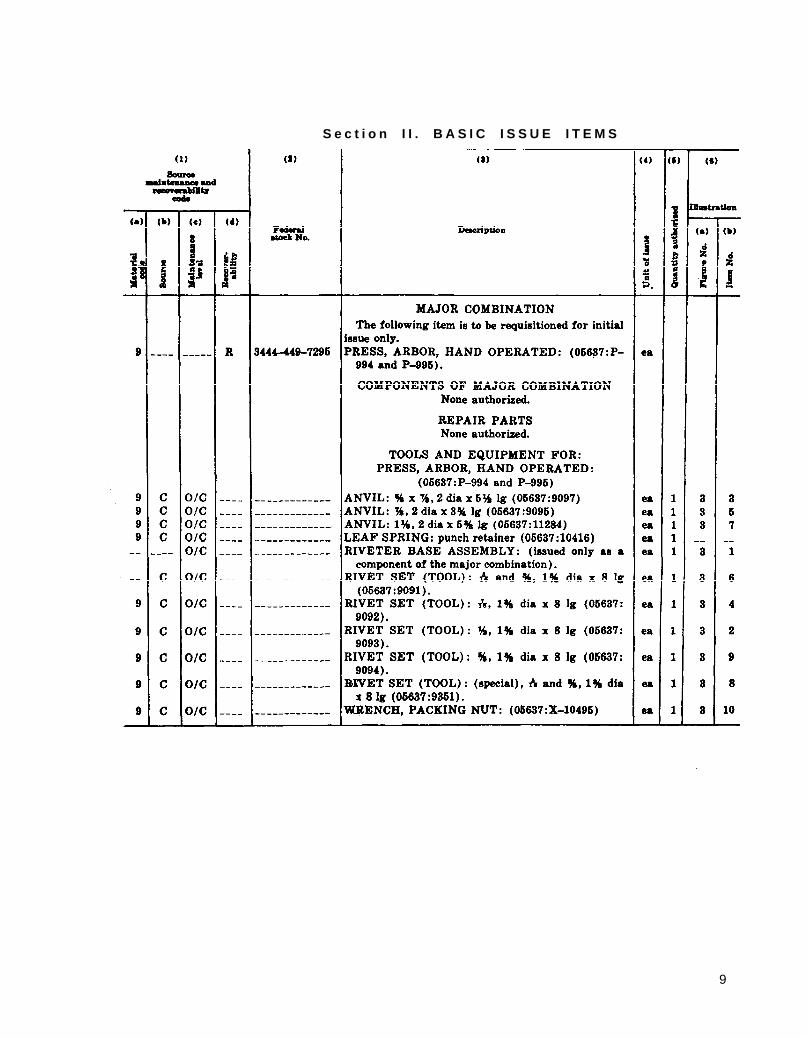
S e c t i o n I I . B A S I C I S S U E I T E M S
9
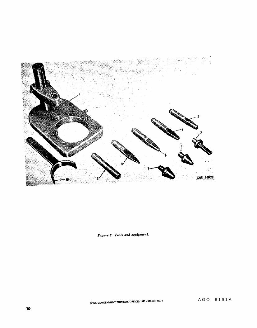
Figure 3.
10
A G O 6 1 9 1 A


PIN : 018496-000

This fine document...
Was brought to you by me:
Liberated Manuals -- free army and government manuals
Why do I do it? I am tired of sleazy CD-ROM sellers, who take publicly available information, slap “watermarks” and other junk on it, and sell it. Those masters of search engine manipulation make sure that their sites that sell free information, come up first in search engines. They did not create it... They did not even scan it... Why should they get your money? Why are not letting you give those free manuals to your friends?
I am setting this document FREE. This document was made by the US Government and is NOT protected by Copyright. Feel free to share, republish, sell and so on.
I am not asking you for donations, fees or handouts. If you can, please provide a link to liberatedmanuals.com, so that free manuals come up first in search engines:
<A HREF=http://www.liberatedmanuals.com/>Free Military and Government Manuals</A>
– SincerelyIgor Chudovhttp://igor.chudov.com/
– Chicago Machinery Movers