Embed Size (px)
Citation preview

TM 9-2320-360-20-1
VOLUME NO. 1
TECHNICAL MANUALUNIT MAINTENANCE
TRUCK, TRACTOR, M1070, 8 X 8,
HEAVY EQUIPMENT TRANSPORTER (HET)
NSN 2320-01-318-9902
EIC:B5C
HOW TO USE THIS MANUAL iv
GENERAL INFORMATION 1-1
EQUIPMENT DESCRIPTIONAND DATA 1-3
PRINCIPLES OFOPERATION 1-4
SERVICE UPON RECEIPT 2-2
PREVENTIVE MAINTENANCECHECKS AND SERVICES 2-5
TROUBLESHOOTING 2-63
MAINTENANCEPROCEDURES 2-984
PREPARATION FOR STORAGEOR SHIPMENT 2-989
SUBJECT INDEX INDEX-1
Approved for public release; distribution is unlimited.
HEADQUARTERS, DEPARTMENT OF THE ARMY
MARCH 1994

TM 9-2320-360-20-1
Technical Manual HEADQUARTERSTM 9-2320-360-20-1 DEPARTMENT OF THE ARMY
WASHINGTON D.C., 31 March 1994
UNIT MAINTENANCE
TRUCK, TRACTOR, M1070, 8 X 8,HEAVY EQUIPMENT TRANSPORTER (HET)
(NSN 2320-01-318-9902)EIC:B5C
REPORTING ERRORS AND RECOMMENDING IMPROVEMENTS
You can help improve this manual. If you find any mistakes or if you know of a way toimprove the procedures, please let us know. Mail your letter, DA Form 2028(Recommended Changes to Publications and Blank Forms), or DA Form 2028-2 located inthe back of this manual direct to: Commander, U.S. Army Tank-Automotive andArmaments Command, ATTN: AMSTA-IM-OPIT, Warren, Ml 48397-5000. A reply will befurnished to you.
TABLE OF CONTENTS
Page
HOW TO USE THIS MANUAL....................................................................................... ivCHAPTER 1
INTRODUCTION
Section I General Information ................................................................................................. 1-1Section II Equipment Description and Data ............................................................................... 1-3Section III Principles of Operation ............................................................................................ 1-4
CHAPTER 2 VEHICLE MAINTENANCE
Section I Repair Parts; Special Tools; Test, Measurement, and DiagnosticEquipment (TMDE); and Support Equipment ........................................................ 2-1
Section II Service Upon Receipt .............................................................................................. 2-2Section III Preventive Maintenance Checks and Services (PMCS).............................................. 2-5Section IV Troubleshootinq ....................................................................................................... 2-63Section V Maintenance Procedures .......................................................................................... 2-984Section Vl Preparation for Storage or Shipment ......................................................................... 2-989
SUBJECT INDEX ............................................................................................................................................ Index-1
Change 3 i

TM 9-2320-360-20-1
TABLE OF CONTENTS (CONT)
PageCHAPTER 3 ENGINE MAINTENANCE
Section I Introduction .................................................................................................................. 3-1Section II Maintenance Procedures ............................................................................................... 3-1
CHAPTER 4 FUEL SYSTEM MAINTENANCE
Section I Introduction .................................................................................................................. 4-1Section II Maintenance Procedures ............................................................................................... 4-1
CHAPTER 5 EXHAUST SYSTEM MAINTENANCE
Section I Introduction .................................................................................................................. 5-1Section II Maintenance Procedures ............................................................................................... 5-1
CHAPTER 6 COOLING SYSTEM MAINTENANCE
Section I Introduction .................................................................................................................. 6-1Section II Maintenance Procedures ............................................................................................... 6-1
CHAPTER 7 ELECTRICAL SYSTEM MAINTENANCE
Section I Introduction .................................................................................................................. 7-2Section II Maintenance Procedures ............................................................................................... 7-3
CHAPTER 8 TRANSMISSION MAINTENANCE
Section I Introduction .................................................................................................................. 8-1Section II Maintenance Procedures ............................................................................................... 8-1
CHAPTER 9 TRANSFER CASE MAINTENANCE
Section I Introduction .................................................................................................................. 9-1Section II Maintenance Procedures ............................................................................................... 9-1
CHAPTER 10 PROPELLER SHAFTS MAINTENANCE
Section I Introduction ................................................................................................................ 10-1Section II Maintenance Procedures . .......................................................................................... 10-1
CHAPTER 11 BRAKE SYSTEM MAINTENANCE
Section I Introduction ................................................................................................................ 11-1Section II Maintenance Procedures ............................................................................................. 11-2
CHAPTER 12 WHEEL AND TIRE MAINTENANCE
Section I Introduction ................................................................................................................ 12-1Section II Maintenance Procedures ............................................................................................. 12-1
ii

TM 9-2320-360-20-1
TABLE OF CONTENTS (CONT)
Page
CHAPTER 13 STEERING SYSTEM MAINTENANCE
Section I Introduction ............................................................................................................. 13-1Section II Maintenance Procedures .......................................................................................... 13-1
CHAPTER 14 FRAME MAINTENANCE
Section I Introduction ............................................................................................................. 14-1Section II Maintenance Procedures .......................................................................................... 14-1
CHAPTER 15 SUSPENSION SYSTEM MAINTENANCE
Section I Introduction ............................................................................................................. 15-1Section II Maintenance Procedures .......................................................................................... 15-1
CHAPTER 16 CAB AND BODY MAINTENANCE
Section I Introduction ............................................................................................................. 16-1Section II Maintenance Procedures .......................................................................................... 16-1
CHAPTER 17 WINCHES MAINTENANCE
Section I Introduction ............................................................................................................. 17-1Section II Maintenance Procedures .......................................................................................... 17-1
CHAPTER 18 BODY ACCESSORY ITEMS MAINTENANCE
Section I Introduction ............................................................................................................. 18-1Section II Maintenance Procedures .......................................................................................... 18-1
CHAPTER 19 SPECIAL PURPOSE KITS MAINTENANCE
Section I Introduction ............................................................................................................. 19-1Section II Maintenance Procedures .......................................................................................... 19-1
CHAPTER 20 NON-ELECTRIC GAGES MAINTENANCE
Section I Introduction ............................................................................................................. 20-1Section II Maintenance Procedures .......................................................................................... 20-1
CHAPTER 21 CHEMICAL, BIOLOGICAL, AND RADIOLOGICAL (CBR) EQUIPMENTMAINTENANCE
Section I Introduction ............................................................................................................. 21-1Section II Maintenance Procedures .......................................................................................... 21-1
APPENDIX A REFERENCES ..........................................................................................................A-1
iii

TM 9-2320-360-20-1
TABLE OF CONTENTS (CONT)Page
APPENDIX B MAINTENANCE ALLOCATION CHART
Section I Introduction ...............................................................................................................B-1Section II Maintenance Allocation Chart for the HET Tractor ........................................................B-4Section III Tool and Test Equipment Requirements for the HET Tractor ......................................B-20Section IV Remarks .................................................................................................................B-24
APPENDIX C EXPENDABLE/DURABLE SUPPLIES AND MATERIALS LIST
Section I Introduction ...............................................................................................................C-1Section II Expendable/Durable Supplies and Materials List ..........................................................C-1
APPENDIX D ILLUSTRATED LIST OF MANUFACTURED ITEMS
Section I Introduction ...............................................................................................................D-1Section II Manufactured Items Part Number Index ......................................................................D-1Section III Illustrated List of Manufactured Items ..........................................................................D-8
APPENDIX E TORQUE VALUES .............................................................................................................E-1
APPENDIX F COMMON TOOLS, SUPPLEMENTS, AND SPECIALTOOLS/FIXTURES LIST
Section I Introduction ...............................................................................................................F-1Section II Common Tools, Supplements, and Special
Tools/Fixtures List ......................................................................................................F-2
APPENDIX G MANDATORY REPLACEMENT PARTS LIST
Section I Introduction .............................................................................................................. G-1Section II Mandatory Replacement Parts List ............................................................................ G-1
APPENDIX H DDEC III DIAGNOSTIC TROUBLESHOOTING GUIDE .........................................................H-1
SUBJECT INDEX ................................................................................................................... Index-1
HOW TO USE THIS MANUAL
OVERVIEW
This technical manual (TM) is provided to help you maintain the HET Tractor at the unit maintenance level. Because of itssize, it is divided into two volumes. Volume 1 contains the following major sections in order of appearance:
• WARNING SUMMARY. Provides a summary of the most important warnings that apply throughout the manual.
• TABLE OF CONTENTS. Lists, for both volumes, the chapters, sections, appendixes, and indexes with pagenumbers in order of appearance.
• CHAPTER 1, INTRODUCTION. Describes the HET Tractor and provides equipment data.
iv Change 3

TM 9-2320-360-20-1
•• CHAPTER 2, VEHICLE MAINTENANCE. This chapter contains information for finding tools; special tools; test,measurement, and diagnostic equipment (TMDE); and repair parts. It also contains the preventive maintenancechecks and services (PMCS) and troubleshooting tables.
•• SUBJECT INDEX. Lists important subjects contained in volume 1 in alphabetical order and gives the pagenumbers on which they are located.
Volume 2 contains the following major sections in order of appearance:
• WARNING SUMMARY. Provides a summary of the most important warnings that apply throughout the manual.
• TABLE OF CONTENTS. Lists, for volume 2, the chapters, sections, appendixes, and index with page numbers inorder of appearance.
The maintenance chapters in volume 2 each concern a specific system or group of components.
• CHAPTER 3, ENGINE MAINTENANCE
•• CHAPTER 4, FUEL SYSTEM MAINTENANCE
•• CHAPTER 5, EXHAUST SYSTEM MAINTENANCE
•• CHAPTER 6, COOLING SYSTEM MAINTENANCE
•• CHAPTER 7, ELECTRICAL SYSTEM MAINTENANCE
•• CHAPTER 8, TRANSMISSION MAINTENANCE
•• CHAPTER 9, TRANSFER CASE MAINTENANCE
•• CHAPTER 10, PROPELLER SHAFTS MAINTENANCE
•• CHAPTER 11, BRAKE SYSTEM MAINTENANCE
•• CHAPTER 12, WHEEL AND TIRE MAINTENANCE
•• CHAPTER 13, STEERING SYSTEM MAINTENANCE
•• CHAPTER 14, FRAME MAINTENANCE
•• CHAPTER 15, SUSPENSION SYSTEM MAINTENANCE
•• CHAPTER 16, CAB AND BODY MAINTENANCE
•• CHAPTER 17, WINCHES MAINTENANCE
•• CHAPTER 18, BODY ACCESSORY ITEMS MAINTENANCE
•• CHAPTER 19, SPECIAL PURPOSE KITS MAINTENANCE
•• CHAPTER 20, NON-ELECTRIC GAGES MAINTENANCE
•• CHAPTER 21, CHEMICAL, BIOLOGICAL, AND RADIOLOGICAL (CBR) EQUIPMENT MAINTENANCE
The last part of volume 2 contains information which will assist you in the performance of unit maintenance on the HETTractor.
• APPENDIX A, REFERENCES . Lists publications used with the HET Tractor.
• APPENDIX B, MAINTENANCE ALLOCATION CHART. The maintenance allocation chart denotes the level ofmaintenance which performs specific maintenance tasks and the time required. It also lists tools and special toolsrequired for each task.
v

TM 9-2320-360-20-1
OVERVIEW (CONT )
• APPENDIX C, EXPENDABLE/DURABLE SUPPLIES AND MATERIALS LIST. Lists expendable and durableitems used in the performance of maintenance.
• APPENDIX D, ILLUSTRATED LIST OF MANUFACTURED ITEMS. Illustrates and describes items that must befabricated from bulk materials for repair of the HET Tractor.
• APPENDIX E, TORQUE VALUES . Lists the standard torques values for specific attaching hardware.
• APPENDIX F, COMMON TOOLS, SUPPLEMENTS, AND SPECIAL TOOLS/FIXTURES LIST. This appendixlists equipment used in the performance of maintenance and references publications which contain informationregarding the equipment.
• APPENDIX G, MANDATORY REPLACEMENT PARTS LIST. This appendix lists the mandatory replacementparts needed to maintain the HET Tractor.
• APPENDIX H, DDEC Ill DIAGNOSTIC TROUBLESHOOTING GUIDE. This appendix contains thetroubleshooting for the DDEC III vehicle.
• SUBJECT INDEX. Lists Important subjects contained in Volume 2 and 3 in alphabetical order and gives the pagenumbers on which they are located.
FINDING INFORMATION I
There are several ways to find the information you need in this manual. They are as follows:
• FRONT COVER INDEX . The front cover index contains a list of the most important topics contained in eachvolume. It features a black box at the right edge of the cover which corresponds with a black box on the pagecontaining the topic. The topics listed on the front cover are highlighted in the table of contents with a box.
• TABLE OF CONTENTS. Lists chapters, sections, appendixes, and indexes with page numbers in order ofappearance.
• CHAPTER INDEXES. List paragraphs contained in the individual chapters with paragraph and page numbers inorder of appearance.
• SYMPTOM INDEX. Lists malfunctions contained in the troubleshooting table with page numbers in order ofappearance.
• SUBJECT INDEX. Lists all important topics with page numbers in alphabetical order.
TROUBLESHOOTING
There are two types of troubleshooting tables contained in this manual, DDEC and vehicle. Always consult the vehicletroubleshooting first when an engine malfunction occurs. Refer to the DDEC troubleshooting logic table in chapter 2 toassist you in fault Isolation for DDEC II vehicles and to Appendix H to assist in fault isolation for DDEC III vehicles. Whena non-engine malfunction occurs, look at the symptom index for the vehicle troubleshooting table (also in chapter 2). Findthe malfunction in the index. Turn to the page number listed for the malfunction in the troubleshooting table. Perform thesteps required to correct the malfunction. If you can't find the malfunction, or the malfunction is not cor rected, notify yoursupervisor. When troubleshooting electrical circuits refer to the electrical schematics for connectors, routing, wirenumbers, etc.
vi Change 3

TM 9-2320-360-20-1
MAINTENANCE
• SCHEDULED MAINTENANCE. Your scheduled maintenance is located in table 2-1, PMCS. These checks andservices are mandatory at the intervals listed. Always follow the WARNINGS and CAUTIONS.
• UNSCHEDULED MAINTENANCE. Unscheduled maintenance is located in chapters 3 thru 21. The PMCS andtroubleshooting tables often reference you to these procedures. When you perform maintenance, look over theentire procedure before starting. Make sure you have the necessary tools and materials at hand. Always followthe WARNINGS and CAUTIONS.
Change 3 vii

TM 9-2320-360-20-1
Right Rear View
TRUCK, TRACTOR, M1070, 8 X 8,HEAVY EQUIPMENT TRANSPORTER (HET)
1-0 Change 2

TM 9-2320-360-20-1
CHAPTER 1INTRODUCTION
Contents Para Page
Scope ...........................................................................................................................................1-1 1-1Maintenance Forms, Records, and Reports .....................................................................................1-2 1-1Destruction of Army Materiel to Prevent Enemy Use .........................................................................1-3 1-1Preparation for Storage or Shipment ...............................................................................................1-4 1-2Nomenclature Cross-Reference ......................................................................................................1-5 1-2Reporting Equipment Improvement Recommendations (EIR) ............................................................1-6 1-2Equipment Improvement Report and Maintenance Digest (EIR MD) and EquipmentImprovement Report and Maintenance Summary (EIR MS) ..............................................................1-7 1-2Warranty Information ......................................................................................................................1-8 1-2Metric System ................................................................................................................................1-9 1-3Equipment Characteristics, Capabilities, and Features ....................................................................1-10 1-3Location and Description of Components ......................................................................................1-11 1-3Equipment Data ...........................................................................................................................1-12 1-3Safety, Care, and Handling ...........................................................................................................1-13 1-3Power Train .................................................................................................................................1-14 1-4Electrical Systems .......................................................................................................................1-15 1-5Steering System ...........................................................................................................................1-16 1-7Air System ...................................................................................................................................1-17 1-8Winch System ..............................................................................................................................1-18 1-10Central Tire Inflation System (CTIS) ..............................................................................................1-19 1-11
Section I. GENERAL INFORMATION
1-1. SCOPE
a. Type of Manual. Unit Maintenance Instructions, TM 9-2320-360-20.
b. Model Number and Equipment Name. Truck, Tractor, M1070, 8 x 8, Heavy Equipment Transporter (HET).
c. Purpose of Equipment. The HET Tractor and the M1000 Trailer form the Heavy Equipment TransportSystem (HETS). HETS will be used to load, unload, and transport the M1 Series Main Battle Tank (MBT) duringadministrative and tactical operations.
1-2. MAINTENANCE FORMS, RECORDS, AND REPORTS
Department of the Army forms and procedures used for equipment maintenance will be those prescribed by DA Pam 738-750, The Army Maintenance Management System (TAMMS).
1-3. DESTRUCTION OF ARMY MATERIEL TO PREVENT ENEMY USE
Command decision, according to tactical situation, will determine when the destruction of the HET Tractor will beaccomplished. A destruction plan will be prepared by the using organization unless one has been prepared by a higherauthority. For general destruction procedures for this equipment, refer to TM 750-244-6, Procedures for Destruction ofTank-Automotive Equipment to Prevent Enemy Use (U.S. Army Tank-Automotive Command).
1-1

TM 9-2320-360-20-1
1-4. PREPARATION FOR STORAGE OR SHIPMENT
Instructions for preparation for storage or shipment are provided in paragraph 2-22 of this manual.
1-5. NOMENCLATURE CROSS-REFERENCE
Table 1-1 lists the nomenclature cross-references used in this manual.
Table 1-1. Nomenclature Cross-Reference
Common Name Official Nomenclature
DDR CTS J1708 ApplicationSTE/ICE-R CTS/ICECable Wire ropeCold Start System Ether quick-start systemEngine Coolant Antifreeze, ethylene glycol mixtureGladhand Quick-disconnect couplingHET Tractor Truck, Tractor, M1070, 8 x 8, Heavy
Equipment Transporter (HET)Jacobs Brakes Engine retarder
1-6. REPORTING EQUIPMENT IMPROVEMENT RECOMMENDATIONS (EIR)
If your HET Tractor needs improvement, let us know. Send us an EIR. You, the user, are the only one who can tell uswhat you don't like about your equipment. Let us know why you don't like the design. Put it on an SF 368 (QualityDeficiency Report). Mail it to us at: Commander, U.S. Army Tank-Automotive and Armaments Command, ATTN:AMSTA-QRT, Warren, Ml 48397-5000. We'll send you a reply.
1-7. EQUIPMENT IMPROVEMENT REPORT AND MAINTENANCE DIGEST (EIR MD) AND EQUIPMENT IMPROVEMENT REPORT AND MAINTENANCE SUMMARY (EIR MS)
The quarterly EIR MD, TB 43-001-39 series, contains valuable field information on the equipment covered in this manual.It is compiled from some of the Quality Deficiency Reports that have been prepared on the vehicles covered in thismanual. Many of these articles result from comments, suggestions, and improvement recommendations that weresubmitted to the EIR program. It also contains information on equipment improvements, minor alterations, proposedModification Work Orders (MWOs), warranties, actions taken on some of the DA Form 2028's (Recommended Changesto Publications), and advance information on proposed changes that may affect this manual. In addition, the moremaintenance significant articles (including minor alterations, field-fixes, etc.) that have a continuing need in the field arerepublished in the EIR MS for TACOM equipment (TM 43-1043). Refer to both of these publications periodically,especially the TB 43-001-39 series, for the most current and authoritative information on the equipment. The informationwill help you to do a better job and will advise of the latest changes to this manual. Also refer to DA Pam 25-30 andAppendix A, References, of this manual.
1-8. WARRANTY INFORMATION
The HET Tractor is warranted by Oshkosh Truck Corporation for 12 months; 4 months additional if placed in storage.(Refer to TB 9-2320-360-14, page 3, paragraph i for details.) Warranty starts on the date found in block 21, DD Form 250,in the logbook. Report all defects in material or workmanship to the supervisor, who will take the appropriate action. Forcomplete information covering warranties, refer to Warranty Technical Bulletin for Truck, Tractor, M1070, 8 x 8, HeavyEquipment Transporter (HET) TB 9-2320-360-14.
1-2 Change 3

TM 9-2320-360-20-1
1-9. METRIC SYSTEM
The equipment described herein contains metric components and requires metric common and special tools, therefore,Metric units in addition to English units will be used throughout this manual. An English-to-metric conversion table isincluded inside the back cover of this manual.
Section II. EQUIPMENT DESCRIPTION AND DATA
1-10. EQUIPMENT CHARACTERISTICS, CAPABILITIES, AND FEATURES
Refer to TM 9-2320-360-10, for equipment characteristics, capabilities, and features.
1-11. LOCATION AND DESCRIPTION OF COMPONENTS
Refer to TM 9-2320-360-10, for location and description of components.
1-12. EQUIPMENT DATA
Refer to TM 9-2320-360-10, for equipment data.
1-13. SAFETY, CARE, AND HANDLING
Significant Hazards and Safety Recommendations. Significant hazards and safety recommendations are listed intable 1-2.
Table 1-2. Significant Hazards and Safety Recommendations
Operating Hazard Safety Recommendation or Precaution Condition*
Low oil pressure/ Stop engine operation when CHECK GAUGES Abnormalhigh coolant temperature and CHECK ENGINE indicators are lit, engine
warning alarm sounds, and gages indicateabnormal readings.
Low air pressure Do not drive HET Tractor while low air Abnormalpressure alarm is sounding or LOW AIRindicator is lit.
Electric shock Do not wear watches, rings, or other Abnormaljewelry while working on or near anelectrical circuit.
Refueling vehicle Fuel is very flammable and can explode easily NormalTo avoid serious injury or death, keep fuel awayfrom open flame and keep fire extinguisher withineasy reach when working with fuel. Do not workon fuel system when engine is hot. Fuel can beignited by hot engine. When working with fuel,post sign that says: NO SMOKING WITHIN 50FEET OF VEHICLE.
*Category of hazards as to whether or not they may be expected under normal or abnormal operating conditions.
1-3

TM 9-2320-360-20-1
1-13. SAFETY, CARE, AND HANDLING (CONT)
Table 1-2. Significant Hazards and Safety Recommendations (Cont)
Operating Hazard Safety Recommendation or Precaution Condition*
Connecting/Disconnecting Make sure that position of assistant is known at all Normal'trailer. times. Make sure no one is standing directly
behind tractor or trailer during connection/disconnection.
Vehicle instability on a Avoid driving diagonally across a hill. HET Tractor Normalhill. may roll, causing equipment damage and injury or
death to personnel.
Winching operations. Do not use winches for lifting personnel. Always Normalwear heavy gloves when handling winch cable.Never let cable run through hands. Frayed cablecan cut severely. Do not operate winch withoutguard in place. Do not place hands or feet nearwinch during operation. Ensure that both DRIVERSIDE and PASSENGER SIDE WINCH KICKOUTcontrols are disengaged prior to paying out winchcables. Failure to disengage KICKOUT controls -may result in injury to personnel.
*Category of hazards as to whether or not they may be expected under normal or abnormal operating conditions.
Section III. PRINCIPLES OF OPERATION
1-14. POWER TRAIN
Power for the HET Tractor is generated by a two-stroke, V-type diesel engine coupled directly to an automatictransmission. The engine is rated at 500 brake horsepower.
The engine is equipped with an electronic control system that regulates fuel delivery to each injector as well as governingengine speed for power takeoff operation. Engine sensors and engine performance can be checked using a plug-indiagnostic reader.
Power from the engine drive shaft transmits torque that is multiplied for greater drive power by a torque converter whenneeded.
Five forward drive ranges can be manually selected, depending on the terrain and conditions. The transmission willautomatically downshift as engine speed and throttle position change.
When the lockup clutch is automatically applied, power is transmitted mechanically through the lockup clutch. A directdrive is engaged from the engine to a converter turbine shaft.
Power from the transmission is directed to the transfer case and propeller shafts forward and rear. The front and reartridem axles are each equipped with planetary wheel ends. In low range, driver-controlled lockouts in the differentialsprovide positive drive to all four axles.
1-4

TM 9-2320-360-20-1
1-15. ELECTRICAL SYSTEM
The HET Tractor electrical system consists of two different circuits, 12 Vdc and 24 Vdc. Four 12-volt storage batteries (1)connected in series parallel provide current to both circuits.
Change 2 1-5

TM 9-2320-360-20-1
1-15. ELECTRICAL SYSTEM (CONT)
Two belt-driven alternators provide current to the electrical system during normal operation, and recharge the batterieswhile the engine is operating. The 24 Vdc system utilizes an alternator (2) with 130 amp capacity. The 12 Vdc systemutilizes an alternator (3) with 145 amp capacity.
The headlights (4), trailer lights, windshield wipers (5) and washer motors, instrument panel/dash lighting and switches(6), and warning lights and gages inside the cab are operated with the 12 Vdc system.
1-6 Change 2

TM 9-2320-360-20-1
The starter motor (7), winches (8), Central Tire Inflation System (CTIS), air dryers (9), trailer lights, and ether injectionsystem (10) are operated with the 24 Vdc system.
The starter motor solenoid receives 24 Vdc from the storage batteries through the engine starter magnetic switch aux-iliary contacts and the neutral start relay. If the transmission range selector is not in the N (neutral) position prior tostartup, the engine cannot be started.
Warning lights and gages that indicate system malfunctions include: CHECK GAUGES alarm, CHECK ENGINE indicator,and CHECK GAUGES indicator.
Change 2 1-6.1 (1-6.2 blank)

TM 9-2320-360-20-1
1-16. STEERING SYSTEM
The steering system uses two steering axles, one at the front (No. 1) (1) and one at the rear (No. 4) (2). Each axle turnsin response to turning the steering wheel (3) in the cab.
Steering power is generated by a steering pump (4) driven directly at the engine providing pressure to two steering gears(5), one at each steering axle. The steering pump delivers fluid to enable the operator to turn the wheels of a fully-loadedtruck. An interconnected series of shaft linkages rotate with hydraulic power assist to turn the two axles. In the event ofmain steering system failure, an auxiliary steering pump (5.1) connected to the transfer case provides power steering.
As the steering wheel is turned, the rotational motion of the upper steering assembly shafts (6) is translated at a tee gearbox (7) below the cab to both the front and rear power steering gears (8). A steering reduction gear (8.1) reduces thesteering angle on axle no. 4. The steering gears multiply the rotational force to a pair of drag links (9) and four axlesteering arms that apply directional motion to turn the axles.
In the event a steering line (10) to no. 4 steering axle is severed or fluid leaks from the system (Power steering isinoperable.), the truck can be steered for short distances in emergency situations.
Change 1 1-7

TM 9-2320-360-20-1
1-17. AIR SYSTEM
The air system operates the service and parking brakes, rear suspension system, and the CTIS. The air system alsoenables operation of the transfer case and interaxle lockups, winch tensioners and kickouts, windshield washer, andhorns.
The air system on the HET Tractor consists of an engine-driven air compressor (1), a purge tank (2), and five airreservoirs (3 thru 7). Reservoir (3) supplies air to reservoirs (4 thru 7). Three reservoirs (5 thru 7) are interconnected andseparated from reservoir (4) with check valves. Air from reservoir (4) is supplied to service brakes on all four axles andparking brakes on the rear tridem axles, transfer case and interaxle lockups, winch tensioners and kickouts, windshieldwasher, and horns. The service brakes are actuated by relay valves which are controlled by the operator pressing thebrake treadle in the cab. The parking brakes are also actuated by relay valves which are controlled by hand controls. Inthe event of the loss of system air pressure, the spring brake valve will modulate the parking brakes so the HET Tractorcan be stopped safely. Reservoirs (5 thru 7) supply air to operate the CTIS, service and parking brakes on rear tridemaxles, and rear suspension system. Air is drawn from the engine air intake and routed to the air compressor (1) where itis pressurized. Air dryers (8 and 9) remove moisture from the pressurized air. Air from the dryers goes to the purgereservoir (2) and air reservoir (3).
System protection elements include an air cleaner restriction indicator (10) that determines whether air flow through theair cleaner is impeded. In the cab, air pressure in reservoir (4) is indicated by the green needle on the AIR PRESSUREgage (11). The red needle on the gage (11) indicates air pressure in reservoirs (5 thru 7). If air pressure falls below 60psi (414 kPa) in any of the reservoirs, warning alarm will sound and LOW AIR indicator will light.
The rear suspension system contains a pair of suspension air springs on each rear axle that automatically inflates ordeflates according to load. Air to the air springs is regulated by a height control valve.
Purging the air in the air dryers is automatically done when 125 psi (862 kPa) system pressure is reached at thecompressor. The compressor cycle is stopped and air from purge tank clears accumulated water through a valve on thebottom of the air dryer.
Air to the transfer case enables engagement of four-wheel drive in high or low gear range. An interaxle lockup pilot valvealso prevents the axles from locking up in high ranges.
1-8 Change 1
TM 9-2320-360-20-1
1-9
TM 9-2320-360-20-1
1-18. WINCH SYSTEM
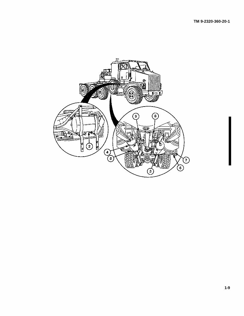
The winch system operates hydraulically and consists of two main winches (1 and 2) and an auxiliary winch (3). The mainwinches operate independently of each other and are used to recover, load, and unload heavy tracked and wheeledvehicles. The main winches are mounted side-by-side directly to the winch platform. The auxiliary winch is used to pullthe main winch cable out to the payload. The auxiliary winch is mounted to the winch platform just below the driver's sidemain winch.
The winches are controlled from the operator's station (4). The operator is protected by a personnel guard (5) duringwinch operations. The main winch controls are the winch kickout control, cable hold down lever, engine idle selectorswitch, engine high idle lock switch, winch speed control switch, and the winch drum control.
Each main winch incorporates a two-speed hydraulic motor (6 and 7). The hydraulic motor is used to provide power. Itconverts hydraulic horsepower from the pump and control circuitry to rotary mechanical horsepower for driving the gearsystem. A single-speed motor (8) is used by the auxiliary winch. A Power Take-Off (PTO) driven hydraulic pump (9)supplies the winch system with hydraulic oil from the reservoir (10). A two-piece driveshaft connects the transmissiondriven PTO to the hydraulic pump (9). A view gage (11) on the reservoir indicates the hydraulic oil level. All wincheshave a fail-safe brake and winch brake valve for winch load control.
1-10