Embed Size (px)
Citation preview
TM 9-2320-356-BD
TECHNICAL MANUAL
OPERATORS ORGANIZATlONALDIRECT SUPPORT AND
GENERAL SUPPORT MAINTENANCE
CHAPTER 1 INTRODUCTION
FOR C H A P T E R 2 A S S E S S I N G B A T T L E F I E L D D A M A G E
TACTICALWHEELEDVEHICLES
APPROVED FORPUBLIC RELEASE;
DISTRIBUTIONIS UNLIMITED.
CHAPTER 3 GENERAL AUTOMOTIVE COMPONENTS
CHAPTER 4 SELF-RECOVERY
C H A P T E R 5 E N G I N E
C H A P T E R 6 F U E L S U P P L Y S Y S T E M S
C H A P T E R 7 C O O L I N G S Y S T E M
C H A P T E R 8 E L E C T R I C A L S Y S T E M
C H A P T E R 9 T R A N S M I S S I O N S Y S T E M S
CHAPTER 10 AXLES AND DRIVE L INES
C H A P T E R 1 1 W H E E L S A N D B R A K E S
CHAPTER 12 STEERING SYSTEM
CHAPTER 13 FRAME AND SUSPENSION
CHAPTER 14 WRECKER AND CRANE ASSY
CHAPTER 15 COMMUNICATION SYSTEM
APPENDIX A REFERENCES
A P P E N D I X B S P E C I A L A N D F A B R I C A T E D T O O L S
A P P E N D I X C A L T E R N A T E S O U R C E S O F S U P P L Y
APPENDIX D POL SUBSTITUTES
HEADQUARTERS, DEPARTMENT OF THE ARMY 18 DECEMBER 1987
CHANGE
NO.1
TM 9-2320-356-BDC1
HEADQUARTERSDEPARTMENT OF THE ARMY
Washington D. C., 14 December, 1989
TECHNICAL MANUAL
OPERATORS, ORGANIZATIONALDIRECT SUPPORT AND
GENERAL SUPPORT MAINTENANCE
BATTLEFIELD DAMAGEASSESSMENT AND REPAIR
FOR
TACTICAL WHEELEDVEHICLES
TM 9-2320-356-BD,18 December 1987, is changed as follows:
1. Remove old pages and insert new pages as indicated below.2. New or changed material is indicated by a vertical bar in the margin of the page.
Remove Pages Insert Pages
None E-1 thru E-5/( E-6 blank)
File this change sheet in front of the publication for reference purposes.
By Order of the Secretary of the Army:
Official:
CARL E. VUONOGeneral, United States Army
Chief of Staff
R.L. DILWORTHBrigadier General, United States Army
The Adjutant General
Distribution:
To be distributed in accordance with DA Form 12-38, Operator, Unit and Direct and General SupportMaintenance requirements for Truck, Utility, l/4-Ton, 4x4, M151 -series and M718-series; and Truck,Utility, 5/4-Ton, 4x4, M966, M996, M997, M998, M1025, M1026, M1035, M1036, M1037, M1038, M1043,M1044, M1045, Ml1046, S250.
TM 9-2320-356-BD
WARNING
This technical manual contains nonstandardmaintenance procedures. All normal safetyprocedures should be observed when the tacticalsituation permits.when maintenance isenvironment.
Extra care shall be takenrequired in a hosti le
WARNING
Before assessing and handling communicationsequipment, turn off the power to all componentsof the communications system. Damaged equipmentcan cause severe shock to personnel andadditional damage to equipment.
a/(b blank)
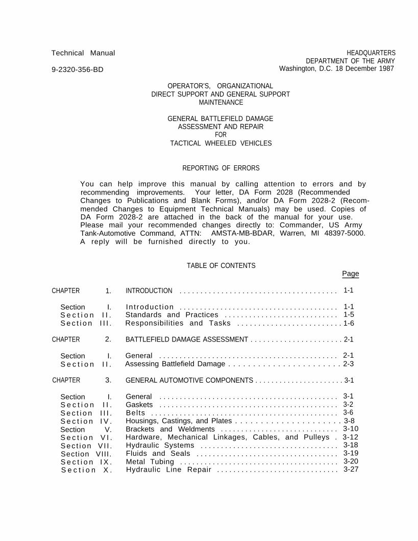
Technical Manual
9-2320-356-BD
HEADQUARTERSDEPARTMENT OF THE ARMY
Washington, D.C. 18 December 1987
OPERATOR’S, ORGANIZATIONALDIRECT SUPPORT AND GENERAL SUPPORT
MAINTENANCE
GENERAL BATTLEFIELD DAMAGEASSESSMENT AND REPAIR
FORTACTICAL WHEELED VEHICLES
REPORTING OF ERRORS
You can help improve this manual by calling attention to errors and byrecommending improvements. Your letter, DA Form 2028 (RecommendedChanges to Publications and Blank Forms), and/or DA Form 2028-2 (Recom-mended Changes to Equipment Technical Manuals) may be used. Copies ofDA Form 2028-2 are attached in the back of the manual for your use.Please mail your recommended changes directly to: Commander, US ArmyTank-Automotive Command, ATTN: AMSTA-MB-BDAR, Warren, MI 48397-5000.A reply will be furnished directly to you.
CHAPTER 1.
Section I.S e c t i o n I I .S e c t i o n I I I .
CHAPTER 2.
Section I.S e c t i o n I I .
CHAPTER 3.
Section I.S e c t i o n I I .S e c t i o n I I I .S e c t i o n I V .Section V.S e c t i o n V I .Sec t i on V I I .Section VIII.S e c t i o n I X .S e c t i o n X .
TABLE OF CONTENTSPage
INTRODUCTION . . . . . . . . . . . . . . . . . . . . . . . . . . . . . . . . . . . . . . 1-1
In t roduct ion . . . . . . . . . . . . . . . . . . . . . . . . . . . . . . . . . . . . . . . 1-1Standards and Practices . . . . . . . . . . . . . . . . . . . . . . . . . . . . 1-5Responsibilities and Tasks . . . . . . . . . . . . . . . . . . . . . . . . . 1-6
BATTLEFIELD DAMAGE ASSESSMENT . . . . . . . . . . . . . . . . . . . . . . 2-1
General . . . . . . . . . . . . . . . . . . . . . . . . . . . . . . . . . . . . . . . . . . . . 2-1Assessing Battlefield Damage . . . . . . . . . . . . . . . . . . . . . . . 2-3
GENERAL AUTOMOTIVE COMPONENTS . . . . . . . . . . . . . . . . . . . . . . 3-1
General . . . . . . . . . . . . . . . . . . . . . . . . . . . . . . . . . . . . . . . . . . . . 3-1Gaskets . . . . . . . . . . . . . . . . . . . . . . . . . . . . . . . . . . . . . . . . . . . . 3-2Belts . . . . . . . . . . . . . . . . . . . . . . . . . . . . . . . . . . . . . . . . . . . . . . 3-6Housings, Castings, and Plates . . . . . . . . . . . . . . . . . . . . . 3-8Brackets and Weldments . . . . . . . . . . . . . . . . . . . . . . . . . . . . . 3-10Hardware, Mechanical Linkages, Cables, and Pulleys . 3-12Hydraulic Systems . . . . . . . . . . . . . . . . . . . . . . . . . . . . . . . . . . 3-18Fluids and Seals . . . . . . . . . . . . . . . . . . . . . . . . . . . . . . . . . . . 3-19Metal Tubing . . . . . . . . . . . . . . . . . . . . . . . . . . . . . . . . . . . . . . . 3-20Hydraulic Line Repair . . . . . . . . . . . . . . . . . . . . . . . . . . . . . . 3-27
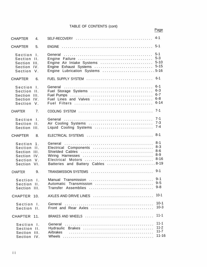
TABLE OF CONTENTS (cont)Page
CHAPTER 4. SELF-RECOVERY . . . . . . . . . . . . . . . . . . . . . . . . . . . . . . . . . . . . . . 4-1
ENGINE . . . . . . . . . . . . . . . . . . . . . . . . . . . . . . . . . . . . . . . . . . . . . 5-1CHAPTER 5.
S e c t i o n I .S e c t i o n I I .Sect ion I I I .Sect ion IV.S e c t i o n V .
General . . . . . . . . . . . . . . . . . . . . . . . . . . . . . . . . . . . . . . . . . . . . 5-1Engine Failure . . . . . . . . . . . . . . . . . . . . . . . . . . . . . . . . . . . . . 5-3Engine Air Intake Systems . . . . . . . . . . . . . . . . . . . . . . . . . . 5-10Engine Exhaust Systems . . . . . . . . . . . . . . . . . . . . . . . . . . . . 5-15Engine Lubrication Systems . . . . . . . . . . . . . . . . . . . . . . . . . 5-16
FUEL SUPPLY SYSTEM . . . . . . . . . . . . . . . . . . . . . . . . . . . . . . . . . 6-1CHAPTER 6.
S e c t i o n I .S e c t i o n I I .Sect ion I I I .Sect ion IV.S e c t i o n V .
General . . . . . . . . . . . . . . . . . . . . . . . . . . . . . . . . . . . . . . . . . . . . 6-1Fuel Storage Systems . . . . . . . . . . . . . . . . . . . . . . . . . . . . . . . 6-3Fuel Pumps . . . . . . . . . . . . . . . . . . . . . . . . . . . . . . . . . . . . . . . . . 6-7Fuel Lines and Valves . . . . . . . . . . . . . . . . . . . . . . . . . . . . . . 6-8Fuel F i l ters . . . . . . . . . . . . . . . . . . . . . . . . . . . . . . . . . . . . . . . 6-14
COOLING SYSTEM . . . . . . . . . . . . . . . . . . . . . . . . . . . . . . . . . . . . . 7-1CHAPTER 7.
General . . . . . . . . . . . . . . . . . . . . . . . . . . . . . . . . . . . . . . . . . . . . 7-1Air Cooling Systems . . . . . . . . . . . . . . . . . . . . . . . . . . . . . . . . 7-3Liquid Cooling Systems . . . . . . . . . . . . . . . . . . . . . . . . . . . . . 7-4
S e c t i o n I .S e c t i o n I I .Sect ion I I I .
ELECTRICAL SYSTEMS . . . . . . . . . . . . . . . . . . . . . . . . . . . . . . . . . 8-1CHAPTER 8.
General . . . . . . . . . . . . . . . . . . . . . . . . . . . . . . . . . . . . . . . . . . . . 8-1Electrical Components . . . . . . . . . . . . . . . . . . . . . . . . . . . . . . 8-3Shielded Cables . . . . . . . . . . . . . . . . . . . . . . . . . . . . . . . . . . . . 8-6Wiring Harnesses . . . . . . . . . . . . . . . . . . . . . . . . . . . . . . . . . . . 8-9Electr ical Motors . . . . . . . . . . . . . . . . . . . . . . . . . . . . . . . . . . 8-16Batteries and Battery Cables . . . . . . . . . . . . . . . . . . . . . . . 8-19
S e c t i o n 1 .S e c t i o n I I .Sect ion I I I .Sect ion IV.S e c t i o n V .Sect ion VI .
TRANSMISSION SYSTEMS . . . . . . . . . . . . . . . . . . . . . . . . . . . . . . . 9-1CHAPTER 9.
Manual Transmission . . . . . . . . . . . . . . . . . . . . . . . . . . . . . . . . 9-1Automatic Transmission . . . . . . . . . . . . . . . . . . . . . . . . . . . . . 9-5Transfer Assemblies . . . . . . . . . . . . . . . . . . . . . . . . . . . . . . . . 9-8
S e c t i o n I .S e c t i o n I I .Sect ion I I I .
CHAPTER 10. AXLES AND DRIVE LINES . . . . . . . . . . . . . . . . . . . . . . . . . . . . . . 10-1
General . . . . . . . . . . . . . . . . . . . . . . . . . . . . . . . . . . . . . . . . . . . . 10-1Front and Rear Axles . . . . . . . . . . . . . . . . . . . . . . . . . . . . . . . 10-3
S e c t i o n I .S e c t i o n I I .
BRAKES AND WHEELS . . . . . . . . . . . . . . . . . . . . . . . . . . . . . . . . . . 11-1CHAPTER 11.
General . . . . . . . . . . . . . . . . . . . . . . . . . . . . . . . . . . . . . . . . . . . . 11-1Hydraulic Brakes . . . . . . . . . . . . . . . . . . . . . . . . . . . . . . . . . . . 11-2Airbrakes . . . . . . . . . . . . . . . . . . . . . . . . . . . . . . . . . . . . . . . . . . 11-7Wheels . . . . . . . . . . . . . . . . . . . . . . . . . . . . . . . . . . . . . . . . . . . . . 11-16
S e c t i o n I .S e c t i o n I I .Sect ion I I I .Sect ion IV.
i i
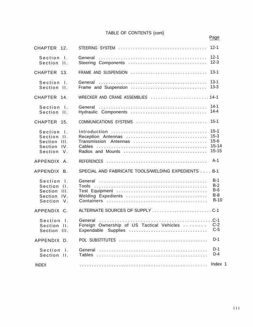
TABLE OF CONTENTS (cont)Page
CHAPTER 12. STEERING SYSTEM . . . . . . . . . . . . . . . . . . . . . . . . . . . . . . . . . . . . 12-1
S e c t i o n I .S e c t i o n I I .
General . . . . . . . . . . . . . . . . . . . . . . . . . . . . . . . . . . . . . . . . . . . . 12-1Steering Components . . . . . . . . . . . . . . . . . . . . . . . . . . . . . . . . 12-3
CHAPTER 13. FRAME AND SUSPENSION . . . . . . . . . . . . . . . . . . . . . . . . . . . . . . . 13-1
S e c t i o n I .S e c t i o n I I .
General . . . . . . . . . . . . . . . . . . . . . . . . . . . . . . . . . . . . . . . . . . . . 13-1Frame and Suspension . . . . . . . . . . . . . . . . . . . . . . . . . . . . . . . 13-3
CHAPTER 14. WRECKER AND CRANE ASSEMBLIES . . . . . . . . . . . . . . . . . . . . . . . 14-1
S e c t i o n I .S e c t i o n I I .
General . . . . . . . . . . . . . . . . . . . . . . . . . . . . . . . . . . . . . . . . . . . . 14-1Hydraulic Components . . . . . . . . . . . . . . . . . . . . . . . . . . . . . . . 14-4
CHAPTER 15. COMMUNICATIONS SYSTEMS . . . . . . . . . . . . . . . . . . . . . . . . . . . . . 15-1
S e c t i o n I .S e c t i o n I I .Sect ion I I I .Sect ion IV.S e c t i o n V .
In t roduct ion . . . . . . . . . . . . . . . . . . . . . . . . . . . . . . . . . . . . . . . 15-1Reception Antennas . . . . . . . . . . . . . . . . . . . . . . . . . . . . . . . . . 15-3Transmission Antennas . . . . . . . . . . . . . . . . . . . . . . . . . . . . . . 15-6Cables . . . . . . . . . . . . . . . . . . . . . . . . . . . . . . . . . . . . . . . . . . . . . 15-14Radios and Mounts . . . . . . . . . . . . . . . . . . . . . . . . . . . . . . . . . . 15-15
APPENDIX A. REFERENCES . . . . . . . . . . . . . . . . . . . . . . . . . . . . . . . . . . . . . . . . . A-1
SPECIAL AND FABRICATE TOOLS/WELDING EXPEDIENTS . . . . B-1APPENDIX B.
S e c t i o n I .S e c t i o n I I .Sect ion I I I .Sect ion IV.S e c t i o n V .
General . . . . . . . . . . . . . . . . . . . . . . . . . . . . . . . . . . . . . . . . . . . . B-1Tools . . . . . . . . . . . . . . . . . . . . . . . . . . . . . . . . . . . . . . . . . . . . . . B-2Test Equipment . . . . . . . . . . . . . . . . . . . . . . . . . . . . . . . . . . . . . B-6Welding Expedients . . . . . . . . . . . . . . . . . . . . . . . . . . . . . . . . . B-8Containers . . . . . . . . . . . . . . . . . . . . . . . . . . . . . . . . . . . . . . . . . B-10
APPENDIX C. ALTERNATE SOURCES OF SUPPLY . . . . . . . . . . . . . . . . . . . . . . . . C-1
General . . . . . . . . . . . . . . . . . . . . . . . . . . . . . . . . . . . . . . . . . . . .C-1Foreign Ownership of US Tactical Vehicles . . . . . . . . C-2 Expendable Supplies . . . . . . . . . . . . . . . . . . . . . . . . . . . . . . . . C-5
S e c t i o n I .S e c t i o n I I .Sect ion I I I .
APPENDIX D. POL SUBSTITUTES . . . . . . . . . . . . . . . . . . . . . . . . . . . . . . . . . . . . D-1
S e c t i o n I .S e c t i o n I I .
General . . . . . . . . . . . . . . . . . . . . . . . . . . . . . . . . . . . . . . . . . . . . D-1Tables . . . . . . . . . . . . . . . . . . . . . . . . . . . . . . . . . . . . . . . . . . . . . D-4
. . . . . . . . . . . . . . . . . . . . . . . . . . . . . . . . . . . . . . . . . . . . . . . . . . . . Index 1INDEX
i i i
TM 9-2320-356-BD
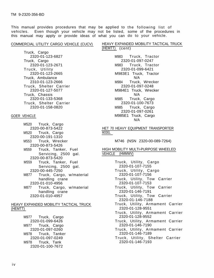
This manual provides procedures that may be applied tovehicles. Even though your vehicle may not be listed,this manual may apply or provide ideas of what you can
COMMERCIAL UTILITY CARGO VEHICLE (CUCV)
Truck, Cargo2320-01-123-6827
Truck, Cargo2320-01-123-2671
Truck , U t i l i t y2320-01-123-2665
Truck, Ambulance2310-01-123-2666
Truck, Shelter Carrier2320-01-127-5077
Truck, Chassis2320-01-133-5368
Truck, Shelter Carrier2320-01-158-0820
GOER VEHICLE
M520 Truck, Cargo2320-00-873-5422
M520 Truck, Cargo2320-00-191-1310
M553 Truck, Wrecker2320-00-873-5426
M559 Truck, Tanker, FuelServicing, 2500 gal.
2320-00-873-5420M559 Truck, Tanker, Fuel
Servicing, 2500 gal.2320-00-445-7250
M877 Truck, Cargo, w/materialhandling crane
2320-01-010-4956M877 Truck, Cargo, w/material
handling crane2320-01-010-4957
HEAVY EXPANDED MOBILITY TACTICAL TRUCK(HEMTT)
M977 Truck, Cargo2320-01-099-6426
M977 Truck, Cargo2320-01-097-0260
M978 Truck, Tanker2320-01-097-0249
M978 Truck, Tank2320-01-100-7672
the fo l lowing l is t o fsome of the procedures indo to your vehicle.
HEAVY EXPANDED MOBILITY TACTICAL TRUCK(HEMTT) (cent)
M983 Truck, Tractor2320-01-097-0247
M983 Truck, Tractor2320-01-099-6421
M983E1 Truck, TractorN/A
M984 Truck, Wrecker2320-01-097-0248
M984E1 Truck, WreckerN/A
M985 Truck, Cargo2320-01-100-7673
M985 Truck, Cargo2320-01-097-0261
M985E1 Truck, CargoN/A
HET 70 HEAVY EQUIPMENT TRANSPORTER
M746 (NSN 2320-00-089-7264)
HIGH MOBILITY MULTI-PURPOSE WHEELEDVEHICLE (HMMWV). ,
Truck, Uti l i ty, Cargo2320-01-107-7155
Truck, Ut i l i ty , Cargo2320-01-107-7156
Truck, Uti l i ty, Tow Carrier2320-01-107-7153
Truck, Uti l i ty, Tow Carrier2320-01-146-7191
Truck, Uti l i ty, Tow Carrier2320-01-146-7188
Truck, Uti l i ty, Armament Carrier2320-01-128-9551
Truck, Uti l i ty, Armament Carrier2320-01-128-9552
Truck, Uti l i ty, Armament Carrier2320-01-146-7190
Truck, Uti l i ty, Armament Carrier2320-01-146-7189
Truck, Ut i l i ty , Shel ter Carr ier2320-01-146-7193
i v
MODEL

TM 9-2320-356-BD
HIGH MOBILITY MULTI-PURPOSE WHEELEDVEHICLE HMMWV) (cent)
Truck, Ut i l i ty , Shel ter Carr ier2320-01-146-7187
Truck, Ambulance2310-01-111-2275
Truck, Ambulance2310-01-111-2274
Truck, Ambulance2310-01-146-7194
M.A.N. VEHICLE SYSTEM
Truck, Tractor2320-12-191-5422
Truck, Wrecker2320-12-191-5423
Truck, Tractor2320-12-191-5424
Truck, Tractor2320-12-191-5425
M35 SERIES 2-1/2-TON VEHICLES
M35A2 Truck, Cargo2320-00-077-1616
M35A2 Truck, Cargo2320-00-077-1617
M35A2C Truck, Cargo2320-00-926-0873
M35A2C Truck, Cargo2320-00-926-0875
M35E8 Truck, Cargo2320-00-542-5635
M36A2 Truck, Cargo, Dropside2320-00-077-1618
M36A2 Truck, Cargo2320-00-077-1619
M44A1 Truck Chassis2320-00-973-4145
M44A2 Truck Chassis2320-00-077-1620
M44A2 Truck Chassis2320-00-077-1621
M44A2 Chassis, Truck2320-00-973-2229
M45A2 Chassis, Truck2320-00-077-1622
M45A2 Truck Chassis2320-00-077-1623
M46A2 Chassis, Truck2320-00-077-1628
M35 SERIES 2-1/2-TON VEHICLES (cent)
M46A2C Chassis, Truck2320-00-077-1629
M46A2C Truck Chassis2320-00-077-1630
M49A1C Truck Tank2320-00-077-1632
M49A1C Truck, Tanker, Fuel, 1200Gal.
2320-00-440-3349M49A2C Truck, Tanker, Fuel, 1200
Gal.2320-00-077-1631
M50A2 Truck, Tanker, Water, 1000Gal.
2320-00-077-1633M50A2 Truck Tank
2320-00-077-1634M50A3 Truck, Tanker, Water, 1000
Gal.2320-00-937-4036
M50A3 Truck Tank2320-00-937-5264
M109A1 Truck, Van2320-00-706-2224
M109A1 Truck, Van, Shop2320-00-690-8365
M109A2 Truck, Van, Shop2320-00-440-8313
M109A2 Truck, Van2320-00-440-8308
M109A3 Truck, Van2320-00-077-1636
M109A3 Truck, Van2320-00-077-1637
M185A1 Truck, Shop, InstrumentRepair
4940-00-973-3995M185A2 Truck, Shop, Instrument
Repair4840-00-987-8799
M185A2 Inst Rep Shop Truck4940-00-987-8800
M185A3 Truck, Shop, InstrumentRepair
4940-00-077-1638M185A3 Inst Rep Shop Truck
4940-00-077-1639M275A2 Truck, Tractor
2320-00-077-1640M275A2 Truck Tractor
2320-00-077-1641
V
TM 9-2320-356-BD
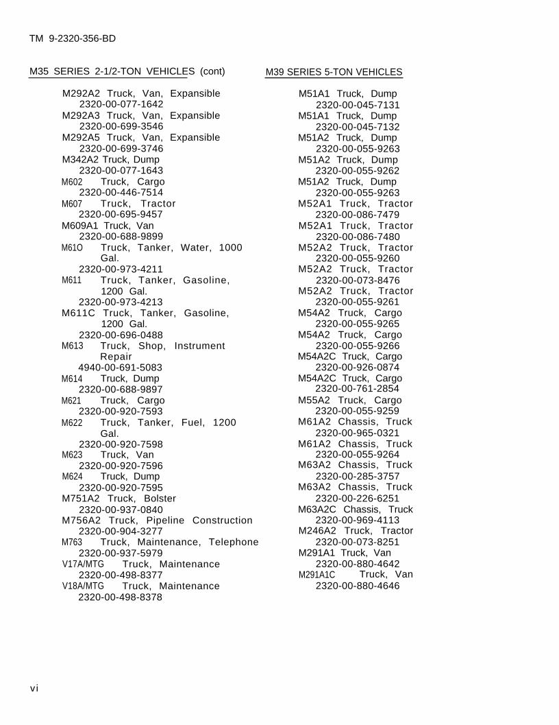
M35 SERIES 2-1/2-TON VEHICLES (cont) M39 SERIES 5-TON VEHICLES
M292A2 Truck, Van, Expansible2320-00-077-1642
M292A3 Truck, Van, Expansible2320-00-699-3546
M292A5 Truck, Van, Expansible2320-00-699-3746
M342A2 Truck, Dump2320-00-077-1643
M602 Truck, Cargo2320-00-446-7514
M607 Truck, Tractor2320-00-695-9457
M609A1 Truck, Van2320-00-688-9899
M61O Truck, Tanker, Water, 1000Gal.
2320-00-973-4211M611 Truck, Tanker, Gasoline,
1200 Gal.2320-00-973-4213
M611C Truck, Tanker, Gasoline,1200 Gal.
2320-00-696-0488M613 Truck, Shop, Instrument
Repair4940-00-691-5083
M614 Truck, Dump2320-00-688-9897
M621 Truck, Cargo2320-00-920-7593
M622 Truck, Tanker, Fuel, 1200Gal.
2320-00-920-7598M623 Truck, Van
2320-00-920-7596M624 Truck, Dump
2320-00-920-7595M751A2 Truck, Bolster
2320-00-937-0840M756A2 Truck, Pipeline Construction
2320-00-904-3277
M51A1 Truck, Dump2320-00-045-7131
M51A1 Truck, Dump2320-00-045-7132
M51A2 Truck, Dump2320-00-055-9263
M51A2 Truck, Dump2320-00-055-9262
M51A2 Truck, Dump2320-00-055-9263
M52A1 Truck, Tractor2320-00-086-7479
M52A1 Truck, Tractor2320-00-086-7480
M52A2 Truck, Tractor2320-00-055-9260
M52A2 Truck, Tractor2320-00-073-8476
M52A2 Truck, Tractor2320-00-055-9261
M54A2 Truck, Cargo2320-00-055-9265
M54A2 Truck, Cargo2320-00-055-9266
M54A2C Truck, Cargo2320-00-926-0874
M54A2C Truck, Cargo2320-00-761-2854
M55A2 Truck, Cargo2320-00-055-9259
M61A2 Chassis, Truck2320-00-965-0321
M61A2 Chassis, Truck2320-00-055-9264
M63A2 Chassis, Truck2320-00-285-3757
M63A2 Chassis, Truck2320-00-226-6251
M63A2C Chassis, Truck2320-00-969-4113
M246A2 Truck, TractorM763 Truck, Maintenance, Telephone 2320-00-073-8251
2320-00-937-5979 M291A1 Truck, VanV17A/MTG Truck, Maintenance 2320-00-880-4642
2320-00-498-8377 M291A1C Truck, VanV18A/MTG Truck, Maintenance 2320-00-880-4646
2320-00-498-8378
vi
TM 9-2320-356-BD
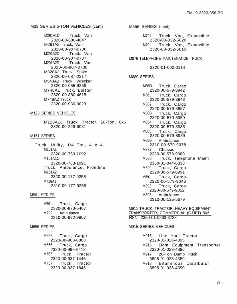
M39 SERIES 5-TON VEHICLES (cent) M656 SERIES (cent)
M291A1D Truck, Van M791 Truck, Van, Expansible2320-00-880-4647 2320-00-832-5620
M291A2 Truck, Van M791 Truck, Van, Expansible2320-00-907-0706 2320-00-832-5610
M291A2C Truck. Van2320-00-907-0707
M291A2D Truck. VanM876 TELEPHONE MAINTENANCE TRUCK
2320-00-907-0708 - 2320-01-000-0114M328A2 Truck, Stake
2320-00-087-2317 M880 SERIESM543A2 Truck, Wrecker
2320-00-055-9258 M880 Truck, CargoM748A1 Truck, Bolster 2320-00-579-8942
2320-00-880-4615 M881 Truck, CargoM748A2 Truck 2320-00-579-8943
2320-00-930-0023 M882 Truck, Cargo2320-00-579-8957
M123 SERIES VEHICLES M883 Truck, Cargo2320-00-579-8959
M123A1C Truck, Tractor, 10-Ton, 6x6 M884 Truck, Cargo2320-00-226-6081 2320-00-579-8985
M885 Truck, CargoM151 SERIES 2320-00-579-8989
M886 AmbulanceTruck, Utility, 1/4 Ton, 4 x 4 2310-00-579-9078
M151A1 M887 Chassis2320-00-763-1092 2320-00-579-9080
M151A1C M888 Truck, Telephone Maint2320-00-763-1091 2350-01-044-0333
Truck, Ambulance, Frontline M890 Truck, CargoM151A2 2320-00-579-8991
2320-00-177-9258 M891 Truck, CargoM718A1 2320-00-579-9046
2310-00-177-9256 M892 Truck, Cargo2320-00-579-9052
M561 SERIES
M561 Truck, Cargo2320-00-873-5407
M792 Ambulance2310-00-832-9907
M656 SERIES
M656 Truck, Cargo2320-00-903-0883
M656 Truck, Cargo2320-00-999-8418
M757 Truck, Tractor2320-00-937-1445
M757 Truck, Tractor2320-00-937-1846
M893 Ambulance2310-00-125-5679
M911 TRUCK, TRACTOR, HEAVY EQUIPMENTTRANSPORTER, COMMERCIAL (C-HET) 8X6,NSN 2320-01-0263-3733
M915 SERIES VEHICLES
M915 Line Haul Tractor2320-01-028-4395
M916 Light Equipment Transporter2320-01-028-4396
M917 20-Ton Dump Truck3805-01-028-4389
M918 Bituminous Distr ibutor3895-01-028-4390
vi i
TM 9-2320-356-BD
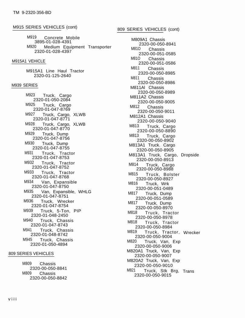
M915 SERIES VEHICLES (cont)
M919 Concrete Mobile3895-01-028-4391
M920 Medium Equipment Transporter2320-01-028-4397
M915A1 VEHICLE
M915A1 Line Haul Tractor2320-01-125-2640
M939 SERIES
M923 Truck, Cargo2320-01-050-2084
M925 Truck, Cargo2320-01-047-8769
M927 Truck, Cargo, XLWB2320-01-047-8771
M928 Truck, Cargo, XLWB2320-01-047-8770
M929 Truck, Dump2320-01-047-8756
M930 Truck, Dump2320-01-047-8755
M931 Truck, Tractor2320-01-047-8753
M932 Truck, Tractor2320-01-047-8752
M933 Truck, Tractor2320-01-047-8768
M934 Van, Expansible2320-01-047-8750
M935 Van, Expansible, WHLG2320-01-047-8751
M936 Truck, Wrecker2320-01-047-8754
M939 Truck, 5-Ton, PIP2320-01-048-2450
M940 Truck, Chassis2320-01-047-8743
M941 Truck, Chassis2320-01-048-8742
M945 Truck, Chassis2320-01-050-4894
809 SERIES VEHICLES
M809 Chassis2320-00-050-8841
M809 Chassis2320-00-050-8842
809 SERIES VEHICLES (cont)
M809A1 Chassis2320-00-050-8941
M81O Chassis2320-00-051-0585
M81O Chassis2320-00-051-0586
M811 Chassis2320-00-050-8985
M811 Chassis2320-00-050-8986
M811Al Chassis2320-00-050-8989
M811A2 Chassis2320-00-050-9005
M812 Chassis2320-00-050-9011
M812A1 Chassis2320-00-050-9040
M813 Truck, Cargo2320-00-050-8890
M813 Truck, Cargo2320-00-050-8902
M813A1 Truck. Cargo2320-00-050-8905
M813A1 Truck, Cargo, Dropside2320-00-050-8913
M814 Truck, Cargo2320-00-050-8988
M815 Truck, Bolster2320-00-050-8927
M816 Truck, Wrk2320-00-051-0489
M817 Truck, Dump2320-00-051-0589
M817 Truck, Dump2320-00-050-8970
M818 Truck, Tractor2320-00-050-8978
M818 Truck, Tractor2320-00-050-8984
M819 Truck, Tractor,2320-00-050-9004
M820 Truck, Van, Exp2320-00-050-9006
M820A1 Truck, Van, Exp2320-00-050-9007
M820A2 Truck, Van, Exp2320-00-050-9010
M821 Truck, Stk Brg,2320-00-050-9015
Wrecker
Trans
v i i i
TM 9-2320-356-BD
CHAPTER 1
INTRODUCTION
BDAR FIXES SHALL BE USED ONLY IN COMBATAT THE DISCRETION OF THE COMMANDER
AND SHALL BE REPAIRED BY STANDARD MAINTENANCE PROCEDURESAS SOON AS PRACTICABLE AFTER THE MISSION IS COMPLETED.
Section I. INTRODUCTION
1-1. PURPOSE
a. This technical manual (TM) is for use by operators and by organizational anddirect support/general support maintenance personnel. It provides procedures andguidel ines for batt lef ield repairs on tact ical vehicles under the forward supportmaintenance concept during combat.
b. The purpose of battlefield damage assessment and repair (BDAR) is to rapidlyreturn disabled tactical wheeled vehicles to the operational commander byexpediently f ixing, bypassing, or jury-rigging components to restore the minimumessential systems required for the support of the specific combat mission or toenable the vehicle to self-recover. These repairs may be temporary and may notrestore ful l performance capabil i ty.
1-2. SCOPE
a. This TM describes BDAR procedures of a general nature applicable to alltactical wheeled vehicles. Expedient repairs applicable to systems or subsystemsof a specific tactical vehicle are covered in system specific TM’s.
b. Many expedient repair techniques helpful in preparing a vehicle for recoveryare included in FM 20-22, Vehicle Recovery Operations. Details of such proceduresare not duplicated in this TM, although certain quick-f ix batt lef ield operat ionswhich would, in some cases, prepare the vehicle for recovery or self-recovery willbe described. Users of this manual should refer to FM 20-22 for further recovery-associated expedient repairs.
c . Not all possible types of combat damage and failure modes can be predicted,nor are all effective field expedient repairs known. This TM provides guidelinesfor assessing and repair ing batt lef ield fai lures of tact ical vehicles and is notintended to be a complete catalog of all possible emergency repairs. The repairsdescribed here will serve as guidelines and will stimulate the experienced operatoror mechanic to devise expedients as needed to repair equipment rapidly in a combatc r i s i s .
1-1
TM 9-2320-356-BD
1-3. APPLICATION
a. The procedures in this manual are designed for battlefield environments andshould be used in situations where standard maintenance procedures areimpract ica l . These procedures are not meant to replace standard maintenancepractices, but rather to supplement them str ict ly in batt lef ield environment.Standard maintenance procedures will provide the most effective means of returninga damaged vehicle to ready status, provided that adequate time, replacement parts,and necessary tools are available. BDAR procedures are authorized for use only inan emergency situation in a battlefield environment and only at the direction ofthe commander.
b. BDAR techniques are not limited to simple restoration of minimum functionalcombat capability. Restore ful l funct ional capabi l i ty i f i t can be doneexpediently and with a limited expenditure of time and assets.
c. Some of the special techniques in this manual, if applied, may result inshortened life or damage to components of tactical vehicles. The commander mustdecide whether the risk of having one less vehicle available for combat outweighsthe r isk of applying the potential ly destruct ive expedient repair technique. Eachtechnique gives appropriate warnings and cautions and lists systems limitationscaused by this action.
1-4. DEFINITIONS
a. Battlefield Damage includes all incidents which occur on the battlefieldand which prevent the vehicle from accomplishing its mission such as combat damage,random failures, operator errors, accidents, and wear-out failures.
b. Repair or Fix in this manual includes any expedient action that returnsa damaged part or assembly to a full or an acceptably degraded operating conditionincluding:
(1) Shortcuts in parts removal or instal lat ion.
(2) Installation of components from other vehicles that can be modified tofit or interchanged with components on the vehicle.
(3) Repair using parts that serve a noncritical function elsewhere on thesame vehicle for the purpose of restoring a critical function.
(4) Bypassing of noncritical components in order to restore basic functionalcapab i l i t y .
(5) Expedit ious cannibal ization procedures.
(6) Fabrication of parts from kits or readily avai lable materials.
( 7 ) Ju ry - r i gg ing .
(8) Use o f subst i tu te fue ls , f lu ids , or lubr icants .
1-2

TM 9-2320-356-BD
c. Damage Assessment is a procedure to determine rapidly what is damaged;whether it is repairable; what assets are required to make the repair; who can dothe repa i r , i . e . , crew, maintenance team (MT), or maintenance support team (MST);and where the repair should be made. The assessment procedure includes thefol lowing steps:
(1) Determine if the repair can be deferred or if it must be done.
(2) Isolate the damaged areas and components.
(3) Determine which components must be fixed.
(4) Prescr ibe f ixes.
(5) Determine if parts or components, materials, and tools are available.
(6) Estimate the manpower and ski 11 required.
(7) Estimate the total time (clock-hours) required to make the repair.
(8) Estab l ish the pr ior i ty o f the f ixes .
(9) Decide where the fix shall be performed.
(10) Decide if recovery is necessary and to what location.
d. Maintenance Team (MT) consists of organizational mechanics who may betrained in assessing battle damage and field repair procedures. An MT is called toout-of-action vehicles to supplement (or confirm) the crew’s original damageassessment. MT assessment determines if field repairs will be conducted or ifrecovery is required. Depending on available time, the MT will assist the crew inrestoring the vehicle to mission capabil i ty.
e. Maintenance Support Team (MST) consists of direct support/general supportmechanics and technical specialists who are trained in assessing battle damage inaddi t ion to the i r spec ia l i ty . The MST is called by the MT when vehicle damageexceeds MT assessment capability or organizational repair capability.
f . MT/MST Assessor is a senior member of the forward MT/MST. He is a systemsmechanic/technician trained in BDAR techniques. He must know:
(1) The units mission and the commander’s requirements.
(2) The maintenance capabil i ty of the unit, including the avai lable ski l ls,tools, repair parts, and materials.
(3) How to detect contamination and effect decontamination of equipment.
(4) The unit’s maintenance workload.
(5) The maintenance capability of all accessible rally and maintenanceco l lec t ion po in ts .
1-3
TM 9-2320-356-BD
g. Fully Mission Capable (FMC) means that the vehicle can perform all itscombat missions without endangering the life of the crew. To be FMC, the vehiclemust be complete and fully operable with no faults listed in the “Equipment is notready/available if” column of the operator’s Preventive Maintenance Checks andServices (PMCS) .
h. Combat Capable means that the vehicle can operate in a combat environmentwith some limitations but meets the minimum functional capability requirements.(Refer to paragraph 1-8.)
i . Combat Emergency Capable means that the vehicle meets the needs forspecific tactical maneuver; however, not all systems are functional. Also,additional damage due to the nature of an expedient repair may occur to the vehicleif i t is used. The commander must decide if these limitations are acceptable forthat specific emergency situation.
j . Self-Recovery Capable means that the vehicle meets the needs for recoveryunder self-power. It could include hazardous equipment conditions such as partialbrakes or limited steering.
k. Cannibalization, as used in this TM, means the use of repair parts orcomponents obtained from another tactical vehicle either damaged or of lowerpriority to the immediate mission. In this TM, the term is used to includecontrolled exchange.
1-5. BDAR RECOMMENDATIONS AND QDR/EIR
a. Personnel originating new BDAR procedures should forward them directly toCommander, US Army Tank-Automotive Command, ATTN: AMSTA-MB-BDAR, Warren, MI48397-5000. Personnel are encouraged to develop and report new BDAR ideas,techniques, and procedures.
b. Equipment Improvement Recommendations (EIR’s) may be submitted by anyone whoknows of an unsatisfactory condition with equipment design or use. You do not haveto show a new design or list a better way to do a procedure; just tell why thedesign is unfavorable or why a procedure is hard. EIR’s may be submitted on SF 368,Quality Deficiency Report. Mail these directly to Commander, US Army Tank-Automotive Command, AMSTA-MT, Warren MI 48397-5000. A reply wi l l be sent direct lyto you.
1-4
TM 9-2320-356-BD
Section II. STANDARDS AND PRACTICES
1-6. BDAR CHARACTERISTICS
BDAR capability requires simplicity, speed, and effectiveness. some BDARprocedures include repair techniques that violate standard peacetime maintenancepract ices . In a combat emergency situation, greater risks are necessary andacceptable.
1-7. WAIVER OF PRECAUTIONS
Under combat conditions, BDAR may be performed on vehicles which are fueled and/orarmed. Other similar precautions may be waived at the discretion of thecommander. Refer to paragraph 1-11e.
1-8. SERVICEABILITY AND OPERABILITY (OPERATING CHRACTERISTICS)
As an example, the Minimum Functional Capability criteria for trucks are givenbelow.
NOTE
These criteria may be waived for recovery or ifthe tactical situation demands otherwise.
a. Vehicle must have operational wheels and tires on both sides of the truck.
b. Drive train must be functional and must be capable of reverse and at leastone forward gear.
c. Power train performance degradation cannot exceed that level which wouldcause the truck to be incapable of traveling 15 miles per hour on a level,unimproved road.
d. Vehicle must be capable of braking/stopping from 15 mph.
e. Vehicle steering system must be operational.
1-9. PERMANENT REPAIR
At the earliest practicable opportunity, the vehicle will be recovered or evacuatedto the appropriate maintenance facility for permanent standard repair as required.
1-5
TM 9-2320-356-BD
Sect ion I I I . RESPONSIBILITIES AND TASKS
1-10. GENERAL
Battlefield damage assessment and repair procedures are applicable at all levelsfrom crew through general support maintenance, depending on the extent of thedamage; the time available; the skills required; and the parts, components, tools,and materials available. Within these l imits, each maintenance level wi l l rapidlytake whatever action is necessary and possible to restore the vehicle to combat-ready condition required for continuation of the mission.
1-11. COMMANDER AND CREW
a. The crew of the damaged vehicle will make the first assessment immediatelyafter damage has occurred. Crew members will provide the vehicle commander with aninitial damage assessment which will include notice of system failure and all majorvehicle systems visibly damaged, inoperative, or impaired. I f poss ib le , a l lsystems will be checked at the same time by different crew members. I f t he f a i l u reis due to hostile fire, the report will include the location of impact and themanning status. Immediacy of the report is more important than how long it willtake to get back into action. The init ial report, therefore, may omit repair timeestimates. The vehicle commander must make an initial out-of-action report to theplatoon leader including these essentials:
(1) Vehicle damage (out-of-action or impaired)
(2) Location of vehicle
(3) F i repower s ta tus ( i f app l icab le)
(4) Mobil i ty status
(5) Manning status
(6) Current and anticipated enemy action
b. If communication capability is damaged, the vehicle commander shouldapproach the nearest friendly radio and make his report.
c. In the forward battle area, it is imperative that the crew attempt to movethe vehicle to a covered or concealed position to prevent additional combatdamage. Th i s i s t he f i r s t p r i o r i t y . I f the vehicle is not capable of self-movement, use any vehicle to recover the vehicle or to move it to a concealed area.
d. Battlefield Damage Assessment/Repair assessment checks include looking atthe damaged parts, determining what system they belong to, and deciding how theycan be f ixed or jury-r igged to permit immediate operation (ful l or part ial).
1-6

TM 9-2320-356-BD
e. A safety check should be made for any obvious hazards.
NOTE
Correct any safety faults/hazards beforeproceeding.
(1) Have any combustibles such as fuel, hydraul ic f luid, or oi l accumulated?
(2) Does wiring appear to be safe? Could arcing occur to stored ammunitionor leaking combustibles?
(3) Is the f i re ex t ingu isher operat iona l?
f . A functional/operational test should be performed next on those systemswhich appear undamaged. Refer to vehicle PMCS table before proceeding. Self-testshall be performed on those systems with a built-in self-test feature. Only thosesystems found to be damaged or inoperative shall be identified.
g. The vehicle commander shall report to the platoon leader the results of thecrew’s damage assessment, naming the major known causes of the vehicle’simmobil ity. If repair by crew is possible, the vehicle commander shall report atotal estimated repair time and what functions may be restored.
h. The platoon leader wil l respond with direct ives and, i f required, wi l l cal lan MT to the location of the damaged vehicle for assistance. I f poss ib le ,sufficient information will be provided to enable the MT to bring needed repairparts or special tools.
i . The crew shall proceed to make field expedient repairs to restorecommunications and/or vehicle mobility as directed by platoon leader.
1-12. ORGANIZATIONAL MAINTENANCE AND MAINTENANCE TEAMS (MT)
a. The organizational maintenance team (MT) and assessor operate out of thecompany or battalion trains. The MT assessor performs his assessment and themaintenance team completes repairs at the damage site if possible. I f the s i te iswithin direct fire or under enemy observation, movement to a more secure site awayfrom fire may be necessary. Th is is s t i l l cons idered “on-s i te” .
b. If the vehicle has been left unattended in the forward battle area, theimmediate area of the vehicle should be checked for mines, and the vehicle shouldbe checked for booby traps before starting the battle damage assessment. The MTshould also make the safety checks listed in paragraph l-he.
c. The MT assessment will be more thorough than the crew’s, usingorganizational maintenance support tools and equipment as needed. MT assessmentincludes:
(1) Reviewing the crew’s out-of-action report, i f avai lable.
(2) Interviewing commander and crew, if available.
(3) Visually inspecting damaged parts and systems.
1-7
TM 9-2320-356-BD
(4) Making tests with organizational test equipment, i f required.
(5) Performing addit ional vehicle operational tests, as necessary.
d. Using this information and following the steps of paragraph 1-4c, the MTw i l l :
(1) Determine what must be repaired or replaced.
(2) Determine sequence and priority of repair actions.
(3) Estimate repair t imes for each repair task.
(4) Total the repair task times and determine if the repairs can be performedin the time available.
(5) Determine repair location and, i f other than on-site, arrange forrecovery of the vehicle to the repair site.
e. If all critical repairs can be made within the available time with theskills, materials, tools, and equipment at hand, the MT, assisted by the crew, willproceed with the on-site repair.
f . If the damage exceeds the repair capability of the MT, and the time isavailable for an MST on-site fix, the MST shall be called.
g. If time for an MST on-site fix is not available, but the vehicle isrepairable, the MT shall provide for recovery of the vehicle to a designatedco l lec t ion po in t .
h. If the vehicle is not repairable, the MT shall provide for one of thefo l lowing:
(1) Recovery to a maintenance C Ol lection point for evacuation to the rear.
(2) On-site stripping (if approved by commander, coordinated with supportmaintenance).
(3) Abandonment/destruction (if directed by commander).
Vehicles should never be abandoned if recovery/evacuation is possiblebecause vehicles can almost always be rebuilt, no matter how badly damaged theyare. If the vehicle is damaged catastrophically and evacuation is not possible,remove items in the following order:
(1) Needed spares on-site.
(2) Sensitive, high value, limited size items.
(3) Other needed spares or repair parts.
j . If the vehicle is contaminated, the MT shall mark the vehicle withcontamination markers and arrange for recovery to a decontamination site. Refer toFM 21-40 NBC (Nuclear, Biological, and Chemical) Defense.
1-8
TM 9-2320-356-BD
1-13. DIRECT SUPPORT/GENERAL SUPPORT MAINTENANCE TEAM
a. The MST shall assist the MT as needed, using direct support maintenancetools and equipment. MST assessment and repair procedures are the same as those ofthe MT except at a higher maintenance level. I f poss ib le , the MT will tell the MSTwhat tools and spare parts are needed to perform the repairs. While waiting forthe MST to arrive, the crew, under the supervision of the MT, will open up thevehicle and make it ready for the MST to perform the assessment and repair.
b. Damaged vehicles removed to designated repair sites shall be selected forMST repair as directed by the company commander.
1-14. TIME LIMITS FOR REPAIRING DAMAGE
a. In combat, the time available for BDAR is limited. One of the factors to beconsidered in the selection of a repair site is the amount of time available at thesite based on the tact ical si tuation. Every assessment must include an estimate oftotal t ime required to restore the vehicle. The time available at the selectedrepair site must equal or exceed the estimated time required to accomplish alltasks associated with the BDAR.
b. Determination of where BDAR will take place should be made by the commander.
1-15. RECORDING BATTLEFIELD DAMAGE REPAIRS
a. Record shall be made of repairs to components of a tactical vehicle by BDARor other expedient techniques in order to enable mechanics to determine authorizedpermanent repair. All expedient repairs and operational limitations must berecorded on DA Form 2404 (Operator’s Daily).
b. DA PAM 738-750, the Army Maintenance Management System (TAMMS), describespreparation and disposition of DA Form 2404 and DA Form 2407. When BDAR is notedon DA Form 2407, a copy shall be mailed to: Combat Data Information Center,AFFDL/FES/CDIC, Wright Patterson AFB, Ohio 45433. The information on these formswill provide data for designing vehicles to be less susceptible to combat damageand easier to repair when damaged.
1-9/(1-10 blank)
TM 9-2320-356-BD
CHAPTER 2ASSESSING BATTLEFIELD DAMAGE
BDAR FIXES SHALL BE USED ONLY IN COMBATAT THE DISCRETION OF THE COMMANDER
AND SHALL BE REPAIRED BY STANDARD MAINTENANCE PROCEDURESAS SOON AS PRACTICABLE AFTER THE MISSION IS COMPLETED.
Section I. GENERAL
2-1. SCOPE
This chapter provides guidelines to use to assess battlefield damage. It directsyou to an expedient repair procedure, or to the standard system TM if an expedientrepair procedure for your problem doesn’t exist.
2-2. GENERAL
Use this TM in conjunction with the operator’s technical manual (TM) andLubrication Order (LO) . This chapter explains how to use this manual to assess andfix battlefield damage that prevents moving and/or communicating. This chaptercontains the general fault assessment tables and general troubleshooting andmaintenance instructions including combat damage report forms. General fault andspecific fault assessment tables and detailed assessment procedures are used tolocate the damage; and an expedient repair procedure tells how to fix the damage.An index of the expedient repair procedures is located in each chapter. If youdon’t know or aren’t sure of exactly what your problem is, you should use theassessment tables and procedures to find the fault.
2-3. APPLICATION
Use the following steps to find and fix battlefield damages:
a. Do the Preventive Maintenance Checks and Services (PMCS) in the TM and theL O . At the same time, look for obvious damage to the vehicle.
b. Do the troubleshooting/repair recommended in the TM, if applicable.
c. If you find the problem, determine its effect on the operation (mobility orccrnmunication) of the vehicle.
d. If you can’t fix the problem using the PMCS table and the procedures in theTM and the LO, use chart 2-1 to assess and fix the problem.
e. If the problem does not affect vehicle operation, the commander will decidewhether to attempt to fix the problem or continue with the mission.
2-1
TM 9-232O-356-BD
f . If the damage does affect vehicle operation, do one of the following:
(1) Replace the bad part/assembly with a good one (from supply or otherveh ic le) .
(2) Replace the bad part/assembly with a substitute that is interchangeable.
(3) Use the expedient repair procedures in this manual to repair the damage.
g. After repairing the damaged system, replace lost f luids and/or lubricants inaccordance with specific LO. If those specified by the LO or TM are not available,refer to appendix D for a possible substitute.
2-2
TM 9-2320-356-BD
Sect ion I I . ASSESSING BATTLEFIELD DAMAGE
2-4. GENERAL
a. This section provides an overall damage assessment procedure to evaluate themobility and communication functions of individual vehicles.
b. The assessmentof veh ic le capabi l i tyrefer you to:
( 1 ) p r o c e d u r e s
(2) the veh ic le
(3) a higher ma”
procedures are designed to ensure that all necessary aspectsare evaluated during the assessment process. The procedures
n this manual i f a quick-f ix is possible,
TM when BDAR is not possible, or
ntenance level if access to devices or materials to do thequick-f ix are avai lable only at those levels.
c. Each procedure:
(1) contains general information about the problem,
(2) lists materials and/or tools required other than those commonly availableto the crew, MT, and MST (If the listed items are not available, anything that willdo the job is acceptable.),
(3) lists the estimated number of soldiers needed and the estimated timerequired to complete the repair,
(4) states the operational 1 imitations caused by the repair action beforeexperiencing further damage/degradation to the vehicle, and
(5) provides other expedient options that can be used, depending on theavai lab i l i ty o f personnel , materials, tools, and/or t ime. (This does not includestandard maintenance procedures or recovery.)
d. Following each assessment procedure is an index of the procedures containedin that chapter. If you know exactly what your problem is, you can use the indexto find the proper expedient repair procedure.
e. Additional data is contained in the appendixes.
(1) Appendix B lists special or fabricated tools used in performing BDARrepai rs .
(2) Appendix C lists alternate sources of supply to include foreign ownershipof US combat vehicles and expendable supplies which are recommended for use toimplement various BDAR repairs.
(3) Appendix D l ists substi tutes for the petroleum, oi l , and lubricants (POL).
2-3
TM 9-2320-356-BD
2-5. ASSESSMENT PROCESS
a. Assessments of damage may be made in turn by operator/crew, MT, and MSTpersonnel. The assessment procedures are as follows:
(1 ) I nspec t .
(2) Funct iona l ly tes t .
(3) Assess the performance.
b. There are three kinds of assessments performed on damaged equipment:
(1) The first is assessment of the extent and kind of damage and how itaffects vehicle operation and capabil i t ies.
(2) The second is assessment of whether the damage needs to be repaired.
(3) The third is assessment of where and how to repair the damage.
2-6. OVERALL VEHICLE ASSESSMENT PROCEDURE
a. This procedure can be used by the crew, but it will be of more use to an MT orMST assessor working to quick-fix vehicles for the completion of a mission or self-recovery. The procedure provides for assessing the kind of damage and determining:
( 1 ) the effect of the damage and if it needs to be fixed,
(2) if the damage can be fixed using BDAR or if only regular maintenanceoperation can fix it, and
(3) how long it will take to fix it.
b. This is accomplished by structuring this manual in rank order, from thevehicle two-function overview down to the specific. Each major function (move andcommunicate) and each subsystem of that function has a stand-alone assessmentprocedure. This makes it easier to identify each significant problem encountered inbattlefield damaged equipment.
c. As an example, presume a 2-l/2-ton truck is down with a bad fuel pump. Fuelpumps are essential for even the lowest level of limp-home self-recovery. Thevehicle/system assessment table, as part of its engine evaluation, tells the readerto visually and functionally check the engine. If it doesn’t work, the assessor canthen visually and functionally check the engine subsystems if time permits. Theassessor would visually and functionally check the fuel subsystem and discover thatthe pump was inoperative. The fuel subsystem assessment table directs the reader toa specific page where BDAR suggestions for alternate fuel supply systems can beconsidered for use.
d. At any point on each of the assessment levels, the assessor can abort theprocedure and direct recovery, evacuation, or o ther ac t ions i f the tac t ica l s i tuat iond ic ta tes .
e. Refer to chart 2-1 to begin the assessment process.
2-4

TM 9-2320-356-BD
Chart 2-1. Vehicle/System Assessment.
ITEM/ACTION FAULT ISOLATION BDAR REFERENCE
NOTE
Items checked in this procedure must work to provide minimum functionalt ac t i ca l capab i l i t y . Even if all systems work, the vehicle may be unsafeand may not satisfy normal required operating capabilities or may notreceive mission-essential maintenance.
CHAPTER 13
CHAPTERS 9, 11, and
CHAPTERS 3, 5,6, 7, and 8
2-5
TM 9-2320-356-BD
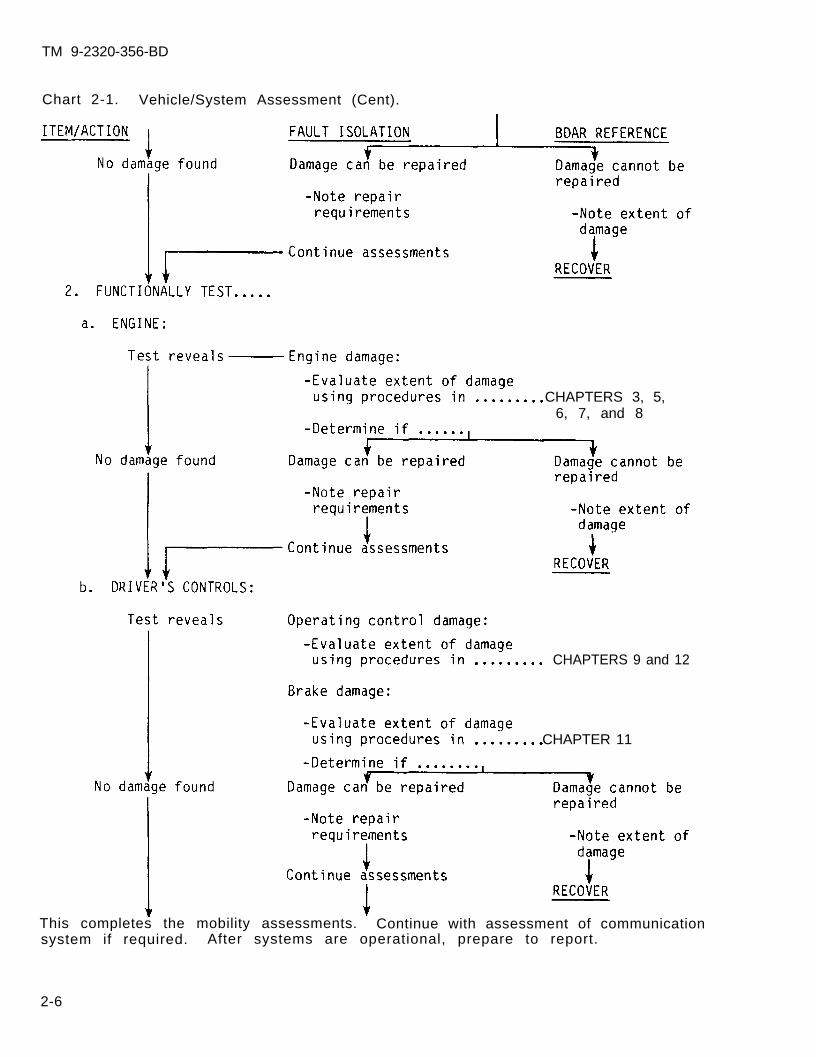
Chart 2-1. Vehicle/System Assessment (Cent).
CHAPTERS 3, 5,6, 7, and 8
CHAPTERS 9 and 12
CHAPTER 11
This completes the mobility assessments. Continue with assessment of communicationsystem if required. After systems are operational, prepare to report.
2-6
TM 9-2320-356-BD
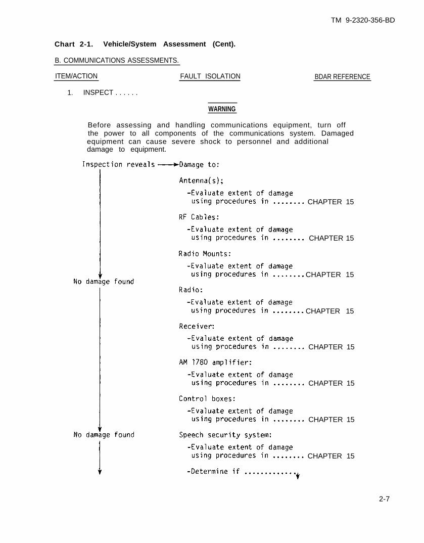
Chart 2-1. Vehicle/System Assessment (Cent).
B. COMMUNICATIONS ASSESSMENTS.
ITEM/ACTION FAULT ISOLATION
1. INSPECT . . . . . .
WARNING
BDAR REFERENCE
Before assessing and handling communications equipment, turn offthe power to all components of the communications system. Damagedequipment can cause severe shock to personnel and additionaldamage to equipment.
CHAPTER 15
CHAPTER 15
CHAPTER 15
CHAPTER 15
CHAPTER 15
CHAPTER 15
CHAPTER 15
CHAPTER 15
2-7
TM 9-2320-356-BD
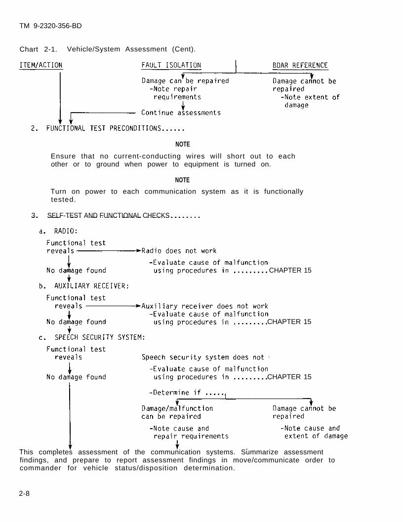
Chart 2-1. Vehicle/System Assessment (Cent).
NOTE
Ensure that no current-conducting wires will short out to eachother or to ground when power to equipment is turned on.
NOTE
Turn on power to each communication system as it is functionallytested.
3. SELF-TEST AND FUNCTIONAL CHECKS . . . . . . . .
CHAPTER 15
CHAPTER 15
CHAPTER 15
This completes assessment of the communication systems. Summarize assessmentfindings, and prepare to report assessment findings in move/communicate order tocommander for vehicle status/disposition determination.
2-8
TM 9-2320-356-BD
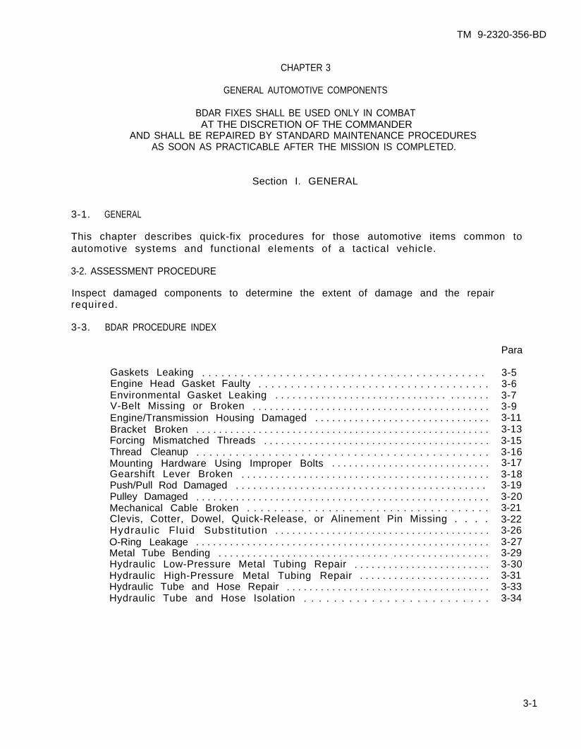
CHAPTER 3
GENERAL AUTOMOTIVE COMPONENTS
BDAR FIXES SHALL BE USED ONLY IN COMBATAT THE DISCRETION OF THE COMMANDER
AND SHALL BE REPAIRED BY STANDARD MAINTENANCE PROCEDURESAS SOON AS PRACTICABLE AFTER THE MISSION IS COMPLETED.
Section I. GENERAL
3-1. GENERAL
This chapter describes quick-fix procedures for those automotive items common toautomotive systems and functional elements of a tactical vehicle.
3-2. ASSESSMENT PROCEDURE
Inspect damaged components to determine the extent of damage and the repairrequired.
3-3. BDAR PROCEDURE INDEX
Para
Gaskets Leaking . . . . . . . . . . . . . . . . . . . . . . . . . . . . . . . . . . . . . . . . . . . . Engine Head Gasket Faulty . . . . . . . . . . . . . . . . . . . . . . . . . . . . . . . . . . . .Environmental Gasket Leaking . . . . . . . . . . . . . . . . . . . . . . . . . . . . . . . . . . . . . .V-Belt Missing or Broken . . . . . . . . . . . . . . . . . . . . . . . . . . . . . . . . . . . . . . . . . .Engine/Transmission Housing Damaged . . . . . . . . . . . . . . . . . . . . . . . . . . . . . . .Bracket Broken . . . . . . . . . . . . . . . . . . . . . . . . . . . . . . . . . . . . . . . . . . . . . . . . . . . .Forcing Mismatched Threads . . . . . . . . . . . . . . . . . . . . . . . . . . . . . . . . . . . . . . . .Thread Cleanup . . . . . . . . . . . . . . . . . . . . . . . . . . . . . . . . . . . . . . . . . . . . .Mounting Hardware Using Improper Bolts . . . . . . . . . . . . . . . . . . . . . . . . . . . .Gearshift Lever Broken . . . . . . . . . . . . . . . . . . . . . . . . . . . . . . . . . . . . . . . . . . . .Push/Pull Rod Damaged . . . . . . . . . . . . . . . . . . . . . . . . . . . . . . . . . . . . . . . . . . . Pulley Damaged . . . . . . . . . . . . . . . . . . . . . . . . . . . . . . . . . . . . . . . . . . . . . . . . . . . .Mechanical Cable Broken . . . . . . . . . . . . . . . . . . . . . . . . . . . . . . . . . . . .Clevis, Cotter, Dowel, Quick-Release, or Alinement Pin Missing . . . .Hydraul ic Fluid Substi tut ion . . . . . . . . . . . . . . . . . . . . . . . . . . . . . . . . . . . . . .O-Ring Leakage . . . . . . . . . . . . . . . . . . . . . . . . . . . . . . . . . . . . . . . . . . . . . . . . . . . .Metal Tube Bending . . . . . . . . . . . . . . . . . . . . . . . . . . . . . . . . . . . . . . . . . . . . . . . .Hydraulic Low-Pressure Metal Tubing Repair . . . . . . . . . . . . . . . . . . . . . . . .Hydraulic High-Pressure Metal Tubing Repair . . . . . . . . . . . . . . . . . . . . . . .Hydraulic Tube and Hose Repair . . . . . . . . . . . . . . . . . . . . . . . . . . . . . . . . . . . .Hydraulic Tube and Hose Isolation . . . . . . . . . . . . . . . . . . . . . . . . .
3-53-63-73-93-113-133-153-163-173-183-193-203-213-223-263-273-293-303-313-333-34
3-1

TM 9-2320-356-BD
Section II. GASKETS
3-4. GENERAL
Damaged gaskets may cause leakage from components. Procedures are available tomake or repair gaskets if standard replacements are not available. L i f t c a p a b i l i t ymay be required to gain access to the gasket. Heat and pressure should beconsidered when selecting gasket materials.
3-5. GASKETS LEAKING
General Information:
When some metal surfaces are bolted together, a compressible gasket is required toreduce or eliminate the leakage of fluids or lubricants. Gaskets are also used toseal systems against fuel leakaqe or to keep contaminants from enterinq. Leaks canbe tolerated if the leaking fluid does notleak at a rate which will deplete the requ
Limi ta t ions:
o Frequent inspections required
Personnel/Time Required:
o 1-2 so ld ierso 1-6 hours
constitute a fire hazard or-does notred lubr icat ion.
Mater ia ls /Tools :
Gasket material such as:o Leathero Used gasketo Cardboardo Teflon tapeo Si l icone gasket sealero Hardening type sealer
Other Options:
o Continue operation, re f i l l ing f lu ids as requi red.
Procedural Steps:
Option 1: Manufactured Gasket.
1. Cut leather, cardboard, or other material to fit the mating surfaces.
a. Hold gasket against mating surface and mark an outline of the component.Cut the material with a knife or shears.
b. Hold material against mating surface. Tap the gasket material with aball-peen hammer along the edges of the mating surfaces and holes to removeunwanted gasket material.
3-2
TM 9-2320-356-BD
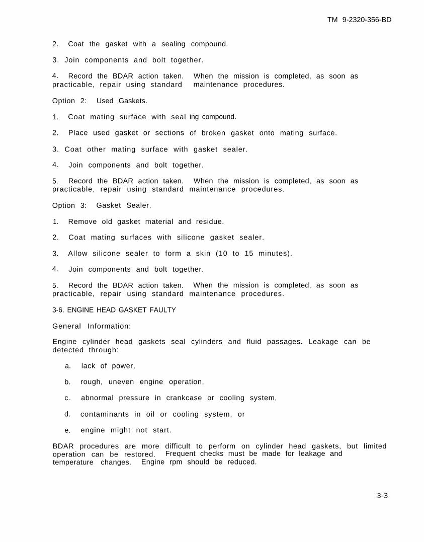
2. Coat the gasket with a sealing compound.
3. Join components and bolt together.
4. Record the BDAR action taken.practicable, repair using standard
Option 2: Used Gaskets.
1. Coat mating surface with seal
2. Place used gasket or sections
When the mission is completed, as soon asmaintenance procedures.
ing compound.
of broken gasket onto mating surface.
3. Coat other mating surface with gasket sealer.
4. Join components and bolt together.
5. Record the BDAR action taken. When the mission is completed, as soon aspracticable, repair using standard maintenance procedures.
Option 3: Gasket Sealer.
1. Remove old gasket material and residue.
2. Coat mating surfaces with silicone gasket sealer.
3. Allow silicone sealer to form a skin (10 to 15 minutes).
4. Join components and bolt together.
5. Record the BDAR action taken. When the mission is completed, as soon aspracticable, repair using standard maintenance procedures.
3-6. ENGINE HEAD GASKET FAULTY
General Information:
Engine cylinder head gaskets seal cylinders and fluid passages. Leakage can bedetected through:
a. lack of power,
b. rough, uneven engine operation,
c. abnormal pressure in crankcase or cooling system,
d. contaminants in oil or cooling system, or
e. engine might not start.
BDAR procedures are more difficult to perform on cylinder head gaskets, but limitedoperation can be restored. Frequent checks must be made for leakage andtemperature changes. Engine rpm should be reduced.
3-3
TM 9-2320-356-BD
Limi ta t ions:
o Reduced vehicle speed
Personnel/Time Required:
o 1-2 so ld ierso 2-6 hours
Mater ia ls /Tools :
o Epoxyo Copper wireo Hardening gasket sealero Sandpaper or emery cloth
Other Options:
o Continue operations.
Procedural Steps:
Option 1: Gasket Sealer.
1. Remove cylinder head.
2. Locate leaking area.
3. Liberally coat leaking area with hardening gasket sealer.
4. Replace cylinder head and tighten mounting bolts or studs.
5. Check engine operation.
6. Record the BDAR action taken. When the mission is completed, as soon aspracticable, repair using standard maintenance procedures.
Option 2: Wire and Sealer.
1. Remove cylinder head.
2. Remove damaged gasket or O-rings.
3. Clean the head and the engine head surface with sandpaper or emery cloth.
4. Lay soft copper wire around each cylinder bore and trim to eliminate anyoverlap.
5. Install old gasket coated with gasket sealer, varnish, or paint.
6. Install cylinder head and tighten mounting bolts or studs.
7. Record the BDAR action taken. When the mission is completed, as soon aspract icab le , repair using standard maintenance procedures.
3-4

TM 9-2320-356-BD
3-7. ENVIRONMENTAL GASKET LEAKING
General Information:
Inspect for water or foreign matter in compartments or areas that should besealed. Rubber weather stripping from civilian vehicles or any rubber hosesecurely glued and sealed will stop leaks. Canvas or rubber inner tubes will alsoseal the system. These seals will prevent excessive water and air leaks.
L imi ta t ions:
o None
Personnel/Time Required:
o 1-2 so ld ierso 20-60 minutes
Mater ia ls /Tools :
o Rubber hoseo Rubber weather strippingo Inner tubeso Adhesiveo Canvas tarpo Epoxyo T a p e
Procedural Steps:
1. Locate leak and remove component or cover.
2. Remove defective gasket and clean the sealing surfaces.
3. Obtain material to fabricate sealing gasket.
4. Cut gasket to f i t .
5. Follow instructions on container and apply available adhesive.
6. Place gasket in proper location.
7. Install component or cover.
8. Record the BDAR action taken. When the mission is completed, as soon aspracticable, repair using standard maintenance procedures.
3-5
TM 9-2320-356-BD
Section I I I . BELTS
3-8. GENERAL
V-Belts provide direct drive and can be substituted or replaced if the basicfactors about each belt are considered. Substitute belts must be the correctlength to maintain tension and wide enough to prevent bottoming in the pulley V.Inspect width and length of the belt. Smaller, narrower belts may be substitutedor V-belts may be taken from another vehicle if there are twin belt drives. Di rectvehicle-to-vehicle removal and installation is a simple method of replacing missingbe l ts .
3-9. V-BELT MISSING OR BROKEN
General Information:
Some vehicle subsystems such as water pumps and radiator fans are driven byV-be l ts . Power generation is also belt driven. Worn or frayed V-belts can slip orbreak causing the system to fail. V-belts should be replaced or substituted torestore system functions. Frequent adjustment may be required for substituteV-be l ts .
L imi ta t ions:
o Frequent stops for belt adjustmento Possible engine overheating
Personnel/Time Required:
o 1 so ld iero 15-60 minutes
Mater ia ls /Tools :
o Adustable link V-beltso Ropeo Wire
Procedural Steps:
Option 1: Rope or Wire.
1. Rope or wire can also be used, but thin wire must be braided to ensure theneeded friction is provided.
2. Adjust the tensioner assembly for minimum belt length.
3. Assemble the rope or wire as close as possible to the minimum belt length.
4. Tighten with the tensioner assembly.
5. Record the BDAR action taken. When the mission is completed, as soon aspracticable, repair using standard maintenance procedures.
3-6

TM 9-2320-356-BD
Option 2: Separable-Link Belts.
1. To remove link, hold one of the links with pliers and pry the next link offwith a screwdriver.
2. Adjust the tensioner assembly for minimum belt length.
3. Assemble the belting as close as possible to the minimum belt length and snaplinks together with pl iers.
4. Install the belt as shown. This prevents undue strain on the belt links.
DIRECTION OF ROTATION
5. Tighten with the vehicle belt tensioner.
6. Record the BDAR action taken. When the mission is completed, as soon aspracticable, repair using standard maintenance procedures.
3-7
TM 9-2320-356-BD
Section IV. HOUSINGS, CASTINGS, AND PLATES
3-10. GENERAL
Castings or plates may be serviceable, even with holes or cracks, provided thestructure is not significantly weakened. Internal structures, such as crankshaftbearing journal webs, are necessary to distribute loads within the casting. Somedamage to these elements can be allowed, but fatigue failures from crack growthcannot be predicted. Service life will depend on the extent of damage.
3-11. ENGINE/TRANSMISSION HOUSING DAMAGED
General Information:
Small cracks or holes caused by vibrations, overheating, or explosive shocks maydevelop in a cylinder head, block, or transmission housing. Cracks that do notharm the structural strength of a housing can be deferred, but cracks that allowcoolant or oil to escape must be repaired. Large holes or cracks will requireexchange of the component. Depending on the extent and location of the damage,frequent fluid level checks may be necessary. In some cases, the engine ortransmission may have to be removed. Use one of the following options to repair asmall crack or hole.
L imi ta t ions:
o Reduced mobility
Personnel/Time Required:
o 2 to 3 soldierso 2-24 hours
Mater ia ls /Tools :
o Sandpapero Epoxyo Plast ic steelo Meta l p la teo Bulk issue f iberglass or
epoxy kito Hardening sealero Lif t capabi l i ty
Procedural Steps:
Option 1: Repair of Small Crack.
1. Remove all paint from around the crack.
2. Cover the crack and 1/4 inch or more of the surrounding area with quick-dryingepoxy.
3. Allow epoxy to harden before running an engine. Use heat to speed up curingthe epoxy.
4. Record the BDAR action taken. When the mission is completed, as soon aspracticable, repair using standard maintenance procedures.
3-8
TM 9-2320-356-BD
Option 2: Repair of Small Crack or Hole.
1. Remove paint from around the area where metal plate is to be positioned.
2. Cover the area with a plate from any available metal large enough to cover thecrack or hole.
3. Seal the edges of the plate with quick-drying epoxy.
4. Allow epoxy to harden before running engine. Use heat to speed up curing theepoxy.
5. Record the BDAR action taken. When the mission is completed, as soon aspract icab le , repair using standard maintenance procedures.
Option 3: Repair of Small Crack or Hole.
1. Clean damaged area.
2. Fill small crack or holes in low-stress area either with hardenfiberglass, or epoxy.
3. Allow filler to harden before running engine.
ing sealer,
4. Record the BDAR action taken. When the mission is completed, as soon aspracticable, repair using standard maintenance procedures.
3-9
TM 9-2320-356-BD
Section V. BRACKETS AND WELDMENTS
3-12. GENERAL
Brackets are used on all vehicles to mount or store items. Brackets are attached tothe vehicle by bolting or welding and are subject to damage through vibrations,impact, or explosive forces. Repairs must be made to restore the brackets necessaryfor essential vehicle functions.
3-13. BRACKET BROKEN
General Information:
Equipment mountinq brackets on the frame will break sometimes due to vibrations orc o l l i s i o n . Bolted brackets should be remountedremoval may be required to gain access to other
L imi ta t ions:
o None
Personnel/Time Required:
o 2 so ld ierso 1 hour
Procedural Steps:
Option 1: Weld.
1. If a bracket is broken off at the base, butunaffected, reweld in place.
2. Elongate mounting holes to compensate for m
us ing bo l ts i f poss ib le . The i rcomponents.
Mater ia ls /Tools :
o Welding equipmento Elastic cordso W i r e o r r o p eo BII tiedown straps
component mounting holes are
isal inement of attaching i tems.
3-10
TM 9-2320-356-BD
3. Bolt components to bracket.
4. Record the BDAR action taken. When the mission is completed, as soon aspract icab le , repair using standard maintenance procedures.
Option 2: Weld in Place.
1. If the bracket mounting holes cannot be used because of stripped threads or ifbroken bolts, weld the bracket in place.
2. Record the- BDAR action taken. When the mission is completed, as soon aspract icab le , repair using standard maintenance procedures.
Option 3: Tie Component.
1. Tie the component in place using rope, wire, elast ic cords, or BII straps i fbrackets cannot be welded or bolted.
2. Record the BDAR action taken. When the mission is completed, as soon aspracticable, repair using standard maintenance procedures.
3-11
TM 9-2320-356-BD
Section VI. HARDWARE, MECHANICAL LINKAGES, CABLES, AND PULLEYS
3-14. GENERAL
Various types of hardware and linkages are used throughout tactical vehicles totransfer the control actions from the crew to the components being controlled.Damage can occur to the mounting hardware or the rods, cables, and levers inmechanical linkage systems. Pins can become lost or linkages can bend or break,disabling or hampering vehicle operation. This section wil l give variousprocedures that may be used to repair or restore needed functions.
3-15. FORCING MISMATCHED THREADS
Mismatched bolts can be used to make BDAR repairs if proper bolts are not available.Care must be taken not to break bolts by forcing them too far. Forced threads willnot hold as much stress as standard threads but will provide a limited operationalcapab i l i t y .
3-16. THREAD CLEANUP
Damaged threads can be repaired using a thread file or a triangular file. Turninga hardened steel nut onto the bolt can also help realine damaged threads. Thethreads must be cleaned to remove dirt or metal particles which might cause furtherdamage to threaded holes. Use a wire brush, nail, or scribe to remove stuck metalpa r t i c l es .
3-17. MOUNTING HARDWARE USING IMPROPER BOLTS
Brackets and components can be connected or mounted using an iron rod or studinserted through the connecting holes. Swaging or bending each end will keep thecomponents together. A stud can be screwed into a threaded hole and a nut used tohold the component. If the proper size nut is not available, use a nut larger thanthe stud threads and flatten the stud end to hold the nut in place. Linkages alsocan be connected by inserting a nut or bolt and flattening the ends to keep it fromdropping out of position.
3-18. GEARSHIFT LEVER BROKEN
General Information:
Binding shift linkage can cause the transmission range selector lever to break,result ing in the loss of shif t ing control. Binding linkages must be repaired toallow shifting without excess strain on the mechanism. A temporary shift lever canbe fabricated to provide selection of the transmission gear ranges.
L imi ta t ions:
o None
3-12
TM 9-2320-356-BD
Personnel/Time Required: Mater ia ls /Tools :
o 1 so ld ier o V ise gr ipso 1-30 minutes o Channel locks
Other Options:
o I f the shif t lever is hol low, insert a screwdriver into the remaining section toa l low sh i f t ing.
Procedural Steps:
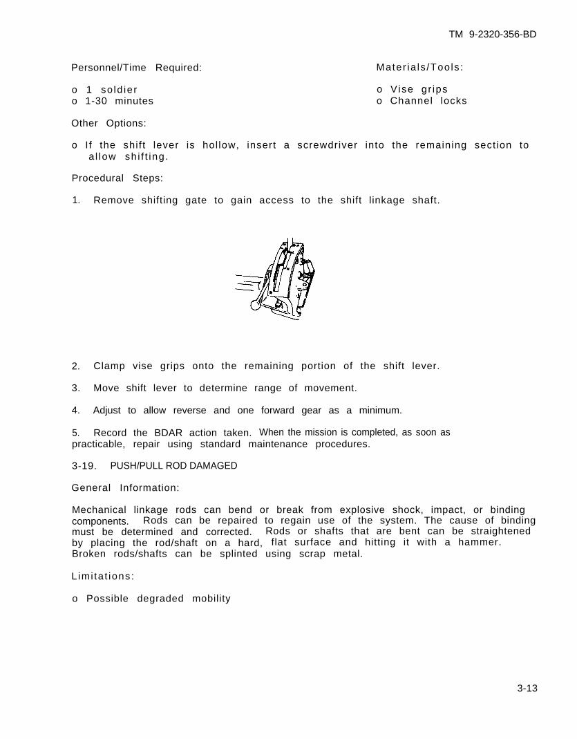
1. Remove shifting gate to gain access to the shift linkage shaft.
2. Clamp vise grips onto the remaining portion of the shift lever.
3. Move shift lever to determine range of movement.
4. Adjust to allow reverse and one forward gear as a minimum.
5. Record the BDAR action taken. When the mission is completed, as soon aspracticable, repair using standard maintenance procedures.
3-19. PUSH/PULL ROD DAMAGED
General Information:
Mechanical linkage rods can bend or break from explosive shock, impact, or bindingcomponents. Rods can be repaired to regain use of the system. The cause of bindingmust be determined and corrected. Rods or shafts that are bent can be straightenedby placing the rod/shaft on a hard, flat surface and hitting it with a hammer.Broken rods/shafts can be splinted using scrap metal.
L imi ta t ions:
o Possible degraded mobility
3-13
TM 9-2320-356-BD
Personnel/Time Required:
o 1-2 soldierso 1 - 2 h o u r s
Mater ia ls /Tools :
o Welding equipmento D r i l lo Hacksawo P l a t e s t o c k
Procedural Steps:
Option 1: Weld.
1. Determine if damaged rod is made of steel or aluminum alloy.
2. Remove rod and weld ends together.
3. Remove metal fragments which would hinder rod operation.
4. Record the BDAR action taken. When the mission is completed, as soon aspracticable, repair using standard maintenance procedures.
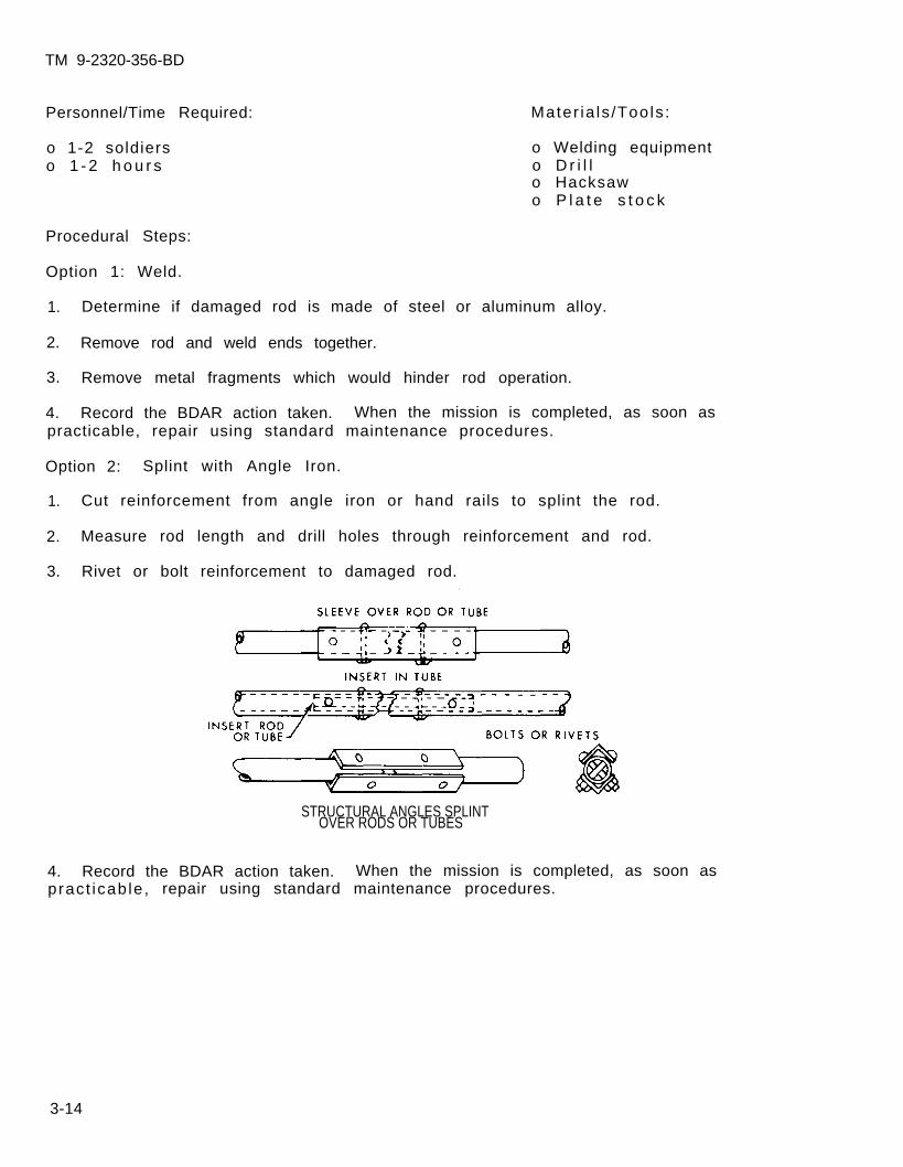
Option 2: Splint with Angle Iron.
1. Cut reinforcement from angle iron or hand rails to splint the rod.
2. Measure rod length and drill holes through reinforcement and rod.
3. Rivet or bolt reinforcement to damaged rod.
STRUCTURAL ANGLES SPLINTOVER RODS OR TUBES
4. Record the BDAR action taken. When the mission is completed, as soon aspract icab le , repair using standard maintenance procedures.
3-14
TM 9-2320-356-BD
Option 3: Weld and Splint.
1. Measure rod length.
2. Cut off both end portions of the damaged rod.
3. Cut a piece of tubular stock that will make the length the same as the originalwhen the end portions are added to it.
4. -Weld the end portions.
5. Record the BDAR action taken. When the mission is completed, as soon aspracticable, repair using standard maintenance procedures.
3-20. PULLEY DAMAGED
General Information:
When cable pulleys are damaged, a replacement may be cannibalized from anothervehicle or the damaged pulley may be welded or wedged into position. A spacer,bolt, and two flat washers can be used as an improvised pulley to guide the cable.
3-21. MECHANICAL CABLE BROKEN
General Information:
Cables may break, causing a system to become inoperative. Cables may be repairedby splicing. When replacement cable is not available, prepare cable for splicingas follows.
L imi ta t ions:
o Range of movement may be limited
Personnel/Time Required:
o 1 so ld iero 1-2 hours
Other Options:
Materials/Tools:
o New or reclaimed cableo Cable clamp or metal
sleeves and instal lat iontoe-l
o V i seo V i se -g r i ps
o Damaged cable may be replaced with braided wire, commo wire (5 to 7 strands), orrope where the cable function will permit.
3-15
TM 9-2320 -356-BD
Procedural
Option 1:
1. Make a
2. Thread
3. Secure
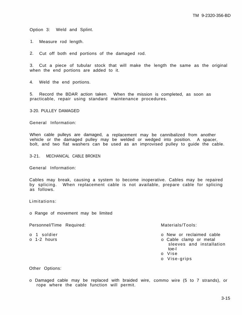
4. Record the BDARaction taken. When the mission is completed, as soon as
Steps:
Be sure to select a length where the cable spliceswi l l not res t rec t the range of cab le t rave l .
Loop and Cable Clamp.
NOTE
loop at the end of one cable.
the other cable end through the loop, and make another loop.
both loops as shown.
pract icab le , repair using standard maintenance procedures.
Option 2: Cable Clamps.
1. Splice cable with two clamps.
2. Connect the other cables by looping through the tie. The end of the cableshould extend at least 1/2 inch beyond the clamp as shown.
3. Record the BDAR action taken. When the mission is completed, as soon aspract icab le , repair using standard maintenance procedures.
3-16
TM 9-2320-356-BD
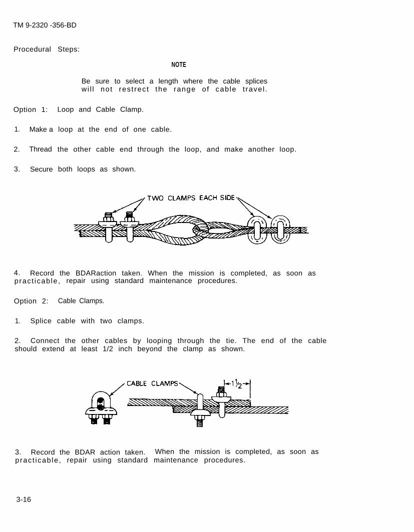
Option 3: Swage Sleeves.
1. Splice the cable with two metal sleeves.
2. Swage the sleeves on the cables with installation tool, a vise, or a hammer.
3. Adjust cable to its proper tens ion.
4. Record the BDAR action taken. When the miss ion is completed, as soon aspracticable, repair using standard maintenance procedures.
3-22. CLEVIS, COTTER, DOWEL, QUICK-RELEASE, OR AL INEMENT PIN MISSING
Most linkages have retainer devices, cotter keys, lacing wire, or safety p ins tokeep the connecting nuts, bolts, or pins in place. During BDAR repairs, wire,welding rod, bolts, or nails can be used to secure connecting nuts, bolts, orpins. Place the item through the hole and bend the ends to keep it from fallingout . Alinement pins or dowels can be replaced with cut bolts. Use a bolt that isa tight fit in the hole, wedge the bolt in, and cut to proper length.
3-17
TM 9-2320-356-BD
Section VII. HYDRAULIC SYSTEMS
3-23. GENERAL
BDAR for a hydraulic system is generally confined to component replacement,expedient l ine repairs, or bypassing damaged lines. If a hydraul ic circuit cannotbe repaired, it may be necessary to isolate it (cut it off) from the system topermit operation of some other hydraulic functions. Damaqe to the hydraulic systemusually requires replenishment of lost f luids.found in appendix D.
A l is t o f -subst i tu te- f lu ids can be
WARNING
Bring hydraulic system to zeromaking repairs.
3-24. ASSESSMENT PROCEDURES
No specific assessment procedures are needed to
pressure before
locate leaks and ruptured lines.System specific TM’s must be checked before isolation is performed.
3-18
TM 9-2320-356-BD
Section VIII. FLUIDS AND SEALS
3-25. GENERAL
Hydraulic circuits use fluids under pressure to activate, regulate, or drivemechanisms in the vehicle. To contain the pressure within the hydraulic system,all moving parts are sealed with gaskets, packing, and O-rings, Leakage at any of these, or at hydraulic devices or the lines that connect them, will render theentire system useless until the leak has been stopped.
3-26. HYDRAULIC FLUID SUBSTITUTION
If the original f luid is lost and standard replacement is not avai lable, asubstitute fluid must be used. Check appendix D for a compatible fluid.
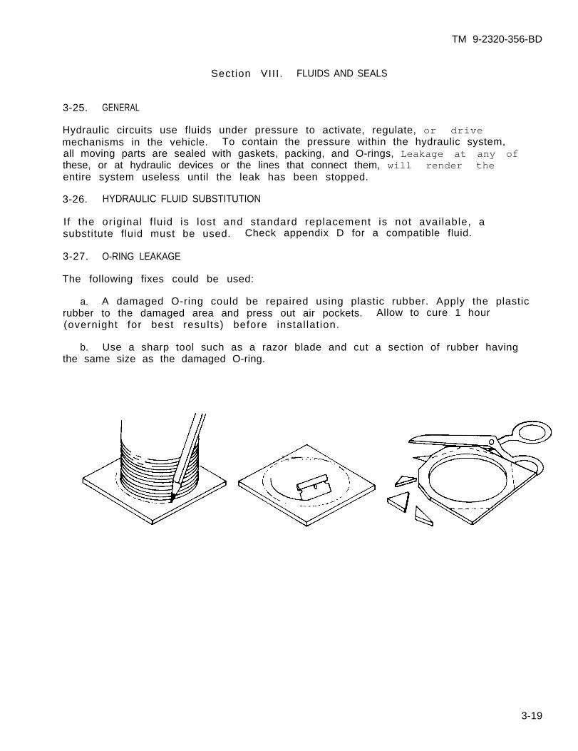
3-27. O-RING LEAKAGE
The following fixes could be used:
a. A damaged O-ring could be repaired using plastic rubber. Apply the plasticrubber to the damaged area and press out air pockets. Allow to cure 1 hour(overnight for best results) before instal lat ion.
b. Use a sharp tool such as a razor blade and cut a section of rubber havingthe same size as the damaged O-ring.
~., -—-. . . . . .
3-19
TM 9-2320-356-BD
Section IX. METAL TUBING
3-28. GENERAL
To operate some of the vehicle mechanisms, a considerable amount of energy must beexerted. Hydraulic power is used to perform these high-energy tasks. High-energyrequirements (or high-speed tasks) are usually met with high-pressure hydrauliclines or tubing made of metal. There are also metal low-pressure lines, usuallyused when heat is a consideration or shape is critical. This section coversexpedient repairs on metal tubing.
3-29. METAL TUBE BENDING
Bending may be required to make tubing repairs. Dry sand can be poured into thetube to be bent. The ends must be plugged to keep the sand from falling out. Softmetal tubes can be sealed with finger pressure, but harder lines should have a pluginserted. After bending the tube, flush the sand from the tubing with a liquid toensure removal of all particles.
3-30. HYDRAULIC LOW-PRESSURE METAL TUBING REPAIR
General Information:
Damaged low-pressure metal hydraulic lines can be replaced with other availablel ines (high-pressure, metal, or rubber hoses).
L imi ta t ions:
o None
Personnel/Time Required:
o 1 so ld iero 30-120 minutes
Mater ia ls /Tools :
o00000000
AN/MS fittingsHacksawHand f i leBeading toolWireStr ingSealantShrink tubingTube cutter
Other Options:
o Refer to chapter 5.
3-20

TM 9-2320-356-BD
Procedural Steps:
Option 1: Replacement of a Short Damaged Tube Section.
1. Cut out and square the damaged portion of the tubing.
2. Deburr and clean the ends.
NOTE
If a beading tool is not available, make animprovised head by wrapping string or wirearound the tube. Coat the string or wire withsealant or hardening epoxy.
3. Bead the tubing 1/2 inch from the ends.
4. Select a length of medium- or high-pressure hose with an inside diameter equalto the outside diameter of the tube. Cut the length 4 inches longer than theremoved piece of tubing.
5.
6.aid
7.
Coat string and hose with sealant.
Slide the hose ends over the ends of the tubing. Use grease or system fluid toin sliding the hose over the tubing, particularly the bead.
Secure the hose with two hose clamps. Position clamp screws 180 degrees toeach other.
8. Record the BDAR action taken. When the mission is completed, as soon aspract icab le , repair using standard maintenance procedures.
3-21
Pressure test the assembly.
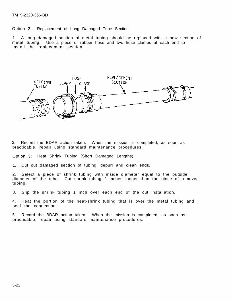
TM 9-2320-356-BD
Option 2: Replacement of Long Damaged Tube Section.
1. A long damaged section of metal tubing should be replaced with a new section ofmetal tubing. Use a piece of rubber hose and two hose clamps at each end toinstall the replacement section.
2. Record the BDAR action taken. When the mission is completed, as soon aspracticable, repair using standard maintenance procedures.
Option 3: Heat Shrink Tubing (Short Damaged Lengths).
1. Cut out damaged section of tubing; deburr and clean ends.
2. Select a piece of shrink tubing with inside diameter equal to the outsidediameter of the tube. Cut shrink tubing 2 inches longer than the piece of removedtubing.
3. Slip the shrink tubing 1 inch over each end of the cut installation.
4. Heat the portion of the heat-shrink tubing that is over the metal tubing andseal the connection.
5. Record the BDAR action taken. When the mission is completed, as soon aspracticable, repair using standard maintenance procedures.
3-22
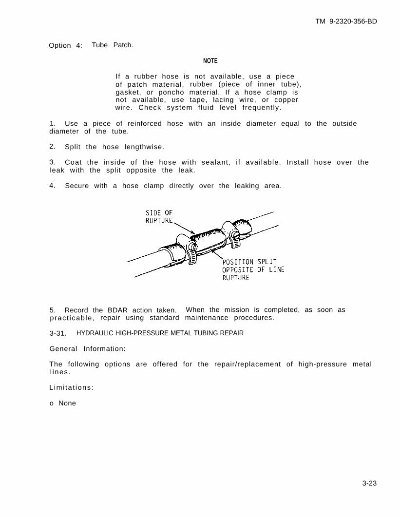
TM 9-2320-356-BD
Option 4: Tube Patch.
NOTE
If a rubber hose is not available, use a pieceof patch material, rubber (piece of inner tube),gasket, or poncho material. If a hose clamp isnot available, use tape, lacing wire, or copperwire. Check system f luid level frequently.
1. Use a piece of reinforced hose with an inside diameter equal to the outsidediameter of the tube.
2. Split the hose lengthwise.
3. Coat the inside of the hose with sealant, i f avai lable. Instal l hose over theleak with the split opposite the leak.
4. Secure with a hose clamp directly over the leaking area.
5. Record the BDAR action taken. When the mission is completed, as soon aspract icab le , repair using standard maintenance procedures.
3-31. HYDRAULIC HIGH-PRESSURE METAL TUBING REPAIR
General Information:
The following options are offered for the repair/replacement of high-pressure metall ines.
L imi ta t ions:
o None
3-23
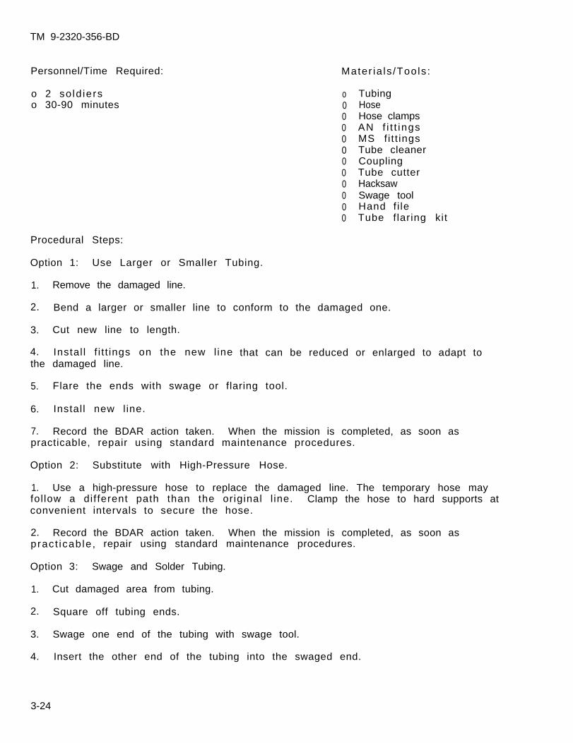
TM 9-2320-356-BD
Personnel/Time Required:
o 2 so ld ierso 30-90 minutes
Procedural Steps:
Option 1: Use Larger or Smaller Tubing.
1. Remove the damaged line.
2. Bend a larger or smaller line to conform to the damaged one.
3. Cut new line to length.
Mater ia ls /Tools :
o00000000000
TubingHoseHose clampsAN f i t t ingsMS f i t t ingsTube cleanerCouplingTube cutterHacksawSwage toolHand f i leTube flaring kit
4. Instal l f i t t ings on the new l inethe damaged line.
that can be reduced or enlarged to adapt to
5. Flare the ends with swage or flaring tool.
6. Instal l new l ine.
7. Record the BDAR action taken. When the mission is completed, as soon aspracticable, repair using standard maintenance procedures.
Option 2: Substitute with High-Pressure Hose.
1. Use a high-pressure hose to replace the damaged line. The temporary hose mayfol low a different path than the original l ine. Clamp the hose to hard supports atconvenient intervals to secure the hose.
2. Record the BDAR action taken. When the mission is completed, as soon aspract icab le , repair using standard maintenance procedures.
Option 3: Swage and Solder Tubing.
1. Cut damaged area from tubing.
2. Square off tubing ends.
3. Swage one end of the tubing with swage tool.
4. Insert the other end of the tubing into the swaged end.
3-24
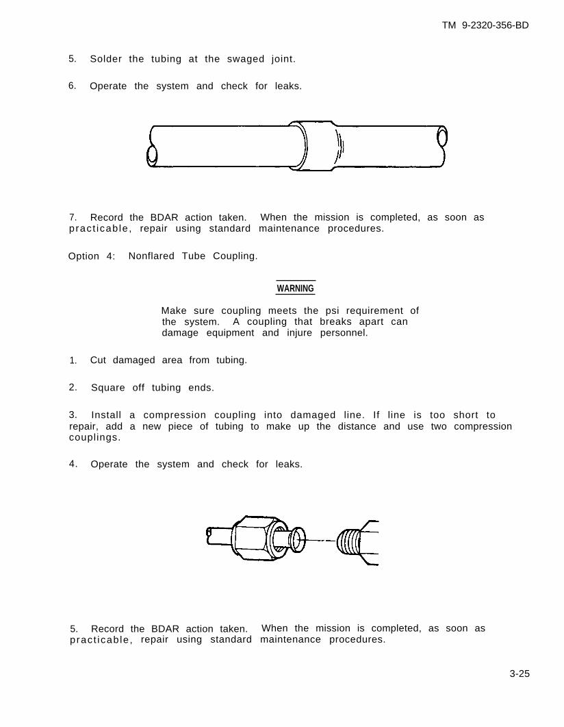
TM 9-2320-356-BD
5. Solder the tubing at the swaged joint.
6. Operate the system and check for leaks.
7. Record the BDAR action taken. When the mission is completed, as soon aspract icab le , repair using standard maintenance procedures.
Option 4: Nonflared Tube Coupling.
WARNING
Make sure coupling meets the psi requirement ofthe system. A coupling that breaks apart candamage equipment and injure personnel.
1. Cut damaged area from tubing.
2. Square off tubing ends.
3. Install a compression coupling into damaged line. If line is too short torepair, add a new piece of tubing to make up the distance and use two compressioncouplings.
4. Operate the system and check for leaks.
5. Record the BDAR action taken. When the mission is completed, as soon aspract icab le , repair using standard maintenance procedures.
3-25
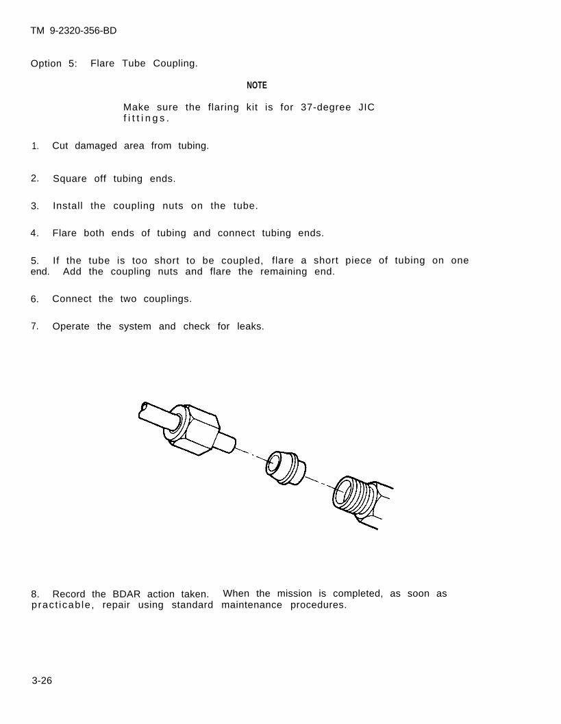
TM 9-2320-356-BD
Option 5: Flare Tube Coupling.
NOTE
Make sure the flaring kit is for 37-degree JICf i t t i n g s .
1. Cut damaged area from tubing.
2. Square off tubing ends.
3. Install the coupling nuts on the tube.
4. Flare both ends of tubing and connect tubing ends.
5. If the tube is too short to be coupled, flare a short piece of tubing on oneend. Add the coupling nuts and flare the remaining end.
6. Connect the two couplings.
7. Operate the system and check for leaks.
8. Record the BDAR action taken. When the mission is completed, as soon aspract icab le , repair using standard maintenance procedures.
3-26
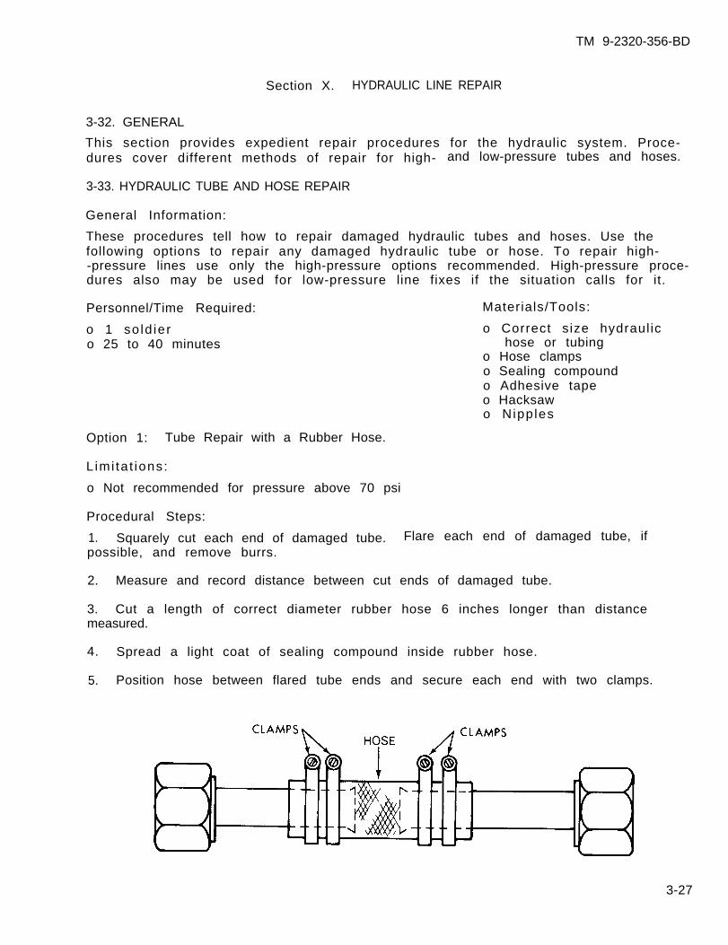
TM 9-2320-356-BD
Section X. HYDRAULIC LINE REPAIR
3-32. GENERAL
This section provides expedient repair procedures for the hydraulic system. Proce-dures cover different methods of repair for high- and low-pressure tubes and hoses.
3-33. HYDRAULIC TUBE AND HOSE REPAIR
General Information:
These procedures tell how to repair damaged hydraulic tubes and hoses. Use thefollowing options to repair any damaged hydraulic tube or hose. To repair high--pressure lines use only the high-pressure options recommended. High-pressure proce-dures also may be used for low-pressure line fixes if the situation calls for it.
Personnel/Time Required: Materials/Tools:
o 1 so ld ier o Correct size hydraul ico 25 to 40 minutes hose or tubing
o Hose clampso Sealing compoundo Adhesive tapeo Hacksawo Nipples
Option 1: Tube Repair with a Rubber Hose.
L imi ta t ions:
o Not recommended for pressure above 70 psi
Procedural Steps:
1. Squarely cut each end of damaged tube. Flare each end of damaged tube, ifpossible, and remove burrs.
2. Measure and record distance between cut ends of damaged tube.
3. Cut a length of correct diameter rubber hose 6 inches longer than distancemeasured.
4. Spread a light coat of sealing compound inside rubber hose.
5. Position hose between flared tube ends and secure each end with two clamps.
3-27
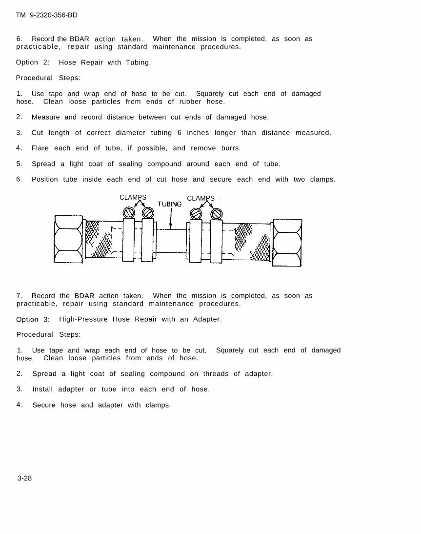
TM 9-2320-356-BD
6. Record the BDARpract icab le , repa i r
action taken. When the mission is completed, as soon asusing standard maintenance procedures.
Option 2: Hose Repair with Tubing.
Procedural Steps:
1. Use tape and wrap end of hose to be cut. Squarely cut each end of damagedhose. Clean loose particles from ends of rubber hose.
2. Measure and record distance between cut ends of damaged hose.
3. Cut length of correct diameter tubing 6 inches longer than distance measured.
4. Flare each end of tube, if possible, and remove burrs.
5. Spread a light coat of sealing compound around each end of tube.
6. Position tube inside each end of cut hose and secure each end with two clamps.
CLAMPS CLAMPS
7. Record the BDAR action taken. When the mission is completed, as soon aspracticable, repair using standard maintenance procedures.
Option 3: High-Pressure Hose Repair with an Adapter.
Procedural Steps:
1. Use tape and wrap each end of hose to be cut. Squarely cut each end of damagedhose. Clean loose particles from ends of hose.
2. Spread a light coat of sealing compound on threads of adapter.
3. Install adapter or tube into each end of hose.
4. Secure hose and adapter with clamps.
3-28

TM 9-2320-356-BD
5. Record the BDAR action taken. When the mission is completed, as soon aspract icab le , repair using standard maintenance procedures.
Option 4: High-Pressure Hose Repair (Same Size Hose Ends).
Procedural Steps:
1. Use tape and wrap each end of hose to be cut. Cut section of hose to lengthrequired. Be sure each end is squarely cut.
2. Spread a light coat of sealing compound on threads of one end of adapter.
3. Install end with sealing compound into hose. Secure with clamps.
4. Repeat steps 2 and 3 for other
5. Record the BDAR action taken.pract icab le , repair using standard
end of hose.
When the mission is completed, as soon asmaintenance procedures.
Option 5: High-Pressure Hose Repair (Different Size Line Ends).
Procedural Steps:
1. Use tape and wrap each end of hose to be cut. Cut section of hose to lengthreauired. Be sure
2. Spread a light
3. Instal l end of
each end is squarely cut.
coat of sealing compound on threads of one end of reducer.
reducer with sealing compound into hose. Secure with clamp.
3-29
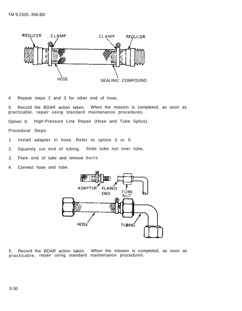
TM 9-2320 -356-BD
HOSE SEALING’ COMPOUND
4. Repeat steps 2 and 3 for other end of hose.
5. Record the BDAR action taken. When the mission is completed, as soon aspracticable, repair using standard maintenance procedures.
Option 6: High-Pressure Line Repair (Hose and Tube Splice).
Procedural Steps:
1. Install adapter in hose. Refer to option 3 or 5.
2. Squarely cut
3. Flare end of
4. Connect hose
end of tubing.
tube and remove
and tube.
Slide tube nut over tube,
burrs .
5. Record the BDAR action taken. When the mission is completed, as soon aspract icab le , repair using standard maintenance procedures.
3-30
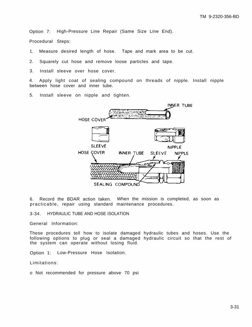
TM 9-2320-356-BD
Option 7: High-Pressure Line Repair (Same Size Line End).
Procedural Steps:
1. Measure desired length of hose. Tape and mark area to be cut.
2. Squarely cut hose and remove loose particles and tape.
3. Install sleeve over hose cover.
4. Apply light coat of sealing compound on threads of nipple. Install nipplebetween hose cover and inner tube.
5. Install sleeve on nipple and tighten.
6. Record the BDAR action taken. When the mission is completed, as soon aspract icab le , repair using standard maintenance procedures.
3-34. HYDRAULIC TUBE AND HOSE ISOLATION
General Information:
These procedures tell how to isolate damaged hydraulic tubes and hoses. Use thefollowing options to plug or seal a damaged hydraulic circuit so that the rest ofthe system can operate without losing fluid.
Option 1: Low-Pressure Hose Isolation.
L imi ta t ions:
o Not recommended for pressure above 70 psi
3-31
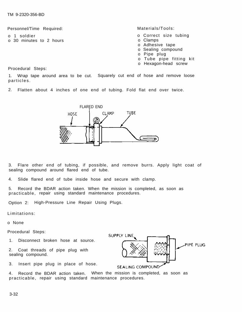
TM 9-2320-356-BD
Personnel/Time Required:
o 1 so ld iero 30 minutes to 2 hours
Mater ia ls /Tools :
o Correct size tubingo Clampso Adhesive tapeo Sealing compoundo Pipe plugo Tube p ipe f i t t ing k i to Hexagon-head screw
Procedural Steps:
1. Wrap tape around area to be cut. Squarely cut end of hose and remove loosepa r t i c l es .
2. Flatten about 4 inches of one end of tubing. Fold flat end over twice.
FLARED END
3. Flare other end of tubing, if possible, and remove burrs. Apply light coat ofsealing compound around flared end of tube.
4. Slide flared end of tube inside hose and secure with clamp.
5. Record the BDAR action taken. When the mission is completed, as soon as pract icab le , repair using standard maintenance procedures.
Option 2: High-Pressure Line Repair Using Plugs.
1. Disconnect broken hose at source.
2. Coat threads of pipe plug withsealing compound.
3. Insert pipe plug in place of hose.
4. Record the BDAR action taken. When the mission is completed, as soon aspract icab le , repair using standard maintenance procedures.
3-32
L im i t a t i ons :
o None
Procedural Steps:
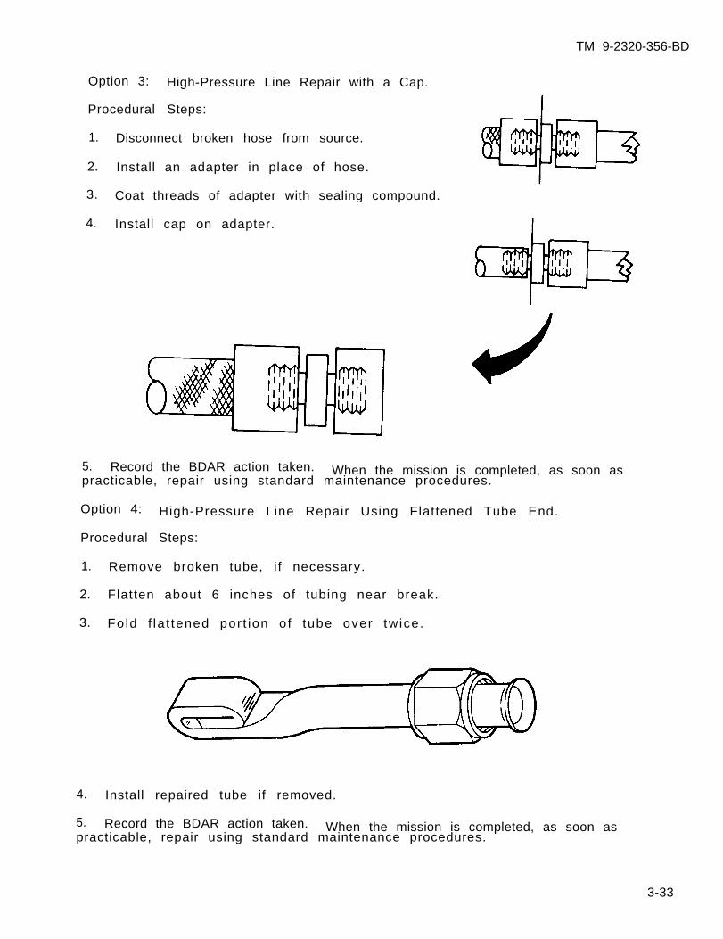
TM 9-2320-356-BD
Option 3: High-Pressure Line Repair with a Cap.
Procedural Steps:
1. Disconnect broken hose from source.
2. Install an adapter in place of hose.
3. Coat threads of adapter with sealing compound.
4. Install cap on adapter.
5. Record the BDAR action taken. When the mission is completed, as soon aspracticable, repair using standard maintenance procedures.
Option 4: High-Pressure Line Repair Using Flattened Tube End.
Procedural Steps:
1. Remove broken tube, i f necessary.
2. Flatten about 6 inches of tubing near break.
3. Fo ld f la t tened por t ion o f tube over tw ice.
4. Install repaired tube if removed.
5. Record the BDAR action taken. When the mission is completed, as soon aspracticable, repair using standard maintenance procedures.
3-33

TM 9-2320-356-BD
Option 5: High-Pressure Line Repair Using a Bolt.
Procedural Steps:
1. Wrap tape around area to be cut. Squarely cut end of hose and remove loosepa r t i c l es .
2. Install long hexagon-head screw inside hose.
3. Secure with clamps.
4. Record the BDAR action taken. When the mission is completed, as soon aspracticable, repair using standard maintenance procedures.
3-34
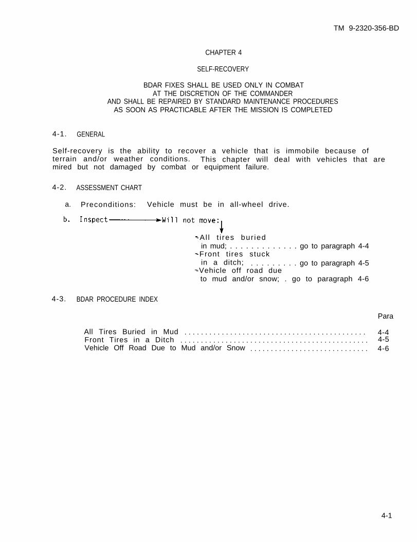
TM 9-2320-356-BD
CHAPTER 4
SELF-RECOVERY
BDAR FIXES SHALL BE USED ONLY IN COMBATAT THE DISCRETION OF THE COMMANDER
AND SHALL BE REPAIRED BY STANDARD MAINTENANCE PROCEDURESAS SOON AS PRACTICABLE AFTER THE MISSION IS COMPLETED
4-1. GENERAL
Self-recovery is the ability to recover a vehicle that is immobile because ofterrain and/or weather conditions. This chapter will deal with vehicles that aremired but not damaged by combat or equipment failure.
4-2. ASSESSMENT CHART
a. Precondit ions: Vehicle must be in all-wheel drive.
-A l l t i res bur iedin mud; . . . . . . . . . . . . . go to paragraph 4-4
-Front t i res stuckin a ditch; . . . . . . . . . go to paragraph 4-5
-Vehicle off road dueto mud and/or snow; . go to paragraph 4-6
4-3. BDAR PROCEDURE INDEX
Para
All Tires Buried in Mud . . . . . . . . . . . . . . . . . . . . . . . . . . . . . . . . . . . . . . . . . . . . 4-4Front Tires in a Ditch . . . . . . . . . . . . . . . . . . . . . . . . . . . . . . . . . . . . . . . . . . . . . .Vehicle Off Road Due to Mud and/or Snow . . . . . . . . . . . . . . . . . . . . . . . . . . . . . 4-6
4-1
4-5
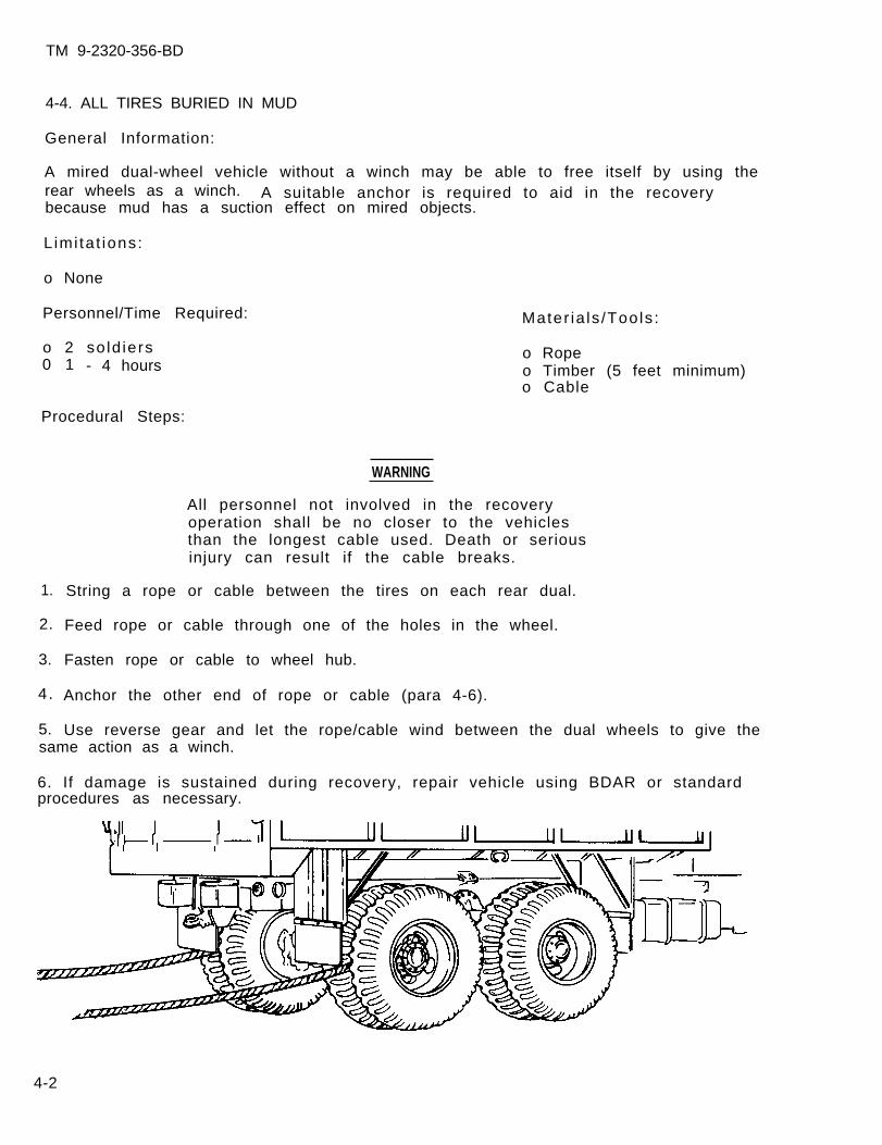
TM 9-2320-356-BD
4-4. ALL TIRES BURIED IN MUD
General Information:
A mired dual-wheel vehicle without a winch may be able to free itself by using therear wheels as a winch. A suitable anchor is required to aid in the recoverybecause mud has a suction effect on mired objects.
L imi ta t ions:
o None
Personnel/Time Required:
o 2 so ld iers0 1 - 4 hours
Procedural Steps:
Mater ia ls /Tools :
o Ropeo Timber (5 feet minimum)o Cable
1.
2.
3.
4.
5.
WARNING
All personnel not involved in the recoveryoperation shall be no closer to the vehiclesthan the longest cable used. Death or seriousinjury can result if the cable breaks.
String a rope or cable between the tires on each rear dual.
Feed rope or cable through one of the holes in the wheel.
Fasten rope or cable to wheel hub.
Anchor the other end of rope or cable (para 4-6).
Use reverse gear and let the rope/cable wind between the dual wheels to give thesame action as a winch.
6. If damage is sustained during recovery, repair vehicle using BDAR or standardprocedures as necessary.
4-2
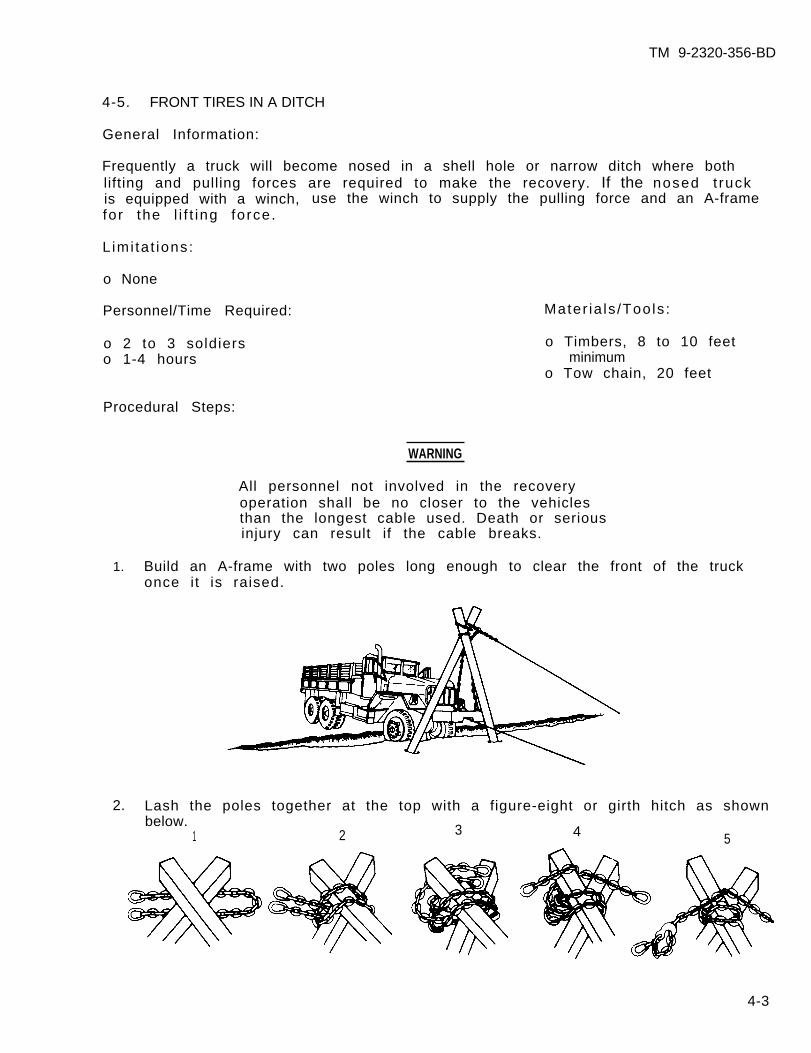
TM 9-2320-356-BD
4-5. FRONT TIRES IN A DITCH
General Information:
Frequently a truck will become nosed in a shell hole or narrow ditch where bothlifting and pulling forces are required to make the recovery. If the nosed t ruckis equipped with a winch, use the winch to supply the pulling force and an A-framefor the l i f t ing force.
L imi ta t ions:
o None
Personnel/Time Required: Mater ia ls /Tools :
o 2 to 3 soldiers o Timbers, 8 to 10 feeto 1-4 hours minimum
o Tow chain, 20 feet
Procedural Steps:
WARNING
All personnel not involved in the recoveryoperation shall be no closer to the vehiclesthan the longest cable used. Death or seriousinjury can result if the cable breaks.
1. Build an A-frame with two poles long enough to clear the front of the truckonce it is raised.
2. Lash the poles together at the top with a figure-eight or girth hitch as shownbelow.
1 2 3 4 5
4-3
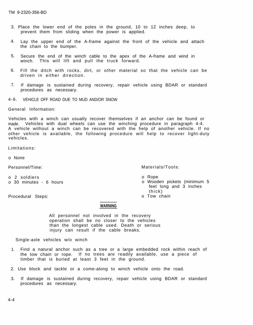
TM 9-2320-356-BD
3. Place the lower end of the poles in the ground, 10 to 12 inches deep, toprevent them from sliding when the power is applied.
4. Lay the upper end of the A-frame against the front of the vehicle and attachthe chain to the bumper.
5. Secure the end of the winch cable to the apex of the A-frame and wind inwinch. This wil l l i f t and pull the truck forward.
6. Fi l l the ditch with rocks, dir t , or other material so that the vehicle can bedr iven in e i ther d i rec t ion.
7. If damage is sustained during recovery, repair vehicle using BDAR or standardprocedures as necessary.
4-6. VEHICLE OFF ROAD DUE TO MUD AND/OR SNOW
General Information:
Vehicles with a winch can usually recover themselves if an anchor can be found ormade. Vehicles with dual wheels can use the winching procedure in paragraph 4-4.A vehicle without a winch can be recovered with the help of another vehicle. If noother vehicle is avai lable, the fol lowing procedure wil l help to recover l ight-dutyvehicles.
L imi ta t ions:
o None
Personnel/Time:
o 2 so ld ierso 30 minutes - 6 hours
Procedural Steps:
Mater ia ls /Tools :
o Ropeo Wooden pickets (minimum 5
feet long and 3 inchest h i c k )
o Tow chain
WARNING
All personnel not involved in the recoveryoperation shall be no closer to the vehiclesthan the longest cable used. Death or seriousinjury can result if the cable breaks.
Single-axle vehicles w/o winch
1. Find a natural anchor such as a tree or a large embedded rock within reach ofthe tow chain or rope. If no trees are readily available, use a piece oftimber that is buried at least 3 feet in the ground.
2. Use block and tackle or a come-along to winch vehicle onto the road.
3. If damage is sustained during recovery, repair vehicle using BDAR or standardprocedures as necessary.
4-4
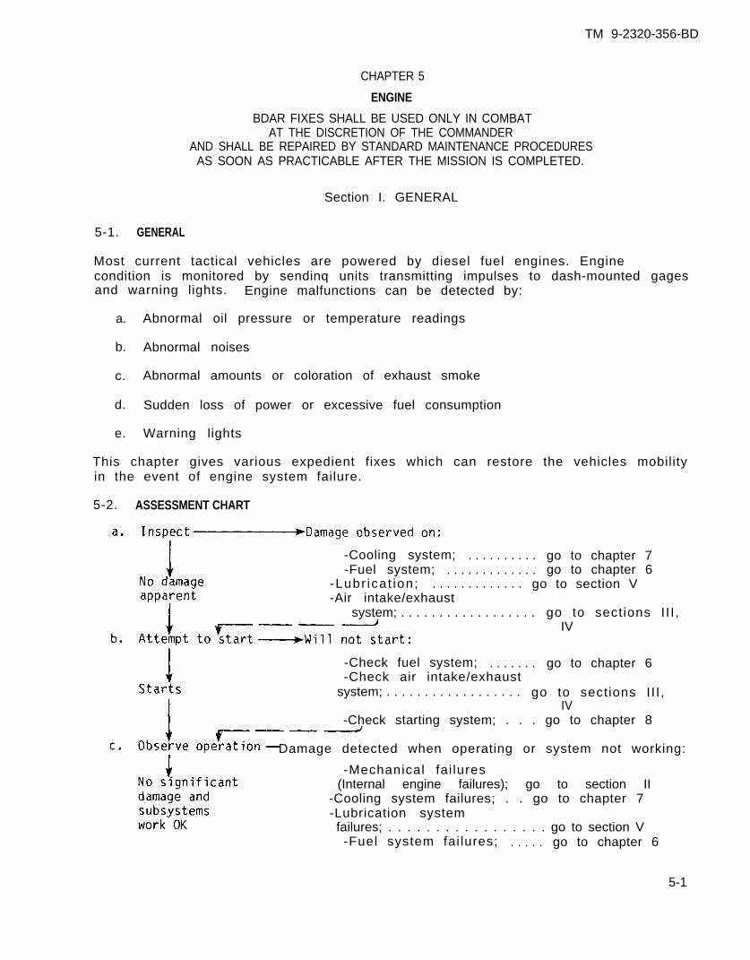
TM 9-2320-356-BD
CHAPTER 5
ENGINE
BDAR FIXES SHALL BE USED ONLY IN COMBATAT THE DISCRETION OF THE COMMANDER
AND SHALL BE REPAIRED BY STANDARD MAINTENANCE PROCEDURESAS SOON AS PRACTICABLE AFTER THE MISSION IS COMPLETED.
Section I. GENERAL
5-1. GENERAL
Most current tactical vehicles are powered by diesel fuel engines. Enginecondition is monitored by sendinq units transmitting impulses to dash-mounted gagesand warning lights. Engine malfunctions can be detected by:
a. Abnormal oil pressure or temperature readings
b. Abnormal noises
c. Abnormal amounts or coloration of exhaust smoke
d. Sudden loss of power or excessive fuel consumption
e. Warning lights
This chapter gives various expedient fixes which can restore the vehicles mobilityin the event of engine system failure.
5-2. ASSESSMENT CHART
-Cooling system; . . . . . . . . . . go to chapter 7-Fuel system; . . . . . . . . . . . . . go to chapter 6
-Lubr icat ion; . . . . . . . . . . . . . go to section V-Air intake/exhaust
system; . . . . . . . . . . . . . . . . . . go to sections II I ,IV
-Check fuel system; . . . . . . . go to chapter 6-Check air intake/exhaust
system; . . . . . . . . . . . . . . . . . . go to sections II I ,IV
-Check starting system; . . . go to chapter 8
Damage detected when operating or system not working:
-Mechanical fai lures(Internal engine failures); go to section II
-Cooling system failures; . . go to chapter 7-Lubrication systemfailures; . . . . . . . . . . . . . . . . . go to section V-Fuel system fai lures; . . . . . go to chapter 6
5-1
TM 9-2320-356-BD
5-3. BDAR PROCEDURE INDEX Para
Engine Interchangeabil i ty . . . . . . . . . . . . . . . . . . . . . . . . . . . . . . . . . . . . . . . . . . .Engine Air Intake for Naturally Aspirated Engines . . . . . . . . . . .Engine Air Intake for Turbocharged Engines . . . . . . . . . . . . . . . . . .Engine Air Intake for Supercharged or Turbosupercharged EnginesBlower Drive Shaft Broken
. . . . .. . . . . . . . . . . . . . . . . . . . . . . . . . . . . . . . . . . . . . . . . . .
Air Cleaner Clogged . . . . . . . . . . . . . . . . . . . . . . . . . . . . . . . . . . . . . . . .Air Cleaner Damaged/Leaking . . . . . . . . . . . . . . . . . . . . . . . . . . . . . . . . . . . . . . . . .Intake Manifold or Other Castings or Containers DamagedExhaust Manifolds Damaged
. . . . . . . . . . . . .. . . . . . . . . . . . . . . . . . . . . . . . . . . . . . . . . . .
Lubrication System Pump Failure . . . . . . . . . . . . . . . . . . . . . . . . . . . . . . . . . . . . .Oil Level Low . . . . . . . . . . . . . . . . . . . . . . . . . . . . . . . . . . . . . . . . . . . . . . . . . . . . . .Hole in Oil Pan . . . . . . . . . . . . . . . . . . . . . . . . . . . . . . . . . . . . . . . . . . . . . . . . . . . . .
5-55-65-75-85-95-105-115-125-145-165-175-18
5-2
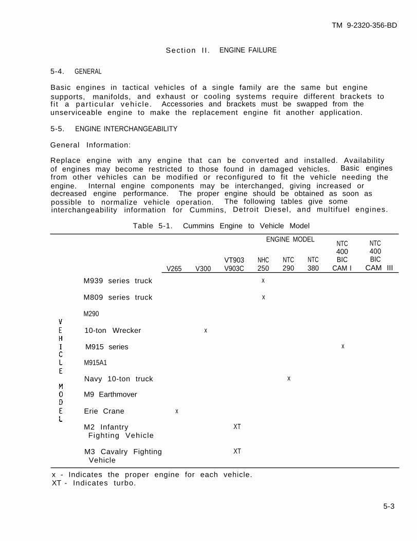
TM 9-2320-356-BD
Sect ion I I . ENGINE FAILURE
5-4. GENERAL
Basic engines in tactical vehicles of a single family are the same but enginesupports, manifolds, and exhaust or cooling systems require different brackets tof i t a par t icu lar veh ic le . Accessories and brackets must be swapped from theunserviceable engine to make the replacement engine fit another application.
5-5. ENGINE INTERCHANGEABILITY
General Information:
Replace engine with any engine that can be converted and installed. Availabilityof engines may become restricted to those found in damaged vehicles. Basic enginesfrom other vehicles can be modified or reconfigured to fit the vehicle needing theengine. Internal engine components may be interchanged, giving increased ordecreased engine performance. The proper engine should be obtained as soon aspossible to normalize vehicle operation. The following tables give someinterchangeability information for Cummins, Detroit Diesel, and mult i fuel engines.
Table 5-1. Cummins Engine to Vehicle Model
ENGINE MODELNTC NTC400 400
VT903 NHC NTC NTC BIC BICV265 V300 V903C 250 290 380 CAM I CAM III
M939 series truck x
M809 series truck x
M290
10-ton Wrecker
M915 series
M915A1
Navy 10-ton truck
M9 Earthmover
Erie Crane
x
x
x
x
M2 Infantry XTFighting Vehicle
M3 Cavalry Fighting XTVehicle
x - Indicates the proper engine for each vehicle.XT - Indicates turbo.
5-3
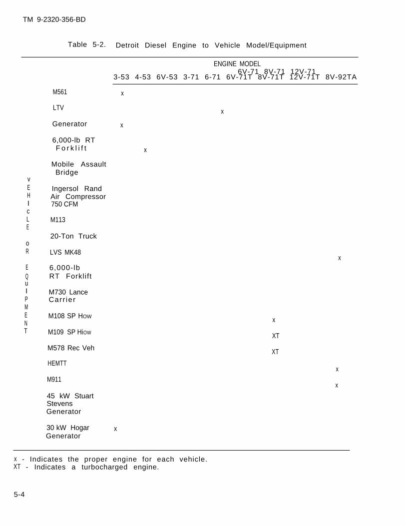
TM 9-2320-356-BD
Table 5-2. Detroit Diesel Engine to Vehicle Model/Equipment
ENGINE MODEL
x
vEHIcLE
oR
EQu
6V-71 8V-71 12V-713-53 4-53 6V-53 3-71 6-71 6V-71T 8V-71T 12V-71T 8V-92TA
M561 x
LTV x
Generator x
6,000-lb RTF o r k l i f t
Mobile AssaultBridge
Ingersol RandAir Compressor750 CFM
M113
20-Ton Truck
LVS MK48
6,000-lbRT Forklift
M730 LanceCarr ier
M108 SP HOW
M109 SP HiOW
M578 Rec Veh
HEMTT
M911
45 kW StuartStevensGenerator
30 kW Hogar xGenerator
IPMENT
x
x
x
x
XT
XT
x - Indicates the proper engine for each vehicle.XT - Indicates a turbocharged engine.
5-4
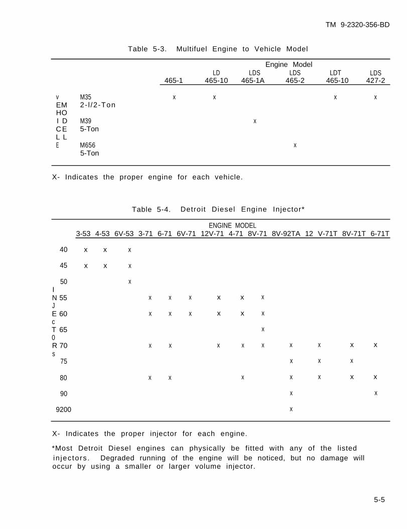
TM 9-2320-356-BD
Table 5-3. Multifuel Engine to Vehicle Model
Engine ModelLD LDS LDS LDT LDS
465-1 465-10 465-1A 465-2 465-10 427-2
v M35 x x x xEM 2- l /2-TonHOI D M39 xC E 5-TonL LE M656 x
5-Ton
X- Indicates the proper engine for each vehicle.
Table 5-4. Detroit Diesel Engine Injector*
ENGINE MODEL3-53 4-53 6V-53 3-71 6-71 6V-71 12V-71 4-71 8V-71 8V-92TA 12 V-71T 8V-71T 6-71T
40
45
50IN 55JE 60cT 650R 70s
75
80
90
9200
x x x
x x x
x
x
x
x
x
x
x
x
x
x x x
x x x
x x
x
x
x
x
x x x x x
x x x
x x x x
x x
x
X- Indicates the proper injector for each engine.
*Most Detroit Diesel engines can physically be fitted with any of the listedin jec tors . Degraded running of the engine will be noticed, but no damage willoccur by using a smaller or larger volume injector.
5-5
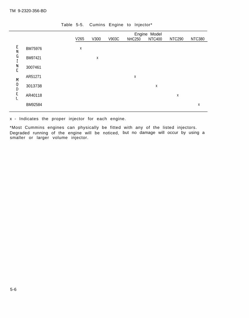
TM 9-2320-356-BD
Table 5-5. Cumins Engine to Injector*
Engine ModelV265 V300 V903C NHC250 NTC400 NTC290 NTC380
BM75976 x
BM97421 x
3007461
AR51271
3013738
AR40118 x
BM92584 x
x
x
x - Indicates the proper injector for each engine.
*Most Cummins engines can physically be fitted with any of the listed injectors.Degraded running of the engine will be noticed, but no damage will occur by using asmaller or larger volume injector.
5-6
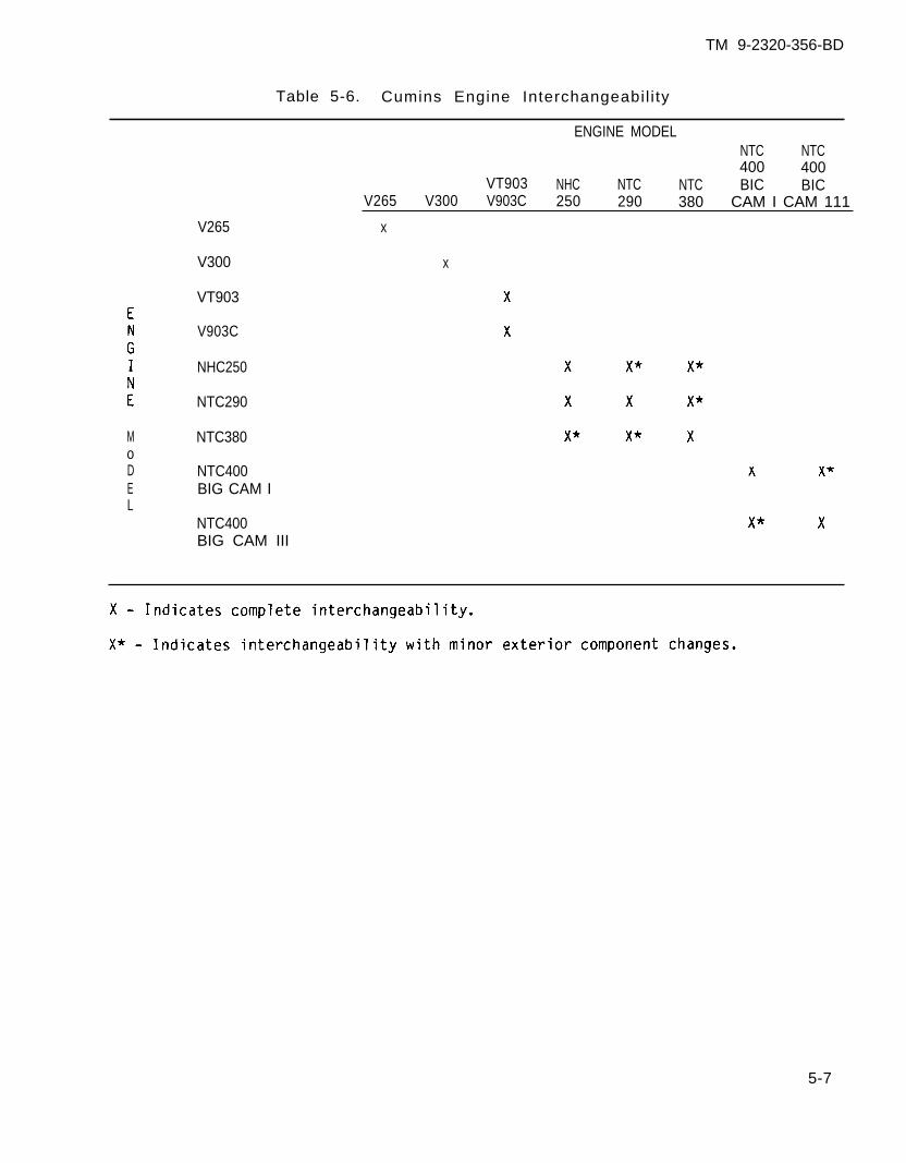
TM 9-2320-356-BD
Table 5-6. Cumins Engine Interchangeabil i ty
MoDEL
V265
V300
VT903
V903C
NHC250
NTC290
NTC380
NTC400BIG CAM I
NTC400BIG CAM III
ENGINE MODELNTC NTC400 400
VT903 NHC NTC NTC BIC BICV265 V300 V903C 250 290 380 CAM I CAM 111
x
x
5-7
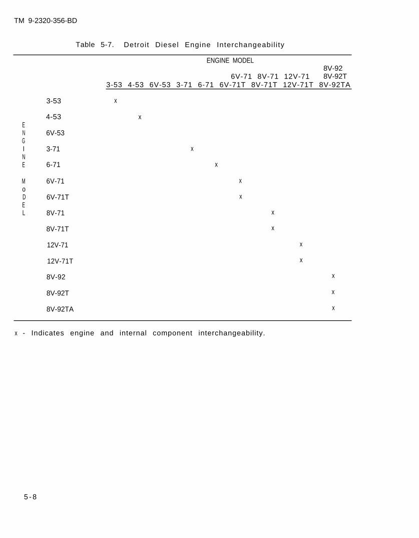
TM 9-2320-356-BD
Table 5-7. Detroit Diesel Engine Interchangeabil i ty
ENGINE MODEL8V-92
6V-71 8V-71 12V-71 8V-92T3-53 4-53 6V-53 3-71 6-71 6V-71T 8V-71T 12V-71T 8V-92TA
x
ENGINE
MoDEL
3-53
4-53
6V-53
3-71
6-71
6V-71
6V-71T
8V-71
8V-71T
12V-71
12V-71T
8V-92 x
8V-92T x
8V-92TA x
x
x
x
x
x
x
x
x
x
x - Indicates engine and internal component interchangeability.
5 - 8
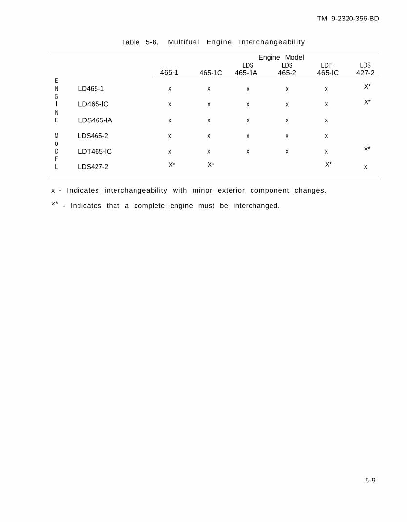
TM 9-2320-356-BD
Table 5-8. Mult i fuel Engine Interchangeabil i ty
Engine ModelLDS LDS LDT LDS
465-1 465-1C 465-1A 465-2 465-lC 427-2EN LD465-1 x x x x x X*GI LD465-lC x x x x x X*
NE LDS465-lA x x x x x
M LDS465-2 x x x x xoD LDT465-lC x x x x x ×*EL LDS427-2 X* X* X* x
x - Indicates interchangeability with minor exterior component changes.
×* - Indicates that a complete engine must be interchanged.
5-9
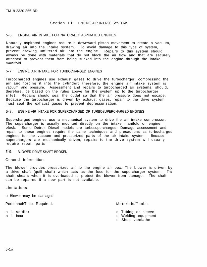
TM 9-2320-356-BD
Sect ion I I I . ENGINE AIR INTAKE SYSTEMS
5-6. ENGINE AIR INTAKE FOR NATURALLY ASPIRATED ENGINES
Naturally aspirated engines require a downward piston movement to create a vacuum,drawing air into the intake system. To avoid damage to this type of system,prevent drawing unfiltered air into the engine. Repairs to this system shouldalways be done with materials that do not block the air flow and that are securelyattached to prevent them from being sucked into the engine through the intakemanifold.
5-7. ENGINE AIR INTAKE FOR TURBOCHARGED ENGINES
Turbocharged engines use exhaust gases to drive the turbocharger, compressing theair and forcing i t into the cyl inder; therefore, the engine air intake system isvacuum and pressure. Assessment and repairs to turbocharged air systems, should,therefore, be based on the rules above for the system up to the turbochargeri n l e t . Repairs should seal the outlet so that the air pressure does not escape.Because the turbocharger is driven by exhaust gases, repair to the drive systemmust seal the exhaust gases to prevent depressurization.
5-8. ENGINE AIR INTAKE FOR SUPERCHARGED OR TURBOSUPERCHARGED ENGINES
Supercharged engines use a mechanical system to drive the air intake compressor.The supercharger is usually mounted directly on the intake manifold or engineblock. Some Detroit Diesel models are turbosupercharged. Damage assessment andrepair to these engines require the same techniques and precautions as turbochargedengines for the vacuum and pressurized parts of the air intake system. Becausesuperchargers are mechanically driven, repairs to the drive system wil l usual lyrequire repair parts.
5-9. BLOWER DRIVE SHAFT BROKEN
General Information:
The blower provides pressurized air to the engine air box. The blower is driven bya drive shaft (quill shaft) which acts as the fuse for the supercharger system. Theshaft shears when it is overloaded to protect the blower from damage. The shaftcan be repaired if a new part is not available.
L imi ta t ions:
o Blower may be damaged
Personnel/Time Required: Mater ia ls /Tools :
o 1 so ld iero 1 hour
o Tubing or sleeveo Welding equipmento Shop van/lathe
5-1o
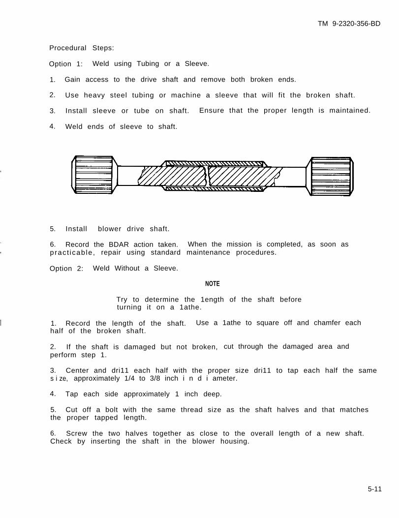
TM 9-2320-356-BD
Procedural Steps:
Option 1: Weld using Tubing or a Sleeve.
1. Gain access to the drive shaft and remove both broken ends.
2. Use heavy steel tubing or machine a sleeve that will fit the broken shaft.
3. Install sleeve or tube on shaft. Ensure that the proper length is maintained.
4. Weld ends of sleeve to shaft.
5. Install blower drive shaft.
6. Record the BDAR action taken. When the mission is completed, as soon aspract icab le , repair using standard maintenance procedures.
Option 2: Weld Without a Sleeve.
NOTE
Try to determine the 1ength of the shaft beforeturning it on a 1athe.
1. Record the length of the shaft. Use a 1athe to square off and chamfer eachhalf of the broken shaft.
2. If the shaft is damaged but not broken, cut through the damaged area andperform step 1.
3. Center and dri11 each half with the proper size dri11 to tap each half the sames i ze, approximately 1/4 to 3/8 inch i n d i ameter.
4. Tap each side approximately 1 inch deep.
5. Cut off a bolt with the same thread size as the shaft halves and that matchesthe proper tapped length.
6. Screw the two halves together as close to the overall length of a new shaft.Check by inserting the shaft in the blower housing.
5-11
TM 9-2320-356-BD
7. After the proper length has been determined unscrew the two halves. Find andinsert a spacer (e.g., washer or nut) that will allow the two shafts to be screwedtogether t ight for proper length.
8. Screw both halves together tight.
9. Chuck the newly made shaft into a lathe.
10. Put a rotat ing center into the tai lstock of the lathe. Adjust the tai lstock toaline the shaft.
11. Turn the lathe by hand and check the shaft for straightness. Tap with a lighthammer if necessary.
CAUTION
Tack the two halves together at four differentpoints to help keep the shaft true. Excess heatcan cause warpage and damage to the shaft.
12. Weld the shaft together whi le the shaft is st i l l locked in the lathe. Rotateand check the shaft after every tack and every weld.
13. Bathe the shaft in clean SAE 30 motor oil to cool.
14. Instal l blower drive shaft.
15. Record the BDAR action taken. When the mission is completed, as soon aspract icab le , repair using standard maintenance procedures.
5-1o. AIR CLEANER CLOGGED
General Information:
The air cleaner is essential for keeping dirt and dust from getting into theengine. Under heavy dust conditions the filter can become clogged and restrict theai r f low. Lack of air wi l l result in incomplete fuel combustion, result ing inreduced power and excessive exhaust smoke. Dirt should be blown out of the filterwith compressed air directed from the inside of the filter element. The f i l t e relement may be tapped to dislodge dirt.
L imi ta t ions:
o None
Personnel/Time Required: Mater ia ls /Tools :
o 1 so ld iero 15 minutes
o Rubber hose(Part of B11)
5-12

TM 9-2320-356-BD
Other Options:
o Use vacuum cleanero Gently tap f i l ter against hard surface
Procedural Steps:
1. Remove air cleaner elements.
2. Clean filters using one of the following methods:
a. Dismount a blower motor (such as dust exhausters), connect to power sourcewith long leads, and blow dirt from air cleaner.
b. Disconnect exhaust hoses from all but one blower. Connect hoses togetherusing tape to gain sufficient length to reach outside. Start engine and blower andblow dirt deposits from f i l ters.
c. Use air from a disabled wheeled vehicle’s tires. Remove valve stem andconnect rubber hose to valve and blow out filters.
d. Use brake air tank from wheeled vehicle by connecting rubber hose, or placefi l ter directly under air f low from valve.
3. Record the BDAR action taken. When the mission is completed, as soon aspracticable, repair using standard maintenance procedures.
5-11. AIR CLEANER DAMAGED/LEAKING
General Information:
The air cleaner must filter incoming air for the engine. Damage or leaks thatcause the air cleaner to be ineffective must be repaired. Leaks in the f i l terhousing or duct work can be taped over or covered by a rag that will filter aircoming through the leak. Sealing the leak is preferred. Only as a last resortshould the air cleaner be bypassed or eliminated. Damage will occur as the engineingests the dirt and dust from unfiltered air. I f the only option is to el iminatethe air f i l ter, this procedure wil l al low a minimum amount of air f i l trat ion.
L imi ta t ions:
o Possible degraded mobility
Personnel/Time Required:
o 1 so ld iero 30 minutes
Mater ia ls /Tools :
o Duct or electr ical tapeo Section cut from blanket
o r sh i r to Hoseo Clampo Wire
5-13
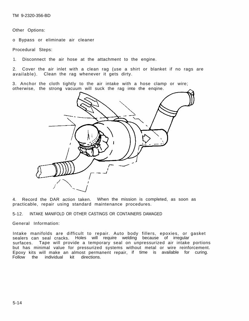
TM 9-2320-356-BD
Other Options:
o Bypass or eliminate air cleaner
Procedural Steps:
1. Disconnect the air hose at the attachment to the engine.
2. Cover the air inlet with a clean rag (use a shirt or blanket if no rags areavai lab le) . Clean the rag whenever it gets dirty.
3. Anchorotherwise,
the cloth tightly to the air intake with a hose clamp or wire;the strong vacuum will suck the rag into the enqine.
4. Record the DAR action taken. When the mission is completed, as soon aspracticable, repair using standard maintenance procedures.
5-12. INTAKE MANIFOLD OR OTHER CASTINGS OR CONTAINERS DAMAGED
General Information:
Intake manifolds are dif f icult to repair. Auto body f i l lers, epoxies, or gasketsealers can seal cracks. Holes will require welding because of irregularsurfaces. Tape will provide a temporary seal on unpressurized air intake portionsbut has minimal value for pressurized systems without metal or wire reinforcement.Epoxy kits will make an almost permanent repair, if time is available for curing.Follow the individual kit directions.
5-14

TM 9-2320-356-BD
Section IV. ENGINE EXHAUST SYSTEMS
5-13. GENERAL
The engine exhaust system consists of the exhaust manifold, muffler, and pipes toroute the gases out of the vehicle. Turbocharged engines have the exhaust gasesrouted through the turbocharger to drive the vanes. Damage to the muffler or pipes(not including the ducting for the turbocharger drive circuit) is inconvenient, butthe vehicle can still be operated. Care must be taken, however, to keep carbonmonoxide out of the crew compartments. Turbocharger drive circuits must berepaired or engine performance will be degraded.
5-14. EXHAUST MANIFOLDS DAMAGED
General Information:
Damaged manifolds are indicated by loud noises. Damage to the exhaust manifoldsahead of the turbocharger will degrade vehicle operation. Continued engineoperation may
Limi ta t ions:
o None
set the fuel l ines on f ire.
Personnel/Time Required:
o 1 so ld iero 15-30 minutes
Mater ia ls /Tools :
o Sheet metalo Clampso Asbestos sheeto Sealing material
Other Options:
o Weld or braze the manifold.
Procedural Steps:
1. Gain access to the damaged manifold.
2. Obtain a sealing material (asbestos sheet preferred) and cut sheet to cover thehole or leak.
3. Use hose clamps
4. Record the BDARpract icab le , repa i r
and secure the
action taken.using standard
sheet in place.
When the mission is completed, as soon asmaintenance procedures.
5-15
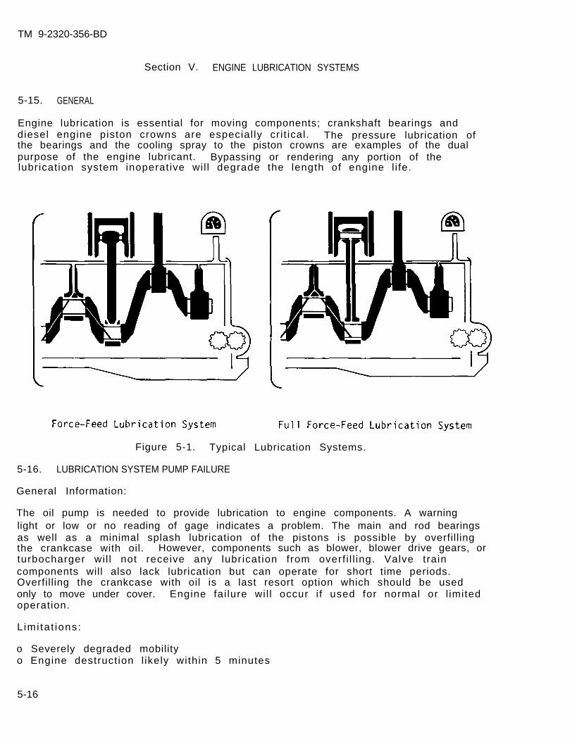
TM 9-2320-356-BD
Section V. ENGINE LUBRICATION SYSTEMS
5-15. GENERAL
Engine lubrication is essential for moving components; crankshaft bearings anddiesel engine piston crowns are especial ly cri t ical. The pressure lubrication ofthe bearings and the cooling spray to the piston crowns are examples of the dualpurpose of the engine lubricant. Bypassing or rendering any portion of thelubrication system inoperative wil l degrade the length of engine l i fe.
Figure 5-1. Typical Lubrication Systems.
5-16. LUBRICATION SYSTEM PUMP FAILURE
General Information:
The oil pump is needed to provide lubrication to engine components. A warninglight or low or no reading of gage indicates a problem. The main and rod bearingsas well as a minimal splash lubrication of the pistons is possible by overfillingthe crankcase with oil. However, components such as blower, blower drive gears, orturbocharger wi l l not receive any lubricat ion from overf i l l ing. Valve traincomponents will also lack lubrication but can operate for short time periods.Overfilling the crankcase with oil is a last resort option which should be usedonly to move under cover. Engine fai lure wil l occur i f used for normal or l imitedoperation.
L imi ta t ions:
o Severely degraded mobilityo Engine destruct ion l ikely within 5 minutes
5-16
TM 9-2320-356-BD
Personnel/Time Required: Mater ia ls /Tools :
o 1 so ld iero 15-20 minutes
o Cooking oilo Engine oilo Transmission oi lo Diese l fue l
Procedural Steps:
1. Check oil level.
2. Obtain enough engine or substitute oil to overfill crankcase.
3. Overf i l l the crankcase.
4. Record the BDAR action taken. When the mission is completed, as soon aspracticable, repair using standard maintenance procedures.
5-17. OIL LEVEL LOW
General Information:
Oil levels can become low because of leakage or burning the oil through normalengine operation. If oils prescribed by the LO are not available, use substituteslisted in appendix D. Oils other than those designed for use in engines willprovide l imited lubricat ion. When using diesel fuel, do not di lute the lubricat ionoil more than approximately three parts diesel fuel to one part engine oil exceptin extreme emergencies. Keep engine rpm low. Do not di lute lubricating oi l withgasoline.
5-18. HOLE IN OIL PAN
General Information:
The oil pan is located at the bottom of the crankcase and serves as an oilreservoir for the engine. In rough terrain, the pan can be punctured very easilybecause of its location.
L imi ta t ions:
o Engine fa i lure
Personnel/Time Required:
o 1 so ld iero 2-4 hours
Mater ia ls /Tools :
o Hardening epoxyo Wire screen (fine mesh)o Aluminum cano Sandpaper
5-17
TM 9-2320-356-BO
Procedural Steps:
1. Clean the hole thoroughly.
2. Smooth out sharp edges.
3. Sandpaper the edges of the hole.
4. Cut a piece of screen 1 inch larger than the hole.
5. Apply a thin coat of epoxy to the edges of the hole.
6. Lay the screen over the hole and add another layer of epoxy around the edges.Let it dry approximately 20 to 30 minutes.
7. Cut a patch the same size as the screen from an aluminum can.
8. Coat the entire screen with epoxy and lay the metal patch over the screen.
9. Apply epoxy over the patch.
10. Let dry for 2 to 3 hours.
11. Record the BDAR action taken. When the mission is completed, as soon aspracticable, repair using standard maintenance procedures.
5-18

TM 9-2320-356-BD
CHAPTER 6
FUEL SUPPLY SYSTEM
BDAR FIXES SHALL BE USED ONLY IN COMBATAT THE DISCRETION OF THE COMMANDER
AND SHALL BE REPAIRED BY STANDARD MAINTENANCE PROCEDURESAS SOON AS PRACTICABLE AFTER THE MISSION IS COMPLETED.
Section I. GENERAL
6-1. GENERAL
Fuel supply systems consist of fuel storage tanks, fuel pumps, filters, and thetubes and hoses needed to route the fuel to the engine. Some systems use electri-cal pumps located in the tanks and a mechanized, engine-mounted pump to move thefue l . Other systems mount the fuel storage tank in a location which allows gravityflow of the fuel to the engine, assisted by an engine-mounted, mechanized pump.Two filters are mounted in series to provide a primary and secondary filtrationsystem to trap dirt and other contaminants. Fuel filters must be checked foraccumulations of dirt and water. A diesel engine can be severely damaged by usingunf i l te red fue ls .
6-2. ASSESSMENT PROCEDURE
-Fuel tank; . . . . . . . . . . . go to section II-Fuel lines; . . . . . . . . . . . go to section IV-Fuel filters; . . . . . . . . . go to section V
-Tank or lines; . . . . . . . . go to sections II and IV-Pump or pumps
inoperative; . . . . . . . . . . go to section II I-Fue l f i l t e r o rfilters inoperative; . . go to section V
-Pumps found; . . . . . . . . . . go to section II I-Fuel filters found; . . . go to section V
6-1
TM 9-2320-356-BD
6-3. BDAR PROCEDURE INDEX
Fuel Tank Leaks . . . . . . . . . . . . . . . . . . . . . . . . . . . . . . . . . . . . . . . . . . . . . . . . . . . .Fuel Tank Substitute . . . . . . . . . . . . . . . . . . . . . . . ...... . . . . . . . . . . . . . . . .In-tank Fuel Pump Interchangeability . . . . . . . . . . . . . . . . . . . . . . . . . . . . . . .Engine Fuel Pump Interchangeability . . . . . . . . ... . . . . . . . . . . . . . .Fuel System Seals Leak . . . . . . . . . . . . . . . . . . . . . . . . . . . . . . . . . .. . . . . . . .Fit t ings Leak . . . . . . . . . . . . . . . . . . . . . . . . . . . . . . . . . . . ..... . . . . . . . . .Fuel Line (Low Pressure Rupture) . . . . . . . . ..... . . . . . . . . . . . . . . . . . .Fuel Injector Line Rupture . . . . . . . . . . . . . . . . . . . . . . . . . . . . . . . . . . . . . . . . .Fuel Filter Clogged or Frozen . . . . . . . . . . . . . . . . . . . . . . . . . . . . . . . . . . . ..Bypassing Fuel Filter . . . . . . . . . . . . . . . . . . . . . . . . . . . . . . . . . . . . . . . . . . . . . .
Para
6-56-66-86-96-116-126-136-146-166-17
6-2

TM 9-2320-356-BD
Section II. FUEL STORAGE SYSTEMS
6-4. GENERAL
Fuel storage systems may be enclosed metal containers, nylon-fiberglass tanks, orrubber reinforced fuel bladders installed in vehicle bulkheads. All systems aresusceptible to contamination by dirt or water. Metal tanks are susceptible tocorrosion which will contaminate the stored fuel. Draining and purging fuel tanksof contaminants are of major importance for long combat usage. Leakage caused bynormal vibration or combat-induced damage must be repaired before the vehicle canbe used for combat.
6-5. FUEL TANK LEAKS
General Information:
The repairs are dictated by the type of material from which the fuel tank, cell, orbladder is manufactured. Fuel leakage is an indication that a fuel storagecontainer is damaged. Time required for repairs will vary with the fuel tanklocation and ease of access for repairs. The area surrounding the damage must becleaned to make a good repair. Heat will hasten curing of fiberglass or epoxy.
Option 1: Aluminum Fuel Tanks.
L imi ta t ions:
o None if welded
Personnel/Time Required:
o 1-3 so ld ierso 2-6 hours
Mater ia ls /Tools :
o Patch material (sheet metal,sheet rubber, plexiglass, orplywood)
o Sealero Rivets or screwso D r i l lo D r i l l b i t s
Other Options:
o Use f iberglass repair or plug.
Procedural Steps:
1. Drain fuel.
2. Remove the fuel tank, if necessary.
3. Clean oil and residue from damaged area.
4. Cut patch material large enough to extend 1 to 2 inches over the hole edges.
5. Attach the patch to the tank.
6-3
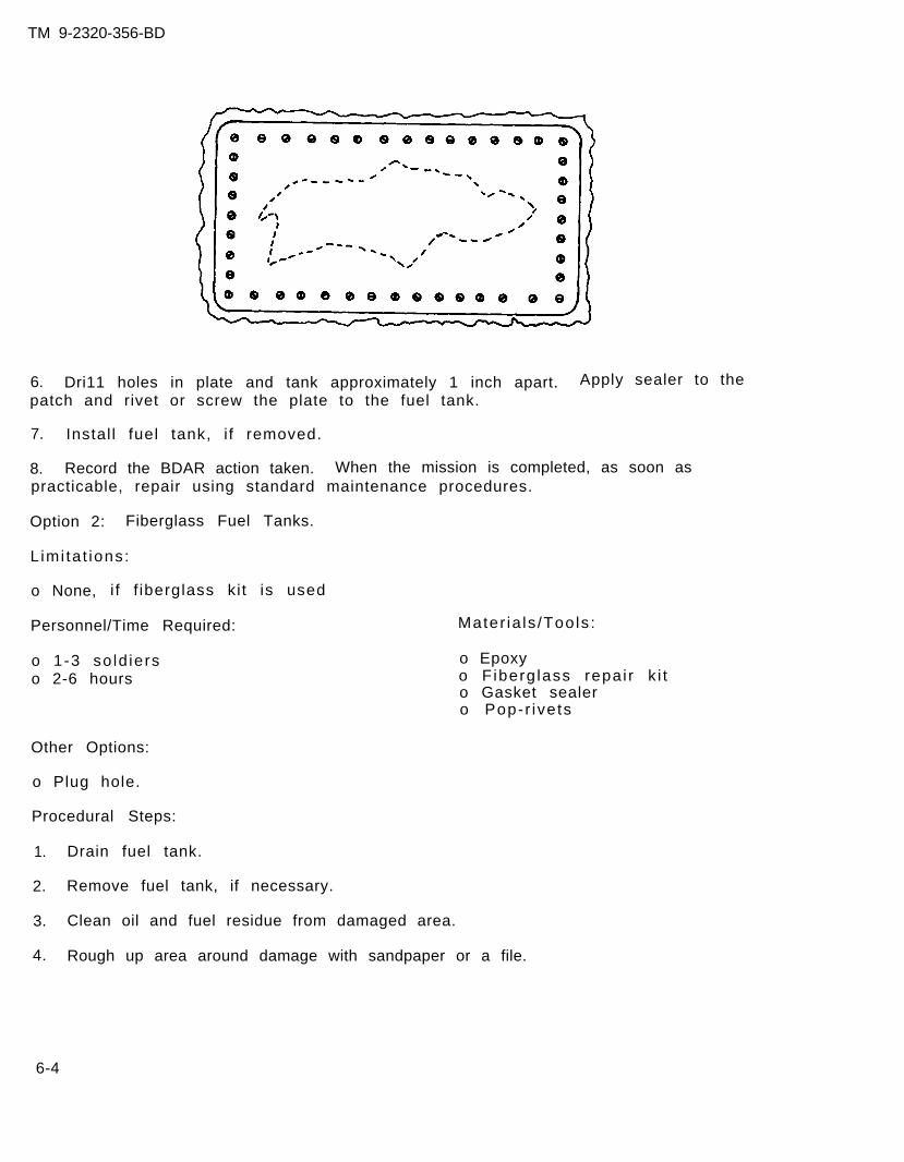
TM 9-2320-356-BD
6. Dri11 holes in plate and tank approximately 1 inch apart.patch and rivet or screw the plate to the fuel tank.
7. Instal l fuel tank, i f removed.
Apply sealer to the
8. Record the BDAR action taken. When the mission is completed, as soon aspracticable, repair using standard maintenance procedures.
Option 2: Fiberglass Fuel Tanks.
L imi ta t ions:
o None, i f f iberglass ki t is used
Personnel/Time Required:
o 1-3 so ld ierso 2-6 hours
Other Options:
o Plug hole.
Procedural Steps:
1. Drain fuel tank.
2. Remove fuel tank, if necessary.
3. Clean oil and fuel residue from damaged area.
4. Rough up area around damage with sandpaper or a file.
Mater ia ls /Tools :
o Epoxyo F iberg lass repai r k i to Gasket sealero Pop-r ivets
6-4
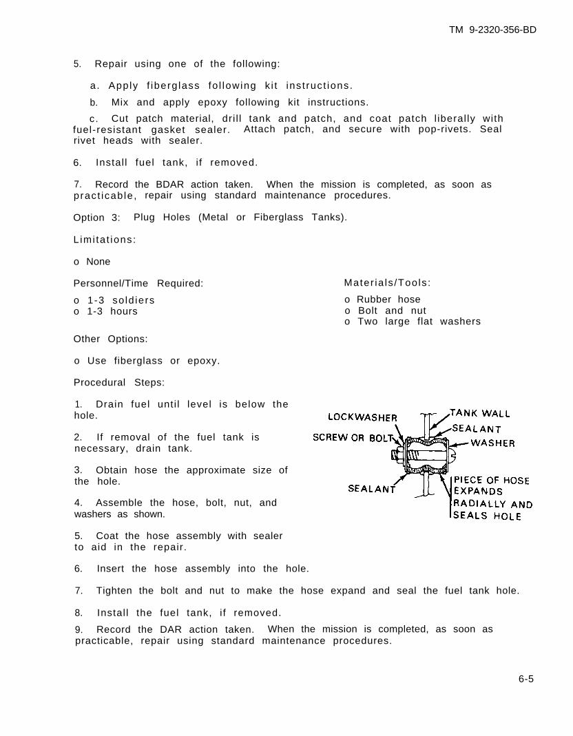
TM 9-2320-356-BD
5. Repair using one of the following:
a . Apply f iberg lass fo l lowing k i t ins t ruc t ions.
b. Mix and apply epoxy following kit instructions.
c. Cut patch material, dr i l l tank and patch, and coat patch l iberal ly withfuel-resistant gasket sealer. Attach patch, and secure with pop-rivets. Sealrivet heads with sealer.
6. Instal l fuel tank, i f removed.
7. Record the BDAR action taken. When the mission is completed, as soon aspract icab le , repair using standard maintenance procedures.
Option 3: Plug Holes (Metal or Fiberglass Tanks).
L imi ta t ions:
o None
Personnel/Time Required:
o 1-3 so ld ierso 1-3 hours
Mater ia ls /Tools :
o Rubber hoseo Bolt and nuto Two large flat washers
Other Options:
o Use fiberglass or epoxy.
Procedural Steps:
1. Drain fuel unti l level is below thehole.
2. If removal of the fuel tank isnecessary, drain tank.
3. Obtain hose the approximate size ofthe hole.
4. Assemble the hose, bolt, nut, andwashers as shown.
5. Coat the hose assembly with sealerto aid in the repair.
6. Insert the hose assembly into the hole.
7. Tighten the bolt and nut to make the hose expand and seal the fuel tank hole.
8. Instal l the fuel tank, i f removed.
9. Record the DAR action taken. When the mission is completed, as soon aspracticable, repair using standard maintenance procedures.
6-5
TM 9-2320-356-BD
6-6. FUEL TANK SUBSTITUTE
General Information:
Tactical operations may not allow sufficient time to make normal or expedientrepairs to the vehicle’s fuel tank. A more rapid repair can be improvised byinstal l ing a substi tute fuel tank. The fuel tank should be mounted to avoidinterfering with operating components. Use as large a container as possible.Frequent refueling wil l be required.
L imi ta t ions:
o Limited mobil i ty (range)
Personnel/Time Required:
o 1 so ld iero 30-60 minutes
Mater ia ls /Tools :
o Fuel container (5-gal longas or oil can, 55-gallondrum, etc.)
o Rubber fuel l ineo Hose clampo Rope or straps
Procedural Steps:
1. Locate a temporary fuel container.
2. Obtain a fuel line.
3. Connect fuel line to container.
4. Secure temporary fuel container to the outside of the vehicle in a position toal low gravity feed for the fuel.
5. Connect fuel line to the inlet side of the mechanical or electrical vehiclefuel pump.
6. Instal l return l ine to the temporary container.
7. Bleed the air from the fuel line.
8. Record the BDAR action taken. When the mission is completed, as soon aspract icab le , repair using standard maintenance procedures.
6-6
TM 9-2320-356-BD
Section III. FUEL PUMPS
6-7. GENERAL
Tactical vehicles use electrical and mechanical fuel pumps. Fuel pumps can berepaired with instructions provided in respective equipment TM's. In a bat t le f ie ldenvironment, replacement of a fuel pump is often the most expedient means to solvethe problem. Fuel pumps on most tactical vehicles are interchangeable with fuelpumps on other vehicles. The multifuel engine needs a small in-tank fuel pump tosupply fuel to the injection pump. Without an in-tank pump, the multifuel enginewil l not operate.
6-8. IN-TANK FUEL PUMP INTERCHANGEABILITY
General Information:
In-tank fuel pumps on tactical vehicles can be interchanged with other vehicles.The difference in the pumps normally is in the brackets used to locate thee lec t r i ca l un i t . The pump must be placed in the proper location for efficient fuelpickup. The electrical unit can normally be installed in the bracket for thevehicle being repaired.
The electrical unit can be clamped using the existing clamps (for example, anadjustable clamp from an air cleaner ducting system). Use a strip of rubber or arubber hose to aid in holding the pump in position. The following vehicles haveinterchangeable fuel pumps:
M35/M44A2 Series, 2-l/2-Ton TruckM48/M60 Series TankM88 Recovery VehicleM109/Ml10 Self-propelled HowitzerM578 Recovery VehicleM39A2 Series, 5-Ton Truck
6-9. ENGINE FUEL PUMP INTERCHANGEABILITY
General Information:
Electric fuel pumps will not normally supply the fuel pressure required by theinjector system if the mechanical fuel pump fails. However, operation in adeqraded mode is possible by replacing the mechanical pump with an electric unit.Mechanical pumps within the-same engine family are interchangeable. The heaterfuel pump can also be used to provide fuel to the engine.
a. Most Cummins fuel pumps are interchangeable. Minor fuel line adjustmentsmight be necessary to attach lines to the pump.
b. Detroit Diesel 3-53 thru 8V92TA fuel pumps are substitutable.
c. Personnel heater fuel pumps may be substituted.
d. ult i fuel fuel pumps are interchangeable. In terna l ad justments wi l l d i f fe r .
6-7
TM 9-2320-356-BD
Section IV. FUEL LINES AND VALVES
6-10. GENERAL
Fuel lines route the fuel from the storage tanks through the filters to the engineand back to the tanks. Lines are a combination of rubber hoses and metal tubes.Leaks and blockages are common failures. Clogged lines can be cleared by blowingcompressed air through them. Broken or cracked lines must be repaired orbypassed. Various methods of repair are given in this section. Other line repairsare also listed in chapter 3, sections IX and X.
6-11. FUEL SYSTEM SEALS LEAK
General Information:
O-rings are used in some systems to seal the fuel in the lines. BDAR as well asnormal repairs will damage the O-rings. Fuel absorption will cause the O-rings toswell, causing installation problems since they no longer fit into the O-ringgroove. Some repairs are possible if the O-ring is damaged. Swollen O-rings canbe allowed to dry until they shrink enough to fit. Torn or cut O-rings can bereplaced with a larger O-ring by cutting it to length. If an adhesive isavailable, glue the cut ends together. O-rings with small cuts can be coated witha silicone gasket sealer to stop the leakage caused by the cut, if the cut in theO-ring is not against a moving surface. Refer to paragraph 3-27.
6-12. FITTINGS LEAK
General Information:
Flared fuel f i t t ings wi l l start to leak because of engine vibrat ions orovertightening. Leaking fittings should first be tightened to attempt to stop theleak. If tightening does not stop the leak, string can be used to push the flaredtubing more firmly against the mating surface. Coating the string with a gasketsealing compound will aid in stopping leaks in a low-pressure fuel line.
L imi ta t ions:
o None
Personnel/Time Required:
o 1 so ld iero 30-60 minutes
Materials/Tools:
o Fuel - res is tant sea lant( s i l i cone , rubber, or similarmater ia l )
o St r ing or l ight t ie cord
6-8
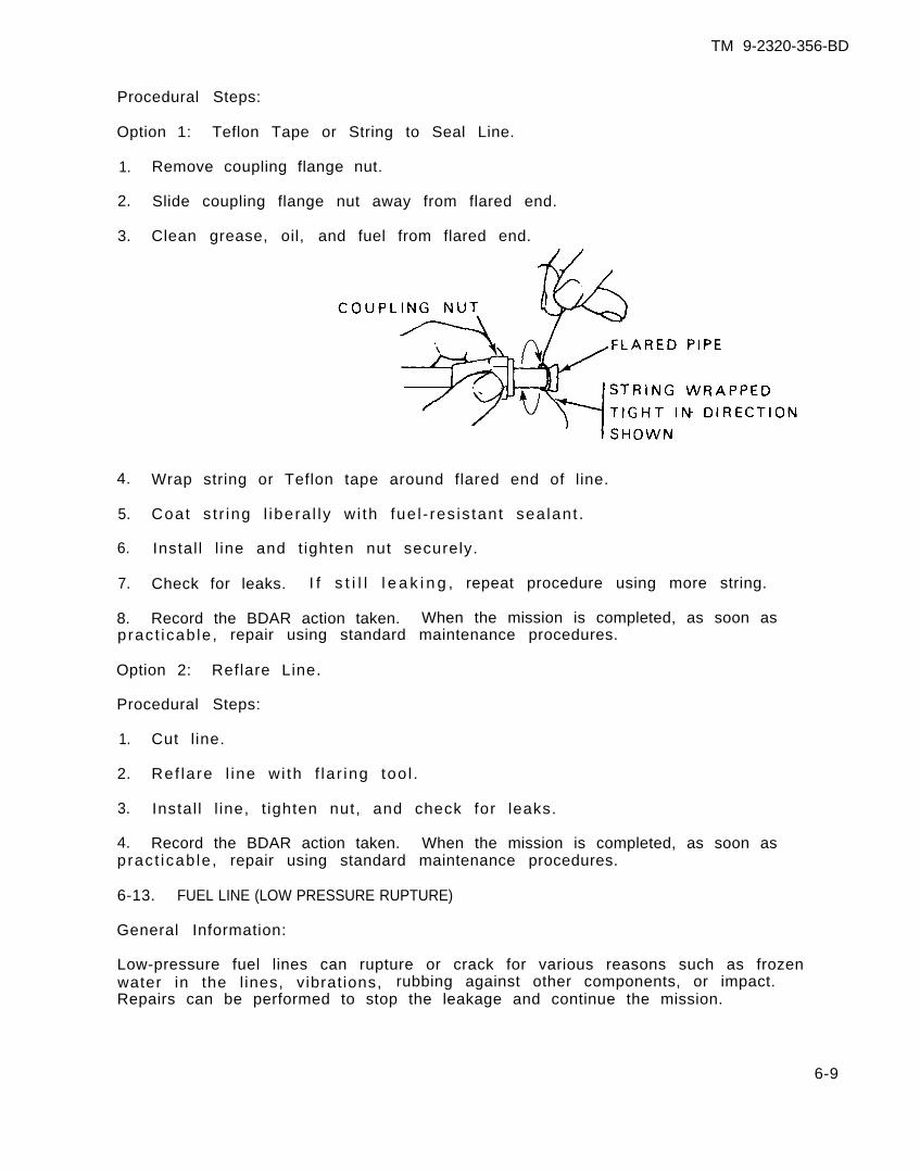
TM 9-2320-356-BD
Procedural Steps:
Option 1: Teflon Tape or String to Seal Line.
1. Remove coupling flange nut.
2. Slide coupling flange nut away from flared end.
3. Clean grease, oil, and fuel from flared end.
4. Wrap string or Teflon tape around flared end of line.
5. Coat s t r ing l ibera l ly w i th fue l - res is tant sea lant .
6. Instal l l ine and t ighten nut securely.
7. Check for leaks. I f s t i l l l e a k i n g , repeat procedure using more string.
8. Record the BDAR action taken. When the mission is completed, as soon aspract icab le , repair using standard maintenance procedures.
Option 2: Reflare Line.
Procedural Steps:
1. Cut l ine.
2. Ref lare l ine wi th f lar ing too l .
3. Instal l l ine, t ighten nut, and check for leaks.
4. Record the BDAR action taken. When the mission is completed, as soon aspract icab le , repair using standard maintenance procedures.
6-13. FUEL LINE (LOW PRESSURE RUPTURE)
General Information:
Low-pressure fuel lines can rupture or crack for various reasons such as frozenwater in the l ines, vibrations, rubbing against other components, or impact.Repairs can be performed to stop the leakage and continue the mission.
6-9
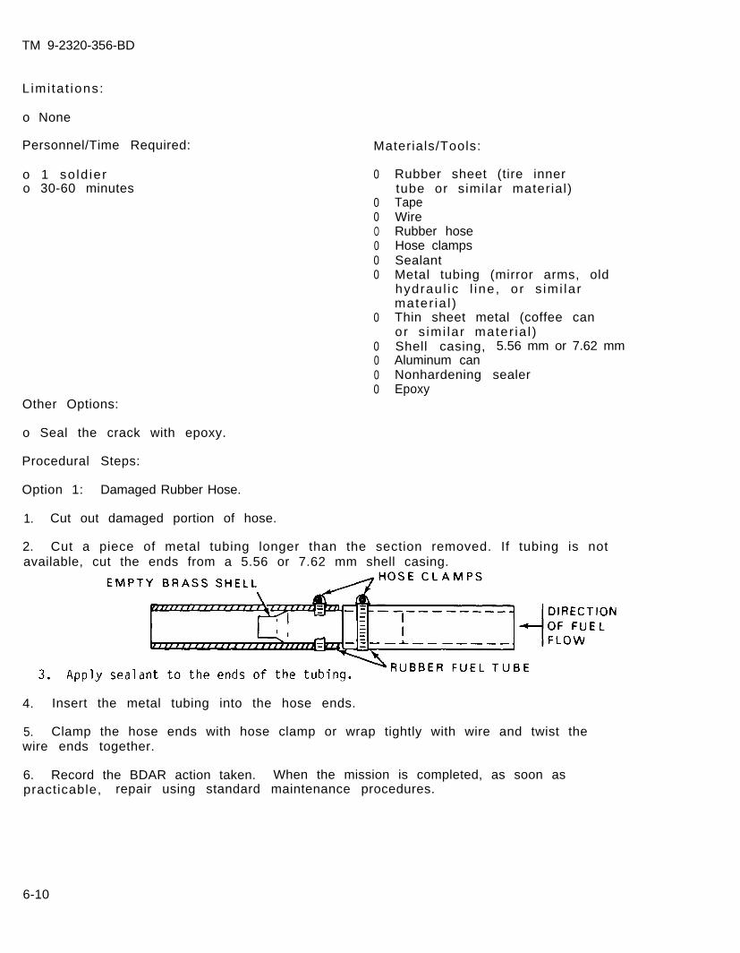
TM 9-2320-356-BD
Limi ta t ions:
o None
Personnel/Time Required: Materials/Tools:
o 1 so ld iero 30-60 minutes
Other Options:
0
00O000
0
0000
Rubber sheet (tire innertube or similar material)TapeWireRubber hoseHose clampsSealantMetal tubing (mirror arms, oldhydrau l ic l ine, or s imi larmater ia l )Thin sheet metal (coffee canor s imi lar mater ia l )Shell casing, 5.56 mm or 7.62 mmAluminum canNonhardening sealerEpoxy
o Seal the crack with epoxy.
Procedural Steps:
Option 1: Damaged Rubber Hose.
1. Cut out damaged portion of hose.
2. Cut a piece of metal tubing longer than the section removed. If tubing is notavailable, cut the ends from a 5.56 or 7.62 mm shell casing.
4. Insert the metal tubing into the hose ends.
5. Clamp the hose ends with hose clamp or wrap tightly with wire and twist thewire ends together.
6. Record the BDAR action taken. When the mission is completed, as soon aspracticable, repair using standard maintenance procedures.
6-10
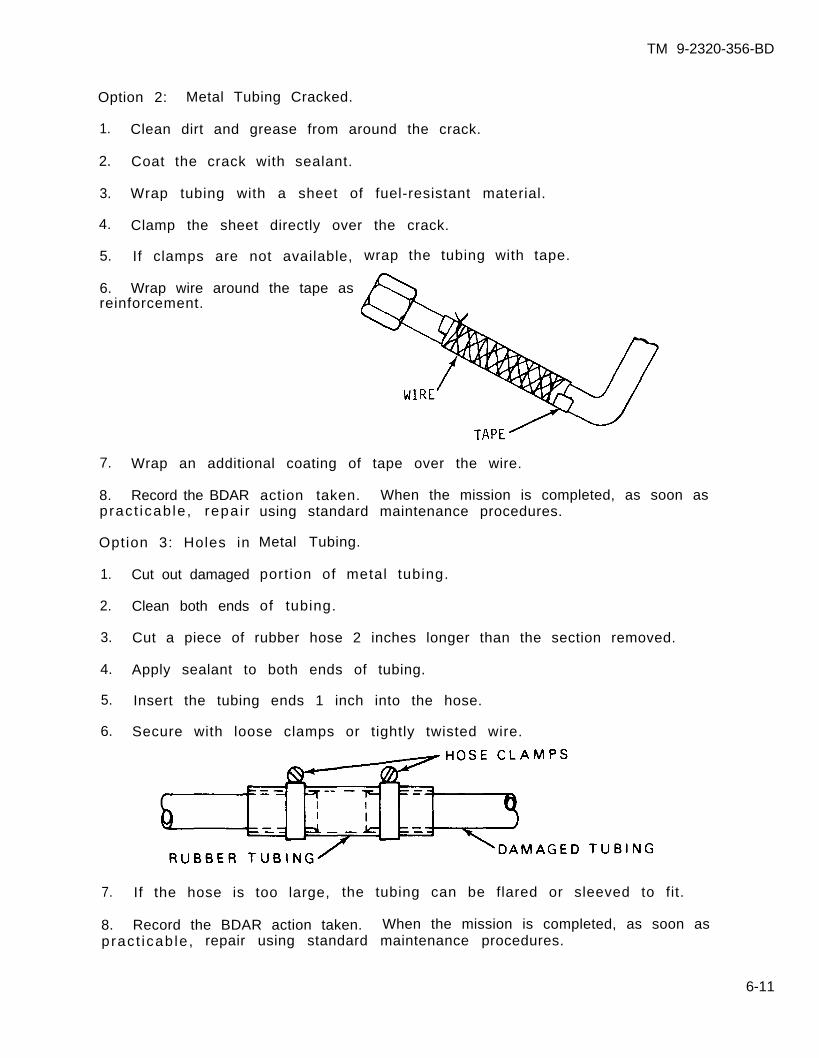
TM 9-2320-356-BD
Option 2: Metal Tubing Cracked.
1. Clean dirt and grease from around the crack.
2. Coat the crack with sealant.
3. Wrap tubing with a sheet of fuel-resistant material.
4. Clamp the sheet directly over the crack.
5. If clamps are not available,
6. Wrap wire around the tape asreinforcement.
wrap the tubing with tape.
7. Wrap an additional coating of tape over the wire.
8. Record the BDARpract icab le , repa i r
Option 3: Holes in
1. Cut out damaged
2. Clean both ends
3.
4.
5.
6.
action taken. When the mission is completed, as soon asusing standard maintenance procedures.
Metal Tubing.
port ion of metal tubing.
of tubing.
Cut a piece of rubber hose 2 inches longer than the section removed.
Apply sealant to both ends of tubing.
Insert the tubing ends 1 inch into the hose.
Secure with loose clamps or tightly twisted wire.
7. If the hose is too large, the tubing can be flared or sleeved to fit.
8. Record the BDAR action taken. When the mission is completed, as soon aspract icab le , repair using standard maintenance procedures.
6-11
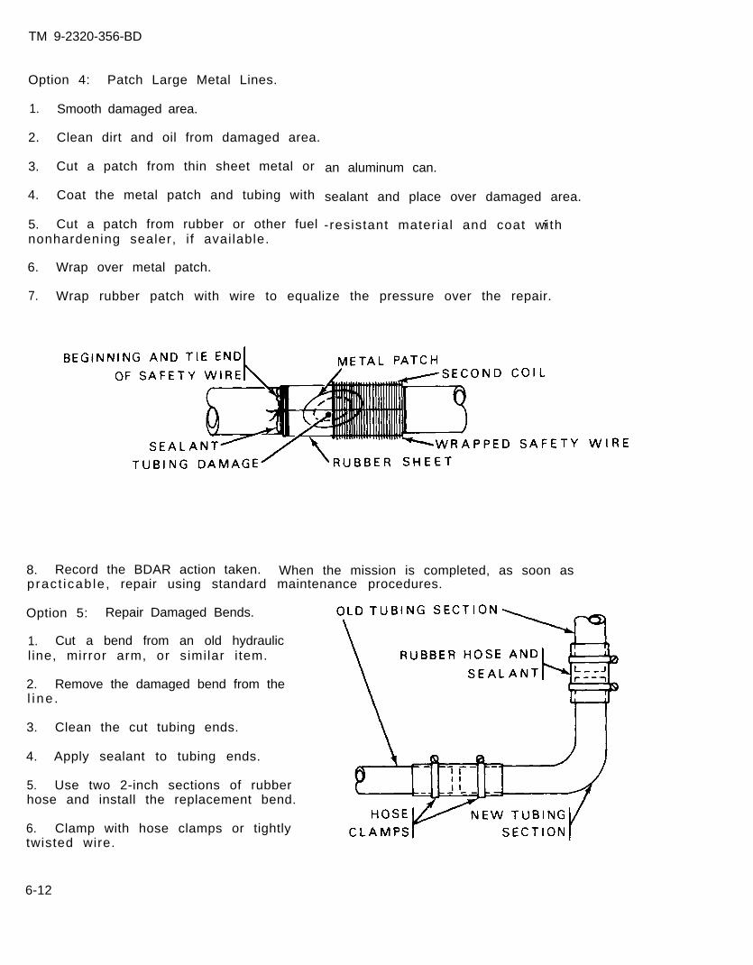
TM 9-2320-356-BD
Option 4: Patch Large Metal Lines.
1. Smooth damaged area.
2. Clean dirt and oil from damaged area.
3. Cut a patch from thin sheet metal or
4. Coat the metal patch and tubing with
5. Cut a patch from rubber or other fuelnonhardening sealer, i f available.
6. Wrap over metal patch.
an aluminum can.
sealant and place over damaged area.
-resistant material and coat with
7. Wrap rubber patch with wire to equalize the pressure over the repair.
8. Record the BDAR action taken. When the mission is completed, as soon aspract icab le , repair using standard maintenance procedures.
Option 5: Repair Damaged Bends.
1. Cut a bend from an old hydraulicl ine, mirror arm, or similar i tem.
2. Remove the damaged bend from thel i ne .
3. Clean the cut tubing ends.
4. Apply sealant to tubing ends.
5. Use two 2-inch sections of rubberhose and install the replacement bend.
6. Clamp with hose clamps or tightlytwisted wire.
6-12
TM 9-2320-356-BD
7. Record the BDAR action taken. When the mission is completed, as soon aspract icab le , repair using standard maintenance procedures.
6-14. FUEL INJECTOR LINE RUPTURE
a. If a high-pressure fuel line is damaged and there is no time for a betterrepair, cut the line and weld or crimp the injector pump side shut. The enginewill run for a limited time on fewer cylinders.
b. I f a replacement l ine is not avai lable, repair the defect ive l ine. Removeit from the vehicle and clean it. Braze pin holes closed. If the hole is toolarge for this procedure, cut out that section of l ine. Use a piece of slightlylarger metal tubing as a sleeve, overlapping both cut ends of the injector line.The sleeve should f i t t ightly over the injector l ine; i f i t is too loose, cr imp toget a t igh t f i t . Then braze or silver solder both ends of the sleeve to the fuell i ne .
6-13
TM 9-2320-356-BD
Section V. FUEL FILTERS
6-15. GENERAL
Fuel filters remove dirt and water from the fuel. Dirt and water will cause damageto fuel system components. Fuel filters are normally mounted in series, makingthem primary and secondary filters. Some vehicles have a fuel filter and waterseparator as a single unit. Other vehicles have a separate fuel filter and waterseparator. Fuel filters should be bypassed only as a last resort.
6-16. FUEL FILTER CLOGGED OR FROZEN
General Information:
The f irst indicat ion of clogged or frozen fuel f i l ters wi l l be a fai lure of theengine to start or degraded performance because of insufficient fuel. Fuelf i l ters, i f drained dai ly, should not freeze. Clogged filters must be cleaned orchanged to correct the problem.
L imi ta t ions:
o Possible internal engine damage if filters are bypassed
Personnel/Time Required: Mater ia l /Tools :
o 1-2 so ld iers o Fuelo 15-30 minutes
Other Options:
o Remove filter elements.
Procedural Steps:
1. Gain access to fuel f i l ters.
2. Remove the fuel filter from the canister.
3. Rinse the filter in a pan of fuel or blow out with compressed air; if frozen,thaw it out.
4 . Instal l and prime the fuel f i l ter.
5. Start the engine.
6. Record the BDAR action taken. When the mission is completed, as soon aspracticable, repair using standard maintenance procedures.
6-14
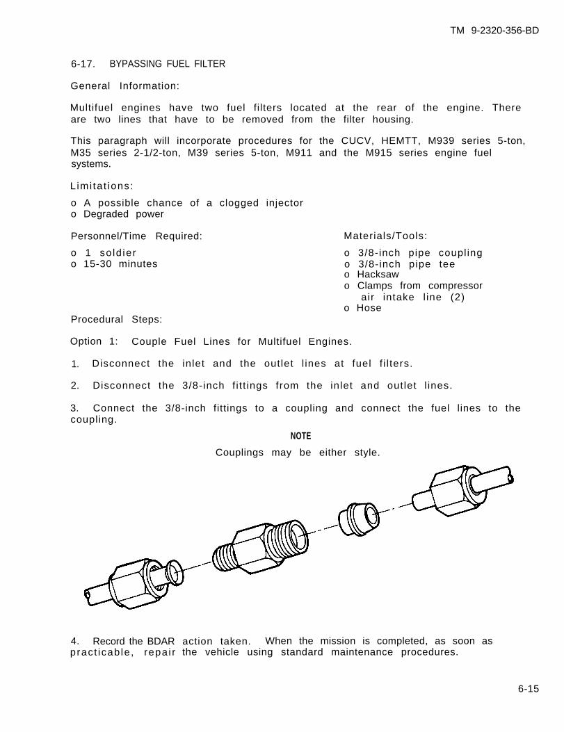
TM 9-2320-356-BD
6-17. BYPASSING FUEL FILTER
General Information:
Multifuel engines have two fuel filters located at the rear of the engine. Thereare two lines that have to be removed from the filter housing.
This paragraph will incorporate procedures for the CUCV, HEMTT, M939 series 5-ton,M35 series 2-1/2-ton, M39 series 5-ton, M911 and the M915 series engine fuelsystems.
L imi ta t ions:
o A possible chance of a clogged injectoro Degraded power
Personnel/Time Required:
o 1 so ld iero 15-30 minutes
Materials/Tools:
o 3/8-inch pipe couplingo 3/8-inch pipe teeo Hacksawo Clamps from compressor
air intake l ine (2)o Hose
Procedural Steps:
Option 1: Couple Fuel Lines for Multifuel Engines.
1. Disconnect the inlet and the outlet l ines at fuel f i l ters.
2. Disconnect the 3/8-inch f i t t ings from the inlet and outlet l ines.
3. Connect the 3/8-inch fittings to a coupling and connect the fuel lines to thecoupling.
NOTE
Couplings may be either style.
4. Record the BDARpract icab le , repa i r
action taken. When the mission is completed, as soon asthe vehicle using standard maintenance procedures.
6-15
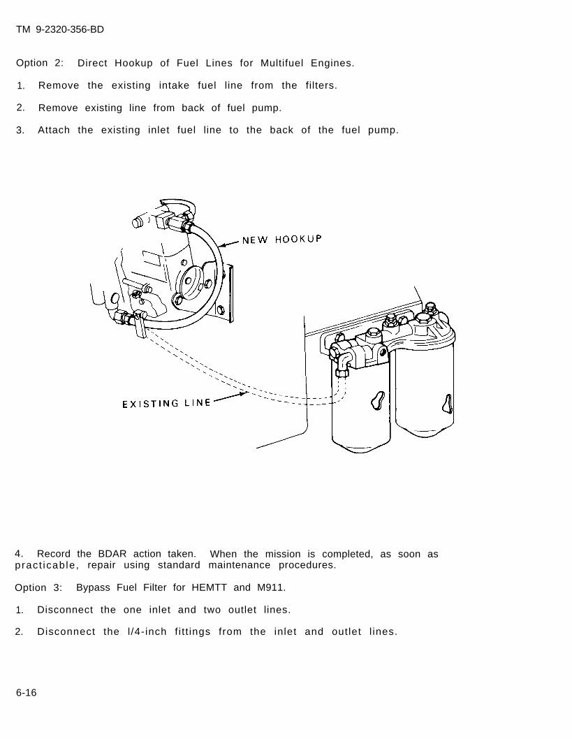
TM 9-2320-356-BD
Option 2: Direct Hookup of Fuel Lines for Multifuel Engines.
1. Remove the existing intake fuel line from the filters.
2. Remove existing line from back of fuel pump.
3. Attach the existing inlet fuel line to the back of the fuel pump.
4. Record the BDAR action taken. When the mission is completed, as soon aspract icab le , repair using standard maintenance procedures.
Option 3: Bypass Fuel Filter for HEMTT and M911.
1. Disconnect the one inlet and two outlet lines.
2. Disconnect the l /4- inch f i t t ings from the inlet and outlet l ines.
6-16
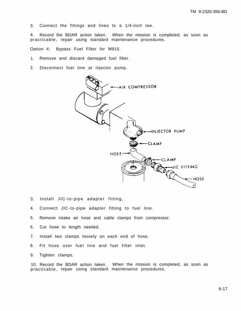
TM 9-2320-356-BD
3. Connect the fittings and lines to a 1/4-inch tee.
4. Record the BDAR action taken. When the mission is completed, as soon aspract icab le , repair using standard maintenance procedures.
Option 4: Bypass Fuel Filter for M915.
1. Remove and discard damaged fuel filter.
2. Disconnect fuel line at injector pump.
3. Ins ta l l J IC- to-p ipe adapter f i t t ing .
4. Connect JIC-to-pipe adapter f i t t ing to fuel l ine.
5. Remove intake air hose and cable clamps from compressor.
6. Cut hose to length needed.
7. Install two clamps loosely on each end of hose.
8. Fit hose over fuel l ine and fuel f i l ter inlet.
9. Tighten clamps.
10. Record the BDAR action taken. When the mission is completed, as soon aspract icab le , repair using standard maintenance procedures.
6-17
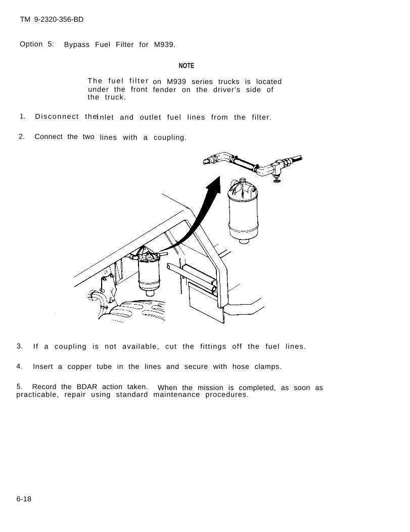
TM 9-2320-356-BD
Option 5: Bypass Fuel Filter for M939.
The fue l f i l t e runder the frontthe truck.
1. D isconnect the
2. Connect the two
NOTE
on M939 series trucks is locatedfender on the driver’s side of
nlet and outlet fuel l ines from the f i l ter.
lines with a coupling.
3. I f a coupl ing is not avai lable, cut the f i t t ings off the fuel l ines.
4. Insert a copper tube in the lines and secure with hose clamps.
5. Record the BDAR action taken. When the mission is completed, as soon aspracticable, repair using standard maintenance procedures.
6-18
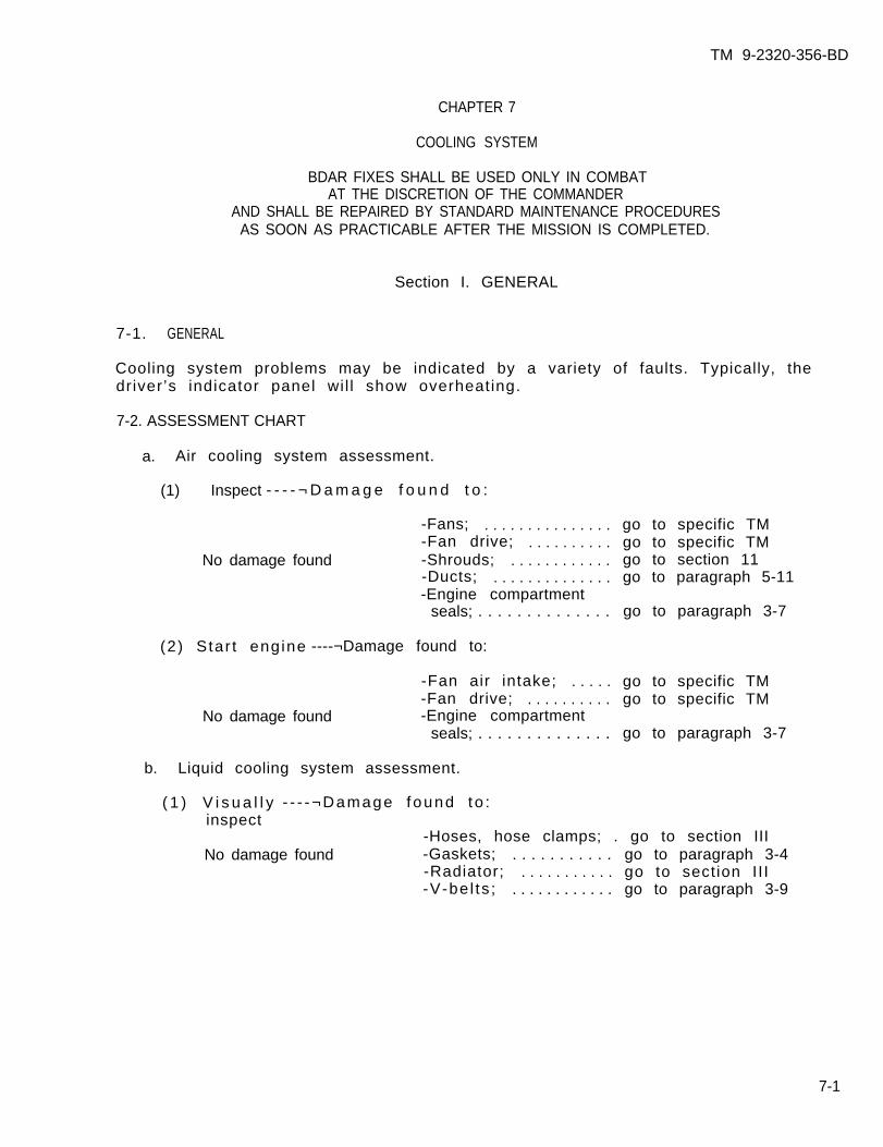
TM 9-2320-356-BD
CHAPTER 7
COOLING SYSTEM
BDAR FIXES SHALL BE USED ONLY IN COMBATAT THE DISCRETION OF THE COMMANDER
AND SHALL BE REPAIRED BY STANDARD MAINTENANCE PROCEDURESAS SOON AS PRACTICABLE AFTER THE MISSION IS COMPLETED.
Section I. GENERAL
7-1. GENERAL
Cooling system problems may be indicated by a variety of faults. Typically, thedriver’s indicator panel wil l show overheating.
7-2. ASSESSMENT CHART
a. Air cooling system assessment.
(1) Inspect - - - - ¬ D a m a g e f o u n d t o :
-Fans; . . . . . . . . . . . . . . . go to specific TM-Fan drive; . . . . . . . . . . go to specific TM
No damage found -Shrouds; . . . . . . . . . . . . go to section 11-Ducts; . . . . . . . . . . . . . . go to paragraph 5-11-Engine compartment
seals; . . . . . . . . . . . . . . go to paragraph 3-7
(2) Star t eng ine ----¬Damage found to:
-Fan air intake; . . . . . go to specific TM-Fan drive; . . . . . . . . . . go to specific TM
No damage found -Engine compartmentseals; . . . . . . . . . . . . . . go to paragraph 3-7
b. Liquid cooling system assessment.
( 1 ) V i s u a l l y - - - -¬Damage found to :inspect
-Hoses, hose clamps; . go to section IIINo damage found -Gaskets; . . . . . . . . . . . go to paragraph 3-4
-Radiator; . . . . . . . . . . . go to section II I-V-be l ts ; . . . . . . . . . . . . go to paragraph 3-9
7-1
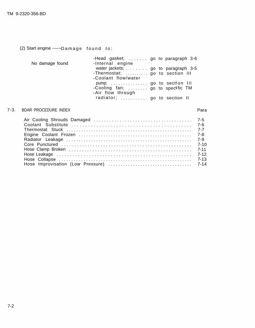
TM 9-2320-356-BD
(2) Start engine ----¬D a m a g e f o u n d t o :
No damage found
7-3. BDAR PROCEDURE INDEX
-Head gasket; . . . . . . .- Internal engine
water jackets; . . . . . . .-Thermostat; . . . . . . . . . .-Coolant f low/water
pump; . . . . . . . . . . . . . . .-Cooling fan; . . . . . . . .-Air f low through
rad ia to r ; . . . . . . . . . . .
go to paragraph 3-6
go to paragraph 3-5go to section II I
go to sectgo to spec
on I I Ific TM
go to section II
Air Cooling Shrouds Damaged . . . . . . . . . . . . . . . . . . . . . . . . . . . . . . . . . . . . . .Coolant Substitute . . . . . . . . . . . . . . . . . . . . . . . . . . . . . . . . . . . . . . . . . . .Thermostat Stuck . . . . . . . . . . . . . . . . . . . . . . . . . . . . . . . . . . . . . . . . . . . . . . . . . . .Engine Coolant Frozen . . . . . . . . . . . . . . . . . . . . . . . . . . . . . . . . . . . . . . . . . . . . . .Radiator Leakage . . . . . . . . . . . . . . . . . . . . . . . . . . . . . . . . . . . . . . . . . . . . . . . . . . .Core Punctured . . . . . . . . . . . . . . . . . . . . . . . . . . . . . . . . . . . . . . . . . . . . . . . . . .Hose Clamp Broken . . . . . . . . . . . . . . . . . . . . . . . . . . . . . . . . . . . . . . . . . . . . . . .Hose Leakage . . . . . . . . . . . . . . . . . . . . . . . . . . . . . . . . . . . . . . . . . . . . . . . . . .Hose Collapse . . . . . . . . . . . . . . . . . . . . . . . . . . . . . . . . . . . . . . . . . . . . . . . . . . . . . .Hose Improvisation (Low Pressure) . . . . . . . . . . . . . . . . . . . . . . . . . . . . . . . . . .
Para
7-57-67-77-87-97-107-117-127-137-14
7-2
TM 9-2320-356-BD
Section II. AIR COOLING SYSTEMS
7-4. GENERAL
Cooling system failures can result in engine failure and therefore must be repairedif the engine is expected to operate for any length of time. Cooling systemproblems most often are indicated on the driver’s instrument panel. Whiletemporary overheating indications may result from excessive workload on the engine,repeated or constant indication of overheating is almost always followed by a majorcooling problem.
7-5. AIR COOLING SHROUDS DAMAGED
Shrouds are used to direct the cooling air over the hot engine. Bent or tornshrouds will upset the flow of air and cause hotspots to occur which can causeinternal engine fai lures. Torn shrouds can be bent back into shape and patched withsheet metal, epoxy, or tape to restore the proper air flow. At a minimum, theymust be bent away from contact with moving components. If the existing shroudscannot be repaired, new shrouds must be fabricated.
7-3

TM 9-2320-356-BD
Sect ion I I I . LIQUID COOLING SYSTEMS
7-6. COOLANT SUBSTITUTE
A liquid-cooled engine cannot operate for long without coolant. When normalcoolants are not available, a substitute may be used. Any liquid, except gasolineor jet fuels, can be used; but some liquids will deteriorate the cooling system’srubber components. Petroleum products will not transfer the heat as efficiently aswater-based coolant, but will work if nothing else is available. Old engine oil orfluids drained from damaged vehicles, transmission oil, or hydraulic fluids may bea possible source of fluids. The cooling system must be drained and flushed assoon as possible if petroleum-based fluids are used.
7-7. THERMOSTAT STUCK
The thermostat regulates the engine operating temperature by controlling coolantflow through the engine. When the thermostat is stuck in the closed position, itprevents coolant from circulating and causes engine overheating. BDAR repair is toremove the thermostat and operate the vehicle. If the thermostat is stuck in theopen position or removed, it may degrade engine performance and increase fuelconsumption.
7-8. ENGINE COOLANT FROZEN
General Information:
During cold weather, inadequate antifreeze protection will cause the coolant tofreeze. Care must be taken when thawing the cooling system that damage is avoided.The water pump may be unable to turn, which will damage drive belts as well as thepump itself. The thawing procedure must include frequent inspections for leakswhich will indicate cracked or broken components. Engine temperature must also bemonitored to prevent damage due to overheating.
L imi ta t ions:
o None, if engine is left running or antifreeze protection is upgraded
Personnel/Time Required:
o 2 so ld ierso 30-60 minutes
Other Options:
o Route air from fuel-operated vehicle heater over the radiator.o Route another vehicle’s exhaust gases over the radiator.
7-4
TM 9-2320-356-BD
Procedural Steps:
1. Gain access to radiator and engine.
2. Inspect for ice and obvious cracks
3. I f coolant is
4. Start the eng
5. Shut down the
n coolant system components.
solid, remove or disengage the water pump drive belts.
ne and allow to warm up. Do not allow engine to overheat.
engine and allow the heat to melt the ice.
6. Attempt to turn water pump pulley.
7. When the water pump pulley can be turned, install the drive belts.
8. Start the engine and allow to warm up. Do not allow engine to overheat.
7-9. RADIATOR LEAKAGE
General Information:
Radiator leakage may be detected-by low coolant levels. Obvious wet areas oroverheating will indicate that the coolant level must be checked. The followingprocedures provide options to stop or stop or reduce the leakage rate.
Option 1: Small Hole.
L imi ta t ions:
o None
Personnel/Time Required:
o 1 so ld iero 15-30 minutes
Mater ia ls /Tools :
o Stop leak chemicalo Cigarette tobaccoo Peppero Eggso Oatmealo Farina (cream of wheat)o Corn meal
7-5
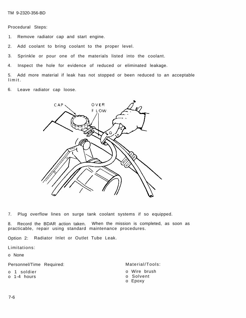
TM 9-2320-356-BD
Procedural Steps:
1. Remove radiator cap and start engine.
2. Add coolant to bring coolant to the proper level.
3. Sprinkle or pour one of the materials listed into the coolant.
4. Inspect the hole for evidence of reduced or eliminated leakage.
5. Add more material if leak has not stopped or been reduced to an acceptablel i m i t .
6. Leave radiator cap loose.
7. Plug overflow lines on surge tank coolant systems if so equipped.
8. Record the BDAR action taken. When the mission is completed, as soon aspracticable, repair using standard maintenance procedures.
Option 2: Radiator Inlet or Outlet Tube Leak.
L imi ta t ions:
o None
Personnel/Time Required:
o 1 so ld iero 1-4 hours
Mater ia l /Tools :
o Wire brusho Solvento Epoxy
7-6
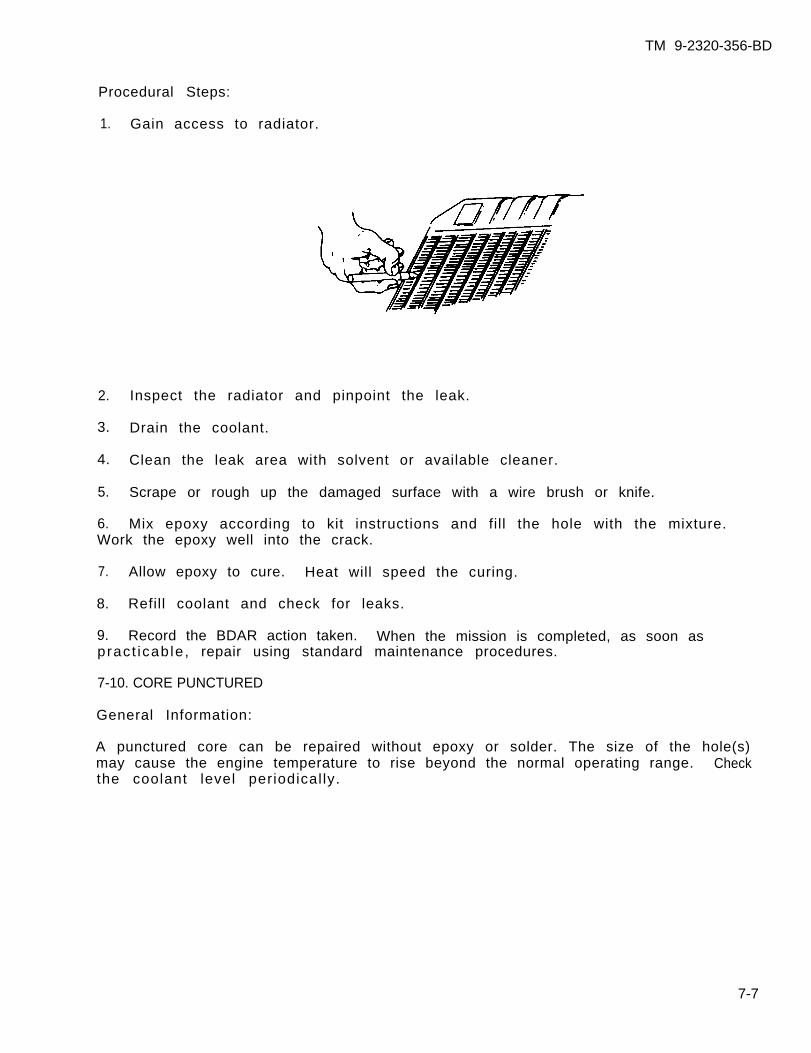
TM 9-2320-356-BD
Procedural Steps:
1. Gain access to radiator.
2. Inspect the radiator and pinpoint the leak.
3. Drain the coolant.
4. Clean the leak area with solvent or available cleaner.
5. Scrape or rough up the damaged surface with a wire brush or knife.
6. Mix epoxy according to kit instructions and fill the hole with the mixture.Work the epoxy well into the crack.
7. Allow epoxy to cure. Heat will speed the curing.
8. Refill coolant and check for leaks.
9. Record the BDAR action taken. When the mission is completed, as soon aspract icab le , repair using standard maintenance procedures.
7-10. CORE PUNCTURED
General Information:
A punctured core can be repaired without epoxy or solder. The size of the hole(s)may cause the engine temperature to rise beyond the normal operating range. Checkthe coolant level periodical ly.
7-7
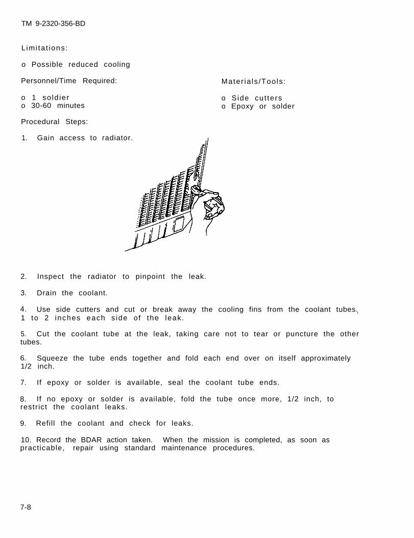
TM 9-2320-356-BD
Limi ta t ions:
o Possible reduced cooling
Personnel/Time Required:
o 1 so ld iero 30-60 minutes
Procedural Steps:
1. Gain access to radiator.
Mater ia ls /Tools :
o S ide cut terso Epoxy or solder
2.
3.
4.
Inspect the radiator to pinpoint the leak.
Drain the coolant.
Use side cutters and cut or break away the cooling fins from the coolant tubes.1 to 2 inches each s ide o f the leak.
,
5. Cut the coolant tube at the leak, taking care not to tear or puncture the othertubes.
6. Squeeze the tube ends together and fold each end over on itself approximately1/2 inch.
7. If epoxy or solder is available, seal the coolant tube ends.
8. If no epoxy or solder is available, fold the tube once more, 1/2 inch, torestr ict the coolant leaks.
9. Refill the coolant and check for leaks.
10. Record the BDAR action taken. When the mission is completed, as soon aspracticable, repair using standard maintenance procedures.
7-8

TM 9-2320-356-BD
7-11. HOSE CLAMP BROKEN
General Information:
A broken hose clamp will allow the hose to leak coolant and cause engineoverheating. The clamp must be replaced or a substitute improvised to regain asealed cooling system. If a replacement clamp is not available, wire can be usedas a substitute. Care must be taken that the wire does not loosen.
L imi ta t ions:
o None
Personnel/Time Required
o 1 so ld iero 5-10 minutes
Mater ia ls /Tools :
o Wire , safe ty ( lac ing) orcommunication
o Ropeo B e l to S t i c ko Tape
Other Options:
o Wrap the hose with wire. Use a stick and twist wire ends together like atourniquet. Tape ends of stick to hose.
Procedural Steps:
1. Make a loop in one end of a wire. Twist the wire so that a permanent loop isformed.
2. Loosely wrap the wire once around the hose and pull the other end through theloop.
7-9
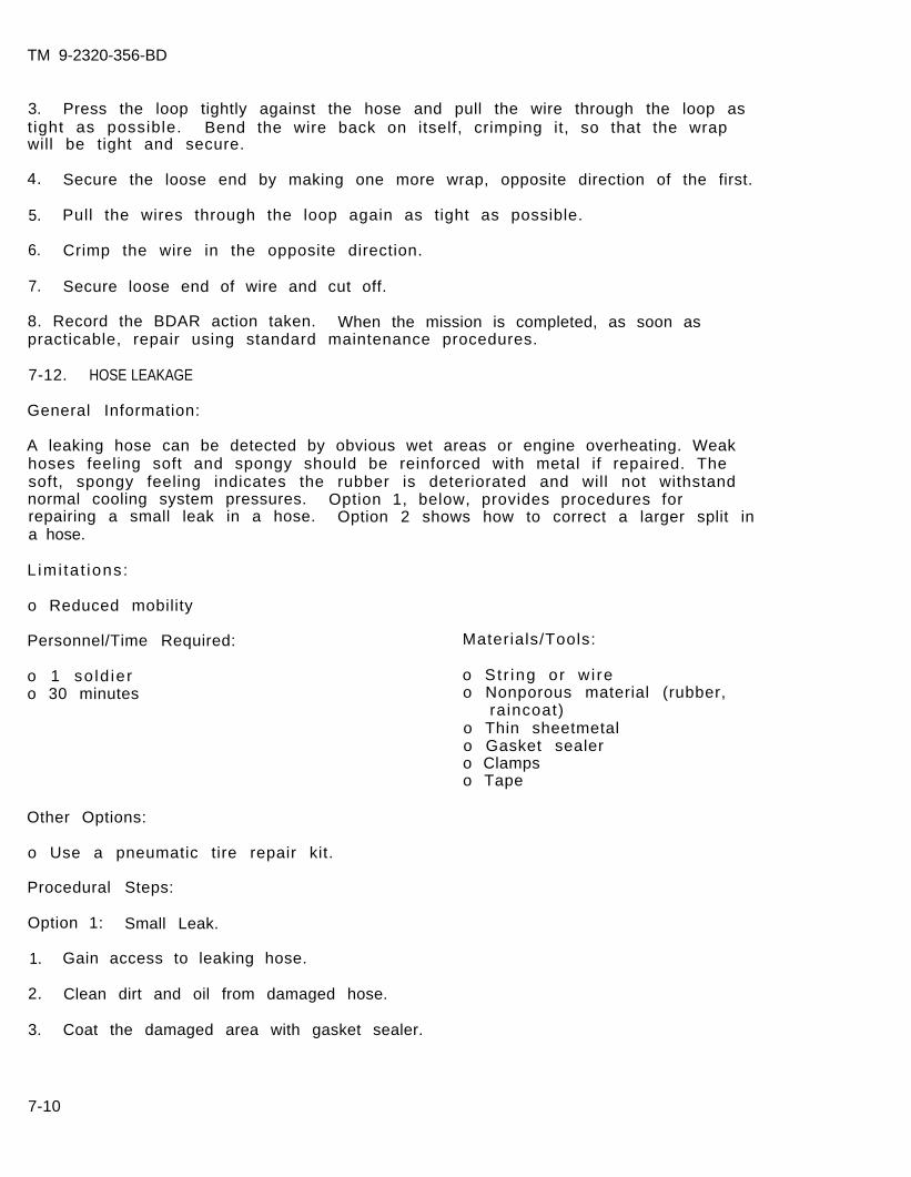
TM 9-2320-356-BD
3. Press the loop tightly against the hose and pull the wire through the loop astight as possible. Bend the wire back on itself, crimping it, so that the wrapwill be tight and secure.
4. Secure the loose end by making one more wrap, opposite direction of the first.
5. Pull the wires through the loop again as tight as possible.
6. Crimp the wire in the opposite direction.
7. Secure loose end of wire and cut off.
8. Record the BDAR action taken. When the mission is completed, as soon aspracticable, repair using standard maintenance procedures.
7-12. HOSE LEAKAGE
General Information:
A leaking hose can be detected by obvious wet areas or engine overheating. Weakhoses feeling soft and spongy should be reinforced with metal if repaired. Thesoft, spongy feeling indicates the rubber is deteriorated and will not withstandnormal cooling system pressures. Option 1, below, provides procedures forrepairing a small leak in a hose. Option 2 shows how to correct a larger split ina hose.
L imi ta t ions:
o Reduced mobility
Personnel/Time Required:
o 1 so ld iero 30 minutes
Other Options:
o Use a pneumatic tire repair kit.
Procedural Steps:
Option 1: Small Leak.
1. Gain access to leaking hose.
2. Clean dirt and oil from damaged hose.
3. Coat the damaged area with gasket sealer.
Materials/Tools:
o St r ing or wi reo Nonporous material (rubber,
raincoat)o Thin sheetmetalo Gasket sealero Clampso Tape
7-10
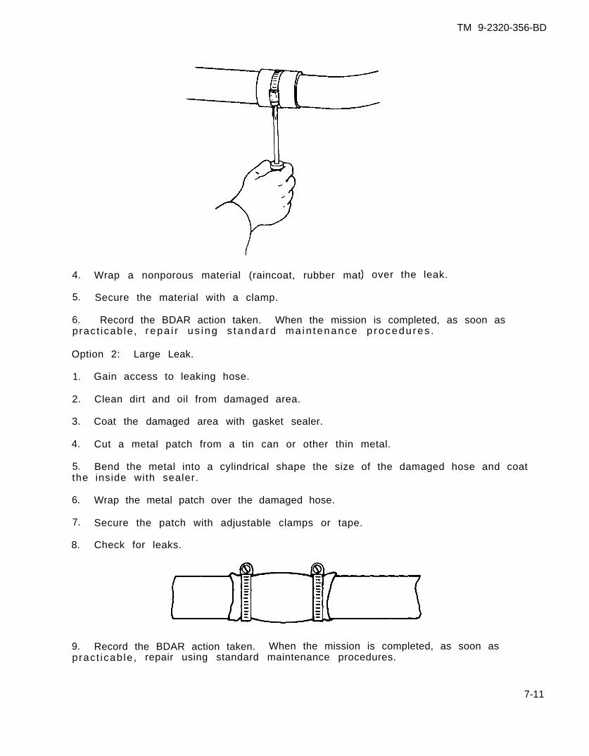
TM 9-2320-356-BD
4.
5.
Wrap a nonporous material (raincoat, rubber mat
Secure the material with a clamp.
over the leak.
6. Record the BDAR action taken. When the mission is completed, as soon aspract icab le , repa i r us ing s tanda rd ma in tenance p rocedu res .
Option 2: Large Leak.
1.
2.
3.
4.
5.the
6.
7.
8.
9.
Gain access to leaking hose.
Clean dirt and oil from damaged area.
Coat the damaged area with gasket sealer.
Cut a metal patch from a tin can or other thin metal.
Bend the metal into a cylindrical shape the size of the damaged hose and coatinside with sealer.
Wrap the metal patch over the damaged hose.
Secure the patch with adjustable clamps or tape.
Check for leaks.
Record the BDAR action taken. When the mission is completed, as soon aspract icab le , repair using standard maintenance procedures.
7-11
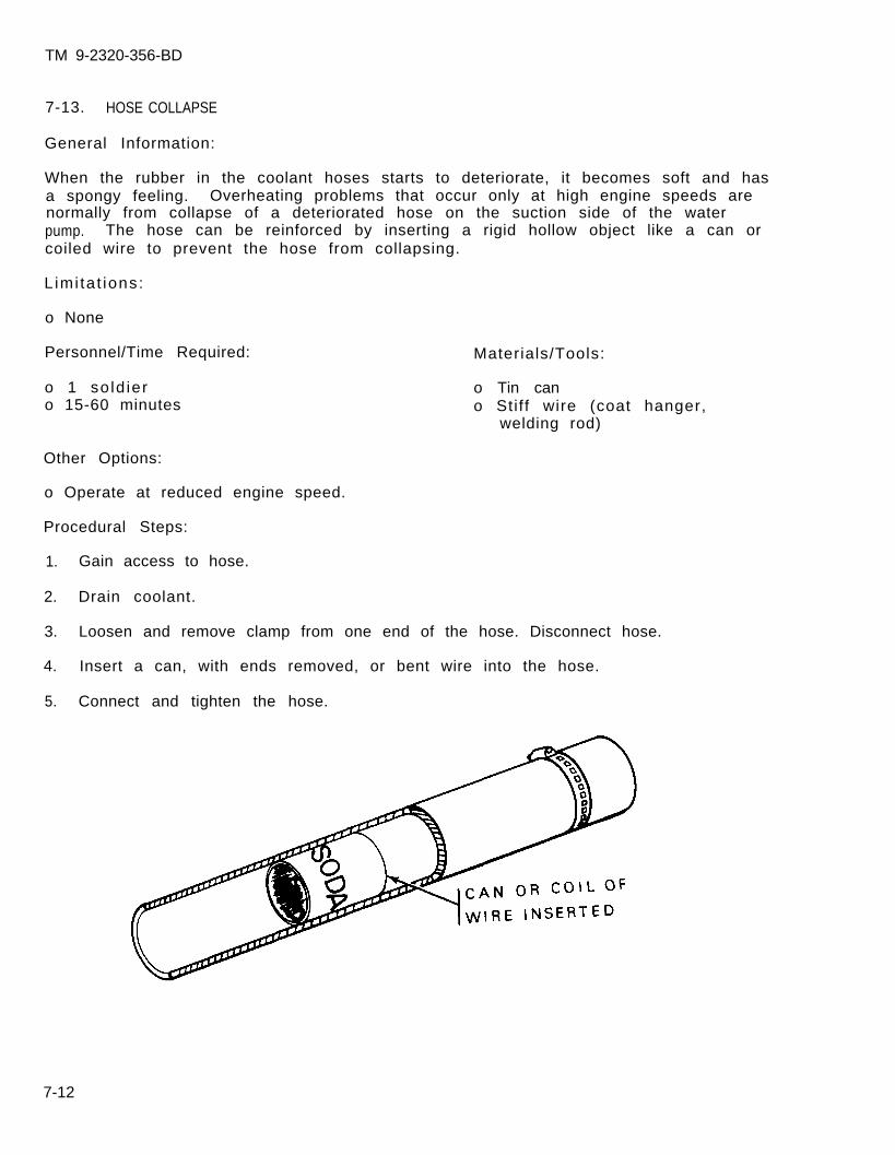
TM 9-2320-356-BD
7-13. HOSE COLLAPSE
General Information:
When the rubber in the coolant hoses starts to deteriorate, it becomes soft and hasa spongy feeling. Overheating problems that occur only at high engine speeds arenormally from collapse of a deteriorated hose on the suction side of the waterpump. The hose can be reinforced by inserting a rigid hollow object like a can orcoiled wire to prevent the hose from collapsing.
L imi ta t ions:
o None
Personnel/Time Required:
o 1 so ld iero 15-60 minutes
Materials/Tools:
o Tin cano Stif f wire (coat hanger,
welding rod)
Other Options:
o Operate at reduced engine speed.
Procedural Steps:
1. Gain access to hose.
2. Drain coolant.
3. Loosen and remove clamp from one end of the hose. Disconnect hose.
4. Insert a can, with ends removed, or bent wire into the hose.
5. Connect and tighten the hose.
7-12
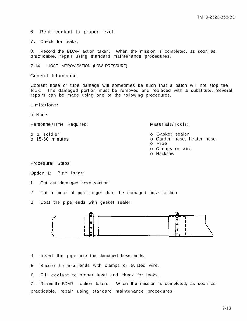
TM 9-2320-356-BD
6. Refi l l coolant to proper level.
7 . Check for leaks.
8. Record the BDAR action taken. When the mission is completed, as soon aspracticable, repair using standard maintenance procedures.
7-14. HOSE IMPROVISATION (LOW PRESSURE)
General Information:
Coolant hose or tube damage will sometimes be such that a patch will not stop theleak. The damaged portion must be removed and replaced with a substitute. Severalrepairs can be made using one of the following procedures.
L imi ta t ions:
o None
Personnel/Time Required:
o 1 so ld iero 15-60 minutes
Mater ia ls /Tools :
o Gasket sealero Garden hose, heater hoseo Pipeo Clamps or wireo Hacksaw
Procedural Steps:
Option 1: Pipe Insert.
1. Cut out damaged hose section.
2. Cut a piece of pipe longer than the damaged hose section.
3. Coat the pipe ends with gasket sealer.
4. Insert the pipe
5. Secure the hose
6. F i l l coo lant to
7 . Record the BDAR
into the damaged hose ends.
ends with clamps or twisted wire.
proper level and check for leaks.
action taken. When the mission is completed, as soon as
practicable, repair using standard maintenance procedures.
7-13
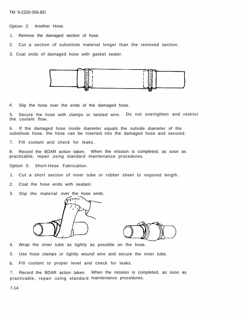
TM 9-2320-356-BD
Option 2: Another Hose.
1. Remove the damaged section of hose.
2. Cut a section of substitute material longer than the removed section.
3. Coat ends of damaged hose with gasket sealer.
4. Slip the hose over the ends of the damaged hose.
5. Secure the hose with clamps or twisted wire. Do not overtighten and restrictthe coolant flow.
6. If the damaged hose inside diameter equals the outside diameter of thesubstitute hose, the hose can be inserted into the damaged hose and secured.
7. Fill coolant and check for leaks.
8. Record the BDAR action taken. When the mission is completed, as soon aspracticable, repair using standard maintenance procedures.
Option 3: Short-Hose Fabrication.
1. Cut a short section of inner tube or rubber sheet to required length.
2. Coat the hose ends with sealant.
3. Slip the material over the hose ends.
4.
5.
6.
Wrap the inner tube as tightly as possible on the hose.
Use hose clamps or tightly wound wire and secure the inner tube.
Fill coolant to proper level and check for leaks.
7. Record the BDAR action taken.pract icable, repair using standard
7-14
When the mission is completed, as soon asmaintenance procedures.
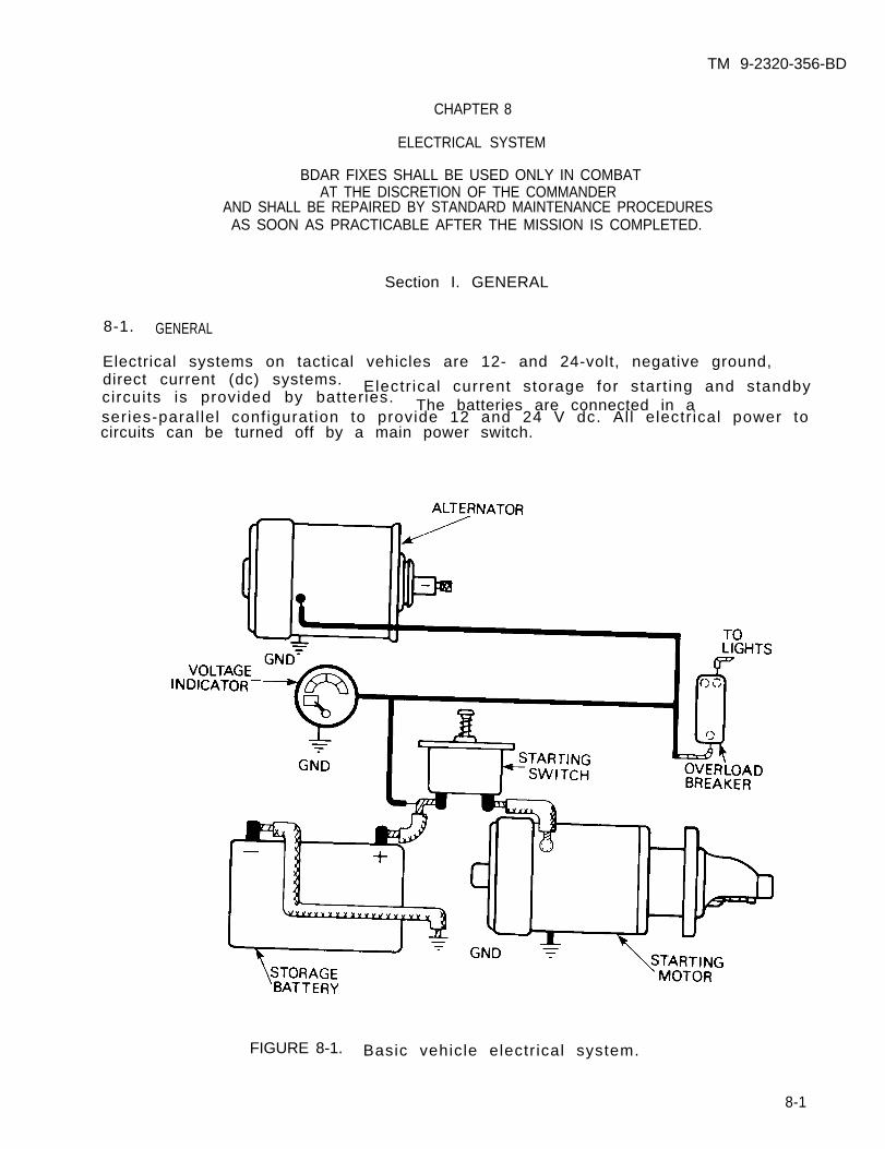
TM 9-2320-356-BD
CHAPTER 8
ELECTRICAL SYSTEM
BDAR FIXES SHALL BE USED ONLY IN COMBATAT THE DISCRETION OF THE COMMANDER
AND SHALL BE REPAIRED BY STANDARD MAINTENANCE PROCEDURESAS SOON AS PRACTICABLE AFTER THE MISSION IS COMPLETED.
Section I. GENERAL
8-1. GENERAL
Electrical systems on tactical vehicles are 12- and 24-volt, negative ground,direct current (dc) systems. Electr ical current storage for start ing and standbycircuits is provided by batteries. The batteries are connected in aseries-paral lel configurat ion to provide 12 and 24 V dc. Al l electr ical power tocircuits can be turned off by a main power switch.
FIGURE 8-1. Basic vehicle electr ical system.
8-1
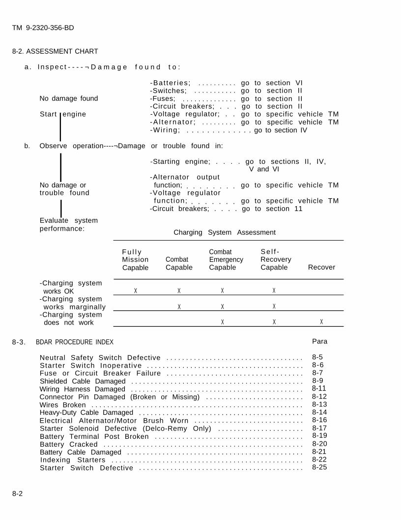
TM 9-2320-356-BD
8-2. ASSESSMENT CHART
a . I nspec t - - - - ¬ D a m a g e f o u n d t o :
-Bat ter ies ; . . . . . . . . . . go to section VI-Switches; . . . . . . . . . . . go to section II
No damage found -Fuses; . . . . . . . . . . . . . . go to section II-Circuit breakers; . . . go to section II
Start engine -Voltage regulator; . .I go to specific vehicle TM-A l t e rna to r ; . . . . . . . . . go to specific vehicle TM-Wir ing; . . . . . . . . . . . . . go to section IV
b. Observe operation----¬Damage or trouble found in:
INo damage ortrouble found
IEvaluate systemperformance:
-Charging systemworks OK
-Charging systemworks marginally
-Charging systemdoes not work
-Starting engine; . . . . go to sections II, IV,V and VI
-Alternator outputfunction; . . . . . . . . go to specific vehicle TM
-Voltage regulatorfunct ion; . . . . . . . go to specific vehicle TM
-Circuit breakers; . . . . go to section 11
Charging System Assessment
F u l l y Combat Se l f -Mission Combat Emergency RecoveryCapable Capable Capable Capable Recover
X X X X
X X X
X X X
8-3. BDAR PROCEDURE INDEX Para
Neutral Safety Switch Defective . . . . . . . . . . . . . . . . . . . . . . . . . . . . . . . . . . .Starter Switch Inoperat ive . . . . . . . . . . . . . . . . . . . . . . . . . . . . . . . . . . . . . . . .Fuse or Circuit Breaker Failure . . . . . . . . . . . . . . . . . . . . . . . . . . . . . . . . . .Shielded Cable Damaged . . . . . . . . . . . . . . . . . . . . . . . . . . . . . . . . . . . . . . . . . . . .Wiring Harness Damaged . . . . . . . . . . . . . . . . . . . . . . . . . . . . . . . . . . . . . . . . . . . .Connector Pin Damaged (Broken or Missing) . . . . . . . . . . . . . . . . . . . . . . . . .Wires Broken . . . . . . . . . . . . . . . . . . . . . . . . . . . . . . . . . . . . . . . . . . . . . . . . . . . . . .Heavy-Duty Cable Damaged . . . . . . . . . . . . . . . . . . . . . . . . . . . . . . . . . . . . . . . . . .Electrical Alternator/Motor Brush Worn . . . . . . . . . . . . . . . . . . . . . . . . . . . .Starter Solenoid Defective (Delco-Remy Only) . . . . . . . . . . . . . . . . . . . . . .Battery Terminal Post Broken . . . . . . . . . . . . . . . . . . . . . . . . . . . . . . . . . . . . . .Battery Cracked . . . . . . . . . . . . . . . . . . . . . . . . . . . . . . . . . . . . . . . . . . . . . . . . . . .Battery Cable Damaged . . . . . . . . . . . . . . . . . . . . . . . . . . . . . . . . . . . . . . . . . . . . .Indexing Starters . . . . . . . . . . . . . . . . . . . . . . . . . . . . . . . . . . . . . . . . . . . . . . . . .Starter Switch Defective . . . . . . . . . . . . . . . . . . . . . . . . . . . . . . . . . . . . . . . . . .
8-58-68-78-98-118-128-138-148-168-178-198-208-218-228-25
8-2
TM 9-2320-356-BD
Section II. ELECTRICAL COMPONENTS
8-4. GENERAL
Electr ical circuits contain switches and protect ion devices. Bypassing a fai ledswitch or protective device is a rapid repair but may create more damage. Thecircuit must be checked for shorts before bypassing a protective device.
8-5. NEUTRAL SAFETY SWITCH DEFECTIVE
General Information:
Engine starter wil l not energize. This procedure will allow the engine to bestarted with the shif t ing lever in any posit ion.
L imi ta t ions:
o None
Personnel/Time Required:
o 1 so ld iero 15 minutes
Mater ia ls /Tools :
o E lec t r i ca l t apeo Duct tapeo Bandaido Shoelace
Procedural Steps:
1. Locate neutral safety switch.
2. Disconnect both wires.
3. Slide protective insulation boots back on the wires to expose the electricalconnectors.
4. Wrap the two electrical connectors together with tape or shoelace.
5. Record the BDAR action taken. When the mission is completed, as soon aspract icab le , repair using standard maintenance procedures.
8-3
TM 9-2320-356-BD
8-6. STARTER SWITCH INOPERATIVE
General Information:
CAUTION
Bypassing the starter switch for more than 30seconds may cause damage to the glow plug andthe combustion chamber of the CUCV and HMMWVengine.
If the engine will not crank, bypass the starter switch and jump the starterterminals.
L imi ta t ions:
o None
Personnel/Time Required:
o 1 so ld iero 15 minutes
Mater ia ls /Tools :
o Piece of wireo Tape
Procedural Steps:
Option 1: Bypass Starter Switch.
1. Locate the starter switch.
2. Remove the wire from the starter switch.
3. Use a jumper wire or touch the wires removed in step 2 together.
4. After engine starts, disconnect jumper or leads.
5. Insulate lead with tape.
6. Record the BDAR action taken. When the mission is completed, as soon aspract icab le , repair using standard maintenance procedures.
Option 2: Jump Starter Terminals.
1. Gain access to starter.
2. Use a piece of wire or suitable object and connect the main power terminals tothe solenoid terminal.
3. After engine starts, disconnect jumper.
4. Record the BDAR action taken. When the mission is completed, as soon aspracticable, repair using standard maintenance procedures.
8-4
TM 9-2320-356-BD
8-7. FUSE OR CIRCUIT BREAKER FAILURE
General Information:
A short or overload in a circuit will cause the fuse to burn out or the circuitbreaker to tr ip, i.e., the circuit becomes inoperative. A temporary repair can bemade by bypassing the protection device with straight wiring or by replacing thefuse with t infoi l , wire, bal lpoint pen spring, or similar conductor. Use of solderwill provide some amount of circuit protection.
CAUTION
Damage to the equipment can occur whencircuits are not properly fused.
Record the BDAR action taken. When the mission is complrepair using standard maintenance procedures.
the
ete, as soon as practicable,
8-5
TM 9-2320-356-BD
Sect ion I I I . SHIELDED CABLES
8-8. GENERAL
Some high-voltage or high-current electrical circuits are shielded to prevent thecircuit from inducing a current in a paral lel circuit . The shield is connected toground which will stop current from escaping or entering the conductor from anysource other than its own circuit. Shielded cables should be replaced wheneverpossible. Communications cables are covered in chapter 15.
8-9. SHIELDED CABLE DAMAGED
General Information:
Repairs are possible if replacement cables are not available. Care must be takenso the shield is not connected to the conductor.
L imi ta t ions:
o Possible radio frequency interference (RFI)
Personnel/Time Required:
o 1 so ld iero 20 - 40 minutes
Mater ia ls /Tools :
o Solder , ros in-coreo Tapeo Solder ing i ron
Procedural Steps:
Option 1: Coaxial Cable.
1. Cut back coaxial cable cover 3 inches from each wire end.
2. Cut back woven shield and inner conductor insulation on one wire 2 inches fromthe end.
3. On the other wire, unweave the shielding and remove the inner conductorinsulation 2 inches from the end.
4. Splice the broken wires by twist ing and soldering. I f soldering iron is notavailable, lay wires side by side and wrap with a busswire.
8-6
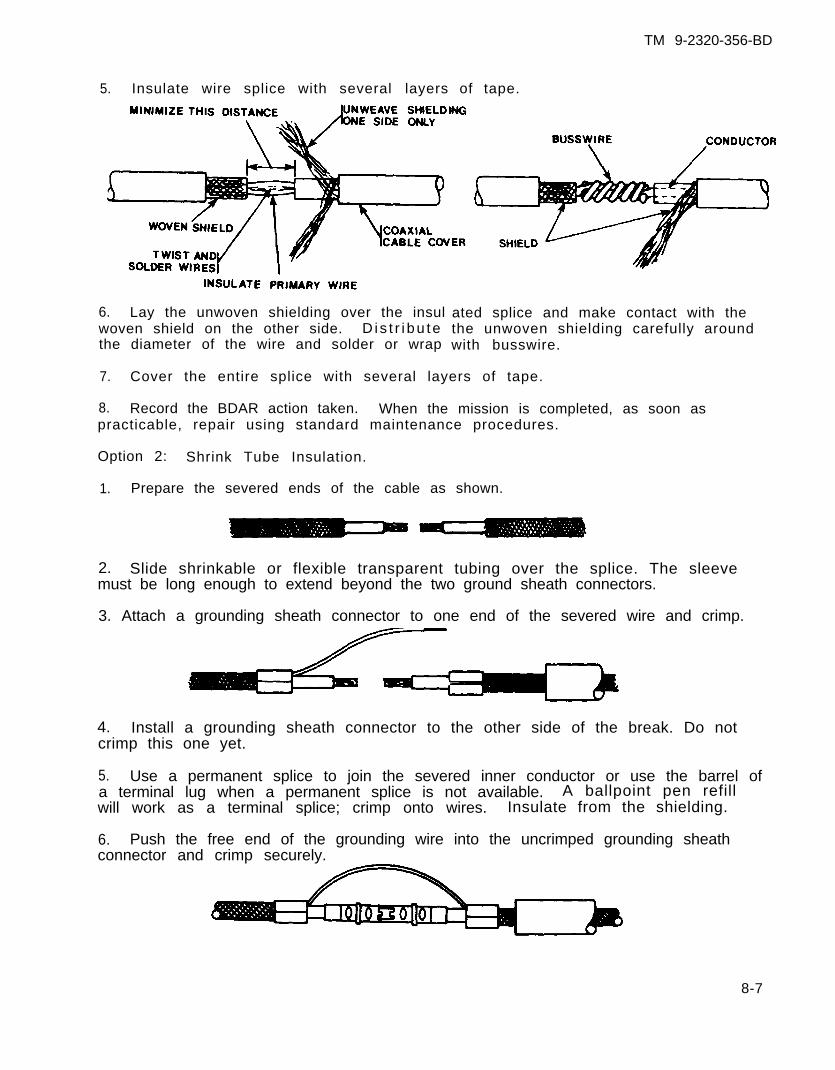
TM 9-2320-356-BD
5. Insulate wire splice with several
6. Lay the unwoven shielding over the insulwoven shield on the other side. D i s t r i bu tethe diameter of the wire and solder or wrap
layers of tape.
ated splice and make contact with thethe unwoven shielding carefully aroundwith busswire.
7. Cover the entire splice with several layers of tape.
8. Record the BDAR action taken. When the mission is completed, as soon aspracticable, repair using standard maintenance procedures.
Option 2: Shrink Tube Insulation.
1. Prepare the severed ends of the cable as shown.
2. Slide shrinkable or flexible transparent tubing over the splice. The sleevemust be long enough to extend beyond the two ground sheath connectors.
3. Attach a grounding sheath connector to one end of the severed wire and crimp.
4. Install a grounding sheath connector to the other side of the break. Do notcrimp this one yet.
5. Use a permanent splice to join the severed inner conductor or use the barrel ofa terminal lug when a permanent splice is not available. A ballpoint pen refillwill work as a terminal splice; crimp onto wires. Insulate from the shielding.
6. Push the free end of the grounding wire into the uncrimped grounding sheathconnector and crimp securely.
8-7
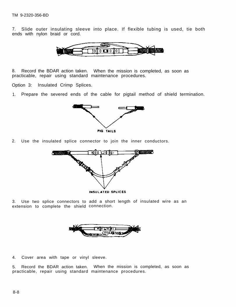
TM 9-2320-356-BD
7. Slide outer insulating sleeve into place. If flexible tubing is used, tie bothends with nylon braid or cord.
8. Record the BDAR action taken. When the mission is completed, as soon aspracticable, repair using standard maintenance procedures.
Option 3: Insulated Crimp Splices.
1. Prepare the severed ends of the cable for pigtail method of shield termination.
2. Use the insulated splice connector to join the inner conductors.
3. Use two splice connectors toextension to complete the shield
add a short lengthconnection.
of insulated wire as an
4. Cover area with tape or vinyl sleeve.
5. Record the BDAR action taken. When the mission is completed, as soon aspracticable, repair using standard maintenance procedures.
8-8
TM 9-2320-356-BD
Section IV. WIRING HARNESSES
8-10. GENERAL
Wiring harnesses are normally replaced when extensiveimprovements or different configurations, replacementof the same vehicle family may use some different styharnesses from an identical model; however. connector
damage occurs. Because ofharnesses from other vehiclese connectors. Try to obtaincan be exchanged with the
damaged harness. The same procedure is followed to change a complete connector orto splice a complete harness. If a wire is damaged but the fault cannot belocated, it should be replaced with a jumper wire.
8-11. WIRING HARNESS DAMAGED
General Information:
Wire harness repairs are general ly a series of single-wire repairs. Establ ishingcircuit continuity in a bundle of wires is dif f icult because individual wires arenot color coded. Wires must be identified before they are connected. Essentialelectrical functions can be rapidly restored by using jumper wires.
L imi ta t ions:
o None
Personnel/Time Required:
o 1 so ld iero 1 - 2 hours
Mater ia ls /Tools :
o Wireo Sp l i ceso E lec t r i ca l t apeo Solder ing i rono P las t i c t i e s
Procedural Steps:
Option 1: Wire Bundle Repairs.
1. Splice the first wire and tape. Leave the tape hanging from the repair.
2. Splice the next wire, lay i t on top of the f irst repair.
3. Continue wrapping with electrical tape.
4. Repeat these steps as often as necessary to repair the wire bundle withoutcutting or breaking the tape until the repair has been completed.
8-9
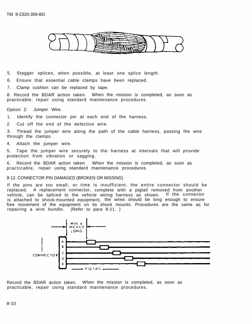
TM 9-2320-356-BD
5. Stagger splices, when possible, at least one splice length.
6. Ensure that essential cable clamps have been replaced.
7. Clamp cushion can be replaced by tape.
8. Record the BDAR action taken. When the mission is completed, as soon aspracticable, repair using standard maintenance procedures.
Option 2: Jumper Wire.
1. Identify the connector pin at each end of the harness.
2. Cut off the end of the defective wire.
3. Thread the jumper wire along the path of the cable harness, passing the wirethrough the clamps.
4. Attach the jumper wire.
5. Tape the jumper wire securely to the harness at intervals that will provideprotection from vibration or sagging.
6. Record the BDAR action taken. When the mission is completed, as soon aspract icab le , repair using standard maintenance procedures.
8-12. CONNECTOR PIN DAMAGED (BROKEN OR MISSING)
If the pins are too small, or t ime is insuff ic ient, the entire connector should bereplaced. A replacement connector, complete with a pigtail removed from anothervehicle, can be spliced to the vehicle wiring harness as shown. If the connectoris attached to shock-mounted equipment, the wires should be long enough to ensurefree movement of the equipment on its shock mounts. Procedures are the same as forrepairing a wire bundle. (Refer to para 8-11. )
Record the BDAR action taken. When the mission is completed, as soon aspracticable, repair using standard maintenance procedures.
8-10
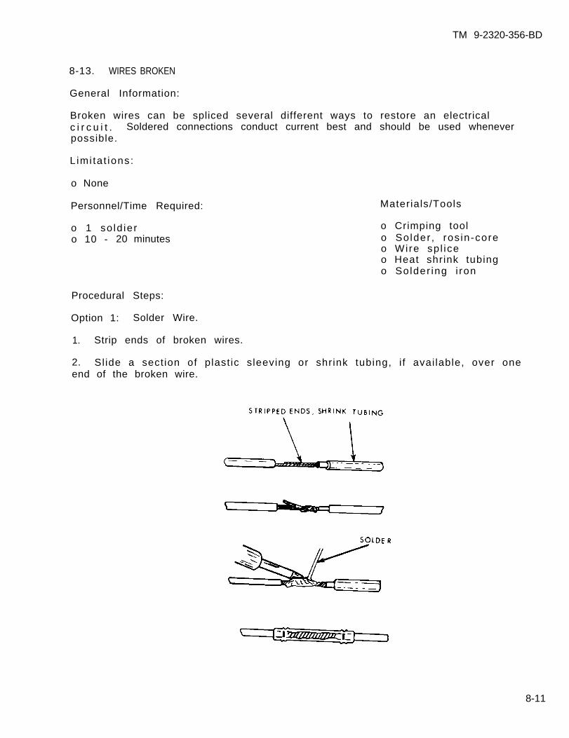
TM 9-2320-356-BD
8-13. WIRES BROKEN
General Information:
Broken wires can be spliced several different ways to restore an electricalc i r c u i t . Soldered connections conduct current best and should be used wheneverpossible.
L imi ta t ions:
o None
Personnel/Time Required:
o 1 so ld iero 10 - 20 minutes
Materials/Tools
o Crimping toolo Solder , ros in-coreo Wire sp l iceo Heat shrink tubingo Solder ing i ron
Procedural Steps:
Option 1: Solder Wire.
1. Strip ends of broken wires.
2. Sl ide a sect ion of plast ic sleeving or shrink tubing, i f avai lable, over oneend of the broken wire.
8-11
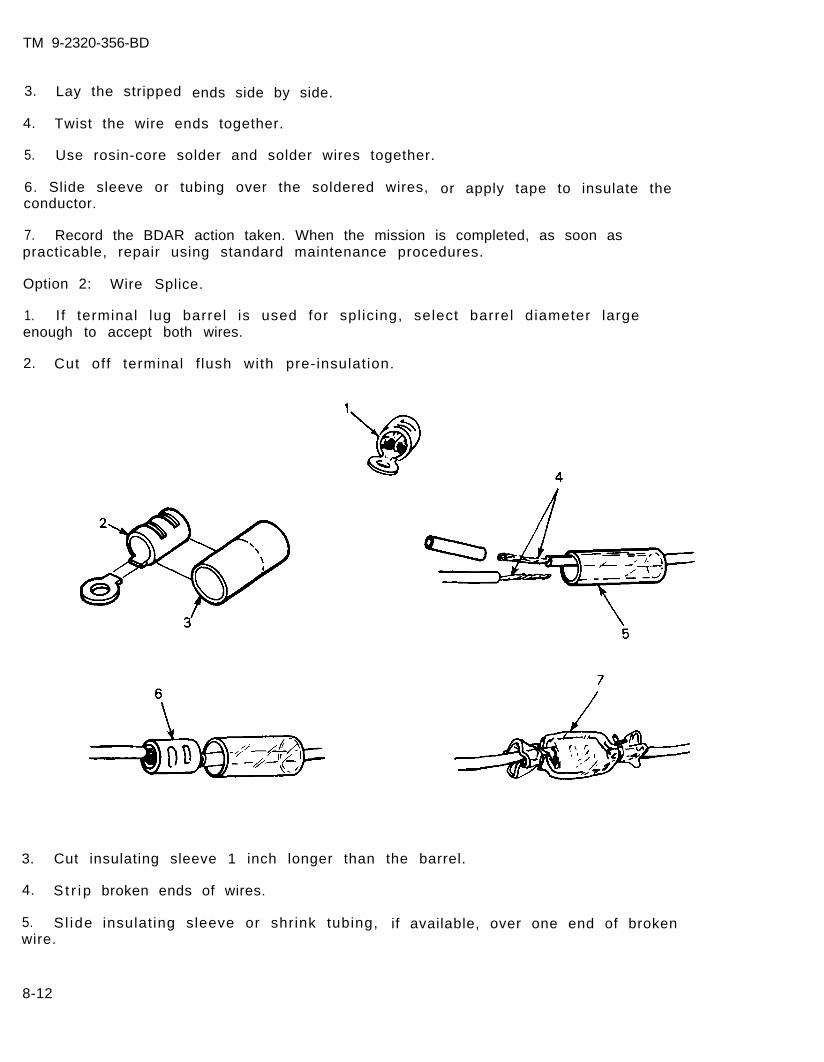
TM 9-2320-356-BD
3. Lay the stripped ends side by side.
4. Twist the wire ends together.
5. Use rosin-core solder and solder wires together.
6. Slide sleeve or tubing over the soldered wires, or apply tape to insulate theconductor.
7. Record the BDAR action taken. When the mission is completed, as soon aspracticable, repair using standard maintenance procedures.
Option 2: Wire Splice.
1. I f terminal lug barrel is used for spl icing, select barrel diameter largeenough to accept both wires.
2. Cut off terminal f lush with pre-insulation.
3. Cut insulating sleeve 1 inch longer than the barrel.
4. S t r i p
5. S l idewire.
8-12
broken ends of wires.
insulat ing sleeve or shrink tubing, if available, over one end of broken
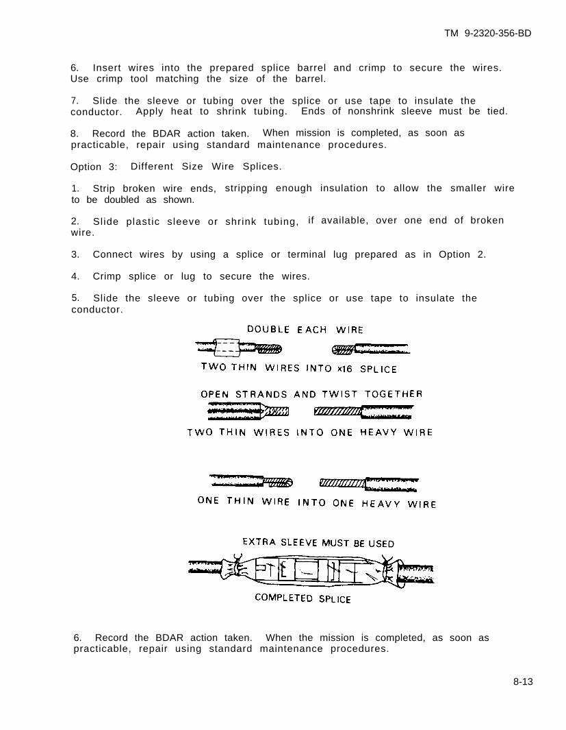
TM 9-2320-356-BD
6. Insert wires into the prepared splice barrel and crimp to secure the wires.Use crimp tool matching the size of the barrel.
7. Slide the sleeve or tubing over the splice or use tape to insulate theconductor. Apply heat to shrink tubing. Ends of nonshrink sleeve must be tied.
8. Record the BDAR action taken. When mission is completed, as soon aspracticable, repair using standard maintenance procedures.
Option 3: Different Size Wire Splices.
1. Strip broken wire ends, stripping enough insulation to allow the smaller wireto be doubled as shown.
2. Slide plastic sleeve or shrink tubing, if available, over one end of brokenwire.
3. Connect wires by using a splice or terminal lug prepared as in Option 2.
4. Crimp splice or lug to secure the wires.
5. Slide the sleeve or tubing over the splice or use tape to insulate theconductor.
6. Record the BDAR action taken. When the mission is completed, as soon aspracticable, repair using standard maintenance procedures.
8-13
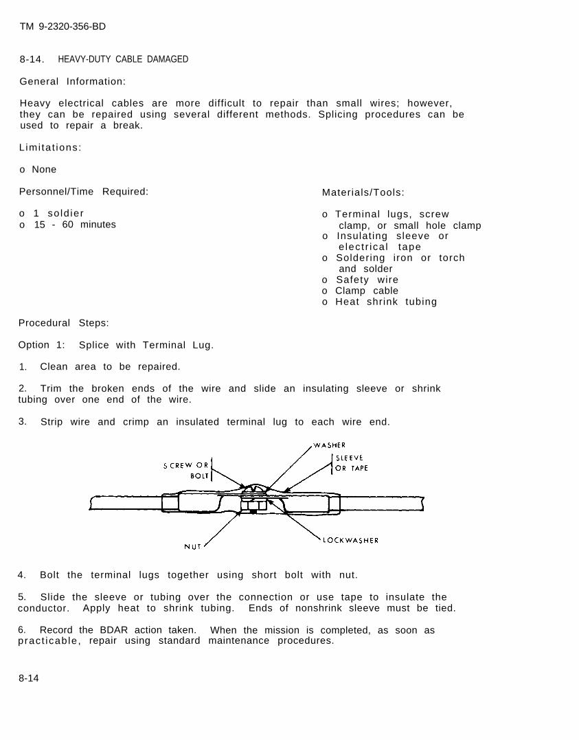
TM 9-2320-356-BD
Procedural Steps:
Option 1: Splice with Terminal Lug.
1. Clean area to be repaired.
2. Trim the broken ends of the wire and slide an insulating sleeve or shrinktubing over one end of the wire.
3. Strip wire and crimp an insulated terminal lug to each wire end.
8-14. HEAVY-DUTY CABLE DAMAGED
General Information:
Heavy electrical cables are more difficult to repair than small wires; however,they can be repaired using several different methods. Splicing procedures can beused to repair a break.
L imi ta t ions:
o None
Personnel/Time Required:
o 1 so ld iero 15 - 60 minutes
Materials/Tools:
o Terminal lugs, screwclamp, or small hole clamp
o Insulat ing sleeve ore lec t r ica l tape
o Soldering iron or torchand solder
o Safety wireo Clamp cableo Heat shrink tubing
4. Bolt the terminal lugs together using short bolt with nut.
5. Slide the sleeve or tubing over the connection or use tape to insulate theconductor. Apply heat to shrink tubing. Ends of nonshrink sleeve must be tied.
6. Record the BDAR action taken. When the mission is completed, as soon aspract icab le , repair using standard maintenance procedures.
8-14
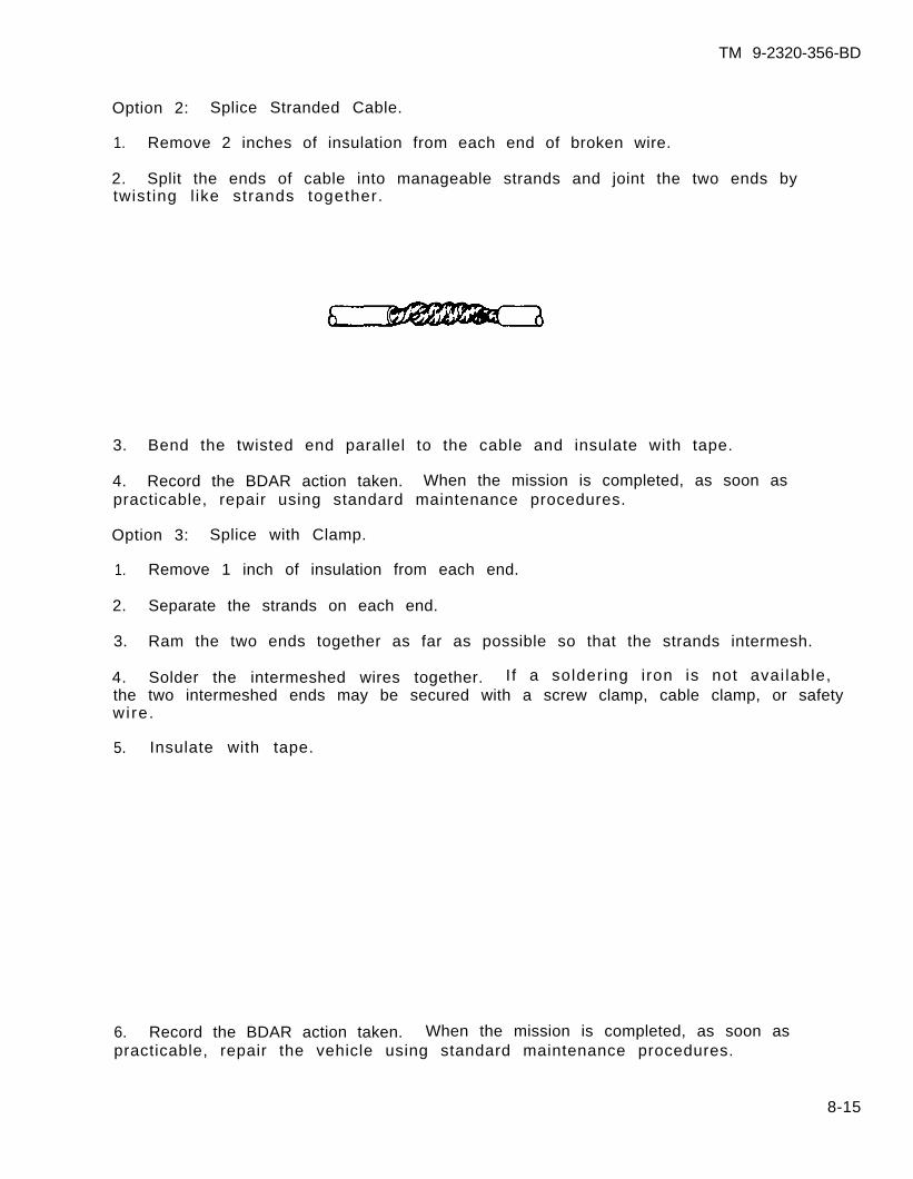
TM 9-2320-356-BD
Option 2: Splice Stranded Cable.
1. Remove 2 inches of insulation from each end of broken wire.
2. Split the ends of cable into manageable strands and joint the two ends bytwist ing l ike strands together.
3. Bend the twisted end parallel to the cable and insulate with tape.
4. Record the BDAR action taken. When the mission is completed, as soon aspracticable, repair using standard maintenance procedures.
Option 3: Splice with Clamp.
1. Remove 1 inch of insulation from each end.
2. Separate the strands on each end.
3. Ram the two ends together as far as possible so that the strands intermesh.
4. Solder the intermeshed wires together. If a soldering iron is not available,the two intermeshed ends may be secured with a screw clamp, cable clamp, or safetywire.
5. Insulate with tape.
6. Record the BDAR action taken. When the mission is completed, as soon aspracticable, repair the vehicle using standard maintenance procedures.
8-15
TM 9-2320-356-BD
Section V. ELECTRICAL MOTORS
8-15. GENERAL
Repair on automotive motors should be restricted to relays, solenoids, andbrushes. Damage to casings and windings cannot be expediently repaired.
8-16. ELECTRICAL ALTERNATOR/MOTOR BRUSH WORN
General Information:
Electrical motors and alternators use a carbon composition brush to transferelectrical energy to or from the armature commutators. The transfer of energycreates an electrical arc which will burn the brushes. Arcing and normal frictionwill cause the brushes to become worn and inefficient for electrical powert ransfer . The brushes can be substituted with the carbon core from a BA30 or BA31f lash l ight bat tery . Care must be taken when opening the battery; the contents arecorrosive. Brush retaining springs can be used to transfer the energy or to holdthe old brush wires in place.
L imi ta t ions:
o Shor ter motor /a l ternator l i fe
Personnel/Time Required:
o 1 to 3 soldierso 1 to 8 hours
Other Options:
o Modify and use other electrical brush sets.
Procedural Steps:
1. Gain access to motor or alternator.
2. Remove electrical brush plate.
3. Obtain a BA30 or BA31 battery.
Materials/Tools:
o BA30 or BA31 batteryo Hacksawo Sandpaper
WARNING
The fibrous material of a battery is corrosiveand could cause injury to eyes and damage toc lo th ing.
4. Use a hacksaw or other available tool and split the battery open, taking carenot to damage the carbon core.
5. Clean and cut the carbon core to fit the brush plate receptacles.
8-16
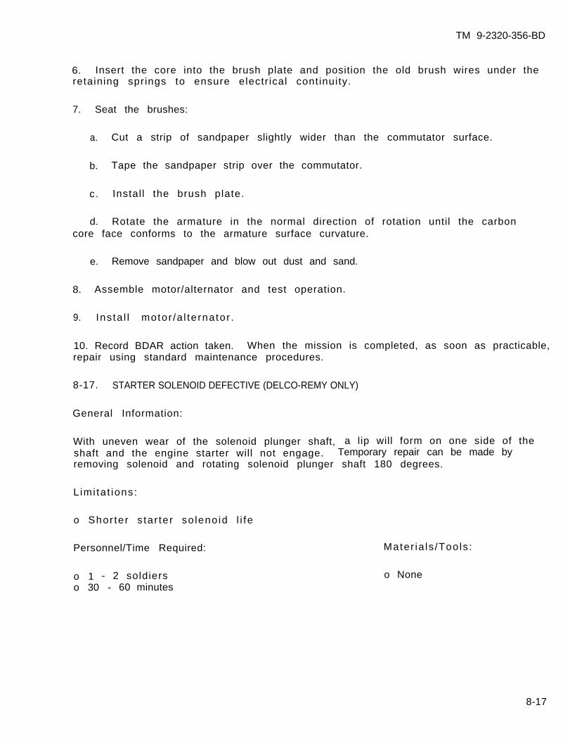
TM 9-2320-356-BD
6. Insert the core into the brush plate and position the old brush wires under theretaining springs to ensure electr ical continuity.
7. Seat the brushes:
a. Cut a strip of sandpaper slightly wider than the commutator surface.
b. Tape the sandpaper strip over the commutator.
c. Instal l the brush plate.
d. Rotate the armature in the normal direction of rotation until the carboncore face conforms to the armature surface curvature.
e. Remove sandpaper and blow out dust and sand.
8. Assemble motor/alternator and test operation.
9. Ins ta l l motor /a l ternator .
10. Record BDAR action taken. When the mission is completed, as soon as practicable,repair using standard maintenance procedures.
8-17. STARTER SOLENOID DEFECTIVE (DELCO-REMY ONLY)
General Information:
With uneven wear of the solenoid plunger shaft, a lip will form on one side of theshaft and the engine starter will not engage. Temporary repair can be made byremoving solenoid and rotating solenoid plunger shaft 180 degrees.
L imi ta t ions:
o Shor ter s tar ter so leno id l i fe
Personnel/Time Required:
o 1 - 2 soldierso 30 - 60 minutes
Mater ia ls /Tools :
o None
8-17
TM 9-2320-356-BD
Procedural Steps:
1. Disconnect power at negative battery terminal.
2. Gain access to engine starter; remove if necessary.
3. Remove solenoid from starter.
4. Rotate solenoid plunger shaft 180 degrees.
5. Instal l solenoid on starter.
6. Instal l starter, i f removed.
7. Connect power.
8 . Test s tar ter operat ion.
9. Record the BDAR action taken. When the mission is completed, as soon aspracticable, repair using standard maintenance procedures.
8-18
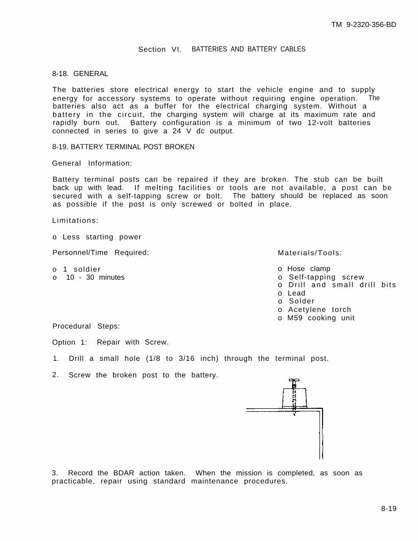
TM 9-2320-356-BD
Section VI. BATTERIES AND BATTERY CABLES
8-18. GENERAL
The batteries store electrical energy to start the vehicle engine and to supplyenergy for accessory systems to operate without requiring engine operation. Thebatteries also act as a buffer for the electrical charging system. Without abat tery in the c i rcu i t , the charging system will charge at its maximum rate andrapidly burn out. Battery configuration is a minimum of two 12-volt batteriesconnected in series to give a 24 V dc output.
8-19. BATTERY TERMINAL POST BROKEN
General Information:
Battery terminal posts can be repaired if they are broken. The stub can be builtback up with lead. If melt ing faci l i t ies or tools are not avai lable, a post can besecured with a self-tapping screw or bolt. The battery should be replaced as soonas possible if the post is only screwed or bolted in place.
L imi ta t ions:
o Less starting power
Personnel/Time Required:
o 1 so ld iero 10 - 30 minutes
Mater ia ls /Tools :
o Hose clampo Self-tapping screwo Dr i l l and sma l l d r i l l b i t so Leado Soldero Acetylene torcho M59 cooking unit
Procedural Steps:
Option 1: Repair with Screw.
1. Drill a small hole (1/8 to 3/16 inch) through the terminal post.
2. Screw the broken post to the battery.
3. Record the BDAR action taken. When the mission is completed, as soon aspracticable, repair using standard maintenance procedures.
8-19
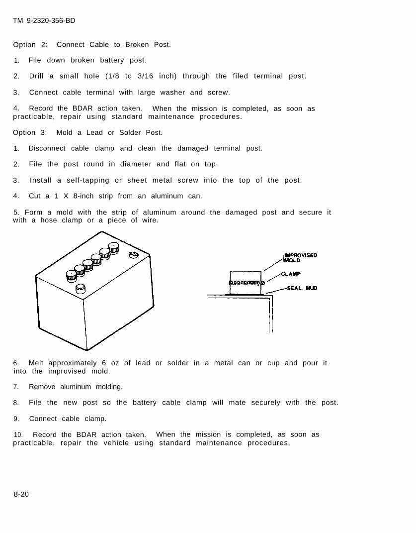
TM 9-2320-356-BD
Option 2: Connect Cable to Broken Post.
1. File down broken battery post.
2. Drill a small hole (1/8 to 3/16 inch) through the filed terminal post.
3. Connect cable terminal with large washer and screw.
4. Record the BDAR action taken. When the mission is completed, as soon aspracticable, repair using standard maintenance procedures.
Option 3: Mold a Lead or Solder Post.
1. Disconnect cable clamp and clean the damaged terminal post.
2. File the post round in diameter and flat on top.
3. Install a self-tapping or sheet metal screw into the top of the post.
4. Cut a 1 X 8-inch strip from an aluminum can.
5. Form a mold with the strip of aluminum around the damaged post and secure itwith a hose clamp or a piece of wire.
6. Melt approximately 6 oz of lead or solder in a metal can or cup and pour itinto the improvised mold.
7. Remove aluminum molding.
8. File the new post so the battery cable clamp will mate securely with the post.
9. Connect cable clamp.
10. Record the BDAR action taken. When the mission is completed, as soon aspracticable, repair the vehicle using standard maintenance procedures.
8-20

TM 9-2320-356-BD
8-20. BATTERY CRACKED
General Information:
Batteries can become cracked from vibrations, impact, or freezing. Cracks can berepaired or sealed until replacements can be obtained. Batteries which are crackedfrom freezing must be inspected for internal shorts or broken plates. Most epoxywil l not shrink and is resistant to acid. Epoxies make a semi-permanent repair andshould be used as a first option.
L imi ta t ions:
o None
Personnel/Time Required:
o 1 so ld iero 1 - 2 hours
Mater ia ls /Tools :
o Bulk issue f iberglasso Epoxyo Hardening sealer
Procedural Steps:
1. Drain battery below the crack.
2. Clean damaged area.
3. Fi l l crack with either hardening sealer, f iberglass, or epoxy.
4. F i l l bat tery to proper leve l .
5. Record the BDAR action taken. When the mission is completed, as soon aspract icab le , repair using standard maintenance procedures.
8-21. BATTERY CABLE DAMAGED
General Information:
Battery cables and cable ends may be repaired if damaged. If splicing is notpossible because of the amount of cable damage, a new cable may be fabricated.
L imi ta t ions:
o Less starting power
Personnel/Time Required:
o 1 so ld iero 30 - 45 minutes
Mater ia ls /Tools :
o Cable clampso Small hose clampso Commo wireo E lec t r i ca l t apeo Wire cutters or pocket
kn i f eo Vise gr ips
8-21
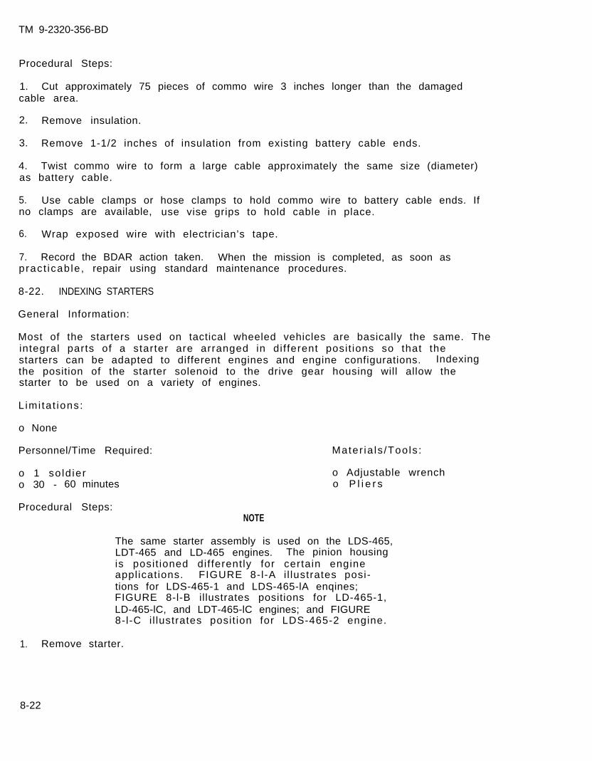
TM 9-2320-356-BD
Procedural Steps:
1. Cut approximately 75 pieces of commo wire 3 inches longer than the damagedcable area.
2. Remove insulation.
3. Remove 1-1/2 inches of insulation from existing battery cable ends.
4. Twist commo wire to form a large cable approximately the same size (diameter)as battery cable.
5. Use cable clamps or hose clamps to hold commo wire to battery cable ends. Ifno clamps are available, use vise grips to hold cable in place.
6. Wrap exposed wire with electrician’s tape.
7. Record the BDAR action taken. When the mission is completed, as soon aspract icab le , repair using standard maintenance procedures.
8-22. INDEXING STARTERS
General Information:
Most of the starters used on tactical wheeled vehicles are basically the same. Theintegral parts of a starter are arranged in dif ferent posit ions so that thestarters can be adapted to different engines and engine configurations. Indexingthe position of the starter solenoid to the drive gear housing will allow thestarter to be used on a variety of engines.
L imi ta t ions:
o None
Personnel/Time Required:
o 1 so ld iero 30 - 60 minutes
Procedural Steps:
Mater ia ls /Tools :
o Adjustable wrencho P l i e r s
NOTE
The same starter assembly is used on the LDS-465,LDT-465 and LD-465 engines. The pinion housingis posit ioned dif ferently for certain engineapplicat ions. FIGURE 8-l-A i l lustrates posi-tions for LDS-465-1 and LDS-465-lA enqines;FIGURE 8-l-B illustrates positions for LD-465-1,LD-465-lC, and LDT-465-lC engines; and FIGURE8-l-C i l lustrates posit ion for LDS-465-2 engine.
1. Remove starter.
8-22
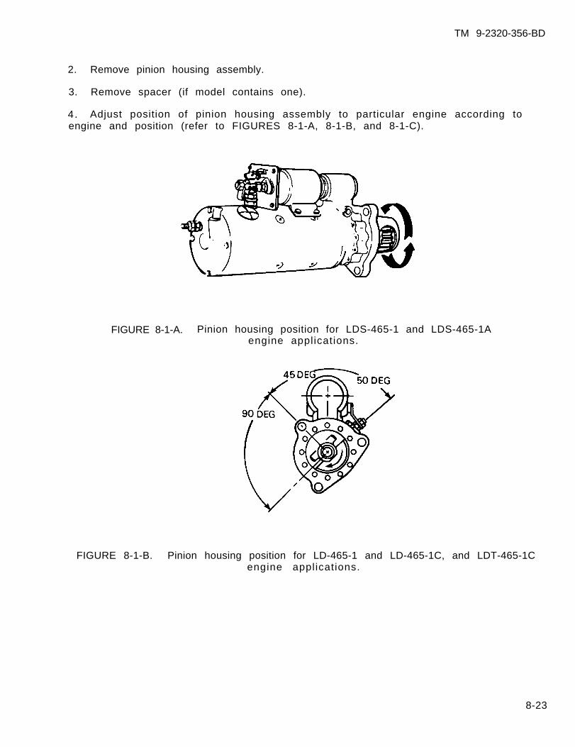
2. Remove pinion housing assembly.
3. Remove spacer (if model contains one).
TM 9-2320-356-BD
4. Adjust position of pinion housing assembly to particular engine according toengine and position (refer to FIGURES 8-1-A, 8-1-B, and 8-1-C).
FIGURE 8-1-A. Pinion housing position for LDS-465-1 and LDS-465-1Aengine applications.
FIGURE 8-1-B. Pinion housing position for LD-465-1 and LD-465-1C, and LDT-465-1Cengine applications.
8-23
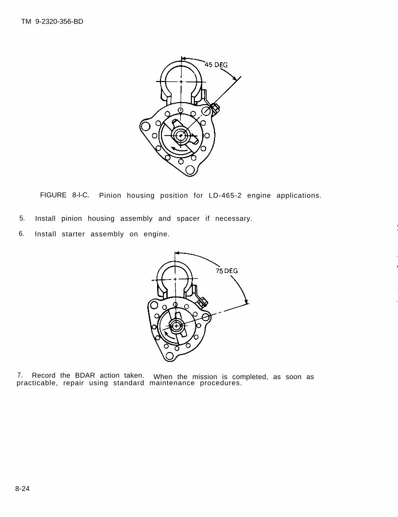
TM 9-2320-356-BD
FIGURE 8-l-C. Pinion housing position for LD-465-2 engine applications.
5. Install pinion housing assembly and spacer if necessary.
6. Install starter assembly on engine.
7. Record the BDAR action taken. When the mission is completed, as soon aspracticable, repair using standard maintenance procedures.
8-24
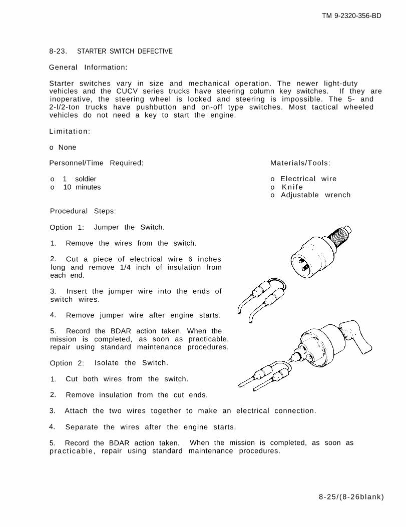
8-23. STARTER SWITCH DEFECTIVE
General Information:
Starter switches vary in size and mechanical operation. The newer light-dutyvehicles and the CUCV series trucks have steering column key switches. If they areinoperative, the steering wheel is locked and steering is impossible. The 5- and2-l/2-ton trucks have pushbutton and on-off type switches. Most tactical wheeledvehicles do not need a key to start the engine.
L imi ta t ion:
o None
Personnel/Time Required:
o 1 soldiero 10 minutes
Procedural Steps:
Option 1: Jumper the Switch.
1. Remove the wires from the switch.
2. Cut a piece of electrical wire 6 incheslong and remove 1/4 inch of insulation fromeach end.
3. Insert the jumper wire into the ends ofswitch wires.
4. Remove jumper wire after engine starts.
5. Record the BDAR action taken. When themission is completed, as soon as practicable,repair using standard maintenance procedures.
Option 2: Isolate the Switch.
1. Cut both wires from the switch.
2. Remove insulation from the cut ends.
Materials/Tools:
o Electr ical wireo K n i f eo Adjustable wrench
3. Attach the two wires together to make an electrical connection.
4. Separate the wires after the engine starts.
5. Record the BDAR action taken. When the mission is completed, as soon aspract icab le , repair using standard maintenance procedures.
8-25/ (8-26blank)
TM 9-2320-356-BD
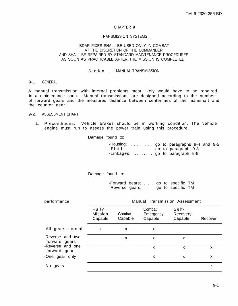
TM 9-2320-356-BD
CHAPTER 9
TRANSMISSION SYSTEMS
BDAR FIXES SHALL BE USED ONLY IN COMBATAT THE DISCRETION OF THE COMMANDER
AND SHALL BE REPAIRED BY STANDARD MAINTENANCE PROCEDURESAS SOON AS PRACTICABLE AFTER THE MISSION IS COMPLETED.
Section I. MANUAL TRANSMISSION
9-1. GENERAL
A manual transmission with internal problems most likely would have to be repairedin a maintenance shop. Manual transmissions are designed according to the numberof forward gears and the measured distance between centerlines of the mainshaft andthe counter gear.
9-2. ASSESSMENT CHART
a. Precondit ions: Vehicle brakes should be in working condition. The vehicleengine must run to assess the power train using this procedure.
Damage found to:
-Housing; . . . . . . . . . go to paragraphs 9-4 and 9-5-F lu id ; . . . . . . . . . . . go to paragraph 9-8-Linkages; . . . . . . . . go to paragraph 9-9
Damage found to:
performance:
-All gears normal
-Reverse and twoforward gears
-Reverse and oneforward gear
-One gear only
-No gears
-Forward gears; . . . go to specific TM-Reverse gears; . . . go to specific TM
Manual Transmission Assessment
F u l l y Combat Se l f -Mission Combat Emergency RecoveryCapable Capable Capable Capable Recover
x x x
x x x
x x x
x x x
x
9-1
TM 9-2320-356-BD
9-3. BDAR PROCEDURE INDEX Para
Cracks or Holes in the Housing . . . . . . . . . . . . . . . . . . . . . . . . . . . . . . . . . . . . . . . 9-4
9-4. CRACKS OR HOLES IN THE HOUSING
General Information:
Repair of cracks or holes in the transmission housing can be attempted withoutremoving the transmission. Cracks or holes in the housing may be repaired withepoxies and sealers if the hole or crack is accessible for cleaning.
L imi ta t ions:
o None
Personnel/Time Required:
o 1 to 2 soldierso 1 to 3 hours
Mater ia l /Tools :
o0oooooooo
Cleaning solventR a g sHardening or silicone sealerNonhardening sealerScreen (fine mesh)Aluminum cansSandpaperWooden pegGear lubricantEpoxy
Procedural Steps:
Option 1: Hardening Sealer.
1. Clean area around holes or cracks with sandpaper.
2. Cut a piece of screen 1 inch larger than the hole.
3. Apply a thin coat of hardening sealer to the edges of the hole.
4. Lay the screen over the hole and add another layer of hardening sealer aroundthe edges. Let sealer dry approximately 20 to 30 minutes.
5. Cut a patch from an aluminum can the same size as the screen.
6. Apply hardening sealer to the entire screen and lay the metal patch over thescreen.
7. Coat the patch with hardening sealer.
8. Let dry for 2 to 3 hours.
9-2
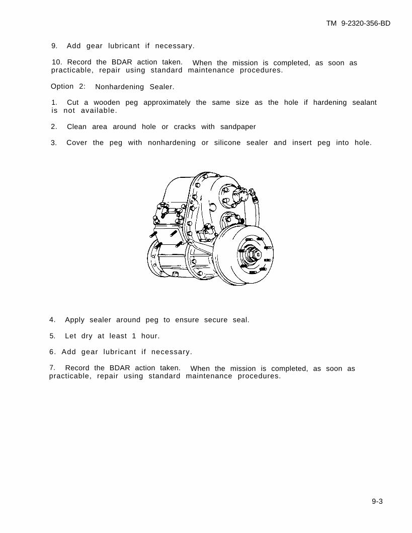
TM 9-2320-356-BD
9. Add gear lubricant if necessary.
10. Record the BDAR action taken. When the mission is completed, as soon aspracticable, repair using standard maintenance procedures.
Option 2: Nonhardening Sealer.
1. Cut a wooden peg approximately the same size as the hole if hardening sealantis not available.
2. Clean area around hole or cracks with sandpaper
3. Cover the peg with nonhardening or silicone sealer and insert peg into hole.
4. Apply sealer around peg to ensure secure seal.
5. Let dry at least 1 hour.
6. Add gear lubricant i f necessary.
7. Record the BDAR action taken. When the mission is completed, as soon aspracticable, repair using standard maintenance procedures.
9-3
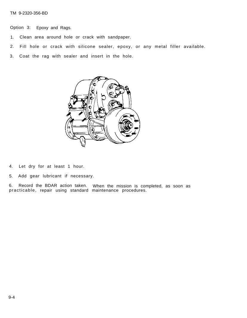
TM 9-2320-356-BD
Option 3: Epoxy and Rags.
1. Clean area around hole or crack with sandpaper.
2. Fi l l hole or crack with si l icone sealer, epoxy, or any metal f i l ler avai lable.
3. Coat the rag with sealer and insert in the hole.
4. Let dry for at least 1 hour.
5. Add gear lubricant if necessary.
6. Record the BDAR action taken. When the mission is completed, as soon aspract icab le , repair using standard maintenance procedures.
9-4
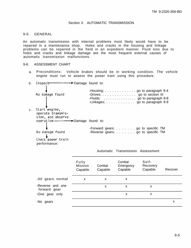
TM 9-2320-356-BD
Section II. AUTOMATIC TRANSMISSION
9-5. GENERAL
An automatic transmission with internal problems most likely would have to berepaired in a maintenance shop. Holes and cracks in the housing and linkageproblems can be repaired in the field in an expedient manner. Fluid loss due toholes and cracks and linkage damage are the most frequent external causes ofautomatic transmission malfunctions.
9-6. ASSESSMENT CHART
a. Precondit ions: Vehicle brakes should be in working condition. The vehicleengine must run to assess the power train using this procedure.
b. Damage found to:
-Housing; . . . . . . . . . . . . . go to paragraph 9-4-Drives; . . . . . . . . . . . . . . go to section III-Fluids; . . . . . . . . . . . . . . . go to paragraph 9-8-Linkages; . . . . . . . . . . . . go to paragraph 9-9
c.
Damage found to:
-Forward gears; . . . . . . . go to specific TM-Reverse gears; . . . . . . . go to specific TM
performance:
Automatic Transmission Assessment
Fu l l y Combat Se l f -Mission Combat Emergency RecoveryCapable Capable Capable Capable Recover
-All gears normal x x x
-Reverse and one x x xforward gear
-One gear only x x
-No gears x
9-5
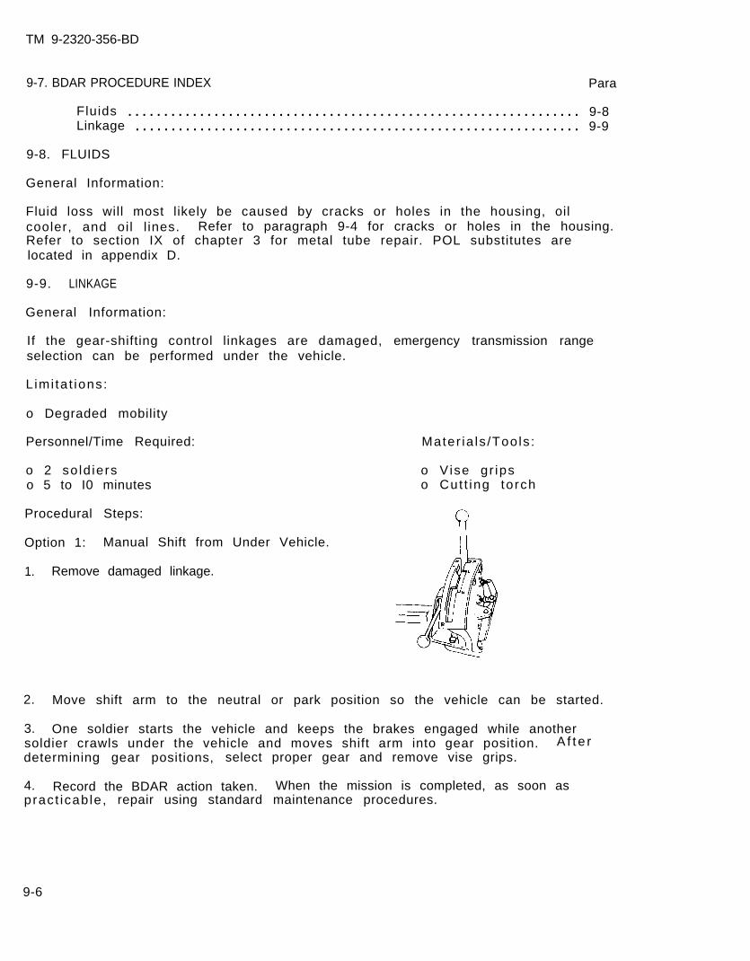
TM 9-2320-356-BD
9-7. BDAR PROCEDURE INDEX Para
Fluids . . . . . . . . . . . . . . . . . . . . . . . . . . . . . . . . . . . . . . . . . . . . . . . . . . . . . . . . . . . . . . . 9-8Linkage . . . . . . . . . . . . . . . . . . . . . . . . . . . . . . . . . . . . . . . . . . . . . . . . . . . . . . . . . . . . . . 9-9
9-8. FLUIDS
General Information:
Fluid loss will most likely be caused by cracks or holes in the housing, oilcooler, and oi l l ines. Refer to paragraph 9-4 for cracks or holes in the housing.Refer to section IX of chapter 3 for metal tube repair. POL substitutes arelocated in appendix D.
9-9. LINKAGE
General Information:
If the gear-shifting control linkages are damaged, emergency transmission rangeselection can be performed under the vehicle.
L imi ta t ions:
o Degraded mobility
Personnel/Time Required:
o 2 so ld ierso 5 to I0 minutes
Procedural Steps:
Option 1: Manual Shift from Under Vehicle.
1. Remove damaged linkage.
Mater ia ls /Tools :
o V ise gr ipso Cut t ing torch
2. Move shift arm to the neutral or park position so the vehicle can be started.
3. One soldier starts the vehicle and keeps the brakes engaged while anothersoldier crawls under the vehicle and moves shift arm into gear position. A f t e rdetermining gear positions, select proper gear and remove vise grips.
4. Record the BDAR action taken. When the mission is completed, as soon aspract icab le , repair using standard maintenance procedures.
9-6
TM 9-2320-356-BD
Option 2: Manual Shift from Inside Vehicle.
1. Cut a hole in the floorboard in the general area of the shifting arm of thetransmission.
2. Remove damaged linkage.
3. Use vise grips and move shift arm to the neutral or park position so thevehicle can be started.
4. Start the vehicle.
5. Determine gear position and select proper gear.
6. Record the bar action taken. When the mission is completed, as soon aspract icab le , repair using standard maintenance procedures.
9-7
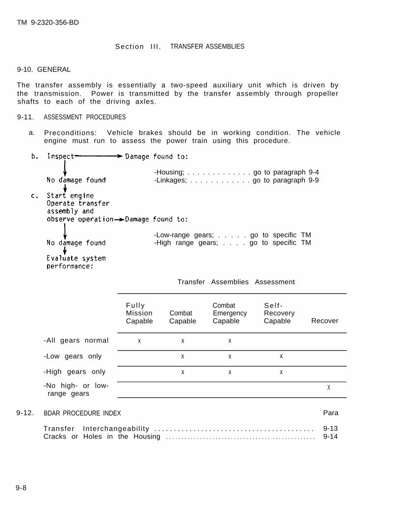
TM 9-2320-356-BD
shafts to each of the driving axles.
9-11. ASSESSMENT PROCEDURES
a. Precondit ions: Vehicle brakes should be in working condition. The vehicleengine must run to assess the power train using this procedure.
Sect ion I I I . TRANSFER ASSEMBLIES
9-10. GENERAL
The transfer assembly is essentially a two-speed auxiliary unit which is driven bythe transmission. Power is transmitted by the transfer assembly through propeller
-Housing; . . . . . . . . . . . . . go to paragraph 9-4-Linkages; . . . . . . . . . . . . go to paragraph 9-9
-Low-range gears; . . . . . go to specific TM-High range gears; . . . . go to specific TM
Transfer Assemblies Assessment
Fu l l y Combat Se l f -Mission Combat Emergency RecoveryCapable Capable Capable Capable Recover
-All gears normal x x x
-Low gears only x x x
-High gears only x x x
-No high- or low- Xrange gears
9-12. BDAR PROCEDURE INDEX Para
Transfer Interchangeabil i ty . . . . . . . . . . . . . . . . . . . . . . . . . . . . . . . . . . . . . . . . . 9-13Cracks or Holes in the Housing . . . . . . . . . . . . . . . . . . . . . . . . . . . . . . . . . . . . . . . . . . . . . . . . 9-14
9-8

TM 9-2320-356-BD
9-13. TRANSFER INTERCHANGEABILITY
General Information:
Transfer failure can have a multitude of causes. Availabi l i ty of replacementtransfers may become a problem that can be solved only by removal from otherdamaged equipment.
An alternate source of supply for transfers is foreign-owned equipment (refer toapp C).
9-14. CRACKS OR HOLES IN THE HOUSING
General Information:
Repair of cracks or holes in the transfer housing can be attempted without removingthe transfer.
L imi ta t ions:
o None
Personnel/Time Required:
o 1 to 2 soldierso 1 to 3 hours
Mater ia l /Tools :
o Cleaning solvento Ragso Hardening sealero Nonhardening sealero Gear lubricanto Wooden pego Aluminum can
Procedural Steps:
Option 1: Hardening Sealer.
1. Clean area around holes or cracks with sandpaper.
2. Cut a piece of screen 1 inch larger than the hole.
3. Apply a thin coat of hardening sealer to the edges of the hole.
4. Lay the screen over the hole and add another layer of hardening sealer aroundthe edges. Let sealer dry approximately 20 to 30 minutes.
5. Cut a patch from a aluminum can the same size as the screen.
6. Apply hardening sealer to the entire screen and lay the metal patch over thescreen.
9-9
TM 9-2320-356-BD
7. Coat the patch with hardening sealer.
8. Let dry for 2 to 3 hours.
9. Add gear lubricant if necessary.
10. Record the BDAR action taken. When the mission is completed, as soon aspracticable, repair using standard maintenance procedures.
Option 2: Nonhardening Sealer.
1. Cut a wooden peg approximately the same size as the hole if hardening sealantis not available.
2. Clean area around hole or cracks with sandpaper.
3. Cover the peg with nonhardening sealer and insert peg into hole.
4. Apply sealer around peg to ensure secure seal.
5. Let dry at least 1 hour.
6. Add gear lubricant if necessary.
7. Record the BDAR action taken. When the mission is completed, as soon aspracticable, repair using standard maintenance procedures.
9-10
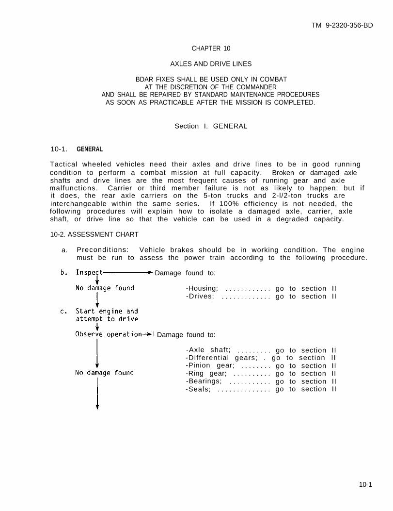
TM 9-2320-356-BD
CHAPTER 10
AXLES AND DRIVE LINES
BDAR FIXES SHALL BE USED ONLY IN COMBATAT THE DISCRETION OF THE COMMANDER
AND SHALL BE REPAIRED BY STANDARD MAINTENANCE PROCEDURESAS SOON AS PRACTICABLE AFTER THE MISSION IS COMPLETED.
Section I. GENERAL
10-1. GENERAL
Tactical wheeled vehicles need their axles and drive lines to be in good runningcondition to perform a combat mission at full capacity. Broken or damaged axleshafts and drive lines are the most frequent causes of running gear and axlemalfunctions. Carrier or third member failure is not as likely to happen; but ifit does, the rear axle carriers on the 5-ton trucks and 2-l/2-ton trucks areinterchangeable within the same series. If 100% efficiency is not needed, thefollowing procedures will explain how to isolate a damaged axle, carrier, axleshaft, or drive line so that the vehicle can be used in a degraded capacity.
10-2. ASSESSMENT CHART
a. Precondit ions: Vehicle brakes should be in working condition. The enginemust be run to assess the power train according to the following procedure.
Damage found to:
-Housing; . . . . . . . . . . . . go to section II-Drives; . . . . . . . . . . . . . go to section II
Damage found to:
-Axle shaft; . . . . . . . . . go to section II-Differential gears; . go to section II-Pinion gear; . . . . . . . . go to section II-Ring gear; . . . . . . . . . . go to section II-Bearings; . . . . . . . . . . . go to section II-Seals; . . . . . . . . . . . . . . go to section II
10-1
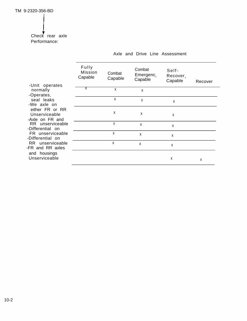
TM 9-2320-356-BD
Check rear axlePerformance:
Axle and Drive Line Assessment
-Unit operatesnormally
-Operates,seal leaks
-We axle oneither FR or RRUnserviceable
-Axle on FR andRR unserviceable
-Differential onFR unserviceable
-Differential onRR unserviceable
-FR and RR axlesand housingsUnserviceable
Fu l l yMission
CombatCombat
Se l f -
Capable EmergencyCapable
Recover y
Capable Capable Recover
x x x
x x x
x x x
x x x
x x x
x x x
x x
10-2

TM 9-2320-356-BD
Section II. FRONT AND REAR AXLES
10-3. BDAR PROCEDURES INDEX Para
Axle shaft in front rear axle damaged . . . . . . . . . . . . . . . . . . . . . . . . . . . . . . . 10-4Axle shaft in front rear and rear rear axles damaged . . . . . . . . . . . . . . . . 10-5Axle housing leaks (front rear or rear rear) . . . . . . . . . . . . . . . . . . . . . . . . 10-6Carrier on front rear or rear rear axle damaged . . . . . . . . . . . . . . . . . . . . . 10-7Axle shafts and carrier damaged on front rear and rear rear axles. . . . . . . . . .Front axle damaged l . . . . . . . . . . . . . . . . . . . . . . . . . . . . . . . . . . . . . . . . . . . . . . . . . 10-9Drive line damaged l . . . . . . . . . . . . . . . . . . . . . . . . . . . . . . . . . . . . . . . . . . . . . . . . . 10-10
10-4. AXLE SHAFT IN FRONT REAR AXLE DAMAGED
NOTE
The axle lock switch must be engaged.
General Information:
A broken left or r ight axle shaft wi l l cause the axle to lose i ts abi l i ty to drivethe vehicle. The vehif ront ax le .
L imi ta t ions:
o Degraded mobility (a
cle can still be propelled by the rear rear axle and the
nd ter ra in capabi l i ty
Personnel/Time Required:
o 1 so ld iero 30 minutes
Procedural Steps:
Option 1: Install Cap.
1. Remove damaged axle shaft.
2. Cut the axle as close to the capas possible.Install cap on the hub.
Mater ia ls /Tools :
o Ragso Cardboardo Cutting torcho Washerso Ratcheto Socket
3. Record the BDAR action taken.When the mission is completed, assoon as practicable, repair usingstandard maintenance procedures.
10-3
10-8
TM 9-2320-356-BD
Option 2: Cardboard Cap.
1. Remove damaged axle shaft.
2. Insert rags in hub.
3. Make a cap from cardboard and install on hub.
4. Record the BDAR action taken. When the mission is completed, as soon aspracticable, repair using standard maintenance procedures.
10-5. AXLE SHAFT IN FRONT REAR AND REAR REAR AXLES DAMAGED
General Information:
If both rear axles have axle shaft damage, most tactical wheeled vehicles willoperate after some of the drive train to the rear axles has been removed. Thiswill allow the vehicle to use the front axle and perform.
L imi ta t ions:
o Degraded mobil i ty, terrain capabil i ty, and load capacity
Personnel/Time Required: Mater ia ls /Tools :
o 2 so ld iers o Ratchet and socketo 30 minutes to 2 hours
Procedural Steps:
1. Remove the propeller shaft between the transfer case and the front rear axle.
NOTE
Some transfers must be in the locked position.
2. Attempt to move vehicle.
3. If vehicle is inoperative, remove propeller shaft between front rear axle andrear rear axle.
4. Attempt to move vehicle.
5. If vehicle is inoperative, refer to paragraph 1O-4.
6. Record the BDAR action taken. When the mission is completed, as soon aspract icab le , repair using standard maintenance procedures.
10-6. AXLE HOUSING LEAKS (FRONT REAR OR REAR REAR)
General Information:
Repair of axle housing leakage due to cracks or holes can be attempted withoutremoving either of the rear axle housings.
10-4
TM 9-2320-356-BD
Limi ta t ions:
o None
Personnel/Time Required: Mater ia ls /Tools :
o 1-2 so ld iers o Cleaning solvento 1 - 2 h o u r s o R a g s
o Hardening sealero Nonhardening sealer
Procedural Steps:
1. Clean area around holes or cracks and fill them with silicone, epoxy sealant,or any metal f i l ler available.
2. If the hole is too large to be filled, make a wooden peg, coat the peg withsealer, and place it in the hole.
3. Apply sealer around peg to ensure secure seal.
4. Fi l l the axle housing to the proper oi l level.
5. Record the BDAR action taken. When the mission is completed, as soon aspract icab le , repair using standard maintenance procedures.
10-7. CARRIER ON FRONT REAR OR REAR REAR AXLE DAMAGED
General Information:
Carrier damage to either of the rear axles will render the vehicle inoperative.
L imi ta t ions:
o Severe mobi l i ty res t r ic t ions
Personnel/Time Required: Mater ia ls /Tools :
o 2 so ld iers o Gasket materialo 1 to 4 hours o Cardboard
NOTE
The carriers in the rear axles of the M939,M809, and M39 series 5-ton trucks are the same.The carr iers in the rear axles of al l 2-1/2-tontrucks are the same.
Procedural Steps:
Option 1. Front rear axle carrier damaged.
1. Remove the axle shafts and the damaged carrier.
10-5

TM 9-2320-356-BD
2. Remove the axle shafts and carrier from the rear rear axle housing.
3. Instal l the rear rear carr ier into front rear axle housing.
4. Install axle shafts into both housings.
5. Record the BDAR action taken. When the mission is completed, as soon aspracticable, repair using standard maintenance procedures.
Option 2. Rear rear axle carrier damaged.
1. Remove both axle shafts.
2. Remove propeller shaft.
3. Make cardboard cover and install on hub.
4. Record the BDAR action taken. When the mission is completed, as soon aspracticable, repair using standard maintenance procedures.
10-8. AXLE SHAFTS AND CARRIER DAMAGED ON FRONT REAR AND REAR REAR AXLES
General Information:
With no rear axles in working condition, the vehicle must drive off the front axleonly.
L imi ta t ions:
o Degraded speedo Te r ra in res t r i c t i ons
Personnel/Time required:
o 2 so ld ierso 2-4 hours
Procedural steps:
1. Remove all axle shafts.
2. Remove propeller shaft.
3. Make a cardboard cover and install on hub.
Mater ia ls /Tools :
o Cardboard
4. Record the BDAR action taken. When the mission is completed, as soon aspracticable, repair using standard maintenance procedures.
10-6
TM 9-2320-356-BD
10-9. FRONT AXLE DAMAGED
General Information:
The front axle is necessary for a vehicle to have a 100% load carrying and pullingcapab i l i t y . If the axle shafts or the gears in the third member are damaged, thevehicle can still be used.
L imi ta t ions:
o Degraded mobil i ty and terrain capabil i ty
Personnel/Time required:
o 1 so ld i e ro 30-45 minutes
Mater ia ls /Tools :
o Various open-end boxwrenches
Procedural steps:
Option 1: 2-1/2- and 5-ton.
1. Disconnect the hub on the front drums.
2. Disconnect the propeller shaft from axle to transfer case.
3. Record the BDAR action taken. When the mission is completed, as soon aspracticable, repair using standard maintenance procedures.
Option 2: CUCV.
1. Put front hubs in free position.
2. Remove propeller shaft from axle to transfer case.
3. Shift transfer case into two-wheel mode.
4. Record the BDAR action taken. When the mission is completed, as soon aspract icab le , repair using standard maintenance procedures.
10-10. DRIVE LINE DAMAGED
General Information:
The drive line or propeller shaft in a vehicle must be straight and free of anydamage to perform at full load capacity. Most tact ical wheeled vehicles ut i l izemore than two drive lines to drive the different axles. Removal of a damaged drivecan greatly decrease the capability of the vehicle. A combat damaged drive linecan be repaired using the following procedure.
10-7
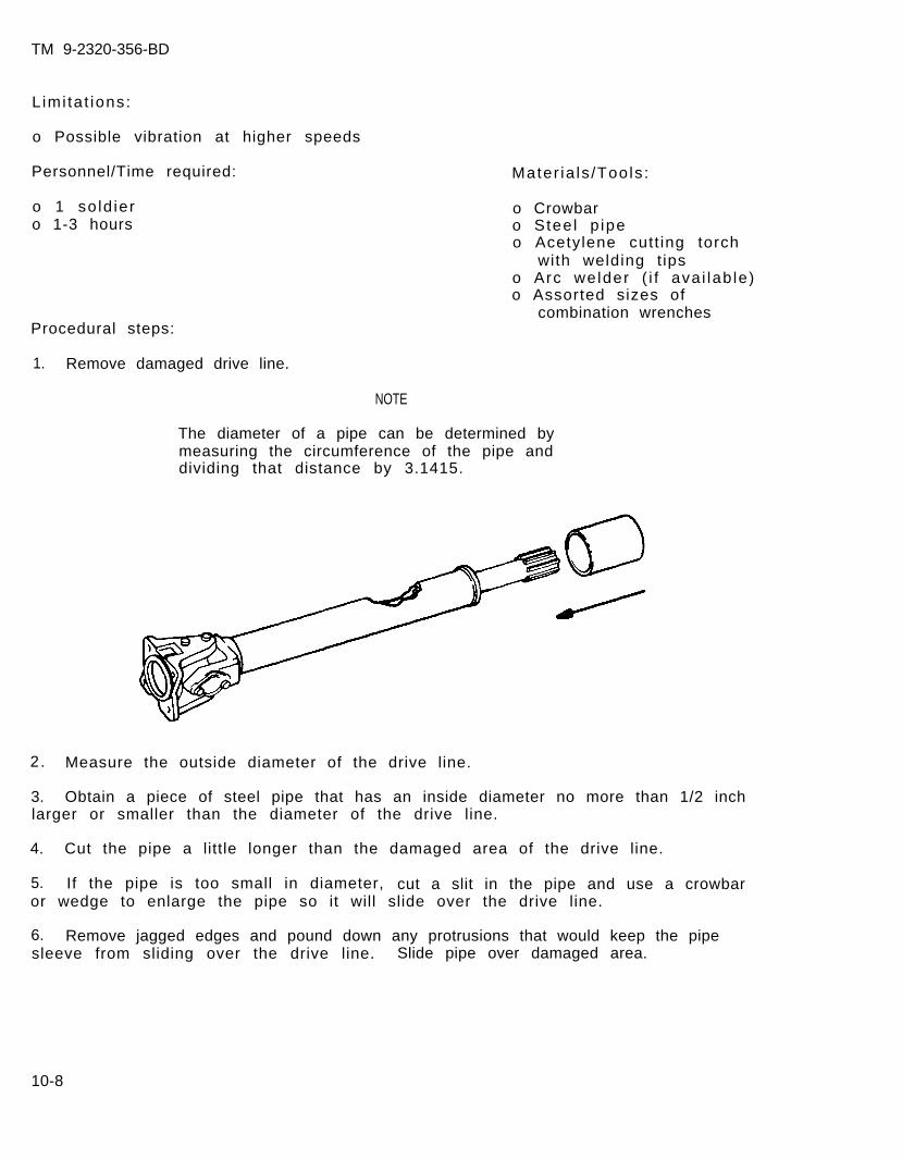
TM 9-2320-356-BD
Limi ta t ions:
o Possible vibration at higher speeds
Personnel/Time required:
o 1 so ld iero 1-3 hours
Procedural steps:
Mater ia ls /Tools :
o Crowbaro Stee l p ipeo Acetylene cutt ing torch
with welding t ipso Arc welder ( i f ava i lab le)o Assorted sizes of
combination wrenches
1. Remove damaged drive line.
NOTE
The diameter of a pipe can be determined bymeasuring the circumference of the pipe anddividing that distance by 3.1415.
2. Measure the outside diameter of the drive line.
3. Obtain a piece of steel pipe that has an inside diameter no more than 1/2 inchlarger or smaller than the diameter of the drive line.
4. Cut the pipe a little longer than the damaged area of the drive line.
5. If the pipe is too small in diameter, cut a slit in the pipe and use a crowbaror wedge to enlarge the pipe so it will slide over the drive line.
6. Remove jagged edges and pound down any protrusions that would keep the pipesleeve from sliding over the drive line. Slide pipe over damaged area.
10-8
TM 9-2320-356-BD
7. If the pipe sleeve is a l i t t le larger, use screwdrivers or wedges (small rocks,sticks, etc) to keep the pipe sleeve centered on the drive line.
CAUTION
Drive line will warp if a large amout of heat isapplied in one area. Weld in l/2-inch passes onopposite sides.
8. Gas weld or arc weld the pipe to the drive line in l/2-inch passes.
9. Ins ta l l d r ive l ine in veh ic le .
10. Record the BDAR action taken. When the mission is completed, as soon aspracticable, repair using standard maintenance procedures.
10-9/(10-10 blank)
TM 9-2320-356-BD
CHAPTER 11
BRAKES AND WHEELS
BDAR FIXES SHALL BE USED ONLY IN COMBATAT THE DISCRETION OF THE COMMANDER
AND SHALL BE REPAIRED BY STANDARD MAINTENANCE PROCEDURESAS SOON AS PRACTICABLE AFTER THE MISSION IS COMPLETED.
Section I. GENERAL
11-1. GENERAL
a. Brake systems are classified in different categories depending upon how theyare actuated or assisted. There are air hydraulic, vacuum assist, hydraulicassist, and air or hydraulic brake systems. Every system except thestraight air system uses hydraulic lines to all wheels, wheel cylinders,hydraulic reservoirs, and master cylinders.
b. Wheel failure can have a multitude of causes. Availabi l i ty of replacementwheels may become a problem that can be solved only by removal from otherdamaged equipment. An alternate source of supply for wheels isforeign-owned equipment (refer to appendix C).
11-1
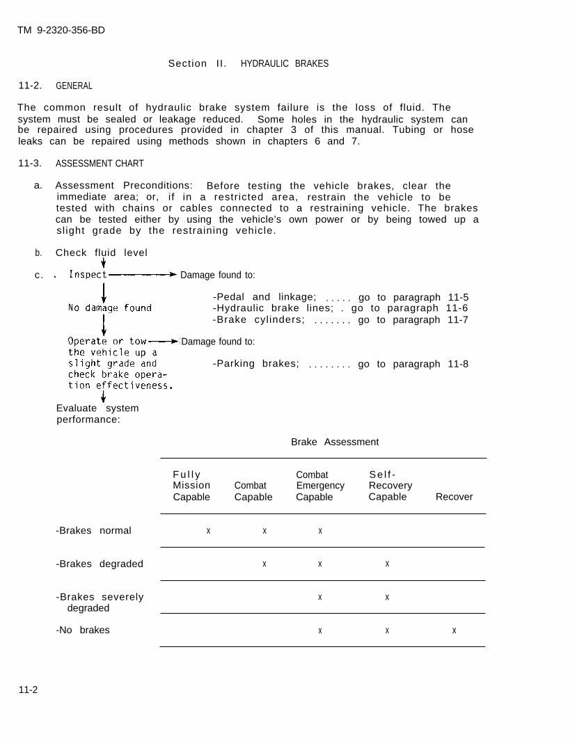
TM 9-2320-356-BD
Section II. HYDRAULIC BRAKES
11-2. GENERAL
The common result of hydraulic brake system failure is the loss of fluid. Thesystem must be sealed or leakage reduced. Some holes in the hydraulic system canbe repaired using procedures provided in chapter 3 of this manual. Tubing or hoseleaks can be repaired using methods shown in chapters 6 and 7.
11-3.
a.
b.
c.
ASSESSMENT CHART
Assessment Preconditions: Before testing the vehicle brakes, clear theimmediate area; or, i f in a restr icted area, restrain the vehicle to betested with chains or cables connected to a restraining vehicle. The brakescan be tested either by using the vehicle’s own power or by being towed up asl ight grade by the restraining vehicle.
Check fluid level
Damage found to:
-Pedal and linkage; . . . . . go to paragraph 11-5-Hydraulic brake lines; . go to paragraph 11-6-Brake cyl inders; . . . . . . . go to paragraph 11-7
Damage found to:
-Parking brakes; . . . . . . . . go to paragraph 11-8
Evaluate systemperformance:
Brake Assessment
F u l l y Combat Se l f -Mission Combat Emergency RecoveryCapable Capable Capable Capable Recover
-Brakes normal x x x
-Brakes degraded x x x
-Brakes severely x xdegraded
-No brakes x x x
11-2
TM 9-2320-356-BD
11-4. BDAR PROCEDURE INDEX
Para
Pedal and Linkage Damage . . . . . . . . . . . . . . . . . . . . . . . . . . . . . . . . . . . . . . . . . . . 11-5Hydraulic Brake Line Damage . . . . . . . . . . . . . . . . . . . . . . . . . . . . . . . . . . . . . . . . . 11-6Brake Cylinder Failure . . . . . . . . . . . . . . . . . . . . . . . . . . . . . . . . . . . . . . . . . . . . . 11-7Parking Brake Locked . . . . . . . . . . . . . . . . . . . . . . . . . . . . . . . . . . . . . . . . . . . . . . . 11-8Brake Malfunction, Hydraulic Fluid Loss . . . . . . . . . . . . . . . . . . . . . . . . . . . . 11-9
11-5. PEDAL AND LINKAGE DAMAGE
General Information:
If the brake pedal linkage is broken, the only BDAR fix would be to weld the brokenparts. Some bent or damaged parts may need to be straightened with heat.
L imi ta t ions: Mater ia ls /Tools :
o Severely degraded brakes o Arc weldero Reduced speed o Acetylene torcho No brakes o 2-lb hammer
o Bench vise
Personnel/Time Required:
o 1 so ld iero 2 hours
Other Options:
o Cannibalize parts from similar vehicle.
Procedural Steps:
1. Remove damaged or broken linkage.
2. Heat and reshape damaged parts or weld if necessary.
3. Replace repaired part or parts.
4. Record the BDAR action taken. When the mission is completed, as soon aspract icab le , repair using standard maintenance procedures.
11-6. HYDRAULIC BRAKE LINE DAMAGE
General Information:
BDAR for a hydraulic system is generally confined to component replacement,expedient l ine repairs, or bypassing damaged lines. If a hydraul ic circuit cannotbe repaired, it may be necessary to isolate it, cutting it off from the system topermit operation of some other hydraulic functions. Damage to the hydraulic brakesystem requires replenishment of lost fluids.
11-3
TM 9-2320-356-BD
Limi ta t ions:
o Degraded brakingo Reduced speedo Uneven braking
Personnel/Time Required:
o 1 so ld iero 30 minutes
Mater ia ls /Tools :
o T ie wi reo Tubing cuttero Hacksawo Sidecut plierso Visegrip pliers
Procedural Steps:
NOTE
Refer to chapter 3 for repair procedures forhydrau l ic l ines.
1. Find the split or break in the line.
2. Cut the line in front of the break.
3. Fold 2 inches of the line back and crimp it together.
4. Fold the crimped portion in half and crimp it again.
5. Wire the line to the nearest stationary place.
6. Check f luid level in the reservoir. I f brake f luid is not avai lable, refer toparagraph 11-9 for substi tute f luids.
7. Record the BDAR action taken. When the mission is completed, as soon aspract icab le , repair using standard maintenance procedures.
11-7. BRAKE CYLINDER FAILURE
General Information:
The wheel cylinder, mounted on the backing plate assembly at both ends of each axleassembly, consists of two opposed rubber cups and pistons enclosed in a casthousing. The fluid forced from the air hydraulic cylinder enters the wheelcylinder at a point between the rubber cups and pistons. This causes the cups andpistons to move outward to exert pressure through the push rods on the upper endsof the brakeshoes. Fluid leakage around the pistons and cups is the biggest factorin brake cyl inder fai lure. This wi l l cause errat ic braking due to f luidcontamination of the brakeshoe linings.
11-4
TM 9-2320-356-BD
Limi ta t ions:
o Degraded brakingo Reduced speedo Uneven braking
Personnel/Time Required:
o 1 or 2 soldierso 30 to 60 minutes
Mater ia l /Tools :
o Wireo Visegrip pliers
Procedural Steps:
1. Remove hydraulic line from the backing plate if necessary.
2. Fold 2 inches of the line back and crimp it together.
3. Fold the crimped portion in half and crimp it again.
4. Wire the line to the nearest stationary place.
5. Record the BDAR action taken. When the mission is completed, as soon aspract icab le , repair using standard maintenance procedures.
11-8. PARKING BRAKE LOCKED
General Information:
Parking brakes are cable operated. Most malfunctions are caused by the cable notreleasing the parking brake. Some parking brakes are fixed to the transfer case,and others are part of the rear axle brake system. In most cases, the parkingbrake handle will not release, causing the brakes to remain applied. Disconnectingthe linkage will release the brakes.
L imi ta t ions:
o No parking brakes
Personnel/Time Required:
o 1 so ld iero 5 minutes
Mater ia ls /Tools :
o P l i e r so Adjusting wrench
11-5

TM 9-2320-356-BD
Procedural Steps:
1. Locate the parking brake handle.
2. Remove cable from parking brake handle and bracket.
3. Record the BDAR action taken. When the mission is completed, as soon aspracticable, repair using standard maintenance procedures.
11-9. BRAKE MALFUNCTION, HYDRAULIC FLUID LOSS
General Information:
If BDAR fixes have been applied to brake components to reduce fluid loss, lostbrake fluid must be replaced to make hydraulic brake action possible. If brakefluid is not avai lable, the fol lowing f luids wil l work as emergency substi tutes:
(1) Hydraulic fluid(2) Ethelyne glycol (antifreeze)(3) Diese l fue l(4) Water(5) Petroleum-based fluids(6) Alcohol
Record the BDAR action taken. When the mission is completed, as soon aspracticable, repair using standard maintenance procedures.
11-6
TM 9-2320-356-BD
Section III. AIRBRAKES
11-10. GENERAL
The basic characteristic of this system is that the brakes are applied bycompressed air. Compressed air provides sufficient braking force to control eventhe heaviest vehicles. The fundamental units and descriptions of their functionsare listed in 1 thru 8 below:
1. Air compressor, driven directly from engine crankshaft or from one of theauxiliary shafts to furnish compressed air for brake operation.
2. Governor, to limit pressure produced by compressor within a predetermined range.
3. Reservoir, to receive air from compressor and store it for use in the brakingsystem. Two or more reservoirs are usually used.
4. Airbrake valve, to control brake operation by directing flow of air fromreservoir to brake chambers when brakes are applied, and from brake chambers toatmosphere when brakes are released.
5. Brake chambers, one for each wheel, to convert pressure of compressed air intomechanical force for applying brakes.
6. Quick-release valve, to speed up exhaust of brake chambers not close to brakevalves so that all the brakes may be quickly released.
7. Relay valve, used on trailers and trucks with long wheelbases to speedoperation of rear wheel brakes. On trucks with short wheelbases, the shorterlength of brake lines permits rapid rear brake action without aid of a relay valve.
8. Slack adjusters, provide a means of adjusting the brakes to compensate for wearin l in ings.
11-11. ASSESSMENT CHART
a. Assessment Preconditions: Before testing the vehicle’s brakes, clear theimmediate area or, i f in a restr icted area, restrain the vehicle to betested with chains or cables connected to a restraining vehicle. The brakescan be tested either by using the vehicle’s own power or by being towed up asl ight grade by the restraining vehicle.
b. Start the engine and check air pressure for a 60-psi minimum.
c. Inspect and check-+ Damage found to:brake operationeffect iveness -Air compressor; . . . . . go to paragraph 11-13
-Air governor; . . . . . . . go to paragraph 11-14-Reservoir; . . . . . . . . . . go to paragraph 11-15
11-7
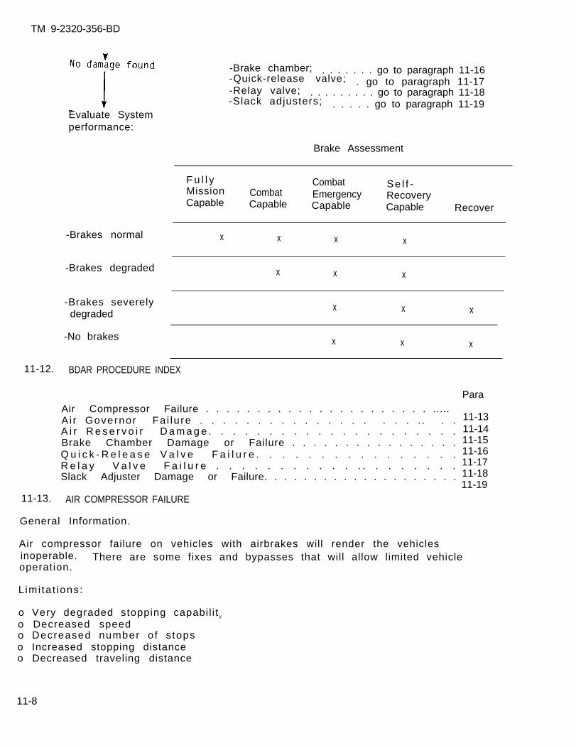
TM 9-2320-356-BD
Evaluate Systemperformance:
-Brakes normal
-Brakes degraded
-Brakes severelydegraded
-No brakes
-Brake chamber; . . . . . . . go to paragraph 11-16-Quick-release valve;-Relay valve;
. go to paragraph 11-17. . . . . . . . . go to paragraph 11-18
-Slack adjusters; . . . . . go to paragraph 11-19
Brake Assessment
F u l l y Combat Se l f -Mission Combat EmergencyCapable
RecoveryCapable Capable Capable Recover
x x x x
x x x
x x x
x x x
11-12. BDAR PROCEDURE INDEX
ParaAir Compressor Failure . . . . . . . . . . . . . . . . . . . . . . ..... A i r Governor Fa i lu re . . . . . . . . . . . . . . . . . . . . . .A i r R e s e r v o i r D a m a g e . . . . . . . . . . . . . . . . . . . . .Brake Chamber Damage or Failure . . . . . . . . . . . . . . . .Q u i c k - R e l e a s e V a l v e F a i l u r e . . . . . . . . . . . . . . . .R e l a y V a l v e F a i l u r e . . . . . . . . . . . . . . . . . . . .Slack Adjuster Damage or Failure. . . . . . . . . . . . . . . . . . . .
11-1311-1411-1511-1611-1711-1811-19
11-13. AIR COMPRESSOR FAILURE
General Information.
Air compressor failure on vehicles with airbrakes will render the vehiclesinoperable. There are some fixes and bypasses that will allow limited vehicleoperation.
L imi ta t ions:
o Very degraded stopping capabil i t y
o Decreased speedo Decreased number o f s topso Increased stopping distanceo Decreased traveling distance
11-8
Personnel/Time Required:
TM 9-2320-356-BD
Mater ia ls /Tools :
o 1-2 solderso 1-3 hours
Procedural Steps:
o Argono Nitrogeno 1/4-inch air hose (10-
15 ft)o Assortment of 1/2-inch
tub ing f i t t i ngso Copper tubing, 6 inches
WARNING
Driving a vehicle without brakes could causedamage to the vehicle and injury to personnel.Operate only in lowest gear. Use this procedureas a last resort.
Option 1: No Brakes.
1. Shift transfer case into low range.
2. Back off caging bolts located in the center of the rear axle fail-safe brakechamber assembly.
3. Use the lowest gear on transmission so that a safe speed without brakes can bemaintained.
4. Record the BDAR action taken. When the mission is completed, as soon aspract icab le , repair using standard maintenance procedures.
Option 2: Insert Gas Substitute.
WARNING
Do not use compressed oxygen as a pressuremedium. Air compressor systems have a slightamount of oil that seeps into the air lines.Oxygen will explode when oil is present in apressurized system, result ing in death orser ious in jury .
1. Obtain a bottle of nitrogen or argon with a regulator. The bottle should be atleast one-half ful l (1000 psi).
2. Secure bottle in the vehicle for easy access.
3. Locate one of the emergency air lines on the rear of the vehicle.
11-9
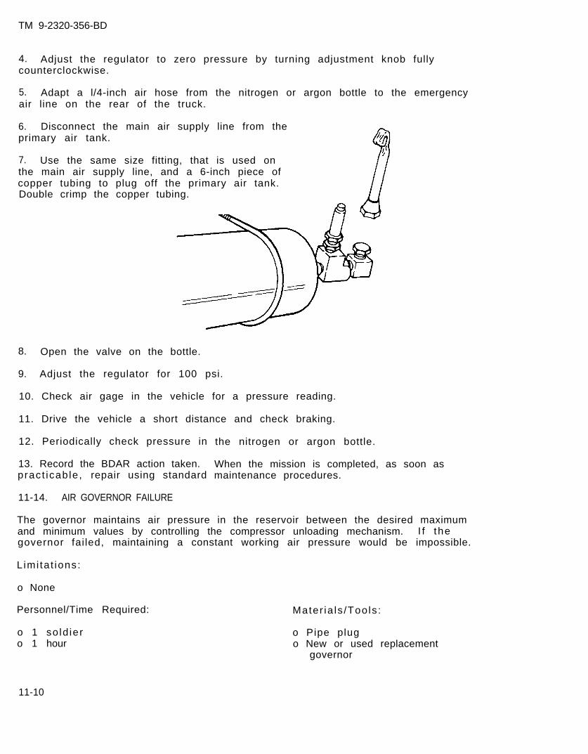
TM 9-2320-356-BD
4. Adjust the regulator to zero pressure by turning adjustment knob fullycounterclockwise.
5. Adapt a l/4-inch air hose from the nitrogen or argon bottle to the emergencyair line on the rear of the truck.
6. Disconnect the main air supply line from theprimary air tank.
7. Use the same size fitting, that is used onthe main air supply line, and a 6-inch piece ofcopper tubing to plug off the primary air tank.Double crimp the copper tubing.
8. Open the valve on the bottle.
9. Adjust the regulator for 100 psi.
10. Check air gage in the vehicle for a pressure reading.
11. Drive the vehicle a short distance and check braking.
12. Periodically check pressure in
13. Record the BDAR action taken.pract icab le , repair using standard
11-14. AIR GOVERNOR FAILURE
the nitrogen or argon bottle.
When the mission is completed, as soon asmaintenance procedures.
The governor maintains air pressure in the reservoir between the desired maximumand minimum values by controlling the compressor unloading mechanism. I f thegovernor fai led, maintaining a constant working air pressure would be impossible.
L imi ta t ions:
o None
Personnel/Time Required:
o 1 so ld iero 1 hour
Mater ia ls /Tools :
o Pipe plugo New or used replacement
governor
11-10
TM 9-2320-356-BD
Procedural Steps:
Option 1: Replace Governor.
1. Locate and remove damaged governor.
2. Install new or used governor.
3. If new or used part is not available, try a governor from another vehicle withan air system.
4. Start the vehicle and check that the air pressure minimum is high enough tosupply the braking operation of the vehicle.
5. Record the BDAR action taken. When the mission is completed, as soon aspracticable, repair using standard maintenance procedures.
Option 2: Isolate Governor.
1. Locate damaged governor. Some are located on the firewall and others near thecompressor.
2. Remove the two largest air lines.
3. Plug the lines with a pipe plug or crimp the copper lines and double them over.
4. Record the BDAR action taken. When the mission is completed, as soon aspract icab le , repair using standard maintenance procedures.
11-15. AIR RESERVOIR DAMAGE
General Information:
The reservoir stores air that it receives from the compressor. Reservoir leaks canbe detected by listening for escaping air or by pouring water over the reservoirand watching for air bubbles. Repairs normally are made by welding the reservoir;but if welding equipment is not available, and the hole is small, a repair canstill be made using this procedure.
L imi ta t ions:
o None
Personnel/Time Required:
o 2 so ld ierso 1 to 2 hours
Mater ia ls /Tools :
ooooooo0
Arc welderSandpaper or fileEpoxyWoodSheet metal screwsLeather bootRubber from tire or tubeLarge diameter washer
11-11
TM 9-2320-356-BD
Procedural Steps:
Option 1: Weld.
1. Locate leak and remove reservoir if necessary.
2. Clean the hole(s) with sandpaper or file.
3. Form-fit a piece of similar metal over damaged area.
4. Weld a two-pass bead around the patch metal.
5. I ns ta l l r ese rvo i r .
6. Start engine and check for leaks.
7. Record the BDAR action taken. When the mission is completed, as soon aspract icab le , repair using standard maintenance procedures.
Option 2: Epoxy and Self-Tapping Screw.
1. Locate leak and remove reservoir.
2. Clean area around hole with sandpaper.
3. Fill holes with available material such as self-tapping sheet metal screw, andcover with a quick-drying epoxy plastic; or force a sheet metal screw through amakeshift washer (leather or rubber). Use a washer, if available, to back up therubber or leather. Ins ta l l in to ho le . Tighten securely.
4. I ns ta l l r ese rvo i r .
5. Record the BDAR action taken. When the mission is completed, as soon aspracticable, repair using standard maintenance procedures.
Option 3: Use One Reservoir; Isolate Damaged One.
1. Disconnect the air line from the damaged air reservoir.
2. Remove the line connecting both reservoirs.
3. Attach air line from compressor to the good reservoir.
4. Plug holes in reservoir to be used with appropriate size pipe plugs.
5. Start engine and check for leaks.
6. Record the BDAR action taken. When the mission is completed, as soon aspracticable, repair using standard maintenance procedures.
11-12
TM 9-2320-356-BD
Option 4: Bypassing Damaged Air Reservoirs.
1. Disconnect air lines from both damaged air reservoirs.
2. Determine which line comes from the compressor and which one goes to the airhydraulic cyl inder. Attach the l ines together.
3. Plug lines needed to maintain air pressure.
4. Start engine and check for leaks.
5. Record the BDAR action taken. When the mission is completed, as soon aspract icab le , repair using standard maintenance procedures.
11-16. BRAKE CHAMBER DAMAGE OR FAILURE
General Information:
The brake chamber is an air device that operates the brakeshoes of a vehicle. Whenthe chamber is damaged or fails, the brakes will automatically lock up and stop thevehicle.
If one or more of the brakes will not release, the following procedure will allowthe vehicle to move.
L imi ta t ions:
o Reduced braking ability o Reduced speed
Personnel/Time Required:
o 1 so ld iero 30 to 60 minutes
Mater ia l /Tools :
o Adjustable wrencho Caging tool
11-13
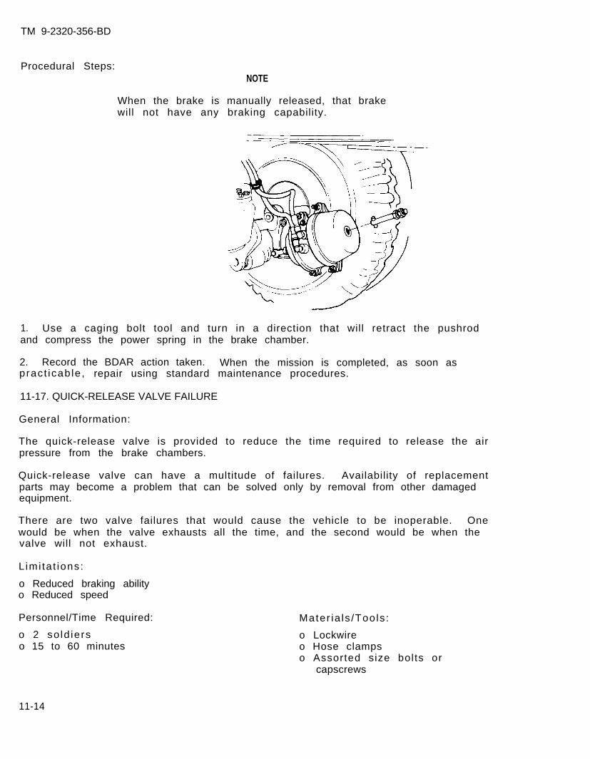
TM 9-2320-356-BD
Procedural Steps:NOTE
When the brake is manually released, that brakewill not have any braking capability.
1. Use a caging bolt tool and turn in a direction that will retract the pushrodand compress the power spring in the brake chamber.
2. Record the BDAR action taken. When the mission is completed, as soon aspract icab le , repair using standard maintenance procedures.
11-17. QUICK-RELEASE VALVE FAILURE
General Information:
The quick-release valve is provided to reduce the time required to release the airpressure from the brake chambers.
Quick-release valve can have a multitude of failures. Availability of replacementparts may become a problem that can be solved only by removal from other damagedequipment.
There are two valve failures that would cause the vehicle to be inoperable. Onewould be when the valve exhausts all the time, and the second would be when thevalve will not exhaust.
L imi ta t ions:
o Reduced braking abilityo Reduced speed
Personnel/Time Required:
o 2 so ld ierso 15 to 60 minutes
Mater ia ls /Tools :
o Lockwireo Hose clampso Assorted size bolts or
capscrews
11-14
TM 9-2320-356-BD
Procedural Steps:
NOTE
Each rear axle of a tandem or triple set has itsown quick-release valve.
Option 1: Isolate Chamber.
1. Remove the main air line to the brake chamber.
2. Plug the main l ine i f f i t t ings are available.
3. I f no f i t t ings are ava i lab le , kink the air l ine by doubling i t over, and t ie i twith wire.
4. Check for leaks.
5. Record the BDAR action taken. When the mission is completed, as soon aspract icab le , repair using standard maintenance procedures.
Option 2: Plug Main Air Line.
1. Cut the main air line.
2. Use a bolt of equal or close diameter and screw it into the line. Lock-wirethe line in two places.
3. Check for leaks.
4. Record the BDAR action taken. When the mission is completed, as soon aspract icab le , repair using standard maintenance procedures.
11-18. RELAY VALVE FAILURE
General Information:
The relay valve is controlled by the brake valve, and speeds up application andrelease of the rear wheel brakes for long wheelbase vehicles. I t reacts quickly toslight changes in air pressure from the brake valve. Repair can be done only byreplacement with a serviceable valve.
11-19. SLACK ADJUSTER DAMAGE OR FAILURE
General Information:
Slack adjusters function as adjustable levers and provide a means of adjusting thebrakes to compensate for wear of linings. During brake operation, the entire slackadjuster rotates with the brake camshaft, which is connected to the slack adjusterthrough the splined central hole. For brake adjustment, the worm moves the gear,changing the position of the lever arm with respect to the camshaft. Repair can bedone only by replacement with a serviceable adjuster.
11-15
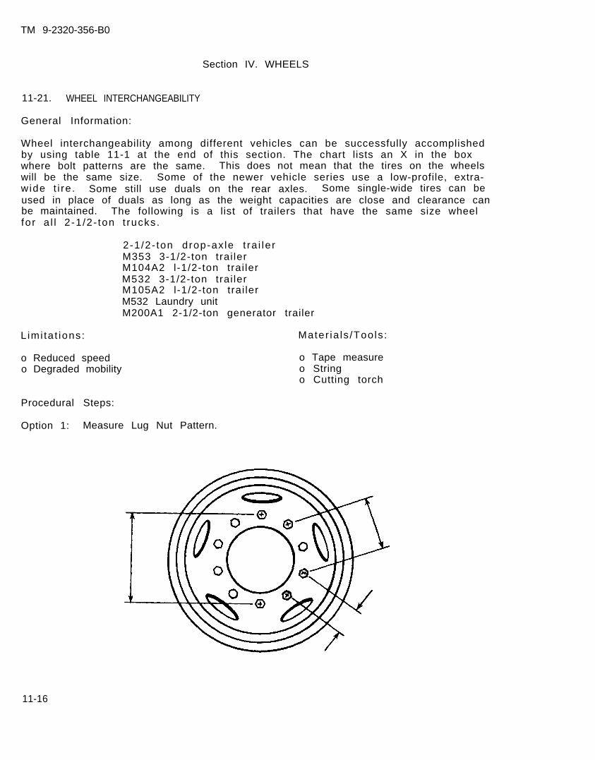
TM 9-2320-356-B0
Section IV. WHEELS
11-21. WHEEL INTERCHANGEABILITY
General Information:
Wheel interchangeability among different vehicles can be successfully accomplishedby using table 11-1 at the end of this section. The chart lists an X in the boxwhere bolt patterns are the same. This does not mean that the tires on the wheelswill be the same size. Some of the newer vehicle series use a low-profile, extra-wide t i re . Some still use duals on the rear axles. Some single-wide tires can beused in place of duals as long as the weight capacities are close and clearance canbe maintained. The following is a list of trailers that have the same size wheelfor a l l 2 -1 /2- ton t rucks.
2-1/2- ton drop-ax le t ra i le rM353 3-1/2-ton trai lerM104A2 l-1/2-ton trai lerM532 3-1/2-ton trai lerM105A2 l-1/2-ton trai lerM532 Laundry unitM200A1 2-1/2-ton generator trailer
L imi ta t ions:
o Reduced speedo Degraded mobility
Mater ia ls /Tools :
o Tape measureo Stringo Cutting torch
Procedural Steps:
Option 1: Measure Lug Nut Pattern.
11-16
TM 9-2320-356-BD
1.
2.
3.
4.
NOTE
Ten-bolt wheel lug nut patterns are identicalon many of the tactical wheeled vehicles. The2-1/2-ton series wheels al l interchange. TheDodge 880 and the HMMWV 8-lug wheel will fit allthe CUCV’S that have 8-lug wheels, but the CUCVwheel will not fit the rear axle of the Dodge orany hub on the HMMWV.
Measure the lugs on the hub or the holes in the wheel for similar patterns.
Measure the center hole in the wheel for hub clearance.
Make sure that tire size is correct so that tire will not hit or rub the
Remove damaged wheel and replace the wheel and tire from another vehicle.
5. Make sure to keep like-size tires on the rear.
6. Record the BDAR action taken. When the mission is completed, as soon aspracticable, repair using standard maintenance procedures.
Option 2: CUCV as a Substitute.
1. If CUCV wheels are the only wheels available for a Dodge 880 or a HMMWV, use acutting torch and cut the center hole about 1/8 inch larger.
2. Install the wheels on vehicle.
3. Record the BDAR action taken. When the mission is completed, as soon aspract icab le , repair using standard maintenance procedures.
Option 3: Rear Wheel.
1. Use one of the dual rear wheels to replace a front wheel.
2. Record the BDAR action taken. When the mission is completed, as soon aspracticable, repair using standard maintenance procedures.
11-17
vehicle.
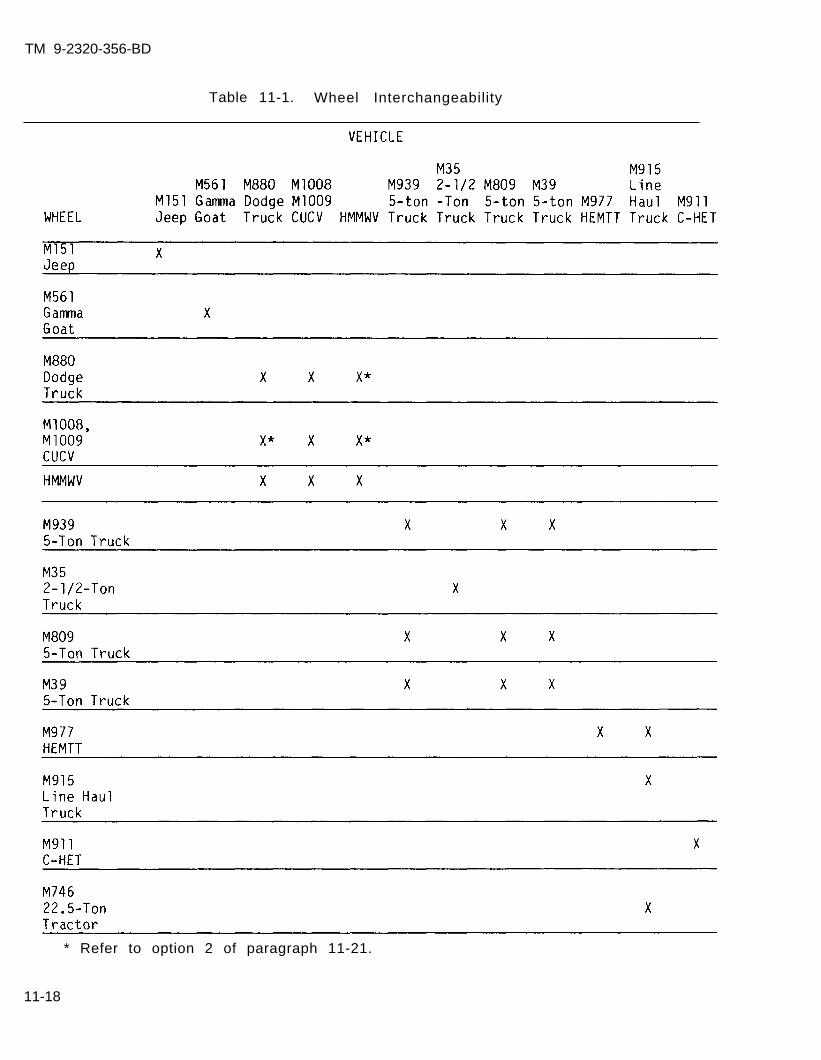
TM 9-2320-356-BD
Table 11-1. Wheel Interchangeability
* Refer to option 2 of paragraph 11-21.
11-18
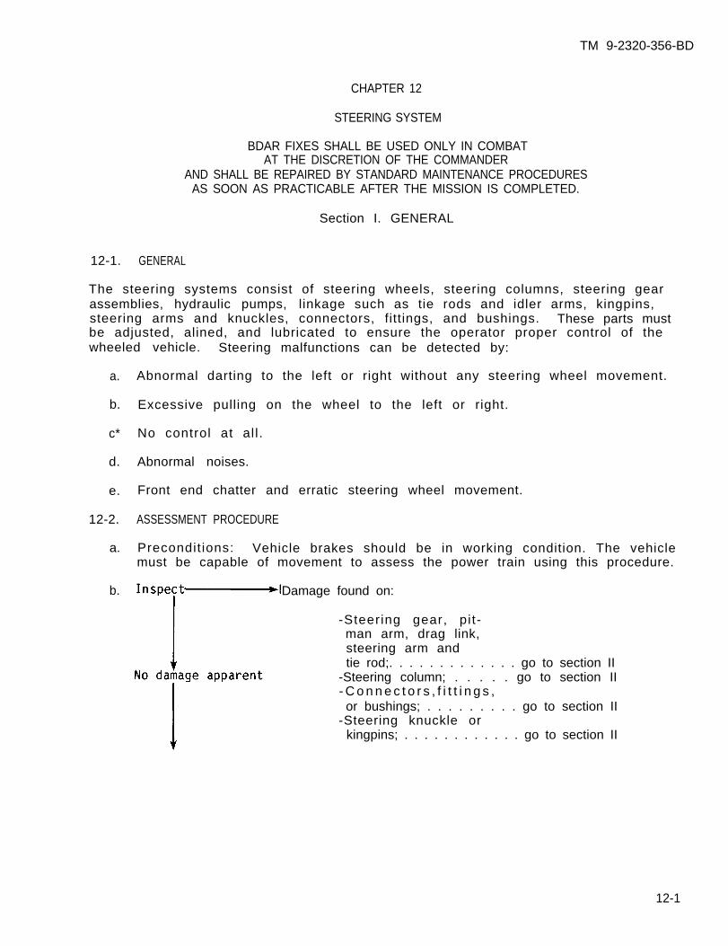
TM 9-2320-356-BD
CHAPTER 12
STEERING SYSTEM
BDAR FIXES SHALL BE USED ONLY IN COMBATAT THE DISCRETION OF THE COMMANDER
AND SHALL BE REPAIRED BY STANDARD MAINTENANCE PROCEDURESAS SOON AS PRACTICABLE AFTER THE MISSION IS COMPLETED.
Section I. GENERAL
12-1. GENERAL
The steering systems consist of steering wheels, steering columns, steering gearassemblies, hydraulic pumps, linkage such as tie rods and idler arms, kingpins,steering arms and knuckles, connectors, fittings, and bushings. These parts mustbe adjusted, alined, and lubricated to ensure the operator proper control of thewheeled vehicle. Steering malfunctions can be detected by:
a.
b.
c*
d.
e.
12-2.
a.
b.
Abnormal darting to the left or right without any steering wheel movement.
Excessive pulling on the wheel to the left or right.
No control at al l .
Abnormal noises.
Front end chatter and erratic steering wheel movement.
ASSESSMENT PROCEDURE
Precondit ions: Vehicle brakes should be in working condition. The vehiclemust be capable of movement to assess the power train using this procedure.
Damage found on:
-Steering gear, pit-man arm, drag link,steering arm andtie rod;. . . . . . . . . . . . . go to section II
-Steering column; . . . . . go to section II- C o n n e c t o r s , f i t t i n g s ,or bushings; . . . . . . . . . go to section II
-Steering knuckle orkingpins; . . . . . . . . . . . . go to section II
12-1
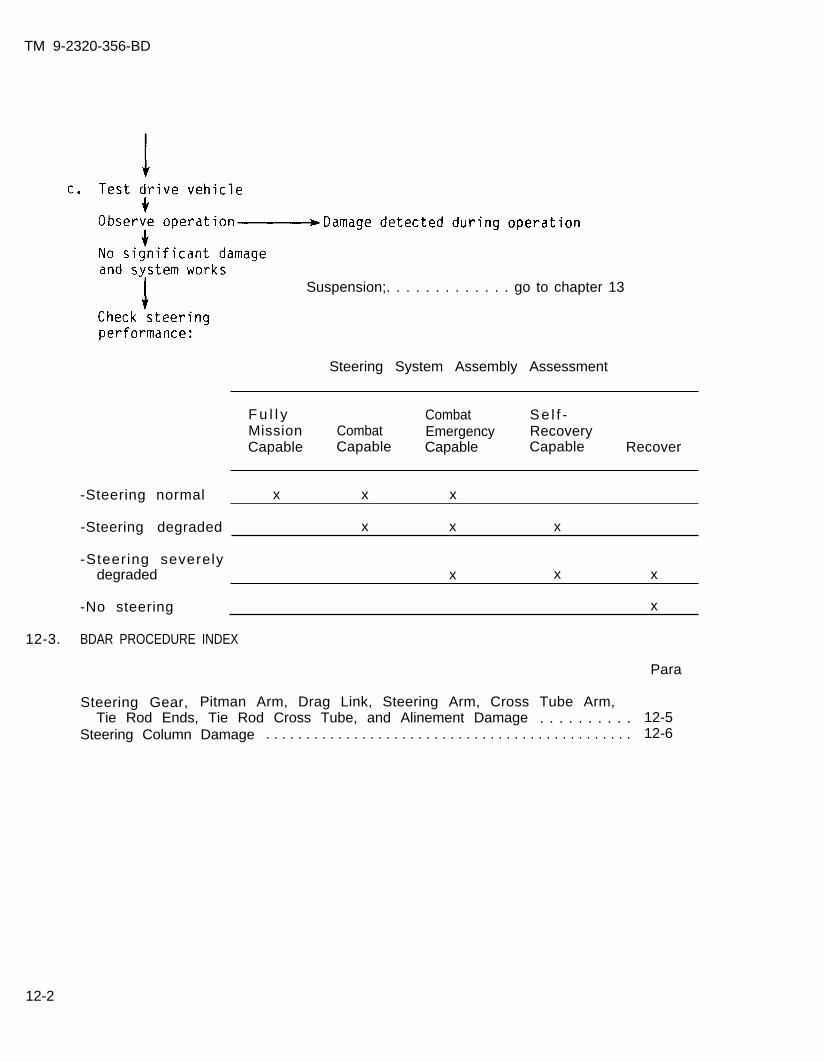
TM 9-2320-356-BD
Suspension;. . . . . . . . . . . . . go to chapter 13
Steering System Assembly Assessment
12-3.
F u l l y Combat Se l f -Mission Combat Emergency RecoveryCapable Capable Capable Capable Recover
-Steering normal x x x
-Steering degraded x x x
-Steering severelydegraded x x x
-No steering x
BDAR PROCEDURE INDEX
Para
Steering Gear, Pitman Arm, Drag Link, Steering Arm, Cross Tube Arm,Tie Rod Ends, Tie Rod Cross Tube, and Alinement Damage . . . . . . . . . . 12-5
Steering Column Damage . . . . . . . . . . . . . . . . . . . . . . . . . . . . . . . . . . . . . . . . . . . . . . 12-6
12-2
TM 9-2320-356-BD
Sect ion I I . STEERING COMPONENTS
12-4. GENERAL
Steering components are, for the most part, hydraulically assisted. The hydraulicsystem does not need to be intact to operate a vehicle. The linkage arms can berepaired if bent or damaged. Reduced vehicle speed will be necessary for control.
12-5. STEERING GEAR, PITMAN ARM, DRAG LINK, STEERING ARM, CROSS TUBE ARM, TIE RODENDS, TIE ROD CROSS TUBE, AND ALINEMENT DAMAGE
General Information:
Vehicle wil l not steer straight. This procedure will allow the vehicle to bedriven without the risk of total tire damage due to misalinement.
L imi ta t ions:
o Reduced speed and maneuverability
Personnel/Time Required:
o 2 so ld ierso 6 hours
Procedural Steps:
1. Remove linkage parts that are damaged and replace with new or used parts.
2. If parts are not available, proceed as follows:
Mater ia ls /Tools :
o Replacement parts new orused
o Wireo Tape measure or stick
longer than axle widtho Pry bar, tree l imb, or
s t r i n g
a. Wire joint or socket connections that are a part of the tie rod end, crosstube arm, tie rod cross tube, and steering arm.
b. If tie rod cross tube is bent, straighten with pry bar or tree limb.
12-3
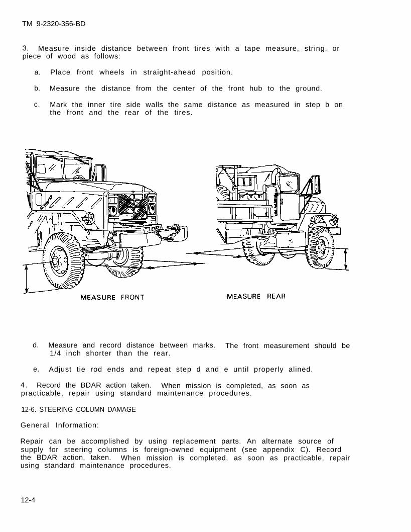
TM 9-2320-356-BD
3. Measure inside distance between front tires with a tape measure, string, orpiece of wood as follows:
a. Place front wheels in straight-ahead position.
b. Measure the distance from the center of the front hub to the ground.
c. Mark the inner tire side walls the same distance as measured in step b onthe front and the rear of the tires.
d. Measure and record distance between marks. The front measurement should be1/4 inch shorter than the rear.
e. Adjust tie rod ends and repeat step d and e until properly alined.
4. Record the BDAR action taken. When mission is completed, as soon aspracticable, repair using standard maintenance procedures.
12-6. STEERING COLUMN DAMAGE
General Information:
Repair can be accomplished by using replacement parts. An alternate source ofsupply for steering columns is foreign-owned equipment (see appendix C). Recordthe BDAR action, taken. When mission is completed, as soon as practicable, repairusing standard maintenance procedures.
12-4
TM 9-2320-356-BD
CHAPTER 13
FRAME AND SUSPENSION
BDAR FIXES SHALL BE USED ONLY IN COMBATAT THE DISCRETION OF THE COMMANDER
AND SHALL BE REPAIRED BY STANDARD MAINTENANCE PROCEDURESAS SOON AS PRACTICABLE AFTER THE MISSION IS COMPLETED.
Section 1. GENERAL
13-1. GENERAL
The frame consists of those parts which support the vehicle and tie the variousunits together. The frame consists of left and right side members which arepressed steel channel sections. The crossmembers, gussets, brackets,reinforcements, and rear engine mounts are riveted to these sections. The rearsuspension assembly of a tandem setup uses six torque rod assemblies, two upper andfour lower. The load is equalized between axles by full-floating springs oscillateon a cross shaft. Axles are kept in place by spring guide brackets on axlehousings. Driving and braking forces are transmitted to the frame by the sixtorque rod assemblies which also maintain correct vertical position of axles andprevent weight transfer between axles.
The front suspension system is more complex than the rear suspension system. Thefront suspension system must allow the wheels to move up and down and must alsoallow the wheels to pivot from side to side so that the vehicle can be steered.In smaller vehicles, the front suspension is basically the same as in larger ones.The rear suspension differs because the smaller vehicle has only one axle, whilethe larger vehicles have two or more.
There are three basic types of springs: leaf, coi l , and torsion bar. Most smallvehicles use coil or torsion bar springs at the front wheels. Some vehicles usecoil springs at the rear wheels, but most use leaf springs. Spring damage is thesingle most frequent cause of suspension failure.
13-2. ASSESSMENT CHART
a. Damage found to:
-Torque rod;. . . . . . . . . go to paragraph 13-5-Coil springs; . . . . . . . go to paragraph 13-6-Leaf springs; . . . . . . . go to paragraph 13-7
b. Damage found to:
-Torque rod;. . . . . . . . . . go to paragraph 13-5
13-1
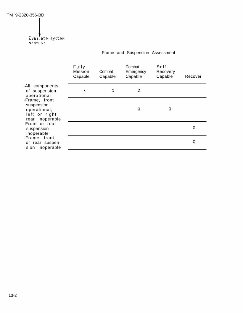
TM 9-2320-356-BD
Frame and Suspension Assessment
-All componentsof suspensionoperational
-Frame, frontsuspensionoperational,l e f t o r r i gh trear inoperable
-Front or rearsuspensioninoperable
-Frame, front,or rear suspen-sion inoperable
F u l l y Combat Se l f -Mission Combat Emergency RecoveryCapable Capable Capable Capable Recover
13-2

TM 9-2320-356-BD
Section II. FRAME AND SUSPENSION
13-3. BDAR PROCEDURE INDEX Para
Front and rear suspension interchangeability . . . . . . . . . . . . . . . . . . . . . . . . 13-4Torque Rod Damage . . . . . . . . . . . . . . . . . . . . . . . . . . . . . . . . . . . . . . . . . . . . . . . . . . . 13-5Coil Spring Damage . . . . . . . . . . . . . . . . . . . . . . . . . . . . . . . . . . . . . . . . . . . . . . . . . . 13-6Leaf Spring Damage . . . . . . . . . . . . . . . . . . . . . . . . . . . . . . . . . . . . . . . . . . . . . . . . . . 13-7
13-4. FRONT AND REAR SUSPENSION INTERCHANGEABILITY
General Information:
Replacement parts may not be available through normal channels. Replacements canbe modified if obtained from other vehicles in the same family of vehicles. Mostparts will be usable without modification or improvised mounting. Suspensionrepairs vary with vehicle and suspension configuration and are covered in moredetai l in specif ic vehicle TM’s.
13-5. TORQUE ROD DAMAGE
General Information:
Each torque rod assembly consists of a torque rod and two ball assemblies. Torquerods are attached to each rear axle and transmit driving and braking forces to theframe.
L imi ta t ions:
o Reduced speedo Degraded mobilityo Reduced vehicle capacity
Personnel/Time Required:
o 2 so ld ierso 30 minutes
Procedural Steps:
1. Remove locknuts.
2. Remove damaged torque rod.
3. Chain axle to the frame.
Mater ia ls /Tools :
o P r y b a ro 6- to 8-lb hammero Chaino Large adjustable wrench
4. Record the BDAR action taken. When the mission is completed, as soon aspract icab le , repair using standard maintenance procedures.
13-3
TM 9-2320-356-BD
13-6. COIL SPRING DAMAGE
General Information:
The coil spring is made of a length of steel rod wound into a coil. The coils areheat treated to make them elastic and to give them strength. A damaged coil thathas been severed cannot be repaired by welding the broken area. Heating the coilremoves the temper and the elasticity from the coil and it will collapse with anyweight or force on it.
L imi ta t ions:
o Reduced speed in rough terraino Reduced vehicle capacity
Personnel/Time Required:
o 2 so ld ierso 1 to 2 hours
Mater ia ls /Tools :
o Arc weldero Acetylene and oxygeno C-clampo Steel rods (minimum
1/2 inch thick)
Procedural Steps:
1. Raise the vehicle with a jack or a wrecker so that vehicle is level.
2. Measure the length of the coil spring.
3. Cut three pieces of steel rod the same length as the spring.
4. Weld the steel rods to the spring at approximately equal distances apart.
5. Record the BDAR action taken. When the mission is completed, as soon aspract icab le , repair using standard maintenance procedures.
13-7. LEAF SPRING DAMAGE
General Information:
Leaf springs are made of heat-treated carbon steel for elasticity and strength.Welding broken or damaged leaf springs will remove the temper from the spring andit will bend with any weight or pressure on it. Welding can be used as a temporaryfix if care is taken to weld a small amount at a time. The following procedureswill work only if no more than three leaf springs are broken on large vehicles andno more than two on small vehicles.
L imi ta t ions:
o Reduced speed in rough terraino Reduced vehicle capacity
13-4
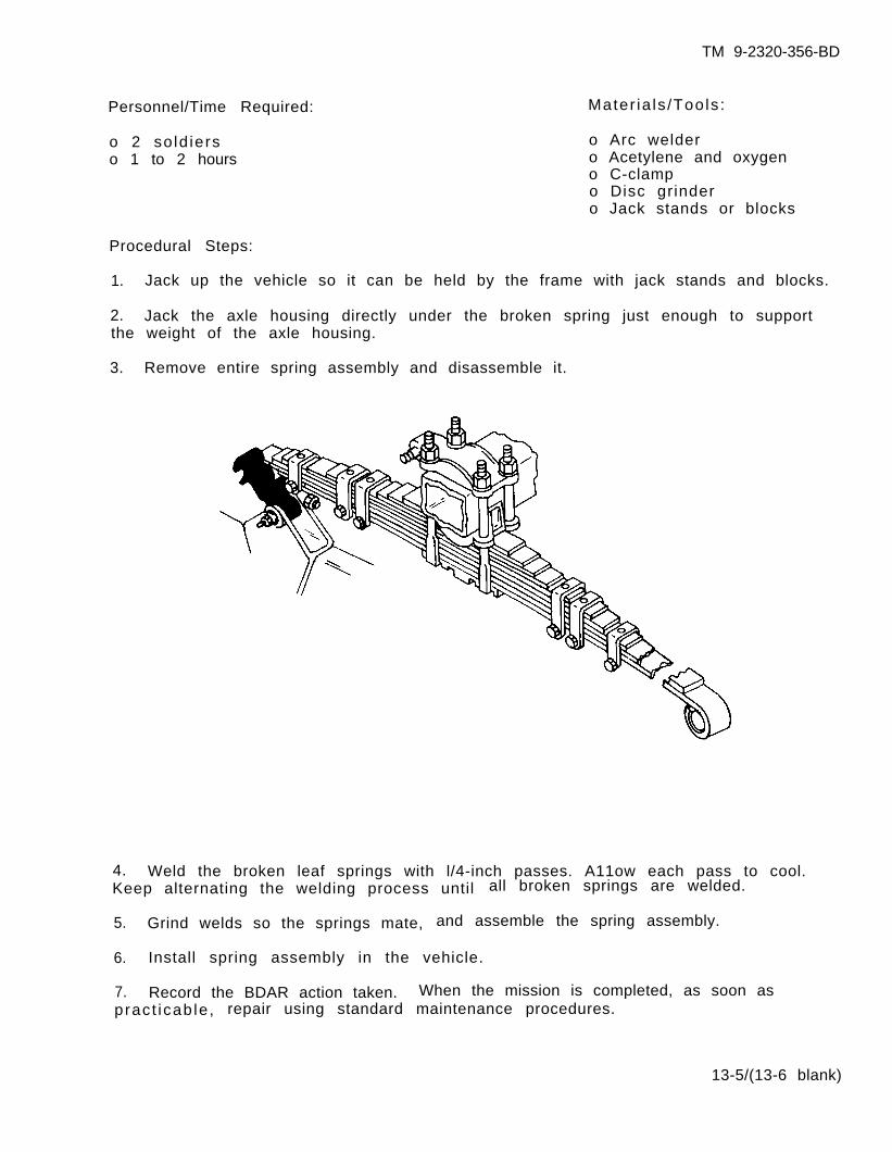
TM 9-2320-356-BD
Personnel/Time Required:
o 2 so ld ierso 1 to 2 hours
Mater ia ls /Tools :
o Arc weldero Acetylene and oxygeno C-clampo Disc grindero Jack stands or blocks
Procedural Steps:
1. Jack up the vehicle so it can be held by the frame with jack stands and blocks.
2. Jack the axle housing directly under the broken spring just enough to supportthe weight of the axle housing.
3. Remove entire spring assembly and disassemble it.
4. Weld the broken leaf springs with l/4-inch passes. A11ow each pass to cool.Keep alternating the welding process until all broken springs are welded.
5. Grind welds so the springs mate, and assemble the spring assembly.
6. Install spring assembly in the vehicle.
7. Record the BDAR action taken. When the mission is completed, as soon aspract icab le , repair using standard maintenance procedures.
13-5/(13-6 blank)
TM 9-2320-356-BD
CHAPTER 14
WRECKER AND CRANE ASSEMBLIES
BDAR FIXES SHALL BE USED ONLY IN COMBATAT THE DISCRETION OF THE COMMANDER
AND SHALL BE REPAIRED BY STANDARD MAINTENANCE PROCEDURESAS SOON AS PRACTICABLE AFTER THE MISSION IS COMPLETED.
Section I. GENERAL
14-1. GENERAL
The wrecker crane consists of the wrecker unit that is mounted above the truckchassis, with the exception of the rear-mounted winch. The various functions ofthe wrecker crane are dependent on all of the hydraulic and mechanical units builtinto the crane. The power for the wrecker crane is supplied by the truck enginethrough a bevel gearbox hydraulic pump. This pump forces fluid to each of thehydraulical ly actuated units. The control of the various functions is in thecontrol valve bank. From there the fluid is directed under high pressure tooperate any of the following: the elevating cyl inders for raising or lowering theboom, the boom crowd cylinder for extending or retracting the boom, the swing motorfor revolving the crane, and the hoist motor for winding and unwinding the hoistcable. A special cone-type worm and drive gear transmits the power for turning thehoist drum and revolving the crane. The following procedures deal with the M543,M816, and M936 5-ton wrecker components.
14-2. ASSESSMENT CHART
NOTE
The engine must be operational to assess thehydraulic system.
Damage found to:
-Hydraulic pumpand bevel gearbox; . . go to paragraph 14-5
-Swing hydraulicmotor and gearbox; . . go to paragraph 14-6
-Boom elevating andcrowd cylinders; . . . . go to paragraph 14-7
-Control valvebank assembly; . . . . . go to paragraph 14-8
-Boom hoist hydrau-lic motor and drumassembly; . . . . . . . . . . . go to paragraph 14-9
-Hydraul ic reser-voir; . . . . . . . . . . . . . . . go to paragraph 14-10
-Hydraulic filter; . . . go to paragraph 14-11-Wire rope or cable; . go to paragraph 14-12
14-1

TM 9-2320-356-BD
b. Start engine and Damage found to:Observe cranefunct ions -Hydraulic pump
and bevel gearbox; . . go to paragraph 14-5-Swing hydraulic motor
and gearbox; . . . . . . . . go to paragraph 14-6No damage f o u n d -Boom elevating
crowd cylinders; . . . . go to paragraph 14-7-Control valve
assembly; . . . . . . . . . . . go to paragraph 14-8-Boom hoist hydraulicmotor and drumassembly; . . . . . . . . . . . go to paragraph 14-9
-Hydraul ic reser-
-All components operational
-Swing hydraulic motor andgearbox unserviceable
-Boom assembly elevatingcylinders operational,extension cylindersunserviceable
-Hydraul ic reservoir leaks
-Boom assembly extensioncylinder operational,elevating cyl indersunserviceable
-Control valve inoperative
-Boom hoist hydraulic motorand drum assembly damagedor inoperative
voir; . . . . . . . . . . . . . . . go to paragraph 14-10
Crane and Wrecker System Assessment
F u l l y CombatMission Combat EmergencyCapable Capable Capable
-Main hydraulic pump andbevel gearbox inoperative
14-2
TM 9-2320-356-BD
14-3. BDAR PROCEDURE INDEX Para
Hydraulic Pump Damaged or Inoperative . . . . . . . . . . . . . . . . . . . . . . . . . . . . . . .Swing Hydraulic Motor and Gearbox Defective or DamagedBoom Elevating or Crowd Cylinders Inoperative
. . . . . . . . . . . . . .. . . . . . . . . . . . . . . . . . . . . . .
Control Valve Bank Assembly Damaged or Defective . . . . . . . . . . . . . . . . . . .Boom Hoist Hydraulic Motor and Drum Assembly Inoperative or Damaged .Hydraulic Reservoir Damaged . . . . . . . . . . . . . . . . . . . . . . . . . . . . . . . . . . . . . . . . .Hydraulic Filter Damaged or Defective . . . . . . . . . . . . . . . . . . . . . . . . . . . .Wire Rope or Cable Damaged . . . . . . . . . . . . . . . . . . . . . . . . . . . . . . . . . . . . ...Wire Rope Attachments . . . . . . . . . . . . . . . . . . . . . . . . . . . . . . . . . . . . . . . .High-Pressure Hose Substitution and Isolation (M543, M816, and M936).High-Pressure Tube Substitution and Isolation (M543, M816, and M936).
14-514-614-714-814-914-1014-1114-1214-1314-1414-15
14-3
TM 9-2320-356-BD
Section II. HYDRAULIC COMPONENTS
14-4. GENERAL
The hydraulic components that will be discussed in this section will be thehydraulic pump, motors, control valve, high-pressure hoses and tubes, and reservoirand f i l t e r . BDAR for a hydraulic system is generally confined to componentreplacement, expedient l ine repairs, or bypassing damaged lines. I f a hydraul iccircuit cannot be repaired, it may be necessary to isolate it (cut it off) from thesystem to permit operation of some other hydraulic functions. Damaqe to thehydraul ic system usually requires replenishment of lost f luids.
WARNING
Hydraulic fluid under pressure can cause deathor injury to personnel. Bring hydraulic systemto zero pressure before making repairs.
14-5. HYDRAULIC PUMP DAMAGED OR INOPERATIVE
General Information:
Hydraulic pumps can have a multitude of failures. Repairs can be accomplished onlyby replacement with a serviceable part. An alternate source of supply for the pumpis foreign-owned equipment (refer to appendix C).
14-6. SWING HYDRAULIC MOTOR AND GEARBOX DEFECTIVE OR DAMAGED.
General Information:
If the hydraulic swing motor becomes inoperative, the wrecker crane can still beused to perform most of its functions. The crane will not have its side-to-sidel i f t c a p a b i l i t y . The swing motor may have to be isolated if there are leakageproblems. Swing motor failure can have a multitude of causes. Repairs can beaccomplished only by replacement with a serviceable part.
L imi ta t ions:
o No side-to-side rotation
Personnel/Time Required:
o 1 so ld iero 20 to 30 minutes
Mater ia ls /Tools :
o Adjustable wrencho Plugs
14-4
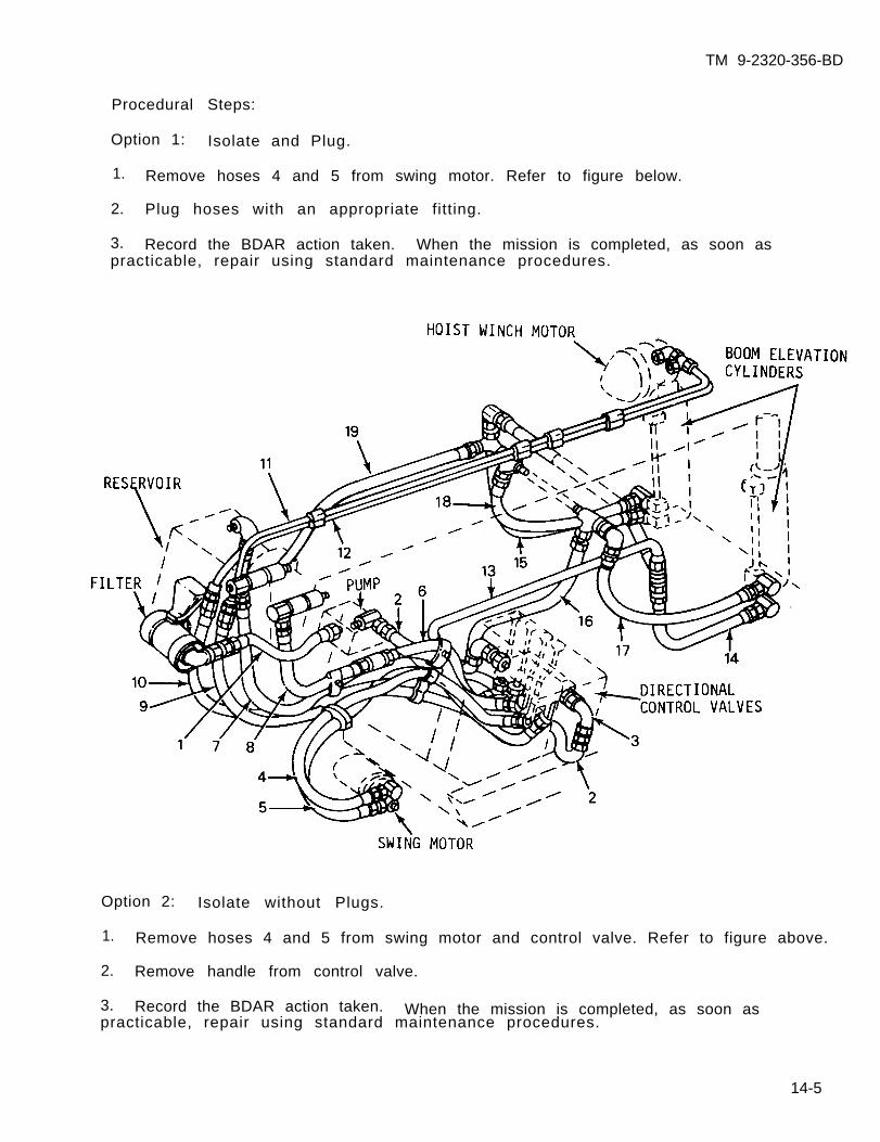
TM 9-2320-356-BD
Option 2: Isolate without Plugs.
Procedural Steps:
Option 1: Isolate and Plug.
1. Remove hoses 4 and 5 from swing motor. Refer to figure below.
2. Plug hoses with an appropriate fitting.
3. Record the BDAR action taken. When the mission is completed, as soon aspracticable, repair using standard maintenance procedures.
1. Remove hoses 4 and 5 from swing motor and control valve. Refer to figure above.
2. Remove handle from control valve.
3. Record the BDAR action taken. When the mission is completed, as soon aspracticable, repair using standard maintenance procedures.
14-5
TM 9-2320-356-BD
14-7. BOOM ELEVATING OR CROWD CYLINDERS INOPERATIVE
General Information:
Most hydraulic cylinder failure is caused by faulty seals
A hydraulic cylinder consists of a cylinder body, a movable piston, and a pistonrod attached to the piston. End caps are attached to the cylinder body barrel bythreads, keeper rings, tie rods, or a weld. (Industr ial cyl inders use t ie rods.)
As the cylinder rod moves in and out, it is guided and supported by a removablebushing called a rod gland.
The side through which the rod protrudes is called the head. The opposite sidewithout the rod is termed the cap. Inlet and outlet ports are located in the headand cap.
For proper operation, a positive seal must exist across a cylinder’s piston as wellas at the rod gland. Cylinder pistons are sealed by using lipseals or cast ironpiston rings.
Rod gland seals come in several varieties. Some cylinders are equipped with aV-shaped or cup-shaped primary seal made of leather, polyurethane, nitrile, orviton, and a wiper seal which prevents foreign materials from being drawn into thecy l inder .
One popular type of rod gland seal consists of a primary seal with serrated edgesalong its inside surface. The edges contact the rod continuously and scrape itclean of f luid. A second wiper seal catches fluid which may get by the primaryseal and also wipes the rod of foreign material when the rod retracts.
L imi ta t ions:
o Degraded load capacity
Personnel/Time Requirement:
o 1 so ld iero 1 to 2 hours
Mater ia ls /Tools :
o Pump packingo S t r i n go Ropeo Candles or paraffin-base waxo Lip protect ion balm
14-6
TM 9-2320-356-BD
Procedural Steps:
Option 1: String or Rope Seal.
1. Remove damaged or worn rod gland seal.
2. Saturate string or rope, depending upon size of packing, with wax or lip balm.
3. Install substitute packing around cylinder rod and cut to make a snug fit.
4. Tap the new packing with a blunt tool to form a tight seal around the cylinderrod.
5. Record the BDAR action taken. When the mission is completed, as soon aspract icab le , repair using standard maintenance procedures.
Option 2: Pump Packing.
1. Remove damaged or worn rod gland seal.
2. Install pump packing around cylinder rod and cut to make a snug fit.
3. Tap packing with a blunt tool to form a tight seal around the cylinder rod.
4. Record the BDAR action taken. When the mission is completed. as soon aspract icab le , repa i r us ing s tandard maintenance procedures. ” -
14-8. CONTROL VALVE BANK ASSEMBLY DAMAGED OR DEFECTIVE
General Information:
A directional control valve consists of a body with internal passages which areconnected and disconnected by a movable part. In directional valves, the movablepart is a spool. Spool valves are by far the most common type of directional valveused in hydraulics.
A directional valve consists of a pump passage, tank passages, and two actuatorpassages. This valve is known as a 4-way valve because it has four distinctpassages within its body.
The function of a 4-way directional valve is to cause the reverse motion of acylinder or hydraulic motor. To perform this function, the spool directs flow fromthe pump passage to one actuator passage when it is in one extreme position. Atthe same time, the spool is positioned so that the other actuator passage isexhausted to tank.
Repair can be accomplished only by replacement with a serviceable part.
14-7
TM 9-2320-356-BD
14-9. BOOM HOIST HYDRAULIC MOTOR AND DRUM ASSEMBLY INOPERATIVE OR DAMAGED
General Information:
The boom hoist motor and drum assembly are an integral part of the wrecker. Witheither the motor or the drum damaged or inoperative, the l i f t ing capabi l i ty o f thewrecker would be minimal. The drum and hoist motor are necessary to operate thein-and-out movement of the hoist cable and hook. The hook movement is one of themost important aspects of wrecker efficiency.
L imi ta t ions:
o Degraded l i f t ing
Personnel/Time Required: Mater ia ls /Tools :
o 2 so ld ier o Acetylene torcho 30 to 60 minutes o Cable clamp
Procedural Steps:
1. Place the boom in the down position and cut the cable or wire rope to a lengththat is twice the distance from the ground to the boom.
2. Attach the cut end of the cable to boom where the cable originally is anchoredwith a cable clamp or by interweaving the cables. Refer to paragraph 14-12 or14-13 to attach cable. The block and hook should be hanging at about ground level.
3. Use the boom elevating control and the crowd cylinder control to raise andlower the hook.
4. Record the BDAR action taken. When the mission is completed, as soon aspracticable, repair using standard maintenance procedures.
14-10. HYDRAULIC RESERVOIR DAMAGED
General Information:
The hydraulic reservoir tank supplies fluid to the main hydraulic pump. Damage tothe hydraulic reservoir may vary, depending on the various types and degree ofdamage sustained during a combat situation. This paragraph describes quick-fixprocedures for repair options according to the degree of damage.
Assessment Procedure:
Inspect damaged component to determine extent of damage and the repair required.
L imi ta t ions:
o Degraded mobility
14-8
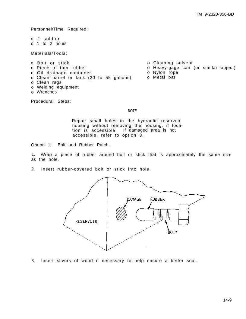
TM 9-2320-356-BD
Personnel/Time Required:
o 2 so ld iero 1 to 2 hours
Materials/Tools:
o Bo l t o r s t ick o Cleaning solvento Piece of thin rubber o Heavy-gage can (or similar object)o Oil drainage container o Nylon ropeo Clean barrel or tank (20 to 55 gallons) o Metal baro Clean ragso Welding equipmento Wrenches
Procedural Steps:
NOTE
Repair small holes in the hydraulic reservoirhousing without removing the housing, if loca-t ion is accessible. If damaged area is notaccessible, refer to option 3.
Option 1: Bolt and Rubber Patch.
1. Wrap a piece of rubber around bolt or stick that is approximately the same sizeas the hole.
2. Insert rubber-covered bolt or st ick into hole.
3. Insert slivers of wood if necessary to help ensure a better seal.
14-9
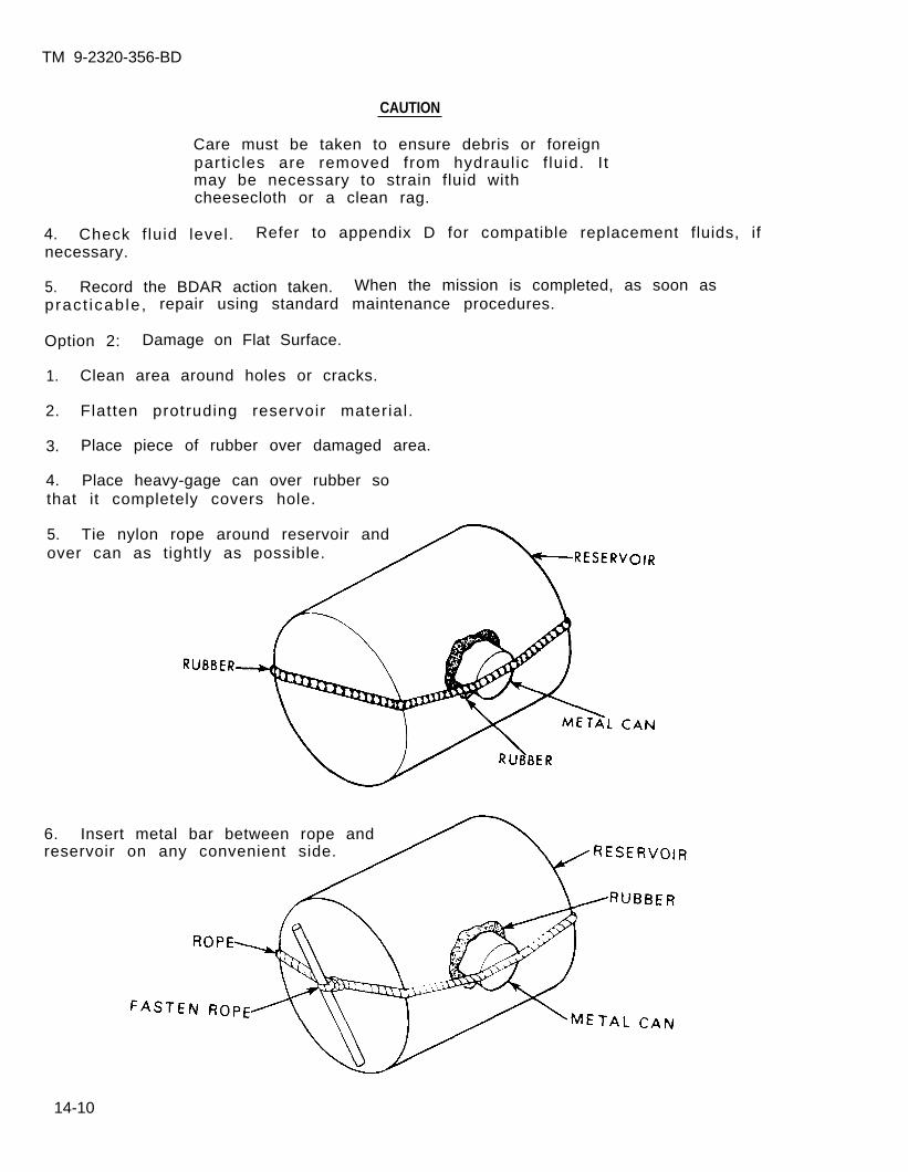
TM 9-2320-356-BD
CAUTION
Care must be taken to ensure debris or foreignpart icles are removed from hydraulic f luid. I tmay be necessary to strain fluid withcheesecloth or a clean rag.
4. Check f luid level. Refer to appendix D for compatible replacement fluids, ifnecessary.
5. Record the BDAR action taken. When the mission is completed, as soon aspract icab le , repair using standard maintenance procedures.
Option 2: Damage on Flat Surface.
1. Clean area around holes or cracks.
2. Flatten protruding reservoir material.
3. Place piece of rubber over damaged area.
4. Place heavy-gage can over rubber sothat it completely covers hole.
5. Tie nylon rope around reservoir andover can as tightly as possible.
6. Insert metal bar between rope andreservoir on any convenient side.
14-10
TM 9-2320-356-BD
7. Twist metal bar to t ighten rope unti l f luid stops leaking.
8. Secure metal bar to prevent unwinding.
CAUTION
Care must be taken to ensure debris or foreignpart icles are removed from hydraulic f luid. I tmay be necessary to strain fluid withcheesecloth or a clean rag.
9. Check f luid level. Refer to appendix D for compatible replacement fluids, ifnecessary.
10. Record the BDAR action taken. When the mission is completed, as soon aspract icab le , repair using standard maintenance procedures.
Option 3: Inaccessible Area Repair.
CAUTION
When disconnecting hydraulic lines and hoses,plug openings with clean rags to prevent dirtfrom entering and causing damage to internalpar ts .
CAUTION
Care must be taken to ensure debris or foreignparticles are removed from fluids. It may benecessary to strain fluid with cheesecloth orclean rag.
1. Remove fittings from reservoir and repair damaged area.
2. Remove damaged reservoir from vehicle.
3. I f subst i tu t ing reservo i r , cut holes in the substi tute container at locat ionsappropriate for connecting existing hoses. If necessary, cut a hole in anappropriate area for a new filler hole. Use a clean rag as a new cap.
4. Weld old f i t t ings into holes of the substi tute reservoir.
5. Flush substi tute reservoir with hydraul ic f luid to remove debris.
6. Reconnect hydraul ic l ines to substi tute reservoir.
7. Secure new reservoir to vehicle and f i l l reservoir with hydraul ic f luid. Referto appendix D for compatible replacement fluids, if necessary.
8. Operate hydraulic system slowly.
14-11
TM 9-2320-356-BD
9. As air bleeds from the system, f i l l reservo i r w i th hydrau l ic f lu id orcompatible replacement fluid.
10. Record the BDAR action taken. When the mission is completed, as soon aspracticable, repair using standard maintenance procedures.
14-11. HYDRAULIC FILTER DAMAGED OR DEFECTIVE
General Information:
The hydraulic fluid filter is designed to keep the oil clean and free of dirt andother foreign particles or contaminants. Contamination affects the performance ofthe hydraulic components. Sticking and sluggish action can occur or passages maybecome plugged. Dirt can prevent valves from seating, resulting in leakage, lossof cont ro l , and damage to the crane.
Assessment Procedure:
Inspect damage components to determine extent of damage and the repair required.
Option 1: Remove Fi l ter Element
Limi ta t ions:
o Degraded usage with time
Personnel/Time Required:
o 1 so ld iero 30 minutes
Procedural Steps:
1. Remove filter element.
Materials/Tools:
o Adjustable wrench
2. Record the BDAR action taken. When the mission is completed, aspract icab le , repair using standard maintenance procedures.
Option 2: Remove Filter Assembly.
Limitations:
Personnel/Time Required:
o 1 so ld iero 30 minutes
Materials/Tools
soon as
o Adjustable wrencho 14- or 18-inch pipe wrencho 2-inch pipe nippleo 2-inch, 90-degree elbow
14-12

TM 9-2320-356-BD
Procedural Steps:
1. Remove filter assembly from reservoir.
2. Install nipple and elbow on reservoir.
3. Connect hose to elbow.
4. Record the BDAR action taken. When the mission is completed, as soon aspract icab le , repair using standard maintenance procedures.
14-12. WIRE ROPE OR CABLE DAMAGED
General:
A wire rope or cable is the most important single item in vehicle recovery. Themost common use in military units is for winch cables. Wire rope is made of manywires twisted together to make a strand. The strands are then twisted togetheraround the core, making a rope. If wire becomes untwisted or frayed and specialf i t t ings are unavai lab le , the seizing method is recommended.
One of the simplest and quickest eye splices for field use is the Flemish eye orMolly Hogan, sometimes referred to as the rolled-in eye splice. I t i s espec ia l lyapplicable to preformed wire rope.
Assessment Procedure:
Inspect damaged component to determine extent of damage and the repair required.
Limitations:
o Degraded weight capacity
Personnel/Time Required:
o 1-2 so ld ierso 30-60 minutes
Materials/Tools:
o Wire rope cuttero Copper wireo E lec t r i ca l t ape
WARNING
Wire ropes or cables can cause serious injury topersonnel. Wear protective gloves when handlingwire ropes or cables.
Procedural Steps:
Option 1: Wire Bind.
1. Bind the wire rope or cable with wire 1/4 inch beyond both sides of the damagedarea.
2. Make cable taut while winding wire on the rope by hand. Keep the coils tight.
14-13
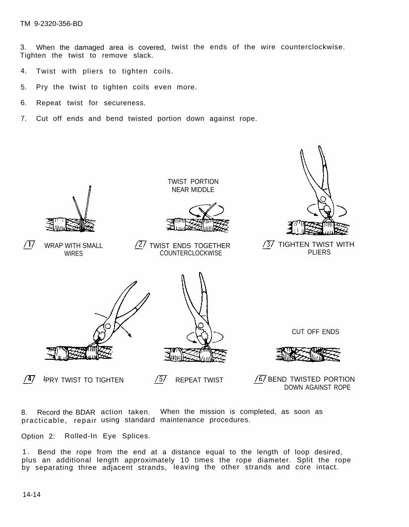
TM 9-2320-356-BD
3. When the damaged area is covered, twist the ends of the wire counterclockwise.Tighten the twist to remove slack.
4. Twist with pl iers to t ighten coi ls.
5. Pry the twist to tighten coils even more.
6. Repeat twist for secureness.
7. Cut off ends and bend twisted portion down against rope.
TWIST PORTIONNEAR MIDDLE
WRAP WITH SMALL TWIST ENDS TOGETHERWIRES COUNTERCLOCKWISE
TIGHTEN TWIST WITHPLIERS
PRY TWIST TO TIGHTEN REPEAT TWIST
8. Record the BDARpract icab le , repa i r
CUT OFF ENDS
BEND TWISTED PORTIONDOWN AGAINST ROPE
action taken. When the mission is completed, as soon asusing standard maintenance procedures.
Option 2: Rolled-In Eye Splices.
1 . Bend the rope from the end at a distance equal to the length of loop desired,plus an additional length approximately 10 times the rope diameter. Split the ropeby separating three adjacent strands, leaving the other strands and core intact.
14-14
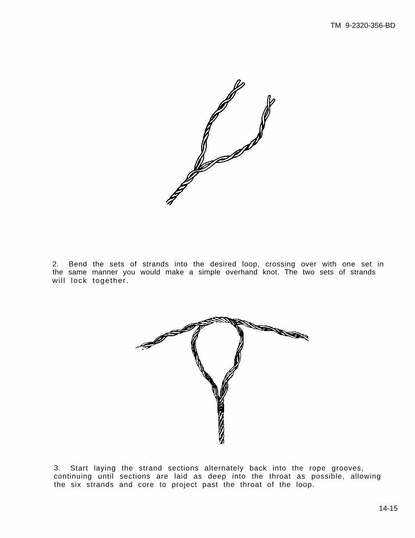
TM 9-2320-356-BD
2. Bend the sets of strands into the desired loop, crossing over with one set inthe same manner you would make a simple overhand knot. The two sets of strandswi l l lock together .
3. Start laying the strand sections alternately back into the rope grooves,continuing until sections are laid as deep into the throat as possible, allowingthe six strands and core to project past the throat of the loop.
14-15
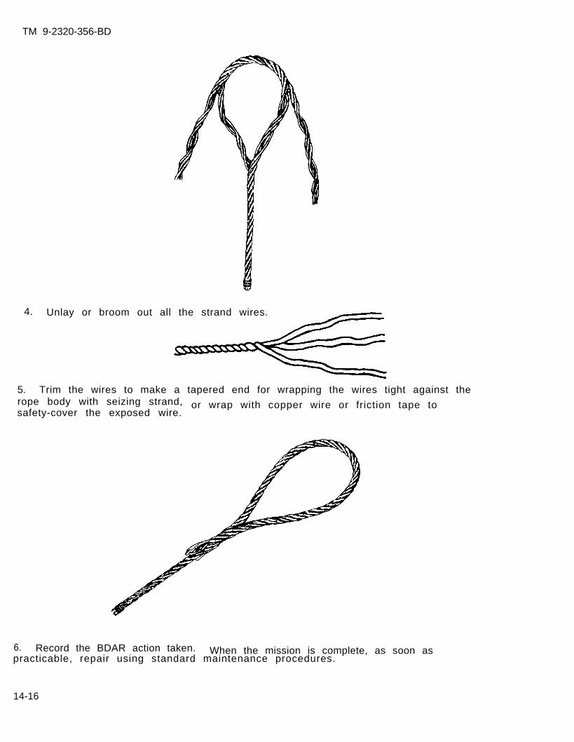
TM 9-2320-356-BD
4. Unlay or broom out all the strand wires.
5. Trim the wires to make a tapered end for wrapping the wires tight against therope body with seizing strand, or wrap with copper wire or friction tape tosafety-cover the exposed wire.
6. Record the BDAR action taken. When the mission is complete, as soon aspracticable, repair using standard maintenance procedures.
14-16
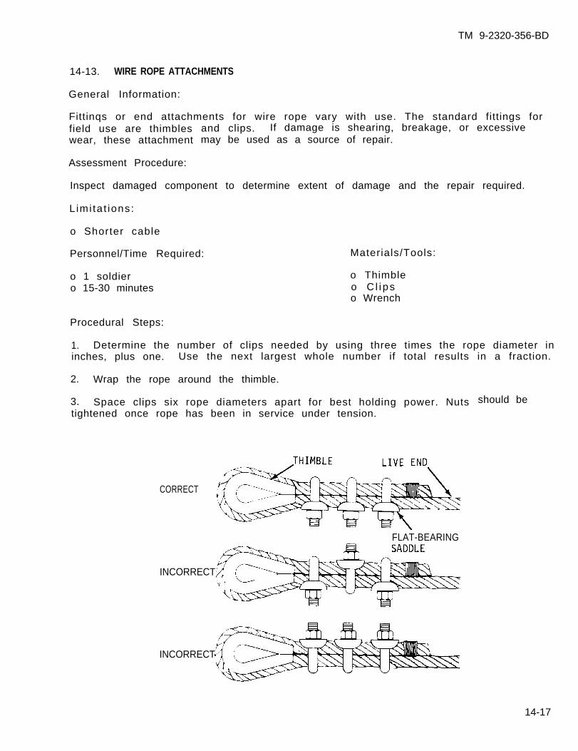
TM 9-2320-356-BD
14-13. WIRE ROPE ATTACHMENTS
General Information:
Fittinqs or end attachments for wire rope vary with use. The standard fittings forfield use are thimbleswear, these attachment
Assessment Procedure:
and clips. If damage is shearing, breakage, or excessivemay be used as a source of repair.
Inspect damaged component to determine extent of damage and the repair required.
L imi ta t ions:
o Shorter cable
Personnel/Time Required:
o 1 soldiero 15-30 minutes
Procedural Steps:
1. Determine the number of clips needed by using three times the rope diameter ininches, plus one. Use the next largest whole number if total results in a fraction.
2. Wrap the rope around the thimble.
Materials/Tools:
o Thimbleo C l i pso Wrench
3. Space clips six rope diameters apart for best holding power. Nutstightened once rope has been in service under tension.
CORRECT
FLAT-BEARING
INCORRECT
should be
INCORRECT
14-17
TM 9-2320-356-BD
4. Place all the V-bolts on the short, or dead, end of the rope.
5. Place the flat-bearing saddle or base against the live end.
6. Record the BDAR action taken. When the mission is completed, as soon aspract icab le , repair using standard maintenance procedures.
14-14. HIGH-PRESSURE HOSE SUBSTITUTION AND ISOLATION (M543, M816, AND M936)
General Information:
High-pressure hose failure or damage to a vital system on the wrecker can be fixedby removing a hose from a system that will not affect the particular task to be per-formed. The following procedures and tables will help to make the proper decisionas to the system from which to remove or to isolate so the crucial system can beu t i l i z e d .
Refer to table 14-1 for hose size, length, location, and function performed. Referto figure in paragraph 14-6 that will show physical location and hose numbers thatinterchange with those in table 14-1.
L imi ta t ions:
o Loss of a hydraulic functiono Extended recovery time
Personnel/Time Required:
o 1 so ld iero 15 to 60 minutes
Mater ia l /Tools :
o Adjustable wrench
Procedural Steps:
1. Locate and remove the damaged hose on the wrecker.
2. Refer to table 14-1 and identify the hose.
3. Select a function that will not be needed or whose loss will not affect themission. Make sure that the substitute hose is as long as or longer than thedamaged hose. Remove good hose and substitute it for the damaged one.
4. Remove the handle from the valve that controls the missing function. This willprevent oi l loss due to accidental act ivat ion.
5. Record the BDAR action taken. When the mission is completed, as soon aspract icab le , repair using standard maintenance procedures.
14-18
TM 9-2320-356-BD
14-15. HIGH-PRESSURE TUBE SUBSTITUTION AND ISOLATION (M543, M816, AND M936)
General Information:
High-pressure tube damage on a wrecker can be repaired by substituting andisolating another tube from the wrecker’s hydraulic system. I f a v i ta l funct ion o fthe crane is inoperative due to a damaged high-pressure tube, refer to table 14-1for the size, length, location, and function of other tubes of approximately thesame length. Refer to the figure in paragraph 14-6 that will show physicallocation and hose numbers that interchange with those in table 14-2.
L imi ta t ions:
o Loss of a hydraulic functiono Extended recovery time
Personnel/Time Required:
o 1 so ld iero 15 to 60 minutes
Mater ia l /Tools :
o Adjustable wrench
Procedural Steps:
1. Locate and remove damaged high-pressure tube.
2. Refer to table 14-1 and identify the tube.
3. Select a function that will not be needed or whose loss will not affect themission. Make sure that the substitute tube is longer than the damaged tube.Remove the tube.
4. Isolate the hydraulic function that is not needed and remove the handle fromthe control valve.
CAUTION
Do not kink tubing when bending it. A kink willweaken the tubing.
5. Bend the substitute tube in the appropriate places to fit and install the tube.
6. Record the BDAR action taken. When the mission is completed, as soon aspracticable, repair using standard maintenance procedures.
14-19
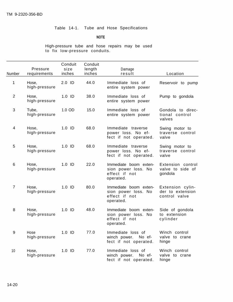
TM 9-2320-356-BD
Table 14-1. Tube and Hose Specifications
NOTE
High-pressure tube and hose repairs may be usedto f ix low-pressure conduits.
Conduit ConduitPressure size length Damage
Number requirements inches inches resu l t Location
1
2
3
4
5
6
7
8
9
10
Hose,high-pressure
2.0 ID
1.0 ID
1.0 OD
44.0
38.0
15.0
68.0
68.0
22.0
80.0
48.0
77.0
77.0
Immediate loss ofentire system power
Reservoir to pump
Hose,high-pressure
Immediate loss ofentire system power
Pump to gondola
Tube,high-pressure
Immediate loss ofentire system power
Gondola to direc-t iona l cont ro lvalves
Hose,high-pressure
1.0 ID Immediate traversepower loss. No ef-fect i f not operated.
Swing motor totraverse controlvalve
Hose,high-pressure
1.0 ID Immediate traversepower loss. No ef-fect i f not operated.
Swing motor totraverse controlvalve
Hose,high-pressure
1.0 ID Immediate boom exten-sion power loss. Noef fec t i f no toperated.
Extension controlvalve to side ofgondola
1.0 ID Immediate boom exten-sion power loss. Noef fec t i f no toperated.
Extension cyl in-der to extensioncontrol valve
Hose,high-pressure
1.0 ID Immediate boom exten-sion power loss. Noef fec t i f no toperated.
Side of gondolato extensioncy l i nde r
Hose,high-pressure
1.0 ID
1.0 ID
Immediate loss ofwinch power. No ef-fect i f not operated.
Winch controlvalve to cranehinge
Hosehigh-pressure
Immediate loss ofwinch power. No ef-fect i f not operated.
Winch controlvalve to cranehinge
Hose,high-pressure
14-20
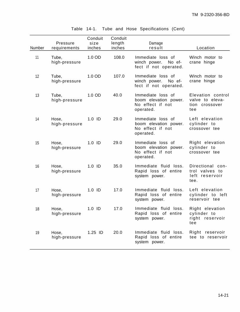
TM 9-2320-356-BD
Table 14-1. Tube and Hose Specifications (Cent)
Conduit ConduitPressure size length Damage
Number requirements inches inches resu l t Location
108.0
107.0
40.0
29.0
29.0
35.0
17.0
17.0
20.0
Immediate loss ofwinch power. No ef-fect i f not operated.
Winch motor tocrane hinge
11
12
13
14
15
16
17
18
19
Tube,high-pressure
1.0 OD
1.0 OD
1.0 OD
Immediate loss ofwinch power. No ef-fect i f not operated.
Winch motor tocrane hinge
Tube,high-pressure
Immediate loss ofboom elevation power.No effect i f notoperated.
Elevation controlvalve to eleva-tion crossovertee
Tube,high-pressure
Hose,high-pressure
1.0 ID Immediate loss ofboom elevation power.No effect i f notoperated.
Lef t e levat ioncy l inder tocrossover tee
1.0 ID
1.0 ID
Immediate loss ofboom elevation power.No effect i f notoperated.
Right elevationcy l inder tocrossover tee
Hose,high-pressure
Immediate fluid loss.Rapid loss of entiresystem power.
Direct ional con-trol valves tol e f t r ese rvo i rtee.
Hose,high-pressure
Immediate fluid loss.Rapid loss of entiresystem power.
Lef t e levat ioncy l inder to le f treservoir tee
Hose,high-pressure
1.0 ID
1.0 ID Immediate fluid loss.Rapid loss of entiresystem power.
Right elevationcy l inder tor ight reservo i rtee
Hose,high-pressure
Immediate fluid loss. Right reservoirHose,high-pressure
1.25 IDRapid loss of entire tee to reservoirsystem power.
14-21
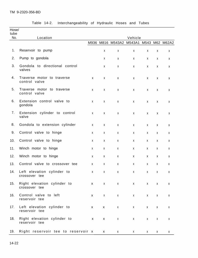
TM 9-2320-356-BD
Table 14-2. Interchangeability of Hydraulic Hoses and Tubes
Hose/tube
No. Location VehicleM936 M816 M543A2 M543A1 M543 M62 M62A2
1. Reservoir to pump
2. Pump to gondola
3. Gondola to directional controlvalves
4. Traverse motor to traversecontrol valve
5. Traverse motor to traversecontrol valve
6. Extension control valve togondola
7. Extension cylinder to controlvalve
8. Gondola to extension cylinder
9. Control valve to hinge
10. Control valve to hinge
11. Winch motor to hinge
12. Winch motor to hinge
13. Control valve to crossover tee
14. Left elevation cyl inder tocrossover tee
15. Right elevation cyl inder tocrossover tee
16. Control valve to leftreservoir tee
17. Left elevation cyl inder toreservoir tee
18. Right elevation cyl inder toreservoir tee
x
x
x
x
x
x
x
x
x
x
x
x
x
x
x
19. R i g h t r e s e r v o i r t e e t o r e s e r v o i r x
x
x
x
x
x
x
x
x
x
x
x
x
x
x
x
x
x
x
x
x
x
x
x
x
x
x
x
x
x
x
x
x
x
x
x
x
x
x
x
x
x
x
x
x
x
x
x
x
x
x
x
x
x
x
x
x
x
x
x
x
x
x
x
x
x
x
x
x
x
x
x
x
x
x
x
x
x
x
x
x
x
x
x
x
x
x
x
x
x
x
x
x
x
x
x
x
x
x
x
x
x
x
x
x
x
x
x
x
x
x
x
x
x
x
14-22
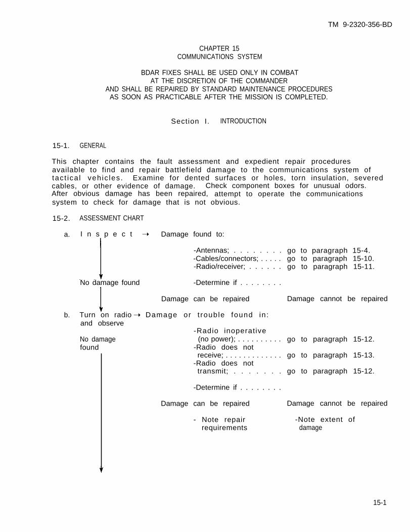
TM 9-2320-356-BD
CHAPTER 15COMMUNICATIONS SYSTEM
BDAR FIXES SHALL BE USED ONLY IN COMBATAT THE DISCRETION OF THE COMMANDER
AND SHALL BE REPAIRED BY STANDARD MAINTENANCE PROCEDURESAS SOON AS PRACTICABLE AFTER THE MISSION IS COMPLETED.
Section I. INTRODUCTION
15-1. GENERAL
This chapter contains the fault assessment and expedient repair proceduresavailable to find and repair battlefield damage to the communications system oftac t ica l veh ic les . Examine for dented surfaces or holes, torn insulation, severedcables, or other evidence of damage. Check component boxes for unusual odors.After obvious damage has been repaired, attempt to operate the communicationssystem to check for damage that is not obvious.
15-2. ASSESSMENT CHART
a. I n s p e c t ➝ Damage found to:
-Antennas; . . . . . . . .-Cables/connectors; . . . . .-Radio/receiver; . . . . . .
No damage found -Determine if . . . . . . . .
Damage can be repaired
b. Turn on radio ➝ Damage or t rouble found in :and observe
-Radio inoperativeNo damage (no power); . . . . . . . . . .found -Radio does not
receive; . . . . . . . . . . . . .-Radio does nottransmit; . . . . . . .
-Determine if . . . . . . . .
Damage can be repaired
- Note repairrequirements
go to paragraph 15-4.go to paragraph 15-10.go to paragraph 15-11.
Damage cannot be repaired
go to paragraph 15-12.
go to paragraph 15-13.
go to paragraph 15-12.
Damage cannot be repaired
-Note extent ofdamage
15-1
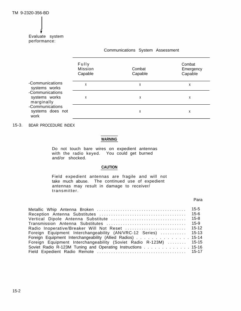
TM 9-2320-356-BD
Evaluate systemperformance:
Communications System Assessment
-Communicationssystems works
-Communicationssystems worksmarginally
-Communicationssystems does notwork
F u l l y CombatMission Combat EmergencyCapable Capable Capable
x x x
x x x
x x
15-3. BDAR PROCEDURE INDEX
WARNING
Do not touch bare wires on expedient antennaswith the radio keyed. You could get burnedand/or shocked.
CAUTION
Field expedient antennas are fragile and will nottake much abuse. The continued use of expedientantennas may result in damage to receiver/t ransmi t ter .
Para
Metallic Whip Antenna Broken . . . . . . . . . . . . . . . . . . . . . . . . . . . . . . . . . . . . . . 15-5Reception Antenna Substitutes . . . . . . . . . . . . . . . . . . . . . . . . . . . . . . . . . . . . . 15-6Vertical Dipole Antenna Substitute . . . . . . . . . . . . . . . . . . . . . . . . . . . . . . . . 15-8Transmission Antenna Substitutes . . . . . . . . . . . . . . . . . . . . . . . . . . . . . . . . . . 15-9Radio Inoperative/Breaker Will Not Reset . . . . . . . . . . . . . . . . . . . . . . . . . . 15-12Foreign Equipment Interchangeability (AN/VRC-12 Series) . . . . . . . . . . . 15-13Foreign Equipment Interchangeability (Allied Radios) . . . . . . . . . . . . . . 15-14Foreign Equipment Interchangeability (Soviet Radio R-123M) . . . . . . . . 15-15Soviet Radio R-123M Tuning and Operating Instructions . . . . . . . . . . . . . 15-16Field Expedient Radio Remote . . . . . . . . . . . . . . . . . . . . . . . . . . . . . . . . . . . . . . 15-17
15-2
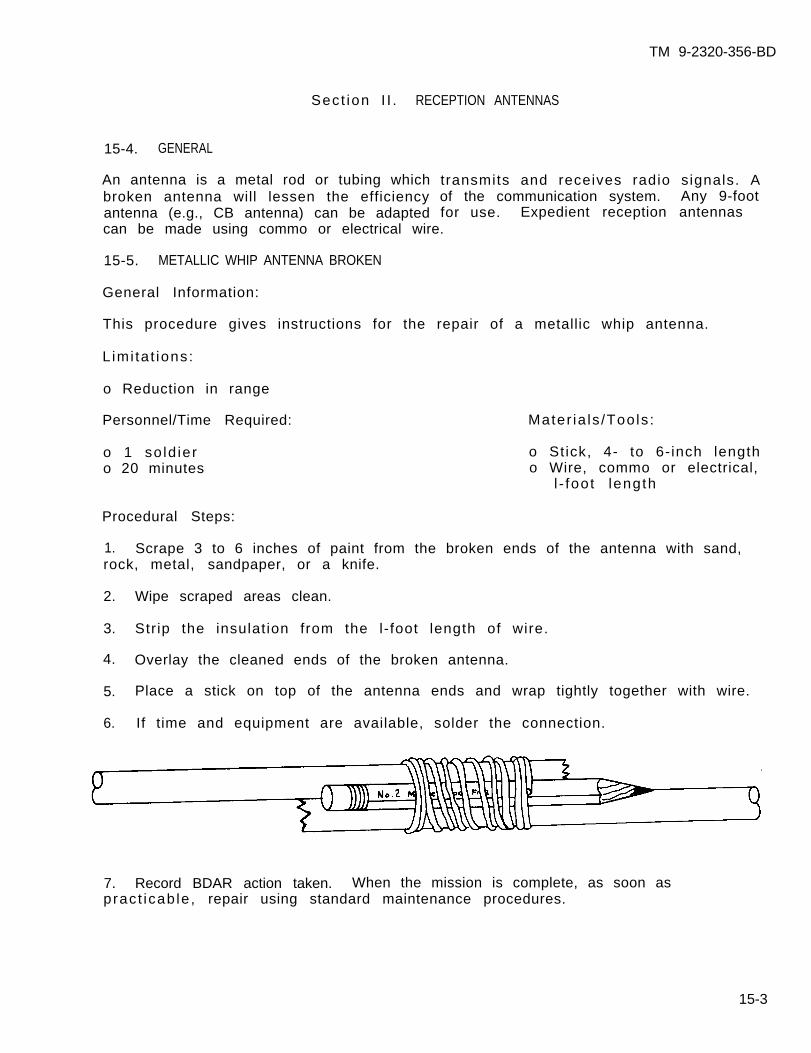
TM 9-2320-356-BD
Sect ion I I . RECEPTION ANTENNAS
15-4. GENERAL
An antenna is a metal rod or tubing whichbroken antenna will lessen the efficiencyantenna (e.g., CB antenna) can be adapted
transmits and receives radio signals. Aof the communication system. Any 9-footfor use. Expedient reception antennas
can be made using commo or electrical wire.
15-5. METALLIC WHIP ANTENNA BROKEN
General Information:
This procedure gives instructions for the repair of a metallic whip antenna.
L imi ta t ions:
o Reduction in range
Personnel/Time Required:
o 1 so ld iero 20 minutes
Mater ia ls /Tools :
o Stick, 4- to 6-inch lengtho Wire, commo or electrical,
l - foot length
Procedural Steps:
1. Scrape 3 to 6 inches of paint from the broken ends of the antenna with sand,rock, metal, sandpaper, or a knife.
2. Wipe scraped areas clean.
3. Str ip the insulat ion from the l-foot length of wire.
4. Overlay the cleaned ends of the broken antenna.
5. Place a stick on top of the antenna ends and wrap tightly together with wire.
6. If time and equipment are available, solder the connection.
7. Record BDAR action taken. When the mission is complete, as soon aspract icab le , repair using standard maintenance procedures.
15-3
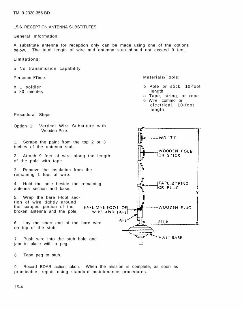
TM 9-2320-356-BD
15-6. RECEPTION ANTENNA SUBSTITUTES
General Information:
A substitute antenna for reception only can be made using one of the optionsbelow. The total length of wire and antenna stub should not exceed 9 feet.
L imi ta t ions:
o No transmission capabil i ty
Personnel/Time:
o 1 so ld iero 30 minutes
Mater ia ls /Tools :
o Pole or st ick, 10-footlength
o Tape, str ing, or ropeo Wire, commo or
e lec t r i ca l , 10 - f oo tlength
Procedural Steps:
Option 1: Vert ical Wire Substi tute withWooden Pole.
1. Scrape the paint from the top 2 or 3inches of the antenna stub.
2. Attach 9 feet of wire along the lengthof the pole with tape.
3. Remove the insulation from theremaining 1 foot of wire.
4. Hold the pole beside the remainingantenna section and base.
5. Wrap the bare l-foot sec-t ion of wire t ight ly aroundthe scraped portion of thebroken antenna and the pole.
6. Lay the short end of the bare wireon top of the stub.
7. Push wire into the stub hole andjam in place with a peg.
8. Tape peg to stub.
9. Record BDAR action taken. When the mission is complete, as soon aspracticable, repair using standard maintenance procedures.
15-4
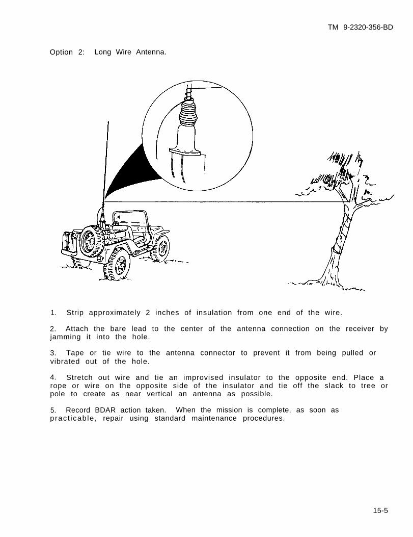
TM 9-2320-356-BD
Option 2: Long Wire Antenna.
1. Strip approximately 2 inches of insulation from one end of the wire.
2. Attach the bare lead to the center of the antenna connection on the receiver byjamming it into the hole.
3. Tape or tie wire to the antenna connector to prevent it from being pulled orvibrated out of the hole.
4. Stretch out wire and tie an improvised insulator to the opposite end. Place arope or wire on the opposite side of the insulator and tie off the slack to tree orpole to create as near vertical an antenna as possible.
5. Record BDAR action taken. When the mission is complete, as soon aspract icab le , repair using standard maintenance procedures.
15-5
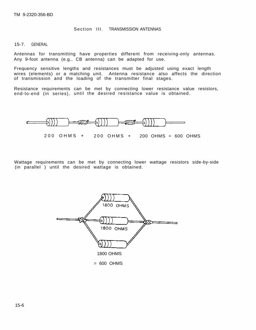
TM 9-2320-356-BD
Sect ion I I I . TRANSMISSION ANTENNAS
15-7. GENERAL
Antennas for transmitting have properties different from receiving-only antennas.Any 9-foot antenna (e.g., CB antenna) can be adapted for use.
Frequency sensitive lengths and resistances must be adjusted using exact lengthwires (elements) or a matching unit. Antenna resistance also affects the directionof transmission and the loading of the transmitter final stages.
Resistance requirements can be met by connecting lower resistance value resistors,end-to-end (in series), unti l the desired resistance value is obtained.
2 0 0 O H M S + 2 0 0 O H M S + 200 OHMS = 600 OHMS
Wattage requirements can be met by connecting lower wattage resistors side-by-side(in parallel ) until the desired wattage is obtained.
1800 OHMS
= 600 OHMS
15-6
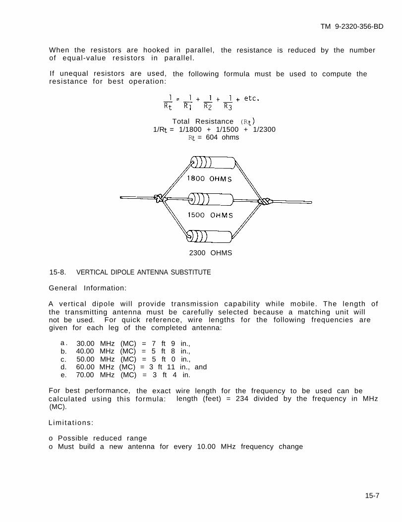
TM 9-2320-356-BD
When the resistors are hooked in parallel, the resistance is reduced by the numberof equal-value resistors in paral lel.
If unequal resistors are used, the following formula must be used to compute theresistance for best operation:
Total Resistance (R 1/R = 1/1800 + 1/1500 + 1/2300
R = 604 ohms
2300 OHMS
15-8. VERTICAL DIPOLE ANTENNA SUBSTITUTE
General Information:
A vert ical dipole wil l provide transmission capabil i ty while mobile. The length ofthe transmitting antenna must be carefully selected because a matching unit willnot be used. For quick reference, wire lengths for the following frequencies aregiven for each leg of the completed antenna:
30.00 MHz (MC) = 7 ft 9 in.,b. 40.00 MHz (MC) = 5 ft 8 in.,c. 50.00 MHz (MC) = 5 ft 0 in.,d. 60.00 MHz (MC) = 3 ft 11 in., ande. 70.00 MHz (MC) = 3 ft 4 in.
For best performance, the exact wire length for the frequency to be used can becalculated using this formula: length (feet) = 234 divided by the frequency in MHz(MC).
L imi ta t ions:
o Possible reduced rangeo Must build a new antenna for every 10.00 MHz frequency change
15-7
a .
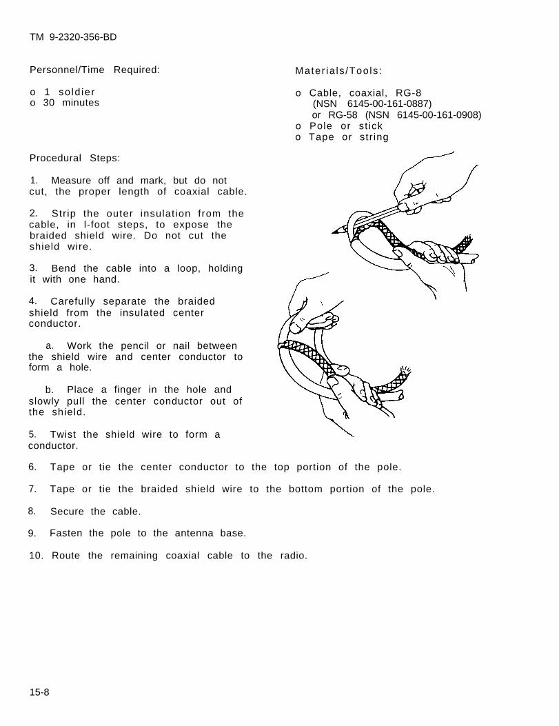
TM 9-2320-356-BD
Personnel/Time Required:
o 1 so ld iero 30 minutes
Procedural Steps:
1. Measure off and mark, but do notcut, the proper length of coaxial cable.
2. Str ip the outer insulat ion from thecable, in l-foot steps, to expose thebraided shield wire. Do not cut theshield wire.
3. Bend the cable into a loop, holdingit with one hand.
4. Carefully separate the braidedshield from the insulated centerconductor.
a. Work the pencil or nail betweenthe shield wire and center conductor toform a hole.
b. Place a finger in the hole andslowly pull the center conductor out ofthe shield.
5. Twist the shield wire to form aconductor.
Mater ia ls /Tools :
o Cable, coaxial, RG-8(NSN 6145-00-161-0887)or RG-58 (NSN 6145-00-161-0908)
o Pole or st icko Tape or str ing
6. Tape or tie the center conductor to the top portion of the pole.
7. Tape or tie the braided shield wire to the bottom portion of the pole.
8. Secure the cable.
9. Fasten the pole to the antenna base.
10. Route the remaining coaxial cable to the radio.
15-8
TM 9-2320-356-BD
11. If there is a BNC connector (twist-lock) on the cable, attach it to the radioantenna connector. If not, prepare and connect the coaxial cable as follows:
a. Carefully strip the outer insulation from the coaxial cable to expose enoughbraided shield to reach a screw near the antenna connector on the radio case. Donot cut shielding.
b. Use a pencil or nail and carefully separate the braided shield from aroundthe center conductor insulation.
c. Twist shield wire into a pigtai l .
d. Strip the center conductor insulation to expose enough wire to push into theantenna connector.
e. Wedge the wire into the center of the antenna connector.
f . Attach the pigtail to a screw on the radio case.
12. Record BDAR action taken. When the mission is complete, as soon aspract icab le , repair using standard maintenance procedures.
15-9. TRANSMISSION ANTENNA SUBSTITUTES
General Information:
This procedure gives instructions for making a 1/4 wave ground plane antenna, longwire antenna, or a half rhombic antenna. The transmission range is greatlyincreased but cannot be used during mobile operations. The length of the 1/4 waveground plane antenna elements must be selected because a matching unit will not beused. For quick reference, wire lengths for the following frequencies are givenfor each leg of the completed antenna:
a. 30.00 MHz (MC) = 7 ft 9 in.,b. 40.00 MHz (MC) = 5 ft 8 in.,c. 50.00 MHz (MC) = 5 ft 0 in.,d. 60.00 MHz (MC) = 3 ft 11 in., ande. 70.00 MHz (MC) = 3 ft 4 in..
For best performance, the exact wire length for each frequency to be used can becalculated using this formula: length (feet) = 234 divided by the frequency in MHz(MC).
L imi ta t ions:
o Not for mobile useo Long wire and half rhombic antennas are very directionalo Must build a new antenna for every 10.00 MHz frequency change
15-9
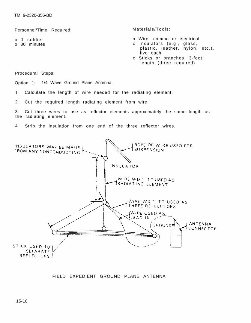
TM 9-2320-356-BD
Personnel/Time Required:
o 1 so ld iero 30 minutes
Mater ia ls /Tools :
o Wire, commo or electricalo Insu la tors (e .g . , g lass ,
p las t ic , lea ther , ny lon, e tc . ) ,five each
o Sticks or branches, 3-footlength (three required)
Procedural Steps:
Option 1: 1/4 Wave Ground Plane Antenna.
1. Calculate the length of wire needed for the radiating element.
2. Cut the required length radiating element from wire.
3. Cut three wires to use as reflector elements approximately the same length asthe radiating element.
4. Strip the insulation from one end of the three reflector wires.
FIELD EXPEDIENT GROUND PLANE ANTENNA
15-10
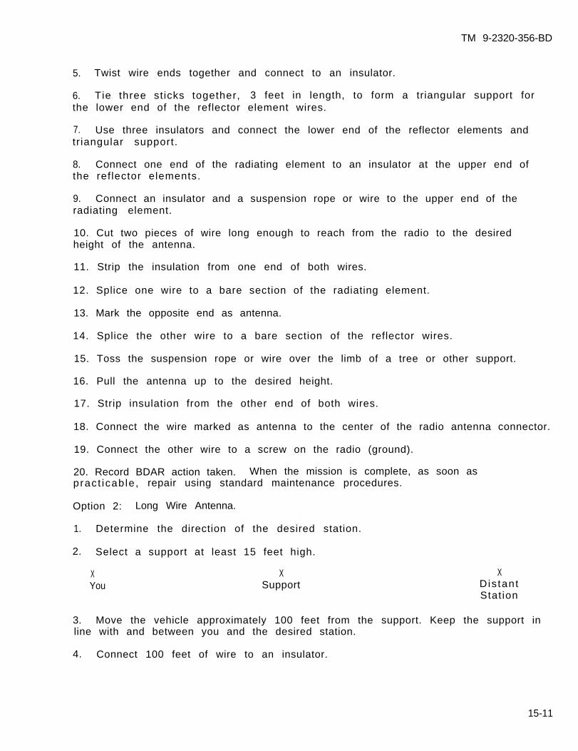
TM 9-2320-356-BD
5. Twist wire ends together and connect to an insulator.
6. Tie three st icks together, 3 feet in length, to form a triangular support forthe lower end of the reflector element wires.
7. Use three insulators and connect the lower end of the reflector elements andtriangular support.
8. Connect one end of the radiating element to an insulator at the upper end ofthe reflector elements.
9. Connect an insulator and a suspension rope or wire to the upper end of theradiating element.
10. Cut two pieces of wire long enough to reach from the radio to the desiredheight of the antenna.
11. Strip the insulation from one end of both wires.
12. Splice one wire to a bare section of the radiating element.
13. Mark the opposite end as antenna.
14. Splice the other wire to a bare section of the reflector wires.
15. Toss the suspension rope or wire over the limb of a tree or other support.
16. Pull the antenna up to the desired height.
17. Strip insulation from the other end of both wires.
18. Connect the wire marked as antenna to the center of the radio antenna connector.
19. Connect the other wire to a screw on the radio (ground).
20. Record BDAR action taken. When the mission is complete, as soon aspract icab le , repair using standard maintenance procedures.
Option 2: Long Wire Antenna.
1. Determine the direction of the desired station.
2. Select a support at least 15 feet high.
X X XYou Support Dis tant
Stat ion
3. Move the vehicle approximately 100 feet from the support. Keep the support inline with and between you and the desired station.
4. Connect 100 feet of wire to an insulator.
15-11
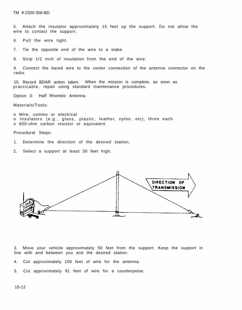
TM 9-2320-356-BD
5. Attach the insulator approximately 15 feet up the support. Do not allow thewire to contact the support.
6. Pull the wire t ight.
7. Tie the opposite end of the wire to a stake.
8. Strip 1/2 inch of insulation from the end of the wire.
9. Connect the bared wire to the center connection of the antenna connector on theradio.
10. Record BDAR action taken. When the mission is complete, as soon aspract icab le , repair using standard maintenance procedures.
Option 3: Half Rhombic Antenna.
Materials/Tools:
o Wire, commo or electricalo Insu la tors (e .g . , g lass , p las t ic , leather, nylon, etc), three eacho 600-ohm carbon resistor or equivalent
Procedural Steps:
1. Determine the direction of the desired station.
2. Select a support at least 30 feet high.
3. Move your vehicle approximately 50 feet from the support. Keep the support inline with and between you and the desired station.
4. Cut approximately 100 feet of wire for the antenna.
5. Cut approximately 91 feet of wire for a counterpoise.
15-12
TM 9-2320-356-BD
6. Connect an insulator to each end of the wire used for the antenna.
7. Tie an insulator to the middle of the antenna wire to be used for elevating theantenna.
8. Connect tiedown wires to the outside of the insulators at the ends of theantenna wire.
9. Connect the counterpoise to the insulators at the same point as the tiedownwires.
10. Connect a long rope or wire to the outside of the insulator at the middle ofthe antenna wire.
11. Raise the center of the antenna up the support approximately 30 feet.
12. Stretch the antenna and counterpoise ends out in a straight line between youand in line with the vehicle and the desired station.
13. Drive stakes in the ground by each tiedown wire.
14. Stretch the antenna and counterpoise tight and tie to the stakes.
15. Connect a wire from the antenna to the center of the antenna connection on theradio.
16. Route a second wire, for ground, from any convenient screw on the radio caseand connect it to the counterpoise wire.
17. Connect a 600-ohm carbon resistor across the insulator on the transmission endof the antenna. Refer to paragraph 15-7 for construction of a 600-ohm resistor.
18. Record BDAR action taken. When the mission is complete, as soon aspracticable, repair using standard maintenance procedures.
15-13
TM 9-2320-356-BD
Section IV. CABLES
15-10. GENERAL
Interconnecting communications cables and connectors can normally be repaired usingprocedures contained in the electrical chapter.
Communications interconnecting cables normally have multiple wires. Put sufficientwraps of tape or insulation on the individual wires to prevent shorts or grounding.
RF cables are shielded cables. The shielding over the splice must make goodcontact with the shielding on the other side to prevent radio frequencyinterference (RFI). When sufficient shielding is not available, a repair can bemade by using a conductive material (such as tubular copper braid, metal gauze,conductive foil from gum wrappers, cigarette packages, or common kitchen foil) overthe repair.
Damaged connectors can be bypassed using a direct wiring procedure or bysubstituting unused connector wire pairs and wiring them to connect the appropriatec i r c u i t s .
15-14
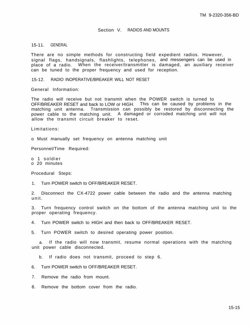
TM 9-2320-356-BD
Section V. RADIOS AND MOUNTS
15-11. GENERAL
There are no simple methods for constructing field expedient radios. However,signal f lags, handsignals, f lashl ights, telephones, and messengers can be used inplace of a radio. When the receiver/transmitter is damaged, an auxiliary receivercan be tuned to the proper frequency and used for reception.
15-12. RADIO INOPERATIVE/BREAKER WILL NOT RESET
General Information:
The radio will receive but not transmit when the POWER switch is turned toOFF/BREAKER RESET and back to LOW or HIGH. This can be caused by problems in thematching unit antenna. Transmission can possibly be restored by disconnecting thepower cable to the matching unit. A damaged or corroded matching unit will notal low the transmit circuit breaker to reset.
L imi ta t ions:
o Must manually set frequency on antenna matching unit
Personnel/Time Required:
o 1 so ld i e ro 20 minutes
Procedural Steps:
1. Turn POWER switch to OFF/BREAKER RESET.
2. Disconnect the CX-4722 power cable between the radio and the antenna matchingun i t .
3. Turn frequency control switch on the bottom of the antenna matching unit to theproper operating frequency.
4. Turn POWER switch to HIGH and then back to OFF/BREAKER RESET.
5. Turn POWER switch to desired operating power position.
a. If the radio will now transmit, resume normal operations with the matchingunit power cable disconnected.
b. If radio does not transmit, proceed to step 6.
6. Turn POWER switch to OFF/BREAKER RESET.
7. Remove the radio from mount.
8. Remove the bottom cover from the radio.
15-15
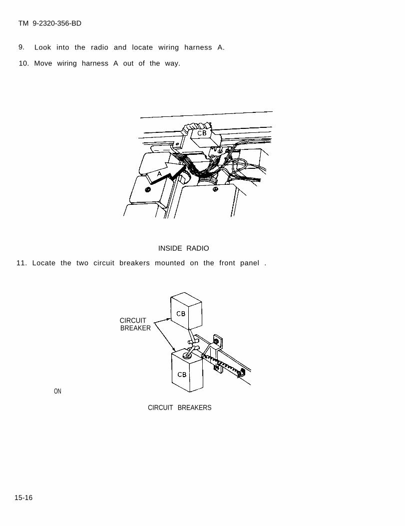
TM 9-2320-356-BD
9. Look into the radio and locate wiring harness A.
10. Move wiring harness A out of the way.
INSIDE RADIO
11. Locate the two circuit breakers mounted on the front panel .
ON
CIRCUITBREAKER
CIRCUIT BREAKERS
15-16
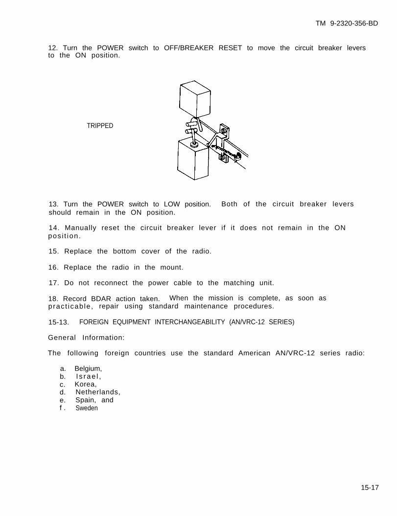
TM 9-2320-356-BD
12. Turn the POWER switch to OFF/BREAKER RESET to move the circuit breaker leversto the ON position.
TRIPPED
13. Turn the POWER switch to LOW position. Both of the circuit breaker leversshould remain in the ON position.
14. Manually reset the circuit breaker lever if it does not remain in the ONposi t ion.
15. Replace the bottom cover of the radio.
16. Replace the radio in the mount.
17. Do not reconnect the power cable to the matching unit.
18. Record BDAR action taken. When the mission is complete, as soon aspract icab le , repair using standard maintenance procedures.
15-13. FOREIGN EQUIPMENT INTERCHANGEABILITY (AN/VRC-12 SERIES)
General Information:
The following foreign
a. Belgium, b. I s rae l ,c. Korea,d. Netherlands,e. Spain, andf . Sweden
countries use the standard American AN/VRC-12 series radio:
15-17
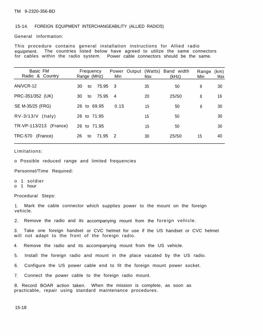
TM 9-2320-356-BD
15-14. FOREIGN EQUIPMENT INTERCHANGEABILITY (ALLIED RADIOS)
General Information:
This procedure contains general instal lat ion instruct ions for Al l ied radioequipment. The countries listed below have agreed to utilize the same connectorsfor cables within the radio system. Power cable connectors should be the same.
Basic FM Frequency Power Output (Watts) Band width Range (km)Radio & Country Range (MHz) Min Max (kHz) Min Max
AN/VCR-12 30 to 75.95 3 35 50 8 30
PRC-351/352 (UK) 30 to 75.95 4 20 25/50 8 16
SE M-35/25 (FRG) 26 to 69.95 0.15 15 50 8 30
RV-3/13/V (I taly) 26 to 71.95 15 50 30
TR-VP-113/213 (France) 26 to 71.95 15 50 30
TRC-570 (France) 26 to 71.95 2 30 25/50 15 40
L imi ta t ions:
o Possible reduced range and limited frequencies
Personnel/Time Required:
o 1 so ld iero 1 hour
Procedural Steps:
1. Mark the cable connectorvehicle.
2. Remove the radio and its
3. Take one foreign handset
which supplies power to the
accompanying mount from the
mount on the foreign
fore ign veh ic le .
or CVC helmet for use if the US handset or CVC helmetwil l not adapt to the front of the foreign radio.
4. Remove the radio and its accompanying mount from the US vehicle.
5. Install the foreign radio and mount in the place vacated by the US radio.
6. Configure the US power cable end to fit the foreign mount power socket.
7. Connect the power cable to the foreign radio mount.
8. Record BOAR action taken. When the mission is complete, as soon aspracticable, repair using standard maintenance procedures.
15-18
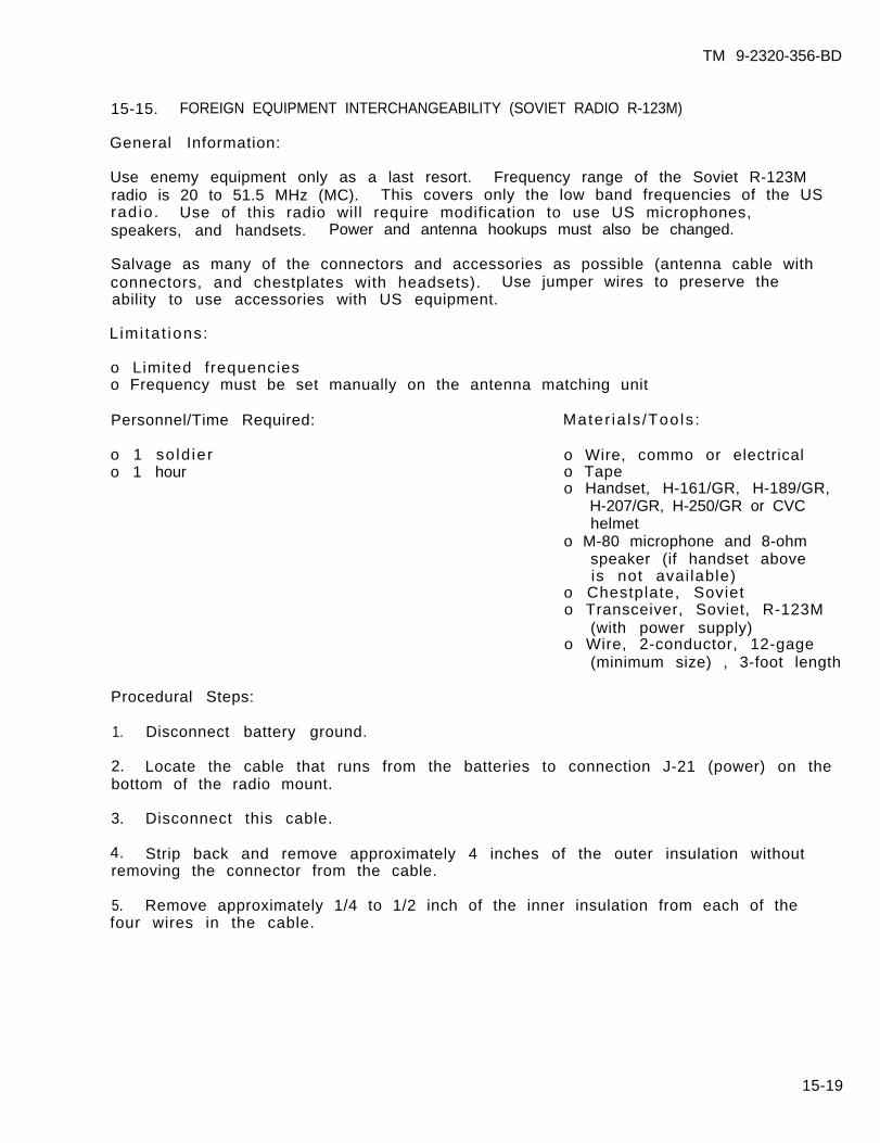
TM 9-2320-356-BD
15-15. FOREIGN EQUIPMENT INTERCHANGEABILITY (SOVIET RADIO R-123M)
General Information:
Use enemy equipment only as a last resort. Frequency range of the Soviet R-123Mradio is 20 to 51.5 MHz (MC). This covers only the low band frequencies of the USradio. Use of this radio will require modification to use US microphones,speakers, and handsets. Power and antenna hookups must also be changed.
Salvage as many of the connectors and accessories as possible (antenna cable withconnectors, and chestplates with headsets). Use jumper wires to preserve theability to use accessories with US equipment.
L imi ta t ions:
o Limited frequencieso Frequency must be set manually on the antenna matching unit
Personnel/Time Required: Mater ia ls /Tools :
o 1 so ld ier o Wire, commo or electricalo 1 hour o Tape
o Handset, H-161/GR, H-189/GR,H-207/GR, H-250/GR or CVChelmet
o M-80 microphone and 8-ohmspeaker (if handset aboveis not avai lable)
o Chestplate, Sovieto Transceiver, Soviet, R-123M
(with power supply)o Wire, 2-conductor, 12-gage
(minimum size) , 3-foot length
Procedural Steps:
1. Disconnect battery ground.
2. Locate the cable that runs from the batteries to connection J-21 (power) on thebottom of the radio mount.
3. Disconnect this cable.
4. Strip back and remove approximately 4 inches of the outer insulation withoutremoving the connector from the cable.
5. Remove approximately 1/4 to 1/2 inch of the inner insulation from each of thefour wires in the cable.
15-19

TM 9-2320-356-BD
6. Jumper the red and the white wires to the positive side of the Soviet powersupply (Point A). Use a jumper cable of at least 12-gauge wire.
7. Jumper the black and the green wires to the negative side of the power supply(Point B). Use a jumper cable of at least 12-gauge wire.
8. Install the R-123M onto the mount and secure.
9. Splice the Soviet coaxial cable to the antenna coaxial cable.
10. Connect the coaxial cable to the antenna connection point located on the rightside of the R-123M, immediately below the AHTEHHA sign.
11. Connect a microphone and speaker to the radio using one of the followingoptions:
15-20
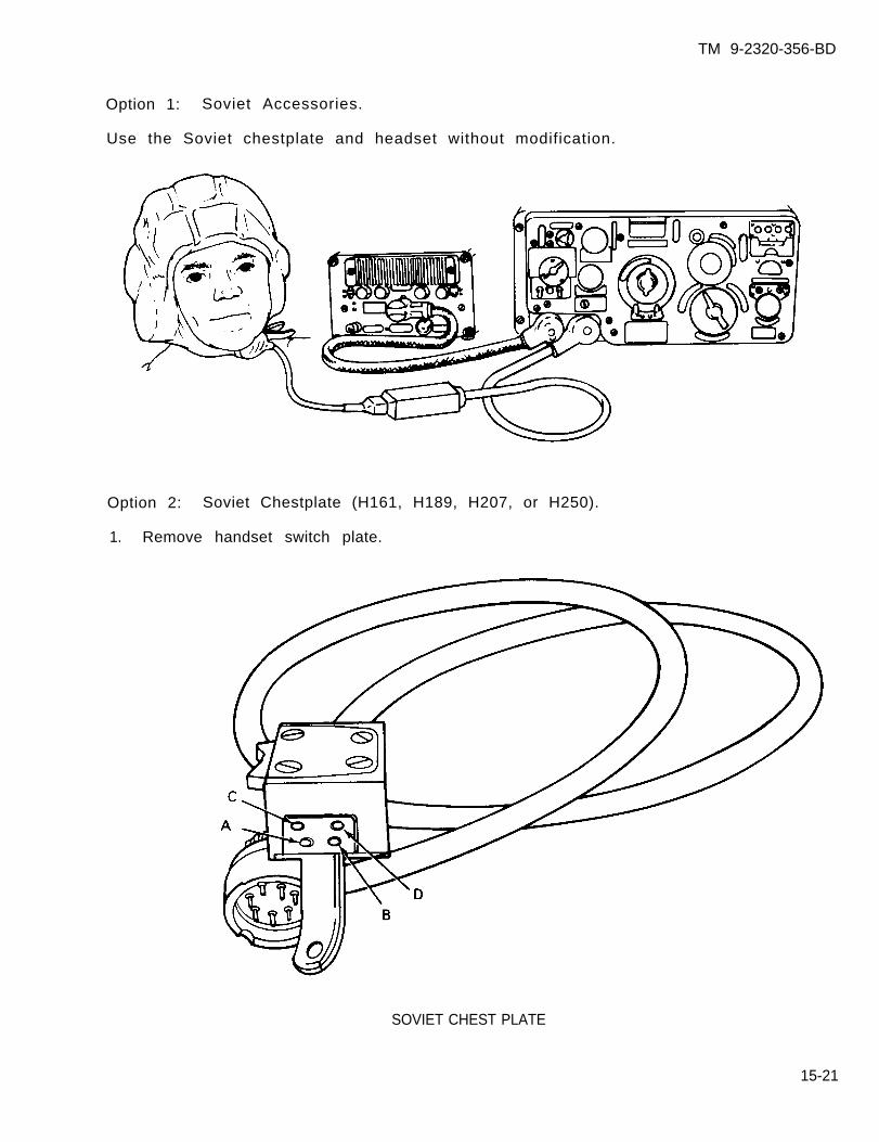
TM 9-2320-356-BD
Option 1: Soviet Accessories.
Use the Soviet chestplate and headset without modification.
Option 2: Soviet Chestplate (H161, H189, H207, or H250).
1. Remove handset switch plate.
SOVIET CHEST PLATE
15-21

TM 9-2320-356-BD
REDWHT
SHIELD
GRN
BLK
HANDSET SWITCH PLATE
2. Connect four wires, 2 feet long, to the black, white, green, and red wireconnections on the handset switch.
3. Connect the jumper wire from the black wire to one of the inside jacks (pointA) on the Soviet chestplate.
4. Connect the jumper wire from the white wire to the other inside jack (point B).
Connect the jumper wire from the green wire to one of the outside jacks (point C).
6. C o n n e c t t h e j u m p e r w i r e t o t h e o t h e r o u t s i d e j a c k ( p o i n t D ) .
7. Reverse the jumper wires at points C and D on the Soviet chestplate if you canreceive but not transmit.
8. Record the BDAR action taken. When the mission is completed, as soon aspract icab le , repair using standard maintenance procedures.
15-22
5 .
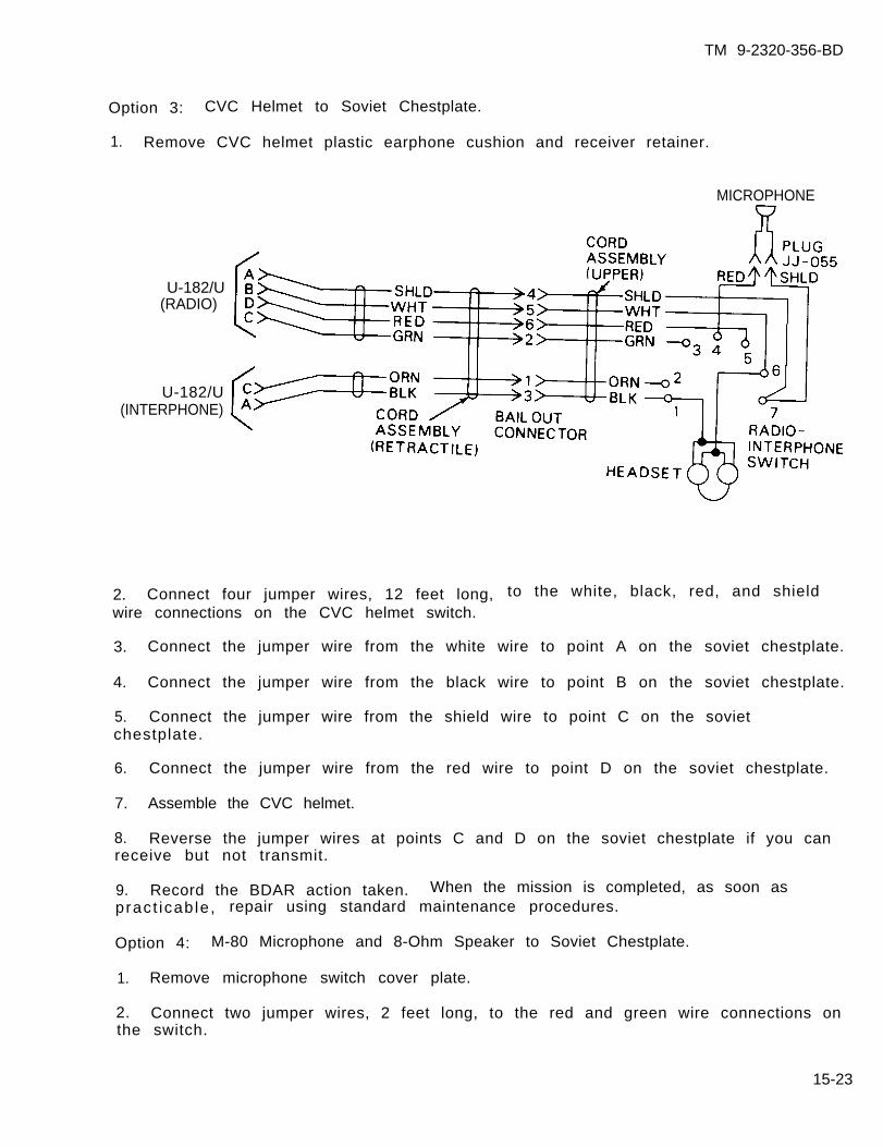
TM 9-2320-356-BD
Option 3: CVC Helmet to Soviet Chestplate.
1. Remove CVC helmet plastic earphone cushion and receiver retainer.
MICROPHONE
U-182/U(RADIO)
U-182/U(INTERPHONE)
2. Connect four jumper wires, 12 feet long, to the white, black, red, and shieldwire connections on the CVC helmet switch.
3. Connect the jumper wire from the white wire to point A on the soviet chestplate.
4. Connect the jumper wire from the black wire to point B on the soviet chestplate.
5. Connect the jumper wire from the shield wire to point C on the sovietchestplate.
6. Connect the jumper wire from the red wire to point D on the soviet chestplate.
7. Assemble the CVC helmet.
8. Reverse the jumper wires at points C and D on the soviet chestplate if you canreceive but not transmit.
9. Record the BDAR action taken. When the mission is completed, as soon aspract icab le , repair using standard maintenance procedures.
Option 4: M-80 Microphone and 8-Ohm Speaker to Soviet Chestplate.
1. Remove microphone switch cover plate.
2. Connect two jumper wires, 2 feet long, to the red and green wire connections onthe switch.
15-23
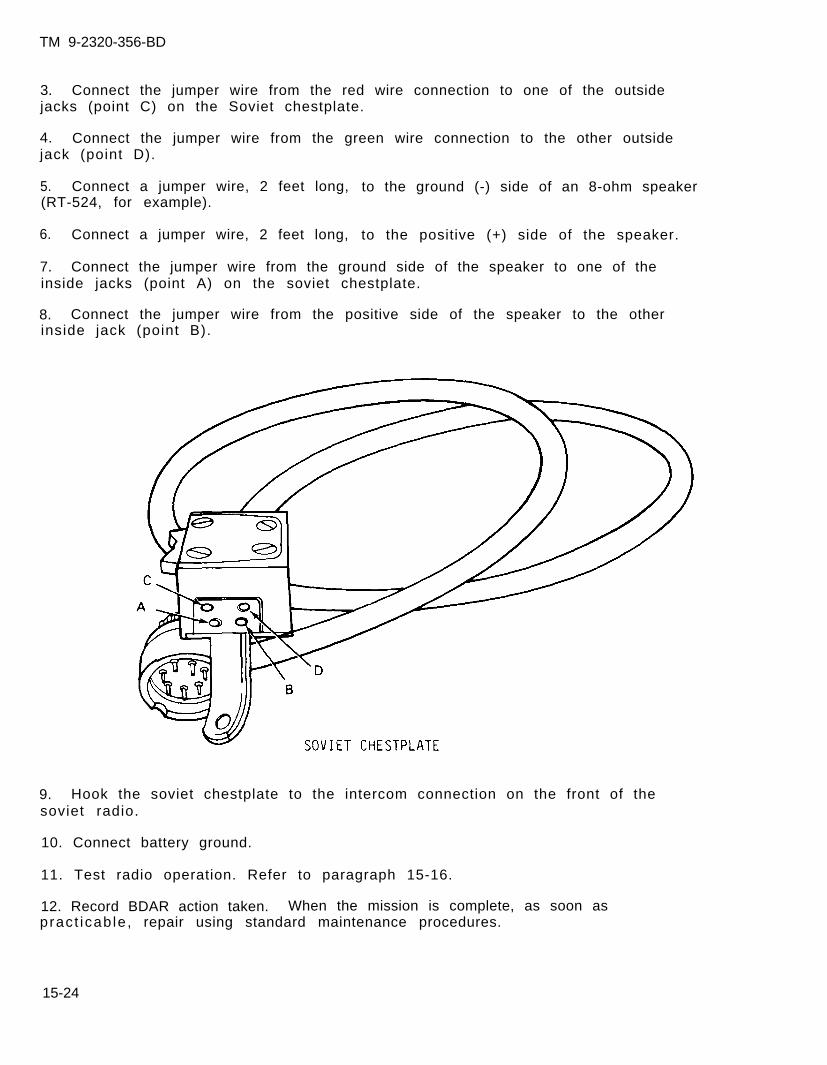
TM 9-2320-356-BD
3. Connect the jumper wire from the red wire connection to one of the outsidejacks (point C) on the Soviet chestplate.
4. Connect the jumper wire from the green wire connection to the other outsidejack (point D).
5. Connect a jumper wire, 2 feet long, to the ground (-) side of an 8-ohm speaker(RT-524, for example).
6. Connect a jumper wire, 2 feet long, to the positive (+) side of the speaker.
7. Connect the jumper wire from the ground side of the speaker to one of theinside jacks (point A) on the soviet chestplate.
8. Connect the jumper wire from the positive side of the speaker to the otherinside jack (point B).
9. Hook the soviet chestplate to the intercom connection on the front of thesoviet radio.
10. Connect battery ground.
11. Test radio operation. Refer to paragraph 15-16.
12. Record BDAR action taken. When the mission is complete, as soon aspract icab le , repair using standard maintenance procedures.
15-24
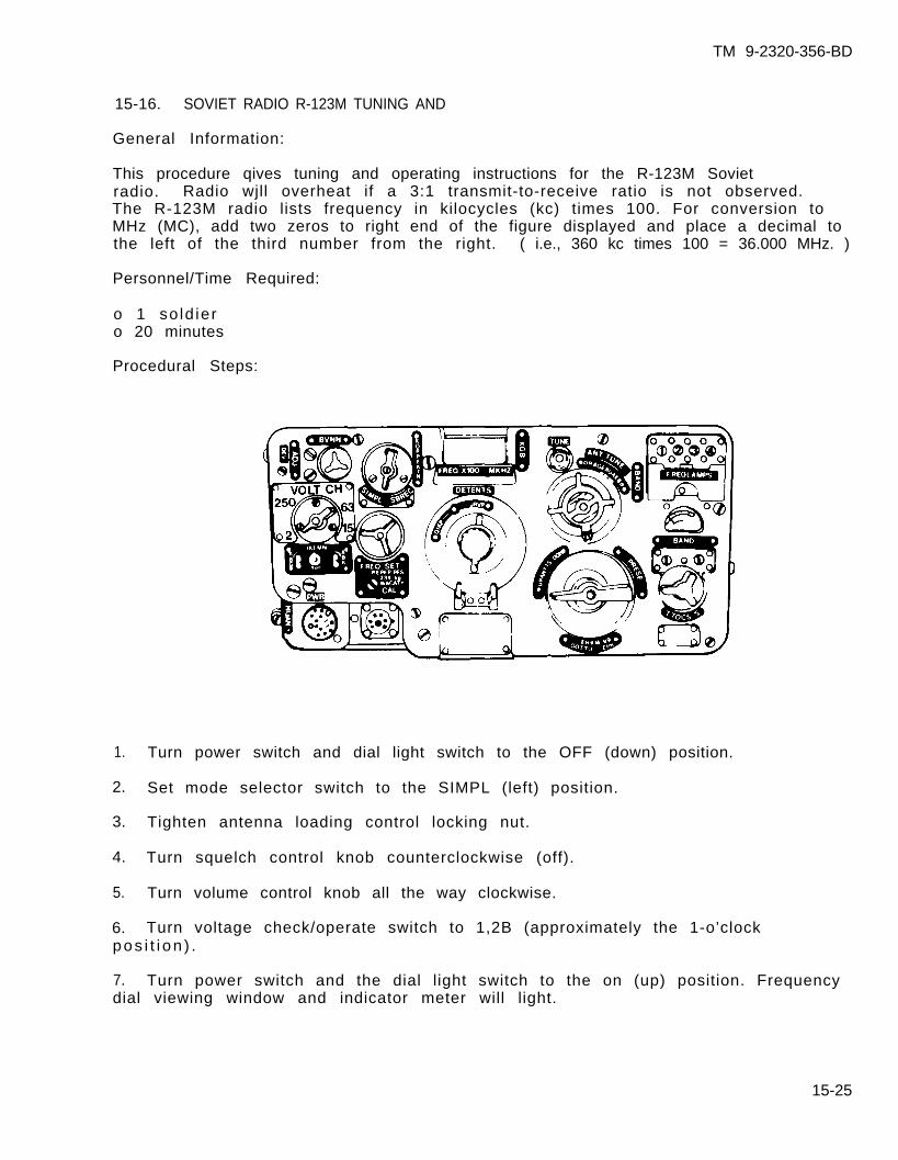
TM 9-2320-356-BD
15-16. SOVIET RADIO R-123M TUNING AND
General Information:
This procedure qives tuning and operating instructions for the R-123M Sovietradio. Radio wjll overheat if a 3:1 transmit-to-receive ratio is not observed.The R-123M radio lists frequency in kilocycles (kc) times 100. For conversion toMHz (MC), add two zeros to right end of the figure displayed and place a decimal tothe left of the third number from the right. ( i.e., 360 kc times 100 = 36.000 MHz. )
Personnel/Time Required:
o 1 so ld iero 20 minutes
Procedural Steps:
1. Turn power switch and dial light switch to the OFF (down) position.
2. Set mode selector switch to the SIMPL (left) position.
3. Tighten antenna loading control locking nut.
4. Turn squelch control knob counterclockwise (off).
5. Turn volume control knob all the way clockwise.
6. Turn voltage check/operate switch to 1,2B (approximately the 1-o’clockpos i t i on ) .
7. Turn power switch and the dial light switch to the on (up) position. Frequencydial viewing window and indicator meter will light.
15-25
TM 9-2320-356-BD
8. Allow the tubes to heat until a rushing noise is heard in the speaker/headset.
9. Adjust volume control knob for the desired volume level.
CAUTION
The receiver and transmitter are tuned simultane-ously. Do not operate the transmitter withoutusing an antenna. Transmitting without connect-ing an antenna will damage the transmitter por-t ion of the radio.
10.
11.
12.
Turn voltage check/operate switch clockwise to the 6, 3B position. The needleon indicator meter should be in the shaded portion of the scale.
Turn the voltage check/operate switch to the 150B position. The needle on theindicater meter should be in the shaded portion of the scale.
Check the power supply for bad fuses and replace or jumper any bad ones if theneedle was not in the shaded area.
13. Turn the voltage check/operate switch to the 1,2B position on the scale(approximately the 7-o’clock posit ion). Indicator meter should read in the shadedportion of the scale.
14. If the meter reading was not in the shaded portion of the scale, check thepower supply for bad fuses and replace or jumper any bad ones.
15. Turn voltage check/operate switch to the 150B position.
16. Momentarily place the chest plate switch switch in the transmit position. Thereading on indicator meter should be in the shaded portion of the scale.
17. Turn voltage check/operate switch to the 250B position.
18. Momentarily place the chest plate switch in the transmit position. The readingon indicator meter should be in the shaded porton of the scale.
19. If the meter reading was not in the shaded portion, check the power supply forbad fuses and replace or jumper any bad ones.
20. Turn voltage check/operate switch to the 600B position.
21. Momentarily press the switch to transmit. The reading should be in the shadedportion of the scale.
22. If the meter reading was not in the shaded portion, check the power supply forbad fuses and replace or jumper any bad ones.
23. Turn voltage check/operate switch to the PAboTA1 (operate) position.
15-26
TM 9-2320-356-BD
24. Turn preset channel/continuous tune selector switch to the I or II position.Position I is used if the operating frequency is between 20 and 35.75 MHz.Position II is used if the operating frequency is between 25.8 and 51.5 MHz. Bandselection is shown by band indicator lights.
25. Rotate frequency tuning knob to the frequency listed that is the closest to theoperating frequency.
Band I: 22.050 MHz 28.350 MHz 34.650 MHzBand II: 36.225 MHz 40.950 MHz 42.525 MHz 45.675 MHz 48.825 MHz
The frequencies are marked on the frequency dial with an extended graduation linecapped by an arrowhead.
26. Turn mode selector switch to the SBREC (receive only) position.
27. Press and hold tone call button. A tone should be heard in the earphones.
28. Rotate frequency tuning knob. The tone heard should progress from a high pitchto a low pitch then to a high pitch again. The proper setting is the point betweenthe high tones and the lowest pitch or when totally absent.
29. Note the positions of the index line and the frequency graduation line throughfrequency dial viewing window.
30. Release tone call button.
31. Perform the following adjustment if the index line is not within one-fifth of agraduation (5 KHz):
a. Remove index line adjustment plug.
b. Rotate the adjustment right and left with a screwdriver until the index lineis alined with the frequency graduation line.
c. Replace index line adjustment plug.
32. Return mode selector switch to the SIMPL position (left).
33. Turn preset channel/continuous tune selector switch to position I or I I .
34. Open preset locking screw access cover on the front panel.
35. Release the preset locking screw with the special key (not shown) attached tothe case of the radio by turning the screw 90 degrees counterclockwise. Use thespecial key (not shown) attached to the case and turn preset locking screw 90degrees counterclockwise.
36. Turn frequency tuning knob to the desired frequency.
37. Hold frequency tuning knob and turn preset locking screw clockwise with thespecial key until the slot is pointed at the red dot.
15-27

TM 9-2320-356-BD
38. Loosen antenna loading control locking nut two or three turns.
39. Push the chestplate switch to the transmit position and hold.
40. Turn antenna loading control knob. Several peaks will be noted on indicatormeter. Tune to the greatest peak.
41. Release the chestplate switch.
42. Hold antenna loading control knob and tighten antenna loading control lockingnut.
43. Press the Soviet chestplate switch to transmit. Release to receive.
44. Record BDAR action taken. When the mission is complete, as soon aspract icab le , repair using standard maintenance procedures.
15-17. FIELD EXPEDIENT RADIO REMOTE
General Information:
This procedure gives instructions for the construction of a field expedient remoteto replace the AN/GRA-39 if it is inoperative. Build the radio remote unit usingthe schematic.
Personnel/Time Required: Mater ia ls /Tools :
o 1 so ld ier o0 1 hour o
0
0
0
0
0
0
000
680-ohm resistor47-ohm resistor5000-ohm variablepotentiometerH-144/U handset (only cordand plug used)M-80 microphone (only cordand plug used)K-1 relay (28 V dc)(NSN 5945-00-951-6458BA-4386/U batteryAN/PRC-77 battery)(NSN 6135-00-926-8322)TA-312/PT field telephones(two each)Elect r ica l tape18- or 24-gage wireSoldering iron and solder
15-28

TM 9-2320-356-BD
Procedural Steps:
1. Cut the cords (at the handset end) from the H-144 handset and the M-80microphone.
2. Remove 6 inches of outer insulation from the cut end of each cord. Do not cutthe inner wires.
3. Remove 1/2 inch of insulation from the end of each inner wire.
4. Use a multimeter or continuity tester to match the wires with the pins in theplug using reference letters.
5. Arrange components in order shown in the schematic.
6. Solder the two resistors together at one end.
7. Solder all other wires to points referenced.
8. Tape the R-3 (5000-ohm) potentiometer, K-1 relay, and 6A-4386 battery(AN/PRC-77 battery) soldily together.
9. Connect the 5-pin connector to the RT-524 jack marked RETRANSMIT R/W.
10. Connect the 10-pin connector to the jack on a TA-312.
15-29
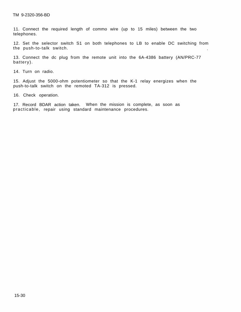
TM 9-2320-356-BD
11. Connect the required length of commo wire (up to 15 miles) between the twotelephones.
12. Set the selector switch S1 on both telephones to LB to enable DC switching fromthe push-to-talk switch. .
13. Connect the dc plug from the remote unit into the 6A-4386 battery (AN/PRC-77bat tery) .
14. Turn on radio.
15. Adjust the 5000-ohm potentiometer so that the K-1 relay energizes when thepush-to-talk switch on the remoted TA-312 is pressed.
16. Check operation.
17. Record BDAR action taken. When the mission is complete, as soon aspract icab le , repair using standard maintenance procedures.
15-30
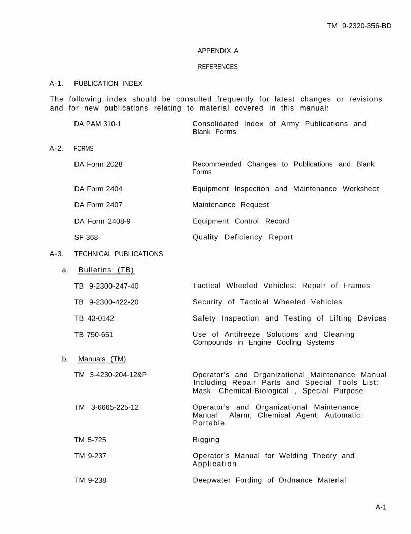
TM 9-2320-356-BD
APPENDIX A
REFERENCES
A-1. PUBLICATION INDEX
The following index should be consulted frequently for latest changes or revisionsand for new publications relating to material covered in this manual:
DA PAM 310-1 Consolidated Index of Army Publications andBlank Forms
A-2. FORMS
DA Form 2028 Recommended Changes to Publications and BlankForms
DA Form 2404 Equipment Inspection and Maintenance Worksheet
DA Form 2407 Maintenance Request
DA Form 2408-9 Equipment Control Record
SF 368 Quality Deficiency Report
A-3. TECHNICAL PUBLICATIONS
a. Bullet ins (TB)
TB 9-2300-247-40
TB 9-2300-422-20
TB 43-0142
TB 750-651
b. Manuals (TM)
TM 3-4230-204-12&P
TM 3-6665-225-12
TM 5-725
TM 9-237
Tactical Wheeled Vehicles: Repair of Frames
Security of Tactical Wheeled Vehicles
Safety Inspection and Testing of Lifting Devices
Use of Antifreeze Solutions and CleaningCompounds in Engine Cooling Systems
Operator’s and Organizational Maintenance ManualIncluding Repair Parts and Special Tools List:Mask, Chemical-Biological , Special Purpose
Operator’s and Organizational MaintenanceManual: Alarm, Chemical Agent, Automatic:Portable
Rigging
Operator’s Manual for Welding Theory andAppl icat ion
TM 9-238 Deepwater Fording of Ordnance Material
A-1
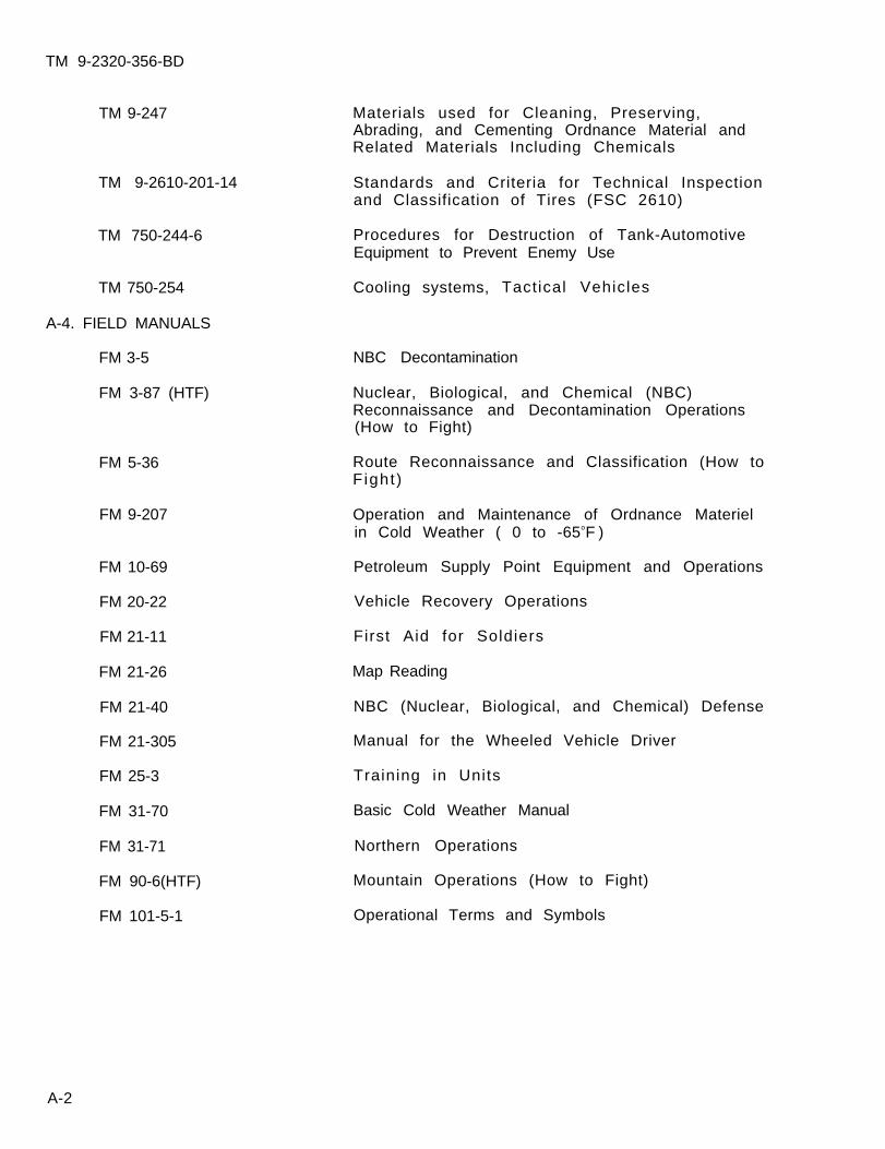
TM 9-2320-356-BD
TM 9-247
TM 9-2610-201-14
TM 750-244-6
TM 750-254
A-4. FIELD MANUALS
FM 3-5
FM 3-87 (HTF)
FM 5-36
FM 9-207
FM 10-69
FM 20-22
FM 21-11
FM 21-26
FM 21-40
FM 21-305
FM 25-3
FM 31-70
FM 31-71
FM 90-6(HTF)
FM 101-5-1
Materials used for Cleaning, Preserving,Abrading, and Cementing Ordnance Material andRelated Materials Including Chemicals
Standards and Criteria for Technical Inspectionand Classification of Tires (FSC 2610)
Procedures for Destruction of Tank-AutomotiveEquipment to Prevent Enemy Use
Cooling systems, Tactical Vehicles
NBC Decontamination
Nuclear, Biological, and Chemical (NBC)Reconnaissance and Decontamination Operations(How to Fight)
Route Reconnaissance and Classification (How toFight )
Operation and Maintenance of Ordnance Materielin Cold Weather ( 0 to -65oF )
Petroleum Supply Point Equipment and Operations
Vehicle Recovery Operations
First Aid for Soldiers
Map Reading
NBC (Nuclear, Biological, and Chemical) Defense
Manual for the Wheeled Vehicle Driver
Training in Units
Basic Cold Weather Manual
Northern Operations
Mountain Operations (How to Fight)
Operational Terms and Symbols
A-2
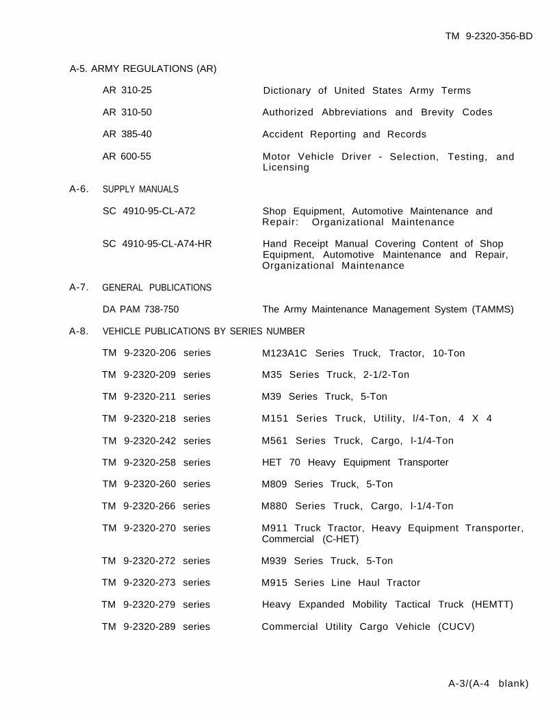
TM 9-2320-356-BD
A-5. ARMY REGULATIONS (AR)
AR 310-25 Dictionary of United States Army Terms
AR 310-50 Authorized Abbreviations and Brevity Codes
AR 385-40 Accident Reporting and Records
AR 600-55 Motor Vehicle Driver - Selection, Testing, andLicensing
A-6. SUPPLY MANUALS
SC 4910-95-CL-A72 Shop Equipment, Automotive Maintenance andRepair: Organizational Maintenance
SC 4910-95-CL-A74-HR Hand Receipt Manual Covering Content of ShopEquipment, Automotive Maintenance and Repair,Organizational Maintenance
A-7. GENERAL PUBLICATIONS
DA PAM 738-750 The Army Maintenance Management System (TAMMS)
A-8. VEHICLE PUBLICATIONS BY SERIES NUMBER
TM 9-2320-206 series M123A1C Series Truck, Tractor, 10-Ton
TM 9-2320-209 series M35 Series Truck, 2-1/2-Ton
TM 9-2320-211 series M39 Series Truck, 5-Ton
TM 9-2320-218 series M151 Series Truck, Utility, l/4-Ton, 4 X 4
TM 9-2320-242 series M561 Series Truck, Cargo, l-1/4-Ton
TM 9-2320-258 series HET 70 Heavy Equipment Transporter
TM 9-2320-260 series M809 Series Truck, 5-Ton
TM 9-2320-266 series M880 Series Truck, Cargo, l-1/4-Ton
TM 9-2320-270 series M911 Truck Tractor, Heavy Equipment Transporter,Commercial (C-HET)
TM 9-2320-272 series M939 Series Truck, 5-Ton
TM 9-2320-273 series M915 Series Line Haul Tractor
TM 9-2320-279 series Heavy Expanded Mobility Tactical Truck (HEMTT)
TM 9-2320-289 series Commercial Utility Cargo Vehicle (CUCV)
A-3/(A-4 blank)
TM 9-2320-356-BD
APPENDIX B
SPECIAL AND FABRICATED TOOLS/WELDING EXPEDIENTS
BDAR FIXES SHALL BE USED ONLY IN COMBATAT THE DISCRETION OF THE COMMANDER
AND SHALL BE REPAIRED BY STANDARD MAINTENANCE PROCEDURESAS SOON AS PRACTICABLE AFTER THE MISSION IS COMPLETED.
Section I. GENERAL
B-1. SCOPE
This appendix lists items recommended for the support of the vehicle in a combatenvironment. The items listed may be required for battlefield damage assessmentand repair at maintenance levels from crew thru DS. Also listed are expedienttools for performing BDAR repairs using nonstandard equipment.
B-1
TM 9-2320-356-BD
B-2. GENERAL
Section II. T O O L S
Tools listed in this appendix will enhance crew members and mechanics at all levelsto accomplish battlefield damage and assessment repairs in a more expedientmanner. Some tools listed may already be on hand in the unit.
The column marked Level indicates the maintenance level at which these items bestocked or carried. The unit commander may modify the items in the list and themaintenance levels carrying the items, based on current mission requirements andrecent operational experience.
The items marked C (Crew) are recommended to be carried on the vehicle for use incombat emergencies at the discretion of the unit commander. Those items marked MTare recommended to be carried by each battlefield damage assessment and repairmaintenance team (MT). Some of these items may already be available atorganizational maintenance; however, additional items will be required to stockeach MT. Those items marked 0 are recommended to be stocked at organizational andthose marked MST are recommended to be carried by the DS maintenance support teams(MST).
B-2

ITEMNUMBER
1
2
3
4
5
6
7
8
9
10
11
12
13
14
15
16
17
18
19
LEVEL NSN
C
C
MT
MT
MT
C
C
C
C
C
C
C
C
C
C
C
C
C
C
5110-00-277-4591
5110-00-927-1063
5120-00-203-6431
5120-00-278-2423
5120-00-278-6520
5120-00-227-8074
5110-00-241-91535110-00-241-9156
5110-00-234-6559
5110-00-289-9657
4940-00-561-1002
5110-00-263-0349
5110-00-240-5943
5120-00-221-1536
5120-00-239-8251
5120-00-247-5177
5120-00-278-0352
5120-00-624-8065
5120-00-293-0448
TM 9-2320-356-BD
EXPENDABLE TOOLS
DESCRIPTION
Blade, hand hacksaw: 24 teeth per in., 10in . l g
Blade, hacksaw, flat (tungsten)
Clamp, C: 6 in. (two required)
Crimping Tool: terminal, hand w/cutting pin,s t ipper
Cutter, tubing, close quarters
Extension, socket wrench: 1/2 in. sq dr 10in . l g
File, hand: half rnd, 10 in.
F i le , hand: rnd s ty le
Frame, hand hacksaw, 10 in. and 12 in. bladeaccommodated
Gun, thermal: PN 8031088
Handle, f i le
Knife, pocket: w/clevis, screwdriver, wirescraper, and cutting blade
Kni fe , put ty
Lifter, roadwheel arm
Pliers: l ineman’s, w/side cutter, 8 in.
Pl iers: rnd nose w/cutter, 6 in.
P l i e r s , s l i p j o i n t : angle nose, multipletongue and groove, 10 in.
P l i e r s , s l i p j o i n t : conduit, w/o hall, w/removable plast ic inserts, 9 in. lg
Punch, al ining: 3/16 in. pt, 8 in. lg,3/8 in. dia
B-3
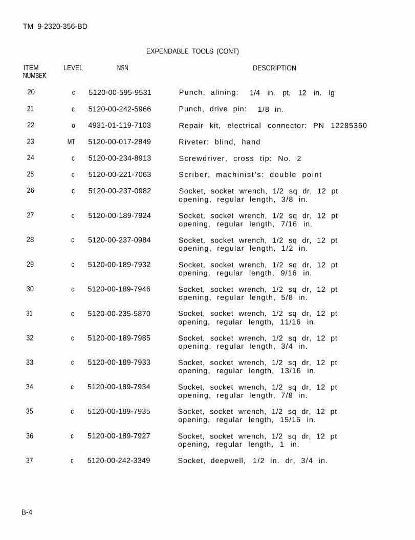
TM 9-2320-356-BD
EXPENDABLE TOOLS (CONT)
ITEM LEVEL NSNNUMBEK
20
21
22
23
24
25
26
27
28
29
30
31
32
33
34
35
36
37
c
c
o
MT
c
c
c
c
c
c
c
c
c
c
c
c
c
c
5120-00-595-9531
5120-00-242-5966
4931-01-119-7103
5120-00-017-2849
5120-00-234-8913
5120-00-221-7063
5120-00-237-0982
5120-00-189-7924
5120-00-237-0984
5120-00-189-7932
5120-00-189-7946
5120-00-235-5870
5120-00-189-7985
5120-00-189-7933
5120-00-189-7934
5120-00-189-7935
5120-00-189-7927
5120-00-242-3349
DESCRIPTION
Punch, al ining: 1/4 in. pt, 12 in. lg
Punch, drive pin: 1/8 in.
Repair kit, electrical connector: PN 12285360
Riveter: bl ind, hand
Screwdriver, cross t ip: No. 2
Scr iber , machin is t ’s : double po in t
Socket, socket wrench, 1/2 sq dr, 12 ptopening, regular length, 3/8 in.
Socket, socket wrench, 1/2 sq dr, 12 ptopening, regular length, 7/16 in.
Socket, socket wrench, 1/2 sq dr, 12 ptopening, regular length, 1/2 in.
Socket, socket wrench, 1/2 sq dr, 12 ptopening, regular length, 9/16 in.
Socket, socket wrench, 1/2 sq dr, 12 ptopening, regular length, 5/8 in.
Socket, socket wrench, 1/2 sq dr, 12 ptopening, regular length, 11/16 in.
Socket, socket wrench, 1/2 sq dr, 12 ptopening, regular length, 3/4 in.
Socket, socket wrench, 1/2 sq dr, 12 ptopening, regular length, 13/16 in.
Socket, socket wrench, 1/2 sq dr, 12 ptopening, regular length, 7/8 in.
Socket, socket wrench, 1/2 sq dr, 12 ptopening, regular length, 15/16 in.
Socket, socket wrench, 1/2 sq dr, 12 ptopening, regular length, 1 in.
Socket, deepwell, 1/2 in. dr, 3/4 in.
B-4
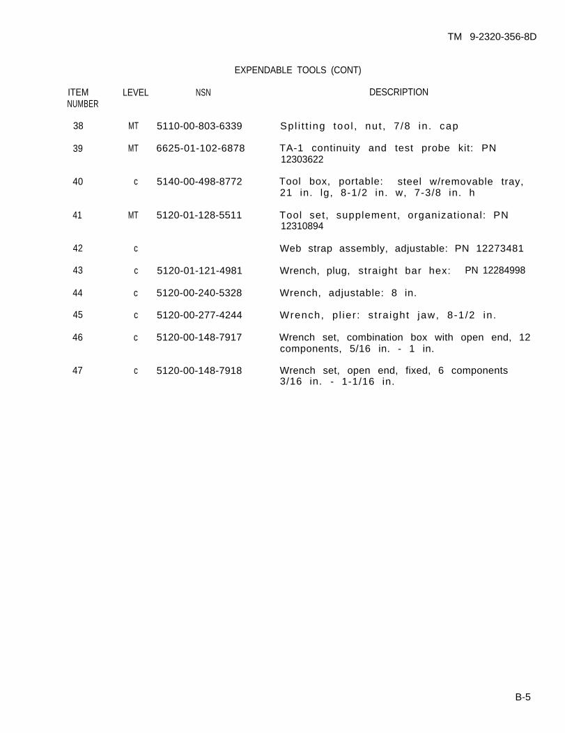
ITEMNUMBER
38
39
40
41
42
43
44
45
46
47
LEVEL NSN
MT 5110-00-803-6339
MT 6625-01-102-6878
c 5140-00-498-8772
MT 5120-01-128-5511
c
c 5120-01-121-4981
c 5120-00-240-5328
c 5120-00-277-4244
c 5120-00-148-7917
c 5120-00-148-7918
TM 9-2320-356-8D
EXPENDABLE TOOLS (CONT)
DESCRIPTION
Spl i t t ing too l , nut , 7 /8 in . cap
TA-1 continuity and test probe kit: PN12303622
Tool box, portable: steel w/removable tray,21 in. lg, 8-1/2 in. w, 7-3/8 in. h
Tool set, supplement, organizational: PN12310894
Web strap assembly, adjustable: PN 12273481
Wrench, plug, straight bar hex: PN 12284998
Wrench, adjustable: 8 in.
Wrench, p l ie r : s t ra ight jaw, 8-1 /2 in .
Wrench set, combination box with open end, 12components, 5/16 in. - 1 in.
Wrench set, open end, fixed, 6 components3/16 in. - 1-1/16 in.
B-5
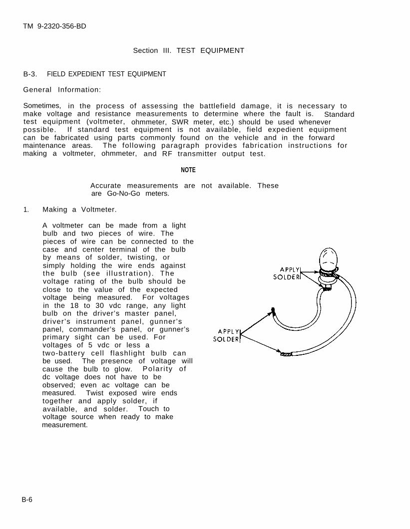
TM 9-2320-356-BD
Section III. TEST EQUIPMENT
B-3. FIELD EXPEDIENT TEST EQUIPMENT
General Information:
Sometimes, in the process of assessing the battlefield damage, it is necessary tomake voltage and resistance measurements to determine where the fault is. Standardtest equipment (voltmeter, ohmmeter, SWR meter, etc.) should be used wheneverpossible. If standard test equipment is not available, field expedient equipmentcan be fabricated using parts commonly found on the vehicle and in the forwardmaintenance areas. The fol lowing paragraph provides fabricat ion instruct ions formaking a voltmeter, ohmmeter, and RF transmitter output test.
NOTE
Accurate measurements are not available. Theseare Go-No-Go meters.
1. Making a Voltmeter.
A voltmeter can be made from a lightbulb and two pieces of wire. Thepieces of wire can be connected to thecase and center terminal of the bulbby means of solder, twisting, orsimply holding the wire ends againstthe bu lb (see i l lus t ra t ion) . Thevoltage rating of the bulb should beclose to the value of the expectedvoltage being measured. For voltagesin the 18 to 30 vdc range, any lightbulb on the driver’s master panel,driver’s instrument panel, gunner’spanel, commander’s panel, or gunner’sprimary sight can be used. Forvoltages of 5 vdc or less atwo-battery cel l f lashl ight bulb canbe used. The presence of voltage willcause the bulb to glow. Polar i ty o fdc voltage does not have to beobserved; even ac voltage can bemeasured. Twist exposed wire endstogether and apply solder, ifavailable, and solder. Touch tovoltage source when ready to makemeasurement.
B-6
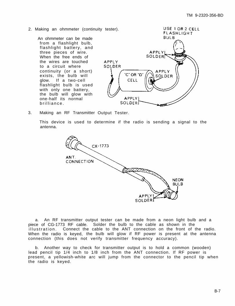
TM 9-2320-356-BD
2. Making an ohmmeter (continuity tester).
An ohmmeter can be madefrom a f lashlight bulb,f lash l ight bat tery , andthree pieces of wire.When the free ends ofthe wires are touchedto a circuit wherecontinuity (or a short)exists, the bulb wi l lglow. If a two-cel lf lashl ight bulb is usedwith only one battery,the bulb will glow withone-half its normalb r i l l i a n c e .
3. Making an RF Transmitter Output Tester.
This device is used to determine if the radio is sending a signal to theantenna.
a. An RF transmitter output tester can be made from a neon light bulb and apiece of CG-1773 RF cable. Solder the bulb to the cable as shown in thei l l u s t r a t i o n . Connect the cable to the ANT connection on the front of the radio.When the radio is keyed, the bulb will glow if RF power is present at the antennaconnection (this does not verify transmitter frequency accuracy).
b. Another way to check for transmitter output is to hold a common (wooden)lead pencil tip 1/4 inch to 1/8 inch from the ANT connection. If RF power ispresent, a yellowish-white arc will jump from the connector to the pencil tip whenthe radio is keyed.
B-7
TM 9-2320-356-BD
Section IV. WELDING EXPEDIENTS
B-4. CONTROLLED AMPERAGE
General Information:
Battlefield repairs requiring welding can be performed by using the auxiliarygenerator (Little Joe) from the M88 or generator recovery vehicle if a regularwelder is not available.
Limitations:
o Possible degraded armor protection
Personnel/Time Required:
o 2-soldiero 1-2 hours
Materials/Tools:
o Auxiliary generator (24 V dc)o Control unit from a welder or
similar controlo Welders helmet and gloveso Welding rod, coat hangers, or
barbed wireo Heavy-gage cable (2.0 gage
or larger)o Vise grips or clampso Fuel line
Other Options:
o Use uncontrolled amperage.o Weld using vehicle battery power.
Procedural Steps:
1. Remove auxiliary generator from M88 recovery vehicle and place close to area tobe welded. Connect heavy-gage cables to (+) and (-) output posts. Also connectcontrol unit to (+) and (-) output posts. Tighten terminal securely.
2. Connect negative (-) cable to tank hull with clamp close to area to be welded.Connect welding rod to positive (+) cable with vise grips. Insulate vise gripswith gloves, rags, or several layers of dry paper.
WARNING
Use welder’s helmet to protect eyes and facefrom arc. Do not touch exposed cable or visegrips with bare hands; metal gets very hot. Donot perform this task in rain or on wet groundbecause of electrical shock hazard.
3. Start auxiliary generator, strike arc, and weld. Set control unit for amperagelevel required by the thickness of
4. Record the BDAR action taken.practicable, repair using standard
B-8
the metal.
When the mission is completed, as soon asmaintenance procedures.
TM 9-2320-356-BD
B-5. UNCONTROLLED AMPERAGE
General Information:
Battlefield repairs requiring welding can be accomplished by using auxiliarygenerator (Little Joe) M88 recovery vehicle or a generator if a regular welder isnot available. Welding will be difficult without amperage control.
L imi ta t ions:
o Possible degraded armor protection
Personnel/Time Required:
o 2 so ld ierso 1-3 hours (24 V dc)
o Heavy gage cable(2.0 gage minimum)
o Vise grips or clampso Fue l l i neo Welder helmet and gloveso Welding rod, coat
hangers, or barbed wire
Other Options:
Weld using the vehicle battery power
Procedural Steps:
1. Remove auxiliary generator from M88 recovery vehicle and place close to area tobe welded. Connect heavy gage cables (+) and (-) output posts and tighten securely.
2. Connect negative (-) cable to vehicle hull with clamp close to area to bewelded. Connect welding rod to positive (+) cable with vise grip and insulate areaagainst heat with gloves, rags, or several layers of dry paper.
WARNING
Use welder’s helmet to protect eyes and facefrom arc. Do not touch exposed cable or visegrips with bare hands; metal will get very hot.Do not perform this task in rain or on wetground because of possible electric shock hazard.
3. Start auxiliary generator, strike arc, and weld. Use small diameter weldingrod for thin metal; use large welding rod for thick metal. Continue to weld untilrepa i r i s sa t is fac tory .
4. Record the BDAR action taken. When the mission is completed, as soon aspracticable, repair using standard maintenance procedures.
B-9
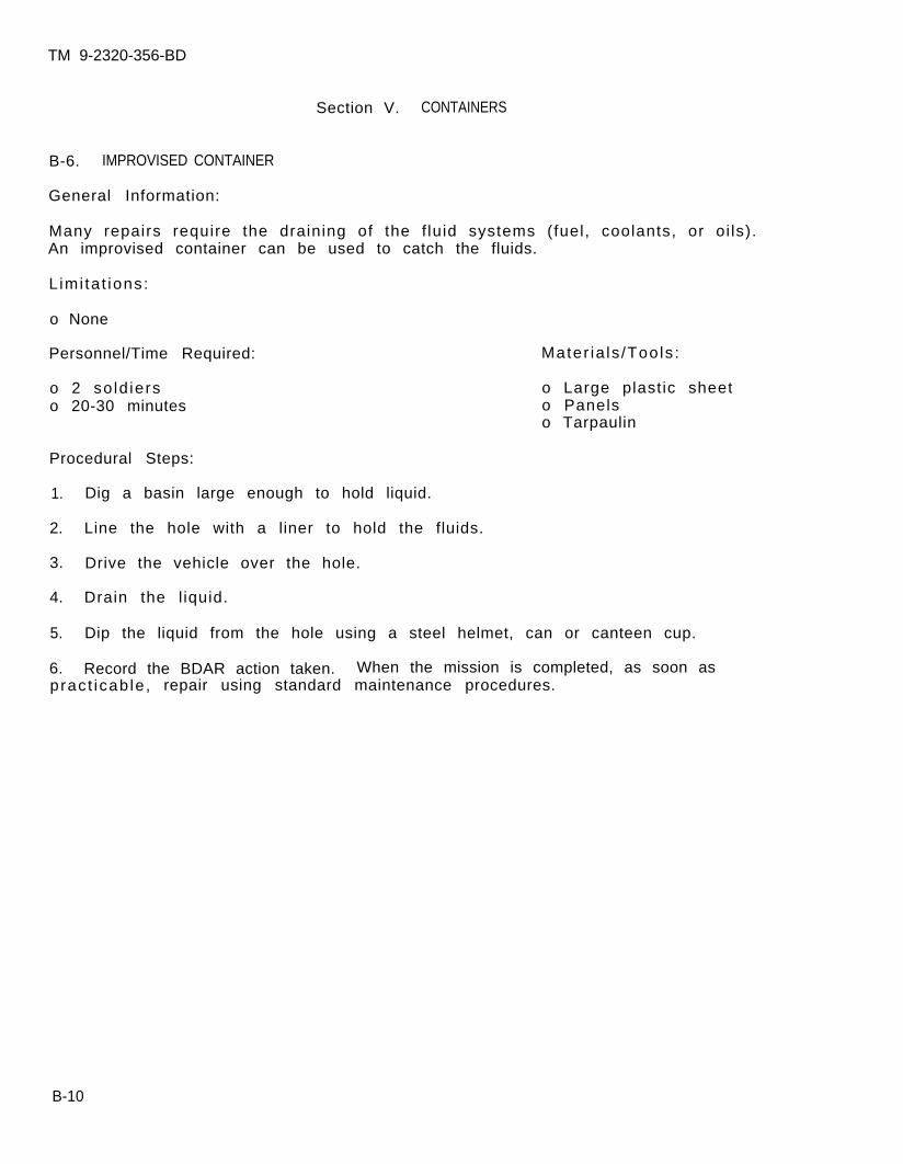
TM 9-2320-356-BD
Section V. CONTAINERS
B-6. IMPROVISED CONTAINER
General Information:
Many repairs require the draining of the f luid systems (fuel, coolants, or oi ls).An improvised container can be used to catch the fluids.
L imi ta t ions:
o None
Personnel/Time Required:
o 2 so ld ierso 20-30 minutes
Mater ia ls /Tools :
o Large plastic sheeto Panelso Tarpaulin
Procedural Steps:
1. Dig a basin large enough to hold liquid.
2. Line the hole with a liner to hold the fluids.
3. Drive the vehicle over the hole.
4. Drain the l iquid.
5. Dip the liquid from the hole using a steel helmet, can or canteen cup.
6. Record the BDAR action taken. When the mission is completed, as soon aspract icab le , repair using standard maintenance procedures.
B-10
TM 9-2320-356-BD
APPENDIX C
ALTERNATE SOURCES OF SUPPLY
BDAR FIXES SHALL BE USED ONLY IN COMBATAT THE DISCRETION OF THE COMMANDER
AND SHALL BE REPAIRED BY STANDARD MAINTENANCE PROCEDURESAS SOON AS PRACTICABLE AFTER THE MISSION IS COMPLETED.
Section I. GENERAL.
C-1. GENERAL
This appendix lists alternate sources of supply to include foreign ownership of UScombat vehicles and expendable supplies which may be utilized for repairs.
C-1

TM 9-2320-356-BD
Section II. FOREIGN OWNERSHIP OF US TACTICAL VEHICLES
C-2. GENERAL
Repair parts are expected to be in short supply. Parts may be available from othernations involved in the immediate combat areas. Friendly nations owning US weaponssystems may have stocks of repair parts or equipment available for cannibali-zation. The following tables identify nations owning American tactical vehicles.
Table C-1. US Tactical Vehicles Sold to Foreign Countries
(Countries That Purchased Vehicles)
1.2.3.4.5.6.7.8.9.
10.11.12.13.14.15.16.17.18.19.20.21.22.23.24.25.26.27.28.
M151 Series
Truck, Uti l i ty, 1/4-Ton, 4 x 4
ArgentinaBahrainBo l i v i aBraz i lCambodiaCameroonCanadaChadChi leChina (Taipei)ColombiaDenmarkDominican RepublicEgyptEl SalvadorEthiopiaF i j iFranceGhanaGreeceGuatemalaHondurasIndonesiaIranIsrae lJamaicaJordanKorea (Seoul)
29.30.31.32.33.34.35.36.37.38.39.40.41.42.43.44.45.46.47.48.49.50.51.52.53.54.55.56.
KuwaitLaosLebanonL ibe r i aLibyaLuxembourgMoroccoPakistanPanamaParaguayPeruPhi l ipp inesPortugalSaudi ArabiaSenegalSingaporeSomaliaSpainSudanThailandTunisiaTurkeyUnited KingdomUruguayVenezuelaVietnamYemen (Sana)Zai re
C-2
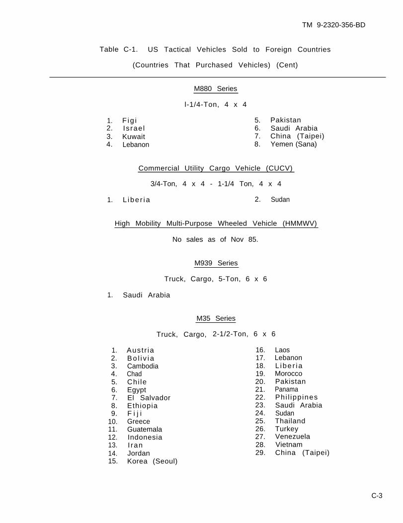
TM 9-2320-356-BD
Table C-1. US Tactical Vehicles Sold to Foreign Countries
(Countries That Purchased Vehicles) (Cent)
M880 Series
l-1/4-Ton, 4 x 4
1. F ig i 5. Pakistan2. Is rae l 6. Saudi Arabia3. Kuwait 7. China (Taipei)4. Lebanon 8. Yemen (Sana)
Commercial Utility Cargo Vehicle (CUCV)
3/4-Ton, 4 x 4 - 1-1/4 Ton, 4 x 4
1. L ibe r i a 2. Sudan
High Mobility Multi-Purpose Wheeled Vehicle (HMMWV)
No sales as of Nov 85.
M939 Series
Truck, Cargo, 5-Ton, 6 x 6
1. Saudi Arabia
M35 Series
Truck, Cargo, 2-1/2-Ton, 6 x 6
1.2.3.4.5.6.7.8.9.
10.11.12.13.14.15.
Aust r iaBo l i v i aCambodiaChadChi leEgyptEl SalvadorEthiopiaF i j iGreeceGuatemalaIndonesiaI ranJordanKorea (Seoul)
16.17.18.19.20.21.22.23.24.25.26.27.28.29.
LaosLebanonL ibe r i aMoroccoPakistanPanamaPhi l ipp inesSaudi ArabiaSudanThailandTurkeyVenezuelaVietnamChina (Taipei)
C-3
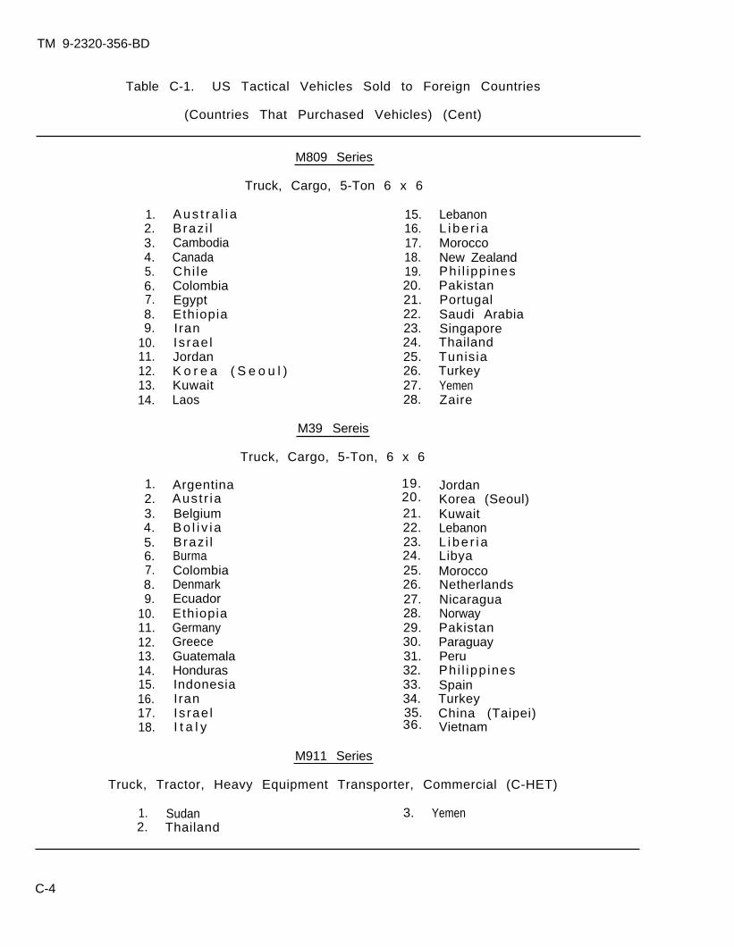
TM 9-2320-356-BD
Table C-1. US Tactical Vehicles Sold to Foreign Countries
(Countries That Purchased Vehicles) (Cent)
1.2.3.4.5.6.7.8.9.
10.11.12.13.14.
2.3.4.5.6.7.8.9.
10.11.12.13.14.15.16.17.18.
M809 Series
Truck, Cargo, 5-Ton 6 x 6
Aus t ra l i aBraz i lCambodiaCanadaChi leColombiaEgyptEthiopiaIranIsrae lJordanK o r e a ( S e o u l ) KuwaitLaos
15.16.17.18.19.20.21.22.23.24.25.26.27.28.
ArgentinaAust r iaBelgiumBo l i v i aBraz i lBurmaColombiaDenmarkEcuadorEthiopiaGermanyGreeceGuatemalaHondurasIndonesiaIranIsrae lI t a l y
M39 Sereis
Truck, Cargo, 5-Ton, 6 x 6
21.22.23.24.25.26.27.28.29.30.31.32.33.34.
LebanonL ibe r i aMoroccoNew ZealandPhi l ipp inesPakistanPortugalSaudi ArabiaSingaporeThailandTunisiaTurkeyYemenZaire
JordanKorea (Seoul)KuwaitLebanonL ibe r i aLibyaMoroccoNetherlandsNicaraguaNorwayPakistanParaguayPeruPhi l ipp inesSpainTurkeyChina (Taipei)Vietnam
M911 Series
Truck, Tractor, Heavy Equipment Transporter, Commercial (C-HET)
1. Sudan 3. Yemen2. Thailand
C-4
1. 19.20.
35.36.
TM 9-2320-356-BD
Sect ion I I I . EXPENDABLE SUPPLIES
C-3. GENERAL
a. This appendix lists items recommended for the support of combat vehicles ina combat environment. The list includes expendable supplies and materials whichmay be used to expedite BDAR repairs in a combat situation. The items listed maybe required for battlefield damage assessment and repair at maintenance levels fromcrew through DS.
b. The column marked Level indicates the maintenance level at which it isrecommended these items be stocked or carried. The unit commander may modify theitems in the list and the maintenance levels carrying the items, based on currentmission requirements and recent operational experience. The items marked C (Crew)are recommended to be carried on the vehicle for use in combat emergencies at thediscretion of the unit commander. Those items marked MT are recommended to becarried by each Battlefield Damage Assessment and Repair maintenance team (MT).Some of these items may already be available at organizational maintenance;however, additional items will be required to stock each MT. Those items marked Oare recommended to be stocked at organizational level, and those marked MST arerecommended to be carried by the DS maintenance support team (MST).
C-5
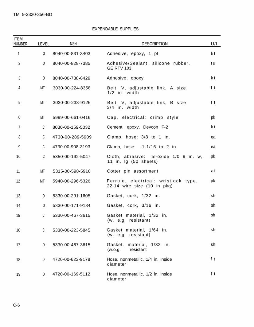
TM 9-2320-356-BD
EXPENDABLE SUPPLIES
ITEMNUMBER LEVEL NSN DESCRIPTION U/I
1
2
3
4
5
6
7
8
9
10
11
12
13
14
15
16
17
18
19
0
0
0
MT
MT
MT
C
C
C
C
MT
MT
0
0
C
C
0
0
0
8040-00-831-3403
8040-00-828-7385
8040-00-738-6429
3030-00-224-8358
3030-00-233-9126
5999-00-661-0416
8030-00-159-5032
4730-00-289-5909
4730-00-908-3193
5350-00-192-5047
5315-00-598-5916
5940-00-296-5326
5330-00-291-1605
5330-00-171-9134
5330-00-467-3615
5330-00-223-5845
5330-00-467-3615
4720-00-623-9178
4720-00-169-5112
Adhesive, epoxy, 1 pt
Adhesive/Sealant, si l icone rubber,GE RTV 103
Adhesive, epoxy
Belt , V, adjustable l ink, A size1/2 in. width
Belt , V, adjustable l ink, B size3/4 in. width
Cap, e lec t r ica l : c r imp s ty le
Cement, epoxy, Devcon F-2
Clamp, hose: 3/8 to 1 in.
Clamp, hose: 1-1/16 to 2 in.
Cloth, abrasive: al-oxide 1/0 9 in. w,11 in. lg (50 sheets)
Cotter pin assortment
Fe r ru l e , e l ec t r i ca l : w r i s t l ock t ype ,22-14 wire size (10 in pkg)
Gasket, cork, 1/32 in.
Gasket, cork, 3/16 in.
Gasket material, 1/32 in.(w. e.g. resistant)
Gasket material, 1/64 in.(w. e.g. resistant)
Gasket. material, 1/32 in.(w.o.g. resistant
Hose, nonmetallic, 1/4 in. insidediameter
Hose, nonmetallic, 1/2 in. insidediameter
k t
t u
k t
f t
f t
pk
k t
ea
ea
pk
at
pk
sh
sh
sh
sh
sh
f t
f t
C-6
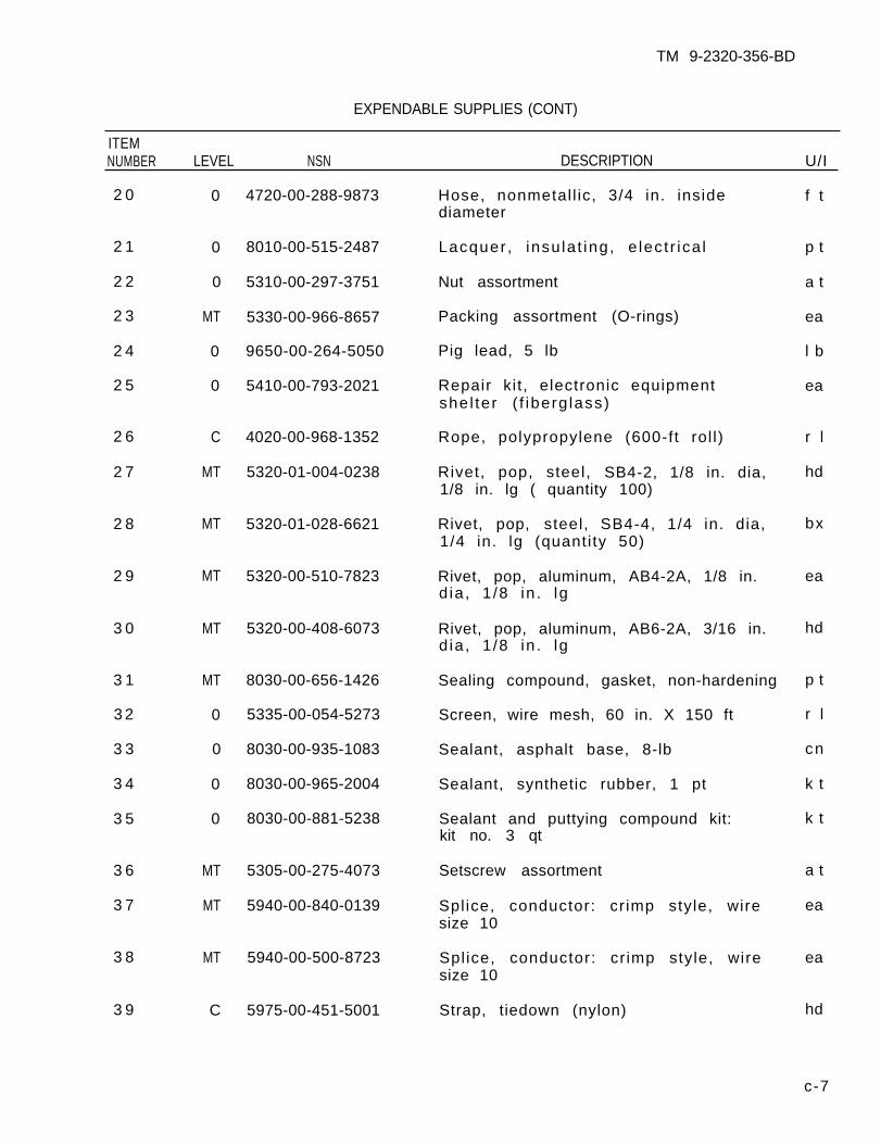
TM 9-2320-356-BD
EXPENDABLE SUPPLIES (CONT)
ITEMNUMBER LEVEL NSN DESCRIPTION U/I
2 0
2 1
2 2
2 3
2 4
2 5
2 6
2 7
2 8
2 9
3 0
3 1
3 2
3 3
3 4
3 5
3 6
3 7
3 8
3 9
0
0
0
MT
0
0
C
MT
MT
MT
MT
MT
0
0
0
0
MT
MT
MT
C
4720-00-288-9873
8010-00-515-2487
5310-00-297-3751
5330-00-966-8657
9650-00-264-5050
5410-00-793-2021
4020-00-968-1352
5320-01-004-0238
5320-01-028-6621
5320-00-510-7823
5320-00-408-6073
8030-00-656-1426
5335-00-054-5273
8030-00-935-1083
8030-00-965-2004
8030-00-881-5238
5305-00-275-4073
5940-00-840-0139
5940-00-500-8723
5975-00-451-5001
Hose, nonmetal l ic, 3/4 in. insidediameter
Lacquer , insu la t ing, e lec t r ica l
Nut assortment
Packing assortment (O-rings)
Pig lead, 5 lb
Repair kit , electronic equipmentshe l ter ( f iberg lass)
Rope, polypropylene (600-ft rol l)
Rivet, pop, steel, SB4-2, 1/8 in. dia,1/8 in. lg ( quantity 100)
Rivet, pop, steel, SB4-4, 1/4 in. dia,1/4 in. lg (quanti ty 50)
Rivet, pop, aluminum, AB4-2A, 1/8 in.d ia , 1 /8 in . lg
Rivet, pop, aluminum, AB6-2A, 3/16 in.d ia , 1 /8 in . lg
Sealing compound, gasket, non-hardening
Screen, wire mesh, 60 in. X 150 ft
Sealant, asphalt base, 8-lb
Sealant, synthetic rubber, 1 pt
Sealant and puttying compound kit:kit no. 3 qt
Setscrew assortment
Spl ice, conductor: cr imp style, wiresize 10
Splice, conductor: cr imp style, wiresize 10
Strap, tiedown (nylon)
f t
p t
a t
ea
l b
ea
r l
hd
bx
ea
hd
p t
r l
cn
k t
k t
a t
ea
ea
hd
c-7
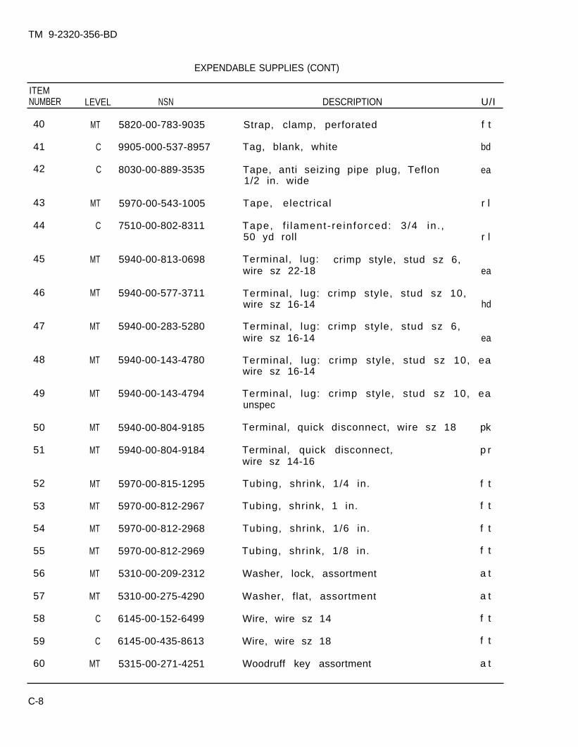
TM 9-2320-356-BD
EXPENDABLE SUPPLIES (CONT)
ITEMNUMBER LEVEL NSN DESCRIPTION U/I
40
41
42
43
44
45
46
47
48
49
50
51
52
53
54
55
56
57
58
59
60
MT
C
C
MT
C
MT
MT
MT
MT
MT
MT
MT
MT
MT
MT
MT
MT
MT
C
C
MT
5820-00-783-9035
9905-000-537-8957
8030-00-889-3535
5970-00-543-1005
7510-00-802-8311
5940-00-813-0698
5940-00-577-3711
5940-00-283-5280
5940-00-143-4780
5940-00-143-4794
5940-00-804-9185
5940-00-804-9184
5970-00-815-1295
5970-00-812-2967
5970-00-812-2968
5970-00-812-2969
5310-00-209-2312
5310-00-275-4290
6145-00-152-6499
6145-00-435-8613
5315-00-271-4251
Strap, clamp, perforated f t
Tag, blank, white bd
Tape, anti seizing pipe plug, Teflon ea1/2 in. wide
Tape, electr ical r l
Tape, f i lament- re in forced: 3 /4 in . ,50 yd roll r l
Terminal, lug: crimp style, stud sz 6,wire sz 22-18 ea
Terminal, lug: crimp style, stud sz 10,wire sz 16-14 hd
Terminal, lug: crimp style, stud sz 6,wire sz 16-14 ea
Terminal, lug: cr imp style, stud sz 10, eawire sz 16-14
Terminal, lug: cr imp style, stud sz 10, eaunspec
Terminal, quick disconnect, wire sz 18
Terminal, quick disconnect,wire sz 14-16
Tubing, shrink, 1/4 in.
Tubing, shrink, 1 in.
Tubing, shrink, 1/6 in.
Tubing, shrink, 1/8 in.
Washer, lock, assortment
Washer, flat, assortment
Wire, wire sz 14
Wire, wire sz 18
Woodruff key assortment
pk
p r
f t
f t
f t
f t
a t
a t
f t
f t
a t
C-8
TM 9-2320-356-BD
APPENDIX DPOL SUBSTITUTES
BDAR FIXES SHALL BE USED ONLY IN COMBATAT THE DISCRETION OF THE COMMANDER
AND SHALL BE REPAIRED BY STANDARD MAINTENANCE PROCEDURESAS SOON AS PRACTICABLE AFTER THE MISSION IS COMPLETED.
Section I. GENERAL
D-1. GENERAL
a. POL products available within the US and NATO military supply systems,commercial products, and captured products may be acceptable substitutes for POLshortages. Some POL will be destructive if used. This appendix provides tables onhow to blend or mix good fuels with poor or nonfuels to increase the availablequantity of fuel. This appendix also presents information on lubricants andhydrau l ic f lu ids . The tables divide POL products into three categories as follows:
(1) Primary. The correct product for the system.
(2 ) A l t e rna te . A product that closely matches the primary but will result inreduced performance. Using the alternate POL will have no effect of the durabilityof the system. There are no restrictions on the duration of use.
(3) Emergency or Expedient. A product that can be used for a short period oftime only. These products are a last resort only and will result in a significantreduction in performance and in serious harm to the system with continued use.
b. POL products are usually identified by NSNs or part numbers which identifythe product; however, specification numbers and product names may also be a meansof identi fying the product. Guidance provided is keyed to specification numbers,product names, application (automotive, aviation, marine), and the type of user(mil i tary, commercial, and foreign).
c. NATO products can usually be assumed to be direct replacements for USmil i tary products, but there are some products which do not meet the same userappl ica t ions. The American Society of Testing and Measurements (ASTM)specifications relate to commercial products found in the US.
d. This section wil l l ist a few elementary characterist ics of importance,although you will have no means of measuring or predicting them. You can use thebasic fuels, as provided, in order of priori ty. It will tell you how to mix one ormore fluids to produce a usable fuel and finally tell how to remove or flush a fuelfrom the system.
D-1
TM 9-2320-356-BD
e. Table D-1 identifies fuels or products that can be used as fuels. One ofthe best means to increase the available fuel is to use potential substitutes asextenders by mixing them with the primary fuels and not using them as the sole fuelsource. This allows some products which could not ordinarily be burned (or pumped)to be used by diluting them. Because of the dangers of varying combustibility offuels, increased by vaporizat ion during f i l l ing, the blending process is veryimportant. The most direct and expedient procedure to mix fuels is to add the twofuels at the same time from two separate fuel lines. If added directly to thevehicle fuel tanks as separate fuels there is not suff ic ient turbulence in f i l l ingor shaking by normal driving to provide a properly mixed fuel. In vehicles withmore than one tank, you could end up with a distinct fuel type in each tank.
D-2. FUEL BLENDING.
a. In following the blending procedure, it must be remembered that the basicfuel is the better of the two fuels and the extender is the poorer. The blendingfuel is the extender. While you can use up to 50 percent (half and half) of theextender you should not use more than is needed to obtain the supply needed. Also,ensure a fuel tank or container is available to hold the quantity of fuel needed toperform the mixing operation.
b. The preferred location to accomplish blending is at a fuel dispensing siteor in fuel dispensing vehicles that utilize their own pumps. The least desirableis using the vehicle’s fuel tanks. Blending in vehicle fuel tanks should only bedone as a last resort because it is imprecise and time consuming.
( 1 ) Blending in Fuel Dispensing Vehicles. Add the blending fuel to the fueltank and mix by connecting the pump inlet hose to the vehicle and recirculating thefuel for a minimum of 15 minutes.
(2) B lending in 55-Gallon Drums. Add the blending fuel directly into a drumand mix by rolling the drum.
(3) B lending in Gravity Feed Tanks (Stationary) not Equipped With FuelTransfer Pumps. Blending fuel can be added manually or by using the pump and meterof a fuel dispensing vehicle. Add the blending fuel and mix by recirculating fromthe tank outlet to the tank truck pump inlet.
NOTE
Blending in the fuel tanks of using equipmentand vehicles should be undertaken only as a lastresor t . Add both fuels to the fuel tank at thesame time with dual nozzles, or from fuel cans.
c. If expedient fuels are not used completely during the operation, they shouldbe drained or pumped out. Fill the vehicle fuel tanks with 10 to 15 gallons of anapproved primary fuel and operate the engine for at least 1/2 hour. Operate theengine under a load or drive the vehicle a sufficient distance to bring the engineup to operating temperature.
D-2
TM 9-2320-356-BD
D-3. LUBRICANTS AND HYDRAULIC FLUIDS
a. This section lists a few elementary characteristics of importance, althoughthere are no expedient means of measuring or predicting them. A list of basicfluids which can be used is provided in order of priority. Cautions onincompatible fluids are mentioned and a means suggested to flush the system.
Table D-2 provides a list of basic fluids which can be used as substitutes(alternate and expedient). It is structured around the vehicle lube order.Alternate products shown are NATO equivalents to the US specifications and canreally be considered as primary fluids. There are no corresponding ASTMdesignators. The expedients are emergency only substitutions. They may causethree problems, either individually or in combination.
(1) They may not al low proper or efficient operations because of improperv iscos i ty .
(2) They may cause high wear rate because of improper viscosity.
(3) They may cause seal damage or create deposits because of improper chemicalcomposition.
c. There are no established time constraints on these expedients, but theshorter the time used the better.
D-4. FLUSHING LUBRICANT AND HYDRAULIC SYSTEMS
a. Expedient lubricant and hydraulic fluids must be removed as soon aspossible, and the system cleaned and inspected.
b. For those systems using oils, f lush ing invo lves dra in ing; f i l l ing wi th theproper product; operating to ensure complete circulation and, when possible, stableoperating temperature (this usually means at least 1/2 hour); a redrain; and fill.For the transmission and hydraulic system, a second period of operations and athird drain and refi l l are needed. Ins ta l la t ion o f new f i l te rs is des i rab le .Filters must as a minimum be removed and cleaned. Operate without f i l ters onlyas a last resort . While systems should not be disassembled to inspect seals,maintenance organizations would be prepared to replace seals that show signs ofleaking. Organizations must observe seals on these systems during subsequentoperations.
c. For systems using grease, it is normally necessary to disassemble the systemand wash the parts, especial ly the bearings, in a suitable solvent. The parts arethen wiped dry, inspected for wear and pitting, replaced if needed, and packed withthe proper product.
D-3
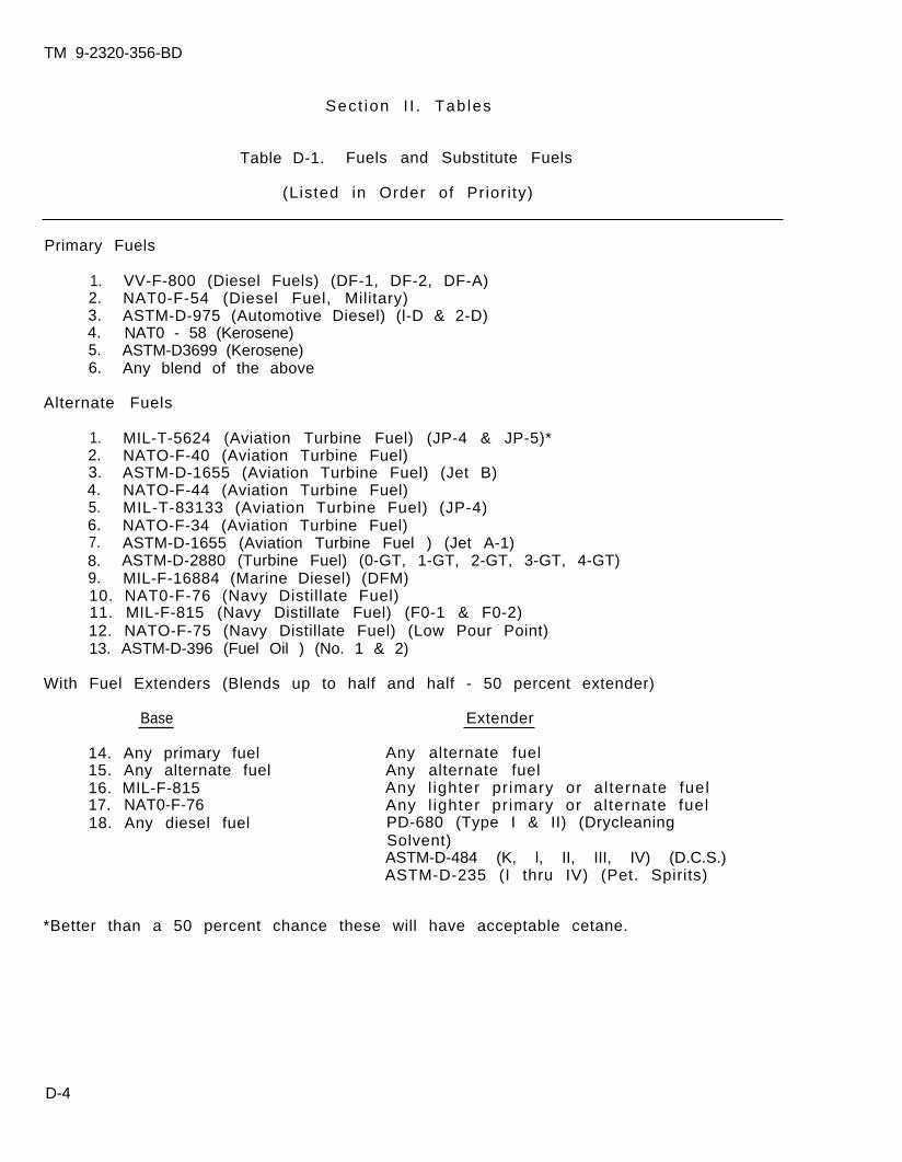
TM 9-2320-356-BD
Sect ion I I . Tab les
Table D-1. Fuels and Substitute Fuels
(Listed in Order of Prior i ty)
Primary Fuels
1. VV-F-800 (Diesel Fuels) (DF-1, DF-2, DF-A)2. NAT0-F-54 (Diesel Fuel, Military)3. ASTM-D-975 (Automotive Diesel) (l-D & 2-D)4. NAT0 - 58 (Kerosene)5. ASTM-D3699 (Kerosene)6. Any blend of the above
Alternate Fuels
1. MIL-T-5624 (Aviation Turbine Fuel) (JP-4 & JP-5)*2. NATO-F-40 (Aviation Turbine Fuel)3. ASTM-D-1655 (Aviation Turbine Fuel) (Jet B)4. NATO-F-44 (Aviation Turbine Fuel)5. MIL-T-83133 (Aviation Turbine Fuel) (JP-4)6. NATO-F-34 (Aviation Turbine Fuel)7. ASTM-D-1655 (Aviation Turbine Fuel ) (Jet A-1)8. ASTM-D-2880 (Turbine Fuel) (0-GT, 1-GT, 2-GT, 3-GT, 4-GT)9. MIL-F-16884 (Marine Diesel) (DFM)10. NAT0-F-76 (Navy Distillate Fuel)11. MIL-F-815 (Navy Distillate Fuel) (F0-1 & F0-2)12. NATO-F-75 (Navy Distillate Fuel) (Low Pour Point)13. ASTM-D-396 (Fuel Oil ) (No. 1 & 2)
With Fuel Extenders (Blends up to half and half - 50 percent extender)
Base Extender
14. Any primary fuel Any alternate fuel15. Any alternate fuel Any alternate fuel16. MIL-F-815 Any l ighter primary or alternate fuel17. NAT0-F-76 Any l ighter primary or alternate fuel18. Any diesel fuel PD-680 (Type I & II) (Drycleaning
Solvent)ASTM-D-484 (K, l, II, III, IV) (D.C.S.)ASTM-D-235 (I thru IV) (Pet. Spirits)
*Better than a 50 percent chance these will have acceptable cetane.
D-4
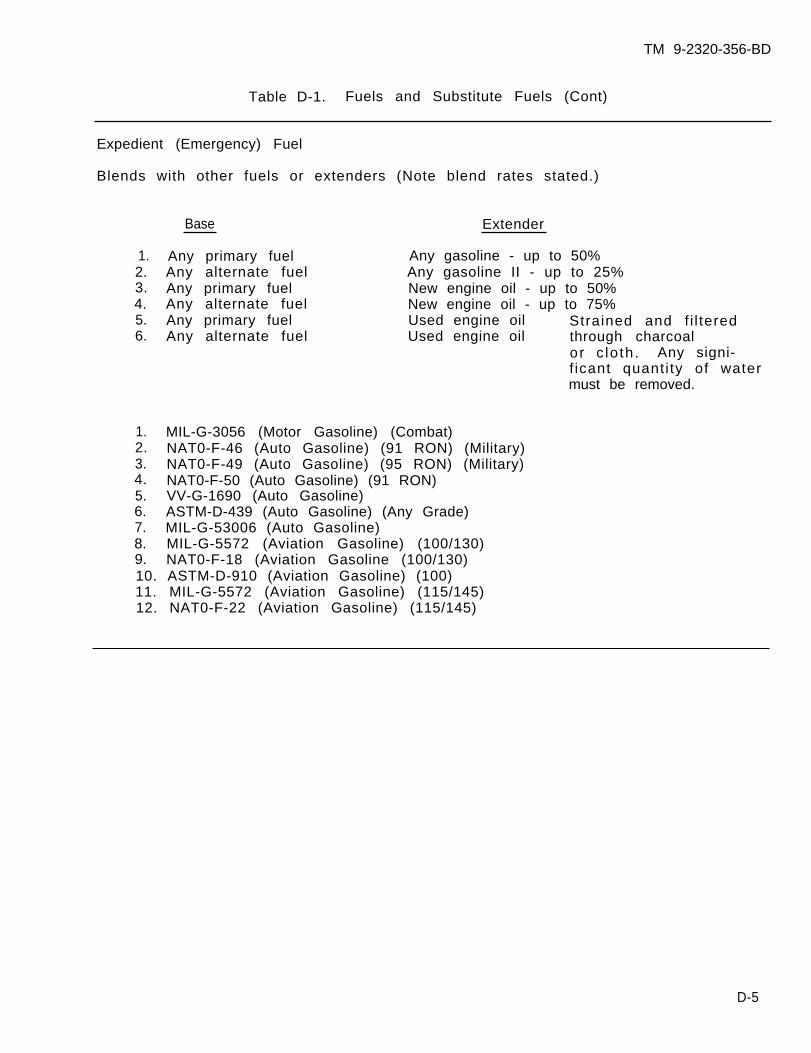
TM 9-2320-356-BD
Table D-1. Fuels and Substitute Fuels (Cont)
Expedient (Emergency) Fuel
Blends with other fuels or extenders (Note blend rates stated.)
Base
1. Any primary fuel2. Any alternate fuel3. Any primary fuel4. Any alternate fuel5. Any primary fuel6. Any alternate fuel
Extender
Any gasoline - up to 50%Any gasoline II - up to 25%New engine oil - up to 50%New engine oil - up to 75%Used engine oil Strained and f i l teredUsed engine oil through charcoal
or c lo th . Any signi-f icant quanti ty of watermust be removed.
1. MIL-G-3056 (Motor Gasoline) (Combat)2. NAT0-F-46 (Auto Gasoline) (91 RON) (Military)3. NAT0-F-49 (Auto Gasoline) (95 RON) (Military)4. NAT0-F-50 (Auto Gasoline) (91 RON)5. VV-G-1690 (Auto Gasoline)6. ASTM-D-439 (Auto Gasoline) (Any Grade)7. MIL-G-53006 (Auto Gasoline)8. MIL-G-5572 (Aviation Gasoline) (100/130)9. NAT0-F-18 (Aviation Gasoline (100/130)10. ASTM-D-910 (Aviation Gasoline) (100)11. MIL-G-5572 (Aviation Gasoline) (115/145)12. NAT0-F-22 (Aviation Gasoline) (115/145)
D-5
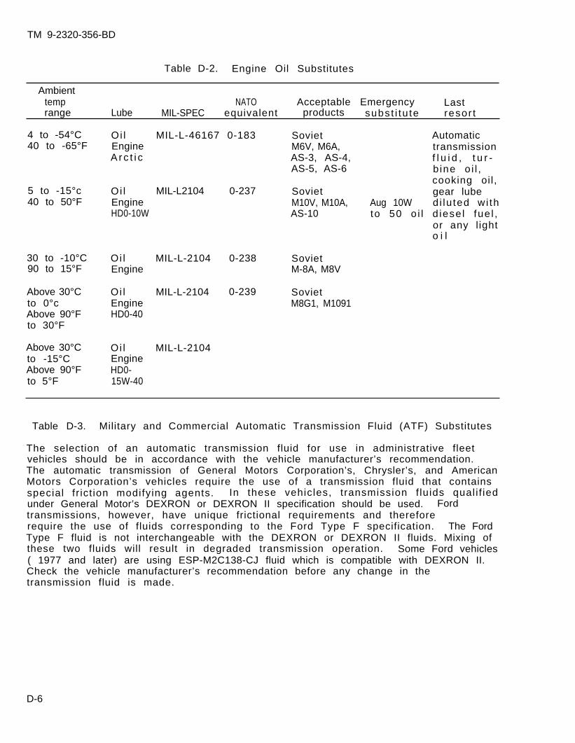
TM 9-2320-356-BD
Table D-2. Engine Oil Substitutes
Ambienttemp NATO Acceptable Emergency Lastrange Lube MIL-SPEC equivalent products subst i tu te resor t
4 to -54°C Oi l MIL-L-46167 0-183 Soviet Automatic40 to -65°F Engine M6V, M6A, transmission
Arc t i c AS-3, AS-4, f l u i d , t u r -AS-5, AS-6 bine o i l ,
cooking oil,5 to -15°c Oi l MIL-L2104 0-237 Soviet gear lube40 to 50°F Engine M10V, M10A, Aug 10W di lu ted wi th
HD0-10W AS-10 to 50 o i l d iese l fue l ,or any l ighto i l
30 to -10°C Oi l MIL-L-2104 0-238 Soviet90 to 15°F Engine M-8A, M8V
Above 30°C Oi l MIL-L-2104 0-239 Sovietto 0°c Engine M8G1, M1091Above 90°F HD0-40to 30°F
Above 30°C Oi l MIL-L-2104to -15°C EngineAbove 90°F HD0-to 5°F 15W-40
Table D-3. Military and Commercial Automatic Transmission Fluid (ATF) Substitutes
The selection of an automatic transmission fluid for use in administrative fleetvehicles should be in accordance with the vehicle manufacturer’s recommendation.The automatic transmission of General Motors Corporation’s, Chrysler’s, and AmericanMotors Corporation’s vehicles require the use of a transmission fluid that containsspecial fr ict ion modifying agents. In these vehicles, transmission f luids qual i f iedunder General Motor’s DEXRON or DEXRON II specification should be used. Fordtransmissions, however, have unique frictional requirements and thereforerequire the use of fluids corresponding to the Ford Type F specification. The FordType F fluid is not interchangeable with the DEXRON or DEXRON II fluids. Mixing ofthese two fluids will result in degraded transmission operation. Some Ford vehicles( 1977 and later) are using ESP-M2C138-CJ fluid which is compatible with DEXRON II.Check the vehicle manufacturer’s recommendation before any change in thetransmission fluid is made.
D-6
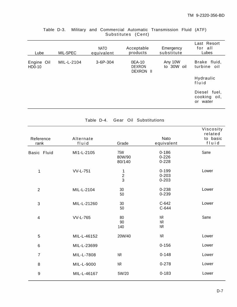
TM 9-2320-356-BD
Table D-3. Military and Commercial Automatic Transmission Fluid (ATF)Subst i tu tes (Cent )
Last ResortNATO Acceptable Emergency fo r a l l
Lube MIL-SPEC equivalent products subst i tu te Lubes
Engine Oil MIL-L-2104 3-6P-304 0EA-10 Any 10W Brake fluid,HD0-10 DEXRON to 30W oil turb ine o i l
DEXRON II
Hydraulicf l u i d
Diesel fuel,cooking oil,or water
Table D-4. Gear Oil Substitutions
Viscos i tyre la ted
Reference Al ternate Nato to basicrank f l u i d Grade equivalent f l u i d
Basic Fluid MI1-L-2105 75W 0-186 Same80W/90 0-22680/140 0-228
1 VV-L-751 1 0-199 Lower2 0-2033 0-203
2 MIL-L-2104 30 0-238 Lower50 0-239
3 MIL-L-21260 30 C-642 Lower50 C-644
4 VV-L-765 80 NR Same90 NR
140 NR
5 MIL-L-46152 20W/40 NR Lower
6 MIL-L-23699 0-156 Lower
7 MIL-L-7808 NR 0-148 Lower
8 MIL-L-9000 NR 0-278 Lower
9 MIL-L-46167 5W/20 0-183 Lower
D-7

TM 9-2320-356-BD
Table D-5. Hydraul ic Fluid Substi tut ions
Viscos i tyre la ted
Preference Al ternate Seal To basicrank f l u i d compa t i b i l i t y f l u i d
Basic Fluid MIL-L-2104C Compatible Same
1 SAE 10 Compatible Samemotor oil
2 Dextron II Compatible Lower
3 MIL-L-46167 Compatible L o w e r(OEA)
4 MIL-L-2104C Compatible Higher(OE/HDO-30)
5 MIL-H-56170A Compatible Lower
6 MIL-H-6083B Compatible L o w e r
7 MIL-H-5606B Compatible Lower
8 MIL-L-23699A Moderate L o w e r(Turbine Oi1 )
9 MIL-L-7808A Moderate LowerMIL-L-7808G(Turbine Oil )
10 Ethylene Glycol Compatible Lower(Ant i - f reeze)
11 Ethylene Glycol Compatible Lowerand Water, 50-50mix
12 Water Compatible Lower
13 Diesel Fuel Compatible Lower
D-8

. . .
TM9-2320-356-BD
APPENDIX E
BDAR FIXES AUTHORIZED FOR TRAINING
BDAR TRAINING FIXES SHALL BEUSED ONLY AT THE DISCRETION OF THE COMMANDER
DAMAGES SHALL BE REPAIRED BY STANDARD MAINTENANCEPROCEDURES AS SOON AS PRACTICABLE
REPAIR PROCEDURE
GENERAL AUTOMOTIVE COMPONENTS
Engine/Transmission Housing Damage . . . . . . . . . . . . . . . . . . . . . . . . . . . . . . . . . . . . . . . . . . . . . . . .3-11
Option 1, Repair of Small Crack.Option 2, Repair of Small Crack or Hole.Option 3, Repair of Small Crack or Hole.
Bracket Broken . . . . . . . . . . . . . . . . . . . . . . . . . . . . . . . . . . . . . . . . . . . . . . . . . . . . . . . . . . . . . . . . . . .3-13
Option 1, Weld.Option 2, Weld to Location.Option 3, Tie Component.
Gearshift Lever Broken. . . . . . . . . . . . . . . . . . . . . . . . . . . . . . . . . . . . . . . . . . . . . . . . . . . . . . . . . . . .3-18
Push/Pull Rod Damaged. . . . . . . . . . . . . . . . . . . . . . . . . . . . . . . . . . . . . . . . . . . . . . . . . . . . . . . . . . . . 3-19
Option 1, Weld.Option 2, Splint with Angle km.Option 3, Weld and Splint.
Pulley Damaged . . . . . . . . . . . . . . . . . . . . . . . . . . . . . . . . . . . . . . . . . . . . . . . . . . . . . . . . . . . . . . . . . .3-20
Mechanical Cable Broken . . . . . . . . . . . . . . . . . . . . . . . . . . . . . . . . . . . . . . . . . . . . . . . . . . . . . . . . . . 3-21
Metal Tube Bending . . . . . . . . . . . . . . . . . . . . . . . . . . . . . . . . . . . . . . . . . . . . . . . . . . . . . . . . . . . . . . . . . . 3-29
Hydraulic Low-Pressure Metal Tubing Repair . . . . . . . . . . . . . . . . . . . . . . . . . . . . . . . . . . . . . . . . . . . 3-30
Option l, Replacement of a Short Damaged Tube Section.Option 2, Replacement of a Long Damaged Tube Section.Option 4, Tube Patch.
Hydraulic Tube and Hose Repair . . . . . . . . . . . . . . . . . . . . . . . . . . . . . . . . . . . . . . . . . . . . . . . . . . . . .3-33
Option l, Tube Repair with Rubber Hose.Option 2, Hose Repair with Tubing.
Hydraulic Tube and Hose lsolation . . . . . . . . . . . . . . . . . . . . . . . . . . . . . . . . . . . . . . . . . . . . . . . . . . .3-34
Option l, Low-Pressure Hose Isolation.
Change1 E-1
PARAGRAPH NO.
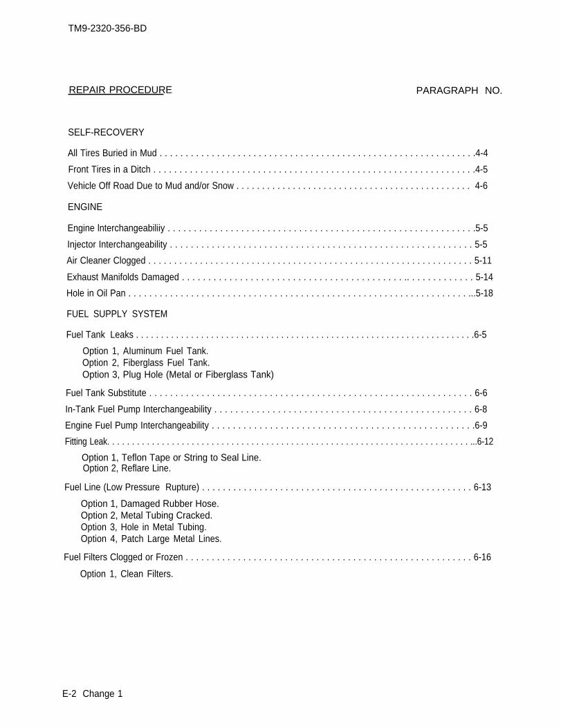
TM9-2320-356-BD
REPAIR PROCEDURE
SELF-RECOVERY
All Tires Buried in Mud . . . . . . . . . . . . . . . . . . . . . . . . . . . . . . . . . . . . . . . . . . . . . . . . . . . . . . . . . . . . .4-4
Front Tires in a Ditch . . . . . . . . . . . . . . . . . . . . . . . . . . . . . . . . . . . . . . . . . . . . . . . . . . . . . . . . . . . . . .4-5
Vehicle Off Road Due to Mud and/or Snow . . . . . . . . . . . . . . . . . . . . . . . . . . . . . . . . . . . . . . . . . . . . . . 4-6
ENGINE
Engine lnterchangeabiliiy . . . . . . . . . . . . . . . . . . . . . . . . . . . . . . . . . . . . . . . . . . . . . . . . . . . . . . . . . . .5-5
Injector Interchangeability . . . . . . . . . . . . . . . . . . . . . . . . . . . . . . . . . . . . . . . . . . . . . . . . . . . . . . . . . . 5-5
Air Cleaner Clogged . . . . . . . . . . . . . . . . . . . . . . . . . . . . . . . . . . . . . . . . . . . . . . . . . . . . . . . . . . . . . . . 5-11
Exhaust Manifolds Damaged . . . . . . . . . . . . . . . . . . . . . . . . . . . . . . . . . . . . . . . . . . .. . . . . . . . . . . . . 5-14
Hole in Oil Pan . . . . . . . . . . . . . . . . . . . . . . . . . . . . . . . . . . . . . . . . . . . . . . . . . . . . . . . . . . . . . . . . . ...5-18
FUEL SUPPLY SYSTEM
Fuel Tank Leaks . . . . . . . . . . . . . . . . . . . . . . . . . . . . . . . . . . . . . . . . . . . . . . . . . . . . . . . . . . . . . . . . . . . .6-5
Option 1, AIuminum Fuel Tank.Option 2, Fiberglass Fuel Tank.Option 3, Plug Hole (Metal or Fiberglass Tank)
Fuel Tank Substitute . . . . . . . . . . . . . . . . . . . . . . . . . . . . . . . . . . . . . . . . . . . . . . . . . . . . . . . . . . . . . . 6-6
In-Tank Fuel Pump Interchangeability . . . . . . . . . . . . . . . . . . . . . . . . . . . . . . . . . . . . . . . . . . . . . . . . . 6-8
Engine Fuel Pump Interchangeability . . . . . . . . . . . . . . . . . . . . . . . . . . . . . . . . . . . . . . . . . . . . . . . . . .6-9
Fitting Leak. . . . . . . . . . . . . . . . . . . . . . . . . . . . . . . . . . . . . . . . . . . . . . . . . . . . . . . . . . . . . . . . . . . . . . . . . ...6-12
Option 1, Teflon Tape or String to Seal Line.
Fuel Line (Low Pressure Rupture) . . . . . . . . . . . . . . . . . . . . . . . . . . . . . . . . . . . . . . . . . . . . . . . . . . . . 6-13
Option 1, Damaged Rubber Hose.Option 2, Metal Tubing Cracked.Option 3, Hole in Metal Tubing.Option 4, Patch Large Metal Lines.
Fuel Filters Clogged or Frozen . . . . . . . . . . . . . . . . . . . . . . . . . . . . . . . . . . . . . . . . . . . . . . . . . . . . . . . 6-16
Option 1, Clean Filters.
E-2 Change 1
PARAGRAPH NO.
Option 2, Reflare Line.
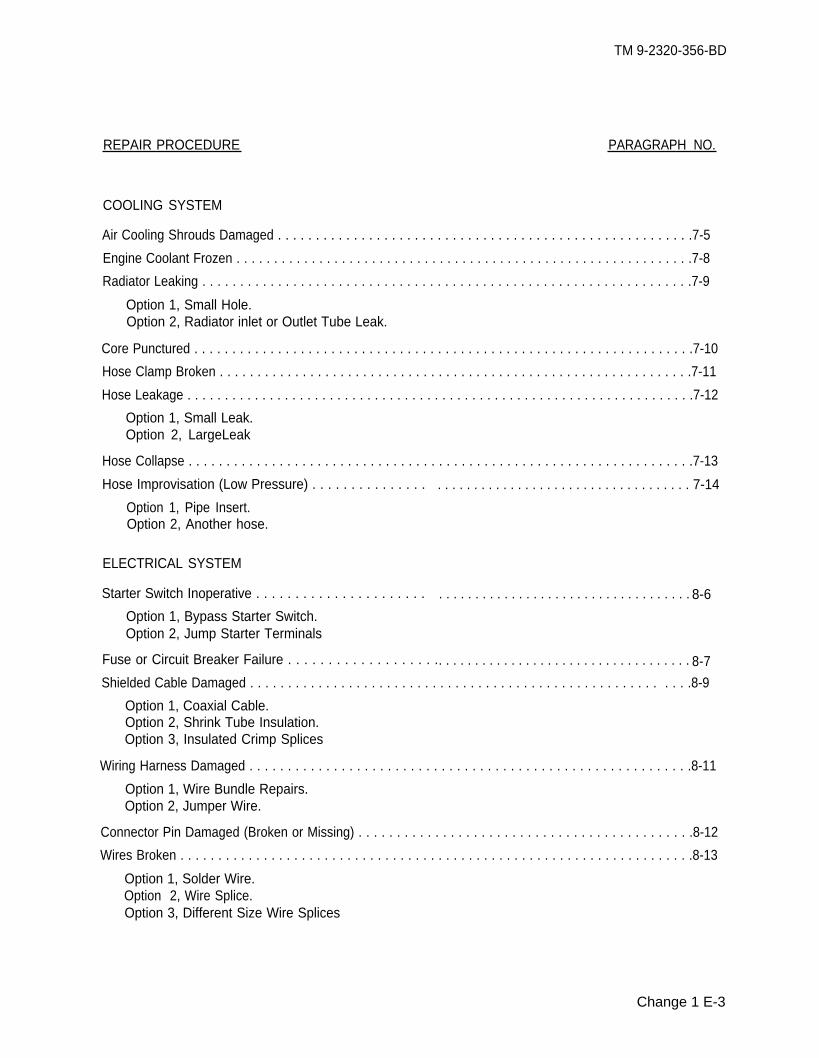
TM 9-2320-356-BD
REPAIR PROCEDURE PARAGRAPH NO.
COOLING SYSTEM
Air Cooling Shrouds Damaged . . . . . . . . . . . . . . . . . . . . . . . . . . . . . . . . . . . . . . . . . . . . . . . . . . . . . . .7-5
Engine Coolant Frozen . . . . . . . . . . . . . . . . . . . . . . . . . . . . . . . . . . . . . . . . . . . . . . . . . . . . . . . . . . . . .7-8
Radiator Leaking . . . . . . . . . . . . . . . . . . . . . . . . . . . . . . . . . . . . . . . . . . . . . . . . . . . . . . . . . . . . . . . . .7-9
Option 1, Small Hole.Option 2, Radiator inlet or Outlet Tube Leak.
Core Punctured . . . . . . . . . . . . . . . . . . . . . . . . . . . . . . . . . . . . . . . . . . . . . . . . . . . . . . . . . . . . . . . . . .7-10
Hose Clamp Broken . . . . . . . . . . . . . . . . . . . . . . . . . . . . . . . . . . . . . . . . . . . . . . . . . . . . . . . . . . . . . . .7-11
Hose Leakage . . . . . . . . . . . . . . . . . . . . . . . . . . . . . . . . . . . . . . . . . . . . . . . . . . . . . . . . . . . . . . . . . . . .7-12
Option 1, Small Leak.Option 2, LargeLeak
Hose Collapse . . . . . . . . . . . . . . . . . . . . . . . . . . . . . . . . . . . . . . . . . . . . . . . . . . . . . . . . . . . . . . . . . . .7-13
Hose Improvisation (Low Pressure) . . . . . . . . . . . . . . .
Option 1, Pipe Insert.Option 2, Another hose.
ELECTRICAL SYSTEM
Starter Switch Inoperative . . . . . . . . . . . . . . . . . . . . . .
Option 1, Bypass Starter Switch.Option 2, Jump Starter Terminals
Fuse or Circuit Breaker Failure . . . . . . . . . . . . . . . . . . .
. . . . . . . . . . . . . . . . . . . . . . . . . . . . . . . . . . . 7-14
. . . . . . . . . . . . . . . . . . . . . . . . . . . . . . . . . . . 8-6
. . . . . . . . . . . . . . . . . . . . . . . . . . . . . . . . . . . 8-7
Shielded Cable Damaged . . . . . . . . . . . . . . . . . . . . . . . . . . . . . . . . . . . . . . . . . . . . . . . . . . . . . . . . . .8-9
Option 1, Coaxial Cable.Option 2, Shrink Tube Insulation.Option 3, Insulated Crimp Splices
Wiring Harness Damaged . . . . . . . . . . . . . . . . . . . . . . . . . . . . . . . . . . . . . . . . . . . . . . . . . . . . . . . . . .8-11
Option 1, Wire Bundle Repairs.Option 2, Jumper Wire.
Connector Pin Damaged (Broken or Missing) . . . . . . . . . . . . . . . . . . . . . . . . . . . . . . . . . . . . . . . . . . . .8-12
Wires Broken . . . . . . . . . . . . . . . . . . . . . . . . . . . . . . . . . . . . . . . . . . . . . . . . . . . . . . . . . . . . . . . . . . . .8-13
Option 1, Solder Wire.Option 2, Wire Splice.Option 3, Different Size Wire Splices
Change 1 E-3
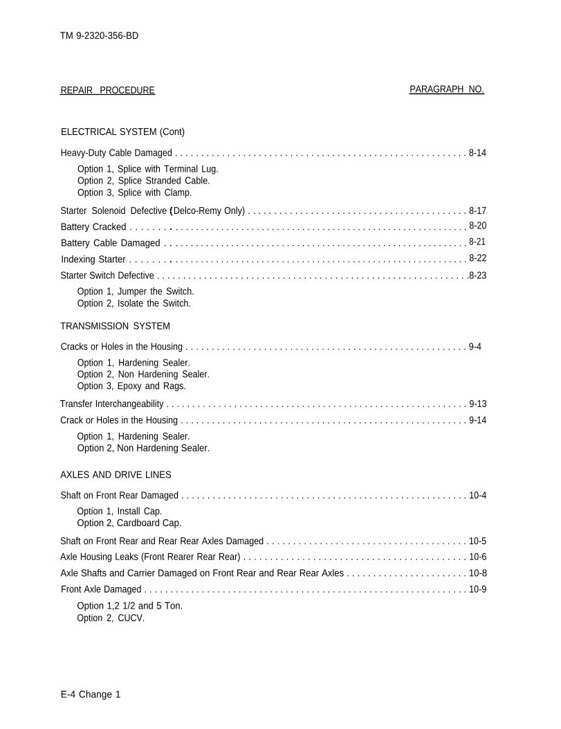
TM 9-2320-356-BD
REPAIR PROCEDURE PARAGRAPH NO.
ELECTRICAL SYSTEM (Cont)
Heavy-Duty Cable Damaged . . . . . . . . . . . . . . . . . . . . . . . . . . . . . . . . . . . . . . . . . . . . . . . . . . . . . . . . 8-14
Option 1, Splice with Terminal Lug.Option 2, Splice Stranded Cable.Option 3, Splice with Clamp.
Starter Solenoid Defective
Battery Cracked . . . . . . .
Battery Cable Damaged .
Indexing Starter . . . . . . .
Delco-Remy Only) . . . . . . . . . . . . . . . . . . . . . . . . . . . . . . . . . . . . . . . . . . 8-17
. . . . . . . . . . . . . . . . . . . . . . . . . . . . . . . . . . . . . . . . . . . . . . . . . . . . . . . . . . 8-20
. . . . . . . . . . . . . . . . . . . . . . . . . . . . . . . . . . . . . . . . . . . . . . . . . . . . . . . . . . 8-21
. . . . . . . . . . . . . . . . . . . . . . . . . . . . . . . . . . . . . . . . . . . . . . . . . . . . . . . . . . 8-22
Starter Switch Defective . . . . . . . . . . . . . . . . . . . . . . . . . . . . . . . . . . . . . . . . . . . . . . . . . . . . . . . . . . . .8-23
Option 1, Jumper the Switch.Option 2, Isolate the Switch.
TRANSMISSION SYSTEM
Cracks or Holes in the Housing . . . . . . . . . . . . . . . . . . . . . . . . . . . . . . . . . . . . . . . . . . . . . . . . . . . . . . 9-4
Option 1, Hardening Sealer.Option 2, Non Hardening Sealer.Option 3, Epoxy and Rags.
Transfer Interchangeability . . . . . . . . . . . . . . . . . . . . . . . . . . . . . . . . . . . . . . . . . . . . . . . . . . . . . . . . . . 9-13
Crack or Holes in the Housing . . . . . . . . . . . . . . . . . . . . . . . . . . . . . . . . . . . . . . . . . . . . . . . . . . . . . . . 9-14
Option 1, Hardening Sealer.Option 2, Non Hardening Sealer.
AXLES AND DRIVE LINES
Shaft on Front Rear Damaged . . . . . . . . . . . . . . . . . . . . . . . . . . . . . . . . . . . . . . . . . . . . . . . . . . . . . . . 10-4
Option 1, Install Cap.Option 2, Cardboard Cap.
Shaft on Front Rear and Rear Rear Axles Damaged . . . . . . . . . . . . . . . . . . . . . . . . . . . . . . . . . . . . . . 10-5
Axle Housing Leaks (Front Rearer Rear Rear) . . . . . . . . . . . . . . . . . . . . . . . . . . . . . . . . . . . . . . . . . . 10-6
Axle Shafts and Carrier Damaged on Front Rear and Rear Rear Axles . . . . . . . . . . . . . . . . . . . . . . . 10-8
Front Axle Damaged . . . . . . . . . . . . . . . . . . . . . . . . . . . . . . . . . . . . . . . . . . . . . . . . . . . . . . . . . . . . . . 10-9
Option 1,2 1/2 and 5 Ton.Option 2, CUCV.
E-4 Change 1
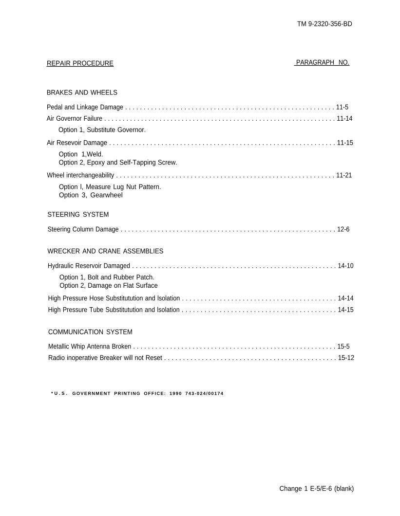
REPAIR PROCEDURE
TM 9-2320-356-BD
PARAGRAPH NO.
BRAKES AND WHEELS
Pedal and Linkage Damage . . . . . . . . . . . . . . . . . . . . . . . . . . . . . . . . . . . . . . . . . . . . . . . . . . . . . . . . . 11-5
Air Governor Failure . . . . . . . . . . . . . . . . . . . . . . . . . . . . . . . . . . . . . . . . . . . . . . . . . . . . . . . . . . . . . . . 11-14
Option 1, Substitute Governor.
Air Resevoir Damage . . . . . . . . . . . . . . . . . . . . . . . . . . . . . . . . . . . . . . . . . . . . . . . . . . . . . . . . . . . . . 11-15
Option 1,Weld.Option 2, Epoxy and Self-Tapping Screw.
Wheel interchangeability . . . . . . . . . . . . . . . . . . . . . . . . . . . . . . . . . . . . . . . . . . . . . . . . . . . . . . . . . . . 11-21
Option l, Measure Lug Nut Pattern.Option 3, Gearwheel
STEERING SYSTEM
Steering Column Damage . . . . . . . . . . . . . . . . . . . . . . . . . . . . . . . . . . . . . . . . . . . . . . . . . . . . . . . . . . 12-6
WRECKER AND CRANE ASSEMBLIES
Hydraulic Reservoir Damaged . . . . . . . . . . . . . . . . . . . . . . . . . . . . . . . . . . . . . . . . . . . . . . . . . . . . . . . 14-10
Option 1, Bolt and Rubber Patch.Option 2, Damage on Flat Surface
High Pressure Hose Substitutution and lsolation . . . . . . . . . . . . . . . . . . . . . . . . . . . . . . . . . . . . . . . . . 14-14
High Pressure Tube Substitutution and lsolation . . . . . . . . . . . . . . . . . . . . . . . . . . . . . . . . . . . . . . . . . 14-15
COMMUNICATION SYSTEM
Metallic Whip Antenna Broken . . . . . . . . . . . . . . . . . . . . . . . . . . . . . . . . . . . . . . . . . . . . . . . . . . . . . . . 15-5
Radio inoperative Breaker will not Reset . . . . . . . . . . . . . . . . . . . . . . . . . . . . . . . . . . . . . . . . . . . . . . 15-12
* U . S . GOVERNMENT PRINT ING OFF ICE: 1990 743 -024 /00174
Change 1 E-5/E-6 (blank)
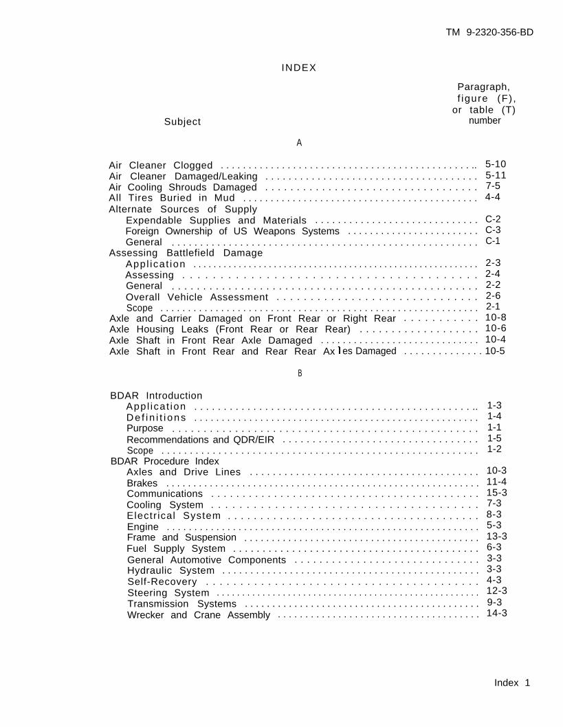
TM 9-2320-356-BD
Paragraph,f igure (F) ,
or table (T)numberSubject
A
Air Cleaner Clogged . . . . . . . . . . . . . . . . . . . . . . . . . . . . . . . . . . . . . . . . . . . . . ..Air Cleaner Damaged/Leaking . . . . . . . . . . . . . . . . . . . . . . . . . . . . . . . . . . . . .Air Cooling Shrouds Damaged . . . . . . . . . . . . . . . . . . . . . . . . . . . . . . . . . .All Tires Buried in Mud . . . . . . . . . . . . . . . . . . . . . . . . . . . . . . . . . . . . . . . . . . .Alternate Sources of Supply
Expendable Supplies and Materials . . . . . . . . . . . . . . . . . . . . . . . . . . . . .Foreign Ownership of US Weapons Systems . . . . . . . . . . . . . . . . . . . . . . . .General . . . . . . . . . . . . . . . . . . . . . . . . . . . . . . . . . . . . . . . . . . . . . . . . . . . . . .
Assessing Battlefield DamageAppl icat ion . . . . . . . . . . . . . . . . . . . . . . . . . . . . . . . . . . . . . . . . . . . . . . . . . . . . . . . . .Assessing . . . . . . . . . . . . . . . . . . . . . . . . . . . . . . . . . . . . . . .General . . . . . . . . . . . . . . . . . . . . . . . . . . . . . . . . . . . . . . . . . . . . . . . . .Overall Vehicle Assessment . . . . . . . . . . . . . . . . . . . . . . . . . . . . . .Scope . . . . . . . . . . . . . . . . . . . . . . . . . . . . . . . . . . . . . . . . . . . . . . . . . . . . . . . . . .
Axle and Carrier Damaged on Front Rear or Right Rear . . . . . . . . . . .Axle Housing Leaks (Front Rear or Rear Rear) . . . . . . . . . . . . . . . . . . .Axle Shaft in Front Rear Axle Damaged . . . . . . . . . . . . . . . . . . . . . . . . . . . . .
5-105-117-54-4
C-2C-3C-1
2-32-42-22-62-110-810-610-4
Axle Shaft in Front Rear and Rear Rear Ax
B
es Damaged . . . . . . . . . . . . . . 10-5
BDAR IntroductionAppl icat ion . . . . . . . . . . . . . . . . . . . . . . . . . . . . . . . . . . . . . . . . . . . . . . . ..De f i n i t i ons . . . . . . . . . . . . . . . . . . . . . . . . . . . . . . . . . . . . . . . . . . . . . . . . . . . .Purpose . . . . . . . . . . . . . . . . . . . . . . . . . . . . . . . . . . . . . . . . . . . . . . . . .Recommendations and QDR/EIR . . . . . . . . . . . . . . . . . . . . . . . . . . . . . . . . .Scope . . . . . . . . . . . . . . . . . . . . . . . . . . . . . . . . . . . . . . . . . . . . . . . . . . . . . . . .
BDAR Procedure IndexAxles and Drive Lines . . . . . . . . . . . . . . . . . . . . . . . . . . . . . . . . . . . . . . . .Brakes . . . . . . . . . . . . . . . . . . . . . . . . . . . . . . . . . . . . . . . . . . . . . . . . . . . . . . . . . .Communications . . . . . . . . . . . . . . . . . . . . . . . . . . . . . . . . . . . . . . . . . . .Cooling System . . . . . . . . . . . . . . . . . . . . . . . . . . . . . . . . . . . . . .Electr ical System . . . . . . . . . . . . . . . . . . . . . . . . . . . . . . . . . . . . . . .Engine . . . . . . . . . . . . . . . . . . . . . . . . . . . . . . . . . . . . . . . . . . . . . . . . . . . . . . . . .Frame and Suspension . . . . . . . . . . . . . . . . . . . . . . . . . . . . . . . . . . . . . . . . . . .Fuel Supply System . . . . . . . . . . . . . . . . . . . . . . . . . . . . . . . . . . . . . . . . . .General Automotive Components . . . . . . . . . . . . . . . . . . . . . . . . . . . . . .Hydraulic System . . . . . . . . . . . . . . . . . . . . . . . . . . . . . . . . . . . . . . . . . . . . . .Self-Recovery . . . . . . . . . . . . . . . . . . . . . . . . . . . . . . . . . . . . . . . .Steering System . . . . . . . . . . . . . . . . . . . . . . . . . . . . . . . . . . . . . . . . . . . . . . . . . . . .Transmission Systems . . . . . . . . . . . . . . . . . . . . . . . . . . . . . . . . . . . . . . . . . . .Wrecker and Crane Assembly . . . . . . . . . . . . . . . . . . . . . . . . . . . . . . . . . . . . .
1-31-41-11-51-2
10-311-415-37-38-35-313-36-33-33-34-312-39-314-3
Index 1
INDEX
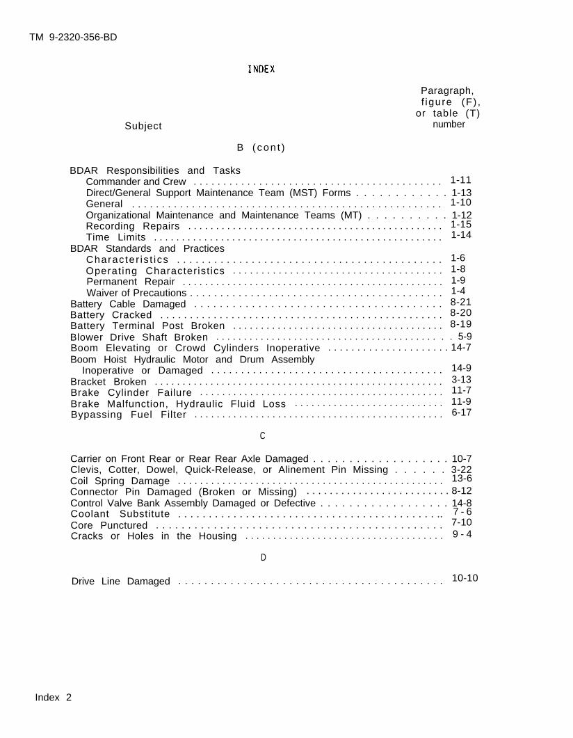
TM 9-2320-356-BD
Subject
Paragraph,f igure (F) ,
or table (T)number
B ( con t )
BDAR Responsibilities and TasksCommander and Crew . . . . . . . . . . . . . . . . . . . . . . . . . . . . . . . . . . . . . . . . . . 1-11Direct/General Support Maintenance Team (MST) Forms . . . . . . . . . . . . 1-13General . . . . . . . . . . . . . . . . . . . . . . . . . . . . . . . . . . . . . . . . . . . . . . . . . . . . 1-10Organizational Maintenance and Maintenance Teams (MT) . . . . . . . . . . 1-12Recording Repairs . . . . . . . . . . . . . . . . . . . . . . . . . . . . . . . . . . . . . . . . . . . . . . 1-15Time Limits . . . . . . . . . . . . . . . . . . . . . . . . . . . . . . . . . . . . . . . . . . . . . . . . . . . . 1-14
BDAR Standards and PracticesCharacter is t ics . . . . . . . . . . . . . . . . . . . . . . . . . . . . . . . . . . . . . . . . . . . 1-6Operating Characterist ics . . . . . . . . . . . . . . . . . . . . . . . . . . . . . . . . . . . . . 1-8Permanent Repair . . . . . . . . . . . . . . . . . . . . . . . . . . . . . . . . . . . . . . . . . . . . . . . 1-9Waiver of Precautions . . . . . . . . . . . . . . . . . . . . . . . . . . . . . . . . . . . . . . . . . . 1-4
Battery Cable Damaged . . . . . . . . . . . . . . . . . . . . . . . . . . . . . . . . . . . . . . . 8-21Battery Cracked . . . . . . . . . . . . . . . . . . . . . . . . . . . . . . . . . . . . . . . . . . . . . . . . 8-20Battery Terminal Post Broken . . . . . . . . . . . . . . . . . . . . . . . . . . . . . . . . . . . . . . 8-19Blower Drive Shaft Broken . . . . . . . . . . . . . . . . . . . . . . . . . . . . . . . . . . . . . . . . . . 5-9Boom Elevating or Crowd Cylinders Inoperative . . . . . . . . . . . . . . . . . . . . . 14-7Boom Hoist Hydraulic Motor and Drum Assembly
Inoperative or Damaged . . . . . . . . . . . . . . . . . . . . . . . . . . . . . . . . . . . . . . . 14-9Bracket Broken . . . . . . . . . . . . . . . . . . . . . . . . . . . . . . . . . . . . . . . . . . . . . . . . . . . . 3-13Brake Cylinder Failure . . . . . . . . . . . . . . . . . . . . . . . . . . . . . . . . . . . . . . . . . . . . 11-7Brake Malfunction, Hydraulic Fluid Loss . . . . . . . . . . . . . . . . . . . . . . . . . . . 11-9Bypassing Fuel Filter . . . . . . . . . . . . . . . . . . . . . . . . . . . . . . . . . . . . . . . . . . . . . 6-17
C
Carrier on Front Rear or Rear Rear Axle Damaged . . . . . . . . . . . . . . . . . . . 10-7Clevis, Cotter, Dowel, Quick-Release, or Alinement Pin Missing . . . . . . 3-22Coil Spring Damage . . . . . . . . . . . . . . . . . . . . . . . . . . . . . . . . . . . . . . . . . . . . . . . . 13-6Connector Pin Damaged (Broken or Missing) . . . . . . . . . . . . . . . . . . . . . . . . . 8-12Control Valve Bank Assembly Damaged or Defective . . . . . . . . . . . . . . . . . . 14-8Coolant Substitute . . . . . . . . . . . . . . . . . . . . . . . . . . . . . . . . . . . . . . . . . . .. 7 - 6Core Punctured . . . . . . . . . . . . . . . . . . . . . . . . . . . . . . . . . . . . . . . . . . . . . 7-10Cracks or Holes in the Housing . . . . . . . . . . . . . . . . . . . . . . . . . . . . . . . . . . . . 9 - 4
D
Drive Line Damaged . . . . . . . . . . . . . . . . . . . . . . . . . . . . . . . . . . . . . . . . . 10-10
Index 2
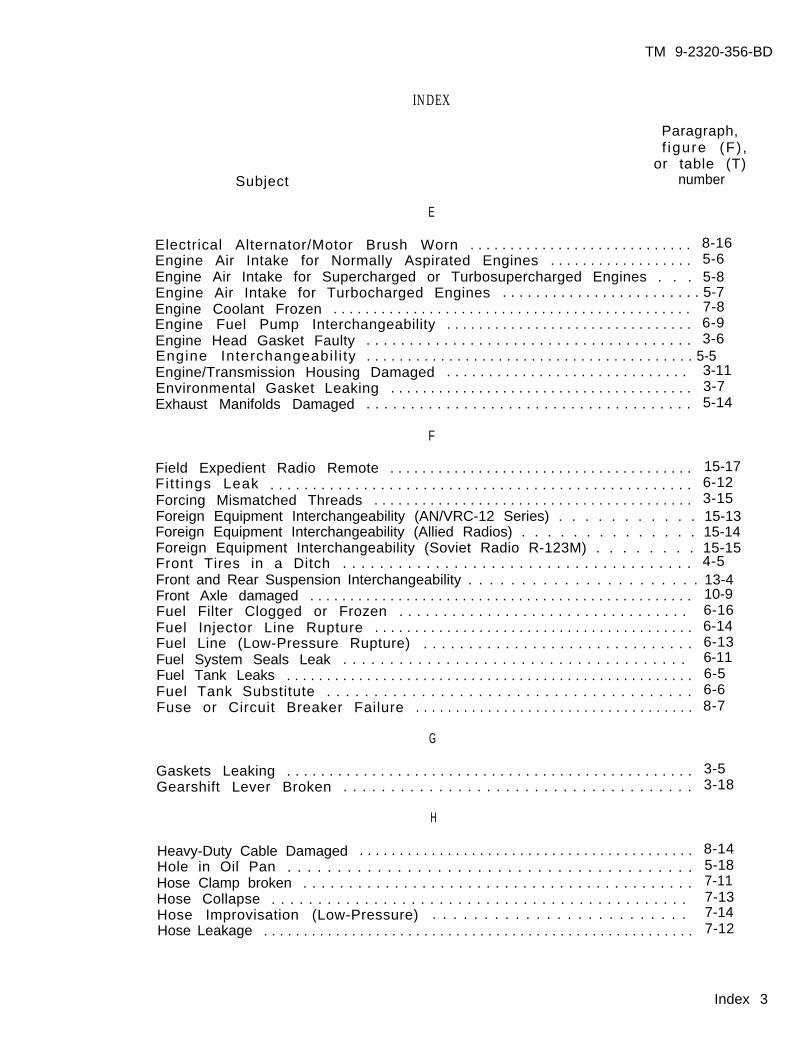
TM 9-2320-356-BD
INDEX
Paragraph,f igure (F) ,
Subjector table (T)
number
E
Electrical Alternator/Motor Brush Worn . . . . . . . . . . . . . . . . . . . . . . . . . . . . 8-16Engine Air Intake for Normally Aspirated Engines . . . . . . . . . . . . . . . . . . 5-6Engine Air Intake for Supercharged or Turbosupercharged Engines . . . 5-8Engine Air Intake for Turbocharged Engines . . . . . . . . . . . . . . . . . . . . . . . . 5-7Engine Coolant Frozen . . . . . . . . . . . . . . . . . . . . . . . . . . . . . . . . . . . . . . . . . . . . . 7-8Engine Fuel Pump Interchangeability . . . . . . . . . . . . . . . . . . . . . . . . . . . . . . . 6-9Engine Head Gasket Faulty . . . . . . . . . . . . . . . . . . . . . . . . . . . . . . . . . . . . . . 3-6Engine Interchangeabil i ty . . . . . . . . . . . . . . . . . . . . . . . . . . . . . . . . . . . . . . . . 5-5Engine/Transmission Housing Damaged . . . . . . . . . . . . . . . . . . . . . . . . . . . . . 3-11Environmental Gasket Leaking . . . . . . . . . . . . . . . . . . . . . . . . . . . . . . . . . . . . . . 3-7Exhaust Manifolds Damaged . . . . . . . . . . . . . . . . . . . . . . . . . . . . . . . . . . . . . 5-14
F
Field Expedient Radio Remote . . . . . . . . . . . . . . . . . . . . . . . . . . . . . . . . . . . . . . 15-17Fitt ings Leak . . . . . . . . . . . . . . . . . . . . . . . . . . . . . . . . . . . . . . . . . . . . . . . . . . 6-12Forcing Mismatched Threads . . . . . . . . . . . . . . . . . . . . . . . . . . . . . . . . . . . . . . . . 3-15Foreign Equipment Interchangeability (AN/VRC-12 Series) . . . . . . . . . . . 15-13Foreign Equipment Interchangeability (Allied Radios) . . . . . . . . . . . . . . 15-14Foreign Equipment Interchangeability (Soviet Radio R-123M) . . . . . . . . 15-15Front Tires in a Ditch . . . . . . . . . . . . . . . . . . . . . . . . . . . . . . . . . . . . . . 4-5Front and Rear Suspension Interchangeability . . . . . . . . . . . . . . . . . . . . . . 13-4Front Axle damaged . . . . . . . . . . . . . . . . . . . . . . . . . . . . . . . . . . . . . . . . . . . . . . . . 10-9Fuel Filter Clogged or Frozen . . . . . . . . . . . . . . . . . . . . . . . . . . . . . . . . . 6-16Fuel Injector Line Rupture . . . . . . . . . . . . . . . . . . . . . . . . . . . . . . . . . . . . . . . . 6-14Fuel Line (Low-Pressure Rupture) . . . . . . . . . . . . . . . . . . . . . . . . . . . . . . 6-13Fuel System Seals Leak . . . . . . . . . . . . . . . . . . . . . . . . . . . . . . . . . . . . . 6-11Fuel Tank Leaks . . . . . . . . . . . . . . . . . . . . . . . . . . . . . . . . . . . . . . . . . . . . . . . . . . . 6-5Fuel Tank Substitute . . . . . . . . . . . . . . . . . . . . . . . . . . . . . . . . . . . . . . . 6-6Fuse or Circuit Breaker Failure . . . . . . . . . . . . . . . . . . . . . . . . . . . . . . . . . . . 8-7
G
Gaskets Leaking . . . . . . . . . . . . . . . . . . . . . . . . . . . . . . . . . . . . . . . . . . . . . . . . 3-5Gearshift Lever Broken . . . . . . . . . . . . . . . . . . . . . . . . . . . . . . . . . . . . . 3-18
H
Heavy-Duty Cable Damaged . . . . . . . . . . . . . . . . . . . . . . . . . . . . . . . . . . . . . . . . . . 8-14Hole in Oil Pan . . . . . . . . . . . . . . . . . . . . . . . . . . . . . . . . . . . . . . . . . 5-18Hose Clamp broken . . . . . . . . . . . . . . . . . . . . . . . . . . . . . . . . . . . . . . . . . . . 7-11Hose Collapse . . . . . . . . . . . . . . . . . . . . . . . . . . . . . . . . . . . . . . . . . . . . . 7-13Hose Improvisation (Low-Pressure) . . . . . . . . . . . . . . . . . . . . . . . . . 7-14Hose Leakage . . . . . . . . . . . . . . . . . . . . . . . . . . . . . . . . . . . . . . . . . . . . . . . . . . . . . . 7-12
Index 3
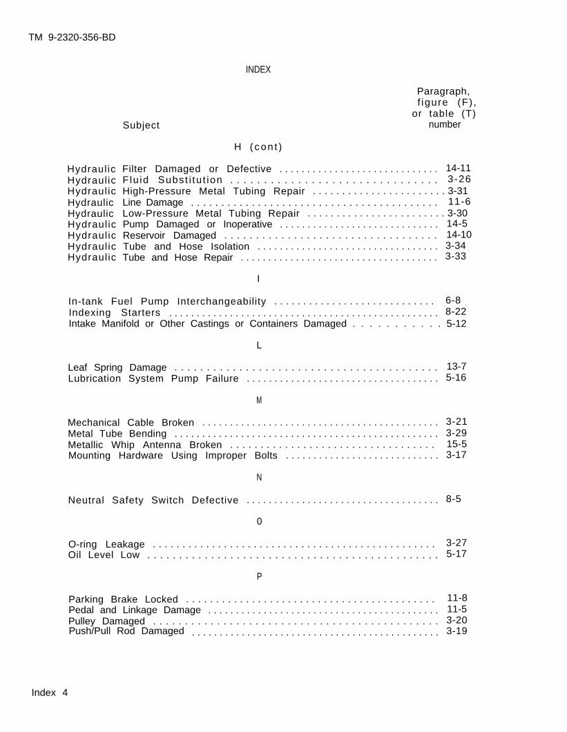
TM 9-2320-356-BD
INDEX
HydraulicHydraulicHydraulicHydraulicHydraulicHydraulicHydraulicHydraulicHydraulic
Paragraph,f igure (F) ,
or table (T)Subject number
H ( con t )
Filter Damaged or Defective . . . . . . . . . . . . . . . . . . . . . . . . . . . . . 14-11Flu id Subst i tu t ion . . . . . . . . . . . . . . . . . . . . . . . . . . . . . . . 3-26High-Pressure Metal Tubing Repair . . . . . . . . . . . . . . . . . . . . . . . 3-31Line Damage . . . . . . . . . . . . . . . . . . . . . . . . . . . . . . . . . . . . . . . . . 11-6Low-Pressure Metal Tubing Repair . . . . . . . . . . . . . . . . . . . . . . . . 3-30Pump Damaged or Inoperative . . . . . . . . . . . . . . . . . . . . . . . . . . . . . 14-5Reservoir Damaged . . . . . . . . . . . . . . . . . . . . . . . . . . . . . . . . . . 14-10Tube and Hose Isolation . . . . . . . . . . . . . . . . . . . . . . . . . . . . . . . . . 3-34Tube and Hose Repair . . . . . . . . . . . . . . . . . . . . . . . . . . . . . . . . . . . . 3-33
I
In-tank Fuel Pump Interchangeability . . . . . . . . . . . . . . . . . . . . . . . . . . . . 6-8Indexing Starters . . . . . . . . . . . . . . . . . . . . . . . . . . . . . . . . . . . . . . . . . . . . . . . . . 8-22Intake Manifold or Other Castings or Containers Damaged . . . . . . . . . . . 5-12
L
Leaf Spring Damage . . . . . . . . . . . . . . . . . . . . . . . . . . . . . . . . . . . . . . . . . 13-7Lubrication System Pump Failure . . . . . . . . . . . . . . . . . . . . . . . . . . . . . . . . . . . 5-16
M
Mechanical Cable Broken . . . . . . . . . . . . . . . . . . . . . . . . . . . . . . . . . . . . . . . . . . . 3-21Metal Tube Bending . . . . . . . . . . . . . . . . . . . . . . . . . . . . . . . . . . . . . . . . . . . . . . . . 3-29Metallic Whip Antenna Broken . . . . . . . . . . . . . . . . . . . . . . . . . . . . . . . . . . 15-5Mounting Hardware Using Improper Bolts . . . . . . . . . . . . . . . . . . . . . . . . . . . . 3-17
N
Neutral Safety Switch Defective . . . . . . . . . . . . . . . . . . . . . . . . . . . . . . . . . . . 8-5
0
O-ring Leakage . . . . . . . . . . . . . . . . . . . . . . . . . . . . . . . . . . . . . . . . . . . . . . . . 3-27Oil Level Low . . . . . . . . . . . . . . . . . . . . . . . . . . . . . . . . . . . . . . . . . . . . . . 5-17
P
Parking Brake Locked . . . . . . . . . . . . . . . . . . . . . . . . . . . . . . . . . . . . . . . . . . 11-8Pedal and Linkage Damage . . . . . . . . . . . . . . . . . . . . . . . . . . . . . . . . . . . . . . . . . . 11-5Pulley Damaged . . . . . . . . . . . . . . . . . . . . . . . . . . . . . . . . . . . . . . . . . . . . . 3-20
3-19Push/Pull Rod Damaged . . . . . . . . . . . . . . . . . . . . . . . . . . . . . . . . . . . . . . . . . . . . .
Index 4
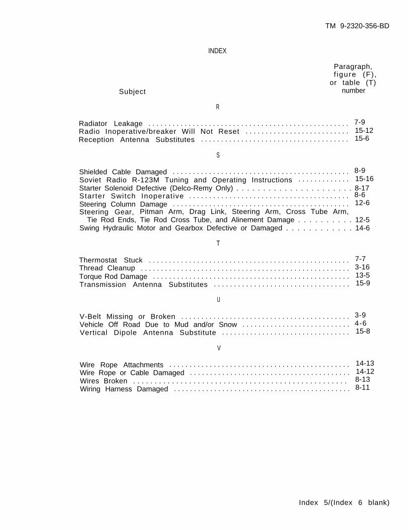
TM 9-2320-356-BD
INDEX
Paragraph,f igure (F) ,
Subjector table (T)
number
R
Radiator Leakage . . . . . . . . . . . . . . . . . . . . . . . . . . . . . . . . . . . . . . . . . . . . . . . . . . 7-9Radio Inoperative/breaker Will Not Reset . . . . . . . . . . . . . . . . . . . . . . . . . . 15-12Reception Antenna Substitutes . . . . . . . . . . . . . . . . . . . . . . . . . . . . . . . . . . . . . 15-6
S
Shielded Cable Damaged . . . . . . . . . . . . . . . . . . . . . . . . . . . . . . . . . . . . . . . . . . . . 8-9Soviet Radio R-123M Tuning and Operating Instructions . . . . . . . . . . . . . 15-16Starter Solenoid Defective (Delco-Remy Only) . . . . . . . . . . . . . . . . . . . . . . 8-17Starter Switch Inoperat ive . . . . . . . . . . . . . . . . . . . . . . . . . . . . . . . . . . . . . . . . 8-6Steering Column Damage . . . . . . . . . . . . . . . . . . . . . . . . . . . . . . . . . . . . . . . . . . . . 12-6Steering Gear, Pitman Arm, Drag Link, Steering Arm, Cross Tube Arm,
Tie Rod Ends, Tie Rod Cross Tube, and Alinement Damage . . . . . . . . . . 12-5Swing Hydraulic Motor and Gearbox Defective or Damaged . . . . . . . . . . . . 14-6
T
Thermostat Stuck . . . . . . . . . . . . . . . . . . . . . . . . . . . . . . . . . . . . . . . . . . . . . . . . . . 7-7Thread Cleanup . . . . . . . . . . . . . . . . . . . . . . . . . . . . . . . . . . . . . . . . . . . . . . . . . . . . 3-16Torque Rod Damage . . . . . . . . . . . . . . . . . . . . . . . . . . . . . . . . . . . . . . . . . . . . . . . . . 13-5Transmission Antenna Substitutes . . . . . . . . . . . . . . . . . . . . . . . . . . . . . . . . . . 15-9
U
V-Belt Missing or Broken . . . . . . . . . . . . . . . . . . . . . . . . . . . . . . . . . . . . . . . . . . 3-9Vehicle Off Road Due to Mud and/or Snow . . . . . . . . . . . . . . . . . . . . . . . . . . . 4-6Vertical Dipole Antenna Substitute . . . . . . . . . . . . . . . . . . . . . . . . . . . . . . . . 15-8
V
Wire Rope Attachments . . . . . . . . . . . . . . . . . . . . . . . . . . . . . . . . . . . . . . . . . . . . . 14-13Wire Rope or Cable Damaged . . . . . . . . . . . . . . . . . . . . . . . . . . . . . . . . . . . . . . . . 14-12Wires Broken . . . . . . . . . . . . . . . . . . . . . . . . . . . . . . . . . . . . . . . . . . . . . . . . . . 8-13Wiring Harness Damaged . . . . . . . . . . . . . . . . . . . . . . . . . . . . . . . . . . . . . . . . . . . . 8-11
Index 5/(Index 6 blank)
TM 9-2320-356-BD
By Order of the Secretary of the Army:
Official:
CARL E. VUONOGeneral, United States Army
Chief of Staff
R.L. DILWORTHBrigadier General, United States Army
The Adjutant General
DISTRIBUTION :
To be distributed in accordance with DA Form 12-38,Operator, Unit and Direct and General Support Maintenancerequirements for Truck, Utility, ¼-Ton, 4x4, M151-series andM718-series; and Truck, Utility, 5/4-Ton, 4x4, M966, M996,M997, M998, M1025, M1026, M1035, M1036, M1037, M1038, M1043,M1044, M1045, M1046, S250.
✩ U.S. GOVERNMENT PRINTING OFFICE: 1988 542-023/60203
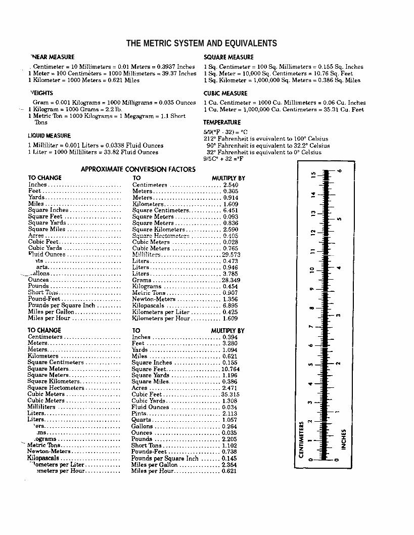
THE METRIC SYSTEM AND EQUIVALENTS

PIN: 063247 -001

![l>lf·· E ·B; -I,:,C-·-1·1V · cat. no.i bd lj.657 bd lj.6]5 bd 4630 bd 4·627 bd 4628 bd 4886 bd 4546 bd 4·545 bd 4544 bd 4542 bd lj,588 bd lj.593 bd 0102 bd 4636 bd 4632 bd](https://img.pdfslide.us/doc/110x75/5f7c69bb7d840d18665ab1e6/llf-e-b-ic-11v-cat-noi-bd-lj657-bd-lj65-bd-4630-bd-4627-bd-4628-bd.jpg)