Embed Size (px)
Citation preview
T M 9-1981
WAR DEPARTMENT TECHNICAL MANUAL
MILITARYPYROTECHNICS
WAR DEPARTM ENT • 8 DECEMBER 1943
RESTRICTED DISSEMINATION OF RESTRICTED MATTER — The information contained in restricted documents and the essential characteristics of restricted materiel may be given to any person known to be in the service of the United States and to persons of undoubted loyalty and discretion who are cooperating in Government work, but will not be*communicated to the public or to the press except by authorized military public relations agencies. (See also par. 18 b, AR 380-5, 28 Sep 1942.)
W AR D E PA R TM E N TWashington 25, D. C., 8 December 1943
T M 9-1981, Military Pyrotechnics, is published for the information and guidance of all concerned.
IA.G. 300.7 (2 Aug 43)O.O. 461/42631 (8 Dec 43) J
B y order of th e Se c r e ta r y of W a r :
G. C. M ARSHALL,Chief of Staff.
O f f ic ia l :
J. A. ULIO,Major General,
The Adjutant General.
D is t r ib u t io n : R & H 1, 7 & 17 (3 ) : R 9 (4 ) ; Bn 9 (2 ) , 1, 6, 7 & 17(2 ) ; C 9 (5 ) , 2, 6, 7 & 17 (2 )
(For explanation of symbols, see FM 21-6.)
*T M 9-1981
CONTENTS
P aro g ra p h j Pages
CHAPTER 1. G en er a l ................................... 1-23 4-27
Section I. Introduction .......................... 1 4
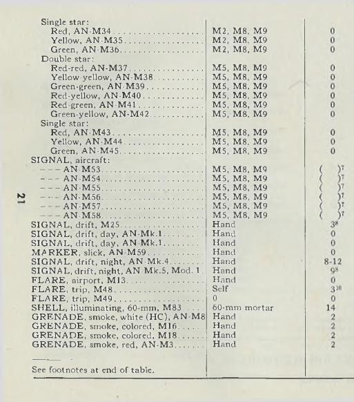
II. General discussion ................ 2—15 4-17
III. Visibility ................................ 16-19 17-19
IV. Tables of pyrotechnic data . 20-23 19-27
CHAPTER 2. A ir cr aft t y p e s ........................ 24-42 28-53
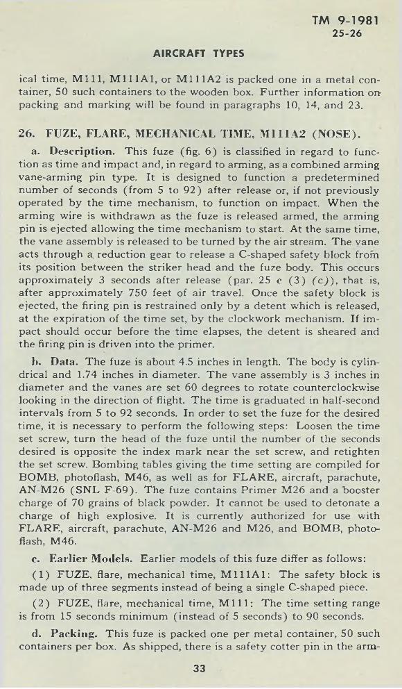
Section I. Flares ...................................... 24-30 28-40
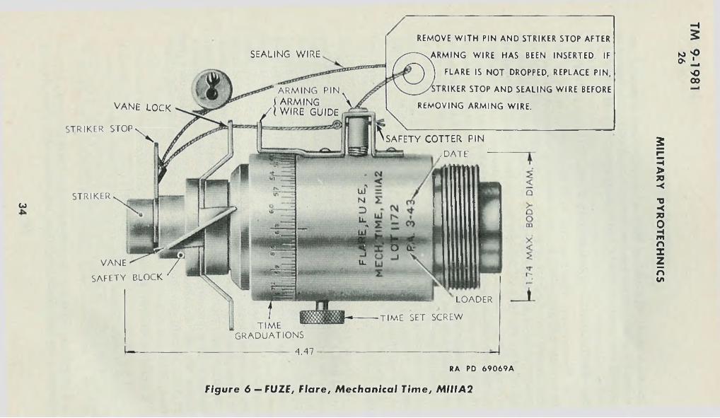
II. Photoflash bombs .................. 31-32 40—43
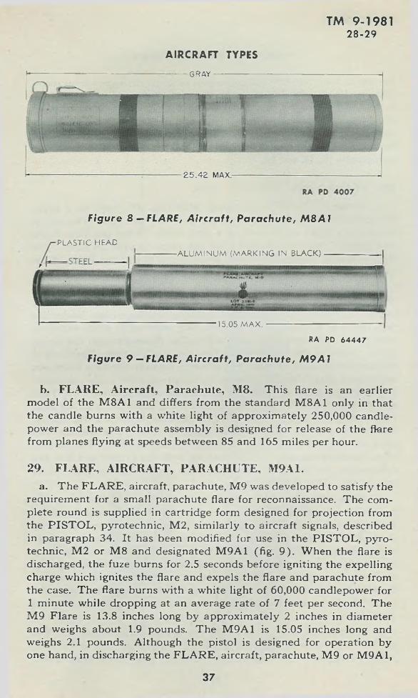
III. Signals .................................... 33-42 43-53
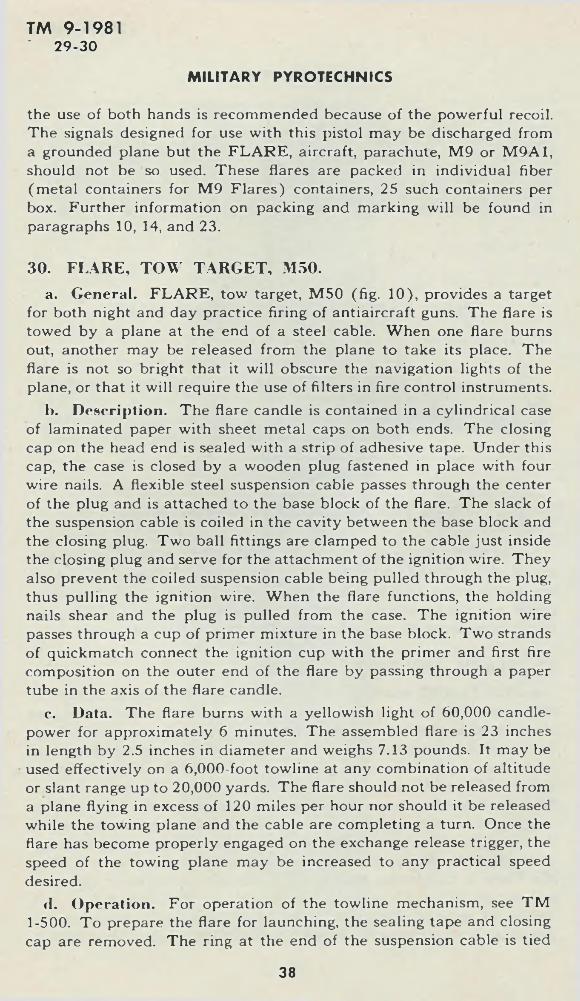
CHAPTER 3. G round t y p e s .......................... 43-49 54-68
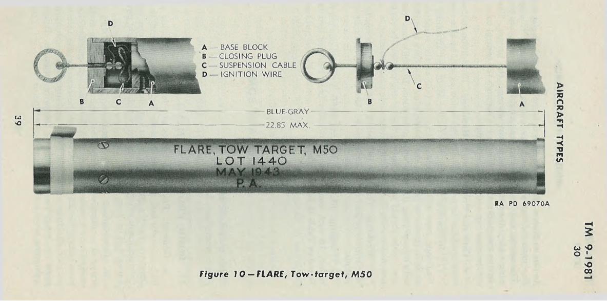
Section I. Flares ..................................... 43-47 54-61
II. Signals ................................... 48-49 62-68
CHAPTER 4. R e f e r e n c e s ...... ......... 50-52 69-70
IN D E X ............... ..................................................................... 71-72
* T h is manual supersedes T M 9-981, dated 30 M a y 1942 and C 1, dated 8 O ctober 1942; also TB 981-1 , dated 1 January 1942 and TB 981-2, dated 13 A utu st 1942.
3
CHAPTER 1
GENERAL
Section I
INTRODUCTION
TM 9-19811
MILITARY PYROTECHNICS
Paragraph
Scope ..................................................................................................... 1
1. SCOPE.a. This manual is published for the information and guidance of
all concerned.I). This manual provides information of a technical nature regard
ing the identification, properties, care, and use of military pyrotechnics and related items.
c. This manual differs from TM 9-981. dated 30 M ay 1942, by inclusion of additional data and new models.
Section II
GENERAL DISCUSSION
Paragraph
General ................................................................................................... 2Nom enclature........................................................................................ 3Classification ........................................................................................ 4Pyrotechnic compositions ................................................................. 5Identification ........................................................................................ 6Model ..................................................................................................... 7Ammunition lot number.............................- ...................................... 8Ammunition data card........................................................................ 9Painting and marking................................... -..................................... 10Priority of issue..................................................................................... 11Expiration date ................................................................................... 12Care, handling, and preservation........................................................ 13Packing and marking for shipment................................................... 14Field report of accidents..................................................................... 15
4
GENERAL
TM 9-19812-4
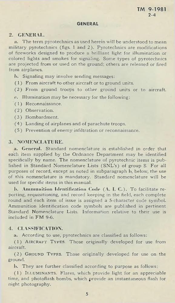
2. GENERAL.a. The term pyrotechnics as used herein will be understood to mean
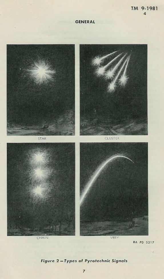
military pyrotechnics (figs. 1 and 2 ). Pyrotechnics are modifications of fireworks designed to produce a brilliant light for illumination or colored lights and smokes for signaling. Some types of pyrotechnics are projected from -or used on the ground: others are released or fired from airplanes.
b. Signaling may involve sending messages:(1 ) From aircraft to other aircraft or to ground units.(2 ) From ground troops to other ground units or to aircraft.c. Illumination may be necessary for the following:(1 ) Reconnaissance.( 2 ) Observation.(3 ) Bombardment.(4 ) Landing of airplanes and of parachute troops.(5 ) Prevention of enemy infiltration or reconnaissance.
3. NOMENCLATURE.a. General. Standard nomenclature is established in order that
each item supplied by the Ordnance Department may be identified specifically by name. The nomenclature of pyrotechnic items is published in Standard Nomenclature Lists (SN L ’s) of group S. For all purposes of record, except as noted in subparagraph b, below, the use of this nomenclature is mandatory. Standard nomenclature will be used for specific items in this manual.
1). Amm unition Identification Code (A . I. C .). To facilitate reporting, requisitioning, and record keeping in the field, each complete round and each item of issue is assigned a 5-character code symbol. Ammunition identification code symbols are published in pertinent Standard Nomenclature Lists. Information relative to their use is included in FM 9-6.
4. CLASSIFICATION.a. According to use, pyrotechnics are classified as follows:( 1 ) A ir c r a ft T y p e s . Those originally developed for use from
aircraft.( 2 ) G round T y p e s . Those originally developed for use on the
ground.1). They are further classified according to purpose as follows:( 1) Il l u m in a n t s . Flares, which provide light for an appreciable
time, and photoflash bombs, which provide an instantaneous flash for night photography.
5
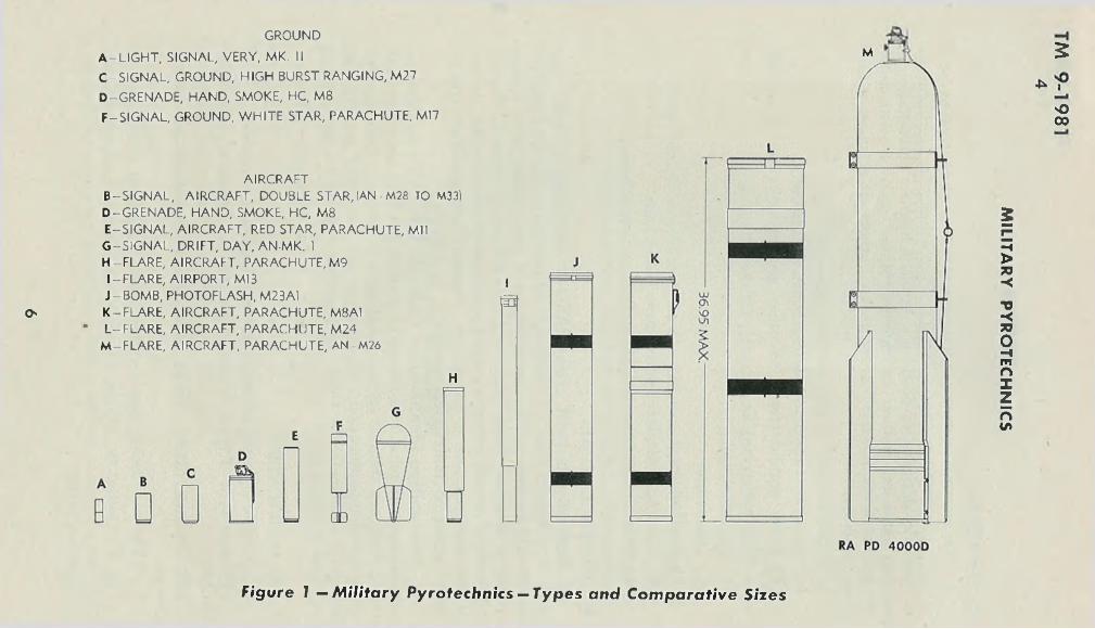
GROUND
O'
A-LIGHT, SIGNAL, VERY, MK. IIC -SIGNAL, GROUND, HIGH BURST RANGING, M27
D-GRENADE, HAND, SMOKE, HC, M8F-SIGNAL, GROUND, WHITE STAR, PARACHUTE, M17
AIRCRAFTB-SIGNAL, AIRCRAFT, DOUBLE STAR,(AN-M28 TO M33) D-GRENADE, HAND, SMOKE, HC, M8 E-SIGNAL, AIRCRAFT, RED STAR, PARACHUTE, Mil G -SIGNAL, DRIFT, DAY, AN-MK. 1 H-FLARE, AIRCRAFT, PARACHUTE, M9 I-FLARE, AIRPORT, M13 J-BOMB, PHOTOFLASH, M23A1 K-FLARE, AIRCRAFT, PARACHUTE, M8A1
* L-FLARE, AIRCRAFT, PARACHUTE, M24 M -FLARE, AIRCRAFT, PARACHUTE, AN M26
E
H
I!o
M 5
'O00
F igu re 1 — M i l ita ry P y ro tech n ic s — T y p e s a n d C o m p a ra t iv e S ize s
MIL
ITA
RY
P
YR
OT
EC
HN
ICS
GENERAL
TM 9-19814
STAR CLUSTER
CHAIN VERYRA PD 5 3 1 7
F igure 2 — T ype s of Pyrotechn ic S ign a ls
7
TM 9-19814 -7
(2 ) Signals which produce lights or smokes of various colors and arrangements for the conveyance of messages.
c. Any of the above types, when provided with parachutes, are known as parachute types.
5. PYROTECHNIC COMPOSITIONS.a. Pyrotechnic compositions consist of a mixture of chemical ele
ments and compounds. On burning, they produce illumination which ranges in intensitj' from the “dark fire” used as an element of blinker signals to the brilliant flash of photoflash bombs. Standard pyrotechnic compositions, in general, consist of compounds to provide oxygen for burning, such as chlorates and nitrates; aluminum or magnesium for fuel; salts of barium, copper, or strontium for color, and agents such as asphalt and paraffin for binding and waterproofing.
Ik Pyrotechnics generally function by means of an igniter train similar to the explosive train. In general, ignition is initiated by a primer mixture and intensified by a “first-fire composition” which properly ignites the luminous candle.
6. IDENTIFICATION., a. Each pyrotechnic item is completely identified by the painting
and marking (which includes standard nomenclature and the ammunition lot number). The marking includes all information necessary for the intelligent handling, storage, and use of the item. It is placed on all containers and, where the size of the item permits, on the item itself.
1). In addition to the standard markings, varieties of one type of signal carry, as a means of identification among themselves, additional marking as follows:
(1 ) Aircraft signals are distinguished by the color and, in some cases, by the embossing on the identification top (outer wad) (pars. 34 and 35) (figs. 13 and 14).
(2 ) Some ground signals are distinguished by the color and embossing on the fin, others by the color and embossing on the identification top (par. 48) (fig. 22).
(3 ) Very signals are distinguished by the color and form of the outer wad (par. 49) (fig. 23).
7. MODEL.a. T o distinguish a particular design, a model designation is as
signed at the time the model is classified as an adopted type. This model designation becomes an essential part of the standard nomenclature and is included in the marking on the item. Prior to 1 July 1925, it was the practice to assign mark numbers. The word “Mark,” abbreviated “Mk.,” was followed by a Roman numeral, for example:
MILITARY PYROTECHNICS
8
TM 9-19817 -1 0
LIGH T, signal, Very, Mk. II, 10-gage. The first modification of a model was indicated by the addition of M I to the mark number, the second by M il, etc. The present system of model designations consists of the letter M followed by an Arabic numeral. Modifications in design are indicated by adding the letter A and appropriate Arabic numerals. Modification in material employed in construction is indicated by adding the letter B and appropriate Arabic numerals. Thus M8A1 indicates the first modification of an item for which the original model designation was M8. Certain items have been adopted for use by both Army and Navy. These are designated by the letters AN preceding the mark or model number.
8. AMMUNITION LOT NUMBER.a. When ammunition is manufactured, an ammunition lot number,
which becomes an essential part of the marking, is assigned in accordance with pertinent specifications. This lot number is stamped or marked on every item of ammunition unless the item is too small, on all packing containers, and on the accompanying ammunition data card. It is required for all purposes of record, including reports on condition, functioning, and accidents in which the ammunition is involved. T o provide for the most uniform functioning, all of the components in any one lot are manufactured under as nearly identical conditions as practicable.
9. AMMUNITION DATA CARD.a. A 5- by 8-inch card, known as an ammunition data card, is sent
with each shipment of ammunition. When required, assembling and firing instructions are printed on the reverse side of the card.
10. PAINTING AND MARKING.a. Painting. Ammunition is painted to prevent rust and to provide,
by the color, a ready means of identification as to type. Pyrotechnics, except those which have an outer covering or case of aluminum, are painted gray and marked in black. (Exceptions are rimless type aircraft signals with plastic base and steel body and cartridge type aircraft signals. These are coated with colorless lacquer and are marked in black.) Other chemical ammunition is also painted gray; but markings and bands— red, green, purple, or yellow— indicate the kind of chemical filler and serve to distinguish between other types of chemical ammunition and pyrotechnics.
h. Marking. Pyrotechnics are marked in such a way as to provide positive identification for all purposes. Each item is marked to show the type and model, ammunition lot number, manufacturer’s initials or symbol, date of manufacture, and, where required, limiting date for use.
GENERAL
9
TM 9-198110-13
c. Overage flares assigned to training will have a blue band approximately 2 inches wide painted around the body immediately below the label. The flares may also be stenciled “FOR TRAIN IN G USE ONLY.” Those assigned to use as substitutes for airport flares will be stenciled “SUBSTITU TE FOR FLARE, AIRPO RT, M13.”
d. For the information of those installing M8, M8A1, and M24 Flares and M23 and M23A1 Photoflash Bombs in airplanes, the word “FR O N T ” is stenciled on the front of the case and the location of suspension bands is indicated by black bands painted on the case.
11. PRIO RITY OF ISSUE.a. Subject to special instructions from the Chief of Ordnance, am
munition of appropriate type and model will be used in the following order: Limited standard, substitute standard, standard. Within this rule, ammunition which has had the longest or least favorable storage will be used first. Among lots of equal age, priority will be given to the smallest lot. Further information will be found in OFSB 3-1, OFSB 3-9, and in AR 775-10.
12. EXPIRATION DATE.a. Some pyrotechnics deteriorate with age. The serviceable life of
these items is indicated in the marking. When the serviceable life has expired, pyrotechnics which are otherwise serviceable will be assigned to training or other use, as prescribed in OFSB 3-9.
13. CARE, HANDLING. AND PRESERVATION.a. Pyrotechnics contain \naterial of an intrinsically hazardous na
ture. Special precautions for certain pyrotechnics are prescribed in chapters 2 and 3. In general, the following regulations will be observed:
( 1) M o istu r e . The functioning of pyrotechnics is affected by moisture. Pyrotechnics are packed in moistureproof and hermetically sealed containers. The seals of such packings should not be broken until just before the item is to be used. If pyrotechnics are exposed to moisture, they should be segregated from all other material until an examination has been made to make sure that they are serviceable and not dangerous. Containers which show signs of dampness or moisture will be opened and, if there is any evidence of moisture on the pyrotechnics, they will be destroyed by authorized and experienced personnel.
( 2 ) H a n d l in g .(a ) Besides the hazardous pyrotechnic compositions, pyrotechnics
are composed of sensitive elements, such as fuzes, friction compositions, and primers. Disassembly of pyrotechnics or components is prohibited. Pyrotechnics should be handled with care and protected against shock;
MILITARY PYROTECHNICS
10
TM 9-198113
boxes should not be dropped or thrown. Boxes containing signal cartridges, which are discharged by percussion primers, should be placed flat with top up. Protective or safety devices should not be removed until just before use. Care should be exercised to avoid damage to fiber cases and parachute pull-out cords. t
(b ) Pyrotechnics, especially the type which are projected, should be so handled as to avoid denting or deforming the barrel or case. Pyrotechnics which are seriously dented or deformed will not be used.
( 3 ) Sto r ag e . Pyrotechnics should be stored in a dry, well-ventilated place, out of the direct rays of the sun, and protected against excessive or variable temperatures. Pyrotechnics should not be stored with other kinds of ammunition, except with small arms ammunition. When storage space is limited, pyrotechnics, except photoflash bombs, may be stored with burning type chemical ammunition (group D ) provided that the total quantity of pyrotechnic, chemical, and explosive material in the magazine does not exceed 1,000 pounds. Photoflash bombs will not be stored with other types of ammunition except that under conditions of limited storage space they may be stored in one magazine with small arms ammunition, provided the total amount of explosives and flashlight powder does not exceed 1,000 pounds. Red and green light pyrotechnics contain compositions which may explode under certain conditions, and hence should be stored separately if practicable. Certain pyrotechnics deteriorate in storage and have an expiration date on the containers. Care should be taken to observe the directions for disposal of this material at the time indicated as prescribed in OFSB 3-9. Smoking will not be permitted in places where pyrotechnics are stored. Matches or flame or spark producing articles will not be permitted in magazines and only approved lights will be used. Precautions should be taken to prevent fires and adequate fire fighting apparatus should be available.
( 4 ) F ires .(a ) Pyrotechnics, such as photoflash bombs and high burst ranging
signals, explode when heated. If a fire should occur in such stocks, there will be no time to take action to save them, so fire fighters’ efforts should be confined to saving surrounding magazines. Other types of pyrotechnics burn with intense heat without serious explosions. The use of water on such fires will generally hasten rather than retard the combustion and may cause explosions. Moreover, water will cause the spontaneous ignition of most pyrotechnic materials. Chemical fire extinguishers may generate quantities of poisonous gases when used on pyrotechnic fires.
(b ) The incendiary effect of pyrotechnic material should be kept in mind in using such material in the vicinity of dry brush and grass.
( 5 ) Se r v ic e a b il it y . Pyrotechnics and components will be maintained in serviceable condition. Those pyrotechnics whose service
GENERAL
ability is uncertain will be tested. Length of serviceable life of pyrotechnics is discussed in paragraph 12.
( 6 ) T o x ic it y . Pyrotechnic material is poisonous to men and animals if taken internally.
( 7 ) R e c o il . Because o f its powerful recoil, the pistol should be held with both hands in discharging the FLARE, aircraft, parachute, M9 or M9A1.
( 8 ) D uds. During maneuvers over terrain other than military reservations, the location of dud flares and photoflash bombs will be observed and reported. The duds will be sought out and destroyed as soon as possible by authorized and experienced personnel. Duds of photoflash bombs are especially dangerous and should be destroyed in place by detonation as provided in T M 9-1900. Painful burns, serious injury, or property damage may result if inexperienced persons handle duds, especially photoflash bomb duds.
(9 ) Sa f e A l titu d e s and D ist a n c e s . Flares not entirely burned out and cool when they land are liable to ignite combustible material. Safe altitudes and distances are dependent upon the burning time, dropping rate, and drift of the flare. Such factors will be considered in determining minimum altitudes and distances of release. Released safe, flares possibly, and photoflash bombs probably, will function on impact. Signals also are a potential fire hazard in case the parachute fails to support the signal properly. In tests and in training maneuvers, if fire is to be avoided, pyrotechnics will not be used over terrain covered with dry vegetation or other inflammable material unless adequate fire protection is available.
(1 0 ) B e fo r e and D u rin g F ir in g .(a ) Pyrotechnics should be inspected to locate any defective units.
Pyrotechnics should be kept clean. Any foreign substance such as dirt, sand, mud, or grease, will be carefully removed before pyrotechnics are stored or used.
(b ) Pyrotechnics to be fired should be stored in small amounts away from the firing point, either to the right or the left, but not directly behind the firing point. They should be placed so as to minimize the possibility of ignition or explosion in case of accident during firing. Smoking will be prohibited wherever pyrotechnics are piled, and only approved lights will be used in their vicinity. When firing pyrotechnics, extreme care should be taken to fire them in such a manner that burning material or burned out signals will not fall on the firer or other personnel, or into boxes of pyrotechnics or other ammunition. Care should also be exercised when firing through trees or obstructions.
( 1 1 ) M isf ir e .(a ) In case of a misfire or hangfire, aircraft signals and FLARES,
aircraft, M9 or M9A1 will be disposed of by releasing the flare from
TM 9-198113
MILITARY PYROTECHNICS
12
GENERAL
TM 9-198113
the pistol. In the case of the M2 Pyrotechnic Pistol, this is done by depressing the thumb release on the left-hand side of the breech of the pistol, which is held outside the airplane muzzle downward. In the case of the M8 Pyrotechnic Pistol, this is done by reversing the procedure used in loading. Hold pistol outside the airplane, muzzle downward.
(b ) In case cartridge type aircraft signals (par. 35) fail to fire from PISTOL, pyrotechnic, AN-M8, mounted in aircraft, the trigger should be pulled twice more and, if the signal still fails to fire, 30 seconds should be allowed to pass. The pistol will then be removed from the mount and unloaded. The misfire signal will be disposed of through the opening in the pistol mount., ( c ) In case rimless type aircraft signals (par. 34) or the M9A1 Aircraft Flare (par. 29) fail to fire from PISTOL, pyrotechnic, AN-M8, mounted in aircraft, the trigger should be pulled twice more and, if the item still fails to fire, 30 seconds should be allowed to pass. Then, leaving the pistol in the mount, the signal or flare will be ejected by opening the pistol, lifting the breech block, depressing the ejector, and pushing the signal or flare forward and out of the barrel.
( d) When the signal or flare might damage the plane if ejected as described above, the round should be ejected through some other opening such as bomb bay door or window as quickly as possible. No safe delay can be assumed.
( 1 2 ) R e n o v atio n . The only pyrotechnics which are reconditioned or renovated are those which are issued in metal cases. Such work will be done in accordance with specific instructions from the Chief of Ordnance.
( 1 3 ) P h o to fla sh B o m b s . Photoflash bombs must be handled with particular care at all times. The flashlight powder used in such bombs is as hazardous as black powder and all precautions taken in handling black powder should be observed in handling photoflash bombs. Noninsulating safety shoes should be worn. If any powder is spilled, all work in the vicinity must be stopped until the loose powder is taken up and the residue washed with water. The spilled powder should be taken up by such a method as touching the powder gently with a wet cloth. The powder adhering to the cloth should be rinsed off beneath the surface in a bucket of water. The process should be repeated until the powder is removed. The explosive properties of any possible residue should then be destroyed by washing the spot with liberal quantities of water. Loose powder and the damaged bomb and container will be placed in a tight covered container to be transported to the disposal area. Powder residue may be neutralized with water but water should not be used on a large amount of the powder. If necessary to protect flashlight powder immediately, cover it with talcum, chalk, or some similar inert, nonabrasive powder.
13
TM 9-198113 -14
(1 4 ) F u ze s . Fuzes should be examined for any deterioration, such as heavy rust or corrosion, which might impair proper functioning. Only serviceable fuzes will be used.
(1 5 ) Su spen sion L ugs. Suspension lugs should be examined for any damage which might weaken the lug or its attachment to the body of the pyrotechnic. Lugs for horizontal suspension should be gaged to assure proper center distance and alinement.
(1 6 ) F uzing. Fuzing and unfuzing will be done at a safe distance from magazines.
( 1 7 ) R e pa c k in g and Sto r ag e . Pyrotechnics will ordinarily be on hand only in sufficient quantities to meet immediate requirements. Any assembled complete rounds in excess of such requirements will be restored to their original packings and appropriately marked. Prior to repacking, components will be inspected and those which were originally sealed will be resealed. Such ammunition should be used first in subsequent firings in order that the stock of opened packings may be kept at a minimum.
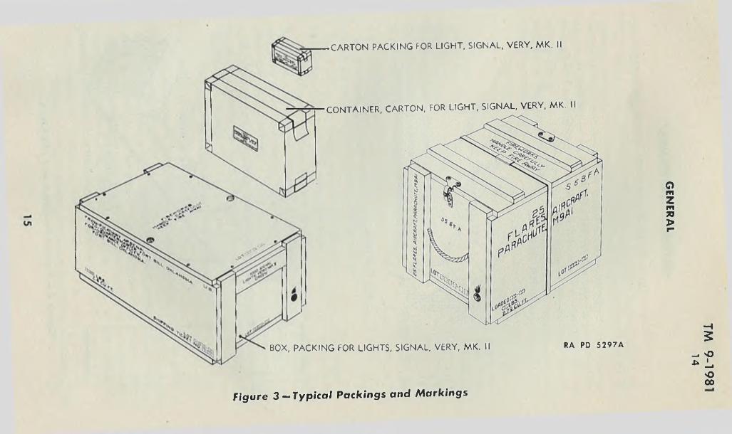
14. PACKING AND MARKING FOR SHIPMENT.a. Pyrotechnics are packed and marked in accordance with perti
nent specifications and drawings. Packings are designed to withstand all conditions ordinarily encountered in handling, storage, and transportation and to comply with Interstate Commerce Commission regulations. Due consideration is given in packing to prevent the entrance of moisture. Packing and marking data are given in paragraph 23 of this manual, SNL S-l and S-5, and under the specific items described herein.
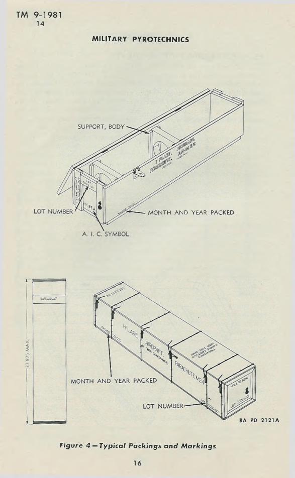
b. Pyrotechnics are packed in metal-lined or unlined, nailed or wire- bound wooden boxes. Those in unlined boxes are placed in inner containers consisting of sealed corrugated board cartons, cylindrical fiber containers, or metal containers. The cartons are dipped in paraffin to protect the contents from moisture. All containers are labeled or marked to show the type or kind, lot number, quantity, and limiting date for use, if any. Typical packings and marking thereon are illustrated in figures 3 and 4.
c. Marking includes all information required.( 1) For complete identification of contents.(2 ) By the Interstate Commerce Commission for shipping, includ
ing addresses of consignor and consignee and shipping designation of the contents.
(3 ) For intelligent handling, storage, and use.d. Pyrotechnics are marked as “FIREW O RK S’' for shipment, with
the exception of photofiash bombs which are marked with the words “EXPLOSIVE BOMB.”
MILITARY PYROTECHNICS
14
CARTON PACKING FOR LIGHT, SIGNAL, VERY, MK. II
CONTAINER, CARTON, FOR LIGHT, SIGNAL, VERY, MK.
BOX, PACKING FOR LIGHTS, SIGNAL, VERY, MK. II RA PD 5 2 9 7 A
-I5
- o u l ,
sO 00
F igu re 3 -‘ Typ ica l P a c k in g s a n d M a r k in g s
GE
NE
RA
L
37 8
75 M
AX
TM 9-198114
MILITARY PYROTECHNICS
SUPPORT, BODY
MONTH AND YEAR PACKED
Figure 4 — Typical Pa ck ing s and M a rk in g s
16
GENERAL
TM 9-198115 -17
15. FIELD REPO RT OF ACCIDENTS.a. When an accident involving the use of ammunition occurs during
training practice, the procedure prescribed in AR 750-10, will be observed by the ordnance officer under whose supervision the ammunition is maintained or issued. Where practicable, reports covering malfunctions of ammunition in combat will be made to the Chief of Ordnance, giving the type of malfunction, type of ammunition, the lot number of the complete rounds or separate-loading components, and condition under which fired.
Section^ III
VISIBILITYParagraph
General .................................... _....... .................................................. 16Variation due to design.... ............................................................ ..... 17Variation due to position............................................ ........ . ......... 18Variation due to atmospheric conditions....................................... 19
16. GENERAL.a. The principal factors controlling the effectiveness of pyrotechnics
are design, position, and atmospheric conditions.b. Factors of design include candlepower, color, and degree of
separation of the parts of a composite signal (blinker, cluster, or chain).c. Factors of position include height at which the flare or signal
functions, distance of observer from signal, distance of flare from objective to be illuminated, background, and relative position of flare, objective, and observer.
<1. Atmospheric conditions include clarity of atmosphere, time (day or night), presence of haze, fog, dust, rain, or snow, and the color and brightness of the sky.
e. Tables of visibility will be found in section IV.
17. VARIATION DDE TO DESIGN.a. Candlepower. The visibility of signals and illuminating power of
flares depends primarily on the candlepower of the pyrotechnic candle. Although there are minor variations due to composition and density, there is a limit to the amount of light produced by a given weight of candle. Thus a short, thick candle will give greater illumination for a shorter time than a long thin candle of the same weight, which will burn for a longer time with less brilliance.
b. Color.(1 ) Variation in the visibility of signals due to color is due to the
following two factors:
17
(a ) The greater sensitivity of the eye to colors in the middle of the spectrum, that is, to yellow and its neighbors green and orange.
(b ) The greater ability of the longer light waves (reds and yellows) to penetrate haze and fog.
(2 ) Color and texture of an objective control the amount of light reflected by it and, consequently, its visibility. For example, barren ground, such as an airport, reflects three or four times as much light as woods or deep water and needs less illumination.
c. Type. A light can be seen much farther than its pattern can be distinguished. At ranges of 2 miles or more, the various parts of such signals as chains or clusters blend into each other, giving the impression of a single spot of light. In addition, most colors fade or otherwise change at long range. Consequently, cluster and chain signals are apt to be misunderstood at distances greater than 1,500 yards in the daytime or 2 miles at night.
18. VARIATION DUE TO POSITION.a. Distance. Light varies inversely as the square of the distance;
that is, a source of illumination will shed on a unit area one-fourth as much light at 2 feet as it will at 1 foot.
b. Relative Position.(1 ) The closer a flare is to an objective, the greater will be the
illumination and, hence, the greater the visibility, provided the flare is not so close to the line of vision as to blind the observer by its glare.
(2 ) A flare above and behind the observer illuminates nearby objects well but is useless for long range observation.
(3 ) A flare midway between the observer and objective loses effectiveness due to the distance its light must travel to the objective and back to the observer.'
(4 ) A flare placed behind the objective and almost in the line of vision is useful in silhouetting the objective, especially when the atmosphere is slightly hazy.
c. Background. Backgrounds which offer contrast in color or brightness increase visibility; noncontrasting backgrounds materially reduce it.
d. Angle o f Observation. Although light is diffused in all directions from an unpolished object, the maximum amount of light is reflected according to the same principle as that of a mirror: The angle at which the light leaves the reflecting surface is equal to the angle at which it strikes;,this angle of observation will consequently give maximum visibility.
19. VARIATION DUE TO ATMOSPHERIC CONDITIONS.a. Particles of dust, moisture, or smoke in the air materially reduce
visibility. All colors are affected, but the reds and yellows less so than
TM 9-198117 -19
MILITARY PYROTECHNICS
18
GENERAL
TM 9-198119-23
the greens and blues. Heavy fog, snow, or rain will totally obscure the light from pyrotechnics at distances so short as to make their use impractical. Sky background and direction alter color and distinctiveness materially, for example, looking toward the sun.
Section IV
TABLES OF PYROTECHNIC DATA
Relative visibility....................................................................Distinguishability ........... ........................................................Authorized rounds ............................................... .......... .......Packing data ....... ...................................................................
20. RELATIVE VISIBILITY.a. The following table will serve as a guide in the use of pyrotech
nics. This table is based on a fixed distance. Variation due to distance should be calculated by use of the inverse square law (pat. 18 a).
b. Candlepower of colored light necessary for visibility at 5,000 yards:
R E D A M B E R W H IT E G R E E N
Night, clear........................................... 1.0 2.0 2.5 2.8Night, rain, light................................. 1.2 2.1 3.0 3.2Night, overcast and haze................... 3.2 4.1 3.1 5.9Night, rain, heavy............................... 8.9 33.5 132.0 33.5Night, snow, light............................... 222.0 835.0 1,556.0 567.0Day, overcast and haze..................... 2,000.0 2,111.0 3,222.0 4,000.0Day, clear.............................................. 4,778.0 7,556.0 11,111.0 10,000.0
21. DISTINGUISHABILITY.a. Distances at which, under average weather conditions, the vari
ous types of signals may be recognized are governed by the following considerations. Signals may be seen at greater distances but, due to the tendency of colors to change with distance and the tendency of several lights to merge into one, reliable recognition of the type of signal should not be expected at distances notably greater than 1,500 yards in the daytime, or 2 miles at night.
22. AUTHORIZED ROUNDS.a. Table I below lists the pyrotechnic items currently authorized,
together with pertinent data.
23. PACKING DATA.a. Table II below gives packing and shipping data for items de
scribed herein.
Paragraph. 20 . 21 . 22 . 23
19
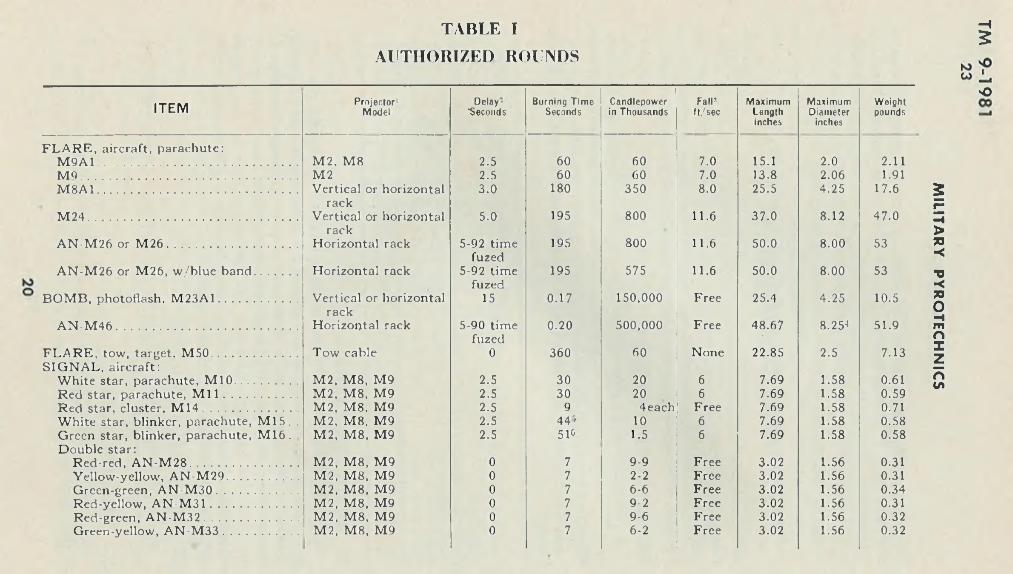
TABLE IAUTHORIZED ROUNDS
- i5
vOITEM Projector1
M o d e lD e lay-
"SecondsB u rn in g T im e
SecondsCandlepow cr in T h ou san d s
F a irft/sec
M a x im u mLengthinches
M a x im u mDiam eter
inches
W e igh tpounds
FLA R E , aircraft, parachute:M 9A 1............................................................ M2, M8 2.5 60 60 7.0 15.1 2.0 2.11MO................................................................. M2 2.5 60 60 7.0 13.8 2.06 1.91M 8A 1............................................................ Vertical or horizontal 3.0 180 350 8.0 25.5 4.25 17.6
M 24 ...............................................................rack
Vertical or horizontal 5.0 195 800 11.6 37.0 8.12 47.0
AN -M 26 or M 2 6 .......................................rack
Horizontal rack 5-92 time 195 800 11.6 50.0 8.00 53
AN -M 26 or M26, w /blue band............. Horizontal rackfuzed
5-92 time 195 575 11.6 50.0 8.00 53
BOM B, photoflash, M 23A1........................ Vertical or horizontalfuzed
15 0.17 150,000 Free 25.4 4.25 10.5
A N -M 46 ......................................................rack
Horizontal rack 5-90 time 0.20 500,000 Free 48.67 8.25J 51.9
FLARE, tow, target. M 50.......................... Tow cablefuzed
0 360 60 None 22.85 2.5 7.13SIGN AL, aircraft:
White star, parachute, M 10................... M2, M8, M9 2.5 30 20 6 7.69 1.58 0.61Red star, parachute, M i l ...................... M2. M8, M9 2.5 30 20 6 7.69 1.58 0.59Red star, cluster, M 1 4 ............................ M2, M8, M9 2.5 9 4each Free 7.69 1.58 0.71White star, blinker, parachute, M 15. . M2, M8, M9 2.5 44' 10 6 7.69 1.58 0.58Green star, blinker, parachute, M 16. M2, M 8, M9 2.5 516 1.5 6 7.69 1.58 0.58Double star:
Red-red, A N -M 28 ................................ M2, M8, M9 0 7 9-9 Free 3.02 1.56 0.31Yellow-yellow, A N -M 29..................... M2, M 8, M9 0 7 2-2 Free 3.02 1.56 0.31Green-green, A N -M 30 ........................ M2, M8, M9 0 7 6-6 Free 3.02 1.56 0.34Red-yellow, A N -M 31 .......................... M2, M8, M9 0 7 9-2 Free 3.02 1.56 0.31Red-green, A N -M 32 ............................ M2. M8, M9 0 7 9-6 Free 3.02 1.56 0.32Green-yellow, A N -M 33...................... M2, M8, M9 0 7 6-2 Free 3.02 1.56 0.32
MIL
ITA
RY
P
YR
OT
EC
HN
ICS
Single star:Red, A N -M 34......................................Yellow, A N -M 35..................................Green, AN -M 36....................................
Double star:Red-red, A N -M 37................................Yellow-yellow, AN -M 38.....................Green-green, A N -M 39........................Red-yellow, A N -M 40.........................Red-green, A N -M 41...........................Green-yellow, AN-M42 ....................
Single star:Red, A N -M 43.......................................Yellow, A N -M 44..................................Green, AN -M 45....................................
SIGNAL, aircraft:- A N -M 53...........................................
-------AN -M 54.............................................-------AN -M 55.............................................
M ------ A N -M 56.............................................-------A N -M 57.............................................
- AN -M 58...........................................SIGNAL, drift, M 25...................................SIGNAL, drift, day, A N -M k .l................SIGNAL, drift, day, AN M k .l..............M A R K E R , slick, AN M 59.......................SIGNAL, drift, night, AN -M k.4..............SIGNAL, drift, night, AN-Mk.5, Mod. 1.FLARE, airport, M 13.................................FLARE, trip, M 48......................................FLARE, trip, M 49......................................SHELL, illuminating, 60-mm, M 83........GREN ADE, smoke, white (HC), AN M8GREN ADE, smoke, colored, M 16..........G REN ADE, smoke, colored, M 18..........GREN ADE, smoke, red, A N -M 3............
M2, M8, M9 M2, M8, M9 M2, M8, M9
M5, M8, M9 M5, M8, M9 M5, M8, M9 M5, M8, M9 M5, M8, M9 M5.-M8, M9
M5, M8, M9 M5, M8, M9 M5, M8, M9
M5, M8, M9 M5, M8, M9 M5, M8. M9 M5, M8, M9 M5, M8, M9 M5, M8, M9 Hand Hand Hand Hand Hand Hand Hand Self 060-mm mortarHandHandHandHand
See footnotes at end o f table.
7 9 Free 3.02 1.56 0.247 2 Free 3.02 1.56 0.247 6 Free 3.02 1.56 0.25
7 25-25 Free 3.85 1.54 0.357 12-12 Free 3.85 1.54 0.427 20-20 Free 3.85 1.54 0.357 25-12 Free 3.85 1.54 0.397 25-20 Free 3.85 1.54 0.357 20 12 Free 3.85 1.54 0.39
7 25 Free 3.85 1.54 0.277 15 Free 3.85 1.54 0.267 30 Free 3.85 1.54 0.32
( )7 ( )7 Free 3.85 1.54 0.40( )7 ( )7 Free 3.85 1.54 0.38( V ( )7 Free 3.85 1.54 0.38( )7 ( )7 Free 3.85 1.54 0.38( )7 ( )7 Free 3.85 1.54 0.39( )7 ( )7 Free 3.85 1.54 0.39
60 0 (Floats) 16 2.4 1.7( ,)9 0 (Floats) 10 3.5 2.0( )9 0 (Floats) 10 3.5 2.5( )9 0 (Floats) 10.88 3.38 2.9
180-210 ( ) 12 (Floats) 13 4.2 2900-1020 ( ) 12 (Floats) 19 3 4
180 40 0 23 1.75 2.320 110 3 7.3 5.25 ( ) 1260 40 0 4 2.5 ( )ii
20-30 110-145 10 14.28 2.33 3.7120-150 Smoke Free 5.7 2.45 1.75110-150 Smoke13 Free 5.7 2.45 1.1-1.2
60 Smoke13 Free 5.7 2.45 1.1-1.2110-150 Smoke Free 5.7 3.41 1.5 to <}
tosO00
GE
NE
RA
L
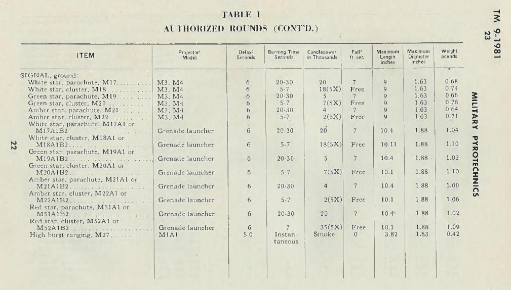
TABLE I
AUTHORIZED ROUNDS (CON T’D .)
—i5
OITEM Projector1
M o d e lD e lay :
Second sB u rn in g T im e
Seco n d sCandlepow er in T h ou san d s
Fall*ft/sec
M a x im u mLengthInches
M a x im u mDiam oter
Inches
W eightpounds
SIGN AL, ground:White star, parachute, M 17................... M 3, M4 6 20-30 20 7 9 1.63 0.68White star, cluster, M 1 8 ........................ M3, M4 6 5-7 18(5X) Free 9 1.63 0.74Green star, parachute, M 19................... M3, M4 6 20-30 5 7 9 1.63 0.66Green star, cluster, M 20 ......................... M3, M4 6 5-7 7(5X) Free 9 1.63 0.76Amber star, parachute, M 2 1 .......... M3, M4 6 20-30 4 7 9 1.63 0.64Amber star, cluster, M 22...................... M3, M4 6 5-7 2(5X) Free 9 1.63 0.71White star, parachute, M17A1 or
M 17A 1B 2................................................ Grenade launcher 6 20-30 20 7 10.4 1.88 1.04White star, cluster, M 18AI or
M I8A 1B 2................................................ Grenade launcher 6 5-7 18(5X) Free 10.11 1.88 1.10Green star, parachute, M19A1 or
M 19A 1B 2................................................ Grenade launcher 6 20-30 5 7 10.4 1.88 1.02Green star, cluster, M20A1 or
M 20A 1B 2................................................ Grenade launcher 6 5-7 7(5X) Free 10.1 1.88 1.10Amber star, parachute, M21A1 or
M 21A 1B 2............................................... Grenade launcher 6 20-30 4 7 10.4 1.88 1.00Amber star, cluster, M22A1 or
M 22A 1B 2................................................ Grenade launcher 6 5-7 2(5X) Free 10.1 1.88 1.06Red star, parachute, M51A1 or
M 51A 1B 2....... ..................................... Grenade launcher 6 20-30 20 7 10.4 1.88 1.02Red star, cluster, M52A1 or
M 52A 1B 2................................................ Grenade launcher 6 7 35(5X) Free 10.1 1.88 1.09High burst ranging, M 2 7 ........................ M1A1 5.0 Instan- Smoke 0 3.82 1.63 0.42
*
tancous
MIL
ITA
RY
P
YR
OT
EC
HN
ICS
LIG H T, signal, Very: Red star, Mk. I I . . White star, Mk. II Green star, Mk. I I .
Mk. I l l , M5 Mk. I l l , MS Mk. I l l , M5
0"0"0"
765
.3
.25
.6
0>'0"0>i
2.432.432.43
0.8750.8750.875
0.060.060.06
roco
1— Projeetors for signals:PROJECTOR, signal, ground, M1A1 PISTOL, pyrotechnic, M2 PROJECTOR, signal, ground, M3 PROJECTOR, signal, ground, M4 D ISCH ARG ER, pyrotechnic, M5 PISTOL, pyrotechnic, M8 PROJECTOR, pyrotechnic, hand, M9
2— Time from release or discharge to fullfunction
3— In still air4— Square tail 8.25 inches x 8.25 inches,
body 8 inch diameter5— Five periods of 5.5 seconds each sepa
rated by 4 seconds dark B—Five periods o f 7 seconds each sepa
rated by 4 seconds dark
7— See paragraph 35 h 3— No. o f seconds from water impact9— Forms a metallic slick— does not burn
10— To give 300- to 500-foot rise11— Burns on rise o f 200 feet12— Not available at time o f publication13— Colors available: Red, orange, yellow,
green, blue, violet and black
•H
io *0GO •
oCO
GE
NE
RA
L
TABLE II
PACKING AND SHIPPING DATA
IN N E RP A C K IN G
O U T E R P A C K IN G E S T IM A T E D P A C K IN G P E R
P A R .IN
T E X T IT E MM A R K I N G R E Q U I R E D
B Y I.C .C .M e thod
andD raw ing
No.
M e th o d D raw in gNo.
D I M E N S I O N S( F T )
A rea Vol. W t.Lbs.
No.
S H IPT O N SP E R
T R U C K R .R . C A R
R E G U L A T IO N S
L. W . H .
Sq.Ft.
Cu.Ft.
PerTon
P K G .1V4Ton
2 Vi Ton
40-Ton
50-Ton
25 FLARE, aircraft, parachute, M26 or AN-M 26 (all mods.)
FIR E W O R K S0 Handle carefully Keep fire away
None 1/W .Bx 76-16-25620-4-271
4.21 0.97 1.03 4.10 4.22 99 20 .106 31 52 574'’ 574V
28 FLARE, aircraft, parachute, M8A1
FIR E W O R K S" Handle carefully Keep fire away
1/cntrM40A1
76-1-24775-14-208
1/W .BB x 76-16-21220-4-187
2.37 0.50 0.50 1.19 0.60 27 74 .015 i l l 187 2984 3730
29 FLARE, aircraft, parachute, M9A1
F IR E W O R K S" Handle carefully Keep fire away
1/ean76-1-205
25/W .B x 76-16-16320-4-142
1.63 1.28 1.34 2.09 2.79 100 20 .070 30 50 800 810v
30 FLARE, tow-target, MSO FIR E W O R K S" Handle carefully Keep fire away
1/cntr M110 75-14-401
16/W .Bx 76-16-34820-4-372
2.28 1.15 1.21 2 62 3.18 157 12 .079 19 31 509 612''
32 BOM B, photoflash, M46 EXPLOSIVEBOM B'-(FLASH LIG H TPO W D E R )
None 1/W .Bx 76-16-32520-4-338
4.05 0.82 0.88 3.32 2.93 76 26 ,074 39 65 864v 864V
26 FUZE, flare, mechanical time, M i l l (all mods.)
D ETO N ATIN GFUZES"Handle carefully
1/can76-1-355
50/W .Bx 76-16-24720-4-255
1.39 1.26 0.97 1.75 1.70 74 27 041 40 68 1089 1360
H5
to 'PCO j_,Ooo
MILITA
RY
PYR
OTEC
HN
ICS
31 BOM B, photoflash, M23A1
EXPLOSIVEBO M B1-(FLASHLIGHTPOW DER)
1/cntr M56 76-1-313
1,/W.Bx
34 SIGNAL, aircraft (rimless)
red star parachute, M il
FIREW O RK S11 Handle carefully Keep fire away
12/crtn76-1-226
60/W .Bx
double star AN-M28 to AN-M33
FIREW ORKS0 Handle carefully Keep fire away
12/crtn76-1-402
144/W.Bx
single star AN M34 to AN-M36
FIREW ORKS0 Handle carefully Keep fire away
12/crtn76-1-1402
144/W.Bx
35 SIGNAL, aircraft (cartridge type)
double star AN-M37 to AN-M42
FIREW O RK S'1 Handle carefully Keep fire away
12/crtn76-1-427
144/W.Bx
single star AN-M43 to AN M45
FIRE W O RK S'1 Handle carefully Keep fire away
12/crtn76-1-427
144/W.Bx
AN-M53 to AN-M54 FIRE W O RK S'1 Handle carefully Keep fire away
12/crtn 144,/W.Bx
SHELL, illuminating, 60-rnm, M83
AM M U N ITIO N FOR CANNON W ITHEXPLOSIVEPRO JECTILE0
1/cntr M85 76-1-438
6/cntr M86 76-1-441
18/bdl
76 16-235 20-4-224
2.37 0.50 0.53 1 19 0.60 17 117 .015 176 296 4706 5202*
76-16-16720-4-149
2.06 1.18 0.93 2 43 2.27 61 32 .057 49 81 1064' 1064''
76-16-29120-4-307
2.22 1.02 0.90 2.26 2.04 79 25 .051 37 63 1012 1152V
■";-16-291 20-4 307
2.22 1.02 0.90 2.26 2 04 67 29 .051 44 74 1152 1152V
76 16-298 20-4-315
2.34 1.13 1.05 2.65 2.84 98 20 .071 30 51 816 952V
76-16.-29820-4-315
2.34 1.13 1.05 2.65 2.84 83 24 .071 36 60 952' 952'-
76-16-364 20 4-397
2 39 1.14
•
1.05 2.73 2 86 75 26 .072 40 66 784' 784'
76-1-29920-4-324
2.69 1 19 111 3.19 3.52 112 17 .088 26 44 648' 648' KJ "O W ' .>o00
GE
NE
RA
L
TABLE IIPACKING AND SHIPPING DATA (C O N T I).)
IN N E RP A C K IN G
O U T E R P A C K IN G E S T IM A T E D P A C K IN G P E R
P A R .IN
T E X T IT EMM A R K I N GR E Q U I R E D
BY I.C .C.M e thod
andD raw ing
No.
M e thod D raw ingNo.
D I M E N S I O N S( I T )
Area Vol. Wt.Lbs.
No.
S H IPT O N SP E R
T R U C K R .R . C A R
R E G U L A T IO N S
L. W . H .
Sq.Ft.
Cu.Ft.
PerTon
P K G .1V4Ton
2V4Ton
40-Ton
50-Ton
46 FLARE, trip, parachute, AM M U N ITIO N 1/crtn 10, W.Bx 76 16-347 2.70 1 09 0 91 2.94 2.68 88 22 .067 34 56 864' 864'’M48 FOR CANNON
W ITHEXPLOSIVEPROJECTILES
76-16-346 20-4-371
47 FLARE, trip. M49 FIREW ORKS'* None 25/W .Bx 76 16 349 1.79 1.26 0.81 2.25 1.82 59 34 .045 50 84 1355 1386'’Handle carefully Keep fire •«»way
76-16-350 20-4-373
36 G REN AD E, hand, smoke HAN D 1/cntr 25/W .Bx 76-16-188 1.53 1.45 0.67 2 17 1.34 48 41 .034 62 104 1485' 1485'’and (all types) GREN AD ES' M42A1 20-4-16537 76-1-252
40 SIGNAL, drift, day, (X ) 6 /ertn 12/W .Bx 76-16-341 2.41 0.78 1 08 1.88 2 02 51 39 .051 58 97 1120v 1120''AN-M k. I 20-4-354
41 SIGNAL, drift, night, FIRE W O RK S0 25/W .Bx 1.17 1.38 1 58 1.61 2.55 65 30 .064 46 71 1020' 1020'AN-M k. 4 Handle carefully
Keep fire away
42 SIGNAL, drift, night, FIREW ORKS'* 25 /W.Bx 1.73 1 46 1.75 2.53 4.42 125 16 111 24 40 460' 460'"AN Mk. 5, Mod. 1 Handle carefully
Keep fire away
K> *0O00
—i
MIL
ITA
RY
P
YR
OT
EC
HN
ICS
48 SIGNAL, ground
M17 to M22 (for projectors)
F IRE W O RK S" Handle carefully Keep fire away
1/cntr M54 76-1-309
50/W .Bx
M17A1 to M22A1 and M17A1B2 to M22A1B2 (tor launchers)
F IRE W O RK S" Handle carefully Keep fire away
1 /entr 75-14-393
50 W.Bx
49 LIG H T, signal. Very (all types)
FIR E W O R K S" Handle carefully Keep fire away
10/crtn76-1-348
1000 W.Bx
25 ertn/entr 76 1-349
KJN
" “ Dangerous” placard required 1 “ Explosives” placard required
(X ) No dangerous commodities designation required ' Limited by volume o f vehicle
76-16-232 1.97 0.93 1.07 1.83 1.95 67 2920-4-220 ,
76-16-29020-4-302
2. 12 1.05 1.11 2.22 2.47 99 20
76-16-24620-.4-250
2.00 1.28 1.03 2.56 2.64 103 19
cntr— container crtn— carton W .Bx— wooden box W.BBx wire bound box b<1l— bundle
45
30
29
75
50
46
1192
808
776
1260*
1010
896*
omzmTO>
io OwOCD
TM 9-198124
MILITARY PYROTECHNICS
CHAPTER 2
AIRCRAFT TYPES
Section I
FLARES
Paragraph
General .................................................................................................... 24Flare, aircraft, parachute, AN -M 26................................................. 25Fuze, flare, mechanical time, M111A2 (n ose )............................... 26Flare, aircraft, parachute, M 24........................................................... 27Flare, aircraft, parachute, M8A1 ...................................................... 28Flare, aircraft, parachute, M 9A 1...................................................... 29Flare, tow target, M 50........................................................................... 30
24. GENERAL.a. Flares for aircraft use are designed to provide illumination for
reconnaissance, observation, bombardment, and landing. Details of design vary with the purpose of the flare, but all flares have certain characteristics in common.
(1 ) All flares produce a white or yellowish light of high intensity for an appreciable length of time ranging from 60,000 candlepower for 1 minute to 800,000 candlepower for 3 minutes or longer.
(2 ) All flares are parachute-supported to retard their dropping speed and make additional time available for illuminating purposes.
(3 ) All flares have some form of delayed ignition to insure their clearing the plane before starting to burn. The method usually employed is the use of the cut-off action of a short cord, which is attached to parachute cable or shock absorber, to pull ignition wires through a block of flame composition. The flame is then carried by quickmatch to the primer, first fire, and illuminant composition of the candle.
b. Flares designed for use below the plane, such as those intended for bombardment, are provided with shades to shield the glare from the bombardier.
c. Flares designed for release from launching tubes or racks are equipped with a hangwire assembly which is attached to the arming pawl of the tube or rack. When the flare is released armed, the hang- wire remains attached to the plane and pulls out the parachute or stabilizing sleeve. A section of soft metal tear wire enables the flare to break free.
28
AIRCRAFT TYPES
TM 9-198124 -25
d. Flares designed for release from racks or launching tubes may be released armed or safe. If released safe, they will not function in the air but may ignite on impact. This possibility must be kept in mind in releasing flares safe over friendly territory.
e. Flares equipped with hangwire are shipped with the hangwire in a hangwire container in the base of the flare case. The case is closed with a shipping cover which is sealed by means of a strip of tape or a soft metal tear strip. The tape or tear strip is torn off and the shipping cover removed when the flare is installed in the plane. If the flare is removed from the plane and returned to storage, the shipping cover will be replaced and sealed with tape.
f. Pyrotechnic compositions are subject to deterioration with time. Although some mixtures become more sensitive, most pyrotechnics become more difficult to ignite and hence less dependable. Such pyrotechnics are marked with an expiration date of serviceable life at which time they are withdrawn from service and assigned to another use, such as training. These flares are identified by a 2-inch blue band painted around the flare case. Further information will be found in OFSB 3-9.
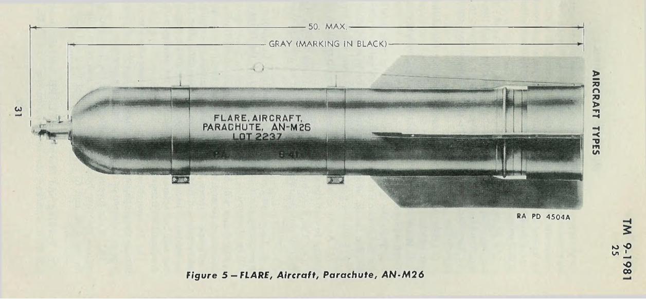
25. FLARE, AIRCRAFT, PARACHUTE, AN-M26.a. Description. This flare (fig. 5 ) is designed to provide illumina
tion for night bombardment. It is parachute-supported type with a shaded candle which burns with a yellowish light. The flare may be released from altitudes 1,200 to 25,000 feet greater than the altitude at which it is desired the flare will function. This is accomplished by means of a time fuze (par. 26) which acts to ignite the flare and expel it from the case a preset number of seconds after the flare is released from the plane. The standard model (A N -M 26) has one modification: FLARE, aircraft, parachute, AN-M26, with blue band. This has a candle of alternate composition. The original model (M 26 ) has an alternate sleeve and a metal hangwire container. This also exists in two forms: FLARE, aircraft, parachute, M26, which has a standard candle; and FLARE, aircraft, parachute, M26, with blue band, which has a candle of alternate composition.
I). Data. The flare case is cylindrical with a rounded nose and four fins attached to the rear third of its length. The rear of the case is closed with a shipping cover which is sealed by a strip of tape. The flare is 50 inches in length and 8 inches in diameter. It is equipped with two lugs for horizontal suspension. The rear lug is positioned at the center of gravity. The flare is adapted for FUZE, flare, mechanical time, M i l l , M111A1, or M111A2. It weighs 53 pounds as released. The standard candle burns for approximately 3 minutes with a yellowish light of 800,000 candlepower. The alternative candle used in the
29
models marked with the blue band burns for 3 minutes with a light of575,000 candlepower. The model designated AN-M26 is designed to be released at speeds up to 275 miles per hour; that designated M26 should be released at speeds not in excess of 180 miles per hour. When the parachute opens, it retards the dropping rate of the burning flare to 11.6 feet per second.
c. Installation and Operation.( 1) F u zin g . Unscrew the fuze hole plug, screw the fuze in by hand,
and seat it handtight. Set the fuze to the desired time by loosening the time set screw, rotating the body of the fuze until the desired number of seconds is indicated opposite the marker, then tightening the time set screw. Tables showing the time setting of the fuze and other data are published (SNL F-69).
(2 ) A r m in g -w ir e — H a n g w ir e . The cover is removed from the base of the flare and the outer end of the arming-wire—hangwire assembly is drawn from the hangwire container, taking care not to pull out the hangwire container or the attached end of the hangwire. The hangwire is brought around the vane stiffener to the suspension side of the flare and the arming wire threaded through first the forward suspension lug, then the inner hole in the arming pin of the fuze, then the inner holes in the vane stop. After this has been done, and not before, the safety cotter pin is withdrawn from the arming pin, the sealing wire is removed from the vane stop, and the fuze striker stop is removed. (I f it is necessary to unfuze a flare, the sealing wire, safety pin, and fuze striker stop will be replaced before the arming wire is removed or the fuze unseated.) The flare is then installed in the plane, and the ring of the arming-wire—hangwire assembly attached to the arming pawl of the rack. CAU TIO N : Make certain striker stop is removed after arming wire is inserted. If the safety block falls out when the striker stop is removed, replace the safety block and fasten it in place. Discard the fuze.
( 3 ) O p e r a tio n . The flare may be released safe or armed. If released safe, it may function on impact. If released armed, the flare functions in the following steps:
(a ) The movement downward withdraws the arming wire from the fuze, allowing the vane to rotate to arm the fuze and, at the same time, allowing the arming pin to be ejected, thus starting the time mechanism.
( b ) When the flare has dropped the length of the hangwire, the latter breaks the seal wire and pulls out the hangwire container, which drops free. Meanwhile the tear wire, which is attached to the hangwire near its end, pulls out the tear-wire cord which, in turn, pulls out the stabilizing sleeve and its shrouds. A short length of cord attached to the shrouds removes the lock of the cover releasing cup.
TM 9-198125
MILITARY PYROTECHNICS
30
------------ 50. M A X .-------------
GRAY (MARKING IN BLACK)
RA PD 4 5 0 4 A
to *0Cn 1 .
F igu re 5 — FLARE, A i r c r a f t , P a r a c h u t e , A N - M 2 6Ooo
AIR
CR
AFT
TYPES
( c) When the flare has dropped the combined length of the hang- wire, tear wire, tear-wire cord, sleeve, and shrouds, its momentum breaks the tear wire, allowing the flare to drop. It is stabilized in flight by its fins and sleeve. The arming vane on the fuze rotates to arm the fuze a maximum of 3 seconds after release when released at speeds of 200 miles per hour or higher.
( d ) At the time set, the fuze functions to push out the cover releasing cup. This releases the detachable cover to which the sleeve shrouds are attached, allowing the sleeve and cover assembly to separate from the flare and, by means of the parachute pull-out cord, pull out the parachute.
( e ) The parachute opens and retards the fall of the flare with a jerk which:
1. Breaks the parachute pull-out cord, allowing the sleeve assembly to fall separately.
2. Pulls the ignition wires through the igniting mixture, thus starting the ignition train of igniter, quickmatch, delay element, primer, first- fire, and candle, which reaches full ignition in approximately 6 seconds.
3. Pulls the flare assembly out of the case, which drops free.( f ) As the candle ignites it expels the rib retainer, allowing the rib
springs to open the shade.( g ) The flare burns for 3 to 3.5 minutes with a light of at least
800,000 c'andlepower while dropping at an average speed of 11.6 feet per second.
d. Care and Precautions in Handling. In addition to the general precautions given in paragraphs 13 and 24, the following precautions will be observed:
(1 ) Fuzes will be handled with care at all times. They will be assembled to and disassembled from the flare as directed in sub- paragraph c above, with particular attention to keeping the seal wire, safety pin, and fuze striker stop in place until after the arming wire is inserted. The seal wire, safety pin, fuze striker stop, and instruction tag will be replaced before removing the arming wire if the fuze is disassembled from the flare.
(2 ) In assembling the arming-wire—hangwire and in installing the flare in the plane, care will be taken not to pull so strongly on the hang- wire as to loosen or remove the hangwire container.
(3 ) If the fuze is disassembled from the flare, care will be taken to replace the fuze hole plug, to replace and reseal the shipping cover on the flare, and to repack and reseal flare and fuze in the original containers.
e. Packing and Marking. FLARE, aircraft, parachute, M26 or AN-M26, is packed, one to a wooden box. The FUZE, flare, mechan
TM 9-198125
MILITARY PYROTECHNICS
32
AIRCRAFT TYPES
TM 9-198125 -26
ical time, M i l l , M111A1, or M i l 1A2 is packed one in a metal container, 50 such containers to the wooden box. Further information on- packing and marking will be found in paragraphs 10, 14, and 23.
26. FUZE, FLARE, MECHANICAL TIME, M 111A2 (N O SE ).a. Description. This fuze (fig. 6 ) is classified in regard to func
tion as time and impact and, in regard to arming, as a combined arming vane-arming pin type. It is designed to function a predetermined number of seconds (from 5 to 92) after release or, if not previously operated by the time mechanism, to function on impact. When the arming wire is withdrawn as the fuze is released armed, the arming pin is ejected allowing the time mechanism to start. At the same time, the vane assembly is released to be turned by the air stream. The vane acts through a. reduction gear to release a C-shaped safety block from its position between the striker head and the fuze body. This occurs approximately 3 seconds after release (par. 25 c (3 ) ( c ) ) , that is, after approximately 750 feet of air travel. Once the safety block is ejected, the firing pin is restrained only by a detent which is released, at the expiration of the time set, by the clockwork mechanism. If impact should occur before the time elapses, the detent is sheared and the firing pin is driven into the primer.
b. Data. The fuze is about 4.5 inches in length. The body is cylindrical and 1.74 inches in diameter. The vane assembly is 3 inches in diameter and the vanes are set 60 degrees to rotate counterclockwise looking in the direction of flight. The time is graduated in half-second intervals from 5 to 92 seconds. In order to set the fuze for the desired time, it is necessary to perform the following steps: Loosen the time set screw, turn the head of the fuze until the number of the seconds desired is opposite the index mark near the set screw, and retighten the set screw. Bombing tables giving the time setting are compiled for BOMB, photoflash, M46, as well as for FLARE, aircraft, parachute, AN-M26 (SN L F-69). The fuze contains Primer M26 and a booster charge of 70 grains of black powder. It cannot be used to detonate a charge of high explosive. It is currently authorized for use with FLARE, aircraft, parachute, AN-M26 and M26, and BOMB, photoflash, M46.
e. Earlier Models. Earlier models of this fuze differ as follows:(1 ) FUZE, flare, mechanical time, M 111A1: The safety block is
made up of three segments instead of being a single C-shaped piece.(2 ) FUZE, flare, mechanical time, M i l l : The time setting range
is from 15 seconds minimum (instead of 5 seconds) to 90 seconds.d. Packing. This fuze is packed one per metal container, 50 such
containers per box. As shipped, there is a safety cotter pin in the arm-
33
CO
' A R M IN G P IN ( A R M IN G l W IRE GU IDE
T IM E
SEAL IN G W IR E
V A N E LO CK
STR IKER STOP
REMOVE W IT H PIN A N D STRIKER STOP AFTER
A R M IN G W IRE H AS BEEN INSERTED. IF
FLARE IS NO T DROPPED, REPLACE PIN,
STR IKER STOP A N D SE A L IN G W IRE BEFORE
R E M O V IN G A R M IN G WIRE.
STR IKER
SAFETY COTTER P IN
, D A TE
O £
LOADER
T IM E SET SCREW
G R A D U A T IO N S
V A N E
SAFETY BLOCK
-4.47 -
RA PD 6 9 0 6 9 A
o00
F igu re 6 — FUZE, F lare, M e ch a n ic a l T ime, M I I IA 2
MIL
ITA
RY
P
YR
OT
EC
HN
ICS
AIRCRAFT TYPES
TM 9-198126-28
ing pin and a forked striker stop between the striker head and the safety block. A sealing wire is threaded through the vane lock, the arming wire guide, the safety cotter pin, and the striker stop, and sealed in place.
e. Caution W hen Unpacking. When the fuze is removed from the container to be inserted in the flare, inspection must be made of these fuzes to be sure that the safety blocks are in place on the fuze. If a fuze is found in which the safety block is not in place, the safety block or an improvised safety block will be fastened in place between the striker and body and the fuze will be destroyed.
27. FLARE, AIRCRAFT, PARACHUTE, M24.a. This flare (fig. 7) is substitute standard for night observation
and bombardment. Its illuminant, shade, and parachute assembly are similar to those of the AN-M26 described above. It is not equipped with a time fuze; the hangwire acts directly to pull the parachute from the flare case and thus function the flare, which reaches full illumination 5 seconds after release from the plane. Candlepower and burning time are essentially the same as those of the AN-M26. Dropping rate is 11.6 feet per second. This flare is designed for release from planes flying at an altitude of 2,500 to 3,000 feet at speeds not greater than 200 miles per hour. For installation in the plane and precautions to be observed, see paragraphs 13 and 24. The FLARE, aircraft, parachute, M24, is 37 inches long by 8 inches in diameter. It weighs 47 pounds. This flare is packed one to a carton, one such carton to the box. Further information on packing and marking will be found in paragraphs 10, 14, and 23.
28. FLARE, AIRCRAFT, PARACHUTE, M8A1.a. This flare (fig. 8) is designed for use in emergency night land
ings. The candle is unshaded and burns with a yellowish light of350,000 candlepower for 3 minutes. Its average dropping rate while burning is approximately 8 feet per second. This flare may be released from horizontal or vertical flare racks. When installed in horizontal racks, the suspension bands, which are shipped separately, must be first attached. The M8A1 operates in a manner similar to the M24, reaching full ignition approximately 5 seconds after release from the plane. It may be released from planes flying at speeds not in excess of 200 miles per hour. The FLARE, aircraft, parachute, M8A1 is 25.5 inches long by 4.25 inches in diameter and weighs approximately 18 pounds. It is packed without suspension bands in individual fiber containers, one such container to the wire-bound box. Further information on packing and marking will be found in paragraphs 10, 14, and 23.
35
KJ 'O 0 0 '
500
—i
GRAY (MARKING IN BLACK)
36.95 MAX.
R A PD 4 0 0 5 A»
F ig u re 7 — FLARE, A irc ra ft , P a ra ch u te , M 2 4
MIL
ITA
RY
P
YR
OT
EC
HN
ICS
AIRCRAFT TYPES
TM 9-198128-29
H-----:------------------------------------------ — GRAY
F igure 8 — FLARE, Aircraft, Parachute, M 8 A 1
PLASTIC HEADALUM INUM (MARKING IN BLACK)
15.05 MAX.
RA PD 64447
F igure 9 — FLARE, Aircraft, Parachute , M 9 A 1
b. FLARE, Aircraft, Parachute, M8. This flare is an earlier model of the M8A1 and differs from the standard M8A1 only in that the candle burns with a white light of approximately 250,000 candle- power and the parachute assembly is designed for release of the flare from planes flying at speeds between 85 and 165 miles per hour.
29. FLARE, AIRCRAFT, PARACHUTE, M9A1.a. The FLARE, aircraft, parachute, M9 was developed to satisfy the
requirement for a small parachute flare for reconnaissance. The complete round is supplied in cartridge form designed for projection from the PISTOL, pyrotechnic, M2, similarly to aircraft signals, described in paragraph 34. It has been modified for use in the PISTOL, pyrotechnic, M2 or M8 and designated M9A1 (fig. 9 ). When the flare is discharged, the fuze burns for 2.5 seconds before igniting the expelling charge which ignites the flare and expels the flare and parachute from the case. The flare burns with a white light of 60,000 candlepower for 1 minute while dropping at an average rate of 7 feet per second. The M9 Flare is 13.8 inches long by approximately 2 inches in diameter and weighs about 1.9 pounds. The M9A1 is 15.05 inches long and weighs 2.1 pounds. Although the pistol is designed for operation by one hand, in discharging the FLARE, aircraft, parachute, M9 or M9A1,
37
the use of both hands is recommended because of the powerful recoil. The signals designed for use with this pistol may be discharged from a grounded plane but the FLARE, aircraft, parachute, M9 or M9A1, should not be so used. These flares are packed in individual fiber (metal containers for M9 Flares) containers, 25 such containers per box. Further information on packing and marking will be found in paragraphs 10, 14, and 23.
30. FLARE, TO W TARG ET, M50.a. General. FLARE, tow target, M50 (fig. 10), provides a target
for both night and day practice firing of antiaircraft guns. The flare is towed by a plane at the end of a steel cable. When one flare burns out, another may be released from the plane to take its place. The flare is not so bright that it will obscure the navigation lights of the plane, or that it will require the use of filters in fire control instruments.
b. Description. The flare candle is contained in a cylindrical case of laminated paper with sheet metal caps on both ends. The closing cap on the head end is sealed with a strip of adhesive tape. Under this cap, the case is closed by a wooden plug fastened in place with four wire nails. A flexible steel suspension cable passes through the center of the plug and is attached to the base block of the flare. The slack of the suspension cable is coiled in the cavity between the base block and the closing plug. Two ball fittings are clamped to the cable just inside the closing plug and serve for the attachment of the ignition wire. They also prevent the coiled suspension cable being pulled through the plug, thus pulling the ignition wire. When the flare functions, the holding nails shear and the plug is pulled from the case. The ignition wire passes through a cup of primer mixture in the base block. Two strands of quickmatch connect the ignition cup with the primer and first fire composition on the outer end of the flare by passing through a paper tube in the axis of the flare candle.
c. Data. The flare burns with a yellowish light of 60,000 candle- power for approximately 6 minutes. The assembled flare is 23 inches in length by 2.5 inches in diameter and weighs 7.13 pounds. It may be used effectively on a 6,000-foot towline at any combination of altitude or slant range up to 20,000 yards. The flare should not be released from a plane flying in excess of 120 miles per hour nor should it be released while the towing plane and the cable are completing a turn. Once the flare has become properly engaged on the exchange release trigger, the speed of the towing plane may be increased to any practical speed desired.
d. Operation. For operation of the towline mechanism, see TM 1-500. T o prepare the flare for launching, the sealing tape and closing cap are removed. The ring at the end of the suspension cable is tied
TM 9-1981' 2 9 -3 0
MILITARY PYROTECHNICS
38
COo
-B LU E -G R A Y
22.85 M A X
RA PD 69070A
Figure 1 0 — FLARE/ Tow -target , M 5 0
■H5
w 'O° -L
o 00
*
AIR
CR
AFT
TYPES
to the lead rope. When the flare is launched, it travels down the tow- line until the ring of the lead rope strikes the exchange release trigger. The sudden stop jerks the suspension cable taut, pulling out the closing plug and pulling the ignition wire through the primer. The primer ignites the quickmatch which flashes through the central tube, blowing off the base cap and igniting the flare.
e. Care and Precautions in Handling. In addition to the precautions specified in paragraph 13, the following will be observed:
(1 ) In opening FLARE, tow target, M50, and attaching it to the lead rope, care will be exercised not to pull on the suspension cable so as to loosen or pull out the closing plug. If a flare should be found with a loose plug, the flare will not be used. In such a case, the suspension cable should not be pulled; the closing cap will be replaced and resealed and the flare marked and set aside for disposal.
f. Marking. The flare is painted blue gray and is marked on the side with type and model, lot number, date loaded, and manufacturers’ initials.
g. Packing. FLARE, tow target, M50, is packed one per fiber container, 16 such containers per wooden box. Further details will be found in Table II, paragraph 23.
TM 9-198130-31
MILITARY PYROTECHNICS
Section II
PHOTOFLASH BOMBSP a ra g ra p h
Bomb, photoflash, M 23A1............................................... ................... 31Bomb, photoflash, M 46....................................................................... 32
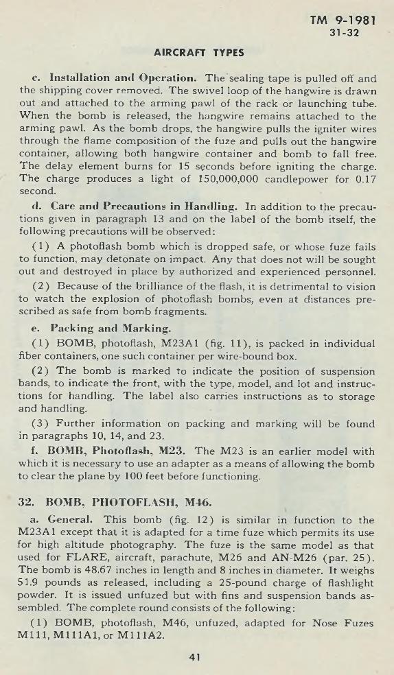
31. BOMB, PHOTOFLASH, M23A1.a. General. Photoflash bombs are designed to provide a light of
high intensity and short duration for night photography. In function they are strictly pyrotechnic but are designated bombs because of their explosive effect. They consist of a charge of flashlight powder and a means of ignition.
b. Description. BOMB, photoflash, M23A1 (fig. 11), is in the shape of a cylinder 25.4 inches long and 4.25 inches in diameter. Its weight is 10.6 pounds, of which 7.75 is flashlight powder charge. The front end ( “FR O N T” is marked on'the case for the information of persons attaching suspension bands and installing bomb in rack) contains the hangwire assembly and hangwire container. It is closed by a shipping cover sealed with adhesive tape.
40
AIRCRAFT TYPES
TM 9-198131 -32
c. Installation ami Operation. The sealing tape is pulled off and the shipping cover removed. The swivel loop of the hangwire is drawn out and attached to the arming pawl of the rack or launching tube. When the bomb is released, the hangwire remains attached to the arming pawl. As the bomb drops, the hangwire pulls the igniter wires through the flame composition of the fuze and pulls out the hangwire container, allowing both hangwire container and bomb to fall free. The delay element burns for 15 seconds before igniting the charge. The charge produces a light of 150,000,000 candlepower for 0.17 second.
d. Care and Precautions in Handling. In addition to the precautions given in paragraph 13 and on the label of the bomb itself, the following precautions will be observed:
(1 ) A photoflash bomb which is dropped safe, or whose fuze fails to function, may detonate on impact. Any that does not will be sought out and destroyed in place by authorized and experienced personnel.
(2 ) Because of the brilliance of the flash, it is detrimental to vision to watch the explosion of photoflash bombs, even at distances prescribed as safe from bomb fragments.
e. Packing and Marking.(1 ) BOMB, photoflash, M23A1 (fig. 11), is packed in individual
fiber containers, one such container per wire-bound box.(2 ) The bomb is marked to indicate the position of suspension
bands, to indicate the front, with the type, model, and lot and instructions for handling. The label also carries instructions as to storage and handling.
(3 ) Further information on packing and marking will be found in paragraphs 10, 14, and 23.
f. BOMB, Photoflash, M23. The M23 is an earlier model with which it is necessary to use an adapter as a means of allowing the bomb to clear the plane by 100 feet before functioning.
32. BOMB, PHOTOFLASH, M46.a. General. This bomb (fig. 12) is similar in function to the
M23A1 except that it is adapted for a time fuze which permits its use for high altitude photography. The fuze is the same model as that used for FLARE, aircraft, parachute, M26 and AN-M26 (par. 25). The bomb is 48.67 inches in length and 8 inches in diameter. It weighs 51.9 pounds as released, including a 25-pound charge of flashlight powder. It is issued unfuzed but with fins and suspension bands assembled. The complete round consists of the following:
(1 ) BOMB, photoflash, M46, unfuzed, adapted for Nose Fuzes M i l l , M i l 1A1, or M111A2.
41
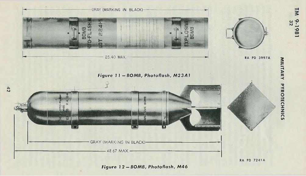
Figure I 1 - B O M B , Photo fla sh , M 2 3 A 1
(O
G RAY (M A R K IN G IN BLACK)
----------- 48.67 M A X . -------------
F igu re 1 2 — B O M B , Photo fla sh , M 4 6
R A PD 7241 A
MIL
ITA
RY
P
YR
OT
EC
HN
ICS
AIRCRAFT TYPES
TM 9-198132 -33
(2 ) FUZE, flare, mechanical time, M i l l , M111A1, or M111A2.(3 ) W IRE, arming, assembly, 82-3-234GB.I). Fuzing. To fuze the bomb proceed as follows:(1 ) Remove fuze hole plug and inspect cavity and threads to be
sure they are clean and free of foreign material or loose flashlight powder. If there is dirt present, clean it out, but if there is loose flashlight powder present, reject the bomb.
(2 ) Unseal fuze can, remove fuze from packings, and inspect it to see that it is not corroded or otherwise unserviceable.
(3 ) Screw fuze into bomb, handtight.(4 ) Set fuze by loosening thumbscrew and rotating the head until
the desired number of seconds is indicated by the marker. Tighten thumbscrew.
(5 ) Thread arming wire through forward suspension lug, then inner hole of the fuze arming pin, and finally through inner holes of the vane stop. Slip on a safety cjip until it just touches the vane. Cut off any excess arming wire, leaving no more than 2 to 3 inches protruding beyond the clip when the bomb is installed in the airplane. Remove all kinks and burs. Remove shipping wire, safety pin, and striker stop.
c. Unfuzing. If the bomb is not used, it will be unfuzed and returned to storage by reversing the steps in subparagraph b above.
cl. Care anti Precaution in Handling. See paragraphs 13, 25, and 29.
Section III
SIGNALSP a ra g ra p h
General ..................................... ........ ........ .............. ........................... 33Aircraft signals, rimless type......... ................... ........................... 34Aircraft signals, cartridge type................... ...................................... 35Grenade, smoke, white (H C ) AN -M 8............. ..... ......... .... 36Colored smoke grenades...................... 37Signal, drift, M 25....................................... 38Marker, slick, AN-M 59....................................................................... 39Signal, drift, day, AN-Mk. 1.................... ....... ....... .............. ........... 40Signal, drift, night, AN-Mk. 4 ............................................................ 41Signal, drift, night, AN-Mk. 5, mod. 1..................................... ...... .. 42
33. GENERAL.a. Description. Aircraft signals (figs. 13 and 14) were originally
designed to be fired from aircraft to convey information to other air
43
craft or to ground troops. A light, compact projector has since been developed which permits their use by ground troops as well. There are two types of aircraft signals: The rimless type, which is assembled in an aluminum or plastic-steel barrel, and the cartridge type which is assembled in a case resembling a large shotgun shell. The rimless type can be fired from PISTOL, pyrotechnic, M2, PISTOL, pyrotechnic, AN-M8 (with or without mount), and PROJECTOR, pyrotechnic, hand, M9. The cartridge type can be fired from DISCHARGER, pyrotechnic, M5, PISTOL, pyrotechnic, AN-M8, and PROJECTOR, pyrotechnic, hand, M9. All these projectors and their operation are described in T M 9-290.
b. Care and Precautions in Handling. In addition to the general precautions prescribed in paragraph 13, the following will be observed:
(1 ) Aircraft signals will be guarded against a blow on the primer, because such a blow may discharge the propellant and ignite the signal.
(2 ) Aircraft signals will be examined on unpacking for use. Those with dented, deformed, or cracked barrels and those with loose closing tops will not be used.
(3 ) In discharging signals free hand (without pistol mount) from aircraft, and in discharging signals from the ground, care will be exercised to aim so that no damage will result to the plane or to friendly ground troops.
34. AIRCRAFT SIGNALS, RIMLESS TYPE.a. Components. This type signal (fig. 13) is assembled in an
aluminum or plastic-steel barrel. The barrel is in the shape of a cylindrical cup which is grooved near the base or closed end. The primer is pressed into the center of the base. A press fit identification top (closing top) is cemented in the opposite end. The barrel is 1.58 inches in diameter. In the case of the parachute and cluster signals, the barrel is 7.69 inches in length. In the case of the double star and single star signals the barrel is 3.02 inches in length.
b. Operation.( 1 ) P a rach u te and C lu ste r T y p e s . The signal assembly is en
closed with an expelling charge in a signal case which, with the propelling charge, is assembled in the barrel. The signal case has a 2.5-second delay fuse assembled in its base. When the signal is fired, the primer ignites the propelling charge which, in turn, ignites the delay fuse while propelling the -signal case from the barrel. At the end of the delay time, the fuse ignites the expelling charge which ignites the signal as it is expelled from the signal case. The signal burns, producing the effect indicated under each model in Table I (par. 22).
(2 ) D o u ble Star and Sin gle Sta r T y pe s . The signal assembly and propelling charge are enclosed with protective wadding in the
TM 9-198133 -34
MILITARY PYROTECHNICS
44
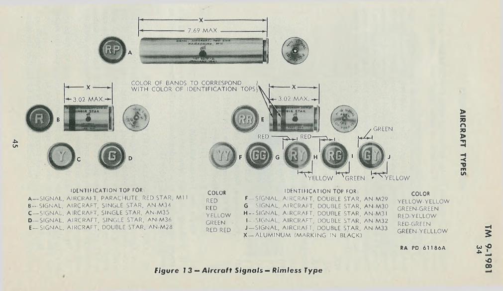
-ucn
ID tN l IF ICAT ION TOP FOR:A — SIGNAL, AIRCRAFT, PARACHUTE., RED STAR, M l I B — SIGNAL, AIRCRAFT, SINGLE STAR, AN-M34 C— SIGNAL, AIRCRAFT, SINGLE STAR, AN M35 D— SIGNAL, AIRCRAFT, SINGLE STAR, AN M36 E_ S IG N A L , AIRCRAFT, DOUBLE STAR, AN M ?8
COLORREDREDYELLOWGREENRED-RED
IDENTIFICATION TOP FORF— SIGNAL, AIRCRAFT, DOUBLE STAR, AN-M29 G — SIGNAL, AIRCRAFT, DOUBLE STAR, AN-M30 H— SIGNAL, AIRCRAFT, DOUBLE STAR, AN M 3 1 I -SIGNAL, AIRCRAFT, DOUBLE STAR, AN-M32 J — SIGNAL, AIRCRAFT, DOUBLE STAR, AN-M33 X — A LU M IN U M (MARKING IN BLACK)
COLORYELLOW-YELLOW GREEN-GREEN RED YELLOW RED-GREEN GREEN-YELLLOW
-H5
F igu re 1 3 — A irc ra ft S i g n a l s — R im le ss Type
RA PD 6 1 186A co 'O ■uO00
AIR
CR
AF
T
TY
PES
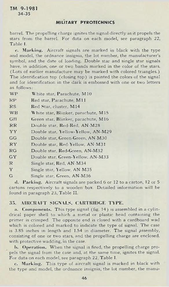
barrel. The propelling charge ignites the signal directly as it propels the stars from the barrel. For data on each model, see paragraph 22, Table I.
e. Marking. Aircraft signals are marked in black with the type and model, the ordnance insignia, the lot number, the manufacturer’s symbol, and the date of loading. Double star and single star signals have, in addition, one or two bands marked in the color of the stars. (Lots of earlier manufacture may be marked with colored triangles.) The identification top (closing top) is painted the colors of the signal and for identification in the dark is embossed with one or two letters as follows:WP White star, Parachute, M10RP Red star, Parachute, M i lRS Red Star, cluster, M14WB White star, Blinker, parachute, M15GB Green star. Blinker, parachute, M16RR Double star, Red-Red, AN-M28Y Y Double star, Yellow-Yellow, AN-M29GG Double star, Green-Green, AN-M30R Y Double star, Red-Yellow, AN-M31R G Double star. Red-Green, AN-M32GY Double star. Green-Yellow, AN-M33R Single star, Red, AN-M34Y Single star, Yellow, AN-M35G Single star, Green, AN-M36
<1. Packing. Aircraft signals are packed 6 or 12 to a carton, 12 or 5 cartons respectively to a wooden box. Detailed information will be found in paragraph 23, Table II.
35. AIRCRAFT SIGNALS, CARTRIDGE TYPE.a. Components. This type signal (fig. 14) is assembled in a cylin
drical paper shell to which a metal or plastic head containing the primer is crimped. The opposite end is closed with a cardboard wad which is colored and marked to indicate the type of signal. The case is 3.85 inches in length and 1.54 in diameter. The signal assembly, consisting of one or two stars, and the propelling charge are enclosed, with protective wadding, in the case.
I>. Operation. When the signal is fired, the propelling charge propels the signal from the case and, at the same time, ignites the signal. For data on each model, see paragraph 22, Table I.
c. Marking. This type of aircraft signal is marked in black with the type and model, the ordnance insignia, the lot number, the manu-
TM 9-198134 -35
MILITARY PYROTECHNICS
46
AIRCRAFT TYPES
TM 9-198135
1ID EN TIFICA TIO N TOP ■RED BAND
S IG N A L , A IR C R A F T , S IN G L E - S T A R , A N - M 4 3
RED 3.85 M AX
5 I 9 N A I , A 1 S C S A W T A N - M 4 |
S I N G L E - S T A R
GREEN j — YELLO W BAND
S I G N A l AieCNANrE -
YELLO W
S I & N A l A t K C N A N T , A N - M 4 2
DOUBLE - S T A R
MAR 1942 P. A .
GREEN BANDID EN TIFICA TIO N TOP
S IG N A L , A IR C R A F T , D O U B L E - S T A R , A N - M 4 2
N O TE:— COLOR OF BANDS AND ID EN TIFICA TIO N TOPS TO CORRESPOND W ITH COLOR OF SIGNAL <SEE TA B LE)
S IG N A L
C O L O R OF B A N D S A N D I D E N T I F I C A T I O N TO PS
A IR CR A FT , D O U B LE -STA R , AN-M37 A IR CR A FT , DOUBLE - STAR, AN-M 38 A IR C R A FT , DOUBLE - STAR, AN-M 39 A IR CR A FT , DOUBLE - STAR, AN-M 40 A IR CR A FT , DOUBLE - STAR, AN -M 4I A IR C R A FT , S IN G LE -S T A R , AN-M 44 A IR CR A FT , SINGLE - STAR, AN -M 45
RED - RED YELLO W - YELLO W GREEN - GREEN RED - YELLO W RED - GREEN YELLO W GREEN
RA PD 7 2 1 0
Figure 1 4 — A ircraft S ig n a ls — Cartr idge Type
47
TM 9-19813 5 -3 7
facturer’s symbol, and the date of loading. The color of the signal is indicated by one or two bands near the mouth of the case in the color of the star or stars. The closing wad is also colored to correspond to the color of the stars, and bears the names of the color printed in black.
cl. Packing. Cartridge type signals are packed 12 to the carton, 12 such cartons to the wooden box. Detailed information will be found in paragraph 23, Table II.
e. New Models. It is the policy in war times not to publish information concerning devices intended for use as recognition signals. Consequently, there will be issued, from time to time, new signals which function in the same manner but which produce pyrotechnic effects different from those described above. Such new models will be differentiated by model number only.
36. GRENADE, SMOKE, WHITE (H C ) AN-M8.a. This item (fig. 15) is standard as an emergency smoke signal.
It is in the shape of a cylinder approximately 6 inches long and 2.5 inches in diameter. A fuze with a safety lever and pin protrudes approximately 3A inch from the head end. To operate, the grenade is grasped with one hand which, at the same time, holds the safety lever in position. The ring and cotter pin are removed with the other hand and the grenade is thrown. The production of smoke starts 2 seconds after the release of the lever and reaches full volume in 3 seconds. The evolution of smoke continues for 2 to 2.5 minutes. The smoke is harmless to personnel or materiel but AR 750-10 forbid the discharge of this type of grenade closer than 20 feet to personnel because of the occurrence of an occasional flashing grenade. These grenades are packed in moisture-resistant fiber containers, 25 such containers to the box. They are painted gray and marked, in yellow, with one band, the symbol of the filler, “HC,” and the word “SMOKE.” Further information on packing and marking will be found in paragraphs 10, 14, and 23.
37. COLORED SMOKE GRENADES.a. GRENADE, Smoke, Colored, M16. This grenade (fig. 16) is
similar to the grenade described above except that the smoke produced is colored. The colors supplied are red, yellow, green, orange, violet, and black: Except for the color of the smoke, the description given for GRENADE, smoke, white (H C ) AN-M8, paragraph 36 above, apply equally to this item. Slight differences in data will be noted in paragraph 22, Table I.
b. GRENADE, Smoke, Colored, M l8. This grenade resembles the M16 above except that the burning time is reduced to 1 minute. As a consequence, this type produces the same volume of smoke in a shorter period, providing a larger and more visible smoke cloud.
MILITARY PYROTECHNICS
48
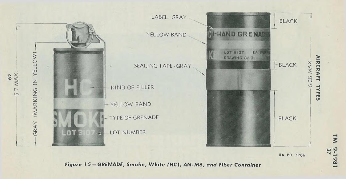
GR
AY
(M
AR
KIN
G
IN Y
EL
LO
W)
L A B E L -G R A Y ^
YELLO W B A N D
SEA L IN G T A P E -G R A Y .
K IN D OF FILLER
YELLO W B A N D
TYPE OF G RENADE
LOT N U M B ER
- BLACK
| BLACK
-B L A C K
RA PD 7206(O 'PN
Figure 1 5 — GRENADE, Smoke, White (HC), A N -M 8 , and Fiber ContainerOoo
AIR
CR
AF
T
TY
PE
S
•XV
W Q
Z'9------
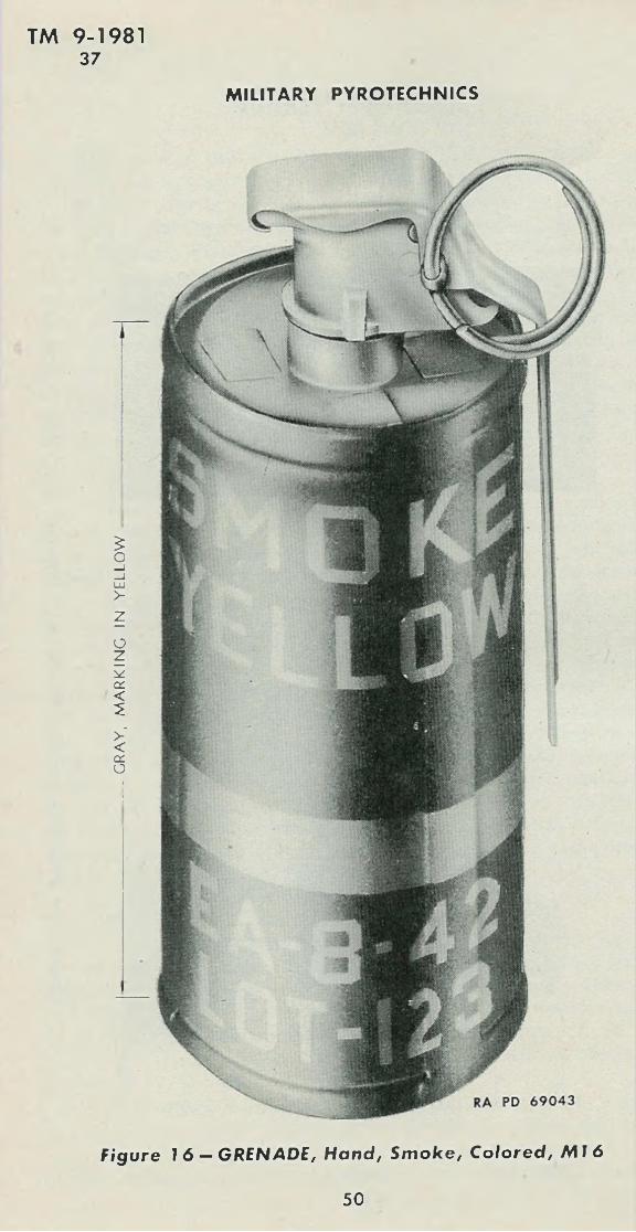
CR
AY
, M
AR
KIN
G
IN
YE
LL
OW
T M 9-198137
MILITARY PYROTECHNICS
Figure 1 6 — G REN AD E , Hand, S m o k e , Co lored , M I 6
R A PD 6 9 0 4 3
50
TM 9-19813 7 -4 0
c. GRENADE, Smoke, Red, AN-M4. This grenade differs from the other smoke grenades described above in that the grenade fuze lever is shortened and the grenade body is assembled in a cylindrical metal container. This container has three flaps, welded to the side, which may be bent outward to furnish additional bearing for supporting the grenade in snow, mud, or other such soft surface. In using this grenade, care should be exercised to hold the short fuze lever firmly when removing the safety pin.
38. SIGNAL, DRIFT, M25.a. This limited standard signal is used as an aid to navigation over
water by providing a stationary reference point for determination of the drift of the airplane. It is in the shape of a cylinder 16 inches long by 2.44 inches in diameter. The signal is released from the plane by hand and drops to the water, stabilized in fall by fins. On impact, the nose fuze functions to ignite a delay pellet which burns for 2 seconds before igniting the charge, thus allowing the signal to bob to the surface before functioning. The signal will not function on impact with solid ground. The charge burns to produce a 6-inch flame and a column of smoke. This signal should not be released from an altitude lower than 500 feet, as it may not have sufficient speed to operate the fuze, nor should it be released at altitudes higher than 16,000 feet, as the point of origin of the smoke column becomes indeterminate due to distance. The SIGNAL, drift, M25, is packed 6 to a carton, 4 such cartons in a wooden box. Further information on packing and marking will be found in paragraphs 10, 14, and 23.
39. MARKER, SLICK. AN-M59.a. M ARKER, slick, AN-M59, is designed to-provide a persistent
slick to mark referehce points on water. It consists of a paper composition case filled with a fluorescent dye. The marker is 10.875 inches in length and 3.375 inches in diameter. It weighs 2.9 pounds. The marker is protected by a cylinder of papier-mache which does not interfere with its function. The marker may be dropped from planes flying at any altitude or speed. Upon striking the water, the case shatters and the dye forms a slick which may be visible up to 10 miles at 3.000 feet altitude. The marker is packed 1 per fiber container, 10 per wooden box.
CAU TIO N : The case of the marker is extremely fragile and care must be exercised in handling this item, even wrhen it is properly packed.
40. SIGNAL, DRIFT, DAY, AN-Mk. 1.a. This signal consists of a streamlined paper shell containing a
metallic powder. When the signal is dropped in water the shell breaks,
AIRCRAFT TYPES
51
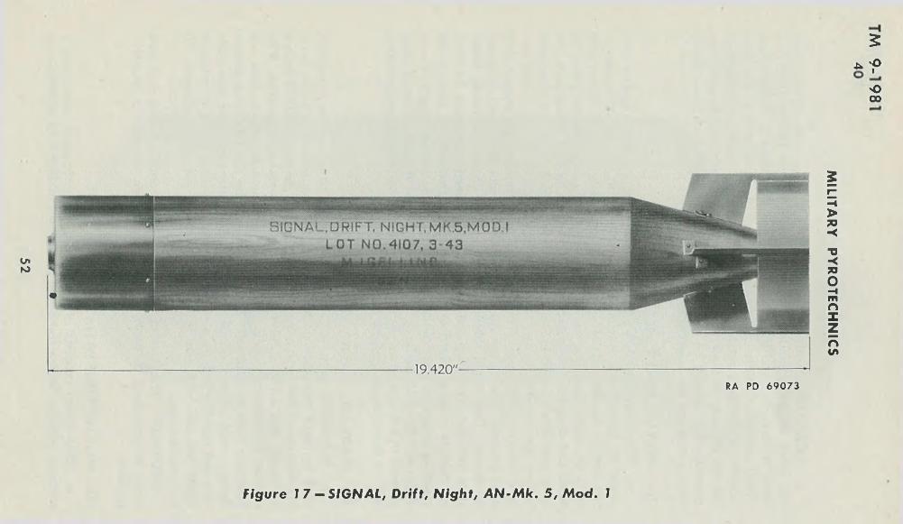
2* 'p
O00
InKi
RA PD 6907 3
F igu re 1 7 - S I G N A L , Drift, N igh t , A N - M k . 5, M o d . 1
MILITA
RY
PYR
OTEC
HN
ICS
TM 9-T9814 0 -4 2
allowing the metallic powder to form a slick on the surface, which may be used as a reference point for air navigation. The shell is of waterproof paper, % ,• inch thick. The nose is of hemispherical shape, 3Y2 inches in diameter, and the body tapers over its 10-inch length to a blunt point. The cone of the tail has four paper fins formed integral with it, which tend to stabilize the flight of the signal. Because the paper shell is fragile these signals should be handled with care to prevent their destruction.
41. SIGNAL, DRIFT. NIGHT, AN-Mk. 4.a. This signal is torpedo-shaped and consists of a bronze hemi
spherical nose, a wood body tapered at the rear, and an aluminum alloy tail fin assembly. It is designed to float in water in a vertical position with the nose submerged. The wooden body is hollow and contains the first fire composition and the pyrotechnic pellet. The fuze functions when the signal strikes the water surface and ignites the first fire composition, which in turn ignites the pyrotechnic pellet. It burns out of the tail and projects a flame which may be used as a reference point for air navigation at night.
42. SIGNAL, DRIFT, NIGHT, AN-Mk. 5, MOD. 1.a. This drift signal is designed to float on the water, nose down, and
produce a smoke and flame signal which would serve as a stationary reference point for aerial navigation. The signal (fig. 17) consists of a hollow cylindrical wood body with a flat metal nose at one end and a sheet metal box fin attached to the other. The body contains a hollow pyrotechnic candle which is held in place by cardboard supports. The nose contains a water-impact fuse which ignites a length of delay fuze which passes through the hollow candle. The delay fuse burns for approximately 9 seconds and then ignites the first fire mixture of the candle. The candle burns out of a hole in the tail producing smoke and flame for 15 to 17 minutes. The signal is approximately 19 inches in length and 3 inches in diameter; it weighs 4 pounds and is packed 25 per box.
AIRCRAFT TYPES
53
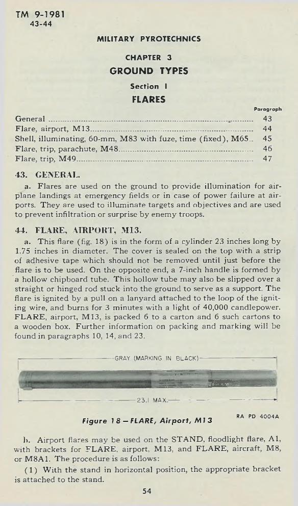
M IL ITARY PYROTECHNICS
CHAPTER 3
GROUND TYPESSection I
FLARESParagraph
TM 9-19814 3 -4 4
General ..................... 43Flare, airport, M 13............ 44Shell, illuminating, 60-mm, M83 with fuze, time (fixed), M65.. 45Flare, trip, parachute, M 48..... 46Flare, trip, M 49..................................................................................... 47
43. GENERAL.a. Flares are used on the ground to provide illumination for air
plane landings at emergency fields or in case of power failure at airports. They are used to illuminate targets and objectives and are used to prevent infiltration or surprise by enemy troops.
44. FLARE, AIRPORT, M13.a. This flare (fig. 18) is in the form of a cylinder 23 inches long by
1.75 inches in diameter. The cover is sealed on the top with a strip of adhesive tape which should not be removed until just before the flare is to be used. On the opposite end, a 7-inch handle is formed by a hollow chipboard tube. This hollow tube may also be slipped over a straight or hinged rod stuck into the ground to serve as a support. The flare is ignited by a pull on a lanyard attached to the loop of the igniting wire, and burns for 3 minutes with a light of 40,000 candlepower. FLARE, airport, M l3, is packed 6 to a carton and 6 such cartons to a wooden box. Further information on packing and marking will be found in paragraphs 10, 14, and 23.
-GRAY (MARKING IN BLACK)-
■ • • t \ T» r n ■ «*
j mame,EEt
■23.1 MAX-
F igure 1 8 - FLARE, A irpo rt , M I 3RA PD 40 04A
h. Airport flares may be used on the STAND, floodlight flare, A l, with brackets for FLARE, airport, M13, and FLARE, aircraft, M8, or M8A1. The procedure is as follows:
(1 ) With the stand in horizontal position, the appropriate bracket is attached to the stand.
54
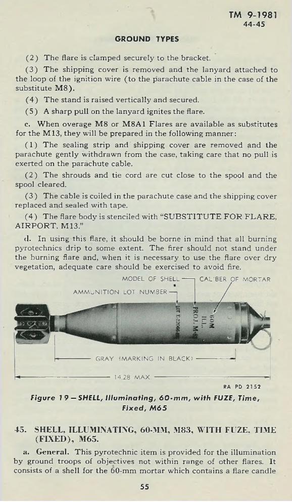
GROUND TYPES
TM 9-198144-45
(2 ) The flare is clamped securely to the bracket.(3 ) The shipping cover is removed and the lanyard attached to
the loop of the ignition wire (to the parachute cable in the case of the substitute M 8).
(4 ) The stand is raised vertically and secured.( 5 ) A sharp pull on the lanyard ignites the flare.c. When overage M 8 or M8A1 Flares are available as substitutes
for the M13, they will be prepared in the following manner:(1 ) The sealing strip and shipping cover are removed and the
parachute gently withdrawn from the case, taking care that no pull is exerted on the parachute cable.
(2 ) The shrouds and tie cord are cut close to the spool and the spool cleared.
(3 ) The cable is coiled in the parachute case and the shipping cover replaced and sealed with tape.
(4 ) The flare body is stenciled with “SUBSTITUTE FOR FLARE. AIRPORT, M13.”
d. In using this flare, it should be borne in mind that all burning pyrotechnics drip to some extent. The firer should not stand under the burning flare and, when it is necessary to use the flare over dry vegetation, adequate care should be exercised to avoid fire.
- GRAY (M ARKING IN BLACK)
-------- 14.28 M AX ----------------
MODEL OF SHELL
AM M UNITION LOT NUMBER
CA LIBER OF MORTAR
RA PD 2152
F igure 7 9 — SHELL, I l lum inat ing , 6 0 - m m , w ith FUZE, Time,
F ixed , M 6 5
45. SHELL. ILLUMINATING, 60-MM, M83, W ITH FUZE, TIME (F IX E D ), M65.
a. General. This pyrotechnic item is provided for the illumination by ground troops of objectives not within range of other flares. It consists of a shell for the 60-mm mortar which contains a flare candle
55
M IL ITARY PYROTECHNICS
and a parachute, and is equipped with a time fuze which ignites the flare and expels the assembly 14 seconds after firing.
1>. Description. This illuminating shell (fig. 19) is 14.28 inches over-all in length and 2.33 inches in diameter. It weighs 3.7 pounds as fired. At the fuze end there is a ring which is provided for ease in extracting the safety pin. (This pin will be removed just before firing and at no other time.) Nested in the fins of the tail are four propellent increments in the form of bundles of square powder flakes. The hollow tail contains the ignition charge, which is held in place by the primer assembly. Sixteen ventholes allow escape of the propelling and igniting gases from the ignition charge.
c. Function. The safety pin is removed from the fuze and the shell inserted fin first into the muzzle of the mortar and the loader’s hands promptly removed. The shell slides by gravity down the mortar tube and the primer strikes the fixed firing pin. igniting the cartridge. The propelling charge burns, projecting the shell. At the instant of firing, a set-back element in the fuze acts to ignite the powder time train, which burns for 14 seconds and then ignites a black powder expelling charge which, in turn, ignites the candle and expels the candle and parachute assembly from the base of the shell body. The candle burns for approximately 25 seconds with a light of 145,000 candle- power (substitute composition 110,000 candlepower), dropping meanwhile at a rate of approximately 10 feet per second.
N OTE: The ballistic properties of this round are markedly different from those of service shell for the 60-mm mortar and the shell will not illuminate the target of high-explosive shell fired with the same zone and elevation.
d. Precautions. In addition to the precautions listed in paragraph 13, the following will be observed (see also FM 23-85) :
(1 ) The safety pin in the fuze will be removed just before firing and at no other time. If the round is not fired or if the primer misfires and the round is removed from the mortar, the pin will be replaced.
(2 ) The shear wire which appears just below the safety pin in the nose of the fuze should not be disturbed. This is a fine wire which passes through the fuze and has its ends twisted together on the outside. If this wire is broken or missing, the round should not be used.
(3 ) Under no circumstances are more than four propellent increments to be used.
e. Painting and Marking. In common with other pyrotechnics, this shell is painted gray and marked in black with the type and model of shell, mortar from which fired, filler, and 1°* number. The fuze is stamped on the flange with the type and model, manufacturer’s symbol,
TM 9-198145
56
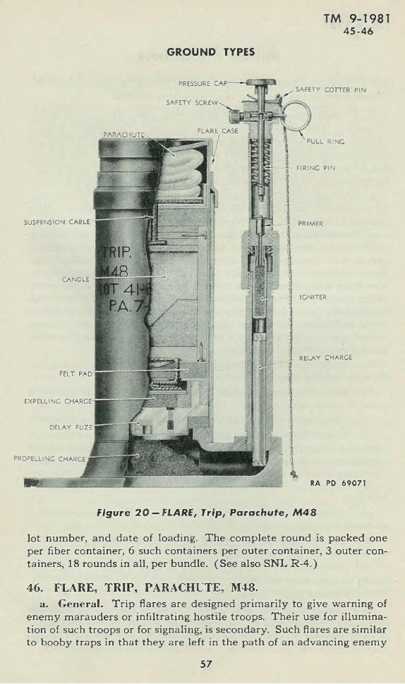
GROUND TYPES
TM 9-198145 -46
SU SPEN SIO N CABLE PR IM ER
C A N D LE
IGN ITER
FELT
EXPELLING
D ELA Y FUZI
PROPELLING CHARGE
■ 1
PRESSURE
SAFETY SCREW
FLARE CASE
SAFETY COTTER P IN
PULL R IN G
F IR IN G P IN
RELAY CHARGE
iRA PD 69071
F igure 2 0 — FLARE, Trip, Parachute , M 4 8
lot number, and date of loading. The complete round is packed one per fiber container, 6 such containers per outer container, 3 outer containers, 18 rounds in all, per bundle. (See also SNL R-4.)
46. FLARE, TRIP, PARACHUTE, M48.a. General. Trip flares are designed primarily to give warning of
enemy marauders or infiltrating hostile troops. Their use for illumination of such troops or for signaling, is secondary. Such flares are similar to booby traps in that they are left in the path of an advancing enemy
57
M IL ITARY PYROTECHNICS
and depend on some deliberate or unconscious action of the enemy for initiation.
b. Description. This flare (fig. 20) is, in effect, a one-shot mortar, fired by a trip wire, projecting an illuminating shell vertically to an altitude of 300 to 500 feet where a parachute-supported candle is ignited and expelled from the shell case. The candle burns for approximately 20 seconds with a white to yellowish light of 110,000 candle- power. It illuminates effectively a circle of 300 yards radius. The flare housing consists of a base plate to which are assembled a steel tube approximately 60 millimeters in inside diameter and a Vi-inch pipe. The cavity in the base plate contains the propelling charge which consists of approximately 75 grains of propellant powder. The large steel tube contains the illuminating shell and acts as a barrel for firing it. The shell contains a delay fuze of 3 seconds delay, an expelling charge, and the candle and parachute assembly. The Vi-inch pipe has a coupling at its upper end for assembling the firing mechanism. The firing mechanism has two safety features; a safety screw and a safety cotter pin. The mechanism consists of a primer and a spring- loaded firing pin. The firing pin is released, after removal of the safety screw and safety pin, by the application of 20 to 30 pounds pressure on the cap or by a tension of 4 to 6 pounds on the pull pin. The firing mechanism is shipped separately.
c. Installation. The following procedure may be taken as a guide for installing the flare:
(1 ) Place the flare in a hole so that the top of the projectile is about 3 inches below grade.
(2 ) Tamp earth around the housing up to the top of the projectile.(3 ) Attach one end of the trip wire to a stake or some equivalent
object and run the wire along the ground to the flare. Examine the installation to be sure that the wire is not visible; if it can be seen, rearrange it so that it will be hidden. This step may conveniently precede steps (1 ) and (2 ) , above. More than one trip wire may be installed.
(4 ) Attach trip wire or wires to the pull ring. Be sure that there is no tension on the pull pin.
(5 ) Arrange cord on the safety cotter pin so that it will not be buried when the flare is covered.
(6 ) Straighten the safety cotter pin so that it can be withdrawn easily by pulling on the cord.
(7 ) Remove safety screw.(8 ) Test safety cotter pin to be sure that it does not bind. If the
safety pin binds when the screw is removed, there is tension on the trip wire or the fuze is defective. In either case, replace safety screw and correct the defect by loosening the trip wire or replacing the fuze.
TM 9-198146
58
TM 9-19814 6 -4 7
(9 ) If the safety pin moves freely, leave it in place and cover the projectile with loose earth to restore original level of the ground. Camouflage as necessary.
(10) Withdraw the safety cotter pin by gently pulling the unburied end of its cord.
(11) Take care not to trip on your own trip wire.(12) Record the location of the flare and cache the safety screw
and safety pin nearby in case it should be necessary to take up the flare.d. Removal. Flares may be taken up by reversing the steps in
subparagraph c, above.e. Care and Precautions in Handling. In addition to the pre
cautions prescribed in paragraph 13, the following will be observed:(1 ) Flares should be planted so that the missiles formed by the
earth cover or the flare case will not endanger friendly personnel.(2 ) The flare housing will be examined before use to see that joints
are tight. The flare should not be planted in wet locations. The access of moisture to the interior of the flare housing will cause the flare to malfunction.
f. Marking. The flare housing is painted lusterless olive-drab and marked in black with type and model, lot number, and date loaded. The flange of the base is marked “FLARE, TRIP, M48.”
g. Packing. FLARE, trip, parachute, M48, is packed one per carton with one firing device and lengths of olive-drab or sand colored trip wire. Ten such cartons are packed in a wooden box. Further details will be found in Table II, paragraph 23.
47. FLARE, TRIP, M49.a. Description. This flare (fig. 21) resembles a hand grenade in
size and shape, except that it is provided with a bracket for attachment to a tree or post and a trigger mechanism for firing. The body is cylindrical, 2.5 inches in diameter and 3.8 inches in length. The fuze protrudes from the head end about % inch. The body is made of laminated paper and is closed at both ends by metal caps. The mounting bracket and trigger mechanism are attached to the base cap. The bracket consists of a triangular plate with three keyhole slots for mounting on three nails supplied with the flare. The trigger mechanism consists of a spring-loaded lever. The lower arm of the trigger is at-, tached to the trip wire; this holds the trigger in a vertical position against the tendency of the spring to turn it. The upper arm restrains the safety lever of the fuze when the safety pin is removed. A pull on the wire removes the upper arm from the fuze lever by rotating the trigger one way; cutting the wire allows the spring to remove the arm by rotating the lever the other way. Although it resembles a hand grenade fuze, there is no delay element in this fuze as there is in all hand grenade fuzes. When the fuze functions, the flare ignites instan-
GROUND TYPES
59
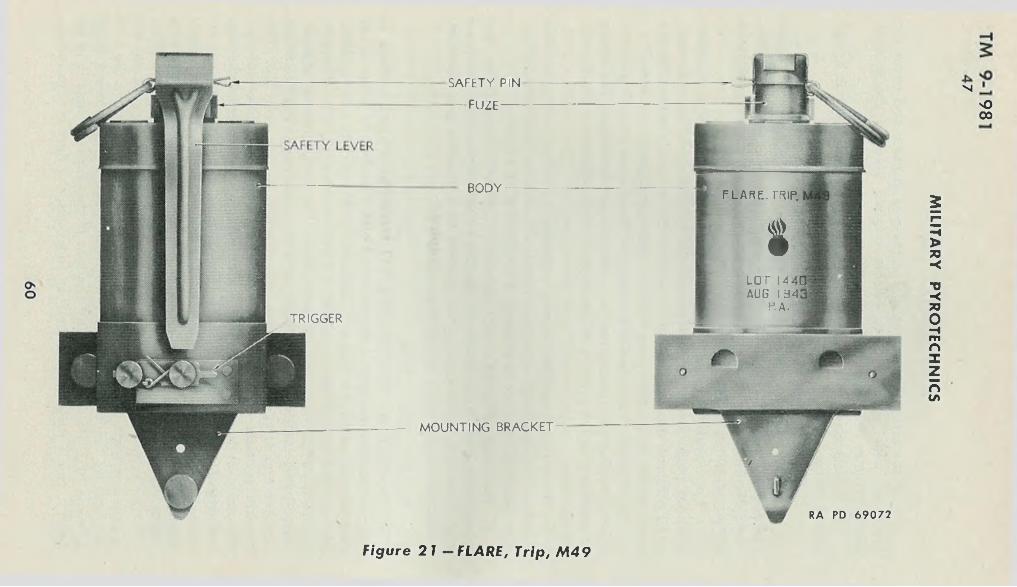
No00
MOUNTING BRACKET -
RA PD 6907 2
FLARE. TRIP,
tTRIGGER
SAFETY PIN
- F U Z E -
BODY-
LOT 14 AUG I 34
P.A.
F igu re 21 — FLA R E , Trip, M 4 9
MIL
ITA
RY
P
YR
OT
EC
HN
ICS
GROUND TYPES
TM 9-198147
taneously. The flare burns for approximately 1 minute with a white to yellowish light of 40,000 candlepower.
h. Installation. The following procedure may be taken as a guide in installing the flare:
( 1) The location chosen for the flare should be to the right (looking toward the enemy) of the field it is desired to illuminate, because of the direction the trip wire must run. Select a spot on a post, wall, or the like, 15 to 18 inches from the ground. Nail the gage plate loosely in place (leave Vj<; to Vs inch under the nail head so that the bracket will slip on). Mount the bracket on the nail heads by means of the keyhole slots.
(2 ) Attach trip wire about 15 to 18 inches from the ground to a rigid object approximately 40 feet to the right, facing the flare. This step may conveniently precede step (1 ), above.
(3 ) Loosen thumb nut on trigger. Press the fuze safety lever to the body of the flare and rotate trigger counterclockwise, against the spring, one-quarter turn, so that the thumb nut is at 6 o’clock and the finger on the other end restrains the fuze lever.
(4 ) Pull the trip wire taut and wrap it around the thumb nut screw once. Tighten the thumb nut. The trip wire should now be taut and the trigger should be vertical with the fuze safety lever held by the upper end, so that it will continue to hold the lever when the fuze safety pin is withdrawn.
(5 ) Hold the lever with one hand and carefully withdraw the safety pin from the fuze. Make sure that the lever will be held by the trigger.
c. Removal. Flares may be removed by reversing the steps in subparagraph 1) above.
d. Care and Precautions in Handling. In addition to the precautions prescribed in paragraph 13, the following should be observed:
(1 ) In regular installations, the safety pin of the fuze will be removed when the flare ia in position and the wire connected and adjusted so that the trigger restrains the safety lever, and at no other time.
(2 ) In using this flare as an illuminating grenade, the pin may be pulled while restraining the lever with the throwing hand, but care must be exercised that the lever is held securely until the flare is leaving the hand.
(3 ) Keep in mind the incendiary effect of the flare.e. Marking. The flare is marked on the body with the type and
model, lot number, manufacturer’s initials, and date loaded.f. Packing. FLARE, trip, M49, is packed 25 per wooden box with
3 nails and a 45-foot length of dull olive-drab wire for each flare. Further details will be found in Table II, paragraph 23.
61
M IL ITARY PYROTECHNICS
Section II
SIGNALSParagraph
TM 9-198148
Signals, ground.................................................................................... 48Light, signal, Very, Mk. II.................................................................. 49
48. SIGNALS, GROUND.a. General. Ground signals are designed to produce a parachute-
supported single star, a cluster of five freely falling stars, or a special effect. They are assembled in a cylindrical signal case approximately 6 inches long and 1.6 inches in diameter. In general, they are equipped with a finned tail assembly which serves to stabilize the signal case in flight. The signal case, containing the signal assembly, is projected from a ground signal projector or a rifle grenade launcher to a height of approximately 600 feet. When the signal is fired, the propelling charge ignites a fuse which burns through in approximately 6 seconds, the time required to reach maximum altitude. When the fuse burns through it ignites the expelling charge which, in turn, expels the signal assembly from the case and ignites the illuminant composition.
b. Types.(1 ) Earlier models of ground signals (A, fig. 22) are designed for
projection from PROJECTOR, signal, ground, M3 and M4. This type of projector resembles a small mortar in that it consists essentially of a tube, open at one end. In the center of the cap closing the other end is a firing pin against which the primer of the signal is driven by striking the projector on the ground. The primer is assembled in the center of the head of the signal. The propelling charge is contained in a small cavity under the head. The opposite end of the signal body is closed by a press-fit cap to which the tail assembly is attached. The signal is inserted in the projector head first and consequently is projected tail first for approximately 100 feet. It then reverses itself in flight and continues head first to an altitude of 600 feet where the signal assembly is ignited and expelled. The signal produces an effect according to model as described in subparagraph e below.
(2 ) Current models of ground signals (B, fig. 22) are modified for projection from service rifles or carbines equipped with the appropriate model of grenade launcher. Early lots of ground signals, designed for use with RIFLE, U. S., M1917, M1903, and M l, are packed with the special CARTRIDGE, rifle grenade, cal. .30, M3, included in the tail of the signal. This cartridge is attached to the cork plug by a metal clip. No attempt should be made to fire the M3 Cartridge from CARBINE, cal. .30, M l and M1A1. If the carbine is used for projecting a ground signal originally equipped with the M3 Cartridge, the
62
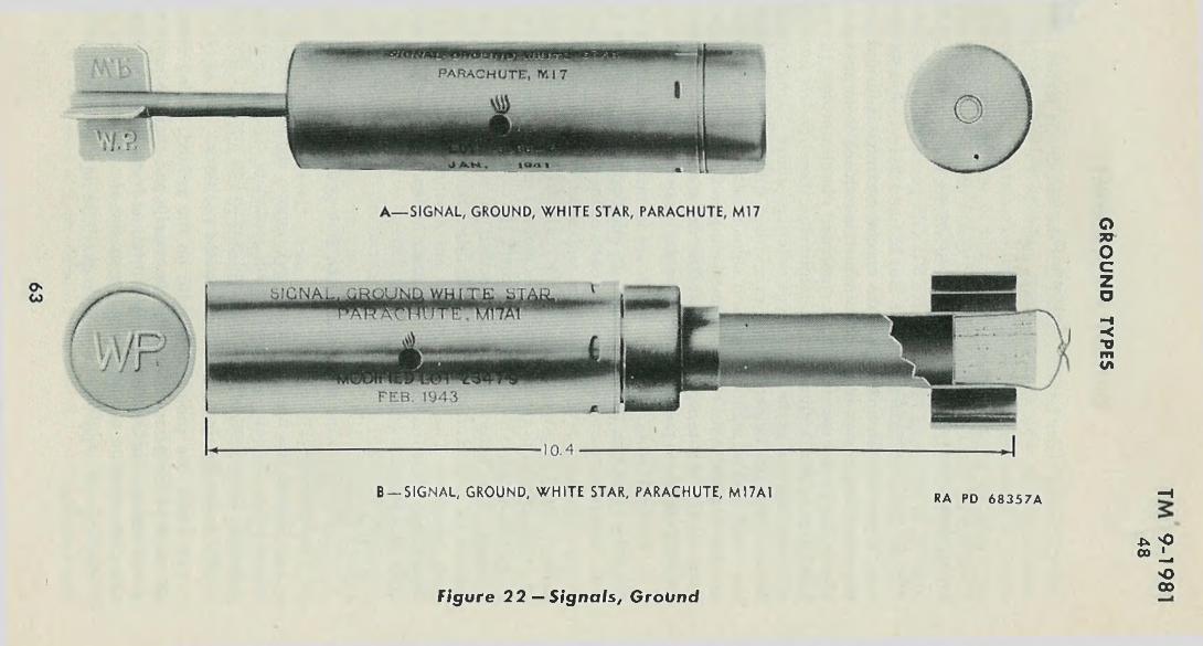
B— SIGNAL, GROUND, W H ITE STAR, PARACHUTE, M 17AI RA PD 6 8 3 5 7 A
Figure 22 — Signa ls, G roundI
-H
* <> 00 Li
'©00
GR
OU
ND
TYPES
TM 9-198148
M3 Cartridge must be extracted from the tail of the signal and the carbine loaded with CARTRIDGE, grenade, carbine, cal. .30, M6, which is issued separately, packed 50 per carton. In recent lots, all cartridges for ground signals are packed in separate cartons and included in the box containing signals. Present packing instructions are: 50 CARTRIDGE, rifle grenade, cal. .30, M3, for use with RIFLE, U. S., M1917, M1903, and M l; 30 CARTRIDGE, grenade, carbine, cal. .30, M6, for use with CARBINE, cal. .30, M l and M1A1; and 48 ground signals per wooden box. When the special cartridge is fired it ignites the propelling charge in the signal which is reduced to compensate for the charge in the cartridge. The combined charges project the signal head first to the required height. Otherwise these models function in the same manner as the earlier type described above. Signals designed for use with the launcher are distinguished from the earlier type by the “-A1” model number. Ground signals designated by the model number “A1B2,” have the same functioning and pyrotechnic characteristics as the “A l ”-series of signals. The designation “A1B2” after the model number on the signal indicates steel construction.
c. Identification. Ground signals are identified by the marking on the packing and on the signal body. In addition to the usual markings described in subparagraph g, below, parts of the signals are painted the color of the light produced and are embossed with the initials of the type of signal for identification in the dark. In the case of signals for use with ground projectors, the fin is painted and marked; in the case of signals for use with grenade launchers, the closing top is painted and marked. The letters used are specified in subparagraph e, below. Signals for projectors may be distinguished readily from those for use with launchers. The projector type has a solid tail stem and an X- shaped fin, while the launcher type has a hollow tail stem (closed by a cork plug) and a wheel-shaped fin.
cl. Use.(1 ) The following steps should be followed in the use of signals
for the ground projector:(a ) Unseal the fiber container and remove signal. Examine it to
be sure that the case is not deformed, dented, or cracked and the tail assembly is not bent or deformed and is attached firmly to the case.
( b ) Insert the signal head first into the projector.( c) Strike the projector smartly on the ground, taking care that
all parts of the person are below the muzzle and that the projector is not aimed so that the signal case will fall on friendly troops, on stores of ammunition, or on inflammable material of any nature.
( d) Signals unpacked but not used will be returned to the packings and resealed.
MILITARY PYROTECHNICS
64
TM 9-198148
(2 ) The following steps should be followed in use of signals modified for use with the launcher:
(a ) Unseal the container and remove the signal.( b ) Examine the signal to insure that it is serviceable.( c ) Remove plug assembly from the tail and place signal on
launcher.(d ) Remove special cartridge from plug assembly and load rifle,
if the signal is of the earlier lot. If the signal is of a recent lot, use appropriate cartridge packed separately.
CAUTION: Use only CARTRIDGE, rifle grenade, cal. .30. M3, when firing ground signals from RIFLE, U. S., cal. .30, M1917, M1903, and M l. Use only CARTRIDGE, grenade, carbine, cal. .30, M6, when firing ground signals from CARBINE, cal. .30, M l or M1A1.
( e ) When firing, the butt of the rifle should be rested on the ground as far from the person as practicable.
( f ) If signal is not fired, return to original condition and packing, reversing the above steps.
e. Models. The following lists the models supplied and the characteristics of each:
(1 ) SIGNAL, ground, white star, parachute, M17, M17A1 or M17A1B2, produces a parachute-supported star which burns for 20 to 30 seconds with a white light of 20,000 candlepower, falling meanwhile at an average rate of 7 feet per second. The fin (M 17 ) or closing top (M 17A1, or M 17A1B2) is painted white and embossed WP, for White star, Parachute.
(2 ) SIGNAL, ground, white star, cluster, M l8, M18A1 or M18A1B2, produces five freely falling stars which burn simultaneously for 5 to 7 seconds, each producing a white light of 18,000 candlepower. The fin (M 18 ) or closing top (M 18A1, or M 18A1B2) is painted white and embossed WS, for White Star, cluster.
(3 ) SIGNAL, ground, green star, parachute, M19, M19A1, or M19A1B2, produces a parachute-supported star which burns for 20 to 30 seconds with a green light of 5,000 candlepower, falling meanwhile at an average rate of 7 feet per second. The fin (M 19 ) or closing top (M 19A1, or M 19A1B2) is painted green and embossed GP, for Green star, Parachute.
(4 ) SIGNAL, ground, green star, cluster, M20, M20A1, or M20A1B2, produces five freely falling stars which burn simultaneously for 5 to 7 seconds each producing a green light of 7.000 candlepower. The fin (M 20 ) for closing top (M20A1, or M 20A1B2), is painted green and embossed GS, for Green Star, cluster.
GROUND TYPES
65
(5 ) SIGNAL, ground, amber star, parachute, M21, M21A1, or M21A1B2, produces a parachute-supported star which burns for 20 to 30 seconds with a yellow' light of 4,000 candlepower, falling meanwhile at an average rate of 7 feet per second. The fin (M 2 1 ) or closing top (M 21A1, or M 21A1B2), is painted yellow and embossed AP, for Amber star, Parachute.
(6 ) SIGNAL, ground, amber star, cluster, M22, M22A1, or M22A1B2, produces five freely falling stars which burn simultaneously for 5 to 7 seconds each producing a yellow light of 2,000 candlepow'er. The fin (M 22 ) or closing top (M22A1, or M 22A1B2), is painted yellow and embossed AS, for Amber Star, cluster.
(7 ) SIGNAL, ground, red star, parachute, M51A1, or M51A1B2, produces a parachute-supported star which burns for 20 to 30 seconds with a red light of 20,000 candlepower, falling meanwhile at an average rate of 7 feet per second. The closing top is painted red and embossed RP for Red star, Parachute.
(8 ) SIGNAL, ground, red star, cluster, M52A1 or M52A1B2, produces five freely falling stars which burn simultaneously for 5 to 7 seconds, each producing a red light of 35,000 candlepower. The closing top is painted red and embossed RS for Red Star, cluster.
(9 ) SIGNAL, ground, high-burst ranging, M27, is used to simulate the air burst of artillery shell for ranging practice. It differs from the models described above in that it has no tail assembly, is fired only from the PROJECTOR, signal, ground, M1A1, and explodes at the top of its rise, producing a flash and a puff of smoke. Cover or other protection from the fragments of the case should be available to personnel firing this signal.
f. Care and Precautions in Handling. In addition to the precautions given in paragraph 13, the following should be observed:
(1 ) The primer should be guarded against blows from a sharp instrument. Such blows may fire the primer and ignite the propelling charge and signal.
(2 ) Signals with deformed, dented, or cracked cases, or bent or deformed fins will not be used.
(3 ) Care should be exercised in firing to keep all parts of the person clear of the muzzle or below the level of the signal when fitted on the launcher. Care should be taken to aim so that the signal case will not fall on friendly personnel or stores of ammunition. If practicable, some measure of cover should be taken to avoid falling signal cases.
(4 ) Signal containers should not be unsealed until the signals are about to be used; in the case of launcher type signals, the cork plug should not be removed from the tail until just before placing the signal on the launcher.
TM 9-198148
MILITARY PYROTECHNICS
66
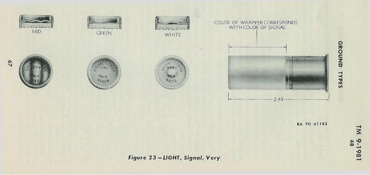
RA PD 6 1 1 8 5 ■H5
oo '
F ig u re 2 3 — L IG H T , S ig n a l , V e r yOoo
GR
OU
ND
TYP
ES
TM 9-19814 8 -49
(5 ) Duds should be destroyed in accordance with instructions in T M 9-1900.
g. Marking. In addition to the specific painting and embossing described in subparagraph e, above, each signal is marked on the side with the following:
(1 ) Type and model.(2 ) The ordnance insignium.(3 ) Lot number.(4 ) Date of loading or modification.(5 ) Manufacturer’s initials.h. Packing. Ground signals are packed in sealed fiber containers,
50 such containers per box. For additional waterproofing each container is paraffin-dipped after sealing.
49. LIGHT, SIGNAL, VERY, Mk. II.a. General. These signals (fig. 23) resemble shotgun shells in
appearance and are designed to be fired from the PISTOL, Very, 10-gage, Mk. I ll or M5. Each cartridge produces a single star which, on firing, ignites almost immediately, burning as it rises to a height of 200 feet.
b. Types.( 1) LIGHT, signal, Very, Mk. II, red star, burns for 7 seconds with
a red light of 300 candlepower. The closing wad is corrugated.(2 ) LIGHT, signal, Very, Mk. II, white star, burns for 6 seconds
with a white light of 250 candlepower. The closing wad has a small cone in the center.
(3 ) LIGHT, signal. Very, Mk. II, green star, burns for 5 seconds with a green light of 600 candlepower. The closing wad is smooth.
c. Marking. Very lights are identified by the marking on the items and on the packings. In addition the closing wad is shaped as noted above for identification by touch in the dark.
d. Packing. Very lights are packed 250 per metal-lined box (old packing); and 10 per carton, 25 cartons per carton container, and 4 carton containers (1,000 rounds) per metal-lined box (new packing). Further information on packing and marking will be found in paragraphs 10, 14, and 23.
MILITARY PYROTECHNICS
68
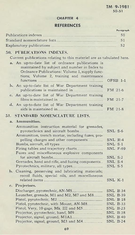
CHAPTER 4
REFERENCESParagraph
Publications indexes............................................................................ 50Standard nomenclature lists.............................................................. 51Explanatory publications ........................... ......... , ........................... 52
50. PUBLICATIONS INDEXES.Current publications relating to this materiel are as tabulated here, a. An up-to-date list of ordnance publications is
maintained by subject and number in Index to Ordnance Publications: Volume 1, supply functions; Volume 2, training and maintenancefunctions ................................... ............................... OFSB 1-1
1). An up-to-date list of War Department trainingpublications is maintained in.............................. FM 21-6
c. An up-to-date list of War Department trainingfilms is maintained in................. ............................. FM 21-7
cl. An up-to-date list of War Department trainingaids is maintained in............................................... FM 21-8
51. STANDARD NOMENCLATURE LISTS, a. Amm unition.
Ammunition instruction material for grenades,pyrotechnics and aircraft bombs........................ SNL S-6
Ammunition, trench mortar, including fuzes, propelling charges and other components............... SNL R-4
Bombs, aircraft, all types............................................ SNL S-lFiring tables and trajectory charts....... ................... SNL F-69Fuzes and miscellaneous explosive components
for aircraft bombs................................................... SNL S-2Grenades, hand and rifle, and fuzing components.. SNL S-4Pyrotechnics, military, all types............................... SNL S-5
1). Cleaning, preserving and lubricating materials; recoil fluids, special oils, and miscellaneous related item s............................................................... SNL K -l
c. Projectors.Discharger, pyrotechnic, AN -M 5................................. SNL B-34Launcher, grenade, M l and M2, M 7 and M 8........ SNL B-39Pistol, pyrotechnic, M 2................................................. SNL B-18Pistol, pyrotechnic, with Mount, AN -M 8................. SNL B-33Pistol, Very, 10-gage, Mk. I l l and M 5...................... SNL B-23Projector, pyrotechnic, hand, M 9............................... SNL B-38Projector, signal, ground, M 1A 1.............................. SNL B-40Projector, signal, ground, M3 and M 4...................... SNL B-24
TM 9-198150-51
69
TM 9-198152
52. EXPLANATORY PUBLICATIONS.a. Am m unition.
Aircraft armament and pyrotechnics........................Ammunition: general .................................................Ammunition, general .................................................Military pyrotechnics.................................................Ordnance safety manual.............................................Qualification in arms and ammunition training
allowances.................................................................Range regulations for firing ammunition for train
ing and target practice............................ ................Unsafe ammunition......................................................
b. B om bing Tables.Bomb, photoflash, M 46............................ ..................Flare, aircraft, parachute, AN-M 26...........................
c. M iscellaneous.Chemical decontamination materials and equip
ment ...........................................................................Cleaning, preserving, lubricating, and welding ma
terials and similar items issued by the OrdnanceDepartm ent...............................................................
Defense against chemical attack...............................Instructions and specifications for packaging ord
nance general supplies........................................ —Signal communication ...............................................Signal communication ...............................................
cl. Projectors.60-mm Mortar M 2................................................. -Bomb racks, tow target equipment, and flare racksG renades........................................................................Ordnance maintenance: Pyrotechnic projectors,
all types....................... ..............................................Pyrotechnic projectors, all types...............................
MILITARY PYROTECHNICS
T M 1-409 OFSB 3-1 T M 9-1900 OFSB 3-9 OO 7224
AR 775-10
AR 750-10 OFSB 3-11
BT PF-A-1 B T FL-A-1
T M 3-220
T M 9-850 FM 21-40
IO SSC-(a) FM 1-45' FM 24-5
FM 23-85 T M 1-500 FM 23-30
T M 9-1290 T M 9-290
70
TM 9-1981
I N D E X
A Page No.
Ammunition data card........................ 9Ammunition identification code 5Ammunition lot number 9Authorized rounds, table o f ......... 20—23
cCare and precautions in handling:
aircraft signals................................. 44bomb, photoflash, M 23A 1............. 41flare, aircraft, parachute,
AN-M 26 ................................. 32flare, tow target. M 50................... 40flare, trip, M 49................................. 61flare, trip, parachute, M 48.......... 59ground signals . ..... 62-68military pyrotechnics ............... 10-14
Classification of pyrotechnics.......... 5—8
Dataflare, aircraft, parachute,
AN -M 26 ............................ 29-30flare, tow target, M 50................... 38fuze, flare, mechanical time,
M 111A2 (nose) .................... 33Description:
bomb, photoflash, M 23A 1___ 40flare, aircraft, parachute,
AN -M 26 ................................. 29flare, aircraft, parachute,
M8A1 ................................... 35-37flare, aircraft, parachute,
M 9A1 ................................... 37-38flare, aircraft, parachute. M24. 35flare, airport, M 13...................... 54-55flare, tow target, M 50................. 38flare, trip, M 49............................. 59-61flare, trip, parachute, M 48.......... 58fuze, flare, mechanical time,
M 111A2 (nose) ................... 33grenade, smoke, white (H C )
AN-M 8 .................................... 48marker, slick, A N -M 59...... ......... 51shell, illuminating, 60-mm, M83,
with fuze, time (fixed ),M65 .......................................... 56
signal, drift, day, AN-M k. 1... 51-53signal, drift, M 25............................. 51signal, drift, night, AN-M k. 4 53signal, drift, night, AN-M k. 5,
Mod. 1 ...................................... 53
E Page No.
Expiration data ................................. 10
FField report o f accidents.................... 17Flares
aircraftflare, aircraft, parachute,
AN -M 26 ........................ 29-33flare, aircraft, parachute,
M8A1 ............................. 35-37flare, aircraft, parachute,
M9A1 ............................. 37-38flare, aircraft, parachute,
M 24 ...................................... 35flare, tow target, M 50.......... 39-40fuze, flare, mechanical time,
M 111A2 (nose) .......... 33-35ground type
flare, airport, M 13................. 54-55flare, trip, parachute, M48.. 57—59flare, trip, M 49........................ 59-61shell, illuminating, 60-mm,
M83, with fuze, time (fixed ), M65 ................. 55-57
Identification of:ground signals ................................. 64pyrotechnics .................................... 8
oOperation:bomb, photoflash, M 23A1............. 41cartridge type aircraft signals............... 46flare, aircraft, parachute,
AN-M 26 ............................. 30-32flare, tow target, M 50............... 38—40rimless type aircraft signals.... 44-46
PPacking
flare, tow target, M 50................... 40fuze, flare, mechanical time,
M111A2 (nose) ............... 33-35Packing and marking
bomb, photoflash, M 23A 1............. 41flare, aircraft, parachute,
AN -M26 ............................ 32-33pyrotechnics for shipment................... 14rimless type aircraft signals................. 46
Packing and shipping data, table of ...................................................... 24-27
71
TM 9-1981
MILITARY PYROTECHNICS
P----- Cont’d Page No.
Painting and markingpyrotechnics ................................. 9—10shell, illum inating, 60-m m ,
M83, with fuze, time (fixed), M65 ...................... 56—57
Photoflash bombsbomb, photoflash, M 23A1........ 40-41bomb, photoflash, M 46............. 41—43care and preservation................... 13
Priority of issue................................... 10Pyrotechnic compositions ............... 8Pyrotechnic data, tables
authorized rounds ...................... 20-23distinguishability .......................... 19packing and shipping data...... 24—27relative visibility .......................... 19
RRelative v is ib ility ............................... 19Renovation .......................................... 13
sSignals, aircraft
cartridge type ............................. 46-48
Page No.
colored smoke grenades............ 48—51grenade, smoke, white (H C )
AN-M 8 ................................... 48marker, slick, AN -M 59................. 51signal, drift, day, AN-Mk. 1.... 51—53signal, drift, M 25............................ 51signal, drift, night, AN-Mk. 4 ...... 53signal, drift, night, AN-M k. 5,
Mod. 1 ...................................... 53Signals, ground
ground .......................................... 62-68light, signal, Very, Mk. II ............. 68
Smoke grenadescolored .......................................... 48—51white (H C ) AN -M 8...................... 48
TToxicity of pyrotechnic material.... 12
VVisibility-
variation due to atmosphericconditions .......................... 18-19
variation due to design............. 17—18variation due to position............... 18
RAPD7JAN44— 87 M 72
P U B L I C A T I O N S D E P A R T M E N T , R A R I T A N A R S E N A L .


![TM 9-1370-203-34__Direct Support and General Support for Military Pyrotechnics [1996]](https://img.pdfslide.us/doc/110x75/577cddbb1a28ab9e78ad9d2f/tm-9-1370-203-34direct-support-and-general-support-for-military-pyrotechnics.jpg)