Embed Size (px)
Citation preview

TM 9-1300-277
TECHNICAL MANUAL
GENERAL INSTRUCTIONS
FOR
DEMILITARIZATION/ DISPOSAL OF
CONVENTIONAL MUNITIONS
This copy is a reprint which includes current pages from Changes1 through 3.
H E A D Q U A R T E R S , D E P A R T M E N T O F T H E A R M YMARCH 1982

WARNINGSBURNING HIGH EXPLOSIVES WHEN INITIATORS OF ANY DESCRIPTION ARE INCLUDED WILLPROBABLY RESULT IN A DETONATION. WHEN BURNING EXPLOSIVES AND/OR MUNITIONS,PROTECTION AGAINST THE POSSIBILITY OF A DETONATION MUST ALWAYS BE 'TAKEN.MIXING OF VARIOUS TYPES OF BULK EXPLOSIVES WILL NOT BE PERMITTED DURINGBURNING OPERATIONS. SINCE EXPLOSIVES CONTAIN THEIR OWN OXIDIZER, BURNINGEXPLOSIVES CANNOT BE EXTINGUISHED BY SMOTHERING.
BURNING OF ICM'S WILL NOT BE UNDERTAKEN AS THIS COULD CAUSE SCATTERING OREJECTION OF CARGO. SCATTERED OR EJECTED CARGO IS CONSIDERED ARMED ANDHAZARDOUS.
DO NOT ATTEMPT TO DETONATE ANY ITEM USING LESS THAN THE AMOUNT OF EXPLOSIVECHARGE SPECIFIED IN THE APPLICABLE DEMILITARIZATION DMWR.
BLASTING CAPS WILL NOT BE BURIED. DO NOT WORK WITH ELECTRIC BLASTING CAPS OROTHER ELECTRO-EXPLOSIVE DEVICES WHILE WEARING STATIC PRODUCING CLOTHING(NYLON, SILK, SYNTHETIC HAIR, ETC.). BLASTING CAPS WILL BE CARRIED IN APPROVEDCONTAINERS AND WILL BE KEPT OUT OF DIRECT RAYS OF THE SUN, WHENEVER POSSIBLE.WHEN EXPLOSIVE CHARGES ARE TO BE COVERED WITH EARTH OR TAMPED WITH EARTH,THE CHARGES WILL BE FITTED WITH DETONATING CORD LEADS THAT HAVE A MINIMUM OF2 METERS (SIX FEET) UNCOVERED ON THE EARTH'S SURFACE.
A SEARCH OF THE SURROUNDING AREA WILL BE MADE AFTER EACH DETONATION. ANYFUZED MUNITION OR ITEMS WHICH MAY HAVE INTERNALLY DAMAGED COMPONENTS THATHAVE BEEN THROWN FROM THE PILE/PIT WILL BE DETONATED IN PLACE. WHEREOPERATIONS REQUIRE THE USE OF A PERSONNEL SHELTER, THE SHELTER WILL BELOCATED NOT LESS THAN 91 METERS (300 FEET) FROM THE DISPOSAL SITE AND WILLAFFORD SUBSTANTIAL FRAGMENT-PROOF OVERHEAD COVER AND FRONTAL PROTECTION.

TM 9-1300-277C4
CHANGE ) HEADQUARTERS) DEPARTMENT OF THE ARMY
NO. 4 ) WASHINGTON, DC, 15 March 2001
Technical ManualGeneral Instructions
forDemilitarization/Disposal of
Conventional Munitions
DISTRIBUTION STATEMENT A: Approved for public release; distribution is unlimited.
TM 9-1300-277, 31 March 1982, is changed as follows:
1. Remove old pages and insert new pages as indicated below.2. New or changed material is indicated by a vertical bar in the outer margin of the page.3. Added or revised illustrations are indicated by a vertical bar adjacent to the illustration identification number.
Remove Pages Insert Pages
Change Sheet No. 1 Change Sheet No. 1A and B A and Bi thru iv i thru viA-1 thru A-4 A-1 thru A-4
File this change sheet in front of the publication for reference purposes.
DISTRIBUTION: To be distributed in accordance with the initial distribution number (IDN) 340812 requirements for TM 9-1300-277.
0106901

TM 9-1300-277
C3
CHANGE HEADQUARTERSDEPARTMENT OF THE ARMY
No. 3 WASHINGTON, D.C., 17 June 1988
TECHNICAL MANUAL
GENERAL INSTRUCTIONSFOR
DEMILITARIZATION/DISPOSAL OFCONVENTIONAL MUNITIONS
TM 9-1300-277, 31 March 1982, is changed as follows:
1. Remove old pages and insert new pages as indicated below. New or changed material is indicated by a verticalbar in the margin of the page. New or revised illustrations are indicated by a vertical bar adjacent to the identificationnumber.
Remove pages Insert pages
A Ai and ii i and ii5-13 and 5-14 5-13 and 5-14
2. File this change sheet in front of the publication for reference purposes.
By Order of the Secretary of the Army:CARL E. VUONO
General, United States ArmyChief of Staff
Official:R. L. DILWORTH
Brigadier General, United States ArmyThe Adjutant General
Distribution:To be distributed in accordance with DA Form 12-34B-R, Requirements for General Information applicable to all
organizations which have Conventional Munitions Missions.
}

TM 9-1300-277
C2
CHANGE HEADQUARTERSDEPARTMENT OF THE ARMY
No. 2 WASHINGTON, D.C., 27 August 1985
TECHNICAL MANUALGENERAL INSTRUCTIONS
FORDEMILITARIZATION/DISPOSAL OF
CONVENTIONAL MUNITIONS
TM 9-1300-277, 31 March 1982, is changed as follows:
1. Remove old pages and insert new pages as indicated below. New or changed material is indicated by a verticalbar in the margin of the page. New or revised illustrations are indicated by a vertical bar adjacent to the identificationnumber.
Remove pages Insert pages
A Ai thru iv i thru iv4-3 and 4-4 4-3 and 4-44-11 and 4-12 4-11 and 4-125-1 thru 5-6 5-1 thru 5-65-9 thru 5-24 5-9 thru 5-246-5 thru 6-12 6-5 thru 6-129-1 thru 9-10 9-1 thru 9-109-10.1 (9-10.2 blank) 9-10.1 (9-10.2 blank)9-11 thru 9-18 9-11 thru 9-189-18.1 (9-18.2 blank) 9-18.1 (9-18.2 blank)B-3 and B-4 B-3 and B-4Index 1 thru Index 6 Index 1 thru Index 6
2. File this change sheet in front of the publication for reference purposes.
By Order of the Secretary of the Army:JOHN A. WICKHAM, JR.
General, United States ArmyChief of Staff
Official:
DONALD J. DELANDROBrigadier General, United States Army
The Adjutant GeneralDistribution:
To be distributed in accordance with DA Form 12-34B-R, Requirements for General Information applicable to allorganizations which have Conventional Munitions Missions.
}

TM 9-1300-277
C1
CHANGE HEADQUARTERSDEPARTMENT OF THE ARMY
No. 1 WASHINGTON, D.C., 20 Oct. 1983
TECHNICAL MANUAL
GENERAL INSTRUCTIONSFOR
DEMILITARIZATION/DISPOSAL OFCONVENTIONAL MUNITIONS
TM 9-1300-277, 31 March 1982, is changed as follows:
1. Remove old pages and insert new pages as indicated below. New or changed material is indicated by a verticalbar in the margin of the page. New or revised illustrations are indicated by a vertical bar adjacent to the identificationnumber.
Remove pages Insert pages
A Aiii and iv............................................................. iii and iv1-1 thru 1-3 (1-4 blank) ...................................... 1-1 thru 1-3 (1-4 blank)2-1 thru 2-4........................................................ 2-1 thru 2-44-1 thru 4-4........................................................ 4-1 thru 4-44-7 thru 4-14...................................................... 4-7 thru 4-145-1 thru 5-8........................................................ 5-1 thru 5-85-11 thru 5-18.................................................... 5-11 thru 5-185-22 and 5-23 .................................................... 5-22 and 5-236-7 and 6-8 ........................................................ 6-7 and 6-89-3 and 9-4. ....................................................... 9-3 and 9-49-7 and 9-8. ....................................................... 9-7 and 9-89-19 and 9-20 .................................................... 9-19 and 9-20A-3 and A-4 ....................................................... A-3 and A-4B-3 thru B-6....................................................... B-3 thru B-6Index 3 thru Index 6........................................... Index 3 thru Index 6
2. File this change sheet in front of the publication for reference purposes.
By Order of the Secretary of the Army:JOHN A. WICKHAM, JR.
General, United States ArmyChief of Staff
Official:
ROBERT M. JOYCEMajor General, United States Army
The Adjutant General
Distribution:To be distributed in accordance with DA Form 12-40, Requirements for General Information applicable to all
organizations which have Conventional Munitions Missions.
}

TM 9-1300-277
Change 4 A
*Zero in this column indicates an original page
LIST OF EFFECTIVE PAGESNOTE The portion of the text affected by the changes is indicated by a
vertical line in the outer margins of the page. Changes to illustrations are indicated by a vertical line adjacent to the identification number.
INSERT LATEST CHANGED PAGES. DESTROY SUPERSEDED PAGES.
Dates of issue for original and changed pages are:
Original . . . . . . . 0 . . . . . . . . . . . . 31 March 1982 Change . . . . . . . 3 . . . . . . . . . . . . . 17 June 1988Change . . . . . . . 1 . . . . . . . . . . .20 October 1983 Change . . . . . . . 4 . . . . . . . . . . . . 15 March 2001Change . . . . . . . 2 . . . . . . . . . . . 27 August 1985
TOTAL NUMBER OF PAGES IN THIS PUBLICATION IS 153, CONSISTING OF THE FOLLOWING:
Page *Change Page *ChangeNo. No. No. No.
Cover ........................................ 0Warnings Summary.................. 0A and B .................................... 4i thru vi ..................................... 41-1 thru 1-3............................... 11-4 blank .................................. 02-1 ............................................ 12-2 ............................................ 02-3 ............................................ 12-4 thru 2-9............................... 02-10 blank ................................ 03-1 thru 3-6............................... 04-1 ............................................ 14-2 ............................................ 04-3 and 4-4 ............................... 24-5 thru 4-7............................... 04-8 thru 4-10............................. 14-11 .......................................... 04-12 .......................................... 24-13 and 4-14 ........................... 14-15 thru 4-17........................... 04-18 blank ................................ 05-1 thru 5-3............................... 25-4 ............................................ 15-5 ............................................ 05-6 ............................................ 25-7 and 5-8 ............................... 15-9 ............................................ 05-10 thru 5-12........................... 25-13 .......................................... 35-14 and 5-15 ........................... 25-16 .......................................... 05-17 .......................................... 15-18 and 5-19 ........................... 25-20 and 5-21 ........................... 05-22 thru 5-24........................... 26-1 thru 6-5............................... 0
6-6............................................. 26-7............................................. 16-8 and 6-9 ............................... 26-10........................................... 06-11........................................... 26-12 and 6-13 ........................... 06-14 blank................................. 07-1 and 7-2 ............................... 08-1 thru 8-3............................... 08-4 blank................................... 09-1 thru 9-10............................. 29-10.1........................................ 29-10.2 blank.............................. 29-11 thru 9-18........................... 29-18.1........................................ 29-18.2 blank.............................. 29-19........................................... 19-20........................................... 010-1 thru 10-4........................... 011-1 thru 11-4........................... 0A-1 thru A-4 ............................. 0B-1 and B-2 .............................. 0B-3............................................ 2B-4............................................ 0B-5............................................ 1B-6 thru B-10 ........................... 0C-1 thru C-8 ............................. 0Index 1 thru Index 3 ................. 2Index 4...................................... 1Index 5...................................... 0Index 6...................................... 2Authentication page.................. 0

TM 9-1300-277
Change 4 i
TECHNICAL MANUAL HEADQUARTERSDEPARTMENT OF THE ARMY
No. 9-1300-277 Washington, DC, 31 MARCH 1982
General Instructionsfor
Demilitarization/Disposal of Conventional Munitions
REPORTING ERRORS AND RECOMMENDING IMPROVEMENTS
You can help improve this manual. If you find any mistakes or if you know of a way to improve the proce-dures, please let us know. Mail your letter or DA Form 2028 (Recommended Changes to Publications andBlank Forms) located in the back of this manual directly to Commander, U.S. Army TACOM, ArmamentResearch, Development and Engineering Center, ATTN: AMSTA-AR-WEL-S, Picatinny Arsenal, NJ07806-5000. You may also send in your recommended changes via electronic mail or by fax. Our e-mailaddress is [email protected]. Our fax number is DSN 880-4633, Commercial (973) 724-4633. A re-ply will be furnished to you.
Page
CHAPTER 1 INTRODUCTIONPurpose and scope. . . . . . . . . . . . . . . . . . . . . . . . . . . . . . . . . . . . . . . . . . . . . . . . . . . . . . . . . . . . . 1-1Forms, records, and reports. . . . . . . . . . . . . . . . . . . . . . . . . . . . . . . . . . . . . . . . . . . . . . . . . . . . . . 1-1Waiver actions . . . . . . . . . . . . . . . . . . . . . . . . . . . . . . . . . . . . . . . . . . . . . . . . . . . . . . . . . . . . . . . 1-2Hazard Classification . . . . . . . . . . . . . . . . . . . . . . . . . . . . . . . . . . . . . . . . . . . . . . . . . . . . . . . . . . 1-3
CHAPTER 2 SAFETY AND ACCIDENT PREVENTIONIntroduction. . . . . . . . . . . . . . . . . . . . . . . . . . . . . . . . . . . . . . . . . . . . . . . . . . . . . . . . . . . . . . . . . . 2-1General requirements . . . . . . . . . . . . . . . . . . . . . . . . . . . . . . . . . . . . . . . . . . . . . . . . . . . . . . . . . . 2-1Safety at demilitarization/disposal areas. . . . . . . . . . . . . . . . . . . . . . . . . . . . . . . . . . . . . . . . . . . . 2-2Demilitarization of chemical munitions . . . . . . . . . . . . . . . . . . . . . . . . . . . . . . . . . . . . . . . . . . . . 2-3Personnel requirements. . . . . . . . . . . . . . . . . . . . . . . . . . . . . . . . . . . . . . . . . . . . . . . . . . . . . . . . . 2-5Ammunition and explosive handling . . . . . . . . . . . . . . . . . . . . . . . . . . . . . . . . . . . . . . . . . . . . . . 2-5Housekeeping . . . . . . . . . . . . . . . . . . . . . . . . . . . . . . . . . . . . . . . . . . . . . . . . . . . . . . . . . . . . . . . . 2-7Security . . . . . . . . . . . . . . . . . . . . . . . . . . . . . . . . . . . . . . . . . . . . . . . . . . . . . . . . . . . . . . . . . . . . . 2-7Standing operating procedures (SOP’s) . . . . . . . . . . . . . . . . . . . . . . . . . . . . . . . . . . . . . . . . . . . . 2-8Procedure in event of electrical storms. . . . . . . . . . . . . . . . . . . . . . . . . . . . . . . . . . . . . . . . . . . . . 2-8Open storage of ammunition. . . . . . . . . . . . . . . . . . . . . . . . . . . . . . . . . . . . . . . . . . . . . . . . . . . . . 2-9
CHAPTER 3 TREATMENT OF CHEMICAL AGENT CASUALTIESGeneral . . . . . . . . . . . . . . . . . . . . . . . . . . . . . . . . . . . . . . . . . . . . . . . . . . . . . . . . . . . . . . . . . . . . . 3-1Chemical group B munitions . . . . . . . . . . . . . . . . . . . . . . . . . . . . . . . . . . . . . . . . . . . . . . . . . . . . 3-2Chemical group C munitions . . . . . . . . . . . . . . . . . . . . . . . . . . . . . . . . . . . . . . . . . . . . . . . . . . . . 3-4First aid . . . . . . . . . . . . . . . . . . . . . . . . . . . . . . . . . . . . . . . . . . . . . . . . . . . . . . . . . . . . . . . . . . . . . 3-5
CHAPTER 4 DESCRIPTION OF DEMOLITION MATERIALSGeneral . . . . . . . . . . . . . . . . . . . . . . . . . . . . . . . . . . . . . . . . . . . . . . . . . . . . . . . . . . . . . . . . . . . . . 4-1Demolition explosive charges. . . . . . . . . . . . . . . . . . . . . . . . . . . . . . . . . . . . . . . . . . . . . . . . . . . . 4-1Demolition charge initiators . . . . . . . . . . . . . . . . . . . . . . . . . . . . . . . . . . . . . . . . . . . . . . . . . . . . . 4-8Demolition accessories . . . . . . . . . . . . . . . . . . . . . . . . . . . . . . . . . . . . . . . . . . . . . . . . . . . . . . . . . 4-12Demolition equipment . . . . . . . . . . . . . . . . . . . . . . . . . . . . . . . . . . . . . . . . . . . . . . . . . . . . . . . . . 4-13

TM 9-1300-277
ii Change 4
Page
CHAPTER 5 FIRING SYSTEMS PROCEDURESGeneral . . . . . . . . . . . . . . . . . . . . . . . . . . . . . . . . . . . . . . . . . . . . . . . . . . . . . . . . . . . . . . . . . . . . . 5-1Nonelectric systems . . . . . . . . . . . . . . . . . . . . . . . . . . . . . . . . . . . . . . . . . . . . . . . . . . . . . . . . . . . 5-1Safety precautions for nonelectric firing systems. . . . . . . . . . . . . . . . . . . . . . . . . . . . . . . . . . . . . 5-1Assembly of nonelectric system . . . . . . . . . . . . . . . . . . . . . . . . . . . . . . . . . . . . . . . . . . . . . . . . . . 5-2Igniting fuse of nonelectric system. . . . . . . . . . . . . . . . . . . . . . . . . . . . . . . . . . . . . . . . . . . . . . . . 5-5Electric firing systems . . . . . . . . . . . . . . . . . . . . . . . . . . . . . . . . . . . . . . . . . . . . . . . . . . . . . . . . . 5-6Safety precautions for electric systems. . . . . . . . . . . . . . . . . . . . . . . . . . . . . . . . . . . . . . . . . . . . . 5-6Preliminary electrical continuity testing . . . . . . . . . . . . . . . . . . . . . . . . . . . . . . . . . . . . . . . . . . . . 5-7Connecting/splicing electric wires . . . . . . . . . . . . . . . . . . . . . . . . . . . . . . . . . . . . . . . . . . . . . . . . 5-9Priming and testing firing circuit . . . . . . . . . . . . . . . . . . . . . . . . . . . . . . . . . . . . . . . . . . . . . . . . . 5-10Blasting machine. . . . . . . . . . . . . . . . . . . . . . . . . . . . . . . . . . . . . . . . . . . . . . . . . . . . . . . . . . . . . . 5-12Use of detonating cord . . . . . . . . . . . . . . . . . . . . . . . . . . . . . . . . . . . . . . . . . . . . . . . . . . . . . . . . . 5-13Safety precautions for detonating cord . . . . . . . . . . . . . . . . . . . . . . . . . . . . . . . . . . . . . . . . . . . . . 5-13Detonating cord connections . . . . . . . . . . . . . . . . . . . . . . . . . . . . . . . . . . . . . . . . . . . . . . . . . . . . 5-13Capping detonating cord. . . . . . . . . . . . . . . . . . . . . . . . . . . . . . . . . . . . . . . . . . . . . . . . . . . . . . . . 5-15Priming the charge . . . . . . . . . . . . . . . . . . . . . . . . . . . . . . . . . . . . . . . . . . . . . . . . . . . . . . . . . . . . 5-15Dual firing systems . . . . . . . . . . . . . . . . . . . . . . . . . . . . . . . . . . . . . . . . . . . . . . . . . . . . . . . . . . . . 5-15Dual nonelectric firing system . . . . . . . . . . . . . . . . . . . . . . . . . . . . . . . . . . . . . . . . . . . . . . . . . . . 5-17Dual electric firing system . . . . . . . . . . . . . . . . . . . . . . . . . . . . . . . . . . . . . . . . . . . . . . . . . . . . . . 5-17Combination dual firing system . . . . . . . . . . . . . . . . . . . . . . . . . . . . . . . . . . . . . . . . . . . . . . . . . . 5-17Dual electric priming system . . . . . . . . . . . . . . . . . . . . . . . . . . . . . . . . . . . . . . . . . . . . . . . . . . . . 5-18Ignition trains . . . . . . . . . . . . . . . . . . . . . . . . . . . . . . . . . . . . . . . . . . . . . . . . . . . . . . . . . . . . . . . . 5-18Preparation of ignition trains . . . . . . . . . . . . . . . . . . . . . . . . . . . . . . . . . . . . . . . . . . . . . . . . . . . . 5-18Misfires . . . . . . . . . . . . . . . . . . . . . . . . . . . . . . . . . . . . . . . . . . . . . . . . . . . . . . . . . . . . . . . . . . . . . 5-22Prevention of nonelectric misfires . . . . . . . . . . . . . . . . . . . . . . . . . . . . . . . . . . . . . . . . . . . . . . . . 5-22Handling nonelectric misfires . . . . . . . . . . . . . . . . . . . . . . . . . . . . . . . . . . . . . . . . . . . . . . . . . . . . 5-22Prevention of electric misfires . . . . . . . . . . . . . . . . . . . . . . . . . . . . . . . . . . . . . . . . . . . . . . . . . . . 5-23Handling of electric misfires. . . . . . . . . . . . . . . . . . . . . . . . . . . . . . . . . . . . . . . . . . . . . . . . . . . . . 5-23
CHAPTER 6 EXISTING DEMILITARIZATION EQUIPMENT AND METHODSGeneral . . . . . . . . . . . . . . . . . . . . . . . . . . . . . . . . . . . . . . . . . . . . . . . . . . . . . . . . . . . . . . . . . . . . . 6-1Munitions disassembly lines . . . . . . . . . . . . . . . . . . . . . . . . . . . . . . . . . . . . . . . . . . . . . . . . . . . . . 6-1APE disassembly equipment . . . . . . . . . . . . . . . . . . . . . . . . . . . . . . . . . . . . . . . . . . . . . . . . . . . . 6-1Washout of explosive fillers . . . . . . . . . . . . . . . . . . . . . . . . . . . . . . . . . . . . . . . . . . . . . . . . . . . . . 6-2High pressure washout and reclamation system . . . . . . . . . . . . . . . . . . . . . . . . . . . . . . . . . . . . . . 6-6Steamout of explosive fillers . . . . . . . . . . . . . . . . . . . . . . . . . . . . . . . . . . . . . . . . . . . . . . . . . . . . 6-6APE 1236 deactivation furnace . . . . . . . . . . . . . . . . . . . . . . . . . . . . . . . . . . . . . . . . . . . . . . . . . . 6-7Open burning grounds . . . . . . . . . . . . . . . . . . . . . . . . . . . . . . . . . . . . . . . . . . . . . . . . . . . . . . . . . 6-9Open detonation grounds . . . . . . . . . . . . . . . . . . . . . . . . . . . . . . . . . . . . . . . . . . . . . . . . . . . . . . . 6-12Chemical munition demilitarization methods. . . . . . . . . . . . . . . . . . . . . . . . . . . . . . . . . . . . . . . . 6-12
CHAPTER 7 DEMILITARIZATION/DISPOSAL TRAININGGeneral . . . . . . . . . . . . . . . . . . . . . . . . . . . . . . . . . . . . . . . . . . . . . . . . . . . . . . . . . . . . . . . . . . . . . 7-1On-site training . . . . . . . . . . . . . . . . . . . . . . . . . . . . . . . . . . . . . . . . . . . . . . . . . . . . . . . . . . . . . . . 7-1Off-site training. . . . . . . . . . . . . . . . . . . . . . . . . . . . . . . . . . . . . . . . . . . . . . . . . . . . . . . . . . . . . . . 7-1Depot maintenance work requirement (DMWR) . . . . . . . . . . . . . . . . . . . . . . . . . . . . . . . . . . . . . 7-2
CHAPTER 8 DISPOSAL METHODSGeneral 8-1Burning on the surface 8-1Burning in pits or trenches 8-2

TM 9-1300-277
Change 4 iii
Page
CHAPTER 8 DISPOSAL METHODS - ContinuedBurning in deactivation furnaces . . . . . . . . . . . . . . . . . . . . . . . . . . . . . . . . . . . . . . . . . . . . . . . . . 8-2Detonation. . . . . . . . . . . . . . . . . . . . . . . . . . . . . . . . . . . . . . . . . . . . . . . . . . . . . . . . . . . . . . . . . . . 8-2Certification of inert scrap materials . . . . . . . . . . . . . . . . . . . . . . . . . . . . . . . . . . . . . . . . . . . . . . 8-3
CHAPTER 9 EXISTING DEMILITARIZATION FACILITIES AND CAPABILITIESDESCOM and AMCCOM facility locations . . . . . . . . . . . . . . . . . . . . . . . . . . . . . . . . . . . . . . . . 9-1DESCOM depot facilities and capabilities . . . . . . . . . . . . . . . . . . . . . . . . . . . . . . . . . . . . . . . . . . 9-1AMCCOM installation facilities and capabilities. . . . . . . . . . . . . . . . . . . . . . . . . . . . . . . . . . . . . 9-1Western demilitarization facility, Hawthorne, Nevada . . . . . . . . . . . . . . . . . . . . . . . . . . . . . . . . 9-15
CHAPTER 10. NEW TECHNOLOGYGeneral . . . . . . . . . . . . . . . . . . . . . . . . . . . . . . . . . . . . . . . . . . . . . . . . . . . . . . . . . . . . . . . . . . . . . 10-1Environmental regulations . . . . . . . . . . . . . . . . . . . . . . . . . . . . . . . . . . . . . . . . . . . . . . . . . . . . . . 10-1Environmental regulation compliance . . . . . . . . . . . . . . . . . . . . . . . . . . . . . . . . . . . . . . . . . . . . . 10-2Reclamation and reutilization of resources. . . . . . . . . . . . . . . . . . . . . . . . . . . . . . . . . . . . . . . . . . 10-3Existing equipment and processes . . . . . . . . . . . . . . . . . . . . . . . . . . . . . . . . . . . . . . . . . . . . . . . . 10-3Fluidized bed incinerators. . . . . . . . . . . . . . . . . . . . . . . . . . . . . . . . . . . . . . . . . . . . . . . . . . . . . . . 10-3Design for demilitarization . . . . . . . . . . . . . . . . . . . . . . . . . . . . . . . . . . . . . . . . . . . . . . . . . . . . . . 10-3
CHAPTER 11 DEMILITARIZATION ACCOUNTForecasting and budgeting . . . . . . . . . . . . . . . . . . . . . . . . . . . . . . . . . . . . . . . . . . . . . . . . . . . . . . 11-1Installation workloading and funding . . . . . . . . . . . . . . . . . . . . . . . . . . . . . . . . . . . . . . . . . . . . . . 11-1Accounting and reporting . . . . . . . . . . . . . . . . . . . . . . . . . . . . . . . . . . . . . . . . . . . . . . . . . . . . . . . 11-3Generations . . . . . . . . . . . . . . . . . . . . . . . . . . . . . . . . . . . . . . . . . . . . . . . . . . . . . . . . . . . . . . . . . . 11-3
APPENDIX A REFERENCES. . . . . . . . . . . . . . . . . . . . . . . . . . . . . . . . . . . . . . . . . . . . . . . . . . . . . . . . . . . . . . . . . A-1
APPENDIX B EXPLANATION OF TERMS . . . . . . . . . . . . . . . . . . . . . . . . . . . . . . . . . . . . . . . . . . . . . . . . . . . . . B-1
APPENDIX C SINGLE MANAGER ASSIGNMENT FOR CONVENTIONAL AMMUNITION(Department of Defense Directive No. 5160.65) . . . . . . . . . . . . . . . . . . . . . . . . . . . . . . . . . . . . . C-1
LIST OF ILLUSTRATIONS
Number Title Page
4-1 M5A1 demolition charge . . . . . . . . . . . . . . . . . . . . . . . . . . . . . . . . . . . . . . . . . . . . . . . . . . . . . . . . . . . 4-14-2 M112 demolition charge . . . . . . . . . . . . . . . . . . . . . . . . . . . . . . . . . . . . . . . . . . . . . . . . . . . . . . . . . . . 4-44-3 M183 demolition charge assembly . . . . . . . . . . . . . . . . . . . . . . . . . . . . . . . . . . . . . . . . . . . . . . . . . . . 4-54-4 M37 demolition charge assembly . . . . . . . . . . . . . . . . . . . . . . . . . . . . . . . . . . . . . . . . . . . . . . . . . . . . 4-64-5 Heavy HEAT mine M15 with M603 antitank mine fuzes installed cross section. . . . . . . . . . . . . . . . 4-74-6 M2 block demolition charge, tetrytol. . . . . . . . . . . . . . . . . . . . . . . . . . . . . . . . . . . . . . . . . . . . . . . . . . 4-84-7 Electric blasting cap . . . . . . . . . . . . . . . . . . . . . . . . . . . . . . . . . . . . . . . . . . . . . . . . . . . . . . . . . . . . . . . 4-94-8 Military nonelectric blasting cap . . . . . . . . . . . . . . . . . . . . . . . . . . . . . . . . . . . . . . . . . . . . . . . . . . . . . 4-104-9 Safety fuse . . . . . . . . . . . . . . . . . . . . . . . . . . . . . . . . . . . . . . . . . . . . . . . . . . . . . . . . . . . . . . . . . . . . . . 4-114-10 M700 time fuse . . . . . . . . . . . . . . . . . . . . . . . . . . . . . . . . . . . . . . . . . . . . . . . . . . . . . . . . . . . . . . . . . . 4-114-11 Detonating cord . . . . . . . . . . . . . . . . . . . . . . . . . . . . . . . . . . . . . . . . . . . . . . . . . . . . . . . . . . . . . . . . . . 4-114-12 M2 weatherproof fuse igniter. . . . . . . . . . . . . . . . . . . . . . . . . . . . . . . . . . . . . . . . . . . . . . . . . . . . . . . . 4-124-13 M60 weatherproof fuse igniter. . . . . . . . . . . . . . . . . . . . . . . . . . . . . . . . . . . . . . . . . . . . . . . . . . . . . . . 4-13

TM 9-1300-277
iv Change 4
LIST OF ILLUSTRATIONS - Continued
Number Title Page
4-14 M1 flash-vented electric squib. . . . . . . . . . . . . . . . . . . . . . . . . . . . . . . . . . . . . . . . . . . . . . . . . . . . . . . 4-134-15 M1A4 priming adapter. . . . . . . . . . . . . . . . . . . . . . . . . . . . . . . . . . . . . . . . . . . . . . . . . . . . . . . . . . . . . 4-144-16 M1 detonating cord clip . . . . . . . . . . . . . . . . . . . . . . . . . . . . . . . . . . . . . . . . . . . . . . . . . . . . . . . . . . . . 4-144-17 Detonating cord connector . . . . . . . . . . . . . . . . . . . . . . . . . . . . . . . . . . . . . . . . . . . . . . . . . . . . . . . . . . 4-144-18 Blasting galvanometer . . . . . . . . . . . . . . . . . . . . . . . . . . . . . . . . . . . . . . . . . . . . . . . . . . . . . . . . . . . . . 4-154-19 M51 blasting cap test set . . . . . . . . . . . . . . . . . . . . . . . . . . . . . . . . . . . . . . . . . . . . . . . . . . . . . . . . . . . 4-154-20 Actuating blasting machines . . . . . . . . . . . . . . . . . . . . . . . . . . . . . . . . . . . . . . . . . . . . . . . . . . . . . . . . 4-165-1 Nonelectric firing system . . . . . . . . . . . . . . . . . . . . . . . . . . . . . . . . . . . . . . . . . . . . . . . . . . . . . . . . . . . 5-15-2 Holding, cutting, and capping time blasting fuse and detonating cord . . . . . . . . . . . . . . . . . . . . . . . . 5-25-3 Lighting time blasting fuse with match . . . . . . . . . . . . . . . . . . . . . . . . . . . . . . . . . . . . . . . . . . . . . . . . 5-35-4 Proper position for crimping blasting cap . . . . . . . . . . . . . . . . . . . . . . . . . . . . . . . . . . . . . . . . . . . . . . 5-45-5 Deleted5-6 M1A4 priming adapter with nonelectric and time blasting fuse or detonating cord . . . . . . . . . . . . . . 5-55-7 Electric firing system . . . . . . . . . . . . . . . . . . . . . . . . . . . . . . . . . . . . . . . . . . . . . . . . . . . . . . . . . . . . . . 5-65-8 Testing the galvanometer . . . . . . . . . . . . . . . . . . . . . . . . . . . . . . . . . . . . . . . . . . . . . . . . . . . . . . . . . . . 5-85-9 Wire splicing . . . . . . . . . . . . . . . . . . . . . . . . . . . . . . . . . . . . . . . . . . . . . . . . . . . . . . . . . . . . . . . . . . . . 5-95-10 Splicing two pairs of wires. . . . . . . . . . . . . . . . . . . . . . . . . . . . . . . . . . . . . . . . . . . . . . . . . . . . . . . . . . 5-105-11 Common series circuit . . . . . . . . . . . . . . . . . . . . . . . . . . . . . . . . . . . . . . . . . . . . . . . . . . . . . . . . . . . . . 5-105-12 Priming adapter . . . . . . . . . . . . . . . . . . . . . . . . . . . . . . . . . . . . . . . . . . . . . . . . . . . . . . . . . . . . . . . . . . 5-115-13 Two half hitches. . . . . . . . . . . . . . . . . . . . . . . . . . . . . . . . . . . . . . . . . . . . . . . . . . . . . . . . . . . . . . . . . . 5-115-14 Testing firing circuit. . . . . . . . . . . . . . . . . . . . . . . . . . . . . . . . . . . . . . . . . . . . . . . . . . . . . . . . . . . . . . . 5-125-15 Connections using M1 detonating cord clip . . . . . . . . . . . . . . . . . . . . . . . . . . . . . . . . . . . . . . . . . . . . 5-135-16 Square knot connections . . . . . . . . . . . . . . . . . . . . . . . . . . . . . . . . . . . . . . . . . . . . . . . . . . . . . . . . . . . 5-145-17 Girth hitch with one extra turn. . . . . . . . . . . . . . . . . . . . . . . . . . . . . . . . . . . . . . . . . . . . . . . . . . . . . . . 5-145-18 Ring main with branch lines . . . . . . . . . . . . . . . . . . . . . . . . . . . . . . . . . . . . . . . . . . . . . . . . . . . . . . . . 5-145-19 Detonating cord connector . . . . . . . . . . . . . . . . . . . . . . . . . . . . . . . . . . . . . . . . . . . . . . . . . . . . . . . . . . 5-165-20 Electrical tape splicing . . . . . . . . . . . . . . . . . . . . . . . . . . . . . . . . . . . . . . . . . . . . . . . . . . . . . . . . . . . . . 5-175-21 Detonating cord priming methods . . . . . . . . . . . . . . . . . . . . . . . . . . . . . . . . . . . . . . . . . . . . . . . . . . . . 5-185-22 Nonelectric dual firing system for a single charge . . . . . . . . . . . . . . . . . . . . . . . . . . . . . . . . . . . . . . . 5-185-23 Dual nonelectric firing system with dual detonating cord priming . . . . . . . . . . . . . . . . . . . . . . . . . . . 5-195-24 Dual electric firing system . . . . . . . . . . . . . . . . . . . . . . . . . . . . . . . . . . . . . . . . . . . . . . . . . . . . . . . . . . 5-205-25 Combination dual firing system. . . . . . . . . . . . . . . . . . . . . . . . . . . . . . . . . . . . . . . . . . . . . . . . . . . . . . 5-205-26 Dual electric priming system . . . . . . . . . . . . . . . . . . . . . . . . . . . . . . . . . . . . . . . . . . . . . . . . . . . . . . . . 5-215-27 Plastic bag of smokeless powder . . . . . . . . . . . . . . . . . . . . . . . . . . . . . . . . . . . . . . . . . . . . . . . . . . . . . 5-216-1 Washout room (APE 1300) . . . . . . . . . . . . . . . . . . . . . . . . . . . . . . . . . . . . . . . . . . . . . . . . . . . . . . . . . 6-36-2 APE 1300 explosive washout plant - schematic diagram . . . . . . . . . . . . . . . . . . . . . . . . . . . . . . . . . . 6-46-3 APE 1300 explosive washout plant - water reclamation system . . . . . . . . . . . . . . . . . . . . . . . . . . . . . 6-56-4 APE 1236 deactivation furnace (general assembly) . . . . . . . . . . . . . . . . . . . . . . . . . . . . . . . . . . . . . . 6-86-5 APE 1236 deactivation furnace (discharge assembly). . . . . . . . . . . . . . . . . . . . . . . . . . . . . . . . . . . . . 6-96-6 Furnace deactivation . . . . . . . . . . . . . . . . . . . . . . . . . . . . . . . . . . . . . . . . . . . . . . . . . . . . . . . . . . . . . . 6-106-7 Kit E010 air pollution control system . . . . . . . . . . . . . . . . . . . . . . . . . . . . . . . . . . . . . . . . . . . . . . . . . 6-119-1 Ammunition storage locations . . . . . . . . . . . . . . . . . . . . . . . . . . . . . . . . . . . . . . . . . . . . . . . . . . . . . . . 9-29-2 Site plan for Western Demilitarization Facility showing locations of all principal buildings,
roads, and rail lines. . . . . . . . . . . . . . . . . . . . . . . . . . . . . . . . . . . . . . . . . . . . . . . . . . . . . . . . . . . . . . 9-19

TM 9-1300-277
Change 4 v
LIST OF TABLES
Number Title Page
2-1 Weather and Time Factors for Disposal of Chemical Munitions . . . . . . . . . . . . . . . . . . . . . . . . . . . . 2-44-1 Leading Characteristics, Explosive Charges, and Initiating Devices . . . . . . . . . . . . . . . . . . . . . . . . . 4-14-2 Disposal Accessories and Equipment . . . . . . . . . . . . . . . . . . . . . . . . . . . . . . . . . . . . . . . . . . . . . . . . . 4-39-1 DESCOM and AMCCOM Capabilities Summary . . . . . . . . . . . . . . . . . . . . . . . . . . . . . . . . . . . . . . . 9-39-2 Conventional Ammunition Demilitarization Facilities and Capabilities (AMCCOM) . . . . . . . . . . . . 9-59-3 Conventional Ammunition Demilitarization Facilities and Capabilities (DESCOM). . . . . . . . . . . . . 9-169-4 Army OCONUS Capabilities Summary . . . . . . . . . . . . . . . . . . . . . . . . . . . . . . . . . . . . . . . . . . . . . . . 9-18.1
TM 9-1300-277
CHAPTER 1
INTRODUCTION
1-1. PURPOSE AND SCOPEa. This user manual provides ready references to
sources of information, regulations, and technicalexperts for the purpose of ensuring thatdemilitarization/disposal activities utilize and implementthe latest guidance and technical knowledge. Thecontents are intended to supplement existinginformation, regulations, and instructions directedspecifically at demilitarization/disposal operations.Requirements and procedures in DMWR's on specificammunition items will take precedence when in conflictwith those stated in this manual.
b. The information, guidance, and referencespertain to excess, unserviceable or obsoleteconventional munitions and explosives. ChemicalGroup A Agents and certain Chemical Group B Agents,including blood agents CG and BZ, are excluded fromthe provisions of this manual.
c. The requirements of this manual apply toMilitary Installations or Facilities, and Joint MilitaryCivilian Activities which are responsible for thedemilitarization/disposal of Conventional Ammunition.They will be followed except where the provisions of thehost country are applicable.
d. Warnings, cautions, and notes which appear inthis manual are defined as follows:
WARNINGAN OPERATING PROCEDURE,PRACTICE, ETC., WHICH IF NOTCORRECTLY FOLLOWED, COULDRESULT IN INJURY TO PERSONNELOR LOSS OF LIFE.
CAUTIONAN OPERATING PROCEDURE,PRACTICE, ETC., WHICH IF NOTSTRICTLY OBSERVED, COULDRESULT IN DAMAGE TO, ORDESTRUCTION OF, EQUIPMENT.
NOTEAn operating procedure, condition,etc., which is essential to highlight.
1-2. FORMS, RECORDS, AND REPORTSa. General. Responsibility for execution of forms,
records, and reports rests upon the commanders of allinstallations performing demilitarization/ disposaloperations. Records, reports, and authorized formsnormally indicate the type, quantity, and condition ofmateriel received, demilitarized, and disposed of.
b. Authorized Forms. The forms generallyapplicable to units handling subject materiel are listed inappendix A. Refer to TM 38-750 and TM 38-750-1 forinstructions on use and completion of these forms. Fora current listing of all forms, refer to DA Pam 310-1
c. Field Report of Accidents. Accidents involvinginjury to personnel or damage to materiel will bereported on DA Form 285, in accordance with AR 385-40.
d. Report of Damaged or Improper Shipment. Allshipments of munitions received in damaged orotherwise unsatisfactory condition, because ofdeficiencies in preservation, packaging, marking,loading, storage, or handling will be reported on SF 364in accordance with AR 735-11-2. Reports of damagedor improper shipment due to transportationdiscrepancies are to be reported on SF 361 inaccordance with AR 55-38.
e. Fires. A fire report will be prepared on all fires,or explosions followed by fires, which result in injury,loss of life, or property damage (repair or replacementcost of $100 or more) at all DA installations. Propertyincludes Army equipment, materials, structures, plants,systems, timber or grassland, or other property. Motorvehicles or aircraft damaged while in use are exceptedfrom this report. For further information, refer to AR420-90. Reports of fire, or explosion followed by fire,involving ammunition or explosives are made in additionto the reports specified in AR 38540.
Change 1 1-1

TM 9-1300-277
1-3. WAIVER ACTIONSa. General. The mandatory requirements and
advisory provisions set forth in this manual apply toeach command, unit, activity, and facility wherecommanders are charged with the responsibility forsafety and are implemented by DARCOM-R 385-100and TM 9-1300-206.
b. Mandatory Requirements. Mandatory require-ments are those in which the terms "shall", "will", or"must" are used. The advisory provisions include theterms "should" or "may".
c. Waivers. Waiver actions regarding deviationfrom mandatory standards of this manual other thanammunition and explosive quantity-distance standardsshall be submitted through channels to the appropriatemajor CONUS or overseas commander for review andapproval. All approved waivers shall be granted fordefinite periods not exceeding one year and shall bereviewed annually by the submitting installation oractivity to determine whether current conditions warrantcontinuation or modification of the wavier. Waiverrenewal requests must be submitted when extensionsare necessary. The only exception to the above is forammunition and explosives quantity-distance conditions.Waivers for Q-D shall be treated as follows:
(1) The Chief of Staff, U.S. Army (CSA) isthe controlling authority for granting waivers of Q-Dsafety standards for ammunition and explosives. Thisauthority is redelegated by this regulation to:
(a) Commanders of major Armycommands-(MACOMS) in CONUS.
(b) Overseas theater commanders.(c) The Chief, National Guard Bureau
(CNGB).(2) This authority will not be redelegated
further.(3) Commanders to whom waiver authority is
delegated (per (a) above) will:
(a) Ensure the existence of necessaryand-compelling reasons before granting waivers to Q-Dstandards.
(b) Grant waivers to Q-D standards for-installations and activities within their areas of authority.
d. Requests for Waivers.(1) General. Commanders of installations,
activities, and other ammunition locations will submitrequests for waivers through command channels. Thiswill be done when Q-D standards cannot be achieved.When such waivers impact on other commands,initiating activities will coordinate requests with theselocal commands. Requests for waivers will includecopies for intermediate commands. CONUScommanders will coordinate with other affected MACOMcommanders before granting waivers.
(2) Requirements. Requests for waivers willcontain the following minimum information:
(a) Description of conditions. This willinclude maps showing distances to internal and externalexposures, location of personnel, facilities exposed, andquantity and type or class of ammunition or explosives.
(b) Safety regulations that will beviolated, and reasons.
(c) Specific time period for the waiver.(d) Safety precautions during the period
of waiver.(e) Development of a waiver plan. This
will include milestones, resources, and actions plannedto eliminate the need for the waiver.
(3) Submission. Requests for waivers will beforwarded as shown below.
(a) Within CONUS, through commandchannels to the CONUS MACOM commanders.
(b) Within overseas commands,through command channels to MACOM and theaterheadquarters.
(c) Within ARNG to CNGB.
Change 1 1-2

TM 9-1300-277
e. Time Limitations.(1) Waivers normally will be limited to 1 year
or less; no waivers will be in effect for more than 5years. A waiver will be considered as rescinded on itsexpiration date. Installation or activity commanders willforward waiver renewal requests in time to permitinvestigation, evaluation, and reply. Waivers will not berenewed unless all practicable means for correctionshave been exhausted.
(2) Waivers granted for more than 1 year willbe reviewed each year by the installation or activitycommander. This will ensure that circumstancesrequiring the waiver have not changed. Results of thisreview (and a progress report regarding milestones thathave been completed) will be forwarded throughcommand channels to the MACOM commander grantingthe waiver.
(3) Request for amendments will be initiatedwhen:
(a) Factors or circumstances provide abasis for a change to the initial requests for waiver.
(b) New conditions arise to affect anexisting waiver.
(4) When factors of circumstances prevent awaiver condition from being corrected within 5 years ofan original request (submitted after the effective date ofthis regulation), the waiver becomes a candidate forexemption. The installation commander will reviewexemptions each year and assure that a record of thisreview be maintained locally.
f. Exemptions.(1) Exemptions are relatively long-term exceptions
to otherwise mandatory standards. They will be grantedonly under the following conditions:
(a) When immediate correctivemeasures are impractical.
(b) Where impairment of the overalldefense posture would result.
(c) When positive programs foreventual .limitation of the exemption's need are beingpursued.
(2) Exemptions can be authorized only by theSecretary or Under Secretary of the Army, or higherauthority.
(3) Requests for exemptions will be sent toHQDA(DAPE-HRS), WASH DC 20310.
(4) Exemption requests must include detailedinformation on the hazards involved in the operation. Ahazard analysis must describe expected casualties andproperty losses on a worst-case basis.
g. DOD Explosives Safety Board.Recommendations of the 'DOD' Explosives SafetyBoard (DODESB) will be considered by HQDA(DAPE-HRS). This will help resolve requests for waivers orexemptions, or controversial decisions. (See AR38560.)
h. Disagreements. Requests for waivers orexemptions within CONUS that cannot be resolvedbetween MACOM commanders will be referred toHQDA(DAPE-HRS), WASH DC 20310, for resolution.
i. Records. Copies of waivers and exemptions willbe maintained in the safety offices of installations andMACOMs .
j. Clarification. Requests for clarification ofprovisions of this regulation will be submitted to HQDA(DAPE-HRS), WASH DC 20310.
1-4. HAZARD CLASSIFICATIONThe U.S. Army DARCOM is responsible for
assigning proper hazard classification (TB 700-2) DODstorage compatibility groups, Department ofTransportation (DOT) class, and DOT markings forammunition and explosives adopted for use by theArmy. Information desired for existing munitions andrequired data regarding newly developed systems shallbe addressed to Director, DARCOM Field SafetyActivity, ATTN: DRXOS-ES, Charleston, IN 47111.
Change 1 1-3 (1-4 Blank)

TM 9-1300-277
CHAPTER 2
SAFETY AND ACCIDENT PREVENTION
2-1. INTRODUCTION
a. All personnel engaged in operations in whichmunitions or other hazardous material are involved shallbe thoroughly trained in explosive safety, and becapable of recognizing hazardous explosive exposures.Safety must become a firmly established habit whenworking with or in the vicinity of items having explosive,flammable, or toxic hazards.
b. The safety requirements in TM 9-1300-206(Ammunition and Explosives Standards) for other thanDARCOM installations and DARCOM-R 385-100 (SafetyManual) for DARCOM installations will be followed.These requirements have been formulated to assuresafety in activities involving ammunition and explosives.
c. Improper, rough, and careless handling ofmunitions may result not only in malfunctioning but maycause accidents which result in loss of life, injury, orproperty damage. The history of accidents which haveoccurred in the use, handling, shipping and storing ofmunitions shows that in most instances, where thecause was determined, the accidents have been due tohuman error and circumstances which were avoidable.
d. Munitions will be handled under the directsupervision of competent personnel who thoroughlyunderstand the hazards and risks involved.
e. Operations will always be based upon minimumpossible exposures consistent with efficient operations.
f. The absence of a safety requirement in thismanual does not necessarily indicate that no safeguardsare needed. If hazardous conditions present immediatedanger to life and property, operations will not becontinued until the hazard has been corrected oreliminated.
2-2. GENERAL REQUIREMENTSNOTE
Limitations and restrictions as to themeans and the items that can bedemilitarized/disposed of vary fromlocation to location. Theselimitations and restrictions must bechecked prior to demilitarization.
a. The following agencies, as a minimum, will benotified prior to starting demilitarization/disposaloperations:
(1) Medical Facility.(2) Security Police.(3) Fire Department.(4) Base Operations.(5) EOD/Safety Office (When available on
base.)b. At minimum safe distances stated in DA-COM-R
385-100/TM 9-1300-206, personnel in the open may beexposed to some fragments and debris. Therefore,action should be taken to reduce hazards by:
(1) Confinement to the greatest extentpossible.
(2) Use of barricades.(3) Evacuation of personnel not essential to
the demilitarization/disposal operation.(4) Use of overhead and frontal cover for
personnel.(5) Personnel engaged in
demilitarization/disposal work shall be given ample timeto reach a safe distance
Change 1 2-1

TM 9-1300-277
prior to detonation. The signal for detonation shall begiven by the supervisor after all personnel are protectedby cover or have reached a safe distance. Safedistances will be observed by all personnel.
(6) If a hazardous situation is encountered, alloperations in the immediate vicinity will be shut down,and personnel evacuated to a safe location. Operationswill not be resumed until the hazard has beeneliminated. Prompt action will be taken to control anyhazard.
(7) The demilitarization/ disposal of munitionsby burning or detonation involves the release of toxicfumes. A covered pit may limit the range of fragmentsbut the control of fumes is dependent upon a number offactors, each of which must be carefully assessed forthe particular material being destroyed at the time andplace the operation is conducted.
(8) No demilitarization/ disposal operation willbe conducted during an electrical storm or when such astorm is approaching within 5 kilometers (3 miles).Additionally, disposal by detonation using an electricalfiring system will not be conducted during sand, dust, orsnow storms.
(9) Demilitarization/disposal by open burningwill not be conducted when wind velocity exceeds 15miles per hour.2-3. SAFETY AT DEMILITARIZATION/DISPOSALAREAS
a. TM 9-1300-206 provides information concerninghazards to personnel and damage to facilities that maybe expected at given distances. These distances do notprovide protection to personnel in the open fromfragments and debris.
b. The minimum required signs or warning devicesat the entrances and around the perimeter of thedemilitarization/disposal are as follows:
(1) Red range flag to be flown or a rotatingred beacon light be in operation during demilitarization/disposal operations and removed only after the rangehas been declared safe. The flag will be a minimum of0.9 2-2 meters (three feet) wide by 1.5 meters (five feet)long.
(2) Danger signs with the legend EXPLOSIVEDISPOSAL RANGE-KEEP OUT imprinted on them, willbe posted at the entrances and at 152 meters (500-footintervals) around the perimeter of the range. The signswill be multilingual when necessary and of sufficient sizeto incorporate the legend in 5 centimeters (two-inch) redletters on the white background.
(3) Guards, safety signal, and warning signalswill be used as required to keep unauthorized personnelfrom danger areas during destruction operations.
c. In areas where demilitarization/disposal rangesare not under constant control of U.S. Armed Forces,the following safety requirements will be strictly adheredto:
(1) Prior to starting demilitarization/disposaloperations, the disposal range will be searched forunauthorized personnel.
(2) Guards will be posted to prevent entry intothe area prior to and throughout the demilitarization/disposal operation. Guards will be afforded adequateprotection from fragments.
d. A first aid kit, NSN 6545-00-116-1410, orsuitable substitute, will be available during disposaloperations. An ambulance or first aid vehicle, mannedby personnel trained to handle casualties that may occurduring demilitarization/ disposal of specific munitions,will be on hand. Type of equipment for specificmunitions being demilitarized/disposed of will becoordinated with the Base Medical Facility.
e. A means of communication with both basefacilities and demilitarization/ disposal personnel will beestablished. Communication may be by the mostconvenient method (radio, telephone, walkie-talkie,etc.), but the equipment used will be in good workingorder prior to commencing any operation. Theapplicable safety distances for electromagnetic devicesin TM 9-1300-206 will be followed.
f. A pit should be used to limit fragments whendemilitarizing by detonation.
2-2
TM 9-1300-277
The pit will be a minimum of 1.2 meters (four feet) deepand the item to be destroyed covered with 0.6 meters(two feet) or more of earth. Pits are not required whendisposal takes place on a bombing range. If pits orsimilar aids are not used to limit fragments, cautions willbe taken to protect personnel and equipment. The useof a pit or barricade or other means of confinement ismandatory where ranges do not have 732 meters (2400feet) of clearance.
g. Where operations require the use of a personnelshelter, the shelter will be located at the appropriateinhabited building distance for the quantity/type ofmaterials being detonated, but in no case less than 91meters (300 feet) from the disposal site. The sheltershall afford substantial fragment-proof overhead coverand frontal protection.
h. Tools and equipment to be used during disposaloperations will be afforded protection to preventdamage. Safety equipment/clothing will be readilyavailable but must be protected from damage.
i. Fire prevention is an integral part of anymunitions disposal operation. At locations where a highfire hazard exists, such factors as weather and localenvironmental conditions become critical. When the firedepartment is contacted, the local fire hazard potentialwill be evaluated and a determination made as toadditional protective measures necessary to ensureeffective fire prevention. If adequate firepreventive/protective measures cannot be taken,demilitarization/disposal operations will not beconducted.
j. Firefighting equipment will be present at thescene to combat grass, brush, or equipment fires. Typeof equipment and any additional protective measuresnecessary in high fire risk areas/periods will becoordinated with the Base Fire Marshall.
k. All disposal operations will be conducted inaccordance with approved SOP's, DMWR's, and thismanual.
l. Disposal actions will be completed in the safestmost expeditious, and cost effective manner available ata particular disposal site. Items with compatiblecharacteristics and similar disposal methods should be
disposed of in a single operation whenever possible. Indisposal operations completed by detonation,consideration should be given to utilizing items with ahigh explosive content to enhance efficiency and costeffectiveness. Mixing of bulk explosives will not bepermitted during burning operations.
m. Some munitions are comparatively difficult toexplode; therefore, a search of the area will be madeafter each detonation for any munition that has not beendetonated. Use caution when investigating post-firingresults. Misfired charges may be present even thoughthe shot appeared to be normal.
n. Inert filled items will not be disposed of orreleased for sale as scrap metal until internal fillers areexposed and unconfined. Heat generated during areclamation operation can cause the filler, moisture andair to expand and burst sealed casings. Venting orexposure may be accomplished in any way necessary topreclude rupture due to confined pressure.2-4. DEMILITARIZATION OF CHEMICAL MUNITIONS
a. Chemical munitions will be destroyed in an openspace (preferably on a hilltop) and there should be nowoods or heavy brush that might trap the vapors oraerosols generated close to the operation, especially inthe downward direction.
b. Factors influencing Disposal of ChemicalMunitions: The following factors will be carefullyconsidered when disposing of munitions containingchemical agents. See table 2-1.
(1) Temperature and pressure. Under normaltemperature and pressure, chemical agents may existphysically as solids, liquids, or gases. The physicalstate in which an agent normally exists determines tosome extent its tactical use, its effective duration, itsphysiological action, the type of munition used for itsdispersion and the disposal procedure for the chemicalagent and the explosive components. The chemicalevaporates or becomes a gas more rapidly as thetemperature increases. If the temperature can be raisedhigh enough, thermal decomposition may result.
Change 1 2-3

TM 9-1300-277
(2) Volatility. There are several factors whichinfluence the period of time a chemical agent will existat the point of its release. Volatility is important indetermining the persistency effect of an agent. Volatilityvaries directly with temperature. A liquid or solidchemical having high volatility will evaporate or turn intoa gaseous state more rapidly than a chemical of lowvolatility.
(3) Temperature gradient. The temperaturegradient also effects the persistency of a chemicalagent. Temperature gradient is the difference obtainedby subtracting the air temperature 0.5 meter (1.6 feet).above the ground from the air temperature 4 meters (13feet) above the ground. If the temperature at 4 meters(13 feet) is greater than that at 0.5 meter (1.6 feet), aninversion or stable atmospheric condition exists.Conversely, if the temperature at 4 meters (13 feet) isless than that at 0.'5 meter (1.6 feet), a lapse or unstableatmospheric condition exists. If the difference is 1degree or less, a neutral condition exists. Chemical
agent clouds released under lapse conditions tend todissipate more rapidly than under neutral or inversionconditions. Obviously, disposal work is best conductedunder lapse conditions whenever possible.
(4) Wind speed. Persistency is also affectedby wind speed. As wind speed increases, the chemicalagent cloud covers the downward hazard area morerapidly; however, the cloud will diffuse sooner and thustravel a shorter total distance. Buildings, vegetation,large bodies of water, contour of the land and otherterrain features play an important role in the duration ofeffectiveness of agent at its point of release and itsdiffusion downwind. Any obstruction to the movementof air creates turbulence which breaks up the clouds.
(5) Rain and humidity. Rain and humidityvary in their effect on chemical agents. Dependingupon the chemical involved, rain can hold the cloudclose to the point of release or wash the chemical fromthe air. Moisture from rain or high humidity will causesome chemicals to break down through hydrolysis.
Table 2-1. Weather and Time Factors for Disposal of Chemical Munitions
Factor ConditionExcellent Fair Fair* Unsatisfactory**
Temperature 75°F and above 55°F - 75°F Under 55°F Under 55°F
Sky Clear Partly Cloudy Clear Cloudy
Wind 4 mph - 15 mph 5 mph - 20 mph 7 mph - 15 mph Under 3 mph orover 20 mph
Time of Day 1000-1600 1000-1600 1000-1600
*This column pertains to winter conditions. When the ground is covered with snow, however, the disposal of toxic agentsand munitions is not feasible.
**Chemical agents or munitions will not be disposed of under these conditions but only when extreme emergencyconditions prevail.
2-4

TM 9-1300-277NOTE
Supervisory personnel shouldbecome thoroughly familiar withChapter 3 of this manual and TM 3-240/FIELD BEHAVIOR OF CHEMICAL,BIOLOGICAL, AND RADIOLOGICALAGENTS. This publication provides acomplete discussion of the influenceof weather on chemical agents. Ingeneral, conditions suitable for thedisposal of toxic munitions aredirectly contrary to those conditionsprescribed for their most effectiveuse in combat operations.
Disposal operations should beperformed under weather conditionswhere a lapse condition exists. If thewind speed is 3 mph or less, it isprobable that the wind direction willchange so frequently as to beunreliable.
2-5. PERSONNEL REQUIREMENTSa. All operations involving explosives will be
analyzed with a view toward reducing the number ofpersonnel that could be subjected to an incident.
b. Personnel limits-A minimum number ofpersonnel will be exposed for a minimum time to thesmallest quantity of explosives consistent with safetyand efficiency. However, at least one additional personshould be available near the hazard area duringexplosives operations to give warning and assist inrescue activities in the event of an accident. Thefollowing will apply in the establishment of personnellimits:
(1) Tasks not necessary to the explosivesoperation will be prohibited within the immediate vicinityof the hazard.
(2) Unnecessary personnel will be prohibitedfrom visiting the operation.
(3) Where it is essential to performconcurrent operations in a single building, the layout willbe planned to separate dissimilar operations to preventpropagation of fire or explosion. Such operations shallbe protected by dividing walls, barricades, or othermeans to minimize personnel exposure.
(4) The maximum number of operators,supervisors, and visitors (casuals) permitted at any onetime in the immediate working area, room, cubicle, orbuilding containing explosives will be effectivelypublicized by conspicuously placed posters or placards.
c. Protection of personnel-In accordance with AR385-32, suitable personal protective clothing,equipment, and devices will be provided to protectpersonnel against hazards inherent in specific jobs.2-6. AMMUNITION AND EXPLOSIVES HANDLING
a. Ammunition and explosives will be handledcarefully. Bale hooks will not be used. Nails will not bedriven into shipping and storage containers containingammunition. Containers will not be tumbled, dropped,dragged, thrown, rolled, or walked. However,ammunition packaged in approved containers designedto permit dragging or towing may be so moved.Unfuzed bombs equipped with shipping bands also maybe rolled, if care is exercised. When it is necessary to liftpalletized munitions or folklifts, the proper use of slingswill be employed.
b. Conveyors and forklifts may be used, exceptwhere such use could cause initiation or create hazards.Sectionalized roller conveyors used to moveammunition will be substantially supported and thesections interlocked or secured. Boxes of ammunitionwill not be used to support conveyors.
c. Loose detonators, initiators, squibs, electricallyactuated devices, blasting caps, and the like will not becarried in pockets of clothing, in tool kits, etc. Nonpropagating containers will be used to provide adequateprotect ion.
2-5

TM 9-1300-277
d. General information relative to the propertiesapplicable to military explosives will be found in TM 9-1300-214, and may be used as a guide in theformulation of safety standards.
e. Personnel responsibilities. Personnel workingwith munitions are required to observe the followingprecautions:
(1) Do not carry fire or spark-producingdevices into ammunition and explosives work areasunless authorized in writing.
(2) Do not smoke, except in authorized areas.After smoking, assure that burning tobacco iscompletely extinguished.
(3) Do not have fires for heating or cooking,except in authorized areas.
(4) Do not allow accumulation of litter,packing material, dunnage, dry leaves, grass or twigs,etc., within fire-break areas.
(5) Pick up any debris within storage area.(6) Do not accumulate oily rags or other
material subject to spontaneous ignition, except incovered metal box. Have such material collected dailyand removed from area.
(7) Do not conduct operations withoutapproved Standing Operating Procedures (SOP's) andproper supervision.
(8) Use only permissible lighting inammunition storage sites.
(9) Do not become careless by reason offamiliarity with ammunition.
(10) In case of fire, sound alarm immediately.Be ready to show location of fire to firefighting personnelsent to scene.
(11) Assure that each man knows what to do incase of fire within work area.
(12) The person in charge should instruct allpersonnel on the existing fire plan to aid firefightingcrews and to prevent loss of life and property in case ofan accident.
(13) Use only authorized vehicles equippedwith spark arrestors to transport munitions andexplosives.
f. Explosive limits-Limits for ammunition,explosives, and pyrotechnic materials shall bedetermined by a careful analysis of all facts, includingoperation timing, transportation methods, size of theitems, and the chemical and physical characteristics ofthe material. Stricter limits will be used for the moresensitive or hazardous material.
(1) Limits shall be established for eachoperation, rather than on an overall basis, and includedin SOP's and applicable DMWR's so that each workerwill be charged with the responsibility of not exceedingthe established limit. Limits may be expressed in unitsof weight, trays, boxes, pallets, or any other unit whichmay be more easily observed and controlled.
(2) Except for storage buildings, explosiveslimits shall not be established on the basis of themaximum quantity of explosives permitted byexplosives safety separation when smaller quantities willsuffice for the operation. The maximum amount ofexplosives (expressed by weight or units of ammunitionitems as applicable) permitted in each room, cubicle, orbuilding containing explosives will be conspicuouslyposted in each such area.
(3) Except for operational necessity, suppliesexceeding approximately a 4-hour work requirementshould be kept in a service storage building located atintraline distance from operating buildings.
g. Safety hand tools -(1) Safety hand tools are constructed of
wood, nonsparking or spark-resistant materials such asbronze, lead, beryllium alloys, and "K" Monel metalwhich, under normal conditions of use, will not producesparks. Properly maintained nonferrous hand tools shallbe used for work in locations which contain exposedexplosives or hazardous concentrations
2-6

TM 9-1300-277
of flammable dusts, gases, or vapors. Authorized handtools or other implements used in the vicinity ofhazardous materials must be handled carefully and keptclean.
(2) If the use of ferrous metal hand tools arerequired because of strength characteristics, theimmediate area and equipment shall be free fromexposed explosives and other highly combustiblematerials.
(3) Non-sparking or spark-resistant tools oflead or beryllium alloys that require sharpening orshaping shall be replaced rather than ground down,unless adequate exhaust ventilation is available on thegrinder being used for this purpose.2-7. HOUSEKEEPING
Buildings and magazines within ademilitarization/disposal area will be kept clean andorderly at all times.
a. Waste Materials. Oily rags, combustible andexplosive scrap, and paper will be kept separate fromeach other. Each type of waste should be placed inclosed, non-combustible containers properly markedand preferably located outside the buildings.
b. Cleaning. A regular cleaning program will becarried on as frequently as required for maintaining safeoperations. Extensive cleaning should not be conductedwhile an explosives operation is being performed.
c. Sweeping Compounds. Hot water or steamshould be used wherever practicable for cleaning floorsin buildings containing explosives. Sweepingcompounds which are non-abrasive and compatible withthe explosives involved may be used where the use ofsteam or hot water is not practicable. Such compoundsmay be combustible but will not be volatile (closed cupflash point will be more than 2300F). Sweepingcompounds containing wax will not be used onconductive flooring. Where nitrated organic explosivesare involved, which may form sensitive explosivescompounds with caustic alkalies, use of cleaning agentscontaining caustic alkalies is prohibited.
d. Explosives Recovery and Reuse. All looseexplosives recovered as sweepings from floors ofoperating buildings will be destroyed.2-8. SECURITY
a. Fencing, Placarding, and Admittance todemilitarization/Disposal Areas. An explosives area willbe placarded at each entrance. Unauthorized personswill not be permitted to enter. Authorized persons mustenter and leave ammunition areas at designated points.The placard will require personnel before entering thearea to present proper credentials and turn over allprohibited articles to the guard on duty, or to place themin containers provided for that purpose. Ademilitarization/disposal area will be separated fromadministration, residential, and entirely unrelated inertand warehouse areas by fences. Fencing (excludingthat installed for security reasons only) should not beplaced closer to magazines than magazine distance norcloser to explosives operating buildings than intralinedistance (See DARCOM-R 385-100/TM 9-1300-206).Reservation boundaries should be fenced. In certaincases, topography and/or other physical considerationsmay make fencing impossible or impracticable. Securitymeasures will be in accordance with AR 50-6 and AR190-11. The boundary of each explosives area will beposted at 160 meters (500-foot intervals) to warn againsttrespassing.
b. Guard Protection.(1) Magazines and areas in which there are
explosives and ammunition will be guarded adequatelyat all times. Entrances to these areas will be lockedunless protected by guards.
(2) Guards and others in charge of explosivesand ammunition will be thoroughly instructed inemergency firefighting procedures and the hazards dueto fire and explosions, and the safety precautions to betaken. They will be instructed that their most importantduty is to protect explosives and ammunition againstfire. Alarms will be given with the greatest possiblespeed so as to start action instantly. Serious fires andexplosions have been avoided by prompt
2-7

TM 9-1300-277action of the guards. After giving the alarm, guards willexert every effort to hold the fire under control until thefirefighting forces arrive, except that should a fire occurin a closed magazine, they will not attempt to enter themagazine.
(3) Guards will be instructed to make aprompt report of the following:
(a) Any unusual occurrence in or near amagazine area.
(b) Grass or forest fires in areasadjacent to the magazine area.
(c) Dangerous practices of personnelworking in magazines or areas in which there areexplosives, such as smoking.
(d) Unauthorized use of fire equipmentand tampering with ammunition or electrical equipment.
(e) Unlocked magazine doors orshutters, defective telephone and electric wires, oropenings in fences surrounding the magazines.
(f) The presence of suspiciouspersonnel.
(4) Generally, shotguns are recommended forguard purposes. Many explosives are not initiated bylow velocity projectiles, but any bullet striking explosivesmay cause a serious fire and/or explosion. Guardsprotecting explosives or ammunition will be instructedregarding the dangers of firing in the direction of amagazine or ammunition in the open.2-9. STANDING OPERATING PROCEDURES (SOP's)
a. A written SOP will be prepared and approvedprior to conducting operations involving ammunition andexplosives. The SOP will include safety requirements,personnel and explosive limits, quality control andquality assurance procedures, description of work to beaccomplished, designation of equipment to be used,location, and sequence of operations (See TM 91300-250, and DARCOM-R 385-1.)
(1) Action to be taken in the event ofelectrical storms, utility or mechanical failures, etc.,occurring during the handling or processing ofhazardous materials will be set forth in SOP's preparedspecifically for such purposes.
(2) When non-English speaking personnelare employed in operations involving explosives, theSOP will be in English and in the language theemployee understands.
b. The SOP will be approved by the commander orby a qualified member of his staff whom he hasdelegated to review and approve procedures. The SOPwill also be approved by persons designated as beingresponsible for performance of an operation. Nochange to an SOP will be permitted unless approved inwriting by the approving authority.
c. All personnel having operational duties ofsupervision thereof will enforce the SOP requirementsfor their particular operation and have ready access tothe SOP for reference purposes.
d. Applicable portions of the approved SOP shallbe conspicuously posted convenient to all stationsinvolved in the operation for the guidance of allpersonnel.2-10. PROCEDURE IN EVENT OF ELECTRICALSTORMS
a. Whenever an electrical storm approaches theestablishment, personnel shall be evacuated fromlocations at which there is a hazard from explosiveswhich could be initiated by lightning. Such locationsinclude the following:
(1) Operating buildings or facilities withoutapproved lightning protection systems, which containexplosives or explosive-loaded ammunition, andlocations within intraline distance of such facilities.
(2) Buildings containing explosives dust orvapors whether or not equipped with approved lightningprotection systems, and locations within intralinedistance of such buildings.
2-8

TM 9-1300-277
(3) Magazines, open storage sites, or loadingdocks not equipped with approved lightning protectionsystems, and vehicles and railroad cars containingexplosives and explosive-loaded ammunition onungrounded tracks, and locations not providingprotection equivalent to unbarricaded intraline distanceof such, and within magazine distance of suchstructures, sites, vehicles, or cars.
(4) Locations (with or without lightningprotection) where operations involving electro-explosivedevices are being performed.
b. When personnel are to be evacuated fromexplosives operations, the operations should be shutdown, windows and doors closed, and electric switchesthrown to the off position.
c. A responsible and qualified person should beempowered with the final decision as to the necessity forevacuation. Where operations are of such nature as torequire advance warning of shutdown, volunteerobservers or an electronic static detector may be used.
d. In an operating line, evacuated personnel shallbe retired to approved, suitable, protective shelterslocated in intraline distance from operating buildings orother hazardous locations. In a magazine area,evacuated personnel shall be retired to approvedshelters or to empty earth covered magazines atintraline distance from class 1.1, and at magazinedistance from class 1.2 - 1.4 ammunition. When such
shelters are not available, personnel shall be withdrawnto places at inhabited building distances from thehazardous locations.
e. Personnel in direct charge of railroad trains andmotor trucks containing explosives should, whenpossible, move the equipment to a predesignatedlocation, but in no case less than approved magazinedistance before retiring to designated bomb-proofs orchange houses.2-11. OPEN STORAGE OF AMMUNITION
a. Open storage is a temporary expedient andshould not be used in lieu of standard methods for long-term storage.
b. Earth covered (igloo) storage should be usedwherever possible. In comparison with other methods, itprovides a higher degree of protection and safety for theammunition and surrounding targets, greater physicalsecurity, and reduced maintenance of the ammunition.
c. Examples of permitted open storage ofammunition would be:
(1) Bombs slated for demilitarization stored inrevetted pads between igloos.
(2) Item size or quantity preclude storage inmagazines.
(3) Material located in outside storage at timeof suspension from issue, movement, and use.
2-9

TM 9-1300-277
CHAPTER 3TREATMENT OF CHEMICAL AGENT CASUALTIES
3-1. GENERALThis chapter covers chemical agents discussed in thismanual, Description, required safety equipment,symptoms, and self-aid are listed for each agent,Decontamination procedures are detailed in TM 3-220.Treatment of casualties are detailed in TM 8-285, TM 3-250, and FM 21-11. Also see TM 9-1300-206 andDARCOM-R 385-100.
a. Purposes of Storing. For purposes of storingand handling, chemical agents are divided into groupsbased on the action of the agent, the degree and type ofhazard, and the type of protection required.
(1) Chemical Group A: Includes the highlytoxic liquid agents. Group A agents are not covered inthis manual,
(2) Chemical Group B: Includes chemicalagents (gaseous, liquids, or solids) which are toxic orincapacitating by inhalation, ingestion or absorptionthrough the skin, Wearing of a suitable protective maskis required for the protection of personnel againstinhalation of vapors, particles, or smoke from burningagents, Since these agents will cause varying degreesof skin irritation, approved protective clothing (such ascoveralls, protective masks, gloves, etc.) shall beprovided and worn. The group consists of chokingagents, blood agents (not treated in this manual), riotcontrol agents, and screening smokes.
(3) Chemical Group C: Includes materialswhich are spontaneously combustible (WP and PWP)and for which special firefighting techniques andmaterials are required. Personnel protection will be ofthe type that will provide protection against fire andheat. Toxic fumes are normally a minimal hazard.
(4) Chemical Group D: Includes signalingsmokes and incendiaries (as TH, IM, NP, PTI) which arenot covered in this manual.
b. Special Protective Equipment for ChemicalGroup B Munitions. The special protective equipmentidentified below must be readily available to personnelworking in demilitarization/ disposal facilities.
(1) Personal protective equipment, Personalprotective equipment consisting of protective masks,coveralls, and protective gloves, sufficient in number toequip all personnel required to work with ChemicalGroup B munitions, shall be centrally stored andmaintained under close supervision, Personnel shall beissued only service protective masks, coveralls, andprotective gloves. However, in addition, personnelhandling liquid acid-type chemical agents shall beissued and wear rubber boots, aprons, and gloves.
(2) First aid equipment, The following first aidequipment shall be stored in locations convenient to theoperations and shall be issued to the person in charge ofpersonnel required to work with Chemical Group Bmunitions:
(a) Gas casualty first aid kit; amyl nitriteampoules; and individual first aid kits.
(b) Stretchers or litters.(c) Woolen blankets,(d) A bottle containing a mixture of 4
ounces of pure grain alcohol (95%) and 4 ounces ofchloroform to which has been added a few drops ofammonia,
(e) A bottle of alcoholic sodiumbicarbonate solution made by dissolving 3-1/2 ounces ofsodium bicarbonate in a pint of water, and then adding apint of alcohol. This solution is used to treat skin rashresulting from tear agent burns,
(f) Saline water solution for irrigatingeyes
3-1

TM 9-1300-277
(g) Sodium sulfite, 1/4 percent watersolution for irrigating eyes.
(h) Bicarbonate of soda solution fornose and throat irrigation.
(i) Soap,(j) Bleach solution.(k) Borated talcum powder(l) Aspirin,
(3) Decontaminating material. Sodiumhydroxide (caustic soda) decontaminating chemical shallbe stored in an area, convenient to the operations, insufficient quantity to cope with the spill or accidentpotential involved. Appropriate decontaminatingequipment and a source of water shall be immediatelyavailable for mixing the solution and responding to anaccident.
c. Special Protective Equipment for ChemicalGroup C Munitions, The special equipment. asindicated below, must be readily available to personnelworking where Chemical Group C munitions are storedand handled,
WARNINGCOPPER SULFATE IS NOTAUTHORIZED FOR USE EXCEPT BYDIRECTION OF A MEDICAL OFFICERBECAUSE OF POSSIBLE COPPERPOISONING. WHERE THERE IS ACREDIBLE RISK OF EXPOSURE TOWP, THE COPPER SULFATETECHNIQUE FOR TREATMENT OFWP BURNS MAY BE USED AT THEOPTION OF THE LOCAL. MEDICALOFFICER IF A TRAINING ANDCERTIFICATION PROGRAM ISESTABLISHED FOR DESIGNATEDFIRST AID PERSONNEL.
(1) Personal protective equipment. Personalprotective equipment-'' consisting of flameproof glovesand coveralls, and chemical safety goggles, sufficient innumber to equip all personnel required to work with
Chemical Group C munitions, shall be stored inlocations convenient to the operations. These itemsshall be issued to personnel working with WP and PWPfilled items and shall be worn whenever leakers developor an accident occurs. Regular work clothes, shoes, andgloves should be flame resistant.
(2) First aid equipment. The following firstaid equipment shall be stored in an area convenient tothe operations and shall be issued to the individual incharge of personnel required to work with ChemicalGroup C munitions.
(a) Sterile gauze pads sufficient foreach worker.
(b) A 5-gallon pail, or other vessel, andtwo sponges.
(c) A 1-gallon bottle of 1 percentcopper sulfate solution and gauze sponges.
(d) Two 1-gallon containers of salinesolution.
(3) First aid station. There should beinstalled in a heated building, convenient to the workarea, a bathtub or similar container and a means ofheating water.
(4) Firefighting equipment. Water-filled tubs,barrels, or tanks, large enough to contain the WP-filleditems, should be located adjacent to the work area.
(5) Emergency permanent eye washes andshowers are required in the buildings wherephosphorous munitions are handled.3-2. CHEMICAL GROUP B MUNITIONS
a. Lacrimators (Tear Agents).
(1) CA (brombenzylcyanide), also know asBBC is usually a liquid. (B.P. 468°F, 242°C). Itsolidifies at 77°F (25°C). The odor is reminiscent ofsour fruit.
(2) CN (Chloroacetophenone) is a whitecrystalline solid (M.P. 129°F, 54°C). The odor of CN isreminiscent of apple blossoms. A CN cloud is bluishwhite at time of release.
3-2

TM 9-1300-277
(3) CNS is CN solution in chloropicrin andchloroform. CNB is a solution of CN in benzene andcarbon tetrachloride (10: 45: 45 respectively).
(4) CS (o-chlorobenzalmalononitrile) is awhite crystalline solid and is stable under ordinarystorage conditions. CS melts at 194oF (900C); it mayalso be used in liquid form in an appropriate solvent.CS has a pungent pepper-like odor and the cloud iswhite at time of release. CS is faster acting, morepotent and less toxic than CN; its effectiveness isapproximately ten times that of CN. CS1 is amicropulverized powder. CS2 is modified CS1 treatedwith liquid silicone, resulting in increased fluidity andpersistence.
(5) Symptoms following exposure are asfollows:
(a) CA and CN (or CNS/ CNB). Thevapors and smokes of these agents cause basically thesame reaction as does CS. However, their toxicity isgenerally higher and their effectiveness as tear agents isgenerally lower than CS. Thus, higher concentrations ofCN and CA are required to produce an equivalent effectto that of CS. Recovery is quick if exposure is brief, butin prolonged exposures mild inflammation of the eyesand some light-intolerance may occur. Do not rub theeyes. There may also be a moderate sense of irritationin the nose and a stinging sensation of the skin,particularly in hot weather. Droplets of liquid or particlesof solid in the eyes are corrosive and produce burnsresembling those of strong acids. The liquid on the skinor clothing may cause superficial skin burns near bodyfolds, especially in hot weather, and sometimes maycause vomiting.
(b) CS. CS may cause irritation andstinging of the skin, especially the face, neck, ears, andbody folds. Stinging may occur even at moderately lowcontamination. Higher concentration may causedermatitis and, rarely, blisters on some body areas. Thestinging normally subsides after 6 to 10 minutes, evenwith continued exposure. An increase in stinging maybe noted when the individual is removed to fresh air.Even if this occurs, permanent damage is unlikely.
(6) Self aid. Put on the protective mask,clear it, and keep the eyes open as much as possible.When vision clears, carry on with duties. When it issafe to do so, remove the mask and blot away the tears,but do not rub the eyes. If liquid or solid agent hasentered the eye (not usually the case), try forcibly tohold the eye open and flush with water from the canteenor eye-wash station. The chest symptoms afterexposure to CS can be relieved merely by talking.Persons with eye or skin burns should report for medicaltreatment as soon as possible.
b. Sternutators (Vomiting Agents).(1) DA (diphenylchloroarsine) is a crystalline
solid. When concentrated, DA smoke is white; it iscolorless when diluted with air. It is dispersed as a fineparticulate smoke by heat.
(2) DC (diphemylcyanoarsine) is a crystallinesolid. When concentrated, DC smoke is white; it iscolorless when diluted with air. It is dispersed as a fineparticulate smoke by heat.
(3) DM (diphenylaminochlorarsine) is alsoknown as Adamsite; it is a crystalline solid. This is themost commonly used vomiting agent. It is dispersed byheat, in a fine particulate smoke which is canary yellowwhen concentrated. It is colorless when diluted with air.
(4) Symptoms: Low concentrations of theseagents are effective and may not be detectable at thetime of exposure. Vomiting agents produce a feeling ofpain and a sense of fulness in the nose and sinuses,accompanied by a severe headache, intense burning inthe throat, tightness and pain in the chest, and irritationof the eyes. Coughing is uncontrollable; sneezing isviolent and persistent. Nasal secretion is greatlyincreased and quantities of ropy saliva flow from themouth. Nausea and vomiting are prominent. Mentaldepression may occur during the progression ofsymptoms. Mild symptoms, caused by exposure to verylow concentrations, resemble those of a severe cold.The onset of symptoms may be delayed for severalminutes after initial exposure, especially
3-3

TM 9-1300-277
with DM, and effective exposure may occur before thepresence of the smoke is suspected. If the mask is puton after this minimal exposure, symptoms will increasefor several minutes in spite of adequate protection. Asconsequence, the victim may believe his mask isineffective and may remove it, thus causing himself tobe further exposed.
(5) Self-aid: Put on the mask and wear it inspite of coughing, sneezing, salivation, and nausea. Liftthe mask from the face briefly if necessary to permitvomiting or to drain saliva from the facepiece. Carry onduties as vigorously as possible; this will help to lessenand shorten the symptoms. Medical treatment isseldom necessary since recovery is usually prompt.
c. Screening Smokes.(1) FM. FM (Titanium tetrachloride) is a
corrosive, heavy, colorless liquid which decomposes oncontact with moist air, yielding a dense white smoke. Itis so unpleasant to breathe that dangerous exposure isunlikely.
(2) FS. FS (Sulfur trioxide-Chlorsulfonic acidsolution) is a heavy, strongly acid liquid which, whendispersed in air, absorbs moisture to form a dense,white fog consisting of small droplets of hydrochloricand sulfuric acids.
(3) HC. HC (Mixture of grained aluminum,zinc oxide, and hexachloroethane). On burning the HCmixture, zinc oxide is produced, which rapidly absorbsmoisture from the air to form a grayish white smoke.The more humid the air, the more dense the smoke.
(4) Symptoms.(a) FM smoke irritates the nose and
throat, but dangerous exposure is unusual. Spraydroplets can be injurious to the eyes but seldom causecorneal injury. Liquid splashes can cause acid burns ofthe skin and severe eye injury including corneal erosion.
(b) FS smoke exposure can causeinflammation of the eyes, respiratory tract, and skin.The symptoms are usually limited to a pricklingsensation of the skin, but exposure to heavyconcentrations or long exposures to ordinary fieldconcentrations, may result in severe irritation of the
eyes, skin, and respiratory tract. Mild cough andsoreness in the chest and moderate irritation of theexposed skin are occasionally seen. Splashes of liquidin the eye are extremely painful and cause mineral acidburns with corneal erosions. Liquid FS on the skin maycause painful acid burns.
(c) HC smoke in high concentrationsproduces an immediate sense of suffocation andirritation of the nose and throat, coughing, and choking.Prolonged exposure to low concentrations causes anelevation of temperature.
(5) Self-aid.(a) FM. Wear the mask in all
concentrations of FM smoke. Wash any liquid splashoff the skin with water. If spray or liquid splash hasentered the eye, forcibly open the eye and flush withwater from the canteen or eye-wash station. Report formedical attention when the situation permits.
(b) FS. Wear the mask in allconcentrations of FS smoke. If the skin is splashed withliquid FS, wash off at once with water. If liquid FS getsinto the eye, forcibly hold the eye open and flush withwater from the canteen or eye-wash station, and reportfor medical treatment as soon as the situation permits.3-3. CHEMICAL GROUP C MUNITIONS
a. Chemical Group C. This group consists of WPand PWP for all practical purposes, They are bothscreening smokes and incendiaries. They are verybrittle and the exploding of the munition in which theyare used causes them to be broken into small particleswhich burn very rapidly.
(1) WP (White phosphorous) is a pale yellow,waxy solid which inflames spontaneously on contactwith air to give a hot, dense, white smoke.
(2) PWP (Plasticized white phosphorous) is apale yellow, putty-like solid which inflamesspontaneously on contact with air to give a hot, dense,white smoke.
b. Symptoms. WP and PWP smoke in fieldconcentrations is harmless although
3-4

TM 9-1300-277
it may cause some temporary irritation of the eyes,nose, and throat. Vapors of WP and PWP (no vapors insmoke) are very poisonous and can produce bonedecay. Burning particles of WP and PWP can produceextensive burns which heal very slowly. Imbeddedparticles may cause systemic phosphorous poisoning.
c. Self-Aid.(1) If burning particles strike and stick to
clothing, take off the contaminated clothing quicklybefore the phosphorous burns through to the skin.
(2) If burning particles strike the skin,smother the flame with water, wet cloth or wet sand.Keep the phosphorous covered with wet material toexclude air until the particles can be removed. WP andPWP continues to burn unless deprived of oxygen.
(3) Try to remove the particles with a knife,stick, or other available object. It may be possible toremove some particles with a wet cloth.
(4) If the eyes become contaminated, flushthe eyes immediately with water. Tilt the head to oneside, pull the eyelids apart with the fingers and pourwater slowly into the eye so that it will run off the side ofthe face to avoid the spreading of the contamination.
(5) Report to the medical services as soon aspossible.3-4. FIRST AID
a. Self-aid comprises those aid measures whichthe individual can apply in helping himself and isdescribed in paragraphs 3-2 and 3-3. First Aidcomprises the emergency actions undertaken bynonmedical personnel to restore or to maintain vitalbody functions in a casualty.
b. Whenever a casualty in a chemicallycontaminated area is unable to put on his protectivemask, that must be done for him immediately by thenearest person able to do so, to prevent furtherexposure.
c. Every individual is responsible for his ownpersonal decontamination if he is physically able to
perform it. If he is incapacitated, decontamination mustbe done for him as soon as possible by any personpresent who can be spared from emergency duties longenough to do so.
d. It is important that all personnel be trained toadminister artificial respiration effectively. The mouth-to-mouth method and its variations as well as the backpressure-arm lift method (Holger-Nielsen method) arerecommended.
e. First aid procedures for the following chemicalgroups are:
(1) CA and CN (including CNS/ CNB). Thecontaminated person should be removed to fresh airand faced toward the wind with eyes open. If somecontaminant remains in the eye (rarely) it should beflushed out promptly with water or saline solution. Ifavailable, a 1/4 percent solution of sodium sulfite will bemore effective in dissolving and neutralizing the agent.The eyes must not be rubbed or bandaged. Dermatitisand superficial skin burns may be treated with Calominelotion for symptomatic relief. The treatment of deeperburns is the same as for thermal burns of like severity(TM 8-285).
(2) CS (CS1 and CS2). Treatment is similarto that for CN. Eyes must be thoroughly irrigated withwater or saline solution or, preferably, a 1/4 percentsolution of sodium sulfite, and the casualty must be sentfor medical treatment of the eyes.
(3) DM, DA, and DC. -Remove the casualtyto fresh air and away from heat. Have him rinse hisnose and throat with salt water or bicarbonate of sodasolution. Wash the exposed skin and scalp with soapand water and allow it to dry on the skin; dust the skinwith borated talcum. Let the casualty sniff chlorinevapor from bleach solution; if the person's reactions aresevere, let him carefully breath chloroform vapors untilthe symptoms or irritation subside. Chloroform is not tobe used to the point of inducing anesthesia, since
3-5
TM 9-1300-277chloroform, itself, is toxic. Aspirin may be given torelieve headache and general discomfort.
(4) FS. For liquid on the skin, wash with alarge amount of water, then with sodium bicarbonateaqueous solution. The skin burns are treated as forthermal burns of like severity. For liquid in the eyes,wash with water or aqueous saline solution, and reportfor medical treatment as soon as possible.
(5) FM. Treatment is the same as for FS.(6) HC. There is no physiological reaction
from solid HC. However, irritation of the nose andthroat should be treated by irrigating with water oraqueous saline solution. Aspirin should be given toease general discomfort. The person should beremoved to fresh air as soon as possible.
(7) WP and PWP. For WP particles burningflesh, immediately plunge portions of the body burnedby WP particles under water; this stops WP from
burning. If the local medical officer and/or certified FirstAid personnel are available, apply a 1percent solution ofcopper sulfate to the particles imbedded in the skin; thiswill produce an airproof, black coating over the particles.The phosphorous particles (copper plated and blackcolored) should be removed by washing or with forceps,and the injury should be treated as an ordinary burn. Ifno copper sulfate is available, keep the burning part ofthe body under water, or apply wet compresses untilmedical help arrives. Oily based salves must not beused to treat WP burns because WP is soluble in oil andmay cause systemic poisoning. A 1-percent coppersulfate solution may also be used in the eyes if WPparticles are not removed by irrigation; if authorized bylocal medical officer. If no local medical officer and/orcertified First Aid personnel are available, water andsaline solution are authorized for use.
3-6

TM 9-1300-277
CHAPTER 4
DESCRIPTION OF DEMOLITION MATERIALS
4-1. GENERAL
a. In this manual, the term demolition materialsmeans those explosive charges and incendiaries,together with necessary accessories, that aredeliberately placed for the express purpose of disposingof (demilitarizing) unserviceable or excess serviceablemunitions. Such materials include explosive charges,explosive initiating devices designed for use with suchcharges, explosive and non-explosive mechanicaldevices, and apparatus such as instruments, tools, andequipment used with charges for performing variousdisposal functions.
b. This chapter contains descriptions of demolitionmaterials specified for demilitarization/disposal use inthis manual. Table 4-1 summarizes the characteristicsof the explosive charges and initiators. Accessories andtools are listed in Table 4-2.
4-2. DEMOLITION EXPLOSIVE CHARGES
a. Demolition explosive charges used indetonation demilitarization procedures are described indetail in FM 5-25, TM 91375-213-12, and as follows:
(1) Charge, demolition, block, M5A1 (fig. 4-1). This is a 2-1/2 pound charge of composition C-4
encased in a clear plastic container with a threaded capwell in each end. Bulk explosive may be obtained bycutting open the plastic container. It is used where ahigh brisance, powerful plastic explosive capable ofbeing shaped is required. Composition C-4 is moldablebetween -70°F and +170°F.
Figure 4-1. M5A1 demolition charge.
(2) Charge, demolition, block, M112 (fig. 4-2). This is a 1-1/4 pound charge of composition C-4packed in a 2x1x11 inch mylar-film container (bag)
Table 4-1. Leading Characteristics, Explosive Charges, and Initiating Devices.Weight
ExplosiveNational (One Item
Stock Dimensions (Inches) Only-NotNomenclature Number Length Width Diameter Height Gross For Pack)
Cap, Blasting, 1375-00-889-2003 3.0 0.275 13.5 grainElectric, M6
Cap, Blasting, 1375-00-028-5228 2.344 0.237 13.5 grainNon-electric,J1 (comm'l)
Cap, Blasting, 1375-00-028-5223 6.9 grainNon-electric,No. 8 Delay(comm'l)
Change 1 4-1

TM 9-1300-277
Table 4-1. Leading Characteristics, Explosive Charges, andInitiating Devices-Continued
WeightExplosive
National (One ItemStock Dimensions (Inches) Only-Not
Nomenclature Number Length Width Diameter Height Gross For Pack)Cap, Blasting,
Non-electric, M7 1375-00-756-1864 2.35 0.241 13.5 grainCharge, Demo- 1375-00-028-5148- 12.00 2.00 2.00 2.5 lb 2.5 lb
lition Block, M038M5A1
Charge, Demo- 1375-00-724-7040- 11.25 1.25 2.06 1.25 lb 1.25 lblition Block, M023M112
Charge, Assembly 1375-00-926-3985- 10.25 4.87 12.75 24 lb 20.00 lbDemolition, M757M183
Charge, Assembly, 1375-00-028-5245- 10.25 4,87 12.75 24 lb 20,00 lbDemolition, M756M37
Mine, Antitank, 1345-00-028-5118- 13.125 4.875 30 lb 22,00 lbM15 K180
Charge, Demo- 1375-00-028-5133- 20.00 lb/lition - Chain, M035 8 packM1
Charge, Demo- 1375-00-028-5135 11 2 2 20,00 lb/lition, Block M036 8 packM2
Charge, Demo- 1375-00-028-5147- 8.00 lblition, Block, M0348 lb, TNT
Cord Detonating 1375-00-028-5161- 5000 ft 0.210 111.0 0.006 lbM455 in 100 per ft
ftspools
1375-00-028-5168- 4000 ft 0.235 117.00 0.007 lbM456 in 500 per ft
ftspools
1375-00-204-0851- 3000 ft 0.235 77.00 0,007 lbM458 in 1000 per ft
ftspools
1375-00-782-5527- 8000 ft 0.235 191.00 0.007 lbM456 in 1000 per ft
ftspools
4-2

TM 9-1300-277
Table 4-1. Leading Characteristics, Explosive Charges, andInitiating Devices-Continued
WeightExplosive
National (One ItemStock Dimensions (Inches) Only-Not
Nomenclature Number Length Width Diameter Height Gross For Pack)1375-00-965-0800 6000 ft 0,235 152.00 0.007 lbM456 in 1000 per ft
ftspools
Fuse, Blasting, 1375-00-028-5149 4000 ft 0.205 93.0 0.007 lbTime (Safety) M670 in 50 ft per ft
coils(M700) 1375-00-038-5246- 4000 ft 0.195 94.0 0.007 lb
M670 in 50 ft per ftcoils
Igniter, Fuse, 1375-00-028-5199- 3.34 0.50Weatherproof, M766M2Igniter, Fuse, 1375-00-691-1671- 3.90 0.63 0.25 0.04 grainM60 M766Squib, Electric, 1377-00-219-8567 1.5 0.27 1.6 grainM1 Flash Vented
Table 4-2. Disposal Accessories and Equipment
Nomenclature NSN ApplicationAdapter, Priming, M1A4 1375-00-212-4595 Secure blasting cap in threaded
1375-00-565-4141 cap well of demolition charge.Battery, Silver Chloride, Dry Cell, 6135-00-128-1632 Authorized for use in the blasting
BA-245/u (0°F to +125°F) galvanometer.Battery, Silver Chloride, Dry Cell, 6135-00-883-9909 Authorized for use in the blasting U
BA-2245/u (-20°F to 0°F) galvanometer.Cable, Power, Electrical, Firing 6145-00-299-6172 Use in electrical firing systems.
500 ft coil
Cable, Reel Assembly 1375-00-212-4618Clip, Detonating Cord, M1 1375-00-212-4602 Used to connect two lengths of
detonating cord.Connector, Detonating Cord 1375-00-225-2419 To connect two strands of deto-
nating cord or to fasten ablasting cap to detonating cord.
Change 2 4-3

TM 9-1300-277
Table 4-2. Disposal Accessories and Equipment-Continued
Nomenclature NSN Application
Crimper, Blasting Cap, M2 5120-00-029-0683 Used to squeeze the shell ofnon-electric blasting cap aroundtime blasting fuse or detonatingcord, and to cut time blastingfuse and detonating cord.
Galvanometer, Testing 6625-00-539-8444 Testing electrical firingsystems.
Knife, Pocket 1386-00-832-4175Machine, Blasting, 10 Cap 1375-00-212-4614 Electric firing system initiator.Machine, Blasting, 10 Cap, M32 1375-00-935-9173 Electric firing system initiator.Machine, Blasting, 50 Cap 1375-00-141-9495 Electric firing system initiator.Machine, Blasting, 50 Cap, M34 1375-00-567-0223 Electric firing system initiator.
Tape, Computing, Demolition 1375-00-590-2781Charge
Tape, Insulation, Electrical, 5970-00-644-3167Adhesive, 3/4-inch wide
Tape, Pressure Sensitive 8135-00-914-1614Adhesive, 2-inch wide 8135-00-663-0916
Test Set, Blasting Cap 4925-00-999-3454 Testing electrical firing systems,Twine, Hemp, #18 8-oz ball 4020-00-241-8892
with pressure-sensitive adhesive tape on one surface,protected by a peelable paper cover. This charge is animproved version of the conventional M5A1 blockdemolition charge and replaces it as the standard itemof issue. The M112 block demolition charge is used inthe same manner as the M5A1 block demolition chargeand is of a more efficient shape and handier size.
Figure 4-2. M112 demolition charge.
(3) Charge, assembly, demolition, M183 (fig.4-3). The M183 demolition charge assembly consists of16 block demolition charges M112 and 4 primingassemblies M15 for a total explosive weight of 20pounds. The demolition blocks are packed in two M5Charge Bags, 8 blocks per bag, and the assembly isplaced in an M85 canvas carrying case. Each primingassembly consists of a 5-foot length of detonating cordwith an RDX booster crimped to each end and a pair ofdetonating cord clips M1 for attaching the primingassembly to a detonating cord main line. This assemblyreplaces the M37 demolition charge assembly as thestandard item of issue. The M183 charge assembly canbe lashed or otherwise used as a whole unit, orindividual 1-1/4 pound M112 block charges can beremoved from the carrying case and charge bags andused separately. For detonation of munitions, anynumber of assemblies can be attached and prepared forsimultaneous detonation as required by the individualitem DMWR.
(4) Charge, assembly, demolition, M37 (fig.4-4). The M37 demolition charge assembly
Change 2 4-4

TM 9-1300-277
Figure 4-3. M183 demolition charge assembly.
consists of four M5A1 (Comp C-4) demolition blocks perbag; two bags and two M15 priming assemblies percanvas carrying bag for a total explosive weight of 20pounds. Two demolition charge assemblies are packedin a wooden box (total weight: 57 pounds). Generally,the M37 assembly has been replaced by the M183demolition charge assembly.
b. Demolition materials which may be used in lieuof Charge, Demolition M183 as authorized by DMWR orspecific waiver.
(1) Mine, antitank, M15 (fig. 4-5) In someareas, quantities of AT Mine M15 are in excess ofcurrent requirements. Consequently, these mines maybe used as demolition charges when a 20 pound,concentrated charge (or multiples of same) is required
and fragments from the mine's steel case will present nohazard. Use of the excess mines will save expendituresof Charge Assemblies M183 and M37 on jobs where justa bulk of explosive is required. Mine M15 is a disk-shaped device 13-1/8 inches in diameter and 4-7/8inches in height. It contains 22 pounds of explosivecharge composition B in a steel case. In normaloperation as a mine, AT Mine fuze M603 is installed inthe large fuze well in the center of the top of the mine.Booster M120 is permanently installed in the main fuzewell. Two smaller, secondary fuze wells (one in the sideand one in the bottom) are also available and, in normaluse, are for installation of boobytraps. If the secondaryfuze wells are used, a special booster, AT MineActivator M1, is required. For use of the mine as ademolition charge, AT Mine Fuze M603 will not normallybe installed.
4-5

TM 9-1300-277
Figure 4-4. M37 demolition charge assembly.
(2) Charge, demolition, chain, M1. The M1chain demolition charge consists of eight 2-1/2 pound75-25 Tetrytol charges strung on detonating cord andpacked one chain per haversack.
(3) Charge, demolition block, M2 (fig. 4-6)The M2 block demolition charge contains 2-1/2 poundsof 75-25 tetrytol with a tetryl booster pellet and athreaded cap well cast in each end. Each block iswrapped in olive-drab, asphalt-impregnated paper; theblocks are packed 8 per haversack.
(4) Charge, demolition, block, 8 pound TNT.The eight pound TNT block demolition charge is packedone per sealed waterproof barrier wrapper.
(5) Other excess munitions and explosives.Other excess munitions and explosive items scheduledfor demilitarization may be used as demolition chargesand in priming techniques to save stocks of DemolitionCharge Assemblies M37 and M183, and prevent waste.In addition, other small explosive items scheduled fordisposal may be mixed in with the main charge for themost cost-effective operation. The use of suchexplosives requires that fragments be of noconsequence, that adequate area is available, that thereis adequate time to set up the priming arrangement, thatthe substitutes contain sufficient explosive charge, andthat the operating personnel have sufficient technicalinformation to safely initiate these other substitutedemolition items. Initial tests should
4-6

TM 9-1300-277
Figure 4-5. Heavy HEAT mine M15 with M603 antitank mine fuses installed cross section.
4-7

TM 9-1300-277
Figure 4-6. M2 block demolition charge, tetrytol.
be run to determine that propagation of the explosion iscomplete for the quantities of munitions to be destroyed.In addition, all safety requirements in theDemilitarization Disposal DMWR's must be followed.Authority to run the tests and use alternate demolitioncharges must first be obtained from Commander, USArmy ARRCOM, ATTN: DRSARMAD, Rock Island, IL61299.
4-3. DEMOLITION CHARGE INITIATORSa. General. Charge initiators include a wide range
of devices and materials which contain explosives insome form and which are used to initiate the detonationof demolition charges.
b. Blasting Caps. Blasting caps are the mainelements used to initiate high explosives. They functionby translating a small signal, either a flame or a pulse ofelectricity, into a detonation wave. They are designedfor insertion into cap wells and are also the detonatingelement in certain firing devices. Blasting caps areclassified by type of ignition and strength. Militaryelectric blasting caps are instantaneous ignition.Commercial electric blasting caps can be delay orinstantaneous ignition; No. 8 strength delay caps aregenerally used since they are compatible with militarydynamite. The blasting caps listed below, both electricand nonelectric, are recognized as interchangeablewithin NATO (the recognized NATO terms for blastingcap is 'detonator').
Detonator Country of Origin
Cap, blasting, electric, USM6
Cap, blasting, non- USelectric, M7
Electric detonator ItalyNonelectric detonator Italy
ET4Detonator No. 1 NetherlandsOrdinary PRB detonator BelgiumBRISKA detonator FranceDM11 detonator Germany
Commercial blasting caps J1 (non-electric caps) may beused in place of military caps M7, and commercialblasting caps J2 (electric caps) may be used in place ofmilitary caps M6, The main charge for the J1 and J2blasting caps is approximately double that of thecommercial No. 8 blasting caps.
(1) Caps, blasting, electric (fig. 4-7). Theseare used when a source of electricity, such as a blastingmachine, is available. Electric caps have lead wires ofvarious lengths, the most common being 12 feet long.To prevent accidental firing, they have a short-circuitingshunt which must be removed before using the cap. Ifthe cap is without a shunt, the bare ends of the leadwires will be twisted together to provide the shortingaction to prevent accidental initiation by static electricity.Electric blasting caps require about half an ampere ofelectricity passing through their wires for ignition.Misfires can result from mixing electric caps of differentcharacteristics in a series circuit-one type cap firesbefore the others have been given enough electricalenergy to fire. With the exception of the military M6cap, electrical characteristics of caps can vary greatly,even from lot to lot made by one manufacturer. For thisreason, different types of commercial caps and evendifferent lots of the same type made by the samemanufacturer should never be put together in a blastingcircuit.
(2) Cap, blasting, electric, M6. Electricblasting cap M6, an instantaneous ignition No. 12strength cap, is the standard Army electric blasting cap.It initiates any standard demolition charge. Blasting capsM6 are electrically uniform and, for this reason, any lotof M6 caps may be mixed with any other lot of M6 capsin a blasting circuit without fear of misfires resulting fromdifferent
Change 1 4-8

TM 9-1300-277
Figure 4-7. Electric blasting cap.
Change 1 4-9

TM 9-1300-277
characteristics. Electric blasting cap M6 is replacingelectric blasting cap J-2. The M6 caps are packed 6caps per carton, 1 carton per waterproof bag, 25 bagsper fiberboard container, 6 containers (900 caps) perwaterproof lined wooden box (114 lb gross).
(3) Caps, blasting, nonelectric, (fig. 4-8).Nonelectric blasting caps initiate any standard
demolition charge. The caps require only a small spit offlame or a shock on their igniter charge (within the cup)for ignition. A time blasting fuse or the primer in a firingdevice coupling base may provide the flame; the shockmay be provided by a detonating cord which is initiatedby another cap.
Figure 4-8. Military nonelectric blasting cap.
(4) Cap, blasting, nonelectric, M7. Thestandard Army nonelectric blasting cap is the M7,replacing the older commercial J1, No. 6 and No. 8.The open end of the M7's cup is flared to make insertionof a fuse or coupling base nipple easier. The caps arepacked 6 caps per carton, 1 carton per waterproof bag,50 bags per fiberboard container, 12 containers (3,600caps) per wooden box.
c. Blasting Fuse(1) Time blasting fuse. Time blasting fuse
transmits a flame from a match or igniter to anonelectric blasting cap or other explosive chargeproviding a time delay wherein blasters may retire to asafe distance prior to the explosion. There are twotypes: safety fuse and time fuse M700. These may beused interchangeably.
(2) Safety fuse (fig. 4-9). Safety fuseconsists of black powder tightly wrapped with severallayers of fiber and waterproofing material and may beany color, orange being the most common. The burningrate may vary for the same or different rolls from 30 to45 seconds per foot under different atmospheric andclimatic conditions (exposure for over 12 hours to theelements, extreme changes in temperature, and thelike), and each roll must be tested prior to using in thearea where the charge is to be placed. Particularprecautions must be taken if used under water, as therate of burning is increased significantly. In artictemperatures, the outside covering becomes brittle andcracks easily.
(3) Time fuse M700 (fig. 4-10).
Change 1 4-10

TM 9-1300-277
Figure 4-9. Safety fuse.
Figure 4-10. M700 time fuse.
This fuse is similar to safety fuse and may be usedinterchangeably with it. The fuse is a dark green cord0.2 inches in diameter with a plastic cover. Dependingupon the time of manufacture, the cover may be smoothor have single bands around the outside at 12 or 18 inchintervals and double bands at 5foot or 90-inch intervals.These bands are provided for easy measuring purposes.The burning rate is approximately 40 seconds per foot.However, the burning rate always must be tested in thesame manner as that for safety fuse. At arctictemperatures, the outside covering becomes brittle andcracks easily.
d. Detonating cord (fig. 4-11). Detonating cord(also known as primer and commercial type Primacord)
consists of a core of PETN or RDX in a textile tubecoated with a thin layer of asphalt. On top of this is anouter textile cover finished with a wax gum compositionor plastic coating. It transmits a detonating wave fromone point to another at a rate of between 20,000 to21,000 feet per second (partially submergedwatersoaked detonating cord will detonate if initiatedfrom a dry end). Although it does not lose its explosiveproperties by exposure to low temperatures, thecovering becomes stiff and cracks when bent. Thus,great care is required in using detonating cord primers inarctic conditions. Detonating cord is issued in a varietyof types and classes including commercial types.Plastic reinforced and wirebound types are available.Detonating cord is used to prime and detonate otherexplosive charges. When its explosive core isdetonated by blasting cap or other explosive devices, itwill transmit the detonation wave to an unlimited numberof explosive charges.
Figure 4-11. Detonating cord
4-11

TM 9-1300-277
e. Igniters
(1) M2 weatherproof fuse igniter (fig. 4-12).This device is designed as a positive method of lightingtime blasting fuse. It operates effectively under all
weather conditions-even under water if it is properlywaterproofed. A pull on the striker retaining pin causesthe striker to hit the primer, igniting the fuse. A sealingcompound is applied between the fuse and the igniter toprotect the open end of the fuse against moisture.
Figure 4-12. M2 weatherproof fuse igniter.
(2) M60 weatherproof fuse igniter (fig. 4-13).This device is designed to ignite time blasting fuse in allsorts of weather conditions and under water. The fuse isinserted through a rubber sealing grommet and into asplit collet which clutches the fuse when the end cap onthe igniter is tightened. A pull on the pull ring releasesthe striker assembly, allowing the firing pin to driveagainst the primer, which ignites the fuse.
(3) Squib, electric, M1 (fig. 4-14). The squibis a small explosive initiating device used to ignitepyrotechnic or incendiary compositions or black powderwhen a source of electricity, such as a blasting machineor battery, is available.
4-4. DEMOLITION ACCESSORIES
These accessories perform particular functionsin detonation systems or adapt components or chargesfor disposal procedures.
a. Priming adapter M1A4 (fig. 4-15). The M1A4priming adapter is used to secure an electric ornonelectric blasting cap in the threaded activator well ofa standard demolition charge. The adapter is made ofplastic and is externally threaded at one end so it can bescrewed into the activator well. The bore in the non-threaded end is large enough to receive safety fuse ordetonating cord (fig. 5-6). A blasting cap is held inplace by a shoulder formed where the bores meet. Aslot along the length of the adapter allows the insertionof lead wires of an electric blasting cap.
b. Clip, cord, detonating, M1 (fig. 4-16). The M1detonating cord clip is a steel device used to holdtogether two strands of detonating cord either parallel orat right angles to each other. Connections are mademore quickly with these clips than with knots.
Change 2 4-12

TM 9-1300-277
Figure 4-13. M60 weatherproof fuse igniter.
Figure 4-14. M1 flash-vented electric squib.
c. Connector, detonating cord (fig. 4-17). Thisconnector is cylindrical and is composed of either whiteor blue plastic molding material. It is 1.72 inches longby 0.62 inch diameter with a 0.12 inch diameter holelocated through the body of the connector. Also, two65° slots are located on the same end as the holes andaid in easy installation of the detonating cord. Thedetonating cord connector is used to connect twostrands of detonating cord. Connections are made morequickly with the connector than with knots.
4-5. DEMOLITION EQUIPMENT
a. Circuit Testers.
(1) Blasting galvanometer (fig. 4-18). Theblasting galvanometer is an instrument used in testingthe electric firing systems to check the continuity of thecircuit (the blasting cap, firing wire, wire connections andsplices). Its components include a D'Arsonval meterand a small, special silver-chloride battery. Where themeter is connected to a closed (continuous) circuit, theflow of current from the battery moves the meter needleacross the scale. The extent of the needle's deflectionis in proportion to the amount of resistance in the closedcircuit (and on the strengths of the battery). Two typesof batteries are authorized for use, one for temperatureabove 0°F, and the other for temperatures below 0°F(Table 4-2).
Change 1 4-13

TM 9-1300-277
Figure 4-15. M1A4 priming adapter.
Figure 4-16. M1 detonating cord clip.
Figure 4-17. Detonating cord connector,
WARNINGONLY USE SILVER CHLORIDE DRYCELL BATTERIES WHICH PRODUCE0.9 VOLTS IN THE GALVANOMETER(TABLE 4-2). OTHER BATTERIESMAY PRODUCE SUFFICIENTVOLTAGE TO DETONATE ELECTRICBLASTING CAPS. WHEN THEGALVANOMETER IS NOT BEINGUSED FOR EXTENDED PERIODS OFTIME, THE BATTERIES SHOULD BEREMOVED BECAUSE OF THEIRTENDENCY TO CORRODE.
(2) M51 blasting cap test set. This test set(fig. 4-19) was developed to replace the blastinggalvanometer for continuity testing of electrical firingcircuits. The test set is a self-contained unit with amagneto-type impulse generator, an indicator lamp, ahandle
Change 1 4-14

TM 9-1300-277
Figure 4-18. Blasting galvanometer.
Figure 4-19. M51 blasting cap test set.
to activate the generator, and two binding posts forattachment of firing leads. The test set is waterproofand may be used at temperatures as low as -400°F.Continuity testing is accomplished by connecting thefiring circuit to the test set binding posts and thendepressing the handle sharply. If there is a cont 1uous(intact) circuit (even one created by a short), theindicator lamp will flash.
b. Blasting Machines (fig. 4-20). Blastingmachines are used to provide the electric impulseneeded in electrical detonations. There are six modelswhich derive their power directly from a shunt-: woundgenerator and two models, the M32 and M34 whichderives their power from an alternator and use acapacitor discharge output circuit. The term used inmany NATO countries for "blasting machine" is"exploder" or "dynamo exploder." The generator typemachines are all actuated by means of a gear-drivenarmature. The 10-cap machines have metal cases andtwist-type drive handles. The higher capacity (30, 50,and 100 cap) machines have varnished or painted woodcases and plunger-type handles. The machines mostoften used are the 10-cap and 50-cap machines.
(1) Newer machines (10 cap and 50 cap). Inaddition to having significantly higher electrical outputthan their predecessors, these machines include a built-in safety circuit. This circuit allows no current to reachthe terminals until the machine's handle (or plunger) hasbeen actuated with sufficient energy to gain nearly themaximum output from the machine.
(2) Older machines (10 cap, 30 cap, 50 cap,and 100 cap ). These include a switch which delays theflow of current from the generator to the outputterminals until the handle (or plunger) is near the end ofits travel. This switch assures that the output producedby the machine's mechanism does not reach theterminals until the operator is producing maximumforce.
(3) Blasting machine: M32. This small, light-weight blasting machine is intended to replace thelarger, heavier machines. Instead of a shunt-woundgenerator, this machine uses a small alternator which isgear-driven by the handle-actuated plunger. Theelectrical output
4-15

TM 9-1300-277
Figure 4-20. Actuating blasting machines.
4-16

TM 9-1300-277
from the alternator is rectified and fed into storagecapacitors. When sufficient energy is available in thecapacitors (may require 3-4 strokes of the handle), aninternal switching circuit discharges the electrical energyto the output terminals and, thus, to the blasting circuit.This machine is capable of initiating 10 M6 electricblasting caps.
(4) Blasting machine: M34. The M34 issimilar to the M32 but is capable of initiating 50 M6electric blasting caps.
c. Marking. Demolition equipment is identified byits nomenclature, identification number, contractnumber, place and date of manufacture, lot number, andnet weight. This information is stenciled on the itemitself, on its container, or on both. Some demolitiondevices do not have either an Army or a Navyidentification number; these devices are identified bytheir nomenclature.
4-17

TM 9-1300-277
CHAPTER 5
FIRING SYSTEMS PROCEDURES
5-1. GENERAL
This chapter contains general operating procedures forboth the nonelectric and electric firing systems. It alsoincludes procedures for priming charges, use ofdetonation cord, dual firing systems, preparation anduse of ignition trains, and prevention and handling ofmisfires. More detailed information can be found in FM5-25 and TM 9-1375-213-12.
WARNINGThe preferred firing system fordemolition is the electric firingsystem. When the electrical systemis not feasible, or when there is anelectromagnetic radiation hazardpresent, the nonelectrical firingsystem will be used.
When items to be detonated arecovered with earth, blasting shall notbe buried beneath ground level withthe initiating charge. The initiatingexplosives should be primed withprimacord of sufficient length toreach up through the covering to apoint where the blasting cap may beconnected above the ground level.
5-2. NONELECTRIC SYSTEMS
NOTEA nonelectric priming system willnormally be assembled in the field atthe demolition site. Under somecircumstances, if desired, somesubassembling may be done inadvance in order to save time or toavoid exposing components to rain,atc.. When it is desired to have 'heassemblies prepared more than t fewhours in advance, use blasting capsealant to waterproof the fuse capjoint. This sealant will protect thefuse cap joint for an indefinite periodof time. The assembly will be treatedas a blasting cap for storage andtransportation (e.g., keep separatefrom other explosives). When usingwaterproof time blasting fuse igniterM60, it may be assembled to the
blasting fuse and cap prior toinsertion into the cap well of theexplosive, IF, the safety pin is stillinstalled.
A nonelectric system (fig. 5-1) consists of a fuse igniter,time blasting fuse, and nonelectric blasting cap. Uponactivation, the fuse igniter initiates the time blasting fusewhich transmits the flame that fires the blasting cap.The blasting cap provides a shock adequate to initiatethe explosive charge. When more than one chargemust be detonated simultaneously, the nonelectricsystem must be combined with detonating cord (pars.5-12 through 5-16) to ensure simultaneous firing.
Figure 5-1. Nonelectric firing system.
5-3. SAFETY PRECAUTIONS FOR NONELECTRICFIRING SYSTEMS
In addition to the general safety requirements in Chapter2, the following precautions will be strictly adhered to inthe use of nonelectric firing systems.
NOTEBlasting caps less than theequivalent of a commercial No. 8 capwill not be used.
a. The ready supply of nonelectric blasting capsshould be kept in non-propagating containers/packs.Blasting caps will be handled near their open ends.
b. Capped time blasting fuses will be handledcarefully so that blasting caps do not contact each other.
c. The preparation of initiators will be performed ata distance of not less than 7.5 meters (25 feet) from thesupply of blasting caps or other explosives.
Change 2 5-1

TM 9-1300-277
d. The preparation of initiators and the priming ofexplosives will not be performed in advance ofrequirements. Prepared initiators, if not used, will beexpended. They will not be returned to explosivestorage locations.
e. Only sufficient explosives or initiators to meetthe requirement of the operation involved will be broughtto the disposal site.
f. Personnel engaged in demolition work shallhave ample time to reach shelter affording overheadand frontal protection. The minimum distance betweenshelter and destruction pit or site shall be in accordancewith TM 91300-206 and DARCOM-R 385-100.
5-4. ASSEMBLY OF NONELECTRIC SYSTEM
Assemble a nonelectric system as instructed in athrough m below:
WARNINGTIME BLASTING FUSE WITH AROUGH JAGGED CUT ACROSS THEEND CAN CAUSE A MISFIRE OF THEBLASTING CAP.
NOTECutting off at least 15 centimeters (6inches) of fuse will reduce thepossibility of a misfire from a damppowder train.
a. Cut and discard at least 15 centimeters (6-inchlengths) from free end of fuse. Cut will be made withcutting jaws of M2 crimper (fig. 5-2). If crimper doesnot have clean sharp jaws, use a sharp knife to cut thefuse. To assure that the fuse is cut square when usingthe knife, cut fuse against a solid wooden surface.
WARNINGTEST BURNING OF TIME BLASTINGFUSE WILL BE PERFORMEDDOWNWIND AT A MINIMUM SAFETYDISTANCE OF 7.5 METERS (25 FEET)FROM BLASTING CAPS OR OTHEREXPLOSIVES.
NOTEAll fuses in the same roll shouldburn at the same rate; although, rateof burning may vary fromapproximately 98 to 148 seconds permeter (30 to 45 seconds per foot) indifferent rolls. The M700 fuse burnsat approximately 131 seconds permeter (40 seconds per foot).
Figure 5-2. Holding, cutting, and capping timeblasting fuse and detonating cord.
b. Cut off 0.91 meters (3 feet) of fuse and checkburning rate. Ignite fuse with fuse igniter if available(par. 5-5), or cut a slit near one end of fuse, insert amatch head into split, and light match (fig. 5-3). Notetime it takes for fuse to burn. Compute burning rate.Compute length of fuse necessary to permit the persondetonating the charge to reach shelter or a safe distanceby walking at a normal pace before the explosion.
c. Cut necessary length of fuse squarely across. Aminimum of 0.91 meters (3 feet) will be used.
NOTEOmit the following step if a primingadapter is not being used.
d. Pass end of time blasting fuse through primingadapter (fig. 5-6).
e. Take one nonelectric blasting cap (fig. 5-6)from cap box.
Change 2 5-2

TM 9-1300-277
Figure 5-3. Lighting time blasting fuse with match.
WARNINGFOREIGN MATTER IN A BLASTINGCAP MAY CAUSE A MISFIRE. IFFOREIGN MATTER IS TO BEREMOVED FROM A NONELECTRICBLASTING CAP, DO NOT TAP CAPWITH A HARD OBJECT OR AGAINSTA HARD OBJECT. NEVER BLOWINTO CAP. DO NOT INSERTANYTHING INTO CAP TO REMOVEDIRT OR FOREIGN MATERIAL.
f. Inspect nonelectric blasting cap by looking intothe open end. If any foreign matter or dirt is present,follow procedures below:
(1) Hold cap, near open end, between thumband middle finger, of one hand (fig. 5-2).
(2) Aim open end of cap at palm of secondhand.
(3) Gently bump wrist of one hand againstwrist of other hand.
(4) If foreign matter does not come out,dispose of cap in accordance with local regulations.
WARNINGFORCING A TIME FUSE INTO ABLASTING CAP BY TWISTING OROTHER MEANS MAY CAUSE CAP TOEXPLODE. DO NOT FORCE TIMEFUSE INTO BLASTING CAP.
WARNING•IF FUSE IS NOT IN CONTACT WITHEXPLOSIVES IN THE CAP, AMISFIRE MAY OCCUR.
•CONTACT BETWEEN CAP END OFTIME FUSE AND MOIST FINGERS OROTHER DAMP OBJECTS CANCAUSE A MISFIRE.
g. Hold time blasting fuse vertically atapproximately arms length with square cut end up andslip blasting cap gently down over it so that ignitioncharge in cap is in contact with end of time fuse; if not incontact, it may misfire. If end is flattened or if it is toolarge to enter blasting cap freely, recut fuse or roll timefuse between thumb and fingers until size is reduced, topermit free entry.
h. After blasting cap has been seated, grasp timeblasting fuse between thumb, ring, and little finger ofless favored hand (left or right) and place forefingerover closed end of cap to hold it firmly against end oftime fuse. Keep a slight pressure on closed end of capwith forefinger (C, fig. 5-2).
WARNING•CRIMPERS ARE EQUIPPED WITHFUSE CUTTER: MAKE CERTAINCUTTING SECTION IS NOT USEDDURING CRIMPING OPERATION.
•A CRIMP TOO NEAR THEEXPLOSIVE IN BLASTING CAP MAYCAUSE DETONATION. DO NOTCRIMP CAP MORE THAN 1/4-INCHFROM OPEN END.
i. Place crimpers around cap just above thumband third finger. Slide second (middle) finger downouter edge of blasting cap to guide crimper (C, fig. 5-2),and thus obtain accurate crimping since finger can beused to locate open end of blasting cap.
Change 2 5-3

TM 9-1300-277
WHEN CRIMPING A CAP DO NOT POINT CAPTOWARD OTHER PERSONNEL OR EXPLOSIVES.
Figure 5-4. Proper position for M crimping blastingcap.
Figure 5-5. Deleted.
j. Extend arms, point cap out and away from body(fig. 5-4), and crimp cap at a point 1/8 to 1/4 inch fromopen end
k. Attach fuse igniter as follows:
(1) M2.
(a) Slide fuse retainer over end of fuseand seat firmly.
(b) Waterproof joint between fuse andigniter, if necessary, by applying sealing compound.
(2) M60.
(a) Unscrew fuse holder cap two orthree turns.
(b) Press shipping plug into igniter torelease split collet and rotate plug as it is removed.
(c) Insert end of fuse in place of plug-until fuse rests against primer base.
(d) Tighten cap sufficiently to hold fusein place, thus waterproofing joint.
1. Priming with or without priming adapter is asfollows:
(1) With priming adapter (fig. 5-6).
Change 1 5-4

TM 9-1300-277
Figure 5-6. M1A4 priming adapter with nonelectric and time blasting fuse or detonating cord.
(a) Pull cap into adapter and insert intocap well of explosive.
(b) Screw adapter into place.
(2) Without priming adapter (method 1):
(a) Wrap a string tightly arounddemolition block; tie securely leaving approximately sixinches of loose string on each end after making the tie.
(b) Insert blasting cap with fuseattached into cap well.
(c) Tie the loose string around fuse toprevent blasting cap from being withdrawn from block.
(3) Without priming adapter (method 2):
(a) Insert fused cap into cap well.
(b) Secure fuse to block, using tape orother available material, to prevent cap from beingwithdrawn.
5-5. IGNITING FUSE OF NONELECTRIC SYSTEM
Fuse may be ignited using one of the following methods:
WARNING
THE SIGNAL FOR IGNITION OF THEFUSE M'ST BE GIVEN BY THEINDIVIDUAL IN CHARGE AND ONLYAFTER ALL OTHER PERSONNEL INTIE VICINITY ARE PROTECTED ORHAVE REACHED A SAFE DISTANCE.
5-5

TM 9-1300-277
NOTEIf M60 igniter fails to function, it canbe reset quickly without disassemblyby pushing plunger all the way inand firing as before. If igniter stillfails to function, replace withserviceable igniter.
a. M60 Fuse Igniter.
(1) Remove safety pin.
(2) Push plunger all the way in.
(3) Turn release ring 1/4 turn and pull.
(4) Note time of ignition.
(5) Retire to safe distance and figureexpected time detonation.
b. Time Blasting Fuse Igniter M2. To fire, holdbarrel in one hand and pull on pull ring with other hand.
c. Lighting Time Blasting Fuse with a Match. If afuse igniter is not available, light the time blasting fusewith a match by splitting the fuse at the end (fig. 5-3),placing the head of an unlighted match in the powdertrain, and then light the inserted match head with aflaming match or by rubbing the abrasive on the matchbox against it.
5-6. ELECTRIC FIRING SYSTEMS
WARNINGWHEN HANDLING ELECTRICBLASTING CAPS DO NOT HOLD THEEXPLOSIVE END OF THE CAP, HOLDTHE END OF THE CAP WHICH ISCONNECTED TO THE LEAD WIRES.
The electric firing system (fig. 5-7) consists ofan electric blasting machine, a firing wire, and anelectric blasting cap. When the blasting machine is
activated, it generates an electric impulse which travelsthrough the firing wire and cap lead wires to fire theelectric blasting cap. Initiation of the cap detonates theexplosive charge into which the cap has been inserted.
Figure 5-7. Electric firing system.
5-7. SAFETY PRECAUTIONS FOR ELECTRICSYSTEMS
The general safety requirements in Chapter 2will be followed during all operations using an electricfiring system. A possibility exists that electric systemsmay be energized to dangerous levels from outsidesources such as static electricity, induced electriccurrents, radar, radio communication equipment, hightension wires, etc. The following precautions will betaken to reduce the possibility of premature initiation ofelectric blasting caps.
a. Electric blasting caps will be connected to thefiring circuit before connection to the demolition charge.This procedure will minimize injury and damage shouldan electric blasting cap prematurely detonate.
b. Minimum distances between transmitters andelectro-explosive devices will be in accordance with TM9-1300-206 and DARCOM-R 385-100.
c. Blasting caps less than the equivalent ofcommercial No. 8 will not be used.
Change 2 5-6

TM 9-1300-277
d. Electric blasting caps of different manufactureor type will not be used in the same system.
e. When uncoiling the leads of blasting caps, thecap will not be held directly in the hand, but will be heldby the wires approximately 2.5 centimeters (1 inch) fromthe cap. The lead wires will be straightened out by handand not thrown, waved, or snapped to loosen coils.
f. Individuals connecting/testing electric blastingcaps will make use of available protective cover whencompleting the circuit. The distance between theindividual and the blasting cap will be the maximumpermitted by length of cap leads. The individual willkeep his back toward the blasting cap when making theconnection.
g. Blasting caps will be tested for continuity with agalvanometer or .'51 test set prior to connecting to firingcircuit. The shunt will not be removed from the leadwires of the blasting cap until the moment of testing.
h. The individual removing the shunt will groundhimself to prevent accumulated static electricity fromfiring the blasting cap by grasping the firing wire.Immediately after testing, the lead wires will be shuntedby twisting the bare ends of the wires together. Thewires will remain shunted until connection into the firingcircuit.
i. Both ends of the firing wires will be shuntedexcept when firing the charge or testing the circuit. Theconnection between blasting caps and the circuit firingwires will not be made unless the power end of the firingwires is shunted and grounded.
j. Firing wires will be secured near the point wherethe blasting cap(s) are connected.
k. Prior to making connections to the blastingmachine, the firing circuit will be tested with agalvanometer or M51 test set for electrical continuity.
l. The blasting machine or its activating device willnot be surrendered to the individual designated to firethe charge until the supervisor is assured that the areais cleared of personnel, equipment, etc.
m. Disposal operations will not be conducted duringan electrical storm or when such a storm is approaching.Additionally, disposal by detonation using an electrical
firing system will not be conducted during sand, dust, orsnow storms. Under such conditions, all electricaloperations will be suspended, cap and lead wiresshunted, and personnel removed from the disposal area.
5-8. PRELIMINARY ELECTRICAL CONTINUITYTESTING
The galvanometer, blasting caps and firingwires will be tested prior to the disposal operation inaccordance with the following paragraphs.
WARNINGPRIOR TO USING GALVANOMETER,ENSURE THAT ONLY THEAPPROPRIATE SILVER CHLORIDEDRY CELL BATTERY IS INSTALLED.ANY OTHER BATTERY MAYPRODUCE SUFFICIENT VOLTAGETO DETONATE BLASTING CAPS.
a. Galvanometer. The galvanometer (fig. 5-8) willbe tested prior to use by holding a piece of metal acrossits two terminals. If this does not cause a widedeflection of the needle (29 to 25 units), the battery isweak and will be replaced. When used in a coldclimate, the galvanometer will be protected fromfreezing by keeping it under clothing and near the body.
b. Blasting Caps.
(1) Each blasting cap to be used in theelectric firing system will be individually tested.
WARNING•.ALWAYS POINT THE EXPLOSIVEEND OF BLASTING CAP AWAYFROM THE BODY, OTHER PERSON-NEL, AND EXPLOSIVES.
•.INDIVIDUALS WILL MAKE USE CFAVAILABLE PROTECTIVE COVERAND KEEP THEIR BACKS TOWARDTHE BLASTING CAP WHEN TESTINGCAPS FOR CONTINUITY WITH AGALVANOMETER. THE DISTANCEBETWEEN INDIVIDUALS ANDBLASTING CAP WILL BE THEMAXIMUM PERMITTED BY LENGTHOF CAP LEADS.
Change 1 5-7

TM 9-1300-277
Figure 5-8. Testing the galvanometer.
WARNING•WHEN UNCOILING CAP LEADWIRES, THE CAP WILL NOT BEHELD DIRECTLY IN THE HAND, BUTWILL BE HELD BY THE WIRESAPPROXIMATELY 2.5 CENTIMETERS(1 INCH) FROM THE CAP.
•.LEAD WIRES WILL BESTRAIGHTENED OUT BY HAND. DONOT THROW, WAVE, OR SNAP TOLOOSEN COILS.
(2) Carefully extend cap lead wires tomaximum length.
(3) Secure cap to prevent movementby placing in a hole or behind a barricade.
WARNINGAN INDIVIDUAL REMOVING THESHUNT WILL GROUND HIMSELF TOPREVENT ACCUMULATED STATICELECTRICITY FROM FIRING THE
BLASTING CAP BY GRASPINC THEFIRING WIRE.
(4) Remove shunt.
(5) Hold one cap lead wire to one postof galvanometer and touch other lead wire to other post.
(6) If cap is satisfactory, galvanometerneedle will deflect slightly less than it did when theinstrument was tested.
(7) Dispose of defective caps byplacing with material being detonated.
WARNINGCARE MUST BE TAKEN TOPROTECT BLASTING CAPS FROMBEING STRUCK OR COMPRESSEDBY OVERBURDEN THAT IS PLACEDON THE MUNITIONS OREXPLOSIVES BEING READIED FORDISPOSAL. DO NOT PLACEDEFECTIVE CAPS TOO CLOSE TOTHE MAIN DETONATING CHARGE.
(8) Shunt lead wires of all capsimmediately after testing. Wires will remain shunteduntil connection to firing circuit.
c. Firing Wire. The firing wire may be tested onthe reel, but must be retested after unreeling asuncoiling may separate broken wires. Firing wire will betested as follows:
(1) Separate firing wire at both ends.Touch wires at one end to galvanometer posts. Theneedle should not move. If needle moves, there is ashort circuit in firing wire. Locate and repair as required.
(2) Shunt wires together at one end andtouch those at other end to galvanometer posts. Thisshould cause a wide deflection of needle. Nomovement of the needle indicates a break in firing wire.A slight movement indicates a point of high resistancewhich could be caused by several strands of multi-stranded wire being broken or by wires not being clean.Locate defect and repair as required.
Change 1 5-8

TM 9-1300-277
5-9. CONNECTING/SPLICING ELECTRIC WIRES
WARNING•.THE FIRIDG WIRE WILL BESHUNTED AND GROUNDED AT THEINITIATING PCINT PRIOR TOCONNECTION OF THE BLASTINCCAP.
•.THE PERSON MAKING THECONNECTION WILL WORK AS FARFROM BLASTING CAP AS CAP LEADWIRES WILL ALLOW WITH BACKTURNED TO TIE CAP TO MINIMIZEINJURY IN CASE OF PREMAT'TUREDETONATION.
NOTEOther methods of splicing may beused as long as electrical continuityis maintained.
a. Insulated wires, before splicing, must have theinsulating material stripped from the ends. Exposeabout e centimeters (3 inches) of bare wire (fig. 5-9.detail A), and remove any foreign matter such asenamel by carefully scraping the wire with the back of aknife blade or other suitable tools. The wires should notbe nicked, cut, or weakened when the wires are bared,and multiple strand wires should be twisted lightly afterscraping.
b. Connecting may be accomplished by any one ofthe following methods.
(1) Method 1 (fig. 5-9).
(a) Point free ends in oppositedirections (detail A), join with a few tight twists aroundeach other, and bend remaining ends up, away fromjoint (detail B).
(b) Twist these ends to form a pigtail(detail C), which is at right angles to connected wires.
(c) Push pigtail to one side to lie alongone of the wires (detail D). Tape connection to ensurecomplete insulation.
Figure 5-9. Wire splicing.
(2) Method 2.
(a) Place the two wires to beconnected, side by side, with free ends pointing in samedirection and wind them together by twisting.
(b) Tape to ensure complete insulation.
c. Splicing. The following precautions will preventa short circuit.
(1) If pairs of wires are spliced, stagger thetwo separate splices and tie with twine or tape (detail A,fig. 5-10).
(2) An alternate method is shown in detail B.Splices are separated, not staggered, in the alternatemethod.
(3) Whenever possible, insulate splices fromground or other conductors by wrapping them withfriction tape or other electric insulating tape.
5-9

TM 9-1300-277
Figure 5-10. Splicing two pairs of wires.
(4) Circuit splices, not taped or insulated,should not lie on moist ground. Splices should besupported on rocks, blocks, or sticks so that onlyinsulated portions of wires touch ground.
d. Common Series. This is used for connectingtwo or more charges fired electrically by a singleblasting machine (fig. 5-11). A common series circuit isprepared by connecting one blasting cap lead wire fromthe first charge to one lead wire in the second chargeand so on until only two end wires are free. Connectingwires (usually annunciator wire) are used when thedistance between blasting caps is greater than thelength of the usual cap lead wires.
5-10. PRIMING AND TESTING FIRING CIRCUIT
NOTEAt firing position, keep free ends offiring wire twisted together andgrounded until ready to connect togalvanometer or to blasting machine.
a. Splice one of the free cap lead wires to a firingwire conductor.
Figure 5-11. Common series circuit.
WARNING•.INDUCED CURRENTS FROM RADIOFREQUENCY (RF) SOURCES CANINITIATE BLASTING CAPSCONNECTED TO LONG LEAD OFWIRE. BEFORE CONNECTINGELECTRIC BLASTING CAPS TO THEFIRING WIRES, THE BLASTINGCIRCUIT MUST BE TESTED FORTHE PRESENCE OF EXTRANEOUSELECTRICITY AND RF ENERGY.
•.FACE AWAY FROM CAPS WHENCIRCUIT IS COMPLETED TOMINIMIZE FACE INJURIES FROMACCIDENTAL INITIATION. IF AT ALLPOSSIBLE, MAINTAIN COVERBETWEEN BLASTING CAPS ANDTESTING PERSONNEL.
b. Check for presence of RF energy and/ orextraneous electricity as follows:
(1) Arrange a dummy test circuit, essentiallythe same as the actual blasting circuit except that a No.47 radio pilot lamp of known good quality inserted inplace of the blasting cap shall be used without applyingelectric current to the circuit. Any glow of the radio pilotlamp, viewed in the darkness, is to be construed asevidence of the presence of possible dangerousamounts of RF energy, and/or extraneous electricity;blasting operations in such areas must be performedwith nonelectric blasting caps and safety fuse.
Change 2 5-10

TM 9-1300-277
(2) The duPont Blaster's Multimeter Model101 may be substituted for the No. 47 radio pilot lampwhen testing for extraneous electricity, but will notdetect RF energy. Distances prescribed in TM 9-1300-206 or DARCOMR 385-100 should be used as a guidein the selection of sites for electric blasting operations inthe vicinity of RF energy transmitters.
c. Splice free end of cap lead wire to free end offiring wire.
WARNINGNEVER TRY TO FORCE A CAP INTOCAP WELL THAT IS TOO SMALL TOADMIT THE CAP EASILY.
d. Priming will be accomplished by one of thefollowing methods, determined by the type of explosiveused.
(1) Charges having cap wells. Chargeshaving cap wells (threaded or unthreaded) may beprimed as follows:
(a) Use of blasting cap with primingadapter. The cap lead wires are passed through the slotof the adapter (fig. 5-12) and blasting cap is pulled intoplace in adapter. The cap and adapter are then insertedinto cap well of the demolition charge and adapter isscrewed into place.
Figure 5-12. Priming adapter.
(b) Use of blasting cap without primingadapter. When priming adapters are not available ordemolition charge does not have a threaded cap well,
cap is inserted in well and cap wires are tied around thecharge by two-half hitches (fig. 5-13). As an alternatemethod, use tape to secure blasting cap to preventblasting cap withdrawal.
Figure 5-13. Two half hitches.
(2) M1 chain demolition block. Tape anelectric blasting cap to one of the free ends of thedetonating cord chain. The explosive end of the cap willpoint toward the chain demolition block.
(3) Plastic explosives composition C. Plasticexplosive charges not having cap wells will be primedby forming a cap well in the charge using the pointed legof the M2 crimper and inserting blasting cap into theformed cap wells. Composition C-4 should then bemolded around the blasting cap.
e. The firing circuit will be tested as follows (fig. 5-14).
(1) Ensure that all joints and bare sectionsare separated and placed out of contact with the groundand all other conductors.
(2) Hold one end of firing wire to one post ofgalvanometer and touch other end to other post.
(3) Circuit is complete if needle movesacross scale. The amount of deflection of needledepends on length and type of firing wire and number ofblasting caps in the firing circuit. If test indicates abreak or high resistance, shunt the wires and then repairwire or connections. Caps will be retested if necessary.
Change 2 5-11

TM 9-1300-277
Figure 5-14. Testing firing circuit.
5-11. BLASTING MACHINE
The blasting machine will be test-operated,attached, and fired in accordance with the following:
a. Test operate the blasting machine by actuatingseveral times with nothing attached to the terminals.
WARNINGDO NOT CONNECT THE BLASTINGMACHINE TO THE FIRING WIRESUNTIL AILL PREFIRING TESTS HAVEBEEN COMPLETED AND UNTIL ASIGNAL IS RECEIVED FROM THESUPERVISOR THAT THE AREA HASBEEN CLEARED OF ALLPERSONNEL AND EQUIPMENT.
b. To prevent a misfire, ensure that the followinghave been accomplished prior to firing the blastingmachine.
(1) All blasting caps are included in the firingcircuit.
(2) All connections between blasting capwires, connecting wires, and firing wires are properlymade (par 5-10e).
(3) The number of blasting caps in any circuitdoes not exceed the rated capacity of the blastingmachine being used.
c. Connect the blasting machine by untwisting theends of the firing wire and fastening them to the twoposts of the blasting machine.
d. Fire the blasting machine using one of thefollowing methods (table 5-1):
(1) Ten-cap blasting machine:(a) Insert hand through strap (if
attached).(b) Grasp the bottom of the blasting
machine.(c) Insert the handle.(d) Twist vigorously.
(2) Fifty-cap blasting machine:(a) Set machine squarely on a solid,
level place and lift plunger by handle to its maximumextension.
(b) With body well balanced, feet wideapart, and in a partially stooped position, grasp handlefirmly with both hands and push plunger down with aquick, hard stroke.
(3) M32 and M34 blasting machines:(a) Release blasting machine handle by
rotating O-ring with handle springs outward from body ofmachine.
(b) Hold machine in upright position(terminals up) in either hand so that the plunger end ofhandle rests under base of thumb and fingers graspmachine body.
(c) Squeeze hand sharply several timesin succession until charge fires. Not more than fourstrokes should be required.
Table 5-1. Maximum Circuit Capacities of Various Power Sources
1 2 3 4 5 6 7 8 9 10Total Power sourcenumber 1 ½ -kw 3-kw 5-kw 3-kw 5-kwof caps 10-cap 30-cap 50-cap portable portable portable portable portable
Circuit design in blasting blasting blasting generator generator, generator, generator, generator,circuit machine machine machine 115-volt, 115-volt 115-volt 220-volt 220-volt
13 ½ amp 26-amp 43 ½ -amp 13 ½ -amp 22 ½ ampThe circuits below are connected by one 500-foot standard two-conductor firing reel
10 caps in continuous 10 X X X X X X X Xseries.30 caps in continuous 30 ---- X X X X X X Xseries.series.50 caps in continuous 50 ---- ---- X ---- ---- ---- X X
Change 2 5-12

TM 9-1300-277
5-12. USE OF DETONATING CORD
Detonating cord is used to initiate explosivecharges as a component of an electric or nonelectricfiring system. If the nonelectric firing system is beingused with more than one charge, detonating cord isrequired to assure simultaneous firing. of the charges.Detonating cord is useable underground or underwater.The initiation of the detonating cord is accomplished bya blasting cap above ground or water.
5-13. SAFETY PRECAUTIONS FOR DETONATINGCORD
In addition to the general safety requirements,the following precautions will be strictly adhered to whenusing detonating cord.
a. Avoid kinks and sharp bends.b. Handle with special care to avoid breaking
covering or explosive train.c. Lay lines out as straight as possible but not
stretched taut. Detonating cord forms a spiral as it isunwound from spool and must be' straightened outcarefully before firing to avoid misfire.
d. Do not remove any part of outer covering.e. When making branch line connections, ensure
that detonating cords touch only at connections.f. The angle formed by branch line and cap end of
main line will not be less than 90 degrees from thedirection in which the blast is coming. At a smallerangle, branch line may be blown off main line withoutbeing detonated.
5-14. DETONATING CORD CONNECTIONS
Detonating cord clips (fig. 5-15) or square knotpulled tight are used to splice the ends of detonatingcord. The tongues of the clips are bent firmly over bothstrands and the connection is made secure by bendingthe trough end of the clip back over the tongue.
The preferred method of connecting thedetonating cord is as follows:
a. Deleted.
b. Overlap the newly cut free ends by 18 inches.
c. Secure the cords together with detonating cordclips at least 6 inches from each end of the free endsand at least 6 inches from each other.
NOTEThe 6-inch overlap of each free endis to keep any moisture absorbed,after the splice is made, fromaffecting the overlap area betweenthe two clips.
If a knot is used, at least a 15 centimeter (6 inch-lengths) should be left free at both sides (fig. 5-16).When fabric is used to cover the detonating cord, thefabric must not be removed. The knot may be placed inwater or in the ground but the cord must be detonatedfrom a dry end.
Figure 5-15. Connections using M1 detonating cord clip.
Change 3 5-13
TM 9-1300-277
Figure 5-16. Square knot connections.
a. Branch Line Connections. A branch line isfastened to a main line by means of a clip (fig. 5-15) ora girth hitch with one extra turn (fig. 5-17). The branchline is clipped with the U-shaped trough of the clip andthe main line with the tongue of the clip. The clip is bentagainst the cord, holding the connection securely. Theangle formed by the branch line and the cap end of themain line should not be less than 900 from the directionfrom which the blast is coming; at a smaller angle, thebranch line may be blown off the main line without beingdetonated. At least 15 centimeters (6 inches) of therunning end of the branch line is left free beyond the tie.The running end of the girth hitch will be on the oppositeside of branch line from initiating point on the main.
b. Ring Main. A ring main is made by bringing themain line back in the form of a loop and attaching it toitself with a girth hitch with one extra turn (fig. 5-18).This will detonate an almost unlimited number ofcharges. The ring main makes the detonation of allcharges more positive because the detonating waveapproaches the branch lines from both directions andthe charges will be detonated even when there is abreak in the ring main. Branch line connections shouldbe made perpendicular to the ring main. Any number ofbranch lines may be connected to the ring main, but abranch line is never connected at a point where the ringmain is spliced. In making detonating cord branch lineconnections, avoid crossing lines. However, if this isnecessary, be sure to have at least 0.30 meters (onefoot) of clearance at all points between the detonating
cords; otherwise, the cords will cut each other anddestroy the firing system.
Figure 5-17. Girth hitch with one extra turn.
Figure 5-18. Ring main with branch lines.
c. Initiating Cap. The detonating cord main line isinitiated by an electric blasting cap when an electricfiring system is being used, or by a nonelectric blastingcap when a nonelectric firing system is being used. Theblasting cap is firmly attached at least
Change 2 5-14

TM 9-1300-277
15 centimeters (6 in.) from the free end of thedetonating cord by numerous wraps of string or tape, ormay be attached by an Ml detonating cord clip (fig. 5-15).
d. Detonating Cord Connector (fig. 5-19). Theconnector may be used to connect detonating cord endto end or at right angles. The connector may also beused to fasten a blasting cap, either electric ornonelectric, to the detonating cord.
e. Electrical Tape (fig. 5-20). Electrical tape maybe used to splice two lengths of detonating cord togetherand for attaching branch lines to the main line. Whensplicing two cords together, overlap the two ends about0.5 meter (18 inches) and tape the center at least 0.15meter (6 in.). Connect branch lines by taping at least0.15 meter (6 in.) pigtail extending along the main linetowards the source of initiation. Tape may also be usedto connect an electric or nonelectric blasting cap todetonating cord as shown in figure 5-20.
5-15. CAPPING DETONATING CORD
When capping detonating cord with nonelectricblasting cap, the following procedures will be used.
a. Use cutting jaw of cap crimper M2 to cutdetonating cord, or use a clean sharp blade. Cutdetonating cord squarely across.
NOTEOmit the following step if a primingadapter is not being used.
b. Pass end of detonating cord through adapter.
c. The method of handling and inspecting thenonelectric blasting cap and the procedure for crimpingit to the detonating cord is the same as used for timeblasting fuse. Follow paragraphs 5-4e to 5-4j for theseoperations.
5-16. PRIMING THE CHARGE
The charge may be primed by use of either acapped detonating cord or by wrapping it directly withnoncapped detonating cord as follows:
a. Noncapped Detonating Cord (Method 1, fig. 5-21).
(1) Tie detonating cord securely aroundexplosive by a clove hitch with two extra turns.
(2) Fit cord snugly against block and pushloops close together.
b. Noncapped Detonating Cord (Method 2, fig. 5-21).
(1) Place loop of detonating cord on the blockand wrap detonating cord four times around the block.
(2) Draw free end of detonating cord throughloop and pull until tight.
c. Noncapped Detonating Cord (Method 3, fig. 5-21):
(1) Lay detonating cord at an angle acrossthe block.
(2) Wrap running end three times over thiscord and around block; at fourth turn slip running endunder the three wraps and parallel with cord laid atangle and draw tight.
d. Capped Detonating Cord with Priming Adapter(fig. 5-6).
(1) Pull cap into adapter and insert into capwell of explosive.
(2) Screw adapter in place.
5-17. DUAL FIRING SYSTEMS
Dual firing systems should be used wheneverpossible to increase the probability of successful firing.Two complete and independent firing systems are used,each capable of firing the same charge. There may betwo electric circuits, two nonelectric circuits, or acombination electric and nonelectric system.
Change 2 5-15

TM 9-1300-277
Figure 5-19. Detonating cord connector.
5-16

TM 9-1300-277
Figure 5-20. Electrical tape splicing.
5-18. DUAL NONELECTRIC FIRING SYSTEM
This consists of two independent nonelectricsystems for firing a single charge or set of charges.Figure 5-22 shows the layout for nonelectric dual firingsystem for a single charge. If two or more charges areto be fired simultaneously, two detonating cord ringmains (fig. 5-23) are laid out, and a branch line fromeach charge is tied into each ring main. Additionalreliability can be obtained from dualdetonating cord-primed firing systems by extending the cap ends of thelead-in detonating cords, as shown in figure 5-23, andtying them together in a square knot (girth hitch with oneextra turn), or by connecting the cord with detonatingcord clips.
5-19. DUAL ELECTRIC FIRING SYSTEM
This consists of two independent electriccircuits, each with an electric blasting cap in eachcharge, so that the firing of either circuit will detonate allcharges (fig. 5-24).
5-20. COMBINATION DUAL FIRING SYSTEM
The combination dual firing system uses anelectric and nonelectric firing system (fig. 5-25). Eachcharge is primed electrically and nonelectrically. Boththe electric and nonelectric systems must be entirelyindependent of each other. The nonelectric systemmust be fired first.
Change 1 5-17

TM 9-1300-277
Figure 5-21. Detonating cord priming methods.
5-21. DUAL ELECTRIC PRIMING SYSTEM
Dual electric priming should be used when dualelectric firing systems are not used. This consists ofone electric firing wire with two electric blasting capsconnected in parallel (fig. 5-26).
Figure 5-22. Nonelectric dual firing system for asingle charge.
5-22. IGNITION TRAINS
An ignition train will be used in pit, trench, orsurface burning operations to allow personnel sufficienttime to reach a safe distance prior to combustion ofmunitions being disposed of. A nonelectric ignition trainconsists of a fuse igniter, time blasting fuse, and a smallbag of smokeless powder. An electrical ignition trainconsists of a blasting machine, firing wire, flashventedsquib, and a small bag of srokeless powder which maybe purchased locally in cne-pound cans, NSN 1375-00772-1369 or 1370. Official nomenclature is Powder,rifle, smokeless, Class 1.3C.
5-23. PREPARATION OF IGNITION TRAINS
Ignition trains will be prepared as follows:
WARNINGDISASSEMBLY OF MUNITIONSITEMS TO OBTAIN PROPELLANT ISUNAUTHORIZED.
a. Nonelectric.
(1) The method of preparing and testing thetime blasting fuse is the same as in the assembly ofnonelectric firing system. Follow paragraphs 5-4a, b,and c.
(2) Attach M60 fuse igniter to one end offuse.
Change 2 5-18

TM 9-1300-277
(3) Split other end of time blasting fuseand insert into a small plastic bag of smokeless powder,approximately one ounce (fig 5-27)
(4) Secure bag to time blasting fusewith tape.
(5) Insert plastic bag of propellant intocombustible material.
(6) Ignite fuse.
Figure 5-23. Dual nonelectric firing system with dual detonating cord priming.
Change 2 5-19

TM 9-1300-277
Figure 5-24. Dual electric firing system.
Figure 5-25. Combination dual firing system.
5-20

TM 9-1300-277
Figure 5-26. Dual electric priming system.
Figure 5-27. Plastic bag of smokeless powder.
5-21

TM 9-1300-277
b. Electric.
NOTE• When preparing and using an
electric ignition train, all applicablesafety precautions in paragraph 5-7will be observed.
•.Squibs and firing wiring will betested prior to preparation of theignition train; squibs in the samemanner as electric blasting caps inparagraph 5-8b; firing wire inaccordance with paragraph 5-8c.
(1) Attach M1 flash-vented squib leadwire to firing wire.
(2) Secure bag to squib by taping top ofbag to squib lead wires.
(3) Insert bag into combustible materialin pit.
(4) Attach firing wire to blastingmachine and operate in accordance with paragraph 5-11.
5-24. MISFIRES
WARNINGWAIT AT LEAST 30 MINUTES AFTEREXPECTED DETONATION ORIGNITION BEFORE APPROACHINGANY MISFIRE. IF IT CAN BEPOSITIVELY ASCERTAINED THATTHE FAILURE IS STRICTLYELECTRICAL IN NATURE, AND IT ISPOSITIVELY KNOWN THAT THEEXPLOSIVES ARE NOT BURNING,CORRECTIVE ACTION MAY BETAKEN IMMEDIATELY.
NOTEThe above warning applies to allnonelectric firing systems, all dualsystems (figs. 5-23, 5-24, 5-25, and 5-26), and to detonating cord primedwith nonelectric blasting caps. Anexception is made only for singleelectrical firing systems (one firingcircuit) and single detonating cordfiring systems primed with anelectric blasting cap.
WARNINGA MISFIRE WILL BE APPROACHEDBY THE PERSON IN CHARGE, ORWHO HAS THE MOST KNOWLEDGEOF THE FIRING SYSTEM INVOLVED.A SECOND PERSON WILL ACT AS ASAFETY BACKUP.
A misfire may occur in spite of all precautions.Therefore, working on or near a misfire is the mosthazardous of all disposal operations. One qualifiedperson will examine the misfire with a second qualifiedperson acting as a safety backup. The safety backupwill stay clear of the immediate danger area. He willutilize natural barriers or obstructions for protection, butremain in a position to observe the actions of the personexamining the misfire. He will be prepared to go to theaid of the person examining the misfire if an accidentshould occur.
5-25. PREVENTION OF NONELECTRIC MISFIRES
All safety precautions will be followed Inaddition, the probability of a misfire may be reduced ifthe following procedures are adhered to:
a. Prepare all initiators properly, ensuring use ofproper blasting cap.
b. Place charges carefully.
c. Place initiator properly.
d. Perform any tamping operation with care toavoid damage to an otherwise carefully preparedcharge.
e. Ensure time blasting fuse is ignited prior towithdrawing.
f. Fire charge according to proper technique.
g. If possible, a dual firing system will be used. Ifboth initiators are properly assembled, the possibility ofa misfire is reduced to a minimum.
5-26. HANDLING NONELECTRIC MISFIRES
Nonelectric misfires will be handled as follows:
a. Nonelectric Blasting Cap Misfire.
(1) Allow a minimum of 30 minutes afterexpected detonation before starting investigation.
Change 2 5-22

TM 9-1300-277
WARNINGUPON REACHING THE MISFIREDCHARGE, IMMEDIATELY REMOVETHE FAILED DETONATOR/INITIATOR.
(2) Insert a new fused detonator/initiator into the charge. Destroy the failed componentsby placing them along side the newly primed charge. Ifthis is not practical, place a new charge next to themisfired charge and prime as required.
b. Detonating Cord Misfire.
(1) Allow a minimum of 30 minutesafter expected detonation before starting investigation,except if initiating blasting cap is electric.
WARNINGUPON REACHING THE MISFIREDCHARGE, IMMEDIATELY REMOVETHE MALFUNCTIONED BLASTINGCAP FROM THE DETONATINGCORD.
(2) Attach a new initiating blasting capto detonating cord, taking care to fasten properly. Placefailed blasting cap on or near the newly primed chargeto ensure destruction.
(3) If detonating cord still fails, removeearth cover and reprime explosive charge with newdetonating cord. Failed detonating cord will be disposedof by placing in the pit. Replace earth cover.
c. Explosive Charge Misfire. After determining inaccordance with paragraphs a and b above that blastingcap and/or detonating cord are satisfactory, replacefailed explosive charge as follows:
(1) Allow a minimum of 30 minutes afterexpected detonation before starting investigation,except if initiating blasting cap is electric and if it ispositively known that the charge is not burning.
(2) Replace charge as follows:
(a) If failed charge has not been buried,place a new charge (counter-charge) at the side of thefailed charge and prime as before.
(b) If failed charge has been coveredwith earth, carefully remove earth cover with a wooden
or nonmetallic tool. Avoid accidental digging into thecharge. When the earth has been removed within onefoot, place a new 1 to 1-1/2 kilograms (2 to 3 pounds)charge over the failed charge and prime as before.
5-27. PREVENTION OF ELECTRIC MISFIRES
All safety precautions will be followed. Inaddition, the probability of a misfire may be reduced ifthe following procedures are adhered to:
a. Ensure use of proper blasting cap.
b. All blasting caps are included in firing circuit.
c. All connections between blasting cap wires,connecting wires, and firing wires are properly made.
d. Short circuits and grounds are avoided.
e. The number of blasting caps in any circuit doesnot exceed the rated capacity of blasting machine beingused.
f. A dual electric firing system should be used orall charges should be dual primed.
5-28. HANDLING ELECTRIC MISFIRES
Electric misfires will be handled as follows:
WARNINGWAIT AT LEAST 30 MINUTES AFTEREXPECTED DETONATION ORIGNITION BEFORE APPROACHINGANY MISFIRE. IF IT CAN BEPOSITIVELY ASCERTAINED THATTHE FAILURE IS STRICTLYELECTRICAL IN NATURE, AND IT ISPOSITIVELY KNOWN THAT THEEXPLOSIVES ARE NOT BURNING,CORRECTIVE ACTION MAY BETAKEN IMMEDIATELY.
a. Check firing wire connections to blastingmachine terminals to be sure that contacts are good.
b. Make two or three more attempts to fire thecircuits.
c. Disconnect blasting machine and check firingwire for continuity. If continuity exists, attempt to fireagain using another blasting machine. If con-
Change 2 5-23

TM 9-1300-277
tinuity does not exist, or the second blasting machinedoes not fire the circuits, proceed to subparagraph d.
d. Shunt firing wire.
e. Check entire circuit, including firing wire, forbreaks and short circuits.
f. If no continuity exists in the blasting cap,disconnect the old blasting cap wires and shunt. Do notdisturb blasting cap.
g. Connect the wires of the new blasting cap to thefiring circuit and reprime.
Change 2 5-24

TM 9-1300-277
CHAPTER 6
EXISTING DEMILITARIZATION EQUIPMENT AND METHODS
6-1. GENERAL
a. Current conventional munition demilitarizationprocesses have been standardized and use the sametype of equipment everywhere. The four major methodsfor demilitarization are: washout/steamout, deactivationfurnace, open burning, and open detonation. The abovemethods may require disassembly of some componentsprior to processing by one of the four major methodslisted above.
b. Current facilities and capabilities-in terms oflocations, capacity, equipment, and techniques will befurther described in this chapter.
c. Detonation capabilities, both above and belowground, will be identified by location.
6-2. MUNITION DISASSEMBLY LINES
a. The first step in most demilitarization/disposaloperation is the disassembly of munitions intocomponents suitable for ultimate disposal. Fixedartillery ammunition, for example, will have theprojectile pulled out of the cartridge case in a specialJig, the propellant powder dumped into a collection bin,and the primer removed from the cartridge case. Theprojectile will have the fuze, the supplemental charge,and the fuze well liner removed to expose the explosivefill for removal. 30/50 caliber machine gun ammunitionwill be separated from the purely mechanical belthardware. 20mm ammunition will usually, but notalways, have the projectile pulled, the powder dumped,and the projectiles and cases collected in separate bins;whereas, smaller ammunition is usually left intact.Bombs, mines, and other large munitions will have theexplosive fill exposed in much the same manner aslarge ammunition.
b. The above operations are typically carried outmore or less remotely on automated disassembly linesdesigned especially for the specific munition. Fixedartillery ammunition, for example, will be placed by handinto a Vertical Pull Apart Machine (APE 1001 or APE
2000) located behind a safety shield, where it isclamped firmly into place. The machine separates theprojectile from the cartridge case. The free projectile isplaced (usually by hand) into another clamping machinewhere jaws grip and unscrew the fuze. Fuzes go downone conveyor, defuzed projectiles down another, emptycartridge cases down still another; and the dumpedpropellant powder is collected into a hopper by vacuum.It is the reverse of an assembly line.
c. The disassembly of smaller ammunition, suchas 20mm, is even more automated. Complete roundsare fed by a conveyor belt, behind a safety shield, to abreakoff wedge where the projectile is forced out of thecartridge case. The projectile drops onto a secondconveyor which takes it to a collection bin. Thecartridge cases drop into a tumbling barrel where thepropellant powder is shaken out and collected in avacuum system. The cases finally drop into a thirdconveyor which takes them to another collection bin.
6-3. APE DISASSEMBLY EQUIPMENT
The equipment components, as used ondisassembly lines, are of a special design identified asAmmunition Peculiar Equipment (APE). They are listedand described in detail in TM 43-0001-47, ArmyEquipment Data Sheets Ammunition PeculiarEquipment, October 1979. Examples of APE used todisassemble fixed artillery munitions are:
a. Vertical Pull Apart Machine (APE 10017, withproper accessories, is designed to pull apart fixedmunitions 40 through 106mm at a production rate of 2rounds per minute. The machine can be used to pullapart Navy ammunition; however, accessories wouldhave to be designed and tested.
b. Vertical Pull Apart Machine (automated, APE2000) is a rotary machine with cam operatedmechanical drive to pull the rounds. It is equipped witha pickoff mechanism to automatically remove the pulledprojectile from the machine and deposit it on adischarge
6-1

TM 9-1300-277
conveyor. The machine has its own shield for protectionof the operators. The drive has a variable speed controlwhich provides a production of 4 to 10 rounds perminute. Accessories can be designed for this machineto pull apart Navy munitions.
c. The two Spindle Defuzing Machine (APE-1002)is designed to remove the fuze, either base or pointdetonating, and tracer from the projectile when thedisassembly torque exceeds the assembly torque or theoperation is considered hazardous. Accessories areavailabile to perform this work on all projectiles withinthe Army inventory and accessories can be designed toaccommodate Navy munitions.
d. The Rocket Disassembly Machine (APE 1215)is used to disassemble the 3.5 inch rocket. Themachine will separate the 3.5 inch component at anypoint required by making the required jaw adjustments.Complete disassembly will produce four components:the motor, fuze, detonator, and the warhead. Themachine is capable of disassembling the 66mm LAWRocket and accessories are available for this round.
e. The Vertical Disassembly Machine (APE 1227)is designed and used to remove the boom assemblyfrom the Cartridge, 90mm: Practice, M371 and Heat,M371A1.
f. The Automatic Deprime Machine (APE 1229) isdesigned to remove screw or press type primers fromcartridge cases ranging in size from 40mm through106mm (except 105mm cartridge cases with the M80,M83, and M86 primers). The accessories for deprime ofNavy munitions, up to the Navy 5-inch cartridge case,have been designed and are available. A machine fordepriming the 105mm cartridge cases with the M80,M83, M86 primer, and all large Navy cartridge cases ispresently under development.
g. The Debanding Machine (APE 1042) is forremoval of the rotating banding from 57 through 120mmprojectiles.
h. Debanding Machine (APE 1208) is a highproduction machine and should be used in place of theAPE 1042 when it is available. This machine can bedesigned, together with accessories, to remove therotating band from Navy munitions.
i. The Large Item Debanding Machine (APE 1212)has been designed to remove the rotating band from155mm through 280mm projectiles. Although theproduction is low, economic analysis has proven that thesale of gilding metal acquired from the large projectileswill amortize the operation.
j. The Hand Grenade Defuzing Machine (APE1202 or APE 2156) with proper accessories can be usedto remove the fuze from all hand grenades within theArmy inventory.
k. Fuze Disassembly Machine (APE 1118) isdesigned to remove the booster assembly from the fuzeand/or the booster cup from the booster body. Byseparating the booster cup from the booster housing, thebooster can be processed through the DeactivationFurnace at a high production rate. Shearing of thebooster on the fuze, however, will also produce an itemthat can be processed in the furnace at a high rate. Thisshearing operation will produce approximately twice theproduction rate of the APE 1118, requiring only oneoperation.
l. The Vertical Disassembly Machine (APE 1153)is designed to remove fuzes and fin assemblies frommortars and projectiles. This is a low productionmachine, single station, remotely controlled, and it is theonly machine available for removal of the fin assemblyfrom mortars.
6-4. WASHOUT OF EXPLOSIVE FILLERS
Washout by APE 1300 Ammunition Washoutand Reclamation System:
a. The Washout Plant is a standard APE itemdesigned and specified in detail, by the U.S. ArmyDirectorate for Ammunition Equipment (D/AE) located atTooele Army Depot. It usually consists of a 4500 squarefoot building (all of whose details are included in thespecifications) containing a water heater, wash racks,explosive reclamation and packaging sections, andwater reclamation facilities. Basically, hot water isinjected under -90 psi pressure into the cavity of anopened and up-ended projectile or bomb, melting outthe fill and washing the metal case clean (figs. 6-1through 6-3).
b. In operation, ammunition items
6-2

TM 9-1300-277
are placed vertically and open end down in holdingracks. Hot water is jetted up into them at 90125 psi tomelt and wash out the explosive fill. The hot water isheld at approximately 1800-2050F, a temperature whichmelts the TNT. Much higher temperatures would clogthe flumes and filters. The molten TNT-water slurry isfed to a settling tank where most of the water isseparated for reuse. The molten explosive is pelletizedby showering dropplets forced through a perforated plateand through ambient cold water. The solidified pelletsare collected, dried, and boxed for storage or shipment.The production rate of the standard APE 1300 system isapproximately 1400 pounds per hour of explosives,limited mainly by the capacity of the pelletizing unit. Amodified washout system at Hawthorne AAP equippedwith a belt flaker has an estimated capacity of 2000pounds per hour.
c. Recycled water is chilled to remove excessdissolved explosive, filtered and sent to a holding tank
for return feed to the heating units. Ordinarily, no wateris discharged from a washout plant while it is running(although some do feature an overflow equal in volumeto the volume of explosive washed out). Instead, thewater is continuously recycled to the washout sectionafter being chilled and filtered to remove excessdissolved and suspended explosive. When a plant isshut down, the water inventory maybe discharged tosome disposal system or filtered through a carboncolumn for purification. It is planned to equip washoutplants with carbon absorption columns for finaltreatment of discharged water.
d. Empty metal munition cases are flashed at theburning ground or in a flashing furnace to remove anyremaining traces of explosive, and then sent to PropertyDisposal Office for disposal. Occasionally, when thecases are needed for reloading, they may be chemicallycleaned to avoid heat warpage. This procedure,however, is unusual.
Figure 6-1. Washout room (APE 1300).
6-3

TM 9-1300-277
Figure 6-2. APE 1300 explosive washout plant - schematic diagram
6-4

TM 9-1300-277
Figure 6-3. APE 1300 explosive washout plant - water reclamation system
6-5

TM 9-1300-277
e. Loaded filter batts and unreclaimable dregsfrom the explosives settling tanks are disposed of byBurning, either on a burning ground or in a suitableincinerator.
f. The APF 1300 Washout System has beendesigned for explosive fills of TNT, Comp B (TNT-BDX),and Tritonal (TNT-A1). TNT, Comp B, and Tritonalhave been successfully pelletized.
g. Most of the APE 1300 Washout plants are inlayaway for lack of workload. The older ones are beingmodernized by the addition of such refinements as W-bottom tanks to handle Comp E, twin settling tankeductors and water-flushed. pump seals. Plants areexpected to be equipped eventually with carbon columnfinal water filters prior to being placed in operation.
h. The APE 1300 System is described in detail inan Army Technical Manual, "Operation andMaintenance-Ammunition Explosives Washout andReclamation System -APE 1300 Revision No. 2, 1February 1974." Air pollution is discussed in Ch. III.
6-5. HIGH PRESSURE WASHOUT ANDRECLAMATION SYSTEM
a. High pressure washout may be used on largeprojectiles, bombs, and rocket motors. High pressurewashout- also called hogout - is not widely used. Thereare at least two operational facilities and there areothers either in layaway or under reconstruction. Thistechnique has been applied more to the removal ofpropellant from large rocket motors than to the removalof explosive fills from projectiles. The most illustrativeexample was at Crane AAA for the removal of HE from3-inch to 6-inch projectiles.
b. In the Crane process, a defused 5-inch (forexample) projectile is clamped into an approximatelyhorizontal cradle, and a water lance penetrates into thecavil.> as the fill is washed out by a 9000 psi axial waterjet. Afterwards, the partially washed-out projectile itsmoved to a second station, identical to the first, exceptthat the lance has to lateral jets instead of an axial jet;this washes out the fill adhering to the sides of theprojectile, At both stations, the projectile is rotatedduring washing.
c. The drained water goes through a hydrosieveand a clarifier, then to a clearwell for recycle back to thepump. The ejected, granular , explosive/water slurry iscollected in a fume and poured into lined boxes. It issold drained but wet (about 15% water) without furtherprocessing for commercial purposes. The empty casesare than flashed or burned out to remove residualexplosive or propellant. It is recommended that allreclaimed or scrap material be inspected forexplosives/contamination prior to reuse or transfer to theDefense Property Disposal Officer or to Inert StorageArea. Certification or scrap metal should be made inaccordance with DOD 4160.21-M-1.
d. Another hogout facility is operated at NOSIndian Head at ∼ 5000 psi for the removal of propellantfrom rocket and missile motors.
6-6. STEAMOUT OF EXPLOSIVE FILLERS
a. Steamout is an alternate method of removingexplosive fillers. Steamout is similar to hot waterwashout in that both processes essentially melt out: TNTfillers from large-caliber projectiles, bombs, and othermunitions. There are two important differences:Steamout is pretty well limited to TNT-only fillers since itlacks the erosive action of the pressurized jetting totwater. There is less water to dispose of from steamoutthan washout.
b. The steamout process at. Crane AAA handleslarge items such as 250 to 1000 pound bombs, mines,depth charges torpedo warheads, and smaller itemssuch as 5-inch and 120mm shells. The large items areplaced on an inclined cradle, and 5 to 15 psi steam isjetted, in to melt out the fill. Two lances are used, thefirst with an axial jet and a second with side jets. Themolten slurry is collected in a jacketed pipe header withrubber connectors, flows to an agitated kettle, andthence to corrugated cooling pans. The pans are held ina vented and heated hood until the water is allevaporated, and are then cooled to allow, the explosiveto solidify. The solidified explosive is broken intochunks, then boxed and shipped out. The empty metalcase is steamed again on a vertical cradle to removeany remaining explosive as, well as the asphalt liner, ifthere is one. The sludge from this final steaming isburned. It is recommended that all reclaimed or scrapmaterial be inspected for explosives/
Change 2 6-6

TM 9-1300-277
contamination prior to reuse or transfer to the DefenseProperty Disposal Officer or to Inert Storage Area.Certification of scrap metal should be made inaccordance with DOD 4160.21-M-1.
c. This facility also has a number of steamcabinets for 5-inch and smaller items. These items areplaced vertically, open-end down on racks in thecabinet, and surrounded with steam until the explosivemelts and runs out. There are no jets into the munitions.
d. There is minimal water discharge from thisfacility. Most of the steam condensate evaporates fromthe corrugated pans. The discharge is mostlywashdown. There is a major problem in that TNT steamdistills overhead and deposits TNT in the overheadductwork which/must be manually cleaned periodically.
e. The explosives removal mechanism reliesprimarily upon the melting action of the hot steam, andthere is little or no erosive action. Consequently, theprocess is best for TNT and less effective for fills with ahigh percentage of non-meltable components such asRDX, HMX, or aluminum. The process is superior forTNT because the steam vapor expands to fill even themost irregular cavity and gives better heat transfer thanhot water which must be in direct contact with theexplosive in order to melt it. It has another advantage inthat the only wastewater it steam condensate, and thatis evaporated in the dewatering step, so that there isminimal wastewater disposal problem. However, this isa time-consuming, manual process.
f. It should also be noted that, in spite of thefeeling that steamout is effectively limited to TNT fills,Crane AAA has successfully applied it to H-6, Tritonal,and HBX. Nevertheless, a study done by Battelle for theWestern Demilitarization Facility recommended that itbe considered mainly for TNT filler.
g. Although it cannot be considered a widely usedprocess, there are steamout facilities at Hawthorne AAP,McAlester AAP, NWS Yorktown, NTS Keyport, JolietAAP, Cornhusker AAP, Newport AAP, and Pine BluffArsenal (for white phosphorus). There is also a related
meltout process installed at Ravenna AAP for removingTNT and Comp B loads from 90mm and 155mnprojectiles. This meltout process applies steam only tothe outside of a munition in a steam cabinet.
6-7. APE 1236 DEACTIVATION FURNACE
a. Small explosive items are normallydemilitarized in the deactivation furnace. The APE1236 Deactivation Furnace is a steel rotary kiln havingan overall length of 30 feet and a diameter of four feet(figs. 6-4 through 6-6). The main body is a horizontalretort (four 60 inch sections bolted end to end) with sidewalls about 2-1/4 inches thick and with a spiral internalelement which acts like a screw conveyor in movingmaterials through the unit as the retort slowly rotates.Newer models have center retort sections with walls 3-1/4 inches thick in order to process individual munitionscontaining 800 grains of explosive. The furnaceprovides the capability for thermal destruction ofexplosives contained in small arms ammunition,primers, fuzes, and boosters. In addition, the furnacemay be utilized for flashing 75mm through 120mmprojectiles after washout of explosive charge. Itemssuch as small arms ammunition, artillery fuzes, emptied20mm cartridge cases, and the like are fed to thefurnace at a predetermined rate prescribed for eachitem via a steel conveyor belt which carries them highabove the mouth of the furnace and drops them down achute into the feed end of the rotating retort. An oil orgas fired burner in the discharge end of the tubeprovides a flame and hot flue gases, which sweepthrough the retort and up a stack mounted over the feedend. The temperature at the burner end is about1200°F; it is about 600-900°F in the middle sections andabout 400-500°F at the stack end.
b. As the items being demilitarized are carriedthrough the retort by the spiral element, explosives burnor detonate as they reach their burning or initiationtemperatures. The furnace operating speeds areadjusted so that this happens approximately in thecenter of the retort. After explosion or burning, theitems progress on through the 1200°F section and fallout the discharge end onto another conveyor whichcarries the now-inert metal parts to a
Change 1 6-7

TM 9-1300-277
scrap collection bin. Some installations carry the scrapmetal over a magnet which separates ferrous fromnonferrous scrap, and others simply collect mixed scrap.Some installations collect molten lead in ingot molds,and others simply leave it in the mixed scrap.
c. The quantity of detonating explosives allowed tobe fed to the Deactivation Furnace is normally limited to600 grains (0.086 pounds, or 39 grams) per item forretorts having a 2-1/4 inch thick wall and 800 grains(0.114 pounds or 52 grams) per item for retorts having a3-1/4 inch thick wall. This permits handling of intactsmall arms ammunition through 20mm and mostartillery fuzes, primers, and the like. Typical feed ratesrun about one item per second. If the furnacetemperature, rate of rotation, and feed rate is not knownfor a specific item, then contact the Directorate for
Ammunition Equipment (D/AE) Tooele AD forsupplemental information.
d. The probable ultimate safety limit is much largerthan 600 or 800 grains. However, the official limit forAPE 1236's in the field is still 600 grains or 800 grainsper item depending upon the furnace model.
e. Fuel oil consumption is estimated by Tooele ADat 9 to 21 gallons per hour, depending upon the workrate.
f. The majority of the deactivation furnaces areequipped with KIT E010 pollution control systems (fig.6-7).
Figure 6-4. APE 1236 deactivation furnace (general assembly).
Change 2 6-8

TM 9-1300-277
Figure 6-5. APE 1236 deactivation furnace (discharge assembly).
g. The APE 1236 Deactivation Furnace isdescribed in detail in the Army "Operation andMaintenance Manual, Deactivation Furnace APE 1236,"9 December 1970, U.S. Army Armament, Munitionsand Chemical Command, Dover, New Jersey.
h. Naval Sea Systems Command Publication TK3P90R01, April 1980, provides data for processingmunitions through the Rotary Deactivation Furnace(APE 1236). The publication provides the explosiveweight, propellant weight, unit weight, temperaturesetting, RPM, and feed rate for various munitions byNSN. This publication provides an excellent guide fortypes of munitions which can be processed through thefurnace.6-8. OPEN BURNING GROUNDS
a. Open burning grounds provide a veryeconomical means of demilitarization.
These grounds provide the capability for open burning ofscrap propellants and explosives, wooden and fiberboxes, fiber containers, and other unserviceablecombustible materials common to ammunitionoperations. The burning process is accomplished byburning unserviceable combustibles which in turn ignitescrap propellants and explosives. This process is alsoused to flash off residue explosive from large metalcomponents.
b. Other than the now-banned ocean dumping,open burning is perhaps the oldest and most universaldemilitarization technique. Unwanted material is piled ina remote, open field with sufficient starter fuel such aswastepaper, scrap dunnage, etc., and ignited. There isno elaborate equipment, negligible fuel cost, and littlelabor required. However, it
Change 2 6-9

TM 9-1300-277
Figure 6-6. Furnace deactivation.6-10

TM 9-1300-277
Figure 6-7. KIT E010 air pollution control system.
is sometimes a very smoky operation, and it is no longerecologically acceptable in some states where there arealternatives. There may be no alternative at times, as inthe case of white phosphorus shells, certain surplusrocket motors, and items too deteriorated for safedisassembly. Therefore, open burning is universallypracticed to some degree, and will probably always benecessary to a limited extent.
c. Burning maybe accomplished on the surface, ina pit, or in a trench. All removable detonators, blastingcaps, etc., will be removed from munitions to be burnedto avoid unexpected detonation. Munitions will beexamined carefully to make certain that no removabledetonators or blasting caps are included. Sites will notbe left unattended during burning, but will be observedfrom the specified safety distance. Detonators that
are removed from munitions items only maybe laidloosely upon the pile and destroyed with the munitions.
d. The selection of a site for destruction ofexplosives by burning shall be based on the principle ofobtaining the maximum practicable distance from allmagazines, inhabited buildings, operating buildings,public highways, and railways. Consideration shall begiven to the direction of prevailing winds and closedcoverage. Consideration shall also be given to thepossibility of mass detonation during burning operations.Whenever possible, natural barricades should beutilized between the burning site, operating buildings,and magazines. The burning site shall be not less thaninhabited-building distances (as prescribed by quantity-distance tables applicable to the material beingdestroyed) from all structures and public thoroughfares.All dry grass, leaves, and other
Change 2 6-11

TM 9-1300-277
flammable materials within a radius of 200 feet from thepoint of destruction will be removed. Firefightingequipment for combating grass fires will be kept readilyavailable and, if practicable, the ground at the point ofdestruction should be wetted down with water at theclose of each day's operation. Burning shall not berepeated on previously burned-over plots within 24hours unless the burning area has been soakedthoroughly with water and an inspection by competentpersonnel has been made to assure the safety ofpersonnel during subsequent burning operations. Theuse of concrete mats for burning or detonation is notpermitted.
6-9. OPEN DETONATION GROUNDS
a. Open detonation is a very economical methodof demilitarizing munitions. Disposal by detonation maybe accomplished on the surface or in a pit or trench.Procedures vary greatly due to the size of the item,amount and type of explosive contained in the item,amount and type of explosive charge necessary toensure complete destruction, method of priming, etc.
b. The selection of a site for destruction ofammunition by detonation is based on the sameprinciples as used in selecting a burning ground site.Such a site should not be less than 2,400 feet frompublic highways, public railways, inhabited buildings,magazines, and operating buildings. Where thisdistance cannot be attained, a pit or trench shall be usedto limit the range of fragments. The pit or trench shouldbe a minimum of four feet deep and materials beingdetonated should be covered with at least two feet ofearth. The 2400 foot limitation does not apply wheresubstantially constructed deactivation furnaces are usedfor the destruction of small quantities of fuzes, primers,small arms ammunition, etc. When demolition chargesare to be covered with earth, the charges should befitted with detonating cord leads of such length that theleads will protrude through the earth cover into the open.
c. Another factor that must be considered, whenselecting a site for the destruction of explosives andammunition, is determining that the proposed site doesnot conflict with existing or proposed airways.Clearance for the proposed site will be obtained fromthe appropriate
Army Airspace Representative through theAdministrator, Federal Aviation Agency (FAA).Reference may be made to AR 95-50 for additionalinformation.
d. The quantity of material to be destroyed at onetime will depend upon local conditions. This quantity willbe carefully determined by starting with a limitednumber and then gradually increasing that number untilthe maximum which can be destroyed without damageto surrounding property or causing disturbance tocivilian areas is attained.
e. In the absence of specific regulations orinformation covering the phase of the destruction ofexplosive material, instructions will be requested fromthe Commander, U.S. Army Armament MaterielReadiness Command, Rock Island, IL 61299 orCommander, U.S. Army Missile Command, RedstoneArsenal, AL 35809.
6-10. CHEMICAL MUNITION DEMILITARIZATIONMETHODS
a. Chemical demilitarization can only beaccomplished at a limited number of facilities.Chemical Munitions are generally processed through thefollowing principal items of equipment:
(1) Furnaces for explosive deactivation,chemical decontamination of metal parts, andincineration of small quantities of chemicals.
(2) Afterburner.(3) Quencher.(4) Electrostatic precipitators to remove
particulates.(5) Packed tower scrubbers.(6) Discharge stack.(7) High capacity ventilation systems to
maintain negative pressures.b. A flow diagram of the system is shown in figure
6-6. A detailed description of the process is as follows:(1) Deactivation furnace. Deactivation
furnace is an oil fired APE 1236 ammunition disposalretort equipped with an over-pressure control systemand bearing cooling system. The internal helix keepsfurnaced materials moving
6-12

TM 9-1300-277
toward the burner end. The furnace also can be capableof liquid material injection for first stage incineration of ismall quantities of hazardous liquids. Typical operatingconditions are 400°F inlet temperature, 1200°F burnerend gas temperature, 600°F flue temperature. Thefurnace is used for first stage incineration andvolatilization of materials contained in bottles, vials, andwooden or cardboard boxes.
(2) Decontamination furnace. TheDecontamination Furnace is a one-of-a kind masonrylined, oil fired furnace. It has two heating zones: Zone1 is used for heat treating metals, burning ofcombustible packing materials or contaminated refuseand melting of low melt point inert parts; and Zone 2 isused as a secondary flue gas incineration chamber.The Decontamination Furnace is fed by means of thedecontamination module. Metal parts are eitherdeposited directly on refractory pedestals or fed instainless steel trays. Combustible materials and parts tobe melted are also fed via these large stainless steeltrays which resemble troughs. The DecontaminationFurnace exhaust has the capability of being ducted intothe afterburner.
(3) Afterburner. The Afterburner is an oilfired horizontal cylindrical furnace which accomplishessecond stage incineration of gas phase materials exitingthe Deactivation Furnace. The Afterburner is equippedwith a replaceable refractory lining which is currentlyrated for 2600°F service. Higher temperaturerefractories are available. Typical operating parametersare: inlet end temperature 2500 2600°F, pre-dischargetemperature 1700° 1750°F, gas residence time greaterthan two seconds (controllable).
(4) Quench chamber. The Quench Chamberis a steel vessel which accepts the Deactivation andDecontamination furnace discharge gases and coolsthem by means of spray humidification. Additionally, alarge part of the particulate loading in the flue gasstreams is removed by the alkaline brine spray medium.Acid gases in the flue gases are also
greatly reduced by the Quench Spray Action. Inlettemperature is typically 600°F. Outlet temperature iscontrolled to 225°F.
(5) Electrostatic precipitator. TheElectrostatic Precipitator (EP) is a dry type electrostaticdust collector manufactured by Precipitator PollutionControl Systems. This unit has five cells arranged inseries. The purpose of the unit is the removal of gasborne metal oxide particles such as tin, zinc, arsenic,and lead from the furnace gases and dust generation.These particles are removed down to the sub-tenthmicrom size range which is a significant achievement.Additionally, the soot and fly ash generated byincineration of wood, plastics, and other organicmaterials is removed.
(6) Packed tower scrubbers. The finalpolishing step for environmental control of furnacegases and ventilation air is the use of Packed TowerScrubbers. These units, too, operate in parallel on thesplit waste gas stream. They are conventional countercurrent packed section towers utilizing polypropylenepall rings, random dumped, as a packing medium andsodium carbonate brine as the scrubbing medium. Theirpurpose is to remove any resident acid gases whichsurvive the Quench Spray Chamber. They serve as anenvironmental safety measure in the event of anupstream system malfunction. The plantmicroprocessor will automatically boost the scrubberalkalinity with caustic soda solution to remove pollutantsgenerated by the upstream condition.
(7) Discharge stack. All gaseous effluent isdischarged to the atmosphere via two driving fansfeeding a single stack.
(8) Ventilation system. The facility utilizes asophisticated negative pressure ventilation system tocontrol air flow direction and volumes. Major processareas and individual operations are maintained undercapture velocities and air change requirements whichare in strict compliance with Army and NIOSH/ OSHAregulations and standards.
6-13

TM 9-1300-277
CHAPTER 7
DEMILITARIZATION/DISPOSAL TRAINING
7-1. GENERAL
Demilitarization and disposal of munitions is a highlyspecialized field requiring proper instruction and trainingof personnel. There are specific training programsavailable for both civilian and military personnel whichshould be completed prior to field assignment. Detailedinstructions for demilitarization and disposal ofmunitions are provided in depot maintenance workrequirement (DMWR) format and also in letters ofinstruction for special cases.
7-2. ON-SITE TRAINING
A training program shall be instituted in each installationto develop and maintain employee's interest in thedemilitarization/disposal program, and to insure thatemployees are trained so they may safely and efficientlyconduct the operations. The training director shalldetermine the need and arrange for training materialsand program. Training may be accomplished by thesupervisor on the job or by special instruction in a localclassroom. In order to insure receiving the maximumbenefits from any training, supervision shall maintain acontinuous program of followup, reinstruction, andenforcement of regulations and procedures with eachemployee.
7-3. OFF-SITE TRAINING
Two courses are presented at the US Army DefenseAmmunition Center and School which is located at theSavanna Army Depot Activity, Savanna, IL. Personnelparticipate in a training program which consists of formalclassroom and on-the-job training.
a. Ammunition Demilitarization Course. This four-week course defines functions and responsibilitiesconcerned with demilitarization operations. After a briefreview of basic publications associated with ammunitionand demilitarization, operational safety, standardequipment, and approved demilitarization
methods are presented. Approved methods discussedare burning, disassembly, detonation, and washout.Requirements for decontamination of facilities,components, scrap metal, and machinery are alsopresented. Practical exercises are completed toreinforce teaching points. Students are given ademilitarization objective and an SOP is prepared tocompletely disassemble an item of ammunition. Finaldisposition of each component must be specified. Uponcompletion of the SOP, students actually set up anddisassemble inert models of the demilitarizationobjective. Live demolition exercises are conductedconsisting of the following:
(1) A discussion of meteorological conditions(e.g., temperature gradient, wind speed and direction,time of day, and other weather conditions) and theireffect on blast waves and the possibility of their beingdirected back to earth.
(2) A review of the proper placement ofcharges for various items as stated in approvedDMWR's and the rationale for such placement.
(3) A demonstration of detonation techniquesby the school staff including individual set up, priming,and functioning of explosive charges.
(4) The students, under supervision, will setup electric and nonelectric charges to detonateunserviceable ammunition (e.g., 5 inch projectile, handgrenades, and mortars) in accordance with an approvedSOP.
b. Surveillance of 'Maintenance/DemilitarizationOperations Course. Another four-week course providestraining in the Surveillance ofMaintenance/Demilitarization Operations to include thefollowing area:
(1) Review of publications, drawings, andother sources of information peculiar to ammunitionrenovation/demilitarization operations.
7-1

TM 9-1300-277
(2) Application of safety standards (explosiveand industrial) to maintenance and demilitarizationsituations.
(3) Consideration of special equipment, tools,and buildings to be used.
(4) Requirements for planning and reporting.(5) Techniques and approved methods used
in maintenance/demilitarization operations.(6) Actual hands-on training is provided using
inert ammunition and components in a fully equippedoperating building. Training consists of physicallyrunning a complete maintenance/demilitarizationoperating line using student prepared SOP's and linelayouts.
7-4. DEPOT MAINTENANCE WORK REQUIREMENT(DMWR)
a. DMWR's are documents which contain theminimum requirements for the demilitarization anddisposal of specific munitions. It specifies equipmentand materials to be used, methods, procedures, andtechniques, safety and inspection criteria, and otheressential factors to assure proper demilitarization anddisposal of the item involved. It serves as a basis forpreparing local standing operating procedures (SOP).
b. An index of Depot Maintenance WorkRequirements is contained in DARCOM pamphlet 310-9. This is an index of current Depot Maintenance WorkRequirements that have been re-ported to the US Army DARCOM Materiel
Readiness Support Activity by the various commoditycommands. This pamphlet is divided into six sectionswhich contain the following information:
(1) Section I-General. This section containsinstructions on use of the pamphlet and identifiesproponents of the various types of materials covered.
(2) Section II-Numerical Index. This sectioncontains a complete listing of current DMWR andchanges that were in effect at the time of publication.
(3) Section III-Alphabetical Index. Thissection is an alphabetically arranged subject index tothe publications listed in Section II, which lists allsecurity classified DMWR first, as indicated with theasterisk (*), then according to the abbreviated or fulltitle.
(4) Section IV-Reference Number to DMWRNumber. This is a number other than a National stocknumber (NSN) used to identify the item. It is crossreferenced to the DMWR number.
(5) Section V-NSN to DMWR Number, This isa cross-reference to the NSN assigned to the DMWRitem.
(6) Section VI-Rescissions. This section listsall rescinded DMVR's since the previous edition of thisindex.
c. A cross-reference listing of demilitarizationDMWR to DODIC has been prepared by the US ArmyArmament Materiel Readiness Command, Rock Island,IL 61299. Copies of this listing may be obtained bywriting to that headquarters, ATTN: DRSAR-DSM.
7-2

TM 9-1300-277
CHAPTER 8
DISPOSAL METHODS
8-1. GENERALa. One method of disposal is the process of
eliminating unwanted material/munition items from theinventory by destruction.
b. Disposal of certain munitions may beaccomplished by burning or detonation. Generalprocedures for each disposal method are included in thechapter. Specific procedures and additionalrequirements are included in other chapters of thismanual and in the specific Demilitarization DepotMaintenance Work Requirement (DMWR) for the item.
c. Disposal of munitions by burning or dumping inwells, marshes, streams, inland waterways, landfills, orpits is not authorized.
d. Munitions with compatible characteristics andsimilar disposal procedures may be disposed of in thesame operation, if permitted by the applicabledemilitarization DMWR. The DMWR index is identifiedin Chapter 7.
8-2. BURNING ON THE SURFACE
WARNING
BURNING HIGH EXPLOSIVES WHENINITIATORS OF ANY DESCRIPTIONARE INCLUDED WILL PROBABLYRESULT IN A DETONATION. WHENBURNING EXPLOSIVES AND/ORMUNITIONS, PROTECTION AGAINSTTHE POSSIBILITY OF ADETONATION MUST ALWAYS BETAKEN. MIXING OF VARIOUSTYPES OF BULK EXPLOSIVES WILLNOT BE PERMITTED DURINGBURNING OPERATIONS. SINCEEXPLOSIVES CONTAIN THEIR OWNOXIDIZER, BURNING EXPLOSIVESCANNOT BE EXTINGUISHED BYSMOTHERING.
BURNING OF ICM'S WILL NOT BEUNDERTAKEN AS THIS COULDCAUSE SCATTERING OR EJECTIONOF CARGO. SCATTERED OR-EJECTED CARGO IS CONSIDEREDARMED AND HAZARDOUS.
CAUTIONDISPOSAL BY OPEN BURNING WILLNOT BE UNDERTAKEN WHEN WINDVELOCITY EXCEEDS 15 MPH.
NOTEOpen burning of munitions mayviolate Federal, State, or LocalEnvironmental Protection Agency(EPA) Regulations. Permission mustbe obtained prior to start of burningoperations.
a. Disposal by burning may be accomplished onthe surface, in a pit, in a trench, or in a deactivationfurnace in accordance with the following paragraphs.Munitions to be burned will be examined carefully tomake certain that no removable detonators or blastingcaps are included. All removable detonators, blastingcaps, etc., will be removed from munitions to be burnedto avoid unexpected detonation. Sites will not be leftunattended during burning, but will be observed from thespecified safety distance.
b. Surface burning is an expeditious method ofdisposing of munitions such as, noninitiating highexplosives and solid propellants. Before surfaceburning is accomplished, the area must be surveyed toassure that the ground is perfectly smooth, free of loosematerial, without cracks or crevices, and is packedsufficiently to prevent explosive materials frominfiltrating during burning operations. Hazardousmaterials must also be considered on an individual basisas to the depth that it can be stacked or positioned inorder to prevent an unwanted detonation. Usually bulkexplosives/propellants/pyrotechnic materials are spreadin a thin layer over a combustible bed in order tofacilitate a proper burning environment. Surfaceburning operations will not be
8-1

TM 9-1300-277repeated at the same burning site within a 24 hourperiod. Generally, surface burning procedures are asfollows:
(1) Stack items/containers in a pile on thesurface.
WARNING
VOLATILE FLAMMABLE LIQUIDWILL NOT BE USED TO FACILITATEBURNING.
NOTE
Volatile flammable liquid is a liquidwhose vapor can be ignited at orbelow temperatures of 100°F, i.e.,ether, acetone, gasoline, ethylalcohol, methyl alcohol, benzene,toluene, zylene, anyl acetate, napalm,and JP-4. Diesel or fuel oil may bepoured over the material to assistcombustion. Oil may be added eitheras layers are constructed or after allmunitions have been laid.
(2) Pour diesel/fuel oil over entire pile, ifapplicable.
(3) Prepare ignition train in accordance withChapter 5.
(4) Effect ignition in accordance with Chapter5.
(5) Inspect the pit for unburned or partiallyburned munitions. Inspection will not be performed untilat least 12 hours after the fire has burned out. Theinspection will be performed by one qualified personwith a second qualified person acting as a safetybackup.
8-3. BURNING IN PITS OR TRENCHES
Pits or trenches will be utilized if the possibilityof propulsion exists or to limit fragmentation ifdetonation should occur. Pits or trenches will not bereused within a 24 hour period. The applicabledemilitarization DMWR will be referred to for additionalinformation pertaining to disposal of a specific munition.Generally, pit/trench burning procedures are as follows:
a. Dig a pit/trench at least 1.22 meters (four feet)deep with sides sloping
enough to prevent cave-in. Size of the pit or length andwidth of the trench will be determined by the quantity ofmaterial being disposed of and by safety distancesestablished for the burning site.
b. Place combustible material, such as scrapwood, in the bottom of the pit at least 0.31 meter (onefoot) deep.
c. Place munitions on combustible material,ensuring that the combustible material extends beyondthe layer of munitions. Layers of combustible materialand munitions will be formed as necessary, allowing anair space of not less than 0.31 meter (one foot) betweenthe top layer of munition and the top of the pit/trench.
d. Pour motor/fuel oil over entire pile, if applicable.
e. Prepare ignition train in accordance withChapter 5.
f. Effect ignition in accordance with Chapter 5.
g. Inspect the pit for unburned or partially burnedmunitions. Inspection will not be performed until at least12 hours after the fire has burned out. The inspectionwill be performed by one qualified person with a secondqualified person acting as a safety backup.
8-4. BURNING IN DEACTIVATION FURNACES
A deactivation furnace may be used for thedisposal of certain munitions. A furnace is considered asafer more expeditious method of burning such items assmall arms ammunition, delay elements, primerdetonators, etc. Deactivation furnaces are described inChapter 6.
8-5. DETONATION
Disposal by detonation is accomplished byplacing demolition charges or other explosive materialsor single or stacked quantities of munitions, priming thecharges, and detonating from a safe distance. Specificinstructions on the use of demolition materials and firingsystems are contained in the individual demilitarizationDWR's and in other chapters of this manual.
8-2

TM 9-1300-277WARNING
DO NOT ATTEMPT TO DETONATEANY ITEM USING LESS THAN THEAMOUNT OF EXPLOSIVE CHARGESPECIFIED IN THE APPLICABLEDEMILITARIZATION DMWR.
BLASTING CAPS WILL NOT BEBURIED. DO NOT WORK WITHELECTRIC BLASTING CAPS OROTHER ELECTROEXPLOSIVEDEVICES WHILE WEARING STATICPRODUCING CLOTHING(NYLON,SILK, SYNTHETIC HAIR, ETC.).BLASTING CAPS WILL BE CARRIEDIN APPROVED CONTAINERS ANDWILL BE KEPT OUT OF DIRECTRAYS OF THE SUN, WHENEVERPOSSIBLE. WHEN EXPLOSIVECHARGES ARE TO BE COVEREDWITH EARTH OR TAMPED WITHEARTH, THE CHARGES WILL BEFITTED WITH DETONATING CORDLEADS THAT HAVE A MINIMUM OF 2METERS (SIX FEET) UNCOVEREDON THE EARTH'S SURFACE.
A SEARCH OF THE SURROUNDINGAREA
WILL BE MADE AFTER EACHDETONATION. ANY FUZEDMUNITION OR ITEMS WHICH MAYHAVE INTERNALLY DAMAGEDCOMPONENTS THAT HAVE BEENTHROWN FROM THE PILE/PIT WILLBE DETONATED IN PLACE. WHEREOPERATIONS REQUIRE THE USE OFA PERSONNEL SHELTER, THESHELTER WILL BE LOCATED NOTLESS THAN 91 METERS (300 FEET)FROM THE DISPOSAL SITE ANDWILL AFFORD SUBSTANTIALFRAGMENT-PROOF OVERHEADCOVER AND FRONTALPROTECTION.
8-6. CERTIFICATION OF INERT SCRAP MATERIALS
a. All scrap and salvaged materials generatedfrom demilitarization/disposal operations will beinspected and certified prior to sale, reuse or storage inaccordance with DARCOM-R 385-100/TM 9-1300-206.
b. Material for sale will be transferred to theDefense Property Disposal Officer in accordance withDOD 4160.21-M.
8-3
TM 9-1300-277
CHAPTER 9
EXISTING DEMILITARIZATION FACILITIES AND CAPABILITIES
9-1. DESCOM AND AMCCOM FACILITY LOCATIONS
Ammunition Storage locations, under control ofDESCOM and AMCCOM, havingdemilitarization/disposal capabilities and facilities areshown in figure 9-1.
9-2. DESCOM DEPOT FACILITIES ANDCAPABILITIES
a. Current conventional ammunitiondemilitarization facilities and capabilities at DESCOMDepots vary widely in available facilities, capabilities,and environmental restrictions. These are summarizedin table 9-1. All depots have adequate disassemblyfacilities with additional breakdown equipment andtooling being required for new or unique munitions (table9-2).
b. APE 1300 washout plants are operational atAnniston Army Depot and Lexington Blue-Grass DepotActivity. The only system equipped with the newcharcoal filter, as a pilot model, is at Lexington Blue-Grass which is currently undergoing testing andevaluation. Following operational approval, thecharcoal filter system will be available as a standardmodification to existing washout plants at an estimatedcost of $65,000 (FY81 Funding).
c. Deactivation furnaces (APE 1236 with KITEO10) are available at all depots except Ft. Wingateand Navajo Depot Activities. APE 1276 can be installedat the above two installations at a cost of $160,000 each(FY 81 Funding). In addition, there are two primerpopping furnaces at Anniston Army Depot and oneprimer popping furnace at Red River Army Depot.
d. Above ground detonation capability was foundto be extremely limited at nine depots. Explosive limitsvary between 0 and 100 pounds. These severedetonation restrictions are a result of the proximity oflocal population together with prevailing meteorologicaland soil conditions. Ft. Wingate and Navajo DepotActivities have above ground detonation capability of5000 pounds each and Sierra Army Depot 10,000pounds. Detonations at each facility are required to beseparated by a specified time delay.
e. Below ground detonation limits are usuallyhigher than above ground limits at each of the depots.Limits vary between 50 and 10,000 pounds dependingupon the location of the depot.
f. Open burning sites exist at all 12 depots. Thereare environmental restrictions at most installationsnormally governed by meteorological conditionstogether with the proximity of the local population.
9-3. AMCCOM INSTALLATION FACILITIES ANDCAPABILITIES
a. Current conventional ammunitiondemilitarization facilities and capabilities at theAMCCOM Installations is very similar to that atDESCOM Depots and are summarized in table 9-1.
b. There is an operational washout plant atHawthorne Army Ammunition Plant which lacks thecharcoal filter system for water treatment. There is anadditional washout plant at Crane Army AmmunitionActivity which is operational. McAlester ArmyAmmunition Plant does not have washout facilities.
c. There are operational steamout facilities atCrane, Hawthorne, and McAlester.
d. Two deactivation furnaces (APE 1236) areequipped with pollution control devices at Crane ArmyActivity but pollution control devices are required atHawthorne and McAlester for their furnaces.
e. Only Hawthorne has an above grounddetonation capability. It is 3000 pounds per detonation.
f. Below ground detonation is permitted atMcAlester with a 150-pound limit, and at Crane with a500-pound limit per detonation.
g. Open burning sites exist at Crane, Hawthorne,and McAlester. There are some environmentalrestrictions or limitations at each of the installations.
h. Current demilitarization capability at Pine BluffArsenal includes nontoxic chemical and WhitePhosphorus (WP)
Change 2 9-1

TM 9-1300-277
Figure 9-1. Ammunition storage location.
Change 2 9-2

TM 9-1300-277
Table 9-1. DESCOM and AMCCOM Capabilities SummaryWashout Deactivation Detonation Open burning
Depot capabilities capabilities capabilities capabilitiesANNISTON AD 1 APE 1300 OPERATIONAL 2 APE 1050 POPPING 22 SITES 15 LB ABOVE 4 SITES; 1 CAGE
FURNACES1 APE 1236 W/KIT 6 SITES 1,000 LB 50 LB EACH TIME
E010 BELOW w/10 FEETEARTH COVER
CRANE 1 EACH NON-STANDARD STEAM- 2 DEACT FURNACE 70 SITES 500 LB BELOW 2 LARGE SITES -OUT W/O POLLUTION CONTROL W/AP CONTROL NO RESTRICTIONS
1 EACH WASHOUT PLANT 1 SMALL PRIMERNO POLLUTION CON- POPPING FURNANCETROL REQUIRED W/AP CONTROL
FORT WINGATE DA 1 APE 1300 REQUIRES 1 APE 1236 W/KIT 8 SITES 5,000 LB 5 SITES NO CAGESREFURB, WATER EO10 ABOVE/10,000 LB 10,000 lbTREATMENT AND CHAR- BELOWCOAL FILTER
HAWTHORNE AAP 1 NON-STANDARD 2 DEACT FURNACE 10 SITES, 3.000 LB 2 SITES - NO RESTRICTIONSLARGE ITEM W/O AP CONTROL ABOVE
1 NON-STANDARD TO750 LB
LETTERKENNY AD APE 1300 W/O CHAR- APE 1236 W/KIT E010 35 SITES 50 LB 3 SITES 6 CAGESCOAL FILTER ABOVE/500 LB 2 CONCRETE PADS
BELOW4,000 LB SMOKELESS/SITE
LEX BLUE-GRASS APE 1300 W/PA APE 1236 W/KIT E010 30 SITES 50 LB BELOW NO O.B. EXCEPT BYADA W/4 FEET EARTH, PERMIT
100 LB W/6 FEETEARTH
MEALESTER AAP 2 EACH NON-STANDARD. DEACT FURNACE WITH 10 SITES 150 LB W/ OPEN AREA RESTRICTEDNO PA REQUIRED. APE 1236 W/KIT 4 FEET EARTH UNTIL CAGES ARE
E010 MANUFACTURING
NAVAJO INOPERABLE APE 1236 W/KIT E010 14 SITES 5,000 LB 1 SITE W/CAGEABOVE/10,000 LBBELOW W/6 FEETEARTH
Change 2 9-3

TM 9-1300-277
Table 9-1. DESCOM and AMCCOM Capabilities Summary - Continued
Washout Deactivation Detonation Open burningDepot capabilities capabilities capabilities capabilities
PINE BLUFF CHEMICAL ITEMS ONLY 1 DEACT FURNACEW/SCRUBBER
NONE None
1 CHAIN GRATE FURN W/SCRUBBER
1 FLUID BED INCINERATORW/SCRUBBER
PUEBLO APE 1300 APE 1236 W/KIT EO10 14 SITES 50 LB ABOVE/ 4 SITES4,000 LB TO 20,000 1 CAGELB BELOW
RED RIVER APE 1300 W/FILTER 2 APE 1236 W/KIT EO10 24 SITES 100 LB ABOVE/ 1 SITE HE 50,000 LB3,000 LB BELOW 1 SITE SMOKELESS
60,000LB.
SAVANNA DA 1 APE 1300 W/O AP APE 1236W/KIT E010 1 SITE 25 LB ABOVE/ 9 SITES UNSAFE,500 LB BELOW UNSTABLE ONLY
SENECA AD NONE 1 APE 1236 W/KIT EO10 8 SITES 50 LB ABOVE 8 SITES 1 CAGEAND BELOW WEATHER CONDITION
RESTRICTIONS
SIERRA AD NONE 1 APE 1236 W/KIT EO10 14 SITES 10,000 LB 2 SITES P&E ITEMS ANDABOVE CONTAMINATED WASTE
ONLY
TOOELE AD APE 1300 W/FILTER 1 APE 1236 W/KIT E010 9 SITES 592 LB ABOVE/ OPEN BURNING SITES5,000 LB BELOW W/7 AVAILABLEFEET COVER
1 APE 1236 W/KIT E010 24 SITES 592 LB ABOVE/10,000 LB BELOW W/10 FEET COVER
UMATILLA DA APE 1300 W/O WATER TREAT- 1 APE 1236 W/KIT E010 24 SITES 50 LB ABOVE/ 1 SITEMENT, REQUIRES BOILER 100 LB BELOW W/SYSTEM 2 FEET COVER
Change 2 9-4

TM 9-1300-277
Table 9-2. Conventional Ammunition Demilitarization Facilities and Capabilities (AMCCOM)
ANNISTON ARMY DEPOTDisassembly Deactivation
facilities Washout furnace Detonation Open burningBldg 381- 14,578 sq Bldg 172- APE 1300 Bldgs 58 & 59- 12,998 22 detonation sites 15 burning sites with
ft. plant. sq ft. with electrical fir- electrical leads.Center substantial Plant is operational. 2 APE 1050 Primer Pop- ing system.
dividing wall with Requires charcoal ping Furnaces (Smalloperational bays. filter system. Arms Ammo). Pollu- Detonation restric- 1 burning cage; 50 lb
Power conveyors. tion abatement not tions:15 lb above net explosive maximumPowder collection sys- required. Caliber ground; 1,000 lb to be burned at one
tem. .30 and Caliber below ground with time.Full complement of .50. 10 ft of earth
APE disassembly and Disassembly, delinking, cover during idealbreakdown equipment decoring, deleading weather conditions.(Pull apart, deband- machines.ing, defuzing, hold- Power conveyors.ing fixtures and Powder collection sys-depriming machines). tem.
Power carloadingequipment.
Bldg 680- 22,246 sq Bldg. 393- 1,451 sqft. ft. Alabama Air Pollution Commission, April 12,
Center substantial APE 1236 W/KIT E010 1978, granted approval to continue the de-dividing wall with militarization of ammunition items of overoperational bays. 600 grains explosive at burning grounds
Power coneyors. and demolition pit subject to:Powder collection sys-
tem. (1) Burning will be conducted only betweenthe hours of 9:00 a.m. and 3:00 p.m.
Bldg 171-Disassembly barricade (2) Burning will be conducted only when
for remote disas- there is good ventilation.sembly of explosiveitems with 50 lb (3) If in the future a more suitable tech-or less explosive. nique and/or facility is designed,
Anniston Army Depot will discontinueBldg 179- the current open disposal methodDisassembly barricade and adopt the new technique/facility.
for remote disassembly(television) ofitems with more than50 lb of explosive.
Change 2 9-5

TM 9-1300-277
Table 9-2. Conventional Ammunition Demilitarization Facilities and Capabilities (AMCCOM)-Continued
ANNISTON ARMY DEPOT- ContinuedDisassembly Deactivation
facilities Washout furnace Detonation Open burning
Bldg 600-11,059 sqft.
Substantial dividingwalls.
Overhead hoist ca-pacity 5,000 lb.Capability fordownloading CBUunits.
Bldg 168- 10,080 sqft.
Substantial dividingwalls.
Power conveyors.Powder collection
system.FT. WINGATE ARMY DEPOT ACTIVITY
Bldg 528- 21,644 sq APE 1300 plant w/o APE 1236 W/KIT E010 8 detonation sites. 5 burning sites.ft. water treatment
Center substantial system. Detonation restric- No burning cage.dividing wall with Washout system is tions; 5,000 lboperational bays. of old design. above ground; Burning restrictions
Power conveyors. Requires refurbish- 10,000 lb below 10,000 lb.APE disassembly and ing and opera- ground.
breakdown equip- tional check out.ment (pull apartand depriming System requiresmachines). water treatment
Powder collection and charcoalsystem. filter system.
Monorail system.
Change 2 9-6

TM 9-1300-277
LETTERKENNY ARMY DEPOT
Bldg 2383- 7,400 sq Bldg 2365- APE Bldg 1456W- 6,000 sq 14 detonation sites 3 burning sites.ft. 1300 plant w/o ft. non-electrical.
Dividing walls sepa- charcoal filter 7 burning cages.(Steel)rate operational system. Requires Detonation restric-bays. dewinterizing, tions; 50 lb above 2 elevated concrete pads
Power conveyor. operational check- ground; 500 lb with curbs for burningPowder collection out and charcoal below ground. small arms ammunition
system. filter system. bullets.21 Detonation sites
(Elect)Bldg 3810- 22,000 sq Class 1.1 not permit- Burning restriction:
ft. ted to be processed Maximum of 4,000 lbCenter substantial di- because of 500 feet of smokeless powder
viding wall. Power distance to recrea- can be burned per siteconveyors. tion area. on 3 sites.
Powder collection sys-tem.
Bldg 5647- 4,000 sqft.
Limited to missiledisassembly.
Bldg 2377-Disassembly barricade
for remote disas,sembly of itemswith less than 50lb of explosive.
Bldg 2763- Deleted
Change 2 9-7

TM 9-1300-277
Table 9-2. Conventional Ammunition Demilitarization Facilities and Capabilities (AMCCOM)-Continued
LEXINGTON BLUE-GRASS ARMY DEPOT ACTIVITYDisassembly Deactivation
facilities Washout furnace Detonation Open burning
Bldgs 550,555,562- APE 1300 Plant with Bldg 273- 30 detonation sites Burning area.Each 18,000 sq ft pilot model char- Small Arms Breakdown with electrical fir-(Bldgs 550,555 coal filter system Facility. ing system.each have powder installed. Addi- APE 1236 W/KIT E010 Meteorological conditionscollection systems.) tional charcoal dictate when munitions
Center substantial column required. can be burned.wall with operational Detonation restric-bays. Bldg 275- tion: 50 lb below
Power conveyors. Contaminated Waste ground with 4 feetFull complement of APE Processor (small earth cover; 100
disassembly and unit) will be lb below groundbreakdown equipment. completed sometime with 6 feet earth
this year. cover.Bldg 1166-Disassembly barricade Under ideal weather
for remote disas- conditions, thesembly of items with upper limit mayless than 50 lb of be used.explosive.
NOTE: Upper limitBldg 1319- seldom used becauseDisassembly barricade of blast pressures
for remote disas- affecting neighbor-sembly of items with ing residences.more than 50 lb ofexplosive.
The only open burning permitted by the Kentucky Environmental Protection Agency is for propellant which has reached a point of unacceptable stability.
Detonation is restricted to H.E. loaded munition on a specific item-by-item basis by the Kentucky Environmental Protection Agency.
Change 2 9-8

TM 9-1300-277
NAVAJO ARMY DEPOT ACTIVITYBldg 301- Three major tank as- APE 1236 W/KIT 14 detonation sites. 1 burning site.Partial center dividing semblies have been E010 - with Part B EPA
walls with opera- removed and in- permit being processed *Detonation restric-tional bays. stalled at Tooele thru state and federal tion: 5,000 lb
Power conveyor. AD. Washout plant levels. above ground;Powder collection system. is completely in- 10,000 lb below
operable. No cost ground with 6 feetBldg 325- estimate available. earth cover.Small Arms Disassembly
(Inactive)
*The limits indicated were recommended by Utah Study (December 15, 1959). Presently operating with self-imposed limitation of 1000 to 1200 pounds per shot.
PUEBLO ARMY DEPOT ACTIVITYBldgs 711-741- APE 1300 washout and APE 1236 W/KIT E010 14 detonation pits/ 4 burning sites.Power conveyors. pelleting system holes.Powder collection sys- and water reclama- 1 burning cage.
tem. tion system. Detonation restriction:APE disassembly and 50 lb maximum above
breakdown equipment. ground; 4,000 lb to20,000 lb maximum
Bldgs 701 - 706 below ground perSmall arms breakdown. pit/hole.Small items breakdown.
State EPQ requiresBldg 761 particulate emissionSmall arms breakdown monitoring.
Power conveyorspowder collection
system.APE disassemblyand breakdown
equipment.
Change 2 9-9

TM 9-1300-277Table 9-2. Conventional Ammunition Demilitarization Facilities and Capabilities (AMCCOM)-Continued
PUEBLO ARMY DEPOT ACTIVITY-ContinuedDisassembly Deactivation
facilities Washout furnace Detonation Open burning
AWS - 10Decluster M42 rkt mtr
for DEMIL (Nike Herc)prepare M30 rkt mtrand M135 whd forDEMIL (Nike Herc).Small arms breakdown.Small items break-down.
TV Disassembly Plantfor disassembly ofbombs, large separ-ate loading shell,rocket motors, etc.
Bldg AWS - 4Breakdown of large orsmall items.
RED RIVER ARMY DEPOTBldg 1163 - 16,280 sq Bldg 1122 - 3,674 sq Bldg 1025 & 1027 - 1 detonation site w/4 High explosive burn-
ft. ft. 2 APE 1236W/KIT E010 electrical firing ing area 350,000Bldg 1116 - 15,540 sq APE 1300 plant with terminals 6 circuits sq ft with an ex-
ft. water reclamation each. plosive limit ofCenter substantial di- system. Requires 50,000 lb.
viding wall with op- operational check- Detonation restric-erational bays. out and charcoal tion:100 lb above Smokeless powder burn-
Power conveyor. filter system. ground; 3,000 lb ing area 250,000Powder collection sys- below ground. sq ft with an explo-
tem. 4 aeration lagoons. sive limit ofFull complement of 8 static firing tanks 60,000 lb.
APE disassembly and for Hawk Missilebreakdown equipment. Motors. Open burning of explo-
sives and propel-Bldg 1149 - lants approved byDisassembly barricade Texas Air Control
for remote disas- Board-2 April 80.sembly of items withless than 70 lb of Destruction of chemi-explosive. cal ammunition
disapproved.Change 2 9-10

TM 9-1300-277
Table 9-2. Conventional Ammunition Demilitarization Facilities and Capabilities (AMCCOM)-Continued
RED RIVER ARMY DEPOT-ContinuedDisassembly Deactivation
furnace Washout furnace Detonation Open burning
Bldg 1107 -Disassembly barricade
for remote disassemb-ly of items with morethan 70 lb of explo-sive.
Both disassembly facil-ities equipped forquick installation oftelevision observa-tion equipment.
Change 2 9-10.1 (9-10.2 blank)

TM 9-1300-277
SAVANNA ARMY DEPOT ACTIVITYBldg 729- 16,176 sq Bldg 2208- Bldgs 941-C47- 1 detonation site. 9 burning sites.
ft. APE 1300 plant 1 APE 1236 W/KIT E010Dividing walls sepa- requires dewinter- Detonation restric- 4 flashing areas.
rate operational izing operational tion:25 lb abovebays. checkout and char- ground; 500 lb below
Power conveyor. coal filter sys- 1 Explosive Waste ground.Powder collection sys- tem. Incinerator
tem.Full complement of 1 Contaminated Waste Illinois EPA prohibit open burning except
APE disassembly Processor for unsafe/unstable ammunition.and breakdownequipment.
Bldg 742- 27,550 sqft.
Dividing walls sepa-rate operationalbays.
Power conveyor.SENECA ARMY DEPOT
Bldg 612- None Bldg 367- 8 detonation sites. 8 burning sites.Disassembly building. 1-APE 1236 W/KIT E010Partial center sub- Detonation restric- 1 burning cage.
stantial dividing tion: Quantity-wall with opera- distance restric- Burning restriction:tional bays. tion 100 lb. Weather conditions
Power conveyors. and wind directionPowder collection sys- Depot restriction: dictate when muni-
tem. 50 lb above or tions can be burned.below ground.
Change 2 9-11

TM 9-1300-277
Table 9-2. Conventional Ammunition Demilitarization Facilities and Capabilities(AMCCOM)-ContinuedSIERRA ARMY DEPOT
Disassembly Deactivationfacilities Washout furnace Detonation Open burning
Bldg 403-10,800 sq None. APE 1236 W/KIT E010 14 detonation sites Open burning site.ft. with electrical
Partial center sub- . firing system Open burning restric-stantial dividing tion: Limited towall with opera- *Local detonation re- explosives and ex-tional bays. striction- 10,000 lb. plosive contaminated
Power conveyors. combustible waste.Powder collection sys- Deactivation furnace
tem. operation licensed Detonation and open burning operations li-APE disassembly and by State of California censed by State of California, Lassen
breakdown equip- Lassen County. County.ment.
Bldg 640- 20,520 sqft.
Center substantial di-viding wall withoperational bays.
Power conveyors.Powder collection
system.APE disassembly and
breakdown equip-ment.
*10,000 pounds per shot, number of shots per day limited only by time required to set up shots and clean the air. Normal operation calls for 1 - 14 shots at oneminute intervals starting from 1430 to 1530 each weekday.
Change 2 9-12

TM 9-1300-277
TOOELE ARMY DEPOTBldg 1375- 22,264 sq Bldg 45- North area- North area- North Area:
ft. APE 1300 Plant is op- Bldg 1320 9 detonation sites Open burning sitesCenter substantial di- erational. Requires APE 1236 W/KIT E010 with electrical available.
viding wall with charcoal filter sys- firing system.operational bays. tem. South Area:
Power conveyors. Detonation restriction: Open burning sitesPowder collection sys- South area- 592 lb maximum above available.
tem. APE 1236 W/KIT E010 ground; 5000 lbFull complement of below ground with
APE disassembly and 7 feet earth cover.breakdown equipment. Cross Flow Scrubber
or Dry Particulate Each detonation isBldg 1303- Control System. dependent on weatherDisassembly barricade conditions, wind
for remote, disas- direction, tempera-sembly/sectioning ture, inversionmunitions with power layer, and airhacksaw. Closed quality.circuit television.
South Area:24 detonation sites
with electricalfiring system.
Detonation restriction:592 lb maximum aboveground; 10,000 lbbelow ground with10 feet earth cover.
Change 2 9-13

TM 9-1300-277
Table 9-2. Conventional Ammunition Demilitarization Facilities and Capabilities(AMCCOM)-Continued
UMATILLA DEPOT ACTIVITYDisassembly Deactivation
facilities Washout furnace Detonation Open burningBldg 614-16,500 sq Bldg 487- Bldg 206- 24 detonation sites. Open burning site.
ft. APE 1300 Plant w/o APE 1236 W/KIT E010Center substantial di- water treatment Detonation restriction:
viding wall with system. 50 lb above ground;operational bays. Requires refurbish- 100 lb with 2 ft.
Power conveyors. ing, operational earth cover.APE disassembly and checkout and new
breakdown equipment. boiler system.Bldgs 601-606- System requiresDisassembly barricade water treatment Oregon Department of Environmental Quality
for remote disas- and charcoal currently permits open burning/open deto-sembly (television filter system. nation to be conducted in accordance withnot operational). Utah Study criteria. However, open burn-
ing/open detonation future operation isBldg 608-18,400 sq under review by Department of Environmental
ft. Quality.Essentially same con-
figuration as Bldg614 with same equip-ment and use.
Change 2 9-14

TM 9-1300-277
munitions. A fluidized bed incinerator is undergoingmodifications and is not yet operational.
i. ANICCOM installations' facilities capabilities aredetailed in table 9-3.
j. Demolition ranges available to the Air Force andthe Navy installations are detailed in Joint ConventionalAmmunition Program Coordinating GroupDemilitarization/Disposal Handbook, Vol IIA, d. Mar 85.
k. Army OCONUS capabilities summary aredetailed in table 9-4.
9-4. WESTERN DEMILITARIZATION FACILITY,HAWTHORNE NEVADA
a. Introduction. The Western DemilitarizationFacility i: s located between the existing depot and thesouth shore of Walker Lake. Details of this facility andhow it will serve the US Defense Establishment aredescribed below. Site plan showing location of allprincipal buildings, roads, and rail lines is presented infigure 9-2.
b. Background. The present capability fordemilitarization consists of small units in scatteredlocations around the country. These units are quite old,tend to be makeshift, and some processes do not meettoday's environmental standards. This points up theneed for modern centralized facilities.
c. Requirements. It was required that the newdemilitarization facility exhibit these capabilities:
(1) Demilitarize all conventional ordnanceitems in the Department of Defense Inventory.
(2) Be of the latest state-of-the-art using onlyproven technology.
(3) Maximize the economic return onrecoverable materials.
(4) Meet all federal, state, and localenvironmental standards.
(5) Guarantee the safety of the workersinvolved.
d. Overview. The Western DemilitarizationFacility consists of nine operating buildings, five storagemagazines, an administration building, a boiler facilityand water treatment plant with three water storageponds. The buildings are spaced so that a major
explosion in any one building cannot set off asympathetic explosion in another building. The facility isconnected to the main depot by two rail lines and twotruck roads. A conventional road goes around theperimeter of the facility. The operating buildings areconnected by a driverless tractor network so thatordnance items may be transferred by remote control.In general, ordinance arrives by way of truck andrailroad, serving the off-loading dock where they aretransferred to the preparation building for uncrating anddisassembly. The resulting materials and componentparts are then transferred to other operating buildings forfurther processing.
e. Off-Loading Dock. The Off-loading dock hastwo revetted chambers capable of accommodatingeither freight cars or trucks. The chambers are rated at40,000 pounds of TNT. A detonation of this quantity inone cell would not cause a sympathetic detonation ofexplosives in the other.
f. Preparation Building. Materials from the off-loading dock arrive by driverless tractor at one end ofthe building. Here the material is unloaded andunpacked. Materials are then processed through one ormore of the six work cells. All operations are remotelycontrolled from consoles in the control room on theother side of the building. Typical operations are pull-apart of gun ammunition, depriming of cartridge cases,collection of smokeless powder, and defuzing ofprojectiles. Bulk smokeless powder is transported bybelt conveyor from cell No. 5 to the smokeless powderaccumulation building. All other materials are loadedonto driverless tractor carts in the other end of thebuilding.
g. Smokeless Powder Accumulation Building.Small-grain smokeless powder comes to this building byvacuum line and is collected in bag filters. Large grainpowder comes by conveyor and is collected in hoppers.All powder is weighed, packaged, and hauled off bytruck for resale or for use in the large item flashingchamber.
h. Mechanical Removal Building. The building isused for miscellaneous mechanical demilitarizationoperations including punching, shearing, sawing, anddefuzing.
i. Large Cells. The three cells are rated at 3,000pounds of TNT each, and are located near themechanical removal building. Operations in the cellsare remotely controlled from the control room
Change 2 9-157

TM 9-1300-277Table 9-3. Conventional Ammunition Demilitarization Facilities-an a Capabilities(DESCOM)
CRANE ARMY AMMUNITION ACTIVITYDisassembly Deactivation
facilities Washout furnace Detonation Open burningBldg 146- Steamout Facility op- 2 Deactivation Furnaces 30 Detonation Sites 1 Large Site withSubstantial dividing erational with with pollution con- with the following 7
walls separate op- pollution abatement. trol systems. restrictions: 500 burning Hawkerational bays. pounds per site Missile Motors.
Power conveyors. 1 Small Primer Popping with earth cover. Presently inac-Powder collection Washout Plant opera- Furnace with air and tive-used for
system. tional ( high water pollution con- Existing environmen- explosive smoke-Disassembly and break- pressure), trol systems. tal constraint of less or detona-
down equipment. Pollution abatement open demolition area tion by flashing.not required. FY80 1 APE 1236 Furnace is variance from
with KIT E010 Air Po- Indiana Air Pollution 2 Primer pitsllution System. Has Control Board which 1 Incinerary pitbeen deferred due to is renewed annually. 1 Burning cagelack of need per 3 Surface impoundmentIndiana Air Pollution 7 Burning padsControl Board. 2 Open pits
*CAAA is operating both explosive burning and explosive detonation sites under the provisions of APC-2, the Indiana Air Pollution Regulation that allows open burning and/ordetonation of hazardous material. The permit (called a variance) that allows CAAA to operate these facilities is renewable on a calendar year basis. CAAA has been assuredthat the EPA has approved Indiana's SIP, and that the state APCB expects to continue renewing the permit indefinitely.
HAWTHORNE ARMY AMMUNITION PLANTBldg 117-10* Bldg 117-5* Bldg 102-31* 20 Detonation Sites 2 Open Burning Areas60MM thru 6" projec- Melting of main 2 Deactivation Furnaces Detonation restric- Current environmen-
tiles/all cartridge charge explosive tions; 3,000 pounds tal restrictions:cases. in steam chambers. Bldg 117-3* above ground per No burning of ma-
Small to large ex- 2 Deactivation Furnaces site with sequential terials containingBldg 117-8* plosive items. 1 Flashing Furnace detonations. Phosphorus or
8" thru 16"/50 pro- Beryllium com-jectiles/large items, Bldg 117-6* Bldg 117-4* No current environmen- pounds.bombs, mines, torpe- North Tower 2 Bulk Explosive In- tal restrictions ondoes, warheads, etc. Meltout/washout of cinerators rated at open detonation of
large explosive 550 pounds explosives explosive loadedBldg 117-9* items. burning capacity per items.Miscellaneous small hour each
explosive items. Bldg 117-6*High pressure wash- Bldg 117-15*
out for Comp A-3 1 Large Items Flashingloaded projectiles. Chamber.Hot water washoutfor Expl "D' load-ed items.
* Items meet or exceed all known safety and environmental requirements.Change 2 9-16

TM 9-1300-277
MCALESTER ARMY AMMUNITION PLANTDisassembly Deactivation
facilities Washout furnace Detonation Open burningBldg 100- Bldg 186- Bldg 452- 52 detonation sites. Open area.Disassembly breakdown Disassembly and Deactivation furnace
and primer punch out steamout plant op- APE 1236 with KIT E Detonation restriction: Burning restriction:of cartridge case of erational (40mm, 010 Air Pollution plant imposed explo- Open burning plantsmall arms ammunition 75mm, 90mm, 105mm, System has been sive limit 150 pounds limitation to ex-including 20mm and 106mm, 120mm, 60mm, installed to Demili- with 15 feet embank- plosives, explo-40mm. 81mm, 4.2 inch, tarize Small Arms ments and 4 feet sive materials,
2.75, 5 inch). Ammunition, Primers, earth cover and pyrotechnicBldg 126 & 130 Pollution abatement Fuzes, Boosters, and 500 lb explosive limit flares.Disassembly and defuz- not required. Detonators. has been approved for
ing of projectiles/ the demolition range.warheads (3 inch, Bldg 445-5 inch, 6 inch, 90mm, Washout plant non-oper- Bldg 662-120mm, 5-inch Rocket ational (8 inch, Small Arms and PrimerWarhead.) 16-inch projectiles). Popping Furnace not
Pollution abatement operational (75%Bldg 198 & 201 not required. complete) pendingDisassembly, breakdown completion of equip-
and defuze (2.75 ment installation ofRocket Warhead, 75mm, pollution control5-inch Rocket Warhead, system.5-inch Rocket Motor,4.2 Mortar).
Bldgs 109-111-Disassembly, breakdown,
and defuzing of largeprojectiles (8 inchthru 16 inch).
Bldg 205-Disassembly, breakdown,
and defuzing of largeprojectiles (6 inch,8 inch, 16 inch).
USE EXISTING LAP FACILITIES FOR DISASSEMBLY AND BREAKDOWN.Change 2 9-17

TM 9-1300-277Table 9-3. Conventional Ammunition Demilitarization Facilities and Capabilities(DESCOM)-Continued
PINE BLUFF ARSENALDisassembly Deactivation
facilities Washout furnace Detonation Open burningCurrent demilitarization capability is limited to white phosphorus (WP) munitions. The No open burning as
existing WP Demilitarization Facility Capability includes equipment and tooling for established byremoval of WP from a variety of munitions. 1977 Clean Air Act.
Operational limitations require equipment modifications for M34 Grenade M110, 155mm The Arkansas Air Pol-WP and CBU-12 and CBU-22 together with refurbishing line operation equipment. lution Control Code
requires a statepermit to open burn.
There is a WP Demilitarization and Download Facility, Incinerator Cluster together withsupporting pollution abatement systems which provides a demilitarization capability No permit has been ap-for non-toxic chemical munitions. plied for all white
phosphorus waste1. Incinerator complex: being held pending
completion of thea. Rotary Kiln Furnace with After Burner Scrubber System. incinerator complex.b. Chain Grate Conveyor Furnace with After Burner Scrubber System.c. Fluid Bed Incinerator with Scrubber System and Associated Slurry Preparation.
2. Download Facility
3. WP Demilitarization Facility
4. Colored Smoke Demilitarization Facility.
Change 2 9-18

TM 9-1300-277
Table 9-4. Army OCONUS Capabilities SummaryEOD Deactivation Detonation Open Burning
Location Capabilities Capabilities Capabilities CapabilitiesITALY Very limited None None None
GERMANYMiesau None APE 1236 W/KIT E010 None NoneBaumholder Very limited None 600 lb limit 600 lb limit
1/2 day/month 1/2 day/monthGrafenwohr Very limited None 500 lb limit Very limited
UNITED KINGDOMCaerwent None None None Propellant up
to 1/2 kiloOtterburn None None 6 detonation sites None
150 lb limit
SPAIN Very limited Furnace to be Very limited Very limitedinstalled - 1984
HAWAII Very limited APE 1236 to be None Noneinstalled by FY1985 W/KIT E010
JAPANMarine base Capability 25 lb limit NoneMt Fuji Capability Small furnace 500 lb limit None
(one item at a time) (not readilyavailable)
PHILLIPPINESSubic Bay Capability APE 1236 W/KIT E010 25 lb limit Limited
KOREA Demil by Korea None None NoneEOD
ALASKAFt Richardson Capability APE 1236 W/KIT E010 None None
Change 2 9-18.1 (9-18.2 blank)

TM 9-1300-277
Figure 9-2. Site plan for Western Demilitarization Facility showing locations of all principal buildings, roads, and rail lines.Change 1 9-19

TM 9-1300-277
in the mechanical removal building. One cell will housea major caliber defuzer capable of defuzing projectilesup to 16 inches in diameter. The other two cells willcontain large band saws for sawing mine cases, depthcharges, and large rockets.
i. Refining Building. It is desirable to recoverexplosives from ordnance items without contaminationfrom steam or water. This is accomplished by a "melt-out" process in which live steam is applied to the outersurface of the item. In the refining building, rackscontaining the ordnance items are lifted to the top deckby overhead crane and placed in steam enclaves. Themolten explosive is collected in hoppers and poured intoa "flaking" conveyor where it solidifies into small pieces.The pieces are packaged and hauled away by driverlesstractor for storage and resale.
k. Bulk Incinerator Building. Certain explosivematerials have no reuse or resale value and must bedisposed of by incineration. These materials are movedby driverless tractor to the bulk incinerator building in55-gallon drums where they are ground up and mixedwith water to form a slurry. The slurry is then pumped totwo rotary kilns for incineration. An afterburner isprovided to reduce the contamination of the resultingsmoke. The smoke also passes through a bag filter.Each incinerator can consume 550 pounds of explosiveper hour.
l. Washout/Steamout Building. Thewashout/steamout building has two towers, each ofwhich has an overhead crane. Large items such asmines and depth charges are lifted to the upper work
deck and washed or steamed out. The explosive flowsby gravity down through a dryer and onto a flakingconveyor and then is packaged for storage orincineration. A water treatment facility is locatedadjacent to the washout/steamout building. All processwater used will be filtered and recycled.
m. Decontamination Building. Thedecontamination building contains three rotary furnacessimilar to APE 1236. They are used to demilitarizecomplete rounds of small caliber ammunition, fuzes,and primers. In order to insure that metal parts sold forscrap are completely free from explosive contamination,they must be flashed by raising them to a temperaturehigher than that necessary to cause the explosive toburn. Medium caliber projectiles are loaded onto racksand moved by an overhead conveyor through a flashingfurnace and then past a water spray for cooling. Itemstoo large for the conveyor are located onto steel cartsand moved into the large items flashing chamber wherea powder train is used for flashing. Bag house filters areused to remove any particulates from the smokeresulting from all incineration operations.
n. Administration Building and Boiler Building. Theadministration building will house offices, a cafeteria, aquality assurance laboratory, and a boiler facility whichcan be fired by either coal or oil, and has three boilers,each capable of generating 5,00 pounds of steam perhour. Effluent air from the facility is filtered through aseries of baghouses before being released to theatmosphere.
o. Magazines. Five magazines are provided forshort-term storage to support operations. Thesemagazines are of conventional design.
9-20

TM 9-1300-277
CHAPTER 10
NEW TECHNOLOGY
10-1. GENERAL
a. Public Laws and implementing regulations haveestablished new directions, standards, and guidelineswhich govern the environment in which demilitarizationand disposal (D/D) is conducted. Much of the existingand proven D/D technology is becoming obsolete inwhole, or in part, and new initiates are required. TheResource Conservation and Recovery Act (RCRA) (PL89-272, as amended by PL 91-512, PL 93-611, and PL94-580) will ultimately have the greatest impact becauseits principal thrust is to conserve resources and torecover resources for reutilization.
b. Generally, there is adequate technology toperform the traditional types of D/D, i.e., open burning,open detonation, washout, and deactivation furnace.There are controversies over the extent to which openburning and open detonation will continue to be viable.However, one state announced that it was suspendingits agreement with an installation pending a definitive re-examination of the materials involved and the emissionscreated.
c. With the new regulatory emphasis outlined inparagraph 10-2, below, it is no longer possible toconduct D/D operations in the same manner and withthe freedom of action with which these activities wereconducted in the past. In particular, open burning andopen detonation as methods of disposal can beexpected to receive increasing scrutiny from regulatoryagencies and become progressively more difficult toJustify, Because of the unique characteristics ofammunition, it is unlikely, however, that disposal byopen burning and open detonation will completelydisappear as viable disposal alternatives. It is in thebest interest of the Military Services at all levels torecognize these D/D limitations, identify those processeswhich do not conform to these limitations, and activelypursue alternatives designed to achieve D/D withinregulatory constraints.
d. There is a substantial list of ammunition items inthe demilitarization inventory which have no other D/Dmethod than open burning and open detonation. Theserange from munitions employing riot control agents,various kinds of explosives, and propellants to firebombs, cluster bombs, and improved conventionalmunitions. Some of these munitions have only recentlyentered Field Service Stocks. The number of theseitems consigned for D/D is expected to grow. The needfor alternative methods of D/D is well established.
e. A large number of concept proposals have beenidentified in a review conducted by the JointConventional Ammunition Program (JCAP)Demilitarization and Disposal Group (JCAPDemilitarization Technology Report, May 1980) whichrecognize and propose technology concepts to meetmost of the problem areas identified. This report servesas a data base of ongoing Research, Development, Testand Evaluation (RDT&E), military construction andengineering projects directed toward new or improveddisposal techniques, analysis of these projects,distribution of information and coordination, Theseconcept proposals can assist the ammunition R&Dprogram manager to implement the Joint Regulationdiscussed in paragraph 10-7, below, as it relates tointegrating D/D plans into item/system supportpackages.
10-2. ENVIRONMENTAL REGULATIONS
a. A series of Public Laws have been enactedwhich establish new directions, standards, andguidelines relating to the environment. Public Law 94-580, perhaps more than any of the others, changes thedirection of D/D technology because it mandatesresource conservation and recovery. Since D/Dtechnology historically was oriented at destruction, theenactment of Public Law 94-580 has resulted in aconsiderable amount of proven D/D technologybecoming obsolete. Thus, the continued use of thatobsolete technology does not satisfy the newrequirements for recovery and reutilization.
10-1

TM 9-1300-277b. The Public Laws referred to are summarized as
follows:
(1) National Environmental Policy Act (PL 91-910).
(2) Clean Air Act (PL 91-604, as amended byPL 92-157, PL 93-15, PL 93319, and PL 95-95).
(3) Resource Conservation and Recovery Act(PL 89-272, as amended by PL 91-512, PL 93-611, andPL 94-580).
(4) Federal Insecticide, Fungicide, andRodenticide Act (PL 92-516, as amended by PL 94-140and PL 95-396).
(5) Safe Drinking Water Act (PL 93-523, asamended by PL 95-190 and PL 96-63).
(6) Noise Control Act of 1972 (PL 92-574, asamended by PL 94-301 and PL 95-609).
(7) Toxic Substances Control Act (PL 94-469).
10-3. ENVIRONMENTAL REGULATIONCOMPLIANCE
a. Operations should be conducted in compliancewith current environmental regulations implemented byfederal, state, and local governments. The impact ofthese regulations will not be the same at eachinstallation due to differences in the material beingprocessed, geographic make up, meteorologicalconditions, and differences among state/localregulations, Vigilance must be constantly exercised tobe aware of changes being imposed in current federal,state, and local regulations in order to be in complianceat all times. Exemptions to Environmental Regulationsare not allowed for CONUS operations. OCONUSoperations will comply with the environmental laws ofthe country in which the installation is located.
b. Consideration must be given to controls whenperforming operations which affect air, soil, surfacewater, and ground water. Government installationsrequire permits to perform demilitarization/disposaloperations by either open burning or detonation, Theresponsible environmental office must verify thatspecific requirements and limitations are met.Limitations and restrictions contained in thosedocuments will be put
into an environmental portion of the local StandingOperating Procedure (SOP). The following must beaddressed:
(1) Insure that appropriate environmentalpermits, licenses, or exemptions are available at theoperating locations.
(2) Temperature, cloud coverage, winddirection and velocity, and authorized operating time ofday will be obtained and integrated into daily operations.
(3) Logs of materials open burned ordetonated will be maintained as required byEnvironmental Regulatory Authority permits, licenses, orexceptions.
(4) Storage and disposition of "wastes" will bein compliance with Resource Conservation andRecovery Act and associated Federal and Stateregulations.
(5) Toxic materials, hazardous wastes, andheavy metals are defined by EPA in Federal Register,Vol. 45-No. 98, Book 2; pages 33066-33253.Materials involved in the Demilitarization and DisposalActivity should be listed and disposal precautions andcontrols given.
Material AMT Per-Round Disposition
(6) Demilitarization/Disposal procedures byopen burning/detonation should identify and quantify allknown combustion products and their toxicity data.
c. Operations should be planned to eliminate orrestrict to an acceptable minimum any procedures whichwould produce residues or emissions hazardous tohealth or environment. -Residues created must bedisposed of by a safe and environmentally acceptablemeans. Fugitive emissions must be dispersed in such amanner that personnel health and the surroundingecology will not be adversely affected.
d. Technical assistance with respect to thesehealth and environmental restrictions can be obtainedfrom the US Army Environmental Hygiene Agency,ATTN: HSE-E, Aberdeen Proving Ground, MD 21010.
10-2

TM 9-1300-277
10-4. RECLAMATION AND REUTILIZATION OFRESOURCES
The requirements of Public Law 94-580,Resource Conservation and Recovery Act (RCRA)requires rethinking of demilitarization and disposaltechnology. Compliance with RCRA will have asubstantial impact on much of the existingdemilitarization and disposal technology. Some of thematerials in ammunition in the demilitarization inventoryhave a recovery value substantially in excess of theoriginal cost of the entire item. This results fromsignificant increases in material costs since the date ofmanufacture. A prime example is the dye componentsin smoke grenades. Their recovery and reutilizationcould reduce the cost of materials for current or futureproduction requirements.
10-5. EXISTING EQUIPMENT AND PROCESSES
The majority of the following equipment andprocesses have been tested and are currently availablefor use. These are in addition to those items ofequipment described in other chapters.
APE 2048, Flashing Furnace
Ammunition Shear Machine
Projectile Saw Machine
Cavijet for Washout of Case
Bonded Missile Motors
Fluidized Bed Incinerators
10-6. FLUIDIZED BED INCINERATORS
The Fluidized Bed Incinerator, with its supportequipment, is a versatile and effective facility whichoffers many advantages in burning waste materials.
a. A Fluid Bed Burner is a large, refractory linedvessel with an air distribution member or plate in thebottom, a hot gas outlet in or near the top and someprovisions for introducing fuel. The actual fluidized bedis formed by blowing air up through a layer of inertparticles at a rate that causes the particles to go intosuspension and continuous motion--analogous to aboiling liquid but with solid particles, therefore, the term"Fluid Bed". It should be noted that the media used inthe burner remains as a granular solid. The material tobe used as a fuel is
introduced into the preheated bed, either from the top orby pneumatic injection into the fluidized bed. Materialmay also be fed into the bed as a slurry.
b. Material to be consumed may either be fed inbulk to the fluidized bed by conveyor, or injected into thebed in the form of a sludge or slurry. Material fed inbulk needs little or no preparation. However, materialsfed in sludge or slurry form require special preparation,handling, and feed facilities. Equipment required wouldconsist of a shredder and/or a mill facility, a mixing andinjection system, and a control system. It should benoted that the slurry feed system is required to capitalizeon the high efficiency and special design features thatthe fluidized bed incinerator has to offer.
c. Fluid bed burners provide the most benefitswhen deriving energy from problem fuels, These fuelsare typically characterized by high moisture levels, slowburning rates (such as char), large material size or highinert levels. Successful testing has been conducted onsuch diverse fuels as high sulfur coal, petroleum coke,wood waste, municipal solid waste, sewage sludge, andchemical waste utilizing fluid beds of sand andlimestone.
10-7. DESIGN FOR DEMILITARIZATION
a. On 15 November 1977, the Joint LogisticsCommanders approved a Joint regulation governing thedevelopment of D/D plans and procedures for new ormodified ammunition items (NAVMAT Instruction8027.1, AFLC/AFSC Regulation 136-5, and DARCOMRegulation 75-2). This regulation established JointDARCOM/NMC/AFLC/AFSC D/D policies,responsibilities, and procedures relating to alldevelopmental phases and release for production ofnew or modified ammunition items. This regulationreflects the growing concern for environmental qualityand provides sufficient flexibility for meetingrequirements which may arise in the future, Theregulation requires that.
(1) D/D considerations are an integral part ofthe planning and decision-making processes for all newor modified ammunition items from conception to finalacceptance of the end item.
10-3

TM 9-1300-277
(2) Provisions for review and approval of D/Dconsiderations and plans are in accordance withprogram management procedures and in all instancesprior to operational test and evaluation (OT&E).
(3) Procedures are developed and testedwhich will permit D/D in accordance with applicableenvironmental requirements prior to inventoryproduction decisions.
(4) A hazard analysis is conducted andsubjected to a formal review
cycle so that safety is a primary consideration in the D/Dprocedures developed.
(5) Maximum attainable recycling ofresources contained in ammunition is achieved.
b. The JCAP D/D Group has prepared a Data ItemDescription (DID) and has initiated staffing andapproval. This DID is required for a standardized inputof data regarding demilitarization plans on futurecontracts for ammunition end items.
10-4
TM 9-1300-277
CHAPTER 11
DEMILITARIZATION ACCOUNT
11-1. FORECASTING AND BUDGETING
a. Forecasting Other Service Requirements.
(1) A five-year forecast of conventionalammunition demilitarization requirements is provided toARRCOM annually by the other services (Navy, MarineCorps, and Air Force) during the March/April time frame.This data represents demilitarization workload that willbe performed by the Army on a common service (non-reimbursable) basis according to its charter as SingleManager for Conventional Ammunition as governed byDOD 5160.65. These forecasts categorize projectedworkload in broad homogeneous groupings, such assmall arms, bombs, mines, etc,; quantify each groupingin tons, and generally identify the sources from whichthe assets will be generated (East or West coastfacilities or Army Storage sites).
(2) From this input, ARRCOM, utilizinghistorical experience and its demilitarization costmodule, develops gross cost estimates foraccomplishing the workload, and determines, based onthe facilities capabilities and shortest shipping distance,the probable site, i.e. ARRCOM plant/arsenal orDESCOM depot.
b. Forecasting Army Requirements forDepots. Army conventional ammunition demilitarizationrequirements to be accomplished in DESCOM depotsare developed by ARRCOM from projected generationsof excess, unserviceable or obsolete materials and are,similarly, processed, as above, to determine estimateddemilitarization cost. While this forecasting process isadmittedly fraught with uncertainties and cannot beexpected to identify, with any degree of precision,specific items that will require demilitarization muchbeyond the immediate time frame, it is nonethelesscapable of portraying annual levels of effort that can beexpected with reasonable accuracy.
c. Forecasting Army Requirements forARRCOM Plants and Arsenals. Since a substantialbacklog of demilitarization material is already on-handwithin the ARRCOM plants and arsenals, workloadforecasts for these facilities, up to their level of annualcapacity, can be developed on a line item and quantitybasis from lip account asset records (JCAPDemilitarization/Disposal Inventory Handbook).
d. Budgeting for ARRCOM. The combinedArmy and other services demilitarization requirementsto be performed in the ARRCOM plants and arsenalsare included in the ARRCOM budget submissions, COBand five year impact memorandum, to DARCOM.Markup of these submissions by DA/DARCOMestablishes the level at which the program can befinanced during execution year and provides planningguidance for the budget and out-years. An executionyear ceiling corresponding to this markup is included inthe DARCOM OMA allotment to ARRCOM andbecomes the basis for implementing the program.Installation workload is authorized on a comparativepriority basis. The mechanics of the workloadingprocess will be described in subsequent paragraphs.
e. Budgeting for DESCOM. Demilitarizationrequirements identified for accomplishment within theArmy Depot System are forwarded to DESCOM forinclusion in their budget submissions. Although fundingto support these requirements is allotted directly toDESCOM by DARCOM, actual workloading of individualdepots is accomplished by ARRCOM.
11-2. INSTALLATION WORKLOADING AND FUNDING
a. ARRCOM Plants/Arsenals.
(1) The DARCOM allotment ofdemilitarization resources to ARRCOM supportsRadioactive Waste disposal contracts and theheadquarters personnel who administer the program,demilitarization of small
11-1

TM 9-1300-277
arms weapons at Rock Island Arsenal, and conventionalammunition demilitarization at Crane AAA, McAlesterAAP, Hawthorne AAP, Pine Bluff Arsenal, RockyMountain Arsenal, and on occasion at some of the 23GOCO ammunition production facilities. RadioactiveWaste contracts and personnel, as well as the smallarms weapons demilitarization program are fully fundedfrom available resources and require approximately$500K annually. The balance of the demilitarizationallotment is equitably distributed to all performinginstallations involved in conventional ammunitiondemilitarization in order to insure that each facility iseffectively utilized. The level of funding allocated toeach is determined by both the priority of items on theirplanned schedule and the capacity of their facility.
(2) ARRCOM funding is transmitted to theinstallations involved in conventional ammunitiondemilitarization via DARCOM Form 1095. To minimizethe quantity of orders needed to implement the programand for which separate accounting records must beestablished and maintained at the headquarters, thefunding documents identify and support the specificdemilitarization processes that will be employed at eachinstallation, rather than individual line items. Examplesof these processes are: Open burning/detonation;deactivation furnace operations; breakdown andwashout/steamout; disassembly and fluidized beddisposal, etc. On each order a list of items by DODAC'sto be disposed of by the process are identified.Individual work authorizations, however, are issued tothe installations for each line item CDODAC) to bedemilitarized. These work authorizations containDODAC, item nomenclature, quantity, unitdemilitarization cost, unit weight, total funds authorized,schedule and specific technical instructions using thelatest DMWR, SOPR, LOI, TM, or TO as a basis thatwill be followed in accomplishing the project. The workauthorization is a product of a local computer programConventional Ammunition Workloading ManagementInformation System (CAWMIS), which maintains acomplete record of all active demilitarization orders,Input to the system is prepared by DRSAR-MAB, theARRCOM program manager for demilitarization. TheCAWMIS program generates either hardcopy workauthorizations for dispatch to non SPEEDEX
installations or card/tape authorizations for autodintransmission to SPEEDEX serviced activities. In eitherinstance, the work authorization conveys authority tocommence the specified demilitarization operation andrequires establishment of individual accounting recordsfor each order in the local cost system. Cards/Tapestransmitted to these installations are in a SPEEDEXcompatible configuration and in input ready format tofacilitate establishment of a Project Cost Number (PCN)in their accounting system for accumulation of costs andaccomplishments on each order.
(3) Each work authorization is assigned aunique fourteen digit Procurement Request OrderNumber (PRON) for identification purposes similar inconstruction to those used throughout DARCOM on theDARCOM Form 1095. The five digit serial numberportion of the PRON is assembled by utilizing a numericone or two in the first position to identify eitherDESCOM depot or ARRCOM plant/ arsenal workload,respectively, and the four digit DODIC of the NSN beingauthorized for demilitarization is entered in theremaining positions. Each work authorization alsoincludes a customer order control number. The PRONnumber of the DARCOM Form 1095 funding documentis entered in this field and provides correlation betweenthe work authorizing and funding documents.
b. DESCOM Depots.
(1) Annual OMA demilitarization fundingallotted to DESCOM by DARCOM is distributed to eachdepot based on their historical level of yearlydemilitarization workload, The DARCOM Form 1095 isthe document used by DESCOM to provide incrementalfunding of the program by quarter. The conventionalammunition demilitarization program at the depotsconsists almost exclusively of disposal ofdemilitarization asset generations as they occur. Forthis reason, program specific (items and quantities)cannot be identified prior to issuance of the fundingorders. As a result, a single bulk service order is issuedto each depot for demilitarization program support.Workloading of these bulk orders is accomplished byARRCOM,
11-2

TM 9-1300-277
(2) Demilitarization stock generations arecontrolled by the item managers at ARRCOM and aredetermined in large part by comparing itemrequirements (acquisition objective) with availability(present inventory posture). These generations occur asa result of excess, obsolescence, or unserviceability.For excess and obsolete items, the item manager issuesa Materiel Release Order (MRO) to each of the depotswhere the assets are located, transferring the materialout of his field service account into the 11P(demilitarization) account, Concurrently, he notifiesDRSAR-MAB, the demilitarization program manager, ofthe transaction. The results of cyclic and specialinspections of ammunition material, stored at eachdepot are forwarded by their quality assurancepersonnel to the ARRCOM item managers in the form ofAmmunition Condition Reports (ACR) and are thesource for identifying unserviceables. An MRO is alsoinitiated by the item manager to transfer theunserviceable material from his field service accountinto the demilitarization account. A copy of the ACR onwhich the MRO number has been referenced isforwarded to DRSAR-MAB.
(3) Upon notification of excess or obsoletetransactions or receipt of ACR unserviceables from theitem manager (DRSAR-MAB) as described above forthe ARRCOM plants/arsenals, inputs for each of theitems and depot specifies all programs into its CAWMISsystem and generates individual work authorizations. Inthe case of the DESCOM depots, the work authorizationis produced in hardcopy form, and a copy signed by thedemilitarization program manager is mailed to theperforming depot to authorize commencement ofdemilitarization on the item. Duplicate informationalcopies are provided DESCOM/DRSAR-S, andARRCOM Maintenance Engineering Division, Theoriginal is retained at DRSAR-MAB for control purposes.
(4) Authorization for small quantities with adisposal cost of less than $1000 for a single undertakingare assumed without an authorization, but are reportedusing as assigned Pseudo DODIC on a cumulative basismonthly in the WARS report.
11-3. ACCOUNTING AND REPORTING
a. All class V material in the specialdemilitarization account will be reported in accordancewith AR 700-22, Worldwide Ammunition ReportingSystem (WARS), including supplements/revisionsincorporating demilitarization.
b. This report is a management informational toolreflecting the assets, accomplishments, schedules,equivalent tonnages, estimated and actual costs ofauthorized programs within the current fiscal year (FY).The balance of all assets (unauthorized) in the 11Paccount are displayed unscheduled in the following FYof the report. Assets are arranged by DODIC andlocation for all DESCOM installations/ARRCOM plantsand arsenals,
c. DARCOM Reg 755-3 governs the accountingand reporting requirements for Special DefenseProperty Disposal Accounts CSPDA) at DARCOMinstallations and activities satellited on those accountsfor demilitarization support.
d. Accounting and reporting requirementsOCONUS for material generated for demilitarization willbe in accordance with theater policies and directives,
11-4. GENERATIONS
a. Ammunition is generated for demilitarizationfrom the following sources:
(1) Shipment of wholesale stock todemilitarization as directed by an Accountable SupplyDistribution Activity (ASDA).
(2) Shipment of other service/ agencymateriel to demilitarization as directed by the otherservice/agency based on inter-service supportagreements.
(3) Shipment of retail stocks (installationsupply account) to demilitarization as directed by theinstallation accountable property officer.
(4) Shipment from a post, camp, or station todemilitarization when the
11-3

TM 9-1300-277
activity is satellited on the demilitarization account fordemilitarization services.
(5) Shipment of wholesale stock by aninstallation commander within limits and underconditions in Chapter 5, TM 38-750.
b. Ammunition authorized for demilitarization isnormally generated by reporting unserviceable,uneconomically repairable or obsolete ammunition tothe ASDA in accordance with TM 38-750, TM 9-1300-206, or SB 742-1.
11-4

TM 9-1300-277
Change 4 A-1
APPENDIX AREFERENCES
A.1 SCOPE.
This appendix lists all Army regulations, field manuals, forms, pamphlets, supply catalogs, technical bulletins, technical man-uals, and miscellaneous publications referenced in this manual. The publication index (DA PAM 25-30) should be consultedfrequently for latest changes or revisions of references given in this appendix and for new publications relating to the materialcovered in this manual.
A.2 ARMY REGULATIONS.
The Army Radiation Safety Program........................................................................................ AR 11-9
Nuclear and Chemical Weapons and Materiel, Chemical Surety ............................................. AR 50-6
Reporting of Transportation Discrepancies in Shipments......................................................... AR 55-38
Malfunctions Involving Ammunition and Explosives .............................................................. AR 75-1
Physical Security of Arms, Ammunition, and Explosives ........................................................ AR 190-11
Environmental Protection and Enhancement ............................................................................ AR 200-1
Army Safety Program................................................................................................................ AR 385-10
Accident Reporting and Records............................................................................................... AR 385-40
U.S. Army Explosives Safety Program..................................................................................... AR 385-64
Fire and Emergency Services .................................................................................................... AR 420-90
U.S. Army Munitions Reporting Systems................................................................................. AR 700-19
Ammunition Peculiar Equipment (APE) Program.................................................................... AR 700-20
Policies and Procedures for Property Accountability ............................................................... AR 735-5
A.3 DOD PUBLICATIONS.
Defense Demilitarization Manual ............................................................................................. DOD 4160.21M-1
Single Manager for Conventional Ammunition (Implementing JointConventional Ammunition Policies and Procedures) ............................................................ DOD 5160.65M
A.4 AMC REGULATIONS .
Demilitarization/Disposal Requirements Relating to the Design of New or Modification of Ammunition Items ........................................................................ AMC-R 75-2
Preparation of Standing Operating Procedures (SOP’s) for Ammunition Operations.............. AMC-R 700-107
Safety Manual ........................................................................................................................... AMC-R 385-100
Depot Maintenance Program Scheduling, Workloading, and Reporting System ..................... AMC-R 750-28

TM 9-1300-277
A-2 Change 4
Authorizing, Accomplishing, and Reporting Demilitarization of Class V Materiel ....................................................................................... AMC-R 755-8
A.5 MILITARY SPECIFICATIONS.
Ammunition, General Specification for .................................................................................... MIL-A-002550C
Inspection System Requirements .............................................................................................. MIL-I-45208
Inspection Equipment, Supply and Maintenance of.................................................................. MIL-I-45607
Depot Maintenance Work Requirements (DMWR) for Maintenance/Demilitarization of Conventional and Chemical Munitions ............................................................................... MIL-PRF-63012)
A.6 PAMPHLETS.
Consolidated Index of Army Publications and Blank Forms.................................................... DA PAM 25-30
Ammunition and Explosives Safety Standards ......................................................................... DA PAM 385-64
Index of Published & Scheduled AMC Sponsored EquipmentPublications AMC-P 25-30
A.7 MILITARY STANDARDS.
Single and Multilevel Continuous Sampling Procedures and Tables for Inspection by Attributes ............................................................................................................................. MIL-STD-105D
Sampling Procedures and Tables for Inspecting by Variables for Percent Defective ............... MIL-STD-414
Lot Numbering of Ammunition ................................................................................................ MIL-STD-1168A
A.8 FIELD MANUALS.
NBC Decontamination .............................................................................................................. FM 3-5
Field Behavior of NBC Agents (Including Smoke and Incendiaries) FM 3-6
Chemical Accident Contamination Control .............................................................................. FM 3-21
Explosives and Demolitions...................................................................................................... FM 5-250
Treatment of Chemical Agent Casualties and Conventional Military Chemical Injuries......... FM 8-285
First Aid for Soldiers................................................................................................................. FM 21-11
A.9 FORMS .
U.S. Army Accident Report ...................................................................................................... DA Form 285
Recommended Changes for Publications and Blank Forms ..................................................... DA Form 2028
A.4 AMC REGULATIONS - Continued.
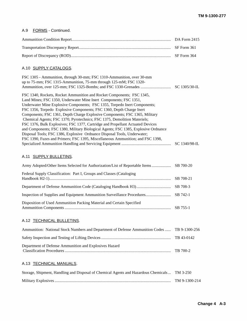
TM 9-1300-277
Change 4 A-3
Ammunition Condition Report.................................................................................................. DA Form 2415
Transportation Discrepancy Report........................................................................................... SF Form 361
Report of Discrepancy (ROD)................................................................................................... SF Form 364
A.10 SUPPLY CATALOGS.
FSC 1305 - Ammunition, through 30-mm; FSC 1310-Ammunition, over 30-mmup to 75-mm; FSC 1315-Ammunition, 75-mm through 125-mM; FSC 1320-Ammunition, over 125-mm; FSC 1325-Bombs; and FSC 1330-Grenades .............................. SC 1305/30-IL
FSC 1340, Rockets, Rocket Ammunition and Rocket Components; FSC 1345, Land Mines; FSC 1350, Underwater Mine Inert Components; FSC 1351, Underwater Mine Explosive Components; FSC 1355, Torpedo Inert Components; FSC 1356, Torpedo Explosive Components; FSC 1360, Depth Charge InertComponents; FSC 1361, Depth Charge Explosive Components; FSC 1365, Military Chemical Agents; FSC 1370, Pyrotechnics; FSC 1375, Demolition Materiels; FSC 1376, Bulk Explosives; FSC 1377, Cartridge and Propellant Actuated Devicesand Components; FSC 1380, Military Biological Agents; FSC 1385, Explosive Ordnance Disposal Tools; FSC 1386, Explosive Ordnance Disposal Tools, Underwater; FSC 1390, Fuzes and Primers; FSC 1395, Miscellaneous Ammunition; and FSC 1398, Specialized Ammunition Handling and Servicing Equipment ................................................. SC 1340/98-IL
A.11 SUPPLY BULLETINS.
Army Adopted/Other Items Selected for Authorization/List of Reportable Items ................... SB 700-20
Federal Supply Classification: Part I, Groups and Classes (Cataloging Handbook H2-1)........................................................................................................................ SB 708-21
Department of Defense Ammunition Code (Cataloging Handbook H3).................................. SB 708-3
Inspection of Supplies and Equipment Ammunition Surveillance Procedures......................... SB 742-1
Disposition of Used Ammunition Packing Material and Certain SpecifiedAmmunition Components ......................................................................................................... SB 755-1
A.12 TECHNICAL BULLETINS.
Ammunition: National Stock Numbers and Department of Defense Ammunition Codes ...... TB 9-1300-256
Safety Inspection and Testing of Lifting Devices ..................................................................... TB 43-0142
Department of Defense Ammunition and Explosives Hazard Classification Procedures ......................................................................................................... TB 700-2
A.13 TECHNICAL MANUALS.
Storage, Shipment, Handling and Disposal of Chemical Agents and Hazardous Chemicals ... TM 3-250
Military Explosives ................................................................................................................... TM 9-1300-214
A.9 FORMS - Continued.

TM 9-1300-277
A-4 Change 4
Ammunition Maintenance......................................................................................................... TM 9-1300-250
Unit Maintenance Manual (Including Repair Parts and Special Tools List) for Artillery Ammunition for Guns, Howitzers, Mortars, Recoilless Rifles, and40-mm Grenade Launchers ....................................................................................................... TM 9-1300-251-20&P
Direct Support and General Support Maintenance Manual (Including Repair Parts and Special Tools List) for Artillery Ammunition for Guns, Howitzers, Mortars, Recoilless Rifles, and 40-mm Grenade Launchers ................................................................... TM 9-1300-251-34&P
Use of Mine, Antitank: HE, Heavy, M15 as a Substitute for Charge Assembly Demolition: M37 or M183 ...................................................................................................... TM 9-1375-200/2
Operator’s and Unit Maintenance Manual (Including Repair Parts and Special Tools List): Demolition Materials ............................................................................................ TM 9-1375-213-12
Direct Support and General Support Maintenance Manual (Including Repair Parts and Special Tools List) for Demolition Materials ..................................................................... TM 9-1375-213-34&P
Army Ammunition Data Sheets for Small Caliber Ammunition (FSC 1305) .......................... TM 43-0001-27
Army Ammunition Data Sheets for Artillery Ammunition: Guns, Howitzers, Mortars, Recoilless Rifles, Grenade Launchers and Artillery Fuzes (FSC 1310, 1315, 1320,1390)....................................................................................................................... TM 43-0001-28
Army Ammunition Data Sheets for Rocket Systems, Rocket Fuzes, Rocket Motors (FSC 1340) ....................................................................................................... TM 43-0001-30
Army Ammunition Data Sheets for Land Mines (FSC 1345) .................................................. TM 43-0001-36
Army Ammunition Data Sheets for Military Pyrotechnics (FSC 1370) ................................... TM 43-0001-37
Army Ammunition Data Sheets for Demolition Materials ....................................................... TM 43-0001-38
Army Ammunition Data Sheets - Ammunition Peculiar Equipment (APE) ............................ TM 43-0001-47
Destruction of Conventional Ammunition and Improved Conventional Munitions (ICM) to Prevent Enemy Use ................................................................................................................... TM 43-0002-33
Demilitarization Procedures for FSC 1040 Chemical Weapons and Equipment, FSC 4310 Compressors and Vacuum Pumps, FSC 1055 Launchers, Rockets and Pyrotechnics .............. TM 43-0003-27
Storage and Materials Handling ................................................................................................ TM 743-200-1
General Instructions for Disposal of Conventional Munitions ................................................. TO 11A-1-42
Firefighting Guidance Transportation and Storage Management Data and Ammunition Com-plete Round Chart...................................................................................................................... TO 11A-1-46
A.13 TECHNICAL MANUALS. - Continued
PIN: 051214-004

TM 9-1300-277
Department of Defense Ammunition Code (CatalogingHandbook H3) ................................ ................................ ................................ ..................SB 708 3
Ammunition Surveillance Procedures ................................ ................................ ........................... SB 742 1Disposal of Supplies and Equipment: Ammunition
Disposition of Used Packing Material and CertainSpecified Ammunition Components ................................ ................................ .................SB 755 1
A-5. SUPPLY CATALOGS
Ammunition and Explosives: ................................ ................................ ................................ .........Classes 1305 thru 1330SC 1305/30-IL
Ammunition and Explosives: ................................ ................................ ................................ .........Classes 1340 thru 1398SC 1340/98-IL
A-4 Change 1

TM 9-1300-277
APPENDIX B
EXPLANATION OF TERMS
The following are descriptions of terms and phases commonly used in conjunction with ammunition, explosives, andother dangerous materials. These are listed to provide a degree of uniformity of description in the use of technicalinformation throughout these standards.
Administration Areas--The areas in which administrativeoffices for the entire establishment are located. Theseareas differ from those directly associated with and apart of the explosive area, such as ammunitionoperations office.
Ammunition-Includes all non-nuclear ordnancecomponents and explosive prepared to form a charge,complete round, or cartridge for small arms, rifle, gun,cannon, or any other weapon or explosiveactuateddevice, impulse device, torpedo warhead, mine, bomb,depth charge, demolition charge, fuze, detonator,projectile, rocket, or guided missile. Ammunition alsoincludes all solid propellants, explosives, hypergolicliquids, propellant systems, and other hazardousmaterials applied to ordnance uses and requiringsurveillance for reasons of explosive safety, all JATO's,boosters, sustainers, military pyrotechnics, andchemical/biological systems, and materials.
Ammunition Operations Office-Any office, exclusive ofthe main administrative area adjacent to or within anexplosive area, in which operational administrativefunctions pertaining to explosives are performed.
Barricade-An intervening approved barrier, natural orartificial, of such type, size, and construction as to limitin a prescribed manner, the effect of an explosion onnearby buildings or exposures.
Biological Agent-A solid, liquid or aerosol, which throughits biological properties produces injurious or lethaleffects on personnel, plants, or animals.
Blast-Brief and rapid movement of air or fluid away froma center of outward pressure, as in an explosion; thepressure accompanying this movement.
Blasting Cap--A cylindrical detonator containing one ormore sensitive initiating explosives used to initiate thedetonation of demolition charges. There are severaltypes of blasting caps, as follows:
a. Electric blasting caps. These are capable ofbeing set off by an electrical current.
b. Nonelectric blasting caps.
These are capable of being set off by a spit of fire(normally from a safety fuze).
Caution-An operating procedure, practice, etc., which ifnot strictly observed, could result in damage to, ordestruction of, equipment.
Change House-A building provided with facilities foremployees to change to and from work clothes. Suchbuildings may be provided with sanitary facilities,drinking fountains, lockers, and eating facilities.
Chemical Agent--A solid, liquid, or gas which through itschemical properties produces lethal or toxic effects onman, animal or plant life, or produces an incendiaryaction or screening or signaling smoke.
Chemical Ammunition-Ammunition, the filler of which isprimarily a chemical agent.
Clearance-An authorization to conduct a test, to enter orexit from a danger area, or to conduct work in a dangerarea. Clearance may be granted only by the safetyobserver having jurisdiction over the danger area inwhich the operation is to be conducted.
Compatibility-Ammunition or explosives are consideredcompatible if they may be stored or transported together
B-1

TM 9-1300-277
without significantly increasing either the probability ofan accident or, for a given quantity, the magnitude ofthe effects of such an accident.
Compatible Storage-Applies to those items which maybe stored together without increasing the hazard.
Component-Any part of a complete item.
Concentration-The amount of a substance, regardless ofits physical state, present in a given unit volume of air.Concentration is visually expressed in milligrams percubic meter (mg/m3). The amount of vapor actuallyinhaled or absorbed by an individual is not referred to asconcentration.
Contamination-The presence of or act of supplying achemical agent in a dangerous amount of concentrationon an individual, object, or area. For liquid agents,contamination is usually expressed in milligrams persquare meter (mg/m2), ounces per square yard (oz/yd2)or tons per square mile (tons/mi2 ).
Controlling Authority-The term controlling authority asused in these standards refers to the headquarters of theDoD Component concerned.
Conversion of Temperature-To convert Fahrenheit toCentigrade, subtract 32 from the Fahrenheit reading andmultiply by 1.8. To convert Centigrade to Fahrenheit,multiply the Centigrade reading by 1.8 and add 32.
Conventional Ammunition- Non-nuclear ammunitionexcludes all biological ammunition and generallyexcludes chemical ammunition except for existingsmoke and incendiary agents and agents of the riotcontrol type.
Decontaminating Material-Any substance used tochemically destroy, physically remove, seal in, orotherwise make harmless a chemical agent.
Decontamination--The process of making any individual,object, or area safe by chemically destroying orphysically removing harmful chemical agents. An objector area may be made safe for unprotected personnel byeffectively sealing in the harmful agent, if it cannot beremoved chemically or physically.
Deflagration-A rapid chemical reaction in which theoutput of heat is sufficient to enable the reaction toproceed and be accelerated without input of heat fromanother source. Deflagration is a surface phenomenonwith the reaction products flowing away from theunreacted material along the surface at subsonicvelocity. The effect of a true deflagration underconfinement is an explosion. Confinement of thereaction increases pressure, rate of reaction andtemperature, and may cause transition into a detonation.
Demilitarization-The act of destroying the militaryoffensive or defense advantages inherent in certaintypes of equipment and material. The termencompasses disassembly and removal of explosives,mutilation, cutting, crushing, scrapping, melting, burningand dumping at sea (when authorized), or alterationdesigned to prevent further use of the equipment andmaterial for its originally intended military or lethalpurpose, and applies equally to material inunserviceable condition, that has been screened throughNational Inventory Control Point (NICP) and declaredsurplus or foreign excess. Demolition ExplosiveCharge-An intentionally placed explosive charge usedunder controlled conditions for a desired explosiveeffect.
Detonation-A violent chemical reaction within achemical compound or mechanical mixture evolvingheat and pressure. A detonation is a reaction whichproceeds through the reacted material toward theunreacted material at a supersonic velocity. The resultof the chemical reaction is exertion of extremely highpressure on the surrounding medium forming apropagating shock wave which is originally of supersonicvelocity. A detonation, when the material is located onor near the surface of the ground, is normallycharacterized by a crater.
Detonator-A device capable of inducing a high-orderdetonation in high explosives.
Detonating Cord-A flexible tubing containing a core ofhigh explosive which carries the detonation wave fromone end to the other at approximately the
B-2

TM 9-1300-277
detonation velocity of the explosive in the core.
Disposal-The process of eliminating unwantedmaterial/munition items from the inventory byredistributing, transferring, detonating, selling,abandoning, or destroying it.
Disposal Range-Any area of land which has beendesignated by proper authority for exclusive use indemilitarization/ disposal operations.
Dividing Wall-A wall designed to prevent, control, ordelay propagation of an explosion between quantities ofexplosives on opposite sides of the wall.
Downwind Vapor Hazard (Quantity/Distance-The dis-tance downwind from the munitions which exposedindividuals can be expected to exhibit certainphysiological effects. This distance is not onlydependent on the source strength (quantity), but alsoupon the toxicity of the agent and the meteorologicalconditions at time of release.
Dud -An explosive loaded item that fails to explodewhen subjected to treatment that should cause it tofunction. A dud can be a bomb, shell, grenade, etc.,that has been discharged from a weapon, dropped froma plane, or thrown by hand that failed to explode onreaching the target.
Electroexplosives Device-Any explosives device, suchas blasting caps, squibs, switches, valves, igniters, etc.,which is designed to be initiated by an electric current.
Electromagnetic Radiation-An energy wave consisting ofelectric and magnetic lines of force, as a radio wave.
Equipment-A general term including apparatus,appliances, devices, wiring, fixtures, fittings, material,and the like.
Establishment-Any plant, works, arsenal, depot, provingground, or any other activity under control of the Army.
Exemption-A relatively long term exception to anotherwise mandatory requirement. Exemptions may be
granted by law, TM 9-1300-277 by Congressionalresolution, or by a finding and determination by theSecretary or Deputy Secretary of Defense, or by aSecretary or Under Secretary of a Military Department.Exemptions (except those established by Congressionalaction) shall be granted only when immediate correctivemeasures are wholly impractical, (such as whereCongressional authorization to purchase real estate foradequate safety clearances has not been granted orwhere significant impairment of the overall defenseposture of the United States would otherwise result) andonly if positive programs for the eventual correction ofthe deficiency are being carried out. Exemptions willnot be granted for a period in excess of that estimatedto be required for correction of the deficiency.
Explosion-A chemical reaction of any chemicalcompound or mechanical mixture which, when initiated,undergoes a very rapid combustion or decompositionreleasing large volumes of highly heated gases whichexert pressure on the surrounding medium. Also, amechanical reaction in which failure of the containercauses the sudden release of pressure from within apressure vessel; for example, pressure rupture of asteam boiler. Depending on the rate of energy release,an explosion can be categorized as a deflagration, adetonation, or a pressure rupture.
Explosive(s)-Materials that either detonate or deflagrate.Any Chemical compound or mechanical mixture which,when subjected to heat, impact, friction, shock or othersuitable initiation, undergoes a very rapid chemicalchange with the evolution of large volumes of highlyheated gases which exert pressures in the surroundingmedium.
Explosives Area-An area specifically designated and setaside from other portions of an installation formanufacturing, processing, storing, and handling ofexplosives and ammunition.
Explosive Equivalent-The equivalent power of anexplosive when compared to an equal weight of TNT.Usually identified as greater or less powerful than TNTand is normally identifiable to two decimal, e.g.,Composition
Change 2 B-3

TM 9-1300-277
C-4 is 1.15 times more powerful than TNT (1 pound ofComposition C-4 is equivalent to 1.15 pounds of TNT).
Explosives Facility-Any structure or location containingammunition and explosives.
Explosives Hazard--Any condition which may result in orcontribute to the severity of an explosives accident orincident.
Explosives Safety Distance (Quantity Distance)-Thepre-scribed minimum distance between various classesand quantities (net weight) of explosives and betweensuch explosives and specified exposures (inhabitedbuildings, public highways, public railways, petroleum,aircraft, etc.) affording an acceptable degree ofprotection and safety.
Exposed Explosives-Those actually visible (unpackagedbulk explosives, disassembled or open components,etc.) and that also are susceptible to initiation directly bystatic or mechanical spark. Explosives that create,accidentally or otherwise, explosives dust or give offvapors, fumes or gases in explosive concentrations.
Field Office-An office required by operational super-vision (e.g., foremen and line supervisors) in directsupport of ammunition and explosives operations.
Firebrand-A projected burning or hot fragment whosethermal energy is transferred to a receptor.
Fire Hazard Area-A location in which the primary, butnot necessarily the only hazard is that of fire, includingexplosions of gas or vapor and air mixtures.
Fire Resistive-Structures, materials, etc., designed toresist fire without becoming weakened to the point offailure.
Fire Retardant-Generally combustible structures, mater-ials, etc., so treated or covered as to retard ignition orspread of fire.
Fire Wall/Fire Division Wall -A wall of fire-resistive con-struction designed to prevent spread of fire from oneside to the other.
Firing Device-A device that causes the initiation ofdemolition charges either directly or through its effect ona blasting cap, electric squib, or detonating cord. It maybe electrical, mechanical, or electromechanical.
Fixed Ammunition-Includes all but small arms androcket ammunition. Consists of cartridge case, loadedwith propellant, firmly attached to the projectile. Suchammunition is loaded in one operation into the weapon.
Flameproof-Combustible materials (e.g., clothing) sotreated or coated as to decrease their burningcharacteristics.
Flammable-Combustible material easily ignited andwhich burns readily.
Flammable Liquid-Any liquid, the vapor of which willburn.
Fragment Distance-The limiting range of a considerablenumber of fragments from the quantity and types ofexplosives involved in certain explosives safety-distance (quantity-distance) tables. (Formerly referredto as missile distance for ammunition in 1.2-1.3 basedon the limiting range of a considerable number offragments for the type of ammunition involved. Thedistances do not take into account occasional fragmentswhich may be projected farther. For class 1.1,theinhabited-building distance is based upon blast damageand does not represent the distance to which somefragments can be projected.
Fragmentation-The breaking up of the confining materialof a chemical compound or mechanical mixture whenan explosion takes place. Fragments may be completeitems, subassemblies, or pieces thereof, as well aspieces of equipment or buildings containing the items.
Fuse-A slow-burning powder filled cord that carriesflame through its length at a known and uniform rate perunit of length. Also known as "safety fuze", "time fuze"and "time blasting fuze."
Fuze-(Not to be confused with fuse). A mechanicalelectrical, or electromechanical device used to functionan explosive device such as a bomb or projectile. Indemolition work, a firing device may be termed a fuze.
B-4

TM 9-1300-277
Hangfire-See Malfunction.
Hazard-Any condition which may result in, or contributeto, the severity of an accident.
Hazard Classification-Identifies the hazardous charac-teristics of explosives items by assignment toestablished hazard categories governing storage andtransportation. These categories are: Quantity-Distance Class, Storage Compatibility Group,Department of Transportation (DOT) Class, and DOTMarking.
Hazardous Fragment-A hazardous fragment is onehaving an impact energy of 58 foot-pounds or greater.
Hazardous Fragment Density-A density of hazardousfragments exceeding one per 600 square feet.
Hazardous Locations for Electrical Equipment-Locationswhere flammable gases or vapors are or may be presentin the air in explosive or ignitable mixtures or wherecombustible dust or easily ignitable particles or fibersmay be present.
Hazardous Material-Any compound, mixture, element,or assemblage or material which, because of inherentcharacteristics, is dangerous to manufacture, process,store, or handle.
High Explosive Equivalent or Explosive Equivalent-Theamount of a standard explosive which, when detonated,will produce a blast effect comparable to that whichresults at the same distance from the detonation orexplosion of a given amount of the material for whichperformance is being evaluated. It is usually expressedas a percentage of the total net weight of all reactivematerials contained in the item or system. For thepurpose of these standards, TNT is used forcomparison.
High Explosives Equivalent or TNT Explosives Equiv-alent - Deleted
Holding Area--That area established, within a site, fortemporary storage of munitions to be destroyed,
demolition material and blasting caps. The holding areamust be situated at great enough distance from thedisposal point or barricaded to ensure the materialstored therein is safe from premature detonation fromflying debris resulting from a disposal action.
Hydrolysis-The reaction of a chemical agent or chemicalsubstance with water, whereby decomposition of thesubstance takes place and one or more new substancesare produced. Hydrolysis reduces the effectiveness ofmany chemical agents; although, in some, the resultingproduct of hydrolysis may in itself be a poison, as withagents containing arsenic. The rate of hydrolysis isdetermined by the resistance offered by a chemicalagent or substance to decomposition by water.
Hypergolic-A property of various combinations ofchemicals to self-ignite upon contact with each otherwithout a spark or other external initiation.
Incendiary-Ammunition with inflammable filling.
ICM-Munitions that embody a unique design to controlthe number, size, and distribution of fragments producedwhen the item functions.
Inert-Ammunition containing no explosives or chemicalagents.
Inert Area-Any area other than an explosives orammunition area within an establishment.
Inert Components-Ammunition parts which contain noexplosives or chemical agents.
Inhabited Building-Any building or structure, other thanan operating building, magazine or auxiliary building,occupied in whole or part as a habitation for humanbeings, or a building, structure or area where people areaccustomed to assemble, such as a church,schoolhouse, railroad station, and similar transportationfacilities, store, theater, or factory, both within andoutside Government establishments. Land outsideboundaries of establishments will be consideredpossible sites of inhabited buildings.
Change 1 B-5

TM 9-1300-277
Inhabited Building Distance-Inhabited building distancesare the minimum distances which may be expected toprotect buildings or structures from substantial structuraldamage (not readily repairable) from blast effect. Thesedistances do not provide protection against glassbreakage, but do provide a high degree of protectionfrom fragments.
Intermagazine Distance-The minimum distance permit-ted between explosives locations, as prescribed forvarious types and quantities of explosives. Thisdistance is expected to prevent propagation by blast(shock wave) and to provide a reasonable degree ofprotection against propagation due to fragments.
Intraline Distance-The minimum permitted (except asindicated below) between any two buildings within anyone operating line. Intraline distances are also used forseparating certain specified areas and locations withinexplosives establishments even though actualoperations are not involved. Intraline distance isexpected to protect from propagation of explosion dueto blast effects, but not against possibility of propagationdue to fragments. Buildings separated by intralinedistances will probably suffer substantial structuraldamage.
Intraline Operations-Processes accomplished within oneoperating line.
Intraline Separations-The distance to be maintainedbetween any two operating buildings and/or sites withinan operating line, at least one of which contains or isdesigned to contain explosives.
Inversion Condition-An increase of air temperatureresulting from an increase in altitude (the ground beingcooler than the surrounding air). This condition isusually found on clear or partially-clear nights and earlyin the morning to about one hour after sunrise. Therewill be no convection currents and little mechanicalturbulence with winds less than six miles per hour. Astable atmospheric condition such as described isfavorable for releasing chemical agents for tacticalpurposes, but it is the most unfavorable condition fordisposal purposes.
Lapse Condition-The condition in which a decrease ofair temperature results from an increase in altitude (the
ground being warmer than the surrounding air). Thiscondition is usually found when skies are clear, betweenthe hours of 1000 and 1600. During such conditions,strong convection currents may exist. An unstableatmospheric condition such as described is favorable fordisposal of chemical agents for tactical purposes.
Liquid Propellants-Substances used for propulsion oroperation of missiles, rockets, or related devices.
Loading Docks-Facilities at ground level or elevatedstructures designed and installed for transferringammunition, explosives, and component parts thereof,to or from automotive vehicles, railway cars, and/orcargo-type aircraft.
Magazine-Any building or structure, except an operatingbuilding, used for storage of ammunition explosives orloaded ammunition components. Includes such facilitiesas an above-ground magazine, an igloo-type magazine,a railroad car, a motor truck, a temporary shelter, or anopen storage site.
Magazine Area-A specifically designated area set asidefor the primary purpose of ammunition and explosivesstorage.
Magazine Distance-This distance is the minimumpermitted between any two storage magazines.Distance required is determined by the type or types ofmagazines and also the type and the quantity ofammunition or explosives from one magazine to anotherfrom blast and provides a reasonable degree ofprotection against propagation of explosion due tofragments. It does not, except perhaps for earthcovered magazines, protect the magazines from severestructural damage.
Magazine, Earth-Covered, Non-standard-All Earth-covered magazines except Army igloo, Navy arch-type,earth-covered, corrugated steel, arch-type, and module,open storage, barricaded with earth covering equal to orgreater than that required by standard igloo magazines.
Malfunction-Failure of item to function in accordancewith its expected performance or functioning of theexplosive components during a non-functional test.
B-6

TM 9-1300-277
A critical malfunction is one which may cause a hazardunder the circumstances described above. Forpurposes of clarity, malfunctions do not includeaccidents and incidents resulting from negligence,malpractice, or implication in such situations asvehicular accidents, fires, etc. However, malfunctionsdo include abnormal or premature function of explosiveammunition items during normal handling, maintenance,storage, transportation, and tactical deployment.Includes cookoff, hangfire, misfire, etc.
Mass-Detonating Explosives-High explosives, blackpowder, certain propellants, certain pyrotechnics, andother similar explosives, alone or in combination, orloaded into various types of ammunition or containers,most of the entire quantity of which can be expected toexplode virtually instantaneously when a small portion issubjected to fire, to severe concussion or impact, to theimpulse of an initiating agent, or to the effect of aconsiderable discharge of energy from without. Such anexplosion normally will cause severe structural damageto adjacent objects. Explosion propagation may occurimmediately to other items of ammunition andexplosives stored sufficiently close to and notadequately protected from the initially exploding pilewith a time interval short enough so that two or morequantities must be considered as one for quantity-distance purposes.
Mass Detonation-Virtually instantaneous explosion ofmass of explosives when only small portion is subject tofire, severe concussion or impact, impulse of initiatingagent, or to effect of considerable discharge of energyfrom without. Such an explosion normally will causesevere structural damage to adjacent objects, or thesimultaneous explosion of other separated ammunitionand explosives stored sufficiently close to the initiallyexploding pile. A mass detonation, when the explosivesare located on or near the surface of the ground, isnormally characterized by a crater.
Measurement of Distance-Measurement of distance fordetermining the maximum allowable quantity ofexplosives shall be made from the nearest outside pointor wall of the room, cubicle, or building proper involvedwhich contains the explosives to the nearest outsidepoint or TM 9-1300-277 wall of the other location underconsideration.
Military Pyrotechnics-Ammunition manufactured specifi-cally for use as signals, illuminants and the like.
Misfire-A misfire is a failure of an explosive to detonateafter initiating action is taken. The failure may be due toa faulty firing mechanism or a faulty element in theexplosive train.
Mound-An elevation of earth having a crest at least 3feet wide, with the earth at the natural slope on eachside and with such elevation that any straight line drawnfrom the top of the sidewall of a magazine or operatingbuilding, or the top of a stack containing explosives toany part of a magazine, operating building, or stack tobe protected will pass through the mound. The toe ofthe mound will be located as near the magazine,operating building, or stack as practicable.
Munitions-Supplies and equipment of all kinds neededby the military services for direct military purposes.
NEG-Net explosive quantity as expressed in kilograms.
Net Explosives Weight (NEW)-The total quantity ofexplosives material or high explosives equivalency ineach item or round to be used when applyingquantitydistance criteria or other standards.
Nitrogen Padding (or Blanket)-To fill the void or ullageof a closed container with nitrogen gas to preventoxidation of the chemical contained therein and to avoidformation of a flammable mixture, or to maintain anitrogen atmosphere in or around an operation, piece ofequipment, etc.
Noncombustible-Not combustible, nor burnable in theordinary sense of the word.
Non-DoD Component-Any entity (Government, private,or corporate which is not a part of the Department ofDefense.
Note-An operating procedure, condition, etc., which isessential to highlight.
Operating Building-Any structure, except a magazine, inwhich operations pertaining to manufacturing,
B-7

TM 9-1300-277
processing, handling, loading, or assembling ofammunition and explosives are performed.
Operating Line-A group of buildings, facilities or relatedwork stations so arranged as to permit performance ofthe consecutive steps in the manufacture of anexplosive, or in the loading, assembly, modification, andmaintenance of ammunition.
Operational Shield-A barrier constructed at a particularlocation or around a particular machine or operatingstation to protect personnel, material, or equipment fromthe effect of localized fire or explosion.
Outdoor Storage Sites-Sites within the magazine areaselected for outdoor storage of ammunition and inexceptional cases inert items. Outdoor storage sitesmay be of the following types:
a. Earth-revetted, four sides (except entrance),located between earth-covered magazines.
b. Earth-revetted, four sides (except entrance), notlocated between earth-covered magazines.
c. Nonrevetted, with roof covered magazines.
d. Nonrevetted, without cover, not located betweenearth-covered magazines.
Personnel Shelter--A shelter providing four to six-footthick frontal protection and a minimum of two-foot thickreinforced overhead protection. Personnel engaged indemolition operations should always have ample time toreach shelter which provides splinter-proof protection.
Photoflash Devices-Photographic aids, such as mag-nesium flashlights, photoflash bulbs, and electronic flashattachments. Only lighting equipment bearing the labelof approval of the Underwriters' Laboratories for thehazard involved will be used in photographing locationsinvolving exposed explosives, explosive dusts,flammable gases or vapors.
Power-In relation to explosives, the term refers torelative end results. It takes into account such factors
as brisance, detonation rate, cratering B-8 potential,steel penetration capability, etc.
Primer-A device or assembly used to prepare ademolition charge for firing. It may vary depending onthe firing system to be employed and in some cases thetype of charge to be set off.
Prohibited Area-A specifically designated area atairfields, seadromes, or heliports in which allammunition and explosives facilities are prohibited.
Propagating Explosion-Communication of an explosion(detonation or deflagration) from one explosives sourceto another by fire, fragment, or blast (shock wave) wherethe time interval between explosions is sufficient to limitthe total overpressure at any given time to that whicheach explosion produced independently. (This conditionwhere detonation occurs would be evidenced by adistant shock wave from each detonation with adiscernible pressure drop between each explosion.)Protected Terrain or an effective artificial barrierinterposed between a propellant facility and inhabitedbuilding, or other exposure, to prevent fragments fromendangering the building or other exposure.
Protective (Gas) Mask-A face mask used by personnelto protect the respiratory system against inhalation ofharmful chemical agents.
Public Highway-Any street, alley, road, or navigablewater open to use of the general public. Navigablewater is that part of a body of water capable ofnavigation by barges, tug-boats, or larger vessels.Public highway distance is the minimum permittedbetween a public highway and an explosives hazard.Public highway distances are based on criteria similar tothose applicable to passenger railroads and are identicalto passenger railroad distances. Persons in the openare considered safe from the blast effects (notfragments) of explosions when separated from theexplosion site by distance equal to one-half the publichighway distance.
Public Railway-Any steam, electric, or other railroadwhich carries passengers for hire. Public railwaydistance is the minimum permitted between a publicrailway as so defined and an explosives hazard.
B-8

TM 9-1300-277
The distance at which cars are considered safe from theblast effects of explosions has been fixed at 60 percentof the inhabited-building distance. These decreaseddistances are used in tables for class 1.1 materials. Theuse of the lesser distances is based on the smallerheight and area of railroad cars exposed to blast; thegreater resistance of cars to blast as compared withbuildings; and the fact that, while a building is stationaryand subject to risk constantly, the presence of a train isonly temporary. For other than class 1.1 materials,inhabited-building distances are required to publicrailways. The minimum separation between privatelyowned railways over which passengers are not carried,and magazines and storage sites will be not less than400 feet unless the public railway distance specified inthe appropriate quantity-distance table is less.However, the railways must be separated by publicrailway distances from operating buildings.
Public Traffic Route-Any public street, road, highway,navigable stream, or passenger railroad.
Pyrotechnic Material-Explosive or chemical ingredients,including powdered metals, used in manufacture ofmilitary pyrotechnics.
Quantity-Distance-The quantity of explosives materialand the distance separation relationships which providedefined types of protection. These relationships arebased on levels of risk considered acceptable for thestipulated exposures and are tabulated in theappropriate quantity-distance tables.
Rail Holding Yard-A railroad yard used for storing ofloaded cars for indefinite periods of time.
Restricted Area-Any area, usually fenced, at anestablishment where entrance and egress of personneland vehicular traffic are controlled for reasons of safetyand security.
Revetment-An explosives location barricaded on at leastthree sides. The revetment may or may not incorporatea structure or an overhead cover.
Riot Control Agent-A chemical that produces temporary,irritating, or disabling effects when in contact with theeyes or when inhaled.
Rocket-A complete missile which derives its thrust fromejection of hot gases generated from propellants in themotor.
Safety Distances-Safety distances are empirical dis-tances in relation to quantity of explosives, and are theminimum permitted for separation of facilities within ahazard area, of possible explosions of the explosivehazard from inhabited buildings, public railway, andpublic highways, in order to control the magnitude ofdamage, loss of life, and serious injuries. Separationdistances are not absolutely safe distances but arerelatively protective or safe distances. Greaterdistances than those shown in the applicable tablesshould be used whenever practicable.
Semifixed Ammunition-Ammunition loaded into theweapon as a unit. The cartridge case is loose-fittedover the base of the projectile so that the propellingcharge may be adjusted for zone firing.
Separate-Loading Ammunition-Ammunition whosemajor components projectile, propelling charge andprimer are issued unassembled and are loaded into theweapon separately.
Separated-Loading Ammunition-Ammunition consistingof a projectile and a primed cartridge case containingpropellant. The propelling charge is not adjustable forzone firing.
Service Magazine-Auxiliary building used for inte-rmediate storage of explosives materials not exceedingthe minimum amount necessary for safe, efficientproduction.
Simultaneous Detonation-Detonation of separatedquantities of explosives or ammunition occurring sonearly at the same time that the effect on thesurroundings is the same as though the severalquantities were not separated and were detonated enmasse.
Single-Revetted Barricades-A mound which has beenmodified on one side by a retaining wall, preferably ofconcrete, of such slope and thickness as to hold firmly inplace the 3-foot width of earth required at the top, withthe earth at the natural angle on one side. All other
B-9

TM 9-1300-277
requirements of a mound will be applicable to the singlerevetted barricade.
Site-The locations within a range which are reservedexclusively for use in conducting specific functionsinvolving munitions. A range may have one or severalsites, i.e., disposal, training, bombing and gunnery, etc.
Small Arms Ammunition-Ammunition for small arms,i.e., all ammunition up to and including caliber .60, andall gauges of shotgun shells.
Solid Propellants-Low explosives used to propelprojectiles, rockets, etc., and to generate gases forpowering auxiliary devices.
Standard Igloo Magazine-An earth-covered, arch-typemagazine, with or without a separate door barricade,constructed according to an approved standard drawing.
Static Fire-Firing, or functioning as designed, a munitionin a hold-down position.
Static Test Stand-Locations whereon liquid propellantengines or solid propellant motors are tested in place.
Storage Compatibility-A relationship between differentitems of ammunition, explosives, and other dangerousmaterials whose characteristics are such that a quantityof two or more of the items stored or transportedtogether is no more hazardous than a comparablequantity of any one of the items stored alone.
Substantial Dividing Wall-An interior wall designed toprevent simultaneous detonation of quantities ofexplosives on opposite sides of the wall.
Surveillance/Quality Assurance-The observation,inspection, test, evaluation, and condition code
classification of ammunition; ammunition componentsand explosives in movement; storage and use todetermine the current degree of serviceability and rateof deterioration. Inspections during salvage anddemilitarization operations to assure compliance withapproved standards.
Toxicity-The property possessed by a material whichenables it to injure the physiological mechanism of aliving organism by chemical means, with maximumeffect being death.
Unbarricaded-Without effective barricade betweenmagazines, operating buildings, stacks, etc., opposedone to another.
Waiver-Written authority from a theater commander,permitting deviation from a mandatory rule for a limitedtime, pending correction of the condition, or writtenauthority from an installation commander, permittingdeviation from an advisory provision. The latter type,local waivers, are also granted for specific periods oftime.
Warhead or Warhead Section-That portion of a rocketor guided missile containing the high explosives chargeor other destructive agent.
Warning-An operating procedure, practice, etc., which ifnot correctly followed, could result in injury to personnelor loss of life.
Wind Direction Indicator-Weather vanes, smoke pots,smoke grenades or similar devices used for indicatingthe direction the wind is blowing.
Wind Velocity Indicator-An anemometer.
B-10

TM 9-1300-277
APPENDIX CSINGLE MANAGER ASSIGNMENT FOR CONVENTIONAL AMMUNITION
(Department of Defense Directive No. 5160.65)
C-1. GENERALPursuant to the authority vested in the Secretary ofDefense, the Secretary of the Army is assigned asSingle Manager for procurement, production, supply andmaintenance/renovation of conventional ammunitionwithin the Department of Defense (DoD) withresponsibilities, functions, authority, and relationships asset forth herein.
C-2. APPLICABILITY
The provisions of this Directive apply to the Office of theSecretary of Defense, the Military Departments, and theDefense Supply Agency (hereinafter referred tocollectively as "DoD Components"). The term "MilitaryServices", as used herein, refers to the Army, Navy,Marine Corps, and Air Force.
C-3. OBJECTIVES
The objectives of this assignment are to:
a. Integrate conventional ammunition logisticsfunctions of the Military Departments to the maximumextent practicable thereby eliminating unwarrantedoverlap and duplication.
b. Achieve the highest possible degree ofefficiency and effectiveness in the DoD operationsrequired to provide top quality conventional ammunitionto U.S. forces during peacetime and mobilization.
C-4. DEFINITION
a. The term "conventional ammunition"(hereinafter referred to as "ammunition") includes thefollowing:
(1) Small arms, mortar, automatic cannon,artillery, and shipgun ammunition.
(2) Bombs (cluster, fuel air explosive, generalpurpose, and incendiary).
(3) Unguided projectiles and rockets.
(4) Chemical ammunition with various fillers(incendiary, riot control, smoke, toxic agents, bursterigniters, peptizers, and thickeners for flame fuel).
(5) Land mines (ground-to-ground and air-to-ground delivered).
(6) Demolition materiel.
(7) Grenades.
(8) Flares and pyrotechnics.
(9) All items included in the foregoing such asexplosives, propellants, chemical agents, cartridges,propelling charges, projectiles, warheads (with variousfillers such as high explosive, illuminating, incendiary,antimateriel, and anti-personnel), fuzes, boosters, andsafe and arm devices, in bulk, combination, orseparately packaged items of issue for complete roundassembly.
b. Specifically excluded are the following:
(1) Guided missiles.
(2) Naval mines and torpedoes.
(3) Nuclear ammunition and included itemssuch as warheads, warhead sections, projectiles,demolition munitions, and training ammunition.
(4) Cartridge and propellant actuateddevices. (5) Chaff and chaff dispensers.
(6) Guidance kits for bombs or otherammunition.
C-5. RESPONSIBILITIES AND FUNCTIONS
a. The Secretary of the Army shall:
(1) Procure ammunition, including his ownand that assigned to him as set forth in C-5b(1),
C-1

TM 9-1300-277
below (hereinafter collectively referred to as "assignedammunition"), upon receipt of purchase requests as setforth in C-5b(3), below, and in accordance with ASPRTArmed Services Procurement Regulation). Thefollowing partial purchase assignments, previouslyassigned by DoD Instruction 4115.1 (DoD CoordinatedProcurement Program-Purchase Assignment) andASPR to the Department of the Navy, are herebyreassigned to the Secretary of the Army: FederalSupply Classification Classes 1310, 1325, 1340, and1390.
(2) Provide contract administration servicesin accordance with ASPR and physical security inaccordance with DoD Directive 5100.76 (PhysicalSecurity Review Board), either separately or byarrangements with the Director, Defense SupplyAgency, where appropriate, during procurement ofassigned ammunition.
(3) Establish and maintain, in coordinationwith the Secretaries of the Navy and Air Force and theDirector, Defense Supply Agency, where appropriate, aquality assurance program, including first article testingand approval, that conforms to the policies prescribedby DoD Directive 4155.1 (Quality Assurance). Thisprogram shall cover assigned ammunition duringprocurement (C-5a(1), above) and in the wholesaleinventory (C-5a(8), below). It shall complement theoverall quality assurance system for ammunition whichis a responsibility of the Secretaries of the Navy and AirForce and is retained by them as set forth in C-5b(15)(b), below.
(4) In planning for production of assignedammunition, comply fully with the policies of DoDDirective 4005.1 (DoD Industrial PreparednessProduction Planning) and ASPR by giving preference toprivately-owned facilities to minimize the need forGovernment-financed facilities.
(5) Manage, operate, and maintain all DoDinstallations and facilities involved in, capable of, andrequired for manufacturing assigned ammunition. Thisresponsibility applies to his own industrial facilities andthose transferred to him by the Secretaries of the Navyand Air Force in accordance with C-5b(7), below. Itincludes functions as follows:
(a) Establishment and operation of DoDcommercial or industrial activities in accordance with
DoD Directive 4100.15 (Commercial or IndustrialActivities).
(b) Providing DoD-owned facilities tocontractors in accordance with DoD Directive 4275.5(Industrial Facility Expansion and Replacement) andASPR.
(c) Operation of facilities in accordancewith DoD Directive 7410.4 (Regulations GoverningIndustrial Fund Operations) when industrial funds areused.
(d) Acquisition, management, anddisposal of real property in accordance with DoDDirective 4165.6 (Real Property, AcquisitionManagement and Disposal), including utilization andretention of such property in accordance with DoDDirective 4165.20 (Utilization and Retention of RealProperty) and obtaining prior approval of real propertyactions in accordance with DoD Instruction 4165.12(Prior Approval of Real Property Actions).
(e) Expansion and replacement ofindustrial facilities in accordance with DoD Directive4275.5.
(f) Maintenance of real property inaccordance with DoD Directive 4165.2 (DoD RealProperty Maintenance Activities Program).
(g) Management of DoD-ownedindustrial plant equipment in accordance with DoDDirective 4215.18 (Management of Defense-OwnedIndustrial Plant Equipment (IPE).
(h) Military construction in accordancewith DoD Directives 7040.4 (Military ConstructionAuthorization and Appropriation) and 7040.2 (Programfor Improvement in Financial Management in the Areaof Appropriations for Acquisition and Construction ofMilitary Real Property) and with DoD Directive 7150.5(Responsibility for Programming and Financing ofFacilities at Military Installations Utilized by Two or MoreDepartment of Defense Components), whenappropriate.
(6) Conduct, in coordination with theSecretaries of the Navy and Air Force, a manufacturing
C-2

TM 9-1300-277
technology program for assigned ammunition inaccordance with DoD Instruction 4200.15(Manufacturing Technology Program).
(7) Conduct, in collaboration with theSecretaries to the Navy and Air Force, industrialpreparedness production planning for assignedammunition in accordance with DoD Directive 4005.1and ASPR (C-5a(4), above).
(8) Manage, operate, and maintain thewholesale inventory of ammunition in CONUS, includingrelated and required installations and facilities or partsof them. Wholesale inventory includes all conventionalammunition stocks between point of production andpoint of receipt at first intermediate retail CONUSactivity (e.g., tidewater port, air base, post, camp, orstation). Retail inventory includes conventionalammunition stocks between point of receipt at firstintermediate/retail CONUS activity and point ofconsumption. The wholesale inventory consists of hisown ammunition and that assigned to him by theSecretaries of the Navy and Air Force (C-5b(1), below).This responsibility applies to his own installations andfacilities, or parts of them, and those transferred to himby the Secretaries of the Navy and Air Force (C-5b(8),below). It includes functions as follows:
(a) Inventory management inaccordance with DoD Directive 4140.1 (InventoryManagement Policies). This management of thewholesale inventory management of the retail inventoryworldwide which is a responsibility of the Secretaries ofthe Navy and Air Force and is retained by them inaccordance with C-5b(15)(d), below.
(b) Receipt and storage of ammunitionin accordance with DoD Instruction 4140.7 (Control,Supply, and Positioning of Materiel) and provision,management, and operation of related storage andwarehousing facilities and services in accordance withDoD Directive 4145.19 (Storage and WarehousingFacilities and Services).
(c) Issuance of his own assets and ofassets owned by the Secretaries of the Navy and AirForce to their retail inventories (C-5b(15)(d), below).Such issues and related movements shall be based on
instructions and transportation resources provided bythe Secretaries of the Navy and Air Force (C-5b(6),below) and in accordance with the movement and issuepriority system prescribed by DoD Directive 4410.6(Uniformed Materiel Movement and Issue PrioritySystem (UMMIPS)). The Single Manager is tocoordinate with the Services in selection or storagedepots so as to minimize cost of maintenance and tooptimize ability to meet Service requirements. TheServices do not have veto power over the final decisionby the Single Manager. Inter-Service transfers willcontinue to require approval by the affected Service(s).However, for items with a high degree of commonality,the Services should provide pre-arranged standingapprovals permitting the Single Manager to make inter-Service transfers. DoDD 4140.1 requires that the SMoperate an Inventory Control Point for wholesaleconventional ammunition stocks assigned whichincludes control of assigned stocks as well asmaintenance of accurate records of those stocks. TheSM is responsible for custodial accountability forwholesale conventional ammunition stocks assigned tohim. Custodial accountability is defined as themaintenance of data elements in the inventory record toreflect by ownership code the receipt, issue, balance,and such other quantitative and financial datadetermined by the SM as minimum essential for propercontrol and management of Service owned stockscommingled in storage. The Single Manager isresponsible for property management. This includesresponsibility for damage, loss, or destruction ofassigned property. The Single Manager is relieved ofhis custodial accountability and property managementresponsibilities upon the Services receipt by anaccountable officer or custodian at the first retail point.Thereupon, the stocks are considered retail stocks andthe Service assumes custodial responsibility andproperty management.
(d) Depot maintenance/renovation ofhis own assets and of assets owned by the Secretariesof the Navy and Air rorc4: in accordance with thegeneral objectives and policies prescribed by DoDDirective 4151.16 (DoD Equipment MaintenanceProgram) and DoD Directive 4151.1 (Use of Contractorand Government Resources for Maintenance ofMateriel). Such maintenance/renovation shall be
C-3

TM 9-1300-277
based on instructions and resources provided by theSecretaries of the Navy and Air Force (C-5b(6), below)and upon procedures jointly developed and agreedupon.
(e) Demilitarization and disposal, incoordination with the Secretaries of the Navy and AirForce and with the Director, Defense Supply Agency, asappropriate, in accordance with DoD Directive 4160.21(Department of Defense Personal Property DisposalProgram) and DoD Instruction 7310.1 (Accounting andReporting for Property Disposal and Proceeds from Saleof Disposable Personal Property and Lumber of TimberProducts).
(f) Wholesale requirementsaggregation and procurement direction in accordancewith DoD Instruction 4140.7.
(g) Maintenance of real property inaccordance with DoD Directive 4165.2.
(h) Management of DoD-ownedindustrial plant equipment in accordance with DoDDirective 4215.18.
(i) Military construction in accordancewith DoD Directives 7040.4 and 7040.2 and with DoDDirective 7150.5, when appropriate.
(9) Use the military standard logistics datasystems prescribed by DoD Directive 4000.25(Administration of Military Standard Logistics DataSystems) in the functions covered in this assignment.
(10) Manage DoD-owned plant equipment atcontractor plants and required to manufacture assignedammunition in accordance with DoD Directive 4215.18.
(11) Manage transportation and handling ofassigned ammunition during procurement and in thewholesale inventory in accordance with the policiesprescribed by DoD Directive 4500.9 (Transportation andTraffic Management) and under the overallmanagement of Single Managers assigned by DoDDirectives 5160.2 (Single Manager for Airlift Services),5160.10 (Single Manager Assignment for OceanTransportation), and 5160.63 (Single ManagerAssignment for Military Traffic, Land Transportation, C-4
and Common-User Ocean Terminals). The SingleManager will coordinate with Military TrafficManagement Command (Army), Military SealiftCommand (Navy), Military Airlift Command (Air Force),and Service Components prior to selection of whichstocks to be shipped and from what depot. The owningService, on an exception basis, can challenge theSingle Manager's decision and provide specificinstructions.
(12) Develop and acquire equipment andfacilities required to demilitarize assigned ammunition inaccordance with DoD Directive 4275.5.
(13) Consistent with the provisions of DoDDirective 5000.19 (Policies for the Management andControl of DoD Information Requirements), act asExecutive Agent, supported by functional requirementsfrom other DoD Components, to develop, design, andcentrally maintain a standard DoD-wide automated datasystem covering the functions in this assignment. Thisstandard system shall not be duplicated and shallreplace nonstandard systems currently used by any DoDComponent.
(14) Provide management information onassigned ammunition during procurement and in thewholesale inventory to the Secretaries of the Navy andAir Force through the automated data system prescribedby C-5a(13), above. The Single Manager will report toeach Service the wholesale assets by quantity facilitylocation, lot number and readiness condition. EachService retains the right to evaluate the condition oftheir own ammunition and prepare summary reports ontheir total inventories. To assure that unwarrantedduplication is eliminated, the Single Manager is tofurnish summary information of the wholesaleconventional ammunition inventory owned by eachService, thus permitting the Service to aggregate thisinformation with their retail stock data to meet theirworldwide asset accountability requirement. Thisprecludes the need of the Services to generate their ownsummary information on the wholesale conventionalammunition stocks.
(15) Collaborate with the Secretaries of theNavy and Air Force and with the Air MunitionsRequirements and Development (AMRAD) Committeethroughout RDT&E of ammunition and on assignedammunition already in use to:
C-4

TM 9-1300-277
(a) Provide logistics implications inshort and long range acquisition planning.
(b) Provide logistics schedules andcosts for the Decision Coordinating Paper (DCP) orProgram Memorandum (PM) required by Dod Instruction5000.2 (The Decision Coordinating Paper (DCP) and theDefense Systems Acquisition Review Council(DSARC)).
(c) Meet standardization objectivesprescribed by DoD Directive 4120.3 (Department ofDefense Standardization Program).
(16) Collaborate with the Secretaries of theNavy and Air Force in advance procurement planningfor assigned ammunition as set forth in C-5b(11), below.
(17) Collaborate with the Department ofDefense Explosives Safety Board on assignedammunition functions in this assignment in accordancewith DoD Directive 5154.4 (The Department of DefenseExplosive Safety Board).
(18) Participate with the Secretaries of theNavy and Air Force in configuration control of assignedammunition in accordance with DoD Directive 5010.19(Configuration Management).
(19) Participate in the industrial facilitiesprotection program prescribed by DoD Directive 5160.54(Industrial Facilities Protection Program) in order toprovide physical security and protection of industrialfacilities managed as set forth in C-5a(5) and C-5a(8),above.
(20) Provide, as necessary, authorizedpersonnel of the Departments of the Navy and Air Forcewith access to plans, operations, and facilities formanufacturing, storage, maintenance/ renovation, anddemilitarization of assigned ammunition.
(21) Establish, by agreement with theSecretaries of the Navy and Air Force, positions forNavy and Air Force military and civilian personnel thatwill provide career development in ammunition logistics.
(22) Provide, as required, and based oninterservice support established in accordance with DoD
Directive 4000.19 (Basic Policies and Principles forInterservice, Interdepartmental, and InteragencySupport), the following:
(a) Fabrication of developmentalammunition in support of RDT&E of the Secretaries ofthe Navy and Air Force upon their request and withresources provided by them.
(b) Limited training of militarypersonnel and military units of the Departments of theNavy and Air Force in ammunition logistics upon theirrequest and with resources provided by them.
(23) Prepare, with assistance of theSecretaries of the Navy and Air Force, and submitprogram changes in manpower and costs required bythis assignment either in Program Objective Memoranda(POMs) or Program Change Requests (PCRs) inaccordance with DoD Instruction 7045.7 (The Planning,Programming, and Budgeting System).
(24) Plan, program, and budget resourcesnecessary for his responsibilities and functions in thisassignment in accordance with DoD Instruction 7045.7and with DoD Directive 7150.5 when the Department ofthe Army is involved in a host-tenant relationship withthe Departments of the Navy and Air Force.
b. The Secretaries of the Navy and Air Force shall:
(1) Assign ammunition approved for use bytheir Military Services and released for full-scaleproduction to the Secretary of the Army for procurementas set forth in C-5a(1) above and for his furthermanagement as set forth in C-5a(2) through (21) above.Arrangements for this interservice support shall beestablished in accordance with DoD Directive 4000.19.
(2) Provide their requirements as toquantities and priorities of assigned ammunition to theSecretary of the Army in time for him to purchase,produce, store, and maintain/renovate such ammunitionfrom or in established privately-owned or Governmentowned facilities or in time to establish the requiredcapability and capacity.
(3) Submit purchase requests forprocurement of assigned ammunition
C-5

TM 9-1300-277
to the Secretary of the Army in accordance with DoDDirective 4115.1 and ASPR.
(4) Use the military standard logistics datasystems prescribed by DoD Directive 4000.25 intransactions on assigned ammunition with the Secretaryof the Army (C-5a(9), above).
(5) Participate with the Secretary of the Armyin establishing and maintaining the quality assuranceprogram set forth in C-5a(3), above).
(6) Provide instructions and resources to theSecretary of the Army for transportation of their assetsfrom the wholesale inventory (C-5a(8) (c), above) andfor maintenance/renovation of their assets in thewholesale inventory (C-5a(8)(d), above).
(7) Transfer their industrial facilities involvedin manufacturing assigned ammunition to the Secretaryof the Army for management as set forth in C-5a(5),above.
(8) Transfer their installations and facilities,or parts of them, involved in receipt, storage, issue,maintenance/renovation, and demilitarization ofassigned ammunition to the Secretary of the Army formanagement as set forth in C-5a(8), above.
(9) Transfer their DoD-owned plantequipment at contractor plants involved inmanufacturing assigned ammunition to the Secretary ofthe Army for management as set forth in C-5a(10),above.
(10) Collaborate with the Secretary of theArmy on the manufacturing technology program setforth in C-5a(6), above and in industrial preparednessproduction planning as set forth in C-5a (7), above.
(11) Conduct, in collaboration with theSecretary of the Army, advance procurement planningfor their ammunition in accordance with ASPR andnegotiations of initial production contracts forammunition when the procedures of ASPR 3-108 areused.
(12) Collaborate with the Secretary of theArmy throughout RDT&E of their ammunition and onassigned ammunition already in use as set forth in C-5a(1), above.
(13) Assign, for purposes of careerdevelopment, military and civilian personnel to positionsestablished by the Secretary of the Army as set forth inC-5a(21), above.
(14) Arrange for services with the Secretary ofthe Army through interservice support established inaccordance with DoD Directive 4000.19 as follows:
(a) Fabrication of developmentalammunition (C-5a(22) (a), above).
(b) Limited training of militarypersonnel and military units CC-5a(22)(b), above).
(15) Retain responsibility for the following:
(a) RDT&E of ammunition developedby their Military Services, including test and evaluationof any developmental ammunition fabricated by theSecretary of the Army (C-5a(22)(a), above).
(b) Overall configuration managementand control in accordance with DoD Directive 5010.19and overall quality assurance in accordance with DoDDirective 4155.1 (Quality Assurance) for ammunitiondeveloped by their Military Services for its life cycle.
(c) Determining their requirement as toquantities of assigned ammunition to be procured by theSecretary of the Army as set forth in C-5a(1), above andthe planning, programming, and budgeting for theserequirements as set forth in C-5b(17)(a), below.
(d) Inventory management world-wideof their retail inventories on ammunition in accordancewith DoD Directive 4140.1. The retail inventoriesconsist of all their ammunition world-wide that is notincluded in the wholesale inventory in CONUS asmanaged and defined in C-5a(18), above.
(e) All other functions assigned by DoDDirective 5100.1 (Functions of the Department ofDefense and Its Major Components) and not specificallyassigned to the Secretary of the Army by this Directive.
(16) Assist the Secretary of the Army inpreparing program changes necessary to implement thisassignment as set forth in C-5a(23), above.
C-6

TM 9-1300-277
(17) Plan, program, and budget resourcesnecessary for their responsibilities and functions in thisassignment in accordance with DoD Instruction 7045.7as follows:
(a) Procurement of their ammunition,including cost of first destination transportation,assigned to the Secretary of the Army for procurement(C-5b(l), C-5b(3), and C-5a(1), above).
(b) Transportation of their assets fromtee wholesale inventory to their retail inventories (C-5b(6) and C-5a(8)(c), above).
(c) Depot maintenance/renovation oftheir assets in the wholesale inventory (C-5b(6), and C-5a(8)(d), above).
(d) Fabrication of developmentalammunition by the Secretary of the Army (C-5b(14)(a)and C-5a(22)(a), above).
(e) Limited training provided by theSecretary of the Army (C-5b (14)(b) and C-5a(22)(b),above).
(f) Programming and financing offacilities in accordance with DoD Directive 7150.5(Responsibility for Programming and Financing ofFacilities at Military Installations Utilized by Two or MoreDepartment of Defense Components) when theDepartment of the Navy and Air Force are involved in ahost-tenant relationship with the Department of the Army(C-5a(5)(h) and C-5a(8)(i), above).
(18) Assess responsiveness of the Secretaryof the Army to their operational needs.
c. The Under Secretary of Defense shall:
(1) Have staff responsibility for thisassignment within the Office of the Secretary ofDefense.
(2) Provide policy and guidance to theSecretary of the Army for this assignment.
(3) Appraise, in collaboration with other staffelements of the Office of the Secretary of Defense, theSecretary of the Army's performance under thisassignment.
(4) Exercise control over implementingdocuments through routine audits and investigation ofany specific questions and/or concerns issued by any ofthe Services.
C-6. AUTHORITY
The Secretary of the Army is the specifically delegatedauthority to have access and direct communications withthe Secretaries of the Navy and Air Force and theDirector, Defense Supply Agency for all matters in thisassignment.
C-7. RELATIONSHIPS
a. In the performance of this assignment, theSecretary of the Army will:
(1) Coordinate actions, as appropriate, withthe Secretaries of the Navy and Air Force and theDirector, Defense Supply Agency.
(2) Maintain appropriate liaison for exchangeof information and findings related to his assignedresponsibilities and functions.
(3) Make maximum use of establishedfacilities, procedures, and channels for procurement,production, supply, and maintenance/renovation and forrelated accounting, disbursing, investigative, safety,security, and other administrative operations.
(4) Obtain information from the Secretaries ofthe Navy and Air Force and the Director, DefenseSupply Agency necessary for performance of hisfunctions. Such information will be obtained inaccordance with DoD Directive 5000.19.
(5) Ensure that the Secretaries of the Navyand Air Force, the Director, Defense Supply Agency,and appropriate staff elements of the Office of theSecretary of Defense are kept fully informed concerninghis activities, as appropriate.
b. The Secretaries of the Navy and Air Force will:
(1) Provide assistance within their respectivefields of responsibility to the Secretary of the Army forcarrying out his assigned responsibilities and functions.
C-7

TM 9-1300-277
(2) Coordinate with the Secretary of the Armyall programs which include or are related to ammunition.
(3) Keep the Secretary of the Army informedas to the substance of their major actions beingcoordinated with each other or with other DoDComponents which relate to the responsibilities andfunctions of the Secretary of the Army in thisassignment.
C-8. EFFECTIVE DATE AND IMPLEMENTATION
This Directive is effective immediately. Four copies ofthe implementing documents shall be forwarded to theAssistant Secretary of Defense (Installations andLogistics) within 180 days. The Single Manager forConventional Ammunition is authorized to publish andmaintain such manuals (DoD 5160.65M) and proceduresas determined necessary to accomplish his assignment.
C-8

TM 9-1300-277INDEX
Paragraph,Figure, Table Page
Accessories, Demolition ................................ ................................ ...................... 4-4 4-12Agencies to be notified ................................ ................................ ........................ 2-2a 2-1Ammunition Peculiar Equipment (APE):
Deactivation Furnace (APE 1236)................................ ............................ Figs. 6-4, 6-5, 6-6 6-8,6-9,6-10
Pollution Control System (KIT E010) ................................ ...................... Fig. 6-7 6-11Washout Plant (APE 1300)................................ ................................ ...... Figs. 6-1, 6-2, 6-3
6-3,6-4,4,6-5
Ammunition Storage Locations ................................ ................................ ............ Fig. 9-1 9-2Blasting Cap:
Precautions for Electric Caps and Circuits ................................ .............. 5-3 5-1Testing ................................ ................................ ................................ .... 5-8b 5-7
Blasting Cap Crimper:Description ................................ ................................ ............................. 5-4a 5-2Operation ................................ ................................ ................................ 5-4(j), fig. 5-4 5-3,5-4
Blasting Fuse: ................................ ................................ ................................ ...... 4-3c 4-10Safety Fuse................................ ................................ ............................. 4-3c(2) 4-10Time Blasting Fuse, General ................................ ................................ ... 4-3c(1) 4-10Time Fuse M700 ................................ ................................ ..................... 4-3c(3), fig. 4-10
4-10,4-11Blasting Machines:
Description -................................ ................................ ............................ 4-5b 4-15Operation ................................ ................................ ............................ 5-11 5-12
Branch Line Connections ................................ ................................ .................... 5-14a 5-14Budgeting ................................ ................................ ................................ ............ 11-1d 11-1Burning in Deactivation Furnace ................................ ................................ ......... 8-4 8-2Burning in Pits or Trenches ................................ ................................ ................. 8-3 8-2
Burning Procedure ................................ ................................ .................. 8-3b-f incl 8-2Pit Dimensions ................................ ................................ ....................... 8-3a 8-2Post Burning Inspection ................................ ................................ .......... 8-3g 8-2
Chemical Agent Casualties Treatment (General) ................................ ................. 3-1 3-1Chemical Agents, Group A................................ ................................ ................... 3-1a(1) 3-1Chemical Agents, Group B:................................ ................................ .................. 3-1a(2) 3-1
Decontaminating Material ................................ ................................ ....... 3-1b(3) 3-2Description - ................................ ................................ ............................ 3-2 3-2Lacrimators (Tear Agents): ................................ ................................ ..... 3-2a 3-2
CA ................................ ................................ ............................. 3-2a(1) 3-2CN ................................ ................................ ............................. 3-2a(2) 3-2CNS ................................ ................................ ............................. 3-2a(3) 3-3CS -. -. ................................ ................................ .......................... . 3-2a(4) 3-3Self Aid ................................ ................................ ......................... 3-2a(6) 3-3Symptoms................................ ................................ ...................... 3-2a(5) 3-3
Protective Equipment: ................................ ................................ ............ 3-1b 3-1First Aid Equipment................................ ................................ ........ 3-1b(2) 3-1Personal Equipment ................................ ................................ ...... 3-1b(1) 3-1
Screening Smokes:................................ ................................ .................. 3-2c 3-4FM ................................ ................................ ............................. 3-2c(1) 3-4FS ................................ ................................ ............................. 3-2c(2) 3-4HC ................................ ................................ ............................. 3-2c(3) 3-4Self Aid ................................ ................................ ......................... 3-2c(5) 3-4Symptoms ................................ ................................ ..................... 3-2c(4) 3-4
Sternutators (Vomiting Agents): ................................ .............................. 3-2b 3-3DA (diphenylchloroarsine) _................................ ........................... 3-2b(1) 3-3DC (diphenylcyanoarsine) ................................ ............................. 3-2b(2) 3-3DM (diphenylaminochlorarsine) ................................ ....................- 3-2b(3) 3-3Self Aid ................................ ................................ ......................... 3-2b(5) 3-4Symptoms ................................ ................................ ....................- 3-2b(4) 3-3
Change 2 Index 1

TM 9-1300-277
Paragraph,Figure, Table Page
Chemical Agents, Group C:Copper Sulfate Warning ................................ ................................ ......... 3-1c 3-2Description: ................................ ................................ ............................ 3-3 3-4
PWP (Plasticized white phosphorous) ................................ ........... 3-3a(2) 3-4WP (White phosphorous) ................................ .............................. 3-3a(1) 3-4Self Aid ................................ ................................ ......................... 3-3c 3-5Symptoms ................................ ................................ ..................... 3-3b 3-4
Emergency Showers ................................ ................................ ............... 3-1c(5) 3-2Firefighting Equipment ................................ ................................ ............ 3-1c(4) 3-2First Aid Stations ................................ ................................ .................... 3-1c(3) 3-2General ................................ ................................ ............................. 3-1a(3) 3-1Protective Equipment: ................................ ................................ ............ 3-1c 3-2
First Aid Equipment ................................ ................................ ....... 3-1c(2) 3-2Personal Equipment ................................ ................................ ...... 3-1c(1) 3-2
Chemical Agents, Group D: ................................ ................................ ................. 3-1a(4) 3-1Chemical Munitions ................................ ................................ ............................. 2-4a 2-3Chemical Munition Demilitarization Methods:
Equipment ................................ ................................ ............................. 6-10a 6-12Process ................................ ................................ ............................. 6-10b 6-12
Clip, Cord, Detonating, M1:Connections ................................ ................................ ............................ 5-14, figs. 5-15
and 5-16 5-13,5-13,5-14
Description ................................ ................................ ............................. 5-14 5-13Communications ................................ ................................ ............................. 2-3e 2-2Connector, Detonating Cord ................................ ................................ ................ 4-4c 4-13Conventional Ammunition DemilitarizationFacilities and Capabilities (AMCCOM) ................................ ................................ Table 9-2 9-5Copper Sulfate Warning, Use of ................................ ................................ .......... 3-1c 3-2Cord, Detonating:
Connections ................................ ................................ ............................ 5-14 5-13Description ................................ ................................ ............................. 5-12 5-13Safety Precautions ................................ ................................ ................. 5-13 5-13Use ................................ ................................ ............................. 5-12 5-13
Deactivation Furnace (APE 1236):Capacity ................................ ................................ ............................. 6-7c 6-8Description ................................ ................................ ............................. 6-7a 6-7Operation ................................ ................................ ............................. 6-7a 6-7Pollution Control System ................................ ................................ ........ 6-7f 6-8
Debanding Equipment:Projectiles 57 thru 120mm (APE 1042 or 1208)................................ ....... 6-3g, h 6-2,6-2Projectiles 155 thru 280mm (APE 122 6................................ ................. 6-3i 6-2
Demilitarization/Disposal Training:General - ................................ ................................ ............................ 7-1 7-1Off-Site Training: ................................ ................................ .................... 7-3 7-1
Ammunition Demilitarization Course ................................ ............. 7-3a 7-1Surveillance of Maintenance/
Demilitarization Operations Course .................................. .... 7-3b 7-1On-Site Training ................................ ................................ ..................... 7-2 7-1
Demilitarization Processes:Chemical - - ................................ ................................ ............................ 6-10a 6-12Deactivation Furnace ................................ ................................ .............. 6-7a 6-7High Pressure Washout ................................ ................................ .......... 6-5a 6-6Open Burning ................................ ................................ ......................... 6-8a 6-9Open Detonation ................................ ................................ .................... 6-9a 6-12Steamout -. ................................ ................................ ........................... 6-6a 6-6Washout - ................................ ................................ ............................ 6-4a 6-2
Demilitarization Technology Report ................................ ................................ ..... 10-1e 10-1
Change 2 Index 2

TM 9-1300-277
Paragraph,Figure, Table Page
Demolition Charges:M2 Block ................................ ................................ ................................ Fig. 4-6 4-8M15 Heat Mine ................................ ................................ ....................... Fig. 4-5 4-7M37 ................................ ................................ ................................ ...... Fig. 4-4 4-6M5A1 ................................ ................................ ................................ ...... Fig. 4-1 4-1M112 ................................ ................................ ................................ ...... Fig. 4-2 4-4M183 ................................ ................................ ................................ ...... Fig. 4-3 4-5
Demolition Charge Initiators:Blasting Machine ................................ ................................ .................... Fig. 4-20 4-16Blasting Galvanometer ................................ ................................ ........... Fig. 4-18 4-15
Demolition Materials:Accessories ................................ ................................ ............................ Table 4-2 4-4Equipment - ................................ ................................ ............................ Table 4-2 4-4Explosive Charges ................................ ................................ .................. Table 4-1 4-3Initiating Devices ................................ ................................ .................... Table 4-1 4-3
Demolition Materials (General): ................................ ................................ .......... 4-1 4-1Alternate Explosive Charges ................................ ................................ ... 4-2b 4-5Charge, Assembly, Demolition, M37 _-................................. ................... 4-2a(4), fig. 4-4 4-4,4-6Charge, Assembly, Demolition, M183 ................................ ..................... 4-2a(3), fig. 4-3 4-4,4-5Charge, Demolition, Block, M2 ................................ ................................ 4-2b(3), fig. 4-6 4-6,4-8Charge, Demolition, Block, M5A1 ................................ ........................... 4-2a(1), fig. 4-1 4-1,4-1Charge, Demolition, Block, AM112 _ ................................ ....................... 4-2a(2), fig. 4-2 4-1,4-4Charge, Demolition, Block, 8 pound, TNT ................................ ............... 4-2b(4) 4-6Charge, Demolition-Chain, Ml ................................ ................................ . 4-2b(2) 4-6Excess Explosive Items ................................ ................................ .......... 4-2b(5) 4-6Explosive Charges ................................ ................................ .................. 4-2 4-1General - ................................ ................................ ............................ 4-2a 4-1Mine Antitank, M15 ................................ ................................ ................. 4-2b(1), fig. 4-5 4-5,4-7
Depot Maintenance Work Requirements (DMWR): ................................ ............. 7-4 7-2Demilitarization DMWR Cross-Reference ................................ ............... 7-4c 7-2DMWR Description ................................ ................................ ................. 7-4a 7-2DMWR Index ................................ ................................ .......................... 7-4b 7-2
DESCOM and AMCCOM Facility Locations ................................ ........................ 9-1 9-1DESCOM Depot Facilities and Capabilities ................................ ......................... 9-2, Table 9-1 9-1,9-3Design for Demilitarization ................................ ................................ .................. 10-7 10-3Detonating Cord ................................ ................................ ............................. 4-3d, fig. 4-11 4-11,4-11Detonating Cord Clip M1................................ ................................ ...................... Fig. 4-16 4-14Detonating Cord Connector ................................ ................................ ................. Fig. 4-17 4-14Detonation, Disposal by ................................ ................................ ....................... 8-5 8-2Detonation Pit ................................ ................................ ............................. 2-3f 2-2Devices, Firing (See Firing Devices)Disassembly Machines:
Cartridge, 90mm (APE 1227)................................ ................................ ... 6-3e 6-2Defuzing, Hand Grenade (APE 1202 or 2156)................................ ......... 6-3j 6-2Defuzing, Projectile (APE 1002) ................................ .............................. 6-3c 6-2Deprime Cartridge Case (APE 1229)................................ ....................... 6-3f 6-2Fuze, Artillery (APE 1118) ................................ ................................ ....... 6-3k 6-2Mortar and Fin Assemblies (APE 1153)................................ ................... 6-3l 6-2Rocket, 3.5-Inch (APE 1215)................................ ................................ ... 6-3d 6-2Vertical Pull Apart, Fixed Ammunition (APE 1001)- ................................ . 6-3a 6-1Vertical Pull Apart, Automated, Fixed
Ammunition (APE 2000) ................................ ................................ 6-3b 6-1Disposal Methods:
Burning on the Surface ................................ ................................ ........... 8-2 8-1Burning Procedure ................................ ................................ .................. 8-2b 8-1General 8-1 ................................ ................................ ........................ 8-1Initial Precautions ................................ ................................ ................... 8-2a 8-1
Change 2 Index 3

TM 9-1300-277
Paragraph,Figure, Table Page
Dual Firing System:Combination ................................ ................................ ........................... 5-20, fig.5-25 5-17,5-20Description ................................ ................................ ............................. 5-19, fig.5-24 5-17,5-20Electric ................................ ................................ ................................ ... 5-19,5-21, 5-17,5-18,
fig.5-26 5-21Electric Blasting Cap ................................ ................................ ........................... Fig.4-7 4-9Electrical Storms ................................ ................................ ................................ . 2-10a 2-8Electric Squib, M1 Flash Vented ................................ ................................ ......... Fig.4-14 4-13Environmental Regulations: ................................ ................................ ................ 10-2 10-1
Compliance ................................ ................................ ............................ 10-3a 10-2Controls ................................ ................................ ................................ .. 10-3b 10-2Technical Assistance ................................ ................................ .............. 10-3d 10-2
Equipment Demolition: ................................ ................................ ........................ 4-5 4-13Blasting Machines (General): ................................ ................................ .. 4-5b 4-15
M32 Blasting Machine ................................ ................................ ... 4-5b(3) 4-15M34 Blasting Machine ................................ ................................ ... 4-5b(4) 4-17Newer Machines ................................ ................................ ............ 4-5b(1) 4-15Older Machines ................................ ................................ ............. 4-5b(2) 4-15
Circuit Testers: ................................ ................................ ....................... 4-5a 4-13Galvanometer, Blasting ................................ ................................ . 4-5a(1), fig. 4-18 4-13,4-15M51 Test Set, Blasting Cap ................................ ........................... 4-5a(2), fig. 4-19 4-14,4-15
Marking, Demolition Equipment ................................ .............................. 4-5c 4-17Explosive Limits ................................ ................................ ................................ .. 2-6f 2-6Explosive Safety ................................ ................................ ................................ . 2-1a 2-1Fire Prevention ................................ ................................ ................................ ... 2-3i 2-3Firing Systems
Electric ................................ ................................ ................................ ... 5-6 5-6Nonelectric ................................ ................................ ............................. 5-2, 5-4 5-1,5-2Safety ................................ ................................ ................................ ..... 5-3, 5-7 5-1,5-6
Firing Systems Procedures:Combination Dual Firing System ................................ ............................ Fig.5-25 5-20Common Series Circuit ................................ ................................ ........... Fig.5-11 5-10Deleted ................................ ................................ ................................ ... Fig.-5 5-4Connections Using M1l Detonating Cord Clip ................................ .......... Fig.5-1.5 5-13Holding, Cutting, and Capping Time Blasting
Fuze and Detonating Cord ................................ ............................ Fig.5-2 5-2Detonating Cord Connector ................................ ................................ .... Fig.5-19 5-36Detonating Cord Priming Methods ................................ .......................... Fig.5-21 5-18Dual Electric Firing System ................................ ................................ ..... Fig.5-24 5-20Dual Electric Priming System ................................ ................................ . Fig.5-26 5-21Dual Nonelectric Firing System with
Dual Detonating Cord Priming ................................ ....................... Fig.5-23 5-19Electric Firing System ................................ ................................ ............. Fig.5-7 5-6Electrical Tape Splicing ................................ ................................ .......... Fig.5-20 5-17Girth Hitch with One Extra Turn ................................ .............................. Fig.5-17 5-14Lighting Time Blasting Fuze with Match ................................ .................. Fig.5-3 5-3Nonelectric Dual Firing System for a
Single Charge ................................ ................................ ............... Fig.5-22 5-18Nonelectric Firing System ................................ ................................ ....... Fig.5-1 5-1Plastic Bag of Smokeless Powder ................................ ........................... Fig.5-27 5-21Priming Adapter ................................ ................................ ...................... Fig.5-12 5-11Priming Adapter M1A4 ................................ ................................ ............ Fig.5-6 5-5Ring Main with Branch Lines ................................ ................................ ... Fig.5-18 5-14Splicing Two Pairs of Wires ................................ ................................ .... Fig.5-10 5-10Proper Position for Crimping Blasting Cap ................................ .............. Fig.5-4 5-4Square Knot Connections ................................ ................................ ....... Fig.5-16 5-14Testing Firing Circuit ................................ ................................ ............... Fig.5-14 5-12Testing the Galvanometer ................................ ................................ ...... Fig.5-8 5-8Two Half Hitches ................................ ................................ .................... Fig.5-13 5-11Wire Splicing ................................ ................................ .......................... Fig.5-9 5-9
Change 1 Index 4

TM 9-1300-277
Paragraph,Figure, Table Page
First Aid: ................................ ................................ ................................ ...... 3-4 3-5General ................................ ................................ ................................ .. 3-4a, b,c, d 3-5Procedures: ................................ ................................ ............................ 3-4e 3-5
CA/CN/CNS/CNB................................ ................................ ........... 3-4e(1) 3-5CS/CS1/CS2 ................................ ................................ ................. 3-4e(2) 3-5DA ................................ ................................ ................................ 3-4e(3) 3-5DCA ................................ ................................ .............................. 3-4e(3) 3-5DM ................................ ................................ ................................ 3-4e(3) 3-5FM ................................ ................................ ................................ 3-4e(5) 3-6FS ................................ ................................ ................................ . 3-4e(4) 3-6HC ................................ ................................ ................................ 3-4e(6) 3-6WP/PWP ................................ ................................ ....................... 3-4eC7) 3-6
Fluidized Bed Incinerators ................................ ................................ ................... 10-6 10-3Forecasting ................................ ................................ ................................ ...... 11-1a 11-1Forms, Records, and Reports ................................ ................................ .............. 1-2 1-1Fuse Igniter, Weatherproof M2 ................................ ................................ ............ 5-4l(61), fig. 4-12 5-4,4-12Fuse Igniter, Weatherproof M60 ................................ ................................ .......... 5-4l(2), fig. 4-13 5-4,4-13Galvanometer:
Testing ................................ ................................ ................................ ... 5-8a 5-7Use ................................ ................................ ................................ ...... 5-8b 5-7
Handling of Munitions................................ ................................ ........................... 2-1c, 2-6a 2-1,2-5Hazard Classification ................................ ................................ .......................... 1-4 1-3High Pressure Washout:
Applications ................................ ................................ ............................ 6-5a 6-6Operation ................................ ................................ ............................... 6- 6-6
Housekeeping:................................ ................................ ................................ ..... 2-7 2-7Cleaning................................ ................................ ................................ .. 2-7b 2-7Explosive Recovery................................ ................................ ................. 2-7d 2-7Sweeping Compounds ................................ ................................ ............ 2-7c 2-7Waste Materials................................ ................................ ....................... 2-7a 2-7
Igniters: ................................ ................................ ................................ ...... 4-3e 4-12M1 Electric Squib ................................ ................................ ................... 4-3e(3), fig. 4-14 4-12,4-13M2 Weatherproof Fuse Igniter ................................ ................................ 4-3g(1), fig. 4-12 4-12,4-12M60 Weatherproof Fuse Igniter ................................ .............................. 4-3_e(2), fig. 4-13 4-12,4-13
Ignition Trains:Description ................................ ................................ ................................ ...... 5-22 5-18
Preparation, Electric ................................ ................................ ............... 5-23b 5-22Preparation, Nonelectric ................................ ................................ ......... 5-23a 5-18
Inert Filled Items ................................ ................................ ................................ . 2-3n 2-3Initiators, Demolition Charge: ................................ ................................ .............. 4-3 4-8
Blasting Caps, (General): ................................ ................................ ........ 4-3b 4-8Electric Blasting Caps ................................ ................................ ... 4-3b(1), fig. 4-7 4-8,4-9M6 Electric Blasting Cap ................................ ............................... 4-3b (2) 4-8Nonelectric Blasting Caps ................................ ............................. 4-3b(3), fig. 4-8 4-10,4-10M7 Nonelectric Blasting Caps ................................ ........................ 4-3b(4) 4-10
General ................................ ................................ ................................ .. 4-3a 4-8M1 Clip, Detonating Cord ................................ ................................ .................... 4-4b, fig. 4-16 4-12,4-14M1A4 Priming Adapter ................................ ................................ ........................ 4-4a, fig. 4-15 4-12,4-14Misfires:
Causes and Preventions................................ ................................ .......... 5-25, 5-27 5-22,5-23Electric, Handling of ................................ ................................ ............... 28 5-23Nonelectric, Handling of ................................ ................................ .......... 26 5-22Safety Precautions ................................ ................................ ................. 5-242
Munition Disassembly ................................ ................................ ......................... 6-2a 6-1Nonelectric Blasting Cap, Military ................................ ................................ ........ Fig. 4-8,4-10Open Burning Grounds:
Capability ................................ ................................ ............................... 6-8a 6-9Operation ................................ ................................ ............................... 6-8b 6-9Safety ................................ ................................ ................................ ..... 6-8d 6-11
Index 5

TM 9-1300-277
Paragraph,Figure, Table Page
Open Burning Grounds:- ContinuedSite Selection ................................ ................................ .......................... 6-8d 6-11
Open Detonation Grounds:Description ................................ ................................ ............................. 6-9b 6-12Site Selection ................................ ................................ .......................... 6-9b 6-12
Open Storage- ................................ ................................ ................................ ..... 2-11 2-9Personnel Evacuation................................ ................................ .......................... 2-10b 2-9Personnel Limits ................................ ................................ ................................ .. 2-5b 2-5Personnel Responsibilities................................ ................................ .................... 2-6e 2-6Priming Adapter M1A4................................ ................................ ......................... Fig. 4-15 4-14Protection of Personnel................................ ................................ ........................ 2-5c 2-5Public Laws ................................ ................................ ................................ ...... 10-1a 10-1Purpose and Scope................................ ................................ .............................. 1-1 1-1Reducing Hazards................................ ................................ ................................ 2-2b 2-1Resource Conservation and Recovery Act (RCRA)................................ .............. 10-4 10-3Ring Main - ................................ ................................ ................................ ..... 5-14b 5-14Safety Fuse ................................ ................................ ................................ ..... Fig. 4-9 4-11Safety Hand Tools................................ ................................ ................................ 2-6g 2-6Security - ................................ ................................ ................................ ..... 2-8 2-7Soap Materials, Inert, Certification of ................................ ................................ ... 8-6 8-3Standing Operating Procedures................................ ................................ ............ 2-9a 2-8Steamout:
Description ................................ ................................ .............................. 6-6a 6-6Operation ................................ ................................ ................................ 6-6b 6-6Steam Cabinets................................ ................................ ....................... 6-6c 6-7Steamout Facilities ................................ ................................ .................. 6-6g 6-7
Technology ................................ ................................ ................................ ...... 10-1b 10-1Temperature Gradient................................ ................................ .......................... 2-4b(3) 2-4Time Fuse ................................ ................................ ................................ ...... Fig. 4-10 4-11Volatility ................................ ................................ ................................ ...... 2-4b(2) 2-4Waiver Actions................................ ................................ ................................ ..... 1-3 1-2Warning Devices................................ ................................ ................................ .. 2-3b 2-2Washout Plant, Explosive (APE 1300):
Description ................................ ................................ .............................. 6-4a 6-2Operation ................................ ................................ ............................... 6-4b 6-2Recycled Water................................ ................................ ....................... 6-4c 6-3Types of Explosive ................................ ................................ .................. 6-4f 6-6
Weather and Time Factors................................ ................................ ................... Table 2-1 2-4Site Plan for Western Demilitarization
Facility Showing Locations of allPrincipal Buildings, Roads, andRail Lines ................................ ................................ ............................... Fig 9-2 9-19
Workloading and Funding:AMCCOM Plants/Arsenals................................ ................................ ....... 11-2a 11-1DESCOM Depots................................ ................................ ..................... 11-2b 11-2Material Release Order (MRO) ................................ ................................ 11-2b(2) 11-3
Worldwide Ammunition Reporting Systems (WARS) ................................ ........... 11-3a 11-3
Change 2 Index 6

TM 9-1300-277
By Order of the Secretary of the Army:
E. C. MEYERGeneral, United States Army
Official: Chief of Staff
ROBERT M. JOYCEBrigadier General, United States Army
The Adjutant General
Distribution:To be distributed in accordance with DA Form 12-40, Requirements for General Information applicable to all
organizations which have Conventional Munitions Missions.
* U.S. GOVERNMENT PRINTING OFFICE : 1993 0 - 342-421 (62164)


PIN: 051214-004

This fine document...
Was brought to you by me:
Liberated Manuals -- free army and government manuals
Why do I do it? I am tired of sleazy CD-ROM sellers, who take publicly available information, slap “watermarks” and other junk on it, and sell it. Those masters of search engine manipulation make sure that their sites that sell free information, come up first in search engines. They did not create it... They did not even scan it... Why should they get your money? Why are not letting you give those free manuals to your friends?
I am setting this document FREE. This document was made by the US Government and is NOT protected by Copyright. Feel free to share, republish, sell and so on.
I am not asking you for donations, fees or handouts. If you can, please provide a link to liberatedmanuals.com, so that free manuals come up first in search engines:
<A HREF=http://www.liberatedmanuals.com/>Free Military and Government Manuals</A>
– SincerelyIgor Chudovhttp://igor.chudov.com/
– Chicago Machinery Movers