Embed Size (px)
DESCRIPTION
M60 Tank Ballistic Drive, M-10
Citation preview
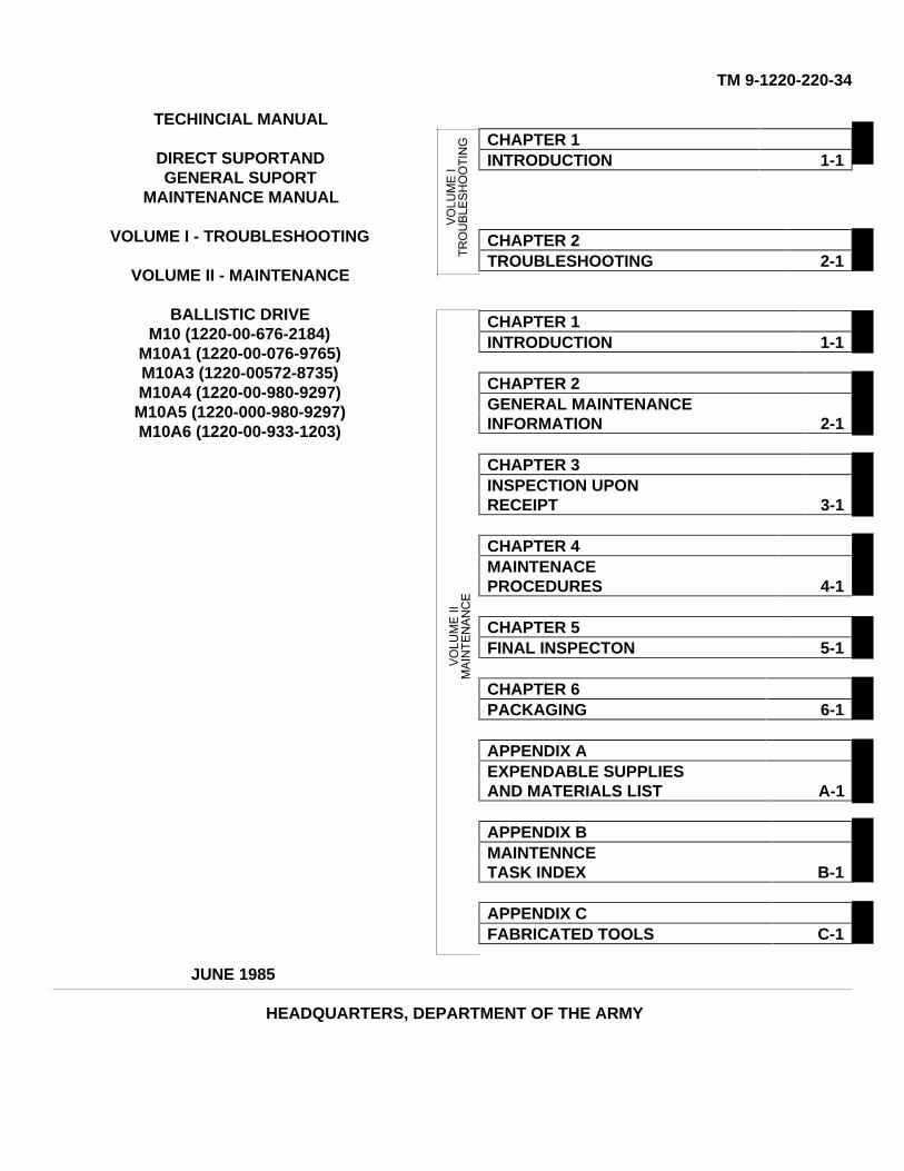
TM 9-1220-220-34
TECHINCIAL MANUAL
DIRECT SUPORTANDGENERAL SUPORT
MAINTENANCE MANUAL
VOLUME I - TROUBLESHOOTING
VOLUME II - MAINTENANCE
BALLISTIC DRIVEM10 (1220-00-676-2184)
M10A1 (1220-00-076-9765)M10A3 (1220-00572-8735)M10A4 (1220-00-980-9297)M10A5 (1220-000-980-9297)M10A6 (1220-00-933-1203)
CHAPTER 1INTRODUCTION 1-1
CHAPTER 2TROUBLESHOOTING 2-1
CHAPTER 1INTRODUCTION 1-1
CHAPTER 2GENERAL MAINTENANCEINFORMATION 2-1
CHAPTER 3INSPECTION UPONRECEIPT 3-1
CHAPTER 4MAINTENACEPROCEDURES 4-1
CHAPTER 5FINAL INSPECTON 5-1
CHAPTER 6PACKAGING 6-1
APPENDIX AEXPENDABLE SUPPLIESAND MATERIALS LIST A-1
APPENDIX BMAINTENNCETASK INDEX B-1
APPENDIX CFABRICATED TOOLS C-1
JUNE 1985
HEADQUARTERS, DEPARTMENT OF THE ARMY

TM 9-1220-2220-34
WARNING
CLEANING SOLVENT CAN CUASE FIRES
Cleaning solvents and the fumes from cleaning solventscan catch fire. Keep it and all materials that can catch onfire away from flames. Use only in a room with a lot offresh air.
TM 9-1220-220-34
HEADQUARTERS,Technical Manual DEPARTMENT OF THE ARMYNo. 9-1220-220-34 Washington, D.C.. 24 June 1985
TECHNICAL MANUAL
DIRECT SUPPORT ANDGENERAL SUPPORT
MAINTENANCE MANUAL
BALLISTICS DRIVE:M10 (1220-00-676-2184)M10A1 (1220-00-076-9765)M10A3 (1220-00-572-8735)M10A4 (1220-00-856-9453)M10A5 (1220-00-980-9297)M10A6 (1220-00-933-1203)
REPORTING ERRORS AND RECOMMENDING IMPROVEMENTS
You can help improve this manual. If you find any mistakesor if you know of a way to improve the procedures, pleaselet us know.
Mail your letter, DA Form 2028 (Recommended Changes toPublications and Blank Forms), or DA Form 2028-2 locatedin the back of this manual directly to:
CommanderU.S. Army Armament, Munitions and Chemical CommandATTN: AMSMC-MASRock Island, IL 61299-6000A reply will be furnished to you.
* This manual supersedes TM 9-1220-220-34, January 1963, including all changes.
i
TM 9-1220-220-34
TABLE OF CONTENTS
Paragraph Page
HOW TO USE THIS MANUAL ...................................................................................................... vVOLUME I
TROUBLESHOOTINGCHAPTER 1. INTRODUCTION ...............................................................................................
Scope ................................................................................................................. 1-1 1-1Organization ....................................................................................................... 1-2 1-1How to Troubleshoot........................................................................................... 1-3 1-2Test Equipment................................................................................................... 1-4 1-4
CHAPTER 2. TROUBLESHOOTING........................................................................................ 2-1Scope.................................................................................................................. 2-1 2-1Performance Test ............................................................................................... 2-2 2-1
VOLUME IIMAINTENANCE
CHAPTER 1. INTRODUCTION ............................................................................................... 1-1
Section 1. General ............................................................................................................... 1-1Scope ................................................................................................................. 1-1 1-1Organization ...................................................................................................... 1-2 1-1
Section 2. Description and Data .......................................................................................... 1-2Description .......................................................................................................... 1-3 1-2Tabulated Data .................................................................................................. 1-4 1-2Differences Between Configurations................................................................... 1-5 1-4
CHAPTER 2. GENERAL MAINTENANCE INFORMATION .................................................. 2-1
Section 1. General .......................................................................................................... 2-1Scope ............................................................................................................ 2-1 2-1
Section 2. Reference Documents . ...................................................................................... 2-1General Maintenance.......................................................................................... 2-2 2-1Cleaning.............................................................................................................. 2-3 2-1Painting .............................................................................................................. 2-4 2-1Sealing ................................................................................................................ 2-5 2-1Lubrication ......................................................................................................... 2-6 2-1
Section 3. Safety Procedures .............................................................................................. 2-1General Procedure ............................................................................................. 2-7 2-1
Section 4. Special Tools and Test Equipment .................................................................... 2-2Tools and Test Equipment .................................................................................. 2-8 2-2
CHAPTER 3. INSPECTION UPON RECEIPT......................................................................... 3-1Scope ............................................................................................................ 3-1 3-1Ballistics Drive Inspection Upon
Receipt........................................................................................................ 3-2 3-1
CHAPTER 4. MAINTENANCE PROCEDURES ..................................................................... 4-1
ii
TM 9-1220-220-34
Paragraph Page
Section 1. General ............................................................................................................ 4-1Scope ............................................................................................................ 4-1 4-1List of Ballistics Drive Items Contained in this
Chapter ...................................................................................................... 4-2 4-1
Section 2. Ballistics Drive .................................................................................................... 4-2Ballistics Drive Maintenance Procedures Index ................................................. 4-3 4-2Ballistics Drive Removal ..................................................................................... 4-4 4-3Ballistics Drive Installation .................................................................................. 4-5 4-17
Section 3. Temperature Compensating Rod ...................................................................... 4-40Temperature Compensating Rod MaintenanceProcedures Index ............................................................................................... 4-6 4-40Temperature Compensating Rod Removal ....................................................... 4-7 4-41Temperature Compensating Rod Installation .................................................... 4-8 4-42
Section 4. Trunnion Link ...................................................................................................... 4-43Trunnion Link Maintenance Procedures Index .................................................. 4-9 4-43Trunnion Link Disassembly ................................................................................ 4-10 4-44Trunnion Link Assembly ..................................................................................... 4-11 4-45
Section 5. Drive Connector .................................................................................................. 4-46Drive Connector Maintenance ProceduresIndex ............................................................................................................ 4-12 4-46Drive Connector Disassembly ............................................................................ 4-13 4-46Drive Connector Assembly ................................................................................. 4-14 4-48
Section 6. Link Connector ................................................................................................... 4-50Link Connector Maintenance ProceduresIndex .................................................................................................................. 4-15 4-50Link Connector Disassembly ............................................................................. 4-16 4-50Link Connector Assembly .................................................................................. 4-17 4-52
Section 7. Fire Control Level................................................................................................ 4-54Fire Control Level Maintenance ProceduresIndex ............................................................................................................ 4-18 4-54Fire Control Level Disassembly ......................................................................... 4-19 4-54Fire Control Level Assembly .............................................................................. 4-20 4-57
Section 8. Light Assembly.................................................................................................... 4-60Light Assembly Maintenance ProceduresIndex ................................................................................................................... 4-21 4-60Light Assembly Removal .................................................................................... 4-22 4-61Light Assembly Disassembly ............................................................................. 4-23 4-62Light Assembly Assembly .................................................................................. 4-24 4-65Light Assembly Installation ................................................................................. 4-25 4-68
iii
TM 9-1220-220-34
Paragraph Page
Section 9. Rangefinder Link Connector Assembly............................................................... 4-69Rangefinder Link Connector Assembly
Maintenance Procedures Index ................................................................. 4-26 4-69Rangefinder Link Connector Assembly
Disassembly. ............................................................................................ 4-27 4-70Rangefinder Link Connector Assembly
Assembly ................................................................................................... 4-28 4-71
Section 10. Junction Box Assembly ...................................................................................... 4-72Junction Box Assembly MaintenanceProcedures Index ............................................................................................... 4-29 4-72Junction Box Assembly Removal ....................................................................... 4-30 4-72Junction Box Assembly Disassembly ................................................................. 4-31 4-74Junction Box Assembly Assembly ..................................................................... 4-32 4-80Junction Box Assembly Installation .................................................................... 4-33 4-86
Section 11. Shaft and Related Parts...................................................................................... 4-88Shaft and Related Parts MaintenanceProcedures Index................................................................................................ 4-34 4-88Shaft and Related Parts Disassembly................................................................. 4-35 4-88Shaft and Related Parts Assembly ..................................................................... 4-36 4-90
CHAPTER 5. FINAL INSPECTION........................................................................................... 5-1
Scope.................................................................................................................. 5-1 5-1Ballistics Drice Final Inspection ......................................................................... 5-2 5-1
CHAPTER 6. PACKAGING ...................................................................................................... 6-1
Scope ................................................................................................................. 6-1 6-1
APPENDIX A. EXPENDABLE SUPPLIES AND MATERIALSLIST ............................................................................................................ A-1
Section 1. Introduction ......................................................................................................... A-1Scope.................................................................................................................. A-1 A-1Explanation of Columns ..................................................................................... A-2 A-1
Section 2. Expendable Supplies and Materials ................................................................... A-2
APPENDIX B. MAINTENANCE TASK INDEX .......................................................................... B-1
Scope.................................................................................................................. B-1 B-1Maintenance Task Index .................................................................................... B-2 B-2
APPENDIX C. FABRICATED TOOL ......................................................................................... C-1
Scope.................................................................................................................. C-1 C-1Fabricated Tool Diagram .................................................................................... C-2 C-1
iv
TM 9-1220-220-34
HOW TO USE THIS MANUAL
This manual has two volumes of maintenance information you will need to repair and service the M10 Series BallisticsDrive.
• Volume I - Troubleshooting
• Volume II - Maintenance
The organization paragraph in each volume tells you what information you can find in each chapter and appendix.
There are four ways to find any maintenance information you need:
• Index on the front cover which tells what information is contained in each chapter.
• Table of Contents located at the front of the manual which has a complete listing by paragraph number andpage number
• Performance Test (Vol I, Chap 2)• Maintenance Task Index (Vol II, App B) which lists major assemblies, subassemblies and paragraph
numbers of all maintenance procedures
Before doing any maintenance, you should read and understand HOW TO TROUBLESHOOT on page 1-2. If you do notknow the equipment well, you should read the section on description and data (Vol II,
Throughout the manual reference is made to a Job Performance Guide 113-091-9000R (JPG 41C) which helps you todevelop skills in doing the maintenance tasks.
v/(vi blank)

TM 9-1220-220-34
TECHNICAL MANUAL
DIRECT SUPPORT ANDGENERAL SUPPORT
MAINTENANCE MANUAL
VOLUME I - TROUBLESHOOTING
BALLISTICS DRIVE:M10M10A1M10A3M10A4M10A5M10A6
Vol I
TM 9-1220-220-34
CHAPTER 1INTRODUCTION
1-1. SCOPE
This volume contains troubleshooting requirements and procedures for direct support and general support (DS/GS)maintenance of the M 10 Series Ballistics Drive. See Volume II for maintenance procedures.
1-2. ORGANIZATIONAll troubleshooting requirements for checking out the M10 Series Ballistics Drive and for finding fault symptoms are givenin Chapter 2. See paragraph 1-3 for how to troubleshoot.
Para 1-1 Vol 1
1-1
TM 9-1220-220-34
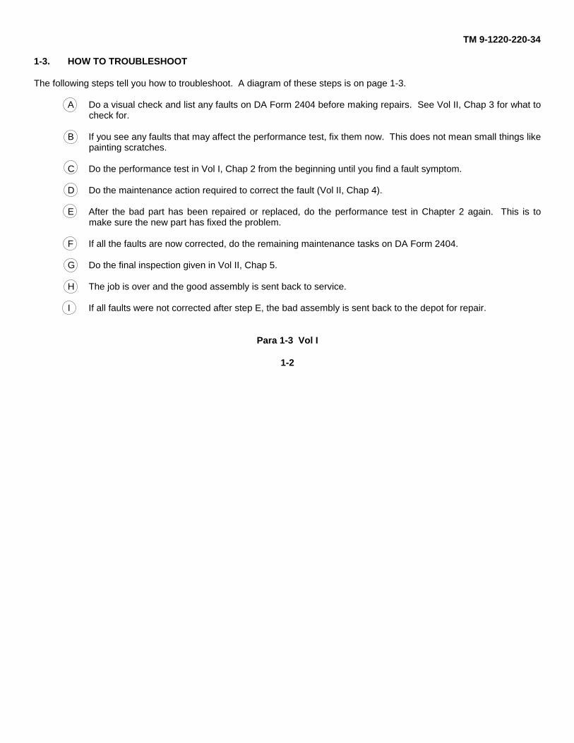
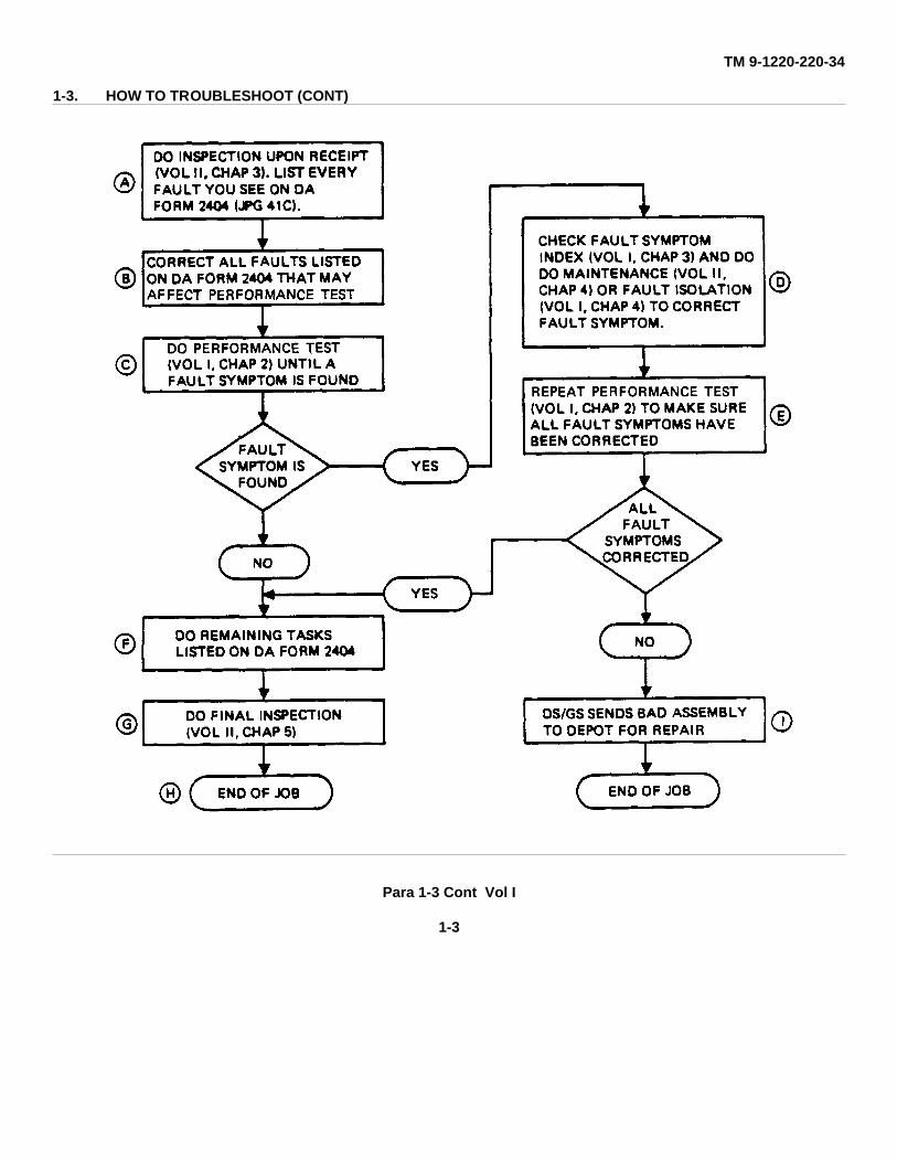
1-3. HOW TO TROUBLESHOOT
The following steps tell you how to troubleshoot. A diagram of these steps is on page 1-3.
A Do a visual check and list any faults on DA Form 2404 before making repairs. See Vol II, Chap 3 for what tocheck for.
B If you see any faults that may affect the performance test, fix them now. This does not mean small things likepainting scratches.
C Do the performance test in Vol I, Chap 2 from the beginning until you find a fault symptom.
D Do the maintenance action required to correct the fault (Vol II, Chap 4).
E After the bad part has been repaired or replaced, do the performance test in Chapter 2 again. This is tomake sure the new part has fixed the problem.
F If all the faults are now corrected, do the remaining maintenance tasks on DA Form 2404.
G Do the final inspection given in Vol II, Chap 5.
H The job is over and the good assembly is sent back to service.
I If all faults were not corrected after step E, the bad assembly is sent back to the depot for repair.
Para 1-3 Vol I
1-2
TM 9-1220-220-34
1-3. HOW TO TROUBLESHOOT (CONT)
Para 1-3 Cont Vol I
1-3

TM 9-1220-220-34
1-4. TEST EQUIPMENT
No special test equipment is needed to do the performance test on the M 10 Series Ballistics Drive.
Para 1-4 Vol I
1-4
TM 9-1220-220-34
CHAPTER 2
TROUBLESHOOTING
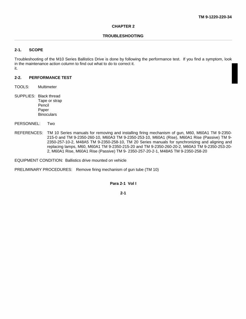
2-1. SCOPE
Troubleshooting of the M10 Series Ballistics Drive is done by following the performance test. If you find a symptom, lookin the maintenance action column to find out what to do to correct it.it.
2-2. PERFORMANCE TEST
TOOLS: Multimeter
SUPPLIES: Black threadTape or strapPencilPaperBinoculars
PERSONNEL: Two
REFERENCES: TM 10 Series manuals for removing and installing firing mechanism of gun, M60, M60A1 TM 9-2350-215-0 and TM 9-2350-260-10, M60A3 TM 9-2350-253-10, M60A1 (Rise), M60A1 Rise (Passive) TM 9-2350-257-10-2, M48A5 TM 9-2350-258-10, TM 20 Series manuals for synchronizing and aligning andreplacing lamps, M60, M60A1 TM 9-2350-215-20 and TM 9-2350-260-20-2, M60A3 TM 9-2350-253-20-2, M60A1 Rise, M60A1 Rise (Passive) TM 9- 2350-257-20-2-1, M48A5 TM 9-2350-258-20
EQUIPMENT CONDITION: Ballistics drive mounted on vehicle
PRELIMINARY PROCEDURES: Remove firing mechanism of gun tube (TM 10)
Para 2-1 Vol I
2-1
TM 9-1220-220-34
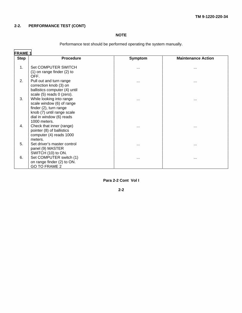
2-2. PERFORMANCE TEST (CONT)
NOTE
Performance test should be performed operating the system manually.
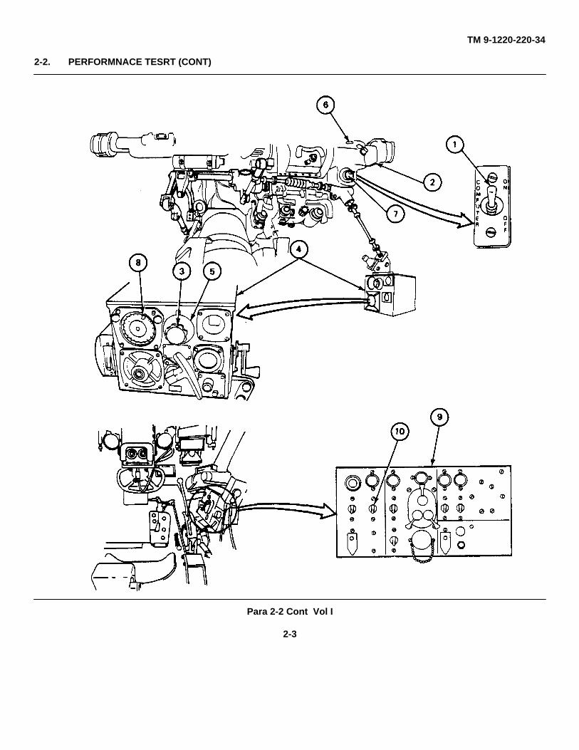
FRAME 1Step Procedure Symptom Maintenance Action
1. Set COMPUTER SWITCH ... ...(1) on range finder (2) toOFF.
2. Pull out and turn range ... ...correction knob (3) onballistics computer (4) untilscale (5) reads 0 (zero).
3. While looking into range ... ...scale window (6) of rangefinder (2), turn rangeknob (7) until range scaledial in window (6) reads1000 meters.
4. Check that inner (range) ... ...pointer (8) of ballisticscomputer (4) reads 1000meters.
5. Set driver’s master control ... ...panel (9) MASTERSWITCH (10) to ON.
6. Set COMPUTER switch (1) ... ...on range finder (2) to ON.GO TO FRAME 2
Para 2-2 Cont Vol I
2-2
TM 9-1220-220-34
2-2. PERFORMNACE TESRT (CONT)
Para 2-2 Cont Vol I
2-3
TM 9-1220-220-34
2-2. PERFORMANCE TEST (CONT)
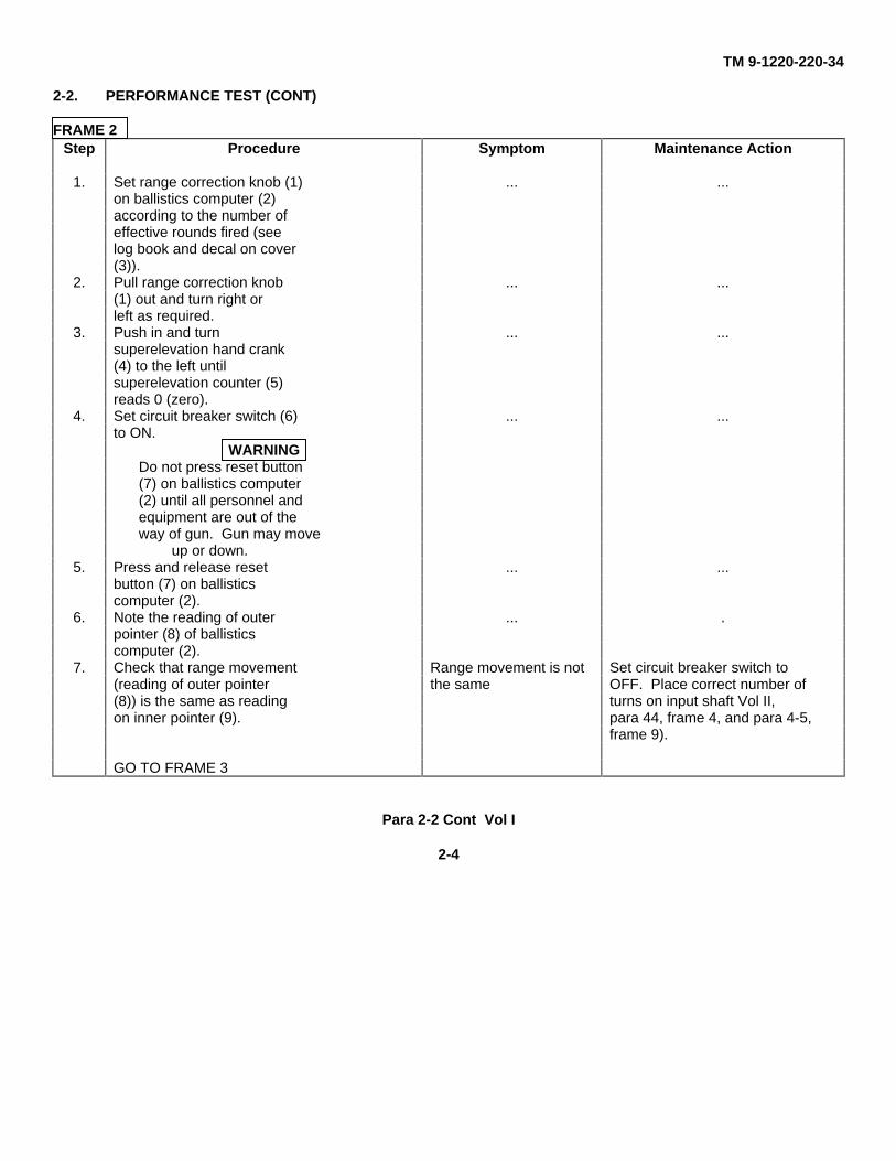
FRAME 2Step Procedure Symptom Maintenance Action
1. Set range correction knob (1) ... ...on ballistics computer (2)according to the number ofeffective rounds fired (seelog book and decal on cover(3)).
2. Pull range correction knob ... ...(1) out and turn right orleft as required.
3. Push in and turn ... ...superelevation hand crank(4) to the left untilsuperelevation counter (5)reads 0 (zero).
4. Set circuit breaker switch (6) ... ...to ON.
WARNINGDo not press reset button(7) on ballistics computer(2) until all personnel andequipment are out of theway of gun. Gun may move
up or down.5. Press and release reset ... ...
button (7) on ballisticscomputer (2).
6. Note the reading of outer ... .pointer (8) of ballisticscomputer (2).
7. Check that range movement Range movement is not Set circuit breaker switch to(reading of outer pointer the same OFF. Place correct number of(8)) is the same as reading turns on input shaft Vol II,on inner pointer (9). para 44, frame 4, and para 4-5,
frame 9).
GO TO FRAME 3
Para 2-2 Cont Vol I
2-4
TM 9-1220-220-34
2-2. PERFORMANCE TEST (CONT)
Para 2-2 Cont Vol I
2-5
TM 9-1220-220-34
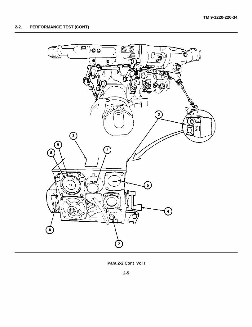
2-2. PERFORMANCE TEST (CONT)
FRAME 3Step Procedure Symptom Maintenance Action
1. Check that ballistic Oscillation or stalling in Set circuit breaker switch (2) tocomputer (1) does not move ballistic computer. OFF. Tell your supervisor.back and forth more thanten times or does not stall.
2. Set circuit breaker switch (2) ... ...to OFF.
3. While looking into range ... ...scale window (3) of rangefinder (4), turn range knob(5) until range scale reads2000 meters.
4. Check that inner (range) ... ...index (6) of ballistic com-puter (1) reads 2000meters.
WARNINGDo not set circuit breakerswitch (2) to ON until all
personnel and equipment areout of the way of gun
movement.5. While looking into gunner’s Rough or bouncy Set circuit breaker switch
periscope (7), set circuit movement of gunner’s (2) to OFF. Check andbreaker switch to ON. Check periscope reticle. reposition ballistics drivethat reticle moves smoothly (Vol II, para 4-4, frame 8,(does not jerk or bounce). step 1 only; then go to para
4-5, frame 2).GO TO FRAME 4
Para 2-2 Cont Vol I
2-6
TM 9-1220-220-34
2-2. PERFORMANCE TEST (CONT)
Para 2-2 Cont Vol I
2-7
TM 9-1220-220-34
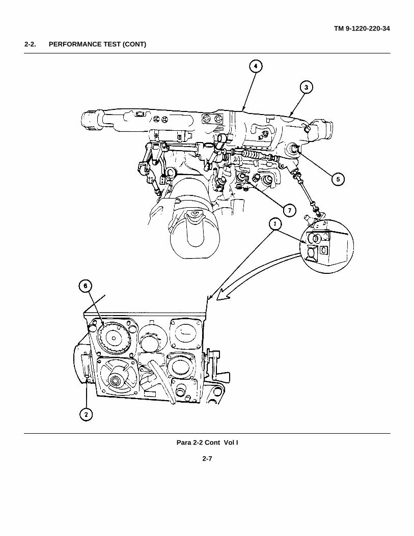
2-2. PERFORMANCE TEST (CONT)
FRAME 4Step Procedure Symptom Maintenance Action
1. Set circuit breaker switch (1) ... .to OFF.
2. While looking into range ...view housing window (2) ofrange finder (3), turn rangeknob (4) until range scalereads 500 meters.
3. While looking into range Rough or bouncy Set circuit breaker switchfinder eyepiece (5), set movement of (1) to OFF. Check con-circuit breaker switch (1) to rangefinder reticle. nector assembly (6) forON. Check that reticle binding. If binding:moves smoothly (does notjerk or bounce). a. Do maintenance procedure
(TM 9-254).b. Repair range finder
link connector assemblyGO TO FRAME 5 (Vol II, para 4-20).
Para 2-1 Vol I
2-8
TM 9-1220-220-34
2-2. PERFORMANCE TEST (CONT)
Para 2-2 Cont Vol I
2-9
TM 9-1220-220-34
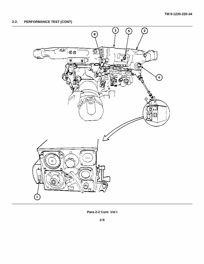
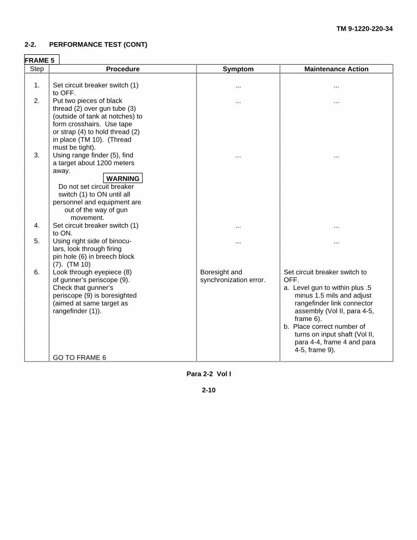
2-2. PERFORMANCE TEST (CONT)
FRAME 5Step Procedure Symptom Maintenance Action
1. Set circuit breaker switch (1) ... ...to OFF.
2. Put two pieces of black ... ...thread (2) over gun tube (3)(outside of tank at notches) toform crosshairs. Use tapeor strap (4) to hold thread (2)in place (TM 10). (Threadmust be tight).
3. Using range finder (5), find ... ...a target about 1200 metersaway.
WARNINGDo not set circuit breakerswitch (1) to ON until all
personnel and equipment areout of the way of gun
movement.4. Set circuit breaker switch (1) ... ...
to ON.5. Using right side of binocu- ... ...
lars, look through firingpin hole (6) in breech block(7). (TM 10)
6. Look through eyepiece (8) Boresight and Set circuit breaker switch toof gunner’s periscope (9). synchronization error. OFF.Check that gunner’s a. Level gun to within plus .5periscope (9) is boresighted minus 1.5 mils and adjust(aimed at same target as rangefinder link connectorrangefinder (1)). assembly (Vol II, para 4-5,
frame 6).b. Place correct number of
turns on input shaft (Vol II,para 4-4, frame 4 and para4-5, frame 9).
GO TO FRAME 6
Para 2-2 Vol I
2-10
TM 9-1220-220-34
2-2. PERFORMANCE TEST (CONT)
Para 2-2 Cont Vol I
2-11
TM 9-1220-220-34
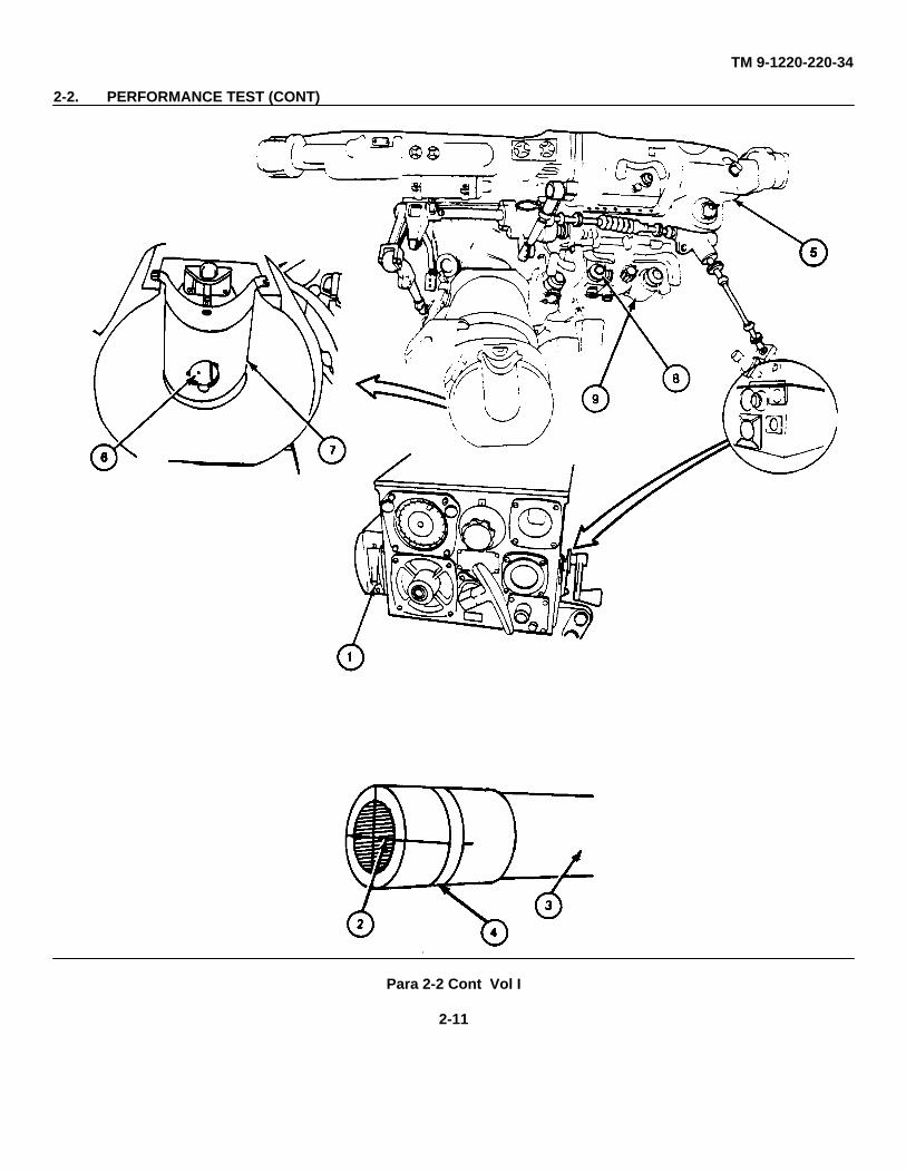
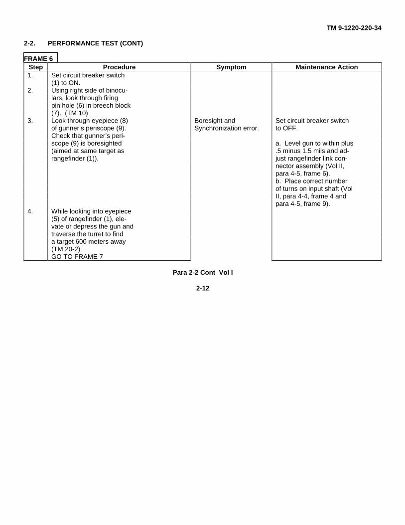
2-2. PERFORMANCE TEST (CONT)
FRAME 6Step Procedure Symptom Maintenance Action1. Set circuit breaker switch
(1) to ON.2. Using right side of binocu-
lars, look through firingpin hole (6) in breech block(7). (TM 10)
3. Look through eyepiece (8) Boresight and Set circuit breaker switchof gunner’s periscope (9). Synchronization error. to OFF.Check that gunner’s peri-scope (9) is boresighted a. Level gun to within plus(aimed at same target as .5 minus 1.5 mils and ad-rangefinder (1)). just rangefinder link con-
nector assembly (Vol II,para 4-5, frame 6).b. Place correct numberof turns on input shaft (VolII, para 4-4, frame 4 andpara 4-5, frame 9).
4. While looking into eyepiece(5) of rangefinder (1), ele-vate or depress the gun andtraverse the turret to finda target 600 meters away(TM 20-2)GO TO FRAME 7
Para 2-2 Cont Vol I
2-12
TM 9-1220-220-34
2-2. PERFORMANCE TEST (CONT)
Para 2-2 Cont Vol I
2-13
TM 9-1220-220-34
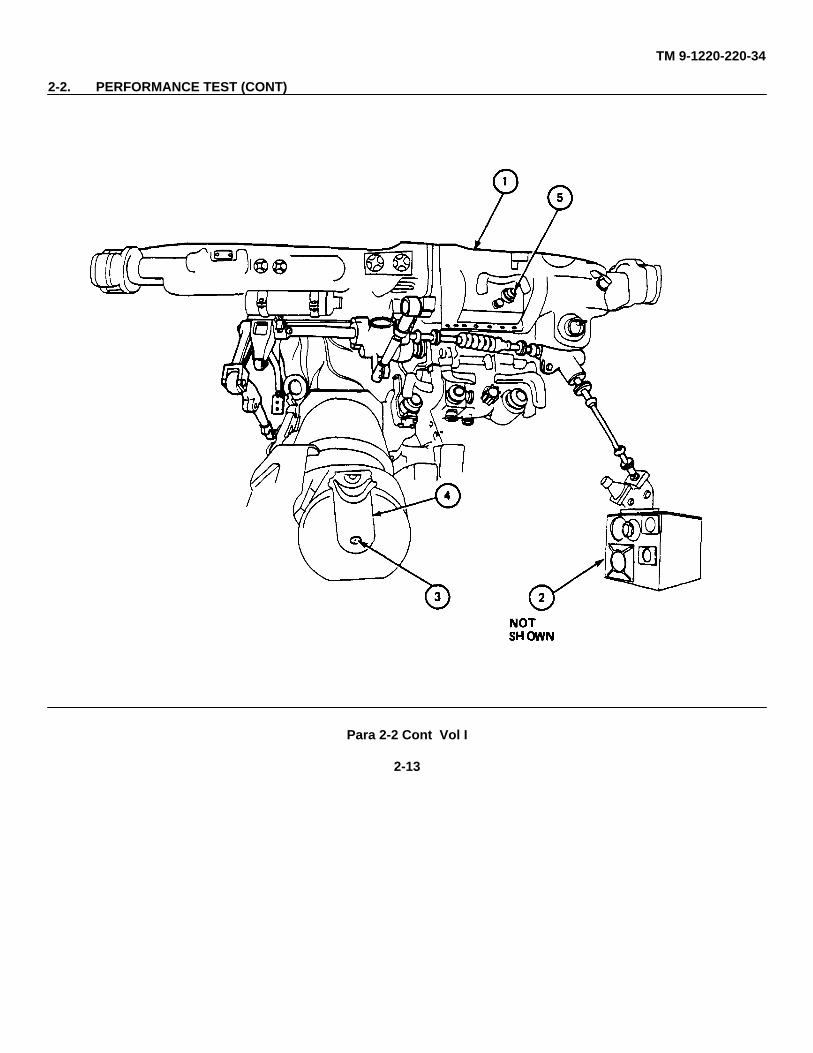
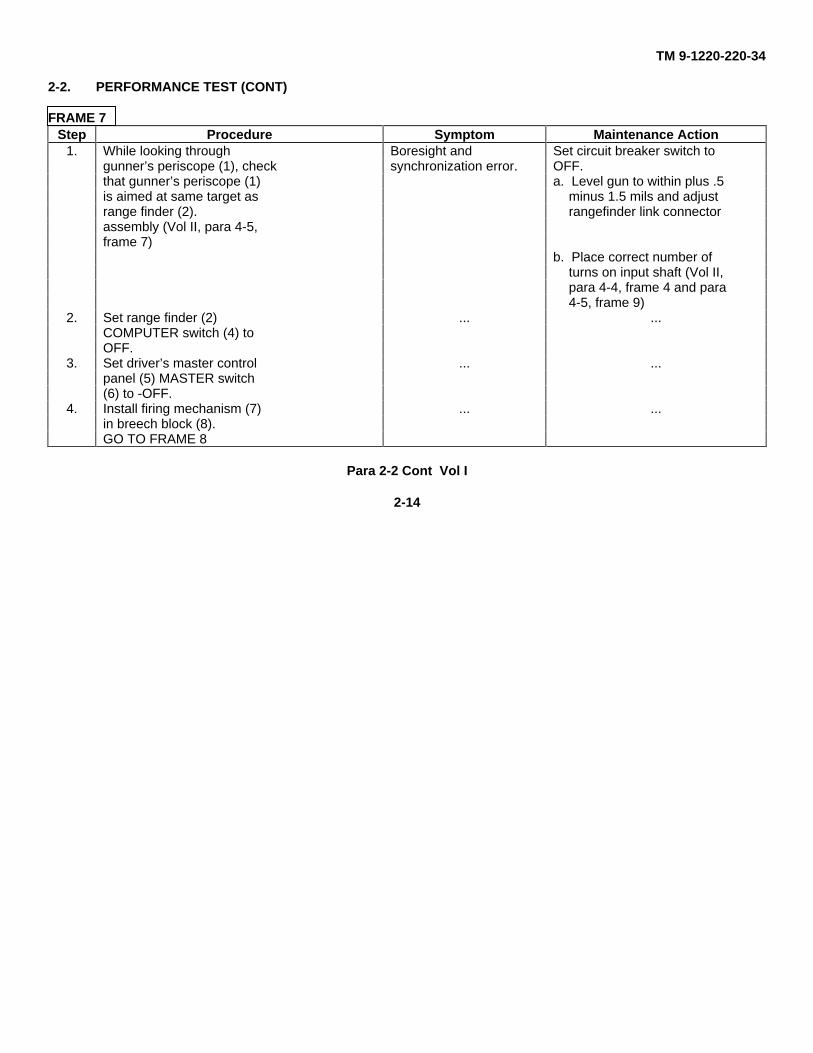
2-2. PERFORMANCE TEST (CONT)
FRAME 7Step Procedure Symptom Maintenance Action
1. While looking through Boresight and Set circuit breaker switch togunner’s periscope (1), check synchronization error. OFF.that gunner’s periscope (1) a. Level gun to within plus .5is aimed at same target as minus 1.5 mils and adjustrange finder (2). rangefinder link connectorassembly (Vol II, para 4-5,frame 7)
b. Place correct number ofturns on input shaft (Vol II,para 4-4, frame 4 and para4-5, frame 9)
2. Set range finder (2) ... ...COMPUTER switch (4) toOFF.
3. Set driver’s master control ... ...panel (5) MASTER switch(6) to -OFF.
4. Install firing mechanism (7) ... ...in breech block (8).GO TO FRAME 8
Para 2-2 Cont Vol I
2-14
TM 9-1220-220-34
2-2. PERFORMANCE TEST (CONT)
Para 2-2 Cont Vol I
2-15
TM 9-1220-220-34
2-2. PERFORMANCE TEST (CONT)
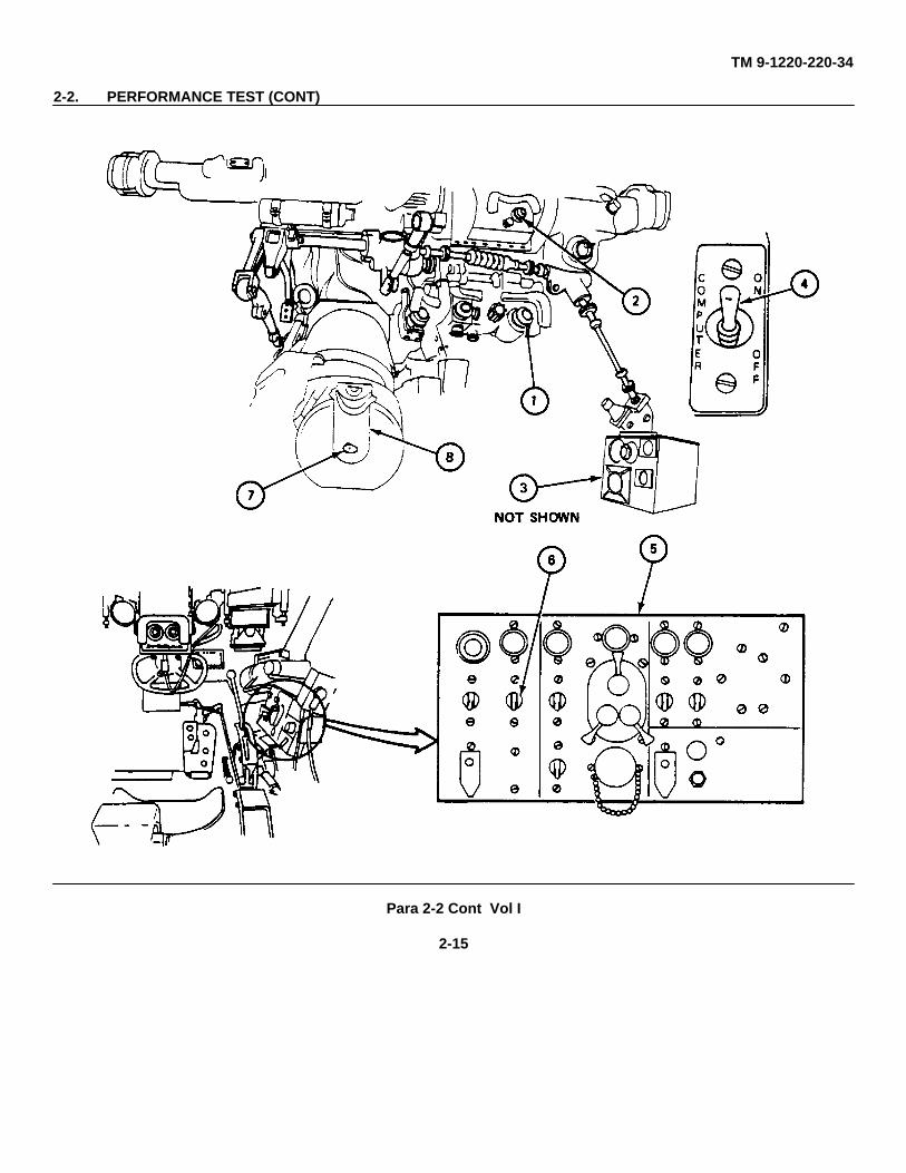
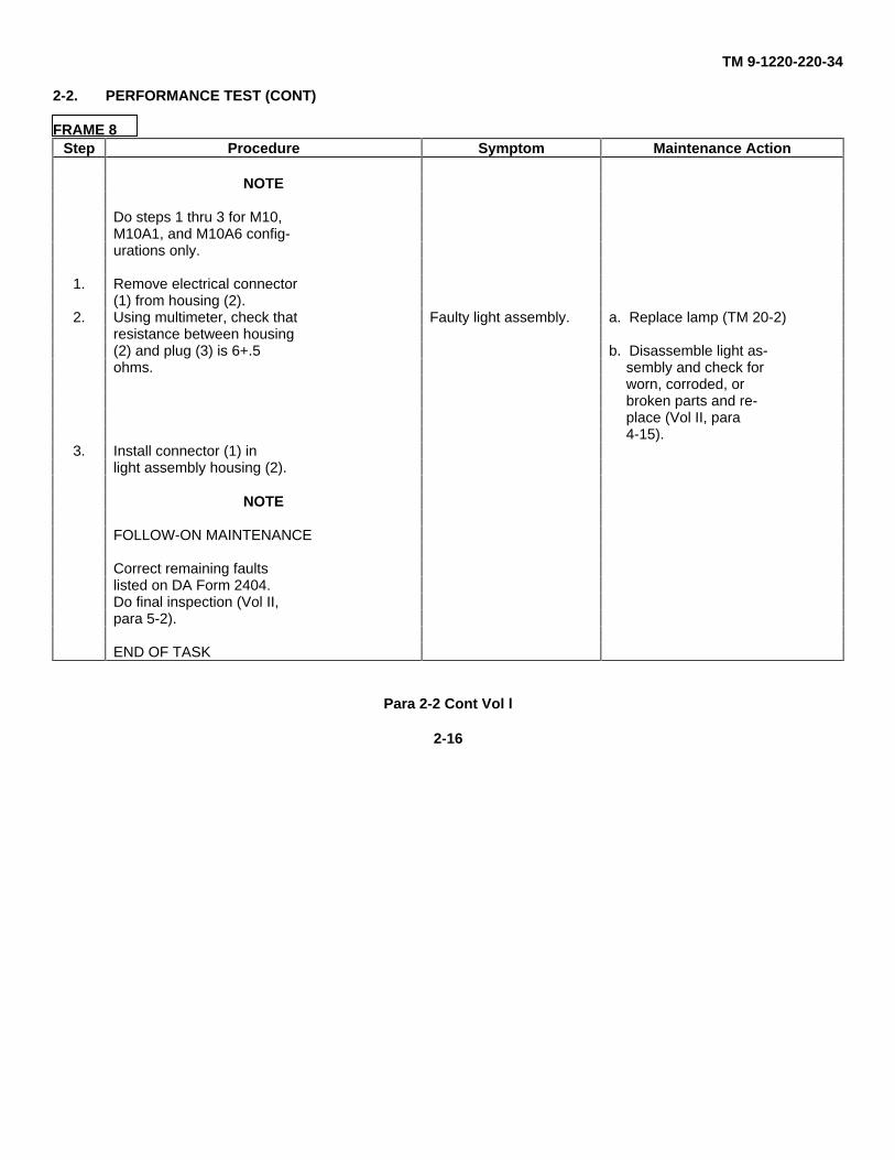
FRAME 8Step Procedure Symptom Maintenance Action
NOTE
Do steps 1 thru 3 for M10,M10A1, and M10A6 config-urations only.
1. Remove electrical connector(1) from housing (2).
2. Using multimeter, check that Faulty light assembly. a. Replace lamp (TM 20-2)resistance between housing(2) and plug (3) is 6+.5 b. Disassemble light as-ohms. sembly and check for
worn, corroded, orbroken parts and re-place (Vol II, para4-15).
3. Install connector (1) inlight assembly housing (2).
NOTE
FOLLOW-ON MAINTENANCE
Correct remaining faultslisted on DA Form 2404.Do final inspection (Vol II,para 5-2).
END OF TASK
Para 2-2 Cont Vol l
2-16
TM 9-1220-220-34
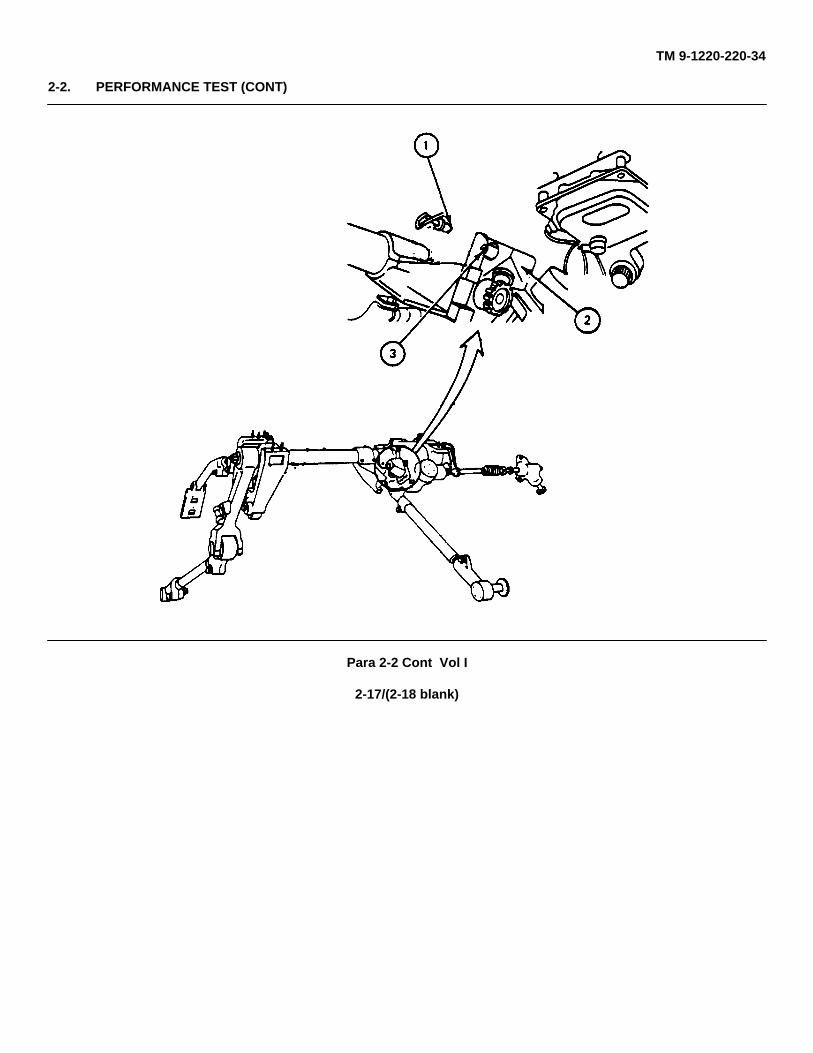
2-2. PERFORMANCE TEST (CONT)
Para 2-2 Cont Vol I
2-17/(2-18 blank)

TM 9-1220-220-34
TECHNICAL MANUAL
DIRECT SUPPORT ANDGENERAL SUPPORT
MAINTENANCE MANUAL
VOLUME II - MAINTENANCE
BALLISTICS DRIVE:M10M1A1M10A3M10A4M10A5M10A6
Vol II
TM 9-1220-220-34
CHAPTER 1
INTRODUCTION
Section 1. GENERAL
1-1. SCOPE
This volume contains maintenance requirements and procedures for direct support and general support (DS/GS)maintenance for the M10 Series Ballistic Drive. See Volume I for troubleshooting Procedures.
1-2. ORGANIZATION
a. Chapter 2, General Maintenance Information, lists the maintenance items and references other proceduresthat are necessary to do the maintenance in this manual.
b. Chapter 3, Inspection Upon Receipt, gives the kind of defects to look for when the ballistics drive is returnedto DS/GS. A complete inspection should be made and faults listed on DA Form 2404 before any repairs are made.
c. Chapter 4, Maintenance Procedures, gives step-by-step procedures to repair faults found during inspection oftroubleshooting.
d. Chapter 5, Final Inspection, gives procedures to be done after repair to make sure that the ballistics driveworks.
e. Chapter 6, Packaging, gives procedures for packaging the ballistics drive for storage or shipment.
f. Appendix A, Expendable Supplies and Materials List, lists the supplies and materials needed to repair theballistics drive.
g. Appendix B, Maintenance Task Index, helps you find the necessary maintenance tasks for the ballistics drive.
h. Appendix C, Fabricated Tools, gives drawings with dimensions and use of each tool, so you can have thetools made.
Para 1-1 Vol II
1-1
TM 9-1220-220-34
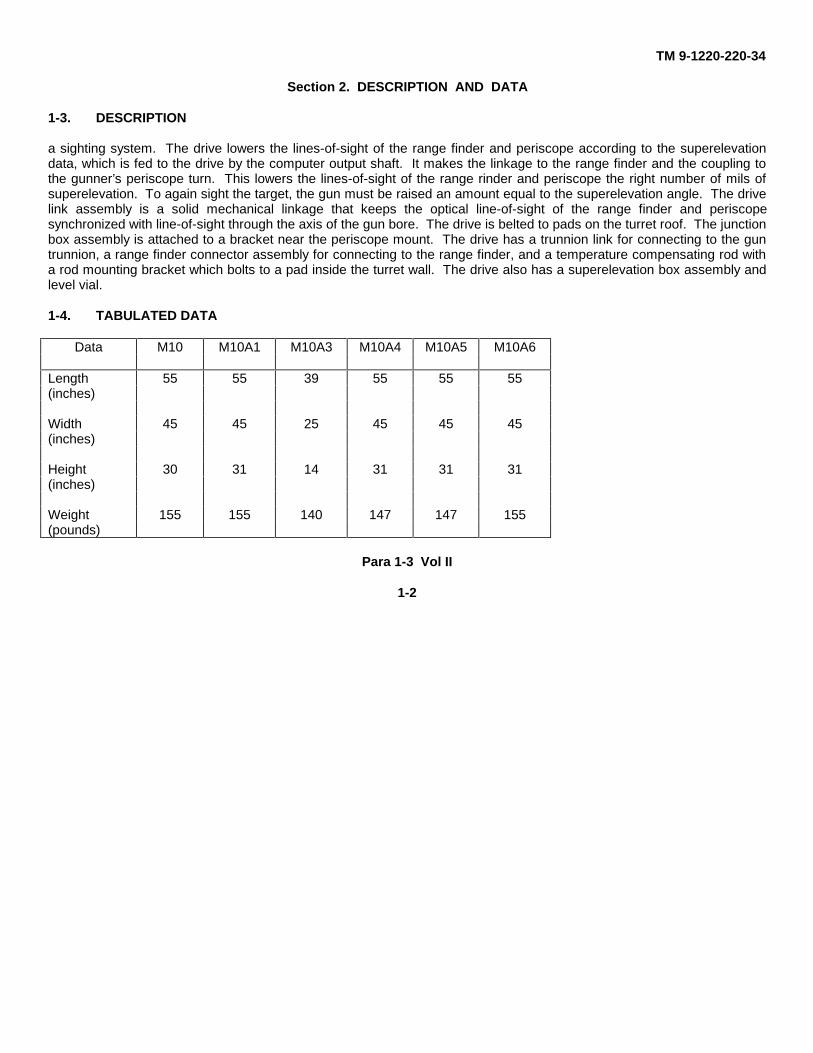
Section 2. DESCRIPTION AND DATA
1-3. DESCRIPTION
a sighting system. The drive lowers the lines-of-sight of the range finder and periscope according to the superelevationdata, which is fed to the drive by the computer output shaft. It makes the linkage to the range finder and the coupling tothe gunner’s periscope turn. This lowers the lines-of-sight of the range rinder and periscope the right number of mils ofsuperelevation. To again sight the target, the gun must be raised an amount equal to the superelevation angle. The drivelink assembly is a solid mechanical linkage that keeps the optical line-of-sight of the range finder and periscopesynchronized with line-of-sight through the axis of the gun bore. The drive is belted to pads on the turret roof. The junctionbox assembly is attached to a bracket near the periscope mount. The drive has a trunnion link for connecting to the guntrunnion, a range finder connector assembly for connecting to the range finder, and a temperature compensating rod witha rod mounting bracket which bolts to a pad inside the turret wall. The drive also has a superelevation box assembly andlevel vial.
1-4. TABULATED DATA
Data M10 M10A1 M10A3 M10A4 M10A5 M10A6
Length 55 55 39 55 55 55(inches)
Width 45 45 25 45 45 45(inches)
Height 30 31 14 31 31 31(inches)
Weight 155 155 140 147 147 155(pounds)
Para 1-3 Vol II
1-2
TM 9-1220-220-34
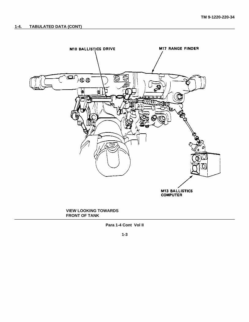
1-4. TABULATED DATA (CONT)
VIEW LOOKING TOWARDSFRONT OF TANK
Para 1-4 Cont Vol II
1-3
TM 9-1220-220-34
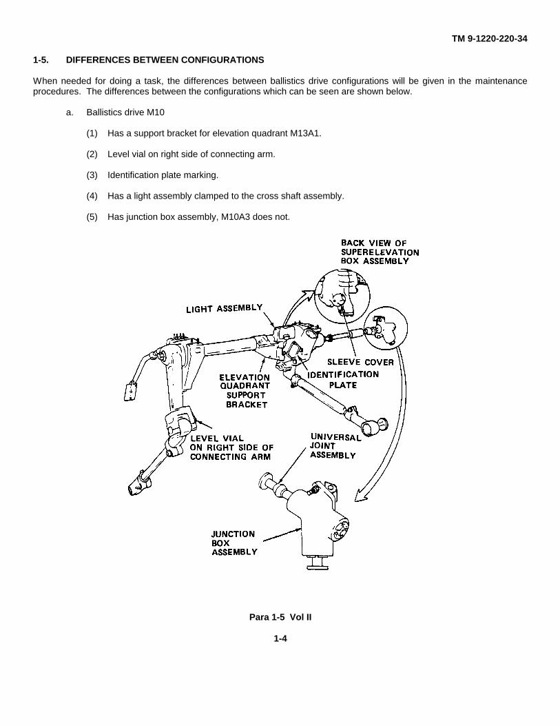
1-5. DIFFERENCES BETWEEN CONFIGURATIONS
When needed for doing a task, the differences between ballistics drive configurations will be given in the maintenanceprocedures. The differences between the configurations which can be seen are shown below.
a. Ballistics drive M10
(1) Has a support bracket for elevation quadrant M13A1.
(2) Level vial on right side of connecting arm.
(3) Identification plate marking.
(4) Has a light assembly clamped to the cross shaft assembly.
(5) Has junction box assembly, M10A3 does not.
Para 1-5 Vol II
1-4
TM 9-1220-220-34
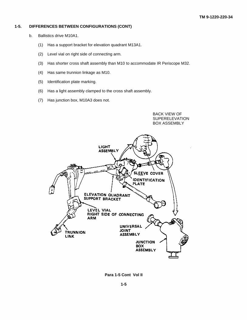
1-5. DIFFERENCES BETWEEN CONFIGURATIONS (CONT)
b. Ballistics drive M10A1.
(1) Has a support bracket for elevation quadrant M13A1.
(2) Level vial on right side of connecting arm.
(3) Has shorter cross shaft assembly than M10 to accommodate IR Periscope M32.
(4) Has same trunnion linkage as M10.
(5) Identification plate marking.
(6) Has a light assembly clamped to the cross shaft assembly.
(7) Has junction box, M10A3 does not.
BACK VIEW OFSUPERELEVATIONBOX ASSEMBLY
Para 1-5 Cont Vol II
1-5
TM 9-1220-220-34
1-5. DIFFERENCES BETWEEN CONFIGURATIONS (CONT)
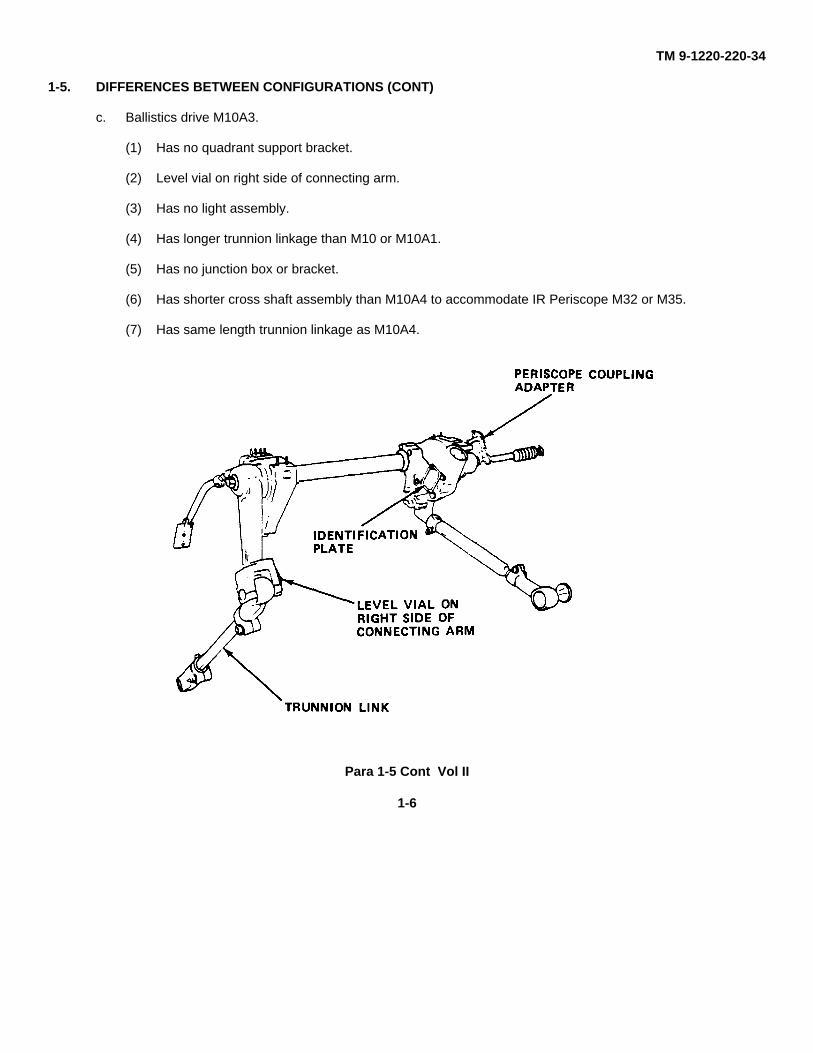
c. Ballistics drive M10A3.
(1) Has no quadrant support bracket.
(2) Level vial on right side of connecting arm.
(3) Has no light assembly.
(4) Has longer trunnion linkage than M10 or M10A1.
(5) Has no junction box or bracket.
(6) Has shorter cross shaft assembly than M10A4 to accommodate IR Periscope M32 or M35.
(7) Has same length trunnion linkage as M10A4.
Para 1-5 Cont Vol II
1-6
TM 9-1220-220-34
1-5. DIFFERENCES BETWEEN CONFIGURATIONS (CONT)
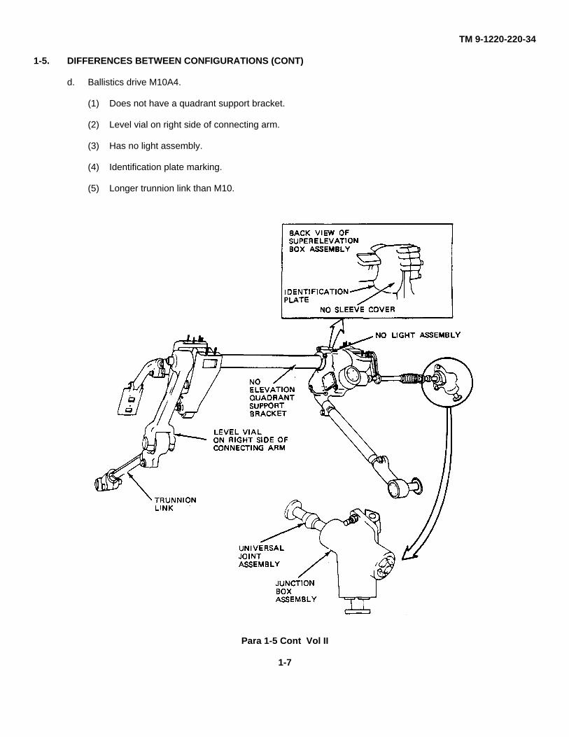
d. Ballistics drive M10A4.
(1) Does not have a quadrant support bracket.
(2) Level vial on right side of connecting arm.
(3) Has no light assembly.
(4) Identification plate marking.
(5) Longer trunnion link than M10.
Para 1-5 Cont Vol II
1-7
TM 9-1220-220-34
1-5. DIFFERENCES BETWEEN CONFIGURATIONS (CONT)
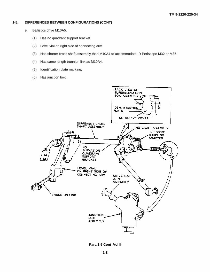
e. Ballistics drive M10A5.
(1) Has no quadrant support bracket.
(2) Level vial on right side of connecting arm.
(3) Has shorter cross shaft assembly than M10A4 to accommodate IR Periscope M32 or M35.
(4) Has same length trunnion link as M10A4.
(5) Identification plate marking.
(6) Has junction box.
Para 1-5 Cont Vol II
1-8
TM 9-1220-220-34
1-5. DIFFERENCES BETWEEN CONFIGURATIONS (CONT)
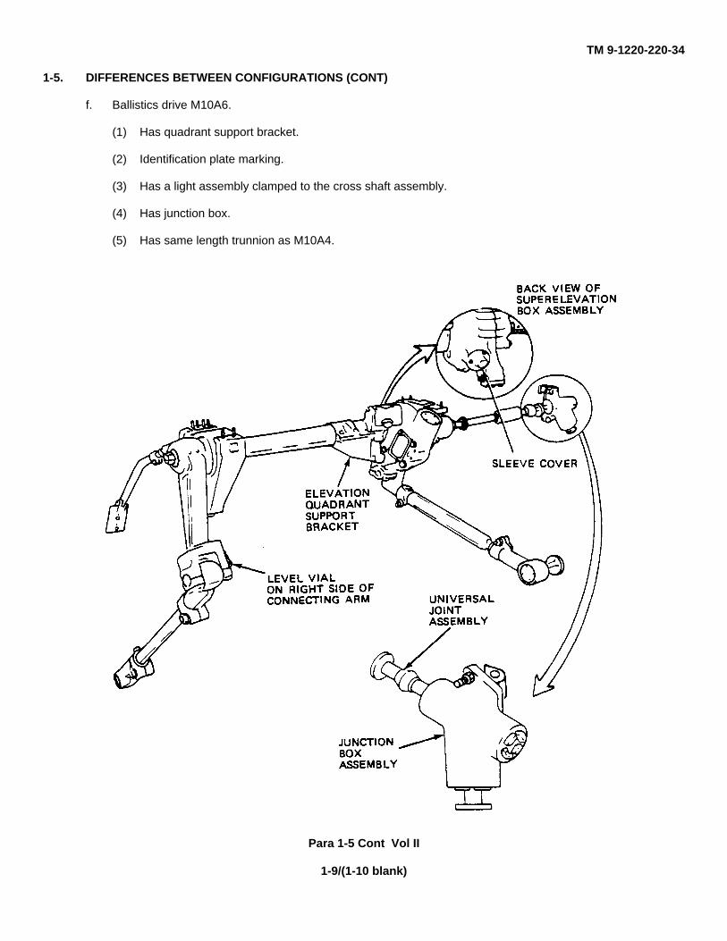
f. Ballistics drive M10A6.
(1) Has quadrant support bracket.
(2) Identification plate marking.
(3) Has a light assembly clamped to the cross shaft assembly.
(4) Has junction box.
(5) Has same length trunnion as M10A4.
Para 1-5 Cont Vol II
1-9/(1-10 blank)
TM 9-1220-220-34
CHAPTER 2
GENERAL MAINTENANCE INFORMATION
Section 1. GENERAL
2-1. SCOPE
This chapter tells you where to find general information and what special tools and test equipment are needed for the M10Series Ballistics Drive.
Section 2. REFERENCE DOCUMENTS
2-2. GENERAL MAINTENANCE
General Maintenance procedures for fire control materiel are in TM 9-254 and Job Performance Guide 113-091-9000R(JPG 41C).
2-3. CLEANING
General cleaning procedures are in JPG 41C.
2-4. PAINTING
General painting procedures are in TM 43-0139.
2-5. SEALING
General instructions for how to use sealing compound are in JPG 41C.
2-6. LUBRICATION
General instructions for how to use lubricants are in JPG 41C.
Section 3. SAFETY PROCEDURES
2-7. GENERAL PROCEDURE
General safety procedures are in AR 385-40 safety: Accident Reporting and Records.
Para 2-1 Vol II
2-1

TM 9-1220-220-34
Section 4. SPECIAL TOOLS AND TEST EQUIPMENT
2-8. TOOLS AND TEST EQUIPMENT
There are no special tools or test equipment needed to repair the M10 Series Ballistics Drive at direct support and generalsupport.
Para 2-8 Vol II
2-2
TM 9-1220-220-34
CHAPTER 3
INSPECTION UPON RECEIPT
3-1. SCOPE
This chapter gives procedures to check the M10 Series Ballistics Drive for faults you can see when it is received in theDS/GS shop. It also tells you what part of this volume to go to for various repairs. A complete inspection should be madeand all faults listed on DA Form 2404 before taking any maintenance actions. The performance test in Volume I, Chapter2, should be done after doing the inspection upon receipt.
3-2. BALLISTICS DRIVE INSPECTION UPON RECEIPT
TOOLS: 1/4", 3/16" flat tip screwdriver7/16", 1/2", 9/16", 3/4", 15/16", 1-1/16", 1-1/8" open end wrench5/64" socket head screw key (Allen wrench or equivalent)3/8" drive ratchet wrench5/16" hexagon stud socket (3/8" drive)6" extension (3/8" drive)3/8" universal joint0.075" to 0.085" adjustable face spanner wrenchs
SUPPLIES: Paint (item 3, App A)5/16" x 5/16" x 1" square stock.
PERSONNEL: One
REFERENCES: JPG 41C for completing DA Form 2404TM 43-0139 for paintingTM 9-254 for general maintenance
EQUIPMENT CONDITION: Ballistic drive mounted on vehicle, except for inspection items marked with an asterisk (*).These items can be checked properly only with ballistics drive or subcomponents removedfrom vehicle.
NOTE
Once the ballistics drive is removed from vehicle DS/GS does not have the tools toaccurately set the fire control level if the level is tampered with. If the fire control levelneeds to be repaired, repair before removing ballistics drive from vehicle.
Para 3-1 Vol II
3-1
TM 9-1220-220-34
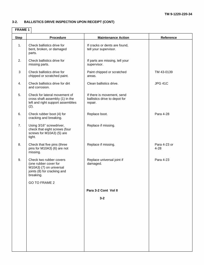
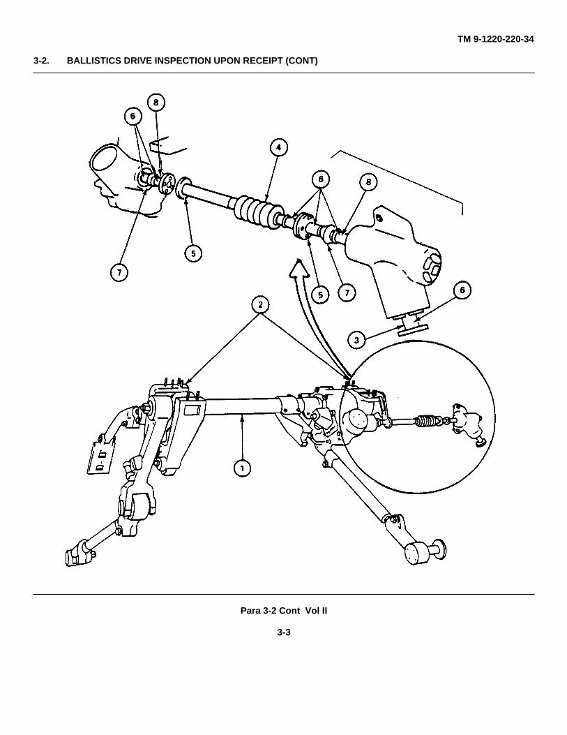
3-2. BALLISTICS DRIVE INSPECTION UPON RECEIPT (CONT)
FRAME 1
Step Procedure Maintenance Action Reference
1. Check ballistics drive for If cracks or dents are found,bent, broken, or damaged tell your supervisor.parts.
2. Check ballistics drive for If parts are missing, tell yourmissing parts. supervisor.
3 Check ballistics drive for Paint chipped or scratched TM 43-0139chipped or scratched paint. areas.
4. Check ballistics drive for dirt Clean ballistics drive. JPG 41Cand corrosion.
5. Check for lateral movement of If there is movement, sendcross shaft assembly (1) in the ballistics drive to depot forleft and right support assemblies repair.(2).
6. Check rubber boot (4) for Replace boot. Para 4-28cracking and breaking.
7. Using 3/16" screwdriver, Replace if missing.check that eight screws (fourscrews for M10A3) (5) aretight.
8. Check that five pins (three Replace if missing. Para 4-23 orpins for M10A3) (6) are not 4-28missing.
9. Check two rubber covers Replace universal joint if Para 4-23(one rubber cover for damaged.M10A3) (7) on universaljoints (8) for cracking andbreaking.
GO TO FRAME 2
Para 3-2 Cont Vol II
3-2
TM 9-1220-220-34
3-2. BALLISTICS DRIVE INSPECTION UPON RECEIPT (CONT)
Para 3-2 Cont Vol II
3-3
TM 9-1220-220-34
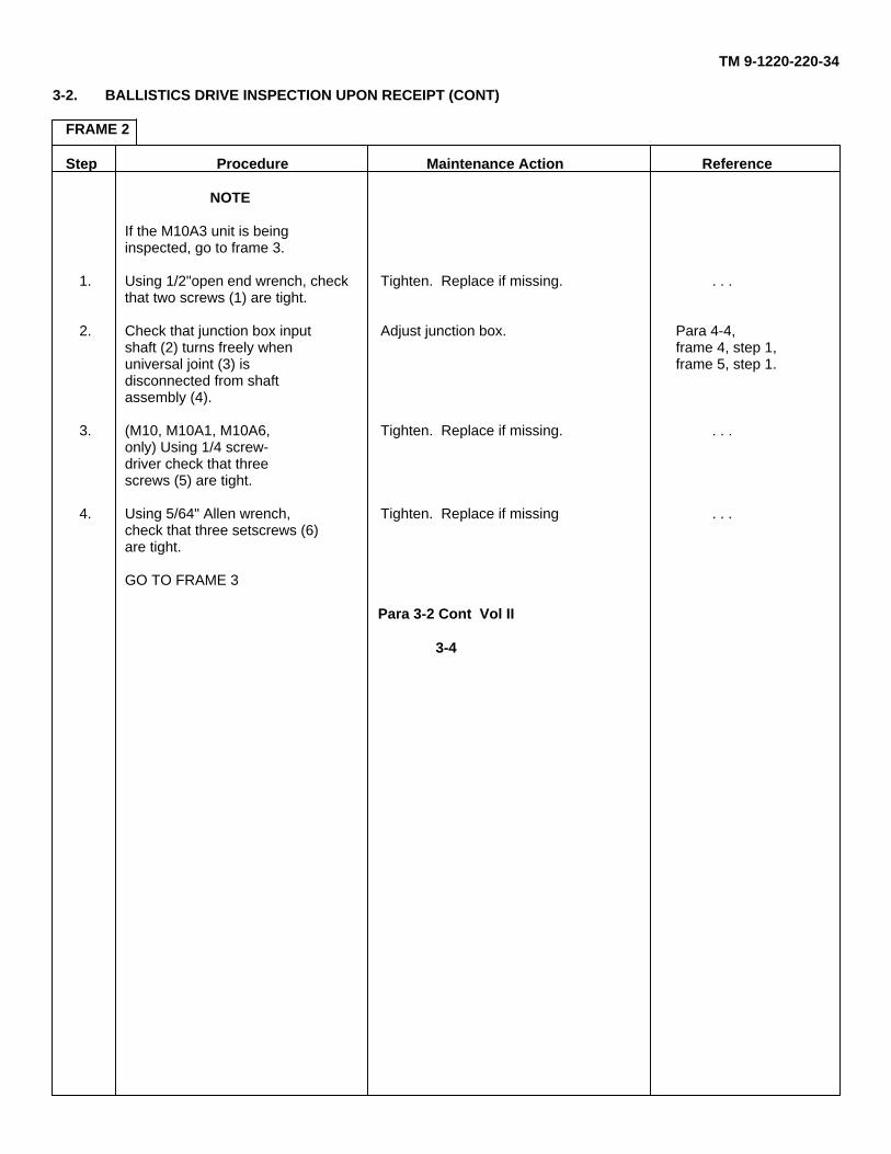
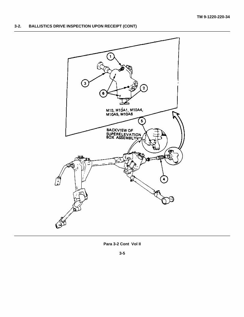
3-2. BALLISTICS DRIVE INSPECTION UPON RECEIPT (CONT)
FRAME 2
Step Procedure Maintenance Action Reference
NOTE
If the M10A3 unit is beinginspected, go to frame 3.
1. Using 1/2"open end wrench, check Tighten. Replace if missing. . . .that two screws (1) are tight.
2. Check that junction box input Adjust junction box. Para 4-4,shaft (2) turns freely when frame 4, step 1,universal joint (3) is frame 5, step 1.disconnected from shaftassembly (4).
3. (M10, M10A1, M10A6, Tighten. Replace if missing. . . .only) Using 1/4 screw-driver check that threescrews (5) are tight.
4. Using 5/64" Allen wrench, Tighten. Replace if missing . . .check that three setscrews (6)are tight.
GO TO FRAME 3
Para 3-2 Cont Vol II
3-4
TM 9-1220-220-34
3-2. BALLISTICS DRIVE INSPECTION UPON RECEIPT (CONT)
Para 3-2 Cont Vol II
3-5
TM 9-1220-220-34
3-2. BALLISTICS DRIVE INSPECTION UPON RECEIPT (CONT)
FRAME 3
Step Procedure Maintenance Action Reference
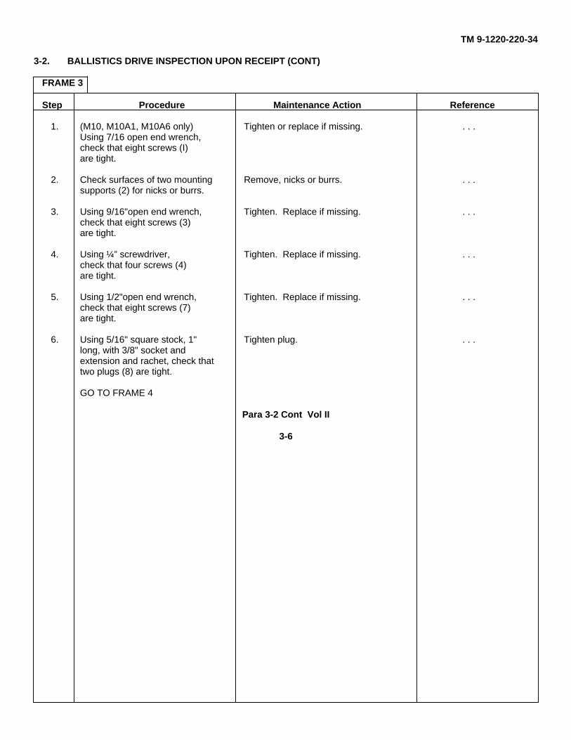
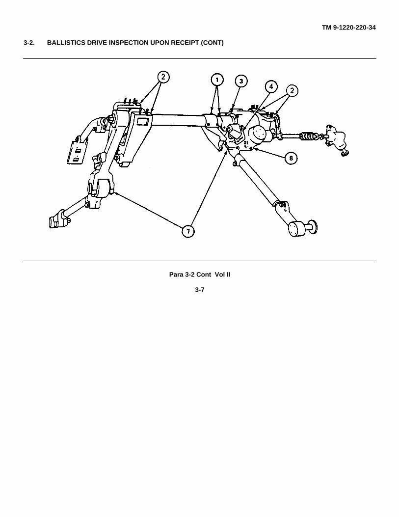
1. (M10, M10A1, M10A6 only) Tighten or replace if missing. . . .Using 7/16 open end wrench,check that eight screws (I)are tight.
2. Check surfaces of two mounting Remove, nicks or burrs. . . .supports (2) for nicks or burrs.
3. Using 9/16"open end wrench, Tighten. Replace if missing. . . .check that eight screws (3)are tight.
4. Using ¼” screwdriver, Tighten. Replace if missing. . . .check that four screws (4)are tight.
5. Using 1/2"open end wrench, Tighten. Replace if missing. . . .check that eight screws (7)are tight.
6. Using 5/16" square stock, 1" Tighten plug. . . .long, with 3/8" socket andextension and rachet, check thattwo plugs (8) are tight.
GO TO FRAME 4
Para 3-2 Cont Vol II
3-6
TM 9-1220-220-34
3-2. BALLISTICS DRIVE INSPECTION UPON RECEIPT (CONT)
Para 3-2 Cont Vol II
3-7
TM 9-1220-220-34
3-2. BALLISTICS DRIVE INSPECTION UPON RECEIPT (CONT)
FRAME 4
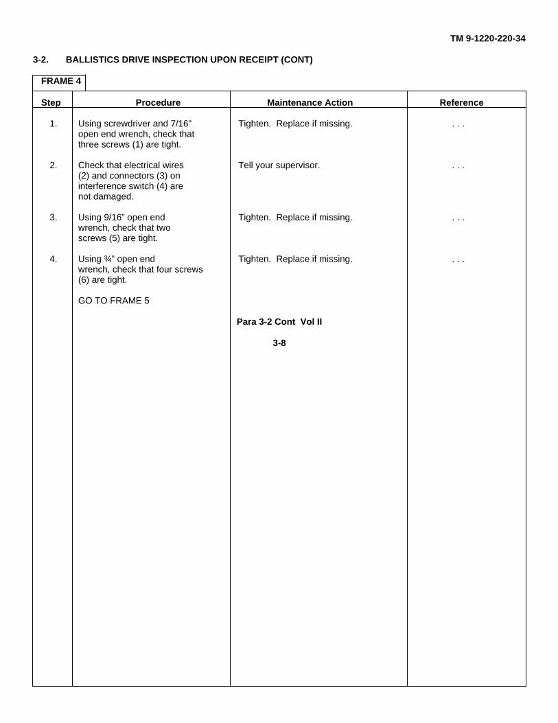
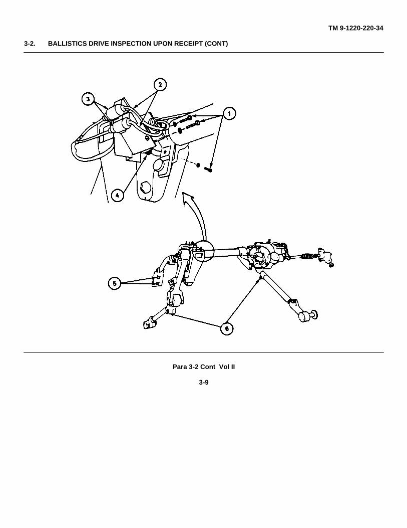
Step Procedure Maintenance Action Reference
1. Using screwdriver and 7/16" Tighten. Replace if missing. . . .open end wrench, check thatthree screws (1) are tight.
2. Check that electrical wires Tell your supervisor. . . .(2) and connectors (3) oninterference switch (4) arenot damaged.
3. Using 9/16” open end Tighten. Replace if missing. . . .wrench, check that twoscrews (5) are tight.
4. Using ¾” open end Tighten. Replace if missing. . . .wrench, check that four screws(6) are tight.
GO TO FRAME 5
Para 3-2 Cont Vol II
3-8
TM 9-1220-220-34
3-2. BALLISTICS DRIVE INSPECTION UPON RECEIPT (CONT)
Para 3-2 Cont Vol II
3-9
TM 9-1220-220-34
3-2. BALLISTICS DRIVE INSPECTION UPON RECEIPT (CONT)
FRAME 5
Step Procedure Maintenance Action Reference
1. Check that fire control level Repair fire control level Para 4-12(1) is not damaged.
2. Using ¼” screwdriver, Tighten. Replace if missing. . . .check that two screws (2) aretight.
3. Using 15/16"open end wrench, Tighten. Replace if missing. . . .check that nut (3) is tight.
4. Using 7/16" open end Tighten. Replace if missing. . . .wrench, check that screw (5)is tight.
5. Using 1 1/16"open end Tighten. Replace if missing. . . .wrench, check that nut (6) istight.
6. Check that stud (7) turns If binding, replace rear Para 4-21,freely without binding. connector assembly (8). frame 1
GO TO FRAME 6
Para 3-2 Cont Vol II
3-10
TM 9-1220-220-34
3-2. BALLISTICS DRIVE INSPECTION UPON RECEIPT (CONT)
Para 3-2 Cont Vol II
3-11
TM 9-1220-220-34
3-2. BALLISTICS DRIVE INSPECTION UPON RECEIPT (CONT)
FRAME 6
Step Procedure Maintenance Action Reference
1 Using 5/16’ stud socket and Tighten. Replace if missing. . . .ratchet, check that eightscrews (1) are tight.
2. Check coupling assembly (2) Send ballistics drive to depot. . . .for damage.
3. Check that qualilfying plate Clean. If still not able to JPG 41C(12) can be read. read, tell your supervisor.
4. Check that scales on spindle, Clean. Replace if necessary. JPG 41Csleeve or cap (4) can be read. Para 4-9
Para 4-205. Check that two clamps (5) Replace clamps if necessary. Para 4-28
are tight.6. Check that cotter pin (6) and Replace missing or damaged Para 4-6
washer (7) are installed on parts.pin (8).
7. Check that three wire seals Replace missing wire seals, if Para 4-5, frame 3,(9) are installed. installed in vehicle. steps 3 and 7 and
frame 7, steps 3and 7 and frame12 steps 2 and 6
8. Separate input shaft (10) Para 4-4, framefrom junction box assembly 5, step 1.(11).
9. Check that input shaft (10) Send ballistics drive to depot . . .of superelevation box for repair.assembly (12) turns freelywithout binding.
10. Connect input shaft (10) to Para 4-5,junction box assembly (11) frame 8,(electronic computer step 2.for M10A3)
NOTEFOLLOW-ON
MAINTENANCE
Correct faults listed on DAForm 2404 that may affect
performance test.Do performance test (Vol I,
para 2-2).
END OF TASK
Para 3-2 Cont Vol II
3-12
TM 9-1220-220-34
3-2. BALLISTICS DRIVE INSPECTION UPON RECEIPT (CONT)
Para 3-2 Cont Vol II
3-13/(3-14 blank)
TM 9-1220-220-34
CHAPTER 4
MAINTENANCE PROCEDURES
Section 1. GENERAL
4-1. SCOPE
This chapter gives maintenance procedures for the M10 Series Ballistics Drive.
4-2. LIST OF BALLISTICS DRIVE ITEMS CONTAINED IN THIS CHAPTER
Item Figure Index No. Reference (para)
Ballistics Drive 1 4-3Temperature Compensating Rod 2 4-6Trunnion Link 3 4-9Drive Connector 4 4-12Link Connector 5 4-15Fire Control Level 6 4-18Light Assembly 7 4-21Rangefinder Link Connector Assembly 8 4-26Junction Box Assembly 9 4-29Shaft and Related Parts 10 4-34
Para 4-1 Vol II
4-1

TM 9-1220-220-34
Section 2. BALLISTICS DRIVE
4-3. BALLISTICS DRIVE MAINTENANCE PROCEDURES INDEX
Task Reference (para)
Removal 4-4Installation 4-5
Para 4-3 Vol II
4-2
TM 9-1220-220-34
4-4. BALLISTICS DRIVE REMOVAL
TOOLS: 3/16" flat tip screwdriver#3 cross tip screwdriver (Phillips type)6" extension (3/8" drive)3/8" drive universal joint3/8" drive ratchet wrench1/2", 3/4", and 1 1/16" open end wrench5/16", 7/16 ", 1/2", 9/16" and 15/16" box end wrench5/16"hexagon stud socket (3/8 drive)
SUPPLIES: 2" by 4" by 4" wooden block
PERSONNEL: Three Repairman A: Holds ballistics drive and removes hardwareRepairman B: Disconnects hardwareRepairman C: Helps in removal of ballistics drive
REFERENCES: TM 20-2 for: Removing M13A1 elevation quadrantRemoving M32 (or M35) gunner’s periscope(TM 9-2350-215-20-2 for M60A1, TM 9-2350-257-20-2 for M60A1 Rise, and TM 9-2350-260-20-2 for M60)
EQUIPMENT CONDITION: Vehicle parked, vehicle MASTER SWITCH off, gun level
PRELIMINARY PROCEDURES: For ballistics drive M10, M10A1, M10A3, and M10A6 removeM13 series elevation quadrant (TM 20-2)Remove M32 (or M35) gunner’s periscope (TM 20-2)
NOTE
When a step is to be done for only some of the ballistics drive models, themodels will be shown. (M10, M10A1) means the step is only to be donefor models M10 and M10A1.
Para 4-4 Vol II
4-3
TM 9-1220-220-34
4-4. BALLISTICS DRIVE REMOVAL (CONT)
FRAME 1Step Procedure
1. Disconnect electrical connection (1) from elevation interference switch (2).
2. Using Phillips screwdriver, remove two screws (3) and two lockwashers (4) holdingbracket (5) to ballistics drive.
3. Remove bracket (5) and switch (2).
4. Using 7/16" box end wrench, remove one screw (6) and one lockwasher (7). Holdingclamp assembly (8) to cross shaft assembly (9).
NOTE
Clamp assembly (8) should remain in vehicle. Clampassembly (8) is not part of ballistics drive.
5. Remove clamp assembly (8) with limit stop attached.
GO TO FRAME 2
Para 4-4 Cont Vol II
4-4
TM 9-1220-220-34
4-4. BALLISTICS DRIVE REMOVAL (CONT)
Para 4-4 Cont Vol II
4-5
TM 9-1220-220-34
4-4. BALLISTICS DRIVE REMOVAL (CONT)
FRAME 2Step Procedure
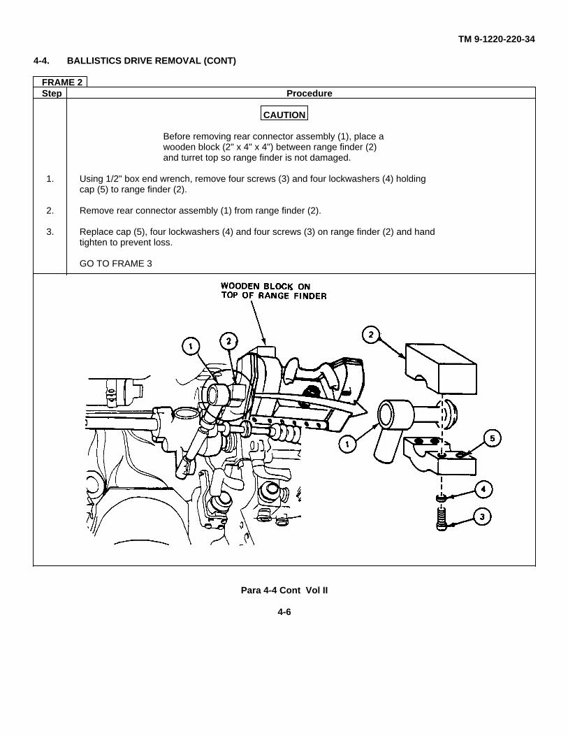
CAUTION
Before removing rear connector assembly (1), place awooden block (2" x 4" x 4") between range finder (2)and turret top so range finder is not damaged.
1. Using 1/2" box end wrench, remove four screws (3) and four lockwashers (4) holdingcap (5) to range finder (2).
2. Remove rear connector assembly (1) from range finder (2).
3. Replace cap (5), four lockwashers (4) and four screws (3) on range finder (2) and handtighten to prevent loss.
GO TO FRAME 3
Para 4-4 Cont Vol II
4-6
TM 9-1220-220-34
4-4. BALLISTICS DRIVE REMOVAL (CONT)
FRAME 3Step Procedure
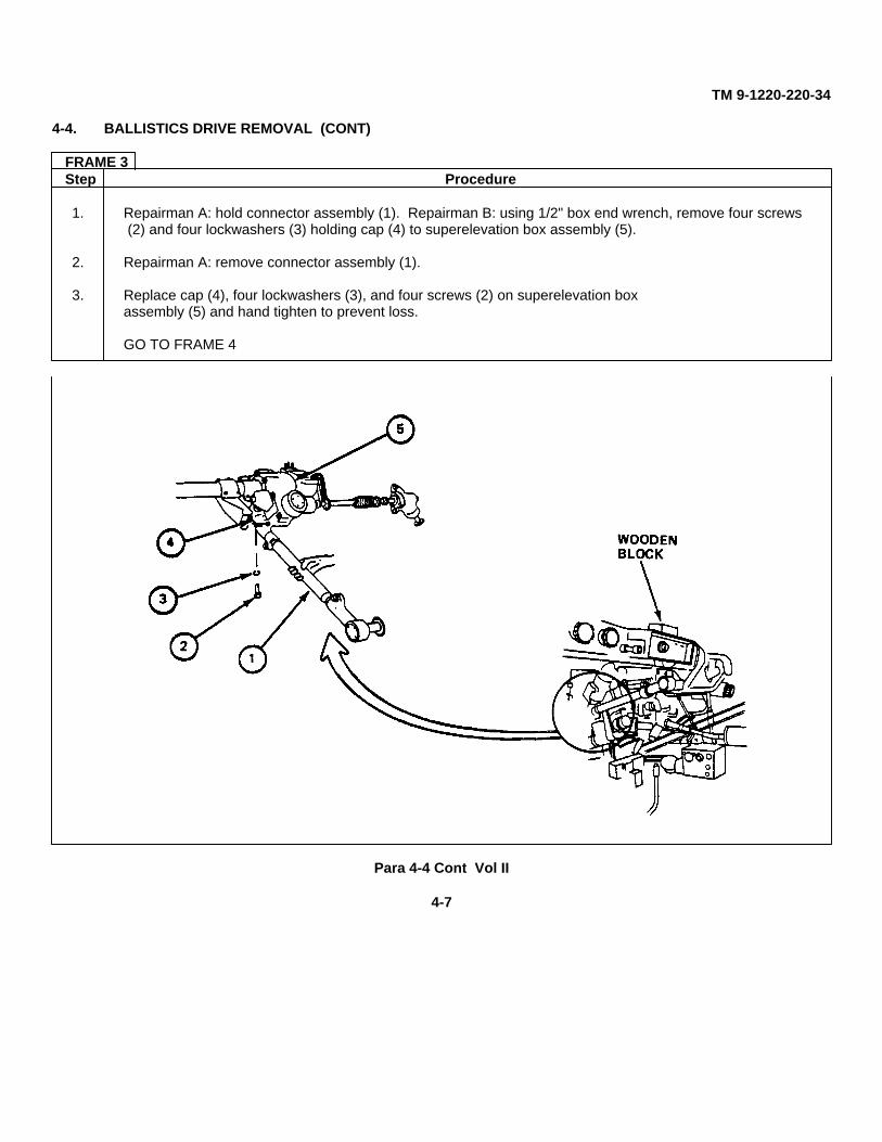
1. Repairman A: hold connector assembly (1). Repairman B: using 1/2" box end wrench, remove four screws (2) and four lockwashers (3) holding cap (4) to superelevation box assembly (5).
2. Repairman A: remove connector assembly (1).
3. Replace cap (4), four lockwashers (3), and four screws (2) on superelevation boxassembly (5) and hand tighten to prevent loss.
GO TO FRAME 4
Para 4-4 Cont Vol II
4-7
TM 9-1220-220-34
4-4. BALLISTICS DRIVE REMOVAL (CONT)
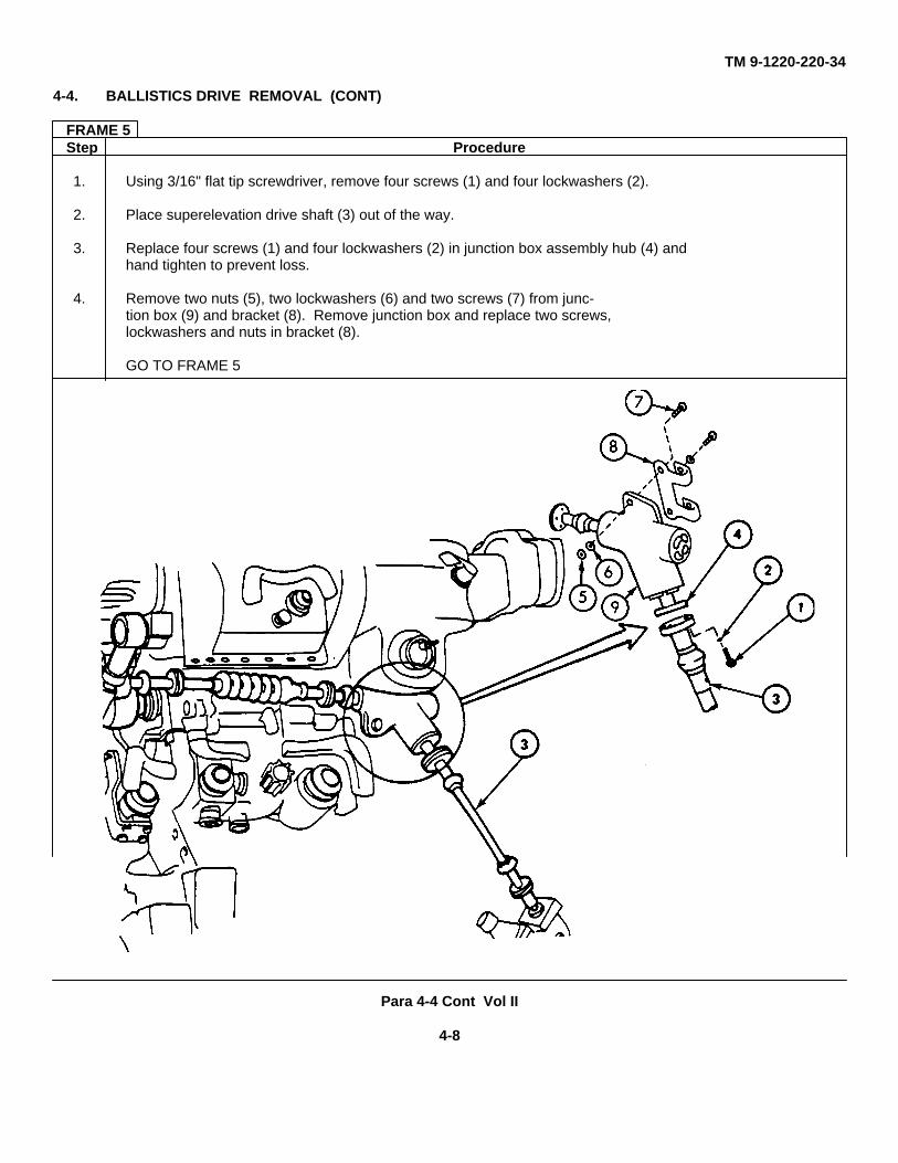
FRAME 5Step Procedure
1. Using 3/16" flat tip screwdriver, remove four screws (1) and four lockwashers (2).
2. Place superelevation drive shaft (3) out of the way.
3. Replace four screws (1) and four lockwashers (2) in junction box assembly hub (4) andhand tighten to prevent loss.
4. Remove two nuts (5), two lockwashers (6) and two screws (7) from junc-tion box (9) and bracket (8). Remove junction box and replace two screws,lockwashers and nuts in bracket (8).
GO TO FRAME 5
Para 4-4 Cont Vol II
4-8
TM 9-1220-220-34
4-4. BALLISTICS DRIVE REMOVAL (CONT)
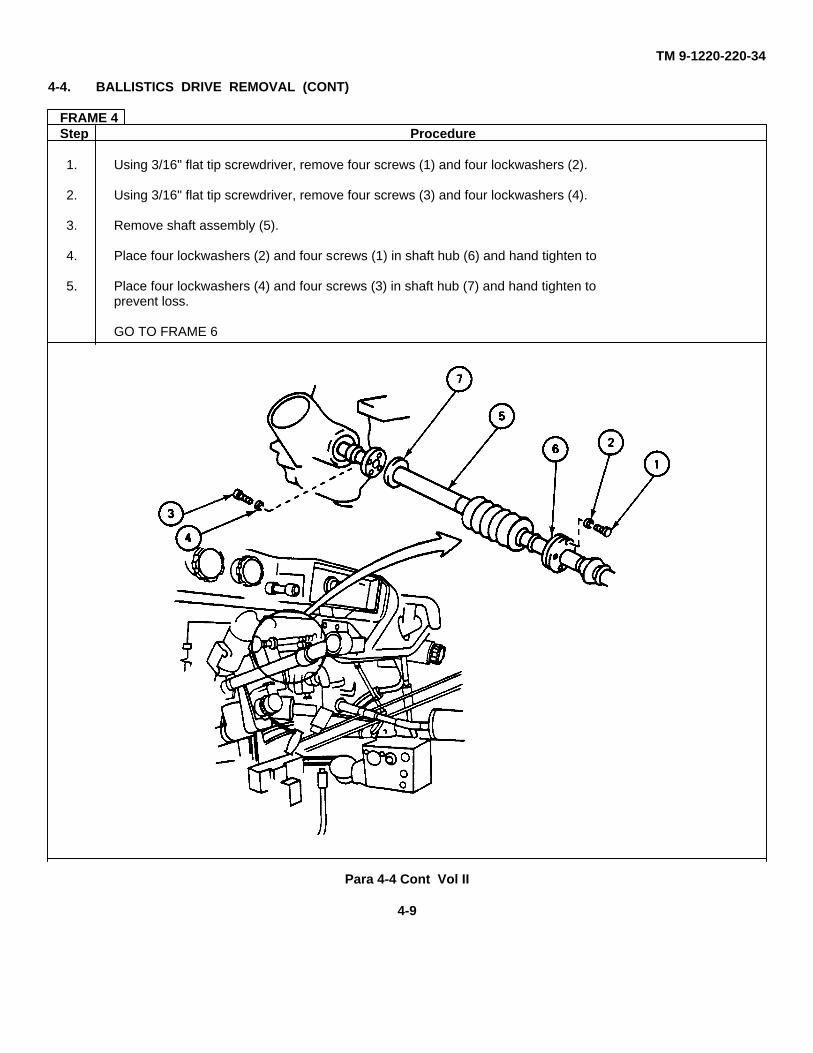
FRAME 4Step Procedure
1. Using 3/16" flat tip screwdriver, remove four screws (1) and four lockwashers (2).
2. Using 3/16" flat tip screwdriver, remove four screws (3) and four lockwashers (4).
3. Remove shaft assembly (5).
4. Place four lockwashers (2) and four screws (1) in shaft hub (6) and hand tighten to
5. Place four lockwashers (4) and four screws (3) in shaft hub (7) and hand tighten toprevent loss.
GO TO FRAME 6
Para 4-4 Cont Vol II
4-9
TM 9-1220-220-34
4-4. BALLISTICS DRIVE REMOVAL (CONT)
FRAME 6Step Procedure
1. Using 1/2" box end wrench, remove two screws (1) and two lockwashers (2) holding cap (3)to left support (4).
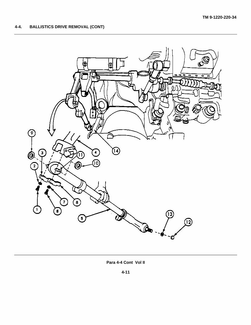
2. Repairman A: hold trunnion link (5). Repairman B: using 1/2" box end wrench, remove twoscrews (6) and two lockwashers (7) holding cap (8) to left support (4).
3. Repairman B: remove spacers (9 and 10) from spindle (11).
4. Remove spindle (11) from left support (4).
5. Place spacers (9 and 10) on spindle and retain spindle and spacers.
6. Repairman B: using 15/16" box end wrench, remove nut (12) and lockwasher (13) holdingtrunnion link (5) to trunnion arm (14).
7. Repairman A: remove trunnion link (5) by tapping with hammer.
8. Replace two caps (3 and 8) four lockwashers (2 and 7) and four screws (1 and 6) and handtighten to prevent loss.
9. Replace lockwasher (13) and nut (12) to trunnion link (5) and hand tighten to prevent loss.
GO TO FRAME 7
Para 4-4 Cont Vol II
4-10
TM 9-1220-220-34
4-4. BALLISTICS DRIVE REMOVAL (CONT)
Para 4-4 Cont Vol II
4-11
TM 9-1220-220-34
4-4. BALLISTICS DRIVE REMOVAL (CONT)
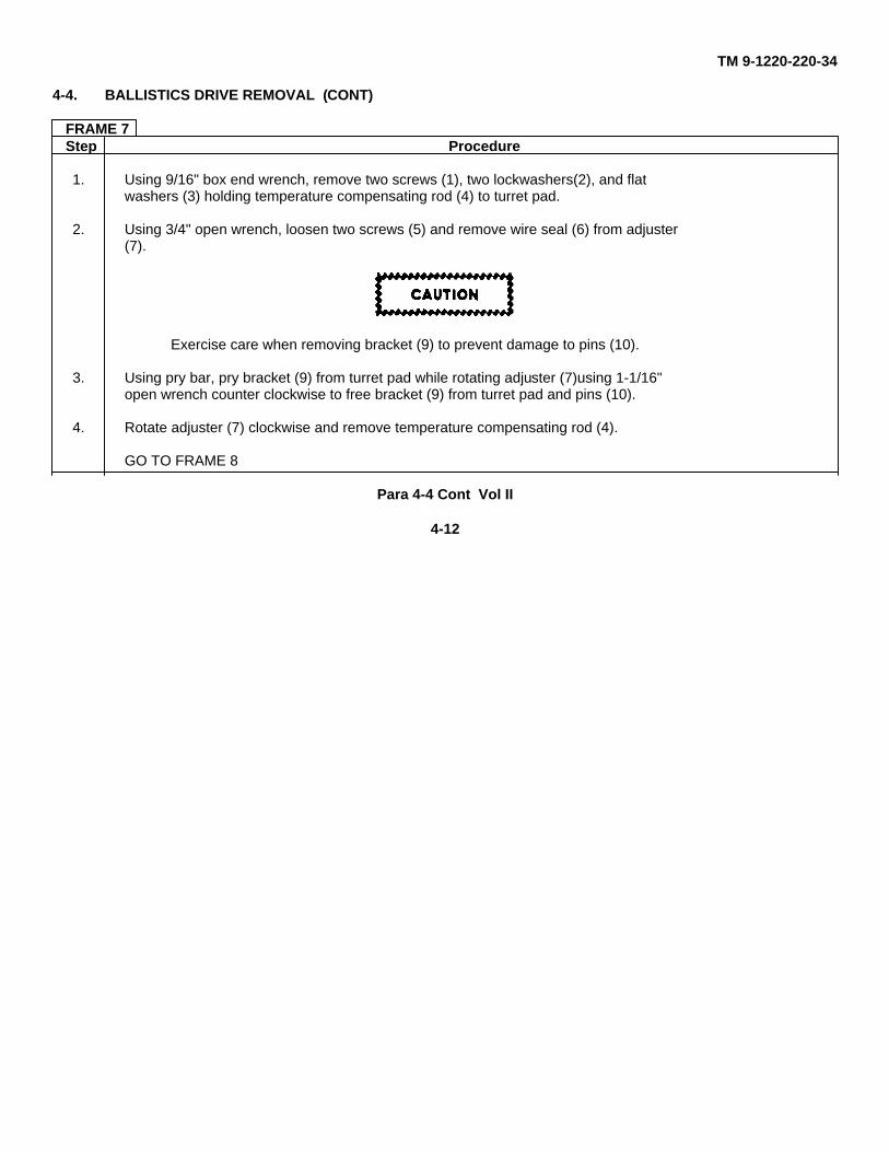
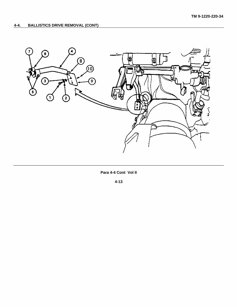
FRAME 7Step Procedure
1. Using 9/16" box end wrench, remove two screws (1), two lockwashers(2), and flatwashers (3) holding temperature compensating rod (4) to turret pad.
2. Using 3/4" open wrench, loosen two screws (5) and remove wire seal (6) from adjuster(7).
Exercise care when removing bracket (9) to prevent damage to pins (10).
3. Using pry bar, pry bracket (9) from turret pad while rotating adjuster (7)using 1-1/16"open wrench counter clockwise to free bracket (9) from turret pad and pins (10).
4. Rotate adjuster (7) clockwise and remove temperature compensating rod (4).
GO TO FRAME 8
Para 4-4 Cont Vol II
4-12
TM 9-1220-220-34
4-4. BALLISTICS DRIVE REMOVAL (CONT)
Para 4-4 Cont Vol II
4-13
TM 9-1220-220-34
4-4. BALLISTICS DRIVE REMOVAL (CONT)
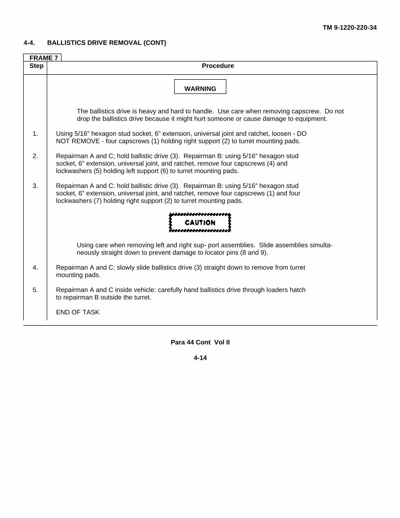
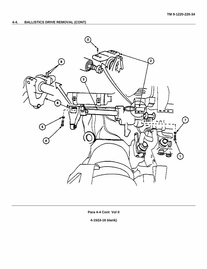
FRAME 7Step Procedure
WARNING
The ballistics drive is heavy and hard to handle. Use care when removing capscrew. Do notdrop the ballistics drive because it might hurt someone or cause damage to equipment.
1. Using 5/16" hexagon stud socket, 6" extension, universal joint and ratchet, loosen - DONOT REMOVE - four capscrews (1) holding right support (2) to turret mounting pads.
2. Repairman A and C; hold ballistic drive (3). Repairman B: using 5/16" hexagon studsocket, 6" extension, universal joint, and ratchet, remove four capscrews (4) andlockwashers (5) holding left support (6) to turret mounting pads.
3. Repairman A and C: hold ballistic drive (3). Repairman B: using 5/16" hexagon studsocket, 6" extension, universal joint, and ratchet, remove four capscrews (1) and fourlockwashers (7) holding right support (2) to turret mounting pads.
Using care when removing left and right sup- port assemblies. Slide assemblies simulta-neously straight down to prevent damage to locator pins (8 and 9).
4. Repairman A and C: slowly slide ballistics drive (3) straight down to remove from turretmounting pads.
5. Repairman A and C inside vehicle: carefully hand ballistics drive through loaders hatchto repairman B outside the turret.
END OF TASK
Para 44 Cont Vol II
4-14
TM 9-1220-220-34
4-4. BALLISTICS DRIVE REMOVAL (CONT)
Para 4-4 Cont Vol II
4-15/(4-16 blank)
TM 9-1220-220-34
4-5. BALLISTICS DRIVE INSTALLATION
TOOLS: 3/16" flat tip screwdriver#3 cross tip screwdriver (Phillips type)1/2", 5/16", 7/16", 9/16", and 15/16" box end wrench1/2", 3/4", and 1 1/16" open end wrench5/16" hexagon stud socket (3/8" drive)6" extension (3/8" drive)3/8" drive ratchet wrench3/8" drive universal jointSpacer gauge toolTorque wrench4-oz ball peen hammerElectric drill15/64" drill bitWire cutter toolLockwire tool1/4" reamer
SUPPLIES: Cleaning ragAlcohol (item 1, App A) or solvent (item 4, App A)
PERSONNEL: Three Repairman A: Holds ballistics driveRepairman B: Installs hardwareRepairman C: Helps in mounting ballistics drive only
REFERENCES: JPG 41C for: Cleaning mounting surfacesTorquingInstalling lockwireUsing electric drill
TM 10 for: Leveling gunZeroing M1 Al(TM 9-2350-215-10 for M60A1, TM 9-2350-257-10 forM60 Rise, and TM 9-2350-260-10 for M60)
TM 20-2 for: Removing and installing M13A1 elevation quadrantRemoving and installing M32 (or M35 gunner’s periscope)(TM 9-2350-215-20-2 for M60A1, TM 9-2350-257-20-2for M60A1 Rise, and TM 9-2350-260-20-2 for M60)
TM 9-1240-258-34 for locating of rangefinder
EQUIPMENT CONDITION: Vehicle parked on level groundGun pointed levelVehicle MASTER SWITCH off
Para 4-5 Vol II
4-17
TM 9-1220-220-34
4-5. BALLISTICS DRIVE INSTALLATION (CONT)
NOTE
When a step is to be done for only some of the ballistics drive models, the models will beshown, (MIO, MIOAI) means the step is only to be done for models M 10 and MIOAI. It is noteasy to change ballistics drives between vehicles. If the ballistics drive being installed is notthe same one removed from the vehicle, the locator pins may not line up with holes in theballistics drive. You may have to drill new holes to put the locator pins in.
FRAME 1Step Procedure
1. Look to see if left support locator pins (1) or right support locator pin (2) are damaged.If damaged, replace with good pin(s). If new ballistics drive is being installed, removepin (2).
WARNING
CLEANING SOLVENTS CAN CAUSE FIRES Cleaning solvents and fumes from cleaningsolvents can catch on fire. Keep it and all materials that can catch on fire away from flames.Use only in a room with a lot of fresh air.
2. Using a cleaning rag and alcohol or solvent, clean all turret mounting pads and ballisticsdrive mounting surfaces (JPG).
3. Repairman B outside the turret: carefully hand ballistics drive through loaders hatch torepairmen A and C inside vehicle.
Use care when installing left and right support assemblies. Slide assemblies straight up tokeep from damaging locator pins ( and 2), if installed.
4. Repairmen A, B, and C: raise ballistics drive (3) to turret mounting pads. Make surelocating key (4) on right support assembly (5) is lined up with keyway (6) in turretmounting pad.
5. Repairmen A and C: hold ballistics drive (3) in place.
Para 4-5 Cont Vol II
4-18
TM 9-1220-220-34
4-5. BALLISTICS DRIVE INSTALLATION (CONT)
Step Procedure
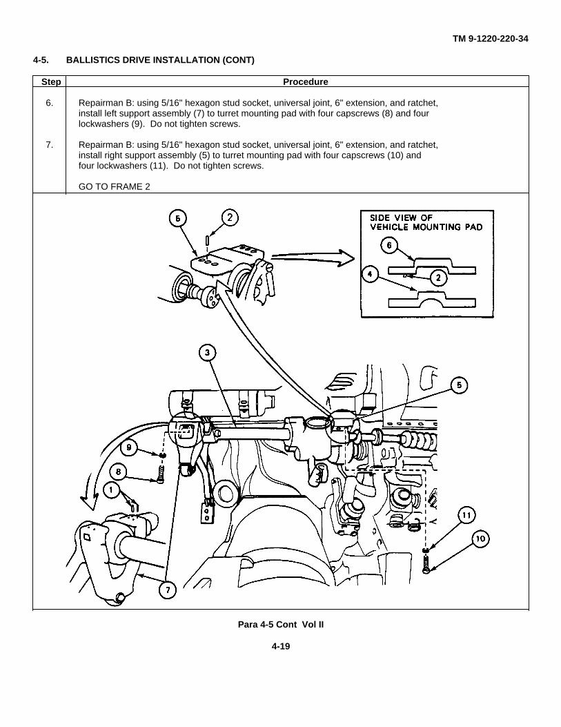
6. Repairman B: using 5/16" hexagon stud socket, universal joint, 6" extension, and ratchet,install left support assembly (7) to turret mounting pad with four capscrews (8) and fourlockwashers (9). Do not tighten screws.
7. Repairman B: using 5/16" hexagon stud socket, universal joint, 6" extension, and ratchet,install right support assembly (5) to turret mounting pad with four capscrews (10) andfour lockwashers (11). Do not tighten screws.
GO TO FRAME 2
Para 4-5 Cont Vol II
4-19
TM 9-1220-220-34
4-5. BALLISTICS DRIVE INSTALLATION (CONT)
FRAME 2Step Procedure
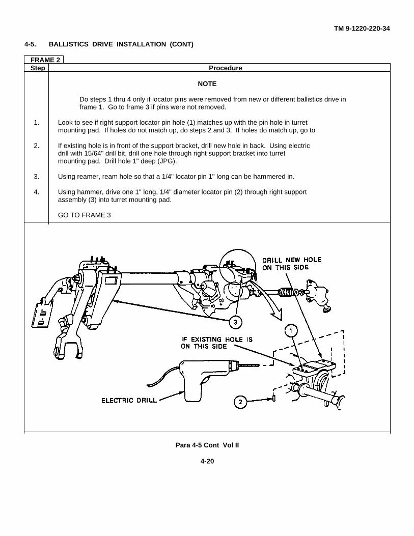
NOTE
Do steps 1 thru 4 only if locator pins were removed from new or different ballistics drive inframe 1. Go to frame 3 if pins were not removed.
1. Look to see if right support locator pin hole (1) matches up with the pin hole in turretmounting pad. If holes do not match up, do steps 2 and 3. If holes do match up, go to
2. If existing hole is in front of the support bracket, drill new hole in back. Using electricdrill with 15/64" drill bit, drill one hole through right support bracket into turretmounting pad. Drill hole 1" deep (JPG).
3. Using reamer, ream hole so that a 1/4" locator pin 1" long can be hammered in.
4. Using hammer, drive one 1" long, 1/4" diameter locator pin (2) through right supportassembly (3) into turret mounting pad.
GO TO FRAME 3
Para 4-5 Cont Vol II
4-20
TM 9-1220-220-34
4-5. BALLISTICS DRIVE INSTALLATION (CONT)
Para 4-5 Cont Vol Ii
4-21
TM 9-1220-220-34
4-5. BALLISTICS DRIVE INSTALLATION (CONT)
FRAME 3Step Procedure
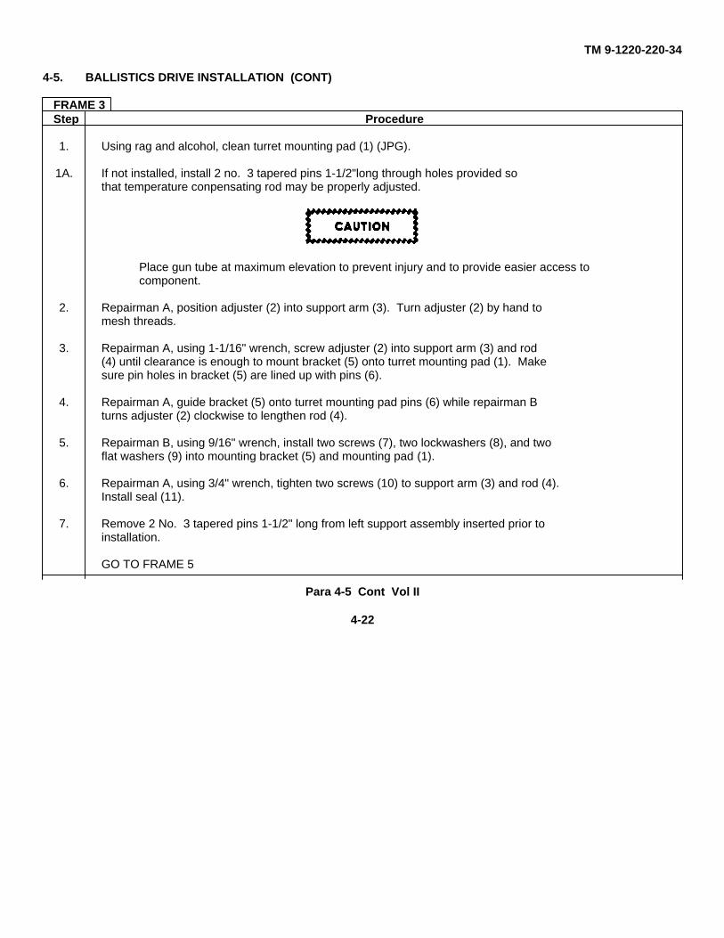
1. Using rag and alcohol, clean turret mounting pad (1) (JPG).
1A. If not installed, install 2 no. 3 tapered pins 1-1/2"long through holes provided sothat temperature conpensating rod may be properly adjusted.
Place gun tube at maximum elevation to prevent injury and to provide easier access tocomponent.
2. Repairman A, position adjuster (2) into support arm (3). Turn adjuster (2) by hand tomesh threads.
3. Repairman A, using 1-1/16" wrench, screw adjuster (2) into support arm (3) and rod(4) until clearance is enough to mount bracket (5) onto turret mounting pad (1). Makesure pin holes in bracket (5) are lined up with pins (6).
4. Repairman A, guide bracket (5) onto turret mounting pad pins (6) while repairman Bturns adjuster (2) clockwise to lengthen rod (4).
5. Repairman B, using 9/16" wrench, install two screws (7), two lockwashers (8), and twoflat washers (9) into mounting bracket (5) and mounting pad (1).
6. Repairman A, using 3/4" wrench, tighten two screws (10) to support arm (3) and rod (4).Install seal (11).
7. Remove 2 No. 3 tapered pins 1-1/2" long from left support assembly inserted prior toinstallation.
GO TO FRAME 5
Para 4-5 Cont Vol II
4-22
TM 9-1220-220-34
4-5. BALLISTICS DRIVE INSTALLATION (CONT)
Para 4-5 Cont Vol II
4-23
TM 9-1220-220-34
4-5. BALLISTICS DRIVE INSTALLATION (CONT)
FRAME 4Step Procedure
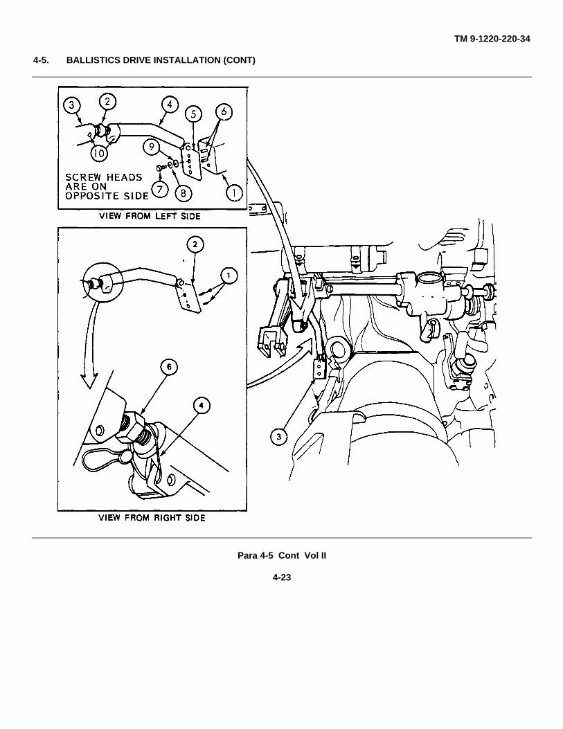
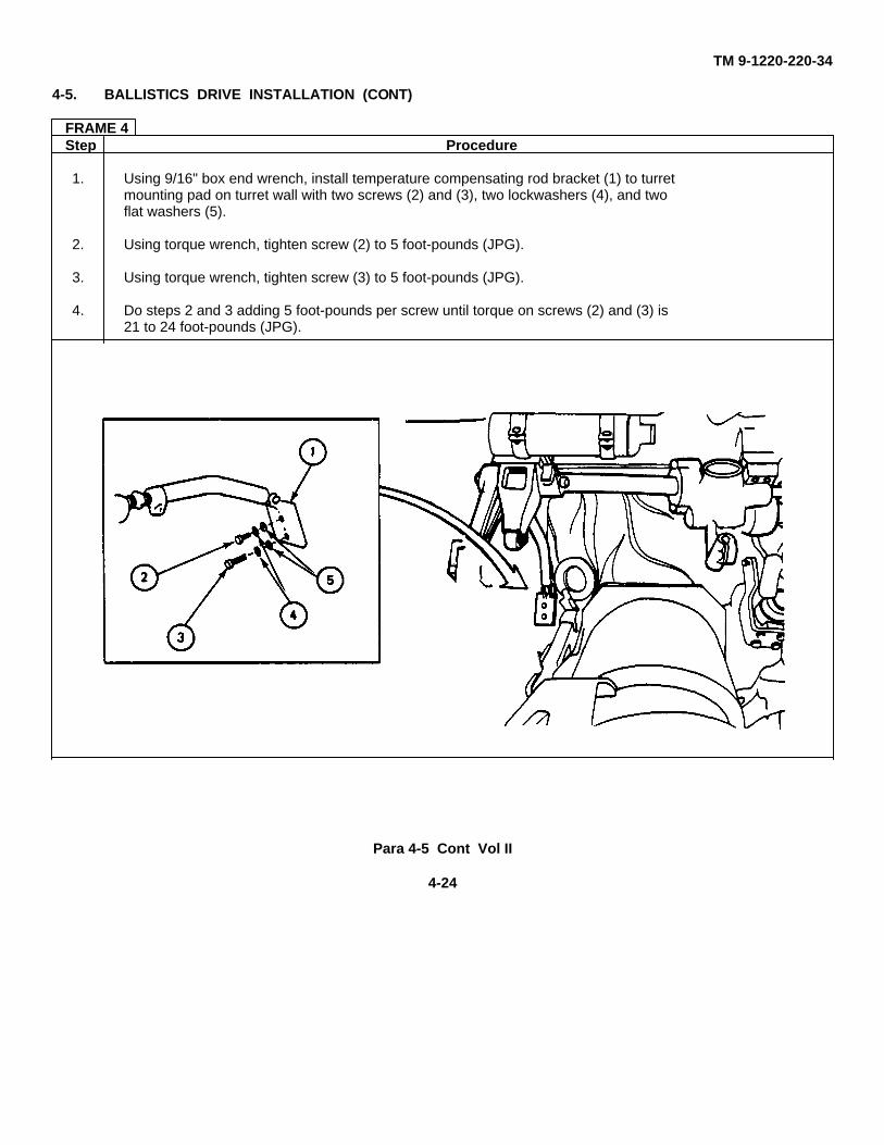
1. Using 9/16" box end wrench, install temperature compensating rod bracket (1) to turretmounting pad on turret wall with two screws (2) and (3), two lockwashers (4), and twoflat washers (5).
2. Using torque wrench, tighten screw (2) to 5 foot-pounds (JPG).
3. Using torque wrench, tighten screw (3) to 5 foot-pounds (JPG).
4. Do steps 2 and 3 adding 5 foot-pounds per screw until torque on screws (2) and (3) is21 to 24 foot-pounds (JPG).
Para 4-5 Cont Vol II
4-24
TM 9-1220-220-34
4-5. BALLISTICS DRIVE INSTALLATION (CONT)
FRAME 5Step Procedure
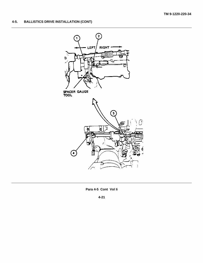
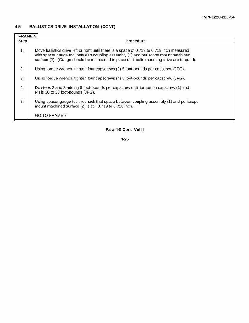
1. Move ballistics drive left or right until there is a space of 0.719 to 0.718 inch measuredwith spacer gauge tool between coupling assembly (1) and periscope mount machinedsurface (2). (Gauge should be maintained in place until bolts mounting drive are torqued).
2. Using torque wrench, tighten four capscrews (3) 5 foot-pounds per capscrew (JPG).
3. Using torque wrench, tighten four capscrews (4) 5 foot-pounds per capscrew (JPG).
4. Do steps 2 and 3 adding 5 foot-pounds per capscrew until torque on capscrew (3) and(4) is 30 to 33 foot-pounds (JPG).
5. Using spacer gauge tool, recheck that space between coupling assembly (1) and periscopemount machined surface (2) is still 0.719 to 0.718 inch.
GO TO FRAME 3
Para 4-5 Cont Vol II
4-25
TM 9-1220-220-34
4-5. BALLISTICS DRIVE INSTALLATION (CONT)
FRAME 6Step Procedure
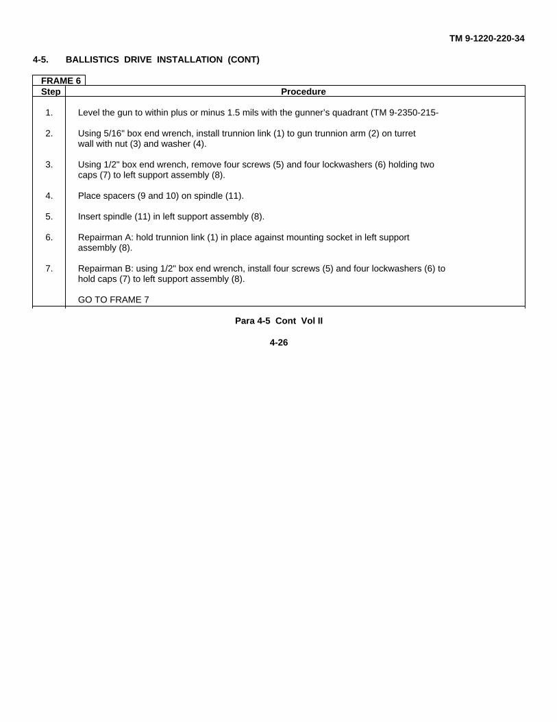
1. Level the gun to within plus or minus 1.5 mils with the gunner’s quadrant (TM 9-2350-215-
2. Using 5/16" box end wrench, install trunnion link (1) to gun trunnion arm (2) on turretwall with nut (3) and washer (4).
3. Using 1/2" box end wrench, remove four screws (5) and four lockwashers (6) holding twocaps (7) to left support assembly (8).
4. Place spacers (9 and 10) on spindle (11).
5. Insert spindle (11) in left support assembly (8).
6. Repairman A: hold trunnion link (1) in place against mounting socket in left supportassembly (8).
7. Repairman B: using 1/2" box end wrench, install four screws (5) and four lockwashers (6) tohold caps (7) to left support assembly (8).
GO TO FRAME 7
Para 4-5 Cont Vol II
4-26
TM 9-1220-220-34
4-5. BALLISTICS DRIVE INSTALLATION (CONT)
Para 4-5 Cont Vol II
4-27
TM 9-1220-220-34
4-5. BALLISTICS DRIVE INSTALLATION (CONT)
FRAME 7Step Procedure
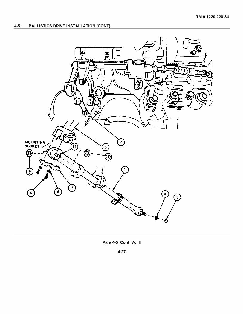
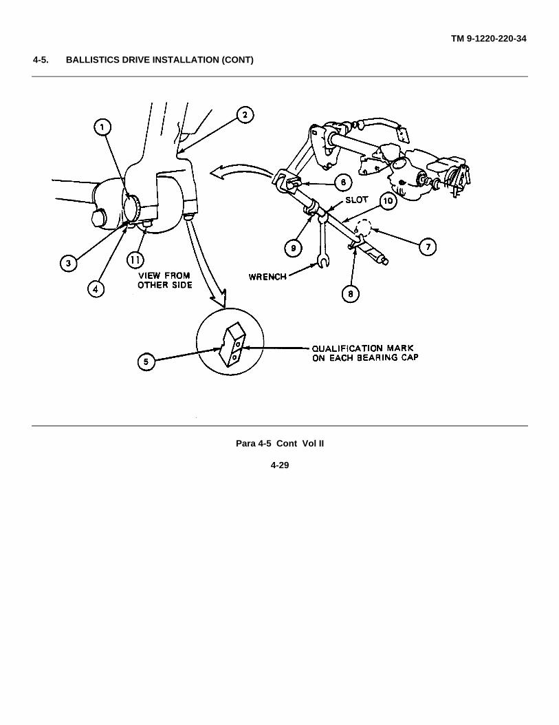
1. Turn index (1) on trunnion link (2) until "O" mark (3) is lined up with qualifying mark (4)on bearing cap (5), tighten four screws (11).
2. Look and see if fire control (6) bubble is centered. If not centered, go to step 3. Ifcentered, go to frame 8.
3. Using wire cutters, cut lockwire (7).
4. Using 15/16" open end wrench, loosen two screws (8) and (9).
5. Using 1 1/4" open end wrench, turn adjuster arm (10) until fire control level (6) bubbleis centered.
6. Using 15/16 open end wrench, tighten two screws (8) and (9).
7. Using lockwire tool, install new lockwire (7) (JPG).
GO TO FRAME 8
Para 4-5 Cont Vol II
4-28
TM 9-1220-220-34
4-5. BALLISTICS DRIVE INSTALLATION (CONT)
Para 4-5 Cont Vol II
4-29
TM 9-1220-220-34
4-5. BALLISTICS DRIVE INSTALLATION (CONT)
FRAME 8Step Procedure
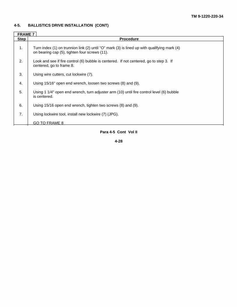
NOTE
Do steps 1,2, and 3 for M10A3 only.
1. Turn the superelevation box output shaft (1) fully clockwise, then, turn counterclockwiseto the number of turns marked on qualification plate (2).
2. Aline mark on output shaft (1) with index mark on qualification plate (2).
3. Set electronic computer to zero" elevation.
4. Using 3/16" flat tip screwdriver, install shaft (3) on superelevation box output shaft (1)with four screws (4) and four lockwashers (5).
5. Using 3/16" flat tip screwdriver, install shaft (3) on junction box assembly (6) (installshaft (3) on inner drive shaft of electronic computer for M10A3) with four screws (7)and four lockwashers (8).
GO TO FRAME 9
Para 4-5 Cont Vol II
4-30
TM 9-1220-220-34
4-5. BALLISTICS DRIVE INSTALLATION (CONT)
Para 4-5 Cont Vol II
4-31
TM 9-1220-220-34
4-5. BALLISTICS DRIVE INSTALLATION (CONT)
FRAME 9Step Procedure
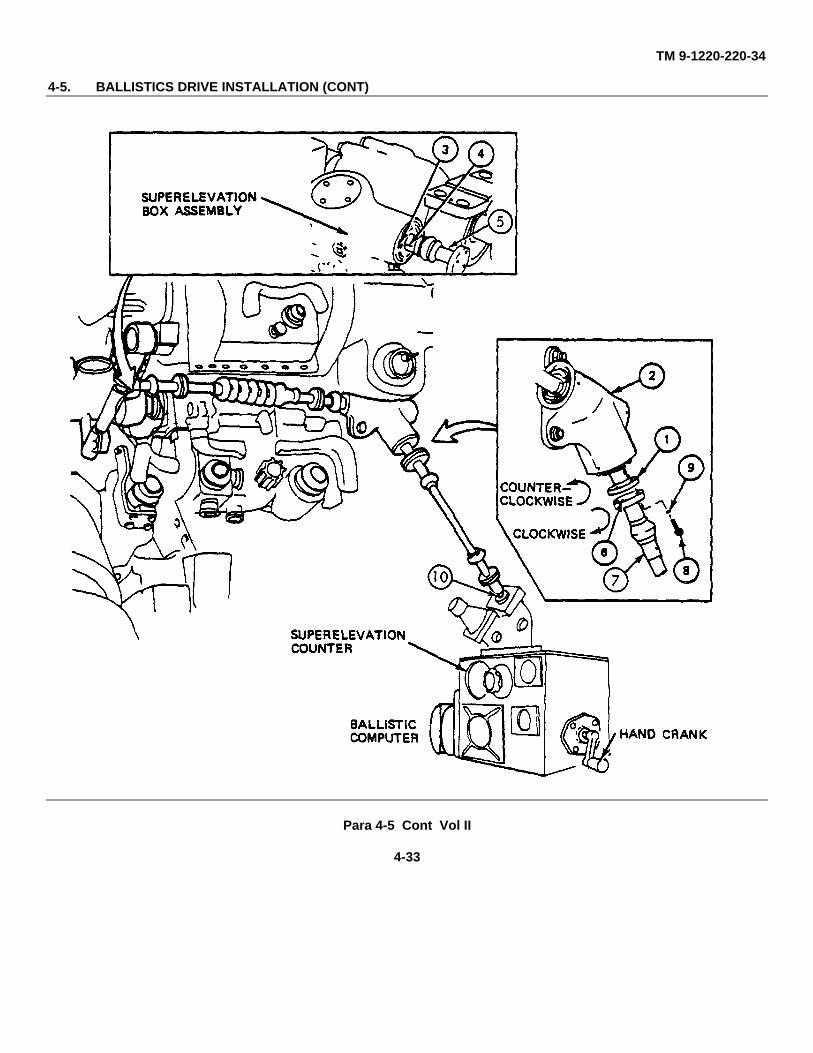
NOTE
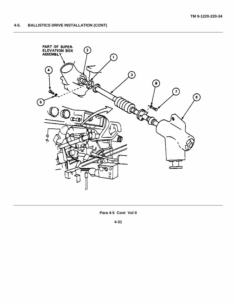
If installing MIOA3 go to frame 10.
1. Turn the input shaft (1) on junction box assembly (2) to the right until it stops.
2. Turn input shaft (1) to the left for the number of turns stamped on the qualificationplate (3). The mark (4) on the input shaft (5) should line up with the index mark onthe qualification plate (3).
3. Push in on hand crank of ballistic computer and crank until the superelevation counterreads zero (TM 10).
NOTE
If holes, in superelevation drive shaft (7) do not line up with holes in junction box assemblyinput shaft (I) do not move the line up between the input shaft and the mark on thequalification plate, do step 4. If holes are lined up, go to step 5.
4. Slide superelevation drive shaft (6) off ballistic computer output shaft (10). Install withfour holes on superelevation drive shaft (7) lined up with four holes on junction boxassembly input shaft (1).
5. Using 3/16" flat tip screwdriver. Install superelevation drive shaft (7) to input shaft (1)with four screws (8) and four lockwashers (9).
GO TO FRAME 10
Para 4-5 Cont Vol II
4-32
TM 9-1220-220-34
4-5. BALLISTICS DRIVE INSTALLATION (CONT)
Para 4-5 Cont Vol II
4-33
TM 9-1220-220-34
4-5. BALLISTICS DRIVE INSTALLATION (CONT)
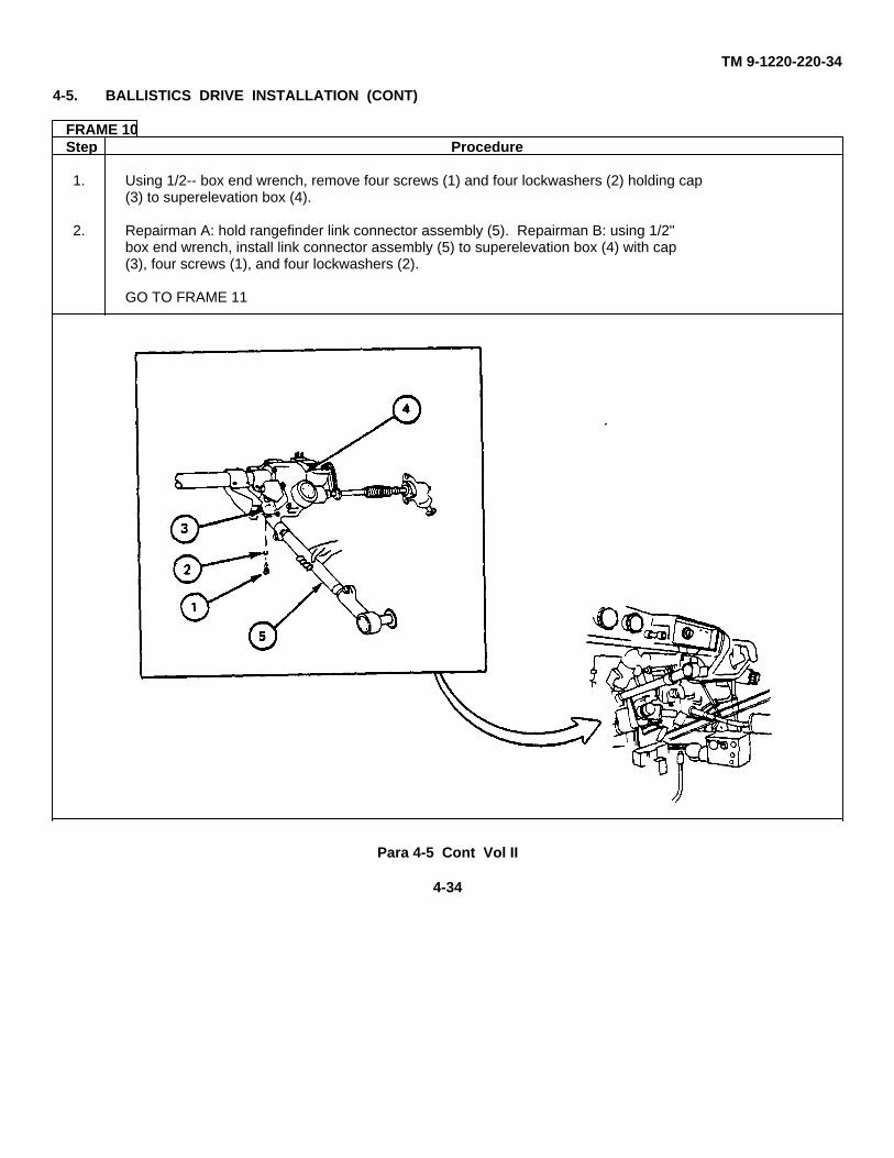
FRAME 10Step Procedure
1. Using 1/2-- box end wrench, remove four screws (1) and four lockwashers (2) holding cap(3) to superelevation box (4).
2. Repairman A: hold rangefinder link connector assembly (5). Repairman B: using 1/2"box end wrench, install link connector assembly (5) to superelevation box (4) with cap(3), four screws (1), and four lockwashers (2).
GO TO FRAME 11
Para 4-5 Cont Vol II
4-34
TM 9-1220-220-34
4-5. BALLISTICS DRIVE INSTALLATION (CONT)
FRAME 11Step Procedure
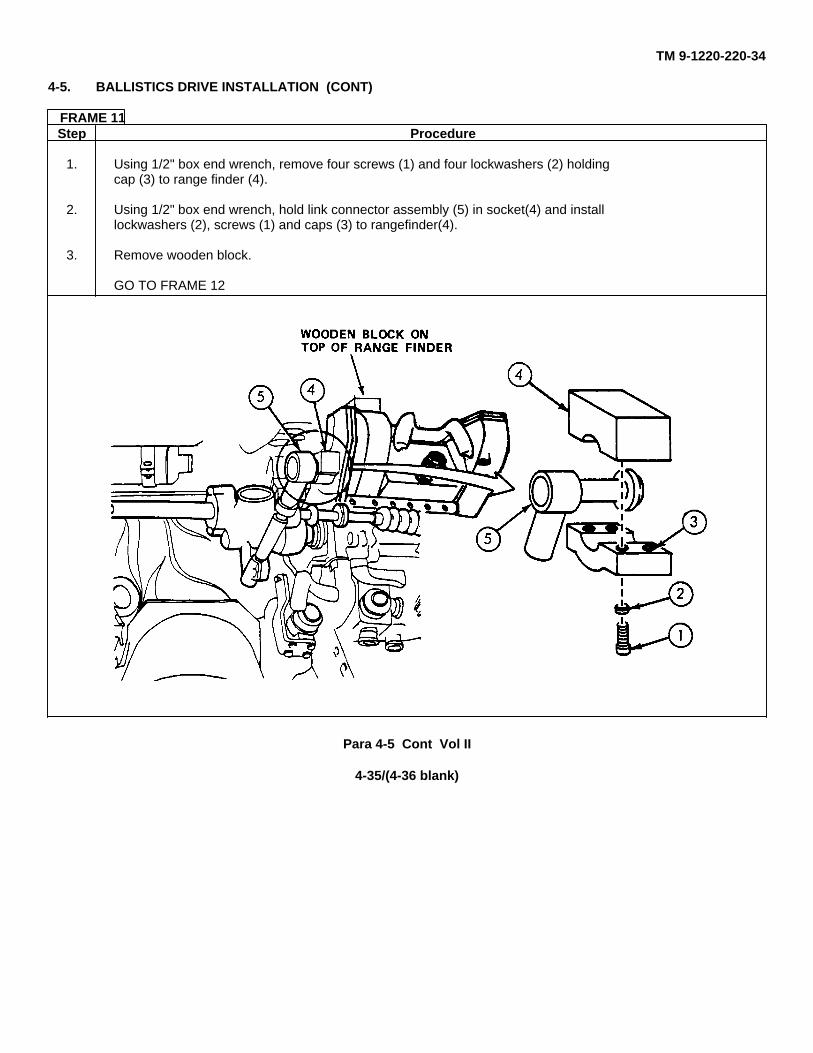
1. Using 1/2" box end wrench, remove four screws (1) and four lockwashers (2) holdingcap (3) to range finder (4).
2. Using 1/2" box end wrench, hold link connector assembly (5) in socket(4) and installlockwashers (2), screws (1) and caps (3) to rangefinder(4).
3. Remove wooden block.
GO TO FRAME 12
Para 4-5 Cont Vol II
4-35/(4-36 blank)
TM 9-1220-220-34
4-5. BALLISTICS DRIVE INSTALLATION (CONT)
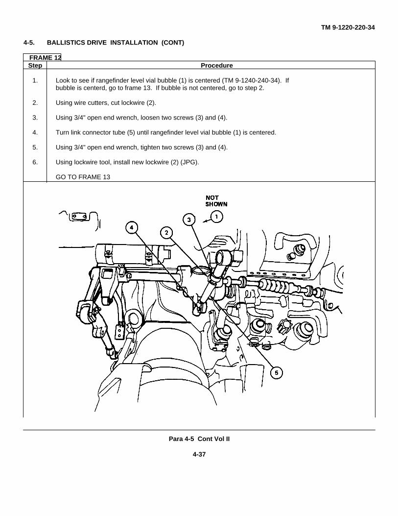
FRAME 12Step Procedure
1. Look to see if rangefinder level vial bubble (1) is centered (TM 9-1240-240-34). Ifbubble is centerd, go to frame 13. If bubble is not centered, go to step 2.
2. Using wire cutters, cut lockwire (2).
3. Using 3/4" open end wrench, loosen two screws (3) and (4).
4. Turn link connector tube (5) until rangefinder level vial bubble (1) is centered.
5. Using 3/4" open end wrench, tighten two screws (3) and (4).
6. Using lockwire tool, install new lockwire (2) (JPG).
GO TO FRAME 13
Para 4-5 Cont Vol II
4-37
TM 9-1220-220-34
4-5. BALLISTICS DRIVE INSTALLATION (CONT)
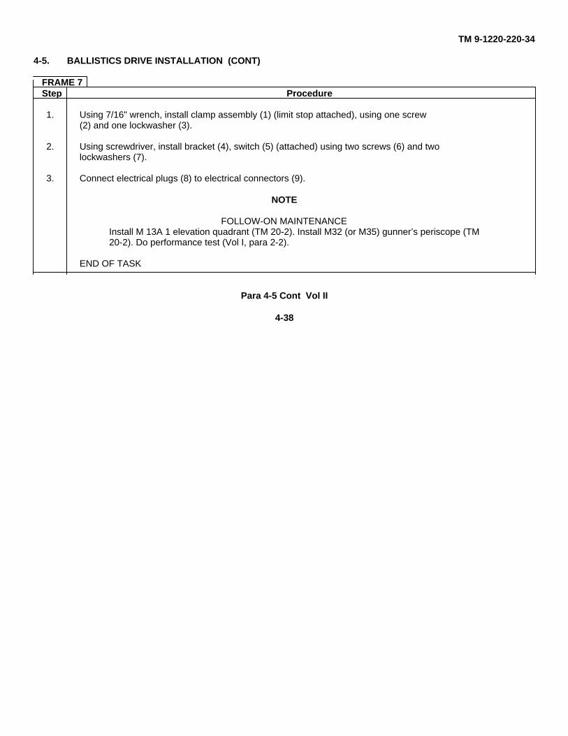
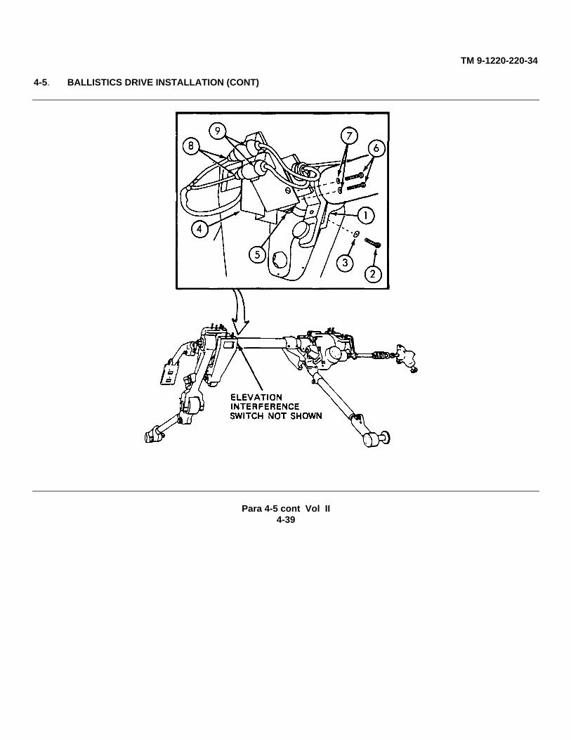
FRAME 7Step Procedure
1. Using 7/16" wrench, install clamp assembly (1) (limit stop attached), using one screw(2) and one lockwasher (3).
2. Using screwdriver, install bracket (4), switch (5) (attached) using two screws (6) and twolockwashers (7).
3. Connect electrical plugs (8) to electrical connectors (9).
NOTE
FOLLOW-ON MAINTENANCEInstall M 13A 1 elevation quadrant (TM 20-2). Install M32 (or M35) gunner’s periscope (TM20-2). Do performance test (Vol I, para 2-2).
END OF TASK
Para 4-5 Cont Vol II
4-38
TM 9-1220-220-34
4-5. BALLISTICS DRIVE INSTALLATION (CONT)
Para 4-5 cont Vol II4-39
TM 9-1220-220-34
Section 3. TEMPERATURE COMPENSATING ROD
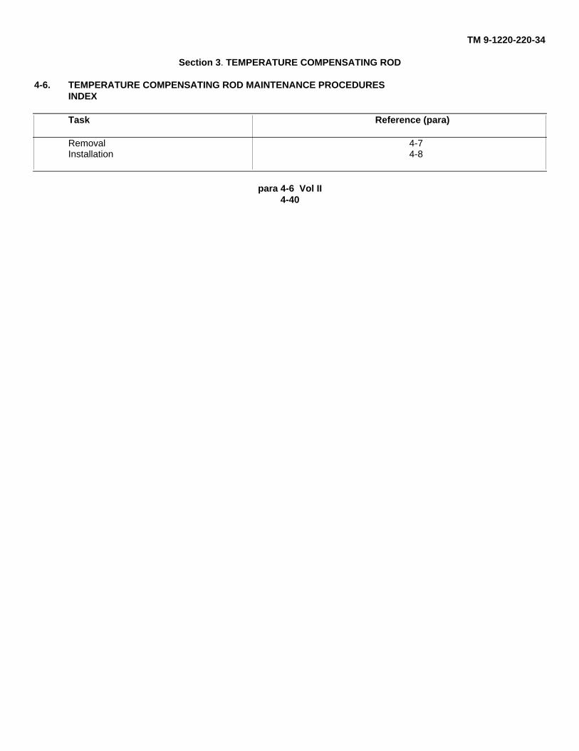
4-6. TEMPERATURE COMPENSATING ROD MAINTENANCE PROCEDURESINDEX
Task Reference (para)
Removal 4-7Installation 4-8
para 4-6 Vol II4-40
TM 9-1220-220-34
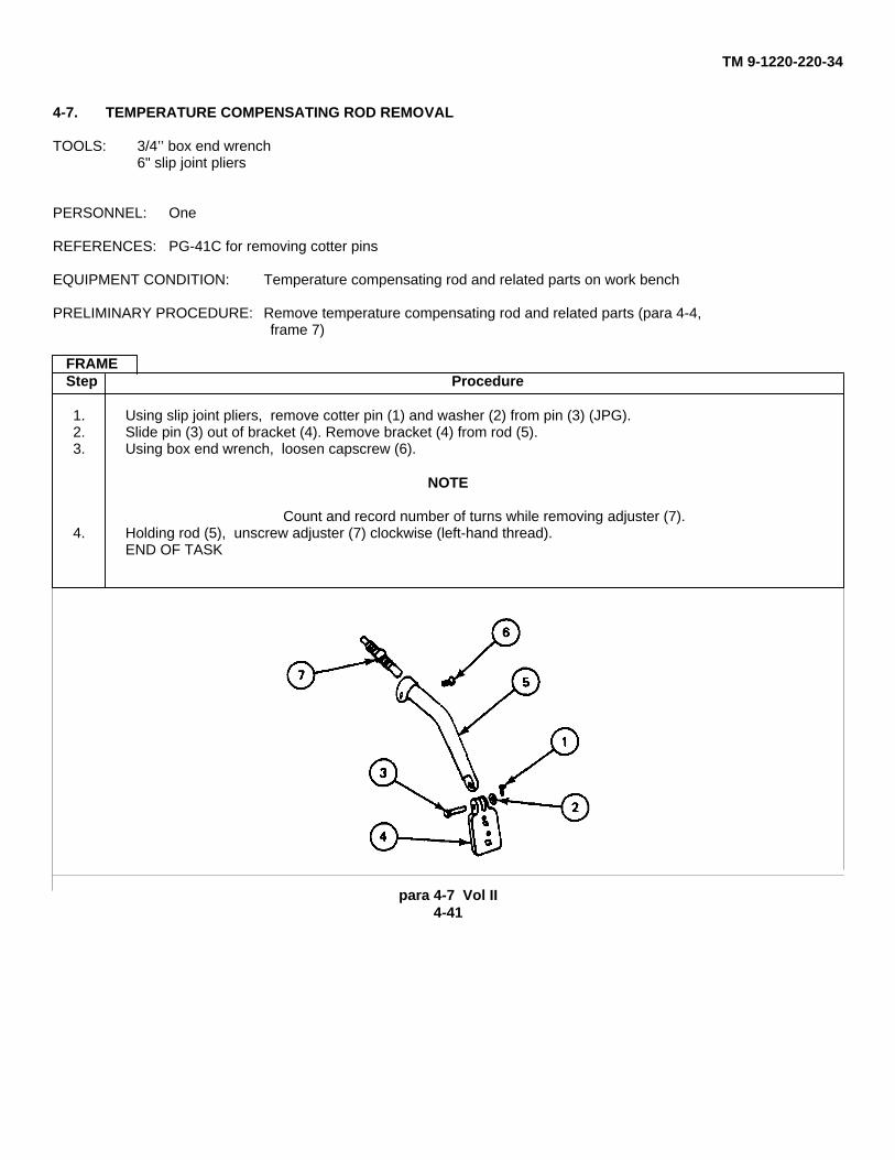
4-7. TEMPERATURE COMPENSATING ROD REMOVAL
TOOLS: 3/4’’ box end wrench6" slip joint pliers
PERSONNEL: One
REFERENCES: PG-41C for removing cotter pins
EQUIPMENT CONDITION: Temperature compensating rod and related parts on work bench
PRELIMINARY PROCEDURE: Remove temperature compensating rod and related parts (para 4-4,frame 7)
FRAMEStep Procedure
1. Using slip joint pliers, remove cotter pin (1) and washer (2) from pin (3) (JPG).2. Slide pin (3) out of bracket (4). Remove bracket (4) from rod (5).3. Using box end wrench, loosen capscrew (6).
NOTE
Count and record number of turns while removing adjuster (7).4. Holding rod (5), unscrew adjuster (7) clockwise (left-hand thread).
END OF TASK
para 4-7 Vol II4-41
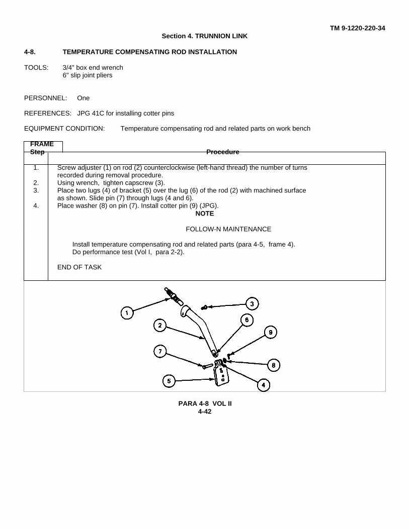
TM 9-1220-220-34Section 4. TRUNNION LINK
4-8. TEMPERATURE COMPENSATING ROD INSTALLATION
TOOLS: 3/4" box end wrench6" slip joint pliers
PERSONNEL: One
REFERENCES: JPG 41C for installing cotter pins
EQUIPMENT CONDITION: Temperature compensating rod and related parts on work bench
FRAMEStep Procedure
1. Screw adjuster (1) on rod (2) counterclockwise (left-hand thread) the number of turnsrecorded during removal procedure.
2. Using wrench, tighten capscrew (3).3. Place two lugs (4) of bracket (5) over the lug (6) of the rod (2) with machined surface
as shown. Slide pin (7) through lugs (4 and 6).4. Place washer (8) on pin (7). Install cotter pin (9) (JPG).
NOTE
FOLLOW-N MAINTENANCE
Install temperature compensating rod and related parts (para 4-5, frame 4).Do performance test (Vol I, para 2-2).
END OF TASK
PARA 4-8 VOL II4-42
TM 9-1220-220-34Section 4. TRUNNION LINK
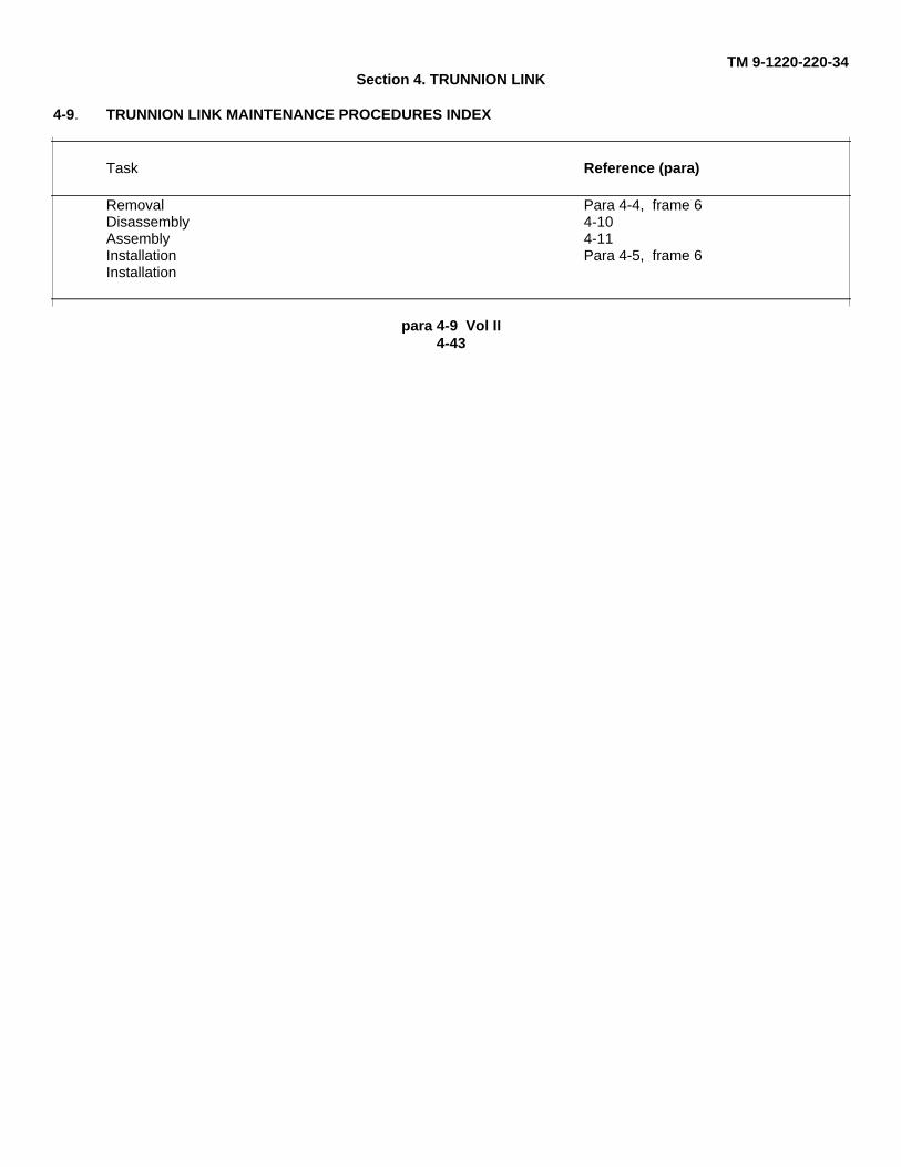
4-9. TRUNNION LINK MAINTENANCE PROCEDURES INDEX
Task Reference (para)
Removal Para 4-4, frame 6Disassembly 4-10Assembly 4-11Installation Para 4-5, frame 6Installation
para 4-9 Vol II4-43
TM 9-1220-220-344-10. TRUNNION LINK DISASSEMBLY
TOOLS: 7/8" and 15/16" box end wrenches
PERSONNEL: One
EQUIPMENT CONDITION: Trunnion link on work bench
PERLIMINARY PROCEDURE: Remove trunnion link (para 4-4, frame 6)
FRAMEStep Procedure
NOTE
Count and record number of turns in steps 2 and 4.
1. Using 5/16" box end wrench, loosen capscrew (I).
2. Holding tube (2), unscrew connector assembly (3).
3. Using 7/8" box end wrench, loosen capscrew (4).
4. Holding tube (2), unscrew connector assembly (5) clockwise (left-hand thread).
END OF TASK
para 4-10 Vol II4-44
TM 9-1220-220-344-11. TRUNNION LINK ASSEMBLY
TOOLS: 7/8" and 15/16" box end wrenches
PERSONNEL: One
EQUIPMENT CONDITION: Trunnion link on work bench
FRAMEStep Procedure
1. Screw connector assembly (1) on tube (2) counterclockwise (left-hand thread) the numberof turns recorded during removal procedure.
2. Using 7/8" box end wrench, tighten capscrew (3).3. Screw connector assembly (4) on tube (2) the number of turns recorded during removal
procedure.4. Using 15/16" box end wrench, tighten capscrew (5).
NOTE
FOLLOW-N MAINTENANCE
Install trunnion link (para 4-5, frame 6).Do performance test (Vol I, para 2-2).
END OF TASK
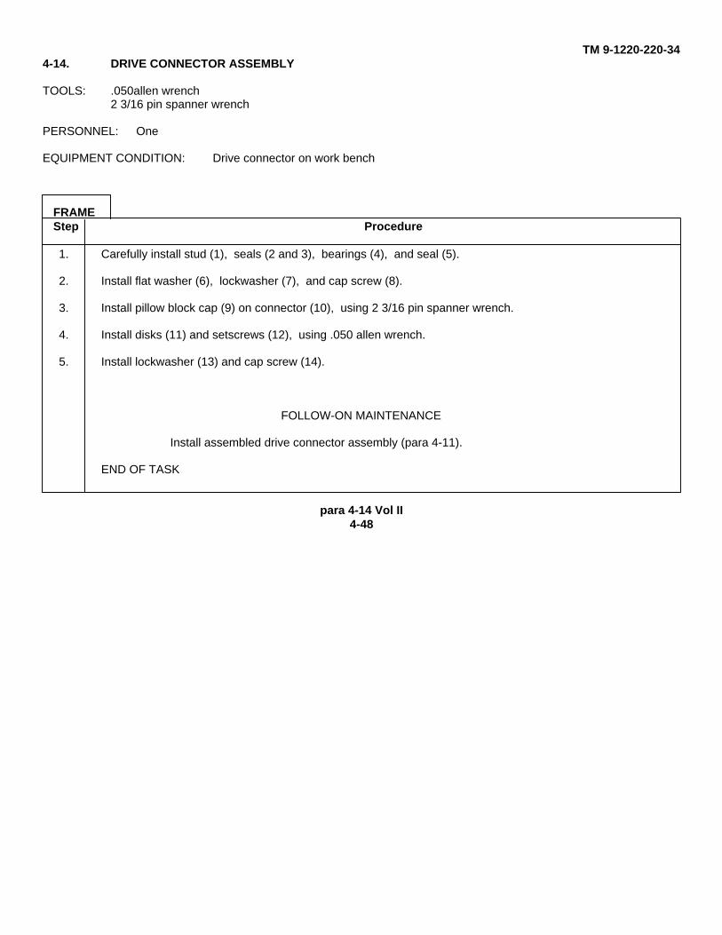
para 4-11 Vol II4-45
TM 9-1 220-220-34Section 5. DRIVE CONNECTOR
4-12. DRIVE CONNECTOR MAINTENANCE PROCEDURES INDEX
Task Reference (para)
Removal Para 4-10, frame 1Disassembly 4-13Assembly 4-14Installation Para 4-11, frame 1
4-13. DRIVE CONNECTOR DISASSEMBLY
TOOLS: 050 allen wrench2 3/16 pin spanner wrench
PERSONNEL: One
EQUIPMENT CONDITION: Drive connector on work bench
PRELIMINARY PROCEDURE: Remove drive connector (para 4-10, frame 1)
FRAMEStep Procedure
1. Unscrew cap screw (1) and remove cap screw (1) and lockwasher (2).
2. Loosen two setscrews (3) using .050 allen wrench.
3. Remove pillow block cap (4) from connector (5), using 2 3/16 pin spanner wrench.
4. Remove cap screw (6), lockwasher (7) and flatwasher (8).
5. Carefully press out seal (9), bearings (10), seals (11 and 12), and stud (13). Discard sealsif damaged.
6. Remove disks (14) by tightening setscrews (3), using .050 allen wrench.
7. Discard disks (14) and remove setscrews (3).END OF TASK
Para 4-12 Vol II4-46
TM 9-1 220-220-344-13. DRIVE CONNECTION DISASSEMBLY (CONT)
para 4-13 Cont Vol II4-47
TM 9-1220-220-344-14. DRIVE CONNECTOR ASSEMBLY
TOOLS: .050allen wrench2 3/16 pin spanner wrench
PERSONNEL: One
EQUIPMENT CONDITION: Drive connector on work bench
FRAMEStep Procedure
1. Carefully install stud (1), seals (2 and 3), bearings (4), and seal (5).
2. Install flat washer (6), lockwasher (7), and cap screw (8).
3. Install pillow block cap (9) on connector (10), using 2 3/16 pin spanner wrench.
4. Install disks (11) and setscrews (12), using .050 allen wrench.
5. Install lockwasher (13) and cap screw (14).
FOLLOW-ON MAINTENANCE
Install assembled drive connector assembly (para 4-11).
END OF TASK
para 4-14 Vol II4-48
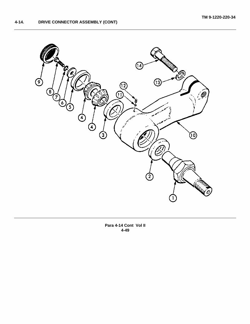
TM 9-1220-220-344-14. DRIVE CONNECTOR ASSEMBLY (CONT)
Para 4-14 Cont Vol II4-49
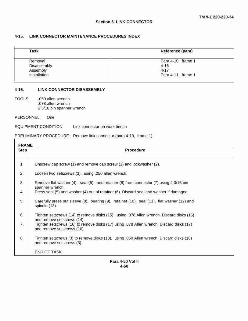
TM 9-1 220-220-34Section 6. LINK CONNECTOR
4-15. LINK CONNECTOR MAINTENANCE PROCEDURES INDEX
Task Reference (para)
Removal Para 4-10, frame 1Disassembly 4-16Assembly 4-17Installation Para 4-11, frame 1
4-16. LINK CONNECTOR DISASSEMBLY
TOOLS: .050 allen wrench.078 allen wrench2 3/16 pin spanner wrench
PERSONNEL: One
EQUIPMENT CONDITION: Link connector on work bench
PRELIMINARY PROCEDURE: Remove link connector (para 4-10, frame 1)
FRAMEStep Procedure
1. Unscrew cap screw (1) and remove cap screw (1) and lockwasher (2).
2. Loosen two setscrews (3), using .050 allen wrench.
3. Remove flat washer (4), seal (5), and retainer (6) from connector (7) using 2 3/16 pinspanner wrench.
4. Press seal (5) and washer (4) out of retainer (6). Discard seal and washer if damaged.
5. Carefully press out sleeve (8), bearing (9), retainer (10), seal (11), flat washer (12) andspindle (13).
6. Tighten setscrews (14) to remove disks (15), using .078 Allen wrench. Discard disks (15)and remove setscrews (14).
7. Tighten setscrews (16) to remove disks (17) using .078 Allen wrench. Discard disks (17)and remove setscrews (16).
8. Tighten setscrews (3) to remove disks (18), using .050 Allen wrench. Discard disks (18)and remove setscrews (3).
END OF TASK
Para 4-50 Vol II4-50
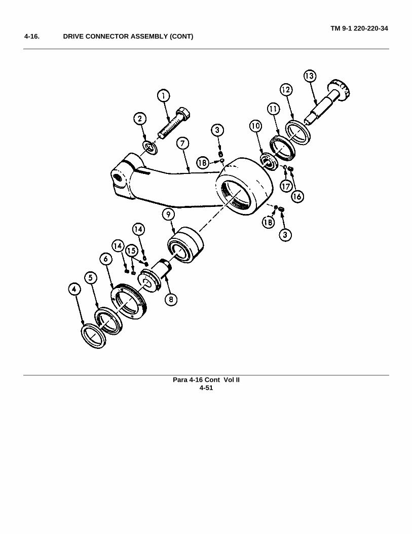
TM 9-1 220-220-344-16. DRIVE CONNECTOR ASSEMBLY (CONT)
Para 4-16 Cont Vol II4-51
TM 9-1220-220-344-17. LINK CONNECTOR ASSEMBLY
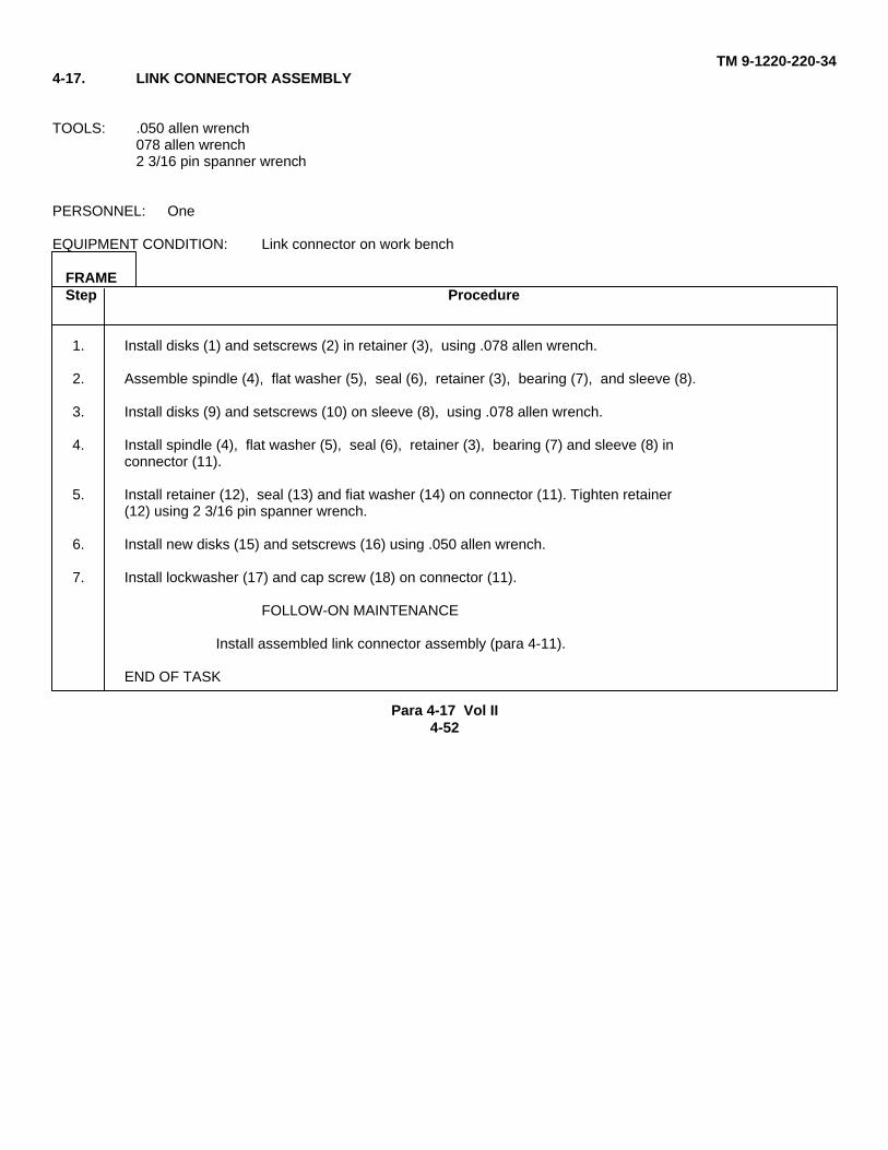
TOOLS: .050 allen wrench078 allen wrench2 3/16 pin spanner wrench
PERSONNEL: One
EQUIPMENT CONDITION: Link connector on work bench
FRAMEStep Procedure
1. Install disks (1) and setscrews (2) in retainer (3), using .078 allen wrench.
2. Assemble spindle (4), flat washer (5), seal (6), retainer (3), bearing (7), and sleeve (8).
3. Install disks (9) and setscrews (10) on sleeve (8), using .078 allen wrench.
4. Install spindle (4), flat washer (5), seal (6), retainer (3), bearing (7) and sleeve (8) inconnector (11).
5. Install retainer (12), seal (13) and fiat washer (14) on connector (11). Tighten retainer(12) using 2 3/16 pin spanner wrench.
6. Install new disks (15) and setscrews (16) using .050 allen wrench.
7. Install lockwasher (17) and cap screw (18) on connector (11).
FOLLOW-ON MAINTENANCE
Install assembled link connector assembly (para 4-11).
END OF TASK
Para 4-17 Vol II4-52
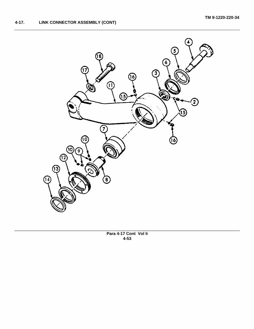
TM 9-1220-220-344-17. LINK CONNECTOR ASSEMBLY (CONT)
Para 4-17 Cont Vol Ii4-53
TM 9-1220-220-34Section 7. FIRE CONTROL LEVEL
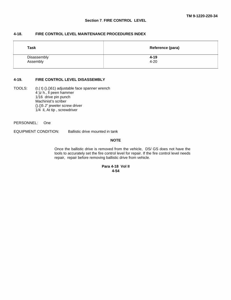
4-18. FIRE CONTROL LEVEL MAINTENANCE PROCEDURES INDEX
Task Reference (para)
Disassembly 4-19Assembly 4-20
4-19. FIRE CONTROL LEVEL DISASSEMBLY
TOOLS: (t.( t) ().()61) adjustable face spanner wrench4 )z h., ll peen hammer1/16 drive pin punchMachinist’s scriber().()5 J" jeweler screw driver1/4 il, At tip , screwdriver
PERSONNEL: One
EQUIPMENT CONDITION: Ballistic drive mounted in tank
NOTE
Once the ballistic drive is removed from the vehicle, DS/ GS does not have thetools to accurately set the fire control level for repair. If the fire control level needsrepair, repair before removing ballistic drive from vehicle.
Para 4-18 Vol II4-54
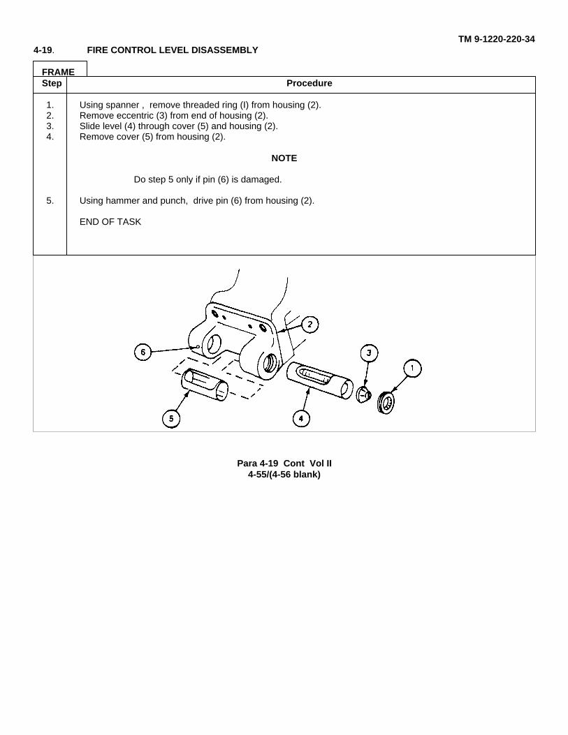
TM 9-1220-220-344-19. FIRE CONTROL LEVEL DISASSEMBLY
FRAMEStep Procedure
1. Using spanner , remove threaded ring (I) from housing (2).2. Remove eccentric (3) from end of housing (2).3. Slide level (4) through cover (5) and housing (2).4. Remove cover (5) from housing (2).
NOTE
Do step 5 only if pin (6) is damaged.
5. Using hammer and punch, drive pin (6) from housing (2).
END OF TASK
Para 4-19 Cont Vol II4-55/(4-56 blank)
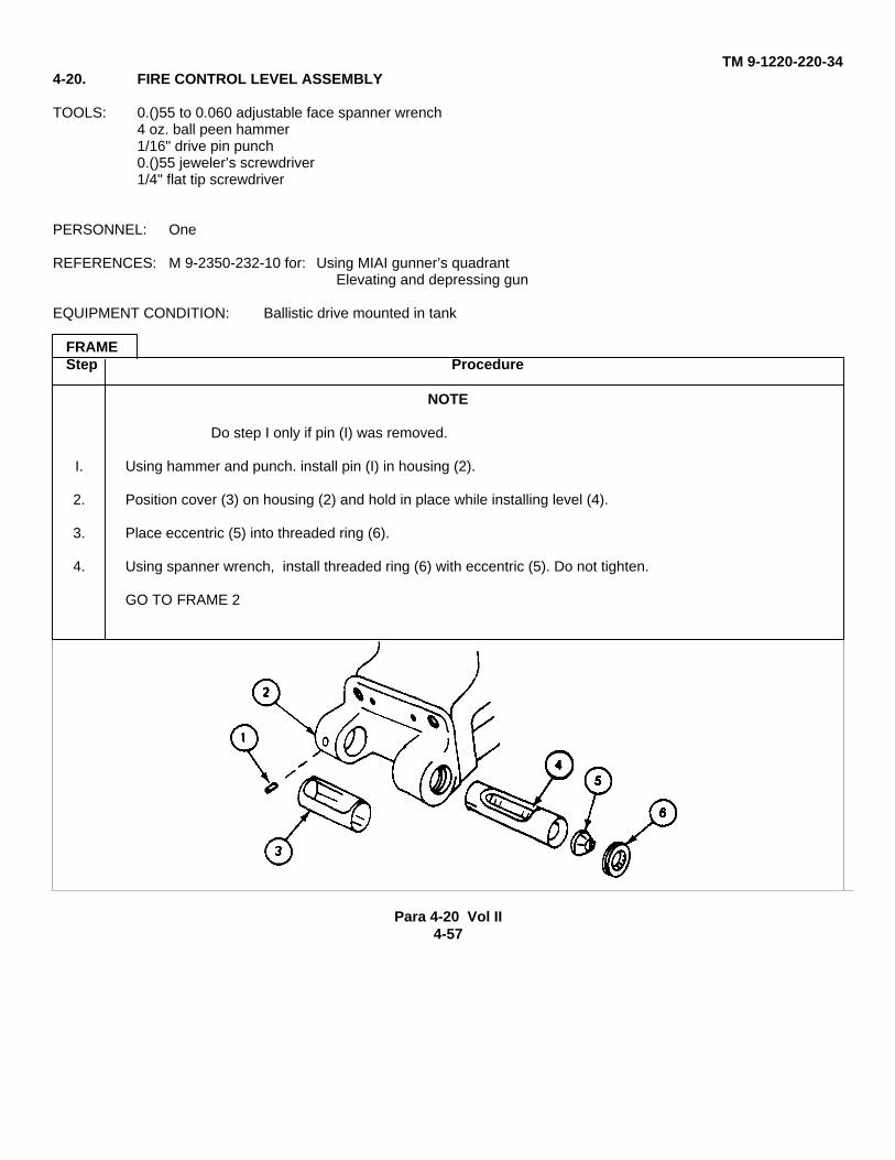
TM 9-1220-220-344-20. FIRE CONTROL LEVEL ASSEMBLY
TOOLS: 0.()55 to 0.060 adjustable face spanner wrench4 oz. ball peen hammer1/16" drive pin punch0.()55 jeweler’s screwdriver1/4" flat tip screwdriver
PERSONNEL: One
REFERENCES: M 9-2350-232-10 for: Using MIAI gunner’s quadrantElevating and depressing gun
EQUIPMENT CONDITION: Ballistic drive mounted in tank
FRAMEStep Procedure
NOTE
Do step I only if pin (I) was removed.
I. Using hammer and punch. install pin (I) in housing (2).
2. Position cover (3) on housing (2) and hold in place while installing level (4).
3. Place eccentric (5) into threaded ring (6).
4. Using spanner wrench, install threaded ring (6) with eccentric (5). Do not tighten.
GO TO FRAME 2
Para 4-20 Vol II4-57
TM 9-1220-220-34
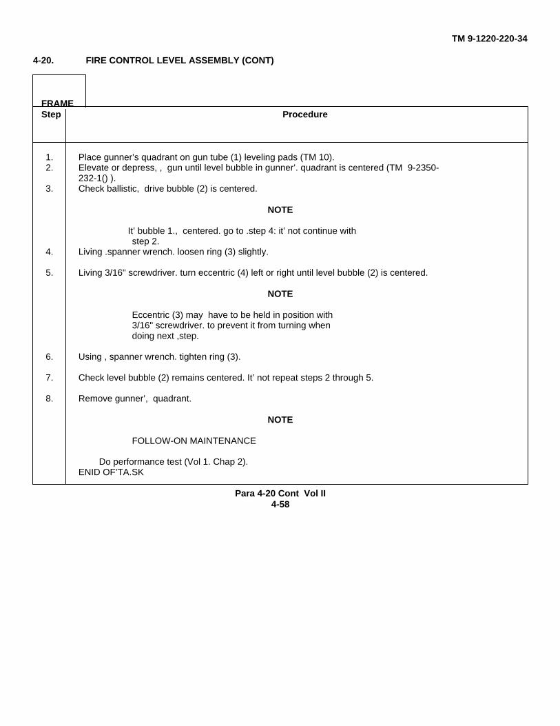
4-20. FIRE CONTROL LEVEL ASSEMBLY (CONT)
FRAMEStep Procedure
1. Place gunner’s quadrant on gun tube (1) leveling pads (TM 10).2. Elevate or depress, , gun until level bubble in gunner’. quadrant is centered (TM 9-2350-
232-1() ).3. Check ballistic, drive bubble (2) is centered.
NOTE
It’ bubble 1., centered. go to .step 4: it’ not continue withstep 2.
4. Living .spanner wrench. loosen ring (3) slightly.
5. Living 3/16" screwdriver. turn eccentric (4) left or right until level bubble (2) is centered.
NOTE
Eccentric (3) may have to be held in position with3/16" screwdriver. to prevent it from turning whendoing next ,step.
6. Using , spanner wrench. tighten ring (3).
7. Check level bubble (2) remains centered. It’ not repeat steps 2 through 5.
8. Remove gunner’, quadrant.
NOTE
FOLLOW-ON MAINTENANCE
Do performance test (Vol 1. Chap 2).ENID OF’TA.SK
Para 4-20 Cont Vol II4-58
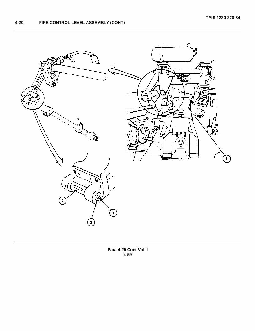
TM 9-1220-220-344-20. FIRE CONTROL LEVEL ASSEMBLY (CONT)
Para 4-20 Cont Vol II4-59

TM 9-1220-220-34Section 8. LIGHT ASSEMBLY
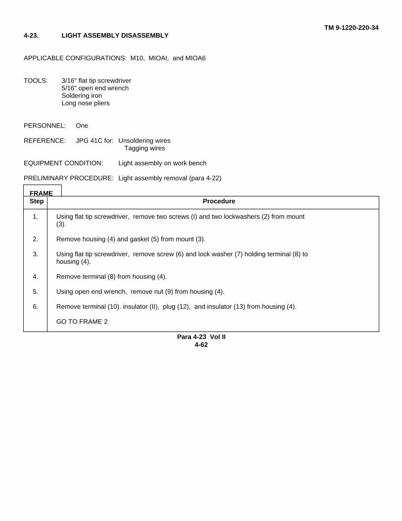
4- 21. LIGHT ASSEMBLY MAINTENANCE PROCEDURES INDEX
Task Reference (para)
Removal 4-22Disassembly 4-23Assembly 4-24Installation 4-25
Para 4-21 Vol II4-60
TM 9-1220-220-34
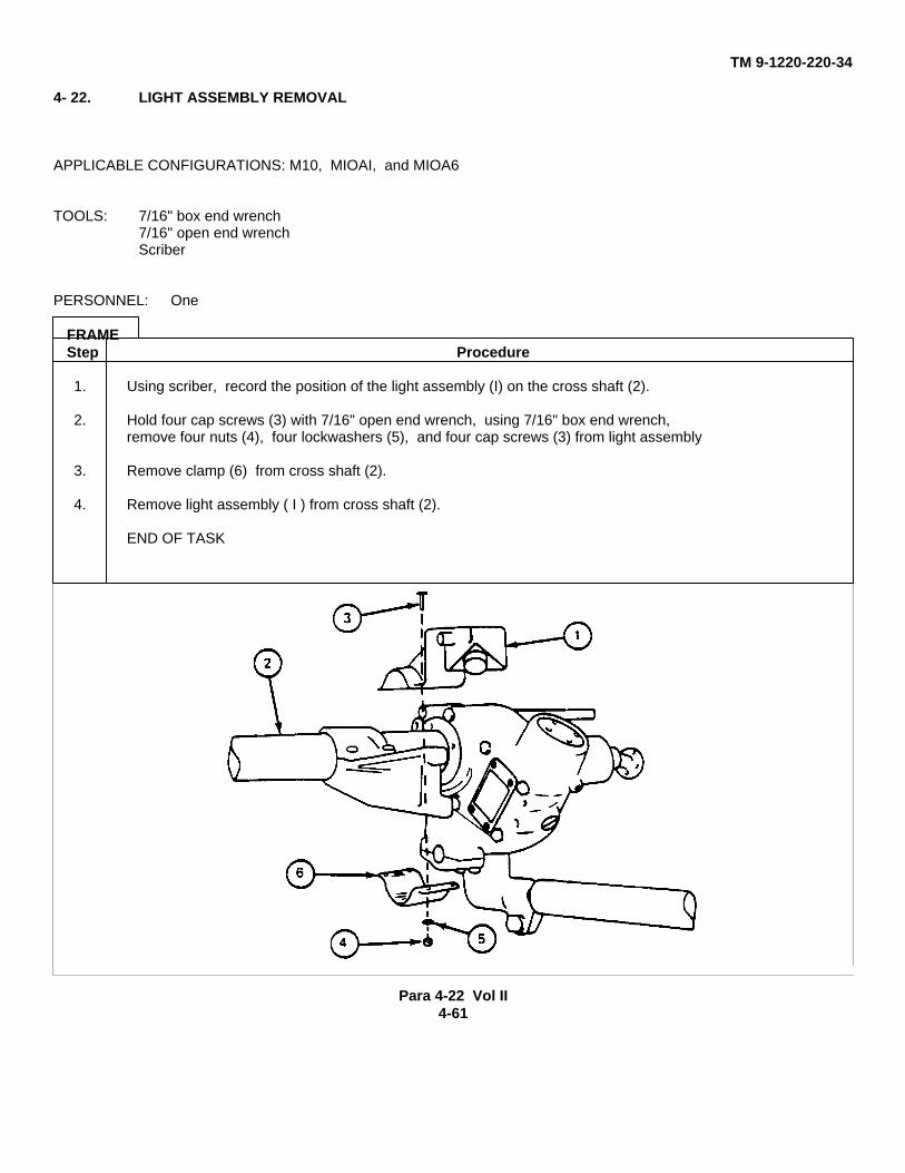
4- 22. LIGHT ASSEMBLY REMOVAL
APPLICABLE CONFIGURATIONS: M10, MIOAI, and MIOA6
TOOLS: 7/16" box end wrench7/16" open end wrenchScriber
PERSONNEL: One
FRAMEStep Procedure
1. Using scriber, record the position of the light assembly (I) on the cross shaft (2).
2. Hold four cap screws (3) with 7/16" open end wrench, using 7/16" box end wrench,remove four nuts (4), four lockwashers (5), and four cap screws (3) from light assembly
3. Remove clamp (6) from cross shaft (2).
4. Remove light assembly ( I ) from cross shaft (2).
END OF TASK
Para 4-22 Vol II4-61
TM 9-1220-220-344-23. LIGHT ASSEMBLY DISASSEMBLY
APPLICABLE CONFIGURATIONS: M10, MIOAI, and MIOA6
TOOLS: 3/16" flat tip screwdriver5/16" open end wrenchSoldering ironLong nose pliers
PERSONNEL: One
REFERENCE: JPG 41C for: Unsoldering wiresTagging wires
EQUIPMENT CONDITION: Light assembly on work bench
PRELIMINARY PROCEDURE: Light assembly removal (para 4-22)
FRAMEStep Procedure
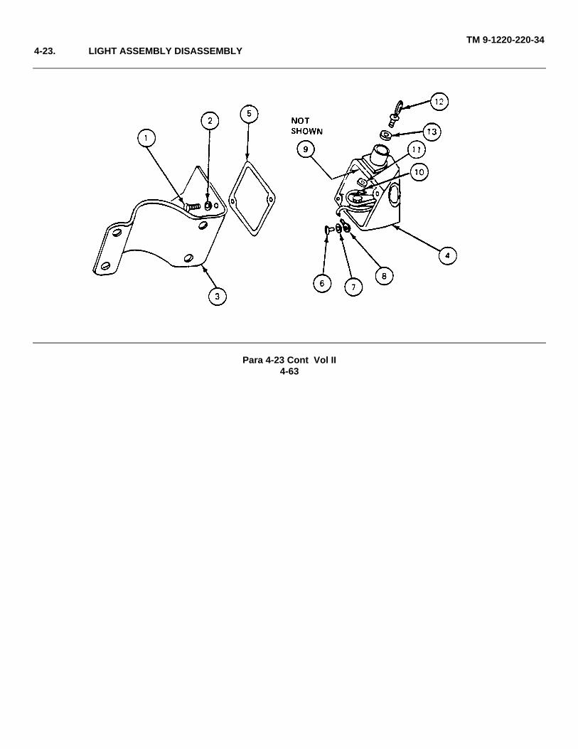
1. Using flat tip screwdriver, remove two screws (I) and two lockwashers (2) from mount(3).
2. Remove housing (4) and gasket (5) from mount (3).
3. Using flat tip screwdriver, remove screw (6) and lock washer (7) holding terminal (8) tohousing (4).
4. Remove terminal (8) from housing (4).
5. Using open end wrench, remove nut (9) from housing (4).
6. Remove terminal (10). insulator (II), plug (12), and insulator (13) from housing (4).
GO TO FRAME 2
Para 4-23 Vol II4-62
TM 9-1220-220-344-23. LIGHT ASSEMBLY DISASSEMBLY
Para 4-23 Cont Vol II4-63
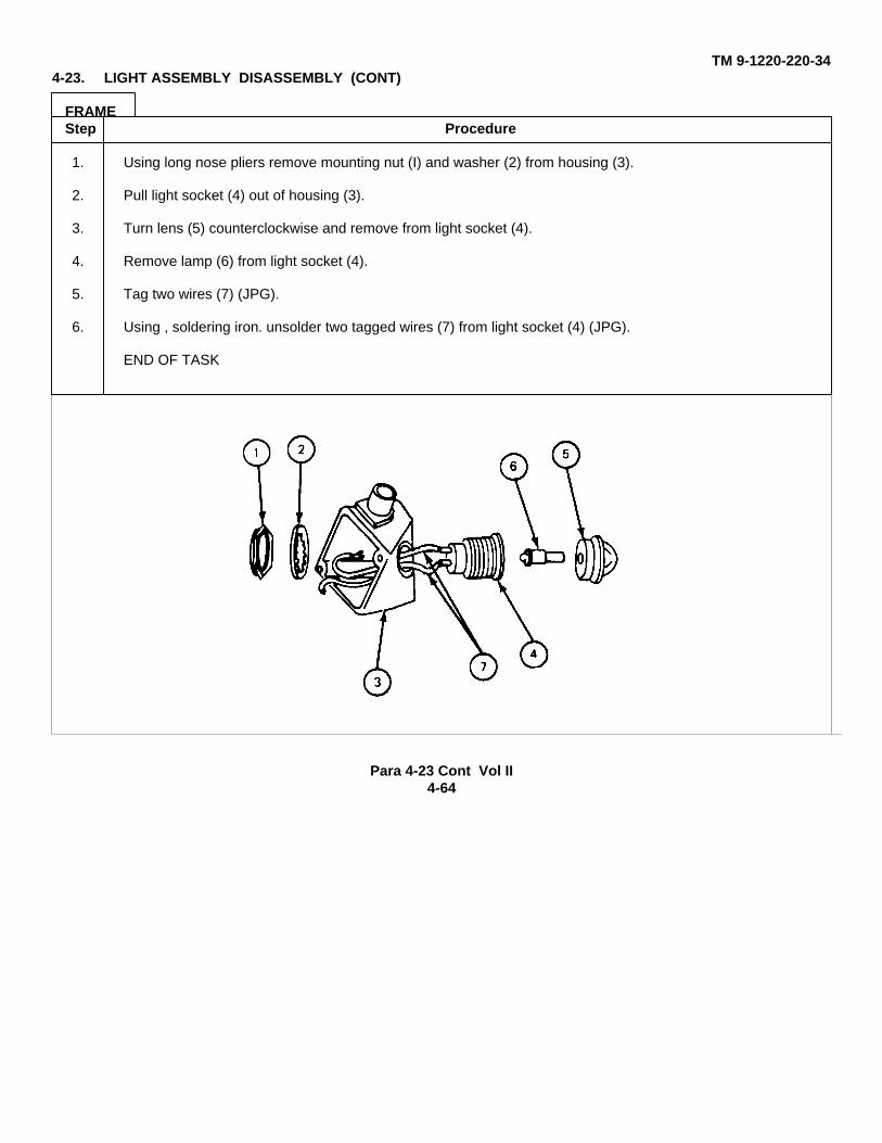
TM 9-1220-220-344-23. LIGHT ASSEMBLY DISASSEMBLY (CONT)
FRAMEStep Procedure
1. Using long nose pliers remove mounting nut (I) and washer (2) from housing (3).
2. Pull light socket (4) out of housing (3).
3. Turn lens (5) counterclockwise and remove from light socket (4).
4. Remove lamp (6) from light socket (4).
5. Tag two wires (7) (JPG).
6. Using , soldering iron. unsolder two tagged wires (7) from light socket (4) (JPG).
END OF TASK
Para 4-23 Cont Vol II4-64
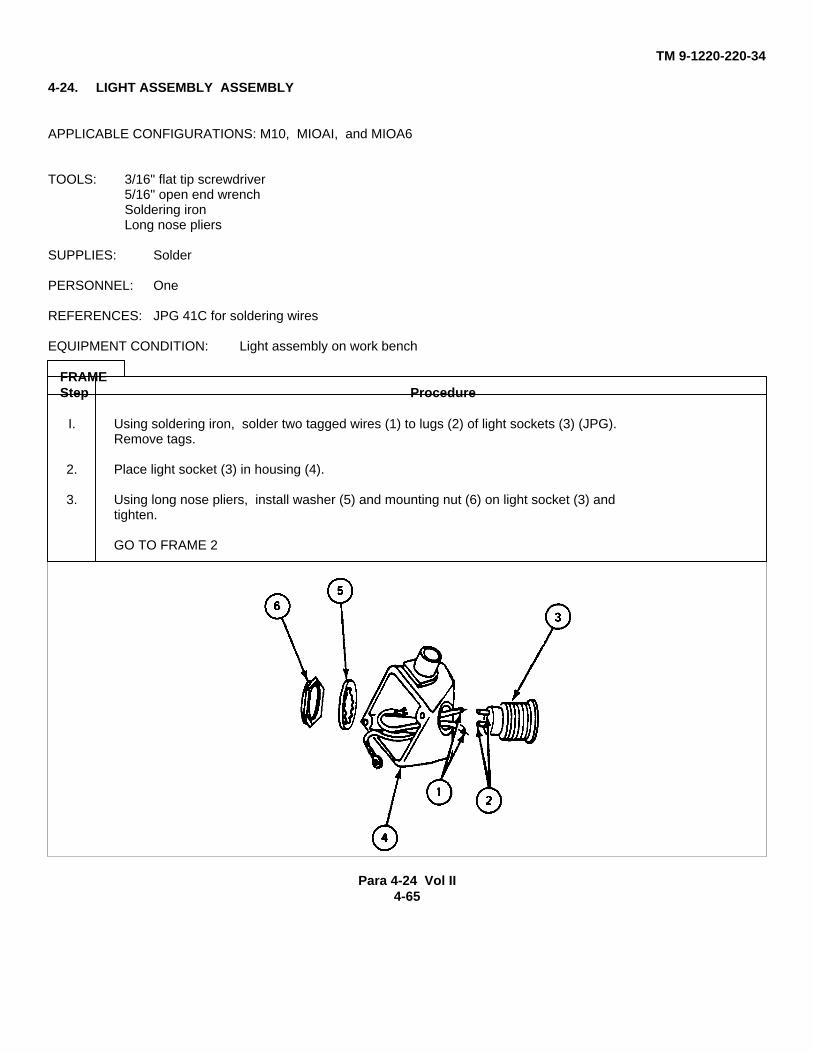
TM 9-1220-220-34
4-24. LIGHT ASSEMBLY ASSEMBLY
APPLICABLE CONFIGURATIONS: M10, MIOAI, and MIOA6
TOOLS: 3/16" flat tip screwdriver5/16" open end wrenchSoldering ironLong nose pliers
SUPPLIES: Solder
PERSONNEL: One
REFERENCES: JPG 41C for soldering wires
EQUIPMENT CONDITION: Light assembly on work bench
FRAMEStep Procedure
I. Using soldering iron, solder two tagged wires (1) to lugs (2) of light sockets (3) (JPG).Remove tags.
2. Place light socket (3) in housing (4).
3. Using long nose pliers, install washer (5) and mounting nut (6) on light socket (3) andtighten.
GO TO FRAME 2
Para 4-24 Vol II4-65
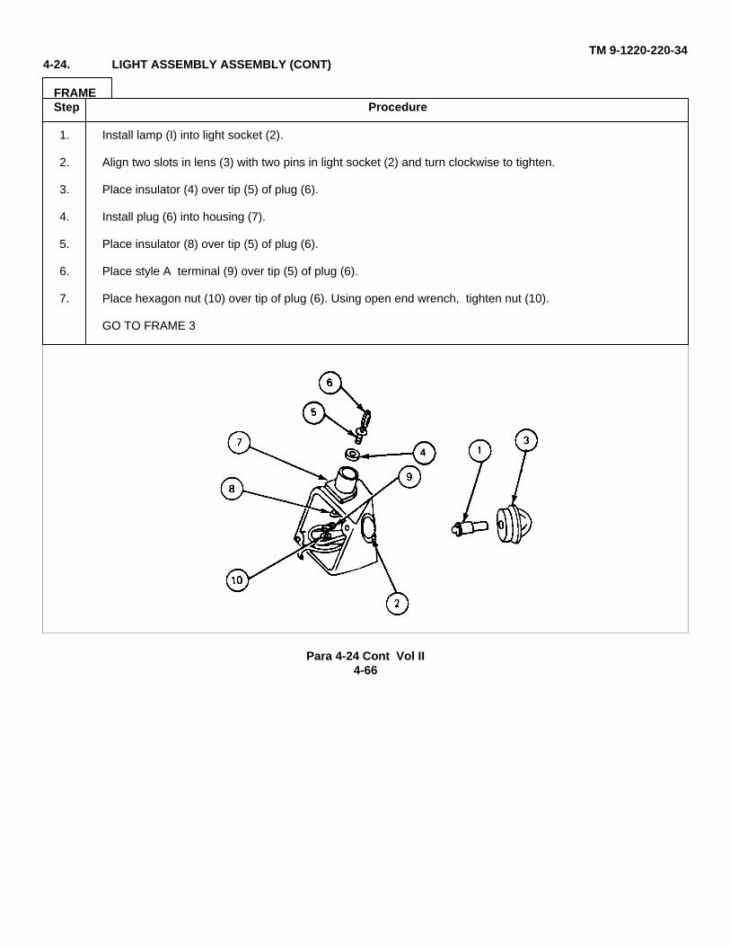
TM 9-1220-220-344-24. LIGHT ASSEMBLY ASSEMBLY (CONT)
FRAMEStep Procedure
1. Install lamp (I) into light socket (2).
2. Align two slots in lens (3) with two pins in light socket (2) and turn clockwise to tighten.
3. Place insulator (4) over tip (5) of plug (6).
4. Install plug (6) into housing (7).
5. Place insulator (8) over tip (5) of plug (6).
6. Place style A terminal (9) over tip (5) of plug (6).
7. Place hexagon nut (10) over tip of plug (6). Using open end wrench, tighten nut (10).
GO TO FRAME 3
Para 4-24 Cont Vol II4-66
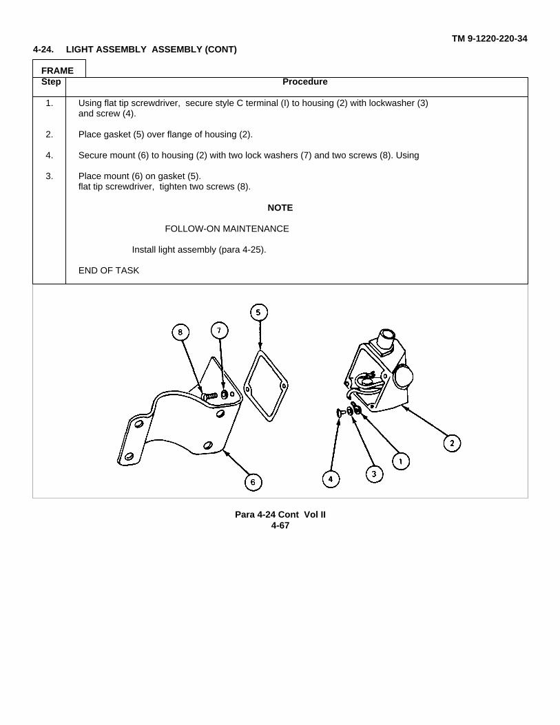
TM 9-1220-220-344-24. LIGHT ASSEMBLY ASSEMBLY (CONT)
FRAMEStep Procedure
1. Using flat tip screwdriver, secure style C terminal (I) to housing (2) with lockwasher (3)and screw (4).
2. Place gasket (5) over flange of housing (2).
4. Secure mount (6) to housing (2) with two lock washers (7) and two screws (8). Using
3. Place mount (6) on gasket (5).flat tip screwdriver, tighten two screws (8).
NOTE
FOLLOW-ON MAINTENANCE
Install light assembly (para 4-25).
END OF TASK
Para 4-24 Cont Vol II4-67
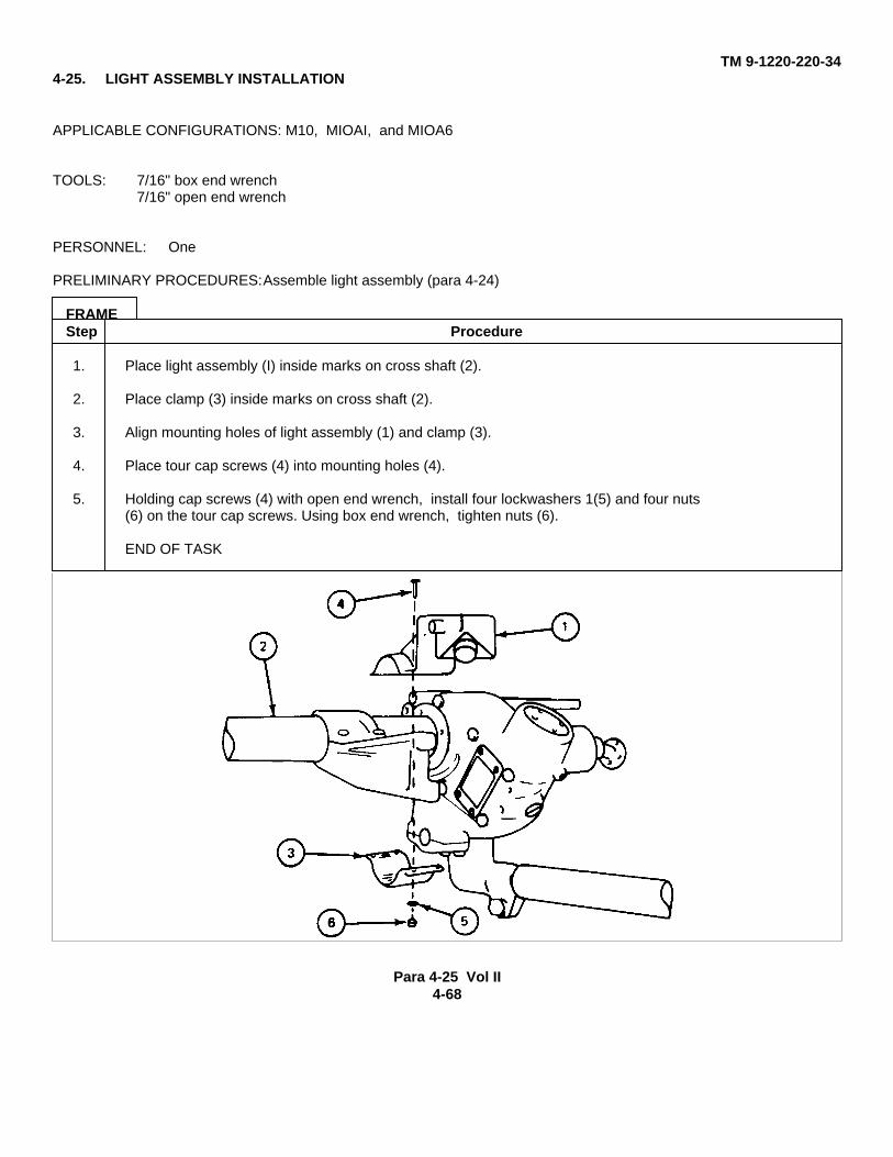
TM 9-1220-220-344-25. LIGHT ASSEMBLY INSTALLATION
APPLICABLE CONFIGURATIONS: M10, MIOAI, and MIOA6
TOOLS: 7/16" box end wrench7/16" open end wrench
PERSONNEL: One
PRELIMINARY PROCEDURES:Assemble light assembly (para 4-24)
FRAMEStep Procedure
1. Place light assembly (I) inside marks on cross shaft (2).
2. Place clamp (3) inside marks on cross shaft (2).
3. Align mounting holes of light assembly (1) and clamp (3).
4. Place tour cap screws (4) into mounting holes (4).
5. Holding cap screws (4) with open end wrench, install four lockwashers 1(5) and four nuts(6) on the tour cap screws. Using box end wrench, tighten nuts (6).
END OF TASK
Para 4-25 Vol II4-68

TM 9-1220-220-34
Section 9. RANGEFINDER LINK CONNECTOR ASSEMBLY
4-26. RANGEFINDER LINK CONNECTOR ASSEMBLY MAINTENANCE PROCEDURES INDEX
Task Reference (para)Removal Para 4-4, frames 2 and 3Disassembly 4-27Assembly 4-28Installation Para 4-5, frames 10. 11, and 12
Para 4-26 Cont Vol II
4-69
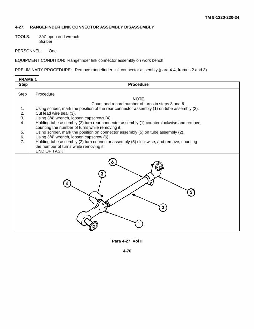
TM 9-1220-220-34
4-27. RANGEFINDER LINK CONNECTOR ASSEMBLY DISASSEMBLY
TOOLS: 3/4” open end wrenchScriber
PERSONNEL: One
EQUIPMENT CONDITION: Rangefinder link connector assembly on work bench
PRELIMINARY PROCEDURE: Remove rangefinder link connector assembly (para 4-4, frames 2 and 3)
FRAME 1Step Procedure
Step ProcedureNOTE
Count and record number of turns in steps 3 and 6.1. Using scriber, mark the position of the rear connector assembly (1) on tube assembly (2).2. Cut lead wire seal (3).3. Using 3/4" wrench, loosen capscrews (4).4. Holding tube assembly (2) turn rear connector assembly (1) counterclockwise and remove,
counting the number of turns while removing it.5. Using scriber, mark the position on connector assembly (5) on tube assembly (2).6. Using 3/4" wrench, loosen capscrew (6).7. Holding tube assembly (2) turn connector assembly (5) clockwise, and remove, counting
the number of turns while removing it.END OF TASK
Para 4-27 Vol II
4-70
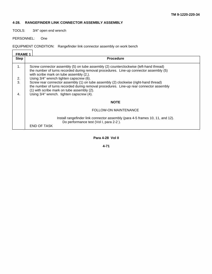
TM 9-1220-220-34
4-28. RANGEFINDER LINK CONNECTOR ASSEMBLY ASSEMBLY
TOOLS: 3/4" open end wrench
PERSONNEL: One
EQUIPMENT CONDITION: Rangefinder link connector assembly on work bench
FRAME 1Step Procedure
1. Screw connector assembly (5) on tube assembly (2) counterclockwise (left-hand thread)the number of turns recorded during removal procedures. Line-up connector assembly (5)with scribe mark on tube assembly (2,).
2. Using 3/4" wrench tighten capscrew (6).3. Screw rear connector assembly (1) on tube assembly (2) clockwise (right-hand thread)
the number of turns recorded during removal procedures. Line-up rear connector assembly(1) with scribe mark on tube assembly (2).
4. Using 3/4" wrench. tighten capscrew (4).
NOTE
FOLLOW-ON MAINTENANCE
Install rangefinder link connector assembly (para 4-5 frames 10, 11, and 12).Do performance test (Vol I, para 2-2 ).
END OF TASK
Para 4-28 Vol II
4-71
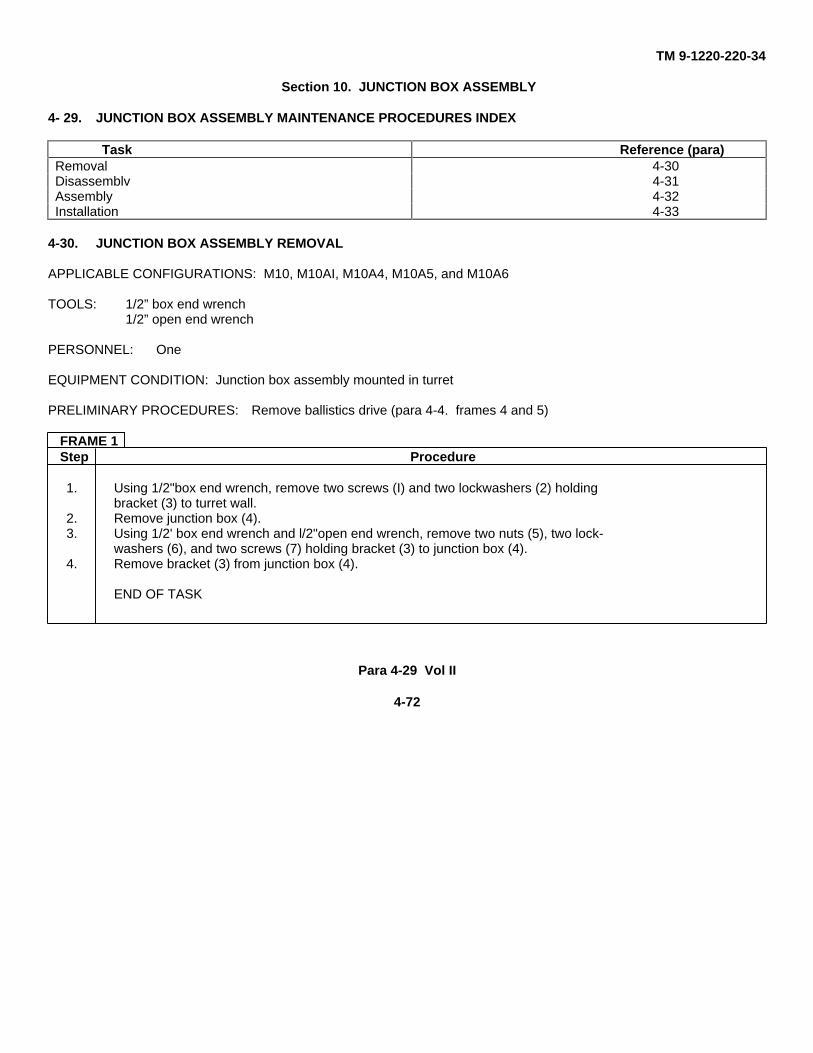
TM 9-1220-220-34
Section 10. JUNCTION BOX ASSEMBLY
4- 29. JUNCTION BOX ASSEMBLY MAINTENANCE PROCEDURES INDEX
Task Reference (para)Removal 4-30Disassemblv 4-31Assembly 4-32Installation 4-33
4-30. JUNCTION BOX ASSEMBLY REMOVAL
APPLICABLE CONFIGURATIONS: M10, M10AI, M10A4, M10A5, and M10A6
TOOLS: 1/2” box end wrench1/2” open end wrench
PERSONNEL: One
EQUIPMENT CONDITION: Junction box assembly mounted in turret
PRELIMINARY PROCEDURES: Remove ballistics drive (para 4-4. frames 4 and 5)
FRAME 1Step Procedure
1. Using 1/2"box end wrench, remove two screws (I) and two lockwashers (2) holdingbracket (3) to turret wall.
2. Remove junction box (4).3. Using 1/2' box end wrench and l/2"open end wrench, remove two nuts (5), two lock-
washers (6), and two screws (7) holding bracket (3) to junction box (4).4. Remove bracket (3) from junction box (4).
END OF TASK
Para 4-29 Vol II
4-72
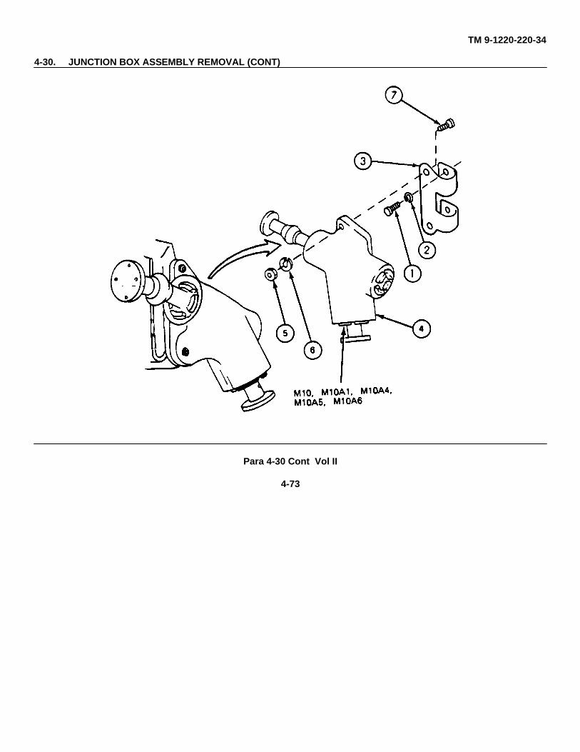
TM 9-1220-220-34
4-30. JUNCTION BOX ASSEMBLY REMOVAL (CONT)
Para 4-30 Cont Vol II
4-73
TM 9-1220-220-34
4-31. JUNCTION BOX ASSEMBLY DISASSEMBLY
APPLICABLE CONFIGURATION: M10, M10A1, M10A5, and M10A6
TOOLS: 4 oz. hall peen hammer1/8” and 3/8” punchSpanner wrench (App C. para C-3)5/64 socket head ,crew key (Allen wrench or equivalent)Brass, drift pinVise
PERSONNEL: One
EQUIPMENT CONDITION: Junction box assembly on work bench
FRAME 1Step Procedure
1. Locate one pin (1) securing universal assembly (2) to junction box assembly (3).2. Using hammer and 1/8" punch, drive one pin (1) out of universal assembly (2).3. Remove universal assembly (2) from junction box assembly (3).
GO TO FRAME 2
Para 4-31 Vol II
4-74
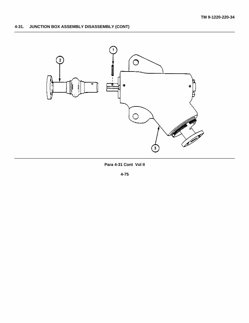
TM 9-1220-220-34
4-31. JUNCTION BOX ASSEMBLY DISASSEMBLY (CONT)
Para 4-31 Cont Vol II
4-75
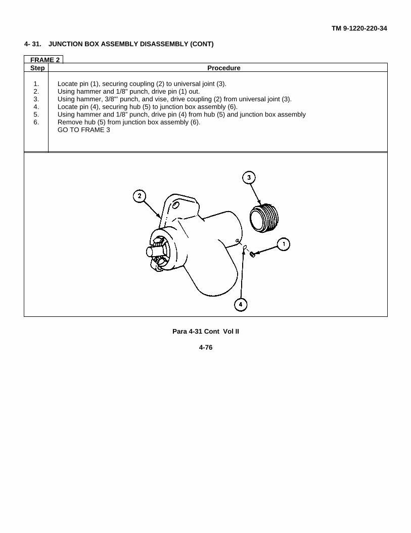
TM 9-1220-220-34
4- 31. JUNCTION BOX ASSEMBLY DISASSEMBLY (CONT)
FRAME 2Step Procedure
1. Locate pin (1), securing coupling (2) to universal joint (3).2. Using hammer and 1/8" punch, drive pin (1) out.3. Using hammer, 3/8"’ punch, and vise, drive coupling (2) from universal joint (3).4. Locate pin (4), securing hub (5) to junction box assembly (6).5. Using hammer and 1/8” punch, drive pin (4) from hub (5) and junction box assembly6. Remove hub (5) from junction box assembly (6).
GO TO FRAME 3
Para 4-31 Cont Vol II
4-76
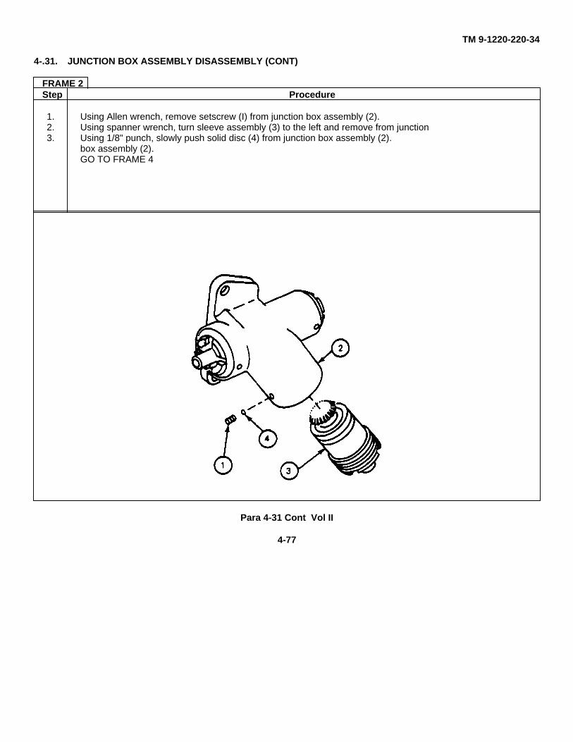
TM 9-1220-220-34
4-.31. JUNCTION BOX ASSEMBLY DISASSEMBLY (CONT)
FRAME 2Step Procedure
1. Using Allen wrench, remove setscrew (I) from junction box assembly (2).2. Using spanner wrench, turn sleeve assembly (3) to the left and remove from junction3. Using 1/8" punch, slowly push solid disc (4) from junction box assembly (2).
box assembly (2).GO TO FRAME 4
Para 4-31 Cont Vol II
4-77
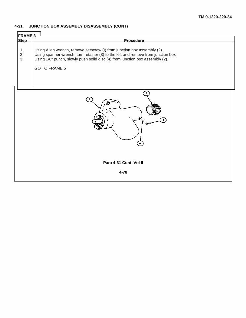
TM 9-1220-220-34
4-31. JUNCTION BOX ASSEMBLY DISASSEMBLY (CONT)
FRAME 3Step Procedure
1. Using Allen wrench, remove setscrew (I) from junction box assembly (2).2. Using spanner wrench, turn retainer (3) to the left and remove from junction box3. Using 1/8" punch, slowly push solid disc (4) from junction box assembly (2).
GO TO FRAME 5
Para 4-31 Cont Vol II
4-78
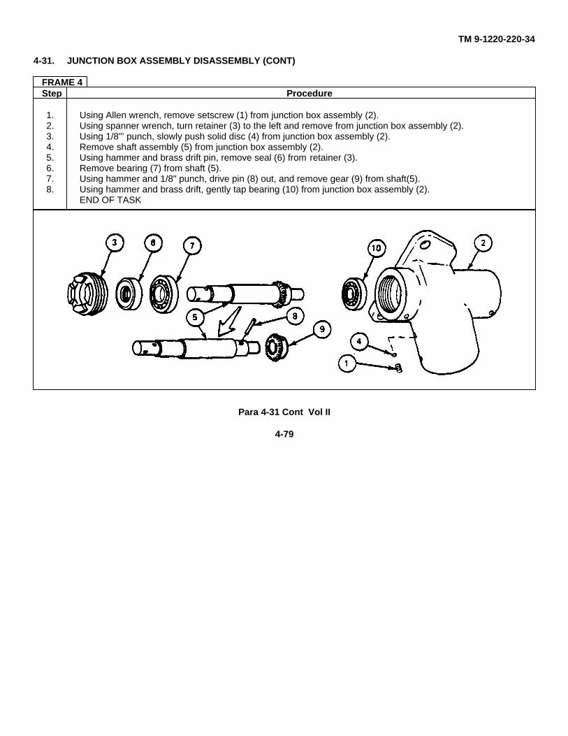
TM 9-1220-220-34
4-31. JUNCTION BOX ASSEMBLY DISASSEMBLY (CONT)
FRAME 4Step Procedure
1. Using Allen wrench, remove setscrew (1) from junction box assembly (2).2. Using spanner wrench, turn retainer (3) to the left and remove from junction box assembly (2).3. Using 1/8"’ punch, slowly push solid disc (4) from junction box assembly (2).4. Remove shaft assembly (5) from junction box assembly (2).5. Using hammer and brass drift pin, remove seal (6) from retainer (3).6. Remove bearing (7) from shaft (5).7. Using hammer and 1/8" punch, drive pin (8) out, and remove gear (9) from shaft(5).8. Using hammer and brass drift, gently tap bearing (10) from junction box assembly (2).
END OF TASK
Para 4-31 Cont Vol II
4-79
TM 9-1220-220-34
4-32. JUNCTION BOX ASSEMBLY ASSEMBLY
APPLICABLE CONFIGURATIONS: M10, M10A1, M10A4, M10A5, and M10A6
TOOLS: 3/16" flat tip screwdriver4 oz ball peen hammerBrass drift pin1/8" punchSpanner wrench (App C, para C-3)5/64" socket head screw key (Allen wrench or equivalent)Open end wrench
SUPPLIES: (Item 2, App A)
PERSONNEL: One
REFERENCES: JPG 41C for lubricating
EQUIPMENT CONDITION: Junction box assembly on work bench
Para 4-32 Vol II
4-80
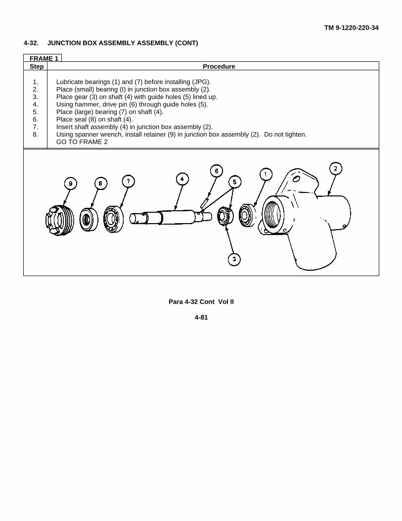
TM 9-1220-220-34
4-32. JUNCTION BOX ASSEMBLY ASSEMBLY (CONT)
FRAME 1Step Procedure
1. Lubricate bearings (1) and (7) before installing (JPG).2. Place (small) bearing (I) in junction box assembly (2).3. Place gear (3) on shaft (4) with guide holes (5) lined up.4. Using hammer, drive pin (6) through guide holes (5).5. Place (large) bearing (7) on shaft (4).6. Place seal (8) on shaft (4).7. Insert shaft assembly (4) in junction box assembly (2).8. Using spanner wrench, install retainer (9) in junction box assembly (2). Do not tighten.
GO TO FRAME 2
Para 4-32 Cont Vol II
4-81
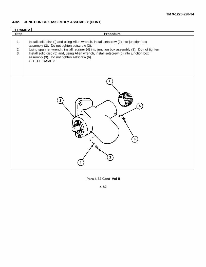
TM 9-1220-220-34
4-32. JUNCTION BOX ASSEMBLY ASSEMBLY (CONT)
FRAME 2Step Procedure
1. Install solid disk (I) and using Allen wrench, install setscrew (2) into junction boxassembly (3). Do not tighten setscrew (2).
2. Using spanner wrench, install retainer (4) into junction box assembly (3). Do not tighten3. Install solid disc (5) and, using Allen wrench, install setscrew (6) into junction box
assembly (3). Do not tighten setscrew (6).GO TO FRAME 3
Para 4-32 Cont Vol II
4-82
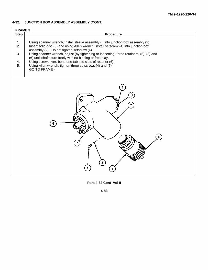
TM 9-1220-220-34
4-32. JUNCTION BOX ASSEMBLY ASSEMBLY (CONT)
FRAME 3Step Procedure
1. Using spanner wrench, install sleeve assembly (I) into junction box assembly (2).2. Insert solid disc (3) and using Allen wrench, install setscrew (4) into junction box
assembly (2). Do not tighten setscrew (4).3. Using spanner wrench, adjust (by tightening or loosening) three retainers, (5), (8) and
(6) until shafts turn freely with no binding or free play.4. Using screwdriver, bend one tab into slots of retainer (6).5. Using Allen wrench, tighten three setscrews (4) and (7).
GO TO FRAME 4
Para 4-32 Cont Vol II
4-83
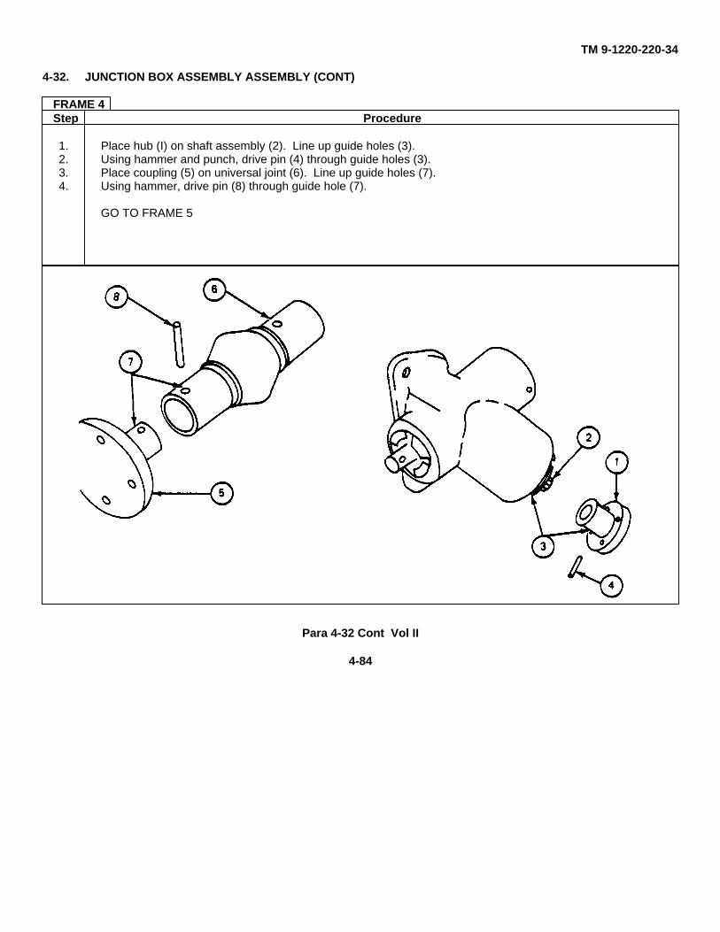
TM 9-1220-220-34
4-32. JUNCTION BOX ASSEMBLY ASSEMBLY (CONT)
FRAME 4Step Procedure
1. Place hub (I) on shaft assembly (2). Line up guide holes (3).2. Using hammer and punch, drive pin (4) through guide holes (3).3. Place coupling (5) on universal joint (6). Line up guide holes (7).4. Using hammer, drive pin (8) through guide hole (7).
GO TO FRAME 5
Para 4-32 Cont Vol II
4-84
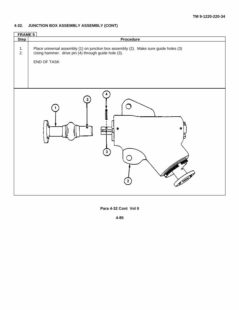
TM 9-1220-220-34
4-32. JUNCTION BOX ASSEMBLY ASSEMBLY (CONT)
FRAME 5Step Procedure
1. Place universal assembly (1) on junction box assembly (2). Make sure guide holes (3)2. Using hammer. drive pin (4) through guide hole (3).
END OF TASK
Para 4-32 Cont Vol II
4-85
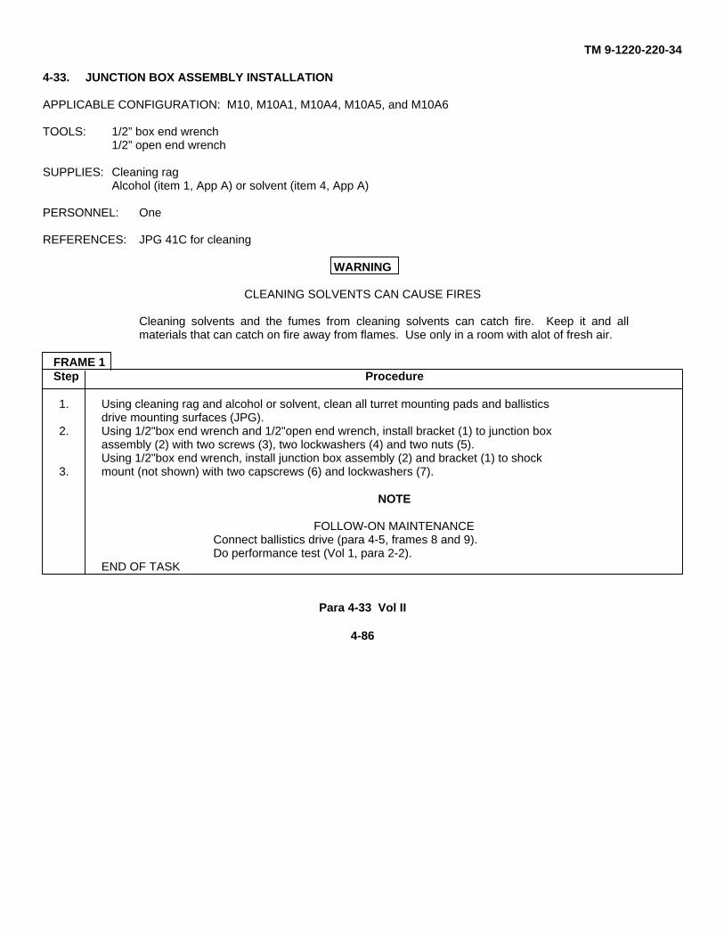
TM 9-1220-220-34
4-33. JUNCTION BOX ASSEMBLY INSTALLATION
APPLICABLE CONFIGURATION: M10, M10A1, M10A4, M10A5, and M10A6
TOOLS: 1/2” box end wrench1/2” open end wrench
SUPPLIES: Cleaning ragAlcohol (item 1, App A) or solvent (item 4, App A)
PERSONNEL: One
REFERENCES: JPG 41C for cleaning
WARNING
CLEANING SOLVENTS CAN CAUSE FIRES
Cleaning solvents and the fumes from cleaning solvents can catch fire. Keep it and allmaterials that can catch on fire away from flames. Use only in a room with alot of fresh air.
FRAME 1Step Procedure
1. Using cleaning rag and alcohol or solvent, clean all turret mounting pads and ballisticsdrive mounting surfaces (JPG).
2. Using 1/2"box end wrench and 1/2"open end wrench, install bracket (1) to junction boxassembly (2) with two screws (3), two lockwashers (4) and two nuts (5).Using 1/2"box end wrench, install junction box assembly (2) and bracket (1) to shock
3. mount (not shown) with two capscrews (6) and lockwashers (7).
NOTE
FOLLOW-ON MAINTENANCEConnect ballistics drive (para 4-5, frames 8 and 9).Do performance test (Vol 1, para 2-2).
END OF TASK
Para 4-33 Vol II
4-86
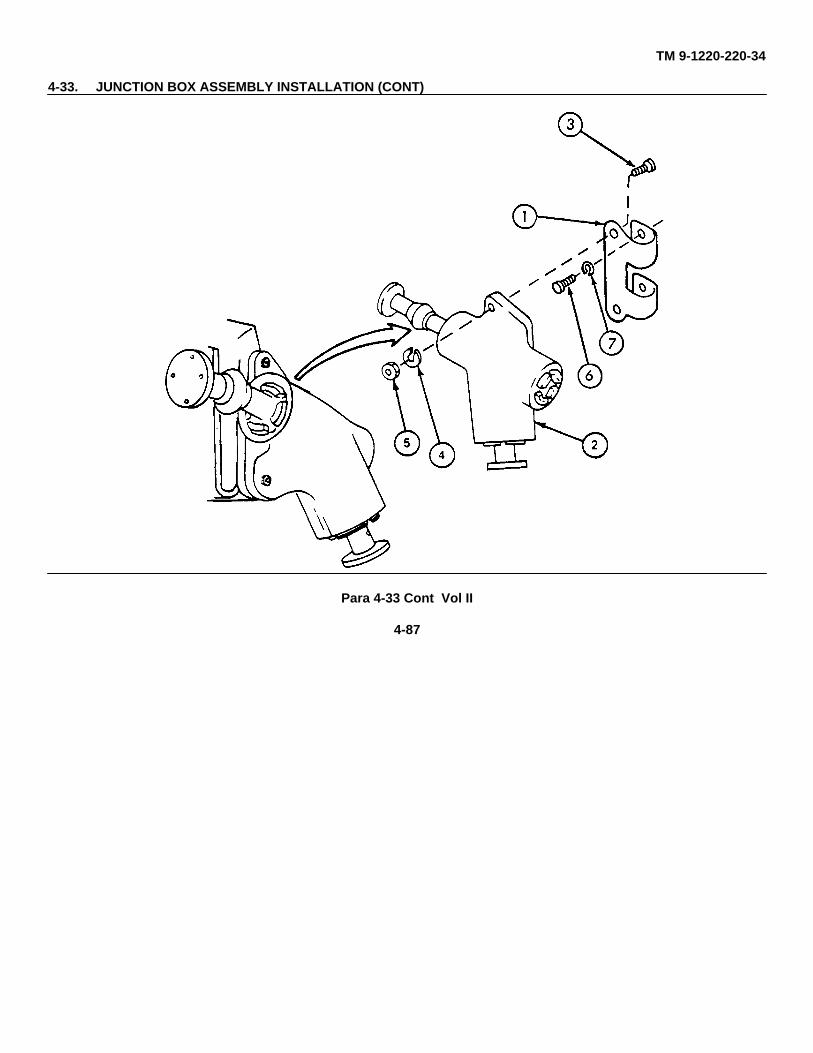
TM 9-1220-220-34
4-33. JUNCTION BOX ASSEMBLY INSTALLATION (CONT)
Para 4-33 Cont Vol II
4-87
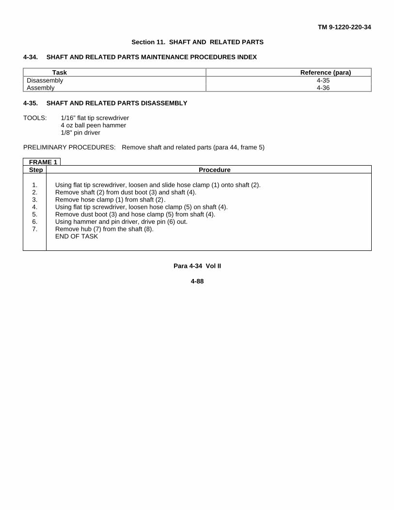
TM 9-1220-220-34
Section 11. SHAFT AND RELATED PARTS
4-34. SHAFT AND RELATED PARTS MAINTENANCE PROCEDURES INDEX
Task Reference (para)Disassembly 4-35Assembly 4-36
4-35. SHAFT AND RELATED PARTS DISASSEMBLY
TOOLS: 1/16” flat tip screwdriver4 oz ball peen hammer1/8" pin driver
PRELIMINARY PROCEDURES: Remove shaft and related parts (para 44, frame 5)
FRAME 1Step Procedure
1. Using flat tip screwdriver, loosen and slide hose clamp (1) onto shaft (2).2. Remove shaft (2) from dust boot (3) and shaft (4).3. Remove hose clamp (1) from shaft (2).4. Using flat tip screwdriver, loosen hose clamp (5) on shaft (4).5. Remove dust boot (3) and hose clamp (5) from shaft (4).6. Using hammer and pin driver, drive pin (6) out.7. Remove hub (7) from the shaft (8).
END OF TASK
Para 4-34 Vol II
4-88
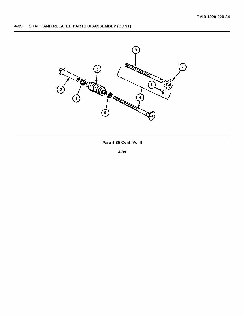
TM 9-1220-220-34
4-35. SHAFT AND RELATED PARTS DISASSEMBLY (CONT)
Para 4-35 Cont Vol II
4-89
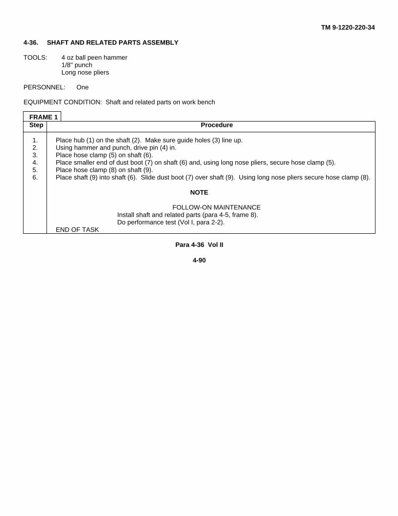
TM 9-1220-220-34
4-36. SHAFT AND RELATED PARTS ASSEMBLY
TOOLS: 4 oz ball peen hammer1/8" punchLong nose pliers
PERSONNEL: One
EQUIPMENT CONDITION: Shaft and related parts on work bench
FRAME 1Step Procedure
1. Place hub (1) on the shaft (2). Make sure guide holes (3) line up.2. Using hammer and punch, drive pin (4) in.3. Place hose clamp (5) on shaft (6).4. Place smaller end of dust boot (7) on shaft (6) and, using long nose pliers, secure hose clamp (5).5. Place hose clamp (8) on shaft (9).6. Place shaft (9) into shaft (6). Slide dust boot (7) over shaft (9). Using long nose pliers secure hose clamp (8).
NOTE
FOLLOW-ON MAINTENANCEInstall shaft and related parts (para 4-5, frame 8).Do performance test (Vol I, para 2-2).
END OF TASK
Para 4-36 Vol II
4-90
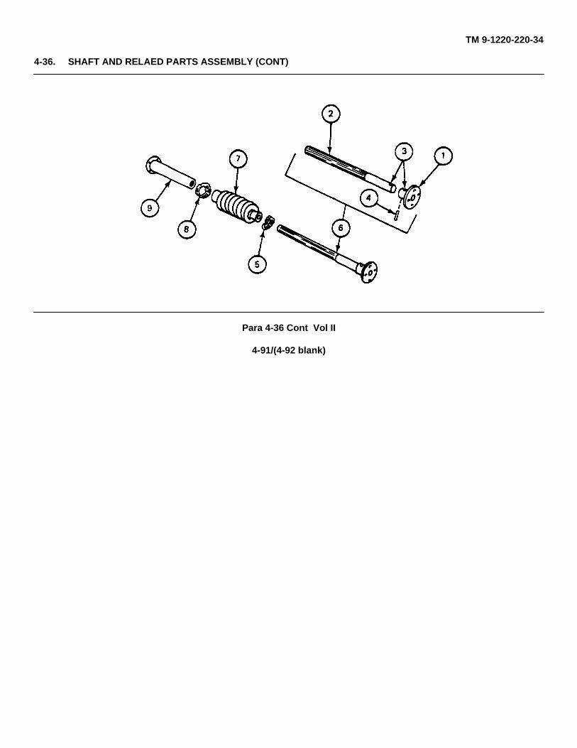
TM 9-1220-220-34
4-36. SHAFT AND RELAED PARTS ASSEMBLY (CONT)
Para 4-36 Cont Vol II
4-91/(4-92 blank)
TM 9-1220-220-34
CHAPTER 5
FINAL INSPECTION
5-1. SCOPE
This chapter gives final inspection and maintenance procedures to be done after repairing the M10 Series Ballistics Drive.
5-2. BALLISTICS DRIVE FINAL INSPECTION
PERSONNEL: One
REFERENCES: JPG 41C for cleaningTM 10 for: Operating gun
Boresighting(TM 9-2350-215-10 for M60A1,TM 9-2350-257-10 for M60A1 Rise, andTM 9-2350-260-10 for M60).
TM 20-2 for synchronizing and aligning (TM 9-2350-215-20-2 for M60A1, TM 9-2350-257-20-2 for M60A1Rise, and TM 9-2350-260-20-2 for M60)
EQUIPMENT CONDITION: Ballistics drive installed in vehicle
NOTE
If you find a fault, tell your supervisor. If you do not find a fault, send ballistics drive back intoservice.
Para 5-1 Vol II
5-1
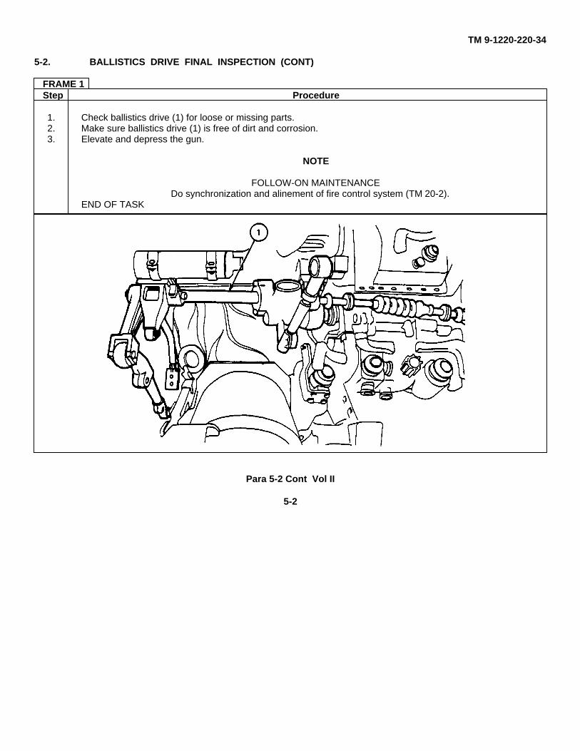
TM 9-1220-220-34
5-2. BALLISTICS DRIVE FINAL INSPECTION (CONT)
FRAME 1Step Procedure
1. Check ballistics drive (1) for loose or missing parts.2. Make sure ballistics drive (1) is free of dirt and corrosion.3. Elevate and depress the gun.
NOTE
FOLLOW-ON MAINTENANCEDo synchronization and alinement of fire control system (TM 20-2).
END OF TASK
Para 5-2 Cont Vol II
5-2

TM 9-1220-220-34
CHAPTER 6
PACKAGING
6-1. SCOPE
Instructions for packaging the M10 Series Ballistics Drive are found in MIL-P-116 and AR 700-15.
Para 6-1 Vol II
6-1/(6-2 blank)
TM 9-1220-220-34
APPENDIX A
EXPENDABLE SUPPLIES AND MATERIALS LIST
Section 1. Introduction
A-1. SCOPE
This appendix lists expendable supplies and materials you will need to repair the M10 Series Ballistics Drive. These itemsare authorized to you by CTA 50-970, Expendable Items (except Medical, Class V, Repair Parts, and Heraldic Items).
A-2. EXPLANATION OF COLUMNS
Column 1 - Item number. This number is assigned to the entry in the listing and is used in the manual to identify thematerial, for example, alcohol (item 1, App A).
Column 2 - Level. This column identifies the lowest levels of maintenance that requires the listed items.
F - Direct Support Maintenance
H - General Support Maintenance
Column 3 - National Stock Number. This is the national stock number assigned to the item. Use it to request orrequisition the item.
Column 4 - Description. This tells the Federal item name and, if needed, a description to identify the item. The last line foreach item indicates the part number followed by the Federal Supply Code for Manufacturer (FSCM) in parentheses, ifapplicable.
Column 5 - Unit of Measure (U/M). This column shows how the item is measured; for example, you may see theseabbreviations: ea (each), in (inches), or pr (pair). Order the smallest amount you need.
Para A-1 Vol II
A-1
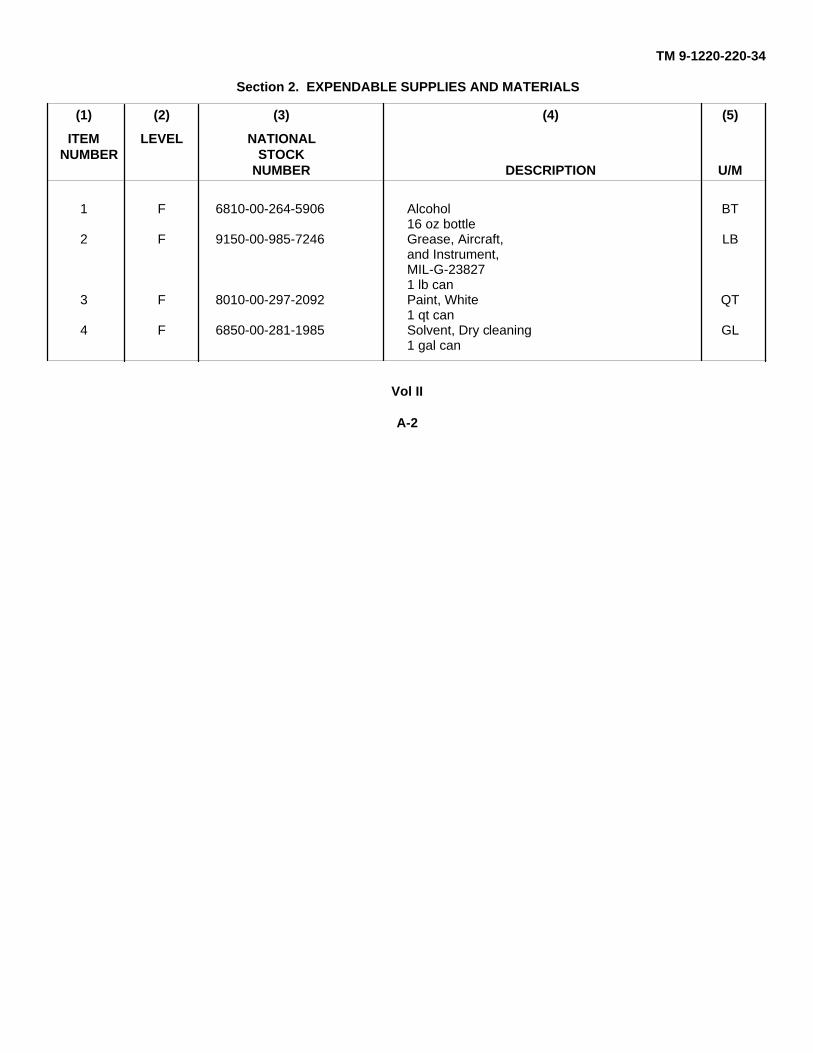
TM 9-1220-220-34
Section 2. EXPENDABLE SUPPLIES AND MATERIALS
(1) (2) (3) (4) (5)
ITEM LEVEL NATIONALNUMBER STOCK
NUMBER DESCRIPTION U/M
1 F 6810-00-264-5906 Alcohol BT16 oz bottle
2 F 9150-00-985-7246 Grease, Aircraft, LBand Instrument,MIL-G-238271 lb can
3 F 8010-00-297-2092 Paint, White QT1 qt can
4 F 6850-00-281-1985 Solvent, Dry cleaning GL1 gal can
Vol II
A-2

TM 9-1220-220-34
APPENDIX B
MAINTENANCE TASK INDEX
B-1. SCOPE
This appendix helps you find maintenance tasks for the M10 Series Ballistics Drive. The maintenance tasks arereferenced to help you find the procedure.
Para B-1 Vol II
B-1
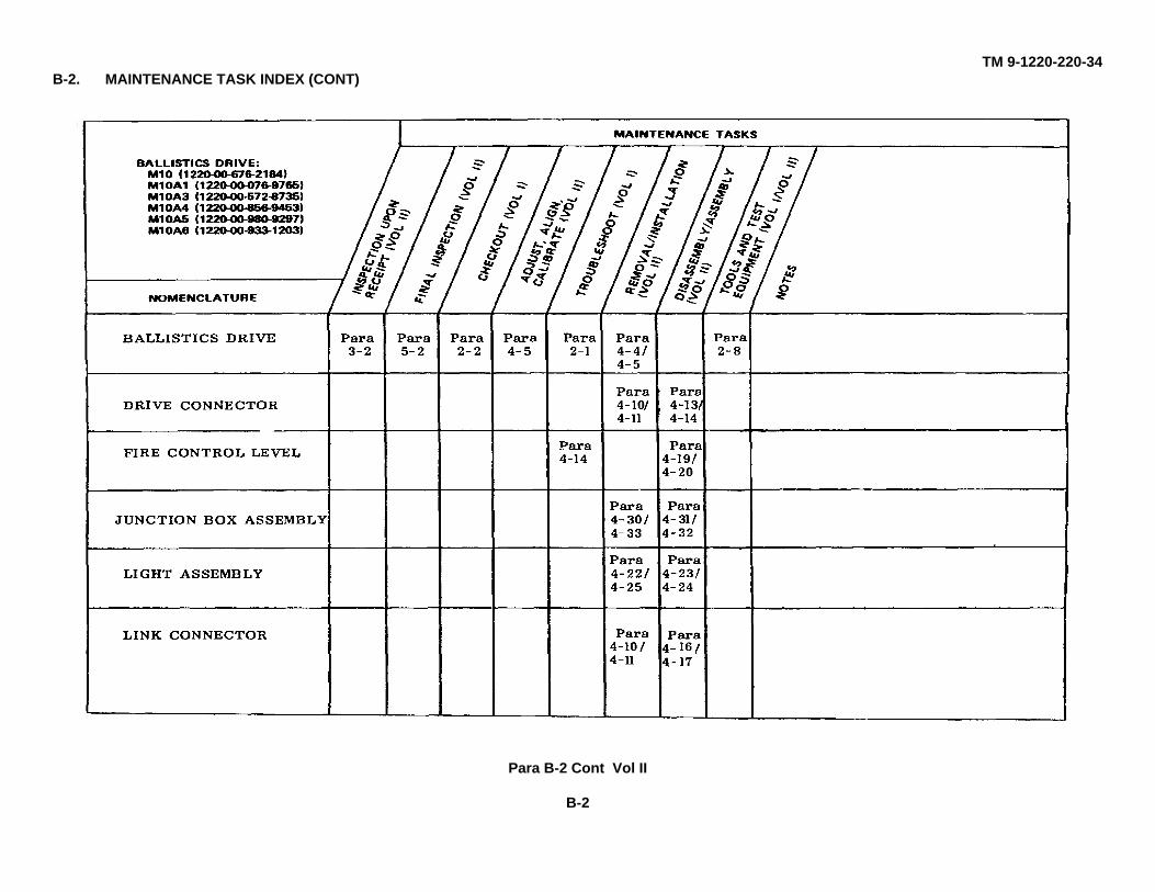
TM 9-1220-220-34B-2. MAINTENANCE TASK INDEX (CONT)
Para B-2 Cont Vol II
B-2
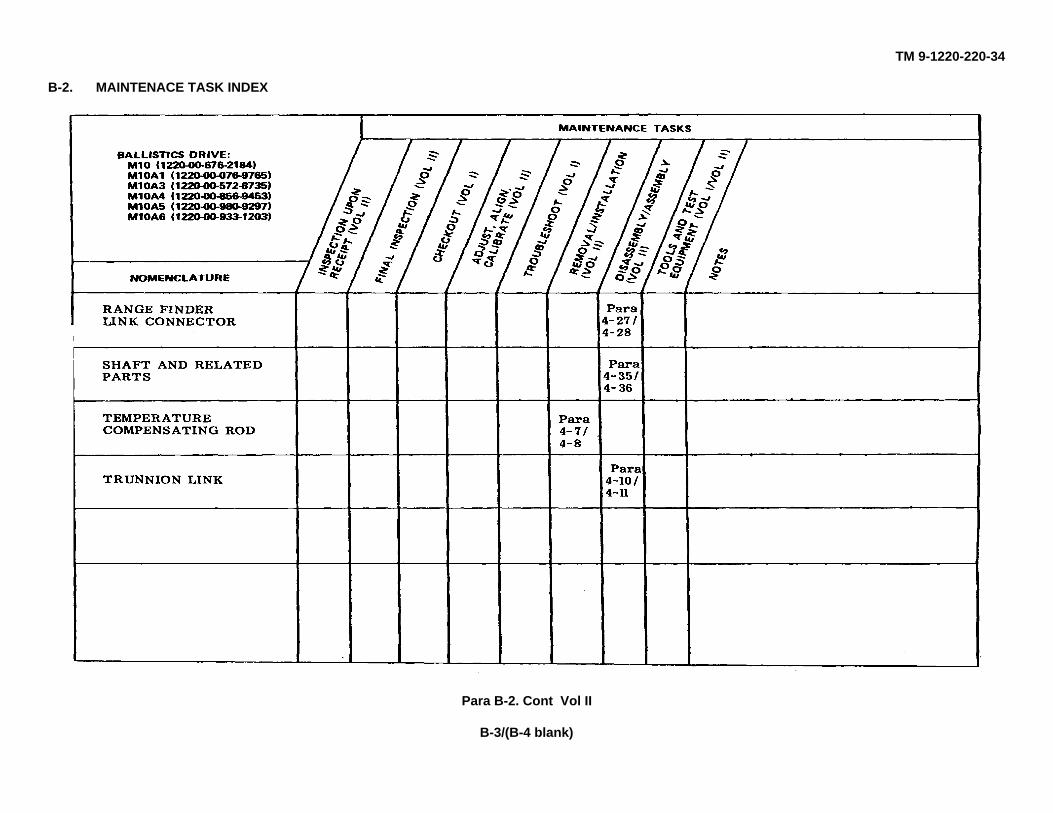
TM 9-1220-220-34
B-2. MAINTENACE TASK INDEX
Para B-2. Cont Vol II
B-3/(B-4 blank)
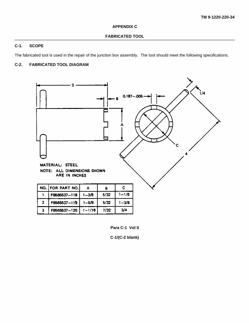
TM 9-1220-220-34
APPENDIX C
FABRICATED TOOL
C-1. SCOPE
The fabricated tool is used in the repair of the junction box assembly. The tool should meet the following specifications.
C-2. FABRICATED TOOL DIAGRAM
Para C-1 Vol II
C-1/(C-2 blank)
TM 9-1220-220-34
By Order of the Secretary of the Army:
JOHN A. WICKHAM, JR.General, United States Army
Chief of Staff
Official:
DONALD J. DELANDROBrigadier General, United States Army
The Adjutant General
DISTRIBUTION:
To be distributed in accordance with DA Form 12-37, Direct Support and General Support Maintenance requirements forTank, Combat, Full Tracked 105-MM, M60A1, Hull and M60A1 AOS and Tank, Combat, Full Tracked, 105-MM, M60A1RISE and M60A1 RISE PASSIVE.
*U.S. GOVERNMENT PRINTING OFFICE, 1985-554-049:10159
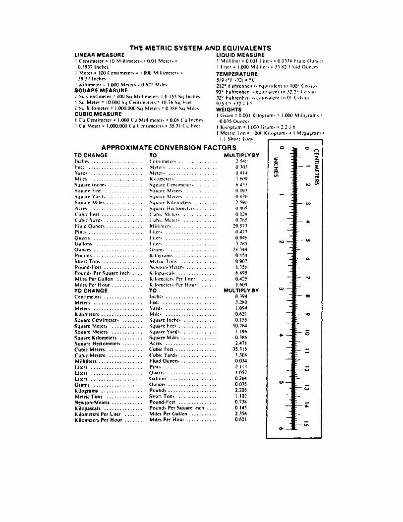

PIN : 026779-000

This fine document...
Was brought to you by me:
Liberated Manuals -- free army and government manuals
Why do I do it? I am tired of sleazy CD-ROM sellers, who take publicly available information, slap “watermarks” and other junk on it, and sell it. Those masters of search engine manipulation make sure that their sites that sell free information, come up first in search engines. They did not create it... They did not even scan it... Why should they get your money? Why are not letting you give those free manuals to your friends?
I am setting this document FREE. This document was made by the US Government and is NOT protected by Copyright. Feel free to share, republish, sell and so on.
I am not asking you for donations, fees or handouts. If you can, please provide a link to liberatedmanuals.com, so that free manuals come up first in search engines:
<A HREF=http://www.liberatedmanuals.com/>Free Military and Government Manuals</A>
– SincerelyIgor Chudovhttp://igor.chudov.com/