Embed Size (px)
Citation preview

TM 55-2350-272-14
TECHNICAL MANUAL
TRANSPORTABILITY GUIDANCE
CARRIER, CARGO, M973, 1-1/2-TON
(NSN 2350-01-132-9099)
SMALL UNIT SUPPORT VEHICLE (SUSV)
HEADQUARTERS, DEPARTMENT OF THE ARMY NOVEMBER 1985

TM 55-2350-272-14TECHNICAL MANUAL HEADQUARTERS
DEPARTMENT OF THE ARMYNo. 55-2350-272-14 Washington, DC 1 November 1985
TRANSPORTABILITY GUIDANCECARRIER, CARGO, M973, 1-1/2-TON
(NSN 2350-01-132-9099)SMALL UNIT-SUPPORT VEHICLE (SUSV)
Paragraph PageCHAPTER 1. INTRODUCTION
Purpose and Scope.............................................................................. 1-1 1-1Reporting of Recommendations and Comments .................................. 1-2 1-1Safety .................................................................................................. 1-4 1-1Definitions of Warnings, Cautions, and Notes ...................................... 1-4 1-1
2. TRANSPORTABILITY DATAScope .................................................................................................. 2-1 2-1Description........................................................................................... 2-2 2-1General................................................................................................ 2-3 2-1Reduced Configuration ........................................................................ 2-4 2-1Unusual Characteristics ....................................................................... 2-5 2-1Hazardous and Dangerous Characteristics........................................... 2-6 2-2General Transportability Characteristics............................................... 2-7 2-2
3. SAFETYGeneral................................................................................................ 3-1 3-1Specific Safety Requirements .............................................................. 3-2 3-1
CHAPTER 4. AIR TRANSPORTABILITY GUIDANCESECTION I. GENERAL
Scope .................................................................................................. 4-1 4-1Maximum Utilization of Aircraft ............................................................ 4-2 4-1Safety .................................................................................................. 4-3 4-1
II. TRANSPORT BY US ARMY HELICOPTERTransport by US Army Helicopter ........................................................ 4-4 4-1
III. TRANSPORT BY US AIR FORCE AIRCRAFTTransport by US Air Force Aircraft ...................................................... 4-5 4-2Tiedown Diagrams and Tables ............................................................ 4-6 4-2
CHAPTER 5. HIGHWAY TRANSPORTABILITY GUIDANCESECTION I. GENERAL
Scope .................................................................................................. 5-1 5-1Safety .................................................................................................. 5-2 5-1General................................................................................................ 5-3 5-1
II. TRANSPORT BY SEMITRAILERPreparation ......................................................................................... 5-4 5-1Transport on M127A1 Semitrailer......................................................... 5-5 5-1Transport on M172A1 Semitrailer......................................................... 5-6 5-6
CHAPTER 6. MARINE AND TERMINAL TRANSPORTABILITY GUIDANCESECTION I. GENERAL
Scope ................................................................................................. 6-1 6-1Safety .................................................................................................. 6-2 6-1Marine Shipment.................................................................................. 6-3 6-1
II. LOADING AND SECURINGGeneral Rules...................................................................................... 6-4 6-1General Cargo and Barge-Type (LASH or SEABEE) Ship.................... 6-5 6-2Roll-On/Roll-Off (RORO) and Seatrain Vessels, Landing Ships, .......... 6-6 6-5
and Attack Cargo Shipsi
}
TM 55-2350-272-14
Paragraph PageCHAPTER 7. RAIL TRANSPORTABILITY GUIDANCESECTION I. GENERAL
Scope .................................................................................................. 7-1 7-1Maximum Utilization of Railcars........................................................... 7-2 7-1
II. TRANSPORT ON CONUS RAILWAYSGeneral................................................................................................ 7-3 7-1Preparation .......................................................................................... 7-4 7-1Loading on General Purpose Flatcars .................................................. 7-5 7-1
III. TRANSPORTATION ON FOREIGN RAILWAYSGeneral................................................................................................ 7-6 7-4Transport on Foreign Service Flatcars ................................................. 7-7 7-4
APPENDIX ............................................................................................................ A-1
ii

TM 55-2350-272-14
CHAPTER 1INTRODUCTION
1-1. Purpose and ScopeThis manual provides transportability guidance for logistical handling and movement of the carrier, cargo, 1½ -ton(referred to hereinafter as M973). It provides transportation officers, down to division level, and other personnel engagedin or responsible for movement or providing transportation services with information considered appropriate for safetransport. Significant technical and physical characteristics, as well as safety considerations, required for worldwidemovement by the various modes of transportation are included. When considered necessary, metric equivalents aregiven in parentheses following dimensions or other measurements.
1-2. Reporting of Recommendations and CommentsThe reporting of errors, omissions, and recommendations for improving this manual by the individual user is encouraged.Reports should be submitted on DA Form 2028 (Recommended Changes to DA Publications and Blank Forms) and for-warded direct to Commander, Military Traffic Management Command Transportation Engineering Agency, ATTN: MTT-TRC, PO Box 6276, Newport News, Virginia 23606- 0276. Electrically transmitted messages should be addressed toCDR MTMCTEA FT EUSTIS VA//MTT-TRC//. A reply will be furnished by this command.
1-3. SafetyAppropriate precautionary measures required during movement of the vehicle are contained in chapter 3.
1-4. Definitions of Warnings, Cautions, and NotesThroughout this manual, warnings, cautions, and notes emphasize important or critical guidance. They are used for thefollowing conditions:
a. Warning. An operating procedure or practice that, if not correctly followed, could result in personal injury or lossof life.
b. Caution. An operating procedure or practice that, if not strictly observed, could result in damage to or destructionof equipment.
c. Note. An operating procedure or condition that must be emphasized.
1-1

TM 55-2350-272-14
CHAPTER 2TRANSPORTABILITY DATA
2-1. ScopeThis chapter provides a general description of the M973, identification photographs, and tabulated transportability char-acteristics and data that are necessary for movement of this vehicle.
2-2. DescriptionThe M973 is a full-tracked, self-propelled, articulated vehicle with drive on all four tracks. It is powered by a diesel en-gine with a fully automatic gearbox. The M973 can be transported by helicopter, ship, rail, high- way, and cargo aircraft.
2-3. GeneralThe M973 cargo carrier is illustrated in figure 2-1. Side and rear elevation drawings (figs 2-2 and 2-3) provide data nec-essary for determining the loadability of the M973 for movement by various transportation modes.
2-4. Reduced ConfigurationTransportation economies can be obtained by reducing the carrier to the minimum dimensions for terminal handling andocean transport. The only items that are readily removable are the radio antenna and winch, which should be shippedinside the cab of the M973.
2-5. Unusual CharacteristicsThe M973 carrier is an articulated vehicle. Before the carrier can be lifted by sling, care must be used to insure that thesteering cylinders are locked. There are no other unusual characteristics requiring that special attention be given to tem-perature, atmospheric pressure, or humidity variations during exposure to normal transportation environments.
Figure 2-1. The M973 cargo carrier.
2-1

TM 55-2350-272-14
Figure 2-2. Side elevation of the M973 cargo carrier.
2-6. Hazardous and Dangerous CharacteristicsThe M973 does not present any hazardous or dangerouscharacteristics during exposure to normal transportationenvironments.
2-7. General Transportability CharacteristicsCarrier, Full-Tracked, M973
National stock number ...........2350-01-132-9099Line item number ..................................C11280Ground pressure
Unloaded (curb weight)......................1.3 psi(0.09 kg/cm2)
Loaded ...................... 1.8 psi (0.125 kg/cm2)Ground contact area ...............55.8 ft2 (5.17 m2)Track type.....................molded rubber with cord
Width...............................24.43 in. (0.62 m)Axleload........................................................ NA
Body ............................. glass-fiber reinforcedplastic (GRP)
PerformanceMaximum speed (roads) ...31 mph (50 km/h)(in water) ............................. 2 mph (3 km/h)Maximum grade (hard surface).....60% (31°)Maximum side slope.....................90% (42°)Cruising range ....................200 mi (330 km)Fuel tank capacity....... 42.2 gal (159.7 liters)Fuel type ............................................dieselTurning ....................................26 ft (8.0 m)Angle of approach ..................................34°Angle of departure ..................................34°Ground clearance .............13.78 in. (0.35 m)
Dimensions and shipping data; operational (notreducible)
Length, operational(w/o winch) ....................270.16 in. (6.86 m)
2-2

TM 55-2350-272-14
Figure 2-3. Rear elevation of the M973 cargo carrier.
Width, operational(w/o mirrors) ....................72.83 in. (1.85 m)
Height, operational (w/o antennamounts) ...........................94.48 in. (2.40 m)
Cube, operational.............1,081 cu ft (30.6 cum)Width between tracks.............24.03 in. (0.61 m)Center of gravity
Front car:Above ground.............. 35.4 in. (0.90 m)From centerline of front car drivesprocket ....................54.13 in. (1.37 m)
Rear car:
Above ground.............. 35.4 in. (0.90 m)From centerline of rear car drivesprocket ....................41.54 in. (1.06 m)
Combined:Above ground............. 35.4 in. (0.90 m)From centerline of front car drivesprocket .....................107.8 in. (0.51 m)Pintle height ................. 20.0 in. (0.51m)Shipping weightFront car...................6,416 lb (2 910 kg)Rear car ...................3,684 lb (1 671 kg)Total....................... 10,100 lb (4 581 kg)
2-3
TM 55-2350-272-14CHAPTER 3
SAFETY
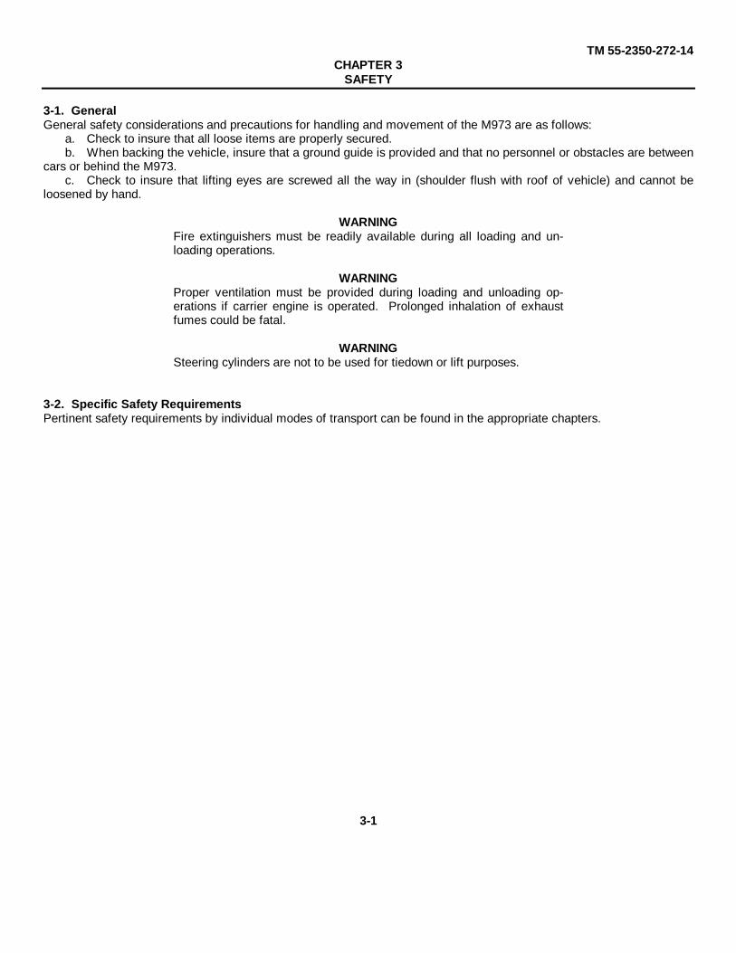
3-1. GeneralGeneral safety considerations and precautions for handling and movement of the M973 are as follows:
a. Check to insure that all loose items are properly secured.b. When backing the vehicle, insure that a ground guide is provided and that no personnel or obstacles are between
cars or behind the M973.c. Check to insure that lifting eyes are screwed all the way in (shoulder flush with roof of vehicle) and cannot be
loosened by hand.
WARNINGFire extinguishers must be readily available during all loading and un-loading operations.
WARNINGProper ventilation must be provided during loading and unloading op-erations if carrier engine is operated. Prolonged inhalation of exhaustfumes could be fatal.
WARNINGSteering cylinders are not to be used for tiedown or lift purposes.
3-2. Specific Safety RequirementsPertinent safety requirements by individual modes of transport can be found in the appropriate chapters.
3-1

TM 55-2350-272-14CHAPTER 4
AIR TRANSPORTABILITY GUIDANCESection I. GENERAL
4-1. ScopeThis chapter provides air transportability guidance for movement of the M973. Examples of tiedown diagrams and tie-down data for loading this vehicle into US Air Force C-130, C-141, and C-5 aircraft are presented, as well as proceduresfor transport by US Army CH- 54A/B and CH-47C/D helicopters.4-2. Maximum Utilization of AircraftAdditional cargo, including nuclear weapons and/or personnel, within allowable load limits and restrictions as prescribedby pertinent safety regulations (app), can be transported with the M973 in US Air Force aircraft.4-3. SafetyIn addition to the safety precautions in chapter 3, the following procedures apply:
a. The activity offering the vehicle for air transport will notify the aircraft commander or his/her representative whenammunition or explosives are to be transported in the vehicle.
b. The vehicle fuel tanks must not be more than three-fourths full.c. The required number of tiedowns plus their capacity must be checked and the criteria for gravity forces adhered
to in accordance with procedures in section IV of Air Force TO 1C-130A-9, TO 1C-141B- 9, and TO 1C-5A-9. Proce-dures outlined in this manual are for general guidance.
CAUTIONDo not allow the carrier to exceed 3 miles per hour on the loading rampsor inside the aircraft.
Section II. TRANSPORT BY US ARMY HELICOPTER
4-4. Transport by US Army Helicoptera. Applicability. This load is suitable for the CH- 54A/B and CH-47C/D helicopters at speeds of 70 knots.b. Load Description
(1) Carrier, M973, all-terrain, full-tracked, with articulated steering.(2) Weight:
Carrier...............................................10,100 poundsAccompanying load .............................3,000 poundsTotal..................................................13,100 pounds
c. Materials.(1) Two sling sets, helicopter, cargo-carrying, external (25,000-lb-capacity), NSN 1670-01-017-2900.(2) Four chains with connector links (25,000-lb- capacity), NSN 4010-01-058-4772.(3) Coupling link, P/N 664241.(4) Cord, nylon, type III, 550-pound breaking strength.(5) Tape, adhesive, pressure-sensitive, 2-inch-wide roll.(6) Grounding rod, locally fabricated.
d. Personnel. Two personnel can prepare and rig the load in 35 minutes.e. Preparation.
(1) Secure all internal cargo and loose items with nylon rope.(2) Lock the articulated steering unit with the steering cylinder locks.(3) Secure all doors, windows, and roof hatches in the closed position.(4) Check to insure that lifting eyes are screwed all the way in (shoulder flush with the roof of the vehicle) and
cannot be loosened by hand.f. Rigging.
(1) Assemble the two sling sets as shown in figure 4-1. Note the sling leg numbering sequence.(2) Loop the chain end of sling legs 5 and 6 through the aft lifting provisions of the front car of the carrier and
insert link 8 in the grabhooks.(3) Loop the chain end of sling legs 7 and 8 through the forward lifting provisions of the rear car of the carrier
and insert link 11 in the grabhooks.(4) Loop the chain end of sling legs 1 and 2 through the forward lifting provisions of the front car. Attach an ad-
ditional chain to the No. 1 link on the chain legs with the connector link. The chain leg must be looped through the liftingprovision prior to attaching the additional chain. Insert link 14 of the additional chain in the grabhook.
(5) Loop the chain end of sling legs 3 and 4 through the aft lifting provisions of the rear car. Attach an additionalchain the same as for sling legs 1 and 2. Insert link 18 of the additional chain leg in the grabhook.
(6) Tape the loose ends of the chain legs.(7) If the carrier has to be driven after being pre- pared for helicopter lift, secure the slings and clevis
4-1

TM 55-2350-272-14
Figure 4-1. Sling diagram for transport of the M973 by helicopter
by gathering them together on the roof of the rear carand tie with nylon cord, Type III.
CAUTIONRemove the nylon cord prior to the helicopter lift.
g. Hookup.(1) For normal operations, two persons are re-
quired to perform the hookup. Both persons stand onthe top of the rear car. One person places the slingclevis in the cargo hook and the other person grounds
the cargo hook with the grounding rod and provides as-sistance to the person performing the hookup.
(2) Both hookup persons depart from the loadto the side of the aircraft. They observe the sling legs toinsure that they are not crossed, tangled, or snagged onthe carrier as it is lifted.
(3) For operations during blinding conditions(extreme dust or snow), a pendant is required. Prior tolifting under these conditions, the unit SOP or the unitpathfinder must be consulted for the proper length andtype of pendant and the procedures to be used.
Section III. TRANSPORT BY US AIR FORCE AIRCRAFT
4-5. Transport by US Air Force AircraftThe M973 is transportable by the C-130, C-141, and C-5aircraft. The aircraft commander or his/her representa-tive is responsible for insuring that the vehicle is loadedor unloaded and properly secured in the air- craft in ac-cordance with the criteria in section IV of the appropriatetechnical order.
4-6. Tiedown Diagrams and TablesFigures 4-2 and 4-3 are diagrams for tiedown of theM973 in C-130, C-141, and C-5 aircraft. Tables 4-1 and4-2 are applications of the tiedowns in C-130, C-141,and C-5 aircraft.
4-2

TM 55-2350-272-14
Figure 4-3. Tiedown diagram of the M973 in C-5 aircraft
Figure 4-2. Tiedown diagram of the M973 in C-130 or C-141 aircraft.
4-3

TM 55-2350-272-14
CAUTIONTension tiedowns evenly. Do not exceed 400 pounds of tension on anysingle tiedown.
NOTEThe M973 is backed into the aircraft. Once it is positioned in the air-craft, the articulated steering unit must be locked with the steering cylin-der locks.
Table 4-1. Tiedown of the M973 in C-130 or C-141 Aircraft.
Tiedown Fitting Tiedown DeviceDesig- Capacity Capacitynation in 1,000 lb Type in 1,000 lb Attach to Item
C1 10 MB1 10 Rear pintleE1 10 MB1 10 Rear pintleC2 10 MB1 10 Over lower support arms to E2 (use
cushioning material between chain and support arms)
B3 10 MB1 10 Loop around left end of towing provisionF3 10 MB1 10 Loop around right end of towing
provision.
Table 4-2. Tiedown of the M973 in. C-5 Aircraft.
Tiedown Fitting Tiedown DeviceDesig- Capacity Capacitynation in 1,000 lb Type in 1,000 lb Attach to Item
E1 25 MB1 10 Rear pintleG1 25 MB1 10 Rear pintle
E2-G2 25 MB1 10 Over lower support arms to G2 (use cushioning material between chain and lower support arm)
E2 25 MB1 10 Loop around left end of towing provisionG2 25 MB1 10 Loop around right end of towing
provision
4-4

TM 55-2350-272-14CHAPTER 5
HIGHWAY TRANSPORTABILITY GUIDANCESection I. GENERAL
5-1. ScopeThis chapter provides transportability guidance for highway movement of the M973. It covers significant technical andphysical characteristics as well as safety precautions; prescribes materials; and provides guidance required to prepare,load, tie down, and unload the M973.
5-2. Safetya. In addition to the safety precautions in chapter 3, movement of the system within CONUS is subject to all safety
laws, rules, and regulations applicable to commercial carriers. Overseas movements are governed by theater and localregulations.
b. Lifting of the M973 is discussed in paragraph 6-3.
5-3. GeneralThe M973 is self-deliverable only under appropriate tactical situations. Movement over paved public highways will not bemade without specific approval as outlined in AR 55-162. Legal limitations for overseas are identified in "Limits of MotorVehicle Sizes and Weights," International Road Federation, Geneva, Switzerland.
Section II. TRANSPORT BY SEMITRAILER
5-4. PreparationRemove all basic issue items from the outside of the M973 and stow them securely inside the M973 to preclude damageduring transport.
WARNINGOther than the M973 driver, no one is allowed on the semitrailer at anytime during loading operations.
WARNINGLoading must not be conducted on side or lateral slopes exceeding 10percent or with a tractor-to-trailer offset angle greater than 5°. Also,loading on a severe downgrade must be avoided to prevent the payloadfrom rolling forward on the trailer.
5-5. Transport on M127A1 Semitrailera. General. Figures 5-1 and 5-2 show the M973 loaded on the M127AI semitrailer. Figure 5-3 shows details of
blocking and tiedown materials used to restrain the M973 on the semitrailer.b. Materials. Adequate blocking and tiedown materials are provided by the shipping activity and are listed in table
5-1. Table 5-2 provides application of materials for blocking and tiedown of the M973 on the M127A1 semitrailer.
5-1

TM 55-2350-272-14
Figure 5-2. End elevation, tiedown of the M973 on the M127A1 semitrailer.
Figure 5-1. Side elevation, tiedown of the M973 on the M127A1 semitrailer
5-2

TM 55-2350-272-14
Figure 5-3. Blocking and tiedown details
5-3

TM 55-2350-272-14Table 5-1. Bill of Materials for Blocking and Tiedown of the M973 on the M127A1 Semitrailers (Figs 5-1, 5-2, and 5-3).
Item Description ApproximateQuantity
Lumber Douglas-fir or comparable, straight-grain free from material defects;Fed Spec MM-L-751: 2 linear ft
2- x 4-inch 100 linear ft2- x 6-inch 40 linear ft2- x 10-inch
Nails Common, steel; flathead, bright or cement-coated, type II, style 10;Fed Spec FF-N-105:12d 270
20d 100Wire rope* 6 x 19 IWRC; improved plow steel; preformed, regular-lay; table X,
Fed Spec RR-W-410:1/2-inch 130 ft
Clamps* Wire rope, U-bolt clips, saddled, single-grip, forged steel, Crosbyheavy-duty or equal; Fed Spec FF-C-450: ½ inch 205/8-inch 6
Thimbles* Standard, open-type, ½ -inch 6*Chains and loadbinders may be substituted.
Table 5-2. Application of Material for Blocking and Tiedown. of the M973 on the M127A1 Semitrailer(Figs 5-1, 5-2, and 5-5).
Item No. Required ApplicationA 2 H-frame bracing (detail 1, fig 5-3). Each layer consists of three pieces of 2- x 6- x 11-inch lumber
and two pieces of 2- x 6- x 96-inch lumber. Place the first piece of 11-inch lumber 70 inches fromthe forward end of the trailer with one end 5.5 inches from the centerline of the trailer. Nail to thetrailer with four 12d nails. Place the second piece (centered) 4 feet from the forward side of thefirst piece. Place the third piece so that the aft edge is 8 feet from the forward edge of the firstpiece. Nail each with four 12d nails. Place one piece of 96-inch lumber against the ends of the11- inch pieces and nail each with sixteen 12d nails. Repeat for the second layer, except nail with20d nails. Build the second H-frame so that the forward end is 38 inches from the aft end of theforward H-frame.Load the M973.
B 4 Forward track chocks (detail 4, fig 5-3). Each consists of five pieces of 2- x 10.inch lumber nailedtogether with 12d nails. Place one chock firmly against each track at the forward end of each unit.Toenail with three 20d nails in each side.
C 4 Rear track chocks (detail 5, fig 5-3). Each consists of five pieces of 2- x 10-inch lumber nailed to-gether with 12d nails. Place one chock firmly against each track at the rear end of each unit.Toenail with three 20d nails in each side.
D 8 Backup cleats. Use two pieces of 2- x 6- x 12-inch lumber. Place against the heel of each trackchock, items B and C. Nail the bottom piece with four 12d nails and the top piece with four 20dnails.
E* 8 Wire rope (detail 3, fig 6-3). Each consists of 1/2-inch wire rope, length as required. Form a com-plete loop between the front units' forward tiedown fixtures and the right stake pocket. Form acomplete loop between the front units' forward tiedown fixtures and the left stake pocket. Placeone complete loop from the left stake pocket over the lower support arms, between the units, to theright stake pocket. Secure a 2- x 4- x 10-inch wooden block between the wire rope and each sup-port arm so that the wire rope does not contact the support arms when wire is tensioned. Form onecomplete loop between the rear units pintle and the right stake pocket. Form a complete loop be-tween the rear units' pintle and the left stake pocket, tension all tiedowns evenly.
CAUTIONTension tiedowns evenly. Do not exceed 400 pounds of tension on any single tiedown.(Wire rope ends should overlap a minimum of 20 inches.) Secure with four 1/2-inch clamps (itemF).
F* 32 Clamps, 1/2-inch (detail 3, fig 5-3). Place four clamps on each wire rope loop at the overlap area.Space the four clamps 2½ inches apart, with a minimum of 6 inches from the free end of the wirerope. Tension wire rope and tighten clamps from 20- to 25-foot-pound torque.
G* 6 Thimbles, 1/2-inch (detail 2, fig 53). Place a thimble between the wire rope and the stake pocketand secure with item H.
H* 6 Clamps, 5linch (detail 2, fig 5-3). Secure each ½ -inch thimble with one clamp.*Chains and loadbinders may be substituted.
5-4

TM 55-2350-272-14
c. Loading. The M973 may be placed in the tiedown position on a semitrailer by a crane of adequate capacity (5-ton minimum), or it may be driven onto the semitrailer provided that a suitable ramp is available. When the M973 is inthe tiedown position, the transmission control must be placed in neutral. Parking brakes must be set.
d. Tiedown. Figures 5-1, 5-2, and 5-3 show the M973 tied down, in accordance with standard loading practices, sothe load will be adequately restrained against forces encountered at normal speeds and operating conditions.
e. Turning Diagram. Figure 5-4 is a turning diagram for the M127A1 semitrailer towed by the M818 truck-tractor.
Figure 5-4. Turning diagram for the M127A1 semitrailer towed by the M818 truck-tractor.
5-5

TM 55-2350-272-14
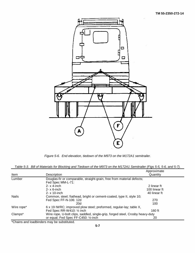
5-6. Transport on M172A1 Semitrailera. Genera. Figures 5-5, 5-6, and 5-7 show the M973 loaded on the M172A1 semitrailer.b. Materials. Adequate blocking and tiedown materials are provided by the shipping activity (table 5-3).c. Loading. The M973 may be driven onto the M172A1 by use of the trailer ramps or a suitable substitute. Once
the M973 is in position, the transmission control must be placed in neutral. Parking brakes must be set.d. Tiedown. Figures 5-5 and 5-6 show the M973 blocked and tied down on the M172A1 semitrailer. Figure 5-7 is a
diagram of the shoring required for the M172A1 semitrailer, and figure 5-8 is a turning diagram for the M172A1 semi-trailer. Tables 5-3 and 5-4 are the bill of materials and application of materials used for blocking and tiedown of theM973 on the M172A1 semitrailer.
Figure 5-5. Side elevation, tiedown of the M973 on the M172A1 semitrailer.
5-6
TM 55-2350-272-14
Figure 5-6. End elevation, tiedown of the M973 on the M172A1 semitrailer.
Table 5-3. Bill of Materials for Blocking and Tiedown of the M973 on the M172A1 Semitrailer (Figs 5-5, 5-6, and 5-7).Approximate
Item Description QuantityLumber Douglas-fir or comparable, straight-grain, free from material defects;
Fed Spec MM-L-71:2- x 4-inch 2 linear ft2- x 6-inch 100 linear ft2- x 10-inch 40 linear ft
Nails Common, steel; fiathead, bright or cement-coated, type II, style 10;Fed Spec FF-N-106: 12d 270
20d 100Wire rope* 6 x 19 IWRC; improved plow steel; preformed, regular-lay; table X,
Fed Spec RR-W410: ½ inch 160 ftClamps* Wire rope, U-bolt clips, saddled, single-grip, forged steel, Crosby heavy-duty
or equal; Fed Spec FF-C450: ½ -inch 20*Chains and loadbinders may be substituted.
5-7

TM 55-2350-272-14
Figure 5-7. Placement of shoring on the M172A1 semitrailer before the M973 is loaded.
5-8

TM 55-2350-272-14
Figure 5-8. Turning diagram for M973 on M172-series semitrailer towed by M818 tractor.
5-9

TM 55-2350-272-14
Table 5-4. Application of Materials for Blocking and Tiedown of M973 on the M172A1 Semitrailer(Figs 5-5, 5-6, and 5-7)
Item No. Required ApplicationA 2 H-frame bracing (figs 5-5 and 5-7). Each layer consists of three pieces of 2- x 6- x 11-inch lumber
and two pieces of 2- x 6- x 96.inch lumber. Place the first piece of 11-inch lumber 20 inches fromthe forward end of the trailer with one end 5.5 inches from the centerline of the trailer. Nail to thetrailer with four 12d nails. Place the second piece (centered) 4 feet from the forward side of thefirst piece. Place the third piece so that the aft edge is 8 feet from the forward edge of the firstpiece. Nail each with four 12d nails. Place one piece of c96inch lumber against the ends of the11- inch pieces and nail each with sixteen 12d nails. Repeat for the second layer, except nail with20d nails. Build the second H-frame so that the forward end is 88 inches from the aft end of theforward H-frame.Load the M978.
B 4 Forward track chocks (detail 4, fig 5-3). Each consists of five pieces of 2 x 10-inch lumber nailedtogether with 12d nails. Place one chock firmly against each track at the forward end of each unit.Toenail with three 20d nails in each side.
C 4 Rear track chocks (detail 5, fig 8-3). Each consists of five pieces of 2- x 10-inch lumber nailed to-gether with 12d nails. Place one chock firmly against each track at the rear end of the forwardunit. Toenail with three 12d nails in each side.
D 8 Backup cleats. Use two pieces of 2- x 6- x 12-inch lumber. Place against the heel of each trackchock, items B and C. Nail the lower piece with four 12d nails and the top piece with four 20dnails.
E* 8 Wire rope (detail 3, fig 5-3). Each consists of ½ -inch wire rope, length as required. Form a com-plete loop between the tiedown point on the M973 and the tiedown fitting on the trailer.
CAUTIONTension tiedowns evenly. Do not exceed 400 pounds of tension on any single tiedown.(Wire rope ends should overlap a minimum of 20 inches.) Secure with four ½ -inch clamps (itemF).
F* 32 Clamps, ½ -inch (detail 3, fig 5-8). Place four clamps on each wire rope loop at the overlap areaand space each clamp 2-1/2 inches apart, with a minimum of 6 inches from the free end of thewire rope. Tension wire rope and tighten clamps from 20- to 25-foot-pound torque.
*Chains and loadbinders may be substituted.
5-10

TM 55-2350-272-14CHAPTER 6
MARINE AND TERMINAL TRANSPORTABILITY GUIDANCESection I. GENERAL
6-1. ScopeThis chapter provides transportability guidance for marine and terminal movement of the M973. It covers significanttechnical and physical characteristics, as well as safety precautions; prescribes materials; and provides guidance re-quired to prepare, lift, tie down, and discharge this vehicle.
6-2. SafetyIn addition to the safety precautions in chapter 3, the following should be noted:
a. The activity offering the vehicle for transport will notify the carrier if ammunition (or explosives) is to be trans-ported with the vehicle. Compliance with AR 55-228, paragraph 2-7, is mandatory.
b. Ammunition and vehicles will be handled and stowed in accordance with provisions contained in Code of FederalRegulations (CFR) 49 or reissues thereof.
c. Fire extinguishers must be available during all loading and discharge operations.d. Vessel equipment and gear should be inspected before being used.e. Personnel should be cautioned not to walk under items being lifted.f. Lifting eyes, shackles, and slings should be inspected to insure that they are complete and not dam- aged.g. All lifts should have at least two tag lines attached to control the swing of the lift while suspended.h. Check to insure that lifting eyes are screwed all the way in (shoulder flush with the roof of vehicle) and cannot be
loosened by hand.WARNING
The articulated steering unit must be locked with the steering ram locksbefore attempting to lift the M973.
6-3. Marine ShipmentThe M973 can be transported by a variety of inland waterway cargo vessels, by lighters, and by most sea-going cargovessels.
NOTEThe methods described in this chapter for lifting and securing are sug-gested procedures. Other methods of handling and stowage may beused provided that they will insure safe delivery without damage.
Section II. LOADING AND SECURING
6-4. General Rulesa. Stowage. Below-deck stowage should be provided whenever possible. In general, good stowage means placing
the carriers as close together as practical, with minimum space between the outer item and the sweatboards (about 4 to 6inches). The M973 is secured by adequate blocking and lashing. Securing includes blocking of tracks on all four sidesso that the M973 cannot move in any direction; bracing of individual blocks to bulkheads, stanchions, and other vehicleblocks; and lashing of the M973 with wire rope, chain, or patented lashings. Breakable parts should be protected; spareparts should be stowed in or near the parent item; brakes should be set; and the transmission control should be placed inneutral.
b. Lifting. Correct lifting points on the carriers are the lifting eyes located at the upper four corners of each car (totalof eight). A typical lifting diagram is shown in figure 6-1.
c. Loading. The M973 will be loaded on seagoing cargo vessels in its minimum configuration as de- scribed inparagraph 2-4. It may be loaded under its own power or by cranes of adequate capacity aboard landing craft, beach dis-charge lighters, heavy and medium amphibious lighters, and landing ships. It can also be driven or towed aboard roll-on/roll-off vessels, or onto the decks of barges from a pier, when tidal conditions are suitable and ramps are available.The M973 can be loaded onto seagoing vessels by shoreside or floating cranes or by heavy-lift ship's gear.
d. Lighterage. When transporting the M973 by lighter to or from vessels, blocking will be required. When trans-porting the M973 by lighter over extended distances or through rough water, tiedowns must also be used.
6-1

TM 55-2350-272-14
Figure 6-1. Lifting diagram for the M973, using an eight-legged sling.
6-5. General Cargo and Barge-Type (LASH or SEABEE) ShipsNOTE
The fuel tanks must be drained; the battery cables must be disconnected from the bat-teries; and the cable clamps or connectors must be taped.
a. Securing. The M973 must be secured by blocking the tracks with timbers at the front and rear and on both sides.The bracing timbers are force-fitted to a bulkhead, stanchion, or the blocking of an adjacent vehicle. The M973 must belashed with turnbuckles and wire rope from the vehicle tiedown fittings to the bulkheads, stanchions, or deck fittings (suchas pad-eyes or D-rings). Figure 6-2 shows typical blocking and tiedown details. Table 6-1 lists the materials for blockingand tiedown, and table 6-2 explains how to apply these materials.
6-2

TM 55-2350-272-14
Figure 6-2. Blocking and tiedown on the M973 in a general cargo vessel.
b. Stowing in Barges. Figure 6-3 shows a typical loading arrangement for stowing M973's on a LASH barge fortransport on a barge-carrying ship. Loading and blocking and bracing must proceed from the outer areas of the bargetoward the center, which is loaded last. Since barge stability is noticeably affected by the loading of heavy items, theM973's should be loaded symmetrically (front to rear as well as side to side) to keep the barge as level as possible at alltimes. Variations in centers of gravity may be counterbalanced by loading vehicles alternately, facing forward and aft orhead to tail. Blocking should be installed as a separator between the tracks and barge bulkheads, between adjacent rowsof M973's, and at the front and rear of the tracks. The bracing timbers must be force- fitted (wedged) to the bulkheadand to the blocking of adjacent vehicles. After the last M973 is loaded, any void area remaining in the center of thebarge must be filled by blocking and force-fitted bracing. Blocking and tiedown materials are listed in table 6-1.
Table 6-1. Bill of Materials for Blocking and Tiedown of the M973 in a General Cargo Vessel (Fig 6-2).Item Description Approximate
QuantityLumber Douglas-fir or comparable, straight-grain, free from material defects;
Fed Spec MM-L-751:2 x 4-inch 2 linear ft4- x 6inch 100 linear ft
Nails Common, steel; flathead, bright or cement-coated, type II, style 10;Fed Spec FF-N-105: 40d 92
Wire rope 6 x 19 IWRC; improved plow steel; preformed, regular-lay; table X,Fed Space RR-W-410: 1½ -inch 50 ft
Clamps Wire rope, U-bolt clips, saddled, single-grip, forged steel, Crosby heavy-dutyor equal; Fed Spec FF-C-450: ½ -inch 32
Turnbuckles 3/4- x 12-inch, eye and clevis type 5
Table 6-2. Application of Materials for Blocking and Tiedown of the M97s in a General Cargo Vessel (Fig 6-2).
Item No. Required ApplicationA 4 Side blocking. Each consists of 4- x 6 x 144-inch lumber. Locate one piece on each side of each
unit against the outside of the tracks. Butt the two pieces on each side in the middle between thetwo units.
B 4 End blocking. Each consists of 4- x 6- x 84Winch lumber. Locate on top of Item A and against thetracks at the front and rear of each unit. Toenail to Item A with four 40d nails at each end.
6-3

TM 55-2350-272-14
Table 6-2 - ContinuedItem No. Required ApplicationC 4 Backup cleats. Each consists of 4- x 6- x 12-inch lumber. Locate on top of item A against item B.
Nail to item A with 40d nails.D 2 Backup cleats. Each consists of 4- x 6-inch x length-to-suit lumber. Locate on top of item A be-
tween the two item B's. Nail to item A with six 40d nails.E 6 Padeyes. Built into vessel deck.F 5 Turnbuckles, 3/4- x 12-inch eye-and-clevis type. Attach clevis end to item E.G as required Wire rope. Make a complete loop through the turnbuckle eye fitting and the opposite side of the
front units' forward tiedown fixture. Repeat for the other forward tiedown. Place one completeloop from the left side tiedown over the lower support arms, between the units, to the turnbuckleeye fitting on the right side. Secure a 2- x 4- x 10-inch wooden block between the wire rope andthe support arms so that the wire does not contact the support arms when wire is tensioned. Forma complete loop through the turnbuckle eye fitting and the rear units' pintle. Repeat for the otherrear tiedown. Tension all tiedowns evenly.
CAUTIONTension tiedowns evenly. Do not exceed 400 pounds of tension on any single tiedown.
H 32 Clamps,3/8-inch. Use four to secure each item G.I as required Bracing. Each consists of 4- x 6-inch x length-to-suit lumber. Brace as required against adjacent
vehicle, cargo, or side of vessel bulkhead. Secure each piece to adjacent blocking or bracing bytoenailing with four 40d nails.
Figure 6-3. Typical loading of M973 vehicles on a LASH (59.9feet by 29.5 feet), using wire rope, cable clips, and turn-buckles with blocking between vehicles and between vehicles and hull.
6-4

TM 55-2350-272-14
6-6. Roll-On/Roll-Off (RORO) and Seatrain Vessels, Landing Ships, and Attack Cargo Ships
NOTEWhen the M973 Is loaded on vessels that are adequately ventilated with power blowers,such as RORO vessels, the fuel need not be drained nor the batteries disconnected.
a. Loading. The M973 can be loaded under its own power or towed aboard .vessels having roll-on capability.b. Securing. RORO and Seatrain vessels, landing ships,. and attack cargo ships are equipped with patented lash-
ing gear (equipment made by Peck and Hale is often used) and permanent fittings m the deck. Eight Peck and Halelashings, size 4M (4.200-lb breaking strength), should be used to tie down each M973, two lashings, crossed, from theforward tiedown points and two lashings, crossed. from the aft tiedown points of each unit to the "cloverleaf” deck socketsor bulkhead fittings. Blocking and bracing is not required with ad equate patented lashing gear (see fig. 6-4)
Figure 6-4. Rear view of the M973 tiedown on a RORO ship, showing typical securement with Peck and Hale lashings.
6-5

TM 55-2350-272-14
CHAPTER 7RAIL TRANSPORTABILITY GUIDANCE
Section I. GENERAL
7-1. ScopeThis chapter provides transportability guidance for rail movement of the M973. It covers significant technical and physi-cal characteristics as well as safety considerations; prescribes materials, and provides guidance required to prepare,load, and tie down the M973 on flatcars.
7-2. Maximum Utilization of RailcarsAdditional cargo, as approved by the activity offering the M973 for transport, may be transported with the M973.
Section II. TRANSPORT ON CONUS RAILWAYS
7-3. GeneralThe transportability guidance contained in this section Is applicable when the M973 is transported on CONUS railways.Consideration is given to single and multiple movements on railcars normally used for this type of equipment. TheM1973 can be transported without restriction and without sectionalization or major disassembly.
7-4. PreparationRemove the basic Issue Items from the outside of the M973 and stow them securely inside the cab of the M973.
CAUTIONOnce the M973 Is in the tiedown position, lock the articulated steering unit with the steeringcylinder locks.
7-5. Loading on General Purpose Flatcars.a. The M973 can be placed m the tiedown position on a railcar by a crane of adequate capacity or it may be driven
or towed onto the railcar provided that a suitable ramp is available Lifting is discussed in paragraph 6-2.CAUTION
Do not allow the M973 to exceed 3 miles per hour during loading or0 unloading operations.
b. The load illustrated in figure 7-1 and 7-2 is based on a flatcar of 8 feet or more. Figure 7-3 shows the M973blocking and tiedown details. Table 7-1 is a bill of materials. and table 7-2 is the application of materials for securing theM973 on general purpose flatcars.
NOTEA staggered nailing pattern should be used when lumber or laminated lumber is nailed to thefloor of a railcar. The nailing pattern for an upper piece of lumber should be adjusted so thata nail will not be driven into or against a nail in a lower piece of lumber.
Figure 7-1. Side elevation, tiedown of the M973 on a general purpose flatcar.7-1

TM 55-2350-272-14
Figure 7-2. End elevation, Tiedown of the M973 on a general purpose flatcar .
Table 7-1. Bill of Materials for Blocking and Tiedown of the M973on a CONUS General Purpose Flatcar (Figs 7-1, 7-2, and 7-3).
ApproximateItem Description Quantity
Lumber Douglas-fir or comparable, straight-grain, free from material defects; Fed Spec MM-L-751:2- x 4-inch 14 linear ft2- x 6-inch 100 linear ft2- x 10-inch 40 linear ft
Nails Common, steel; flathead, bright or cement-coated, type II, style 10; Fed Spec FF-N-105: 12d27030d 100
Wire rope 6 x 19 IWRC; improved plow steel; preformed, regular-lay; table X, Fed Spec RR-W-410: ½ inch 125ft
Clamps Wire rope, U-bolt clips saddled, single-grip, forged steel, Crosby heavy-duty or equal;Fed Spec FF-C-450 1/2-inch 20
5/8-inch 6
Thimbles Standard, open-type, ½ -inch 6
7-2

TM 55-2350-272-14
Figure 7-3. Blocking and tiedown details.
7-3

TM 55-2350-272-14
Table 7-2. Application of Materials for Blocking and Tiedown of the M973on a General Purpose Flatcar (Figs 7-1, 7-2, and 7-3).
ItemNo.
Req. ApplicationA Brake wheel clearance. Minimum clearance required is 6 inches above, in back of, and on both sides of, and 4
inches underneath wheel (figure 7-1).B 4 Forward track chocks (detail 2, fig 7-3). Each consists of five pieces of 2- X 10-inch lumber nailed together with
12d nails, or pieces may be cut from 8- X 10-inch lumber. Solid chocks cut from 8- X 10-inch lumber are re-quired by Alaskan railroads. Place one chock firmly against the center of each track at the forward end of eachunit. Toenail with three 30d nails in each side.
C 8 Backup cleats. Use two pieces of 2- X 6- X 18-inch lumber. Place against the heel of each track chock, items Band D. Nail the bottom pieces with three 30d nails.
D 4 Rear track chocks (detail 3, fig 7-3). Each consists of five pieces of 2- X 10-inch lumber nailed together with 12dnails or pieces may be cut from 8- X 10-inch lumber. Solid chocks cut from 8- X 10-inch lumber are requiredby the Alaskan railroads. Place one chock firmly against the center of each track at the aft end of each unit.Toenail with three 30d nails in each side.
E 4 Barrier material. Place barrier material on the railcar and against the tracks.F 4 Side blocking. Each consists of two 2- X 4- 72-inch lumber. Place on tope of and against barrier material and
firmly against the track. Nail the bottom pieces with ten 30d nails and the top piece with ten 30d nails.G 5 Wire rope (detail 4, fig 7-3). Each consists of ½ -inch wire rope, length as required. Form a complete loop be-
tween the front units’ forward tiedown fixture and the right stake pocket on the flatcar. Form a complete loopbetween the front units’ forward tiedown fixture and the left stake pocket on the flatcar. Place one completeloop from the left stake pocket on the flatcar over the lower support arms between the units, tot he right stakepocket on the flatcar. Secure a 2- X 4- X 10- inch wooden block between the wire rope and each support armsso that the wire does not contact the support arms when wire is tensioned. Form a complete loop between therear units’ pintle and the right stake pocket on the flatcar. Form a complete loop between the pintle on the leftstake pocket of the flatcar. Tension all tiedowns evenly and secure with four cable clamps, item H.
H 20 Clamps (detail 4, fig 7-3). Place four ½ -inch clamps on each wire loop at the overlap area and space each clamp3 inches apart, with a minimum of 6 inches from each end of the wire rope. After placement of thimble (item I)at the stake pocket, tension wire rope and tighten clamps from 20- to 25-foot-pound torque.
I 6 Thimbles (detail 5, fig 7-3). Place one ½ -inch thimble between the wire rope and the stake pocket and secure withitem J.
J 6 Clamps (detail 5, fig 7-3). Secure each ½ -inch thimble with one 5/8-inch clamp.
GENERAL INSTRUCTIONS1. Wooden blocks (2- X 4- X 10-inch) must be used to protect the support arms of the articulation drive assemblybetween the two units of the M973. Secure wire rope to wooden block by driving a 12d nail half way and bending the nailover the wire rope until the head of the nail contacts the wood.2. Tensioning of wire rope can be accomplished with an applicable sized come-along mechanical hoist or equaltensioning device.3. When the M973 is in the tiedown position, place the transmission control in neutral and set parking brakes.4. Loading Rules 1A, 2, 3, 4, 5, 9, 14, 15, and 19A in Section No. 1 of the Rules Governing the Loading of Com-modities on Open-Top Cars and Trailers, published by the Association of American Railroads, provide applicable guide-lines and are mandatory in application.
Section III. TRANSPORT ON FOREIGN RAILWAYS7-6. GeneralThe transportability guidance contained in this section is applicable when the M973 is transported on foreign railways.Consideration is given to single and multiple movements on the types of railcars normally used for the transport of thistype of vehicle. The M973. when loaded on a suitable flatcar, can be transported, with restrictions, within Europeancountries complying with the passe-partout international (PPI) gauge railways. Because of the various designation sys-tems used by different countries, foreign railcars are difficult to classify. In addition, clearances may very between coun-tries and within a country. Consequently, evaluation of transport capability must be made o an individual basis.
7-7. Transport on Foreign Service FlatcarsThe M973 can he transported on a number of foreign service flatcars The materials required for blocking and tiedown onforeign service flatcars are essentially the same as those used in CONUS Dimensions, load capacity, and other data forseveral flatcars available in Europe, as well as detailed guidance for securing vehicles on these cars, are contained in4TH TRANSCOM Pamphlet 55-2, Tiedown Guide for Rail Movements, 15 May 1982.
7-4

TM 55-2350-272-14
APPENDIXREFERENCES
A-1. Army Regulations (AR)55-29 Military Convoy Operations in
CONUS
55-80 Highways for National Defense
55-162 Permits for Oversize, Over-weight, or Other Special MilitaryMovements on Public Highwaysin the United States
55-228 Transportation by Water of Ex-plosives or Hazardous Cargo
55-355 Military Traffic ManagementRegulation
70-44 DOD Engineering for Trans-portability
385-40 Accident Reporting and Rec-ords
746-1 Packaging of Army Material forshipment and Storage
A-2. Field Manuals (FM)55-9 Unit Air Movement Planning
55-15 Transportation Reference Data
55-17 Terminal Operations Coordina-tor’s Handbook
A-3. Supply Bulletins (SB)700-20 Army Adopted/Other Items for
Authorization/List of ReportableItems
A-4. Technical Bulletins (TB)55-46-1 Standard Characteristics
(Dimensions, Weight, andCube) for Transportability ofMilitary Vehicles and OtherOutsize/Overweight Equipment
A-5. Technical Manuals (TM)9-2350-272-10 Operator’s Manual: Small Unit
Support Vehicle (SUSV)
38-250 (AFR 71-4) Packaging and Materials Han-dling: Preparation of Hazard-ous Materials for Military Airshipment
55-405-9 Army Aviation MaintenanceEngineering Manual: Weightand Balance
55-500 Marine Equip. Characteristicsand Data
55-1520-217-10-1 Operators Manual: Army ModelCH-54A Helicopter
55-1520-217-10-2 Operators Manual: Army ModelCH-54B Helicopter
55-1520-227-10 Operators Manual: Army ModelCH-47D Helicopter
55-2200-001-12 Transportability Guidance forApplication of Blocking, Brac-ing, and Tiedown Materials forRail Transportation
A-6. Technical Orders (TO) (Air Force)1-1B-40 Handbook of Weight and Bal-
ance Data
1C-5A-9 Loading Instructions, USAF Se-ries C-5A Airplane
1C-130A-9 Loading Instructions, USAF Se-ries C-130A Airplane
1C-141B-9 Loading Instructions, USAF Se-ries C-141B Airplane
A-7. 4TH TRANSCOM Pamphlet55-2 Tiedown Guide for Rail Move-
ments
A-8. Other Publications and Source of Procurementa. Code of Federal Regulations, Title 49-
Transportation, Parts 170-179
Available from: Superintendent of DocumentsUS Government Printing OfficeWashington, DC 20402
b. Association of American Railroads Rules Gov-erning the Loading of Com-modities on Open-Top Cars andTrailersSection No. 1 - General RulesSection No. 6 - Rules Govern-ing the Loading of Departmentof Defense Material on Open-Top Cars
A-1

TM 55-2350-272-14
Available from Association of American Railroads59 E Van Buren StreetChicago, IL 60605
c. American Association of State Highway andTransportation Officials (AASHTO) LegalMaximum Dimensions and weight of MotorVehicles Compared with AASHTO Standards
Available from American Assoc. of State Highwayand Transportation Officials341 National Press BuildingWashington, DC 20004
A-9. Department of TransportationUSCG 108 Rules and Regulations for Military Explo-sives and Hazardous Munitions
USCG 108 ****
A-2

By Order of the Secretary of the Army:
JOHN A. WICKHAM, JR.General, United States Army
Official: Chief of Staff
MILDRED E. HEDBERGBrigadier General, United States Army
The Adjutant General
DISTRIBUTION:To be distributed in accordance with DA Form 12-37, Operators Maintenance requirements for Carrier, Cargo,
Tracked, 1-1/2- ton, Small Unit Support Vehicle, (SUSV), M973.


PIN: 058789

This fine document...
Was brought to you by me:
Liberated Manuals -- free army and government manuals
Why do I do it? I am tired of sleazy CD-ROM sellers, who take publicly available information, slap “watermarks” and other junk on it, and sell it. Those masters of search engine manipulation make sure that their sites that sell free information, come up first in search engines. They did not create it... They did not even scan it... Why should they get your money? Why are not letting you give those free manuals to your friends?
I am setting this document FREE. This document was made by the US Government and is NOT protected by Copyright. Feel free to share, republish, sell and so on.
I am not asking you for donations, fees or handouts. If you can, please provide a link to liberatedmanuals.com, so that free manuals come up first in search engines:
<A HREF=http://www.liberatedmanuals.com/>Free Military and Government Manuals</A>
– SincerelyIgor Chudovhttp://igor.chudov.com/
– Chicago Machinery Movers