Embed Size (px)
Citation preview
TM 5-6665-202-13
TECHNICAL MANUAL
OPERATOR, ORGANIZATIONAL AND DIRECT
SUPPORT MAINTENANCE MANUAL
DETECTING SET, MINE: AURAL INDICATION;
10V DC OPERATING POWER: PORTABLE
TRANSISTORIZED, W/CASE AN/PSS-11
( P O L A N M O D E L S P 1 5 3 A N D P 1 5 8 ) F S N 6 6 6 5 - 9 6 6 - 9 0 7 1
( P O L A N M O D E L P 1 9 0 ) F S N 6 6 6 5 - 1 8 1 - 0 4 3 2
(OREGON TECHNICAL PRODUCTS MODEL MD-M)
F S N 6 6 6 5 - 9 6 6 - 0 9 7 2
( T H E V P C O M P A N Y M O D E L V P 2 0 0 ) F S N 6 6 6 5 - 1 4 4 - 7 6 5 5
( F O U R D E E M O D E L 4 D 5 0 0 0 ) F S N 6 6 6 5 - 1 8 1 - 0 3 6 9
H E A D Q U A R T E R S , D E P A R T M E N T O F T H E A R M Y
27 DECEMBER 1971

TM 5-6665-202-13C4
CHANGE
NO. 4
HEADQUARTERSDEPARTMENTOF THE ARMY
WASHINGTON, D.C., 31 October 1994
Operator, Organizational and Direct SupportMaintenance Manual
DETECTING SET, MINE: AURAL INDICATION;10 V DC OPERATING POWER; PORTABLETRANSISTORIZED, W/CASE AN/PSS-11
(POLAN MODELS P153 AND P158) NSN 6665-00-966-9071(POLAN MODEL P190) NSN 6665-00-181-0432
(OREGON TECHNICAL PRODUCTS MODEL MD-M)NSN 6665-00-966-9072
(THE VP COMPANY MODEL VP200) NSN 6665-00-144-7655FOURDEE MODEL 4D5000) NSN 6665-00-181-0369
DISTRIBUTION STATEMENT A: Approved for public release; distribution is unlimited
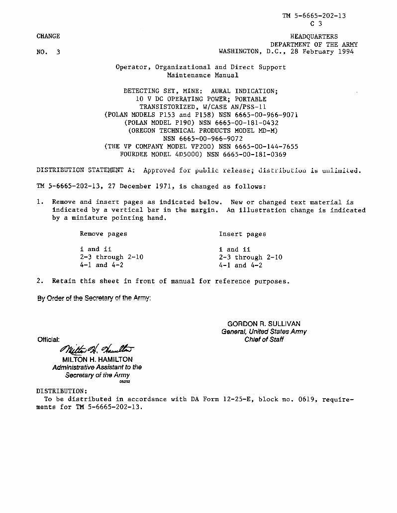
TM 5-6665-202-13, 27 December 1971, is changed as follows:
1. Remove and insert pages as indicated below. New or changed text material is indicated by a vertical barin the margin. An illustration change is indicated by a miniature pointing hand.
Remove pages Insert pages
2-1 and 2-2 2-1 and 2-2
6-9 and 6-10 6-9 and 6-10
2. Retain this sheet in front of manual for reference purposes.
By Order of the Secretary of the Army:
Official:
MILTON H. HAMILTONAdministrative Assistant to the
Secretary of the Army07679
GORDON R. SULLIVANGeneral, United States Army
Chief of Staff
DISTRIBUTION:To be distributed in accordance with DA Form 12-25-E, block no. 0619, requirements for
TM 5-6665-202-13.
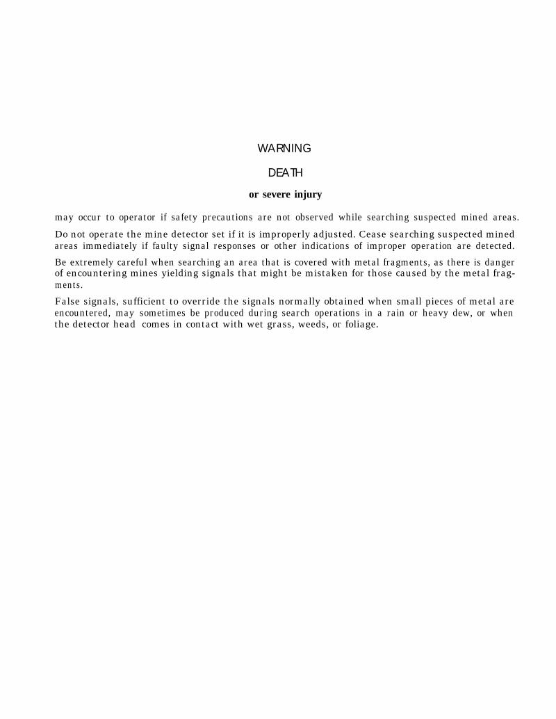
WARNING
DEATH
or severe injury
may occur to operator if safety precautions are not observed while searching suspected mined areas.
Do not operate the mine detector set if it is improperly adjusted. Cease searching suspected minedareas immediately if faulty signal responses or other indications of improper operation are detected.
Be extremely careful when searching an area that is covered with metal fragments, as there is dangerof encountering mines yielding signals that might be mistaken for those caused by the metal frag-ments.
False signals, sufficient to override the signals normally obtained when small pieces of metal areencountered, maythe detector head
sometimes be produced during search operations in a rain or heavy dew, or whencomes in contact with wet grass, weeds, or foliage.

TM 5-6665-202-13
DEATH
or severe injury
may occur to operator if safety precautions are not observed while searching suspected minedareas.
Do not operate the mine detector set if it is improperly adjusted. Cease searching suspected minedareas immediately if faulty signal responses or other indications of improper operation aredetected.
Be extremely careful when searching an area that is covered with metal fragments, as there isdanger of encountering mines yielding signals that might be mistaken for those caused by the metalfragments.
False signals, sufficient to override the signals normally obtained when small pieces of metal areencountered, may sometimes be produced during search operations in a rain or heavy dew, or whenthe detector head comes in contact with wet grass, weeds or foliage.
Do not operate detector unless yellow with black stripe output amplifier module is installed. Outputamplifier modules other than the yellow with black stripe may not alert the operator of low batteryvoltage. Detectors operated with low battery voltage will not detect metallic objects, whichendangers the life of the operator.
Do not operate the mine detector set prior to performing preliminary adjustment and sensitivitycheck. Faulty signal responses or other indications of improper operation endanger the life of theoperator.
Change 2 a(b blank)

TECHNICAL MANUAL *TM 5-6665-202-13HEADQUARTERS
DEPARTMENT OF THE ARMYNo. 5-6665-202-13 Washington, D.C., 27 December 1971
Operator, Organizational and DirectSupport Maintenance Manual
DETECTING SET, MINE: AURAL INDICATION;10V DC OPERATING POWER; PORTABLETRANSISTORIZED, W/CASE AN /PSS-11
(POLAN MODELS P153 AND P158) NSN 6665-00-966-9071(POLAN MODEL P190) NSN 6665-00-181-0432
(OREGON TECHNICAL PRODUCTS MODEL MD-M)NSN 6665-00-966-9072
(THE VP COMPANY MODEL VP200) NSN 6665-00-144-7655(FOURDEE MODEL 4D5000) NSN 6665-00-181-0369
REPORTING ERRORS AND RECOMMENDING IMPROVEMENTS
You can help improve this manual. If you find any mistakes or if you know of a way toimprove the procedures, please let us know. Mail your letter, DA Form 2028(Recommended Changes to Publications and Blank Forms), or DA Form 2028-2 locatedin back of this manual direct to: Commander, US Army Aviation and Troop Command,ATTN: AMSAT–I–MP, 4300 Goodfellow Blvd., St. Louis, MO 631 20–1 798. A reply will befurnished to you.
CHAPTER 1.
Section I.II.
1-11-1
CHAPTER 2.
Section I.II.
III.IV.V.
CHAPTER 3.
Section I.II .III.IV.
CHAPTER 4.
Section I.II.
III.IV.V.VI.
VII.
CHAPTER 5.Section I.
II.III.
ParagraphINTRODUCTION
General . . . . . . . . . . . . . . . . . . . . . . . . . . . . . . . . . . . . . . . . . . . . . . . . . . . . . . . . . . . . . . . . . . . . . . . . . . . . . . . . . . . . . . . . . . . . . . . . . . . . . . . 1-1Description and Data . . . . . . . . . . . . . . . . . . . . . . . . . . . . . . . . . . . . . . . . . . . . . . . . . . . . . . . . . . . . . . . . . . . . . . . . . . . . . . . . . 1-5
OPERATING INSTRUCTIONS
Service upon receipt of materiel . . . . . . . . . . . . . . . . . . . . . . . . . . . . . . . . . . . . . . . . . . . . . . . . . . . . . . . . . . . . . . . . 2-1Movement to a new worksite . . . . . . . . . . . . . . . . . . . . . . . . . . . . . . . . . . . . . . . . . . . . . . . . . . . . . . . . . . . . . . . . . . . . . 2-3Controls and instruments . . . . . . . . . . . . . . . . . . . . . . . . . . . . . . . . . . . . . . . . . . . . . . . . . . . . . . . . . . . . . . . . . . . . . . . . . . 2-5Operation under usual conditions . . . . . . . . . . . . . . . . . . . . . . . . . . . . . . . . . . . . . . . . . . . . . . . . . . . . . . . . . . . . . 2-7Operation under unusual conditions . . . . . . . . . . . . . . . . . . . . . . . . . . . . . . . . . . . . . . . . . . . . . . . . . . . . . . . . . 2-11
OPERATOR/CREW MAINTENANCE INSTRUCTIONS
Lubrication instructions . . . . . . . . . . . . . . . . . . . . . . . . . . . . . . . . . . . . . . . . . . . . . . . . . . . . . . . . . . . . . . . . . . . . . . . . . . . . .Preventive maintenance checks and services . . . . . . . . . . . . . . . . . . . . . . . . . . . . . . . . . . . . . . . . . . . . 3-1Troubleshooting . . . . . . . . . . . . . . . . . . . . . . . . . . . . . . . . . . . . . . . . . . . . . . . . . . . . . . . . . . . . . . . . . . . . . . . . . . . . . . . . . . . . . . . . . . 3-3Maintenance of the mine detecting set . . . . . . . . . . . . . . . . . . . . . . . . . . . . . . . . . . . . . . . . . . . . . . . . . . . . . . 3-5
ORGANIZATIONAL MAINTENANCE INSTRUCTIONS
Service upon receipt of material . . . . . . . . . . . . . . . . . . . . . . . . . . . . . . . . . . . . . . . . . . . . . . . . . . . . . . . . . . . . . . . . 4-1Movement to a new worksite . . . . . . . . . . . . . . . . . . . . . . . . . . . . . . . . . . . . . . . . . . . . . . . . . . . . . . . . . . . . . . . . . . . . .Repair parts, special tools, and equipment . . . . . . . . . . . . . . . . . . . . . . . . . . . . . . . . . . . . . . . . . . . . . . . 4-3Lubrication instructions . . . . . . . . . . . . . . . . . . . . . . . . . . . . . . . . . . . . . . . . . . . . . . . . . . . . . . . . . . . . . . . . . . . . . . . . . . . . .Preventive maintenance checks and services . . . . . . . . . . . . . . . . . . . . . . . . . . . . . . . . . . . . . . . . . . . . 4-5Troubleshooting . . . . . . . . . . . . . . . . . . . . . . . . . . . . . . . . . . . . . . . . . . . . . . . . . . . . . . . . . . . . . . . . . . . . . . . . . . . . . . . 4-7Maintenance of the mine detecting set . . . . . . . . . . . . . . . . . . . . . . . . . . . . . . . . . . . . . . . . . . . . . . . . . . . . . . 4-9
DIRECT SUPPORT MAINTENANCE INSTRUCTIONSRepair parts and special tools, and equipment . . . . . . . . . . . . . . . . . . . . . . . . . . . . . . . . . . . . . . . . . 5-1Troubleshooting . . . . . . . . . . . . . . . . . . . . . . . . . . . . . . . . . . . . . . . . . . . . . . . . . . . . . . . . . . . . . . . . . . . . . . . . . . . . . . . 5-4Removal and installation of major components and auxiliaries. . . . . . . . . . . . ...5-6
Page
2-12-22-32-32-9
3-13-13-23-2
4-14-14-14-14-14-24-3
5-15-15-2
*This manual supersedes TM 5-6665-202-15, 8 June 1964 including all changes.. Change 2 i

TM 5-6665-202-13
CHAPTER 6. REPAIR OF MINE DETECTOR SET . . . . . . . . . . . . . . . . . . . . . . . . . . . . . . . . . . . . . . . . . . . . . . . . . . . . . . . 6-1 6-1
APPENDIX A. REFERENCES . . . . . . . . . . . . . . . . . . . . . . . . . . . . . . . . . . . . . . . . . . . . . . . . . . . . . . . . . . . . . . . . . . . . . . . . . . . . . . . . . . . . . . . . . . . . . . . . . . . . . . . . . . . . . . . . .A-1
Number1-11-22-12-22-32-42-62-62-72-82-94-14-25-15-25-35 45-56-16-26-36 46-56-6FO-1
B. COMPONENTS OF END ITEM LIST . . . . . . . . . . . . . . . . . . . . . . . . . . . . . . . . . . . . . . . . . . . . . . . . . . . . . . . . . . . . . . . . . . . . . . . . . . . . . B-1C. MAINTENANCE ALLOCATION CHART . . . . . . . . . . . . . . . . . . . . . . . . . . . . . . . . . . . . . . . . . . . . . . . . . . . . . . . . . . . . . . . . . . . . . . . C-1
LIST OF ILLUSTRATIONS
Title PageMine detector set with shipping instructions . . . . . . . . . . . . . . . . . . . . . . . . . . . . . . . . . . . . . . . . . . . . . . . . . . . . . . . . . . . . . . . . . . . . . . 1-2Schematic wiring diagram . . . . . . . . . . . . . . . . . . . . . . . . . . . . . . . . . . . . . . . . . . . . . . . . . . . . . . . . . . . . . . . . . . . . . . . . . . . . . . . . . . . . . . . . . . . . . . . . . . . 1-4Battery, removal and installation . . . . . . . . . . . . . . . . . . . . . . . . . . . . . . . . . . . . . . .. . . . . . . . . . . . . . . . . . . . . . . . . . . . . . . . . . . . . . . . . . .2-1Preparations for search operation . . . . . . . . . . . . . . . . . . . . . . . . . . . . . . . . . . . . . . . . . . . . . . . . . . . . . . . . . . . . . . . . . . . . . . . . . . . . . . . . . . . . . . . . 2-2Controls . . . . . . . . . . . . . . . . . . . . . . . . . . . . . . . . . . . . . . . . . . . . . . . . . . . . . . . . . . . . . . . . . . . . . . . . . . . . . . . . . . . . . . . . . . . . . . . . . . . . . . . . . . . . . . . . . . . . . . . . . . . ......2-3Starting and stopping the mine detector set . . . . . . . . . . . . . . . . . . . . . . . . . . . . . . . . . . . . . . . . . . . . . . . . . . . . . . . . . . . . . . . . . . . . . . . 2-5Mine detector set circuits . . . . . . . . . . . . . . . . . . . . . . . . . . . . . . . . . . . . . . . . . . . . . . . . . . . . . . . . . . . . . . . . . . . . . . . . . . . . . . . . . . . . . . . . . . . . . . . . . . . . . 2-6Module and Sensitivity Check . . . . . . . . . . . . . . . . . . . . . . . . . . . . . . . . . . . . . . . . . . . . . . . . . . . . . . . . . . . . . . . . . . . . . . . . . . . . . . . . . . . . . . . . . . . . . . 2-6Detector head cover . . . . . . . . . . . . . . . . . . . . . . . . . . . . . . . . . . . . . . . . . . . . ........ . . . . . . . . . . . . . . . . . . . . . . . . . . . . . . . . . . . . . . . . . . . . . . . . . . . . . . . . .2-8Detector head, positions and uses . . . . . . . . . . . . . . . . . . . . . . . . . . . . . . . . . . . . . . . . . . . . . . . . . . . . . . . . . . . . . . . . . . . . . . . . . . . . . . . . . . . . . . . . 2-8Battery adapter, removal and installation . . . . . . . . . . . . . . . . . . . . . . . . . . . . . . . . . . . . . . . . . . . . . . . . . . . . . . . . . . . . . . . . . . . . . . . . . . 2-9Carrying case and inserts, disassembly and reassembly . . . . . . . . . . . . . . . . . . . . . . . . . . . . . . . . . . . . . . . . . . . . . . . . . . . . 4-4Modules, removal and installation . . . . . . . . . . . . . . . . . . . . . . . . . . . . . . . . . . . . . . . . . . . . . . . . . . . . . . . . . . . . . . . . . . . . . . . . . . . . . . . . . . . . . . 4-5Headset, removal and installation . . . . . . . . . . . . . . . . . . . . . . . . . . . . . . . . . . . . . . . . . . . . . . . . . . . . . . . . . . . . . . . . . . . . . . . . . . . . . . . . . . . . . . . 5-3Control box, removal and installation . . . . . . . . . . . . . . . . . . . . . . . . . . . . . . . . . . . . . . . . . . . . . . . . . . . . . . . . . . . . . . . . . . . . . . . . . . . . . . . . . 5-4Short handle, detector head and balance coil removal and installation . . . . . . . . . . . . . . . . . . . . . . . . . . . . . 5-5Variometer phasing adjustment . . . . . . . . . . . . . . . . . . . . . . . . . . . . . . . . . . . . . . . . . . . . . . . . . . . . . . . . . . . . . . . . . . . . . . . . . . . . . . . . . . . . . . . . . . 5-7Transmitter/Receiver Assembly . . . . . . . . . . . . . . . . . . . . . . . . . . . . . . . . . . . . . . . . . . . . . . . . . . . . . . . . . . . . . . . . . . . . . . . . . . . . . . . . . . . . . . . . . . . 5-8Battery adapter, disassembly and reassembly . . . . . . . . . . . . . . . . . . . . . . . . . . . . . . . . . . . . . . . . . . . . . . . . . . . . . . . . . . . . . . . . . . . . 6-3Header, removal and installation . . . . . . . . . . . . . . . . . . . . . . . . . . . . . . . . . . . . . . . . . . . . . . . . . . . . . . . . . . . . . . . . . . . . . . . . . . . . . . . . . . . . . . . . 6-4Terminal board, removal and installation . . . . . . . . . . . . . . . . . . . . . . . . . . . . . . . . . . . . . . . . . . . . . . . . . . . . . . . . . . . . . . . . . . . . . . . . . . . 6-4Capacitor, removal and installation . . . . . . . . . . . . . . . . . . . . . . . . . . . . . . . . . . . . . . . . . . . . . . . . . . . . . . . . . . . . . . . . . . . . . . . . . . . . . . . . . . . . 6-5Control box, disassembly and reassembly . . . . . . . . . . . . . . . . . . . . . . . . . . . . . . . . . . . . . . . . . . . . . . . . . . . . . . . . . . . . . . . . . . . . . . . . . . . 6-7Short handle, detector head and balance coil, disassembly ..........................................................6-10Electrical schematic diagram . . . . . . . . . . . . . . . . . . . . . . . . . . . . . . . . . . . . . . . . . . . . . . . . . . . . . . . . . . . . . . . . . . . . . . . . . . . . . . Back of Manual
ii CHANGE 2
TM 5-6665-202-13
CHAPTER 1
INTRODUCTION
Section I. GENERAL
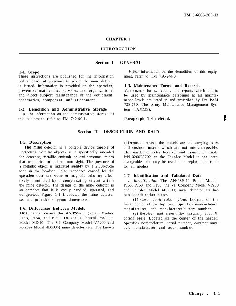
1-1. ScopeThese instructions are published for the informationand guidance of personnel to whom the mine detectoris issued. Information is provided on the operation;preventive maintenance services, and organizationaland direct support maintenance of the equipment,accessories, component, and attachment.
1-2. Demolition and Administrative Storagea. For information on the administrative storage of
this equipment, refer to TM 740-90-1.
b. For information on the demolition of this equip-ment, refer to TM 750-244-3.
1-3. Maintenance Forms and RecordsMaintenance forms, records and reports which are tobe used by maintenance personnel at all mainte-nance levels are listed in and prescribed by DA PAM738-750, The Army Maintenance Management Sys-tem (TAMMS).
Paragraph 1-4 deleted.
Section II. DESCRIPTION AND DATA
1-5. DescriptionThe mine detector is a portable device capable of
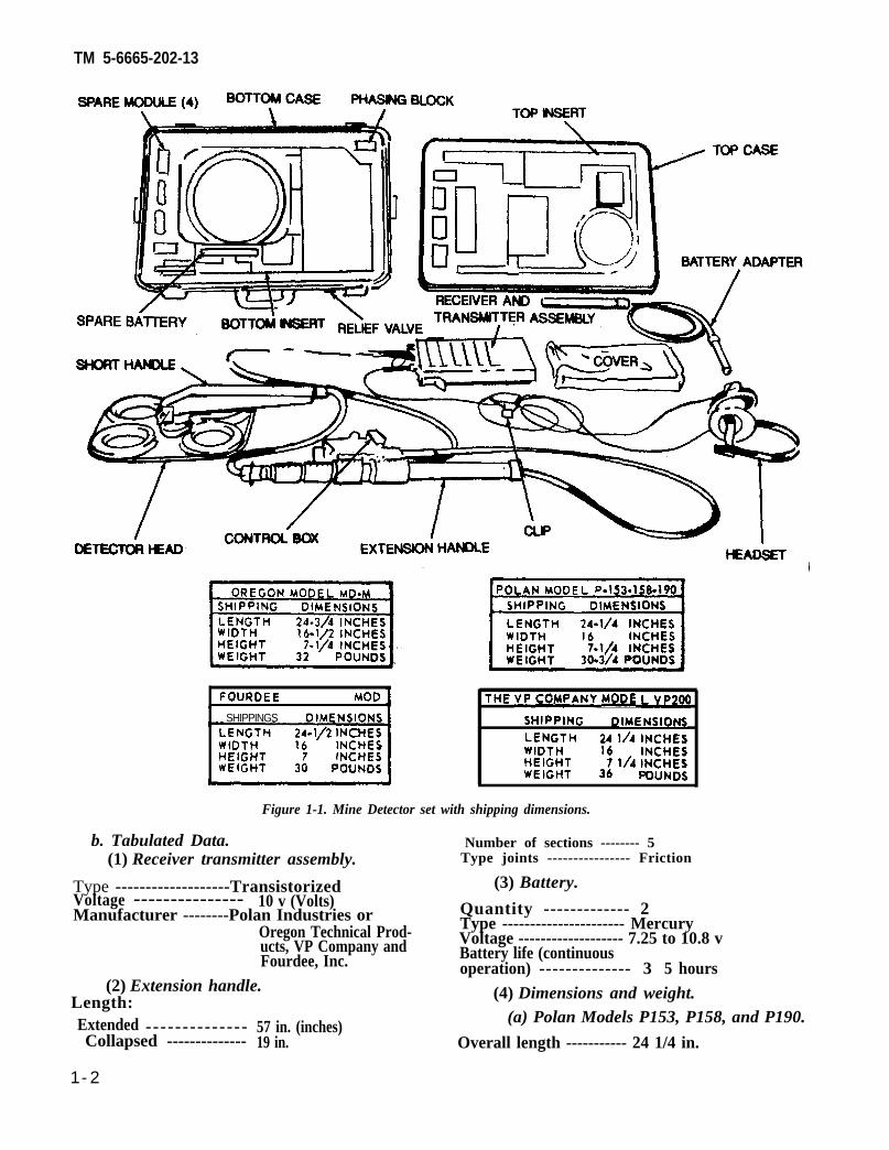
detecting metallic objects; it is specifically intendedfor detecting metallic antitank or anti-personnel minesthat are buried or hidden from sight. The presence ofa metallic object is indicated audibly by a 2,500-cycletone in the headset. False responses caused by theoperation over salt water or magnetic soils are effec-tively eliminated by a compensating circuit withinthe mine detector. The design of the mine detector isso compact that it is easily handled, operated, andtransported. Figure 1-1 illustrates the mine detectorset and provides shipping dimensions.
1-6. Differences Between ModelsThis manual covers the AN/PSS-11 (Polan ModelsP153, P158, and P190, Oregon Technical ProductsModel MD-M, The VP Company Model VP200 andFourdee Model 4D5000) mine detector sets. The known
differences between the models are the carrying casesand cushion inserts which are not interchangeable.The smaller diameter Receiver and Transmitter Cable,P/N13200E2702 on the Fourdee Model is not inter-changeable, but may be used as a replacement cablefor all models.
1-7. Identification and Tabulated Dataa. Identification. The AN/PSS-11 Polan Models
P153, P158, and P190, the VP Company Model VP200and Fourdee Model 4D5000) mine detector set hastwo identification plates.
(1) Case identification plate. Located on thefront, center of the top case. Specifies nomenclature,manufacturer, and manufacturer’s part number.
(2) Receiver and transmitter assembly identifi-cation plate. Located on the center of the header.Specifies nomenclature, serial number, contract num-ber, manufacturer, and stock number.
Change 2 1 - 1
TM 5-6665-202-13
FOURDEE MODEL4D5000-
SHIPPINGS DIMENSIONSLENGTH ffl/2 INCHESWIDTH INCHESHEIGHT 7 INCHESWEIGHT 30 POUNDS
THE VP COMPANY MODE LVp2~
SHIPPING DIMENSIONSLENGTH 24 1/4 INCHESWIDTH 16HEIGHT 7 1/4 !;%:WEIGHT 36 POUNDS
Figure 1-1. Mine Detector set with shipping dimensions.
b. Tabulated Data. Number of sections -------- 5(1) Receiver transmitter assembly. Type joints ---------------- Friction
Type -------------------Transistorized (3) Battery.Voltage --------------- 10 v (Volts)Manufacturer --------Polan Industries or Quantity ------------- 2
Oregon Technical Prod- Type ---------------------- MercuryVoltage ------------------- 7.25 to 10.8 vucts, VP Company and
Fourdee, Inc. Battery life (continuousoperation) -------------- 3 5 hours
(2) Extension handle.Length:Extended -------------- 57 in. (inches)Collapsed -------------- 19 in.
(4) Dimensions and weight.(a) Polan Models P153, P158, and P190.
Overall length ----------- 24 1/4 in.
1-2
TM 5-6665-202-13
Overall width -------------- 16 in. Overall height -------------- 7 in.Overall height -------------- 7 1/4 in. Weight ----------------------------- 30 lbs.Weight -------------------- 32 lb (pounds)
(5) Detector set characteristics.(b) Oregon Model MD-M.
Overall length -------------- 24 3/4 in.Overall width --------------- 16 1/2 in.Overall height -------------- 7 1/4 in.Weight -------------------- 30 3/4 lb.
(c) The VP Company Model
Overall length ------------- 24 1/2 in.Overall width -------------- 16 in.Overall height -------------- 7 l/2 in.Weight -------------------- 36 lb
(d) Fourdee Model 4D5000.
Overall length -------------- 24 1/2 in.Overall width -------------- 16 in.
Oscillation frequency ----------- 2,500 cps (cycles persecond)
Temperature range(operating) --------------- -25°F. to +125°F.
Temperature range
VP200. (storage) ---------------- -65°F to +155°F.Relative humidity
(operating) -------------- 100 percentRelative humidity
(storage) ------------------ 100 percent
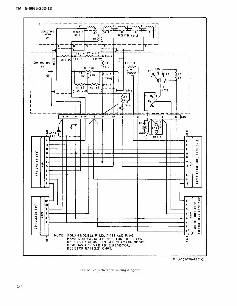
(6) Electrical wiring and schematic dia-grams. Refer to figure 1-2 and FO-1 (Locatedin back of Manual) for the electrical wiring andschematic diagrams.
1-3
TM 5-6665-202-13
Figure 1-2. Schematic wiring diagram.
1-4
TM 5-6665-202-13
CHAPTER 2
OPERATING INSTRUCTIONS
Section I. SERVICE UPON RECEIPT OF MATERIEL
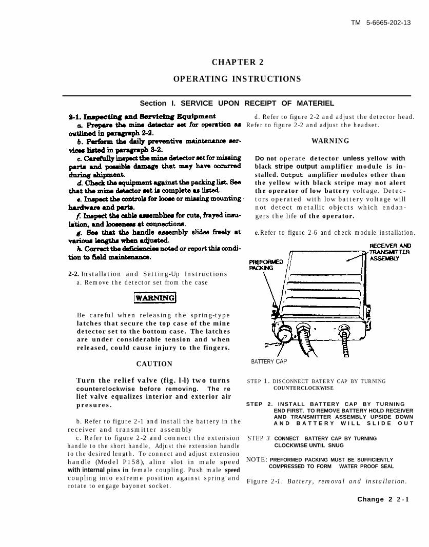
2-2. Installation and Setting-Up Instructionsa. Remove the detector set from the case
Be careful when releasing the spring-typelatches that secure the top case of the minedetector set to the bottom case. The latchesare under considerable tension and whenreleased, could cause injury to the fingers.
CAUTION
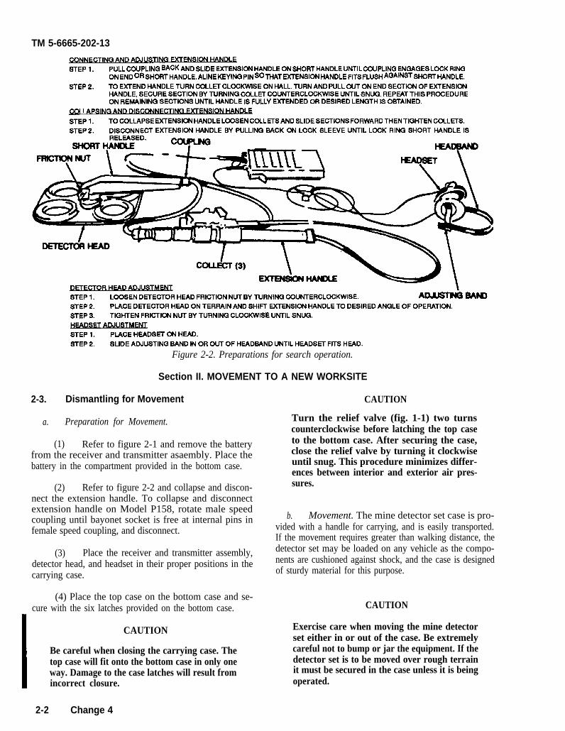
d. Refer to figure 2-2 and adjust the detector head.Refer to figure 2-2 and adjust the headset.
WARNING
Do not operate detector unless yellow withblack stripe output amplifier module is in-stalled. Output amplifier modules other thanthe yellow with black stripe may not alertthe operator of low battery voltage. Detec-tors operated with low battery voltage willnot detect metallic objects which endan-gers the life of the operator.
e. Refer to figure 2-6 and check module installation.
BATTERY CAP
Turn the relief valve (fig. l-l) two turns STEP 1. DISCONNECT BATERY CAP BY TURNINGcounterclockwise before removing. The re COUNTERCLOCKWISE
lief valve equalizes interior and exterior airp r e s u r e s . STEP 2. INSTALL BATTERY CAP BY TURNING
b. Refer to figure 2-1 and install the battery in thereceiver and transmitter assembly
c. Refer to figure 2-2 and connect the extension STEP 3handle to the short handle, Adjust the extension handle
END FIRST. TO REMOVE BATTERY HOLD RECEIVERAMD TRANSMITTER ASSEMBLY UPSIDE DOWNA N D B A T T E R Y W I L L S L I D E O U T
CONNECT BATTERY CAP BY TURNINGCLOCKWISE UNTIL SNUG
to the desired length. To connect and adjust extensionhandle (Model P158), aline slot in male speed NOTE: PREFORMED PACKING MUST BE SUFFICIENTLY
with internal pins in female coupling. Push male speedCOMPRESSED TO FORM WATER PROOF SEAL
coupling into extreme position against spring androtate to engage bayonet socket.
Figure 2-1. Battery, removal and installation.
Change 2 2 - 1
TM 5-6665-202-13
STEP 1. PULL COUPLING BACK AND SLIDE EXTENSION HANDLE ON SHORT HANDLE UNTIL COUPLING ENGAGES LOCK RINQON END OR SHORT HANDLE. ALlNE KEYING PIN SO THAT EXTENSION HANDLE FITS FLUSH AGAINST SHORT HANDLE.
STEP 2. TO EXTEND HANDLE TURN COLLET CLOCKWISE ON HALL. TURN AND PULL OUT ON END SECTION OF EXTENSIONHANDLE, SECURE SECTION BY TURNING COLLET COUNTERCLOCKWISE UNTIL SNUG. REPEAT THIS PROCEDUREON REMAINING SECTIONS UNTIL HANDLE IS FULLY EMENDED OR DESIRED LENGTH IS OBTAINED.
m I Ap~TINQ F~F~STEP 1. TO COLLAPSE EXTENSION HANDLE LOOBEN COLLETS AND SLIDE SECTIONS FORWARD THEN TIGHTEN CcXLETS.STEP 2. DISCONNECT EXTENSION HANDLE BY PULLING BACK ON LOCK SLEEVE UNTIL LOCK RING SHORT HANDLE IS
STEP 1. LOOSEN DETECTOR HEAD FRICTION NUT BY TURNING COUNTERCLOCKWISE.STEP 2. PLACE DETECTOR HEAD ON TERRAIN AND SHIIT EXTENSION HANDLE TO DESIRED ANGLE OF OPERATION.STEP 3. TIQHTEN FRICTION NUT BY TURNING CLOCKWISE UNTIL SNUG.
HFADSET ADJU=MFWSTEP 1. PIACE HEADSET ON HEAD.STEP 2. SLIDE ADJUSTING BAND IN OR OUT OF HEADBAND UNTIL HEADSET FITS HEAD.
Figure 2-2. Preparations for search operation.
Section II. MOVEMENT TO A NEW WORKSITE
2-3. Dismantling for Movement
a. Preparation for Movement.
(1) Refer to figure 2-1 and remove the batteryfrom the receiver and transmitter asaembly. Place thebattery in the compartment provided in the bottom case.
(2) Refer to figure 2-2 and collapse and discon-nect the extension handle. To collapse and disconnectextension handle on Model P158, rotate male speedcoupling until bayonet socket is free at internal pins infemale speed coupling, and disconnect.
(3) Place the receiver and transmitter assembly,detector head, and headset in their proper positions in thecarrying case.
(4) Place the top case on the bottom case and se-cure with the six latches provided on the bottom case.
CAUTION
Be careful when closing the carrying case. Thetop case will fit onto the bottom case in only oneway. Damage to the case latches will result fromincorrect closure.
CAUTION
Turn the relief valve (fig. 1-1) two turnscounterclockwise before latching the top caseto the bottom case. After securing the case,close the relief valve by turning it clockwiseuntil snug. This procedure minimizes differ-ences between interior and exterior air pres-sures.
b. Movement. The mine detector set case is pro-vided with a handle for carrying, and is easily transported.If the movement requires greater than walking distance, thedetector set may be loaded on any vehicle as the compo-nents are cushioned against shock, and the case is designedof sturdy material for this purpose.
CAUTION
Exercise care when moving the mine detectorset either in or out of the case. Be extremelycareful not to bump or jar the equipment. If thedetector set is to be moved over rough terrainit must be secured in the case unless it is beingoperated.
2-2 Change 4

TM 5-6665-202-13
NOTE 2-4. Reinstallation After Movement
If the mine detecting set is accidently dropped orsubjected to hard bumps, it should be thoroughly Refer to paragraph 2-2 for setting-up instructions afterinspected for damage before it is operated. movement.
2-5. General
Section III. CONTROLS AND INSTRUMENTS
2-6. Controls and Instruments
This section describes, locates, illustrates, and furnishes Refer to figure 2-3 for a complete description of thethe operator, or organizational maintenance personnel controls.sufficient informaiton about the various controls for properoperation of the mine detector set.
NOTE: NORMAL PO.SmONS OF mNTRoLs sTATED HERE ASSUME AN AMBIE~ TEMpE~~RE oF70 F. NOMAL POSITIONS MAY VARY WITH EXTREMES IN AMBlENT TEMPERATURE.
NOTE: NORMAL POSITIONS OF THE TWO CONTROL KNOBS ARE ALSO OBTAINED WHEN INDEXMARK ON EACH KNOB IS ALLV3NED WITH RELATED INDEX MARK ON CONTROL BOX.
Figure 2-3. Controls.
Section IV. OPERATION UNDER USUSAL CONDITIONS
2-7. General 2-8. Starting
a. The instructions in this section are published for the a. Preparation for Starting.information and guidance of the personnel responsible forthe operation of the AN/PSS-11 mine detector set. (1) Perform the setting-up instructions (para 2-2).
b. The operator must know how to perform every (2) Perform the daily preventive maintenanceoperation of which the mine detector set is capable. This services (para 3-2).section gives instructions on starting, operating, andstopping the mine detector set. Operation under unusual (3) Position headset on head.environmental conditions is also explained. Since terrainand weather are so variable, the operator may have to adapt (4) Attach receiver and transmitter assembly (fig.stated procedures to meet actual field conditions. 1-1) to pistol belt.
2-3
TM 5-6665-202-13
b. Starting. Refer to figure 2-4 and start the minedetector set.
2-9. Stopping
Refer to figure 2-4 and stop the mine detector set.
CAUTION
Do not leave the battery in the mine detector set whenthe set is not in use. The battery will sometimes corrode,causing damage to the terminals inside the batteryhousing. (Refer to fig. 2-1 for removal of battery).
2-10. Mine Detector Set Operation
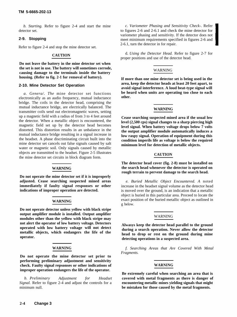
a. Genera/. The mine detector set functionselectronically as an audio frequency, mutual inductancebridge. The coils in the detector head, comprising themutual inductance bridge, are electrically balanced. Thetransmitter coils send out electromagnetic waves, settingup a magnetic field with a radius of from 3 to 4 feet aroundthe detector. When a metallic object is encountered, themagnetic field set up by the detector head becomesdistorted. This distortion results in an unbalance in themutual inductance bridge resulting in a signal increase inthe headset. A phase discriminating circuit built into themine detector set cancels out false signals caused by saltwater or magnetic soil. Only signals caused by metallicobjects are transmitted to the headset. Figure 2-5 illustratesthe mine detector set circuits in block diagram form.
WARNING
Do not operate the mine detector set if it is improperlyadjusted. Cease searching suspected mined areasimmediately if faulty signal responses or otherindications of improper operation are detected.
WARNING
Do not operate detector unless yellow with black stripeoutput amplifier module is installed. Output amplifiermodules other than the yellow with black stripe maynot alert the operator of low battery voltage. Detectorsoperated with low battery voltagemetallic objects, which endangersoperator.
will not detectthe life of the
WARNING
Do not operate the mine detector set prior toperforming preliminary adjustment and sensitivitycheck. Faulty signal repsonses or other indications ofimproper operation endangers the life of the operator.
b. Preliminary Adjustment for HeadsetSignal. Refer to figure 2-4 and adjust the controls for aminimum null.
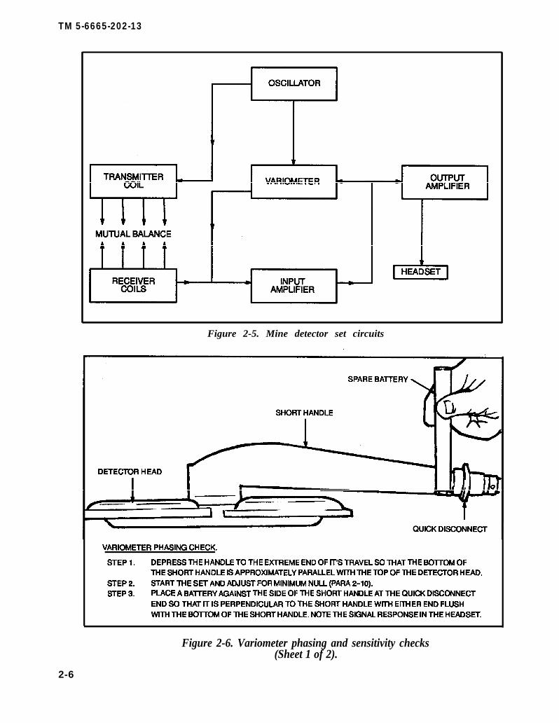
c. Variometer Phasing and Sensitivity Check-. Referto figures 2-6 and 2-6.1 and check the mine detector forvariometer phasing and sensitivity. If the detector does notmeet minimum requirements specified in figures 2-6 and2-6.1, turn the detector in for repair.
d. Using the Detector Head. Refer to figure 2-7 forproper positions and use of the detector head.
WARNING
If more than one mine detector set is being used in thearea, keep the detector heads at least 20 feet apart, toavoid signal interference. A loud beat-type signal willbe heard when units are operating too close to eachother.
WARNING
Cease searching suspected mined area if the usual lowlevel (2,500 cps) signal changes to a sharp piercing highlevel signal. When battery voltage drops below 7 voltsthe output amplifier module automatically induces alow raspy signal. Operation of equipment during thiscondition imperils life as voltage is below the requiredminimum level for detection of metallic objects.
CAUTION
The detector head cover (fig. 2-8) must be installed onthe search head whenever the detector is operated onrough terrain to pervent damage to the search head.
e. Buried Metallic Object Encountered. A notedincrease in the headset signal volume as the detector headis moved over the ground, is an indication that a metallicobject is buried in this particular area. Proceed to locate theexact position of the buried metallic object as outlined ing below.
WARNING
Alwasys keep the detector head parallel to the groundduring a search operation. Never allow the detectorhead to drop or rest on the ground during minedetecting operations in a suspected area.
f. Searching Areas that Are Covered With MetalFragments.
WARNING
Be extremely careful when searching an area that iscovered with metal fragments as there is danger ofencountering metallic mines yielding signals that mightbe mistaken for those caused by the metal fragments.
2-4 Change 3

TM 5-6665-202-13
STARTING:STEP 1. HOLD DETECTOR HEAD FIVE FEET ABOVE TERRAIN AND AT LEAST FIVE FEET FROM METALLIC OBJECTS.
“STEP 2. TURN POWER SELECTOR SWITCH TOM POSITION.
STEP 3. ALlNE INDEX MARK ON FINE “X CONTROL KNOB WITH RELATED INDEX MARK ON CONTROL BOX. ALlNEFINE “R” CONTROL KNOB IN LIKE MANNER. (2,500 CPS RINGING SIGNAL SHOULD BE HEARD INHEADSET). ADJUST CONTROL KNOBS UNTIL MINIMUM NULL (SIGNAL) IS OBTAINED.
STEP 4. IF NULL IS NOT OBTAINED. TURN POWER SELECTOR SWITCH TO LQ POSITION AND REPEAT STEP 3.
CAUTION: DO NOT START UNIT UNLESS DETECTOR HEAD IS AT LEAST FIVE FEET FROM METALLIC OBJECTS.VOLTAGE INDUCED BY METALLIC OBJECTS CAN SERIOUSLY DAMAGE UNTUNED CIRCUITS.
NOTE: IF MINIMUM NULL CANNOT BE OBTAINED REPORT THE CONDITION TO ORGANIZATIONAL MAINTENANCE.
~TOPPING:
TURN POWER SELECTOR SWITCH TO m POSITION.
Figure 2-4. Starting and stopping the mine detector set.
When searching over an area that is covered with shrapnelor where metal fragmentation is evident, resultant signalswill be similar to those produced where an actual mine isencountered. In searching an area such as this, sweep theground with the detector head at heights ranging from 3 to8 inches, depending on the quantity, size, and distributionfo metal fragments. Response from small metallic objectswill be eliminated, but larger objects such as metallic mineswill yield adequate signals.
g. Locating Exact Position of Buried MetallicObject. When a sharp change in signal volume is heard,move the detector head slowly from side to side. Increasedsignal will be noted as either side of the detector head is
passed over the metallic object; a decrease will be noted asthe center of the detector head moves over the buriedobject. If no decrease in signal volume is noted, as thecenter of the detector head moves over the buried object,a saturated condition exists. If this occurs, raise the detectorhead 1 or 2 inches higher and repeat the sweeping motion.If necessary, raise the detector head until a definite changein volume is evident when the detector head moves over theburied object. At this point the detector head is directlyover the location of the buried object.
h. Procedure Upon Completion of Search. Turn offthe mine detector set when a search operation is completed(para 2-8).
2-5
TM 5-6665-202-13
Figure 2-5. Mine detector set circuits
VARIOMETER PHASING CHECK.
STEP 1. DEPRESS THE HANDLE TO THE EXTREME END OF IT’S TRAVEL SO THAT THE BOITOM OFTHE SHORT HANDLE IS APPROXIMATELY PARALLEL WITH THE TOP OF THE DETECTOR HEAD.
STEP 2. START THE SET AND ADJUST FOR MINIMUM NULL (PARA 2-lo).STEP 3. PLACE A BAITERYAGAINST THE SIDE OF THE SHORT HANDLE AT THE QUICK DISCONNECT
END SO THAT IT IS PERPENDICULAR TO THE SHORT HANDLE WITH EITHER END FLUSHWITH THE BOITOM OF THE SHORT HANDLE. NOTE THE SIGNAL RESPONSE IN THE HEADSET.
Figure 2-6. Variometer phasing and sensitivity checks(Sheet 1 of 2).
2-6

TM 5-6665-202-13
STEP 4. PLACE THE PHASING BLOCK; FIRST OVER THE WHITE TEST DOT ON THE DETECTOR HEAD, AND THENON THE SIDE OPPOSITE THE WHITE DOT. NOTE THE SIGNAL RISE IN THE HEADSET.
STEP 5. THE SIGNAL RESPONSE WHEN THE PHASING BLOCK IS PLACED ON EITHER SIDE OF THE DETECTORHEAD, SHOULD BE LESS THAN THE SIGNAL FROM THE BAITERY. A NOTICEABLY HIGHER SIGNAL FROMTHE PHASING BLOCK INDICATES INCORRECT VARIOMETER PHASING IN WHICH CASE REPORTTHE CONDITION TO ORGANIZATIONAL MAINTENANCE. VARIOMETER PHASING ADJUSTMENT ISPERFORMED AT DIRECT SUPPORT MAINTENANCE.
ER PHASING CHECK (ALTFRNAT~
W-EPI.
STEP 2.
STEP 3.
IN THE CENTER OF A SMOOTHED 3-4 FT. DIAMETER CIRCLE, FREE OF ANY METALLIC OBJECTS, PLACEAN M-16 CARTRIDGE (BULLET END DOWN, PRIMER END LEVEL WITH THE SOIL SURFACE).
PLACE THE SEARCH HEAD ATA HEIGHT OF APPROXIMATELY 2 INCHES ABOVE THE SOIL AND AT LEAST2 FT. FROM ANY METALLIC OBJECT (CARTRIDGE). NUI-I. THE DETECTOR IN THE “INT” POSITION.HOLD THE DETECTOR OFF THE GROUND BETWEEN 5-6 INCHES. PASS THE FRONT TWO COILS SLOWLYOVER THk M-16 CARTRIDGE. TWO DISTINCT PEAKS OF SOUND WITH A VERY NOTICEABLE DECREASE INSOUND BETWEEN THEM SHOULD BE HEARD IN THE HEADSET. THE TWO PEAKS SHOULD BEAPPROXIMATELY EQUAL IN LOUDNESS.
THE 5.6 lNcH HEiGHT is CONSIDERED ACCeptable. IF THE DETECTOR HEAD HEIGHT NEEDS TO BE ADJusTED To4-5 INCHES TO ACHIEVE THE TWO PEAKS, IT IS CONSIDERED MARGINAL. IF THE HEAD HEIGHT NEEDS TO BEADJUSTED BELOW 4 INCHES TO ACHIEVE THE TWO PEAKS, THE DETECTOR SHOULD BE RETURNED FOR REPAIR.
Figure 2-6. Variometer Phasing and Sensitivity Checks(sheet 2 of 2).
Change 3 2 - 7
TM 5-6665-202-13
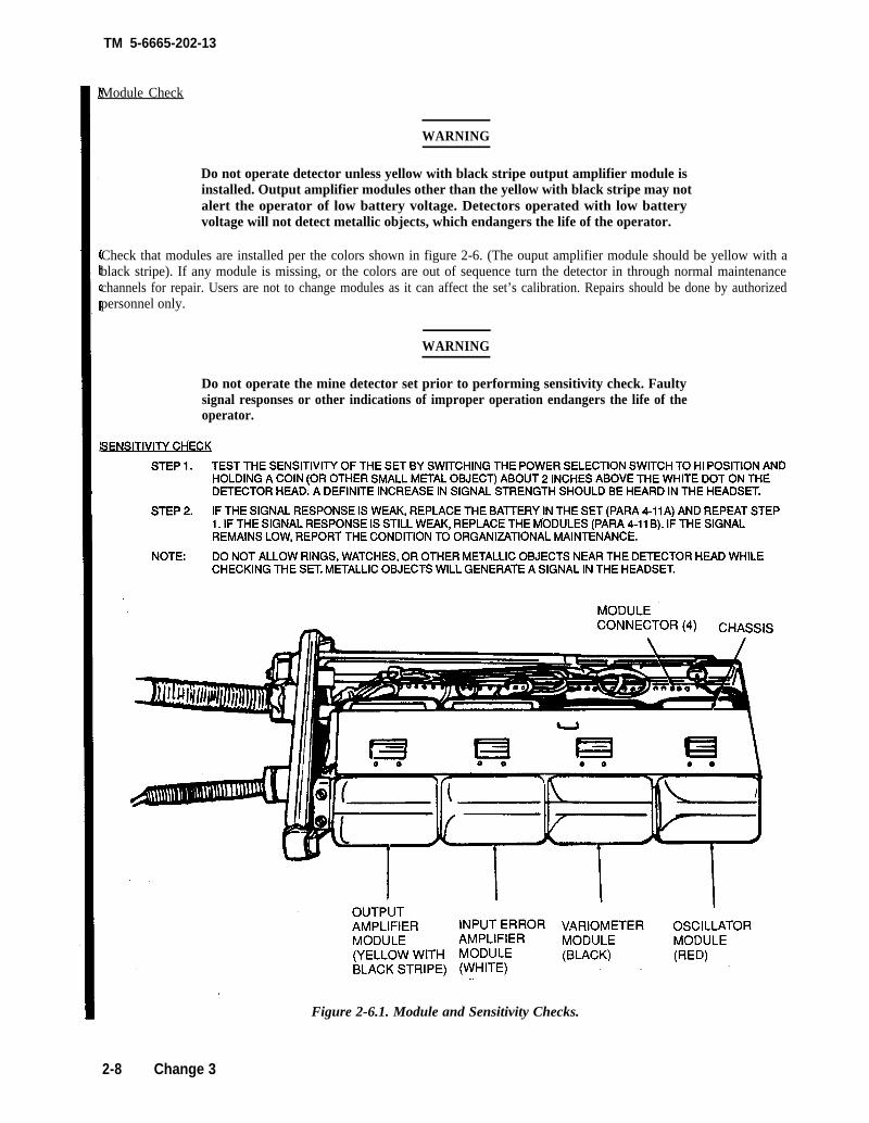
Module Check
WARNING
Do not operate detector unless yellow with black stripe output amplifier module isinstalled. Output amplifier modules other than the yellow with black stripe may notalert the operator of low battery voltage. Detectors operated with low batteryvoltage will not detect metallic objects, which endangers the life of the operator.
Check that modules are installed per the colors shown in figure 2-6. (The ouput amplifier module should be yellow with ablack stripe). If any module is missing, or the colors are out of sequence turn the detector in through normal maintenancechannels for repair. Users are not to change modules as it can affect the set’s calibration. Repairs should be done by authorizedpersonnel only.
WARNING
Do not operate the mine detector set prior to performing sensitivity check. Faultysignal responses or other indications of improper operation endangers the life of theoperator.
wwwmm&xSTEP 1. TEST THE SENSITIVITY OF THE SET BY SWITCHING THE POWER SELECTION SWITCH TO HI POSITION AND
HOLDING A COIN (OR OTHER SMALL METAL OBJECT) ABOUT 2 INCHES ABOVE THE WHITE DOT ON THEDETECTOR HEAD. A DEFINITE INCREASE IN SIGNAL STRENGTH SHOULD BE HEARD IN THE HEADSET.
STEP 2. IF THE SIGNAL RESPONSE IS WEAK, REPLACE THE BAITERY IN THE SET (PARA 4-11A) AND REPEAT STEP1. IF THE SIGNAL RESPONSE IS STILL WEAK, REPLACE THE M’ODULES (PARA 4-11 B). IF THE SIGNALREMAINS LOW, REPORT THE CONDITION TO ORGANIZATIONAL MAINTENANCE.
NOTE: DO NOT ALLOW RINGS, WATCHES, OR OTHER METALLIC OBJECTS NEAR THE DETECTOR HEAD WHILECHECKING THE SET. METALLIC OBJECTS WILL GENERATE A SIGNAL IN THE HEADSET.
Figure 2-6.1. Module and Sensitivity Checks.
2-8 Change 3
TM 5-6665-202-13
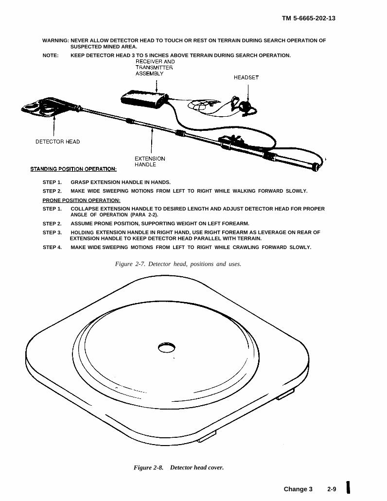
WARNING: NEVER ALLOW DETECTOR HEAD TO TOUCH OR REST ON TERRAIN DURING SEARCH OPERATION OFSUSPECTED MlNED AREA.
NOTE: KEEP DETECTOR HEAD 3 TO 5 INCHES ABOVE TERRAIN DURING SEARCH OPERATION.
STEP 1. GRASP EXTENSION HANDLE IN HANDS.
STEP 2. MAKE WIDE SWEEPING MOTIONS FROM LEFT TO RIGHT WHILE WALKING FORWARD SLOWLY.
PRONE POSITION OPERATION:
STEP 1. COLLAPSE EXTENSION HANDLE TO DESIRED LENGTH AND ADJUST DETECTOR HEAD FOR PROPERANGLE OF OPERATION (PARA 2-2).
STEP 2. ASSUME PRONE POSITION, SUPPORTING WEIGHT ON LEFT FOREARM.
STEP 3. HOLDING EXTENSION HANDLE IN RIGHT HAND, USE RIGHT FOREARM AS LEVERAGE ON REAR OFEXTENSION HANDLE TO KEEP DETECTOR HEAD PARALLEL WITH TERRAIN.
STEP 4. MAKE WIDE SWEEPING MOTIONS FROM LEFT TO RlGHT WHILE CRAWLING FORWARD SLOWLY.
Figure 2-7. Detector head, positions and uses.
Figure 2-8. Detector head cover.
Change 3 2-9
TM 5-6665-202-13
Section V. Operation Under Unusual Conditions
2-11. Operation in Temperatures Below 40° F.
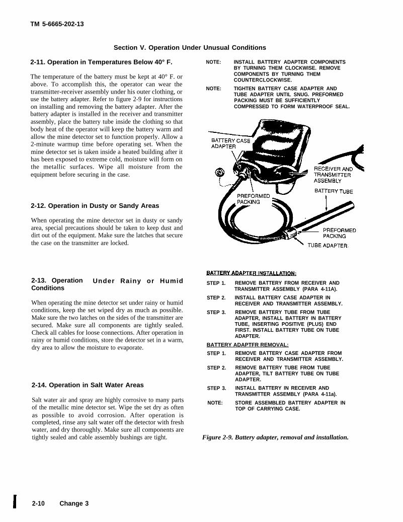
The temperature of the battery must be kept at 40° F. orabove. To accomplish this, the operator can wear thetransmitter-receiver assembly under his outer clothing, oruse the battery adapter. Refer to figure 2-9 for instructionson installing and removing the battery adapter. After thebattery adapter is installed in the receiver and transmitterassembly, place the battery tube inside the clothing so thatbody heat of the operator will keep the battery warm andallow the mine detector set to function properly. Allow a2-minute warmup time before operating set. When themine detector set is taken inside a heated building after ithas been exposed to extreme cold, moisture will form onthe metallic surfaces. Wipe all moisture from theequipment before securing in the case.
2-12. Operation in Dusty or Sandy Areas
When operating the mine detector set in dusty or sandyarea, special precautions should be taken to keep dust anddirt out of the equipment. Make sure the latches that securethe case on the transmitter are locked.
2-13. Operation Under Rainy or HumidConditions
When operating the mine detector set under rainy or humidconditions, keep the set wiped dry as much as possible.Make sure the two latches on the sides of the transmitter aresecured. Make sure all components are tightly sealed.Check all cables for loose connections. After operation inrainy or humid conditions, store the detector set in a warm,dry area to allow the moisture to evaporate.
2-14. Operation in Salt Water Areas
Salt water air and spray are highly corrosive to many partsof the metallic mine detector set. Wipe the set dry as oftenas possible to avoid corrosion. After operation iscompleted, rinse any salt water off the detector with freshwater, and dry thoroughly. Make sure all components aretightly sealed and cable assembly bushings are tight.
2-10 Change 3
NOTE: INSTALL BATTERY ADAPTER COMPONENTSBY TURNING THEM CLOCKWISE. REMOVECOMPONENTS BY TURNING THEMCOUNTERCLOCKWISE.
NOTE: TIGHTEN BATTERY CASE ADAPTER ANDTUBE ADAPTER UNTIL SNUG. PREFORMEDPACKING MUST BE SUFFICIENTLYCOMPRESSED TO FORM WATERPROOF SEAL.
STEP 1. REMOVE BATTERY FROM RECEIVER ANDTRANSMITTER ASSEMBLY (PARA 4-11A).
STEP 2. INSTALL BATTERY CASE ADAPTER INRECEIVER AND TRANSMlTTER ASSEMBLY.
STEP 3. REMOVE BATTERY TUBE FROM TUBEADAPTER, INSTALL BATTERY IN BATTERYTUBE, INSERTING POSITIVE (PLUS) ENDFIRST. INSTALL BATTERY TUBE ON TUBEADAPTER.
BATTERY ADAPTFR REMOVAL:
STEP 1. REMOVE BATTERY CASE ADAPTER FROMRECEIVER AND TRANSMITTER ASSEMBLY.
STEP 2. REMOVE BATTERY TUBE FROM TUBEADAPTER, TILT BATTERY TUBE ON TUBEADAPTER.
STEP 3. INSTALL BATTERY IN RECEIVER ANDTRANSMlTTER ASSEMBLY (PARA 4-11a).
NOTE: STORE ASSEMBLED BATTERY ADAPTER INTOP OF CARRYING CASE.
Figure 2-9. Battery adapter, removal and installation.

TM 5-6665-202-13
CHAPTER 3
OPERATOR/CREW MAINTENANCE INSTRUCTIONS
Section I. LUBRICATION lNSTRUCTlONS
No lubrication of the mine detector set will be performed by the operator/crew personnel.
Section Il. PREVENTIVE MAINTENANCE CHECKS AND SERVICES
3-1. General
To insure that the mine detecting set is readyfor operation at all times, it must be inspectedsystematically so that defects may be discoveredand corrected before they result in serious dam-age or failure. The necessary preventive mainte-nance checks and services to be performed arelisted as described in table 3-1. The item num-bers indicate the sequence of minimum inspec-tion requirements. Defects discovered during op-eration of the unit will be noted for future cor-rection to be made as soon as operation hasceased. Stop operation immediately if a deficiency
is noted during operation which would damagethe equipment if operation were continued. Alldeficiencies and shortcomings will be recordedtogether with the corrective action taken cm form2404 at the earliest possible opportunity.
3-2. Preventive Maintenance Checks andServices
Refer to table 3-1 and perform the daily preven-tive maintenance checks and services. If equipment is not in use, perform maintenance checksand services on a weekly basis.
Table 3-1. Preventive Maintenance Checks and Services
Operator Maintenance Category Daily Schedule (or weekly)
Interval
Beforeomratioai
1
2
s
4
6
6
7
Huence No.
During)peration
10
11
AfterOI)eratiOn
.13
14
15
16
Item to be insDected
Receiver and Trans-
mitter
Battery
Headset
Cables
Battery Adapter
Detector Head and
Balance Coil
Assembly
Caee
Procedure
Clean receiver and tr; msmitter.
Check for corrosion, missing
hardware or other (Iefect%
Check for proper ope]ation
Check for corrosion 01* other
damage.
Remove battery from battery
tube
Clean headset
Check for audio tone
Check for worn, crack ed or
frayed :ablee.
Check for damaged or defective
battery adapter and worn,
cracked or frayed CI lble.
Clean assembly and cleck for
damage and defects
Clean case and check for worn,
damaged, or defecti re case,
lining, seal, latches, handle,
or vent.
Psragraph reference
para 2-8
para 2-2
para 2-9
para 2-2
para 9-10
para 2-4
para 2-2
para 3-7
para 2-11
paras 2-2
and 3-6
Change 1 3-1
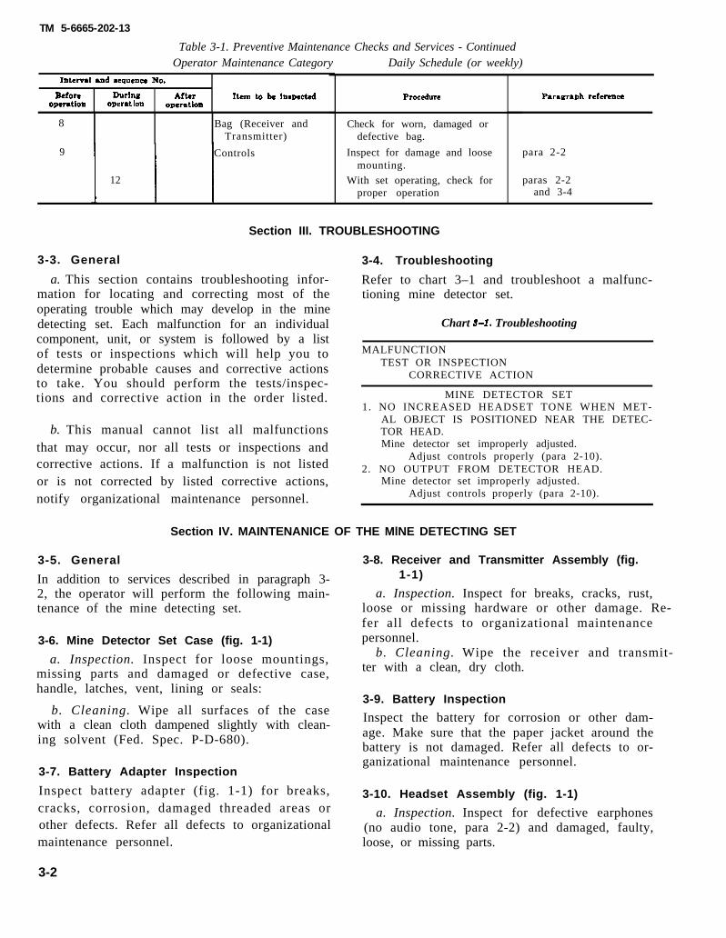
TM 5-6665-202-13
Table 3-1. Preventive Maintenance Checks and Services - ContinuedOperator Maintenance Category Daily Schedule (or weekly)
Interval and seauence No.
Before During After Item to be hmpect.edoperation omrat ion operation
8 Bag (Receiver andTransmitter)
9 Controls
12
Procedure
Check for worn, damaged ordefective bag.
Inspect for damage and loosemounting.
With set operating, check forproper operation
Paragraph reference
para 2-2
paras 2-2and 3-4
Section III. TROUBLESHOOTING
3-3. General 3-4. Troubleshooting
a. This section contains troubleshooting infor-mation for locating and correcting most of theoperating trouble which may develop in the minedetecting set. Each malfunction for an individualcomponent, unit, or system is followed by a listof tests or inspections which will help you todetermine probable causes and corrective actionsto take. You should perform the tests/inspec-tions and corrective action in the order listed.
b. This manual cannot list all malfunctionsthat may occur, nor all tests or inspections andcorrective actions. If a malfunction is not listedor is not corrected by listed corrective actions,notify organizational maintenance personnel.
Refer to chart 3–1 and troubleshoot a malfunc-tioning mine detector set.
Chart 8-1. Troubleshooting
MALFUNCTIONTEST OR INSPECTION
CORRECTIVE ACTION
MINE DETECTOR SET1. NO INCREASED HEADSET TONE WHEN MET-
AL OBJECT IS POSITIONED NEAR THE DETEC-TOR HEAD.Mine detector set improperly adjusted.
Adjust controls properly (para 2-10).2. NO OUTPUT FROM DETECTOR HEAD.
Mine detector set improperly adjusted.Adjust controls properly (para 2-10).
Section IV. MAINTENANICE OF THE MlNE DETECTING SET
3-5. General
In addition to services described in paragraph 3-2, the operator will perform the following main-tenance of the mine detecting set.
3-6. Mine Detector Set Case (fig. 1-1)
a. Inspection. Inspect for loose mountings,missing parts and damaged or defective case,handle, latches, vent, lining or seals:
b. Cleaning. Wipe all surfaces of the casewith a clean cloth dampened slightly with clean-ing solvent (Fed. Spec. P-D-680).
3-7. Battery Adapter Inspection
Inspect battery adapter (fig. 1-1) for breaks,cracks, corrosion, damaged threaded areas orother defects. Refer all defects to organizationalmaintenance personnel.
3-2
3-8. Receiver and Transmitter Assembly (fig.1-1)
a. Inspection. Inspect for breaks, cracks, rust,loose or missing hardware or other damage. Re-fer all defects to organizational maintenancepersonnel.
b. Cleaning. Wipe the receiver and transmit-ter with a clean, dry cloth.
3-9. Battery Inspection
Inspect the battery for corrosion or other dam-age. Make sure that the paper jacket around thebattery is not damaged. Refer all defects to or-ganizational maintenance personnel.
3-10. Headset Assembly (fig. 1-1)
a. Inspection. Inspect for defective earphones(no audio tone, para 2-2) and damaged, faulty,loose, or missing parts.

TM 5-6665-202-13
b. Service. Wipe the headset with a clean clothand tighten any loose connections. Refer all de-fects to organizational maintenance personnel.
3-11. Detector Head and Balance CoilAssembly
a. Inspection.(1) Inspect the detector head (fig. 1-1) for
breaks, cracks, damaged threaded areas, corrodedelectrical leads, or other defects.
(2) Refer all defects to organizational main-tenance personnel.
b. Service. Wipe any accumulation of dirt ormoisture from the detector head and balance coilassembly with a clean, dry cloth.
CAUTIONDo not use cleaning solvent on plasticparts of mine detector set. The compo-nents may be damaged if they arecleaned with some types of solvent.
3-3
TM 5-6665-202-13
CHAPTER 4
ORGANIZATlONAL MAINTENANCE INSTRUCTIONS
Section I. SERVICE UPON RECEIPT OF MATERIEL
4-1. Inspecting and Servicing the Equipment (2) Servicing. Wipe the battery with a
a. Battery Adapter. clean, dry cloth.
(1) Inspection. Inspect battery adapter (fig.NOTE
Discard cloth after wiping battery clean, Traces2-9) for breaks, cracks, corrosion, damaged of battery corrosion absorbed by the cloth may
threaded areas, or other defects. Replace a dam- damage other parts of the set.
aged or defective battery adapter. (3) Test. Refer to paragraph 4-11 and test
(2) Servicing. Wipe the battery adapter battery. Replace a weak, damaged, or defectivewith a clean, dry cloth. battery.
b. Battery. 4-2. Installation
(1) Inspect. Refer to paragraph 3-9 and in- Refer to paragraphspect the battery. mine detecting set.
2–2 for installation of the
Section Il. MOVEMENT TO A NEW WORKSITE
Refer to paragraphs 2-3 and 2-4 for instructions on moving the mine detecting set to a new worksite.
Section Ill. REPAIR PARTS, SPECIAL TOOLS, AND EQUIPMENT
4-3. Special Tools and Equipment 4-4. Maintenance Repair Parts
No special tools are required to perform organ- Repair parts are listed and illustrated in the re-pair parts and special tools list covering organ-
izational maintenance on the mine detecting set. izational maintenance for this equipment in TM5-6665-202-23P.
Section IV. LUBRICATION INSTRUCTIONS
No lubrication of the mine detecting set will be performed by organizational maintenance personnel.
Section V. PREVENTIVE MAINTENANCE CHECKS AND SERVICES
4-5. GeneralTo insure that the mine detecting set is readyfor operation at all times, it must be inspectedsystematically so that defects may be discoveredand corrected before they result in serious dam-age or failure. The necessary preventive mainte-nance checks and services to be performed arelisted as described in table 4-1. The item num-bers indicate the sequence of minimum inspec-
tion requirements. Defects discovered during op-eration of the unit will be noted for future cor-rection to be made as soon as operation hasceased. Stop operation immediately if a deficiencyis noted during operation which would damagethe equipment if operation were continued. Alldeficiencies and shortcomings will be recordedtogether with the corrective action taken on form2404 at the earliest possible opportunity.
Change 1 4-1
TM 5-6665-202-13
Sequencenumber
2
3
4
5
6
Table 4-1.OrganizationalMai
Item to be Inspected
Battery
Headset
Battery adapter
Detector head andbalance coil assembly
Case
Modules
4-6. Preventive Maintenance
Preventive Maintenance Checks and Servicesntenance Category Monthly Schedule (or quarterly)
Procedures
Clean corroded battery. Test battery voltage.Replace a weak, damaged, or defective battery.
Check headset for damage, defects, and propertone response.
Replace damaged or defective battery adapterand cable. Test battery adapter for continuity.
Tighten loose mounting.
Tighten loose mounting. Replace worn, damagedor defective case, lining seal, handle latches,or vent.
Replace damaged or defective modules.
Paragraph References
para 4-11a
para 4-8
para 4-10
para 4-9
para 4-11b
Checks and maintenance checks and services. If equipment is not inServices use, perform maintenance checks and services on aRefer to table 4-1 and perform the monthly preventive quarterly basis.
Section VI. TROUBLESHOOTING4-7. General
a. This section contains troubleshooting informationfor locating and correcting most of the operating troublewhich may develop in the mine detecting set. Eachmalfunction for an individual component, unit, or systemis followed by a list of tests or inspections which will helpyou to determine probable causes and corrective actions totake. You should perform the tests/inspections andcorrective action in order listed.
b. This manual cannot list all malfunctions that mayoccur, nor all tests or inspections and corrective actions. Ifa malfunction is not listed or is not corrected by listedcorrective actions, notify direct support maintenancepersonnel.
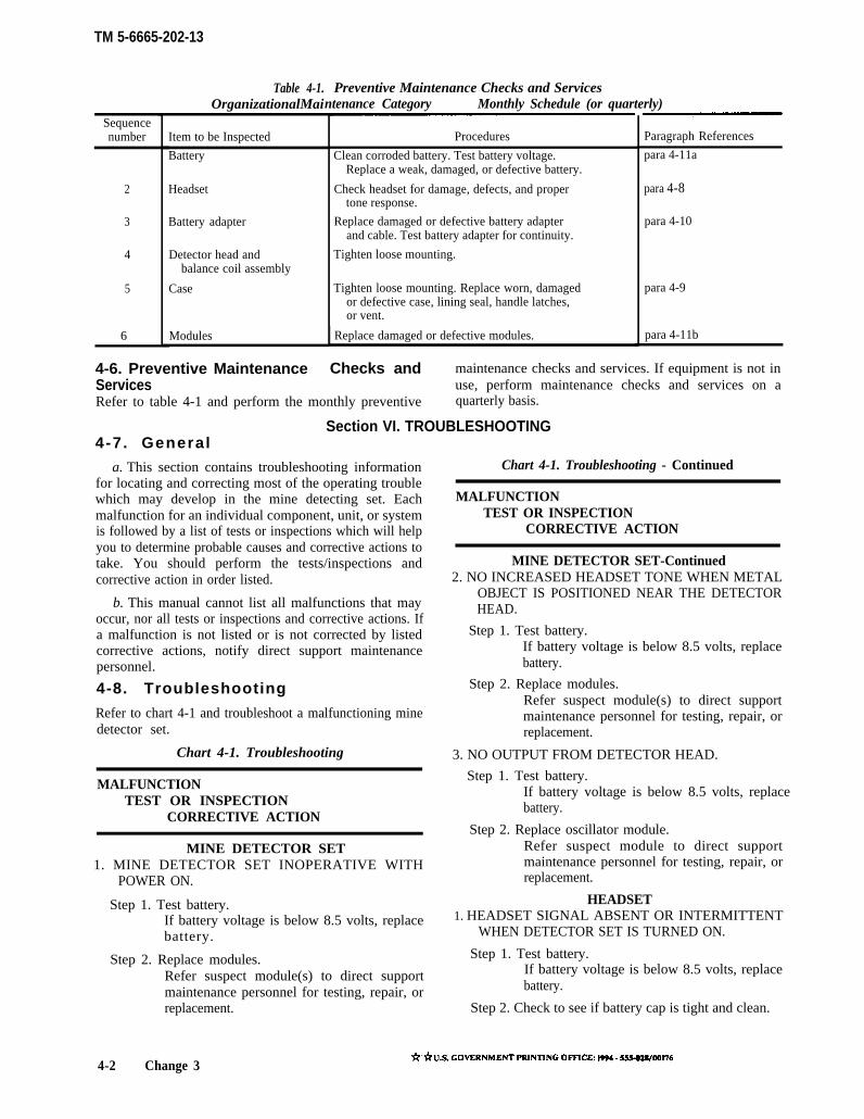
4-8. Troubleshooting
Refer to chart 4-1 and troubleshoot a malfunctioning minedetector set.
Chart 4-1. Troubleshooting
MALFUNCTIONTEST OR INSPECTION
CORRECTIVE ACTION
MINE DETECTOR SET1. MINE DETECTOR SET INOPERATIVE WITH
POWER ON.
Step 1. Test battery.If battery voltage is below 8.5 volts, replacebattery.
Step 2. Replace modules.Refer suspect module(s) to direct supportmaintenance personnel for testing, repair, orreplacement.
Chart 4-1. Troubleshooting - Continued
MALFUNCTIONTEST OR INSPECTION
CORRECTIVE ACTION
MINE DETECTOR SET-Continued2. NO INCREASED HEADSET TONE WHEN METAL
OBJECT IS POSITIONED NEAR THE DETECTORHEAD.
Step 1. Test battery.If battery voltage is below 8.5 volts, replacebattery.
Step 2. Replace modules.Refer suspect module(s) to direct supportmaintenance personnel for testing, repair, orreplacement.
3. NO OUTPUT FROM DETECTOR HEAD.
Step 1. Test battery.If battery voltage is below 8.5 volts, replacebattery.
Step 2. Replace oscillator module.Refer suspect module to direct supportmaintenance personnel for testing, repair, orreplacement.
HEADSET1. HEADSET SIGNAL ABSENT OR INTERMITTENT
WHEN DETECTOR SET IS TURNED ON.
Step 1. Test battery.If battery voltage is below 8.5 volts, replacebattery.
Step 2. Check to see if battery cap is tight and clean.
4-2 Change 3h.LS. GOVERNMENT PRINTING OFFICE: IW4 - SSS-0WOO176
TM 5-6665-202-13
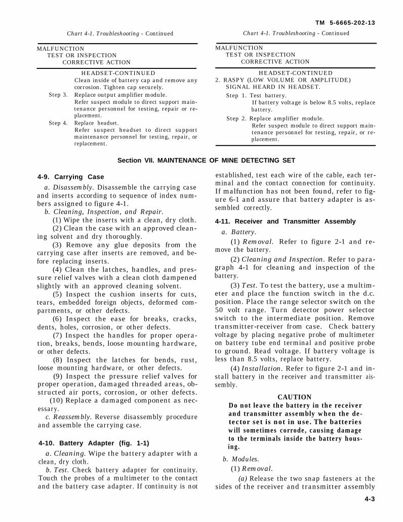
Chart 4-1. Troubleshooting - Continued Chart 4-1. Troubleshooting - Continued
MALFUNCTION MALFUNCTIONTEST OR INSPECTION TEST OR INSPECTION
CORRECTIVE ACTION CORRECTIVE ACTION
Step 3.
Step 4.
HEADSET-CONTINUEDClean inside of battery cap and remove anycorrosion. Tighten cap securely.Replace output amplifier module.Refer suspect module to direct support main-tenance personnel for testing, repair or re-placement.Replace headset.Refer suspect headset to direct supportmaintenance personnel for testing, repair, orreplacement.
HEADSET-CONTINUED2. RASPY (LOW VOLUME OR AMPLITUDE)
SIGNAL HEARD IN HEADSET.Step 1. Test battery.
If battery voltage is below 8.5 volts, replacebattery.
Step 2. Replace amplifier module.Refer suspect module to direct support main-tenance personnel for testing, repair, or re-placement.
Section VII. MAINTENANCE OF MINE DETECTING SET
4-9. Carrying Case
a. Disassembly. Disassemble the carrying caseand inserts according to sequence of index num-bers assigned to figure 4-1.
b. Cleaning, Inspection, and Repair.(1) Wipe the inserts with a clean, dry cloth.(2) Clean the case with an approved clean-
ing solvent and dry thoroughly.(3) Remove any glue deposits from the
carrying case after inserts are removed, and be-fore replacing inserts.
(4) Clean the latches, handles, and pres-sure relief valves with a clean cloth dampenedslightly with an approved cleaning solvent.
(5) Inspect the cushion inserts for cuts,tears, embedded foreign objects, deformed com-partments, or other defects.
(6) Inspect the ease for breaks, cracks,dents, holes, corrosion, or other defects.
(7) Inspect the handles for proper opera-tion, breaks, bends, loose mounting hardware,or other defects.
(8) Inspect the latches for bends, rust,loose mounting hardware, or other defects.
(9) Inspect the pressure relief valves forproper operation, damaged threaded areas, ob-structed air ports, corrosion, or other defects.
(10) Replace a damaged component as nec-essary.
c. Reassembly. Reverse disassembly procedureand assemble the carrying case.
4-10. Battery Adapter (fig. 1-1)
a. Cleaning. Wipe the battery adapter with aclean, dry cloth.
b. Test. Check battery adapter for continuity.Touch the probes of a multimeter to the contactand the battery case adapter. If continuity is not
established, test each wire of the cable, each ter-minal and the contact connection for continuity.If malfunction has not been found, refer to fig-ure 6-1 and assure that battery adapter is as-sembled correctly.
4-11. Receiver and Transmitter Assembly
a. Battery.(1) Removal. Refer to figure 2-1 and re-
move the battery.(2) Cleaning and Inspection. Refer to para-
graph 4-1 for cleaning and inspection of thebattery.
(3) Test. To test the battery, use a multim-eter and place the function switch in the d.c.position. Place the range selector switch on the50 volt range. Turn detector power selectorswitch to the intermediate position. Removetransmitter-receiver from case. Check batteryvoltage by placing negative probe of multimeteron battery tube end terminal and positive probeto ground. Read voltage. If battery voltage isless than 8.5 volts, replace battery.
(4) Installation. Refer to figure 2-1 andstall battery in the receiver and transmittersembly.
in-ais-
CAUTIONDo not leave the battery in the receiverand transmitter assembly when the de-tector set is not in use. The batterieswill sometimes corrode, causing damageto the terminals inside the battery hous-ing.
b. Modules.(1) Removal.
(a) Release the two snap fasteners at thesides of the receiver and transmitter assembly
4-3
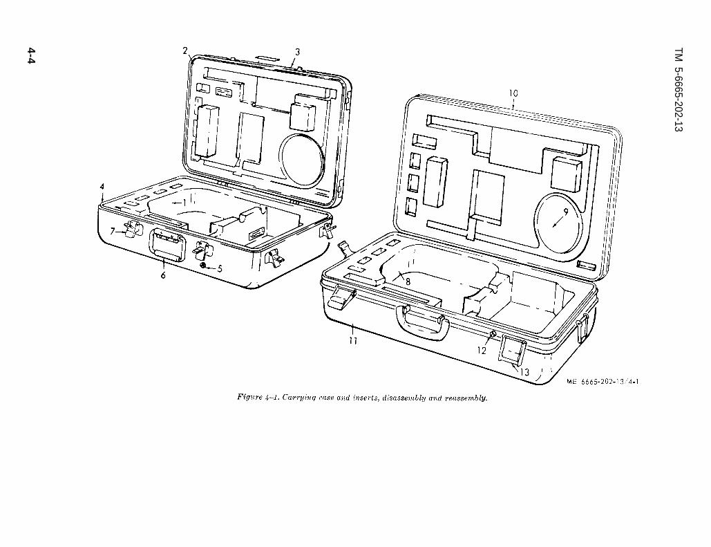
Figure 4-1.
TM 5-6665-202-13
4-4
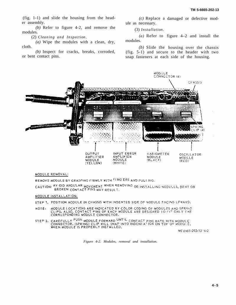
(fig. 1-1) and slide the housing from the head-er assembly.
(b) Refer to figure 4-2, and remove themodules.
(2) Cleaning and Inspection.(a) Wipe the modules with a clean, dry,
cloth.(b) Inspect for cracks, breaks, corroded,
or bent contact pins.
(c) Replace aule as necessary.
(3) Installation.
(a) Refer tomodules.
(b) Slide the
TM 5-6665-202-13
damaged or defective mod-
figure 4–2 and install the
housing over the chassis(fig. 5-1) and secure to the header with twosnap fasteners at each side of the housing.
OUTPUT INPUT ERROR VARIOMETER OSCILLATORAMPLIFIER AMPLIFIER MODULEMODULE MODULE (BLAcK)
MODULE
(YELLOW)(RED)
(WHITE)
MODULE REMOVAL:
REMOVE MODULE BY GRASPING FIRMLY WITH FI NG ERS AND PULLING.
CAUTION: AV OID ANGULAR MOVEMENT WHEN REMOVING OR INSTALLING MODULES, BENT ORBROKEN CONTACT PINS MAY RESULT.
MODULE INSTALLATION:
STEP 1.
NOTE:
STEP 2.
POSITION MODULE IN CHASSIS WITH INDENTED SIDE OF MODULE FACING UPWARD.
MODULE LOCATIONS ARE INDICATED BY COLOR CODING OF MODULES AND SPRINGCLIPS. ALSO, CONTACT PINS OF EACH MODULE ARE DESIGNED TO FIT ONLY THECORRESPONDING MODULE CONNECTOR.
CAREFULLY PUSH MODULE FORWARD UNTIL CONTACT PINS MATE WITH MODULECONNECTOR. (SPRING) CLIP WILL SNAP INTO INDENTATION ON TOP OF MODULE,WHEN MODULE IS PROPERLY INSTALLED.
ME 6665-202-13 ‘4.2
Figure 4-2. Modules, removal and installation.
4 - 5
TM 5-6665-202-13
CHAPTER 5
DIRECT SUPPORT MAINTENANCE INSTRUCTIONS
Section I. REPAIR PARTS AND SPECIAL TOOLS AND EQUIPMENT
5-1. Tools and Equipment maintenance on the mine detecting set are listed inTools, equipment, and repair parts issued with or section III of appendix B.authorized for the mine detecting set are listed andillustrated in TM 5-6665-202-23P. An electronic AC 5-3. Maintenance Repair PartsRMS voltmeter replaces the vacuum tube voltmeter. Repair parts and equipment are listed and illustrated
in the repair parta and special tools list covering direct5-2. Special Tools and Equipment support maintenance for this equipment in TM
The special tools required to perform direct support 5-6665-202-23P
Section II. TROUBLESHOOTING
5-4. Generala. This section contains troubleshooting information
for locating and correcting most of the operating troublewhich may develop in the mine detecting set. Eachmalfunction for an individual component, unit, or sys-tem is followed by a list of tests or inspections whichwill help you to determine probable causes and correc-tive actions to take. You should perform the tests/inspections and corrective action in the order listed.
b. This manual cannot list all malfunctions that mayoccur, nor all tests or inspections and correctiveactions. If a malfunction is not lieted or is not correctedby listed corrective actions, notify depot maintenancepersonnel.
5-5. TroubleshootingRefer to chart 5-1 and troubleshoot a malfunctioningmine detector set.
Chart 5-1. Troubleshooting
MALFUNCTIONTEST OR INSPECTION
CORRECTIVE ACTION
1. MINE DETECTOR FAILS TO START WHENSWITCH IS TURNED ON.Step 1. Inspect for loose, corroded, broken or defective
battery connections.Clean corroded battery connections, tightenloose, or replace broken battery connections.
Chart 5-1. Troubleshooting-Continued
MALFUNCTIONTEST OR INSPECTION
CORRECTIVE ACTION
2.
3.
Step 2. Check for defective switch.Test switch for continuity while in the ONposition. Replace switch if test indicatesan “open” circuit.
Step 3. Check for defective terminal board.Remove modules end test terminal board.Replace a defective terminal board.
HEADSET DOES NOT GIVE SATISFACTORYSIGNALStep 1.
Step 2.
Step 3.
Check for defective headset.Teat headset and replace if either or bothearphones are defective.Check for defective detector head.Test transmitter coil and receiver coil locatedin detector head and replace coils if defective.Check for defective terminal board.Remove modules end test terminal board.Replace a defective terminal board.
SET CUTS OFF AND ON DURING OPERATIONStep 1.
Step 2.
Step 3.
Check for loose connection at detector head.Tighten loose or repair broken connectionat detector head.Check for defective detector head.Test transmitter coil and receiver coil locatedin detector head and replace coils if defective.Check for defective terminal board.Remove modules and test terminal board.Replace a defective terminal board.
5-1

TM 5-6665-202-13
Chart 5-1. Troubleshooting - Continued Chart 5-1. Troubleshooting - Continued
MALFUNCTION MALFUNCTIONTEST OR INSPECTION TEST OR INSPECTION
CORRECTIVE ACTION CORRECTIVE ACTION
3. SET CUTS OFF AND ON DURING OPERATION - 5.CONTINUEDStep 4.
Step 5.
Step 6.
Check for defective headset.Test headset and replace if either or bothearphones are defective.Check for defective capacitor.Remove and test capacitor. Replace a defectivecapacitor.Check for defective power selector switch.Test power selector switch for continuity while 6.in the “ON” position. Replace switch if testindicates an “open” circuit.
SIGNAL DOES NOT INCREASE AS DETECTOR HEADCOMES CLOSER TO METAL OBJECT.
4.
Step 1.
Step 2.
Check for defective detector head.Test transmitter coil and receiver coil locatedin detector head and replace coils if defective.Check for defective terminal board.
PROPER ADJUSTMENT CANNOT BE OBTAINEDWITH FINE X CONTROLStep 1. Check for defective Fine X control.
Remove Fine X control resistor (19, fig. 6-5)and test. Replace a defective Fine Xcontrol resistor.
Step 2. Check for defective terminal board.Remove modules and test terminal board.Replace a defective terminal board.
PROPER ADJUSTMENT CANNOT BE OBTAINEDWITH FINE R CONTROL.Step 1. Check for defective Fine R control resistor.
Remove Fine R control resistor (16, fig. 6-5)and test. Replace a defective Fine Rcontrol resistor.
Step 2. Check for defective terminal board.Remove modules and test terminal board.Replace terminal board if defective.
Remove modules and test terminal board. 7.Replace a defective terminal board.
SET FAILS SENSITIVITY TEST(Para 2-10, Fig 2-6)Step 1. Check battery; replace if necessary.Step 2. Check variometer phasing adjustment using
the phasing fixture and magnetite tube.
Section III. REMOVAL AND INSTALLATION OF MAJOR COMPONENTSAND AUXILIARIES
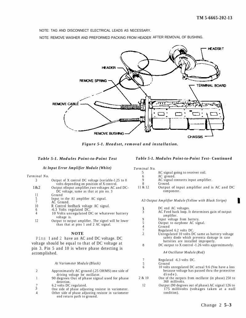
5-6. Headseta. Removal.
(1) Remove the housing from the transmitter(para 4-11b).
(2) Refer to figure 5-1 and remove the headset.b. Installation.
(1) Refer to figure 5-1 and install the headset.(2) Install the housing on the transmitter (para
4-11b).
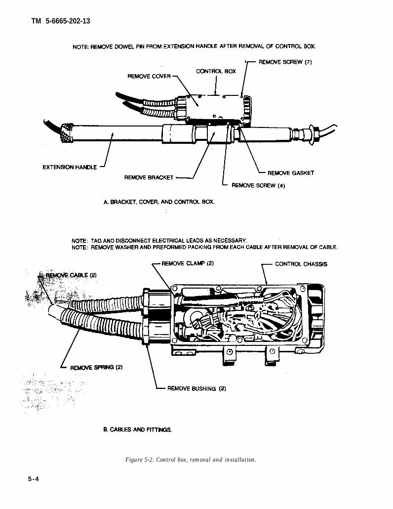
5-7. Control Boxa. Removal. Refer to figure 5-2 and remove the
control box.b. Installation. Refer to figure 5-2 and install the
control box.
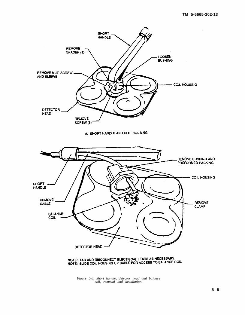
5-8. Detector Head and Balance Coil Assemblya. Removal. Refer to figure 5-3 and remove the
detector head and balance coil assembly.b. Installation. Refer to figure 5-3 and install the
detector head and balance coil assembly.
5-9. Modulesa. Removal. Refer to paragraph 4-11b and remove
the four modules from the transmitter and receiverassembly.
Change 2
b. Test. Refer to Table 5-1 and perform the point-to-point test applicable to each of the four modules.Replace a defective module. When performing thesetests, use an electronic AC RMS Voltmeter (1-B, Appen-dix C) and Test Leads (2-B, Appendix C).
c. Installation. Refer to paragraph 4-11b and installthe four modules in the transmitter and receiverassembly.
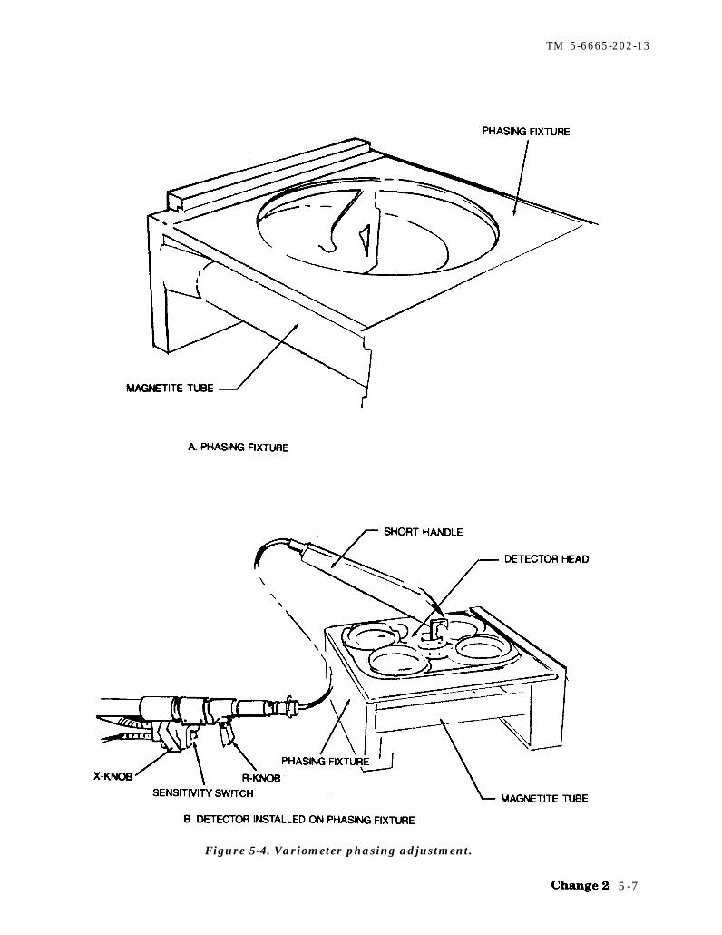
d. Variometer Phasing Adjustment. Adjust the de-tecting set with the detection head positioned on thephasing fixture (figure 5-4). The phasing fixture willpermit optimizing the phase adjustment so that thepresence of magnetite will produce the smallest back-ground signal possible. The phasing fixture should beused whenever a variometer module not previouslyphased to the particular detector is inserted in thedetector. The phasing fixture and detector head shouldrest on a non-metallic table or stand whose construc-tion can be of plastic or wood except there can be nometal fasteners used. Keep metallic objects (watches,rings, belt buckles, tools, metal lab stools, etc.) awayfrom the detection head at least 2 1/2 feet in alldirections. A non-metallic alignment tool (plastic wandwith a small metal blade mounted in the end) should beused for any adjustments. The following steps willenable the phase adjustment to be properly made.
5 - 2
TM 5-6665-202-13
NOTE: TAG AND DISCONNECT ELECTRICAL LEADS AS NECESSARY.
NOTE: REMOVE WASHER AND PREFORMED PACKING FROM HEADER AFTER REMOVAL OF BUSHING.
Figure 5-1. Headset, removal and installation.
Table 5-1. Modules Point-to-Point Test
At Input Error Amplifier Module (White)5
Terminal No.3
1&2
11571064
12
Output of X control DC voltage (variable-1.25 to 0volts depending on position of X control.
Output ofinput amplifier,two voltages AC and DC-DC voltage, same as that at pin no. 3
GroundInput to the A1 amplifier AC signal.AC Ground.R Control feedback voltage AC signal.-6.3 Volts regulated DC.10 Volts unregulated DC or whatever battery
voltage is.Output to output amplifier. The signel will be lower
than that at pins 1 and 2 AC signal.
NOTEPins 1 and 2 have an AC and DC voltage. DC
voltage should be equal to that of DC voltage atpin 3. Pin 5 and 10 is where phase detecting isaccomplished.
At Variometer Module (Black)
2 Approximately AC ground (.25 OHMS) one side ofdriving voltage for oscillator.
1 90 degrees Out of phase signal used for phasedetection.
7 6.2 volts DC regulated.One side of phase adjusting resistor in variometer.
4 Other side of phase adjusting resistor in variometerend return path to ground.
Table 5-1. Modules Point-to-Point Test- Continued
Terminal No.
698
11 & 12
AC signal going to receiver coil.AC ground.AC signal connects input amplifier.Ground.Output of input amplifier and is AC and DC
component.
A3 Output Amplifier Module (Yellow with Black Stripe)
3
95472
8
756
2 & 10
12
DC end AC voltages.AC Feed back loop. It determines gain of output
amplifier.Input voltage from battery.Output to earphone AC signal.GroundRegulated 6.2 volts DC.Unregulated 10 volts DC same as battery voltage
safety diode which preventa damage in casebatteries are installed improperly.
DC output to X control -1.26 volts approximately.
A4 Oscillator Module (Red)
Regulatad -6.3 volts DC.Ground10 volts unregulated DC actual 9.6 (You have a loss
because voltage has passed thru the protectived i ode ) .
One of the outputs from oscillator (in phase) 250 to360 millivolts.
Output (90 degrees out of phase) AC signal 126 to175 millivolts (voltages taken at a null3condition).
Change 2 5-3
TM 5-6665-202-13
Figure 5-2. Control box, removal and installation.
5-4
TM 5-6665-202-13
Figure 5-3. Short handle, detector head and balancecoil, removal and installation.
5 - 5
TM 5-6665-202-13
(1) Disconnect the collapsed long handle from theshort handle. Slide this unit along the cable at least 2.5feet away from the detector head (placement near thetransmitter/receiver package).
(2) Place detector head on the phasing fixture(figure 5-4).
(3) Position the short handle on the detector headto an angle of 46 degrees with the horizontal.
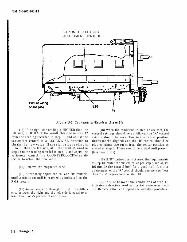
(4) Remove the transmitter/receiver cover andconnect the RMS Voltmeter to point E4 and E16 (seefigure 5-5).
(5) Adjust the “R” control (ten turn potentiometer)to the center of its rotation (five turns from either endof its rotation) and align the index marks.
(6) Adjust the “X” control (one turn potentiometer)to the center of its rotation and align the index marks.
(7) Insure that the magnetite tube is not posi-tioned in the phasing fixture.
(8) Turn the detector on and set the selectorswitch to the intermediate (INT) position. The RMSmeter will read up scale. Adjust the meter sensitivityfor a mid-scale reading.
(9) Using the non-metallic tuning wand, adjustthe variometer control (A-2 module) (see figure 5-5) toobtain a null (minimum AC millivolts) as indicated onthe RMS meter. Reduce meter sensitivity as necessaryto achieve the lowest meter reading.
NOTE
The initial measurement values (step 10 andstep 11) will vary from detector to detector. Thenumber of measurements/adjustment steps willvary from detector to detector and will dependupon the right/left balance point. The end resultof the balance between the right (step 10) and theleft (step 11) are important factors, not the nu-merical values obtained.
(10) Place the magnetite tube on the right side ofthe phasing fixture, (right side is identified by the“white dot” on the detector head). Record the readingindicated on the meter.
(11) Place the magnetite tube on the left side ofthe phasing fixture. Record the RMS meter reading.
(12) Subtract the lesser meter reading from thelarger one (step 10& step 11) and divide the result bytwo.
(13) Place the magnetite tube on the right side.
5-6 Change 2
TM 5-6665-202-13
Figure 5-4. Variometer phasing adjustment.
5-7
TM 5-6665-202-13
VARIOMETER PHASINGADJUSTMENT CONTROL
Figure 5-5. Transmitter/Receiver Assembly
(14) If the right side reading is HIGHER than theleft side, SUBTRACT the result obtained in step 12from the reading recorded in step 10 and adjust thevariometer control in a CLOCKWISE direction toobtain the new value. If the right side reading isLOWER than the left side, ADD the result obtained instep 12 to the reading recorded in step 10 and adjust thevariometer control in a COUNTERCLOCKWISE di-rection to obtain the new value.
(15) Remove the magnetite tube.
(16) Alternately adjust the "X" and "R" controlsuntil a minimum null is reached as indicated on theRMS meter.
(17) Repeat steps 10 through 16 until the differ-ence between the right and the left side is equal to orless then + or -5 percent of each other.
(18) When the conditions in step 17 are met, thecontrol settings should be as follows: the "X" controlsetting should be very close to the center position(index marks aligned) and the “R” control should beplus or minus two turns from the center position asstated in step 5. There should be a good null present(less than 7 mv).
(19) If “R” control does not meet the requirementsof step 18, center the “R” control as per step 5 and adjustR6 (inside the control box) for a good null. A minoradjustment of the “R” control should restore the "lessthan 7 mv" requirement of step 18.
(2) Failure to meet the conditions of step 18indicates a defective head and or A-2 variometer mod-ule. Replace either and repeat the complete procedure.
5-8 Change 2
TM 5-6665-202-13
CHAPTER 6
REPAIR OF MINE DETECTOR SET
6-1. Battery Adapter
a. Removal. Refer to figure 2-9 and removethe battery adapter.
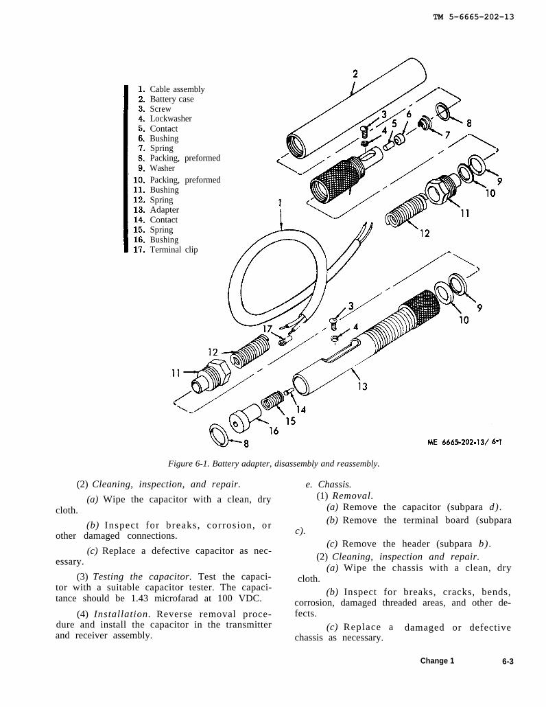
b. Disassembly. Refer to figure 6-1 and dis-assemble the battery adapter.
c. Cleaning, Inspection, and Repair.(1) Clean the contacts, terminals, and cable
with a clean, dry cloth, Clean all other parts withcleaning solvent (Fed. Spec. P-D-680) and drythoroughly.
(2) Inspect for cracks, breaks, dents, rust,damaged threaded areas, or other defects.
(3) Replace damaged or deteriorated con-tacts, terminals, or cable. Replace componentswhich have damaged threaded areas. Replacesprings that are bent, broken or which have losttension. Replace defective bushings and packingas necessary.
d. Reassembly. Refer to figure 6-1 and reas-semble the battery adapter.
e. Installation. Refer to figure 2-9 and installthe battery adapter.
6-2. Receiver and Transmitter Assembly
a. General. The receiver and transmitter as-sembly consists of a header, cover, four moduleswhich contain sealed circuitry, battery tube, ter-minal board, capacitor, cables and electricalleads, and the chassis to which most of the com-ponents are mounted. The item is designed in acompact manner for ease of handling and trans-porting.
b. Header.(1) Removal.
(a) Remove the modules (para 4-11b).(b) Remove the headset (para 5-6).(c) Refer to figure 6-2 and remove the
header.(2) Cleaning, inspection and repair.
(a)cloth.
(b)or missing
Wipe the headset with a clean, dry
Inspect for breaks, cracks, rust, loose,mounting hardware, or other damage.
(c) Replace a damaged or defective head-er as necessary.
(3) Installation.(a) Refer to figure 6-2 and install the
header.(b) Install the headset (para 5-6).(c) Install the modules (para 4-11b).
c. Terminal Board.(1) General. The terminal board consists of
a printed circuit board and four module connec-tors. A rectangular spacer separates the terminalboard from the chassis.
(2) Test. Refer to tables 6-1 and 6-2 andperform the point-to-point voltage and resistancechecks with terminal board installed but withmodules removed. If terminal board is defective,remove and replace.
(3) Removal.(a) Remove the modules (para 4-11b).(b) Refer to figure 6-3 and remove the
terminal board.(4) Cleaning, inspection, and repair.
(a) Wipe the terminal board with a clean,dry cloth. Clean corrosion from terminals andelectrical components with an approved corrosionremoving compound (FSN 6850-550-5565,MIL-C-14460A). Clean electrical componentswith electrical part cleaner (FSN 6850-664-5641).
(b) Inspect for breaks, cracks, corrosion,or other defects.
(c) Replace a damaged or defective ter-minal board m necessary.
(5) Installation.(a) Refer to figure 6-3 and install tht
terminal board.(b) Install the modules (para 4-11b)
d. Capacitor.(1) Removal.
(a) Remove the housing (para 4-11b)(b) Refer to figure 6-4 and remove the
capacitor.
6-1
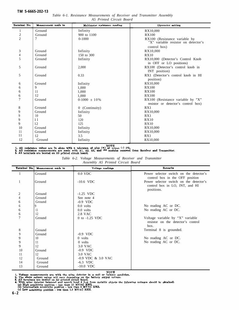
TM 5-6665-202-13Table 6-1. Resistance Measurements of Receiver and Transmitter Assembly
Terminal No.
122
345
5
5
66667
89
9910111112
Measurement made to
GroundGround7
GroundGroundGround
Ground
Ground
Ground91112Ground
GroundGround
9 101 l12GroundGround12
Ground
A5 Printed Circuit Board
Multimeter resistance reading
Infinity900 to 11000-1000
Infinity150 to 300Infinity
2,000
0.33
Infinity1,0001,0001,0000-1000 ± 10%
0 (Continuity)Infinity50120125InfinityInfinity3.5Infinity
Ohmmeter setting
RX10,000RX100RX100 (Resistance variable by
"X" variable resistor on detector’scontrol box)
RX10,000RX10RX10,000 (Detector’s Control Knob
in OFF or LO positions)RX100 (Detector’s control knob in
INT position)RX1 (Detector’s control knob in HI
position)RX10,000RX100RX100RX100RX100 (Resistance variable by ”X”
resistor or detector’s control box)RX1RX10,000RX1RX10RX10RX10,000RX10,000RX1RX10,000
NOTE1. All resistance values are in ohms with a tolerancb of P1US (+) or minus (-) Wo.2. All resistance measurements are made with Al, A2, A9, and A4 modules removed from Receiver and Transmitter.8. All t.ermhmls are located cm A6 printed circuit board.
Terminal No.
1
1
2466667
899991011121413
Table 6-2. Voltage Measurements of Receiver and Transmitter
Measurement made to
Ground
Ground
GroundGroundGround
91112Ground
GroundGround101112Ground12GroundGroundGround
Assembly A5 Printed Circuit Board
Voltage readings
0.0 VDC
-10.6 VDC
-1.25 VDCSee note 4-0.9 VDC0.0 volts0.0 volts2.8 VAC0 to -1.25 VDC
-0.9 VDC0 volts0 volts3.0 VAC-0.9 VDC3.0 VAC-0.9 VDC & 3.0 VAC-6.3 VDC-10.0 VDC
Remarks
Power selector switch on the detector’scontrol box in the OFF position
Power selector switch on the detector’scontrol box in LO, INT, and HIpositions.
No reading AC or DC.No reading AC or DC.
Voltage variable by “X” variableresistor on the detector’s controlbox.
Terminal 8 is grounded.
No reading AC or DC.No reading AC or DC.
NOTEL Voltage measurements are with the mine detector hi a null or bakmce condition.Z. The above voltage values will vary depending on the battery output voltage.8. All tirminals are located on A5 printed circuit bawd.4. With mine detector balanced and search head 9 feet from metallic objects the following voltages should be obtained:
(a) High sensitivity position - less than 16 MVAC RMS.(b) Intermediate sensitivity position - less than 5 MVAC RMS.(c) LOW sensitivity position - less than 1.6 MVAC RMS.
6 - 2
TM 5-6665-202-13
Cable assemblyBattery caseScrewLockwasherContactBushingSpringPacking, preformedWasherPacking, preformedBushingSpringAdapterContactSpringBushingTerminal clip
Figure 6-1. Battery adapter, disassembly and reassembly.
(2) Cleaning, inspection, and repair.
(a) Wipe the capacitor with a clean, drycloth.
(b) Inspect for breaks, corrosion, orother damaged connections.
(c) Replace a defective capacitor as nec-essary.
(3) Testing the capacitor. Test the capaci-tor with a suitable capacitor tester. The capaci-tance should be 1.43 microfarad at 100 VDC.
(4) Installation. Reverse removal proce-dure and install the capacitor in the transmitterand receiver assembly.
e. Chassis.(1) Removal.
(a) Remove the capacitor (subpara d).(b) Remove the terminal board (subpara
c).(c) Remove the header (subpara b).
(2) Cleaning, inspection and repair.(a) Wipe the chassis with a clean, dry
cloth.(b) Inspect for breaks, cracks, bends,
corrosion, damaged threaded areas, and other de-fects.
(c) Replace a damaged or defectivechassis as necessary.
Change 1 6-3

TM 5-6665-202-13
Figure 6-2. Header, removal and installation.
NOTE: TAG AND DISCONNECT ELECTRICAL LEADS AS NECESSARY.
Figure 6-3. Terminal board, removal and installation.
6-4
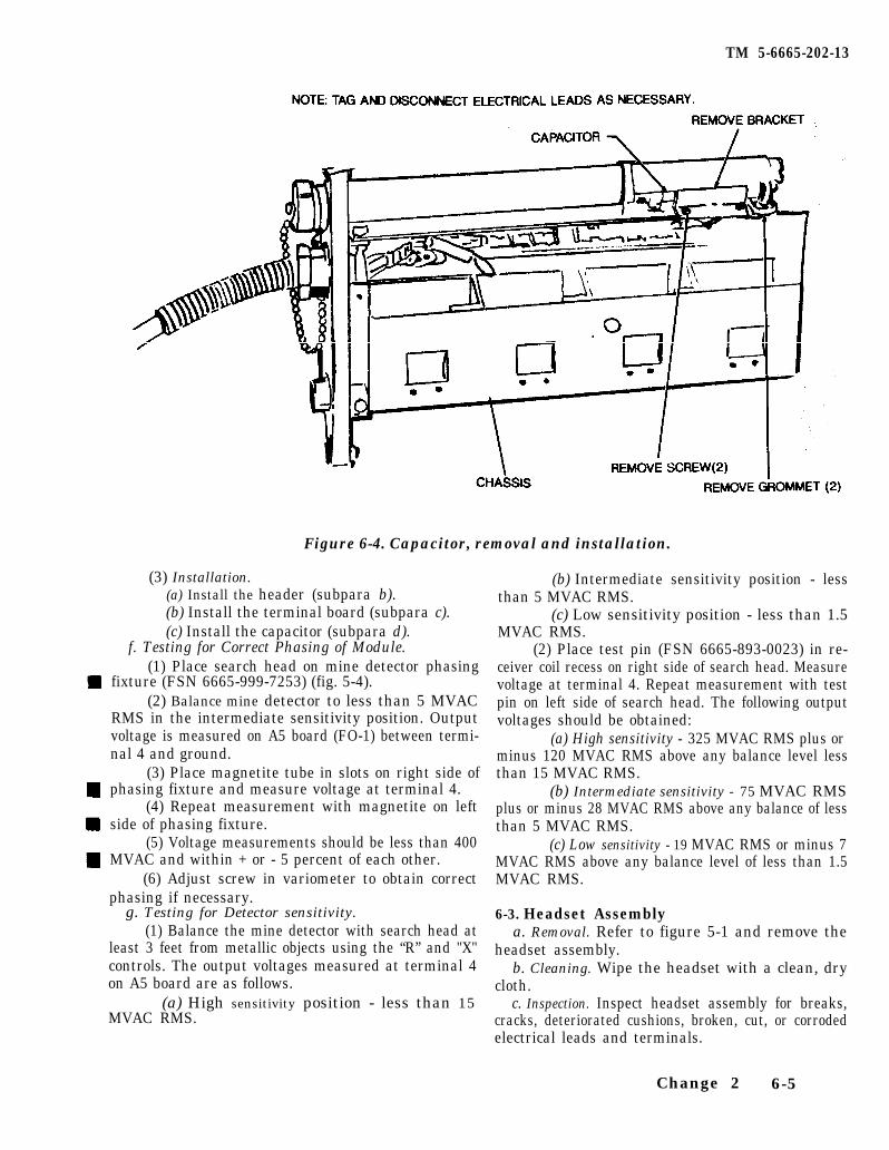
TM 5-6665-202-13
Figure 6-4. Capacitor, removal and installation.
(3) Installation.(a) Install the header (subpara b).(b) Install the terminal board (subpara c).(c) Install the capacitor (subpara d).
f. Testing for Correct Phasing of Module.(1) Place search head on mine detector phasing
fixture (FSN 6665-999-7253) (fig. 5-4).(2) Balance mine detector to less than 5 MVAC
RMS in the intermediate sensitivity position. Outputvoltage is measured on A5 board (FO-1) between termi-nal 4 and ground.
(3) Place magnetite tube in slots on right side ofphasing fixture and measure voltage at terminal 4.
(4) Repeat measurement with magnetite on leftside of phasing fixture.
(5) Voltage measurements should be less than 400MVAC and within + or - 5 percent of each other.
(6) Adjust screw in variometer to obtain correctphasing if necessary.
g. Testing for Detector sensitivity.(1) Balance the mine detector with search head at
least 3 feet from metallic objects using the “R” and "X"controls. The output voltages measured at terminal 4on A5 board are as follows.
(a) High sensitivity position - less than 15MVAC RMS.
(b) Intermediate sensitivity position - lessthan 5 MVAC RMS.
(c) Low sensitivity position - less than 1.5MVAC RMS.
(2) Place test pin (FSN 6665-893-0023) in re-ceiver coil recess on right side of search head. Measurevoltage at terminal 4. Repeat measurement with testpin on left side of search head. The following outputvoltages should be obtained:
(a) High sensitivity - 325 MVAC RMS plus orminus 120 MVAC RMS above any balance level lessthan 15 MVAC RMS.
(b) Intermediate sensitivity - 75 MVAC RMSplus or minus 28 MVAC RMS above any balance of lessthan 5 MVAC RMS.
(c) Low sensitivity - 19 MVAC RMS or minus 7MVAC RMS above any balance level of less than 1.5MVAC RMS.
6-3. Headset Assemblya. Removal. Refer to figure 5-1 and remove the
headset assembly.b. Cleaning. Wipe the headset with a clean, dry
cloth.c. Inspection. Inspect headset assembly for breaks,
cracks, deteriorated cushions, broken, cut, or corrodedelectrical leads and terminals.
Change 2 6-5

TM 5-6665-202-13
d. Testing and Repair. Test headset by re-moving lead from terminal no. 4 on A5 Board(Receiver transmitter assy). Connect ohmmeterto removed lead and ground. An approximateresistance reading of 150 to 300 ohms should beobtained. Place headset to ear and touch multim-eter lead to disconnected headset lead. A distinctclick should be heard in each ear phone if head-set is functioning properly. If there is no indica-tion in the headset, or 150 to 300 ohms is notindicated on the multimeter, the headset is defec-tive and must be replaced.
NOTEAudio Sears model headset is 160 ohms andRoanwell model headset is 300 ohms.
NOTEPerform the above test in the same manner onboth ear pieces. If one earpiece is operative andthe other one is defective, the complete earphoneassembly must still be replaced.
e. Installation. Refer to figure 5-1 and installthe headset assembly.
6-4. Control Boxa. Disassembly. Disassemble the control box
in the order of numerical sequence as illustratedby figure 6-5.
b. Cleaning, Inspection and Repair.(1) Clean all metal parts with an approved
cleaning solvent and dry thoroughly, Clean ter-minals and contacts with a clean dry cloth. Cleanvariable resistors with electrical control cleaner(FSN 6850-664-5641). Wipe all plastic andfiber components with a clean, dry cloth.
CAUTIONWhen cleaning components with clean-ing solvents, do not allow the solventsto come in contact with the plastic com-ponents of the control, as most cleaningfluids are harmful to plastics.
Avoid prolonged breathing of cleaningsolvents. If it becomes necessary tobreath any amount of solvents venti-late the area as much as possible. Pro-longed breathing of solvents may beharmful and injurious to health.
(2) Inspect resistors and terminal connec-tions for breaks, corrosion, or other defects. In-spect control chassis for breaks, cracks, damagedthreaded areas, or other defects. Inspect knobcovers for breaks, cracks, or other defects. In-spect knobs for chips, nicks, scratches, damaged
threads in setscrew hole, or other defects. In-spect variable resistors and control switch forproper operation when shaft is turned.
(3) Replace all damaged or defective com-ponents.
c. Reassembly. Reassemble the control box inthe reverse order of numerical sequence as illus-trated in figure 6-5.
d. Testing.(1) Fixed resistors. Test the fixed resistors
(1, fig. 6-5). The resistance reading should bebetween 1,995 and 2,005 ohms. If resistancereading is other than specified above, the resis-tor is defective and must be replaced.
(2) Test fixed resistor (3, fig. 6-5). Theresistance reading should be between 78 and 86ohms. If the resistance reading is other thanspecified above, the resistor is defective and mustbe replaced.
(3) Test fixed resistor (7, fig. 6-5). Theresistance reading should be between 4,257 to4,343 ohms. If the resistance reading is otherthan specified above, the resistor is defective andmust be replaced.
(4) Test fixed resistor (9, fig. 6-5). Theresistance reading should be between 2,980 and3,040 ohms, if the resistance reading is otherthan specified above, the resistor is defective andmust be replaced.
(5) To test the variable resistor (8, fig. 6-5), rotate the screw (located in the end of theresistor) clockwise for maximum resistance andcounterclockwise for minimum resistance. Valuesof resistance should vary from 0 to 2,000 ohms.If no reading is obtained or the value indicatedon the meter is above 2,000 ohms, the resistoris defective and must be replaced. Test total re-sistance with a Wheatstone Bridge. Disconnectyellow lead of resistor on TB1-1 and connectmultimeter to TB1-6 and the disconnected yel-low lead in order to make this test.
(6) Test variable resistor (16, fig. 6-5).Resistance should read from 0 to 1100 ohms. Ifresistance reads above 1,100 ohms or no readingis obtained as the resistor shaft is rotated ineither direction, the resistor is defective andmust be replaced. Test total resistance with aWeatstone Bridge. In order to test resistor, dis-connect yellow and white lead from terminalboard A5 terminal no. 7. Connect multimeter toground and disconnect lead.
(7) Test variable resistor (19, fig. 6-5).Resistance should read from 0 to 525 ohms asresistor shaft is rotated. If resistance reads above525 ohms or no reading is obtained as shaft is
6 - 6
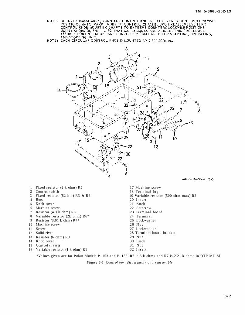
123456789
10111213141516
NOTE:
NOTE:
TM 5-6665-202-13
BEFORE DISASSEMBLY, TURN ALL CONTROL KNOBSTO EXTREME COUNTERCLOCKWISEPOSITIONS. MATCHMARK KNOBS TO CONTROL CHASSIS. UPON REASSEMBLY, TURNCONTROL KNOB MOUNTING SHAFTS TO EXTREME COUNTERCLOCKWISE POSITIONS.MOUNT KNOBS ON SHAFTS SO THAT MATCHMARKS ARE ALINED. THIS PROCEDUREASSURES CONTROL KNOBS ARE CORRECTLY POSITIONED FOR STARTING, OPERATING,AND STOPPING UNIT.EACH CIRCULAR CONTROL KNOB IS MOUNTED BY 2 SETSCREWS.
Fixed resistor (2 k ohm) R5 17 Machine screwControl switch 18 Terminal lugFixed resistor (82 hm) R3 & R4 19 Variable resistor (500 ohm max) R2Boot 20 InsertKnob cover 21 KnobMachine screw 22 SetscrewResistor (4.3 k ohm) R8 23 Terminal boardVariable resistor (2k ohm) R6* 24 TerminalResistor (3.01 k ohm) R7* 25 LockwasherMachine screw 26 NutScrew 27 LockwasherSolid rivet 28 Terminal board bracketResistor (6 ohm) R9 29 NutKnob cover 30 KnobControl chassis 31 NutVariable resistor (1 k ohm) R1 32 Insert
*Values given are for Polan Models P–153 and P–158. R6 is 5 k ohms and R7 is 2.21 k ohms in OTP MD-M.
Figure 6-5. Control box, disassembly and reassembly.
6 - 7
TM 5-6665-202-13
rotated, the resistor is defective and must be re-placed. Test total resistance with a WhetstoneBridge. Disconnect all connections on end termi-nal of variable resistor (8) or slider terminal.Test resistor by connecting multimeter to sliderterminal and terminal of resistor marked CCW.Rotate shaft and resistance should vary from 0to 525 ohms. Connect multimeter to slider ter-minal and terminal marked CW, again rotateshaft and resistance should vary from 0 to 525ohms.
6-5. Short Handle, Detector Head, andBalance Coil
a. Disassembly. Disassemble the short handle,detector head, and balanoe coil in the order ofnumerical sequence as illustrated by figure 6-6.
NOTEObserve location of electrical leads on balancecoil and clearly tag them before disconnectingto insure proper connection upon reassembly.
b. Cleaning, Inspection, and Repair.(1) Wipe the detector head and short han-
dle with a clean cloth slightly dampened withan approved cleaning solvent and dry thorough-ly.
(2) Wipe any accumulation of dirt or mois-ture from the balance coil with a clean, dry cloth.
CAUTIONBe careful of type of cleaning solventthat is used on the equipment. The com-ponents are constructed of plastic andwill be damaged if they are cleaned withsome types of solvent. Make sure a suit-able solvent that is approved for plasticis used when cleaning plastic compo-nents.
(3) Inspect the detector head for breaks,cracks, damaged threaded areas, corroded elec-trical leads, or other defects.
(4) Inspect the balance coil for breaks,cracks, defective seals, corroded or broken elec-trical leads, or other damage,
(5) Inspect the handle for breaks, cracks,damaged threaded areas, or other defects.
(6) Inspect the screws, bushings, washers,nut and adapter for chips, cracks, damagedthreaded areas, or other defects.
(7) Replace a damaged or defective part asnecessary.
c. Testing.(1) Transmitter coil. Test the transmitter
coils in the detector head by placing the meter
probes on 3 and 4 terminals of coils. The ap-proximate resistance reading should be 2.6 to 2.8ohms. If resistance readings are above or below2.6 to 2.8 ohms, transmitter coil could be defec-tive and detector head may have to be replaced.
(2) Receiver coil. Test the receiver coil inthe detector head by placing the meter probes on6 and 1 terminals of coils. Resistance should read40 to 50 ohms. If resistance readings are aboveor below 40 to 50 ohms, coils are defective anddetector head should be replaoed.
d. Reassembly. Reassemble the short handle,detector head, and balance coil in the reverseorder of numerical sequence as illustrated in fig-ure 6-6.
6-6. Wiring
a. Cleaning.(1) Wipe the wires with a cloth dampened
slightly with an approved cleaning solvent anddry thoroughly.
(2) Clean corrosion from terminals with abrush or an approved corrosion remover.
b. Inspection.(1) Inspect the insulation for cracks, fray-
ing, and deterioration. Pay special attention toareas where wires pass through holes and overrough or sharp edges. Wrap cracked or frayedarea with an approved electrical tape. Replacedefective wires.
(2) Inspect wire terminals for cracks, splits,corrosion, and insecure mounting. Replace a de-fective terminal.
c. Testing. To test a wire for continuity, dis-connect one end of the wire from the compo-nent to which it is attached. Touch the probesof a multimeter, set on the lowest ohm scale, toeach end of the wire. The multimeter should in-dicate continuity. Replace a wire that does notshow continuity.
d. Repair.(1) If a broken wire is accessible, remove
sufficient insulation from each side of the breakto allow a good connection to the bared ends bytwisting them together. Solder the connectionand wrap it with electrical tape. Do not leave abare connection exposed.
CAUTIONDo not use acid-core solder when per-forming maintenance on the detector set.Acidic action can erode circuit compo-nents, resulting in a defective or inop-
6-8
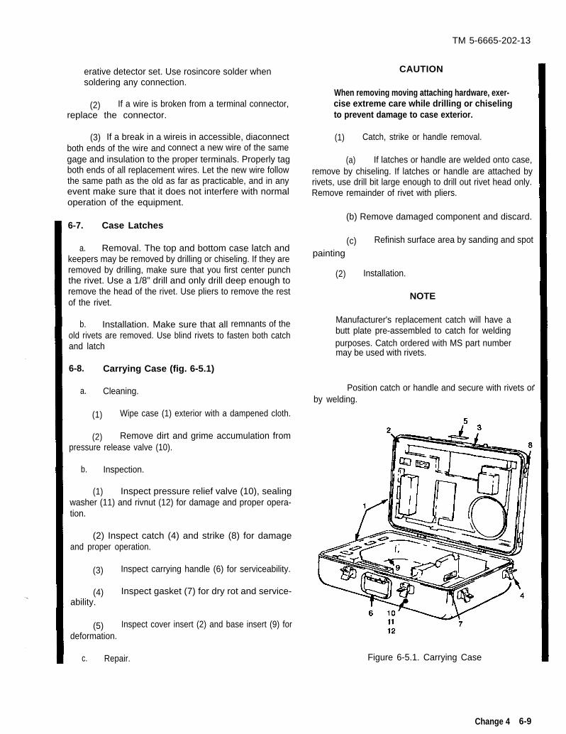
TM 5-6665-202-13
erative detector set. Use rosincore solder whensoldering any connection.
(2) If a wire is broken from a terminal connector,replace the connector.
(3) If a break in a wireis in accessible, diaconnectboth ends of the wire and connect a new wire of the samegage and insulation to the proper terminals. Properly tagboth ends of all replacement wires. Let the new wire followthe same path as the old as far as practicable, and in anyevent make sure that it does not interfere with normaloperation of the equipment.
6-7. Case Latches
a. Removal. The top and bottom case latch andkeepers may be removed by drilling or chiseling. If they areremoved by drilling, make sure that you first center punchthe rivet. Use a 1/8” drill and only drill deep enough toremove the head of the rivet. Use pliers to remove the restof the rivet.
b. Installation. Make sure that all remnants of theold rivets are removed. Use blind rivets to fasten both catchand latch
6-8. Carrying Case (fig. 6-5.1)
a. Cleaning.
(1) Wipe case (1) exterior with a dampened cloth.
(2) Remove dirt and grime accumulation frompressure release valve (10).
b. Inspection.
(1) Inspect pressure relief valve (10), sealingwasher (11) and rivnut (12) for damage and proper opera-tion.
(2) Inspect catch (4) and strike (8) for damageand proper operation.
(3) Inspect carrying handle (6) for serviceability.
(4) Inspect gasket (7) for dry rot and service-ability.
(5) Inspect cover insert (2) and base insert (9) fordeformation.
c. Repair.
CAUTION
When removing moving attaching hardware, exer-cise extreme care while drilling or chiselingto prevent damage to case exterior.
(1) Catch, strike or handle removal.
(a) If latches or handle are welded onto case,remove by chiseling. If latches or handle are attached byrivets, use drill bit large enough to drill out rivet head only.Remove remainder of rivet with pliers.
(b) Remove damaged component and discard.
(c) Refinish surface area by sanding and spot
painting
(2) Installation.
NOTE
Manufacturer's replacement catch will have abutt plate pre-assembled to catch for weldingpurposes. Catch ordered with MS part numbermay be used with rivets.
Position catch or handle and secure with rivets orby welding.
Figure 6-5.1. Carrying Case
Change 4 6-9
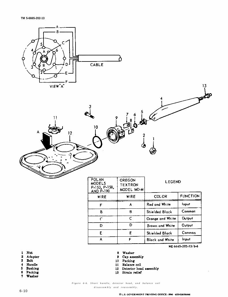
TM 5-6665-202-13
F i g u r e 6 - 6 . S h o r t h a n d l e , d e t e c t o r h e a d , a n d b a l a n c e c o i l
d i s a s s e m b l y a n d r e a s s e m b l y .
6-10
TM 5-6665-202-13
APPENDIX A
REFERENCES
A-1. Maintenance
T M 5 - 6 6 6 5 - 2 0 2 - 2 3 P O r g a n i z a t i o n a l , D i r e c t S u p p o r t a n d G e n e r a l S u p p o r t a n d D e p o t M a i n t e -
n a n c e R e p a i r P a r t s a n d S p e c i a l T o o l s L i s t s . D e t e c t i n g S e t , M i n e
T M 3 8 - 7 5 0 The Army Maintenance Management System (TAMMS)
A-2. Shipment and Storage
T M 7 4 0 - 9 0 - 1 A d m i n i s t r a t i v e S t o r a g e o f E q u i p m e n t
T M 7 4 0 - 2 4 4 - 3 Procedures fo r Dest ruc t ion o f Equ ipment to Prevent Enemy Use
C h a n g e 1 A-1/ (A-2 blank)
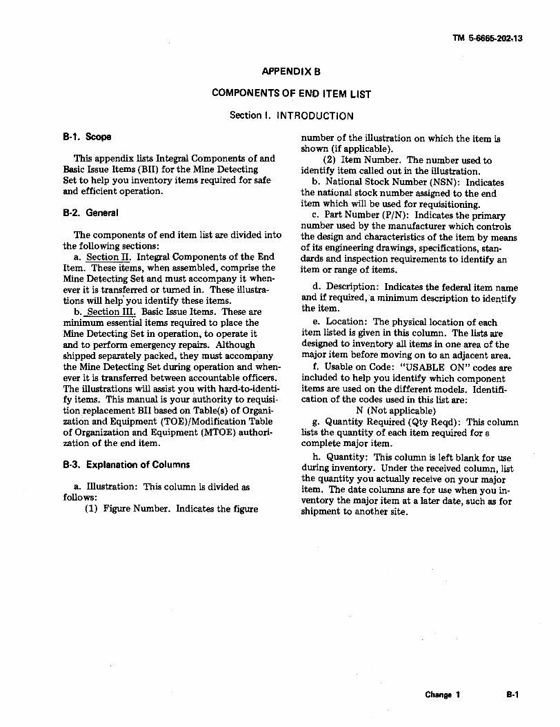
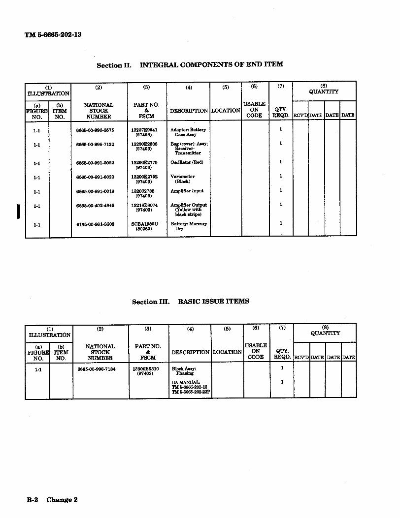
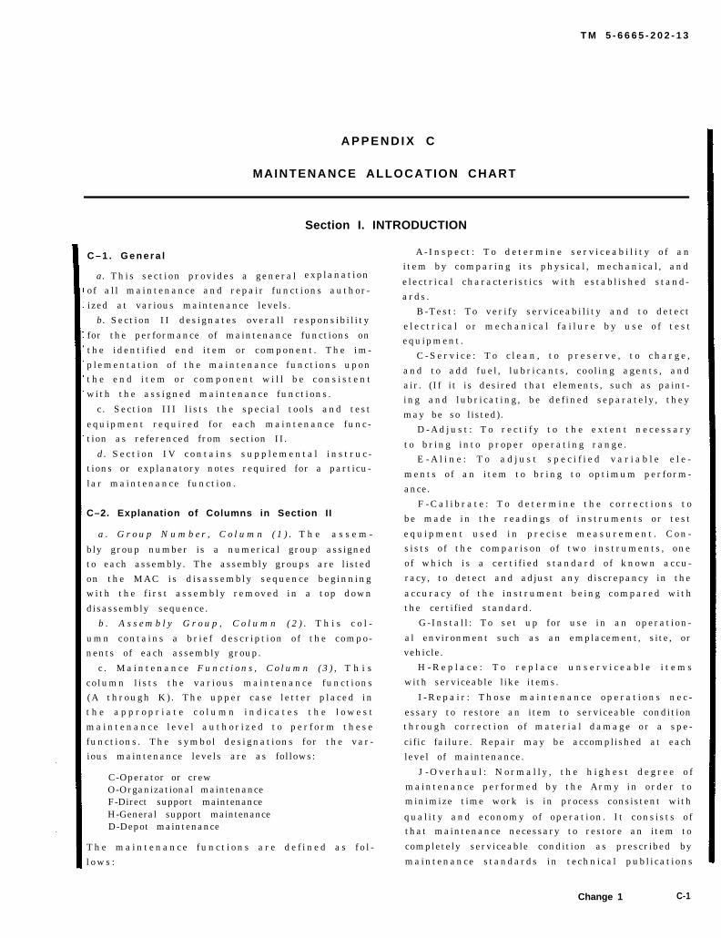
T M 5 - 6 6 6 5 - 2 0 2 - 1 3
A P P E N D I X C
MAINTENANCE ALLOCATION CHART
C – 1 . G e n e r a l
a. This sect ion provides a general
Section I. INTRODUCTION
explanat ion
of a l l maintenance and repair funct ions author-
ized at various maintenance levels.
b. Sect ion II des ignates overal l responsibi l i ty
for the performance of maintenance functions on
the ident i f ied end i tem or component . The im-
plementat ion o f the maintenance funct ions upont h e e n d i t e m o r c o m p o n e n t w i l l b e c o n s i s t e n t
with the ass igned maintenance funct ions .
c . Sect ion III l is ts the special too ls and test
equipment required for each maintenance func-tion as referenced from section II.
d. S e c t i o n I V c o n t a i n s s u p p l e m e n t a l i n s t r u c -tions or explanatory notes required for a particu-
lar maintenance funct ion.
C–2. Explanation of Columns in Section II
a . G r o u p N u m b e r , C o l u m n ( 1 ) . T h e a s s e m -
bly group number is a numerical group assignedto each assembly. The assembly groups are listed
on the MAC is d isassembly sequence beginningwith the f i rs t assembly removed in a top down
disassembly sequence.
b . A s s e m b l y G r o u p , C o l u m n ( 2 ) . T h i s c o l -
umn contains a br ie f descr ipt ion o f the compo-nents of each assembly group.
c . M a i n t e n a n c e F u n c t i o n s , C o l u m n ( 3 ) , T h i s
co lumn l is ts the var ious maintenance funct ions(A through K) . The upper case le t ter p laced int h e a p p r o p r i a t e c o l u m n i n d i c a t e s t h e l o w e s t
m a i n t e n a n c e l e v e l a u t h o r i z e d t o p e r f o r m t h e s e
funct ions . The symbol des ignat ions for the var -ious maintenance levels are as follows:
C-Operator or crewO-Organizational maintenanceF-Direct support maintenanceH-General support maintenanceD-Depot maintenance
T h e m a i n t e n a n c e f u n c t i o n s a r e d e f i n e d a s f o l -
l o w s :
A - I n s p e c t : T o d e t e r m i n e s e r v i c e a b i l i t y o f a nitem by comparing i ts physical , mechanical , and
electr ical character ist ics with establ ished stand-
ards .
B-Test : To ver i fy serviceabi l i ty and to detect
e l e c t r i c a l o r m e c h a n i c a l f a i l u r e b y u s e o f t e s tequipment .
C - S e r v i c e : T o c l e a n , t o p r e s e r v e , t o c h a r g e ,
and to add fuel , lubricants , cool ing agents , andair. (If it is desired that elements, such as paint-ing and lubricat ing, be def ined separately , they
may be so listed).
D - A d j u s t : T o r e c t i f y t o t h e e x t e n t n e c e s s a r y
to br ing into proper operat ing range .E - A l i n e : T o a d j u s t s p e c i f i e d v a r i a b l e e l e -
ments o f an i tem to br ing to opt imum per form-
ance.
F - C a l i b r a t e : T o d e t e r m i n e t h e c o r r e c t i o n s t o
be made in the readings o f instruments or test
e q u i p m e n t u s e d i n p r e c i s e m e a s u r e m e n t . C o n -s ists o f the comparison o f two instruments , one
of which is a cert i f ied s tandard o f known accu-
racy, to detect and adjust any discrepancy in the
accuracy o f the instrument be ing compared withthe certified standard.
G-Instal l : To set up for use in an operat ion-
al environment such as an emplacement, site, orvehicle.
H - R e p l a c e : T o r e p l a c e u n s e r v i c e a b l e i t e m s
with serviceable like items.
I - R e p a i r : T h o s e m a i n t e n a n c e o p e r a t i o n s n e c -
essary to restore an item to serviceable conditionthrough correct ion o f mater ia l damage or a spe-
cific failure. Repair may be accomplished at each
level of maintenance.
J - O v e r h a u l : N o r m a l l y , t h e h i g h e s t d e g r e e o f
maintenance per formed by the Army in order tominimize time work is in process consistent with
qual i ty and economy o f operat ion . I t cons ists o fthat maintenance necessary to restore an item to
completely serviceable condition as prescribed by
maintenance standards in technical publ icat ions
Change 1 C-1
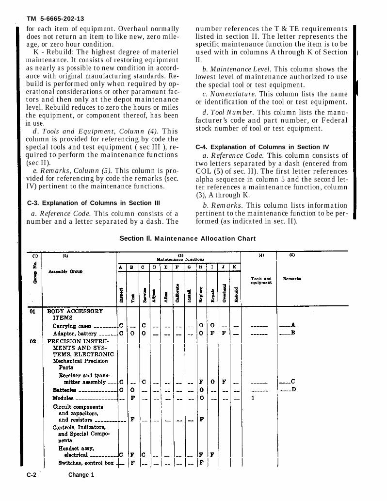
TM 5-6665-202-13
for each item of equipment. Overhaul normallydoes not return an item to like new, zero mile-age, or zero hour condition.
K - Rebuild: The highest degree of materielmaintenance. It consists of restoring equipmentas nearly as possible to new condition in accord-ance with original manufacturing standards. Re-build is performed only when required by op-erational considerations or other paramount fac-tors and then only at the depot maintenancelevel. Rebuild reduces to zero the hours or milesthe equipment, or component thereof, has beenin use.
d. Tools and Equipment, Column (4). Thiscolumn is provided for referencing by code thespecial tools and test equipment ( sec III ), re-quired to perform the maintenance functions(sec II).
e. Remarks, Column (5). This column is pro-vided for referencing by code the remarks (sec.IV) pertinent to the maintenance functions.
C-3. Explanation of Columns in Section III
a. Reference Code. This column consists of anumber and a letter separated by a dash. The
number references the T & TE requirementslisted in section II. The letter represents thespecific maintenance function the item is to beused with in columns A through K of SectionII.
b. Maintenance Level. This column shows thelowest level of maintenance authorized to usethe special tool or test equipment.
c. Nomenclature. This column lists the nameor identification of the tool or test equipment.
d. Tool Number. This column lists the manu-facturer’s code and part number, or Federalstock number of tool or test equipment.
C-4. Explanation of Columns in Section IVa. Reference Code. This column consists of
two letters separated by a dash (entered fromCOL (5) of sec. II). The first letter referencesalpha sequence in column 5 and the second let-ter references a maintenance function, column(3), A through K.
b. Remarks. This column lists informationpertinent to the maintenance function to be per-formed (as indicated in sec. II).
Section Il. Maintenance Allocation Chart
C-2 Change 1

TM 5-6665-202-13
Section III. SPECIAL TOOL AND SPECIAL TEST EQUIPMENT REQUIREMENTS
Section IV. REMARKS
Change 2 C-3/(C-4 blank)
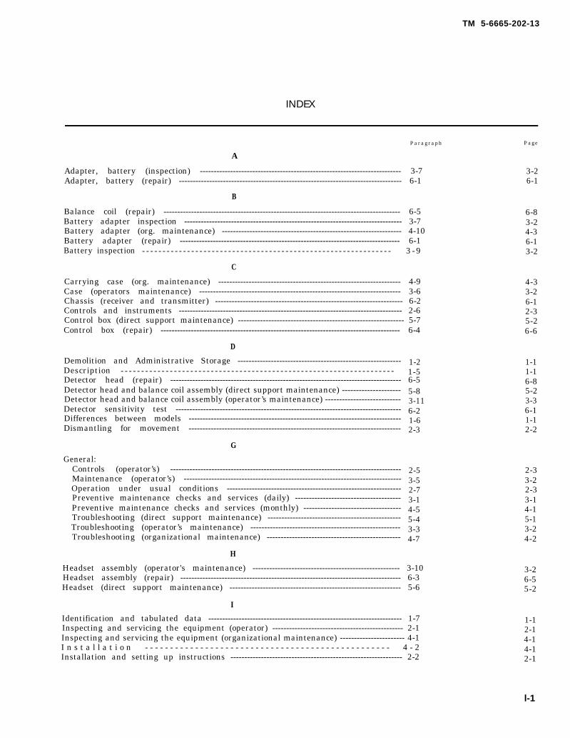
TM 5-6665-202-13
INDEX
Paragraph Page
A
Adapter, battery (inspection) ------------------------------------------------------------------------- 3-7 3-2Adapter, battery (repair) --------------------------------------------------------------------------------- 6-1 6-1
B
Balance coil (repair) -------------------------------------------------------------------------------------- 6-5 6-8Battery adapter inspection ------------------------------------------------------------------------------- 3-7 3-2Battery adapter (org. maintenance) ----------------------------------------------------------------- 4-10 4-3Battery adapter (repair) -------------------------------------------------------------------------------- 6-1 6-1Battery inspection - - - - - - - - - - - - - - - - - - - - - - - - - - - - - - - - - - - - - - - - - - - - - - - - - - - - - - - - - - - - - 3 - 9 3-2
C
Carrying case (org. maintenance) ------------------------------------------------------------------ 4-9 4-3Case (operators maintenance) ------------------------------------------------------------------------- 3-6 3-2Chassis (receiver and transmitter) -------------------------------------------------------------------- 6-2 6-1Controls and instruments --------------------------------------------------------------------------------- 2-6 2-3Control box (direct support maintenance) ------------------------------------------------------------ 5-7 5-2Control box (repair) --------------------------------------------------------------------------------------- 6-4 6-6
D
Demolition and Administrative Storage -----------------------------------------------------------Description - - - - - - - - - - - - - - - - - - - - - - - - - - - - - - - - - - - - - - - - - - - - - - - - - - - - - - - - - - - - - - - - - - -Detector head (repair) ------------------------------------------------------------------------------------Detector head and balance coil assembly (direct support maintenance) ---------------------Detector head and balance coil assembly (operator’s maintenance) ---------------------------Detector sensitivity test ----------------------------------------------------------------------------------Differences between models -----------------------------------------------------------------------------Dismantling for movement -----------------------------------------------------------------------------
G
General:Controls (operator’s) ------------------------------------------------------------------------------------Maintenance (operator’s) -------------------------------------------------------------------------------Operation under usual conditions ---------------------------------------------------------------Preventive maintenance checks and services (daily) --------------------------------------Preventive maintenance checks and services (monthly) -----------------------------------Troubleshooting (direct support maintenance) ------------------------------------------------Troubleshooting (operator’s maintenance) ------------------------------------------------------Troubleshooting (organizational maintenance) ------------------------------------------------
1-21-56-55-83-116-21-62-3
2-53-52-73-14-55-43-34-7
1-11-16-85-23-36-11-12-2
2-33-22-33-14-15-13-24-2
H
Headset assembly (operator's maintenance) ----------------------------------------------------- 3-10 3-2Headset assembly (repair) -------------------------------------------------------------------------------- 6-3 6-5Headset (direct support maintenance) -------------------------------------------------------------- 5-6 5-2
I
Identification and tabulated data ---------------------------------------------------------------------- 1-7 1-1Inspecting and servicing the equipment (operator) ----------------------------------------------- 2-1 2-1Inspecting and servicing the equipment (organizational maintenance) ----------------------- 4-1 4-1I n s t a l l a t i o n - - - - - - - - - - - - - - - - - - - - - - - - - - - - - - - - - - - - - - - - - - - - - - - - - 4 - 2 4-1Installation and setting up instructions -------------------------------------------------------------- 2-2 2-1
l-1
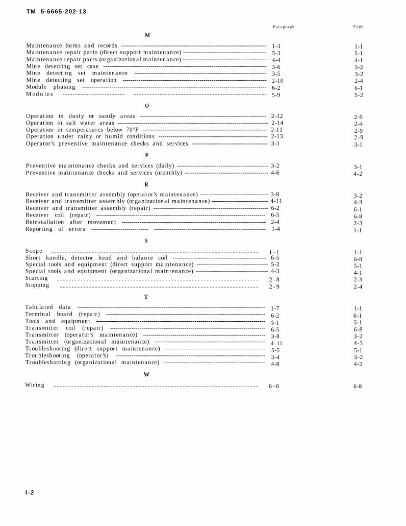
TM 5-6665-202-13
Paragraph
M
Maintenance forms and records --------------------------------------------------------------------------Maintenance repair parts (direct support maintenance) ------------------------------------------Maintenance repair parts (organizational maintenance) ------------------------------------------Mine detecting set case -----------------------------------------------------------------------------------Mine detecting set maintenance -------------------------------------------------------------------Mine detecting set operation -------------------------------------------------------------------------Module phasing ----------------------------------------------------------------------------------------------Modules --- - - - - - - - - - - - - - - - - - - - - - - - - - - - - - - - - - - - - - - - - - - - - - - - - - - - - - - - - - - - - - - - - - - - - - - - -
O
1-35-34-43-63-52-106-25-9
Operation in dusty or sandy areas ---------------------------------------------------------------- 2-12Operation in salt water areas ---------------------------------------------------------------------------- 2-14Operation in temperatures below 70°F --------------------------------------------------------------- 2-11Operation under rainy or humid conditions ------------------------------------------------------- 2-13Operator’s preventive maintenance checks and services -------------------------------------- 3-1
P
Preventive maintenance checks and services (daily) ---------------------------------------------- 3-2Preventive maintenance checks and services (monthly) ------------------------------------------ 4-6
R
Receiver and transmitter assembly (operator’s maintenance) ---------------------------------- 3-8Receiver and transmitter assembly (organizational maintenance) ---------------------------- 4-11Receiver and transmitter assembly (repair) ---------------------------------------------------------- 6-2Receiver coil (repair) -------------------------------------------------------------------------------------- 6-5Reinstallation after movement ------------------------------------------------------------------------- 2-4Reporting of errors ----------------------------- --------------------------------------------------------- 1-4
S
Scope - - - - - - - - - - - - - - - - - - - - - - - - - - - - - - - - - - - - - - - - - - - - - - - - - - - - - - - - - - - - - - - - - - - - - - - 1 - 1Short handle, detector head and balance coil ----------------------------------------------- 6-5Special tools and equipment (direct support maintenance) ------------------------------------ 5-2Special tools and equipment (organizational maintenance) ------------------------------------ 4-3Starting - - - - - - - - - - - - - - - - - - - - - - - - - - - - - - - - - - - - - - - - - - - - - - - - - - - - - - - - - - - - - - - - - - - - - 2 - 8Stopping - - - - - - - - - - - - - - - - - - - - - - - - - - - - - - - - - - - - - - - - - - - - - - - - - - - - - - - - - - - - - - - - - - - - 2 - 9
T
Tabulated data ------------------------------------------------------------------------------------------------Terminal board (repair) ---------------------------------------------------------------------------------Tools and equipment --------------------------------------------------------------------------------------Transmitter coil (repair) -------------------------------------------------------------------------------Transmitter (operator’s maintenance) --------------------------------------------------------------Transmitter (organizational maintenance) --------------------------------------------------------Troubleshooting (direct support maintenance) ---------------------------------------------------Troubleshooting (operator’s) ----------------------------------------------------------------------------Troubleshooting (organizational maintenance) ---------------------------------------------------
W
1-76-25-16-53-84–115-53-44-8
Wiring - - - - - - - - - - - - - - - - - - - - - - - - - - - - - - - - - - - - - - - - - - - - - - - - - - - - - - - - - - - - - - - - - - - - - - 6 - 6
Page
1-15-14-13-23-22-46-15-2
2-92-42-92-93-1
3-14-2
3-24-36-16-82-31-1
1-16-85-14-12-32-4
1-16-15-16-83-24-35-13-24-2
6-8
I -2

Figure FO-1.
T M 5 - 6 6 6 5 - 2 0 2 - 1 3
FO–1. Electrical schematic diagram.
TM 5-6665-202-13
By Order of the Secretary of the Army:
Official:
W. C. WESTMORELAND,General, United States Army,Chief of Staff.
VERNE L. BOWERSMajor General, United States Army,The Adjutant General.
Distribution:
To be distributed in accordance with DA Form 12-25A (qty rqr Block #133), Operator require-ments for Land Mine Detection.


PIN: 026247-004

This fine document...
Was brought to you by me:
Liberated Manuals -- free army and government manuals
Why do I do it? I am tired of sleazy CD-ROM sellers, who take publicly available information, slap “watermarks” and other junk on it, and sell it. Those masters of search engine manipulation make sure that their sites that sell free information, come up first in search engines. They did not create it... They did not even scan it... Why should they get your money? Why are not letting you give those free manuals to your friends?
I am setting this document FREE. This document was made by the US Government and is NOT protected by Copyright. Feel free to share, republish, sell and so on.
I am not asking you for donations, fees or handouts. If you can, please provide a link to liberatedmanuals.com, so that free manuals come up first in search engines:
<A HREF=http://www.liberatedmanuals.com/>Free Military and Government Manuals</A>
– SincerelyIgor Chudovhttp://igor.chudov.com/
– Chicago Machinery Movers