Embed Size (px)
DESCRIPTION
TM-2100 AVEVA Marine (12 Series) Hull and Outfitting Drafting Rev 6.0
Citation preview
TTRR
AAII NN
II NNGG
GGUU
II DDEE
www.aveva.com
AVEVA Marine (12 Series) Hull/Outfitting Drafting TM-2100

AVEVA Marine (12 Series) Hull/Outfitting Drafting TM-2100
2
www.aveva.com
AVEVA Marine (12 Series) Hull/Outfitting Drafting TM-2100
3
www.aveva.com
Revision Log
Date Revision Description of Revision Author Reviewed Approved
18/082009 3.0 Approved for Training 12.0 SP4 J.P. O.K. SH
03/11/2009 3.1 Issued for Review 12.0 SP5 S.K.
06/11/2009 3.2 Reviewed for SP5 S.K. J.P.
07/12/2009 4.0 Approved for Training 12.0 SP5 S.K. J.P. SH
19/03/2010 4.1 Updated to Hull/Outfitting Drafting SP5 JP
16/04/2010 4.2 Reviewed for Hull/Outfitting Drafting SP5 JP AH
07/05/2010 5.0 Approved for Training 12.0 SP6 JP AH
21/05/2010 5.1 Reviewed for Hull/Outfitting Drafting SP6 MZ
27/07/2010 6.0 Approved for Training 12.0 SP6 MZ MZ SH
Updates
All headings containing updated or new material will be highlighted.
Suggestion / Problems
If you have a suggestion about this manual or the system to which it refers please report it to the AVEVA Group Solutions Centre at [email protected]
This manual provides documentation relating to products to which you may not have access or which may not be licensed to you. For further information on which products are licensed to you please refer to your licence conditions.
Visit our website at http://www.aveva.com
Disclaimer
Information of a technical nature, and particulars of the product and its use, is given by AVEVA Solutions Ltd and its subsidiaries without warranty. AVEVA Solutions Ltd. and its subsidiaries disclaim any and all warranties and conditions, expressed or implied, to the fullest extent permitted by law.
Neither the author nor AVEVA Solutions Ltd or any of its subsidiaries shall be liable to any person or entity for any actions, claims, loss or damage arising from the use or possession of any information, particulars or errors in this publication, or any incorrect use of the product, whatsoever.
Trademarks
AVEVA and Tribon are registered trademarks of AVEVA Solutions Ltd or its subsidiaries. Unauthorised use of the AVEVA or Tribon trademarks is strictly forbidden.
AVEVA product names are trademarks or registered trademarks of AVEVA Solutions Ltd or its subsidiaries, registered in the UK, Europe and other countries (worldwide).
The copyright, trademark rights or other intellectual property rights in any other product, its name or logo belongs to its respective owner.
AVEVA Marine (12 Series) Hull/Outfitting Drafting TM-2100
4
www.aveva.com
Copyright
Copyright and all other intellectual property rights in this manual and the associated software, and every part of it (including source code, object code, any data contained in it, the manual and any other documentation supplied with it) belongs to AVEVA Solutions Ltd. or its subsidiaries.
All other rights are reserved to AVEVA Solutions Ltd and its subsidiaries. The information contained in this document is commercially sensitive, and shall not be copied, reproduced, stored in a retrieval system, or transmitted without the prior written permission of AVEVA Solutions Limited. Where such permission is granted, it expressly requires that this Disclaimer and Copyright notice is prominently displayed at the beginning of every copy that is made.
The manual and associated documentation may not be adapted, reproduced, or copied in any material or electronic form without the prior written permission of AVEVA Solutions Ltd. The user may also not reverse engineer, decompile, copy or adapt the associated software. Neither the whole nor part of the product described in this publication may be incorporated into any third-party software, product, machine or system without the prior written permission of AVEVA Solutions Limited or save as permitted by law. Any such unauthorised action is strictly prohibited and may give rise to civil liabilities and criminal prosecution.
The AVEVA products described in this guide are to be installed and operated strictly in accordance with the terms and conditions of the respective licence agreements, and in accordance with the relevant User Documentation. Unauthorised or unlicensed use of the product is strictly prohibited.
Printed by AVEVA Solutions on 27 July 2010
© AVEVA Solutions and its subsidiaries 2001 – 2010
AVEVA Solutions Ltd, High Cross, Madingley Road, Cambridge, CB3 0HB, United Kingdom.
5
www.aveva.com
Contents
1 Introduction .............................................................................................................................................. 9 1.1 Aim .................................................................................................................................................... 9 1.2 Objectives ......................................................................................................................................... 9 1.3 Prerequisites .................................................................................................................................... 9 1.4 Course Structure ............................................................................................................................. 9 1.5 Using this guide ............................................................................................................................. 10
2 How AVEVA Marine can Help You. ...................................................................................................... 11 3 Getting Started. ...................................................................................................................................... 13
3.1 The Interface .................................................................................................................................. 14 3.2 Toolbars .......................................................................................................................................... 14
3.2.1 Toolbar Tips ............................................................................................................................. 14 3.2.2 File Toolbar .............................................................................................................................. 15 3.2.3 Button Toolbar ......................................................................................................................... 15 3.2.4 Geometry Toolbar .................................................................................................................... 15 3.2.5 Geometry 2 Toolbar ................................................................................................................. 15 3.2.6 Geometry Arc Toolbar.............................................................................................................. 16 3.2.7 Geometry Conic Toolbar .......................................................................................................... 16 3.2.8 Geometry Line Toolbar ............................................................................................................ 16 3.2.9 Geometry Polyline .................................................................................................................... 16 3.2.10 The Vitesse Toolbar ................................................................................................................. 16 3.2.11 Cursor Toolbar ......................................................................................................................... 17 3.2.12 2D Lock Toolbar ....................................................................................................................... 17 3.2.13 Transform Toolbar ................................................................................................................... 17 3.2.14 Number Toolbar (Subpicture level) .......................................................................................... 18 3.2.15 Shaded View Tools .................................................................................................................. 18 3.2.16 Dimension toolbar .................................................................................................................... 18 3.2.17 Subpicture Toolbar ................................................................................................................... 18 3.2.18 Windows Toolbar ..................................................................................................................... 19 3.2.19 Symbol Toolbar ........................................................................................................................ 19 3.2.20 Text toolbar .............................................................................................................................. 19 3.2.21 History ...................................................................................................................................... 19 3.2.22 Search ...................................................................................................................................... 19 3.2.23 Default ...................................................................................................................................... 19 3.2.24 Assembly Drafting .................................................................................................................... 20 3.2.25 Assembly Department.............................................................................................................. 20 3.2.26 3D Request .............................................................................................................................. 20
3.3 Opening an Existing Drawing ....................................................................................................... 21 3.3.1 Starting a New Drawing ........................................................................................................... 23 3.3.2 Saving and Deleting Drawings ................................................................................................. 23
3.4 Functions and Operations ............................................................................................................ 24 3.5 Viewing the Workspace/Drawing ................................................................................................. 25
3.5.1 Zoom In .................................................................................................................................... 25 3.5.2 Zoom Out ................................................................................................................................. 25 3.5.3 Mouse Wheel Zoom ................................................................................................................. 26 3.5.4 Mouse Wheel Move / Pan ........................................................................................................ 26 3.5.5 Move / Pan ............................................................................................................................... 26 3.5.6 Display Entire Drawing............................................................................................................. 26 3.5.7 Display Previous Window ........................................................................................................ 26 3.5.8 Predefined Windows ................................................................................................................ 26 3.5.9 Display a Predefined Window .................................................................................................. 27
3.6 Displaying Viewports .................................................................................................................... 27 3.7 Setting up a drawing ..................................................................................................................... 27
3.7.1 New geometry preferences ...................................................................................................... 27 3.7.2 Defaults .................................................................................................................................... 27 3.7.3 Drawing Scale .......................................................................................................................... 28 3.7.4 The Title Block ......................................................................................................................... 28
Exercise 1 ....................................................................................................................................................... 29
AVEVA Marine (12 Series) Hull/Outfitting Drafting TM-2100
6
www.aveva.com
4 Viewing the Ship Model ........................................................................................................................ 31 4.1 The Marine Drafting View Concept .............................................................................................. 31 4.2 Adding a New Hull Model Projection to the Drawing ................................................................. 31
4.2.1 Changing an existing model view projection ........................................................................... 34 4.2.2 Copy model objects from an existing view to a new view ........................................................ 34
4.3 Model Draw Codes ......................................................................................................................... 35 4.4 Exchange Model View ................................................................................................................... 35 4.5 View Types ..................................................................................................................................... 36
4.5.1 Wireline .................................................................................................................................... 36 4.5.2 Modelled Wireline .................................................................................................................... 37 4.5.3 Wireline Hidden Line ................................................................................................................ 37 4.5.4 Local Hidden Line .................................................................................................................... 37 4.5.5 Global Hidden Line .................................................................................................................. 37 4.5.6 Universal Hidden Line .............................................................................................................. 38 4.5.7 Changing View Type ................................................................................................................ 38
4.6 Validate ........................................................................................................................................... 38 4.7 Adding Outfit Items to a Model View ........................................................................................... 39 4.8 Creating a Symbolic View ............................................................................................................. 40
4.8.1 The Plane Tab ......................................................................................................................... 40 4.8.2 The Limits Tab ......................................................................................................................... 41 4.8.3 The Select Tab ......................................................................................................................... 42 4.8.4 The Outfit Tab .......................................................................................................................... 43 4.8.5 The Misc Tab ........................................................................................................................... 43
4.9 Recreate an Existing Symbolic View. .......................................................................................... 43 4.10 Modify an Existing Symbolic View. .............................................................................................. 44 4.11 Modify the limits of a view. ........................................................................................................... 44 4.12 Detail Views. ................................................................................................................................... 45
4.12.1 Creating a detail view of Flanges, Stiffeners, Brackets or Seams ........................................... 45 4.12.2 Creating a detail view of multiple objects................................................................................. 45 4.12.3 Creating a Sliced View ............................................................................................................. 48
4.13 Model Information .......................................................................................................................... 48 Exercise 2 ....................................................................................................................................................... 49
4.14 Adding Rulers to an Existing View .............................................................................................. 50 4.15 How to add text .............................................................................................................................. 50
4.15.1 Options for Text. ...................................................................................................................... 51 4.15.2 Delete Text ............................................................................................................................... 52
4.16 Introduction to Subpictures ......................................................................................................... 52 4.17 The Drawing Structure .................................................................................................................. 53 4.18 Current subpicture. ....................................................................................................................... 53
4.18.1 Make an existing subpicture current ........................................................................................ 54 4.19 Create new subpicture (level 1 view) ........................................................................................... 54 4.20 Create new subview (level 2) ........................................................................................................ 54 4.21 Create new component (level 3) ................................................................................................... 55 4.22 Transforming a Subpicture ........................................................................................................... 55
4.22.1 Ways to Transform. .................................................................................................................. 56 4.23 Copy a subpicture ......................................................................................................................... 59 4.24 Deleting a subpicture .................................................................................................................... 59
Exercise 3 ....................................................................................................................................................... 60 4.25 Re-use of Subpictures ................................................................................................................... 61
4.25.1 To split level 1. (Create new view) ........................................................................................... 61 4.25.2 Split level 2 (Create new subview) ........................................................................................... 62 4.25.3 Regroup Subpicture ................................................................................................................. 62 4.25.4 Output subpicture ..................................................................................................................... 64 4.25.5 Insert subpicture ...................................................................................................................... 64 4.25.6 Exchange subpicture ............................................................................................................... 65
Exercise 4 ....................................................................................................................................................... 66 5 Basic Geometry ..................................................................................................................................... 69
5.1 Creating geometry ......................................................................................................................... 69 5.1.1 Points ....................................................................................................................................... 69 5.1.2 Lines......................................................................................................................................... 72 5.1.3 Arcs .......................................................................................................................................... 73
AVEVA Marine (12 Series) Hull/Outfitting Drafting TM-2100
7
www.aveva.com
5.2 Modifying geometry ....................................................................................................................... 74 5.2.1 Colour ...................................................................................................................................... 74 5.2.2 Line type .................................................................................................................................. 74 5.2.3 Modifying Properties at Subpicture level. ................................................................................ 75
5.3 Trimming ........................................................................................................................................ 76 5.3.1 Trim by length. ......................................................................................................................... 76 5.3.2 Remove part of a geometry, Trim by Gap ............................................................................... 77 5.3.3 Trim by Fillet ............................................................................................................................ 77 5.3.4 Stretch ...................................................................................................................................... 78
5.4 Hatching ......................................................................................................................................... 80 5.5 Deleting geometry ......................................................................................................................... 81
5.5.1 Deleting an individual geometry ............................................................................................... 81 5.5.2 Deleting a group/area of geometry .......................................................................................... 81
Exercise 5 ....................................................................................................................................................... 82 5.5.3 Polylines ................................................................................................................................... 83 5.5.4 Splines ..................................................................................................................................... 83 5.5.5 Parallel Curves ......................................................................................................................... 84 5.5.6 Rectangle ................................................................................................................................. 84 5.5.7 Squares .................................................................................................................................... 84 5.5.8 Conic ........................................................................................................................................ 84 5.5.9 Moving geometry ..................................................................................................................... 85 5.5.10 Copying geometry .................................................................................................................... 85 5.5.11 Additional 2D Geometry Functions .......................................................................................... 86 5.5.12 Chain geometry ........................................................................................................................ 86
6 Dimensioning ......................................................................................................................................... 87 6.1.1 Horizontal / Vertical Linear dimensions (Normal) .................................................................... 87 6.1.2 Parallel Linear dimensions (Normal) ........................................................................................ 88 6.1.3 Mould Line Dimensioning ........................................................................................................ 88 6.1.4 Horizontal / Vertical Linear dimensions (Chain) ...................................................................... 89 6.1.5 Horizontal / Vertical Linear dimensions (Stair) ........................................................................ 89 6.1.6 Linear Dimension Parameters. ................................................................................................ 90 6.1.7 Radius measure ....................................................................................................................... 93 6.1.8 Diameter measure ................................................................................................................... 93 6.1.9 Angle measure ......................................................................................................................... 93 6.1.10 Dimension along a curve ......................................................................................................... 94 6.1.11 Dimension along a curve, between two points. ....................................................................... 95 6.1.12 Dimension area ........................................................................................................................ 95 6.1.13 3D Linier ................................................................................................................................... 96 6.1.14 3D Axis Parallel ........................................................................................................................ 96 6.1.15 3D Coordinate .......................................................................................................................... 96 6.1.16 3D Curve Length ...................................................................................................................... 96 6.1.17 3D Weight and COG ................................................................................................................ 96 6.1.18 Shell Profile Mounting Angle .................................................................................................... 96 6.1.19 Dimensions from a plane ......................................................................................................... 97 6.1.20 Associated Dimensions............................................................................................................ 97 6.1.21 Deleting dimensions ................................................................................................................. 97
Exercise 6 ....................................................................................................................................................... 98 6.2 Adding notes .................................................................................................................................. 99
6.2.1 Information from the model ...................................................................................................... 99 6.2.2 Delete note ............................................................................................................................. 100
6.3 Position Numbers ........................................................................................................................ 101 6.3.1 Adding Hull Position Numbers to a Drawing .......................................................................... 101 6.3.2 Adding General Position Numbers to a Drawing ................................................................... 101
6.4 Symbol .......................................................................................................................................... 102 6.4.1 Inserting a Symbol ................................................................................................................. 102 6.4.2 Symbol Status ........................................................................................................................ 102 6.4.3 Deleting a Symbol .................................................................................................................. 102
Exercise 7 ..................................................................................................................................................... 103 7 Status Control ...................................................................................................................................... 105
7.1 Activating the Status Controller ................................................................................................. 106 7.2 Status Control Toolbar ................................................................................................................ 107

AVEVA Marine (12 Series) Hull/Outfitting Drafting TM-2100
8
www.aveva.com
7.3 Changing the Elements Status ................................................................................................... 107 7.4 Removing Status ......................................................................................................................... 108 7.5 Status History .............................................................................................................................. 108 7.6 Statistical Reports ....................................................................................................................... 109
Changing the Graphical representation of the report ............................................................................ 110 Additional Graphical Report Features ................................................................................................... 111
7.7 Saving a Status Layout ............................................................................................................... 111 Exercise 8 ..................................................................................................................................................... 112
9
www.aveva.com
CHAPTER 1
1 Introduction
This training course will be taken by all users of the Hull / Outfitting system and provides the grounding for further training in the AVEVA Marine modelling applications. With AVEVA Marine 12.0 it is possible to view the model by creating a wide range of views of the ship model. There are special functions to handle these views and produce the desired drawings rapidly and accurately. Once the relevant views are placed in a drawing they can be annotated with further information. AVEVA Marine 12.0 has powerful text and dimensioning functions and full 2D drafting functionality. AVEVA Marine 12.0 also has very powerful editing functions. All entities have editable properties, such as, colour, layer, and line type. Whilst a series of transformations provide all other tools needed to edit the layout of the drawing.
The basic Hull/Outfitting Drafting functions can also be found in all the AVEVA Marine Hull Design products (Structural Design, Planar Modelling, Curved Hull, and Plate Nesting).
1.1 Aim
Over the next two days the participants will learn the basic functions to control the graphical view, create hull symbolic views, outfits views, annotate and dimension the drawings.
1.2 Objectives
To have a clear understanding of the basic features of AVEVA Marine.
To be familiar with the screen layout and the workings of the user interface.
To create and manipulate views of a model, in a way that reflects the intended use of the
system.
To discover the ways in which the model can be interpreted on screen.
To understand the concept of sub-pictures and be able to work effectively with them.
To create geometry and add text and other annotation to a drawing.
To understand the various ways in which a drawing can be edited or modified.
1.3 Prerequisites
Trainees should be familiar with Microsoft Windows
1.4 Course Structure
Training will consist of oral and visual presentations, demonstrations and set exercises. Each workstation will have a training project, populated with model objects. This will be used by the trainees to practice their methods, and complete the set exercises.
AVEVA Marine (12 Series) Hull/Outfitting Drafting TM-2100
10
www.aveva.com
1.5 Using this guide
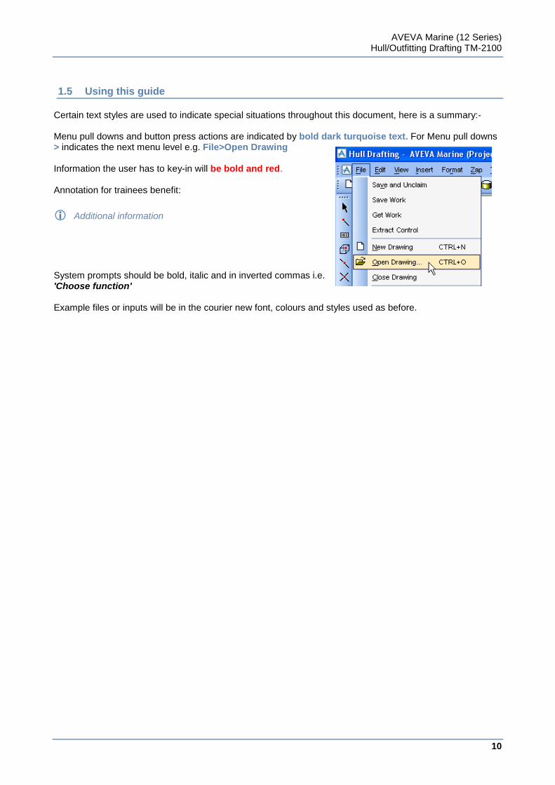
Certain text styles are used to indicate special situations throughout this document, here is a summary:- Menu pull downs and button press actions are indicated by bold dark turquoise text. For Menu pull downs > indicates the next menu level e.g. File>Open Drawing Information the user has to key-in will be bold and red. Annotation for trainees benefit:
Additional information
System prompts should be bold, italic and in inverted commas i.e. 'Choose function' Example files or inputs will be in the courier new font, colours and styles used as before.
11
www.aveva.com
CHAPTER 2
2 How AVEVA Marine can Help You.
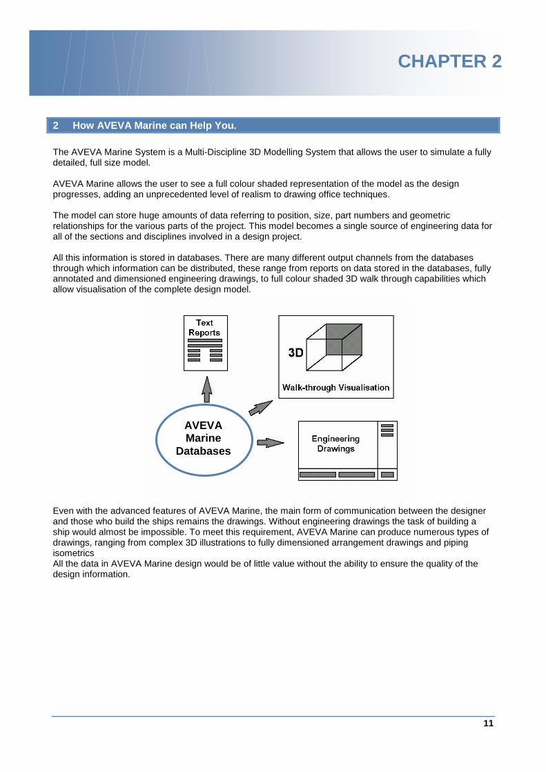
The AVEVA Marine System is a Multi-Discipline 3D Modelling System that allows the user to simulate a fully detailed, full size model. AVEVA Marine allows the user to see a full colour shaded representation of the model as the design progresses, adding an unprecedented level of realism to drawing office techniques. The model can store huge amounts of data referring to position, size, part numbers and geometric relationships for the various parts of the project. This model becomes a single source of engineering data for all of the sections and disciplines involved in a design project. All this information is stored in databases. There are many different output channels from the databases through which information can be distributed, these range from reports on data stored in the databases, fully annotated and dimensioned engineering drawings, to full colour shaded 3D walk through capabilities which allow visualisation of the complete design model. Even with the advanced features of AVEVA Marine, the main form of communication between the designer and those who build the ships remains the drawings. Without engineering drawings the task of building a ship would almost be impossible. To meet this requirement, AVEVA Marine can produce numerous types of drawings, ranging from complex 3D illustrations to fully dimensioned arrangement drawings and piping isometrics All the data in AVEVA Marine design would be of little value without the ability to ensure the quality of the design information.
AVEVA Marine
Databases

AVEVA Marine (12 Series) Hull/Outfitting Drafting TM-2100
12
www.aveva.com
13
www.aveva.com
CHAPTER 3
3 Getting Started.
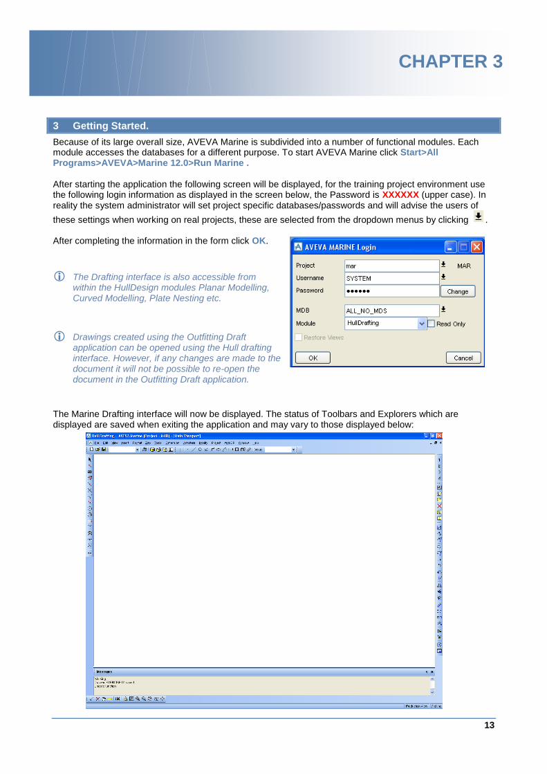
Because of its large overall size, AVEVA Marine is subdivided into a number of functional modules. Each module accesses the databases for a different purpose. To start AVEVA Marine click Start>All Programs>AVEVA>Marine 12.0>Run Marine . After starting the application the following screen will be displayed, for the training project environment use the following login information as displayed in the screen below, the Password is XXXXXX (upper case). In reality the system administrator will set project specific databases/passwords and will advise the users of
these settings when working on real projects, these are selected from the dropdown menus by clicking . After completing the information in the form click OK.
The Drafting interface is also accessible from within the HullDesign modules Planar Modelling, Curved Modelling, Plate Nesting etc.
Drawings created using the Outfitting Draft application can be opened using the Hull drafting interface. However, if any changes are made to the document it will not be possible to re-open the document in the Outfitting Draft application.
The Marine Drafting interface will now be displayed. The status of Toolbars and Explorers which are displayed are saved when exiting the application and may vary to those displayed below:
AVEVA Marine (12 Series) Hull/Outfitting Drafting TM-2100
14
www.aveva.com
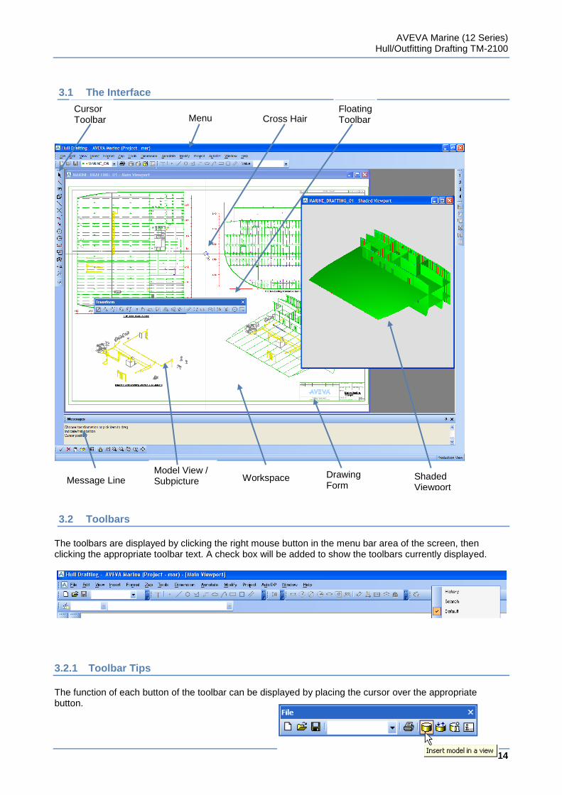
3.1 The Interface
3.2 Toolbars
The toolbars are displayed by clicking the right mouse button in the menu bar area of the screen, then clicking the appropriate toolbar text. A check box will be added to show the toolbars currently displayed.
3.2.1 Toolbar Tips
The function of each button of the toolbar can be displayed by placing the cursor over the appropriate button.
Cursor Toolbar Menu
Bar
Floating Toolbar Cross Hair
Model View / Subpicture Workspace Shaded
Viewport
Drawing Form
Message Line Drawing Form
AVEVA Marine (12 Series) Hull/Outfitting Drafting TM-2100
15
www.aveva.com
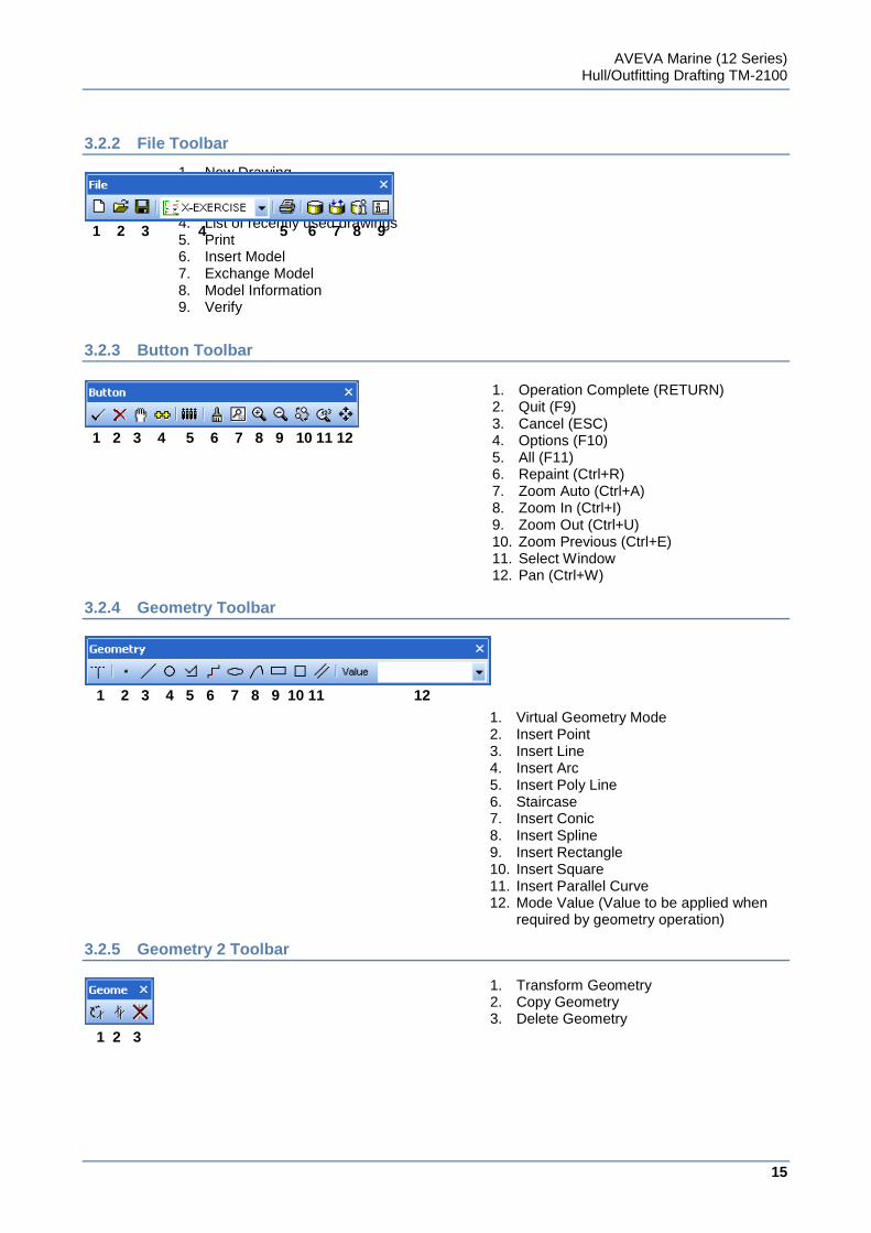
3.2.2 File Toolbar
1 2 3 4 5 6 7 8 9
3.2.3 Button Toolbar
1 2 3 4 5 6 7 8 9 10 11 12
3.2.4 Geometry Toolbar
1 2 3 4 5 6 7 8 9 10 11 12
3.2.5 Geometry 2 Toolbar
1 2 3
1. New Drawing 2. Open Drawing 3. Save Drawing 4. List of recently used drawings 5. Print 6. Insert Model 7. Exchange Model 8. Model Information 9. Verify
1. Operation Complete (RETURN) 2. Quit (F9) 3. Cancel (ESC) 4. Options (F10) 5. All (F11) 6. Repaint (Ctrl+R) 7. Zoom Auto (Ctrl+A) 8. Zoom In (Ctrl+I) 9. Zoom Out (Ctrl+U) 10. Zoom Previous (Ctrl+E) 11. Select Window 12. Pan (Ctrl+W)
1. Virtual Geometry Mode 2. Insert Point 3. Insert Line 4. Insert Arc 5. Insert Poly Line 6. Staircase 7. Insert Conic 8. Insert Spline 9. Insert Rectangle 10. Insert Square 11. Insert Parallel Curve 12. Mode Value (Value to be applied when
required by geometry operation)
1. Transform Geometry 2. Copy Geometry 3. Delete Geometry
AVEVA Marine (12 Series) Hull/Outfitting Drafting TM-2100
16
www.aveva.com
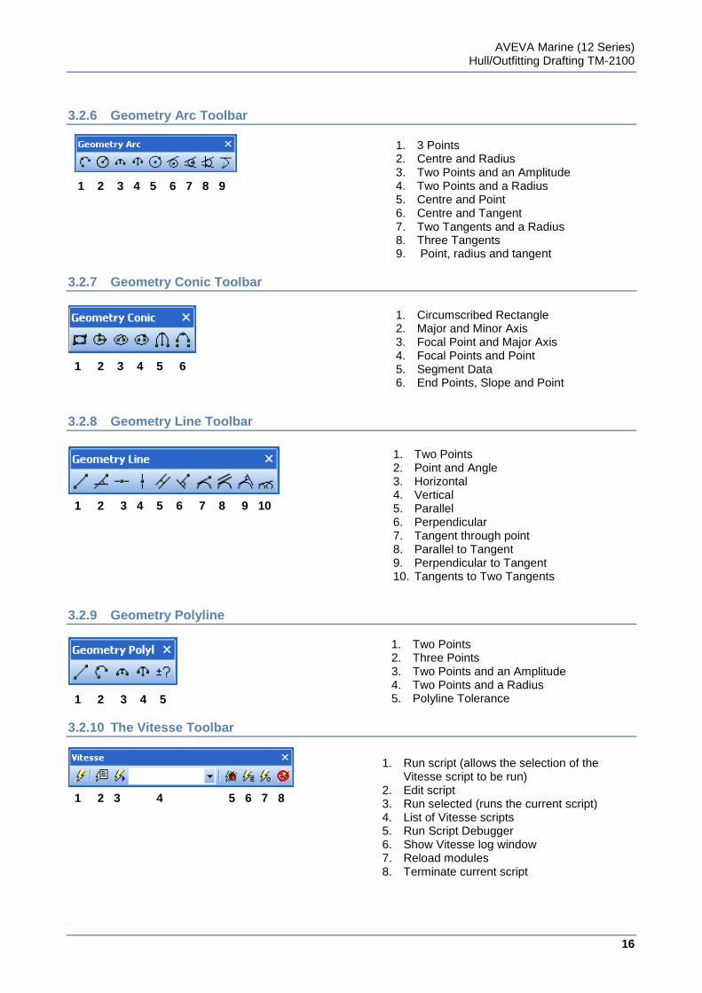
3.2.6 Geometry Arc Toolbar
1 2 3 4 5 6 7 8 9
3.2.7 Geometry Conic Toolbar
1 2 3 4 5 6
3.2.8 Geometry Line Toolbar
1 2 3 4 5 6 7 8 9 10
3.2.9 Geometry Polyline
1 2 3 4 5
3.2.10 The Vitesse Toolbar
1 2 3 4 5 6 7 8
1. Run script (allows the selection of the Vitesse script to be run)
2. Edit script 3. Run selected (runs the current script) 4. List of Vitesse scripts 5. Run Script Debugger 6. Show Vitesse log window 7. Reload modules 8. Terminate current script
1. Two Points 2. Point and Angle 3. Horizontal 4. Vertical 5. Parallel 6. Perpendicular 7. Tangent through point 8. Parallel to Tangent 9. Perpendicular to Tangent 10. Tangents to Two Tangents
1. 3 Points 2. Centre and Radius 3. Two Points and an Amplitude 4. Two Points and a Radius 5. Centre and Point 6. Centre and Tangent 7. Two Tangents and a Radius 8. Three Tangents 9. Point, radius and tangent
1. Two Points 2. Three Points 3. Two Points and an Amplitude 4. Two Points and a Radius 5. Polyline Tolerance
1. Circumscribed Rectangle 2. Major and Minor Axis 3. Focal Point and Major Axis 4. Focal Points and Point 5. Segment Data 6. End Points, Slope and Point
AVEVA Marine (12 Series) Hull/Outfitting Drafting TM-2100
17
www.aveva.com
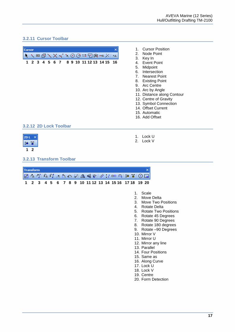
3.2.11 Cursor Toolbar
1 2 3 4 5 6 7 8 9 10 11 12 13 14 15 16
3.2.12 2D Lock Toolbar
1 2
3.2.13 Transform Toolbar
1 2 3 4 5 6 7 8 9 10 11 12 13 14 15 16 17 18 19 20
1. Cursor Position 2. Node Point 3. Key In 4. Event Point 5. Midpoint 6. Intersection 7. Nearest Point 8. Existing Point 9. Arc Centre 10. Arc by Angle 11. Distance along Contour 12. Centre of Gravity 13. Symbol Connection 14. Offset Current 15. Automatic 16. Add Offset
1. Lock U 2. Lock V
1. Scale 2. Move Delta 3. Move Two Positions 4. Rotate Delta 5. Rotate Two Positions 6. Rotate 45 Degrees 7. Rotate 90 Degrees 8. Rotate 180 degrees 9. Rotate –90 Degrees 10. Mirror V 11. Mirror U 12. Mirror any line 13. Parallel 14. Four Positions 15. Same as 16. Along Curve 17. Lock U 18. Lock V 19. Centre 20. Form Detection
AVEVA Marine (12 Series) Hull/Outfitting Drafting TM-2100
18
www.aveva.com
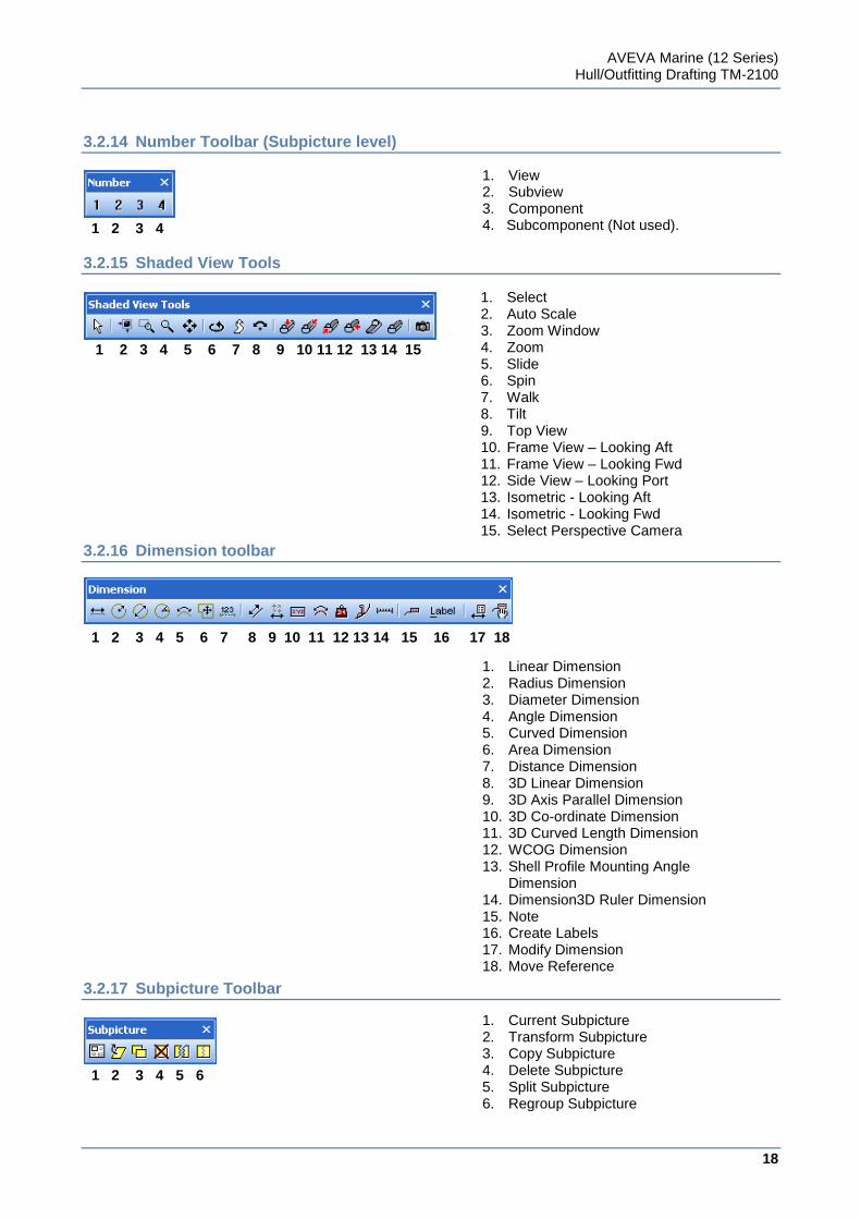
3.2.14 Number Toolbar (Subpicture level)
1 2 3 4
3.2.15 Shaded View Tools
1 2 3 4 5 6 7 8 9 10 11 12 13 14 15
3.2.16 Dimension toolbar
1 2 3 4 5 6 7 8 9 10 11 12 13 14 15 16 17 18
3.2.17 Subpicture Toolbar
1 2 3 4 5 6
1. View 2. Subview 3. Component 4. Subcomponent (Not used).
1. Select 2. Auto Scale 3. Zoom Window 4. Zoom 5. Slide 6. Spin 7. Walk 8. Tilt 9. Top View 10. Frame View – Looking Aft 11. Frame View – Looking Fwd 12. Side View – Looking Port 13. Isometric - Looking Aft 14. Isometric - Looking Fwd 15. Select Perspective Camera
1. Linear Dimension 2. Radius Dimension 3. Diameter Dimension 4. Angle Dimension 5. Curved Dimension 6. Area Dimension 7. Distance Dimension 8. 3D Linear Dimension 9. 3D Axis Parallel Dimension 10. 3D Co-ordinate Dimension 11. 3D Curved Length Dimension 12. WCOG Dimension 13. Shell Profile Mounting Angle
Dimension 14. Dimension3D Ruler Dimension 15. Note 16. Create Labels 17. Modify Dimension 18. Move Reference
1. Current Subpicture 2. Transform Subpicture 3. Copy Subpicture 4. Delete Subpicture 5. Split Subpicture 6. Regroup Subpicture
AVEVA Marine (12 Series) Hull/Outfitting Drafting TM-2100
19
www.aveva.com
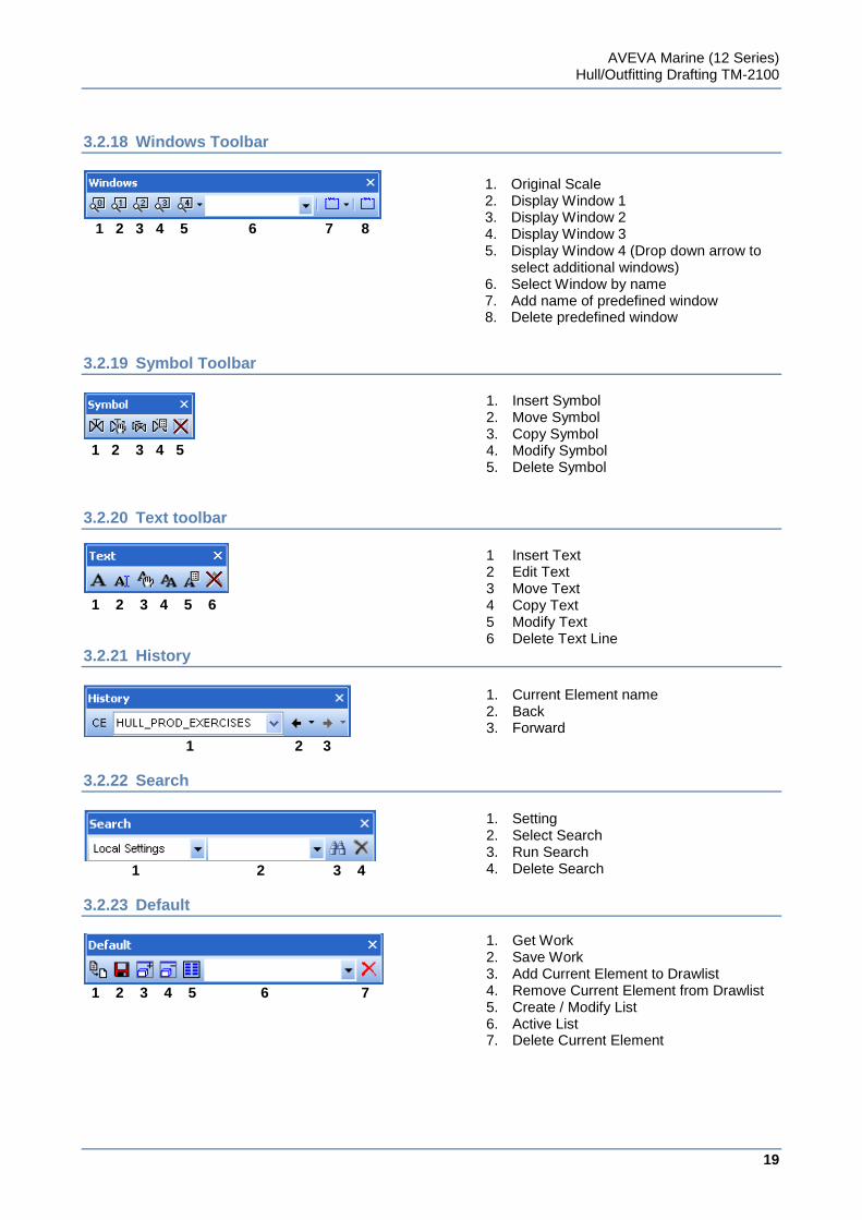
3.2.18 Windows Toolbar
1 2 3 4 5 6 7 8
3.2.19 Symbol Toolbar
1 2 3 4 5
3.2.20 Text toolbar
1 2 3 4 5 6
3.2.21 History
1 2 3
3.2.22 Search
1 2 3 4
3.2.23 Default
1 2 3 4 5 6 7
1. Original Scale 2. Display Window 1 3. Display Window 2 4. Display Window 3 5. Display Window 4 (Drop down arrow to
select additional windows) 6. Select Window by name 7. Add name of predefined window 8. Delete predefined window
1. Insert Symbol 2. Move Symbol 3. Copy Symbol 4. Modify Symbol 5. Delete Symbol
1 Insert Text 2 Edit Text 3 Move Text 4 Copy Text 5 Modify Text 6 Delete Text Line
1. Current Element name 2. Back 3. Forward
1. Setting 2. Select Search 3. Run Search 4. Delete Search
1. Get Work 2. Save Work 3. Add Current Element to Drawlist 4. Remove Current Element from Drawlist 5. Create / Modify List 6. Active List 7. Delete Current Element
AVEVA Marine (12 Series) Hull/Outfitting Drafting TM-2100
20
www.aveva.com
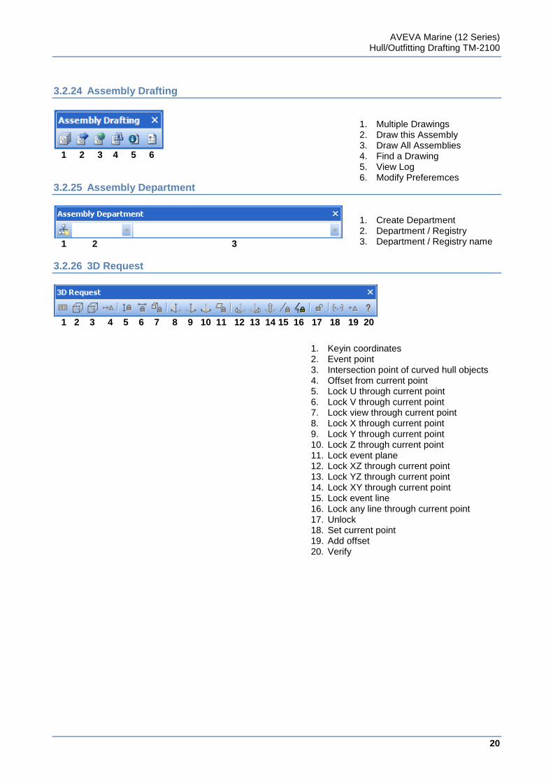
3.2.24 Assembly Drafting
1 2 3 4 5 6
3.2.25 Assembly Department
1 2 3
3.2.26 3D Request
1 2 3 4 5 6 7 8 9 10 11 12 13 14 15 16 17 18 19 20
1. Multiple Drawings 2. Draw this Assembly 3. Draw All Assemblies 4. Find a Drawing 5. View Log 6. Modify Preferemces
1. Create Department 2. Department / Registry 3. Department / Registry name
1. Keyin coordinates 2. Event point 3. Intersection point of curved hull objects 4. Offset from current point 5. Lock U through current point 6. Lock V through current point 7. Lock view through current point 8. Lock X through current point 9. Lock Y through current point 10. Lock Z through current point 11. Lock event plane 12. Lock XZ through current point 13. Lock YZ through current point 14. Lock XY through current point 15. Lock event line 16. Lock any line through current point 17. Unlock 18. Set current point 19. Add offset 20. Verify
AVEVA Marine (12 Series) Hull/Outfitting Drafting TM-2100
21
www.aveva.com
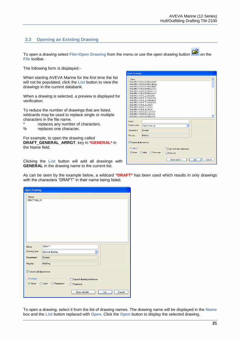
3.3 Opening an Existing Drawing
To open a drawing select File>Open Drawing from the menu or use the open drawing button on the File toolbar. The following form is displayed:- When starting AVEVA Marine for the first time the list will not be populated, click the List button to view the drawings in the current databank. When a drawing is selected, a preview is displayed for verification. To reduce the number of drawings that are listed, wildcards may be used to replace single or multiple characters in the file name. * replaces any number of characters. % replaces one character. For example, to open the drawing called DRAFT_GENERAL_ARRGT, key in *GENERAL* in the Name field. Clicking the List button will add all drawings with GENERAL in the drawing name to the current list. As can be seen by the example below, a wildcard *DRAFT* has been used which results in only drawings with the characters “DRAFT” in their name being listed.
To open a drawing, select it from the list of drawing names. The drawing name will be displayed in the Name box and the List button replaced with Open. Click the Open button to display the selected drawing.
AVEVA Marine (12 Series) Hull/Outfitting Drafting TM-2100
22
www.aveva.com
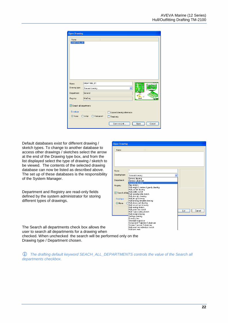
Default databases exist for different drawing / sketch types. To change to another database to access other drawings / sketches select the arrow at the end of the Drawing type box, and from the list displayed select the type of drawing / sketch to be viewed. The contents of the selected drawing database can now be listed as described above. The set up of these databases is the responsibility of the System Manager. Department and Registry are read-only fields defined by the system administrator for storing different types of drawings. The Search all departments check box allows the user to search all departments for a drawing when checked. When unchecked the search will be performed only on the Drawing type / Department chosen.
The drafting default keyword SEACH_ALL_DEPARTMENTS controls the value of the Search all
departments checkbox.
AVEVA Marine (12 Series) Hull/Outfitting Drafting TM-2100
23
www.aveva.com
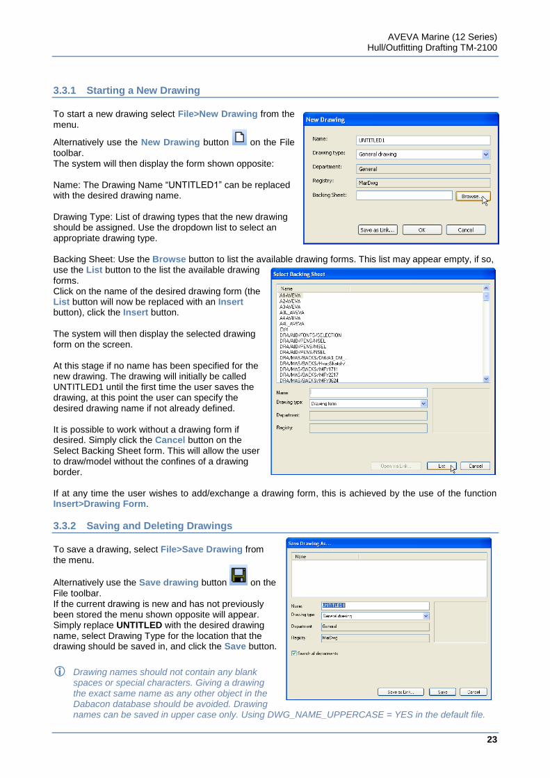
3.3.1 Starting a New Drawing
To start a new drawing select File>New Drawing from the menu.
Alternatively use the New Drawing button on the File toolbar. The system will then display the form shown opposite: Name: The Drawing Name “UNTITLED1” can be replaced with the desired drawing name. Drawing Type: List of drawing types that the new drawing should be assigned. Use the dropdown list to select an appropriate drawing type. Backing Sheet: Use the Browse button to list the available drawing forms. This list may appear empty, if so, use the List button to the list the available drawing forms. Click on the name of the desired drawing form (the List button will now be replaced with an Insert button), click the Insert button. The system will then display the selected drawing form on the screen. At this stage if no name has been specified for the new drawing. The drawing will initially be called UNTITLED1 until the first time the user saves the drawing, at this point the user can specify the desired drawing name if not already defined. It is possible to work without a drawing form if desired. Simply click the Cancel button on the Select Backing Sheet form. This will allow the user to draw/model without the confines of a drawing border. If at any time the user wishes to add/exchange a drawing form, this is achieved by the use of the function Insert>Drawing Form.
3.3.2 Saving and Deleting Drawings
To save a drawing, select File>Save Drawing from the menu.
Alternatively use the Save drawing button on the File toolbar. If the current drawing is new and has not previously been stored the menu shown opposite will appear. Simply replace UNTITLED with the desired drawing name, select Drawing Type for the location that the drawing should be saved in, and click the Save button.
Drawing names should not contain any blank spaces or special characters. Giving a drawing the exact same name as any other object in the Dabacon database should be avoided. Drawing names can be saved in upper case only. Using DWG_NAME_UPPERCASE = YES in the default file.
AVEVA Marine (12 Series) Hull/Outfitting Drafting TM-2100
24
www.aveva.com
If the drawing name already exists in the database the message shown opposite will appear. Click the OK button and the system will return to the previous menu allowing the definition of a unique drawing name. If you have a drawing open and you wish to save it with a different name use File>Save Drawing As. The system will display the previous menu. The current name of the drawing will appear in the Name field. Edit this to suit and then click the Save button. Please note that Save Drawing As will result in a drawing with the new name being stored in the database, the original drawing will not be deleted. To delete a drawing from the database use File>Databank>Delete, the system will display the menu shown opposite. Click 1 Drawings and the system will display the following menu:
If the list is empty select the List button to display the available drawings.
Locate the drawing to be deleted, using wildcards if required. Click once on the drawing to be deleted (the List button will be replaced with the Delete button when a drawing has been selected), click the Delete button. The system will prompt for confirmation before deleting the drawing. Click the Yes button and the drawing will be removed from the database.
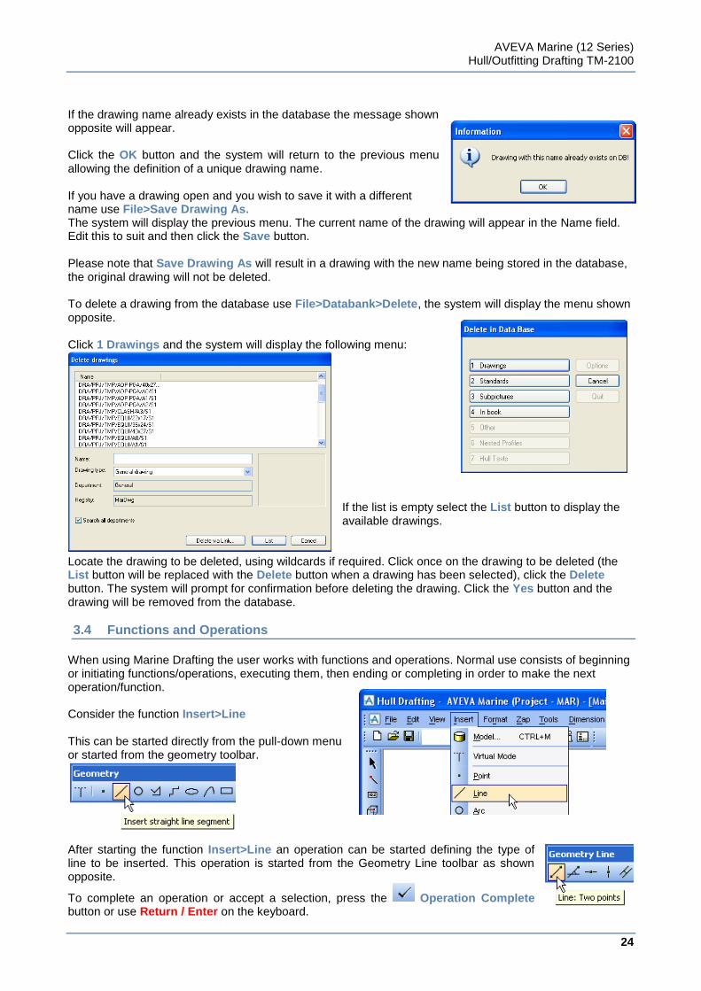
3.4 Functions and Operations
When using Marine Drafting the user works with functions and operations. Normal use consists of beginning or initiating functions/operations, executing them, then ending or completing in order to make the next operation/function. Consider the function Insert>Line This can be started directly from the pull-down menu or started from the geometry toolbar.
After starting the function Insert>Line an operation can be started defining the type of line to be inserted. This operation is started from the Geometry Line toolbar as shown opposite.
To complete an operation or accept a selection, press the Operation Complete button or use Return / Enter on the keyboard.
AVEVA Marine (12 Series) Hull/Outfitting Drafting TM-2100
25
www.aveva.com
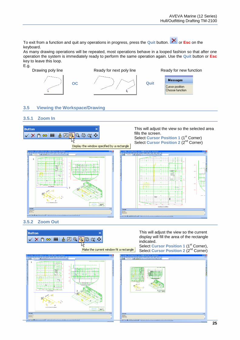
To exit from a function and quit any operations in progress, press the Quit button. or Esc on the keyboard. As many drawing operations will be repeated, most operations behave in a looped fashion so that after one operation the system is immediately ready to perform the same operation again. Use the Quit button or Esc key to leave this loop. E.g. Drawing poly line Ready for next poly line Ready for new function
3.5 Viewing the Workspace/Drawing
3.5.1 Zoom In
This will adjust the view so the selected area fills the screen. Select Cursor Position 1 (1
st Corner)
Select Cursor Position 2 (2nd
Corner)
3.5.2 Zoom Out
This will adjust the view so the current display will fill the area of the rectangle indicated. Select Cursor Position 1 (1
st Corner),
Select Cursor Position 2 (2nd
Corner)
OC Quit
1
2
1
2
AVEVA Marine (12 Series) Hull/Outfitting Drafting TM-2100
26
www.aveva.com
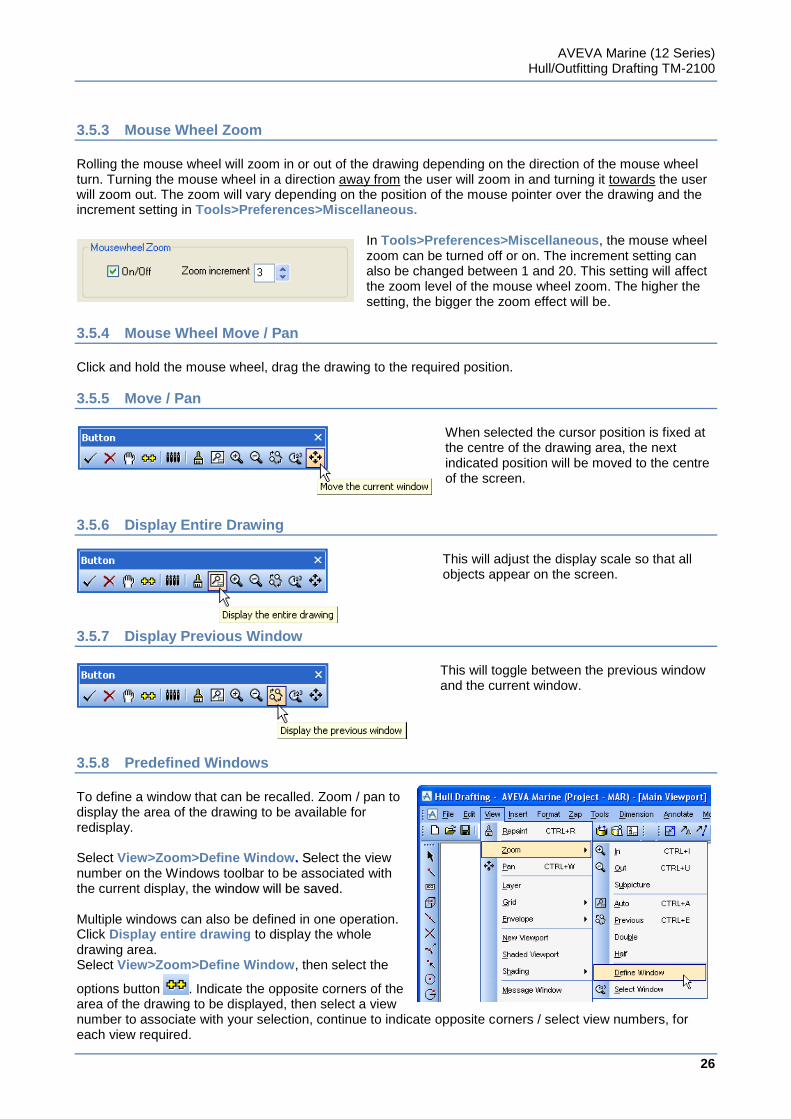
3.5.3 Mouse Wheel Zoom
Rolling the mouse wheel will zoom in or out of the drawing depending on the direction of the mouse wheel turn. Turning the mouse wheel in a direction away from the user will zoom in and turning it towards the user will zoom out. The zoom will vary depending on the position of the mouse pointer over the drawing and the increment setting in Tools>Preferences>Miscellaneous.
In Tools>Preferences>Miscellaneous, the mouse wheel zoom can be turned off or on. The increment setting can also be changed between 1 and 20. This setting will affect the zoom level of the mouse wheel zoom. The higher the setting, the bigger the zoom effect will be.
3.5.4 Mouse Wheel Move / Pan
Click and hold the mouse wheel, drag the drawing to the required position.
3.5.5 Move / Pan
When selected the cursor position is fixed at the centre of the drawing area, the next indicated position will be moved to the centre of the screen.
3.5.6 Display Entire Drawing
This will adjust the display scale so that all objects appear on the screen.
3.5.7 Display Previous Window
This will toggle between the previous window and the current window.
3.5.8 Predefined Windows
To define a window that can be recalled. Zoom / pan to display the area of the drawing to be available for redisplay. Select View>Zoom>Define Window.. SSelect the view number on the Windows toolbar to be associated with the current display, thhee wwiinnddooww wwiillll bbee ssaavveedd..
Multiple windows can also be defined in one operation. Click Display entire drawing to display the whole drawing area. Select View>Zoom>Define Window, then select the
options button . Indicate the opposite corners of the area of the drawing to be displayed, then select a view number to associate with your selection, continue to indicate opposite corners / select view numbers, for each view required.
AVEVA Marine (12 Series) Hull/Outfitting Drafting TM-2100
27
www.aveva.com
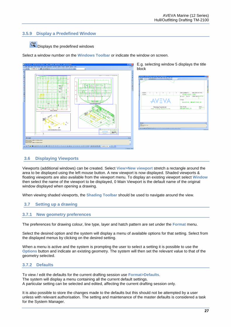
3.5.9 Display a Predefined Window
Displays the predefined windows Select a window number on the Windows Toolbar or indicate the window on screen.
E.g. selecting window 5 displays the title block
3.6 Displaying Viewports
Viewports (additional windows) can be created. Select View>New viewport stretch a rectangle around the area to be displayed using the left mouse button. A new viewport is now displayed. Shaded viewports & floating viewports are also available from the viewport menu. To display an existing viewport select Window then select the name of the viewport to be displayed, 0 Main Viewport is the default name of the original window displayed when opening a drawing. When viewing shaded viewports, the Shading Toolbar should be used to navigate around the view.
3.7 Setting up a drawing
3.7.1 New geometry preferences
The preferences for drawing colour, line type, layer and hatch pattern are set under the Format menu. Select the desired option and the system will display a menu of available options for that setting. Select from the displayed menus by clicking on the desired setting. When a menu is active and the system is prompting the user to select a setting it is possible to use the Options button and indicate an existing geometry. The system will then set the relevant value to that of the geometry selected.
3.7.2 Defaults
To view / edit the defaults for the current drafting session use Format>Defaults. The system will display a menu containing all the current default settings. A particular setting can be selected and edited, affecting the current drafting session only. It is also possible to store the changes made to the defaults but this should not be attempted by a user unless with relevant authorisation. The setting and maintenance of the master defaults is considered a task for the System Manager.
AVEVA Marine (12 Series) Hull/Outfitting Drafting TM-2100
28
www.aveva.com
3.7.3 Drawing Scale
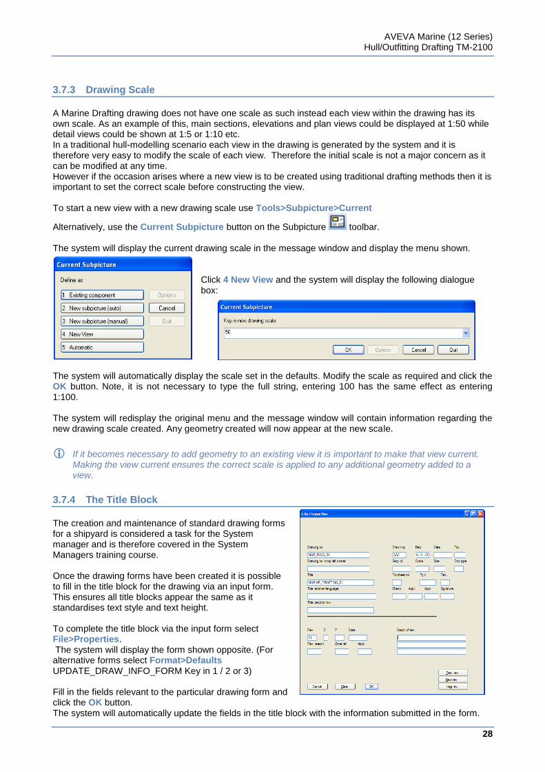
A Marine Drafting drawing does not have one scale as such instead each view within the drawing has its own scale. As an example of this, main sections, elevations and plan views could be displayed at 1:50 while detail views could be shown at 1:5 or 1:10 etc. In a traditional hull-modelling scenario each view in the drawing is generated by the system and it is therefore very easy to modify the scale of each view. Therefore the initial scale is not a major concern as it can be modified at any time. However if the occasion arises where a new view is to be created using traditional drafting methods then it is important to set the correct scale before constructing the view. To start a new view with a new drawing scale use Tools>Subpicture>Current
Alternatively, use the Current Subpicture button on the Subpicture toolbar. The system will display the current drawing scale in the message window and display the menu shown.
Click 4 New View and the system will display the following dialogue box:
The system will automatically display the scale set in the defaults. Modify the scale as required and click the OK button. Note, it is not necessary to type the full string, entering 100 has the same effect as entering 1:100. The system will redisplay the original menu and the message window will contain information regarding the new drawing scale created. Any geometry created will now appear at the new scale.
If it becomes necessary to add geometry to an existing view it is important to make that view current. Making the view current ensures the correct scale is applied to any additional geometry added to a view.
3.7.4 The Title Block
The creation and maintenance of standard drawing forms for a shipyard is considered a task for the System manager and is therefore covered in the System Managers training course. Once the drawing forms have been created it is possible to fill in the title block for the drawing via an input form. This ensures all title blocks appear the same as it standardises text style and text height. To complete the title block via the input form select File>Properties. The system will display the form shown opposite. (For alternative forms select Format>Defaults UPDATE_DRAW_INFO_FORM Key in 1 / 2 or 3) Fill in the fields relevant to the particular drawing form and click the OK button. The system will automatically update the fields in the title block with the information submitted in the form.
AVEVA Marine (12 Series) Hull/Outfitting Drafting TM-2100
29
www.aveva.com
Exercise 1
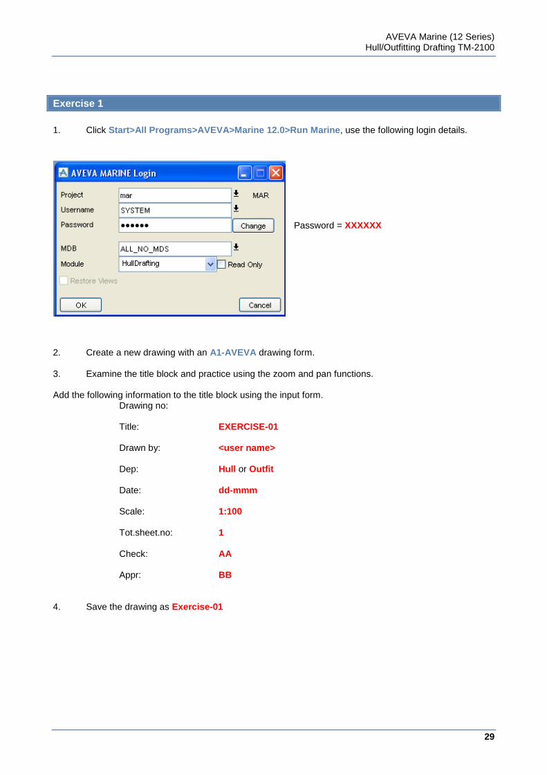
1. Click Start>All Programs>AVEVA>Marine 12.0>Run Marine, use the following login details.
Password = XXXXXX
2. Create a new drawing with an A1-AVEVA drawing form.
3. Examine the title block and practice using the zoom and pan functions.
Add the following information to the title block using the input form. Drawing no: Title: EXERCISE-01 Drawn by: <user name> Dep: Hull or Outfit Date: dd-mmm Scale: 1:100 Tot.sheet.no: 1 Check: AA Appr: BB 4. Save the drawing as Exercise-01

AVEVA Marine (12 Series) Hull/Outfitting Drafting TM-2100
30
www.aveva.com
31
www.aveva.com
CHAPTER 4
4 Viewing the Ship Model
This chapter involve working with an existing model, which has been created by the designers and modellers at AVEVA Solutions. The modelling functions are covered in other training courses.
4.1 The Marine Drafting View Concept
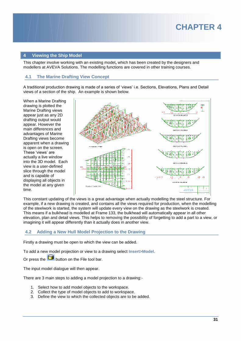
A traditional production drawing is made of a series of „views‟ i.e. Sections, Elevations, Plans and Detail views of a section of the ship. An example is shown below. When a Marine Drafting drawing is plotted the Marine Drafting views appear just as any 2D drafting output would appear. However the main differences and advantages of Marine Drafting views become apparent when a drawing is open on the screen. These „views‟ are actually a live window into the 3D model. Each view is a user-defined slice through the model and is capable of displaying all objects in the model at any given time. This constant updating of the views is a great advantage when actually modelling the steel structure. For example, if a new drawing is created, and contains all the views required for production, when the modelling of the steelwork is started, the system will update every view on the drawing as the steelwork is created. This means if a bulkhead is modelled at Frame 133, the bulkhead will automatically appear in all other elevation, plan and detail views. This helps to removing the possibility of forgetting to add a part to a view, or imagining it will appear differently than it actually does in another view.
4.2 Adding a New Hull Model Projection to the Drawing
Firstly a drawing must be open to which the view can be added. To add a new model projection or view to a drawing select Insert>Model.
Or press the button on the File tool bar. The input model dialogue will then appear. There are 3 main steps to adding a model projection to a drawing:-
1. Select how to add model objects to the workspace. 2. Collect the type of model objects to add to workspace. 3. Define the view to which the collected objects are to be added.
AVEVA Marine (12 Series) Hull/Outfitting Drafting TM-2100
32
www.aveva.com
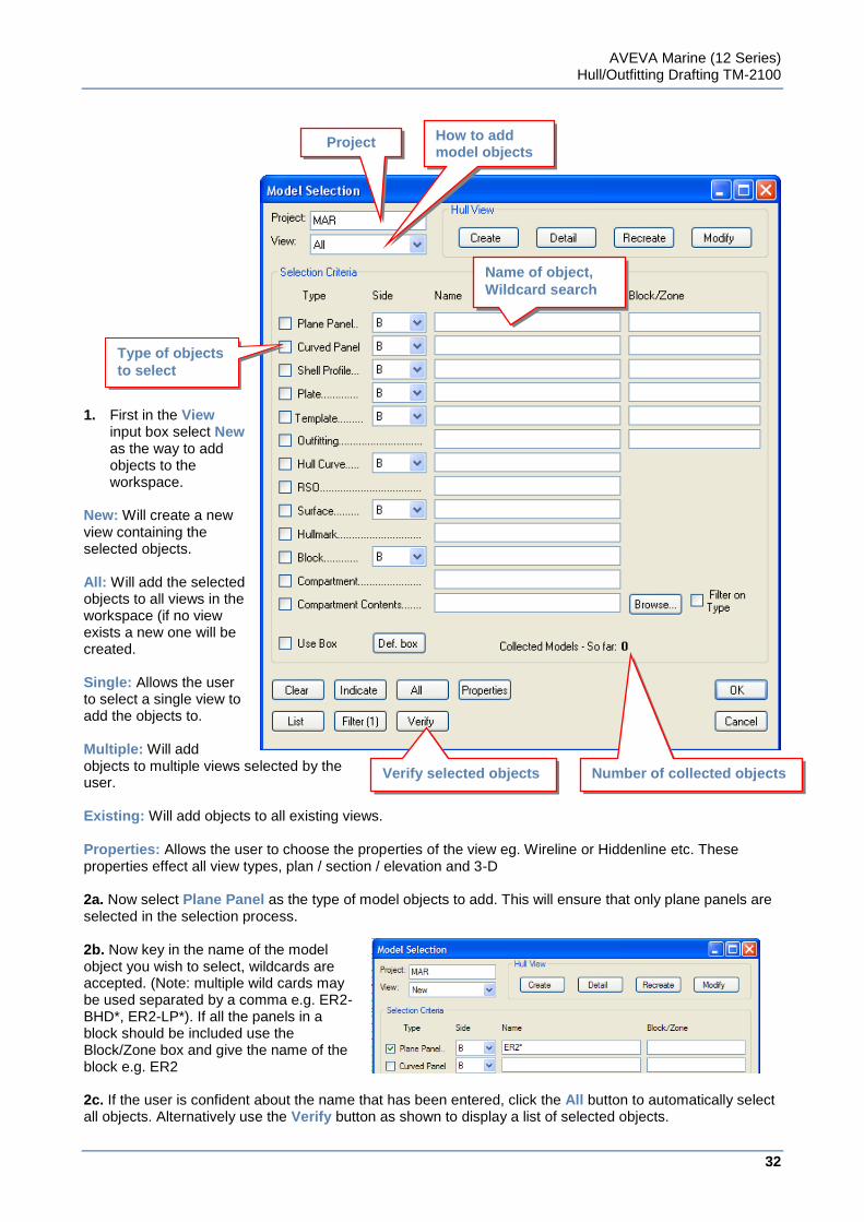
1. First in the View
input box select New as the way to add objects to the workspace.
New: Will create a new view containing the selected objects. All: Will add the selected objects to all views in the workspace (if no view exists a new one will be created. Single: Allows the user to select a single view to add the objects to. Multiple: Will add objects to multiple views selected by the user. Existing: Will add objects to all existing views. Properties: Allows the user to choose the properties of the view eg. Wireline or Hiddenline etc. These properties effect all view types, plan / section / elevation and 3-D 2a. Now select Plane Panel as the type of model objects to add. This will ensure that only plane panels are selected in the selection process. 2b. Now key in the name of the model object you wish to select, wildcards are accepted. (Note: multiple wild cards may be used separated by a comma e.g. ER2-BHD*, ER2-LP*). If all the panels in a block should be included use the Block/Zone box and give the name of the block e.g. ER2 2c. If the user is confident about the name that has been entered, click the All button to automatically select all objects. Alternatively use the Verify button as shown to display a list of selected objects.
Project name
How to add model objects
Type of objects
to select
Name of object,
Wildcard search
Verify selected objects Number of collected objects
AVEVA Marine (12 Series) Hull/Outfitting Drafting TM-2100
33
www.aveva.com
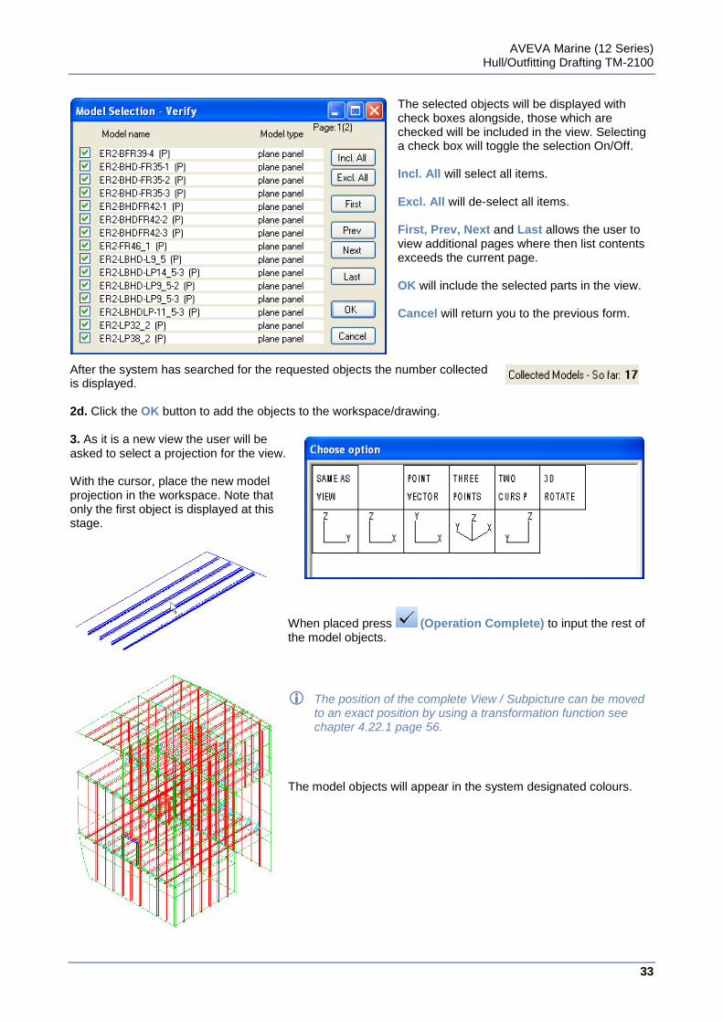
The selected objects will be displayed with check boxes alongside, those which are checked will be included in the view. Selecting a check box will toggle the selection On/Off. Incl. All will select all items. Excl. All will de-select all items. First, Prev, Next and Last allows the user to view additional pages where then list contents exceeds the current page. OK will include the selected parts in the view. Cancel will return you to the previous form.
After the system has searched for the requested objects the number collected is displayed. 2d. Click the OK button to add the objects to the workspace/drawing. 3. As it is a new view the user will be asked to select a projection for the view. With the cursor, place the new model projection in the workspace. Note that only the first object is displayed at this stage.
When placed press (Operation Complete) to input the rest of the model objects.
The position of the complete View / Subpicture can be moved to an exact position by using a transformation function see chapter 4.22.1 page 56.
The model objects will appear in the system designated colours.
AVEVA Marine (12 Series) Hull/Outfitting Drafting TM-2100
34
www.aveva.com
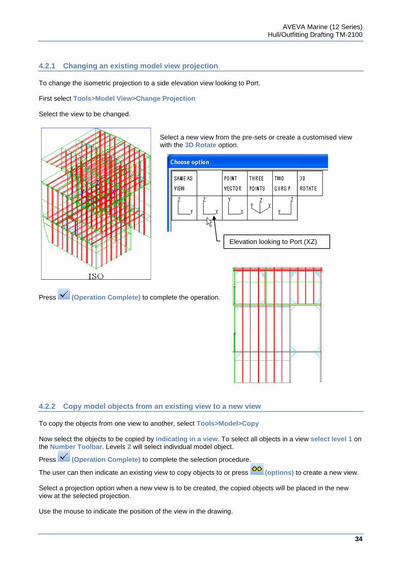
4.2.1 Changing an existing model view projection
To change the isometric projection to a side elevation view looking to Port. First select Tools>Model View>Change Projection Select the view to be changed.
Select a new view from the pre-sets or create a customised view with the 3D Rotate option.
Press (Operation Complete) to complete the operation.
4.2.2 Copy model objects from an existing view to a new view
To copy the objects from one view to another, select Tools>Model>Copy Now select the objects to be copied by indicating in a view. To select all objects in a view select level 1 on the Number Toolbar. Levels 2 will select individual model object.
Press (Operation Complete) to complete the selection procedure.
The user can then indicate an existing view to copy objects to or press (options) to create a new view. Select a projection option when a new view is to be created, the copied objects will be placed in the new view at the selected projection. Use the mouse to indicate the position of the view in the drawing.
Elevation looking to Port (XZ) View
AVEVA Marine (12 Series) Hull/Outfitting Drafting TM-2100
35
www.aveva.com
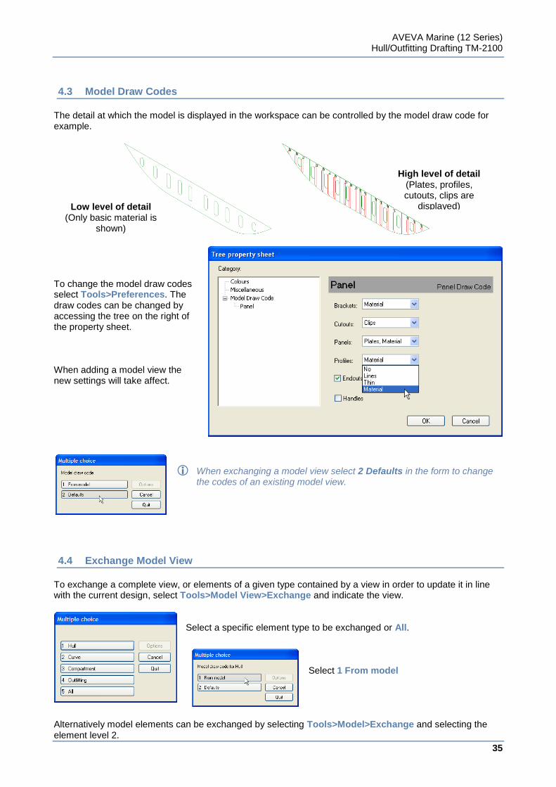
4.3 Model Draw Codes
The detail at which the model is displayed in the workspace can be controlled by the model draw code for example.
To change the model draw codes select Tools>Preferences. The draw codes can be changed by accessing the tree on the right of the property sheet. When adding a model view the new settings will take affect.
When exchanging a model view select 2 Defaults in the form to change the codes of an existing model view.
4.4 Exchange Model View
To exchange a complete view, or elements of a given type contained by a view in order to update it in line with the current design, select Tools>Model View>Exchange and indicate the view.
Select a specific element type to be exchanged or All.
Select 1 From model
Alternatively model elements can be exchanged by selecting Tools>Model>Exchange and selecting the element level 2.
Low level of detail (Only basic material is
shown)
High level of detail (Plates, profiles, cutouts, clips are
displayed)
AVEVA Marine (12 Series) Hull/Outfitting Drafting TM-2100
36
www.aveva.com
4.5 View Types
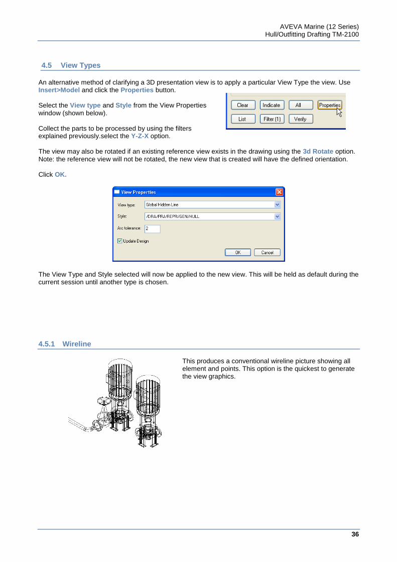
An alternative method of clarifying a 3D presentation view is to apply a particular View Type the view. Use Insert>Model and click the Properties button. Select the View type and Style from the View Properties window (shown below). Collect the parts to be processed by using the filters explained previously.select the Y-Z-X option. The view may also be rotated if an existing reference view exists in the drawing using the 3d Rotate option. Note: the reference view will not be rotated, the new view that is created will have the defined orientation. Click OK. The View Type and Style selected will now be applied to the new view. This will be held as default during the current session until another type is chosen.
4.5.1 Wireline
This produces a conventional wireline picture showing all element and points. This option is the quickest to generate the view graphics.
AVEVA Marine (12 Series) Hull/Outfitting Drafting TM-2100
37
www.aveva.com
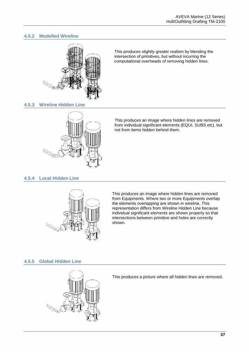
4.5.2 Modelled Wireline
This produces slightly greater realism by blending the intersection of primitives, but without incurring the computational overheads of removing hidden lines.
4.5.3 Wireline Hidden Line
This produces an image where hidden lines are removed from individual significant elements (EQUI, SUBS etc), but not from items hidden behind them.
4.5.4 Local Hidden Line
This produces an image where hidden lines are removed from Equipments. Where two or more Equipments overlap the elements overlapping are shown in wireline. This representation differs from Wireline Hidden Line because individual significant elements are shown properly so that intersections between primitive and holes are correctly shown.
4.5.5 Global Hidden Line
This produces a picture where all hidden lines are removed.
AVEVA Marine (12 Series) Hull/Outfitting Drafting TM-2100
38
www.aveva.com
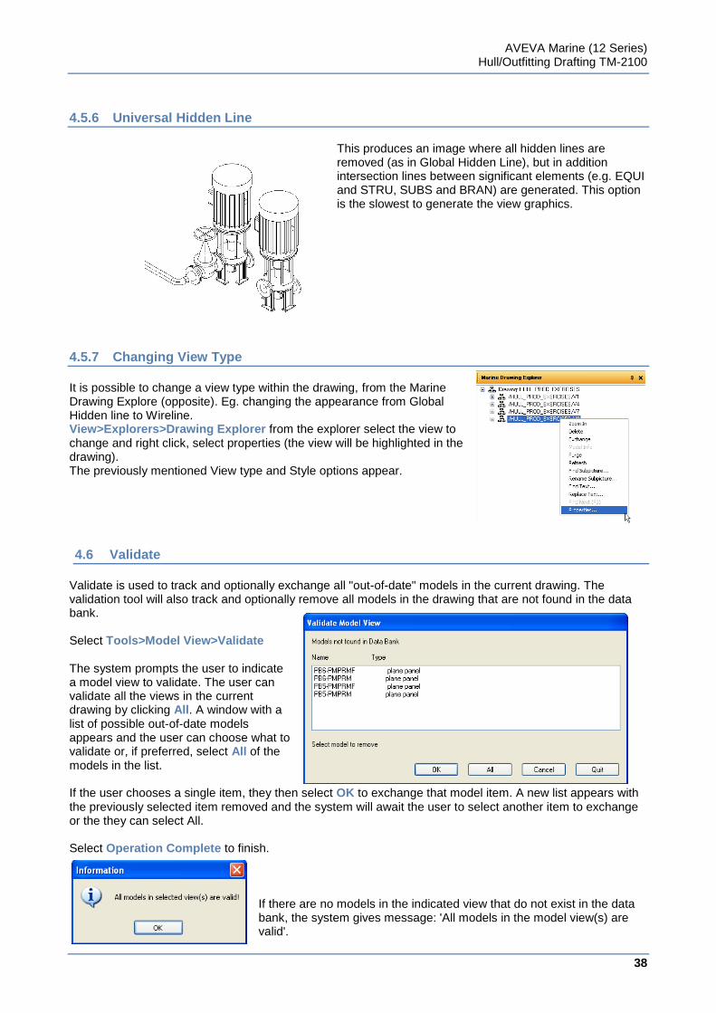
4.5.6 Universal Hidden Line
This produces an image where all hidden lines are removed (as in Global Hidden Line), but in addition intersection lines between significant elements (e.g. EQUI and STRU, SUBS and BRAN) are generated. This option is the slowest to generate the view graphics.
4.5.7 Changing View Type
It is possible to change a view type within the drawing, from the Marine Drawing Explore (opposite). Eg. changing the appearance from Global Hidden line to Wireline. View>Explorers>Drawing Explorer from the explorer select the view to change and right click, select properties (the view will be highlighted in the drawing). The previously mentioned View type and Style options appear.
4.6 Validate
Validate is used to track and optionally exchange all "out-of-date" models in the current drawing. The validation tool will also track and optionally remove all models in the drawing that are not found in the data bank. Select Tools>Model View>Validate The system prompts the user to indicate a model view to validate. The user can validate all the views in the current drawing by clicking All. A window with a list of possible out-of-date models appears and the user can choose what to validate or, if preferred, select All of the models in the list. If the user chooses a single item, they then select OK to exchange that model item. A new list appears with the previously selected item removed and the system will await the user to select another item to exchange or the they can select All. Select Operation Complete to finish.
If there are no models in the indicated view that do not exist in the data bank, the system gives message: 'All models in the model view(s) are valid'.
AVEVA Marine (12 Series) Hull/Outfitting Drafting TM-2100
39
www.aveva.com
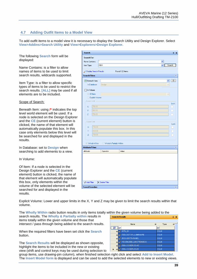
4.7 Adding Outfit Items to a Model View
To add outfit items to a model view it is necessary to display the Search Utility and Design Explorer. Select View>Addins>Search Utility and View>Explorers>Design Explorer. The following Search form will be displayed: Name Contains: is a filter to allow names of items to be used to limit search results, wildcards supported. Item Type: is a filter to allow specific types of items to be used to restrict the search results. [ALL] may be used if all elements are to be included. Scope of Search: Beneath Item: using /* indicates the top level world element will be used. If a node is selected on the Design Explorer and the CE (current element) button is clicked, the name of that element will automatically populate this box. In this case only elements below this level will be searched for and displayed in the results. In Database: set to Design when searching to add elements to a view. In Volume: Of Item: If a node is selected in the Design Explorer and the CE (current element) button is clicked, the name of that element will automatically populate this box, only elements within the volume of the selected element will be searched for and displayed in the results. Explicit Volume: Lower and upper limits in the X, Y and Z may be given to limit the search results within that volume. The Wholly Within radio button results in only items totally within the given volume being added to the search results. The Wholly & Partially within results in items totally within the given volume and those that intersect / pass through being added to the search results. When the required filters have been set click the Search button. The Search Results will be displayed as shown opposite, highlight the items to be included in the new or existing view (shift and control keys may be used during selection to group items, use drawing-pin column), when finished selection right click and select Add to Insert Model. The Insert Model form is displayed and can be used to add the selected elements to new or existing views.
AVEVA Marine (12 Series) Hull/Outfitting Drafting TM-2100
40
www.aveva.com
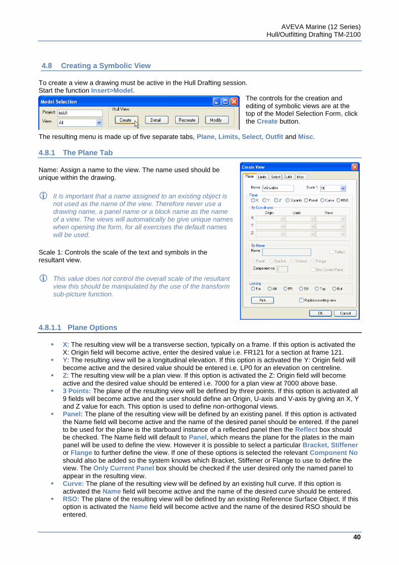
4.8 Creating a Symbolic View
To create a view a drawing must be active in the Hull Drafting session. Start the function Insert>Model.
The controls for the creation and editing of symbolic views are at the top of the Model Selection Form, click the Create button.
The resulting menu is made up of five separate tabs, Plane, Limits, Select, Outfit and Misc.
4.8.1 The Plane Tab
Name: Assign a name to the view. The name used should be unique within the drawing.
It is important that a name assigned to an existing object is not used as the name of the view. Therefore never use a drawing name, a panel name or a block name as the name of a view. The views will automatically be give unique names when opening the form, for all exercises the default names will be used.
Scale 1: Controls the scale of the text and symbols in the resultant view.
This value does not control the overall scale of the resultant view this should be manipulated by the use of the transform sub-picture function.
4.8.1.1 Plane Options
X: The resulting view will be a transverse section, typically on a frame. If this option is activated the
X: Origin field will become active, enter the desired value i.e. FR121 for a section at frame 121. Y: The resulting view will be a longitudinal elevation. If this option is activated the Y: Origin field will
become active and the desired value should be entered i.e. LP0 for an elevation on centreline. Z: The resulting view will be a plan view. If this option is activated the Z: Origin field will become
active and the desired value should be entered i.e. 7000 for a plan view at 7000 above base. 3 Points: The plane of the resulting view will be defined by three points. If this option is activated all
9 fields will become active and the user should define an Origin, U-axis and V-axis by giving an X, Y and Z value for each. This option is used to define non-orthogonal views.
Panel: The plane of the resulting view will be defined by an existing panel. If this option is activated the Name field will become active and the name of the desired panel should be entered. If the panel to be used for the plane is the starboard instance of a reflected panel then the Reflect box should be checked. The Name field will default to Panel, which means the plane for the plates in the main panel will be used to define the view. However it is possible to select a particular Bracket, Stiffener or Flange to further define the view. If one of these options is selected the relevant Component No should also be added so the system knows which Bracket, Stiffener or Flange to use to define the view. The Only Current Panel box should be checked if the user desired only the named panel to appear in the resulting view.
Curve: The plane of the resulting view will be defined by an existing hull curve. If this option is activated the Name field will become active and the name of the desired curve should be entered.
RSO: The plane of the resulting view will be defined by an existing Reference Surface Object. If this option is activated the Name field will become active and the name of the desired RSO should be entered.
AVEVA Marine (12 Series) Hull/Outfitting Drafting TM-2100
41
www.aveva.com
Reference Surface Objects are created in Initial Design and are used to define compartmentation for the vessel to be used in Naval Architecture Calculations, additional RSO’s can also be defined in the hull applications.
Looking: For: The resulting view will look from Aft Fore Aft: The resulting view will look from Fore Aft PS: The resulting view will look from Starboard Port SB: The resulting view will look from Port Starboard Top: The resulting view will look from Bottom Top Bot: The resulting view will look from Top Bottom The symbolic views default directions for views are as follows:
Sections - Looking aft, Plans - Looking down Elevations - Looking to port.
Pick: If the current drawing already contains views then it is possible to select one of these and the system will fill out the fields in the form to match those used to create the selected view. After the form has been populated it is possible to change the view name and create a new view using the selected views values. To get values from an existing view click the Pick button. The system will prompt ‘Indicate view’. Use the cursor to indicate the desired view in the drawing. The system will return to the Create View form having filled in the fields with the values from the indicated view. Replace Existing View: If this box is checked the system will replace an existing view instead of creating a new one. If the Pick button has been used the system will automatically replace the view previously selected when the form is submitted. If the Pick button was not used the system will prompt the user to select a view to be replaced.
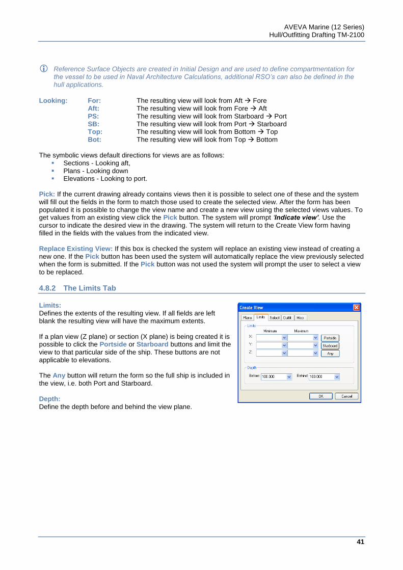
4.8.2 The Limits Tab
Limits: Defines the extents of the resulting view. If all fields are left blank the resulting view will have the maximum extents. If a plan view (Z plane) or section (X plane) is being created it is possible to click the Portside or Starboard buttons and limit the view to that particular side of the ship. These buttons are not applicable to elevations. The Any button will return the form so the full ship is included in the view, i.e. both Port and Starboard. Depth: Define the depth before and behind the view plane.
AVEVA Marine (12 Series) Hull/Outfitting Drafting TM-2100
42
www.aveva.com
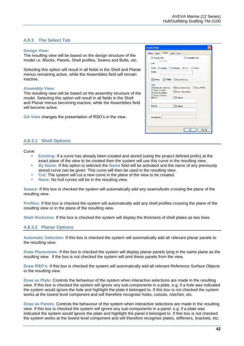
4.8.3 The Select Tab
Design View: The resulting view will be based on the design structure of the model i.e. Blocks, Panels, Shell profiles, Seams and Butts, etc. Selecting this option will result in all fields in the Shell and Planar menus remaining active, while the Assemblies field will remain inactive. Assembly View: The resulting view will be based on the assembly structure of the model. Selecting this option will result in all fields in the Shell and Planar menus becoming inactive, while the Assemblies field will become active. GA View changes the presentation of RSO‟s in the view.
4.8.3.1 Shell Options
Curve
Existing: If a curve has already been created and stored (using the project defined prefix) at the exact plane of the view to be created then the system will use this curve in the resulting view.
By Name: If this option is selected the Name field will be activated and the name of any previously stored curve can be given. This curve will then be used in the resulting view.
Cut: The system will cut a new curve in the plane of the view to be created. None: No hull curves will be in the resulting view.
Seams: If this box is checked the system will automatically add any seams/butts crossing the plane of the resulting view. Profiles: If this box is checked the system will automatically add any shell profiles crossing the plane of the resulting view or in the plane of the resulting view. Shell thickness: If this box is checked the system will display the thickness of shell plates as two lines.
4.8.3.2 Planar Options
Automatic Selection: If this box is checked the system will automatically add all relevant planar panels to the resulting view. Draw Planeviews: If this box is checked the system will display planar panels lying in the same plane as the resulting view. If the box is not checked the system will omit these panels from the view. Draw RSO’s: If this box is checked the system will automatically add all relevant Reference Surface Objects to the resulting view. Draw as Plate: Controls the behaviour of the system when interactive selections are made in the resulting view. If this box is checked the system will ignore any sub-components in a plate, e.g. if a hole was indicated the system would ignore the hole and highlight the plate it belonged to. If this box is not checked the system works at the lowest level component and will therefore recognise holes, cutouts, notches, etc. Draw as Panels: Controls the behaviour of the system when interactive selections are made in the resulting view. If this box is checked the system will ignore any sub-components in a panel, e.g. if a plate was indicated the system would ignore the plate and highlight the panel it belonged to. If this box is not checked the system works at the lowest level component and will therefore recognise plates, stiffeners, brackets, etc.
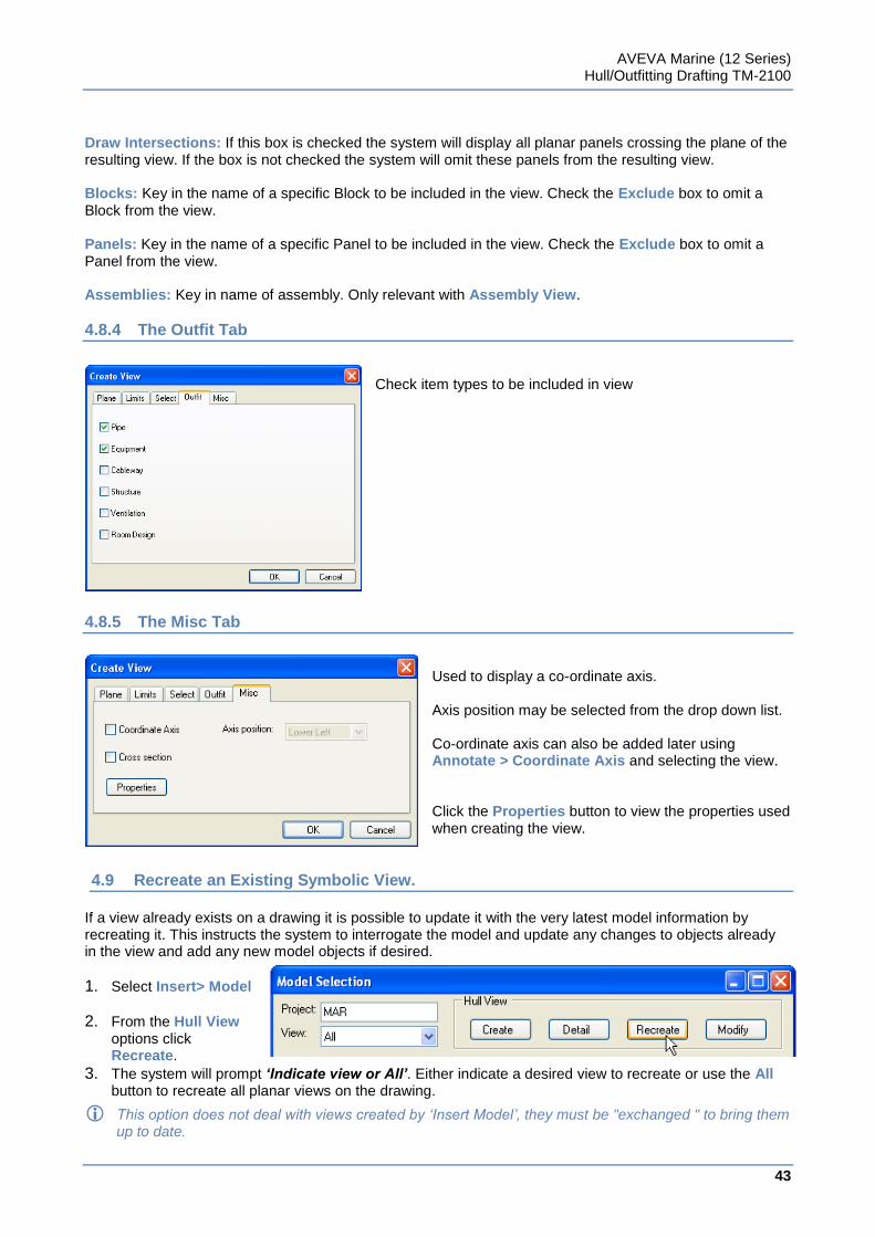
AVEVA Marine (12 Series) Hull/Outfitting Drafting TM-2100
43
www.aveva.com
Draw Intersections: If this box is checked the system will display all planar panels crossing the plane of the resulting view. If the box is not checked the system will omit these panels from the resulting view. Blocks: Key in the name of a specific Block to be included in the view. Check the Exclude box to omit a Block from the view. Panels: Key in the name of a specific Panel to be included in the view. Check the Exclude box to omit a Panel from the view. Assemblies: Key in name of assembly. Only relevant with Assembly View.
4.8.4 The Outfit Tab
Check item types to be included in view
4.8.5 The Misc Tab
Used to display a co-ordinate axis. Axis position may be selected from the drop down list. Co-ordinate axis can also be added later using Annotate > Coordinate Axis and selecting the view. Click the Properties button to view the properties used when creating the view.
4.9 Recreate an Existing Symbolic View.
If a view already exists on a drawing it is possible to update it with the very latest model information by recreating it. This instructs the system to interrogate the model and update any changes to objects already in the view and add any new model objects if desired.
1. Select Insert> Model
2. From the Hull View options click Recreate.
3. The system will prompt ‘Indicate view or All’. Either indicate a desired view to recreate or use the All button to recreate all planar views on the drawing.
This option does not deal with views created by ‘Insert Model’, they must be "exchanged " to bring them up to date.
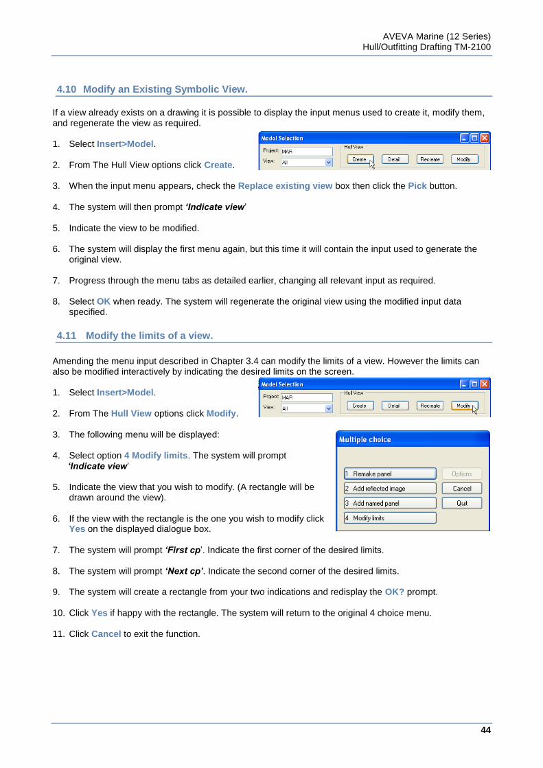
AVEVA Marine (12 Series) Hull/Outfitting Drafting TM-2100
44
www.aveva.com
4.10 Modify an Existing Symbolic View.
If a view already exists on a drawing it is possible to display the input menus used to create it, modify them, and regenerate the view as required. 1. Select Insert>Model. 2. From The Hull View options click Create. 3. When the input menu appears, check the Replace existing view box then click the Pick button. 4. The system will then prompt ‘Indicate view‟ 5. Indicate the view to be modified. 6. The system will display the first menu again, but this time it will contain the input used to generate the
original view. 7. Progress through the menu tabs as detailed earlier, changing all relevant input as required. 8. Select OK when ready. The system will regenerate the original view using the modified input data
specified.
4.11 Modify the limits of a view.
Amending the menu input described in Chapter 3.4 can modify the limits of a view. However the limits can also be modified interactively by indicating the desired limits on the screen. 1. Select Insert>Model. 2. From The Hull View options click Modify. 3. The following menu will be displayed: 4. Select option 4 Modify limits. The system will prompt ‘Indicate view‟ 5. Indicate the view that you wish to modify. (A rectangle will be
drawn around the view). 6. If the view with the rectangle is the one you wish to modify click
Yes on the displayed dialogue box. 7. The system will prompt ‘First cp‟. Indicate the first corner of the desired limits. 8. The system will prompt ‘Next cp’. Indicate the second corner of the desired limits. 9. The system will create a rectangle from your two indications and redisplay the OK? prompt. 10. Click Yes if happy with the rectangle. The system will return to the original 4 choice menu. 11. Click Cancel to exit the function.
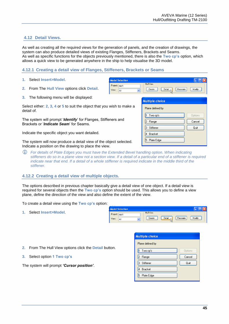
AVEVA Marine (12 Series) Hull/Outfitting Drafting TM-2100
45
www.aveva.com
4.12 Detail Views.
As well as creating all the required views for the generation of panels, and the creation of drawings, the system can also produce detailed views of existing Flanges, Stiffeners, Brackets and Seams. As well as specific functions for the objects previously mentioned, there is also the Two cp’s option, which allows a quick view to be generated anywhere in the ship to help visualise the 3D model.
4.12.1 Creating a detail view of Flanges, Stiffeners, Brackets or Seams
1. Select Insert>Model. 2. From The Hull View options click Detail. 3. The following menu will be displayed: Select either: 2, 3, 4 or 5 to suit the object that you wish to make a detail of. The system will prompt „Identify‟ for Flanges, Stiffeners and Brackets or „Indicate Seam‟ for Seams. Indicate the specific object you want detailed. The system will now produce a detail view of the object selected. Indicate a position on the drawing to place the view.
For details of Plate Edges you must have the Extended Bevel handling option. When indicating stiffeners do so in a plane view not a section view. If a detail of a particular end of a stiffener is required indicate near that end. If a detail of a whole stiffener is required indicate in the middle third of the stiffener.
4.12.2 Creating a detail view of multiple objects.
The options described in previous chapter basically give a detail view of one object. If a detail view is required for several objects then the Two cp’s option should be used. This allows you to define a view plane, define the direction of the view and also define the extent of the view. To create a detail view using the Two cp’s option: 1. Select Insert>Model. 2. From The Hull View options click the Detail button. 3. Select option 1 Two cp’s The system will prompt ‘Cursor position’.
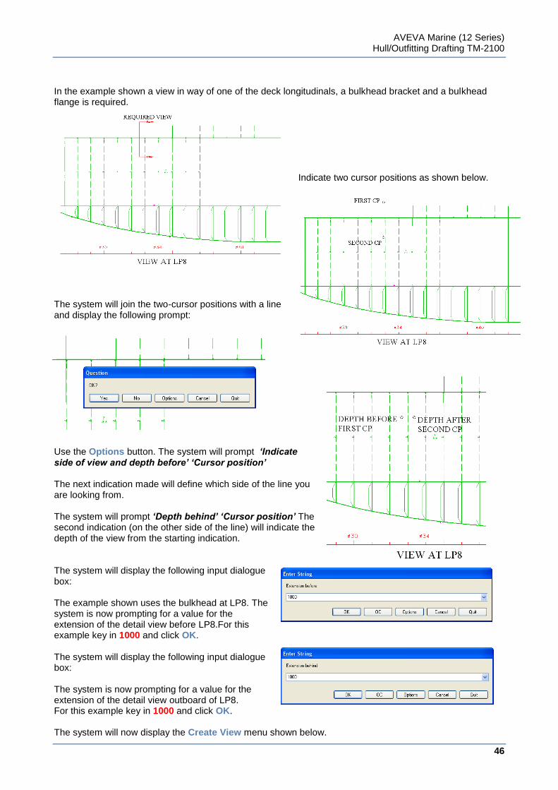
AVEVA Marine (12 Series) Hull/Outfitting Drafting TM-2100
46
www.aveva.com
In the example shown a view in way of one of the deck longitudinals, a bulkhead bracket and a bulkhead flange is required.
Indicate two cursor positions as shown below.
The system will join the two-cursor positions with a line and display the following prompt:
Use the Options button. The system will prompt ‘Indicate side of view and depth before’ ‘Cursor position’ The next indication made will define which side of the line you are looking from. The system will prompt ‘Depth behind’ ‘Cursor position’ The second indication (on the other side of the line) will indicate the depth of the view from the starting indication. The system will display the following input dialogue box: The example shown uses the bulkhead at LP8. The system is now prompting for a value for the extension of the detail view before LP8.For this example key in 1000 and click OK. The system will display the following input dialogue box: The system is now prompting for a value for the extension of the detail view outboard of LP8. For this example key in 1000 and click OK. The system will now display the Create View menu shown below.
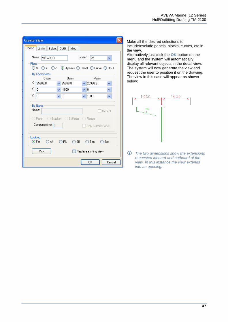
AVEVA Marine (12 Series) Hull/Outfitting Drafting TM-2100
47
www.aveva.com
Make all the desired selections to include/exclude panels, blocks, curves, etc in the view. Alternatively just click the OK button on the menu and the system will automatically display all relevant objects in the detail view. The system will now generate the view and request the user to position it on the drawing. The view in this case will appear as shown below:
The two dimensions show the extensions requested inboard and outboard of the view. In this instance the view extends into an opening.
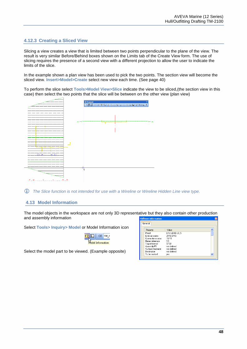
AVEVA Marine (12 Series) Hull/Outfitting Drafting TM-2100
48
www.aveva.com
4.12.3 Creating a Sliced View
Slicing a view creates a view that is limited between two points perpendicular to the plane of the view. The result is very similar Before/Behind boxes shown on the Limits tab of the Create View form. The use of slicing requires the presence of a second view with a different projection to allow the user to indicate the limits of the slice. In the example shown a plan view has been used to pick the two points. The section view will become the sliced view. Insert>Model>Create select new view each time. (See page 40) To perform the slice select Tools>Model View>Slice indicate the view to be sliced,(the section view in this case) then select the two points that the slice will be between on the other view (plan view)
The Slice function is not intended for use with a Wireline or Wireline Hidden Line view type.
4.13 Model Information
The model objects in the workspace are not only 3D representative but they also contain other production and assembly information Select Tools> Inquiry> Model or Model Information icon Select the model part to be viewed. (Example opposite)
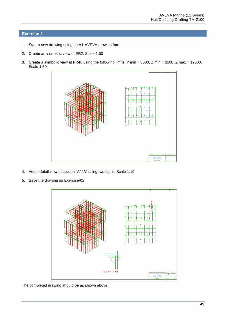
AVEVA Marine (12 Series) Hull/Outfitting Drafting TM-2100
49
www.aveva.com
Exercise 2
1. Start a new drawing using an A1-AVEVA drawing form. 2. Create an isometric view of ER2. Scale 1:50 3. Create a symbolic view at FR46 using the following limits, Y min = 6500, Z min = 6500, Z max = 19000.
Scale 1:50 4. Add a detail view at section “A”-“A” using two c.p.‟s. Scale 1:10 5. Save the drawing as Exercise-02 The completed drawing should be as shown above.
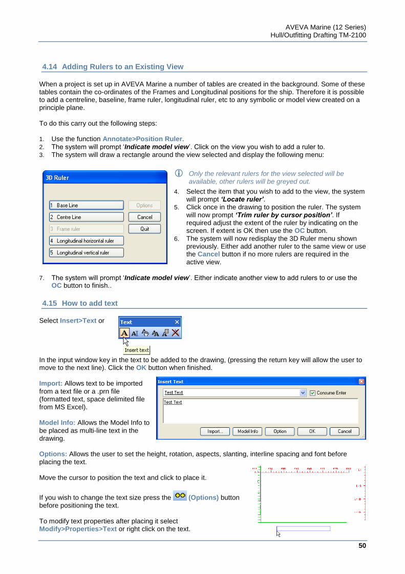
AVEVA Marine (12 Series) Hull/Outfitting Drafting TM-2100
50
www.aveva.com
4.14 Adding Rulers to an Existing View
When a project is set up in AVEVA Marine a number of tables are created in the background. Some of these tables contain the co-ordinates of the Frames and Longitudinal positions for the ship. Therefore it is possible to add a centreline, baseline, frame ruler, longitudinal ruler, etc to any symbolic or model view created on a principle plane. To do this carry out the following steps: 1. Use the function Annotate>Position Ruler. 2. The system will prompt „Indicate model view‟. Click on the view you wish to add a ruler to. 3. The system will draw a rectangle around the view selected and display the following menu:
Only the relevant rulers for the view selected will be available, other rulers will be greyed out.
4. Select the item that you wish to add to the view, the system will prompt ‘Locate ruler’.
5. Click once in the drawing to position the ruler. The system will now prompt ‘Trim ruler by cursor position’. If required adjust the extent of the ruler by indicating on the screen. If extent is OK then use the OC button.
6. The system will now redisplay the 3D Ruler menu shown previously. Either add another ruler to the same view or use the Cancel button if no more rulers are required in the active view.
7. The system will prompt „Indicate model view‟. Either indicate another view to add rulers to or use the
OC button to finish.. 4.15 How to add text
Select Insert>Text or In the input window key in the text to be added to the drawing, (pressing the return key will allow the user to move to the next line). Click the OK button when finished. Import: Allows text to be imported from a text file or a .prn file (formatted text, space delimited file from MS Excel). Model Info: Allows the Model Info to be placed as multi-line text in the drawing. Options: Allows the user to set the height, rotation, aspects, slanting, interline spacing and font before placing the text. Move the cursor to position the text and click to place it.
If you wish to change the text size press the (Options) button before positioning the text. To modify text properties after placing it select Modify>Properties>Text or right click on the text.
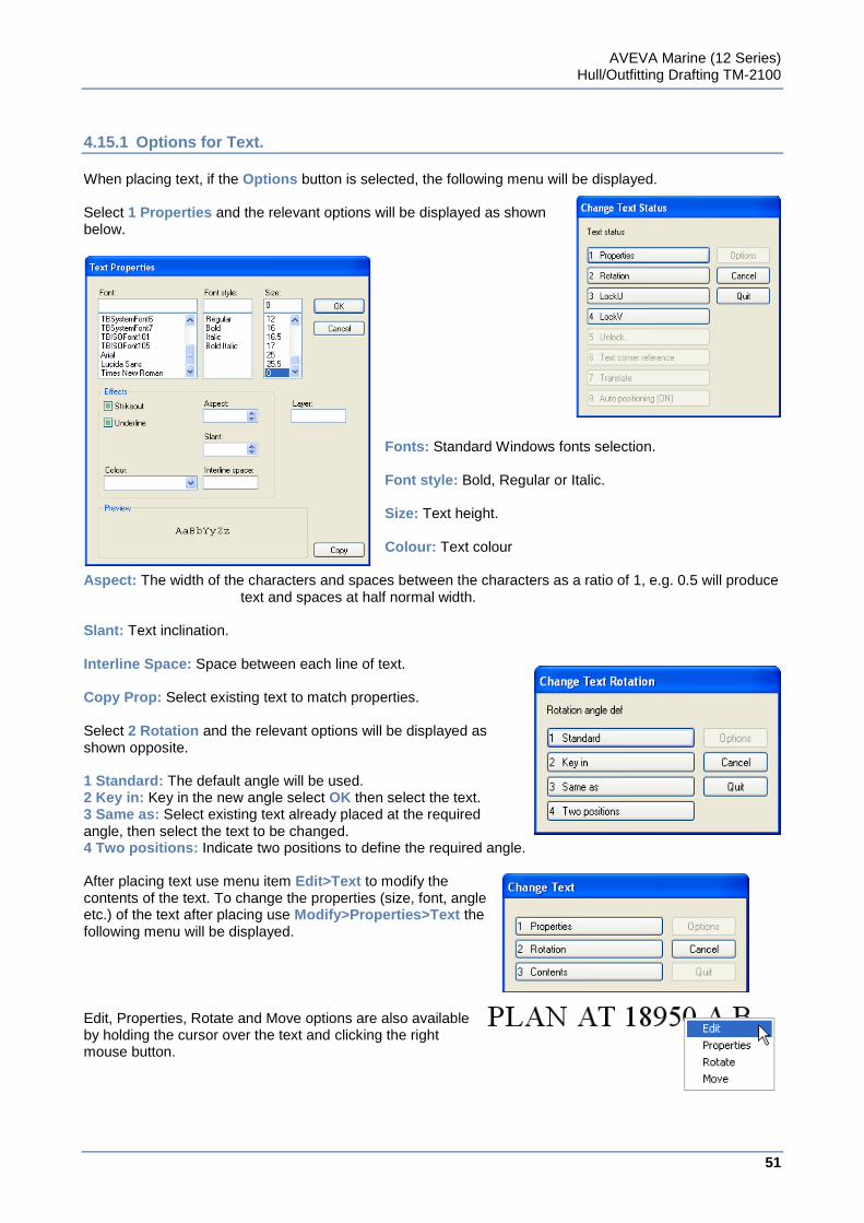
AVEVA Marine (12 Series) Hull/Outfitting Drafting TM-2100
51
www.aveva.com
4.15.1 Options for Text.
When placing text, if the Options button is selected, the following menu will be displayed. Select 1 Properties and the relevant options will be displayed as shown below.
Fonts: Standard Windows fonts selection. Font style: Bold, Regular or Italic. Size: Text height. Colour: Text colour
Aspect: The width of the characters and spaces between the characters as a ratio of 1, e.g. 0.5 will produce text and spaces at half normal width.
Slant: Text inclination. Interline Space: Space between each line of text. Copy Prop: Select existing text to match properties. Select 2 Rotation and the relevant options will be displayed as shown opposite. 1 Standard: The default angle will be used. 2 Key in: Key in the new angle select OK then select the text. 3 Same as: Select existing text already placed at the required angle, then select the text to be changed. 4 Two positions: Indicate two positions to define the required angle. After placing text use menu item Edit>Text to modify the contents of the text. To change the properties (size, font, angle etc.) of the text after placing use Modify>Properties>Text the following menu will be displayed.
Edit, Properties, Rotate and Move options are also available by holding the cursor over the text and clicking the right mouse button.
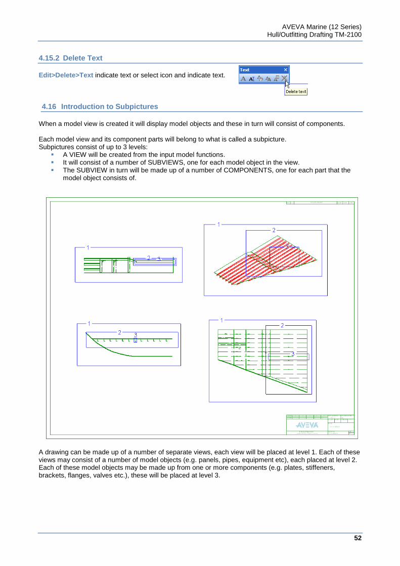
AVEVA Marine (12 Series) Hull/Outfitting Drafting TM-2100
52
www.aveva.com
4.15.2 Delete Text
Edit>Delete>Text indicate text or select icon and indicate text.
4.16 Introduction to Subpictures
When a model view is created it will display model objects and these in turn will consist of components. Each model view and its component parts will belong to what is called a subpicture. Subpictures consist of up to 3 levels:
A VIEW will be created from the input model functions. It will consist of a number of SUBVIEWS, one for each model object in the view. The SUBVIEW in turn will be made up of a number of COMPONENTS, one for each part that the
model object consists of.
A drawing can be made up of a number of separate views, each view will be placed at level 1. Each of these views may consist of a number of model objects (e.g. panels, pipes, equipment etc), each placed at level 2. Each of these model objects may be made up from one or more components (e.g. plates, stiffeners, brackets, flanges, valves etc.), these will be placed at level 3.
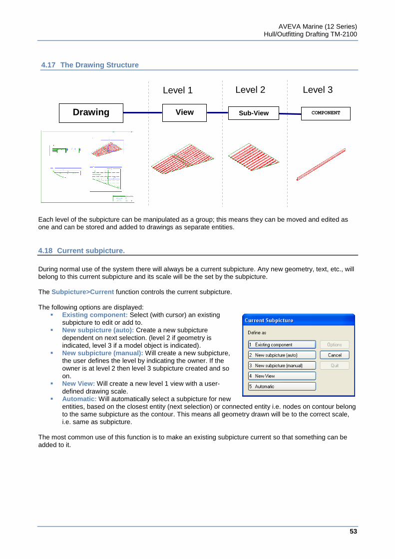
AVEVA Marine (12 Series) Hull/Outfitting Drafting TM-2100
53
www.aveva.com
4.17 The Drawing Structure
Each level of the subpicture can be manipulated as a group; this means they can be moved and edited as one and can be stored and added to drawings as separate entities.
4.18 Current subpicture.
During normal use of the system there will always be a current subpicture. Any new geometry, text, etc., will belong to this current subpicture and its scale will be the set by the subpicture. The Subpicture>Current function controls the current subpicture. The following options are displayed:
Existing component: Select (with cursor) an existing subpicture to edit or add to.
New subpicture (auto): Create a new subpicture dependent on next selection. (level 2 if geometry is indicated, level 3 if a model object is indicated).
New subpicture (manual): Will create a new subpicture, the user defines the level by indicating the owner. If the owner is at level 2 then level 3 subpicture created and so on.
New View: Will create a new level 1 view with a user-defined drawing scale.
Automatic: Will automatically select a subpicture for new entities, based on the closest entity (next selection) or connected entity i.e. nodes on contour belong to the same subpicture as the contour. This means all geometry drawn will be to the correct scale, i.e. same as subpicture.
The most common use of this function is to make an existing subpicture current so that something can be added to it.
Level 1 Level 2 Level 3
Drawing View Sub-View COMPONENT
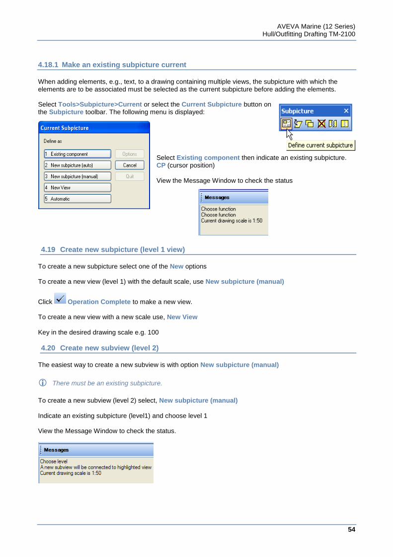
AVEVA Marine (12 Series) Hull/Outfitting Drafting TM-2100
54
www.aveva.com
4.18.1 Make an existing subpicture current
When adding elements, e.g., text, to a drawing containing multiple views, the subpicture with which the elements are to be associated must be selected as the current subpicture before adding the elements. Select Tools>Subpicture>Current or select the Current Subpicture button on the Subpicture toolbar. The following menu is displayed:
Select Existing component then indicate an existing subpicture. CP (cursor position) View the Message Window to check the status
4.19 Create new subpicture (level 1 view)
To create a new subpicture select one of the New options To create a new view (level 1) with the default scale, use New subpicture (manual)
Click Operation Complete to make a new view. To create a new view with a new scale use, New View Key in the desired drawing scale e.g. 100
4.20 Create new subview (level 2)
The easiest way to create a new subview is with option New subpicture (manual)
There must be an existing subpicture.
To create a new subview (level 2) select, New subpicture (manual) Indicate an existing subpicture (level1) and choose level 1 View the Message Window to check the status.
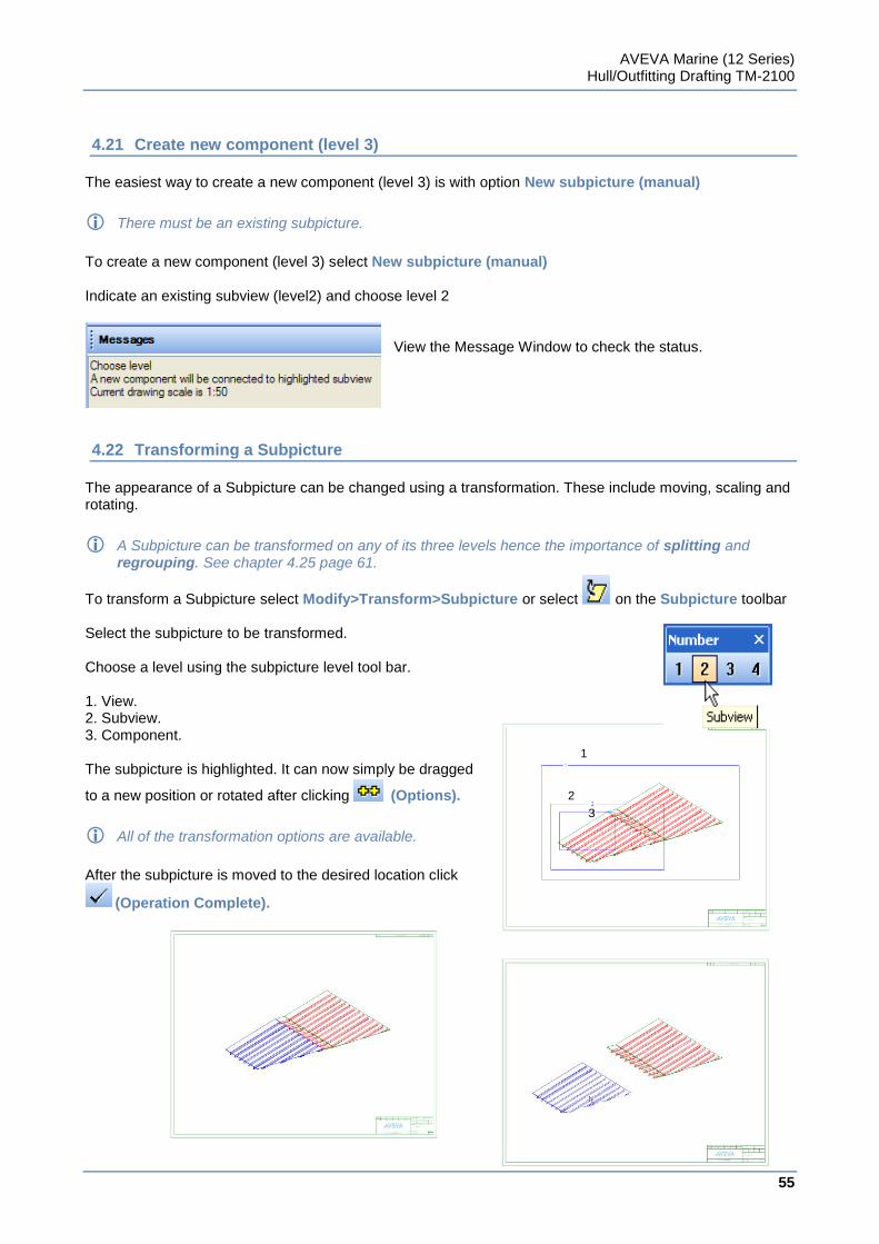
AVEVA Marine (12 Series) Hull/Outfitting Drafting TM-2100
55
www.aveva.com
4.21 Create new component (level 3)
The easiest way to create a new component (level 3) is with option New subpicture (manual)
There must be an existing subpicture.
To create a new component (level 3) select New subpicture (manual) Indicate an existing subview (level2) and choose level 2
View the Message Window to check the status.
4.22 Transforming a Subpicture
The appearance of a Subpicture can be changed using a transformation. These include moving, scaling and rotating.
A Subpicture can be transformed on any of its three levels hence the importance of splitting and regrouping. See chapter 4.25 page 61.
To transform a Subpicture select Modify>Transform>Subpicture or select on the Subpicture toolbar Select the subpicture to be transformed. Choose a level using the subpicture level tool bar. 1. View. 2. Subview. 3. Component. The subpicture is highlighted. It can now simply be dragged
to a new position or rotated after clicking (Options).
All of the transformation options are available.
After the subpicture is moved to the desired location click
(Operation Complete).
1
2
3
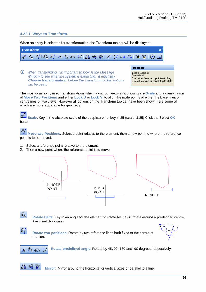
AVEVA Marine (12 Series) Hull/Outfitting Drafting TM-2100
56
www.aveva.com
4.22.1 Ways to Transform.
When an entity is selected for transformation, the Transform toolbar will be displayed.
When transforming it is important to look at the Message Window to see what the system is expecting. It must say 'Choose transformation' before the Transform toolbar options can be used.
The most commonly used transformations when laying out views in a drawing are Scale and a combination of Move Two Positions and either Lock U or Lock V, to align the node points of either the base lines or centrelines of two views. However all options on the Transform toolbar have been shown here some of which are more applicable for geometry.
Scale: Key in the absolute scale of the subpicture i.e. key in 25 (scale 1:25) Click the Select OK button.
Move two Positions: Select a point relative to the element, then a new point to where the reference point is to be moved. 1. Select a reference point relative to the element, 2. Then a new point where the reference point is to move.
Rotate Delta: Key in an angle for the element to rotate by. (It will rotate around a predefined centre, +ve = anticlockwise).
Rotate two positions: Rotate by two reference lines both fixed at the centre of rotation.
Rotate predefined angle: Rotate by 45, 90, 180 and -90 degrees respectively.
Mirror: Mirror around the horizontal or vertical axes or parallel to a line.
1. NODE POINT 2. MID
POINT RESULT
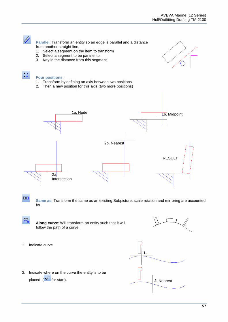
AVEVA Marine (12 Series) Hull/Outfitting Drafting TM-2100
57
www.aveva.com
Parallel: Transform an entity so an edge is parallel and a distance from another straight line. 1. Select a segment on the item to transform 2. Select a segment to be parallel to 3. Key in the distance from this segment.
Four positions: 1. Transform by defining an axis between two positions 2. Then a new position for this axis (two more positions)
Same as: Transform the same as an existing Subpicture; scale rotation and mirroring are accounted for.
Along curve: Will transform an entity such that it will follow the path of a curve.
1. Indicate curve
2. Indicate where on the curve the entity is to be
placed ( for start).
2b. Nearest
2a. Intersection
RESULT
1a. Node 1b. Midpoint
1.
2. Nearest
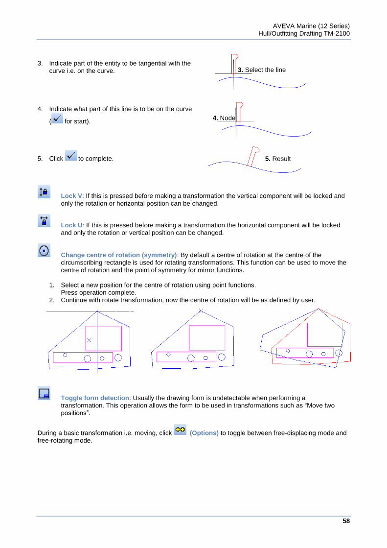
AVEVA Marine (12 Series) Hull/Outfitting Drafting TM-2100
58
www.aveva.com
3. Indicate part of the entity to be tangential with the
curve i.e. on the curve.
4. Indicate what part of this line is to be on the curve
( for start).
5. Click to complete.
Lock V: If this is pressed before making a transformation the vertical component will be locked and only the rotation or horizontal position can be changed.
Lock U: If this is pressed before making a transformation the horizontal component will be locked and only the rotation or vertical position can be changed.
Change centre of rotation (symmetry): By default a centre of rotation at the centre of the circumscribing rectangle is used for rotating transformations. This function can be used to move the centre of rotation and the point of symmetry for mirror functions.
1. Select a new position for the centre of rotation using point functions.
Press operation complete. 2. Continue with rotate transformation, now the centre of rotation will be as defined by user.
Toggle form detection: Usually the drawing form is undetectable when performing a transformation. This operation allows the form to be used in transformations such as “Move two positions”.
During a basic transformation i.e. moving, click (Options) to toggle between free-displacing mode and free-rotating mode.
3. Select the line
4. Node
5. Result
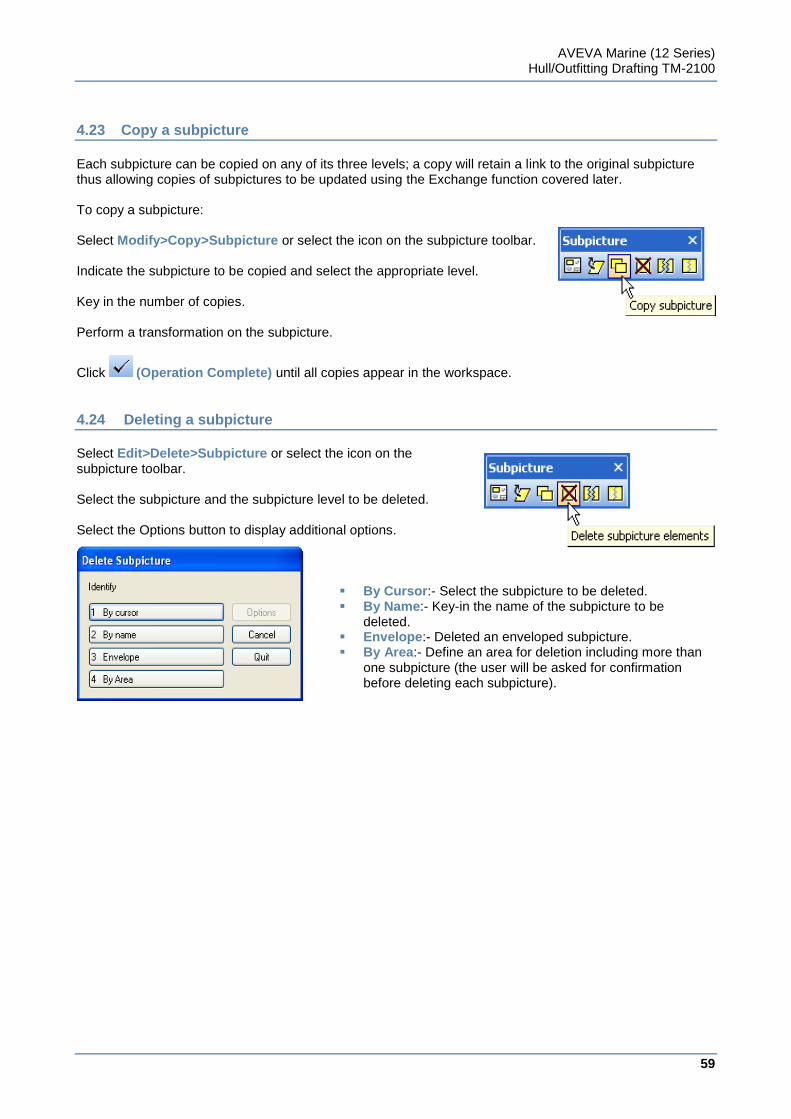
AVEVA Marine (12 Series) Hull/Outfitting Drafting TM-2100
59
www.aveva.com
4.23 Copy a subpicture
Each subpicture can be copied on any of its three levels; a copy will retain a link to the original subpicture thus allowing copies of subpictures to be updated using the Exchange function covered later. To copy a subpicture: Select Modify>Copy>Subpicture or select the icon on the subpicture toolbar. Indicate the subpicture to be copied and select the appropriate level. Key in the number of copies. Perform a transformation on the subpicture.
Click (Operation Complete) until all copies appear in the workspace.
4.24 Deleting a subpicture
Select Edit>Delete>Subpicture or select the icon on the subpicture toolbar. Select the subpicture and the subpicture level to be deleted. Select the Options button to display additional options.
By Cursor:- Select the subpicture to be deleted. By Name:- Key-in the name of the subpicture to be
deleted. Envelope:- Deleted an enveloped subpicture. By Area:- Define an area for deletion including more than
one subpicture (the user will be asked for confirmation before deleting each subpicture).
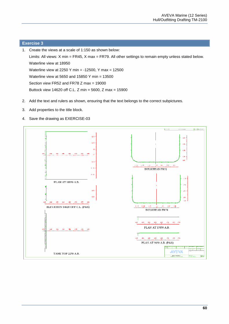
AVEVA Marine (12 Series) Hull/Outfitting Drafting TM-2100
60
www.aveva.com
Exercise 3
1. Create the views at a scale of 1:150 as shown below:
Limits: All views: X min = FR45, X max = FR79. All other settings to remain empty unless stated below.
Waterline view at 18950
Waterline view at 2250 Y min = -12500, Y max = 12500
Waterline view at 5650 and 15850 Y min = 13500
Section view FR52 and FR78 Z max = 19000
Buttock view 14620 off C.L. Z min = 5600, Z max = 15900
2. Add the text and rulers as shown, ensuring that the text belongs to the correct subpictures. 3. Add properties to the title block. 4. Save the drawing as EXERCISE-03
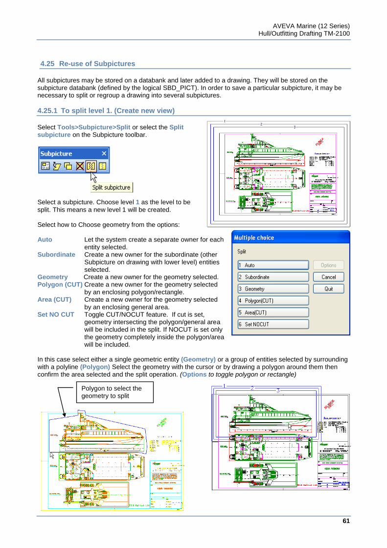
AVEVA Marine (12 Series) Hull/Outfitting Drafting TM-2100
61
www.aveva.com
4.25 Re-use of Subpictures
All subpictures may be stored on a databank and later added to a drawing. They will be stored on the subpicture databank (defined by the logical SBD_PICT). In order to save a particular subpicture, it may be necessary to split or regroup a drawing into several subpictures.
4.25.1 To split level 1. (Create new view)
Select Tools>Subpicture>Split or select the Split subpicture on the Subpicture toolbar.
Select a subpicture. Choose level 1 as the level to be split. This means a new level 1 will be created. Select how to Choose geometry from the options: Auto Let the system create a separate owner for each
entity selected. Subordinate Create a new owner for the subordinate (other
Subpicture on drawing with lower level) entities selected.
Geometry Create a new owner for the geometry selected. Polygon (CUT) Create a new owner for the geometry selected
by an enclosing polygon/rectangle. Area (CUT) Create a new owner for the geometry selected
by an enclosing general area. Set NO CUT Toggle CUT/NOCUT feature. If cut is set,
geometry intersecting the polygon/general area will be included in the split. If NOCUT is set only the geometry completely inside the polygon/area will be included.
In this case select either a single geometric entity (Geometry) or a group of entities selected by surrounding with a polyline (Polygon) Select the geometry with the cursor or by drawing a polygon around them then confirm the area selected and the split operation. (Options to toggle polygon or rectangle)
Polygon to select the geometry to split
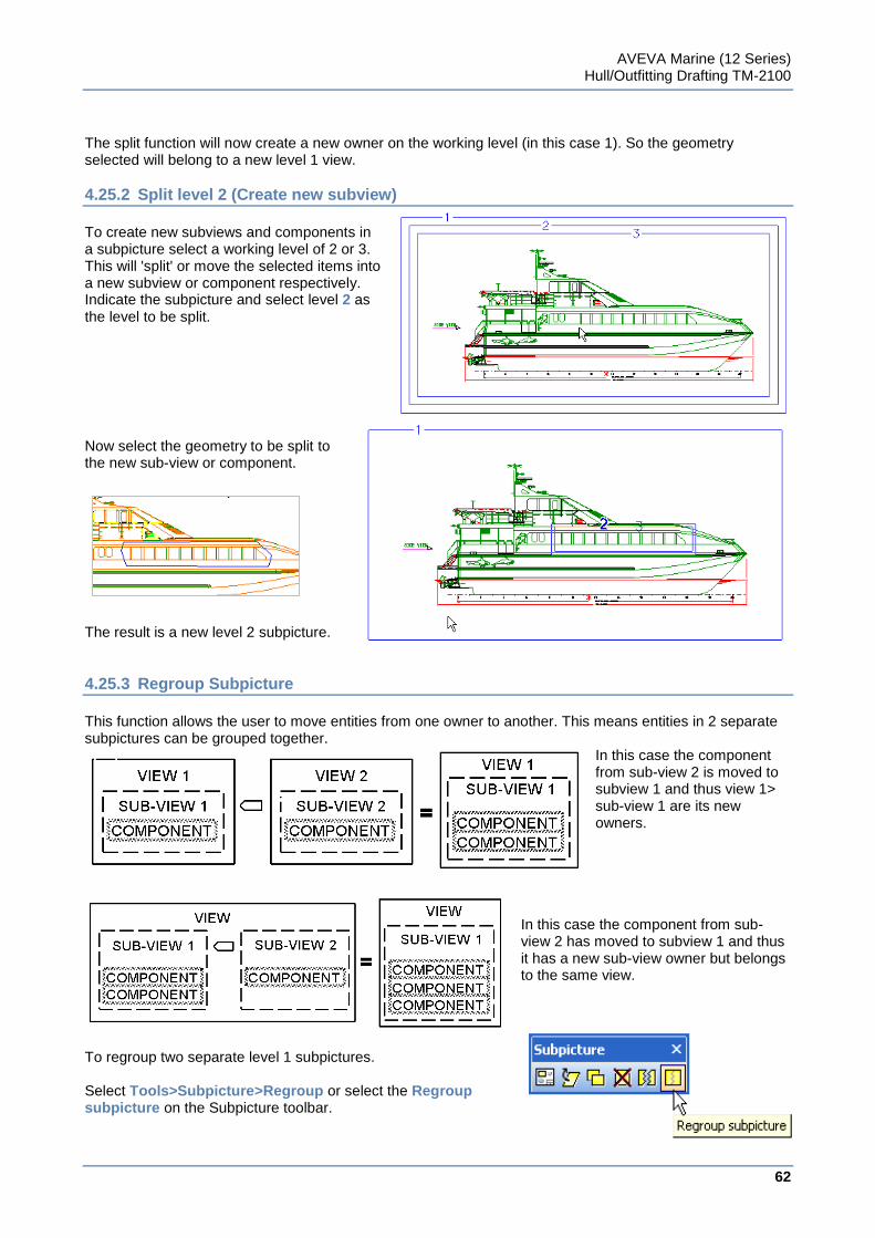
AVEVA Marine (12 Series) Hull/Outfitting Drafting TM-2100
62
www.aveva.com
The split function will now create a new owner on the working level (in this case 1). So the geometry selected will belong to a new level 1 view.
4.25.2 Split level 2 (Create new subview)
To create new subviews and components in a subpicture select a working level of 2 or 3. This will 'split' or move the selected items into a new subview or component respectively. Indicate the subpicture and select level 2 as the level to be split.
Now select the geometry to be split to the new sub-view or component.
The result is a new level 2 subpicture.
4.25.3 Regroup Subpicture
This function allows the user to move entities from one owner to another. This means entities in 2 separate subpictures can be grouped together.
In this case the component from sub-view 2 is moved to subview 1 and thus view 1> sub-view 1 are its new owners.
In this case the component from sub-view 2 has moved to subview 1 and thus it has a new sub-view owner but belongs to the same view.
To regroup two separate level 1 subpictures. Select Tools>Subpicture>Regroup or select the Regroup subpicture on the Subpicture toolbar.
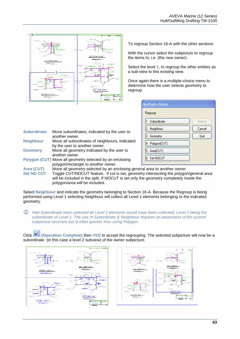
AVEVA Marine (12 Series) Hull/Outfitting Drafting TM-2100
63
www.aveva.com
To regroup Section 16-A with the other sections With the cursor select the subpicture to regroup the items to, i.e. (the new owner). Select the level 1, to regroup the other entities as a sub-view to this existing view. Once again there is a multiple-choice menu to determine how the user selects geometry to regroup.
Subordinate Move subordinates, indicated by the user to
another owner. Neighbour Move all subordinates of neighbours, indicated
by the user to another owner. Geometry Move all geometry indicated by the user to
another owner. Polygon (CUT) Move all geometry selected by an enclosing
polygon/rectangle to another owner. Area (CUT) Move all geometry selected by an enclosing general area to another owner. Set NO CUT Toggle CUT/NOCUT feature. If cut is set, geometry intersecting the polygon/general area
will be included in the split. If NOCUT is set only the geometry completely inside the polygon/area will be included.
Select Neighbour and indicate the geometry belonging to Section 16-A. Because the Regroup is being performed using Level 1 selecting Neighbour will collect all Level 1 elements belonging to the indicated geometry.
Had Subordinate been selected all Level 2 elements would have been collected, Level 2 being the subordinate of Level 1. The use of Subordinate & Neighbour requires an awareness of the current subpicture structure but is often quicker than using Polygon.
Click (Operation Complete) then YES to accept the regrouping. The selected subpicture will now be a subordinate (in this case a level 2 subview) of the owner subpicture.
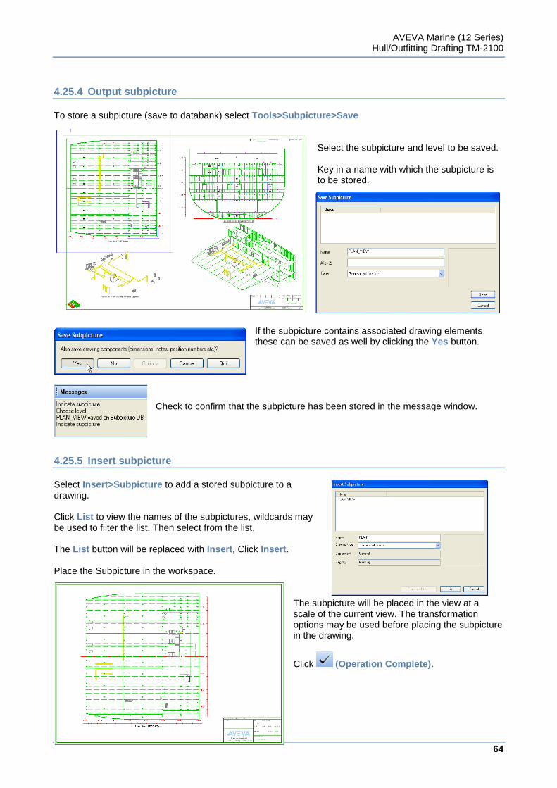
AVEVA Marine (12 Series) Hull/Outfitting Drafting TM-2100
64
www.aveva.com
4.25.4 Output subpicture
To store a subpicture (save to databank) select Tools>Subpicture>Save
Select the subpicture and level to be saved. Key in a name with which the subpicture is to be stored.
If the subpicture contains associated drawing elements these can be saved as well by clicking the Yes button.
Check to confirm that the subpicture has been stored in the message window.
4.25.5 Insert subpicture
Select Insert>Subpicture to add a stored subpicture to a drawing. Click List to view the names of the subpictures, wildcards may be used to filter the list. Then select from the list. The List button will be replaced with Insert, Click Insert. Place the Subpicture in the workspace.
The subpicture will be placed in the view at a scale of the current view. The transformation options may be used before placing the subpicture in the drawing.
Click (Operation Complete).
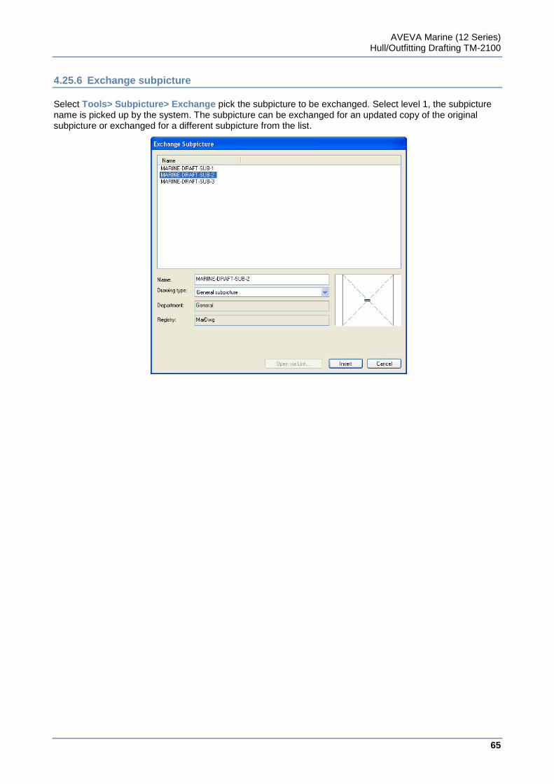
AVEVA Marine (12 Series) Hull/Outfitting Drafting TM-2100
65
www.aveva.com
4.25.6 Exchange subpicture
Select Tools> Subpicture> Exchange pick the subpicture to be exchanged. Select level 1, the subpicture name is picked up by the system. The subpicture can be exchanged for an updated copy of the original subpicture or exchanged for a different subpicture from the list.
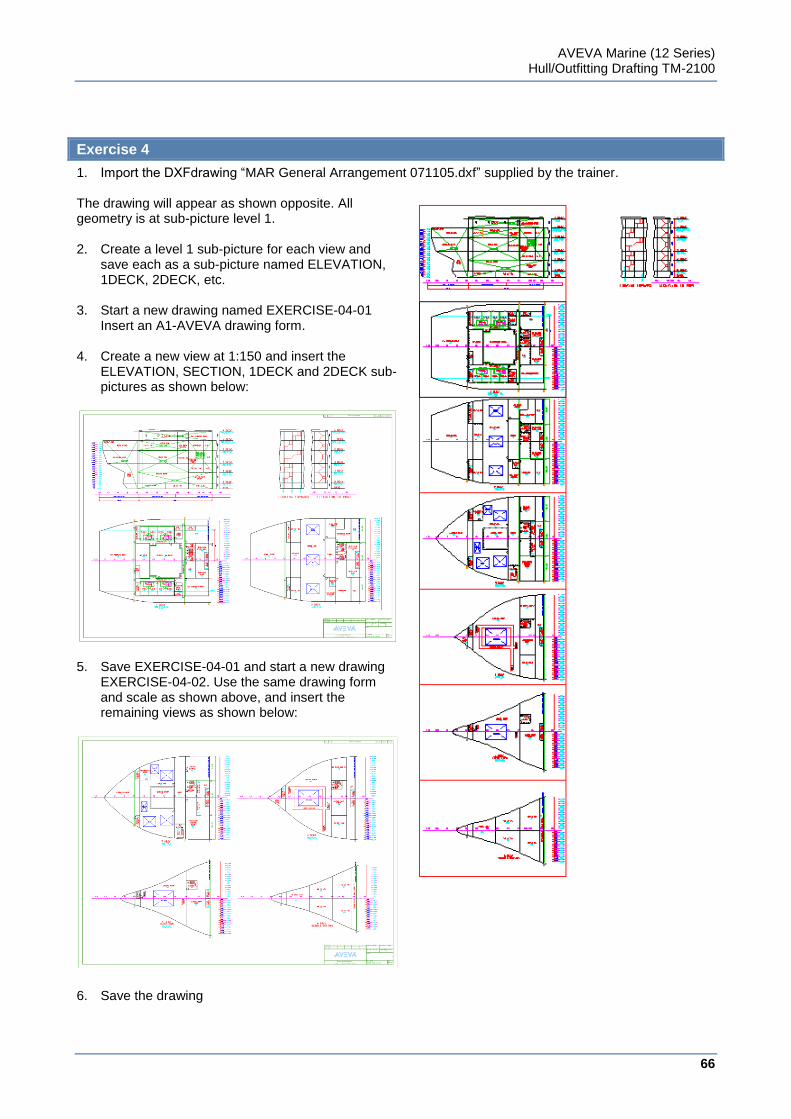
AVEVA Marine (12 Series) Hull/Outfitting Drafting TM-2100
66
www.aveva.com
Exercise 4
1. Import the DXFdrawing “MAR General Arrangement 071105.dxf” supplied by the trainer. The drawing will appear as shown opposite. All geometry is at sub-picture level 1. 2. Create a level 1 sub-picture for each view and
save each as a sub-picture named ELEVATION, 1DECK, 2DECK, etc.
3. Start a new drawing named EXERCISE-04-01
Insert an A1-AVEVA drawing form.
4. Create a new view at 1:150 and insert the ELEVATION, SECTION, 1DECK and 2DECK sub-pictures as shown below:
5. Save EXERCISE-04-01 and start a new drawing
EXERCISE-04-02. Use the same drawing form and scale as shown above, and insert the remaining views as shown below:
6. Save the drawing
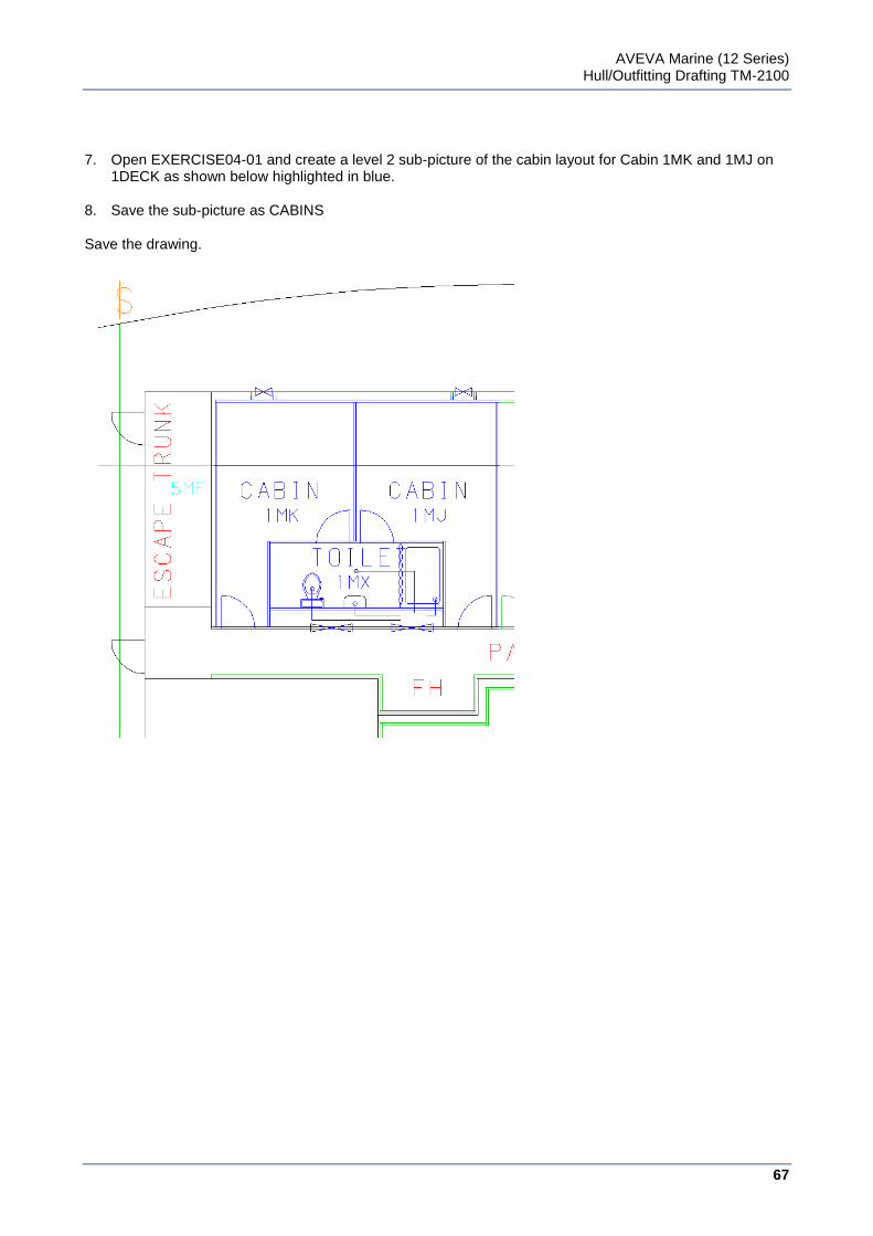
AVEVA Marine (12 Series) Hull/Outfitting Drafting TM-2100
67
www.aveva.com
7. Open EXERCISE04-01 and create a level 2 sub-picture of the cabin layout for Cabin 1MK and 1MJ on
1DECK as shown below highlighted in blue. 8. Save the sub-picture as CABINS Save the drawing.

AVEVA Marine (12 Series) Hull/Outfitting Drafting TM-2100
68
www.aveva.com
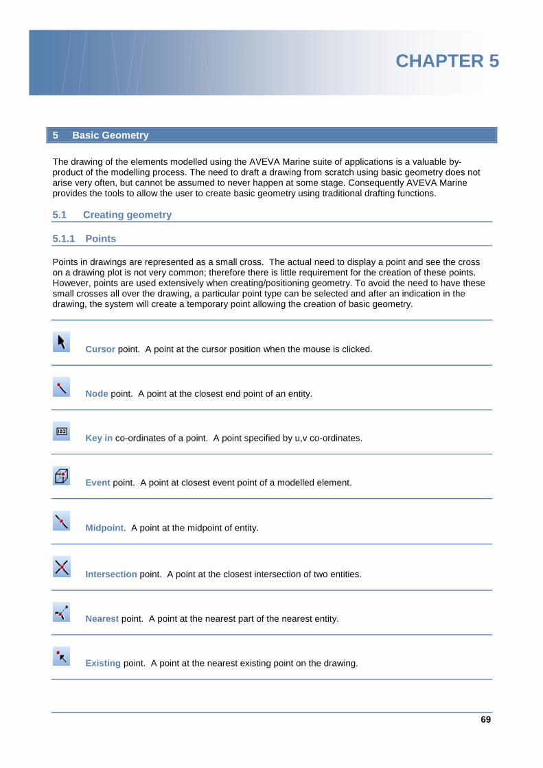
69
www.aveva.com
CHAPTER 5
5 Basic Geometry
The drawing of the elements modelled using the AVEVA Marine suite of applications is a valuable by-product of the modelling process. The need to draft a drawing from scratch using basic geometry does not arise very often, but cannot be assumed to never happen at some stage. Consequently AVEVA Marine provides the tools to allow the user to create basic geometry using traditional drafting functions.
5.1 Creating geometry
5.1.1 Points
Points in drawings are represented as a small cross. The actual need to display a point and see the cross on a drawing plot is not very common; therefore there is little requirement for the creation of these points. However, points are used extensively when creating/positioning geometry. To avoid the need to have these small crosses all over the drawing, a particular point type can be selected and after an indication in the drawing, the system will create a temporary point allowing the creation of basic geometry.
Cursor point. A point at the cursor position when the mouse is clicked.
Node point. A point at the closest end point of an entity.
Key in co-ordinates of a point. A point specified by u,v co-ordinates.
Event point. A point at closest event point of a modelled element.
Midpoint. A point at the midpoint of entity.
Intersection point. A point at the closest intersection of two entities.
Nearest point. A point at the nearest part of the nearest entity.
Existing point. A point at the nearest existing point on the drawing.
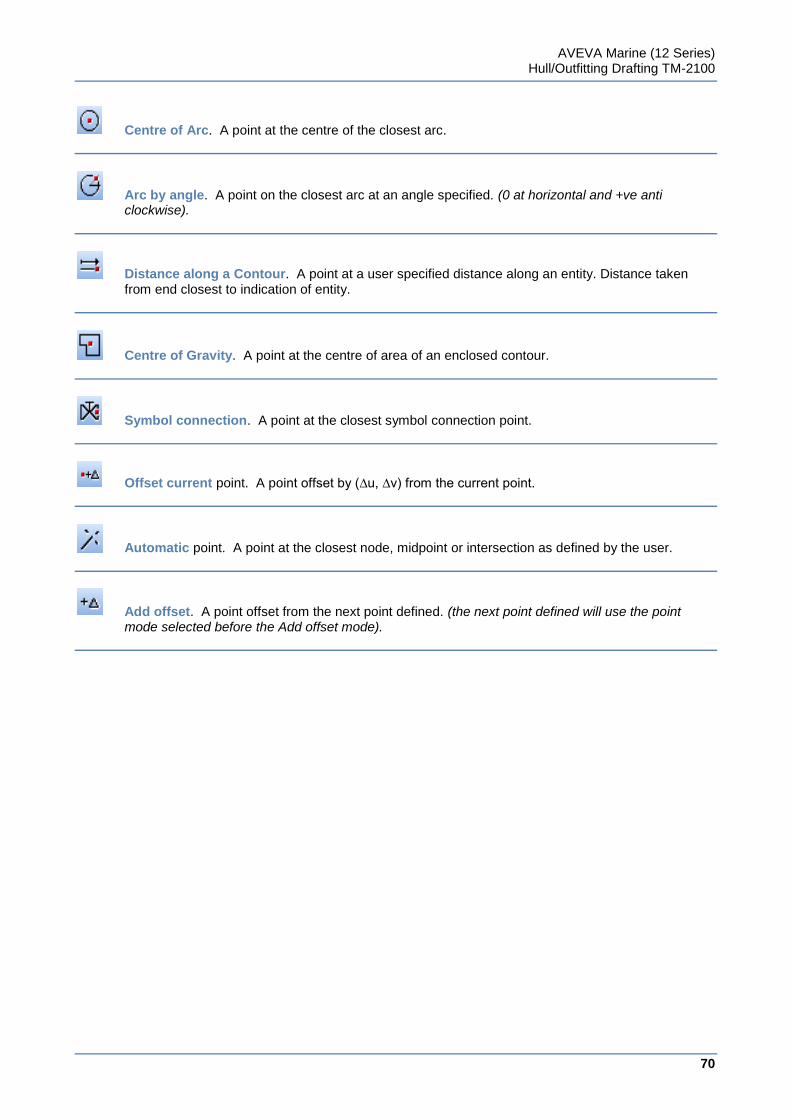
AVEVA Marine (12 Series) Hull/Outfitting Drafting TM-2100
70
www.aveva.com
Centre of Arc. A point at the centre of the closest arc.
Arc by angle. A point on the closest arc at an angle specified. (0 at horizontal and +ve anti clockwise).
Distance along a Contour. A point at a user specified distance along an entity. Distance taken from end closest to indication of entity.
Centre of Gravity. A point at the centre of area of an enclosed contour.
Symbol connection. A point at the closest symbol connection point.
Offset current point. A point offset by (∆u, ∆v) from the current point.
Automatic point. A point at the closest node, midpoint or intersection as defined by the user.
Add offset. A point offset from the next point defined. (the next point defined will use the point mode selected before the Add offset mode).
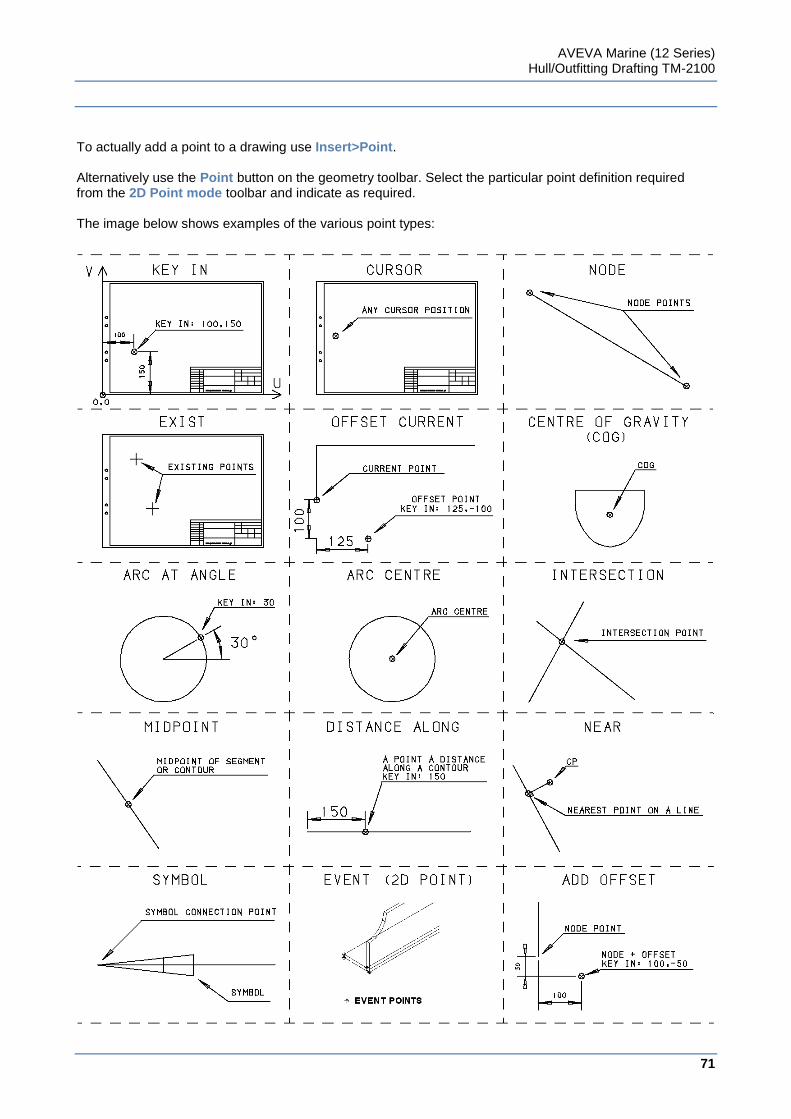
AVEVA Marine (12 Series) Hull/Outfitting Drafting TM-2100
71
www.aveva.com
To actually add a point to a drawing use Insert>Point. Alternatively use the Point button on the geometry toolbar. Select the particular point definition required from the 2D Point mode toolbar and indicate as required. The image below shows examples of the various point types:
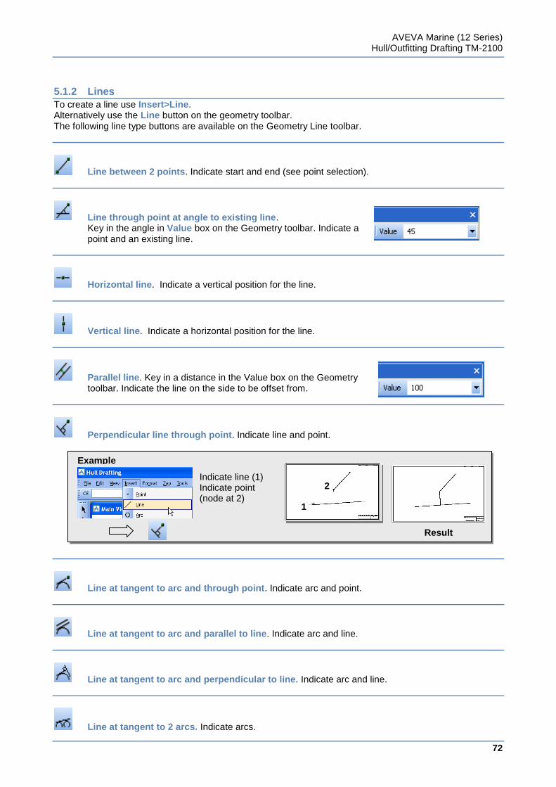
AVEVA Marine (12 Series) Hull/Outfitting Drafting TM-2100
72
www.aveva.com
Indicate line (1) Indicate point
(node at 2)
Example
2
1
Result
5.1.2 Lines
To create a line use Insert>Line. Alternatively use the Line button on the geometry toolbar. The following line type buttons are available on the Geometry Line toolbar.
Line between 2 points. Indicate start and end (see point selection).
Line through point at angle to existing line. Key in the angle in Value box on the Geometry toolbar. Indicate a point and an existing line.
Horizontal line. Indicate a vertical position for the line.
Vertical line. Indicate a horizontal position for the line.
Parallel line. Key in a distance in the Value box on the Geometry toolbar. Indicate the line on the side to be offset from.
Perpendicular line through point. Indicate line and point.
Line at tangent to arc and through point. Indicate arc and point.
Line at tangent to arc and parallel to line. Indicate arc and line.
Line at tangent to arc and perpendicular to line. Indicate arc and line.
Line at tangent to 2 arcs. Indicate arcs.
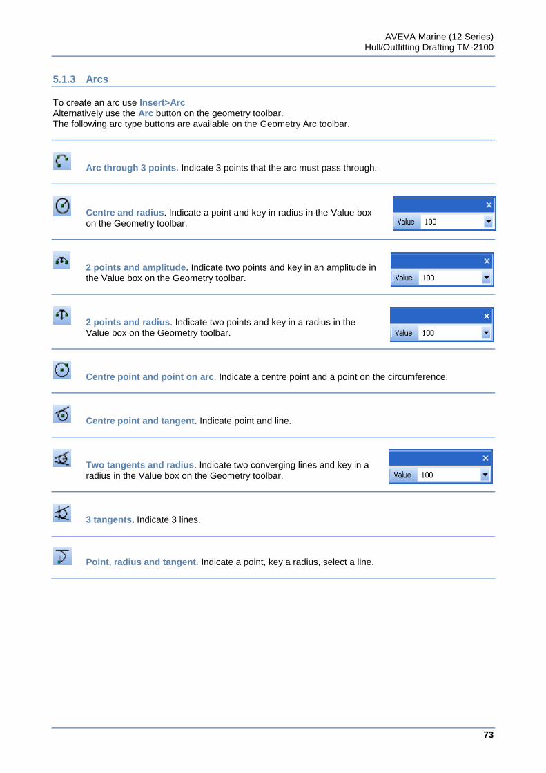
AVEVA Marine (12 Series) Hull/Outfitting Drafting TM-2100
73
www.aveva.com
5.1.3 Arcs
To create an arc use Insert>Arc Alternatively use the Arc button on the geometry toolbar. The following arc type buttons are available on the Geometry Arc toolbar.
Arc through 3 points. Indicate 3 points that the arc must pass through.
Centre and radius. Indicate a point and key in radius in the Value box on the Geometry toolbar.
2 points and amplitude. Indicate two points and key in an amplitude in the Value box on the Geometry toolbar.
2 points and radius. Indicate two points and key in a radius in the Value box on the Geometry toolbar.
Centre point and point on arc. Indicate a centre point and a point on the circumference.
Centre point and tangent. Indicate point and line.
Two tangents and radius. Indicate two converging lines and key in a radius in the Value box on the Geometry toolbar.
3 tangents. Indicate 3 lines.
Point, radius and tangent. Indicate a point, key a radius, select a line.
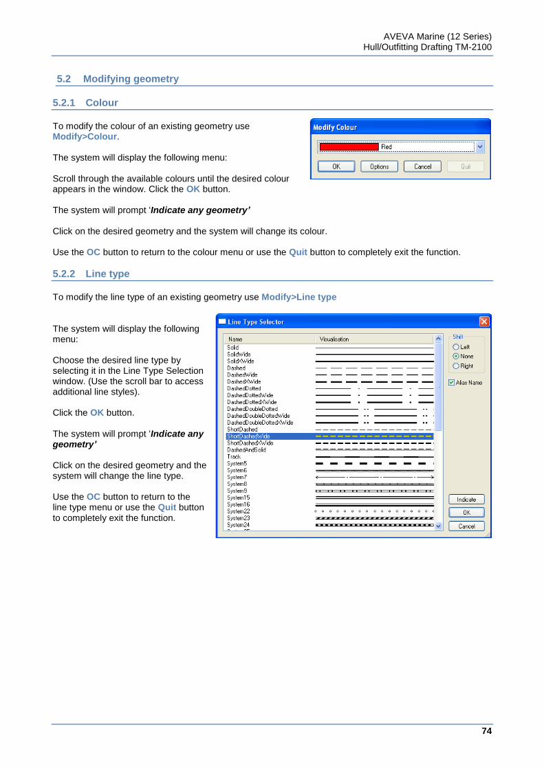
AVEVA Marine (12 Series) Hull/Outfitting Drafting TM-2100
74
www.aveva.com
5.2 Modifying geometry
5.2.1 Colour
To modify the colour of an existing geometry use Modify>Colour. The system will display the following menu: Scroll through the available colours until the desired colour appears in the window. Click the OK button. The system will prompt „Indicate any geometry’ Click on the desired geometry and the system will change its colour. Use the OC button to return to the colour menu or use the Quit button to completely exit the function.
5.2.2 Line type
To modify the line type of an existing geometry use Modify>Line type The system will display the following menu: Choose the desired line type by selecting it in the Line Type Selection window. (Use the scroll bar to access additional line styles). Click the OK button. The system will prompt „Indicate any geometry’ Click on the desired geometry and the system will change the line type. Use the OC button to return to the line type menu or use the Quit button to completely exit the function.
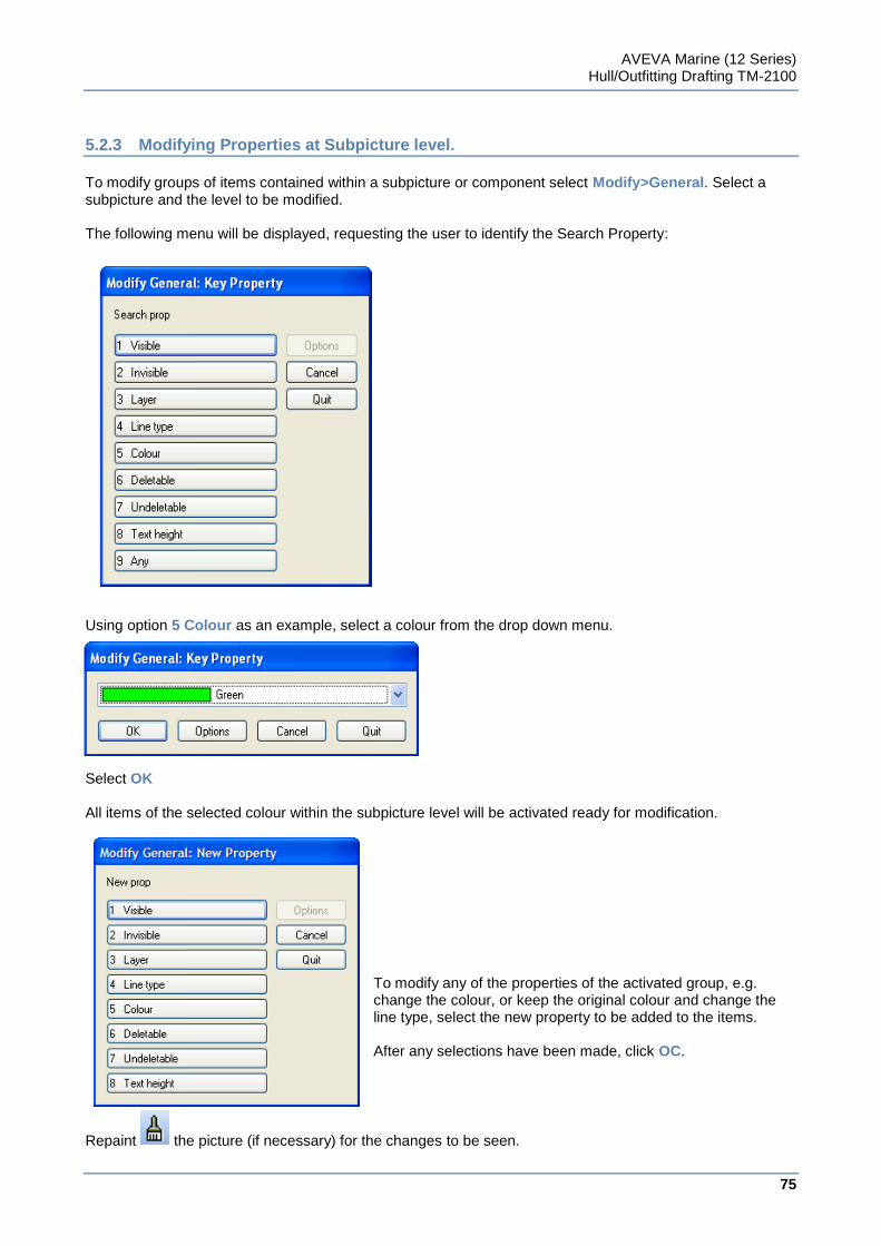
AVEVA Marine (12 Series) Hull/Outfitting Drafting TM-2100
75
www.aveva.com
5.2.3 Modifying Properties at Subpicture level.
To modify groups of items contained within a subpicture or component select Modify>General. Select a subpicture and the level to be modified. The following menu will be displayed, requesting the user to identify the Search Property:
Using option 5 Colour as an example, select a colour from the drop down menu.
Select OK All items of the selected colour within the subpicture level will be activated ready for modification.
To modify any of the properties of the activated group, e.g. change the colour, or keep the original colour and change the line type, select the new property to be added to the items. After any selections have been made, click OC.
Repaint the picture (if necessary) for the changes to be seen.
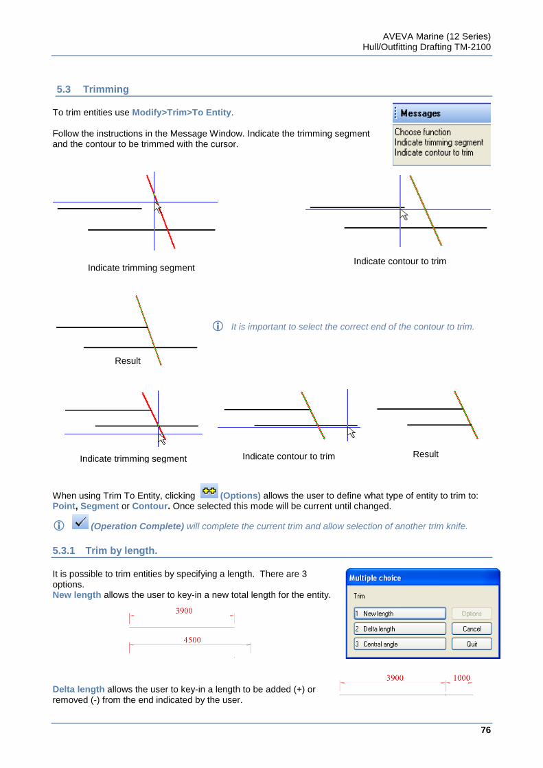
AVEVA Marine (12 Series) Hull/Outfitting Drafting TM-2100
76
www.aveva.com
5.3 Trimming
To trim entities use Modify>Trim>To Entity. Follow the instructions in the Message Window. Indicate the trimming segment and the contour to be trimmed with the cursor.
It is important to select the correct end of the contour to trim.
When using Trim To Entity, clicking (Options) allows the user to define what type of entity to trim to: Point, Segment or Contour. Once selected this mode will be current until changed.
(Operation Complete) will complete the current trim and allow selection of another trim knife.
5.3.1 Trim by length.
It is possible to trim entities by specifying a length. There are 3 options. New length allows the user to key-in a new total length for the entity. Delta length allows the user to key-in a length to be added (+) or removed (-) from the end indicated by the user.
Indicate trimming segment
Result
Indicate contour to trim
Indicate trimming segment Indicate contour to trim Result
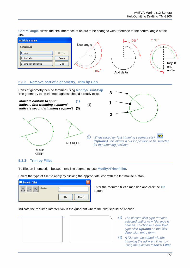
AVEVA Marine (12 Series) Hull/Outfitting Drafting TM-2100
77
www.aveva.com
Central angle allows the circumference of an arc to be changed with reference to the central angle of the arc.
5.3.2 Remove part of a geometry, Trim by Gap
Parts of geometry cen be trimmed using Modify>Trim>Gap. The geometry to be trimmed against should already exist. ‘Indicate contour to split’ (1) ‘Indicate first trimming segment’ (2) ‘Indicate second trimming segmen’t (3)
When asked for first trimming segment click (Options), this allows a cursor position to be selected for the trimming position.
5.3.3 Trim by Fillet
To fillet an intersection between two line segments, use Modify>Trim>Fillet. Select the type of fillet to apply by clicking the appropriate icon with the left mouse button.
Enter the required fillet dimension and click the OK button.
Indicate the required intersection in the quadrant where the fillet should be applied.
The chosen fillet type remains selected until a new fillet type is chosen. To choose a new fillet type click Options on the fillet dimension entry form.
A fillet can be added without trimming the adjacent lines, by using the function Insert > Fillet
New angle
Add delta angle
Key in end angle
1
2
3
NO KEEP
Result KEEP
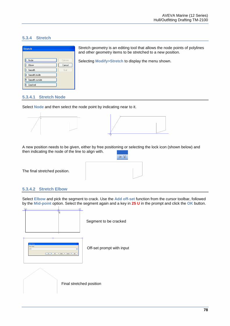
AVEVA Marine (12 Series) Hull/Outfitting Drafting TM-2100
78
www.aveva.com
5.3.4 Stretch
Stretch geometry is an editing tool that allows the node points of polylines and other geometry items to be stretched to a new position. Selecting Modify>Stretch to display the menu shown.
5.3.4.1 Stretch Node
Select Node and then select the node point by indicating near to it.
A new position needs to be given, either by free positioning or selecting the lock icon (shown below) and then indicating the node of the line to align with.
The final stretched position.
5.3.4.2 Stretch Elbow
Select Elbow and pick the segment to crack. Use the Add off-set function from the cursor toolbar, followed by the Mid-point option. Select the segment again and a key in 25 U in the prompt and click the OK button.
Segment to be cracked Off-set prompt with input
Final stretched position
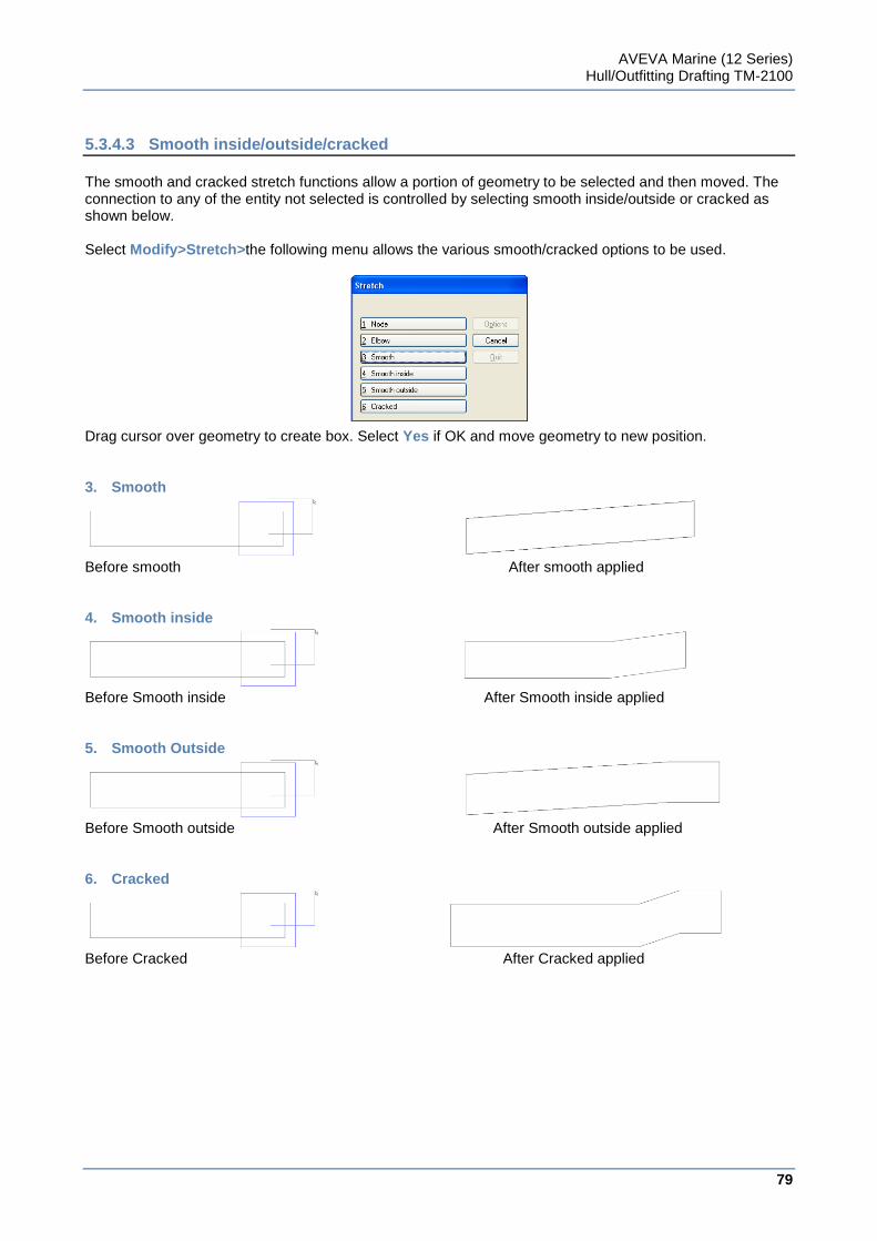
AVEVA Marine (12 Series) Hull/Outfitting Drafting TM-2100
79
www.aveva.com
5.3.4.3 Smooth inside/outside/cracked
The smooth and cracked stretch functions allow a portion of geometry to be selected and then moved. The connection to any of the entity not selected is controlled by selecting smooth inside/outside or cracked as shown below. Select Modify>Stretch>the following menu allows the various smooth/cracked options to be used. Drag cursor over geometry to create box. Select Yes if OK and move geometry to new position. 3. Smooth
Before smooth After smooth applied 4. Smooth inside
Before Smooth inside After Smooth inside applied 5. Smooth Outside
Before Smooth outside After Smooth outside applied 6. Cracked
Before Cracked After Cracked applied
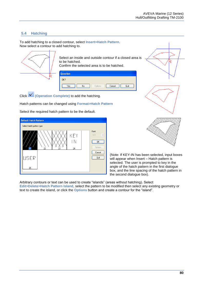
AVEVA Marine (12 Series) Hull/Outfitting Drafting TM-2100
80
www.aveva.com
5.4 Hatching
To add hatching to a closed contour, select Insert>Hatch Pattern. Now select a contour to add hatching to.
Select an inside and outside contour if a closed area is to be hatched. Confirm the selected area is to be hatched.
Click (Operation Complete) to add the hatching.
Hatch patterns can be changed using Format>Hatch Pattern Select the required hatch pattern to be the default.
(Note: If KEY-IN has been selected, input boxes will appear when Insert – Hatch pattern is selected. The user is prompted to key in the angle of the hatch pattern in the first dialogue box, and the line spacing of the hatch pattern in the second dialogue box).
Arbitrary contours or text can be used to create “islands” (areas without hatching). Select Edit>Delete>Hatch Pattern Island, select the pattern to be modified then select any existing geometry or text to create the island, or click the Options button and create a contour for the “island”.
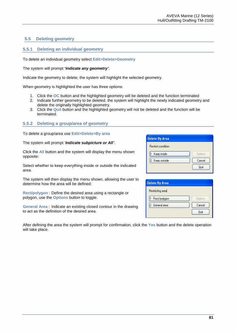
AVEVA Marine (12 Series) Hull/Outfitting Drafting TM-2100
81
www.aveva.com
5.5 Deleting geometry
5.5.1 Deleting an individual geometry
To delete an individual geometry select Edit>Delete>Geometry The system will prompt ‘Indicate any geometry’. Indicate the geometry to delete; the system will highlight the selected geometry. When geometry is highlighted the user has three options:
1. Click the OC button and the highlighted geometry will be deleted and the function terminated 2. Indicate further geometry to be deleted, the system will highlight the newly indicated geometry and
delete the originally highlighted geometry. 3. Click the Quit button and the highlighted geometry will not be deleted and the function will be
terminated.
5.5.2 Deleting a group/area of geometry
To delete a group/area use Edit>Delete>By area The system will prompt „Indicate subpicture or All’. Click the All button and the system will display the menu shown opposite: Select whether to keep everything inside or outside the indicated area. The system will then display the menu shown, allowing the user to determine how the area will be defined: Rect/polygon : Define the desired area using a rectangle or polygon, use the Options button to toggle. General Area : Indicate an existing closed contour in the drawing to act as the definition of the desired area. After defining the area the system will prompt for confirmation, click the Yes button and the delete operation will take place.
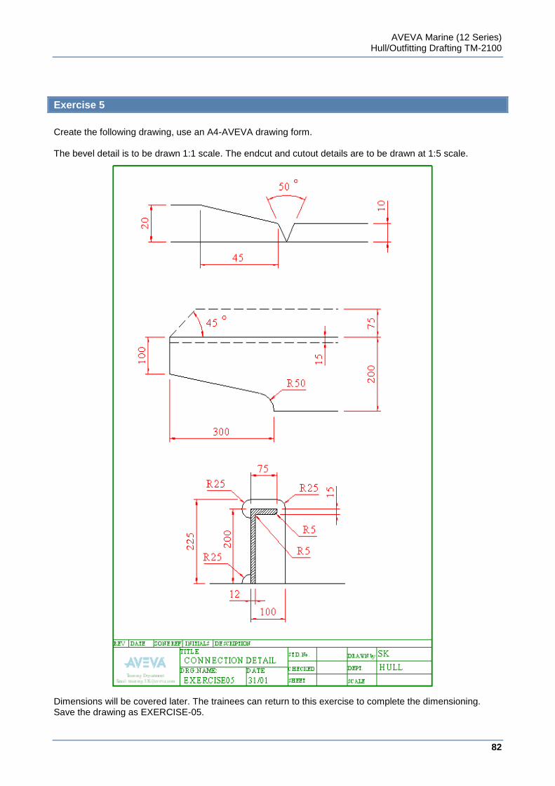
AVEVA Marine (12 Series) Hull/Outfitting Drafting TM-2100
82
www.aveva.com
Exercise 5
Create the following drawing, use an A4-AVEVA drawing form. The bevel detail is to be drawn 1:1 scale. The endcut and cutout details are to be drawn at 1:5 scale. Dimensions will be covered later. The trainees can return to this exercise to complete the dimensioning. Save the drawing as EXERCISE-05.
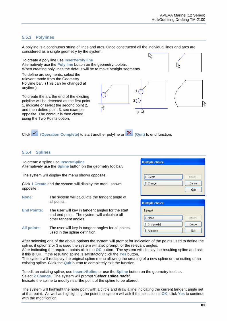
AVEVA Marine (12 Series) Hull/Outfitting Drafting TM-2100
83
www.aveva.com
5.5.3 Polylines
A polyline is a continuous string of lines and arcs. Once constructed all the individual lines and arcs are considered as a single geometry by the system. To create a poly line use Insert>Poly line Alternatively use the Poly line button on the geometry toolbar. When creating poly lines the default will be to make straight segments.
To define arc segments, select the relevant mode from the Geometry Polyline bar. (This can be changed at anytime). To create the arc the end of the existing polyline will be detected as the first point 1, indicate or select the second point 2, and then define point 3, see example opposite. The contour is then closed using the Two Points option.
Click (Operation Complete) to start another polyline or (Quit) to end function.
5.5.4 Splines
To create a spline use Insert>Spline Alternatively use the Spline button on the geometry toolbar. The system will display the menu shown opposite: Click 1 Create and the system will display the menu shown opposite: None: The system will calculate the tangent angle at all points. End Points: The user will key in tangent angles for the start and end point. The system will calculate all other tangent angles. All points: The user will key in tangent angles for all points
used in the spline definition. After selecting one of the above options the system will prompt for indication of the points used to define the spline, if option 2 or 3 is used the system will also prompt for the relevant angles. After indicating the required points click the OC button. The system will display the resulting spline and ask if this is OK. If the resulting spline is satisfactory click the Yes button. The system will redisplay the original spline menu allowing the creating of a new spline or the editing of an existing spline. Click the Quit button to completely exit the function. To edit an existing spline, use Insert>Spline or use the Spline button on the geometry toolbar. Select 2 Change. The system will prompt ‘Select spline node’. Indicate the spline to modify near the point of the spline to be altered. The system will highlight the node point with a circle and draw a line indicating the current tangent angle set at that point. As well as highlighting the point the system will ask if the selection is OK, click Yes to continue with the modification.
1
2
3
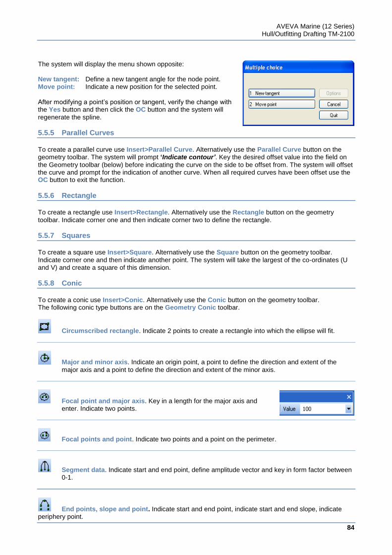
AVEVA Marine (12 Series) Hull/Outfitting Drafting TM-2100
84
www.aveva.com
The system will display the menu shown opposite: New tangent: Define a new tangent angle for the node point. Move point: Indicate a new position for the selected point. After modifying a point‟s position or tangent, verify the change with the Yes button and then click the OC button and the system will regenerate the spline.
5.5.5 Parallel Curves
To create a parallel curve use Insert>Parallel Curve. Alternatively use the Parallel Curve button on the geometry toolbar. The system will prompt ‘Indicate contour’. Key the desired offset value into the field on the Geometry toolbar (below) before indicating the curve on the side to be offset from. The system will offset the curve and prompt for the indication of another curve. When all required curves have been offset use the OC button to exit the function.
5.5.6 Rectangle
To create a rectangle use Insert>Rectangle. Alternatively use the Rectangle button on the geometry toolbar. Indicate corner one and then indicate corner two to define the rectangle.
5.5.7 Squares
To create a square use Insert>Square. Alternatively use the Square button on the geometry toolbar. Indicate corner one and then indicate another point. The system will take the largest of the co-ordinates (U and V) and create a square of this dimension.
5.5.8 Conic
To create a conic use Insert>Conic. Alternatively use the Conic button on the geometry toolbar. The following conic type buttons are on the Geometry Conic toolbar.
Circumscribed rectangle. Indicate 2 points to create a rectangle into which the ellipse will fit.
Major and minor axis. Indicate an origin point, a point to define the direction and extent of the major axis and a point to define the direction and extent of the minor axis.
Focal point and major axis. Key in a length for the major axis and enter. Indicate two points.
Focal points and point. Indicate two points and a point on the perimeter.
Segment data. Indicate start and end point, define amplitude vector and key in form factor between 0-1.
End points, slope and point. Indicate start and end point, indicate start and end slope, indicate periphery point.
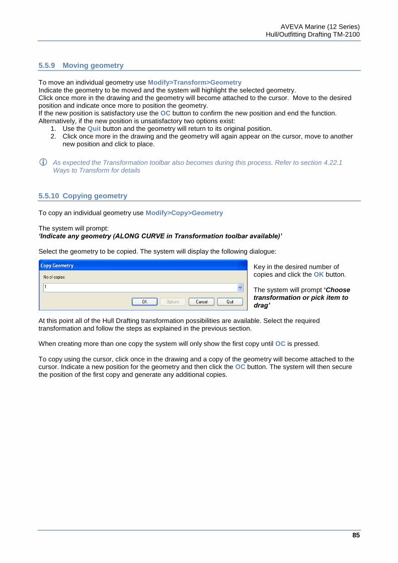
AVEVA Marine (12 Series) Hull/Outfitting Drafting TM-2100
85
www.aveva.com
5.5.9 Moving geometry
To move an individual geometry use Modify>Transform>Geometry Indicate the geometry to be moved and the system will highlight the selected geometry. Click once more in the drawing and the geometry will become attached to the cursor. Move to the desired position and indicate once more to position the geometry. If the new position is satisfactory use the OC button to confirm the new position and end the function. Alternatively, if the new position is unsatisfactory two options exist:
1. Use the Quit button and the geometry will return to its original position. 2. Click once more in the drawing and the geometry will again appear on the cursor, move to another
new position and click to place.
As expected the Transformation toolbar also becomes during this process. Refer to section 4.22.1 Ways to Transform for details
5.5.10 Copying geometry
To copy an individual geometry use Modify>Copy>Geometry The system will prompt: ‘Indicate any geometry (ALONG CURVE in Transformation toolbar available)’ Select the geometry to be copied. The system will display the following dialogue:
Key in the desired number of copies and click the OK button. The system will prompt ‘Choose transformation or pick item to drag’
At this point all of the Hull Drafting transformation possibilities are available. Select the required transformation and follow the steps as explained in the previous section. When creating more than one copy the system will only show the first copy until OC is pressed. To copy using the cursor, click once in the drawing and a copy of the geometry will become attached to the cursor. Indicate a new position for the geometry and then click the OC button. The system will then secure the position of the first copy and generate any additional copies.
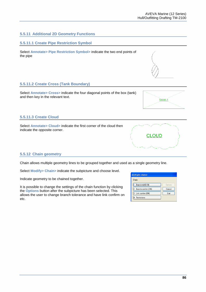
AVEVA Marine (12 Series) Hull/Outfitting Drafting TM-2100
86
www.aveva.com
5.5.11 Additional 2D Geometry Functions
5.5.11.1 Create Pipe Restriction Symbol
Select Annotate> Pipe Restriction Symbol> indicate the two end points of the pipe
5.5.11.2 Create Cross (Tank Boundary)
Select Annotate> Cross> indicate the four diagonal points of the box (tank) and then key in the relevant text.
5.5.11.3 Create Cloud
Select Annotate> Cloud> indicate the first corner of the cloud then indicate the opposite corner.
5.5.12 Chain geometry
Chain allows multiple geometry lines to be grouped together and used as a single geometry line. Select Modify> Chain> indicate the subpicture and choose level. Indicate geometry to be chained together. It is possible to change the settings of the chain function by clicking the Options button after the subpicture has been selected. This allows the user to change branch tolerance and have link confirm on etc.
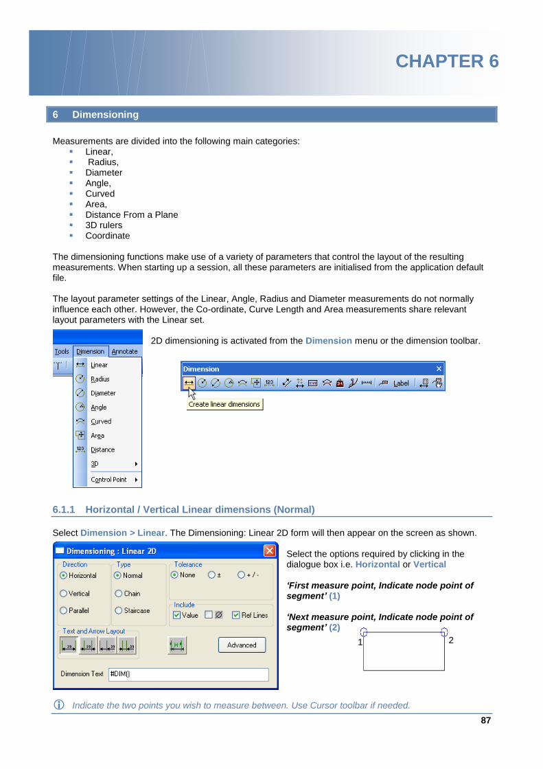
87
www.aveva.com
CHAPTER 6
6 Dimensioning
Measurements are divided into the following main categories:
Linear, Radius, Diameter Angle, Curved Area, Distance From a Plane 3D rulers Coordinate
The dimensioning functions make use of a variety of parameters that control the layout of the resulting measurements. When starting up a session, all these parameters are initialised from the application default file. The layout parameter settings of the Linear, Angle, Radius and Diameter measurements do not normally influence each other. However, the Co-ordinate, Curve Length and Area measurements share relevant layout parameters with the Linear set.
2D dimensioning is activated from the Dimension menu or the dimension toolbar.
6.1.1 Horizontal / Vertical Linear dimensions (Normal)
Select Dimension > Linear. The Dimensioning: Linear 2D form will then appear on the screen as shown.
Select the options required by clicking in the dialogue box i.e. Horizontal or Vertical ‘First measure point, Indicate node point of segment’ (1) ‘Next measure point, Indicate node point of segment’ (2)
Indicate the two points you wish to measure between. Use Cursor toolbar if needed.
1 2
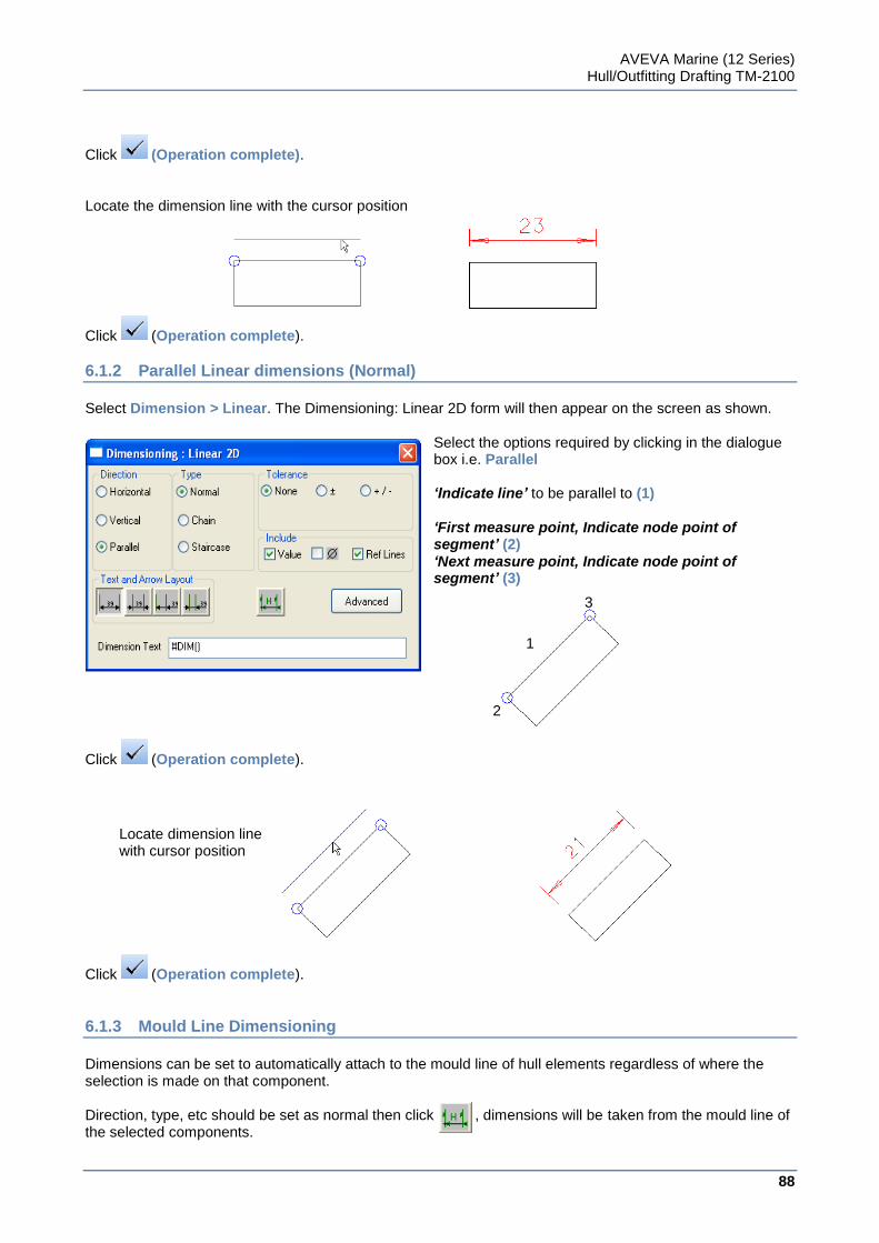
AVEVA Marine (12 Series) Hull/Outfitting Drafting TM-2100
88
www.aveva.com
Click (Operation complete). Locate the dimension line with the cursor position
Click (Operation complete).
6.1.2 Parallel Linear dimensions (Normal)
Select Dimension > Linear. The Dimensioning: Linear 2D form will then appear on the screen as shown.
Select the options required by clicking in the dialogue box i.e. Parallel ‘Indicate line’ to be parallel to (1) ‘First measure point, Indicate node point of segment’ (2) ‘Next measure point, Indicate node point of segment’ (3)
Click (Operation complete).
Click (Operation complete).
6.1.3 Mould Line Dimensioning
Dimensions can be set to automatically attach to the mould line of hull elements regardless of where the selection is made on that component. Direction, type, etc should be set as normal then click , dimensions will be taken from the mould line of the selected components.
Locate dimension line with cursor position
2
3
1
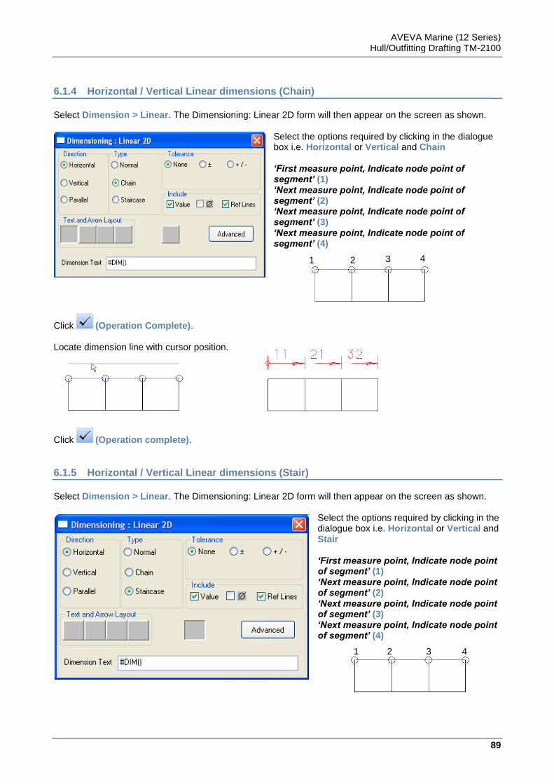
AVEVA Marine (12 Series) Hull/Outfitting Drafting TM-2100
89
www.aveva.com
6.1.4 Horizontal / Vertical Linear dimensions (Chain)
Select Dimension > Linear. The Dimensioning: Linear 2D form will then appear on the screen as shown.
Select the options required by clicking in the dialogue box i.e. Horizontal or Vertical and Chain ‘First measure point, Indicate node point of segment’ (1) ‘Next measure point, Indicate node point of segment’ (2) ‘Next measure point, Indicate node point of segment’ (3) ‘Next measure point, Indicate node point of segment’ (4)
Click (Operation Complete). Locate dimension line with cursor position.
Click (Operation complete).
6.1.5 Horizontal / Vertical Linear dimensions (Stair)
Select Dimension > Linear. The Dimensioning: Linear 2D form will then appear on the screen as shown.
Select the options required by clicking in the dialogue box i.e. Horizontal or Vertical and Stair ‘First measure point, Indicate node point of segment’ (1) ‘Next measure point, Indicate node point of segment’ (2) ‘Next measure point, Indicate node point of segment’ (3) ‘Next measure point, Indicate node point of segment’ (4)
1 2 3 4
1 2 3 4
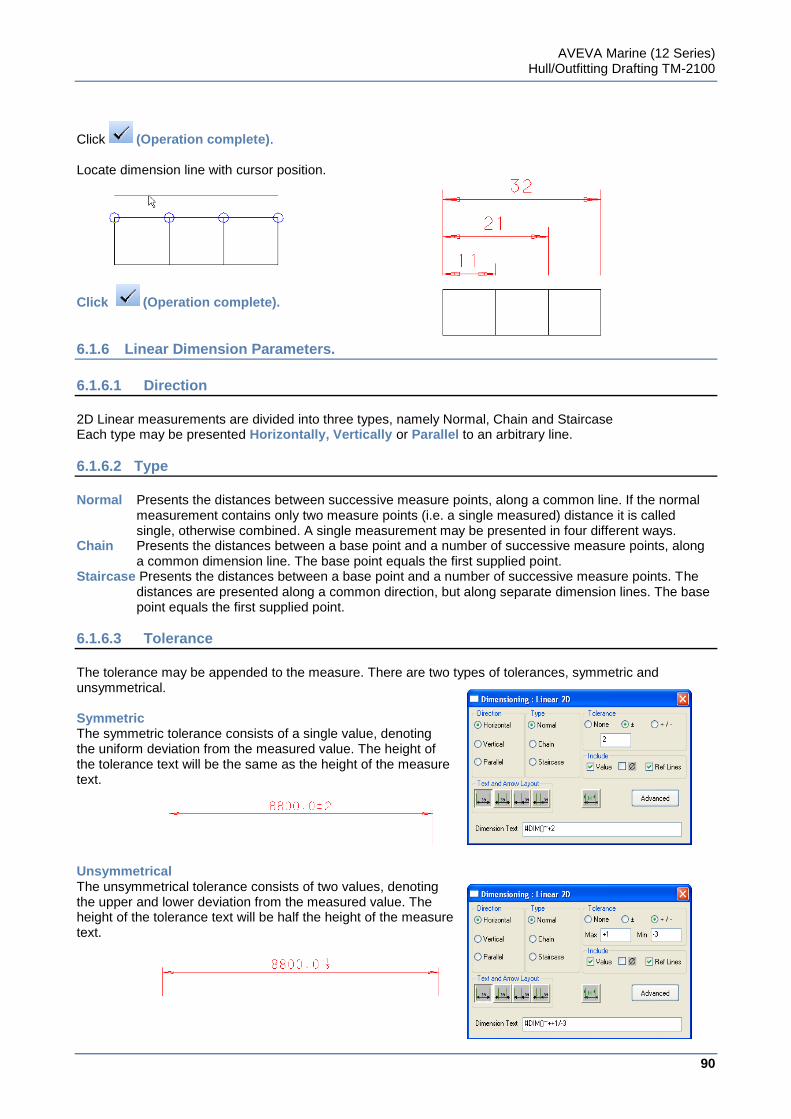
AVEVA Marine (12 Series) Hull/Outfitting Drafting TM-2100
90
www.aveva.com
Click (Operation complete). Locate dimension line with cursor position.
Click (Operation complete).
6.1.6 Linear Dimension Parameters.
6.1.6.1 Direction
2D Linear measurements are divided into three types, namely Normal, Chain and Staircase Each type may be presented Horizontally, Vertically or Parallel to an arbitrary line.
6.1.6.2 Type
Normal Presents the distances between successive measure points, along a common line. If the normal
measurement contains only two measure points (i.e. a single measured) distance it is called single, otherwise combined. A single measurement may be presented in four different ways.
Chain Presents the distances between a base point and a number of successive measure points, along a common dimension line. The base point equals the first supplied point.
Staircase Presents the distances between a base point and a number of successive measure points. The distances are presented along a common direction, but along separate dimension lines. The base point equals the first supplied point.
6.1.6.3 Tolerance
The tolerance may be appended to the measure. There are two types of tolerances, symmetric and unsymmetrical. Symmetric The symmetric tolerance consists of a single value, denoting the uniform deviation from the measured value. The height of the tolerance text will be the same as the height of the measure text. Unsymmetrical The unsymmetrical tolerance consists of two values, denoting the upper and lower deviation from the measured value. The height of the tolerance text will be half the height of the measure text.
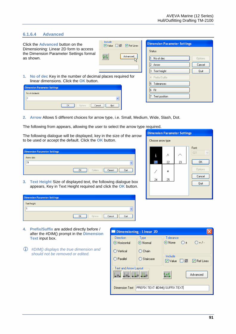
AVEVA Marine (12 Series) Hull/Outfitting Drafting TM-2100
91
www.aveva.com
6.1.6.4 Advanced
Click the Advanced button on the Dimensioning: Linear 2D form to access the Dimension Parameter Settings formal as shown. 1. No of dec Key in the number of decimal places required for
linear dimensions. Click the OK button.
2. Arrow Allows 5 different choices for arrow type, i.e. Small, Medium, Wide, Slash, Dot. The following from appears, allowing the user to select the arrow type required. The following dialogue will be displayed, key in the size of the arrow to be used or accept the default. Click the OK button.
3. Text Height Size of displayed text, the following dialogue box
appears, Key in Text Height required and click the OK button.
4. Prefix/Suffix are added directly before /
after the #DIM() prompt in the Dimension Text input box.
#DIM() displays the true dimension and should not be removed or edited.
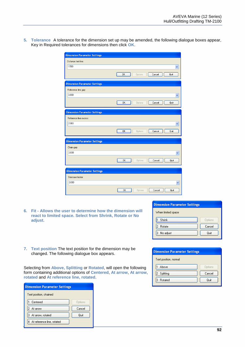
AVEVA Marine (12 Series) Hull/Outfitting Drafting TM-2100
92
www.aveva.com
5. Tolerance A tolerance for the dimension set up may be amended, the following dialogue boxes appear,
Key in Required tolerances for dimensions then click OK. 6. Fit - Allows the user to determine how the dimension will
react to limited space. Select from Shrink, Rotate or No adjust.
7. Text position The text position for the dimension may be
changed. The following dialogue box appears. Selecting from Above, Splitting or Rotated, will open the following form containing additional options of Centered, At arrow, At arrow, rotated and At reference line, rotated.
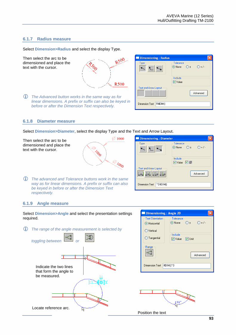
AVEVA Marine (12 Series) Hull/Outfitting Drafting TM-2100
93
www.aveva.com
6.1.7 Radius measure
Select Dimension>Radius and select the display Type. Then select the arc to be dimensioned and place the text with the cursor.
The Advanced button works in the same way as for linear dimensions. A prefix or suffix can also be keyed in before or after the Dimension Text respectively.
6.1.8 Diameter measure
Select Dimension>Diameter, select the display Type and the Text and Arrow Layout. Then select the arc to be dimensioned and place the text with the cursor.
The advanced and Tolerance buttons work in the same way as for linear dimensions. A prefix or suffix can also be keyed in before or after the Dimension Text respectively.
6.1.9 Angle measure
Select Dimension>Angle and select the presentation settings required.
The range of the angle measurement is selected by
toggling between or
Locate reference arc.
Indicate the two lines that form the angle to be measured.
Position the text
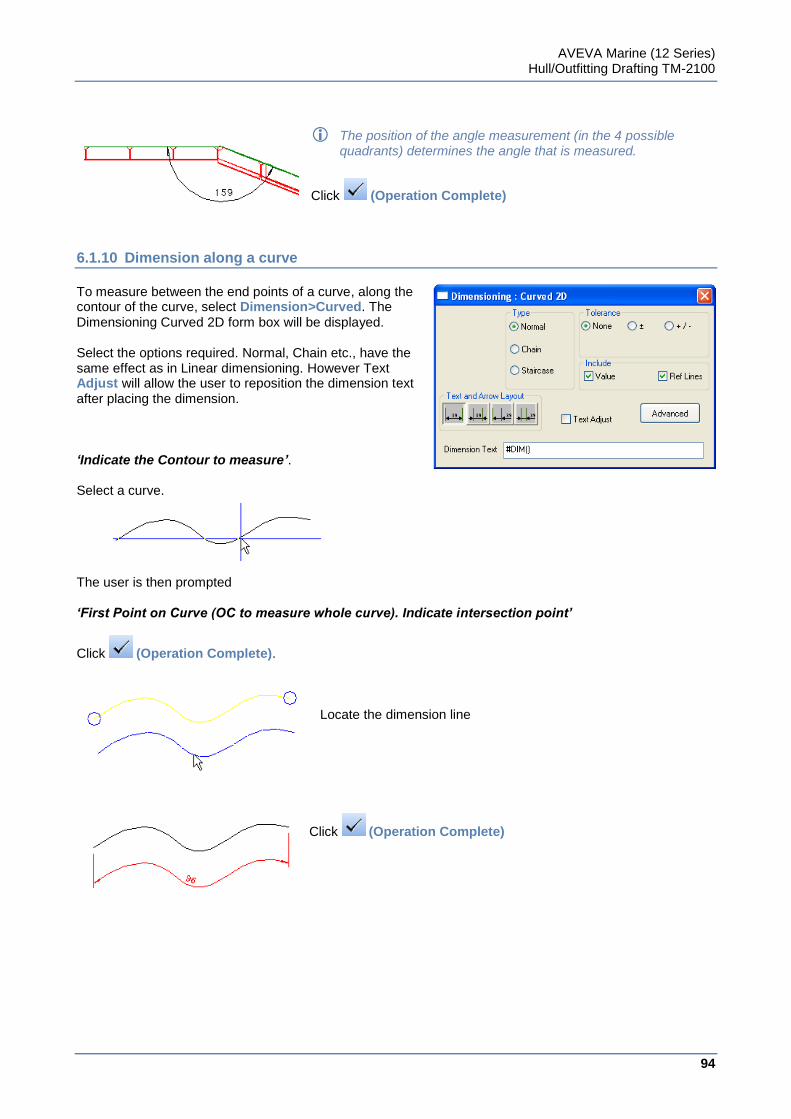
AVEVA Marine (12 Series) Hull/Outfitting Drafting TM-2100
94
www.aveva.com
The position of the angle measurement (in the 4 possible quadrants) determines the angle that is measured.
Click (Operation Complete)
6.1.10 Dimension along a curve
To measure between the end points of a curve, along the contour of the curve, select Dimension>Curved. The Dimensioning Curved 2D form box will be displayed. Select the options required. Normal, Chain etc., have the same effect as in Linear dimensioning. However Text Adjust will allow the user to reposition the dimension text after placing the dimension. ‘Indicate the Contour to measure’. Select a curve. The user is then prompted ‘First Point on Curve (OC to measure whole curve). Indicate intersection point’
Click (Operation Complete).
Locate the dimension line
Click (Operation Complete)
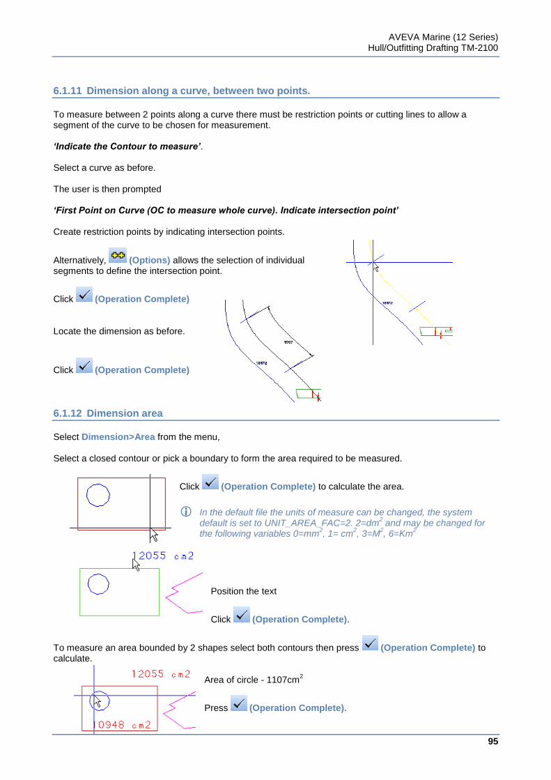
AVEVA Marine (12 Series) Hull/Outfitting Drafting TM-2100
95
www.aveva.com
6.1.11 Dimension along a curve, between two points.
To measure between 2 points along a curve there must be restriction points or cutting lines to allow a segment of the curve to be chosen for measurement. ‘Indicate the Contour to measure’. Select a curve as before. The user is then prompted ‘First Point on Curve (OC to measure whole curve). Indicate intersection point’ Create restriction points by indicating intersection points.
Alternatively, (Options) allows the selection of individual segments to define the intersection point.
Click (Operation Complete) Locate the dimension as before.
Click (Operation Complete)
6.1.12 Dimension area
Select Dimension>Area from the menu, Select a closed contour or pick a boundary to form the area required to be measured.
Click (Operation Complete) to calculate the area.
In the default file the units of measure can be changed, the system default is set to UNIT_AREA_FAC=2. 2=dm
2 and may be changed for
the following variables 0=mm2, 1= cm
2, 3=M
2, 6=Km
2
Position the text
Click (Operation Complete).
To measure an area bounded by 2 shapes select both contours then press (Operation Complete) to calculate.
Area of circle - 1107cm2
Press (Operation Complete).
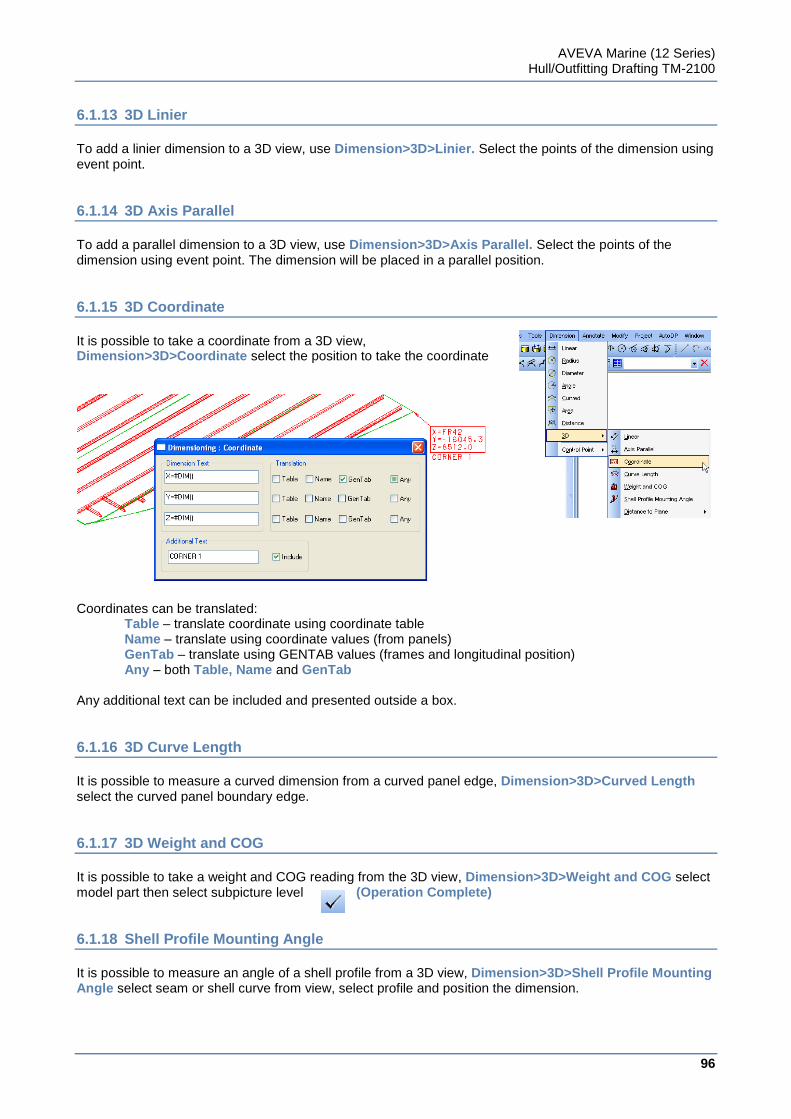
AVEVA Marine (12 Series) Hull/Outfitting Drafting TM-2100
96
www.aveva.com
6.1.13 3D Linier
To add a linier dimension to a 3D view, use Dimension>3D>Linier. Select the points of the dimension using event point.
6.1.14 3D Axis Parallel
To add a parallel dimension to a 3D view, use Dimension>3D>Axis Parallel. Select the points of the dimension using event point. The dimension will be placed in a parallel position.
6.1.15 3D Coordinate
It is possible to take a coordinate from a 3D view, Dimension>3D>Coordinate select the position to take the coordinate
Coordinates can be translated:
Table – translate coordinate using coordinate table Name – translate using coordinate values (from panels) GenTab – translate using GENTAB values (frames and longitudinal position) Any – both Table, Name and GenTab
Any additional text can be included and presented outside a box.
6.1.16 3D Curve Length
It is possible to measure a curved dimension from a curved panel edge, Dimension>3D>Curved Length select the curved panel boundary edge.
6.1.17 3D Weight and COG
It is possible to take a weight and COG reading from the 3D view, Dimension>3D>Weight and COG select model part then select subpicture level (Operation Complete)
6.1.18 Shell Profile Mounting Angle
It is possible to measure an angle of a shell profile from a 3D view, Dimension>3D>Shell Profile Mounting Angle select seam or shell curve from view, select profile and position the dimension.
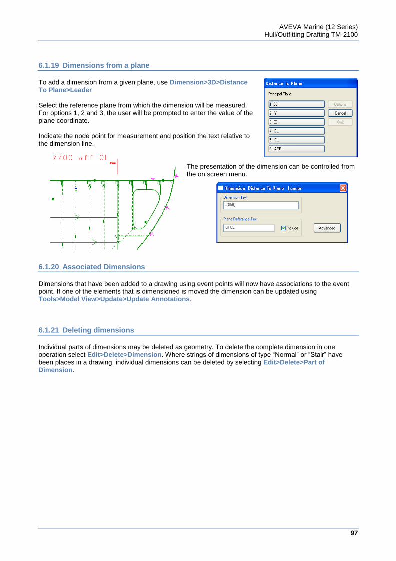
AVEVA Marine (12 Series) Hull/Outfitting Drafting TM-2100
97
www.aveva.com
6.1.19 Dimensions from a plane
To add a dimension from a given plane, use Dimension>3D>Distance To Plane>Leader Select the reference plane from which the dimension will be measured. For options 1, 2 and 3, the user will be prompted to enter the value of the plane coordinate. Indicate the node point for measurement and position the text relative to the dimension line.
The presentation of the dimension can be controlled from the on screen menu.
6.1.20 Associated Dimensions
Dimensions that have been added to a drawing using event points will now have associations to the event point. If one of the elements that is dimensioned is moved the dimension can be updated using Tools>Model View>Update>Update Annotations.
6.1.21 Deleting dimensions
Individual parts of dimensions may be deleted as geometry. To delete the complete dimension in one operation select Edit>Delete>Dimension. Where strings of dimensions of type “Normal” or “Stair” have been places in a drawing, individual dimensions can be deleted by selecting Edit>Delete>Part of Dimension.
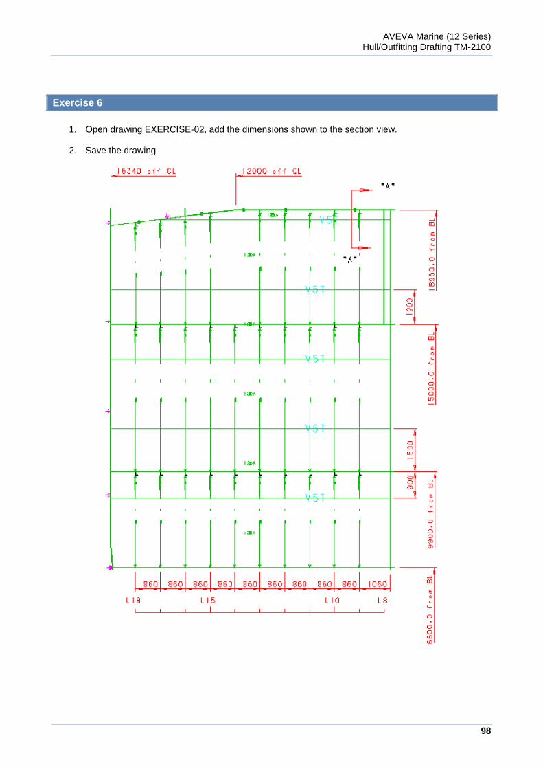
AVEVA Marine (12 Series) Hull/Outfitting Drafting TM-2100
98
www.aveva.com
Exercise 6
1. Open drawing EXERCISE-02, add the dimensions shown to the section view.
2. Save the drawing
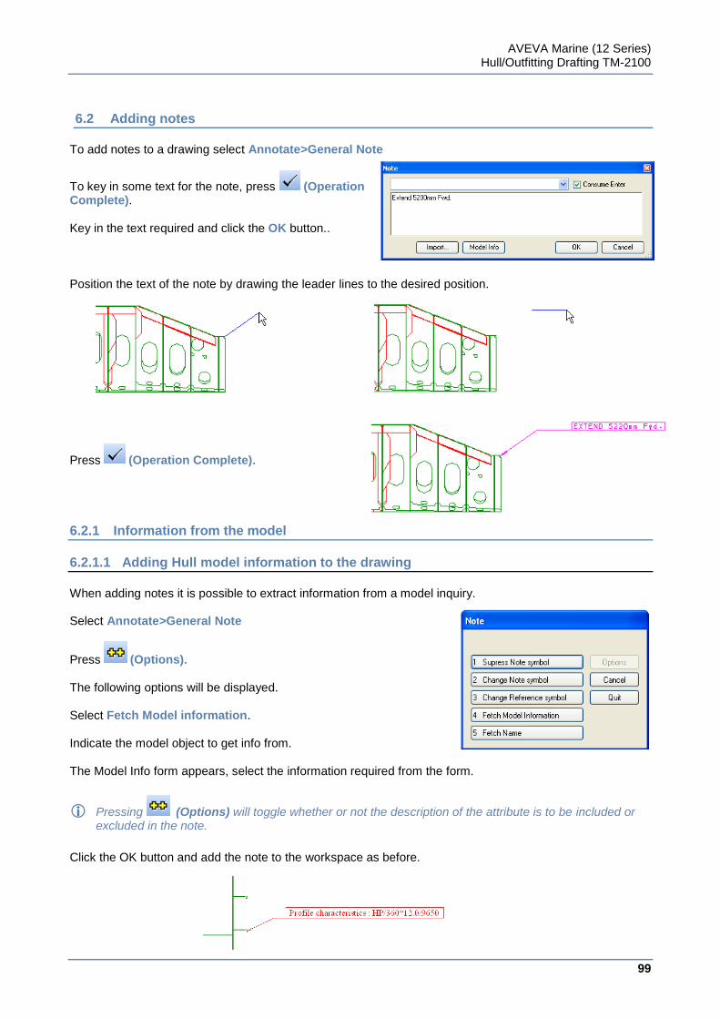
AVEVA Marine (12 Series) Hull/Outfitting Drafting TM-2100
99
www.aveva.com
6.2 Adding notes
To add notes to a drawing select Annotate>General Note
To key in some text for the note, press (Operation Complete). Key in the text required and click the OK button.. Position the text of the note by drawing the leader lines to the desired position.
Press (Operation Complete).
6.2.1 Information from the model
6.2.1.1 Adding Hull model information to the drawing
When adding notes it is possible to extract information from a model inquiry. Select Annotate>General Note
Press (Options). The following options will be displayed. Select Fetch Model information. Indicate the model object to get info from. The Model Info form appears, select the information required from the form.
Pressing (Options) will toggle whether or not the description of the attribute is to be included or excluded in the note.
Click the OK button and add the note to the workspace as before.
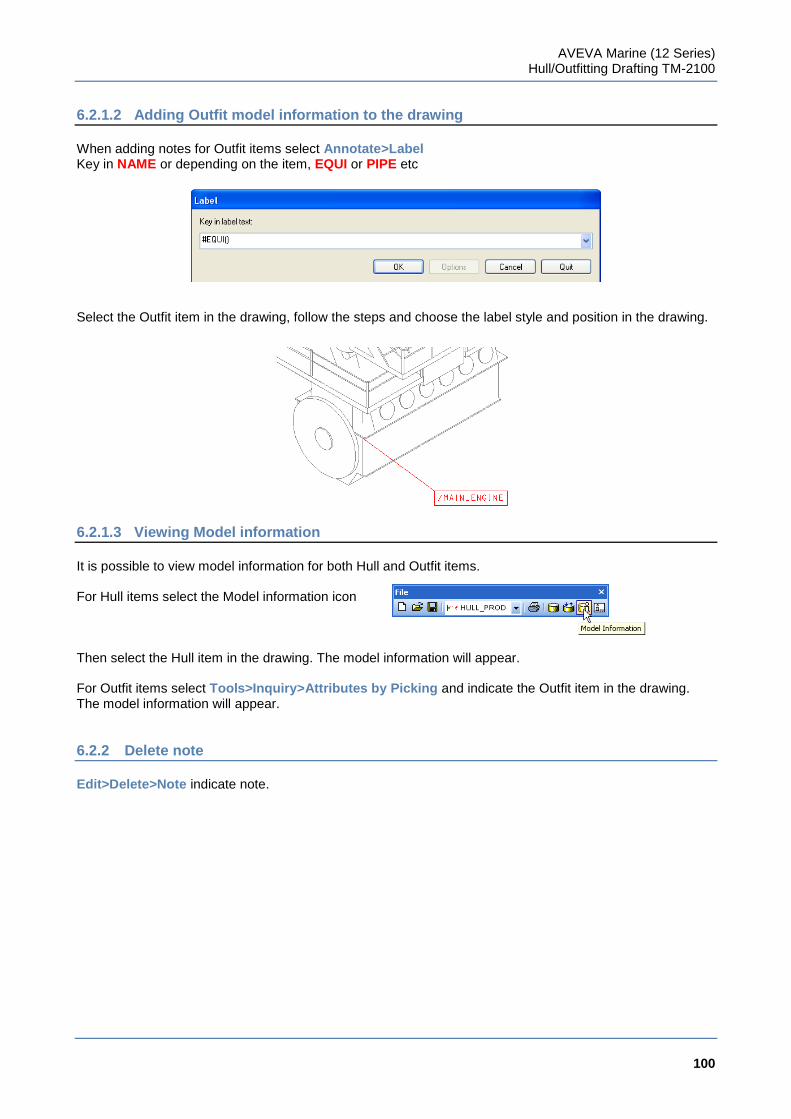
AVEVA Marine (12 Series) Hull/Outfitting Drafting TM-2100
100
www.aveva.com
6.2.1.2 Adding Outfit model information to the drawing
When adding notes for Outfit items select Annotate>Label Key in NAME or depending on the item, EQUI or PIPE etc Select the Outfit item in the drawing, follow the steps and choose the label style and position in the drawing.
6.2.1.3 Viewing Model information
It is possible to view model information for both Hull and Outfit items. For Hull items select the Model information icon Then select the Hull item in the drawing. The model information will appear. For Outfit items select Tools>Inquiry>Attributes by Picking and indicate the Outfit item in the drawing. The model information will appear.
6.2.2 Delete note
Edit>Delete>Note indicate note.
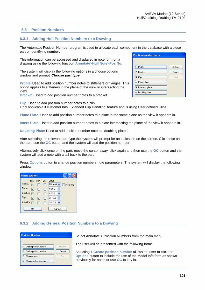
AVEVA Marine (12 Series) Hull/Outfitting Drafting TM-2100
101
www.aveva.com
6.3 Position Numbers
6.3.1 Adding Hull Position Numbers to a Drawing
The Automatic Position Number program is used to allocate each component in the database with a piece part or identifying number. This information can be accessed and displayed in note form on a drawing using the following function Annotate>Hull Note>Pos No. The system will display the following options in a choose options window and prompt „Choose part type‟ Profile: Used to add position number notes to stiffeners or flanges. This option applies to stiffeners in the plane of the view or intersecting the view. Bracket: Used to add position number notes to a bracket. Clip: Used to add position number notes to a clip. Only applicable if customer has „Extended Clip Handling‟ feature and is using User defined Clips. Plane Plate: Used to add position number notes to a plate in the same plane as the view it appears in. Inters Plate: Used to add position number notes to a plate intersecting the plane of the view it appears in. Doubling Plate: Used to add position number notes to doubling plates. After selecting the relevant part type the system will prompt for an indication on the screen. Click once on the part, use the OC button and the system will add the position number. Alternatively click once on the part, move the cursor away, click again and then use the OC button and the system will add a note with a tail back to the part. Press Options button to change position numbers note parameters. The system will display the following window:
6.3.2 Adding General Position Numbers to a Drawing
Select Annotate > Position Numbers from the main menu. The user will be presented with the following form:- Selecting 1 Create position number allows the user to click the Options button to include the use of the Model Info form as shown previously for notes or use OC to key in.
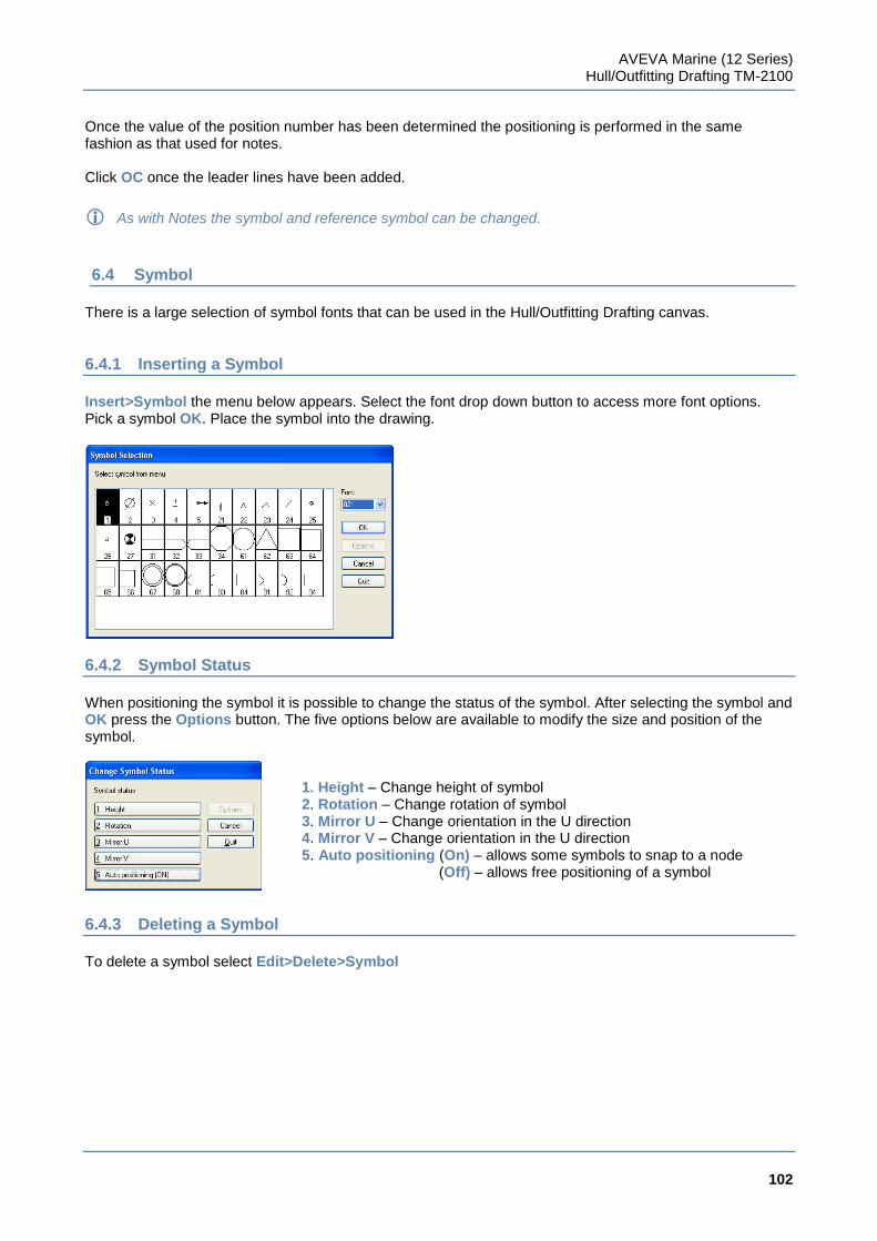
AVEVA Marine (12 Series) Hull/Outfitting Drafting TM-2100
102
www.aveva.com
Once the value of the position number has been determined the positioning is performed in the same fashion as that used for notes. Click OC once the leader lines have been added.
As with Notes the symbol and reference symbol can be changed.
6.4 Symbol
There is a large selection of symbol fonts that can be used in the Hull/Outfitting Drafting canvas.
6.4.1 Inserting a Symbol
Insert>Symbol the menu below appears. Select the font drop down button to access more font options. Pick a symbol OK. Place the symbol into the drawing.
6.4.2 Symbol Status
When positioning the symbol it is possible to change the status of the symbol. After selecting the symbol and OK press the Options button. The five options below are available to modify the size and position of the symbol.
1. Height – Change height of symbol 2. Rotation – Change rotation of symbol 3. Mirror U – Change orientation in the U direction 4. Mirror V – Change orientation in the U direction 5. Auto positioning (On) – allows some symbols to snap to a node
(Off) – allows free positioning of a symbol
6.4.3 Deleting a Symbol
To delete a symbol select Edit>Delete>Symbol
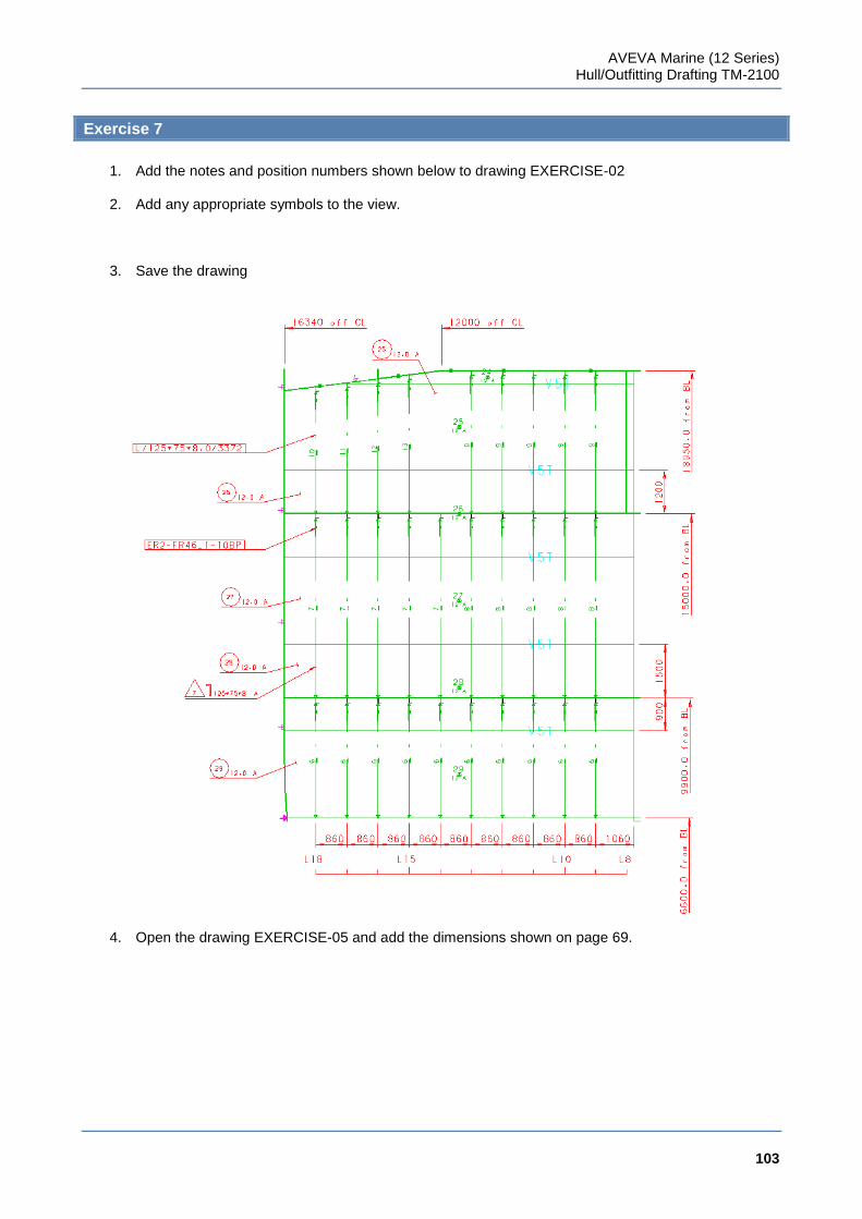
AVEVA Marine (12 Series) Hull/Outfitting Drafting TM-2100
103
www.aveva.com
Exercise 7
1. Add the notes and position numbers shown below to drawing EXERCISE-02
2. Add any appropriate symbols to the view.
3. Save the drawing
4. Open the drawing EXERCISE-05 and add the dimensions shown on page 69.

AVEVA Marine (12 Series) Hull/Outfitting Drafting TM-2100
104
www.aveva.com
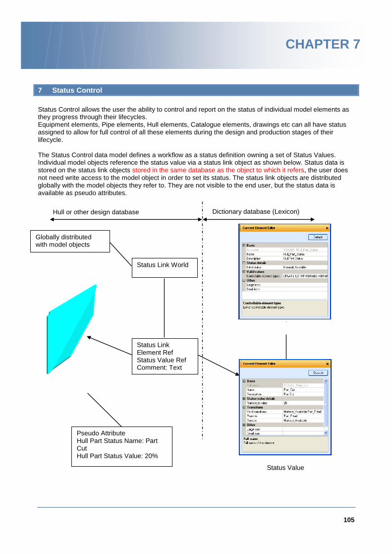
105
www.aveva.com
CHAPTER 7
7 Status Control
Status Control allows the user the ability to control and report on the status of individual model elements as they progress through their lifecycles. Equipment elements, Pipe elements, Hull elements, Catalogue elements, drawings etc can all have status assigned to allow for full control of all these elements during the design and production stages of their lifecycle. The Status Control data model defines a workflow as a status definition owning a set of Status Values. Individual model objects reference the status value via a status link object as shown below. Status data is stored on the status link objects stored in the same database as the object to which it refers, the user does not need write access to the model object in order to set its status. The status link objects are distributed globally with the model objects they refer to. They are not visible to the end user, but the status data is available as pseudo attributes.
Status Value
Hull or other design database Dictionary database (Lexicon)
Pseudo Attribute Hull Part Status Name: Part Cut Hull Part Status Value: 20%
Status Link Element Ref Status Value Ref Comment: Text
Status Link World
Globally distributed with model objects
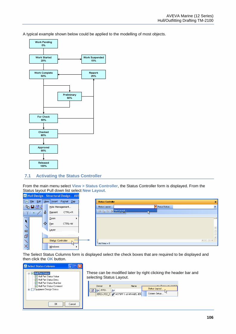
AVEVA Marine (12 Series) Hull/Outfitting Drafting TM-2100
106
www.aveva.com
A typical example shown below could be applied to the modelling of most objects.
7.1 Activating the Status Controller
From the main menu select View > Status Controller, the Status Controller form is displayed. From the Status layout Pull down list select New Layout.
The Select Status Columns form is displayed select the check boxes that are required to be displayed and then click the OK button.
These can be modified later by right clicking the header bar and selecting Status Layout.
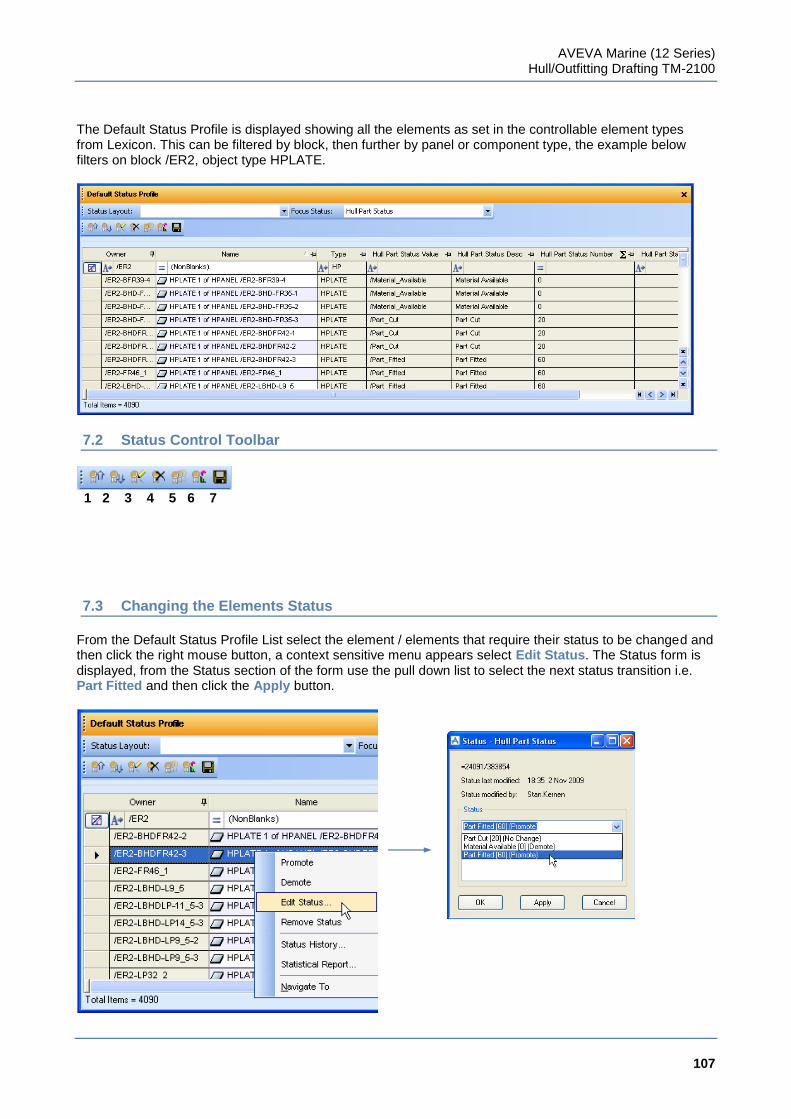
AVEVA Marine (12 Series) Hull/Outfitting Drafting TM-2100
107
www.aveva.com
The Default Status Profile is displayed showing all the elements as set in the controllable element types from Lexicon. This can be filtered by block, then further by panel or component type, the example below filters on block /ER2, object type HPLATE.
7.2 Status Control Toolbar
1 2 3 4 5 6 7
7.3 Changing the Elements Status
From the Default Status Profile List select the element / elements that require their status to be changed and then click the right mouse button, a context sensitive menu appears select Edit Status. The Status form is displayed, from the Status section of the form use the pull down list to select the next status transition i.e. Part Fitted and then click the Apply button.
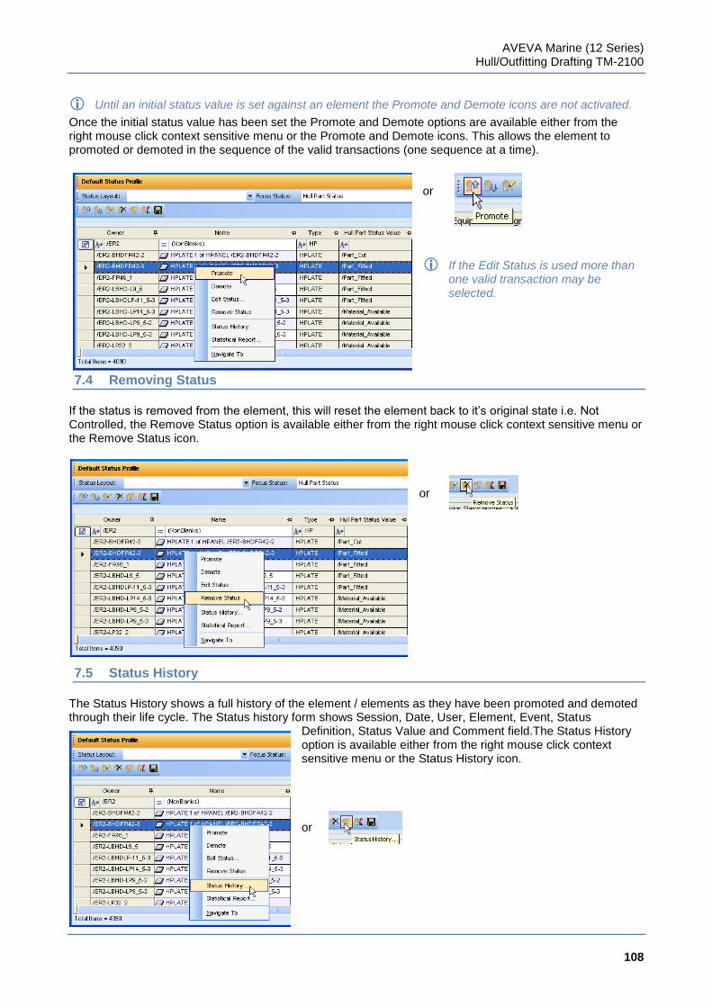
AVEVA Marine (12 Series) Hull/Outfitting Drafting TM-2100
108
www.aveva.com
Until an initial status value is set against an element the Promote and Demote icons are not activated.
Once the initial status value has been set the Promote and Demote options are available either from the right mouse click context sensitive menu or the Promote and Demote icons. This allows the element to promoted or demoted in the sequence of the valid transactions (one sequence at a time).
or
If the Edit Status is used more than one valid transaction may be selected.
7.4 Removing Status
If the status is removed from the element, this will reset the element back to it‟s original state i.e. Not Controlled, the Remove Status option is available either from the right mouse click context sensitive menu or the Remove Status icon.
or
7.5 Status History
The Status History shows a full history of the element / elements as they have been promoted and demoted through their life cycle. The Status history form shows Session, Date, User, Element, Event, Status
Definition, Status Value and Comment field.The Status History option is available either from the right mouse click context sensitive menu or the Status History icon. or
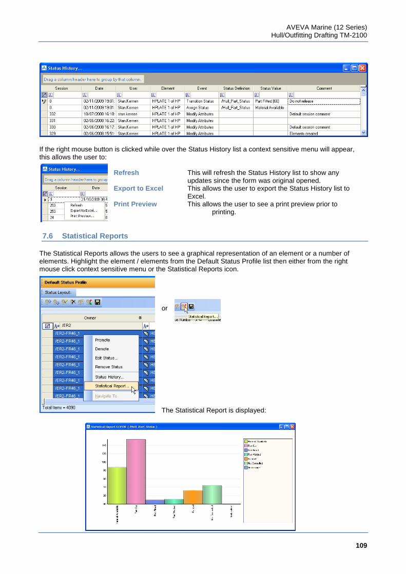
AVEVA Marine (12 Series) Hull/Outfitting Drafting TM-2100
109
www.aveva.com
If the right mouse button is clicked while over the Status History list a context sensitive menu will appear, this allows the user to:
Refresh This will refresh the Status History list to show any updates since the form was original opened. Export to Excel This allows the user to export the Status History list to Excel. Print Preview This allows the user to see a print preview prior to printing.
7.6 Statistical Reports
The Statistical Reports allows the users to see a graphical representation of an element or a number of elements. Highlight the element / elements from the Default Status Profile list then either from the right mouse click context sensitive menu or the Statistical Reports icon.
or The Statistical Report is displayed:
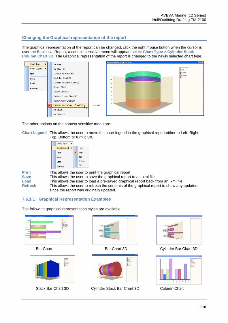
AVEVA Marine (12 Series) Hull/Outfitting Drafting TM-2100
110
www.aveva.com
Changing the Graphical representation of the report
The graphical representation of the report can be changed, click the right mouse button when the cursor is over the Statistical Report, a context sensitive menu will appear, select Chart Type > Cylinder Stack Column Chart 3D. The Graphical representation of the report is changed to the newly selected chart type.
The other options on the context sensitive menu are: Chart Legend This allows the user to move the chart legend in the graphical report either to Left, Right,
Top, Bottom or turn it Off. Print This allows the user to print the graphical report Save This allows the user to save the graphical report to an .xml file Load This allows the user to load a pre-saved graphical report back from an .xml file Refresh This allows the user to refresh the contents of the graphical report to show any updates
since the report was originally updated.
7.6.1.1 Graphical Representation Examples
The following graphical representation styles are available Bar Chart Bar Chart 3D Cylinder Bar Chart 3D Stack Bar Chart 3D Cylinder Stack Bar Chart 3D Column Chart
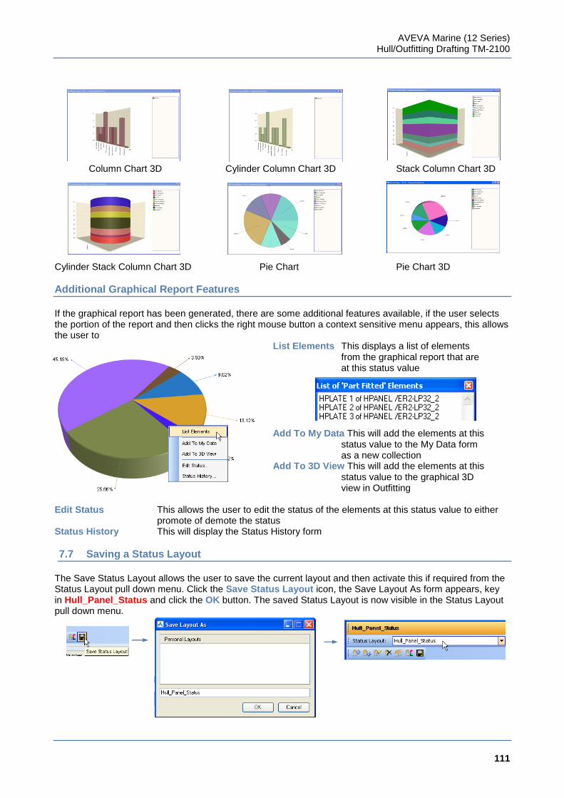
AVEVA Marine (12 Series) Hull/Outfitting Drafting TM-2100
111
www.aveva.com
Column Chart 3D Cylinder Column Chart 3D Stack Column Chart 3D Cylinder Stack Column Chart 3D Pie Chart Pie Chart 3D
Additional Graphical Report Features
If the graphical report has been generated, there are some additional features available, if the user selects the portion of the report and then clicks the right mouse button a context sensitive menu appears, this allows the user to
List Elements This displays a list of elements from the graphical report that are at this status value Add To My Data This will add the elements at this status value to the My Data form as a new collection Add To 3D View This will add the elements at this status value to the graphical 3D view in Outfitting
Edit Status This allows the user to edit the status of the elements at this status value to either promote of demote the status
Status History This will display the Status History form
7.7 Saving a Status Layout
The Save Status Layout allows the user to save the current layout and then activate this if required from the Status Layout pull down menu. Click the Save Status Layout icon, the Save Layout As form appears, key in Hull_Panel_Status and click the OK button. The saved Status Layout is now visible in the Status Layout pull down menu.
AVEVA Marine (12 Series) Hull/Outfitting Drafting TM-2100
112
www.aveva.com
If the Hull_Panel_Status is to be removed then this needs deleting from the C:\Documents and Settings\<user name>\Local Settings\Application Data\Aveva\Pdms\MARStatusGridProfiles folder.
Exercise 8
1. Use Status Controller to modify the status of items in block ER2, user the panel name as a filter and set
all the components on a particular panel to the same status, use different status levels on the next set of panel components. Leave one panel without any status.
2. Generate a Statistical Report, change the type of graph generated and list the elements at different
status levels.