Embed Size (px)
Citation preview
CE1N4211en2015-07-14 Building Technologies
s 4211
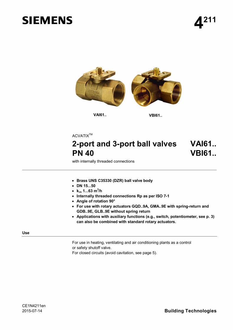
VAI61.. VBI61..
ACVATIXTM
2-port and 3-port ball valvesPN 40
VAI61..VBI61..
with internally threaded connections
· Brass UNS C35330 (DZR) ball valve body· DN 15...50· kvs 1...63 m3/h· Internally threaded connections Rp as per ISO 7-1· Angle of rotation 90°· For use with rotary actuators GQD..9A, GMA..9E with spring-return and
GDB..9E, GLB..9E without spring return· Applications with auxiliary functions (e.g., switch, potentiometer, see p. 3)
can also be combined with standard rotary actuators.
Use
For use in heating, ventilating and air conditioning plants as a controlor safety shutoff valve.For closed circuits (avoid cavitation, see page 5).

2 / 12
Siemens 2-port and 3-port ball valves PN 40 CE1N4211enBuilding Technologies 2015-07-14
Type summary
Type DN kvs Sv
2-port 3-port [m3/h]VAI61.15-1 -
15
1.0
> 500
VAI61.15-1.6 VBI61.15-1.6 1.6VAI61.15-2.5 VBI61.15-2.5 2.5VAI61.15-4 VBI61.15-4 4.0VAI61.15-6.3 VBI61.15-6.3 6.3VAI61.15-10 - 10VAI61.20-4 VBI61.20-4
204
VAI61.20-6.3 VBI61.20-6.3 6.3VAI61.20-10 - 10VAI61.25-6.3 -
256.3
VAI61.25-10 VBI61.25-10 10VAI61.25-16 - 16VAI61.32-10 -
3210
VAI61.32-16 VBI61.32-16 16VAI61.32-25 - 25VAI61.40-16 -
4016
VAI61.40-25 VBI61.40-25 25VAI61.40-40 - 40VAI61.50-25 -
5025
VAI61.50-40 VBI61.50-40 40VAI61.50-63 VBI61.50-63 63DN = nominal sizekvs = nominal flow rate of cold water (5…30 °C) through the fully open ball valve at a differential
pressure of 100 kPa (1 bar)Sv = rangeability kvs / kvr
kvr = smallest kv value at which the flow characteristic tolerances can still be maintained at adifferential pressure of 100 kPa (1 bar)
For thermal insulation, separate insulation covers are available.
Ball valve Insulation cover Ball valve Insulation coverVAI61.15.. ALI15VAI60/61 VBI61.15.. ALI15VBI60/61
VAI61.20.. ALI20VAI60/61 VBI61.20.. ALI20VBI61
VAI61.25.. ALI25VAI60/61 VBI61.25.. ALI25VBI60/61
VAI61.32.. ALI32VAI60/61 VBI61.32.. ALI32VBI60/61
VAI61.40.. ALI40VAI60/61 VBI61.40.. ALI40VBI60/61
VAI61.50.. ALI50VAI60/61 VBI61.50.. ALI50VBI60/61
Equipment combinations
Type Rotary actuatorsGQD..9A GDB..9E GMA..9E GLB..9E
Dpmax Dps Dpmax Dps Dpmax Dps Dpmax Dps
Ball valve [kPa]VAI61.15..
350 1’400 350 1’400
350
1’400
350
1’400VAI61.20..VAI61.25..VAI61.32-10
1’000 1’000VAI61.32-16VAI61.32-25VAI61.40-16
800 800VAI61.40-25VAI61.40-40VAI61.50-25
600 600VAI61.50-40VAI61.50-63
Accessories
3 / 12
Siemens 2-port and 3-port ball valves PN 40 CE1N4211enBuilding Technologies 2015-07-14
VBI61.15..350 350
350 350
VBI61.20..VBI61.25-10VBI61.32-16VBI61.40-25VBI61.50-40VBI61.50-63Dpmax = maximum permissible differential pressure across ball valve’s control path, valid for the entire
actuating range of the motorized ball valve; for low noise operation, we recommend a maxi-mum permissible differential pressure of 200 kPa
Dps = maximum permissible differential pressure at which the motorized ball valve will close secure-ly against the pressure (close off pressure)
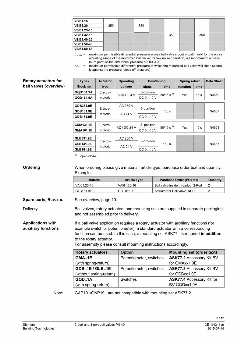
Type /Stock no.
Actuatortype
Operatingvoltage
Positioning Spring return Data Sheetsignal time function time
GQD131.9A Electro-motoric
AC/DC 24 V3-position
30/15 s 1) Yes 15 s N4659GQD161.9A DC 0…10 V
GDB331.9EElectro-
motoric
AC 230 V3-position
150 s N4657GDB131.9EAC 24 V
GDB161.9E DC 0…10 V
GMA131.9E Electro-
motoricAC / DC 24 V
3- position90/15 s 1) Yes 15 s N4658
GMA161.9E DC 0…10 V
GLB331.9EElectro-motoric
AC 230 V3-position
150 s N4657GLB131.9EAC 24 V
GLB161.9E DC 0…10 V1) open/close
When ordering please give material, article type, purchase order text and quantity.Example:
Material Article Type Purchase Order (PO) text QuantityVAI61.25-16 VAI61.25-16 Ball valve inside threaded, 2-Port 2
GLB161.9E GLB161.9E Actuator for Ball valve, NSR 2
See overview, page 10.
Ball valves, rotary actuators and mounting sets are supplied in separate packagingand not assembled prior to delivery.
If a ball valve application requires a rotary actuator with auxiliary functions (forexample switch or potentiometer), a standard actuator with a correspondingfunction can be used. In this case, a mounting set ASK77.. is required in additionto the rotary actuator.For assembly please consult mounting instructions accordingly.
Rotary actuators Option Mounting set (order text)GMA..1E(with spring-return)
Potentiometer, switches ASK77.2 Accessory Kit BVfor GMAxx1.9E
GDB..1E / GLB..1E(without spring-return)
Potentiometer, switches ASK77.3 Accessory Kit BVfor GDBxx1.9E
GQD..1A(with spring-return)
Switches ASK77.4 Accessory Kit forBV GQDxx1.9A
GAP19../GNP19.. are not compatible with mounting set ASK77.2.
Rotary actuators forball valves (overview)
Ordering
Spare parts, Rev. no.
Delivery
Applications withauxiliary functions
Note:

4 / 12
Siemens 2-port and 3-port ball valves PN 40 CE1N4211enBuilding Technologies 2015-07-14
Technical design
Parts1 Body2 Connection with internal thread3 Seat4 O-ring5 Ball with integral characterized bore6 Stem7 Antifriction washer8 O-ring
Sizing
600
500
400
300
200
100806050403020108654321
0,01
0,02
0,03
0,04
0,05
0,06
0,08
0,1
0,2
0,3
0,4
0,5
0,6
0,8
1 2 3 4 5 6
0,060,080,1
0,2
0,30,40,50,60,81
2
34568
10
20
3040506080
100 2822,416,81411,2
8,4
5,8
2,82,21,71,41,10,85
0,6
0,30,20,1750,150,110,08
0,06
0,030,020,017
Dpv100 [bar]
V 100
[m³/h
]
V 100
[l/s]
Dpv100 [kPa] 4211
D04
8 1080
010
00
Dp m
ax
kvs
4025
16106,3
2,5
1,6
1
4
63
Low
nois
eop
erat
ion
----- Δpmax for VAI61.. and VBI61.. see table equipment combinations for details
Dpmax = maximum permissible differential pressure across the ball valve, valid for the entire actu-ating range of the motorized ball valve; for low noise operation, we recommend a maxi-mum permissible differential pressure of 200 kPa
Dpv100 = differential pressure across the fully open ball valve and the ball valve’s control path at avolumetric flow V100
V& 100 = volumetric flow through the fully open ball valve100 kPa = 1 bar » 10 mWC1 m3/h = 0.278 l/s water at 20 °C
Flow diagram
1
2
3 4
6
7
54211J08

5 / 12
Siemens 2-port and 3-port ball valves PN 40 CE1N4211enBuilding Technologies 2015-07-14
2-port 3-port
Flow
k v/k
vs
0,8
0,6
0,4
0,2
0
1
0 20 40 60 80 90°
421
1D03
Flow
k v/k
vs
0,8
0,6
0,4
0,2
0
1
0 20 40 60 80 90°
4211
D02
Angle of rotation Angle of rotationFlow characteristic0…100 %: ® A ‒ AB equal-percentage,
ngl = 3.9 as per VDI / VDE 2173Through-port 0...100 %: ® equal-percentage,
ngl = 3.9 as perVDI / VDE 2173
Bypass 0...100 %: ® B – AB linear, kvs
> 70 % of A ‒ AB
Cavitation accelerates wear on the ball and seat, and also results in undesirablenoise. Cavitation can be avoided by not exceeding the differential pressure shownin the flow diagram on page 4, and by adhering to the static pressures shown be-low.
0 100 200 300 400 500 600 700 800 900 10001100 1200 1300
25
20
15
10
5
0
2500
2000
1500
1000
500
0
P 1[k
Pa]
P 1[b
ar]
Dpmax [kPa]
4382
D05
140 °C
180 ° C
160 °C
120 °C
100 °C
80 °C
J
Dpmax = differential pressure with ball valve almost closed atwhich cavitation can largely be avoided
p1 = static pressure at ball valve inletp3 = static pressure at ball valve outletM = pumpJ = water temperature
p3p1
4382
Z06
Dpmax
M
Pressure p1 at ball valve inlet: 500 kPa (5 bar)Water temperature: 120 °C
From the diagram above, it will be seen that with the ball valve almost closed, themaximum permissible differential pressure Dpmax is 200 kPa (2 bar).
To avoid cavitation in chilled water circuits, ensure sufficient counter-pressure atthe ball valve’s outlet, e.g. with an additional throttling ball valve downstream from
Ball valve flowcharacteristic
Cavitation
High temperaturehot water example:
Note on chilled water

6 / 12
Siemens 2-port and 3-port ball valves PN 40 CE1N4211enBuilding Technologies 2015-07-14
the ball valve. Select the maximum differential pressure across the ball valveaccording to the 80 °C curve in the flow diagram above.
Ope
ratin
gpr
essu
re[b
ar]
Operating temperature [°C]
Operating pressure and medium temperature as per IS0 7005
Current local legislation must be observed.
Notes
We recommend installation in the return pipe, as the temperatures in this pipe arelower for applications in heating systems, which extends the stem sealing gland'slife.
Ensure cavitation-free flow (refer to page 5).
Always use a strainer upstream of the ball valve to increase the ball valve'sfunctional safety.
Ball valve and rotary actuator can easily be assembled on site. Neither specialtools nor adjustments are required.The ball valve is supplied with Mounting Instructions(VAI61.., VBI61..: 74 319 0647 0.
VAI61.. 90°
4211
Z03
90° VBI61.. 90°42
11Z
04
90°
When mounting, pay attention to the ball valve's flow direction symbol.
VAI61.. VBI61..
Operating pressure andtemperatureFluids
Engineering
Mounting
Orientation
Direction of flow

7 / 12
Siemens 2-port and 3-port ball valves PN 40 CE1N4211enBuilding Technologies 2015-07-14
Ball valve Laser mark Delivery positon Turned 90 °VAI61..Control ball valve2-port –
A – AB = 100 % A – AB = 0 %
VBI61..Control ball valve3-port
A – AB = 100 %B – AB = 0 %
A – AB = 0 %B – AB = 100 %
Prevent leakage· Manufacture screw fittings per ISO 7-1: Ball valves (internal threading) = “Rp”;
piping (external threading) = “R”.· Do not use too much hemp or PTFE tape.· Do not damage threading, e.g. by screwing on fitting “until it no longer turns”.· Apply pliers/wrench on the ball valve nut that is closer to the piping.
Commission the ball valve only if the rotary actuator has been mounted cor-rectly.
Ball valve stem moves counterclockwise: Ball valve opens = increasing flowBall valve stem moves clockwise: Ball valve closes = decreasing flow
Maintenance
VAI61.. and VBI61.. ball valves are maintenance-free.
When doing service work on the ball valve / rotary actuator:· Deactivate the pump and turn off the power supply· Close the shutoff ball valves· Fully reduce the pressure in the piping system and allow pipes to completely
cool downIf necessary, disconnect the electrical wires.
Before putting the ball valve into operation again, make sure the rotary actuator iscorrectly fitted.
Before disposal, the ball valve must be dismantled and separated into its variousconstituent materials.Legislation may demand special handling of certain components, or it may be sen-sible from an ecological point of view.
Current local legislation must be observed.
Warranty
The technical data given for applications is valid only in conjunction with the Sie-mens rotary actuators listed under "Equipment combinations", page 2.All terms of the warranty will be invalidated if rotary actuators of other manufactureare used.
Pipe connection
Commissioning
Warning
Disposal
A AB
B
4212
Z13
A AB
4213Z01
A AB
4213Z02
B
A AB
4213Z05
B
A AB
4213Z06

8 / 12
Siemens 2-port and 3-port ball valves PN 40 CE1N4211enBuilding Technologies 2015-07-14
Technical data
VAI61.. VBI61..Functional data PN class PN 40 as per ISO 7268
Operating pressure To ISO 7005 within the permissible medium tempera-ture range according to diagram on page 6
Ball valve characteristic Through-port 0…100 % equal-percentage;
ngl = 3.9 as per VDI / VDE2173
equal-percentage;ngl = 3.9 as per VDI / VDE2173
Bypass 0…100 % linearLeakage rate Through-port „Waterproof“ as per EN
60534-4 L/1, better thanclass 5
„Waterproof“ as per EN60534-4 L/1, better thanclass 4
Bypass < 1 %Permissible media Cold water, chilled water, low temperature hot water,
high temperature hot water, water with anti-freeze.Recommendation: water treatment to VDI 2035
Medium temperature -10…120 °CRangeability Sv > 500Angle of rotation 90 °
Materials Ball valve body Brass UNS C35330 (DZR)Ball Brass UNS C35330 (DZR), chromium-platedStem Brass UNS C35330 (DZR)Gland EPDM O-rings
Dimensions / weight Refer to "Dimensions"belowInternally threadedconnections
Rp as per ISO 7-1
Standards Pressure EquipmentDirective
PED 97/23/EC
Pressure accessories As per article 1, section 2.1.4Fluid group 2 Without CE marking as per article 3, section 3 (sound
engineering practice)Environmental compatibility ISO 14001 (Environment)
ISO 9001 (Quality)SN 36350 (Environmentally compatible products)RL 2002/95/EC (RoHS)
9 / 12
Siemens 2-port and 3-port ball valves PN 40 CE1N4211enBuilding Technologies 2015-07-14
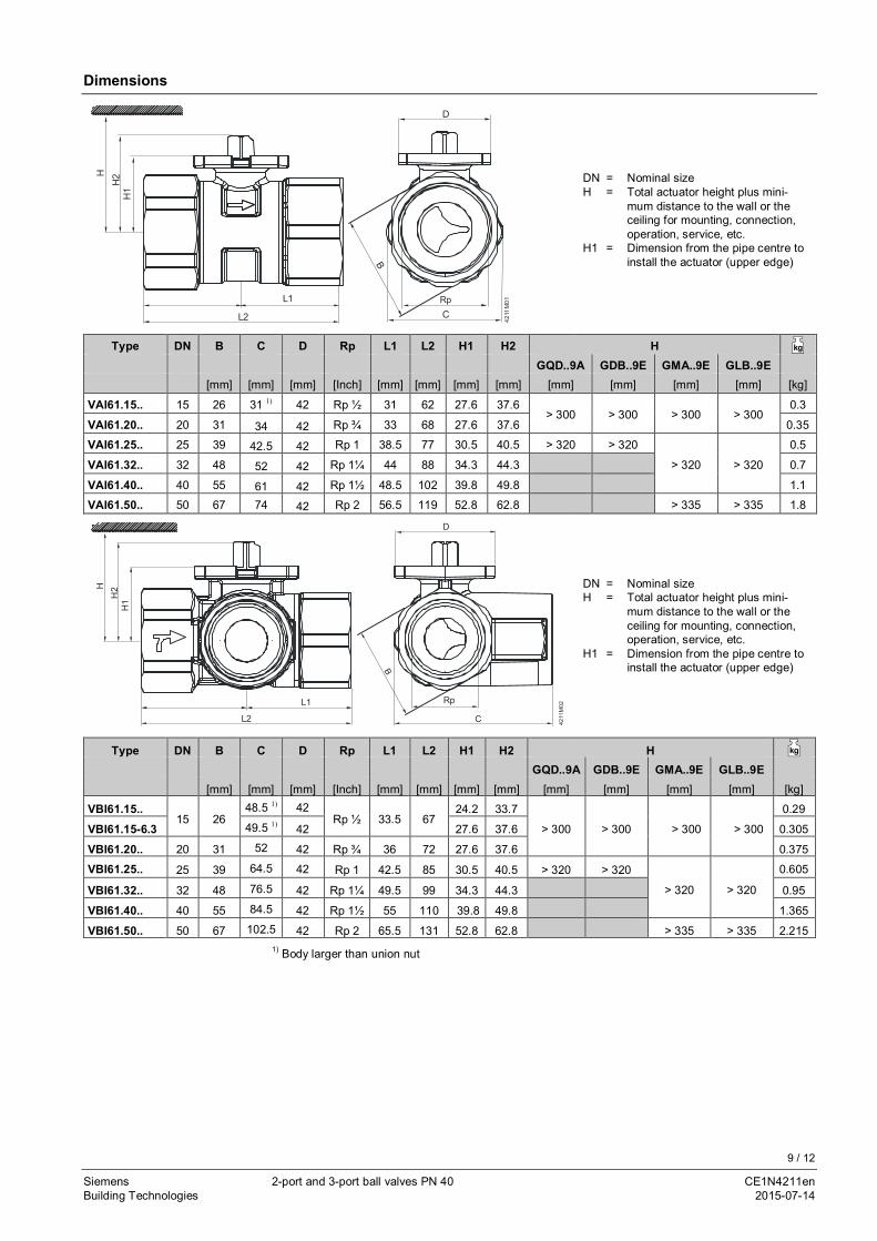
Dimensions
4211
M01
L2
RpL1C
HH
2H
1D
B
DN = Nominal sizeH = Total actuator height plus mini-
mum distance to the wall or theceiling for mounting, connection,operation, service, etc.
H1 = Dimension from the pipe centre toinstall the actuator (upper edge)
Type DN B C D Rp L1 L2 H1 H2 H kg
GQD..9A GDB..9E GMA..9E GLB..9E[mm] [mm] [mm] [Inch] [mm] [mm] [mm] [mm] [mm] [mm] [mm] [mm] [kg]
VAI61.15.. 15 26 31 1) 42 Rp ½ 31 62 27.6 37.6> 300 > 300 > 300 > 300
0.3
VAI61.20.. 20 31 34 42 Rp ¾ 33 68 27.6 37.6 0.35
VAI61.25.. 25 39 42.5 42 Rp 1 38.5 77 30.5 40.5 > 320 > 320
> 320 > 320
0.5
VAI61.32.. 32 48 52 42 Rp 1¼ 44 88 34.3 44.3 0.7
VAI61.40.. 40 55 61 42 Rp 1½ 48.5 102 39.8 49.8 1.1
VAI61.50.. 50 67 74 42 Rp 2 56.5 119 52.8 62.8 > 335 > 335 1.8
4211
M02
L2
L1
C
Rp
D
HH
2H
1
B
DN = Nominal sizeH = Total actuator height plus mini-
mum distance to the wall or theceiling for mounting, connection,operation, service, etc.
H1 = Dimension from the pipe centre toinstall the actuator (upper edge)
Type DN B C D Rp L1 L2 H1 H2 H kg
GQD..9A GDB..9E GMA..9E GLB..9E[mm] [mm] [mm] [Inch] [mm] [mm] [mm] [mm] [mm] [mm] [mm] [mm] [kg]
VBI61.15..15 26
48.5 1) 42Rp ½ 33.5 67
24.2 33.7
> 300 > 300 > 300 > 300
0.29
VBI61.15-6.3 49.5 1) 42 27.6 37.6 0.305
VBI61.20.. 20 31 52 42 Rp ¾ 36 72 27.6 37.6 0.375
VBI61.25.. 25 39 64.5 42 Rp 1 42.5 85 30.5 40.5 > 320 > 320
> 320 > 320
0.605
VBI61.32.. 32 48 76.5 42 Rp 1¼ 49.5 99 34.3 44.3 0.95
VBI61.40.. 40 55 84.5 42 Rp 1½ 55 110 39.8 49.8 1.365
VBI61.50.. 50 67 102.5 42 Rp 2 65.5 131 52.8 62.8 > 335 > 335 2.2151) Body larger than union nut
10 / 12
Siemens 2-port and 3-port ball valves PN 40 CE1N4211enBuilding Technologies 2015-07-14
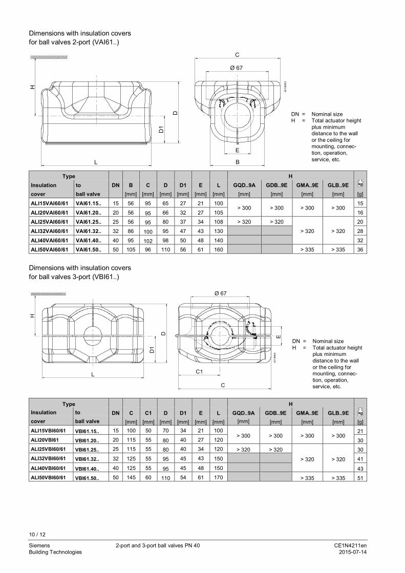
DN = Nominal sizeH = Total actuator height
plus minimumdistance to the wallor the ceiling formounting, connec-tion, operation,service, etc.
Type HInsulation to DN B C D D1 E L GQD..9A GDB..9E GMA..9E GLB..9E kg
cover ball valve [mm] [mm] [mm] [mm] [mm] [mm] [mm] [mm] [mm] [mm] [g]
ALI15VAI60/61 VAI61.15.. 15 56 95 65 27 21 100> 300 > 300 > 300 > 300
15
ALI20VAI60/61 VAI61.20.. 20 56 95 66 32 27 105 16
ALI25VAI60/61 VAI61.25.. 25 56 95 80 37 34 108 > 320 > 320
> 320 > 320
20
ALI32VAI60/61 VAI61.32.. 32 86 100 95 47 43 130 28
ALI40VAI60/61 VAI61.40.. 40 95 102 98 50 48 140 32
ALI50VAI60/61 VAI61.50.. 50 105 96 110 56 61 160 > 335 > 335 36
DN = Nominal sizeH = Total actuator height
plus minimumdistance to the wallor the ceiling formounting, connec-tion, operation,service, etc.
Type HInsulation to DN C C1 D D1 E L GQD..9A GDB..9E GMA..9E GLB..9E kg
cover ball valve [mm] [mm] [mm] [mm] [mm] [mm] [mm] [mm] [mm] [mm] [g]ALI15VBI60/61 VBI61.15.. 15 100 50 70 34 21 100
> 300 > 300 > 300 > 30021
ALI20VBI61 VBI61.20.. 20 115 55 80 40 27 120 30ALI25VBI60/61 VBI61.25.. 25 115 55 80 40 34 120 > 320 > 320
> 320 > 320
30ALI32VBI60/61 VBI61.32.. 32 125 55 95 45 43 150 41
ALI40VBI60/61 VBI61.40.. 40 125 55 95 45 48 150 43ALI50VBI60/61 VBI61.50.. 50 145 60 110 54 61 170 > 335 > 335 51
LD
1
D
B
Ø 67
C
E
4213
M03
D
D1
67Ø
L C1
C
E
H
4213
M04
Dimensions with insulation coversfor ball valves 2-port (VAI61..)
Dimensions with insulation coversfor ball valves 3-port (VBI61..)
11 / 12
Siemens 2-port and 3-port ball valves PN 40 CE1N4211enBuilding Technologies 2015-07-14
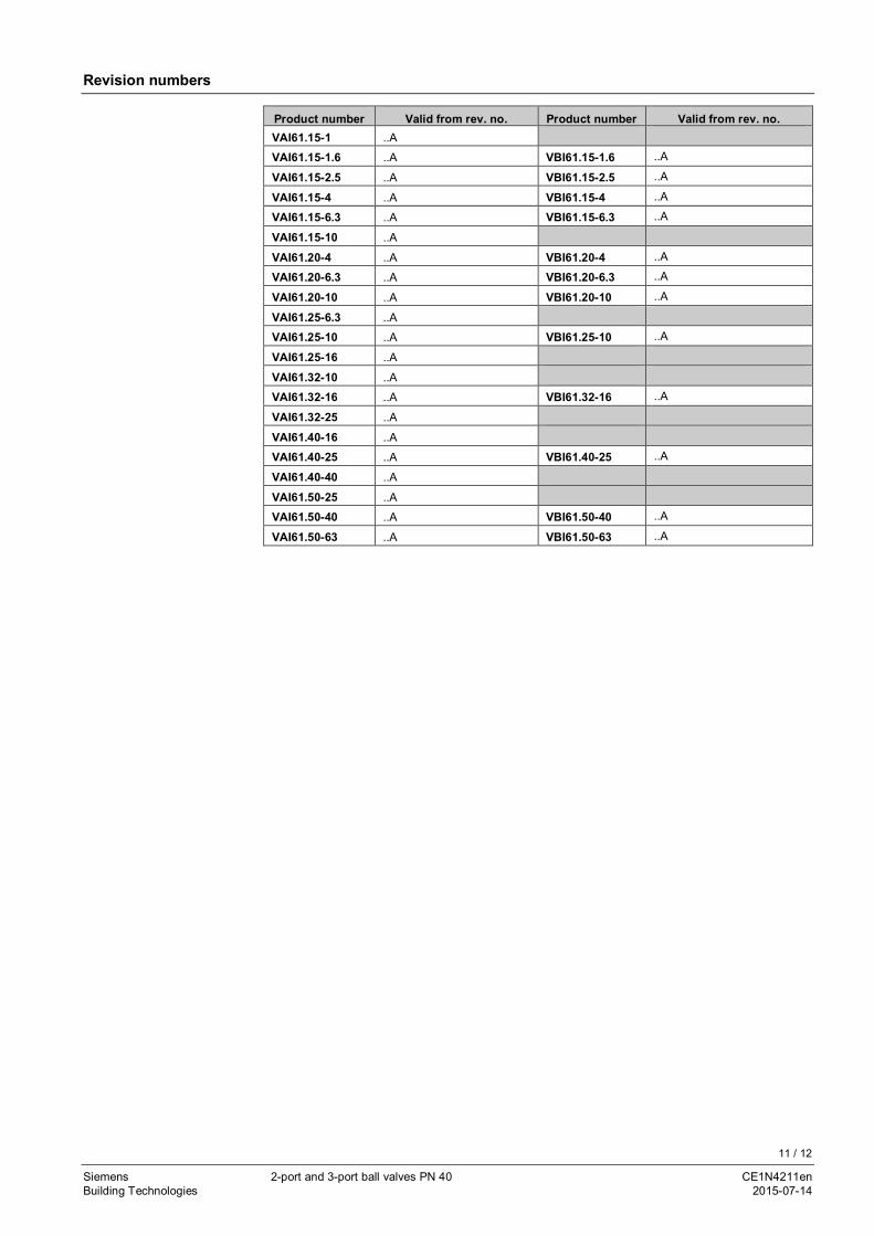
Revision numbers
Product number Valid from rev. no. Product number Valid from rev. no.VAI61.15-1 ..A
VAI61.15-1.6 ..A VBI61.15-1.6 ..A
VAI61.15-2.5 ..A VBI61.15-2.5 ..A
VAI61.15-4 ..A VBI61.15-4 ..A
VAI61.15-6.3 ..A VBI61.15-6.3 ..A
VAI61.15-10 ..A
VAI61.20-4 ..A VBI61.20-4 ..A
VAI61.20-6.3 ..A VBI61.20-6.3 ..A
VAI61.20-10 ..A VBI61.20-10 ..A
VAI61.25-6.3 ..A
VAI61.25-10 ..A VBI61.25-10 ..A
VAI61.25-16 ..A
VAI61.32-10 ..A
VAI61.32-16 ..A VBI61.32-16 ..A
VAI61.32-25 ..A
VAI61.40-16 ..A
VAI61.40-25 ..A VBI61.40-25 ..A
VAI61.40-40 ..A
VAI61.50-25 ..A
VAI61.50-40 ..A VBI61.50-40 ..A
VAI61.50-63 ..A VBI61.50-63 ..A

12 / 12
Siemens 2-port and 3-port ball valves PN 40 CE1N4211enBuilding Technologies 2015-07-14
ã 2010 ‒ 2015 Siemens Switzerland Ltd. Subject to change


![Sphere Decoding for Noncoherent Channelshcdc/Library/vortrag.pdf · fRefr [k]vr[k 1]gg ( ) r [k 1] r[k] ^v[k] Delay L. Lampe: Sphere Decoding for Noncoherent Channels. Multiple-Symbol](https://img.pdfslide.us/doc/110x75/60d2b5bf845115239005162c/sphere-decoding-for-noncoherent-hcdclibraryvortragpdf-frefr-kvrk-1gg-.jpg)