Embed Size (px)
Citation preview

TM 11-6625-847-12
TECHNICAL MANUAL
OPERATOR’S AND ORGANIZATIONAL MAINTENANCE MANUALINCLUDING REPAIR PARTS AND SPECIAL TOOLS LISTS
SIMULATOR, RADIO FREQUENCY SM-442A/GRC
This copy is a reprint which includes currentpages from Changes 1 and 2. The title waschanged by C1 to read as shown above.
H E A D Q U A R T E R S , D E P A R T M E N T O F T H E A R M YAUGUST 1967
WARNING
Voltages up to 200 volts dc and 115 volts ac exist in this equipment. Serious injury mayresult if operating personnel fail to observe safety precautions.
DON’T TAKE CHANCES!
Operation and maintenance personnel should be familiar with the requirements of TB SIG291 before attempting installation or operation of Simulator, Radio Frequency SM-442A/GRC.
CAUTION
Be sure to make resistance measurements in the transistorized circuits of this equipmentonly as specified; the voltage present in the ohmmeter may destroy transistors.
TM 11-6625-847-12
TECHNICAL MANUAL HEADQUARTERSDEPARTMENT OF THE ARMY
No. 11-6625-847-12 WASHINGTON, D.C., 30 August 1967
Operator's and Organizational Maintenance ManualIncluding Repair Parts and Special Tools List
SIMULATOR, RADIO FREQUENCY SM-442A/GRC
Paragraph PageCHAPTER 1. INTRODUCTIONSection I. General .................................................................................................................... 1-1— 1-3 1-1
II. Description and data................................................................................................. 1-4— 1-7 1-1CHAPTER 2. INSTALLATION........................................................................................................ 2-1— 2-5 2-1CHAPTER 3. OPERATING INSTRUCTIONSSection I. Operating controls, indicators, and connectors.......................................................... 3-1— 3-7 3-1
II. Operational instructions ............................................................................................ 3-8— 3-19 3-21CHAPTER 4. OPERATOR AND ORGANIZATIONAL MAINTENANCESection I. Operator's maintenance............................................................................................ 4-1— 4-5 4-1
II. Organizational maintenance ..................................................................................... 4-6— 4-12 4-2III. Organizational troubleshooting ................................................................................. 4-13— 4-26 4-3
CHAPTER 5. SHIPMENT, LIMITED STORAGE, AND DEMOLITION TO PREVENT ENEMY USESection I. Shipment and limited storage ................................................................................... 5-1— 5-5 5-1
II. Demolition of materiel to prevent enemy use............................................................ 5-6— 5-7 5-1APPENDIX A. REFERENCES................................................................................................................................A-1
B. BASIC ISSUE ITEMS LIST (Deleted)C. MAINTENANCE ALLOCATION .......................................................................................................C-1D. ORGANIZATIONAL MAINTENANCE REPAIR PARTS....................................................................D-1
Index .......................................................................................................................................................................... I-1
Change 2 i
TM 11-6625-847-12
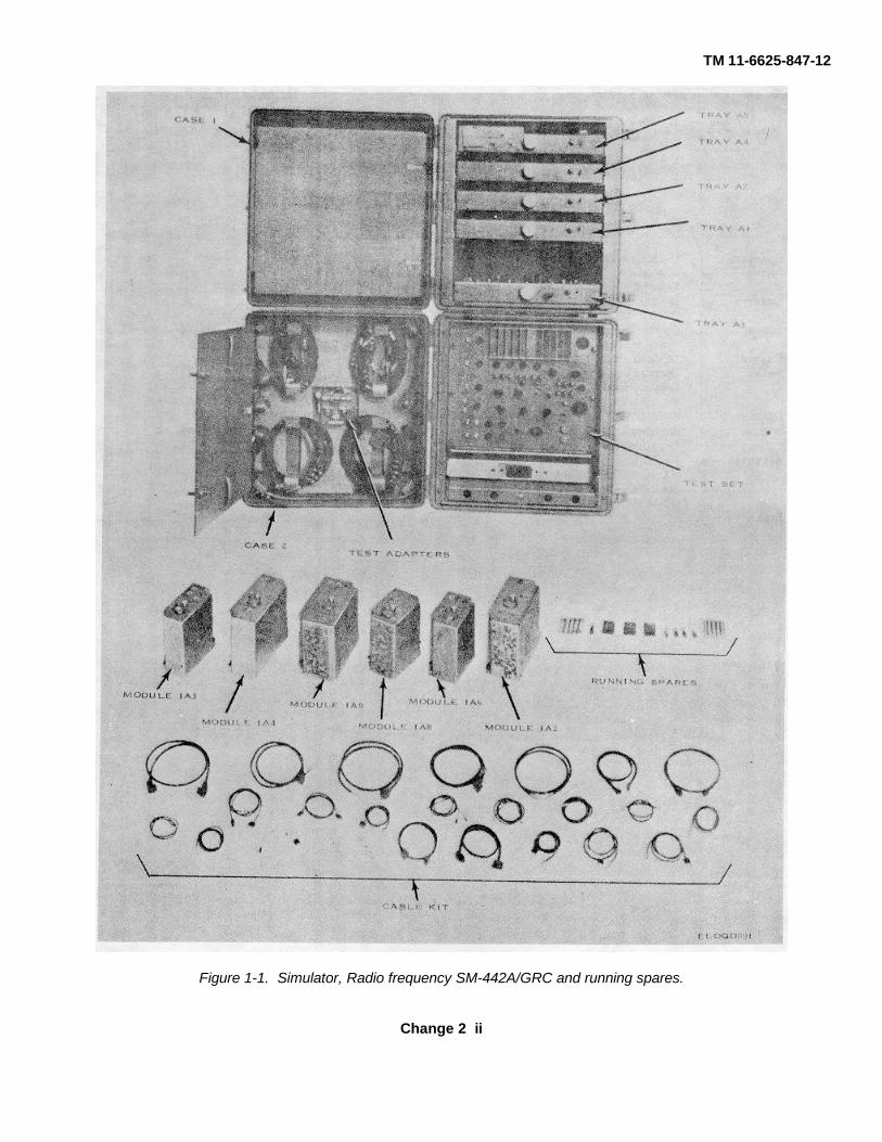
Figure 1-1. Simulator, Radio frequency SM-442A/GRC and running spares.
Change 2 ii
TM 11-6625-847-12
CHAPTER 1INTRODUCTION
Section I. GENERAL
1-1. Scope of ManualThis manual describes Simulator, Radio Frequency SM-442A/GRC (fig. 1-1) and covers its installation,operation, and maintenance. It includes operation,cleaning, and inspection of the equipment, andreplacement of parts available to the operator andorganizational maintenance personnel.
1-2. Indexes of Publicationsa. DA Pam 310-4. Refer to the latest issue of DA
Pam 3104 to determine whether there are new editions,changes, or additional publications pertaining to theequipment.
b. DA Pam 310-7. Refer to DA Pam 310-7 todetermine whether there are modification work orders(MWO's) pertaining to the equipment.
1-3. Forms and Recordsa. Reports of Maintenance and Unsatisfactory
Equipment. Maintenance forms, records, and reportswhich are to be used by maintenance personnel at allmaintenance levels are listed in and prescribed by TM38-750.
b. Report of Packaging and Handling Deficiencies.Fill out and forward DD Form 6 (Report of Packagingand Handling Deficiencies) as prescribed in AR 700-58and DSAR 4145.8.
c. Discrepancy in Shipment Report (DISREP) (SF361). Fill out and forward Discrepancy in ShipmentReport (DISREP) (SF 361) as prescribed in AR 5548and DSAR 4500.15.
d. Administrative Storage. The procedures foradministrative storage are outlined in TM 740-90-1;however, the exact procedure in repacking for limitedstorage depends on the materials available and theconditions under which the equipment is to be stored.
1-3.1. Reporting of ErrorsThe reporting of errors, omissions, andrecommendations for improving this publication by theindividual user is encouraged. Reports should besubmitted on DA Form 2028, (Recommended Changesto Publications, and Blank Forms), and forwarded directto Commander, US Army Electronics Command, ATTN:DRSEL-MAQ, Fort Monmouth, NJ 07703.
Section II. DESCRIPTION AND DATA
1-4. Purpose and UseThe SM-442A/GRC (fig. 1-1) serves as a simulator thatprovides stimulus controls, mechanical coupling,resistive power loads, and direct current (dc) andalternating current (ac) power which are necessary toconduct a performance test of Radio Set AN/GRC-106with the use of standard external test equipment. Whenthe SM442A/GRC is used to test the modules ofReceiver-Transmitter, Radio RT-662/GRC or Amplifier,Radio Frequency AM-3349/GRC-106, it supplies thestimulus inputs and controls which are normally suppliedby the remaining unit. When the SM442A/GRC is usedto test the modules of the AN/GRC-106, it supplies thestimulus, the mechanical coupling, the power, theswitching information, and loads which are normallysupplied by the parent unit.
1-5. Technical CharacteristicsPrimary power requirements 27 ± 2 volts dc at 10
amperes min. (from external power supply).Power consumption 400 watts, max.Transportability Air, rail, or vehicular (intact in
shipping crate).Cabling requirements Input power cable (W15, W16,
or W17) plus cables specifiedfor a particular test. Cablessecured from supplied cable kit.
Dc output voltages -30 volts at 3 ma.+ 20 .volts at 500 ma.+27 volts at 10 amp., max.+ 125 volts at 50 ma.+200 volts at 158 ma.
Ac output voltages 6.3 volts at 0.75 amp.Input frequencies 50 cps to 1 kc.Output frequencies 1.750000 mc + 100 cps,
1.751500 mc + 100 cps,1.752500 mc + 100 cps.
Change 2 1-1

TM 11-6625-847-12
Pulse outputs 1 ± .05 µ sec, 85 ± 15µ sec, 150 ± 10 and 1 kc synthesizer60 µ sec (neg). module 1A4, RT-662/GRC.
Frequency selection Selectable between 2 to 29.999 mc Frequency divider module 1A6,by means of five-wire coding. RT-662/GRC.
Testing capabilities Test set (alone) is used to test: Translator module 1A8,RT-662/GRC. AM-3349/GRC- RT-6621GRC.106. Mc synthesizer module 1A9
Test set with common module RT-662GRC.tray A1 is used to test: Test set with converter and con-
RF amplifier module 1A12, trol tray A4 is used to test:RT-662/GRC. RT-6621GRC.
Dc-to-dc converter and Front panel assembly 2A5,regulator module 1A11, AM-3349/GRC-106.RT-662GRC. Dc to ac inverter assembly
Noise blanker subassembly 2A6A1, AM-3349/GRC-106.1A1A6, RT462/GRC. Inputs to antenna coupler as-
Test set with common module sembly 2A3, AM-3349/tray A2 is used to test: GRC-106.
Receiver IF module 1A7, Test set with driver, discrimina-RT 662/GRC. tor, and antenna coupler tray
Receiver audio module 1A10, A5 is used to test:RT-662/GRC. Antenna coupler assembly
Transmitter IF and audio 2A3, AM3349/GRC-106.module 1A5, RT462/GRC. Discriminator assembly 2A4,
Test set with synthesizer test tray AM-3349/GRC-106.A3 is used to test: Relay assembly 2A7,
100 kc synthesizer module AM3349/GRC-106.1A2, RT-62/GRC. Driver assembly 2A8,
Frequency standard module AM-3349/GRC-106.1A3, RT462/GRC.
1-6. Items Comprising an Operable Simulator, Radio Frequency SM-442A/GRCFSN Qty Nomenclature, part No., and mfr code Fig. No.
NOTEThe part number is followed by the applicable 5-digit Federal supply code for manufacturers(FSCM) identified in SB 708-42 and used to identify manufacturer, distributor, Governmentagency, etc.
6625-937-4029 Simulator, Radio Frequency SM-442A/GRC consisting of:5935-201-2411 2 Adapter, Connector: MS35173-274B; 96906.................................................................................... 1-15935-837-9648 1 Adapter, Connector: UG107B/U; 80058........................................................................................... 1-15935-832-9291 1 Adapter, Radio Frequency Cable: A51870-001; 58189 .................................................................... 1-15935-901-8708 1 Adapter, Radio Frequency Cable: A518364)01; 58189 .................................................................... 1-15995-832-4860 1 Cable Assembly R.F.: (4 ft 6 in.); A518684001; 58189 .................................................................... 1-15995-905-7194 4 Cable Assembly R.F. CG-409G/U: (6 ft 0 in.); A51795; 58189....................................................... 1-15995-935-0343 3 Cable Assembly R.F.: (6 ft 0 in.); A51796; 58189 ............................................................................ 1-15995-935-4344 2 Cable Assembly R.F.: (6 ft 0 in.); A51797; 58189 ............................................................................ I-15995-935-4345 1 Cable Assembly R.F.: (6 ft 0 in.). A517984001; 58189 ................................................................... 1-15995-935-4349 2 Cable Assembly R.F.: (6 in.); A51865; 58189 .................................................................................. 1-15995-935-4350 1 Cable Assembly R.F.: (4 ft 6 in.); A51869-001; 58189..................................................................... 1-15995-935-0352 1 Cable Assembly R.F.: (3 ft 0 in.); A51841-001; 58189..................................................................... 1-15995-947-7419 3 Cable Assembly, Power, Electrical: (6 ft 0 in.); A51843; 58189 ....................................................... 1-15995-832-6853 1 Cable Assembly, Special Purpose Electrical: (6 in.); A51866-001; 58189 ....................................... 1-15995-832-6861 1 Cable Assembly, Special Purpose, Electrical: (4 ft 0 in.). A41867-001; 58189 ............................... 1-15995-935-0351 1 Cable Assembly, Special Purpose, Electrical: (3 ft 0 in.); A51842-001; 58189 ................................ 1-15995-947-7417 1 Cable Assembly, Special Purpose, Electrical: (6 ft 0 in.) A51799-001; 58189 ................................. 1-15995-947-7418 1 Cable Assembly, Special Purpose, Electrical: (6 ft 0 in.); A51800-001; 58189 ................................ 1-15995-947-7420 1 Cable Assembly, Special Purpose, Electrical: (4 ft 0 in.); A51844-001; 58189 ................................ 1-15995-947-7421 1 Cable Assembly, Special Purpose, Electrical: (4 ft 0 in.); A518640M01; 58189 .............................. 1-15995-061-1330 1 Crystal Unit, Quartz: 694087-83; 58189........................................................................................... 1-15995-944-9525 1 Crystal Unit, Quartz: 694087-85; 58189........................................................................................... 1-1
Change 2 1-2

TM 11-6625-847-12
FSN Qty Nomenclature, part No., and mfr code Fig. No.5995-968-5494 1 Crystal Unit, Quartz: 69408787; 58189 ............................................................................................ 1-14931-546-4347 1 Dummy Conductor Plug: 534-2; 95712 ............................................................................................ 1-15820-226-5369 1 Frequency Divider Assembly: SM-D-500014; 80063........................................................................ 1-15820-226-5368 1 Frequency Standard: SM-D500011; 80063...................................................................................... 1-15820-226-5436 1 Synthesizer, Electrical Frequency: SM-D-500012; 80063 ................................................................ 1-15820-226-5437 1 Synthesizer, Electrical Frequency: SM-D-503249; 80063 ................................................................ 1-15820-226-5438 1 Synthesizer, Electrical Frequency: SM-D-500010; 80063 ................................................................ 1-15820-226-5365 1 Translator, Signal Data: SM-D-500016; 80063................................................................................. 1-11-6.1. Operational Items Stored in Cases
FSN Qty Nomenclature5935-201-2411 2 Adapter, Connector.5935-837-9648 1 Adapter, Connector.5935-932-9291 1 Adapter, Radio frequency Cable.5935-901-8708 1 Adapter, Radio frequency Cable.5995-947-7419 1 Cable Assembly, Power, Electrical (6 ft 0 in.).5995-832-6860 1 Cable Assembly R.F. (4 ft 6 in.).5995-905-7194 4 Cable Assembly R.F. CG409G/U (6 ft 0 in.).5995-935-0349 2 Cable Assembly R.F. (6 in.).5995-935-4343 3 Cable Assembly R.F. (6 ft 0 in.).5995-935-0344 2 Cable Assembly R.F. (6 ft 0 in.).5995-935-0345 1 Cable Assembly R.F. (6 ft 0 in.).5995-935-0350 1 Cable Assembly R.F. (4 ft 6 in.).5995-935-0352 1 Cable Assembly R.F. (6 ft 0 in.).5995-832-4853 1 Cable Assembly, Special Purpose Electrical (6 in.).5995-832-6861 1 Cable Assembly, Special Purpose Electrical (4 ft 0 in.).5995-935-0351 1 Cable Assembly, Special Purpose Electrical (3 ft 0 in.).5995-947-7417 1 Cable Assembly, Special Purpose Electrical (6 ft 0 in.).5995-947-7418 1 Cable Assembly, Special Purpose Electrical (6 ft 0 in.).5995-947-7420 1 Cable Assembly, Special Purpose Electrical (4 ft 0 in.).5995-947-7421 1 Cable Assembly, Special Purpose Electrical (4 ft 0 in.).5995-061-1330 1 Crystal Unit, Quartz.5995-944-9525 1 Crystal Unit, Quartz.5995-968-5494 1 Crystal Unit, Quartz.4931-546-4347 1 Dummy Connector Plug.
1-7. Description of EquipmentThe SM442A/GRC is contained in two hand-portable,moisture-sealed cases. The first case (case 2) containsthe test set which is secured to case 2 by six front panelmounting screws. The second case (case 1) isequipped with metal slides for the storage of the fivetest fixture trays, common module tray A1 (tray A1),common module tray A2 (tray A2), synthesizer test tray
A3 (tray A3), converter and control tray A4 (tray A4),and driver, discriminator, and antenna coupler tray A5(tray A5). The trays are secured in the slides by the useof the connector holddown screws on the rear panel ofthe trays. A cable storage area is provided on the insideof the front cover of the cases by a hinged panel.
Change 2 1-3
TM 11-6625-847-12
CHAPTER 2INSTALLATION
2-1. Unpacking(fig. 2-1)
a. Unpack case 1 as follows; use at least two men:(1) Remove the klimp fasteners from the top
cover of the plywood crate.(2) Remove the corrugated carton marked
test set.(3) With a knife or any sharp instrument, slit
the tape which holds the top of the corrugated packingcarton; open the carton.
(4) Remove the polyethylene shroud fromcase 1.
(5) Remove the four polystyrene corner padsfrom the top of case 1.
(6) With one man at the front and one at therear, lift case 1 from its crate.
(7) Store the packaging material for futurereshipment.
b. Unpack case 2 as follows:(1) Remove the second corrugated carton from
its plywood crate.(2) With a knife or any sharp instrument, slit the
tape which holds the top of the corrugated packing carton;open the carton.
(3) Remove the polyethylene shroud from case2.
(4) Remove the four polystyrene corner padsfrom top of case 2.
(5) With one man at the front and one at therear, lift case 2 from its crate.
(6) Store the packaging material for futurereshipment.
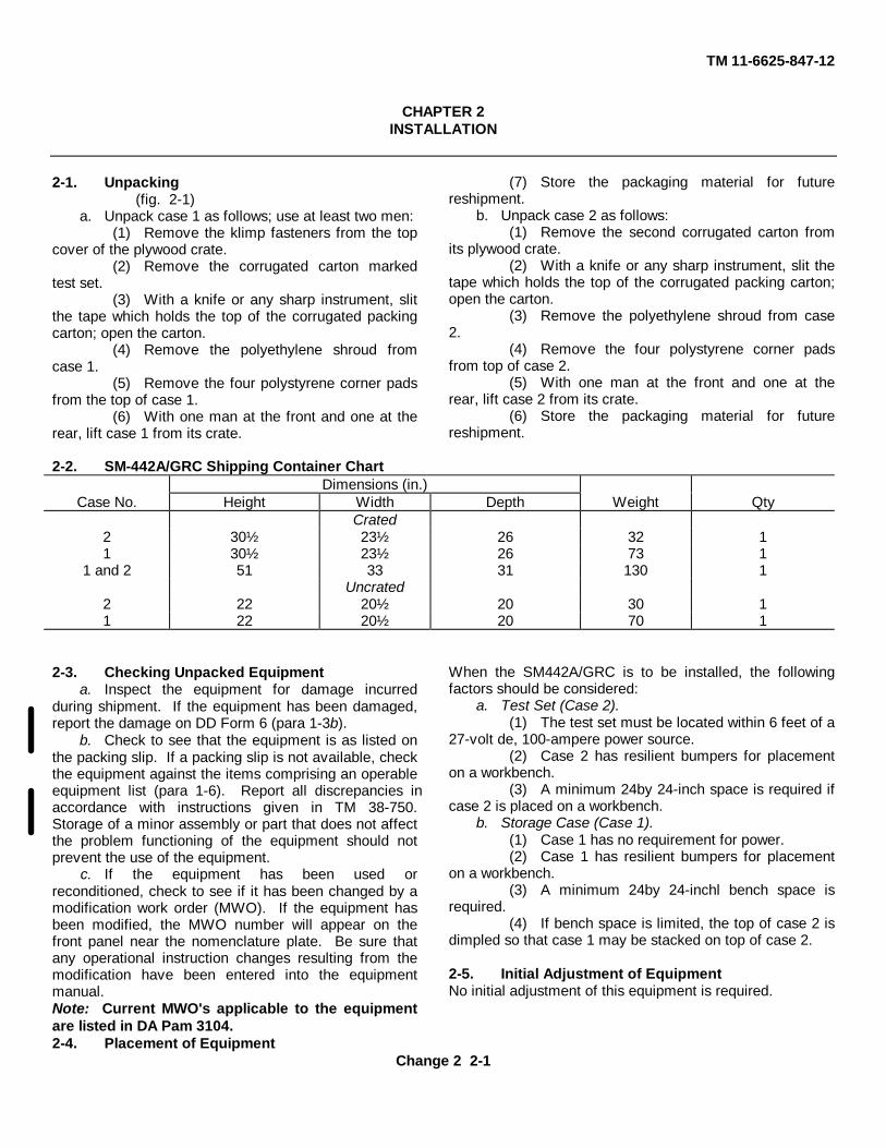
2-2. SM-442A/GRC Shipping Container ChartDimensions (in.)
Case No. Height Width Depth Weight QtyCrated
2 30½ 23½ 26 32 11 30½ 23½ 26 73 1
1 and 2 51 33 31 130 1Uncrated
2 22 20½ 20 30 11 22 20½ 20 70 1
2-3. Checking Unpacked Equipmenta. Inspect the equipment for damage incurred
during shipment. If the equipment has been damaged,report the damage on DD Form 6 (para 1-3b).
b. Check to see that the equipment is as listed onthe packing slip. If a packing slip is not available, checkthe equipment against the items comprising an operableequipment list (para 1-6). Report all discrepancies inaccordance with instructions given in TM 38-750.Storage of a minor assembly or part that does not affectthe problem functioning of the equipment should notprevent the use of the equipment.
c. If the equipment has been used orreconditioned, check to see if it has been changed by amodification work order (MWO). If the equipment hasbeen modified, the MWO number will appear on thefront panel near the nomenclature plate. Be sure thatany operational instruction changes resulting from themodification have been entered into the equipmentmanual.Note: Current MWO's applicable to the equipmentare listed in DA Pam 3104.2-4. Placement of Equipment
When the SM442A/GRC is to be installed, the followingfactors should be considered:
a. Test Set (Case 2).(1) The test set must be located within 6 feet of a
27-volt de, 100-ampere power source.(2) Case 2 has resilient bumpers for placement
on a workbench.(3) A minimum 24by 24-inch space is required if
case 2 is placed on a workbench.b. Storage Case (Case 1).
(1) Case 1 has no requirement for power.(2) Case 1 has resilient bumpers for placement
on a workbench.(3) A minimum 24by 24-inchl bench space is
required.(4) If bench space is limited, the top of case 2 is
dimpled so that case 1 may be stacked on top of case 2.
2-5. Initial Adjustment of EquipmentNo initial adjustment of this equipment is required.
Change 2 2-1

TM 11-6625-847-12
Figure 2-1. SM-442A/GRC packing diagram.
2-3

TM 11-6625-847-12
CHAPTER 3OPERATING INSTRUCTIONS
Section I. OPERATING CONTROLS, INDICATORS, AND CONNECTORS
3-1. Operator's Controls, Indicators, andConnectors
The controls, indicators, connectors, and fuses on thefront panel of the test set are listed maintenance of theequipment are covered in paragraph 3-2. Paragraphs3-3 through 3-7 list controls, indicators, connectors, and
fuses for the test trays used in conjunction with the testset.
Note. This section covers only those itemsused when the equipment is being operated; itemsused during tions given for the appropriate categoryof maintenance
3-2. Test Set Controls, Indicators, and Connectors
Control, indicator, or connector FunctionSERV SEL switch ----------------------------------------------- Controls +27-volt de primary power to test set in first four
positions (OFF, OVEN ON, STBY, and SSB/NSK), andmode of operation of subassemblies, modules, or units ofAN/GRC-106, when connected to the test set.
Pos ActionOFF +27-volt de primary power removed from all
circuitsOVEN ON a. +27-volt dc primary power to regulator
section of dc-to-dc converter and regassembly A3.
b. +27-volt dc primary power for OVEN ON.c. +27-volt de primary power to REC/XMIT
switch S4 contact terminal 9, for RCVR +27VDC/XMTR GND.
STBY a. All OVEN ON functions repeated.b. +27-volt dc primary power for STBY and all
modesc. PA/RT switch contact terminal 5, section C,
grounded, in STBY and OPER.SSB/NSK a. All STBY and OVEN ON functions repeated.
b. PA/RT switch contact terminal 2 and contactterminal 5, section C, grounded, for +27 VDC OPR.
c. +27-volt dc primary power for DC OPR.
3-1

TM 11-6625-847-12
Control, indicator, or connector FunctionPos Action
FSK a. All STBY and OVEN ON functions repeated.b. PA/RT switch contact terminal 2 and contact
terminal 5, section C, grounded.c. Keyline connected to VOX OFF KEY.
AM a. All STBY and OVEN ON functions repeated.b. PA/RT switch contact terminals 2 and 5
groundedCW a. All STBY and OVEN ON functions repeated.
b. PA/RT switch contact terminals 2 and 6grounded.
POWER switch -------------------------------------------------- Controls +27-volt dc primary power to test set.2400 VDC LOAD switch --------------------------------------- Controls size of resistive load.
Pos Action1-------------------------------- 24,000 ohms2-------------------------------- 16,000 ohms3-------------------------------- 12,000 ohms4-------------------------------- 9,000 ohms5-------------------------------- 800 ohms6-------------------------------- 766 ohms7-------------------------------- 657 ohms
REC-XMIT switch ----------------------------------------------- Pos ActionREC ----------- a. +20 volts dc to RCVR +20V DC/XMTR
GRD.------------ b. +27-volts dc primary power to PA/RT switch
contact terminal 2, section. A.XMIT ---------- a. +20 volts dc to RCVR GRD/ XMTR +20 V
DC.------------ b. PA/TR switch contact terminal 2, section A
grounded.XMIT STATUS switch ----------------------------------------- When set to TUNE, provides TUNE INFO GRD, and PA/RT
switch contact to terminal 7, section A.KEY switch ------------------------------------------------------- When set to ON, provides the ground to pin F of AUDIO
INPUT IN/OUT connector.500 VDC LOADI switch --------------------------------------- Controls the resistive load.
Pos ActionLOW ---------------------------4,900 ohmsHI -------------------------------4,000 ohms
IF OSCILLATOR select switch------------------------------- Controls selection of three IF oscillators.Pos Action
1 ------------ Selects 1.7500 me IF oscillator.1 + 2---------- Selects 1.7500 me and 1/7515 me IF
oscillators 1 + 3 Selects 1.7500 me and1.7525 me IF oscillators.
2 + 3---------- Selects 1.7515 me and 1.7525 me IFoscillators.
4 ------------ Selects 1.7500 me, 1/7515 me and 1.7525me IF oscillators
MC FREQ select switches; 10MC, 1MC and .1MC ----- Controls mc shaft coupler on tray Al and tray A3 and fixe-wirecoding information to AM3349/GRC-106.
3-2
TM 11-6625-847-12
Control, indicator, or connector FunctionPos Action
PA/RT switch ---------------------------------------------------- PA ------------- Provides five-wire coding information, frequencychange ground, frequency information ground,and ALC VOLTAGES test points; TUNE INand INFO IN are connected to PA CONTROLconnector J12.
RT ------------- Provides inputs on PA CONTROL connectorpins connected to J1, ALC VOLTAGE INFO,and TUNE test points OUT and ALC controlvoltages; ALC VOLTAGE INFO and TUNEare connected to PA CONTROL connectorJ12.
POWER indicator ----------------------------------------------- Indicates POWER switch S2 is set to ON, and +27volt dcprimary power is supplied from external source.
ALC VOLTAGE INFO control -------------------------------- Adjusts level of dc voltage at test point ALC VOLTAGE INFOOUT and to PA/RT switch contact terminal 4, section D.
ALC VOLTAGE TUNE control ------------------------------- Adjust level of dc voltage at test point ALC VOLTAGE TUNEOUT and to PA/RT switch contact terminal 1, section C.
DC VOLTAGE 200 control ----------------------------------- Adjusts level of +200-volt de output voltage.DC VOLTAGE 20 control-------------------------------------- Adjusts level of +20-volt dc output voltage.IF OSCILLATORS 1 1.75 MC output level control ----- Adjusts 1.75-me RF output level of IF oscillator module.IF OSCILLATORS 2 1.7515 MC output level control -- Adjusts 1.7515-mc RF output level of IF oscillator module.IF OSCILLATORS 3 1.7525 MC output level control -- Adjusts 1.7527-mc RF output level of IF oscillator module.PULSE GENERATOR (upper) AMPLITUDE Controls amplitude of this 85-µsec pulse, and 150-µsec
control. pulse at OUTPUT connectors 1 and 2, respectively.PULSE GENERATOR (upper) WIDTH control ------- Controls width of output pulse to 85-µsec at connectorPULSE GENERATOR (lower) AMPLITUDE-------------- 1, or to 150-µsec at connector 2.
control. Controls amplitude of 1-µsec pulse at connector 3.PULSE GENERATOR (lower) WIDTH control --------- Controls width of 1-µsec pulse at connector 3.10 AMP fuse ----------------------------------------------------- Current protection for test set.SPACE fuse ------------------------------------------------------ Receptacle for storage of spare fuse.IF OSCILLATOR 4 TWO TONE output level control -- Adjust RF output level of mixer assembly.POWER connector -------------------------------------------- Multipin connector for power cable W15.DC VOLTAGE (ground) test connector ------------------- Ground test point for dc voltage measurements.DC VOLTAGE +200 test connector ----------------------- Test point for measuring +200 volts dc.AUDIO IN/OUT connector ------------------------------------ Multipin connector for audio cable W12.AUDIO IN 600 (ohm) connector ----------------------------- For connecting external audio test equipment to AUDIO
IN/OUT connector.AUDIO IN (ground) connector ------------------------------- Ground connector for external audio test equipment at AUDIO
IN/OUT connector.AUDIO IN 50 (ohm) connector ------------------------------ For connecting external audio test equipment to AUDIO
IN/OUT connector.AUDIO OUT 2 WATT connector ---------------------------- Connector for measuring audio input signals at AUDIO
IN/OUT connector.AUDIO OUT (ground) connector ---------------------------- Ground connection for measuring audio input signals at
AUDIO IN/OUT connector.AUDIO OUT 10 MW connector ---------------------------- Connector for measuring audio input signals at AUDIO/OUT
connector.DC VOLTAGE +20 test connector ------------------------- Test point for measuring +20 volts de.PA CON'TROL connector ------------------------------------ Multipin connector for control cable W11.
3-3

TM 11-6625-847-12
Control, indicator, or connector FunctionALC VOLTAGE INFO IN test connector ------------------ Test point for measuring ALC VOLTAGE INFO input at PA
CONTROL connector.ALC VOLTAGE INFO (ground) test connector ---------- Ground test point for ALC VOLTAGE INFO.ALC VOLTAGE INFO OUT test connector --------------- Test point for measuring ALC VOLTAGES INFO output at PA
CONTROL connector.ALC VOLTAGE TUNE IN test connector ---------------- Test point for measuring ALC VOLTAGES TUNE input at PA
CONTROL connector.ALC VOLTAGE TUNE (ground) test connector --------- Ground test point for ALC VOLTAGES TUNE.ALC VOLTAGE TUNE ----------------------------------------- OUT test connector Test point for measuring ALC
VOLTAGES TUNE output at PA CONTROL connectorJ12.
IF OSCILLATOR 3 1.7525 MC OUT connector --------- Connector for monitoring output of 1.7525 me IF oscillator.IF OSCILLATOR 2 1.7515 MC OUT connector --------- Connector for monitoring output of 1.7515 me IF oscillator.IF OSCILLATOR 1 1.75 MC OUT connector ------------ Connector for monitoring output of 1.75 me IF oscillator.PULSE GENERATOR INPUT connector ---------------- For connecting external audio signal generator to trigger pulse
generator.PULSE GENERATOR OUTPUTS 2 connector --------- Output connector for 150-µsec pulse.PULSE GENERATOR OUTPUTS 1 connector --------- Output connector for 85--µsec pulse.PULSE GENERATOR OUTPUTS 3 connector --------- Output connector for 1-µsec pulse.
Figure 3-1 (1). Test set, controls, indicators, and connectors.
3-4

TM 11-6625-847-12
Figure 3-1 (2).— Continued.
3-3. Common Module Tray A1, Controls, Indicators, and Connectors(fig. 3-2 (1) and (2))
Control, indicator, or connector FunctionPOWER switch ------------------------------------------------- Controls +27-volt dc primary power from test set SERV SEL
switch (positions: SS,B/NSK, FSK, AM and CW) tocircuits and connectors on common module tray Al.
DC/DC CONVERTER CONV/REC TEST REG Permits input current measurement tests of regu-switch lator section of dc-to-dc converter and regulator module,
RT-662/GRC.DC/DC CONVERTER CONV/REC TEST Permits input current measurement tests of converter
CONV switch section of de-to-c converter and regulator module, RT-662/GRC.
DC/DC CONVERTER TE'ST SELECTOR switch ------ Controls DC/DC CONVERTER test points HI and LO forvoltage measurements of dc-to-dc converter and regulatormodule, RT-62/GRC at connector J9.
Pos Action1---------------- Hi test point connected to +27 v dc.
LOW test point connected to ground.2---------------- HI test point connected to switch S1 front.
3-5

TM 11-6625-847-12
Control, indicator, or connector FunctionPos Action
LOW test point connected to ground.3---------------- HI test point connected to DC/ DC converter.
LOW test point connected to ground.4---------------- HI test point connected to ground.
LOW test point connected to DC/DCconverter.
5---------------- HI test point connected to DC/ 'DC converter.LOW test point connected to DC/DC
converter.
RF AMPL AGC switch------------------------------------------ When set to ON, variable -dc voltage from RF AMPL AGCADJ control is connected to RF AMPL.
DC/DC CONVERTER LOAD SELECT switch ----------- Controls size of resistive load for +20-volt dc regulator sectionof dc-to-dc converter module, RT-462/GRC.
Pos Action100------------- 196.3 ohms, 100 ma, load.500------------- 38,3 ohms, 500 ma, load.600------------- 32A ohms, 600 ma, load.
RF AMPL AGC ADJ control ---------------------------------- Controls level of -dc voltage to contact terminal 1 of RF AMPLAGC switch.
RF AMPL 100 KC SELECTOR AND 10 KC -------------- Mechanically positions 100 kc and 10 kc shaftSELECTOR switches ---------------------------------------- couplers for rf amplifier module, RT-662/GRC.
POWER INDICATOR ----------------------------------------- Indicates POWER switch S1, is set to ON, and +27volt dcprimary power is supplied from test set.
J1 ------------------------------------------------------------------- Multipin connector for electrical interconnection of tray Al andtest set.
NOISE BLANKER NOISE BLANKER 20 VDC----------- For connecting +20 volts dc to noise blanker,connector ------------------------------------------------------- RT-662/GRC.
NOISE BLANKER (ground) connector ------------------- Ground connector for noise blanker RT-662/GRC.DC/DC CONVERTER CONV/REC TEST HI ------------- Test point for measuring input current to converter
test connector-------------------------------------------------- or regulator sections of dc-to-dc converter and regulatormodule, RT462/GRC.
DC/DC CONVERTEIR CONV/REC TEST CONV Test point for measuring input current of converterLOW test connector section of dc-to-dc converter and regulator module,
RT62/GRC.DC/DC CONVERTER CONV/REC TEST REG Test point for measuring input current of regulator
LOW test connector section of dc-to-dc converter and regulator module, RT -462/GRC.
DC/DC CONVERTER LOAD SELECT HI test Test point for voltage measurements of dc-to-dcconnector converter and regulator module, RT-62/GRC.
DC/DC CONVERTER LOAD SELECT LOW test Test point for voltage measurements of dc-to-dcconnector converter and regulator module, RT462/GRC.
DC/DC CONVERTER connector -------------------------- Multipin connector for electrical interconnection of dc-to-dcconverter and regulator module, RT-62/ GRC to tray Al.
DC/DC CONVERTER LOAD SELECT (ground)--------- Ground test point for voltage measurements ofconnector +20-volt dc output of regulator section of dc-to-dc
converter and regulator module, RT-662/GRC.
3-6
TM 11-6625-847-12
Control, indicator, or connector FunctionDC/DC AGC TEST connector -------------------------------- Test point for voltage measurements of +2 -volt de output of
regulator section, dc-to-dc converter and regulatormodule, RT-662/GRC.
RF AMPL AGC TEST connector ---------------------------- Test point for voltage measurements of age output voltage;controlled by AGC ADJ control.
RF AMPL AGC (ground) test connector ------------------- Ground test point for voltage measurements of age voltage.RF AMPL RF IN connector------------------------------------ For connecting external test equipment.RF AMPL connector -------------------------------------------- Multipin connector for electrical interconnection of rf amplifier
module, RT4-62GRC to tray A1.NOISE BLANKER 1 USEC PULSE IN MODULE connector. For connecting output pulse of noise blanker, RT46/GRC to
tray A1.NOISE BLANKER 1 USEC PULSE IN EXT connector. For connecting inputs from external test equipment to noise
blanker, RT-622/GRC.RF AMPL RF OUT connector -------------------------------- For connecting external test equipment to output of rf
amplifier, RT-622/GRC.NOISE BLANKET PULSE OUT TEST connector. ------ For connecting test equipment to output of noise blanker, RT-
662/GRC.NOISE BLANKER PULSE OUT MODULE connector.- For connecting inputs from tray A1 to noise blanker, RT-
622/GRC.
Change 2 3-7

TM 11-6625-847-12
Figure 3-2 (1). Common module tray A1, controls, indicators, and connectors.
Change 2 3-8
TM 11-6625-847-12
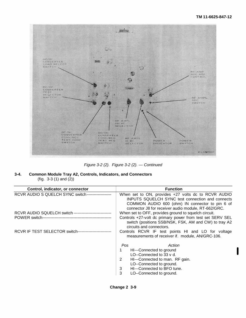
Figure 3-2 (2). Figure 3-2 (2). — Continued
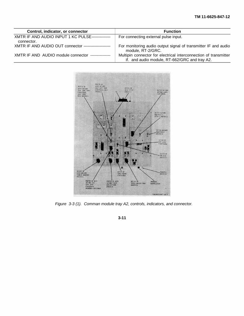
3-4. Common Module Tray A2, Controls, Indicators, and Connectors(fig. 3-3 (1) and (2))
Control, indicator, or connector FunctionRCVR AUDIO S QUELCH SYNC switch ------------------ When set to ON, provides +27 volts dc to RCVR AUDIO
INPUTS SQUELCH SYNC test connection and connectsCOMMON AUDIO 600 (ohm) IN connector to pin 6 ofconnector J8 for receiver audio module, RT-662/GRC.
RCVR AUDIO SQUELCH switch ---------------------------- When set to OFF, provides ground to squelch circuit.POWER switch--------------------------------------------------- Controls +27-volt dc primary power from test set SERV SEL
switch (positions SSB/NSK, FSK, AM and CW) to tray A2circuits and connectors.
RCVR IF TEST SELECTOR switch------------------------- Controls RCVR IF test points HI and LO for voltagemeasurements of receiver if. module, AN/GRC-106.
Pos Action1 HI---Connected to ground
LO--Connected to 33 v d.2 HI---Connected to man. RF gain.
LO--Connected to ground.3 HI---Connected to BFO tune.3 LO--Connected to ground.
Change 2 3-9
TM 11-6625-847-12
Control, indicator, or connector FunctionRCVR IF BFO TONE control ------------------------------- Controls level of dc voltage to BFO TUNE.RCVR IF RF GAIN control ----------------------------------- Controls level of dc voltage to MAN. RF GAIN.XMTR IF AND AUDIO ALC APC PPC CONTROL------ Controls level of dc voltage to XMTR IF AND
POWER CONTROL ----------------------------------------- AUDIO ALC APC PPC CONTROL APC/PPC SEL switchand ALC switch.
POWER indicator ----------------------------------------------- Indicates POWER switch is set to ON, and +27 volts dc issupplied to test tray from test set.
J1 -------------------------------------------------------------------- Multipin connector for connecting tray A2 to test set.RCVR AUDIO INPUTS (ground) test connector ------- Ground test point for input audio signal measurements.RCVR AUDIO INPUTS AUDIO IN test connector ------ Test point for monitoring audio input signals.RCVR AUDIO INPUTS SQUELCH SYNC test ---------- Test point for oscilloscope trigger input connector.
connector.RCVR AUDIO OUTPUTS (ground) test connector ---- Ground test point for audio output measurements of receiver
audio module RT-62/GRC.RCVR AUDIO OUTPUTS 10MW test connector ------- Test point for monitoring audio output signals of receiver
audio module, RT462/GRC.RCVR AUDIO OUTPUTS 2 WATT test connector ----- Test point for monitoring audio output signal of receiver audio
module, RT-662/GRC.RCVR AUDIO module connector ------------------------- Multipin connector for connecting receiver audio module, RT-
662/GRC to tray A2.RCVR IF LO test connector ---------------------------------- Test point for voltage measurements of receiver IF module,
RT662/GRC at J17.RCVR IF HI test connector ----------------------------------- Test point for voltage measurements of receiver IF module,
RT9-62/GRC at J17.COMMON IF OUT test connector -------------------------- Connector for measuring if. output signals from J17 and J25
across 51-ohm load.COMMON AUDIO 600 (ohm) IN connector ------------- For connecting external audio signal generator to tray A2.RCVR IF AMPL IF OUT connector ------------------------- For monitoring amplified output IF signal of receiver if.
module, RT-662/GRC at J17.RCVR IF AGC SYNC test connector --------------------- Test point for oscilloscope trigger input connector.RCVR IF RF AGC (ground) test connector -------------- Ground test point for age measurements.RCVR IF RF AGC OUTPUT test connector ------------ Test point for measuring RF age voltage of receiver IF
module, RT-662/GIRC.RCVR IF module connector --------------------------------- Multipin connector for connecting receiver IF module to tray
A2.XMTR IF AND AUDIO HI test connector ----------------- Test point for voltage measurements of transmitter IF and
audio module, RT-662/GRC.XMTR IF AND AUDIO KEYLINE RT test------------------ Test point for measurements RT-662/GRC keyline
connector ------------------------------------------------------- voltage.XMTR IF ANR AUDIO KEYLINE PA test------------------ Test point for measuring power amplifier, RT-62/
connector ------------------------------------------------------- GRC keyline voltage.XMTR IF AND AUDIO LO test connector ---------------- Test point for voltage measurements of transmitter IF and
audio module, RT-662/GRC.XMTR IF AND AUDIO INPUT 50 (ohm) AUDIO--------- For connecting external audio signal generator.
connector.
3-10
TM 11-6625-847-12
Control, indicator, or connector FunctionXMTR IF AND AUDIO INPUT 1 KC PULSE-------------- For connecting external pulse input.
connector.XMTR IF AND AUDIO OUT connector -------------------- For monitoring audio output signal of transmitter IF and audio
module, RT-2/GRC.XMTR IF AND AUDIO module connector --------------- Multipin connector for electrical interconnection of transmitter
if. and audio module, RT-662/GRC and tray A2.
Figure 3-3 (1). Comman module tray A2, controls, indicators, and connector.
3-11

TM 11-6625-847-12
Figure 3-3 (2). — Continued.
3-5. Synthesizer Test Tray A3, Controls, Indicators, and Connectors(fig. 3-4 (1) and (2))
Control, indicator, or connector FunctionPOWER switch ------------------------------------------------ Controls +27-volt dc primary power from test set SERV SEL
switch (positions OVEN ON, STBY, SSB/NSK, FSK, AM,and CW) to circuits and connectors on tray A3.
POWER VAR/FIXED switch ------------------------------- Selects either fixed level dc voltage (+20 volts dc) or variabledc voltage to MODULE SELECT switch, contact terminal12.
MODULE SELECT switch ----------------------------------- Provides, to module selected, a fixed or variable de B+ supplyvoltage, depending on position of POWER FIXED/VARswitch. Provides a fixed level 20-volts dc B + voltage toother modules.
FREQ DIVIDER FREQ SHIFT switch ------------------- Selects levels of dc voltage signal to frequency dividermodule, AN/GRC-106.
10 & 1KC SYNTH SYNTH OUTPUTS AMPL ------------ Controls input to amplifier module AR4.switch.
Pos ActionON Input amplified.OFF Amplifier bypassed.
10 & 1KC SYNTH OUTPUT AMPL switch -------------- Controls input to amplifier module AR5.Pos Action
ON Input amplified.OFF Amplifier bypassed.
3-12

TM 11-6625-847-12
Control, indicator, or connector FunctionFREQ STANDARD OUTPUT AMPL switch (2) --------- Controls input to amplifier modules AR1 and AR2.
Pos Action-------------------------------------------------------------------- ON Input amplified.-------------------------------------------------------------------- OFF Amplifier bypassed.
MC SYNTH OUTPUT AMPL switch ----------------------- Controls input to amplifier module AR3.Pos Action
-------------------------------------------------------------------- ON Input amplified.-------------------------------------------------------------------- OFF Amplifier bypassed.
FREQ SELECT 1KC 10KC and controls ----------------- Controls, mechanically, position of 10-ke and 1-kc shaftcouplers.
FREQ SELECT 1OOKC control ---------------------------- Controls, mechanically, position of 100-kc shaft couplers.POWER ADJ control ----------------------------------------- Controls level of de variable supply voltage.10&1KC SYNTH SYNTH OUTPUTS VOLTS ADJ------ Controls output level of amplifier AR4.
control.10&1KC SYNTH OUTPUT VOLT ADJ control ---------- Controls output level of amplifier AR5.FREQ STANDARD OUTPUT VOLT ADJ control ------- Controls output level of amplifiers AR1 and AR2.
(2).MC SYNTH OUTPUT VOLT ADJ control ---------------- Controls output level of amplifier AR3.POWER indicator ---------------------------------------------- Indicates POWER switch S1 is set to ON, and +27 volts de is
supplied to test tray from test set.MC SYNTH HI indicator --------------------------------------- Indicates selection of high band of frequencies.MC SYNTH LO indicator ------------------------------------- Indicates selection of low band of frequencies.J1 ------------------------------------------------------------------- Multipin connector for electrical interconnection of tray A3 and
test set.POWER INPUTS FIXED test connector --------------- Test point for measurement of fixed +20-volt dc supply.POWER INPUTS VAR test connector ------------------- Test point for measurements of variable +20-volt dc supply.POWER INPUTS (ground) test connector --------------- Ground test point for measurement of input voltage.FREQ STANDARD 5MC EXT/INT connector ---------- For connecting test equipment to frequency standard module,
RT662/GRC at J7.FREQ STANDARD OUTPUT 1MC connector ---------- For monitoring 1-mc output of frequency standard module,
RT-62/GRC.FREQ STANDARD module connector -------------------- Multipin connector for electrical interconnection of frequency
standard module, RT-662/GRC, and tray A3.FREQ STANDARD module connector -------------------- Multipin connector for electrical interconnection of frequency
standard module, RT62/GRC, and tray A3.MC SYNTH module connector ---------------------------- Multipin connector for electrical interconnection of me
synthesizer module, RT-662/GRC, and tray A3.FREQ DIVIDER OUTPUTS 1OOKC SPECTRUM------ For monitoring the 100-kc spectrum output of fre-
connector ------------------------------------------------------- quency divider module RT-662/GRC.FREQ DIVIDER OUTPUTS 1.75MC connector --------- For monitoring the 1.75-me output of frequency divider
module, RT-462/GRC.FREQ DIVIDER module connector ----------------------- Multipin connector for electrical interconnection of frequency
divider module, RT462/GRC and tray A3.FREQ DIVIDER module connector ------------------------ Multipin connector for electrical interconnection of frequency
divider module, RT-662/GRC, and tray A3.FREQ DIVIDER OUTPUTS 1KC PULSE ----------------- For monitoring 1-kc pulse output of frequency di-
connector ------------------------------------------------------- vider module, RT-662/GRC.FREQ DIVIDER OUTPUTS O1KC SPECTRUM ------- For monitoring 10-kc spectrum output of frequency
connector ------------------------------------------------------- divider module, RT-662/GRC.FREQ STANDARD OUTPUT 10MC connector --------- For monitoring 10-me output of frequency standard module,
RT-662/GRC.MC SYNTH OUTPUT MC SYNTH connector ---------- For monitoring rf output of me synthesizer module, RT-
662/GRC.
3-13

TM 11-6625-847-12
Control, indicator, or connector Function10&1KC SYNTH SYNTH OUTPUTS 10&1KC ----------- For monitoring RF output of 10and 1-kc synthe-
connector ------------------------------------------------------- sizer module, RT-662/GRC.TRANSLATOR INPUTS RCVR RF connector ---------- For connecting external inputs to translator module, RT-
62/GRC.TRANSLATOR OUTPUTS RCVR IF connector -------- For monitoring translator module, RT-42/GRC, receiver IF
output.100KC SYNTH 100KC SYNTH OUTPUT connector -- For monitoring output of 100-kc synthesizer module, RT-
62/GRC.TRANSLATOR module connector -------------------------- Multipin connector for electrical interconnection of translator
module, RT-62/G-RC, and tray A3.TRANSLATOR module connector -------------------------- Multipin connector for electrical interconnection of translator
module, RT662/GRC, and tray A3.100KC SYNTH module connector -------------------------- Multipin connector for electrical interconnection of translator
module, RT462/GRC and tray A3.TRANSLATOR OUTPUTS XMTR RF connector ------- For monitoring transmitter RF output of translator module, RT-
62/GRC at J22.TRANSLATOR INPUTS XMTR IF connector ------------ For connecting external inputs to translator module, RT-
62/GRC at J23.10&1KC SYNTH OUTPUT 7.1MC connector ----------- For monitoring 7.1-mc output of 10 and 1-kc synthesizer
module, RT-662/GRC.10&1KC SYNTH module connector ----------------------- Multipin connector for electrical interconnection of 10and 1-kc
synthesizer module, RT-622/GRC and tray A3.10&1KC module connector ---------------------------------- Multipin connector for electrical interconnection of 10and 1-kc
synthesizer module, RT-662/GRC and tray A3.10&1KC SYNTH INPUTS NOISE BLANK connector -- For connecting external inputs to 10and 1-kc synthesizer
module, RT-662/GRC.
Figure 3-4. (1). Synthesizer test tray A3, controls, indicators, and connectors.
3-14
TM 11-6625-847-12
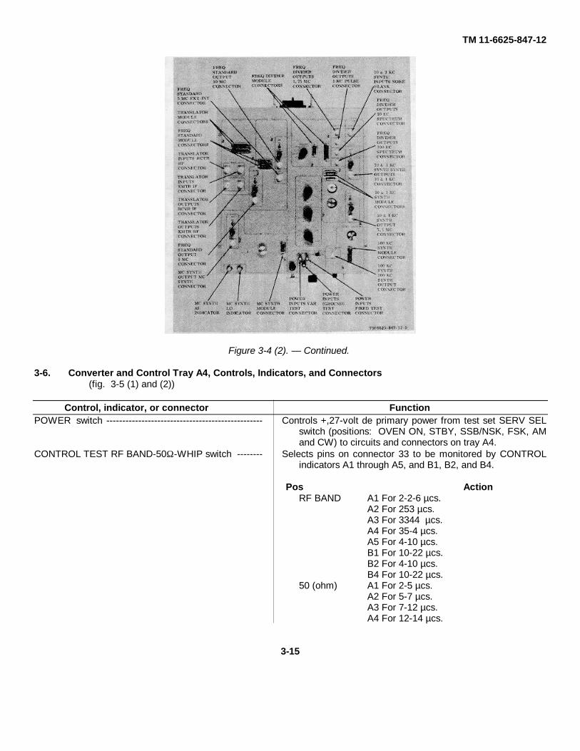
Figure 3-4 (2). — Continued.
3-6. Converter and Control Tray A4, Controls, Indicators, and Connectors(fig. 3-5 (1) and (2))
Control, indicator, or connector FunctionPOWER switch ------------------------------------------------- Controls +,27-volt de primary power from test set SERV SEL
switch (positions: OVEN ON, STBY, SSB/NSK, FSK, AMand CW) to circuits and connectors on tray A4.
CONTROL TEST RF BAND-50Ω -WHIP switch -------- Selects pins on connector 33 to be monitored by CONTROLindicators A1 through A5, and B1, B2, and B4.
Pos ActionRF BAND A1 For 2-2-6 µcs.
A2 For 253 µcs.A3 For 3344 µcs.A4 For 35-4 µcs.A5 For 4-10 µcs.B1 For 10-22 µcs.B2 For 4-10 µcs.B4 For 10-22 µcs.
50 (ohm) A1 For 2-5 µcs.A2 For 5-7 µcs.A3 For 7-12 µcs.A4 For 12-14 µcs.
3-15

TM 11-6625-847-12
Control, indicator, or connector FunctionPos Action
A5 For 14-19 µcs.B1 For 19-24 µcs.B2 For 24-30 µcs.B4 For 10-22 µcs.
WHIP A1 For 10-11 µcs.A2 For 11-12 µcs.A3 For 12-14 µcs.A4 For 27-30 µcs.A5 For 15-24 µcs.B1 (open).B2 For 27-30 µcs.B4 For 10-22 µcs.
CONTROL TEST ANT. MOTOR CONTROL ------------------- When set to CAP, connects CONTROL B5 indicatorMONITOR switch --------------------------------------------------- into circuit.
CONTROL TEST ANT. MOTOR CONTROL ------------------- When set to RF BAND, or when set to CAP, groundsCODE switch -------------------------------------------------------- the circuit.
PA METER TEST ANT. LOAD-ANT. TUNE-------------------- When set to ANT. LOAD, connects variable dc volt-switch------------------------------------------------------------------ age from ANTENNA LOAD/TUNE control. When set to ANT.
TUNE, connects variable dc voltage from ANTENNALOAD/TUNE control.
INPUT CURRENT switch ------------------------------------------- Permits input current measurement tests of inverter assembly,AM3349/GRC-106
EXTERNAL BLOWER switch -------------------------------------- When set to HI, increases speed of BLOWER. When set to LO,decreases speed of BLOWER.
TEST SELECTOR switch ------------------------------------------ Controls test points HI and LO voltage measurements of inverterassembly, AM3349/GRC-106.
Pos Action1 HI---Connected to +27 vdc.
LO--Connected to ground.2 HI---Connected to test circuit.
LO--Connected to EXTERNAL BLOWER.3 HI---Connected to test circuit.
LO--Connected to test circuit.4 HI---Connected to ground.
LO--Connected to test circuit.5 HI---Connected to INT BLOWER.
LO--Connected to inverter.PA METER TEST ANTENNA LOAD/TUNE---------------------- Controls dc voltage level to PA METER TEST
control ----------------------------------------------------------------- ANT. LOAD-ANT. TUNE switch, contact terminal 2.PA METER TEST ALC METER control -------------------------- Controls dc voltage level to test point.PA METER TEST GRID DRIVE control ------------------------- Controls dc voltage level to test point.CONTROL TEST Al thru As, and B1, B2, and B4-------------- Indicates ground at pins selected by CONTROL
indicators ------------------------------------------------------------- TEST RF BAND-500-WHIP switch.CONTROL TEST B3 indicator ------------------------------------- Indicates ground for freq. change.CONTROL TEST B5 indicator ------------------------------------- Indicates ground on CONTROL TEST ANT. MOTOR CONTROL
MONITOR switch.CONTROL TEST C1 indicator ------------------------------------- Indicates +27 volts dc at ANT. MOTOR CONTROL MONITOR
switch.CONTROL TEST C2 indicator ------------------------------------- Indicates +27 volts dc.CONTROL TSST C3 indicator ------------------------------------ Indicates +27 volts dc.CONTROL TEST C4 indicator ------------------------------------- -Indicates +27 volts dc.CONTROL TEST C5 indicator ------------------------------------- Indicates ground.POWER indicator ---------------------------------------------------- Indicates POWER switch is set to ON, and +27 volts dc is supplied
to test tray from test set.J1 ------------------------------------------------------------------------- Multipin connector for electrical interconnection of tray A4 and test
set.
3-16

TM 11-6625-847-12
Control, indicator, or connector FunctionPA METER TEST connector -------------------------------- Mutipin connector for electrical interconnection of front panel
assembly, AM-3349/GRC-106, and tray A4.CONTROL test connector ------------------------------------ Multipin connector for electrical interconnection of antenna
coupler assembly input connector, and tray A4.PA METER TEST ANTENNA LOAD/TUNE -------------- Test point for measuring antenna load/tune voltage.
test connector.PA METER TEST ALC METER test connector---------- Test point for measuring ALC meter voltage.PA METER TEST (ground) test connector --------------- Ground test point for voltage measurementsINPUT CLURRENT HI test connector --------------------- Test point for input current measurements of dc-to-ac inverter
assembly, AM-3349/GRC-106.INPUT CURRENT LO test connector --------------------- Test point for input current measurements of dc-to-ac inverter
assembly, AM3349/GRC-106.TEST SELECTOR LO test connector --------------------- Test point for voltage measurements of dc-to-ac inverter
assembly, AM-3349/GRC-106.TEST SELECTOR HI test connector ---------------------- Test point for voltage measurements of dc-to-ac inverter
assembly, AM-3349/GRC-106.PA METER TEST GRID DRIV.E test connector -------- Test point for measuring grid drive voltage.Connector --------------------------------------------------------- Multipin connector for electrical interconnection of dc-to-ac
inverter assembly, AM3349/GRC-106.
Figure 3-5 (1). Converter and control tray A4, controls, indicators, and connectors.
3-17

TM 11-6625-847-12
Figure 3-5 (2). — Continued.
3-7. Driver, Discriminator, and Antenna Coupler Tray A5, Controls, indicators and Connectors(fig. 3-6 (1) and (2))
Control, indicator, or connector FunctionPOWER switch ------------------------------------------------- Controls +27-volt dc primary power from test set SERV SEL
switch (positions: OVEN ON, STBY, SSB/NSK, FSK, AMand CW) to circuits and controls of tray A5.
DRIVER TEST switch ----------------------------------------- Controls DRIVER test points HI and LO for voltagemeasurements of driver assembly, AM3349/ GRC-106.
Pos Action1 HI --- Connected for 6.3 v ac.
LO -- Connected to ground.2 HI -- Connected for +200 v de.
LO -- Connected to ground.3 HI -- Connected to meter.
LO -- Connected to ground.4 HI -- Connected for +27 v dc.
LO -- Connected to ground..5 HI -- Connected to +200 v dc.
LO -- Connected to +200 v dc.DISCRIMINATOR TEST SELECTOR switch ------------ Controls DISCRIMINATOR test points HI and LO for voltage
measurements of the discriminator assembly, AM-3349/GRC-106.
3-18

TM 11-6625-847-12
Control, indicator, or connector FunctionPos Action
1 HI -- Connected to test circuit.LO -- Connected to test circuit.
2 HI --- Connected to test circuit.LO -- Connected to test circuit.
3 HI --- Connected to ground.LO -- Connected to test circuit.
RELAY RELAY CONTROL switch ------------------------- Grounds various pins on connector J10.Pos Action
1 (Open)2 Circuit grounded.3 Circuit grounded.4 Circuit grounded.5 Circuit grounded.
ANTENNA COUPLER CODE switch ---------------------- Selects correct load condition for testing at frequencies of 2me to 30 me. Controls motor for physical position ofantenna coupler inductor and capacitor tuning shafts onantenna coupler assembly, AM-3349/GRCA-06.
ANTENNA COUPLER 50n DUMMY LOAD Selects antenna coupler load for the antenna couplerCOUPLER TERMINATION WHIP-50Ω assembly, AM-349/GRC-106.DOUBLET switch.
POWER indicator ----------------------------------------------- Indicates POWER switch is set to ON, and +27 volts dc issupplied to test tray from test set.
DRIVER 200 VDC indicator ........................................ Indicates +200 volts dc supplied to test tray from test set.ANTENNA COUPLER CAP. MOTOR indicator ........ Indicates correct ground, and +27 volts dc is at pin 14 present.ANTENNA COUPLER BAND SW MOTOR Indicates correct ground, and +27 volts dc is present.
indicator.RELAY 1 indicator----------------------------------------------- Indicates +27 volts dc is present.RELAY 2 indicator ---------------------------------------------- Indicates correct ground.RELAY 3 indicator ---------------------------------------------- Indicates +27 volts dc is present.RELAY 4 indicator ---------------------------------------------- Indicates +27 volts dc is present.RELAY 5 indicator ---------------------------------------------- Indicates +27 volts dc is present.RELAY 6 indicator --------------------------------------------- Indicates +27 volts de is present.RELAY 7 indicator----------------------------------------------- Indicates correct groundDRIVER BAND SEL switch ---------------------------------- Mechanically selects load transformers for driver assembly,
AM-3349/GRC-106.FEEDBACK IN connector ------------------------------------ For connecting external feedback voltage to driver assembly
under test.RF IN connector ------------------------------------------------ For connecting external RF signals to driver assembly under
test.RF OUT connector ------------------------------------------- For connecting test equipment to monitor RF within driver
assembly under test.J1 -------------------------------------------------------------------- Multipin connector for electrical interconnection of tray A5,
and test set.DISCRIMINATOR RF IN connector ------------------------ For connecting external signals to discriminator assembly AM-
3349/GRC-106.DISCRIMINATOR assembly connector ------------------ Multipin connector for electrical interconnection of
discriminator assembly AM-3349/GRC-106, and tray A5.DRIVER HI test connector ----------------------------------- Test point for voltage measurements of driver assembly
AM349/GRC-106.DRIVER LO test connector ----------------------------------- Test point for voltage measurements of driver assembly AM-
349/GRC-106.DISCRIMINATOR HI test connector ----------------------- Test point for voltage measurements of discriminator
assembly AM-349/GRC-106.3-19

TM 11-6625-847-12
Control, indicator, or connector FunctionDISCRIMINATOR LO test connector ---------------------- Test point for voltage measurements of discriminator
assembly AM4349/GRC-106.DISCRIMINATOR connector -------------------------------- For connecting DISCRIMINATOR RF IN connector to
discriminator assembly AM3349/GRC-106.DISCRIMINATOR ALC OUT test connector ------------- For monitoring the ALC output of the discriminator assembly
AM-3349/GRC-106.RELAY assembly connector -------------------------------- Multipin connector for electrical interconnection of relay
assembly AM-349/GRC-106, and tray AS.ANTENNA COUPLER assembly connector------------- Multipin connector for electrical interconnection of antenna
coupler assembly AM-349/GRC-106, and tray AS.
Figure 3-6 (1). Driver, discriminator, and antenna coupler tray A5, controls, indicators, and connectors.
3-20

TM 11-6625-847-12
Figure 3-6 (2). — Continued.
Section II. OPERATIONAL INSTRUCTIONS
3-8. GeneralThis section provides turn-on, normal operation, andshutdown procedures for the 2A/GRC.
3-9. ChartsThe charts given in paragraphs 3-10 through 3-15provide the operator with a fast, convenient, and safemethod of equipment turn-on; paragraph 3-10 coversthe preliminary switch and control settings for the testset, and paragraphs 3-11 through 3-16 cover theindividual test trays used with the test set.
3-10. Test Set, Preliminary Switch and Control Settings
(fig. 3-1 (1) and (2))
Switch or control SettingPOWER switch ------------------ OFF.SERV SEL switch OFF.
Switch or control SettingPA/RT switch---------------------- PA.KEY switch ----------------------- OFF.XMIT STATUS switch----------- OPR.REC-XMIT switch ---------------- REC.
ALC VOLTAGE INFO----------- Fully counterclock-control. ----------------------- wise.
ALC VOLTAGE TUNE---------- Fully counterclock-control. ----------------------- wise.
IF OSCILLATOR select -------- 4.Switch
MC FREQ 10MC switch-------- 0.MC FREQ 1MC switch --------- 0.MC FREQ .1MC switch--------- 0.500 VDC LOAD switch --------- LOW.2400 VDC LOAD switch-------- 1.
3-21

TM 11-6625-847-12
3-11. Common Module Tray, A1 PreliminarySwitch and Control Settings
(fig. 3-2 (1) and (2))Switch or control Setting
POWER switch ------------------ OFF.DC/DC CONVERTER:
LOAD SELECT switch ----- 100.TEST SELECTOR ---------- 1.
switch.CONV/REC TEST CONV - Normal relaxed.
switch (momentary).CONV/REG TEST REG --- Normal relaxed.
switch (momentary).RF AMPL:
100 KC SELECTOR -------- 0.switch
10 KC SELECTOR---------- 0.switch.
AGC ON-OFF switch ------- OFF.AGC ADJ control ------------ Fully counterclock-
wise
3-12. Common Module Tray A2, PreliminarySwitch and Control Settings
(fig. 3-3 (1) and (2))
Switch or control SettingPOWER switch------------------- OFF.RCVR AUDIO:
SQUELCH switch------------ OFF.SQUELCH SYNC switch--- OFF.AUDIO GAIN control-------- Fully counterclock-
wise.RCVR IF:
AGC SYNC switch ---------- OFF.RF AGC ON-OFF switch -- OFF.TEST SELECTOR ---------- 1.switch.BFO TONE control ---------- Fully counterclock-
wiseRF GAIN control ------------- Fully counterclock-
wiseXMTR IF AND AUDIO:
ALC APC PPC CONTROL OFF.ALC switch.ALC APC PPC CONTROL OFF.APC/PPC SEL switch.ALC APC PPC CONTROL Fully counterclock-
POWER CONTROL.----- wise.VOICE MODES switch----- PUSH TO TALK.TEST SELECTOR switch - 1.
3-13. Synthesizer Test Tray A3, Preliminary Switchand Control Settings
(fig. 3-4 (1) and (2))Switch or control Setting
POWER switch_ ----------------- OFF.MODULE SELECT switch ...... 10&1KC.POWER:
VAR-FIXED switch ---------- FIXED.ADJ control -------------------- Midrange
FREQ SELECT:10KC control ------------------ 0.1 KC control ------------------- 0.100KC control----------------- 0.
10&1KC SYNTH:SYNTH OUTPUTS AMPL - OFF.
ON-OFF switchSYNTH OUTPUTS VOLT - Midrange
ADJ controlOUTPUT AMPL ON-OFF-- OFF.
switch.OUTPUT VOLT ADJ-------- Midrange
controlFREQ DIVIDER FREQ--------- OFF.
SHIFT switch.FREQ STANDARD:
OUTPUT AMPL ON-OFF-- OFF.switch (2).
OUTPUT VOLT ADJ-------- Midrange.control (2).
MC SYNTH section:OUTPUT AMPL ON-OFF .. OFF.
switch.OUTPUT VOLT ADJ-------- Midrangecontrol.
3-14. Converter and Control Tray AA, Preliminary Switch and Control Settings
(fig. 3-4 (1) and (2))
Switch or control SettingPOWER switch------------------- OFF.INPUT CURRENT switch ------ Normally relaxed.TEST SELECTOR switch------ 1.PA METER TEST:
ANT. LOAD-ANT. TUNE . ANT. TUNE.switch.
ANTENNA LOAD/TUNE --- Midrangecontrol.
ALC METER control -------- Fully counter-clockwise.
GRID DRIVE control -------- Fully counter-clockwise.
CONTROL TEST:ANT. MOTOR CONTROL RF BAND.
MONITOR switch.
3-22

TM 11-6625-847-12
Swatch or control SettingANT. MOTOR CONTROL Normally
CODE switch relaxed.RF BAND -50Ω -WHIP RF BAND.
switch.
3-15. Driver, Discriminator, and Antenna Coupler Tray A5, Preliminary Switch and Control Settings(fig. 3-6 (1) and (2))
Switch or control SettingPOWER switch------------------ OFF.RELAY RELAY CONTROL 1.
switch.ANTENNA COUPLER:
CODE switch ---------------- 1.50Ω DUMMY LOAD 50Ω DUMMY
COUPLER TERMINA LOAD.TION WHIP-50ΩDOUBLET switch.
DISCRIMINATOR TEST 1.SELECTOR switch.
DRIVER:BAND SEL switch ---------- 3.25 MC.TEST SELECTOR 1.
switch.
3-16. Starting ProceduresApply power to the test set as follows:
a. Set the switches and the controls located on thetest set to the settings listed in paragraph 3-10.
Note. If the AN/GRC-106 modules test isto be done, perform the procedures given in ebelow. For a system test, perform the proceduresgiven in b below.
b. Connect the equipment to be tested to the testset with the appropriate test cables as shown in figures1-1 and 4-1.
c. Set the test set POWER switch ON; POWERindicator should light.
d. On the test set, connect the dc test leads ofMultimeter AN/PSM-6 (AN/PSM-6) between DCVOLTAGE test points +20 and ground. Rotate theSERV SEL switch to OVEN ON, and adjust the DCVOLTAGE 20 control for a +20volt de indication on themultimeter.
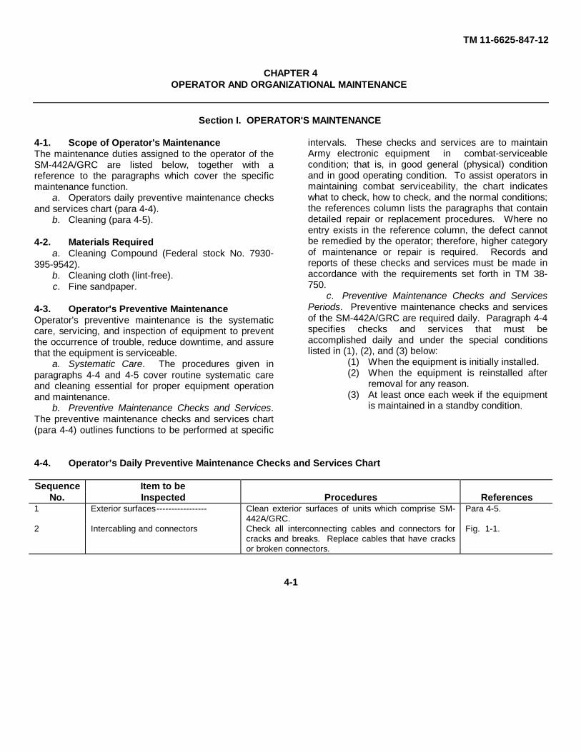
e. To test the AN/GRC-106 modules, connect andsecure the appropriate test tray to the test set with theconnector holddown screw on the front panel of themodule test tray, as TM 11-6625-847-12 shown infigure 3-8. Refer to paragraph 1-5 for a cross-referenceof AN/GRC-106 modules testable by the test set testtrays.
f. On the test tray being used, set the switchesand the controls to the settings listed in the appropriateparagraph (para 3-11 through 3-15).
g. Set the test set POWER switch to ON; POWERindicator should light.
h. On the test set, connect the AN/PSM-6 dc testleads between DC VOLTAGE test points +20 andground. Adjust the DC VOLTAGE 20 control for +20-volt dc indication on the.AN/PSM-6.
Note. If tray A5 is connected to the test set,perform the procedures given in i below .
i. On the test set, connect the AN/PSM-6 dc testleads between DC VOLTAGE test points +200 andground. Adjust the DC VOLTAGE 200 control for +200-volt dc indication on the AN/PSM-6.
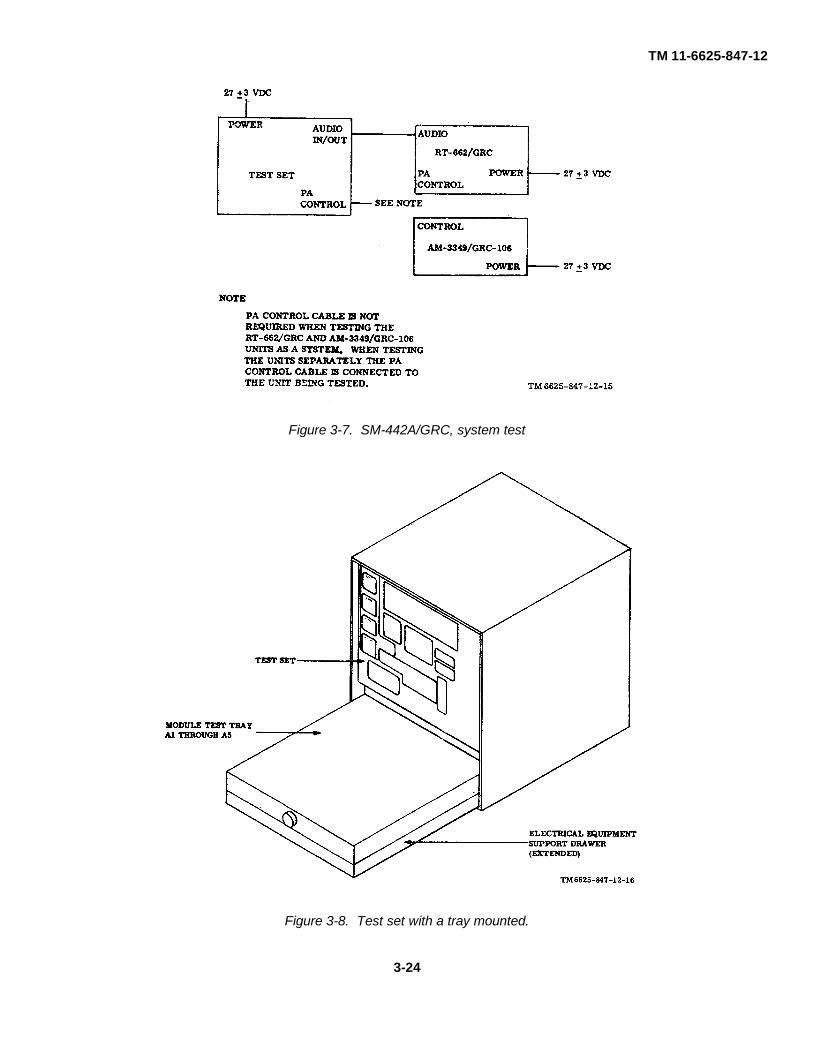
3-17. Preparation for System Test OperationPrepare for the AN/GRC-106 system test with the testset as follows:
a. Perform the procedures given in paragraph 3-16e through h and, if necessary, the procedures given inparagraph 3-16i.
b. Rotate the SERV SEL switch to STBY; allow 15minutes for warmup.
3-18. Preparation for Module Test OperationPrepare to test the AN/GRC-106 modules with the testset as follows:
a. Perform the procedures given in paragraph 3-17b, c, and d and, if necessary, the procedures given inparagraph 3-16i.
b. Rotate the SERV SEL switch to STBY.c. Set the test tray POWER switch to ON.
3-19. Stopping ProceduresShutdown the test set after use as follows:
a. Set the SERV SEL switch to OFF.b. Set the test set POWER switch to OFF.
3-23
TM 11-6625-847-12
Figure 3-7. SM-442A/GRC, system test
Figure 3-8. Test set with a tray mounted.
3-24
TM 11-6625-847-12
CHAPTER 4OPERATOR AND ORGANIZATIONAL MAINTENANCE
Section I. OPERATOR'S MAINTENANCE
4-1. Scope of Operator's MaintenanceThe maintenance duties assigned to the operator of theSM-442A/GRC are listed below, together with areference to the paragraphs which cover the specificmaintenance function.
a. Operators daily preventive maintenance checksand services chart (para 4-4).
b. Cleaning (para 4-5).
4-2. Materials Requireda. Cleaning Compound (Federal stock No. 7930-
395-9542).b. Cleaning cloth (lint-free).c. Fine sandpaper.
4-3. Operator's Preventive MaintenanceOperator's preventive maintenance is the systematiccare, servicing, and inspection of equipment to preventthe occurrence of trouble, reduce downtime, and assurethat the equipment is serviceable.
a. Systematic Care. The procedures given inparagraphs 4-4 and 4-5 cover routine systematic careand cleaning essential for proper equipment operationand maintenance.
b. Preventive Maintenance Checks and Services.The preventive maintenance checks and services chart(para 4-4) outlines functions to be performed at specific
intervals. These checks and services are to maintainArmy electronic equipment in combat-serviceablecondition; that is, in good general (physical) conditionand in good operating condition. To assist operators inmaintaining combat serviceability, the chart indicateswhat to check, how to check, and the normal conditions;the references column lists the paragraphs that containdetailed repair or replacement procedures. Where noentry exists in the reference column, the defect cannotbe remedied by the operator; therefore, higher categoryof maintenance or repair is required. Records andreports of these checks and services must be made inaccordance with the requirements set forth in TM 38-750.
c. Preventive Maintenance Checks and ServicesPeriods. Preventive maintenance checks and servicesof the SM-442A/GRC are required daily. Paragraph 4-4specifies checks and services that must beaccomplished daily and under the special conditionslisted in (1), (2), and (3) below:
(1) When the equipment is initially installed.(2) When the equipment is reinstalled after
removal for any reason.(3) At least once each week if the equipment
is maintained in a standby condition.
4-4. Operator’s Daily Preventive Maintenance Checks and Services Chart
Sequence Item to beNo. Inspected Procedures References
1 Exterior surfaces----------------- Clean exterior surfaces of units which comprise SM-442A/GRC.
Para 4-5.
2 Intercabling and connectors Check all interconnecting cables and connectors forcracks and breaks. Replace cables that have cracksor broken connectors.
Fig. 1-1.
4-1

TM 11-6625-847-12
Sequence Item to beNo. Inspected Procedures References
3 Fuses ------------------------------ Check fuses for correct value. Check spares forquantity and proper values.
Fig. 3-1.
4 Knobs, controls and switches Check to be sure that mechanical action of all knobs,controls, and switches is smooth and free fromexternal or internal binding.
Fig. 3-1 through 3-6.
5 Completeness ------------------- Check to see that SM-442A/GRC is complete. App B.6 Indicator lamps------------------ Check indicator lamps for correct value. Check
spares for quantity and proper values.App B.
4-5. CleaningInspect the exterior of the SM-442A/GRC; exteriorsurfaces must be free of dust, dirt, grease, and fungus.
a. Remove dust and loose dirt with a clean, softcloth.
Warning: Prolonged breathing of cleaningcompound is dangerous; make sure adequateventilation is provided. Cleaning compound isflammable; do not use near a flame. Avoid contactwith the skin; wash off any that spills on the hands.
b. Remove grease, fungus, and ground-in dirt fromthe case being cleaned; use a cloth dampened (not wet)with the cleaning compound.
c. Remove dust or dirt from the connectors with abrush.
d. Clean the front panel and the control knob; usea soft, clean cloth. If dirt is difficult to remove, dampenthe cloth with water; use mild soap if necessary.
Section II. ORGANIZATIONAL MAINTENANCE
4-6. Scope of Organizational MaintenanceThis section contains instructions coveringorganizational maintenance of the SM-442A/ GRC. Itincludes instructions for performing preventive andperiodic maintenance services and repair functions to beaccomplished by the organizational repairman asfollows:
a. Organizational preventive maintenance (para 4-8).
b. Organizational quarterly preventivemaintenance (para 4-9).
c. Organizational quarterly preventivemaintenance checks and services chart (para 4-10).
d. Preservation (para 4-11).e. Lubrication (para 4-12).f. Troubleshooting (para 4-13 through 4-25).g. Replacement and adjustment (para 4-26).
4-7. Test Equipment RequiredThe test equipment required for organizationalmaintenance is as follows:
a. Multimeter AN/PSM-6.b. Voltmeter, Electronic AN/URM-145.
c. Counter, Electronic, Digital Readout AN/ USM-207.
d. Generator, Signal AN/URM-127.e. Oscilloscope AN/USM-140.f. Power Supply PP-3940/G.g. Multimeter ME-26A/U, ME-26B/U, or ME-26C/U.
4-8. Organizational Preventive Maintenance
a. Organizational preventive maintenance is thesystematic care and inspection of equipment to maintainit in serviceable condition, prevent breakdowns, andassure maximum operational capability. Preventivemaintenance is the responsibility of all catagoriesconcerned with the equipment. It includes inspection,testing, and repair or replacement of parts thatinspections and tests indicate would probably fail beforethe next scheduled periodic service. Preventivemaintenance checks and services of the SM-442A/GRCat the organizational category are made at quarterlyinterval, unless otherwise directed by the commandingofficer.
4-2
TM 11-6625-847-12
b. Maintenance forms and records to be used andmaintained on this equipment are specified in TM38750.
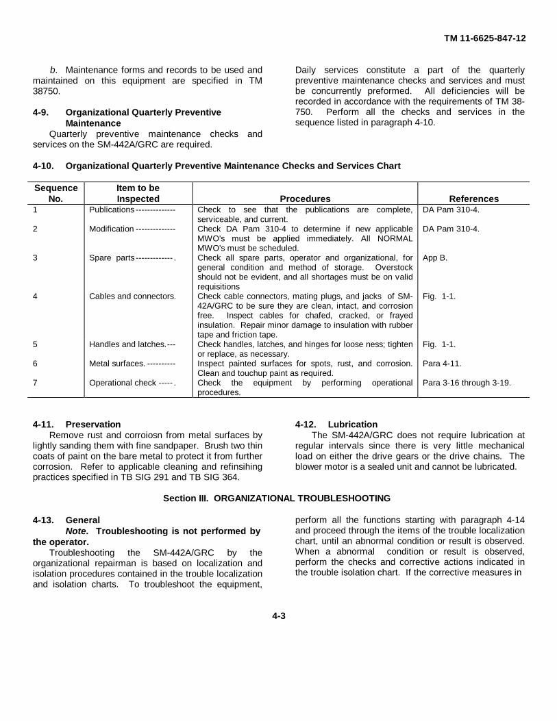
4-9. Organizational Quarterly Preventive Maintenance
Quarterly preventive maintenance checks andservices on the SM-442A/GRC are required.
Daily services constitute a part of the quarterlypreventive maintenance checks and services and mustbe concurrently preformed. All deficiencies will berecorded in accordance with the requirements of TM 38-750. Perform all the checks and services in thesequence listed in paragraph 4-10.
4-10. Organizational Quarterly Preventive Maintenance Checks and Services Chart
Sequence Item to beNo. Inspected Procedures References
1 Publications -------------- Check to see that the publications are complete,serviceable, and current.
DA Pam 310-4.
2 Modification -------------- Check DA Pam 310-4 to determine if new applicableMWO's must be applied immediately. All NORMALMWO's must be scheduled.
DA Pam 310-4.
3 Spare parts ------------- . Check all spare parts, operator and organizational, forgeneral condition and method of storage. Overstockshould not be evident, and all shortages must be on validrequisitions
App B.
4 Cables and connectors. Check cable connectors, mating plugs, and jacks of SM-42A/GRC to be sure they are clean, intact, and corrosionfree. Inspect cables for chafed, cracked, or frayedinsulation. Repair minor damage to insulation with rubbertape and friction tape.
Fig. 1-1.
5 Handles and latches.--- Check handles, latches, and hinges for loose ness; tightenor replace, as necessary.
Fig. 1-1.
6 Metal surfaces. ---------- Inspect painted surfaces for spots, rust, and corrosion.Clean and touchup paint as required.
Para 4-11.
7 Operational check ----- . Check the equipment by performing operationalprocedures.
Para 3-16 through 3-19.
4-11. PreservationRemove rust and corroiosn from metal surfaces by
lightly sanding them with fine sandpaper. Brush two thincoats of paint on the bare metal to protect it from furthercorrosion. Refer to applicable cleaning and refinsihingpractices specified in TB SIG 291 and TB SIG 364.
4-12. LubricationThe SM-442A/GRC does not require lubrication at
regular intervals since there is very little mechanicalload on either the drive gears or the drive chains. Theblower motor is a sealed unit and cannot be lubricated.
Section III. ORGANIZATIONAL TROUBLESHOOTING
4-13. GeneralNote. Troubleshooting is not performed by
the operator.Troubleshooting the SM-442A/GRC by the
organizational repairman is based on localization andisolation procedures contained in the trouble localizationand isolation charts. To troubleshoot the equipment,
perform all the functions starting with paragraph 4-14and proceed through the items of the trouble localizationchart, until an abnormal condition or result is observed.When a abnormal condition or result is observed,perform the checks and corrective actions indicated inthe trouble isolation chart. If the corrective measures in
4-3
TM 11-6625-847-12
dicated do not result in correction of the trouble, ahigher category of maintenance is required. Paragraph4-26 contains additional information and instructions tobe used during the replacement and adjustmentprocedures.
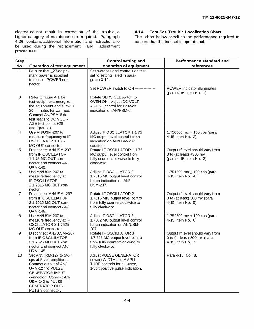
4-14. Test Set, Trouble Localization ChartThe chart below specifies the performance required tobe sure that the test set is operational.
Step Control setting and Performance standard andNo. Operation of test equipment operation of equipment references
1 Be sure that +27-dc pri- Set switches and controls on testmary power is supplied set to setting listed in para-to test set POWER con- graph 3-10.nector.
Set POWER switch to ON---------------- POWER indicator illuminates(para 4-15, item No. 1).
3 Refer to figure 4-1 for Rotate SERV SEL switch totest equipment; energize OVEN ON. Adjust DC VOLT-the equipment and allow X AGE 20 control for +20-volt30 minutes for warmup. indication on AN/PSM-6.Connect AN/PSM-6 dctest leads to DC VOLT-AGE test points +20and (ground).
4 Use AN/USM-207 to Adjust IF OSCILLATOR 1 1.75 1.750000 mc + 100 cps (parameasuse frequency at IF MC output level control for an 4-15, item No. 2).OSCILLATOR 1 1.75 indication on AN/USM-207MC OUT connector. counter.
5 Disconnect AN/USM-207 Rotate IF OSCILLATOR 1 1.75 Output rf level should vary fromfrom IF OSCILLATOR MC output level control from 0 to (at least) +300 mv1 1.75 MC OUT con- fully counterclockwise to fully (para 4-15, item No. 3).nector and connect ANI clockwise.URM-145.
6 Use AN/USM-207 to Adjust IF OSCILLATOR 2 1.751500 mc + 100 cps (parameasure frequency at 1.7515 MC output level control 4-15, item No. 4).IF OSCILLATOR for an indication on AN/2 1.7515 MC OUT con- USM-207.nector.
7 Disconnect AN/USM -297 Rotate IF OSCILLATOR 2 Output rf level should vary fromfrom IF OSCILLIATOR 1.7515 MIC output level control 0 to (at least) 300 mv (para2 1.7515 MC OUT con- from fully counterclockwise to 4-15, item No. 5).nector and connect AN/ fully clockwise.URM-145.
8 Use AN/USM-207 to Adjust IF OSCILLATOR 3 1.752500 me ± 100 cps (parameasure frequency at IF 1.7502 MC output level control 4-15, item No. 6).OSCILLATOR 3 1.7525 for an indication on AN/USM-MC OUT connector. 207.
9 Disconnect AN,/U,SM--207 Rotate IF OSCILI.ATOR 3 Output rf level should vary fromfrom IF OSCILILATOR 1.7.525 MC output level control 0 to (at least) 300 mv (para3 1.7525 MC OUT con- from fully counterclockwise to 4-15, item No. 7).nector and connect AN/ fully clockwise.URM-145.
10 Set AN',TRM-127 to 5%(h Adjust PULSE GENERATOR Para 4-15, No. 8.cps at 5-volt amplitude. (lower) WIDTH and AMPLI-Connect output of AN/ TUDE controls for a 1-usec,URM-127 to PULSE 1-volt positive pulse indication.GENERATOR INPUTconnector. Connect AN/USM-140 to PULSEGENERATOR OUT-PUTS 3 connector.
4-4
TM 11-6625-847-12
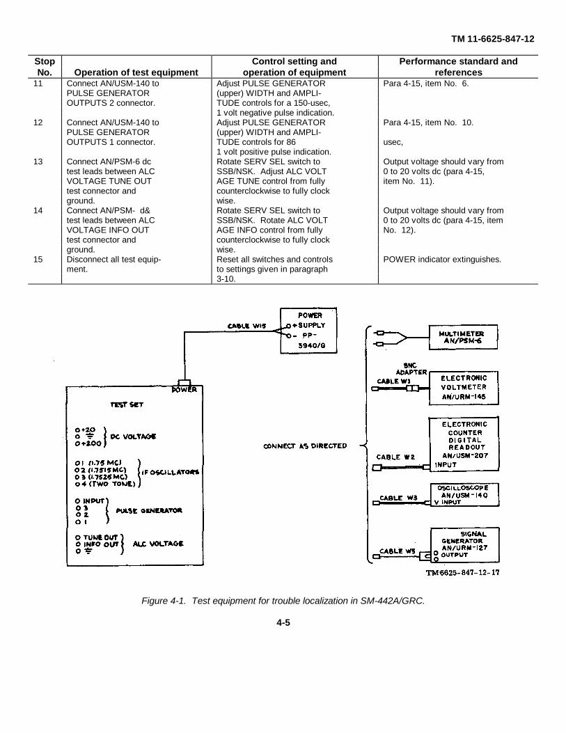
Stop Control setting and Performance standard andNo. Operation of test equipment operation of equipment references
11 Connect AN/USM-140 to Adjust PULSE GENERATOR Para 4-15, item No. 6.PULSE GENERATOR (upper) WIDTH and AMPLI-OUTPUTS 2 connector. TUDE controls for a 150-usec,
1 volt negative pulse indication.12 Connect AN/USM-140 to Adjust PULSE GENERATOR Para 4-15, item No. 10.
PULSE GENERATOR (upper) WIDTH and AMPLI-OUTPUTS 1 connector. TUDE controls for 86 usec,
1 volt positive pulse indication.13 Connect AN/PSM-6 dc Rotate SERV SEL switch to Output voltage should vary from
test leads between ALC SSB/NSK. Adjust ALC VOLT 0 to 20 volts dc (para 4-15,VOLTAGE TUNE OUT AGE TUNE control from fully item No. 11).test connector and counterclockwise to fully clockground. wise.
14 Connect AN/PSM- d& Rotate SERV SEL switch to Output voltage should vary fromtest leads between ALC SSB/NSK. Rotate ALC VOLT 0 to 20 volts dc (para 4-15, itemVOLTAGE INFO OUT AGE INFO control from fully No. 12).test connector and counterclockwise to fully clockground. wise.
15 Disconnect all test equip- Reset all switches and controls POWER indicator extinguishes.ment. to settings given in paragraph
3-10.
Figure 4-1. Test equipment for trouble localization in SM-442A/GRC.
4-5
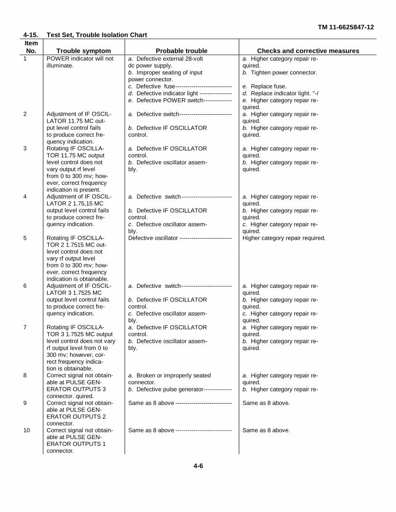
TM 11-6625847-124-15. Test Set, Trouble Isolation ChartItemNo. Trouble symptom Probable trouble Checks and corrective measures
1 POWER indicator will not a. Defective external 28-volt a. Higher category repair re-illuminate. dc power supply. quired.
b. Improper seating of input b. Tighten power connector.power connector.c. Defective fuse---------------------------- e. Replace fuse.d. Defective indicator light ---------------- d. Replace indicator light. "-/e. Defective POWER switch-------------- e. Higher category repair re-
quired.2 Adjustment of IF OSCIL- a. Defective switch-------------------------- a. Higher category repair re-
LATOR 11.75 MC out- quired.put level control fails b. Defective IF OSCILLATOR b. Higher category repair re-to produce correct fre- control. quired.quency indication.
3 Rotating IF OSCILLA- a. Defective IF OSCILLATOR a. Higher category repair re-TOR 11.75 MC output control. quired.level control does not b. Defective oscillator assem- b. Higher category repair re-vary output rf level bly. quired.from 0 to 300 mv; how-ever, correct frequencyindication is present.
4 Adjustment of IF OSCIL- a. Defective switch------------------------- a. Higher category repair re-LATOR 2 1.75,15 MC quired.output level control fails b. Defective IF OSCILLATOR b. Higher category repair re-to produce correct fre- control. quired.quency indication. c. Defective oscillator assem- c. Higher category repair re-
bly. quired.5 Rotating IF OSCILLA- Defective oscillator -------------------------- Higher category repair required.
TOR 2 1.7515 MC out-level control does notvary rf output levelfrom 0 to 300 mv; how-ever, correct frequencyindication is obtainable.
6 Adjustment of IF OSCIL- a. Defective switch------------------------- a. Higher category repair re-LATOR 3 1.7525 MC quired.output level control fails b. Defective IF OSCILLATOR b. Higher category repair re-to produce correct fre- control. quired.quency indication. c. Defective oscillator assem- c. Higher category repair re-
bly. quired.7 Rotating IF OSCILLA- a. Defective IF OSCILLATOR a. Higher category repair re-
TOR 3 1.7525 MC output control. quired.level control does not vary b. Defective oscillator assem- b. Higher category repair re-rf output level from 0 to bly. quired.300 mv; however, cor-rect frequency indica-tion is obtainable.
8 Correct signal not obtain- a. Broken or improperly seated a. Higher category repair re-able at PULSE GEN- connector. quired.ERATOR OUTPUTS 3 b. Defective pulse generator-------------- b. Higher category repair re-connector. quired.
9 Correct signal not obtain- Same as 8 above ---------------------------- Same as 8 above.able at PULSE GEN-ERATOR OUTPUTS 2connector.
10 Correct signal not obtain- Same as 8 above ---------------------------- Same as 8 above.able at PULSE GEN-ERATOR OUTPUTS 1connector.
4-6

TM 11-6625847-12
ItemNo. Trouble symptom Probable trouble Checks and corrective measures
11 Adjustment of ALC Defective SERV SEL switch ------------- Higher category repair required.VOLTAGE TUNE con-trol
12 Adjustment of ALC Defective SERV SEL switch ------------- Higher category repair requiredVOLTAGE. INFO con-trol does not vary out-put voltage from 0 to22 volts de.
4-16. Common Module Tray A1, Trouble Localization Chart
The chart below specifies the performance required to be sure that tray A1 is operational.
Step Control setting and Performance standard andNo. Oration of test equipment operation of equipment references
Note. AN/PSM-6 is onlypiece of test equipment re-quired for following test.
1 Remove tray A1 fromstorage case and secureit to the test set.
2 Insure that +27-volt de Set switches and controls on testprimary power is sup set to positions listed in para-plied to POWER con- graph 3-10. Set switches andnector on test set. controls on tray Al to settings
listed in paragraph 3-11.3 Rotate SERV SEL switch Set test set POWER switch to ON. Test set POWER indicator illum-
to SSB/NSK. Set tray A1 POWER switch inates (para 4-17, item No. 1).to ON.
4 Measure dc voltage at DC/ +27 + 1 volts dc; tray A1DC LOAD SELECT POWER indicator illuminatesCONVERTER test con- (para 4-17, item No. 2).nectors between HI (+)and LOW (-) with AN/PSM-6.
5 Connect de test leads of Set AGC OFF/ON switch to ON. Measured voltage should varyAN/PSM-6 to RF Rotate RF AMPL AGC ADJ from 0 to 28 volts de (paraAMPL AGC test connec- control from fully counter- 4-17, item No. 4).tors TEST (-) and clockwise to fully clockwise(ground (+)).
6 Measure de voltage at +20 + 1 volts de (para 4-17,NOISE BLANKER item No. 5).NOISE BLANKER20 VDC test connectorwith AN/PSM-6. Rotate test set MC FREQ select Tray A1 mc shaft coupler should
switches 10MC and 1 MC rotate and indicate 29 posi-from 2.0 me to 29.0 me in 1-mc tions selected (para 4-17, itemsteps. No. 6).Note. As MC FREQ selectswitches are turned clockwise,mc shaft coupler advances 90°per 1-mc step.
8 Disconnect AN/PSM-6 ---------- Reset all switches and controls Test set and tray A1 POWERto settings listed in paragraphs indicators extinguish.3-10 and 3-11.
4-7

TM 11-6625-847-12
4-17. Common Module Tray A1, Trouble Isolation ChartItemNo. Trouble symptom Probable trouble Checks and corrective measure
1 Test set POWER indicator a. Defective external 27-volt de a. Higher category repair re-does not illuminate. power supply. quired.
b. Improper seating of input b. Tighten power connector.power connector.c. Defective test set fuse------------------- c. Replace fuse (para 4-26a).d. Defective indicator light --------------- d. Replace indicator light (para
4-26b).e. Defective POWER switch ------------- e. Higher category repair re-
quiredf. Defective test set SERV f. Higher category repair eSEL switch. quired
2 +27 + 1 volts dc is not ob- a. Defective DC/DC converter ----------- a. Higher category repair re-tainable at DC/DC quired.LOAD SELECT CON- b. Defective test set SERV SEL b. Higher category repair re-VERTER HI and LOW switch. quired.test connectors.
3 Tray A1 POWER indi- a. Broken or improperly seated a. Repair or replace as required.cator does not illumi- connectors.nate. b. Defective indicator ----------------------- b. Check lamp by replacing itwith new lamp.
c. Defective POWER switch -------------- c. Higher category repair re-quired.
4 Rotating RF AMPL AGC a. Broken or imrpoperly seated a. Higher category repair re-OFF-ON control does connectors. quired.not vary voltage from b. Defective RF AMPL AGC b. Higher category repair -0 to 28 volts. OFF-ON control. quired.
c. Defective RF AMPL AGC c. Higher category repair re-OFF-ON switch quired.
5 20 volts dc not obtainable Broken or improperly seated con- Higher category repair required.at NOISE BLANKER nectors.NOISE BLANKER 20VDC test connector.
6 Me shaft coupler will not Defective motor------------------------------- Listen for motor operation; ifrotate or does not indi- motor operation cannot becate one or all of 28 heard, higher category repairpositions selected by test required.MC FREQ selectswitches.
4-18. Common Module Tray A2, Trouble Localization Chart
The chart below specifies the performance required to be sure that tray A2 is operational.
Step Control setting and Performance standard andNo. Operation of test
equipmentoperation of equipment reference
1 Remove tray A2 fromstorage case and secureit to test set.
2 Insure that +27 vac Set test set switches and con-primary power is supplied trols to settings listed in para-to connector on the test graph 3-10. Set tray A2set. switches and controls to set-
tings listed in paragraph 3-12.
4-8

TM 11-6625-847-12
Step Control setting and Performance standard andNo. Operation of test equipment operation of equipment references3 Set test set POWER switch to Test set POWER indicator il-
ON. luminates.4 Note. Allow 10-minute Rotate test set SERV SEL switch Tray A2 POWER indicator il-
warmup period for test set to SSB/NSK. Set tray A2 luminates (para 4-19, item No.frequency standard. POWER switch to ON. 1).
5 Connect AN/PSM-6 de 30 +2 volts dc (para 4-19, itemtest leads to RCVR IF. No. 2).test connectors HI andLO.
6 Set RCVR IF TEST SELECTOR Dc voltage should vary from 0.35switch to 2. Rotate RCVR IF to 2.5 volts dc (para 4-19, itemRF GAIN control from fully No. 3).counterclockwise to fully clock-wise
7 Observe AN/PSM-6 dc Switch test set RC-XMIT switch Dc voltage drops to 0 volt dcvoltage indication when from REC to XMIT, then to when REC-XMIT switch is settest set RC-XMIT REC. to XMIT (para 4-19, itemswitch is set to XMIT. No. 4).
8 Set RCVR IF TEST SELECTOR +20 + 1 volts dc (BFO TONEswitch to 3. Rotate test set control has no effect on volt-SERV SEL switch to CW. age) (para 4-19, item No. 5).Rotate RCVR IF BFO TONEcontrol from fully counterclock-wise to fully clockwise.
9 Connect AN/USM-207 to Set RCVR IF AGC SYNC switch 1.7615 mc + 100 cps (para 4-19,test set IF OSCILLA- to ON, and test set IF OS- item No. 6).TOR TWO TONE OUT CILLATOR select switch toconnector (use HI gain 1+2.preamplifier on AN/USM-207). Refer to fig-ure 4-1.
10. Set test set IF OSCILLATOR 1.7525 mc + 100 cps (para 4-19,select switch to 1+3. item No. 7).
11 Measure dc voltage at + 20 + 1 volts dc (para 4-19,XMTR IF AND AUDIO item No. 8).test points HI and LO.
12 Set XMTR IF AND AUDIO Dc voltage should vary fromTEST SELECTOR switch to 3. minimum of 0 volt do to maxi-Set test set KEY switch to ON. mum of +20 volts dc (paraRotate XMTR IF AND AUDIO 4-19, item No. 9).ALC APC PPC CONTROLPOWER CONTROL from fullycounterclockwise to fully clock-wise.
13 Disconnect all test equip- Reset all switches and controls Test set and tray A2 POWERment. to positions listed in para- indicator extinguish.
graphs 3-10 and 3-12.
4-9

TM 11-6625-847-12
Figure 4-2. Synthesizer test tray A3, trouble localization test equipment.
4-19. Common Module Tray A2, Trouble Isolation ChartItemNo. Trouble symptom Probable trouble Checks and corrective measure
POWER indicator lamp a. Defective external 27-volt a. Higher category repair re-will not illuminate dc power supply. quired.
b. Improper seating of input b. Tighten power connector.power connector.c. Defective test set fuse------------------------- c. Replace fuse (para 4-26a).d. Defective indicator light---------------------- d. Replace indicator light (para
4-26b).e. Defective POWER switch ------------------- e. Higher category repair re-
quired.f. Defective test set SERV SEL f. Higher category repair re-
switch. quired.2 When AN/PSM-6 dc tests a. Improper seating of input a. Tighten power connector.
leads are connected to power connector.RCVR IF test points b. Defective RCVR IF TEST b. Higher category repair re-HI and LO, voltage SELECTOR switch. quired.varies more or less thanlimits of 29 to 31 voltsdc.
3 When RCVR IF TEST a. Improper seating of input a. Tighten power connector.SELECTOR switch is power connector.placed at 2, and RCVR b. Defective RCVR IF TEST b. Higher category repair re-IF GAIN control is ro- SELECTOR switch. quiredtated from fully counter- c. Defective RCVR IF RF c. Higher category repair re-clockwise to clockwise, GAIN control. quired.voltage varies more orless than limits of 0.35to 2.5 volts dc.
4-10
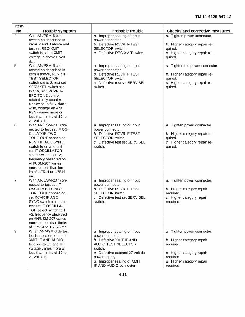
TM 11-6625-847-12
ItemNo. Trouble symptom Probable trouble Checks and corrective measures
4 With AN/PSM-6 con- a. Improper seating of input a. Tighten power connector.nected as described in power connector.items 2 and 3 above and b. Defective RCVR IF TEST b. Higher category repair re-test set REC-XMIT SELECTOR switch.. quired.switch is set to XMIT, c. Defective REC-XMIT switch. c. Higher category repair re-voltage is above 0 volt quired.dc .
5 With AN/PSM-6 con- a. Improper seating of input a. Tighten the power connector.nected as described in power connector.item 4 above, RCVR IF b. Defective RCVR IF TEST b. Higher category repair re-TEST SELECTOR SELECTOR switch. quired.switch set to 3, test set c. Defective test set SERV SEL c. Higher category repair re-SERV SEL switch set switch. quired.to CW, and RCVR IFBFO TONE controlrotated fully counter-clockwise to fully clock-wise, voltage on AN/PSM- varies more orless than limits of 19 to21 volts dc.
6 With AN/USM-207 con- a. Improper seating of input a. Tighten power connector.nected to test set IF OS- power connector.CILLATOR TWO b. Defective RCVR IF TEST b. Higher category repair re-TONE OUT connector, SELECTOR switch. quired.RCVR IF AGC SYNC c. Defective test set SERV SEL c. Higher category repair re-switch to on and test switch. quired.set IF OSCILLATORselect switch to 1+2;frequency observed onAN/USM-207 variesmore or less than lim-its of 1.7514 to 1.7516mc.
7 With AN/USM-207 con- a. Improper seating of input a. Tighten power connector.nected to test set IF power connector.OSCILLATOR TWO b. Defective RCVR IF TEST b. Higher category repairTONE OUT connector, SELECTOR switch. required.set RCVR IF AGC c. Defective test set SERV SEL c. Higher category repairSYNC switch to on and switch. required.test set IF OSCILLA-TOR select switch to 1+3; frequency observedon AN/USM-207 variesmore or less than limitsof 1.7524 to 1.7526 mc.
8 When AN/PSM-6 de test a. Improper seating of input a. Tighten power connector.leads are connected to power connector.XMIT IF AND AUDIO b. Defective XMIT IF AND b. Higher category repairtest points LO and HI, AUDIO TEST SELECTOR required.voltage varies more or switch.less than limits of 10 to c. Defective external 27-volt de c. Higher category repair21 volts de. power supply. required.
d. Improper seating of XMIT d. Higher category repairIF AND AUDIO connector. required.
4-11
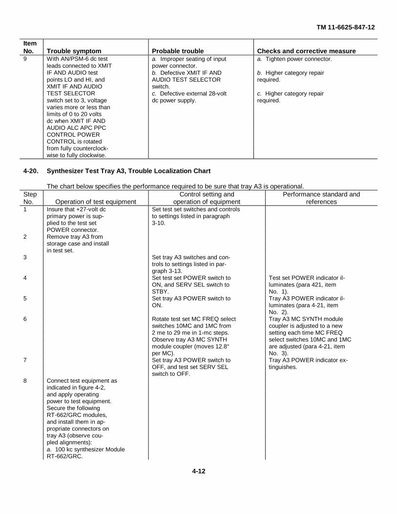
TM 11-6625-847-12
ItemNo. Trouble symptom Probable trouble Checks and corrective measure9 With AN/PSM-6 dc test a. Improper seating of input a. Tighten power connector.
leads connected to XMIT power connector.IF AND AUDIO test b. Defective XMIT IF AND b. Higher category repairpoints LO and HI, and AUDIO TEST SELECTOR required.XMIT IF AND AUDIO switch.TEST SELECTOR c. Defective external 28-volt c. Higher category repairswitch set to 3, voltage dc power supply. required.varies more or less thanlimits of 0 to 20 voltsdc when XMIT IF ANDAUDIO ALC APC PPCCONTROL POWERCONTROL is rotatedfrom fully counterclock-wise to fully clockwise.
4-20. Synthesizer Test Tray A3, Trouble Localization Chart
The chart below specifies the performance required to be sure that tray A3 is operational.Step Control setting and Performance standard andNo. Operation of test equipment operation of equipment references1 Insure that +27-volt dc Set test set switches and controls
primary power is sup- to settings listed in paragraphplied to the test set 3-10.POWER connector.
2 Remove tray A3 fromstorage case and installin test set.
3 Set tray A3 switches and con-trols to settings listed in par-graph 3-13.
4 Set test set POWER switch to Test set POWER indicator il-ON, and SERV SEL switch to luminates (para 421, itemSTBY. No. 1).
5 Set tray A3 POWER switch to Tray A3 POWER indicator il-ON. luminates (para 4-21, item
No. 2).6 Rotate test set MC FREQ select Tray A3 MC SYNTH module
switches 10MC and 1MC from coupler is adjusted to a new2 me to 29 me in 1-mc steps. setting each time MC FREQObserve tray A3 MC SYNTH select switches 10MC and 1MCmodule coupler (moves 12.8° are adjusted (para 4-21, itemper MC). No. 3).
7 Set tray A3 POWER switch to Tray A3 POWER indicator ex-OFF, and test set SERV SEL tinguishes.switch to OFF.
8 Connect test equipment asindicated in figure 4-2,and apply operatingpower to test equipment.Secure the followingRT-662/GRC modules,and install them in ap-propriate connectors ontray A3 (observe cou-pled alignments):a. 100 kc synthesizer ModuleRT-662/GRC.
4-12

TM 11-6625-847-12
Step Control setting and Performance standard andNo. Operation of test
equipmentoperation of equipment references
b. Frequency standardModule 1A3, RT-662/GRC.c. 10 and 1 kc synthesizerModule 1A4, RT-622/GRC.d. Frequency dividerModule 1A6, RT-662/GRC.e. Translator Module 1A8,RT-662/GRC.f. Mc synthesizer Module1A9, RT-/GRC.
9 Set test set SERV SEL switch Tray A3 POWER indicator il-to STBY, and tray AS POWER luminates.switch to ON.
10 If operating from a cold start,allow 15-minute warmup timefor equipment stability. Ifequipment has been warmed upwithin the last hour, 5-minutewarmup time is sufficient.
11 Connect AM/PSM-across Adjust tray AS POWER ADJ AN/PSM-indicates voltagetray AS POWER IN- control from fully counter- varying from minimum 0 voltPUTS VAR test connector clockwise to fully clockwise. dc to maximum +26 volts dc;and POWER INPUTS set to +20 volts dc (para(ground) test connector. 4-21, item No. 4).
12 Disconnect AN/PSM-6.13 Connect AN/URM-145 Set 10&1KC SYNTH OUTPUT Observe that output increases
to tray A2 10&1KC AMPL switch to ON, and ad- as adjustment is made clock-SYNTH OUTPUT 7.1 just 10&1KC SYNTH OUT- wise (para 4-21, item No. 5).MC connector. PUT VOLT ADJ control fromCaution: Adjust AN/ fully counterclockwise to fullyURM-145 to scale above clockwise. Return 10&1KC1 volt, and readjust ac- SYNTH OUTPUT VOLT ADJcordingly to avoid damage control from fully counterclock-to instrument. wise to fully clockwise. Return
10&1KC SYNTH OUTPUTVOLT ADJ control to mid-range.
14 Disconnect AN/URM-145from 10&1KC SYNTHOUTPUT 7.1 MC con-nector.
15 Connect AN/URM-145 to Set tray A3 10&1KC SYNTH Observe that the output increasestray AS 10&1KC SYNTH SYNTH OUTPUTS AMPL as the adjustment is madeOUTPUTS connector. switch to ON, and adjust clockwise (para 421, itemCaution: Adjust AN/ 10&1KC SYNTH SYNTH No. 6).URM-145 to scale above OUTPUTS VOLT ADJ con-1 volt, and readjust ac- trol from fully counterclock-cordingly to avoid damage wise to fully clockwise. Returnto instrument. 10&1KC SYNTH SYNTH
OUTPUTS VOLT ADJ controlto midrange.
16 Disconnect AN/URM-145from 10&1KC SYNTHSYNTH OUTPUTSconnector.
4-13

TM 11-6625-847-12
Step Control setting and Performance standard andNo. Operation of test
equipmentoperation of equipment reference
17 Connect AN/URM-145 to Set tray A3 MC SYNTH OUT- Observe that output increases astray A3 MC SYNTH PUT AMPL switch to ON, and adjustment is made clockwiseOUTPUT MC SYNTH adjust MC SYNTH OUTPUT (para 4-21, item No. 7).connector. VOLT ADJ control from fullyCaution: Adjust AN/ counterclockwise to fully clock-URM-145 to scale above wise. Return MC SYNTH1 volt, and readjust ac- OUTPUT VOLT ADJ control as/cordingly to avoid damage to midrange.to instrument.
18 Disconnect AN/URM-145.19 Reset all switches and controls Test set and tray A3 POWER
to settings listed in paragraphs indicators extinguish3-10 and 3-13.
20 Remove RT-62/GRC Remove tray A3 from test setmodules (1A2, 1A3, 1A4, and return to case 2.1A8, and 1A9) fromtray A3 and returnthem to proper storageplace.
4-21. Synthesizer Test Tray A3, Trouble Isolation ChartItemNo. Trouble symptom Probable trouble Checks and corrective measure
1 POWER indicator lamp a. Defective external 27-volt de a. Higher category repair re-will not illuminate. power supply. quired.
b. Improper seating of input b. Tighten power connector.power connector.c. Defective fuse---------------------------------- c. Replace fuse (para 4-26a).d. Defective lamp---------------------------------- d. Replace indicator lamp (para
4-26b).e. Defective POWER switch ------------------- e. Higher category repair re-
quired.2 Tray A3 POWER indicator a. Improper seating of input a. Tighten power connector.
lamp will not illuminate. power connector.b. Defective test set fuse ------------------------ b. Replace fuse (para 4-26a).c. Defective indicator lamp---------------------- c. Replace indicator lamp (para
4-26b).3 When test set MC FREQ a. Improper seating of input a. Tighten power connector.
select switches 10MC and power connector.1MC are rotated in 1-mc b. Defective motor positioner ------------------- b. Higher category repair re-steps, module coupler quired.does not adjust to newsetting.
4 With AN/PSM-6 con- a. Improper seating of input a. Tighten power connector.nected across POWER power connector.INPUTS (ground) test b. Defective POWER switch ------------------- b. Higher category repair re-connectors, adjust quired.POWER ADJ controlfully counterclockwiseto fully clockwise; volt-age varies more or lessthan limits of 0 to +26volts dc
5 With AN/URM-1465 con- Improper seating of power con- Tighten power connector.nected to 10&1KC nector.SYNTH OUTPUT 7.1MC connector, indication
4-14

TM 11-6625-847-12
ItemNo. Trouble symptom Probable trouble Checks and corrective measure
does not increase when10&1KC SYNTH OUT-PUT VOLT ADJ controlis adjusted clockwise
6 With AN/URM-145 con- a. Improper seating of power a. Tighten power connector.nected to 10&1KC connector.SYNTH SYNTH OUT- b. Defective VOLT ADJ control. b. Higher category repair re-PUTS '10&1KC con- quired.nector, indication does notincrease when 10&1KCSYNTH SYNTH OUT-PUTS VOLT ADJ con-trol is adjusted clock-wise.
7 With AN/URM-145 con- a. Improper seating of power a. Tighten power connector.nected to MC SYNTH1 connector.OUTPUT MC SYNTH b. Defective MC SYNTH OUT- b. Higher category repair re-connector, indication PUT VOLT ADJ control. quired.does not increase whenMC SYNTH OUTPUTVOLT ADJ control isadjusted clockwise
4-22. Converter and Control Tray A4, Trouble Localization ChartThe chart below specifies the performance required to be sure that tray A4 is operational.
step Control setting and Performance standard andNo. Operation of test
equipmentoperation of equipment references
Note. AN/PSM- is theonly test equipment requiredfor the following test.
1 Remove tray A4 fromstorage case and secureto test set.
2 Insure that +27-volt de Set test set switches and controls Para 4-23, item No. 1.primary power is sup- to setting listed in paragraphplied to test set POWER 3-10. Set tray A4 switches andconnector. controls to settings listed in
paragraph 3-14.3 Set test set POWER switch to Test set and tray A4 POWER
ON, and rotate SERV SEL indicators illuminate (paraswitch to STBY. Set tray A4 4-23, item No. 1).POWER switch to ON.
4 Connect AN/PSM-6 to test Adjust test set DC VOLTAGEset DC VOLTAGE +20 +20 control to obtain an AN/test connector. PSM-6 20-volt dc indication.
5 Press CONTROL TEST indca- Each indicator should light whentors A1 through A5, B1 through pressed (para 4-23, item No.B5, and C1 through C5. 2).
6 Connect AN/PSM- d Rotate PA METER TEST AN- Voltage should vary from -4 voltsleads across PA METER TENNA LOAD/TUNE control de to +3.6 volts de (paraTEST ANTENNA from fully counterclockwise to 4-23, item No. 3).LOAD/TUNE test point fully clockwise.and ground.
7 Connect AN/PSM- de Rotate PA METER TEST ALC Voltage should vary from 0 volttest leads across PA METER control from fully dc to +1.7 volts de (para 4-23,METER TEST ALC counterclockwise to fully lock- item No. 4).METER test point and wise.ground.
4-15
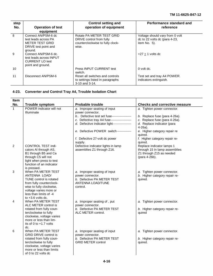
TM 11-6625-847-12
step Control setting and Performance standard andNo. Operation of test
equipmentoperation of equipment reference
8 Connect AN/PSM-6 dc Rotate PA METER TEST GRID Voltage should vary from 0 volttest leads across PA DRIVE control from fully dc to 22 volts dc (para 4-23,METER TEST GRID counterclockwise to fully clock- item No. 5).DRIVE test point and wise.ground.
9 Connect AN/PSM-6 dc. +27 + 1 volts dctest leads across INPUTCURRENT LO testpoint and ground.
10 Press INPUT CURRENT test 0 volt dc.switch.
11 Disconnect AN/PSM-6 Reset all switches and controls Test set and tray A4 POWER.to settings listed in paragraphs indicators extinguish.3-10 and 3-14.
4-23. Converter and Control Tray A4, Trouble Isolation Chart
ItemNo. Trouble symptom Probable trouble Checks and corrective measure1 POWER indicator will not a. Improper seating of input a. Tighten power connector.
Illuminate power connector.b.. Defective test set fuse------------------ b. Replace fuse (para 4-26a).c. Defective tray A4 fuse------------------- c. Replace fuse (para 4-26a).d. Defective indicator light----------------- d. Replace indicator (para
4-26a).e. Defective POWER switch ------------- e. Higher category repair re
quired.f. Defective 27-volt dc power f. Higher category repair re-supply. quired.
2 CONTROL TEST indi- Defective indicator lights in lamp Replace indicator lamps 1cators Al through AS, assemblies Z1 through Z16. through 15 in lamp assembliesB1 through B5 and Ca Z1 through Z15 as neededthrough C5 will not (para 4-26b).light when press to testfunction of an indicatoris pressed.
3 When PA METER TEST a. Improper seating of input a. Tighten power connector.ANTENNA LOAD/ power connector. b. Higher category repair re-TUNE control is rotated b. Defective PA METER TEST quired.from fully counterclock- ANTENNA LOAD/TUNEwise to fully clockwise, control.voltage varies more orless than limits of -4to +3.6 volts dc.
4 When PA METER TEST a. Improper seating of , put a. Tighten power connector.ALC METER control is power connector.rotated from fully coun- b. Defective PA METER TEST b. Higher category repair re-terclockwise to fully ALC METER control. quiredclockwise, voltage variesmore or less than lim-its of 0 to +1.7 voltsdc.
6 When PA METER TEST a. Improper seating of input a. Tighten power connector.GRID DRIVE control is power connector.rotated from fully coun- b. Defective PA METER TEST b. Higher category repair re-terclockwise to fully GRID METER control quired.clockwise, voltage variesmore or less than limitsof 0 to 22 volts dc
4-16
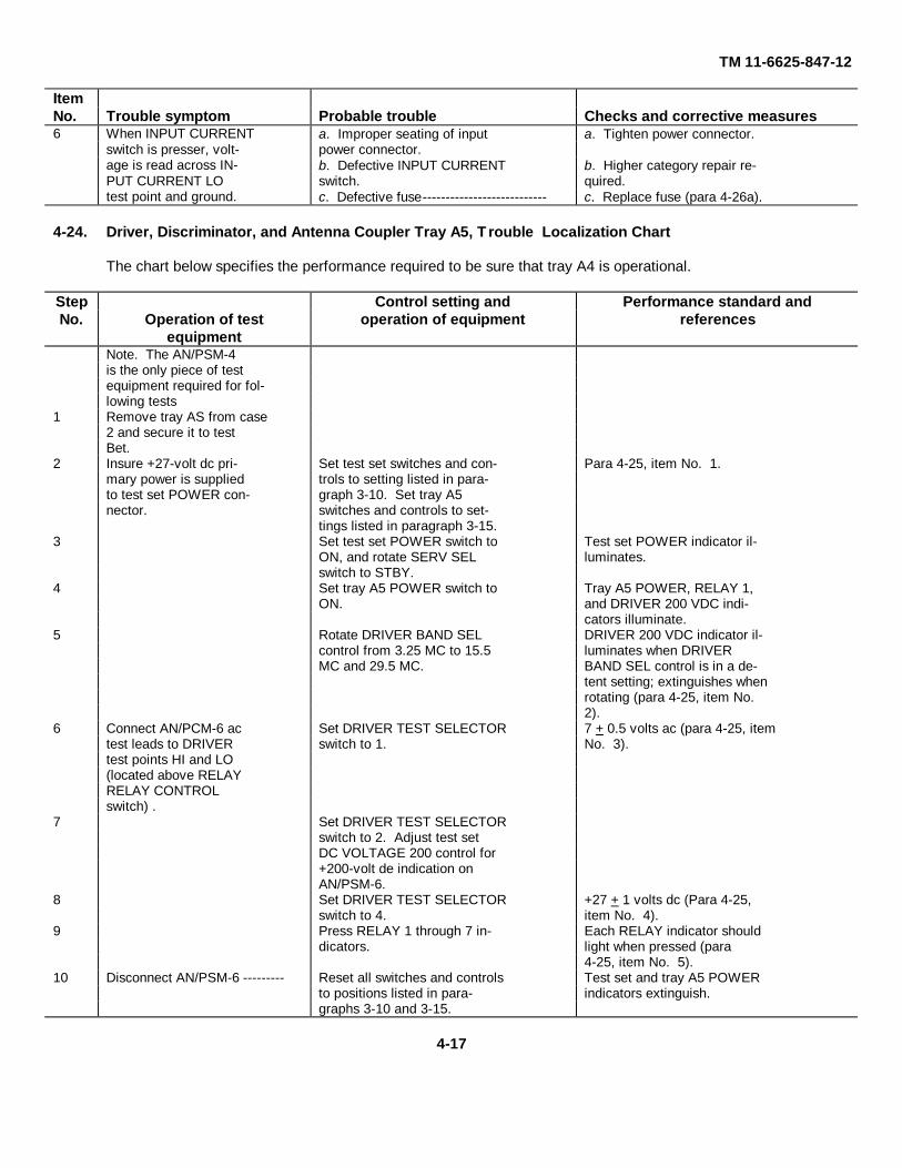
TM 11-6625-847-12
ItemNo. Trouble symptom Probable trouble Checks and corrective measures6 When INPUT CURRENT a. Improper seating of input a. Tighten power connector.
switch is presser, volt- power connector.age is read across IN- b. Defective INPUT CURRENT b. Higher category repair re-PUT CURRENT LO switch. quired.test point and ground. c. Defective fuse--------------------------- c. Replace fuse (para 4-26a).
4-24. Driver, Discriminator, and Antenna Coupler Tray A5, Trouble Localization Chart
The chart below specifies the performance required to be sure that tray A4 is operational.
Step Control setting and Performance standard andNo. Operation of test
equipmentoperation of equipment references
Note. The AN/PSM-4is the only piece of testequipment required for fol-lowing tests
1 Remove tray AS from case2 and secure it to testBet.
2 Insure +27-volt dc pri- Set test set switches and con- Para 4-25, item No. 1.mary power is supplied trols to setting listed in para-to test set POWER con- graph 3-10. Set tray A5nector. switches and controls to set-
tings listed in paragraph 3-15.3 Set test set POWER switch to Test set POWER indicator il-
ON, and rotate SERV SEL luminates.switch to STBY.
4 Set tray A5 POWER switch to Tray A5 POWER, RELAY 1,ON. and DRIVER 200 VDC indi-
cators illuminate.5 Rotate DRIVER BAND SEL DRIVER 200 VDC indicator il-
control from 3.25 MC to 15.5 luminates when DRIVERMC and 29.5 MC. BAND SEL control is in a de-
tent setting; extinguishes whenrotating (para 4-25, item No.2).
6 Connect AN/PCM-6 ac Set DRIVER TEST SELECTOR 7 + 0.5 volts ac (para 4-25, itemtest leads to DRIVER switch to 1. No. 3).test points HI and LO(located above RELAYRELAY CONTROLswitch) .
7 Set DRIVER TEST SELECTORswitch to 2. Adjust test setDC VOLTAGE 200 control for+200-volt de indication onAN/PSM-6.
8 Set DRIVER TEST SELECTOR +27 + 1 volts dc (Para 4-25,switch to 4. item No. 4).
9 Press RELAY 1 through 7 in- Each RELAY indicator shoulddicators. light when pressed (para
4-25, item No. 5).10 Disconnect AN/PSM-6 --------- Reset all switches and controls Test set and tray A5 POWER
to positions listed in para- indicators extinguish.graphs 3-10 and 3-15.
4-17

TM 11-6625-847-12
4-25. Driver, Discriminator, and Antenna Coupler Tray A5, Trouble Isolation Chart
ItemNo. Trouble symptom Probable trouble Checks and corrective measures
1 POWER indicator will not a. Improper seating of input a. Tighten power connector.illuminate. power connector.
b. Defective test set fuse ------------------ b. Replace fuse (para 4-26a).c. Defective indicator light----------------- c. Replace indicator light (para
4-26b).d. Defective POWER switch ------------- d. Higher category repair re-
quired.2 DRIVER 200 indicator will a. Microswitch defective ------------------ a. Higher category repair re-
not illuminate. quired.b. Defective 200-volt dc power b. Higher category repair re-supply. quired.c. Defective indicator light----------------- c. Replace indicator light (para
4-26b).d. Improper seating of input d. Tighten power connector.power connector.e. Improper seating of DIS- e. Reset discriminator assembly;CRIMINATOR assembly if this does not correct prob-connector, and discrimina- lem, check DISCRIMINA-tor assembly 2A4, AM- TOR assembly connector for3349/GRC-106. bent pins or broken wires.
Higher category repair re-quired.
3 DRIVER TEST SELEC- a. Defective DRIVER TEST a. Higher category repair re-TOR switch set to 1, and SELECTOR switch quiredAN/PSM-6 ac leads b. Improper seating of input b. Tighten power connector.connected to DRIVER power connector.HI and LO test points c. Defective 6.3-volt ac power c. Higher category repair re-(lower right side); volt- supply. quired.age varies more or lessthan limits of 6.5 to 7.5volts ac.
4 DRIVER TEST SELEC a. Defective DRIVER TEST a. Higher category repair re-TOR switch set to 4; 27 SELECTOR switch quired.volts de is not present. b. Improper seating of input b. Tighten power connector.
power connector.c. Defective test set fuse. c. Replace fuse (par. 4-26a).
d. Defective POWER switch -------------- d. Higher category repair re-quired.
e. Defective 27-volt dc power e. Higher category repair re-supply. quired.
5 RELAY 1 through 7 indi- Defective indicator lamp assem- Replace RELAY indicators 1cators do not light when blies Z1 through Z7. through 7 in lamp assembliespress to test function of Z1 through Z7 as needed (paraindicators is press 4-26b).
4-26. Replacement and Adjustmentsa. Replacement of Fuses.
(1) Press in on the fuse cap and turn itcounterclockwise to unlock; remove thecap and the fuse.
(2) Discard the old fuse and insert a newfuse of the same type and rating in thefuse cap. A spare fuse for the test
set is mounted in the spare fuseholder,directly below the main fuseholder. Aspare fuse for tray A4 will be part of therunning spare items list.
(3) Replace the cap and the fuse in thefuseholder; tighten by pressing in andturning the cap clockwise.
4-18

TM 11-6625-847-12
b. Replacement of Indicator Lamps.
(1) Unscrew the indicator lens (counterclockwise)and remove it from the lampholder.
(2) Press in on the lamp bulb and turn itcounterclockwise to unlock it.
(3) Replace the defective lamp bulb with a newlamp bulb of the same type.
(4) Replace the indicator lens.
c. Adjustment. No adjustment procedures are tobe performed by organizational maintenance personnel.
4-19

TM 11-6625-847-12
CHAPTER 5SHIPMENT, LIMITED STORAGE, AND DEMOLITION
TO PREVENT ENEMY USE
Section I. SHIPMENT AND LIMITED STORAGE
5-1. Disassembly of EquipmentPrepare the SM-442A/GRC for shipment and storage asfollows:
a. Disconnect all cabling, adapters, and dummyloads from the test set.
b. Store cables, adapters, and dummy loads in thestorage compartment in the front of cover of case 2.
c. Check to see that trays A1 through A5 aremounted and secured in case 1.
d. Close and secure the front covers on case 1 andcase 2 with the attached fasteners.5-2. Repacking for Shipment or Limited StorageThis section describes the method for preparing the SM-442A/GRC for reshipment. Package the units in theoriginal containers. If the original containers are notavailable, use those of similar quantity and size.5-3. Case 1
(fig. 2-1)Package case 1 as follows:
a. Place the four polystyrene corner pads in the
corrugated carton, arrange the pads so that they willreceive the four corners of case 1 when it is placed in itscarton.
b. Place case I on the four polystyrene corner padsin the corrugated carton.
c. Set one corner pad on each of the top cornersof case 1.
d. Place the polyethylene shroud over case 1.e. Place the taped corrugated carton into the
plywood crate.5-4. Case 2
(fig. 2-1)Package case 2 as follows:
a. Repeat the procedures given in paragraph 5-3athrough f b. Place the top on the plywood crate andfasten it securely with No. 2 klimp fasteners.5-5. Storage Conditions
a. Prolonged Storage. Pack case 1 and case 2 inthe plywood crate in which they were shipped.
b. Short storage. Seal the self-contained storagecases and place them in an upright position.
Section II. DEMOLITION OF MATERIEL TO PREVENT ENEMY USE
5-6. Authority for DemolitionThe demolition procedures given in paragraph 5-7 willbe used to prevent the enemy from using or salvagingthis equipment. Demolition of the equipment will beaccomplished only upon the order of the commander.5-7. Methods of DestructionThe tactical situation and the time available willdetermine the method to be used when destruction ofequipment is ordered. In most cases, it is preferred tocompletely demolish some portions of the equipmentrather than partially destroy all the equipment units.
a. Smash. Smash the interior units of the SM-442A/GRC.
(1) Smash the connectors, the meters, theknobs, the dials, and the power supply.
Note. Heavy tools will effectively destroy theexternal parts mentioned in (1) above, but theremainder of the exposed surfaces of the equipmentare constructed of steel plate; attempts to damage itby smashing will be useless .
(2) Remove the chassis from the cabinet.Smash as many of the exposed parts of the variouschassis as possible.
b. Cut. Cut the cabling, the cording, and thewiring. Cut the power cable and all the cords and thecables in a number of places.
Warning: Be extremely careful withexplosives and incendiary devices. Use these itemsonly when the need is urgent.
c. Burn. Burn the technical manuals first. Burn asmuch of the equipment as is flammable. Pour gasolineon the cut cables and internal wiring and ignite them.Burn spare parts, or pour gasoline on the spare partsand ignite them. Complete the
Change 2 5-1

TM 11-6625-847-12
destruction of the SM-442A/GRC.
d. Explode. USE explosives to completedemolition or to case destruction by other means.Power chargers, fragmentation grenades, or incendiarygrenades may be used. Incendiary grenades usually aremost effective if destruction of small parts and wiring isdesired.
(1) Use a fragmentation grenade to destroythe interior of the test set. Unlatch the fasteners on thefront cover of case 2; open the front cover. Release thesix captive screws on the test set front panel. Pull thefront panel forward and drop the grenade into theinterior.
(2) Destroy case 1 by use of a fragmentationgrenade as follow:
(a) Unlatch the fasteners on the frontcover of case 1.
(b) Open the front cover and drop thegrenade onto the top of the test tray in case 1.
(3) For quick destruction of the SM-442A/GRC, place an incendiary grenade on top of bothof the unit. Get away from the units after the grenade isplaced.
e. Dispose. Bury or scatter destroyed parts, orthrow them into nearly important if a number ofparticularly important if a number of parts have not beencompletely destroyed.
Change 2 5-2

TM 11-6625-847-12
APPENDIX AREFERENCES
Following is a list of references available to the operator and organizational repairman of Simulator, Radio FrequencySM-442A/GRC.
DA Pam 3104 Index of Technical Manuals, Technical Bulletins, Supply Manuals (Types 7, 8, and9), Supply Bulletins, and Lubrication Orders.
DA Pam 310-7 Modification Work Orders.SB 38-100 Preservation, Packaging, and Packing Materials, Supplies, and Equipment Used by
the Army.TB SIG 291 Safety Measures to be observed When Installing and Using Whip Antennas, Field
Type Masts, Antennas, and Metal Poles that are used with Communication, Radar,and Direction Finder Equipment.
TB 434118 Field Instructions for Painting and Preserving Electronics Command EquipmentIncluding Camouflage Pattern Painting of Electrical Equipment shelters.
TM 43-0139 Painting Instructions for Field Use.TM 114820-520-12 Operator's and Organizational Maintenance Manual Including Repair Parts and
Special Tools Lists: Radio Sets AN/GRC-106 and AN/GRC-106A.TM 38-750 The Army Maintenance Management System (TAMMS).TM 740-90-1 Administrative Storage of Equipment.
Change 2 A-1

TM 11-6625-847-12
APPENDIX CMAINTENANCE ALLOCATION
Section I. INTRODUCTION
C-1. GeneralThis appendix provides a summary of the maintenanceoperations for SM-442A/GRC. It authorizes categoriesof maintenance for specific maintenance functions onrepairable items and components and the tools andequipment required to perform each function. Thisappendix may be used as an aid in planningmaintenance operations.C-2. Maintenance FunctionMaintenance functions will be limited to and defined asfollows:
a. Inspect. To determine the serviceability of anitem by comparing its physical, mechanical, and/orelectrical characteristics with established standardsthrough examination.
b. Test. To verify serviceability and to detectincipient failure by measuring. the mechanical orelectrical characteristics of an item and comparing thosecharacteristics with prescribed standards.
c. Service. Operations required periodically tokeep an item in proper operating condition, i.e., to clean,preserve, drain, paint, or to replenishfuel/lubricants/hydraulic fluids or compressed airsupplies.
d. Adjust. Maintain within prescribed limits bybringing into proper or exact position. or by setting theoperating characteristics to the specified parameters.
e. Align. To adjust specified variable elements ofan item to about optimum or desired performance.
f. Calibrate. To determine and cause correctionsto be made or to be adjusted on instruments or testmeasuring and diagnostic equipment used in precisionmeasurement. Consists of the comparison of twoinstruments, one of which is a certified standard ofknown accuracy, to detect and adjust any discrepancy inthe accuracy of the instrument being compared.
g. Install. The act of emplacing, seating, or fixinginto position an item, part, module (component orassembly) in a manner to allow the proper functioning ofthe equipment/system.
h. Replace. The act of substituting a serviceablelike-type part, subassembly, model (component orassembly) for an unserviceable counterpart.
i. Repair. The application of maintenanceservices (inspect, test, service, adjust, align, calibrate,replace) or other maintenance actions (welding,grinding, riveting, straightening, facing, remachining, orresurfacing) to restore serviceability to an item bycorrecting specific damage, fault, malfunction, or failurein a part, subassembly, module/component/assembly,end item or system. This function does not include thetrial and error replacement of running spare type itemssuch as fuses, lamps, or electron tubes.
j. Overhaul. That periodic maintenance effort(service/action) necessary to restore an item to acompletely serviceable/operational condition asprescribed by maintenance standards (e.g., DMWR) inappropriate technical publications. Overhaul is normallythe highest degree of maintenance performed by theArmy. Overhaul does not normally return an item to like-new condition.
k. Rebuild. Consists of those services/actionsnecessary for the restoration of unserviceableequipment to a like-new condition in accordance withoriginal manufacturing standards. Rebuild is the highestdegree of material maintenance applied to Armyequipment. The rebuild operation includes the act ofreturning to zero those age measurements (hours,miles, etc) considered in classifying Armyequipment/components.C-3. Column Entries
a. Column 1, Group Number. Column I lists groupnumbers, the purpose of which is to identifycomponents, assemblies, subassemblies and moduleswith the next higher assembly.
b. Column 2, Component/Assembly. Column 2contains the noun names of components. assemblies,subassemblies, and modules for which maintenance isauthorized.
c. Column 3, Maintenance Functions. Column 3lists the functions to be performed on the item listed incolumn 2. When items are listed without maintenancefunctions, it is solely for purpose of having the groupnumbers in the MAC and RPSTL coincide.
d. Column 4, Maintenance Category. Column 4specifies, by the listing of a "worktime" figure in theappropriate subcolumn(s), the lowest level of
Change 2 C-1

TM 11-6625-847-12
maintenance authorized to perform the function listed incolumn 3. This figure represents the active timerequired to perform that maintenance function at theindicated category of maintenance. If the number orcomplexity of the tasks within the listed maintenancefunction vary at different maintenance categories,appropriate "worktime" figures will be shown for eachcategory. The number of man-hours specified by the"worktime" figure represents the average time requiredto restore an item (assembly, subassembly, component,module, end item or system) to a serviceable conditionunder typical field operating conditions. This timeincludes preparation time, troubleshooting time andquality assurance/quality control time in addition to thetime required to perform the specific tasks identified forthe maintenance functions authorized in themaintenance allocation chart. Subcolumns of column 4are as follows:
C - Operator/Crew0 - OrganizationalF - Direct SupportH - General SupportD- Depot
e. Column 5, Tools and Equipment. Column 5
specifies by code, those common tool sets (notindividual tools) and special tools, test, and supportequipment required to perform the designated function.C-4. Tool and Test Equipment Requirements(Table 1)
a. Tool or Test Equipment Reference Code. Thenumbers in this column coincide with the numbers usedin the tools and equipment column of the MAC. Thenumbers indicate the applicable tool or test equipmentfor the maintenance functions.
b. Maintenance Category. The codes in thiscolumn indicate the maintenance category allocated thetool or test equipment.
c. Nomenclature. This column lists the noun nameand nomenclature of the tools and test equipmentrequired to perform the maintenance functions.
d. National/NATO Stock Number. This columnlists the National/NATO stock number of the specifictool or test equipment.
e. Tool Number. This column lists themanufacturer's part number of the tool followed by theFederal Supply Code for manufacturers (5-digit) inparentheses.
Change 2 C-2

TM 11-6625-847-12
SECTION II. MAINTENANCE ALLOCATION CHARTFOR
SIMULATOR, RADIO FREQUENCY SM-442A/GRC
(1) (2) (3) (4) (5))
GROUP MAINTENANCE MAINTENANCE LEVEL TOOLS ANDNUMBER COMPONENT ASSEMBLY FUNCTION C O F H D EQUIPMENT
00 SIMULATOR, RF Inspect1 0.2SM-442A/GRC Inspect2 0.5 18,19
Test3 0.4 1 thru 7Test 0.5 1 thru 14Service1 0. 2Service 0.5 18,19Adjust4 0 .4Adjust 0.5 18,19Calibrate 0.5 1 thru 14Repair5 0.2 15 thru 19Repair6 1.0Repair 3.0 15 thru 19Overhaul 4.0 1 thru 19Rebuild 10.0 1 thru 19
01 FRAME, STORAGE Inspect7 0.1Inspect 0.3 18,19Test3 0.2 1 thru 6Test 0.4 1,2,6,9,13Service1 0.2Service 0.3 18,19Adjust4 0.3 6,9,13,18,19Adjust 0.5 6,9,13,18,19Calibrate 0.5 1 thru 6,9,13Repair5 0.2Repair6 0.8 18.19Repair 1.0 18,19Overhaul 2.0 1 thru 6,9,13,
18,19Rebuild 4.0 1 thru 6,9,13,
18,190101 TRAY A1 Inspect1 0.1
(COMMON MODULE TRAY) Inspect 0.3Test3 0.2 1Test 0.4 1Service1 0.2Service 0.4 18,19Adjust 0.2Adjust 0.4Calibrate 0.5 1Repair5 0.1Repair6 1.0 18,19Repair 2.0 18,19Overhaul 3.0 1,18,19Rebuild 4.0 1,18,19
010101 GEAR DRIVE ASSEMBLY Inspect1 0.2Inspect 0.4 18,19Test3 0.2Test 0.5Service1 0.2Service 0.5 18,19Repair 1.0 18,19Overhaul 2.0 18,19Rebuild 4..0 18,19
See footnotes at end of chart.Change 2 C-3

TM 11-6625-847-12
SECTION II MAINTENANCE ALLOCATION CHARTFOR
SIMULATOR, RADIO FREQUENCY SM-442A/GRC
(1) (2) (3) (4) (5))
GROUP MAINTENANCE MAINTENANCE LEVEL TOOLS ANDNUMBER COMPONENT ASSEMBLY FUNCTION C O F H D EQUIPMENT
0102 TRAY A2 Inspect1 0.1(COMMON MODULE TRAY) Inspect 0.3 18,19
Test3 0.2 1,3Test 0.4 1,2,6,9,13Service1 0.2Service 0.4 18.19Adjust 0.2 6,9,13,18Adjust 0.4 6,9,13,18Calibrate 0.5 2,6,9,13Repair5 0.1Repair 1.0 18,19Overhaul 2.0 1,2,6,9.13,18,19Rebuild 4.0 1,2,6,9,13,18,19
0103 TRAY A3 Inspect1 0.1(SYNTHESIZER TEST TRAY) Inspect 0.3 18,19
Test3 0.2 1,2Test 0.4 2,6,9,13Service1 0.2Service 0.4 18,19Adjust4 0.2 18,19Adjust 0.4 18,19Calibrate 0.5 1,2,6,9,13Repair5 0.1Repair6 1.0 18,19Repair 2.0 18,19Overhaul 2.0 1,2,6,9,13,18,19Rebuild 4.0 1,2,6,9,13,18,19
010301 GEAR DRIVE ASSEMBLY Inspect1 0.2Inspect 0.4 18,19Test3 0.2Test 0.5Service1 0.2Service 0.5 18,19Repair 1.0 18,19Overhaul 2.0 18,19Rebuild 4.0 18,19
0104 TRAY A4 Inspect1 0.1(CONVERTER AND CONTROL TRAY) Inspect 0.3 18,19
Test3 0.2 1Test 0.4 1Service1 0.2Service 0.4 18,19Adjust4 0.2 18,19Adjust 0.4 18,19Calibrate 0.5 18,19Repair5 0.1Repair 1.0 18,19Overhaul 2.0 1,18,19Rebuild 4.0 1,18,19
See footnotes at end of chart.Change 2 C-14

TM 11-6625-847-12
SECTION II MAINTENANCE ALLOCATION CHARTFOR
SIMULATOR, RADIO FREQUENCY SM-442A/GRC
(1) (2) (3) (4) (5))
GROUP MAINTENANCE MAINTENANCE LEVEL TOOLS ANDNUMBER COMPONENT ASSEMBLY FUNCTION C O F H D EQUIPMENT
0105 TRAY A5 Inspect1 0.2(DRIVER, DISCRIMINATOR, AND Inspect 0.3 18,19ANTENNA COUPLER TRAY) Test3 0.2 1
Test 0.4 1Service1 0.2Service 0.4 18,19Calibrate 0.5 1Repair5 0.1Repair 1.0 18,19Overhaul 2.0 1,18,19Rebuild 4.o 1,18,19
0106 10-XHZ SYNTHESIZER MODULE 1A2 Inspect1 0.2Inspect 0.3 18,19
0107 FREQUENCY STANDARD MODULE Test3 0.2 1 thru 61A3
Test 0.5 1 thru 140108 10-KHZ AND 1-HZ SYNTHESIZER Service1 0.2
MODULE 1A40109 FREQUENCY DIVIDER MODULE 1A6 Service 0.4 18,19
adjust 1.0 18,190110 MC SYNTHESIZER 1A9 Align 1.0 18,19
Repair 4.0 18.19Rebuild 8.0 18,19
0111 TRANSLATOR MODULE 1A8 Inspect1 0.2Inspect 0.3Test3 0.2Test 1.0 1 thru 14Service1 0.2Service 0.4 18,19Adjust 1.0 18,19Align 1.0 18,19Repair 6.0 18,19Rebuild 8.5 18,19
02 TEST SET Inspect1 0.3Inspect 0.4 18,19Test3 0.3 1 thru 7Test 0.5 1 thru 14Service1 0.3 0.5 18,19Service 0.5 18.19AdJust4 0.2Adjust 0.5 18,19Calibrate 0.5 1 thru 14Repair5 0.2Repair 1.0 18,19Overhaul 3.0 1 thru 19Rebuild 8.o 1 thru 19
03 CABLE ASSEMBLIES Inspect 0.2W1 Through W25 Test 0.5
Service 0.5Repair 0.5Overhaul 0.8Rebuild 1.0
(1) Exterior only.(2) All inspections.(3) Operational performance tests only.(4) Only those adjustments which do not affect calibration.(5) By replacement of knobs and fuses.(6) All repair, except gear drive assemblies.(7) Exterior of cases and trays,
Change 2 C-5
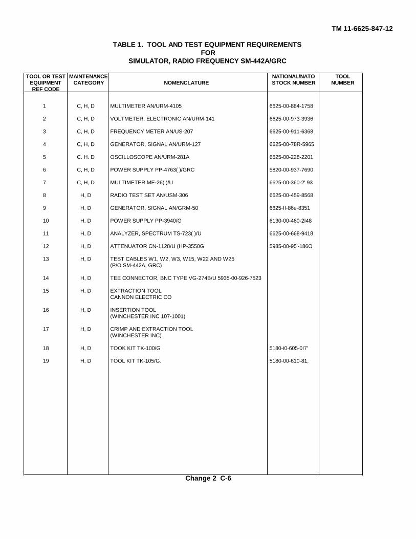
TM 11-6625-847-12
TABLE 1. TOOL AND TEST EQUIPMENT REQUIREMENTSFOR
SIMULATOR, RADIO FREQUENCY SM-442A/GRC
TOOL OR TEST MAINTENANCE NATIONAL/NATO TOOLEQUIPMENT CATEGORY NOMENCLATURE STOCK NUMBER NUMBERREF CODE
1 C, H, D MULTIMETER AN/URM-4105 6625-00-884-1758
2 C, H, D VOLTMETER, ELECTRONIC AN/URM-141 6625-00-973-3936
3 C, H, D FREQUENCY METER AN/US-207 6625-00-911-6368
4 C, H, D GENERATOR, SIGNAL AN/URM-127 6625-00-78R-5965
5 C. H. D OSCILLOSCOPE AN/URM-281A 6625-00-228-2201
6 C, H, D POWER SUPPLY PP-4763( )/GRC 5820-00-937-7690
7 C, H, D MULTIMETER ME-26( )/U 6625-00-360-2'.93
8 H, D RADIO TEST SET AN/USM-306 6625-00-459-8568
9 H, D GENERATOR, SIGNAL AN/GRM-50 6625-II-86e-8351
10 H, D POWER SUPPLY PP-3940/G 6130-00-460-2I48
11 H, D ANALYZER, SPECTRUM TS-723( )/U 6625-00-668-9418
12 H, D ATTENUATOR CN-1128/U (HP-3550G 5985-00-95'-186O
13 H, D TEST CABLES W1, W2, W3, W15, W22 AND W25(P/O SM-442A, GRC)
14 H, D TEE CONNECTOR, BNC TYPE VG-274B/U 5935-00-926-7523
15 H, D EXTRACTION TOOLCANNON ELECTRIC CO
16 H, D INSERTION TOOL(WINCHESTER INC 107-1001)
17 H, D CRIMP AND EXTRACTION TOOL(WINCHESTER INC)
18 H, D TOOK KIT TK-100/G 5180-i0-605-0I7'
19 H, D TOOL KIT TK-105/G. 5180-00-610-81,
Change 2 C-6
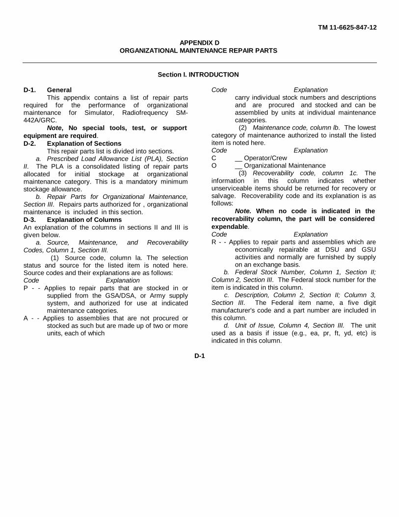
TM 11-6625-847-12
APPENDIX DORGANIZATIONAL MAINTENANCE REPAIR PARTS
Section I. INTRODUCTION
D-1. GeneralThis appendix contains a list of repair parts
required for the performance of organizationalmaintenance for Simulator, Radiofrequency SM-442A/GRC.
Note, No special tools, test, or supportequipment are required.D-2. Explanation of Sections
This repair parts list is divided into sections.a. Prescribed Load Allowance List (PLA), Section
II. The PLA is a consolidated listing of repair partsallocated for initial stockage at organizationalmaintenance category. This is a mandatory minimumstockage allowance.
b. Repair Parts for Organizational Maintenance,Section III. Repairs parts authorized for , organizationalmaintenance is included in this section.D-3. Explanation of ColumnsAn explanation of the columns in sections II and III isgiven below.
a. Source, Maintenance, and RecoverabilityCodes, Column 1, Section III.
(1) Source code, column la. The selectionstatus and source for the listed item is noted here.Source codes and their explanations are as follows:Code ExplanationP - - Applies to repair parts that are stocked in or
supplied from the GSA/DSA, or Army supplysystem, and authorized for use at indicatedmaintenance categories.
A - - Applies to assemblies that are not procured orstocked as such but are made up of two or moreunits, each of which
Code Explanationcarry individual stock numbers and descriptionsand are procured and stocked and can beassemblied by units at individual maintenancecategories.
(2) Maintenance code, column lb. The lowestcategory of maintenance authorized to install the listeditem is noted here.Code ExplanationC __ Operator/CrewO __ Organizational Maintenance
(3) Recoverability code, column 1c. Theinformation in this column indicates whetherunserviceable items should be returned for recovery orsalvage. Recoverability code and its explanation is asfollows:
Note. When no code is indicated in therecoverability column, the part will be consideredexpendable.Code ExplanationR - - Applies to repair parts and assemblies which are
economically repairable at DSU and GSUactivities and normally are furnished by supplyon an exchange basis.
b. Federal Stock Number, Column 1, Section II;Column 2, Section III. The Federal stock number for theitem is indicated in this column.
c. Description, Column 2, Section II; Column 3,Section III. The Federal item name, a five digitmanufacturer's code and a part number are included inthis column.
d. Unit of Issue, Column 4, Section III. The unitused as a basis if issue (e.g., ea, pr, ft, yd, etc) isindicated in this column.
D-1

TM 11-6625-847-12
e. Quantity Incorporated in Unit Pack, Column 4,Section II; Column 5, Section III. Not used.
f. Quantity Incorporated in Unit, Column 6, SectionIII. The quantity of repair parts in an assembly is givenin this column.
g. Maintenance Allowances, Column 3, Section II;Column 7, Section III.
(1) The allowance columns are divided intosubcolumns. Indicated in each subcolumn opposite eachitem is the total quantity of items authorized for thenumber of equipments supported. Items authorized foruse as required but not for initial stockage are identifiedwith an asterisk (*) in the allowance column.
(2) The quantitive allowances fororganizational category of maintenance represents oneinitial prescribed load for a 15-day period for the numberof equipments supported. Units and organizationsauthorized additional prescribed loads will multiply thenumber of prescribed loads authorized by the quantity ofrepair parts reflected in the appropriate density columnto obtain the total quantity or repair parts authorized.
(3) Subsequent changes to organizationalallowances will be limited as follows: No change in therange of items is authorized. If additional items areconsidered necessary, recommendation should beforwarded to Commanding General, U. S. ArmyElectronics Command, ATTN: AMSEL-MR-NMP-CR,Fort Monmouth, N. J., 07703, for exception or revisionto the allowance list. Revisions to the range of itemsauthorized will be made by the USA ECOM NationalMaintenance Point based upon engineering experience,demand data, or TAERS information.
h. Illustration, Column 8, Section III.(1) Figure number, column 8a. Not used.(2) Item or symbol number, column 8b. The
callout number used to reference the item in theillustration appears in this column.D-4. Location of Repair Parts
a. When the Federal stock number is unknown,follow the procedures given in (1) through (4) below.
(1) Locate the appropriate appendix of therepair parts list.
(2) If the item or symbol number is available,locate the item by scrutiny of column 8b of the repairparts list.
(3) If the item, symbol, and figure number arenot known, check the description column (column 3) inthe repair parts list to locate the part. The parts in thecolumn are arranged in alphabetical order.
(4) Locate the applicable illustration in thismanual and note the figure number and item number.Use the repair parts listing and locate the item numberas noted on the illustration.
b. When the Federal stock number is known, usethe repair part listing to find the repair part and the itemnumber.D-5. Federal Supply Codes
This paragraph list the Federal supply code andthe associated manufacturer's name.Code Manufacturer00141 -------Pic Design Corp.58189 -------General Dynamics Corp, Electronics
Div.80058 -------Joint Electronics Type Designation
System80063 -------Army Electronics Command81349 -------Military Specifications95712 -------Dage Electric Co., Inc.96906 -------Military Standards
D-2

TM 11-6625-847-12
SECTION II. PRESCRIBED LOAD ALLOWANCE LIST
PRESCRIBED LOAD ALLOWANCE
(1) (2) (3)15-DAY ORG MAINT. ALW
FEDERAL DESCRIPTION (A) (B) (C) (D)STOCKNUMBER 1-5 6-20 21-50 51-100
5355-556-0145 KNOB: 96906; MS91528-1K2B * * 2 2
5355-582-3804 KNOB: 96906; MS91528-2P2B * * * 2
5355-937-9335 KNOB: 96906; MS91528-OE1B * * * 2
5920-243-3787 FUSE, CARTRIDGE: 81349; F03A250V10AS 2 2 3 6
5920-850-6092 FUSE, CARTRIDGE: 81349; F02B32V10AS 2 2 6 11
5935-965-4891 KNOB: 96906; MS91528-1C2B * * 2 2
6240-155-7836 LAMP INCANDESCENT: 96906; MS25237-327 2 2 4 8
6240-892-4420 LAMP, NEON: 96906; MS25252NE2D * * * 2
D-3
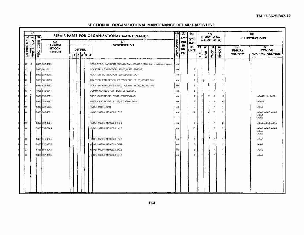
TM 11-6625-847-12
SECTION III. ORGANIZATIONAL MAINTENANCE REPAIR PARTS LIST
A C R 6625-937-4029 SIMULATOR, RADIOFREQUENCY SM-442A/GRC (This item is nonexpendable) ea
P C 5935-201-2411 ADAPTER, CONNECTOR: 96906; MS35173-274B ea 2 * * * *
P C 5935-837-9648 ADAPTER, CONNECTOR: 80058; UG107B/U ea 1 * * * *
P C 5935-901-8708 ADAPTER, RADIOFREQUENCY CABLE: 58189; A51836-001 ea 1 * * * *
P C 5935-832-9291 ADAPTER, RADIOFREQUENCY CABLE: 58189; A51870-001 ea 1 * * * *
P C 4931-546-6347 DUMMY CONNECTOR PLUG: 95712; 534-2 ea 1 * * * *
P C 5920-850-6092 FUSE, CARTRIDGE: 81349; F02B32V10AS ea 2 2 2 6 11 A1A4F1, A1A4F2
P C 5920-243-3787 FUSE, CARTRIDGE: 81349; F03A250V10AS ea 2 2 2 3 6 A2A1F1
P 0 5310-832-6186 KNOB: 00141; 4081 ea 2 * * * A1A1
P 0 5935-965-4891 KNOB: 96906; MS91528-1C2B ea 17 * * 2 2 A1A1, A1A2, A1A3,A1A4A2A1
P 0 5355-582-3804 KNOB: 96906; MS91528-2P2B ea 6 * * * 2 A1A1, A1A3, A1A5
P 0 5355-556-0145 KNOB: 96906; MS91528-1K2B ea 18 * * 2 2 A1A1, A1A3, A1A4,A1A5A2A1
P 0 5355-616-9604 KNOB: 96906; MS91528-1P2B ea 4 * * * * A1A2
P 0 5355-937-9335 KNOB: 96906; MS91528-OE1B ea 5 * * * 2 A1A3
P 0. 5355-559-8943 KNOB: 96906; MS91528-2K2B ea 1 * * * * A2A1
P 0 5355-937-9336 KNOB: 96906; MS91528-1C1B ea 4 * * * * A2A1
D-4

TM 11-6625-847-12
SM-442A/GRC (continued)P C 6240-155-7836 LAMP INCANDESCENT: 96906; MS25237-327 ea 32 2 2 4 8 A1A1DS1
A1A2DS1A1A3DS1 thruA1A3DS3A1A4DS1 thru
A1A4DS16A1A5DS1, A1A5DS3,A1A5DS4,A1A5Z1 thruA1A5Z7A2A1DS1
P C 6240-892-4420 LAMP, NEON: 96906; MS25252NE2D ea 1 * * * 2 A1A5DS2
D-5

TM 11-6625-847-12
INDEX
Paragraph PageAuthority, demolition---------------------------------------------------------------------------------------------------- 5-6 5-1Case 1:
Packaging------------------------------------------------------------------------------------------------------------ 5-3 5-1Placement ----------------------------------------------------------------------------------------------------------- 2-4a 2-2
Case 2:Packaging --------------------------------------------------------------------------------------------------------- 5-4 5-1Placement ---------------------------------------------------------------------------------------------------------- 2-4b 2-2
Characteristics, technical -------------------------------------------------------------------------------------------- 1-5 1-1Checking unpacked equipment -------------------------------------------------------------------------------------- 2-3 2-1Cleaning ------------------------------------------------------------------------------------------------------------------- 4-5 4-2Common module tray Al:
Controls, indicators, and connectors ------------------------------------------------------------------------- 3-3 3-5Preliminary switch and control settings ---------------------------------------------------------------------- 3-11 3-22Trouble isolation chart ------------------------------------------------------------------------------------------- 4-17 4-8Trouble localization chart --------------------------------------------------------------------------------------- 4-16 4-7
Common module tray A2:Controls, indicators, and connectors -------------------------------------------------------------------------- 3-4 3-8Preliminary switch and control settings ---------------------------------------------------------------------- 3-12 3-22Trouble isolation chart ------------------------------------------------------------------------------------------- 4-19 4-10Trouble localization chart ---------------------------------------------------------------------------------------- 4-18 4-8
Components, list ------------------------------------------------------------------------------------------------------ 1-6 1-2Controls, indicators, and connectors:
Common module tray A1----------------------------------------------------------------------------------------- 3-3 3-5Common module tray A2----------------------------------------------------------------------------------------- 3-4 3-8Converter and control tray A4 --------------------------------------------------------------------------------- 3-6 3-15Driver, discriminator, and antenna coupler tray A5-------------------------------------------------------- 3-7 3-18Operator's ----------------------------------------------------------------------------------------------------------- 3-1 3-1Synthesizer test tray A3 S --------------------------------------------------------------------------------------- 3-5 3-12Test set -------------------------------------------------------------------------------------------------------------- 3-2 3-1
Converter and control tray A4:Controls, indicators, and connectors ------------------------------------------------------------------------- 3-6 8-15Preliminary switch and control settings ---------------------------------------------------------------------- 3-14 3-22Trouble isolation chart -------------------------------------------------------------------------------------------- 4-23 4-16Trouble localization chart ---------------------------------------------------------------------------------------- 4-22 4-15
Demolition, authority---------------------------------------------------------------------------------------------------- 5-6 5-1Description, equipment ------------------------------------------------------------------------------------------------ 1-7 1-2Destruction, methods ------------------------------------------------------------------------------------------------- 5-7 5-1Disassembly, equipment ---------------------------------------------------------------------------------------------- 5-1 5-1Driver, discriminator, and antenna coupler tray AS:
Controls, indicators, and connectors ------------------------------------------------------------------------- 3-7 3-18Preliminary switch and control settings ---------------------------------------------------------------------- 3-15 3-23Trouble isolation chart ------------------------------------------------------------------------------------------- 4-25 4-18Trouble localization chart ---------------------------------------------------------------------------------------- 4-24 4-17
Equipment:Description ---------------------------------------------------------------------------------------------------------- 1-7 1-2Disassembly -------------------------------------------------------------------------------------------------------- 5-1 5-1Manual improvements, reporting ----------------------------------------------------------------------------- 1-3c 1-1
I-1
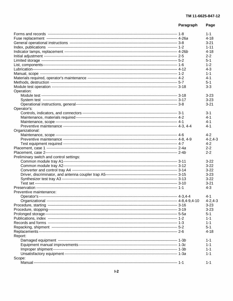
TM 11-6625-847-12
Paragraph Page
Forms and records ----------------------------------------------------------------------------------------------------- 1-8 1-1Fuse replacement ------------------------------------------------------------------------------------------------------ 4-26a 4-18General operational instructions ------------------------------------------------------------------------------------ 3-8 3-21Index, publications ----------------------------------------------------------------------------------------------------- 1-2 1-11Indicator lamps, replacement ---------------------------------------------------------------------------------------- 4-26b 4-18Initial adjustment -------------------------------------------------------------------------------------------------------- 2-5 2-2Limited storage ---------------------------------------------------------------------------------------------------------- 5-2 5-1List, components--------------------------------------------------------------------------------------------------------- 1-6 1-2Lubrication----------------------------------------------------------------------------------------------------------------- 4-12 4-3Manual, scope ----------------------------------------------------------------------------------------------------------- 1-2 1-1Materials required, operator's maintenance ---------------------------------------------------------------------- 4-2 4-1Methods, destruction --------------------------------------------------------------------------------------------------- 5-7 5-1Module test operation -------------------------------------------------------------------------------------------------- 3-18 3-3Operation:
Module test ---------------------------------------------------------------------------------------------------------- 3-18 3-23System test --------------------------------------------------------------------------------------------------------- 3-17 3-23Operational instructions, general------------------------------------------------------------------------------- 3-8 3-21
Operator's:Controls, indicators, and connectors -------------------------------------------------------------------------- 3-1 3-1Maintenance, materials required ------------------------------------------------------------------------------- 4-2 4-1Maintenance, scope ----------------------------------------------------------------------------------------------- 4-1 4-1Preventive maintenance ----------------------------------------------------------------------------------------- 4-3, 4-4 4-1
Organizational:Maintenance, scope ----------------------------------------------------------------------------------------------- 4-6 4-2Preventive maintenance ----------------------------------------------------------------------------------------- 4-8, 4-9 4-2,4-3Test equipment required ----------------------------------------------------------------------------------------- 4-7 4-2
Placement, case 1 ------------------------------------------------------------------------------------------------------ 2-4a 2-2Placement, case 2------------------------------------------------------------------------------------------------------- 2-4b 2-2Preliminary switch and control settings:
Common module tray A1----------------------------------------------------------------------------------------- 3-11 3-22Common module tray A2----------------------------------------------------------------------------------------- 3-12 3-22Converter and control tray A4 ---------------------------------------------------------------------------------- 3-14 3-22Driver, discriminator, and antenna coupler trap A5-------------------------------------------------------- 3-15 3-23Synthesizer test tray A3 ------------------------------------------------------------------------------------------ 3-13 3-22Test set --------------------------------------------------------------------------------------------------------------- 3-10 3-21
Preservation -------------------------------------------------------------------------------------------------------------- 1-1 4-3Preventive maintenance:
Operator's ------------------------------------------------------------------------------------------------------------ 4-3,4-4 4-1Organizational ------------------------------------------------------------------------------------------------------ 4-8,4-9,4-10 4-2,4-3
Procedure, starting ----------------------------------------------------------------------------------------------------- 3-16 3-23Procedure, stopping----------------------------------------------------------------------------------------------------- 3-19 3-23Prolonged storage------------------------------------------------------------------------------------------------------- 5-5a 5-1Publications, index ----------------------------------------------------------------------------------------------------- 1-2 1-1Records and forms ----------------------------------------------------------------------------------------------------- 1-3 1-1Repacking, shipment -------------------------------------------------------------------------------------------------- 5-2 5-1Replacements ------------------------------------------------------------------------------------------------------------ 2-6 4-18Report:
Damaged equipment --------------------------------------------------------------------------------------------- 1-3b 1-1Equipment manual improvements ----------------------------------------------------------------------------- 1-3c 1-1Improper shipment------------------------------------------------------------------------------------------------- 1-3b 1-1Unsatisfactory equipment ---------------------------------------------------------------------------------------- 1-3a 1-1
Scope:Manual ---------------------------------------------------------------------------------------------------------------- 1-1 1-1
I-2
TM 11-6625-847-12
Paragraph Page
Operator's maintenance ----------------------------------------------------------------------------------------- 4-1 4-1Organizational maintenance ------------------------------------------------------------------------------------ 4-6 4-2
Shipping container chart ----------------------------------------------------------------------------------------------- 2-2 2-1Short storage ------------------------------------------------------------------------------------------------------------ 5-5b 5-1Starting procedure------------------------------------------------------------------------------------------------------- 1-6 2-23Stopping procedure ----------------------------------------------------------------------------------------------------- 3-19 2-23Storage conditions ------------------------------------------------------------------------------------------------------ 5-6 5-1Synthesizer test tray A3:
Controls, indicators, and connectors -------------------------------------------------------------------------- 3-5 3-12Preliminary switch and control settings----------------------------------------------------------------------- 3-13 3-22Trouble isolation chart -------------------------------------------------------------------------------------------- 4-21 4-14Trouble localization chart ---------------------------------------------------------------------------------------- 4-20 4-12
System test operation -------------------------------------------------------------------------------------------------- 3-17 3-23Technical characteristics ---------------------------------------------------------------------------------------------- 1-5 1-1Test equipment required ---------------------------------------------------------------------------------------------- 4-7 4-2Test set:
Controls, indicators, and connectors ------------------------------------------------------------------------- 3-2 3-1Placement------------------------------------------------------------------------------------------------------------ 2-4a 2-2Preliminary switch and control settings----------------------------------------------------------------------- 3-10 3-21Trouble isolation chart -------------------------------------------------------------------------------------------- 4-15 4-6Trouble localization chart ---------------------------------------------------------------------------------------- 4-44 4-4
Trouble isolation chart:Common module tray A1 ---------------------------------------------------------------------------------------- 4-17 4-8Common module tray A2----------------------------------------------------------------------------------------- 4-19 4-10Converter arid control tray A4----------------------------------------------------------------------------------- 4-23 4-16Driver, discriminator, and antenna couples tray A5 ------------------------------------------------------ 4-25 4-18Synthesizer test tray A3 ----------------------------------------------------------------------------------------- 4-21 4-14Test set --------------------------------------------------------------------------------------------------------------- 4-15 4-6
Trouble localization chart:Common module tray A1----------------------------------------------------------------------------------------- 4-16 4-7Common module tray A2 ---------------------------------------------------------------------------------------- 4-18 4-8Converter and control tray A4 ---------------------------------------------------------------------------------- 4-22 4-15Driver, discriminator, and antenna coupler tray A5 ------------------------------------------------------- 4-24 4-17Synthesizer test tray A3 ------------------------------------------------------------------------------------------ 4-20 4-12Test set --------------------------------------------------------------------------------------------------------------- 4-14 4-4
Troubleshooting, general ---------------------------------------------------------------------------------------------- 4-13 4-3Unpacked equipment, checking ------------------------------------------------------------------------------------- 2-3 2-1Unpacking ---------------------------------------------------------------------------------------------------------------- 2-1 2-1
I-3

TM 11-6625-847-12
By Order of the Secretary of the Army:
HAROLD K. JOHNSON,General, United States Army,
Official: Chief of Staff.KENNETH G. WICKHAM,Major General, United States Army,The Adjutant General.
Distribution:Active Army.:
CONGA (1) TOAD (14)Dir./Trains (1) LEAD (7)CofEngrs (1) NAAD (3)TSG (1) SVAD (3)CofEngs (1) ATAD (10)OCC,-E (2) Svc Colleges (1)USAMB (10) 1st Cav Div (7)USAARENBD (2) GENDEP (1)USCONARC (2) Sig Sec GENDEP (4)USAMC (2) Sig Dep (6)USAMICOM (2) USACRREL (2)USAECOM (2) Fort Huachuca (5)ARADCOM (2) WSMR (2)ARADCOM Rgn (1) Fort Carson (7)OS Maj Comd (2) USAERDAA (2)USACDEC (10) USAERDAW (2)USASTRATCOM (2) MAAG (2)USAESC (70) USARMIS (2)Armies (1) Units org under fol TOE:Sig FLDMS (2) (1 copy each)USASESS (26) 11-155USASA (2) 11-157USACDCCEA (1) 11-158USACDCCEA Pt Huachuca (1) 11487Army Depots (1) except 11-592
LBAD (14) 11-97SAAD (30) 29-134
NG: None.USAR :None.For explanation of abbreviations used, see AR 320-50.
*U.S. GOVERNMENT PRINTING OFFICE: 1992 - 311-831/60933

PIN: 013598-000

This fine document...
Was brought to you by me:
Liberated Manuals -- free army and government manuals
Why do I do it? I am tired of sleazy CD-ROM sellers, who take publicly available information, slap “watermarks” and other junk on it, and sell it. Those masters of search engine manipulation make sure that their sites that sell free information, come up first in search engines. They did not create it... They did not even scan it... Why should they get your money? Why are not letting you give those free manuals to your friends?
I am setting this document FREE. This document was made by the US Government and is NOT protected by Copyright. Feel free to share, republish, sell and so on.
I am not asking you for donations, fees or handouts. If you can, please provide a link to liberatedmanuals.com, so that free manuals come up first in search engines:
<A HREF=http://www.liberatedmanuals.com/>Free Military and Government Manuals</A>
– SincerelyIgor Chudovhttp://igor.chudov.com/
– Chicago Machinery Movers