Embed Size (px)
Citation preview


TM 11-6625-200-15
DEPARTMENT OF THE ARMY TECHNICAL MANUAL
OPERATOR, ORGANIZATIONAL, DS, GS
AND DEPOT MAINTENANCE MANUAL
MULTIMETERS ME-26A/U
ME-26B/U, ME-26C/U
AND ME-26D/U
This copy is a reprint which includes currentpages from changes 1 through 3
HEADQUARTERS, DEPARTMENT OF THE ARMY
MARCH 1968
TM 11-6625-200-15
WARNING
RADIATION HAZARD
Co 60
Tube type 0B2 used in this test set contains radioactive material. This tube is potentially hazardous when broken; seequalified medical personnel and the Safety Director if you are exposed to or cut by broken tubes. Use extreme care inreplacing this tube and follow safe procedures in its handling, storage, and disposal.
Never place radioactive tubes in your pocket.
Use extreme care not to break radioactive tubes while handling them.
Never remove radioactive tubes from cartons until ready to use them.
i
STD-RW-2

TM 11-6625-200-15
WARNING
The fumes of TRICHLOROETHANE are toxic. Provide thorough ventilation whenever it is used; avoid prolongedor repeated breathing of vapor. Do not use near an open flame or hot surface; trichloroethane is non flammablebut heat converts the fumes to a highly toxic phosgene gas. The inhalation of this gas could result in seriousinjury or death. Prolonged or repeated skin contact with trichloroethane can cause skin inflammation. Whennecessary, use gloves, sleeves, and aprons which the solvent cannot penetrate.
Change 3 ii

*TM 11-6625-200-15
Technical Manual HEADQUARTERSDEPARTMENT OF THE ARMY
No. 11-6625-200-15 Washington, D.C., 22 March 1968
Operator, Organizational, Direct Support, General Support,and Depot Maintenance Manual
MULTIMETERS ME-26A/U, ME-26B/U,ME-26C/U, AND ME-26D/U
Paragraph Page
B/U,Chapter 1 INTRODUCTIONSection I General .............................................................................................................. 1-1—1-3 1-1
II Description and data.......................................................................................... 1-4—1-8 1-1Chapter 2 SERVICE UPON RECEIPT OF EQUIPMENT................................................... 2-1—2-4 2-1
3 OPERATING INSTRUCTIONSSection I Controls and indictors ........................................................................................ 3-1, 3-2 3-1
II Operation ........................................................................................................... 3-3—3-10 3-5Chapter 4 MAINTENANCE INSTRUCTIONS..................................................................... 4-1—4-11 4-1
5 FUNCTIONINGSection I Block diagram analysis ...................................................................................... 5-1—5-4 5-1
II Circuit analysis................................................................................................... 5-5—5-10 5-4Chapter 6 TROUBLESHOOTINGSection I General troubleshooting techniques .................................................................. 6-1, 6-2 6-1
II Troubleshooting Multimeter ME-26(*)/U ............................................................ 6-3—6-7 6-14Chapter 7 REPAIRS AND ALIGNMENTSection I Repair ................................................................................................................ 7-1—7-4 7-1
II Changes to Multimeters ME-26B/U and ME-26C/U to prevent shock hazard... 7-5—7-7 7-4III Alignment ........................................................................................................... 7-8—7-12 7-7
Chapter 8 GENERAL SUPPORT TESTING PROCEDURES ............................................ 8-1—8-9 8-19 SHIPMENT, LIMITED STORAGE, AND DEMOLITION TO PREVENT
ENEMY USESection I Shipment and limited tore .................................................................................. 9-1, 9-2 9-1
II Demolition of materiel to prevent enemy use .................................................... 9-3, 9-4 9-1Appendix A REFERENCES .................................................................................................. A-1
B BASIC ISSUE ITEMS LIST (BIIL) AND ITEMS TROOP INSTALLEDOR AUTHORIZED LIST (ITIAL) (Not Applicable)
C MAINTENANCE ALLOCATION......................................................................... C-1
Index................................................................................................................................................... I-1
*This manual supersedes TM 11-6625-200-12, 13 February 1959, Including all changes, and TM 11-6625-200-35, 15January 1980, Including all changes.
Change 2 iii
}

TM 11-6625-200-15
Figure 1-1. Multimeter ME-26B/U, less running spares.
iv

TM 11-6625-200-15CHAPTER 1
INTRODUCTION
1-1. Scopea This manual describes Multimeter ME-26(*)/U
(multimeter) and covers the installation, operation,organizational, general support, and depot maintenanceof these equipments It includes operation under unusualconditions, and replacement of parts available to theorganizational, general support, and depot maintenancepersonnel. It also lists the tools and test equipmentavailable to organizational, general support, and depotmaintenance personnel.
b. Official nomenclature followed by (*) is used todesignate all models of the equipment covered in thismanual; therefore, Multimeter ME[26(*)/U representsMultimeters ME-26A/U, ME-26B/U, ME-26C/U, and ME-26D/U.1-2. Indexes of Publications
a. DA Pam 310-4. Refer to the latest issue of DAPam 310-4 to determine whether there are new editions,changes, or additional publications pertaining to theequipment.
b. DA Pan 310-7. Refer to DA Pam 310-7 todetermine whether there are modification work orders(MWO’s) pertaining to the equipment.1-3. Forms and Records
a. Reports of Maintenance and UnsatisfactoryEquipment Maintenance forms, records, and reportswhich are to be used by maintenance personnel at allmaintenance levels are listed in and prescribed by TM38-750.
b. Report of Packaging and Handling Deficiencies.Fill out and forward DD Form 6 (Packaging ImprovementReport) as prescribed in AR 700-58/NAVSUPINST4030.29/AFR 71-13/MCO P4030.29A, and DLAR 4145.8.
c. Discrepancy in Shipment Report (DISREP) (SF361). Fill out and forward Discrepancy in ShipmentReport (DISREP) (SF 361) as prescribed in AR 55-88/NAVSUPINST 4610.33B/AFR 75-18/MCO P4610.19Cand DLAR 4500.15.1-3.1. Reporting of Errors and EIR’s
a The reporting of errors, omissions, andrecommendations for improving this publication by theindividual user is encouraged. Reports should besubmitted on DA Form 2028 (Recommended Changesto Publications and Blank Forms) and forwarded direct toCommander, US Army Communications and ElectronicsMateriel Readiness Command, ATTN: DRSEL-ME-MQ,Fort Monmouth, NJ 07708.
b. Equipment Improvement Recommendations(EIR) will be prepared using SF 368 (Quality DeficiencyReport) Instructions for preparing EIR's are provided inTM 38-750, the Army Maintenance Management SystemEIR's should be mailed direct to Commander, US ArmyCommunications and Electronics Materiel ReadinessCommand, ATTN: DRSEL-ME. MQ, Fort Monmouth,NJ 07703. A reply will be furnished direct to you.
Section II. DESCRIPTION AND DATA1-4. Purpose and Use (fig. 1-1, 1-2)
a Multimeter ME-26(*) U is an electron tubemultimeter voltmeter-ohmmeter) that is used to measuredirect current (dc) voltage, resistance, and alternatingcurrent (ac) voltage at frequencies from 20 cycles persecond (cps) to 700 megacycles per second (mc).
b. When the multimeter is used as a voltmeter, thehigh input impedance permits measurements to be madewithout affecting either the voltage being tested or theoperation of the equipment under test.1-5. Technical CharacteristicsVoltage ranges:
Dc ............................... 0 to 1 volt0 to 8 volts0 to 10 volts0 to 00 volts0 to 100 volts0 to 300 volts0 to 1,000 volts
Ac ............................... 0 to 1 volt0 to 3 volts0 to 10 volts0 to 30 volts0 to 100 volts0 to 300 volts
Resistance range ............. 0 to 500 ohms0 to 5,000 ohms0 to 50,000 ohms0 to 500,000 ohms0 to 5 megohms0 to 500 megohms
Frequency range(ac voltage) ................. 20 cps to 700 mc
Frequency range(AC probe) .................. Flat within +1 db from 20 cps to
700 mc on ME-26A/U; and fiatwithin + 1 db from 20 cps to 800mc and +2 db from 20 cps to 700mc on all other models
Input impedance:Dc ............................... 122 megohm
Change 3 1-1

TM 11-6625-200-15
Ac .............................10 megohms below 100 kc,morethan 01 me-ohm at 100 me, and0.01 megohm at 700 me
Accuracy:Dc.............................+3 percent of full-scale value on
all rangesAc .............................+3 percent of full-scale value on
all ranges for sinusoidal input(midfrequency range-
NOTEThe meter scales are calibrated toindicate 0707 of the peak voltage of asine wave For a sine wave, the meterindication is the rms value of the sinewave, but for a complex wave, themeter indication is not the rms valueof the complex wave
Resistance.....................±10 percent at center scale onRX1range.+5 percent at center scale on allother ranges
Number of tube..............5Line-voltage input .........115 or 280 volts, single phase,
50 to 1,000 cpsPower consumption 40 watts
1-6. Items Comprising an Operable Equipment
Multimeter, Meter ME-26A/U (NSN 6625-
Item ME-226A/UDimension .....................................12 by 7 3/8 by 8Weight ..........................................11 1/4 lbSwitch (ON-OFF) and function ......SELECTOR
selectorTest leads......................................Connected to
detachable connector,brought out throughbottom of chassis.
00-360-2493), Multimeters, Meter ME-26B/U, ME-26C/U(NSN 6625-00-646-9409), and Multimeter, Meter ME-26D/U (NSN 6625-00-913-9781) comprise operableequipments.
1-7. DescriptionThe multimeter (figs. 1-1 and 1-2) consists of a chassis(figs. 3-1, 3-2, 4-1, and 4-2) contained in a metal case.All operating controls (figs. 3-2 and 3-3), the meter, andthe pilot lamp are mounted on the front panel. The ME-26A/U test leads are mounted on a detachable connectorand are attached to the underside of the multimeter. TheME-26B/U, the ME-26C/U, and the ME-26D/U test leadsare permanently attached to the chassis and extendthrough the front panel. The ME-26B/U, the ME-26C/U,and the ME-26D/U power cables are contained in astorage compartment in the case. A rear cover isprovided to reach the power cable, the fuse, and thestorage compartment. The power cable and the fusecan be reached on the back of the ME-26A/U.
1-8. External Differences in ModelsMultimeters ME-26A[U, ME-26B/U, ME-26C/U, and ME-26D/U are similar in purpose and operation. Externaldifferences are listed below.
ME-26C/U and ME-26D/U M-26B/U
11 by 7 1/8 by 7V4 11 by 7 by 7½11½ lb 11 ½ lbFUNCTION FUNCTION
Permanently attached, Permanently attached,bought out through front brought out through frontof panel. of panel
Change 3 1-2

TM 11-6625-200-15
Figure 1-2. Multimeter ME-26A/U, withdrawn from cabinet, lens running spares.
1-3

TM 11-6625-200-15
CHAPTER 2
SERVICE UPON RECEIPT OF EQUIPMENT
2-1. Unpackinga. Packaging Data. The multimeter is packed for
shipment in a corrugated carton; the dimensions of theequipment package are 14 1/2 by 10 3/4 by 10 1/4inches; the weight is 14 pounds and the volume is 0.93cubic foot. The running spares are packed in a separatecorrugated carton; the dimensions are 3 by 2 5/8 by 2 5/8inches.
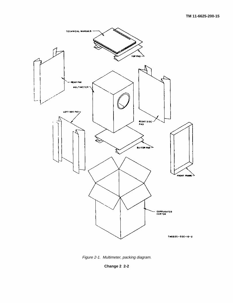
b. Unpacking Multimeter (fig. 2-1).(1) Open the corrugated carton and fold back
the top flaps.(2) Remove the envelope that contains the
technical manuals; open the envelope and remove thetechnical manuals.
(3) Remove the top pad, the rear pad, the leftand right side pads, and the front frame.
(4) Remove the multimeter from thecorrugated carton.
c. Unpacking Running Spares (fig. 2-2).(1) Open the corrugated carton and fold back
the top flaps.(2) Remove the running spares from the
carton.(3) Store the running spares in the storage
compartment of the multimeter (para 2-2d).
2-2. Checking Unpacked Equipment
a. Inspect the equipment for damage. If theequipment has been damaged, refer to paragraph 1-8.
b. Check the equipment against the packing list. Ifthe equipment is incomplete, refer to procedures given inparagraph 1-3.
c. Check to be sure that the test leads are firmlyattached to the front of the multimeter.
d. Store the running spares in Multimeters (ME-26B/U, ME-26C/U, and ME-26D/U) in the rear storagecavity and check the power cable as follows: (1)Remove the rear cover by giving each of the fasteners aone-quarter turn.
(2) Check to be sure that the power cable isfolded in the storage compartment, and the cable is heldfirmly by the grommet in the rear of the chassis.
(3) Place the running spares in the storagecompartment.
(4) If the multimeter is not to be usedimmediately, replace the rear cover.
2-3. installation of Multimeters ME-26B/U, ME-26C/U, and ME-26D/U
NOTEThe multimeter normally is wired foroperation from a 115-volt ac powersource.
To operate the multimeter from a 230-volt ac powersource, follow the procedures given in a below. Toreconnect the multimeter for operation from a 115-volt acpower source, follow the procedures given in b below.
a. Connection for 230-Volt Operation.(1) Remove the rear cover by giving each of
the fasteners a one-quarter turn.(2) Remove the retaining screws (fig. 1-1)
from the front panel, the top of the case, and the rearcrosspiece.
Change 2 2-1
TM 11-6625-200-15
Figure 2-1. Multimeter, packing diagram.
Change 2 2-2

TM 11-6625-200-15
(3) Remove the chassis by gently sliding itforward out of the case, while lifting the power cable fromthe groove in the rear crosspiece.
(4) Remove the jumper which connects thefirst (rear) terminal on the bottom row of terminal boardTB2 (fig. 3-1) and the second (next to rear) terminal onthe top row; also remove the jumper which connects thesecond terminal on the bottom row and the third terminalon the top row.
(5) Connect a jumper from the first to thesecond terminal on the bottom row of terminal boardTB2.
(6) Slide the chassis back into the case andreplace the retaining screws.
(7) Replace the 1.5-ampere fuse with a ¾ampere fuse.
(8) Replace the rear cover.
b. Connection for 115-Volt Operation.
(1) Perform the procedures given in a(1), (2),and (3) above.
(2) Remove the jumper which connects thefirst (rear) and second terminals on the bottom row ofterminal board TB2 (fig. 3-1).
(3) Connect a jumper from the first terminalon the bottom row to the second (next to rear) terminalon the top row.
(4) Connect a jumper from the secondterminal on the bottom row to the third terminal on thetop row.
(5) Slide the chassis back into the case andreplace the retaining screws.
(6) Replace the S/3-ampere fuse with a 1.5-ampere fuse.
(7) Replace the rear cover.
2-4. Installation of Multimeter ME-26A/U
Note. The multimeter is normally wired foroperation from a 115-volt power source.
To operate the Multimeter ME-6A/U from a 230-volt acpower source, follow the procedures given in a below.To reconnect the ME-26A/U for operation from a 115-voltac power source, follow the procedures given in b below.
Figure 2-2. Running spares packing diagram.
a. Connection for 230-Volt Operation.(1) Remove the rear cover by pressing the
spring-release button on the top rear of the case (fig. 1-2).
(2) Remove the retaining screws that hold themain chassis to the cabinet (3) Remove the chassis bygently sliding it forward out of the case.
(4) Remove the leads that connect terminals1 to 2, and 4 to 5 of terminal board TB3 (fig. 3-2).
(5) Connect terminals 2 and 4 together.(6) Replace the 1.5-ampere fuse with a 3/4
ampere fuse (fig. 4-2).(7) Slide the chassis back into the cam and
replace the retaining screws.b. Connection for 115-Volt Operation.
(1) Perform the procedures given in a(1), (2),and (8) above.
2-3
TM 11-6625-200-15
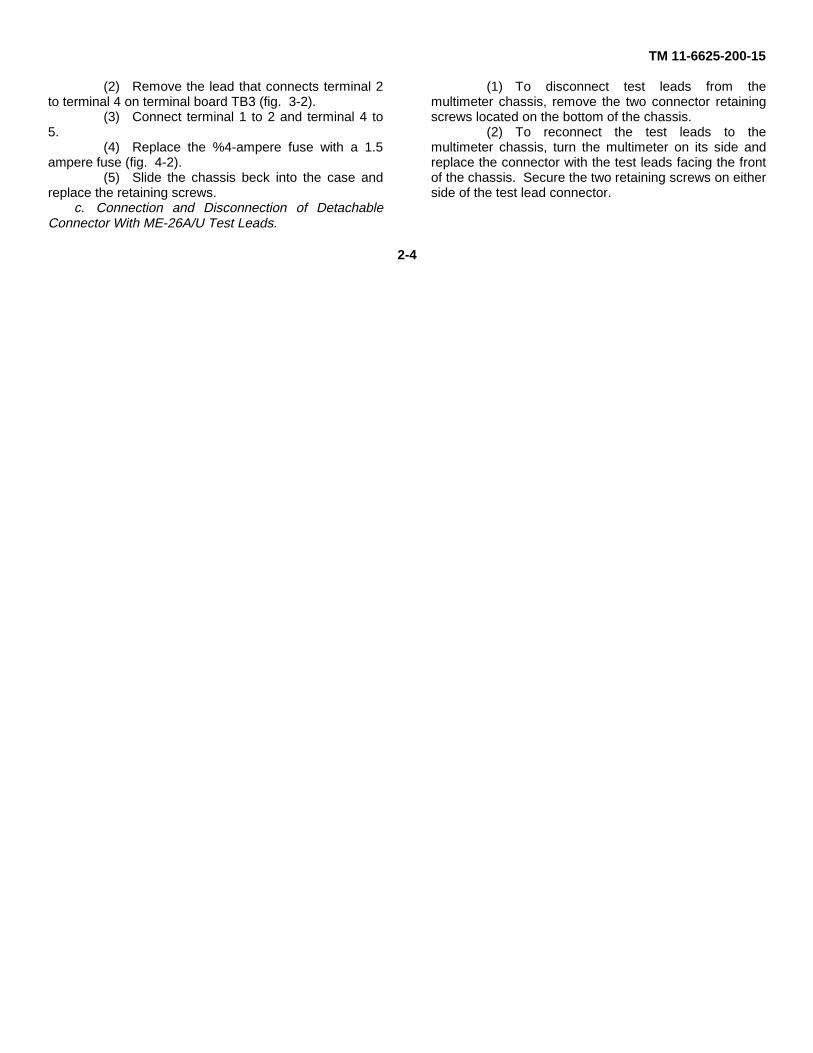
(2) Remove the lead that connects terminal 2to terminal 4 on terminal board TB3 (fig. 3-2).
(3) Connect terminal 1 to 2 and terminal 4 to5.
(4) Replace the %4-ampere fuse with a 1.5ampere fuse (fig. 4-2).
(5) Slide the chassis beck into the case andreplace the retaining screws.
c. Connection and Disconnection of DetachableConnector With ME-26A/U Test Leads.
(1) To disconnect test leads from themultimeter chassis, remove the two connector retainingscrews located on the bottom of the chassis.
(2) To reconnect the test leads to themultimeter chassis, turn the multimeter on its side andreplace the connector with the test leads facing the frontof the chassis. Secure the two retaining screws on eitherside of the test lead connector.
2-4
TM 11-6625-200-15
CHAPTER 3
OPERATING INSTRUCTIONS
Section I. CONTROLS AND INDICATORS
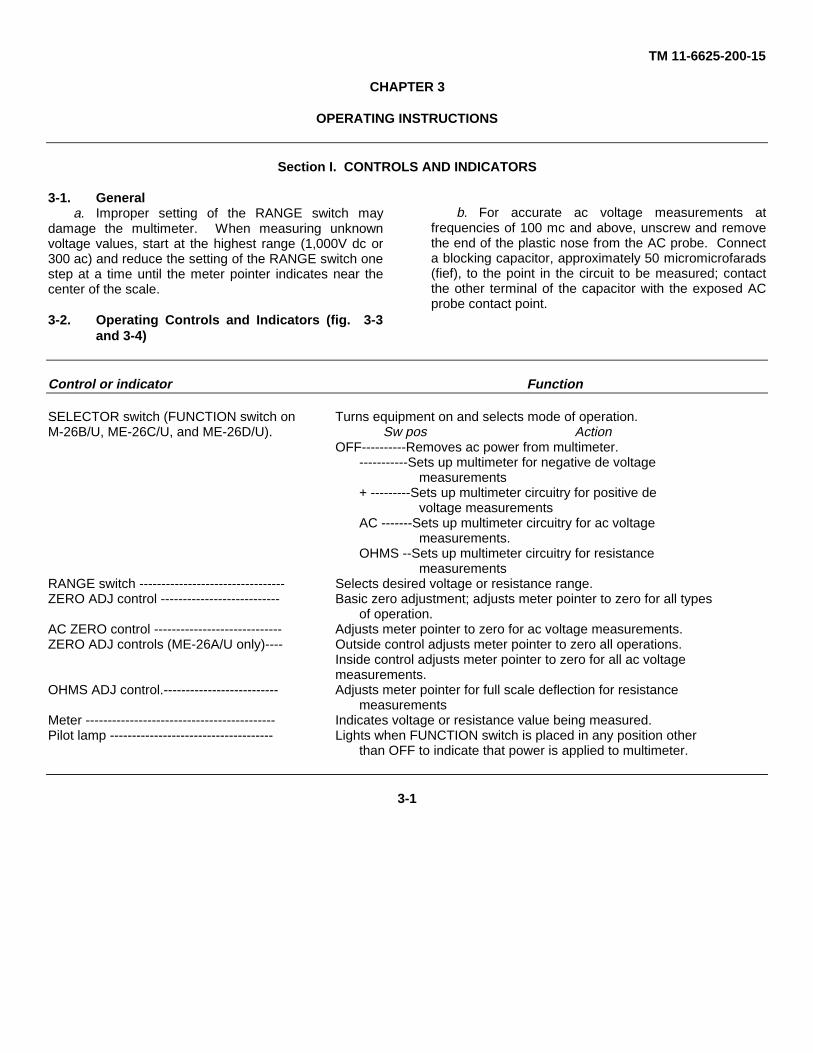
3-1. Generala. Improper setting of the RANGE switch may
damage the multimeter. When measuring unknownvoltage values, start at the highest range (1,000V dc or300 ac) and reduce the setting of the RANGE switch onestep at a time until the meter pointer indicates near thecenter of the scale.
3-2. Operating Controls and Indicators (fig. 3-3and 3-4)
b. For accurate ac voltage measurements atfrequencies of 100 mc and above, unscrew and removethe end of the plastic nose from the AC probe. Connecta blocking capacitor, approximately 50 micromicrofarads(fief), to the point in the circuit to be measured; contactthe other terminal of the capacitor with the exposed ACprobe contact point.
Control or indicator Function
SELECTOR switch (FUNCTION switch on Turns equipment on and selects mode of operation.M-26B/U, ME-26C/U, and ME-26D/U). Sw pos Action
OFF----------Removes ac power from multimeter.-----------Sets up multimeter for negative de voltage
measurements+ ---------Sets up multimeter circuitry for positive de
voltage measurementsAC -------Sets up multimeter circuitry for ac voltage
measurements.OHMS --Sets up multimeter circuitry for resistance
measurementsRANGE switch --------------------------------- Selects desired voltage or resistance range.ZERO ADJ control --------------------------- Basic zero adjustment; adjusts meter pointer to zero for all types
of operation.AC ZERO control ----------------------------- Adjusts meter pointer to zero for ac voltage measurements.ZERO ADJ controls (ME-26A/U only)---- Outside control adjusts meter pointer to zero all operations.
Inside control adjusts meter pointer to zero for all ac voltagemeasurements.
OHMS ADJ control.-------------------------- Adjusts meter pointer for full scale deflection for resistancemeasurements
Meter ------------------------------------------- Indicates voltage or resistance value being measured.Pilot lamp ------------------------------------- Lights when FUNCTION switch is placed in any position other
than OFF to indicate that power is applied to multimeter.
3-1

TM 11-6625-200-15
Figure. 3-1. Multimeter ME-16B/U, ME-6C/U, and ME-26D/U chassis, bottom view, showing location of terminal boardTB2.
3-2

TM 11-6625-200-15
Figure 3-2. Multimeter ME-26A/U chassis, side view, showing location of terminal board TB3.
3-3

TM 11-6625-200-15
Figure 3-3. Multimeters ME-26B/U, ME-26C/U, and ME-26D/U, operating controls and indicators.
3-4

TM 11-6625-200-15
Figure 3-4. Multimeter ME-26A/U operating control and indicators.
Section II.
3-3. Starting Procedurea. General.
(1) Set the FUNCTION switch (SELECTORswitch on the ME-26A/U) to OFF.
(2) Remove the rear cover (on the ME-26B/U,ME-26C/U and ME-26D/U) by giving each of thefasteners a one-quarter turn.
(3) Remove the power cable from the storagecompartment at the rear of the multimeter.
Caution: Check the available power sourcevoltage and make sure that the multimeter isinternally connected to operate from
that source (para 2-3 and 2-4). If the multimeter isimproperly connected, damage to the equipment, orwrong meter readings will result.
(4) Connect the power cable to the powersource. Keep the test leads separated to avoid contactwhen the multimeter is turned on.
(5) Replace the rear cover to allow the powercable to pass through the slot in the cover.
b. Zero Adjustment.(1) Set the FUNCTION switch (SELECTOR
switch on the ME-26A/U) to minus (-); the pilot lampshould illuminate. Allow 5 minutes for the multimeter towarm up.
3-5

TM 11-6625-200-15
(2) Set the RANGE switch to 1V.(3) Connect the COMMON clip (fig. 1-1 and
1-2) to the tip of the DC probe.(4) Adjust the ZERO ADJ control to position
the meter pointer to zero.(5) Disconnect the COMMON clip from the
DC probe.
3-4. Measurement of DC VoltageCaution: When using Multimeters ME-26A/ U, ME-
26B/U, and ME-26C/U which have not been changedin accordance with paragraph 7-5, be careful of theshock hazard. Do not connect the COMMON lead toany voltage which is not at ground potential.
a. the starting procedures (para 3-3).b. Set the FUNCTION switch (SELECTOR switch
on the ME-26A/U) to minus (-) or plus (+), depending onthe polarity of the voltage to be measured.
Caution: If the voltage to be measured isunknown, set the RANGE switch to 1,000V and, ifnecessary, reduce the setting of the RANGE switchone step at a time until the meter pointer indicatesnear the center of the scale.
c. Set the RANGE switch to the range position that includes the voltage value to be measured and will causethe meter’ pointer to deflect near the center of the scale.
d. Observe caution notice below paragraphheading above and connect the COMMON clip to theside of the circuit nearest ground potential.
e. Hold the tip of the DC probe in contact with thepoint of the circuit to be measured. If the meter pointerdeflects to the left (below zero), set the FUNCTIONswitch (SELECTOR switch on the ME-26A/U) to minus(-) or plus (+), depending on where it had beenpreviously set
f. Read the meter indication.
3-5. Measurement of AC Voltage
Note. The meter scales are calibrated to indicate0.707 of the peak voltage of an ac Nine wave. For a
sine wave, the meter indication is the root meansquare (rms) value of the sine wave. In a complexwave, the meter indication is not the rms value of thecomplex wave. For additional information on themeasurement of complex waves, refer to paragraph348.
Caution: When using Multimeters ME-26A/ U, ME-26B/U, and ME-26C/U which have not been changedin accordance with paragraph 7-5, be careful of theshock hazard. Do not connect the COMMON lead orthe ac ground clip to any voltage which is not atground potential.
a. Voltage Measurements at Frequencies Below 20Mc.
(1) Perform the starting procedure (para 3-3).(2) Set the FUNCTION switch (SELECTOR switch on theME-26A/U) to AC.
(3) Connect the ac ground clip (fig. 1-1 and 1-2) to the tip of the AC probe.
(4) Adjust the AC ZERO control to position themeter pointer on zero.
(5) Disconnect the ac ground clip from the tipof the AC probe.
(6) Set the RANGE switch on the rangeposition that includes the voltage value to be measuredand will cause the meter pointer to deflect near thecenter of the scale.
Caution: If the voltage value to be measured isunknown, set the RANGE switch one step at a timeuntil the meter pointer indicates near the center ofthe scale.
(7) Observe caution notice below note aboveand connect the ac ground clip to the side of the circuitnearest ground potential.
(8) Hold the tip of the AC probe in contact withthe point of the circuit to be measured.
(9) Read the meter indication.b. Voltage Measurements at Frequencies Above 20
Mc. To measure voltage at frequencies above 20 mc,follow the procedures given in a above, and observe thefollowing precautions:
(1) Keep) the ac ground clip as close to thepoint of measurement as possible.
Caution: Do not attempt to solder the capacitor tothe AC probe contact point; the
3-6

TM 11-6625-200-15
heat will cause permanent damage to the AC probe.(2) At frequencies of 100 mc and above,
unscrew and remove the end of the plastic nose from theAC probe. Connect a blocking capacitor (approximately50 uuf) to the point in the circuit to be measured.Contact the other terminal of the capacitor with theexposed AC probe contact point.3-6. Preliminary Data for Pulse Measurements
a. General. For measurement of the positivevoltage rise in a pulse, the following characteristics of thepulse generator must be known. This information isused to determine the correction factor (b below) for themeasured voltage value.
(1) t, duration of the positive portion of thepulse voltage in microseconds.
(2) t.; duration of the negative portion of thepulse voltage in microseconds.
(3) PRF; pulse repetition frequency in pulsesper second.
(4) R.; impedance of the pulse generator inkilohms.
(5) K; pulse generator form factor (c below).b. Correction Factor. The correction factor for
pulse measurements is 1.4 (1 + t,/t, + K/ PRF). Thecorrection factor applies when the PRF is 500 pulses persecond or higher, and t, is 10 microseconds or higher.
c. Pulse Generator Form Factor. The pulsegenerator form factor (K) is determined from the curvesshown in figure 3-5. Note that the impedance of thepulse generator (R,) divided by the duration of thepositive portion of the pulse voltage (t,) is plottedhorizontally, and the pulse generator form factor (K) isplotted vertically. The running parameters indicate thevalue of K for any value of R,/t, between 0 and 10.
(1) The curve labeled X1 is used when thevalue of R,/t, is between 0 and 10. When this curve isused, the scale values for R,/t, and K are read directly.
(2) The curve labeled X10 is used when the value ofR0/t1 is between 1 and 10. When this curve is used, thescale values for R,/t, and K must be multiplied by 10.3-7. Pulse MeasurementsMeasure the positive voltage rise in a pulse by followingthe procedures given in a below. A numerical example isgiven in b below.
a. Procedure.(1) Measure the ac voltage (para 3-5).(2) Multiply the indicated value of the ac
voltage by the correction factor (para 3-6b).b. Use of Correction Factor.
(1) To determine the pulse voltage value, themeasured voltage (a(1) above) is multiplied by thecorrection factor (1.4(1+t1/ t2 + K/PRF)). Assume the
following values:t1, =10 microseconds.
PRF-1,000 pulses per second.R0-2 kilohms.
Measured voltage (a(1) above = 0.8 volt.(2) To determine T2, subtract the time
duration of the positive portion of the pulse (t1,) from the
total time available for the pulse. Note that with a PRF of1,000 pulses per second, the time interval from the startof one pulse to the start of the next pulse is 1,000microseconds; t2, =1,000-10=990 microseconds.
(3) To determine K, divide R. by t1; R0/ t1,-
2/10-0.2. Apply this value to figure 3-5 and use the curvelabeled X1, K=0.55.
(4) Substitute known values in the formula(pulse voltage = measured voltage X correction factor)and solve for the pulse voltage: Pulse voltage .8 X 1.4 (1+ 10/990 + 55/1000)=1.1328 volts.3-8. Turnover Effect
Note. The procedure given below applies only toequipment where the equipment ground is notcommon with the power source ground, directly orthrough a capacitor.Complex ac waveforms may have positive peak valueswhich are different from the negative
3-7
TM 11-6625-200-15
peake value. If this condition occurs, the multimeter willindicate a certain reading when the AC probe and acground clip are applied to the circuit under test. Adifferent reading will be obtained if the AC probe and acground clip of the multimeter are transposed. Thiscondition is referred to as turnover effect. If thiscondition is suspected, use procedures as follows:
a. Make an ac voltage measurement as describedin paragraph 3-5. Observe and note the reading of themultimeter.
b. Transpose the connections of the multimeter tothe circuit under test. Observe and note the reading ofthe multimeter.
c. Disconnect the multimeter from the circuit undertest.
d. The readings obtained in a and b above may beused to calculate the mean voltage or the actual peak-to-peak voltage of the complex wave. Proceed as follows:
(1) To obtain the mean voltage, add the tworeadings (a and b above) and divide the sum by 2. Thequotient is the mean voltage value.
(2) To obtain the peak-to-peak voltage,multiply each reading (a and b above) by 1.414 and addthe products. The sum is the peak-to peak voltagevalue.3-9. Measurement of Resistance
Caution: Turn off or disconnect the power fromthe equipment under test when measuringresistance. Damage to the multimeter may
result from an external voltage applied to theresistance measurement circuit.
a. Perform the starting procedure (para 3-3).b. Set the FUNCTION switch (SELECTOR switch
on the ME-26A/U) to OHMS.c. Adjust the OHMS ADJ control to position the
meter pointer at the last scale division (Ô) of the ohmsscale.
d. Connect the COMMON clip (fig. 1-1 and 1-2)and the OHMS probe to the opposite ends of theresistance to be measured.
e. Set the RANGE switch to the range positionwhich will cause the meter pointer to deflect near thecenter of the scale.
f. Read the indication on the meter, and multiply itby the factor indicated by the setting of the RANGEswitch.3-10. Stopping Procedure (fig. 3-3 and 3-4)
a. Set the FUNCTION switch (SELECTOR switchon the ME-26A/U) to OFF; the pilot lamp extinguishes.
b. Disconnect the power cable from the powersource.
c. If there is no immediate need for the multimeter,remove the rear cover, coil the power cable and place itin the storage compartment, and replace the read cover.On Multimeter ME-26A/U, coil the power cable and testleads around the case.
3-8

TM 11-6625-200-15
Figure 3-5. Pulse generator from factor curves.
3-9

TM 11-6625-200-15
CHAPTER 4
MAINTENANCE INSTRUCTIONS
4-1. Scope of Maintenance
a. The maintenance duties assigned to theoperator of the multimeter are listed below, together witha reference to the paragraphs covering the specificmaintenance functions. The duties assigned do notrequire tools or test equipment other than those issuedwith the equipment.
(1) Operator’s daily preventive maintenancechecks and services (para 4-4).
(2) Operator's weekly preventive maintenancechecks and services (para 4-5).
(3) Cleaning (para 4-7).b. The maintenance duties assigned to the
organizational maintenance repairmen of the multimeterare listed below, together with a reference to theparagraphs covering the specific functions. The dutiesassigned do not require tools or test equipment otherthan those normally assigned because of the assignedmission.
(1) Organizational monthly preventivemaintenance checks and services (para 4-6).
(2) Cleaning and painting (para 4-7).4-2. Preventive MaintenanceOperator’s preventive maintenance is the systematiccare, servicing. and inspection of the equipment toprevent the occurrence of trouble, to reduce downtime,and to assure that the equipment is serviceable.
a. Systematic Ca-re. The procedures given inparagraphs 4-4, 4-5, and 4-6 cover routine systematiccare and cleaning essential to proper upkeep andoperation of the equipment.
b. Preventive Maintenance Checks and Services.The preventive maintenance checks and services charts(para 4-4 and 4-5) out:
line functions to be performed at specific intervals.These checks and services are designed to maintainArmy equipment in a combat-serviceable condition; thatis, in good general (physical) condition and in goodoperating condition. To assist operators in maintainingcombat serviceability, the charts indicate what the normalconditions are; the References column lists theparagraphs that contain detailed repair or replacementprocedures. If the defect cannot be remedied by theoperator, higher category of maintenance or repair isrequired. Records and reports of these checks andservices must be made in accordance with TM 38-750.
4-3. Preventive Maintenance Checks andServices Periods
Preventive maintenance checks and services of themultimeter are required daily, weekly, and monthly.
a. Paragraph 4-4 specifies the checks and servicesthat must be accomplished daily, and under the specialconditions listed below:
(1) Before the multimeter is taken on amission.
(2) When the multimeter is initially installed.(3) When the test set is reinstalled after
removal for any reason.(4) At least once a week if the equipment is
maintained in a standby condition.b. Paragraphs 4-5 and 4-7 specify additional
checks and services that must be performed on a weeklyand monthly basis, respectively. Perform themaintenance functions indicated in the monthlypreventive maintenance checks and services chart (para4-6)
4-1

TM 11-6625-200-15
once each month. A month is defined as approximately30 calendar days of 8hour-perday operation. If theequipment is operated 16 hours a day, the monthlypreventive maintenance checks and services should beperformed at 15-day intervals. Adjustment of themaintenance interval must be made to com-
pensate for any unusual operating conditions.Equipment maintained in a standby (ready for immediateoperation) condition must have monthly preventivemaintenance checks and services. Equipment in limitedstorage (requires service before operation) does not require monthly preventive maintenance.
4-4. Operator’s Daily Preventive Maintenance Checks and Services Chart
SequenceNo. Item to be inspected Procedure References
1 Multimeter------------- Check equipment for completeness and general condition. App B.2 Exterior surfaces---- Clean exterior surfaces of the equipment ----------------- Para 4-7.3 Meter glass----------- Inspect front panel glass window for damaged housing,
broken glass, physical damage, dust, or moisture.4 Knobs, controls, and During operation (item 5), check knobs, controls, and
switches. switches for proper mechanical action. Action must be posi-tive, without backlash, binding, or scraping.
5 Operation------------- During operation, be alert for any abnormal indications.
4-5. Operator’s Weekly Preventive Maintenance Checks and Services Chart
SequenceNo. Item to be inspected Procedure References
1 Cables Inspect external cables for cuts, cracked or gouged jackets,fraying, or kinks.
2 Hardware Inspect all exterior hardware for looseness and damage. Allscrews must be tight and not damaged.
3 Preservation Inspect the equipment to determine that it is free of bare Para 4-7.spots, rust, and corrosion. If these conditions exist, referto a higher maintenance category for repair.
4-6. Organizational Monthly Preventive Maintenance Checks and Services Chart
SequenceNo. Item to be inspected Procedure References
1 Publications---------- Inspect the manual for completeness, and to see if it is in DA Pam 310-4.usable condition. Be sure that all changes are on hand.
2 Modification work Check to see that all URGENT MWO’s have been applied DA Pam 310-7.orders. and that all NORMAL MWO’s have been scheduled.
3 Completeness Check the equipment for completeness and general condition. App B.4 Cleanliness Clean the exterior surfaces of the equipment.5 Preservation-------- Inspect the equipment to determine if it is free of bare spots, Para 4-7.
rust, and corrosion.6 Meter glass-------- Inspect the front panel glass window for damaged housing,
broken glass, physical damage, dust, or moisture.7 Cables-------------- Inspect the external cables for cuts, cracked or gouged
jackets, fraying, or kinks.8 Hardware----------- Inspect all exterior hardware for looseness and damage. All
exterior screws must be tight and not damaged.9 Operation----------- During operation, be alert for any abnormal indications.
4-2

TM 11-6625-200-15
4.7. Cleaning and Touchup PaintingWARNING
The fumes of TRICHLOROETHANEare toxic. Provide thoroughventilation whenever it is used; avoidprolonged or repeated breathing ofvapor. Do not use near an openflame or hot surface; trichloroethaneis non flammable but heat convertsthe fumes to a highly toxic phosgenegas. The inhalation of this gas couldresult in serious injury or death.Prolonged or repeated skin contactwith trichloroethane can cause skininflammation. When necessary, usegloves, sleeves, and aprons whichthe solvent cannot penetrate.
a. Use a clean cloth to remove dust, dirt, moisture,and grease from the front panel and the case. Ifnecessary, dampen (not wet) the cloth withtrichloroethane; wipe parts with a clean, dry cloth.
b. Clean rust and corrosion from the metal surfacesby lightly sanding them with fine sandpaper. Brush
two thin coats of paint on the bare metal to protect it fromfurther corrosion. Refer to the applicable clean andrefinishing practices specified in TB 43-0118.4-8. Replacement of Pilot Lamp (fig. 3-3 and 3-4)When the multimeter operates normally but the pilotlamp does not illuminate, the pilot lamp is probablydefective. Replace the pilot lamp with one known to begood. If the pilot lamp still does not illuminate, highermaintenance category repair is required. Replace thepilot lamp as follows:
a Unscrew (counterclockwise) the glass indicatorjewel and remove it to expose the pilot lamp.
b. Press in on the pilot lamp and turn itcounterclockwise to unlock.
c. Remove the defective pilot lamp and replace itwith a new one. Push the pilot lamp in and twist itclockwise to lock. Replace the glass indicator jewel.
Figure 4-1. Multimeters ME-26B/U, ME-26C/U chassis, top view, showing location ofrectifier tube, voltage regular tube, and fuse.
4-9. Replacement of Fuse (fig. 4-1 and 4-2)If the multimeter is completely inoperative (pilot lampdoes not illuminate and meter pointer does not deflect),
the fuse is probably defective. Replace the defectivefuse with a new one. If the new fuse blows when thepower is applied, check the rectifier and voltage regulatortubes (para 4-10 and 4-11) If the fuse still
Change 3 4-3
TM 11-6625-200-15
blows, higher maintenance category repair is required.Replace the fuse as follows:
a. Remove the rear cover by giving each of thefasteners a one-quarter turn on the ME-26B/U, the ME-26C/U and the ME-26D/U. On the ME-26A/U, push thespring release button.
b. Turn the fuseholder cap counterclockwise tounlock.
c Pull out the fuseholder cap with the defectivefuse. Remove the defective fuse and replace it with anew one.
d. Insert the fuseholder cap, with the new fuse intothe fuseholder. Press in on the fuseholder cap and turn
it clockwise to lock.e. Replace the rear cover.
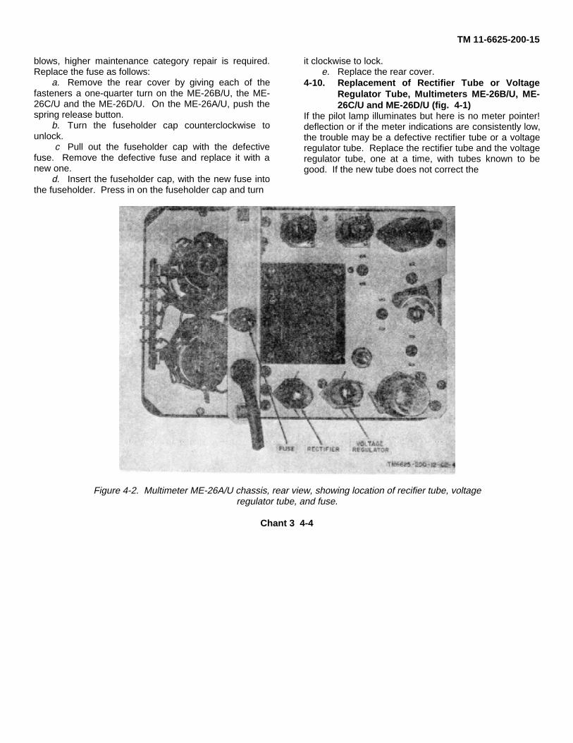
4-10. Replacement of Rectifier Tube or VoltageRegulator Tube, Multimeters ME-26B/U, ME-26C/U and ME-26D/U (fig. 4-1)
If the pilot lamp illuminates but here is no meter pointer!deflection or if the meter indications are consistently low,the trouble may be a defective rectifier tube or a voltageregulator tube. Replace the rectifier tube and the voltageregulator tube, one at a time, with tubes known to begood. If the new tube does not correct the
Figure 4-2. Multimeter ME-26A/U chassis, rear view, showing location of recifier tube, voltageregulator tube, and fuse.
Chant 3 4-4

TM 11-6625-200-15
trouble, replace the original tube and turn the multimeterin for higher maintenance category repair. Replace thetubes as follows:
a. Remove the rear cover.b. Remove the retaining screws (fig. 1-1) from the
front panel, the top of the case, and the rear crosspiece.c. Remove the chassis by gently sliding it forward
while lifting the power cable from the groove in the rearcrosspiece.
d. Press down on the tube shield and turn itcounterclockwise to unlock; remove the tube shield.
Caution: Do not rock or rotate a tube whenremoving it from the tube socket; pull it straight out.
e. Pull out and replace a suspected rectifier tube orvoltage regulator tube with a new one. Replace theoriginal tube if the multimeter remains inoperative.
f. Place the tube shield over the tube; press downand turn the tube shield clockwise to lock.
g. Slide the chassis back into the case and replacethe retaining screws.
h. Replace the rear cover.
4-11. Replacement of Redifier Tube or VoltageRegulator Tube, Multimter ME-26A/U
(fig. 4-2)Replace the Multimeter ME-26A/U tubes as follows:
a. Remove the rear cover by pressing the springrelease button on the top rear of the case (fig. 1-2).
b. Remove the retaining screws that hold the mainchassis to the case.
c. Remove the chassis by gently sliding it forwardout of the case.
d. Push the spring wire tube retainer away from thetube.
Caution: Do not rock or rotate a tube whenremoving it from the tube socket; pull it straight out.
c. Pull out the suspected rectifier tube or voltageregulator tube and replace it with a new. one. Replacethe original tube if the multimeter remains inoperative.
f. Push the spring wire retainer back on the tube.g. Slide the chassis back into the case and replace
the retaining screws.h. Replace the rear cover.
4-5

TM 11-6625-200-15
CHAPTER 5
FUNCTIONING
Section I. BLOCK DIAGRAM ANALYSIS
5-1. Block Diagram FunctioningMultimeter ME-26(*)/U is an electron tube multimeter(voltmeter-ohmmeter) used to measure direct currentvoltage, alternating current voltage, and resistance. Ablock diagram analysis is given in paragraphs 5-2, 5-3,and 5-4. For complete circuit details, refer to theschematic diagrams (fig. 9-3 and 9-4).5-2. DC Voltage Measurements
(fig. 5-1)a. The dc voltage to be measured is applied
between the DC probe and the COMMON clip. InMultimeters ME-26B/U, ME-26C/U, and ME-26D/U whichhave been changed in accordance with paragraph 7-, theCOMMON clip is isolated from the chassis ground. InMultimeter ME-26A/U, and Multimeters ME-26B/U andME-26C/U which have not been changed, the COMMONlead goes directly to the chassis ground. In zither case,the voltage is fed through the FUNCTION switch(SELECTOR switch on’ Multimeter ME-26A/ U) to themultiplier resistors, selected by RANGE switch S2, thenapplied to amplifier V2A.
b. With no voltage applied to amplifier V2A,amplifiers V2A and V2B function as a balanced amplifierstage. The balancing resistors provide identical dc biasto amplifiers V2A and V2B so that, with no input, theiroutputs are identical. Amplifiers V2A and V2B controlcathode followers V3A and V3B, respectively. When theamplifiers are balanced, the inputs to the cathodefollowers are identical. Current flow through cathodefollowers
V3A and V3B is equal, and’ the meter-balancing circuit isbalanced. Under this condition, there is no output fromthe meter-balancing circuit to the meter.
c. With a voltage applied to amplifier V2A (a above)amplifiers V2A and V2B become unbalanced. Theresultant change in the inputs to cathode followers V3Aand V3B causes unequal currents to flow in the cathodefollowers, and the meter-balancing circuit becomesunbalanced. Under this condition, the output of themeter-balancing circuit is applied to meter M1 throughthe dc calibration control.
d. The power supply, which consists of transformerT1, full-wave rectifier V5, and voltage regulator V4,provides the required operating and bias voltages.5-3. AC Voltage Measurements
(fig. 5-2)a. The ac voltage to be measured is applied to the
AC probe where it is rectified and filtered. The output ofthe AC probe is then applied to the multiplier resistorsthrough FUNCTION switch S1 (SELECTOR switch onMultimeter ME-26A/U). A portion of the voltage acrossthe multiplier resistors, selected by RANGE switch S2, isapplied to amplifier V2A.
b. With no voltage applied to the AC probe, the acsignal rectifier within the AC probe produces an emissioncurrent that develops a voltage across the multiplierresistors. A portion of this voltage is applied to amplifierV2A through RANGE switch S2. To compensate for thevoltage produced by the emission
5-1

TM 11-6625-200-15
Figure 5-1. Dc voltage measurement circuit, block diagram.
5-2

TM 11-6625-200-15
Figure 5-2. Ac voltage measurement circuit, block diagram
5-3.

TM 11-6625-200-15
Figure 5-3. Resistance measurement circuit, block diagram.
5-4
current, a negative voltage is applied from the acbalancing resistors to amplifier V2B. The AC ZEROcontrol is used to adjust the voltage applied to amplifierV2B until it is equal to the emission voltage. AmplifiersV2A and V2B are now balanced, and the inputs tocathode followers V3A and V3B are identical. Currentflow through cathode followers V3A and V3B is equaland the meter-balancing circuit is balanced. Under thiscondition, there is no output from the meter-balancingcircuit to meter M1.
c. After the AC ZERO control has been adjusted,and with a voltage applied to the AC probe (a above), thefunction of amplifiers V2A and V2B and cathode followerV3A and V3B is identical with that described Inparagraph 5-2c, except that the output to meter M1 isthrough the ac calibration control. The function of thepower supply is described in paragraph 5-2d.
5-4. Resistance Measurements (fig. .5-3)a. The resistance measurement circuit differs from
the voltage measurements circuits (para .5-2 and 5-3above) in that amplifiers V2A and V2B and cathodefollowers V3A and V3B are normally at maximumunbalance When the OHMS probe and the COMMO Nclip are separated, a negative voltage is applied toamplifier V2A. On the RX1 range, the output of metallicrectifier CR1 is applied through FUNCTION switch S tothe OHMS probe, and through RANGE switch S2 toamplifier V2A. On all other resistance ranges (RX10-
TM 11-6625-200-15
RPX1M), the B-output of voltage regulator V4 is appliedto the multiplier resistors. A portion of the voltage acrossthe multiplier resistors, selected by RANGE switch S2, Isapplied directly to amplifier V2A and, throughFUNCTION switch S1, to the OHMS probe With avoltage applied to amplifier V2A, the function ofamplifiers V2A and V2B is identical with that described inparagraph 5-2c, except that the output to meter M1 isthrough the OHMS ADJ control, the OHMS ADJ controlis adjusted so that meter Ml indicates infinity (maximumright-hand deflection of the meter needle).
b. When the OHMS probe and the COMMON clipare touched together (shorted), no voltage is applied toamplifier V2A. Under this condition, the function ofamplifiers V2A and V2B and cathode followers V3A andV3B is identical with that described in paragraph 5-2b.
c. When an unknown resistance is connectedbetween the OHMS probe and the COMMON clip,current flows through the resistance and causes thevoltage applied to amplifier V2A to decrease. Theresultant change in the outputs of amplifiers V2A andV2B also causes cathode followers VSA and V3B toapproach a balanced condition, and the output from themeter-balancing circuit decreases; current flowingthrough meter M1 decreases, and the meter needlemoves to the left (toward zero) to indicate the resistancevalue connected between the OHMS probe and theCOMMON clip
d. The power supply, which consists oftransformer T1, full-wave rectifier Vt5, and voltageregulator V4, supplies the required operating and biasvoltages
Section II. CIRCUIT ANALYSIS
5-5. Amplifier and Cathode Follower Circuit (fig. 5-4)
When the outputs of the cathode follower stages arebalanced, no current flows in the meter circuit and themeter needle does not deflect (a below); however, whenthe outputs of the cathode follower stages areunbalanced, current flows through the meter circuit andthe meter needle does deflect (b below).
The amount of deflection is proportional to the unbalance
a. Balanced(1) Identical positive dc voltages are fed to the
plates of amplifiers V2A and V2B through plate loadresistors R2O and R25 Also, the cathodes are connectedthrough balancing resistors R21, R22, and PR23 to acommon negative dc potential. Because the potentials
5-5

TM 11-6625-200-15
Figure 5-4. Dc voltage measurement circuit, partial schematic diagram.
5-6

TM 11-6625-200-15
applied to the grids of tube V2 are also identical, theoutputs of amplifiers V2A and V2B remain constant, andthe circuit functions as a balanced amplifier.
(2) The plates of amplifiers V2A and V2B aredirectly coupled to the grids of cathode followers V3Aand V3B. respectively. The plates of tube V3 are both atthe same positive (B +) potential and the cathodes areconnected to the same negative (B-) potential. As aresult of the identical potentials at the grids, thecathodes, and the plates of tube V3, the current flow insection V3A is equal and opposite to that in section V3B.These equal but opposite currents flow through themeter-balancing circuit (resistors R19A, R27, and R29)and produce identical voltages at the junction of resistorsR26 and R27, and resistors R29 and R30. Becausethese identical voltages of the same polarity are appliedto the meter terminals, no current flows through themeter’ circuit and the meter needle does not deflect.
(3) ZERO ADJ control R19A compensates forany unbalance that may exist in the circuit because ofdifferent tolerances of the components. Also, the verylow voltages of tube V2 (+ 15 volts on the plates and+0.75 volt on the cathode) together with the negativefeedback developed across common cathode resistorsR23, R33, and R34 produce stable circuit operation.Resistors R26 and R30 are cathode-dropping ;resistors.Resistors R41, together with resistors R42 and R4i, forma voltage-divider network from the -175 volts to ground.Resistor R28 is a parasitic suppressor for amplifier V2Aand, in conjunction with capacitor C4, provides adampening effect to prevent surges from beingintroduced in meter M1 at the moment the probe istouched to a voltage source. Capacitors C5 and C6 arecathode bypass capacitors. Capacitor C7 bypassesradiofrequencies around meter M1, capacitor C8 shuntsradiofrequencies to ground, and capacitor C4 is an RFbypass capacitor in the grid circuit of amplifier V2B.(Capacitor C9 is in the circuit only during the ac voltagefunction.)
b. Unbalanced. When an input signal is applied,amplifier stage V2 becomes unbalanced
and functions in push-pull, and also causes cathodefollower stage V3 to become unbalanced and function inpush-pull.
(1) Negative input voltage. A negativevoltage (never more than -0.9 volt) applied to the grid ofamplifier V2A decreases the platecathode current andcauses an increase in plate voltage. Because amplifiersV2A and V2B are cathode coupled (through resistorR23), the decrease in current through resistor R23places the cathode of amplifier V2B at a less positivepotential (effectively making the grid more positive),resulting in a decrease in plate voltage. The increasedplate voltage (more positive) of amplifier V2A is directlycoupled to the grid of cathode followed V3A, causing anincrease in plate-cathode current. The decreased platevoltage (less positive) of amplifier V2B is directlycoupled to the grid of cathode followed V3B, causing adecrease in plate-cathode current. As a result of theincreased current flow in tube V3A and the decreasedcurrent flow in tube .V3B. the voltage at the junction ofresistors R26 and R27 becomes more )positive while thevoltage at the junction of resistors R29 and R30becomes less positive. This unbalanced voltagecondition (proportional to the voltage al)l)lied to the gridof amplifier V2A) causes current to flow- in the metercircuit, and meter M1 deflects.
(2) Positive input voltage . A positive voltage(never more than t-0.9 volt) applied to the grid ofamplifierV2A, increases the platecathode current andcauses a decrease in plate voltage. Because amplifiersV2A and V2P, are cathode of amplifiers V2B at a morepositive potential (effectively making the grid morenegative), resulting in an increase in plate voltage. Thedecreased plate voltage (less positive) of amplifier V2Ais directly coupled to the grid of cathode follower V3A,causing a decrease in plate-cathode current. Theincreased plate voltage (more positive) of amplifier V2Bis directly coupled to the grid of cathode follower V3P,,causing an increase in plate-cathode current. As a resultof the decreased current flow in tube V3A and theincreased current flow in tube V3B, the voltage at thejunction of resistors R26 and R27 becomes less positive,while the voltage at the
5-7

TM 11-6625-200-15
junction of resistors R29 and R30 becomes morepositive. This unbalanced voltage condition (proportionalto the voltage applied to the grid of amplifier V2A)causes current to flow in the meter circuit, and meter M1deflects.
5-6. DC Voltage Measurements Analysis (fig. 5-4)
When the multimeter is set up for dc voltagemeasurements, FUNCTION switch S1 (SELECTORswitch on Multimeter ME-26A/ U) may be in either the -or + position (table 1, fig. 5-4); either position placesthe DC probe and the COMMON clip across themultiplier resistors (voltage-divider network) whichconsists of resistors R1 and 1\fs20 3 through R13. Toobtain the required range of operation, an appropriateportion of the voltage-divider network is selected by thesetting of RANGE switch S2 (table 2, fig. 5-4)
a. No Input Voltage. Under no input conditions, thegrids of amplifiers V2A and V’2B are at groundpotential, the amplifier and cathode follower circuit isbalanced, and the meter indication is zero.
b. Input Voltage Applied. With an input voltageapplied between the DC probe and the COMMON clip,the amplifier and cathode follower circuit becomesunbalanced.
(1) Negative input voltage. When a negativeinput voltage is applied to the input (DC probe negative,and COMMON clip positive), current flows into the topside of resistor R9 and through the voltage-dividernetwork to chassis ground The negative voltage selectedby RANGE switch S2 is applied to the grid of amplifierV2A; the amplifier and cathode follower circuitbecomes unbalanced, and meters M1 indicates the valueof the voltage being measured.
(2) Positive input voltage. PlacingFUNCTION switch S1 in the i position reverses theconnections at meter M1 to enable meter M1 to indicateproperly. When a positive input voltage is al)l)lied to theinput (DC probe positive and COMMON clip negative),current flows into the voltage-divider network
from the chassis ground and out of the top side ofresistor R9. The positive voltage selected by RANGEswitch S2 is applied to the control gild of amplifier V2A;the amplifier and cathode follower circuit becomesunbalanced and meter M1 indicates the value of thevoltage being measured. With either type of input (-or +), resistor R1 prevents capacitive loading of the circuitunder test by the multimeter. DC-CAL control R32 isused to calibrate meter M1 for dc voltage measurements(para 7-5).
5-7. AC Voltage Measurements, Analysis (fig. 5-5)
When the multimeter is set up for ac voltagemeasurements. FUNCTION switch S1 is set to AC.placing the AC probe across the voltage-divider networkwhich consists of resistors R2 through R13 To obtainthe required range of operation, an appropriate portion ofthe voltage-divider network is selected by the setting ofRANGE switch S2. (Refer to table on fig 5-5.)
a. No input Voltage. Under no input voltageconditions, the amplifier and cathode follower circuit isbalanced and the meter indication is zero.
(1) During the ac function, ac signal rectifierV1 produces an emission current that flows into thevoltage-divider network The emission current flows intothe top side of resistor R9 and though the voltage dividerto ground. The negative voltage developed is fed to thegrid of amplifier V2A. This negative voltage tends tounbalance the two sections of the amplifier stage.
(2) To compensate for the negative voltageapplied to amplifier V2A, the grid of amplifier V2B is tiedto an ac-balancing network which consists of AC ZEROcontrol R53 and resistors R14 through R18. The ac-balancing network feeds a negative voltage to the grid ofamplifier V2T1 The negative voltage, selected by sectionS2D real of RANGE switch S2, is made identical withthat applied to amplifier V2A by adjusting AC ZEROcontrol R53. This condition keeps the grids of amplifiersV2A and V2r, at the same potential, and the ampli-
5-8

TM 11-6625-200-15
Figure 5-5. Ac voltage measurement circuit, partial schematic diagram.
5-9
TM 11-6625-200-15
fier and cathode follower circuit remains balanced.b. Input Voltage Applied. With an ac
voltage applied between the tip and the ground clip of theAC probe, the amplifier and cathode follower circuitbecomes unbalanced. (1) The ac input voltage applied tothe AC probe is rectified by ac signal rectifier V1. The dccurrent output of the rectifier circuit flows into the top sideof resistor R9 and through the voltage-divider network tothe chassis ground. Because an additional negativevoltage (over and above that discussed in a above) isapplied to the grid of amplifier V2A, the amplifier andcathode follower circuit becomes unbalanced and meterM1 indicates the value of the ac voltage undermeasurement.
(2) Capacitor C1, together with resistor R2,prevents capacitive loading of the circuit under test bythe multimeter. Also, capacitor C1 serves as a dcblocking capacitor, and resistor R2 is part of the filtercircuit that includes capacitors C2 and C3. The acalignment controls (resistors R3,5 through R40) are usedto calibrate meter M1 for ac voltage measurements (para7-6).
5-8. Resistance Measurements (fig. 5-6)
When the multimeter is set up for resistancemeasurements, FUNCTION switch S1 is placed atOHMS, and the OHMS probe and COMMON clip areplaced across the internal resistance measurementcircuit. To obtain the required range of operation, selectan appropriate series-parallel or parallel resistancevalue by the setting of RANGE switch S2. (Refer to thetable on fig. 5-6.)
a. Infinity Indication. When no external resistanceis connected between the OHMS 1probe and theCOMMON clip (probe and clip separated), the grid ofamplifier V2A is connected to a -0.9-volt dc potential, andthe grid of the amplifier is connected to the chassisground.
(1) When RANGE switch S2 is set to RX1, -0.9 volt dc is applied from the low-voltage supply (para 5-9) to the input probes,
resistor R47, and the grid of amplifier V2A.. WhenRANGE switch S2 is set to any other position (RX10-RX1M),- 0.9 volt dc is applied from the negative output (-60 volts) of the high-voltage supply (para 5-9c) to theinput probes, the voltage-divider network (resistors R3through R6 and R10 through R13), and the grid ofamplifier V2A.
(2) Because of the negative voltage applied tothe grid of amplifier V2A, the amplifier and cathodefollower circuit becomes unbalanced, and meter M1indicates infinity (needle at extreme right).
b. Zero Indication. When no external resistance isconnected between the OHMS probe and the COMMONclip, but with the probe and clip connected (shorted),both grids of amplifier V2 are connected to the chassisground, the amplifier and cathode follower circuit isbalanced, and the meter indicates zero (needle atextreme left). OHMS ADJ control R31 is used to adjustthe meter M1 needle exactly to infinity with the inputopen, and ZERO ADJ control R19A is used to adjust themeter M1 needle exactly to zero with the input shorted.
c. Resistance Indication. When an externalresistor is connected between the OHMS probe and theCOMMON clip, the meter indicates the value of theresistor under measurement.
(1) When RANGE switch S2 is set to RX1, theunknown resistor is placed in parallel with resistor R47.The parallel circuit thus created draws additional currentfrom the low-voltage supply and the voltage drop acrossresistors R48 and R49 (fig. 57) increases. Theincreased voltage drop reduces the voltage (to less than-0.9 volt) that was originally impressed on the grid ofamplifier V2A (a(1) above).
(2) When RANGE switch S2 is in any otherposition (RX1 through RX1M), the unknown resistor isplaced in series-parallel with that value of resistanceselected by the position of RANGE switch S2. (Refer totable on fig. 5-6.) The total dc voltage (-0.9 volt)available from the negative output (-60 volts) of the high-voltage supply is now divided proportionately betweenthe unknown
5-10

TM 11-6625-200-15
Figure 5-6. Resistance measurement circuit, partial schematic diagram.
5-11

TM 11-6625-200-15
resistor and the selected resistors of the voltage-dividernetwork. The result of this voltage division is a lessnegative voltage (less than - 0.9 volt) impressed on thegrid of amplifier V2A.
(3) As a result of the decrease in the negative((1) or (2) above) applied to the grid of amplifier V2A, theamplifier and cathode follower circuit is unbalanced to alesser degree and the meter indicates the value of theunknown resistance.
5-9. Power Supply
a. Impact Power. The ac voltage (115 or 230 volts)is fed from the power source, through power connectorPl (fig. 5-7), FUSE F1, and switch SIC (part ofFUNCTION switch S1 (SELECTOR switch in MultimeterME-26A/U)) to the primary of transformer T1.
(1) Switch section SIC is closed whenFUNCTION switch S1 (fig. 9-3 and 9-4) is in any positionother than OFF.
(2) For a 115-volt ac voltage input (fig. 5-7),the two primary windings are connected in parallel. For a230-volt ac voltage input, the two primary windings areconnected in series.
(3) Capacitors C11 and C12 prevent spuriousvoltage, which may be present in the power source, fromaffecting the equipment. Capacitor C11 and C12 alsoprevent noise generated in the multimeter from enteringthe powerline.
b. Filament Supply.(1) One section of the low-voltage winding of
transformer T1 provides 6.25 volts for the filaments oftubes V2, V3, and V5, and pilot lamp II. Resistor
R52 is a current limiting resistor in the pilot lamp II circuit.The complete low-voltage winding (8-10) provides 12.5volts for the filament circuit of tube VI ((2 below) and forthe low-voltage supply. Resistor R51 drops the voltageapplied to the filament of tube V2 to insure low cathodeemission.
(2) Ballast RT1 and resistors R24, R50, andR54 maintain a constant voltage on the filament of tubeV1. Resistor R50 is adjusted (para 7-6) so that thefilament voltage is 5 volts.
c. High-Voltage Dc Supply. The High-voltagesecondary winding (1-3) of transformer T1 provides thehigh voltage required for full wave rectifier V5.
(1) Full-wave rectifier V5 provides unregulatedB-(-175 volts dc) and the B+ (+150 volts dc) required bycathode followers V3A and V3B. The B+ voltage is alsosupplied to the voltage regulator circuit, consisting ofvoltage regulator V4 and a voltage divider network(resistors R41-R44). This circuit supplies the +44 voltsdc and the -60 volts dc required by amplifiers V2A andV2B. The -60 volts is also applied to the resistancemeasuring circuit when the equipment is set up forresistance measurements above the RXI range (para 58a (1)).
(2) Capacitor C10, together with resistors R45and R46, form a filter for the full-wave rectifier.
d. Low-Voltage Dc Supply. Rectifier CR1 providesthe low dc voltage (-0.9 volt) required for making 58a(1)). Resistor R49 is adjusted (para 7-8) so that thevoltage across resistor R47 is -0.9 volt. Resistor R48 isvoltage dropping resistor.
5-12 Change

TM 11-6625-200-15
Figure 5-7. Power supply, partial schematic diagram.
5-13
TM 11-6625-200-15
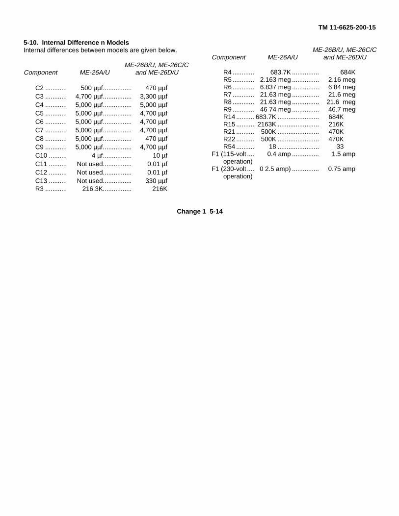
5-10. Internal Difference n ModelsInternal differences between models are given below.
ME-26B/U, ME-26C/CComponent ME-26A/U and ME-26D/U
C2 ............ 500 µµf................ 470 µµfC3 ............ 4,700 µµf................ 3,300 µµfC4 ............ 5,000 µµf................ 5,000 µµfC5 ............ 5,000 µµf................ 4,700 µµfC6 ............ 5,000 µµf................ 4,700 µµfC7 ............ 5,000 µµf................ 4,700 µµfC8 ............ 5,000 µµf................ 470 µµfC9 ............ 5,000 µµf................ 4,700 µµfC10 .......... 4 µf................ 10 µfC11 .......... Not used................ 0.01 µfC12 .......... Not used................ 0.01 µfC13 .......... Not used................ 330 µµfR3 ............ 216.3K................ 216K
ME-26B/U, ME-26C/CComponent ME-26A/U and ME-26D/U
R4 ............ 683.7K ............... 684KR5 ............ 2.163 meg ............... 2.16 megR6 ............ 6.837 meg ............... 6 84 megR7 ............ 21.63 meg ............... 21.6 megR8 ............ 21.63 meg ............... 21.6 megR9 ............ 46 74 meg ............... 46.7 megR14 .......... 683.7K ....................... 684KR15 .......... 2163K ....................... 216KR21 .......... 500K ....................... 470KR22 .......... 500K ....................... 470KR54 .......... 18 ....................... 33
F1 (115-volt .... 0.4 amp ............... 1.5 ampoperation)
F1 (230-volt .... 0 2.5 amp) ............... 0.75 ampoperation)
Change 1 5-14

TM 11-6625-200-15
CHAPTER 6TROUBLESHOOTING
Section I. GENERAL TROUBLESHOOTING TECHNIQUES
NOTEAll troubleshooting, repair, and calibrator procedures should be performed by general supportpersonnel, except for rebuilding the equipment. The equipment should be rebuilt by depotpersonnel.
6-1. Troubleshooting Procedures
a. General. The first step in servicing a defectivemultimeter is to localize the fault. Localizing meanstracing the fault to a stage or circuit responsible forabnormal operation. The second step is to isolate thefault. Isolation means tracing the fault to a defective partresponsible for the abnormal condition. Some faults,such as burned-out resistors and arcing or shortedtransformers, often can be isolated by means of sight,smell, or hearing; however, the majority of faults must beisolated by checking voltages and resistances.
b. Localization and Isolation. The tests listed belowwill aid in localizing and isolating the trouble. First,localize the trouble to a single stage or circuit, and thenisolate the trouble within that circuit by voltage,resistance, and continuity measurements.
(1) Visual inspection. The purpose of visualinspection is to locate faults without testing or measuringcircuits. All meter indications, or other visual signs,should be observed and an attempt made to localize orisolate the fault.
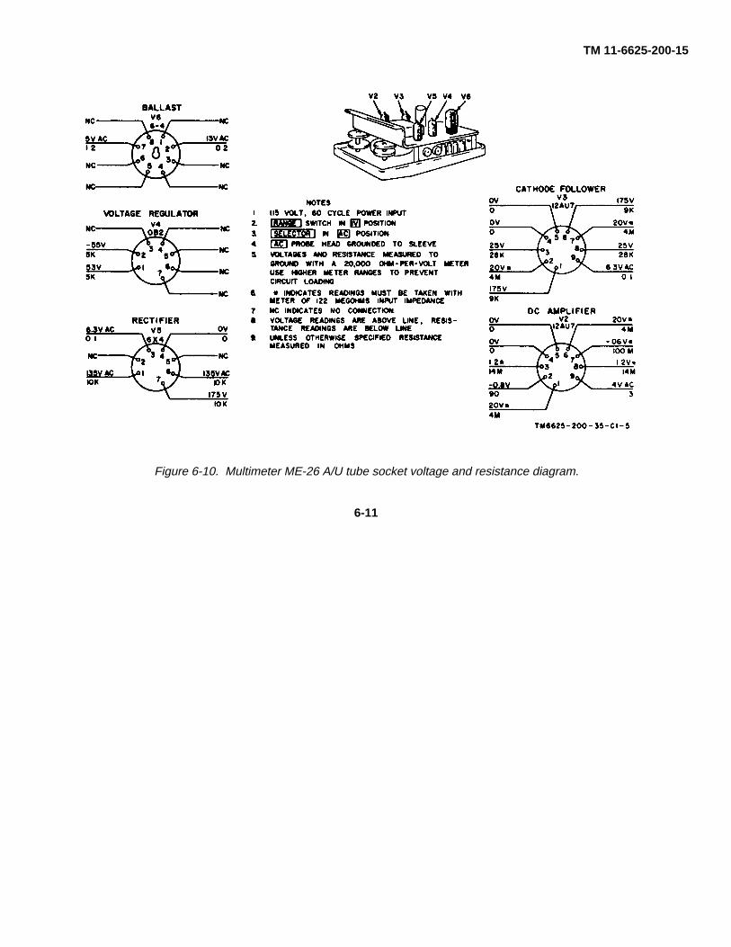
(2) Voltage and resistance measurements.These measurements will help locate the individualcomponent part at fault. Use the resistor and capacitorcolor codes (fig. 9-1 and 9-2) to find the value of thecomponents. Use the voltage and resistance diagrams(fig. 6-8 through 6-11) to find normal readings, andcompare them with the readings taken.
(3) Troubleshooting chart. The troublesymptoms listed in the chart (para 6-4b) will aid inisolating the trouble to a component part. Componentlocation is shown in figures 6-1 through 6-7.
(4) Intermittent troubles. In all of the tests, thepossibility of intermittent troubles should not beoverlooked. If present, this type of trouble often may bemade to appear by tapping or jarring the equipment.
6-2. Tools and Test Equipment Required
The chart below lists the tools and test equipmentrequired for troubleshooting the multimeter. Theapplicable technical manuals and the assigned commonnames are also listed.
Item Technical manual Common name
Test Set, Meter TS-682A/GSM-1 ................................................................TM 11-6625-277-14 Meter testerMultimeter ANI/USM-223 ............................................................................TM 11-6625-654-14Test Set, Electron Tube TV-2/U (depot only) ..............................................TM 11-6625-316-12 Tube testerTest Set, Electron Tube TV-7/U (general support only) ..............................TM 11-6625-274-12 Tube testerTool Equipment TK-105/G...........................................................................
Change 3 6-1

TM 11-6625-200-15
Figure 6-1. Multimeters ME-26B/U, ME-26CIU, and ME26DIU chassis, top view.
Change 3 6-2

TM 11-6625-200-15
Figure 6-2. Multimeter ME-26B/U, ME-26C/U, and ME-26D/U chassis, bottom view.
6-3

TM 11-6625-200-15
Figure 6-3. Multimeter ME-26A/U, chassis, rear view.
6-4
TM 11-6625-200-15
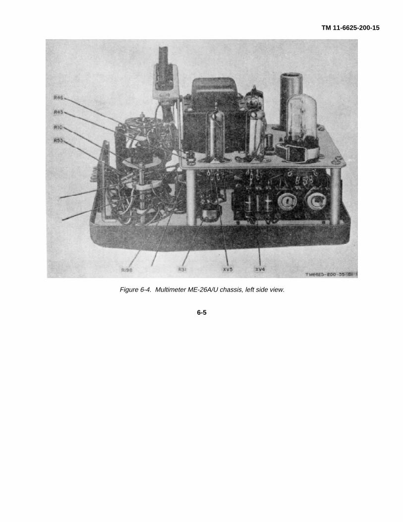
Figure 6-4. Multimeter ME-26A/U chassis, left side view.
6-5

TM 11-6625-200-15
Figure 6-5. Multimeter ME-26A/U chassis, right side view.
6-6

TM 11-6625-200-15
Figure 6-6. Changed Multimeters ME-26 B/U, ME-26 C/U, and Multimeter ME-26D/U chassis, rear view.
6-7
TM 11-6625-200-15
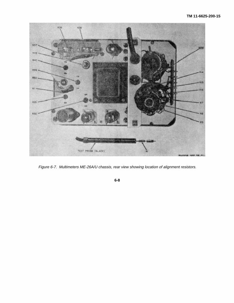
Figure 6-7. Multimeters ME-26A/U chassis, rear view showing location of alignment resistors.
6-8

TM 11-6625-200-15
TM 6625-200-35-8
Figure 6-8. Multimeters ME-26B/U, ME-2C/IU, and ME-26D/U, tube socket voltage and resistance diagram.
6-9
TM 11-6625-200-15
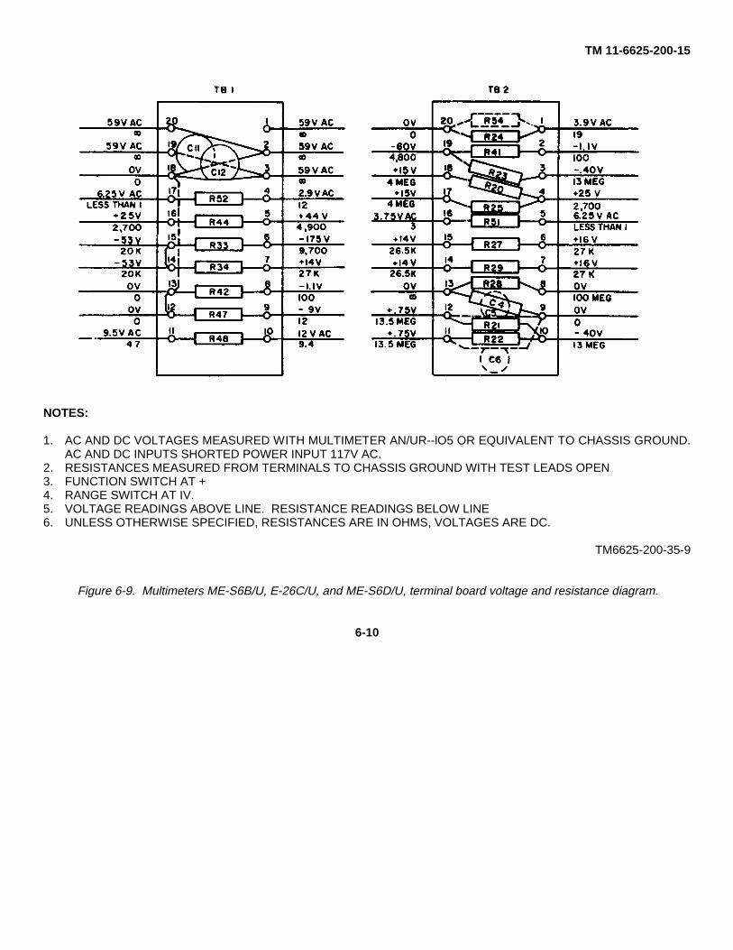
NOTES:
1. AC AND DC VOLTAGES MEASURED WITH MULTIMETER AN/UR--lO5 OR EQUIVALENT TO CHASSIS GROUND.AC AND DC INPUTS SHORTED POWER INPUT 117V AC.
2. RESISTANCES MEASURED FROM TERMINALS TO CHASSIS GROUND WITH TEST LEADS OPEN3. FUNCTION SWITCH AT +4. RANGE SWITCH AT IV.5. VOLTAGE READINGS ABOVE LINE. RESISTANCE READINGS BELOW LINE6. UNLESS OTHERWISE SPECIFIED, RESISTANCES ARE IN OHMS, VOLTAGES ARE DC.
TM6625-200-35-9
Figure 6-9. Multimeters ME-S6B/U, E-26C/U, and ME-S6D/U, terminal board voltage and resistance diagram.
6-10
TM 11-6625-200-15
Figure 6-10. Multimeter ME-26 A/U tube socket voltage and resistance diagram.
6-11

TM 11-6625-200-15
Figure 6-11. Multimeter ME-26 A/U, terminal board voltage and resistance diagram.
6-12

TM 11-6625-200-15
Figure 6-12. Unchanged Multimeters ME-26 B/U and ME-26 C/U chassis, rear view.
6-13

TM 11-6625-200-15
Section II. TROUBLESHOOTING MULTIMETER ME-26(*)/U
Caution: Do not attempt the removal or replacementof parts before reading the instructions given inparagraph 7-1.
6-3. Checking B+ Circuits for Shorts
a. When to Check. When any of the conditionsgiven below exist, check for short circuits and clear thetrouble before applying power.
(1) When the nature of the abnormalsymptoms are not known.
(2) When abnormal symptoms, such asoverheating, arcing, or a blown fuse, indicate possiblepower supply troubles.
b. Conditions for Tests. Prepare for short circuittests as follows:
(1) the power cable from the power source.(2) Set the FUNCTION switch to minus (-).(3) Remove the chassis from the case(4) Remove tubes V2 through V5, ballast
RT1, and pilot lamp I1.
Note. It is not necessary to remove ac rectifier tubeVi when making this test.
c. Measurements. Use the AN/URM-105 andmake the resistance measurement indicated in (1)below. If an abnormal result is obtained, make theadditional isolating checks given in (2), (3), and (4)below. When the faulty part is found, repair the troublebefore applying power to the equipment.
(1) Measure the resistance between pin 1 oftube socket XV5 (fig. 6-8 and 6-10) and chassis ground.The AN/URM-105 should indicate a normal resistance ofapproximately 9,800 ohms.
Switch positionItem FUNCTIONNo. (SELECTOR) RANGE Trouble symptom
1 Any, except Any. Pilot lamp 11 OFF. does not light;
meter M1needledoes not deflect.
(2) If the resistance is approximately half ofthe normal indication (4,900 ohms), check for shortedcapacitor C10 (fig. 6-1 and 6-8).
(3) If the resistance is very low, check thehigh-voltage winding in transformer T1 for a short toground (fig. 9-3 and 9-6).
(4) If the resistance is higher than normal,check for open resistor R41, R42, or R46.
6-4. Troubleshooting Chart
a. General. In the troubleshooting chart (b below),procedures are given for localizing and isolating troublesto a stage or part. Parts locations are indicated in figures6-1 through 6-7. Voltage and resistance measurementsare shown in figures 6-8 through 6-11, overall schematicdiagrams are shown in figures 9-3 and 9-4. When troublehas been localized to a particular stage, use voltage andresistance measurements to isolate trouble to aparticular part.
b. Procedure. The chart below is given as an aid inlocating trouble in the multimeter. The chart lists thesymptoms, the probable troubles, and the correctivemeasures to be taken. If the trouble symptom is known,go directly to the appropriate item. If no symptoms areknown, start with the first item and proceed until thetrouble is found. If the trouble indicates the possibility ofshort circuits within the multimeter, make the short circuittests described in paragraph 6-3 before applying powerto the equipment.
Note. Before replacing a component, asindicated in the Checks and corrective measurescolumn, check the component (para 6-5, 6-6, and 6-7)to be sure that it is defective.
Probable trouble Checks and corrective measures
a. Fuse Fl open. a. Replace fuse Fl (para4-1).
b. Power cable defective. b. Repair or replace powercable.
c. Transformer T1 c. Replace transformer T1defective. (fig. 6-1 and 6-3).
6-14

TM 11-6625-200-15Switch position
Item FUNCTIONNo (SELECTOR) RANGE Trouble symptom Probable trouble Checks ad corrective measures
d. Capacitor C11 or C12 d. Replace defectivedefective. (Not used capacitor (fig. 6-9).on ME-26A/U.)
e. FUNCTION switch e. Replace FUNCTIONS1 defective. switch S1 (SELEC-
TOR switch on ME-26A/U) (fig. 6-2 or6-4).
2 Any, except Any. Pilot lamp 11 does not Pilot lamp I1 defective. Replace pilot lamp I1OFF. light; meter operates (para 4-10).
normally.3 Any, except Any. Meter M1 needle does a. Tube V2, V3, or V5 a. Check for and replace
OFF. not deflect during defective. defective tube (parainitial warmup, or 6-5).during any type b. Resistor R28 or R61 (or b. Replace resistor (figoperation; pilot R51A in the 6-5 or 6-9).lamp 11 illuminates ME-26A/U) open.
c. Capacitor C4 shorted. c. Replace capacitor C4(fig. 6-5 or 6-9).
d. Resistor R23 open. d. Replace resistor R23(fig. 6-4 or 6-9).
e. Resistor R20 or R25 e. Replace defective resis-open. tors (fig. 6-2 and 6-4,
or 6-9 and 6-11)f. Resistor R41, R43, R44, f. Replace defective resis-
R45, or R46 open. tor (fig. 6-2 and 6-4,or 6-9 and 6-11).
g. Resistor R19A, R26, or g. Replace defective resis-R30 open. tor (fig. 6-2 or 6-4
and 6-5).h. Resistor R33 or R34 h. Replace defective resis-
open. tor (fig. 6-9 or 6-11).t. Capacitor C7 or C8 t. Replace defective capac-
shorted. itor (fig 6-1 and 6-2,or 6-3 and 6-4).
j. Capacitor C10 defective. j. Replace capacitor C10(fig 6-1 or 6-3).
k. FUNCTION switch S1 k. Replace switch S1 (fig.(SELECTOR switch 6-2 or 6-4).on ME-26A/U)defective.
l. RANGE switch S2 l. Replace switch S2 (fig.defective. 6-2 or 6-4)
m. Meter M1 defective. m. Replace meter M1 (fig.6-1 or 6-3).
4 Any, except Any. Meter M1 indication a. Tube V4 defective. a. Replace tube V4 (paraOFF. erratic during initial 6-5).
warmup and during b. Resistor R21 or R22 b. Replace defective resis-all types of defective. tor (fig. 6-9 or 6-11).operation. c. Capacitor C5 or C6 c. Replace defective capac-
defective. itor (fig. 6-5 or 6-9).d. Resistor R19A, R20, d. Replace defective resis-
R25, R27, or R29 tor (fig. 6-2 and 6-4,open. or 6-9 and 6-11).
5 - - or +. 1V. Meter M1 cannot be set a. Resistor R1 open. a. Replace resistor R1at zero with ZERO (fig. 6-6 or 6-7).
6-15

TM 11-6625-200-15Switch position
Item FUNCTIONNo (SELECTOR) RANGE Trouble symptom Probable trouble Checks ad corrective measures
ADJ control R19A; b. Tube V2 or V3 b. Replace defective tubeCOMMON clip defective. (para 6-5).connected to DCprobe; pilot lamp 11illuminates.
6 -- or +. 1V. Low or no indication a. One of voltage-divider a. Replace defective resis-on meter M1 with dc resistors (R3 to R13) tors (fig. 6-2 and 6-4,voltage applied defective. or 6-7 and 6-9).between DC probe b. Resistor R42 open. b. Replace resistor R42and COMMON clip; (fig. 6-9 or 6-11).pilot lamp I1 c. DC-CAL control R32 c. Replace DC-CAL con-illuminates. defective. trol R32 (fig. 6-6 or
6-7).d. RANGE switch S2 d. Replace RANGE switch
defective. S2 (fig. 6-2 or 6-5).7 Ac 1V. Meter M1 cannot be set a. Open filament in tube a. Replace tube V1 (para
at zero with AC V1. 6-5 and 7-2).ZERO control R53. b. Capacitor S1 or resistor b. Replace defective com-Ground clip AC R2 open. ponent (para 7-2 andprobe connected to 7-3, and fig. 7-1 andtip, meter M1 7-2).adjusted with ZERO c. Capacitor C2 or C3 c. Replace shorted capaci-ADJ control R19A, shorted. tor (fig. 6-2, 6-5, 7-1and pilot lamp I1 and 7-2).Illuminates d. Capacitor C9 defective. d. Replace capacitor C9
(fig. 6-2 or 6-5).e. AC ZERO control R53 e. Replace AC ZERO
(R19B on ME- control R53 or R19B26A/U) defective. (fig. 6-2 or 6-4).
f. 1V-AC control R35 f. Replace IV-AC controldefective. R35 (fig. 6-4 or 6-7).
8 AC. Any Meter M1 does not a. Open filament in tube a. Replace tube VI (paraexcept deflect ac voltage V1. 6-5 and 7-2).1000V. applied between tip b. Ballast RT1 open. b. Replace ballast RT1
and ground clip of (fig. 6-1 or 6-3).AC probe; probe c. V1 FIL control RS0 c. Replace RSO (fig. 6-6 ordoes not get warm defective 6-7), and then adjustafter 15 minutes; V1 FIL control RSOpilot lamp I1 (para 7-5).illuminates
9 AC. Any. Meter M1 defects with Capacitor C1 shorted. Replace capacitor C1dc voltage applied (para 7-2 or 6-6).to AC ground. Replace probe tip (fig.
7-2).10 AC. 1V. Meter M1 does not 1V-AC control 15 per Replace 1V-AC control
deflect; ac voltage R39 (fig. 6-6 or 6-7).(within correctrange) applied toAC probe Multim-eter operates on allother functions.
11 AC. 3V. Same as item 10 above.3V-AC control R39 open. Replace 3V-AC controlR39.
12 AC. 10V. Same as item 10 above.10V-AC control R40 open. Replace 10V-AC control
6-16

TM 11-6625-200-15Switch position
Item FUNCTIONNo (SELECTOR) RANGE Trouble symptom Probable trouble Checks ad corrective measures13 AC. 30V. Same as item 10 above. 30V-AC control R3S open. Replace 30V-AC control
R36.14 AC. 100V. Same as item 10 above. 100V-AC control R87 Replace 100V-AC control
open. R37.15 AC. 300V. Same as item 10 above . 30OOV-AC control R38 Replace 300V-AC control
open. R38.16 OHMS. RX1. Meter M1 cannot be set a. Rectifier CR1 defective. a. Replace rectifier CR1
to full scale with (fig. 6-2 or 6-4).OHMS ADJ control b. OHMS ADJ control b. Replace OHMS ADSR31; meter has been R31 defective. control (fig. 6-2 andadjusted with ZERO 6-4).ADJ control R19A; c. Resistor R47, R48, or c. Replace defective resisno external resistance R49 defective. tor (fig. 6-6, 6-7, 6-9,connected between and 6-11).OHMS probe andCOMMON clip; andpilot lamp I1illuminates.
17 OHMS. RX l Same as item 16 above.a. Resistor R41 or R32 a. Replace defective resis-MEG. defective. tor (fig. 6-9 or 6-11).
b. Resistor R46 defective. b. Replace defective resis-tor (fig. 6-2 or 6-4).
c. Resistor R28 defective. c. Replace defective R28(fig. 6-7 and 6-9).
d. One of the voltage- d. Replace defective resis-divider resistors (R3 tor (fig. 6-2, 6-4, 6-6,to R6 and R10 to and 6-7).R13) defective.
18 OHMS. RX1. Meter Ml deflects Resistor R47 open. Replace resistor R47beyond full scale; (fig.6-9 or 6-11).OHMS ADJ controlR31 has no effect.
6-5. Tube-Testing Techniques
If tube failure is suspected, use the applicable proceduregiven below to check the tubes.
Note If tube V1, V2, or V3 is replaced, be sure toalign the multimeter (para 7-4 through 7-8). To removetube V1, refer to procedures given in paragraphs 7-2 and7-3,
a. Selection of Replacement Tube. To select newtube V2 or V3, checks must be made as follows:
(1) Amplifier balance with line voltage at 115volts.
(2) Microphonics.(3) Cathode emission.(4) Gas.(5) Voltage calibration.
(a) To select tubes for balance, proceedas follows:
1. Remove tube V2.2. With tube V3 in its socket, check
the ZERO ADJ range both +DC and -DC switchpositions. The range should be the same for both the +and - positions. Substitute several tubes until the bestone is found which has an equal range adjustment.
3. The ZERO ADJ control shouldallow the meter pointer to deflect one-third of the wayupscale in both the +DC and -DC volts position.
(b) To check the tubes formicrophonics:
1. Set the ZERO ADJ control to zerothe meter.
2. Tap tubes V2 and V3.3. If the meter moves erratically,
either tube V2 or V3 is microphonic.
6-17

TM 11-6625-200-15
4. tube V2. (Be sure to check forbalance.) If the meter still moves erratically when tubesV2 and V3 are tapped, replace tube V3.
(c) To check for cathode emission, proceedas follows:
1. Connect the multimeter to thevariac and set the output of the variac to 115 volts, 60cycles ac. Use Multimeter AN/URM105.
2. Zero Multimeter ME-26(*)/U andallow the meter to warm up for 5 minutes.
3. Reduce the output of VariableTransformer CN-16A/U to 103 volts. Let the multimetersit for at least 1 minute with this input voltage.
4. The zero drift of the meter pointershould be less than 5 percent for both +DC and -DCpositions.
5. Adjust the CN-16A/U for 115 volts.6. After the multimeter has stabilized at
115 volts, adjust the variac for a 127-volt output.7. After 1 minute, the drift should beless than 5 percent.
(d) To check for gas, proceed as follows:1. Set the RANGE switch to the 1V-DC
position. Adjust the meter to zero.2. Rotate the RANGE switch to the
300V range. The zero adjustment should not change; ifit does move, the tubes are gassy and should bediscarded.
(e) To check voltage alignment, follow theprocedures given in paragraph 7-5 through 7-11 after 50hours of break-in time.
b. Tube Testing Method. Remove and test onetube at a time. Discard a tube only if its defect is obviousor if the tube tester shows it to be defective. Do notdiscard a tube that tests at or near its minimum test limiton the tube tester. Put back the original tube, or insert anew one if required, before testing the next tube.
c. Tube Substitution Method. Replace asuspected tube with a new tube. If the equip-
ment still does not work, remove the new tube and putback the original tube. Repeat this procedure with eachsuspected tube until the defective tube is located.
6-6. Isolating Trouble Within Stage
When trouble has been localized to a stage, use thefollowing techniques to isolate the defective part.
a. Test the tube involved, either in the tube tester orby substituting a known good tube of the same type(para 6-5).
b. Take the voltage measurements at the tubesockets (fig. 6-8 and 6-10) or at the terminal boards (fig.6-9 and 6-11) related to the stage in question.
c. If readings vary more than ±10 percent fromnormal, remove the power from the multimeter and takeresistance measurements at the tube sockets (fig. 6-8and 6-10) or at the terminal boards (fig. 6-9 and 6-11).
d. Use the wiring diagrams (fig. 9-5 and 9-6) totrace and isolate the faulty component.
6-7. DC Resistance of Transformer Windings
The dc resistance of the winding of transformer T isshown in a below for Multimeters ME-36B/U, ME-26C/Uand ME-26D/U, and in b below for Multimeter ME-26A/U.
a. Multimeters ME-26B/U, ME-26C/U, and ME-26D/U.
Terminals Ohms1 and 2 310.2 and 3 310.4 and 5 18.6 and 7 18.8 and 9 Less than 1.9 and 10 Less than 1.
b. Multimeter ME-26A/U.
Terminals Ohms1 and 2 176.2 and 3 180.4 and 5 Less than 1.5 and 6 Less than 1.7 and 9 175.8 and 10 18.
6-18

TM 11-6625-200-15
CHAPTER 7REPAIRS AND ALIGNMENT
Section I. REPAIRS
7-1. General Parts Replacement Techniques
Most of the Multimeter ME-26(*)/U parts can be reachedwithout special procedures. The following precautionsapply:
a. Be sure to follow the instructions given inparagraph 7-2 and 7-3 to remove tube V1 from the ACprobe. Tube V1 is easily broken if squeezed,mishandled, or forced.
b. All the voltage-divider resistors (R3 through R18and R47) are precision-type resistors. When solderingthese resistors, keep the tip of a long-nosed pliersbetween the end of the resistor and the point beingsoldered. This procedure will prevent excessive heatfrom entering the resistor and changing its value.
c. When removing switch S1 or S2, make a note ofthe position of the pointer and tag all leads beforeunsoldering them.
Note. Before mounting the switches, all leadsshould first be soldered to the terminals.
d. To remove transformer T1 (fig. 6-6), it may benecessary to remove the screws from one end of eachterminal board and then shift the terminal boards slightly.
e. To remove transformer T1 on Multimeter ME-26A/U (fig. 64), remove the main chassis from the frontpanel by removing the four retaining screws located atthe corners of the main chassis.
f. To remove terminal boards TB1 and TB2, it isnecessary to first remove rectifier CR1.
g. Check all connections against the wiringdiagrams (fig. 9-5 and 9-6) before disconnecting andafter reconnecting to a component.
7-2. Disassembly and Reassembly of AC Probe,Changed Multimeters ME-268/ U and ME-26C/U, and Multimeter ME-26D/U(fig. 7-1)
a. Disassembly.(1) Unscrew the tip and capacitor C1
assembly from the plug of the AC probe. If the screwjoint is too tight to turn manually, wrap a rubberbandaround the tip to obtain a better grip. Slide back thejacket.
(2) Remove the mounting screws that fastenthe end assembly to the barrel.
(3) Gently pull back on the end assembly untilit is approximately one-quarter of an inch out of thebarrel.
(4) Remove the mounting screws at the plugend of the barrel.
Caution: Do not bend or twist the plugwhen removing it from the barrel.
(5) With a straight, smooth action, pull theplug out of the barrel.
(6) Carefully slide the barrel off socket XV1and the end assembly.
(7) Slide the spring contact off the end of tubeV1.
(8) Gently pull tube V1 out of the contactsprings of socket XV1.
b. Reassembly.(1) Insert tube V1 into socket XV1; be sure
that the flat center contact of the tube lines up with theflat center contact of the socket. Do not force the tubeinto the socket.
(2) Carefully slide the spring contact onto theend of tube V1.
7-1

TM 11-6625-200-15
Figure 7-1. Changed Multimeters ME-26B/U and ME-C/U, and Multimeter ME-t6D/U AC probe disassemble
(3) Slide the barrel over socket XV1; be surethat tube V1 is properly centered inside the barrel andnot off to one side.
(4) Fasten the end assembly to the barrel withthe mounting screws.
Caution: Do not use excessive force. If the twoholes in the plug do not line up with the two holes in thebarrel, remove the plug, rotate 180°, and reinsert it intothe barrel. Do not twist or rotate the plug when it isinside the barrel
(5) Insert the plug into the barrel and fastenwith the mounting screws.
(6) Screw the tip and capacitor C1 assemblyinto the threaded end of the plug; be sure that theassembly makes a tight contact.
7-3. Disassembly and Reassembly of AC Probe,ME-26A/U(fig. 7-2)
a. Disassembly.(1) Remove the ac ground clip, including the
leads.(2) Unscrew the probe head from the probe
body.(3) Unscrew the sleeve from the cap retainer
nut; be careful not to jar tube V1.
(4) Remove the tube contact.(5) Remove the mounting screws that fasten
the sleeve to the probe body. Remove the probe bodyby pushing the body toward the tapped end of the sleeve.
(6) Gently pull tube V1 out of socket XV1.b. Reassembly.
(1) Insert tube V1 into socket XV1; be surethat the flat center contact of the tube lines up with theflat center contact of the socket. Do not force the tubeinto the socket.
(2) Insert the probe body into the sleeve andinsert the screws that hold the sleeve to the probe body.
(3) Place the tube contact onto the plateconnector of V1.
(4) Screw in the cap retainer nut.(5) Place the ac ground clip in position.
7-4. Disassembly and Reassembly of AC Probeon Unchanged Multimeters ME-26B/U andME-26C/U
a. Disassembly.(1) Unscrew the tip and capacitor C1
assembly from the plug of the AC probe. If the
7-2

TM 11-6625-200-15
Figure 7-2. Multimeter ME-26A/U AC probe disassembled.
screw joint is too tight to turn by hand, wrap a rubberband around the tip to obtain a better grip.
(2) Remove the mounting screws that fastenthe end assembly to the barrel.
(3) Gently pull back on the end assemblyuntil it is approximately one-quarter inch out of thebarrel.
(4) Remove the mounting screws at the plugend of the barrel.
(5) "With a straight smooth action, pull theplug out of the barrel.
Caution: Do not bend or twist the plug whenremoving it from the barrel.
(6) Carefully slide the barrel off socket XV1and the end assembly.
(7) Slide the spring contact off the end oftube V1.
(8) Gently pull tube V1 out of the contactsprings of socket XV1.
b. Reassembly.(1) Insert tube V1 into socket XV1; be
sure that the flat center contact of the tube aligns withthe flat center contact of the socket. Do not force thetube into the socket.
(2) Carefully slide tie spring contact onto theend of tube V1.
(3) Slide the barrel over socket XV1; be surethat tube V1 is properly centered inside the barrel andnot off tot one side.
(4) Fasten the end assembly to the barrelwith the mounting screws.
(5) Insert the plug into the barrel and fastenwith the mounting screws.
Caution: Do not use excessive force. If the twoholes in the plug do not align with the two holes inthe barrel, remove the plug, rotate it 180"', andreinsert it into the barrel. Do not twist or rotate theplug when it is inside the barrel.
(6) Screw the tip and capacitor C1 assemblyinto the thread end of the plug; be sure that theassembly makes a tight contact.
7-3
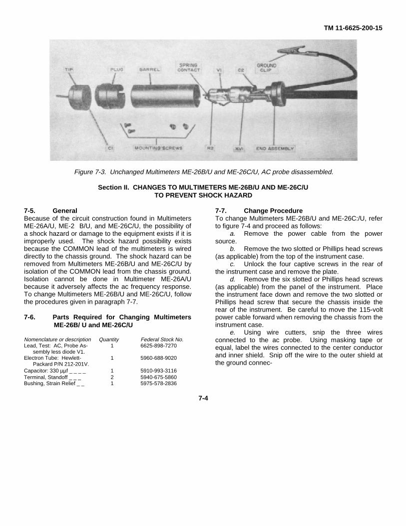
TM 11-6625-200-15
Figure 7-3. Unchanged Multimeters ME-26B/U and ME-26C/U, AC probe disassembled.
Section II. CHANGES TO MULTIMETERS ME-26B/U AND ME-26C/UTO PREVENT SHOCK HAZARD
7-5. GeneralBecause of the circuit construction found in MultimetersME-26A/U, ME-2 B/U, and ME-26C/U, the possibility ofa shock hazard or damage to the equipment exists if it isimproperly used. The shock hazard possibility existsbecause the COMMON lead of the multimeters is wireddirectly to the chassis ground. The shock hazard can beremoved from Multimeters ME-26B/U and ME-26C/U byisolation of the COMMON lead from the chassis ground.Isolation cannot be done in Multimeter ME-26A/Ubecause it adversely affects the ac frequency response.To change Multimeters ME-26B/U and ME-26C/U, followthe procedures given in paragraph 7-7.
7-6. Parts Required for Changing MultimetersME-26B/ U and ME-26C/U
Nomenclature or description Quantity Federal Stock No.Lead, Test: AC, Probe As- 1 6625-898-7270
sembly less diode V1.Electron Tube: Hewlett- 1 5960-688-9020
Packard P/N 212-201V.Capacitor: 330 µµf _ _ _ _ 1 5910-993-3116Terminal, Standoff _ _ _ 2 5940-675-5860Bushing, Strain Relief _ _ 1 5975-578-2836
7-7. Change ProcedureTo change Multimeters ME-26B/U and ME-26C:/U, referto figure 7-4 and proceed as follows:
a. Remove the power cable from the powersource.
b. Remove the two slotted or Phillips head screws(as applicable) from the top of the instrument case.
c. Unlock the four captive screws in the rear ofthe instrument case and remove the plate.
d. Remove the six slotted or Phillips head screws(as applicable) from the panel of the instrument. Placethe instrument face down and remove the two slotted orPhillips head screw that secure the chassis inside therear of the instrument. Be careful to move the 115-voltpower cable forward when removing the chassis from theinstrument case.
e. Using wire cutters, snip the three wiresconnected to the ac probe. Using masking tape orequal, label the wires connected to the center conductorand inner shield. Snip off the wire to the outer shield atthe ground connec-
7-4

TM 11-6625-200-15
tion closest to the RANGE switch. Remove the acprobe from the front panel.
f. Using wire cutters, snip off all remaining wires(three) that are connected to the ground connectorclosest to the RANGE switch
g. Using wire cutters, snip off the wire that isconnected to the shield of the dc probe.
h. Mount the standoff insulators on XRT-1 andXV-5 (fig. 7-3).
i. Using hookup wire, measure the amount ofwire necessary to connect the shield on the dc probelead to the standoff insulator mounted to XV-5. Cut the-length as necessary. Route this wire close to the frontpanel and chassis.
Figure 7-4. Under chassis view showing parts changed in Multimeters ME-26B/U and ME-26C/U.
7-5
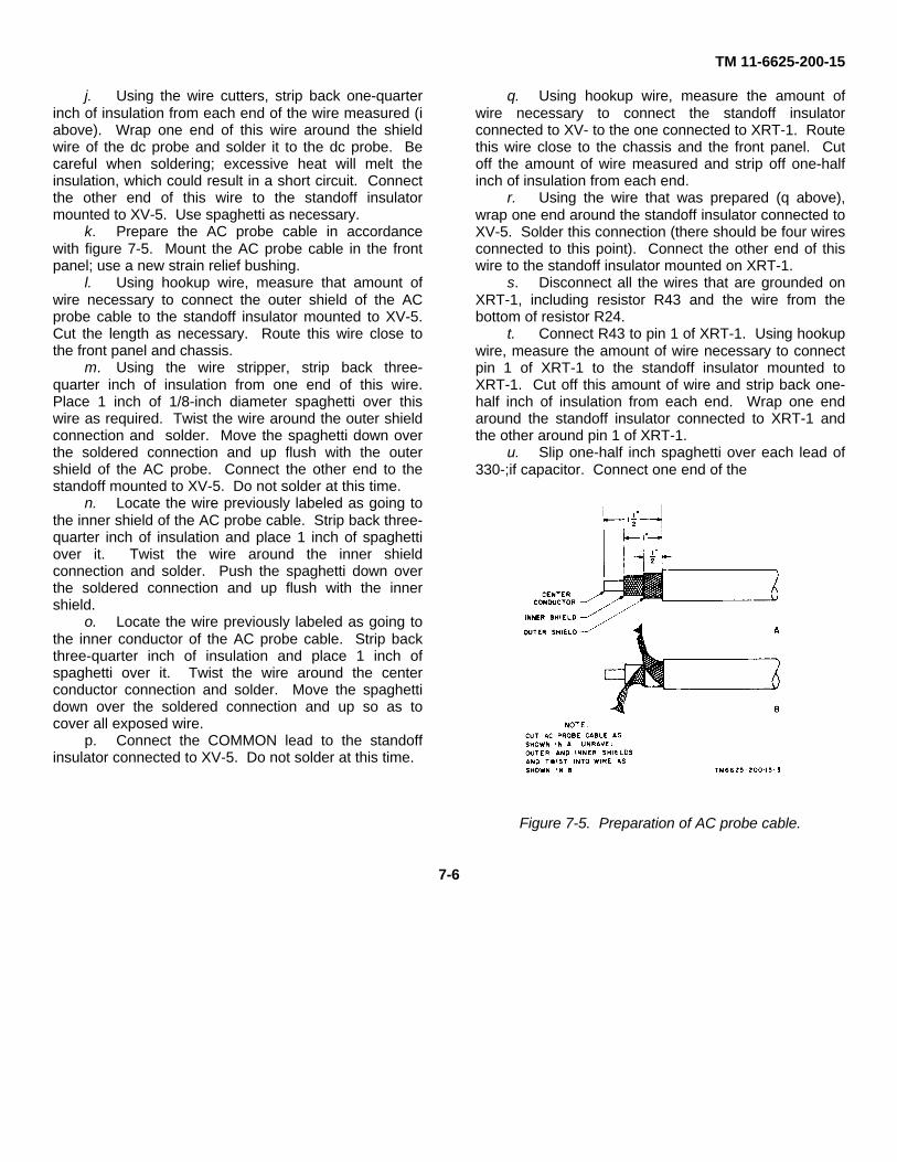
TM 11-6625-200-15
j. Using the wire cutters, strip back one-quarterinch of insulation from each end of the wire measured (iabove). Wrap one end of this wire around the shieldwire of the dc probe and solder it to the dc probe. Becareful when soldering; excessive heat will melt theinsulation, which could result in a short circuit. Connectthe other end of this wire to the standoff insulatormounted to XV-5. Use spaghetti as necessary.
k. Prepare the AC probe cable in accordancewith figure 7-5. Mount the AC probe cable in the frontpanel; use a new strain relief bushing.
l. Using hookup wire, measure that amount ofwire necessary to connect the outer shield of the ACprobe cable to the standoff insulator mounted to XV-5.Cut the length as necessary. Route this wire close tothe front panel and chassis.
m. Using the wire stripper, strip back three-quarter inch of insulation from one end of this wire.Place 1 inch of 1/8-inch diameter spaghetti over thiswire as required. Twist the wire around the outer shieldconnection and solder. Move the spaghetti down overthe soldered connection and up flush with the outershield of the AC probe. Connect the other end to thestandoff mounted to XV-5. Do not solder at this time.
n. Locate the wire previously labeled as going tothe inner shield of the AC probe cable. Strip back three-quarter inch of insulation and place 1 inch of spaghettiover it. Twist the wire around the inner shieldconnection and solder. Push the spaghetti down overthe soldered connection and up flush with the innershield.
o. Locate the wire previously labeled as going tothe inner conductor of the AC probe cable. Strip backthree-quarter inch of insulation and place 1 inch ofspaghetti over it. Twist the wire around the centerconductor connection and solder. Move the spaghettidown over the soldered connection and up so as tocover all exposed wire.
p. Connect the COMMON lead to the standoffinsulator connected to XV-5. Do not solder at this time.
q. Using hookup wire, measure the amount ofwire necessary to connect the standoff insulatorconnected to XV- to the one connected to XRT-1. Routethis wire close to the chassis and the front panel. Cutoff the amount of wire measured and strip off one-halfinch of insulation from each end.
r. Using the wire that was prepared (q above),wrap one end around the standoff insulator connected toXV-5. Solder this connection (there should be four wiresconnected to this point). Connect the other end of thiswire to the standoff insulator mounted on XRT-1.
s. Disconnect all the wires that are grounded onXRT-1, including resistor R43 and the wire from thebottom of resistor R24.
t. Connect R43 to pin 1 of XRT-1. Using hookupwire, measure the amount of wire necessary to connectpin 1 of XRT-1 to the standoff insulator mounted toXRT-1. Cut off this amount of wire and strip back one-half inch of insulation from each end. Wrap one endaround the standoff insulator connected to XRT-1 andthe other around pin 1 of XRT-1.
u. Slip one-half inch spaghetti over each lead of330-;if capacitor. Connect one end of the
Figure 7-5. Preparation of AC probe cable.
7-6

TM 11-6625-200-15
330-µf capacitor to pin 1 of XRT-1. Connect the otherend to the chassis ground connection between pins 7and 8 of XRT-1; solder.
v. Using hookup wire, measure and cut asnecessary the amount of wire necessary to go betweenthe bottom of R24 and pin 1 of XRT-1. Route this wireclose to the chassis as shown in figure 7-3. Strip off one-half inch of insulation from each end.
w. Using the wire that was prepared (v above),wrap one end around the terminal to which the bottom ofR24 is connected and
solder. Connect the other end to pin 1 of XRT-1, solder(there should be four wires connected to pin 1 of XRT-1).
x. Connect all remaining wires that wereremoved (r above) to the standoff insulator mounted onXRT-1; solder. There should be five wires connected toXRT-1.
y. Clip off the remaining wire of pin 5 of theRANGE switch.
z. Check the wiring to see that it is in accordancewith figure 7-4.
Section III. ALIGNMENT
7-8. Alignment Proceduresa. Test Equipment. The test equipment required
for alignment is given in paragraph 6-2.b. Conditions for Alignment Tests. To prepare
the multimeter for alignment, proceed as follows:(1) Remove the rear access cover.(2) Connect the power cable to the power
source. Be sure that the ac voltage is the same as thatused for normal operation of the multimeter.
(3) Rotate FUNCTION switch S1 to anyposition except OFF; the pilot lamp should illuminate.
(4) Allow the multimeter to warm up for atleast 5 minutes before proceeding with the alignment.
Note. All alignment controls are variableresistors with slotted shafts (fig. 6-6) that should beturned with a small screwdriver.
7-9. DC Volts AlignmentAlignment of the 1V range is the only dc voltagealignment required. When the 1V range is aligned, allother ranges fall within permissible tolerances. To alignthe DC function of the multimeter, proceed as follows:
a. Set the FUNCTION switch (SELECTOR switchon the ME-26A/U) to +.
b. Set the RANGE switch to 1V.c. Connect the COMMON clip to the DC probe.d. Adjust the ZERO ADJ control until meter M1
indicates zero.e. Connect the COMMON clip to the COMMON
connector on the meter tester and connect the DC probeto the 1-volt jack.
f. Rotate the shaft of DC-CAL control R32 (fig.6-6 and 6-7) until meter M1 indicates exactly 1 volt.
g. Disconnect the COMMON clip and the DCprobe from the meter tester.
7-10. Filament Voltage Adjustment, AC SignalRectifier
To adjust the filament voltage of the ac signal rectifier,proceed as follows:
a. Set the FUNCTION switch (SELECTOR switchon Multimeter ME-26A/U) to AC.
b. Connect the AN/URM-105 across the innershield of the AC probe (gray wire) and the chassisground.
c. Adjust V-1 FIL control R50 (fig. 6-6 and 6-7until the AN/URM-105 indicates 5 volts ac.
d. Disconnect the AN/URM-105 from themultimeter.
7-7

TM 11-6625-200-15
7-11. AC Volts Alignment
To align the Ac function of the multimeter, proceed asfollow:
a. Set the FUNCTION switch (SELECTOR switchon Multimeter ME-16A/U) to Ac.
b. Set the RANGE switch to 1V.
c. Connect the ground clip to the tip of the ACprobe.
d. Adjust the AC ZERO control until meter M1indicates zero.
e. Disconnect the ground clip from the tip of theAC probe and connect it to the COMMON connector onthe meter tester.
f. Align each ac voltage range in sequence asfollows:
(1) Set the RANGE switch to the positionindicated in Column 1 of the chart below.
(2) Connect the tip of the AC probe to the acjack on the meter tester that is applicable to the acvoltage listed in Column 2.
(3) Set the meter tester output to the acvoltage value listed in Column 2.
(4) Adjust the alignment control (fig. 6-6 and6-7) listed in Column 3 until meter M1 of the multimeter
indicate the voltage of the meter tester (Column 2).
Column 1 Column 2 Column 3Range switch Meter tester Calibration
output control(volts ac)
1V 3 1V-AC R353V 3 3V-AC R39
10V 10 10V-AC R4030V 30 30v-AC R36
100V 100 100V-AC R37300V 300 300V-AC R38
g. Disconnect the Ac probe from the metertester.
7-12. Low-Voltage Supply Adjustment
To adjust the output of the low-voltage supply, proceedas follows:
a. Set the FUNCTION switch (SELECTOR)switch on Multimeter ME-26A/U) to OHMS.
b. Set the RANGE switch to RX1 position.
c. Observing polarity, connect the AN/URM-105across resistor R47 (fig. 6-9 and 6-11).
d. Adjust RX1 control R49 (fig. 6-6) until theAN/URM-105 indicates - 0.9 volt dc.
e. Disconnect the AN/URM-105 from resistorR47.
7-8

TM 11-6625-200-15
CHAPTER 8GENERAL SUPPORT TESTING PROCEDURES
8-1. Generala. Testing procedures are prepared for use by
Electronics Field Maintenance Shops and ElectronicsService Organizations responsible for general supportmaintenance of electronic equipment to determine theacceptability of repaired equipment. These proceduresset forth specific requirements that repaired equipmentmust meet before it is returned to the usingorganization. These procedures may also be used as aguide for testing equipment that has been repaired atdirect support maintenance if the proper tools and testequipments are available.
b. Comply with the instructions preceding eachchart before proceeding to the chart. Perform each stepin sequence; do not vary the sequence. For each step,perform all the actions required in the Control settingscolumns; then perform each specific test procedure andverify it against its performance standard.
8-2. Test Equipment RequiredAll the test equipment required to perform the testing
Control settingsStep TestNo. equipment Equipment under test
1. N/A Controls may be in any position.
2. N/A. Controls may be in any position.
procedures given in this chapter are listed in the chartbelow, and are authorized under TA 11-17 and TA 11-100 (11-17).
Nomenclature Technical manualTest Set, Meter TS-682A/GSM-1............... TM 11-6625-277-14Resistor, Decade ZM-16/U........................ TM 11-5102.Transformer, Power (Variable) CN-16A/U.Multimeter AN/USM-223 ........................... TM 11-6625-654-14
8-3. Modification Work OrdersThe performance standards listed in the tests (para 8-5through 8-9) assume that all modification work orders onthis equipment have been performed. A listing ofcurrent modification work orders will be found in DAPam 310-7.
8-4. Physical Tests and Inspectionsa. Test Equipment. None required.b. Test Connections and Conditions.
(1) No connections are necessary.(2) Remove the cover from the multimeter.
c. Procedure.
Test procedure Performance standarda. Inspect case and chassis for a. No damage evident or parts miss-
damage, missing parts, and ing. External surfaces intendedcondition of paint. to be painted do not showNote. Touchup metal. Panel lettering is legible.painting is recom-mended in place ofrefinishing wheneverpracticable. Screw-heads, binding posts,receptacles, andother plated partswill not be painted orpolished withabrasives.
b. Inspect all controls and b. Screws, nuts, and bolts are tight;mechanical assemblies for none are missing.loose or missing screws,bolts, and nuts.
c. Inspect all connectors, c. No looseness or damage issockets, evident.receptacles, and fuseholdersfor looseness, damage, ormissing parts.
a. Rotate all panel controls a. Controls rotate freely withoutthroughout their limits of binding or excessive looseness.Travel.
b. Operate all switches. b. Switches operate properly.
8-5. DC Zero Adjust Test and DC Balance Test, AC Zero Control Range Test and Ohms Infinity Testa. Test Equipment. None required.b. Test Connections and Conditions. Follow procedure as outlined in c below.c. Procedure.
Change 3 8-1

TM 11-6625-200-15Step Control settingsno. Test equipment Equipment under test Test procedure Performance standard
1 N/A. FUNCTION (SELECTOR) a. Connect COMMON clip to tip a. None.switch: -. of DC probe. Adjust ZERORANGE: switch IV. ADJ control until meter M1
indicates zero.b. Set RANGE switch to each b. Meter M1 indicates zero for each
higher position (in se- position of RANGE switch.quence) from 3V through1000V. Note meter indica-tion at each position.
2 N/A. FUNCTION (SELECTOR) a. Connect COMMON clip to tip a. None.switch: +. of AC probe. Rotate ZERORANGE switch: 3V. ADJ control to extreme
right. Note and record meterdeflector in percentage offull scale.Note. Reading of0.4 volt on 1-volt(top) scale would be40% of full-scaledeflection.
b. Set FUNCTION (SELECTOR) b. Sum of two deflections noted in aswitch to -. Rotate ZERO) and b must equal 100%.ADJ control to extreme left.Note and record meterdeflection in percentage offull scale.
3 N/A. FUNCTION (SELECTOR) a. Connect COMMON clip to tip a. None.switch: AC. of AC probe.RANGE switch: 1V. b. Rotate AC ZERO control fully b. Meter Ml should read minimum
clockwise. of 0.5 volt on 1-volt scale.4 N/A. Same as step 3. a. Rotate AC ZERO control a. None.
counterclockwise untilmeter M1 indicates 0.
b. Rotate RANGE switch to b. Variation from zero indicationother ac positions should be less than 1 percent(3V-300V). (0.01
Change 3 8-2

TM 11-6625-200-15
Figure 8-1. Multimeter response with line voltage variation test setup.
8-3

TM 11-6625-200-15
Step Control settingsno. Test equipment Equipment under test Test procedure Performance standard
volt) of full scale foreach setting of RANGE'switch.
5 N/A. FUNCTION a. Connect COMMON clip to a. None.(SELECTOR) OHMS probe.switch: OHMS. b. Adjust ZERO ADJ control b. None.RANGE switch: so meter M1 indicatesRX10. zero.
c. Separate COMMON clip c. None.from OHMS probe, andadjust OHMS ADJ con-trol so meter M1 indicatesfull scale (infinity).
d. Set RANGE switch to RX1, d. Variation from zero indi-and connect COMMON cation should be lessclip to OHMS probe. than 3 percent of full-
scale deflection.6 N/A. Same as step 5, a. Separate COMMON clip a. Meter indication should be
except: from OHMS probe. full scale.RANGE switch b. Rotate RANGE switch to b. Meter indication for eachRX10. Other OHMS positions position should be full
(RX10 to RX1M). scale.
8-6. Multimeter Response with Line Voltage Variation Testa. Test Equipment.
(1) Test Set, Meter TS-682A/GSM-1.(2) Transformer, Power (Variable) CN-16A,/U.(3) Multimeter TS-352B/U.
b. Test Connections (kid Conditions. Connect the equipment as shown in figure 8-1.c. Procedure.
Step Control settingsno. Test equipment Equipment under test Test procedure Performance standard
1 N/A. FUNCTION a. Adjust CN-16A/U for 115- a. None.(SELECTOR) volt reading on TS-
+. switch: 352B/U.RANGE switch: 1V. b. Connect COMMON clip to b. None.
tip of DC probe. AdjustZERO ADJ control untilmeter M1 indicates zero.
c. Adjust CN-16A/U for a c. Change In meter M1 zero103.5-volt reading on TS- indication should be less352B/U. than ± 0.04 volt of full
scale.2 TS-682A, GS-1: Same as step 1. a. Same as step 1a. a. None.
BATTERY switch: b. Connect the equipment as b. None.OFF. shown in figure 8-1.AC LINE switch: c. Adjust TS 682A GSM-1 to c. Meter M1 should indicateON. deliver 1 volt to ME- 1 voltCenter selector 26(*)/U.switch: DC d. Vary CN-16A/U output so d. Change in indication ofVOLTS AND TS-352B/U is varying meter M1 should be lessMV. continuously between 103.5 than ± 3 percent (0.03
and 126.5 volts. Observe volt) of full scale.meter M1 indication.
8-4

TM 11-6625-200-15
8-7. Reverse Polarity Test and Meter Tracking Test
a. Test Equipment. Test Set, Meter TS-682A/GSM-1.b. Test Connection and Conditions. Connect the equipment as shown in figure 8-2.c. Procedure.
Step Control settingsno. Test equipment Equipment under test Test procedure Performance standard
1 TS-682A/GSM-1: FUNCTION a. Connect equipment as shown a. None.AC LINE switch: (SELECTOR) in A, figure 8-2.
OFF. switch: +. b. Adjust voltage output con- b. None.BATTERY switch: RANGE switch: 1V. trols on TS-682A/GSM-1
OFF. for a 1-volt indication onOutput controls: test set. Note meter M1
maximum indication.counterclockwise.
Right-hand selectorswitch: ACAND DC.
Center selectorswitch: DCVOLTS ANDMA.
Left-hand selectorswitch:.1 TO 500V.
2 Same as step 1. FUNCTION Leave controls in same posi- Meter M1 indication should(SELECTOR) tion at end of step 1. be within 1 1/2 percent ofswitch: -. Connect equipment as shown reading noted in step 1.RANGE switch: 1V. in B, figure 8-2. Note me-
ter M1 indication.3 Same as step 1. Same as step 1. Same as step 1 except adjust None.
TS-682A/GSM-1 controlsfor a 0.5-volt indication.
4 Same as step 1. Same as step 2. Same as step 2, except leave Same as step 2.controls in same position atend of step 3.
5 Same as step 1. Same as step 1. Same as step 1. None.6 Same as step 1. Same as step 1. Decrease TS-682A/GSM-1 Meter deflection at each step
output in steps of 0.1 volt, (1 volt to 0.1 volt) shoulddown o 0.1 volt; note me- track applied voltage with-ter M1 indication for each in + 1 percent (± 0.01step. volt) of full scale.
8-5
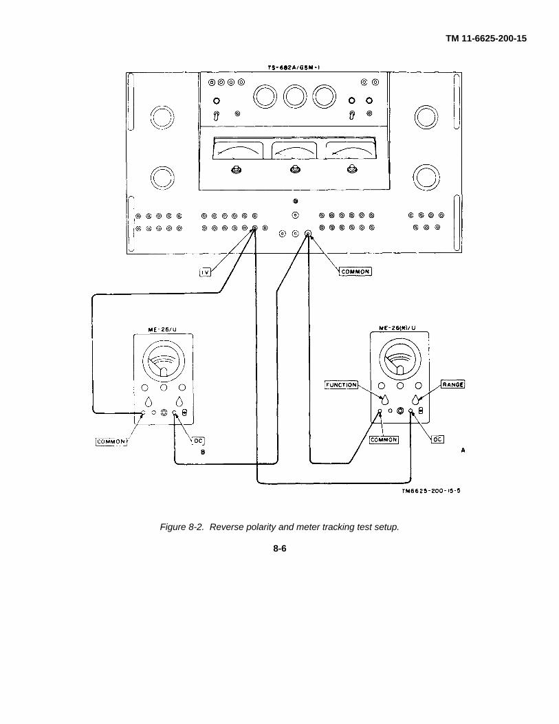
TM 11-6625-200-15
Figure 8-2. Reverse polarity and meter tracking test setup.
8-6

TM 11-6625-200-15
8-8. DC Calibration Test
a. Test Equipment. Test Set, Meter TS-682A/GSM-1.b. Test Connections and Conditions. Connect the equipment as indicated in figure 8-3.c. Procedure.
Step Control settingsno. Test equipment Equipment under test Test procedure Performance standard
1. TS-682A/GSM-1: FUNCTION a. Connect equipment as shown a. None.AC LINE switch: (SELECTOR) in figure 8-3, step 1.
OFF. Switch: +. b. Operate TS-682A/GSM-1 b. None.BATTERY switch: RANGE switch: 1V. AC LINE switch to ON.
OFF. c. Adjust TS-682A/GSM-1 c. None.Output controls: voltage output controls
Maximum until multimeter indicatescounterclockwise. Full-scale deflection.
Right-hand selector d. Press TS-682A/GSM-1 d. TS-682A/GSM-1 indica-switch: AC BUZZER switch for ap- tion should be 1 voltAND DC. proximately 2 seconds; ±0.03
Center selector note indication on centerswitch: DC meter.
VOLTS AND e. Operate voltage output con- e. None.MA. trols maximum counter-
Left-hand selector clockwise.Switch:.1 to 500V.
2. Same as step 1. Same as step 1, a. Connect equipment as shown a. None.except: in figure 8-3, step 2.
RANGE switch: b. Repeat test procedures c, d, b. TS-682A/GSM-1 indica-and e of step 1. tion should be 3 ± 0.09
volts.3 Same as step 1. Same as step 1, a. Connect equipment as shown a. None.
RANGE switch: in figure 8-3, step 3.10V. b. Repeat test procedures c, d, b. TS-682A/GSM-1 indica-
and e of step 1. tion should be 10 ± 0.34 Same as step 1. Same as step 1, a. Connect equipment as shown a. None.
except: in figure 8-3, step 4.RANGE switch: b. Repeat test procedures c, d, b. TS-682A/GSM-1 indica-
30V. and e of step 1. tion should be 30 ± 0.9volts.
5 Same as step 1. Same as step 1, a. Connect equipment as shown a. None.except: in figure 8-3, step 5.
RANGE switch: b. Repeat test procedures c, d, b. TS-682A/GSM-1 indica-100V. and e of step 1. tion should be 100 ± 3
volts.6 Same as step 1. Same as step 1, a. Connect equipment as shown a. None.
except: in figure 8-3, step 6.RANGE switch: b. Repeat test procedures c, d, b. TS-682A/GSM-1 indica-
300V. and e of step 1. tion should be 300 ± 9Warning: HIGH VOLTAGE: volts.
Turn TS-682A/GSM-1 voltageoutput controls fully counter-clockwise before making anychanges to connections.
7 Same as step 1. Same as step 1, a. Connect equipment as shown a. None.except: except: in figure 8-3, step 7.
Left-hand selector RANGE switch: b. Repeat test procedures c, d, b. TS-682A/GSM-1 indica-switch: 1000V. and e of step 1. tion should be 1,000 ± 301000 VDC volts.
Change 1 8-7

TM 11-6625-200-15
Figure 8-3. Dc calibration test setup.
8-8

TM 11-6625-200-15
8-9. Ohms Calibration Testa. Test Equipment. Resistor, Decade ZM-16A/U.b. Test Connections and Conditions. Connect the equipment as shown in figure 8-4.c. Procedure.
Step Control settingsno. Test equipment Equipment under test Test procedure Performance standard
1 ZM-16/U: FUNCTION Be sure OHMS function has Meter M1 indicates 10 ± 1X10 switch: 1. (SELECTOR) been zeroed; connect equip- ohms.All other switches: 0. switch: OHMS. ment as shown in figure 8-4.
RANGE switch:RX1.
2 ZM-16/U: Same as step 1, Same as step 1. Meter M1 indicates 100 ± 5X100 switch: X1. except: ohms.All other switches: 0. RANGE switch:
RX10.3 ZM-16/U: Same as step 1, Same as step 1. Meter M1 indicates 1,000
X1000 switch: X1. except: ± 50 ohms.All other switches: O. RANGE switch:
RX100.4 ZM-16/U: Same as step 1, Same as step 1. Meter M1 indicates 10,000
X10000 switch: 1. except: ± 500 ohmsAll other switches: 0. RANGE switch:
RX1K.5 ZM-16/U: Same as step 1, Same as step 1. Meter M1 indicates 100,000
X100000 switch: 1: except: ± 5,000 ohms.All other switches: 0. RANGE switch:
RX10K.6 ZM-16/U: Same as step 1, Same as step 1. Meter M1 indicates 1,000,000
X1000000 switch: 1. except: ± 50,000 ohms.All other switches: 0. RANGE switch:
RX100K.
Figure 8-4. Ohms calibration test setup.
8-9

TM 11-6625-200-15
Step Control settingsno. Test equipment Equipment under test Test procedure Performance standard
7 ZM-16/U: Same as step 1, Same as step 1. Meter M1 indicates 10,000,-X10000000 except: 000 ± 500,000 ohms.
switch: 1. RANGE switch:All other switches: 0. RX1M.
8-10
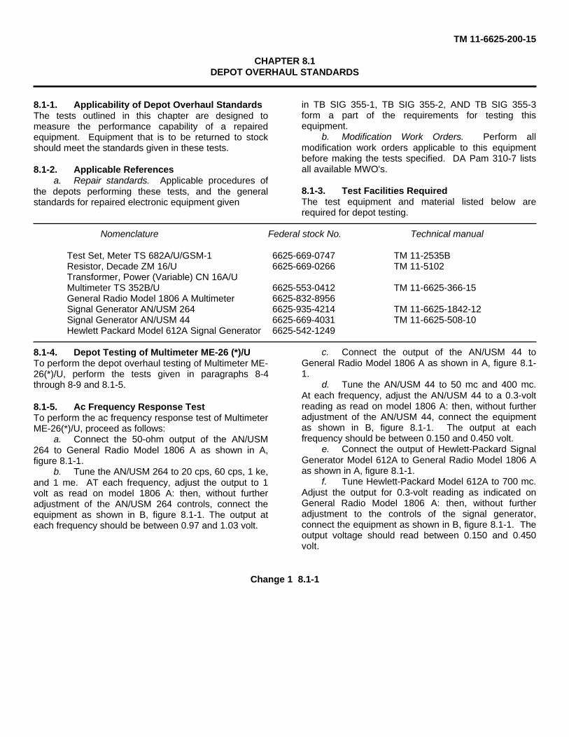
TM 11-6625-200-15
CHAPTER 8.1DEPOT OVERHAUL STANDARDS
8.1-1. Applicability of Depot Overhaul StandardsThe tests outlined in this chapter are designed tomeasure the performance capability of a repairedequipment. Equipment that is to be returned to stockshould meet the standards given in these tests.
8.1-2. Applicable Referencesa. Repair standards. Applicable procedures of
the depots performing these tests, and the generalstandards for repaired electronic equipment given
in TB SIG 355-1, TB SIG 355-2, AND TB SIG 355-3form a part of the requirements for testing thisequipment.
b. Modification Work Orders. Perform allmodification work orders applicable to this equipmentbefore making the tests specified. DA Pam 310-7 listsall available MWO's.
8.1-3. Test Facilities RequiredThe test equipment and material listed below arerequired for depot testing.
Nomenclature Federal stock No. Technical manual
Test Set, Meter TS 682A/U/GSM-1 6625-669-0747 TM 11-2535BResistor, Decade ZM 16/U 6625-669-0266 TM 11-5102Transformer, Power (Variable) CN 16A/UMultimeter TS 352B/U 6625-553-0412 TM 11-6625-366-15General Radio Model 1806 A Multimeter 6625-832-8956Signal Generator AN/USM 264 6625-935-4214 TM 11-6625-1842-12Signal Generator AN/USM 44 6625-669-4031 TM 11-6625-508-10Hewlett Packard Model 612A Signal Generator 6625-542-1249
8.1-4. Depot Testing of Multimeter ME-26 (*)/UTo perform the depot overhaul testing of Multimeter ME-26(*)/U, perform the tests given in paragraphs 8-4through 8-9 and 8.1-5.
8.1-5. Ac Frequency Response TestTo perform the ac frequency response test of MultimeterME-26(*)/U, proceed as follows:
a. Connect the 50-ohm output of the AN/USM264 to General Radio Model 1806 A as shown in A,figure 8.1-1.
b. Tune the AN/USM 264 to 20 cps, 60 cps, 1 ke,and 1 me. AT each frequency, adjust the output to 1volt as read on model 1806 A: then, without furtheradjustment of the AN/USM 264 controls, connect theequipment as shown in B, figure 8.1-1. The output ateach frequency should be between 0.97 and 1.03 volt.
c. Connect the output of the AN/USM 44 toGeneral Radio Model 1806 A as shown in A, figure 8.1-1.
d. Tune the AN/USM 44 to 50 mc and 400 mc.At each frequency, adjust the AN/USM 44 to a 0.3-voltreading as read on model 1806 A: then, without furtheradjustment of the AN/USM 44, connect the equipmentas shown in B, figure 8.1-1. The output at eachfrequency should be between 0.150 and 0.450 volt.
e. Connect the output of Hewlett-Packard SignalGenerator Model 612A to General Radio Model 1806 Aas shown in A, figure 8.1-1.
f. Tune Hewlett-Packard Model 612A to 700 mc.Adjust the output for 0.3-volt reading as indicated onGeneral Radio Model 1806 A: then, without furtheradjustment to the controls of the signal generator,connect the equipment as shown in B, figure 8.1-1. Theoutput voltage should read between 0.150 and 0.450volt.
Change 1 8.1-1
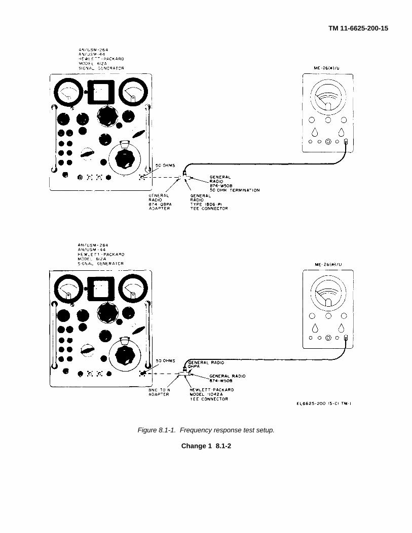
TM 11-6625-200-15
Figure 8.1-1. Frequency response test setup.
Change 1 8.1-2

TM 11-6625-200-15
CHAPTER 9
SHIPMENT, LIMITED STORAGE, AND DEMOLITION TO PREVENT ENEMY USE
Section I. SHIPMENT AND LIMITED STORAGE
9-1. Disassembly of Equipmenta. Remove the power, cable from the power
source.b. Remove the rear cover; coil the power cable
and place it in the storage compartment; replace therear cover.
c. Coil the test leads and secure them with tape,string, or rubberbands.
9-2. Repackaging for Shipment or LimitedStorage
The exact procedure for repackaging depends on thematerial available and the conditions under which theequipment is to be shipped or' stored. Adapt theprocedure given below when-ever circumstances permit.The information concerning the original packaging (para2-1) will also be helpful.
a. Material Requirements. The materials givenbelow are required for packaging multimeter ME-26 B/U.For stock numbers of materials, consult SB 38-100.
Material QuantityWaterproof paper-------------------------------- 9 sq ft.Waterproof tape---------------------------------- 20 ft.Cotton twine--------------------------------------- 20 ft.'
Material QuantityCorrugated cardboard -------------------------- 20 sq ft.Gummed tape ------------------------------------ 20 ft.Filler material ------------------------------------- 5 lb.
b. Packaging.(1) Cushion the multimeter with pads of filler
material on all sides. Place the cushioned unit within awrap of corrugated cardboard and secure the ends withgummed tape.
(2) Package each spare tube, spare lamp,and spare fuse in a wrap of corrugated cardboard;secure the ends of the packages with gummed tape.Consolidate al the spare parts within a single wrap ofcorrugated cardboard; secure the ends of the packagewith gummed tape.
(3) Package the technical manuals within aclose-fitting bag fabricated of waterproof paper. Sealthe bag with waterproof tape.
(4) Use corrugated cardboard and form acarton large enough to hold the packaged multimeter,the spare parts, and the technical manuals. Line thecarton with waterproof paper. Place the packages in thecarton and fill all voids with filler material. Seal thewaterproof carton liner with waterproof tape; seal thecarton with gummed tape.
Section II. DEMOLITION OF MATERIEL TO PREVENT ENEMY USE
9-3. Authority for DemolitionThe demolition procedures given in paragraph 9-4 willbe used to prevent the enemy from using or salvagingthis equipment. Demolition of the equipment will beaccomplished only upon the order of the commander.
9-4. Methods of Destructiona. The size and construction of the multimeter
particularly lends itself to destruction by smashing. Iftime permits, remove the chassis from the case beforesmashing.
b. Cut the power cable and test leads.c. Burn the technical manuals.d. Bury or scatter the destroyed parts in slit
trenches, foxholes, or throw them into streams.
9-1

TM 11-6625-200-15
Figure 9-1. MIL-STD resistor color-code markings.
9-2

TM 11-6625-200-15
APPENDIX AREFERENCES
Following is a list of publications available to maintenance personnel for Multimeters ME-26(*)/U:DA Pam 310-4 Index of Technical Manuals, Technical Bulletins, Supply Manuals (Types 7, 8, and
9), Supply Bulletins, and Lubrication Orders.DA Pam 310-7 US Army Equipment Index of Modification Work Orders.SB 11-573 Painting and Preservation Supplies Available for Field Use for Electronics Com-
mand Equipment.SB 38-100 Preservation, Packaging, Packing and Marking Materials, Supplies, and Equip-
ment Used by the Army.TB 43-0118 Field Instructions for Painting and Preserving Electronics Command Equipment
Including Camouflage Pattern Painting of Electrical Equipment Shelters.TB 43-0122 Instructions for Safe Handling and Identification of US Army Electronics Com-
mand Managed Radioactive Items in the Army Supply System.TM 11-5102 Resistors, Decade ZM-16/U, ZM-16A/U, and ZM-16B/U.TM 11-6625-274-12 Operator's and Organizational Maintenance Manual: Test Sets, Electron Tube
TV-7/U, TV-7A/U, TV-7B/U, and TV-7D/U.TM 11-6625-277-14 Operator's, Organizational, Direct Support, and General Support Maintenance
Manual: Meter Test Sets TS-682/GSM-1 and TS-682A/GSM-1 (NSN 6625-00-669-0747).
TM 11-6625-316-12 Operator's and Organizational Maintenance Manual: Test Sets, Electron TubeTV-2/U, TV-2A/U, TV-2B/U, and TV-2C/U.
TM 11-6625-654-14 Operator's, Organizational, Direct Support, and General Support MaintenanceManual Including Repair Parts and Special Tools Lists (Including Depot Main-tenance Repair Parts and Special Tools) for Multimeter AN/USM-223.
TM 38-750 The Army Maintenance Management System (TAMMS).
Change 3 A-1

TM 11-6625-200-15
APPENDIX CMAINTENANCE ALLOCATION
Section I. INTRODUCTION
C-1. GeneralThis appendix provides a summary of the maintenanceoperations for it authorizes categories of maintenancefor specific maintenance functions on repairable itemsand components and the tools and equipment requiredto perform each function. This appendix may be usedas an aid in planning maintenance operations.C-2. Maintenance FunctionMaintenance functions will be limited to and defined asfollows:
a. Inspect. To determine the serviceability of anitem by comparing its physical, mechanical, and/orelectrical characteristics with established standardsthrough examination.
b. Test. To verify serviceability and to detectincipient failure by measuring the mechanical orelectrical characteristics of an item and comparing thosecharacteristics with prescribed standards.
c. Service. Operations required periodically tokeep an item in proper operating condition, i.e., to clean(decontaminate), to preserve, to drain, to paint, or toreplenish fuel, lubricants, hydraulic fluids, orcompressed air supplies.
d. Adjust. To maintain, within prescribed limits,by bringing into proper or exact position, or by settingthe operating characteristics to the specifiedparameters.
e. Align. To adjust specified variable elements ofan item to bring about optimum or desired performance.
f. Calibrate. To determine and cause correctionsto be made or to be adjusted on instruments or testmeasuring and diagnostic equipments used in precisionmeasurement. Consists of comparisons of twoinstruments, one of which is a certified standard ofknown accuracy, to detect and adjust any discrepancy inthe accuracy of the instrument being compared.
g. Install. The act of emplacing, seating, or fixinginto position an item, part, module (component orassembly) in a manner to allow the proper functioning ofthe equipment or system.
h. Replace. The act of substituting a serviceablelike type part, subassembly, or module (component orassembly) for an unserviceable counterpart.
i. Repair. The application of maintenanceservices (inspect, test, service, adjust, align, calibrate,replace) or other maintenance actions (welding,grinding, riveting, straightening, facing, remachining, orresurfacing) to restore serviceability to an item bycorrecting specific damage, fault, malfunction, or failurein a part, subassembly, module (component orassembly), end item, or system.
j. Overhaul. That maintenance effort (ser-
vice/action) necessary to restore an item to a completelyserviceable/operational condition as prescribed bymaintenance standards (i.e., DMWR) in appropriatetechnical publications. Overhaul is normally the highestdegree of maintenance performed by the Army.Overhaul does not normally return an item to like newcondition.
k. Rebuild. Consists of those services/actions)necessary for the restoration of unserviceableequipment to a like new condition in accordance withoriginal manufacturing standards. Rebuild is the highestdegree of materiel maintenance applied to Armyequipment. The rebuild operation includes the act ofreturning to zero those age measurements (hours,miles, etc.) considered in classifying Armyequipments/components.C-3. Column Entries
a. Column 1, Group Number. Column 1 lists groupnumbers, the purpose of which is to identifycomponents, assemblies, subassemblies, and moduleswith the next higher assembly.
b. Column 2, Component/Assembly. Column 2contains the noun names of components, assemblies,subassemblies, and modules for which maintenance isauthorized.
c. Column 3, Maintenance Functions. Column 3lists the functions to be performed on the item listed incolumn 2. When items are listed without maintenancefunctions, it is solely for purpose of having the groupnumbers in the MAC and RPSTL, coincide.
d. Column 4, Maintenance Category. Column 4specifies, by the listing of a "worktime" figure in theappropriate subcolumn(s), the lowest level ofmaintenance authorized to perform the function listed incolumn 3. This figure represents the active timerequired to perform that maintenance function at theindicated category of maintenance. If the number orcomplexity of the tasks within the listed maintenancefunction vary at different maintenance categories,appropriate "worktime" figures will be shown for eachcategory. The number of task-hours specified by the '"worktime"'' figure represents the average time requiredto restore an item (assembly, subassembly, component,module, end item or system) to a serviceable conditionunder typical field operating conditions. This time,includes preparation time, troubleshooting time, andquality assurance/quality control time in addition to thetime required to perform the specific tasks identified forthe maintenance functions authorized in themaintenance allocation chart. Subcolumns of column 4are as follows:
C-1
TM 11-6625-200-15
C-Operator/CrewO-OrganizationalF-Direct SupportH-General SupportD-Depote. Column 5, Tools and Equipment. Column 5
specifies by code, those common tool sets (notindividual tools) and special tools, test, and supportequipment required to perform the designated function.
f. Column 6, Remarks. Column 6 contains analphabetic code which leads to the remark in section IV,Remarks, which is pertinent to the item opposite theparticular code.C-4. Tool and Test Equipment Requirements
(Sec III)a. Tool or Test Equipment Reference Code. The
numbers in this column coincide with the numbers usedin the tools and equipment column of the MAC. Thenumbers indicate the applicable tool or test equipment
for the maintenance functions.b. Maintenance Category. The codes in this
column indicate the maintenance category allocated thetool or test equipment.
c. Nomenclature. This column lists the nounname and nomenclature of the tools and test equipmentrequired to perform the maintenance functions.
d. National/NATO Stock Number. This columnlists the National/NATO stock number of the specifictool or test equipment.
e. Tool Number. This column lists themanufacturer's part number of the tool followed by theFederal Supply Code for manufacturers (S,-digit) inparentheses.C-5. Remarks (Sec IV)
a. Reference Code. This code refers to theappropriate item in section II, column 6.
b. Remarks. This column provides the requiredexplanatory information necessary to clarify itemsappearing in section II.
(Next printed page is C-3)
C-2

TM 11-6625-200-15Section II. MAINTENANCE ALLOCATION CHART
FORMULTIMETERS ME-26A/U, ME-26B/U, ME/26C/U, AND ME-26D/U
(1) (2) (3) (4) (5) (6)
Group Maint. Maint. category Tool/number Component/assembly function C O F H D equipment Remarks
00 Multimeters ME-26A/U, INSPECT 0.5 10ME-26B/U, ME/26C/U, REPAIR 0.5 10 AAND ME-26D/U. TEST 1.0 1-9
ALIGN 2.0 1-9REPAIR 2.0 1-9OVERHAUL 4.0 1-9
CHANGE 3 C-3
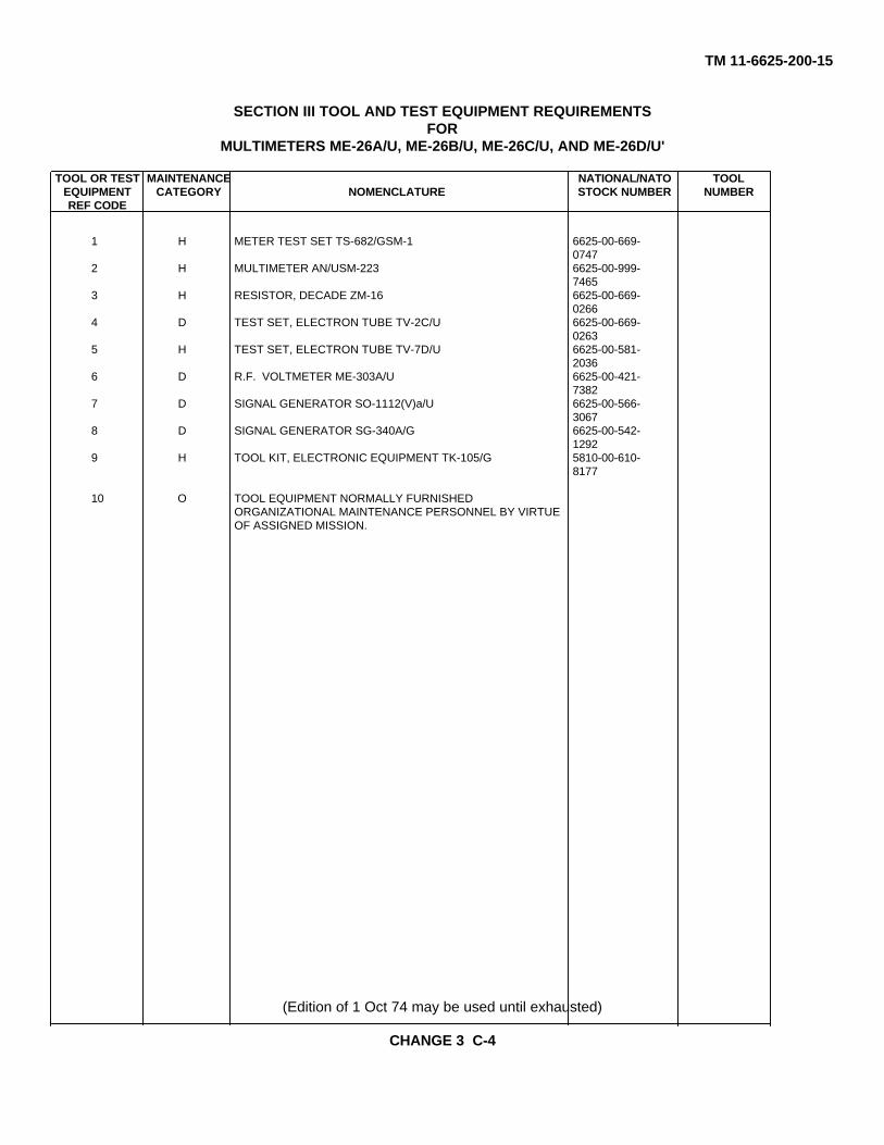
TM 11-6625-200-15
SECTION III TOOL AND TEST EQUIPMENT REQUIREMENTSFOR
MULTIMETERS ME-26A/U, ME-26B/U, ME-26C/U, AND ME-26D/U'
TOOL OR TEST MAINTENANCE NATIONAL/NATO TOOLEQUIPMENT CATEGORY NOMENCLATURE STOCK NUMBER NUMBERREF CODE
1 H METER TEST SET TS-682/GSM-1 6625-00-669-0747
2 H MULTIMETER AN/USM-223 6625-00-999-7465
3 H RESISTOR, DECADE ZM-16 6625-00-669-0266
4 D TEST SET, ELECTRON TUBE TV-2C/U 6625-00-669-0263
5 H TEST SET, ELECTRON TUBE TV-7D/U 6625-00-581-2036
6 D R.F. VOLTMETER ME-303A/U 6625-00-421-7382
7 D SIGNAL GENERATOR SO-1112(V)a/U 6625-00-566-3067
8 D SIGNAL GENERATOR SG-340A/G 6625-00-542-1292
9 H TOOL KIT, ELECTRONIC EQUIPMENT TK-105/G 5810-00-610-8177
10 O TOOL EQUIPMENT NORMALLY FURNISHEDORGANIZATIONAL MAINTENANCE PERSONNEL BY VIRTUEOF ASSIGNED MISSION.
(Edition of 1 Oct 74 may be used until exhausted)
CHANGE 3 C-4

TM 11-6625-200-15
SECTION IV. REMARKS
ReferenceCode Remarks
A REPAIR BY ORGANIZATION IS LIMITED TO REPLACEMENT OF KNOBS, LAMPS ANDFUSES.
CHANGE 3 C-5

TM 11-6625-200-15INDEX
Paragraph Page Paragraph PageAc voltage measurement analysis ----------- 5-7 5-8 Measurement-ContinuedAc voltage measurements --------------------- 5-3 5-1 Resistance- ---------------------------------------- 3-9 3-8Ac volts alignment -----------------------------7-11 7-8 Methods, destruction---------------------------------- 9-4 9-1Alignment procedures --------------------------- 7-8 7-7 Modification work orders ----------------------------- 8-3 8-1Amplifier and cathode follower circuit ------- 5-5 5-4 Monthly maintenance --------------------------------- 4-3 4-1Authority, demolition----------------------------- 9-3 9-1 Monthly preventative maintenance .checks
and services chart-------------------------------- 4-6 4-2Block diagram functioning---------------------- 5-1 5-1 Multimeter response with line voltageChecking: ----------------------------------- variation test --------------------------------------- 8-6 8-4
B1 circuits for shorts----------------------- 6-3 6-14 Ohms calibration test --------------------------------- 8-9 8-9Unpacked equipment---------------------- 2-2 2-1 Operating controls and indications ---------------- 3-2 3-1
Cleaning ------------------------------ 4-4 4-2 Operator's daily preventative maintenanceCleaning and touchup painting--------------------- checks and ---------------------------------------------- 4-4 4-2
instructions ------------------------------ 4-7 4-3Daily preventive maintenance checks and------ Painting instructions----------------------------------- 4-9 4-4
services chart ------------------------------ 4-4 4-2 Physical tests and Inspection ----------------------- 8-4 8-1Direct current: ----------------------------------- Power supply-------------------------------------------- 5-9 5-12
Calibration test------------------------------ 8-8 8-7 Preliminary data, pulse measurements ---------- 3-6 3-7Resistance, transformer windings------ 6-7 6-18 Preventive maintenance ----------------------------- 4-2 4-1Voltage measurement analysis- -------- 5-6 5-8 Publications, index,------------------------------------ 1-2 1-1Voltage measurements ------------------- 5-2 5-1 Pulse measurements --------------------------------- 3-7 3-7Volts alignment ----------------------------- 7-9 7-7 Purpose and use --------------------------------------- 1-4 1-1Zero adjustment test, dc balance ----------- Repackaging, shipment or limited storage ------ 9-2 9-1test, ac zero control range, and-------------- Replacement:ohms infinity test --------------------------- 8-5 8-2 Fuse-------------------------------------------------- 4-9 4-4
Demolition, authority----------------------------- 9-3 9-1 Pilot lamp------------------------------------------- 4-8 4-3Description ------------------------------ 1-6 1-2 Rectifier tube or voltage regulatorDisassembly and reassembly:---------------------- tube on Multimeter ME-26A/U ----------4-11 4-5
Ac probe, Multimeter ME-26A/U ------- 7-3 7-2 Rectifier tube or voltage regulatorAc probe, changed Multimeters ------------- tube on Multimeters ME-26B/C,
ME-26B/U, ME-26C/U, and ------------ ME-26C/U, and ME-26D/U--------------------4-10 4-4ME-26D/U ----------------------------- 7-2 7-1 Resistance:
Disassembly, equipment------------------------ 9-1 9-1 Measurement analysis -------------------------- 5-1 5-10External differences, models ----------------- 1-7 1-2 Measurements ------------------------------------ 5-4 5-4
Reverse polarity test and meter trackingFilament voltage adjustment, ac signal ---------- test --------------------------------------------------- 8-7 8-5
rectifier ------------------------------ 7-6 7-4Forms and records ------------------------------ 1-3 1-1 Scope:Fuse, replacement ------------------------------ 4-9 4-4 Manual --------------------------------------------- -1-1 1-1General parts replacement techniques------ 7-1 7-1 Operator's maintenance ------------------------ 4-1 4-1
Organizational maintenance------------------- 4-1 4-1Index, publications ------------------------------ 1-2 1-1 Starting procedure------------------------------------- 3-3 3-5Installation:
Multimeter ME-26A/U --------------------- 2-4 2-3 Stopping procedure ----------------------------------3-10 3-8Multimeters ME-26B/U, ME-26C/ ----------- Technical characteristics----------------------------- 1-5 1-2
U, and ME-26D/U-------------------- 2-3 2-1 Test equipment required ----------------------------- 8-2 8-1Internal differences, models ------------------5-10 5-12 Tools and test equipment required ---------------- 6-2 6-1Isolating trouble within a stage ---------------- 6-6 6-18 Troubleshooting chart--------------------------------- 6-4 6-14Low-voltage supply adjustment --------------7-12 7-8 Troubleshooting procedures ----------------------- -6-2 6-1
Tube-testing techniques------------------------------ 6-5 6-17Measurement: ----------------------------------- Turnover effect ----------------------------------------- 3-8 3-7
Ac voltage ------------------------------ 3-5 3-6Dc voltage ------------------------------ 3-4 3-6 Unpacking ----------------------------------------------- 2-1 2-1
I-1
TM 11-6625-200-15By Order of the Secretary of the Army:
HAROLD K. JOHNSON,General, United States Army,
Official: Chief of Staff.KENNETH G. WICKHAM,Major General, United State Army,The Adjutant General
Distribution:Active Army:USASA (2) Fort Belvoir (5)CNGB (1) WSMR (5)ACSC-E (2) JCA, Ft Ritchie (5)Dir/Trans (1) Army Dep (5) exceptCofEngrs (1) LBAD (14)TSG (1) SAAD (30)CofSptS (1) TOAD (14)Bd (5) ATAD (10)USACDC Agey (1) PG (6)USAMC (5) Gen Deps (2)USCONARC (5) Sig Sec Gen Deps (5)ARADCOM (6) Sig Dep (12)ARADCOM Rgn (2) Sig FLDMS (2)OS MaJ Com(i (4) AMS (1)LOGCOMD (2) USAERDAA (2)USAMICOM (4) USAERDAW (13)USASTRATCOM (4) USACRREL (2)USASTRATCOM-EUR (5) NLABS (5)USASTRATCOM-SO (6) USABIOLABS (6'USARYIS (5) USAEHA (5)USARHAW (5) MAAG (2)USAESC (70) USARMIS (2)MDW (1) USARMA (2)Armies (2) except LGH (5)
First USA (5) Redstone Arsenal (5)Seventh USA (5) Edgewood Arsenal (5)Eighth USA (5) Units org under fol TOE:
Corps (2) (2 copies each)USAC (3) 1-55 6-185Svc Colleges (2) 1-56 6-186Br Svc Schools (3) 1-76 6-200USATC Armor (2) 1-76 6-201USATC Inf (2) 1-100 6-216USASTC (2) 1-101 6-300WRAMC (1) 1-128 6-345Army Pic Cen (2) 1-155 6-346USACDCEC (10) 1-156 6-355USAATC (5) 1-207 6-365USATTC (5) 1-307 6-385ARADMAC (5) 6-100 6-386USATCFE (5) 6-115 6-425USAJFKCENSPWAR (5) 6-116 6-426Instl (2) except 6-155 6-435Fort Gordlon (10) 6-156 6-436Fort Huachuca (10) 6-165 6-455Fort Carson (25) 6-166 6-456Fort Knox (12) 6-1756-565

TM 11-6625-200-15
6-575 11-225 29-55 44-86-576 11-226 29-56 44-126-577 11-247 29-57 44-2366-615 11-327 29-75 44-5356-616 11-347 29-79 44-5366-700 11-357 29-85 44-5376-701 11-377 29-86 44-5457 11-500 (AA-AC, 29-87 44-5467-100 EL, RB, RE, 29-102 44-5477-157 RN-RX) 29-105 44-5489-247 11-587 29 109 44-56811-5 11-592 29-134 55-8911-6 11-597 29-138 55-9911-35 17 29-139 55-15711-38 17-100 29-205 55-40511-56 21-105 29-206 55-40611-57 29-1 29-207 55-40711-97 29-11 29-245 55-45711-98 29-15 29-247 55-45811-117 29-16 29-402 55-50011-127 29-17 29-500 (FA) 55-51011-137 29-21 32-57 5711-155 29-25 32-500 57-10011-156 29-35 33-500 (KD)) 57-10211-157 29-36 37 6711-158 29-37 37-100 77-10011-215 29-41 39-401 77-10211-216 29-51 44-2
NG: State AG (3); units-same as active Army except allowance is one (1) copy per unit.USAR: None.
For explanation of abbreviations used, see AR 320-50.
*U.S. GOVERNMENT PRINTING OFFICE: 1987 181 421/70704

TM 11-6625-200-15
Figure 9-2. MIL-STD capacitor color-code markings.
9-3

TM 11-6625-200-15
Figure 9-3. Change Multimeter ME-26B/U, ME-26C/U, and Multimeter ME-26D/U, schematic diagram.
9-5

TM 11-6625-200-15
Figure 9-4. Multimeter ME-26A/U, schematic diagram
9-6

TM 11-6625-200-15
Figure 9-5. U changed Multimeter ME-26B/U and ME-26C/U
9-7


PIN: 019404-000

TB 11-6625-624-35
DEPARTMENT OF THE ARMY TECHNICAL BULLETIN
CALIBRATION PROCEDURE FORELECTRONIC VOLTIMETER
ME-262/U
Headquarters, Department of the Army, Washington, D.C.28 June 1976
REPORTING OF ERRORS
You can help improve this publication by calling attention to errors and by recommending improvementsand stating your reason for the recommendations. Report such recommendations on DA Form 2028(Recommended Changes to Publications and Blank Forms), and mail it direct to Commander, US ArmyElectronics Command, AITN: DRSEL-MA-Q, Fort Monmouth, NJ 07703. A reply will be furnished directlyto you.
Paragraph Page
SECTION I. INTRODUCTION AND DESCRIPTIONTest instrument identification .............................................................. 1 2Calibration data card, DA Form 2416 .................................................. 2 2Calibration description ......................................................................... 3 2
II. EQUIPMENT REQUIREMENTSEquipment required ........................................................................... 4 3Accessories required ........................................................................... 5 3
III. PRELIMINARY OPERATIONSPreliminary instructions ....................................................................... 6 4Equipment setup .................................................................................. 7 4
IV. CALIBRATION PROCESS, USING TOE 29-134HFrequency response............................................................................. 8 5Meter accuracy .................................................................................... 9 5Meter range ......................................................................................... 10 5Final procedure ................................................................................... 11 7
V. CALIBRATION PROCESS, USING AN/GSM-256Scale linearity and stability .................................................................. 12 8Frequency response ............................................................................ 13 8Attenuator accuracy ............................................................................ 14 8Meter range ......................................................................................... 15 9Final procedure ................................................................................... 16 10
*This bulletin supersedes TB 116625624-35/1, 22 September 19661

SECTION I
INTRODUCTION AND DESCRIPTION
1. Test Instrument Identification. This bulletinprovides instruction for the calibration of ElectronicVoltmeter ME-262/U. The manufacturer’s instructionmanual was used as the prime data source in compilingthese instructions. The equipment being calibrated willbe referred to as the TI (test instrument) throughout thisbulletin.
a. Model Variations. Variations among models aredescribed in text.
b. Time and Technique. The time required for thiscalibration is approximately 3 hours, using the dc and lowfrequency technique.
2. Calibration Data Card, DA Form 2416. a. Forms,records, and reports required for calibration personnel atall levels are prescribed by TM 38-750. DA Form 2416must be annotated in accordance with TM 38-750 foreach calibration performed.
b. Adjustments to be reported on DA Form 2416
are designated (R) at the end of the sentence in whichthey appear. When adjustments are in tables, the (R)will follow the designated adjustment. Report only thoseadjustments made and designated with (R).3. Calibration Description. TI parameters andperformance specifications which pertain to thiscalibration are listed in table 1.
Table 1. Calibration Description
Test instrument parameters Performance specifications
Voltage range 1 millivolt to 1000v p-p.
Accuracy ±2%, 20 Hz to 200 kHz±4%, 5 Hz to 500 kHz.1
Stability Satisfactory performance with any line voltage between 105 and 125 v.
1Not verified below 20 Hz.
2

SECTION IIEQUIPMENT REQUIREMENTS
4. Equipment Required. Table 2 identifies the specificequipment used in this calibration procedure. Thisequipment is issued with Secondary Transfer StandardsCalibration Set AN/GSM-256, NSN 4931-00- 525-8175and standards set TOE 29-134H and is to be used whenperforming this procedure. Alternate items may be usedby the calibrating activity *when the equipment listed intable 2 is not available. The items selected must beverified to perform satisfactorily prior to use and mustbear evidence of current calibration. The equipmentmust meet or exceed the minimum use specificationslisted in table 2. The
accuracies listed in table 2 provide a four-to-oneaccuracy ratio between the standard and TI. Where thefour-to-one ratio cannot be met, the actual accuracy ofthe equipment selected is shown in parenthesis.
5. Accessories Required. The accessories listed intable 3 are issued with Secondary Transfer StandardsCalibration Set AN/GSIM-256, NSN 4931-00-525-8175,and standards set TOE 29-134H and are to be used inthis calibration procedure. When necessary, these itemsmay be substituted by equivalent items unlessspecifically prohibited.
Table 2. Minimum Specifications of Equipment Required
Manufacturer, Model and Part NumberItem Common name Minimum Use
specificationsTOE 29-134H AN/GSM-256
A1 Auto Transformer1 Range: 105 to 125 vac1 TF-510l. General Radio, ModelAccuracy: ±1% W10MIT3AS3 (7910809).
A2 Electronic Voltmeter Range: 96 to 104 mvac ME-30 U Not required.Accuracy: +0.25% (6625-00-669-0742).
A3 Electronic Voltmeter Range: 347 to 361 mvac ATE-202 U Not requiredAccuracy: ±0.25%a (6625-00-7090288).
A4 Meter Calibrator Range: 11.21 to 360 v TS-682 GSMI-1 Ballantine, ModelRange: 23.4.3 my to 1020 v (662500-669-0747). 421A-S2Accuracy: ± 0.25%c (6625-00-10.5-8198).
A5 Ratio Transformer Range: 0.001 to 0.1 TF-.384'U Not required.Accuracy: +0.25% (6625-00-733-5914).
A6 Signal Generator Range: 20 Hz to 500 kHz SG-71 FCC Hewlett-Packard,Flatness: ±0.25%C (6625-00-66902.55). Model 652A
(MIS-I 0224).1Required for TOE 29-134H.2Required for AN/,GSM-256.
Table 3. Accessories RequiredDescription and part number
Item Common name TOE 29-134h AN/GSM-256B1 Adapter Single banana jack to Not required.
Alligator clip (P:O Test Lead Set CX-1331 U).
B2 Cable1 3O-in., RG-58:U with 30-in., R-58/U with double banana plug double banana plug terminations terminations (493100-846-0010). (7907470).
B3 Cable Not required 36-in., RG-58K U with double banana and BNC plug termina- tions (7907471).
B4 Lead 24-in., with single Not required. banana plug termina-tions (red) (7907197).
B5 Lead 24-in., with single Not required. banana plug termina- tions (blk) (7907498).
B6 Termination Not required. 50ohbm feed-thru Hewlett-Packard, M0DEL 11048B (11048B) P/OM.IS 10224).
1Two required for TOE 29134H.3

SECTION IIIPRELIMINARY OPERATIONS
6. Preliminary Instructions. a. The instructions out-lined in this section are preparatory to the calibrationprocess. Personnel should become familiar withsections I through IV when using standards set TOE 29-134H; sections I, II, and III and V when using SecondaryTransfer Standards Calibration Set AN/ GSM-256 beforebeginning the calibration.
b. Items of equipment used in this procedure arereferenced within the text by common name and itemidentification number as listed in tables 2 and 3. For theidentification of equipment referenced by item numbersprefixed with A, see table 2, and for prefix B, see table 3.
WARNINGHIGH VOLTAGE is used during theperformance of this calibration.DEATH ON CONTACT may result ifpersonnel fail to observe safetyprecautions.
7. Equipment Setup. a. If TI meter does not indicatezero, adjust to zero, using adjusting screw located belowmeter face.
b. Connect TI to autotransformer (Al).
c. Connect autotransformer to 115-volt a.c. sourceand adjust controls of autotransformer to 115 volts.
d. Set TI ON-OFF switch to ON and allow at least30 minutes for warmup.
4

SECTION IVCALIBRATION PROCESS, USING TOE 29-134H
NOTEUnless otherwise specified, verify the results of each test and take corrective action whenever the testrequirement is not met before continuing with the calibration.
8. Frequency Response. a. Performance Check:
(1) Connect signal generator (A6) and electronicvoltmeter (A2) to TI input, using two cables (B2)
(2) Position TI controls as listed in (a) (b), and (c)below.
(a) FULL SCALE switch to 100 MILLIVOLTS.(b) POSITIVE-NEGATIVE switch to
POSITIVE.(c) Function switch to PEAK TO PEAK.
(3) Adjust signal generator frequency to 50 Hz andoutput amplitude for an indication of 100 millivolts on TImeter. Record electronic voltmeter indication.
(4) Increase signal generator frequency to 200 kHzkeeping output amplitude to value recorded in (3) above.If TI meter does not indicate between 98 and 102millivolts, perform b(1) through (5) below.
(5) Increase signal generator frequency to 500 kHz,keeping output amplitude to value recorded in (3) above.If TI does not indicate between 96 and 104 millivolts,perform b(l) through (5) below.
b. Adjustments.
(1) Adjust signal generator frequency to 400 kHz,keeping output amplitude to value recorded in a(3)above.
(2) Adjust C6 and C20 (fig. 1) in equal amountsuntil TI indicates 100 millivolts (R).
(3) Turn POSITIVE-NEGATIVE switch toNEGATIVE.
(4) Adjust C15 (fig. 1) until TI indicates 100millivolts (R).
(5) Turn POSITIVE-NEGATIVE switch to POSITIVE.(6) Repeat a(3), (4), and (5) above.
9. Meter Accuracy. a. Performance Check.
(1) Connect electronic voltmeter (A3) and signalgenerator (A6) to TI input, using two cables (B2).
(2) Turn TI FULL SCALE switch to 1000MILLIVOLTS.
(3) Adjust signal generator frequency to 1000 Hzand output amplitude for an indication of 1000 millivolts
on TI meter. If electronic voltmeter does not indicatebetween 346.5 and 360.5 millivolts, perform b(1) through(6) below.
(4) Turn TI FULL SCALE switch to 3.5 VOLTS. If TIdoes not indicate 1 volt, perform b(4) through (6) below.
(5) Turn TI FULL SCALE switch to 1000MILLIVOLTS and function switch to PEAK. If TI does notindicate 500 millivolts, perform b(7) below.
b. Adjustments.(1) Adjust signal generator output amplitude for an
indication of 354 millivolts as indicated on electronicvoltmeter.
(2) Adjust TI CAL ADJ until TI indicates 1000millivolts.
(3) Turn TI FULL SCALE switch to 3.5 VOLTS.(4) Adjust TI SCALE ADJ until TI meter indicates 1
volt.
NOTETap meter lightly during adjustment.
(5) Turn TI FULL SCALE switch to 1000MILLIVOLTS.
(6) Repeat (1) through (5) above until no furtheradjustments are required.
(7) Adjust PEAK ADJ until TI indicates 500 millivolts.
10. Meter Range. a. Performance Check.
(1) Connect ratio transformer (A5) output to TI input,using cable (B2).
(2) Connect ratio transformer input terminals tometer calibrator (A4) ac volts and common terminals,using leads (B4 and B5), adapter (B1), and cablesupplied with meter calibrator.
(3) Turn TI FULL SCALE switch to 3.5 MILLIVOLTSand function switch to PEAK TO PEAK.
(4) Adjust ratio transformer to .001000.(5) Adjust meter calibrator for an indication of 3.5
millivolts on TI meter. Meter calibrator will indicatebetween 1.212 and 1.262 volts rms.
(6) Repeat (3), (4), and (5) above at values listed intable 4. Meter calibrator will indicate within limitsspecified.
5

Figure 1. Electronic Voltmeter - right view or bottom view for rack mounted models.
6

Table 4. Meter Range
b. Adjustments. No adjustments can be made.11. Final Procedure. a. Deenergize and disconnect allequipment and replace TI within protective cover.
b. In accordance with TM 38-750, annotate and
affix DA Label 80 (U.S. Army Calibration System). Whenthe TI cannot be adjusted within tolerance, annotate andaffix DA Form 2417 (Unserviceable or Limited Use) tag.
7

SECTION VCALIBRATION PROCESS, USING AN/GSM-256
NOTEUnless otherwise specified, verify the results of each test and take corrective action whenever thetest requirement is not met before continuing with the calibration.
12. Scale Linearity and Stability. a. PerformanceCheck.
(1) Connect meter calibrator (A4) to TI inputterminals, using cable (B2).
(2) Position TI controls as listed in ((t), (1), and (c)below.
(a) POSITIVE-NEGATIVE switch toPOSITIVE.
(b) Function switch to PEAK TO PEAK.(c) FULL SCALE switch to 1000
MILLIVOLTS.(3) Adjust meter calibrator frequency to 1000 Hz
and output voltage for an indication of 10 on TI meterupper scale.
(4) Turn FULL SCALE switch to 3.5 VOLTS. If TImeter does not indicate 1 on 1 to 3.5 scale, adjustSCALE ADJ until TI meter indicates 1 on 1 to 3.5 scale,then repeat (2), (3), and (4) above.
NOTETap meter face lightly to reduce friction.
(5) Turn TI FULL SCALE switch to 1000MILLIVOLTS.
(6) Adjust meter calibrator output voltage to 0.354volt rms. If TI meter does not indicate to 10 on upperscale, adjust CAL ADJ until TI meter indicates 10 onupper scale.
NOTETap meter face lightly when making adjustment.(7) Adjust autotransformer (Al) to 105 volts.(8) Adjust meter calibrator output voltage for an
indication of 10 on TI meter upper scale. Meter calibration output voltage will be between 0.347 and 0.361volt rms.
(9) Repeat (8) above at autotransformer setting of125 volts.
(10) Adjust autotransformer to 115 volts.(11) Adjust meter calibrator output voltage for an
indication of 10 on TI meter upper scale.(12) Turn TI function switch to PEAK. If TI meter
does not indicate 5 on upper scale, adjust PEAK ADJ.until TI meter indicates 5.b. Adjustments. No adjustments can be made.13. Frequency Response. a. Performance Check.
(1) Connect signal generator (A6) to TI input, usingcable (B3) and termination (B6).
(2) Turn TI function switch to PEAK TO PEAK andFULL SCALE switch to 100 MILLIVOLTS.
(3) Adjust signal generator’ frequency to 1000 Hz
and output amplitude for an indication of 8 on TI upperscale.
(4) Adjust signal generator to expand mode.(5) Vary signal generator frequency between 20 Hz
and 200 kHz, keeping output amplitude to 8 on TI upperscale. If signal generator does not remain within +2percent, perform b(1), (2), and (3) below.
(6) Vary signal generator frequency between 200kHz and 500 kHz, keeping output amplitude to 8 on TIupper scale. If signal generator does not remain within+4 percent, perform b(l) through (4) below.
(7) Turn TI FULL SCALE switch to 1000MILLIVOLTS.
(8) Adjust signal generator frequency to 1000 Hzand output amplitude for an indication of 8 on TI meterupper scale.
(9) Adjust signal generator to expand mode.(10) Turn POSITIVE-NEGATIVE switch to
NEGATIVE.(11) Adjust signal generator output amplitude for an
indication of 8 on TI meter upper scale. If signalgenerator does not indicate within +0.5 percent, performb(5) and (6) below.
b. Adjustments.(1) Adjust signal generator frequency to 400 kHz
and output amplitude to zero percent.(2) Adjust C6 and C20 (fig. 1) until TI meter
indicates within 0.5 to 1 percent below indication of 8 onTI meter upper scale (R).
NOTEAdjust C6 and C20 so both capacitorswill have approximately the samecapacitance.
(3) Repeat a (3), (4), and (5) above.(4) Repeat a(6) above.(5) Adjust signal generator output amplitude until TI
meter indicates zero percent.(6) Adjust C15 (fig. 1) until TI meter indicates 8 on
upper scale (R).14. Attenuator Accuracy. a. Performance Check.
(1) Turn TI POSITIVE-NEGATIVE switch toPOSITIVE and FULL SCALE switch to 10 VOLTS.
(2) Adjust signal generator (A6) frequency to 1000Hz and output amplitude for an indication of 8 on TImeter upper scale.
(3) Adjust signal generator to expand mode.(4) Adjust frequency of signal generator to 200 kHz
while maintaining an indication of 8 on TI meter upperscale. If signal generator does not indicate within ±2percent, perform b(1) and (2) below.
8(5) Turn TI FULL SCALE switch to 1000 MIL-
LIVOLTS.(6) Repeat (2), (3), and (4) above, except if signal
generator does not indicate within ±2 percent, performb(l) and (3) below.

b. Adjustments.(1) Adjust signal generator to 0 percent indication.
(2) Adjust C2 (fig. 2) until TI meter indicates 8 onupper scale (R).
Figure 2. Electronic voltmeter, front view (plate removed)
(3) Adjust C3 (fig. 2) until TI meter indicates 8 onupper scale (R).15. Meter Range. a. Performance Check.
(1) Connect meter calibrator (A4) to TI input, usingcable (B2).
(2) Turn FULL SCALE switch to 3.5 MILLIVOLTS.(3) Adjust meter calibrator frequency to 400 Hz and
output amplitude for an indication of 3.5 millivolts on TImeter. Meter calibrator will indicate between 3.43 and3.57 millivolts peak to peak.
(4) Repeat (2) and (3) above at TI FULL SCALEswitch positions and meter indications listed in table
5. Meter calibrator will indicate within limits specified.
9
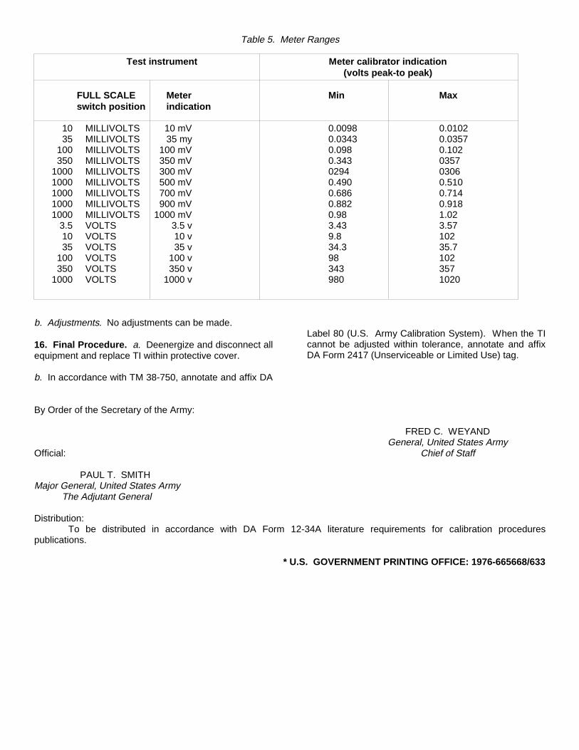
Table 5. Meter Ranges
Test instrument Meter calibrator indication(volts peak-to peak)
FULL SCALE Meter Min Maxswitch position indication
10 MILLIVOLTS 10 mV 0.0098 0.010235 MILLIVOLTS 35 my 0.0343 0.0357
100 MILLIVOLTS 100 mV 0.098 0.102350 MILLIVOLTS 350 mV 0.343 0357
1000 MILLIVOLTS 300 mV 0294 03061000 MILLIVOLTS 500 mV 0.490 0.5101000 MILLIVOLTS 700 mV 0.686 0.7141000 MILLIVOLTS 900 mV 0.882 0.9181000 MILLIVOLTS 1000 mV 0.98 1.02
3.5 VOLTS 3.5 v 3.43 3.5710 VOLTS 10 v 9.8 10235 VOLTS 35 v 34.3 35.7
100 VOLTS 100 v 98 102350 VOLTS 350 v 343 357
1000 VOLTS 1000 v 980 1020
b. Adjustments. No adjustments can be made.
16. Final Procedure. a. Deenergize and disconnect allequipment and replace TI within protective cover.
b. In accordance with TM 38-750, annotate and affix DA
Label 80 (U.S. Army Calibration System). When the TIcannot be adjusted within tolerance, annotate and affixDA Form 2417 (Unserviceable or Limited Use) tag.
By Order of the Secretary of the Army:
FRED C. WEYANDGeneral, United States Army
Official: Chief of Staff
PAUL T. SMITHMajor General, United States Army
The Adjutant General
Distribution:To be distributed in accordance with DA Form 12-34A literature requirements for calibration procedures
publications.
* U.S. GOVERNMENT PRINTING OFFICE: 1976-665668/633

PIN: 031933

TM 11-6625-200-24P
TECHNICAL MANUAL
ORGANIZATIONAL, DIRECT SUPPORT, AND GENERAL SUPPORT MAINTENANCEREPAIR PARTS AND SPECIAL TOOLS LISTS
(INCLUDING DEPOT MAINTENANCE REPAIR PARTS AND SPECIAL TOOLS)
FOR
MULTIMETERS
ME-26A/U (NSN 6625-00-360-2493)
ME-26B/U (NSN 6625-00-646-9409)
ME-26C/U (NSN 6625-00-646-9409)
AND
ME-26D/U (NSN 6625-00-913-9781)
H E A D Q U A R T E R S , D E P A R T M E N T O F T H E A R M YAUGUST 1978

*TM 11-6625-200-24P
TECHNICAL MANUAL HEADQUARTERSDEPARTMENT OF THE ARMY
No. 11-6625-200-24P WASHINGTON, DC, 4 August 1978
ORGANIZATIONAL, DIRECT SUPPORT, AND GENERAL SUPPORT MAINTENANCEREPAIR PARTS AND SPECIAL TOOLS LISTS
(INCLUDING DEPOT MAINTENANCE REPAIR PARTS AND SPECIAL TOOLS)FOR
MULTIMETERSME-26A/U (NSN 6625-00360-2493)ME-26B/U (NSN 6625-00-649409)ME-26C/U (NSN 6625-006469409)
ANDME-26D/U (NSN 6625-00-913-9781)
Current as of 18 January 1978
REPORTING OF ERRORSYou can improve this manual by recommending improvements using DA Form 2028-2 located in the backof the manual. Simply tear out the self addressed form, fill it out as shown on the sample, fold it whereshown, and drop it in the mail.
If there are no blank DA Form 2028-2 in the back of your manual, use the standard DA Form 2028(Recommended Changes to Publications and Blank Forms) and forward to the Commander, US ArmyCommunications and Electronics Materiel Readiness Command, ATTN: DRSEL-MA-Q, Fort Monmouth,New Jersey 07703.
In either case a reply will be furnished direct to you.
Table of ContentsIllus.
Page FigureSECTION I. Introduction ----------------------------------------------------------------------------------------------- 1
II. Repair parts list ----------------------------------------------------------------------------------------- 5Group 00. Multimeters ME-26A/U, ME-26B/U, ME-26C/U, and ME-26D/U ---------------------------- 5 1-16SECTION III. Special tools list (Not applicable)
IV. National stock number and part number index --------------------------------------------------------- 36
*This manual supersedes TM 11-625-200-24P, 17 September 1973.
}

TM 11-6625-200-24PSECTION I
INTRODUCTION
1. ScopeThis manual lists spares and repair parts; special tools;special test, measurement, and diagnostic equipment(TMDE), and other special support equipment requiredfor performance of original, direct support, and generalsupport maintenance of the ME-26A/U, ME-26B/U, ME-26C/U, and ME-26D/U. It authorizes the requisitioningand issue of spares and repair parts as indicated by thesource and maintenance codes.2. GeneralThis Repair Parts and Special Tools List is divided intothe following sections:
a. Section II. Repair Parts List. A list of sparesand repair parts authorized for use in the performance ofmaintenance. The list also includes parts which must beremoved for replacement of the authorized parts. Partslists are composed of functional groups in numericsequence, with the parts in each group listed in figureand item number sequence.
b. Section III. Special Tools List. Not applicable.c. Section IV. National Stock Number and Part
Number Index. A list, in National item identificationnumber (NIIN) sequence, of all National stock numbers(NSN) appearing in the listings, followed by a list, inalphanumeric sequence, of all part numbers appearing inthe listings. National stock numbers and part numbersare cross-referenced to each illustration figure and itemnumber appearance.3. Explanation of Columns
a. Illustration. This column is divided as follows:(1) Figure number. Indicates the figure
number of the illustration on which the item is shown.(2) Item number. The number used to identify
item called out in the illustration.b. Source, Maintenance, and Recoverability (SMR)
Codes.(1) Source code. Source codes indicate the
manner of acquiring support items for maintenance
repair, or overhaul of end items. Source codes areentered in the first and second positions of the UniformSMR Code format as follows:Code DefinitionPA -Item procured and stocked for anticipated or known
usage.XD -A support item that is not stocked. When required,
item will be procured through normal supplychannels.
NOTECannibalization or salvage may beused as a source of supply for anyitems source coded above exceptthose coded XA and aircraft supportitems as restricted by AR 700-42.
(2) Maintenance code. Maintenance codesare assigned to indicate the levels of maintenanceauthorized to USE and REPAIR support items Themaintenance codes are entered in the third and fourthpositions of the Uniform SMR Code format as follows:
(a) The maintenance code entered inthe third position will indicate the lowest maintenancelevel authorized to remove, replace, and use the supportitem. The maintenance code entered in the third positionwill indicate one of the following levels of maintenance:Code Application/ExplanationO- Support item is removed, replaced, used at the
organizational level.H- Support item is removed, replaced, used at the
general support level.(b) The maintenance code entered in the fourth
position indicates whether the item is to be repaired andidentifies the lowest maintenance level with the capabilityto perform complete repair (i.e., all authorizedmaintenance functions). This position will contain one ofthe following maintenance codes:Code Application/ExplanationZ- Nonreparable. No repair is authorized.
1

TM 11-6625-200-24P(3) Recoverability code. Recoverability codes
are assigned to support items to indicate the dispositionaction on unserviceable items. The recoverability code isentered in the fifth position of the Uniform SMR Codeformat as follows:Recover-abilitycodes DefinitionZ- Nonreparable item. When unserviceable, condemn
and dispose at the level indicated inposition 3.c. National Stock Number. Indicates the National
stock number assigned to the item and will be used forrequisitioning purposes.
d. Part Number. Indicates the primary numberused by the manufacturer (individual, company, firm,corporation, or Government activity), which controls thedesign and characteristics of the item by means of itsengineering drawings, specifications, standards, andinspection requirements to identify an item or range ofitems.
NOTEWhen a stock numbered item isrequisitioned, the repair part receivedmay have a different part numberthan the part being replaced.
e. Federal Supply Code for Manufacturer (FSCM). The FSCM is a 5-digit numeric codelisted in SB 708-42 which is used to identify themmanufacturer, distributor, or Government agency, etc.
f. Description. Indicates the Federal item nameand, if required, a minimum description to identify theitem.
g. Unit of Measure (U/M). Indicates the standard ofthe basic quantity of the listed item as used in performingthe actual maintenance function. This measure isexpressed by a two-character alphabetical abbreviation(e.g., ea, in, pr, etc). When the unit of measure differsfrom the unit of issue, the lowest unit of issue that willsatisfy the required units of measure will berequisitioned.
h. Quantity Incorporated in Unit. Indicates thequantity of the item used in the breakout shown on theillustration figure, which is prepared for a
functional group, subfunctional group, or an assembly.4. Special Information
a. Usable on codes are shown in the descriptioncolumn. Uncoded items are applicable to all models.Identification of the usable on codes used in thispublication are:Code Used onAE2 ME-26A/UAE3 ME-26B/UAE4 ME-26C/UAXL ME-26D-U
b. The following publication pertains to the ME-26A/U, ME-26B/U, ME-26C/U, and ME-26/U and theircomponents: TM 11-6625-200-15, Multimeters ME-26A/U, ME-26B/U, ME-26C/U, and ME-26D/U5. How to Locate Repair Parts
a. When National stock number or part number isunknown.
(1) First. Using the table of contents, deter-mine the functional group within which the itembelongs. This is necessary since illustrations areprepared for functional groups and listings aredivided into the same groups.
(2) Second. Find the illustration covering thefunctional group to which the item belongs.
(3) Third. Identify the item on the illustrationand note the illustration figure and item number of theitem.
(4) Fourth. Using the Repair Parts Listing,find the figure and item number noted on the illustration.
b. When National stock number or part number isknown.
(1) First. Using the Index of National StockNumbers and Part Numbers, find the pertinent Nationalstock number or part number. This index is in NIINsequence followed by a list of part numbers inalphanumeric sequence, cross-referenced to theillustration figure number and item number.
(2) Second. After finding the figure and itemnumber, locate the figure and item number in the repairparts list.6. AbbreviationsNot applicable.
2

TM 11-6625-200-24P
Figure 1. ME-26A/U Multimeter.
4

SECTION II TM11-6625-200-24P
(1) (2) (3) (4) (5) (6) (7) (8)ILLUSTRATION DESCRIPTION QTY
(a) (b) NATIONAL INCFIG ITEM SMR STOCK PART INNO. NO. CODE NUMBER NUMBER FSCM USABLE ON CODE U/M UNIT
GROUP 00 ME-26A, B, C.D/U MULTIMETERS
1 1 XDHZZ 1440-0002 00837 HANDLE, LUGGAGE AE2 EA I1 2 PAHZZ 6145-00-635-9338 8410 70903 CABLE, RF AE2 FT 41 3 PAHZZ 6625-00-898-7270 SCM339386 80063 LEAD, TEST AE2 EA 11 4 XDHZZ 6580202Y2K 72982 PLUG, TIP AE2 EA 31 5 PAHZZ 662S-00-821-2307 410821-95D 28480 LEAD, TEST AE2 EA 11 6 PAHZZ 6625-00-068-1739 410821-95C 28480 LEAD, TEST AE2 EA 11 7 PAHZZ 6625-00-825-6704 410821-95E 28480 LEAD, TEST AE2 EA 11 8 PAHZZ 6625-00-302-4909 4l0821-95A 28480 LEAD SET, TEST AE2 EA 11 9 PAHZZ 5340-00-846-8451 0403-0004 28480 BUMPER, RUBBER AE2 EA 41 10 PAHZZ 5935-00-636-7145 UP121M 81349 CONNECTION, PLUG, ELEC AE2 EA I1 11 PAHZZ 6145-00-284-0579 C003MGF3-18-0330 81349 CABLE, PWR, ELEC AE2 FT 7
5

TM 11-6625-200-24P
EL4RV002Figure 2. ME-26B, C, D/U Multimeters.
6
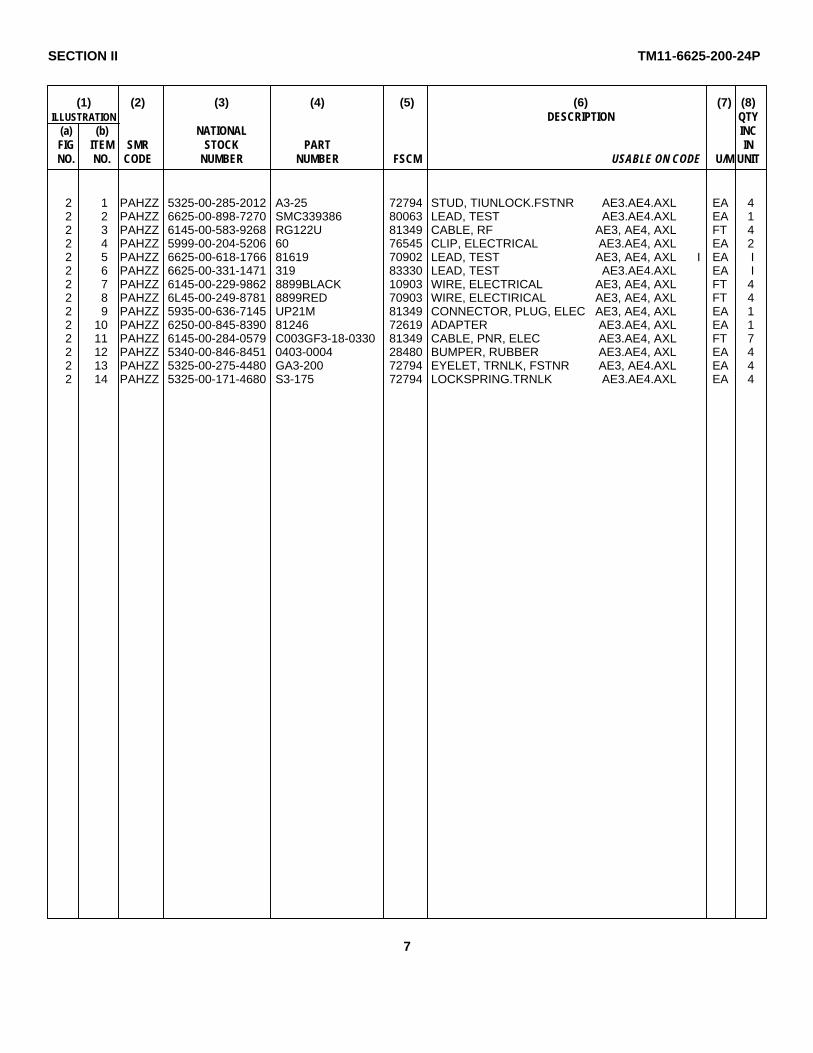
SECTION II TM11-6625-200-24P
(1) (2) (3) (4) (5) (6) (7) (8)ILLUSTRATION DESCRIPTION QTY
(a) (b) NATIONAL INCFIG ITEM SMR STOCK PART INNO. NO. CODE NUMBER NUMBER FSCM USABLE ON CODE U/M UNIT
2 1 PAHZZ 5325-00-285-2012 A3-25 72794 STUD, TIUNLOCK.FSTNR AE3.AE4.AXL EA 42 2 PAHZZ 6625-00-898-7270 SMC339386 80063 LEAD, TEST AE3.AE4.AXL EA 12 3 PAHZZ 6145-00-583-9268 RG122U 81349 CABLE, RF AE3, AE4, AXL FT 42 4 PAHZZ 5999-00-204-5206 60 76545 CLIP, ELECTRICAL AE3.AE4, AXL EA 22 5 PAHZZ 6625-00-618-1766 81619 70902 LEAD, TEST AE3, AE4, AXL I EA I2 6 PAHZZ 6625-00-331-1471 319 83330 LEAD, TEST AE3.AE4.AXL EA I2 7 PAHZZ 6145-00-229-9862 8899BLACK 10903 WIRE, ELECTRICAL AE3, AE4, AXL FT 42 8 PAHZZ 6L45-00-249-8781 8899RED 70903 WIRE, ELECTIRICAL AE3, AE4, AXL FT 42 9 PAHZZ 5935-00-636-7145 UP21M 81349 CONNECTOR, PLUG, ELEC AE3, AE4, AXL EA 12 10 PAHZZ 6250-00-845-8390 81246 72619 ADAPTER AE3.AE4, AXL EA 12 11 PAHZZ 6145-00-284-0579 C003GF3-18-0330 81349 CABLE, PNR, ELEC AE3.AE4, AXL FT 72 12 PAHZZ 5340-00-846-8451 0403-0004 28480 BUMPER, RUBBER AE3.AE4, AXL EA 42 13 PAHZZ 5325-00-275-4480 GA3-200 72794 EYELET, TRNLK, FSTNR AE3, AE4.AXL EA 42 14 PAHZZ 5325-00-171-4680 S3-175 72794 LOCKSPRING.TRNLK AE3.AE4.AXL EA 4
7
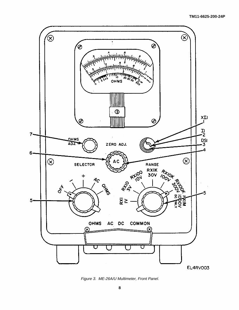
TM11-6625-200-24P
Figure 3. ME-26A/U Multimeter, Front Panel.
8
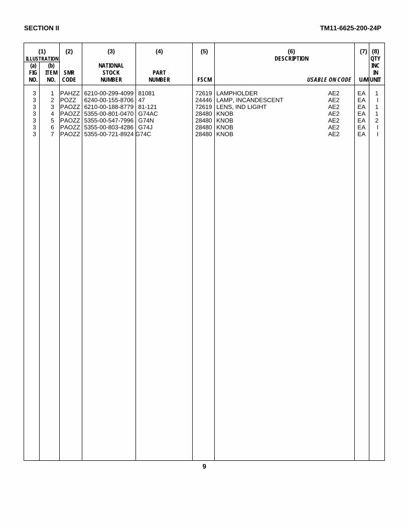
SECTION II TM11-6625-200-24P
(1) (2) (3) (4) (5) (6) (7) (8)ILLUSTRATION DESCRIPTION QTY
(a) (b) NATIONAL INCFIG ITEM SMR STOCK PART INNO. NO. CODE NUMBER NUMBER FSCM USABLE ON CODE U/M UNIT
3 1 PAHZZ 6210-00-299-4099 81081 72619 LAMPHOLDER AE2 EA 13 2 POZZ 6240-00-155-8706 47 24446 LAMP, INCANDESCENT AE2 EA I3 3 PAOZZ 6210-00-188-8779 81-121 72619 LENS, IND LIGIHT AE2 EA 13 4 PAOZZ 5355-00-801-0470 G74AC 28480 KNOB AE2 EA 13 5 PAOZZ 5355-00-547-7996 G74N 28480 KNOB AE2 EA 23 6 PAOZZ 5355-00-803-4286 G74J 28480 KNOB AE2 EA I3 7 PAOZZ 5355-00-721-8924 G74C 28480 KNOB AE2 EA I
9

TM11-6625-200-24P
Figure 4. ME-26B, C, D/U Multimeters, Front Panel.
10

SECTION II TM11-6625-200-24P
(1) (2) (3) (4) (5) (6) (7) (8)ILLUSTRATION DESCRIPTION QTY
(a) (b) NATIONAL INCFIG ITEM SMR STOCK PART INNO. NO. CODE NUMBER NUMBER FSCM USABLE ON CODE U/M UNIT
4 1 PAOLZ 5355-00-543-0789 MS91528-1N2D 96906 KNOB AE3, AE4, AXL EA 34 2 PAOZZ 5355-00-556- 0145 MS91528-1K2D 96906 KNOB AE3, AE4, AXL EA 24 3 PAHZZ 6210-00-299-4099 810B1 72619 LAMPHOLDER AE3, AE4, AXL EA 14 4 XDHZZ LH50BR2 81349 LIGHT, INDICATOR AE3, AE4, AXL EA 1
11
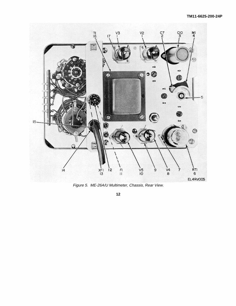
TM11-6625-200-24P
Figure 5. ME-26A/U Multimeter, Chassis, Rear View.
12

SECTION II TM11-6625-200-24P
(1) (2) (3) (4) (5) (6) (7) (8)ILLUSTRATION DESCRIPTION QTY
(a) (b) NATIONAL INCFIG ITEM SMR STOCK PART INNO. NO. CODE NUMBER NUMBER FSCM USABLE ON CODE U/M UNIT
5 1 PAHZZ 5960-00-636-2218 6189-12AU7 81349 ELECTRON TUBE AE2 EA 25 2 PAHZZ 5910-00-722-1552 DD472 71590 CAPACITOR, FXD, CER AE2 EA 15 3 PAHZZ 5910-00-816-4176 028434 56289 CAPACITOR, ELCTLT AE2 EA 15 4 PAHZZ 6625-00-649-4958 1120-0009 28480 MULTIMETER, REPLMENT AE2 EA 15 5 PAHZZ 5935-00-845-1376 410B21K 28480 NUT, BUSHING, RTNR AE2 EA 15 6 PAHZZ 5905-00-258-0794 6-4 70563 RESISTOR, CUR, RGLT AE2 EA 15 7 PAHZZ 5960-00-715-0179 1200D-63AHS 91506 RETAINER.TUBE AE2 EA 15 8 PAHZZ 5960-00-624-4718 0B2WA 81349 ELECTRON TUBE AE2 EA 15 9 PAHZZ 5340-00-844-3170 1400-0039 25480 RETAINER, TUBE AE2 EA 25 10 PAHZZ 5969-00-272-9182 6X4WA 81349 ELECTRON, TUBE AE2 EA 15 11 PAOZZ 5920-00-503-2882 313-400 75915 FUSE, CARTRIDGE, SEL AE2 EA l5 11 PAOZZ 5920-00-504-8634 313-250 75915 FUSE, CARTRIDGE, SEL AE2 EA L5 12 PAOZZ 5999-00-244-5150 9435-1-2 71400 CAP, ELECTRICAL AE2 EA L5 13 PAHZZ 5920-00-892-9311 FHN27U 81349 FUSEHOLDER AE2 EA 15 14 PAHZZ 5975-00-273-0788 6P1 28520 BUSHES, STRAIN RLF AE2 EA 15 15 PAHZZ 5325-00-846-8452 500 0I538 GROMMET, RUBBER AE2 EA 15 16 PAHZZ 5950-00-950-0524 9100-0021 28480 TRANSFORMER, SDN, SU AE2 EA 15 17 PAHZZ 5960-00-284-6893 1400-0005 28480 RETAINER, TUBE AE2 EA 2
13
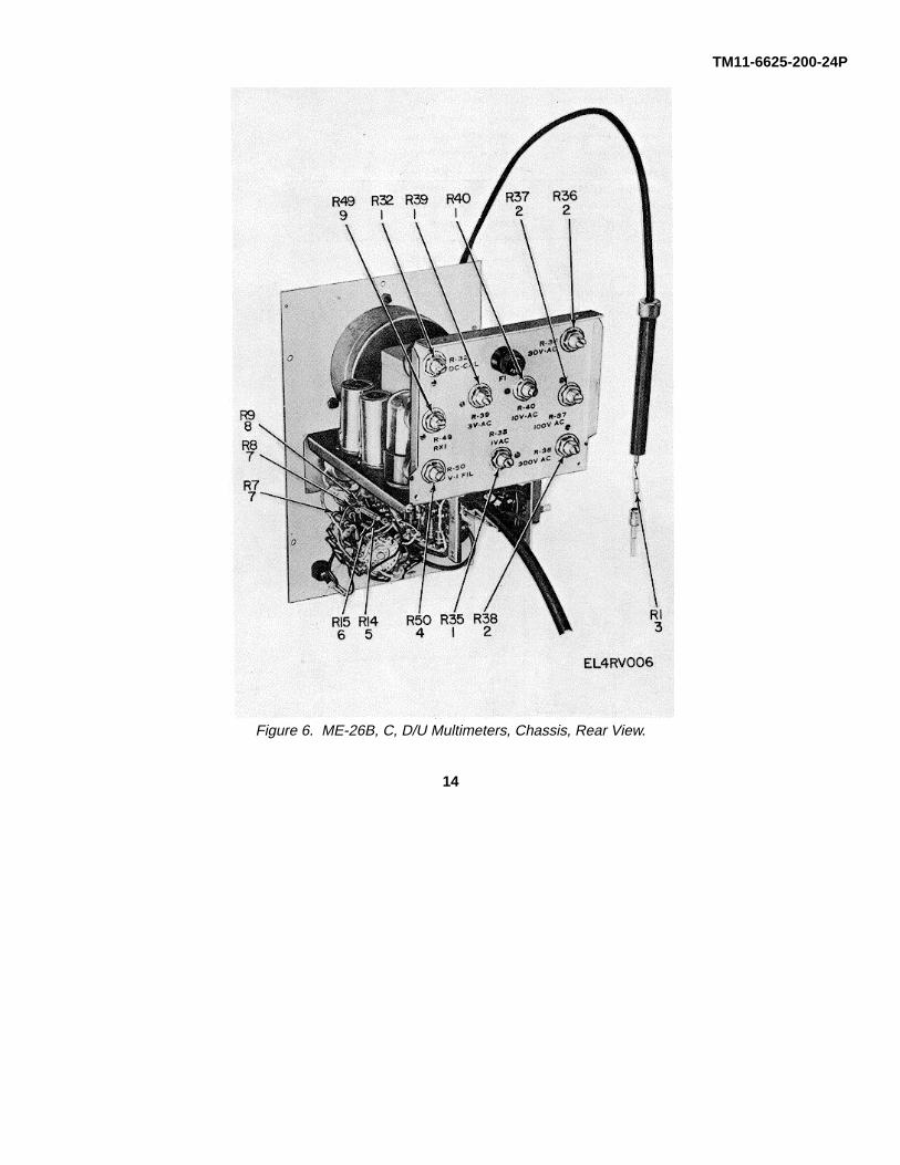
TM11-6625-200-24P
Figure 6. ME-26B, C, D/U Multimeters, Chassis, Rear View.
14
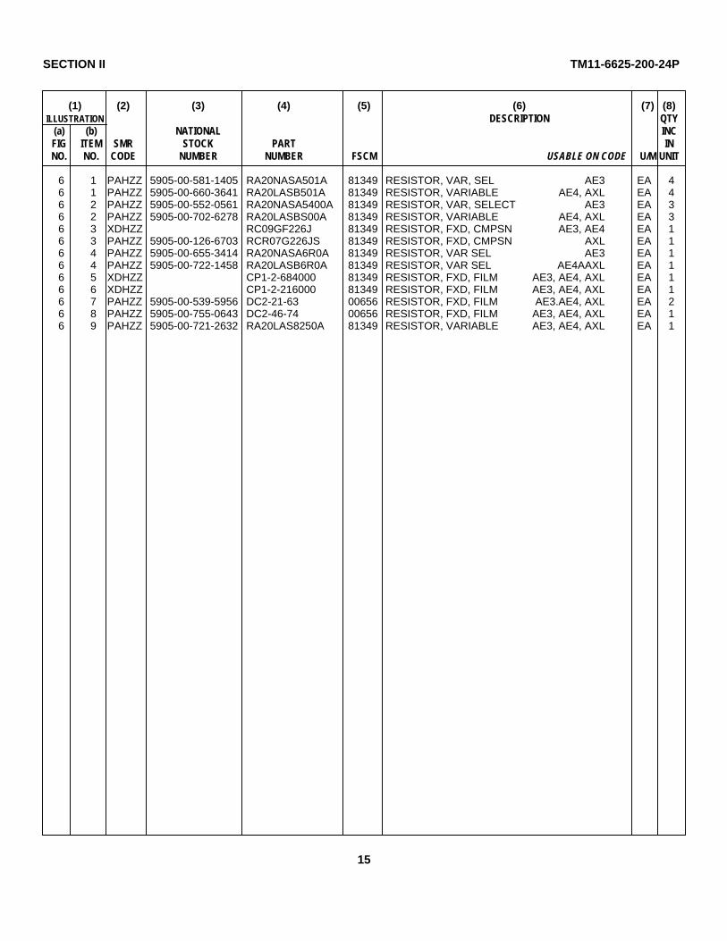
SECTION II TM11-6625-200-24P
(1) (2) (3) (4) (5) (6) (7) (8)ILLUSTRATION DESCRIPTION QTY
(a) (b) NATIONAL INCFIG ITEM SMR STOCK PART INNO. NO. CODE NUMBER NUMBER FSCM USABLE ON CODE U/M UNIT
6 1 PAHZZ 5905-00-581-1405 RA20NASA501A 81349 RESISTOR, VAR, SEL AE3 EA 46 1 PAHZZ 5905-00-660-3641 RA20LASB501A 81349 RESISTOR, VARIABLE AE4, AXL EA 46 2 PAHZZ 5905-00-552-0561 RA20NASA5400A 81349 RESISTOR, VAR, SELECT AE3 EA 36 2 PAHZZ 5905-00-702-6278 RA20LASBS00A 81349 RESISTOR, VARIABLE AE4, AXL EA 36 3 XDHZZ RC09GF226J 81349 RESISTOR, FXD, CMPSN AE3, AE4 EA 16 3 PAHZZ 5905-00-126-6703 RCR07G226JS 81349 RESISTOR, FXD, CMPSN AXL EA 16 4 PAHZZ 5905-00-655-3414 RA20NASA6R0A 81349 RESISTOR, VAR SEL AE3 EA 16 4 PAHZZ 5905-00-722-1458 RA20LASB6R0A 81349 RESISTOR, VAR SEL AE4AAXL EA 16 5 XDHZZ CP1-2-684000 81349 RESISTOR, FXD, FILM AE3, AE4, AXL EA 16 6 XDHZZ CP1-2-216000 81349 RESISTOR, FXD, FILM AE3, AE4, AXL EA 16 7 PAHZZ 5905-00-539-5956 DC2-21-63 00656 RESISTOR, FXD, FILM AE3.AE4, AXL EA 26 8 PAHZZ 5905-00-755-0643 DC2-46-74 00656 RESISTOR, FXD, FILM AE3, AE4, AXL EA 16 9 PAHZZ 5905-00-721-2632 RA20LAS8250A 81349 RESISTOR, VARIABLE AE3, AE4, AXL EA 1
15

TM11-6625-200-24P
Figure 7. ME-26A/U Multimeter, Chassis, Left Side View.
16

SECTION II TM11-6625-200-24P
(1) (2) (3) (4) (5) (6) (7) (8)ILLUSTRATION DESCRIPTION QTY
(a) (b) NATIONAL INCFIG ITEM SMR STOCK PART INNO. NO. CODE NUMBER NUMBER FSCM USABLE ON CODE U/M UNIT
7 1 PAHZZ 5330-00-821-2506 58-41-0-63 94222 PACKING, PREFORMED AE2 EA 17 2 PAHZZ 5935-00-257-6870 51A12272 71785 SOCKET, ELCTRN TUBE AE2 EA 17 3 PAHZZ 5905-00-853-4863 3100-0036 81349 RESISTOR, VARIABLE AE2 EA 17 4 PAHZZ 5905-00-853-4862 3100-0050 28480 RESISTOR, VARIABLE AE2 EA 17 5 XDHZZ 56437 08474 PACKIING, PREFORMED AE2 EA 17 6 PAHZZ 5910-00-821-5215 CK60AX471K 81349 CAPACITOR, FXD, CER AE2 EA 17 7 PAHZZ 5905-00-539-4231 RW30G502 81349 RESISTOR, FXD.FILM AE2 EA 2
17

TM11-6625-200-24P
Figure 8. ME-26A/U Multimeter, Chassis, Right Side View.
18

SECTION II TM11-6625-200-24P
(1) (2) (3) (4) (5) (6) (7) (8)ILLUSTRATION DESCRIPTION QTY
(a) (b) NATIONAL INCFIG ITEM SMR STOCK PART INNO. NO. CODE NUMBER NUMBER FSCM USABLE ON CODE U/M UNIT
8 1 PAHZZ 5905-00-526-0493 CP1-2-2-16 81349 RESISTOR, FXD.FILM AE2 EA 18 2 PAHZZ 5905-00-681-1077 CP1-6-84 81349 RESISTOR, FXD, FILM AE2 EA 18 3 XDHZZ DC1-2C 19701 RESISTOR, FXD.FILM AE2 EA 18 4 PAHZZ 5905-00-681-1079 CP1-2-9000 81349 RESISTOR, FXD, FILM AE2 EA 18 5 PAHZZ 5905-00-988-0149 RN70D9092F 81349 RESISTOR, FXD, FILM AE2 EA 18 6 PAHZZ 5905-00-141-0591 RCR20G103JS 81349 RESISTOR, FXD, CMPSN AE2 EA 18 7 PAHZZ 5905-00-171-2004 RC20GF223J 81349 RESISTOR, FXD, CMPSN AE2 EA 18 8 PAHZZ 5905-00-106-9345 RCR20G683JS 81349 RESISTOR, FXD, CMPSN AE2 EA 18 9 PAHZZ 5905-00-195-6791 RC20GF681J 81349 RESISTOR, FXD, CHPSN AE2 EA 28 10 PAHZZ 5935-00-260-0516 TS102P01 81349 SOCKET, ELCTRN, TUBE AE2 EA 18 11 PAHZZ 5935-00-222-9828 TS1103C01 81349 SOCKET, ELCTRN, TUBE AE2 EA 18 12 PAHZZ 5910-00-823-1068 CK62Y472Z 81349 CAPACITOR, FXD, CER AE2 EA 38 13 PAHZZ 5910-00-822-5684 CK62AW332M 81349 CAPACITOR, FXD, CER AE2 EA 18 14 PAHZZ 6130-00-577-8470 RS30S100HS56 81349 RECTIFIER, METALLIC AE2 EA 1
19

TM11-6625-200-24P
Figure 9. ME-26A/U Multimeter, Alignment Resistor Locations.
20

SECTION II TM11-6625-200-24P
(1) (2) (3) (4) (5) (6) (7) (8)ILLUSTRATION DESCRIPTION QTY
(a) (b) NATIONAL INCFIG ITEM SMR STOCK PART INNO. NO. CODE NUMBER NUMBER FSCM USABLE ON CODE U/M UNIT
9 1 PAHZZ 5905-00-279-2657 RC20GF565K 81349 RESISTOR, FXD, CMPSN AE2 EA 19 2 PAHZZ 5905-00-902-2887 DC128 19701 RESISTOR, FXD, FILM AE2 EA 19 3 XDHZZ RN082163F 81349 RESISTOR, FXD, FILM AE2 EA 19 4 PAHZZ 5905-00-106-9345 RCR20G683JS 81349 RESISTOR, FXD, CMPSN AE2 EA 19 5 PAHZZ 5905-00-539-5956 DC2-21-63 00656 RESISTOR, FXD, FILM AE2 EA 29 6 PAHZZ 5905-00-755-0643 DC2-46-74 00656 RESISTOR, FXD, FILM AE2 EA 19 7 PAHZZ 5905-00-646-5763 RC32GF226J 81349 RESISTOR, FXD, CMPSN AE2 EA 19 8 PAHZZ 5905-00-951-3363 2100-0185 28480 RESISTOR, VARIABLE AE2 EA 49 9 PAHZZ 5905-00-913-6315 2100-0870 28480 RESISTOR, VARIABLE AE2 EA 2
21

TM11-6625-200-24P
Figure 10. ME-26B, C, D/U Multimeters, Chassis, Top View.
22

SECTION II TM11-6625-200-24P
(1) (2) (3) (4) (5) (6) (7) (8)ILLUSTRATION DESCRIPTION QTY
(a) (b) NATIONAL INCFIG ITEM SMR STOCK PART INNO. NO. CODE NUMBER NUMBER FSCM USABLE ON CODE U/M UNIT
10 1 PAHZZ 5960-00-636-2218 6189-12AU7 81349 ELECTRON TUBE AE3, AE4, AXL EA 210 2 PAHZZ 5960-00-729-8150 TS102U03 81349 SHIELD, ELCTRN TUBE AE3, AE4, AXL EA 210 3 PAHZZ 5910-00-823-1068 CK62Y472Z 81349 CAPACITOR, FXD, CER AE3, AE4, AXL EA 110 4 PAHZZ 6625-00-670-7580 SMC200010 80063 MULTIMETER, REPLMENT AE3, AE4, AXL EA 110 5 XDHZZ 26-015 99395 PACKING.PREFCRMED AE3, AE4, AXL EA 110 6 PAHZZ 5960-00-264-3004 TS103U02 81349 SHIELD, ELCTRN TUBE AE3, AE4, AXL EA 210 7 PAHZZ 5960-00-272-9182 6X4W4 81349 ELECTRON TUBE AE3, AE4, AXL EA 110 8 PAHZZ 5960-00-624-4718 0B2WA 81349 ELECTRON TUBE AE3, AE4, AXL EA 110 9 PAHZZ 5910-00-165-2753 CE34C150R 81349 CAPACITOR.ELCTLT AE3, AE4, AXL EA 110 10 PAOZZ 5920-00-280-9328 F02D1R508 81349 FUSE, CARTRIDGE, SEL AE3, AE4, AXL EA l10 10 PAOZZ 5920-00-284-6804 F02GR7508 81349 FUSE, CARTRIDGE.SEL AE3, AE4, AXL EA 110 11 PAOZZ 5999-00-244-5150 9435-1-2 71400 CAP, ELECTRICAL AE3, AE4, AXL EA 110 12 PAHZZ 5975-00-273-0788 6P1 28520 BUSHING, STRAIN RLF AE3, AE4, AXL EA 110 13 PAHZZ 5920-00-892-9311 FHN27U 81349 FUSEHOLDER AE3, AE4, AXL EA 110 14 PAHZZ 5975-00-889-5118 2M1 28520 BUSHING, STRAIN RLF AE3, AE4, AXL EA 310 15 PAHZZ 5935-00-257-6870 51A12272 71785 SOCKET, ELCTRN TUBE AE3, AE4, AXL EA 110 16 PAHZZ 5905-00-258-0794 6-4 70563 RESISTOR, CUR, RGLT AE3, AE4, AXL EA 110 17 PAHZZ 5950-00-681-2563 C2350 88813 TRANSFORMER, SDN-SU AE3, AE4, AXL EA 1
23

TM11-6625-200-24P
Figure 11. ME-26B, C, D/U Multimeter, Chassis, Rear View.
24

SECTION II TM11-6625-200-24P
(1) (2) (3) (4) (5) (6) (7) (8)ILLUSTRATION DESCRIPTION QTY
(a) (b) NATIONAL INCFIG ITEM SMR STOCK PART INNO. NO. CODE NUMBER NUMBER FSCM USABLE ON CODE U/M UNIT
11 1 PAHZZ 5935-00-721-0124 44F16388 71785 SOCKET, ELCTRN TUBE AE3, AE4, AXL EA 211 2 PAHZZ 6130-00-548-0757 4SFLH1RV 84970 RECTIFIER, METALLIC AE3, AE4, AXL EA 111 3 PAHZZ 5905-00-106-1245 RCR32G272JS 81349 RESISTOR, FXD, CMPSN AE3, AE4, AXL EA 111 4 PAHZZ 5935-00-581-6400 111-19-21-025 71785 SOCKET, ELCTRN TUBE AE3, AE4, AXL EA 211 5 PAHZZ 5905-00-228-6088 RCR32G331JS 81349 RESISTOR, FXD, CMPSN AE3, AE4, AXL EA 111 6 PAHZZ 5910-00-722-1552 DD472 71590 CAPACITOR, FXD, CER AE3, AE4, AXL EA 211 7 XDHZZ 45643H3AC 76854 SWITCH, ROTARY AE3, AE4, AXL EA 111 8 PAHZZ 5930-00-755-0765 43852H5C 76854 SWITCH, ROTARY AE3, AE4, AXL EA 111 9 PAHZZ 5905-00-552-3893 RN7081000F 81349 RESISTOR, FXD, FILM AE3, AE4, AXL EA 111 10 PAHZZ 5905-00-902-2887 DC1-28 19701 RESISTOR, FXD, FILM AE3, AE4, AXL EA 211 11 PAHZZ 5905-00-539-5437 RN25X2163F 81349 RESISTOR, FXD, FILM AE3, AE4, AXL EA 111 12 PAHZZ 5905-00-539-4971 RN7586183F 81349 RESISTOR, FXD, FILM AE3, AE4, AXL EA 111 13 PAHZZ 5905-00-087-0560 RN70D2154F 81349 RESISTOR, FXD, FILIM AE3, AE4, AXL EA 111 14 PAHZZ 5905-00-542-9116 CPI-2-900 81349 RESISTOR, FXD, FILM AE3, AE4, AXL EA 111 15 PAHZZ 5905-00-539-5955 DCL-6-837 19701 RESISTOR, FXD, FILM AE3, AE4, AXL EA 1
25

TM11-6625-200-24P
Figure 12. ME-26B, C, D/U Multimeters, Chassis, Bottom View.
26

SECTION II TM11-6625-200-24P
(1) (2) (3) (4) (5) (6) (7) (8)ILLUSTRATION DESCRIPTION QTY
(a) (b) NATIONAL INCFIG ITEM SMR STOCK PART INNO. NO. CODE NUMBER NUMBER FSCM USABLE ON CODE U/M UNIT
12 1 PAHZZ 5905-00-106-1245 RCR32G272JS 81349 RESISTOR, FXD, CMPSN AE3, AE4, AXL EA 112 2 PAHZZ 5310-00-680-7669 CLA632-1 46384 NUT, PLAIN, CLINCH AE3, AE4, AXL EA 612 3 PAHZZ 5310-00-141-1815 CL632-1 24347 NUT, PLAIN, CLINCH AE3, AE4, AXL EA 812 4 PAHZZ 5340-00-282-7966 6-5-16 95987 CLAMP, LOUP AE3, AE4, AXL EA 112 5 PAHZZ 5905-00-539-4231 RW30G502 81349 RESISTOR, FXD, FILM AE3, AE4, AXL EA 212 6 PAHZZ 5935-00-222-9828 TS103C01 81349 SOCKET, ELCTRN TUBE AE3, AE4, AXL EA 112 7 PAHZZ 5935-00-935-2231 M12883-01-2 81349 SOCKET, ELCTRN TUBE AE3, AE4, AXL EA 112 8 PAHZZ 5961-00-828-9184 IN253 81349 SEMICONDUCTOR, DIODE AE3, AE4, AXL EA 112 9 PAHZZ 5905-00-578-9129 RA20NASK102A 81349 RESISTOR, VAR, SEL AE3 EA 112 9 PAHZZ 5910-00-578-2551 RA2ONASD102A 81349 RESISTOR, VAR, SEL AE4, AXL EA 112 10 PAHZZ 5910-00-821-5215 CK60AX471K 81349 CAPACITOR, FXD, CER AE3, AE4, AXL EA 112 11 XDHZZ RA238AFK201A 81349 RESISTOR, VAR, SEL AE3 EA 112 11 PAHZZ 5905-00-752-3834 RA20NASD201A 81349 RESISTOR, VARIABLE AE4, AXL EA 112 12 PAHZZ 5930-00-571-8675 81618 70902 SWITCH, ROTARY AE3, AE4, AXL EA 112 13 PAHZZ 5325-00-279-1235 S3448 76385 GROMMET, RUBBER AE3, AE4, AXL EA 112 14 PAHZZ 5910-00-822-5684 CK62AW332M 81349 CAPACITOR, FXD, CER AE3, AE4, AXL EA 112 15 PAHZZ 5930-00-577-8676 1617 70902 SWITCH, ROTARY AE3, AE4, AXL EA 112 16 XDHZZ Y3986 76385 GROMMET, RUBBER AF3, AE4, AXL EA 112 17 XDHZZ U2130 76385 GROMMET, RUBBER AE3, AE4, AXL EA 112 18 XDHZZ CP1-2-216000 81349 RESISTOR, FXD, FILM AE3, AE4, AXL EA 112 19 XDHZZ CP1-2-684010 81349 RESISTOR, FXD, FILM AE3, AE4, AXL EA 112 20 PAHZZ 5905-00-141-0591. RCR20G103JS 81349 RESISTOR, FXD, CMPSN AE3, AE4, AXL EA 112 21 PAHZZ 5905-00-l7l-2004 RC20GF223J 81349 RESISTOR, FXD, CMPSN AE3, AE4, AXL EA 112 22 PAHZZ 5905-00-617-8014 RA20NASK101A 81349 RESISTOR, VAR, SEL AE3 EA 112 22 PAHZZ 5905-00-581-0449 RA20NASD010A 81349 RESISTOR, VARIABLE AE4, AXL EA 1
27

TM11-6625-200-24P
Figure 13. ME-26A/U Multimeter, Terminal Boards.
28

SECTION II TM11-6625-200-24P
(1) (2) (3) (4) (5) (6) (7) (8)ILLUSTRATIONDESCRIPTION QTY
(a) (b) NATIONAL INCFIG ITEM SMR STOCK PART INNO NO CODE NUMBER NUMBER FSCM USABLE ON CODE U/M UNIT
13 1 PAHZZ 5905-00-454-2801 RCR32G136JS 81349 RESISTOR, FXD, CMPSN AE2 EA 113 2 PAHZZ 5905-00-454-2812 RCR32G395JS 81349 RESISTOR, FXD, CMPSM AE2 EA l13 3 PAHZZ 5905-00-111-8372 RCR32G222JS 81349 RESISTOR, FXD, CMPSN AE2 EA 113 4 PAHZZ 5905-00-247-8722 RCR32G271JS 81349 RESISTOR, FXD, CMPSN AE2 EA 213 5 PAHZZ 5905-00-185-8516 RC42GF103J 81349 RESISTOR, FXD, CMPSN AE2 EA 113 6 PAHZZ 5905-00-104-8345 RCR20G560JS 81349 RESISTOR, FXD, CMPSN AE2 EA 113 7 PAHZZ 5905-00-141-0720 RCR32G330JS 81349 RESISTOR, FXD, CMPSN AE2 EA 113 8 PAHZZ 5905-00-454-2875 RCR32G180JS 81349 RESISTOR, FXD, CMPSN AE2 EA 113 9 PAHZZ 5905-00-279-2528 RC42GF682J 81349 RESISTOR, FXD, CMPSN AE2 EA 113 10 PAHZZ 5905-00-141-1071 RCR20G474JS 81349 RESISTOR, FXD, CMPSN AE2 EA 213 11 PAHZZ 5905-00-279-2626 RC32GF681J 81349 RESISTOR, FXD, CMPSN AE2 EA 213 12 PAHZZ 5905-00-106-1245 RCR32G272JS 81349 RESISTOR, FXD, CMPSN AE2 EA 213 13 PAHZZ 5905-00-195-6449 RC42GF472K 81349 RESISTOR, FXD, CMPSN AE2 EA 113 14 PAHZZ 5905-00-106-9344 RCR20G101JS 81349 RESISTOR, FXD, CMPSN AE2 EA 113 15 PAHZZ 5905-00-897-9658 2100-0020 28480 RESISTOR, VARIABLE AE2 EA 313 16 PAHZZ 5905-00-141-0720 RCR32G330JS 81349 RESISTOR, FXD, CMPSN AE2 EA 113 17 PAHZZ 5905-00-807-7808 410B26 28480 RESISTOR, PRECISION AE2 EA 1
29

TM11-6625-200-24P
Figure 14. ME-26B, C, D/U Multimeters, Terminal Boards.
30

SECTION II TM 11-662-200-24P
(1) (2) (3) (4) (5) (6) (7) (8)ILLUSTRATION DESCRIPTION
(a) (b) NATIONAL QTYFIG ITEM SMR STOCK PART INCNO. NO. CODE NUMBER NUMBER FSCM USABLE ON CODE U/M IN
UNIT
14 1 PAHZZ 5905-00-141-0720 RCR32G330JS 81349 RESISTOR, FXD. CMPSN AE3,AE4,AXL EA 214 2 PAHZZ 5905-00-131-9992 RCR20G136JS 81349 RESISTOR, FXD. CMPSN AE3,AE4,AXL EA 114 3 PAHZZ 5905-00-279-2510 RCR20GF395J 81349 RESISTOR, FXD, CMPSN AE3,AE4.AXL EA 214 4 PAHZZ 5905-00-104-8345 RCR20G560JS 81349 RESISTOR, FXD, CMPSN AE3,AE4.AXL EA I14 5 PAHZZ 5905-00-171-2006 RC20GF271J 81349 RESISTOR, FXD.CMPSN AE3,AE4,AXL EA 214 6 PAHZZ 5910-00-722-1552 DD472 71590 CAPACITOR, FXD, CER AE3,AE4,AXL EA 314 7 PAHZZ 5905-00-104-8347 RCR32G101JS 81349 RESISTOR. FXD, CMPSN AE3,AE4,AXL EA 214 8 PAHZZ 5905-00-279-2657 RC20GF565K 81349 RESISTOR, FXD, CMPSN AE3,AE4,AXL EA 114 9 PAHZZ 5905-00-195-6449 RC42GF472K 81349 RESISTOR, FXD, CMPSN AE3,AE4,AXL EA 114 10 PAHZZ 5905-00-219-3418 RC42GF390J 81349 RESISTOR, FXD. CMPSN AE3,AE4,AXL EA 214 11 PAHZZ 5910-00-822-5683 CK63Y103Z 81349 CAPACITOR, FXD, CER AE3,AE4,AXL EA 214 12 PAHZZ 5905-00-185-8516 RC42GF103J 61349 RESISTOR, FXD, CMPSN AE3,AE4,AXL EA 114 13 PAHZZ 5905-00-106-9344 RCR20G101JS 81349 RESISTOR, FXD, CMPSN AE3,AE4,AXL EA 114 14 PAHZZ 5905-00-807-7808 410826 28480 RESISTOR, PRECISION AE3,AE4,AXL EA 114 15 PAHZZ 5905-00-279-2528 RC42GF682J 81349 RESISTOR, FXD. CMPSN AE3,AE4,AXL EA 114 16 PAHZZ 5905-00-111-8372 RCR32G222JS 81349 RESISTOR., FXD, CMPSN AE3,AE4,AXL EA I
31

TM 11-6625-200-24P
Figure 15. ME-26A/U Multimeter, AC Probe Disassembled.
32
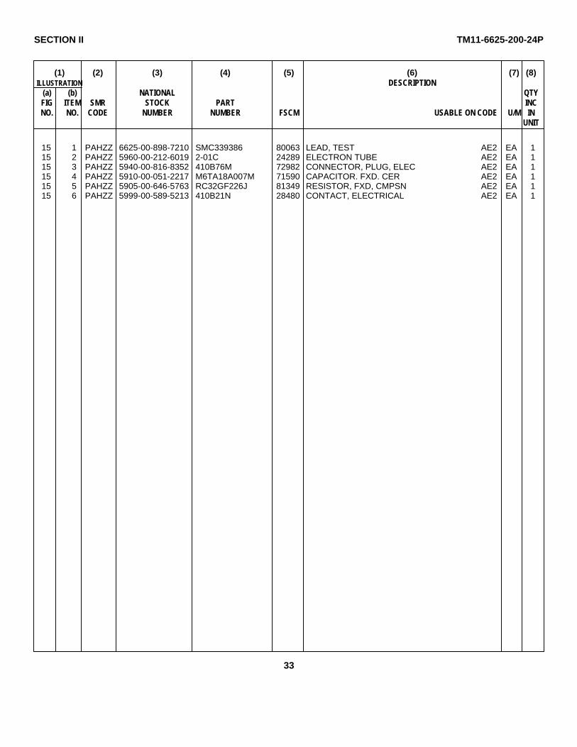
SECTION II TM11-6625-200-24P
(1) (2) (3) (4) (5) (6) (7) (8)ILLUSTRATION DESCRIPTION
(a) (b) NATIONAL QTYFIG ITEM SMR STOCK PART INCNO. NO. CODE NUMBER NUMBER FSCM USABLE ON CODE U/M IN
UNIT
15 1 PAHZZ 6625-00-898-7210 SMC339386 80063 LEAD, TEST AE2 EA 115 2 PAHZZ 5960-00-212-6019 2-01C 24289 ELECTRON TUBE AE2 EA 115 3 PAHZZ 5940-00-816-8352 410B76M 72982 CONNECTOR, PLUG, ELEC AE2 EA 115 4 PAHZZ 5910-00-051-2217 M6TA18A007M 71590 CAPACITOR. FXD. CER AE2 EA 115 5 PAHZZ 5905-00-646-5763 RC32GF226J 81349 RESISTOR, FXD, CMPSN AE2 EA 115 6 PAHZZ 5999-00-589-5213 410B21N 28480 CONTACT, ELECTRICAL AE2 EA 1
33
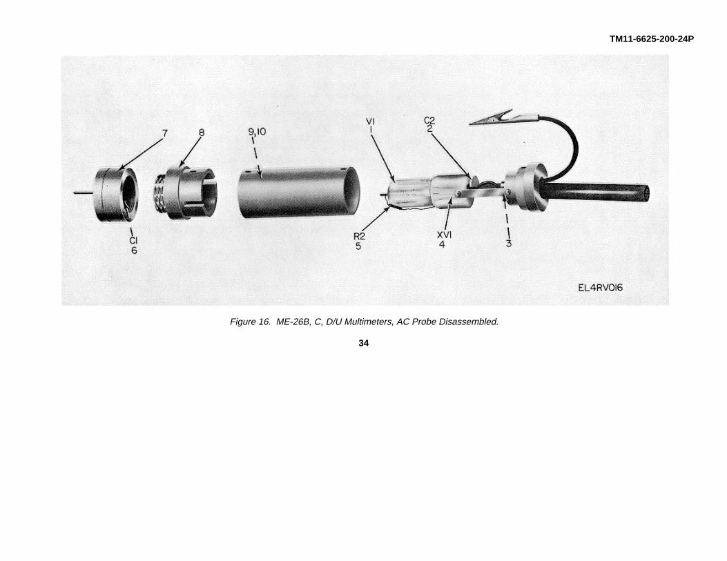
TM11-6625-200-24P
Figure 16. ME-26B, C, D/U Multimeters, AC Probe Disassembled.
34

SECTION II TM11-625-200-24P
(1) (2) (3) (4) (5) (6) (7) (8)ILLUSTRATION DESCRIPTION
(a) (b) NATIONAL QTYFIG ITEM SMR STOCK PART INCNO. NO. CODE NUMBER NUMBER FSCM USABLE ON CODE U/M IN
UNIT
16 1 PAHZZ 5960-00-212-6019 2-01C 24289 ELECTRON TU8E AE3,AF4,AXL EA 116 2 PAHZZ 5910-00-821-5215 CK60AX471K 81349 CAPACITOR, FXD, CER AE3,AE4,AXL EA 116 3 PAHZZ 5940-00-675-586C 1855394 10001 TERMINAL, STANDOFF AE3,AE4,AXL EA 216 4 PAHZZ 5935-00-260-0516 TS102P01 81349 SOCKET. ELECTRON TUBE AE3,AE4.AXL EA 116 5 XDHZZ RC09GF226J 81349 RESISTOR, FXD.CMPSN AE3,AE4 EA 116 5 PAHZZ 5905-00-126-6703 RCR07G226J 41349 RESISTOR, FXD, CMPSN AXL EA 116 6 PAOZZ 5910-00-902-4190 658-010-242K 72182 CAPACITOR, FXD. MICA AE3,AE4 EA 116 6 PAHZZ 5910-00-988-7311 M6TA18A003M 72982 CAPACITOR, FXD. TA AXL EA 116 7 PAOZZ 6625-00-898-7240 SMB339387 80063 PLUG, TIP AE3,AE4,AXL EA 116 8 PAHZZ 6625-00-087-6820 SMB339390 80063 PROBE, BAND AE3,AE4,AXL EA 116 9 PAHZZ 59700-0-087-2334 SMB339391 80063 INSULATOR, SLEEVE AE3,AE4,AXL EA 116 10 PAHZZ 5975-00-503-1440 62 76545 INSULATOR AE3,AE4,AXL EA 1
35

SECTION IV TM11-6625-200-24PNATIONAL STOCK NUMBER AND PART NUMBER INDEX
NOTE: LATEST NATIONAL STOCK NUMBER AND PART NUMBER ASSIGNMENTS ARE INCLUDED AT END OF INDEXFIG. ITEM FIG. ITEM
STOCK NUMBER NO. NO. STOCK NUMBER NO. NO.5910-00-051-2217 15 4 5920-00-503-2882 5 116625-00-068-1739 1 6 5920-00-504-8634 5 11
5905-00-526-0493 8 15905-00-087-0560 11 13 5905-00-539-4231 7 75970-00-087-2334 16 9 5905-00-539-4231 12 56625-00-087-6820 16 8 5905-00-539-4971 11 125905-00-104-8345 13 6 5905-00-539-5437 11 115905-00-104-8345 14 4 5905-00-539-5955 11 155905-00-106-9344 13 14 5905-00-539-5556 6 75905-00-106-9344 14 13 5905-00-539-5956 9 55905-00-111-8372 13 3 5905-00-542-9116 11 145905-00-111-8372 14 16 5355-00-543-0789 4 15905-00-141-0720 13 7 5355-00-547-7996 3 55310-00-141-1815 12 3 6130-00-548-0757 11 26240-00-155-8706 3 2 5905-00-552-0561 6 25910-00-165-2753 10 9 5905-00-552-3893 11 95905-00-171-2004 8 7 5355-00-556-0145 4 25905-00-171-2004 12 21 6130-00-577-8470 8 145905-00-171-2006 14 5 5930-00-577-8675 12 125325-00-171-4680 2 14 5930-00-577-8676 12 155905-00-185-8516 13 5 5905-00-578-2551 12 9
5905-00-578-9129 12 95905-00-581-0449 12 22
6210-00-185-8779 3 3 5905-00-581-1405 6 15905-00-195-6449 13 13 6145-00-583-9268 2 35905-00-195-6449 14 9 5999-00-589-5213 15 65999-00-204-5206 2 4 6625-00-618-1766 2 55960-00-212-6019 15 2 5960-00-624-4718 5 85935-00-222-9828 8 11 5960-00-624-4718 10 85935-00-222-9828 12 6 6145-00-635-9338 1 25905-00-228-6088 11 5 5960-00-636-2218 5 16145-00-229-9862 2 7 5960-00-636-2218 10 15999-00-244-5150 5 12 5935-00-636-7145 1 105999-00-244-5150 10 11 5535-00-636-7145 2 95905-00-247-8722 13 4 5905-00-646-5763 9 7
5905-00-646-5763 15 56625-00-649-4958 5 4
6145-00-249-6781 2 8 5905-00-655-3414 6 45935-00-257-6870 7 2 5905-00-660-3641 6 15935-00-257-6870 10 15 6625-00-670-7580 10 45905-00-258-0794 5 6 5940-00-675-5860 16 35905-00-258-0794 10 16 5905-00-681-1077 8 25935-C0-260-0516 8 10 5905-00-681-1079 8 45935-C0-260-0516 16 4 5950-00-681-2563 10 175960-00-264-3004 10 6 5905-00-702-6278 6 25960-00-272-9182 5 10 5960-00-715-0790 5 75960-00-272-9182 10 7 5935-00-721-0124 11 15975-00-273-0788 5 14 5905-00-721-2632 6 95975-00-273-0788 10 12 5355-00-721-8924 3 75325-00-275-4480 2 13 5905-00-722-1458 6 45325-00-279-1235 12 13 5960-00-729-8150 10 2
5905-00-752-3834 12 115905-00-279-2295 14 15 5905-00-755-0643 6 85905-00-279-2510 14 3 5905-00-755-0643 9 6
5930-00-755-0765 11 85905-00-279-2626 13 11 5355-00-801-0470 3 4
5355-C0-803-4286 3 65905-00-807-7808 13 175905-00-807-7808 14 14
5905-00-279-2657 9 1 5910-00-816-4176 5 35905-00-279-2657 14 8 5940-00-816-8352 15 35905-00-279-3418 14 10 6625-00-821-2307 1 5
5330-00-821-2506 7 15910-00-821-5215 7 65910-00-821-5215 12 10
5920-00-280-9328 10 10 5910-00-821-5215 16 25340-00-282-7966 12 4 5910-00-822-5683 14 116145-00-284-0579 1 11 5910-00-822-5684 8 136145-00-284-0579 2 11 5910-00-8z2-5684 12 145920-00-284-6804 10 10 5910-00-823-1068 8 125960-00-284-6893 5 17 5910-00-823-1068 10 35325-00-285-2012 2 1 6625-00-825-6704 1 7
5961-00-828-9184 12 86210-00-299-4099 3 1621C-00-299-4099 4 36625-00-302-4909 1 8 5340-00-844-3170 5 96625-00-331-1471 2 6 5935-00-845-1376 5 55905-00-454-2801 13 1 6250-00-845-8390 2 105905-00-454-2875 13 8 5340-00-846-8451 1 95975-00-503-1440 16 10 5340-00-846-8451 2 12
36
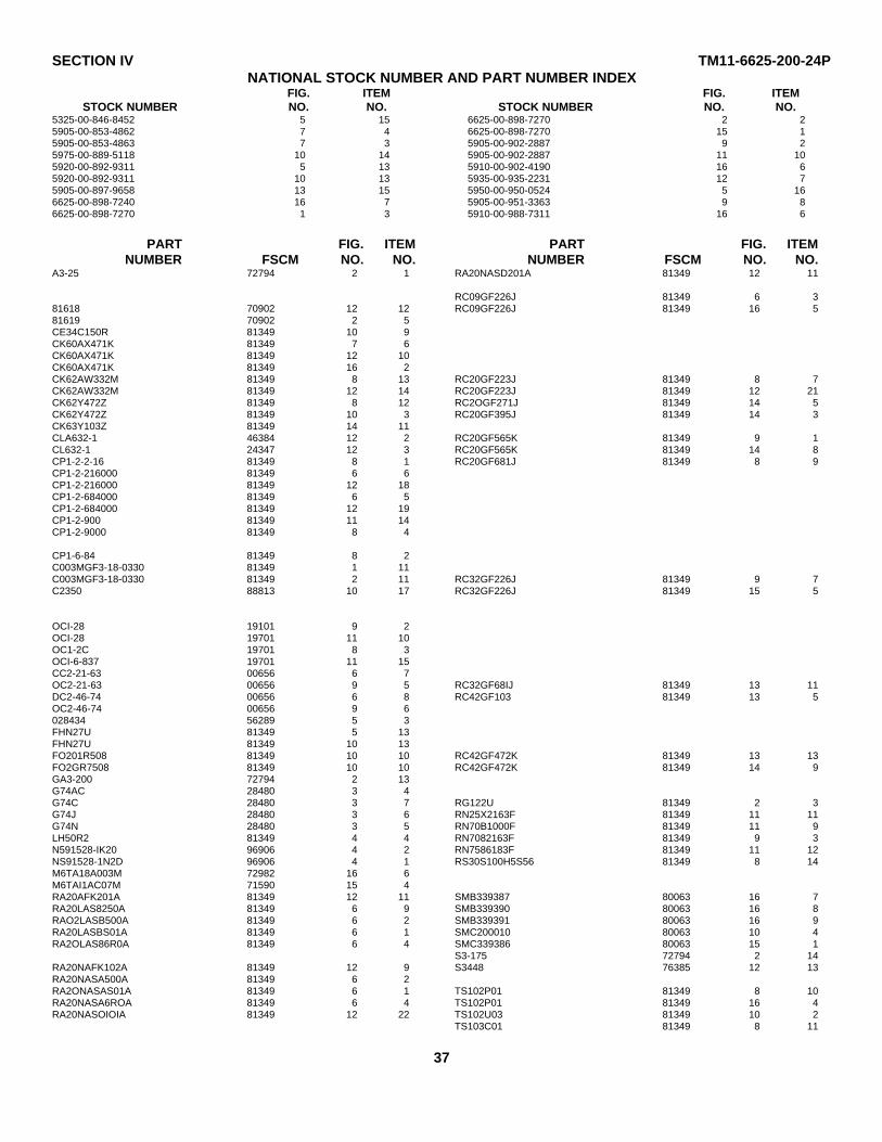
SECTION IV TM11-6625-200-24PNATIONAL STOCK NUMBER AND PART NUMBER INDEX
FIG. ITEM FIG. ITEMSTOCK NUMBER NO. NO. STOCK NUMBER NO. NO.
5325-00-846-8452 5 15 6625-00-898-7270 2 25905-00-853-4862 7 4 6625-00-898-7270 15 15905-00-853-4863 7 3 5905-00-902-2887 9 25975-00-889-5118 10 14 5905-00-902-2887 11 105920-00-892-9311 5 13 5910-00-902-4190 16 65920-00-892-9311 10 13 5935-00-935-2231 12 75905-00-897-9658 13 15 5950-00-950-0524 5 166625-00-898-7240 16 7 5905-00-951-3363 9 86625-00-898-7270 1 3 5910-00-988-7311 16 6
PART FIG. ITEM PART FIG. ITEMNUMBER FSCM NO. NO. NUMBER FSCM NO. NO.
A3-25 72794 2 1 RA20NASD201A 81349 12 11
RC09GF226J 81349 6 381618 70902 12 12 RC09GF226J 81349 16 581619 70902 2 5CE34C150R 81349 10 9CK60AX471K 81349 7 6CK60AX471K 81349 12 10CK60AX471K 81349 16 2CK62AW332M 81349 8 13 RC20GF223J 81349 8 7CK62AW332M 81349 12 14 RC20GF223J 81349 12 21CK62Y472Z 81349 8 12 RC2OGF271J 81349 14 5CK62Y472Z 81349 10 3 RC20GF395J 81349 14 3CK63Y103Z 81349 14 11CLA632-1 46384 12 2 RC20GF565K 81349 9 1CL632-1 24347 12 3 RC20GF565K 81349 14 8CP1-2-2-16 81349 8 1 RC20GF681J 81349 8 9CP1-2-216000 81349 6 6CP1-2-216000 81349 12 18CP1-2-684000 81349 6 5CP1-2-684000 81349 12 19CP1-2-900 81349 11 14CP1-2-9000 81349 8 4
CP1-6-84 81349 8 2C003MGF3-18-0330 81349 1 11C003MGF3-18-0330 81349 2 11 RC32GF226J 81349 9 7C2350 88813 10 17 RC32GF226J 81349 15 5
OCI-28 19101 9 2OCI-28 19701 11 10OC1-2C 19701 8 3OCI-6-837 19701 11 15CC2-21-63 00656 6 7OC2-21-63 00656 9 5 RC32GF68IJ 81349 13 11DC2-46-74 00656 6 8 RC42GF103 81349 13 5OC2-46-74 00656 9 6028434 56289 5 3FHN27U 81349 5 13FHN27U 81349 10 13FO201R508 81349 10 10 RC42GF472K 81349 13 13FO2GR7508 81349 10 10 RC42GF472K 81349 14 9GA3-200 72794 2 13G74AC 28480 3 4G74C 28480 3 7 RG122U 81349 2 3G74J 28480 3 6 RN25X2163F 81349 11 11G74N 28480 3 5 RN70B1000F 81349 11 9LH50R2 81349 4 4 RN7082163F 81349 9 3N591528-IK20 96906 4 2 RN7586183F 81349 11 12NS91528-1N2D 96906 4 1 RS30S100H5S56 81349 8 14M6TA18A003M 72982 16 6M6TAI1AC07M 71590 15 4RA20AFK201A 81349 12 11 SMB339387 80063 16 7RA20LAS8250A 81349 6 9 SMB339390 80063 16 8RAO2LASB500A 81349 6 2 SMB339391 80063 16 9RA20LASBS01A 81349 6 1 SMC200010 80063 10 4RA2OLAS86R0A 81349 6 4 SMC339386 80063 15 1
S3-175 72794 2 14RA20NAFK102A 81349 12 9 S3448 76385 12 13RA20NASA500A 81349 6 2RA2ONASAS01A 81349 6 1 TS102P01 81349 8 10RA20NASA6ROA 81349 6 4 TS102P01 81349 16 4RA20NASOIOIA 81349 12 22 TS102U03 81349 10 2
TS103C01 81349 8 11
37

SECTION IV NATIONAL STOCK NUMBER AND PART INDEX TM11-6625-200-24P
PART FIG. ITEM PART FIG. ITEMNUMBER FSCM NO. NO. NUMBER FSCM NO. NO.
TS103C01 81349 12 6 410821K 28480 5 5TS103UO2 81349 10 6 410821N 28480 15 6UPI21M 81349 1 10 410826 28480 13 17UPI21M 81349 2 9 410826 28480 14 14U2130 76385 12 17 410876M 72982 15 3Y3986 76385 12 16 43852H5C 76854 11 8082WA 81349 5 8 44F16388 71785 11 1O82WA 81349 10 8 45643H3AC 76854 11 70403-0004 28480 1 9 47 24446 3 20403-0004 28480 2 12 500 01538 5 151N253 81349 12 8 51A12272 71785 7 21120-0009 28480 5 4 51A12272 71785 10 11120D5-63AHS 91506 5 7 56437 08474 7 51400-0005 28480 5 17 58-41-0-63 94222 7 11400-0039 28480 5 9 6-4 70563 5 61440-0002. 00837 1 1 6-4 70563 10 161617 70902 12 15 6-5-16 95987 12 41855394 10001 16 3 6P1 28520 5 142M1 28520 10 14 6P1 28520 10 122100-0020 28480 13 15 6X4WA 81349 5 10
6X4W4 81349 10 72100-0185 28480 9 8 60 76545 2 4
6109-12AU7 81349 5 16189-12AU7 81349 10 1
26-015 99395 10 5 62 76545 16 113100-0036 81349 7 3 658-010-242K 72982 16 631C0-0050 28480 7 4 6580202Y2K 72982 1 4313-250 75915 5 11 81-121 72619 3 3313-400 75915 5 11 81081 72619 3 1
81081 72619 4 3319 83330 2 6 81246 72619 2 114SFIHIRV 84970 11 2 8410 70903 1 2410821-95A 28480 1 8 8899BLACK 70903 2 7
8899RE0 70903 2 8410821-95C 28480 1 6 9100-0021 28480 5 16410821-95D 28480 1 5 9435-1-2 71400 5 12410821-95t 28480 1 7 9435-1-2 71400 10 11
LATEST NATIONAL STOCK NUMBER ASSIGNMENTS
FIG. ITEM FIG. ITEMSTOCK NUMBER NO. NO. STOCK NUMBER NO. NO.
5905-00-131-9992 14 2 5310-00-680-7669 12 25905-00-185-8516 14 12 5910-00-722-1552 5 25905-00-195-6791 8 9 5910-00-722-1552 11 65960-00-212-6019 16 1 5910-00-722-1552 14 65905-00-617-8014 12 22
LATEST PART NUMBER ASSIGNMENTS
PART FIG. ITEM PART FIG. ITEMNUMBER FSCM NO. NO. NUMBER FSCM NO. NO.
DD472 71590 5 2 RC20GF136JS 81349 14 2DD472 71590 11 6 RC42GF103J 81349 14 12DD472 71590 14 6 2-01C 24289 16 1RA20NASK101A 81349 12 22
ADDITIONAL LATEST NATIONAL STOCK NUMBER ASSIGNMENTS
FIG. ITEM FIG. ITEMSTOCK NUMBER NO. NO. STOCK NUMBER NO. NO.
5905-00-104-8347 14 7 5905-00-141-0720 13 165905-00-106-1245 11 3 5905-00-141-0720 14 15905-00-106-1245 12 1 5905-00-141-1071 13 105905-00-106-1245 13 12 5905-00-279-2528 13 95905-00-106-9345 8 8 5905-00-279-2528 14 155905-00-106-9345 9 4 5905-00-454-2812 13 25905-00-126-6703 6 3 5935-00-581-6400 11 45905-00-126-6703 16 5 5960-00-729-8150 10 25905-00-141-4091 8 6 5905-00-913-6315 9 95905-00-141-05 91 12 20 5905-00-988-0149 8 5
38
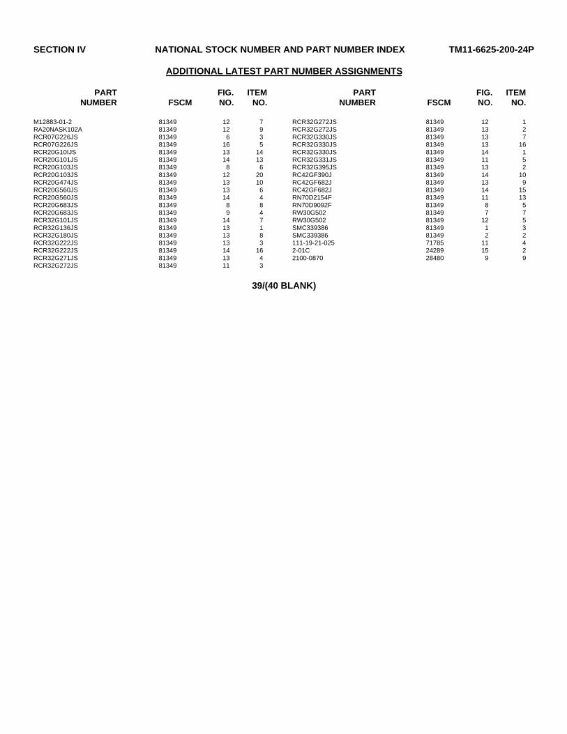
SECTION IV NATIONAL STOCK NUMBER AND PART NUMBER INDEX TM11-6625-200-24P
ADDITIONAL LATEST PART NUMBER ASSIGNMENTS
PART FIG. ITEM PART FIG. ITEMNUMBER FSCM NO. NO. NUMBER FSCM NO. NO.
M12883-01-2 81349 12 7 RCR32G272JS 81349 12 1RA20NASK102A 81349 12 9 RCR32G272JS 81349 13 2RCR07G226JS 81349 6 3 RCR32G330JS 81349 13 7RCR07G226JS 81349 16 5 RCR32G330JS 81349 13 16RCR20G10IJS 81349 13 14 RCR32G330JS 81349 14 1RCR20G101JS 81349 14 13 RCR32G331JS 81349 11 5RCR20G103JS 81349 8 6 RCR32G395JS 81349 13 2RCR20G103JS 81349 12 20 RC42GF390J 81349 14 10RCR20G474JS 81349 13 10 RC42GF682J 81349 13 9RCR20G560JS 81349 13 6 RC42GF682J 81349 14 15RCR20G560JS 81349 14 4 RN70D2154F 81349 11 13RCR20G683JS 81349 8 8 RN70D9092F 81349 8 5RCR20G683JS 81349 9 4 RW30G502 81349 7 7RCR32G101JS 81349 14 7 RW30G502 81349 12 5RCR32G136JS 81349 13 1 SMC339386 81349 1 3RCR32G180JS 81349 13 8 SMC339386 81349 2 2RCR32G222JS 81349 13 3 111-19-21-025 71785 11 4RCR32G222JS 81349 14 16 2-01C 24289 15 2RCR32G271JS 81349 13 4 2100-0870 28480 9 9RCR32G272JS 81349 11 3
39/(40 BLANK)

TM 11-6625-200-24P
By Order of the Secretary of the Army:BERNARD W. ROGERS
General, United States ArmyOfficial: Chief of Staff
J. C. PENNINGTONBrigadier General, United States Army
The Adjutant General
DISTRIBUTION: 6-186 29-36Active Army 6-200 29-37
USAINSCOM (2) 6-201 29-51COE (1) 6-300 29-55TSG (1) 6-302 29-56USAARENBD (1) 6-365 29-57DARCOM (1) 6-366 29-75TRADOC (2) 6-425 29-79OS Maj Comd (4) 6-426 29-102TECOM (2) 6-435 29-105USACC (4) 6-436 29-109MDW (1) 6-455 29-134Armies (2) 6-456 29-139Corps (2) 6-575 29-245USMA (2) 6-576 29-247Svc Colleges (1) 6-577 29-427USASIGS (5) 6-615 30-34USAADS (2) 6-616 31-105USAFAS (2) 7 32-57USAARMS (2) 7-100 32-87USAIS (2) 7-157 32-97USAES (2) 11-15 32-500USAICS (3) 11-16 37MAAG (1) 11-17 37-100USARMIS (1) 11-19 39-401USAERDAA (1) 11-35 44-2USAERDAW (1) 11-37 44-8USACC-EUR (2) 11-38 44-12Fort Gillem (10) 11-39 44-236Fort Gordon (10) 11-117 44-255Fort Huachuca (10) 11-127 44-256Fort Carson (5) 11-137 44-535Ft Monmouth (HISA) (33) 11-215 44-536Ft Richardson (CERCOM) (2) 11-216 44-537Army Dep (1) except 11-225 44-545
LBAD (14) 11-226 44-546SAAD (30) 11-327 44-547TOAD (14) 11-347 55-89SHAD (3) 11-357 55-99
USA Dep (1) 11-367 55-157Sig Sec USA Dep (1) 11-368 55-457Units org under fol TOE: 11-377 55-458
(1 cy each unit) UNOINDC 11-500 (AA-AC) 571-128 17 57-1001-207 7-100 57-1026-100 29-1 676-115 29-11 77-1006-116 29-15 77-1026-155 29-16 29-207 (2)6-156 29-17 29-610 (2)6-165 29-216-166 29-25 NG: State AG (3); Units-Same as Active Army6-175 29-26 USAR: None6-176 29-27 For explanation of abbreviations used, see AR 310-50.6-185 29-35
* U. S. GOVERNMENT PRINTING OFFICE : 1990 290-483 (56/27)


PIN : 019405-000