Embed Size (px)
Citation preview
TM 11-5895-1483-13&P
TECHNICAL MANUAL
OPERATOR’S, UNIT, AND DIRECT SUPPORTMAINTENANCE MANUAL
(INCLUDING REPAIR PARTSAND SPECIAL TOOLS LIST)
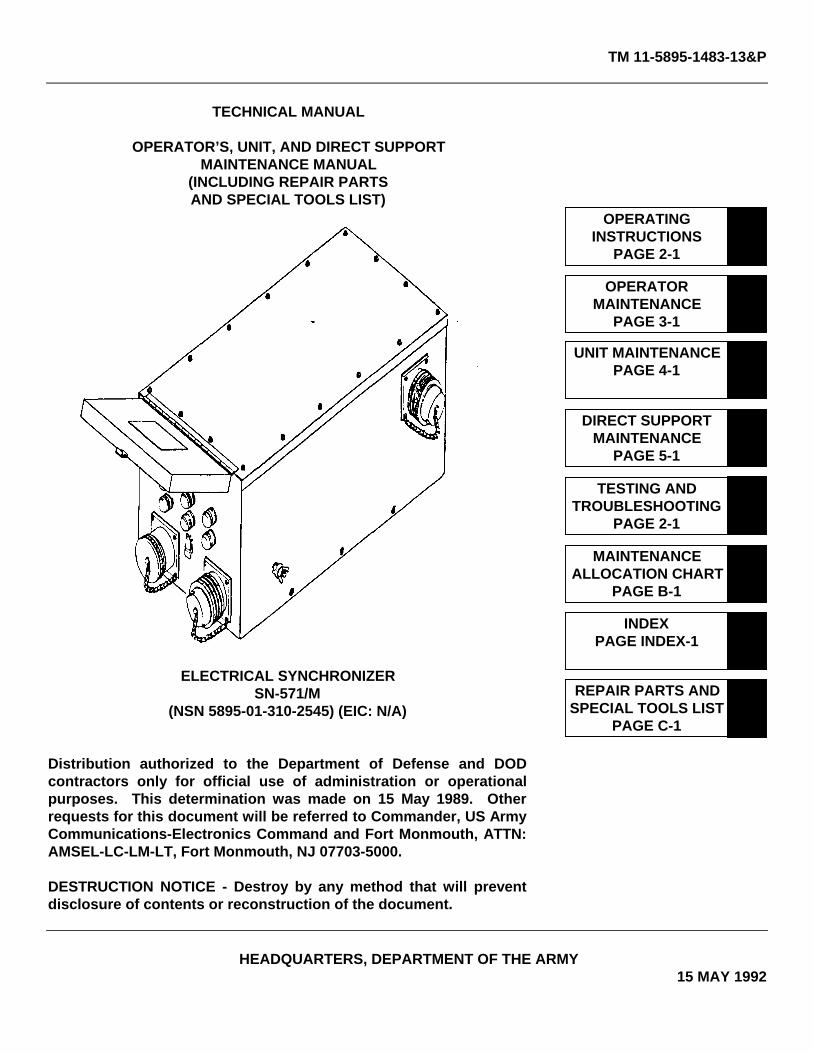
ELECTRICAL SYNCHRONIZERSN-571/M
(NSN 5895-01-310-2545) (EIC: N/A)
Distribution authorized to the Department of Defense and DODcontractors only for official use of administration or operationalpurposes. This determination was made on 15 May 1989. Otherrequests for this document will be referred to Commander, US ArmyCommunications-Electronics Command and Fort Monmouth, ATTN:AMSEL-LC-LM-LT, Fort Monmouth, NJ 07703-5000.
DESTRUCTION NOTICE - Destroy by any method that will preventdisclosure of contents or reconstruction of the document.
HEADQUARTERS, DEPARTMENT OF THE ARMY15 MAY 1992
OPERATINGINSTRUCTIONS
PAGE 2-1
OPERATORMAINTENANCE
PAGE 3-1
UNIT MAINTENANCEPAGE 4-1
TESTING ANDTROUBLESHOOTING
PAGE 2-1
DIRECT SUPPORTMAINTENANCE
PAGE 5-1
MAINTENANCEALLOCATION CHART
PAGE B-1
REPAIR PARTS ANDSPECIAL TOOLS LIST
PAGE C-1
INDEXPAGE INDEX-1
TM 11-5895-1483-13&P
A

TM 11-5895-1483-13&P
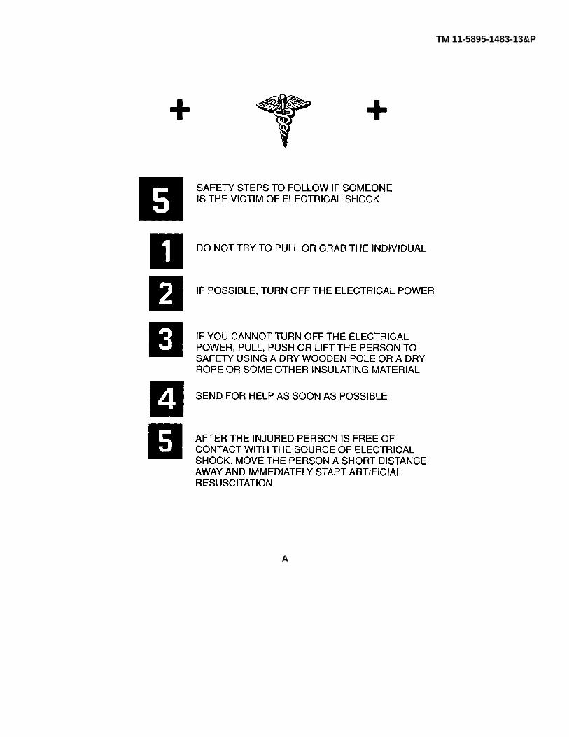
WARNING
B
TM 11-5895-1483-13&P
Technical Manual HEADQUARTERSDEPARTMENT OF THE ARMY
No. 11-5895-1483-13&P Washington, DC, 15 May 1992
OPERATOR’S, UNIT, AND DIRECT SUPPORTMAINTENANCE MANUAL
(INCLUDING REPAIR PARTS AND SPECIAL TOOLS LIST)ELECTRICAL SYNCHRONIZER SN-571/M
(NSN 5895-0110-2445) (EIC: N/A)
Current as of 15 February 1992
REPORTING ERRORS AND RECOMMENDING IMPROVEMENTS
You can help improve this manual. If you find any mistakes, or if you know of a way toimprove the procedures, please let us know. Mail your letter, DA Form 2028(Recommended Changes to Publications and Blank Forms) or DA Form 2028-2 locatedin back of this manual direct to: Commander, US Army Communications-ElectronicsCommand and Fort Monmouth, ATTN: AMSEL-LC-LM-LT, Fort Monmouth, New Jersey07703-5007.In either case a reply will be furnished direct to you.
TABLE OF CONTENTS
Page
HOW TO USE THIS MANUAL .......................................................................................................................................... iii
CHAPTER 1 INTRODUCTION ........................................................................................................................... 1-1Section I. General Information....................................................................................................................... 1-1Section II. Description and Data ..................................................................................................................... 1-3
CHAPTER 2 OPERATING INSTRUCTIONS ..................................................................................................... 2-1Section I. Introduction:................................................................................................................................... 2-1Section II. Preventive Maintenance Checks and Services ............................................................................. 2-2Section III. Operation Under Usual Conditions................................................................................................ 2-2Section IV. Operation Under Unusual Conditions............................................................................................ 2-7
CHAPTER 3 OPERATOR MAINTENANCE INSTRUCTIONS ........................................................................... 3-1
CHAPTER 4 UNIT MAINTENANCE................................................................................................................... 4-1
CHAPTER 5 DIRECT SUPPORT MAINTENANCE ........................................................................................... 5-1Section I. Introduction.................................................................................................................................... 5-1Section II. Maintenance .................................................................................................................................. 5-1
i
TM 11-5895-1483-13&P
TABLE OF CONTENTS - Continued
Page
CHAPTER 6 TESTING AND TROUBLESHOOTING ......................................................................................... 6-1Section I. General Information....................................................................................................................... 6-1Section II. Description and Data ..................................................................................................................... 6-1Section III. Operation Under Usual Conditions................................................................................................ 6-1Section IV. Operation Under Unusual Conditions............................................................................................ 6-9
APPENDIX A. REFERENCES ..............................................................................................................................A-1
APPENDIX B. MAINTENANCE ALLOCATION CHART .......................................................................................B-1
APPENDIX C. REPAIR PARTS AND SPECIAL TOOLS LIST..............................................................................C-1Section I. Introduction....................................................................................................................................C-1Section II. Repair Parts List ............................................................................................................................C-11Group 00 Electrical Synchronizer SN-571/M.................................................................................................C-11Section III. Special Tools List (Not applicable)Section IV. Cross-Reference Indexes..............................................................................................................C-I-1
CHAPTER 5 DIRECT SUPPORT MAINTENANCE ........................................................................................... 5-1Section I. Introduction.................................................................................................................................... 5-1Section II. Maintenance .................................................................................................................................. 5-1
INDEX....................................................................................................................................... Index-1
LIST OF TABLES
Number Title Page
6-1 Switches S1 and S2 Troubleshooting............................................................................................ 6-36-2 Switch S3 Troubleshooting............................................................................................................ 6-46-3 Contactors K and K2 Troubleshooting........................................................................................... 6-66-4 Synchronizer Box Wire List ........................................................................................................... 6-6
ii
TM 11-5895-1483-13&P
HOW TO USE THIS MANUAL
Your manual is divided into six chapters. Chapter 1 introduces you to your Electrical Synchronizer. Chapter 2 tells youhow to operate your Electrical Synchronizer. Chapter 3 details operator maintenance. Chapter 4 details unit maintenance.Chapter 5 details Direct Support maintenance. Chapter 6 details testing and troubleshooting. Appendix A lists allpublications referenced in this manual. Appendix B is the maintenance allocation chart (MAC) and gives information onwho is authorized to perform maintenance procedures, estimated times, and tools used. Appendix C is the Repair Partsand Special Tools List (RPSTL) and gives all information necessary to procure repair parts.
INDEXING. The front cover index identifies frequently used information. Each item is boxed and identified by topicnumber. Boxed-in items on the cover are also thumb-indexed with edge marks so you can go to the right area quickly.Bend the manual back and follow front cover margin index to the page with the black edge mark. When appropriate,chapters and sections have indexes to allow you to find information on a particular subject quickly.
HOW TO FIND SOMETHING FAST. Flip to the index at the back of this manual. Look for the subject you need to knowabout, then turn to the page listed.
OPERATING PROCEDURES. The procedures in this manual are easy to use by first-time users and experiencedoperators. Important information is boxed in or set with dark type. Illustrations are located within the narrative.
iii/(iv blank)
TM 11-5895-1483-13&P
CHAPTER 1INTRODUCTION
PAGE
Section I General Information....................................................................................................................................1-1Section II Description and Data..................................................................................................................................1-3
Section I. GENERAL INFORMATION
ITEM PAGE
Scope ...................................................................................................................................................................................1-1Maintenance Forms, Records and Reports .........................................................................................................................1-1Consolidated Index of Army Publications and Blank Forms.................................................................................................1-2Destruction of Army Electronics Materiel to Prevent Enemy Use ........................................................................................1-2Reporting Equipment Improvement Recommendations ......................................................................................................1-2Preparation for Storage or Shipment....................................................................................................................................1-2Nomenclature Cross-Reference List ....................................................................................................................................1-2
SCOPE
This technical manual is designed as an aid to testing, troubleshooting, and maintaining the Electrical Synchronizer SN-571/M, hereinafter referred to as the synchronizer box. The synchronizer box is a 50-ampere switch box that can transferpower to the load from one generator to another synchronously to allow uninterrupted operations during the switchover. Inaddition to operating instructions and operator, unit, and direct support maintenance instructions, this manual contains aRepair Parts and Special Tools List for the synchronizer box.
MAINTENANCE FORMS, RECORDS, AND REPORTS
Reports of Maintenance and Unsatisfactory Equipment. Department of the Army forms and procedures used forequipment maintenance will be those prescribed by DA PAM 738-750 as contained in Maintenance Management Update.
Report of Item and Packaging Discrepancies. Fill out and forward SF 364, Report of Discrepancy (ROD) as prescribedin AR 735-11-2/DLAR 4140.55/SECNAVINST 4355.18/AFR 400-54/MCO 4430.3J.
Transportation Discrepancy In Shipment Reports (TDR) (SF 361). Fill out and forward a Transportation DiscrepancyReport (TDR) (SF 361) as prescribed in AR 55-38/NAVSUPINST 4610.33C/AFR 75-18/MCO P4610.19D/DLAR 4500.15.
1-1

TM 11-5895-1483-13&P
CONSOLIDATED INDEX OF ARMY PUBLICATIONS AND BLANK FORMS
Refer to the latest issue of DA PAM 25-30 to determine whether there are new editions, changes, or additional publicationspertaining to the equipment.
DESTRUCTION OF ARMY ELECTRONICS MATERIEL TO PREVENT ENEMY USE
Destruction of Army electronics materiel to prevent enemy use shall be in accordance with TM 750-244-2.
REPORTING EQUIPMENT IMPROVEMENT RECOMMENDATIONS (EIRs)
If your synchronizer box needs improvement, let us know. Send us an EIR. You, the user, are the only one who can tellus what you don’t like about the design. Put it on an SF 368 (Product Quality Deficiency Report). Mail it to Commander,U.S. Army Communications-Electronics Command and Fort Monmouth, ATTN: AMSEL-ED-PH, Fort Monmouth, NJ07703-5000. We’ll send you a reply.
PREPARATION FOR STORAGE OR SHIPMENT
Preparation for storage or shipment shall be in accordance with references cited in AR 708-1.
NOMENCLATURE CROSS-REFERENCE LIST
Common Name Official Nomenclature
Synchronizer Box Electrical Synchronizer SN-571/M
1-2
TM 11-5895-1483-13&P
Section II. DESCRIPTION AND DATA
ITEM PAGE
Description............................................................................................................................................................................1-3Equipment Data....................................................................................................................................................................1-4
DESCRIPTION
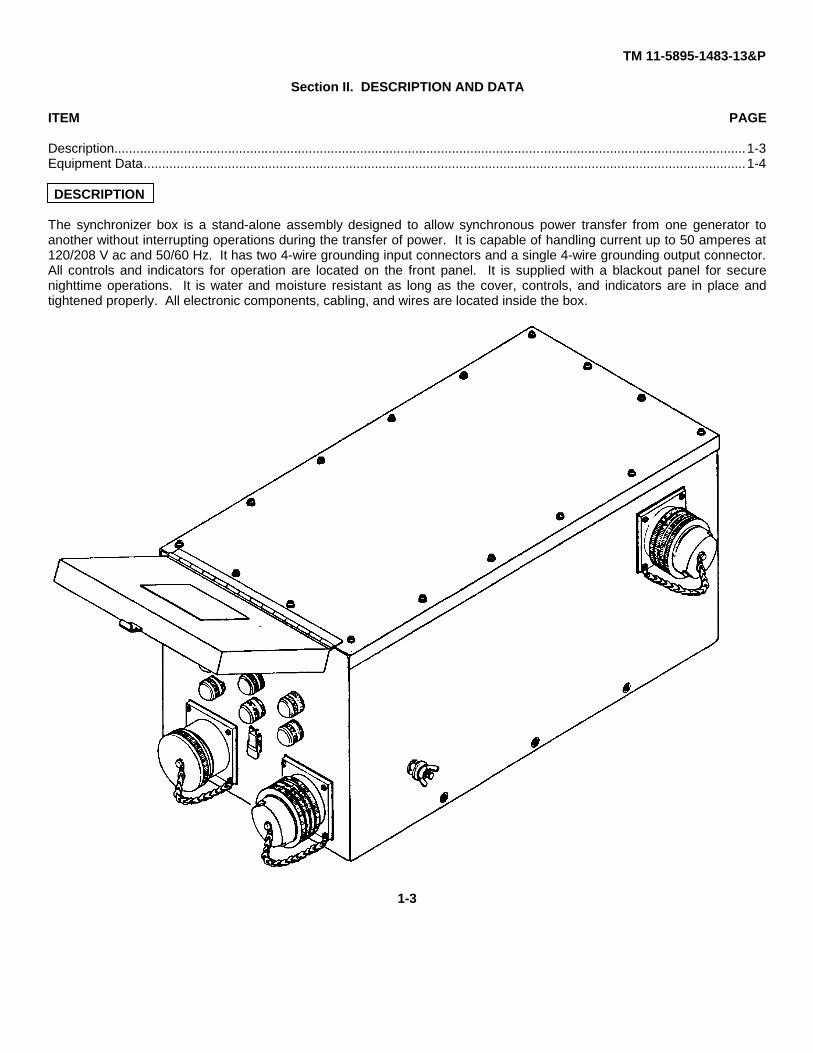
The synchronizer box is a stand-alone assembly designed to allow synchronous power transfer from one generator toanother without interrupting operations during the transfer of power. It is capable of handling current up to 50 amperes at120/208 V ac and 50/60 Hz. It has two 4-wire grounding input connectors and a single 4-wire grounding output connector.All controls and indicators for operation are located on the front panel. It is supplied with a blackout panel for securenighttime operations. It is water and moisture resistant as long as the cover, controls, and indicators are in place andtightened properly. All electronic components, cabling, and wires are located inside the box.
1-3
TM 11-5895-1483-13&P
EQUIPMENT DATA
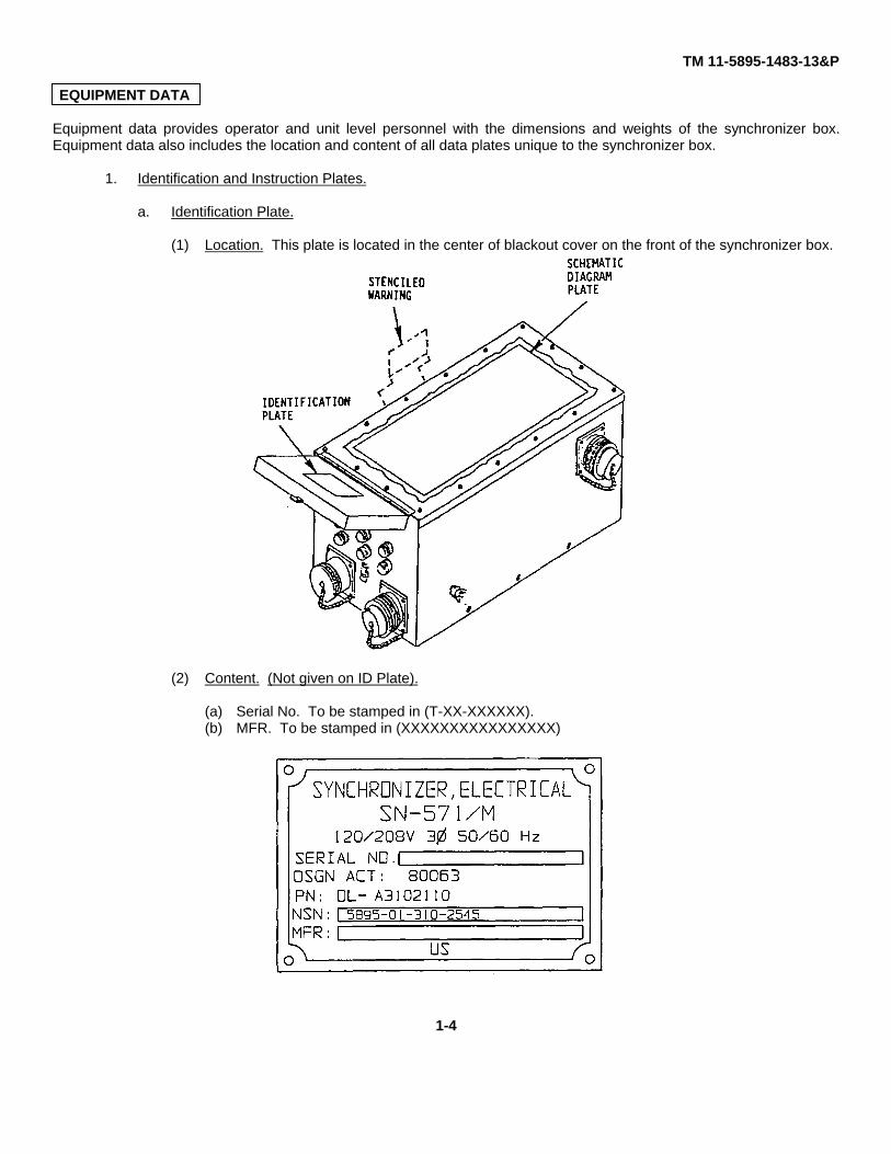
Equipment data provides operator and unit level personnel with the dimensions and weights of the synchronizer box.Equipment data also includes the location and content of all data plates unique to the synchronizer box.
1. Identification and Instruction Plates.
a. Identification Plate.
(1) Location. This plate is located in the center of blackout cover on the front of the synchronizer box.
(2) Content. (Not given on ID Plate).
(a) Serial No. To be stamped in (T-XX-XXXXXX).(b) MFR. To be stamped in (XXXXXXXXXXXXXXXX)
1-4
TM 11-5895-1483-13&P
b. Warning Notice.
Location. A stenciled warning notice similar to the one below is located in center of left-hand side ofsynchronizer box when facing indicator panel.
208 VOLTS
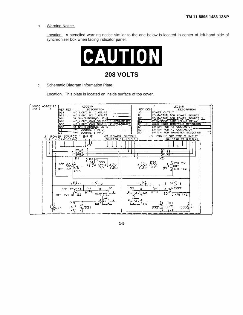
c. Schematic Diagram Information Plate.
Location. This plate is located on inside surface of top cover.
1-5

TM 11-5895-1483-13&P
2. Equipment Data for Synchronizer Box.
Overall Length 26.5 in. (67.31cm)Overall Width 16.75 in. (42.5 cm)Overall Height 10.75 in. (27.3 cm)Net Weight 60 lbs (27.2 kg)Cubage 2.67 cu ft (0.772 cu m)
1-6
TM 11-5895-1483-13&P
CHAPTER 2
OPERATING INSTRUCTIONS
PAGE
Section I Introduction.................................................................................................................................................2-1Section II Preventive Maintenance Checks and Services..........................................................................................2-2Section III Operation Under Usual Conditions.............................................................................................................2-2Section IV Operation Under Unusual Conditions.........................................................................................................2-8
Section I. INTRODUCTION
ITEM PAGE
General.................................................................................................................................................................................2-1Description............................................................................................................................................................................2-1Power Sources .....................................................................................................................................................................2-1
INTRODUCTION
General. This chapter provides information, Preventive Maintenance Checks and Services (PMCS), and operatinginstructions under usual and unusual conditions for the Electrical Synchronizer SN-571/M.
Description. The synchronizer box is a 50-ampere switch box that can transfer power to the load from one generator toanother synchronously to allow uninterrupted operations during the switchover.
Power Sources. The synchronizer box may be used with either commercial or generator supplied three-phase, 120/208V ac, 50/60 Hz.
WARNING
If a commercial power source is connected to one of the power inputs on synchronizerbox, commercial power neutral line must be connected to ground.
NOTE
For additional generator information not specifically covered in these procedures, seeapplicable generator technical manual.
2-1

TM 11-5895-1483-13&P
Section II. PREVENTIVE MAINTENANCE CHECKS AND SERVICES
There are no preventive maintenance checks and services for the Electrical Synchronizer SN-571/M.
Section III. OPERATION UNDER USUAL CONDITIONS
ITEM PAGE
Initial Turn-On and Check - Generator Power......................................................................................................................2-2Generator-to-Generator Transfer .........................................................................................................................................2-5
INITIAL TURN-ON AND CHECK - GENERATOR POWER
NOTE
The label designations on connectors J1, J2, and J3 on all illustrations in this chapter arelabeled internally and are shown on these illustrations for reference only.
The OFF position on the POWER TRANSFER switch is not physically labeled on theequipment but is shown for reference only.
1. Set all circuit breakers on Power Distribution Panel (PDP) in equipment shelter to OFF position.
2. Set AC CIRCUIT BREAKER switch on both generators to OFF position.
3. Connect power cables from generator 1 and generator 2 to input connectors J1 and J2 on synchronizer box.
4. Connect output power cable to connector J3 on synchronizer box and other end to equipment shelter PowerEntrance Box (PEB).
2-2

TM 11-5895-1483-13&P
5. Set POWER TRANSFER switch on synchronizer box to OFF (center) position.
6. Set generator for 120/208V, three-phase, 50/60 Hz operation.
7. Start and warm up both generators. Refer to specific generator manual for further information.
8. Ensure that phase to neutral voltage on both generators is set for 120 ± 2 V ac and 60 ± 1 Hz.
CAUTION
Incorrect voltage setting may cause damage to synchronizer box.
NOTE
Input power connector J1 is controlled by POWER SOURCE 1 switch and conditions forthat connector are displayed on two green indicators located immediately below it. Inputpower connector J2 is controlled by POWER SOURCE 2 switch and conditions for thatconnector are displayed on two green indicators located immediately below it.
2-3
TM 11-5895-1483-13&P
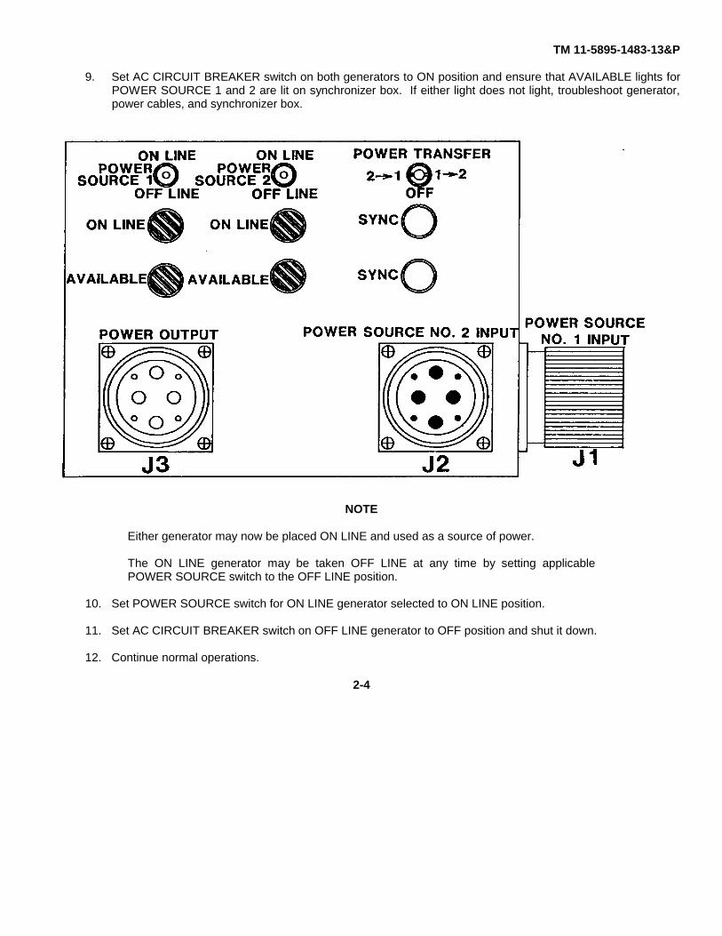
9. Set AC CIRCUIT BREAKER switch on both generators to ON position and ensure that AVAILABLE lights forPOWER SOURCE 1 and 2 are lit on synchronizer box. If either light does not light, troubleshoot generator,power cables, and synchronizer box.
NOTE
Either generator may now be placed ON LINE and used as a source of power.
The ON LINE generator may be taken OFF LINE at any time by setting applicablePOWER SOURCE switch to the OFF LINE position.
10. Set POWER SOURCE switch for ON LINE generator selected to ON LINE position.
11. Set AC CIRCUIT BREAKER switch on OFF LINE generator to OFF position and shut it down.
12. Continue normal operations.
2-4
TM 11-5895-1483-13&P
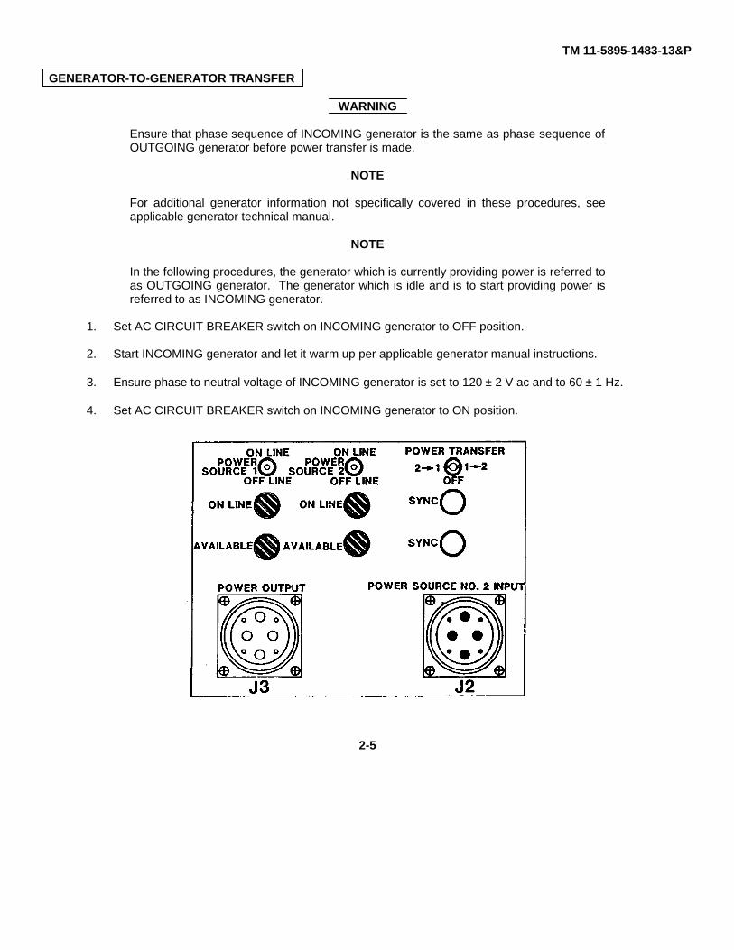
GENERATOR-TO-GENERATOR TRANSFER
WARNING
Ensure that phase sequence of INCOMING generator is the same as phase sequence ofOUTGOING generator before power transfer is made.
NOTE
For additional generator information not specifically covered in these procedures, seeapplicable generator technical manual.
NOTE
In the following procedures, the generator which is currently providing power is referred toas OUTGOING generator. The generator which is idle and is to start providing power isreferred to as INCOMING generator.
1. Set AC CIRCUIT BREAKER switch on INCOMING generator to OFF position.
2. Start INCOMING generator and let it warm up per applicable generator manual instructions.
3. Ensure phase to neutral voltage of INCOMING generator is set to 120 ± 2 V ac and to 60 ± 1 Hz.
4. Set AC CIRCUIT BREAKER switch on INCOMING generator to ON position.
2-5

TM 11-5895-1483-13&P
NOTE
The input power connector J1 is controlled by the POWER SOURCE 1 switch andconditions for that connector are displayed on two green indicators located immediatelybelow it. The input power connector J2 is controlled by POWER SOURCE 2 switch andconditions for that connector are displayed on two green indicators located immediatelybelow it.
5. Verify that AVAILABLE light for INCOMING generator is illuminated. If light is not illuminated, troubleshootgenerator, cables, and synchronizer box.
6. If INCOMING generator is connected to input power connector J1, move POWER TRANSFER switch to 2 1position. If INCOMING generator is connected to input power connector J2, move POWER TRANSFERswitch to 1 2 position.
NOTE
As procedures in the following paragraphs are observed and completed, SYNC lights willdim and brighten to OFF and ON conditions.
7. Verify that SYNC lights cycle ON and OFF simultaneously at approximately a 3-second rate. Only whenthese indications are correct, can load transfer procedure continue. If indications are correct, followinstructions in step 8. If indications are not as noted, examine the following steps for corrective procedure.
NOTE
Either generator may be used to "fine tune" the frequency to achieve proper sync lightindications.
a. SYNC LIGHTS CYCLE AT A FAST RATE. This indicates that one of the generators is too far offfrequency. Check the frequency of both generators and fine tune either generator until sync lights cycleON and OFF simultaneously at approximately a 3-second rate. Only then can the load transferprocedure continue. Follow instructions in step 8.
2-6
TM 11-5895-1483-13&P
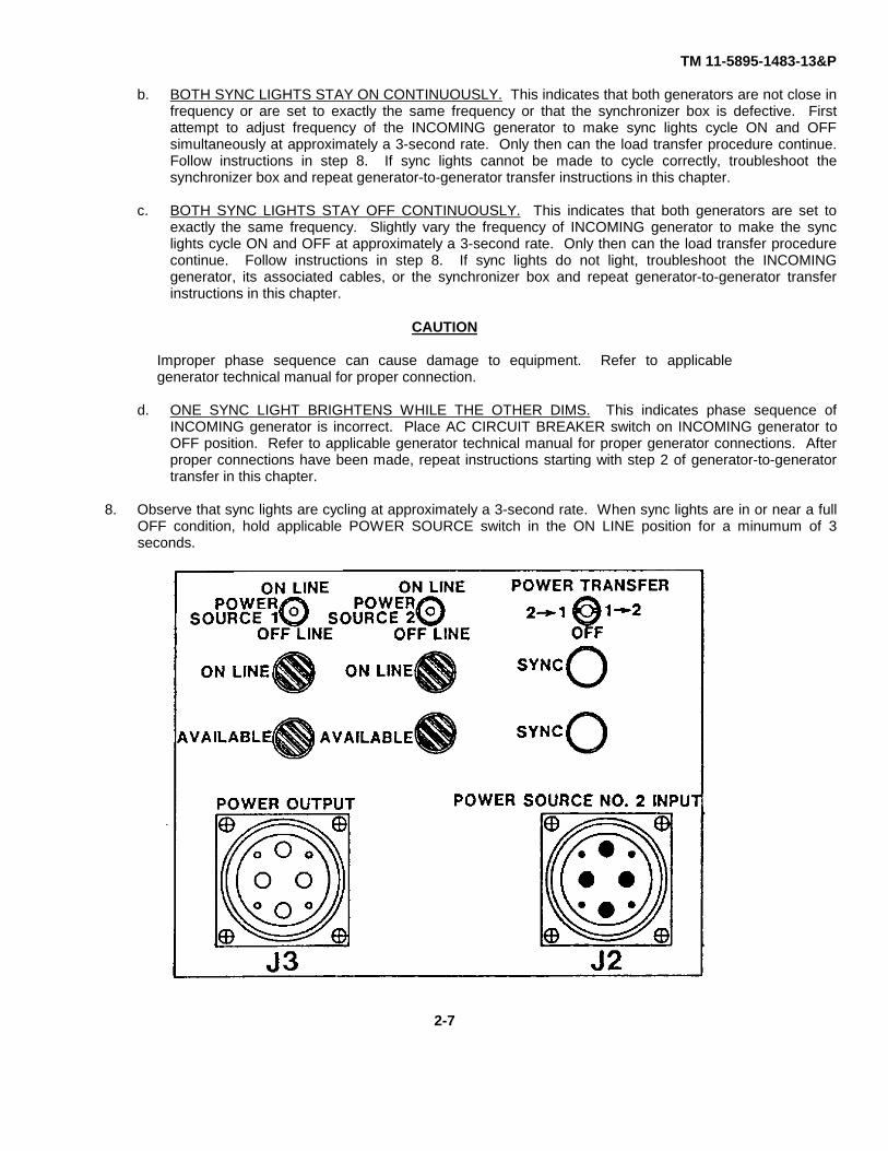
b. BOTH SYNC LIGHTS STAY ON CONTINUOUSLY. This indicates that both generators are not close infrequency or are set to exactly the same frequency or that the synchronizer box is defective. Firstattempt to adjust frequency of the INCOMING generator to make sync lights cycle ON and OFFsimultaneously at approximately a 3-second rate. Only then can the load transfer procedure continue.Follow instructions in step 8. If sync lights cannot be made to cycle correctly, troubleshoot thesynchronizer box and repeat generator-to-generator transfer instructions in this chapter.
c. BOTH SYNC LIGHTS STAY OFF CONTINUOUSLY. This indicates that both generators are set toexactly the same frequency. Slightly vary the frequency of INCOMING generator to make the synclights cycle ON and OFF at approximately a 3-second rate. Only then can the load transfer procedurecontinue. Follow instructions in step 8. If sync lights do not light, troubleshoot the INCOMINGgenerator, its associated cables, or the synchronizer box and repeat generator-to-generator transferinstructions in this chapter.
CAUTION
Improper phase sequence can cause damage to equipment. Refer to applicablegenerator technical manual for proper connection.
d. ONE SYNC LIGHT BRIGHTENS WHILE THE OTHER DIMS. This indicates phase sequence ofINCOMING generator is incorrect. Place AC CIRCUIT BREAKER switch on INCOMING generator toOFF position. Refer to applicable generator technical manual for proper generator connections. Afterproper connections have been made, repeat instructions starting with step 2 of generator-to-generatortransfer in this chapter.
8. Observe that sync lights are cycling at approximately a 3-second rate. When sync lights are in or near a fullOFF condition, hold applicable POWER SOURCE switch in the ON LINE position for a minumum of 3seconds.
2-7
TM 11-5895-1483-13&P
9. Verify that INCOMING generator ON LINE light is lit and that OUTGOING generator ON LINE light is out.When these indications are correct, the load has been transferred to INCOMING generator. If indications areincorrect, troubleshoot synchronizer box and repeat generator-to-generator transfer instructions in thischapter. Otherwise, continue at step 10.
CAUTION
Leaving POWER TRANSFER switch in ON position will decrease the life of permissiverelay K3.
10. Set POWER TRANSFER switch to OFF (center) position. Ensure both sync lights are out.
11. Readjust INCOMING generator as necessary to ensure it is providing proper input voltage and frequency.
12. Set AC CIRCUIT BREAKER switch on OUTGOING generator to OFF position and shut it down.
13. Continue normal operations.
Section IV. OPERATION UNDER UNUSUAL CONDITIONS
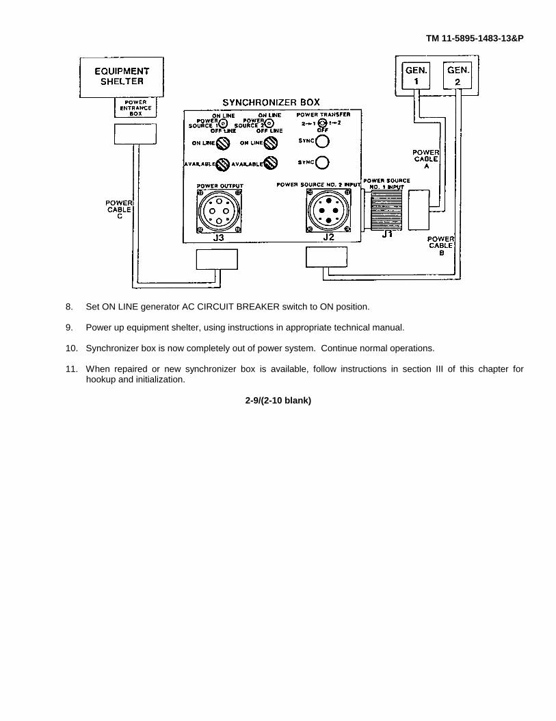
If the synchronizer box fails and cannot be replaced or repaired within a reasonable time, a temporary fix can be made tocontinue with normal operations. The procedure eliminates the synchronizer box from the power circuit and eliminates thecapability of switching generators. A temporary shutdown of operations is necessary. Perform the following steps:
1. Power down equipment shelter, using instructions in appropriate technical manual.
2. Set synchronizer box POWER SOURCE switch for ON LINE generator to OFF LINE position.
3. Set ON LINE generator AC CIRCUIT BREAKER switch to OFF position (generator can remain running).
4. Locate power cable coming from ON LINE generator (either cable A or B) and disconnect it from eitherconnector J1 or J2 on synchronizer box.
5. Locate power cable C coming from equipment shelter and disconnect it from connector J3 on synchronizerbox.
6. Connect power cable C coming from equipment shelter to power cable coming from ON LINE generator(cable A or B).
7. Ensure that phase to neutral voltage on the ON LINE generator is set for 120 ± 2 V ac and 60 ± 1 Hz.
2-8
TM 11-5895-1483-13&P
8. Set ON LINE generator AC CIRCUIT BREAKER switch to ON position.
9. Power up equipment shelter, using instructions in appropriate technical manual.
10. Synchronizer box is now completely out of power system. Continue normal operations.
11. When repaired or new synchronizer box is available, follow instructions in section III of this chapter forhookup and initialization.
2-9/(2-10 blank)

TM 11-5895-1483-13&P
CHAPTER 3
OPERATOR MAINTENANCE INSTRUCTIONS
ITEM PAGE
Introduction...........................................................................................................................................................................3-1Operator Maintenance..........................................................................................................................................................3-1
INTRODUCTION
This chapter provides information for operator maintenance of the Electrical Synchronizer SN-571/M.
OPERATOR MAINTENANCE
Maintenance of the synchronizer box at the operator level is limited to removal and replacement of light bulbs in theindicators on the front panel of the synchronizer box.
1. Removal.
a. Turn lens cover counterclockwise on indicator suspected of having a bad bulb.
b. Remove light bulb by pressing inward while turning the bulb counterclockwise. A short length ofmasking tape may be used to get a good grip on the bulb.
2. Checking.
a. Inspect the bulb for indications such as darkening or separated filaments internally.
b. If above indications are present, replace the bulb with a new one and ensure the indicator is lighting.
c. If the indicator still does not light, return the synchronizer box to the Direct Support level of maintenancefor repair.
3. Replacement.
a. Replace bulb by inserting in indicator base and turning until base pins fit loosely in their mating grooves.
b. Push bulb in against the spring action and turn clockwise until base pins fully engage in their matinggrooves and bulb is securely in place.
3-1

TM 11-5895-1483-13&P
c. Replace lens cover by turning clockwise. Ensure rubber gasket is in place. Finger-tighten only.
3-2
TM 11-5895-1483-13&P
CHAPTER 4
UNIT MAINTENANCE
ITEM PAGE
Introduction...........................................................................................................................................................................4-1Unit Maintenance..................................................................................................................................................................4-1
INTRODUCTION
This chapter provides information for Unit Maintenance of the Electrical Synchronizer SN-571/M.
UNIT MAINTENANCE
Maintenance of the synchronizer box at the Unit level is limited to removal and replacement of the entire box as anassembly for repair at the Direct Support level.
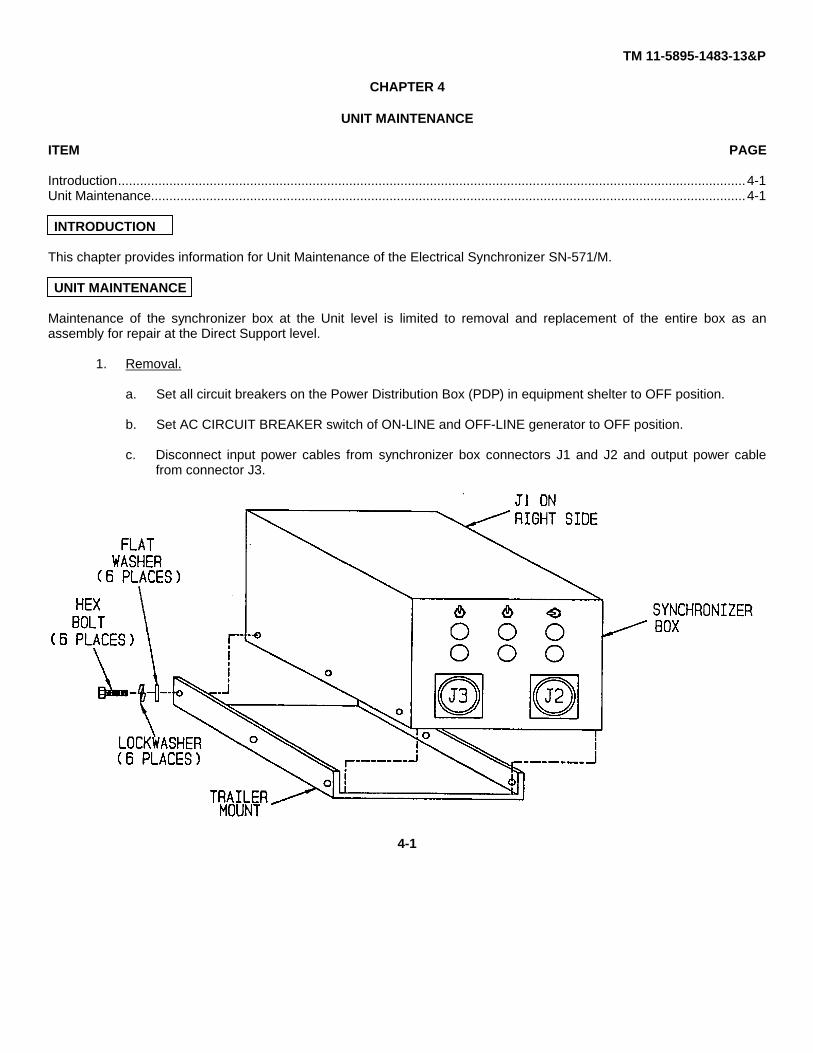
1. Removal.
a. Set all circuit breakers on the Power Distribution Box (PDP) in equipment shelter to OFF position.
b. Set AC CIRCUIT BREAKER switch of ON-LINE and OFF-LINE generator to OFF position.
c. Disconnect input power cables from synchronizer box connectors J1 and J2 and output power cablefrom connector J3.
4-1
TM 11-5895-1483-13&P
d. Remove six bolts, lockwashers, and flat washers holding synchronizer box to generator trailer mount.
e. Remove synchronizer box.
2. Replacement.
a. Install synchronizer box (new or repaired) on generator trailer mounts, lining up mounting holes.
b. Insert six bolts, lockwashers, and flat washers through mount and into synchronizer box and tightensecurely.
c. Reconnect input power cables to synchronizer box connectors J1 and J2 and output power cable toconnector J3.
d. Referring to Initial Turn-on and Check in section III of chapter 2, bring up ON-LINE generator.
e. Resume normal operations.
4-2

TM 11-5895-1483-13&P
CHAPTER 5
DIRECT SUPPORT MAINTENANCE
ITEM PAGE
Section I Introduction.................................................................................................................................................5-1Section II Maintenance...............................................................................................................................................5-1
Section I. INTRODUCTION
ITEM PAGE
General.................................................................................................................................................................................5-1
GENERAL
This chapter contains the Direct Support level maintenance procedures for the Electrical Synchronizer SN-571/M.
Section II. MAINTENANCE
Item Page
Cover Assembly ................................................................................................................................................................ 5-2Harness Assemblies A3102112-001, A3102112-002, and A3102112-003....................................................................... 5-3Component Mounting Plate............................................................................................................................................... 5-9Contactors K1 and K2 ....................................................................................................................................................... 5-10Resistors R1 and R2 ......................................................................................................................................................... 5-13Permissive Parallel Special Purpose Relay K3 ................................................................................................................. 5-13Neutral Busbar Backer and Busbar................................................................................................................................... 5-14Busbar ............................................................................................................................................................................... 5-15Ground Terminal Strip ....................................................................................................................................................... 5-16Terminal Board TB1 .......................................................................................................................................................... 5-17Indicator Lights DS1 thru DS6........................................................................................................................................... 5-18Switches S1, S2, and S3................................................................................................................................................... 5-20Ground Stud ...................................................................................................................................................................... 5-22
DIRECT SUPPORT MAINTENANCE
Maintenance of the synchronizer box at the Direct Support level consists of replacing assemblies as required in thefollowing procedures.
5-1
TM 11-5895-1483-13&P
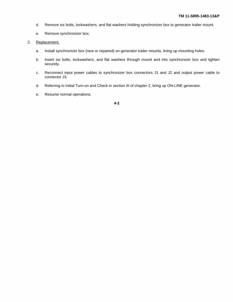
1. Cover Assembly.
a. Removal.
(1) Remove 16 screws, lockwashers, and flat washers from perimeter of cover assembly.
(2) Ensure that catch on blackout shield is not latched.
(3) Carefully remove cover and blackout shield. Ensure gasket underneath cover is not damaged.
b. Replacement.
NOTE
Ensure gasket is properly positioned under cover.
(1) Set cover on synchronizer box with blackout shield toward front of box.
(2) Insert 16 screws, lockwashers, and flat washers on perimeter of cover assembly.
(3) Tighten all screws securely, but do not overtighten to prevent distortion of gasket.
5-2
TM 11-5895-1483-13&P
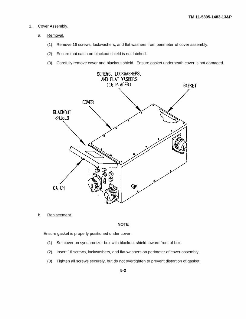
2. Harness Assemblies A3102112-001. A3102112-002. and A3102112-003.
NOTE
Removal and replacement procedures of individual harness assemblies are identicalexcept where noted in the procedures.
Connectors J1, J2, and J3 are integral parts of each harness assembly.
Illustrations in this chapter list wire destinations.
The notations of 001, 002, and 003 in the following procedures refer to the last three digitsin the harness assembly part number.
a. Removal.
(1) Remove cover assembly, using procedure in paragraph 1a.
NOTE
It is not necessary to remove the two small wires from connecting posts B2 and C2 oneither contactor and three large wires from connecting posts A2, B2, and C2 on contactorK2 when removing harness assemblies. They are not part of harness assemblies.
5-3

TM 11-5895-1483-13&P
(2) Remove two hex nuts, lockwashers, and flat washers from connecting posts X1 and X2 oncontactor from which harness assembly is to be removed. The small wires connected to theseposts need not be removed. Remove protective cover from applicable contactor.
(3) Remove three hex nuts, lockwashers, and flat washers:
(a) For harness 001 - From contactor K1, connecting posts A2, B2, and C2.
(b) For harness 002 - From contactor K2, connecting posts A2, B2, and C2.
(c) For harness 003 - From contactor K1, connecting posts A1, B1, and C1.
NOTE
When removing any wires, if ID tags are unreadable, attach a temporary tag to ensurecorrect replacement later.
(4) Remove three large white wires:
(a) For harness 001 - From contactor K1 connecting posts A2, B2, and C2. Do not remove smallwires connected to terminals B2 and C2.
(b) For harness 002 - From contactor K2 connecting posts A2, B2, and C2. Do not remove smallwires connected to terminals B2 and C2.
(c) For harness 003 - From contactor K1 connecting posts A1, B1, and C1. Do not remove thethree large wires between connecting posts A1, B1, and C1 on contactors K1 and K2.
5-4
TM 11-5895-1483-13&P
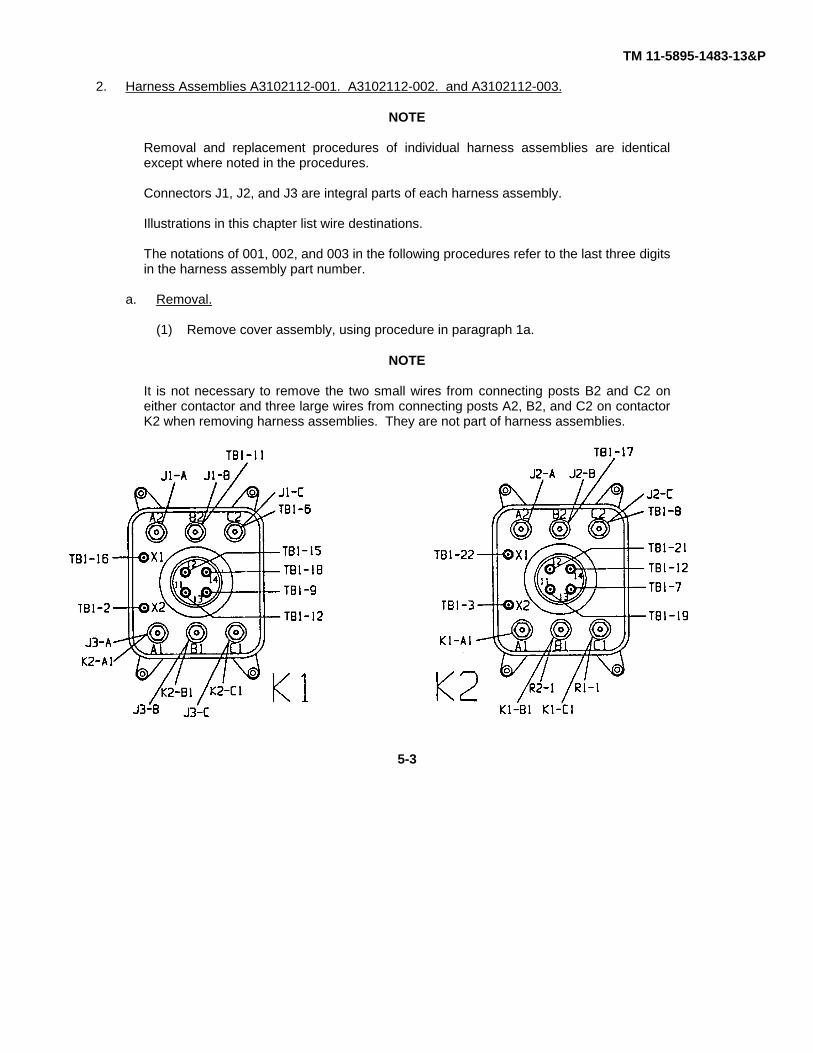
(5) On ground terminal strip, remove:
(a) For harness 001 - Four screws, lockwashers, and flat washers and four long green wirescoming from connector J1 (POWER SOURCE INPUT NO. 1).
(b) For harness 002 - Four screws, lockwashers, and flat washers and four short green wirescoming from connector J2 (POWER SOURCE INPUT NO. 2).
(c) For harness 003 - Four screws, lockwashers, and flat washers and four medium length greenwires coming from connector J3 (POWER OUTPUT).
(6) On neutral busbar, remove one screw, lockwasher, and flat washer:
(a) For harness 001 - From terminal No. 1: remove one large wire.
(b) For harness 002 - From terminal No. 2: remove one large wire.
(c) For harness 003 - From terminal No. 3: remove one large wire.
(d) Do not remove small wire connected to terminal 4.
5-5
TM 11-5895-1483-13&P
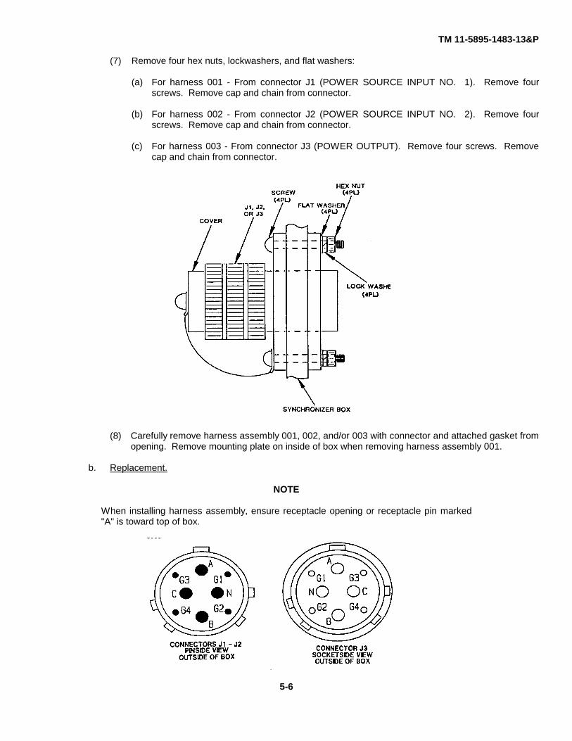
(7) Remove four hex nuts, lockwashers, and flat washers:
(a) For harness 001 - From connector J1 (POWER SOURCE INPUT NO. 1). Remove fourscrews. Remove cap and chain from connector.
(b) For harness 002 - From connector J2 (POWER SOURCE INPUT NO. 2). Remove fourscrews. Remove cap and chain from connector.
(c) For harness 003 - From connector J3 (POWER OUTPUT). Remove four screws. Removecap and chain from connector.
(8) Carefully remove harness assembly 001, 002, and/or 003 with connector and attached gasket fromopening. Remove mounting plate on inside of box when removing harness assembly 001.
b. Replacement.
NOTE
When installing harness assembly, ensure receptacle opening or receptacle pin marked"A" is toward top of box.
5-6
TM 11-5895-1483-13&P
(1) Carefully guide wires of harness assembly 001, 002, and/or 003 through respective opening in box andloosely seat connector and gasket over screw holes. When installing harness assembly 001, ensuremounting plate is in place on inside of box.
(2) Insert four screws through connector, gasket, and mounting plate and through holes in box, ensuring capand chain are attached to:(a) For J1 (POWER SOURCE INPUT NO. 1) - On lower left screw.(b) For J2 (POWER SOURCE INPUT NO. 2) - On lower right screw.(c) For J3 (POWER OUTPUT) - On lower left screw.
(3) Install four hex nuts, lockwashers, and flat washers on screws for connectors JI, J2, and/or J3. Tightensecurely.
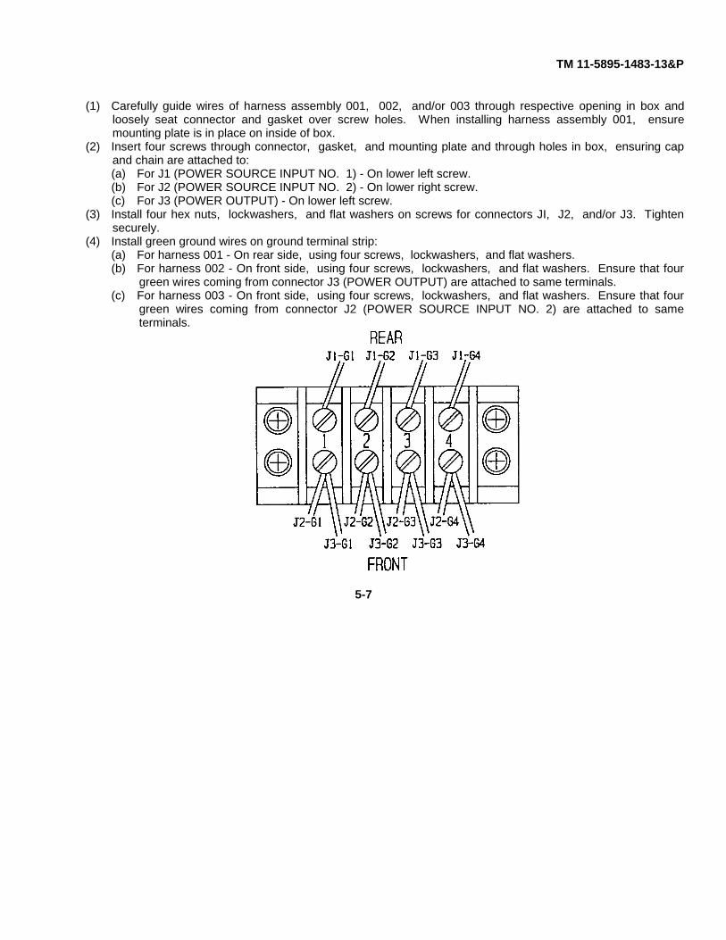
(4) Install green ground wires on ground terminal strip:(a) For harness 001 - On rear side, using four screws, lockwashers, and flat washers.(b) For harness 002 - On front side, using four screws, lockwashers, and flat washers. Ensure that four
green wires coming from connector J3 (POWER OUTPUT) are attached to same terminals.(c) For harness 003 - On front side, using four screws, lockwashers, and flat washers. Ensure that four
green wires coming from connector J2 (POWER SOURCE INPUT NO. 2) are attached to sameterminals.
5-7
TM 11-5895-1483-13&P
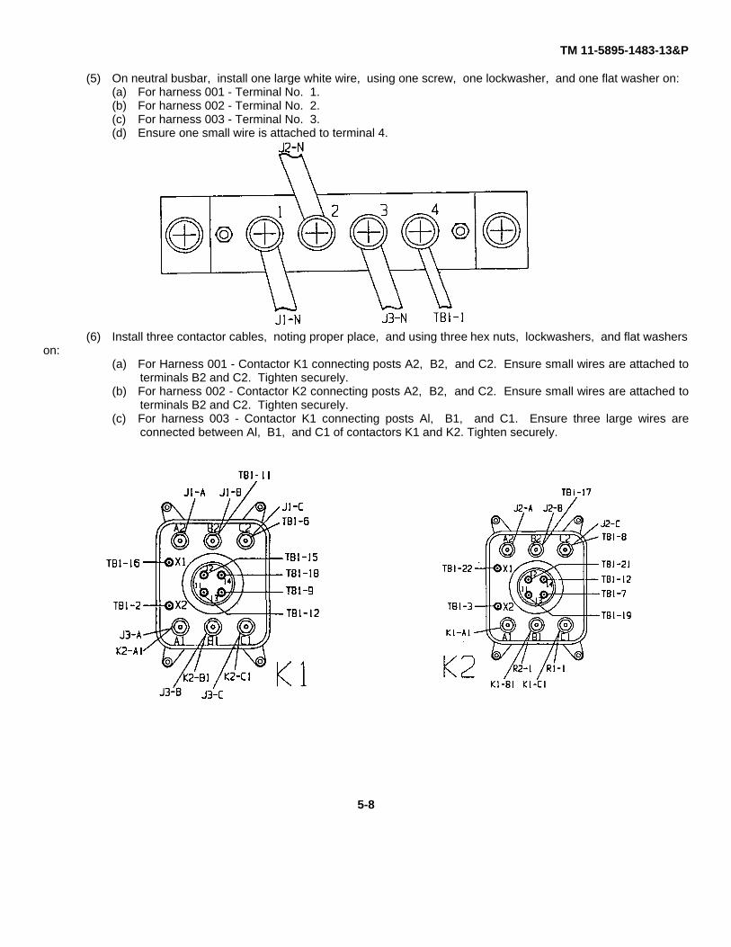
(5) On neutral busbar, install one large white wire, using one screw, one lockwasher, and one flat washer on:(a) For harness 001 - Terminal No. 1.(b) For harness 002 - Terminal No. 2.(c) For harness 003 - Terminal No. 3.(d) Ensure one small wire is attached to terminal 4.
(6) Install three contactor cables, noting proper place, and using three hex nuts, lockwashers, and flat washerson:
(a) For Harness 001 - Contactor K1 connecting posts A2, B2, and C2. Ensure small wires are attached toterminals B2 and C2. Tighten securely.
(b) For harness 002 - Contactor K2 connecting posts A2, B2, and C2. Ensure small wires are attached toterminals B2 and C2. Tighten securely.
(c) For harness 003 - Contactor K1 connecting posts Al, B1, and C1. Ensure three large wires areconnected between Al, B1, and C1 of contactors K1 and K2. Tighten securely.
5-8

TM 11-5895-1483-13&P
(7) Install the protective cover on applicable contactor.(8) Install two flat washers, lockwashers, and hex nuts on connecting posts X1 and X2, ensuring a small wire is
attached to each post. Tighten securely.(9) Install cover assembly, using procedure in paragraph lb.
3. Component Mounting Plate.a. Removal.
(1) Remove cover assembly, using procedure in paragraph la.(2) Remove harness assemblies A3102112-001, A3102112-002, and A3102112-003, using procedure in
paragraph 2a.(3) Remove 18 screws from right side of TB1.Remove 18 small white wires taking note of ID tags for
replacement later.
(4) Remove six screws, lockwashers, and flat washers holding the component mounting plate to the box.CAUTION
Be extremely careful when liftingcomponent mounting plate so that nowires or cables are broken.
(5) Carefully lift component mounting plate and remove it from synchronizer box with all components stillmounted.
5-9
TM 11-5895-1483-13&P
b. Replacement.(1) After individual components on component mounting plate have been tested and/or replaced, carefully
lower component mounting plate to bottom of box, lining up mounting holes with brackets on bottom ofbox.
(2) Insert six screws, lockwashers, and flat washers holding component mounting plate to bottom of box.Ensure cable clamp holding small white wire bundle is secured to front right corner of plate with one ofthe screws. Tighten all screws securely.
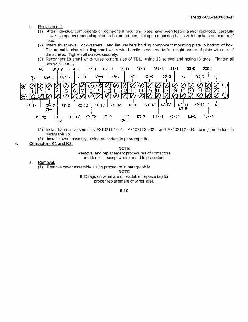
(3) Reconnect 18 small white wires to right side of TB1, using 18 screws and noting ID tags. Tighten allscrews securely.
(4) Install harness assemblies A3102112-001, A3102112-002, and A3102112-003, using procedure inparagraph 2b.
(5) Install cover assembly, using procedure in paragraph lb.4. Contactors K1 and K2.
NOTERemoval and replacement procedures of contactors
are identical except where noted in procedure.a. Removal.
(1) Remove cover assembly, using procedure in paragraph la.NOTE
If ID tags on wires are unreadable, replace tag forproper replacement of wires later.
5-10
TM 11-5895-1483-13&P
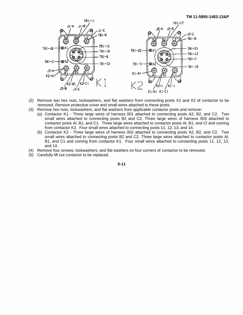
(2) Remove two hex nuts, lockwashers, and flat washers from connecting posts X1 and X2 of contactor to beremoved. Remove protective cover and small wires attached to these posts.
(3) Remove hex nuts, lockwashers, and flat washers from applicable contactor posts and remove:(a) Contactor K1 - Three large wires of harness 001 attached to connecting posts A2, B2, and C2. Two
small wires attached to connecting posts B2 and C2. Three large wires of harness 003 attached tocontactor posts Al, B1, and C1. Three large wires attached to contactor posts Al, B1, and Cl and comingfrom contactor K2. Four small wires attached to connecting posts 11, 12, 13, and 14.
(b) Contactor K2 - Three large wires of harness 002 attached to connecting posts A2, B2, and C2. Twosmall wires attached to connecting posts B2 and C2. Three large wires attached to contactor posts Al,B1, and C1 and coming from contactor K1. Four small wires attached to connecting posts 11, 12, 13,and 14.
(4) Remove four screws, lockwashers, and flat washers on four corners of contactor to be removed.(5) Carefully lift out contactor to be replaced.
5-11

TM 11-5895-1483-13&P
b. Replacement.(1) Place new contactor on component mounting plate, line up holes, and insert four mounting screws
through four corners of contactor and into component mounting plate fasteners. Tighten securely.(2) Using hex nuts, lockwashers and flat washers, install the following:
(a) Contactor K1 - Three large wires of harness 001 to connecting posts A2, B2, and C2. Two smallwires to connecting posts B2 and C2. Three large wires of harness 003 to contactor posts Al, B1,and Cl. Three large wires to contactor posts Al, B1, and C1 and coming from contactor K2. Foursmall wires to connecting posts 11, 12, 13, and 14.
(b) Contactor K2 - Three large wires of harness 002 to connecting posts A2, B2, and C2. Two smallwires to connecting posts B2 and C2. Three large wires to contactor posts Al, B1, and C1 andcoming from contactor K1. Four small wires to connecting posts 11, 12, 13. and 14.
(3) Install protective cover on applicable contactor.(4) Install two small wires on connecting posts X1 and X2 of applicable contactor. Install two hex nuts,
lockwashers, and flat washers on connecting posts X1 and X2 and tighten securely.(5) Install cover assembly using, procedure in paragraph lb.
5-12
TM 11-5895-1483-13&P
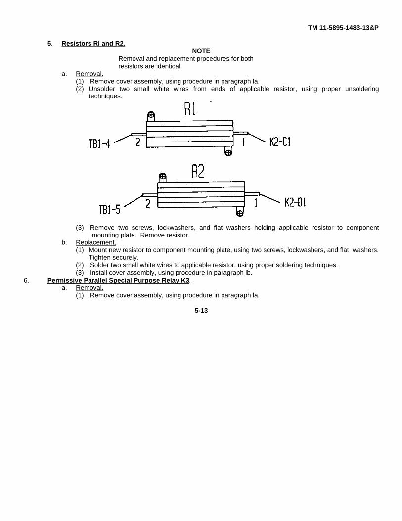
5. Resistors RI and R2.NOTE
Removal and replacement procedures for bothresistors are identical.
a. Removal.(1) Remove cover assembly, using procedure in paragraph la.(2) Unsolder two small white wires from ends of applicable resistor, using proper unsoldering
techniques.
(3) Remove two screws, lockwashers, and flat washers holding applicable resistor to componentmounting plate. Remove resistor.
b. Replacement.(1) Mount new resistor to component mounting plate, using two screws, lockwashers, and flat washers.
Tighten securely.(2) Solder two small white wires to applicable resistor, using proper soldering techniques.(3) Install cover assembly, using procedure in paragraph lb.
6. Permissive Parallel Special Purpose Relay K3.a. Removal.
(1) Remove cover assembly, using procedure in paragraph la.
5-13
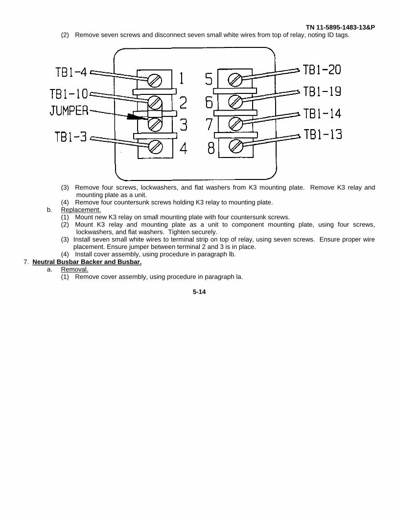
TN 11-5895-1483-13&P(2) Remove seven screws and disconnect seven small white wires from top of relay, noting ID tags.
(3) Remove four screws, lockwashers, and flat washers from K3 mounting plate. Remove K3 relay andmounting plate as a unit.
(4) Remove four countersunk screws holding K3 relay to mounting plate.b. Replacement.
(1) Mount new K3 relay on small mounting plate with four countersunk screws.(2) Mount K3 relay and mounting plate as a unit to component mounting plate, using four screws,
lockwashers, and flat washers. Tighten securely.(3) Install seven small white wires to terminal strip on top of relay, using seven screws. Ensure proper wire
placement. Ensure jumper between terminal 2 and 3 is in place.(4) Install cover assembly, using procedure in paragraph lb.
7. Neutral Busbar Backer and Busbar.a. Removal.
(1) Remove cover assembly, using procedure in paragraph la.
5-14

TM 11-5895-1483-13&P
(2) Remove four screws, lockwashers, and flat washers holding three large wires on terminals 1, 2, and 3,and one small wire on terminal 4. Remove wires.
(3) Remove two screws, lockwashers, and flat washers from ends of busbar backer and busbar.
(4) Remove busbar backer and busbar as an assembly.(5) Remove phenolic insulator plate and set aside for later installation.
b. Replacement.(1) Install phenolic insulator plate.(2) Place new busbar backer and busbar assembly over mounting holes and secure with two screws, lockwashers, and flat washers.(3) Reconnect three large wires to terminals 1, 2, and 3, and one small wire to terminal 4. Tighten screws securely.(4)Install cover assembly, using procedure in paragraph lb.
8. Busbar.a. Removal.(1) Remove cover assembly, using procedure in paragraph la.(2) Remove busbar backer and busbar assembly, using procedure in paragraph 7a.(3) Remove two hex nuts, lockwashers, flat washers, and screws holding busbar to busbar backer.(4) Remove busbar from busbar backer.
5-15
TM 11-5895-1483-13&P
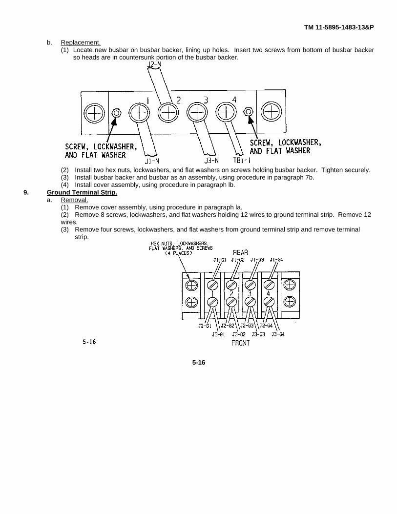
b. Replacement.(1) Locate new busbar on busbar backer, lining up holes. Insert two screws from bottom of busbar backer
so heads are in countersunk portion of the busbar backer.
(2) Install two hex nuts, lockwashers, and flat washers on screws holding busbar backer. Tighten securely.(3) Install busbar backer and busbar as an assembly, using procedure in paragraph 7b.(4) Install cover assembly, using procedure in paragraph lb.
9. Ground Terminal Strip.a. Removal.
(1) Remove cover assembly, using procedure in paragraph la.(2) Remove 8 screws, lockwashers, and flat washers holding 12 wires to ground terminal strip. Remove 12 wires.(3) Remove four screws, lockwashers, and flat washers from ground terminal strip and remove terminal
strip.
5-16
TM 11-5895-1483-13&P
b. Replacement.(1) Secure new ground terminal strip to component mounting plate, using four screws, lockwashers and flat
washers. Tighten securely.(2) Noting proper location, install 12 wires on ground strip using 4 screws, lockwashers, and flat washers.
Tighten securely.(3) Install cover assembly, using procedure in paragraph lb.
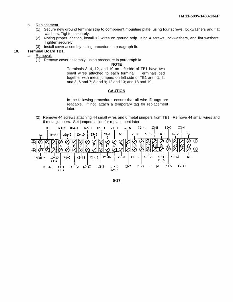
10. Terminal Board TB1.a. Removal.
(1) Remove cover assembly, using procedure in paragraph la.NOTE
Terminals 3, 4, 12, and 19 on left side of TB1 have twosmall wires attached to each terminal. Terminals tiedtogether with metal jumpers on left side of TB1 are: 1, 2,and 3; 6 and 7; 8 and 9; 12 and 13; and 18 and 19.
CAUTION
In the following procedure, ensure that all wire ID tags arereadable. If not, attach a temporary tag for replacementlater.
(2) Remove 44 screws attaching 44 small wires and 6 metal jumpers from TB1. Remove 44 small wires and6 metal jumpers. Set jumpers aside for replacement later.
5-17

TM 11-5895-1483-13&P
(3) Remove four screws, lockwashers, and flat washers holding TB1 to component mounting plate.(4) Remove TBI.
b. Replacement.(1) Install jumpers on left side of new TB1 terminal strip between terminals 1, 2, and 3; terminals 6 and 7;
terminals 8 and 9; terminals 12 and 13; and terminals 18 and 19. Secure with four screws in terminals 1,2, 6, 8, 13 and 19. Do not tighten as wires will be attached to these terminals later.
(2) Secure new TB1 to component mounting plate with four screws, lockwashers and flat washers. Tightensecurely.
(3) Install 44 small wires on TB1, using 44 screws. Ensure six metal jumpers are in place. Ensureterminals 3, 4, 12, and 16 have two small wires attached to them. Tighten all screws securely.
(4) Install cover assembly, using procedure in paragraph lb.11. Indicator Lights DS1 thru DS6.
a. Removal.(1) Remove cover assembly, using procedure in paragraph la.
NOTERemoval procedures for DS1 thru DS6 are identicalexcept for the number of wires removed and connectionpoints.
5-18
TM 11-5895-1483-13&P
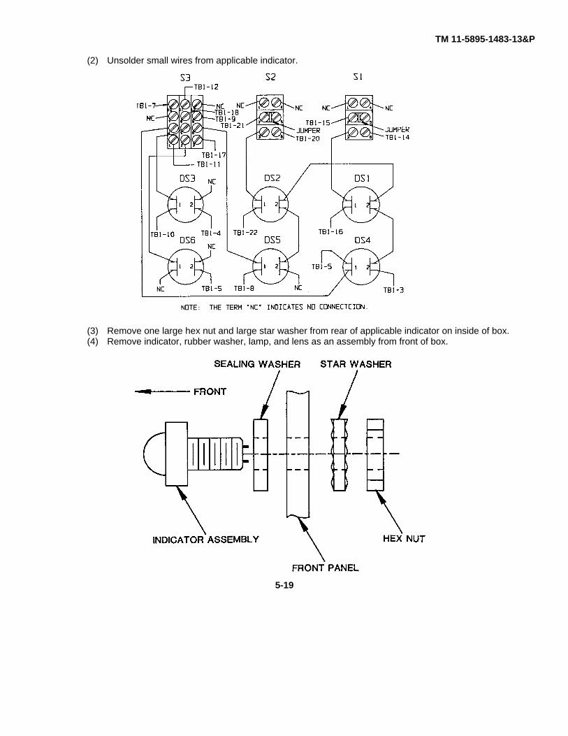
(2) Unsolder small wires from applicable indicator.
(3) Remove one large hex nut and large star washer from rear of applicable indicator on inside of box.(4) Remove indicator, rubber washer, lamp, and lens as an assembly from front of box.
5-19
TM 11-5895-1483-13&P
b. Replacement.(1) Install new indicator, with rubber washer in place, through opening from outside front of box.(2) Place one large star washer and large hex nut on indicator assembly from inside of box and tighten securely.(3) Install small wires on applicable indicator, and solder in place.(4) Install cover assembly, using procedure in paragraph lb.
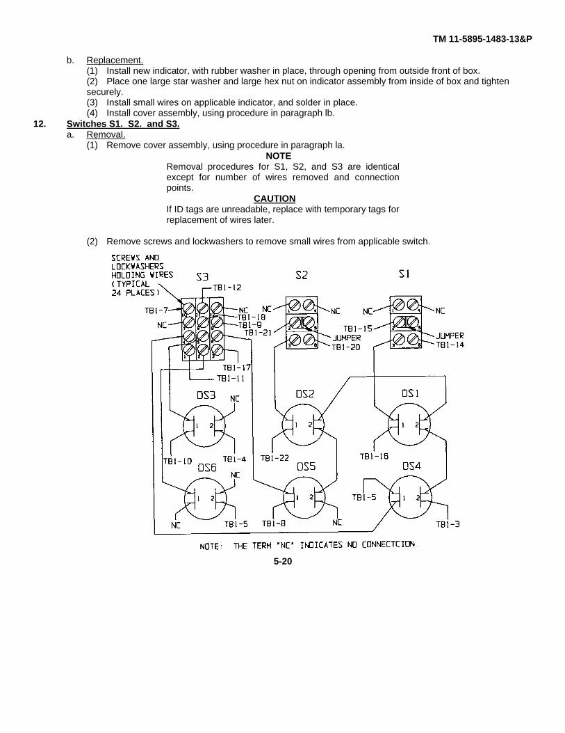
12. Switches S1. S2. and S3.a. Removal.
(1) Remove cover assembly, using procedure in paragraph la.NOTE
Removal procedures for S1, S2, and S3 are identicalexcept for number of wires removed and connectionpoints.
CAUTIONIf ID tags are unreadable, replace with temporary tags forreplacement of wires later.
(2) Remove screws and lockwashers to remove small wires from applicable switch.
5-20
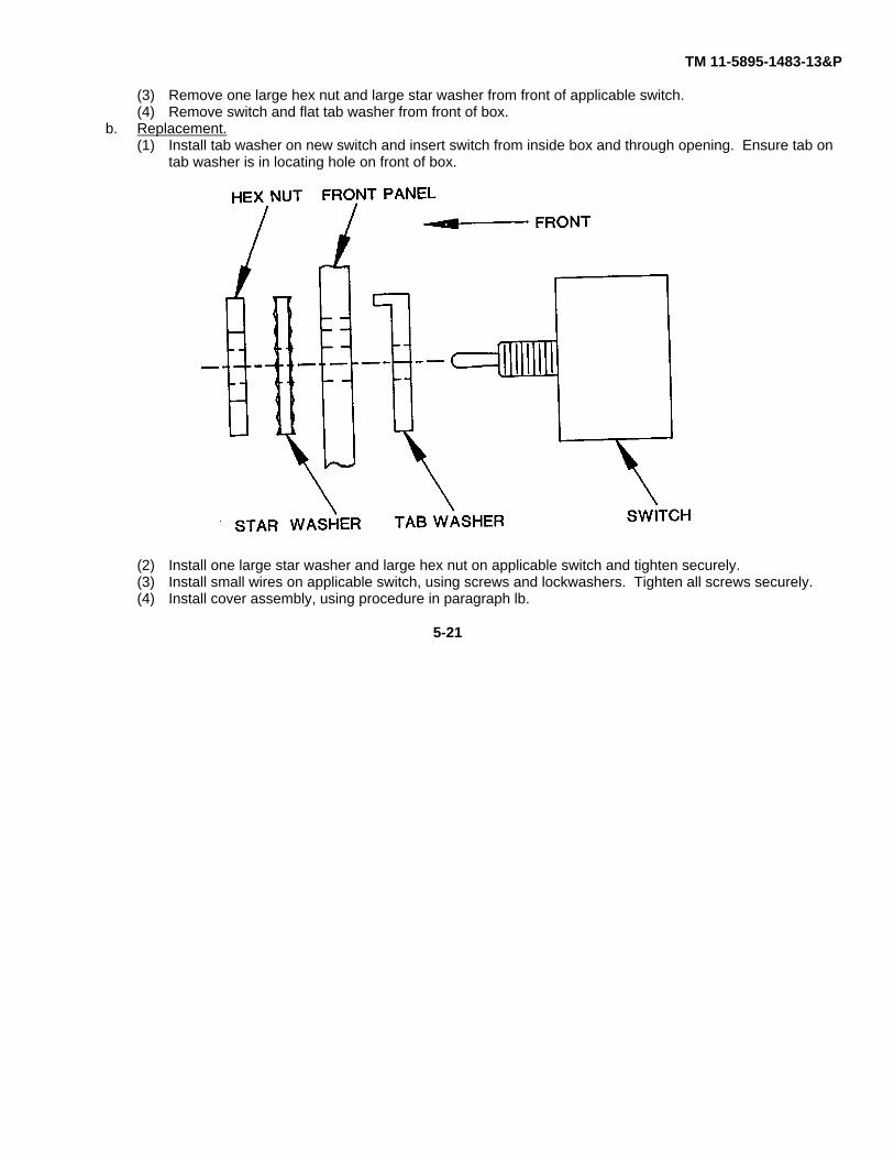
TM 11-5895-1483-13&P
(3) Remove one large hex nut and large star washer from front of applicable switch.(4) Remove switch and flat tab washer from front of box.
b. Replacement.(1) Install tab washer on new switch and insert switch from inside box and through opening. Ensure tab on
tab washer is in locating hole on front of box.
(2) Install one large star washer and large hex nut on applicable switch and tighten securely.(3) Install small wires on applicable switch, using screws and lockwashers. Tighten all screws securely.(4) Install cover assembly, using procedure in paragraph lb.
5-21
TM 11-5895-1483-13&P
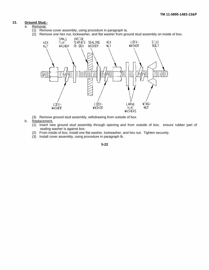
13. Ground Stud.-a. Removal.
(1) Remove cover assembly, using procedure in paragraph la.(2) Remove one hex nut, lockwasher, and flat washer from ground stud assembly on inside of box.
(3) Remove ground stud assembly, withdrawing from outside of box.b. Replacement.
(1) Insert new ground stud assembly through opening and from outside of box. ensure rubber part ofsealing washer is against box.
(2) From inside of box, install one flat washer, lockwasher, and hex nut. Tighten securely.(3) Install cover assembly, using procedure in paragraph lb.
5-22

TM 11-5895-1483-13&PCHAPTER 6
TESTING AND TROUBLESHOOTING
PAGESection I Introduction ........................................................................................................................ 6-1Section II Operational Testing ............................................................................................................ 6-1Section III Troubleshooting.................................................................................................................. 6-1Section IV Synchronizer Box Schematic ............................................................................................ 6-9
Section I. INTRODUCTIONITEM PAGEGeneral ............................................................................................................................................ 6-1
GENERAL
This chapter provides information on testing the synchronizer box as an assembly and troubleshooting individualcomponents to determine if a component is defective prior to removing or replacing.
Section II. OPERATIONAL TESTINGITEM PAGEOperational Testing .................................................................................................................................. 6-1
OPERATIONAL TESTING
Follow procedures in chapter 2, section III.
Section III. TROUBLESHOOTINGITEM PAGEComponent Troubleshooting .................................................................................................................... 6-2
Permissive Relay K3 ....................................................................................................................... 6-2Switches S1 and S2 ........................................................................................................................ 6-3Switch S3 ........................................................................................................................... 6-4Contactors Ki and K2....................................................................................................................... 6-5Wiring Troubleshooting ................................................................................................................... 6-6
Indicator Light Sockets Troubleshooting .................................................................................................. 6-8
6-1

TM 11-5895-1483-13&P
COMPONENT TROUBLESHOOTING I
a. Permissive Relay K3.(1) Remove all wires connected to relay K3.If wire markers are unreadable, attach temporary marker.(2) Remove jumper connected to terminals 2 and 3.(3) Connect jumper between terminals 6 and 7.
(4) Connect variable ac autotransformer power supply across terminals 1 and 2. Adjust autotransformer for a 60Hz, zero V ac output.(5) Connect VOM M1 (set for ac voltage to monitor autotransformer output) to terminals 1 and 2.(6) Connect VOM M2 (set for ohms to monitor contact status) to terminals 5 and 8.(7) Apply 120 V ac power source across terminals 3 and 4.(8) VOM M2 should read zero ohms and VOM M1 should read zero V ac at this point in test procedure.(9) Increase autotransformer output to value of 20 V ac as indicated by VOM M1. Relay contacts shall have
opened as indicated by VOM M2 reading infinity.(10) Slowly decrease autotransformer output until relay contacts close, indicated by VOM M2 reading zero ohms.
This should occur at 8 +1 V ac, as indicated by VOM M1.(11) Slowly increase autotransformer output until relay contacts open, indicated by VOM M2 reading infinity. This
should occur at no more than 1 volt above contact closing measured in step (10) and indicated on VOM M1.
6-2

TM 11-5895-1483-13&P(12) If all indications above are met, relay is good. Install all wires removed in step (1). Remove jumper from
terminals 6 and 7 connected in step (3) and install on terminals 2 and 3.(13) If any indication is not met, relay is defective and should be replaced by following the procedure in Chapter 5,
section III.b. Switches SI and S2.
(1) Remove all wires from applicable switch. If wire markers are unreadable, attach temporary marker.(2) Remove jumper connected to terminals 2 and 5.
(3) Connect VOM to show continuity across terminals listed in table 6-1. Readings should agree with those listedin CONTACT STATUS column.
Table 6-1. Switches S1 and S2 Troubleshooting
SWITCH CENTER ON LINE OFF LINEPOSITIONTERMINALS CONTACT STATUS1 TO 2 OPEN OPEN CLOSED2 TO 3 CLOSED CLOSED OPEN3 TO 4 OPEN OPEN OPEN4 TO 5 CLOSED OPEN CLOSED5 TO 6 OPEN CLOSED OPEN
(4) If all readings agree with those in table 6-1, switch is good. Replace all wires and jumper removed in steps(1) and (2).
6-3
TM 11-5895-1483-13&P
(5) If any reading differs with those in table 6-1, switch is defective. Replace switch, using procedure in chapter5, section III.
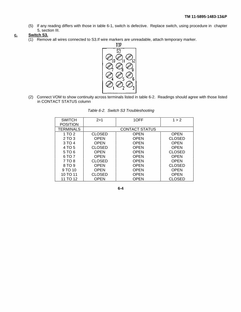
c. Switch S3.(1) Remove all wires connected to S3.If wire markers are unreadable, attach temporary marker.
(2) Connect VOM to show continuity across terminals listed in table 6-2. Readings should agree with those listedin CONTACT STATUS column
Table 6-2. Switch S3 Troubleshooting
SWITCH 2>1 1OFF 1 > 2POSITION
TERMINALS CONTACT STATUS1 TO 2 CLOSED OPEN OPEN2 TO 3 OPEN OPEN CLOSED3 TO 4 OPEN OPEN OPEN4 TO 5 CLOSED OPEN OPEN5 TO 6 OPEN OPEN CLOSED6 TO 7 OPEN OPEN OPEN7 TO 8 CLOSED OPEN OPEN8 TO 9 OPEN OPEN CLOSED9 TO 10 OPEN OPEN OPEN10 TO 11 CLOSED OPEN OPEN11 TO 12 OPEN OPEN CLOSED
6-4
TM 11-5895-1483-13&P
(3) If all readings agree with those in table 6-2, switch is good. Replace all wires removed in step (1).(4) If any reading differs from those in table 6-2, switch is defective. Replace switch, using procedure in Chapter
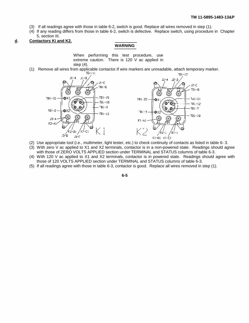
5, section III.d. Contactors Ki and K2.
WARNING
When performing this test procedure, useextreme caution. There is 120 V ac applied instep (4).
(1) Remove all wires from applicable contactor.If wire markers are unreadable, attach temporary marker.
(2) Use appropriate tool (i.e., multimeter, light tester, etc.) to check continuity of contacts as listed in table 6- 3.(3) With zero V ac applied to X1 and X2 terminals, contactor is in a non-powered state. Readings should agree
with those of ZERO VOLTS APPLIED section under TERMINAL and STATUS columns of table 6-3.(4) With 120 V ac applied to X1 and X2 terminals, contactor is in powered state. Readings should agree with
those of 120 VOLTS APPLIED section under TERMINAL and STATUS columns of table 6-3.(5) If all readings agree with those in table 6-3, contactor is good. Replace all wires removed in step (1).
6-5

TM 11-5895-1483-13&P
(6) If any reading differs from those in table 6-3, contactor is defective. Replace contactor, using procedure inChapter 5, section III.
Table 6-3. Contactors KI and K2 Troubleshooting
K1 and K2 CONTACTORS
VOLTAGE APPLIED TERMINAL STATUSZERO VAC Al TO A2 OPENAPPLIED B1 TO B2 OPENACROSS C1 TO C2 OPEN
X1 AND X2 11 TO 12 OPENTERMINALS 13 TO 14 CLOSED
120 VAC Al TO A2 CLOSEDAPPLIED B1 TO B2 CLOSEDACROSS C1 TO C2 CLOSED
X1 AND X2 11 TO 12 CLOSEDTERMINALS 13 TO 14 OPEN
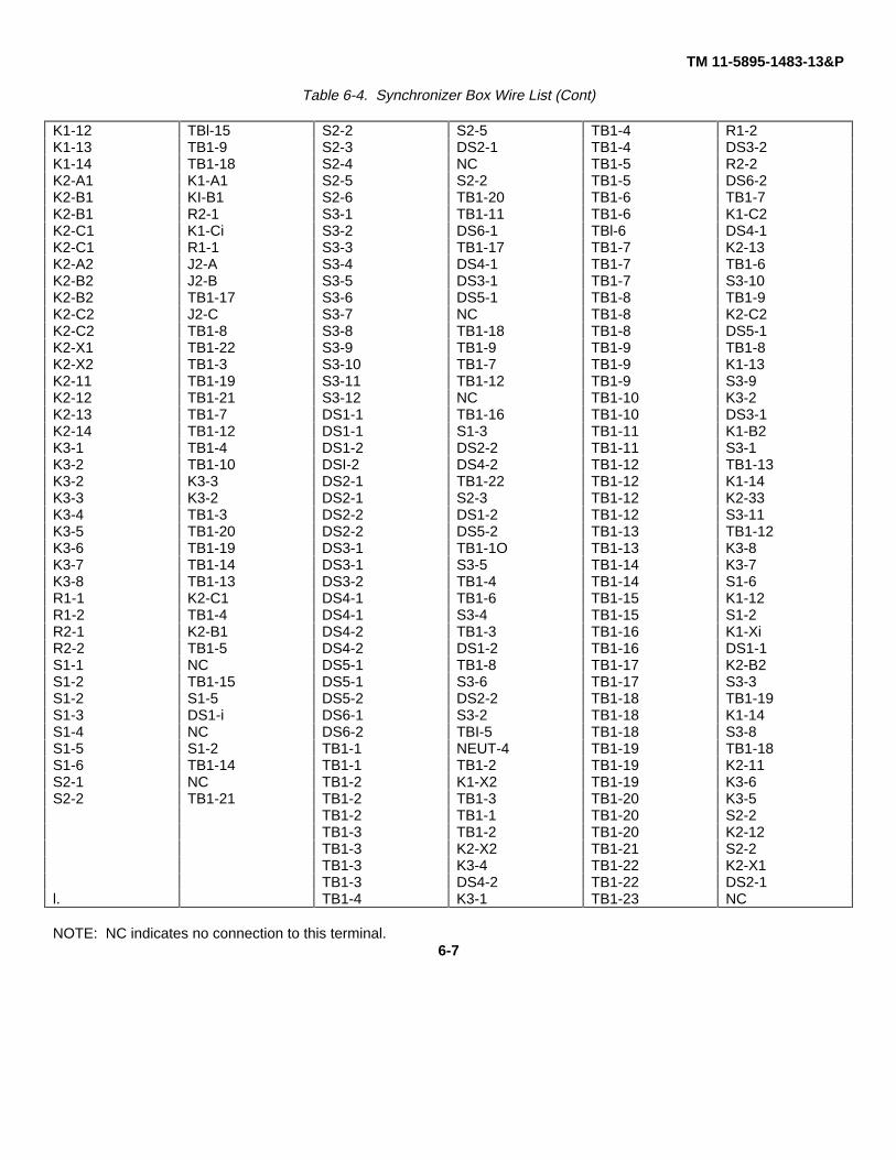
Wiring Troubleshooting
1. Use appropriate tool (i.e., multimeter, light tester, etc.) to check continuity between points as listed in table 6-4.Table 6-4. Synchronizer Box Wire List
JI-A K1-A2 J3-C K1-C1 GND-3 J3-G331-B K1-B2 J3-N NEUT-3 GND-4 J1-G4J1-C K1-C2 J3-G1 GND-1 K1-A1 J3-AJ1-N NEUT-1 J3-G2 GND-2 K1-A1 K2-A1J1-G1 GND-1 J3-G2 GND-3 K1-B1 J3-BJ1-G2 GND-2 J3-G4 GND-4 K1-B1 K2-B131-G3 GND-3 NEUT-1 J1-N K1-C1 J3-CJ1-G4 GND-4 NEUT-2 J2-N K1-C1 K2-C1J2-A K2-A2 NEUT-3 J3-N K1-A2 J1-AJ2-B K2-B2 NUET-4 TB1-1 K1-B2 J1-BJ2-C K2-C2 GND-1 J1-GI K1-B2 TB1-11J2-N NEUT-2 GND-1 J2-G1 K1-C1 J1-CJ2-G1 GND-1 GND-1 J3-G1 K1-C2 TB1-6J2-G2 GND-2 GND-2 J1-G2 K1-X1 TB1-16J2-G3 GND-3 GND-2 J2-G2 K1-X2 TB1-2J2-G4 GND-4 GND-2 J3-G2 K1-ll TB1-12J3-A K1-A1 GND-3 J1-G3J3-B K1-B1 GND-3 J2-G3
6-6
TM 11-5895-1483-13&P
Table 6-4. Synchronizer Box Wire List (Cont)
K1-12 TBl-15 S2-2 S2-5 TB1-4 R1-2K1-13 TB1-9 S2-3 DS2-1 TB1-4 DS3-2K1-14 TB1-18 S2-4 NC TB1-5 R2-2K2-A1 K1-A1 S2-5 S2-2 TB1-5 DS6-2K2-B1 KI-B1 S2-6 TB1-20 TB1-6 TB1-7K2-B1 R2-1 S3-1 TB1-11 TB1-6 K1-C2K2-C1 K1-Ci S3-2 DS6-1 TBl-6 DS4-1K2-C1 R1-1 S3-3 TB1-17 TB1-7 K2-13K2-A2 J2-A S3-4 DS4-1 TB1-7 TB1-6K2-B2 J2-B S3-5 DS3-1 TB1-7 S3-10K2-B2 TB1-17 S3-6 DS5-1 TB1-8 TB1-9K2-C2 J2-C S3-7 NC TB1-8 K2-C2K2-C2 TB1-8 S3-8 TB1-18 TB1-8 DS5-1K2-X1 TB1-22 S3-9 TB1-9 TB1-9 TB1-8K2-X2 TB1-3 S3-10 TB1-7 TB1-9 K1-13K2-11 TB1-19 S3-11 TB1-12 TB1-9 S3-9K2-12 TB1-21 S3-12 NC TB1-10 K3-2K2-13 TB1-7 DS1-1 TB1-16 TB1-10 DS3-1K2-14 TB1-12 DS1-1 S1-3 TB1-11 K1-B2K3-1 TB1-4 DS1-2 DS2-2 TB1-11 S3-1K3-2 TB1-10 DSI-2 DS4-2 TB1-12 TB1-13K3-2 K3-3 DS2-1 TB1-22 TB1-12 K1-14K3-3 K3-2 DS2-1 S2-3 TB1-12 K2-33K3-4 TB1-3 DS2-2 DS1-2 TB1-12 S3-11K3-5 TB1-20 DS2-2 DS5-2 TB1-13 TB1-12K3-6 TB1-19 DS3-1 TB1-1O TB1-13 K3-8K3-7 TB1-14 DS3-1 S3-5 TB1-14 K3-7K3-8 TB1-13 DS3-2 TB1-4 TB1-14 S1-6R1-1 K2-C1 DS4-1 TB1-6 TB1-15 K1-12R1-2 TB1-4 DS4-1 S3-4 TB1-15 S1-2R2-1 K2-B1 DS4-2 TB1-3 TB1-16 K1-XiR2-2 TB1-5 DS4-2 DS1-2 TB1-16 DS1-1S1-1 NC DS5-1 TB1-8 TB1-17 K2-B2S1-2 TB1-15 DS5-1 S3-6 TB1-17 S3-3S1-2 S1-5 DS5-2 DS2-2 TB1-18 TB1-19S1-3 DS1-i DS6-1 S3-2 TB1-18 K1-14S1-4 NC DS6-2 TBI-5 TB1-18 S3-8S1-5 S1-2 TB1-1 NEUT-4 TB1-19 TB1-18S1-6 TB1-14 TB1-1 TB1-2 TB1-19 K2-11S2-1 NC TB1-2 K1-X2 TB1-19 K3-6S2-2 TB1-21 TB1-2 TB1-3 TB1-20 K3-5
TB1-2 TB1-1 TB1-20 S2-2TB1-3 TB1-2 TB1-20 K2-12TB1-3 K2-X2 TB1-21 S2-2TB1-3 K3-4 TB1-22 K2-X1TB1-3 DS4-2 TB1-22 DS2-1
l. TB1-4 K3-1 TB1-23 NC
NOTE: NC indicates no connection to this terminal.6-7
TN 11-5895-1483-13&P
2. If any reading between points in table 6-4 does not show continuity, wire is probably broken and must bereplaced.
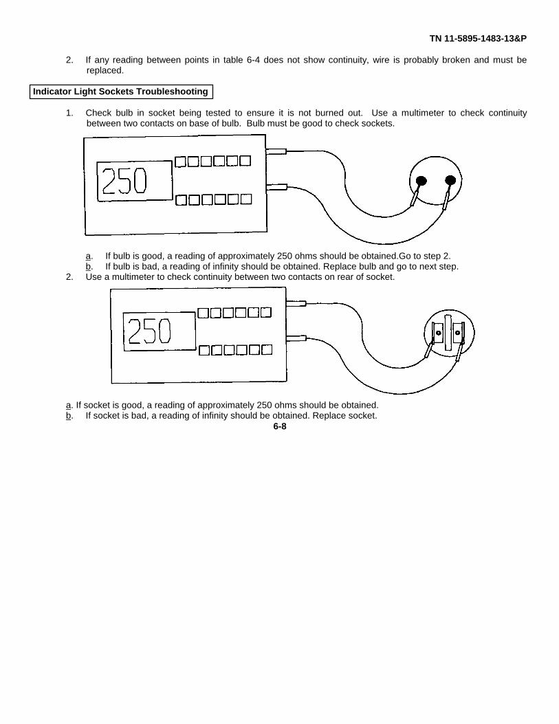
Indicator Light Sockets Troubleshooting
1. Check bulb in socket being tested to ensure it is not burned out. Use a multimeter to check continuitybetween two contacts on base of bulb. Bulb must be good to check sockets.
a. If bulb is good, a reading of approximately 250 ohms should be obtained.Go to step 2.b. If bulb is bad, a reading of infinity should be obtained. Replace bulb and go to next step.
2. Use a multimeter to check continuity between two contacts on rear of socket.
a. If socket is good, a reading of approximately 250 ohms should be obtained.b. If socket is bad, a reading of infinity should be obtained. Replace socket.
6-8
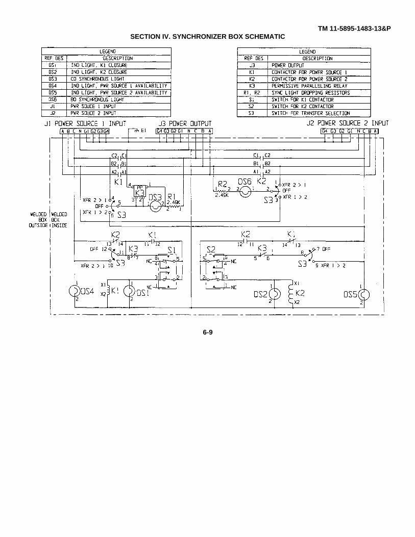
TM 11-5895-1483-13&PSECTION IV. SYNCHRONIZER BOX SCHEMATIC
6-9
TM 11-5895-1483-13&PAPPENDIX A
REFERENCES
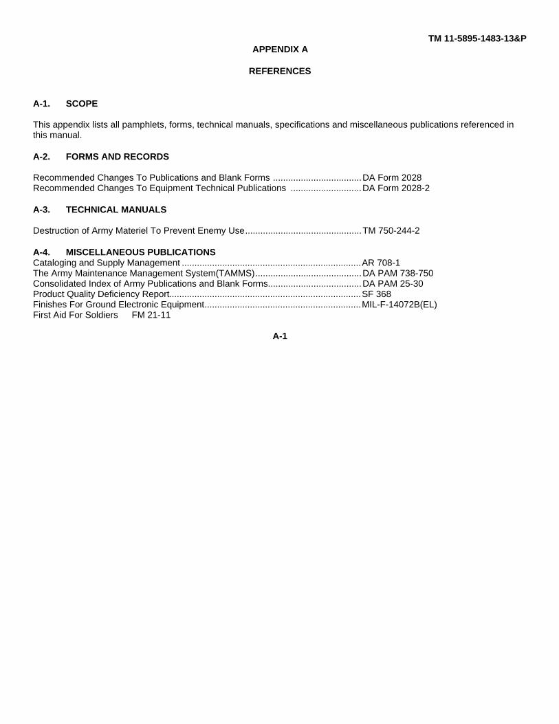
A-1. SCOPE
This appendix lists all pamphlets, forms, technical manuals, specifications and miscellaneous publications referenced inthis manual.
A-2. FORMS AND RECORDS
Recommended Changes To Publications and Blank Forms ...................................DA Form 2028Recommended Changes To Equipment Technical Publications ............................DA Form 2028-2
A-3. TECHNICAL MANUALS
Destruction of Army Materiel To Prevent Enemy Use..............................................TM 750-244-2
A-4. MISCELLANEOUS PUBLICATIONSCataloging and Supply Management .......................................................................AR 708-1The Army Maintenance Management System(TAMMS)..........................................DA PAM 738-750Consolidated Index of Army Publications and Blank Forms.....................................DA PAM 25-30Product Quality Deficiency Report............................................................................SF 368Finishes For Ground Electronic Equipment..............................................................MIL-F-14072B(EL)First Aid For Soldiers FM 21-11
A-1
TM 11-5895-1483-13&P
APPENDIX BMAINTENANCE ALLOCATION CHART
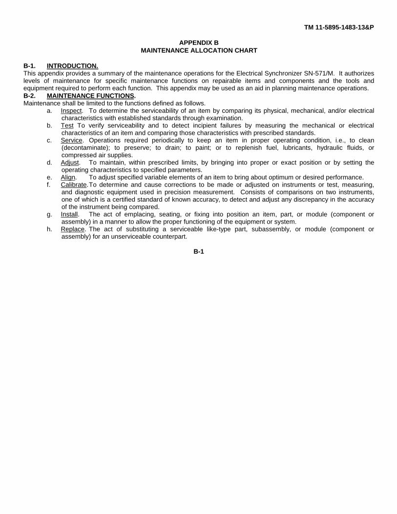
B-1. INTRODUCTION.This appendix provides a summary of the maintenance operations for the Electrical Synchronizer SN-571/M. It authorizeslevels of maintenance for specific maintenance functions on repairable items and components and the tools andequipment required to perform each function. This appendix may be used as an aid in planning maintenance operations.B-2. MAINTENANCE FUNCTIONS.Maintenance shall be limited to the functions defined as follows.
a. Inspect. To determine the serviceability of an item by comparing its physical, mechanical, and/or electricalcharacteristics with established standards through examination.
b. Test To verify serviceability and to detect incipient failures by measuring the mechanical or electricalcharacteristics of an item and comparing those characteristics with prescribed standards.
c. Service. Operations required periodically to keep an item in proper operating condition, i.e., to clean(decontaminate); to preserve; to drain; to paint; or to replenish fuel, lubricants, hydraulic fluids, orcompressed air supplies.
d. Adjust. To maintain, within prescribed limits, by bringing into proper or exact position or by setting theoperating characteristics to specified parameters.
e. Align. To adjust specified variable elements of an item to bring about optimum or desired performance.f. Calibrate.To determine and cause corrections to be made or adjusted on instruments or test, measuring,
and diagnostic equipment used in precision measurement. Consists of comparisons on two instruments,one of which is a certified standard of known accuracy, to detect and adjust any discrepancy in the accuracyof the instrument being compared.
g. Install. The act of emplacing, seating, or fixing into position an item, part, or module (component orassembly) in a manner to allow the proper functioning of the equipment or system.
h. Replace. The act of substituting a serviceable like-type part, subassembly, or module (component orassembly) for an unserviceable counterpart.
B-1
TN 11-5895-1483-13&P
i. Repair. The application of maintenance services (inspect, test, service, adjust, align, calibrate, or replace) orother maintenance actions (welding, grinding, riveting, straightening, facing, remachining, or resurfacing) torestore serviceability to an item by correcting specific damage, fault, malfunction, or failure in a part,subassembly, module (component or assembly), end item, or system.
j. Overhaul. That maintenance effort (service/action) necessary to restore an item to a completelyserviceable/operational condition as prescribed by maintenance standards in appropriate technicalpublications (e.g., DMWR). Overhaul is normally the highest degree of maintenance performed by the Army.Overhaul does not normally return an item to like-new condition.
k. Rebuild. Consists of those services/actions necessary for the restoration of unserviceable equipment to alike-new condition in accordance with original manufacturing standards. Rebuild is the highest degree ofmateriel maintenance applied to Army equipment. The rebuild operation includes the act of returning to zerothose age measurements (hours, miles, etc.) considered in classifying Army equipment/components
B-3. COLUMN ENTRIES (SECTION II).a. Column 1 - Group Number. Column 1 lists group numbers, the purpose of which is to identify components,
assemblies, subassemblies, and modules with next higher assemblyb. Column 2 - Component/Assembly. Column 2 contains the noun names of components, assemblies,
subassemblies, and modules for which maintenance is authorized.c. Column 3 - Maintenance Functions. Column 3 lists the functions to be performed on the item listed in
column 2. When items are listed without maintenance functions, it is solely for the purpose of having thegroup numbers in the MAC and RPSTL coincide.
d. Column 4 - Maintenance Level. Column 4 specifies, by the listing of a work time figure in the appropriatesubcolumn(s), the lowest level of maintenance authorized to perform the function listed in column 3. Thisfigure represents the active time required to perform that maintenance function at the indicated level ofmaintenance. If the number or complexity of the tasks within the listed maintenance function varies atdifferent maintenance levels, appropriate work time figures will be shown for each level. The number of task-hours specified by the work time figure represents the average time required to restore an item (assembly,subassembly, component, module, end item or system) to a serviceable condition under typical fieldoperating conditions. This time includes preparation time, troubleshooting time, and quality assurance/qualitycontrol time in addition to the time required to perform the specific tasks identified for the maintenancefunctions authorized in the MAC. Subcolumns of column 4 are as follows:
B-2
TN 11-5895-1483-13&P
C..............................................................Operator0 ..............................................................UnitF ..............................................................Direct SupportH..............................................................General SupportD..............................................................Depot
e. Column 5 - Tools and Equipment. Column 5 specifies by code those common tool sets (not individual tools)and special tools, test, and support equipment required to perform the designated function.
f. Column 6 - Remarks. Column 6 contains an alphabetic code which leads to the remark in Section IV,Remarks, which is pertinent to the item opposite the particular code.
B-4. TOOLS AND TEST EQUIPMENT REOUIREMENTS (SECTION III).a. Tool or Test Equipment Reference Code. The numbers in this column coincide with the numbers used in the
tools and equipment column of the MAC. The numbers indicate the applicable tool or test equipment for themaintenance functions.
b. Maintenance Level. The codes in this column indicate the maintenance level allocated the tool or testequipment.
c. Nomenclature. This column lists the noun name and nomenclature of the tools and test equipment requiredto perform the maintenance functions.
d. National/NATO Stock Numbers. This column lists the National/NATO stock number of the specific tool ortest equipment.
e. Tool Numbers. This column lists the manufacturer’s part number of the tool followed by the 5-digitCommercial and Government Entity (CAGE) in parentheses.
5-5. REMARKS (SECTION IV).a. Reference Code. This code refers to the appropriate item in section II, column 6.b. Remarks. This column provides the required explanatory information necessary to clarify items appearing in
section II.
B-3
TM 11-5895-1483-13&P
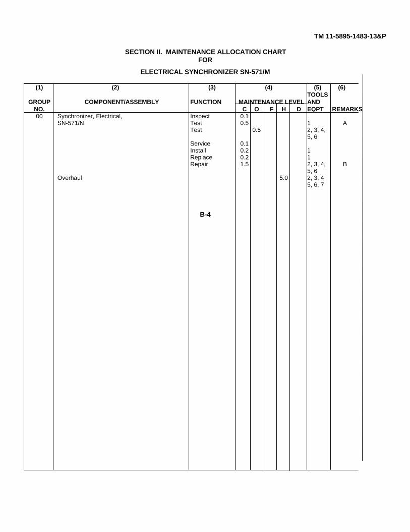
SECTION II. MAINTENANCE ALLOCATION CHARTFOR
ELECTRICAL SYNCHRONIZER SN-571/M
(1) (2) (3) (4) (5) (6)TOOLS
GROUP COMPONENT/ASSEMBLY FUNCTION MAINTENANCE LEVEL ANDNO. C O F H D EQPT REMARKS00 Synchronizer, Electrical, Inspect 0.1
SN-571/N Test 0.5 1 ATest 0.5 2, 3, 4,
5, 6Service 0.1Install 0.2 1Replace 0.2 1Repair 1.5 2, 3, 4, B
5, 6Overhaul 5.0 2, 3, 4
5, 6, 7
B-4
TM 11-5895-1493-13&P
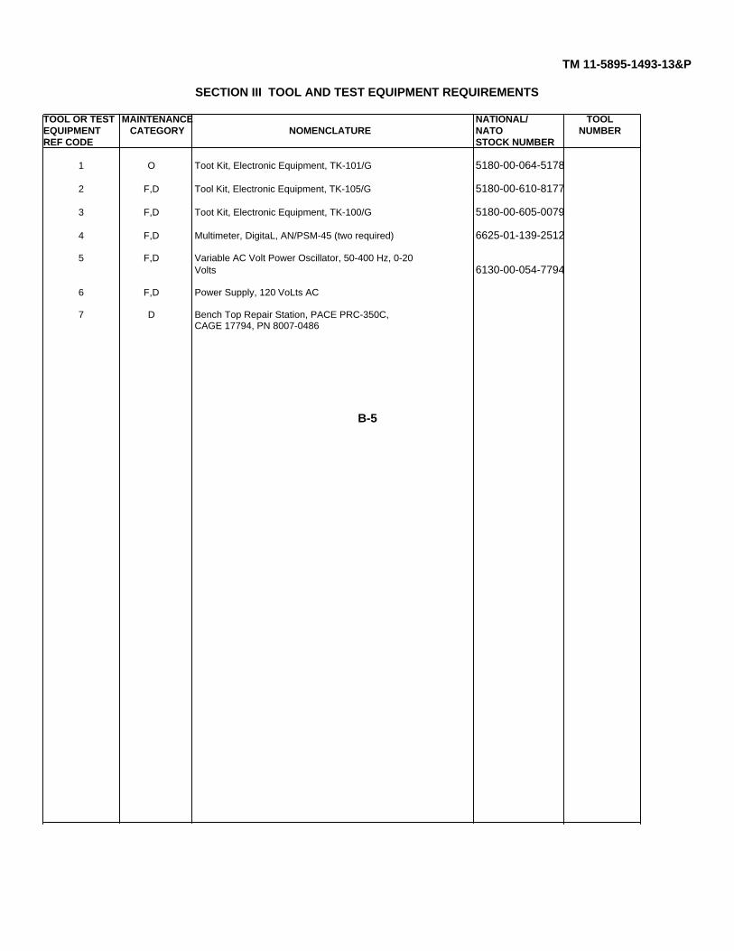
SECTION III TOOL AND TEST EQUIPMENT REQUIREMENTS
TOOL OR TEST MAINTENANCE NATIONAL/ TOOLEQUIPMENT CATEGORY NOMENCLATURE NATO NUMBERREF CODE STOCK NUMBER
1 O Toot Kit, Electronic Equipment, TK-101/G 5180-00-064-5178
2 F,D Tool Kit, Electronic Equipment, TK-105/G 5180-00-610-8177
3 F,D Toot Kit, Electronic Equipment, TK-100/G 5180-00-605-0079
4 F,D Multimeter, DigitaL, AN/PSM-45 (two required) 6625-01-139-2512
5 F,D Variable AC Volt Power Oscillator, 50-400 Hz, 0-20Volts 6130-00-054-7794
6 F,D Power Supply, 120 VoLts AC
7 D Bench Top Repair Station, PACE PRC-350C,CAGE 17794, PN 8007-0486
B-5
TM 11-5895-1493-13&P
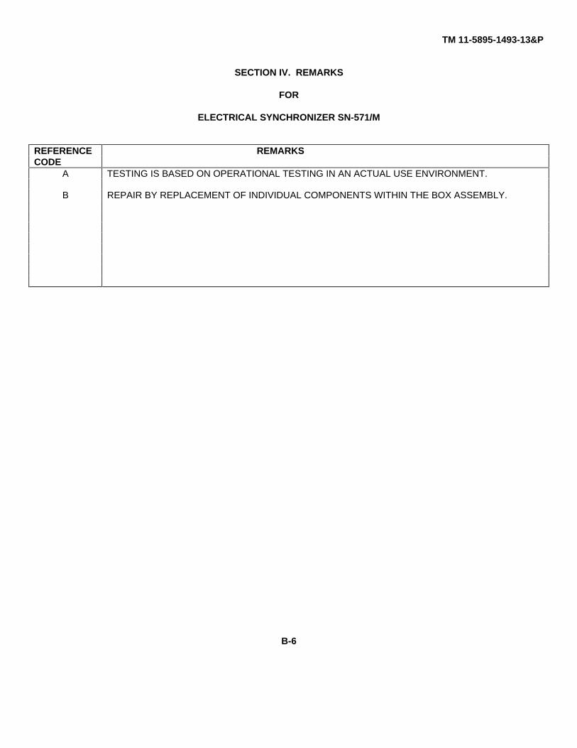
SECTION IV. REMARKS
FOR
ELECTRICAL SYNCHRONIZER SN-571/M
REFERENCE REMARKSCODE
A TESTING IS BASED ON OPERATIONAL TESTING IN AN ACTUAL USE ENVIRONMENT.
B REPAIR BY REPLACEMENT OF INDIVIDUAL COMPONENTS WITHIN THE BOX ASSEMBLY.
B-6
TM 11-5895-1493-13&P
APPENDIX C
OPERATOR, UNIT, AND DIRECT SUPPORT
REPAIR PARTS AND SPECIAL TOOLS LIST
SECTION I. INTRODUCTIONC-1. SCOPE.
This RPSTL lists and authorizes spares and repair parts; special tools; special test, measurement, and diagnosticequipment (TMDE); and other special support equipment required for performance of operator, unit, and direct supportmaintenance of the Electrical Synchronizer SN-571/M. It authorizes the requisitioning, issue, and disposition of spares,repair parts, and special tools as indicated by the source, maintenance, and recoverability (SMR) codes.
C-2. GENERAL.
In addition to Section I, Introduction, this Repair Parts and Special Tools List is divided into the following sections.
a. Section II - Repair Parts List. A list of spares and repair parts authorized by this RPSTL for use in theperformance of maintenance. The list also includes parts which must be removed for replacement of theauthorized parts. Parts lists are composed of functional groups in ascending alphanumeric sequence,with the parts in each group listed in ascending figure and item number sequence. Bulk materials arelisted by item name in FIG BULK at the end of the section. Repair parts kits or sets are listed separatelyin their own fuctional group within Section II. Repair parts for repairable special tools are also listed in thesection.
b. Section III - Special Tools List. Not applicable.
c. Section IV - Cross-reference Indexes. A list, in National Item Identification Number (NIIN) sequence, of allNational stock numbered items appearing in the listings, followed by a list in alphanumeric sequence of allpart numbers appearing in the listing. National stock numbers and part numbers are cross-referenced toeach illustration figure and item number appearance. The figure and item number index lists figure anditem number in alphanumeric sequence and cross-references NSN, CAGE, and part number.
C-1

TM 11-5895-1493-13&P
C-3. EXPLANATION OF COLUMNS (SECTIONS II AND III).
a. ITEM NO. (Column(1)). Indicates the number used to identify items called out in the illustration.
b. SMR CODE (Column (2)). The Source, Maintenance, and Recoverability (SMR) code is a five-position codecontaining supply/requisitioning information, maintenance category authorization criteria, and dispositioninstruction, as shown in the following breakout:
*Complete Repair: Maintenance capacity, capability, and authority to perform all corrective maintenance tasks of the"Repair" function in a use/user environment in order to restore service ability to a failed item.
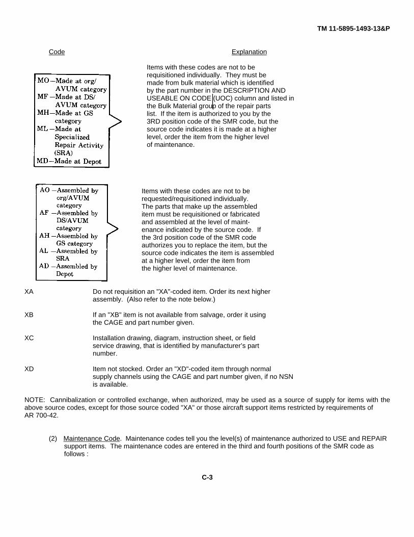
(1) Source Code. The source code tells you how to get an itemneeded for maintenance, repair, or overhaul of an end item/equipment. Explanations of source codesfollow:
Code Explanation
Stocked items; Use the applicable NSN torequest/requisition items with these source codes. Theyare authorized to the category indicated by the codeentered in the third position of the SMR code.
**NOTE: Items coded PC are subject to deterioration.
Items with these codes are not be berequested/requisitioned individualy. Theyare a part of a kit which is authorized tomaintenance category indicated in the 3rdposition of the SMR code. The complete kit
must be requisitioned and applied.
C-2
TM 11-5895-1493-13&P
Code Explanation
Items with these codes are not to berequisitioned individually. They must bemade from bulk material which is identifiedby the part number in the DESCRIPTION ANDUSEABLE ON CODE (UOC) column and listed inthe Bulk Material group of the repair partslist. If the item is authorized to you by the3RD position code of the SMR code, but thesource code indicates it is made at a higherlevel, order the item from the higher levelof maintenance.
Items with these codes are not to berequested/requisitioned individually.The parts that make up the assembleditem must be requisitioned or fabricatedand assembled at the level of maint-enance indicated by the source code. Ifthe 3rd position code of the SMR codeauthorizes you to replace the item, but thesource code indicates the item is assembledat a higher level, order the item fromthe higher level of maintenance.
XA Do not requisition an "XA"-coded item. Order its next higherassembly. (Also refer to the note below.)
XB If an "XB" item is not available from salvage, order it usingthe CAGE and part number given.
XC Installation drawing, diagram, instruction sheet, or fieldservice drawing, that is identified by manufacturer’s partnumber.
XD Item not stocked. Order an "XD"-coded item through normalsupply channels using the CAGE and part number given, if no NSNis available.
NOTE: Cannibalization or controlled exchange, when authorized, may be used as a source of supply for items with theabove source codes, except for those source coded "XA" or those aircraft support items restricted by requirements ofAR 700-42.
(2) Maintenance Code. Maintenance codes tell you the level(s) of maintenance authorized to USE and REPAIRsupport items. The maintenance codes are entered in the third and fourth positions of the SMR code asfollows :
C-3
TM 11-5895-1493-13&P
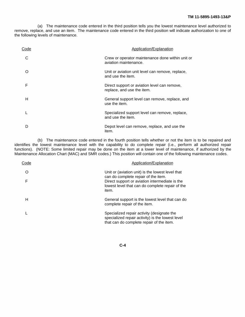
(a) The maintenance code entered in the third position tells you the lowest maintenance level authorized toremove, replace, and use an item. The maintenance code entered in the third position will indicate authorization to one ofthe following levels of maintenance.
Code Application/Explanation
C Crew or operator maintenance done within unit oraviation maintenance.
O Unit or aviation unit level can remove, replace,and use the item.
F Direct support or aviation level can remove,replace, and use the item.
H General support level can remove, replace, anduse the item.
L Specialized support level can remove, replace,and use the item.
D Depot level can remove, replace, and use theitem.
(b) The maintenance code entered in the fourth position tells whether or not the item is to be repaired andidentifies the lowest maintenance level with the capability to do complete repair (i.e., perform all authorized repairfunctions). (NOTE: Some limited repair may be done on the item at a lower level of maintenance, if authorized by theMaintenance Allocation Chart (MAC) and SMR codes.) This position will contain one of the following maintenance codes.
Code Application/Explanation
O Unit or (aviation unit) is the lowest level thatcan do complete repair of the item.
F Direct support or aviation intermediate is thelowest level that can do complete repair of theitem.
H General support is the lowest level that can docomplete repair of the item.
L Specialized repair activity (designate thespecialized repair activity) is the lowest levelthat can do complete repair of the item.
C-4
TM 11-5895-1493-13&P
D Depot is the lowest level that can do completerepair of the item.
Z Nonrepairable. No repair is authorized.
B No repair is authorized. (No parts or specialtools are authorized for the maintenance of a"B" coded item.) However, the item may bereconditioned by adjusting, lubricating, etc.,at the user category.
(3) Recoverability code. Recoverability codes are assigned to items to indicate the disposition action onunserviceable items. The recoverability code is entered in the fifth position of the SMR code as follows:
Recoverability Code Application/Explanation
Z .Nonrepairable item. When unserviceable, condemnand dispose of the item at the level ofmaintenance shown in the third position of theSMR Code.
0 Repairable item. When uneconomicallyrepairable, condemn and dispose of the item atunit or aviation unit level.
F Repairable item. When uneconomicallyrepairable, condemn and dispose of the item atthe direct support or aviation level.
H Repairable item. When uneconomicallyrepairable, condemn and dispose of the item atthe general support level.
D Repairable item. When beyond lower level repaircapability, return to depot. Condemnation anddisposal of item not authorized below depotlevel.
L Repairable item. Condemnation and disposal notauthorized below specialized repair activity(SRA).
A Item requires special handling or condemnationprocedures because of specific reasons (e.g.,precious metal content, high dollar value,critical material, or hazardous material).Refer to appropriate manuals/directives forspecific instructions.
C-5
TM 11-5895-1493-13&P
c. CAGE (Column(3)). The Commercial and Government Entity (CAGE) is a five-digit numeric code which is used toidentify the manufacturer, distributor, or Government agency, etc., that supplies the item.
d. PART NUMBER (Column(4)). Indicates the primary number used by the manufacturer (individual, company, firm,corporation, or Government activity), which controls the design and characteristics of the item by means of itsengineering drawings, specifications, standards, and inspection requirements to identify an item or range of items.
NOTE
When you use an NSN to requisition an item, the itemyou receive may have a different part number from thepart ordered.
e. DESCRIPTION AND USABLE ON CODE (UOC) (Column(5)). This column includes the following information:
(1) The Federal item name and, when required, a minimum description to identify the item.
(2) The physical security classification of item is indicated by the parenthetical entry (insert applicable physicalsecurity classification abbreviation, e.g. Phy Sec Cl (C) - Confidential; Phy Sec Cl (S) - Secret; Phy Sec Cl(T) - Top Secret).
(3) Items that are included in kits and sets are listed below the name of the kit or set.
(4) Spare/repair parts that make up an assembled item are listed immediately following the assembled item lineentry.
(5) Part numbers for bulk materials are referenced in this column in the line entry for the item to bemanufactured/fabricated.
(6) When the item is not used with all serial numbers of the same model, the effective serial numbers are shownon the last line(s) of the description (before UOC).
(7) The usable on code, when applicable, (see paragraph 5, Special Information).
(8) Not applicable.
C-6

TM 11-5895-1493-13&P
(9) The statement "END OF FIGURE" appears just below the last item description in Column 5 for a given figurein both Section II and Section III.
f. QTY (Column(6)). The QTY (quantity per figure column) indicates the quantity of the item used in the breakoutshown on the illustration figure, which is prepared for a functional group, subfunctional group, or an assembly. A"V" appearing in this column in lieu of a quantity indicates that the quantity is variable and the quantity may varyfrom application to application.
C-4. EXPLANATION OF COLUMNS (SECT IV).
a. NATIONAL STOCK NUMBER (NSN) INDEX.
(1) STOCK NUMBER Column. This column lists the NSN by National item identification number (NIIN)sequence. The NIIN is the
_____NSN_____
last nine digits of the NSN (i.e., 5305-01-674-1467. WhenNIIN
using this to locate an item, ignore the first four digits of the NSN. However, the complete NSN should beused when ordering items by stock number.
(2) FIG. Column. This column lists the number of the figure where the item is identified/located. The illustrationsare in numerical sequence in sections II and III.
(3) ITEM Column. The item number identifies the item associated with the figure listed in the adjacent figurenumber column. This item is also identified by the NSN listed on the same line.
b. PART NUMBER INDEX. Part numbers in this index are listed by part number in ascending alphanumericsequence (i.e. vertical arrangement of letter and number combination which places the first letter or digit of eachgroup in order A through Z, followed by the numbers 0 through 9 and each following letter or digit in like order).
(1) CAGE Column. The Government and Commercial Entitiy (CAGE) is a five-digit numeric code used to identifythe manufacturer, distributor, or Government agency, etc., that supplies the item.
(2) PART NUMBER Column. Indicates the primary number used by the manufacturer (individual, firm,corporation, or Government activity), which controls the design and characteristics of the item by means of itsengineering drawings, specifications standards, and inspection requirements to identify an item or range ofitems.
C-7
TM 11-5895-1493-13&P
(3) STOCK NUMBER COLUMN. This column lists the National stock number for the associated partnumber and manufacturer identified in the part number and CAGE columns to the left.
(4) FIG. COLUMN. This column lists the number of the figure where the item is identified/located insections II and III.
(5) ITEM COLUMN. The item number is that number assigned to the item as it appears in the figurereferenced in the adjacent figure number column.
c. FIGURE AND ITEM NUMBER INDEX.
(1) FIG column. This column lists the number of the figure where the item is identified/located in Section IIand III.
(2) ITEM column. The item number is that number assigned to the item as it appears in the figurereferenced in the adjacent figure number column.
(3) STOCK NUMBER column. This column lists the NSN for the item.
(4) CAGE column. The Commercial and Government Entity (CAGE) is a five-digit numeric code used toidentify the manufacturer, distributor, or Government agency, etc., that supplies the item.
(5) PART NUMBER column. Indicates the primary number used by the manufacturer (individual, firm,corporation, or Government activity), which controls the design and characteristics of the item bymeans of its engineering drawings, specifications standards, and inspection requirements to identify anitem or range of items.
C-5. SPECIAL INFORMATION.
Use the following subparagraphs as applicable:
(a) USABLE ON CODE. (Not applicable)
C-8
TM 11-5895-1493-13&P
(b) FABRICATION INSTRUCTIONS. Bulk materials required to manufacture items are listed in the Bulk MaterialFunctional Group of this RPSTL. Part numbers for bulk materials are also referenced in the descriptioncolumn of the line item entry for the item to be manufactured/fabricated. Detailed fabrication instructions foritems source codes to be manufactured or fabricated are found in (appropriate maintenance manual).
(c) ASSEMBLY INSTRUCTION. Detailed assembly instructions for items source coded to be assembled fromcomponent spare/repair parts are found in (appropriate maintenance manual.) Items that make up theassembly are listed immediately following the assembly item entry or reference is made to an applicablefigure.
(d) KITS. Line item entries for repair parts kits appear in a group in Section II (See table of contents).
(e) INDEX NUMBERS. Items which have the word BULK in the figure column will have an index number shownin the item number column. This index number is a cross-reference between the National StockNumber/Part Number Index and the bulk material list in Section II.
(f) ASSOCIATED PUBLICATIONS. Not applicable.
(g) ILLUSTRATIONS - LISTING. Not applicable
C-6. HOW TO LOCATE REPAIR PARTS.
a. When National Stock Number or Part Number is Not Known.
(1) First. Using the table of contents, determine the assembly group or subassembly group to which theitem belongs. This is necessary since figures are prepared for assembly groups and subassemblygroups, and listings are divided into the same groups.
(2) Second. Find the figure covering the assembly group or subassembly group to which the item belongs.
(3) Third. Identify the item on the figure and use the Figure and Item Number Index to find the NSN.
b. When National Stock Number or Part Number is Known.
(1) First. Using the National Stock Number or the Part Number Index, find the pertinent National StockNumber or Part Number. The NSN Index is in National Item Identification Number (NIIN) sequence(see 4.1(1)). The part numbers in the Part Number Index are listed in ascending alphanumericsequence (see 4.b). Both indexes cross-reference you to the illustration/figure and item number of theitem you are looking for.
C-9

TM 11-5895-1493-13&P
(2) Second. Turn to the figure and item number, verify that the item is the one you’re looking for, then locate theitem number in the repair parts list for the figure.
C-7. ABBREVIATIONS.
Not applicable.
C-10
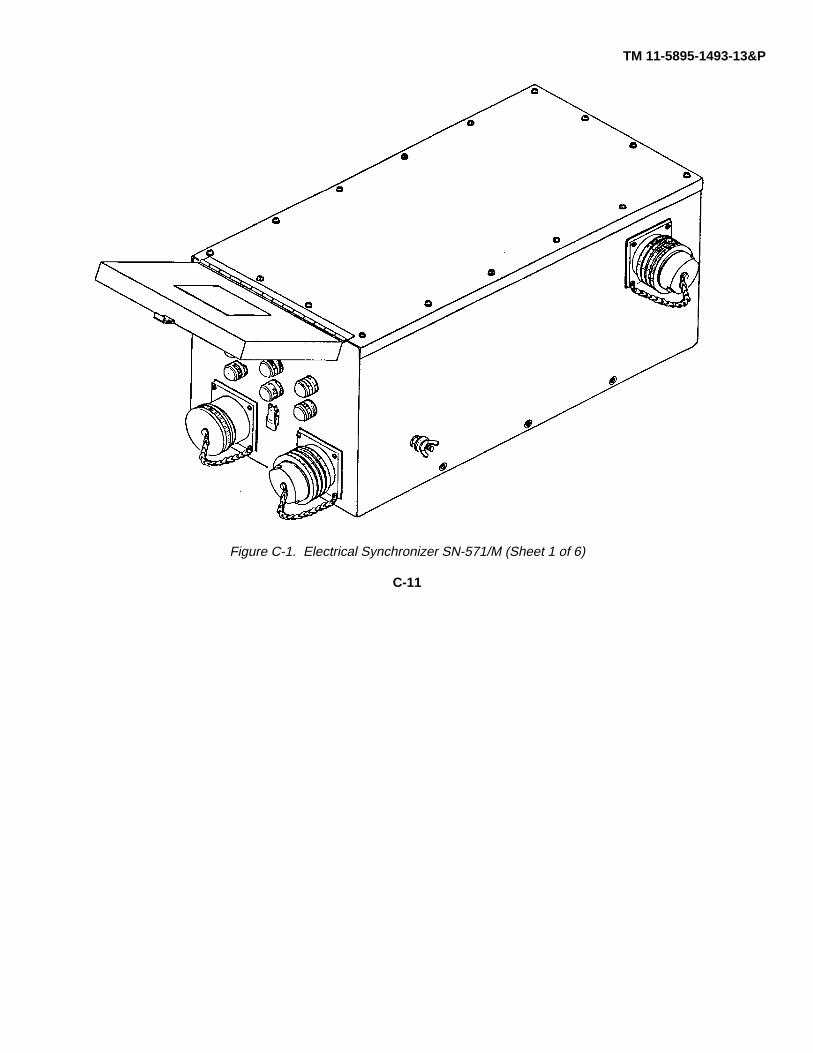
TM 11-5895-1493-13&P
Figure C-1. Electrical Synchronizer SN-571/M (Sheet 1 of 6)
C-11
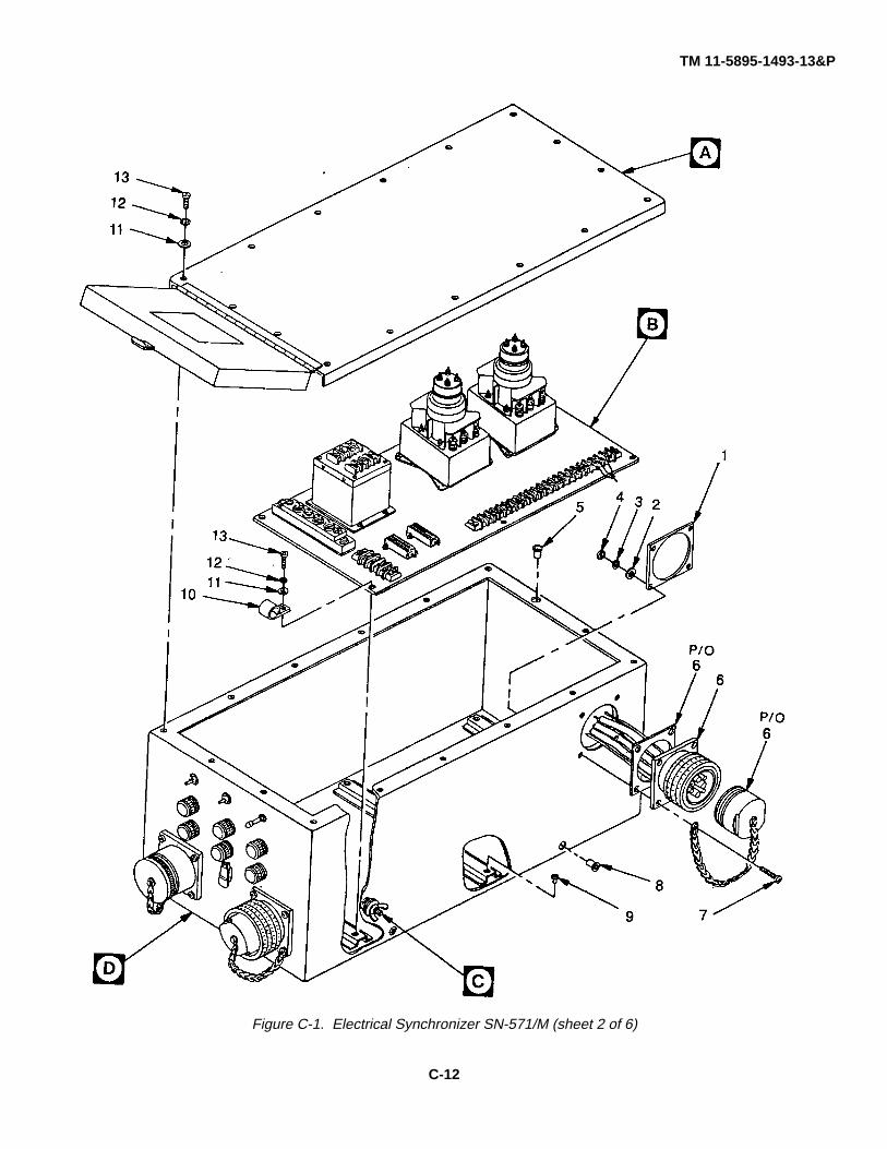
TM 11-5895-1493-13&P
Figure C-1. Electrical Synchronizer SN-571/M (sheet 2 of 6)
C-12
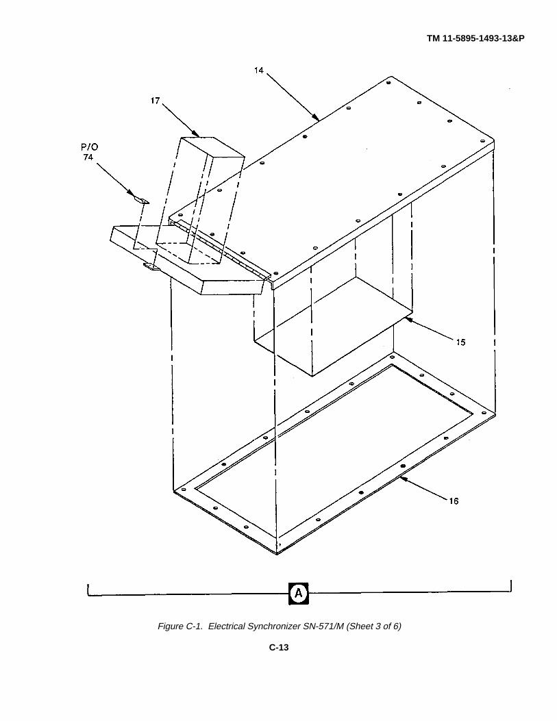
TM 11-5895-1493-13&P
Figure C-1. Electrical Synchronizer SN-571/M (Sheet 3 of 6)
C-13
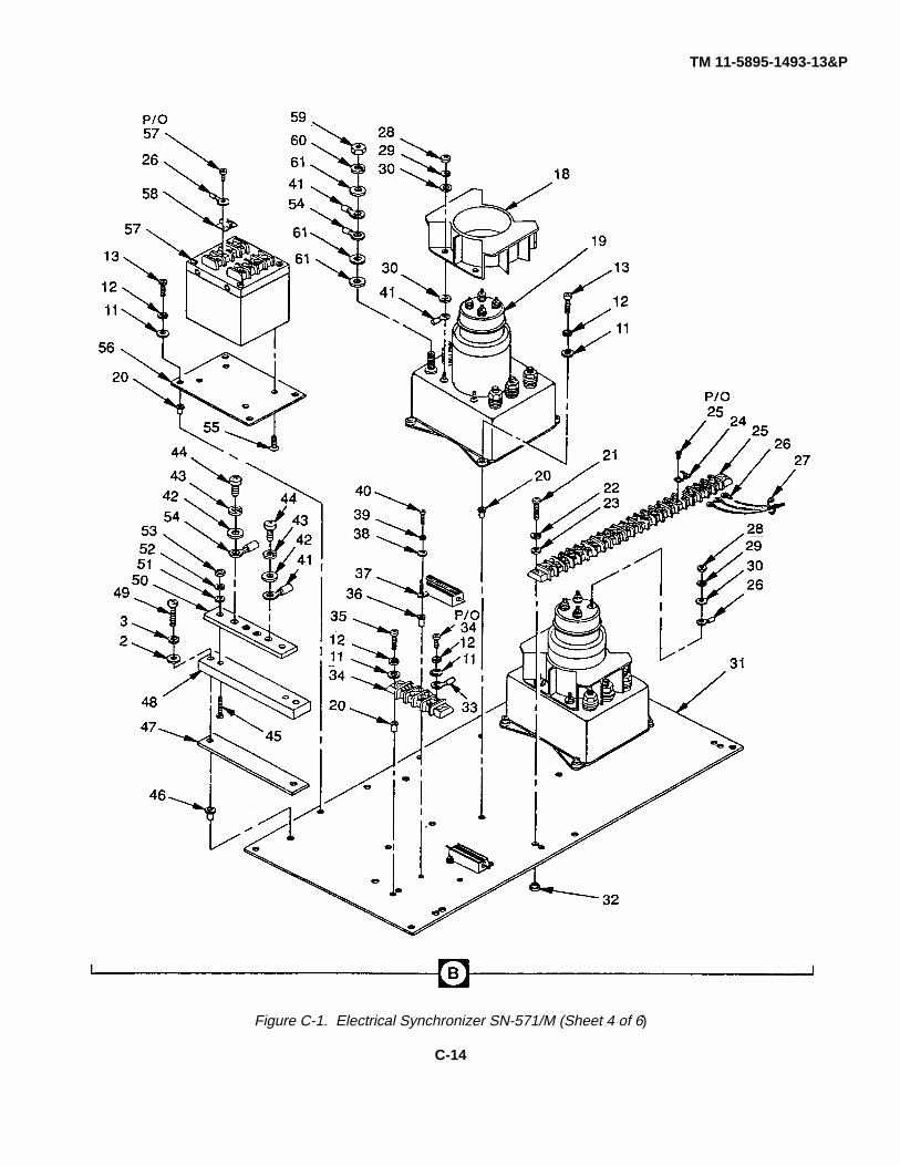
TM 11-5895-1493-13&P
Figure C-1. Electrical Synchronizer SN-571/M (Sheet 4 of 6)
C-14
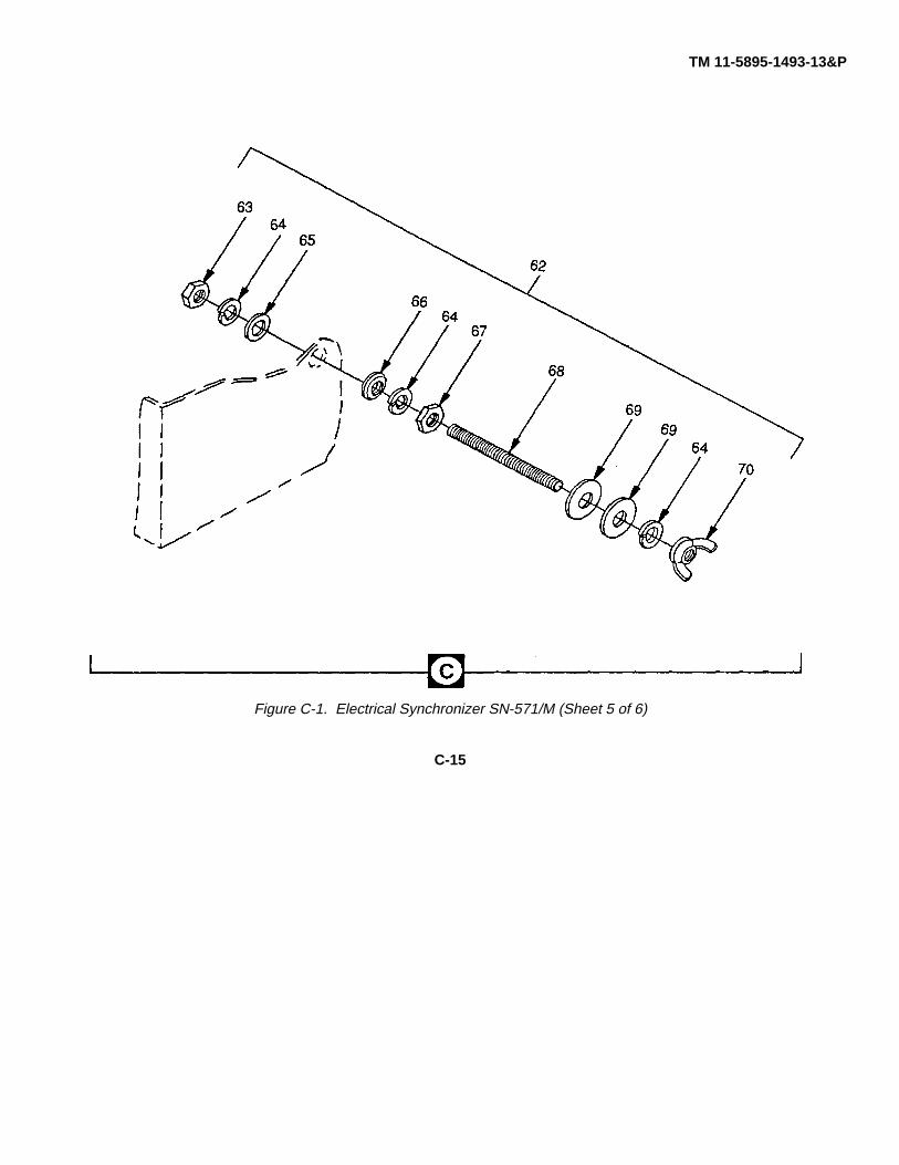
TM 11-5895-1493-13&P
Figure C-1. Electrical Synchronizer SN-571/M (Sheet 5 of 6)
C-15
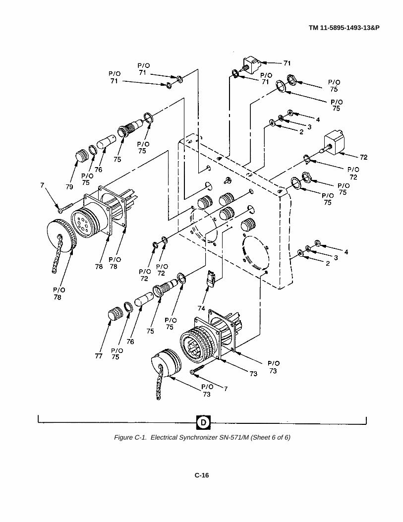
TM 11-5895-1493-13&P
Figure C-1. Electrical Synchronizer SN-571/M (Sheet 6 of 6)
C-16

TM 11-5895-1493-13&P
SECTION II(1) (2) (3) (4) (5) (6)
ITEM SMR PARTNO CODE CAGEC NUMBER DESCRIPTION AND USABLE ON CODES (UOC) QTY
GROUP 00 SYNCHRONIZER, SN-571/M
FIGURE C-1
1 XBFZZ 80063 A3102202 PLATE,BACKER.......................................................... 12 PAFZZ 96906 M515795-810 WASHER,FLAT ........................................................... 143 PAFZO 96906 M535338-139 WASHER,LOCK .......................................................... 124 PAFZF 96906 MS35649-2254 NUT,PLAIN,HEXAGON ............................................... 125 PAFZZ 80063 SC-D-681080-28 NUT,BLIND,RIVET ...................................................... 166 PAFZZ 80063 A3102212-001 HARNESS ASSEMBLY ............................................... 17 PAFZZ 96906 MS51957-84 SCREW,MACHINE...................................................... 128 PAFZZ 80063 SC-D-681080-38 NUT,B LIND,RIVET ..................................................... 69 PAFZZ 96906 MS27130-CR99 NUT,PLAIN,BLIND RIV................................................ 6
10 PAFZZ 96906 MS21333-71 CLAMP,LOOP.............................................................. 111 PAFZZ 96906 MSi5795-842 WASHER,FLAT ........................................................... 3812 PAFZZ 96906 MS35338-138 WASHER,LOCK .......................................................... 3813 PAFZF 96906 M551958-64 SCREW,M ACHINE..................................................... 3814 XBFZZ 80063 A3102113 COVER ASSEMBLY.................................................... 115 XBFZZ 80063 A3102120 PLATE,SCHEMATIC ................................................... 116 PAFZZ 80063 A3102116 GASKET,COVER ASSY.............................................. 117 XBFZZ 80063 A3102118 PLATE,IDENTIFICATIO .............................................. 118 PAFZZ 96906 M527243-4 TERMINAL COVERS,REL........................................... 219 PAFZZ 96906 MS24168-A4 RELAY,EL ECTROMAGNET....................................... 220 XBFZZ 80063 SC-D-681075-28 NUT,BLIND RIV ET ..................................................... 1621 PAFZZ 96906 MS51957-32 SCREW,MACHINE...................................................... 422 PAFZZ 96906 M535338-136 WASHER,LOCK .......................................................... 423 PAFZO 95906 MS15795-806 WASHER,FLAT .......................................................... 424 PAFZZ 81349 TBJA BUS,CONDUCTOR ..................................................... 625 PAFZZ 81349 37TB23 TERMINAL BOARD..................................................... 126 PAFZZ 96906 MS25036-106 TERMINAL,LUG .......................................................... 7927 PAFZO 96906 M53367-4-9 STRAP,TIEDOWN,ELECT .......................................... 1528 PAFZZ 96906 MS35649-265T NUT,PLAIN,HEXAGON ............................................... 1229 PAFZZ 96906 M535338-98 WASHER,LOCK .......................................................... 1230 PAFZZ 88044 AN961-6T WASHER,FLAT ........................................................... 1631 XBFZZ 80063 A3102137 PLATE,MOUNTING..................................................... 132 PAFZZ 81349 M45938/1-9C NUT,PLAIN,CLINCH.................................................... 433 PAFZZ 96906 M525036-156 TERMINAL,LUG .......................................................... 1234 PAFZZ 81349 39TB4B TERMINAL BOARD..................................................... 135 PAFZZ 96906 MS51958-67 SCREW,MACHINE...................................................... 436 PAFZZ 80205 NAS1330C04-131 NUT,PLAIN,BLIND,...................................................... 437 PAFZZ 81349 RER75F2491R RESISTO R,FIXED,WIRE ........................................... 238 PAFZZ 96906 M515795-804 WASHER,FLAT ........................................................... 439 PAFZZ 96906 M535338-135 WASHER,LOCK .......................................................... 440 PAFZZ 96906 MS51957-17 SCREW,MACHINE...................................................... 441 PAFZF 96906 M525036-126 TERMINAL,LUG .......................................................... 1842 PAFZZ 80063 SC-C-681574-1 WASHER,FLAT ........................................................... 443 PAFZZ 80063 SC-C-681573-1 WASHER,LOCK .......................................................... 444 XBF,Z 96906 A3102129-1 SCREW,MACHINE,BRASS......................................... 445 PAFZO 96906 MS51957-47 SCREW,MACHINE...................................................... 246 PAFZZ 83481 SS25-151 NUT,PLAIN,BLIND,RIV................................................ 247 XBFZZ 80063 A3102147 INSULATOR,BUSBAR................................................. 1
C-I-1
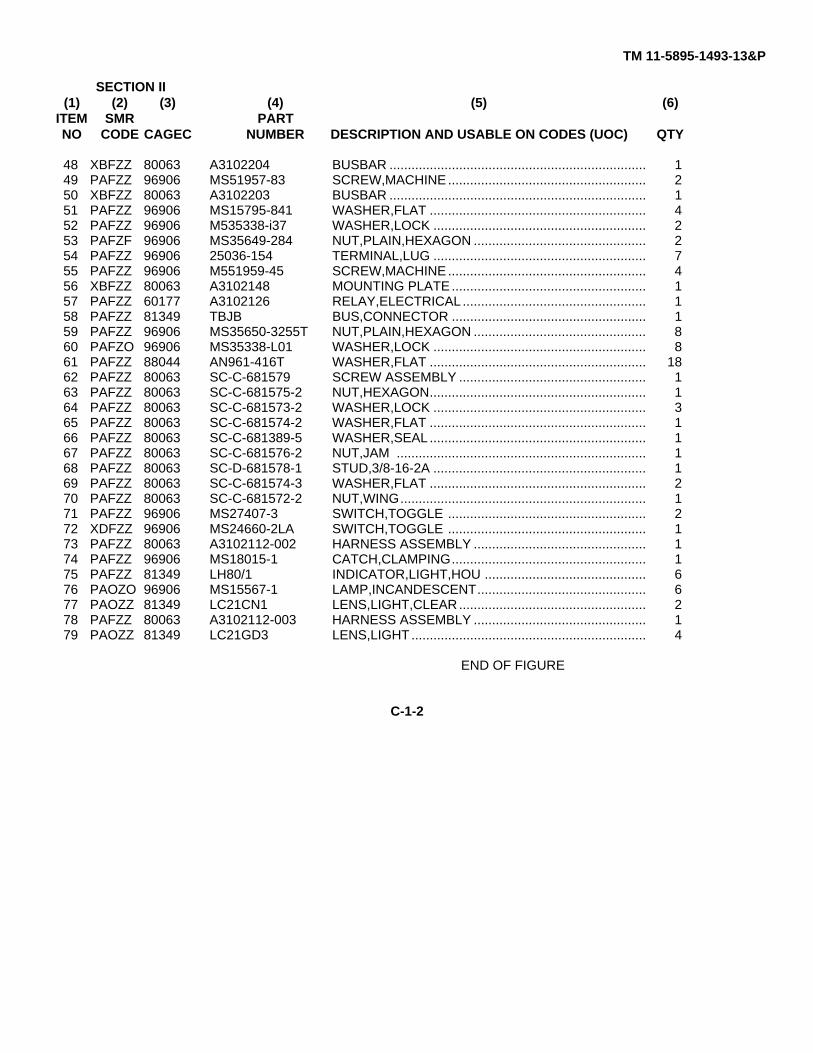
TM 11-5895-1493-13&P
SECTION II(1) (2) (3) (4) (5) (6)
ITEM SMR PARTNO CODE CAGEC NUMBER DESCRIPTION AND USABLE ON CODES (UOC) QTY
48 XBFZZ 80063 A3102204 BUSBAR ...................................................................... 149 PAFZZ 96906 MS51957-83 SCREW,MACHINE...................................................... 250 XBFZZ 80063 A3102203 BUSBAR ...................................................................... 151 PAFZZ 96906 MS15795-841 WASHER,FLAT ........................................................... 452 PAFZZ 96906 M535338-i37 WASHER,LOCK .......................................................... 253 PAFZF 96906 MS35649-284 NUT,PLAIN,HEXAGON ............................................... 254 PAFZZ 96906 25036-154 TERMINAL,LUG .......................................................... 755 PAFZZ 96906 M551959-45 SCREW,MACHINE...................................................... 456 XBFZZ 80063 A3102148 MOUNTING PLATE..................................................... 157 PAFZZ 60177 A3102126 RELAY,ELECTRICAL .................................................. 158 PAFZZ 81349 TBJB BUS,CONNECTOR ..................................................... 159 PAFZZ 96906 MS35650-3255T NUT,PLAIN,HEXAGON ............................................... 860 PAFZO 96906 MS35338-L01 WASHER,LOCK .......................................................... 861 PAFZZ 88044 AN961-416T WASHER,FLAT ........................................................... 1862 PAFZZ 80063 SC-C-681579 SCREW ASSEMBLY ................................................... 163 PAFZZ 80063 SC-C-681575-2 NUT,HEXAGON........................................................... 164 PAFZZ 80063 SC-C-681573-2 WASHER,LOCK .......................................................... 365 PAFZZ 80063 SC-C-681574-2 WASHER,FLAT ........................................................... 166 PAFZZ 80063 SC-C-681389-5 WASHER,SEAL ........................................................... 167 PAFZZ 80063 SC-C-681576-2 NUT,JAM .................................................................... 168 PAFZZ 80063 SC-D-681578-1 STUD,3/8-16-2A .......................................................... 169 PAFZZ 80063 SC-C-681574-3 WASHER,FLAT ........................................................... 270 PAFZZ 80063 SC-C-681572-2 NUT,WING................................................................... 171 PAFZZ 96906 MS27407-3 SWITCH,TOGGLE ...................................................... 272 XDFZZ 96906 MS24660-2LA SWITCH,TOGGLE ...................................................... 173 PAFZZ 80063 A3102112-002 HARNESS ASSEMBLY ............................................... 174 PAFZZ 96906 MS18015-1 CATCH,CLAMPING..................................................... 175 PAFZZ 81349 LH80/1 INDICATOR,LIGHT,HOU ............................................ 676 PAOZO 96906 MS15567-1 LAMP,INCANDESCENT.............................................. 677 PAOZZ 81349 LC21CN1 LENS,LIGHT,CLEAR................................................... 278 PAFZZ 80063 A3102112-003 HARNESS ASSEMBLY ............................................... 179 PAOZZ 81349 LC21GD3 LENS,LIGHT ................................................................ 4
END OF FIGURE
C-1-2

TM 11-5895-1493-13&P
SECTION IVCROSS- REFERENCE-INDEXES
NATIONAL STOCK NUMBER INDEXSTOCK NUMBER FIG. ITEM STOCK NUMBER FIG. ITEM
5905-00-024-0591 C-1 375305-00-054-5651 C-1 405305-00-054-6656 C-1 215305-00-054-6672 C-1 455340-00-057-2904 C-1 105305-00-059-3660 C-1 135305-00-059-3663 C-1 355305-00-071-1318 C-1 495305-00-071-2087 C-1 75930-00-105-5331 C-1 715310-00-136-1472 C-1 306240-00-143-3060 C-1 765940-00-143-4775 C-1 335940-00-143-4833 C-1 255310-00-163-2662 C-1 85310-00-177-1156 C-1 615310-00-184-8970 C-1 605310-00-184-8977 C-1 295310-00-225-5328 C-1 516210-00-244-2897 C-1 775310-00-250-9477 C-1 45940-00-283-5280 C-1 265310-00-410-3016 C-1 285310-00-437-8523 C-1 595945-00-461-9059 C-1 185940-00-557-4339 C-1 416150-00-632-7234 C-1 245975-00-727-5153 C-1 276210-00-753-2289 C-1 755305-00-764-0068 C-1 555310-00-782-1349 C-1 386210-00-839-8865 C-1 795310-00-849-1751 C-1 95310-00-880-5976 C-1 235310-00-883-9384 C-1 115310-00-929-6395 C-1 225310-00-933-8118 C-1 395310-00-933-8119 C-1 525310-00-933-8120 C-1 125310-00-933-8121 C-1 35310-00-934-9759 C-1 535340-00-975-2126 C-1 745310-01-044-6570 C-1 325310-01-077-1024 C-1 655310-01-091-1248 C-1 25945-01-178-5212 C-1 195310-01-249-4080 C-1 435310-01-288-1441 C-1 365310-01-315-1169 C-1 55310-01-315-1170 C-1 67
I-1
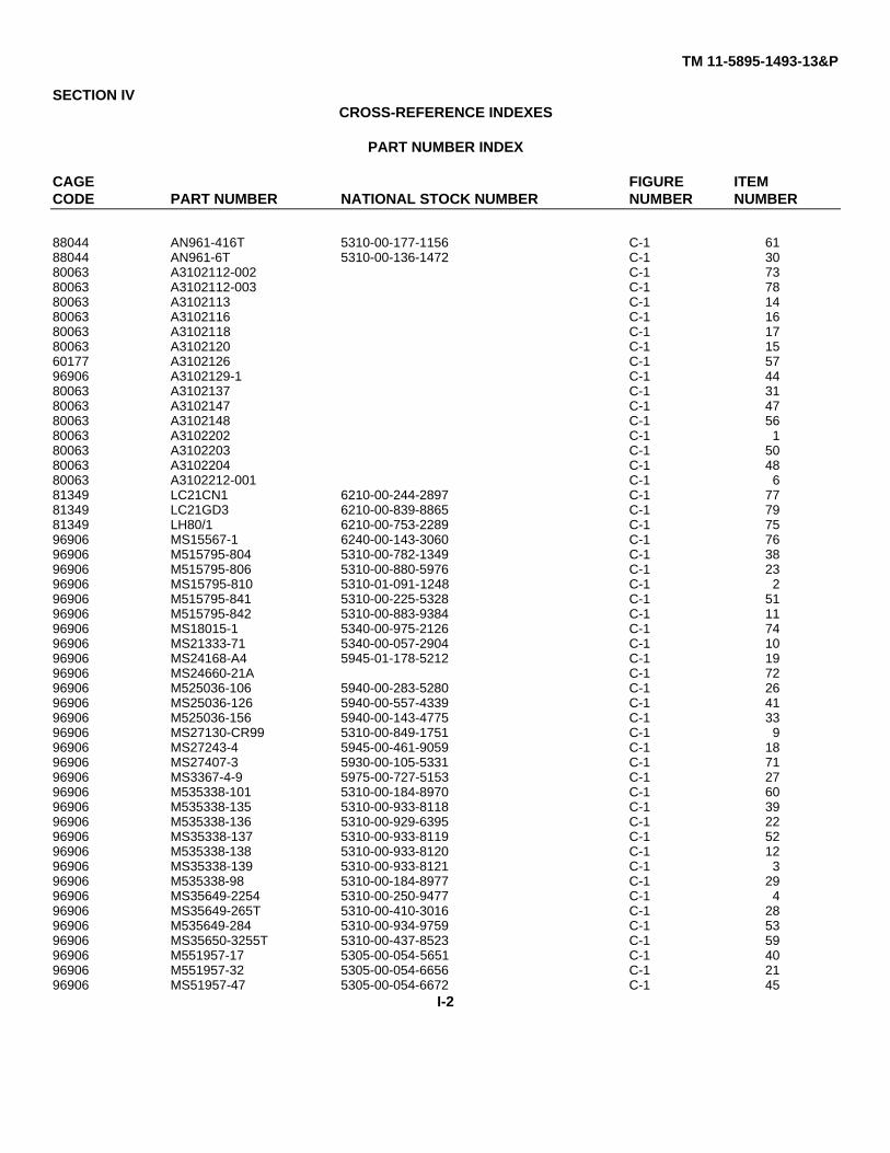
TM 11-5895-1493-13&P
SECTION IVCROSS-REFERENCE INDEXES
PART NUMBER INDEX
CAGE FIGURE ITEMCODE PART NUMBER NATIONAL STOCK NUMBER NUMBER NUMBER
88044 AN961-416T 5310-00-177-1156 C-1 6188044 AN961-6T 5310-00-136-1472 C-1 3080063 A3102112-002 C-1 7380063 A3102112-003 C-1 7880063 A3102113 C-1 1480063 A3102116 C-1 1680063 A3102118 C-1 1780063 A3102120 C-1 1560177 A3102126 C-1 5796906 A3102129-1 C-1 4480063 A3102137 C-1 3180063 A3102147 C-1 4780063 A3102148 C-1 5680063 A3102202 C-1 180063 A3102203 C-1 5080063 A3102204 C-1 4880063 A3102212-001 C-1 681349 LC21CN1 6210-00-244-2897 C-1 7781349 LC21GD3 6210-00-839-8865 C-1 7981349 LH80/1 6210-00-753-2289 C-1 7596906 MS15567-1 6240-00-143-3060 C-1 7696906 M515795-804 5310-00-782-1349 C-1 3896906 M515795-806 5310-00-880-5976 C-1 2396906 MS15795-810 5310-01-091-1248 C-1 296906 M515795-841 5310-00-225-5328 C-1 5196906 M515795-842 5310-00-883-9384 C-1 1196906 MS18015-1 5340-00-975-2126 C-1 7496906 MS21333-71 5340-00-057-2904 C-1 1096906 MS24168-A4 5945-01-178-5212 C-1 1996906 MS24660-21A C-1 7296906 M525036-106 5940-00-283-5280 C-1 2696906 MS25036-126 5940-00-557-4339 C-1 4196906 M525036-156 5940-00-143-4775 C-1 3396906 MS27130-CR99 5310-00-849-1751 C-1 996906 MS27243-4 5945-00-461-9059 C-1 1896906 MS27407-3 5930-00-105-5331 C-1 7196906 MS3367-4-9 5975-00-727-5153 C-1 2796906 M535338-101 5310-00-184-8970 C-1 6096906 M535338-135 5310-00-933-8118 C-1 3996906 M535338-136 5310-00-929-6395 C-1 2296906 MS35338-137 5310-00-933-8119 C-1 5296906 M535338-138 5310-00-933-8120 C-1 1296906 MS35338-139 5310-00-933-8121 C-1 396906 M535338-98 5310-00-184-8977 C-1 2996906 MS35649-2254 5310-00-250-9477 C-1 496906 MS35649-265T 5310-00-410-3016 C-1 2896906 M535649-284 5310-00-934-9759 C-1 5396906 MS35650-3255T 5310-00-437-8523 C-1 5996906 M551957-17 5305-00-054-5651 C-1 4096906 M551957-32 5305-00-054-6656 C-1 2196906 MS51957-47 5305-00-054-6672 C-1 45
I-2
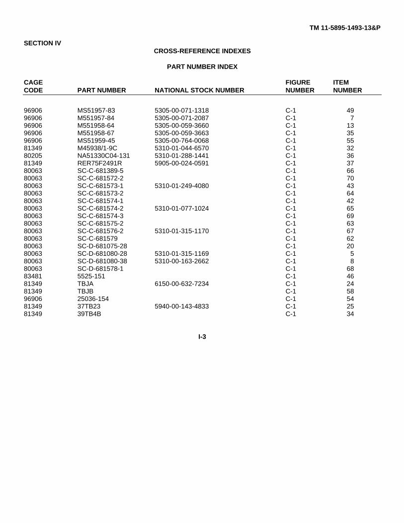
TM 11-5895-1493-13&P
SECTION IVCROSS-REFERENCE INDEXES
PART NUMBER INDEX
CAGE FIGURE ITEMCODE PART NUMBER NATIONAL STOCK NUMBER NUMBER NUMBER
96906 MS51957-83 5305-00-071-1318 C-1 4996906 M551957-84 5305-00-071-2087 C-1 796906 M551958-64 5305-00-059-3660 C-1 1396906 M551958-67 5305-00-059-3663 C-1 3596906 MS51959-45 5305-00-764-0068 C-1 5581349 M45938/1-9C 5310-01-044-6570 C-1 3280205 NA51330C04-131 5310-01-288-1441 C-1 3681349 RER75F2491R 5905-00-024-0591 C-1 3780063 SC-C-681389-5 C-1 6680063 SC-C-681572-2 C-1 7080063 SC-C-681573-1 5310-01-249-4080 C-1 4380063 SC-C-681573-2 C-1 6480063 SC-C-681574-1 C-1 4280063 SC-C-681574-2 5310-01-077-1024 C-1 6580063 SC-C-681574-3 C-1 6980063 SC-C-681575-2 C-1 6380063 SC-C-681576-2 5310-01-315-1170 C-1 6780063 SC-C-681579 C-1 6280063 SC-D-681075-28 C-1 2080063 SC-D-681080-28 5310-01-315-1169 C-1 580063 SC-D-681080-38 5310-00-163-2662 C-1 880063 SC-D-681578-1 C-1 6883481 5525-151 C-1 4681349 TBJA 6150-00-632-7234 C-1 2481349 TBJB C-1 5896906 25036-154 C-1 5481349 37TB23 5940-00-143-4833 C-1 2581349 39TB4B C-1 34
I-3

TM 11-5895-1493-13&P
SECTION IVCROSS-REFERENCE INDEXES
FIGURE AND ITEM NUMBER INDEX
FIG. ITEM STOCK NUMBER CAGEC PART NUMBER
C-1 1 80063 A3102202C-1 2 5310-01-091-1248 96906 MS15795-810C-1 3 5310-00-933-8121 96906 MS35338-139C-1 4 5310-00-250-9477 96906 MS35649-2254C-1 5 5310-01-315-1169 80063 SC-D-681080-28C-1 6 80063 A3102212-001C-1 7 5305-00-071-2087 96906 MS51957-84C-1 8 5310-00-163-2662 80063 SC-D-681080-38C-1 9 5310-00-849-1751 96906 MS27130-CR99C-1 10 5340-00-057-2904 96906 MS21333-71C-1 11 5310-00-883-9384 96906 MS15795-842C-1 12 5310-00-933-8120 96906 MS35338-138C-1 13 5305-00-059-3660 96906 M551958-64C-1 14 80063 A3102113C-1 15 80063 A3102120C-1 16 80063 A3102116C-1 17 80063 A3102118C-1 18 5945-00-461-9059 96906 Ms27243-4C-1 19 5945-01-178-5212 96906 MS24168-A4C-1 20 80063 SC-D-681075-28C-1 21 5305-00-054-6656 96906 MS51957-32C-1 22 5310-00-929-6395 96906 M535338-136C-1 23 5310-00-880-5976 96906 MS15795-806C-1 24 6150-00-632-7234 81349 TBJAC-1 25 5940-00-143-4833 81349 37TB23C-1 26 5940-00-283-5280 96906 MS25036-i06C-1 27 5975-00-727-5153 96906 MS3367-4-9C-1 28 5310-00-410-3016 96906 MS35649-265TC-1 29 5310-00-184-8977 96906 MS35338-98C-1 30 5310-00-136-1472 88044 AN961-6TC-1 31 80063 A3102137C-1 32 5310-01-044-6570 81349 M45938/1-9CC-1 33 5940-00-143-4775 96906 MS25036-156C-1 34 81349 39TB4BC-i 35 5305-00-059-3663 96906 MS51958-67C-1 36 5310-01-288-1441 80205 NAs1330C04-131C-1 37 5905-00-024-0591 81349 RER75F2491RC-1 38 5310-00-782-1349 96906 MS15795-804C-1 39 5310-00-933-8118 96906 MS35338-135C-1 40 5305-00-054-5651 96906 MS51957-17C-1 41 5940-00-557-4339 96906 MS25036-126C-1 42 80063 SC-C-681574-1C-1 43 5310-01-249-4080 80063 SC-C-681573-1C-1 44 96906 A3102129-1C-1 45 5305-00-054-6672 96906 MS51957-47C-1 46 83481 SS25-151C-1 47 80063 A3102147C-1 48 80063 A3102204C-1 49 5305-00-071-1318 96906 MS51957-83C-1 50 80063 A3102203C-1 51 5310-00-225-5328 96906 M5i5795-841
I-4

TM 11-5895-1493-13&P
SECTION IVCROSS-REFERENCE INDEXES
FIGURE AND ITEM NUMBER INDEX
FIG. ITEM STOCK NUMBER CAGEC PART NUMBER
C-1 52 5310-00-933-8119 96906 MS35338-137C-1 53 5310-00-934-9759 96906 MS35649-284C-1 54 96906 25036-154C-1 55 5305-00-764-0068 96906 MS51959-45C-1 56 80063 A3102148C-1 57 60177 A3102126C-1 58 81349 TBJBC-1 59 5310-00-437-8523 96906 MS35650-3255TC-1 60 5310-00-184-8970 96906 MS35338-101C-1 61 5310-00-177-1156 88044 AN961-416TC-1 62 80063 SC-C-681579C-1 63 80063 SC-C-681575-2C-1 64 80063 SC-C-681573-2C-1 65 5310-01-077-1024 80063 SC-C-681574-2C-1 66 80063 SC-C-681389-5C-1 67 5310-01-315-1170 80063 SC-C-681576-2C-1 68 80063 SC-D-681578-1C-1 69 80063 SC-C-681574-3C-1 70 80063 SC-C-681572-2C-1 71 5930-00-105-5331 96906 MS27407-3C-1 72 96906 MS24660-21AC-1 73 80063 A3102112-002C-1 74 5340-00-975-2126 96906 MS18015-1C-1 75 6210-00-753-2289 81349 LH80/1C-1 76 6240-00-143-3060 96906 MS15567-1C-1 77 6210-00-244-2897 81349 LC21CN1C-1 78 80063 A3102112-003C-1 79 6210-00-839-8865 81349 LC21GD3
I-5
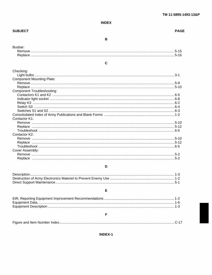
TM 11-5895-1493-13&P
INDEX
SUBJECT PAGE
B
Busbar:Remove ...................................................................................................................................................... 5-15Replace ...................................................................................................................................................... 5-16
C
Checking:Light bulbs .................................................................................................................................................. 3-1
Component Mounting Plate:Remove ...................................................................................................................................................... 5-9Replace ...................................................................................................................................................... 5-10
Component Troubleshooting:Contactors K1 and K2 ............................................................................................................................... 6-5Indicator light socket .................................................................................................................................. 6-8Relay K3 .................................................................................................................................................... 6-2Switch S3 ................................................................................................................................................... 6-4Switches S1 and S2 ................................................................................................................................... 6-3
Consolodated Index of Army Publications and Blank Forms ......................................................................... 1-2Contactor K1:
Remove ..................................................................................................................................................... 5-10Replace ..................................................................................................................................................... 5-12Troubleshoot .............................................................................................................................................. 6-5
Contactor K2:Remove ..................................................................................................................................................... 5-10Replace ..................................................................................................................................................... 5-12Troubleshoot .............................................................................................................................................. 6-5
Cover Assembly:Remove ..................................................................................................................................................... 5-2Replace ..................................................................................................................................................... 5-2
D
Description....................................................................................................................................................... 1-3Destruction of Army Electronics Materiel to Prevent Enemy Use ................................................................... 1-2Direct Support Maintenance............................................................................................................................ 5-1
E
EIR, Reporting Equipment Improvement Recommendations ......................................................................... 1-2Equipment Data............................................................................................................................................... 1-6Equipment Description .................................................................................................................................... 1-3
F
Figure and Item Number Index........................................................................................................................ C-17
INDEX-1
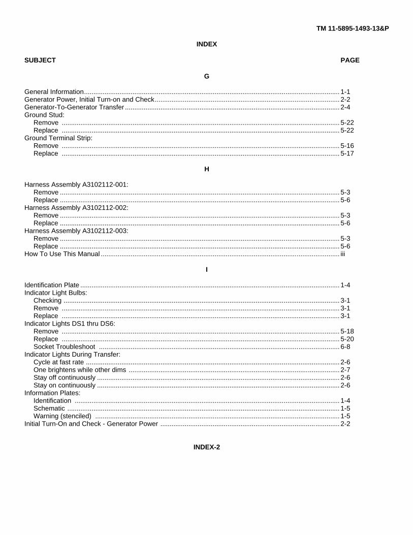
TM 11-5895-1493-13&P
INDEX
SUBJECT PAGE
G
General Information......................................................................................................................................... 1-1Generator Power, Initial Turn-on and Check................................................................................................... 2-2Generator-To-Generator Transfer ................................................................................................................... 2-4Ground Stud:
Remove ..................................................................................................................................................... 5-22Replace ..................................................................................................................................................... 5-22
Ground Terminal Strip:Remove ..................................................................................................................................................... 5-16Replace ..................................................................................................................................................... 5-17
H
Harness Assembly A3102112-001:Remove ...................................................................................................................................................... 5-3Replace ...................................................................................................................................................... 5-6
Harness Assembly A3102112-002:Remove ...................................................................................................................................................... 5-3Replace ...................................................................................................................................................... 5-6
Harness Assembly A3102112-003:Remove ...................................................................................................................................................... 5-3Replace ...................................................................................................................................................... 5-6
How To Use This Manual ................................................................................................................................ iii
I
Identification Plate ........................................................................................................................................... 1-4Indicator Light Bulbs:
Checking .................................................................................................................................................... 3-1Remove ..................................................................................................................................................... 3-1Replace ..................................................................................................................................................... 3-1
Indicator Lights DS1 thru DS6:Remove ..................................................................................................................................................... 5-18Replace ..................................................................................................................................................... 5-20Socket Troubleshoot ................................................................................................................................. 6-8
Indicator Lights During Transfer:Cycle at fast rate ........................................................................................................................................ 2-6One brightens while other dims ................................................................................................................. 2-7Stay off continuously .................................................................................................................................. 2-6Stay on continuously .................................................................................................................................. 2-6
Information Plates:Identification .............................................................................................................................................. 1-4Schematic .................................................................................................................................................. 1-5Warning (stenciled) ................................................................................................................................... 1-5
Initial Turn-On and Check - Generator Power ................................................................................................ 2-2
INDEX-2
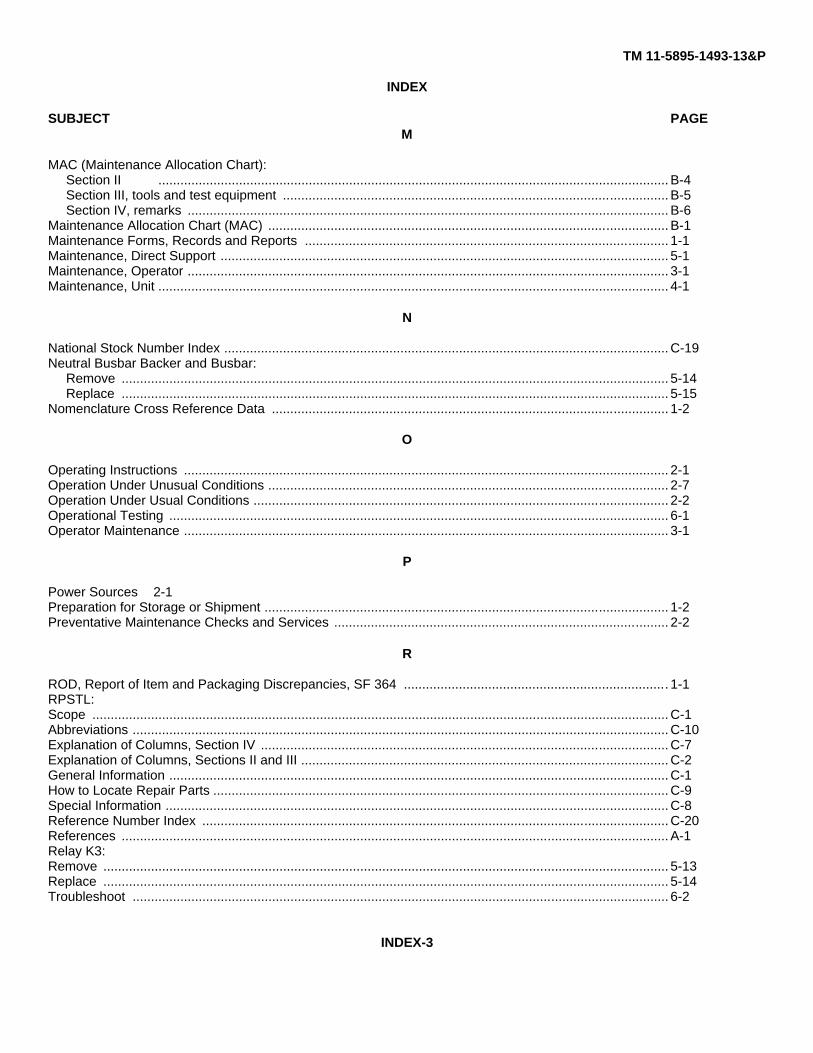
TM 11-5895-1493-13&P
INDEX
SUBJECT PAGEM
MAC (Maintenance Allocation Chart):Section II ........................................................................................................................................... B-4Section III, tools and test equipment ......................................................................................................... B-5Section IV, remarks ................................................................................................................................... B-6
Maintenance Allocation Chart (MAC) ............................................................................................................. B-1Maintenance Forms, Records and Reports ................................................................................................... 1-1Maintenance, Direct Support .......................................................................................................................... 5-1Maintenance, Operator ................................................................................................................................... 3-1Maintenance, Unit ........................................................................................................................................... 4-1
N
National Stock Number Index ......................................................................................................................... C-19Neutral Busbar Backer and Busbar:
Remove ..................................................................................................................................................... 5-14Replace ..................................................................................................................................................... 5-15
Nomenclature Cross Reference Data ............................................................................................................ 1-2
O
Operating Instructions .................................................................................................................................... 2-1Operation Under Unusual Conditions ............................................................................................................. 2-7Operation Under Usual Conditions ................................................................................................................. 2-2Operational Testing ........................................................................................................................................ 6-1Operator Maintenance .................................................................................................................................... 3-1
P
Power Sources 2-1Preparation for Storage or Shipment .............................................................................................................. 1-2Preventative Maintenance Checks and Services ........................................................................................... 2-2
R
ROD, Report of Item and Packaging Discrepancies, SF 364 ........................................................................ 1-1RPSTL:Scope ............................................................................................................................................................. C-1Abbreviations .................................................................................................................................................. C-10Explanation of Columns, Section IV ............................................................................................................... C-7Explanation of Columns, Sections II and III .................................................................................................... C-2General Information ........................................................................................................................................ C-1How to Locate Repair Parts ............................................................................................................................ C-9Special Information ......................................................................................................................................... C-8Reference Number Index ............................................................................................................................... C-20References ..................................................................................................................................................... A-1Relay K3:Remove .......................................................................................................................................................... 5-13Replace .......................................................................................................................................................... 5-14Troubleshoot .................................................................................................................................................. 6-2
INDEX-3
TM 11-5895-1493-13&P
INDEX
SUBJECT PAGE
R (cont)
Remove:Busbar ....................................................................................................................................................... 5-15Component mounting plate ....................................................................................................................... 5-9Contactors K] and K2 ................................................................................................................................ 5-10Cover assembly ......................................................................................................................................... 5-2Ground stud ............................................................................................................................................... 5-22Ground terminal strip ................................................................................................................................. 5-16Harness assembly A3102112-001 ............................................................................................................ 5-3Harness assembly A3102112-002 ............................................................................................................ 5-3Harness assembly A3102112-003 ............................................................................................................ 5-3Indicator lights DS1 thru DS6 .................................................................................................................... 5-18Light bulbs ................................................................................................................................................. 3-1Neutral busbar backer and busbar ............................................................................................................ 5-14Relay K3 .................................................................................................................................................... 5-13Resistors R1 and R2 ................................................................................................................................. 5-13Switches S1, S2, and S3 ........................................................................................................................... 5-20Synchronizer box ....................................................................................................................................... 4-1Terminal board TB1 ................................................................................................................................... 5-17
Repair Parts and Special Tools List (RPSTL) ................................................................................................ C-1Replace:
Busbar ....................................................................................................................................................... 5-16Component mounting plate ....................................................................................................................... 5-10Contactors K1 and K2 ............................................................................................................................... 5-12Cover assembly ......................................................................................................................................... 5-2Ground stud ............................................................................................................................................... 5-22Ground terminal strip ................................................................................................................................. 5-17Harness assembly A3102112-001 ............................................................................................................ 5-6Harness assembly A3102112-002 ............................................................................................................ 5-6Harness assembly A3102112-003 ............................................................................................................ 5-6Indicator lights DSi thru DS6 ..................................................................................................................... 5-20Light bulbs ................................................................................................................................................. 3-1Neutral busbar backer and busbar ............................................................................................................ 5-15Relay K3 .................................................................................................................................................... 5-14Resistors R1 and R2 ................................................................................................................................. 5-13Switches SI, S2, and S3 ............................................................................................................................ 5-21Synchronizer box ....................................................................................................................................... 4-2Terminal strip TB1 ..................................................................................................................................... 5-18
Report of Item and Packaging Deficiencies ................................................................................................... 1-1Reporting Equipment Improvement Recommendations (EIR) ....................................................................... 1-2Reports of Maintenance and Unsatisfactory Equipment ................................................................................ 1-1Resistor R1:
Remove ..................................................................................................................................................... 5-13Replace ..................................................................................................................................................... 5-13
Resistor R2:Remove ..................................................................................................................................................... 5-13Replace ..................................................................................................................................................... 5-13
INDEX-4

TM 11-5895-1493-13&P
INDEX
SUBJECT PAGES
Schematic Diagram Information Plate............................................................................................................. 1-5Schematic Diagram, Synchronizer Box .......................................................................................................... 6-9Scope .............................................................................................................................................................. 1-1SF 361, TRD, Transportation Discrepancy in Shipment Report ..................................................................... 1-1SF364, ROD, Report of Item and Packaging Discrepancies ......................................................................... 1-1Switch S3:
Remove ..................................................................................................................................................... 5-20Replace ..................................................................................................................................................... 5-21Troubleshoot .............................................................................................................................................. 6-4
Switches S1 and S2 ........................................................................................................................................ 6-3Remove ..................................................................................................................................................... 5-20Replace ..................................................................................................................................................... 5-21Troubleshoot .............................................................................................................................................. 6-3
Synchronizer Box:Description ................................................................................................................................................. 1-3Direct support maintenance ...................................................................................................................... 5-1Introduction ................................................................................................................................................ 1-1Operating instructions ................................................................................................................................ 2-1Operator maintenance ............................................................................................................................... 3-1Remove ..................................................................................................................................................... 4-1Replace ..................................................................................................................................................... 4-2Schematic .................................................................................................................................................. 6-9Unit maintenance ....................................................................................................................................... 4-1
T
Terminal Board TB1:Remove ...................................................................................................................................................... 5-17Replace ...................................................................................................................................................... 5-18
Testing and Troubleshooting........................................................................................................................... 6-1Testing:
Contactors K1 and K2 ............................................................................................................................... 6-5Indicator light bulbs .................................................................................................................................... 3-1Indicator light sockets ................................................................................................................................ 6-8Operational testing ..................................................................................................................................... 6-1Relay K3 .................................................................................................................................................... 6-2Switch S3 ................................................................................................................................................... 6-4Switches Si and S2 .................................................................................................................................... 6-3Wiring ......................................................................................................................................................... 6-6
Tools and Test Equipment ............................................................................................................................. B-5Transportation Discrepancy in Shipment Reports (TDR) (SF361).................................................................. 1-1TRD, SF361, Transportation Discrepancy in Shipment Report....................................................................... 1-1
Troubleshooting:Contactors K1 and K2 ............................................................................................................................... 6-5Indicator light sockets ................................................................................................................................ 6-8Relay K3 .................................................................................................................................................... 6-2Switches S1 and S2 .................................................................................................................................. 6-3Switch S3 ................................................................................................................................................... 6-4Wiring ......................................................................................................................................................... 6-6
INDEX-5
TM 11-5895-1493-13&P
INDEX
SUBJECT PAGE
U
Unit Maintenance............................................................................................................................................. 4-1
V
Voltage Warning (Stenciled) ........................................................................................................................... 1-5
W
Wire List ......................................................................................................................................................... 6-6Wiring Troubleshooting .................................................................................................................................. 6-6
INDEX-6

By Order of the Secretary of the Army:
GORDON R. SULLIVANGeneral, United States Army
Official: Chief of Staff
MILTON H. HAMILTONAdministrative Assistant to the
Secretary of the Army01383
DISTRIBUTION:
to be distributed in accordance with DA Form 12-36-E, block 9229, Operator and Unit, Direct and General Supportmaintenance requirements for TM 11-5895-1483-13&P.
*U.S. GOVERN&MENT PRINTING OFFICE: 1993 - 342-421/80077
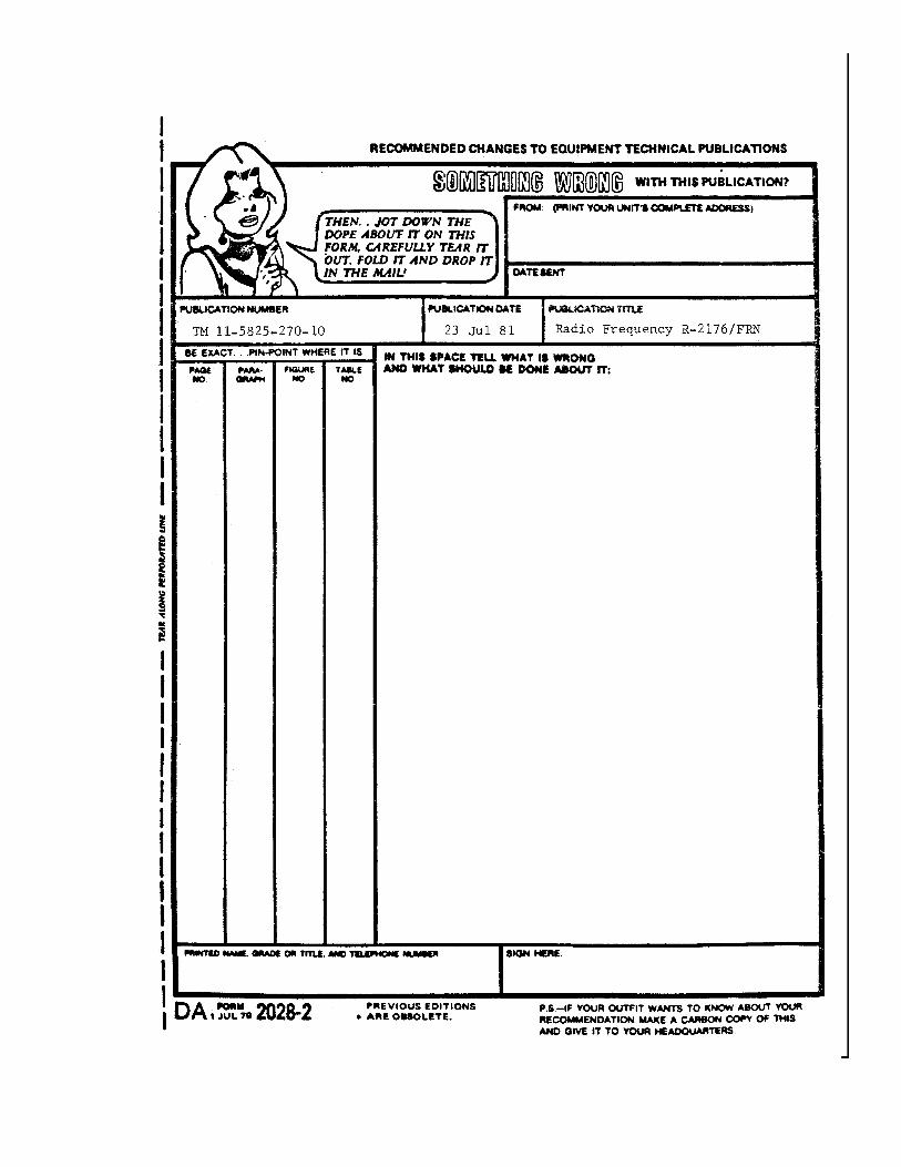

PIN: 069831-000