Embed Size (px)
Citation preview

TM 11-5820-765-12DEPARTMENT OF THE ARMY TECHNICAL MANUAL
OPERATOR AND ORGANIZATIONAL MAINTENANCE MANUAL
POWER SUPPLIESPP-4763/GRC
AND PP-4763A/GRC
This copy is a reprint which includes current
pages from Changes 3 and 4.
HEADQUARTERS, D E P A R T M E N T O F
28 OCTOBER 1968
T H E A R M Y
TAGO 6195A

WARNING
DANGEROUS VOLTAGES EXIST IN THE EQUIPMENTDON’T TAKE CHANCES!
Low-voltage, high-amperage current is present at output connectionsand at connections inside the equipment. Do not touch connections or re-move the cabinet cover until equipment is removed from power source.Reenergize the power supply before connecting or disconnecting the equip-ment to be powered and before performing any maintenance.
Be careful when working on the 115- or 230-volt ac line connections.Serious injury or DEATH may result from contact with these terminals.

Changes in force: C3 and C4
Change
No. 4
TM 11-5820-765-12*C4
HEADQUARTERSDEPARTMENT OF THE ARMY
Washington, DC, 26 November 1983
OPERATOR’S AND ORGANIZATIONALMAINTENANCE MANUAL
POWER SUPPLIES PP-4763/GRC (NSN 5820-00-937-7690)AND PP-4763A/GRC (NSN 5820-00-113-9768)
TM 11-5820-765-12, 28 October 1968, is changedas follows:
The title of the manual is changed as shown above.
Page 1-1. Paragraph 1-1 is superseded as follows:
1-1. Scope
a. This manual descr ibes Power Suppl iesPP-4763/GRC and PP-4763A/GRC (fig. l-l) andprovides instructions for their installation, opera-tion, and maintenance. It includes instructions forcleaning and inspection of the equipment, andtouchup painting instructions.
b. The Components of End Items List is con-tained in appendix B.
c. The Maintenance Allocation Chart (MAC)appears in appendix C.
d. Appendix C is current as of 15 October 1968.
Page 1-1. Paragraph 1-2 is superseded as follows:
1-2. Consolidated Index of Army Publications andBlank Forms
Refer to the latest issue of DA Pam 310-1 to deter-mine whether there are new editions, changes oradditional publications pertaining to the equip-ment.
Page 1-1. Paragraphs 1-3, 1-3.1 and 1-3.2 aresuperseded as follows:
1-3. Maintenance Forms, Records, and Reports
a. Reports of Maintenance and UnsatisfactoryEquipment. Department of the Army forms andprocedures used for equipment maintenance willbe those prescribed by TM 38-750, The ArmyMaintenance Management System.
b. Report of Packaging and Handling Defi-ciencies. Fill out and forward SF 364 (Report ofDiscrepancy (ROD)) as prescribed in AR 735-11-2/DLAR 4140.55/NAVMATINST 4355.73A/AFR 400-54/MCO 4430.3F.
*This change supersedes change 2, 13 Sept 1978.
c. Discrepancy in Shipment Report (DISREP)(SF 361) . Fil l out and forward Discrepancyin Shipment Report (DISREP) (SF 361) as pre-scribed in AR 55-38/NAVSUPINST 4610.33C/A F R 7 5 - 1 8 / M C O P 4 6 1 0 . 1 9 D / D L A R 4 5 0 0 . 1 5 .1-3.1. Reporting Errors and Recommending
Improvements
You can help improve this manual. If you find anymistakes or if you know of a way to improve theprocedures, please let us know. Mail your letter orDA Form 2028 (Recommended Changes to Pub-l icat ions and Blank Forms), direct to: Com-mander , US Army Communicat ions-ElectronicsCommand and Fort Monmouth, ATTN: DRSEL-ME-MP, Fort Monmouth, New Jersey 07703.In either case, a reply will be furnished directto you.1-3.2. Reporting Equipment Improvement
Recommendations (ElR)
If your Power Supply needs improvement, let usknow. Send us an EIR. You, the user, are theonly one who can tell us what you don’t like aboutyour equipment. Let us know why you don’t likethe design. Put it on an SF 368 (Quality Defi-ciency Report). Mail it to Commander, US ArmyCommunications-Electronics Command and FortMonmouth, ATTN: DRSEL-ME-MP, Fort Mon-mouth, New Jersey 07703. We’ll send you a reply.
Page 1-1. Paragraphs 1-3.3 and 1-3.4 are addedas follows:
1-3.3. Administrative Storage
Administrative Storage of equipment issued to andused by Army activities will have preventive main-tenance performed in accordance with the PMCScharts before storing. When removing the equip-ment from administrative storage the PMCS shouldbe performed to assure operational readiness. Dis-assembly and repacking of equipment for shipmentor limited storage are covered in Chapter 5.
1

C4, TM 11-5820-765-12
1-3.4. Destruction of Army Electronics MaterielDestruction of Army electronics materiel to pre-vent enemy use shall be in accordance with TM750-244-2.
Page 1-2. Add paragraph 1-7 after paragraph 1-6.
1-7. Items Comprising an Operable Equipment
Power Supply PP-4763/GRC (NSN 5820-00-937-7690) or Power Supply PP-4763A/GRC (NSN5820-00-113-9768) is an operable equipment.
Page 2-1. Add the following CAUTION aftersubparagraph
CAUTIONDue to the weight of Power SuppliesPP-4763/GRC and PP-4763A/GRC, twopeople are required for ease of handling,and to avoid possible injury to personnel,or damage to equipment.
Subparagraph 2-2b. The second and third sen-tences are superseded as follows: If a packing slipis not available, check the equipment againstparagraph 1-7. Report all discrepancies in ac-cordance with AR 735-11-2.
2-lb(2): Page 3-1. Chapter 3 is superseded as follows:
CHAPTER 3OPERATOR’S MAINTENANCE
3-1. Scope of Operator’s MaintenanceThe maintenance duties assigned to the operatorof the power supply are listed below together witha reference to the table or paragraph covering thespecific maintenance function.
a. Operator’s preventive maintenanceservices (table 3-1).
b. Cleaning (para 3-3b).
Paragraph 3-2 is deleted.
3-3. Operator’s Preventive MaintenanceNOTE
checks and
Refer to TM 750-244-2 for proper pro-cedures for destruction of this equipmentto prevent enemy use.
a. Operator/crew preventive maintenance is thesystematic care, servicing and inspection of equip-ment to prevent the occurrence of trouble, to re-duce downtime, and to maintain equipment inserviceable condition. To be sure that your equip-ment is always ready for your mission, you mustdo scheduled preventive maintenance checks andservices (PMCS).
(1) BEFOREPMCS to be surego.
(2) DURING
OPERATION, perform your Bthat your equipment is ready to
OPERATION, perform your DPMCS. This should help you to spot small troublesbefore they become big problems.
(3) When an item of equipment is reinstalledafter removal, for any reason, perform the neces-sary B PMCS to be sure the item meets the readi-
2
ness reporting criteria.
(4) Use the ITEM NO. column in the PMCStable to get the number to be used in the TMITEM NO. column on DA Form 2404 (EquipmentInspection and Maintenance Worksheet) whenyou fill out the form.
b. Routine checks like CLEANING, PRESER-VATION, DUSTING, WASHING, CHECKINGFOR FRAYED CABLES, STOWING ITEMS NOTIN USE, COVERING UNUSED RECEPTACLES,CHECKING FOR LOOSE NUTS AND BOLTSAND CHECKING FOR COMPLETENESS are notlisted as PMCS checks. They are things that youshould do any time you see they must be done. Ifyou find a routine check like one of those listed inyour PMCS, it is because other operators reportedproblems with this item.
NOTE
When you are doing any PMCS or routinechecks, keep in mind the warnings andcautions.
WARNINGS
Be careful when working on the 115- or230-volt ac line connections. Serious in-jury or DEATH may result from contactwith these terminals.Low-voltage, high amperage current ispresent at output connections and at con-nections inside equipment. Do not touchconnections or remove cabinet cover untilequipment is removed from power source.Reenergize power supply before perform-ing any maintenance.
Adequate ventilation should be provided
C4, TM 11-5820-765-12
while using TRICHLOROTRIFLUORO-ETHANE. Prolonged breathing of vaporshould be avoided. The solvent should notbe used near heat or open flame; the pro-ducts of decomposition are toxic andirritating. Since TRICHLOROTRI-FLUOROETHANE dissolves natural oils,prolonged contact with skin should beavoided. When necessary, use gloves whichthe solvent cannot penetrate. If the solventis taken internally, consult a physicianimmediately.
Compressed air is dangerous and can causeserious bodily harm if protective means ormethods are not observed to prevent a chipor particle (of whatever size) from beingblown into the eyes or unbroken skin ofthe operator or other personnel. Gogglesmust be worn at all times while cleaningwith compressed air. Compressed air shallnot be used for cleaning purposes exceptwhere reduced to less than 29 pounds persquare inch gage (psig) and then only witheffective chip guarding and personnel pro-tective equipment. Do not use compressedair to dry parts when trichlorotrifluoro-ethane has been used.
charts instruct how to perform the requiredchecks and services. Carefully follow theseinstructions and, if tools are needed or thechart so instructs, get organizational main-tenance to do the necessary work.If your equipment must be in operation allthe time, check those items that can bechecked and serviced without disturbingoperation. Make the complete checks andservices when the equipment can be shutdown.
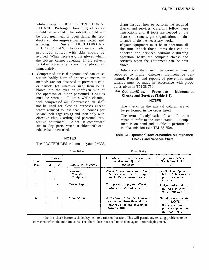
c. Deficiencies that cannot be corrected must bereported to higher category maintenance per-sonnel. Records and reports of preventive main-tenance must be made in accordance with proce-dures given in TM 38-750.3-4. Operator/Crew Preventive Maintenance
Checks and Services (Table 3-1).NOTES
The checks in the interval column are tobe performed in the order listed.
The terms “ready/available” and “missioncapable” refer to the same status — Equip-ment is on hand and is able to perform itscombat mission (see TM 38-750).
Table 3-1. Operator/Crew Preventive MaintenanceNOTES Checks and Services Chart
The PROCEDURES column in your PMCS
B — Before D — During
*Do this check before each deployment to a mission location. This will permit any existing problems to becorrected before the mission starts. The check does not need to be done again until redeployment.
3

C4, TM 11-5820-765-12
Page 4-1. Chapter 4 is superseded as follows:
CHAPTER 4
ORGANIZATIONAL MAINTENANCE
4-1. Scope of Organizational Maintenance
a. This chapter contains instructions coveringorganizational maintenance for the power supply.It includes instructions for performing preventiveand periodic maintenance services and repairfunctions to be accomplished by the organizationalrepair personnel.
b. Organizational maintenance of the powersupply includes:
(1) Preventive maintenance checks and ser-vices (table 4-1).
(2) Touchup painting (para 4-4).
4-2. Test Equipment, Tools, and MaterialsRequired
The test equipment, tools, and materials requiredfor organizational maintenance of the powersupply are listed below:
a. Test Equipment. Multimeter AN/URM-105.
b. Tools. Tool Kit, Electronic EquipmentTK-101/G.
c . Mater ia l s .
(1) Trichlorotrifluoroethane. (NSN 6850-00-105-3084).
(2) Cleaning cloth.
(3) Fine sandpaper (supplied with Tool Kit,Electronic Equipment TK-101/G).
(4) Cotton swab sticks.
(5) Silicone (NSN 6850-00-880-7616).
4-3. Organizational Preventive Maintenance
Organizational preventive maintenance proceduresare designed to help maintain equipment in ser-viceable condition. They include items to be
checked and how to check them. These checksand services, described in table 4-1, outline in-spections that are to be made at specific monthly(M) intervals. Accomplish routine checks as de-scribed in paragraph 3-3b including WARNINGSand NOTES.
Table 4-1. Organizational Preventive MaintenanceChecks and Services Chart
M – Monthly
Item Interval . Item to beNo. M Inspected Procedures
1 ● output Check output voltage.Voltage Adjust to read be-
tween 27 to 29 volts,if required.
4-4. Touchup PaintingRemove rust and corrosion from metal surfaces bylightly sanding them with fine sandpaper. Brushtwo thin coats of paint (Enamel, Semigloss, OliveDrab NSN 8010-00-844-8088) on the bare metalto protect it from further corrosion. Refer to theapplicable cleaning and refinishing practices speci-fied in TB 43-0118 and the painting suppliesavailable for field use in SB 11-573.
Page 5-1. Section II, paragraphs 5-3 and 5-4 aresuperseded as follows:
5-3. Authority for DemolitionRefer to paragraph 1-3.4. Destruction of ArmyElectronics Materiel.
5-4. Paragraph 5-4 deleted.Page A-1. Appendix A is superseded as follows:
APPENDIX A
REFERENCES
The following is a list of applicable references that are available to the operator and organizational repair-man of the power supply.
AR 55-38 Reporting of Transportation Discrepancies in Shipments(Reports Control Symbol (MTMTS-54)).
AR 735-11-2 Reporting of Item and Packaging Discrepancies.
4
C4, TM 11-5820-765-12
APPENDIX A
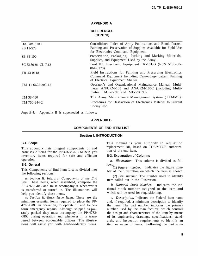
REFERENCES(CONT’D)
DA Pam 310-1 Consolidated Index of Army Publications and Blank Forms.SB 11-573 Painting and Preservation of Supplies Available for Field Use
for Electronics Command Equipment.
SB 38-100 Preservation, Packaging, Packing and Marking Materials,Supplies, and Equipment Used by the Army.
SC 5180-91-CL-R13 Tool Kit, Electronic Equipment TK-101/G (NSN 5180-00-064-5178).
TB 43-0118 Field Instructions for Painting and Preserving ElectronicsCommand Equipment Including Camouflage pattern Paintingof Electrical Equipment Shelter.
TM 11-6625-203-12 Operator’s and Organizational Maintenance Manual: Multi-meter AN/URM-105 and AN/URM-105C (Including Multi-meter ME-77/U and ME-77C/U).
TM 38-750 The Army Maintenance Management System (TAMMS).
TM 750-244-2 Procedures for Destruction of Electronics Materiel to PreventEnemy Use.
Page B-1. Appendix B is superseded as follows:
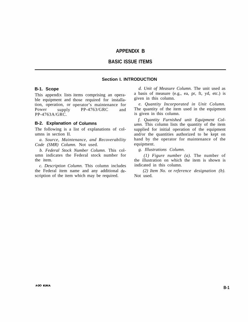
APPENDIX B
COMPONENTS OF END ITEM LIST
Section I. INTRODUCTION
B-1. Scope
This appendix lists integral components of andbasic issue items for the PP-4763/GRC to help youinventory items required for safe and efficientoperation.
B-2. GeneralThis Components of End Item List is divided intothe following sections:
a. Section II. Intergral Components of the EndItem. These items, when assembled, comprise thePP-4763/GRC and must accompany it whenever itis transferred or turned in. The illustrations willhelp you identify these items.
b. Section II. Basic Issue Items. These are theminimum essential items required to place the PP-4763/GRC in operation, to operate it, and to per-form emergency repairs. Although shipped sepa-rately packed they must accompany the PP-4763/GRC during operation and whenever it is trans-ferred between accountable officers. The illustra-tions will assist you with hard-to-identify items.
This manual is your authority to requisitionreplacement BII, based on TOE/MTOE authoriza-tion of the end item.
B-3. Explanation of Columnsa. Illustration. This column is divided as fol-
lows:(1) Figure number. Indicates the figure num-
ber of the illustration on which the item is shown.
(2) Item number. The number used to identifyitem called out in the illustration.
b. National Stock Number. Indicates the Na-tional stock number assigned to the item andwhich will be used for requisitioning.
c. Description. Indicates the Federal item nameand, if required, a minimum description to identifythe item. The part number indicates the primarynumber used by the manufacturer, which controlsthe design and characteristics of the item by meansof its engineering drawings, specifications, stand-ards, and inspection requirements to identify anitem or range of items. Following the part num-
5
1-1
1-1
C4, TM 11-5820-765-12
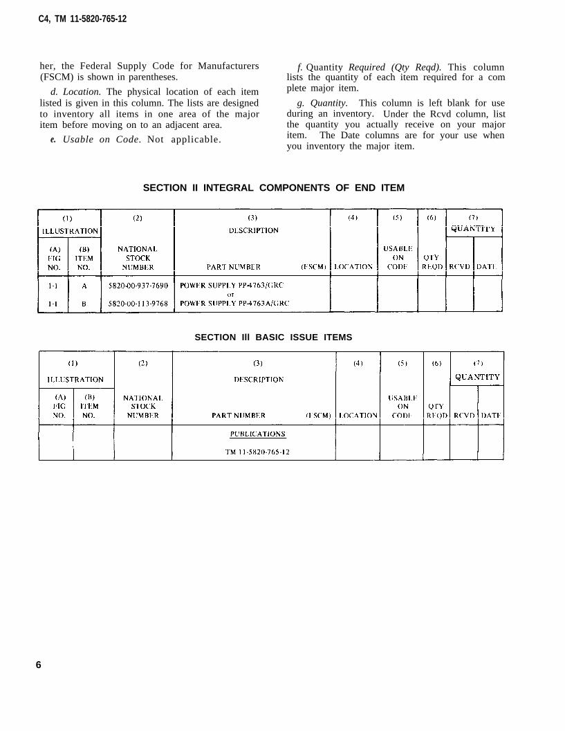
her, the Federal Supply Code for Manufacturers f. Quantity Required (Qty Reqd). This column(FSCM) is shown in parentheses. lists the quantity of each item required for a com
d. Location. The physical location of each item plete major item.
listed is given in this column. The lists are designed g. Quantity. This column is left blank for useto inventory all items in one area of the major during an inventory. Under the Rcvd column, listitem
e.
before moving on to an adjacent area. the quantity you actually receive on your major
Usable on Code. Not applicable. item. The Date columns are for your use whenyou inventory the major item.
SECTION II INTEGRAL COMPONENTS OF END ITEM
SECTION Ill BASIC ISSUE ITEMS
6

C4, TM 11-5820-765-12
By Order of the Secretary of the Army:
JOHN A. WICKHAM JR.General, United States Army
Official: Chief of StaffROBERT M. JOYCE
Major General, United States ArmyThe Adjutant General
DISTRIBUTION:
To be distributed in accordance with DA Form 12-51, Operator’s Maintenance requirements forPP-4763/GRC.

Changes In force: C2 and C3TM 11-5820-765-12
*C3
CHANGE HEADQUARTERSDEPARTMENT OF THE ARMY
No. 3 WASHINGTON , DC, 18 September 1980
OPERATOR’S AND ORGANIZATIONAL MAINTENANCE MANUALPOWER SUPPLIES PP-4763/GRC (NSN 5820-00-937-7690)
ANDPP-4763A/GRC (NSN 5820-00-113-9768)
This Change current as of 15 April 1980.
TM 11-5820-765-12, 28 October 1968, is changedas follows:
Page C-1. Appendix C is superseded as follows:
APPENDIX CMAINTENANCE ALLOCATION
Section I. INTRODUCTIONC-1. GeneralThis appendix provides a summary of themaintenance operations for PP-4763/GRC andPP-4763A/GRC. It authorizes categories ofmaintenance for specific maintenance functionson repairable items and components and thetools and equipment required to perform eachfunction. This appendix may be used as an aid inplanning maintenance operations.
C-2. Maintenance FunctionMaintenance functions will be limited to anddefined as follows:
a. Inspect To determine the serviceability ofan item by comparing its physical, mechanical,and/or electrical characteristics with estab-lished standards through examination.
b. Test. To verify serviceability and to detectincipient failure by measuring the mechanicalor electrical characteristics of an item andcomparing those characteristics of an item andcomparing those characteristics with prescribedstandards.
c. Service. Operations required periodically tokeep an item in proper operating condition, i.e.,to clean (decontaminate), to preserve, to drain,to paint, or to replenish fuel, lubricants, hy-draulic fluids, or compressed air supplies.
d. Adjust To maintain, within prescribedlimits, by bringing into proper or exact position,
or by setting the operating characteristics to thespecified parameters.
e. Align. To adjust specified variable elementsof an item to bring about optimum or desiredperformance.
f. Calibrate. To determine and cause correc-tions to be made or to be adjusted on instru-ments or test measuring and diagnosticequipments used in precision measurement.Consists of comparisons of two instruments, oneof which is a certified standard of knownaccuracy, to detect and adjust any discrepancyin the accuracy of the instrument being com-pared.
g. Install. The act of emplacing, seating, orfixing into position an item, part, module(component or assembly) in a manner to allowthe proper functioning of the equipment orsystem.
h. Replace. The act of substituting a service-able like type part, subassembly, or module(component or assembly) for an unserviceablecounterpart.
i. Repair. The application of maintenanceservices (inspect, test, service, adjust, align,calibrate, replace) or other maintenance actions(welding, grinding, riveting, straightening,facing, remachining, or resurfacing) to restoreserviceability to an item by correcting specificdamage, fault, malfunction, or failure in a part,
1

subassembly, module (component or assembly),end item, or system.
j. Overhaul. That main tenance e f fo r t(service/action) necessary to restore an item to acompletely serviceable/operational condition asprescribed by maintenance standards (i.e.,DMWR) in appropriate technical publications.Overhaul is normally the highest degree ofmaintenance performed by the Army. Overhauldoes not normally return an item to like newcondition.
k. Rebuild. Consists of those services/actionsnecessary for the restoration of unserviceableequipment to a like new condition in accordancewith original manufacturing standards. Re-build is the highest degree of materiel mainte-nance applied to Army equipment. The rebuildoperation includes the act of returning to zerothose age measurements (hours, miles, etc.)considered in classifying Army equipments/components.
C-3. Column Entries
a. Column 1, Group Number. Column 1 listsgroup numbers, the purpose of which is toidentify components , assemblies, subas-semblies, and modules with the next higherassembly.
b. Column 2, Maintenance Category. Column 2contains the noun names of components, as-semblies, subassemblies, and modules for whichmaintenance is authorized.
c. Column 3, Maintenance Functions. Column3 lists the functions to be performed on the itemlisted in column 2. When items are listed withoutmaintenance functions, it is solely for purpose ofhaving the group numbers in the MAC andRPSTL coincide.
d. Column 4, Maintenance Category Column 4specifies, by the listing of a “work time” figure inthe appropriate subcolumn(s), the lowest level ofmaintenance authorized to perform the func-tion listed in column 3. This figure representsthe active time required to perform that main-tenance function at the indicated category ofmaintenance. If the number or complexity of thetasks within the listed maintenance functionvary at different maintenance categories, ap-propriate “work time” figures will be shown foreach category. The number of task-hoursspecified by the “work time” figure representsthe average time required to restore an item(assembly, subassembly, component, module,
2
end item or system) to a serviceable conditionunder typical field operating conditions. Thistime includes preparation time, troubleshootingtime, and quality assurance/quality control timein addition to the time required to perform thespecific tasks identified for the maintenancefunctions authorized in the maintenance alloca-tion chart. Subcolumns of column 4 are asfollows:
C - Operator/CrewO - OrganizationalF - Direct SupportH - General SupportD - Depot
e. Column 5, Tools and Equipment. Column 5specifies by code, those common tool sets (notindividual tools) and special tools, test, andsupport equipment required to perform thedesignated function.
f. Column 6, Remarks. Column 6 contains analphabetic code which leads to the remarks insection IV, Remarks, which is pertinent to theitem opposite the particular code.
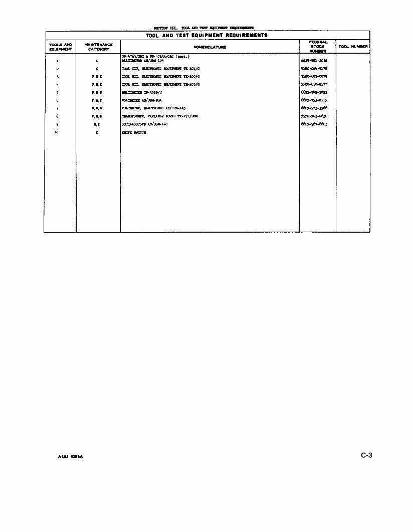
C-4. Tool and Test Equipment Requke-ments (Sec. Ill)
a. Tool or Test Equipment Reference Code. Thenumbers in this column coincide with thenumbers used in the tools and equipmentcolumn of the MAC. The numbers indicate theapplicable tool or test equipment for the main-tenance functions.
b. Maintenace Category, The codes in thiscolumn indicate the maintenance categoryallocated the tool or test equipment.
c. Nomenclature. This column lists the nounname and nomenclature of the tools and testequipment required to perform the mainte-nance functions.
d. National/NATO Stock Number. This columnlists the National/NATO stock number of thespecific tool or test equipment.
e. Tool Number. This column lists the manu-facturer’s part number of the tool followed bythe Federal Supply Code for manufacturers(5-digit) in parentheses.
C-5. Remarks (Sec. IV)
a. Reference Code. This code refers to theappropriate item in section II, column 6.
b. Remarks. This column provides the re-quired explanatory information necessary toclarify items appearing in section II.

00
01
TM 11-5820-765-12
SECTION II MAINTENANCE ALLOCATION CHARTFOR
POWER SUPPLIES PP-4763/GRC AND PP-4763A/GRC
3

TM 11-5820-765-12
SECTION III TOOL AND TEST EQUIPMENT REQUIREMENTSFOR
POWER SUPPLlES PP-4763/GRC AND PP-4763A/GRC
4

TM 11-5820-765-12
SECTION IV. REMARKS
5

By Order of the Secretary of the Army:
Official:
E. C. MEYERGeneral, United States Army
Chief of Staff
J. C. PENNINGTONMajor General, United States Army
The Adjutant General
DISTRIBUTION:To be distributed in accordance with DA Form 12-51, Operator maintenance requirements
for PP-4763/GRC.
6

TECHNICAL MANUAL
NO. 11-5820-765-12
ParagraphCHAPTER 1.
Section I.
II.
CHAPTER 2.Section I.
II.
III.
CHAPTER 3.
CHAPTER 4.
CHAPTER 5.
Section I.
II.
APPENDIX A.B.C.
AGO 6196A
Operator and Organizational
TM 11-5820-765-12
H E A D Q U A R T E R SDEPARTMENT OF THE ARMY
W A S H I N G T O N, D.C., 28 October 1968
Maintenance Manual
POWER SUPPLIES PP-4763/GRC AND PP-4763/GRC
INTRODUCTIONGeneralScope-----------------------------------------------------------------------------------1-1Indexes of publications-------------------------------------------------------------------l-2Forms and records -------------------------------------------------------------- 1-3Description and dataPurpose and use----------------------------------------------------------------------------1-4Technical characteristics -----------------------------------------------------------------1-5Description of Power Supplies
PP-4763/GRC andPP-4768A/GRC--------------------------------------------------------------1-6
INSTALLATION AND OPERATING INSTRUCTIONSService upon receipt of equipmentUnpacking------------------------------------------------------------------------2-1Checking unpacked equipment--------------------------------------------------------2-2Installation instructionsSuitable location------------------------------------------------------------------------2-3Connections----------------------------------------------------------------------2-4OperationOperating control and indicators-----------------------------------------------------2-5Preliminary operating procedure-----------------------------------------------------2-6Operating procedure--------------------------------------------------------------------2-7Stopping procedure ----------------------------- ------------------------------- 2-8
OPERATOR’S MAINTENANCEScope of operator's maintenance-------------------------------------------------- 3-1Materials required--------------------------------------------------------------------------3-2Operator’s preventive maintenance---------------------------------------------------3-3Operator’s preventive maintenance checks and services periods------3-4Operator’s daily preventive maintenance checks and services chart-----3-5Operator’s weekly preventive maintenance checks and services chart.-3-6Cleaning--------------------------------------------------------------------3-7ORGANIZATIONAL MAINTENANCEScope of Organizational maintenance-----------------------------------------------4-1Test equipment tools and materials required------------------------------------ 4-2Organizational monthly maintenance-----------------------------------------------4-3Organizational monthly preventive maintenance checks and services
chart------------------------------------------------------------------------------------4-4Touchup painting--------------------------------------------------------------------------4-5SHIPMENT AND LIMITED STORAGE AND DEMOLITION TO
PREVENT ENEMY USEShipment and limited storageDisassembly and repacking of equipment---------------------------------------- 5-1Repackaging-------------------------------------------------------------------------------5-2Demolition of materiel to prevent enemy useAuthority for demolition-----------------------------------------------------------------5-3Methods of destruction-------------------------------------------------------------------5-4REFERENCES------------------------------------------------------------------------BASIC ISSUE ITEMS-------------------------------------------------------------------------MAINTENANCE ALLOCATION------------------------------------------------------------------------------
Page
1-11-11-1
1-11-1
1-2
2-12-1
2-32-3
2-52-52-52-5
3-13-13-13-13-13-23-2
4-14-14-1
4-14-2
5-15-1
5-15-1
A-1B-1C- l
i

Figure 1-1. Power Supplies PP-4763/GRC and PP-4763A/GRC.

CHAPTER 1
INTRODUCTION
Section I.
1-1. Scopea. This manual describes Power Supplies
PP-4763/GRC and PP-4763A/GRC (fig. l-l)and provides instructions for their installation,operation, and maintenance. It includes in-structions for cleaning and inspection of theequipment, and touchup painting instructions.
b. The basic items issue list (BIIL) appearsin appendix B.
c. The maintenance allocation chart (MAC)appears in appendix C.
d. Appendixes B and C are current as of 15October 1968.
e. Throughout this manual, Power SuppliesPP-4763/GRC and PP-4763A/GRC are re-ferred to as power supp1y, except when a spe-cific model is cited.
1-2. Indexes of Publicationsa. DA Pam 310-4. Refer to the latest issue of
DA Pam 310-4 to determine whether there arenew editions, changes, or additional publica-tions pertaining to the equipment.
b. DA Pam 310-7. Refer to the latest issue ofDA Pam 310-7 to determine whether there aremodification work orders (MWO’S) pertainingto the equipment.
GENERAL
1-3. Forms and Records
a. Reports of Maintenance and Unsatisfac-tory Equipment. Use equipment forms and rec-ords in accordance with instructions given inTM 38-750.
b. Report of Packing and Handling Defi-ciencies. Fill out and forward DD Form 6 (Re-port of Packaging and Handling Deficiencies)as prescribed in AR 700-58 (Army), NAVSUPPub 378 (Navy), AFR 71-4 (Air Force), andMCO 4030.29 (Marine Corps).
c. Discrepancy in Shipment Report (DIS-REP) (SF 861). Fill out and forward Discrep-ancy in Shipment Report (DISREP) (SF 361)as prescribed in AR 55-38 (Army), NAVSUPPub 459 (Navy), AFM 75-34 (Air Force), andMCO P4610.19 (Marine Corps).
d. Report of Equipment Manual Improve-ments. Report of errors, omissions, and recom-mendations for improving this publication bythe individual user is encouraged. Reportsshould be submitted on DA Form 2028 (Rec-ommended Changes to DA Publications) andforwarded direct to Commanding General, U.S.Army Electronics Command, ATTN: AMSEL-ME-NMP-AD, Fort Monmouth, N.J. 07703.
Section II. DESCRIPTION AND DATA
1-4. Purpose and Use source for communication equipment or anyPower Supply PP-4763/GRC converts 115 type of load with requirements within their
volts alternating current (at) to direct current voltage and current ratings.
(dc) at a selected regulated voltage. PowerSupply PP-4763A/GRC converts either 115 or 1-5. Technical Characteristics
230 volts ac to direct current at a selected re- Power input:Voltage --------------- 115 volts ±10% at 47 to
gulated voltage. The power supplies function 63 cps.(PP-476S/GRC).in a similar way; both provide a dc power 115 volts ±10% at 47 to
AGO 6196A 1-1

Phase -----------------Current (full load) ----
Power output:Voltage---------------
Current (full load)----------Ripple voltage-------------Voltage regulation--------
Surrounding operatingtemperature --------------
Meters:Output current meter,type MR36W080DCAAROutput voltage meter,type MR36W050DCVVR
Solid-state devicesSemiconductor device,diode:
PP-4763/GRC-------PP-4763A/GRC------
Transistor-------------Semiconductor device,
controlled rectifier ---Rectifier, semiconductor
device:PP-4763/GRC-------PP-4763A/GRC---------
63 cps, or 230 volts±10% at 47 to 68 cps(PP-4763A/GRW).
Single.23 amperes (PP-4763/
GRC).
23 amperes (PP-4763A/GRC at 116 volt input).
11.5 amperes (PP-4763A/GRC at 280 volt input).
Variable from 27 to 20volts dc (28-volt opera-tion).
60 amperes, continuous1.0% (root mean square).±0.5%
-4°F (-20°C) to 131°F(55oC).
0 to 80 amperes
0 to 60 volts
16 ea.24 ea.4 ea.
3 ea.
2 ea.None.
1-6. Description of Power SuppliesPP4763/GRC and PP4763A/GRC(fig. l-l)
a. Phyiscal Description. The power supply isa self-contained unit in a metal cabinetPP-4763/GRC is 13½ inches high, 19½inches wide, and 14¾ inches deep and weighs120 pounds. PP-4763A/GRC is 13½ inches
high, 19½ inches wide, and 15¼ inches deepand weighs 125 pounds. A hinged front paneland a removable cover provide access to theelectrical components. The PP-4763A/GRC isprovided with an interlock switch which openthe ac input power circuit when the cover is re-moved. An input circuit breaker and indicatorare mounted on the front panel. A carryinghandle is mounted on each side of the metalcabinet. An output voltage adjustment ismounted behind the front panel and can bereached by removing a plate on the outside ofthe front panel. The PP-4763A/GRC is pro-vided with movable links for converting theequipment for use from a 116-volt ac powersource to a 230-volt ac power source. The linkscan be reached by removing the cover. Thesides of the cabinet are flanged on the bottomand at the back for mounting purposes. Vent-ing is provided by air louvers on the bottomand on the top cover of the cabinet An acpower cable (fig. 2-2) is connected through ther e a r p a n e l o f t h e p o w e r s u p p l y . T h ePP-4763A/GRC is supplied with an ac plug abtached to the cable, and the PP4763/GRC issupplied with a cable that has three terminallugs on each end. Output terminals (dc) withpolarity plainly marked are located behind anaccess plate at the rear panel for connectingthe output of the power supply to the equip-ment being powered (cable not supplied). Also,the PP-4763A/GRC is provided with a dc output receptacle at the rear panel which may beused instead of the output terminals for con-necting to equipment being powered.
b. Solid-State Devices. The power suppliesare solid-state controlled devices. Automaticand continuous regulation of voltage withinthe limits specified under technical characteria-tics (para 1-5) is accomplished by a controlcircuit built into printed card PC101.
1-2

CHAPTER 2
INSTALLATION AND OPERATING INSTRUCTIONS
Section I. SERVICE UPON
2-1. Unpackinga. Packaging Data. When packed for ship-
ment, Power Supply PP-4763/GRC is packedin a 24¾ by 21¾ -by 17¼ -inch wooden box.The volume is 5.4 cubic feet, and the totalshipping weight is 193 pounds. The PP-4763A/GRC is packed in a 24¾ -by 22¼ -by 17¼-inchbox. The volume is 5.5 cubic feet, and the totalshipping weight is 200 pounds. A typicalwooden box and its contents are shown infigure 2-1.
b. Removing Contents. Follow the procedureoutlined below when unpacking the equipment.
(1) Remove the nails that secure the ply-wood box to the wooden base. Lift the box freeof the unit and the base.
(2) Remove the bolts that fasten thepower supply to the base.
(3) Lift the power supply clearbase.
(4) Remove the fitted corrugatedping paper from the power supply.
of the
wrap-
RECEIPT OF EQUIPMENT
2-2. Checking Unpacked Equipmenta. Inspect the equipment for damage that
may have incurred during shipment. If theequipment has been damaged, refer to para-graph 1-3 for applicable forms and records.
b. Check to see that the equipment is com-plete as listed on the packing slip. If a packingslip is not available, check the equipmentagainst the basic issue items list (appx B). Re-port all discrepancies in accordance with TM33-750. The equipment should be placed in ser-vice even though a minor assembly or part thatdoes not affect proper functioning is missing.
c. Check to see whether the equipment hasbeen modified. If the equipment has been modi-fied, the MWO number will appear on the frontpanel, near the nomenclature plate. Also, checkto see whether all MWO’S current at the timethe equipment is placed in use have been ap-plied.
Note. Current MWO’s applicable to the equipmentare listed in DA PAM 810-7.
d. Check the latest issue of DA PAM 310-4to see whether you have the latest editions ofall applicable maintenance literature.
2-1

Figure 2-1. Typical packaging.
2-2

Section II. INSTALLATION INSTRUCTIONS
2-3. Suitable locationCaution: Do not operate the equipment if
there is evidence of water inside the cabinet.The power supply is designed to operate withina sheltered location protected from the ele-ments. It is not designed to operate in rain,snow, or ice, or where surrounding tempera-ture exceeds 55° CH.
2-4. Connections(fig. 2-2)
Warnings:1. The metal cabinet must be grounded at
all times when it is connected to an ac source.The PP-4763A/GRC is grounded by the acpower cable when the ac power cable is pluggedinto an ac outlet. The ac power cable suppliedwith the PP-4763/GRC includes a ground(GRD) wire for this push The AC ON-OFFswitch must be set to OFF before the powersupply is connected.
2. Be careful when working on the 115-or230-volt ac line connections Serious injury orDEATH may result from contact with themterminals,
3. Low-voltage, high-amperage current ispresent at output connections and at connec-tions inside the equipment. Do not touch con-nections or remove the cabinet cover until theequipment is removed from power source. Re-energize the power supply before connectingor disconnecting the equipment to be powered.
a. Turn the AC ON-OFF switch (fig. l-l)to OFF.
Caution: Measure the available ac supplyvoltage, to determine whether it is 115-or 230-volts ac.
b. Connect the three-wire, ac power cable toa single-phase, 115-volt, 50- to 60-cps source
when using the PP-4763/GRC. Connect thepower cable to either a single-phase 115-volt,50- to 60-cps source, or a single-phase, 230-volt, 50- to 60-cps source when using thePP4763A/GRC. After determining whichpower source will be used, secure the ac inputlinks in the correct position for the selectedinput power as illustrated in figure 2-2. For115-volt power, secure the links as shown infigure 2-2; for 230-volt power, secure the linksas shown in figure 2-2. Note that in the 230-volt position, both links are fastened (in paral-lel) across the two center terminals and se-cured. A connector is mounted on the powercable to connect the PP-4763A/GRC to the acpower supply; the power cable for thePP4768/GRC maybe connected directly to theac power supply as follows:
(1 ) Connec t the whi te wi re to thegrounded ac terminal.
(2) Connect the black wire to the un-grounded ac terminal.
(3) Connect the GRD wire to a good earthground.
c. Remove the rear panel access plate to ex-pose the dc output terminals (fig. 2-2).
Caution: Be sure to observe correctpolarity; for example (+) output terminal to(+) load terminal; (-) output terminal to(-) load terminal.
d. Connect two dc leads with ¼-inch lugscapable of carrying 50-ampere current (or thecurrent requirements of the load connected) tothe power supply output terminals . ThePP-4763A/GRC is provided with dc output re-ceptacle J1 at the rear panel (fig. 2-2), and ei-ther the output terminals or output receptacleJ1 may be used.
e. Replace the access panel and tighten thecable clamps.
2-3

Figure 2-2. Installation connections.
2-4

Section Ill. OPERATION
2-5. Operating Controls and Indicators(fig. 2-3)
Control or Indicator
AC ON-OFF swi tch(two-posit ion toggle).
O u t p u t c u r r e n t m e t e rM2.
Output voltage meterM l .
Dc voltage adjustcontrol.
Function
Serves dual function: ON-O F F s w i t c h f o r n o r m a loperation, and protec-t ive circuit breaker ifoperat ing current loadexceeds safe currentload.
Indicates power supplyoutput current.
Indicates power supply dcoutput voltage.
Permits varying output vol-t a g e o f p o w e r s u p p l yfrom 27 to 29 volts.
2-6. Preliminary Operating Procedure
Caution: A continuous flow of air throughthe power supply is necessary during operationto prevent damage because of overheating. Donot obstruct the flow of air through the louverson the underside or the top of the equipment.If the fan fails to operate, do not continueoperation of the equipment.
After performing the procedures given in par-agraph 2-4, proceed as follows:
a. Place the AC ON-OFF switch to ON andread the output voltage as indicated on outputvoltage meter Ml (para 2-5).
b. Remove the ADJUST access plate on thefront panel (fig. 2-3).
c. With a screwdriver, turn the shaft of thedc voltage adjust control until the output volt-age meter Ml indicates the desired output volt-age.
d. Check output current meter M2 indica-tion. Output current should not exceed 50 am-peres.
e. Place the AC ON-OFF switch at OFF andreplace the ADJUST access plate on the frontpanel.
2-7. Operating Procedurea. To operate the power supply, place the AC
ON-OFF switch at ON.b. Check the output voltage at intervals dur-
ing operation of the power supply. When nec-essary, adjust the dc voltage adjust control tomaintain the desired output voltage.
2-8. Stopping ProcedurePlace the AC ON-OFF switch at OFF.
2-5

Figure 2–3. Front panel controls and indicators.
2-6

CHAPTER 3
OPERATOR’S MAINTENANCE
3-1. Scope of Operator’s MaintenanceThe maintenance duties assigned to the opera-tor of the power supply are listed below to-gether with a reference to paragraphs cover-ing the specific maintenance function.
a. Operator’s daily preventive maintenancechecks and services chart (para 3-5).
b. Operator’s weekly preventive maintenancechecks and services chart (para 3-6).
c. Cleaning (para 3-7).
3-2. Materials Requireda. Cleaning compound
9542) .(FSN 7930-395-
b. Cleaning cloth.
3-3. Operator’s Preventive MaintenancePreventive maintenance is the systematic care,servicing, and inspection of equipment to prev-ent the occurrence of trouble, reduce down-time, and assure that the equipment is service-able.
a. Systematic Care. The procedures given inparagraphs 3-5, 3-6, and 3-7 cover routinesystematic care and cleaning essential to theproper upkeep of the power supply.
b. Preventive Maintenance Check and Ser-vices. The preventive maintenance checks andservices charts (para 3-5 and 3-6) outline
functions to be performed at specific intervals.These checks and services are to maintainArmy electronic equipment in a combat-ser-viceable condition; that is, in good general(physical) condition and in good operatingcondition. To assist operators in maintainingcombat serviceability, the chart indicates whatto check, how to check, and the normal indica-tions; the References column lists the illustra-tions, paragraphs, or manuals that containdetailed repair or replacement procedures. Ifthe defect cannot be remedied by the operator,a higher category of maintenance or repair isrequired. Records and reports of these checksand services must be made in accordance withthe requirements set forth in TM 38-750.
3-4. Operator’s Preventive MaintenanceChecks and Services Periods
Paragraph 3-5 specifies checks and servicesthat must be accomplished daily, or under theconditions listed below.
a. Before the power supply is put into opera-tion.
b. When the power supply initially is in-Stalled.
c. When the power supply is reinstalledafter removal for any reason.
d. At least once each week if the power sup-ply is maintained in a standby condition.
3-5. Operator’s Daily Preventive Maintenance Checks and Services Chart
Warnings:
1. Be careful when working on the 115- or 230-volt ac line connections Serious injury or DEATHmay result from contact with these terminals.
2. Low-voltage, high-amperage current is present at output connations and at connections in-side equipment. Do not touch connections or remove cabinet cover until equipment is removedfrom power source. Reenergize power supply before performing any maintenance.
3-1

1 Completeness -------------------- Check to see that equipment is com- Appx B.plete.
2 Exterior surfaces ---------------- Clean exterior surfaces, including panel Para 3-7.and meter glasses. Check both meterglasses for cracks.
3 O p e r a t i o n - - - - - - - - - - - - - - - - - - - - - - - - Operate equipment. Output voltage and Para 2-6 and 2-7.o u t p u t c u r r e n t m e t e r s s h o u l d i n d i -cate output voltage and output cur-rent, respectively.
3-6. Operator's Weekly Preventive Maintenance Checks and Service ChartWarnings:
1. Be careful when working on the 115-or 230-volt ac line connections Serious injury or DEATHmay result from contact with these terminals.
2. Low-voltage high-amperage current is prestmt at output connections and at connections in-side equipment. Do not touch connections or remove cabinet cover until equipment is removed frompower eourah Reenergize power supply before performing any maintenance.
1 C a b l e - - - - - - - - - - - - - - - - - - - - - - - - - - - Inspect cable for frayed, chafed, or Refer to higher categorycracked insulation. Replace any con- of maintenance.nector that is broken, arced, or wornexcessively.
2 M e t a l s u r f a c e s - - - - - - - - - - - - - - - - - - - Inspect exposed metal surface for rust Refer to higher categoryor corrosion. Clean and touchup paint of maintenance.as required.
3-7. CleaningThe exterior surfaces of the power supplyshould be free of dust, dirt, grease, and fungus.
a. Remove dust and loose dirt with a clean,soft cloth.
Warning: Prolonged breathing of cleaningcompound is dangerous; make sure adequateventilation is provided. Cleaning compound isflammable; do not use near a flame. Avoidcontact with the skin; wash off any that spillson the hands.
b. Remove grease, fungus, and ground-in dirt
from the case; use a cloth dampened (not wet)with the cleaning compound.
c. Remove dust or dirt from the plug andjack with a cotton swab stick lightly dampenedwith the cleaning compound.
Caution: Do not press on the meter face(glass) when cleaning; the meter may becomedamaged.
d. Clean the front panel, meters, and knob;use a soft, clean cloth. If dirt is difficult to re-move, dampen the cloth with water; mild soapmay be used for more effective cleaning.
3 -2

CHAPTER 4
ORGANIZATIONAL MAINTENANCE
4-1. Scope of Organizational Maintenance
a. This chapter contains instructions cover-ing organizational maintenance for the powersupply. It includes instructions for performingpreventive and periodic maintenance servicesand repair functions to be accomplished by theorganizational repairman.
b. Organizational maintenance of the powersupply includes:
(1) Preventive maintenance checks andservices (para 4-4).
(2) Touchup painting (para 4-5).
4-2. Test Equipment, Tools, and MaterialsRequired
The test equipment, tools, and materials re-quired for organizational maintenance of thepower supply are listed below.
a. Test Equipment. Multimeter106 (TM 11-6625-208-12) .
b. Tool. Tool kit ElectronicTK-101/G (SM 11-4-5180-R13).
c. Materia1s.
AN/URM-
Equipment
No.(1) Cleaning compound (Federal stock7930-395-9542) .
(2) Cleaning cloth.
(3) Fine sandpaper (supplied with ToolKit, Electronic Equipment TK-101/G).
(4) Cotton swab sticks.
4-3. Organization Monthly MaintenancePerform the maintenance functions indicatedin the organizational monthly preventive main-tenance checks and services chart (para 4-4)once each month. A month is defined as ap-proximately 30 calendar days of 8 hour-per-day operation. If the equipment is operation 16hours a day, the monthly preventive mainte-nance checks and services should be performedat 15-day intervals. Adjustment of the mainte-nance interval must be made to compensate forany unusual operating conditions. Equipmentmaintained in a standby (ready for immediateoperation) condition must have monthly prev-entive maintenance checks and services per-formed on it. Equipment in limited storage(requires service before operation) does not re-quire monthly preventive maintenance. Thedaily and weekly periodic services constitute apart of the monthly preventive maintenancechecks and services and must be performedconcurrently. All deficiencies or shortcomingsshould be recorded in accordance with the re-quirements of TM 38-750. Perform all thechecks and services listed in the monthly pre-ventive maintenance checks and services chart(para 4-4) in the sequence listed.
4-4. Organizational Monthly Preventive Maintenance Checks and Service Chart
Warning:
1. Be careful when working on the 115- or 230-volt ac line connections. Serious injury or DEATHmay result from contact with these terminals.
2. Low-voltage, high-amperage current iS present at output connections and at connections in-side the equipment. DO not touch connetions or remove cabinet cover until equipment is removedfrom power source. Deenergize the power supply before performing any maintenance
4-1

1.
2
3
4
5
6
7
8
Installation--------------------------------
Preservation-------------------------------
P u b l i c a t i o n s - - - - - - - - - - - - - - - - - - - - - - - - -
Modidcations---------------------------
Connections and cables---------------------
ACON-OFF switch---------------------------
Hardware-------------------------------------
Fan--------------------------------------------
C h e c k t o s e e t h a t e q u i p m e n t i s c o r n - A p p x B .plete.
Check al l surfaces for evidence of fun- Para 4-6.gus. Remove rust and corrosion andspot-paint bare spots.
Check to see that al l publicat ions are DA Pam 310-4.complete, serviceable and current
Check DA Pam 310-7 to determine if DA Pam 310-7.new app l i cab l e MWO’S have beenp u b l i s h e d . A U U R G E N T M W O ’ Sm u s t b e a p p l i e d i m m e d i a t e l y . A l lNORMAL MWO’S must be scheduled.
Check to be sure that connectors areintact , clean, and t ight-fi t t ing, andcable is in good condition, free fromc r a c k s o r d e t e r i o r a t e d i n s u l a t i o n .Check cables for continuity.
Check that mechanical operation of ACON-OFF switch is smooth and freefrom internal and external binding.
C h e c k t o s e e t h a t n o p a r t s o r h a r d -ware, such as bolts, nuts, and screwsare missing.
Check to see that fan and interior ofpower supply is clean.
4-5. Touchup Painting the bare metal to protect it from further corro-
Remove rust and corrosion from metal sur- sion. Refer to the applicable cleaning and re-
faces by lightly sanding them with fine sand- finishing practices specified in TB SIG 364 and
paper. Brush two thin coats of paint (Enamel, the painting supplies available for field use inSemigloss, olive Drab FSN 8010-844-8088) on SB 11-573.
4-2

CHAPTER 5
SHIPMENT AND LIMITED STORAGE
TO PREVENT ENEMY
AND DEMOLITION
USE
Section I. SHIPMENT AND LIMITED STORAGE
5-1. Dissassembly and Repacking ofEquipment
Prepare the power supply for repacking forshipment and limited storage as follows:
a. Place the AC ON-OFF switch at OFF.
b. Remove the two dc leads that connect thepower supply output to other equipment.
c. Disconnect the ac cable.
e. Fasten the packages that contain the cableassembly and the technical manuals to thepower supply (fig. 2-1).
5-2. RepackingNormally, repackaging the power supply forshipment or limited storage will be performedat a packaging facility or by a repackagingteam. If emergency packaging is required, se-lect the materials from those listed in SB
d. Wrap the technical manual in wrapping 38-100. Package the equipment in accordancepaper and secure it with pressure-sensitive with the original packaging (para 2-1) sofartape. as possible with the available materials.
Section II. DEMOLITION OF MATERIEL TO PREVENT ENEMY USE
5-3. Authority for DemolitionDemolition of the equipment will be accom-plished only upon order of the commander. Usethe destruction procedures outlined in para-graph 5-4 to prevent further use of the equipment
5-4. Methods of DestructionThe tactical situation and time available willdetermine the method to be used when destruc-tion of equipment is ordered. In most cases, itis preferable to completely demolish some por-tions of the equipment rather than partiallydestroy all the equipment components. Spareparts should be destroyed with the same thor-oughness as the basic equipment.
a. Smash. Smash the electronic parts, metersand controls, and cabinet.
b. Cut. Cut the wiring and cabling of thepower supply.
c. Burn. Burn the spare parts and the tech-nical manuals covering the equipment.
Warning: Be extremely careful with explo-sives and incendiary devices. Use these itemsonly when the need is urgent.
d. Explode. If explosives are necessary, usegrenades, TNT, or firearms.
e. Dispose. Bury or scatter destroyed parts,including spare parts.
5-1

APPENDIX A
REFERENCES
The following is a list of applicable references that are available to the operator and organisationalrepairman of the power supply.
AR 55-38 ------------- Report of Transportation Discrepancies in Shipments (Reports ControlSymbol MTMTS-54).
AR 700-58 -------- -- Report of Packaging and Handling Deficienies (Reports Control SymbolAMC-137) .
DA Pam 310-4 ---------- Index of Technical Manuals, Technical Bulletins, Supply Manuals (types7, 8, and 9), Supply Bulletins, and Lubrication Orders.
DA Pam 310-7 ---------- U.S. Army Equipment Index of Modification Work Orders.SB 11-578---------------- Painting and Preservation Supplies Available for Field Use for Electron-
ics Command Equipment.SB 38-100 ---------------- Preservation, Packaging, and Packing Materials, Supplies, and Equipment
Used by the Army.SM 11-4-5180-R13 -- Tool Kit, Electronics Equipment TK-101/G.TB SIG 364--------------- Field Instructions for Painting and Preserving Electronics Command
Equipment.TM 11-6625-203-12 ----- Operator and Organizational Maintenance Manual; Multimeter AN/URM-
106, Including Multimeter ME-77/U.TM 38-750 -------- Army Equipment Record Procedures.
A-1
APPENDIX B
BASIC ISSUE ITEMS
Section I. INTRODUCTION
B-1. ScopeThis appendix listsble equipment andtion, operation, orPower supplyPP-4763A/GRC.
B-2. ExplanationThe following is aumns in section II.
items comprising an opera-those required for installa-operator’s maintenance for
PP-4763/GRC and
of Columnslist of explanations of col-
a. Source, Maintenance, and RecoverabilityCode (SMR) Column. Not used.
b. Federal Stock Number Column. This col-umn indicates the Federal stock number forthe item.
c. Description Column. This column includesthe Federal item name and any additionalscription of the item which may be required.
de-
d. Unit of Measure Column. The unit used asa basis of measure (e.g., ea, pr, ft, yd, etc.) isgiven in this column.
e. Quantity Incorporated in Unit Column.The quantity of the item used in the equipmentis given in this column.
f. Quantity Furnished unit Equipment Col-umn. This column lists the quantity of the itemsupplied for initial operation of the equipmentand/or the quantities authorized to be kept onhand by the operator for maintenance of theequipment.
g. Illustrations Column.(1) Figure number (a). The number of
the illustration on which the item is shown isindicated in this column.
(2) Item No. or reference designation (b).Not used.
B-1

1-1
I-1
1-1
SECTION II BASIC ISSUE ITEMS
B-2

APPENDIX C
MAINTENANCE ALLOCATION
Section I. INTRODUCTION
C-1. GeneralThis appendix provides a summary of themaintenance operations covered in the equip-ment literature for Power supplyPP-4763/GRC and PP-4763A/GRC. It autho-rizes categories of maintenance for specificmaintenance functions on repairable items andcomponents and the tools and equipment re-quired to perform each function. This appendixmay be used as an aid in planning maintenanceoperations.
C-2. Explanation of Format for Mainten-ance Allocation Chart
a. Group Number. Not used.b. Component Assembly Nomenclature. This
column lists the item names of componentunits, assemblies, subassemblies, and moduleson which maintenance is authorized.
c. Maintenance Function. This column indi-cates the maintenance category at which per-formance of the specific maintenance functionis authorized. Authorization to perform afunction at higher categories. The codes usedrepresent the various maintenance categoriesas follows:
C Opera to r /CrewO Organizational MaintenanceF Direct Support MaintananceH General Support MaintenanceD Depot Maintenance
d. Tools and Equipment. The numbers ap-pearing in this column refer to specific toolsand equipment which are identied by thesenumbers in section III.
e. Remarks. Self explainatory.
C-3. Explanation of Format for Tool andTest Equipment Requirements
The columns in the tool and test equipment re-quirements chart are as follows:
a. Tools and Equipment. The numbers inthis column coincide with the numbers used inthe tools and equipment column of the MAC.The numbers indicate the applicable tool forthe maintenance function.
b. Maintenance Category. The codes in thiscolumn indicate the maintenance category nor-mally allocated the facility.
c. Nomenclature. This column lists tools,test and maintenance equipment required toperform the maintenance functions
d. Federal Stock Number. This column liststhe Federal stock number.
e. Tool Number. Not used
C-1

SECTON II.
C-2
SECTION III.
C-3

By Order of the Secretary of the Army:
Official:KENNETH G. WICKHAM,Major General, United States Army,The Adjutant General
WILLIAM C. WESTMORELAND,General, United States Army,Chief of Staff.
Distribution:
To be distributed in accordance with DA Form 12-61 Organization maintenance literaturerequirements for AN/GRC-106, AN/GRC-122, AN/GRC-142 and AN/VSC-2 radio sets.
U. S. GOVERNMENT PRINTING OFFICE : 1 9 8 7 - 201-421 (70877)


PIN : 030807-004