Embed Size (px)
Citation preview
*TM 1-1500-204-23-2
TECHNICAL MANUAL
AVIATION UNIT MAINTENANCE (AVUM)AND AVIATION INTERMEDIATEMAINTENANCE (AVIM) MANUAL
FOR
GENERAL AIRCRAFT MAINTENANCE
(PNEUDRAULICS MAINTENANCE AND PRACTICES)
VOLUME 2
*This manual together with TM 1-1500-204-23-1, TM 1-1500-204-23-3 through TM 1-1500-204-23-10, dated 31 July 1992, supersedes TM 55-1500-204-25/1, dated 6 April 1970,including all changes.
DISTRIBUTION STATEMENT A: Approved for public release; distribution is unlimited.
H E A D Q U A R T E R S , D E P A R T M E N T O F T H E A R M Y 3 1 J U L Y 1 9 9 2
This copy is a reprint which includes current pages from Changes 1 and 2.
CHANGE
NO. 3
TM 1-1500-204-23-2C3
HEADQUARTERSDEPARTMENT OF THE ARMY
WASHINGTON, D.C., 29 January 1999
AVIATION UNIT MAINTENANCE (AVUM) AND
AVIATION INTERMEDIATE MAINTENANCE (AVIM) MANUAL
FOR
GENERAL AIRCRAFT MAINTENANCE
(PNEUDRAULICS MAINTENANCE AND PRACTICES)
VOLUME 2
DISTRIBUTION STATEMENT A: Approved for public release: distribution is unlimited
TM 1-1500-204-23-2, 31 July 1992, is changed as follows:
1. Remove and insert pages as indicated below. New or changed text material is indicated by a verticalbar in the margin.
Remove pages Insert pages
i/ii(blank)
4-1 and 4-24-21 and 4-224-35 and 4-364-69 and 4-70
i/(ii blank)3-8.1/(3-8.2 blank)4-1 and 4-24-21 and 4-224-35 and 4-364-69 and 4-70
2. Retain this sheet in front of manual for reference purposes.

TM 1-1500-204-23-2C3
By Order of the Secretary of the Army:
Official:
DENNIS J. REIMERGeneral, United States Army
Chief of Staff
JOEL B. HUDSONAdministrative Assistant to the
Secretary of the Army05555
DISTRIBUTION:
To be distributed in accordance with Initial Distribution Number (IDN) 313302, requirements for TM1-1500-204-23-2.

TM 1-1500-204-23-2C 2
CHANGE HEADQUARTERSDEPARTMENT OF THE ARMY
NO. 2 WASHINGTON, D.C., 1 FEBRUARY 1994
Aviation Unit Maintenance (AVUM) andAviation Intermediate Maintenance (AVIM) Manual
forGENERAL AIRCRAFT MAINTENANCE
(PNEUDRAULICS MAINTENANCE AND PRACTICES)VOLUME 2
DISTRIBUTION STATEMENT A: Approved for public release; distribution is unlimited.
TM 1-1500-204-23-2, 31 July 1992, is changed as follows:
1. Remove and insert pages as indicated below. New or changed text material is indicated by a vertical bar in themargin. An illustration change is indicated by a miniature pointing hand.
Remove pages Insert pages
4-65 and 4-66 4-65 and 4-664-71 and 4-72 4-71 and 4-72
-------- 4-74.1 and 4-74.24-75 and 4-76 4-75 and 4-76
-------- 4-76.1/(4-76.2 blank)4-169/(4-170 blank) 4-169/(4-170 blank)
2. Retain this sheet in front of manual for reference purposes.
By Order of the Secretary of the Army:
GORDON R. SULLIVANGeneral, United States Army
Chief of Staff
Official:
MILTON H. HAMILTONAdministrative Assistant to the
Secretary of the Army06311
Distribution:
To be distributed in accordance with DA Form 12-31-E, block no. 3302, requirements for TM 1-1500-204-2
U.S. GOVERNMENT PRINTING OFFICE: 1994 - 510-106-00002
TM 1-1500-204-23-2C 1
CHANGE HEADQUARTERSDEPARTMENT OF THE ARMY
NO. 1 WASHINGTON, D.C., 30 JUNE 1993
Aviation Unit Maintenance (AVUM) andAviation Intermediate Maintenance (AVIM) Manual
forGENERAL AIRCRAFT MAINTENANCE
(PNEUDRAULICS MAINTENANCE AND PRACTICES)VOLUME 2
DISTRIBUTION STATEMENT A: Approved for public release; distribution is unlimited.
TM 1-1500-204-23-2, 31 July 1992, is changed as follows:
1. Remove and insert pages as indicated below. New or changed text material is indicated by a vertical bar in themargin. An illustration change is indicated by a miniature pointing hand.
Remove pages Insert pages
i/(ii blank) i/(ii blank)4-1 through 4-4 4-1 through 4-44-25 and 4-26 4-25 and 4-264-35 and 4-36 4-35 and 4-364-73 and 4-74 4-73 and 4-74
2. Retain this sheet in front of manual for reference purposes.
By Order of the Secretary of the Army:
GORDON R SULLIVANGeneral, United States Army
Official Chief of Staff
MILTON H HAMILTONAdministrative Assistant to the
Secretary of the Army04458
DISTRIBUTION:To be distributed in accordance with DA Form 12-31-E, block no. 3302, requirements for TM 1-1500-204-23-2.
TM 1-1500-204-23-2
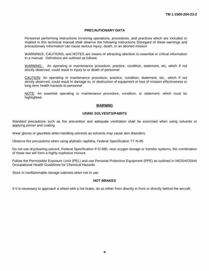
PRECAUTIONARY DATA
Personnel performing instructions Involving operations, procedures, and practices which are included orImplied in this technical manual shall observe the following instructions Disregard of these warnings andprecautionary Information can cause serious Injury, death, or an aborted mission
WARNINGS, CAUTIONS, and NOTES are means of attracting attention to essential or critical informationIn a manual. Definitions are outlined as follows
WARNING: An operating or maintenance procedure, practice, condition, statement, etc, which If notstrictly observed, could result In injury to or death of personnel
CAUTION: An operating or maintenance procedure, practice, condition, statement, etc., which If notstrictly observed, could result In damage to, or destruction of equipment or loss of mission effectiveness orlong term health hazards to personnel
NOTE: An essential operating or maintenance procedure, condition, or statement, which must behighlighted.
WARNING
USING SOLVENTS/PAINTS
Standard precautions such as fire prevention and adequate ventilation shall be exercised when using solvents orapplying primer and coating
Wear gloves or gauntlets when handling solvents as solvents may cause skin disorders.
Observe fire precautions when using aliphatic naphtha, Federal Specification TT-N-95
Do not use drycleaning solvent, Federal Specification P-D-680, near oxygen storage or transfer systems; the combinationof these two will form a highly explosive mixture.
Follow the Permissible Exposure Limit (PEL) and use Personal Protective Equipment (PPE) as outlined in NIOSH/OSHAOccupational Health Guidelines for Chemical Hazards
Store In nonflammable storage cabinets when not In use
HOT BRAKES
If it is necessary to approach a wheel with a hot brake, do so either from directly in front or directly behind the aircraft.
a
TM 1-1500-204-23-2
GROUND SUPPORT EQUIPMENT
Always operate all equipment in accordance with the operator's manual.
To prevent accidental falls, appropriate maintenance platforms/safety stands illustrated in appropriate workstandmanuals or any other approved locally procured/manufactured safety stands/restraint equipment will be used whenworking (above 10 feet) on aircraft in a non-tactical environment.
Install safety lock when an adjustable-height maintenance platform Is in use.
Ensure the air hose used with compressed air Is safe for the pressure being handled.
FIRE EXTINGUISHERS
Monobromotrifluoromethane (CF3Br) is highly volatile, but not easily detected by odor. Although nontoxic, CF3Br shall beconsidered in the same class as other freons and carbon dioxide, i.e., capable of causing danger to personnel primarilyby reduction of oxygen available for proper breathing. The liquid may cause frostbite or low temperature burns if allowedto come in contact with the skin.
Bromochloromethane (CB) is a narcotic agent of moderate Intensity, but of prolonged duration. It Is considered less toxicthan carbon tetrachloride, methylbromide, or the usual products of combustion. Normal precautions should be takenwhile using bromochloromethane, including the use of oxygen masks.
HYDRAULIC FLUID
To avoid contamination, do not use previously opened cans of hydraulic fluid. A new, sealed can of fluid must beopened and used when opening can, clean top and use a clean sharp, unplated Instrument to prevent contamination.
COMPRESSED AIR
Compressed air shall not be used for cleaning purposes unless reduced to less than 30 psi and then only with effectivechip-guarding and personal protective equipment.
NOISE HAZARD
Noise levels reached during ground runup of Army aircraft are of a level that may cause permanent hearing loss.Maintenance personnel shall wear adequate hearing protection when working on aircraft with engines In operation.
PROPER USE OF PLATED TOOLS
Use only chrome plated steel or unplated steel tools for disassembly or reassembly procedures described in this manual.Use of cadmium or zinc plated tools is not permitted since these platings are prone to chipping and flaking. Should thesechips or flakes become embedded in aircraft parts, galvanic corrosion will result. Should these chips or flakes enter fuelor oil wetted components, they may eventually clog the filter or produce intergranular attack of nickel or titanium basealloys at elevated temperature. All tools regardless of type plating should be serviceable and free of chipping.
b

TM 1-1500-204-23-2
SPECIAL INSTRUCTIONS
All equipment must be operated per the manufacturer's operating instructions. If unavailable, instructions for the use andcare will be developed SOPs will be prepared and used for all shop operations (refer to AR 38595). The supportingSafety Office will use their expertise to provide assistance. Guidance for industrial hazards can be found in Code ofFederal Regulations 29 CFR 1910, and Chemical Hazards in NIOSH/OSHA Guidelines for Chemical Hazards.
c/(d blank)
TM 1-1500-204-23-2
TECHNICAL MANUAL HEADQUARTERS,DEPARTMENT OF THE ARMY
NO. 1-1500-204-23-2 WASHINGTON, D.C., 31 JULY 1992
AVIATION UNIT MAINTENANCE (AVUM) AND AVIATION INTERMEDIATE MAINTENANCE (AVIM) MANUAL
FOR
GENERAL AIRCRAFT MAINTENANCE
(PNEUDRAULICS MAINTENANCE AND PRACTICES)
VOLUME 2
REPORTING ERRORS AND RECOMMENDING IMPROVEMENTS
You can help improve this manual. If you find any mistakes or if you know of a way to improve theprocedures, please let us know. Mail your letter or DA Form 2028 (Recommended Changes to Publicationsand Blank Forms) or DA Form 2028-2 located in the back of this manual directly to: Commander, US ArmyAviation and Missile Command, ATTN: AMSAM-MMC-LS-LP, Redstone Arsenal, AL 35898-5230. Youmay also submit your recommended changes by E-Mail directly to [email protected] or by fax256-842-6546/DSN 788-6546. A reply will be furnished directly to you. Instruction for sending an electronic2028 may be found at the back of this manual immediately preceding the hard copy 2028.
DISTRIBUTION STATEMENT A: Approved for public release; distribution is unlimited.
TABLE OF CONTENTS
CHAPTER 1 INTRODUCTION . . . . . . . . . . . . . . . . . . . . . . . . . . . . . . . . . . . . . . . . . . . . . . . . . . . . . . . . . . . 1-1
CHAPTER 2 PNEUDRAULICS GENERAL . . . . . . . . . . . . . . . . . . . . . . . . . . . . . . . . . . . . . . . . . . . . . . . . . 2-1
CHAPTER 3 HYDRAULIC SHOP OPERATIONS . . . . . . . . . . . . . . . . . . . . . . . . . . . . . . . . . . . . . . . . . . . 3-1
CHAPTER 4 HYDRAULIC MAINTENANCE PRACTICES . . . . . . . . . . . . . . . . . . . . . . . . . . . . . . . . . . . . 4-1
APPENDIX A REFERENCES . . . . . . . . . . . . . . . . . . . . . . . . . . . . . . . . . . . . . . . . . . . . . . . . . . . . . . . . . . . . . A-1
GLOSSARY . . . . . . . . . . . . . . . . . . . . . . . . . . . . . . . . . . . . . . . . . . . . . . . . . . . . . . . . . . . . . . . . . . . . . . . . . . Glossary 1
INDEX . . . . . . . . . . . . . . . . . . . . . . . . . . . . . . . . . . . . . . . . . . . . . . . . . . . . . . . . . . . . . . . . . . . . . . . . . . . Index 1
Change 3 i/(ii blank)

TM 1-1500-204-23-2
CHAPTER 1
INTRODUCTION
1-1. Purpose. This volume provides general information pertaining to aircraft hydraulic and pneumatic systems. Theapplication of materials and techniques used on specific aircraft is not covered In this volume. Specific aircraftapplication, usage, and substitution are found in the individual aircraft maintenance manuals This volume is of maximumbenefit to the mechanic who desires information about tubing systems, flexible hoses, packings and O-rings, and aircraftsystem components. This volume furnishes the mechanic a source of information about how to perform variousmechanical functions which are used on all aircraft This volume is not a requisitioning authority, and applicable repairparts and special tools list should be consulted to obtain the unit of Issue and National Stock Number of the Itemsrequired for maintenance.
1-2. Scope. General information to guide aircraft maintenance personnel is covered within this volume; however, noattempt has been made to include special parts or equipment which are applicable only to individual or specific aircraftGeneral information on aircraft hydraulic systems is contained In Chapter 2 and hydraulic shop operations are discussedin Chapter 3. Procedures, techniques, and materials for maintenance of tubing, hoses, packings, O-rings, reservoirs,filters, pumps, accumulators, valves, brake systems, and absorbing units are presented in Chapter 4.
1-3. Consumable Materials. Refer to TM 1- 1500-204-23-6 for consumable materials in this volume.
1-1/(1-2 blank)
TM 1-1500-204-23-2
CHAPTER 2
PNEUDRAULICS GENERAL
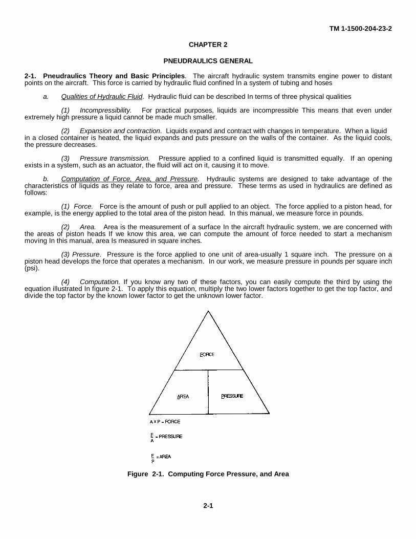
2-1. Pneudraulics Theory and Basic Principles. The aircraft hydraulic system transmits engine power to distantpoints on the aircraft. This force is carried by hydraulic fluid confined In a system of tubing and hoses
a. Qualities of Hydraulic Fluid. Hydraulic fluid can be described In terms of three physical qualities
(1) Incompressibility. For practical purposes, liquids are incompressible This means that even underextremely high pressure a liquid cannot be made much smaller.
(2) Expansion and contraction. Liquids expand and contract with changes in temperature. When a liquidin a closed container is heated, the liquid expands and puts pressure on the walls of the container. As the liquid cools,the pressure decreases.
(3) Pressure transmission. Pressure applied to a confined liquid is transmitted equally. If an openingexists in a system, such as an actuator, the fluid will act on it, causing it to move.
b. Computation of Force, Area, and Pressure. Hydraulic systems are designed to take advantage of thecharacteristics of liquids as they relate to force, area and pressure. These terms as used in hydraulics are defined asfollows:
(1) Force. Force is the amount of push or pull applied to an object. The force applied to a piston head, forexample, is the energy applied to the total area of the piston head. In this manual, we measure force in pounds.
(2) Area. Area is the measurement of a surface In the aircraft hydraulic system, we are concerned withthe areas of piston heads If we know this area, we can compute the amount of force needed to start a mechanismmoving In this manual, area Is measured in square inches.
(3) Pressure. Pressure is the force applied to one unit of area-usually 1 square inch. The pressure on apiston head develops the force that operates a mechanism. In our work, we measure pressure in pounds per square inch(psi).
(4) Computation. If you know any two of these factors, you can easily compute the third by using theequation illustrated In figure 2-1. To apply this equation, multiply the two lower factors together to get the top factor, anddivide the top factor by the known lower factor to get the unknown lower factor.
Figure 2-1. Computing Force Pressure, and Area
2-1
TM 1-1500-204-23-2
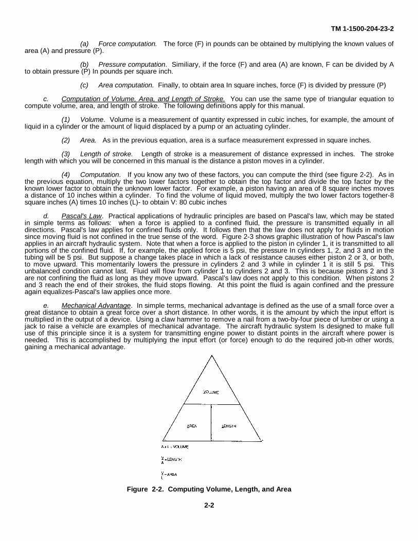
(a) Force computation. The force (F) in pounds can be obtained by multiplying the known values ofarea (A) and pressure (P).
(b) Pressure computation. Similiary, if the force (F) and area (A) are known, F can be divided by Ato obtain pressure (P) In pounds per square inch.
(c) Area computation. Finally, to obtain area In square inches, force (F) is divided by pressure (P)
c. Computation of Volume, Area, and Length of Stroke. You can use the same type of triangular equation tocompute volume, area, and length of stroke. The following definitions apply for this manual.
(1) Volume. Volume is a measurement of quantity expressed in cubic inches, for example, the amount ofliquid in a cylinder or the amount of liquid displaced by a pump or an actuating cylinder.
(2) Area. As in the previous equation, area is a surface measurement expressed in square inches.
(3) Length of stroke. Length of stroke is a measurement of distance expressed in inches. The strokelength with which you will be concerned in this manual is the distance a piston moves in a cylinder.
(4) Computation. If you know any two of these factors, you can compute the third (see figure 2-2). As inthe previous equation, multiply the two lower factors together to obtain the top factor and divide the top factor by theknown lower factor to obtain the unknown lower factor. For example, a piston having an area of 8 square inches movesa distance of 10 inches within a cylinder. To find the volume of liquid moved, multiply the two lower factors together-8square inches (A) times 10 inches (L)- to obtain V: 80 cubic inches
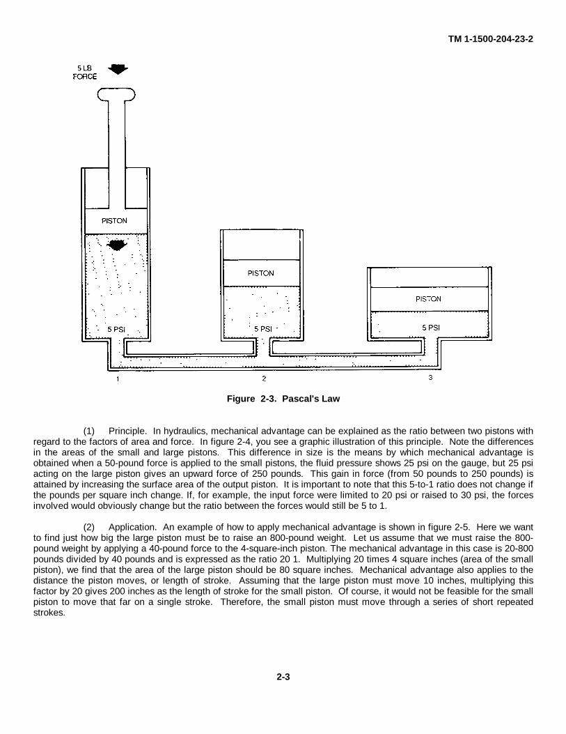
d. Pascal's Law. Practical applications of hydraulic principles are based on Pascal's law, which may be statedin simple terms as follows: when a force is applied to a confined fluid, the pressure is transmitted equally in alldirections. Pascal's law applies for confined fluids only. It follows then that the law does not apply for fluids in motionsince moving fluid is not confined in the true sense of the word. Figure 2-3 shows graphic illustration of how Pascal's lawapplies in an aircraft hydraulic system. Note that when a force is applied to the piston in cylinder 1, it is transmitted to allportions of the confined fluid. If, for example, the applied force is 5 psi, the pressure In cylinders 1, 2, and 3 and in thetubing will be 5 psi. But suppose a change takes place in which a lack of resistance causes either piston 2 or 3, or both,to move upward. This momentarily lowers the pressure in cylinders 2 and 3 while in cylinder 1 it is still 5 psi. Thisunbalanced condition cannot last. Fluid will flow from cylinder 1 to cylinders 2 and 3. This is because pistons 2 and 3are not confining the fluid as long as they move upward. Pascal's law does not apply to this condition. When pistons 2and 3 reach the end of their strokes, the fluid stops flowing. At this point the fluid is again confined and the pressureagain equalizes-Pascal's law applies once more.
e. Mechanical Advantage. In simple terms, mechanical advantage is defined as the use of a small force over agreat distance to obtain a great force over a short distance. In other words, it is the amount by which the input effort ismultiplied in the output of a device. Using a claw hammer to remove a nail from a two-by-four piece of lumber or using ajack to raise a vehicle are examples of mechanical advantage. The aircraft hydraulic system Is designed to make fulluse of this principle since it is a system for transmitting engine power to distant points in the aircraft where power isneeded. This is accomplished by multiplying the input effort (or force) enough to do the required job-in other words,gaining a mechanical advantage.
Figure 2-2. Computing Volume, Length, and Area
2-2
TM 1-1500-204-23-2
Figure 2-3. Pascal's Law
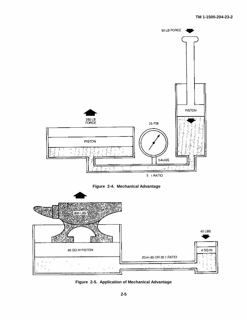
(1) Principle. In hydraulics, mechanical advantage can be explained as the ratio between two pistons withregard to the factors of area and force. In figure 2-4, you see a graphic illustration of this principle. Note the differencesin the areas of the small and large pistons. This difference in size is the means by which mechanical advantage isobtained when a 50-pound force is applied to the small pistons, the fluid pressure shows 25 psi on the gauge, but 25 psiacting on the large piston gives an upward force of 250 pounds. This gain in force (from 50 pounds to 250 pounds) isattained by increasing the surface area of the output piston. It is important to note that this 5-to-1 ratio does not change ifthe pounds per square inch change. If, for example, the input force were limited to 20 psi or raised to 30 psi, the forcesinvolved would obviously change but the ratio between the forces would still be 5 to 1.
(2) Application. An example of how to apply mechanical advantage is shown in figure 2-5. Here we wantto find just how big the large piston must be to raise an 800-pound weight. Let us assume that we must raise the 800-pound weight by applying a 40-pound force to the 4-square-inch piston. The mechanical advantage in this case is 20-800pounds divided by 40 pounds and is expressed as the ratio 20 1. Multiplying 20 times 4 square inches (area of the smallpiston), we find that the area of the large piston should be 80 square inches. Mechanical advantage also applies to thedistance the piston moves, or length of stroke. Assuming that the large piston must move 10 inches, multiplying thisfactor by 20 gives 200 inches as the length of stroke for the small piston. Of course, it would not be feasible for the smallpiston to move that far on a single stroke. Therefore, the small piston must move through a series of short repeatedstrokes.
2-3
TM 1-1500-204-23-2
f. Use of Air in Hydraulic Systems. When subjected to an applied force, a gas (such as air or nitrogen) acts ina manner similar to a spring: it yields but pushes back with as much force as is being applied to it. This characteristic ofgases makes them useful in aircraft systems.
(1) Gases used. Air is the gas commonly used in hydraulic systems. It is used in accumulators, shockstruts, and emergency systems and for pressurizing system reservoirs. In terms of compressibility, almost any gas couldbe used, but many are dangerous because they are flammable or explosive. Pure nitrogen is the only safe substitute foratmospheric air in hydraulic systems, and it is the only substitute authorized.
(2) Boyle's law. Assuming a constant temperature, the volume of a confined gas changes in oppositeorder to changes in pressure. For example, if a given volume of gas is reduced to half its initial size, its pressure doublesor, if the volume doubles, the pressure is halved. This characteristic of gases is known as Boyle's law and is expressedby the equation:
V x P = V1 x P1
whereV = initial volumeP = initial pressureV1 = changed volumeP1 = changed pressure
If the measurements of any three of these factors are known, the fourth factor can be determined. To illustrate, let usassume that 30 cubic inches of gas (V) at a constant temperature and under 90-psi pressure (P) is forced into a 15-cubic-inch space (V1). To find the changed pressure (p1) we substitute in the equation as follows.
90 x 30 = 15 x P1
2700 = 15P1
270015 = p1
180 = p1
2-2. Uses of Hydraulic Systems in Army Aircraft. Hydraulic systems perform a variety of functions in Army aircraft.They are used in fixed-wing aircraft for such purposes as changing propeller pitch and operating landing gear, wing flaps,wheel brakes, and shock struts in helicopters, hydraulic systems start engines and operate brakes, shock struts, dampers,flight control systems, loading ramps, folding pylons, winch hoists, and hydraulic clutches. There are a number ofreasons why hydraulic systems have been designed for so many uses in aircraft.
a. Efficiency. A hydraulic system is almost 100 percent efficient. The slight loss of efficiency (a fraction of 1percent) is due to internal friction in the system machinery.
b. Ease of Operation. The moving parts of a hydraulic system, being light In weight, can be quickly put intomotion or brought to rest. The valves used in a hydraulic system are capable of quickly starting or stopping the flow offluid under pressure, and very little effort is needed to operate them. For these reasons, the system is easy for theoperator to control.
c. Ease of Installation. Hydraulic lines can be routed almost anywhere. Unlike mechanical systems, whichmust follow straight pathways, the lines of a hydraulic system can be easily bent around obstructions. The major parts ofhydraulic systems can be located in a wide variety of places.
d. Size. Since the components of a hydraulic system are small in comparison with those of other systems, thespace requirement is small.
e. Lubrication. Most of the parts of a hydraulic system operate in a bath of oil, making the system self-lubricating.
2-3 Types Of Hydraulic Fluid Used in Army Aircraft. Hydraulic fluids are classified generally as vegetable-base,petroleum-base, and synthetic- base.
a. Vegetable-Base Fluid. Vegetable-base fluid is no longer authorized for use In Army aircraft.
b. Petroleum-Base Fluid. Petroleum-base fluid has an odor similar to penetrating oil and is dyed red. Syntheticrubber seals are used with this fluid.
2-4
TM 1-1500-204-23-2
Figure 2-5. Application of Mechanical Advantage
Figure 2-4. Mechanical Advantage
2-5
TM 1-1500-204-23-2
(1) Petroleum-base fluid MIL-H-6083. MIL-H-6083 is still authorized for certain uses in Army aircraft. It isused as a preservative oil in shock struts, hydraulic equipment, and spare parts, and as a testing and flushing oil forsome components. It should not be used in operational aircraft hydraulic systems.
(2) Petroleum-base fluid MIL-H-5606. MIL-H-5606 is being phased out for most Army aircraft, and beingreplaced with synthetic-base fluid MIL-H-83282. It is, however, still used for cold weather operation. Refer to thefollowing paragraph and paragraph 4-21 for more information on this fluid and its conversion.
c. Synthetic-Base Fluid MIL-H-83282. As stated above, MIL-H-5606 is being replaced in most operations byMIL-H-83282. MIL-H-83282 has a higher flash point and fire point, as well as additives which provide better anti-wearcharacteristics and provide better resistance to corrosion and oxidation. Refer to paragraph 4-21 for more information onthis fluid and its conversion.
d. Precautions. Use of the correct, uncontaminated fluid in a particular hydraulic system is critical for thecontinued serviceability of that system.
(1) Proper fluid. You must be extremely careful to use only the fluid authorized for a particular componentor system. To determine the correct fluid, consult the applicable technical manual. In addition, read the instruction plateaffixed to the individual unit or reservoir and check the color of the fluid contained in the system.
(2) Drained fluid. Fluid drained, for any reason, from a hydraulic system or component shall not bereused.
(3) Disposition of containers. Hydraulic fluid containers, when emptied, shall be destroyed.
2-4 Fluid Contamination. Contamination in a hydraulic system is the presence of any material other than thehydraulic fluid being used. This includes water, metal, dust, and other solids. Contamination sources may be internal orexternal. Internal contamination can cause abnormal wear of the pump or of other components. When filters are usedtoo long (especially the paper element type), particles may begin breaking off from the filter element. Moving seals andbackup rings also add contamination to the system. External contamination is generally caused by poor maintenancepractices. Examples include leaving hydraulic lines open after removing a part, wiping fittings with dirty rags; leavingvalves, tubing, etc , uncovered on workbenches; changing fluid with dirty test equipment, and installing new or rebuiltparts that have not been properly cleaned Hydraulic fluid (red color), MIL-H-83282 or MIL-H-5606, shall be used in allhydraulic systems The choice of MIL-H-83282 or MIL-H-5606 depends on the particular hydraulic system and theambient temperature Refer to the aircraft manual or to TB 55-1500-334-25.
a. Detecting Fluid Contamination. A kit has been developed, part number 57L414, NSN 6630-00-150-6486, tosample fluid for contamination in order to help control contamination in aircraft. Contamination checks should become aroutine part of your work. You should check for dirt, metal, and visible solids every time a unit is removed ordisassembled. Normal contamination checks for most aircraft are made by examining the condition of the filterelements. For example, a clogged filter or an extended filter indicator pin is a symptom of contaminated fluid. Thesefindings, as well as a pump failure, require flushing of the system.
b. System Flushing. Evidence of contamination makes it necessary that hydraulic system be flushed.
CAUTION
To avoid contamination, do not use hydraulic fluid that shows evidence of contamination or is in open cansthat are stored uncovered/unprotected. Unused fluid may be kept in filler pumps or sealed jars.
(1) Fluid. Hydraulic fluid, MIL-H-5606 or MIL-H-83282, shall be used for flushing systems andcomponents. Discard after use.
(2) Accidental servicing. In the event that a system or component Is Inadvertently serviced with incorrecttype fluid, drain fluid, flush system, and replace all packings and gaskets in affected components.
c. Contamination Prevention. Contamination can be prevented by taking the following precautions.
(1) Cap or plug all open connections when removing a part.
(2) Never use dirty rags to wipe off connections.
2-6

TM 1-1500-204-23-2
(3) Clean and deburr new tubing and fittings before installing them.
(4) Store new or overhauled parts in sealed containers.
(5) Before installing a pump, fill it with hydraulic fluid.
(6) Take good care of test stands and ground equipment.
(7) Handle flexible hydraulic hoses carefully. Particles from their walls enter the system when hoses arekinked or run over or when quick disconnections are not cleaned before being joined.
(8) Fluid drained, for any reason, from a hydraulic system or component shall not be reused.
(9) Hydraulic fluid containers, when emptied, shall be destroyed.
2-7/(2-8 blank)
TM 1-1500-204-23-2
CHAPTER 3
HYDRAULIC SHOP OPERATIONS
3-1. General Shop Rules. The practices and procedures described in this chapter pertain to the manufacturing andrepair functions of aviation activities and are applicable to all levels of maintenance. Because of the many types of Armyaircraft, each shop within the manufacturing and repair section must, of necessity, have personnel trained in generalpractices and procedures to the extent that different types and model aircraft do not upset a smooth running shop.
a. Responsibility. All supervisory personnel in the manufacturing section are responsible for a continuing andeffective shop safety program. To implement and maintain this program, shop supervisors will utilize bulletin boards,signs, and any other effective method. Shop personnel will cooperate in the shop safety program by making helpfulrecommendations, and continually exercising care and caution in the operation of all shop equipment. All shoppersonnel will strive to improve the safety program and be especially alert to observe and correct hazardous conditionsand unsafe shop practices. All accidents, no matter how minor, shall be reported to the shop supervisor, and allpublished instructions regarding safety shall be strictly adhered to. Also, safety engineers and safety officers will ensurethat proper safety procedures are adhered to in accordance with AR 385-10, The Army Safety Program; AR 385-30,Safety Color Code Markings and Signs, AR-385-32, Protective Clothing and Equipment; The Occupational Safety andHealth Act of 1971, OSHA 1910.251; all applicable fire codes, NFPA 410, and other accepted civilian and military safetypractices.
b. Shop Housekeeping. Housekeeping is the yardstick by which the shops in the manufacturing section arejudged. A clean, well arranged shop is a safe shop and reflects credit on all personnel concerned with its operation. Thefollowing shop practices shall be observed:
(1) Oil pans or drip pans shall be used where leaking oil, grease, and similar materials may causehazardous accumulations on equipment or floors. All spills shall be cleaned up immediately. Approved sweepingcompound may be used to remove these materials from the floor.
CAUTION
Floors shall not be cleaned with volatile or flammable liquids.
(2) Floors shall be maintained smooth and clean, free of all obstructions and slippery substances. Holesand irregularities in floors shall be repaired to maintain a level surface free from tripping hazards.
(3) All unnecessary materials on walls shall be removed and projections shall be kept to a minimum.
(4) Aisles shall be clearly defined and kept free of hazardous obstructions. Where possible, aisles shall besuitably marked by painting.
(5) All machines, work benches, aisles, etc, shall be adequately illuminated.
(6) Some units that you will disassemble are made up of small parts that can easily be lost, broken, ormixed with other parts. A unit Improperly reassembled or one reassembled with defective parts is the starting place foran aircraft accident.
(7) Wornout parts should be disposed of through the proper supply channels and never placed on the floorwhere they can become dangerous or forgotten.
(8) After servicing equipment with hydraulic fluid, MIL-H-5606 or MIL-H-83282, any oil remaining in canwhich cannot be used immediately shall be sealed and moved to storage area for flammable materials.
(9) Containers of hydraulic fluid which have been accidently left unsealed shall be consideredcontaminated and shall be destroyed.
c. Shop Safety. Unsafe equipment and fire hazards are the main factors to be observed while planning safetyprocedures.
3-1
TM 1-1500-204-23-2
(1) Equipment safety. Unsafe equipment shall be reported immediately. The following equipment safetypractices shall be observed:
(a) Machines shall be located to provide operators with sufficient space to handle materials andperform job operations without interference.
(b) Bolt down all machinery that can move or walk due to vibration (drill press, bench grinder, etc.).
(c) Substantial low resistance conductors shall be used to ground all stationary and portablemachines, equipment, or other devices in which static charges may be generated, or which require electrical circuits of ahazardous nature.
(d) Shop machinery shall be operated only by qualified personnel observing safe practices.
(e) Safety devices, such as guards, interlocks, automatic releases, and stops, shall always be kept inoperating condition.
(f) Ensure that all unauthorized personnel are clear of area before opening valves or energizingelectrical circuits for starting machinery.
(g) Suitable mechanical guards, such as enclosures or barricades, shall be permanently installed onall machinery not already equipped with such to eliminate danger of injury from moving parts.
(h) Machinery shall not be adjusted, repaired, oiled, or cleaned while machine is In operation orpower is on.
(i) Personnel operating machinery shall wear protective clothing as prescribed. A protective faceshield or goggles shall be worn when operating a grinder regardless of whether grinder is equipped with attached shields.
(j) Jewelry shall not be worn while performing any maintenance.
(2) Fire safety. A constant vigilance must be maintained to seek out fire hazards. Fire hazards areconstantly present In the shop where sparks, friction, or careless handling can cause an explosion that may destroyequipment or buildings, and injure or kill personnel. Refer to AR 385-10, The Army Safety Program and theOccupational Safety and Health Act of 1971. The following fire safety practices shall be observed.
(a) NO SMOKING signs shall be placed in areas where smoking could create a fire hazard.
(b) Personnel shall be trained In the use, knowledge, and location of shop fire fighting equipment.
(c) Each shop shall be equipped with fire extinguishers suited for type of fire most likely to occur.
(d) Use correct fire extinguisher for class of fire as follows:
Class A fire (wood, paper, trash, etc). Use water or soda-acid fire extinguisher.Class B fire (oil, paint, fuel, grease, etc). Use bromotrifluoromethane or carbon dioxide fireextinguisher.Class C fire (electrical equipment) Use bromotrofluoromethane or carbon dioxide fireextinguisher.Class D fire (combustible metals) magnesium, titanium, zirconium, sodium, lithium, andpotassium Use dry powder type fire extinguisher.
(e) Oily waste, rags, and similar combustible materials shall be discarded In self-closing metalcontainers which shall be emptied daily.
(f) Flammable materials shall not be stored in the shop.
(g) Use only approved cleaning solvents.
d. Shop Tools and Materials. Handling tools and materials requires observance of the following common safetypractices:
(1) Do not leave tools or objects in elevated positions from which they can fall or be knocked off.
(2) Do not point a compressed airstream toward any part of the body.
(3) All unserviceable tools will be plainly marked and removed from service.
(4) Electrical cables and air hoses to portable units will be laid out so there Is no danger of tripping.
3-2
TM 1-1500-204-23-2(5) Electrical tools must be connected to a low resistance ground
3-2. Maintenance of Shop Equipment. Maintenance of shop equipment consists of cleaning, preventivemaintenance, and replacement of defective parts. Preventive maintenance includes before-operation, during-operation,after-operation services performed by operator, and scheduled services to be performed at designated intervals. Consultthe operation and service instructions manual for specific maintenance instructions on particular types of equipment.
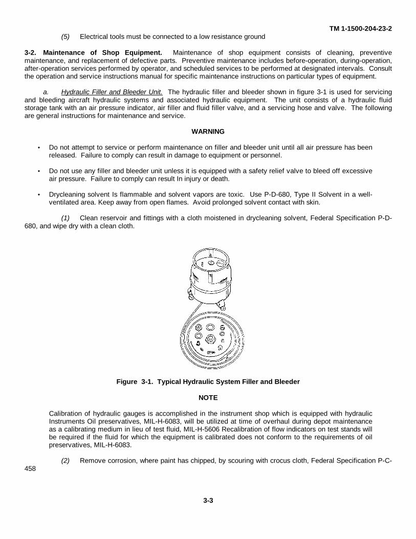
a. Hydraulic Filler and Bleeder Unit. The hydraulic filler and bleeder shown in figure 3-1 is used for servicingand bleeding aircraft hydraulic systems and associated hydraulic equipment. The unit consists of a hydraulic fluidstorage tank with an air pressure indicator, air filler and fluid filler valve, and a servicing hose and valve. The followingare general instructions for maintenance and service.
WARNING
Do not attempt to service or perform maintenance on filler and bleeder unit until all air pressure has beenreleased. Failure to comply can result in damage to equipment or personnel.
Do not use any filler and bleeder unit unless it is equipped with a safety relief valve to bleed off excessiveair pressure. Failure to comply can result In injury or death.
Drycleaning solvent Is flammable and solvent vapors are toxic. Use P-D-680, Type II Solvent in a well-ventilated area. Keep away from open flames. Avoid prolonged solvent contact with skin.
(1) Clean reservoir and fittings with a cloth moistened in drycleaning solvent, Federal Specification P-D-680, and wipe dry with a clean cloth.
Figure 3-1. Typical Hydraulic System Filler and Bleeder
NOTE
Calibration of hydraulic gauges is accomplished in the instrument shop which is equipped with hydraulicInstruments Oil preservatives, MIL-H-6083, will be utilized at time of overhaul during depot maintenanceas a calibrating medium in lieu of test fluid, MIL-H-5606 Recalibration of flow indicators on test stands willbe required if the fluid for which the equipment is calibrated does not conform to the requirements of oilpreservatives, MIL-H-6083.
(2) Remove corrosion, where paint has chipped, by scouring with crocus cloth, Federal Specification P-C-458
3-3
TM 1-1500-204-23-2
(3) Touch up areas with original finish paint where corrosion was removed
(4) Keep reservoir filled to specified level with hydraulic fluid, MIL-H-5606 or MIL-H- 83282.
NOTE
Consult applicable operation and service instructions manual for specific air pressurizing procedures.
(5) Replace flexible hose connections or manual control valve when leaking
(6) Replace defective valve core In valve stem and defective gauge unit with a like serviceable item.
(7) Replace flexible hose that is frayed, cut, and deteriorated.
b. Hydraulic Test Stand. Fixed. This test stand is used for adjusting, flushing, and testing the performance andoperating characteristics of hydraulic system components to determine serviceability status
WARNING
Supervisors shall ensure that only qualified personnel operate, service, and maintain hydraulic testequipment. Because of the high pressures involved in testing, proper precautions must be taken toprevent damage or injury to the operator in case of line rupture.
Drycleaning solvent is flammable and solvent vapors are toxic. Use P-D-680, Type II Solvent in a well-ventilated area. Keep away from open flames. Avoid prolonged solvent contact with skin.
(1) Cleaning. Clean test stand by wiping with a cloth moistened in drycleaning solvent, FederalSpecification P-D-680, and wiping dry with a clean cloth.
(2) Daily inspection. Daily inspection will consist of the following:
(a) Visually inspect entire test stand for signs of leaking valves, fittings, and connections.
(b) Examine fluid level in reservoir and add hydraulic fluid, MIL-H-6083, as necessary.
NOTE
Preservative hydraulic fluid shall be used in all hydraulic test stands permanently Installed in the shop.
(c) Inspect for worn bearings, packings, or broken seals at drive shafts on pump and motor.
(d) Examine test stands for proper operation and correct reading of gauges
(3) Periodic Inspection. For frequency and scope of periodic Inspection, consult the operation and serviceinstructions manual for specific test stand; however, the following will be used as a general guide:
(a) With machine operating under full-load conditions, make a complete visual Inspection of teststand to determine if there is any leakage.
(b) Disconnect electrical power and examine all electrical connections In junction box for loose orbroken leads.
(c) Remove sump cover and clean out any dirt or lint with a clean cloth. Remove sump drain plugsand flush sump with test fluid from machine Reinstall sump drain plug.
(d) Examine filters and replace filter elements In accordance with applicable operation and serviceinstructions manual.
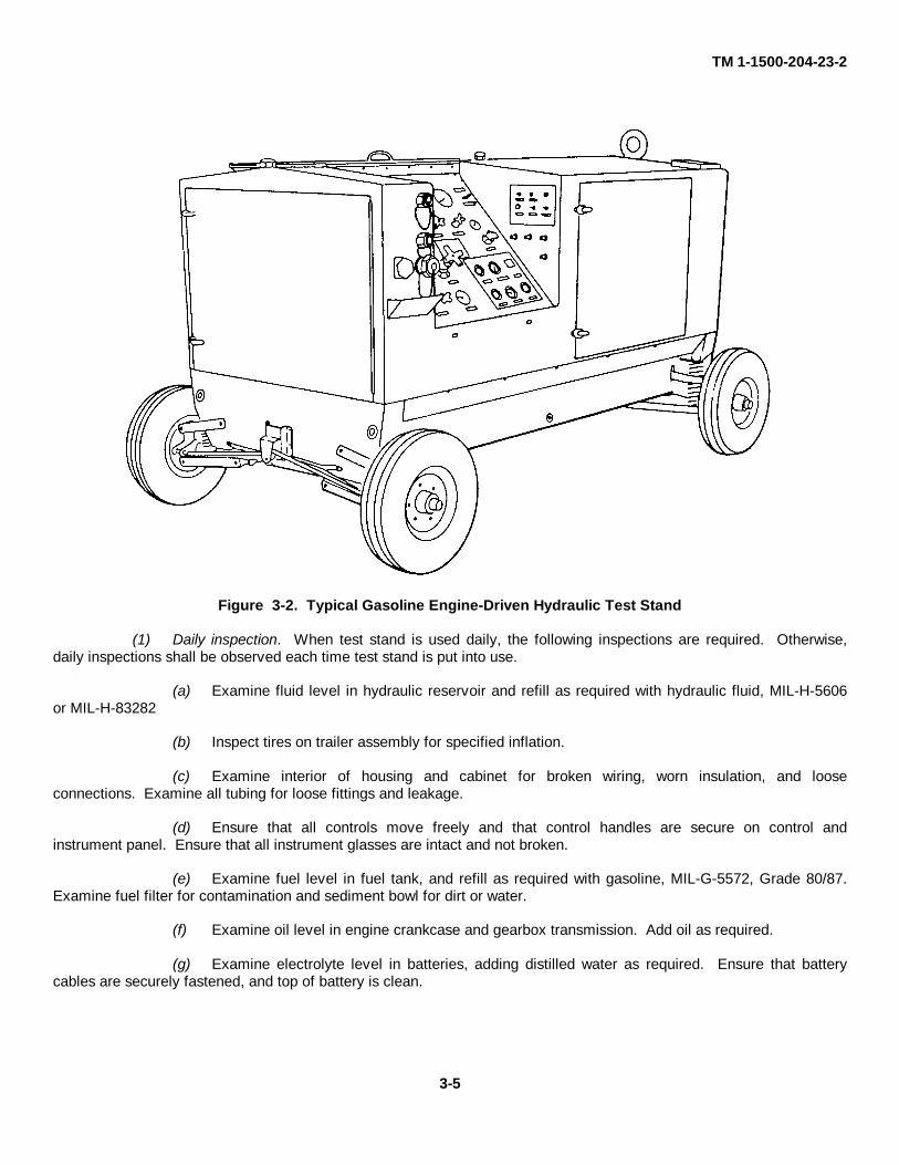
c. Hydraulic Test Stand, Portable, Gasoline Engine-Driven. This test stand shown In figure 3-2 is used directlyon the aircraft, and simulates the engine-driven hydraulic pump in performing system operational checks, checkingsystem for leaks, and filling or flushing the system.
3-4
TM 1-1500-204-23-2
Figure 3-2. Typical Gasoline Engine-Driven Hydraulic Test Stand
(1) Daily inspection. When test stand is used daily, the following inspections are required. Otherwise,daily inspections shall be observed each time test stand is put into use.
(a) Examine fluid level in hydraulic reservoir and refill as required with hydraulic fluid, MIL-H-5606or MIL-H-83282
(b) Inspect tires on trailer assembly for specified inflation.
(c) Examine interior of housing and cabinet for broken wiring, worn insulation, and looseconnections. Examine all tubing for loose fittings and leakage.
(d) Ensure that all controls move freely and that control handles are secure on control andinstrument panel. Ensure that all instrument glasses are intact and not broken.
(e) Examine fuel level in fuel tank, and refill as required with gasoline, MIL-G-5572, Grade 80/87.Examine fuel filter for contamination and sediment bowl for dirt or water.
(f) Examine oil level in engine crankcase and gearbox transmission. Add oil as required.
(g) Examine electrolyte level in batteries, adding distilled water as required. Ensure that batterycables are securely fastened, and top of battery is clean.
3-5
TM 1-1500-204-23-2(h) Prior to first use of test stand, examine pressure gauge to determine that maximum hydraulic
pressure is obtainable, and Inspect for high pressure leaks.
(2) Periodic inspection. For frequency and scope of periodic inspection, consult the operation and serviceinstructions manual for the specific test stand; however, the following will be used as a general guide.
(a) Visually inspect interior of hydraulic reservoir for possible accumulation of sludge. Inspect andreplace reservoir vent filter when necessary.
(b) Examine tire treads on trailer assembly for uneven wear. Rotate tires when necessary
(c) Carefully inspect housing and cabinet assembly for loose screws, bolts, and nuts. Tighten asrequired.
(d) Inspect fuel system for loose fittings that may cause fuel leakage. Examine and replace fuelfilter as necessary.
(e) Examine oil level in engine crankcase and gearbox transmission, and add oil as required.Replace engine oil filter. Examine oil-bath type air cleaner and service as necessary.
(f) Remove and examine spark plugs, and clean with spark plug cleaner. Discard all unserviceablespark plugs.
(g) Inspect battery cell electrolyte with a hydrometer. A specific gravity reading of 1.150 or lessindicates a low battery charge.
NOTE
When test stand is out of operation for lengthy, intermittent periods, batteries should be tested morefrequently, or placed on trickle charge in battery charge.
(h) Examine engine ignition timing, magneto point condition, and gap.
(3) Lubrication. Consult applicable operation and service instructions manual of particular hydraulic teststand for type of lubricant, time of application, amount and point of lubrication.
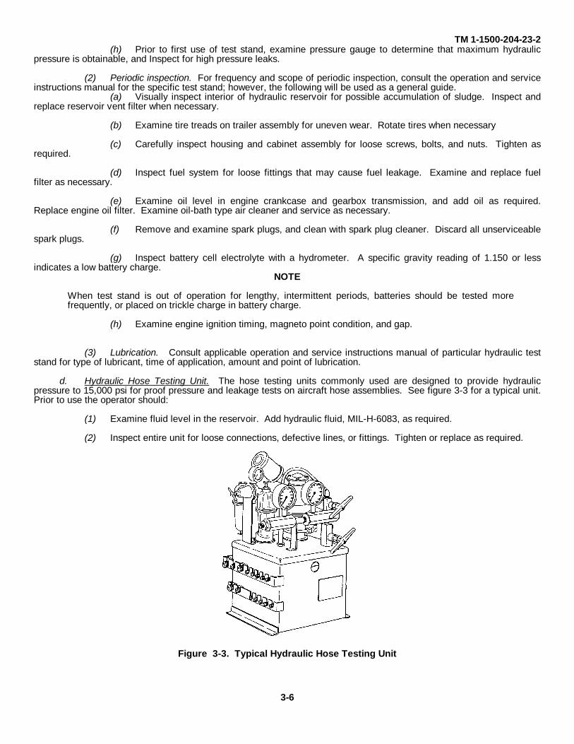
d. Hydraulic Hose Testing Unit. The hose testing units commonly used are designed to provide hydraulicpressure to 15,000 psi for proof pressure and leakage tests on aircraft hose assemblies. See figure 3-3 for a typical unit.Prior to use the operator should:
(1) Examine fluid level in the reservoir. Add hydraulic fluid, MIL-H-6083, as required.
(2) Inspect entire unit for loose connections, defective lines, or fittings. Tighten or replace as required.
Figure 3-3. Typical Hydraulic Hose Testing Unit
3-6
TM 1-1500-204-23-2
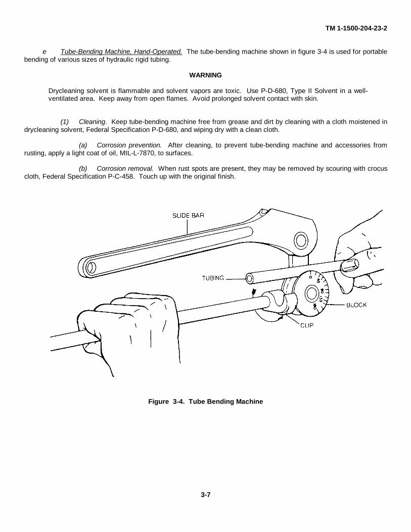
e Tube-Bending Machine, Hand-Operated. The tube-bending machine shown in figure 3-4 is used for portablebending of various sizes of hydraulic rigid tubing.
WARNING
Drycleaning solvent is flammable and solvent vapors are toxic. Use P-D-680, Type II Solvent in a well-ventilated area. Keep away from open flames. Avoid prolonged solvent contact with skin.
(1) Cleaning. Keep tube-bending machine free from grease and dirt by cleaning with a cloth moistened indrycleaning solvent, Federal Specification P-D-680, and wiping dry with a clean cloth.
(a) Corrosion prevention. After cleaning, to prevent tube-bending machine and accessories fromrusting, apply a light coat of oil, MIL-L-7870, to surfaces.
(b) Corrosion removal. When rust spots are present, they may be removed by scouring with crocuscloth, Federal Specification P-C-458. Touch up with the original finish.
Figure 3-4. Tube Bending Machine
3-7

TM 1-1500-204-23-2
(2) Periodic inspection. For frequency and scope of periodic inspection, consult operation and serviceinstructions manual for specific bending machine; however, the following shall be used as a general guide.
(a) Visually Inspect tube-bending machine for cracks, loose bolts and nuts, mounts for security, anddefective or damaged parts.
(b) Lubricate tube-bending machine as required.
f. Master Gauge Unit. This unit consists of a pressure gauge, a manual control valve, and length of flexiblehose with connecting fittings. A typical unit is shown in figure 3-5
(1) Replace flexible hose when it becomes frayed, cut, or deteriorated.
(2) Replace gauge or control valve when found to be defective.
Figure 3-5. Typical Master Gauge Unit
3-8

TM 1-1500-204-23-2
4930-00-245-1832.g. Hydraulic Fluid Dispenser, Aircraft, AF-5, NSN
(1) Model AF-5 Hydraulic Fluid dispenser con-tains a buna N and nylon cord bladder in which air pres-sure is maintained in order to eject oil from the machine.This special bladder is approximately the same size asthe tank and when filled with air approximately fills thetank’s volume.
(2) The purpose of the bladder is to separate thehydraulic fluid in the tank from the compressed air usedto expel fluid into a hydraulic system, thereby insuringthat no air or condensation will contaminate the hydraulicfluid or brake system.
(3) This type of construction requires specialprocedure in filling dispenser and charging it with com-pressed air.
(4) To fill the dispenser
(a) Close the valve at the outer end of thehose.
(b) Open the bleeder valve located underthe pressure gauge. Do not tamper with the pressurerelief valve. This bleeder valve drains air cavity.
(c) To deflate the bladder completely, put nomore than 10 psi of air pressure into the fluid cavity of thetankthrough the air valve located in the filler cap. This willreduce the size of the bladder to allow maximum oil ca-pacity in the tank.
(d) When all air stops coming from the blad-der bleeder valve, thus indicating that the bladder is flat,close the bleeder valve.
(e) Release the air pressure in the oil cavityof the tank by pressing the red tank air drain button.When pressure gauge reads zero and no further air flowsfrom the button valve, remove the filler cap.
(f) Pour up to 5 gallons of hydraulic fluid intothe tank. Replace filler cap and tighten with wrench.
(g) Inflate bladder through the air valve lo-cated under the pressure gauge to 10 psi.
(h) Bleed all trapped air from the fluid cavityby pressing the red button valve and holding it until aclear stream of hydraulic oil ejects.
(i) Inflate bladder through air valve underpressure gauge until the pressure relief valve pops. Donot exceed 50 psi.
(j) Recharge the bladder as required. If3-1/2 to 4 gallons of oil used to charge the tank, a suffi-cient air cavity will be left to expel the liquid charge witha single air charge.
(k) Stencil the dispenserto show the specifi-cation number of the fluid that it contains.
(I) The discharge nozzle end of the dis-pensing line shall be wiped clean prior to and after eachuse, and protected from contamination by a smallamount of plastic food wrap and rubber band.
Change 3 3-8.1/(3-8.2 blank)

TM 1-1500-204-23-2
3-3. Handling of Hydraulic Fluid in 55-Gallon Drums. Correct storage and handling of hydraulic fluid is critical toensure a supply of uncontaminated fluid for aircraft servicing.
a. Storage. Store 55-gallon drums horizontally with the closures at the 9 o'clock and 3 o'clock positions. Thisprevents contaminating material from collecting around the top of the drum and around the closures. The drums shouldbe placed in covered storage either under a roof or covered by a plastic sheet or tarpaulin.
b. Cleaning. Prior to use or prior to standing the drum on end, the top of the drum should be thoroughlybrushed with a stiff brush to remove all gross contaminating material. The top and particularly the closures should thenbe wiped with lintless rags saturated with hydraulic fluid MIL-H-5606, MIL-H-6083 or MIL-H-83282.
c. Withdrawing Fluid from Drum. Fluid can be withdrawn from the drum using the following methods:
CAUTION
Use an apron, goggles, protective glasses, and protective gloves when working with solvents or hydraulicfluid as fluid can be absorbed into the skin.
(1) Faucet. If small quantities of hydraulic fluid are to be used, a faucet may be installed in the 3/4-inchclosure for use while the drum is in a horizontal position. The faucet must be thoroughly wiped with hydraulic fluid priorto use. Fluid should be permitted to flow for a short period to flush any contamination that may have accumulated in thefaucet.
CAUTION
Prior to inserting pump in drum, the drum must be cleaned as per paragraph 3-3b. Prior to drawing offhydraulic fluid to be used in aircraft, a small amount of fluid must be flushed through the pump. Failure tocomply may result in contamination of fluid, rendering it useless.
(2) Pumps. If large quantities of hydraulic fluid are needed, the following new, thoroughly cleaned, hand-operated pumps may be used (See Chapter 1, Part 1, FM 10-69).
NOTE
It is necessary to clean even new pumps to prevent contamination of hydraulic fluid. Cleaning may beaccomplished by pumping approximately 1 gallon of cleaning compound MIL-C-87936 through the pump.After draining the cleaning solvent completely, pump approximately 5 gallons of the appropriate hydraulicfluid through the pump. Thoroughly clean and wipe the portions of the pump to be installed in the 55-gallon drum with clean, lint-free rags saturated with the appropriate hydraulic fluid, before installing thepump in the drum.
Dispensing pump, hand-driven, piston-type, self-measuring type, 1-quart-per-stroke.
12 GPM, hand-driven dispensing pump (100 cycles per minute).
15 GPM, piston-type, hand-driven dispensing pump with 20-foot hose (22 gallons per 100 revolutions).
WARNING
Never siphon by mouth. Ingestion of hydraulic fluid can cause sickness or be fatal.
(3) Nozzles. The discharge nozzle end of the dispensing line shall be wiped clean prior to and after eachuse, and protected with a small piece of plastic food wrap and rubber band This procedure will eliminate contaminationfrom entering the nozzle.
d. Transporting Fluid to Aircraft. Hydraulic fluid may be transported from bulk storage to the aircraft in thefollowing manner.
3-9

TM 1-1500-204-23-2
A 5-gallon military gasoline can. A new or thoroughly cleaned and flushed 5-gallon military gasoline can may be used fortransporting hydraulic fluid from drums to the aircraft. Once a can is used for hydraulic fluid, it is to be so marked, andnever used for any other fluids. The can must be kept securely closed when not in use. Any fluid left in the can afterdispensing to aircraft must either be disposed of or added to a hydraulic test stand.
3-10
TM 1-1500-204-23-2
CHAPTER 4
HYDRAULIC MAINTENANCE PRACTICES
4-1. General. This chapter provides general instruc-tions for maintenance of aircraft hydraulic systems, thematerials required, and methods to be used. A systemat-ic application of the basic information in this chapter willresult in more efficient maintenance practices. In thosecases where specific instructions for a particular aircraftare required, refer to the applicable aircraft maintenancemanual. Materials and processes recommended areidentified by military or federal specification number or bymanufacturer.
4-2. Tubing Systems and Repairs. Tubing used inaircraft hydraulic systems carries pressure to distantpoints in the aircraft to provide control of various criticalcomponents. Failure of this tubing will result in pressureloss and subsequent loss of control, resulting in possibledestruction to aircraft and injury or death.
a. Types. Corrosion-resistant steel tubing and alu-minum alloy tubing are used in aircraft for fuel, oil, cool-ant, oxygen, instrument, hydraulic, and vent lines, as wellas for electrical conduits and ventilating ducts. Coppertubing generally has been superseded as a general pur-pose tubing by aluminum alloy tubing because of its light-er weight, ease of forming, and resistance to corrosionand fatigue. Tubing material can be identified by visualinspection or by the aluminum alloy designation stampedon the surface.
(1) Corrosion-resistant steel tubing. Corrosion-resistant steel tubing, MIL-T-8504 and MIL-T-6845, isused in high pressure hydraulic systems (3000 psi) suchas landing gear, wing flaps, and brakes. External brakelines should always be made of steel to prevent damagecaused by flying gravel and stones and ground handlingaccidents. On hydraulic systems using 1/2-inch corro-sion-resistant tubing or larger, aluminum alloy nuts andsleeves may be used. Steel nuts and sleeves should beused on 3/8 inch corrosion resistant tubingor smaller.Corrosion-resistant steel tubing does not have to be an-nealed for flaring or forming. The flared section is some-what strengthened by cold working and consequentstrain hardening. The high tensile strength of corrosion-resistant steel tubing permits use of thinner walls thanthose of aluminum alloy tubing, but the weight is aboutthe same as thick-walled aluminum alloy tubing.
(2) Aluminum alloy tubing. Aluminum alloy tub-ing, Federal Specification WW-T-700/1, is used for gen-eral purpose lines and conduits of low fluid pressure,such as instrument lines, and electrical and ventilatingconduits. Aluminum alloy tubing Federal Specifications
WWT-700/4 and WW-T-700/6, is the most widely usedtubing for general purpose lines of low and medium pres-sures. It is easily flared, and is soft enough to be formedwith handtools. It should be handled with care to preventscratches, dents, and nicks. Aluminum alloy tubing isused with either of two types of connections; flared jointfor mechanical connections, or beaded end for use withclamps and flexible hose connections. In hydraulic sys-tems, 5052-0 aluminum alloy tubing, Federal Specifica-tion WW-T-700/4, is used for reduced pressure (1500 psimaximum) and return lines. Aluminum alloy tubing 6061and 6062 MIL-T-7081, may be used for high pressurelines (3000 psi). Use of MIL-T-7081 tubing in aircraft islimited by MIL-H-5440. Tubing conforming to FederalSpecifications WW-T-700/1 and WW-T-700/6 shall notbe used in hydraulic systems.
(3) Copper tubing. High pressure oxygen sys-tems use 3/16-inch diameter, 0.032-inch wall thicknesscopper tubing, Federal Specification WW-T-799, Type N.Fittings are silver soldered onto the tubing in accordancewith MIL-B-7883, before tubing is installed.
(4) Rigid Tubing. The tubing used to producerigid tubing assemblies is sized by its outside diameter(OD) and wall thickness. Outside diameter sizes are insixteenth-of-an-inch increments, the number of the tubeindicating its size in sixteenths of an inch. For example,the number 6 tubing is 6/16 or 3/8 inch, number 8 tubingis 8/16 or 1/2 inch, and so forth. Wall thickness is speci-fied in thousandths of an inch. Most aircraft maintenancemanuals contain a table which lists the original materialand acceptable substitutes and gives the wall thicknessfor each.
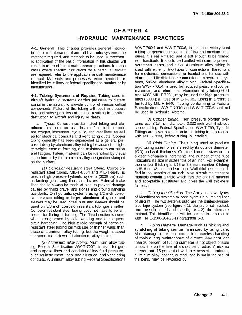
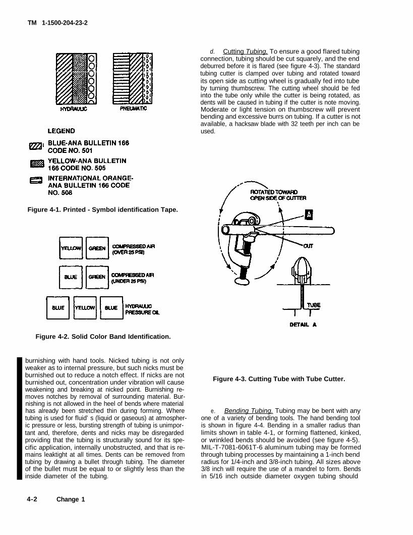
b. Tubing Identification. The Army uses two typesof identification systems to code hydraulic plumbing linesof aircraft. The two systems used are the printed-symbol-ized tape system (see figure 4-1), the preferred method,and the solidcolor band (see figure 4-2), the alternatemethod. This identification will be applied in accordancewith TM 1-1500-204-23-1) paragraph 6-3.
c. Tubing Damage. Damage such as nicking andscratching of tubing can be minimized by using care.Most damage of this kind occurs from careless handlingof tools during maintenance of aircraft. Any dent lessthan 20 percent of tubing diameter is not objectionableunless it is on the heel of a short bend radius. A nick nodeeper than 15 percent of wall thickness of aluminum,aluminum alloy, copper, or steel, and is not in the heel ofthe bend, may be reworked by
Change 3 4-1
TM 1-1500-204-23-2
Figure 4-1. Printed - Symbol identification Tape.
d. Cutting Tubing, To ensure a good flared tubingconnection, tubing should be cut squarely, and the enddeburred before it is flared (see figure 4-3). The standardtubing cutter is clamped over tubing and rotated towardits open side as cutting wheel is gradually fed into tubeby turning thumbscrew. The cutting wheel should be fedinto the tube only while the cutter is being rotated, asdents will be caused in tubing if the cutter is note moving.Moderate or light tension on thumbscrew will preventbending and excessive burrs on tubing. If a cutter is notavailable, a hacksaw blade with 32 teeth per inch can beused.
Figure 4-2. Solid Color Band Identification.
burnishing with hand tools. Nicked tubing is not onlyweaker as to internal pressure, but such nicks must beburnished out to reduce a notch effect. If nicks are notburnished out, concentration under vibration will causeweakening and breaking at nicked point. Burnishing re-moves notches by removal of surrounding material. Bur-nishing is not allowed in the heel of bends where materialhas already been stretched thin during forming. Wheretubing is used for fluid’s (liquid or gaseous) at atmospher-ic pressure or less, bursting strength of tubing is unimpor-tant and, therefore, dents and nicks may be disregardedproviding that the tubing is structurally sound for its spe-cific application, internally unobstructed, and that is re-mains leaktight at all times. Dents can be removed fromtubing by drawing a bullet through tubing. The diameterof the bullet must be equal to or slightly less than theinside diameter of the tubing.
Figure 4-3. Cutting Tube with Tube Cutter.
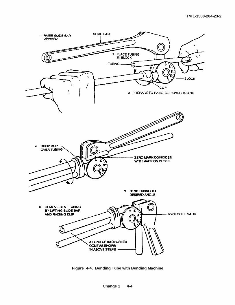
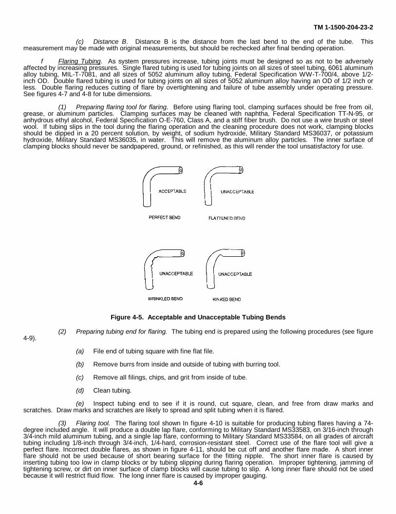
e. Bending Tubing. Tubing may be bent with anyone of a variety of bending tools. The hand bending toolis shown in figure 4-4. Bending in a smaller radius thanlimits shown in table 4-1, or forming flattened, kinked,or wrinkled bends should be avoided (see figure 4-5).MIL-T-7081-6061T-6 aluminum tubing may be formedthrough tubing processes by maintaining a 1-inch bendradius for 1/4-inch and 3/8-inch tubing. All sizes above3/8 inch will require the use of a mandrel to form. Bendsin 5/16 inch outside diameter oxygen tubing should
4-2 Change 1
TM 1-1500-204-23-2
have a radius for 1/4-inch and 3/8-inch tubing. All sizes above 3/8 inch will require the use of a mandrel to form. Bendsin 5/16 inch outside diameter oxygen tubing should have a radius or curvature of at least 11/16 inch. Tubing may bebent without the aid of tools by carefully forming desired radius by hand; however, this method is crude and should beused only in absence of proper tools. Aluminum alloy tubing used in oxygen systems should not be hand bent. Tubing1/2 inch outside diameter or larger should be packed with fusible alloy, Federal Specification QQ-F-838, to preventcracked or wrinkled bends. When bending tubing, a large radius should be formed and gradually worked down to desiredradius.
CAUTION
A torch or flame should never be applied to tubing or fusible alloy, as excessive heat will destroy bothstrength of heat-treated tubing and melting characteristics of fusible alloy. Boiling water will not meltfusible alloy after a flame has been applied.
(1) Use of fusible alloy for bending tubing. A bending machine should be used when bending aluminum orduralumin tubing. Before bending, most aluminum alloy tubing is in annealed condition, and should be packed withfusible alloy, Federal Specification QQ-F-838. One end of tube to be bent is closed to prevent leakage of fusible alloy.Tubing and ladle containing fusible alloy is immersed in a tank of boiling water until alloy is melted. Melting point of thefusible alloy is 160 degrees (71 degrees C). For ordinary tubing lengths, a hot water tank similar to that used in platingshops may be used. For longer lengths, a special tank may be constructed, or a length of pipe used so that both tubingand ladle will be completely submerged. When fusible alloy has melted, it is poured into tubing. Both tubing and ladleare kept beneath surface of hot water during pouring operation so that molten alloy will displace water in tubing. Removetubing from hot water and cool with cold water or allow to air cool until fusible alloy is solidified. Tubing can then be bentwith a bending machine or form blocks. Fusible alloy should be cold when bending tubing, and tubing should be bentslowly. When bending operation is completed, fusible alloy may be removed from tubing by immersing both tubing andladle in tank of hot water and pouring alloy back into ladle. When pouring alloy back into ladle, both tubing and ladleshould be kept beneath surface of hot water, as this reduces tendency of alloy to stick to inside of tubing.
(2) Tube flattening. In some cases, a certain amount of flattening may occur when bending tubingregardless of procedure used, especially on thin-walled tubing bent to minimum bend radii. As tube flattens, it assumesthe shape of an ellipse in cross section, and the area is reduced. This restriction either reduces amount of fluid actuallydelivered, or requires additional pumping power to overcome increased line friction. When tube is flattened so that minoraxis of ellipse is 75 percent of normal tube diameter, area is reduced to 90 percent of original. Further flattening of tubemay be considered as cause for rejection.
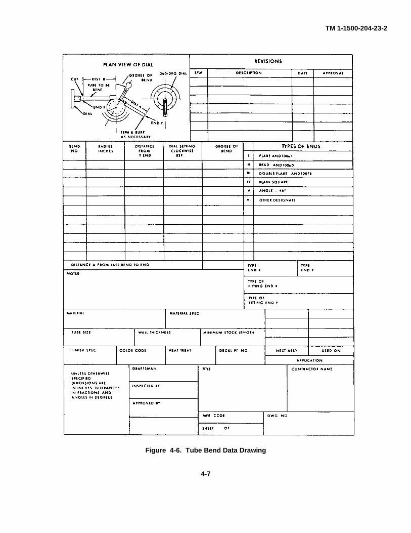
(3) Tube bend data drawing. Tube bend data shall be prepared on A size drawings in accordance withformat shown in figure 4-6. Local forms for tube bend data are no longer acceptable. Points of possible confusion areexplained in the following paragraphs.
(a) Distance from Y end. DISTANCE FROM Y END column shows the measured distance from theY end to the first bend, the measured distance from Y end to the second bend, etc. This distance can be measuredeither by making all measurements before any bending takes place, or by utilizing scale on the bending machine.
(b) Dial setting. DIAL SETTING column shows degree of bend from the horizontal reference plane.This column is based on a 360-degree graduated dial for the bending machine. Where a dial is graduated in 180degrees, right and left indications are used, and it is necessary to compute necessary setting for settings more than 180degrees. This calculation consists of subtracting the dial setting shown from 360 degrees. Result will be proper settingfor left side of dial. Dial settings less than 180 degrees are identified for both types of dials. For continuity of operation,dial settings are based on continual clockwise rotation of dial.
NOTE
Example: For a desired dial setting of 286 degrees, the reading on a 360-degree dial is 286 degrees. Todetermine the reading on a 180 degree dial for a dial setting of 286 degrees, subtract 286 degrees from360 degrees. The difference (74 degrees) is the reading as read on the left side of the dial.
Change 1 4-3
TM 1-1500-204-23-2
Figure 4-4. Bending Tube with Bending Machine
Change 1 4-4
TM 1-1500-204-23-2
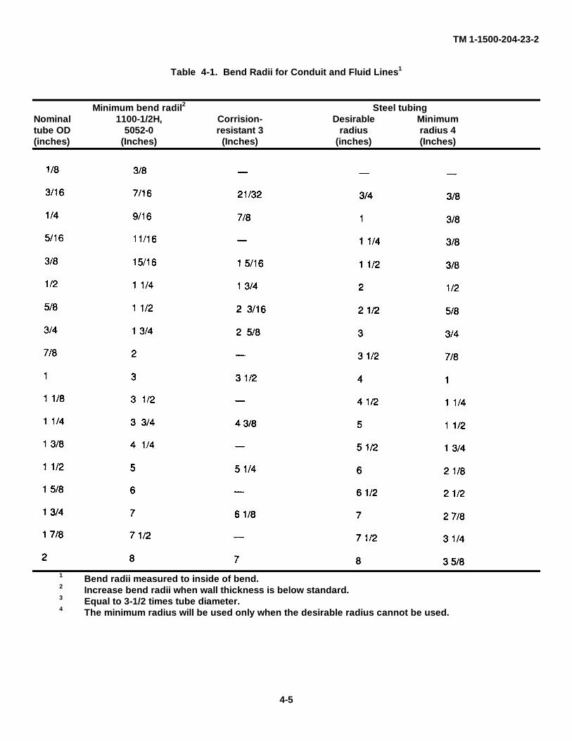
Table 4-1. Bend Radii for Conduit and Fluid Lines1
Minimum bend radil2 Steel tubingNominal 1100-1/2H, Corrision- Desirable Minimumtube OD 5052-0 resistant 3 radius radius 4(inches) (Inches) (Inches) (inches) (Inches)
1 Bend radii measured to inside of bend.2 Increase bend radii when wall thickness is below standard.3 Equal to 3-1/2 times tube diameter.4 The minimum radius will be used only when the desirable radius cannot be used.
4-5
TM 1-1500-204-23-2
(c) Distance B. Distance B is the distance from the last bend to the end of the tube. Thismeasurement may be made with original measurements, but should be rechecked after final bending operation.
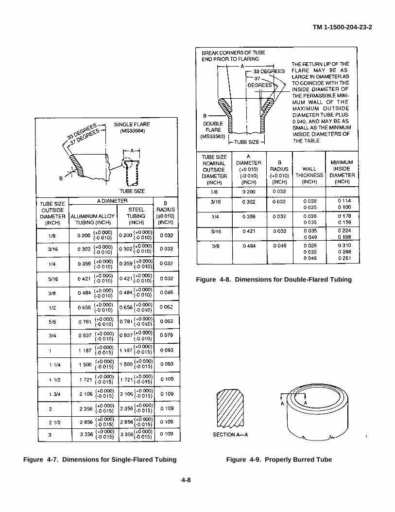
f Flaring Tubing. As system pressures increase, tubing joints must be designed so as not to be adverselyaffected by increasing pressures. Single flared tubing is used for tubing joints on all sizes of steel tubing, 6061 aluminumalloy tubing, MIL-T-7081, and all sizes of 5052 aluminum alloy tubing, Federal Specification WW-T-700/4, above 1/2-inch OD. Double flared tubing is used for tubing joints on all sizes of 5052 aluminum alloy having an OD of 1/2 inch orless. Double flaring reduces cutting of flare by overtightening and failure of tube assembly under operating pressure.See figures 4-7 and 4-8 for tube dimensions.
(1) Preparing flaring tool for flaring. Before using flaring tool, clamping surfaces should be free from oil,grease, or aluminum particles. Clamping surfaces may be cleaned with naphtha, Federal Specification TT-N-95, oranhydrous ethyl alcohol, Federal Specification O-E-760, Class A, and a stiff fiber brush. Do not use a wire brush or steelwool. If tubing slips in the tool during the flaring operation and the cleaning procedure does not work, clamping blocksshould be dipped in a 20 percent solution, by weight, of sodium hydroxide, Military Standard MS36037, or potassiumhydroxide, Military Standard MS36035, in water. This will remove the aluminum alloy particles. The inner surface ofclamping blocks should never be sandpapered, ground, or refinished, as this will render the tool unsatisfactory for use.
Figure 4-5. Acceptable and Unacceptable Tubing Bends
(2) Preparing tubing end for flaring. The tubing end is prepared using the following procedures (see figure4-9).
(a) File end of tubing square with fine flat file.
(b) Remove burrs from inside and outside of tubing with burring tool.
(c) Remove all filings, chips, and grit from inside of tube.
(d) Clean tubing.
(e) Inspect tubing end to see if it is round, cut square, clean, and free from draw marks andscratches. Draw marks and scratches are likely to spread and split tubing when it is flared.
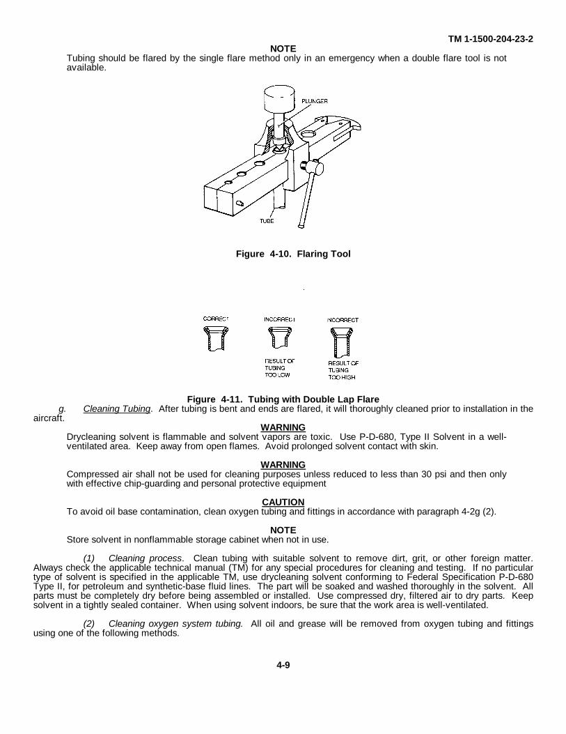
(3) Flaring tool. The flaring tool shown In figure 4-10 is suitable for producing tubing flares having a 74-degree included angle. It will produce a double lap flare, conforming to Military Standard MS33583, on 3/16-inch through3/4-inch mild aluminum tubing, and a single lap flare, conforming to Military Standard MS33584, on all grades of aircrafttubing including 1/8-inch through 3/4-inch, 1/4-hard, corrosion-resistant steel. Correct use of the flare tool will give aperfect flare. Incorrect double flares, as shown in figure 4-11, should be cut off and another flare made. A short innerflare should not be used because of short bearing surface for the fitting nipple. The short inner flare is caused byinserting tubing too low in clamp blocks or by tubing slipping during flaring operation. Improper tightening, jamming oftightening screw, or dirt on inner surface of clamp blocks will cause tubing to slip. A long inner flare should not be usedbecause it will restrict fluid flow. The long inner flare is caused by improper gauging.
4-6
TM 1-1500-204-23-2
Figure 4-6. Tube Bend Data Drawing
4-7
TM 1-1500-204-23-2
Figure 4-7. Dimensions for Single-Flared Tubing Figure 4-9. Properly Burred Tube
Figure 4-8. Dimensions for Double-Flared Tubing
4-8
TM 1-1500-204-23-2NOTE
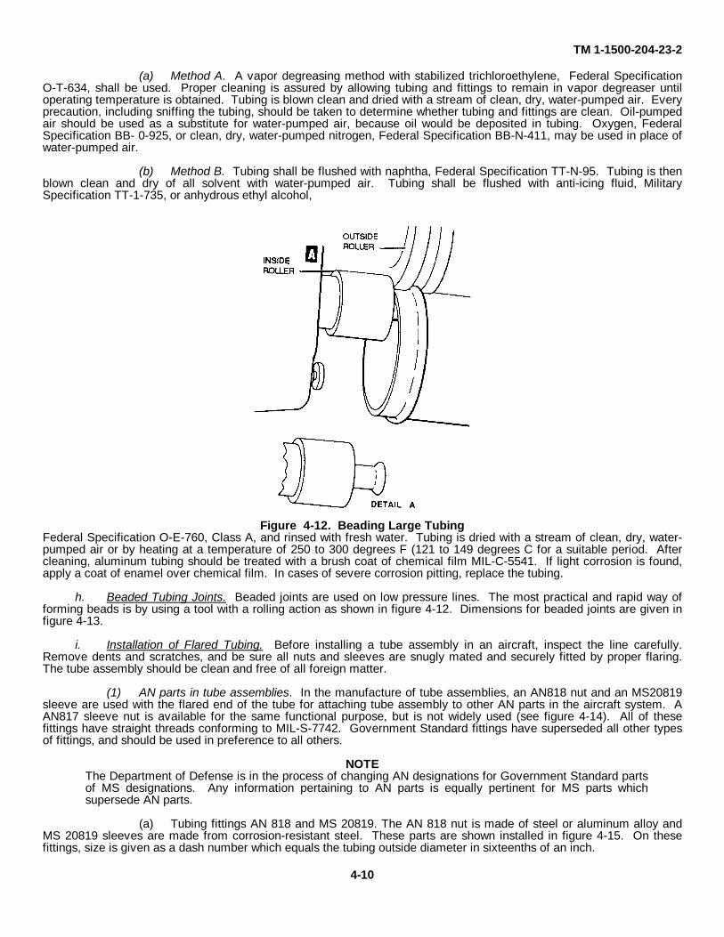
Tubing should be flared by the single flare method only in an emergency when a double flare tool is notavailable.
Figure 4-11. Tubing with Double Lap Flareg. Cleaning Tubing. After tubing is bent and ends are flared, it will thoroughly cleaned prior to installation in the
aircraft.WARNING
Drycleaning solvent is flammable and solvent vapors are toxic. Use P-D-680, Type II Solvent in a well-ventilated area. Keep away from open flames. Avoid prolonged solvent contact with skin.
WARNINGCompressed air shall not be used for cleaning purposes unless reduced to less than 30 psi and then onlywith effective chip-guarding and personal protective equipment
CAUTIONTo avoid oil base contamination, clean oxygen tubing and fittings in accordance with paragraph 4-2g (2).
NOTEStore solvent in nonflammable storage cabinet when not in use.
(1) Cleaning process. Clean tubing with suitable solvent to remove dirt, grit, or other foreign matter.Always check the applicable technical manual (TM) for any special procedures for cleaning and testing. If no particulartype of solvent is specified in the applicable TM, use drycleaning solvent conforming to Federal Specification P-D-680Type II, for petroleum and synthetic-base fluid lines. The part will be soaked and washed thoroughly in the solvent. Allparts must be completely dry before being assembled or installed. Use compressed dry, filtered air to dry parts. Keepsolvent in a tightly sealed container. When using solvent indoors, be sure that the work area is well-ventilated.
(2) Cleaning oxygen system tubing. All oil and grease will be removed from oxygen tubing and fittingsusing one of the following methods.
4-9
Figure 4-10. Flaring Tool
TM 1-1500-204-23-2
(a) Method A. A vapor degreasing method with stabilized trichloroethylene, Federal SpecificationO-T-634, shall be used. Proper cleaning is assured by allowing tubing and fittings to remain in vapor degreaser untiloperating temperature is obtained. Tubing is blown clean and dried with a stream of clean, dry, water-pumped air. Everyprecaution, including sniffing the tubing, should be taken to determine whether tubing and fittings are clean. Oil-pumpedair should be used as a substitute for water-pumped air, because oil would be deposited in tubing. Oxygen, FederalSpecification BB- 0-925, or clean, dry, water-pumped nitrogen, Federal Specification BB-N-411, may be used in place ofwater-pumped air.
(b) Method B. Tubing shall be flushed with naphtha, Federal Specification TT-N-95. Tubing is thenblown clean and dry of all solvent with water-pumped air. Tubing shall be flushed with anti-icing fluid, MilitarySpecification TT-1-735, or anhydrous ethyl alcohol,
Figure 4-12. Beading Large TubingFederal Specification O-E-760, Class A, and rinsed with fresh water. Tubing is dried with a stream of clean, dry, water-pumped air or by heating at a temperature of 250 to 300 degrees F (121 to 149 degrees C for a suitable period. Aftercleaning, aluminum tubing should be treated with a brush coat of chemical film MIL-C-5541. If light corrosion is found,apply a coat of enamel over chemical film. In cases of severe corrosion pitting, replace the tubing.
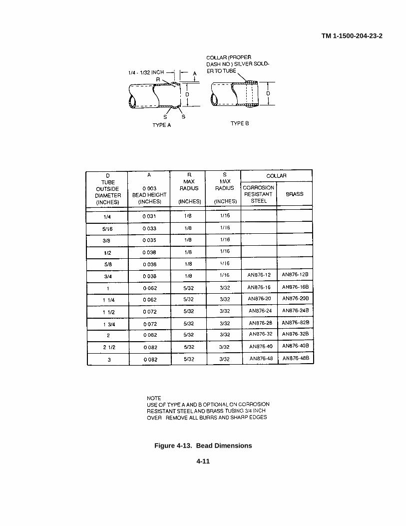
h. Beaded Tubing Joints. Beaded joints are used on low pressure lines. The most practical and rapid way offorming beads is by using a tool with a rolling action as shown in figure 4-12. Dimensions for beaded joints are given infigure 4-13.
i. Installation of Flared Tubing. Before installing a tube assembly in an aircraft, inspect the line carefully.Remove dents and scratches, and be sure all nuts and sleeves are snugly mated and securely fitted by proper flaring.The tube assembly should be clean and free of all foreign matter.
(1) AN parts in tube assemblies. In the manufacture of tube assemblies, an AN818 nut and an MS20819sleeve are used with the flared end of the tube for attaching tube assembly to other AN parts in the aircraft system. AAN817 sleeve nut is available for the same functional purpose, but is not widely used (see figure 4-14). All of thesefittings have straight threads conforming to MIL-S-7742. Government Standard fittings have superseded all other typesof fittings, and should be used in preference to all others.
NOTEThe Department of Defense is in the process of changing AN designations for Government Standard partsof MS designations. Any information pertaining to AN parts is equally pertinent for MS parts whichsupersede AN parts.
(a) Tubing fittings AN 818 and MS 20819. The AN 818 nut is made of steel or aluminum alloy andMS 20819 sleeves are made from corrosion-resistant steel. These parts are shown installed in figure 4-15. On thesefittings, size is given as a dash number which equals the tubing outside diameter in sixteenths of an inch.
4-10
TM 1-1500-204-23-2
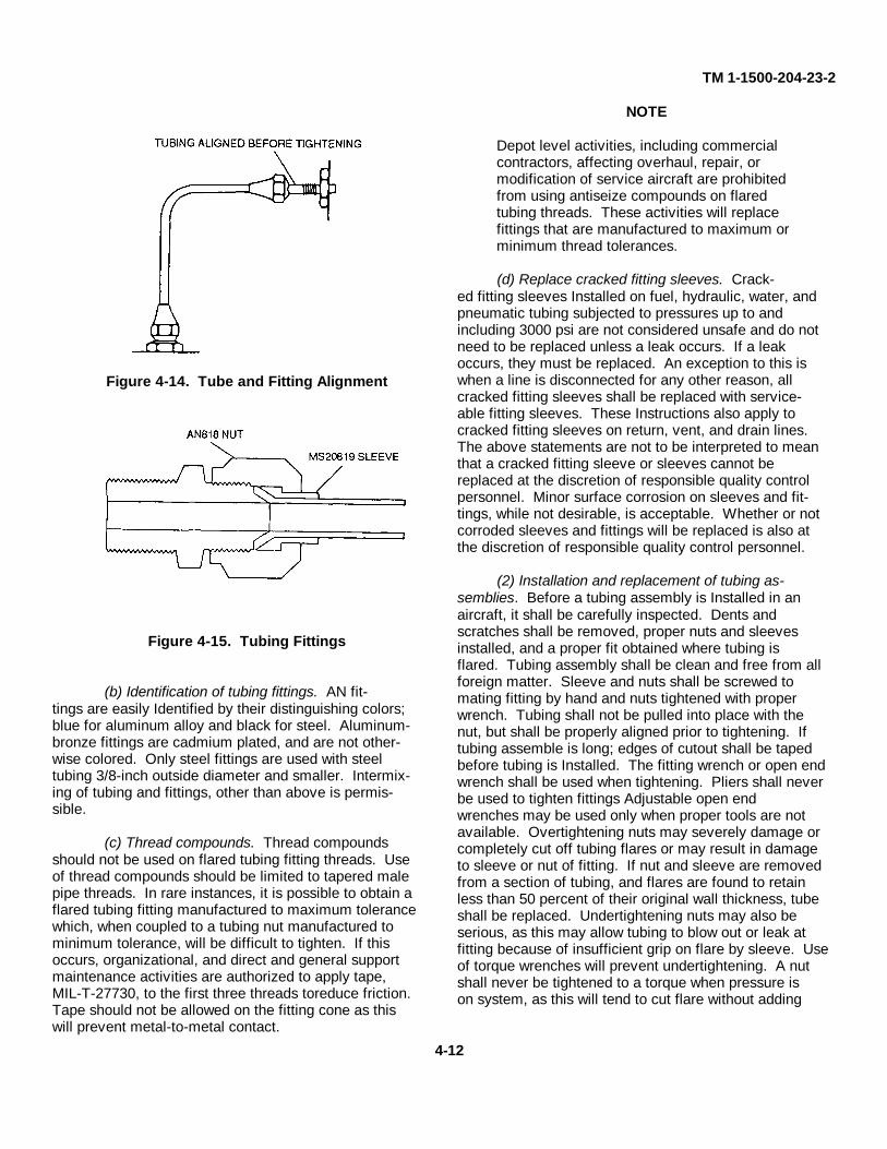
Figure 4-13. Bead Dimensions
4-11
TM 1-1500-204-23-2
Figure 4-14. Tube and Fitting Alignment
Figure 4-15. Tubing Fittings
(b) Identification of tubing fittings. AN fit-tings are easily Identified by their distinguishing colors;blue for aluminum alloy and black for steel. Aluminum-bronze fittings are cadmium plated, and are not other-wise colored. Only steel fittings are used with steeltubing 3/8-inch outside diameter and smaller. Intermix-ing of tubing and fittings, other than above is permis-sible.
(c) Thread compounds. Thread compoundsshould not be used on flared tubing fitting threads. Useof thread compounds should be limited to tapered malepipe threads. In rare instances, it is possible to obtain aflared tubing fitting manufactured to maximum tolerancewhich, when coupled to a tubing nut manufactured tominimum tolerance, will be difficult to tighten. If thisoccurs, organizational, and direct and general supportmaintenance activities are authorized to apply tape,MIL-T-27730, to the first three threads toreduce friction.Tape should not be allowed on the fitting cone as thiswill prevent metal-to-metal contact.
NOTE
Depot level activities, including commercialcontractors, affecting overhaul, repair, ormodification of service aircraft are prohibitedfrom using antiseize compounds on flaredtubing threads. These activities will replacefittings that are manufactured to maximum orminimum thread tolerances.
(d) Replace cracked fitting sleeves. Crack-ed fitting sleeves Installed on fuel, hydraulic, water, andpneumatic tubing subjected to pressures up to andincluding 3000 psi are not considered unsafe and do notneed to be replaced unless a leak occurs. If a leakoccurs, they must be replaced. An exception to this iswhen a line is disconnected for any other reason, allcracked fitting sleeves shall be replaced with service-able fitting sleeves. These Instructions also apply tocracked fitting sleeves on return, vent, and drain lines.The above statements are not to be interpreted to meanthat a cracked fitting sleeve or sleeves cannot bereplaced at the discretion of responsible quality controlpersonnel. Minor surface corrosion on sleeves and fit-tings, while not desirable, is acceptable. Whether or notcorroded sleeves and fittings will be replaced is also atthe discretion of responsible quality control personnel.
(2) Installation and replacement of tubing as-semblies. Before a tubing assembly is Installed in anaircraft, it shall be carefully inspected. Dents andscratches shall be removed, proper nuts and sleevesinstalled, and a proper fit obtained where tubing isflared. Tubing assembly shall be clean and free from allforeign matter. Sleeve and nuts shall be screwed tomating fitting by hand and nuts tightened with properwrench. Tubing shall not be pulled into place with thenut, but shall be properly aligned prior to tightening. Iftubing assemble is long; edges of cutout shall be tapedbefore tubing is Installed. The fitting wrench or open endwrench shall be used when tightening. Pliers shall neverbe used to tighten fittings Adjustable open endwrenches may be used only when proper tools are notavailable. Overtightening nuts may severely damage orcompletely cut off tubing flares or may result in damageto sleeve or nut of fitting. If nut and sleeve are removedfrom a section of tubing, and flares are found to retainless than 50 percent of their original wall thickness, tubeshall be replaced. Undertightening nuts may also beserious, as this may allow tubing to blow out or leak atfitting because of insufficient grip on flare by sleeve. Useof torque wrenches will prevent undertightening. A nutshall never be tightened to a torque when pressure ison system, as this will tend to cut flare without adding
4-12
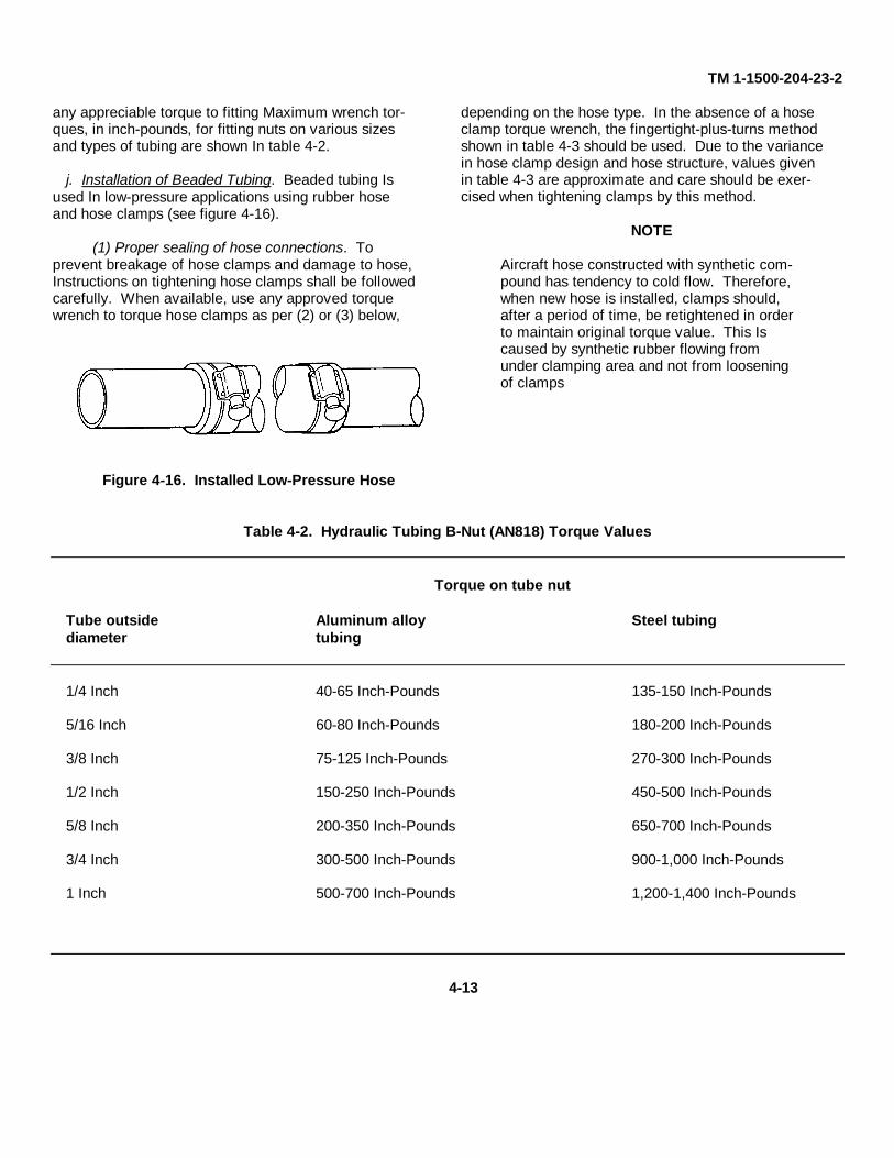
TM 1-1500-204-23-2
any appreciable torque to fitting Maximum wrench tor-ques, in inch-pounds, for fitting nuts on various sizesand types of tubing are shown In table 4-2.
j. Installation of Beaded Tubing. Beaded tubing Isused In low-pressure applications using rubber hoseand hose clamps (see figure 4-16).
(1) Proper sealing of hose connections. Toprevent breakage of hose clamps and damage to hose,Instructions on tightening hose clamps shall be followedcarefully. When available, use any approved torquewrench to torque hose clamps as per (2) or (3) below,
Figure 4-16. Installed Low-Pressure Hose
depending on the hose type. In the absence of a hoseclamp torque wrench, the fingertight-plus-turns methodshown in table 4-3 should be used. Due to the variancein hose clamp design and hose structure, values givenin table 4-3 are approximate and care should be exer-cised when tightening clamps by this method.
NOTE
Aircraft hose constructed with synthetic com-pound has tendency to cold flow. Therefore,when new hose is installed, clamps should,after a period of time, be retightened in orderto maintain original torque value. This Iscaused by synthetic rubber flowing fromunder clamping area and not from looseningof clamps
Table 4-2. Hydraulic Tubing B-Nut (AN818) Torque Values
Torque on tube nut
Tube outside Aluminum alloy Steel tubingdiameter tubing
1/4 Inch 40-65 Inch-Pounds 135-150 Inch-Pounds
5/16 Inch 60-80 Inch-Pounds 180-200 Inch-Pounds
3/8 Inch 75-125 Inch-Pounds 270-300 Inch-Pounds
1/2 Inch 150-250 Inch-Pounds 450-500 Inch-Pounds
5/8 Inch 200-350 Inch-Pounds 650-700 Inch-Pounds
3/4 Inch 300-500 Inch-Pounds 900-1,000 Inch-Pounds
1 Inch 500-700 Inch-Pounds 1,200-1,400 Inch-Pounds
4-13
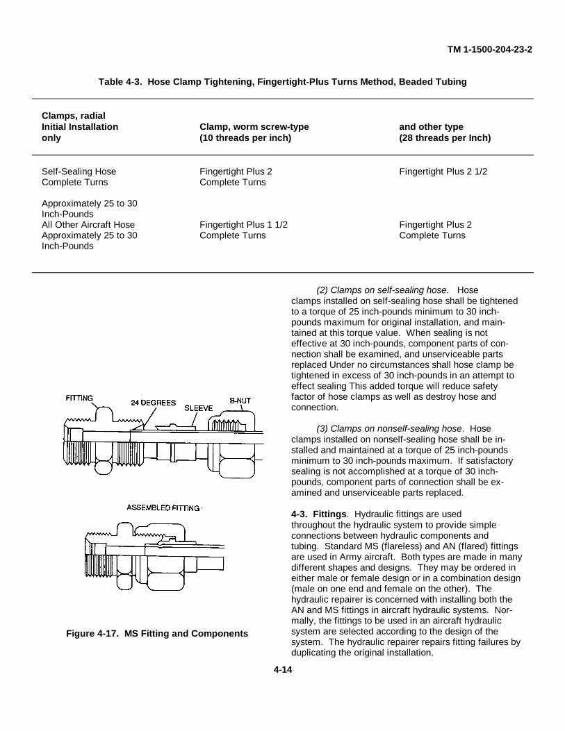
TM 1-1500-204-23-2
Table 4-3. Hose Clamp Tightening, Fingertight-Plus Turns Method, Beaded Tubing
Clamps, radialInitial Installation Clamp, worm screw-type and other typeonly (10 threads per inch) (28 threads per Inch)
Self-Sealing Hose Fingertight Plus 2 Fingertight Plus 2 1/2Complete Turns Complete Turns
Approximately 25 to 30Inch-PoundsAll Other Aircraft Hose Fingertight Plus 1 1/2 Fingertight Plus 2Approximately 25 to 30 Complete Turns Complete TurnsInch-Pounds
Figure 4-17. MS Fitting and Components
(2) Clamps on self-sealing hose. Hoseclamps installed on self-sealing hose shall be tightenedto a torque of 25 inch-pounds minimum to 30 inch-pounds maximum for original installation, and main-tained at this torque value. When sealing is noteffective at 30 inch-pounds, component parts of con-nection shall be examined, and unserviceable partsreplaced Under no circumstances shall hose clamp betightened in excess of 30 inch-pounds in an attempt toeffect sealing This added torque will reduce safetyfactor of hose clamps as well as destroy hose andconnection.
(3) Clamps on nonself-sealing hose. Hoseclamps installed on nonself-sealing hose shall be in-stalled and maintained at a torque of 25 inch-poundsminimum to 30 inch-pounds maximum. If satisfactorysealing is not accomplished at a torque of 30 inch-pounds, component parts of connection shall be ex-amined and unserviceable parts replaced.
4-3. Fittings. Hydraulic fittings are usedthroughout the hydraulic system to provide simpleconnections between hydraulic components andtubing. Standard MS (flareless) and AN (flared) fittingsare used in Army aircraft. Both types are made in manydifferent shapes and designs. They may be ordered ineither male or female design or in a combination design(male on one end and female on the other). Thehydraulic repairer is concerned with installing both theAN and MS fittings in aircraft hydraulic systems. Nor-mally, the fittings to be used in an aircraft hydraulicsystem are selected according to the design of thesystem. The hydraulic repairer repairs fitting failures byduplicating the original installation.
4-14
TM 1-1500-204-23-2
a. Flareless Fittings. The main feature of MSfittings is that they can be used to connect unflaredtubing. An MS fitting has a counterbore in which thetube end is Installed. In the half-sectional view of anMS fitting in figure 4-17, notice the 24-degree beveledportion of the counterbore and its seat. The seat formsa slope for the tube during the connection of one tubeto another tube or for a tube to a component and thebeveled area causes the tube connector sleeve to sealthe connection as the tube B-nut is tightened.
(1) Identification of flareless fittings. MS fit-tings are made of aluminum alloy or steel Aluminumalloy fittings can be identified visually by their yellowcolor, which is caused from the anodizing treatment.The cadmium plating on steel fittings are identified byletter-number codes; for example, MS21900-4, whichis interpreted as follows:
MS........prefix (military specification)
21900...design part number (adapter, flare-less tube to AN flared tube)
4..........size of fitting in sixteenths of an inch (4/16 (inch)
The material from which the fittings are made is indi-cated by the absence of a letter at the end of the MSnumber or by the addition of a letter at the end of thenumber, for example:
MS21900-4 is made from carbon steel
MS21900-8-D is made from aluminumalloy
MS21900-8-S is made from corrosion-resistant steel, class 347
(2) Types of flareless fittings. See figure 4-18for examples of MS flareless fittings.
WARNING
Compressed air shall not be used for cleaning pur-poses unless reduced to less than 30 psi and thenonly with effective chip-guarding and personalprotective equipment.
(3) Installation of flareless fittings. MS fittingsmust be inspected before Installation. If It Is Impossibleto see through a fitting or tube, blow clean, dry com-pressed air through it to be certain that no obstructionsexist. Any lines that have caps removed in storage orbefore installation should be flushed with cleanhydraulic fluid. Male threads and sleeves of the fittingsbeing assembled should be lubricated with the type ofhydraulic fluid used in the system On fittings withtapered threads, use antiseize compound on thethreads, except for the first three, which are left dry.
(a) Gasket. To make a connection be-tween tubing and a component, the proper gasket isselected, lubricated, and Installed In position as shownin figure 4-19. The fitting is screwed into the boss of thecomponent until it bottoms on the boss.
(b) Installing tubing. When connectingtubing to an MS fitting, the tube should be aligned withthe fitting and the nut should be started by hand withoutexcessive strain on the line (see figure 4-20). Do notuse force to align tubing Tube alignment can often beobtained by loosening clamps on connecting lines orby rotating fittings. Both ends of the tubing should beconnected and tightened until a decided increase Inresistance to turning of the B-nut is encountered. Atthis point, tighten the clamps, ensuring that they do notpull the tubing out of alignment and place it in a bindingposition. Complete the installation by turning the B-nutone-sixth of a turn. See figure 4-21 for turns and torquevalues. Pressurize the hydraulic system and Inspect forleaks. If leakage is noted, release system pressure andcompletely loosen the B-nut. If possible, rotate thesleeve to a new position and then retorque the B-nutto its previous position plus one-sixth of a turn. Normal-ly this will stop the leak, but If it does not, replace theassembly.
4-15
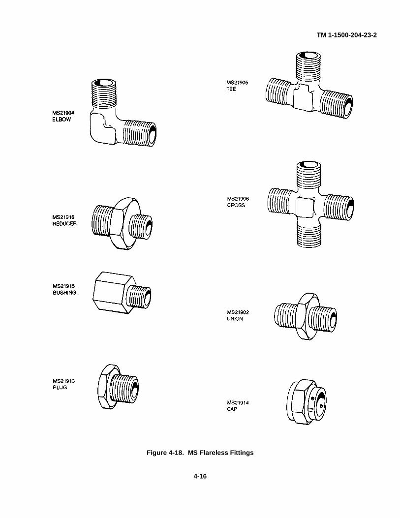
TM 1-1500-204-23-2
Figure 4-18. MS Flareless Fittings
4-16
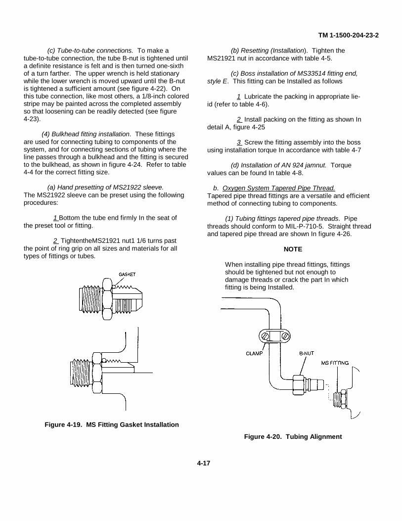
TM 1-1500-204-23-2
(c) Tube-to-tube connections. To make atube-to-tube connection, the tube B-nut is tightened untila definite resistance is felt and is then turned one-sixthof a turn farther. The upper wrench is held stationarywhile the lower wrench is moved upward until the B-nutis tightened a sufficient amount (see figure 4-22). Onthis tube connection, like most others, a 1/8-inch coloredstripe may be painted across the completed assemblyso that loosening can be readily detected (see figure4-23).
(4) Bulkhead fitting installation. These fittingsare used for connecting tubing to components of thesystem, and for connecting sections of tubing where theline passes through a bulkhead and the fitting is securedto the bulkhead, as shown in figure 4-24. Refer to table4-4 for the correct fitting size.
(a) Hand presetting of MS21922 sleeve.The MS21922 sleeve can be preset using the followingprocedures:
1 Bottom the tube end firmly In the seat ofthe preset tool or fitting.
2 TightentheMS21921 nut1 1/6 turns pastthe point of ring grip on all sizes and materials for alltypes of fittings or tubes.
Figure 4-19. MS Fitting Gasket Installation
(b) Resetting (Installation). Tighten theMS21921 nut in accordance with table 4-5.
(c) Boss installation of MS33514 fitting end,style E. This fitting can be Installed as follows
1 Lubricate the packing in appropriate lie-id (refer to table 4-6).
2 Install packing on the fitting as shown Indetail A, figure 4-25
3 Screw the fitting assembly into the bossusing installation torque In accordance with table 4-7
(d) Installation of AN 924 jamnut. Torquevalues can be found In table 4-8.
b. Oxygen System Tapered Pipe Thread.Tapered pipe thread fittings are a versatile and efficientmethod of connecting tubing to components.
(1) Tubing fittings tapered pipe threads. Pipethreads should conform to MIL-P-710-5. Straight threadand tapered pipe thread are shown In figure 4-26.
NOTE
When installing pipe thread fittings, fittingsshould be tightened but not enough todamage threads or crack the part In whichfitting is being Installed.
Figure 4-20. Tubing Alignment
4-17

TM 1-1500-204-23-2
TIGHTENING - RULE OF THUMBTORQUE (FLAT TURNS AFTER PRETIGHTENING)
TUBING SIZE (INCH POUNDS)NORMAL TIGHT EXTRA TIGHT
ALUMINUM -3 65 TO 95OR STEEL -4 100 TO 150 1 TO 1 1/2 2 MAXIMUM
-6 175 TO 300 1 TO 1 1/2 2 MAXIMUM-8 325 TO 500 1 TO 1 1/2 2 MAXIMUM
-10 400 TO 700 1 TO 1 1/2 2 MAXIMUM-12 500 TO 800 1 TO 1 1/2 2 MAXIMUM-16 500 TO 800 1 TO 1 1/2 2 MAXIMUM
ALUMINUM -20 600 TO 900 1 TO 1 1/2 2 MAXIMUM-24 600 TO 900 5/6 TO 1 1 1/2 MAXIMUM
Figure 4-21. MS Turns and Torque Values
Figure 4-22. Tubing-To-Tubing Connections Figure 4-23. Marking MS Fitting
4-18
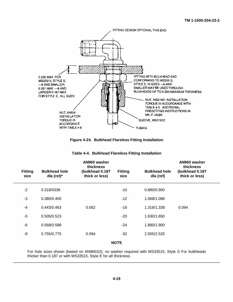
TM 1-1500-204-23-2
Figure 4-24. Bulkhead Flareless Fitting Installation
Table 4-4. Bulkhead Flareless Fitting Installation
AN960 washer AN960 washerthickness thickness
Fitting Bulkhead hole (bulkhead 0.187 Fitting Bulkhead hole (bulkhead 0.187size dla (ret)* thick or less) size dla (ref) thick or less)
-2 0.318/0338 -10 0.880/0.900
-3 0.380/0.400 -12 1.068/1.088
-4 0.443/0.463 0.062 -16 1.318/1.338 0.094
-5 0.505/0.523 -20 1.630/1.650
-6 0.568/0.588 -24 1.880/1.900
-8 0.755/0.775 0.094 -32 2.505/2.525
NOTE
For hole sizes shown (based on AN9601D), no washer required with MS33515, Style S For bulkheadsthicker than 0.187 or with MS33515, Style E for all thickness.
4-19
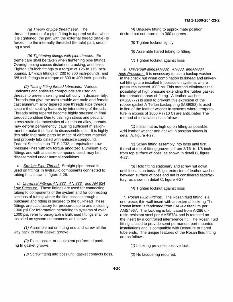
TM 1-1500-204-23-2
(a) Theory of pipe thread seal. Thethreaded portion of a pipe fitting Is tapered so that whenit is tightened, the part with the external thread (male) Isforced into the internally threaded (female) part, creat-ing a seal.
(b) Tightening fittings with pipe threads. Ex-treme care shall be taken when tightening pipe fittings.Overtightening causes distortion, cracking, and leaks.Tighten 1/8-inch fittings to a torque of 125 to 175 Inch-pounds, 1/4-inch fittings of 200 to 300 inch-pounds, and3/8-inch fittings to a torque of 300 to 400 Inch- pounds.
(2) Tubing fitting thread lubricants. Variouslubricants and antiseize compounds are used onthreads to prevent seizing and difficulty In disassembly.Threads that give the most trouble are male and femalecast aluminum alloy tapered pipe threads Pipe threadssecure their sealing features by interlocking of threads.Threads being tapered become highly stressed In finaltorqued condition Due to this high stress and peculiarstress-strain characteristics of aluminum alloy, threadsmay deform permanently, causing sufficient misalign-ment to make it difficult to disassemble unit. It is highlydesirable that male parts be made of different materialand properly lubricated with antiseize compound.Federal Specification TT-S-1732, or equivalent Lowpressure lines with low torque anodized aluminum alloyfittings and with antiseize compound used, may bedisassembled under normal conditions.
c . Straight Pipe Thread. Straight pipe thread isused on fittings In hydraulic components connected totubing It Is shown in figure 4-26.
d. Universal Fittings AN 832. AN 833. and AN 834Low Pressure. These fittings are used for connectingtubing to components of the system and for connectingsections of tubing where the line passes through abulkhead and fitting is secured to the bulkhead Thesefittings are satisfactory for pressures up to and including1000 psi For Information pertaining to systems of over1000 psi, refer to paragraph e Bulkhead fittings shall beinstalled on system components as follows:
(1) Assemble nut on fitting end and screw all theway back to clear gasket groove.
(2) Place gasket or equivalent performed pack-ing In gasket groove.
(3) Screw fitting into boss until gasket contacts boss.
(4) Unscrew fitting to approximate positiondesired but not more than 360 degrees
(5) Tighten locknut lightly.
(6) Assemble flared tubing to fitting.
(7) Tighten locknut against boss
e. UniversalFittingsAN832. AN833, andAN834High Pressure. It is necessary to use a backup washerin the check nut when combination bulkhead and univer-sal fittings are installed In bosses on systems wherepressures exceed 1000 psi This method eliminates thepossibility of high pressure extending the rubber gasketinto threaded areas of fitting. A leather washer(MS28777) is used to prevent this extrusion of therubber gasket A Teflon backup ring (MS9058) Is usedin lieu of the leather washer in systems where tempera-ture in excess of 1600 F (710 C) are anticipated Themethod of installation is as follows:
(1) Install nut as high up on fitting as possible.Add leather washer and gasket in position shown indetail A, figure 4-27.
(2) Screw fitting assembly into boss until firstthread at top of fitting groove is from 3/16- to 1/8-inchfrom top surface of boss, as shown In detail B, figure4-27.
(3) Hold fitting stationary and screw nut downuntil it seats on boss. Slight extrusion of leather washerbetween surface of boss and nut is considered satisfac-tory, as shown in detail C, figure 4-27.
(4) Tighten locknut against boss
f. Rosan Fluid Fittings. The Rosan fluid fitting is aone-piece, thin wall insert with an external lockring TheRosan insert is fabricated from 6AL-4V titanium perAMS4967. The lockring is fabricated from A-286 or-rosin-resistant steel per AMS5734 and is retained onthe insert by a controlled interference fit. The Rosan fluidfitting is used to provide semi-permanent port mountedinstallations and is compatible with Denature or flaredtube ends. The unique features of the Rosan fluid fittingare as follows.
(1) Lockring provides positive lock.
(2) No lacquering required.
4-20
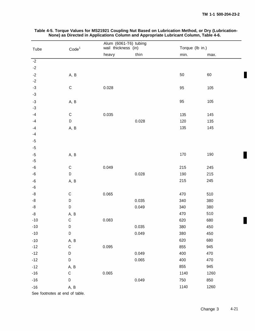
TM 1-1 500-204-23-2
Table 4-5. Torque Values for MS21921 Coupling Nut Based on Lubrication Method, or Dry (Lubrication-None) as Directed in Applications Column and Appropriate Lubricant Column, Table 4-6.
Alum (6061-T6) tubingTube Code1 wail thickness (in) Torque (lb in.)
heavy thin min. max.
-2
-2
-2 A, B-2
-3 C
-3
-3 A, B-3
-4 C
-4 D
-4 A, B-4
-5
-5
-5 A, B-5
-6 C
-6 D
-6 A, B-6
-8 C
-8 D-8 D
-8 A, B-10 C
-10 D
-10 D
-10 A, B-12 C
-12 D
-12 D
-12 A, B-16 C
-16 D
-16 A, BSee footnotes at end of table.
0.028 95 105
0.035
0.028
0.049
0.028
0.065
0.0350.049
0.083
0.035
0.049
0.095
0.049
0.065
0.065
0.049
50 60
95
135120
135
170
215 245
190 215
215 245
470 510
340 380340 380
470 510
620 680
380 450
380 450
620 680
855 945
400 470
400 470
855 945
1140 1260
750 850
1140 1260
105
145
135
145
190
Change 3 4-21
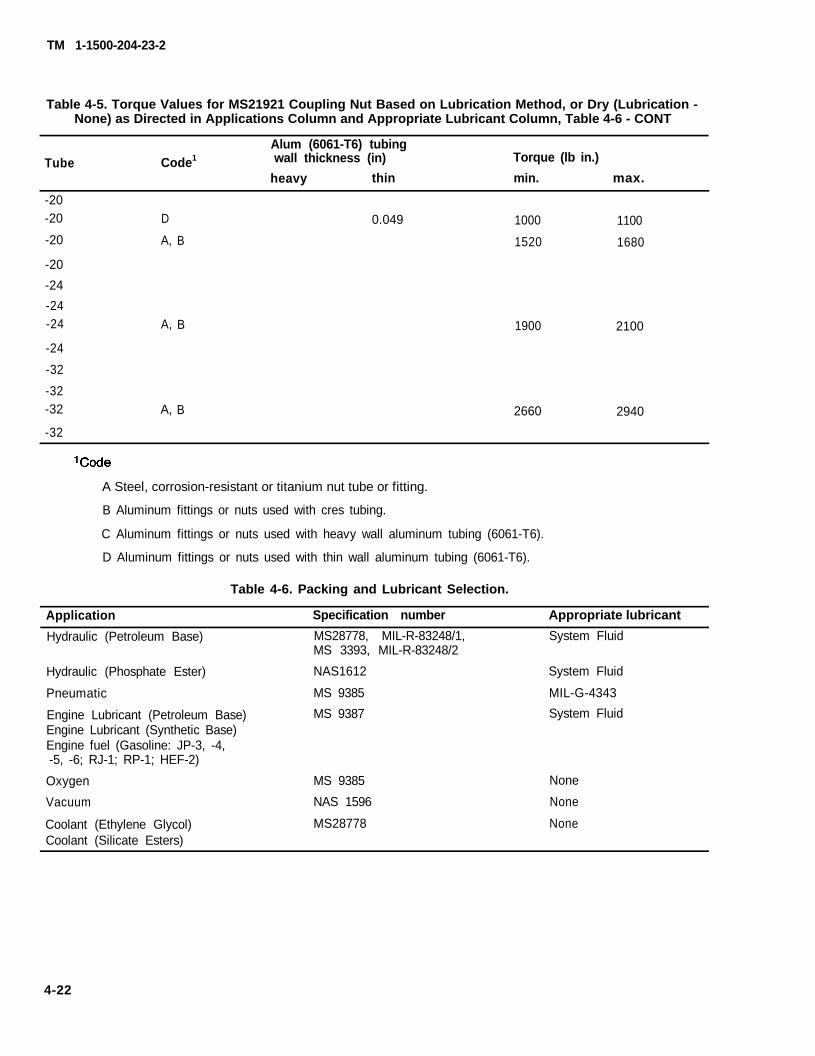
TM 1-1500-204-23-2
Table 4-5. Torque Values for MS21921 Coupling Nut Based on Lubrication Method, or Dry (Lubrication -None) as Directed in Applications Column and Appropriate Lubricant Column, Table 4-6 - CONT
Tube Code1Alum (6061-T6) tubingwall thickness (in)
heavy thin
Torque (lb in.)
min. max.
-20-20 D 0.049 1000 1100-20 A, B 1520 1680
-20
-24-24-24 A, B 1900 2100
-24
-32
-32-32 A, B 2660 2940
-32
A Steel, corrosion-resistant or titanium nut tube or fitting.
B Aluminum fittings or nuts used with cres tubing.
C Aluminum fittings or nuts used with heavy wall aluminum tubing (6061-T6).
D Aluminum fittings or nuts used with thin wall aluminum tubing (6061-T6).
Table 4-6. Packing and Lubricant Selection.
Application
Hydraulic (Petroleum Base)
Hydraulic (Phosphate Ester)
Pneumatic
Engine Lubricant (Petroleum Base)Engine Lubricant (Synthetic Base)Engine fuel (Gasoline: JP-3, -4,-5, -6; RJ-1; RP-1; HEF-2)
Oxygen
Vacuum
Coolant (Ethylene Glycol)Coolant (Silicate Esters)
Specification number
MS28778, MIL-R-83248/1,MS 3393, MIL-R-83248/2
NAS1612
MS 9385
MS 9387
MS 9385
NAS 1596
MS28778
Appropriate lubricant
System Fluid
System Fluid
MIL-G-4343System Fluid
None
None
None
4-22
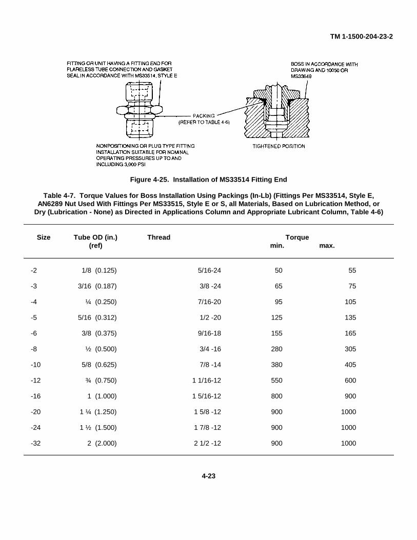
TM 1-1500-204-23-2
Figure 4-25. Installation of MS33514 Fitting End
Table 4-7. Torque Values for Boss Installation Using Packings (In-Lb) (Fittings Per MS33514, Style E,AN6289 Nut Used With Fittings Per MS33515, Style E or S, all Materials, Based on Lubrication Method, or
Dry (Lubrication - None) as Directed in Applications Column and Appropriate Lubricant Column, Table 4-6)
Size Tube OD (in.) Thread Torque(ref) min. max.
-2 1/8 (0.125) 5/16-24 50 55
-3 3/16 (0.187) 3/8 -24 65 75
-4 ¼ (0.250) 7/16-20 95 105
-5 5/16 (0.312) 1/2 -20 125 135
-6 3/8 (0.375) 9/16-18 155 165
-8 ½ (0.500) 3/4 -16 280 305
-10 5/8 (0.625) 7/8 -14 380 405
-12 ¾ (0.750) 1 1/16-12 550 600
-16 1 (1.000) 1 5/16-12 800 900
-20 1 ¼ (1.250) 1 5/8 -12 900 1000
-24 1 ½ (1.500) 1 7/8 -12 900 1000
-32 2 (2.000) 2 1/2 -12 900 1000
4-23
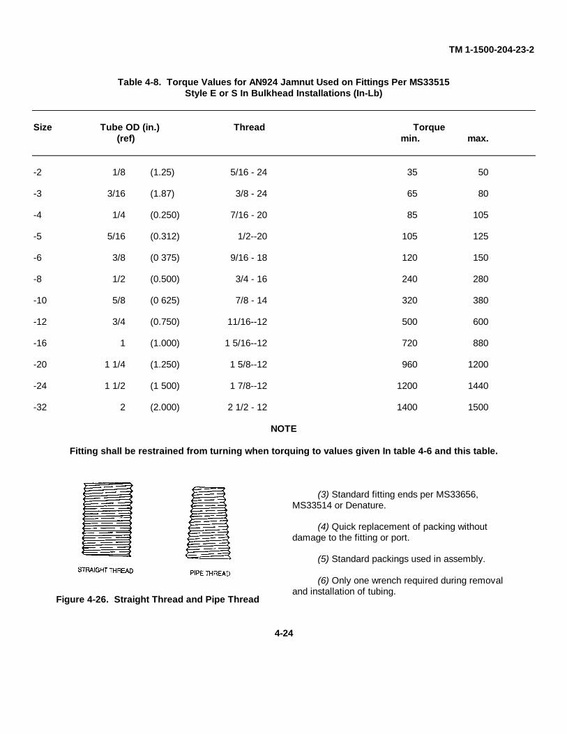
TM 1-1500-204-23-2
Table 4-8. Torque Values for AN924 Jamnut Used on Fittings Per MS33515Style E or S In Bulkhead Installations (In-Lb)
Size Tube OD (in.) Thread Torque(ref) min. max.
-2 1/8 (1.25) 5/16 - 24 35 50
-3 3/16 (1.87) 3/8 - 24 65 80
-4 1/4 (0.250) 7/16 - 20 85 105
-5 5/16 (0.312) 1/2--20 105 125
-6 3/8 (0 375) 9/16 - 18 120 150
-8 1/2 (0.500) 3/4 - 16 240 280
-10 5/8 (0 625) 7/8 - 14 320 380
-12 3/4 (0.750) 11/16--12 500 600
-16 1 (1.000) 1 5/16--12 720 880
-20 1 1/4 (1.250) 1 5/8--12 960 1200
-24 1 1/2 (1 500) 1 7/8--12 1200 1440
-32 2 (2.000) 2 1/2 - 12 1400 1500
NOTE
Fitting shall be restrained from turning when torquing to values given In table 4-6 and this table.
Figure 4-26. Straight Thread and Pipe Thread
(3) Standard fitting ends per MS33656,MS33514 or Denature.
(4) Quick replacement of packing withoutdamage to the fitting or port.
(5) Standard packings used in assembly.
(6) Only one wrench required during removaland installation of tubing.
4-24
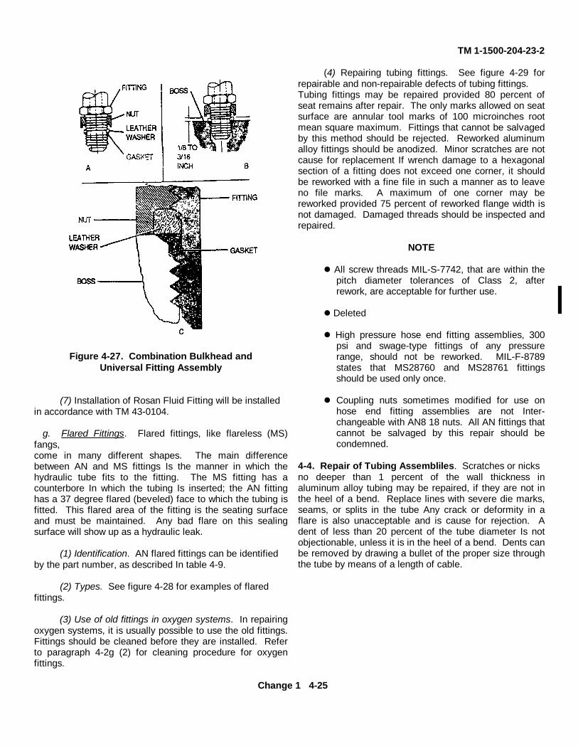
TM 1-1500-204-23-2
Figure 4-27. Combination Bulkhead andUniversal Fitting Assembly
(7) Installation of Rosan Fluid Fitting will be installedin accordance with TM 43-0104.
g. Flared Fittings. Flared fittings, like flareless (MS)fangs,come in many different shapes. The main differencebetween AN and MS fittings Is the manner in which thehydraulic tube fits to the fitting. The MS fitting has acounterbore In which the tubing Is inserted; the AN fittinghas a 37 degree flared (beveled) face to which the tubing isfitted. This flared area of the fitting is the seating surfaceand must be maintained. Any bad flare on this sealingsurface will show up as a hydraulic leak.
(1) Identification. AN flared fittings can be identifiedby the part number, as described In table 4-9.
(2) Types. See figure 4-28 for examples of flaredfittings.
(3) Use of old fittings in oxygen systems. In repairingoxygen systems, it is usually possible to use the old fittings.Fittings should be cleaned before they are installed. Referto paragraph 4-2g (2) for cleaning procedure for oxygenfittings.
(4) Repairing tubing fittings. See figure 4-29 forrepairable and non-repairable defects of tubing fittings.Tubing fittings may be repaired provided 80 percent ofseat remains after repair. The only marks allowed on seatsurface are annular tool marks of 100 microinches rootmean square maximum. Fittings that cannot be salvagedby this method should be rejected. Reworked aluminumalloy fittings should be anodized. Minor scratches are notcause for replacement If wrench damage to a hexagonalsection of a fitting does not exceed one corner, it shouldbe reworked with a fine file in such a manner as to leaveno file marks. A maximum of one corner may bereworked provided 75 percent of reworked flange width isnot damaged. Damaged threads should be inspected andrepaired.
NOTE
All screw threads MIL-S-7742, that are within thepitch diameter tolerances of Class 2, afterrework, are acceptable for further use.
Deleted
High pressure hose end fitting assemblies, 300psi and swage-type fittings of any pressurerange, should not be reworked. MIL-F-8789states that MS28760 and MS28761 fittingsshould be used only once.
Coupling nuts sometimes modified for use onhose end fitting assemblies are not Inter-changeable with AN8 18 nuts. All AN fittings thatcannot be salvaged by this repair should becondemned.
4-4. Repair of Tubing Assembliles. Scratches or nicksno deeper than 1 percent of the wall thickness inaluminum alloy tubing may be repaired, if they are not inthe heel of a bend. Replace lines with severe die marks,seams, or splits in the tube Any crack or deformity in aflare is also unacceptable and is cause for rejection. Adent of less than 20 percent of the tube diameter Is notobjectionable, unless it is in the heel of a bend. Dents canbe removed by drawing a bullet of the proper size throughthe tube by means of a length of cable.
Change 1 4-25
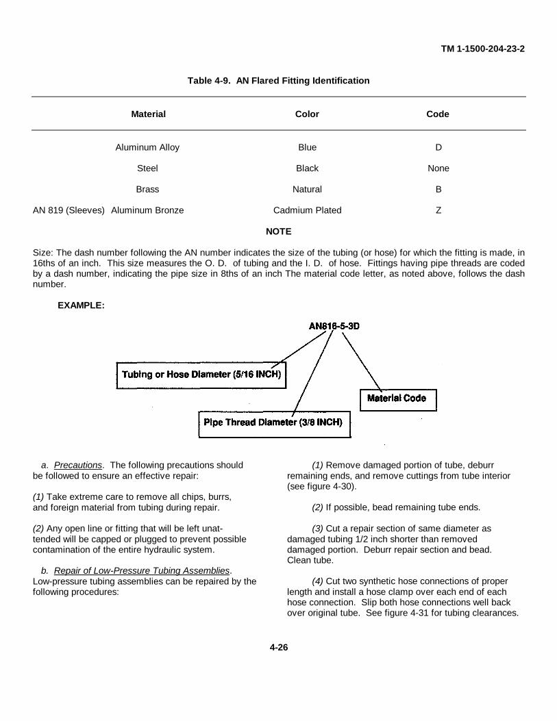
TM 1-1500-204-23-2
Table 4-9. AN Flared Fitting Identification
Material Color Code
Aluminum Alloy Blue D
Steel Black None
Brass Natural B
AN 819 (Sleeves) Aluminum Bronze Cadmium Plated Z
NOTE
Size: The dash number following the AN number indicates the size of the tubing (or hose) for which the fitting is made, in16ths of an inch. This size measures the O. D. of tubing and the I. D. of hose. Fittings having pipe threads are codedby a dash number, indicating the pipe size in 8ths of an inch The material code letter, as noted above, follows the dashnumber.
EXAMPLE:
a. Precautions. The following precautions shouldbe followed to ensure an effective repair:
(1) Take extreme care to remove all chips, burrs,and foreign material from tubing during repair.
(2) Any open line or fitting that will be left unat-tended will be capped or plugged to prevent possiblecontamination of the entire hydraulic system.
b. Repair of Low-Pressure Tubing Assemblies.Low-pressure tubing assemblies can be repaired by thefollowing procedures:
(1) Remove damaged portion of tube, deburrremaining ends, and remove cuttings from tube interior(see figure 4-30).
(2) If possible, bead remaining tube ends.
(3) Cut a repair section of same diameter asdamaged tubing 1/2 inch shorter than removeddamaged portion. Deburr repair section and bead.Clean tube.
(4) Cut two synthetic hose connections of properlength and install a hose clamp over each end of eachhose connection. Slip both hose connections well backover original tube. See figure 4-31 for tubing clearances.
4-26
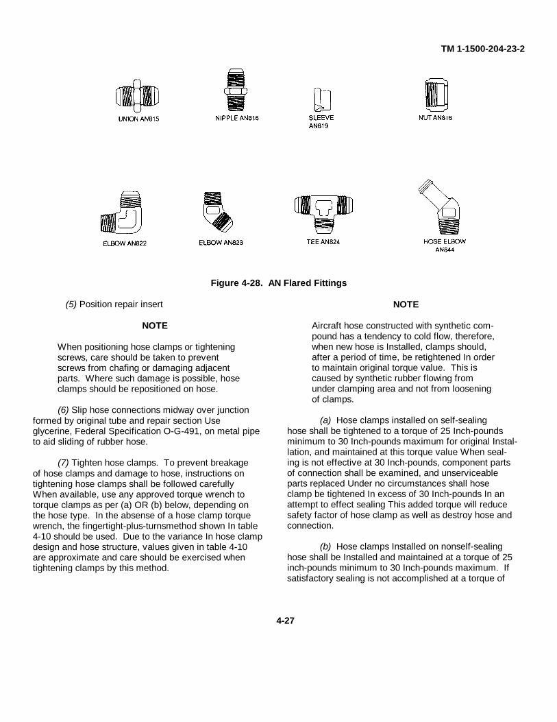
TM 1-1500-204-23-2
Figure 4-28. AN Flared Fittings
(5) Position repair insert
NOTE
When positioning hose clamps or tighteningscrews, care should be taken to preventscrews from chafing or damaging adjacentparts. Where such damage is possible, hoseclamps should be repositioned on hose.
(6) Slip hose connections midway over junctionformed by original tube and repair section Useglycerine, Federal Specification O-G-491, on metal pipeto aid sliding of rubber hose.
(7) Tighten hose clamps. To prevent breakageof hose clamps and damage to hose, instructions ontightening hose clamps shall be followed carefullyWhen available, use any approved torque wrench totorque clamps as per (a) OR (b) below, depending onthe hose type. In the absense of a hose clamp torquewrench, the fingertight-plus-turnsmethod shown In table4-10 should be used. Due to the variance In hose clampdesign and hose structure, values given in table 4-10are approximate and care should be exercised whentightening clamps by this method.
NOTE
Aircraft hose constructed with synthetic com-pound has a tendency to cold flow, therefore,when new hose is Installed, clamps should,after a period of time, be retightened In orderto maintain original torque value. This iscaused by synthetic rubber flowing fromunder clamping area and not from looseningof clamps.
(a) Hose clamps installed on self-sealinghose shall be tightened to a torque of 25 Inch-poundsminimum to 30 Inch-pounds maximum for original Instal-lation, and maintained at this torque value When seal-ing is not effective at 30 Inch-pounds, component partsof connection shall be examined, and unserviceableparts replaced Under no circumstances shall hoseclamp be tightened In excess of 30 Inch-pounds In anattempt to effect sealing This added torque will reducesafety factor of hose clamp as well as destroy hose andconnection.
(b) Hose clamps Installed on nonself-sealinghose shall be Installed and maintained at a torque of 25inch-pounds minimum to 30 Inch-pounds maximum. Ifsatisfactory sealing is not accomplished at a torque of
4-27
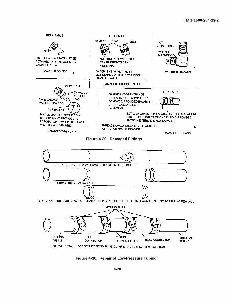
TM 1-1500-204-23-2
Figure 4-30. Repair of Low-Pressure Tubing
Figure 4-29. Damaged Fittings
4-28
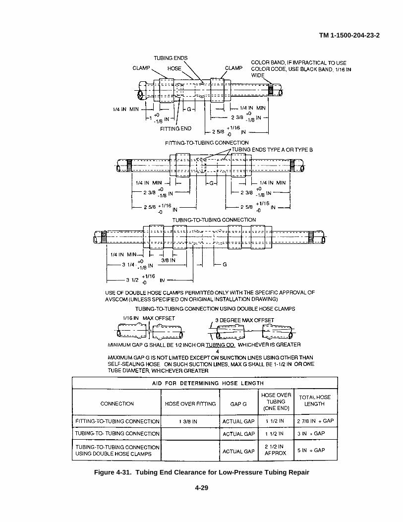
TM 1-1500-204-23-2
Figure 4-31. Tubing End Clearance for Low-Pressure Tubing Repair
4-29
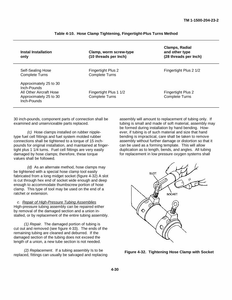
TM 1-1500-204-23-2
Table 4-10. Hose Clamp Tightening, Fingertight-Plus Turns Method
Clamps, RadialInstal Installation Clamp, worm screw-type and other typeonly (10 threads per Inch) (28 threads per Inch)
Self-Sealing Hose Fingertight Plus 2 Fingertight Plus 2 1/2Complete Turns Complete Turns
Approximately 25 to 30Inch-PoundsAll Other Aircraft Hose Fingertight Plus 1 1/2 Fingertight Plus 2Approximately 25 to 30 Complete Turns Complete TurnsInch-Pounds
30 inch-pounds, component parts of connection shall beexamined and unserviceable parts replaced.
(c) Hose clamps installed on rubber nipple-type fuel cell fittings and fuel system molded rubberconnections shall be tightened to a torque of 15 inch-pounds for original installation, and maintained at finger-tight plus 1 1/4 turns. Fuel cell fittings are very easilydamaged by hose clamps; therefore, these torquevalues shall be followed.
(d) As an alternate method, hose clamps maybe tightened with a special hose clamp tool easilyfabricated from a long midget socket (figure 4-32) A slotis cut through hex end of socket wide enough and deepenough to accommodate thumbscrew portion of hoseclamp. This type of tool may be used on the end of aratchet or extension.
c. Repair of High-Pressure Tubing AssembliesHigh-pressure tubing assembly can be repaired eitherby removal of the damaged section and a union in-stalled, or by replacement of the entire tubing assembly.
(1) Repair. The damaged portion of tubing iscut out and removed (see figure 4-33). The ends of theremaining tubing are cleaned and deburred. If thedamaged section of the tubing does not exceed thelength of a union, a new tube section is not needed.
(2) Replacement. If a tubing assembly Is to bereplaced, fittings can usually be salvaged and replacing
assembly will amount to replacement of tubing only. Iftubing is small and made of soft material, assembly maybe formed during installation by hand bending. How-ever, if tubing is of such material and size that handbending is impractical, care shall be taken to removeassembly without further damage or distortion so that itcan be used as a forming template. This will allowduplication as to length, bends, and angles. All tubingfor replacement in low pressure oxygen systems shall
Figure 4-32. Tightening Hose Clamp with Socket
4-30
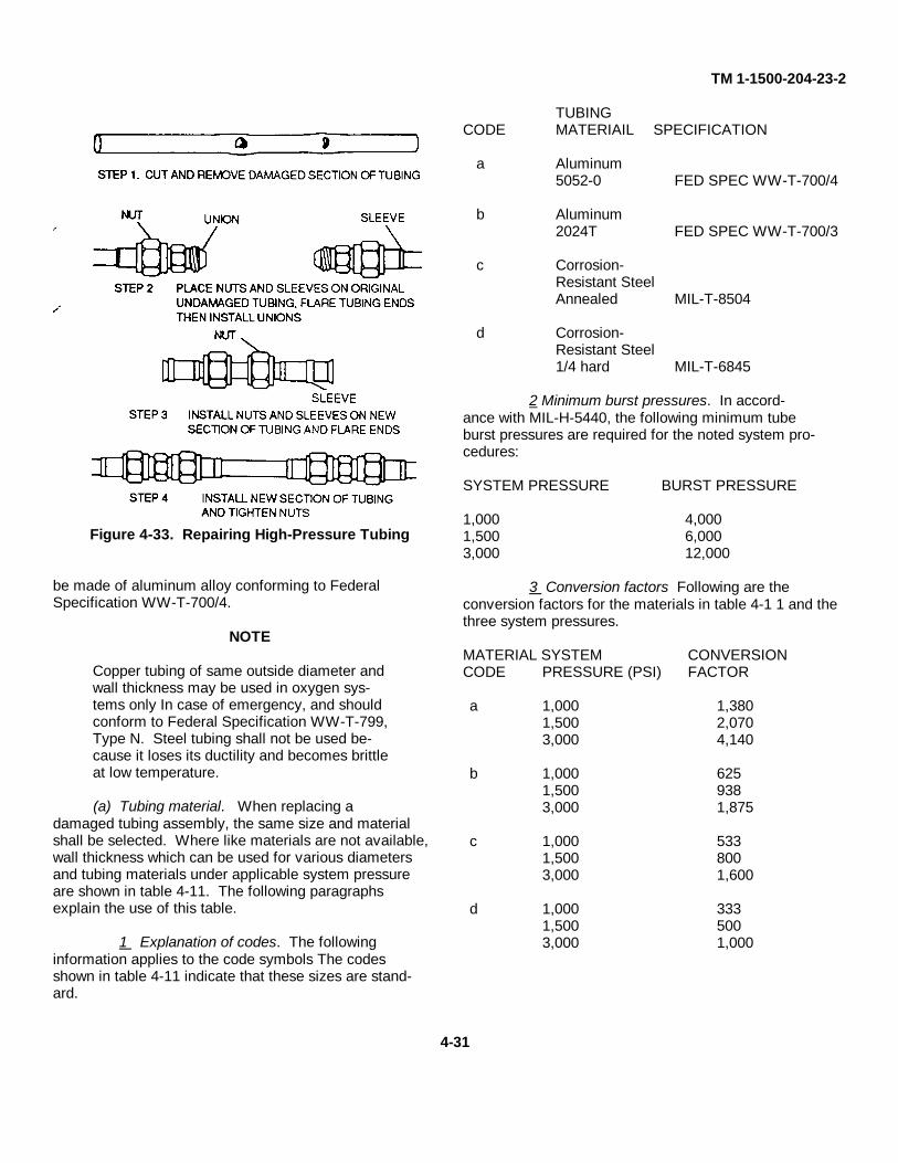
TM 1-1500-204-23-2
Figure 4-33. Repairing High-Pressure Tubing
be made of aluminum alloy conforming to FederalSpecification WW-T-700/4.
NOTE
Copper tubing of same outside diameter andwall thickness may be used in oxygen sys-tems only In case of emergency, and shouldconform to Federal Specification WW-T-799,Type N. Steel tubing shall not be used be-cause it loses its ductility and becomes brittleat low temperature.
(a) Tubing material. When replacing adamaged tubing assembly, the same size and materialshall be selected. Where like materials are not available,wall thickness which can be used for various diametersand tubing materials under applicable system pressureare shown in table 4-11. The following paragraphsexplain the use of this table.
1 Explanation of codes. The followinginformation applies to the code symbols The codesshown in table 4-11 indicate that these sizes are stand-ard.
TUBINGCODE MATERIAIL SPECIFICATION
a Aluminum5052-0 FED SPEC WW-T-700/4
b Aluminum2024T FED SPEC WW-T-700/3
c Corrosion-Resistant SteelAnnealed MIL-T-8504
d Corrosion-Resistant Steel1/4 hard MIL-T-6845
2 Minimum burst pressures. In accord-ance with MIL-H-5440, the following minimum tubeburst pressures are required for the noted system pro-cedures:
SYSTEM PRESSURE BURST PRESSURE
1,000 4,0001,500 6,0003,000 12,000
3 Conversion factors Following are theconversion factors for the materials in table 4-1 1 and thethree system pressures.
MATERIAL SYSTEM CONVERSIONCODE PRESSURE (PSI) FACTOR
a 1,000 1,3801,500 2,0703,000 4,140
b 1,000 6251,500 9383,000 1,875
c 1,000 5331,500 8003,000 1,600
d 1,000 3331,500 5003,000 1,000
4-31

TM 1-1500-204-23-2
4 Use of table. For example, the mini-mum standard wall thickness must be determined for a1/2 Inch outside diameter (OD), 1/4 hard corrosion-resistant steel tube for a 3,000 psi system. From theabove paragraph, the conversion factor is 1000. Fromtable 4-1 1, the nearest value must be found that appliesto this material This value is 1,120. This indicates a 1/2inch OD x 0.028 inch tube, which is a standard sizeindicated by the code d for 1/4 hard corrosion-resistantsteel.
5 Burst pressure. Taking any value fromthe table, it is easy to determine the actual burst pres-sure for a tube The following factors are multiplied bythe pressure values shown In table 4-11 to produce theactual burst pressure
MATERIAL BURST PRESSURECODE FACTOR
a 2.9b 6.4c 7.5d 1.2
For example, the system pressure producing 10,000 psistress on the wall of a 1/4 Inch OD x 0.012 annealedcorrosion-resistant steel tube is 960 If the system pres-sure is 1,500 psi, the minimum burst pressure is 6,000.Multiplying 960 by the burst pressure factor of 7.5 forthis material, the actual burst pressure is 7,100 psi, wellabove the minimum of 6,000 required for this system.
(b) Layout. A piece of tubing approximately10 percent longer than length of tubing to be replacedshould be cut. After required bends have been made,new tubing may be 1/2 to 2 inches longer than oldtubing Allowances should be made for flaring opera-tin. The amount of tubing in excess of amount requiredto flare tube should be cut off.
NOTE
After cutting, bending, and flaring opera-tins, oxygen tubing assemblies should becleaned in accordance with paragraph 4-2g(2)
d. Template. A path should not be selected thatrequires no bends unless original tubing had a path withno bends A section of tubing cannot be cut and flaredaccurately enough to be Installed without bends and stillavoid initial mechanical strain on tubing except In
straight runs not having rigid connections on each end.A fluid line is a mechanical part when installed, and Issensitive to vibration; therefore, direct, straight-line con-nektons shall never be made between two solid fixedattachment points, as bends allow tubing to expand andcontract under temperature differences. All bends shallbe started a reasonable distance from fittings, so sleeveand nut can be slipped back along tubing for inspection.This will also prevent tubing from binding againstsleeve Tubing assemblies shall be formed prior to in-stallation so it will not be necessary to pull assembly intoalignment by use of coupling nut If old tubing is intactand the bends have not been changed, It may be usedas a template. If rerouting is required and a newtemplate must be made, proceed as follows:
1 Place material selected for use as a templateinto one of the fittings where tube is to be connected.
2 Form necessary bends In template.
3 Remove template and use pattern tobend new tube
4 Select path with least total degreesbend. This reduces flow loss and simplifies bending.
5 Use path, if possible, with all bends Insame plane.
6 Lay out path which provides for eitherbrackets or clamps to be used as supports at intervalsnot greater than those given In table 4-12.
4-5. Flexible Hose Assemblies. Flexible hose isused In aircraft plumbing to connect moving parts withstationary parts in locations subject to vibration or wherea great amount of flexibility is needed. It can also serveas a connector In metal tubing systems
WARNING
Do not use flexible hose and hose as-semblies in oxygen systems, as they readilyabsorb grease and oil. Failure to comply mayresult in damage to aircraft of Injury to per-sonnel
a. Identification of Flexible Hose. Aircraft hose orhose assemblies can be readily identified as to age and
4-32
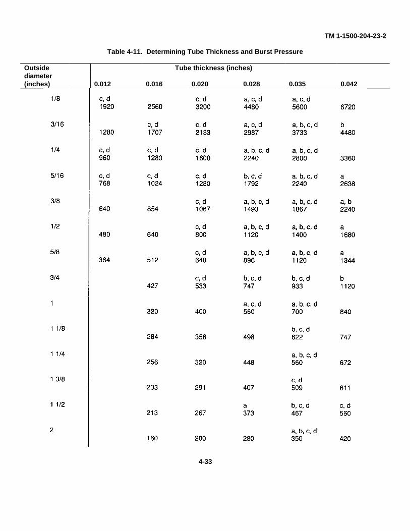
TM 1-1500-204-23-2
Table 4-11. Determining Tube Thickness and Burst Pressure
Outside Tube thickness (inches)diameter(inches) 0.012 0.016 0.020 0.028 0.035 0.042
4-33
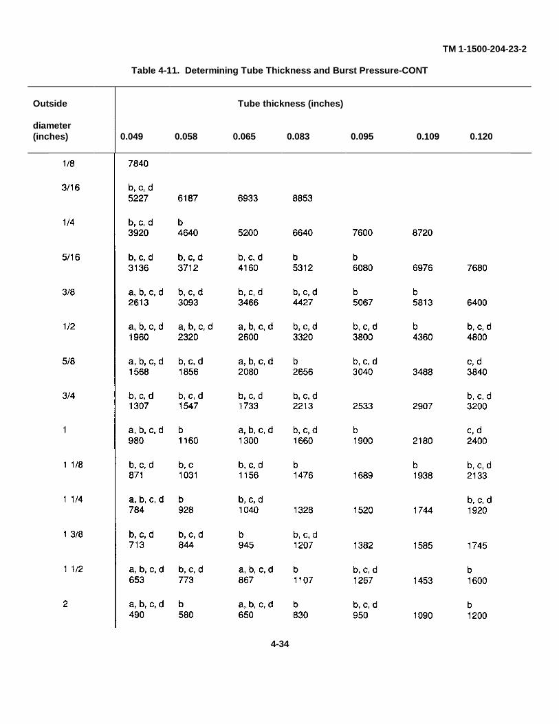
TM 1-1500-204-23-2
Table 4-11. Determining Tube Thickness and Burst Pressure-CONT
Outside Tube thickness (inches)
diameter(inches) 0.049 0.058 0.065 0.083 0.095 0.109 0.120
4-34
TM 1-1500-204-23-2
manufacturer by code markings which are repeatedlystenciled along the full length of the hose.
(1) Markings. The identification markings willeither be manufacturer’s code number or manufacturer’ssymbol, also date of manufacture in quarter year andyear, size of hose, and specification of hose in numerals(figures 4-34 through 4-38).
(2) Stripe. The indicator stripe or code symbolalong length of hose shall, in all cases, identify hose
(2) Store hose or hose assemblies on rackswhich support and protect hose and hose assemblies.
(3) Store hose or hose assemblies so that olderitems are used first.
c. Replacement of Flexible Hose. Inspection andreplacement of hose or hose assemblies will be accom-plished at inspection periods perscribed in applicableaircraft maintenance manual or whenever defects listedbelow are evident.
manufacturer.
(3) Temperature range. The indicator stripe indi-cates that hose is suitable for use through a temperaturerange of -65 to 160°F (-54 to 71 ºC).
(4) Hose. MIL-H-8788. This hose will appear inassemblies only
(a) Markings. Hose in each assembly will bemarked with quarter year and year of manufacture ofhose, hose size, specification number, and an indicatorstripe in the form of a yellow dot and dash code, showingdirection of natural lay of hose. Markings are repeated atintervals of not more than 9 inches along length of hose.
(b) Identification tag. This hose is also iden-tified by a removable metal tag or band, installed at thefactory when hose is assembled, showing part numberof hose assembly, date of assembly, and name or trade-mark of manufacturer.
b. Storage of Hose and Hose Assemblies. Hose orhose assemblies shall be stored as follows:
Do not store hose or hose assemblies in piles. (c) Inspection. Rubber products should beTo do so will result in decreased strength and carefully inspected prior to installation and during use forintegrity. weather checking.
(1) Seal both ends of bulk hose. Cap or plugeach hose or hose assembly as outlined in paragraph4-51.
(d) Replacement. Replace hose or hose as-semblies with weather checking that is deep or wideenough to expose fabric.
(7) Deterioration. Replace all hose and hoseassemblies showing signs of deterioration indicated byseparation of rubber cover or braid from inner tube,cracks, hardening and lack of flexibility.
(2) Cold Flow. Replace hose or hose assem-blies showing signs of excessive cold flow indicated bydeep permanent impressions and cracks in hose or cov-er produced by pressure of hose clamps and head ofnipple chafing.
(3) Weather checking. Weather checking of rub-ber is caused by sunlight and atmospheric oxidization.
(a) Early stages. Rubber hoses, tubing orrubber outer coated surfaces will show fine line cracks orcrazing but will be pliable when squeezed between thefingers or rolled between the hands. This is a sign of theearly stages of deterioration.
(b) Advanced deterioration. As deteriora-tion continues, the cracks and crazing become moreprominent, and when the rubber hose or tubing issqueezed or rolled, the item will break, shatter, or turn topowder, thus becoming useless.
Change 3 4-35
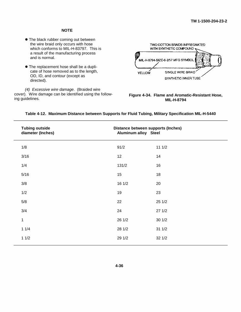
TM 1-1500-204-23-2
NOTE
The black rubber coming out betweenthe wire braid only occurs with hosewhich conforms to MIL-H-83797. This isa result of the manufacturing processand is normal.
The replacement hose shall be a dupli-cate of hose removed as to the length,OD, ID, and contour (except asdirected).
(4) Excessive wire damage. (Braided wirecover). Wire damage can be identified using the follow-ing guidelines.
Figure 4-34. Flame and Aromatic-Resistant Hose,MIL-H-8794
Table 4-12. Maximum Distance between Supports for Fluid Tubing, Military Specification MIL-H-5440
Tubing outside Distance between supports (Inches)diameter (Inches) Aluminum alloy Steel
1/8 91/2 11 1/2
3/16 12 14
1/4 131/2 16
5/16 15 18
3/8 16 1/2 20
1/2 19 23
5/8 22 25 1/2
3/4 24 27 1/2
1 26 1/2 30 1/2
1 1/4 28 1/2 31 1/2
1 1/2 29 1/2 32 1/2
4-36
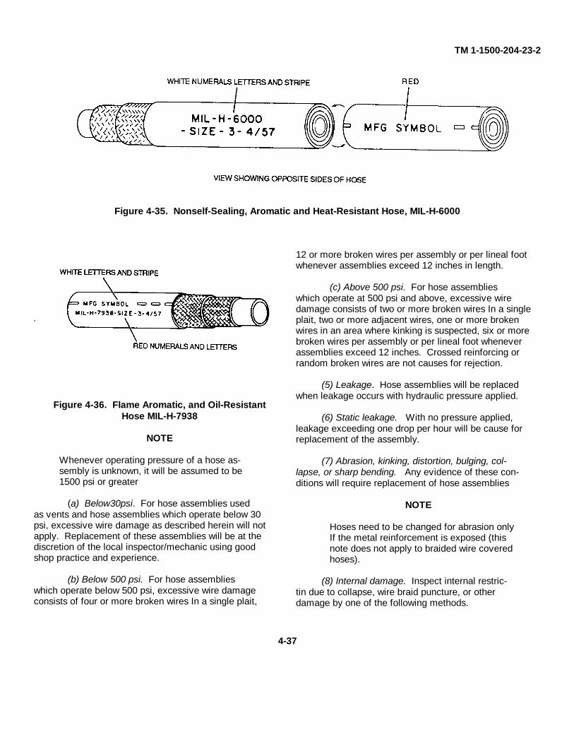
TM 1-1500-204-23-2
Figure 4-35. Nonself-Sealing, Aromatic and Heat-Resistant Hose, MIL-H-6000
Figure 4-36. Flame Aromatic, and Oil-ResistantHose MIL-H-7938
NOTE
Whenever operating pressure of a hose as-sembly is unknown, it will be assumed to be1500 psi or greater
(a) Below30psi. For hose assemblies usedas vents and hose assemblies which operate below 30psi, excessive wire damage as described herein will notapply. Replacement of these assemblies will be at thediscretion of the local inspector/mechanic using goodshop practice and experience.
(b) Below 500 psi. For hose assemblieswhich operate below 500 psi, excessive wire damageconsists of four or more broken wires In a single plait,
12 or more broken wires per assembly or per lineal footwhenever assemblies exceed 12 inches in length.
(c) Above 500 psi. For hose assemblieswhich operate at 500 psi and above, excessive wiredamage consists of two or more broken wires In a singleplait, two or more adjacent wires, one or more brokenwires in an area where kinking is suspected, six or morebroken wires per assembly or per lineal foot wheneverassemblies exceed 12 inches. Crossed reinforcing orrandom broken wires are not causes for rejection.
(5) Leakage. Hose assemblies will be replacedwhen leakage occurs with hydraulic pressure applied.
(6) Static leakage. With no pressure applied,leakage exceeding one drop per hour will be cause forreplacement of the assembly.
(7) Abrasion, kinking, distortion, bulging, col-lapse, or sharp bending. Any evidence of these con-ditions will require replacement of hose assemblies
NOTE
Hoses need to be changed for abrasion onlyIf the metal reinforcement is exposed (thisnote does not apply to braided wire coveredhoses).
(8) Internal damage. Inspect internal restric-tin due to collapse, wire braid puncture, or otherdamage by one of the following methods.
4-37
TM 1-1500-204-23-2
(a) Internal inspection. The various con-structions of hose assemblies are inspected as follows:
1 Straight hose assemblies. Insert lightat one end and inspect by looking through from theopposite end.
2 Hose assembly with elbow fitting oneend. Insert flexible inspection light into elbow fittingand examine by looking through from the opposite end
3 Hose assembly with elbow fittings bothends. Insert flexible inspection light into one end andexamine from the opposite end using a dental-typemirror. This procedure is practical on large size hoseassemblies only.
(b) Other configurations and small size hoseassemblies. Pass a ball of proper size (refer to table4-13) through the hose assembly to check for restrictionor kinking.
d. Instructions for Repair of Flexible Rubber Hose.Replace all defective hose assemblies without attempt-ing repair. MS28759, MS28762, MS28741, and AN6270 hose assemblies are field fabricated, and arereplaced as a complete unit. However, fittings from theold hose assemblies should be reused on the newassemblies when they are in good condition All factoryassembled hose, or field assembled hose which hasbeen in storage, shall be subjected to pressure test priorto installation in accordance with paragraph 4-5f
e. Instructions for Assembly of High Pressure(3000 psi) Hose Assemblies MS28759 and MS28762.High pressure hose assemblies MS28759 andMS28762 are fabricated from high pressure bulk hoseconforming to MIL-H-8788 or MIL-H-8790, and fittingsconforming to Military Standards MS28760 andMS28761
(1) Visually check bulk hose. Visually checkbulk hose when hose Is cut for assembly. Check hosefor mutilations, mandrel joints, marks, seams, and ex-cessive graphite
(2) Visually check fittings. Check fittings for
Mutilations, nicks, and distortions causedbe overtightening, scratches, or otherdamage to the cone seat sealing surface.
Backed out retaining wires on swivel nuts.
Mutilation or other damage to threaded areas.
Damage to the finish which would affectthe corrosion-resistance of the fitting.
NOTE
Do not intermix the socket and nipple fromone manufacturer with those of another. Allfittings are marked with the manufacturer'ssymbol Also, do not reuse aluminum sock-ets on high pressure hose fittings.
(3) Equipment required. The following equip-ment is required for field fabrication of high pressurehose assemblies:
Wire brush or soft wire wheel.
6 inch slip-joint pliers.
Knife (leather or linoleum), ground asshown in figure 4-39.
Fine tooth hacksaw.
10,000 psi hydrostatic test machine.
Standard wrenches.
Shop vise.
(4) Determine correct length of hose. Deter-mine correct length of hose required as shown in table4-14 and figure 4-40. Cut hose squarely using a finetooth hacksaw. Using compressed air, clean hose aftercutting to remove all cutting residue.
(5) Hose and fittings assembly. Assemblehose and fittings using following procedures and figure4-41, steps 1 through 9:
4-38
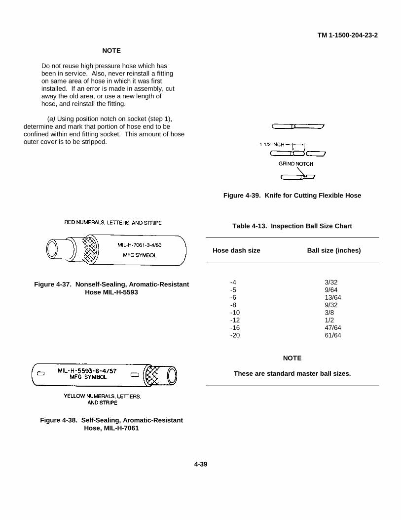
TM 1-1500-204-23-2
NOTE
Do not reuse high pressure hose which hasbeen in service. Also, never reinstall a fittingon same area of hose in which it was firstinstalled. If an error is made in assembly, cutaway the old area, or use a new length ofhose, and reinstall the fitting.
(a) Using position notch on socket (step 1),determine and mark that portion of hose end to beconfined within end fitting socket. This amount of hoseouter cover is to be stripped.
Figure 4-37. Nonself-Sealing, Aromatic-ResistantHose MIL-H-5593
Figure 4-38. Self-Sealing, Aromatic-ResistantHose, MIL-H-7061
Figure 4-39. Knife for Cutting Flexible Hose
Table 4-13. Inspection Ball Size Chart
Hose dash size Ball size (inches)
-4 3/32-5 9/64-6 13/64-8 9/32-10 3/8-12 1/2-16 47/64-20 61/64
NOTE
These are standard master ball sizes.
4-39
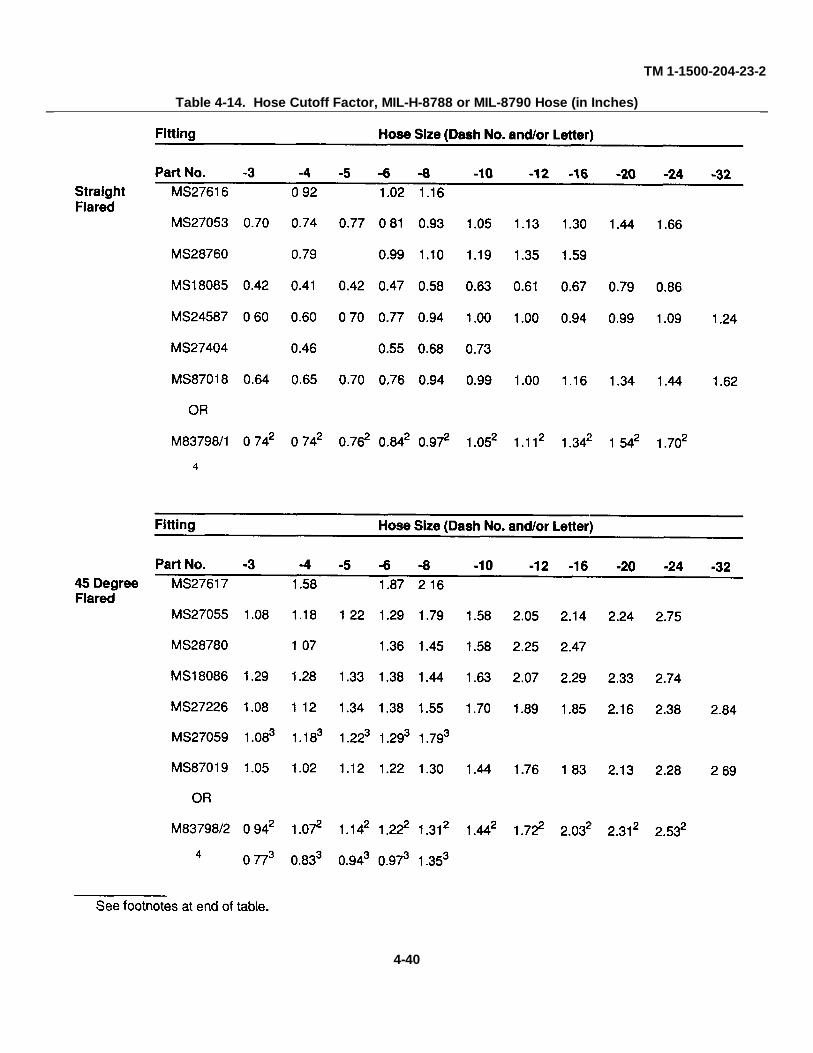
TM 1-1500-204-23-2
Table 4-14. Hose Cutoff Factor, MIL-H-8788 or MIL-8790 Hose (in Inches)
4-40
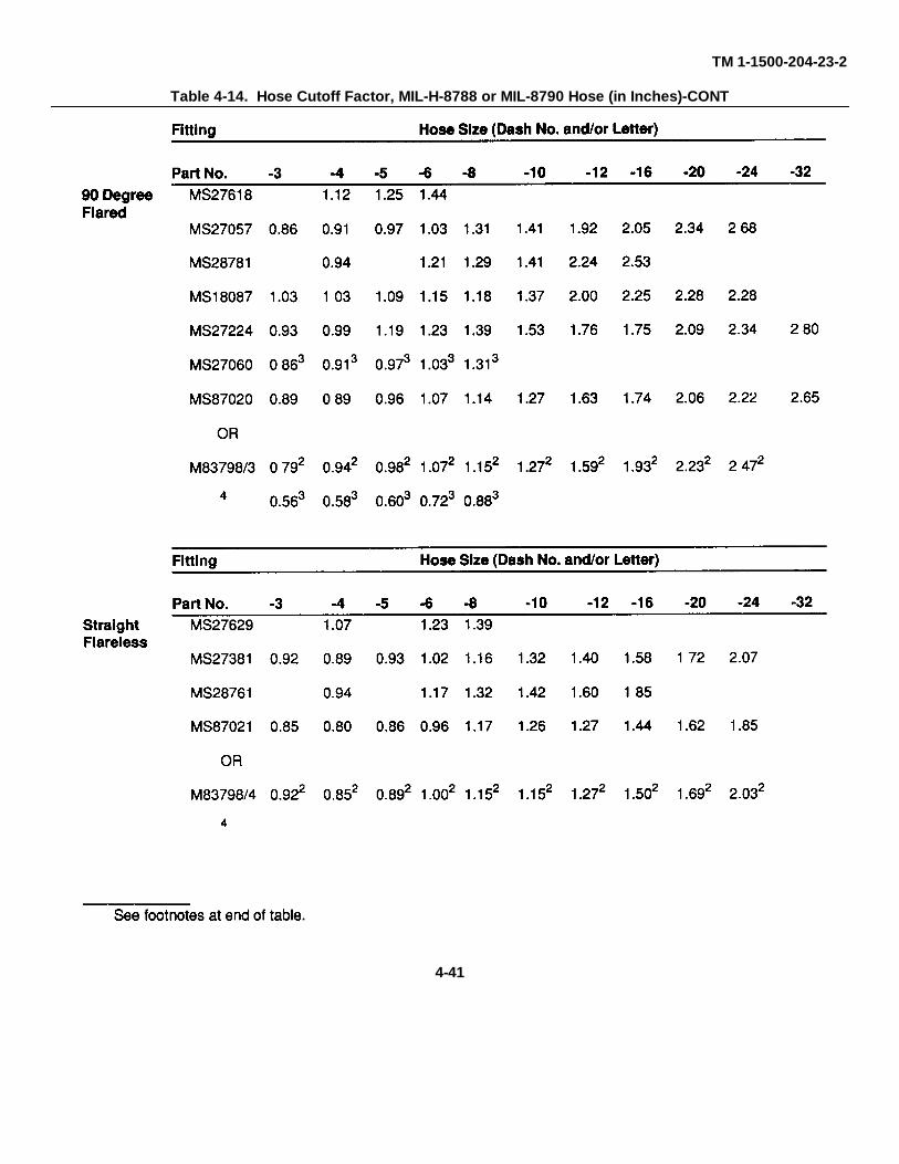
TM 1-1500-204-23-2
Table 4-14. Hose Cutoff Factor, MIL-H-8788 or MIL-8790 Hose (in Inches)-CONT
4-41
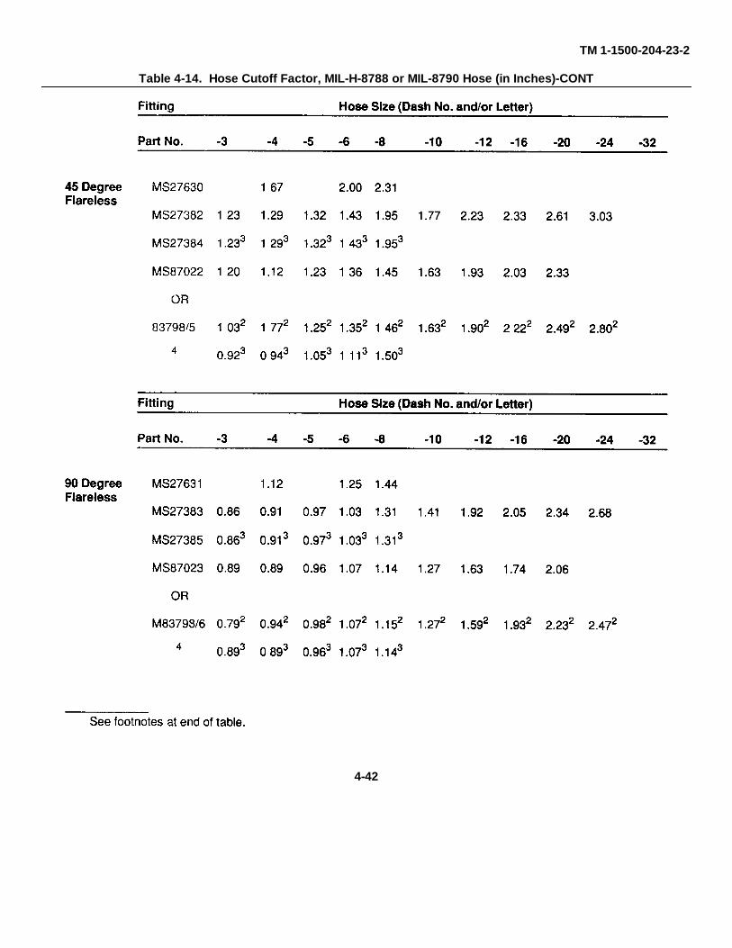
TM 1-1500-204-23-2
Table 4-14. Hose Cutoff Factor, MIL-H-8788 or MIL-8790 Hose (in Inches)-CONT
4-42
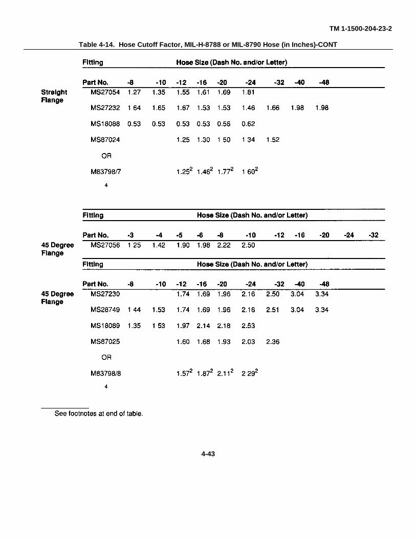
TM 1-1500-204-23-2
Table 4-14. Hose Cutoff Factor, MIL-H-8788 or MIL-8790 Hose (in Inches)-CONT
4-43
TM 1-1500-204-23-2
Table 4-14. Hose Cutoff Factor, MIL-H-8788 or MIL-8790 Hose (in Inches)-CONT
(b) Using knife, cut around mark made In (a)above step 2 of figure 4-40. Make sure cut Is through towire braid Slit this section of outer cover lengthwise(step 3) Pry up outer cover and use pliers to twist coveroff (step 4). Using wire brush or soft wire wheel, removeany rubber particle adhering to the wire braid (step 5)Exercise extreme care when operation to ensure thatwire braid Is not loosened, frayed, or flared when brush-ing.
(c) Place socket in a vise. Screw hose into thesocket counterclockwise until it bottoms (step b); thenback off 1/4 turn
NOTE
Avoid excessive turning of hose in aluminumsockets. This will tend to grind away materialfrom the buttresses Inside socket
(d) Using wrenches, screw nipple end fittingonto nipple end with counterclockwise movement andstart nipple hex nut onto opposite end using clockwisemovement (step 7).
(e) Lubricate nipple threads (step 8) and in-side of hose liberally using a light motor oil or hydraulicfluid, MIL-H-5606.
(f) Position wrench on nipple hex nut andInstall nipple assembly into socket and hose by turningnut clockwise (step 9). Maximum allowable gap be-tween nipple hex and socket in 1/16 inch
(6) Inspect hose assembly internally. Inspecthose assembly internally for cut or bridged inner tube,obstructions and cleanliness. Minimum Inner diameterfor a bulged inner tube is shown in table 4-15 Inspectfor proper gap between nipple hex hex and socket.Ensure that nut swivels freely.
4-44
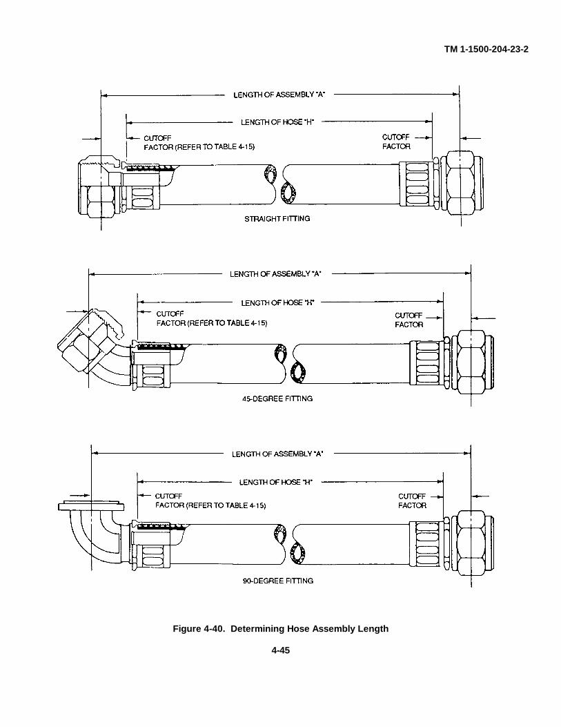
TM 1-1500-204-23-2
Figure 4-40. Determining Hose Assembly Length
4-45
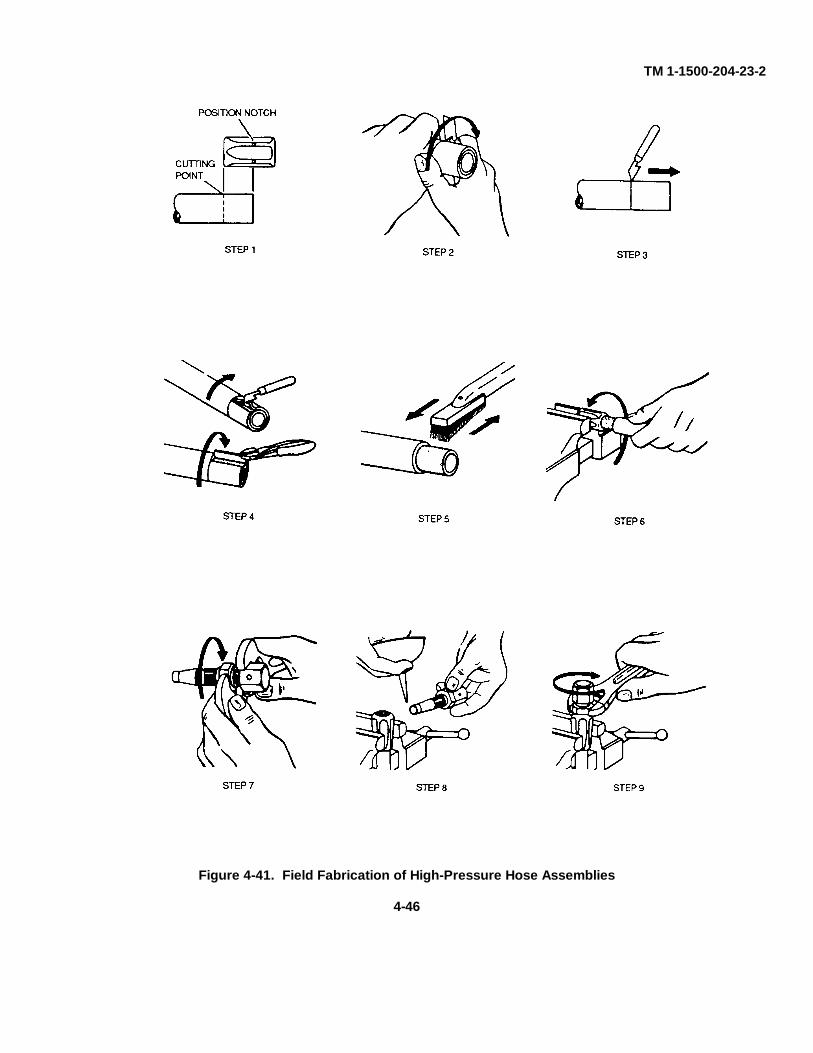
TM 1-1500-204-23-2
Figure 4-41. Field Fabrication of High-Pressure Hose Assemblies
4-46
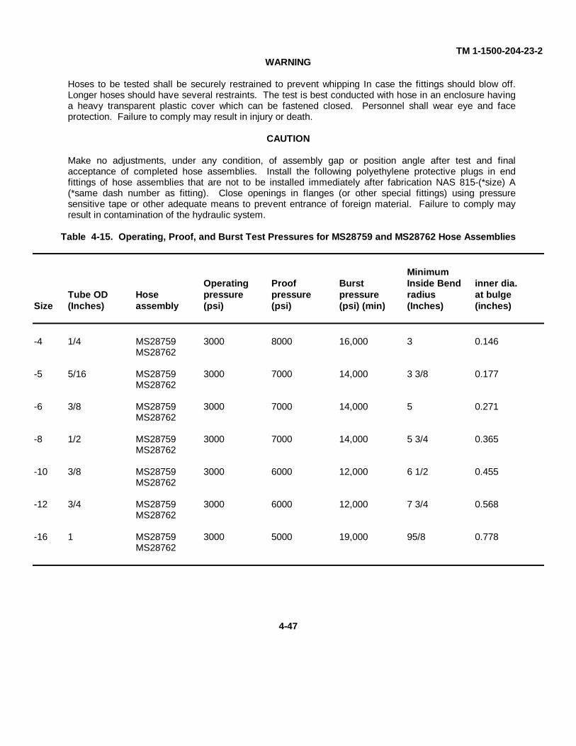
TM 1-1500-204-23-2WARNING
Hoses to be tested shall be securely restrained to prevent whipping In case the fittings should blow off.Longer hoses should have several restraints. The test is best conducted with hose in an enclosure havinga heavy transparent plastic cover which can be fastened closed. Personnel shall wear eye and faceprotection. Failure to comply may result in injury or death.
CAUTION
Make no adjustments, under any condition, of assembly gap or position angle after test and finalacceptance of completed hose assemblies. Install the following polyethylene protective plugs in endfittings of hose assemblies that are not to be installed immediately after fabrication NAS 815-(*size) A(*same dash number as fitting). Close openings in flanges (or other special fittings) using pressuresensitive tape or other adequate means to prevent entrance of foreign material. Failure to comply mayresult in contamination of the hydraulic system.
Table 4-15. Operating, Proof, and Burst Test Pressures for MS28759 and MS28762 Hose Assemblies
MinimumOperating Proof Burst Inside Bend inner dia.
Tube OD Hose pressure pressure pressure radius at bulgeSize (Inches) assembly (psi) (psi) (psi) (min) (Inches) (inches)
-4 1/4 MS28759 3000 8000 16,000 3 0.146MS28762
-5 5/16 MS28759 3000 7000 14,000 3 3/8 0.177MS28762
-6 3/8 MS28759 3000 7000 14,000 5 0.271MS28762
-8 1/2 MS28759 3000 7000 14,000 5 3/4 0.365MS28762
-10 3/8 MS28759 3000 6000 12,000 6 1/2 0.455MS28762
-12 3/4 MS28759 3000 6000 12,000 7 3/4 0.568MS28762
-16 1 MS28759 3000 5000 19,000 95/8 0.778MS28762
4-47
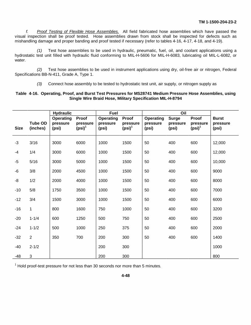
TM 1-1500-204-23-2
f. Proof Testing of Flexible Hose Assemblies. All field fabricated hose assemblies which have passed thevisual inspection shall be proof tested. Hose assemblies drawn from stock shall be inspected for defects such asmishandling damage and proper banding and proof tested if necessary (refer to tables 4-16, 4-17, 4-18, and 4-19).
(1) Test hose assemblies to be used in hydraulic, pneumatic, fuel, oil, and coolant applications using ahydrostatic test unit filled with hydraulic fluid conforming to MIL-H-5606 for MIL-H-6083, lubricating oil MIL-L-6082, orwater.
(2) Test hose assemblies to be used in instrument applications using dry, oil-free air or nitrogen, FederalSpecifications BB-N-411, Grade A, Type 1.
(3) Connect hose assembly to be tested to hydrostatic test unit, air supply, or nitrogen supply as
Table 4-16. Operating, Proof, and Burst Test Pressures for MS28741 Medium Pressure Hose Assemblies, usingSingle Wire Braid Hose, Military Specification MIL-H-8794
Hydraulic Fuel OilOperating Proof Operating Proof Operating Surge Proof Burst
Tube OD pressure pressure pressure pressure pressure pressure pressure pressureSize (inches) (psi) (psi)1 (psi) (psi)1 (psi) (psi) (psi)1 (psi)
-3 3/16 3000 6000 1000 1500 50 400 600 12,000
-4 1/4 3000 6000 1000 1500 50 400 600 12,000
-5 5/16 3000 5000 1000 1500 50 400 600 10,000
-6 3/8 2000 4500 1000 1500 50 400 600 9000
-8 1/2 2000 4000 1000 1500 50 400 600 8000
-10 5/8 1750 3500 1000 1500 50 400 600 7000
-12 3/4 1500 3000 1000 1500 50 400 600 6000
-16 1 800 1600 750 1000 50 400 600 3200
-20 1-1/4 600 1250 500 750 50 400 600 2500
-24 1-1/2 500 1000 250 375 50 400 600 2000
-32 2 350 700 200 300 50 400 600 1400
-40 2-1/2 200 300 1000
-48 3 200 300 800
1 Hold proof-test pressure for not less than 30 seconds nor more than 5 minutes.
4-48
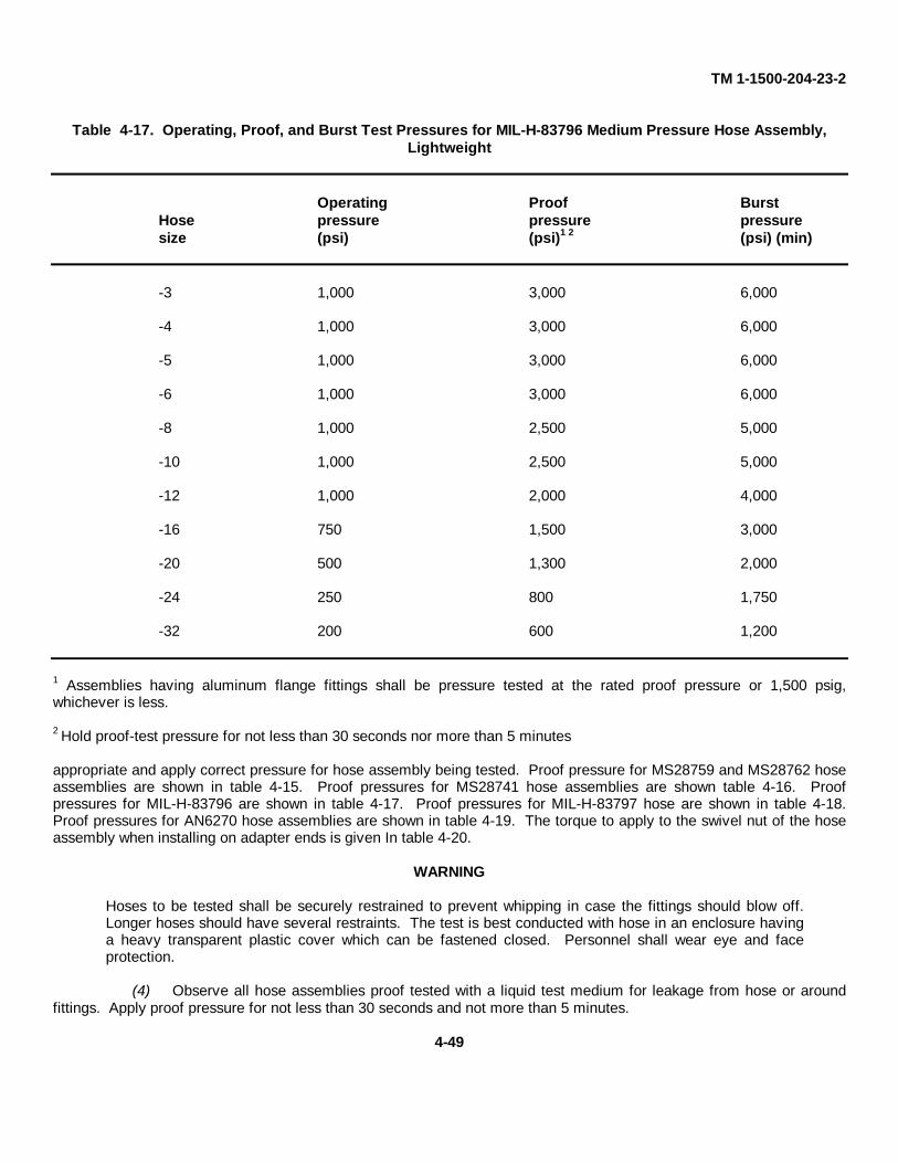
TM 1-1500-204-23-2
Table 4-17. Operating, Proof, and Burst Test Pressures for MIL-H-83796 Medium Pressure Hose Assembly,Lightweight
Operating Proof BurstHose pressure pressure pressuresize (psi) (psi)1 2 (psi) (min)
-3 1,000 3,000 6,000
-4 1,000 3,000 6,000
-5 1,000 3,000 6,000
-6 1,000 3,000 6,000
-8 1,000 2,500 5,000
-10 1,000 2,500 5,000
-12 1,000 2,000 4,000
-16 750 1,500 3,000
-20 500 1,300 2,000
-24 250 800 1,750
-32 200 600 1,200
1 Assemblies having aluminum flange fittings shall be pressure tested at the rated proof pressure or 1,500 psig,whichever is less.
2 Hold proof-test pressure for not less than 30 seconds nor more than 5 minutes
appropriate and apply correct pressure for hose assembly being tested. Proof pressure for MS28759 and MS28762 hoseassemblies are shown in table 4-15. Proof pressures for MS28741 hose assemblies are shown table 4-16. Proofpressures for MIL-H-83796 are shown in table 4-17. Proof pressures for MIL-H-83797 hose are shown in table 4-18.Proof pressures for AN6270 hose assemblies are shown in table 4-19. The torque to apply to the swivel nut of the hoseassembly when installing on adapter ends is given In table 4-20.
WARNING
Hoses to be tested shall be securely restrained to prevent whipping in case the fittings should blow off.Longer hoses should have several restraints. The test is best conducted with hose in an enclosure havinga heavy transparent plastic cover which can be fastened closed. Personnel shall wear eye and faceprotection.
(4) Observe all hose assemblies proof tested with a liquid test medium for leakage from hose or aroundfittings. Apply proof pressure for not less than 30 seconds and not more than 5 minutes.
4-49
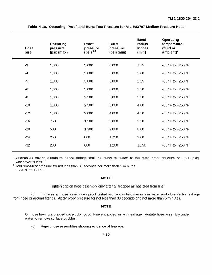
TM 1-1500-204-23-2
Table 4-18. Operating, Proof, and Burst Test Pressure for MIL-H83797 Medium Pressure Hose
Bend OperatingOperating Proof Burst radius temperature
Hose pressure pressure pressure Inches (fluid orsize (psi) (max) (psi) 1,2 (psi) (min) (min) ambient)3
-3 1,000 3,000 6,000 1.75 -65 °F to +250 °F
-4 1,000 3,000 6,000 2.00 -65 °F to +250 °F
-5 1,000 3,000 6,000 2.25 -65 °F to +250 °F
-6 1,000 3,000 6,000 2.50 -65 °F to +250 °F
-8 1,000 2,500 5,000 3.50 -65 °F to +250 °F
-10 1,000 2,500 5,000 4.00 -65 °F to +250 °F
-12 1,000 2,000 4,000 4.50 -65 °F to +250 °F
-16 750 1,500 3,000 5.50 -65 °F to +250 °F
-20 500 1,300 2,000 8.00 -65 °F to +250 °F
-24 250 800 1,750 9.00 -65 °F to +250 °F
-32 200 600 1,200 12.50 -65 °F to +250 °F
1 Assemblies having aluminum flange fittings shall be pressure tested at the rated proof pressure or 1,500 psig,whichever is less.
2 Hold proof-test pressure for not less than 30 seconds nor more than 5 minutes.3 -54 °C to 121 °C.
NOTE
Tighten cap on hose assembly only after all trapped air has bled from line.
(5) Immerse all hose assemblies proof tested with a gas test medium in water and observe for leakagefrom hose or around fittings. Apply proof pressure for not less than 30 seconds and not more than 5 minutes.
NOTE
On hose having a braided cover, do not confuse entrapped air with leakage. Agitate hose assembly underwater to remove surface bubbles.
(6) Reject hose assemblies showing evidence of leakage.
4-50
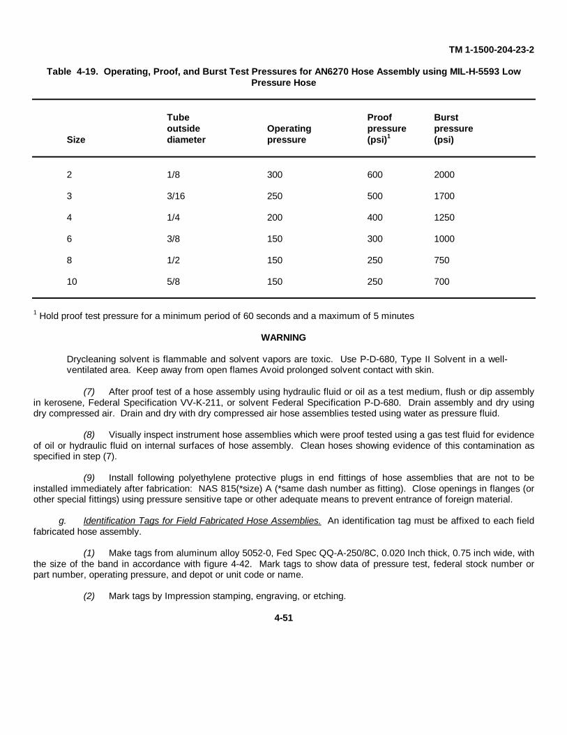
TM 1-1500-204-23-2
Table 4-19. Operating, Proof, and Burst Test Pressures for AN6270 Hose Assembly using MIL-H-5593 LowPressure Hose
Tube Proof Burstoutside Operating pressure pressure
Size diameter pressure (psi)1 (psi)
2 1/8 300 600 2000
3 3/16 250 500 1700
4 1/4 200 400 1250
6 3/8 150 300 1000
8 1/2 150 250 750
10 5/8 150 250 700
1 Hold proof test pressure for a minimum period of 60 seconds and a maximum of 5 minutes
WARNING
Drycleaning solvent is flammable and solvent vapors are toxic. Use P-D-680, Type II Solvent in a well-ventilated area. Keep away from open flames Avoid prolonged solvent contact with skin.
(7) After proof test of a hose assembly using hydraulic fluid or oil as a test medium, flush or dip assemblyin kerosene, Federal Specification VV-K-211, or solvent Federal Specification P-D-680. Drain assembly and dry usingdry compressed air. Drain and dry with dry compressed air hose assemblies tested using water as pressure fluid.
(8) Visually inspect instrument hose assemblies which were proof tested using a gas test fluid for evidenceof oil or hydraulic fluid on internal surfaces of hose assembly. Clean hoses showing evidence of this contamination asspecified in step (7).
(9) Install following polyethylene protective plugs in end fittings of hose assemblies that are not to beinstalled immediately after fabrication: NAS 815(*size) A (*same dash number as fitting). Close openings in flanges (orother special fittings) using pressure sensitive tape or other adequate means to prevent entrance of foreign material.
g. Identification Tags for Field Fabricated Hose Assemblies. An identification tag must be affixed to each fieldfabricated hose assembly.
(1) Make tags from aluminum alloy 5052-0, Fed Spec QQ-A-250/8C, 0.020 Inch thick, 0.75 inch wide, withthe size of the band in accordance with figure 4-42. Mark tags to show data of pressure test, federal stock number orpart number, operating pressure, and depot or unit code or name.
(2) Mark tags by Impression stamping, engraving, or etching.
4-51
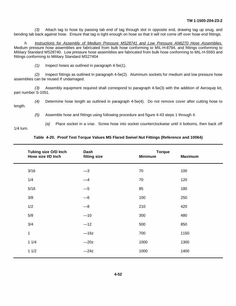
TM 1-1500-204-23-2
(3) Attach tag to hose by passing tab end of tag through slot in opposite end, drawing tag up snug, andbending tab back against hose. Ensure that tag is tight enough on hose so that it will not come off over hose end fittings.
h. Instructions for Assembly of Medium Pressure MS28741 and Low Pressure AN6270 Hose Assemblies.Medium pressure hose assemblies are fabricated from bulk hose conforming to MIL-H-8794, and fittings conforming toMilitary Standard MS28740. Low pressure hose assemblies are fabricated from bulk hose conforming to MIL-H-5593 andfittings conforming to Military Standard MS27404
(1) Inspect hoses as outlined in paragraph 4-5e(1).
(2) Inspect fittings as outlined In paragraph 4-5e(2). Aluminum sockets for medium and low pressure hoseassemblies can be reused If undamaged.
(3) Assembly equipment required shall correspond to paragraph 4-5e(3) with the addition of Aeroquip kit,part number S-1051.
(4) Determine hose length as outlined in paragraph 4-5e(4). Do not remove cover after cutting hose tolength.
(5) Assemble hose and fittings using following procedure and figure 4-43 steps 1 through 4.
(a) Place socket in a vise. Screw hose into socket counterclockwise until it bottoms, then back off1/4 turn.
Table 4-20. Proof Test Torque Values MS Flared Swivel Nut Fittings (Reference and 10064)
Tubing size O/D Inch Dash TorqueHose size I/D Inch fitting size Minimum Maximum
3/16 — 3 70 100
1/4 — 4 70 120
5/16 — 5 85 180
3/8 — 6 100 250
1/2 — 8 210 420
5/8 — 10 300 480
3/4 — 12 500 850
1 — 16z 700 1150
1 1/4 — 20z 1000 1300
1 1/2 — 24z 1000 1400
4-52
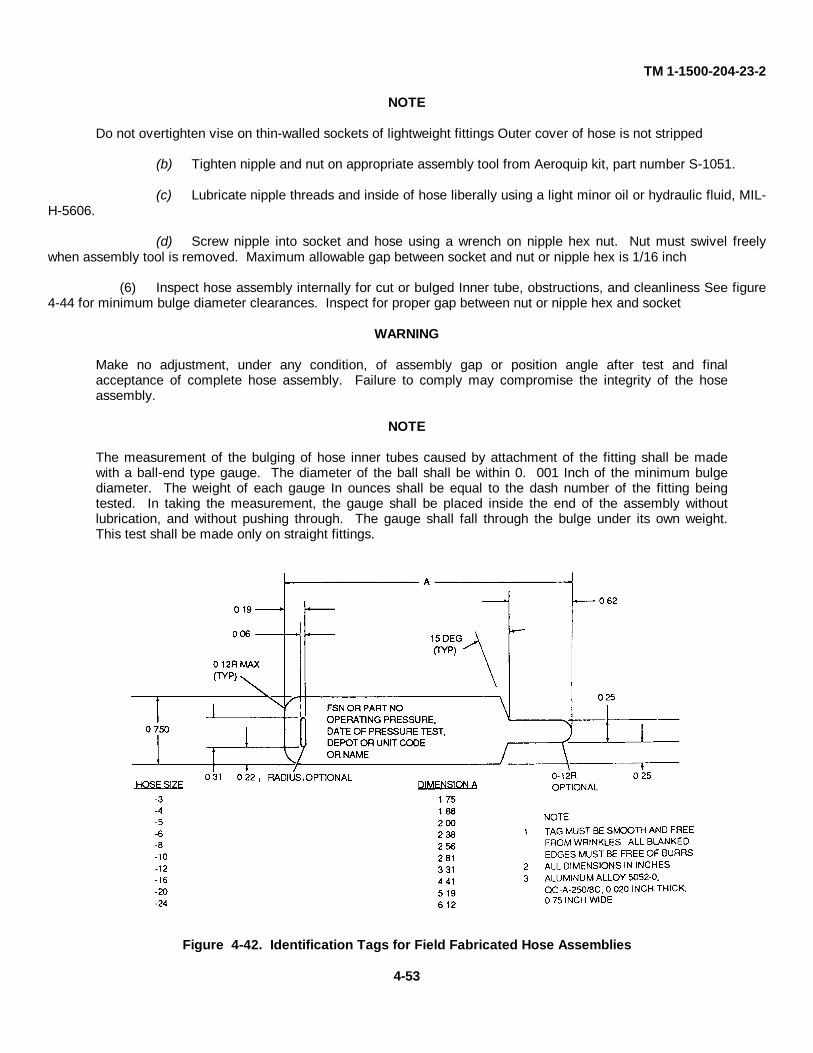
TM 1-1500-204-23-2
NOTE
Do not overtighten vise on thin-walled sockets of lightweight fittings Outer cover of hose is not stripped
(b) Tighten nipple and nut on appropriate assembly tool from Aeroquip kit, part number S-1051.
(c) Lubricate nipple threads and inside of hose liberally using a light minor oil or hydraulic fluid, MIL-H-5606.
(d) Screw nipple into socket and hose using a wrench on nipple hex nut. Nut must swivel freelywhen assembly tool is removed. Maximum allowable gap between socket and nut or nipple hex is 1/16 inch
(6) Inspect hose assembly internally for cut or bulged Inner tube, obstructions, and cleanliness See figure4-44 for minimum bulge diameter clearances. Inspect for proper gap between nut or nipple hex and socket
WARNING
Make no adjustment, under any condition, of assembly gap or position angle after test and finalacceptance of complete hose assembly. Failure to comply may compromise the integrity of the hoseassembly.
NOTE
The measurement of the bulging of hose inner tubes caused by attachment of the fitting shall be madewith a ball-end type gauge. The diameter of the ball shall be within 0. 001 Inch of the minimum bulgediameter. The weight of each gauge In ounces shall be equal to the dash number of the fitting beingtested. In taking the measurement, the gauge shall be placed inside the end of the assembly withoutlubrication, and without pushing through. The gauge shall fall through the bulge under its own weight.This test shall be made only on straight fittings.
Figure 4-42. Identification Tags for Field Fabricated Hose Assemblies
4-53
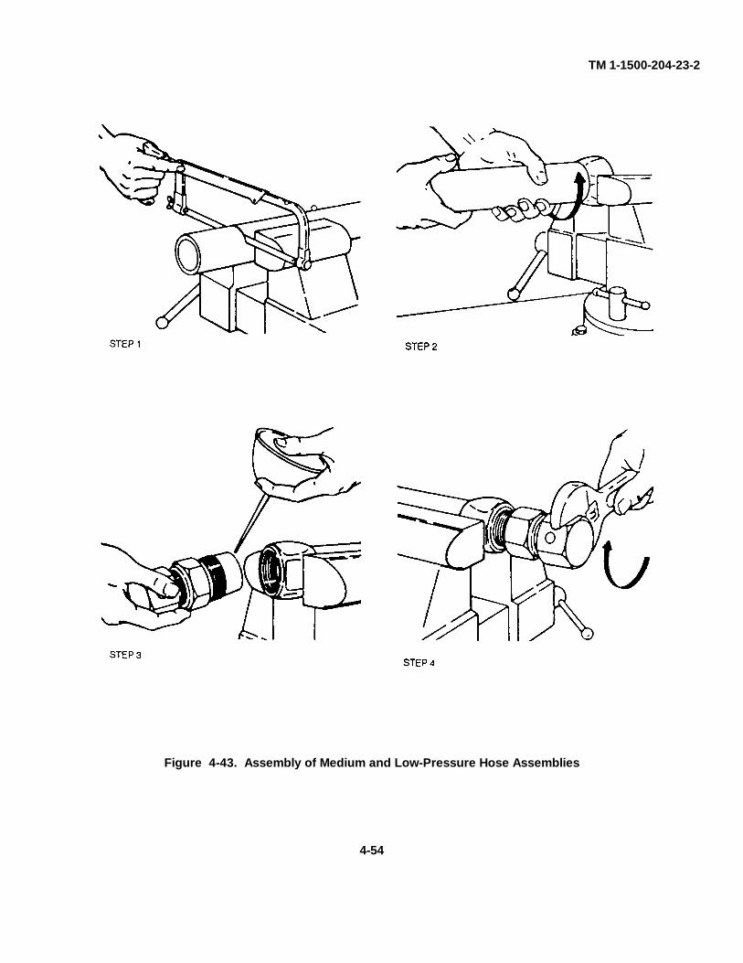
TM 1-1500-204-23-2
Figure 4-43. Assembly of Medium and Low-Pressure Hose Assemblies
4-54
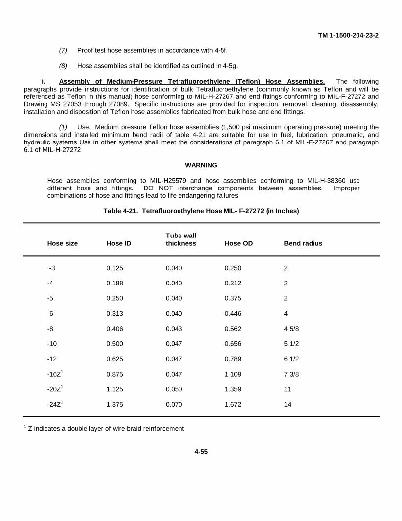
TM 1-1500-204-23-2
(7) Proof test hose assemblies in accordance with 4-5f.
(8) Hose assemblies shall be identified as outlined in 4-5g.
i. Assembly of Medium-Pressure Tetrafluoroethylene (Teflon) Hose Assemblies. The followingparagraphs provide instructions for identification of bulk Tetrafluoroethylene (commonly known as Teflon and will bereferenced as Teflon in this manual) hose conforming to MIL-H-27267 and end fittings conforming to MIL-F-27272 andDrawing MS 27053 through 27089. Specific instructions are provided for inspection, removal, cleaning, disassembly,installation and disposition of Teflon hose assemblies fabricated from bulk hose and end fittings.
(1) Use. Medium pressure Teflon hose assemblies (1,500 psi maximum operating pressure) meeting thedimensions and installed minimum bend radii of table 4-21 are suitable for use in fuel, lubrication, pneumatic, andhydraulic systems Use in other systems shall meet the considerations of paragraph 6.1 of MIL-F-27267 and paragraph6.1 of MIL-H-27272
WARNING
Hose assemblies conforming to MIL-H25579 and hose assemblies conforming to MIL-H-38360 usedifferent hose and fittings. DO NOT interchange components between assemblies. Impropercombinations of hose and fittings lead to life endangering failures
Table 4-21. Tetrafluoroethylene Hose MIL- F-27272 (in Inches)
Tube wallHose size Hose ID thickness Hose OD Bend radius
-3 0.125 0.040 0.250 2
-4 0.188 0.040 0.312 2
-5 0.250 0.040 0.375 2
-6 0.313 0.040 0.446 4
-8 0.406 0.043 0.562 4 5/8
-10 0.500 0.047 0.656 5 1/2
-12 0.625 0.047 0.789 6 1/2
-16Z1 0.875 0.047 1 109 7 3/8
-20Z1 1.125 0.050 1.359 11
-24Z1 1.375 0.070 1.672 14
1 Z indicates a double layer of wire braid reinforcement
4-55
TM 1-1500-204-23-2
(2) Identification. Teflon hose and hose assemblies, and fittings are identified in the following paragraphs.
(a) Size. Bulk Teflon hose manufactured to requirement of MIL-H-27267 shall conform todimensions referenced In table 4-21.
(b) Appearance and markings. Hose construction shall be a smooth bore (firm, waxy feeling) innertube covered with corrosion-resistant steel wire braid. Hose shall be Identified by an identification band spaced at 3-footintervals, marked with specification number and manufacturer's code number as listed in Federal Handbook H4-1.
(c) Fittings. All end fitting assemblies conforming to MIL-F-27272 are identified by an attachedcardboard disc marked with MS number, manufacturer's part number, name or trademark. All component parts of endfitting assemblies conforming to referenced specification are impression stamped with MS numbers as listed inparagraph 3 of the referenced specification.
CAUTION
To eliminate the possibility of hose failure by mismatch of similar type fittings, check each Item of theassembly carefully to ensure that it conforms to the proper Military Standard (MS) prior to the assembly ofthe hose.
(d) Hose assemblies. Factory fabricated Teflon hose assemblies are identified by a permanentlyattached metal band marked with MIL-H-25579, operating pressure in psi, assembly part number, date of proof test andhose manufacturer's code number. Locally manufactured or tested Teflon hose assemblies shall be identified by a metalband made from Federal Specification QQ-A-250/8, 5052-0 aluminum alloy, 0. 020 Inch thick, 0 75 Inch wide, Inaccordance with figure 4-42. The markings on the band may be impression stamped, etched or engraved to include dateof pressure test, Federal stock number or part number, operating pressure, and depot or unit code or name. If thepressure test date is more than one year prior to installation in the aircraft or system, the assembly shall be retested andbanded prior to installation. Original manufacture date of all retested hoses shall be brought forward onto the new band,if available
(3) Handling. Exercise extreme care when handling bulk Teflon hose and hose assemblies to preventinjury to hands from the wire braid ends and damage to hose due to kinking. Kinking results when hose is bent to ashorter radius than specified in table 4-21 and from twisting during installation. Teflon hose assemblies tend to conformto the shape of installed positions on hot fluid lines; therefore, exercise care in handling and removing these lines toprevent straightening which could result in kinking. A kinked Teflon hose must not be installed since this will result in afailure at point of kink
(4) Maintenance Inspection and Replacement Criteria. Inspect installed Teflon hose assemblies forevidence of deterioration due to wire fatigue or chafing at the specified periods prescribed in the applicable aircraftinspection or maintenance manuals and replace when any of the following conditions are found.
(a) Leaking. Static leakage exceeding 1 drop per hour.(b) Excessive Wire Damage. Excessive wire damage consists of 2 or more broken wires in a single
plait, or more than 6 broken wires per assembly or per lineal foot whenever assemblies exceed 12 inches in length.Broken wires where kinking is suspected are evidence by sharp dents or twisted wire braid.
NOTE
Crossed reinforcing or random broken wires is not cause for replacement
(c) Distortion. Any evidence of abrasion, kinking, distortion, bulging, or sharp bends.(d) Hoses from stock. Hose assemblies drawn from stock shall be inspected for defects such as
mishandling damage and proper banding Hoses that are suspected to have damage or are not banded will be proof-tested and banded.
(e) Hoses removed from aircraft. Hose assemblies removed from an aircraft shall be inspected,proof tested, and banded.
(5) Hose Assemblies and Pump Pressure Lines. Clean hose assemblies removed from installation forreasons other than cited in paragraph 4-51 (8) and pump pressure lines removed by replacement schedule in
4-56

TM 1-1500-204-23-2
accordance with instructions contained in paragraph 4-5i (9).
(6) Internal Inspection. Inspect hose assemblies internally for evidence of tube restriction due to collapse,wire braid puncture, or other damage. Following methods for internal inspection are recommended.
(a) Straight hose assemblies. Insert light at one end and inspect by looking through from theopposite end.
(b) Hose assembly with elbow fitting one end. Insert flexible inspection light into elbow fitting andexamine by looking through the opposite end.
(c) Hose assemblies with elbow fitting both ends. Insert flexible inspection light into one end andexamine from the opposite end using a dental-type mirror. This procedure is only practical on large size hoseassemblies.
(7) Disassembly. The hose can be completely disassembled using the following procedures (see figure 4-45).
(a) Place socket in vise and remove nipple assembly by applying wrench to nipple hex (see figure 4-45, detail A).
(b) Remove socket from vise and tap edge of pocket against flat surface to loosen pull socket backonto hose to expose hose end and sleeve insert (see figure 4-45, detail B).
(c) Remove sleeve inserting end of nipple into sleeve internal diameter and gently pry sleeve frominner tube (see figure 4-45, detail C).
(d) Remove socket by pulling or threading socket from hose.
(e) Remove hose fitting on opposite end of assembly.
(f) All removed hose will be condemned and disposed of in accordance with existing regulations.
(8) Reusability Check. Use the following procedures to determine whether parts that are removed may bereused.
(a) Cleaning. Clean fittings in accordance with paragraph 4-5i (a).(b) Finishes. Examine all fitting details with anodized or plated finish for corrosion damage.
Condemn corrosion-damaged parts Minor scratches are not cause for replacement; however, parts with wrench, vise jaw,or similar marks shall be replaced.
(c) Flanges, sealing faces and/or swivel nuts Inspect these components as follows:
CAUTIONUse care when handling flange fittings to prevent damaging the gasket, flange or sealing face of pad orfitting. Failure of equipment could result.
1 Check for wraping of the flange.2 Check for damage to the sealing face of the flange fitting. Any damage, nicks, scratches,
etc., will be cause of rejection.3 Check for multilated threads and evidence of overtightening (This will show up as a belled
condition or pulled condition or flared connections and may result in a frozen or tight swiveling nut).4 Examine for backed-out retaining wires on wired-on swivel nuts. If backed-out wires are
found, drive wire back into nut using a drift pin of proper size and ball peen hammer.
(d) Nipples. Visually inspect for sealing surface (chamfered area) for damage or galling on stainlessnipples (figure 4-46) and for the following defects:
1 Nicks, spiral or longitudinal scratches or scoring which could create an escape passage forfluids.
2 Flare-out or distortion of cone seats resulting from over torquing.3 Damaged or galled threads (nipple to socket thread) test by threading a new socket of
proper size on to the nipple threads.
4-57
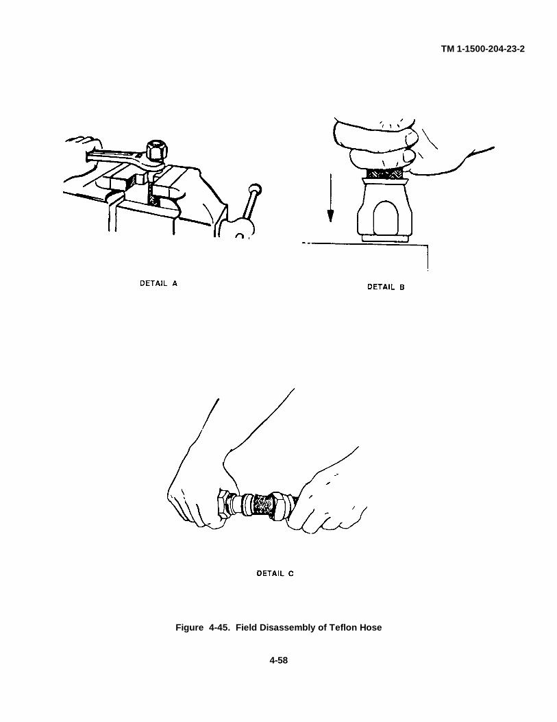
TM 1-1500-204-23-2
Figure 4-45. Field Disassembly of Teflon Hose
4-58
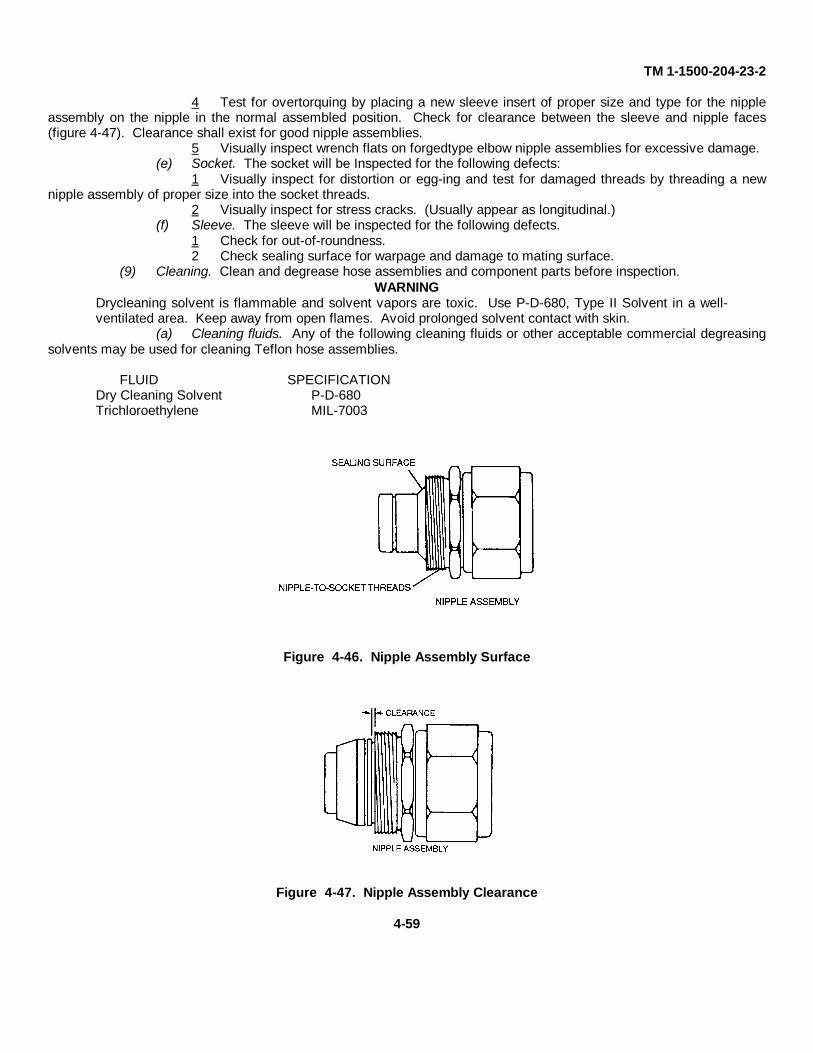
TM 1-1500-204-23-2
4 Test for overtorquing by placing a new sleeve insert of proper size and type for the nippleassembly on the nipple in the normal assembled position. Check for clearance between the sleeve and nipple faces(figure 4-47). Clearance shall exist for good nipple assemblies.
5 Visually inspect wrench flats on forgedtype elbow nipple assemblies for excessive damage.(e) Socket. The socket will be Inspected for the following defects:
1 Visually inspect for distortion or egg-ing and test for damaged threads by threading a newnipple assembly of proper size into the socket threads.
2 Visually inspect for stress cracks. (Usually appear as longitudinal.)(f) Sleeve. The sleeve will be inspected for the following defects.
1 Check for out-of-roundness.2 Check sealing surface for warpage and damage to mating surface.
(9) Cleaning. Clean and degrease hose assemblies and component parts before inspection.WARNING
Drycleaning solvent is flammable and solvent vapors are toxic. Use P-D-680, Type II Solvent in a well-ventilated area. Keep away from open flames. Avoid prolonged solvent contact with skin.
(a) Cleaning fluids. Any of the following cleaning fluids or other acceptable commercial degreasingsolvents may be used for cleaning Teflon hose assemblies.
FLUID SPECIFICATIONDry Cleaning Solvent P-D-680Trichloroethylene MIL-7003
Figure 4-46. Nipple Assembly Surface
Figure 4-47. Nipple Assembly Clearance
4-59
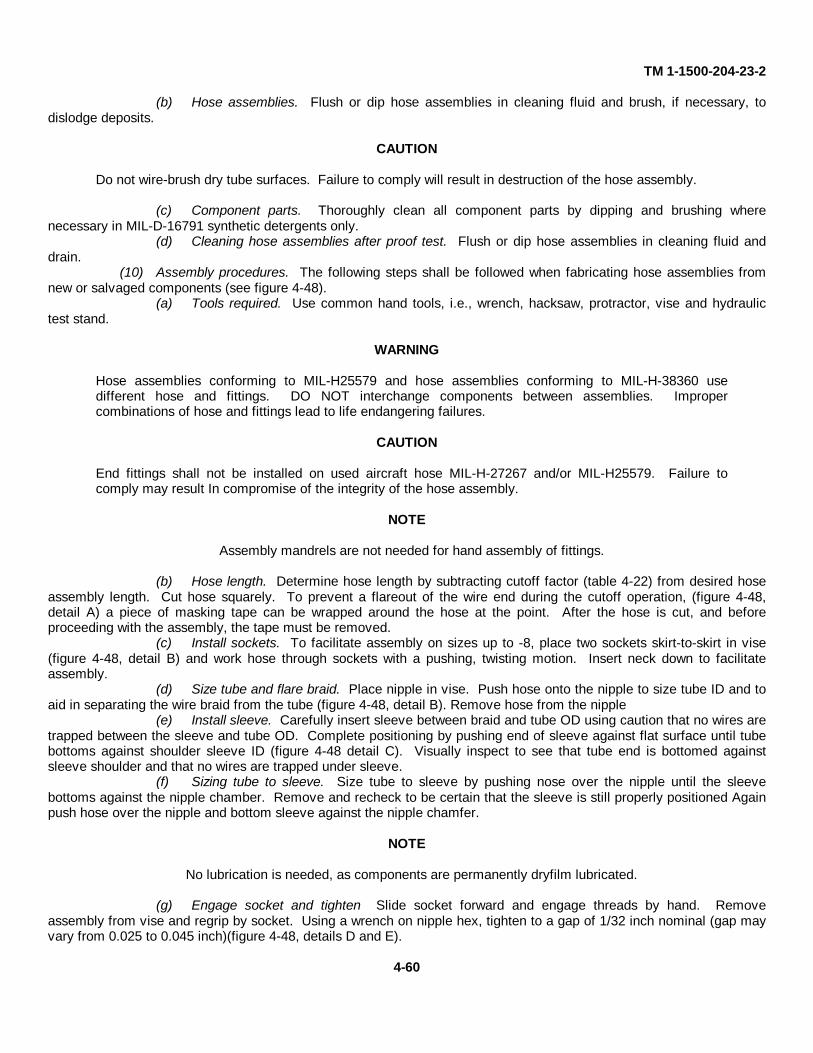
TM 1-1500-204-23-2
(b) Hose assemblies. Flush or dip hose assemblies in cleaning fluid and brush, if necessary, todislodge deposits.
CAUTION
Do not wire-brush dry tube surfaces. Failure to comply will result in destruction of the hose assembly.
(c) Component parts. Thoroughly clean all component parts by dipping and brushing wherenecessary in MIL-D-16791 synthetic detergents only.
(d) Cleaning hose assemblies after proof test. Flush or dip hose assemblies in cleaning fluid anddrain.
(10) Assembly procedures. The following steps shall be followed when fabricating hose assemblies fromnew or salvaged components (see figure 4-48).
(a) Tools required. Use common hand tools, i.e., wrench, hacksaw, protractor, vise and hydraulictest stand.
WARNING
Hose assemblies conforming to MIL-H25579 and hose assemblies conforming to MIL-H-38360 usedifferent hose and fittings. DO NOT interchange components between assemblies. Impropercombinations of hose and fittings lead to life endangering failures.
CAUTION
End fittings shall not be installed on used aircraft hose MIL-H-27267 and/or MIL-H25579. Failure tocomply may result In compromise of the integrity of the hose assembly.
NOTE
Assembly mandrels are not needed for hand assembly of fittings.
(b) Hose length. Determine hose length by subtracting cutoff factor (table 4-22) from desired hoseassembly length. Cut hose squarely. To prevent a flareout of the wire end during the cutoff operation, (figure 4-48,detail A) a piece of masking tape can be wrapped around the hose at the point. After the hose is cut, and beforeproceeding with the assembly, the tape must be removed.
(c) Install sockets. To facilitate assembly on sizes up to -8, place two sockets skirt-to-skirt in vise(figure 4-48, detail B) and work hose through sockets with a pushing, twisting motion. Insert neck down to facilitateassembly.
(d) Size tube and flare braid. Place nipple in vise. Push hose onto the nipple to size tube ID and toaid in separating the wire braid from the tube (figure 4-48, detail B). Remove hose from the nipple
(e) Install sleeve. Carefully insert sleeve between braid and tube OD using caution that no wires aretrapped between the sleeve and tube OD. Complete positioning by pushing end of sleeve against flat surface until tubebottoms against shoulder sleeve ID (figure 4-48 detail C). Visually inspect to see that tube end is bottomed againstsleeve shoulder and that no wires are trapped under sleeve.
(f) Sizing tube to sleeve. Size tube to sleeve by pushing nose over the nipple until the sleevebottoms against the nipple chamber. Remove and recheck to be certain that the sleeve is still properly positioned Againpush hose over the nipple and bottom sleeve against the nipple chamfer.
NOTE
No lubrication is needed, as components are permanently dryfilm lubricated.
(g) Engage socket and tighten Slide socket forward and engage threads by hand. Removeassembly from vise and regrip by socket. Using a wrench on nipple hex, tighten to a gap of 1/32 inch nominal (gap mayvary from 0.025 to 0.045 inch)(figure 4-48, details D and E).
4-60
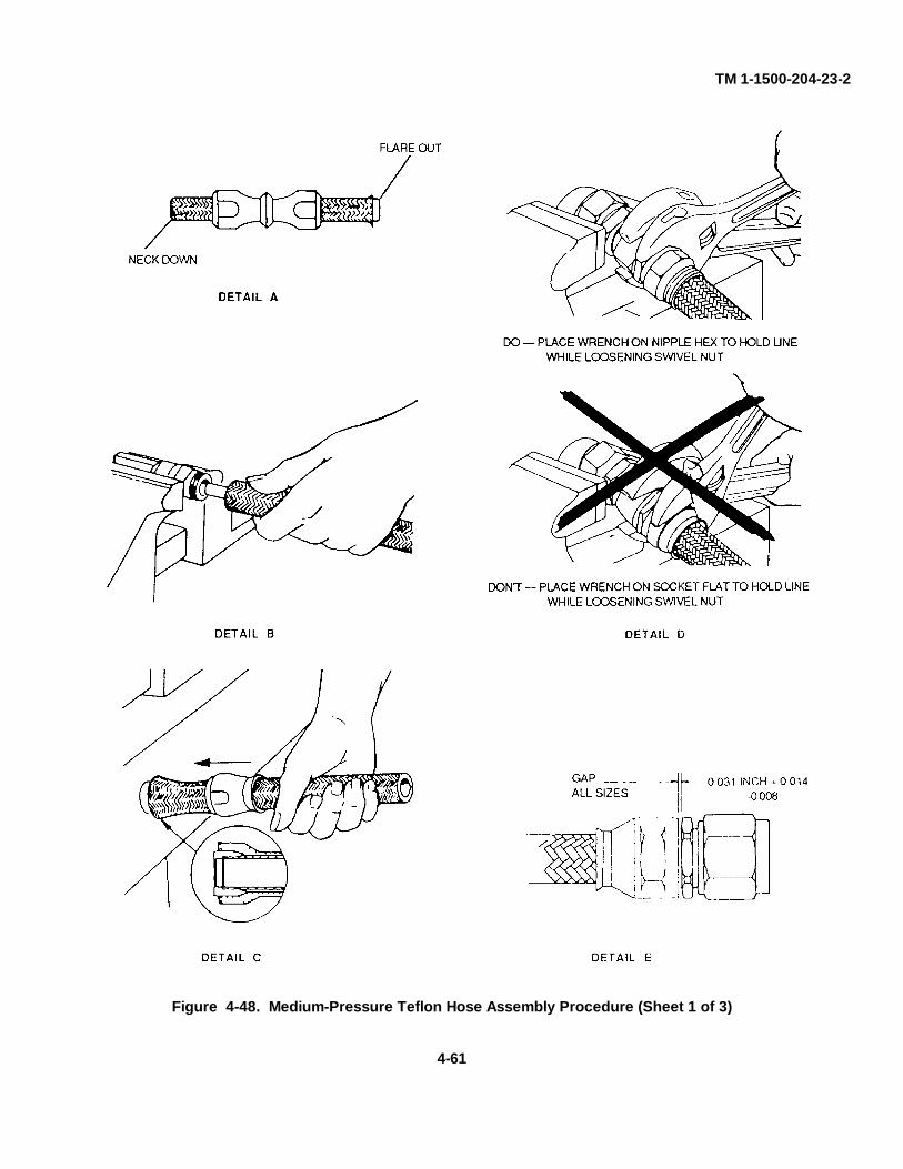
TM 1-1500-204-23-2
Figure 4-48. Medium-Pressure Teflon Hose Assembly Procedure (Sheet 1 of 3)
4-61
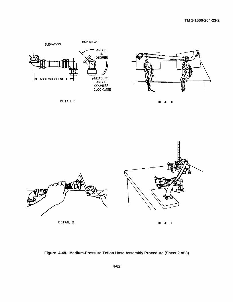
TM 1-1500-204-23-2
Figure 4-48. Medium-Pressure Teflon Hose Assembly Procedure (Sheet 2 of 3)
4-62
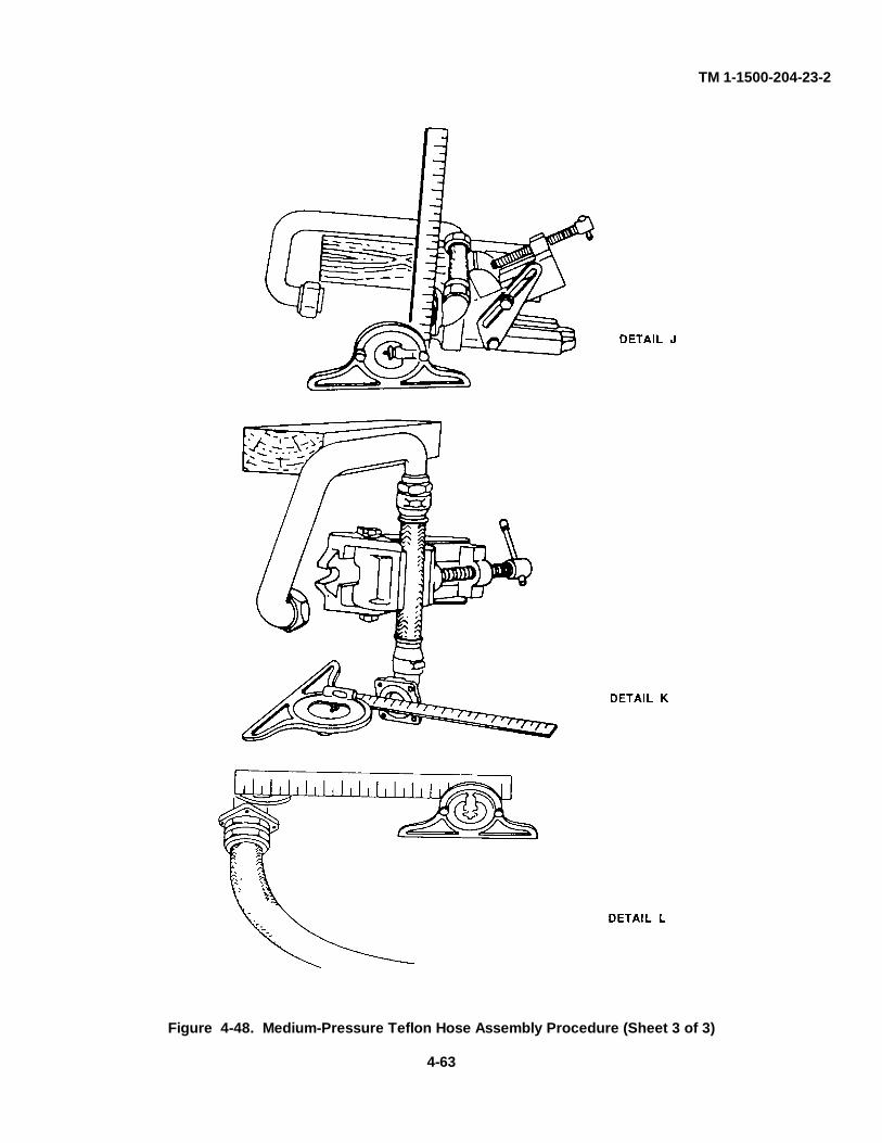
TM 1-1500-204-23-2
Figure 4-48. Medium-Pressure Teflon Hose Assembly Procedure (Sheet 3 of 3)
4-63
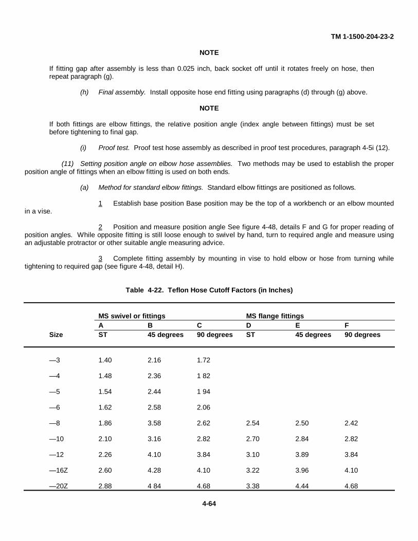
TM 1-1500-204-23-2
NOTE
If fitting gap after assembly is less than 0.025 inch, back socket off until it rotates freely on hose, thenrepeat paragraph (g).
(h) Final assembly. Install opposite hose end fitting using paragraphs (d) through (g) above.
NOTE
If both fittings are elbow fittings, the relative position angle (index angle between fittings) must be setbefore tightening to final gap.
(i) Proof test. Proof test hose assembly as described in proof test procedures, paragraph 4-5i (12).
(11) Setting position angle on elbow hose assemblies. Two methods may be used to establish the properposition angle of fittings when an elbow fitting is used on both ends.
(a) Method for standard elbow fittings. Standard elbow fittings are positioned as follows.
1 Establish base position Base position may be the top of a workbench or an elbow mountedin a vise.
2 Position and measure position angle See figure 4-48, details F and G for proper reading ofposition angles. While opposite fitting is still loose enough to swivel by hand, turn to required angle and measure usingan adjustable protractor or other suitable angle measuring advice.
3 Complete fitting assembly by mounting in vise to hold elbow or hose from turning whiletightening to required gap (see figure 4-48, detail H).
Table 4-22. Teflon Hose Cutoff Factors (in Inches)
MS swivel or fittings MS flange fittingsA B C D E F
Size ST 45 degrees 90 degrees ST 45 degrees 90 degrees
— 3 1.40 2.16 1.72
— 4 1.48 2.36 1 82
— 5 1.54 2.44 1 94
— 6 1.62 2.58 2.06
— 8 1.86 3.58 2.62 2.54 2.50 2.42
— 10 2.10 3.16 2.82 2.70 2.84 2.82
— 12 2.26 4.10 3.84 3.10 3.89 3.84
— 16Z 2.60 4.28 4.10 3.22 3.96 4.10
— 20Z 2.88 4 84 4.68 3.38 4.44 4.68
4-64
TM 1-1500-204-23-2
4 Recheck position angle to be sure position angle has not changed.
(b) Method for special elbow bends and/or preformed hose. Special elbows and preformed hose arepositioned as follows.
1 Assemble one end of the hose assembly as described above.2 Determine required angles. Required angles may be obtained from the hose assembly part
number by comparison with a known good hose assembly or with an assembly mocked-up on the installation. Preferablythe assembly to be repaired should be set up on a fiat surface, vises and parallels set and clamped, and required anglesset on protractor before the assembly is disassembled See figure 4-48, details I, J, and K for this setup.
3 Establish base positions and check angle, drop dimension and assembly length. Anglevises shall be tilted so that the flange mounting plates are parallel to the face of the flange and the flange mounting holeslined up with the bolt holes already tapped in the mounting plates. Any necessary spacing with parallel bars shall bedone at this time. When this procedure is followed properly, the result will be a fixture with the proper angles, dropdimensions, and lengths established. See figure 4-48, details I, J. K, and L for this setup.
4 Complete fitting assembly by mounting in vise to hold elbow or hose from turning whiletightening to required gap.
5 Recheck position angle to be sure position angle has not changed.(12) Proof test procedures. Proof test all hose assemblies after assembly for a minimum period of 30
seconds and maximum period of 5 minutes, using Tester, Hose Assembly, Part Number 78344, FSN 4920-00-855-9035.
(a) Proof test pressures. Recommended proof test pressures are listed in table 4-23.
NOTE
Proof pressures for flange fittings are reduced to avoid possible distortion of the flange and shoulder byexceeding design pressure limitations for flange fittings.
(b) Proof test medium. Proof test medium shall be hydraulic oil, MIL-H-5606.(c) Cleaning. Clean and drain hose assembly after proof test as directed in paragraph 4-5i (9).
NOTE
Application of an identifying mark such as a paint dot, indicating satisfactory proof test, is recommended.
(d) Capping. Cap or plug all hose assemblies to ensure cleanliness.
(13) Installation. The following procedures and precautions will be followed when installing Teflon hoseassemblies (see figure 4-49).
CAUTION
Do not place wrench on socket of hose fitting when installing hose assembly. Failure to comply willcompromise the strength and integrity of the union between the hose and fitting.
(a) Route and securely clamp. Teflon hose assemblies to avoid abrasion, and particularly to preventkinking where flexing occurs.
(b) Eliminate chafing against structure, moving parts, or other assemblies by clamping and use ofchafing guard if necessary.
(c) Support Teflon hose assemblies by clamping every 24 inches. Closer support is preferred ifpossible. Support flexible hose assemblies by clamping so that they cannot cause deflection of rigid connectingassemblies. Support clamps shall not restrict travel or cause hose to be subjected to tension, torsion, compression orshear stress during flexing cycles. Select proper size support clamps as indicated in table 4-24.
4-65
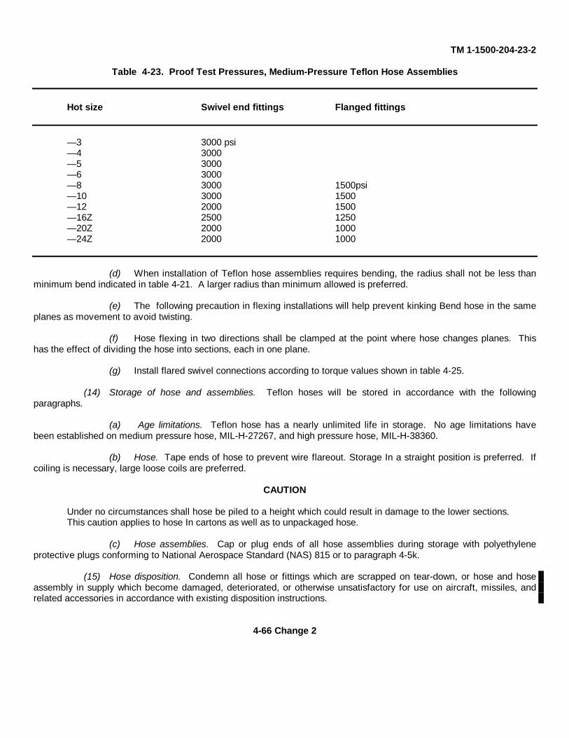
TM 1-1500-204-23-2
Table 4-23. Proof Test Pressures, Medium-Pressure Teflon Hose Assemblies
Hot size Swivel end fittings Flanged fittings
— 3 3000 psi— 4 3000— 5 3000— 6 3000— 8 3000 1500psi— 10 3000 1500— 12 2000 1500— 16Z 2500 1250— 20Z 2000 1000— 24Z 2000 1000
(d) When installation of Teflon hose assemblies requires bending, the radius shall not be less thanminimum bend indicated in table 4-21. A larger radius than minimum allowed is preferred.
(e) The following precaution in flexing installations will help prevent kinking Bend hose in the sameplanes as movement to avoid twisting.
(f) Hose flexing in two directions shall be clamped at the point where hose changes planes. Thishas the effect of dividing the hose into sections, each in one plane.
(g) Install flared swivel connections according to torque values shown in table 4-25.
(14) Storage of hose and assemblies. Teflon hoses will be stored in accordance with the followingparagraphs.
(a) Age limitations. Teflon hose has a nearly unlimited life in storage. No age limitations havebeen established on medium pressure hose, MIL-H-27267, and high pressure hose, MIL-H-38360.
(b) Hose. Tape ends of hose to prevent wire flareout. Storage In a straight position is preferred. Ifcoiling is necessary, large loose coils are preferred.
CAUTION
Under no circumstances shall hose be piled to a height which could result in damage to the lower sections.This caution applies to hose In cartons as well as to unpackaged hose.
(c) Hose assemblies. Cap or plug ends of all hose assemblies during storage with polyethyleneprotective plugs conforming to National Aerospace Standard (NAS) 815 or to paragraph 4-5k.
(15) Hose disposition. Condemn all hose or fittings which are scrapped on tear-down, or hose and hoseassembly in supply which become damaged, deteriorated, or otherwise unsatisfactory for use on aircraft, missiles, andrelated accessories in accordance with existing disposition instructions.
4-66 Change 2
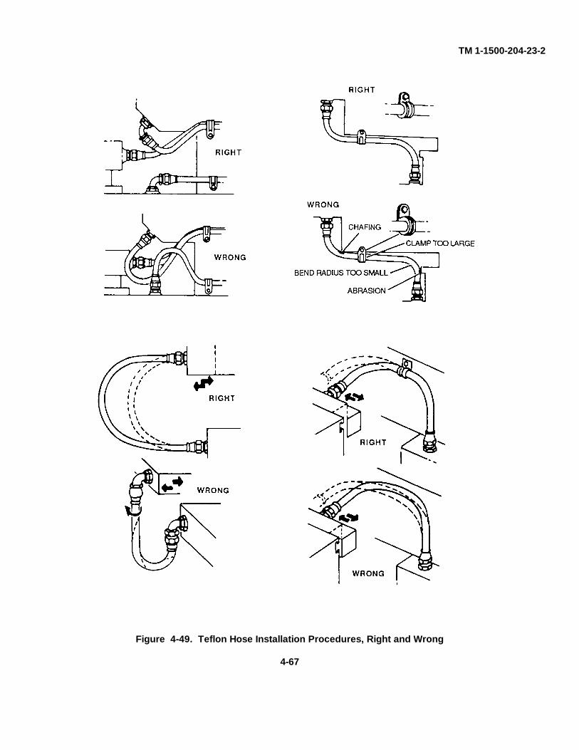
TM 1-1500-204-23-2
Figure 4-49. Teflon Hose Installation Procedures, Right and Wrong
4-67
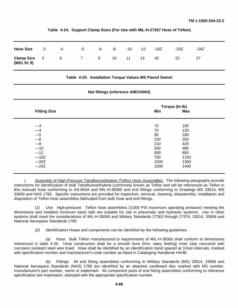
TM 1-1500-204-23-2
Table 4-24. Support Clamp Sizes (For Use with MIL-H-27267 Hose of Teflon)
Hose Size -3 -4 -5 -6 -8 -10 -12 -16Z -20Z -24Z
Clamp Size 5 6 7 8 10 11 13 18 22 27(MS1 91 9)
Table 4-25. Installation Torque Values MS Flared Swivel
Nut fittings (reference AND10064)
Torque (In-lb)Fitting Size Min Max
— 3 70 100— 4 70 120— 5 85 180— 6 100 250— 8 210 420— 10 300 480— 12 500 850— 16Z 700 1150— 20Z 1000 1300— 24Z 1000 1400
j Assembly of High-Pressure Tetrafluoroethylene (Teflor) Hose Assemblies. The following paragraphs provideinstructions for identification of bulk Tetrafluoroethylene (commonly known as Teflon and will be referenced as Teflon inthis manual) hose conforming to AS-604A and MIL-H-38360 and end fittings conforming to Drawings MS 33514, MS33656 and NAS 1760. Specific instructions are provided for inspection, removal, cleaning, disassembly, installation anddisposition of Teflon hose assemblies fabricated from bulk hose and end fittings.
(1) Use. High-pressure. Teflon hose assemblies (3,000 PSI maximum operating pressure) meeting thedimensions and installed minimum band radii are suitable for use in pneumatic and hydraulic systems. Use in othersystems shall meet the considerations of MIL-H-38360 and Military Standards 27363 through 27374, 33514, 33656 andNational Aerospace Standards 1760.
(2) Identification Hoses and components can be identified by the following guidelines.
(a) Hose. Bulk Teflon manufactured to requirements of MIL-H-38360 shall conform to dimensionsreferenced in table 4-26. Hose construction shall be a smooth bore (firm, waxy feeling) inner tube convered withcorrosion resistant steel wire braid. Hose shall be identified by an identification band spaced at 3-foot intervals, markedwith specification number and manufacturer's code number as listed In Cataloging Handbook H4/48.
(b) Fittings. All end fitting assemblies conforming to Military Standards (MS) 33514, 33656 andNational Aerospace Standards (NAS) 1760 are identified by an attached cardboard disc marked with MS number,manufacturer's part number, name or trademark. All component parts of end fitting assemblies conforming to referencespecification are impression ,stamped with the appropriate specification number.
4-68
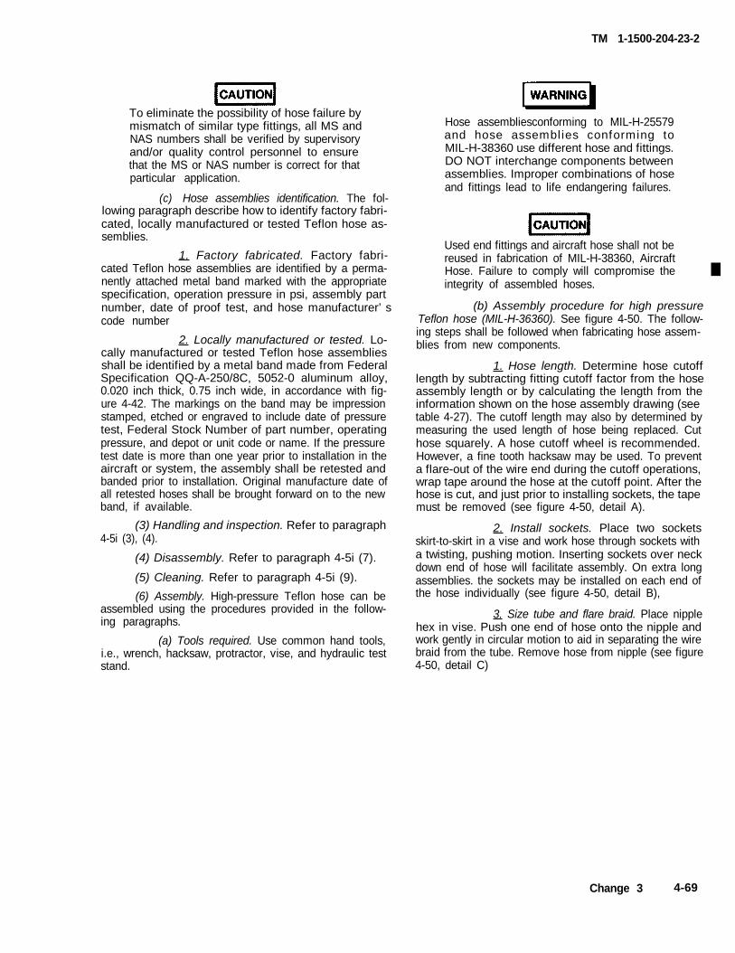
TM 1-1500-204-23-2
To eliminate the possibility of hose failure bymismatch of similar type fittings, all MS andNAS numbers shall be verified by supervisoryand/or quality control personnel to ensurethat the MS or NAS number is correct for thatparticular application.
(c) Hose assemblies identification. The fol-lowing paragraph describe how to identify factory fabri-cated, locally manufactured or tested Teflon hose as-semblies.
1. Factory fabricated. Factory fabri-cated Teflon hose assemblies are identified by a perma-nently attached metal band marked with the appropriatespecification, operation pressure in psi, assembly partnumber, date of proof test, and hose manufacturer’scode number
2. Locally manufactured or tested. Lo-cally manufactured or tested Teflon hose assembliesshall be identified by a metal band made from FederalSpecification QQ-A-250/8C, 5052-0 aluminum alloy,0.020 inch thick, 0.75 inch wide, in accordance with fig-ure 4-42. The markings on the band may be impressionstamped, etched or engraved to include date of pressuretest, Federal Stock Number of part number, operatingpressure, and depot or unit code or name. If the pressuretest date is more than one year prior to installation in theaircraft or system, the assembly shall be retested andbanded prior to installation. Original manufacture date ofall retested hoses shall be brought forward on to the newband, if available.
(3) Handling and inspection. Refer to paragraph
(4) Disassembly. Refer to paragraph 4-5i (7).
4-5i (3), (4).
(5) Cleaning. Refer to paragraph 4-5i (9).
Hose assembliesconforming to MIL-H-25579and hose assemblies conforming toMIL-H-38360 use different hose and fittings.DO NOT interchange components betweenassemblies. Improper combinations of hoseand fittings lead to life endangering failures.
Used end fittings and aircraft hose shall not bereused in fabrication of MIL-H-38360, AircraftHose. Failure to comply will compromise theintegrity of assembled hoses.
(b) Assembly procedure for high pressureTeflon hose (MIL-H-36360). See figure 4-50. The follow-ing steps shall be followed when fabricating hose assem-blies from new components.
1. Hose length. Determine hose cutofflength by subtracting fitting cutoff factor from the hoseassembly length or by calculating the length from theinformation shown on the hose assembly drawing (seetable 4-27). The cutoff length may also by determined bymeasuring the used length of hose being replaced. Cuthose squarely. A hose cutoff wheel is recommended.However, a fine tooth hacksaw may be used. To preventa flare-out of the wire end during the cutoff operations,wrap tape around the hose at the cutoff point. After thehose is cut, and just prior to installing sockets, the tapemust be removed (see figure 4-50, detail A).
a twisting, pushing motion. Inserting sockets over neckdown end of hose will facilitate assembly. On extra longassemblies. the sockets may be installed on each end of
2. Install sockets. Place two sockets
the hose individually (see figure 4-50, detail B),
skirt-to-skirt in a vise and work hose through sockets with
3. Size tube and flare braid. Place nipplehex in vise. Push one end of hose onto the nipple andwork gently in circular motion to aid in separating the wirebraid from the tube. Remove hose from nipple (see figure4-50, detail C)
(6) Assembly. High-pressure Teflon hose can beassembled using the procedures provided in the follow-ing paragraphs.
(a) Tools required. Use common hand tools,i.e., wrench, hacksaw, protractor, vise, and hydraulic teststand.
Change 3 4-69

TM 1-1500-204-23-2
4-70
Figure 4-50. Field Assembly of High-Pressure Teflon Hose, MIL-H-38360.
*U.S. GOVERNMENT PRINTING OFFlCE: 1999-733-083/00089PIN: 070461-003
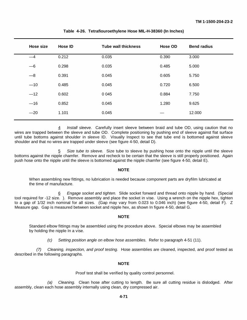
TM 1-1500-204-23-2
Table 4-26. Tetrafiouroethylene Hose MIL-H-38360 (In Inches)
Hose size Hose ID Tube wall thickness Hose OD Bend radius
— 4 0.212 0.035 0.390 3.000
— 6 0.298 0.035 0.485 5.000
— 8 0.391 0.045 0.605 5.750
— 10 0.485 0.045 0.720 6.500
— 12 0.602 0 045 0.884 7.750
— 16 0.852 0.045 1.280 9.625
— 20 1.101 0.045 — 12.000
4 Install sleeve. Carefully insert sleeve between braid and tube OD, using caution that nowires are trapped between the sleeve and tube OD. Complete positioning by pushing end of sleeve against flat surfaceuntil tube bottoms against shoulder in sleeve ID. Visually Inspect to see that tube end is bottomed against sleeveshoulder and that no wires are trapped under sleeve (see figure 4-50, detail D).
5 Size tube to sleeve. Size tube to sleeve by pushing hose onto the nipple until the sleevebottoms against the nipple chamfer. Remove and recheck to be certain that the sleeve is still properly positioned. Againpush hose onto the nipple until the sleeve is bottomed against the nipple chamfer (see figure 4-50, detail E).
NOTE
When assembling new fittings, no lubrication is needed because component parts are dryfilm lubricated atthe time of manufacture.
6 Engage socket and tighten. Slide socket forward and thread onto nipple by hand. (Specialtool required for -12 size. ). Remove assembly and place the socket in vise. Using a wrench on the nipple hex, tightento a gap of 1/32 inch nominal for all sizes. (Gap may vary from 0.023 to 0.046 inch) (see figure 4-50, detail F). ZMeasure gap. Gap is measured between socket and nipple hex, as shown In figure 4-50, detail G.
NOTE
Standard elbow fittings may be assembled using the procedure above. Special elbows may be assembledby holding the nipple In a vise.
(c) Setting position angle on elbow hose assemblies. Refer to paragraph 4-51 (11).
(7) Cleaning, inspection, and proof testing. Hose assemblies are cleaned, inspected, and proof tested asdescribed in the following paragraphs.
NOTE
Proof test shall be verified by quality control personnel.
(a) Cleaning. Clean hose after cutting to length. Be sure all cutting residue is dislodged. Afterassembly, clean each hose assembly internally using clean, dry compressed air.
4-71
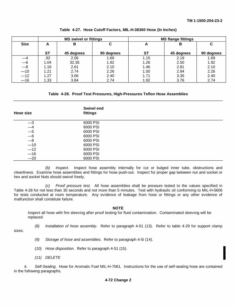
TM 1-1500-204-23-2
Table 4-27. Hose Cutoff Factors, MIL-H-38360 Hose (In Inches)
MS swivel or fittings MS flange fittingsSize A B C A B C
ST 45 degrees 90 degrees ST 45 degrees 90 degrees— 4 .92 2.06 1.69 1.15 2.19 1.69— 6 1.04 32.35 1.92 1.26 2.50 1.92— 8 1.16 2.61 2.10 1.46 2.81 2.10— 10 1.21 2.74 2.26 1.50 2.94 2.26— 12 1.27 3.06 2.40 1.71 3.35 2.40— 16 1.33 3.84 2.74 1.92 3.76 2.74
Table 4-28. Proof Test Pressures, High-Pressures Teflon Hose Assemblies
Swivel endHose size fittings
— 3 6000 PSI— 4 6000 PSI— 5 6000 PSI— 6 6000 PSI— 8 6000 PSI— 10 6000 PSI— 12 6000 PSI— 16 6000 PSI— 20 6000 PSI
(b) Inspect. Inspect hose assembly internally for cut or bulged inner tube, obstructions andcleanliness. Examine hose assemblies and fittings for hose push-out. Inspect for proper gap between nut and socket orhex and socket Nuts should swivel freely.
(c) Proof pressure test. All hose assemblies shall be pressure tested to the values specified inTable 4-28 for not less than 30 seconds and not more than 5 minutes. Test with hydraulic oil conforming to MIL-H-5606for tests conducted at room temperature. Any evidence of leakage from hose or fittings or any other evidence ofmalfunction shall constitute failure.
NOTEInspect all hose with fire sleeving after proof testing for fluid contamination. Contaminated sleeving will bereplaced.
(8) Installation of hose assembly. Refer to paragraph 4-51 (13). Refer to table 4-29 for support clampsizes.
(9) Storage of hose and assemblies. Refer to paragraph 4-5i (14).
(10) Hose disposition. Refer to paragraph 4-51 (15).
(11) DELETE
k. Self-Sealing. Hose for Aromatic Fuel MIL-H-7061. Instructions for the use of self-sealing hose are containedin the following paragraphs.
4-72 Change 2
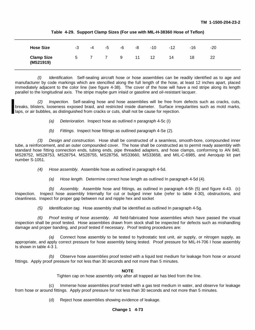
TM 1-1500-204-23-2
Table 4-29. Support Clamp Sizes (For use with MIL-H-38360 Hose of Teflon)
Hose Size -3 -4 -5 -6 -8 -10 -12 -16 -20
Clamp Size 5 7 7 9 11 12 14 18 22(MS21919)
(I) Identification. Self-sealing aircraft hose or hose assemblies can be readily identified as to age andmanufacturer by code markings which are stencilled along the full length of the hose, at least 12 inches apart, placedimmediately adjacent to the color line (see figure 4-38). The cover of the hose will have a red stripe along its lengthparallel to the longitudinal axis. The stripe maybe gum inlaid or gasoline and oil-resistant lacquer.
(2) Inspection. Self-sealing hose and hose assemblies will be free from defects such as cracks, cuts,breaks, blisters, looseness exposed braid, and restricted inside diameter. Surface irregularities such as mold marks,laps, or air bubbles, as distinguished from cracks or cuts, shall not be cause for rejection.
(a) Deterioration. Inspect hose as outlined n paragraph 4-5c (I)
(b) Fittings. Inspect hose fittings as outlined paragraph 4-Se (2).
(3) Design and construction. Hose shall be constructed of a seamless, smooth-bore, compounded innertube, a reinforcement, and an outer compounded cover. The hose shall be constructed as to permit ready assembly withstandard hose fitting connection ends, tubing ends, pipe threaded adapters, and hose clamps, conforming to AN 840,MS28752, MS28753, MS28754, MS28755, MS28756, MS33660, MS33658, and MIL-C-6985, and Aeroquip kit partnumber S-1051.
(4) Hose assembly. Assemble hose as outlined in paragraph 4-5d.
(a) Hose length. Determine correct hose length as outlined In paragraph 4-5d (4).
(b) Assembly. Assemble hose and fittings, as outlined in paragraph 4-5h (5) and figure 4-43. (c)Inspection. Inspect hose assembly Internally for cut or bulged inner tube (refer to table 4-30), obstructions, andcleanliness. Inspect for proper gap between nut and nipple hex and socket
(5) Identification tag. Hose assembly shall be identified as outlined In paragraph 4-5g.
(6) Proof testing of hose assembly. All field-fabricated hose assemblies which have passed the visualinspection shall be proof tested. Hose assemblies drawn from stock shall be inspected for defects such as mishandlingdamage and proper banding, and proof tested if necessary. Proof testing procedures are:
(a) Connect hose assembly to be tested to hydrostatic test unit, air supply, or nitrogen supply, asappropriate, and apply correct pressure for hose assembly being tested. Proof pressure for MIL-H-706 I hose assemblyIs shown in table 4-3 1.
(b) Observe hose assemblies proof tested with a liquid test medium for leakage from hose or aroundfittings. Apply proof pressure for not less than 30 seconds and not more than 5 minutes.
NOTETighten cap on hose assembly only after all trapped air has bled from the line.
(c) Immerse hose assemblies proof tested with a gas test medium in water, and observe for leakagefrom hose or around fittings. Apply proof pressure for not less than 30 seconds and not more than 5 minutes.
(d) Reject hose assemblies showing evidence of leakage.
Change 1 4-73
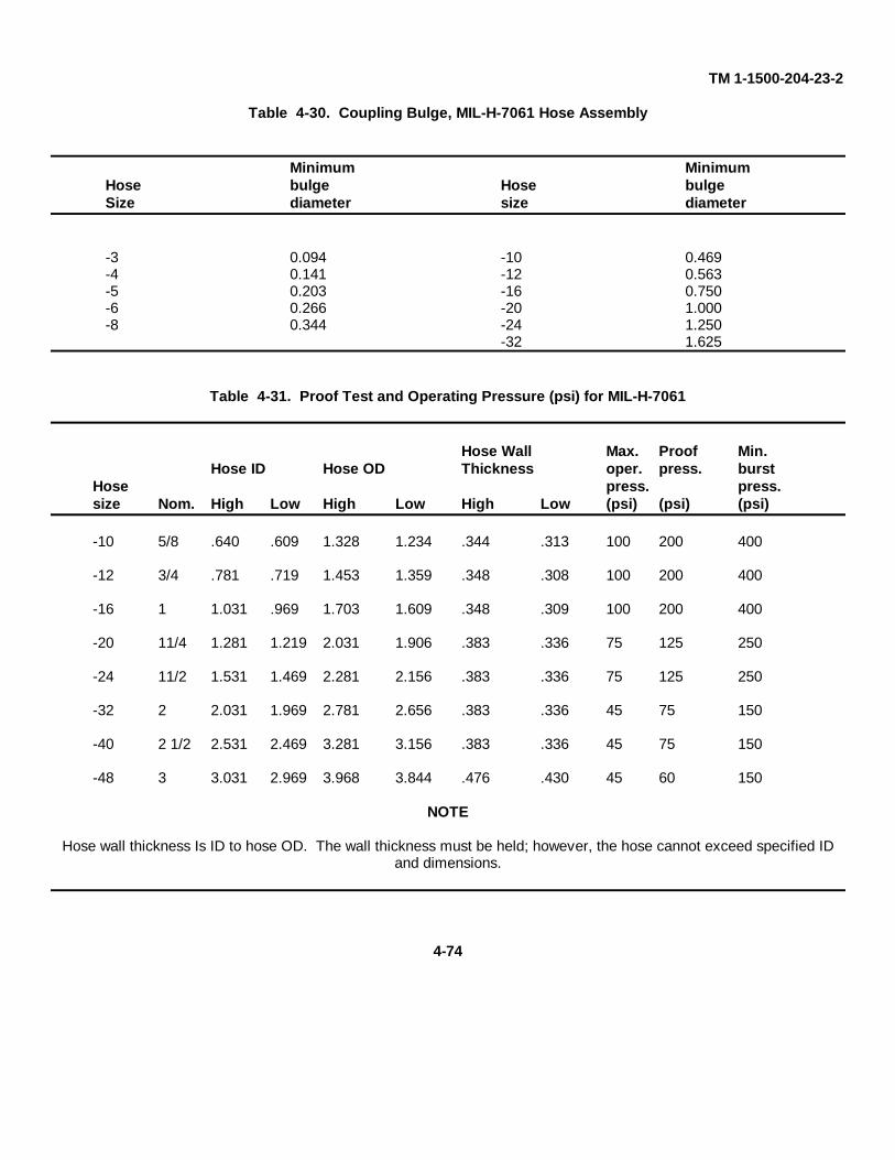
TM 1-1500-204-23-2
Table 4-30. Coupling Bulge, MIL-H-7061 Hose Assembly
Minimum MinimumHose bulge Hose bulgeSize diameter size diameter
-3 0.094 -10 0.469-4 0.141 -12 0.563-5 0.203 -16 0.750-6 0.266 -20 1.000-8 0.344 -24 1.250
-32 1.625
Table 4-31. Proof Test and Operating Pressure (psi) for MIL-H-7061
Hose Wall Max. Proof Min.Hose ID Hose OD Thickness oper. press. burst
Hose press. press.size Nom. High Low High Low High Low (psi) (psi) (psi)
-10 5/8 .640 .609 1.328 1.234 .344 .313 100 200 400
-12 3/4 .781 .719 1.453 1.359 .348 .308 100 200 400
-16 1 1.031 .969 1.703 1.609 .348 .309 100 200 400
-20 11/4 1.281 1.219 2.031 1.906 .383 .336 75 125 250
-24 11/2 1.531 1.469 2.281 2.156 .383 .336 75 125 250
-32 2 2.031 1.969 2.781 2.656 .383 .336 45 75 150
-40 2 1/2 2.531 2.469 3.281 3.156 .383 .336 45 75 150
-48 3 3.031 2.969 3.968 3.844 .476 .430 45 60 150
NOTE
Hose wall thickness Is ID to hose OD. The wall thickness must be held; however, the hose cannot exceed specified IDand dimensions.
4-74
TM 1-1500-204-23-2
WARNING
Drycleaning solvent is flammable and solvent vapors are toxic. Use P-D-680, Type II Solvent In a well-ventilated area. Keep away from open flames. Avoid prolonged solvent contact with skin.
(e) After proof test of a hose assembly using hydraulic fluid or oil as a test medium, flush or dipassembly in kerosene, Federal Specification VV-K-211, or solvent, Federal Specification P-D-680. Drain assembly anddry using by compressed air. Those assemblies tested with water as the pressure fluid will be drained and dried with drycompressed air.
(f) Install the following polyethylene protective plugs in end fittings of hose assemblies that are notto be immediately installed after fabrication. NAS 815(*size) (*same dash number as fitting). Close openings in flanges(or other special fittings) using pressure sensitive tape or other adequate means to prevent entrance of foreign material.
l. Use of Dust Plugs, Dust Caps, and Moisture Seals. The following paragraphs provide instructions for use ofplugs, caps, and seals.
(1) Sealing with plugs, caps, and seals. Dust plugs, dust caps, and moisture seals shall be used toprovide proper closures to prevent leakage and contamination of aircraft systems when lines or units are disconnectedfor maintenance, repair, shipping, storage, and bulk material in free stock. See figures 4-51 through 4-56 for types ofdust plugs, dust caps, and moisture seals. These plugs and seals are of plastic (polyethylene), aluminum, steel(cadmium or zinc plates), rubber, and synthetic rubber. They will not scale or chip and require no tools for installation,hand tightening being sufficient to provide proper protection. After removal, plugs and seals shall be thoroughly cleanedand sorted for reuse.
NOTE
Plugs or seals shall not be used under operating pressures.
(2) Alternate sealing methods. Exposure to high temperature and dust conditions, such as in desertclimates, cause plastic and rubber closures to shrink, deteriorate, and become difficult or Impractical to use. Heavyaluminum foil may be used to protect plugs and seals from deterioration and prevent dirt and sand from entering tubing,connectors, and threaded fittings, especially on equipment stored outside. Heavy aluminum foil may also be used toprotect open lines, connections, quick disconnect couplings, etc.,. when standard AN-SAE threaded closures are notavailable. Recommended aluminum foil thickness is from 0.003 to 0.005 Inch, and can be locally procured orrequisitioned from Federal Stock Class 9535.
NOTE
Prior to connection on any lines where aluminum foil has been used with standard AN-SAE threadedclosures, a thorough Inspection will be made to ensure that no foil has entered lines. Any conflict betweenthis manual and the manual for a particular aircraft or other item of equipment concerning use ofaluminum foil will void Instruction in paragraph (2).
Change 2 4-74.1
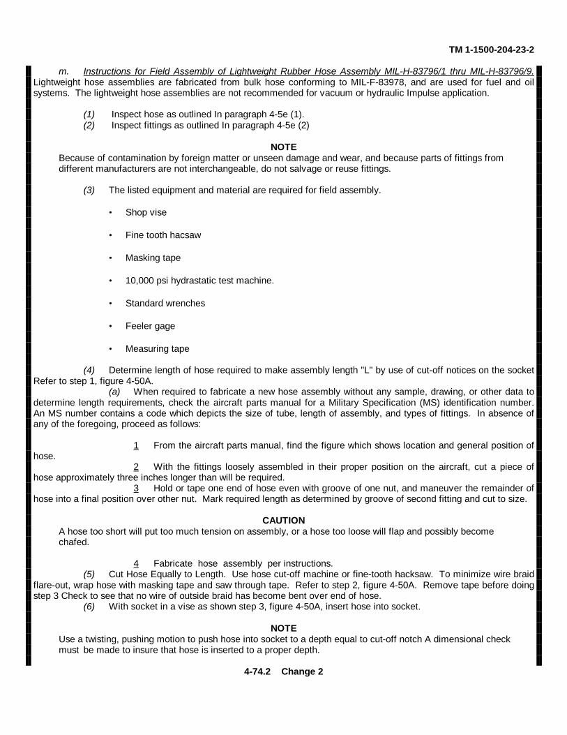
TM 1-1500-204-23-2
m. Instructions for Field Assembly of Lightweight Rubber Hose Assembly MIL-H-83796/1 thru MIL-H-83796/9.Lightweight hose assemblies are fabricated from bulk hose conforming to MIL-F-83978, and are used for fuel and oilsystems. The lightweight hose assemblies are not recommended for vacuum or hydraulic Impulse application.
(1) Inspect hose as outlined In paragraph 4-5e (1).(2) Inspect fittings as outlined In paragraph 4-5e (2)
NOTEBecause of contamination by foreign matter or unseen damage and wear, and because parts of fittings from different manufacturers are not interchangeable, do not salvage or reuse fittings.
(3) The listed equipment and material are required for field assembly.
• Shop vise • Fine tooth hacsaw • Masking tape • 10,000 psi hydrastatic test machine. • Standard wrenches • Feeler gage • Measuring tape
(4) Determine length of hose required to make assembly length "L" by use of cut-off notices on the socketRefer to step 1, figure 4-50A.
(a) When required to fabricate a new hose assembly without any sample, drawing, or other data todetermine length requirements, check the aircraft parts manual for a Military Specification (MS) identification number.An MS number contains a code which depicts the size of tube, length of assembly, and types of fittings. In absence ofany of the foregoing, proceed as follows:
1 From the aircraft parts manual, find the figure which shows location and general position ofhose.
2 With the fittings loosely assembled in their proper position on the aircraft, cut a piece ofhose approximately three inches longer than will be required.
3 Hold or tape one end of hose even with groove of one nut, and maneuver the remainder ofhose into a final position over other nut. Mark required length as determined by groove of second fitting and cut to size.
CAUTIONA hose too short will put too much tension on assembly, or a hose too loose will flap and possibly become chafed.
4 Fabricate hose assembly per instructions.(5) Cut Hose Equally to Length. Use hose cut-off machine or fine-tooth hacksaw. To minimize wire braid
flare-out, wrap hose with masking tape and saw through tape. Refer to step 2, figure 4-50A. Remove tape before doingstep 3 Check to see that no wire of outside braid has become bent over end of hose.
(6) With socket in a vise as shown step 3, figure 4-50A, insert hose into socket.
NOTEUse a twisting, pushing motion to push hose into socket to a depth equal to cut-off notch A dimensional checkmust be made to insure that hose is inserted to a proper depth.
4-74.2 Change 2
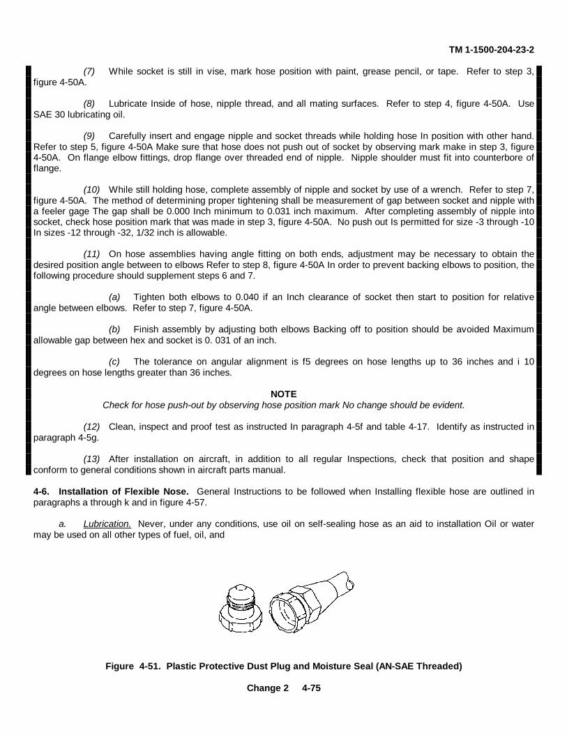
TM 1-1500-204-23-2
(7) While socket is still in vise, mark hose position with paint, grease pencil, or tape. Refer to step 3,figure 4-50A.
(8) Lubricate Inside of hose, nipple thread, and all mating surfaces. Refer to step 4, figure 4-50A. UseSAE 30 lubricating oil.
(9) Carefully insert and engage nipple and socket threads while holding hose In position with other hand.Refer to step 5, figure 4-50A Make sure that hose does not push out of socket by observing mark make in step 3, figure4-50A. On flange elbow fittings, drop flange over threaded end of nipple. Nipple shoulder must fit into counterbore offlange.
(10) While still holding hose, complete assembly of nipple and socket by use of a wrench. Refer to step 7,figure 4-50A. The method of determining proper tightening shall be measurement of gap between socket and nipple witha feeler gage The gap shall be 0.000 Inch minimum to 0.031 inch maximum. After completing assembly of nipple intosocket, check hose position mark that was made in step 3, figure 4-50A. No push out Is permitted for size -3 through -10In sizes -12 through -32, 1/32 inch is allowable.
(11) On hose assemblies having angle fitting on both ends, adjustment may be necessary to obtain thedesired position angle between to elbows Refer to step 8, figure 4-50A In order to prevent backing elbows to position, thefollowing procedure should supplement steps 6 and 7.
(a) Tighten both elbows to 0.040 if an Inch clearance of socket then start to position for relativeangle between elbows. Refer to step 7, figure 4-50A.
(b) Finish assembly by adjusting both elbows Backing off to position should be avoided Maximumallowable gap between hex and socket is 0. 031 of an inch.
(c) The tolerance on angular alignment is f5 degrees on hose lengths up to 36 inches and i 10degrees on hose lengths greater than 36 inches.
NOTECheck for hose push-out by observing hose position mark No change should be evident.
(12) Clean, inspect and proof test as instructed In paragraph 4-5f and table 4-17. Identify as instructed inparagraph 4-5g.
(13) After installation on aircraft, in addition to all regular Inspections, check that position and shapeconform to general conditions shown in aircraft parts manual.
4-6. Installation of Flexible Nose. General Instructions to be followed when Installing flexible hose are outlined inparagraphs a through k and in figure 4-57.
a. Lubrication. Never, under any conditions, use oil on self-sealing hose as an aid to installation Oil or watermay be used on all other types of fuel, oil, and
Figure 4-51. Plastic Protective Dust Plug and Moisture Seal (AN-SAE Threaded)
Change 2 4-75
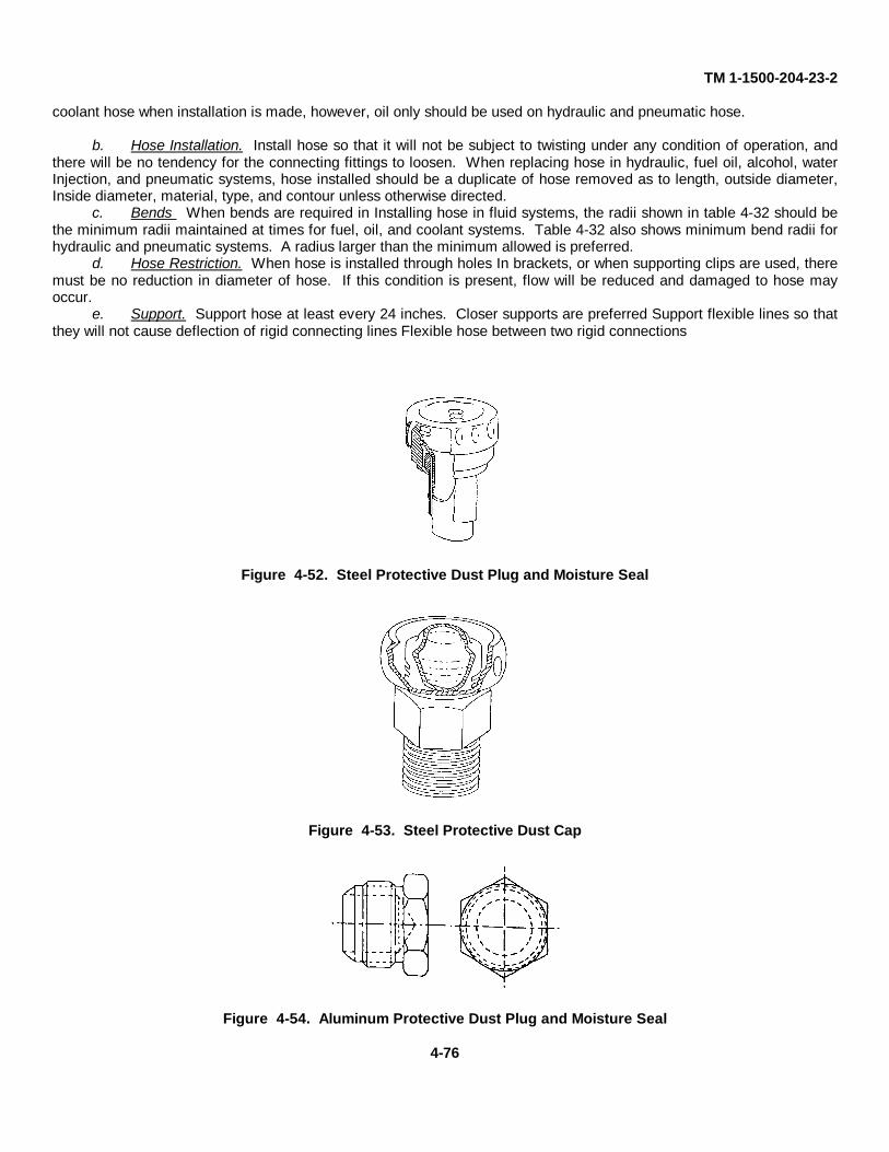
TM 1-1500-204-23-2
coolant hose when installation is made, however, oil only should be used on hydraulic and pneumatic hose.
b. Hose Installation. Install hose so that it will not be subject to twisting under any condition of operation, andthere will be no tendency for the connecting fittings to loosen. When replacing hose in hydraulic, fuel oil, alcohol, waterInjection, and pneumatic systems, hose installed should be a duplicate of hose removed as to length, outside diameter,Inside diameter, material, type, and contour unless otherwise directed.
c. Bends When bends are required in Installing hose in fluid systems, the radii shown in table 4-32 should bethe minimum radii maintained at times for fuel, oil, and coolant systems. Table 4-32 also shows minimum bend radii forhydraulic and pneumatic systems. A radius larger than the minimum allowed is preferred.
d. Hose Restriction. When hose is installed through holes In brackets, or when supporting clips are used, theremust be no reduction in diameter of hose. If this condition is present, flow will be reduced and damaged to hose mayoccur.
e. Support. Support hose at least every 24 inches. Closer supports are preferred Support flexible lines so thatthey will not cause deflection of rigid connecting lines Flexible hose between two rigid connections
Figure 4-52. Steel Protective Dust Plug and Moisture Seal
Figure 4-53. Steel Protective Dust Cap
Figure 4-54. Aluminum Protective Dust Plug and Moisture Seal
4-76
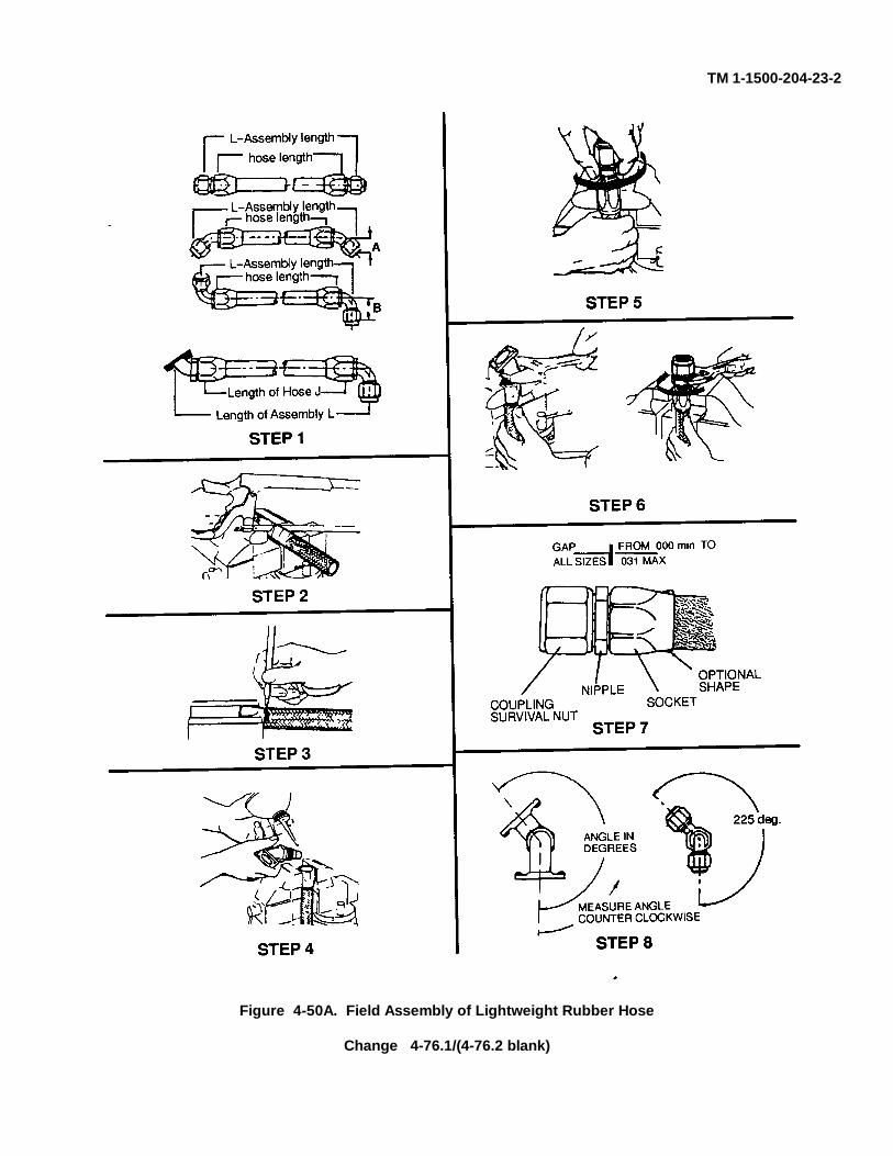
TM 1-1500-204-23-2
Figure 4-50A. Field Assembly of Lightweight Rubber Hose
Change 4-76.1/(4-76.2 blank)
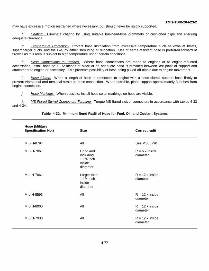
TM 1-1500-204-23-2may have excessive motion restrained where necessary, but should never be rigidly supported.
f. Chafing. Eliminate chafing by using suitable bulkhead-type grommets or cushioned clips and ensuringadequate clearance.
g. Temperature Protection. Protect hose installation from excessive temperature such as exhaust blasts,supercharger ducts, and the like, by either shrouding or relocation. Use of flame-resistant hose is preferred forward offirewall as this area is subject to high temperature under certain conditions.
h. Hose Connections to Engines. Where hose connections are made to engines or to engine-mountedaccessories, install hose so 1 1/2 inches of slack or an adequate bend is provided between last point of support andattachment to engine or accessory. This prevents possibility of hose being pulled off nipple due to engine movement.
i. Hose Clamp. When a length of hose is connected to engine with a hose clamp, support hose firmly toprevent vibrational and torsional strain on hose connection. When possible, place support approximately 3 inches fromengine connection.
j. Hose Markings. When possible, install hose so all markings on hose are visible.
k. MS Flared Swivel Connectors Torquing. Torque MS flared swivel connectors in accordance with tables 4-33and 4-34.
Table 4-32. Minimum Bend Radii of Hose for Fuel, Oil, and Coolant Systems
Hose (MilitarySpecification No.) Size Correct radii
MIL-H-8794 All See MS33790
MIL-H-7061 Up to and R = 6 x insideincluding diameter1 1/4 inchinsidediameter
MIL-H-7061 Larger than R = 12 x inside1 1/4 inch diameterinsidediameter
MIL-H-5593 All R = 12 x insidediameter
MIL-H-6000 All R = 12 x insidediameter
MIL-H-7938 All R = 12 x insidediameter
4-77
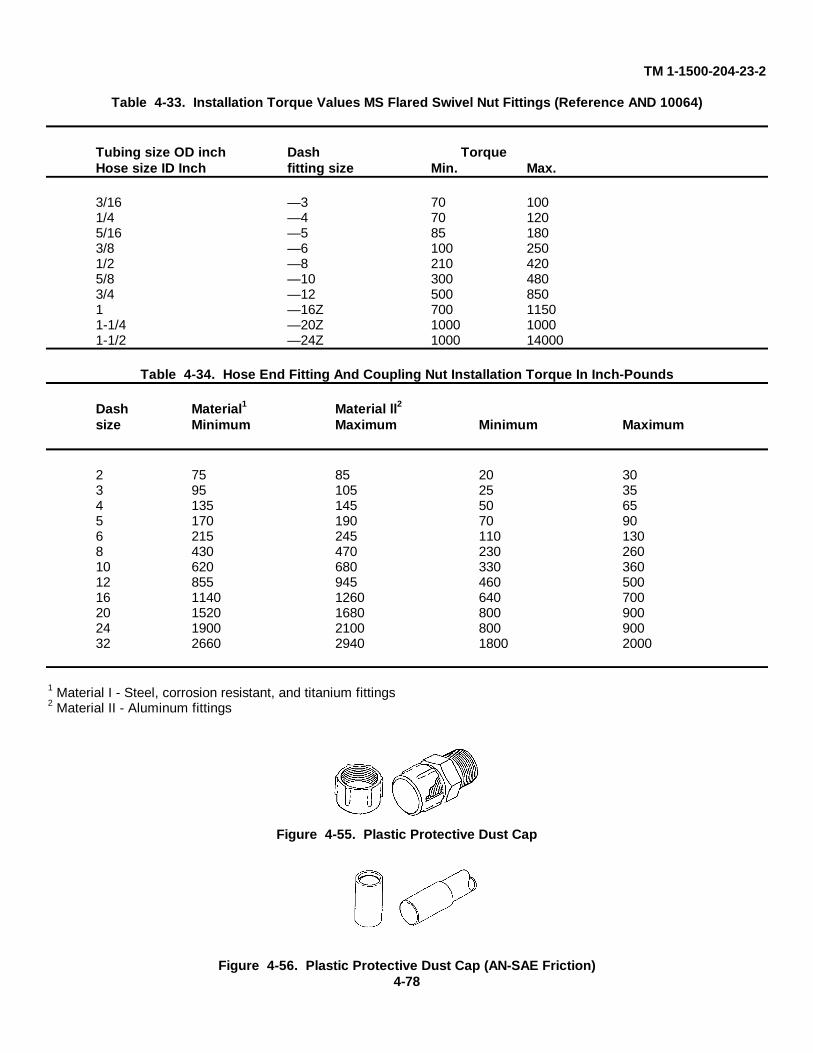
TM 1-1500-204-23-2
Table 4-33. Installation Torque Values MS Flared Swivel Nut Fittings (Reference AND 10064)
Tubing size OD inch Dash TorqueHose size ID Inch fitting size Min. Max.
3/16 — 3 70 1001/4 — 4 70 1205/16 — 5 85 1803/8 — 6 100 2501/2 — 8 210 4205/8 — 10 300 4803/4 — 12 500 8501 — 16Z 700 11501-1/4 — 20Z 1000 10001-1/2 — 24Z 1000 14000
Table 4-34. Hose End Fitting And Coupling Nut Installation Torque In Inch-Pounds
Dash Material1 Material ll2
size Minimum Maximum Minimum Maximum
2 75 85 20 303 95 105 25 354 135 145 50 655 170 190 70 906 215 245 110 1308 430 470 230 26010 620 680 330 36012 855 945 460 50016 1140 1260 640 70020 1520 1680 800 90024 1900 2100 800 90032 2660 2940 1800 2000
1 Material I - Steel, corrosion resistant, and titanium fittings2 Material II - Aluminum fittings
Figure 4-55. Plastic Protective Dust Cap
Figure 4-56. Plastic Protective Dust Cap (AN-SAE Friction)4-78
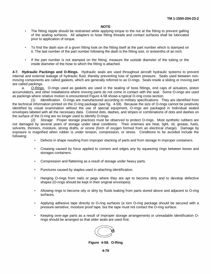
TM 1-1500-204-23-2
NOTE• The fitting nipple should be restrained while applying torque to the nut at the fitting to prevent galling
of the sealing surfaces. All adapters to hose fitting threads and contact surfaces shall be lubricatedprior to application of torque.
• To find the dash size of a given fitting look on the fitting itself at the part number which is stamped on
it. The last number of the part number following the dash is the fitting size, in sixteenths of an inch. • If the part number is not stamped on the fitting, measure the outside diameter of the tubing or the
inside diameter of the hose to which the fitting is attached.
4-7. Hydraulic Packings and O-Rings. Hydraulic seals are used throughout aircraft hydraulic systems to preventinternal and external leakage of hydraulic fluid, thereby preventing loss of system pressure. Seals used between non-moving components are called gaskets, which are generally referred to as O-rings. Seals inside a sliding or moving partare called packings.
a. O-Rings. O-rings used as gaskets are used in the sealing of boss fittings, end caps of actuators, pistonaccumulators, and other installations where moving parts do not come in contact with the seal. Some O-rings are usedas packings where relative motion is encountered Figure 4-58 shows a typical O-ring cross section.
(1) Identification. O-rings are manufactured according to military specifications. They are identified fromthe technical information printed on the O-ring package (see fig. 4-59). Because the size of O-rings cannot be positivelyidentified by visual examination without the use of special equipment, O-rings are packaged in Individual sealedenvelopes labeled with all the necessary data. Colored dots, dashes, and stripes or combinations of dots and dashes onthe surface of the O-ring are no longer used to identify O-rings.
(2) Storage Proper storage practices must be observed to protect O-rings. Most synthetic rubbers arenot damaged by several years of storage under ideal conditions. Their enemies are heat, light, oil, grease, fuels,solvents, thinners, moisture, strong drafts, or ozone (form of oxygen formed from an electrical charge). Damage byexposure is magnified when rubber is under tension, compression, or stress. Conditions to be avoided include thefollowing:
• Defects in shape resulting from improper stacking of parts and from storage In improper containers. • Creasing caused by force applied to corners and edges any by squeezing rings between boxes and
storages containers. • Compression and flattening as a result of storage under heavy parts. • Punctures caused by staples used in attaching identification. • Hanging O-rings from nails or pegs where they are apt to become dirty and to develop defective
shapes (O-rings should be kept in their original envelopes). • Allowing rings to become oily or dirty by fluids leaking from parts stored above and adjacent to O-ring
surfaces. • Applying adhesive tape directly to O-ring surfaces (a torn O-ring package should be secured with a
pressure-sensitive, moisture proof tape, but the tape must not contact the O-ring surface. • Keeping over-age parts as a result of improper storage arrangements or unreadable identification O-
rings should be arranged so that older seals are used first.
Figure 4-58. O-Ring
4-79
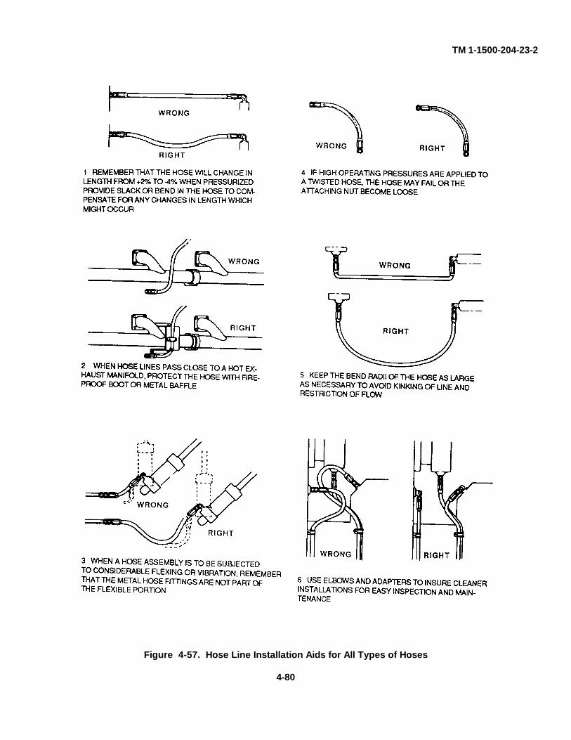
TM 1-1500-204-23-2
Figure 4-57. Hose Line Installation Aids for All Types of Hoses
4-80
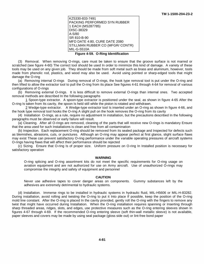
TM 1-1500-204-23-2KZ5330-833-7491PACKING PERFORMED SYN RUBBER1 EACH (MS287785)DISC-38329A-5/80SR 810-B-90MFD DATE 4:80, CURE DATE 2080STILLMAN RUBBER CO (MFGR/ CONTR)MIL-G-5510A
Figure 4-59. O-Ring Identification
(3) Removal. When removing O-rings, care must be taken to ensure that the groove surface is not marred orscratched (see figure 4-60) The correct tool should be used In order to minimize this kind of damage. A variety of thesetools may be used on any given job. They should be made from soft metal such as brass and aluminum, however, toolsmade from phenolic rod, plastics, and wood may also be used. Avoid using pointed or sharp-edged tools that mightdamage the O-ring
(a) Removing internal O-rings During removal of O-rings, the hook type removal tool is put under the O-ring andthen lifted to allow the extractor tool to pull the O-ring from its place See figures 4-61 through 4-64 for removal of variousconfigurations of O-rings
(b) Removing external O-rings. It is less difficult to remove external O-rings than internal ones. Two acceptedremoval methods are described In the following paragraphs
1 Spoon-type extractor. A spoon-type extractor is positioned under the seal, as shown in figure 4-65 After theO-ring Is taken from Its cavity, the spoon Is held still while the piston is rotated and withdrawn.
2 Wedge-type extractor. A Wedge-type extractor tool Is inserted under an O-ring as shown In figure 4-66, andthe hook type removal tool hooks the O-ring A slight pull on the hook removes the O-ring from its cavity
(4) Installation O-rings, as a rule, require no adjustment In installation, but the precautions described In the followingparagraphs must be observed or early failure will result.
(a) Cleaning. After all O-rings are removed, cleaning of the parts that will receive new O-rings is mandatory Ensurethat the area used for such Installations is clean and free from all contamination
(b) Inspection. Each replacement O-ring should be removed from its sealed package and Inspected for defects suchas blemishes, abrasions, cuts, or punctures. Although an O-ring may appear perfect at first glance, slight surface flawsmay exist These can prevent satisfactory O-ring performance under the variable operating pressures of aircraft systemsO-rings having flaws that will affect their performance should be rejected
(c) Sizing. Ensure that O-ring Is of proper size. Uniform pressure on O-ring In Installed position is necessary forsatisfactory operation
WARNINGO-ring splicing and O-ring assortment kits do not meet the specific requirements for O-ring usage onaviation equipment and are not authorized for use on Army aircraft. Use of unauthorized O-rings maycompromise the integrity and safety of equipment and personnel
CAUTIONNever use adhesive tapes to cover danger areas on components. Gummy substances left by theadhesives are extremely detrimental to hydraulic systems.
(d) Installation. Immerse rings to be installed in hydraulic systems in hydraulic fluid, MIL-H5606 or MIL-H-83282.During installation, avoid rolling and twisting the O-ring to put it Into place If possible, keep the position of the O-ringmold line constant. After the O-ring is placed In the cavity provided, gently roll the O-ring with the fingers to remove anytwist that might have occurred during Installation. When the O-ring installation requires spanning or Inserting throughsharp threaded areas, ridges, slots, and edges, use protective measures such as the O-ring entering sleeves shown Infigures 4-67 through 4-69. If the recommended O-ring entering sleeve (soft thin-wall metallic sleeve) is not available,paper sleeves and covers may be made by using seal package (gloss side out) or lint-free bond paper
4-81
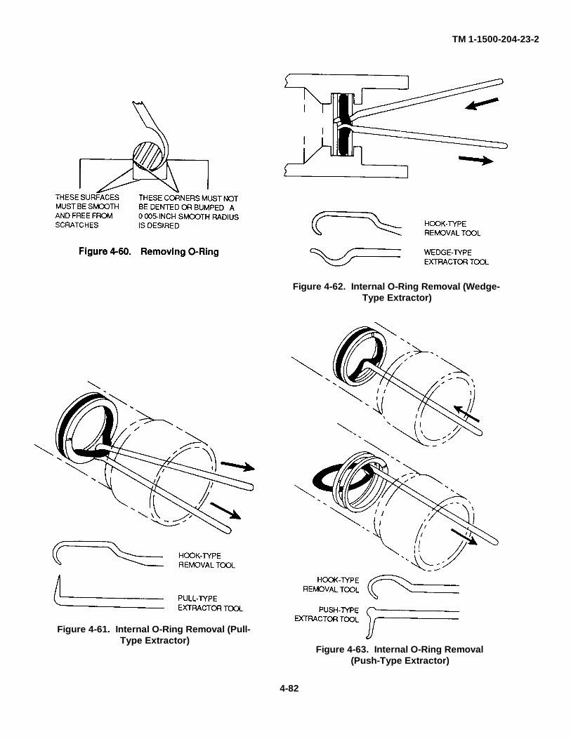
TM 1-1500-204-23-2
Figure 4-62. Internal O-Ring Removal (Wedge-Type Extractor)
Figure 4-61. Internal O-Ring Removal (Pull-Type Extractor)
Figure 4-63. Internal O-Ring Removal(Push-Type Extractor)
4-82
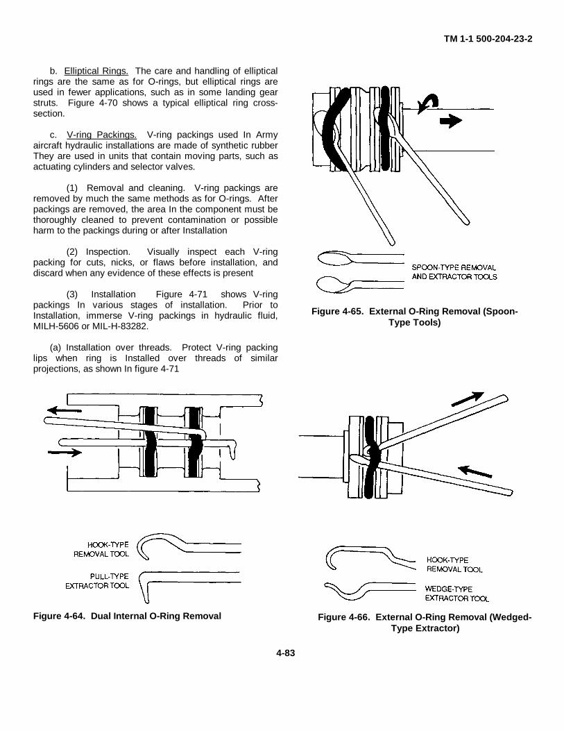
TM 1-1 500-204-23-2
b. Elliptical Rings. The care and handling of ellipticalrings are the same as for O-rings, but elliptical rings areused in fewer applications, such as in some landing gearstruts. Figure 4-70 shows a typical elliptical ring cross-section.
c. V-ring Packings. V-ring packings used In Armyaircraft hydraulic installations are made of synthetic rubberThey are used in units that contain moving parts, such asactuating cylinders and selector valves.
(1) Removal and cleaning. V-ring packings areremoved by much the same methods as for O-rings. Afterpackings are removed, the area In the component must bethoroughly cleaned to prevent contamination or possibleharm to the packings during or after Installation
(2) Inspection. Visually inspect each V-ringpacking for cuts, nicks, or flaws before installation, anddiscard when any evidence of these effects is present
(3) Installation Figure 4-71 shows V-ringpackings In various stages of installation. Prior toInstallation, immerse V-ring packings in hydraulic fluid,MILH-5606 or MIL-H-83282.
(a) Installation over threads. Protect V-ring packinglips when ring is Installed over threads of similarprojections, as shown In figure 4-71
Figure 4-64. Dual Internal O-Ring Removal
Figure 4-65. External O-Ring Removal (Spoon-Type Tools)
Figure 4-66. External O-Ring Removal (Wedged-Type Extractor)
4-83
TM 1-1500-204-23-2
(b) Installation precautions Install V-ring packing individually, making certain that packing is properly seated bytapping lightly with a small, clean, well-rounded blunt rod or similar instrument. Do not use screwdriver or other sharptools. Do not Install rings in sets, that is, more than one ring at a time. V-ring packings must never be squeezedexcessively nor be loose in gland, but should be held firm to operate properly Packing should contact gland walls on bothinside and outside diameter.
4-8. Backup Rings. Backup rings are used to support O-rings and to prevent them from wearing, thus causingleakage. Teflon backup rings are generally used with both packings and gaskets; however, leather backup rings may beused with gasket type seals in systems operating up to 1,500 psi. Teflon rings are made from a fluorocarbon-resinmaterial which is tough and friction resistant and which is more durable than leather Backup rings made from Teflon donot deteriorate with age, they are unaffected by any other system fluid or vapor, and they tolerate temperature extremesgreater than those encountered In high-pressure hydraulic systems Precautions similar to those applicable to O-ringsmust be taken to avert contamination of backup rings and damage to hydraulic components.
a. Identification Backup rings are not color coded or otherwise marked and must be identified from package labelsThe dash number, which follows the specification number on the package, shows the size, and In some cases relatesdirectly to the dash number, of the O-ring for which the backup ring is dimensionally suited. For example, the singlespiral Teflon ring MS28774-6 is used with the MS28775-006 O-ring and the double spiral Teflon ring MS28782-1 is usedwith the AN6227B-1 O-ring
b. Installation. Care must be taken during handling and installation of backup rings. If possible, backup rings shouldbe put on by hand and without the use of sharp tools.
(1) Teflon backup rings Teflon backup rings must be Inspected before reuse and must be discarded If there isevidence of compression damage, scratches, cuts, nicks, and fraying conditions.
Figure 4-67. Internal O-Ring Installation(Paper Cover) Figure 4-68. Internal O-Ring Installation (Metallic Sleeve)
4-84
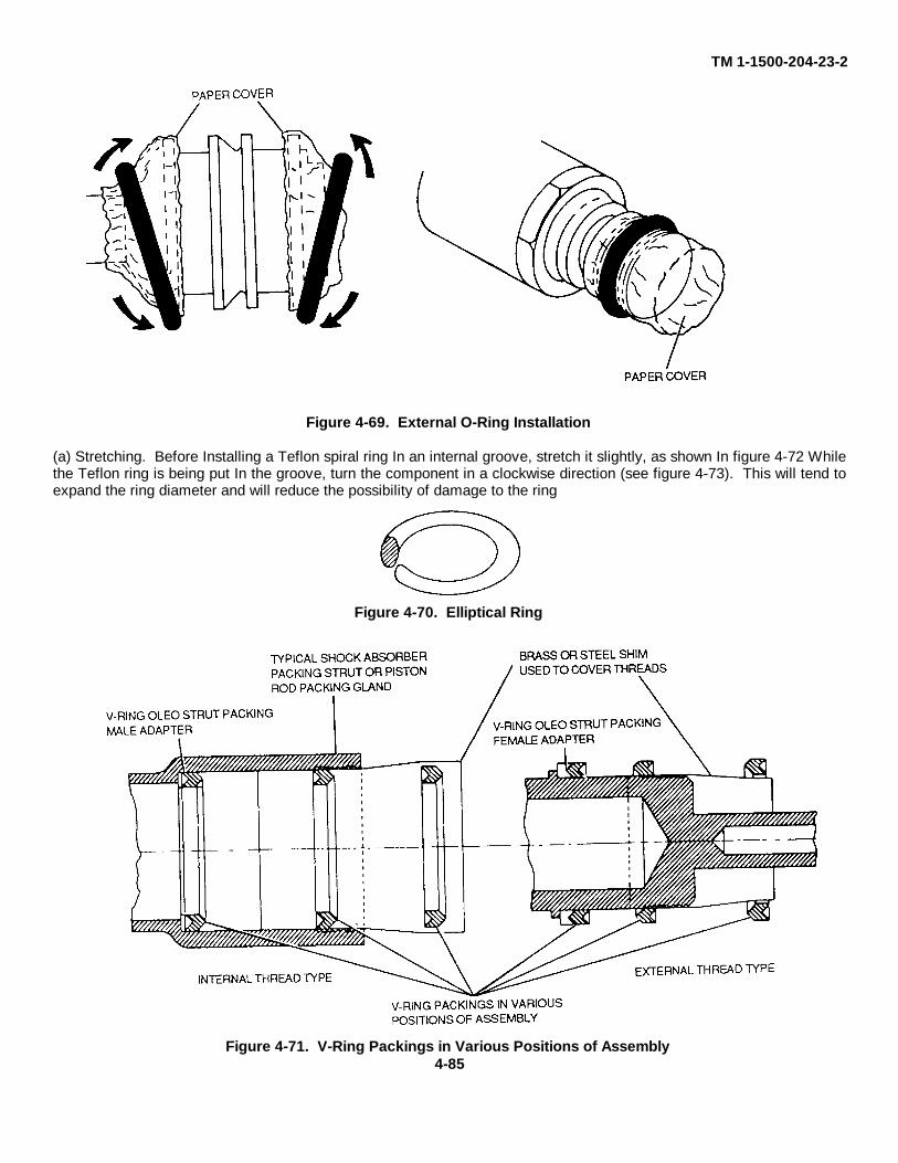
TM 1-1500-204-23-2
Figure 4-69. External O-Ring Installation
(a) Stretching. Before Installing a Teflon spiral ring In an internal groove, stretch it slightly, as shown In figure 4-72 Whilethe Teflon ring is being put In the groove, turn the component in a clockwise direction (see figure 4-73). This will tend toexpand the ring diameter and will reduce the possibility of damage to the ring
Figure 4-70. Elliptical Ring
Figure 4-71. V-Ring Packings in Various Positions of Assembly4-85
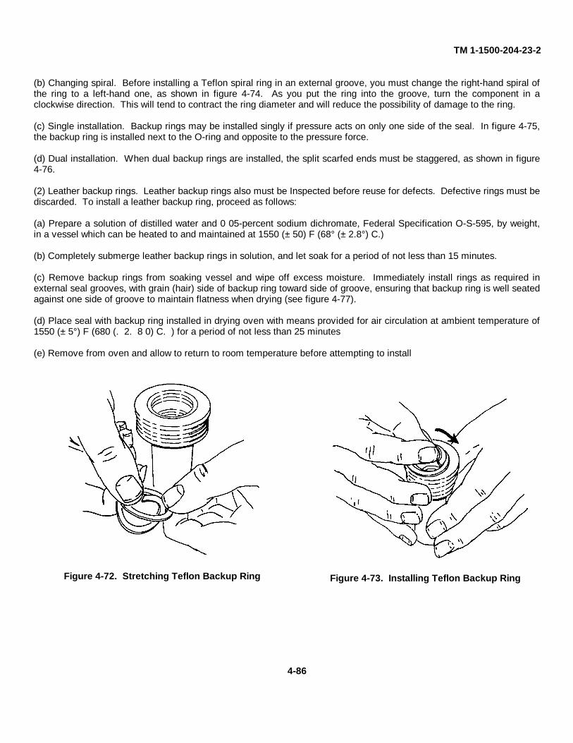
TM 1-1500-204-23-2
(b) Changing spiral. Before installing a Teflon spiral ring in an external groove, you must change the right-hand spiral ofthe ring to a left-hand one, as shown in figure 4-74. As you put the ring into the groove, turn the component in aclockwise direction. This will tend to contract the ring diameter and will reduce the possibility of damage to the ring.
(c) Single installation. Backup rings may be installed singly if pressure acts on only one side of the seal. In figure 4-75,the backup ring is installed next to the O-ring and opposite to the pressure force.
(d) Dual installation. When dual backup rings are installed, the split scarfed ends must be staggered, as shown in figure4-76.
(2) Leather backup rings. Leather backup rings also must be Inspected before reuse for defects. Defective rings must bediscarded. To install a leather backup ring, proceed as follows:
(a) Prepare a solution of distilled water and 0 05-percent sodium dichromate, Federal Specification O-S-595, by weight,in a vessel which can be heated to and maintained at 1550 (± 50) F (68° (± 2.8°) C.)
(b) Completely submerge leather backup rings in solution, and let soak for a period of not less than 15 minutes.
(c) Remove backup rings from soaking vessel and wipe off excess moisture. Immediately install rings as required inexternal seal grooves, with grain (hair) side of backup ring toward side of groove, ensuring that backup ring is well seatedagainst one side of groove to maintain flatness when drying (see figure 4-77).
(d) Place seal with backup ring installed in drying oven with means provided for air circulation at ambient temperature of1550 (± 5°) F (680 (. 2. 8 0) C. ) for a period of not less than 25 minutes
(e) Remove from oven and allow to return to room temperature before attempting to install
Figure 4-72. Stretching Teflon Backup Ring Figure 4-73. Installing Teflon Backup Ring
4-86
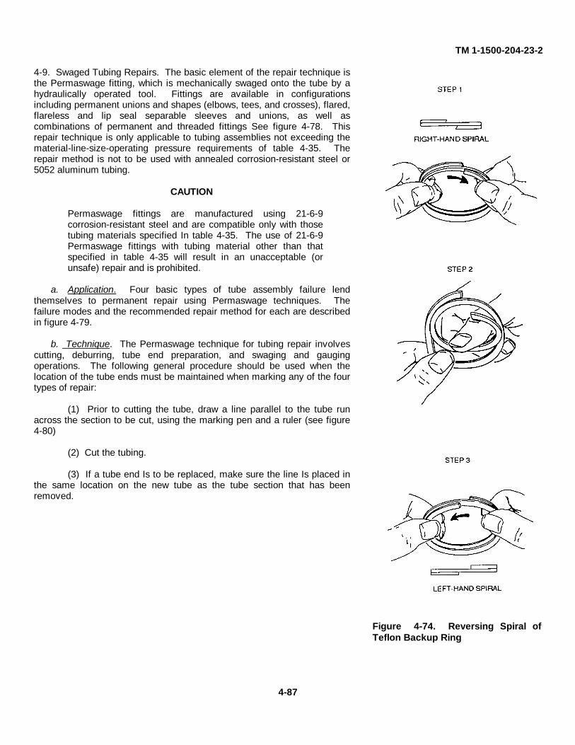
TM 1-1500-204-23-2
4-9. Swaged Tubing Repairs. The basic element of the repair technique isthe Permaswage fitting, which is mechanically swaged onto the tube by ahydraulically operated tool. Fittings are available in configurationsincluding permanent unions and shapes (elbows, tees, and crosses), flared,flareless and lip seal separable sleeves and unions, as well ascombinations of permanent and threaded fittings See figure 4-78. Thisrepair technique is only applicable to tubing assemblies not exceeding thematerial-line-size-operating pressure requirements of table 4-35. Therepair method is not to be used with annealed corrosion-resistant steel or5052 aluminum tubing.
CAUTION
Permaswage fittings are manufactured using 21-6-9corrosion-resistant steel and are compatible only with thosetubing materials specified In table 4-35. The use of 21-6-9Permaswage fittings with tubing material other than thatspecified in table 4-35 will result in an unacceptable (orunsafe) repair and is prohibited.
a. Application. Four basic types of tube assembly failure lendthemselves to permanent repair using Permaswage techniques. Thefailure modes and the recommended repair method for each are describedin figure 4-79.
b. Technique. The Permaswage technique for tubing repair involvescutting, deburring, tube end preparation, and swaging and gaugingoperations. The following general procedure should be used when thelocation of the tube ends must be maintained when marking any of the fourtypes of repair:
(1) Prior to cutting the tube, draw a line parallel to the tube runacross the section to be cut, using the marking pen and a ruler (see figure4-80)
(2) Cut the tubing.
(3) If a tube end Is to be replaced, make sure the line Is placed inthe same location on the new tube as the tube section that has beenremoved.
Figure 4-74. Reversing Spiral ofTeflon Backup Ring
4-87
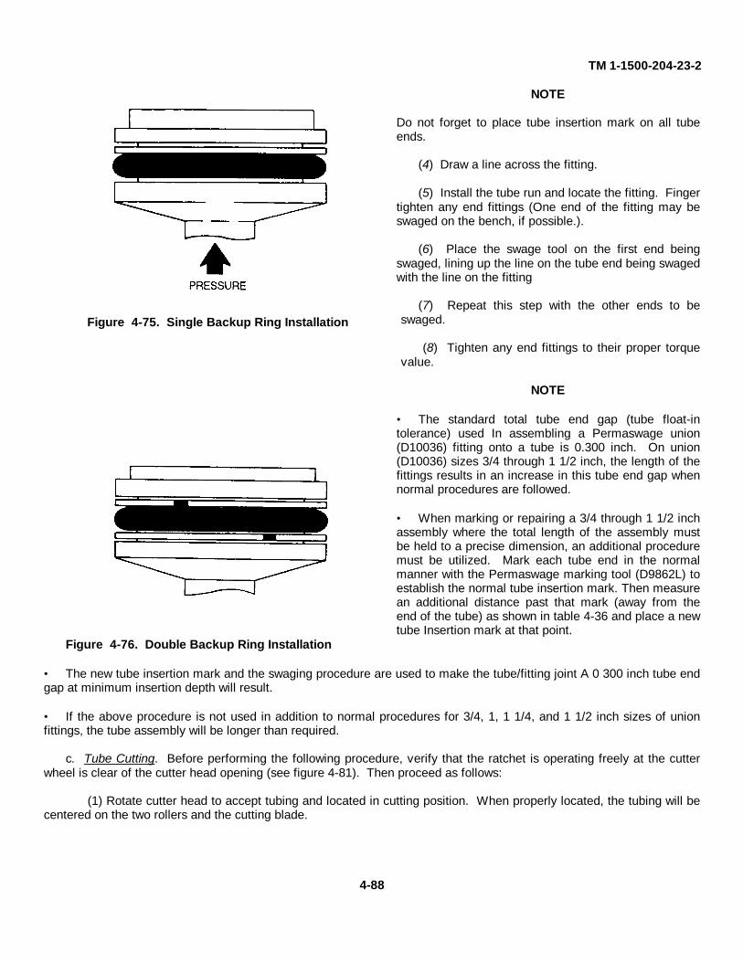
TM 1-1500-204-23-2
NOTE
Do not forget to place tube insertion mark on all tubeends.
(4) Draw a line across the fitting.
(5) Install the tube run and locate the fitting. Fingertighten any end fittings (One end of the fitting may beswaged on the bench, if possible.).
(6) Place the swage tool on the first end beingswaged, lining up the line on the tube end being swagedwith the line on the fitting
(7) Repeat this step with the other ends to beswaged.
(8) Tighten any end fittings to their proper torquevalue.
NOTE
• The standard total tube end gap (tube float-intolerance) used In assembling a Permaswage union(D10036) fitting onto a tube is 0.300 inch. On union(D10036) sizes 3/4 through 1 1/2 inch, the length of thefittings results in an increase in this tube end gap whennormal procedures are followed.
• When marking or repairing a 3/4 through 1 1/2 inchassembly where the total length of the assembly mustbe held to a precise dimension, an additional proceduremust be utilized. Mark each tube end in the normalmanner with the Permaswage marking tool (D9862L) toestablish the normal tube insertion mark. Then measurean additional distance past that mark (away from theend of the tube) as shown in table 4-36 and place a newtube Insertion mark at that point.
Figure 4-76. Double Backup Ring Installation
• The new tube insertion mark and the swaging procedure are used to make the tube/fitting joint A 0 300 inch tube endgap at minimum insertion depth will result.
• If the above procedure is not used in addition to normal procedures for 3/4, 1, 1 1/4, and 1 1/2 inch sizes of unionfittings, the tube assembly will be longer than required.
c. Tube Cutting. Before performing the following procedure, verify that the ratchet is operating freely at the cutterwheel is clear of the cutter head opening (see figure 4-81). Then proceed as follows:
(1) Rotate cutter head to accept tubing and located in cutting position. When properly located, the tubing will becentered on the two rollers and the cutting blade.
4-88
Figure 4-75. Single Backup Ring Installation
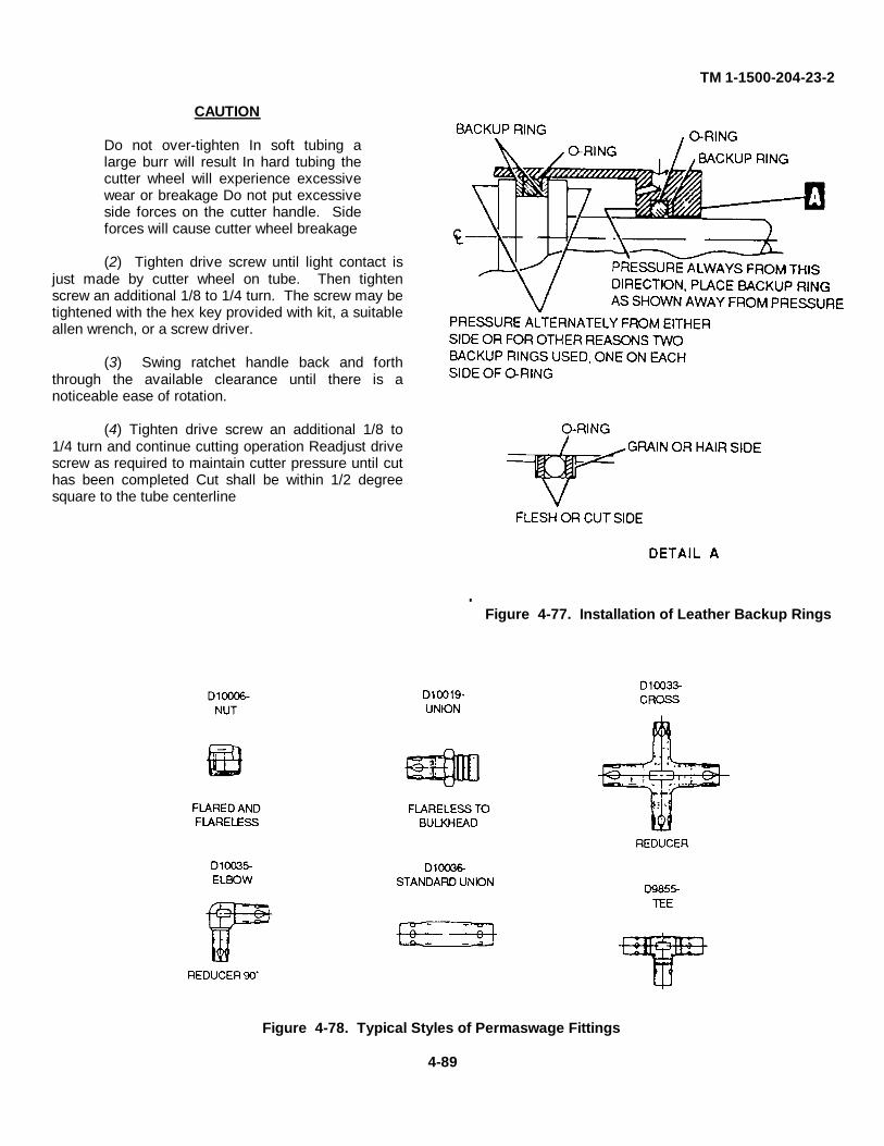
TM 1-1500-204-23-2
CAUTION
Do not over-tighten In soft tubing alarge burr will result In hard tubing thecutter wheel will experience excessivewear or breakage Do not put excessiveside forces on the cutter handle. Sideforces will cause cutter wheel breakage
(2) Tighten drive screw until light contact isjust made by cutter wheel on tube. Then tightenscrew an additional 1/8 to 1/4 turn. The screw may betightened with the hex key provided with kit, a suitableallen wrench, or a screw driver.
(3) Swing ratchet handle back and forththrough the available clearance until there is anoticeable ease of rotation.
(4) Tighten drive screw an additional 1/8 to1/4 turn and continue cutting operation Readjust drivescrew as required to maintain cutter pressure until cuthas been completed Cut shall be within 1/2 degreesquare to the tube centerline
FFigure 4-77. Installation of Leather Backup Rings
Figure 4-78. Typical Styles of Permaswage Fittings
4-89
TM 1-1500-204-23-2
NOTE
When cutting tubing 1/2 inch in diameter or larger, after cutter has made one revolution, retighten drivescrew 1/8 to 1/4 turn to prevent threading of cutter blade or tubing.
d. Tube Deburring. Special deburring tools are provided to remove burrs from the inside diameter (ID) of the tubing.The tool consists of a plunger-activated stem subassembly, Incorporating an elastic plug, that is inserted into the tubeend up to the point where the cutter makes contact with the burr. Deactivation of the plunger causes the elastic plug ofthe stem subassembly to expand, thus creating an interference fit with the ID of the tube. Hand rotation of the knurledtool body operates the cutter and accomplishes the deburring, while the elastic plug prevents chips generated during thedeburring operation from entering the tubing After trapping the chips, the plug wipes the tube ID clean as it is withdrawn.
e. Tube End Preparation. The tube end to be swaged shall be deburred and square to within 1/2 degree of squareto the tube centerline Deburring forms a slight chamfer on the Inner edges of the cut tube. The chamfer shall be amaximum of 1/2 of the tube wall thickness at an angle no greater than 45 degrees Mark the tube ends with a tubeinsertion band or mark using the felt tip pen (provided with kit), ink, or other suitable marking media in accordance withone of the following procedures.'
NOTE
Remove any paint from the end of lines for a minimum distance of 1/2 the length of a union (D10036)fitting prior to swaging. After swaging, prime and repaint per normal procedures.
(1) Tube insertion mark using Permaswage Marking Tool D9862 may be accomplished by positioning the lipstop of the marking tool, as shown In figure 4-82, over the end of the tube to be swaged Use the appropriate tube sizeslot as a marking guide, making sure the total width of the mark is made on the tube The tube Insertion length and 0.300of an inch marking band width are part of the D9862 marking tool.
(2) Using table 4-37, determine the Tube Insertion Band Location as shown In figure 4-83 (This method is usedwhen Permaswage Marking Tool is not available).
CAUTIONDo not glass bead blast or electro-etch aluminum tubing. Failure to comply will compromise the strengthof the tubing.
NOTEIf required, either procedure (1) or (2) may be accomplished with permanent marking such as glass beadblast, electro-etching, paint, dye, tape, or other suitable permanent marking media.
f. Swaging Operation. Swaging tools D10001, D10002, and D10003 are used to make permanent tubing joints byswaging an appropriate Permaswage fitting onto compatible tubing. The types of tubing are restricted to thosealuminum, stainless steel, or titanium tubing listed in Table 4-35 The fittings may be unions, tees, crosses, separablefittings, reducer fittings, or other special fittings, as shown in figure 4-84. A tube end gap Installation tolerance of 0.300of an inch is provided to facilitate production assembly for all fittings except separables, which have 0 150 of an inch gap.Each of the three swaging tools covers a range of tubing sizes, as shown In the following list.
SWAGING TOOL TUBING SIZE
D10001 3/16" (-3) 1/4" (-4)5/16" (-5) 3/8" (-6)
D10002 1/2" (-S) 5/8" (-10)3/4" (-12)
D10003 1" (-16) 1-1/4" (-20)1-1/2" (-24)
4-90
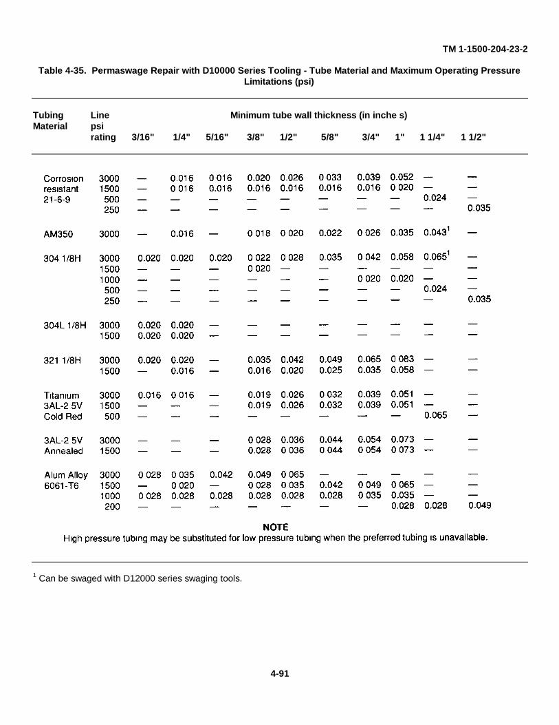
TM 1-1500-204-23-2
Table 4-35. Permaswage Repair with D10000 Series Tooling - Tube Material and Maximum Operating PressureLimitations (psi)
Tubing Line Minimum tube wall thickness (in inche s)Material psi
rating 3/16" 1/4" 5/16" 3/8" 1/2" 5/8" 3/4" 1" 1 1/4" 1 1/2"
1 Can be swaged with D12000 series swaging tools.
4-91
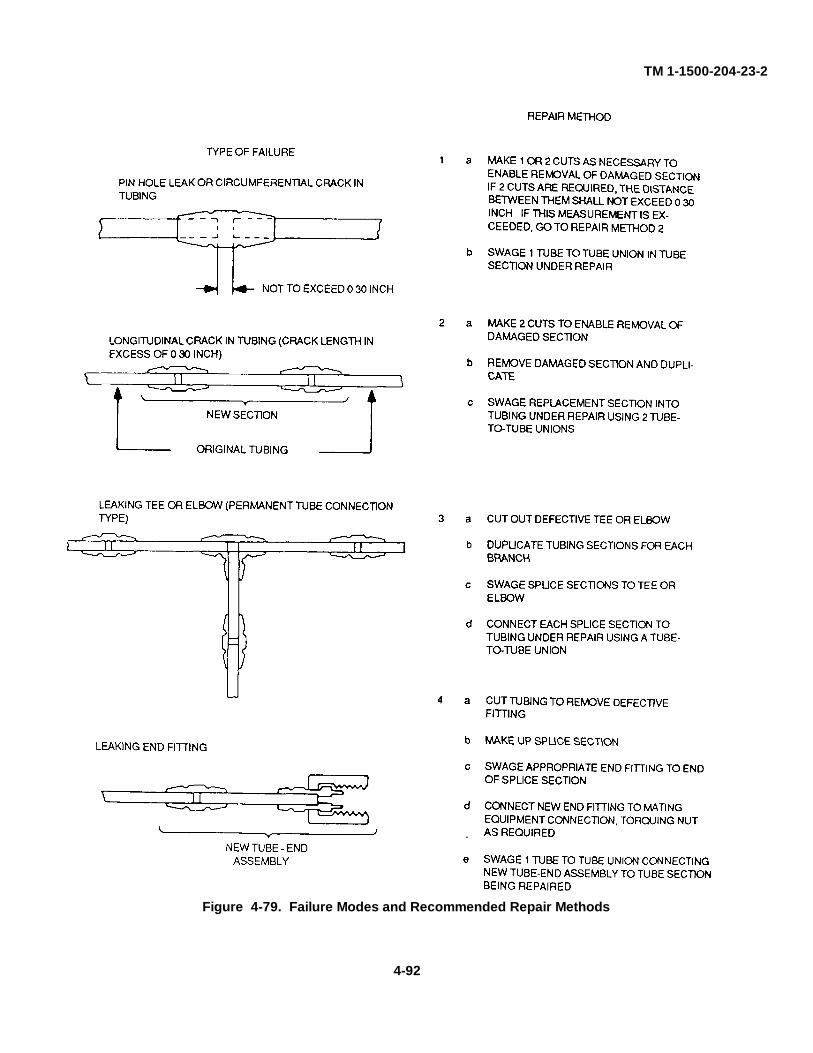
TM 1-1500-204-23-2
Figure 4-79. Failure Modes and Recommended Repair Methods
4-92
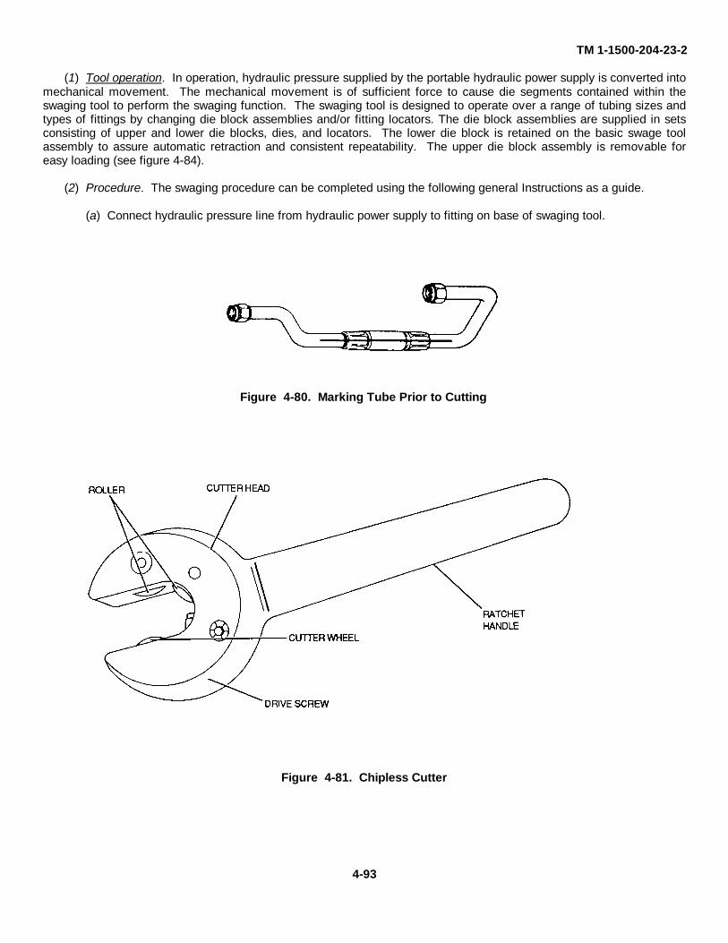
TM 1-1500-204-23-2
(1) Tool operation. In operation, hydraulic pressure supplied by the portable hydraulic power supply is converted intomechanical movement. The mechanical movement is of sufficient force to cause die segments contained within theswaging tool to perform the swaging function. The swaging tool is designed to operate over a range of tubing sizes andtypes of fittings by changing die block assemblies and/or fitting locators. The die block assemblies are supplied in setsconsisting of upper and lower die blocks, dies, and locators. The lower die block is retained on the basic swage toolassembly to assure automatic retraction and consistent repeatability. The upper die block assembly is removable foreasy loading (see figure 4-84).
(2) Procedure. The swaging procedure can be completed using the following general Instructions as a guide.
(a) Connect hydraulic pressure line from hydraulic power supply to fitting on base of swaging tool.
Figure 4-80. Marking Tube Prior to Cutting
Figure 4-81. Chipless Cutter
4-93
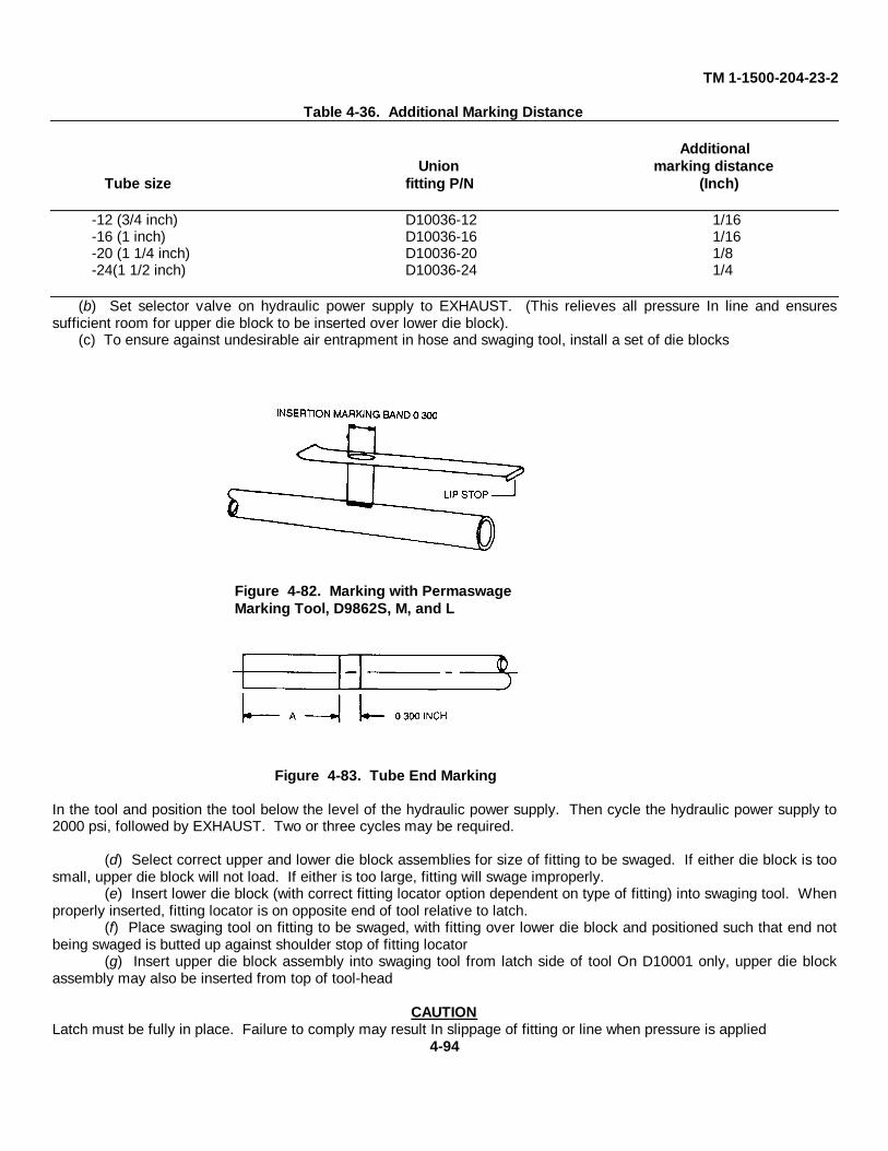
TM 1-1500-204-23-2
Table 4-36. Additional Marking Distance
AdditionalUnion marking distance
Tube size fitting P/N (Inch)
-12 (3/4 inch) D10036-12 1/16-16 (1 inch) D10036-16 1/16-20 (1 1/4 inch) D10036-20 1/8-24(1 1/2 inch) D10036-24 1/4
(b) Set selector valve on hydraulic power supply to EXHAUST. (This relieves all pressure In line and ensuressufficient room for upper die block to be inserted over lower die block).
(c) To ensure against undesirable air entrapment in hose and swaging tool, install a set of die blocks
Figure 4-83. Tube End Marking
In the tool and position the tool below the level of the hydraulic power supply. Then cycle the hydraulic power supply to2000 psi, followed by EXHAUST. Two or three cycles may be required.
(d) Select correct upper and lower die block assemblies for size of fitting to be swaged. If either die block is toosmall, upper die block will not load. If either is too large, fitting will swage improperly.
(e) Insert lower die block (with correct fitting locator option dependent on type of fitting) into swaging tool. Whenproperly inserted, fitting locator is on opposite end of tool relative to latch.
(f) Place swaging tool on fitting to be swaged, with fitting over lower die block and positioned such that end notbeing swaged is butted up against shoulder stop of fitting locator
(g) Insert upper die block assembly into swaging tool from latch side of tool On D10001 only, upper die blockassembly may also be inserted from top of tool-head
CAUTIONLatch must be fully in place. Failure to comply may result In slippage of fitting or line when pressure is applied
4-94
Figure 4-82. Marking with PermaswageMarking Tool, D9862S, M, and L
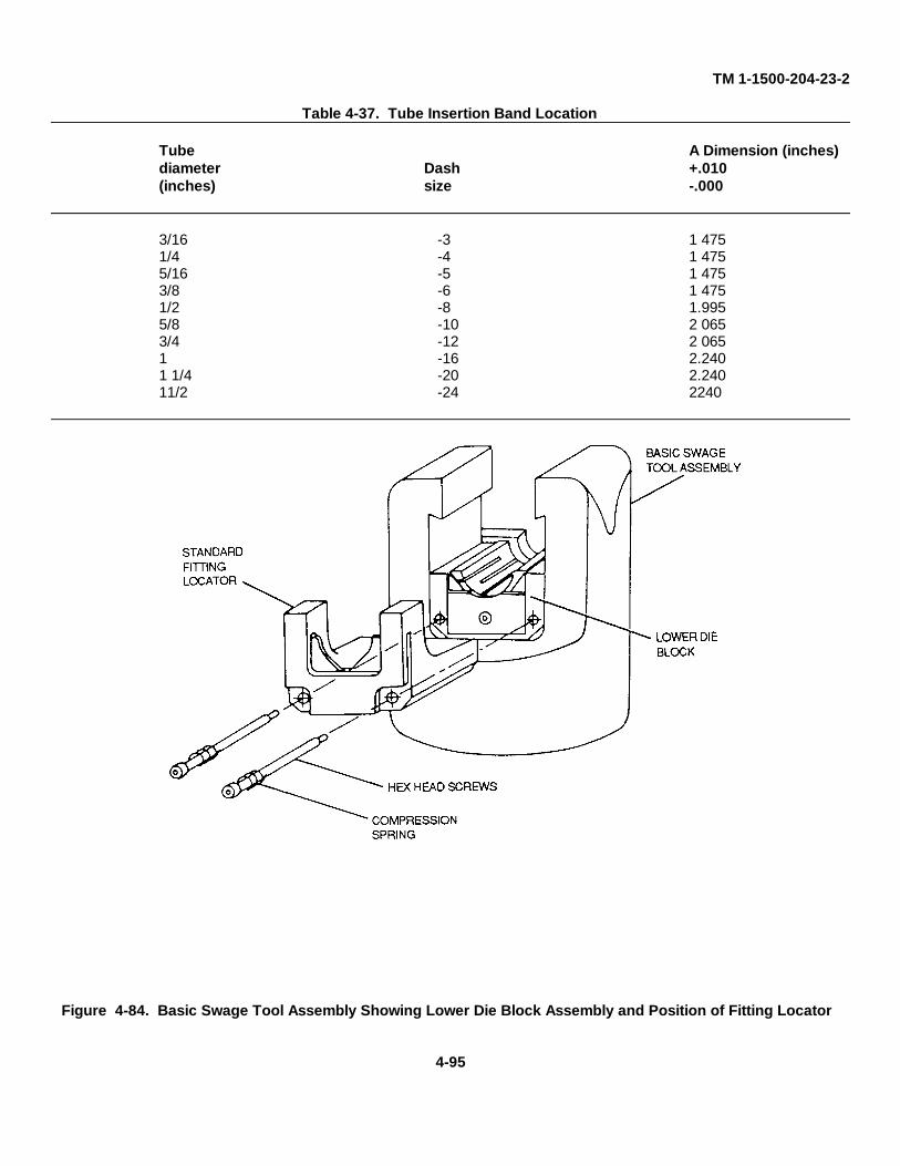
TM 1-1500-204-23-2
Table 4-37. Tube Insertion Band Location
Tube A Dimension (inches)diameter Dash +.010(inches) size -.000
3/16 -3 1 4751/4 -4 1 4755/16 -5 1 4753/8 -6 1 4751/2 -8 1.9955/8 -10 2 0653/4 -12 2 0651 -16 2.2401 1/4 -20 2.24011/2 -24 2240
Figure 4-84. Basic Swage Tool Assembly Showing Lower Die Block Assembly and Position of Fitting Locator
4-95
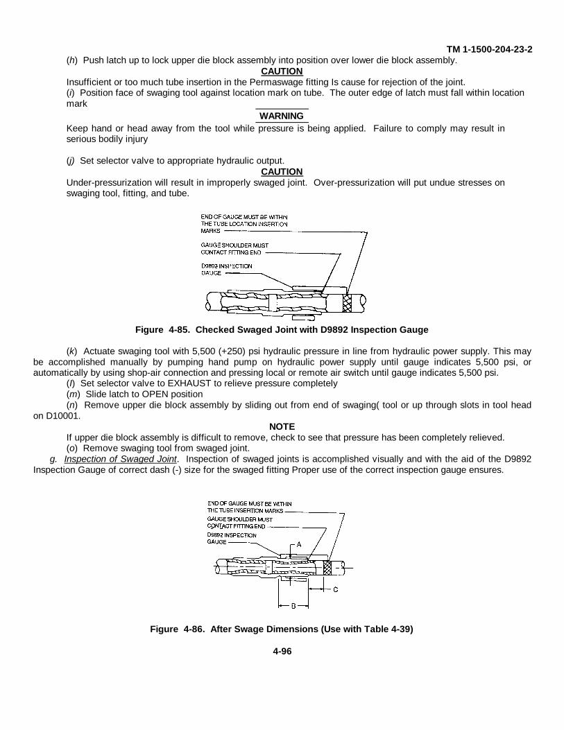
TM 1-1500-204-23-2(h) Push latch up to lock upper die block assembly into position over lower die block assembly.
CAUTIONInsufficient or too much tube insertion in the Permaswage fitting Is cause for rejection of the joint.(i) Position face of swaging tool against location mark on tube. The outer edge of latch must fall within location mark
WARNINGKeep hand or head away from the tool while pressure is being applied. Failure to comply may result inserious bodily injury
(j) Set selector valve to appropriate hydraulic output.CAUTION
Under-pressurization will result in improperly swaged joint. Over-pressurization will put undue stresses onswaging tool, fitting, and tube.
Figure 4-85. Checked Swaged Joint with D9892 Inspection Gauge
(k) Actuate swaging tool with 5,500 (+250) psi hydraulic pressure in line from hydraulic power supply. This maybe accomplished manually by pumping hand pump on hydraulic power supply until gauge indicates 5,500 psi, orautomatically by using shop-air connection and pressing local or remote air switch until gauge indicates 5,500 psi.
(I) Set selector valve to EXHAUST to relieve pressure completely(m) Slide latch to OPEN position(n) Remove upper die block assembly by sliding out from end of swaging( tool or up through slots in tool head
on D10001.NOTE
If upper die block assembly is difficult to remove, check to see that pressure has been completely relieved.(o) Remove swaging tool from swaged joint.
g. Inspection of Swaged Joint. Inspection of swaged joints is accomplished visually and with the aid of the D9892Inspection Gauge of correct dash (-) size for the swaged fitting Proper use of the correct inspection gauge ensures.
Figure 4-86. After Swage Dimensions (Use with Table 4-39)
4-96
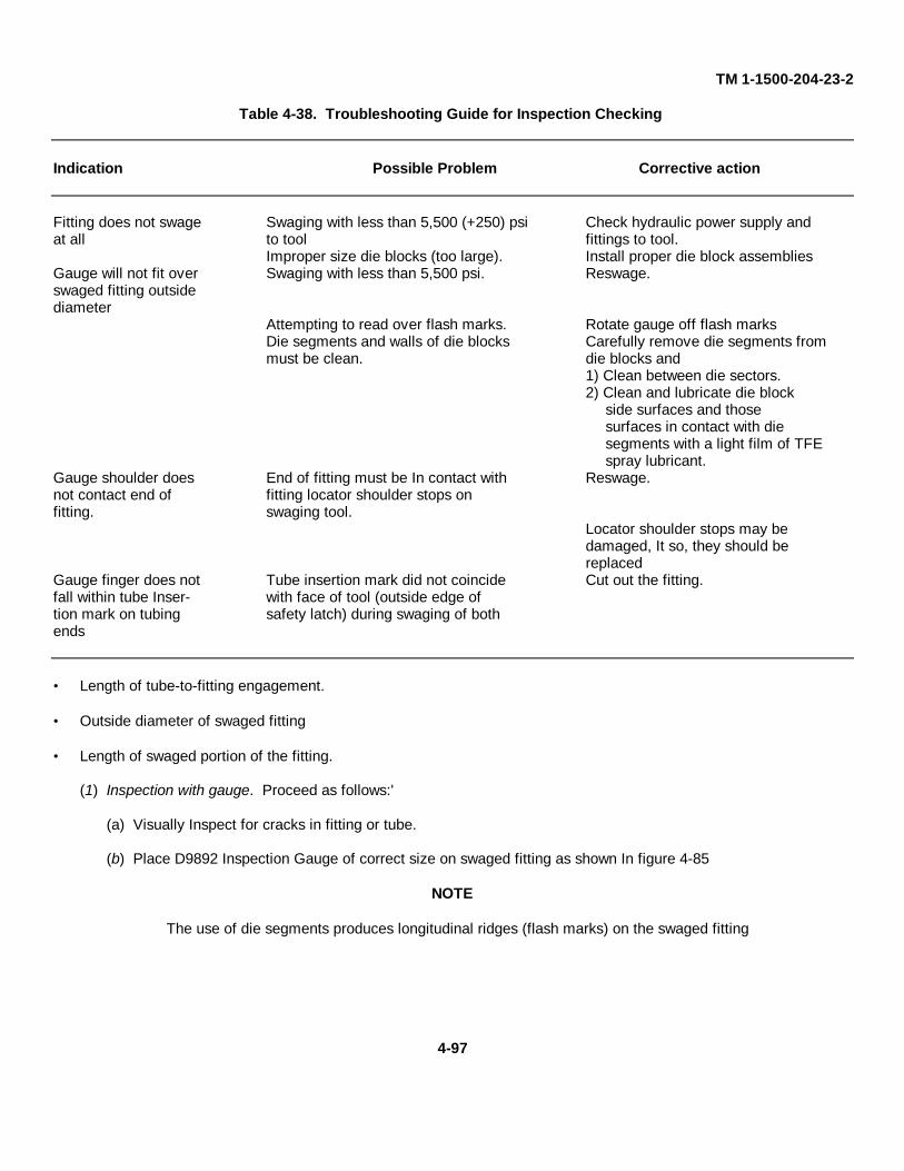
TM 1-1500-204-23-2
Table 4-38. Troubleshooting Guide for Inspection Checking
Indication Possible Problem Corrective action
Fitting does not swage Swaging with less than 5,500 (+250) psi Check hydraulic power supply andat all to tool fittings to tool.
Improper size die blocks (too large). Install proper die block assembliesGauge will not fit over Swaging with less than 5,500 psi. Reswage.swaged fitting outsidediameter
Attempting to read over flash marks. Rotate gauge off flash marksDie segments and walls of die blocks Carefully remove die segments frommust be clean. die blocks and
1) Clean between die sectors.2) Clean and lubricate die block
side surfaces and thosesurfaces in contact with diesegments with a light film of TFEspray lubricant.
Gauge shoulder does End of fitting must be In contact with Reswage.not contact end of fitting locator shoulder stops onfitting. swaging tool.
Locator shoulder stops may bedamaged, It so, they should bereplaced
Gauge finger does not Tube insertion mark did not coincide Cut out the fitting.fall within tube Inser- with face of tool (outside edge oftion mark on tubing safety latch) during swaging of bothends
• Length of tube-to-fitting engagement.
• Outside diameter of swaged fitting
• Length of swaged portion of the fitting.
(1) Inspection with gauge. Proceed as follows:'
(a) Visually Inspect for cracks in fitting or tube.
(b) Place D9892 Inspection Gauge of correct size on swaged fitting as shown In figure 4-85
NOTE
The use of die segments produces longitudinal ridges (flash marks) on the swaged fitting
4-97

TM 1-1500-204-23-2
Table 4-39. Fitting Dimensions After Swaging
Maximum Minimumswaged diameter swaged length Tube location
Tube diameter A dimension B dimension C diminsion
(inches) (size) (inches) (inches) (inches)
3/16 -3 0 2465 0 340 1.010 to 0.7101/4 -4 0.315 0 460 0.865 to 0.5655/16 -5 0.3815 0.500 0.820 to 0 5203/8 -6 0 447 0.530 0 784 to 0 4841/2 -8 0 606 1 020 0 820 to 0 5205/8 -10 0.735 1.020 0.820 to 0.5203/4 -12 0 853 1 020 0 820 to 0.5201 -16 1.144 1.160 0 820 to 0 5201 1/4 -20 1.30 1.160 0.820 to 0-5201 1/2 -24 1 597 1 160 0 820to 0 520
NOTE
It is permissible and advisable to reswage fittings in order to comply with dimensions of table 4-37providing that the correct upper and lower die block assemblies are employed
(c) Rotate gauge between flash marks. Gauge must fit over all swaged segments between flashmarks.
NOTEGauge shoulder must contact end of fitting and end of gauge must fall within tube insertion mark on tubing
(d) If fitting does not meet requirements of inspection gauge, corrective action shall be taken as indicated in table 4-38 Troubleshooting Guide for Inspection Checking14-98
(2) Inspection without gauge. in the absence of proper inspection gauge, the swaged fitting shall meet the dimensionalrequirements of table 4-39 and figure 4-86
NOTEThe outside diameter (A Dimension in table 4-39) must be measured in the area between the longitudinalridges (flash marks) produced by the swaging action of the die segments.
4-98
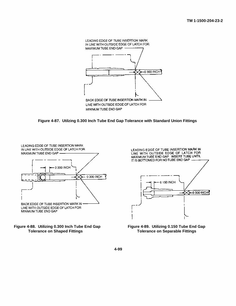
TM 1-1500-204-23-2
Figure 4-87. Utilzing 0.300 Inch Tube End Gap Tolerance with Standard Union Fittings
Figure 4-88. Utilizing 0.300 Inch Tube End Gap Figure 4-89. Utilizing 0.150 Tube End GapTolerance on Shaped Fittings Tolerance on Separable Fittings
4-99
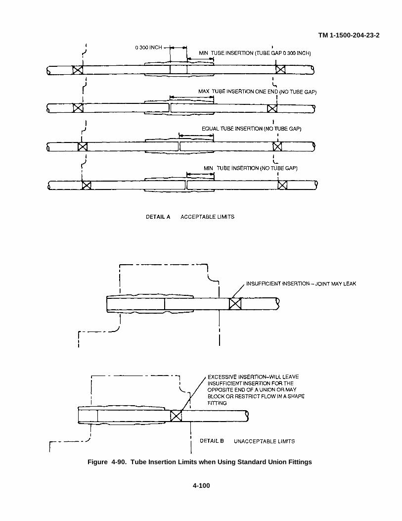
TM 1-1500-204-23-2
Figure 4-90. Tube Insertion Limits when Using Standard Union Fittings
4-100
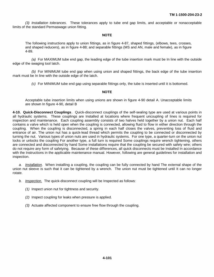
TM 1-1500-204-23-2
(3) Installation tolerances. These tolerances apply to tube end gap limits, and acceptable or nonacceptablelimits of the standard Permaswage union fitting.
NOTE
The following instructions apply to union fittings, as in figure 4-87, shaped fittings, (elbows, tees, crosses,and shaped reducers), as in figure 4-88; and separable fittings (MS and AN, male and female), as in figure4-89.
(a) For MAXIMUM tube end gap, the leading edge of the tube insertion mark must be In line with the outsideedge of the swaging tool latch.
(b) For MINIMUM tube end gap when using union and shaped fittings, the back edge of the tube insertionmark must be In line with the outside edge of the latch.
(c) For MINIMUM tube end gap using separable fittings only, the tube is inserted until it is bottomed.
NOTE
Acceptable tube insertion limits when using unions are shown in figure 4-90 detail A. Unacceptable limitsare shown In figure 4-90, detail B
4-10. Quick-Disconnect Couplings . Quick-disconnect couplings of the self-sealing type are used at various points inall hydraulic systems. These couplings are Installed at locations where frequent uncoupling of lines is required forinspection and maintenance. Each coupling assembly consists of two halves held together by a union nut. Each halfcontains a valve which is held open when the coupling is connected, allowing fluid to flow in either direction through thecoupling. When the coupling is disconnected, a spring in each half closes the valves, preventing loss of fluid andentrance of air. The union nut has a quick-lead thread which permits the coupling to be connected or disconnected byturning the nut. Various types of union nuts are used in hydraulic systems. For one type, a quarter-turn on the union nutlocks or unlocks the coupling For another type, a full turn is required Some couplings require wrench tightening, othersare connected and disconnected by hand Some installations require that the coupling be secured with safety wire; othersdo not require any form of safetying. Because of these differences, all quick disconnects must be Installed In accordancewith the Instructions in the applicable maintenance manual. However, following are general guidelines for installation andinspection.
a. Installation. When installing a coupling, the coupling can be fully connected by hand The external shape of theunion nut sleeve is such that it can be tightened by a wrench. The union nut must be tightened until It can no longerrotate.
b. Inspection. The quick-disconnect coupling will be Inspected as follows:
(1) Inspect union nut for tightness and security.
(2) Inspect coupling for leaks when pressure is applied.
(3) Actuate affected component to ensure free flow through the coupling.
4-101

TM 1-1500-204-23-2
4-11. Hydraulic Reservoirs. The system reservoir hold enough fluid for use in operation of the system and to replacefluid lost through minor leakage or evaporation. Reservoirs may also be Installed to provide a space for increase in fluidvolume over the original amount, such as that which might occur through thermal expansion or foaming They alsoprovide a place of escape for air trapped in the system.
a. Types of Reservoirs Used in Hydraulic Systems. Two types of reservoirs are used in aircraft hydraulic systemsthe in-line and the integral type.
(1) In-line. The in-line reservoir, seen in figure 4-91, has its own housing, is complete within itself, and isconnected with other components in the system by tubing or hose. The in-line type is most common in Army aircraft, andis covered in this manual.
(2) Integral. The integral reservoir consists merely of a space set aside within a major component for thepurpose of holding a supply of operational fluid. An example of this kind of reservoir is an automotive brake mastercylinder.
Figure 4-91. Reservoir with Baffles, Fins and Finger Strainer
b. Theory of Operation. A space is provided in the reservoir above the normal level of the fluid for fluid expansionand for escape of trapped air. Most reservoirs are designed so they cannot be serviced completely to the top. This Isdone by locating the filler neck somewhat below the top of the reservoir. On most reservoirs, a dipstick or glass sightgauge is provided so that fluid level can be easily and accurately checked. All reservoirs are either vented or closed tothe atmosphere and pressurized.
(1) Vented reservoirs. In vented reservoirs, atmospheric pressure and gravity are the forces which cause fluid toflow out of the reservoir and into the pump. In order to supply a pump with fluid, a vented reservoir must be positioned ata higher location than the pump. If the reservoir and the pump were at the same level, gravity would have no effect onfluid flow. If the reservoir was at a level below the pump, fluid would tend to run out of the pump and into the reservoirMost hydraulic system reservoirs of current Army aircraft are vented.
(2) Pressurized reservoirs. In the hydraulic systems of some aircraft, it is necessary to mount the reservoir at alevel below the pump In this case, the weight of the fluid obviously deters, rather than aids, the flow of fluid into thepump. A reservoir so located has to have the fluid it contains under greater than atmospheric pressure to force the fluidupward into the pump. Another reason for pressurizing reservoirs is to enable aircraft to fly at very high altitudes Sinceatmospheric pressure decreases as altitude increases and at very high altitudes become too low to force enough fluidinto a pump, the reservoir has to be pressurized Two general methods of pressurizing reservoirs are employed Onemethod employs fluid, the other air.
(a) Fluid-pressurized reservoir. This method makes use of fluid pressure bled from the pressure lines of thesystem In which the reservoir is Incorporated The reservoir is designed In such a way as to develop a relatively lowpressure on the supply fluid contained in the reservoir by use of a stream of fluid fed Into the reservoir at a much higherpressure Such a reservoir is commonly called an airless reservoir.
1 Construction Figure 4-92 shows the construction and operation of a typical reservoirpressurized In this manner. The major parts of the assembly are a cylindrical housing that has three fluid ports and apolished bore, a housing tube which terminates in a head, and a piston and piston tube assembly The piston and pistontube assembly are free to slide back and forth
4-102
TM 1-1500-204-23-2relative to the housing The housing tube and head are stationary.
2 Operation. In operation, as shown In figure 4-93, fluid pressure admitted to the housing tube atsystem operating pressure-of example, at 3,000 psi-enters the space formed between the piston and the housing tubehead This pressure tends to force the piston and housing tube head in opposite directions. However, since the housingtube head cannot move and the piston can, the piston moves toward the right, pushing against the supply fluid on its rightand thus develop- ing pressure In the fluid The surface of the housing tube is exposed to 3,000 psi pressure within aspace that is one-sixtieth as large in area as the piston surface that contacts the supply fluid This means that a pressureof 50 psi (3,000 psi - by 60) is built up in the supply fluid.
(b) Air-pressurized reservoir. Pressurizing with air is done by forcing air into the reservoir above the level ofthe fluid The amount of pressure kept in an air-pressurized reservoir is usually around 15 psi No attempt is made to keepthe air and fluid separated In most cases, the initial source of air pressure In the compressor section of the aircraftengine. Since pressure within the engine compressor is normally about 100 psi, it has to be reduced before beingdelivered to the reservoir This is accomplished by passing the air through an air pressure regulator.
c. Baffles and Fins. Baffles and/or fins are used in most reservoirs to prevent the fluid within the reservoir fromswirling and surging These conditions could cause fluid to foam and air to enter the pump along with the fluid (see figure4-93).
d. Finger Strainers. Many reservoirs have strainers in the filler neck to keep foreign matter from entering when thefiller cap is off. These strainers are made of fine gauze and are called finger strainers because of their shape Fingerstrainers should never be removed or punctured as a means of speeding up the pouring of fluid into the reservoir (seefigure 4-93).
e. Filter Elements. Filter elements are Incorporated In some reservoirs either to filter air before It enters thereservoir or to filter fluid before It leaves the reservoir Figure 4-94 shows these filters Installed When an air vent filterelement Is used, It Is located In the upper part of the reservoir above the fluid level When a fluid filter element Is used, ItIs located at or near the bottom of the reservoir Fluid returning to the reservoir surrounds the filter element and flowsthrough the wall of the element This leaves any fluid contaminant on the outside of the element The fluid filter elementscommonly used In aircraft reservoirs are made of treated cellulose formed into accordion-like pleats This constructionexposes the fluid to the maximum amount of filter surface within a given space.
f. Filter Element Bypass Valve. Reservoirs having filter elements have a bypass valve to ensure that the pump willnot be without fluid even If the filter element becomes clogged This valve is normally held closed by a spring that wouldbe opened by the stronger partial vacuum that would develop If the element be- came badly clogged.
g. Standpipes. Some aircraft have emergency hydraulic systems that take over If the main system fails In manysuch cases, the pumps of both systems obtain fluid from a single reservoir Under such circumstances, fluid for theemergency pump is drawn from the bottom of the reservoir and the main system draws Its fluid through a standpipelocated at a higher elevation With this arrangement, operation of the emergency system is ensured should the mainsystem fall.
h. Air Cylinders. Air cylinders are the pneumatic reservoirs In an aircraft pneumatic system, which serves as anemergency source of pressure for the hydraulic system. These cylinders are made of steel and may have a cylindrical ora spherical shape (see figure 4-95) Cooling of the high-pressure air In the storage cylinders will cause somecondensation to collect In them. To ensure positive operation of systems, storage cylinders must be purged of moistureperiodically This Is done by slightly cracking the moisture drain fitting located on the cylinder manifold.
i. Maintenance of Reservoirs. A typical reservoir consists essentially of a reservoir shell assembly which houses afilter element, relief valve, and required gaskets, seals, and O-ring packings.
WARNING
Drycleaning solvent is flammable and solvent vapors are toxic. Use P-D-680, Type II Solvent in a well-ventilated area. Keep away from open flames. Avoid prolonged solvent contact with skin.
(1) Wash all parts and flush Inside of tank with drycleaning solvent, Federal Specification P-D-680. Dry withcompressed air.
4-103
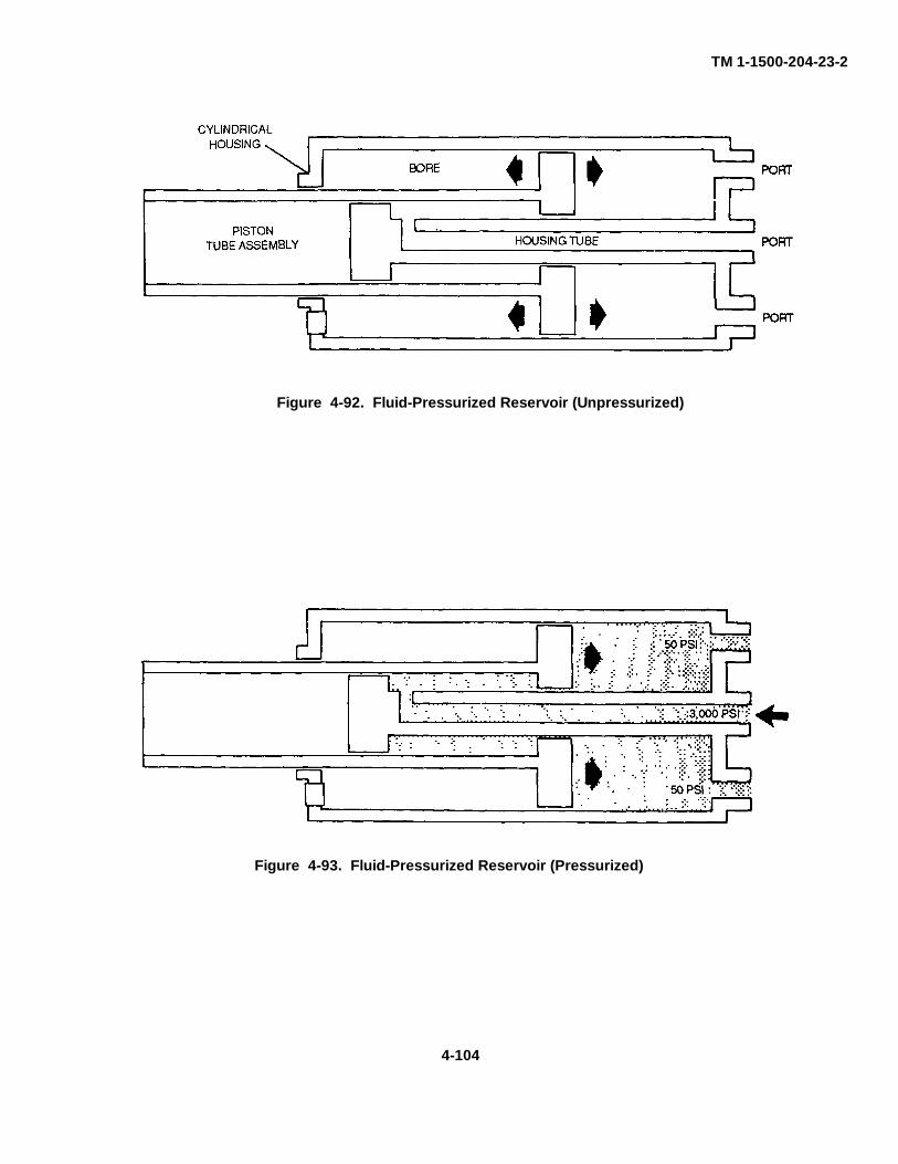
TM 1-1500-204-23-2
Figure 4-93. Fluid-Pressurized Reservoir (Pressurized)
Figure 4-92. Fluid-Pressurized Reservoir (Unpressurized)
4-104
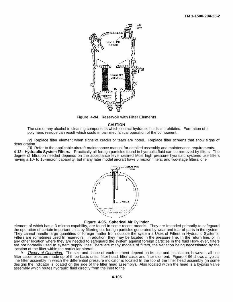
TM 1-1500-204-23-2
Figure 4-94. Reservoir with Filter Elements
CAUTIONThe use of any alcohol in cleaning components which contact hydraulic fluids is prohibited. Formation of apolymeric residue can result which could impair mechanical operation of the component.
(2) Replace filter element when signs of cracks or tears are noted. Replace filter screens that show signs ofdeterioration.
(3) Refer to the applicable aircraft maintenance manual for detailed assembly and maintenance requirements.4-12. Hydraulic System Filters. Practically all foreign particles found in hydraulic fluid can be removed by filters. Thedegree of filtration needed depends on the acceptance level desired Most high pressure hydraulic systems use filtershaving a 10- to 15-micron capability, but many later model aircraft have 5 micron filters; and two-stage filters, one
Figure 4-95. Spherical Air Cylinderelement of which has a 3-micron capability, are found In some recent models. They are Intended primarily to safeguardthe operation of certain important units by filtering out foreign particles generated by wear and tear of parts in the system.They cannot handle large quantities of foreign matter from outside the system a Uses of Filters in Hydraulic Systems.Filters are sometimes used In reservoirs. In addition, they may be located in the pressure line, In the return line, or Inany other location where they are needed to safeguard the system against foreign particles in the fluid How- ever, filtersare not normally used In system supply lines There are many models of filters, the variation being necessitated by thelocation of the filter within the particular aircraft.
b. Theory of Operation. The size and shape of each element depend on Its use and installation; however, all linefilter assemblies are made up of three basic units: filter head, filter case, and filter element. Figure 4-96 shows a typicalline filter assembly In which the differential pressure indicator is located In the top of the filter head assembly (in somedesigns the indicator is located on the side of the filter head assembly). Also located within the head is a bypass valveassembly which routes hydraulic fluid directly from the inlet to the
4-105
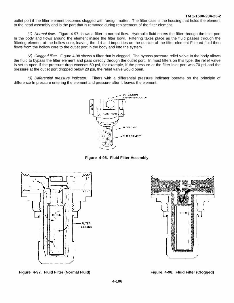
TM 1-1500-204-23-2outlet port if the filter element becomes clogged with foreign matter. The filter case is the housing that holds the elementto the head assembly and is the part that is removed during replacement of the filter element.
(1) Normal flow. Figure 4-97 shows a filter in normal flow. Hydraulic fluid enters the filter through the inlet portIn the body and flows around the element inside the filter bowl. Filtering takes place as the fluid passes through thefiltering element at the hollow core, leaving the dirt and impurities on the outside of the filter element Filtered fluid thenflows from the hollow core to the outlet port in the body and into the system
(2) Clogged filter. Figure 4-98 shows a filter that is clogged. The bypass pressure relief valve In the body allowsthe fluid to bypass the filter element and pass directly through the outlet port. In most filters on this type, the relief valveIs set to open If the pressure drop exceeds 50 psi, for example, if the pressure at the filter inlet port was 70 psi and thepressure at the outlet port dropped below 20 psi, the relief valve would open.
(3) Differential pressure indicator. Filters with a differential pressure indicator operate on the principle ofdifference In pressure entering the element and pressure after It leaves the element.
Figure 4-96. Fluid Filter Assembly
Figure 4-97. Fluid Filter (Normal Fluid) Figure 4-98. Fluid Filter (Clogged)
4-106
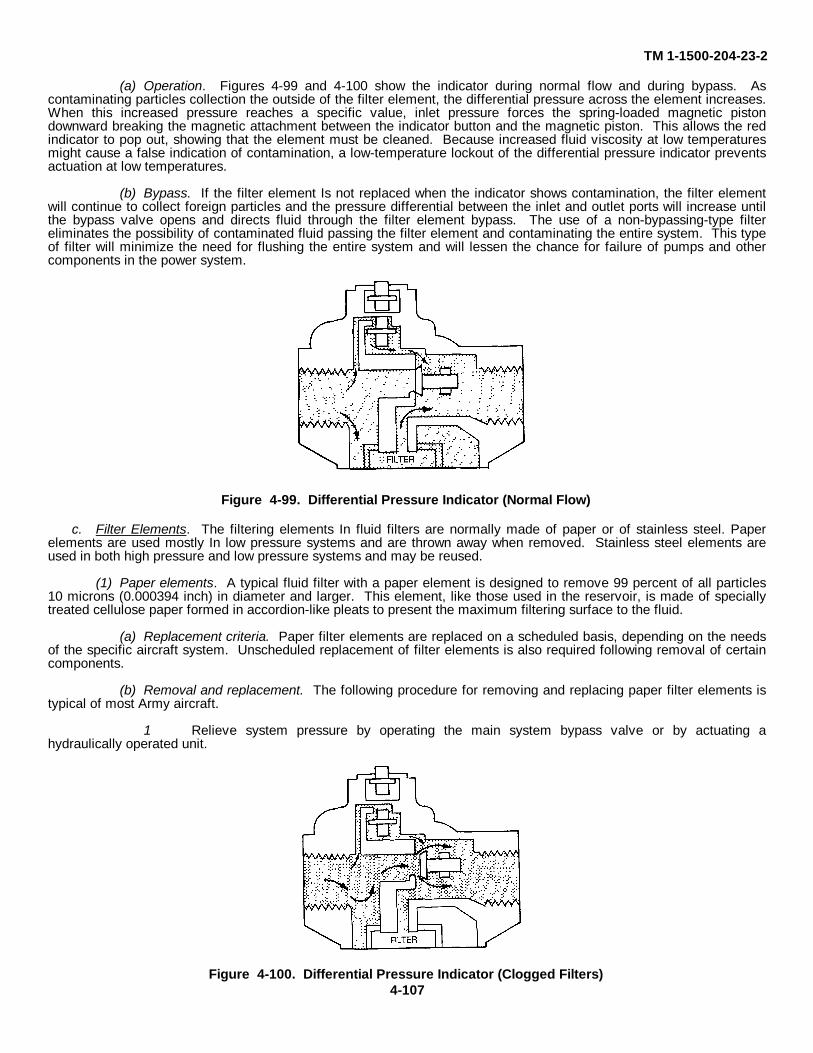
TM 1-1500-204-23-2
(a) Operation. Figures 4-99 and 4-100 show the indicator during normal flow and during bypass. Ascontaminating particles collection the outside of the filter element, the differential pressure across the element increases.When this increased pressure reaches a specific value, inlet pressure forces the spring-loaded magnetic pistondownward breaking the magnetic attachment between the indicator button and the magnetic piston. This allows the redindicator to pop out, showing that the element must be cleaned. Because increased fluid viscosity at low temperaturesmight cause a false indication of contamination, a low-temperature lockout of the differential pressure indicator preventsactuation at low temperatures.
(b) Bypass. If the filter element Is not replaced when the indicator shows contamination, the filter elementwill continue to collect foreign particles and the pressure differential between the inlet and outlet ports will increase untilthe bypass valve opens and directs fluid through the filter element bypass. The use of a non-bypassing-type filtereliminates the possibility of contaminated fluid passing the filter element and contaminating the entire system. This typeof filter will minimize the need for flushing the entire system and will lessen the chance for failure of pumps and othercomponents in the power system.
Figure 4-99. Differential Pressure Indicator (Normal Flow)
c. Filter Elements. The filtering elements In fluid filters are normally made of paper or of stainless steel. Paperelements are used mostly In low pressure systems and are thrown away when removed. Stainless steel elements areused in both high pressure and low pressure systems and may be reused.
(1) Paper elements. A typical fluid filter with a paper element is designed to remove 99 percent of all particles10 microns (0.000394 inch) in diameter and larger. This element, like those used in the reservoir, is made of speciallytreated cellulose paper formed in accordion-like pleats to present the maximum filtering surface to the fluid.
(a) Replacement criteria. Paper filter elements are replaced on a scheduled basis, depending on the needsof the specific aircraft system. Unscheduled replacement of filter elements is also required following removal of certaincomponents.
(b) Removal and replacement. The following procedure for removing and replacing paper filter elements istypical of most Army aircraft.
1 Relieve system pressure by operating the main system bypass valve or by actuating ahydraulically operated unit.
Figure 4-100. Differential Pressure Indicator (Clogged Filters)4-107
TM 1-1500-204-23-2
2 Depressurize reservoir (if necessary).
3 Cut lockwire.
4 Unscrew the filter case and remove it from the filter head, using a slight rocking and downward pull on thecase after the case threads are free from the filter.
5 Extract the retaining ring and remove the filter element from the cases.
6 After ensuring that a replacement filter element is available, cut the filter element.
7.Before Installing the new filter, clean the filter head and the filter case and inspect them for damage;replace all damaged parts.
8 Replace all O-ring packings
9 Fill the filter bowl with new fluid before attaching it to the filter housing head. Filling the bowls helps tostop the Injection of air into the system
10 Install the filter in its case and screw the case into the filter head. The correct torque is usually handtightplus one-eighth of a turn, but always check the specific maintenance manual for the specific torque value.
11. Pressurize the hydraulic system and inspect the filter assembly for leaks. If the assembly isSatisfactory, replace the lockwire between the filter case and the head assembly.
(2) Stainless steel elements. Stainless steel filter elements are used in most modern aircraft. Filter elementsurfaces of this type usually have a corrugated stainless steel mesh construction. Such filters are usually rated from 5to10-micron nominal flow and at 25micron absolute flow. This means about 95 percent of 5to 10-micron particles and 100percent of 25-micron particles will be filtered from the fluid. The curved passages of the filter element limit the length ofthe particles that pass through the filter.
WARNINGDrycleaning solvent is flammable and solvent vapors are toxic. Use P-D-680, Type II Solvent in a well-ventilated area Keep away from open flames. Avoid prolonged solvent contact with skin.
CAUTIONUnder no condition shall a wire brush be used in cleaning filter element. Failure to comply will result inpossible failure of equipment.
CAUTIONThe use of any alcohol in cleaning components which contact hydraulic fluids is prohibited Formation of apolymeric residue can result which could impair mechanical operation of the component.
(a) Wash filter element In drycleaning solvent, Federal Specification P-D-680, using a soft lint-free clothAllow to drain, and dry with low pressure compressed air
(b) Replace filter element when cracks, tears, and other signs of deterioration are noted.d. Two-Stage Fluid Filters. Two-stage line-type hydraulic system filters are being used in some recent
aircraft models The typical two-stage filter has two filter elements, two bypass valves, and two differential pressureindicators The first-stage element can filter out smaller particles than the second-stage element can. Normally, the fluidpasses through both elements, flowing first through the first stage element. As long as the first stage element isunclogged and functioning, there will be no foreign matter left for the second-stage element to remove. However, if thefirst-stage element becomes clogged, its bypass valve opens and fluid goes directly from the filter inlet port to thesecond-stage element, which then takes over the job of filtering out foreign particles Although the second-stage elementis not capable of filtering out the very small particles, it can be safely used until the first-stage element is unclogged.
4-108
TM 1-1500-204-23-2
e. Air Filters. An air filter is usually located in the line leading into the system supply source. Additionalfilters may be located at various points in the system lines to remove any foreign matter that may enter the system. Likehydraulic filters, air filters have a removable element and a built-in relief valve. The relief valve is designed to open andbypass the air supply around the filter element in case the element becomes clogged. Some air filters are equipped witha paper-type element which must be replaced periodically. Others have a screen mesh-type which requires periodiccleaning. The screen mesh-type may be returned to the system after being cleaned and dried.
f. Servicing Filters, Filters should be serviced in accordance with schedules and procedures contained Intechnical manuals pertaining to the specific aircraft involved. However, the following general guidelines apply to theservicing of all aircraft hydraulic system filters:
(1) Handle filters carefully. A hole no larger than a pinprick will permit large foreign particles to pass throughthe element.
(2) Service filters in a clean area; this will help keep dirt and other foreign particles from entering the systemwhile the filter is being serviced.
(3) Do not leave a disassembled filter housing unprotected because this may cause contamination.
(4) Remove wrappings from a replacement element only when the element is to be inspected or installed.
(5) The filter bowl should only be hand tightened to the head. Always safety the bowl and head together
(6) Be sure that a popped-out Indicator button is indicating the need to service the filter. Push the buttonback In with the system at normal operating pressure. If the button pops out again, the filter needs servicing; if It staysin, the filter is not clogged.
4-13. Pumps and Motors. The hydraulic pump is the mechanism for transferring and pressurizing aircraft hydraulicfluid. Aircraft systems use engine-driven power pumps for this purpose. Hand pumps are also provided as emergencyequipment and for ground checking the hydraulic system. Hydraulic motors in Army aircraft perform such functions aslanding gear retraction and extension and operating cargo ramps, doors, and winch hoists.
a. Power Pumps. The primary energizing unit of the hydraulic system is the power pump. It is the unit thatnormally delivers hydraulic fluid under pressure to the actuators. Power pumps may be driven by an electric motor, aturbine unit, or the aircraft engine; however, engine-driven pumps are used in all Army aircraft at this time. The pistontype power pumps used in modern hydraulic systems run at a rated speed of about 1 1/2 times engine crank-shaft speed.In the drive shafts of all power pumps, there is a thinned portion that provides for a shearing action. If the pump seizes,the shaft will break at this point, thus preventing damage to the engine or the transmission.
(1) Bent-axis constant-volume pumps. Constant-volume piston-type pumps put out a constant flow of fluidfor any given rpm. The pistons (usually seven or nine In number) are fastened by universal linkage to the drive shaft, asshown in figure 4-101. The universal link (2) in the center drives the cylinder block (4). This block is held at an angle tothe drive shaft (1) by the housing. Pumps are available with different angles between the drive shaft and the cylinderblock; a large angle provides more output volume per revolution because the larger angle increases the piston stroke
(a) Theory of operation. Figure 4-102 illustrates the theory of operation. As the drive shaft (1) rotates thecylinder block (4) and the piston assemblies, all the pistons are always the same distance from their points of attachment(3) on the drive shaft Although the pistons appear to move within the cylinders, it Is actually the cylinders that move backand forth around the pistons as the block and piston assembly rotates. Figure 4-103 shows a pump with pistons on intakeand pressure strokes. Piston (1) is at the top of its cylinder,
4-109
TM 1-1500-204-23-2having just completed its pressure stroke and ready to being its intake stroke. As the block starts to rotate from thispoint, the piston becomes aligned with the intake port (3). When the block has turned one-half of a revolution, the pistonreaches the bottom of the cylinder (4). The cylinder space formerly occupied by the piston is now full of fluid. As theblock continues to rotate, the piston becomes aligned with the outlet port (2) Having now moved through the last 180degrees of rotation, it has exhausted all fluid from the cylinder and is ready to make another cycle. Since several pistonsare operating as described and since the cylinder block and piston assembly rotate rapidly, there are always pistonssomewhere between the upper and lower positions. This ensures a constant intake and output of fluid
(b) Cooling and lubrication. The piston-type pump uses case pressure for cooling and lubrication. Fluidseeps by the pistons in the cylinder block and fills all the space inside the pump. This fluid cannot escape through thedrive end of the pump because of a seal around the drive shaft. Excess case pressure within the housing is routed backto the intake side of the pump. This is done through a relief valve called a foot valve (figure 4-104). This valve preventsthe case pressure from rising above approximately 15 psi Drilled passageways through the universal link rods help tokeep the rod ball end lubricated
(2) Variable-volume pumps A variable volume pump has some advantages. One is that its use does awaywith the need for a pressure regulator or an unloading valve Integral flow control valves regulate the pressure accordingto the demands made on the system A second advantage is that pressure surges are reduced. Accumulators are notneeded to smooth out surges with systems using variable-volume pumps, but they are retained to aid the pump whenpeak loads occur.
(a) Stratopower effective stroke pumps. As shown in figure 4-105, the drive shaft (1) rotates the cam (3).This cam causes the nine spring-loaded pistons (4) to move back and forth in their cylinders, which are in a stationarycylinder block. In operation, each piston is forced Into and removed from the cylinder once for each revolution of thecam. The pistons are held in contact with the cam by piston springs, which also return the pistons after each forward orpower stroke Each piston has a half-ball bearing surface which acts like a universal linkage The flat side contacts thecam during all angle changes. The pistons have fairly large hollow centers, connected with cross-drilled holes. Aroundeach piston there is a sleeve (5) attached to a spider (6), which in turn is attached to the compensator (7). An increase inpressure moves the compensator to the right Decreased pressure allows it to move to the left because of the valvespring tension. As the pistons travel to the left, fluid drawn from the inlet port (12) passes through the open center of thecylinder block and then Into the cylinders (13) At this point, hydraulic fluid fills the center of the pistons. Some fluid willcontinue to flow out through the cross-drilled holes and on to the pump return port (2) on the drive end of the pump. Asthe pistons are forced to the right by the cam (3), the cross-drilled hole of each piston is blocked off by its sleeve Aboutthe time that the cross-drilled passage is blocked off, the supply annulus (8) that surrounds the cylinder is also blockedoff. This condition traps the fluid in the piston and cylinder. As the piston continues on to the right, pressure builds upagainst the check valve (10). Fluid under pressure goes out the check valve into the pressure chamber (9) and throughthe outlet port (11). When the piston moves as far right as possible, the cycle starts all over again. This cycle is thesame for all nine pistons.
1 Zero flow. (See figure 4-106). As pressure rises in the pressure outlet line, it is also felt in the passageway(14). This pressure acts on the compensator (7), forcing it to the right. This compresses the spring and carries the spiderand sleeves (6 and 5) with the compensator. The more the sleeves move to the right, the farther each piston travelsbefore the cross drilled passage is covered. This means that less fluid is trapped by the right end of the piston for outputto the pressure manifold. The maximum setting of the compensator is all the way to the right. Then the output to thepressure manifold drops to zero, as shown In figure 4-106 In this condition, all intake of the pump goes out the return port(2) Rotation of the cam draws fluid through the pump for cooling and lubrication There is always fluid being pumpedthrough the inlet port. But fluid will not be pumped through the outlet port until system pressure drops low enough todemand it. Always connect the proper lines to the ports marked IN, OUT, and RETURN
2 Pressure regulation. The stratopower pump does not require a pressure regulator The compressor servesnearly the same purpose Pressure can be increased by turning the adjusting screw (15, figure 4-106) clockwise ordecreased by turning it counterclockwise
(b) Vickers stroke-reduction pump. (See figure 4-107). The Vickers stroke-reduction pump operatessomewhat like the constant volume piston-
4-110
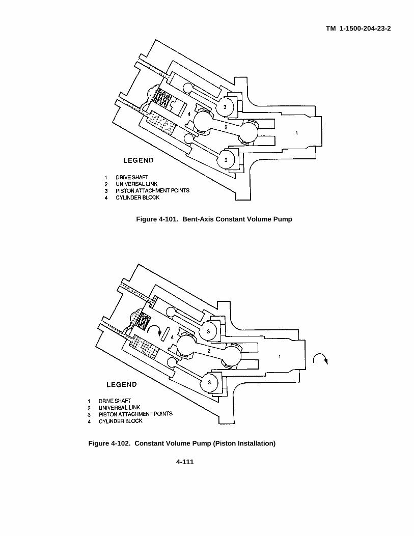
TM 1-1500-204-23-2
Figure 4-101. Bent-Axis Constant Volume Pump
Figure 4-102. Constant Volume Pump (Piston Installation)
4-111

TM 1-1500-204-23-2
Figure 4-104. Constant Volume Pump Foot Valve
4-112
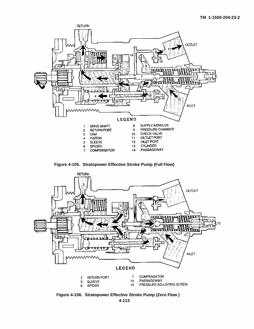
TM 1-1500-204-23-2
Figure 4-105. Stratopower Effective Stroke Pump (Full Flow)
Figure 4-106. Stratopower Effective Stroke Pump (Zero Flow )4-113
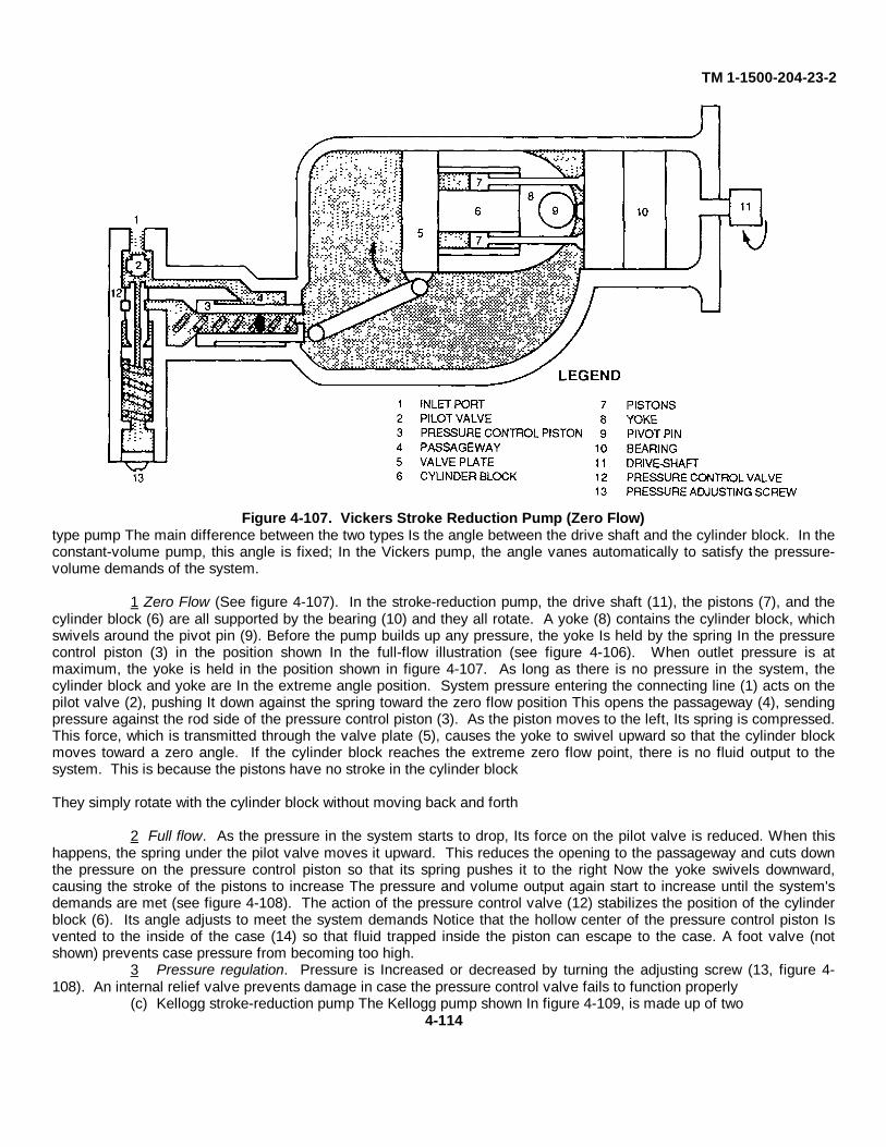
TM 1-1500-204-23-2
Figure 4-107. Vickers Stroke Reduction Pump (Zero Flow)type pump The main difference between the two types Is the angle between the drive shaft and the cylinder block. In theconstant-volume pump, this angle is fixed; In the Vickers pump, the angle vanes automatically to satisfy the pressure-volume demands of the system.
1 Zero Flow (See figure 4-107). In the stroke-reduction pump, the drive shaft (11), the pistons (7), and thecylinder block (6) are all supported by the bearing (10) and they all rotate. A yoke (8) contains the cylinder block, whichswivels around the pivot pin (9). Before the pump builds up any pressure, the yoke Is held by the spring In the pressurecontrol piston (3) in the position shown In the full-flow illustration (see figure 4-106). When outlet pressure is atmaximum, the yoke is held in the position shown in figure 4-107. As long as there is no pressure in the system, thecylinder block and yoke are In the extreme angle position. System pressure entering the connecting line (1) acts on thepilot valve (2), pushing It down against the spring toward the zero flow position This opens the passageway (4), sendingpressure against the rod side of the pressure control piston (3). As the piston moves to the left, Its spring is compressed.This force, which is transmitted through the valve plate (5), causes the yoke to swivel upward so that the cylinder blockmoves toward a zero angle. If the cylinder block reaches the extreme zero flow point, there is no fluid output to thesystem. This is because the pistons have no stroke in the cylinder block
They simply rotate with the cylinder block without moving back and forth
2 Full flow. As the pressure in the system starts to drop, Its force on the pilot valve is reduced. When thishappens, the spring under the pilot valve moves it upward. This reduces the opening to the passageway and cuts downthe pressure on the pressure control piston so that its spring pushes it to the right Now the yoke swivels downward,causing the stroke of the pistons to increase The pressure and volume output again start to increase until the system'sdemands are met (see figure 4-108). The action of the pressure control valve (12) stabilizes the position of the cylinderblock (6). Its angle adjusts to meet the system demands Notice that the hollow center of the pressure control piston Isvented to the inside of the case (14) so that fluid trapped inside the piston can escape to the case. A foot valve (notshown) prevents case pressure from becoming too high.
3 Pressure regulation. Pressure is Increased or decreased by turning the adjusting screw (13, figure 4-108). An internal relief valve prevents damage in case the pressure control valve fails to function properly
(c) Kellogg stroke-reduction pump The Kellogg pump shown In figure 4-109, is made up of two4-114
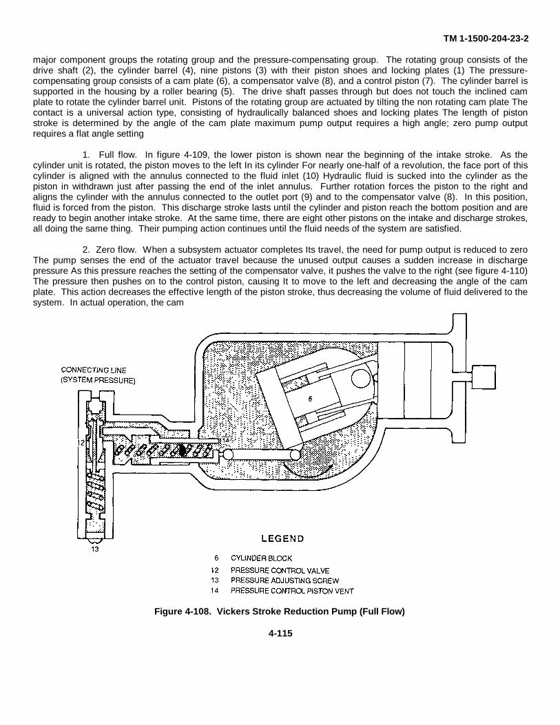
TM 1-1500-204-23-2
major component groups the rotating group and the pressure-compensating group. The rotating group consists of thedrive shaft (2), the cylinder barrel (4), nine pistons (3) with their piston shoes and locking plates (1) The pressure-compensating group consists of a cam plate (6), a compensator valve (8), and a control piston (7). The cylinder barrel issupported in the housing by a roller bearing (5). The drive shaft passes through but does not touch the inclined camplate to rotate the cylinder barrel unit. Pistons of the rotating group are actuated by tilting the non rotating cam plate Thecontact is a universal action type, consisting of hydraulically balanced shoes and locking plates The length of pistonstroke is determined by the angle of the cam plate maximum pump output requires a high angle; zero pump outputrequires a flat angle setting
1. Full flow. In figure 4-109, the lower piston is shown near the beginning of the intake stroke. As thecylinder unit is rotated, the piston moves to the left In its cylinder For nearly one-half of a revolution, the face port of thiscylinder is aligned with the annulus connected to the fluid inlet (10) Hydraulic fluid is sucked into the cylinder as thepiston in withdrawn just after passing the end of the inlet annulus. Further rotation forces the piston to the right andaligns the cylinder with the annulus connected to the outlet port (9) and to the compensator valve (8). In this position,fluid is forced from the piston. This discharge stroke lasts until the cylinder and piston reach the bottom position and areready to begin another intake stroke. At the same time, there are eight other pistons on the intake and discharge strokes,all doing the same thing. Their pumping action continues until the fluid needs of the system are satisfied.
2. Zero flow. When a subsystem actuator completes Its travel, the need for pump output is reduced to zeroThe pump senses the end of the actuator travel because the unused output causes a sudden increase in dischargepressure As this pressure reaches the setting of the compensator valve, it pushes the valve to the right (see figure 4-110)The pressure then pushes on to the control piston, causing It to move to the left and decreasing the angle of the camplate. This action decreases the effective length of the piston stroke, thus decreasing the volume of fluid delivered to thesystem. In actual operation, the cam
Figure 4-108. Vickers Stroke Reduction Pump (Full Flow)
4-115
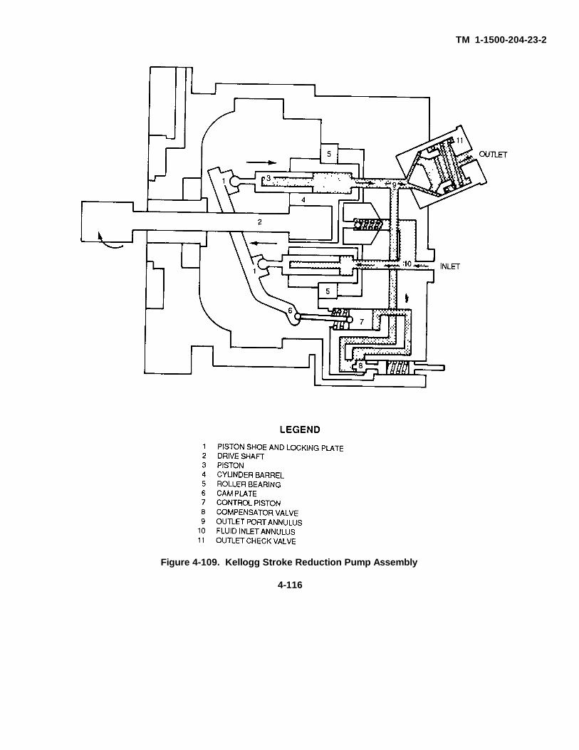
TM 1-1500-204-23-2
Figure 4-109. Kellogg Stroke Reduction Pump Assembly
4-116
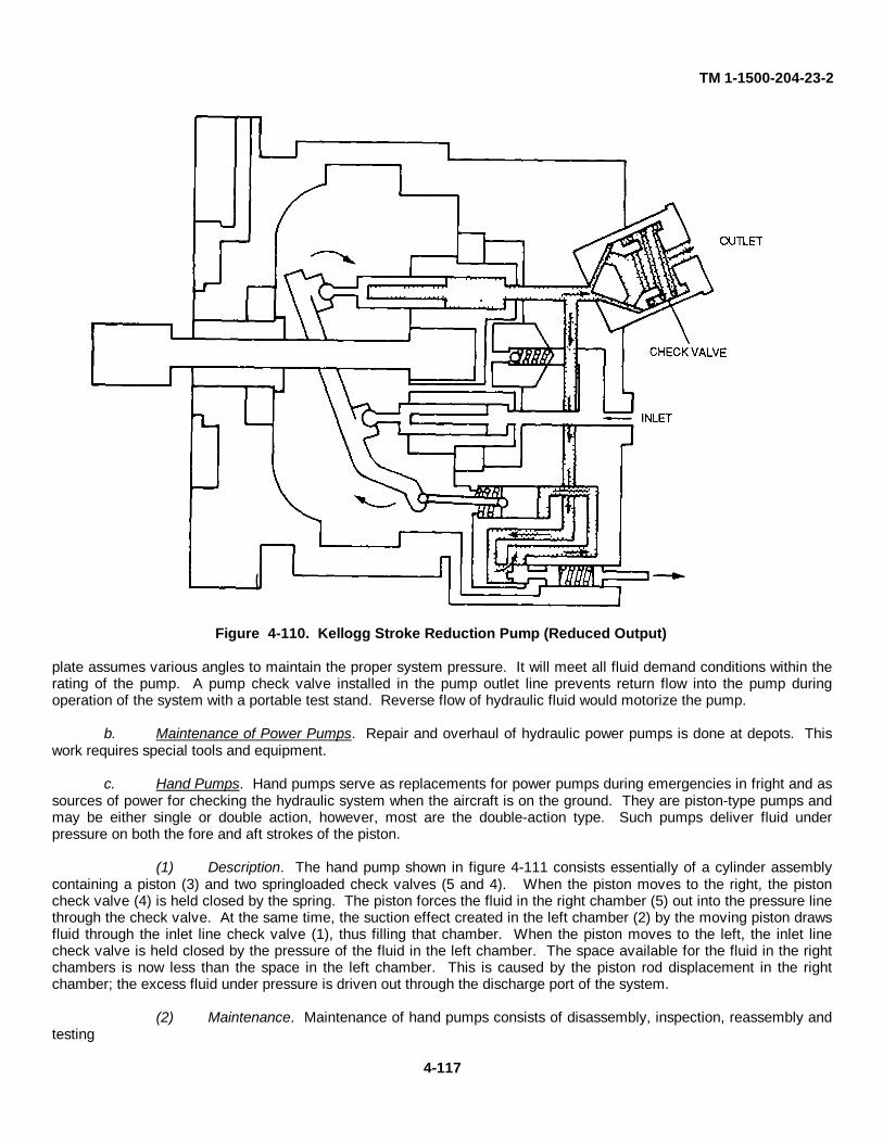
TM 1-1500-204-23-2
Figure 4-110. Kellogg Stroke Reduction Pump (Reduced Output)
plate assumes various angles to maintain the proper system pressure. It will meet all fluid demand conditions within therating of the pump. A pump check valve installed in the pump outlet line prevents return flow into the pump duringoperation of the system with a portable test stand. Reverse flow of hydraulic fluid would motorize the pump.
b. Maintenance of Power Pumps. Repair and overhaul of hydraulic power pumps is done at depots. Thiswork requires special tools and equipment.
c. Hand Pumps. Hand pumps serve as replacements for power pumps during emergencies in fright and assources of power for checking the hydraulic system when the aircraft is on the ground. They are piston-type pumps andmay be either single or double action, however, most are the double-action type. Such pumps deliver fluid underpressure on both the fore and aft strokes of the piston.
(1) Description. The hand pump shown in figure 4-111 consists essentially of a cylinder assemblycontaining a piston (3) and two springloaded check valves (5 and 4). When the piston moves to the right, the pistoncheck valve (4) is held closed by the spring. The piston forces the fluid in the right chamber (5) out into the pressure linethrough the check valve. At the same time, the suction effect created in the left chamber (2) by the moving piston drawsfluid through the inlet line check valve (1), thus filling that chamber. When the piston moves to the left, the inlet linecheck valve is held closed by the pressure of the fluid in the left chamber. The space available for the fluid in the rightchambers is now less than the space in the left chamber. This is caused by the piston rod displacement in the rightchamber; the excess fluid under pressure is driven out through the discharge port of the system.
(2) Maintenance. Maintenance of hand pumps consists of disassembly, inspection, reassembly andtesting
4-117
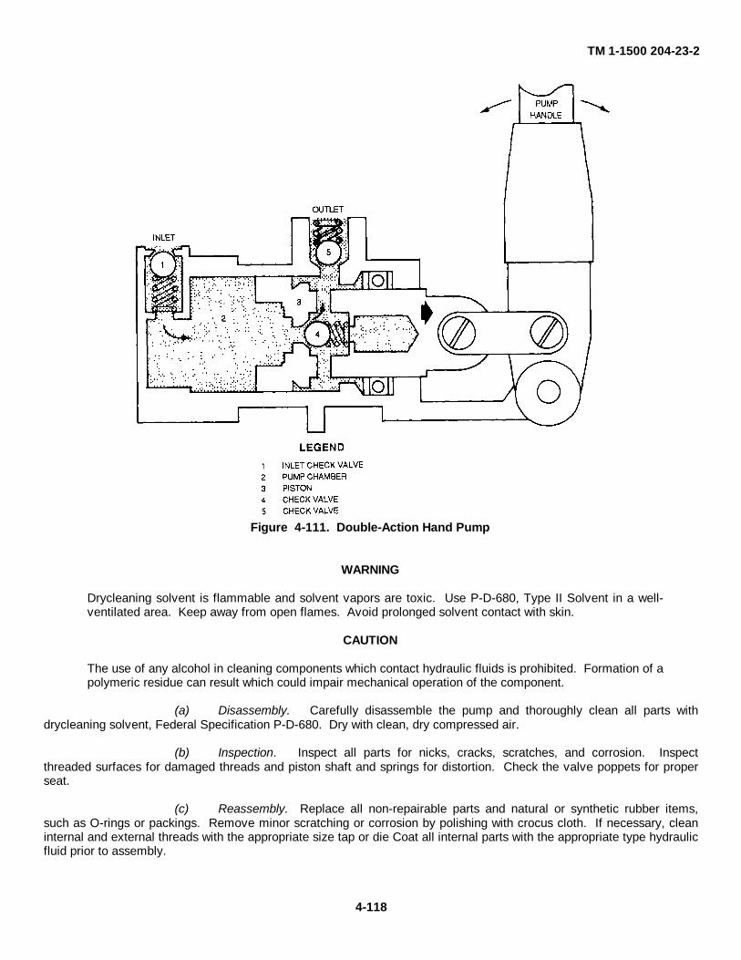
TM 1-1500 204-23-2
Figure 4-111. Double-Action Hand Pump
WARNING
Drycleaning solvent is flammable and solvent vapors are toxic. Use P-D-680, Type II Solvent in a well-ventilated area. Keep away from open flames. Avoid prolonged solvent contact with skin.
CAUTION
The use of any alcohol in cleaning components which contact hydraulic fluids is prohibited. Formation of apolymeric residue can result which could impair mechanical operation of the component.
(a) Disassembly. Carefully disassemble the pump and thoroughly clean all parts withdrycleaning solvent, Federal Specification P-D-680. Dry with clean, dry compressed air.
(b) Inspection. Inspect all parts for nicks, cracks, scratches, and corrosion. Inspectthreaded surfaces for damaged threads and piston shaft and springs for distortion. Check the valve poppets for properseat.
(c) Reassembly. Replace all non-repairable parts and natural or synthetic rubber items,such as O-rings or packings. Remove minor scratching or corrosion by polishing with crocus cloth. If necessary, cleaninternal and external threads with the appropriate size tap or die Coat all internal parts with the appropriate type hydraulicfluid prior to assembly.
4-118
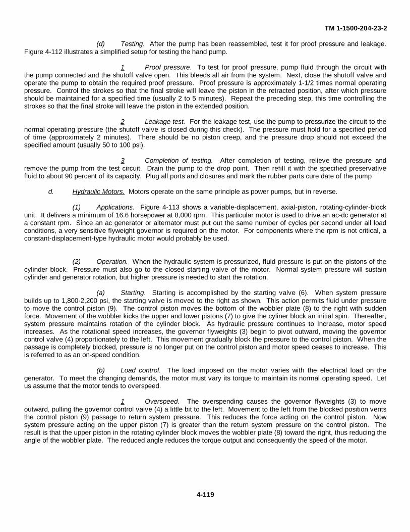
TM 1-1500-204-23-2
(d) Testing. After the pump has been reassembled, test it for proof pressure and leakage.Figure 4-112 illustrates a simplified setup for testing the hand pump.
1 Proof pressure. To test for proof pressure, pump fluid through the circuit withthe pump connected and the shutoff valve open. This bleeds all air from the system. Next, close the shutoff valve andoperate the pump to obtain the required proof pressure. Proof pressure is approximately 1-1/2 times normal operatingpressure. Control the strokes so that the final stroke will leave the piston in the retracted position, after which pressureshould be maintained for a specified time (usually 2 to 5 minutes). Repeat the preceding step, this time controlling thestrokes so that the final stroke will leave the piston in the extended position.
2 Leakage test. For the leakage test, use the pump to pressurize the circuit to thenormal operating pressure (the shutoff valve is closed during this check). The pressure must hold for a specified periodof time (approximately 2 minutes). There should be no piston creep, and the pressure drop should not exceed thespecified amount (usually 50 to 100 psi).
3 Completion of testing. After completion of testing, relieve the pressure andremove the pump from the test circuit. Drain the pump to the drop point. Then refill it with the specified preservativefluid to about 90 percent of its capacity. Plug all ports and closures and mark the rubber parts cure date of the pump
d. Hydraulic Motors. Motors operate on the same principle as power pumps, but in reverse.
(1) Applications. Figure 4-113 shows a variable-displacement, axial-piston, rotating-cylinder-blockunit. It delivers a minimum of 16.6 horsepower at 8,000 rpm. This particular motor is used to drive an ac-dc generator ata constant rpm. Since an ac generator or alternator must put out the same number of cycles per second under all loadconditions, a very sensitive flyweight governor is required on the motor. For components where the rpm is not critical, aconstant-displacement-type hydraulic motor would probably be used.
(2) Operation. When the hydraulic system is pressurized, fluid pressure is put on the pistons of thecylinder block. Pressure must also go to the closed starting valve of the motor. Normal system pressure will sustaincylinder and generator rotation, but higher pressure is needed to start the rotation.
(a) Starting. Starting is accomplished by the starting valve (6). When system pressurebuilds up to 1,800-2,200 psi, the starting valve is moved to the right as shown. This action permits fluid under pressureto move the control piston (9). The control piston moves the bottom of the wobbler plate (8) to the right with suddenforce. Movement of the wobbler kicks the upper and lower pistons (7) to give the cyliner block an initial spin. Thereafter,system pressure maintains rotation of the cylinder block. As hydraulic pressure continues to Increase, motor speedincreases. As the rotational speed increases, the governor flyweights (3) begin to pivot outward, moving the governorcontrol valve (4) proportionately to the left. This movement gradually block the pressure to the control piston. When thepassage is completely blocked, pressure is no longer put on the control piston and motor speed ceases to increase. Thisis referred to as an on-speed condition.
(b) Load control. The load imposed on the motor varies with the electrical load on thegenerator. To meet the changing demands, the motor must vary its torque to maintain its normal operating speed. Letus assume that the motor tends to overspeed.
1 Overspeed. The overspending causes the governor flyweights (3) to moveoutward, pulling the governor control valve (4) a little bit to the left. Movement to the left from the blocked position ventsthe control piston (9) passage to return system pressure. This reduces the force acting on the control piston. Nowsystem pressure acting on the upper piston (7) is greater than the return system pressure on the control piston. Theresult is that the upper piston in the rotating cylinder block moves the wobbler plate (8) toward the right, thus reducing theangle of the wobbler plate. The reduced angle reduces the torque output and consequently the speed of the motor.
4-119
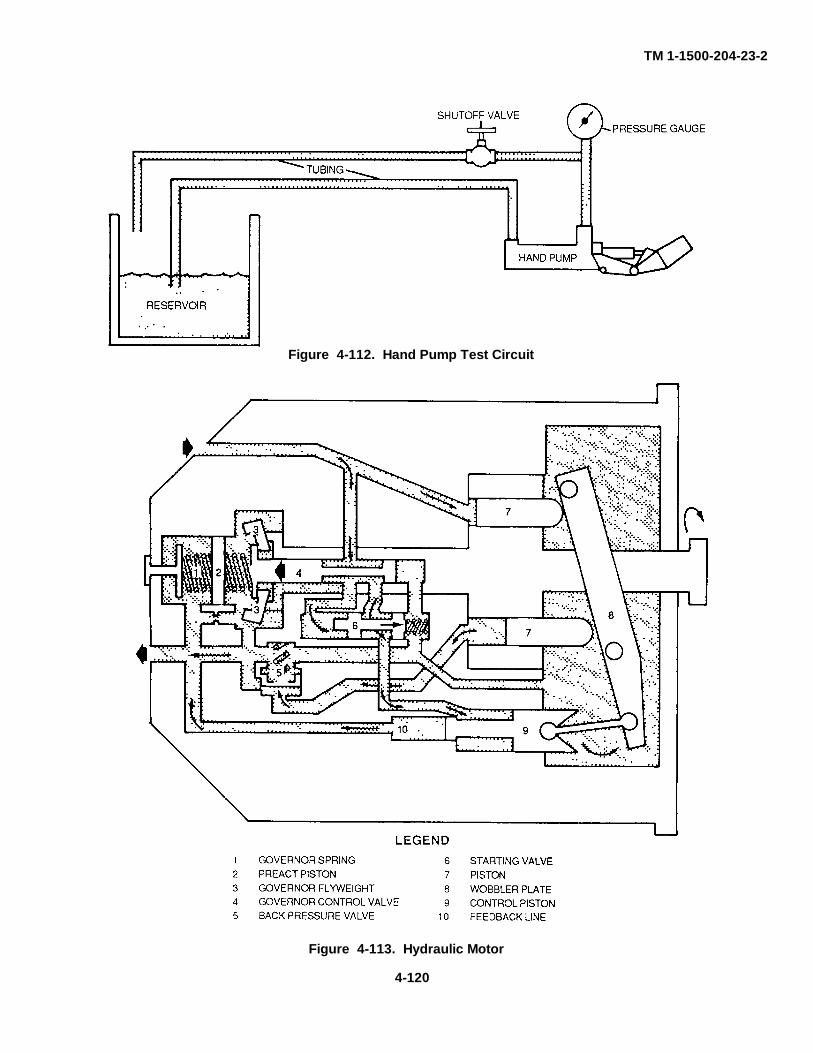
TM 1-1500-204-23-2
Figure 4-113. Hydraulic Motor
Figure 4-112. Hand Pump Test Circuit
4-120
TM 1-1500-204-23-2
2 Activation of flyweight governor. Movement of the wobbler plate alsomomentarily activates the preact piston (2) of the flyweight governor This prevents over-travel of the governor controlvalve and hastens the motor's response to changes in load. The preact piston acts when the wobbler plate moves to theright and the control piston moves to the left. This action forces fluid in the feedback line (10) into the chamber on theleft side of the preact piston When fluid moves into this chamber, the preact piston moves to the right, increasing tensionon the governor spring (1) and opposing movement on the governor control valve to the left. Motor speed decreases andthe fluid in the preact piston chamber bleeds off through the restrictor bleed. The governor control valve moves back tothe right, blocking the control piston passage and holding the wobbler plate in its new position. These events occuralmost instantly to match torque requirement with the load.
3 Back pressure valve. A back pressure valve (5) is installed in the discharge lineof the lower piston to prevent the piston from floating and chattering. If this valve were not In the return line, returnpressure would exist on both sides of the lower pistons. Under this condition, the pistons would tend to float. The backpressure valve puts 100 psi over return pressure load on the back side of the lower pistons. This load holds them againstthe wobbler plate and prevents chattering.
(3) Maintenance. Repair and overhaul of hydraulic motors are done at depots. This work requiresspecial tools and equipment.
4-14. Devices for Regulating Pressure. Devices for regulating pressure in aircraft hydraulic systems includepressure gauges, pressure switches, relief valves, and pressure reducing valves.
a. Pressure Gauges. Hydraulic pressure gauges indicate the amount of pressure in a hydraulic system.Gauge dials are calibrated to display this pressure in pounds-per square inch (psi). Direct-reading and remote-indicatinggauges are the types used.
(1) Direct-reading gauges. The direct-reading gauge shown in figure 4-114 consists essentially of aBourdon tube, a pointer, a dial, and a raintight case. The Bourdon tube and the pointer are interconnected by gearing tocause them to move together. Pressure within the hydraulic system is admitted into the Bourdon tube through aconnecting line. As hydraulic system pressure increases, it causes the Bourdon tube to straighten to a correspondingdegree. The change in curvature of the tube reacts on the gearing, causing the pointer to move to a correspondinglyhigher reading on the dial. As hydraulic system pressure decreases, the Bourdon tube curls back toward its originalshape by a corresponding amount. This causes the pointer to fall back to a correspondingly lower dial reading. Pressuregauge snubbers are usually used with hydraulic pressure gauges to dampen oscillations of the pointer.
(2) Remote-indicating gauges. In the remote-indicating gauge, the gauge transmitter contains aBourdon tube diaphragm, or bellows, to which hydraulic system pressure is admitted through a connecting line. TheBourdon tube diaphragm reacts to pressure changes in a manner similar to that of the direct-reading type gauge.Movements of the diaphragm produce electrical signals that are transmitted through connecting wiring to the indicatorunit, where they cause the indicator pointer to move. Some aircraft systems have a direct-reading gauge in a location inthe system in addition to a remote-indicating gauge In the event a remote-indicating gauge indicates a possible problem,always check the direct-reading gauge to confirm whether the gauge or the system is at fault.
b Pressure Switches. A pressure switch is designed to open or close an electrical circuit in response to apredetermined hydraulic pressure entering the switch from a connected source Piston-type and diaphragm-type pressureswitches are the types commonly used in Army aircraft.
(1) Piston-type. The piston-type pressure switch shown in figure 4-115 consists of a rectangularshaped housing, a cylinder bore and piston, an adjustable spring for loading the piston, a microswitch and a linkage fortransmitting movement of the piston to the microswitch. The housing has a port for connecting the switch to a systempressure line and an electrical receptacle for connecting the switch with an electrical circuit.
(2) Diaphragm-type. The diaphragm -type pressure switch consists of a cylindrical-shaped housinga diaphragm, an adjustable spring to load the diaphragm, a microswitch, and linkage for transmitting movements of thediaphragm to the microswitch. The housing has a port at one end for connecting the switch to a system pressure line andan electrical receptacle for connecting the switch with an electrical circuit at the other end.
(3) Operation. The operation described here covers the piston-type pressure switch. However, thediaphragm switch operates on essentially the same
4-121
TM 1-1500 204-23-2
principles. Fluid pressure entering the port of the pressure switch acts on the face of the piston to move it against theresistance of the piston return spring. When the fluid pressure acting on the piston becomes great enough to overcomethe force of the piston return spring, movement of the piston causes the pivoted lever of the connecting linkage betweenthe piston and the micro-switch to rotate. The movement of the pivoted lever is transmitted through the Idler spring tothe actuating button of the microswitch. When the microswitch actuating button has moved a sufficient amount, themicro-switch contacts move into the pressure-induced position. Some pressure switches are designed so that theircontacts remain open until closed by the action of fluid pressure against the switch position. Such switches are specifiedas NORMALLY OPEN (NO). Other switches are designed for their contacts to remain closed until opened by thereaction of fluid pressure against the switch piston. These are specified as NORMALLY CLOSED (NC).
(4) Uses. Pressure switches on Army aircraft serve two purposes. One is to close the circuit of awarning fight that shows low pressure in a system. The other is to affect the circuits of solenoid valves in aircraft havingdual hydraulic boost control systems in such a manner that operating pressure to one boost system cannot be shut offunless the other boost system is provided with enough operating pressure to fly the aircraft. Some pressure switches aredesigned with two sets of contacts so as to provide control for both the warning light and the solenoid valve.
(5) Maintenance. Maintenance of hydraulic pressure switches is limited to testing, removal, andreplacement.
c. Pressure Relief Valves. Relief valves are safety devices used to prevent pressure from building up to apoint where it might blow seals and thus burst or otherwise damage the container in which it is installed. Relief valvesare installed in aircraft hydraulic systems to relieve excessive fluid pressure caused by thermal expansion, pressuresurges, and the failure of a hydraulic pump compensator or other regulating devices.
(1) System relief valves. Main system relief valves are set to open and close at pressuredetermined by the system in which they are installed. In systems made to operate at 3,000-psi normal pressure, therelief valve might be set to be completely open at 3,650 psi and to reseat at 3,190 psi. These pressure ranges may bedifferent from one aircraft to another. When the relief valve is in the open position, it sends excess pressurized fluid tothe reservoir return line.
(a) Description. A typical main system relief valve and a breakdown of its component partsis shown in figure 4-116. The relief valve consists of a cylindrical housing containing a poppet valve and a pistonassembly Each end of the housing is made to include a wrench-holding surface and a threaded port for installation of ahydraulic fitting. The housing is stamped to Denny the ports as PRESS (pressure) and RET (return). The poppet valve(1), which is located just inside the pressure port, is seated over a passage through the valve.
(b) Operation. When fluid pressure at the pressure port reaches 3,650 psi, the pressureforces the piston (2) to depress the load spring (3) and to move clear of the poppet valve. Thus, the passage through thepiston is opened, and fluid flows through the valve into the return line. When pressure at the pressure port is reduced to3,190 psi the coil spring reseats the piston against the poppet valve and fluid flow through the relief valve ceases.Should the pressure at the outlet port exceed the pressure at the inlet port, the poppet valve will unseat and fluid from thereturn line will flow through the valve into the pressure line.
(2) Thermal relief valves. Thermal relief valves are usually smaller than system relief valves. Theyare used in systems where a check valve or a selector valve prevents pressure from being relieved through the mainsystem relief valve. As pressurized fluid in the line in which it is installed builds up to an excessive amount, the valvepoppet is forced off its seat and the excess pressurized fluid flows through the relief valve to the reservoir. When systempressure decreases to a preset pressure, spring tension overcomes system pressure and forces the valve poppet to theclosed position.
(3) Maintenance. Relief valve maintenance is limited to adjusting the valve for proper reliefpressure and checking the valve for leakage. If it is thought that a relief valve is leaking internally a flexible hose may beconnected to the return port of the valve and the drippings, if any, caught in a container. The opening and closingpressure of the valve may also be checked in this manner provided an external source of power is used.
d. Pressure Reducing Valves. Pressure reducing valves are used in hydraulic systems where it isnecessary to lower the normal system operating pressure to a specified amount.
4-122
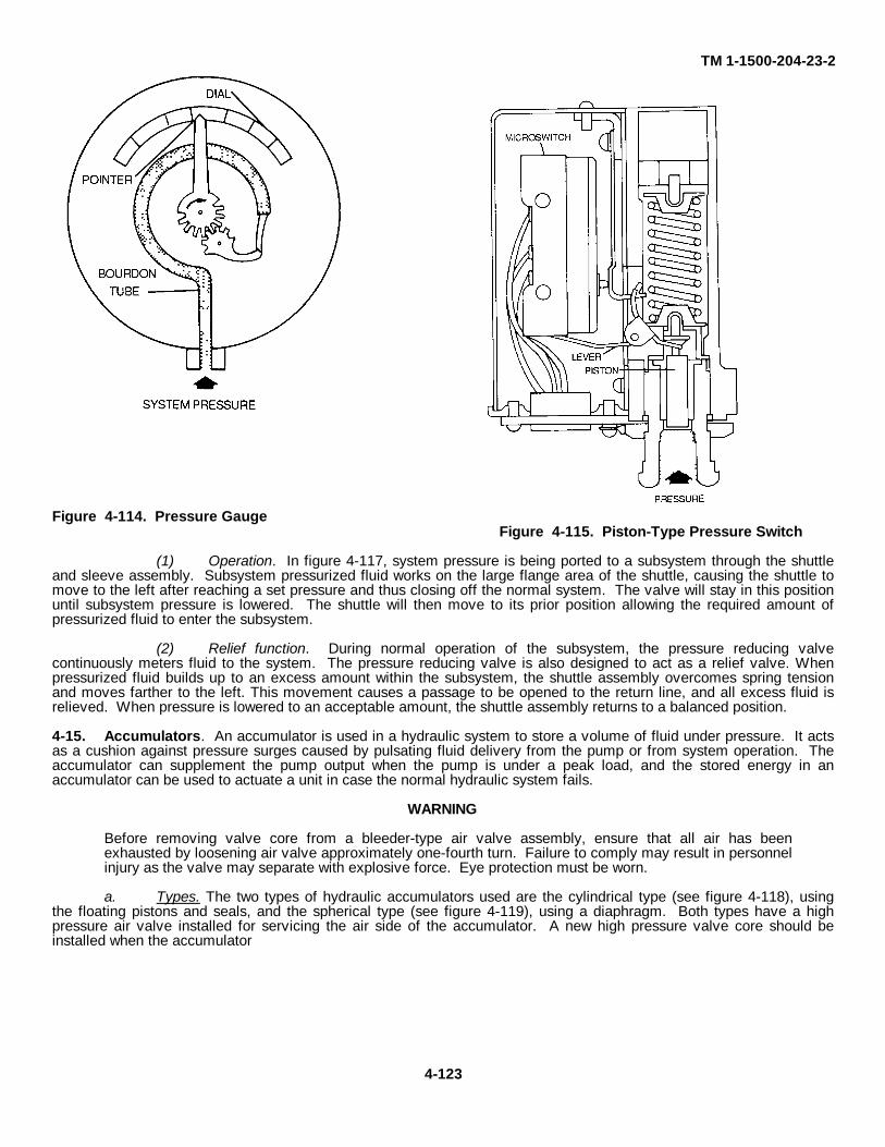
TM 1-1500-204-23-2
Figure 4-114. Pressure GaugeFigure 4-115. Piston-Type Pressure Switch
(1) Operation. In figure 4-117, system pressure is being ported to a subsystem through the shuttleand sleeve assembly. Subsystem pressurized fluid works on the large flange area of the shuttle, causing the shuttle tomove to the left after reaching a set pressure and thus closing off the normal system. The valve will stay in this positionuntil subsystem pressure is lowered. The shuttle will then move to its prior position allowing the required amount ofpressurized fluid to enter the subsystem.
(2) Relief function. During normal operation of the subsystem, the pressure reducing valvecontinuously meters fluid to the system. The pressure reducing valve is also designed to act as a relief valve. Whenpressurized fluid builds up to an excess amount within the subsystem, the shuttle assembly overcomes spring tensionand moves farther to the left. This movement causes a passage to be opened to the return line, and all excess fluid isrelieved. When pressure is lowered to an acceptable amount, the shuttle assembly returns to a balanced position.
4-15. Accumulators. An accumulator is used in a hydraulic system to store a volume of fluid under pressure. It actsas a cushion against pressure surges caused by pulsating fluid delivery from the pump or from system operation. Theaccumulator can supplement the pump output when the pump is under a peak load, and the stored energy in anaccumulator can be used to actuate a unit in case the normal hydraulic system fails.
WARNING
Before removing valve core from a bleeder-type air valve assembly, ensure that all air has beenexhausted by loosening air valve approximately one-fourth turn. Failure to comply may result in personnelinjury as the valve may separate with explosive force. Eye protection must be worn.
a. Types. The two types of hydraulic accumulators used are the cylindrical type (see figure 4-118), usingthe floating pistons and seals, and the spherical type (see figure 4-119), using a diaphragm. Both types have a highpressure air valve installed for servicing the air side of the accumulator. A new high pressure valve core should beinstalled when the accumulator
4-123
TM 1-1500-204-23-2
air pressure has been exhausted through the valve core or the valve core has been removed from the air valveassembly. The hydraulic system pressure gauge will indicate the approximate accumulator air pressure when thehydraulic hand pump has been operated for a period of time starting with zero pressure on the hydraulic system.
b. Accumulator Operation. Spherical and cylindrical accumulators operate in essentially the same manner.In operation, the compressed-air chamber is charged to a pressure somewhat lower than the system operating pressure.This initial charge is referred to as the accumulator preload. When a preload is Introduced in an accumulator, thehydraulic system pressure will be zero. As the system is subsequently pressurized and overcomes the preload pressure,the air will be compressed in the accumulator. When use of hydraulic units lowers system pressure, the compressed airwill then force fluid from the accumulator into the system to satisfy system demands. Many aircraft have severalaccumulators in the hydraulic system. There may be an accumulator for the main and emergency systems, and theremay be auxiliary accumulators located in venous unit systems.
c. Maintenance.. Maintenance of accumulators at the organizational and Intermediate maintenance levelsprimarily consists of inspection and servicing. Some intermediate maintenance activities may have the responsibility foroverhaul or repair, but this primarily rests with the depot maintenance units Inspection and servicing procedures are asfollows.
(1) Visually inspect accumulators for indications of external hydraulic leaks.
NOTE
Use only dry air or nitrogen when pressurizing accumulator.
(2) Test for internal leaks by momentarily depressing the valve core.
NOTE
• On cylindrical type accumulators, a slight amount of atomized hydraulic fluid is permissible. Whenliquid fluid escapes from the air valve, excessively worn seals or a scored piston are indicated andreplacement of the accumulators necessary.
• On spherical type accumulators any indication of fluid at the air valve shall be cause for replacement
of the accumulator, as this is an indication of deterioration or rupture of the diaphragm.
(3) Check the preload pressure on the accumulator by depleting the fluid pressure. This may bedone by operating the controls of a system of which the accumulator is a part until all reserve pressure has been used.
(4) Ensure that the air preload is completely exhausted before disassembling the accumulator.
4-16. Flow Control Units . Numerous valving devices are used in aircraft hydraulic systems to control the flow of fluidwithin the system. These devices perform such functions as controlling direction, sequence, and priority of flow;transforming fluid pressure into mechanical energy; holding loads in position against feedback-induced forces; andpreventing leaks. The devices that perform these functions are selector valves, control valves, check valves, sequencevalves, priority valves, shuttle valves, actuating cylinders, ratchet valves, servos, irreversible valves, and fuses.
a. Selector Valves. The purpose of a selector valve is to control the direction of movement of an actuatingunit. It does this by providing pathways for pressure and return fluid into and out of an actuating unit, and by providingthe means for immediately and conveniently switching the directions of the pressure and return fluid (necessary forreversing the direction of movement of the actuating unit). Selector valves are classified as closed-center and open-center types. These classifications are based on what happens to the flow of fluid when the selector valve is placed inthe off position. When a closed-center selector valve is placed in the off position, its pressure passage is blocked to theflow of fluid and no fluid can pass through its pressure port. When an open-center selector valve is placed in
4-124
TM 1-1500 204-23-2the off position, its pressure passage and return passage become interconnected and fluid can flow into the pressure portand out of the return port. Selector valves may be further classified on the basis of design characteristics as cam-operated, in-line radial, and compound.
(1) Closed-center selector valves. The four closed-center type selector valves are the ones mostcommonly used in aircraft hydraulic systems. Rotor and spool type valving devices are used in these valves. Thevalves operate in one off position and in two on positions. Figure 4-120 shows a typical four-way, closed-center rotor-type selector valve. This valve is in the off position: all the valve ports are blocked, and no fluid can flow into or out ofthe valve.
(2) Open-center selector valves. Figure 4-121 illustrates an open-center, spool-type selector valve.This valve is in the off position, and as can be seen, the center seat provides an interconnection between the pressureport and the drilled passage in the spool. This permits fluid to enter the pressure port and pass freely through the valveand out of the return port.
(3) Cam-operated selector valves. Poppet type and ball-type selector valves are operated by camsthat lift the poppet or ball off its seat. Purpose, use, and operation of the two types are the same one controls fluid flowby the use of poppets; the other employs a ball-shaped valve. The piston-type selector valve may also be cam-operatedIn this case, flow is directed by the sliding action of a piston, which is a spool-shaped plunger within a housing.
(a) In-line cam-operated selector valve (poppet-type). The poppets of an in-line selectorvalve are similar to the pistons of an IN-LINE aircraft engine. In the neutral position, all four poppets are closed. Withthis type of valve, a pressure rise caused by an increase in temperature in either cylinder line can unseat an upperpoppet. This will relieve the pressure into the return line. An Integral temperature relief valve, relieving from thepressure manifold into the return line is used in several models of the valve. Figure 4-122 shows a condition in whichfluid pressure is forcing the actuating cylinder piston Inward, permitting fluid to flow from the actuating cylinder throughthe lower unseated poppet to the return line. In figure 4-123, the selector valve control has been placed in the oppositedirection. Fluid pressure is forcing the actuating cylinder piston outward, and fluid from the actuating cylinder flowsthrough the other unseated poppet to the return line.
(b) Radial cam-operated selector valve (poppet-type). In the typical poppet-type radialselector valve shown in figure 4-124, the cam in the center is attached to a control handle. Moving the control handlecauses the cam to rotate and moves the poppets on or off their seats. In the position shown here, poppets A and C areseated and poppets B and D are unseated. Fluid entering the inlet pressure port flows around poppet B and to theactuator unit through the cylinder 1 port. Fluid returning from the actuator unit enters through the cylinder 2 port, flowsaround poppet D, and exits through
Figure 4-116. System Relief Valve
4-125
TM 1-1500-204-23-2
the return line. If the cam is rotated 90 degrees, poppets A and C will unseat and poppets B and D will seat. Fluidentering the inlet pressure port then passes around poppet A and to the actuator unit through the cylinder 2 port. Fluidresuming from the actuator unit flows to the return line by entering the selector valve through the cylinder 1 port, flowingaround poppet C, and exiting through the return port. If the cam is rotated 45 degrees from the position shown in theschematic, all poppets are seated and the selector valve is in a neutral position.
(4) Compound selector valve. To conserve space and make installation easy when banks of unitsare to be controlled, several selector valves are compounded into one unit. Each selector valve is controlledindependently, but only one connection is needed for the pressure line and one for the return line.
b. Control Valves. For Army aircraft, the term control valve refers to a valve that controls direction of flowthrough alternate channels. Although similar in principle to a selector valve, a control valve functions more like a shutoffvalve. Some control valves are actuated manually; others, electrically. Electrical actuation may be by means of either asolenoid or a motor. A solenoid-actuated valve is shown in figures 4-125 and 4-126. The
Figure 4-118. Cylindrical Accumulator
4-126
Figure 4-117. Pressure Reducing Valve
TM 1-1500-204-23-2valve device is spring-loaded to one position and solenoid-actuated to the other position.
c. Check Valves. For hydraulic components and systems to operate as they should, the flow of fluid mustbe rigidly controlled. Fluid must be made to flow according to needs of the system. Many kinds of valve units are usedfor exercising such control. One of the simplest and most commonly used is the check valve. The check valve allowsfree flow of fluid in one direction, but no flow or a restricted flow in the other direction. There are two types of in-linecheck values simple and orifice.
(1) Simple-type. Simple-type check valves shown in figure 4-127 are used when a free flow of fluidis desired in only one direction. Fluid entering the inlet port of the check valve forces the valving device off its seatagainst the spring. This permits fluid to flow through the passageway thus opened. The instant that fluid stops moving inthis direction, the valving device is returned to its seat by the spring. This blocks the opening in the valve seat, thusblocking the flow of fluid through the valve.
Figure 4-119. Spherical Accumulator(2) Orifice-type. The orifice-type check valve (sometimes called a damping valve) is used to allow
normal operating speed of a mechanism by providing free flow of fluid in one direction, while allowing limited operationspeed through restricted flow of fluid in the opposite direction. An orifice-type check valve is shown in figure 4-128. Theoperation of the orifice-type check valve is the same as that of the simple-type except for the restricted flow allowedwhen closed. This is accomplished by having a second opening in the valve seat. This second opening is never closedand is the means by which some reverse flow can take place through the valve. The second opening is much smallerthan the opening in the valve seat. As a rule, this opening is a specified size in order to maintain close control over therate at which fluid can flow through the valve in reverse.
(3) Marking of valves. The director of fluid flow through in-line check valves is indicated by stampedarrow markings on the housing as shown in figures 4-127 and 4-128 On the simple-type in-line check valve, a singlearrow shows the direction in which fluid can flow. The orifice-type in-line check valve is usually marked with two arrows.One arrow is more pronounced than the other, and indicates the direction of unrestricted flow. The other arrow is eithersmaller than the first or of broken-line construction and points in the direction of restricted reverse fluid flow.
d. Sequence Valves. The purpose of sequence valves (sometimes called timer check valves) is to set up asequence of operation. In Army aircraft, these valves are used in such mechanisms as landing gear doors, landing gearuplocks and downlocks, cargo doors, ramps, and locks, and ejection seats to cause hydraulic operations to occur in aspecific order. Two major types are used: mechanically-actuated and pressure-actuated.
(1) Mechanically-actuated sequence valves. The mechanically-actuated sequence valve is the typecommonly used in Army aircraft. A typical valve of this type (shown in figure 4-127) consists of a housing in which thereare two ports, a ball valving device, two springs, a plunger that extends through one end of the housing, and thenecessary seals to prevent leakage. The input pressure line is connected as shown to the actuating cylinder and tosequence valve B Since sequence valve B is now closed, fluid cannot pass through it. When the door is opened, thedoor actuating cylinder piston rod extends far enough to contact and depress the plunger of sequence valve B. Thisopens sequence valve B and allows fluid pressure to pass through to the
4-127
TM 1-1500-204-23-2
Figure 4-120. Rotary-Type, Closed Center Selector Valve
Figure 4-121. Spool-Type, Open Center Selector Valve (Closed)
4-128

TM 1-1500-204-23-2
Figure 4-123. In-Line Cam-Operated Selector Valve (Actuator Extending)
Figure 4-122. In-Line Cam-Operated Selector Valve (Actuator Retracting)
4-129
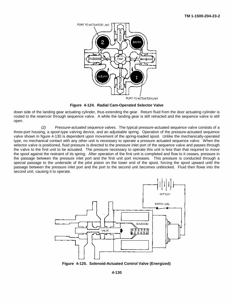
TM 1-1500-204-23-2
Figure 4-124. Radial Cam-Operated Selector Valve
down side of the landing gear actuating cylinder, thus extending the gear. Return fluid from the door actuating cylinder isrouted to the reservoir through sequence valve. A while the landing gear is still retracted and the sequence valve is stillopen.
(2) Pressure-actuated sequence valves. The typical pressure-actuated sequence valve consists of athree-port housing, a spool-type valving device, and an adjustable spring. Operation of the pressure-actuated sequencevalve shown in figure 4-130 is dependent upon movement of the spring-loaded spool. Unlike the mechanically-operatedtype, no mechanical contact with any other unit is necessary to operate a pressure actuated sequence valve. When theselector valve is positioned, fluid pressure is directed to the pressure inlet port of the sequence valve and passes throughthe valve to the first unit to be actuated. The pressure necessary to operate this unit is less than that required to movethe spool against the restraint of its spring. After operation of the first unit is completed and flow to it ceases, pressure inthe passage between the pressure inlet port and the first unit port increases. This pressure is conducted through aspecial passage to the underside of the pilot piston on the lower end of the spool, forcing the spool upward until thepassage between the pressure inlet port and the port to the second unit becomes unblocked. Fluid then flows into thesecond unit, causing it to operate.
Figure 4-125. Solenoid-Actuated Control Valve (Energized)
4-130
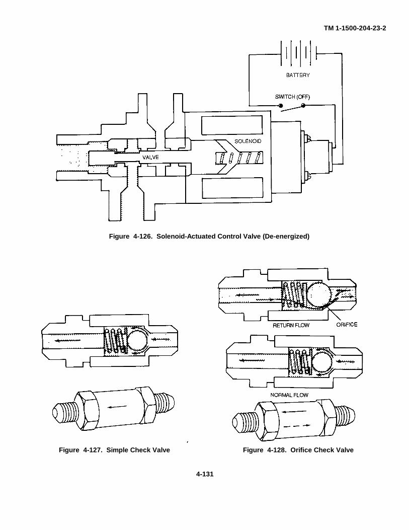
TM 1-1500-204-23-2
Figure 4-127. Simple Check Valve Figure 4-128. Orifice Check Valve
4-131
Figure 4-126. Solenoid-Actuated Control Valve (De-energized)
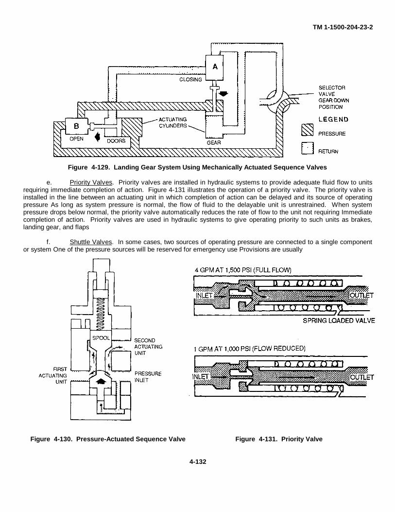
TM 1-1500-204-23-2
Figure 4-129. Landing Gear System Using Mechanically Actuated Sequence Valves
e. Priority Valves. Priority valves are installed in hydraulic systems to provide adequate fluid flow to unitsrequiring immediate completion of action. Figure 4-131 illustrates the operation of a priority valve. The priority valve isinstalled in the line between an actuating unit in which completion of action can be delayed and its source of operatingpressure As long as system pressure is normal, the flow of fluid to the delayable unit is unrestrained. When systempressure drops below normal, the priority valve automatically reduces the rate of flow to the unit not requiring Immediatecompletion of action. Priority valves are used in hydraulic systems to give operating priority to such units as brakes,landing gear, and flaps
f. Shuttle Valves. In some cases, two sources of operating pressure are connected to a single componentor system One of the pressure sources will be reserved for emergency use Provisions are usually
Figure 4-130. Pressure-Actuated Sequence Valve Figure 4-131. Priority Valve
4-132
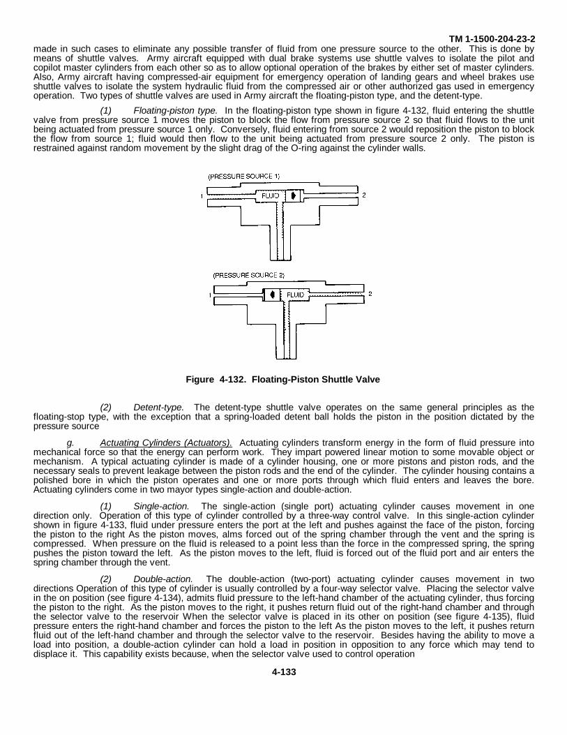
TM 1-1500-204-23-2made in such cases to eliminate any possible transfer of fluid from one pressure source to the other. This is done bymeans of shuttle valves. Army aircraft equipped with dual brake systems use shuttle valves to isolate the pilot andcopilot master cylinders from each other so as to allow optional operation of the brakes by either set of master cylinders.Also, Army aircraft having compressed-air equipment for emergency operation of landing gears and wheel brakes useshuttle valves to isolate the system hydraulic fluid from the compressed air or other authorized gas used in emergencyoperation. Two types of shuttle valves are used in Army aircraft the floating-piston type, and the detent-type.
(1) Floating-piston type. In the floating-piston type shown in figure 4-132, fluid entering the shuttlevalve from pressure source 1 moves the piston to block the flow from pressure source 2 so that fluid flows to the unitbeing actuated from pressure source 1 only. Conversely, fluid entering from source 2 would reposition the piston to blockthe flow from source 1; fluid would then flow to the unit being actuated from pressure source 2 only. The piston isrestrained against random movement by the slight drag of the O-ring against the cylinder walls.
Figure 4-132. Floating-Piston Shuttle Valve
(2) Detent-type. The detent-type shuttle valve operates on the same general principles as thefloating-stop type, with the exception that a spring-loaded detent ball holds the piston in the position dictated by thepressure source
g. Actuating Cylinders (Actuators). Actuating cylinders transform energy in the form of fluid pressure intomechanical force so that the energy can perform work. They impart powered linear motion to some movable object ormechanism. A typical actuating cylinder is made of a cylinder housing, one or more pistons and piston rods, and thenecessary seals to prevent leakage between the piston rods and the end of the cylinder. The cylinder housing contains apolished bore in which the piston operates and one or more ports through which fluid enters and leaves the bore.Actuating cylinders come in two mayor types single-action and double-action.
(1) Single-action. The single-action (single port) actuating cylinder causes movement in onedirection only. Operation of this type of cylinder controlled by a three-way control valve. In this single-action cylindershown in figure 4-133, fluid under pressure enters the port at the left and pushes against the face of the piston, forcingthe piston to the right As the piston moves, alms forced out of the spring chamber through the vent and the spring iscompressed. When pressure on the fluid is released to a point less than the force in the compressed spring, the springpushes the piston toward the left. As the piston moves to the left, fluid is forced out of the fluid port and air enters thespring chamber through the vent.
(2) Double-action. The double-action (two-port) actuating cylinder causes movement in twodirections Operation of this type of cylinder is usually controlled by a four-way selector valve. Placing the selector valvein the on position (see figure 4-134), admits fluid pressure to the left-hand chamber of the actuating cylinder, thus forcingthe piston to the right. As the piston moves to the right, it pushes return fluid out of the right-hand chamber and throughthe selector valve to the reservoir When the selector valve is placed in its other on position (see figure 4-135), fluidpressure enters the right-hand chamber and forces the piston to the left As the piston moves to the left, it pushes returnfluid out of the left-hand chamber and through the selector valve to the reservoir. Besides having the ability to move aload into position, a double-action cylinder can hold a load in position in opposition to any force which may tend todisplace it. This capability exists because, when the selector valve used to control operation
4-133
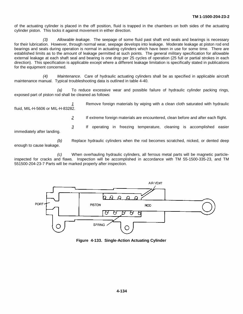
TM 1-1500-204-23-2
of the actuating cylinder is placed in the off position, fluid is trapped in the chambers on both sides of the actuatingcylinder piston. This locks it against movement in either direction.
(3) Allowable leakage. The seepage of some fluid past shaft end seals and bearings is necessaryfor their lubrication. However, through normal wear, seepage develops into leakage. Moderate leakage at piston rod endbearings and seals during operation is normal in actuating cylinders which have been in use for some time. There areestablished limits as to the amount of leakage permitted at such points. The general military specification for allowableexternal leakage at each shaft seal and bearing is one drop per 25 cycles of operation (25 full or partial strokes in eachdirection). This specification is applicable except where a different leakage limitation is specifically stated in publicationsfor the equipment concerned.
(4) Maintenance. Care of hydraulic actuating cylinders shall be as specified in applicable aircraftmaintenance manual. Typical troubleshooting data is outlined in table 4-40.
(a) To reduce excessive wear and possible failure of hydraulic cylinder packing rings,exposed part of piston rod shall be cleaned as follows:
1 Remove foreign materials by wiping with a clean cloth saturated with hydraulicfluid, MIL-H-5606 or MIL-H-83282.
2 If extreme foreign materials are encountered, clean before and after each flight.
3 If operating in freezing temperature, cleaning is accomplished easierimmediately after landing.
(b) Replace hydraulic cylinders when the rod becomes scratched, nicked, or dented deepenough to cause leakage.
(c) When overhauling hydraulic cylinders, all ferrous metal parts will be magnetic particle-inspected for cracks and flaws. Inspection will be accomplished in accordance with TM 55-1500-335-23, and TM551500-204-23-7 Parts will be marked properly after inspection.
Figure 4-133. Single-Action Actuating Cylinder
4-134
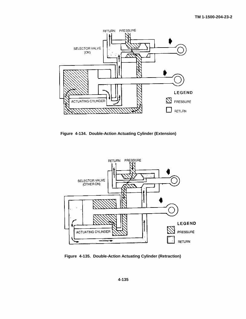
TM 1-1500-204-23-2
Figure 4-135. Double-Action Actuating Cylinder (Retraction)
4-135
Figure 4-134. Double-Action Actuating Cylinder (Extension)

TM 1-1500-204-23-2Table 4-40. Troubleshooting Actuators
Trouble Probable Cause Remedy
Leakage from operating end Packing around piston rod is Disassemble cylinder and replaceof piston leaking packing, if worn
External leakage around head Lockring holding gasket is Tightenand base not right
Gasket is worn Replace with new gasket
Leakage from one side of Packing on piston is worn or Disassemble and replacepiston to the other scored packing
Packing Inside piston is worn Disassemble and replaceor scored packing
Piston is not securely fastened Tighten nut holding piston onto piston rod piston rod
Smooth finish on barrel is Overhaulscratched or scored
h. Ratchet Valve. Hydraulic ratchet valves are used as companion devices to double-action actuatingcylinders. The purpose of a ratchet valve is to aid an actuating cylinder in holding a load in the position into which it hasbeen moved by operation of a hand pump. The ratchet valve insures that there will be trapped fluid on each side of theactuating cylinder piston. This is necessary for the actuating cylinder to lock a load against movement in either direction,and is especially vital should the selector valve which controls the actuating cylinder be left in the on piston or haveInternal leakage. The ratchet valve does not affect actuating cylinder piston movements that are intentionally producedby means of system operating pressure. Ratchet valves are optional equipment and are used only in cases wherelocking a load in position is of great importance. In figure 4-136, the ratchet valve is shown with no pressure applied(selector valve off ). The piston is centered in its bore, and both check valves (balls A and B) are closed. This locks theactuating cylinder in position by trapping all fluid in the cylinder. The ratchet valve is shown in figure 4-137 with pressureapplied to port 1. This forces the piston to the rig ht where it unseats ball check B. Pressure entering port 1 unseats ballcheck A on the left side. Fluid then flows through the ratchet valve, and the piston moves to the right, unseating ballcheck B.
i. Hydraulic Servos. Many situations exist in which powered movements must be consistently made withaccuracy within thousandths of an inch; such exact control cannot be effected by an actuating cylinder merely connectedwith a selector valve. Hydraulic servos perform this function. Hydraulic servos are used in both airplanes andhelicopters to multiply the physical effort expended by personnel in operating the aircraft. Servos enable a pilot to usefingertip force in controlling the actions of a flight control system that may actually require hundreds of pounds of force toactuate.
(1) Design. In effect, a hydraulic servo is a combination of an actuating cylinder and a selectorvalve in a single unit. The servo selector valve is manually opened by the operator and is automatically closed by theservo's movement. The spool-shaped valving device of the servo selector valve is commonly referred to as a pilotvalve. Servos are made in two general designs. In one design, the servo cylinder housing is stationary and the pistonrod moves. In the other design, the piston rod is stationary and the cylinder housing moves. For convenience, a servo inwhich the
4-136
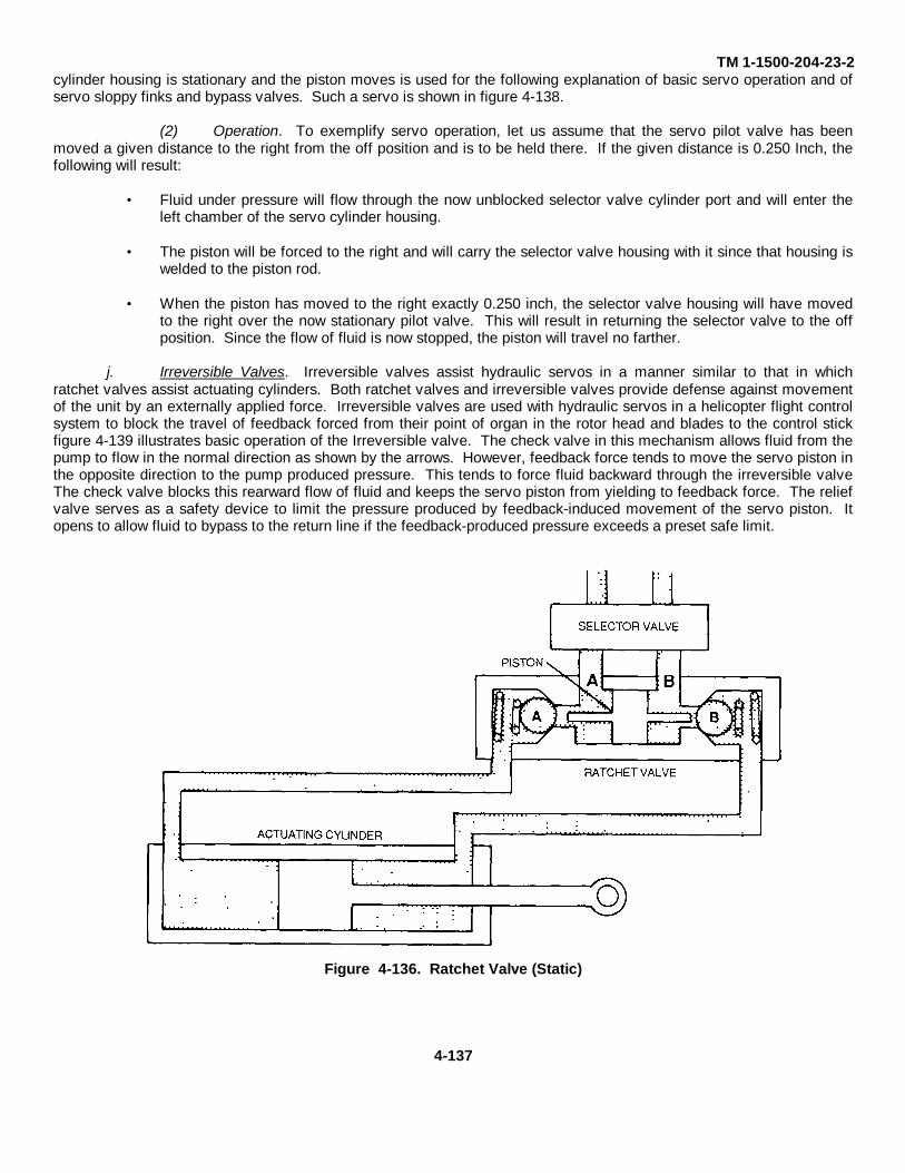
TM 1-1500-204-23-2cylinder housing is stationary and the piston moves is used for the following explanation of basic servo operation and ofservo sloppy finks and bypass valves. Such a servo is shown in figure 4-138.
(2) Operation. To exemplify servo operation, let us assume that the servo pilot valve has beenmoved a given distance to the right from the off position and is to be held there. If the given distance is 0.250 Inch, thefollowing will result:
• Fluid under pressure will flow through the now unblocked selector valve cylinder port and will enter theleft chamber of the servo cylinder housing.
• The piston will be forced to the right and will carry the selector valve housing with it since that housing is
welded to the piston rod. • When the piston has moved to the right exactly 0.250 inch, the selector valve housing will have moved
to the right over the now stationary pilot valve. This will result in returning the selector valve to the offposition. Since the flow of fluid is now stopped, the piston will travel no farther.
j. Irreversible Valves. Irreversible valves assist hydraulic servos in a manner similar to that in whichratchet valves assist actuating cylinders. Both ratchet valves and irreversible valves provide defense against movementof the unit by an externally applied force. Irreversible valves are used with hydraulic servos in a helicopter flight controlsystem to block the travel of feedback forced from their point of organ in the rotor head and blades to the control stickfigure 4-139 illustrates basic operation of the Irreversible valve. The check valve in this mechanism allows fluid from thepump to flow in the normal direction as shown by the arrows. However, feedback force tends to move the servo piston inthe opposite direction to the pump produced pressure. This tends to force fluid backward through the irreversible valveThe check valve blocks this rearward flow of fluid and keeps the servo piston from yielding to feedback force. The reliefvalve serves as a safety device to limit the pressure produced by feedback-induced movement of the servo piston. Itopens to allow fluid to bypass to the return line if the feedback-produced pressure exceeds a preset safe limit.
Figure 4-136. Ratchet Valve (Static)
4-137
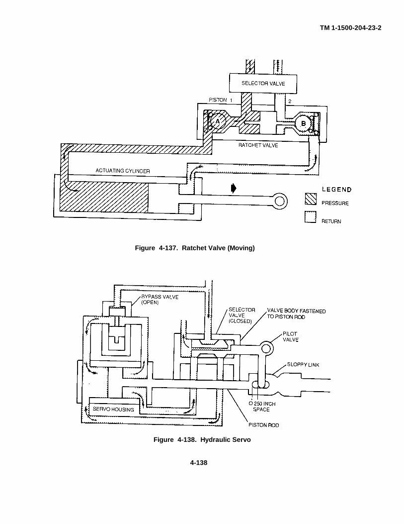
TM 1-1500-204-23-2
Figure 4-138. Hydraulic Servo
Figure 4-137. Ratchet Valve (Moving)
4-138
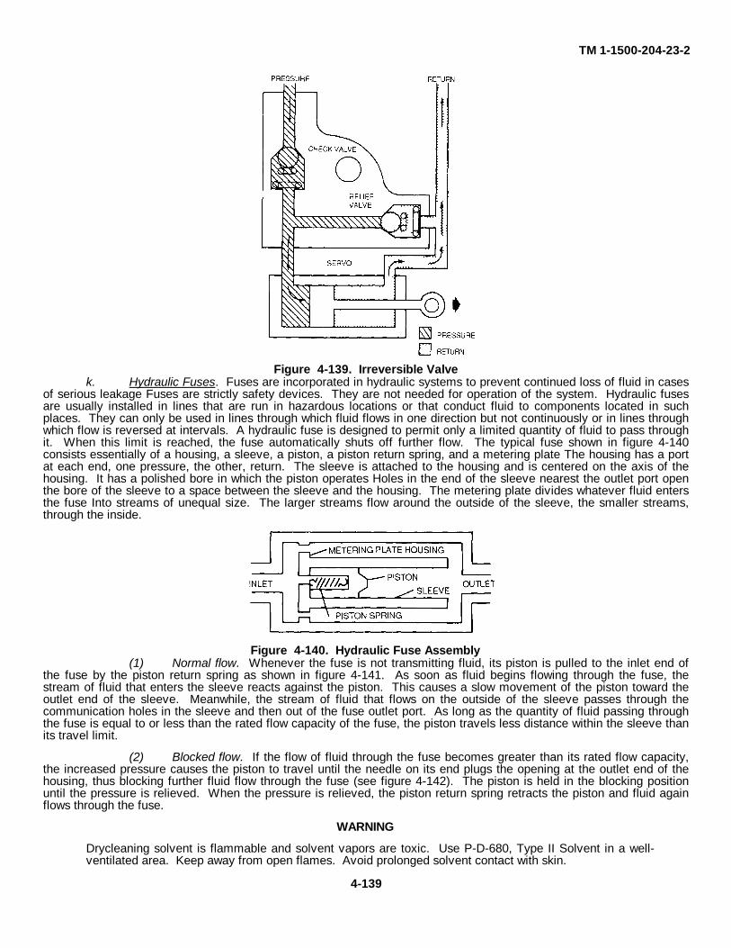
TM 1-1500-204-23-2
Figure 4-139. Irreversible Valvek. Hydraulic Fuses. Fuses are incorporated in hydraulic systems to prevent continued loss of fluid in cases
of serious leakage Fuses are strictly safety devices. They are not needed for operation of the system. Hydraulic fusesare usually installed in lines that are run in hazardous locations or that conduct fluid to components located in suchplaces. They can only be used in lines through which fluid flows in one direction but not continuously or in lines throughwhich flow is reversed at intervals. A hydraulic fuse is designed to permit only a limited quantity of fluid to pass throughit. When this limit is reached, the fuse automatically shuts off further flow. The typical fuse shown in figure 4-140consists essentially of a housing, a sleeve, a piston, a piston return spring, and a metering plate The housing has a portat each end, one pressure, the other, return. The sleeve is attached to the housing and is centered on the axis of thehousing. It has a polished bore in which the piston operates Holes in the end of the sleeve nearest the outlet port openthe bore of the sleeve to a space between the sleeve and the housing. The metering plate divides whatever fluid entersthe fuse Into streams of unequal size. The larger streams flow around the outside of the sleeve, the smaller streams,through the inside.
Figure 4-140. Hydraulic Fuse Assembly(1) Normal flow. Whenever the fuse is not transmitting fluid, its piston is pulled to the inlet end of
the fuse by the piston return spring as shown in figure 4-141. As soon as fluid begins flowing through the fuse, thestream of fluid that enters the sleeve reacts against the piston. This causes a slow movement of the piston toward theoutlet end of the sleeve. Meanwhile, the stream of fluid that flows on the outside of the sleeve passes through thecommunication holes in the sleeve and then out of the fuse outlet port. As long as the quantity of fluid passing throughthe fuse is equal to or less than the rated flow capacity of the fuse, the piston travels less distance within the sleeve thanits travel limit.
(2) Blocked flow. If the flow of fluid through the fuse becomes greater than its rated flow capacity,the increased pressure causes the piston to travel until the needle on its end plugs the opening at the outlet end of thehousing, thus blocking further fluid flow through the fuse (see figure 4-142). The piston is held in the blocking positionuntil the pressure is relieved. When the pressure is relieved, the piston return spring retracts the piston and fluid againflows through the fuse.
WARNING
Drycleaning solvent is flammable and solvent vapors are toxic. Use P-D-680, Type II Solvent in a well-ventilated area. Keep away from open flames. Avoid prolonged solvent contact with skin.
4-139
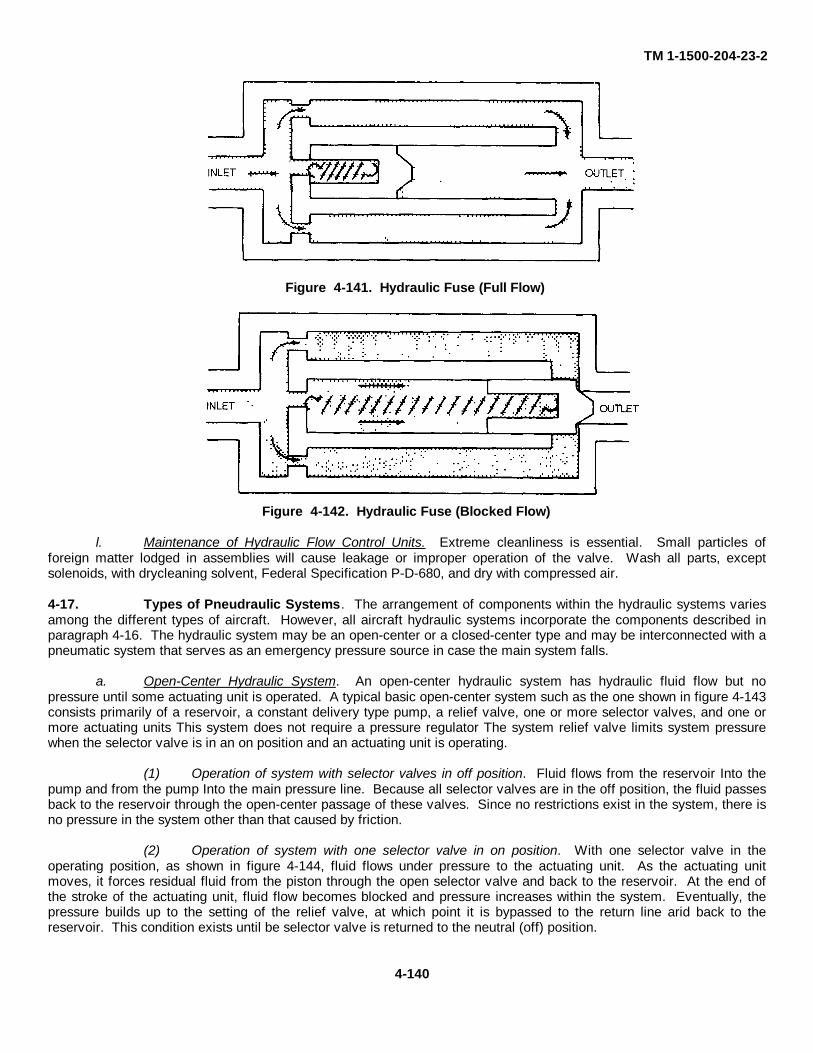
TM 1-1500-204-23-2
Figure 4-142. Hydraulic Fuse (Blocked Flow)
l. Maintenance of Hydraulic Flow Control Units. Extreme cleanliness is essential. Small particles offoreign matter lodged in assemblies will cause leakage or improper operation of the valve. Wash all parts, exceptsolenoids, with drycleaning solvent, Federal Specification P-D-680, and dry with compressed air.
4-17. Types of Pneudraulic Systems. The arrangement of components within the hydraulic systems variesamong the different types of aircraft. However, all aircraft hydraulic systems incorporate the components described inparagraph 4-16. The hydraulic system may be an open-center or a closed-center type and may be interconnected with apneumatic system that serves as an emergency pressure source in case the main system falls.
a. Open-Center Hydraulic System. An open-center hydraulic system has hydraulic fluid flow but nopressure until some actuating unit is operated. A typical basic open-center system such as the one shown in figure 4-143consists primarily of a reservoir, a constant delivery type pump, a relief valve, one or more selector valves, and one ormore actuating units This system does not require a pressure regulator The system relief valve limits system pressurewhen the selector valve is in an on position and an actuating unit is operating.
(1) Operation of system with selector valves in off position. Fluid flows from the reservoir Into thepump and from the pump Into the main pressure line. Because all selector valves are in the off position, the fluid passesback to the reservoir through the open-center passage of these valves. Since no restrictions exist in the system, there isno pressure in the system other than that caused by friction.
(2) Operation of system with one selector valve in on position. With one selector valve in theoperating position, as shown in figure 4-144, fluid flows under pressure to the actuating unit. As the actuating unitmoves, it forces residual fluid from the piston through the open selector valve and back to the reservoir. At the end ofthe stroke of the actuating unit, fluid flow becomes blocked and pressure increases within the system. Eventually, thepressure builds up to the setting of the relief valve, at which point it is bypassed to the return line arid back to thereservoir. This condition exists until be selector valve is returned to the neutral (off) position.
Figure 4-141. Hydraulic Fuse (Full Flow)
4-140
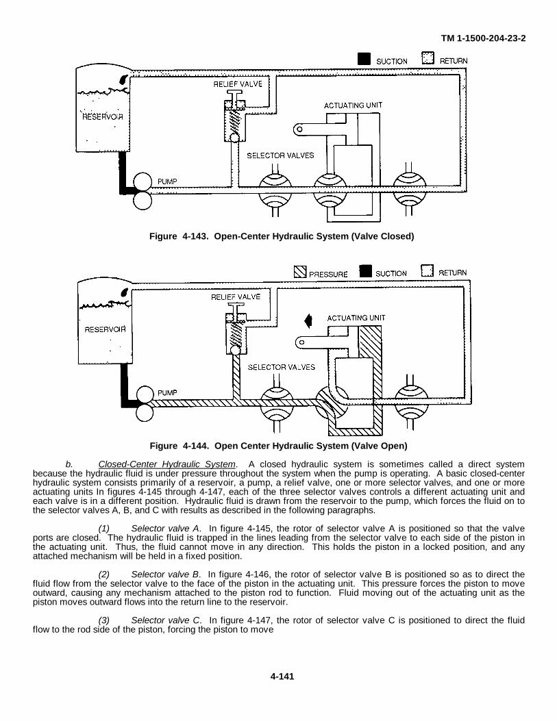
TM 1-1500-204-23-2
Figure 4-144. Open Center Hydraulic System (Valve Open)
b. Closed-Center Hydraulic System. A closed hydraulic system is sometimes called a direct systembecause the hydraulic fluid is under pressure throughout the system when the pump is operating. A basic closed-centerhydraulic system consists primarily of a reservoir, a pump, a relief valve, one or more selector valves, and one or moreactuating units In figures 4-145 through 4-147, each of the three selector valves controls a different actuating unit andeach valve is in a different position. Hydraulic fluid is drawn from the reservoir to the pump, which forces the fluid on tothe selector valves A, B, and C with results as described in the following paragraphs.
(1) Selector valve A. In figure 4-145, the rotor of selector valve A is positioned so that the valveports are closed. The hydraulic fluid is trapped in the lines leading from the selector valve to each side of the piston inthe actuating unit. Thus, the fluid cannot move in any direction. This holds the piston in a locked position, and anyattached mechanism will be held in a fixed position.
(2) Selector valve B. In figure 4-146, the rotor of selector valve B is positioned so as to direct thefluid flow from the selector valve to the face of the piston in the actuating unit. This pressure forces the piston to moveoutward, causing any mechanism attached to the piston rod to function. Fluid moving out of the actuating unit as thepiston moves outward flows into the return line to the reservoir.
(3) Selector valve C. In figure 4-147, the rotor of selector valve C is positioned to direct the fluidflow to the rod side of the piston, forcing the piston to move
Figure 4-143. Open-Center Hydraulic System (Valve Closed)
4-141

TM 1-1500-204-23-2
Figure 4-147. Selector Valve C Open
Figure 4-145. Selector Valve A Closed
Figure 4-146. Selector Valve B Open
4-142
TM 1-1500-204-23-2inward. Fluid moving of the actuating unit as the piston moves Inward flows into the return line to the reservoir.
c. Pneumatic System. Aircraft pneumatic systems are mostly used as an emergency source of pressure forhydraulically operated subsystems. The pneumatic power system usually consists of one or more high pressure aircylinders, pressure gauges, and pressure warning lights. Since the pneumatic power source does not replenish itselfduring flight, the compressed supply is good for only a certain number of operations.
(1) Construction. High pressure pneumatic systems are constructed to operate in much the samemanner as hydraulic systems. A shuttle valve connects the pneumatic system to the hydraulic system. This allows theuse of the same tubing and units for both systems. The shuttle valve separates the normal hydraulic system from thepneumatic system. Pneumatic system selector valves control the air to the subsystems. Each subsystem is connectedto the high pressure air source through a pressure regulator and relief valve assembly and a selector valve. Sincepneumatic selector valves are installed in parallel, air pressure is Immediately available to all subsystems for instantoperation. Connected in this manner, more than one system can be operated at the same time.
(2) Servicing. The air cylinders are charged through a ground test filler connection by a portablenitrogen cart or a high pressure air compressor. All nitrogen or air is filtered by a filter in the service line.
4-18. Aircraft Brake Systems. All hydraulic brake systems operate on the same basic principle. When the operatormoves a brake pedal or other brake operating control, the movement is transmitted to a master cylinder or to a powerbrake control valve from which fluid pressure is delivered through connecting lines to a brake assembly connected to awheel or shaft whose movement is to be braked. The fluid pressure acting on the brake assembly pushes brake liningsInto contact with surfaces of a rotating disc. The resulting friction slows--and finally stops--the continued rotation of thewheel or shaft to which the disc is connected. When the brake pedal or brake control is returned to the off position, brakeoperating pressure is relieved, the brake lining loses contact with the disc, and the wheel or shaft is free to turn again.
a. Wheel Brake Systems. Aircraft wheel brake systems are dual in nature in that they are composed of twoidentical subsystems that can be operated independently of each other to provide separate braking action for the landinggear on each side of the aircraft. Each subsystem is operated by a toe plate (brake pedal) that is hinge-mounted to thetop of the aircraft rudder pedal. Since each brake pedal can be operated independently the brakes can be used forsteering the aircraft. A list of components, which may be found in varying combinations to make up the different wheelbrake systems, includes the following: master cylinder (or a power brake control valve), wheel brake assembliesdeboosters, parking brake valves, shuttle valves, accumulators, connecting lines, and bottles charged with compressedair. The minimum number of parts which could be used to perform the function of a simple wheel brake system are amaster cylinder (or a power brake control valve), a wheel brake assembly, and connecting lines.
(1) Master cylinders. Master cylinders are used in some wheel brake systems as the means oftransforming force applied by the of the operator foot into fluid pressure; the greater the force applied to the pedal, thehigher the fluid pressure. Master cylinders fall into three general classifications: simple, compound, and powerboost.Within these classifications, there are many variations in shape, size, and design, depending on the manufacturer and onhow the cylinder functions in the brake system. Brake systems incorporating simple and compound master cylindersoperate independently of any other hydraulic system within the aircraft and are sometimes called independent brakesystems. In brake systems using a power boost master cylinder, some of the power needed for braking is supplied by apower-driven pump.
(a) Simple master cylinder. Some simple cylinders have integral reservoirs; others areconnected with in-line reservoirs by means of a hose. In some designs, a push rod actuates the piston; in others a pullrod performs this function. The design shown in figure 4-148 has an integral reservoir, and the piston is actuated by apush rod. Note that the illustration shows the cylinder in released position, with the compensating valve open. Thisallows any thermally expanded fluid within a connected wheel brake assembly to pass freely into the reservoir and fromthe reservoir back into the assembly to replace fluid that may have been lost due to minor leakage. When the brakepedal is depressed, the first few thousandths of an inch of travel of the master cylinder push rod closes the compensatingvalve, thus trapping the fluid that lies between the underface of the piston and the wheel brake assembly. Furtherdepression of the brake pedal moves the piston within its bore and forces fluid out of the master cylinder
4-143
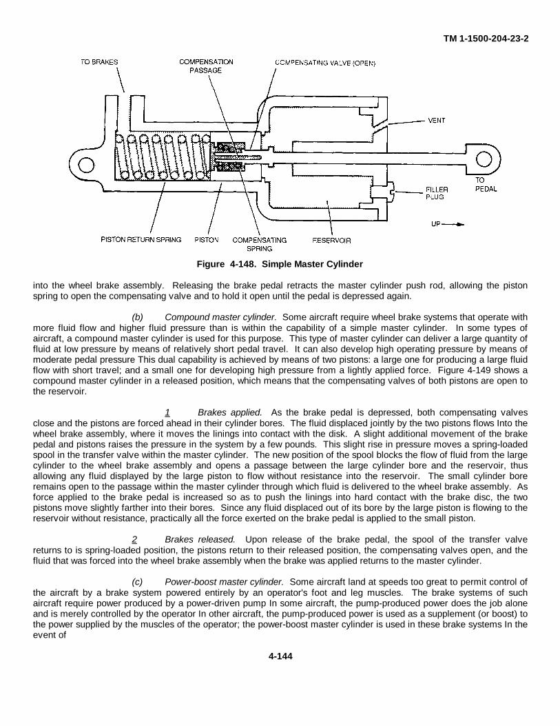
TM 1-1500-204-23-2
Figure 4-148. Simple Master Cylinder
into the wheel brake assembly. Releasing the brake pedal retracts the master cylinder push rod, allowing the pistonspring to open the compensating valve and to hold it open until the pedal is depressed again.
(b) Compound master cylinder. Some aircraft require wheel brake systems that operate withmore fluid flow and higher fluid pressure than is within the capability of a simple master cylinder. In some types ofaircraft, a compound master cylinder is used for this purpose. This type of master cylinder can deliver a large quantity offluid at low pressure by means of relatively short pedal travel. It can also develop high operating pressure by means ofmoderate pedal pressure This dual capability is achieved by means of two pistons: a large one for producing a large fluidflow with short travel; and a small one for developing high pressure from a lightly applied force. Figure 4-149 shows acompound master cylinder in a released position, which means that the compensating valves of both pistons are open tothe reservoir.
1 Brakes applied. As the brake pedal is depressed, both compensating valvesclose and the pistons are forced ahead in their cylinder bores. The fluid displaced jointly by the two pistons flows Into thewheel brake assembly, where it moves the linings into contact with the disk. A slight additional movement of the brakepedal and pistons raises the pressure in the system by a few pounds. This slight rise in pressure moves a spring-loadedspool in the transfer valve within the master cylinder. The new position of the spool blocks the flow of fluid from the largecylinder to the wheel brake assembly and opens a passage between the large cylinder bore and the reservoir, thusallowing any fluid displayed by the large piston to flow without resistance into the reservoir. The small cylinder boreremains open to the passage within the master cylinder through which fluid is delivered to the wheel brake assembly. Asforce applied to the brake pedal is increased so as to push the linings into hard contact with the brake disc, the twopistons move slightly farther into their bores. Since any fluid displaced out of its bore by the large piston is flowing to thereservoir without resistance, practically all the force exerted on the brake pedal is applied to the small piston.
2 Brakes released. Upon release of the brake pedal, the spool of the transfer valvereturns to is spring-loaded position, the pistons return to their released position, the compensating valves open, and thefluid that was forced into the wheel brake assembly when the brake was applied returns to the master cylinder.
(c) Power-boost master cylinder. Some aircraft land at speeds too great to permit control ofthe aircraft by a brake system powered entirely by an operator's foot and leg muscles. The brake systems of suchaircraft require power produced by a power-driven pump In some aircraft, the pump-produced power does the job aloneand is merely controlled by the operator In other aircraft, the pump-produced power is used as a supplement (or boost) tothe power supplied by the muscles of the operator; the power-boost master cylinder is used in these brake systems In theevent of
4-144
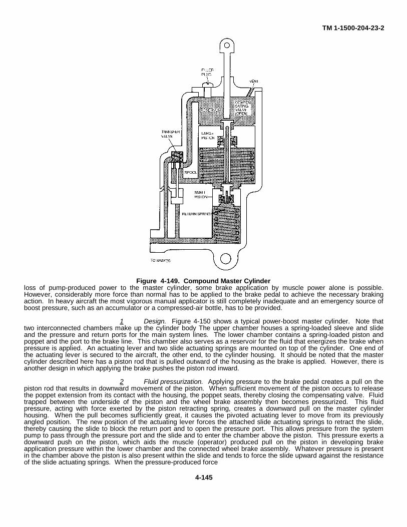
TM 1-1500-204-23-2
Figure 4-149. Compound Master Cylinderloss of pump-produced power to the master cylinder, some brake application by muscle power alone is possible.However, considerably more force than normal has to be applied to the brake pedal to achieve the necessary brakingaction. In heavy aircraft the most vigorous manual applicator is still completely inadequate and an emergency source ofboost pressure, such as an accumulator or a compressed-air bottle, has to be provided.
1 Design. Figure 4-150 shows a typical power-boost master cylinder. Note thattwo interconnected chambers make up the cylinder body The upper chamber houses a spring-loaded sleeve and slideand the pressure and return ports for the main system lines. The lower chamber contains a spring-loaded piston andpoppet and the port to the brake line. This chamber also serves as a reservoir for the fluid that energizes the brake whenpressure is applied. An actuating lever and two slide actuating springs are mounted on top of the cylinder. One end ofthe actuating lever is secured to the aircraft, the other end, to the cylinder housing. It should be noted that the mastercylinder described here has a piston rod that is pulled outward of the housing as the brake is applied. However, there isanother design in which applying the brake pushes the piston rod inward.
2 Fluid pressurization. Applying pressure to the brake pedal creates a pull on thepiston rod that results in downward movement of the piston. When sufficient movement of the piston occurs to releasethe poppet extension from its contact with the housing, the poppet seats, thereby closing the compensating valve. Fluidtrapped between the underside of the piston and the wheel brake assembly then becomes pressurized. This fluidpressure, acting with force exerted by the piston retracting spring, creates a downward pull on the master cylinderhousing. When the pull becomes sufficiently great, it causes the pivoted actuating lever to move from its previouslyangled position. The new position of the actuating lever forces the attached slide actuating springs to retract the slide,thereby causing the slide to block the return port and to open the pressure port. This allows pressure from the systempump to pass through the pressure port and the slide and to enter the chamber above the piston. This pressure exerts adownward push on the piston, which aids the muscle (operator) produced pull on the piston in developing brakeapplication pressure within the lower chamber and the connected wheel brake assembly. Whatever pressure is presentin the chamber above the piston is also present within the slide and tends to force the slide upward against the resistanceof the slide actuating springs. When the pressure-produced force
4-145
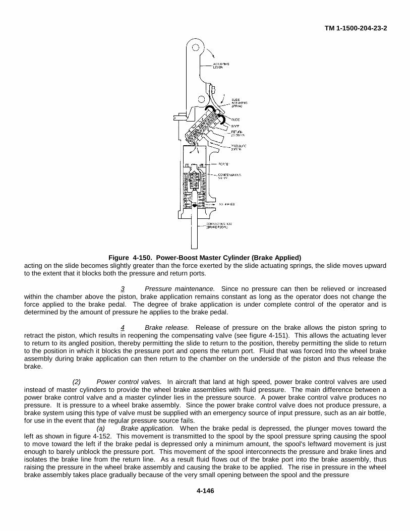
TM 1-1500-204-23-2
Figure 4-150. Power-Boost Master Cylinder (Brake Applied)acting on the slide becomes slightly greater than the force exerted by the slide actuating springs, the slide moves upwardto the extent that it blocks both the pressure and return ports.
3 Pressure maintenance. Since no pressure can then be relieved or increasedwithin the chamber above the piston, brake application remains constant as long as the operator does not change theforce applied to the brake pedal. The degree of brake application is under complete control of the operator and isdetermined by the amount of pressure he applies to the brake pedal.
4 Brake release. Release of pressure on the brake allows the piston spring toretract the piston, which results in reopening the compensating valve (see figure 4-151). This allows the actuating leverto return to its angled position, thereby permitting the slide to return to the position, thereby permitting the slide to returnto the position in which it blocks the pressure port and opens the return port. Fluid that was forced Into the wheel brakeassembly during brake application can then return to the chamber on the underside of the piston and thus release thebrake.
(2) Power control valves. In aircraft that land at high speed, power brake control valves are usedinstead of master cylinders to provide the wheel brake assemblies with fluid pressure. The main difference between apower brake control valve and a master cylinder lies in the pressure source. A power brake control valve produces nopressure. It is pressure to a wheel brake assembly. Since the power brake control valve does not produce pressure, abrake system using this type of valve must be supplied with an emergency source of input pressure, such as an air bottle,for use in the event that the regular pressure source fails.
(a) Brake application. When the brake pedal is depressed, the plunger moves toward theleft as shown in figure 4-152. This movement is transmitted to the spool by the spool pressure spring causing the spoolto move toward the left if the brake pedal is depressed only a minimum amount, the spool's leftward movement is justenough to barely unblock the pressure port. This movement of the spool interconnects the pressure and brake lines andisolates the brake line from the return line. As a result fluid flows out of the brake port into the brake assembly, thusraising the pressure in the wheel brake assembly and causing the brake to be applied. The rise in pressure in the wheelbrake assembly takes place gradually because of the very small opening between the spool and the pressure
4-146
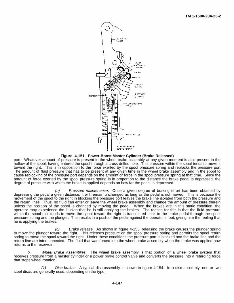
TM 1-1500-204-23-2
Figure 4-151. Power-Boost Master Cylinder (Brake Released)port. Whatever amount of pressure is present in the wheel brake assembly at any given moment is also present in thehollow of the spool, having entered the spool through a cross-drilled hole. This pressure within the spool tends to move ittoward the right. This is in opposition to the force exerted by the spool pressure spring and reblocks the pressure portThe amount of fluid pressure that has to be present at any given time in the wheel brake assembly and in the spool tocause reblocking of the pressure port depends on the amount of force in the spool pressure spring at that time. Since theamount of force exerted by the spool pressure spring is in proportion to the distance the brake pedal is depressed, thedegree of pressure with which the brake is applied depends on how far the pedal is depressed.
(b) Pressure maintenance. Once a given degree of braking effort has been obtained bydepressing the pedal a given distance, it will remain unchanged as long as the pedal is not moved. This is because themovement of the spool to the right in blocking the pressure port leaves the brake line isolated from both the pressure andthe return lines. Thus, no fluid can enter or leave the wheel brake assembly and change the amount of pressure thereinunless the position of the spool is changed by moving the pedal. When the brakes are in this static condition, theoperator may experience the illusion that he is still applying the brakes. The reason for this is that the fluid pressurewithin the spool that tends to move the spool toward the right is transmitted back to the brake pedal through the spoolpressure spring and the plunger. This results in a push of the pedal against the operator's foot, giving him the feeling thathe is applying the brakes.
(c) Brake release. As shown in figure 4-153, releasing the brake causes the plunger springto move the plunger toward the right. This releases pressure on the spool pressure spring and permits the spool returnspring to move the spool toward the right. Under these conditions the pressure port is blocked and the brake line and thereturn line are interconnected. The fluid that was forced into the wheel brake assembly when the brake was applied nowreturns to the reservoir.
b. Wheel Brake Assemblies. The wheel brake assembly is that portion of a wheel brake system thatreceives pressure from a master cylinder or a power brake control valve and converts the pressure into a retarding forcethat stops wheel rotation.
(1) Disc brakes. A typical disc assembly is shown in figure 4-154. In a disc assembly, one or twosteel discs are generally used, depending on the type
4-147
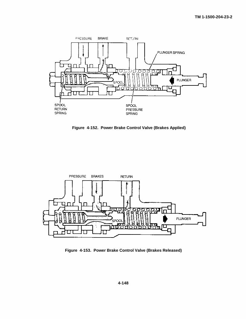
TM 1-1500-204-23-2
Figure 4-153. Power Brake Control Valve (Brakes Released)
4-148
Figure 4-152. Power Brake Control Valve (Brakes Applied)
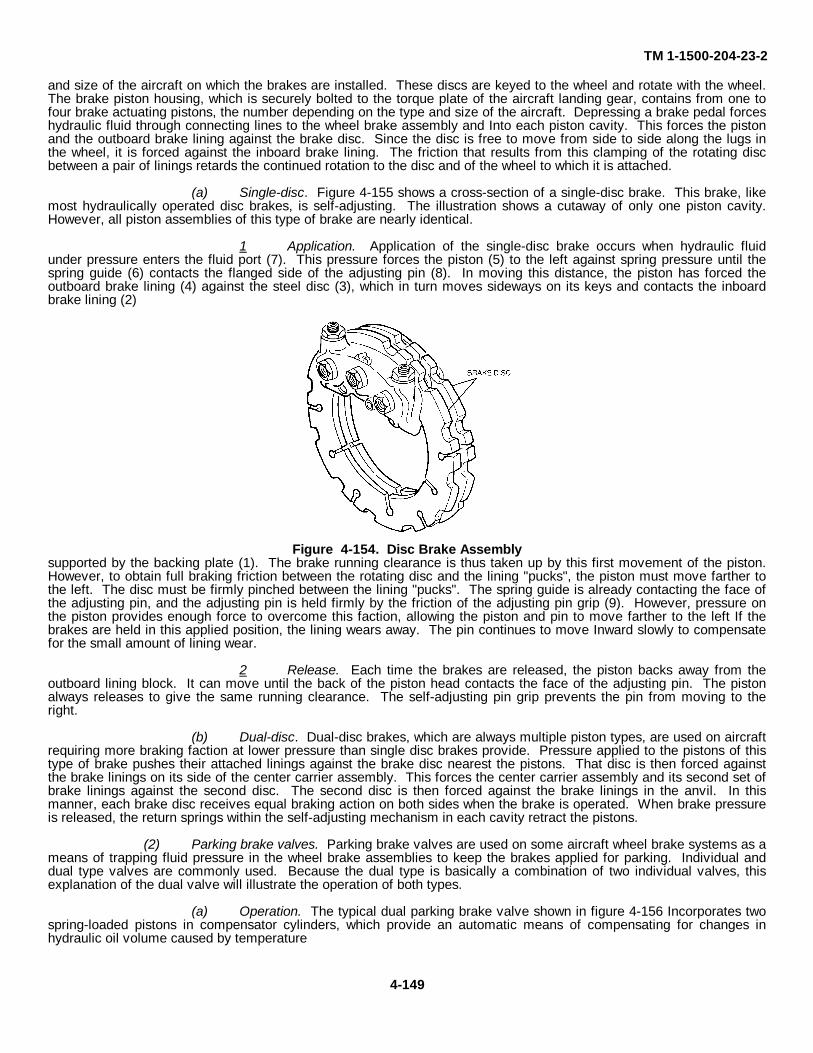
TM 1-1500-204-23-2
and size of the aircraft on which the brakes are installed. These discs are keyed to the wheel and rotate with the wheel.The brake piston housing, which is securely bolted to the torque plate of the aircraft landing gear, contains from one tofour brake actuating pistons, the number depending on the type and size of the aircraft. Depressing a brake pedal forceshydraulic fluid through connecting lines to the wheel brake assembly and Into each piston cavity. This forces the pistonand the outboard brake lining against the brake disc. Since the disc is free to move from side to side along the lugs inthe wheel, it is forced against the inboard brake lining. The friction that results from this clamping of the rotating discbetween a pair of linings retards the continued rotation to the disc and of the wheel to which it is attached.
(a) Single-disc. Figure 4-155 shows a cross-section of a single-disc brake. This brake, likemost hydraulically operated disc brakes, is self-adjusting. The illustration shows a cutaway of only one piston cavity.However, all piston assemblies of this type of brake are nearly identical.
1 Application. Application of the single-disc brake occurs when hydraulic fluidunder pressure enters the fluid port (7). This pressure forces the piston (5) to the left against spring pressure until thespring guide (6) contacts the flanged side of the adjusting pin (8). In moving this distance, the piston has forced theoutboard brake lining (4) against the steel disc (3), which in turn moves sideways on its keys and contacts the inboardbrake lining (2)
Figure 4-154. Disc Brake Assemblysupported by the backing plate (1). The brake running clearance is thus taken up by this first movement of the piston.However, to obtain full braking friction between the rotating disc and the lining "pucks", the piston must move farther tothe left. The disc must be firmly pinched between the lining "pucks". The spring guide is already contacting the face ofthe adjusting pin, and the adjusting pin is held firmly by the friction of the adjusting pin grip (9). However, pressure onthe piston provides enough force to overcome this faction, allowing the piston and pin to move farther to the left If thebrakes are held in this applied position, the lining wears away. The pin continues to move Inward slowly to compensatefor the small amount of lining wear.
2 Release. Each time the brakes are released, the piston backs away from theoutboard lining block. It can move until the back of the piston head contacts the face of the adjusting pin. The pistonalways releases to give the same running clearance. The self-adjusting pin grip prevents the pin from moving to theright.
(b) Dual-disc. Dual-disc brakes, which are always multiple piston types, are used on aircraftrequiring more braking faction at lower pressure than single disc brakes provide. Pressure applied to the pistons of thistype of brake pushes their attached linings against the brake disc nearest the pistons. That disc is then forced againstthe brake linings on its side of the center carrier assembly. This forces the center carrier assembly and its second set ofbrake linings against the second disc. The second disc is then forced against the brake linings in the anvil. In thismanner, each brake disc receives equal braking action on both sides when the brake is operated. When brake pressureis released, the return springs within the self-adjusting mechanism in each cavity retract the pistons.
(2) Parking brake valves. Parking brake valves are used on some aircraft wheel brake systems as ameans of trapping fluid pressure in the wheel brake assemblies to keep the brakes applied for parking. Individual anddual type valves are commonly used. Because the dual type is basically a combination of two individual valves, thisexplanation of the dual valve will illustrate the operation of both types.
(a) Operation. The typical dual parking brake valve shown in figure 4-156 Incorporates twospring-loaded pistons in compensator cylinders, which provide an automatic means of compensating for changes inhydraulic oil volume caused by temperature
4-149
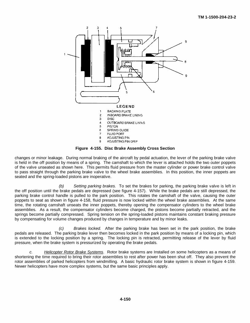
TM 1-1500-204-23-2
Figure 4-155. Disc Brake Assembly Cross Section
changes or minor leakage. During normal braking of the aircraft by pedal actuation, the lever of the parking brake valveis held in the off position by means of a spring. The camshaft to which the lever is attached holds the two outer poppetsof the valve unseated as shown here. This permits fluid pressure from the master cylinder or power brake control valveto pass straight through the parking brake valve to the wheel brake assemblies. In this position, the inner poppets areseated and the spring-loaded pistons are inoperative.
(b) Setting parking brakes. To set the brakes for parking, the parking brake valve is left inthe off position until the brake pedals are depressed (see figure 4-157). While the brake pedals are still depressed, theparking brake control handle is pulled to the park position. This rotates the camshaft of the valve, causing the outerpoppets to seat as shown in figure 4-158, fluid pressure is now locked within the wheel brake assemblies. At the sametime, the rotating camshaft unseats the inner poppets, thereby opening the compensator cylinders to the wheel brakeassemblies. As a result, the compensator cylinders become charged, the pistons become partially retracted, and thesprings become partially compressed. Spring tension on the spring-loaded pistons maintains constant braking pressureby compensating for volume changes produced by changes in temperature and by minor leaks.
(c) Brakes locked. After the parking brake has been set in the park position, the brakepedals are released. The parking brake lever then becomes locked in the park position by means of a locking pin, whichis extended to the locking position by a spring. The locking pin is retracted, permitting release of the lever by fluidpressure, when the brake system is pressurized by operating the brake pedals.
c. Helicopter Rotor Brake Systems. Rotor brake systems are Installed on some helicopters as a means ofshortening the time required to bring their rotor assemblies to rest after power has been shut off. They also prevent therotor assemblies of parked helicopters from windmilling. A basic hydraulic rotor brake system is shown in figure 4-159.Newer helicopters have more complex systems, but the same basic principles apply.
4-150
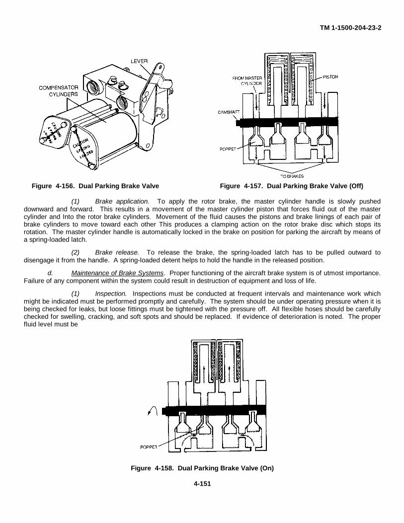
TM 1-1500-204-23-2
Figure 4-156. Dual Parking Brake Valve Figure 4-157. Dual Parking Brake Valve (Off)
(1) Brake application. To apply the rotor brake, the master cylinder handle is slowly pusheddownward and forward. This results in a movement of the master cylinder piston that forces fluid out of the mastercylinder and Into the rotor brake cylinders. Movement of the fluid causes the pistons and brake linings of each pair ofbrake cylinders to move toward each other This produces a clamping action on the rotor brake disc which stops itsrotation. The master cylinder handle is automatically locked in the brake on position for parking the aircraft by means ofa spring-loaded latch.
(2) Brake release. To release the brake, the spring-loaded latch has to be pulled outward todisengage it from the handle. A spring-loaded detent helps to hold the handle in the released position.
d. Maintenance of Brake Systems. Proper functioning of the aircraft brake system is of utmost importance.Failure of any component within the system could result in destruction of equipment and loss of life.
(1) Inspection. Inspections must be conducted at frequent intervals and maintenance work whichmight be indicated must be performed promptly and carefully. The system should be under operating pressure when it isbeing checked for leaks, but loose fittings must be tightened with the pressure off. All flexible hoses should be carefullychecked for swelling, cracking, and soft spots and should be replaced. If evidence of deterioration is noted. The properfluid level must be
Figure 4-158. Dual Parking Brake Valve (On)
4-151
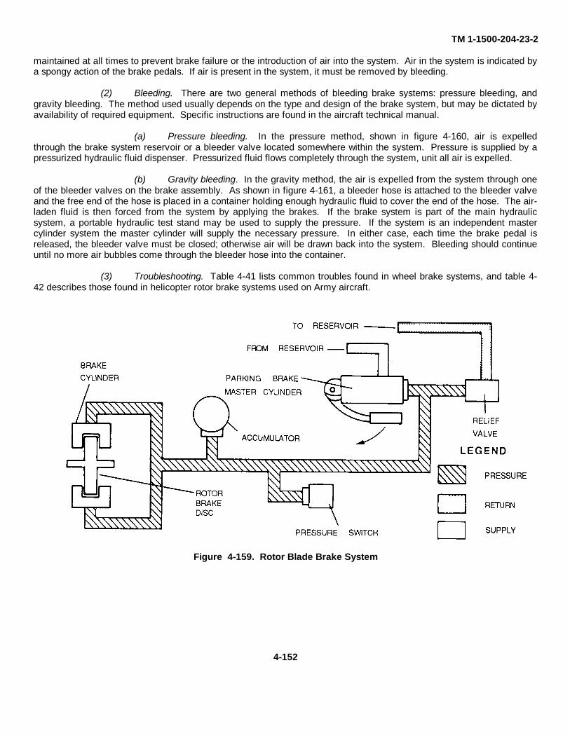
TM 1-1500-204-23-2
maintained at all times to prevent brake failure or the introduction of air into the system. Air in the system is indicated bya spongy action of the brake pedals. If air is present in the system, it must be removed by bleeding.
(2) Bleeding. There are two general methods of bleeding brake systems: pressure bleeding, andgravity bleeding. The method used usually depends on the type and design of the brake system, but may be dictated byavailability of required equipment. Specific instructions are found in the aircraft technical manual.
(a) Pressure bleeding. In the pressure method, shown in figure 4-160, air is expelledthrough the brake system reservoir or a bleeder valve located somewhere within the system. Pressure is supplied by apressurized hydraulic fluid dispenser. Pressurized fluid flows completely through the system, unit all air is expelled.
(b) Gravity bleeding. In the gravity method, the air is expelled from the system through oneof the bleeder valves on the brake assembly. As shown in figure 4-161, a bleeder hose is attached to the bleeder valveand the free end of the hose is placed in a container holding enough hydraulic fluid to cover the end of the hose. The air-laden fluid is then forced from the system by applying the brakes. If the brake system is part of the main hydraulicsystem, a portable hydraulic test stand may be used to supply the pressure. If the system is an independent mastercylinder system the master cylinder will supply the necessary pressure. In either case, each time the brake pedal isreleased, the bleeder valve must be closed; otherwise air will be drawn back into the system. Bleeding should continueuntil no more air bubbles come through the bleeder hose into the container.
(3) Troubleshooting. Table 4-41 lists common troubles found in wheel brake systems, and table 4-42 describes those found in helicopter rotor brake systems used on Army aircraft.
Figure 4-159. Rotor Blade Brake System
4-152
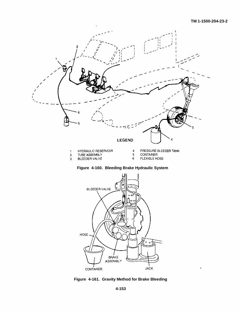
TM 1-1500-204-23-2
Figure 4-161. Gravity Method for Brake Bleeding
4-153
Figure 4-160. Bleeding Brake Hydraulic System
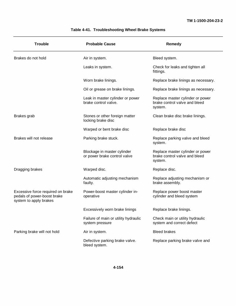
TM 1-1500-204-23-2
Table 4-41. Troubleshooting Wheel Brake Systems
Trouble Probable Cause Remedy
Brakes do not hold Air in system. Bleed system.
Leaks in system. Check for leaks and tighten allfittings.
Worn brake linings. Replace brake linings as necessary.
Oil or grease on brake linings. Replace brake linings as necessary.
Leak in master cylinder or power Replace master cylinder or powerbrake control valve. brake control valve and bleed
system.
Brakes grab Stones or other foreign matter Clean brake disc brake linings.locking brake disc
Warped or bent brake disc Replace brake disc
Brakes will not release Parking brake stuck. Replace parking valve and bleedsystem.
Blockage in master cylinder Replace master cylinder or poweror power brake control valve brake control valve and bleed
system.
Dragging brakes Warped disc. Replace disc.
Automatic adjusting mechanism Replace adjusting mechanism orfaulty. brake assembly.
Excessive force required on brake Power-boost master cylinder in- Replace power boost masterpedals of power-boost brake operative cylinder and bleed systemsystem to apply brakes
Excessively worn brake linings Replace brake linings.
Failure of main or utility hydraulic Check main or utility hydraulicsystem pressure system and correct defect
Parking brake will not hold Air in system. Bleed brakes
Defective parking brake valve. Replace parking brake valve andbleed system.
4-154
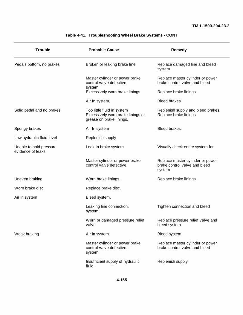
TM 1-1500-204-23-2
Table 4-41. Troubleshooting Wheel Brake Systems - CONT
Trouble Probable Cause Remedy
Pedals bottom, no brakes Broken or leaking brake line. Replace damaged line and bleedsystem
Master cylinder or power brake Replace master cylinder or powercontrol valve defective brake control valve and bleedsystem.Excessively worn brake linings. Replace brake linings.
Air In system. Bleed brakes
Solid pedal and no brakes Too little fluid in system Replenish supply and bleed brakes.Excessively worn brake linings or Replace brake liningsgrease on brake linings.
Spongy brakes Air In system Bleed brakes.
Low hydraulic fluid level Replenish supply
Unable to hold pressure Leak In brake system Visually check entire system forevidence of leaks.
Master cylinder or power brake Replace master cylinder or powercontrol valve defective brake control valve and bleed
system
Uneven braking Worn brake linings. Replace brake linings.
Worn brake disc. Replace brake disc.
Air in system Bleed system.
Leaking line connection. Tighten connection and bleedsystem.
Worn or damaged pressure relief Replace pressure relief valve andvalve bleed system
Weak braking Air in system. Bleed system
Master cylinder or power brake Replace master cylinder or powercontrol valve defective. brake control valve and bleedsystem
Insufficient supply of hydraulic Replenish supplyfluid.
4-155
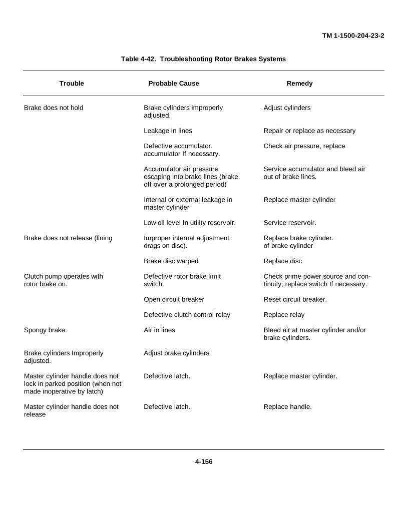
TM 1-1500-204-23-2
Table 4-42. Troubleshooting Rotor Brakes Systems
Trouble Probable Cause Remedy
Brake does not hold Brake cylinders improperly Adjust cylindersadjusted.
Leakage in lines Repair or replace as necessary
Defective accumulator. Check air pressure, replaceaccumulator If necessary.
Accumulator air pressure Service accumulator and bleed airescaping into brake lines (brake out of brake lines.off over a prolonged period)
Internal or external leakage in Replace master cylindermaster cylinder
Low oil level In utility reservoir. Service reservoir.
Brake does not release (lining Improper internal adjustment Replace brake cylinder.drags on disc). of brake cylinder
Brake disc warped Replace disc
Clutch pump operates with Defective rotor brake limit Check prime power source and con-rotor brake on. switch. tinuity; replace switch If necessary.
Open circuit breaker Reset circuit breaker.
Defective clutch control relay Replace relay
Spongy brake. Air in lines Bleed air at master cylinder and/orbrake cylinders.
Brake cylinders Improperly Adjust brake cylindersadjusted.
Master cylinder handle does not Defective latch. Replace master cylinder.lock in parked position (when notmade inoperative by latch)
Master cylinder handle does not Defective latch. Replace handle.release
4-156
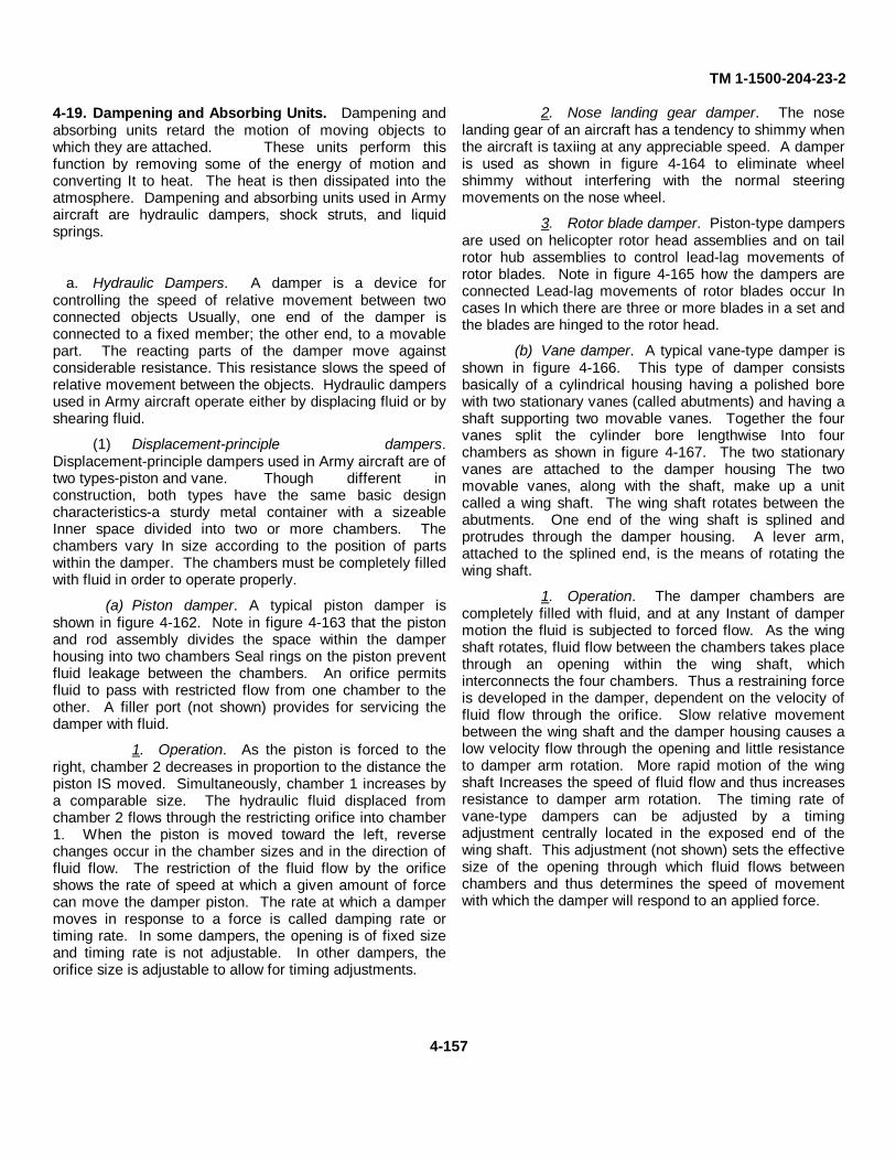
TM 1-1500-204-23-2
4-19. Dampening and Absorbing Units. Dampening andabsorbing units retard the motion of moving objects towhich they are attached. These units perform thisfunction by removing some of the energy of motion andconverting It to heat. The heat is then dissipated into theatmosphere. Dampening and absorbing units used in Armyaircraft are hydraulic dampers, shock struts, and liquidsprings.
a. Hydraulic Dampers. A damper is a device forcontrolling the speed of relative movement between twoconnected objects Usually, one end of the damper isconnected to a fixed member; the other end, to a movablepart. The reacting parts of the damper move againstconsiderable resistance. This resistance slows the speed ofrelative movement between the objects. Hydraulic dampersused in Army aircraft operate either by displacing fluid or byshearing fluid.
(1) Displacement-principle dampers.Displacement-principle dampers used in Army aircraft are oftwo types-piston and vane. Though different inconstruction, both types have the same basic designcharacteristics-a sturdy metal container with a sizeableInner space divided into two or more chambers. Thechambers vary In size according to the position of partswithin the damper. The chambers must be completely filledwith fluid in order to operate properly.
(a) Piston damper. A typical piston damper isshown in figure 4-162. Note in figure 4-163 that the pistonand rod assembly divides the space within the damperhousing into two chambers Seal rings on the piston preventfluid leakage between the chambers. An orifice permitsfluid to pass with restricted flow from one chamber to theother. A filler port (not shown) provides for servicing thedamper with fluid.
1. Operation. As the piston is forced to theright, chamber 2 decreases in proportion to the distance thepiston IS moved. Simultaneously, chamber 1 increases bya comparable size. The hydraulic fluid displaced fromchamber 2 flows through the restricting orifice into chamber1. When the piston is moved toward the left, reversechanges occur in the chamber sizes and in the direction offluid flow. The restriction of the fluid flow by the orificeshows the rate of speed at which a given amount of forcecan move the damper piston. The rate at which a dampermoves in response to a force is called damping rate ortiming rate. In some dampers, the opening is of fixed sizeand timing rate is not adjustable. In other dampers, theorifice size is adjustable to allow for timing adjustments.
2. Nose landing gear damper. The noselanding gear of an aircraft has a tendency to shimmy whenthe aircraft is taxiing at any appreciable speed. A damperis used as shown in figure 4-164 to eliminate wheelshimmy without interfering with the normal steeringmovements on the nose wheel.
3. Rotor blade damper. Piston-type dampersare used on helicopter rotor head assemblies and on tailrotor hub assemblies to control lead-lag movements ofrotor blades. Note in figure 4-165 how the dampers areconnected Lead-lag movements of rotor blades occur Incases In which there are three or more blades in a set andthe blades are hinged to the rotor head.
(b) Vane damper. A typical vane-type damper isshown in figure 4-166. This type of damper consistsbasically of a cylindrical housing having a polished borewith two stationary vanes (called abutments) and having ashaft supporting two movable vanes. Together the fourvanes split the cylinder bore lengthwise Into fourchambers as shown in figure 4-167. The two stationaryvanes are attached to the damper housing The twomovable vanes, along with the shaft, make up a unitcalled a wing shaft. The wing shaft rotates between theabutments. One end of the wing shaft is splined andprotrudes through the damper housing. A lever arm,attached to the splined end, is the means of rotating thewing shaft.
1. Operation. The damper chambers arecompletely filled with fluid, and at any Instant of dampermotion the fluid is subjected to forced flow. As the wingshaft rotates, fluid flow between the chambers takes placethrough an opening within the wing shaft, whichinterconnects the four chambers. Thus a restraining forceis developed in the damper, dependent on the velocity offluid flow through the orifice. Slow relative movementbetween the wing shaft and the damper housing causes alow velocity flow through the opening and little resistanceto damper arm rotation. More rapid motion of the wingshaft Increases the speed of fluid flow and thus increasesresistance to damper arm rotation. The timing rate ofvane-type dampers can be adjusted by a timingadjustment centrally located in the exposed end of thewing shaft. This adjustment (not shown) sets the effectivesize of the opening through which fluid flows betweenchambers and thus determines the speed of movementwith which the damper will respond to an applied force.
4-157
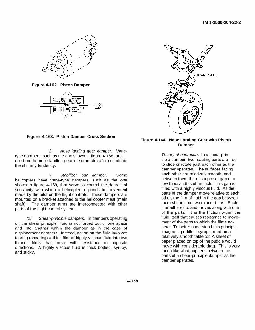
TM 1-1500-204-23-2
Figure 4-163. Piston Damper Cross Section
2 Nose landing gear damper. Vane-type dampers, such as the one shown in figure 4-168, areused on the nose landing gear of some aircraft to eliminatethe shimmy tendency.
3 Stabilizer bar damper. Somehelicopters have vane-type dampers, such as the oneshown in figure 4-169, that serve to control the degree ofsensitivity with which a helicopter responds to movementmade by the pilot on the flight controls. These dampers aremounted on a bracket attached to the helicopter mast (mainshaft). The damper arms are interconnected with otherparts of the flight control system.
(2) Shear-principle dampers. In dampers operatingon the shear principle, fluid is not forced out of one spaceand into another within the damper as in the case ofdisplacement dampers. Instead, action on the fluid involvestearing (shearing) a thick film of highly viscous fluid into twothinner films that move with resistance in oppositedirections. A highly viscous fluid is thick bodied, syrupy,and sticky.
Figure 4-164. Nose Landing Gear with PistonDamper
Theory of operation. In a shear-prin-ciple damper, two reacting parts are freeto slide or rotate past each other as thedamper operates. The surfaces facingeach other are relatively smooth, andbetween them there is a preset gap of afew thousandths of an inch. This gap isfilled with a highly viscous fluid. As theparts of the damper move relative to eachother, the film of fluid In the gap betweenthem shears into two thinner films. Eachfilm adheres to and moves along with oneof the parts. It is the friction within thefluid itself that causes resistance to move-ment of the parts to which the films ad-here. To better understand this principle,imagine a puddle if syrup spilled on arelatively smooth table top A sheet ofpaper placed on top of the puddle wouldmove with considerable drag. This is verymuch like what happens between theparts of a shear-principle damper as thedamper operates.
Figure 4-162. Piston Damper
4-158
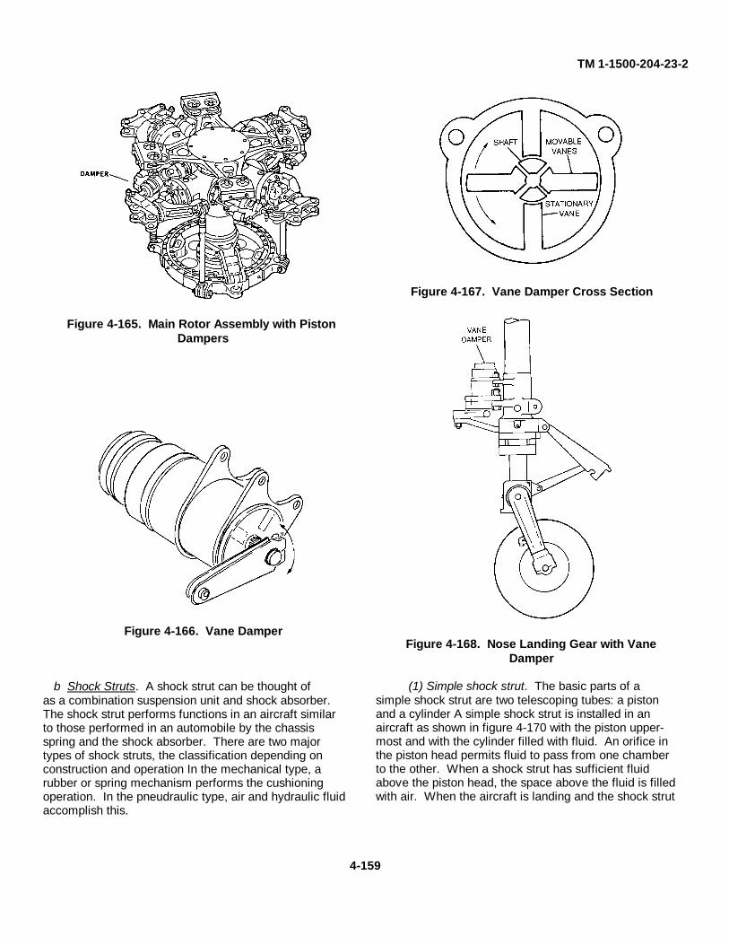
TM 1-1500-204-23-2
Figure 4-165. Main Rotor Assembly with PistonDampers
Figure 4-166. Vane Damper
b Shock Struts. A shock strut can be thought ofas a combination suspension unit and shock absorber.The shock strut performs functions in an aircraft similarto those performed in an automobile by the chassisspring and the shock absorber. There are two majortypes of shock struts, the classification depending onconstruction and operation In the mechanical type, arubber or spring mechanism performs the cushioningoperation. In the pneudraulic type, air and hydraulic fluidaccomplish this.
Figure 4-167. Vane Damper Cross Section
Figure 4-168. Nose Landing Gear with VaneDamper
(1) Simple shock strut. The basic parts of asimple shock strut are two telescoping tubes: a pistonand a cylinder A simple shock strut is installed in anaircraft as shown in figure 4-170 with the piston upper-most and with the cylinder filled with fluid. An orifice inthe piston head permits fluid to pass from one chamberto the other. When a shock strut has sufficient fluidabove the piston head, the space above the fluid is filledwith air. When the aircraft is landing and the shock strut
4-159
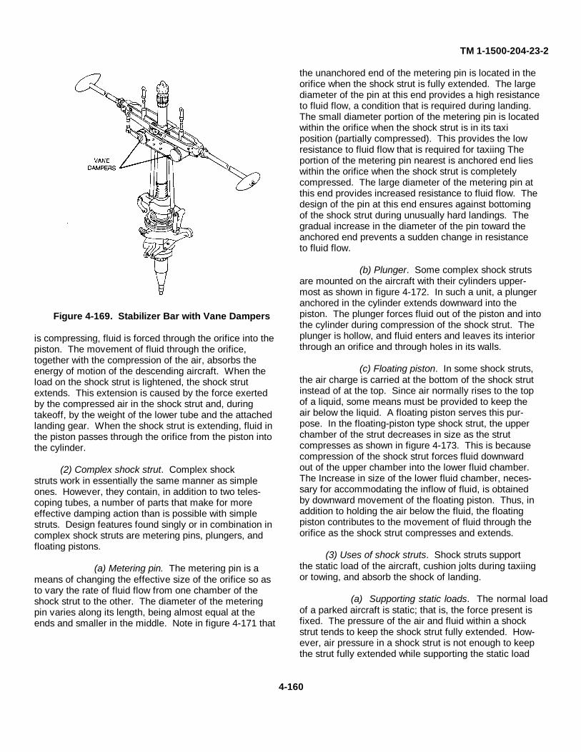
TM 1-1500-204-23-2
Figure 4-169. Stabilizer Bar with Vane Dampers
is compressing, fluid is forced through the orifice into thepiston. The movement of fluid through the orifice,together with the compression of the air, absorbs theenergy of motion of the descending aircraft. When theload on the shock strut is lightened, the shock strutextends. This extension is caused by the force exertedby the compressed air in the shock strut and, duringtakeoff, by the weight of the lower tube and the attachedlanding gear. When the shock strut is extending, fluid inthe piston passes through the orifice from the piston intothe cylinder.
(2) Complex shock strut. Complex shockstruts work in essentially the same manner as simpleones. However, they contain, in addition to two teles-coping tubes, a number of parts that make for moreeffective damping action than is possible with simplestruts. Design features found singly or in combination incomplex shock struts are metering pins, plungers, andfloating pistons.
(a) Metering pin. The metering pin is ameans of changing the effective size of the orifice so asto vary the rate of fluid flow from one chamber of theshock strut to the other. The diameter of the meteringpin varies along its length, being almost equal at theends and smaller in the middle. Note in figure 4-171 that
the unanchored end of the metering pin is located in theorifice when the shock strut is fully extended. The largediameter of the pin at this end provides a high resistanceto fluid flow, a condition that is required during landing.The small diameter portion of the metering pin is locatedwithin the orifice when the shock strut is in its taxiposition (partially compressed). This provides the lowresistance to fluid flow that is required for taxiing Theportion of the metering pin nearest is anchored end lieswithin the orifice when the shock strut is completelycompressed. The large diameter of the metering pin atthis end provides increased resistance to fluid flow. Thedesign of the pin at this end ensures against bottomingof the shock strut during unusually hard landings. Thegradual increase in the diameter of the pin toward theanchored end prevents a sudden change in resistanceto fluid flow.
(b) Plunger. Some complex shock strutsare mounted on the aircraft with their cylinders upper-most as shown in figure 4-172. In such a unit, a plungeranchored in the cylinder extends downward into thepiston. The plunger forces fluid out of the piston and intothe cylinder during compression of the shock strut. Theplunger is hollow, and fluid enters and leaves its interiorthrough an orifice and through holes in its walls.
(c) Floating piston. In some shock struts,the air charge is carried at the bottom of the shock strutinstead of at the top. Since air normally rises to the topof a liquid, some means must be provided to keep theair below the liquid. A floating piston serves this pur-pose. In the floating-piston type shock strut, the upperchamber of the strut decreases in size as the strutcompresses as shown in figure 4-173. This is becausecompression of the shock strut forces fluid downwardout of the upper chamber into the lower fluid chamber.The Increase in size of the lower fluid chamber, neces-sary for accommodating the inflow of fluid, is obtainedby downward movement of the floating piston. Thus, inaddition to holding the air below the fluid, the floatingpiston contributes to the movement of fluid through theorifice as the shock strut compresses and extends.
(3) Uses of shock struts. Shock struts supportthe static load of the aircraft, cushion jolts during taxiingor towing, and absorb the shock of landing.
(a) Supporting static loads. The normal loadof a parked aircraft is static; that is, the force present isfixed. The pressure of the air and fluid within a shockstrut tends to keep the shock strut fully extended. How-ever, air pressure in a shock strut is not enough to keepthe strut fully extended while supporting the static load
4-160
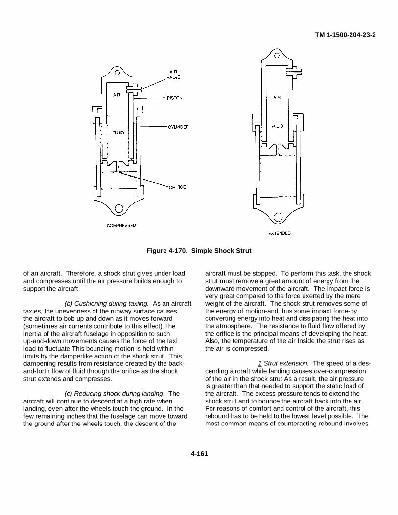
TM 1-1500-204-23-2
Figure 4-170. Simple Shock Strut
of an aircraft. Therefore, a shock strut gives under loadand compresses until the air pressure builds enough tosupport the aircraft
(b) Cushioning during taxiing. As an aircrafttaxies, the unevenness of the runway surface causesthe aircraft to bob up and down as it moves forward(sometimes air currents contribute to this effect) Theinertia of the aircraft fuselage in opposition to suchup-and-down movements causes the force of the taxiload to fluctuate This bouncing motion is held withinlimits by the damperlike action of the shock strut. Thisdampening results from resistance created by the back-and-forth flow of fluid through the orifice as the shockstrut extends and compresses.
(c) Reducing shock during landing. Theaircraft will continue to descend at a high rate whenlanding, even after the wheels touch the ground. In thefew remaining inches that the fuselage can move towardthe ground after the wheels touch, the descent of the
aircraft must be stopped. To perform this task, the shockstrut must remove a great amount of energy from thedownward movement of the aircraft. The Impact force isvery great compared to the force exerted by the mereweight of the aircraft. The shock strut removes some ofthe energy of motion-and thus some impact force-byconverting energy into heat and dissipating the heat intothe atmosphere. The resistance to fluid flow offered bythe orifice is the principal means of developing the heat.Also, the temperature of the air Inside the strut rises asthe air is compressed.
1 Strut extension. The speed of a des-cending aircraft while landing causes over-compressionof the air in the shock strut As a result, the air pressureis greater than that needed to support the static load ofthe aircraft. The excess pressure tends to extend theshock strut and to bounce the aircraft back into the air.For reasons of comfort and control of the aircraft, thisrebound has to be held to the lowest level possible. Themost common means of counteracting rebound involves
4-161
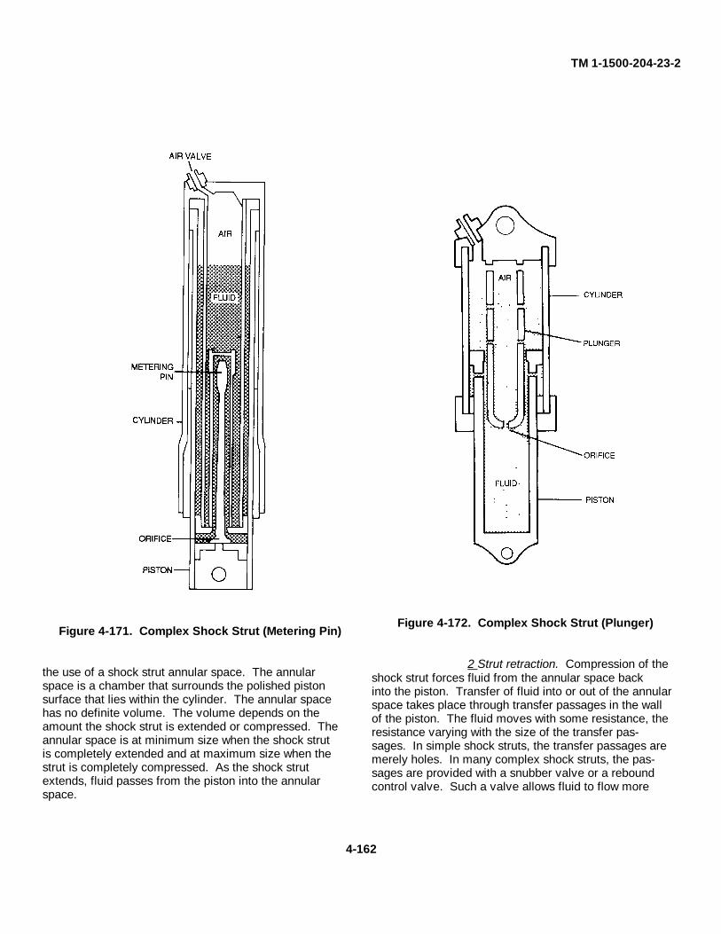
TM 1-1500-204-23-2
Figure 4-171. Complex Shock Strut (Metering Pin)
the use of a shock strut annular space. The annularspace is a chamber that surrounds the polished pistonsurface that lies within the cylinder. The annular spacehas no definite volume. The volume depends on theamount the shock strut is extended or compressed. Theannular space is at minimum size when the shock strutis completely extended and at maximum size when thestrut is completely compressed. As the shock strutextends, fluid passes from the piston into the annularspace.
Figure 4-172. Complex Shock Strut (Plunger)
2 Strut retraction. Compression of theshock strut forces fluid from the annular space backinto the piston. Transfer of fluid into or out of the annularspace takes place through transfer passages in the wallof the piston. The fluid moves with some resistance, theresistance varying with the size of the transfer pas-sages. In simple shock struts, the transfer passages aremerely holes. In many complex shock struts, the pas-sages are provided with a snubber valve or a reboundcontrol valve. Such a valve allows fluid to flow more
4-162
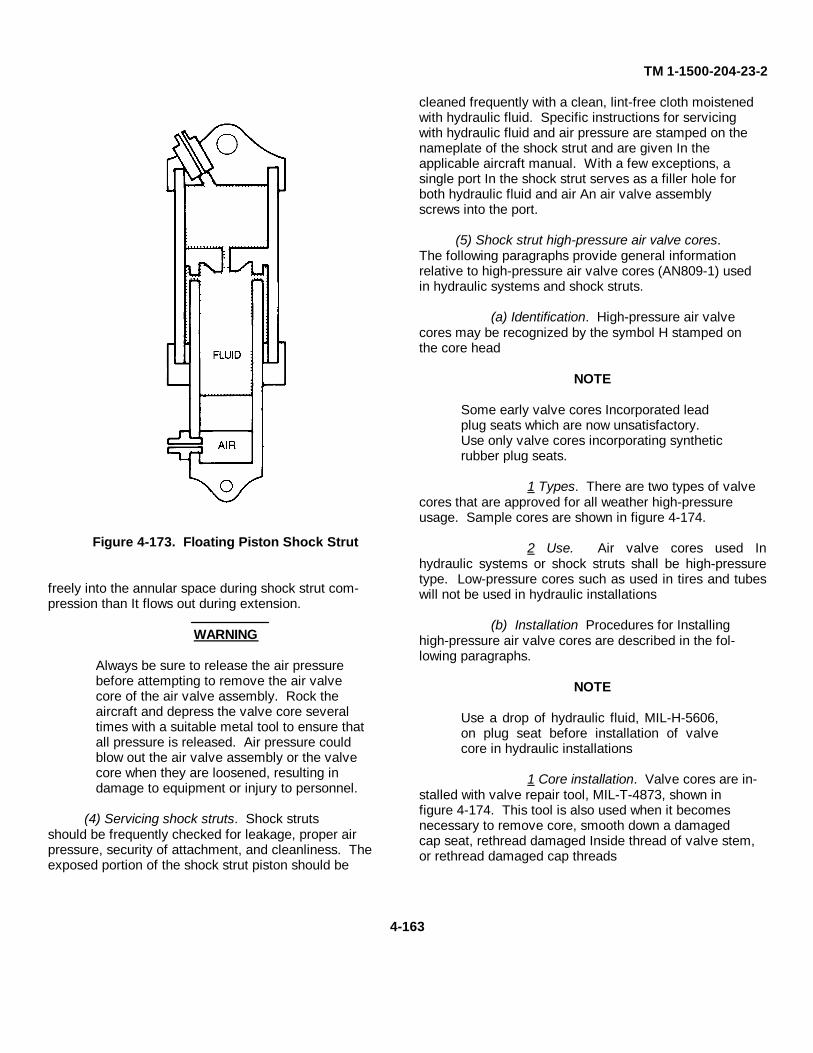
TM 1-1500-204-23-2
Figure 4-173. Floating Piston Shock Strut
freely into the annular space during shock strut com-pression than It flows out during extension.
WARNING
Always be sure to release the air pressurebefore attempting to remove the air valvecore of the air valve assembly. Rock theaircraft and depress the valve core severaltimes with a suitable metal tool to ensure thatall pressure is released. Air pressure couldblow out the air valve assembly or the valvecore when they are loosened, resulting indamage to equipment or injury to personnel.
(4) Servicing shock struts. Shock strutsshould be frequently checked for leakage, proper airpressure, security of attachment, and cleanliness. Theexposed portion of the shock strut piston should be
cleaned frequently with a clean, lint-free cloth moistenedwith hydraulic fluid. Specific instructions for servicingwith hydraulic fluid and air pressure are stamped on thenameplate of the shock strut and are given In theapplicable aircraft manual. With a few exceptions, asingle port In the shock strut serves as a filler hole forboth hydraulic fluid and air An air valve assemblyscrews into the port.
(5) Shock strut high-pressure air valve cores.The following paragraphs provide general informationrelative to high-pressure air valve cores (AN809-1) usedin hydraulic systems and shock struts.
(a) Identification. High-pressure air valvecores may be recognized by the symbol H stamped onthe core head
NOTE
Some early valve cores Incorporated leadplug seats which are now unsatisfactory.Use only valve cores incorporating syntheticrubber plug seats.
1 Types. There are two types of valvecores that are approved for all weather high-pressureusage. Sample cores are shown in figure 4-174.
2 Use. Air valve cores used Inhydraulic systems or shock struts shall be high-pressuretype. Low-pressure cores such as used in tires and tubeswill not be used in hydraulic installations
(b) Installation Procedures for Installinghigh-pressure air valve cores are described in the fol-lowing paragraphs.
NOTE
Use a drop of hydraulic fluid, MIL-H-5606,on plug seat before installation of valvecore in hydraulic installations
1 Core installation. Valve cores are in-stalled with valve repair tool, MIL-T-4873, shown infigure 4-174. This tool is also used when it becomesnecessary to remove core, smooth down a damagedcap seat, rethread damaged Inside thread of valve stem,or rethread damaged cap threads
4-163
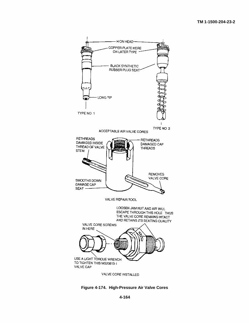
TM 1-1500-204-23-2
Figure 4-174. High-Pressure Air Valve Cores
4-164
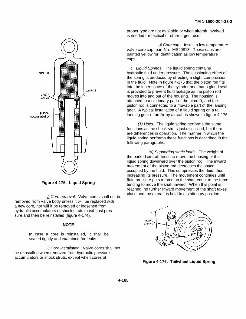
TM 1-1500-204-23-2
Figure 4-175. Liquid Spring
2 Core removal. Valve cores shall not beremoved from valve body unless it will be replaced witha new core, nor will it be removed or loosened fromhydraulic accumulators or shock struts to exhaust pres-sure and then be reinstalled (figure 4-174).
NOTE
In case a core is reinstalled, it shall beseated tightly and examined for leaks.
3 Core installation. Valve cores shall notbe reinstalled when removed from hydraulic pressureaccumulators or shock struts, except when cores of
proper type are not available or when aircraft involvedis needed for tactical or other urgent use.
4 Core cap. Install a low temperaturevalve core cap, part No. MS20813. These caps arepainted yellow for identification as low temperaturecaps.
c. Liquid Springs. The liquid spring containshydraulic fluid under pressure. The cushioning effect ofthe spring is produced by effecting a slight compressionin the fluid. Note in figure 4-175 that the piston rod fitsinto the inner space of the cylinder and that a gland sealis provided to prevent fluid leakage as the piston rodmoves into and out of the housing. The housing isattached to a stationary part of the aircraft, and thepiston rod is connected to a movable part of the landinggear. A typical installation of a liquid spring on a taillanding gear of an Army aircraft is shown in figure 4-176.
(1) Uses. The liquid spring performs the samefunctions as the shock struts just discussed, but thereare differences in operation. The manner in which theliquid spring performs these functions is described in thefollowing paragraphs.
(a) Supporting static loads. The weight ofthe parked aircraft tends to move the housing of theliquid spring downward over the piston rod. The inwardmovement of the piston rod decreases the spaceoccupied by the fluid. This compresses the fluid, thusincreasing Its pressure. The movement continues untilfluid pressure puts a force on the shaft equal to the forcetending to move the shaft inward. When this point isreached, no further Inward movement of the shaft takesplace and the aircraft is held In a stationary position.
Figure 4-176. Tailwheel Liquid Spring
4-165
TM 1-1500-204-23-2
(b) Cushioning during taxiing. The liquidspring controls the bouncing motion of the aircraft inmuch the same way as the shock strut does. As thepiston in the liquid spring moves inward and outward Inrelation to its housing, there is a back-and-forth move-ment of fluid through an orifice in the piston. This fluidflow restrains the rate at which the piston moves, thusdampening the up-and-down movements of the aircraftfuselage.
(c) Reducing shock during landing. In theliquid spring, the resistance to fluid flow necessary toconvert motion energy to heat energy is effected bymeans of a check valve in the piston. As the liquid springcompresses, fluid flows through the check valve Inaddition to flowing through the orifice. During extension,the check valve closes and fluid then passes throughthe orifice only. The additional restraint that is set up tothe movement of fluid from one side of the piston to theother provides rebound control during landing.
(2) Servicing. The liquid spring can be ser-viced as follows'
(a) The exposed portion of the liquid springshaft should be cleaned by using a clean, lint-free clothmoistened with hydraulic fluid.
(b) When the liquid spring is serviced to thecorrect level with the proper type of hydraulic fluid, thefluid is under pressure A special gun, which looks likea hand grease gun, is used to force the fluid Inside thespring.
NOTE
Specific servicing instructions are stampedon the nameplate of the spring and are alsoincluded In the manual for the aircraft.
4-20. Use of Test Stands. The purpose of theaircraft hydraulic test stand is to perform the followingtest operations on aircraft hydraulic systems flush orfill the system with micronically filtered hydraulic fluid,provide a source of hydraulic pressure for testing aircrafthydraulic systems without the necessity of operating theaircraft engine, and test all components of the aircrafthydraulic systems, including aircraft with pressurizedreservoir systems. The appropriate aircraft and equip-ment technical manuals must be consulted prior to useof any test stand This manual contains only generalguidelines for their use.
a. Safety. Prior to use of a test stand, it is essen-tial that the personnel responsible for its operation arecompletely familiar with procedures and operation of theequipment.
WARNING
Always wear ear protection when noiseproduced by test stand engines exceedsestablished limits. Failure to comply willresult in serious injury to personnel.
Do not connect or disconnect any hoseswith the fluid bypass valve closed andthe test stand inoperation. High pressurecontained in the hose may injure person-nel
b. Procedures. General operating procedures are asfollows:
(1) Set the parking brake to secure the test standin position.
(2) Perform the operator inspection of the teststand
(3) Connect the test stand coupling halves to thecorresponding outlets on the aircraft. Keep unused cou-plings capped at all times.
(4) Open the fluid bypass valve.
(5) Start the engine in accordance with ap-plicable operating procedures.
(6) Adjust the pump delivery for requirements ofthe aircraft under test.
WARNING
Do not connect or disconnect any hoseswith the fluid bypass valve closed and thetest stand In operation. High pressurecontained in the hose may injurepersonnel.
(7) Slowly close the fluid bypass valve.
4-166

TM 1-1500-204-23-2
(8) Adjust the pressure relief valve to relievepressure at approximately 200 psi above the systempressure of the system under test.
(9) Open the flow control valves and proceedwith the test In accordance with the applicable aircrafttechnical manual
(10) Following the test procedure, open thebypass valve
(11) Close the flow control valves
(12) Allow the engine to cool as required by thespecific operating procedures
(13) Shut down test stand In accordance withapplicable operating procedures
(14) Disconnect couplings from aircraft and capImmediately to prevent contamination.
(15) Release parking brake and tow test standfrom work area
4-21. Conversion of Aircraft to Fire-ResistantHydraulic Fluid . Following are general guidelines forconversion of Army aircraft from MIL-H-5606 to MIL-H-83282 hydraulic fluid.
a. Hydraulic Fluid MIL-H-5606. MIL-H-5606 is apetroleum base hydraulic fluid and IS presently specifiedfor use In some Army rotary wing and fixed wing aircraftBecause of its relatively low flashpoint of 200°F (93 C),It has been considered a safety hazard In an effort toremove the vulnerability of aircraft systems and relatedsupport equipment to accidental or combat-incurredfires, hydraulic fluid MIL-H-83282 has been developedas a directly interchangeable fluid which is significantlyless susceptible to fire, with a flashpoint of 400°F(204°C).
b. Hydraulic Fluid MIL-H-83282. MIL-H-83282consists of a synthetic hydrocarbon base and containsadditives which provide superior anti-wear charac-teristics and inhibit oxidation and corrosion. MIL-H-83282 has an operational high temperature limit of400°F (204 C) as compared to 275°F degrees (135 C)for MIL-H-5606. These factors should provide sig-nificantly improved reliability. Flashpoint, fire point, andspontaneous ignition temperatures of MIL-H-83282 ex-ceed that of MIL-H-5606 by greater than 200°F (93 C),
and tests show that MIL-H-83282 extinguishes itselfwhen the external source of flame or heat is removedMIL-H-83282 is compatible with all materials used insystems presently employing hydraulic fluid MIL-H-5606 and may be combined with the latter fluid with noadverse effect except a degradation of Its fire resistantproperties. However, the presence of MIL-H-5606 inamounts exceeding 3 percent by volume will com-promise the fire resistant performance of MIL-H-83282.Although MIL-H-83282 exceeds the performance ofMIL-H-5606 at normal temperatures, the viscosity ofMIL-H-83282 increases at low temperatures, therefore,use of MIL-H-83282 must be within the limitations setforth in paragraph 4-21f.
c. Applications of MIL-H-83282. The fire hazardsof MIL-H-5606 are greatest in flight control systemswhich are under high pressure and which have a rela-tively large volume of fluid The aircraft hydraulic sys-tems and components shown in table 4-43 will beconverted from MIL-H-5606 to MIL-H-83282.
d. Non-Applicability of MIL-H-83282. The com-ponents shown In table 4-44 will retain MIL-H-5606hydraulic fluid. These components cannot be readilyserviced by field personnel or have not been tested forMIL-H-83282. In the event that the temperature limita-tions in paragraph b above are exceeded, field person-nel will be unable to change these components fromMIL-H-83282 back to MIL-H-5606.
e. Conversion Procedures. Procedures will beperformed at Direct Support or higher levels of main-tenance unless otherwise directed by reference to aspecific maintenance manual Refer to the applicableaircraft Technical Manual or to TB 55-1500-334-25 forspecific conversion procedures
f. Operating Temperature Limitations. AlthoughMIL-H-83282 operates well under normal temperatures,the viscosity of the fluid increases as the temperaturedecreases Therefore, the minimum ambient operatingtemperatures shown In table 4-45 have been estab-lished for the use of MIL-H-83282. These temperaturesare based on a cloid soak of the hydraulic fluid at lowtemperatures. Aircraft that are sheltered or pre-heatedprior to engine start should not have any problems withstiff or sluggish flight controls. Unless the shelteredareas are at or below the temperatures in table 4-45, theviscosity of MIL-H-83282 will not create any difficulty.Once the aircraft is started and warm, the hydraulic fluidshould stabilize within normal operating limits.
4-167
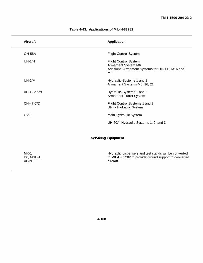
TM 1-1500-204-23-2
Table 4-43. Applications of MIL-H-83282
Aircraft Application
OH-58A Flight Control System
UH-1/H Flight Control SystemArmament System M6Additional Armament Systems for UH-1 B, M16 andM21
UH-1/M Hydraulic Systems 1 and 2Armament Systems M6, 16, 21
AH-1 Series Hydraulic Systems 1 and 2Armament Turret System
CH-47 C/D Flight Control Systems 1 and 2Utility Hydraulic System
OV-1 Main Hydraulic System
UH-60A Hydraulic Systems 1, 2, and 3
Servicing Equipment
MK-1 Hydraulic dispensers and test stands will be convertedD6, MSU-1 to MIL-H-83282 to provide ground support to convertedAGPU aircraft.
4-168
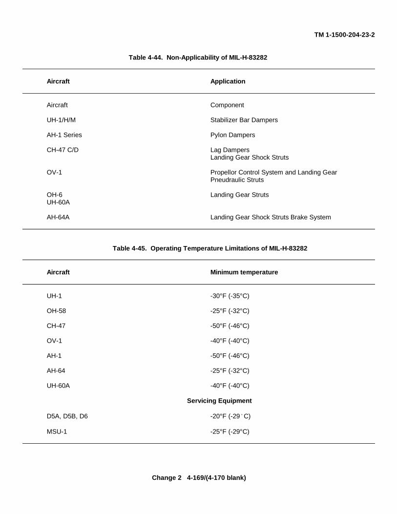
TM 1-1500-204-23-2
Table 4-44. Non-Applicability of MIL-H-83282
Aircraft Application
Aircraft Component
UH-1/H/M Stabilizer Bar Dampers
AH-1 Series Pylon Dampers
CH-47 C/D Lag DampersLanding Gear Shock Struts
OV-1 Propellor Control System and Landing GearPneudraulic Struts
OH-6 Landing Gear StrutsUH-60A
AH-64A Landing Gear Shock Struts Brake System
Table 4-45. Operating Temperature Limitations of MIL-H-83282
Aircraft Minimum temperature
UH-1 -30°F (-35°C)
OH-58 -25°F (-32°C)
CH-47 -50°F (-46°C)
OV-1 -40°F (-40°C)
AH-1 -50°F (-46°C)
AH-64 -25°F (-32°C)
UH-60A -40°F (-40°C)
Servicing Equipment
D5A, D5B, D6 -20°F (-29 C)
MSU-1 -25°F (-29°C)
Change 2 4-169/(4-170 blank)
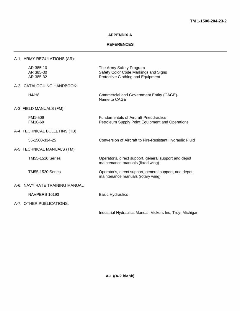
TM 1-1500-204-23-2
APPENDIX A
REFERENCES
A-1. ARMY REGULATIONS (AR):
AR 385-10 The Army Safety ProgramAR 385-30 Safety Color Code Markings and SignsAR 385-32 Protective Clothing and Equipment
A-2. CATALOGUING HANDBOOK:
H4/H8 Commercial and Government Entity (CAGE)-Name to CAGE
A-3 FIELD MANUALS (FM):
FM1-509 Fundamentals of Aircraft PneudraulicsFM10-69 Petroleum Supply Point Equipment and Operations
A-4 TECHNICAL BULLETINS (TB)
55-1500-334-25 Conversion of Aircraft to Fire-Resistant Hydraulic Fluid
A-5 TECHNICAL MANUALS (TM)
TM55-1510 Series Operator's, direct support, general support and depotmaintenance manuals (fixed wing)
TM55-1520 Series Operator's, direct support, general support, and depotmaintenance manuals (rotary wing)
A-6. NAVY RATE TRAINING MANUAL
NAVPERS 16193 Basic Hydraulics
A-7. OTHER PUBLICATIONS.
Industrial Hydraulics Manual, Vickers Inc, Troy, Michigan
A-1 /(A-2 blank)
TM 1-1500-204-23-2
GLOSSARY
AC (AIR CORPS)- Flared tube fittings. Now obsolete.
AN (ARMY-NAVY) - Flared tube fittings
AXIAL- Pertaining to an axis, commonly refers to flow of fluid or air througha component parallel to that component's lengthwise axis.
BOURDON TUBE - Tube in an instrument that tends to straighten when fluid or airpressure acts upon it, thereby acting on an indicating needle.
BUNA N - Synthetic rubber compound with excellent resistance to petroleumproducts; used as material for flexible hose.
CHAMFER - A beveled edge.
COLD FLOW - Deep, permanent impressions in flexible hose produced bypressure from hose clamps or supports.
FIRE POINT - Temperature at which fluid gives off vapor in sufficient quantity toignite and continue to burn when exposed to a spark or flame.
FLASH POINT - Temperature at which fluid gives off vapor in sufficient quantity toignite momentarily or flash when exposed to a spark of flame.
GASKET- Hydraulic seal used In applications where there is no relative motion.
MICRON - 0000394 inch or 1/1000th millimeter.
MONEL- High-strength nickel steel used for rivets and other materials usedin high-heat applications.
MS (MILITARY STANDARD) - Designation of certain materials used in aircraft maintenance.
PACKING - Hydraulic seal used in areas of relative motion.
PERMASWAGE - Repair technique for permanent installation of fittings squeezedonto hydraulic tubing under very high pressure.
PHENOLIC - Cotton fabric filled with a phenolic resin to form a hard materialsuitable for fairleads, supports, etc.
SAE (SOCIETY OF AUTOMOTIVEENGINEERS) - Standards for thread sizes, metal identification numbers, etc.
Glossary 1
TM 1-1500-204-23-2
GLOSSARY-CONT
SOLENOID - Switch using an electromagnetic field to hold it is one position.
SWAGING - Process of installing a fitting on tubing by squeezing it under veryhigh pressure.
TETRAFLUOROETHYLENE - Compound commonly known as Teflon used in flexible hose, back-up rings, gaskets, etc.
VISCOSITY - A fluid's internal resistance to flow.
Glossary 2
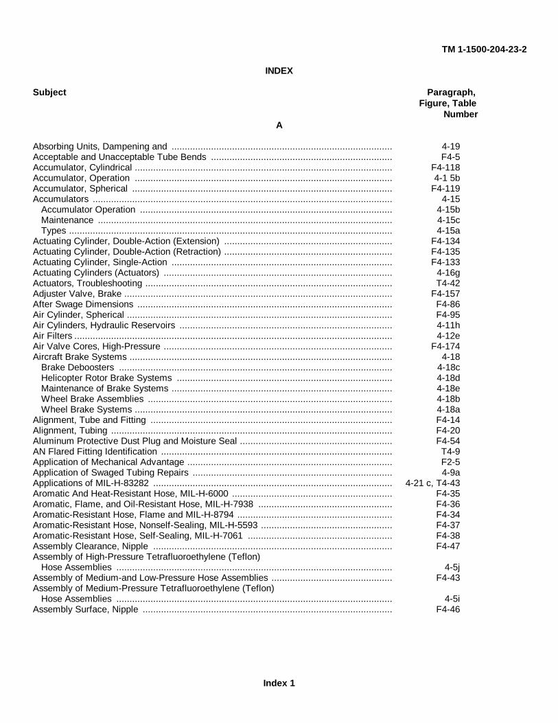
TM 1-1500-204-23-2
INDEX
Subject Paragraph,Figure, Table
NumberA
Absorbing Units, Dampening and .................................................................................... 4-19Acceptable and Unacceptable Tube Bends ..................................................................... F4-5Accumulator, Cylindrical .................................................................................................. F4-118Accumulator, Operation .................................................................................................. 4-1 5bAccumulator, Spherical ................................................................................................... F4-119Accumulators .................................................................................................................. 4-15
Accumulator Operation ................................................................................................ 4-15bMaintenance ................................................................................................................ 4-15cTypes ........................................................................................................................... 4-15a
Actuating Cylinder, Double-Action (Extension) ................................................................ F4-134Actuating Cylinder, Double-Action (Retraction) ................................................................ F4-135Actuating Cylinder, Single-Action .................................................................................... F4-133Actuating Cylinders (Actuators) ....................................................................................... 4-16gActuators, Troubleshooting .............................................................................................. T4-42Adjuster Valve, Brake ...................................................................................................... F4-157After Swage Dimensions ................................................................................................. F4-86Air Cylinder, Spherical ..................................................................................................... F4-95Air Cylinders, Hydraulic Reservoirs ................................................................................. 4-11hAir Filters ......................................................................................................................... 4-12eAir Valve Cores, High-Pressure ....................................................................................... F4-174Aircraft Brake Systems .................................................................................................... 4-18
Brake Deboosters ........................................................................................................ 4-18cHelicopter Rotor Brake Systems .................................................................................. 4-18dMaintenance of Brake Systems .................................................................................... 4-18eWheel Brake Assemblies ............................................................................................. 4-18bWheel Brake Systems .................................................................................................. 4-18a
Alignment, Tube and Fitting ............................................................................................ F4-14Alignment, Tubing ........................................................................................................... F4-20Aluminum Protective Dust Plug and Moisture Seal .......................................................... F4-54AN Flared Fitting Identification ........................................................................................ T4-9Application of Mechanical Advantage .............................................................................. F2-5Application of Swaged Tubing Repairs ............................................................................ 4-9aApplications of MIL-H-83282 ........................................................................................... 4-21 c, T4-43Aromatic And Heat-Resistant Hose, MIL-H-6000 ............................................................. F4-35Aromatic, Flame, and Oil-Resistant Hose, MIL-H-7938 ................................................... F4-36Aromatic-Resistant Hose, Flame and MIL-H-8794 ........................................................... F4-34Aromatic-Resistant Hose, Nonself-Sealing, MIL-H-5593 .................................................. F4-37Aromatic-Resistant Hose, Self-Sealing, MIL-H-7061 ....................................................... F4-38Assembly Clearance, Nipple ........................................................................................... F4-47Assembly of High-Pressure Tetrafluoroethylene (Teflon)
Hose Assemblies ......................................................................................................... 4-5jAssembly of Medium-and Low-Pressure Hose Assemblies .............................................. F4-43Assembly of Medium-Pressure Tetrafluoroethylene (Teflon)
Hose Assemblies ......................................................................................................... 4-5iAssembly Surface, Nipple ............................................................................................... F4-46
Index 1
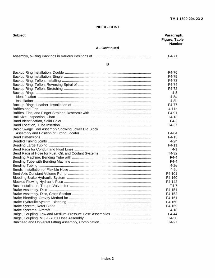
TM 1-1500-204-23-2
INDEX - CONT
Subject Paragraph,Figure, Table
NumberA - Continued
Assembly, V-Ring Packings in Various Positions of ......................................................... F4-71
B
Backup Ring Installation, Double ..................................................................................... F4-76Backup Ring Installation, Single ...................................................................................... F4-75Backup Ring, Teflon, Installing ........................................................................................ F4-73Backup Ring, Teflon, Reversing Spiral of ........................................................................ F4-74Backup Ring, Teflon, Stretching ...................................................................................... F4-72Backup Rings .................................................................................................................. 4-8
Identification ................................................................................................................ 4-8aInstallation ................................................................................................................... 4-8b
Backup Rings, Leather, Installation of ............................................................................. F4-77Baffles and Fins .............................................................................................................. 4-11cBaffles, Fins, and Finger Strainer, Reservoir with ............................................................ F4-91Ball Size, Inspection, Chart ............................................................................................. T4-13Band Identification, Solid Color ....................................................................................... F4-2Band Location, Tube Insertion ......................................................................................... T4-37Basic Swage Tool Assembly Showing Lower Die Block
Assembly and Position of Fitting Locator ...................................................................... F4-84Bead Dimensions ............................................................................................................ F4-13Beaded Tubing Joints ...................................................................................................... 4-2hBeading Large Tubing ..................................................................................................... F4-11Bend Radii for Conduit and Fluid Lines ........................................................................... T4-1Bend Radii of Hose for Fuel, Oil, and Coolant Systems ................................................... T4-32Bending Machine, Bending Tube with .............................................................................. F4-4Bending Tube with Bending Machine ............................................................................... F4-4Bending Tubing ............................................................................................................... 4-2eBends, Installation of Flexible Hose ................................................................................. 4-2cBent-Axis Constant-Volume Pump .................................................................................. F4-101Bleeding Brake Hydraulic System ................................................................................... F4-160Blocked Flowing Hydraulic Fuse ...................................................................................... F4-142Boss Installation, Torque Valves for ................................................................................ T4-7Brake Assembly, Disc ..................................................................................................... F4-151Brake Assembly, Disc, Cross Section .............................................................................. F4-152Brake Bleeding, Gravity Method for ................................................................................. F4-161Brake Hydraulic System, Bleeding .................................................................................. F4-160Brake System, Rotor Blade ............................................................................................. F4-159Brake Systems, Aircraft ................................................................................................... 4-18Bulge, Coupling, Low-and Medium-Pressure Hose Assemblies ....................................... F4-44Bulge, Coupling, MIL-H-7061 Hose Assembly ................................................................. T4-30Bulkhead and Universal Fitting Assembly, Combination .................................................. T4-27
Index 2
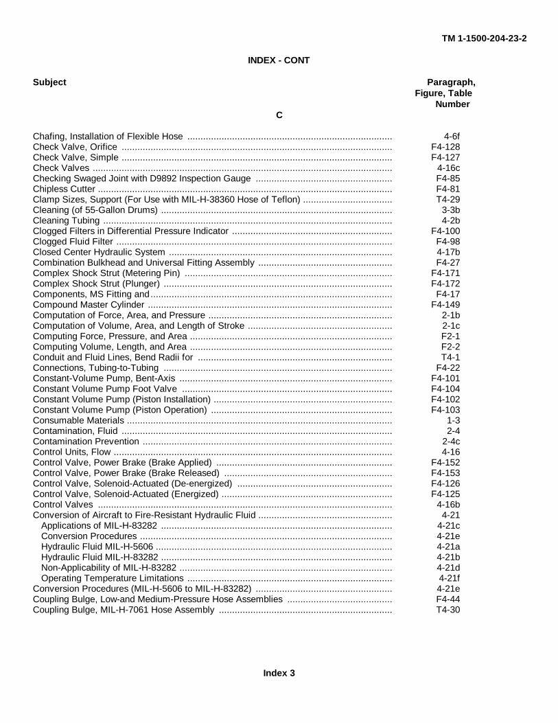
TM 1-1500-204-23-2
INDEX - CONT
Subject Paragraph,Figure, Table
NumberC
Chafing, Installation of Flexible Hose .............................................................................. 4-6fCheck Valve, Orifice ....................................................................................................... F4-128Check Valve, Simple ....................................................................................................... F4-127Check Valves .................................................................................................................. 4-16cChecking Swaged Joint with D9892 Inspection Gauge .................................................... F4-85Chipless Cutter ................................................................................................................ F4-81Clamp Sizes, Support (For Use with MIL-H-38360 Hose of Teflon) .................................. T4-29Cleaning (of 55-Gallon Drums) ........................................................................................ 3-3bCleaning Tubing .............................................................................................................. 4-2bClogged Filters in Differential Pressure Indicator ............................................................. F4-100Clogged Fluid Filter ......................................................................................................... F4-98Closed Center Hydraulic System ..................................................................................... 4-17bCombination Bulkhead and Universal Fitting Assembly ................................................... F4-27Complex Shock Strut (Metering Pin) ............................................................................... F4-171Complex Shock Strut (Plunger) ....................................................................................... F4-172Components, MS Fitting and............................................................................................ F4-17Compound Master Cylinder ............................................................................................. F4-149Computation of Force, Area, and Pressure ...................................................................... 2-1bComputation of Volume, Area, and Length of Stroke ....................................................... 2-1cComputing Force, Pressure, and Area ............................................................................. F2-1Computing Volume, Length, and Area ............................................................................. F2-2Conduit and Fluid Lines, Bend Radii for .......................................................................... T4-1Connections, Tubing-to-Tubing ....................................................................................... F4-22Constant-Volume Pump, Bent-Axis ................................................................................. F4-101Constant Volume Pump Foot Valve ................................................................................ F4-104Constant Volume Pump (Piston Installation) .................................................................... F4-102Constant Volume Pump (Piston Operation) ..................................................................... F4-103Consumable Materials ..................................................................................................... 1-3Contamination, Fluid ....................................................................................................... 2-4Contamination Prevention ............................................................................................... 2-4cControl Units, Flow .......................................................................................................... 4-16Control Valve, Power Brake (Brake Applied) ................................................................... F4-152Control Valve, Power Brake (Brake Released) ................................................................ F4-153Control Valve, Solenoid-Actuated (De-energized) ........................................................... F4-126Control Valve, Solenoid-Actuated (Energized) ................................................................. F4-125Control Valves ................................................................................................................ 4-16bConversion of Aircraft to Fire-Resistant Hydraulic Fluid ................................................... 4-21
Applications of MIL-H-83282 ........................................................................................ 4-21cConversion Procedures ................................................................................................ 4-21eHydraulic Fluid MIL-H-5606 .......................................................................................... 4-21aHydraulic Fluid MIL-H-83282 ........................................................................................ 4-21bNon-Applicability of MIL-H-83282 ................................................................................. 4-21dOperating Temperature Limitations .............................................................................. 4-21f
Conversion Procedures (MIL-H-5606 to MIL-H-83282) .................................................... 4-21eCoupling Bulge, Low-and Medium-Pressure Hose Assemblies ........................................ F4-44Coupling Bulge, MIL-H-7061 Hose Assembly .................................................................. T4-30
Index 3
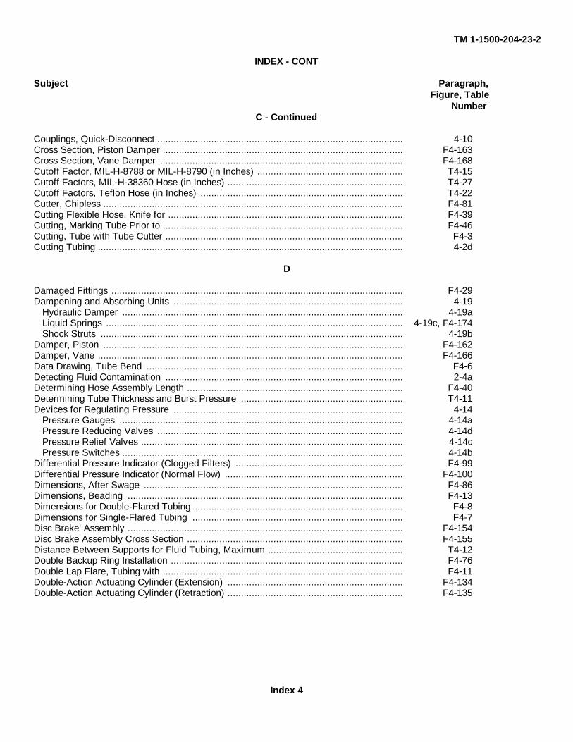
TM 1-1500-204-23-2
INDEX - CONT
Subject Paragraph,Figure, Table
NumberC - Continued
Couplings, Quick-Disconnect ........................................................................................... 4-10Cross Section, Piston Damper ......................................................................................... F4-163Cross Section, Vane Damper .......................................................................................... F4-168Cutoff Factor, MIL-H-8788 or MIL-H-8790 (in Inches) ...................................................... T4-15Cutoff Factors, MIL-H-38360 Hose (in Inches) ................................................................. T4-27Cutoff Factors, Teflon Hose (in Inches) ........................................................................... T4-22Cutter, Chipless ............................................................................................................... F4-81Cutting Flexible Hose, Knife for ....................................................................................... F4-39Cutting, Marking Tube Prior to ......................................................................................... F4-46Cutting, Tube with Tube Cutter ........................................................................................ F4-3Cutting Tubing ................................................................................................................. 4-2d
D
Damaged Fittings ............................................................................................................ F4-29Dampening and Absorbing Units ..................................................................................... 4-19
Hydraulic Damper ........................................................................................................ 4-19aLiquid Springs .............................................................................................................. 4-19c, F4-174Shock Struts ................................................................................................................ 4-19b
Damper, Piston ............................................................................................................... F4-162Damper, Vane ................................................................................................................. F4-166Data Drawing, Tube Bend ............................................................................................... F4-6Detecting Fluid Contamination ........................................................................................ 2-4aDetermining Hose Assembly Length ................................................................................ F4-40Determining Tube Thickness and Burst Pressure ............................................................ T4-11Devices for Regulating Pressure ..................................................................................... 4-14
Pressure Gauges ......................................................................................................... 4-14aPressure Reducing Valves ........................................................................................... 4-14dPressure Relief Valves ................................................................................................. 4-14cPressure Switches ........................................................................................................ 4-14b
Differential Pressure Indicator (Clogged Filters) .............................................................. F4-99Differential Pressure Indicator (Normal Flow) .................................................................. F4-100Dimensions, After Swage ................................................................................................ F4-86Dimensions, Beading ...................................................................................................... F4-13Dimensions for Double-Flared Tubing ............................................................................. F4-8Dimensions for Single-Flared Tubing .............................................................................. F4-7Disc Brake' Assembly ...................................................................................................... F4-154Disc Brake Assembly Cross Section ................................................................................ F4-155Distance Between Supports for Fluid Tubing, Maximum .................................................. T4-12Double Backup Ring Installation ...................................................................................... F4-76Double Lap Flare, Tubing with ......................................................................................... F4-11Double-Action Actuating Cylinder (Extension) ................................................................. F4-134Double-Action Actuating Cylinder (Retraction) ................................................................. F4-135
Index 4
TM 1-1500-204-23-2
INDEX - CONT
Subject Paragraph,Figure, Table
Number
D - Continued
Double-Action Hand Pump .............................................................................................. F4-111Double-Flared Tubing, Dimensions for ............................................................................ F4-8Dual Internal O-Ring Removal ........................................................................................ F4-64Dual Parking Brake Valve ............................................................................................... F4-156Dual Parking Brake Valve (Off) ....................................................................................... F4-157Dual Parking Brake Valve (On) ....................................................................................... F4-158Dust Cap (AN-SAE Friction), Plastic Protective ............................................................... F4-56Dust Cap, Plastic Protective ............................................................................................ F4-55Dust Cap, Steel Protective .............................................................................................. F4-53Dust Plug and Moisture Seal, Aluminum Protective ......................................................... F4-54Dust Plug and Moisture Seal (AN-SAE Threaded) Plastic Protective ............................... F4-51Dust Plug and Moisture Seal, Steel Protective ................................................................ F4-52
E
Ease of Installation (of Hydraulic Systems) ..................................................................... 2-2cEase of Operation (of Hydraulic Systems) ....................................................................... 2-2bEfficiency (of Hydraulic Systems) .................................................................................... 2-2aElliptical Rings ................................................................................................................ 4-7b, F4-70External O-Ring Installation ............................................................................................. F4-69External O-Ring Removal (Spoon-Type Tools) ................................................................ F4-65External O-Ring Removal (Wedge-Type Tools) .............................................................. F4-66
F
Failure Modes and Recommended (Permaswage) Repair Methods ................................. F4-79Field Assembly of High Pressure Teflon Hose, MIL-H-38360 ........................................... F4-50Field Disassembly of Teflon Hose ................................................................................... F4-45Field Fabrication of High-Pressure Hose Assemblies ...................................................... F4-41Filter Element Bypass Valve, Hydraulic Reservoirs ......................................................... 4-11fFilter Elements, Hydraulic Reservoirs .............................................................................. 4-11eFilter Elements, Hydraulic Systems Filters ...................................................................... 4-12cFilter Elements, Reservoir with ........................................................................................ F4-94Filter, Fluid, Assembly ..................................................................................................... F4-96Filters, Hydraulic System ................................................................................................ 4-12Finger Strainers, Hydraulic Reservoirs ............................................................................ 4-11dFingertight-Plus Turns Methods, Hose Clamp Tightening ................................................ T4-10Fingertight-Plus Turns Methods, Hose Clamp Tightening, Beaded Tubing ....................... F4-3
Fitting Dimensions After Swaging ................................................................................. T4-39Fittings ............................................................................................................................ 4-3
Flared Fittings .............................................................................................................. 4-3gFlareless Fittings .......................................................................................................... 4-3aOxygen System Tapered Pipe Thread ......................................................................... 4-3b
Index 5
TM 1-1500-204-23-2
INDEX - CONT
Subject Paragraph,Figure, Table
Number
F - Continued
Rosan Fluid Fittings .............................................................. ....................................... 4-3fStraight Pipe Thread ........................................................... ......................................... 4-3cUniversal Fittings AN 832, AN 833, and AN 834, High Pressure ................................... 4-3eUniversal Fittings AN 832, AN 833, and AN 834, Low Pressure .................................... 4-3d
Fittings, Damaged ............................................................... ............................................ F4-29Fittings, Tubing ............................................... ................................................................ F4-15Flame and Aromatic Resistant Hose, MIL-H-8794 ...................................... ..................... F4-34Flame, Aromatic, and Oil-Resistant Hose, MIL-H-7938 ................................... ................ F4-36Flared Fitting Identification, AN ...................................................... ................................. T4-9Flared Fittings .................................................................. ............................................... 4-3gFlareless Fitting Installation, Bulkhead ............................................................................. F4-24, T4-4Flareless Fittings ................................................................ ............................................. 4-3aFlareless Fittings, MS ...................................................................................................... F4-18Flaring Tubing .................................................................. ............................................... 4-2fFlexible Hose Assemblies
Assembly of High-Pressure Tetrafluoroethylene (Teflon)Hose Assemblies ................... 4-5jAssembly of Medium-Pressure Tetrafluoroethylene (Teflon) Hose Assemblies ............. 4-5iIdentification of Flexible Hose .................................................... .................................. 4-5aIdentification Tags for Field Fabricated Hose Assemblies ............................................. 4-5g, F4-42Instructions for Assembly of High-Pressure (3000 psi)
Hose Assemblies MS28759 and MS28762 ................................................................ 4-5eInstructions for Assembly of Medium-Pressure, MS28741, and
Low-Pressure, AN6270, Hose Assemblies ................................................................. 4-5hInstructions for Repair of Flexible Rubber Hose ............................................................ 4-5dProof Testing of Flexible Hose Assemblies .......................................... ........................ 4-5fReplacement of Flexible Hose ............................................... ...................................... 4-5cSelf-Sealing Hose for Aromatic Fuel, MIL-H-7061 ..................................... ................... 4-5kStorage of Hose and Hose Assemblies ............................................. ........................... 4-5bUse of Dust Plugs, Dust Caps, and Moisture Seals ..................................... ................. 4-51
Flexible Hose, Installation of ....................................................... .................................... 4-6Floating Piston Shock Strut ........................................................ ..................................... F4-173Floating Piston Shuttle Valve ....................................................... ................................... F4-132Flow Control Units ........................................................................................................... 4-16
Actuating Cylinders (Actuators) ................................................... ................................. 4-16gCheck Valves ............................................................................................................... 4-16cControl Valves ................................................................ ............................................. 4-16bHydraulic Fuses ........................................................................................................... 4-16kHydraulic Servos .......................................................................................................... 4-16i, F4-138Irreversible Valves ....................................................................................................... 4-16j, F4-139Maintenance of Hydraulic Flow Control Units ............................................................... 4-161Priority Valves .............................................................................................................. 4-16eRachet Valve ............................................................................................................... 4-16hSelector Valves ............................................................................................................ 4-16aSequence Valves ......................................................................................................... 4-16d
Index 6
TM 1-1500-204-23-2
INDEX - CONT
Subject Paragraph,Figure, Table
Number
F - Continued
Shuttle Valves .............................................................................................................. 4-16fFluid Contamination .............................................................. .......................................... 2-4
Contamination Prevention ............................................................................................ 2-4cDetecting Fluid Contamination .................................................... ................................. 2-4aSystem Flushing ............................................................... ........................................... 2-4b
Fluid Dispenser, Hydraulic ............................................................................................... F3-6Fluid Filter Assembly ....................................................................................................... F4-96Fluid Filter (Clogged) ............................................................. ......................................... F4-98Fluid Filter (Normal Flow) ................................................................................................ F4-97Fluid-Pressurized Reservoir (Pressurized) ....................................................................... F4-93Fluid-Pressurized Reservoir (Unpressurized) ................................................................... F4-92Full Flow in Hydraulic Fuse ........................................................ ..................................... F4-141Fuse Assembly, Hydraulic ......................................................... ...................................... F4-140
G
Gasket Installation, MS Fitting ......................................................................................... F4-19Gauge, Pressure ............................................................................................................. F4-114General Hydraulic Maintenance Practices ............................................. .......................... 4-1General Shop Rules (Hydraulic Shop) ................................................ ............................. 3-1
Responsibility ............................................................................................................... 3-1aShop Housekeeping ............................................................ ......................................... 3-1bShop Safety .................................................................. ............................................... 3-1dShop Tools and Materials ............................................................................................. 3-1c
Gravity Method for Brake Bleeding .................................................................................. F4-161
H
Hand Pump Test Circuit ................................................................................................... F4-112Hand Pumps .................................................................................................................... 4-13cHandling of Hydraulic Fluid in 55-Gallon Drums ............................................................... 3-3
Cleaning ..................................................................... ................................................. 3-3bStorage ...................................................................... .................................................. 3-3aTransporting Fluid to Aircraft ........................................................................................ 3-3dWithdrawing Fluid from Drum ..................................................... ................................. 3-3c
Helicopter Rotor Brake Systems ...................................................................................... 4-18dHigh-Pressure Air Valve Cores ........................................................................................ F4-174High-Pressure Hose Assemblies, Field Fabrication of ................................... .................. F4-41High-Pressure Teflon Hose, MIL-H-38360, Field Assembly of ............................. ............ F4-50High-Pressure Tubing, Repairing ..................................................................................... F4-33Hose Assemblies, Flexible ......................................................... ..................................... 4-5Hose Assembly Length, Determining................................................................................ F4-42Hose Clamp, in Installation of Flexible Hose ........................................... ........................ 4-6iHose Clamp Tightening, Fingertight-Plus Turns Method................................................... T4-10Hose Clamp Tightening, Fingertight-Plus Turns Method, Beaded Tubing .................... .... T4-3Hose Clamp, Tightening, With Socket ................................................ ............................. F4-32
Index 7
TM 1-1500-204-23-2
INDEX - CONT
Subject Paragraph,Figure, Table
Number
H - Continued
Hose Connections to Engines, Installation of Flexible Hose ............................................. 4-6hHose Cutoff Factor, MIL-H-8788 or MIL-H-8790 Hose (in Inches)..................................... T4-14Hose Cutoff Factors, MIL-H-38360 Hose (in Inches) ........................................................ T4-27Hose End Fitting and Coupling Nut Installation Torque in Inch-Pounds ............................ T4-34Hose Installation, Flexible Hose .................................................... .................................. 4-5bHose Line Installation Aids for All Types of Hoses ........................................................... F4-57Hose Markings, and Installation of Flexible Hose ............................................................ 4-6jHose, MIL-F-27272, Tetrafluoroethylene (in Inches) ........................................................ T4-21Hose, MIL-H-38360, Tetrafluoroethylene (in Inches) ........................................................ T4-27Hose Restrictions, Installation of Flexible Hose ............................................................... 4-6dHydraulic Dampers........................................................................................................... 4-19aHydraulic Filler and Bleeder Unit ..................................................................................... 3-2aHydraulic Fluid (Fire Resistant), Conversion of Aircraft to ............................................... 4-21Hydraulic Fluid in Army Aircraft, Types ............................................... ............................ 2-3Hydraulic Fluid in 55-Gallon Drums, Handling of ........................................ ..................... 3-3Hydraulic Fluid MIL-H-5606 ............................................................................................. 4-21aHydraulic Fluid MIL-H-83282 ........................................................................................... 4-21bHydraulic Fuse Assembly ................................................................................................ F4-140Hydraulic Fuse (Blocked Flow) ........................................................................................ F4-142Hydraulic Fuse (Full Flow) ............................................................................................... F4-141Hydraulic Hose Testing Unit ............................................................................................ 3-2dHydraulic Hose Testing Unit, Typical ............................................................................... F3-3Hydraulic Maintenance Practices, General ....................................................................... 4-1Hydraulic Motor ............................................................................................................... F4-113Hydraulic Motors ................................................................. .......................................... 4-13dHydraulic Packings and O-Rings .................................................... ................................. 4-7Elliptical Rings ................................................................................................................ 4-7b, F4-70
O-Rings ..................................................................... .................................................. 4-7aV-Ring Packings ............................................................... ........................................... 4-7c
Hydraulic Reservoirs ............................................................. .......................................... 4-11Air Cylinders ................................................................. ............................................... 4-11hBaffles and Fins ............................................................... ............................................ 4-11cFilter Element Bypass Valve ..................................................... ................................... 4-11fFilter Elements ............................................................................................................. 4-11eFinger Strainers ............................................. .................. .......................................... 4-11dMaintenance of Reservoirs ........................................................................................... 4-11iStandpipes ................................................................................................................... 4-11gTheory of Operation ............................................................ ......................................... 4-11bTypes of Hydraulic Reservoirs Used in Hydraulic Systems ........................................... 4-11a
Hydraulic Servos ............................................................................................................. 4-16i, F4-138Hydraulic System Filler and Bleeder, Typical ............................................. ..................... F3-1Hydraulic System Filters .......................................................... ....................................... 4-12
Air Filters .................................................................... ................................................. 4-12eFilter Elements ............................................................................................................. 4-12cServicing Filters ............................................................... ............................................ 4-12fTheory of Operation ............................................................ ......................................... 4-12b
Index 8

TM 1-1500-204-23-2
INDEX - CONT
Subject Paragraph,Figure, Table
Number
H - Continued
Two-Stage Fluid Filters ......................................................... ....................................... 4-12dUses of Filters in Hydraulic Systems ............................................... ............................. 4-12a
Hydraulic System, Open-Center (Valve Closed) ........................................ ...................... F4-143Hydraulic System, Open-Center (Valve Open) ......................................... ....................... F4-144Hydraulic Systems in Army Aircraft, Use of ........................................... .......................... 2-2Hydraulic Test Stand, Fixed ........................................................ .................................... 3-2bHydraulic Test Stand, Portable, Gasoline Engine-Driven ................................. ................ 3-2cHydraulic Test Stand, Typical Gasoline Engine-Driven .................................................... F3-2
I
Identification of Backup Rings ...................................................... ................................... 4-8aIdentification of Flexible Hose ...................................................... ................................... 4-5aIdentification of O-Rings .................................................................................................. F4-63Identification Tags for Field Fabricated Hose Assemblies ................................................ 4-5g, F4-42Identification Tape, Printed-Symbol ................................................................................. F4-1In-Line Cam-Operated Selector Valve (Actuator Extending) ............................... ............. F4-123In-Line Cam-Operated Selector Valve (Actuator Retracting) ............................................ F4-122Inspection
of Quick Disconnect Coupling ...................................................................................... 4-10bof Swaged Joint ............................................................... ............................................ 4-9g
Inspection Ball Size Chart ............................................................................................... T4-13Inspection Checking (of Swaging), Troubleshooting Guide for ......................................... T4-38Installation
Hose ........................................................................ .................................................... 4-6bof Backup Rings ........................................................................................................... 4-8bof Beaded Tubing ......................................................................................................... 4-2jof Flared Tubing ........................................................................................................... 4-2iof Flexible Hose ............................................................... ............................................ 4-6of Quick-Disconnect Couplings ................................................... ................................. 4-10a
Installation Aids, Hose Line, for all Types of Hose ...................................... ..................... F4-57Installation of Flexible Hose ....................................................... ..................................... 4-6
Bends .............................................. .......................................................... 4-6cChafing ...................................................................... .................................................. 4-6fHose Clamp ................................................ ................................................................ 4-6iHose Connections to Engines .................................................... .................................. 4-6hHose Installation ............................................................... ........................................... 4-6bHose Markings ................................................................ ............................................. 4-6jHose Restrictions .............................................................. ........................................... 4-6dLubrication ................................................................... ................................................ 4-6aMS Flared Swivel Connections Torquing ...................................................................... 4-6kSupport ...................................................................... .................................................. 4-6eTemperature Protection ......................................................... ...................................... 4-6g
Installation of Leather Backup Rings ................................................. .............................. F4-77Installation of MS33514 Fitting End .................................................. ............................... F4-25
Index 9
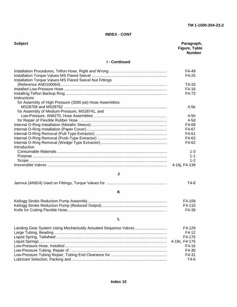
TM 1-1500-204-23-2
INDEX - CONT
Subject Paragraph,Figure, Table
Number
I - Continued
Installation Procedures, Teflon Hose, Right and Wrong ................................................... F4-49Installation Torque Values MS Flared Swivel ................................................................... F4-25Installation Torque Values MS Flared Swivel Nut Fittings
(Reference AND100064)............................................................................................... T4-33Installed Low-Pressure Hose ............................................................................................ F4-16Installing Teflon Backup Ring .......................................................................................... F4-73Instructions
for Assembly of High Pressure (3000 psi) Hose AssembliesMS28759 and MS28762 ............................................................................................ 4-5e
for Assembly of Medium-Pressure, MS28741, andLow-Pressure, AN6270, Hose Assemblies ................................................................. 4-5h
for Repair of Flexible Rubber Hose . ............................................................................. 4-5dInternal O-Ring Installation (Metallic Sleeve).................................................................... F4-68Internal O-Ring Installation (Paper Cover)........................................................................ F4-67Internal O-Ring Removal (Pull-Type Extractor) ................................................................ F4-61Internal O-Ring Removal (Push-Type Extractor) .............................................................. F4-63Internal O-Ring Removal (Wedge-Type Extractor) ........................................................... F4-62Introduction
Consumable Materials .................................................................................................. 1-3Purpose ........................................................................................................................ 1-1Scope ........................................................................................................................... 1-2
Irreversible Valves .......................................................................................................... 4-16j, F4-139
J
Jamnut (AN924) Used on Fittings, Torque Values for ...................................................... T4-8
K
Kellogg Stroke Reduction Pump Assembly....................................................................... F4-109Kellogg Stroke Reduction Pump (Reduced Output) .......................................................... F4-110Knife for Cutting Flexible Hose......................................................................................... F4-39
L
Landing Gear System Using Mechanically Actuated Sequence Valves ............................ F4-129Large Tubing, Beading ..................................................................................................... F4-12Liquid Spring, Tailwheel ................................................................................................... F4-176Liquid Springs .................................................................................................................. 4-19c, F4-175Low-Pressure Hose, Installed ........................................................................................... F4-16Low-Pressure Tubing, Repair of . ..................................................................................... F4-30Low-Pressure Tubing Repair, Tubing End Clearance for .................................................. F4-31Lubricant Selection, Packing and ..................................................................................... T4-6
Index 10
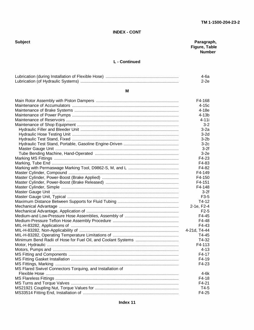
TM 1-1500-204-23-2
INDEX - CONT
Subject Paragraph,Figure, Table
Number
L - Continued
Lubrication (during Installation of Flexible Hose) ............................................................. 4-6aLubrication (of Hydraulic Systems) .................................................................................. 2-2e
M
Main Rotor Assembly with Piston Dampers ..................................................................... F4-168Maintenance of Accumulators ......................................................................................... 4-15cMaintenance of Brake Systems ....................................................................................... 4-18eMaintenance of Power Pumps ......................................................................................... 4-13bMaintenance of Reservoirs .............................................................................................. 4-11iMaintenance of Shop Equipment ..................................................................................... 3-2
Hydraulic Filler and Bleeder Unit .................................................................................. 3-2aHydraulic Hose Testing Unit ......................................................................................... 3-2dHydraulic Test Stand, Fixed ......................................................................................... 3-2bHydraulic Test Stand, Portable, Gasoline Engine-Driven .............................................. 3-2cMaster Gauge Unit ....................................................................................................... 3-2fTube Bending Machine, Hand-Operated ...................................................................... 3-2e
Marking MS Fittings ........................................................................................................ F4-23Marking, Tube End .......................................................................................................... F4-83Marking with Permaswage Marking Tool, D9862-S, M, and L .......................................... F4-82Master Cylinder, Compound ............................................................................................ F4-149Master Cylinder, Power-Boost (Brake Applied) ................................................................ F4-150Master Cylinder, Power-Boost (Brake Released) ............................................................. F4-151Master Cylinder, Simple .................................................................................................. F4-148Master Gauge Unit .......................................................................................................... 3-2fMaster Gauge Unit, Typical ............................................................................................. F3-5Maximum Distance Between Supports for Fluid Tubing ................................................... T4-12Mechanical Advantage .................................................................................................... 2-1e, F2-4Mechanical Advantage, Application of ............................................................................. F2-5Medium-and Low-Pressure Hose Assemblies, Assembly of ............................................. F4-45Medium-Pressure Teflon Hose Assembly Procedure ....................................................... F4-48MIL-H-83282, Applications of .......................................................................................... F4-43MIL-H-83282, Non-Applicability of ................................................................................... 4-21d, T4-44MIL-H-83282, Operating Temperature Limitations of ....................................................... T4-45Minimum Bend Radii of Hose for Fuel Oil, and Coolant Systems .................................... T4-32Motor, Hydraulic .............................................................................................................. F4-113Motors, Pumps and ......................................................................................................... 4-13MS Fitting and Components ............................................................................................ F4-17MS Fitting Gasket Installation .......................................................................................... F4-19MS Fittings, Marking ....................................................................................................... F4-23MS Flared Swivel Connectors Torquing, and Installation of
Flexible Hose ............................................................................................................... 4-6kMS Flareless Fittings ....................................................................................................... F4-18MS Turns and Torque Valves .......................................................................................... F4-21MS21921 Coupling Nut, Torque Values for ...................................................................... T4-5MS33514 Fitting End, Installation of ................................................................................ F4-25
Index 11

TM 1-1500-204-23-2
INDEX - CONT
Subject Paragraph,Figure, Table
Number
N
Nipple Assembly Clearance ............................................................................................ F4-47Nipple Assembly Surface ................................................................................................ F4-46Non-Applicability of MIL-H-83282 .................................................................................... 4-21 d, T4-44Nonself-Sealing, Aromatic and Heat-Resistant Hose, MIL-H-6000 ................................... F4-35Nonself-Sealing, Aromatic-Resistant Hose, MIL-H-5593 .................................................. F4-37Normal Flow in Differential Pressure Indicator ................................................................. F4-99Normal Flow in Fluid Filter .............................................................................................. F4-97Nose Landing Gear with Piston Damper .......................................................................... F4-164Nose Landing Gear with Vane Damper ............................................................................ F4-168Nut Installation Torque in Inch-Pounds, Hose End Fitting and Coupling ........................... T4-34
O
O-Ring Identification ....................................................................................................... F4-59O-Ring Installation, External ............................................................................................ F4-69O-Ring Installation, Internal (Metallic Sleeve) .................................................................. F4-68O-Ring Installation, Internal (Paper Cover) ...................................................................... F4-69O-Ring, Removal of ........................................................................................................ F4-60O-Ring Removal, Dual Internal ....................................................................................... F4-64O-Ring Removal, External (Spoon-Type Extractor) ......................................................... F4-65O-Ring Removal, External (Wedge-Type Extractor) ........................................................ F4-66O-Ring Removal, Internal (Pull-Type Extractor) .............................................................. F4-61O-Ring Removal, Internal (Push-Type Extractor) ............................................................ F4-63O-Ring Removal, Internal (Wedge-Type Extractor) ......................................................... F4-62O-Rings ........................................................................................................................... 4-7aOpen-Center Hydraulic System (Value Closed) ............................................................... F4-143Open-Center Hydraulic System (Value Open) ................................................................. F4-144Operating Pressure (psi) for MIL-H-7061, Proof Test and ................................................ T4-31Operating, 'Proof, and Burst Test Pressures for AN6270 Hose
Assembly using MIL-H-5593 Low Pressure Hose ......................................................... T4-19Operating, Proof, and Burst Test Pressures for MIL-H-83796
Medium Pressure Hose Assembly, Lightweight ............................................................ T4-17Operating, Proof, and Burst Test Pressures for MIL-H-83797
Medium Pressure Hose ................................................................................................ T4-18Operating, Proof, and Burst Test Pressures for MS28741 Medium
Pressure Hose Assemblies, using Single Wire Braid Hose,Military Specification MIL-H-8794 ................................................................................. T4-16
Operating, Proof, and Burst Test Pressures for MS28759 andMS28762 Hose Assemblies using MIL-H-8788 High Pressure Hose ............................. T4-15
Operating Temperature Limitations (of Hydraulic Fluid) ................................................... 4-21fOperating Temperature Limitations of MIL-H-83282 ........................................................ T4-45Orifice Check Valve ........................................................................................................ F4-128Oxygen System Tapered Pipe Thread ............................................................................. 4-3b
P
Packing and Lubricant Selection ..................................................................................... T4-6
Index 12
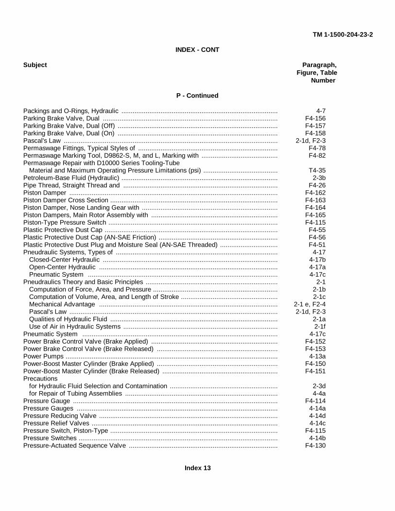
TM 1-1500-204-23-2
INDEX - CONT
Subject Paragraph,Figure, Table
Number
P - Continued
Packings and O-Rings, Hydraulic .................................................................................... 4-7Parking Brake Valve, Dual .............................................................................................. F4-156Parking Brake Valve, Dual (Off) ...................................................................................... F4-157Parking Brake Valve, Dual (On) ...................................................................................... F4-158Pascal's Law ................................................................................................................... 2-1d, F2-3Permaswage Fittings, Typical Styles of ........................................................................... F4-78Permaswage Marking Tool, D9862-S, M, and L, Marking with ......................................... F4-82Permaswage Repair with D10000 Series Tooling-Tube
Material and Maximum Operating Pressure Limitations (psi) ........................................ T4-35Petroleum-Base Fluid (Hydraulic) .................................................................................... 2-3bPipe Thread, Straight Thread and ................................................................................... F4-26Piston Damper ................................................................................................................ F4-162Piston Damper Cross Section .......................................................................................... F4-163Piston Damper, Nose Landing Gear with ......................................................................... F4-164Piston Dampers, Main Rotor Assembly with .................................................................... F4-165Piston-Type Pressure Switch ........................................................................................... F4-115Plastic Protective Dust Cap ............................................................................................. F4-55Plastic Protective Dust Cap (AN-SAE Friction) ................................................................ F4-56Plastic Protective Dust Plug and Moisture Seal (AN-SAE Threaded) ............................... F4-51Pneudraulic Systems, Types of ....................................................................................... 4-17
Closed-Center Hydraulic .............................................................................................. 4-17bOpen-Center Hydraulic ................................................................................................ 4-17aPneumatic System ...................................................................................................... 4-17c
Pneudraulics Theory and Basic Principles ....................................................................... 2-1Computation of Force, Area, and Pressure ................................................................... 2-1bComputation of Volume, Area, and Length of Stroke .................................................... 2-1cMechanical Advantage ................................................................................................ 2-1 e, F2-4Pascal's Law ................................................................................................................ 2-1d, F2-3Qualities of Hydraulic Fluid .......................................................................................... 2-1aUse of Air in Hydraulic Systems ................................................................................... 2-1f
Pneumatic System ......................................................................................................... 4-17cPower Brake Control Valve (Brake Applied) .................................................................... F4-152Power Brake Control Valve (Brake Released) ................................................................. F4-153Power Pumps .................................................................................................................. 4-13aPower-Boost Master Cylinder (Brake Applied) ................................................................. F4-150Power-Boost Master Cylinder (Brake Released) .............................................................. F4-151Precautions
for Hydraulic Fluid Selection and Contamination .......................................................... 2-3dfor Repair of Tubing Assemblies .................................................................................. 4-4a
Pressure Gauge .............................................................................................................. F4-114Pressure Gauges ............................................................................................................ 4-14aPressure Reducing Valve ................................................................................................ 4-14dPressure Relief Valves .................................................................................................... 4-14cPressure Switch, Piston-Type .......................................................................................... F4-115Pressure Switches ........................................................................................................... 4-14bPressure-Actuated Sequence Valve ................................................................................ F4-130
Index 13
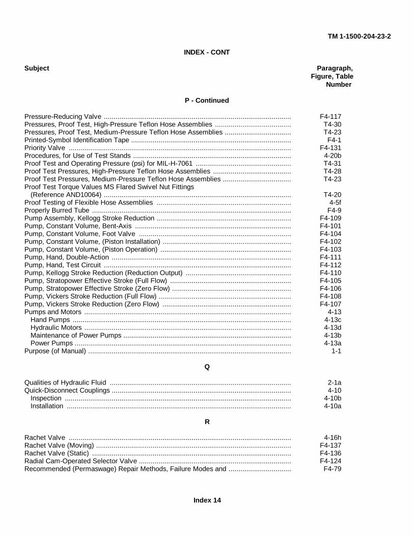
TM 1-1500-204-23-2
INDEX - CONT
Subject Paragraph,Figure, Table
Number
P - Continued
Pressure-Reducing Valve ................................................................................................ F4-117Pressures, Proof Test, High-Pressure Teflon Hose Assemblies ....................................... T4-30Pressures, Proof Test, Medium-Pressure Teflon Hose Assemblies .................................. T4-23Printed-Symbol Identification Tape .................................................................................. F4-1Priority Valve .................................................................................................................. F4-131Procedures, for Use of Test Stands ................................................................................. 4-20bProof Test and Operating Pressure (psi) for MIL-H-7061 ................................................. T4-31Proof Test Pressures, High-Pressure Teflon Hose Assemblies ........................................ T4-28Proof Test Pressures, Medium-Pressure Teflon Hose Assemblies ................................... T4-23Proof Test Torque Values MS Flared Swivel Nut Fittings
(Reference AND10064) ................................................................................................ T4-20Proof Testing of Flexible Hose Assemblies ..................................................................... 4-5fProperly Burred Tube ...................................................................................................... F4-9Pump Assembly, Kellogg Stroke Reduction ..................................................................... F4-109Pump, Constant Volume, Bent-Axis ................................................................................ F4-101Pump, Constant Volume, Foot Valve .............................................................................. F4-104Pump, Constant Volume, (Piston Installation) .................................................................. F4-102Pump, Constant Volume, (Piston Operation) ................................................................... F4-103Pump, Hand, Double-Action ............................................................................................ F4-111Pump, Hand, Test Circuit ................................................................................................ F4-112Pump, Kellogg Stroke Reduction (Reduction Output) ...................................................... F4-110Pump, Stratopower Effective Stroke (Full Flow) .............................................................. F4-105Pump, Stratopower Effective Stroke (Zero Flow) ............................................................. F4-106Pump, Vickers Stroke Reduction (Full Flow) .................................................................... F4-108Pump, Vickers Stroke Reduction (Zero Flow) .................................................................. F4-107Pumps and Motors .......................................................................................................... 4-13
Hand Pumps ................................................................................................................ 4-13cHydraulic Motors .......................................................................................................... 4-13dMaintenance of Power Pumps ...................................................................................... 4-13bPower Pumps ............................................................................................................... 4-13a
Purpose (of Manual) ........................................................................................................ 1-1
Q
Qualities of Hydraulic Fluid ............................................................................................. 2-1aQuick-Disconnect Couplings ............................................................................................ 4-10
Inspection .................................................................................................................... 4-10bInstallation ................................................................................................................... 4-10a
R
Rachet Valve .................................................................................................................. 4-16hRachet Valve (Moving) .................................................................................................... F4-137Rachet Valve (Static) ...................................................................................................... F4-136Radial Cam-Operated Selector Valve .............................................................................. F4-124Recommended (Permaswage) Repair Methods, Failure Modes and ................................ F4-79
Index 14
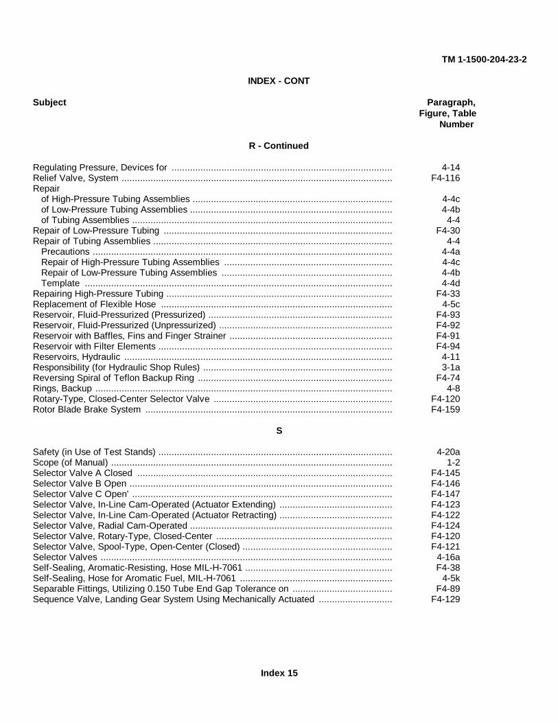
TM 1-1500-204-23-2
INDEX - CONT
Subject Paragraph,Figure, Table
Number
R - Continued
Regulating Pressure, Devices for .................................................................................... 4-14Relief Valve, System ....................................................................................................... F4-116Repair
of High-Pressure Tubing Assemblies ............................................................................ 4-4cof Low-Pressure Tubing Assemblies ............................................................................. 4-4bof Tubing Assemblies ................................................................................................... 4-4
Repair of Low-Pressure Tubing ....................................................................................... F4-30Repair of Tubing Assemblies ........................................................................................... 4-4
Precautions .................................................................................................................. 4-4aRepair of High-Pressure Tubing Assemblies ................................................................ 4-4cRepair of Low-Pressure Tubing Assemblies ................................................................. 4-4bTemplate ..................................................................................................................... 4-4d
Repairing High-Pressure Tubing ...................................................................................... F4-33Replacement of Flexible Hose ........................................................................................ 4-5cReservoir, Fluid-Pressurized (Pressurized) ...................................................................... F4-93Reservoir, Fluid-Pressurized (Unpressurized) .................................................................. F4-92Reservoir with Baffles, Fins and Finger Strainer .............................................................. F4-91Reservoir with Filter Elements ......................................................................................... F4-94Reservoirs, Hydraulic ...................................................................................................... 4-11Responsibility (for Hydraulic Shop Rules) ........................................................................ 3-1aReversing Spiral of Teflon Backup Ring .......................................................................... F4-74Rings, Backup ................................................................................................................. 4-8Rotary-Type, Closed-Center Selector Valve .................................................................... F4-120Rotor Blade Brake System .............................................................................................. F4-159
S
Safety (in Use of Test Stands) ......................................................................................... 4-20aScope (of Manual) ........................................................................................................... 1-2Selector Valve A Closed ................................................................................................. F4-145Selector Valve B Open .................................................................................................... F4-146Selector Valve C Open' ................................................................................................... F4-147Selector Valve, In-Line Cam-Operated (Actuator Extending) ........................................... F4-123Selector Valve, In-Line Cam-Operated (Actuator Retracting) ........................................... F4-122Selector Valve, Radial Cam-Operated ............................................................................. F4-124Selector Valve, Rotary-Type, Closed-Center ................................................................... F4-120Selector Valve, Spool-Type, Open-Center (Closed) ......................................................... F4-121Selector Valves ............................................................................................................... 4-16aSelf-Sealing, Aromatic-Resisting, Hose MIL-H-7061 ........................................................ F4-38Self-Sealing, Hose for Aromatic Fuel, MIL-H-7061 .......................................................... 4-5kSeparable Fittings, Utilizing 0.150 Tube End Gap Tolerance on ...................................... F4-89Sequence Valve, Landing Gear System Using Mechanically Actuated ............................ F4-129
Index 15

TM 1-1500-204-23-2
INDEX - CONT
Subject Paragraph,Figure, Table
Number
S - Continued
Sequence Valve, Pressure-Actuated ............................................................................... F4-130Sequence Valves ............................................................................................................ 4-16dServicing Filters .............................................................................................................. 4-12fShaped Fittings, Utilizing 0.300 Inch Tube End Gap Tolerance on .................................. F4-92Shock Strut, Complex (Metering Pin) .............................................................................. F4-171Shock Strut, Complex (Plunger) ...................................................................................... F4-172Shock Strut, Floating Pin ................................................................................................. F4-173Shock Strut, Simple ........................................................................................................ F4-170Shock Struts .................................................................................................................... 4-19bShop Equipment, Maintenance ........................................................................................ 3-2Shop Housekeeping (Hydraulic Shop) ............................................................................. 3-1bShop Rules, General (Hydraulic Shop) ............................................................................ 3-1Shop Safety (Hydraulic Shop) ......................................................................................... 3-1cShop Tools and Materials (Hydraulic Shop) ..................................................................... 3-1dShuttle Valve, Floating-Piston ......................................................................................... F4-132Shuttle Valves ................................................................................................................. 4-16fSimple Check Valve ........................................................................................................ F4-127Simple Master Cylinder ................................................................................................... F4-148Simple Shock Strut ......................................................................................................... F4-170Single Backup Ring Installation ....................................................................................... F4-75Single Flared Tubing, Dimensions for .............................................................................. F4-7Single-Action Actuating Cylinder ..................................................................................... F4-133Size (of Hydraulic Systems) ............................................................................................ 2-2dSolenoid-Actuated Control Valve (De-energized) ............................................................ F4-126Solenoid-Actuated Control Valve (Energized) .................................................................. F4-125Solid Color Band Identification ........................................................................................ F4-2Spherical Accumulator .................................................................................................... F4-119Spherical Air Cylinder ...................................................................................................... F4-95Spool-Type, Open-Center, Selector Valve (Closed) ......................................................... F4-121Stabilizer Bar with Vane Dampers ................................................................................... F4-169Standard Union Fittings, Tube Insertion Limits when Using ............................................. F4-90Standard Union Fittings, Utilizing 0.300 Inch Tube End Gap Tolerance with .................... F4-87Standpipes ...................................................................................................................... 4-11gSteel Protective Dust Cap ............................................................................................... F4-53Steel Protective Dust Plug and Moisture Seal ................................................................. F4-52Storage of Hose and Hose Assemblies ............................................................................ 4-5bStorage (55-Gallon Drums) ............................................................................................. 3-3aStraight Pipe Thread ....................................................................................................... 4-3cStraight Thread and Pipe Thread .................................................................................... F4-26Stratopower Effective Stroke Pump (Full Flow) ............................................................... F4-105Stratopower Effective Stroke Pump (Zero Flow) .............................................................. F4-106Stretching Teflon Backup Ring ........................................................................................ F4-72Support Clamp Sizes (for Use with MIL-H-27267 Hose of Teflon) .................................... T4-24Support Clamp Sizes (for Use with MIL-H-38360 Hose of Teflon) .................................... T4-29
Index 16
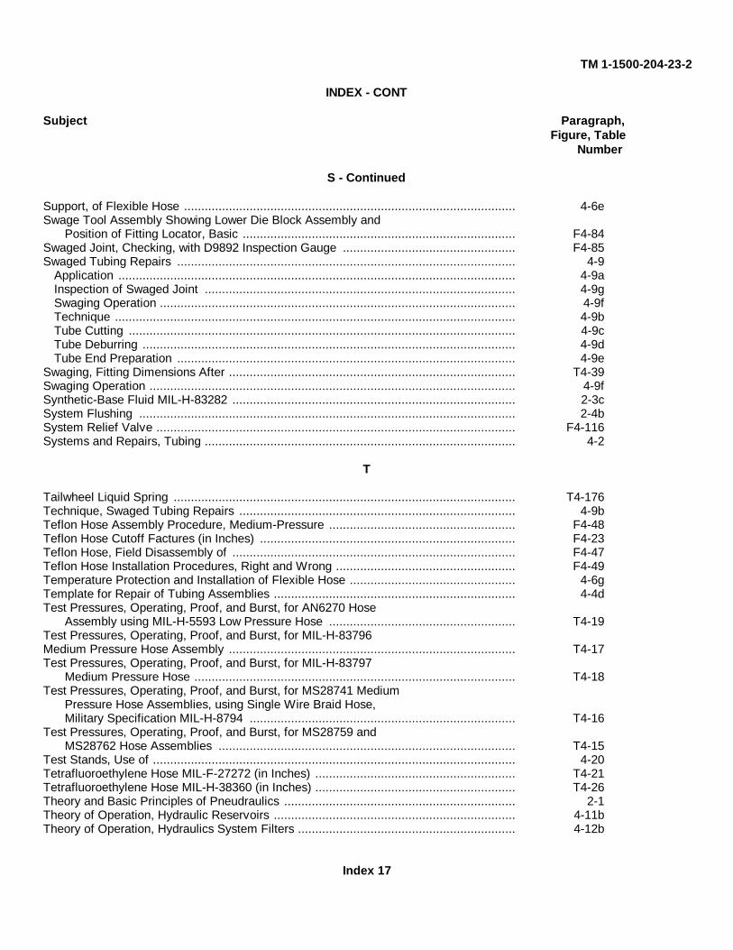
TM 1-1500-204-23-2
INDEX - CONT
Subject Paragraph,Figure, Table
Number
S - Continued
Support, of Flexible Hose ................................................................................................ 4-6eSwage Tool Assembly Showing Lower Die Block Assembly and
Position of Fitting Locator, Basic ............................................................................... F4-84Swaged Joint, Checking, with D9892 Inspection Gauge .................................................. F4-85Swaged Tubing Repairs .................................................................................................. 4-9
Application ................................................................................................................... 4-9aInspection of Swaged Joint .......................................................................................... 4-9gSwaging Operation ....................................................................................................... 4-9fTechnique .................................................................................................................... 4-9bTube Cutting ................................................................................................................ 4-9cTube Deburring ............................................................................................................ 4-9dTube End Preparation .................................................................................................. 4-9e
Swaging, Fitting Dimensions After ................................................................................... T4-39Swaging Operation .......................................................................................................... 4-9fSynthetic-Base Fluid MIL-H-83282 .................................................................................. 2-3cSystem Flushing ............................................................................................................. 2-4bSystem Relief Valve ........................................................................................................ F4-116Systems and Repairs, Tubing .......................................................................................... 4-2
T
Tailwheel Liquid Spring ................................................................................................... T4-176Technique, Swaged Tubing Repairs ................................................................................ 4-9bTeflon Hose Assembly Procedure, Medium-Pressure ...................................................... F4-48Teflon Hose Cutoff Factures (in Inches) .......................................................................... F4-23Teflon Hose, Field Disassembly of .................................................................................. F4-47Teflon Hose Installation Procedures, Right and Wrong .................................................... F4-49Temperature Protection and Installation of Flexible Hose ................................................ 4-6gTemplate for Repair of Tubing Assemblies ...................................................................... 4-4dTest Pressures, Operating, Proof, and Burst, for AN6270 Hose
Assembly using MIL-H-5593 Low Pressure Hose ...................................................... T4-19Test Pressures, Operating, Proof, and Burst, for MIL-H-83796Medium Pressure Hose Assembly ................................................................................... T4-17Test Pressures, Operating, Proof, and Burst, for MIL-H-83797
Medium Pressure Hose ............................................................................................. T4-18Test Pressures, Operating, Proof, and Burst, for MS28741 Medium
Pressure Hose Assemblies, using Single Wire Braid Hose,Military Specification MIL-H-8794 ............................................................................. T4-16
Test Pressures, Operating, Proof, and Burst, for MS28759 andMS28762 Hose Assemblies ...................................................................................... T4-15
Test Stands, Use of ......................................................................................................... 4-20Tetrafluoroethylene Hose MIL-F-27272 (in Inches) .......................................................... T4-21Tetrafluoroethylene Hose MIL-H-38360 (in Inches) .......................................................... T4-26Theory and Basic Principles of Pneudraulics ................................................................... 2-1Theory of Operation, Hydraulic Reservoirs ...................................................................... 4-11bTheory of Operation, Hydraulics System Filters ............................................................... 4-12b
Index 17
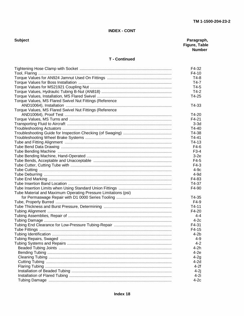
TM 1-1500-204-23-2
INDEX - CONT
Subject Paragraph,Figure, Table
Number
T - Continued
Tightening Hose Clamp with Socket ................................................................................ F4-32Tool, Flaring .................................................................................................................... F4-10Torque Values for AN924 Jamnut Used On Fittings ........................................................ T4-8Torque Values for Boss Installation ................................................................................. T4-7Torque Values for MS21921 Coupling Nut ....................................................................... T4-5Torque Values, Hydraulic Tubing B-Nut (AN818) ............................................................. T4-2Torque Values, Installation, MS Flared Swivel ................................................................. T4-25Torque Values, MS Flared Swivel Nut Fittings (Reference
AND10064), Installation ............................................................................................ T4-33Torque Values, MS Flared Swivel Nut Fittings (Reference
AND10064), Proof Test ............................................................................................. T4-20Torque Values, MS Turns and ......................................................................................... F4-21Transporting Fluid to Aircraft ........................................................................................... 3-3dTroubleshooting Actuators ............................................................................................... T4-40Troubleshooting Guide for Inspection Checking (of Swaging) .......................................... T4-38Troubleshooting Wheel Brake Systems ........................................................................... T4-41Tube and Fitting Alignment ............................................................................................. T4-13Tube Bend Data Drawing ................................................................................................ F4-6Tube Bending Machine ................................................................................................... F3-4Tube Bending Machine, Hand-Operated .......................................................................... 3-2eTube Bends, Acceptable and Unacceptable .................................................................... F4-5Tube Cutter, Cutting Tube with ........................................................................................ F4-3Tube Cutting ................................................................................................................... 4-9cTube Deburring ............................................................................................................... 4-9dTube End Marking ........................................................................................................... F4-83Tube Insertion Band Location .......................................................................................... T4-37Tube Insertion Limits when Using Standard Union Fittings .............................................. F4-90Tube Material and Maximum Operating Pressure Limitations (psi)
for Permaswage Repair with D1 0000 Series Tooling ................................................ T4-35Tube, Properly Burred ..................................................................................................... F4-9Tube Thickness and Burst Pressure, Determining ........................................................... T4-11Tubing Alignment ............................................................................................................ F4-20Tubing Assemblies, Repair of .......................................................................................... 4-4Tubing Damage ............................................................................................................... 4-2cTubing End Clearance for Low-Pressure Tubing-Repair .................................................. F4-31Tube Fittings ................................................................................................................... F4-15Tubing Identification ........................................................................................................ 4-2bTubing Repairs, Swaged ................................................................................................. 4-9Tubing Systems and Repairs ........................................................................................... 4-2
Beaded Tubing Joints .................................................................................................. 4-2hBending Tubing ............................................................................................................ 4-2eCleaning Tubing ........................................................................................................... 4-2gCutting Tubing ............................................................................................................. 4-2dFlaring Tubing .............................................................................................................. 4-2fInstallation of Beaded Tubing ....................................................................................... 4-2jInstallation of Flared Tubing ......................................................................................... 4-2iTubing Damage ........................................................................................................... 4-2c
Index 18
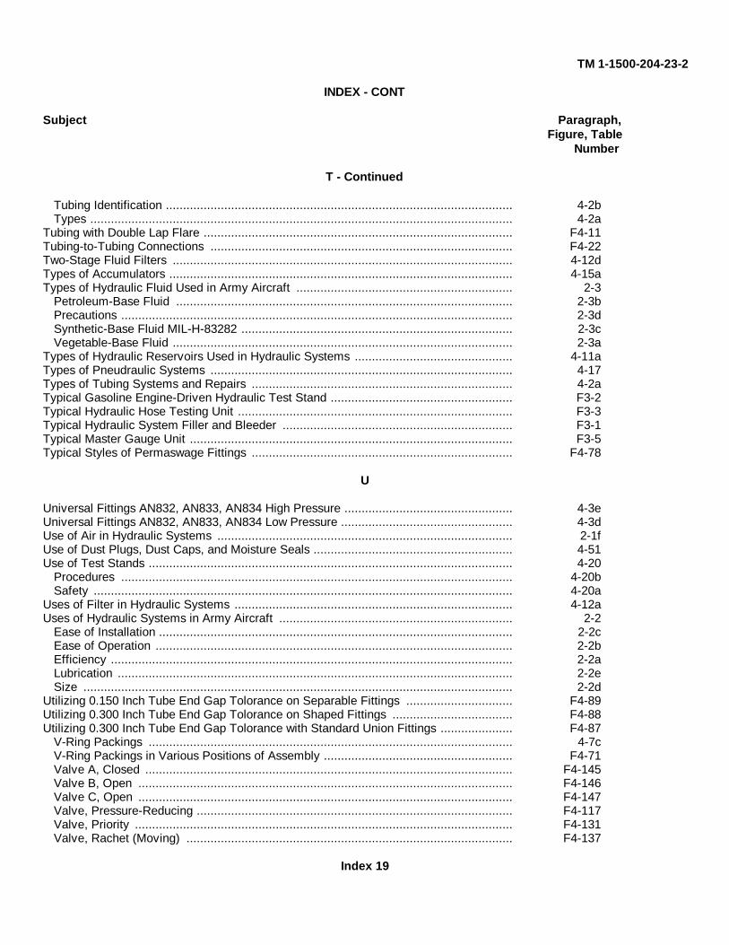
TM 1-1500-204-23-2
INDEX - CONT
Subject Paragraph,Figure, Table
Number
T - Continued
Tubing Identification ..................................................................................................... 4-2bTypes ........................................................................................................................... 4-2a
Tubing with Double Lap Flare .......................................................................................... F4-11Tubing-to-Tubing Connections ........................................................................................ F4-22Two-Stage Fluid Filters ................................................................................................... 4-12dTypes of Accumulators .................................................................................................... 4-15aTypes of Hydraulic Fluid Used in Army Aircraft ............................................................... 2-3
Petroleum-Base Fluid .................................................................................................. 2-3bPrecautions .................................................................................................................. 2-3dSynthetic-Base Fluid MIL-H-83282 ............................................................................... 2-3cVegetable-Base Fluid ................................................................................................... 2-3a
Types of Hydraulic Reservoirs Used in Hydraulic Systems .............................................. 4-11aTypes of Pneudraulic Systems ........................................................................................ 4-17Types of Tubing Systems and Repairs ............................................................................ 4-2aTypical Gasoline Engine-Driven Hydraulic Test Stand ..................................................... F3-2Typical Hydraulic Hose Testing Unit ................................................................................ F3-3Typical Hydraulic System Filler and Bleeder ................................................................... F3-1Typical Master Gauge Unit .............................................................................................. F3-5Typical Styles of Permaswage Fittings ............................................................................ F4-78
U
Universal Fittings AN832, AN833, AN834 High Pressure ................................................. 4-3eUniversal Fittings AN832, AN833, AN834 Low Pressure .................................................. 4-3dUse of Air in Hydraulic Systems ...................................................................................... 2-1fUse of Dust Plugs, Dust Caps, and Moisture Seals .......................................................... 4-51Use of Test Stands .......................................................................................................... 4-20
Procedures .................................................................................................................. 4-20bSafety .......................................................................................................................... 4-20a
Uses of Filter in Hydraulic Systems ................................................................................. 4-12aUses of Hydraulic Systems in Army Aircraft .................................................................... 2-2
Ease of Installation ....................................................................................................... 2-2cEase of Operation ........................................................................................................ 2-2bEfficiency ..................................................................................................................... 2-2aLubrication ................................................................................................................... 2-2eSize ............................................................................................................................. 2-2d
Utilizing 0.150 Inch Tube End Gap Tolorance on Separable Fittings ............................... F4-89Utilizing 0.300 Inch Tube End Gap Tolorance on Shaped Fittings ................................... F4-88Utilizing 0.300 Inch Tube End Gap Tolorance with Standard Union Fittings ..................... F4-87
V-Ring Packings .......................................................................................................... 4-7cV-Ring Packings in Various Positions of Assembly ....................................................... F4-71Valve A, Closed ........................................................................................................... F4-145Valve B, Open ............................................................................................................. F4-146Valve C, Open ............................................................................................................. F4-147Valve, Pressure-Reducing ............................................................................................ F4-117Valve, Priority .............................................................................................................. F4-131Valve, Rachet (Moving) ............................................................................................... F4-137
Index 19
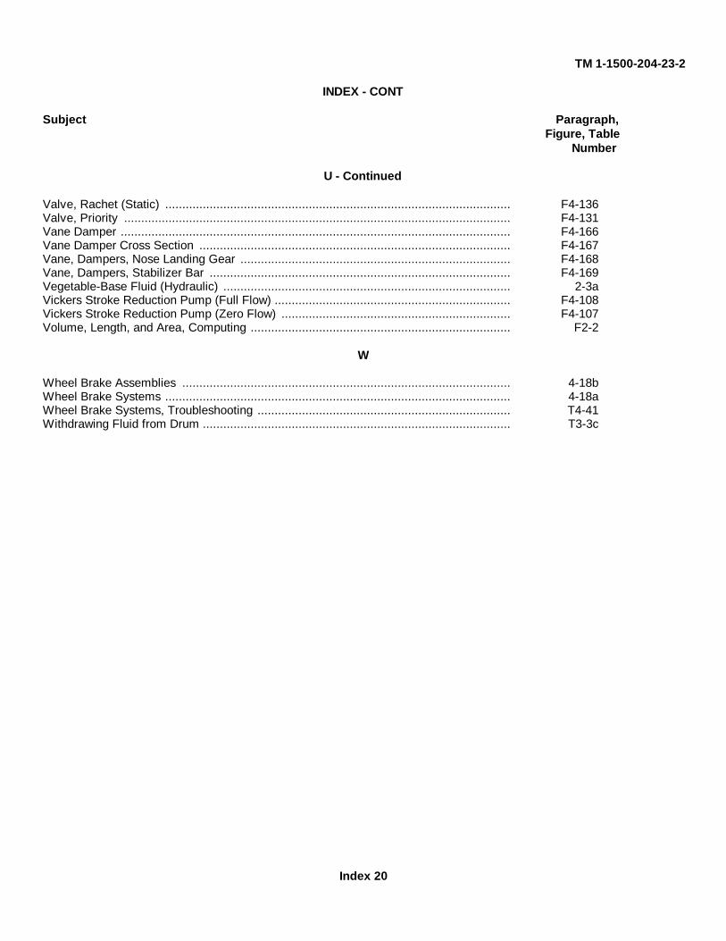
TM 1-1500-204-23-2
INDEX - CONT
Subject Paragraph,Figure, Table
Number
U - Continued
Valve, Rachet (Static) ..................................................................................................... F4-136Valve, Priority ................................................................................................................. F4-131Vane Damper .................................................................................................................. F4-166Vane Damper Cross Section ........................................................................................... F4-167Vane, Dampers, Nose Landing Gear ............................................................................... F4-168Vane, Dampers, Stabilizer Bar ........................................................................................ F4-169Vegetable-Base Fluid (Hydraulic) .................................................................................... 2-3aVickers Stroke Reduction Pump (Full Flow) ..................................................................... F4-108Vickers Stroke Reduction Pump (Zero Flow) ................................................................... F4-107Volume, Length, and Area, Computing ............................................................................ F2-2
W
Wheel Brake Assemblies ................................................................................................ 4-18bWheel Brake Systems ..................................................................................................... 4-18aWheel Brake Systems, Troubleshooting .......................................................................... T4-41Withdrawing Fluid from Drum .......................................................................................... T3-3c
Index 20

These are the instructions for sending an electronic 2028
The following format must be used if submitting an electronic 2028. The subject line must be exactly thesame and all fields must be included; however only the following fields are mandatory: 1, 3, 4, 5, 6, 7, 8,9, 10, 13, 15, 16, 17, and 27.
From: “Whomever” <[email protected]>To: [email protected]
Subject: DA Form 20281. From: Joe Smith2. Unit: home3. Address: 4300 Park4. City: Hometown5. St: MO6. Zip: 777777. Date Sent: 19-OCT-938. Pub no: 1-1500-204-23-29. Pub Title: TM10. Publication Date: 31-JUL-9211. Change Number: 712. Submitter Rank: MSG13. Submitter FName: Joe14. Submitter MName: T15. Submitter LName: Smith16. Submitter Phone: 123-123-123417. Problem: 118. Page: 219. Paragraph: 320. Line: 421. NSN: 522. Reference: 623. Figure: 724. Table: 825. Item: 926. Total: 12327. Text:This is the text for the problem below line 27.

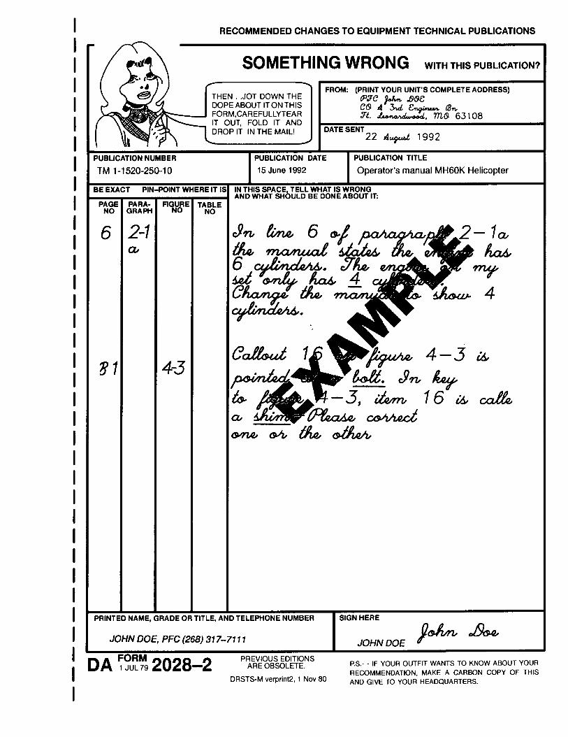
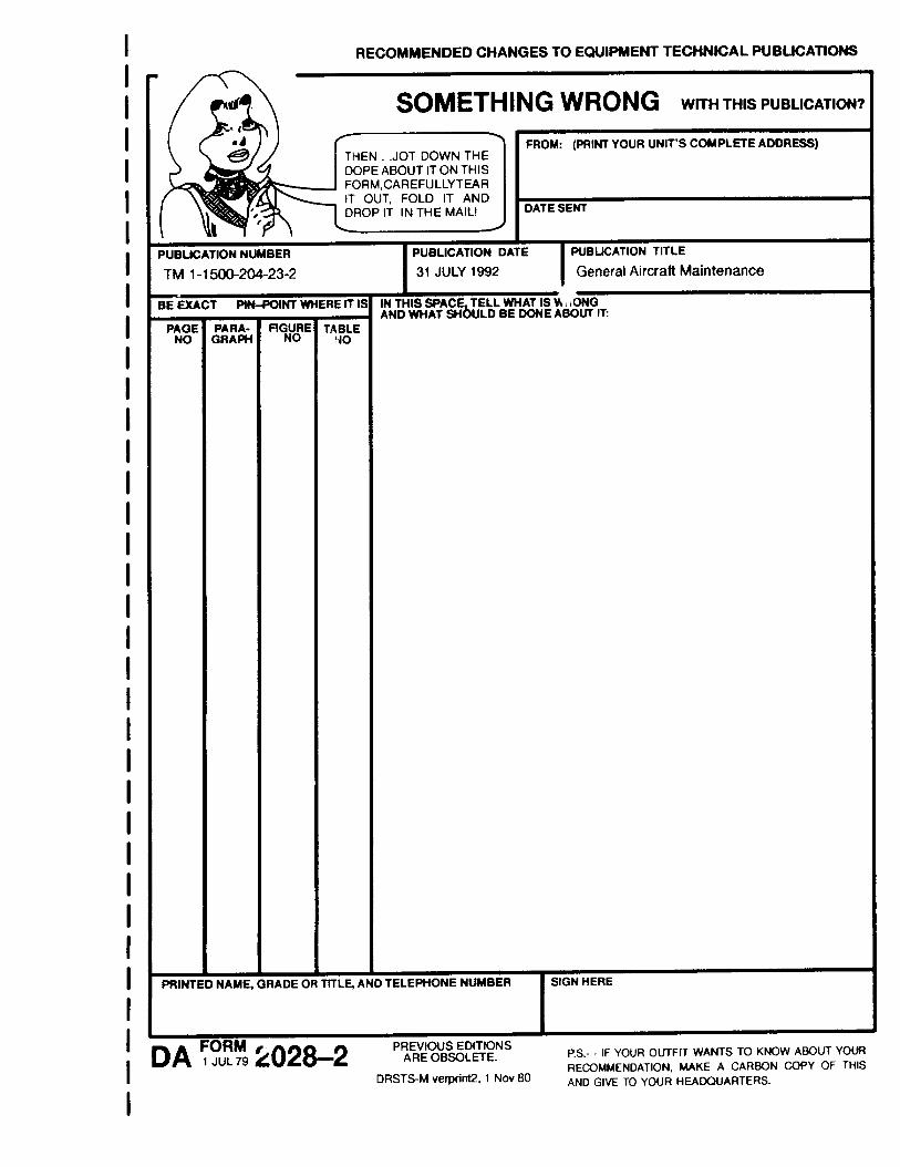

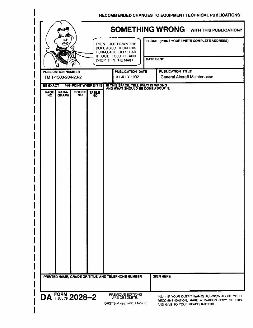
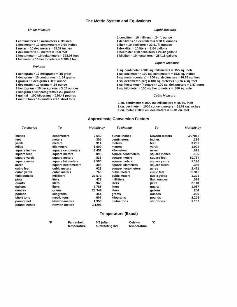
The Metric System and Equivalents
Linear Measure Liquid Measure
1 centiliter = 10 milliters = .34 fl. ounce1 centimeter = 10 millimeters = .39 inch 1 deciliter = 10 centiliters = 3.38 fl. ounces1 decimeter = 10 centimeters = 3.94 inches 1 liter = 10 deciliters = 33.81 fl. ounces1 meter = 10 decimeters = 39.37 inches 1 dekaliter = 10 liters = 2.64 gallons1 dekameter = 10 meters = 32.8 feet 1 hectoliter = 10 dekaliters = 26.42 gallons1 hectometer = 10 dekameters = 328.08 feet 1 kiloliter = 10 hectoliters = 264.18 gallons1 kilometer = 10 hectometers = 3,280.8 feet
Square MeasureWeights
1 sq. centimeter = 100 sq. millimeters = .155 sq. inch1 centigram = 10 milligrams = .15 grain 1 sq. decimeter = 100 sq. centimeters = 15.5 sq. inches1 decigram = 10 centigrams = 1.54 grains 1 sq. meter (centare) = 100 sq. decimeters = 10.76 sq. feet1 gram = 10 decigram = .035 ounce 1 sq. dekameter (are) = 100 sq. meters = 1,076.4 sq. feet1 decagram = 10 grams = .35 ounce 1 sq. hectometer (hectare) = 100 sq. dekameters = 2.47 acres1 hectogram = 10 decagrams = 3.52 ounces 1 sq. kilometer = 100 sq. hectometers = .386 sq. mile1 kilogram = 10 hectograms = 2.2 pounds1 quintal = 100 kilograms = 220.46 pounds Cubic Measure1 metric ton = 10 quintals = 1.1 short tons
1 cu. centimeter = 1000 cu. millimeters = .06 cu. inch1 cu. decimeter = 1000 cu. centimeters = 61.02 cu. inches1 cu. meter = 1000 cu. decimeters = 35.31 cu. feet
Approximate Conversion Factors
To change To Multiply by To change To Multiply by
inches centimeters 2.540 ounce-inches Newton-meters .007062feet meters .305 centimeters inches .394yards meters .914 meters feet 3.280miles kilometers 1.609 meters yards 1.094square inches square centimeters 6.451 kilometers miles .621square feet square meters .093 square centimeters square inches .155square yards square meters .836 square meters square feet 10.764square miles square kilometers 2.590 square meters square yards 1.196acres square hectometers .405 square kilometers square miles .386cubic feet cubic meters .028 square hectometers acres 2.471cubic yards cubic meters .765 cubic meters cubic feet 35.315fluid ounces milliliters 29,573 cubic meters cubic yards 1.308pints liters .473 milliliters fluid ounces .034quarts liters .946 liters pints 2.113gallons liters 3.785 liters quarts 1.057ounces grams 28.349 liters gallons .264pounds kilograms .454 grams ounces .035short tons metric tons .907 kilograms pounds 2.205pound-feet Newton-meters 1.356 metric tons short tons 1.102pound-inches Newton-meters .11296
Temperature (Exact)
°F Fahrenheit 5/9 (after Celsius °Ctemperature subtracting 32) temperature

PIN: 070461-000