Embed Size (px)
Citation preview
TLX106 WEATHER STATIONINSTRUCTION MANUAL
REVISION: 9/02
COPYRIGHT (c) 1993-2002 CAMPBELL SCIENTIFIC, INC.

This is a blank page.

Warranty and AssistanceThe TLX106 WEATHER STATION is warranted by CAMPBELLSCIENTIFIC, INC. to be free from defects in materials and workmanship undernormal use and service for twelve (12) months from date of shipment unlessspecified otherwise. Batteries have no warranty. CAMPBELL SCIENTIFIC,INC.'s obligation under this warranty is limited to repairing or replacing (atCAMPBELL SCIENTIFIC, INC.'s option) defective products. The customershall assume all costs of removing, reinstalling, and shipping defective productsto CAMPBELL SCIENTIFIC, INC. CAMPBELL SCIENTIFIC, INC. willreturn such products by surface carrier prepaid. This warranty shall not applyto any CAMPBELL SCIENTIFIC, INC. products which have been subjected tomodification, misuse, neglect, accidents of nature, or shipping damage. Thiswarranty is in lieu of all other warranties, expressed or implied, includingwarranties of merchantability or fitness for a particular purpose. CAMPBELLSCIENTIFIC, INC. is not liable for special, indirect, incidental, orconsequential damages.
Products may not be returned without prior authorization. To obtain aReturned Materials Authorization (RMA), contact CAMPBELL SCIENTIFIC,INC., phone (435) 753-2342. After an applications engineer determines thenature of the problem, an RMA number will be issued. Please write thisnumber clearly on the outside of the shipping container. CAMPBELLSCIENTIFIC's shipping address is:
CAMPBELL SCIENTIFIC, INC.RMA#_____815 West 1800 NorthLogan, Utah 84321-1784
CAMPBELL SCIENTIFIC, INC. does not accept collect calls.
Non-warranty products returned for repair should be accompanied by apurchase order to cover the repair.
815 W. 1800 N.Logan, UT 84321-1784USAPhone (435) 753-2342FAX (435) 750-9540www.campbellsci.com
Campbell Scientific Canada Corp.11564 -149th StreetEdmonton, Alberta T5M 1W7CANADAPhone (780) 454-2505FAX (780) 454-2655
Campbell Scientific Ltd.Campbell Park80 Hathern RoadShepshed, LoughboroughLE12 9GX, U.K.Phone +44 (0) 1509 601141FAX +44 (0) 1509 601091

This is a blank page.
i
TLX106 Weather StationTable of Contents
1. Preparation and Siting1.1 Installation Tasks .................................................................................. 1-1
1.1.1 Indoors ........................................................................................ 1-11.1.2 Outdoors...................................................................................... 1-1
1.2 Tools Required...................................................................................... 1-11.2.1 Tools for Tower Installation........................................................ 1-21.2.2 Tools for Instrumentation and Maintenance................................ 1-21.2.3 Supplies for Power and Communications Options ...................... 1-3
1.3 Siting and Exposure .............................................................................. 1-31.3.1 Wind Speed and Direction .......................................................... 1-31.3.2 Temperature and Relative Humidity ........................................... 1-3
1.4 Determining True North for Wind Vane Orientation............................ 1-41.4.1 Prompts from GEOMAG ............................................................ 1-5
2. TLX106 Tower Installation2.1 Base Installation.................................................................................... 2-2
2.1.1 Supplied Components ................................................................. 2-22.2.2 Installation................................................................................... 2-2
2.2 Tower Installation ................................................................................. 2-32.2.1 Supplied Components ................................................................. 2-32.2.2 Installation................................................................................... 2-3
2.3 Tower Grounding.................................................................................. 2-42.3.1 Supplied Components ................................................................. 2-42.3.2 Grounding Procedure .................................................................. 2-5
3. TLX106 Instrumentation Installation3.1 Enclosure, Datalogger, Power Supply................................................... 3-2
3.1.1 Battery Option Installation .......................................................... 3-23.1.2 Solar Panel Installation ............................................................... 3-23.1.3 AC Power Installation ................................................................. 3-33.1.4 Enclosure Installation.................................................................. 3-3
3.2 Sensor Connection ................................................................................ 3-43.3 Communication and Data Storage Peripherals...................................... 3-5
3.3.1 Phone Modems............................................................................ 3-63.3.2 Short-Haul Modem...................................................................... 3-7
3.4 Sealing and Desiccating the Enclosure ................................................. 3-9
4. TLX106 Sensor Arm Installation4.1 Components .......................................................................................... 4-14.2 Installation ............................................................................................ 4-14.3 Sensor Connection ................................................................................ 4-24.4 034A Wind Sensor Installation ............................................................. 4-24.5 RH and Temperature Radiation Shield ................................................. 4-3

TLX106 Weather Station Table of Contents
ii
4.6 Pyranometer .......................................................................................... 4-34.7 Sensor Verification and Clock Set ........................................................ 4-34.8 Sensor Schematics................................................................................. 4-4
5. Software Installation and Settings5.1 Measure Sensors and Process Data ....................................................... 5-15.2 Software Install and Settings ................................................................. 5-15.3 Create Message ..................................................................................... 5-7
6. Maintenance and Troubleshooting6.1 Maintenance .......................................................................................... 6-1
6.1.1 Instrumentation Maintenance ...................................................... 6-16.1.2 Batteries....................................................................................... 6-16.1.3 Desiccant ..................................................................................... 6-16.1.4 Sensor Maintenance..................................................................... 6-2
6.2 Troubleshooting .................................................................................... 6-36.2.1 No Response Using the Keypad .................................................. 6-36.2.2 No Response from Datalogger through SC32A or
Modem Peripheral ................................................................. 6-36.2.3 -99999 Displayed in an Input Location ....................................... 6-46.2.4 Unreasonable Results Displayed in an Input Location ................ 6-4
Figures1.3-1. Effect of Structure on Wind Flow..................................................... 1-41.4-1 Magnetic Declination for the Contiguous United States .................... 1-51.4-2 Declination Angles East of True North Are Subtracted from
0 to Get True North....................................................................... 1-71.4-3 Declination Angles West of True North Are Added to 0
to Get True North.......................................................................... 1-82.1-1 TLX106 Tower Installation ............................................................... 2-12.1-2 TLX106 Tower Base Installation....................................................... 2-32.2-1 Raising and Grounding the TLX106 Tower ...................................... 2-43-1 TLX106 Instrumentation Mounted on the ET Tower ........................... 3-13.1-1 Rechargeable Power Mounting Connections ..................................... 3-23.1-2 Solar Panel Mounting ........................................................................ 3-23.1-3 Mounting and Grounding the TLX106 Enclosure ............................. 3-43.2-1 Position of Sensor Bulkhead Connectors ........................................... 3-53.3-1 Phone Modem Mounting and Connections ........................................ 3-63.3-2 Short-Haul Modem Mounting and Connection.................................. 3-73.3-3 Short-Haul Modem Wiring Diagram ................................................. 3-93.4-1 Desiccant Installation....................................................................... 3-104.2-1 TLX106 Sensor Arm Mounting ......................................................... 4-14.4-1 Wind and RH/Temperature Sensor Installation ................................. 4-24.6-1 Pyranometer Leveling ........................................................................ 4-34.8-1 Schematic of HMP45C-LC RH Temperature Probe and
Connector #1................................................................................. 4-54.8-2 Schematic of 034A-LC Wind Speed and Direction Probe and
Connector #2................................................................................. 4-54.8-3 Schematic of LI200X-LC Solar Radiation Sensor and
Connector #3................................................................................. 4-64.8-4 Schematic of TE525-LC Rain Sensor and Connector #5................... 4-6

TLX106 Weather Station Table of Contents
iii
5.3-1 ProLine software provides an easy-to-use message editor................. 5-75.3-2 The available options provided by the source menu are shown......... 5-85.3-3 When the weather station source has been chosen, several
meteorological conditions reported in various units areprovided under the field menu ...................................................... 5-8

TLX106 Weather Station Table of Contents
iv
This is a blank page.
1-1
Section 1. Preparation and SitingThese guidelines apply to several Campbell Scientific weather stations.
1.1 Installation tasks
1.1.1 Indoors• Immediately upon receipt of your shipment…
⇒ Open shipping cartons.
⇒ Check contents against invoice. Contact CSI immediately about anyshortages.
• Several days prior to the planned installation date…
⇒ Collect tools and site information (Section 1)
⇒ Trial run the tower, assembling as much as possible (Section 2)
⇒ Repackage equipment for transport to the field site
1.1.2 Outdoors• Locate suitable site (Section 1)
• Prepare tower (Section 2)
• TLX106 Stations:
⇒ Place instrumentation enclosure low on the TLX106 Tower (Section3)
⇒ Install sensor option (Section 4)
⇒ Slide enclosure to top of tower and secure with correct orientation(Section 3)
1.2 Tools RequiredTools required to install and maintain a weather station are listed below.
Section 1. Preparation and Siting
1-2
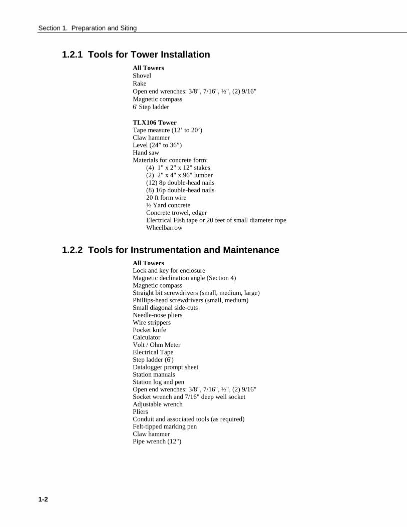
1.2.1 Tools for Tower InstallationAll TowersShovelRakeOpen end wrenches: 3/8", 7/16", ½", (2) 9/16"Magnetic compass6' Step ladder
TLX106 TowerTape measure (12’ to 20’)Claw hammerLevel (24” to 36”)Hand sawMaterials for concrete form:
(4) 1" x 2" x 12" stakes(2) 2" x 4" x 96" lumber(12) 8p double-head nails(8) 16p double-head nails20 ft form wire½ Yard concreteConcrete trowel, edgerElectrical Fish tape or 20 feet of small diameter ropeWheelbarrow
1.2.2 Tools for Instrumentation and MaintenanceAll TowersLock and key for enclosureMagnetic declination angle (Section 4)Magnetic compassStraight bit screwdrivers (small, medium, large)Phillips-head screwdrivers (small, medium)Small diagonal side-cutsNeedle-nose pliersWire strippersPocket knifeCalculatorVolt / Ohm MeterElectrical TapeStep ladder (6')Datalogger prompt sheetStation manualsStation log and penOpen end wrenches: 3/8", 7/16", ½", (2) 9/16"Socket wrench and 7/16" deep well socketAdjustable wrenchPliersConduit and associated tools (as required)Felt-tipped marking penClaw hammerPipe wrench (12")
Section 1. Preparation and Siting
1-3
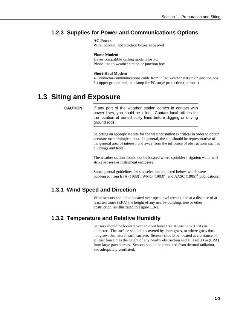
1.2.3 Supplies for Power and Communications OptionsAC PowerWire, conduit, and junction boxes as needed
Phone ModemHayes compatible calling modem for PCPhone line to weather station or junction box
Short-Haul Modem4 Conductor communications cable from PC to weather station or junction box6' copper ground rod and clamp for PC surge protection (optional)
1.3 Siting and ExposureIf any part of the weather station comes in contact withpower lines, you could be killed. Contact local utilities forthe location of buried utility lines before digging or drivingground rods.
Selecting an appropriate site for the weather station is critical in order to obtainaccurate meteorological data. In general, the site should be representative ofthe general area of interest, and away from the influence of obstructions such asbuildings and trees.
The weather station should not be located where sprinkler irrigation water willstrike sensors or instrument enclosure.
Some general guidelines for site selection are listed below, which werecondensed from EPA (1988)1, WMO (1983)2, and AASC (1985)3 publications.
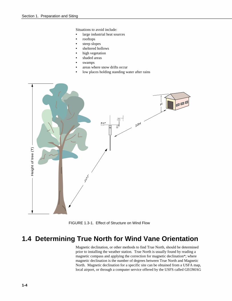
1.3.1 Wind Speed and DirectionWind sensors should be located over open level terrain, and at a distance of atleast ten times (EPA) the height of any nearby building, tree or otherobstruction, as illustrated in Figure 1.3-1.
1.3.2 Temperature and Relative HumiditySensors should be located over an open level area at least 9 m (EPA) indiameter. The surface should be covered by short grass, or where grass doesnot grow, the natural earth surface. Sensors should be located at a distance ofat least four times the height of any nearby obstruction and at least 30 m (EPA)from large paved areas. Sensors should be protected from thermal radiation,and adequately ventilated.
CAUTION
Section 1. Preparation and Siting
1-4
Situations to avoid include:• large industrial heat sources• rooftops• steep slopes• sheltered hollows• high vegetation• shaded areas• swamps• areas where snow drifts occur• low places holding standing water after rains
H
10H
10T
He
igh
t o
f tr
ee
(T
)
Logan, UtahMADE IN USA
FIGURE 1.3-1. Effect of Structure on Wind Flow
1.4 Determining True North for Wind Vane OrientationMagnetic declination, or other methods to find True North, should be determinedprior to installing the weather station. True North is usually found by reading amagnetic compass and applying the correction for magnetic declination*; wheremagnetic declination is the number of degrees between True North and MagneticNorth. Magnetic declination for a specific site can be obtained from a USFA map,local airport, or through a computer service offered by the USFS called GEOMAG
Section 1. Preparation and Siting
1-5
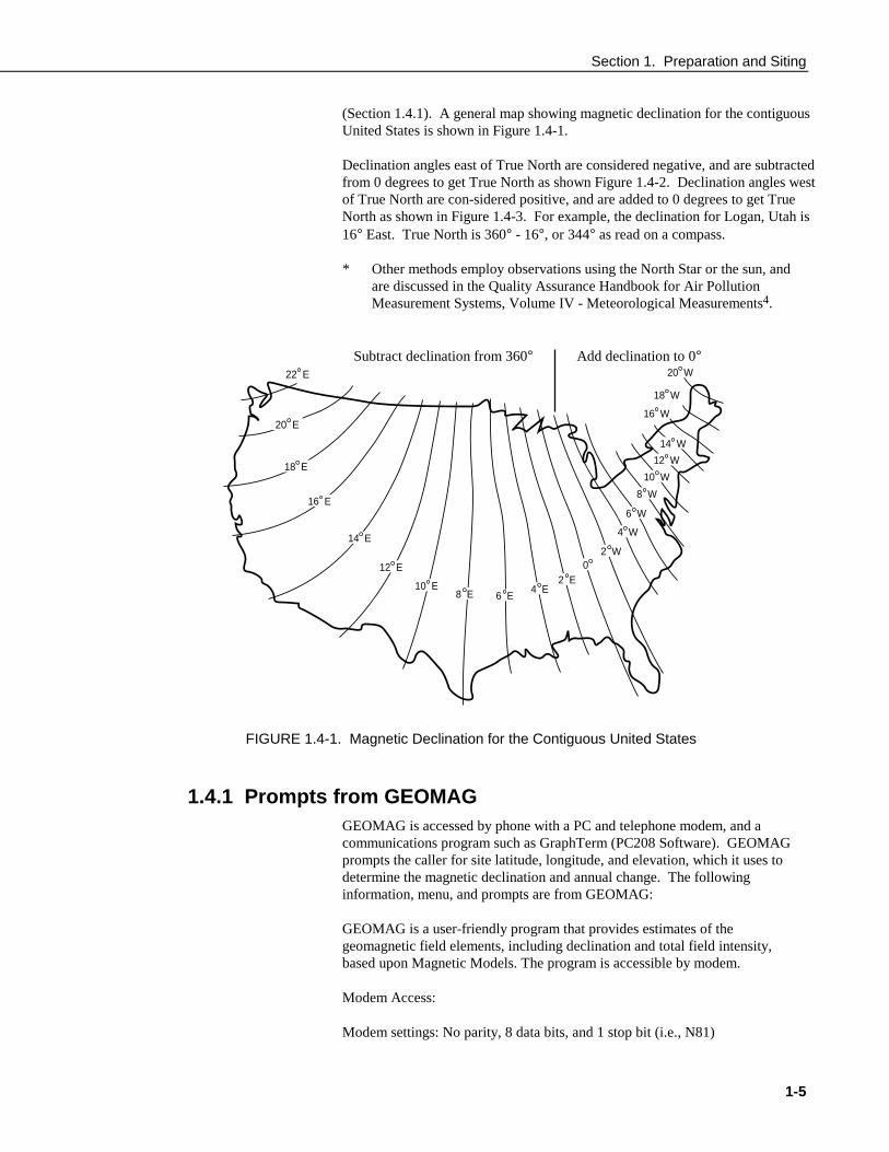
(Section 1.4.1). A general map showing magnetic declination for the contiguousUnited States is shown in Figure 1.4-1.
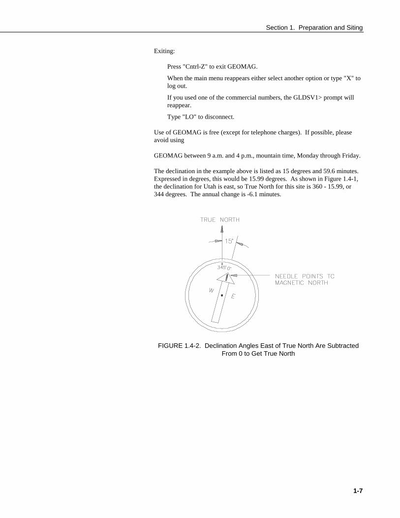
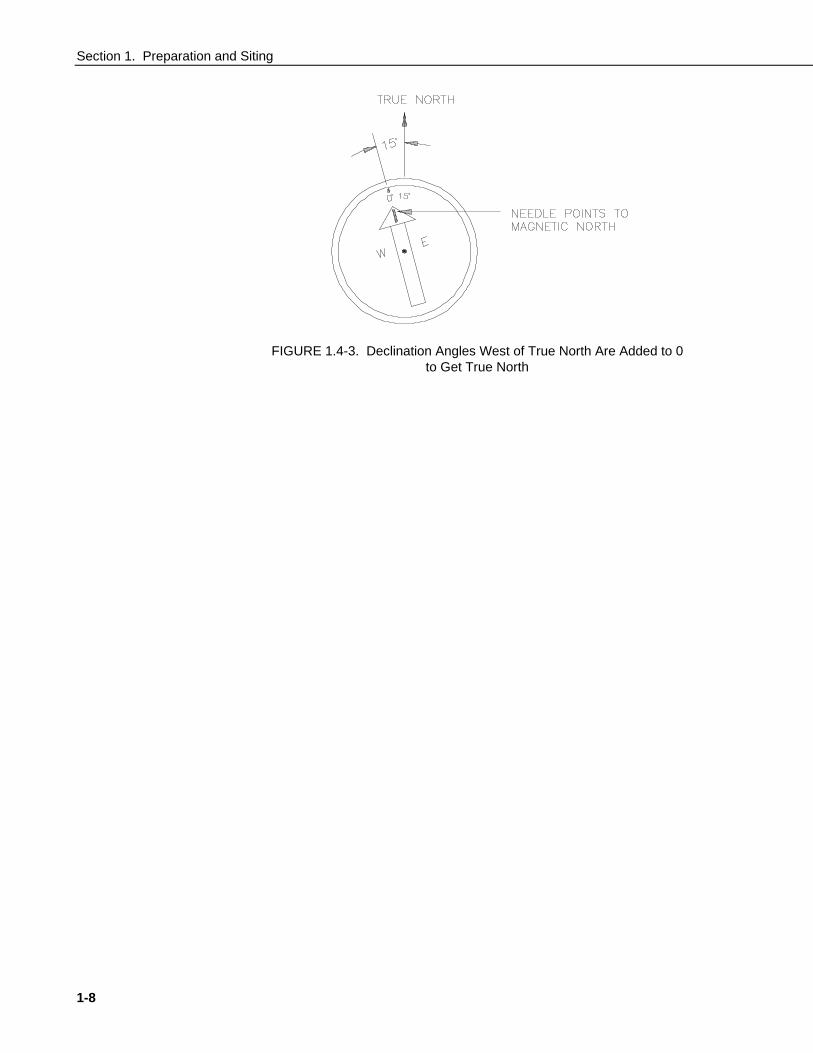
Declination angles east of True North are considered negative, and are subtractedfrom 0 degrees to get True North as shown Figure 1.4-2. Declination angles westof True North are con-sidered positive, and are added to 0 degrees to get TrueNorth as shown in Figure 1.4-3. For example, the declination for Logan, Utah is16° East. True North is 360° - 16°, or 344° as read on a compass.
* Other methods employ observations using the North Star or the sun, andare discussed in the Quality Assurance Handbook for Air PollutionMeasurement Systems, Volume IV - Meteorological Measurements4.
Subtract declination from 360° Add declination to 0°22 E
18 E
16 E
14 E
12 E
10 E8 E 6 E
4 E2 E
02 W
4 W
6 W
8 W
10 W
14 W
12 W
16 W
18 W
20 W
20 E
FIGURE 1.4-1. Magnetic Declination for the Contiguous United States
1.4.1 Prompts from GEOMAGGEOMAG is accessed by phone with a PC and telephone modem, and acommunications program such as GraphTerm (PC208 Software). GEOMAGprompts the caller for site latitude, longitude, and elevation, which it uses todetermine the magnetic declination and annual change. The followinginformation, menu, and prompts are from GEOMAG:
GEOMAG is a user-friendly program that provides estimates of thegeomagnetic field elements, including declination and total field intensity,based upon Magnetic Models. The program is accessible by modem.
Modem Access:
Modem settings: No parity, 8 data bits, and 1 stop bit (i.e., N81)
Section 1. Preparation and Siting
1-6
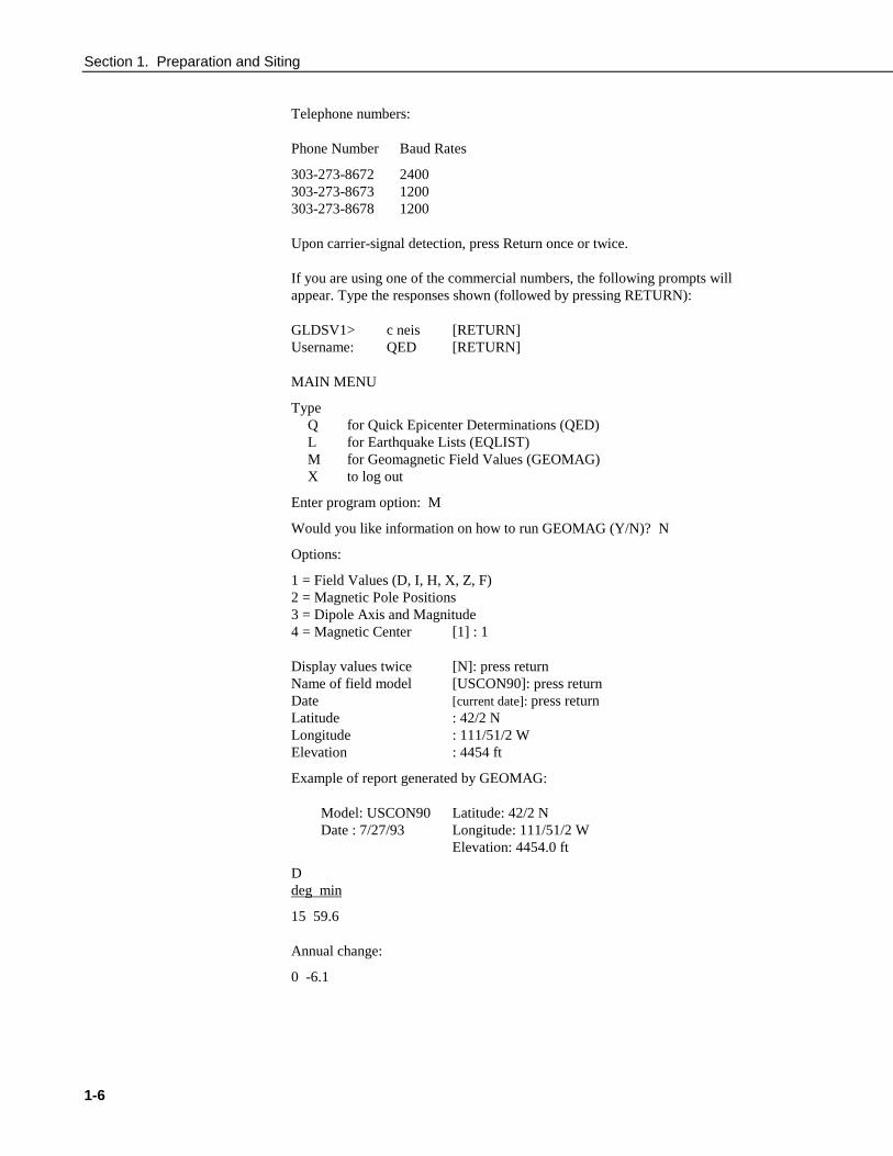
Telephone numbers:
Phone Number Baud Rates
303-273-8672 2400303-273-8673 1200303-273-8678 1200
Upon carrier-signal detection, press Return once or twice.
If you are using one of the commercial numbers, the following prompts willappear. Type the responses shown (followed by pressing RETURN):
GLDSV1> c neis [RETURN]Username: QED [RETURN]
MAIN MENU
TypeQ for Quick Epicenter Determinations (QED)L for Earthquake Lists (EQLIST)M for Geomagnetic Field Values (GEOMAG)X to log out
Enter program option: M
Would you like information on how to run GEOMAG (Y/N)? N
Options:
1 = Field Values (D, I, H, X, Z, F)2 = Magnetic Pole Positions3 = Dipole Axis and Magnitude4 = Magnetic Center [1] : 1
Display values twice [N]: press returnName of field model [USCON90]: press returnDate [current date]: press returnLatitude : 42/2 NLongitude : 111/51/2 WElevation : 4454 ft
Example of report generated by GEOMAG:
Model: USCON90 Latitude: 42/2 NDate : 7/27/93 Longitude: 111/51/2 W
Elevation: 4454.0 ft
Ddeg min
15 59.6
Annual change:
0 -6.1
Section 1. Preparation and Siting
1-7
Exiting:
Press "Cntrl-Z" to exit GEOMAG.
When the main menu reappears either select another option or type "X" tolog out.
If you used one of the commercial numbers, the GLDSV1> prompt willreappear.
Type "LO" to disconnect.
Use of GEOMAG is free (except for telephone charges). If possible, pleaseavoid using
GEOMAG between 9 a.m. and 4 p.m., mountain time, Monday through Friday.
The declination in the example above is listed as 15 degrees and 59.6 minutes.Expressed in degrees, this would be 15.99 degrees. As shown in Figure 1.4-1,the declination for Utah is east, so True North for this site is 360 - 15.99, or344 degrees. The annual change is -6.1 minutes.
FIGURE 1.4-2. Declination Angles East of True North Are SubtractedFrom 0 to Get True North
Section 1. Preparation and Siting
1-8
FIGURE 1.4-3. Declination Angles West of True North Are Added to 0to Get True North

2-1
Section 2. TLX106 Tower Installation
Do not install near power lines. If any part of the towercomes in contact with power lines you could beKILLED. Contact local utilities for the location ofburied utility lines before digging or driving groundingrods.
Do not fit the 3 meter TLX106 Tower sections together untilthe appropriate time. Once attached, they cannot bedetached.
The TLX106 Tower provides a support structure for mounting the TLX106weather station components. Figure 2.1-1 shows a typical TLX106 Towerinstallation option. The tower is designed to withstand winds of 100 mph. Thelightning rod assembly is attached after the instrumentation enclosure isinstalled (Section 3.1).
TransformerUser Supplied Junction Box
110 VAC
16 VACPower Valve Box
CommunicationsLine
Direct BurySplices
ConcreteBase
GroundRod
ET Tower
FIGURE 2.1-1. TLX106 Tower Installation
DANGER
CAUTION
Section 2. TLX106 Tower Installation
2-2
2.1 Base Installation
2.1.1 Supplied Components(3) ½ inch L-Bolts(9) ½ inch Nuts(1) Anchor Template
Refer to Section 1 for components supplied by installer.
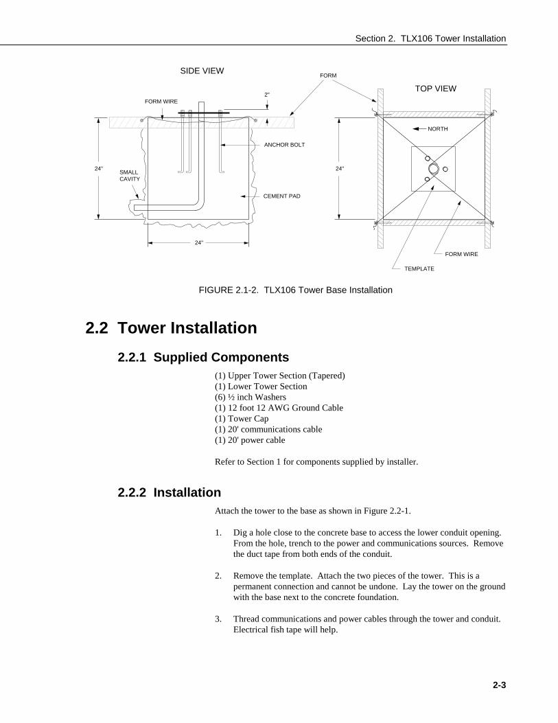
2.1.2 Installation1. The TLX106 Tower attaches to a user supplied concrete foundation
constructed as shown in Figure 2.1-2.
2. Construct the concrete form with 2" x 4" lumber and 16p nails.
3. Assemble the template and anchor bolts. There should be two nuts belowand one nut above the template on each bolt.
4. Clear an area large enough to set the form at the desired elevation.
5. Dig a hole 2 feet x 2 feet x 2 feet. Lighter soils may require a deeper hole.About 20 inches below the top of the hole, gouge a small cavity in onewall of the hole. The cavity should be about 4 inches deep and just largeenough in diameter to insert one end of the conduit. Make certain thecavity "points" in the direction from which power and communicationscables will come.
6. Center the form over the hole. Adjacent to the form, drive four stakes intothe soil. Secure the leveled form to the stakes with the 8p nails.
7. Cap the ends of the conduit with duct tape. Position the conduit and wireinto place by securing the wire to nails in the form.
8. Fill the hole and form with approximately ½ yard of concrete. Screed theconcrete level with the top of the form. Center the template assembly overthe conduit and press into the concrete. Put 2 x 4 spacers between thetemplate and the top of the form. The bottom of the bolt threads should beabout ½ inch above the concrete. The template must be level in twodimensions. Use a trowel and edger to finish.
9. Wait 24 hours before removing the concrete form. Wait 7 days beforemounting the TLX106 Tower.
Section 2. TLX106 Tower Installation
2-3
SIDE VIEW
TOP VIEW
ANCHOR BOLT
FORM
FORM WIRE
CEMENT PAD
SMALLCAVITY
24"
24"
24"
TEMPLATE
2"
NORTH
FORM WIRE
FIGURE 2.1-2. TLX106 Tower Base Installation
2.2 Tower Installation
2.2.1 Supplied Components(1) Upper Tower Section (Tapered)(1) Lower Tower Section(6) ½ inch Washers(1) 12 foot 12 AWG Ground Cable(1) Tower Cap(1) 20' communications cable(1) 20' power cable
Refer to Section 1 for components supplied by installer.
2.2.2 InstallationAttach the tower to the base as shown in Figure 2.2-1.
1. Dig a hole close to the concrete base to access the lower conduit opening.From the hole, trench to the power and communications sources. Removethe duct tape from both ends of the conduit.
2. Remove the template. Attach the two pieces of the tower. This is apermanent connection and cannot be undone. Lay the tower on the groundwith the base next to the concrete foundation.
3. Thread communications and power cables through the tower and conduit.Electrical fish tape will help.

Section 2. TLX106 Tower Installation
2-4
4. Cut and save a 9 inch piece of 12 AWG ground wire from the 12 footlength provided. Thread the remaining 11 foot ground wire through thetower. Secure all wiring so it does not slip back into the tower or conduit.
5. Place the tower cap over the tower end.
6. Raise the tower on a still day. Place a washer on top of the two nuts oneach foundation bolt. Taking great care not to damage cables between thetower and conduit, raise the tower and lower it onto the conduit andmounting bolts. Install a washer and nut on each bolt and hand tighten.Check plumb of the tower by placing a level on the north and east sides ofthe lower tower section. Adjust the topmost of the two lower nuts(leveling nut) on each bolt as necessary. When plumb is established, lockthe leveling nut in place by tightening the lowest nut against it. Tightenthe three top nuts with the wrench.
12AWG Wire 4AWG Cable
FIGURE 2.2-1. Raising and Grounding the TLX106 Tower
2.3 Tower Grounding
2.3.1 Supplied Components(1) 5 foot 4 AWG Ground Cable(1) Copper Ground Lug, Bolt(1) Ground Rod, Clamp
Refer to Section 1 for components supplied by installer.
Section 2. TLX106 Tower Installation
2-5
2.3.2 Grounding ProcedureGround the tower as shown in Figure 2.2-1.
1. Place the ground rod clamp on the rod. Secure it about 3 inches from thetop. Do this before the rod is driven into the ground. Be careful not todamage the clamp with the hammer
2. Taking care not to damage power or communications lines, drive theground rod close to the foundation using a fence post driver or sledgehammer. Drive the rod at an angle if an impenetrable hardpan layer exists.Soften hard clay soils with water if necessary.
3. Strip 1 inch of insulation from both ends of the 4 AWG ground cable.Strip 1 inch of insulation from the lower end of the 14 AWG ground wire.Install the tower grounding lug to the tower base with the 7/16 boltprovided (Figure 2.2-1). Loosen the lug's set screw and insert the 4 AWGand 14 AWG wire. Tighten the set screw.
4. Loosen the ground rod clamp. Insert the 4 AWG wire. Tighten the clamp(Figure 2.2-1).

Section 2. TLX106 Tower Installation
2-6
This is a blank page.
3-1
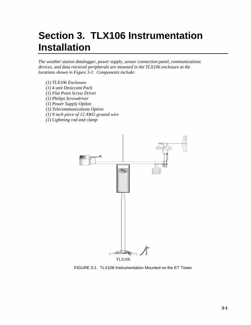
Section 3. TLX106 InstrumentationInstallationThe weather station datalogger, power supply, sensor connection panel, communicationsdevices, and data retrieval peripherals are mounted in the TLX106 enclosure at thelocations shown in Figure 3-1. Components include:
(1) TLX106 Enclosure(1) 4 unit Desiccant Pack(1) Flat Point Screw Driver(1) Philips Screwdriver(1) Power Supply Option(1) Telecommunications Option(1) 9 inch piece of 12 AWG ground wire(1) Lightning rod and clamp
Logan, UtahMADE IN USA
FIGURE 3-1. TLX106 Instrumentation Mounted on the ET Tower
TLX106

Section 3. TLX106 Instrumentation Installation
3-2
3.1 Enclosure, Datalogger, Power Supply
3.1.1 Battery Option Installation
YUASA
FIGURE 3.1-1. Rechargeable Power Mounting and Connections
a) Sealed Rechargeable Battery Option: Install the kit as shown in Figure3.1-1. An unregulated solar panel or 17 to 24 VAC must be used with therechargeable battery at all times. In either case, power is routed throughthe Heyco fitting on the enclosure back and connected to the CHG portsby depressing connector levers. Polarity of the CHG connection does notmatter. Install the rechargeable battery and plug the battery lead into theconnector labeled “LA”.
Press the connector levers gently or they might break.
3.1.2 Solar Panel Installation
FIGURE 3.1-2. Solar Panel Mounting
a) Mount the solar panel to the tower using the mounting brackets as shownin Figure 3.1-2. Mount the solar panel to the tower so it faces south(northern hemisphere). Position it as high off the ground as practical,ensuring it cannot interfere with air flow or sunlight around the sensors.
NOTE
Solar Panel or 16 VACPower Cable
Section 3. TLX106 Instrumentation Installation
3-3
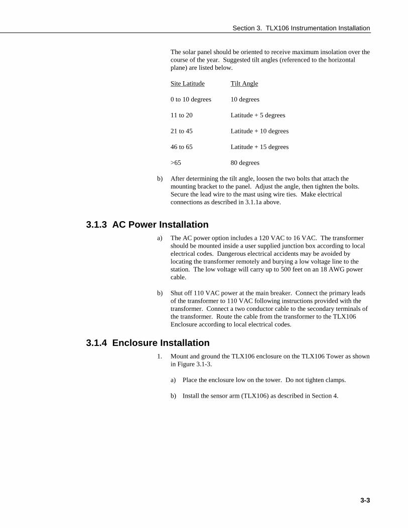
The solar panel should be oriented to receive maximum insolation over thecourse of the year. Suggested tilt angles (referenced to the horizontalplane) are listed below.
Site Latitude Tilt Angle
0 to 10 degrees 10 degrees
11 to 20 Latitude + 5 degrees
21 to 45 Latitude + 10 degrees
46 to 65 Latitude + 15 degrees
>65 80 degrees
b) After determining the tilt angle, loosen the two bolts that attach themounting bracket to the panel. Adjust the angle, then tighten the bolts.Secure the lead wire to the mast using wire ties. Make electricalconnections as described in 3.1.1a above.
3.1.3 AC Power Installationa) The AC power option includes a 120 VAC to 16 VAC. The transformer
should be mounted inside a user supplied junction box according to localelectrical codes. Dangerous electrical accidents may be avoided bylocating the transformer remotely and burying a low voltage line to thestation. The low voltage will carry up to 500 feet on an 18 AWG powercable.
b) Shut off 110 VAC power at the main breaker. Connect the primary leadsof the transformer to 110 VAC following instructions provided with thetransformer. Connect a two conductor cable to the secondary terminals ofthe transformer. Route the cable from the transformer to the TLX106Enclosure according to local electrical codes.
3.1.4 Enclosure Installation1. Mount and ground the TLX106 enclosure on the TLX106 Tower as shown
in Figure 3.1-3.
a) Place the enclosure low on the tower. Do not tighten clamps.
b) Install the sensor arm (TLX106) as described in Section 4.

Section 3. TLX106 Instrumentation Installation
3-4
NORTH
FIGURE 3.1-3. Mounting and Grounding the TLX106 Enclosure
c) Slide the enclosure to the top of the TLX106 tower. Position it on thenorth side of the tower (northern hemisphere). The top of theenclosure should be flush with the top of the tower, with the width ofthe sensor arm extending above the tower. Tighten the clamps untilthe enclosure is snug. Do not over-tighten since doing so maydamage the tower or enclosure.
d) Carefully mount the lightning rod and clamp to the top of the TLX106Tower. Clearance between the clamp and the enclosure is minimal.Care should be taken not to scratch the enclosure or sensor assembly.Strip 1 inch of insulation from the top end of the 12 AWG greentower ground wire, curl the end and place the curled end under thehead of one of the lightning rod clamp bolts. Tighten the bolt.
e) Strip 1 inch of insulation from each end of the 9 inch piece of 12AWG ground wire. Insert one end into the brass ground lug locatedat the top back of the enclosure. Curl the other end and place underthe head of one of the lightning rod clamp bolts. Tighten the bolt.
3.2 Sensor Connection1) Install the sensor set as described in Section 4.
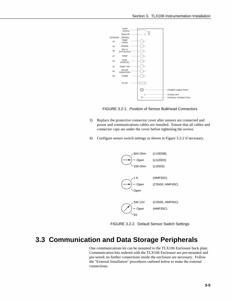
2) Remove the protective connector cover from the back of the TLX106Enclosure by removing the two phillips head screws. Sensors connect toone of seven labeled bulkhead connectors as shown in Figure 3.2-1.
9-inchGround
Wire TowerGround
Wire
Section 3. TLX106 Instrumentation Installation
3-5
EarthGround
Stand off
Connector
#4
Sensors
TEMPCS615
TEMP
RAIN(PRECIP)
TEMP / RH
SOLARRADIATION
COMM
WS/WD
SDI 12GYP BLOCK
#2
#6
#7
#5
#1
#3
#8
CS I/O
POWER CABLE PORT
STAND OFF
COAXIAL CONNECTION
FIGURE 3.2-1. Position of Sensor Bulkhead Connectors
3) Replace the protective connector cover after sensors are connected andpower and communications cables are installed. Ensure that all cables andconnector caps are under the cover before tightening the screws.
4) Configure sensor switch settings as shown in Figure 3.2-2 if necessary.
Open
604 Ohm
100 Ohm
(LI1200X)
(LI190SB)
(LI200S)
Open
1 K
Open
(CS500, HMP45C)
(CS500, HMP45C)
(HMP35C)
Open
SW 12V
5V
(HMP35C)
FIGURE 3.2-2. Default Sensor Switch Settings
3.3 Communication and Data Storage PeripheralsOne communications kit can be mounted to the TLX106 Enclosure back plate.Communication kits ordered with the TLX106 Enclosure are pre-mounted andpre-wired; no further connections inside the enclosure are necessary. Followthe "External Installation" procedures outlined below to make the externalconnections.
Section 3. TLX106 Instrumentation Installation
3-6
If you received a telecommunications kit separate from the TLX106 Enclosure,follow the "Internal Installation" procedures outlined below.
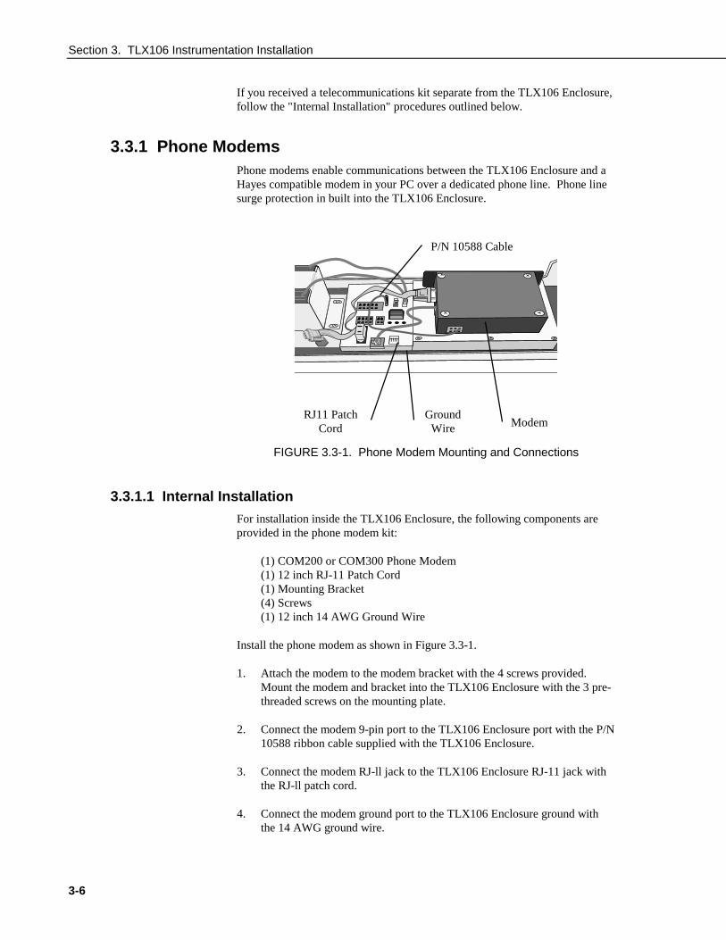
3.3.1 Phone ModemsPhone modems enable communications between the TLX106 Enclosure and aHayes compatible modem in your PC over a dedicated phone line. Phone linesurge protection in built into the TLX106 Enclosure.
FIGURE 3.3-1. Phone Modem Mounting and Connections
3.3.1.1 Internal Installation
For installation inside the TLX106 Enclosure, the following components areprovided in the phone modem kit:
(1) COM200 or COM300 Phone Modem(1) 12 inch RJ-11 Patch Cord(1) Mounting Bracket(4) Screws(1) 12 inch 14 AWG Ground Wire
Install the phone modem as shown in Figure 3.3-1.
1. Attach the modem to the modem bracket with the 4 screws provided.Mount the modem and bracket into the TLX106 Enclosure with the 3 pre-threaded screws on the mounting plate.
2. Connect the modem 9-pin port to the TLX106 Enclosure port with the P/N10588 ribbon cable supplied with the TLX106 Enclosure.
3. Connect the modem RJ-ll jack to the TLX106 Enclosure RJ-11 jack withthe RJ-ll patch cord.
4. Connect the modem ground port to the TLX106 Enclosure ground withthe 14 AWG ground wire.
P/N 10588 Cable
RJ11 PatchCord
GroundWire Modem
Section 3. TLX106 Instrumentation Installation
3-7
3.3.1.2 External Installation
The following modem kit components are used to make the externalconnections:
(1) Direct Burial Splice Kit(1) 20 foot Telephone Patch Cord with Connector
1) Connect the 20 foot patch cord to the connector marked "comm" on theexternal back panel, under the protective cover.
2) Splice the labeled "Tip" and "Ring" lines of the patch cord to thetelephone service line. Use the direct burial splice kit when splices are ina valve box or buried.
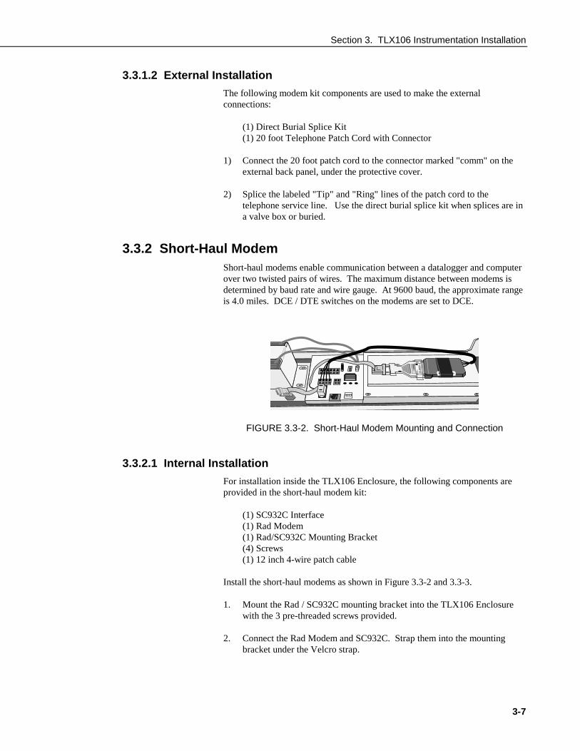
3.3.2 Short-Haul ModemShort-haul modems enable communication between a datalogger and computerover two twisted pairs of wires. The maximum distance between modems isdetermined by baud rate and wire gauge. At 9600 baud, the approximate rangeis 4.0 miles. DCE / DTE switches on the modems are set to DCE.
CAMP
BELL
SCIEN
TIFIC
LTD
SC932
- S/N
E1055
QC
FIGURE 3.3-2. Short-Haul Modem Mounting and Connection
3.3.2.1 Internal Installation
For installation inside the TLX106 Enclosure, the following components areprovided in the short-haul modem kit:
(1) SC932C Interface(1) Rad Modem(1) Rad/SC932C Mounting Bracket(4) Screws(1) 12 inch 4-wire patch cable
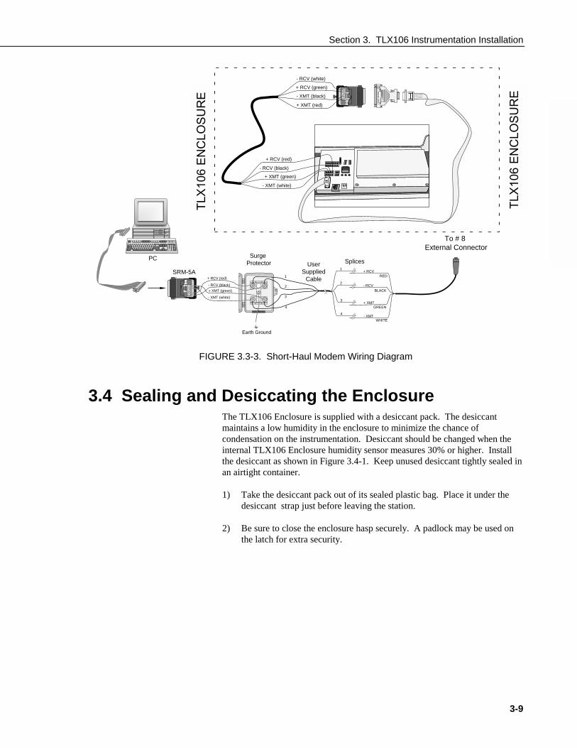
Install the short-haul modems as shown in Figure 3.3-2 and 3.3-3.
1. Mount the Rad / SC932C mounting bracket into the TLX106 Enclosurewith the 3 pre-threaded screws provided.
2. Connect the Rad Modem and SC932C. Strap them into the mountingbracket under the Velcro strap.
Section 3. TLX106 Instrumentation Installation
3-8
3. Connect the SC932C 9-pin port to the internal TLX106 Enclosure 9-pinport with the blue ribbon cable provided.
4. Wire the Rad Modem to the TLX106 Enclosure with the 12 inch patchcord. Match wire labels to wiring panel labels on both the TLX106Enclosure and the Rad Modem (+XMT to +XMT, etc.). A small screwdriver in provided with the TLX106 Enclosure to access the Rad Modemconnections.
3.3.2.2 External Installation
The following short-haul kit components are used to make the externalconnections:
At the TLX106 Enclosure:
(1) 20 foot 4-Wire Patch Cable(2) 2 Direct Burial Splice Kits(1) Length of User Supplied Wire (Supplier: Anixter, p/n F-02P22BPN,
Phone 847-677-2600)
At the PC:
(1) Rad Modem(1) 5 foot 4-wire Patch Cable(1) 10 foot 14 AWG Ground Wire(1) Surge Protector and Case
1) Connect the 20 foot patch cable to the connector marked "comm" on theexternal back panel of the TLX106 Enclosure. Splice this cable to theuser supplied cable, using the direct burial splice kits.
2) Mount the surge protector to a flat surface near the PC's serial port.Ground the center terminal to an earth (or building) ground using the 14AWG wire.
3) Connect the 5 foot patch cord to the Rad Modem. Fasten the cable to thestrain relief tab with a cable tie. Connect the Rad to the PC's serial porteither directly (25 pin port) or through a 9 to 25 pin serial converter.
4) Route the user-supplied cable from the remote splice to the surgeprotector. Connect it and the 5 foot patch cord to the surge protector.
Section 3. TLX106 Instrumentation Installation
- RCV (white)
+ RCV (green)
+ XMT (red)
- XMT (black)
SRM-5
PC
E ETC
AMPBELL
SCIENTIFIC LTD
SC932 - S/N E1055
QC
3.4 Sealing a
E
RE
3-9
- RCV (black)
+ RCV (red)
+ XMT (green)
- XMT (white)
- RCV
+ RCV
+ XMT
- XMT
BLACK
RED
GREEN
WHITE
2
1
3
4
- RCV (black)
+ RCV (red)
+ XMT (green)
- XMT (white)
2
1
3
4
A
Surge Protector User
SuppliedCable
Splices
ET
106
EN
CLO
SU
R 106 EN
CLO
SU
RE
To # 8 External Connector
Earth Ground
FIGURE 3.3-3. Short-Haul Modem Wiring Diagram
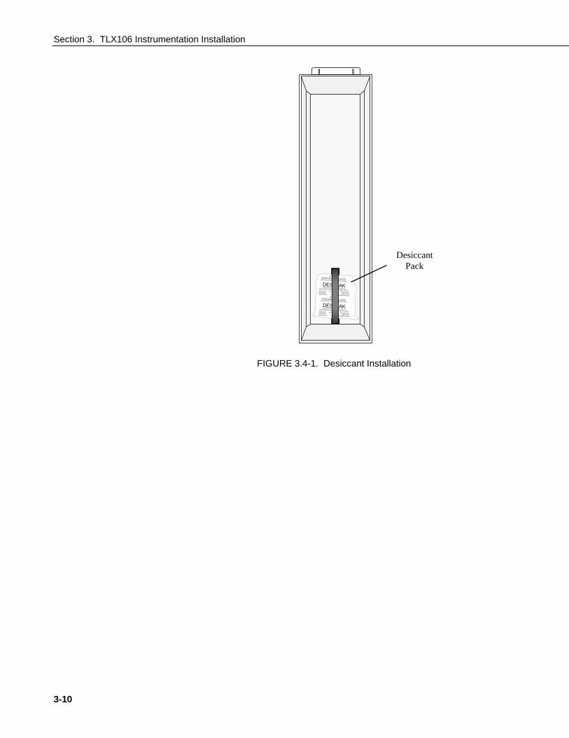
nd Desiccating the EnclosureThe TLX106 Enclosure is supplied with a desiccant pack. The desiccantmaintains a low humidity in the enclosure to minimize the chance ofcondensation on the instrumentation. Desiccant should be changed when theinternal TLX106 Enclosure humidity sensor measures 30% or higher. Installthe desiccant as shown in Figure 3.4-1. Keep unused desiccant tightly sealed inan airtight container.
1) Take the desiccant pack out of its sealed plastic bag. Place it under thedesiccant strap just before leaving the station.
2) Be sure to close the enclosure hasp securely. A padlock may be used onthe latch for extra security.
TLX
106
EN
CLO
SU
R
TLX
106
EN
CLO
SU
Section 3. TLX106 Instrumentation Installation
3-10
DO NOT EATUNITED DESICCANTS-GATES101CHRISTINE, BELEN, NEW MEXICO 87002
DESI PAKSPECIFICATION MIL-D-3464 TYPE I &IIREACTIVATION TIME IN-BAG 16 HOURS AT 250 FDESICCANTACTIVATEDBAGGED FOR
CONTENTS4
UNITS
PACKAGE USE AND STATIC
DEHUMIDIFICATIONDO NOT EAT
UNITED DESICCANTS-GATES101CHRISTINE, BELEN, NEW MEXICO 87002
DESI PAKSPECIFICATION MIL-D-3464 TYPE I &IIREACTIVATION TIME IN-BAG 16 HOURS AT 250 FDESICCANTACTIVATEDBAGGED FOR
CONTENTS4
UNITS
PACKAGE USE AND STATIC
DEHUMIDIFICATION
O
O
FIGURE 3.4-1. Desiccant Installation
DesiccantPack
4-1
Section 4. TLX106 Sensor ArmInstallation
4.1 Components(1) TLX106 Sensor Arm(1) Met One 034A Wind Sensor(1) 034A Mounting Shaft(1) Radiation Shield
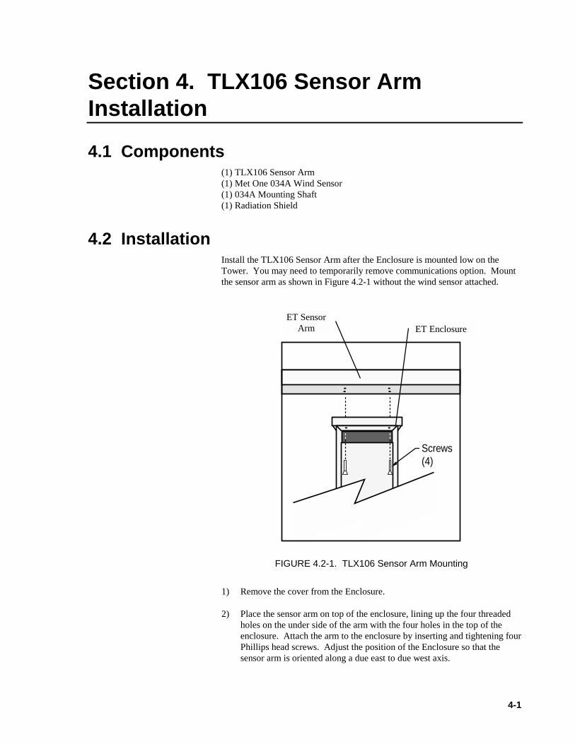
4.2 InstallationInstall the TLX106 Sensor Arm after the Enclosure is mounted low on theTower. You may need to temporarily remove communications option. Mountthe sensor arm as shown in Figure 4.2-1 without the wind sensor attached.
Screws (4)
FIGURE 4.2-1. TLX106 Sensor Arm Mounting
1) Remove the cover from the Enclosure.
2) Place the sensor arm on top of the enclosure, lining up the four threadedholes on the under side of the arm with the four holes in the top of theenclosure. Attach the arm to the enclosure by inserting and tightening fourPhillips head screws. Adjust the position of the Enclosure so that thesensor arm is oriented along a due east to due west axis.
ET SensorArm ET Enclosure
Section 4. TLX106 Sensor Arm Installation
4-2
4.3 Sensor ConnectionRefer to Section 3 for sensor connection details.
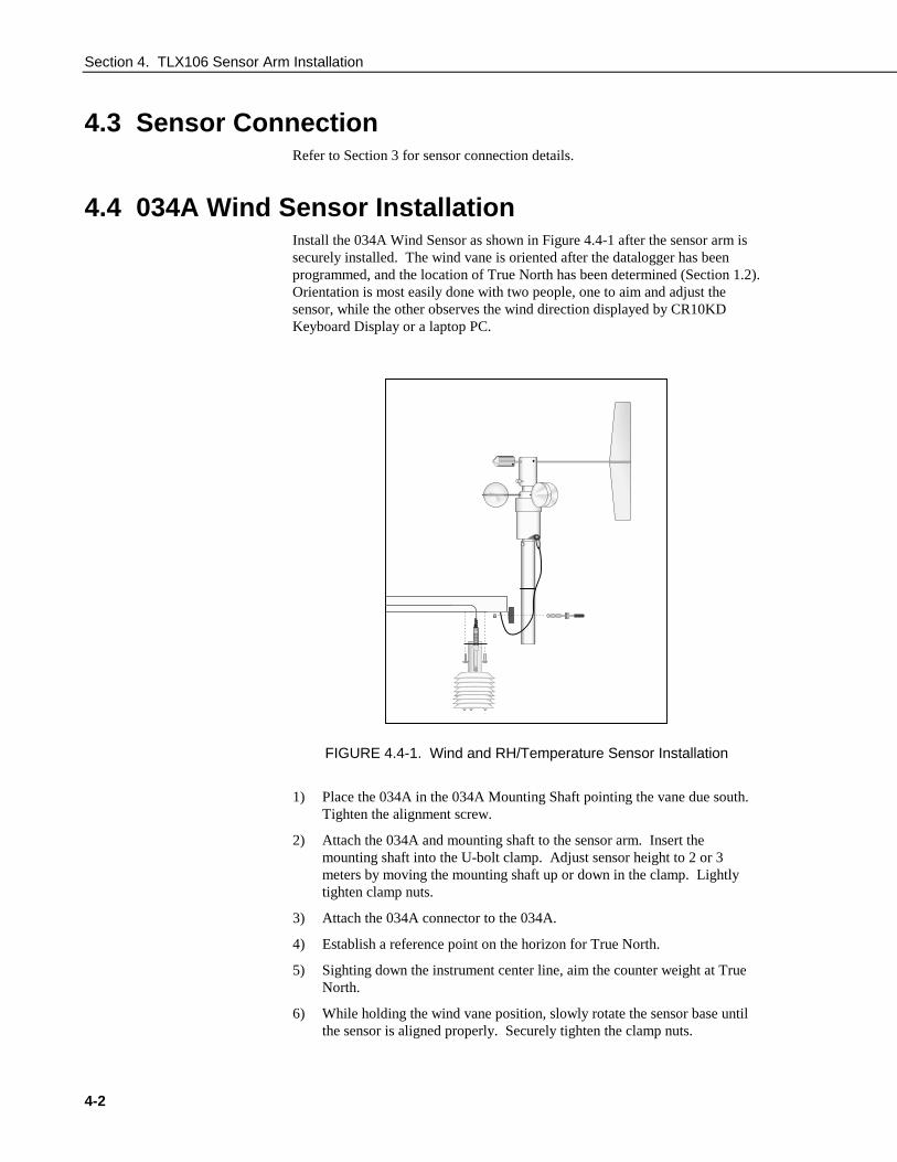
4.4 034A Wind Sensor InstallationInstall the 034A Wind Sensor as shown in Figure 4.4-1 after the sensor arm issecurely installed. The wind vane is oriented after the datalogger has beenprogrammed, and the location of True North has been determined (Section 1.2).Orientation is most easily done with two people, one to aim and adjust thesensor, while the other observes the wind direction displayed by CR10KDKeyboard Display or a laptop PC.
FIGURE 4.4-1. Wind and RH/Temperature Sensor Installation
1) Place the 034A in the 034A Mounting Shaft pointing the vane due south.Tighten the alignment screw.
2) Attach the 034A and mounting shaft to the sensor arm. Insert themounting shaft into the U-bolt clamp. Adjust sensor height to 2 or 3meters by moving the mounting shaft up or down in the clamp. Lightlytighten clamp nuts.
3) Attach the 034A connector to the 034A.
4) Establish a reference point on the horizon for True North.
5) Sighting down the instrument center line, aim the counter weight at TrueNorth.
6) While holding the wind vane position, slowly rotate the sensor base untilthe sensor is aligned properly. Securely tighten the clamp nuts.
Section 4. TLX106 Sensor Arm Installation
4-3
4.5 RH and Temperature Radiation ShieldMount the radiation shield to the sensor arm as shown in Figure 4.4-1. Removeyellow cap. Place the RH and temperature assembly inside the shield shaft.Attach the shield to the sensor arm with the two screws.
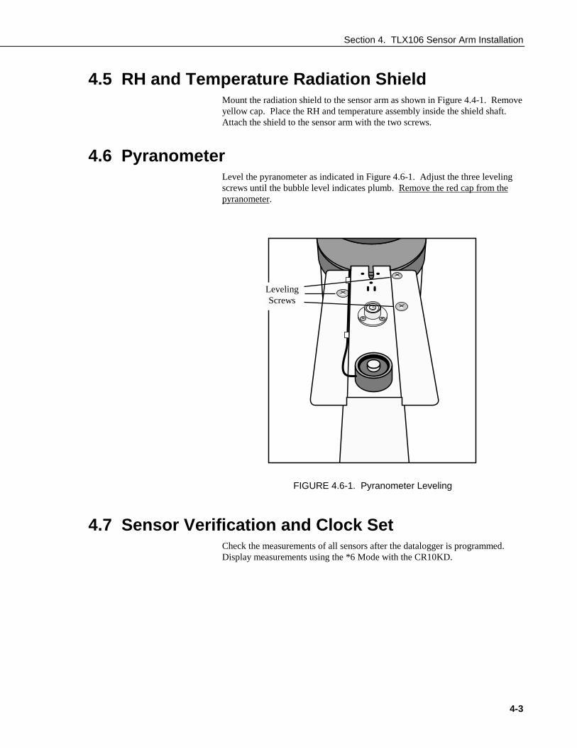
4.6 PyranometerLevel the pyranometer as indicated in Figure 4.6-1. Adjust the three levelingscrews until the bubble level indicates plumb. Remove the red cap from thepyranometer.
FIGURE 4.6-1. Pyranometer Leveling
4.7 Sensor Verification and Clock SetCheck the measurements of all sensors after the datalogger is programmed.Display measurements using the *6 Mode with the CR10KD.
LevelingScrews
Section 4. TLX106 Sensor Arm Installation
4-4
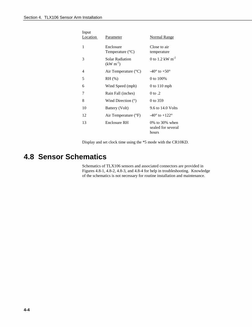
InputLocation Parameter Normal Range
1 Enclosure Close to airTemperature (°C) temperature
3 Solar Radiation 0 to 1.2 kW m-2
(kW m-2)
4 Air Temperature (°C) -40° to +50°
5 RH (%) 0 to 100%
6 Wind Speed (mph) 0 to 110 mph
7 Rain Fall (inches) 0 to .2
8 Wind Direction (°) 0 to 359
10 Battery (Volt) 9.6 to 14.0 Volts
12 Air Temperature (°F) -40° to +122°
13 Enclosure RH 0% to 30% whensealed for severalhours
Display and set clock time using the *5 mode with the CR10KD.
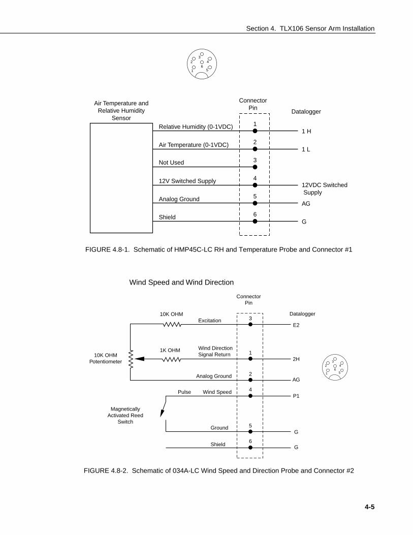
4.8 Sensor SchematicsSchematics of TLX106 sensors and associated connectors are provided inFigures 4.8-1, 4.8-2, 4.8-3, and 4.8-4 for help in troubleshooting. Knowledgeof the schematics is not necessary for routine installation and maintenance.
Section 4. TLX106 Sensor Arm Installation
4-5
1
23
4
56
Air Temperature andRelative Humidity
Sensor
ConnectorPin
Datalogger
Relative Humidity (0-1VDC)
Air Temperature (0-1VDC)
12V Switched Supply
Not Used
Analog Ground
Shield
1
2
3
4
5
6
1 H
1 L
12VDC Switched Supply
AG
G
FIGURE 4.8-1. Schematic of HMP45C-LC RH and Temperature Probe and Connector #1
3
ConnectorPin
MagneticallyActivated Reed
Switch
Wind Speed and Wind Direction
Ground
Pulse Wind Speed
Analog Ground
Wind DirectionSignal Return
Excitation10K OHM
10K OHMPotentiometer
1K OHM
Datalogger
Shield
1
2
4P1
AG
2H
E2
G
G5
6
1
23
4
56
FIGURE 4.8-2. Schematic of 034A-LC Wind Speed and Direction Probe and Connector #2

Section 4. TLX106 Sensor Arm Installation
4-6
Solar RadiationSensor
40.2 - 90.2 OHM
ConnectorPin
Datalogger
1
3
2
Not Used
Not Used
Not Used
3 H
3 L
GShield
4
5
6
1
23
4
56
FIGURE 4.8-3. Schematic of LI200X-LC Solar Radiation Sensor and Connector #3
1Not Used
ConnectorPin
MagneticallyActivated Reed
Switch
Tipping Rain Bucket
Not Used
Not Used
Ground
PulseDatalogger
Shield
2
4
3P2
G
G5
6
1
23
4
56
FIGURE 4.8-4. Schematic of TE525-LC Rain Sensor and Connector #5

5-1
Section 5. Software Installation andSettings
5.1 Measure Sensors and Process DataA pre-written datalogger program (PN 14079) comes installed in theTLX106. This program sets the scan rate, measures the sensors,processes internally and stores the data. This program will be factorycorrected for the station’s latitude, longitude, elevation, and standardtime meridian, and then downloaded to the station before shipping.
5.2 Software Install and SettingsInstall Proline and make sure to select the Weather Source install usingthe install procedure. The user must have purchased the WeatherSource as an option to their ProLine software package.
Install LoggerNet according to the manual (refer to the LoggerNetmanual). Set up the communication link to the logger with the NetworkEditor as shown below. (This is for the phone modem with ACpowered station; other setup combinations may vary slightly, but theywill be very similar.) Start the LoggerNet server by clicking on the blueicon. Make sure Communications Enabled is checked and the properCom Port Connection is selected. Enter 10 seconds in the ExtraResponse Time box. Click on the Apply button and proceed to the nextstep.
Section 5. Software Installation and Settings
5-2
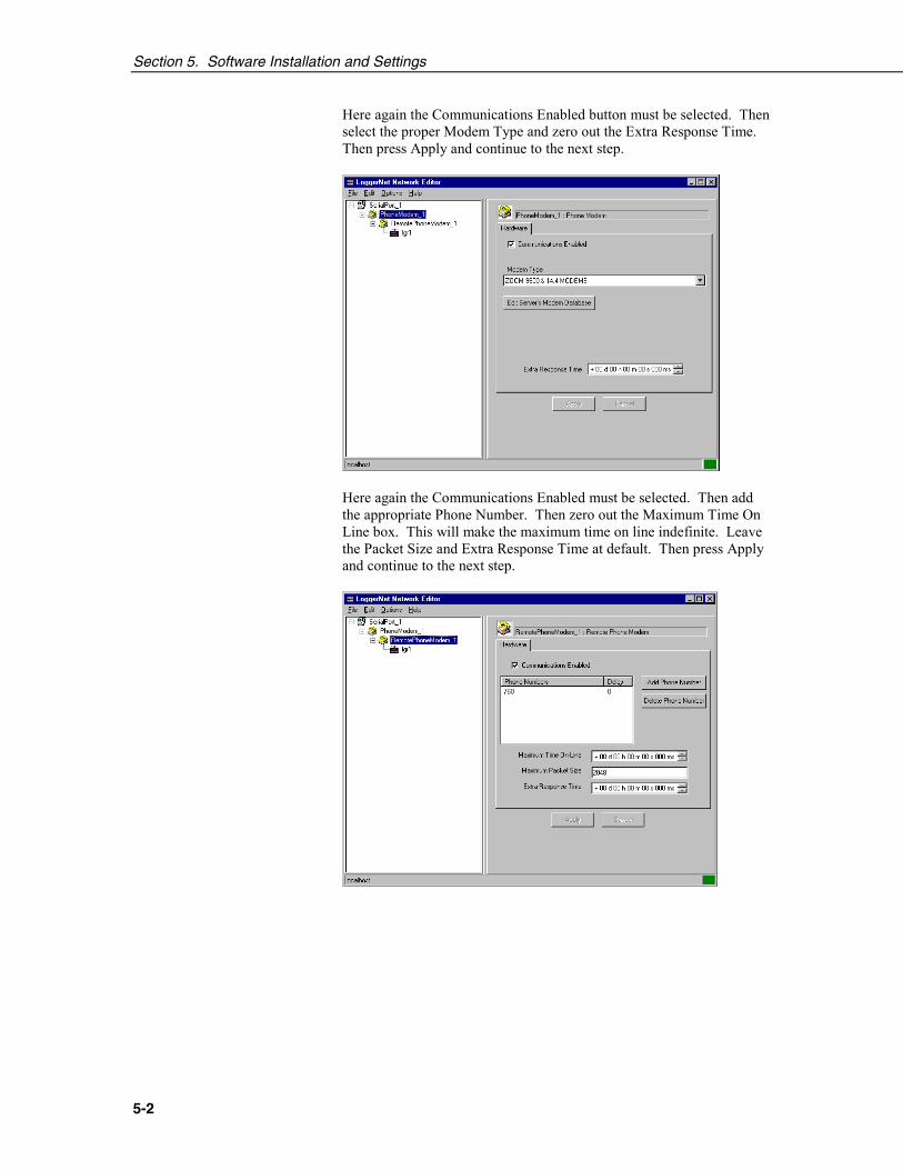
Here again the Communications Enabled button must be selected. Thenselect the proper Modem Type and zero out the Extra Response Time.Then press Apply and continue to the next step.
Here again the Communications Enabled must be selected. Then addthe appropriate Phone Number. Then zero out the Maximum Time OnLine box. This will make the maximum time on line indefinite. Leavethe Packet Size and Extra Response Time at default. Then press Applyand continue to the next step.

Section 5. Software Installation and Settings
5-3
The final termination must be to a CR10X-TD logger. The Proline willdefault to work with a logger named ‘lgr1’, but you can change thisdefault if you want to name your logger something else. Change thelogger name here and then refer to the RDE extra settings to make sureyou change the name there so that the RDE will be able to find thelogger with the appropriate data. Then zero out the Maximum Time OnLine, leave the Packet Size and Extra Response Time at default. Setyour Security Code options. They may be left at the default if desired.
Here the user will normally want to select a Collection Interval of 1second, a Primary Retry Interval of 10 seconds, a Number of PrimaryRetries at 3, and a Secondary Retry Interval of 2 minutes. Longer timesmay be entered, but this may effect the RDE settings if the collectioninterval is longer than 1 or 2 minutes. If your Collection Interval is sethigher to conserve power, you will want to hang up and redial, as thephone modem in the weather station is the major power consumer (140ma active and .12 ma when inactive). For the station to hang up, the“Keep Logger On Line” box must be deselected in the extra settings ofthe RDE mentioned later in this manual. For now, do not enable datacollection by selecting the “Scheduled Collection Enable” box untilafter you set up the extra settings in the RDE. For now, press the Applybutton, close the Network Editor, and continue.
Section 5. Software Installation and Settings
5-4
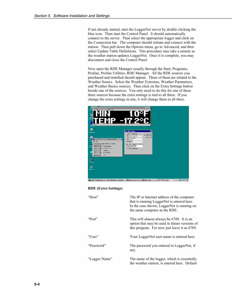
If not already started, start the LoggerNet server by double clicking theblue icon. Then start the Control Panel. It should automaticallyconnect to the server. Then select the appropriate logger and click onthe Connection bar. The computer should initiate and connect with thestation. Then pull down the Options menu, go to Advanced, and thenselect Update Table Definitions. This procedure may take a minute asthe weather station updates LoggerNet. Once it is complete, you maydisconnect and close the Control Panel.
Now open the RDE Manager usually through the Start, Programs,Proline, Proline Utilities, RDE Manager. All the RDE sources youpurchased and installed should appear. Three of them are related to theWeather Source. Select the Weather Extremes, Weather Parameters,and Weather Basics sources. Then click on the Extra Settings buttonbeside one of the sources. You only need to do this for one of thesethree sources because the extra settings is tied to all three. If youchange the extra settings in one, it will change them in all three.
RDE (Extra Settings)
“Host” The IP or Internet address of the computerthat is running LoggerNet is entered here.In the case shown, LoggerNet is running onthe same computer as the RDE.
“Port” This will almost always be 6789. It is anoption that may be used in future versions ofthis program. For now just leave it as 6789.
“User” Your LoggerNet user name is entered here.
“Password” The password you entered in LoggerNet, ifany.
“Logger Name” The name of the logger, which is essentiallythe weather station, is entered here. Default

Section 5. Software Installation and Settings
5-5
is lgr1. The name of the logger is set in NetAdmin of LoggerNet.
“Keep Logger On Line” This is used to force LoggerNet to stayconnected to the station the entire time theLoggerNet server is open. This is desirablewhen there are short collection intervals.
The default settings are shown below. The Host is the computer that isrunning LoggerNet. This is why the “LocalHost” is shown in this caseas LoggerNet is running on the same machine as the RDE. The Portsetting will almost always be set to 6789. The User name and Passwordare for LoggerNet security. The Logger Name must be the name of thelogger previously set up in the Net Admin. This will allow theLoggerNet program to communicate with other loggers (not interfacedwith the sign) and allow the user to select the name for the logger thatsign data will come from. The Keep Logger Online check box willallow the user to force the LoggerNet server to connect to the stationand stay connected. This is desirable when the collection interval in NetAdmin is set to 1 or 2 minute or less. It may be unchecked so that aslower collection interval may be used. This will decrease the powerconsumption of the station in case a solar panel is used. It has provenuseful in AC powered stations as well when AC power is unreliable andthe sign/station administrator will be gone for an extended period oftime (weekend). They can set the collection interval to a longer one andmake it so that the logger will connect every 15 minutes or so. Thisway if the power does go out for a couple of days, the modem won’t runthe battery down too low.
Put the LoggerNet server in the startup menu so that it is started eachtime the computer is booted. This will cause the station toautomatically re-establish connections with the sign when an autoreboot is done.
Section 5. Software Installation and Settings
5-6
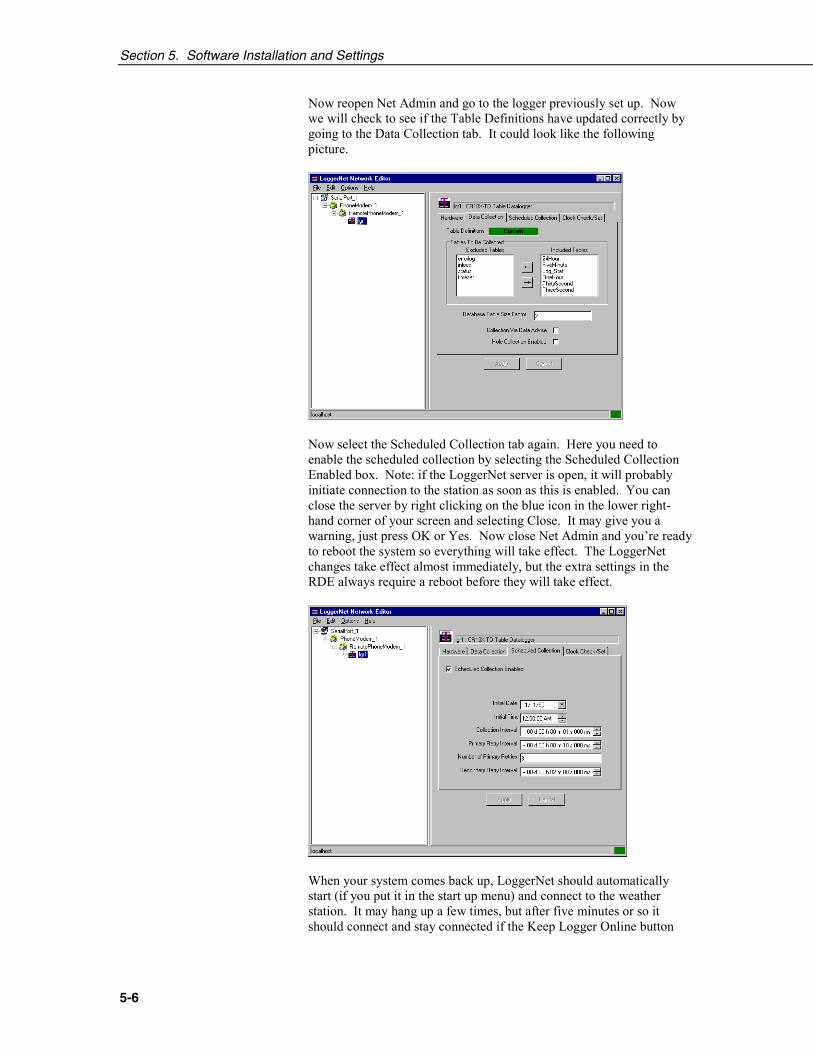
Now reopen Net Admin and go to the logger previously set up. Nowwe will check to see if the Table Definitions have updated correctly bygoing to the Data Collection tab. It could look like the followingpicture.
Now select the Scheduled Collection tab again. Here you need toenable the scheduled collection by selecting the Scheduled CollectionEnabled box. Note: if the LoggerNet server is open, it will probablyinitiate connection to the station as soon as this is enabled. You canclose the server by right clicking on the blue icon in the lower right-hand corner of your screen and selecting Close. It may give you awarning, just press OK or Yes. Now close Net Admin and you’re readyto reboot the system so everything will take effect. The LoggerNetchanges take effect almost immediately, but the extra settings in theRDE always require a reboot before they will take effect.
When your system comes back up, LoggerNet should automaticallystart (if you put it in the start up menu) and connect to the weatherstation. It may hang up a few times, but after five minutes or so itshould connect and stay connected if the Keep Logger Online button

Section 5. Software Installation and Settings
5-7
has been selected in the extra RDE settings. Data is now available formessage creation.
5.3 Create MessagePerform the following steps using the Message Editor provided inProLine Software:
1. Type the message in the area indicated in Figure 5.3-1.
2. Move cursor to where you want data inserted.
3. Select a source from the Source pull-down menu (Figure 5.3-2).
4. Select the desired field (Figure 5.3-3).
5. Click on the white cross (Figure 5.3-1) and the data stored in theselected field will be inserted into the message where the cursor islocated.
Enter the message
that will appear on
the sign here.
The font of the
message and
data are chosen
here.
Source
Pull-Down
MenuField
Pull-Down Menu Click on this to insert the
data into the message.
FIGURE 5.3-1. ProLine software provides an easy-to-use message editor.
Section 5. Software Installation and Settings
5-8
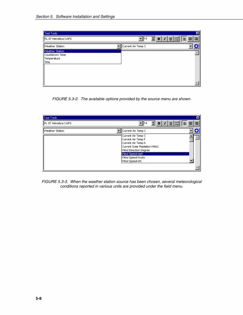
FIGURE 5.3-2. The available options provided by the source menu are shown.
FIGURE 5.3-3. When the weather station source has been chosen, several meteorologicalconditions reported in various units are provided under the field menu.
6-1
Section 6. Maintenance andTroubleshootingThese guidelines apply to several Campbell Scientific weather stations.
6.1 MaintenanceProper maintenance of weather station components is essential to obtainaccurate data. Equipment must be in good operating condition, which requiresa program of regular inspection and maintenance. Routine and simplemaintenance can be accomplished by the person in charge of the weatherstation. More difficult maintenance such as sensor calibration, sensorperformance testing (i.e., bearing torque), and sensor component replacement,generally requires a skilled technician, or that the instrument be sent toCampbell Scientific or the manufacturer.
A station log should be maintained for each weather station that includes serialnumbers, dates that the site was visited, and maintenance that was performed.
6.1.1 Instrumentation MaintenanceThe instrumentation requires a minimum of routine maintenance. A fewpreventative maintenance steps will optimize battery life and decrease thechances of datalogger failure.
6.1.2 BatteriesRechargeable power supplies should be connected to an AC transformer orunregulated solar panel at all times. Be aware of battery voltage thatconsistently decreases over time, which indicates a failure in the chargingcircuitry.
6.1.3 DesiccantEnclosure humidity is monitored in the ET Enclosure systems by an RH chipincorporated into the connector board. Change the desiccant packs when theenclosure RH exceeds 35%.
Desiccant may be ordered through Campbell Scientific (DSC 20/4) or item#4905.
Desiccant packs inside of the dataloggers do not require replacement undernormal conditions.

Section 6. Maintenance and Troubleshooting
6-2
6.1.4 Sensor MaintenanceSensor maintenance should be performed at regular intervals, depending on thedesired accuracy and the conditions of use. A suggested maintenance schedule isoutlined below.
1 week
• Check the pyranometer for level and contamination. Gently clean, ifneeded.
• Visually inspect the wind sensors and radiation shield.
1 month
• Check the rain gage funnel for debris and level.
• Do a visual/audio inspection of the anemometer at low wind speeds.
• Check the filter of the temperature/humidity sensor for contamination.
General Maintenance
• An occasional cleaning of the glass on the solar panel will improve itsefficiency.
• Check sensor leads and cables for cracking, deterioration, proper routing,and strain relief.
• Check the tripod or tower for structural damage, proper alignment, and forlevel/plumb.
6 months
• Clean the temperature/humidity sensor.
• Clean the Gill Radiation Shield.
1 year
• Replace anemometer bearings.
• Calibrate the rain gage.
• Calibrate the HMP45C probe.
2 years
• Calibrate the pyranometer (some users suggest yearly).
• Calibrate the HMP45C temperature/humidity sensor.
• Replace the wind vane potentiometer and bearings.
4 - 5 years
• Replace sensor cables as required.
Rain Gage Calibration Check
1. Secure a metal can that will hold at least one quart of water.
Section 6. Maintenance and Troubleshooting
6-3
2. Punch a very small hole in the bottom of the can.
3. Place the can in the top funnel of the rain gage and pour 16 fluid ounces (1pint) of water into the can. (A 16 oz. soft drink bottle filled to within 2.5inches of the top may be used for a rough field calibration. An exactvolume will allow for a more precise calibration).
4. If it takes less than 45 minutes for this water to run out, the hole in the canis too large.
5. One hundred tips plus or minus three tips should occur.
6. Adjusting screws are located on the bottom adjacent to the large centerdrain hole. Adjust both screws the same number of turns. Rotationclockwise increases the number of tips per 16 oz. of water; counterclockwise rotation decreases the number of tips per 16 oz. of water. Onehalf turn of both screws causes a 2% to 3% change.
7. Check and re-level the rain gage lid.
6.2 TroubleShooting
6.2.1 No Response Using the KeypadCheck keypad response after each of the following steps.
A. Make sure the battery has been installed, and the power switch, if any, is"ON".
B. Use a voltmeter to measure the voltage on the 12 V and G terminals; thevoltage must be between 9.6 and 16 VDC.
C. Disconnect any sensor or peripheral wires connected to the 5 V and 12 Vterminals.
D. Disconnect any communications or storage peripherals from thedatalogger.
E. Reset the datalogger by turning the power switch to "OFF", then to "ON"or disconnect the solar panel or switch off AC power to the station thendisconnect and reconnect the battery. Remember to reconnect the solarpanel or switch on the AC power.
F. If still no response, call Campbell Scientific.
6.2.2 No Response from Datalogger through SC32A or ModemPeripheral
At the datalogger:
A. Make sure the battery has been installed, and the power switch, if any, is"ON".
B. Use a voltmeter to measure the voltage on the 12 V and G terminals; thevoltage must be between 9.6 and 16 V DC.
C. Make sure the datalogger is connected to the modem, and the modem isproperly configured and cabled.

Section 6. Maintenance and Troubleshooting
6-4
At the computer:
D. Make sure the Station File is configured correctly.
E. Check the cable(s) between the serial port and the modem. If cables havenot been purchased through Campbell Scientific, check for the followingconfiguration using an ohm meter:
25-pin serial port:
computer end modem end
2 23 37 720 20
9-pin serial port:
computer end modem end
2 33 24 205 7
F. Make sure the modem is properly configured and cabled (Section 6.6).
G. If still no response, call Campbell Scientific.
6.2.3 -99999 Displayed in an Input LocationA. Make sure the battery voltage is between 9.6 and 16 VDC.
B. With the TLX106, verify that the sensor is connected to the properbulkhead connector.
6.2.4 Unreasonable Results Displayed in an Input LocationA. Inspect the sensor for damage and/or contamination.
B. Make sure the sensor is properly wired to the datalogger.
C. Check the multiplier and offset parameters in the measurement instruction.