Embed Size (px)
Citation preview
TM
TL-TB-006JNovember 2001
PUBLISHED BY THE SPINCO BUSINESS CENTER OF BECKMAN COULTER, INC., PALO ALTO, CALIFORNIA 94304
TLS-55 Rotor
Used in Beckman CoulterOptima
™
MAX, MAX-E, TL,and TLX Series
Tabletop Ultracentrifuges
© 2001 Beckman Coulter, Inc.

2
TLS-55 Rotor
SAFETY NOTICE
This safety notice summarizes information basic to the safe use of the rotor described in this manual. The international symbol displayed above is a reminder to the user that all safety instructions should be read and understood before operation or maintenance of this equip-ment is attempted. When you see the symbol on other pages throughout this publication, pay special attention to the specific safety information presented. Observance of safety precau-tions will also help to avoid actions that could damage or adversely affect the performance of the rotor. This rotor was developed, manufactured, and tested for safety and reliability as part of a Beckman Coulter ultracentrifuge/rotor system. Its safety or reliability cannot be assured if used in a centrifuge not of Beckman Coulter’s manufacture or in a Beckman Coulter ultracentrifuge that has been modified without Beckman Coulter’s approval.
Handle body fluids with care because they can transmit disease. No known test offers complete assurance that such fluids are free of micro-organisms. Some of the most virulent—Hepatitis (B and C) viruses, HIV (I–V), atypical mycobacteria, and certain systemic fungi — further emphasize the need for aerosol protection. Handle other infectious samples according to good laboratory procedures and methods to prevent spread of disease. Because spills may generate aerosols, observe proper safety precautions for aerosol contain-ment. Do not run toxic, pathogenic, or radioactive materials in this centrifuge without taking appropriate safety precautions. Biosafe containment should be used when Risk Group II materials (as identified in the World Health Organization
Laboratory Biosafety Manual
) are handled; materials of a higher group require more than one level of protection.
The rotor and accessories are not designed for use with materials capable of developing flammable or explosive vapors. Do not centrifuge such materials in nor handle or store them near the ultracentrifuge.
Although rotor components and accessories made by other manufacturers may fit in the TLS-55 rotor, their safety in this rotor cannot be ascertained by Beckman Coulter. Use of other manufacturers’ components or accessories in the TLS-55 rotor may void the rotor warranty and should be prohibited by your laboratory safety officer. Only the components and accessories listed in this publication should be used in this rotor.
Hook all four buckets, loaded or empty, to the rotor for every run. Make sure that filled containers are loaded symmetrically into the rotor and that opposing tubes are filled to the same level with liquid of the same density. Make sure that buckets containing Quick-Seal tubes have the proper floating spacers inserted (if applicable) before installing the bucket cap.
If disassembly reveals evidence of leakage, you should assume that some fluid escaped the rotor. Apply appropriate decontamination procedures to the centrifuge and accessories.
Never exceed the maximum rated speed of the rotor and labware in use. Refer to the section on
RUN SPEEDS
, and derate the run speed as appropriate.
Do not use sharp tools on the rotor that could cause scratches in the rotor surface. Corrosion begins in scratches and may open fissures in the rotor with continued use.
!
!
!
!
!
!
!
!
3
*
Relative Centrifugal Field (RCF) is the ratio of the centrifugal acceleration at a specified radiusand speed (
r
ω
2
) to the standard acceleration of gravity (
g
) according to the following formula:
where
r
is the radius in millimeters,
ω
is the angular velocity in radians per second(2
π
RPM /60), and
g
is the standard acceleration of gravity (9807 mm/s
2
). After substitution:
RCF rω2
g---------=
RCF 1.12 rRPM1000------------
2=
TLS-55 Rotor
TLS-55 Rotor
SPECIFICATIONS
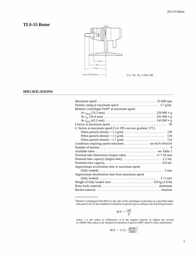
Maximum speed . . . . . . . . . . . . . . . . . . . . . . . . . . . . . . . . . . . . 55 000 rpmDensity rating at maximum speed. . . . . . . . . . . . . . . . . . . . . . . . . 1.7 g/mLRelative Centrifugal Field* at maximum speed
At
r
max
(76.5 mm) . . . . . . . . . . . . . . . . . . . . . . . . . . . . . . . 259 000
×
g
At
r
av
(59.4 mm) . . . . . . . . . . . . . . . . . . . . . . . . . . . . . . . . 201 000
×
g
At
r
min
(42.2 mm) . . . . . . . . . . . . . . . . . . . . . . . . . . . . . . . 143 000
×
gk
factor at maximum speed . . . . . . . . . . . . . . . . . . . . . . . . . . . . . . . . . . . 50
k
´ factors at maximum speed (5 to 20% sucrose gradient; 5°C)When particle density = 1.3 g/mL . . . . . . . . . . . . . . . . . . . . . . . . . 130When particle density = 1.5 g/mL . . . . . . . . . . . . . . . . . . . . . . . . . 119When particle density = 1.7 g/mL . . . . . . . . . . . . . . . . . . . . . . . . . 114
Conditions requiring speed reductions . . . . . . . . . . . . . . . see
RUN SPEEDS
Number of buckets . . . . . . . . . . . . . . . . . . . . . . . . . . . . . . . . . . . . . . . . . . 4Available tubes . . . . . . . . . . . . . . . . . . . . . . . . . . . . . . . . . . . . . see Table 1Nominal tube dimensions (largest tube) . . . . . . . . . . . . . . . . . . 11
×
34 mmNominal tube capacity (largest tube). . . . . . . . . . . . . . . . . . . . . . . . . 2.2 mLNominal rotor capacity . . . . . . . . . . . . . . . . . . . . . . . . . . . . . . . . . . . 8.8 mLApproximate acceleration time to maximum speed
(fully loaded) . . . . . . . . . . . . . . . . . . . . . . . . . . . . . . . . . . . . . . . . 3 minApproximate deceleration time from maximum speed
(fully loaded) . . . . . . . . . . . . . . . . . . . . . . . . . . . . . . . . . . . . . 2
1
/
2
minWeight of fully loaded rotor . . . . . . . . . . . . . . . . . . . . . . . . . 0.8 kg (1.8 lb)Rotor body material. . . . . . . . . . . . . . . . . . . . . . . . . . . . . . . . . . . aluminumBucket material . . . . . . . . . . . . . . . . . . . . . . . . . . . . . . . . . . . . . . . titanium
U.S. Pat. No. 4,400,166
Axis of Rotation
rmax
rminrav
4
TLS-55 Rotor
DESCRIPTION
This Beckman Coulter rotor has been manufactured in an NSAI-registered ISO 9001 or 9002 facility for use with the appropriately classified Beckman Coulter ultracentrifuge.
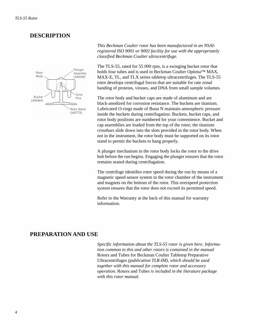
The TLS-55, rated for 55 000 rpm, is a swinging bucket rotor that holds four tubes and is used in Beckman Coulter Optima™ MAX, MAX-E, TL, and TLX series tabletop ultracentrifuges. The TLS-55 rotor develops centrifugal forces that are suitable for rate zonal banding of proteins, viruses, and DNA from small sample volumes.
The rotor body and bucket caps are made of aluminum and are black-anodized for corrosion resistance. The buckets are titanium. Lubricated O-rings made of Buna N maintain atmospheric pressure inside the buckets during centrifugation. Buckets, bucket caps, and rotor body positions are numbered for your convenience. Bucket and cap assemblies are loaded from the top of the rotor; the titanium crossbars slide down into the slots provided in the rotor body. When not in the instrument, the rotor body must be supported on its rotor stand to permit the buckets to hang properly.
A plunger mechanism in the rotor body locks the rotor to the drive hub before the run begins. Engaging the plunger ensures that the rotor remains seated during centrifugation.
The centrifuge identifies rotor speed during the run by means of a magnetic speed sensor system in the rotor chamber of the instrument and magnets on the bottom of the rotor. This overspeed protection system ensures that the rotor does not exceed its permitted speed.
Refer to the Warranty at the back of this manual for warranty information.
PREPARATION AND USE
Specific information about the TLS-55 rotor is given here. Informa-tion common to this and other rotors is contained in the manual
Rotors and Tubes for Beckman Coulter Tabletop Preparative Ultracentrifuges
(publication TLR-IM), which should be used together with this manual for complete rotor and accessory operation.
Rotors and Tubes
is included in the literature package with this rotor manual.
DrivePins
RotorBody
Bucket(346364)
Rotor Stand(345773)
PlungerAssembly(349338)
5
TLS-55 Rotor
➠ NOTE
Although rotor components and accessories made by other manufacturers may fit in the TLS-55 rotor, their safety in this rotor cannot be ascertained by Beckman Coulter. Use of other manufacturers’ components or accessories in the TLS-55 rotor may void the rotor warranty and should be prohibited by your laboratory safety officer. Only the components and accessories listed in this publication should be used in
this rotor.
PRERUN SAFETY CHECKS
Read the Safety Notice page at the front of this manual before using the rotor.
1. Make sure that the rotor, buckets, and caps are clean and show no signs of corrosion or cracking.
2. Check the chemical compatibilities of all materials used (refer to Appendix A in
Rotors and Tubes
).
3. Verify that the tubes and accessories being used are listed in Table 1.
ROTOR PREPARATION
For runs at other than room temperature, refrigerate or warm the rotor beforehand for fast equilibration.
1. Before each use of the rotor, make sure that bucket cap threads are lightly but evenly lubricated with Spinkote™ lubricant (306812), and the bucket O-rings are lightly but evenly coated with silicone vacuum grease (335148).
!
6
TLS-55 Rotor
➠ NOTE
Never run a bucket without an O-ring, as it
will leak.
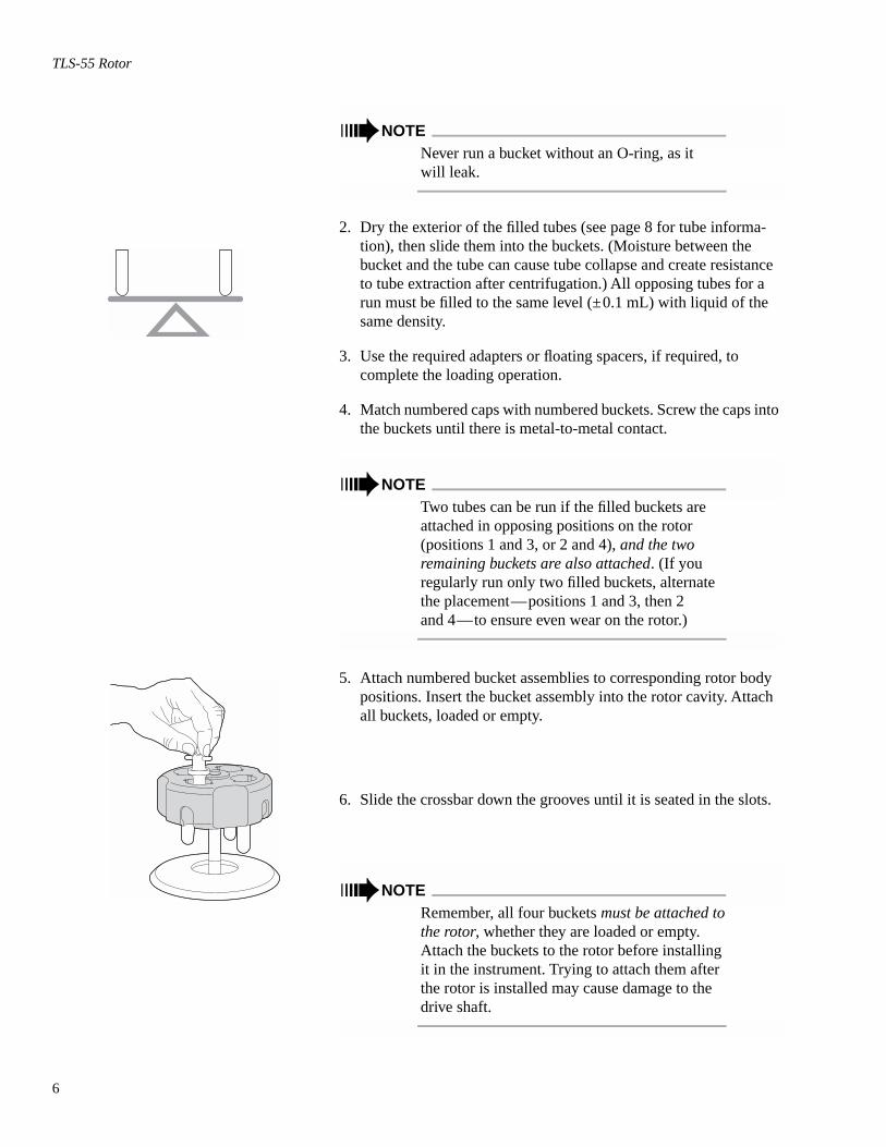
2. Dry the exterior of the filled tubes (see page 8 for tube informa-tion), then slide them into the buckets. (Moisture between the bucket and the tube can cause tube collapse and create resistance to tube extraction after centrifugation.) All opposing tubes for a run must be filled to the same level (±0.1 mL) with liquid of the same density.
3. Use the required adapters or floating spacers, if required, to complete the loading operation.
4. Match numbered caps with numbered buckets. Screw the caps into the buckets until there is metal-to-metal contact.
➠ NOTE
Two tubes can be run if the filled buckets are attached in opposing positions on the rotor (positions 1 and 3, or 2 and 4),
and the two remaining buckets are also attached
. (If you regularly run only two filled buckets, alternate the placement—positions 1 and 3, then 2
and 4—to ensure even wear on the rotor.)
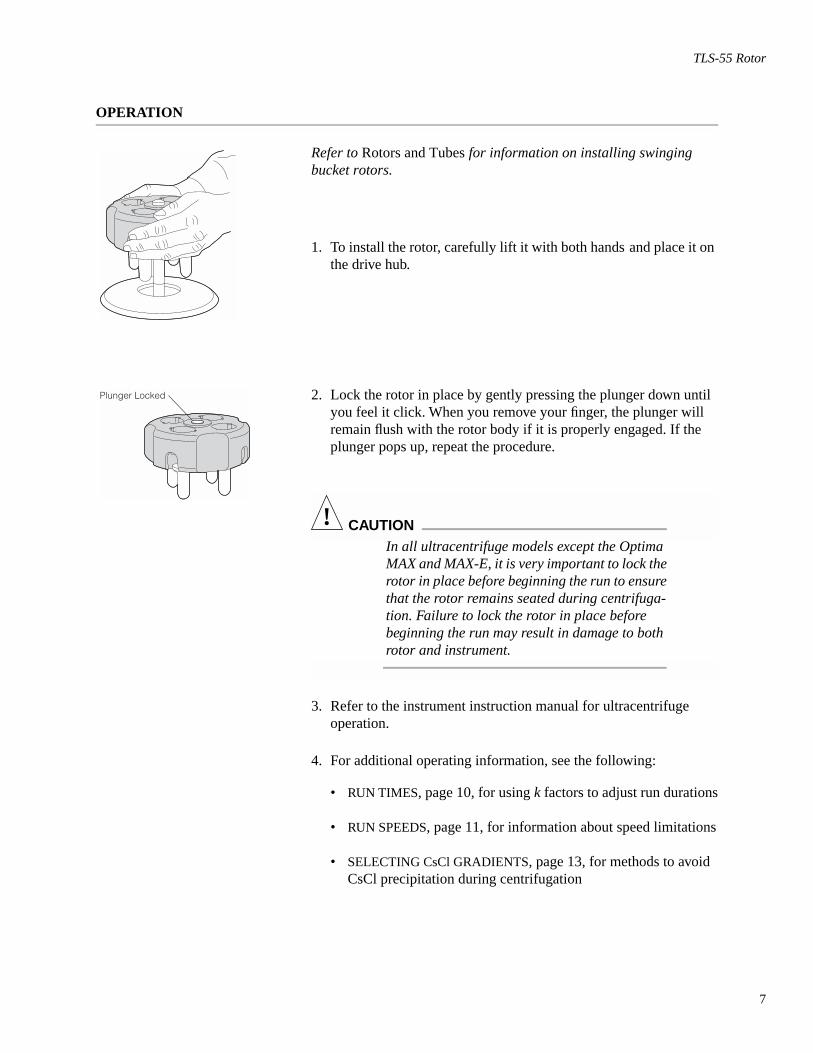
5. Attach numbered bucket assemblies to corresponding rotor body positions. Insert the bucket assembly into the rotor cavity. Attach all buckets, loaded or empty.
6. Slide the crossbar down the grooves until it is seated in the slots.
➠ NOTE
Remember, all four buckets
must be attached to the rotor
, whether they are loaded or empty. Attach the buckets to the rotor before installing it in the instrument. Trying to attach them after the rotor is installed may cause damage to the
drive shaft.
7
TLS-55 Rotor
OPERATION
Refer to
Rotors and Tubes
for information on installing swinging bucket rotors.
1. To install the rotor, carefully lift it with both hands and place it on the drive hub.
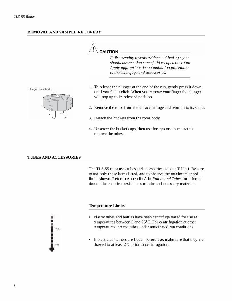
2. Lock the rotor in place by gently pressing the plunger down until you feel it click. When you remove your finger, the plunger will remain flush with the rotor body if it is properly engaged. If the plunger pops up, repeat the procedure.
! CAUTION
In all ultracentrifuge models except the Optima MAX and MAX-E, it is very important to lock the rotor in place before beginning the run to ensure that the rotor remains seated during centrifuga-tion. Failure to lock the rotor in place before beginning the run may result in damage to both
rotor and instrument.
3. Refer to the instrument instruction manual for ultracentrifuge operation.
4. For additional operating information, see the following:
•
RUN TIMES
, page 10, for using
k
factors to adjust run durations
•
RUN SPEEDS
, page 11, for information about speed limitations
•
SELECTING CsCl GRADIENTS
, page 13, for methods to avoid CsCl precipitation during centrifugation
Plunger Locked
8
TLS-55 Rotor
REMOVAL AND SAMPLE RECOVERY
! CAUTION
If disassembly reveals evidence of leakage, you should assume that some fluid escaped the rotor. Apply appropriate decontamination procedures
to the centrifuge and accessories.
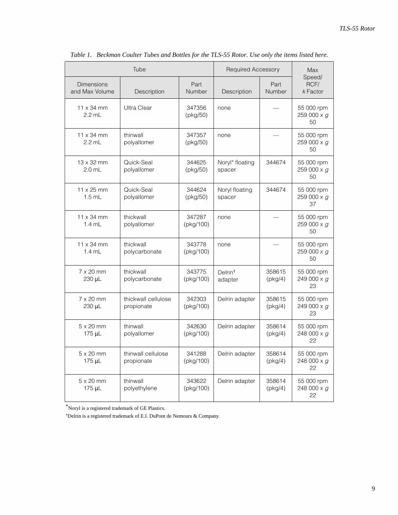
1. To release the plunger at the end of the run, gently press it down until you feel it click. When you remove your finger the plunger will pop up to its released position.
2. Remove the rotor from the ultracentrifuge and return it to its stand.
3. Detach the buckets from the rotor body.
4. Unscrew the bucket caps, then use forceps or a hemostat to remove the tubes.
TUBES AND ACCESSORIES
The TLS-55 rotor uses tubes and accessories listed in Table 1. Be sure to use only those items listed, and to observe the maximum speed limits shown. Refer to Appendix A in
Rotors and Tubes
for informa-tion on the chemical resistances of tube and accessory materials.
Temperature Limits
• Plastic tubes and bottles have been centrifuge tested for use at temperatures between 2 and 25
°
C. For centrifugation at other temperatures, pretest tubes under anticipated run conditions.
• If plastic containers are frozen before use, make sure that they are thawed to at least 2
°
C prior to centrifugation.
Plunger Unlocked
25°C
2°C
9
TLS-55 Rotor
Table 1. Beckman Coulter Tubes and Bottles for the TLS-55 Rotor. Use only the items listed here.
*Noryl is a registered trademark of GE Plastics.
†
Delrin is a registered trademark of E.I. DuPont de Nemours & Company.
Tube Required Accessory Max Speed/RCF/
k
FactorDimensions
and Max Volume DescriptionPart
Number DescriptionPart
Number
11 x 34 mm2.2 mL
Ultra Clear 347356(pkg/50)
none — 55 000 rpm259 000 x
g
50
11 x 34 mm2.2 mL
thinwallpolyallomer
347357(pkg/50)
none — 55 000 rpm259 000 x
g
50
13 x 32 mm2.0 mL
Quick-Sealpolyallomer
344625(pkg/50)
Noryl* floating spacer
344674 55 000 rpm259 000 x
g
50
11 x 25 mm1.5 mL
Quick-Sealpolyallomer
344624(pkg/50)
Noryl floatingspacer
344674 55 000 rpm259 000 x
g
37
11 x 34 mm1.4 mL
thickwallpolyallomer
347287(pkg/100)
none — 55 000 rpm259 000 x
g
50
11 x 34 mm1.4 mL
thickwall polycarbonate
343778(pkg/100)
none — 55 000 rpm259 000 x
g
50
7 x 20 mm230
µ
Lthickwall polycarbonate
343775(pkg/100)
Delrin
†
adapter
358615(pkg/4)
55 000 rpm249 000 x
g
23
7 x 20 mm230
µ
Lthickwall cellulose propionate
342303(pkg/100)
Delrin adapter 358615(pkg/4)
55 000 rpm249 000 x
g
23
5 x 20 mm175
µ
Lthinwallpolyallomer
342630(pkg/100)
Delrin adapter 358614(pkg/4)
55 000 rpm248 000 x
g
22
5 x 20 mm175
µ
Lthinwall cellulose propionate
341288(pkg/100)
Delrin adapter 358614(pkg/4)
55 000 rpm248 000 x
g
22
5 x 20 mm175
µ
Lthinwall polyethylene
343622(pkg/100)
Delrin adapter 358614(pkg/4)
55 000 rpm248 000 x
g
22
10
TLS-55 Rotor
Quick-Seal
®
Tubes
Quick-Seal tubes must be sealed prior to centrifugation. These tubes are heat sealed and do not need caps; however, spacers are required on top of the tubes when they are loaded into the rotor buckets.
• Fill Quick-Seal tubes leaving a small bubble of air at the base of the neck. Do not leave a large air space—too much air can cause excessive tube deformation.
• Refer to Rotors and Tubes for detailed information on the use and care of Quick-Seal tubes.
Some of the tubes listed in Table 1 are part of the g-Max™ system. The g-Max system uses a combination of small bell-top Quick-Seal tubes and floating spacers (also called g-Max spacers). This means that you can run the shorter tubes listed in the table in the TLS-55 rotor without reduction in g force. Additional information about the g-Max system is available in publication DS-709.
Open-Top Tubes
Open-top tubes should be filled as full as possible for tube support. If necessary, float mineral oil (or some other low-density, immiscible liquid) on top of the tube contents to fill the tube to its maximum volume. (Do not use an oil overlay in Ultra-Clear tubes.)
RUN TIMES
The k factor of the rotor is a measure of the rotor’s pelleting efficiency. (Beckman Coulter has calculated the k factors for all of its preparative rotors at maximum rated speed and using full tubes.) The k factor is calculated from the formula:
(1)
TIME HR:MIN
03:30
krmax rmin⁄( )ln
ω2------------------------------------- 1013
3600------------×=
11
TLS-55 Rotor
where ω is the angular velocity of the rotor in radians per second (ω = 0.105 × rpm), rmax is the maximum radius, and rmin is the minimum radius.
After substitution:
(2)
Use the k factor in the following equation to estimate the run time t (in hours) required to pellet particles of known sedimentation coeffi-cient s (in Svedberg units, S).
(3)
Run times can be estimated for centrifugation at less than maximum speed by adjusting the k factor as follows:
(4)
Run times can also be estimated from data established in prior exper-iments if the k factor of the previous rotor is known. For any two rotors, a and b:
(5)
For more information on k factors see Use of k Factor for Estimating Run Times from Previously Established Run Conditions (publication DS-719).
RUN SPEEDS
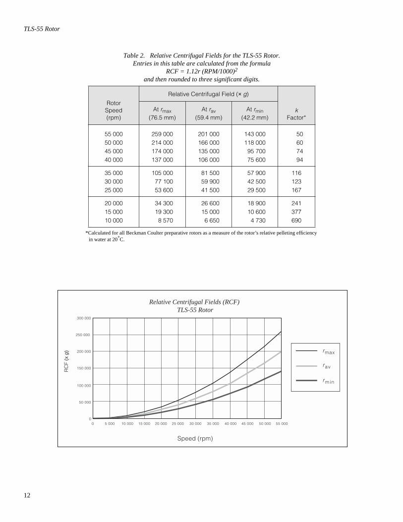
The centrifugal force at a given radius in a rotor is a function of speed. Comparisons of forces between different rotors are made by comparing the rotors’ relative centrifugal fields (RCF). When rotational speed is adjusted so that identical samples are subjected to the same RCF in two different rotors, the samples are subjected to the same force. The RCF at a number of rotor speeds is provided in Table 2.
k2.533 1011×( ) rmax r⁄ min( )ln
rpm2--------------------------------------------------------------------------=
tks--=
kadj k55 000
actual run speed---------------------------------------
2
=
ta tb ------
ka kb -------=
SPEED RPM/RCF
55 000 RPM
12
TLS-55 Rotor
Table 2. Relative Centrifugal Fields for the TLS-55 Rotor.Entries in this table are calculated from the formula
RCF = 1.12r (RPM/1000)2
and then rounded to three significant digits.
*Calculated for all Beckman Coulter preparative rotors as a measure of the rotor’s relative pelleting efficiency in water at 20°C.
RotorSpeed(rpm)
Relative Centrifugal Field (× g)
kFactor*
At rmax(76.5 mm)
At rav(59.4 mm)
At rmin(42.2 mm)
55 00050 00045 00040 000
259 000214 000174 000137 000
201 000166 000135 000106 000
143 000118 00095 70075 600
50607494
35 00030 00025 000
105 00077 10053 600
81 50059 90041 500
57 90042 50029 500
116123167
20 00015 00010 000
34 30019 3008 570
26 60015 0006 650
18 90010 6004 730
241377690
rmax
rav
r min
Relative Centrifugal Fields (RCF) TLS-55 Rotor
Speed (rpm)
RC
F (x
g)
5 000 15 000 25 000 35 000 45 0000
50 000
100 000
150 000
200 000
250 000
300 000
0 10 000 20 000 30 000 40 000 50 000 55 000
13
TLS-55 Rotor
Do not select rotational speeds in excess of 55 000 rpm. In addition, speeds must be reduced under the following circumstances:
1. If nonprecipitating solutions more dense than 1.7 g/mL are centri-fuged, reduce the maximum allowable run speed according to the following equation:
(6)
where ρ is the density of the tube contents. This speed reduction will protect the rotor from excessive stresses due to the added tube load.
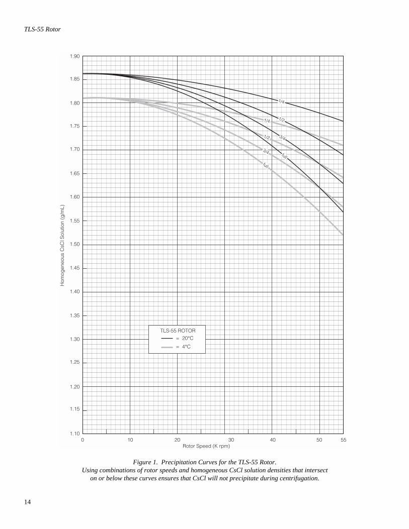
2. Further speed limits must be imposed when CsCl or other self-forming-gradient salts are centrifuged, as equation (6) does not predict concentration limits/speeds that are required to avoid precipitation of salt crystals. Solid CsCl has a density of 4 g/mL, and if precipitated during centrifugation may cause rotor failure. Figures 1 and 2, together with the description and examples below, show how to reduce run speeds when using CsCl gradients.
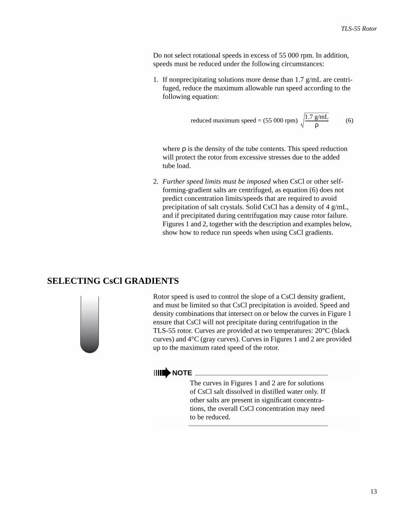
SELECTING CsCl GRADIENTS
Rotor speed is used to control the slope of a CsCl density gradient, and must be limited so that CsCl precipitation is avoided. Speed and density combinations that intersect on or below the curves in Figure 1 ensure that CsCl will not precipitate during centrifugation in the TLS-55 rotor. Curves are provided at two temperatures: 20°C (black curves) and 4°C (gray curves). Curves in Figures 1 and 2 are provided up to the maximum rated speed of the rotor.
➠ NOTEThe curves in Figures 1 and 2 are for solutions of CsCl salt dissolved in distilled water only. If other salts are present in significant concentra-tions, the overall CsCl concentration may need to be reduced.
reduced maximum speed = (55 000 rpm) 1.7 g/mLρ
----------------------
14
TLS-55 Rotor
Figure 1. Precipitation Curves for the TLS-55 Rotor. Using combinations of rotor speeds and homogeneous CsCl solution densities that intersect
on or below these curves ensures that CsCl will not precipitate during centrifugation.
1.20
01.10
1.15
1.25
1.35
1.30
1.40
1.45
1.50
1.55
1.60
1.65
1.70
1.75
1.80
Hom
ogen
eous
CsC
l Sol
utio
n (g
/mL)
10 20 30 40 50 55Rotor Speed (K rpm)
1.85
1.90
3/4
3/4
full
full
1/4
1/41/2
1/2
TLS-55 ROTOR= 20°C
= 4°C
15
TLS-55 Rotor
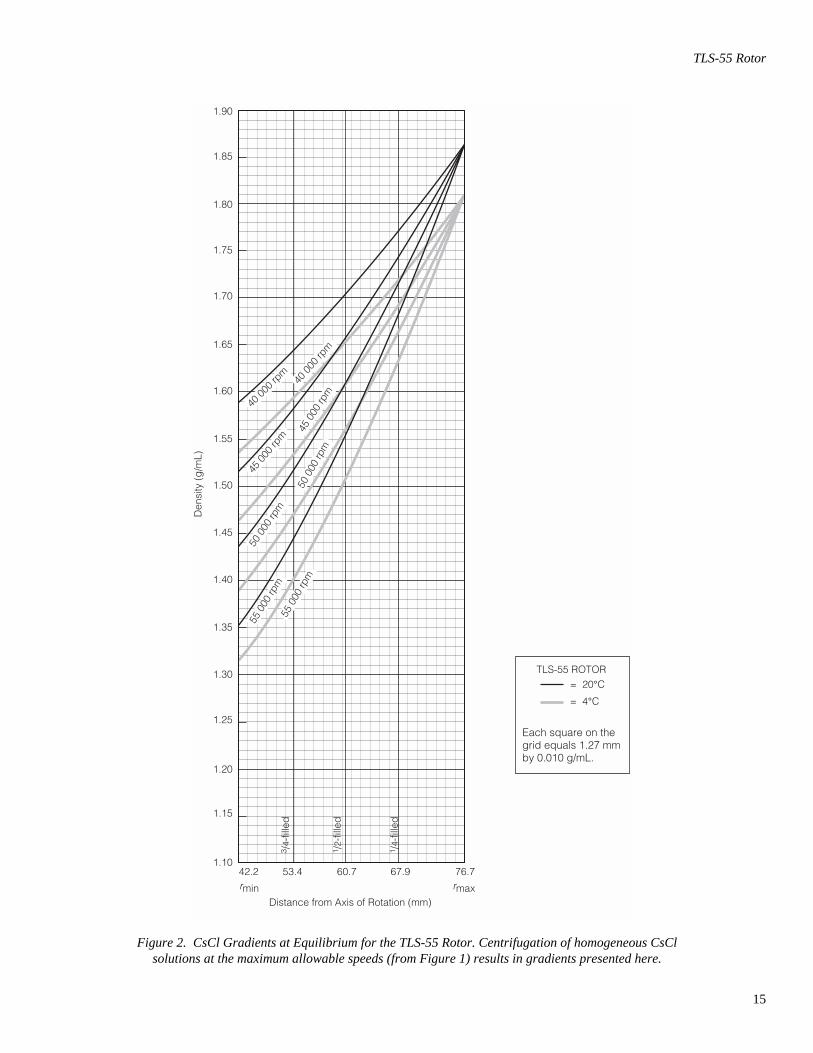
Figure 2. CsCl Gradients at Equilibrium for the TLS-55 Rotor. Centrifugation of homogeneous CsCl solutions at the maximum allowable speeds (from Figure 1) results in gradients presented here.
1.20
1.10
1.15
1.25
1.35
1.30
1.40
1.45
1.50
1.55
1.60
1.65
1.70
1.75
1.80
1.85
1.90
TLS-55 ROTOR= 20°C
= 4°C
50 0
00 rp
m
50 0
00 rp
m
45 0
00 rp
m
40 00
0 rpm
40 0
00 rp
m
45 0
00 rp
m
55 0
00 rp
m55
000
rpm
42.2 53.4 60.7 67.9 76.7
Each square on thegrid equals 1.27 mmby 0.010 g/mL.
3 /4-
fille
d
1 /4-
fille
d
1 /2-
fille
d
Den
sity
(g
/mL)
Distance from Axis of Rotation (mm)
rmin rmax
16
TLS-55 Rotor
The reference curves in Figure 2 show gradient distribution at equi-librium. Each curve in Figure 2 is within the density limits allowed for the TLS-55 rotor: each curve was generated for a single run speed using the maximum allowable homogeneous CsCl densities (one for each fill level) that avoid precipitation at that speed. (The gradients in Figure 2 can be generated from step or linear gradients, or from homogeneous solutions. But the total amount of CsCl in solution must be equivalent to a homogeneous solution corresponding to the concentrations specified in Figure 2.) Figure 2 can also be used to approximate the banding positions of sample particles. Curves not shown in the figure may be interpolated.
ADJUSTING FILL VOLUMES
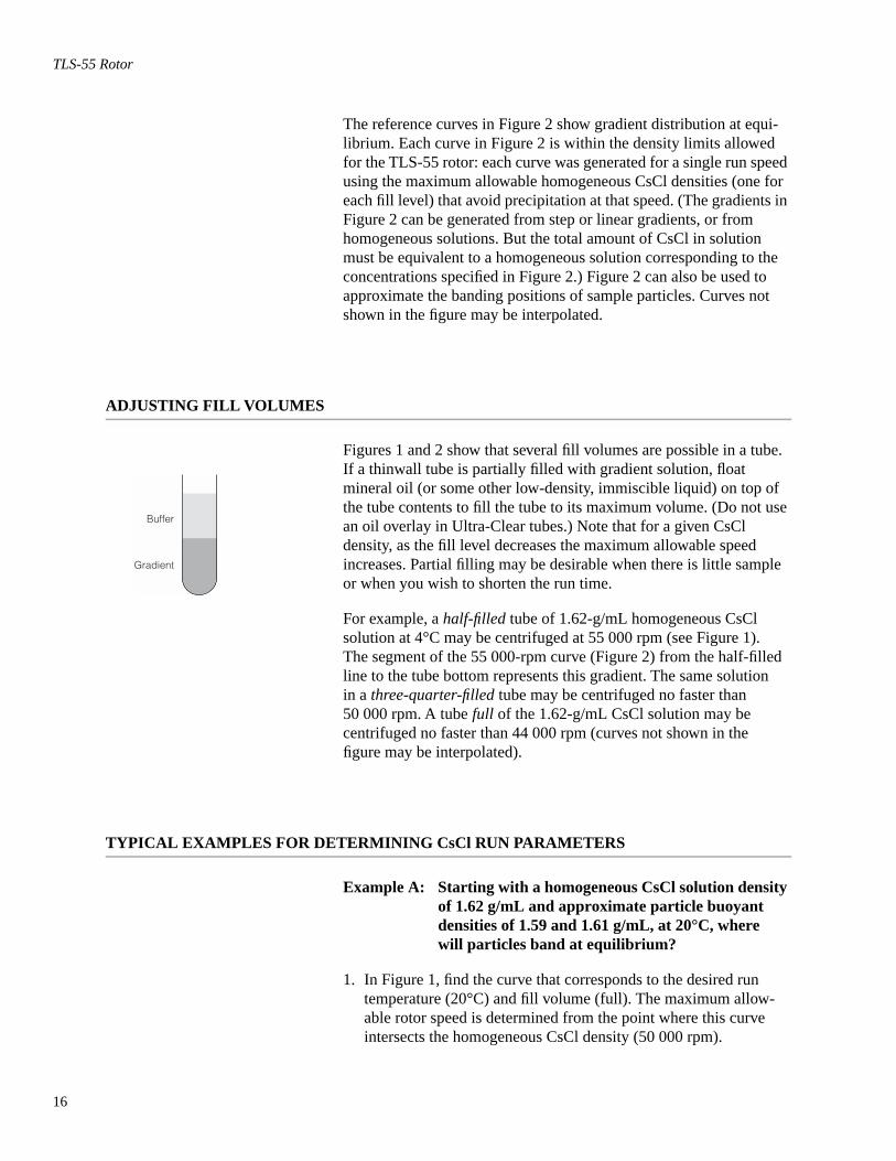
Figures 1 and 2 show that several fill volumes are possible in a tube. If a thinwall tube is partially filled with gradient solution, float mineral oil (or some other low-density, immiscible liquid) on top of the tube contents to fill the tube to its maximum volume. (Do not use an oil overlay in Ultra-Clear tubes.) Note that for a given CsCl density, as the fill level decreases the maximum allowable speed increases. Partial filling may be desirable when there is little sample or when you wish to shorten the run time.
For example, a half-filled tube of 1.62-g/mL homogeneous CsCl solution at 4°C may be centrifuged at 55 000 rpm (see Figure 1). The segment of the 55 000-rpm curve (Figure 2) from the half-filled line to the tube bottom represents this gradient. The same solution in a three-quarter-filled tube may be centrifuged no faster than 50 000 rpm. A tube full of the 1.62-g/mL CsCl solution may be centrifuged no faster than 44 000 rpm (curves not shown in the figure may be interpolated).
TYPICAL EXAMPLES FOR DETERMINING CsCl RUN PARAMETERS
Example A: Starting with a homogeneous CsCl solution density of 1.62 g/mL and approximate particle buoyant densities of 1.59 and 1.61 g/mL, at 20°C, where will particles band at equilibrium?
1. In Figure 1, find the curve that corresponds to the desired run temperature (20°C) and fill volume (full). The maximum allow-able rotor speed is determined from the point where this curve intersects the homogeneous CsCl density (50 000 rpm).
Buffer
Gradient
17
TLS-55 Rotor
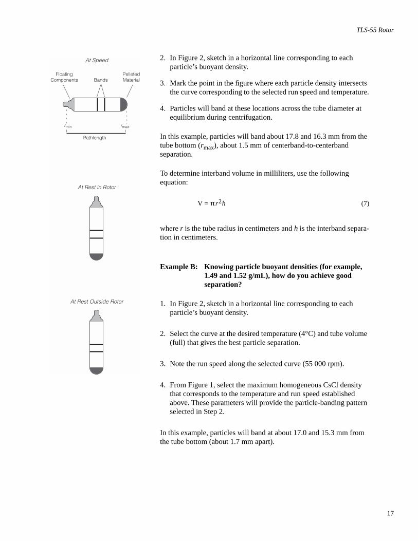
2. In Figure 2, sketch in a horizontal line corresponding to each particle’s buoyant density.
3. Mark the point in the figure where each particle density intersects the curve corresponding to the selected run speed and temperature.
4. Particles will band at these locations across the tube diameter at equilibrium during centrifugation.
In this example, particles will band about 17.8 and 16.3 mm from the tube bottom (rmax), about 1.5 mm of centerband-to-centerband separation.
To determine interband volume in milliliters, use the following equation:
(7)
where r is the tube radius in centimeters and h is the interband separa-tion in centimeters.
Example B: Knowing particle buoyant densities (for example, 1.49 and 1.52 g/mL), how do you achieve good separation?
1. In Figure 2, sketch in a horizontal line corresponding to each particle’s buoyant density.
2. Select the curve at the desired temperature (4°C) and tube volume (full) that gives the best particle separation.
3. Note the run speed along the selected curve (55 000 rpm).
4. From Figure 1, select the maximum homogeneous CsCl density that corresponds to the temperature and run speed established above. These parameters will provide the particle-banding pattern selected in Step 2.
In this example, particles will band at about 17.0 and 15.3 mm from the tube bottom (about 1.7 mm apart).
At Speed
At Rest in Rotor
At Rest Outside Rotor
rmin rmax
Pathlength
PelletedMaterialBands
FloatingComponents
V = πr2h
18
TLS-55 Rotor
CARE AND MAINTENANCE
MAINTENANCE
➠ NOTEDo not use sharp tools on the rotor that could cause scratches in the rotor surface. Corrosion begins in scratches and may open fissures in the rotor with continued use.
• Frequently check the bucket O-rings (841648) for signs of wear. Replace O-rings every 6 months, or whenever worn or damaged. Keep the O-rings lightly coated with silicone vacuum grease (335148).
• Regularly lubricate the bucket cap threads with a thin, even coat of Spinkote lubricant (306812) before every run.
Refer to Appendix A in Rotors and Tubes for the chemical resistances of rotor and accessory materials. Your Beckman Coulter representa-tive provides contact with the Field Rotor Inspection Program and the rotor repair center.
CLEANING
Wash the rotor and rotor components immediately if salts or other corrosive materials are used or if spillage has occurred. Do not allow corrosive materials to dry on the rotor.
Under normal use, wash the rotor frequently (at least weekly) to prevent buildup of residues.
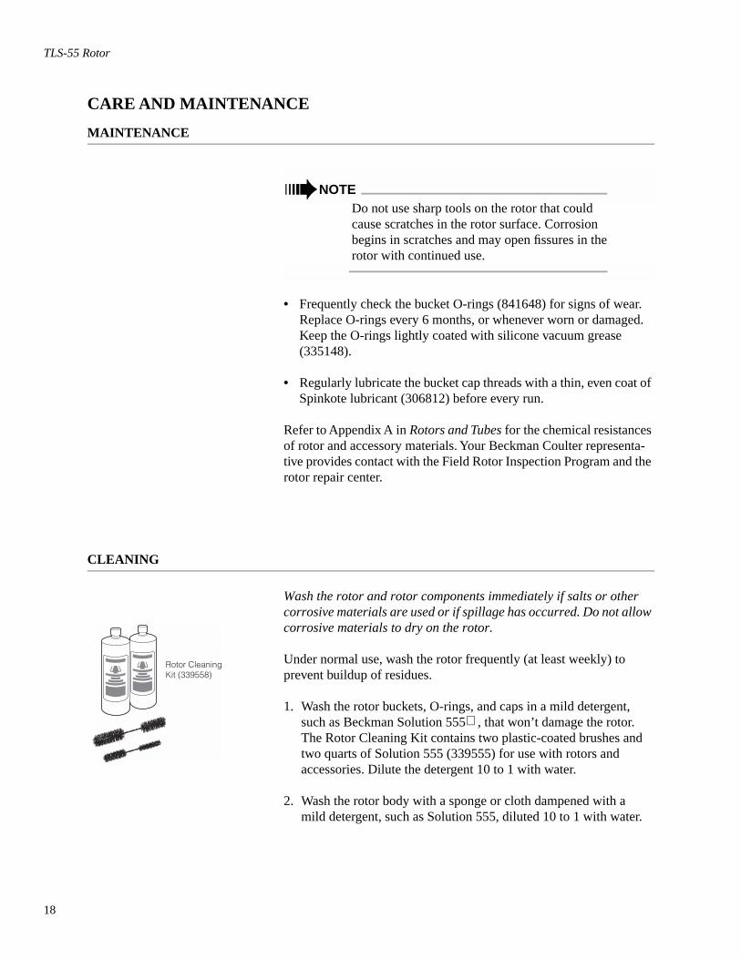
1. Wash the rotor buckets, O-rings, and caps in a mild detergent, such as Beckman Solution 555 , that won’t damage the rotor. The Rotor Cleaning Kit contains two plastic-coated brushes and two quarts of Solution 555 (339555) for use with rotors and accessories. Dilute the detergent 10 to 1 with water.
2. Wash the rotor body with a sponge or cloth dampened with a mild detergent, such as Solution 555, diluted 10 to 1 with water.
Rotor CleaningKit (339558)
19
TLS-55 Rotor
➠ NOTEDo not immerse the rotor body in water, since the hanger mechanism is difficult to dry and can rust.
3. Rinse the cleaned rotor and components with distilled water.
4. Air-dry the buckets upside down. Do not use acetone to dry the rotor.
Clean metal threads frequently to prevent buildup of residues and ensure adequate closure. Use a brush and concentrated Solution 555. Rinse and dry thoroughly, then lubricate lightly but evenly with Spinkote to coat all threads.
DECONTAMINATION
If the rotor or other components are contaminated with toxic, radioactive, or pathogenic materials, follow appropriate decontamina-tion procedures as outlined by your laboratory safety officer. Refer to Appendix A in Rotors and Tubes to select solutions that will not damage the rotor and accessory materials.
STERILIZATION AND DISINFECTION
• The rotor and all rotor components can be autoclaved at 121°C for up to an hour. Remove the lids from the rotor buckets and place the rotor, buckets, lid, and spacers in the autoclave upside down.
• Ethanol (70%)* or hydrogen peroxide (6%) may be used on all rotor components, including those made of plastic. Bleach (sodium hypochlorite) may be used, but may cause discoloration of anodized surfaces. Use the minimum immersion time for each solution, per laboratory standards.
* Flammability hazard. Do not use in or near operating ultracentrifuges.
121°C
20
TLS-55 Rotor
While Beckman Coulter has tested these methods and found that they do not damage the rotor or components, no guarantee of sterility or disinfection is expressed or implied. When sterilization or disinfec-tion is a concern, consult your laboratory safety officer regarding proper methods to use.
Refer to publication IN-192 (included with each box of tubes) for tube sterilization and disinfection procedures. Quick-Seal, Ultra Clear, and thinwall open-top tubes are disposable and should be discarded after a single use.
STORAGE
When it is not in use, store the rotor in a dry environment (not in the instrument) with the bucket lids removed to allow air circulation so moisture will not collect in the tube cavities.
21
TLS-55 Rotor
RETURNING A ROTOR
Before returning a rotor or accessory for any reason, prior permission (a Returned Goods Authorization form) must be obtained from Beckman Coulter, Inc. This RGA form may be obtained from your local Beckman Coulter sales office, and should contain the following information:
• serial number,
• history of use (approximate frequency of use),
• reason for the return,
• original purchase order number, billing number, and shipping number, if possible,
• name and phone number of the person to be notified upon receipt of the rotor or accessory at the factory, and,
• name and phone number of the person to be notified about repair costs, etc.
To protect our personnel, it is the customer’s responsibility to ensure that all parts are free from pathogens and/or radioactivity. Steriliza-tion and decontamination must be done before returning the parts. Smaller items (such as tubes, bottles, etc.) should be enclosed in a sealed plastic bag.
All parts must be accompanied by a note, plainly visible on the out-side of the box or bag, stating that they are safe to handle and that they are not contaminated with pathogens or radioactivity. Failure to attach this notification will result in return or disposal of the items without review of the reported problem.
Use the address label printed on the RGA form when mailing the rotor and/or accessories to:
Beckman Coulter, Inc.1050 Page Mill RoadPalo Alto, CA 94304
Attention: Returned Goods
Customers located outside the United States should contact their local Beckman Coulter office.
RGA
22
TLS-55 Rotor
SUPPLY LIST
➠ NOTETo obtain copies of referenced publications, contact Beckman Coulter, Inc., Technical Publi-cations Department, 1050 Page Mill Road, Palo Alto, CA 94304, U.S.A. (Telephone 650-859-1753; Fax 650-859-1375).
Contact Beckman Coulter Sales (1-800-742-2345 in the United States; worldwide offices are listed on the back cover of this manual) or see the Beckman Coulter Ultracentrifuge Rotors, Tubes & Acces-sories catalog (BR-8101) for detailed information on ordering parts and supplies. For your convenience, a partial list is given below.
REPLACEMENT ROTOR PARTS
TLS-55 rotor assembly . . . . . . . . . . . . . . . . . . . . . . . . . . . . . . . . . . . 346936Buckets (set of 4). . . . . . . . . . . . . . . . . . . . . . . . . . . . . . . . . . . . . . . . 346364Bucket cap assembly . . . . . . . . . . . . . . . . . . . . . . . . . . . . . . . . . . . . . 345770Bucket O-ring (set of 4). . . . . . . . . . . . . . . . . . . . . . . . . . . . . . . . . . . 868638Rotor stand . . . . . . . . . . . . . . . . . . . . . . . . . . . . . . . . . . . . . . . . . . . . 345773Bucket stand . . . . . . . . . . . . . . . . . . . . . . . . . . . . . . . . . . . . . . . . . . . 347358Cap and plunger assembly. . . . . . . . . . . . . . . . . . . . . . . . . . . . . . . . . 349338
OTHER
Tubes and accessories . . . . . . . . . . . . . . . . . . . . . . . . . . . . . . . . . see Table 1Tube rack . . . . . . . . . . . . . . . . . . . . . . . . . . . . . . . . . . . . . . . . . . . . . . 348305Quick-Seal Cordless Tube Topper kit, 60 Hz . . . . . . . . . . . . . . . . . . 358312Quick-Seal Cordless Tube Topper kit, 50 Hz (Europe). . . . . . . . . . . 358313Quick-Seal Cordless Tube Topper kit, 50 Hz (Great Britain) . . . . . . 358314Quick-Seal Cordless Tube Topper kit, 50 Hz (Australia) . . . . . . . . . 358315Tube Topper rack (11-mm dia. tubes) . . . . . . . . . . . . . . . . . . . . . . . . 349387Floating spacer removal tool . . . . . . . . . . . . . . . . . . . . . . . . . . . . . . . 338765Tube removal tool (Quick-Seal tubes). . . . . . . . . . . . . . . . . . . . . . . . 361668Fraction Recovery System (for TL-series tubes). . . . . . . . . . . . . . . . 347828CentriTube Slicer. . . . . . . . . . . . . . . . . . . . . . . . . . . . . . . . . . . . . . . . 347960CentriTube Slicer blades (pkg of 10) . . . . . . . . . . . . . . . . . . . . . . . . 348299Spinkote lubricant (2 oz) . . . . . . . . . . . . . . . . . . . . . . . . . . . . . . . . . . 306812Silicone vacuum grease (1 oz). . . . . . . . . . . . . . . . . . . . . . . . . . . . . . 335148Rotor Cleaning Kit . . . . . . . . . . . . . . . . . . . . . . . . . . . . . . . . . . . . . . 339558Beckman Solution 555 (1 qt) . . . . . . . . . . . . . . . . . . . . . . . . . . . . . . 339555Rotor cleaning brush . . . . . . . . . . . . . . . . . . . . . . . . . . . . . . . . . . . . . 339379
ULTRACENTRIFUGE ROTOR WARRANTY
All Beckman Coulter ultracentrifuge Fixed Angle, Vertical Tube,Near Vertical Tube, Swinging Bucket, and Airfuge rotors arewarranted against defects in materials or workmanship for the timeperiods indicated below, subject to the Warranty Conditions statedbelow.
Preparative Ultracentrifuge Rotors . . . . . 5 years — No Proration
Analytical Ultracentrifuge Rotors. . . . . . 5 years — No Proration
ML and TL Series UltracentrifugeRotors . . . . . . . . . . . . . . . . . . . . . . . . . 5 years — No Proration
Airfuge Ultracentrifuge Rotors . . . . . . . . . 1 year — No Proration
For Zonal, Continuous Flow, Component Test, and Rock Coreultracentrifuge rotors, see separate warranty.
Warranty Conditions (as applicable)
1) This warranty is valid for the time periods indicated above fromthe date of shipment to the original Buyer by Beckman Coulteror an authorized Beckman Coulter representative.
2) This warranty extends only to the original Buyer and may notbe assigned or extended to a third person without writtenconsent of Beckman Coulter.
3) This warranty covers the Beckman Coulter Centrifuge Systemsonly (including but not limited to the centrifuge, rotor, andaccessories) and Beckman Coulter shall not be liable fordamage to or loss of the user’s sample, non-Beckman Coultertubes, adapters, or other rotor contents.
4) This warranty is void if the Beckman Coulter Centrifuge Sys-tem is determined by Beckman Coulter to have been operatedor maintained in a manner contrary to the instructions in theoperator’s manual(s) for the Beckman Coulter CentrifugeSystem components in use. This includes but is not limited tooperator misuse, abuse, or negligence regarding indicated main-tenance procedures, centrifuge and rotor classification require-ments, proper speed reduction for the high density of certainfluids, tubes, and tube caps, speed reduction for precipitatinggradient materials, and speed reduction for high-temperatureoperation.
5) Rotor bucket sets purchased concurrently with or subsequent tothe purchase of a Swinging Bucket Rotor are warranted only fora term co-extensive with that of the rotor for which the bucketsets are purchased.
6) This warranty does not cover the failure of a Beckman Coulterrotor in a centrifuge not of Beckman Coulter manufacture, or ifthe rotor is used in a Beckman Coulter centrifuge that has beenmodified without the written permission of Beckman Coulter,or is used with carriers, buckets, belts, or other devices not ofBeckman Coulter manufacture.
7) Rotor parts subject to wear, including but not limited to rotorO-rings, VTi, NVT™, TLV, MLN, and TLN rotor tube cavityplugs and gaskets, tubing, tools, optical overspeed disks, bear-ings, seals, and lubrication are excluded from this warranty andshould be frequently inspected and replaced if they becomeworn or damaged.
8) Keeping a rotor log is not mandatory, but may be desirable formaintenance of good laboratory practices.
Repair and Replacement Policies
1) If a Beckman Coulter rotor is determined by Beckman Coulterto be defective, Beckman Coulter will repair or replace it,subject to the Warranty Conditions. A replacement rotor will bewarranted for the time remaining on the original rotor’swarranty.
2) If a Beckman Coulter centrifuge is damaged due to a failure ofa rotor covered by this warranty, Beckman Coulter will supplyfree of charge (i) all centrifuge parts required for repair (exceptthe drive unit, which will be replaced at the then current priceless a credit determined by the total number of revolutions oryears completed, provided that such a unit was manufactured orrebuilt by Beckman Coulter), and (ii) if the centrifuge is cur-rently covered by a Beckman Coulter warranty or Full ServiceAgreement, all labor necessary for repair of the centrifuge.
3) If a Beckman Coulter rotor covered by this warranty is dam-aged due to a malfunction of a Beckman Coulter ultracentrifugecovered by an Ultracentrifuge System Service Agreement,Beckman Coulter will repair or replace the rotor free of charge.
4) If a Beckman Coulter rotor covered by this warranty isdamaged due to a failure of a Beckman Coulter tube, bottle,tube cap, spacer, or adapter, covered under the Conditions ofthis Warranty, Beckman Coulter will repair or replace the rotorand repair the instrument as per the conditions in policy point(2) above, and the replacement policy.
5) Damage to a Beckman Coulter rotor or instrument due to thefailure or malfunction of a non-Beckman Coulter tube, bottle,tube cap, spacer, or adapter is not covered under this warranty,although Beckman Coulter will assist in seeking compensationunder the manufacturer’s warranty.
Disclaimer
IT IS EXPRESSLY AGREED THAT THE ABOVE WARRANTYSHALL BE IN LIEU OF ALL WARRANTIES OF FITNESS ANDOF THE WARRANTY OF MERCHANTABILITY ANDBECKMAN COULTER, INC. SHALL HAVE NO LIABILITYFOR SPECIAL OR CONSEQUENTIAL DAMAGES OF ANYKIND WHATSOEVER ARISING OUT OF THE MANUFAC-TURE, USE, SALE, HANDLING, REPAIR, MAINTENANCE,OR REPLACEMENT OF THE PRODUCT.
Factory Rotor Inspection Service
Beckman Coulter, Inc., will provide free mechanical andmetallurgical inspection in Palo Alto, California, USA, of anyBeckman Coulter rotor at the request of the user. (Shipping chargesto Beckman Coulter are the responsibility of the user.) Rotors willbe inspected in the user’s laboratory if the centrifuge in which theyare used is covered by an appropriate Beckman Coulter ServiceAgreement. Contact your local Beckman Coulter office for detailsof service coverage or cost.
Before shipping, contact the nearest Beckman Coulter Sales andService office and request a Returned Goods Authorization (RGA)form and packaging instructions. Please include the complete rotorassembly, with buckets, lid, handle, tube cavity caps, etc. ASIGNED STATEMENT THAT THE ROTOR AND ACCESSO-RIES ARE NON-RADIOACTIVE, NON-PATHOGENIC, NON-TOXIC, AND OTHERWISE SAFE TO SHIP AND HANDLE ISREQUIRED.
Beckman Coulter Worldwide Life Science Research Division Offices
AUSTRALIA
Beckman Coulter Australia Pty LtdUnit D, 24 College St.Gladesville, NSW 2111Australia
Telephone: (61) 2 9844-6000or toll free: 1 800 060 880Fax: (61) 2 9844-6096email: [email protected]
CANADA
Beckman Coulter (Canada) Inc.6755 Mississauga Road, Suite 600Mississauga, OntarioCanada L5N 7Y2
Telephone: (905) 819-1234Fax: (905) 819-1485
CHINA
Beckman Coulter Inc.Beijing Representative OfficeUnit 2005A, 2006-2009, East Ocean CenterJian Guomenwai AvenueBeijing 100004China
Telephone: (86) 10 6515 6028Fax: (86) 10 6515 6025, 6515 6026
EASTERN EUROPE/MIDDLE EAST/AFRICA
Beckman Coulter International S.A.22, Rue Juste-OlivierCase Postale 301-303CH-1260 Nyon, Switzerland
Telephone: (41) 22 994 07 07Fax: (41) 22 994 07 00
FRANCE
Beckman Coulter France S.A.Paris Nord II, 33/66 rue des VanessesB.P. 50359Villepinte, France 95942 ROISSY CDG Cedex
Telephone: 01 49 90 90 00Fax: 01 49 90 90 10e-mail: [email protected]
GERMANY
Beckman Coulter GmbHSiemensstrasse 1D-85716 Unterschleissheim-LohhofGermany
Telephone: (89) 35870-0Fax: (89) 35870-490e-mail: [email protected]
SPAIN
Beckman Coulter España S.A.C/ Caleruega, 8128033 Madrid, Spain
Telephone: (34) 91 3836080Fax: (34) 91 3836096email: [email protected]
SWEDEN
Beckman Coulter ABArchimedesvaegen 7Box 111 56SE-168 11 BrommaSweden
Telephone: (0)8 564 85 900Telefax: (0)8 564 85 901
SWITZERLAND
Beckman Coulter International S.A.22, Rue Juste-OlivierCase Postale 301-303CH-1260 NyonSwitzerland
Telephone: 0800 850 810Fax: 0848 850 810
TAIWAN
Beckman Coulter Taiwan Inc.Taiwan Branch8th Floor216 Tun Hwa South Road, Section 2Taipei 106, Taiwan Republic of China
Telephone: (886) 2 2378 3456Fax: (886) 2 2377 0408
TURKEY
Beckman Coulter Ltd.E-5 Yanyol Faith Cad.81410 Soganlik KartalIstanbulTurkey
Telephone: 90 216 309 1900Fax: 90 216 309 0090
UNITED KINGDOM
Beckman Coulter United Kingdom LtdOakley CourtKingsmead Business ParkLondon RoadHigh WycombeBucks HP11 1JUEngland, U.K.
Telephone: 01494 441181Fax: 01494 447558e-mail: [email protected]
Authorized dealers in other countries
.
Beckman Coulter, Inc. • 4300 N. Harbor Boulevard, Box 3100 • Fullerton, California 92834-3100Sales: 1-800-742-2345 • Service: 1-800-551-1150 • Internet: www.beckmancoulter.com • Telex: 678413 • Fax: 1-800-643-4366
©2001 Beckman Coulter, Inc.
TM
I.S. EN ISO 9001
Printed on recycled paper
HONG KONG
Beckman Coulter Hong Kong Ltd.12th Floor, Oxford House979 King’s RoadTaikoo Place, Hong Kong
Telephone: (852) 2814 7431, 2814 0481Fax: (852) 2814 1599, 2873 4511
ITALY
Beckman Coulter S.p.a.Centro Direzionale LombardoPalazzo F/1, Via Roma 10820060 Cassina de’ PecchiMilano, Italy
Telephone: 02-953921Fax: 02-95392264e-mail: [email protected]
JAPAN
Beckman Coulter K.K.Toranomon 37 Mori Bldg.3-5-1, ToranomonMinato-ku, Tokyo 105-0001Japan
Telephone: 03-5404-8359Fax: 03-5404-8436
MEXICO
Beckman Coulter de Mexico S.A DE C.VAvenida Popocatépetl #396Colonia Gral. Pedro Maria AnayaCodigo Postal 03340Maxico, D.F. Mexico
Telephone: 525 605-77-70Fax: 525 575-18-25
NETHERLANDS
Beckman Coulter Nederland B.V.Nijverheidsweg 213641 RP-MijdrechtPostbus 473640 AA MijdrechtThe Netherlands
Telephone: 0297-230630Fax: 0297-288082
SINGAPORE
Beckman Coulter Singapore Pte. Ltd.116 Changi RoadUnit #03-01/02Singapore 419718
Telephone: (65) 339 3633Fax: (65) 336 6303
SOUTH AFRICA
Beckman CoulterStand 1A Primegro ParkTonetti Street1685 Halfway HouseJohannesburgRepublic of South Africa
Telephone: (27) 11-805-2014/5Fax: (27) 11-805-4120