Embed Size (px)
Citation preview

Application Note Please read the Important Notice and Warnings at the end of this document V 1.0
www.infineon.com page 1 of 31 2020-03-02
AppNote TLI4971 MS2Go & S2Go
TLI4971 Current Sensor
The MS2Go & S2Go Kit User Manual
About this document
Scope and purpose
Infineon’s magnetic current sensor MS2Go evaluation kit is a low cost 2GO kit which enables the user to quickly evaluate the TLI4971 current sensor. The TLI4971 Current 2go Evaluation kit is offered in two configurations, such as Magnetic Sensor 2Go (MS2Go) & Shield 2Go (S2Go) kits.
The following key aspects are discussed in this document.
− Sensor board description & schematic
− Sensor Shield board description & schematic
− MCU board description & schematic
− Current2Go Evalkit GUI description & installation procedure
− GUI operation with MS2Go kit in electric drive application example
− MS2Go, S2Go kit and companion board order information
− MS2Go and S2Go kit use cases
− Typical application setup using MS2Go kit
o To modify the current sensor parameters such as operating mode, sensitivity, over-current threshold and filtering time using volatile settings, as well as monitoring sensor signals
The programmer board is CE certified and to be used by the customer solely for the purpose of evaluation and
testing. It is not a commercialized product and shall not be used for series production. The programmer board is thus not intended to meet any industrial specifications and must be operated in the room temperature
conditions.
Due to the purpose of the system, it is not subject to the same procedures regarding Returned Material Analysis
(RMA), Process Change Notification (PCN) and Product Withdraw (PWD) as regular products.
Intended audience
Current Sensor Module Developers
Inverter/Converter applications
Industrial Drive applications
Smart Relay and socket applications
Welding machine applications
Application Note 2 of 31 V 1.0
2020-03-02
TLI4971 Current Sensor The MS2Go & S2Go Kit User Manual
Introduction
Table of contents
About this document ....................................................................................................................... 1
Table of contents ............................................................................................................................ 2
1 Introduction .......................................................................................................................... 3 1.1 TLI4971 MS2Go configuration ................................................................................................................. 3 1.2 TLI4971 S2Go configuration .................................................................................................................... 4 1.3 TLI4971 Current 2Go Evaluation Kit Use Cases ...................................................................................... 5
1.4 MS2Go & S2Go Kits Features ................................................................................................................... 6
1.5 MS2Go & S2Go Kits Hardware and Software Overview ......................................................................... 7 1.5.1 Hardware Overview ............................................................................................................................ 7 1.5.2 Software Overview ............................................................................................................................. 7
1.5.3 Software Installation .......................................................................................................................... 7
2 MS2Go and S2Go Kits Description ............................................................................................. 8 2.1 Sensor Shield Pin Description ................................................................................................................. 8
2.2 MCU Board ............................................................................................................................................... 9 2.3 In-Plane Edge Connector ...................................................................................................................... 10 2.4 Sensor Board ......................................................................................................................................... 10
3 Current Sensor Evaluation Setup ............................................................................................ 11 3.1 Graph View ............................................................................................................................................. 11 3.1.1 File (Drop down Menu) ..................................................................................................................... 15
3.1.1.1 Quit .............................................................................................................................................. 15
3.1.2 Settings (Drop down Menu) ............................................................................................................. 15
3.1.2.1 Volatile Settings .......................................................................................................................... 15 3.1.2.2 EEPROM Map ............................................................................................................................... 18
4 Appendix I ............................................................................................................................ 19
5 Appendix II ........................................................................................................................... 25
6 Glossary ............................................................................................................................... 28
7 References ........................................................................................................................... 29
Revision history............................................................................................................................. 30
Application Note 3 of 31 V 1.0
2020-03-02
TLI4971 Current Sensor The MS2Go & S2Go Kit User Manual
Introduction
1 Introduction
The TLI4971 MS2Go and S2Go kits are budget-priced evaluation kits enabling the possibility to evaluate
the Infineon TLI4971 current sensor. Infineon’s magnetic current sensor available in two configurations, such as MS2Go and S2Go kit.
Figure 1 TLI4971 Current Sensor 2GO Kit
1.1 TLI4971 MS2Go configuration
The MS2Go kit contains the following components in its order package.
− Sensor board (equipped with M4 screw connectors for high current capabilities), built in thick copper technology (140um copper / dual layer) (see Figure 2).
− MCU board equipped with XMC1100 as target microcontroller and XMC4200 as debugger microcontroller. This board implements the application circuit of the sensor (see Figure 2).
− Sensor shield, in addition to the MCU board, the sensor board can be connected to the shield. This PCB
only implements sensor application circuit & peripherals with connection pinout to XMC2go platform (see Figure 2). XMC2Go board mounted on the sensor shield board using the pin headers attached in the
package.
− Zip lock bag with 2xM4 screws, 1 PCB edge connector (for connecting the sensor board to MCU board/ shield), and pin headers (male & female) to access data lines (see Figure 2).
− Disclaimer for safety precautions.
Application Note 4 of 31 V 1.0
2020-03-02
TLI4971 Current Sensor The MS2Go & S2Go Kit User Manual
Introduction
3
2
1
OCD2
AOUT
OCD1
VDD
VREF
GND
TLI4971
In-Plane Edge
Connector
MCU Board
Sensor Shield
MUX
LEDs
PMOS transistors
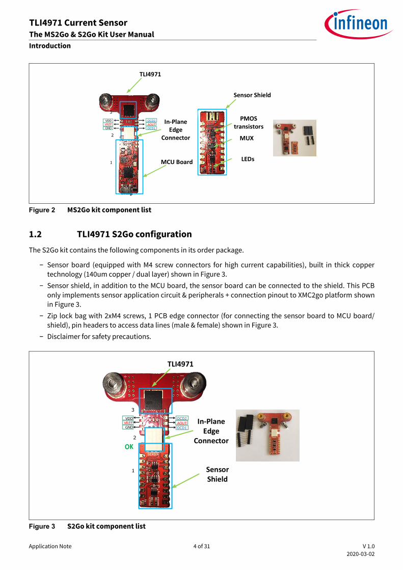
Figure 2 MS2Go kit component list
1.2 TLI4971 S2Go configuration
The S2Go kit contains the following components in its order package.
− Sensor board (equipped with M4 screw connectors for high current capabilities), built in thick copper technology (140um copper / dual layer) shown in Figure 3.
− Sensor shield, in addition to the MCU board, the sensor board can be connected to the shield. This PCB
only implements sensor application circuit & peripherals + connection pinout to XMC2go platform shown
in Figure 3.
− Zip lock bag with 2xM4 screws, 1 PCB edge connector (for connecting the sensor board to MCU board/ shield), pin headers to access data lines (male & female) shown in Figure 3.
− Disclaimer for safety precautions.
3
2
1
OCD2
AOUT
OCD1
VDD
VREF
GND
TLI4971
In-Plane Edge
Connector
Sensor Shield
Figure 3 S2Go kit component list

Application Note 5 of 31 V 1.0
2020-03-02
TLI4971 Current Sensor The MS2Go & S2Go Kit User Manual
Introduction
The MS2Go Kit includes a GUI software that can be downloaded from the Infineon website. Table 1 shows the S2Go & MS2GO kit order information.
Table 1 Order Information
Type / Name SP – Number
S2GO_CUR-SENSE_TLI4971 SP005345472
TLI4971_MS2GO SP005345474
The following chapters describe the different parts of the MS2Go kit, hardware connection, software installation and clarifies how to use the graphical user interface (GUI) to do the first evaluations of the sensor in a particular application. The MS2Go kit design meets the required clearance and creepage distances for high voltage
applications according to the TLI4971 specification. The sensor on the sensor board provides a galvanic isolation.
Please consider the safety precautions for high voltage applications as described in the enclosed disclaimer document along with the delivered sensor kit. The communication between the current sensor and XMC2GO
board is provided through a connector called in-plane edge connector which has shown in the Figure 9.
1.3 TLI4971 Current 2Go Evaluation Kit Use Cases
The current 2Go kit can be used for different use cases as shown in the below.
− MS2Go kit use case with MCU Board (See Figure 4)
− S2Go kit use case with XMC2GO Board (See Figure 5)
− Sensor board alone (See Figure 6)
+ +
(cable not included in
the either MS2Go or
S2Go kit order)PC running Windows 7 or newer
GUI provided by Infineon
Figure 4 MS2Go kit Use Case with MCU Board
The MS2Go kit can be used as independent evaluation kit by connecting sensor board with MCU board together as shown in the Figure 4. The user has to connect the XMC2GO board with the PC/Laptop using the USB cable,
which must have micro USB on one side and standard USB port on the other side of the cable. The provided GUI is plug & play.
The MS2Go kit used with Arduino shield by plugging the sensor board together with the shield board. It is mandatory to have an XMC2go platform, which is not provided in the package. Programming can be done in Arduino IDE by selecting the XMC2go platform.
Application Note 6 of 31 V 1.0
2020-03-02
TLI4971 Current Sensor The MS2Go & S2Go Kit User Manual
Introduction
XMC2go
(not included in the
S2Go kit order)
+ + +
Cable
(not included in the
S2Go kit order)
PC running Windows 7 or newer
Arduino IDE
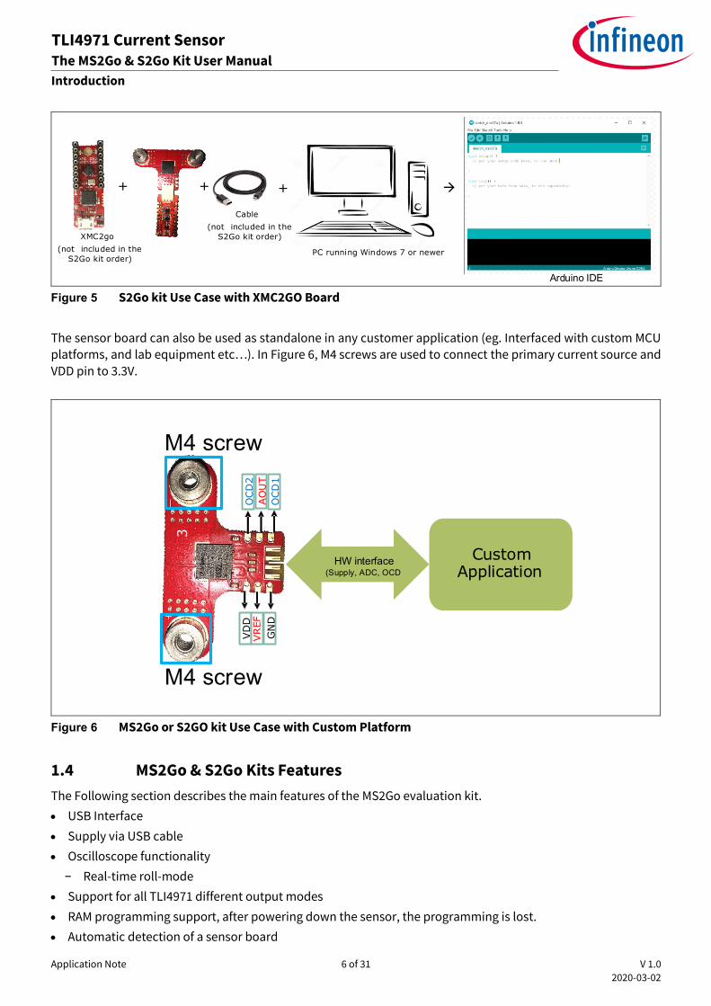
Figure 5 S2Go kit Use Case with XMC2GO Board
The sensor board can also be used as standalone in any customer application (eg. Interfaced with custom MCU platforms, and lab equipment etc…). In Figure 6, M4 screws are used to connect the primary current source and
VDD pin to 3.3V.
Custom Application )
3
OCD
2
AO
UT
OCD
1
VD
D
VREF
GN
D
M4 screw
M4 screw
HW interface(Supply, ADC, OCD
Figure 6 MS2Go or S2GO kit Use Case with Custom Platform
1.4 MS2Go & S2Go Kits Features
The Following section describes the main features of the MS2Go evaluation kit.
USB Interface
Supply via USB cable
Oscilloscope functionality
− Real-time roll-mode
Support for all TLI4971 different output modes
RAM programming support, after powering down the sensor, the programming is lost.
Automatic detection of a sensor board
Application Note 7 of 31 V 1.0
2020-03-02
TLI4971 Current Sensor The MS2Go & S2Go Kit User Manual
Introduction
1.5 MS2Go & S2Go Kits Hardware and Software Overview
1.5.1 Hardware Overview
The MS2Go and S2Go kit contains the following items:
The XMC2GO board contains (Neither MS2Go nor S2Go contains this board, needs to order separately)
− XMC1100 Infineon target micro-controller
− XMC4200 on-board debugger microcontroller running a SEGGER Jlink debugger
In-plane edge interface connector
Sensor shield board
MCU Board (Not included in the S2Go kit order)
Isolator board (Not included in the either MS2Go or S2Go kit order): This board might be required if the
customer required reinforced HV application s.
Sensor board
USB Cable (Not included in the either MS2Go or S2Go kit order)
Disclaimer and Safety precautions document
1.5.2 Software Overview
Please download the required software from Infineon website. For further information about the software
installation please refer to the Section 1.5.3.
The software package contains:
A Graphical User Interface (GUI) software for the sensor evaluation.
SEGGER Jlink debugger software with USB driver.
This software was designed to be used with Windows 7 and Windows 10. It is compatible with both 32-bit and 64-
bit systems. Other versions may also work, but have not been tested. The MS2Go & S2Go kit will work with GUI
version 1.0.0 and onwards.
1.5.3 Software Installation
The following description guides through the installation procedure of the free evaluation software for the MS2Go & S2Go kit through the following steps:
Before proceeding further, please get the Admin Rights to proceed with the installation
Download the required software from the Infineon website.
Connect the MS2Go kit via the USB link to your PC (see Figure 11).
Extract the GUI software from Current2GoEvalkitX.X.X.zip file to local folder
To start the installation double click on the “Current2GoEvalkitX.X.X.exe” [see folder .../
Current2GoEvalkitX.X.X.zip] and proceed as discussed in the Appendix.
After the successful completion of the installation, to start the GUI software, go to Windows Start button and select the “Current2GO”.
Application Note 8 of 31 V 1.0
2020-03-02
TLI4971 Current Sensor The MS2Go & S2Go Kit User Manual
MS2Go and S2Go Kits Description
2 MS2Go and S2Go Kits Description
The MS2Go and S2Go kit contains the following main components as discussed in the section 1.1 & 1.2, which are the ready-to-use printed circuit boards (PCBs).
Sensor board
Sensor Shield board
MCU Board
In-plane edge connector
Note: The MS2Go & S2Go kit automatically detects the different types of Infineon Current Sensor EVAL
boards connected to the programmer
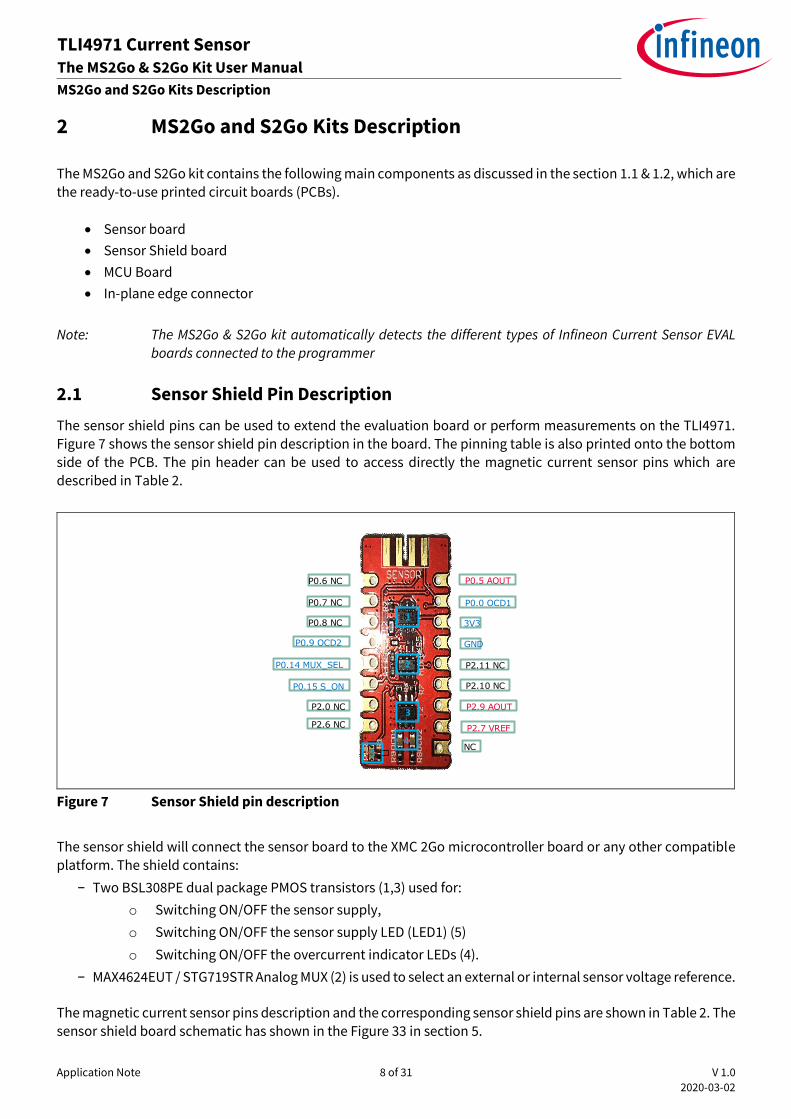
2.1 Sensor Shield Pin Description
The sensor shield pins can be used to extend the evaluation board or perform measurements on the TLI4971. Figure 7 shows the sensor shield pin description in the board. The pinning table is also printed onto the bottom
side of the PCB. The pin header can be used to access directly the magnetic current sensor pins which are described in Table 2.
P2.6 NC
P2.0 NC
P0.15 S_ON
P0.14 MUX_SEL
P0.9 OCD2
P0.8 NC
P0.7 NC
P0.6 NC P0.5 AOUT
P0.0 OCD1
3V3
GND
P2.11 NC
P2.10 NC
P2.9 AOUT
P2.7 VREF
NC5
4
1
2
3
Figure 7 Sensor Shield pin description
The sensor shield will connect the sensor board to the XMC 2Go microcontroller board or any other compatible platform. The shield contains:
− Two BSL308PE dual package PMOS transistors (1,3) used for:
o Switching ON/OFF the sensor supply,
o Switching ON/OFF the sensor supply LED (LED1) (5)
o Switching ON/OFF the overcurrent indicator LEDs (4).
− MAX4624EUT / STG719STR Analog MUX (2) is used to select an external or internal sensor voltage reference.
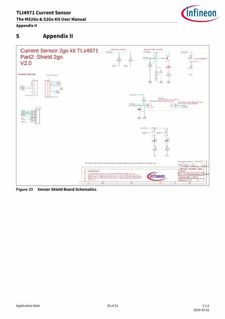
The magnetic current sensor pins description and the corresponding sensor shield pins are shown in Table 2. The sensor shield board schematic has shown in the Figure 33 in section 5.
Application Note 9 of 31 V 1.0
2020-03-02
TLI4971 Current Sensor The MS2Go & S2Go Kit User Manual
MS2Go and S2Go Kits Description
Table 2 Sensor Shield Pins Description
TLI4971 pin
number
Pin name on board Header (J6) Pin Sensor pin description
1 VSENS -- Supply Voltage (VDD) pin of TLI4971
2 GND -- Ground pin of TLI4971
3 VREF P2.7 Reference Voltage pin of TLI4971
4 AOUT P0.5 Analog Output Voltage pin of TLI4971
5 OCD1 P0.0 Over Current Detection (OCD1) pin of TLI4971
6 OCD2 P0.9 Over Current Detection (OCD2) pin of TLI4971
NA MUX_SEL P0.14 To select an external or internal sensor voltage
reference.
NA S_ON P0.15
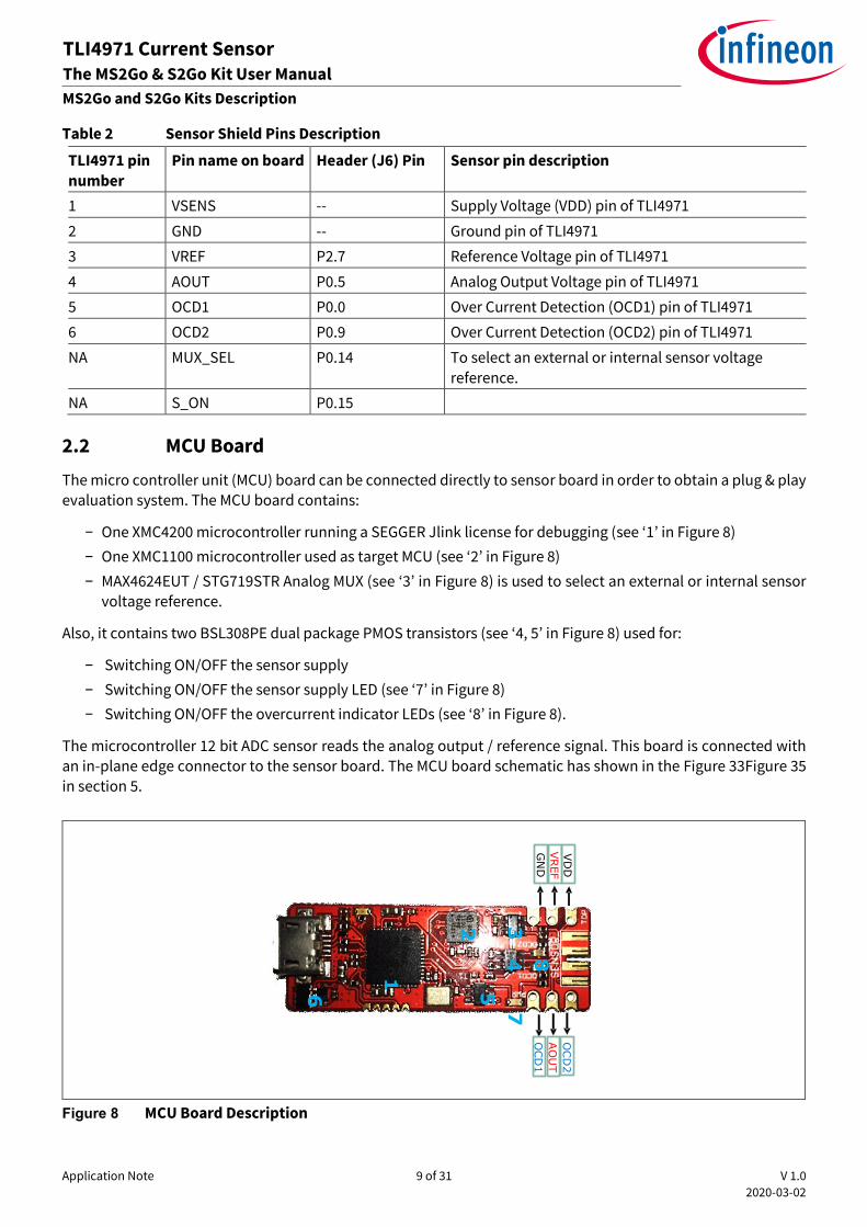
2.2 MCU Board
The micro controller unit (MCU) board can be connected directly to sensor board in order to obtain a plug & play
evaluation system. The MCU board contains:
− One XMC4200 microcontroller running a SEGGER Jlink license for debugging (see ‘1’ in Figure 8)
− One XMC1100 microcontroller used as target MCU (see ‘2’ in Figure 8)
− MAX4624EUT / STG719STR Analog MUX (see ‘3’ in Figure 8) is used to select an external or internal sensor voltage reference.
Also, it contains two BSL308PE dual package PMOS transistors (see ‘4, 5’ in Figure 8) used for:
− Switching ON/OFF the sensor supply
− Switching ON/OFF the sensor supply LED (see ‘7’ in Figure 8)
− Switching ON/OFF the overcurrent indicator LEDs (see ‘8’ in Figure 8).
The microcontroller 12 bit ADC sensor reads the analog output / reference signal. This board is connected with
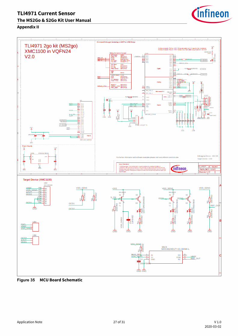
an in-plane edge connector to the sensor board. The MCU board schematic has shown in the Figure 33Figure 35 in section 5.
1
2 34
56
7
8
OCD
2
AO
UT
OCD
1
VD
D
VREF
GN
D
Figure 8 MCU Board Description
Application Note 10 of 31 V 1.0
2020-03-02
TLI4971 Current Sensor The MS2Go & S2Go Kit User Manual
MS2Go and S2Go Kits Description
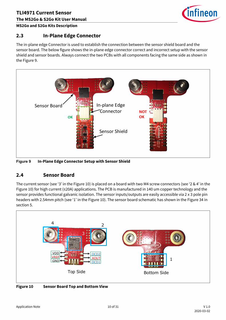
2.3 In-Plane Edge Connector
The in-plane edge Connector is used to establish the connection between the sensor shield board and the sensor board. The below figure shows the in-plane edge connector correct and incorrect setup with the sensor
shield and sensor boards. Always connect the two PCBs with all components facing the same side as shown in the Figure 9.
In-plane Edge Connector
Sensor Shield
Sensor Board
Figure 9 In-Plane Edge Connector Setup with Sensor Shield
2.4 Sensor Board
The current sensor (see ‘3’ in the Figure 10) is placed on a board with two M4 screw connectors (see ‘2 & 4’ in the
Figure 10) for high current (≤20A) applications. The PCB is manufactured in 140 um copper technology and the sensor provides functional galvanic isolation. The sensor inputs/outputs are easily accessible via 2 x 3 pole pin
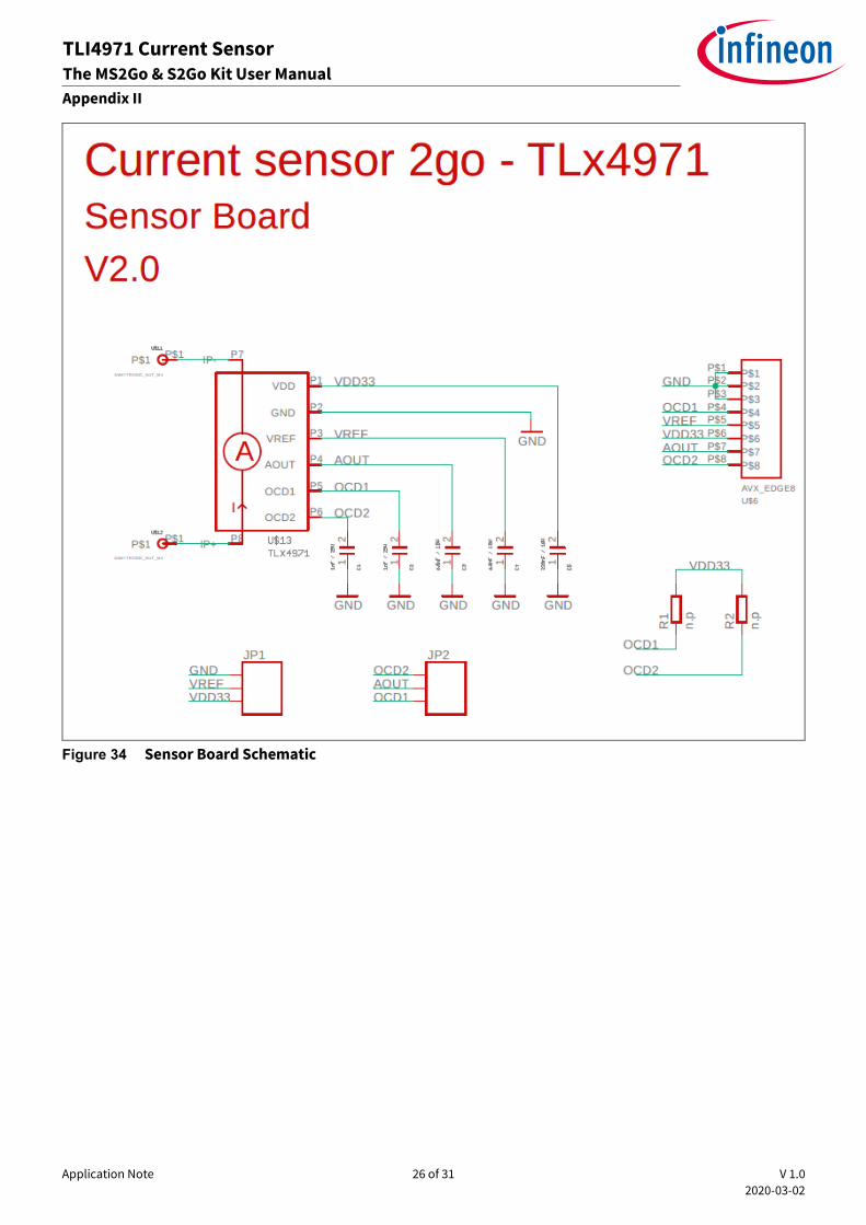
headers with 2.54mm pitch (see ‘1’ in the Figure 10). The sensor board schematic has shown in the Figure 34 in section 5.
3
OCD2
AOUT
OCD1
VDD
VREF
GND
Bottom SideTop Side
1
24
Figure 10 Sensor Board Top and Bottom View
Application Note 11 of 31 V 1.0
2020-03-02
TLI4971 Current Sensor The MS2Go & S2Go Kit User Manual
Current Sensor Evaluation Setup
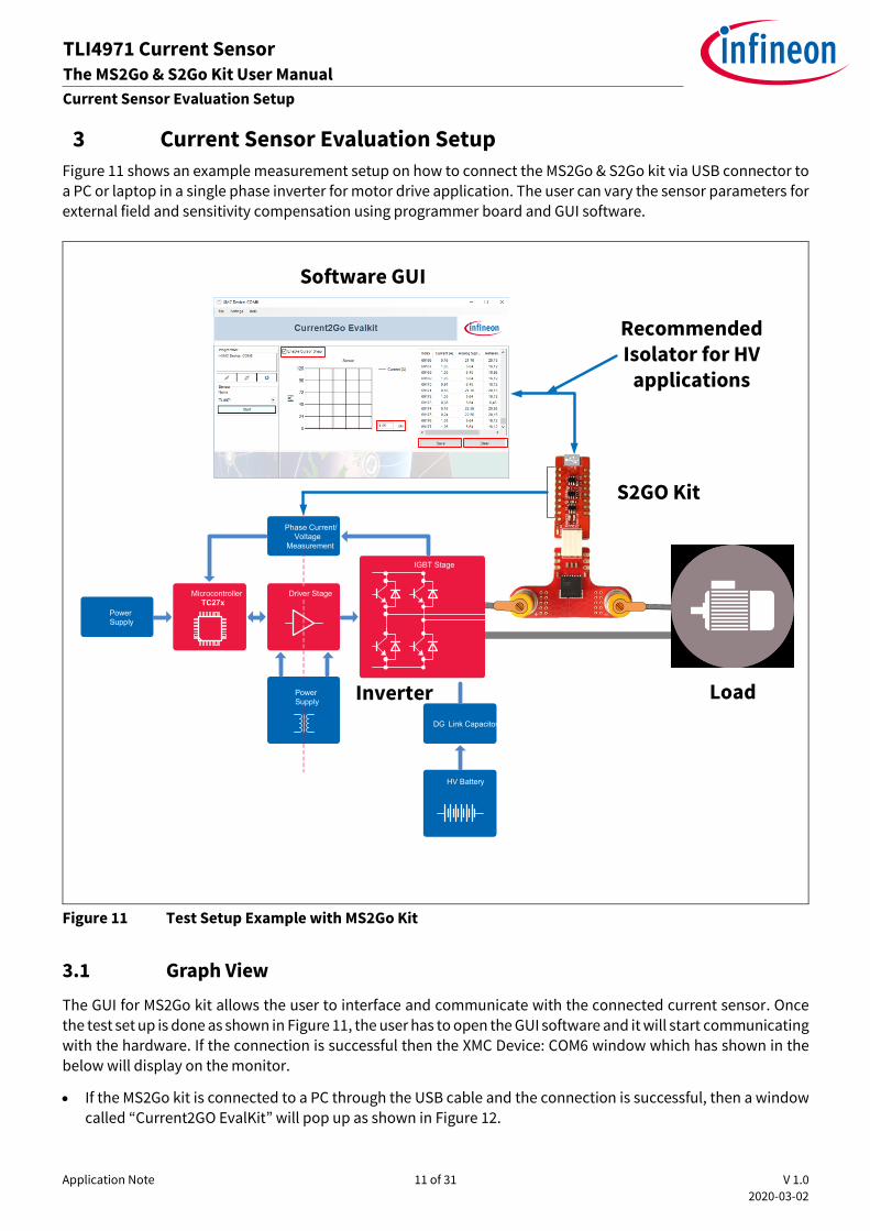
3 Current Sensor Evaluation Setup
Figure 11 shows an example measurement setup on how to connect the MS2Go & S2Go kit via USB connector to a PC or laptop in a single phase inverter for motor drive application. The user can vary the sensor parameters for external field and sensitivity compensation using programmer board and GUI software.
S2GO Kit
Software GUI
Phase Current/
Voltage
Measurement
Power
Supply
Microcontroller
TC27x
Driver Stage
Power
Supply
DC- Link Capacitor
IGBT Stage
HV Battery
LoadInverter
Recommended Isolator for HV
applications
Figure 11 Test Setup Example with MS2Go Kit
3.1 Graph View
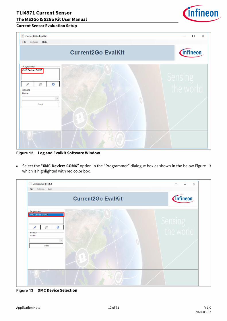
The GUI for MS2Go kit allows the user to interface and communicate with the connected current sensor. Once the test set up is done as shown in Figure 11, the user has to open the GUI software and it will start communicating with the hardware. If the connection is successful then the XMC Device: COM6 window which has shown in the below will display on the monitor.
If the MS2Go kit is connected to a PC through the USB cable and the connection is successful, then a window
called “Current2GO EvalKit” will pop up as shown in Figure 12.
Application Note 12 of 31 V 1.0
2020-03-02
TLI4971 Current Sensor The MS2Go & S2Go Kit User Manual
Current Sensor Evaluation Setup
Figure 12 Log and Evalkit Software Window
Select the “XMC Device: COM6” option in the “Programmer” dialogue box as shown in the below Figure 13
which is highlighted with red color box.
^^
Figure 13 XMC Device Selection
Application Note 13 of 31 V 1.0
2020-03-02
TLI4971 Current Sensor The MS2Go & S2Go Kit User Manual
Current Sensor Evaluation Setup
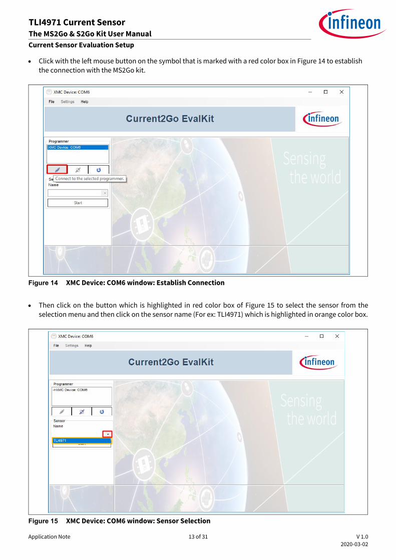
Click with the left mouse button on the symbol that is marked with a red color box in Figure 14 to establish the connection with the MS2Go kit.
Figure 14 XMC Device: COM6 window: Establish Connection
Then click on the button which is highlighted in red color box of Figure 15 to select the sensor from the selection menu and then click on the sensor name (For ex: TLI4971) which is highlighted in orange color box.
Figure 15 XMC Device: COM6 window: Sensor Selection
Application Note 14 of 31 V 1.0
2020-03-02
TLI4971 Current Sensor The MS2Go & S2Go Kit User Manual
Current Sensor Evaluation Setup
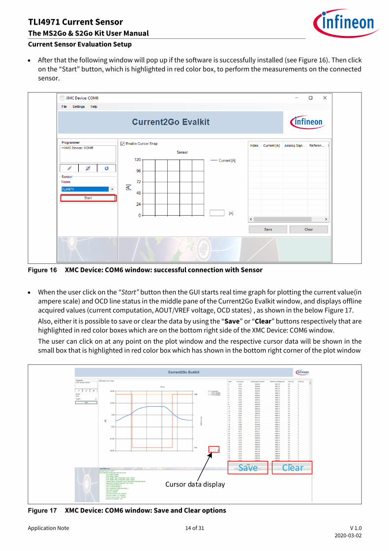
After that the following window will pop up if the software is successfully installed (see Figure 16). Then click on the “Start” button, which is highlighted in red color box, to perform the measurements on the connected
sensor.
Figure 16 XMC Device: COM6 window: successful connection with Sensor
When the user click on the “Start” button then the GUI starts real time graph for plotting the current value(in
ampere scale) and OCD line status in the middle pane of the Current2Go Evalkit window, and displays offline acquired values (current computation, AOUT/VREF voltage, OCD states) , as shown in the below Figure 17.
Also, either it is possible to save or clear the data by using the “Save” or “Clear” buttons respectively that are highlighted in red color boxes which are on the bottom right side of the XMC Device: COM6 window.
The user can click on at any point on the plot window and the respective cursor data will be shown in the small box that is highlighted in red color box which has shown in the bottom right corner of the plot window
Cursor data display
ClearSave
Figure 17 XMC Device: COM6 window: Save and Clear options
Application Note 15 of 31 V 1.0
2020-03-02
TLI4971 Current Sensor The MS2Go & S2Go Kit User Manual
Current Sensor Evaluation Setup
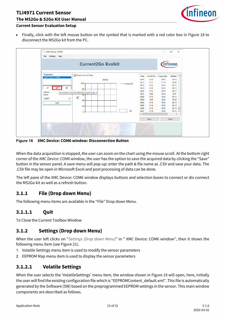
Finally, click with the left mouse button on the symbol that is marked with a red color box in Figure 18 to disconnect the MS2Go kit from the PC.
Figure 18 XMC Device: COM6 window: Disconnection Button
When the data acquisition is stopped, the user can zoom on the chart using the mouse scroll. At the bottom right
corner of the XMC Device: COM6 window, the user has the option to save the acquired data by clicking the “Save” button in the sensor panel. A save menu will pop-up: enter the path & file name as .CSV and save your data. The
.CSV file may be open in Microsoft Excel and post processing of data can be done.
The left pane of the XMC Device: COM6 window displays buttons and selection boxes to connect or dis-connect the MS2Go kit as well as a refresh button.
3.1.1 File (Drop down Menu)
The following menu items are available in the “File” Drop down Menu.
3.1.1.1 Quit
To Close the Current Toolbox Window
3.1.2 Settings (Drop down Menu)
When the user left clicks on "Settings (Drop down Menu)" in " XMC Device: COM6 window", then it shows the following menu item (see Figure 21).
1. Volatile Settings menu item is used to modify the sensor parameters
2. EEPROM Map menu item is used to display the sensor parameters
3.1.2.1 Volatile Settings
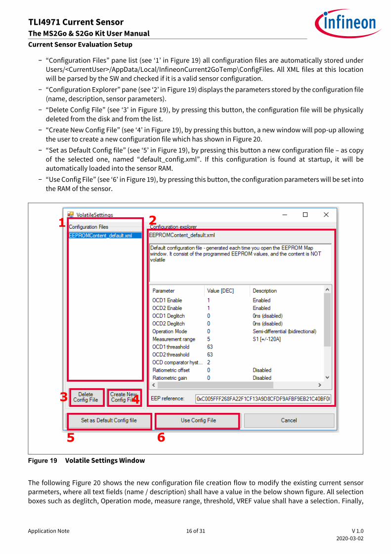
When the user selects the ‘VolatileSettings’ menu item, the window shown in Figure 19 will open, here, initially
the user will find the existing configuration file which is “EEPROMContent_default.xml”. This file is automatically
generated by the Software (SW) based on the preprogrammed EEPROM settings in the sensor. This main window
components are described as follows.
Application Note 16 of 31 V 1.0
2020-03-02
TLI4971 Current Sensor The MS2Go & S2Go Kit User Manual
Current Sensor Evaluation Setup
− “Configuration Files” pane list (see ‘1’ in Figure 19) all configuration files are automatically stored under Users/<CurrentUser>/AppData/Local/InfineonCurrent2GoTemp\ConfigFiles. All XML files at this location
will be parsed by the SW and checked if it is a valid sensor configuration.
− “Configuration Explorer” pane (see ‘2’ in Figure 19) displays the parameters stored by the configuration file
(name, description, sensor parameters).
− “Delete Config File” (see ‘3’ in Figure 19), by pressing this button, the configuration file will be physically
deleted from the disk and from the list.
− “Create New Config File” (see ‘4’ in Figure 19), by pressing this button, a new window will pop-up allowing
the user to create a new configuration file which has shown in Figure 20.
− “Set as Default Config file” (see ‘5’ in Figure 19), by pressing this button a new configuration file – as copy of the selected one, named “default_config.xml”. If this configuration is found at startup, it will be
automatically loaded into the sensor RAM.
− “Use Config File” (see ‘6’ in Figure 19), by pressing this button, the configuration parameters will be set into
the RAM of the sensor.
1 2
3 4
5 6
Figure 19 Volatile Settings Window
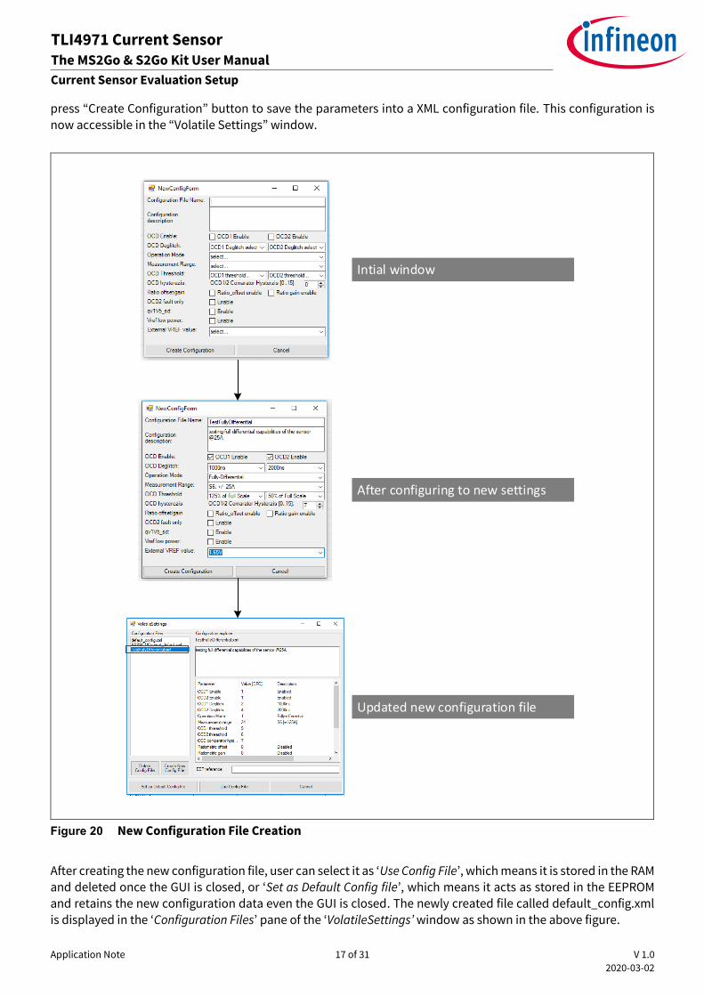
The following Figure 20 shows the new configuration file creation flow to modify the existing current sensor parmeters, where all text fields (name / description) shall have a value in the below shown figure. All selection boxes such as deglitch, Operation mode, measure range, threshold, VREF value shall have a selection. Finally,
Application Note 17 of 31 V 1.0
2020-03-02
TLI4971 Current Sensor The MS2Go & S2Go Kit User Manual
Current Sensor Evaluation Setup
press “Create Configuration” button to save the parameters into a XML configuration file. This configuration is now accessible in the “Volatile Settings” window.
Intial window
After configuring to new settings
Updated new configuration file
Figure 20 New Configuration File Creation
After creating the new configuration file, user can select it as ‘Use Config File’, which means it is stored in the RAM and deleted once the GUI is closed, or ‘Set as Default Config file’, which means it acts as stored in the EEPROM and retains the new configuration data even the GUI is closed. The newly created file called default_config.xml is displayed in the ‘Configuration Files’ pane of the ‘VolatileSettings’ window as shown in the above figure.
Application Note 18 of 31 V 1.0
2020-03-02
TLI4971 Current Sensor The MS2Go & S2Go Kit User Manual
Current Sensor Evaluation Setup
3.1.2.2 EEPROM Map
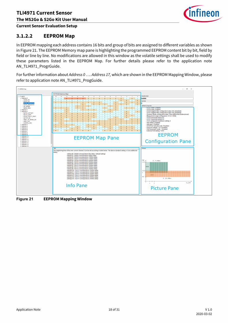
In EEPROM mapping each address contains 16 bits and group of bits are assigned to different variables as shown in Figure 21. The EEPROM Memory map pane is highlighting the programmed EEPROM content bit by bit, field by
field or line by line. No modifications are allowed in this window as the volatile settings shall be used to modify these parameters listed in the EEPROM Map. For further details please refer to the application note AN_TLI4971_ProgrGuide.
For further information about Address 0 …. Address 17, which are shown in the EEPROM Mapping Window, please
refer to application note AN_TLI4971_ProgGuide.
Info Pane Picture Pane
EEPROM Map PaneEEPROM
Configuration Pane
Figure 21 EEPROM Mapping Window
Application Note 19 of 31 V 1.0
2020-03-02
TLI4971 Current Sensor The MS2Go & S2Go Kit User Manual
Appendix I
4 Appendix I
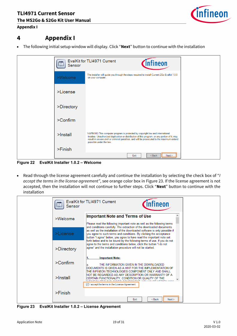
The following initial setup window will display. Click “Next” button to continue with the installation
Figure 22 EvalKit Installer 1.0.2 – Welcome
Read through the license agreement carefully and continue the installation by selecting the check box of “I accept the terms in the license agreement”, see orange color box in Figure 23. If the license agreement is not accepted, then the installation will not continue to further steps. Click “Next” button to continue with the
installation
Figure 23 EvalKit Installer 1.0.2 – License Agreement
Application Note 20 of 31 V 1.0
2020-03-02
TLI4971 Current Sensor The MS2Go & S2Go Kit User Manual
Appendix I
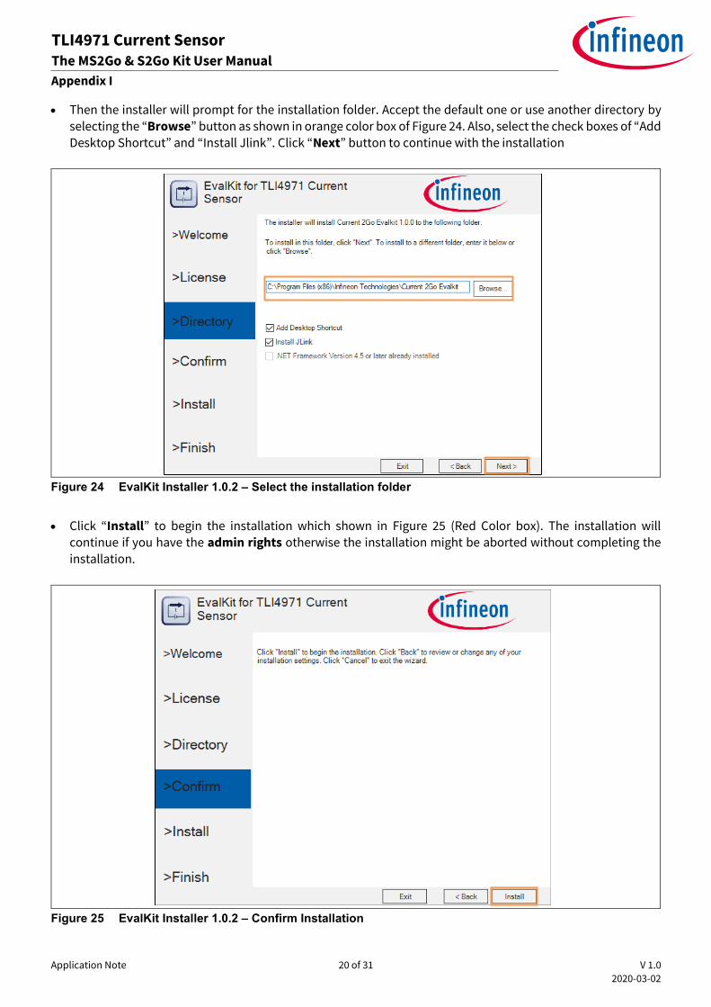
Then the installer will prompt for the installation folder. Accept the default one or use another directory by selecting the “Browse” button as shown in orange color box of Figure 24. Also, select the check boxes of “Add
Desktop Shortcut” and “Install Jlink”. Click “Next” button to continue with the installation
Figure 24 EvalKit Installer 1.0.2 – Select the installation folder
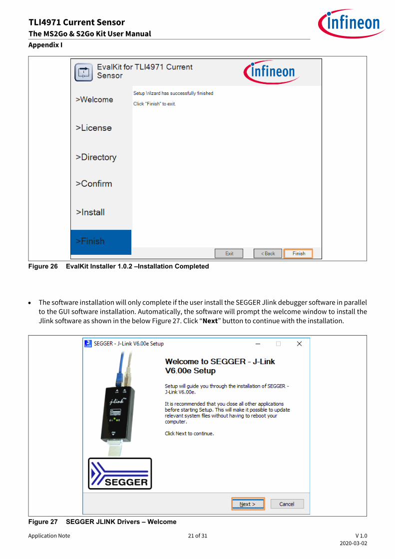
Click “Install” to begin the installation which shown in Figure 25 (Red Color box). The installation will
continue if you have the admin rights otherwise the installation might be aborted without completing the installation.
Figure 25 EvalKit Installer 1.0.2 – Confirm Installation
Application Note 21 of 31 V 1.0
2020-03-02
TLI4971 Current Sensor The MS2Go & S2Go Kit User Manual
Appendix I
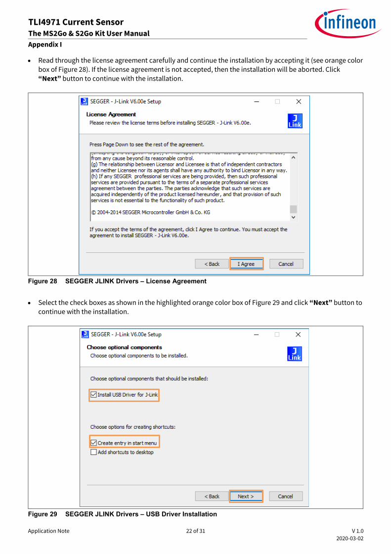
Figure 26 EvalKit Installer 1.0.2 –Installation Completed
The software installation will only complete if the user install the SEGGER Jlink debugger software in parallel to the GUI software installation. Automatically, the software will prompt the welcome window to install the
Jlink software as shown in the below Figure 27. Click “Next” button to continue with the installation.
Figure 27 SEGGER JLINK Drivers – Welcome
Application Note 22 of 31 V 1.0
2020-03-02
TLI4971 Current Sensor The MS2Go & S2Go Kit User Manual
Appendix I
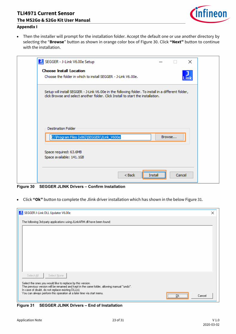
Read through the license agreement carefully and continue the installation by accepting it (see orange color box of Figure 28). If the license agreement is not accepted, then the installation will be aborted. Click
“Next” button to continue with the installation.
Figure 28 SEGGER JLINK Drivers – License Agreement
Select the check boxes as shown in the highlighted orange color box of Figure 29 and click “Next” button to
continue with the installation.
Figure 29 SEGGER JLINK Drivers – USB Driver Installation
Application Note 23 of 31 V 1.0
2020-03-02
TLI4971 Current Sensor The MS2Go & S2Go Kit User Manual
Appendix I
Then the installer will prompt for the installation folder. Accept the default one or use another directory by selecting the “Browse” button as shown in orange color box of Figure 30. Click “Next” button to continue
with the installation.
Figure 30 SEGGER JLINK Drivers – Confirm Installation
Click “Ok” button to complete the Jlink driver installation which has shown in the below Figure 31.
Figure 31 SEGGER JLINK Drivers – End of Installation
Application Note 24 of 31 V 1.0
2020-03-02
TLI4971 Current Sensor The MS2Go & S2Go Kit User Manual
Appendix I
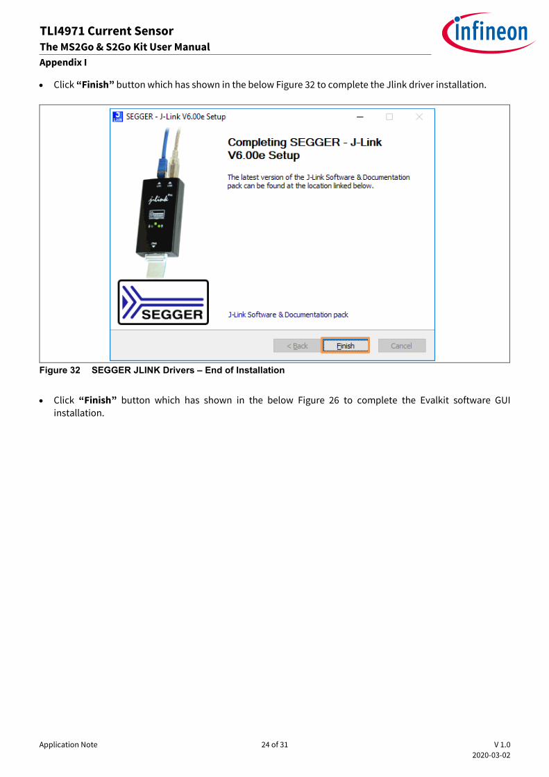
Click “Finish” button which has shown in the below Figure 32 to complete the Jlink driver installation.
Figure 32 SEGGER JLINK Drivers – End of Installation
Click “Finish” button which has shown in the below Figure 26 to complete the Evalkit software GUI
installation.
Application Note 25 of 31 V 1.0
2020-03-02
TLI4971 Current Sensor The MS2Go & S2Go Kit User Manual
Appendix II
5 Appendix II
Figure 33 Sensor Shield Board Schematics
Application Note 26 of 31 V 1.0
2020-03-02
TLI4971 Current Sensor The MS2Go & S2Go Kit User Manual
Appendix II
Figure 34 Sensor Board Schematic
Application Note 27 of 31 V 1.0
2020-03-02
TLI4971 Current Sensor The MS2Go & S2Go Kit User Manual
Appendix II
Figure 35 MCU Board Schematic
Application Note 28 of 31 V 1.0
2020-03-02
TLI4971 Current Sensor The MS2Go & S2Go Kit User Manual
Glossary
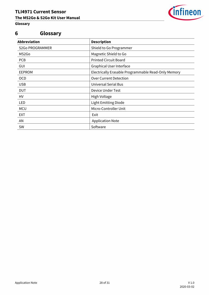
6 Glossary
Abbreviation Description
S2Go PROGRAMMER Shield to Go Programmer
MS2Go Magnetic Shield to Go
PCB Printed Circuit Board
GUI Graphical User Interface
EEPROM Electrically Erasable Programmable Read-Only Memory
OCD Over Current Detection
USB Universal Serial Bus
DUT Device Under Test
HV High Voltage
LED Light Emitting Diode
MCU Micro-Controller Unit
EXT Exit
AN Application Note
SW Software
Application Note 29 of 31 V 1.0
2020-03-02
TLI4971 Current Sensor The MS2Go & S2Go Kit User Manual
References
7 References
[1] A Reference. See the code examples at www.infineon.com
[2] AN_TLI4971_ProgGuide User Manual
Application Note 30 of 31 V 1.0
2020-03-02
TLI4971 Current Sensor The MS2Go & S2Go Kit User Manual
Revision history
Revision history
Document
version
Date of release Description of changes
V 1.0 2019-04-05 Initial version
…
Trademarks All referenced product or service names and trademarks are the property of their respective owners.
Edition 2019-04-05
AppNote TLI4971 MS2Go & S2Go
Published by
Infineon Technologies AG
81726 Munich, Germany
© 2020 Infineon Technologies AG.
All Rights Reserved.
Do you have a question about this
document?
Email: [email protected]
Document reference
IMPORTANT NOTICE The information contained in this application note is given as a hint for the implementation of the product only and shall in no event be regarded as a description or warranty of a certain functionality, condition or quality of the product. Before implementation of the product, the recipient of this application note must verify any function and other technical information given herein in the real application. Infineon Technologies hereby disclaims any and all warranties and liabilities of any kind (including without limitation warranties of non-infringement of intellectual property rights of any third party) with respect to any and all information given in this application note. The data contained in this document is exclusively intended for technically trained staff. It is the responsibility of customer’s technical departments to evaluate the suitability of the product for the intended application and the completeness of the product information given in this document with respect to such application.
For further information on the product, technology, delivery terms and conditions and prices please contact your nearest Infineon Technologies office (www.infineon.com).
WARNINGS Due to technical requirements products may contain dangerous substances. For information on the types in question please contact your nearest Infineon Technologies office. Except as otherwise explicitly approved by Infineon Technologies in a written document signed by authorized representatives of Infineon Technologies, Infineon Technologies’ products may not be used in any applications where a failure of the product or any consequences of the use thereof can reasonably be expected to result in personal injury.