Embed Size (px)
Citation preview

TL4076 Top 5 Tips Get to know your TL4076
Hot End Assembly: The Hot End Assembly consists of the Thermal Break, Fan, Heat Block, Heater Cartridge and
Thermistor. As the name suggests, the Hot End can get very hot (over 200 degrees) and care should
be taken when working near the Hot End, even after the power is turned off.
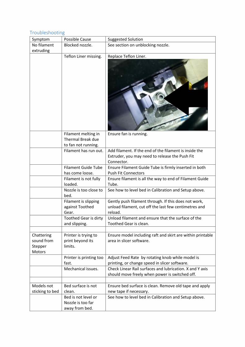
Thermal Break with Teflon Liner: The Thermal Break keeps the heat from the Heat Block from melting the filament further up the tube (which would cause a blockage). If the Teflon Liner is missing, the filament will not feed as the filament will stick to the walls of the Thermal Break.
Fan
Heat
Block
Nozzle
Extruder with
toothed gear(brass)
and idler (steel)
Cable for
thermistor and
heater cartridge.
Linear
Rail (2)
Linear
Bearing (2) Bed Levelling
Screws (4 in total)
Thermal
Break with
Teflon liner
(behind fan) Filament
Guide Tube
Card Slot
Stepper Motor
(4 in total)
Limit Switch
(3 in total) X Axis
Z Axis
Y Axis
Bed
Threaded
Rod
Control
Panel
Z Limit Switch
Adjustment
Toothed
Belt (2)
Main Board
Push-fit
connector (2)
Hot End Assembly
Z Tower

Fan: The fan keeps the Thermal Break cool, and should be running all times the printer is turned on.
Heat Block: The Heat Block is an aluminium block containing a Heater Cartridge and Thermistor, through which the filament feeds and becomes melted before coming out of the nozzle. The Heater Cartridge and Thermistor are kept in place by the Kapton Tape. If either the Heater Cartridge or Thermistor fall out of the Heater Block, they might overheat and catch fire.
Extruder: The Extruder drives the filament by rotating the Toothed Gear, which is engaged by spring pressure from the Idler. If the Idler appear to be stationary while the Toothed Gear is turning, the filament may be slipping due to a blockage or other issue.
Filament Guide Tube: The Filament Guide Tube provides a flexible connection between the Extruder and Nozzle, and should be firmly pushed into the Push Fit Connectors at each end. It can be ordered as spare part TL4115.
Stepper Motors: The Stepper Motors provide the precise positioning necessary to control the printer.
Threaded Rod: The Threaded Rod converts the rotary motion of the Z-Axis Stepper Motor into vertical motion. It is connected to the Z-Axis Stepper Motor via a Flexible Coupler.
Limit Switch: During the homing sequence which should run at the start of each print job, the limit switch for each Axis tells the printer when that Axis is at the zero position.
Push Fit Connector: The Filament Guide Tube is connected to a Push Fit Connector at each end. To attach the Filament Guide Tube to the Push Fit Connector, simply push it in. To remove the Filament Guide Tube from the Push Fit Connector, push the blue ring in until it clicks slightly, then pull back on the Filament Guide Tube. If the Push Fit Connector does not firmly hold the Filament Guide Tube, you may need to cut the small amount of damaged tube off the end to give it a fresh surface to grip onto.
X Axis: The X-Axis describes motion towards and away from the Z-Axis tower. The X-Axis Stepper Motor drives a Toothed Belt which is attached to the Hot End Assembly. Zero on the X-Axis is when the Hot End Assembly is closest to the Z-Axis Tower.
Y Axis: The Y-Axis describes motion towards and away from the Control Panel. The Y-Axis Stepper Motor drives a Toothed Belt which is attached to the Bed. Zero on the Y-Axis is when the Bed is closest to the Control Panel.
Z axis: The Z-Axis described movement of the Hot End up and down. The Z-Axis Stepper Motor drives the Threaded Rod on which the X-Axis Assembly rides. Zero on the Z-Axis is when the X-Axis Assembly and Hot End are down.
Z Tower: The Z-Tower carries the Hot End Assembly up and down. The bracket at the base of the Z-Tower should be firmly attached to the main body of the printer so there is no movement between the two.

Z Limit Switch Adjustment: The Z Limit Switch Adjustment provides fine positioning of the Z Axis, and is critical to ensuring filament adhesion to the Bed. The Z Limit Switch should be activated when the Nozzle is almost touching the Bed (about the thickness of a piece of standard A4 copy paper should be between them). Note that turning the wing-nut anti-clockwise will cause the Nozzle to be higher above the Bed after a homing sequence, and turning the wing-nut clockwise will cause the Nozzle to be closer to the Bed after a homing sequence. Also be sure to hold the body of the bolt while adjusting the wing-nut, so that the bolt doesn’t spin. See the section on Calibration and Setup for more details.
Toothed Belt: The Toothed Belts transfer drive from the Stepper Motors, and should be tight enough that they do not sag. There is no adjustment as the tension springs should keep them tight. If they are sagging, they may have been stretched excessively.
Bed: This is the surface on which melted filament is laid during a print run. The bare aluminium surface does not adhere to filament well, and should be covered with a flat layer of3d Printing Tape such as Jaycar Blue 3d Printing Tape. The Bed must also be kept level through adjustment of the Bed Levelling Screws.
Control Panel: The Control Panel provides an information display and control knob to display the printer status and issue commands.
Linear Rail: The Linear Rails provide a straight, smooth path for the X-Axis and Y-Axis, and should be kept clean by wiping with a lint-free cloth, and occasionally lubricated with a light application of a light machine oil such our NA1022.
Linear Bearing: The Linear Bearings run on the Linear Rails, and like the Linear Rails, should be kept clean by wiping with a lint-free cloth.
Bed Levelling Screws: The Bed Levelling Screws are adjusted to ensure the bed is level. To do this, turn the screw with the Allen key to adjust the height while keeping the wing nut from spinning- clockwise to lower and anti-clockwise to raise. See the section on Calibration and Setup for more details.
Card Slot: Insert a SD card into this slot to print without being tethered to a computer
Main Board: The Main Board provides control of the printer. Its firmware can be updated if necessary.

Calibration and Setup Initial calibration and setup is essential to getting satisfactory prints from the TL4076.
See the User Manual and also the following videos:
Unboxing: https://youtu.be/I4zh_l0QqrM
Setup: https://youtu.be/BI7JMbDgue8
Calibration: https://youtu.be/wH784EjKnq0
Changing Filament: https://youtu.be/0L8ufpYyHpk
Operation: https://youtu.be/pxLXv4DPsG8
Printing: https://youtu.be/BTnk6IrNySI
After removing the unit from the box, place it on a level surface, and install the Filament Guide Tube
by pushing it firmly into the Push Fit Connectors at each end. If you need to remove the Filament
Guide Tube, gently push the blue ring in until it clicks- the Filament Guide Tube should then slide
out.
Check that Z Tower is rigidly attached to the base. There should not be any movement between the
two. If there is movement, you may need to tighten the bolts. The X Carriage and Bed should slide
freely along their Linear Rails, but everything else should be fairly tight.

Lift the Control Panel up and rotate 180 degrees, and sit back in the holes- this will make the display
sit the right way. Then plug the power adaptor into the printer and into a mains socket.
The Calibration process is to ensure that when the Nozzle is at its lowest position (Z=0), it is as close
as possible, but not quite touching the Bed. The process is as follows:
Home Printer (Menu>Prepare>Auto Home)
o This Homes all three Axis, first X, then Y and Z. If any Axis does not hit its Limit Switch, it
may make a grinding sound. In this case, turn off the Printer and check why the Limit
Switch is not being engaged. We are mostly interested in ensuring that the printer is at
Z=0.
Disable Stepper motors (Menu>Prepare>Disable Steppers)
o This allows the X and Y Axis to be moved freely by hand.
Bolts holding
Base to Z Tower

Check Bed height in relation to Nozzle at each corner near Bed Levelling Screw
o If the Bed and Nozzle are touching, loosen the wing nut on the Z Limit Switch
Adjustment and go back to the first step, as the nozzle may be damaged if it crashes
hard into the Bed. Check also that the springs at each Bed Levelling Screw are lightly
compressed as shown below. If necessary, adjust the Z Limit Switch to allow the Bed
Levelling Screws to be adjusted to near this position.
Adjust Bed Levelling Screws and/or Z Limit Switch Adjustment
o Move the Bed and Nozzle around by hand to near each Bed Levelling Screw and adjust
that Bed Levelling Screw so that it is not quite touching (ideally, a piece of copy paper
should just fit between them).
Repeat if necessary
o Usually, the adjustments will interact, so it’s necessary to repeat to ensure that
calibration is correct. If you can do a home and check without having to change
anything, the calibration is good.

Often, it is possible to fine tune the calibration after observing how the printer prints the first few
layers. The below photos give examples of what to do in certain cases.
Filament is very thin, squished into Bed and is difficult to remove. Nozzle is too close to Bed. Either
screw Bed Levelling Screws in (clockwise) or turn wingnut anticlockwise.
Extrusion appears solid and uniform. Filament adheres well but is not too difficult to remove. This is
ideal, and no adjustment is required.

Filament is lifting and not adhering to the bed in spots. Model can be lifted without effort and
without leaving a mark on the bed. Either screw Bed Levelling Screws out (anticlockwise) or turn
wingnut clockwise.
The Filament loading process is detailed in the manual, and this should be the next step. If you need
to detach the Filament Guide Tube to load the filament, so this at the end closest to the Extruder,
otherwise there is the risk of the Teflon Liner coming loose from the Thermal Break.
You may find it easier to remove the Filament Guide Tube at the Extruder end, feed the filament
through the Extruder, and then slide the Filament Guide Tube over the filament and into place at the
Push Fit Connector.

Care and Maintenance Despite its rugged appearance, the 3D Printer is a precision piece of equipment, and should be
treated as such if you expect it to continue to print finely detailed models. In particular, it should be
kept clean and not be dropped or have things dropped on it. By following the care and maintenance
advice here, your printer can perform at its best.
The printer should be kept in an area free of dust, as this will clog up the Linear Rails and Extruder.
Dust can also enter the Extruder and ultimately block the nozzle. The printer will also perform best if
it’s not subject to breezes and drafts, so set up a wind-block if drafts cannot be avoided in the
printer location.
Routine maintenance should include wiping the printer with a clean lint-free cloth, especially the
Linear Rails. A very light application of light machine oil to moving parts such as the Linear Rails and
Threaded Rod will assist smooth operation.
The calibration should also be checked occasionally. You should observe the printer at the start of
each job and you will get an idea of how well the printer is calibrated by how well the first few
printed layers come out. If you see symptoms of poor printing occurring (eg layers too thick or thin
or not adhering), then the calibration should be checked.
Dust collecting
on Linear Rails

Unblocking the Nozzle WARNING: When you are unblocking the nozzle, you will likely have your hands near parts of the
printer that are very hot. If you touch these parts, you will get burned.
WARNING: Never attempt to remove the Nozzle while the Hot End is cold, as the Nozzle will be
‘glued’ to the Hot End with plastic, and will probably snap off, making removal of the remaining
piece of Nozzle very difficult.
One thing that will probably happen no matter how careful you are is that the Nozzle will block.
Symptoms of this might include the Toothed Gear ‘jumping’ or ‘skipping’ steps, or the Idler Gear
stays still while the Toothed Gear is moving. You should also see that no or insufficient filament
comes out of the nozzle, and the print looks ‘stringy’. The first thing you can try while the printer is
running is to gently assist the Extruder by gently pushing the filament into the Filament Guide Tube.
If it’s a small blockage, that might be enough to push past it. Some fine wire like WW4040 Nichrome
Wire could be used to try to clear the Nozzle hole too.
If pushing the filament doesn’t fix the problem, you may need to remove the Nozzle. To do this, we
need the Hot End to be hot enough that the plastic is soft (eg about 200 degrees for PLA), so take
care not be burnt by touching hot parts. Set the Hot End temperature using
Menu>Control>Temperature, and wait for it to reach the set point.
Gently grip the Heat Block with pliers, being careful not to pinch the wires of the Heater Cartridge
and Thermistor, and unscrew the nozzle with another set of pliers. Once the old Nozzle is loose,
leave it on a heat-proof surface to cool. The spare Nozzle can now be threaded into the Heat Block
and tightened. You may need to hold the Push Fit Connector if it doesn’t tighten hard against Heat
Block. Before you start printing with the spare Nozzle, check the calibration, as things may have
moved around slightly.
To unblock the now removed nozzle, after it has cooled, try drilling it out using small drills (eg our 3d
Printing Tool Kit TD2119 has a few small drill bit sizes). You could also try heating the Nozzle with a
gas torch to soften the filament and seeing if the blockage can be pushed out with fine wire. Try
pushing the blockage back up the Nozzle, as it may be too big to come through the tip.
Before reusing the blocked Nozzle, you should be able to see light through the Nozzle- this indicates
that it has been cleared sufficiently.
This guide also describes a technique that we’ve had some success with: http://bukobot.com/nozzle-
cleaning.
Troubleshooting Symptom Possible Cause Suggested Solution
No filament extruding
Blocked nozzle. See section on unblocking nozzle.
Teflon Liner missing. Replace Teflon Liner.
Filament melting in
Thermal Break due to fan not running.
Ensure fan is running.
Filament has run out. Add filament. If the end of the filament is inside the Extruder, you may need to release the Push Fit Connector.
Filament Guide Tube has come loose.
Ensure Filament Guide Tube is firmly inserted in both Push Fit Connectors
Filament is not fully loaded.
Ensure filament is all the way to end of Filament Guide Tube.
Nozzle is too close to bed.
See how to level bed in Calibration and Setup above.
Filament is slipping against Toothed Gear.
Gently push filament through. If this does not work, unload filament, cut off the last few centimetres and reload.
Toothed Gear is dirty and slipping.
Unload filament and ensure that the surface of the Toothed Gear is clean.
Chattering sound from Stepper Motors
Printer is trying to print beyond its limits.
Ensure model including raft and skirt are within printable area in slicer software.
Printer is printing too fast.
Adjust Feed Rate by rotating knob while model is printing, or change speed in slicer software.
Mechanical issues. Check Linear Rail surfaces and lubrication. X and Y axis should move freely when power is switched off.
Models not sticking to bed
Bed surface is not clean.
Ensure bed surface is clean. Remove old tape and apply new tape if necessary.
Bed is not level or Nozzle is too far away from bed.
See how to level bed in Calibration and Setup above.

Printer is printing too fast.
Adjust Feed Rate by rotating knob while model is printing, or change speed in slicer software.
Nozzle Temperature is incorrect.
Try a different Nozzle Temperature (up to 220 degrees on PLA)
Gaps in Model Partial Blockage in nozzle.
See section on unblocking nozzle.
Incorrect filament diameter in slicer software.
Check filament diameter in slicer software, and if necessary, adjust filament multiplier.
Layers are shifted
Printer is printing too fast.
Adjust Feed Rate by rotating knob while model is printing, or change speed in slicer software.
Mechanical issues. Check Linear Rail surfaces and lubrication. X and Y axis should move freely when power is switched off.
Nozzle is catching on warping parts of model.
Try adding rafts or supports in slicer software.
Models are warping
Excessive Airflow past Printer.
Ensure Printer does not have excessive airflow (especially cold air from an air conditioner). Add a shield to block air flow if necessary.
Nozzle temperature too high.
Change Nozzle temperature in slicer software.
Model tends to warp Add a raft or supports in the slicer software settings.