Embed Size (px)
Citation preview

Directed Digital System
TL2Firmware Specific Guide
This product is intended for installation by a professional installer only! Attempts to install this product by a person other than a trained professional may result in severe damage to a vehicle’s electrical system and components.
© 2015 Directed, Vista, CA Directed Digital System 2015-07
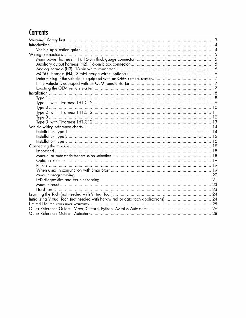
ContentsWarning! Safety first ....................................................................................................................... 3Introduction .................................................................................................................................... 4
Vehicle application guide ........................................................................................................... 4Wiring connections ......................................................................................................................... 5
Main power harness (H1), 12-pin thick gauge connector ............................................................... 5Auxiliary output harness (H2), 16-pin black connector ................................................................... 5Analog harness (H3), 18-pin white connector ............................................................................... 6MC501 harness (H4), 8 thick-gauge wires (optional) ..................................................................... 6Determining if the vehicle is equipped with an OEM remote starter.................................................. 7If the vehicle is equipped with an OEM remote starter .................................................................... 7Locating the OEM remote starter ................................................................................................. 7
Installation ...................................................................................................................................... 8Type 1 ..................................................................................................................................... 8Type 1 (with T-Harness THTLC12) ................................................................................................ 9Type 2 ................................................................................................................................... 10Type 2 (with T-Harness THTLC12) .............................................................................................. 11Type 3 ................................................................................................................................... 12Type 3 (with T-Harness THTLC12) .............................................................................................. 13
Vehicle wiring reference charts ....................................................................................................... 14Installation Type 1 ................................................................................................................... 14Installation Type 2 ................................................................................................................... 15Installation Type 3 ................................................................................................................... 16
Connecting the module .................................................................................................................. 18Important! .............................................................................................................................. 18Manual or automatic transmission selection ................................................................................ 18Optional sensors ..................................................................................................................... 19RF kits .................................................................................................................................... 19When used in conjunction with SmartStart .................................................................................. 19Module programming .............................................................................................................. 20LED diagnostics and troubleshooting .......................................................................................... 21Module reset .......................................................................................................................... 23Hard reset .............................................................................................................................. 23
Learning the Tach (not needed with Virtual Tach) ............................................................................... 24Initializing Virtual Tach (not needed with hardwired or data tach applications) ..................................... 24Limited lifetime consumer warranty .................................................................................................. 25Quick Reference Guide – Viper, Clifford, Python, Avital & Automate.................................................... 26Quick Reference Guide – Autostart .................................................................................................. 28
3 Directed Digital System TL2© 2015 Directed. All rights reserved.
Warning! Safety firstThe following safety warnings must be observed at all times:
• Due to the complexity of this system, installation of this product must only be performed by an authorized Directed dealer.
• When properly installed, this system can start the vehicle via a command signal from the remote control. Therefore, never operate the system in an area that does not have adequate ventilation.
The following precautions are the sole responsibility of the user; however, authorized Directed dealers should:• Never use a test light or logic probe when installing this unit. Always use a multimeter. • Never operate the system in an enclosed or partially enclosed area without ventilation (such as a garage). • When parking in an enclosed or partially enclosed area or when having the vehicle serviced, the
remote start system must be disabled using the installed toggle switch. It is the user’s sole responsibility to properly handle and keep out of reach from children all remote controls to assure that the system does not unintentionally remote start the vehicle.
• USER MUST INSTALL A CARBON MONOXIDE DETECTOR IN OR ABOUT THE LIVING AREA ADJACENT TO THE VEHICLE. ALL DOORS LEADING FROM ADJACENT LIVING AREAS TO THE ENCLOSED OR PARTIALLY ENCLOSED VEHICLE STORAGE AREA MUST REMAIN CLOSED AT ALL TIMES.
Use of this product in a manner contrary to its intended mode of operation may result in property damage, personal injury, or death. Except when performing the Safety Check outlined in this installation guide, (1) Never remotely start the vehicle with the vehicle in gear, and (2) Never remotely start the vehicle with the keys in the ignition. The user is responsible for having the neutral safety feature of the vehicle periodically checked, wherein the vehicle must not remotely start while the car is in gear. This testing should be performed by an authorized Directed dealer in accordance with the Safety Check outlined in this product installation guide. If the vehicle starts in gear, cease remote start operation immediately and consult with the user to fix the problem immediately.
OPERATION OF THE REMOTE START MODULE IF THE VEHICLE STARTS IN GEAR IS CONTRARY TO ITS INTENDED MODE OF OPERATION. OPERATING THE REMOTE START SYSTEM UNDER THESE CONDITIONS MAY RESULT IN PROPERTY DAMAGE OR PERSONAL INJURY. IMMEDIATELY CEASE THE USE OF THE UNIT AND REPAIR OR DISCONNECT THE INSTALLED REMOTE START MODULE. DIRECTED WILL NOT BE HELD RESPONSIBLE OR PAY FOR INSTALLATION OR REINSTALLATION COSTS.
Remote starters for manual transmission pose significant risks if not properly installed and operated. When testing to ensure the installation is working properly, only remote start the vehicle in neutral gear, on a flat surface and with a functional, fully engaged parking brake. Do not allow anyone to stand in front of or behind the vehicle.
This product should not be installed in any convertible vehicles, soft or hard top with a manual transmission. Installation in such vehicles may pose certain risk.
4 Directed Digital System TL2© 2015 Directed. All rights reserved.
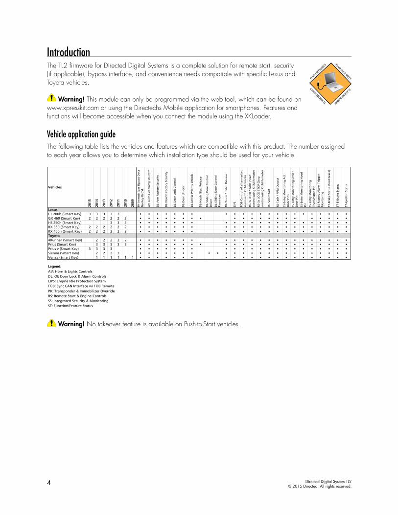
IntroductionThe TL2 firmware for Directed Digital Systems is a complete solution for remote start, security (if applicable), bypass interface, and convenience needs compatible with specific Lexus and Toyota vehicles.
Warning! This module can only be programmed via the web tool, which can be found on www.xpresskit.com or using the Directechs Mobile application for smartphones. Features and functions will become accessible when you connect the module using the XKLoader.
Vehicle application guideThe following table lists the vehicles and features which are compatible with this product. The number assigned to each year allows you to determine which installation type should be used for your vehicle.
Warning! No takeover feature is available on Push-to-Start vehicles.
Vehicles
2015
2014
2013
2012
2011
2010
2009
PK-I
mm
ob
ilize
r B
ypas
s-D
ata
No
Key
Req
'd
AV
-Au
to H
ead
lam
p S
hu
toff
DL-
Arm
Fac
tory
Sec
uri
ty
DL-
Dis
arm
Fac
tory
Sec
uri
ty
DL-
Do
or
Lock
Co
ntr
ol
DL-
Do
or
Un
lock
DL-
Dri
ver
Prio
rity
Un
lock
DL-
Hat
ch G
lass
Rel
ease
DL-
Slid
ing
Do
or
Co
ntr
ol
Dri
ver
DL-
Slid
ing
Do
or
Co
ntr
ol
Pass
eng
er
DL-
Tru
nk
/ Hat
ch R
elea
se
EIPS
FOB
-Co
ntr
ol o
f af
term
arke
t al
arm
wit
h O
EM r
emo
te
RS-
3x L
OC
K S
TAR
T (S
tart
co
ntr
ol u
sin
g O
EM R
emo
te)
RS-
3x L
OC
K S
TOP
(Sto
p
con
tro
l usi
ng
OEM
Rem
ote
)
RS-
Smar
tSta
rt
RS-
Tach
/ R
PM O
utp
ut
SS-E
ntr
y M
on
ito
rin
g A
LL
Do
or
Pin
s
SS-E
ntr
y M
on
ito
rin
g D
rive
r D
oo
r Pi
n
SS-E
ntr
y M
on
ito
rin
g H
oo
d
Pin
SS-E
ntr
y M
on
ito
rin
g
Tru
nk/
Hat
ch P
in
SS-F
acto
ry A
larm
Tri
gg
er
Mo
nit
ori
ng
ST-B
rake
Sta
tus
(fo
ot
bra
ke)
ST-E
-Bra
ke S
tatu
s
ST-I
gn
itio
n S
tatu
s
LexusCT 200h (Smart Key) 3 3 3 3 3 • • • • • • • • • • • • • • • • • • • • • •GX 460 (Smart Key) 2 2 2 2 2 2 • • • • • • • • • • • • • • • • • • • • •HS 250h (Smart Key) 3 3 3 • • • • • • • • • • • • • • • • • • • • • •RX 350 (Smart Key) 2 2 2 2 2 2 • • • • • • • • • • • • • • • • • • • • • •RX 450h (Smart Key) 2 2 2 2 2 2 • • • • • • • • • • • • • • • • • • • • • •Toyota4Runner (Smart Key) 2 2 2 2 2 • • • • • • • • • • • • • • • • • • • • • •Prius (Smart Key) 3 3 3 3 3 • • • • • • • • • • • • • • • • • • • • • • •Prius v (Smart Key) 3 3 3 3 • • • • • • • • • • • • • • • • • • • • • •Sienna (Smart Key) 2 2 2 2 • • • • • • • • • • • • • • • • • • • • • • • •Venza (Smart Key) 1 1 1 1 1 1 • • • • • • • • • • • • • • • • • • • • • •
Legend:AV: Horn & Lights ControlsDL: OE Door Lock & Alarm ControlsEIPS: Engine Idle Protection SystemFOB: Sync CAN Interface w/ FOB RemotePK: Transponder & Immobilizer OverrideRS: Remote Start & Engine ControlsSS: Integrated Security & MonitoringST: Function/Feature Status
5 Directed Digital System TL2© 2015 Directed. All rights reserved.
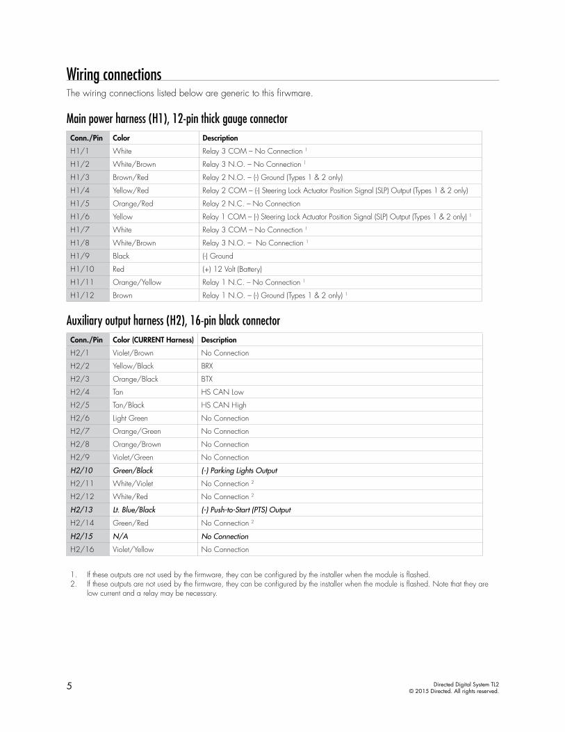
Wiring connectionsThe wiring connections listed below are generic to this firwmare.
Main power harness (H1), 12-pin thick gauge connectorConn./Pin Color Description
H1/1 White Relay 3 COM – No Connection 1
H1/2 White/Brown Relay 3 N.O. – No Connection 1
H1/3 Brown/Red Relay 2 N.O. – (-) Ground (Types 1 & 2 only)
H1/4 Yellow/Red Relay 2 COM – (-) Steering Lock Actuator Position Signal (SLP) Output (Types 1 & 2 only)
H1/5 Orange/Red Relay 2 N.C. – No Connection
H1/6 Yellow Relay 1 COM – (-) Steering Lock Actuator Position Signal (SLP) Output (Types 1 & 2 only) 1
H1/7 White Relay 3 COM – No Connection 1
H1/8 White/Brown Relay 3 N.O. – No Connection 1
H1/9 Black (-) Ground
H1/10 Red (+) 12 Volt (Battery)
H1/11 Orange/Yellow Relay 1 N.C. – No Connection 1
H1/12 Brown Relay 1 N.O. – (-) Ground (Types 1 & 2 only) 1
Auxiliary output harness (H2), 16-pin black connectorConn./Pin Color (CURRENT Harness) Description
H2/1 Violet/Brown No Connection
H2/2 Yellow/Black BRX
H2/3 Orange/Black BTX
H2/4 Tan HS CAN Low
H2/5 Tan/Black HS CAN High
H2/6 Light Green No Connection
H2/7 Orange/Green No Connection
H2/8 Orange/Brown No Connection
H2/9 Violet/Green No Connection
H2/10 Green/Black (-) Parking Lights Output
H2/11 White/Violet No Connection 2
H2/12 White/Red No Connection 2
H2/13 Lt. Blue/Black (-) Push-to-Start (PTS) Output
H2/14 Green/Red No Connection 2
H2/15 N/A No Connection
H2/16 Violet/Yellow No Connection
1. If these outputs are not used by the firmware, they can be configured by the installer when the module is flashed.2. If these outputs are not used by the firmware, they can be configured by the installer when the module is flashed. Note that they are
low current and a relay may be necessary.
6 Directed Digital System TL2© 2015 Directed. All rights reserved.
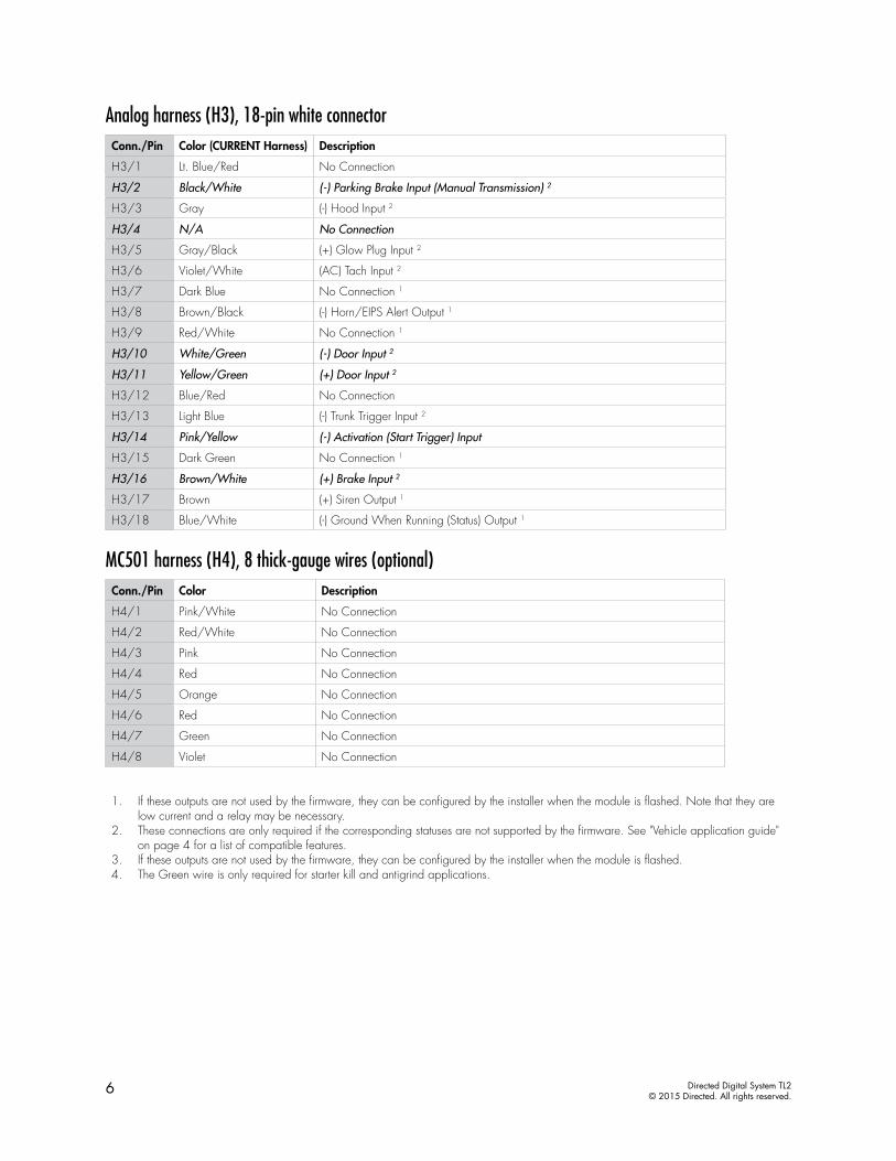
Analog harness (H3), 18-pin white connectorConn./Pin Color (CURRENT Harness) Description
H3/1 Lt. Blue/Red No Connection
H3/2 Black/White (-) Parking Brake Input (Manual Transmission) 2
H3/3 Gray (-) Hood Input 2
H3/4 N/A No Connection
H3/5 Gray/Black (+) Glow Plug Input 2
H3/6 Violet/White (AC) Tach Input 2
H3/7 Dark Blue No Connection 1
H3/8 Brown/Black (-) Horn/EIPS Alert Output 1
H3/9 Red/White No Connection 1
H3/10 White/Green (-) Door Input 2
H3/11 Yellow/Green (+) Door Input 2
H3/12 Blue/Red No Connection
H3/13 Light Blue (-) Trunk Trigger Input 2
H3/14 Pink/Yellow (-) Activation (Start Trigger) Input
H3/15 Dark Green No Connection 1
H3/16 Brown/White (+) Brake Input 2
H3/17 Brown (+) Siren Output 1
H3/18 Blue/White (-) Ground When Running (Status) Output 1
MC501 harness (H4), 8 thick-gauge wires (optional)Conn./Pin Color Description
H4/1 Pink/White No Connection
H4/2 Red/White No Connection
H4/3 Pink No Connection
H4/4 Red No Connection
H4/5 Orange No Connection
H4/6 Red No Connection
H4/7 Green No Connection
H4/8 Violet No Connection
1. If these outputs are not used by the firmware, they can be configured by the installer when the module is flashed. Note that they are low current and a relay may be necessary.
2. These connections are only required if the corresponding statuses are not supported by the firmware. See "Vehicle application guide" on page 4 for a list of compatible features.
3. If these outputs are not used by the firmware, they can be configured by the installer when the module is flashed. 4. The Green wire is only required for starter kill and antigrind applications.
7 Directed Digital System TL2© 2015 Directed. All rights reserved.
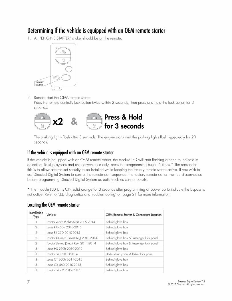
Determining if the vehicle is equipped with an OEM remote starter1. An “ENGINE STARTER” sticker should be on the remote.
2. Remote start the OEM remote starter:Press the remote control’s lock button twice within 2 seconds, then press and hold the lock button for 3 seconds.
The parking lights flash after 3 seconds. The engine starts and the parking lights flash repeatedly for 20 seconds.
If the vehicle is equipped with an OEM remote starterIf the vehicle is equipped with an OEM remote starter, the module LED will start flashing orange to indicate its detection. To skip bypass and use convenience only, press the programming button 5 times.* The reason for this is to allow aftermarket security to be installed while keeping the factory remote starter active. If you wish to use Directed Digital System to control the remote start sequence, the factory remote starter must be disconnected before programming Directed Digital System as both modules cannot coexist.
* The module LED turns ON solid orange for 3 seconds after programming or power up to indicate the bypass is not active. Refer to "LED diagnostics and troubleshooting" on page 21 for more information.
Locating the OEM remote starterInstallation
Type Vehicle OEM Remote Starter & Connectors Location
1 Toyota Venza Push-to-Start 2009-2014 Behind glove box
2 Lexus RX 450h 2010-2015 Behind glove box
2 Lexus RX 350 2010-2015 Behind glove box
2 Toyota 4Runner (Smart Key) 2010-2014 Behind glove box & Passenger kick panel
2 Toyota Sienna (Smart Key) 2011-2014 Behind glove box & Passenger kick panel
3 Lexus HS 250h 2010-2012 Behind glove box
3 Toyota Prius 2010-2014 Under dash panel & Driver kick panel
3 Lexus CT 200h 2011-2015 Behind glove box
3 Lexus GX 460 2010-2015 Behind glove box
3 Toyota Prius V 2012-2015 Behind glove box
8 Directed Digital System TL2© 2015 Directed. All rights reserved.
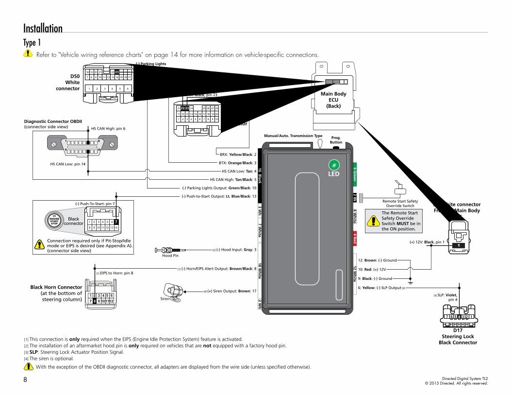
InstallationType 1
Refer to "Vehicle wiring reference charts" on page 14 for more information on vehicle-specific connections.
1235 47 6
16
8
9
1
Diagnostic Connector OBDII(connector side view)
HS CAN Low: pin 14
[1] EIPS to Horn: pin 8
(+) 12V: Black, pin 1
[3] SLP: Violet,pin 4
HS CAN High: pin 6
HS CAN Low: Tan: 4
BRX: Yellow/Black: 2
BTX: Orange/Black: 3
HS CAN High: Tan/Black: 5
(-) Push-to-Start Output: Lt. Blue/Black: 13
[1] (-) Horn/EIPS Alert Output: Brown/Black: 8
9: Black: (-) Ground
12: Brown: (-) Ground
6: Yellow: (-) SLP Output [3]
10: Red: (+) 12V
D17Steering Lock
Black Connector
2A White connector Front of Main Body
ECU
Black Horn Connector(at the bottom of steering column) 101112987
1 2 3 4 5 6
(-) Parking LightsRed, pin 23
BRX: Black, pin 23
BTX: Blue, pin 22
With the exception of the OBDII diagnostic connector, all adapters are displayed from the wire side (unless specified otherwise).
[1] This connection is only required when the EIPS (Engine Idle Protection System) feature is activated.
The Remote Start Safety Override Switch MUST be in the ON position.
Remote Start SafetyOverride Switch
1
[2] The installation of an aftermarket hood pin is only required on vehicles that are not equipped with a factory hood pin.[3] SLP: Steering Lock Actuator Position Signal.
Hood Pin
[2] (-) Hood Input: Gray: 3
(-) Parking Lights Output: Green/Black: 10
Main Body ECU
(Back)
22 2618
107
25
13 14 16 178
21
9 11 12 15
24
1 2 3 4 5 6
2319 20
13 15 16 18
23 26
14 17
24 25
5 6 7 8 9 104321
12 201911
22 282721 22 23
D50White
connector
D49White connector
[4] The siren is optional.
[4] (+) Siren Output: Brown: 17
Siren
15431
8 11 12109 14
6
13
2ENGINESTARTSTOP 7Black
connector
Connection required only if Pit-Stop/Idle mode or EIPS is desired (see Appendix A).(connector side view)
(-) Push-To-Start: pin 7
16 Black
3 Wh
4 Wh
ite12 W
hite
4 Red
7 Wh
ite2 W
h
2 Bk
6 Green
18 Wh
ite
Manual/Auto. Transmission Type Prog.Button
Manual/Auto. Transmission Type Prog.Button
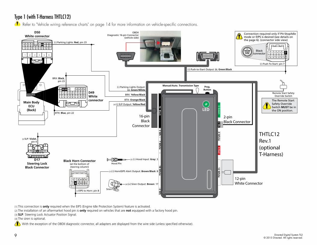
9 Directed Digital System TL2© 2015 Directed. All rights reserved.
Type 1 (with T-Harness THTLC12) Refer to "Vehicle wiring reference charts" on page 14 for more information on vehicle-specific connections.
[2] (-) Hood Input: Gray: 3
The Remote Start Safety Override Switch MUST be in the ON position.
Remote Start SafetyOverride Switch
[4] (+) Siren Output: Brown: 17
Siren
THTLC12Rev.1(optionalT-Harness)
12-pin White Connector
16-pinBlack
Connector
2-pin Black Connector
Hood Pin
(-) Push-to-Start Output: Lt. Green/Black
Connection required only if Pit-Stop/Idle mode or EIPS is desired (see details on the page 6). (connector side view)
(-) Push-To-Start: pin 7
BRX: Yellow/Black
(-) Parking Lights Output:Lt. Green/White
BTX: Orange/Black
1235 47 6
[1] EIPS to Horn: pin 8
[3] SLP: Violet,pin 4
[1] (-) Horn/EIPS Alert Output: Brown/Black: 8
[3] (-) SLP Output: Yellow/Red
D17Steering Lock
Black Connector
Black Horn Connector(at the bottom of steering column)
1011129871 2 3 4 5 6
(-) Parking Lights: Red, pin 23
BRX: Black,pin 23
BTX: Blue, pin 22
Main Body ECU
(Back)
D50White connector
D49Whiteconnector
D50 D49
OBDIIDiagnostic 16-pin Connector
(vehicle side)
22 2618
107
25
13 14 16 178
21
9 11 12 15
24
1 2 3 4 5 6
2319 20
21
13 15 16 18
23 26
14 17
24 25
5 6 7 8 9 104321
12 201911
22 282722 23
15431
8 11 12109 14
6
13
2ENGINESTARTSTOP 7Black
connector
With the exception of the OBDII diagnostic connector, all adapters are displayed from the wire side (unless specified otherwise).
[1] This connection is only required when the EIPS (Engine Idle Protection System) feature is activated.[2] The installation of an aftermarket hood pin is only required on vehicles that are not equipped with a factory hood pin.[3] SLP: Steering Lock Actuator Position Signal.[4] The siren is optional.
16 Black
3 Wh
4 Wh
ite12 W
hite
4 Red
7 Wh
ite2 W
h
2 Bk
6 Green
18 Wh
ite
Manual/Auto. Transmission Type Prog.Button
Manual/Auto. Transmission Type Prog.Button
10 Directed Digital System TL2© 2015 Directed. All rights reserved.
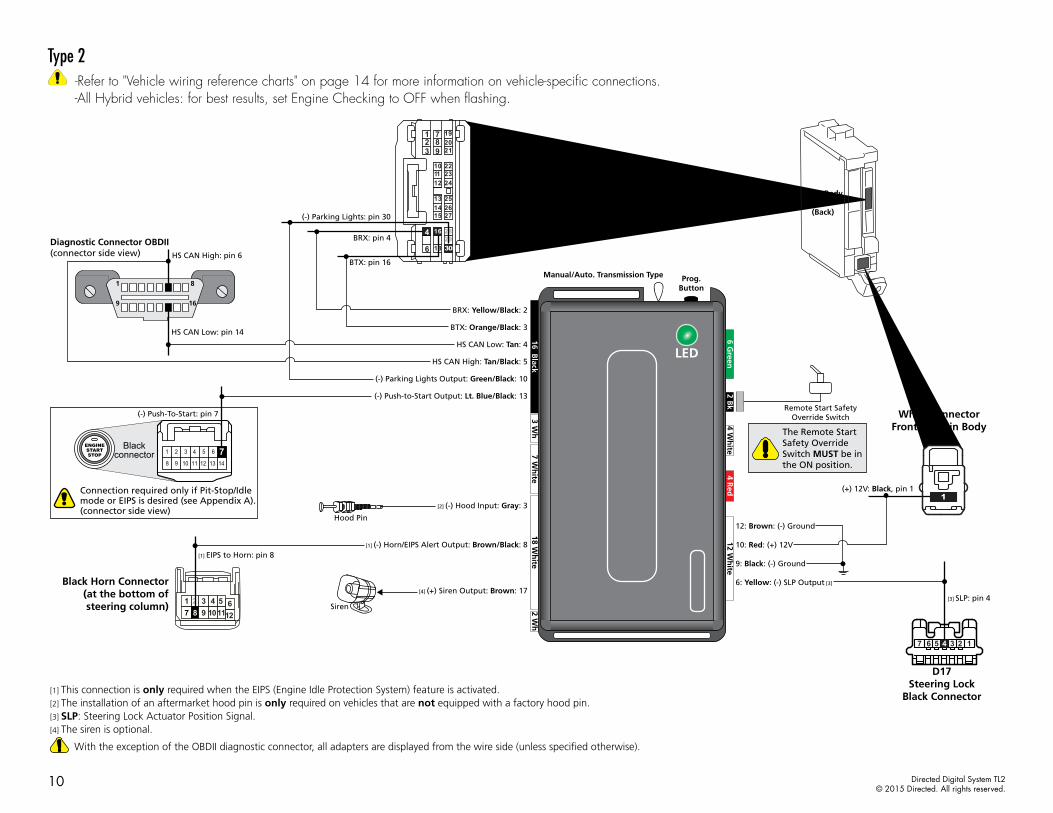
Type 2 -Refer to "Vehicle wiring reference charts" on page 14 for more information on vehicle-specific connections.-All Hybrid vehicles: for best results, set Engine Checking to OFF when flashing.
1235 47 6
16
8
9
1
Diagnostic Connector OBDII(connector side view)
HS CAN Low: pin 14
(+) 12V: Black, pin 1
[3] SLP: pin 4
HS CAN High: pin 6
HS CAN Low: Tan: 4
BRX: Yellow/Black: 2
BTX: Orange/Black: 3
HS CAN High: Tan/Black: 5
D17Steering Lock
Black Connector
White connector Front of Main Body
ECU
BRX: pin 4
With the exception of the OBDII diagnostic connector, all adapters are displayed from the wire side (unless specified otherwise).
The Remote Start Safety Override Switch MUST be in the ON position.
Remote Start SafetyOverride Switch
1
Hood Pin
[2] (-) Hood Input: Gray: 3
White connector Main Body
ECU(Back)
1 72 83
6
9 21
22
25
10
13
23
26
11
14
29
24
27
12
15
18
2019
30
4 16 28
(-) Parking Lights: pin 30
BTX: pin 16
9: Black: (-) Ground
12: Brown: (-) Ground
6: Yellow: (-) SLP Output [3]
10: Red: (+) 12V[1] EIPS to Horn: pin 8
[1] (-) Horn/EIPS Alert Output: Brown/Black: 8
Black Horn Connector(at the bottom of steering column) 101112987
1 2 3 4 5 6
(-) Push-to-Start Output: Lt. Blue/Black: 13
[1] This connection is only required when the EIPS (Engine Idle Protection System) feature is activated.[2] The installation of an aftermarket hood pin is only required on vehicles that are not equipped with a factory hood pin.[3] SLP: Steering Lock Actuator Position Signal.
(-) Parking Lights Output: Green/Black: 10
[4] The siren is optional.
[4] (+) Siren Output: Brown: 17
Siren
15431
8 11 12109 14
6
13
2ENGINESTARTSTOP 7Black
connector
Connection required only if Pit-Stop/Idle mode or EIPS is desired (see Appendix A).(connector side view)
(-) Push-To-Start: pin 7
16 Black
3 Wh
4 Wh
ite12 W
hite
4 Red
7 Wh
ite2 W
h
2 Bk
6 Green
18 Wh
ite
Manual/Auto. Transmission Type Prog.Button
Manual/Auto. Transmission Type Prog.Button
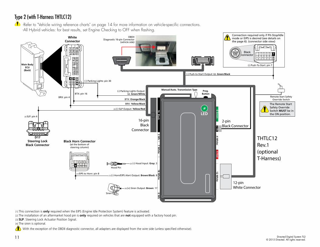
11 Directed Digital System TL2© 2015 Directed. All rights reserved.
Type 2 (with T-Harness THTLC12) -Refer to "Vehicle wiring reference charts" on page 14 for more information on vehicle-specific connections.-All Hybrid vehicles: for best results, set Engine Checking to OFF when flashing.
[2] (-) Hood Input: Gray: 3
The Remote Start Safety Override Switch MUST be in the ON position.
Remote Start SafetyOverride Switch
[4] (+) Siren Output: Brown: 17
Siren
THTLC12Rev.1(optionalT-Harness)
12-pin White Connector
16-pinBlack
Connector
2-pin Black Connector
Hood Pin
1235 47 6
[1] EIPS to Horn: pin 8
[3] SLP: pin 4
[1] (-) Horn/EIPS Alert Output: Brown/Black: 8
D17Steering Lock
Black ConnectorBlack Horn Connector
(at the bottom of steering column)
1011129871 2 3 4 5 6
BRX: pin 4
White Connector
Main Body ECU
(Back)
1 72 83
6
9 21
22
25
10
13
23
26
11
14
29
24
27
12
15
18
2019
30
4 16 28(-) Parking Lights: pin 30
BTX: pin 16
BRX: Yellow/Black
(-) Parking Lights Output:Lt. Green/White
BTX: Orange/Black
[3] (-) SLP Output: Yellow/Red
OBDIIDiagnostic 16-pin Connector
(vehicle side)
(-) Push-to-Start Output: Lt. Green/Black
Connection required only if Pit-Stop/Idle mode or EIPS is desired (see details on the page 6). (connector side view)
(-) Push-To-Start: pin 7
15431
8 11 12109 14
6
13
2ENGINESTARTSTOP 7Black
connector
With the exception of the OBDII diagnostic connector, all adapters are displayed from the wire side (unless specified otherwise).
[1] This connection is only required when the EIPS (Engine Idle Protection System) feature is activated.[2] The installation of an aftermarket hood pin is only required on vehicles that are not equipped with a factory hood pin.[3] SLP: Steering Lock Actuator Position Signal.[4] The siren is optional.
16 Black
3 Wh
4 Wh
ite12 W
hite
4 Red
7 Wh
ite2 W
h
2 Bk
6 Green
18 Wh
ite
Manual/Auto. Transmission Type Prog.Button
Manual/Auto. Transmission Type Prog.Button
12 Directed Digital System TL2© 2015 Directed. All rights reserved.
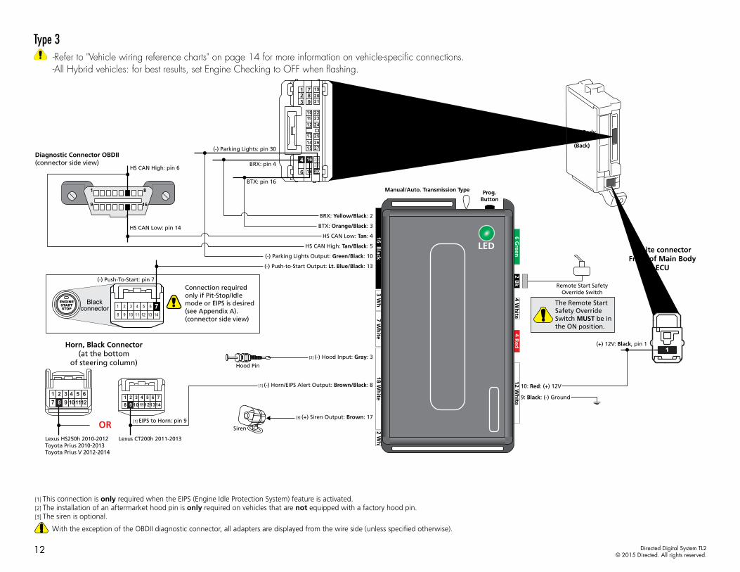
Type 3 -Refer to "Vehicle wiring reference charts" on page 14 for more information on vehicle-specific connections.-All Hybrid vehicles: for best results, set Engine Checking to OFF when flashing.
16
8
9
1
Diagnostic Connector OBDII(connector side view)
HS CAN Low: pin 14
(+) 12V: Black, pin 1
HS CAN High: pin 6
HS CAN Low: Tan: 4
BRX: Yellow/Black: 2
BTX: Orange/Black: 3
HS CAN High: Tan/Black: 5
[1] EIPS to Horn: pin 9
Lexus CT200h 2011-2013Lexus HS250h 2010-2012Toyota Prius 2010-2013Toyota Prius V 2012-2014
9: Black: (-) Ground
10: Red: (+) 12V
White connector Front of Main Body
ECU
BRX: pin 4
With the exception of the OBDII diagnostic connector, all adapters are displayed from the wire side (unless specified otherwise).
[1] This connection is only required when the EIPS (Engine Idle Protection System) feature is activated.
The Remote Start Safety Override Switch MUST be in the ON position.
Remote Start SafetyOverride Switch
[2] The installation of an aftermarket hood pin is only required on vehicles that are not equipped with a factory hood pin.
White connector
Horn, Black Connector (at the bottom
of steering column)
Main Body ECU
(Back)
1 72 83
6
9 21
22
25
10
13
23
26
11
14
29
24
27
12
15
18
2019
30
4 16 28
(-) Parking Lights: pin 30
BTX: pin 16
OR
1011129871 2 3 4 5 6
1110981 2 3 4 5 6 7
121314
Hood Pin
[2] (-) Hood Input: Gray: 3
[1] (-) Horn/EIPS Alert Output: Brown/Black: 8
(-) Push-to-Start Output: Lt. Blue/Black: 13
(-) Parking Lights Output: Green/Black: 10
[3] The siren is optional.
[3] (+) Siren Output: Brown: 17
Siren
1
15431
8 11 12109 14
6
13
2ENGINESTARTSTOP 7Black
connector
Connection required only if Pit-Stop/Idle mode or EIPS is desired (see Appendix A). (connector side view)
(-) Push-To-Start: pin 7
16 Black
3 Wh
4 Wh
ite12 W
hite
4 Red
7 Wh
ite2 W
h
2 Bk
6 Green
18 Wh
ite
Manual/Auto. Transmission Type Prog.Button
Manual/Auto. Transmission Type Prog.Button
13 Directed Digital System TL2© 2015 Directed. All rights reserved.
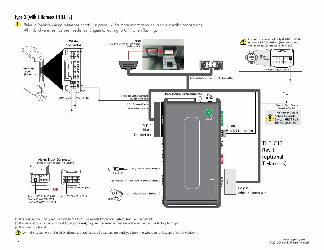
Type 3 (with T-Harness THTLC12) -Refer to "Vehicle wiring reference charts" on page 14 for more information on vehicle-specific connections.-All Hybrid vehicles: for best results, set Engine Checking to OFF when flashing.
[2] (-) Hood Input: Gray: 3
The Remote Start Safety Override Switch MUST be in the ON position.
Remote Start SafetyOverride Switch
[3] (+) Siren Output: Brown: 17
Siren
THTLC12Rev.1(optionalT-Harness)
12-pin White Connector
16-pinBlack
Connector
2-pin Black Connector
Hood Pin
[1] (-) Horn/EIPS Alert Output: Brown/Black: 8
White Connector
Main Body ECU
(Back)
1 72 83
6
9 21
22
25
10
13
23
26
11
14
29
24
27
12
15
18
2019
30
4 16 28
[1] EIPS to Horn: pin 9
Horn, Black Connector (at the bottom of steering column)
OR
1011129871 2 3 4 5 6
1110981 2 3 4 5 6 7
121314
OBDIIDiagnostic 16-pin Connector
(vehicle side)
(-) Push-to-Start Output: Lt. Green/Black
BRX: pin 4 BTX: pin 16
BRX: Yellow/Black
(-) Parking Lights Output:Lt. Green/White
BTX: Orange/Black
Lexus CT200h 2011-2013Lexus HS250h 2010-2012Toyota Prius 2010-2013Toyota Prius V 2012-2014
Connection required only if Pit-Stop/Idle mode or EIPS is desired (see details on the page 6). (connector side view)
(-) Push-To-Start: pin 7
15431
8 11 12109 14
6
13
2ENGINESTARTSTOP 7Black
connector
With the exception of the OBDII diagnostic connector, all adapters are displayed from the wire side (unless specified otherwise).
[1] This connection is only required when the EIPS (Engine Idle Protection System) feature is activated.[2] The installation of an aftermarket hood pin is only required on vehicles that are not equipped with a factory hood pin.[3] The siren is optional.
16 Black
3 Wh
4 Wh
ite12 W
hite
4 Red
7 Wh
ite2 W
h
2 Bk
6 Green
18 Wh
ite
Manual/Auto. Transmission Type Prog.Button
Manual/Auto. Transmission Type Prog.Button
14 Directed Digital System TL2© 2015 Directed. All rights reserved.
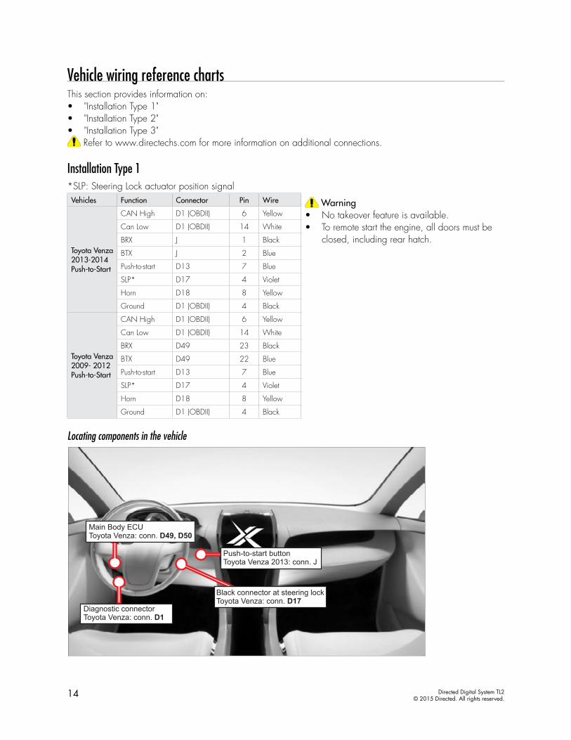
Vehicle wiring reference chartsThis section provides information on:• "Installation Type 1"• "Installation Type 2"• "Installation Type 3"
Refer to www.directechs.com for more information on additional connections.
Installation Type 1*SLP: Steering Lock actuator position signalVehicles Function Connector Pin Wire Warning
• No takeover feature is available. • To remote start the engine, all doors must be
closed, including rear hatch.Toyota Venza 2013-2014 Push-to-Start
CAN High D1 (OBDII) 6 Yellow
Can Low D1 (OBDII) 14 White
BRX J 1 Black
BTX J 2 Blue
Push-to-start D13 7 Blue
SLP* D17 4 Violet
Horn D18 8 Yellow
Ground D1 (OBDII) 4 Black
Toyota Venza 2009- 2012 Push-to-Start
CAN High D1 (OBDII) 6 Yellow
Can Low D1 (OBDII) 14 White
BRX D49 23 Black
BTX D49 22 Blue
Push-to-start D13 7 Blue
SLP* D17 4 Violet
Horn D18 8 Yellow
Ground D1 (OBDII) 4 Black
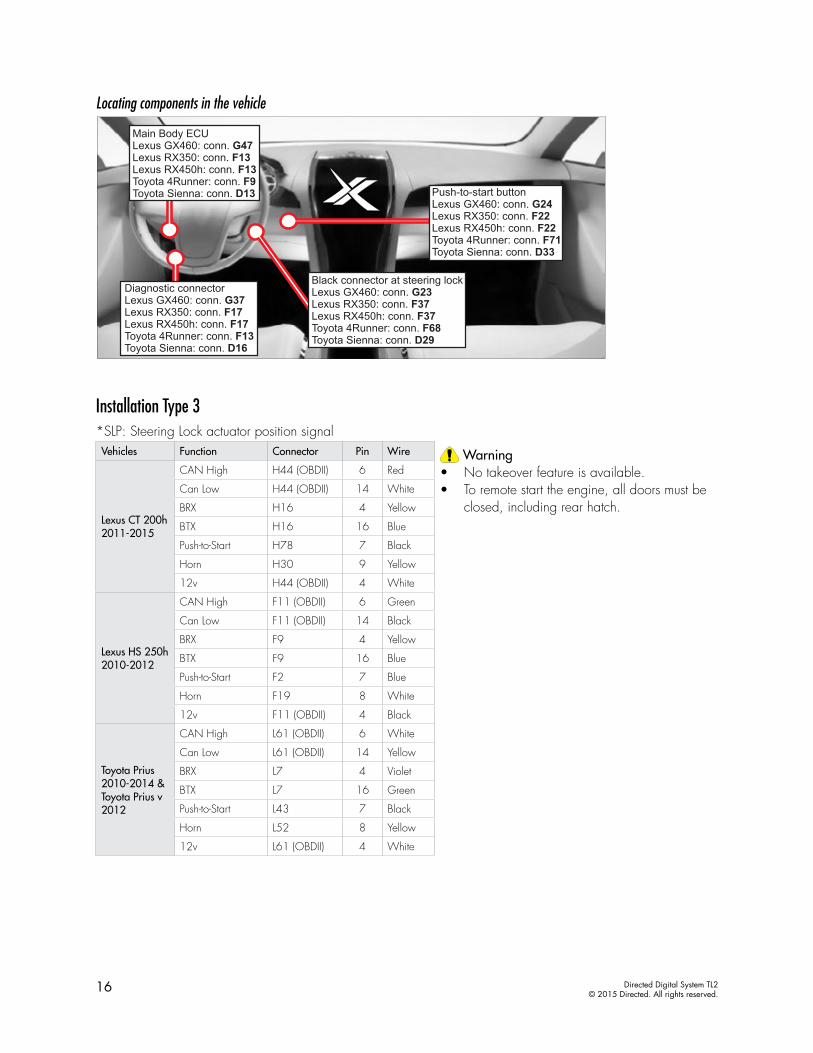
Locating components in the vehicle
15 Directed Digital System TL2© 2015 Directed. All rights reserved.
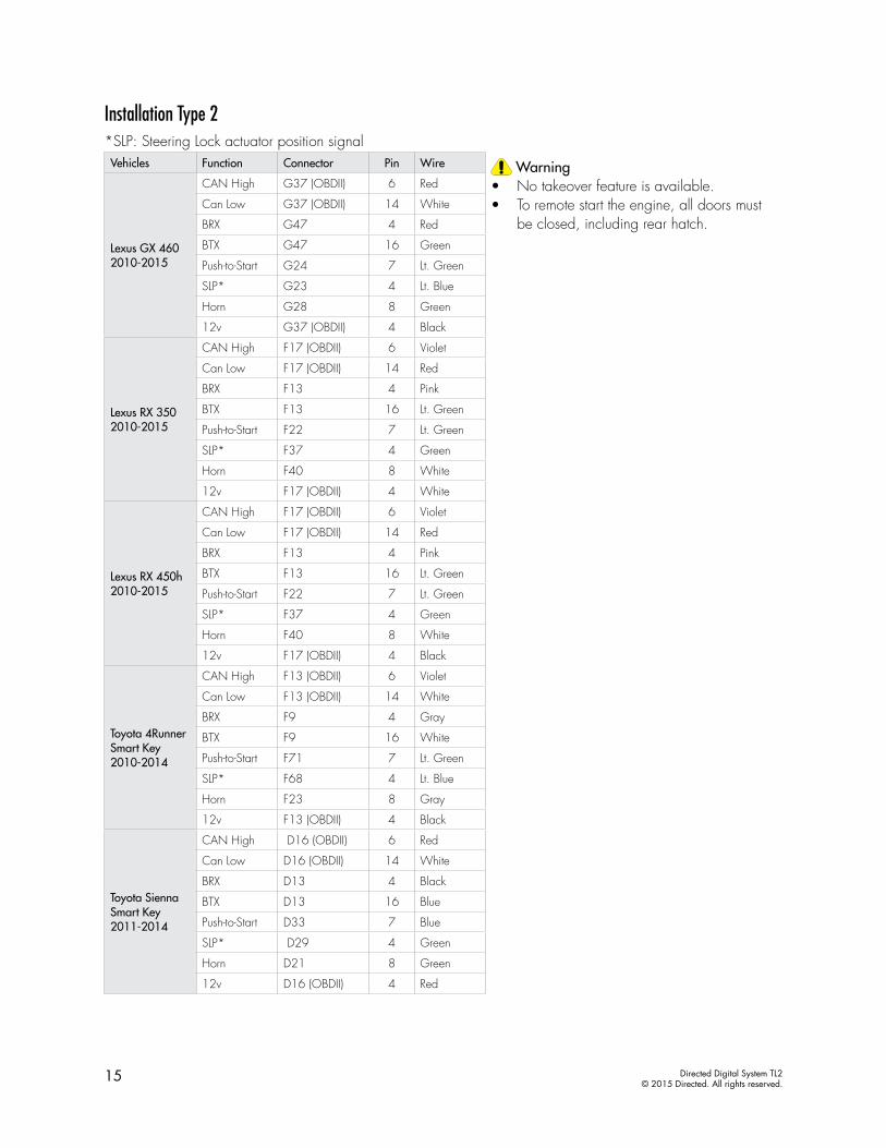
Installation Type 2*SLP: Steering Lock actuator position signalVehicles Function Connector Pin Wire Warning
• No takeover feature is available. • To remote start the engine, all doors must
be closed, including rear hatch.
Lexus GX 460 2010-2015
CAN High G37 (OBDII) 6 Red
Can Low G37 (OBDII) 14 White
BRX G47 4 Red
BTX G47 16 Green
Push-to-Start G24 7 Lt. Green
SLP* G23 4 Lt. Blue
Horn G28 8 Green
12v G37 (OBDII) 4 Black
Lexus RX 350 2010-2015
CAN High F17 (OBDII) 6 Violet
Can Low F17 (OBDII) 14 Red
BRX F13 4 Pink
BTX F13 16 Lt. Green
Push-to-Start F22 7 Lt. Green
SLP* F37 4 Green
Horn F40 8 White
12v F17 (OBDII) 4 White
Lexus RX 450h 2010-2015
CAN High F17 (OBDII) 6 Violet
Can Low F17 (OBDII) 14 Red
BRX F13 4 Pink
BTX F13 16 Lt. Green
Push-to-Start F22 7 Lt. Green
SLP* F37 4 Green
Horn F40 8 White
12v F17 (OBDII) 4 Black
Toyota 4Runner Smart Key2010-2014
CAN High F13 (OBDII) 6 Violet
Can Low F13 (OBDII) 14 White
BRX F9 4 Gray
BTX F9 16 White
Push-to-Start F71 7 Lt. Green
SLP* F68 4 Lt. Blue
Horn F23 8 Gray
12v F13 (OBDII) 4 Black
Toyota Sienna Smart Key 2011-2014
CAN High D16 (OBDII) 6 Red
Can Low D16 (OBDII) 14 White
BRX D13 4 Black
BTX D13 16 Blue
Push-to-Start D33 7 Blue
SLP* D29 4 Green
Horn D21 8 Green
12v D16 (OBDII) 4 Red
16 Directed Digital System TL2© 2015 Directed. All rights reserved.
Locating components in the vehicle
Installation Type 3*SLP: Steering Lock actuator position signalVehicles Function Connector Pin Wire Warning
• No takeover feature is available. • To remote start the engine, all doors must be
closed, including rear hatch.Lexus CT 200h 2011-2015
CAN High H44 (OBDII) 6 Red
Can Low H44 (OBDII) 14 White
BRX H16 4 Yellow
BTX H16 16 Blue
Push-to-Start H78 7 Black
Horn H30 9 Yellow
12v H44 (OBDII) 4 White
Lexus HS 250h 2010-2012
CAN High F11 (OBDII) 6 Green
Can Low F11 (OBDII) 14 Black
BRX F9 4 Yellow
BTX F9 16 Blue
Push-to-Start F2 7 Blue
Horn F19 8 White
12v F11 (OBDII) 4 Black
Toyota Prius 2010-2014 &Toyota Prius v 2012
CAN High L61 (OBDII) 6 White
Can Low L61 (OBDII) 14 Yellow
BRX L7 4 Violet
BTX L7 16 Green
Push-to-Start L43 7 Black
Horn L52 8 Yellow
12v L61 (OBDII) 4 White
17 Directed Digital System TL2© 2015 Directed. All rights reserved.
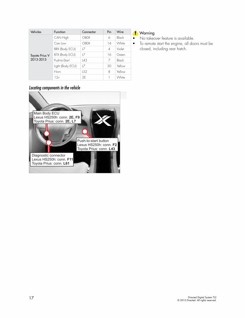
Vehicles Function Connector Pin Wire Warning• No takeover feature is available. • To remote start the engine, all doors must be
closed, including rear hatch.
Toyota Prius V 2013-2015
CAN High OBDII 6 Black
Can Low OBDII 14 White
BRX (Body ECU) L7 4 Violet
BTX (Body ECU) L7 16 Green
Push-to-Start L43 7 Black
Light (Body ECU) L7 30 Yellow
Horn L52 8 Yellow
12v 2E 1 White
Locating components in the vehicle
18 Directed Digital System TL2© 2015 Directed. All rights reserved.
Connecting the module
Important!Before connecting the Directed Digital System, it is important to ensure that the proper feature and function programming is selected using the configuration wizard. Visit www.xpresskit.com to use the latest version of the online tool.
To make this selection:1. Disconnect the main module from any (+)12V power source, then connect it to your computer using the
XKLoader.2. Open the Internet Explorer browser (version 6.0 and later) and go to www.xpresskit.com; the programming
window will be displayed automatically.3. Follow the instructions in the pop up window that will be displayed when the module is detected.
Note: If the latest firmware is already loaded, only the feature options will be flashed. Check the Yes box if you wish to flash the firmware as well.
Once the module is programmed, you can proceed with the instructions below.
Manual or automatic transmission selectionThe yellow loop on the Directed Digital System controls which transmission type the unit is configured for. The state of the loop (uncut or cut) when the main module is powered up will determine which type is selected.• Uncut (default): Manual transmission.• Cut: Automatic transmission.
For safety reasons, all Directed Digital Systems are shipped ready to use with a manual transmission (the yellow loop is untouched). If the loop is cut after power has been applied, it is necessary to cycle power to the main module (via the white 12-pin main power harness) so the unit will see the state change on the loop and appropriately configure the transmission type.
Ready modeTo successfully remote start a vehicle equipped with a manual transmission, the Ready Mode feature must be enabled before exiting the vehicle. Please refer to the Owner’s Guide for more details on this required process.
Additional connections required for vehicles equipped with a manual transmission (if not supported by firmware)
Connection Description
(-) Emergency Brake Input (black/white, pin 2)
Must be connected to a working emergency brake in the vehicle. Although most vehicles have simple (-) trigger emergency brake circuits note some vehicles do not and may require unique integration methodologies.
(-) Door Input (white/green, pin 10) OR (+) Door Input (yellow/green, pin 11)
Must be connected to a working door trigger in the vehicle, which monitors all doors. The unit must monitor the door pins to allow the Ready Mode process to be enabled.Note: Some vehicles may require unique integration methodologies for this circuit.
(AC) Tachometer Input (violet/white, pin 6)
Must be connected to a working tachometer signal in the vehicle (fuel injector, ignition coil, true tach, etc.) and learned successfully to the Directed Digital System.
Note: Refer to www.directechs.com for more information.
19 Directed Digital System TL2© 2015 Directed. All rights reserved.
Optional sensorsNote: The sensor port is only active on hybrid systems.
The 4-pin sensor port is compatible with a number of different Directed sensors including, but not limited to:• Shock Sensor – 504D• Field Disturbance Sensor – 508D• Ultrasonic Sensor – 509U
Note: In the case of 508D, power and ground must be hardwired to the vehicle – power and ground should NOT be obtained from the 4-pin sensor port.
Each sensor will have its own instructions, which must be followed for installation and adjustment.
RF kitsAn RF kit consists of one or multiple remotes, a Control Center (antenna), and an antenna cable – various combinations exist. An RF kit allows the vehicle owner to control the system with enhanced range. Two-way models are available. Please follow the instructions included with the kit for appropriate installation and programming information.
When flashing the Directed Digital System, make sure to pick the remote you will be using. This way the main module will have the necessary firmware to interact with the remote and Control Center (antenna) combination.
When used in conjunction with SmartStartThe Directed Digital System main module must be disconnected from any power source before SmartStart can be connected to it. Failing to do so could damage main module.
To ensure that the D2D communication between the Directed Digital System and SmartStart works properly, one of the following actions must be executed, depending on the hardware you are using:• Rev A SmartStart – The brown or blue loop must be cut. • Rev B SmartStart – The gray wire must be connected to a ground source.
Do NOT connect the SmartStart 2-pin power harness. Power and ground will be provided by the D2D connector on main module.
20 Directed Digital System TL2© 2015 Directed. All rights reserved.
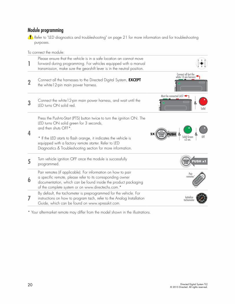
Module programmingRefer to "LED diagnostics and troubleshooting" on page 21 for more information and for troubleshooting purposes.
To connect the module:
1Please ensure that the vehicle is in a safe location an cannot move forward during programming. For vehicles equipped with a manual transmission, make sure the gearshift lever is in the neutral position.
2 Connect all the harnesses to the Directed Digital System, EXCEPT the white12-pin main power harness.
Connect all but the white 12-pin harness
3 Connect the white12-pin main power harness, and wait until the LED turns ON solid red.
Must be connected LAST
&Solid
4
Press the Push-to-Start (PTS) button twice to turn the ignition ON. The LED turns ON solid green for 3 seconds,and then shuts OFF*.
* If the LED starts to flash orange, it indicates the vehicle is equipped with a factory remote starter. Refer to LEDDiagnostics & Troubleshooting section for more information.
& &
PUSH1X
PUSH2XSolid Green
x3 sec.Off
5 Turn vehicle ignition OFF once the module is successfully programmed.
6Pair remotes (if applicable). For information on how to pair a specific remote, please refer to its corresponding owner documentation, which can be found inside the product packaging of the complete system or on www.directechs.com.*
Pair remotes*
7By default, the tachometer is preprogrammed for the vehicle. For instructions on how to program tach, refer to the Analog Installation Guide, which can be found on www.xpresskit.com.
Initialize tachometer
* Your aftermarket remote may differ from the model shown in the illustrations.
21 Directed Digital System TL2© 2015 Directed. All rights reserved.
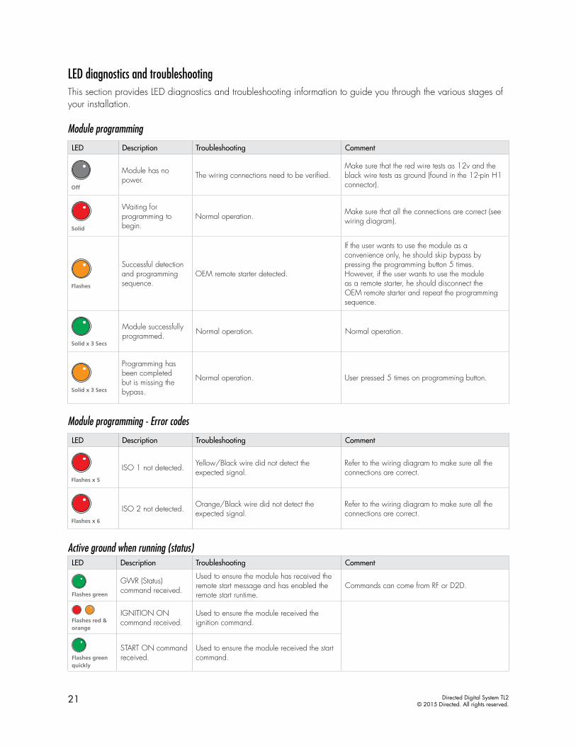
LED diagnostics and troubleshootingThis section provides LED diagnostics and troubleshooting information to guide you through the various stages of your installation.
Module programming
LED Description Troubleshooting Comment
Off
Module has no power. The wiring connections need to be verified.
Make sure that the red wire tests as 12v and the black wire tests as ground (found in the 12-pin H1 connector).
Solid
Waiting for programming to begin.
Normal operation. Make sure that all the connections are correct (see wiring diagram).
Flashes
Successful detectionand programmingsequence.
OEM remote starter detected.
If the user wants to use the module as a convenience only, he should skip bypass by pressing the programming button 5 times. However, if the user wants to use the module as a remote starter, he should disconnect the OEM remote starter and repeat the programming sequence.
Solid x 3 Secs
Module successfully programmed. Normal operation. Normal operation.
Solid x 3 Secs
Programming has been completed but is missing the bypass.
Normal operation. User pressed 5 times on programming button.
Module programming - Error codes
LED Description Troubleshooting Comment
Flashes x 5
ISO 1 not detected. Yellow/Black wire did not detect the expected signal.
Refer to the wiring diagram to make sure all the connections are correct.
Flashes x 6
ISO 2 not detected. Orange/Black wire did not detect the expected signal.
Refer to the wiring diagram to make sure all the connections are correct.
Active ground when running (status)LED Description Troubleshooting Comment
Flashes green
GWR (Status) command received.
Used to ensure the module has received the remote start message and has enabled the remote start runtime.
Commands can come from RF or D2D.
Flashes red & orange
IGNITION ON command received.
Used to ensure the module received the ignition command.
Flashes green quickly
START ON command received.
Used to ensure the module received the start command.
22 Directed Digital System TL2© 2015 Directed. All rights reserved.
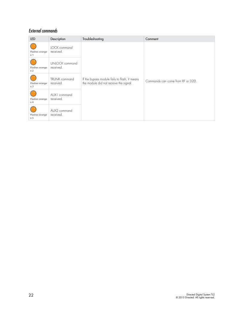
External commands
LED Description Troubleshooting Comment
Flashes orange x 1
LOCK command received.
If the bypass module fails to flash, it means the module did not receive the signal. Commands can come from RF or D2D.
Flashes orange x 2
UNLOCK command received.
Flashes orange x 3
TRUNK command received.
Flashes orange x 4
AUX1 command received.
Flashes orange x 5
AUX2 command received.
23 Directed Digital System TL2© 2015 Directed. All rights reserved.
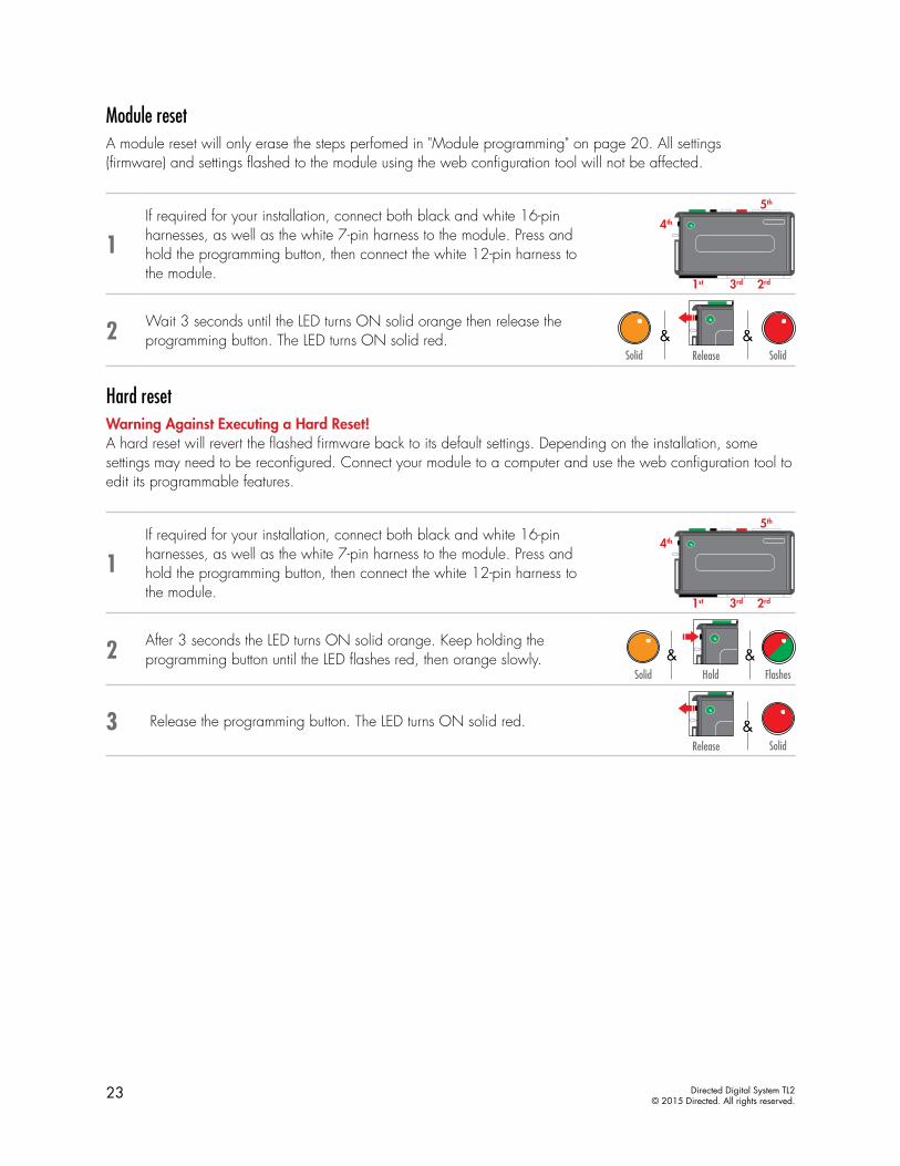
Module resetA module reset will only erase the steps perfomed in "Module programming" on page 20. All settings (firmware) and settings flashed to the module using the web configuration tool will not be affected.
1If required for your installation, connect both black and white 16-pin harnesses, as well as the white 7-pin harness to the module. Press and hold the programming button, then connect the white 12-pin harness to the module.
1st
4th
3rd 2rd
5th
2 Wait 3 seconds until the LED turns ON solid orange then release the programming button. The LED turns ON solid red.
Solid Solid
&&Release
Hard resetWarning Against Executing a Hard Reset! A hard reset will revert the flashed firmware back to its default settings. Depending on the installation, some settings may need to be reconfigured. Connect your module to a computer and use the web configuration tool to edit its programmable features.
1If required for your installation, connect both black and white 16-pin harnesses, as well as the white 7-pin harness to the module. Press and hold the programming button, then connect the white 12-pin harness to the module.
1st
4th
3rd 2rd
5th
2 After 3 seconds the LED turns ON solid orange. Keep holding the programming button until the LED flashes red, then orange slowly.
Hold FlashesSolid
&&
3 Release the programming button. The LED turns ON solid red.
Solid
&Release

24 Directed Digital System TL2© 2015 Directed. All rights reserved.
Learning the Tach (not needed with Virtual Tach)Tach comes preprogrammed, therefore learning is not required; however, it can be readjusted with the following operations:1. Start the vehicle using the key. 2. Within 5 seconds, press and hold the Control Center* (antenna) or the main module programming button,
until the LED on the Control Center (antenna) or the main module turns ON soild.3. Release the button. Tachometer value is now stored in memory.
If the LED does not turn ON solid, find an alternate tach source.
* If the Control Center (antenna) was not included in your kit, the tach can be programmed using the programming button directly on the main module.
Note: When the tachometer is programmed, the main module automatically enters the Tachometer engine checking mode.
Initializing Virtual Tach (not needed with hardwired or data tach applications)To program Virtual Tach:1. After the install is complete, remote start the engine. The programming operation may require 3 cranks of
the starter before the engine starts and runs. Do not turn off the remote start if this happens, it is a normal programming operation.
2. Once the engine begins running, let it run for at least 30 seconds.3. Using the Remote, send the Remote start command to turn remote start off. Virtual Tach is programmed. To
reset Virtual Tach, a module reset must be done.
Note: Virtual Tach cannot be used in Manual Transmission Mode. It is also not recommended for diesel trucks.
Virtual Tach handles disengaging the starter motor during remote starting – it does not address over-rev. If the customer wants to have the over-rev protection capability, the tach wire or data tach must be used.
Important! After successfully learning Virtual Tach, a small minority of vehicle starters may over crank or under crank during remote start. Use the VirtualTach Fine tune feature in the configuration wizard to adjust the starter output time in 50mS increments to compensate for such an occurrence.
25 Directed Digital System TL2© 2015 Directed. All rights reserved.
Limited lifetime consumer warrantyDirected Electronics. (“Directed”) promises to the original purchaser to repair or replace (at Directed’s election) with a comparable reconditioned model any Directed unit (hereafter the “unit”), excluding without limitation the siren, the remote transmitters, the associated sensors and accessories, which proves to be defective in workmanship or material under reasonable use during the lifetime of the vehicle provided the following conditions are met: the unit was purchased from an authorized Directed dealer, the unit was professionally installed and serviced by an authorized Directed dealer; the unit will be professionally reinstalled in the vehicle in which it was originally installed by an authorized Directed dealer; and the unit is returned to Directed, shipping prepaid with a legible copy of the bill of sale or other dated proof of purchase bearing the following information: consumer’s name, telephone number and address; the authorized dealers name, telephone number and address; complete product description, including accessories; the year, make and model of the vehicle; vehicle license number and vehicle identification number. All components other than the unit, including without limitation the siren, the remote transmitters and the associated sensors and accessories, carry a one-year warranty from the date of purchase of the same. ALL PRODUCTS RECEIVED BY DIRECTED FOR WARRANTY REPAIR WITHOUT PROOF OF PURCHASE FROM AN AUTHORIZED DEALER WILL BE DENIED. This warranty is non-transferable and is automatically void if: the unit’s date code or serial number is defaced, missing or altered; the unit has been modified or used in a manner contrary to its intended purpose; the unit has been damaged by accident, unreasonable use, neglect, improper service, installation or other causes not arising out of defects in materials or construction. The warranty does not cover damage to the unit caused by installation or removal of the unit. Directed, in its sole discretion, will determine what constitutes excessive damage and may refuse the return of any unit with excessive damage. TO THE MAXIMUM EXTENT ALLOWED BY LAW, ALL WARRANTIES, INCLUDING BUT NOT LIMITED TO EXPRESS WARRANTY, IMPLIED WARRANTY, WARRANTY OF MERCHANTABILITY, FITNESS FOR PARTICULAR PURPOSE AND WARRANTY OF NON-INFRINGEMENT OF INTELLECTUAL PROPERTY, ARE EXPRESSLY EXCLUDED; AND DIRECTED NEITHER ASSUMES NOR AUTHORIZES ANY PERSON OR ENTITY TO ASSUME FOR IT ANY DUTY, OBLIGATION OR LIABILITY IN CONNECTION WITH ITS PRODUCTS. DIRECTED DISCLAIMS AND HAS ABSOLUTELY NO LIABILITY FOR ANY AND ALL ACTS OF THIRD PARTIES INCLUDING ITS AUTHORIZED DEALERS OR INSTALLERS. DIRECTED SECURITY SYSTEMS, INCLUDING THIS UNIT, ARE DETERRENTS AGAINST POSSIBLE THEFT. DIRECTED IS NOT OFFERING A GUARANTEE OR INSURANCE AGAINST VANDALISM, DAMAGE OR THEFT OF THE AUTOMOBILE, ITS PARTS OR CONTENTS; AND HEREBY EXPRESSLY DISCLAIMS ANY LIABILITY WHATSOEVER, INCLUDING WITHOUT LIMITATION, LIABILITY FOR THEFT, DAMAGE AND/OR VANDALISM. THIS WARRANTY DOES NOT COVER LABOR COSTS FOR MAINTENANCE, REMOVAL OR REINSTALLATION OF THE UNIT OR ANY CONSEQUENTIAL DAMAGES OF ANY KIND. IN THE EVENT OF A CLAIM OR A DISPUTE INVOLVING DIRECTED OR ITS SUBSIDIARY, THE VENUE SHALL BE SAN DIEGO COUNTY IN THE STATE OF CALIFORNIA. CALIFORNIA STATE LAWS AND APPLICABLE FEDERAL LAWS SHALL APPLY AND GOVERN THE DISPUTE. THE MAXIMUM RECOVERY UNDER ANY CLAIM AGAINST DIRECTED SHALL BE STRICTLY LIMITED TO THE AUTHORIZED DIRECTED DEALER’S PURCHASE PRICE OF THE UNIT. DIRECTED SHALL NOT BE RESPONSIBLE FOR ANY DAMAGES WHATSOEVER, INCLUDING BUT NOT LIMITED TO, ANY CONSEQUENTIAL DAMAGES, INCIDENTAL DAMAGES, DAMAGE TO VEHICLE, DAMAGES FOR THE LOSS OF TIME, LOSS OF EARNINGS, COMMERCIAL LOSS, LOSS OF ECONOMIC OPPORTUNITY AND THE LIKE. NOTWITHSTANDING THE ABOVE, THE MANUFACTURER DOES OFFER A LIMITED WARRANTY TO REPLACE OR REPAIR THE CONTROL MODULE SUBJECT TO THE CONDITIONS AS DESCRIBED HEREIN. THIS WARRANTY IS VOID IF THE UNIT HAS NOT BEEN PURCHASED FROM DIRECTED, OR AN AUTHORIZED DIRECTED DEALER, OR IF THE UNIT HAS BEEN DAMAGED BY ACCIDENT, UNREASONABLE USE, NEGLIGENCE, ACTS OF GOD, NEGLECT, IMPROPER SERVICE, OR OTHER CAUSES NOT ARISING OUT OF DEFECT IN MATERIALS OR CONSTRUCTION.
Some states do not allow limitations on how long an implied warranty will last or the exclusion or limitation of incidental or consequential damages. This warranty gives you specific legal rights and you may also have other rights that vary from State to State.
This warranty is only valid for sale of product(s) within the United States of America and in Canada. Product(s) sold outside of the United States of America or Canada are sold “AS-IS” and shall have NO WARRANTY, express or implied.
For further details relating to warranty information of Directed products, please visit the support section of Directed’s website at: www.directed.com.
This product may be covered by a Guaranteed Protection Plan (“GPP”). See your authorized Directed dealer for details of the plan or call Directed Customer Service at 1-800-876-0800.
(920-10011-01 2011-06)
Directed Digital System TL2© 2015 Directed. All rights reserved.
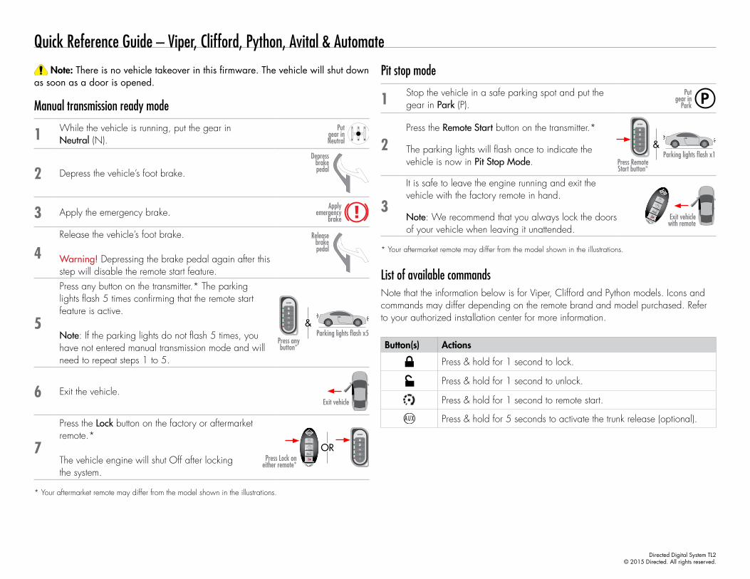
Quick Reference Guide – Viper, Clifford, Python, Avital & Automate
Note: There is no vehicle takeover in this firmware. The vehicle will shut down as soon as a door is opened.
Manual transmission ready mode
1 While the vehicle is running, put the gear in Neutral (N).
Put gear in Neutral
2 Depress the vehicle’s foot brake.
Depress brake pedal
3 Apply the emergency brake.Apply
emergency brake
4Release the vehicle’s foot brake.
Warning! Depressing the brake pedal again after this step will disable the remote start feature.
Release brake pedal
5
Press any button on the transmitter.* The parking lights flash 5 times confirming that the remote start feature is active.
Note: If the parking lights do not flash 5 times, you have not entered manual transmission mode and will need to repeat steps 1 to 5.
Parking lights flash x5Press any button*
&
6 Exit the vehicle.Exit vehicle
7
Press the Lock button on the factory or aftermarket remote.*
The vehicle engine will shut Off after locking the system.
Press Lock on either remote*
OR
* Your aftermarket remote may differ from the model shown in the illustrations.
Pit stop mode
1 Stop the vehicle in a safe parking spot and put the gear in Park (P).
Put gear in
Park
2Press the Remote Start button on the transmitter.*
The parking lights will flash once to indicate the vehicle is now in Pit Stop Mode.
Parking lights flash x1Press Remote Start button*
&
3
It is safe to leave the engine running and exit the vehicle with the factory remote in hand.
Note: We recommend that you always lock the doors of your vehicle when leaving it unattended.
Exit vehicle with remote
* Your aftermarket remote may differ from the model shown in the illustrations.
List of available commandsNote that the information below is for Viper, Clifford and Python models. Icons and commands may differ depending on the remote brand and model purchased. Refer to your authorized installation center for more information.
Button(s) Actions
Press & hold for 1 second to lock.
Press & hold for 1 second to unlock.
Press & hold for 1 second to remote start.
Press & hold for 5 seconds to activate the trunk release (optional).
Directed Digital System TL2© 2015 Directed. All rights reserved.
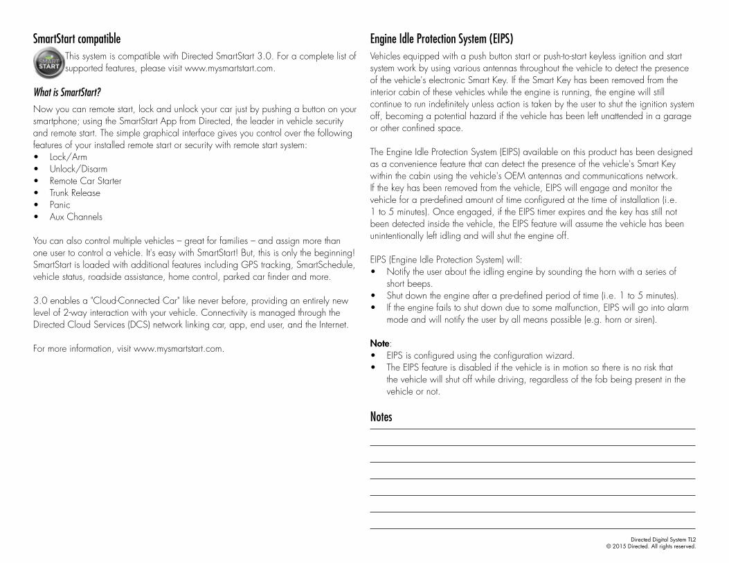
SmartStart compatibleThis system is compatible with Directed SmartStart 3.0. For a complete list of supported features, please visit www.mysmartstart.com.
What is SmartStart?Now you can remote start, lock and unlock your car just by pushing a button on your smartphone; using the SmartStart App from Directed, the leader in vehicle security and remote start. The simple graphical interface gives you control over the following features of your installed remote start or security with remote start system: • Lock/Arm• Unlock/Disarm• Remote Car Starter• Trunk Release• Panic• Aux Channels
You can also control multiple vehicles – great for families – and assign more than one user to control a vehicle. It's easy with SmartStart! But, this is only the beginning! SmartStart is loaded with additional features including GPS tracking, SmartSchedule, vehicle status, roadside assistance, home control, parked car finder and more.
3.0 enables a "Cloud-Connected Car" like never before, providing an entirely new level of 2-way interaction with your vehicle. Connectivity is managed through the Directed Cloud Services (DCS) network linking car, app, end user, and the Internet.
For more information, visit www.mysmartstart.com.
Engine Idle Protection System (EIPS)Vehicles equipped with a push button start or push-to-start keyless ignition and start system work by using various antennas throughout the vehicle to detect the presence of the vehicle's electronic Smart Key. If the Smart Key has been removed from the interior cabin of these vehicles while the engine is running, the engine will still continue to run indefinitely unless action is taken by the user to shut the ignition system off, becoming a potential hazard if the vehicle has been left unattended in a garage or other confined space.
The Engine Idle Protection System (EIPS) available on this product has been designed as a convenience feature that can detect the presence of the vehicle's Smart Key within the cabin using the vehicle's OEM antennas and communications network. If the key has been removed from the vehicle, EIPS will engage and monitor the vehicle for a pre-defined amount of time configured at the time of installation (i.e. 1 to 5 minutes). Once engaged, if the EIPS timer expires and the key has still not been detected inside the vehicle, the EIPS feature will assume the vehicle has been unintentionally left idling and will shut the engine off.
EIPS (Engine Idle Protection System) will:• Notify the user about the idling engine by sounding the horn with a series of
short beeps.• Shut down the engine after a pre-defined period of time (i.e. 1 to 5 minutes).• If the engine fails to shut down due to some malfunction, EIPS will go into alarm
mode and will notify the user by all means possible (e.g. horn or siren).
Note: • EIPS is configured using the configuration wizard. • The EIPS feature is disabled if the vehicle is in motion so there is no risk that
the vehicle will shut off while driving, regardless of the fob being present in the vehicle or not.
Notes
Directed Digital System TL2© 2015 Directed. All rights reserved.
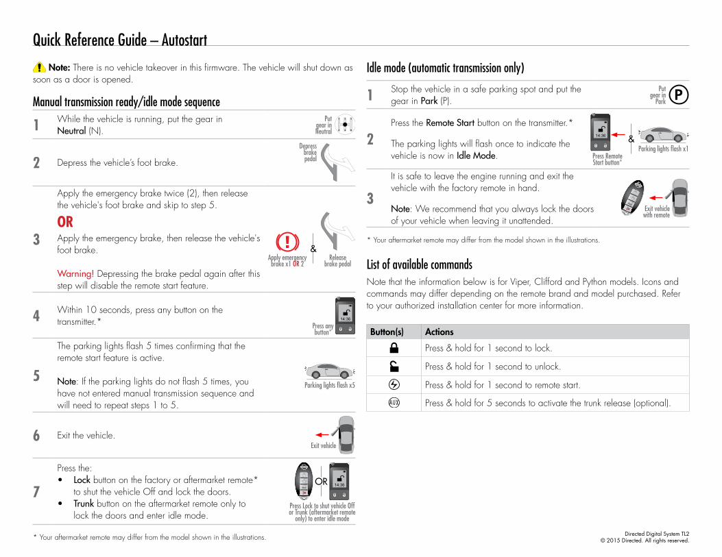
Quick Reference Guide – Autostart
Note: There is no vehicle takeover in this firmware. The vehicle will shut down as soon as a door is opened.
Manual transmission ready/idle mode sequence
1 While the vehicle is running, put the gear in Neutral (N).
Put gear in Neutral
2 Depress the vehicle’s foot brake.
Depress brake pedal
3
Apply the emergency brake twice (2), then release the vehicle's foot brake and skip to step 5.
Apply emergency brake x1 OR 2
Release brake pedal
&
ORApply the emergency brake, then release the vehicle's foot brake.
Warning! Depressing the brake pedal again after this step will disable the remote start feature.
4 Within 10 seconds, press any button on the transmitter.* 14:36
Press any button*
5
The parking lights flash 5 times confirming that the remote start feature is active.
Note: If the parking lights do not flash 5 times, you have not entered manual transmission sequence and will need to repeat steps 1 to 5.
Parking lights flash x5
6 Exit the vehicle.Exit vehicle
7
Press the:• Lock button on the factory or aftermarket remote*
to shut the vehicle Off and lock the doors.• Trunk button on the aftermarket remote only to
lock the doors and enter idle mode.Press Lock to shut vehicle Off or Trunk (aftermarket remote
only) to enter idle mode
14:36OR
* Your aftermarket remote may differ from the model shown in the illustrations.
Idle mode (automatic transmission only)
1 Stop the vehicle in a safe parking spot and put the gear in Park (P).
Put gear in
Park
2Press the Remote Start button on the transmitter.*
The parking lights will flash once to indicate the vehicle is now in Idle Mode.
Parking lights flash x1&
Press Remote Start button*
14:36
3
It is safe to leave the engine running and exit the vehicle with the factory remote in hand.
Note: We recommend that you always lock the doors of your vehicle when leaving it unattended.
Exit vehicle with remote
* Your aftermarket remote may differ from the model shown in the illustrations.
List of available commandsNote that the information below is for Viper, Clifford and Python models. Icons and commands may differ depending on the remote brand and model purchased. Refer to your authorized installation center for more information.
Button(s) Actions
Press & hold for 1 second to lock.
Press & hold for 1 second to unlock.
Press & hold for 1 second to remote start.
Press & hold for 5 seconds to activate the trunk release (optional).

Directed Digital System TL2© 2015 Directed. All rights reserved.
SmartStart compatibleThis system is compatible with Directed SmartStart 3.0. For a complete list of supported features, please visit www.mysmartstart.com.
What is SmartStart?Now you can remote start, lock and unlock your car just by pushing a button on your smartphone; using the SmartStart App from Directed, the leader in vehicle security and remote start. The simple graphical interface gives you control over the following features of your installed remote start or security with remote start system: • Lock/Arm• Unlock/Disarm• Remote Car Starter• Trunk Release• Panic• Aux Channels
You can also control multiple vehicles – great for families – and assign more than one user to control a vehicle. It's easy with SmartStart! But, this is only the beginning! SmartStart is loaded with additional features including GPS tracking, SmartSchedule, vehicle status, roadside assistance, home control, parked car finder and more.
3.0 enables a "Cloud-Connected Car" like never before, providing an entirely new level of 2-way interaction with your vehicle. Connectivity is managed through the Directed Cloud Services (DCS) network linking car, app, end user, and the Internet.
For more information, visit www.mysmartstart.com.
Engine Idle Protection System (EIPS)Vehicles equipped with a push button start or push-to-start keyless ignition and start system work by using various antennas throughout the vehicle to detect the presence of the vehicle's electronic Smart Key. If the Smart Key has been removed from the interior cabin of these vehicles while the engine is running, the engine will still continue to run indefinitely unless action is taken by the user to shut the ignition system off, becoming a potential hazard if the vehicle has been left unattended in a garage or other confined space.
The Engine Idle Protection System (EIPS) available on this product has been designed as a convenience feature that can detect the presence of the vehicle's Smart Key within the cabin using the vehicle's OEM antennas and communications network. If the key has been removed from the vehicle, EIPS will engage and monitor the vehicle for a pre-defined amount of time configured at the time of installation (i.e. 1 to 5 minutes). Once engaged, if the EIPS timer expires and the key has still not been detected inside the vehicle, the EIPS feature will assume the vehicle has been unintentionally left idling and will shut the engine off.
EIPS (Engine Idle Protection System) will:• Notify the user about the idling engine by sounding the horn with a series of
short beeps.• Shut down the engine after a pre-defined period of time (i.e. 1 to 5 minutes).• If the engine fails to shut down due to some malfunction, EIPS will go into alarm
mode and will notify the user by all means possible (e.g. horn or siren).
Note: • EIPS is configured using the configuration wizard. • The EIPS feature is disabled if the vehicle is in motion so there is no risk that
the vehicle will shut off while driving, regardless of the fob being present in the vehicle or not.
Notes