Embed Size (px)
Citation preview

TKT-3500
Microcontroller
systems
Lec 1 – Introduction to
Microcontrollers, Basics of debugging
Teemu Laukkarinen
Department of Computer Systems
Tampere University of Technology
Fall 2011
Copyright Tampere University of Technology Department of Computer Systems

#2/67
Copyright notice
Course slides originally prepared by
Erno Salminen
Part of the slides
adapted from slide set EE1A2 PIC Course by
Sandra I. Woolley, Univ. Birmingham
based on [B. Colwell, The power of most likely,
Computer, Vol. 35, Iss. 10, Oct. 2002, pp.12 –
14]
Copyright Tampere University of Technology Department of Computer Systems

#3/67
Contents
What and where are microcontrollers
Basic features of microcontrollers
Embedded systems
Commercial microcontrollers, e.g. PIC-family
Platform for exercises: Multisensor node
Key components
Debugging: The power of most likely
Copyright Tampere University of Technology Department of Computer Systems

#4/67
Microcontroller
Merriam-Webster dictionary:
microcontroller [\mī-krō\\-kən-trō-lər\ ]
Function: noun, Date: 1971
a microprocessor that controls some or all of
the functions of an electronic device (as a
home appliance) or system
micro - very small
controller - one that controls or has power or authority to control
control - to exercise restraining or directing influence over
Copyright Tampere University of Technology Department of Computer Systems

#5/67
Microcontroller (2)
Microcontrollers are used in automatically controlled products and devices such as automobile engine control systems,
remote controls, office machines, appliances, power tools, and toys
Lecturer stopped counting MCUs at the count of 14 in his 2002 car…
i.e. in embedded systems
Microcontroller chip includes, for example an integrated microprocessor
memories (RAM, Flash, EEPROM etc.)
input and output peripherals
timers, event counters, PWM generators etc.
clock generator
many include analog-to-digital converters
in-circuit programming and debugging support
A PIC 18F8720
microcontroller in an
80-pin TQFP package.
Copyright Tampere University of Technology Department of Computer Systems

#6/67
Microcontroller (2)
It emphasizes high integration, in contrast to a microprocessor which only contains a CPU (and cache) functional computer system-on-a-chip (SoC)
Modest processing capability Adequate for simple control applications
Usually not meant for heavy number crunching
Low power consumption
Cheap unit price, high volumes
Usually general purpose Compare e.g. to mobile phone SoCs e.g. TI OMAP
Programmable devices
Copyright Tampere University of Technology Department of Computer Systems

#7/67
Classification of microprocessors
Number of bits 4,8,16,32,64...
Number of instructionsa) RISC (Reduced instruction-set computer)
b) CISC (Complex instruction-set computer) ASIP (Application-specific instruction-set processor)
Memory spacea) von Neumann – same for instr. and data
b) Harvard – separate addr spaces
Data path – where are the operandsa) Stack
b) Accumulator
c) Register-memory
d) Register-register (so called load-store)
e) Memory-memory
Integrated peripherals, pipelining, num of ALUs...Copyright Tampere University of Technology Department of Computer Systems

#8/67
Where are the processors [Tennenhouse00]
Interactive 2% denotes PCs and
servers
98% of CPUs are elsewhere
Portable devices (cell phones
etc) have spread after 2000
[Tennenhouse, D. 2000. Proactive computing.
Commun. ACM 43, 5 (May. 2000), 43-50]
Copyright Tampere University of Technology Department of Computer Systems
#9/67
WHAT ARE EMBEDDED
SYSTEMS
Copyright Tampere University of Technology Department of Computer Systems

#10/67
Embedded systems (1)
Application specific electronic sub-system used in a larger system such as an appliance, an instrument or a vehicle
Not User-Programmable
System needs to implement only a limited function whose characteristics are known at design time
The design can take advantage of the specification’s characteristics in ways that general-purpose computing systems cannot
Targeting certain performance level instead of maximum
Based on both hardwired and programmable components e.g. CPU, DSP, custom HW
Question: Is a modern mobile phone an embedded system? What about personal video recorder?
Copyright Tampere University of Technology Department of Computer Systems

#11/67
Embedded systems (2)
Fig: [Pinello, TVLSI08]
Hardware/Software co-design required
Resemble distributed systems multiple tasks are running on multiple processing
elements (PE)
interprocess communication and synchronizationcritical
Are subject to external timing constraints Hard real-time – missed deadlines are fatal
e.g. ABS brakes, safety system of nuclear plant
Soft real-time – missed deadlines causedegraded quality or inconvenience e.g. video frames are dropped
Copyright Tampere University of Technology Department of Computer Systems

#12/67
Embedded systems (3)
Reactive Real-Time Systems
Continuous interaction with external
environment
Ideally never terminate
while (1) {
read the sensors
control the actuators
sleep()
}
Where would execution
go after main()?
Copyright Tampere University of Technology Department of Computer Systems

#13/67
Examples of embedded systems
asdcar
digital
camera
mobile phone
harvester
robot
Figures from Wikipedia
network router
elevator
washing
machine
PDA
game console
printer medical
equipment
microwave oven
factory automationCopyright Tampere University of Technology Department of Computer Systems

#14/67
COMMERCIAL
MICROCONTROLLERS,
ESPECIALLY PIC
Copyright Tampere University of Technology Department of Computer Systems

#15/67
Example microcontrollers
Atmel AVR 8- ja 32-bit RISC families
Over 80 models
Texas Instruments (TI) MSP430 – low power
TMS320 – high performance
TMS470 – ARM7-based
Renesas SuperH – High speed / performance
MR32 – 32-bit
H8 – low cost
ST microelectronics
And many others...
Copyright Tampere University of Technology Department of Computer Systems

#16/67
PIC microcontrollers
Designed and sold by Microchip Corporation
http://www.microchip.com
PIC = initially Programmable Interface
Controller
then Programmable Intelligent Computer
Many configurations of 8-, 16- and 32-
microcontrollers
8-bit volume prices ~2$-12$
Minimalist basic ideology
Copyright Tampere University of Technology Department of Computer Systems
#17/67
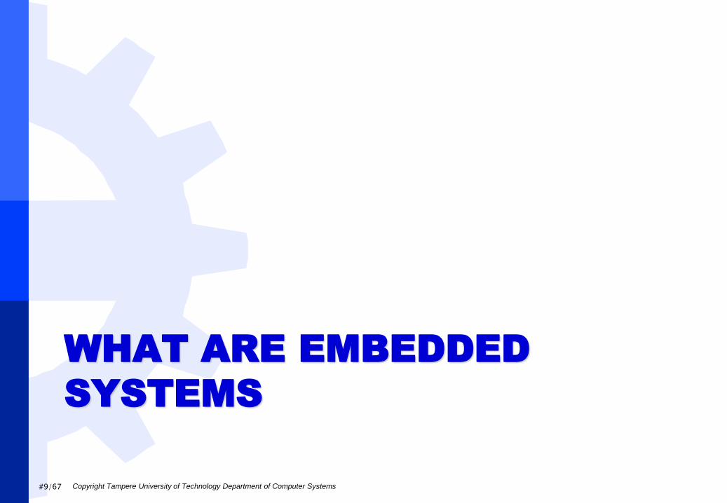
8-bit PIC Families
8-bit stands for width of data path
PIC10 (and some PIC12 and PIC16)
Baseline architecture, 12-bit program word
16-134 Bytes of SRAM
256- 2K Bytes of flash program memory
4-32 IO-Pins, 2 level deep HW stack
PIC12 and PIC16
Midrange architecture, 14-bit program word
64-368 Bytes of SRAM
1 -8 kBytes of flash program memory
6-53 IO-pins, 8 level deep HW stack
Images: www.microchip.com
Copyright Tampere University of Technology Department of Computer Systems

#18/67
PIC18 family
High-tech 8-bit architecture, program word
16-bit
256 bytes – 4kBytes of SRAM
4-128 kBytes of program memory
15-70 GPIO-pins
Plenty of peripherals
75 instructions (some models have 83)
31 level deep stack
Copyright Tampere University of Technology Department of Computer Systems

#20/67
PIC 18Fxxxx Instruction set example
Copyright Tampere University of Technology Department of Computer Systems
Source:
PIC18F8722 datasheet, page 324
© Microchip
f == file register address
W == working ”register”, accu
nibble == 4bits

#21/67
PIC vs. Pentium roughly speaking
PIC
8-bit
1-50 MHz
5 mW
6 €
10-80 pins
Harvard arch.
1-10 MIPS
Few instructions
Accumulator
1 instr/4 cycles
no pipeline or very short
Pentium4
32-bit, 64-bit
2-4 GHz
150 W
150 €
~1000 pins
von Neumann arch.
60 000 MIPS
Zillions of instructions
Register bank, Superscalar/EPIC
Deeply Pipelined
Copyright Tampere University of Technology Department of Computer Systems

#22/67
Platform for exercises –
Multisensor sensor network
node
Copyright Tampere University of Technology Department of Computer Systems
#23/67
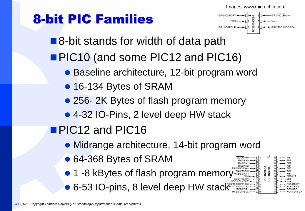
TUT Wireless Sensor Network (TUTWSN)
Very large research project in TUT/DCS since 2002
Sensor networks are emerging technology where the network consists of nodes that measure (‖sense‖) the
environment
communicate autonomously and wireleslly
self-organizing topology
may control actuators
Special courses TKT-2300 and TKT-2456
Copyright Tampere University of Technology Department of Computer Systems

#24/67
TUTWSN Nodes
Multisensor node
Includes many sensors
Used in TKT-3500
Other nodes
Pipe Node
Long range pipe node
Badge node
Wrist node
Ethernet gateway
http://www.tkt.cs.tut.fi/research/
daci/ra_tutwsn_prototypes.html
Copyright Tampere University of Technology Department of Computer Systems
#25/67
TUTWSN Multisensor node
Copyright Tampere University of Technology Department of Computer Systems

#26/67
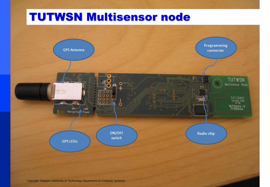
TUTWSN Multisensor node
Copyright Tampere University of Technology Department of Computer Systems
GPS receiver

#27/67
TUTWSN Multisensor node
Microcontroller: PIC18LF8722
256 kByte external SRAM
Sensors and modules
GPS (Global Positioning System) receiver
Radio – 2.4 GHz license free ISM band
Temperature
Humidity
Accelerometer
Compass
Luminance
Copyright Tampere University of Technology Department of Computer Systems

#28/67
TUTWSN Multisensor node
Add-on modules (not connected)
PIR (passive infrared, motion detector)
VGA Camera
Microphone
PCB Interface
1 Pushbutton, 1 led
Input/Output
RS-232 serial port
MAX3226E is used to convert voltage levels
SPI (Serial peripheral interface), I2C
4 input/output pins
ADC (analog-to-digital converter)
Copyright Tampere University of Technology Department of Computer Systems
#29/67
Power control
Possible power sources
a) DC power supply
b) 2 AA Batteries
c) Solar panel
All sensors can be turned off by uC
Voltage after regulation: 3 V/2 V and 2,7 V
2.7 V is used for GPS, 3V/2V (software
selectable) for other devices
Copyright Tampere University of Technology Department of Computer Systems

#30/67
PIC18LF8722
8 bit RISC microcontroller with Harvard architecture
High End 8-bit microcontroller
Accumulator… Assembly programming complicated
128 kB program memory, 4 kB SRAM, 1kB EEPROM
Operating voltage: 2.0 – 5.5 V Max. Power dissipation 1 W
Min. Power dissipation (@1 Mhz): 3 mW
Compare: Normal red led 2V and max 20 mA -> 40 mW
Image: www.futurlec.com
Copyright Tampere University of Technology Department of Computer Systems

#31/67
PIC18LF8722
Plenty of peripherals
SPI, I2C, USART
16 channel 10-bit AD-converter
5 timers and capture/compare/PWM module
HW 8-bit multiplier
Watchdog, Brown-out
Max. Frequency: 40 Mhz
Many power management modes
Clock sources on platform:
Low frequency external clock
Internal clock
Copyright Tampere University of Technology Department of Computer Systems

#32/67
C18 compiler and Programming
Microchip’s C-compiler for PIC18
microcontrollers
Not optimal but student version is free
Limitations in student version after 60 days:
No optimiztions
Processor works only in normal mode (77 instructions)
Microchip ICD2 - In-Circuit Debugger
Includes 5V Power supply
Not used with TUTWSN nodes due to lower
voltages -> External voltage source needed
Works fine with MPLAB IDE
Image: www.microchip.com
Copyright Tampere University of Technology Department of Computer Systems

#33/67
GPS: iTrax03-s+GeoHelix–S
Fasttrax iTrax03-s
Includes lots of functionality: only few
extra components needed
Communication: USART with NMEA
(National Marine Electronics Association)
messages
Operating voltage: 2.7 – 3.3 V
Max power dissipation 500 mW
Sarantel GeoHelix-S
Active GPS antenna
Operating voltage: 2-3.5 V
Typical current 15 mACopyright Tampere University of Technology Department of Computer Systems

#34/67
Radio: nRF24L01
Operating voltage: 1.9 – 3.6 V
Frequency: 2.400 – 2.4835GHz
Communication: SPI
Fully automated packet handling
Current consumption:
Power down 900 nA
Standby 22 uA or 320 uA (Two standby modes)
Transmission < 11.3 mA, Reception < 12.3 mA
Range about 15-30 meters indoors
Antenna dependable
Image: www.nordicsemi.com
Copyright Tampere University of Technology Department of Computer Systems

#35/67
Temperature Sensor Maxim DS620
Operating voltage: 1.7 – 3.5 V
Communication: I2C
Selectable resolution:
LSB 0.5°C, 0.25°C, 0.125°C or 0.0625°C
Conversion time depends on accuracy
10 bit 25 ms, 13 bit 200 ms
Continuos conversion and one shot modes
Image: www.maxim-ic.com
Copyright Tampere University of Technology Department of Computer Systems

#36/67
Humidity: Sensirion SHT1x
Humidity AND temperature sensor
Operating voltage: 2.4 – 5.5 V
Communication: ‖almost I2C‖ Not compatible with standard I2C interface
Conversion times: 11 ms (8 bit)
210 ms (14 bit)
Accuracy: Humidity 2 %, temperature 0.3 °K
Current consumption: Sleep 0,3 uA, measuring 550 uA
Copyright Tampere University of Technology Department of Computer Systems

#37/67
Accelerometer: VTI SCA3000
3D accelerometer
Operating voltage: 2.35 – 3.6 V
Communication: SPI
Modes:
Free fall detection
Motion detection
Normal mode
Current consumption 120 uA in active mode
Image: www.vti.fi
Copyright Tampere University of Technology Department of Computer Systems

#38/67
Compass: Hitachi HM55B
Operating voltage: 4.8 – 5.2 V
Communication: SPI
Transmission length 4 bits (normal SPI 8 bits)
Current consumption: Sleep 1 uA, Measuring
9 mA
Measuring time 30 ms
Resolution: 11 bits
Measures magnetic field strength
Min. value -180 uT max. 180 uT
Image: www.parallax.com
Copyright Tampere University of Technology Department of Computer Systems

#39/67
Luminance: Agilent APDS-9002
Photosensor: Luminance is relative to current
Operating voltage: 2.4 – 5.5 V
Connected to uC’s analog-to-digital converter
Resolution equals AD-converter’s resolution
10 bit in PIC18LF8722
Sample rate = ADC’s sample rate
In PIC user selectable, but depends on clock
frequency. About 1 Mhz is theoretical maximum
PIC’s AD-converter operates also in idle
mode
Completion of conversion can cause an interrupt
Image: www.farnell.com
Copyright Tampere University of Technology Department of Computer Systems

#40/67
PIR MS300
PIR = Passive Infra Red
Connected to uC’s ADC, but needs an operating
voltage
Used as motion detector
Operating voltage: 2.6 V – 5.5 V
Current consumption: ~35 uA
Copyright Tampere University of Technology Department of Computer Systems
#41/67
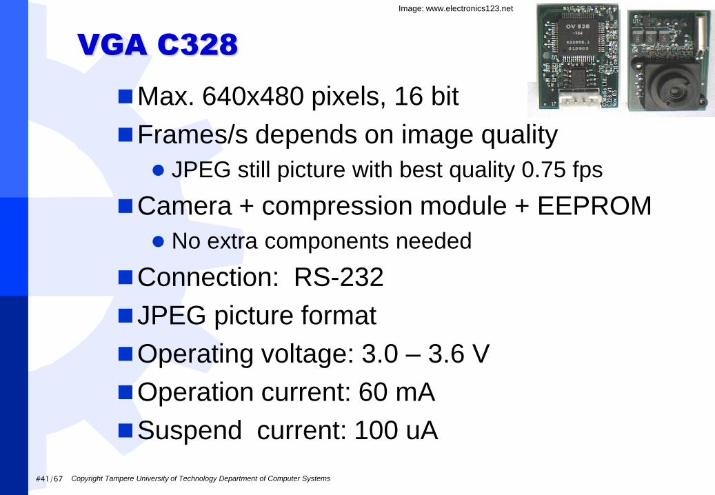
VGA C328
Max. 640x480 pixels, 16 bit
Frames/s depends on image quality
JPEG still picture with best quality 0.75 fps
Camera + compression module + EEPROM
No extra components needed
Connection: RS-232
JPEG picture format
Operating voltage: 3.0 – 3.6 V
Operation current: 60 mA
Suspend current: 100 uA
Image: www.electronics123.net
Copyright Tampere University of Technology Department of Computer Systems

#42/67
Microphone AOM-6746P-R
Capacitor microphone
Omnidirectional
Picks up sound evenly from all directions
Connection: ADC
PIC18LF8722 has 16 ADC channels, but one converter
Image: www.farnell.com
Image: www.farnell.com
Copyright Tampere University of Technology Department of Computer Systems

#43/67
ARDUINO
Copyright Tampere University of Technology Department of Computer Systems

#44/67
What is Arduino
An open source project for embedded systems that has
Modular HW design (open source), connect new external devices/modules,
‖shields‖, without soldering or any HW design understanding
Easy to use open source (and free) integrated development environment
Uses by default weird ―Processing‖ language for those who cannot program (artists)
More or less, just a library of C/C++ functions
Luckily, assembly, C and C++ are usable and you can do everything from a scratch
HW are made by various companies, including some ‖proprietary‖ shields
Each Arduino I/O board has an Atmel ATmega MCU
The MCU has a bootloader, which can be used to flash new program image
to the MCU through serial interface
Thus, there is no need for additional programming device
As long as no one corrupts/overwrites the bootloader section
Cheap, well supported, quality HW compared to the ‖tein ite, säästin‖,
excellent for hobbyists
More info:
http://arduino.cc/
Maybe some day this course will use Arduino boards..
Copyright Tampere University of Technology Department of Computer Systems

#45/67
Arduino Hardware examples
Copyright Tampere University of Technology Department of Computer Systems
I/O Boards:
Image © Arduino arduino.cc
Shields:
Ethernet / Image: © Arduino arduino.cc
Motor control / Image: © ???

#46/67
TI LaunchPad
MSP430 LaunchPad (MSP-EXP430G2)
http://processors.wiki.ti.com/index.php/MSP4
30_LaunchPad_%28MSP-EXP430G2%29
Copyright Tampere University of Technology Department of Computer Systems

#47/67
WHAT EMBEDDED MCU
SYSTEMS ARE MADE OF?
Copyright Tampere University of Technology Department of Computer Systems

#48/67
Knowhow
Even if you are software oriented, you must understand
some basics of hardware
If you do not want, you will still have to
Hardware oriented may succeed without understanding
software, but it helps to communicate with software oriented
people
And you may give them some ‖good‖ tips/hints
… but you do not need to know everything from both of the
worlds
Lecturer does not really know anything about EMC stuff
This course consentraits more on the software and gives
basics of hardware
Go to ELE –courses for better hardware understanding
Copyright Tampere University of Technology Department of Computer Systems

#49/67
Practical work
Read a data sheet
Read some more of the data sheet
Try to figure out what the data sheet says
Implement by following the data sheet
Nothing works, so read even more of the data sheet
In some cases, start reverse engineering the target
due to a crappy data sheet
In other cases, find the one line in 400 pages of data
sheet, which says that register X must be inverted in
this special occasion etc.
Move to the next component and start from the
beginning…
Copyright Tampere University of Technology Department of Computer Systems

#50/67
DEBUGGING (AT ABSTRACT
LEVEL)
Copyright Tampere University of Technology Department of Computer Systems

#51/67
Colwell, Power of most likely
―Unquestioned assumptions are by far the
biggest time-waster for system debuggers‖
When a system malfunctions, the most likely
causes get attention first
Checking simple things first is a good policy,
as anyone who has ever wasted time on a
computer or peripheral only to find it wasn’t
plugged in can testify.
After checking the simple things, attitude
matters
Copyright Tampere University of Technology Department of Computer Systems

#52/67
Debug rules [Colwell]
1. Change one thing at a time
2. Don’t ignore the unexpected
3. Follow the bug trail
4. Reduce complex phenomena to simple absolutes
5. Keep accurate lab notes
6. Debug is an immersion activity
7. Bugs almost never live alone
8. Test your test equipment
9. Know when you’re stuck, and call in the cavalry
Copyright Tampere University of Technology Department of Computer Systems

#53/67
Debug rules (2)
1. Change one thing at a time
Otherwise you won’t know what caused the change in system’s behavior
Even if you’re chasing down a systems issue that requires an hour to set up, the temptation can be very strong to ―try a couple of things‖ per run.
1. Don’t do it.
However, don’t make irreversible changes to the system during debug
2. Don’t ignore the unexpected
Investigate all suspicious behavior
Copyright Tampere University of Technology Department of Computer Systems

#54/67
Debug rules (3)
3. Follow the bug trail
You need to follow the bug trail wherever it leads,
not just where you wish it would go
4. Reduce complex phenomena to simple
absolutes
Strip the system down to the simplest configuration
that still shows the problem
This reduces the number of possibilities to consider
when generating hypotheses about what could be
wrong and what to try next
Faster compilation, synthesis, simulation, analysis
etc.
Copyright Tampere University of Technology Department of Computer Systems

#55/67
Debug rules (4)
5. Keep accurate lab notes1. What you’re doing
2. why you’re doing it
3. what should be the result
4. the results you get
This way you must focus more deeply in what you are doing
Others can refer to your notebook and leverage your work instead of unknowingly replicating it.
If you forget the details, it becomes a virtual certainty that a related bug will appear several months down the road, and it will be déjà vu—all over again.
Copyright Tampere University of Technology Department of Computer Systems

#56/67
Debug rules (5)
6. Debug is an immersion activity
Allocate several hours
1. to set up a system run
2. to run the experiment,
3. to analyze the result
Don’t allow distractions.
If you are interrupted, you’ll probably have to
start over
This is one reason serious debug often happens
wee hours of the morning.
Copyright Tampere University of Technology Department of Computer Systems

#57/67
Debug rules (6)
7. Bugs almost never live alone
Where you find one bug, there are often others
1. Other problems in the same module Remember that 20% of code modules cause
80% of faults
While you’re in the neighborhood,check for them
2. Similar problems elsewhere Check buffer overflows in all places when you
encounter one
Ensure that the ‖fix‖ does not break anything
Copyright Tampere University of Technology Department of Computer Systems

#58/67
Debug rules (7)
8. Test your test equipment
check instruments against one another
9. Know when you’re stuck, and call in the cavalry
Some people just are good at finding errors
People easily become ‖blind‖ to their own work
Copyright Tampere University of Technology Department of Computer Systems

#59/67
Further reading
Jakob Engblom, Debugging real-time
multiprocessor systems: Part 1 -Programming
parallel machines and Part 2 - Debugging
Parallel Programs, Embedded.com, March
2006 http://www.embedded.com/columns/technicalinsights/183701679?_requestid=345393
Copyright Tampere University of Technology Department of Computer Systems

#60/67
Lecturer’s notes (1)
Modern day approach: iterate
instead of hacking everything together at once and then
starting to debug
Start from small things: ensure basic communication
before testing AND debbuging the whole thing
Ensure that the configuration has been successfully written to
the device/pheriperal, many devices have ‖echo‖ or read
command, check it!
While iterating, complement implementation and do
integration testing/debugging
Even in industry one programmer might be
responsible for design, implementation, and testing
of the code in the embedded world
Copyright Tampere University of Technology Department of Computer Systems

#61/67
Lecturer’s notes (2)
Programmer:
You must know hardware when working with embedded systems Which ‖O‖ pin is connected to which ‖I‖ pin (configurable I/O, remember to
check direction)
Nokian vesikriisi..
If you are stuck, remember to check HW schemas and ensurecorrect pin configuration
Start from the simple ones: does the DUT (design/device under test) have supply current, connect oscilloscope and verify that there is something meaningful going on the interface
HW designer:
You must know software, HW cannot be tested (completly) withoutsoftware
If a programmer complains that HW does not work, ask goodquestions Question configuration, ask for very basic tests: ”have you written
something to the register X and read it back then?”
If you have failed, some HW things can be ‖corrected‖ withsoftware…
Copyright Tampere University of Technology Department of Computer Systems

#62/67 Erno Salminen - Nov. 2008
Version control
Use version control (Git, SVN, ...)
Teaches one to take logically consistent steps
in a project
Helps backup process
Easy throw-away code prototyping
Keeps track of your work (how many changes
in a week?)
Keeps track who did what
One can go back to see any previous version
A must for all work
Copyright Tampere University of Technology Department of Computer Systems

#63/67
Conclusions
Copyright Tampere University of Technology Department of Computer Systems

#64/67
At first
Make sure that
simple things work
before even trying
more complex onesHUOM! OBS!
Muy importante!
Copyright Tampere University of Technology Department of Computer Systems

#65/67
Two great truths in design
1.If it's not tested,
it's broken
2.If it's not simple,
it's broken[M. Keating, ISQED, 2006]
Copyright Tampere University of Technology Department of Computer Systems

#66/67
Conclusions
Microprocessors/controllers are used practically everywhere
High volume necessitates cheap price per device
This allows only modest performance
Controllers integrate several peripherals into same chip with processor
In embedded systems, designers target certain performance level, not for max. perf.
System is optimized (made maximally cheap) while still meeting the requirements
Programmability allows faster development and upgrades also after shipping
Connectivity of components is the key in many projects
Exercise platform integrates many sensors. Extremely good for educational purposes
Portability and shorter dev.time favor using high-level languages (C/C++) instead of assembly
Copyright Tampere University of Technology Department of Computer Systems

#67/67
Extra slides
Reminder: microprocessor basics
Copyright Tampere University of Technology Department of Computer Systems

#68/67
Stored program concept
Program’s instructions (control statements) are
stored in memory
In contrast to e.g. ASIC, in which the control is hard-wired
during manufacturing
CPU repeats fetch-execute cycle for every instruction
Originates from Turing machine (1936) that
manipulates data based on the instructions and state
of the machine
The behavior can be programmed
An universal machine – it can simulate the behavior of any
other machine
Theoretical concept that assumes infinite memory capacity
Copyright Tampere University of Technology Department of Computer Systems
#69/67
Memory types
Every microprocessor needs some memory May be internal (on the same chip), external, or
combination
1. Instruction memory Stores the program’s inctructions
Non-volatile – keeps the information when powered off mask-programmed read-only memory (ROM)
(electronically) erasable programmable ROM (EEPROM/EPROM)
flash memory
2. Data memory Stores the program’s variables and status
Most parts volatile – contents lost when powered off static random access memory (SRAM), dynamic RAM
(DRAM)
Some parts may be non-volatile EEPROM, Flash, (in principle also hard-disk)
Copyright Tampere University of Technology Department of Computer Systems
#70/67
Memories (2)
Memory type affects cost, speed, area, and power
consumption notably
E.g. SRAM is expensive, fast, area- and power consuming
technology
The program may be copied from non-volatile mem
to faster RAM during initalization
The same RAM may contain both program and data
sections as well (classical von Neumann architecture)
Whereas Harvard architecture separates program and data
address spaces
‖Memory is guilty until proven innocent‖ –
E.Salminen
= They cause lots of headache in embedded world
Copyright Tampere University of Technology Department of Computer Systems

#71/67
Microprocessor Programming
A program is a set of instructions written in a specific sequence for a processor to accomplish specified tasks
An instruction is defined as a simple task (such as addition) performed by the microprocessor
To the microprocessor, instructions must be supplied in binary, i.e., as machine language
Instruction-set is processor-specific (PIC, x86, MIPS…)
Assembly language is a symbolic language which represents machine-language instructions with short human-readable mnemonics
For example, in PIC assembler a null operation or ‘no operation’is represented by the mnemonic ‘NOP’
One-to-one correspondence between the assembly language mnemonics and the machine code instructions
An assembler is a software tool that converts assembler source programs into machine language object files
Copyright Tampere University of Technology Department of Computer Systems

#72/67
Machine and assembly languages are referred to as low-level languages Generally faster and more
compact than higher-level language programs
Not portable to other processors, tedious to write
High-level languages are machine-independent E.g. C/C++, Java
Program’s source codes are translated by compilers or interpreters into machine language
The translated code is called object code
Easier to debug and port
CPU+mem+etc
compiler
assembler
interpreter
de
sig
n-tim
eru
n-tim
e
.c, .h
.asm
.java
.hex
Microprocessor Programming(2)
Copyright Tampere University of Technology Department of Computer Systems

#73/67
CPU’s instruction-set architecture (ISA)
Defines the supported machine-instructions
Defines size of instruction word and its fields Operation codes (ADD, SUB, JMP...)
Parameters (src0, src0, dst)
Whether params are in registers or in memory
Addressing types (direct, indirect...)
add/sub/
AND/XO
R/OR...
src0 src1 dst
instr type 1
instr type 2
add/sub/
AND/XO
R/OR...
src0
(also dst)
immediate
add reg0, reg5, reg3
i.e. reg3 ← reg0 + reg5
and reg0, 0x500
i.e. reg3 ← reg0 & 0x500
instr type 3jmp address goto Nevada
i.e. PC ← address of label Nevada
...
015 347811
Copyright Tampere University of Technology Department of Computer Systems

#74/67
Micro-architecture
Defines the HW resources that implement ISA arithmetic-logic unit (ALU) performs the actual computation
control logic fetches the instructions, decodes them and passes to ALU
registers store temporary data
(optional) internal memories store instructions and/or data
memory and IO buses provide connection to outside world
Peripherals perform supplementary tasks
There may be several micro-architectures for the same ISA
digital IO
instr. fetch ext. mem IO
instr. mem
data mem
instr. decode
oscillator
register filepipeline ctrl ALU
timer
power ctrl analog IO
watchdog
CPU
peripherals
micro-
controller
multiplier
Copyright Tampere University of Technology Department of Computer Systems

#75/67
Clock cycle and Instruction cycle
Machine operations are sequenced by clock signal
Provided by external or internal oscillator (RC circuit, INV-
loop, quartz crystal)
Oscillator signal may multiplied/divided by constant (e.g. 10
MHZ * 4 = 40 MHZ)
Execution of machine instruction may take more than
one clock cycle
4 clock cycles/instr. in PIC
40 MHz clock yields approx. 10 MIPS
Some instructions take over 4 cycles, e.g. operations
affecting program counter (PC)
Some CPUs pipeline the execution of instructions
E.g. instr takes 4 cycles but the next finishes after 1 cycle
Copyright Tampere University of Technology Department of Computer Systems

#76/67
Program flow
CPU executes instructions step by step
Instructions are executed consecutively (addresses
0x0, 0x2, 0x4) until
a) Branch occurs – if-then-else, function call, goto
b) Exception occurs – interrupt, div-by-zero
The address of the next instruction is stored into
register program counter (PC)
Interrupts are function calls made from HW
a) Timer overflow (e.g. 1ms passed)
b) Peripheral device (e.g. serial IO transmit completed)
c) External pin (e.g. from button or sensor)
Extremely useful concept
Copyright Tampere University of Technology Department of Computer Systems

#77/67
Program flow (2)
After reset, PC gets the value of reset
vector
Usually rst vec points to some sort of
(compiler-generated) initialization
function that will call the user’s main
function
Call graph shows which functions are
called and their order (nesting)
Interrupt service routine (ISR) may be
called ‖anywhere‖
After that execution continues from the
interrupted point
init(){
...
main()}
main(){
...
foo()
...
while(1){}
foo() {
...
bar() ...
return
bar(){
...
return
isr() {
....
return from int}
0x0rst vec
Copyright Tampere University of Technology Department of Computer Systems


![Atmel SAM3S4 SAM3S2 SAM3S1 Datasheet...PCK0-PCK2 In-Circuit Emulator 24-Bit SysTick Counter FLASH 256 KBytes 128 KBytes 64 KBytes SRAM 48 KBytes 32 KBytes 16 KBytes WKUPx TC[3..5]](https://img.pdfslide.us/doc/110x75/60b24c17c6049f6cff2e0b48/atmel-sam3s4-sam3s2-sam3s1-datasheet-pck0-pck2-in-circuit-emulator-24-bit-systick.jpg)