Embed Size (px)
Citation preview
8/8/2019 TK-99D Installation Instructions
http://slidepdf.com/reader/full/tk-99d-installation-instructions 1/4
IS-TK-99D
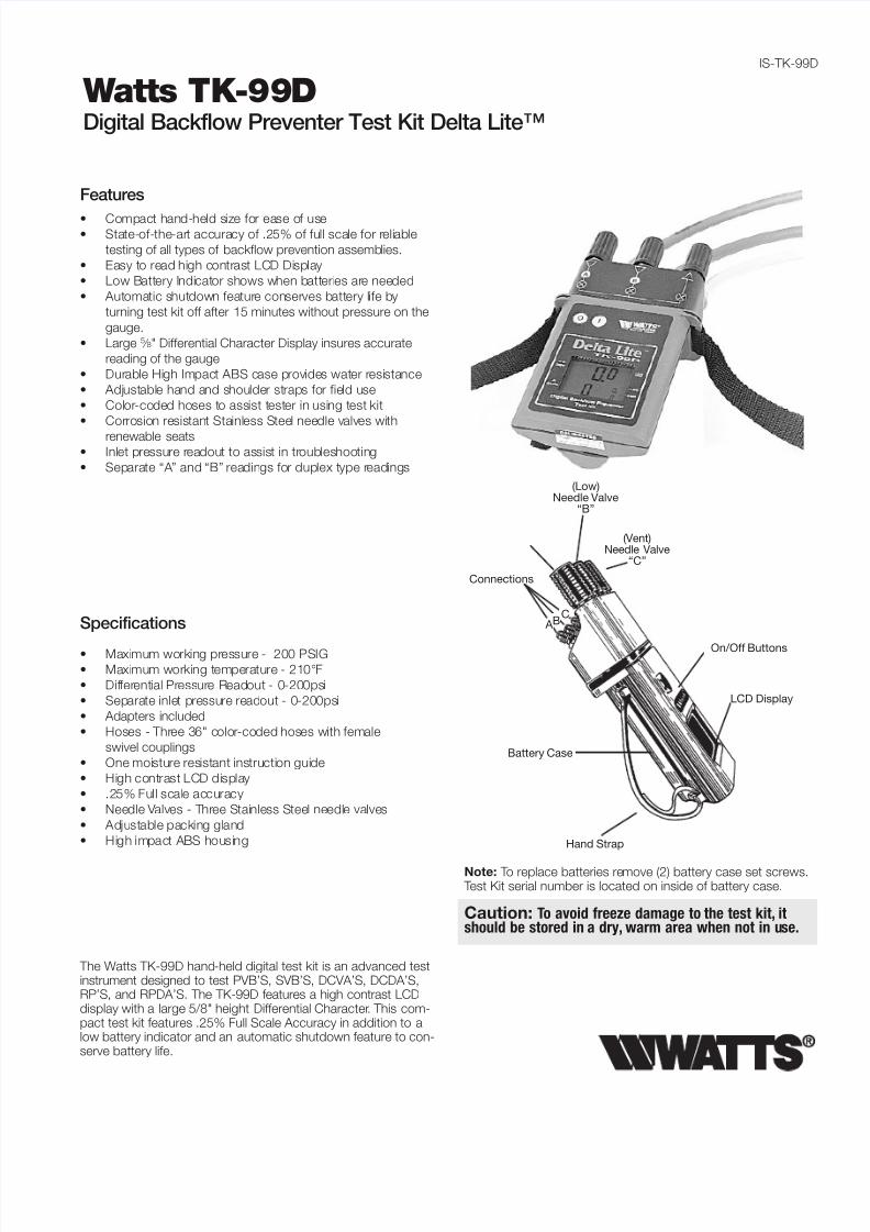
The Watts TK-99D hand-held digital test kit is an advanced testinstrument designed to test PVB’S, SVB’S, DCVA’S, DCDA’S,RP’S, and RPDA’S. The TK-99D features a high contrast LCDdisplay with a large 5/8" height Differential Character. This com-pact test kit features .25% Full Scale Accuracy in addition to alow battery indicator and an automatic shutdown feature to con-serve battery life.
Watts TK-99DDigital Backflow Preventer Test Kit Delta Lite™
Specifications
• Maximum working pressure - 200 PSIG
• Maximum working temperature - 210°F
• Differential Pressure Readout - 0-200psi
• Separate inlet pressure readout - 0-200psi
• Adapters included
• Hoses - Three 36" color-coded hoses with female
swivel couplings
• One moisture resistant instruction guide
• High contrast LCD display
• .25% Full scale accuracy
• Needle Valves - Three Stainless Steel needle valves
• Adjustable packing gland
• High impact ABS housing
• Compact hand-held size for ease of use• State-of-the-art accuracy of .25% of full scale for reliable
testing of all types of backflow prevention assemblies.
• Easy to read high contrast LCD Display
• Low Battery Indicator shows when batteries are needed
• Automatic shutdown feature conserves battery life by
turning test kit off after 15 minutes without pressure on the
gauge.
• Large 5 ⁄ 8" Differential Character Display insures accurate
reading of the gauge
• Durable High Impact ABS case provides water resistance
• Adjustable hand and shoulder straps for field use
• Color-coded hoses to assist tester in using test kit
• Corrosion resistant Stainless Steel needle valves with
renewable seats• Inlet pressure readout to assist in troubleshooting
• Separate “A” and “B” readings for duplex type readings
Features
Hand Strap
(Vent)Needle Valve
“C”
(Low)Needle Valve
“B”
Connections
A
LCD Display
Battery Case
Note: To replace batteries remove (2) battery case set screws. Test Kit serial number is located on inside of battery case.
Caution: To avoid freeze damage to the test kit, itshould be stored in a dry, warm area when not in use.
On/Off Buttons
BC

8/8/2019 TK-99D Installation Instructions
http://slidepdf.com/reader/full/tk-99d-installation-instructions 2/4
Test Procedure for Reduced Pressure Assembly
A. All needle valves must be closed on test kit.
B. Open test cock No. 4 and flush test cocks Nos. 1, 2 and 3on reduced pressure assembly. Close test cock No. 4.
C. Attach hoses as shown. High side hose between TC #2
and low side hose to TC #3 and close No. 2 shutoff. Bleed
air from kit by opening TC #4 to establish flow through the
backflow preventer and prevent premature opening of the
relief valve. Open TC#3, needle valve “B “, and vent needle
valve. Close needle valve “B”. Open TC#2 and needle valve
“A”, close needle valve “A” and TC #4. Attach vent (yellow)
hose to TC#4 and vent needle valve. Open TC #4 and
loosen hose at vent needle valve connection bleeding air
from test kit. Re-tighten hose to vent needle valve.
High (red)
909QT-S shown
Turn Test Kit On
Test No. 1 - Check Valve No. 2
Purpose: To test check valve No. 2 for tightness against reverse
flow.
Requirements: Valve must be tight against reverse flow under
all pressure differentials.
Step 1 With vent needle valve open, slowly open needle
valve “A”. (keep “B” closed)
Step 2 Indicated pressure differential will decrease slightly.
If pressure differential continues to decrease (until
the relief valve opens) the No. 2 check valve is
reported as “leaking”.
Test No. 2 - Shutoff Valve No. 2
Purpose: To test shutoff valve No. 2 for tightness.
Step 1 After passing Test No. 1, continue to test No. 2 by
closing test cock No. 2.
Step 2 The indicated pressure differential will decrease
slightly. If pressure differential continues to decrease
(approaching Zero), the No. 2 shutoff valve is re-
ported to be leaking. Note: A leaking No. 2 shutoff
will give a false reading in tests No. 3 and 4.
Test No. 3 - To test No. 1 check valve
Purpose: To test check valve No. 1 for tightness.
Requirements: Valve must be tight against reverse flow under all
pressure differentials.
Step 1 Close needle valve “A” high side (red) and open test
cock No. 2
Low (blue)
Bypass(yellow)
Test Procedure for Anti-Spill Vacuum Breaker
The following test procedure is one of several that is recognized
throughout the United States for verification of the functioning of
Backflow Preventers.
The following procedure is not a specific recommendation. The
Watts series of test kits are capable of performing any of the
recognized Backflow Preventer test procedures.
Note: For all of the following tests the test kit must be held at
the same level as the assembly being tested.
A. Before starting test, all needle valves on the test kit mustbe closed.
B. Flush test cocks before testing.
Test Cock
High(red)
Test No. 1 and 2, Watts 008QT shown
Turn Test Kit On
Test No. 1 - Differential Test
Requirement: Differential pressure across check must be 1.0
PSID or above.
Step 1 Remove two screws on top of hood then remove
hood.
Step 2 Install hose between test cock and connection “A”
high side (red) of test kit.
Step 3 Open test cock then open needle valve “A” and vent
or bypass needle valve. Bleed air from hose then
close vent needle valve.
Step 4 Close shutoff valve No. 2 then shutoff valve No. 1 on
the assembly.
Step 5 Slowly unscrew bleed screw on spill proof vacuum
breaker body to relieve pressure down stream of
check (about 3 turns)
Step 6 When dripping from bleed screw stops and gauge
stabilizes, record the differential pressure and re-
tighten bleed screw.
Test No. 2 - Air Inlet - Vent Opening
Requirement: Air inlet must start to open when supply pressure
is 1.0psi or above. Air inlet must be fully open when supply
pressure is atmospheric.
Step 7 Slowly open vent needle valve until gauge reads
1.0 PSID then close vent needle valve holding pres-
sure at 1.0 PSID.
Step 8 Visually inspect that the vent on top is slightly open,
about 1⁄32", to pass test.
Step 9 Open vent needle valve fully until dripping from vent
connection stops.
Step 10 Visually inspect that the vent is fully open to pass test.
Step 11 Replace hood and two screws on top of assembly.
Step 12 Restore valve to original working condition.
Note: After test, leave all valves on test kit must be fully openand hose removed to prevent freeze damage to test kit.
2

8/8/2019 TK-99D Installation Instructions
http://slidepdf.com/reader/full/tk-99d-installation-instructions 3/4
High(red)
TestCockNo. 2
Test CockNo. 1
Test Procedure for Pressure Type VacuumBreaker
Note: For both of the following tests the test kit must be held at
the same level as the assembly being tested.
A. Before starting test all needle valves must be closed.
B. Flush test cock #2 and #1.
Turn Test Kit On
Test No. 1 - Air Inlet
Requirement: Air inlet must start to open when down stream
pressure is 1.0psi or above.
Step 1 Remove two screws on top of hood and remove
hood.
Step 2 Install hose between test cock No. 2 and connection
“A” on high side(red) on test kit.
Step 3 Open test cock No. 2 and needle valve “A” high side
(red) on test kit.
Step 4 Open vent needle valve and bleed air from hose.
Then close vent valve.
Step 2 Close test cock No. 4. Disconnect bypass hose (yel-
low) at test cock No. 4. Close vent needle valve.
Step 3 Open needle valve “B” and vent or bypass needle
valve, bleeding to atmosphere, then closing needle
valve “B” restores the system to a normal static
condition.
Step 4 Observe the pressure differential gauge. If there is a
decrease in the indicated value, the No. 1 check valve
is reported as leaking.
Test No. 4 - Pressure Differential Relief Valve
Purpose: To test Operation of pressure differential relief valveRequirements: The pressure differential relief valve must operate
to maintain the “zone” between the two check valves at least
2psi less than the supply pressure.
Step 1 Close vent or bypass needle valve
Step 2 Open needle valve “A” high side.
Step 3 Open needle valve “B” low very slowly until the differ-
ential reading starts to drop.
Step 4 Hold the valve at this position and observe the read-
ing at the moment the first discharge is noted from the
relief valve. Record this as the opening differential
pressure of the relief valve. Note: it is important the
differential reading drop slowly.
Step 5 Close test cocks Nos. 2 and 3.
Step 6 Use bypass hose (yellow) to relieve pressure from testkit by opening needle valve “A”, “B”, and vent needle
valve.
Step 7 Remove all test equipment and open No. 2 shutoff
valve of the device.
Test No. 1
800M4QT shown
Test No. 2
800M4QT shown
High(red)
Test CockNo. 1
Test CockNo. 2
Test No. 2 - Test check Valve Pressure DropRequirement: Supply pressure drop must be 1.0 PSID or more
when water flow stops from test cock No. 2.
Step 10 Install hose between test cock No.1 and connection
“A” high side (red) on test kit.
Step 11 Open test cock No. 1 and bleed valve by opening
vent needle valve. Bleed air from hose then shut vent
needle valve
Step 12 Close shutoff valve #1.
Step 13 Open test cock No. 2. When flow of water out of test
cock No. 2 stops, the differential reading is the pres-
sure drop reading.
Step 14 Close test cock No. 1 and test cock No. 2. Remove
hoses.
Step 15 Replace hood and two screws on top of hood.
Note: After test, all valves must be open and hoses removed toprevent damage to test kit.
Step 5 Close shutoff valve No. 2 then shutoff valve No. 1.
Step 6 Slowly open vent needle valve just as air inlet opens.
Record differential pressure.
Step 7 Close test cock No. 2 and remove hose.
Step 8 Close vent needle valve.
Step 9 Open shutoff valve No. 1.
Test Procedure for Double Check Valve Assembly
A. Before starting test, all needle valves on test kit must be
closed.
B. Flush test cocks before test.
Turn Test Kit On
Test No. 1
High(red)
Low(blue)
Bypass(yellow)
007 shown
3

8/8/2019 TK-99D Installation Instructions
http://slidepdf.com/reader/full/tk-99d-installation-instructions 4/4
Calibration Repair Centers
Nicholson Labs11423 Queen City Ave.Cincinnatai, OH 45214Tel: (513) 251-8378
Fax: (513) 251-4388
BAVCO20435 S. Susana RoadLong Beach, CA 90810-1136Tel: (310) 639-5231Fax: (310) 639-0721
TechEn, Inc.115 Cedar StreetMilford, MA 01757Tel: (508) 478-0042
Fax: (508) 634-3208
email: [email protected]
Test No. 1 - Check Valve No. 1
Step 1 Insure shutoff No. 1 is open, shutoff No. 2 is closed.
Step 2 Install high side hose between connection “A” high
side and test cock No. 3, low side hose between “B”
low side and test cock No. 2 and open both test cock
No. 2 and No. 3.
Step 3 Open vent needle valve and bleed air by opening nee-
dle valve “A”. Close “A” then open needle valve “B”
bleeding air and then closing “B”.
Step 4 Connect bypass hose between vent needle valve and
loosely connect to test cock No. 1. Open needle valve“A” high side and vent needle valve to vent air from
bypass hose. Tighten bypass hose at test cock No. 1,
open test cock No. 1.
Step 5 Close shutoff No. 1. Slowly loosen hose connection at
TC# 2 until differential gauge rises to about 2psi then
tighten. If the differential reading does not decrease
record check valve as tight.
Step 6 Close all test cocks. Then close needle valves “A”, “B”,
and vent needle valve.
Test No. 2 - Check Valve No. 2
Step 7 Move the high side hose to test cock No. 4, low side
hose to test cock No. 3 and open both test cock No.
3 and 4. Remove bypass hose from test cock No. 1,
open shutoff valve No. 1.Step 8 Open vent needle valve and needle valve “A” to bleed
air. Close needle valve “A”. Open needle valve “B” to
bleed air and then close “B” and vent needle valve.
Step 9 Connect bypass hose loosely to test cock No. 1.
Open needle valves “A”high side and vent needle valve
to relieve air from the bypass hose. Tighten bypass
hose at test cock No. 1, open test cock No. 1.
Step 10 Close shutoff No. 1. Slowly loosen hose connection at
TC#3 until differential gauge rises to about 2psi, then
tighten. If the differential reading does not decrease
record check as tight. Close all test cocks and remove
hoses.
Note: The assembly will fail both the first and second check valve tests above, if shutoff No. 2 leaks excessively. To test for aleaky No. 2 shutoff, use the following procedure.
High(red)
Bypass(yellow)
Low(blue)
007 shown
Test No. 2
Test for Leaky No. 2 ShutoffStep 11 Connect the high side hose to test cock No. 1, low
side hose to test cock No. 4. Open test cocks No. 1
and 4. Close shutoffs No. 1 and 2.
Step 12 Close vent needle valve. Open needle valve “A” high
side, then open needle valve “B” low side + turn,
loosen hose at test cock No. 4 to remove air.
Retighten hose.
Step 13 If the differential gauge rises above 0 there is exces-
sive leakage at shutoff No. 2 and it must be replacedto test the assembly.
Test for Leaky No. 2 Shutoff
Low(blue)
High(red)
007 shown
IS-TK-99D 0829 EDP# 1910812 © Watts, 2008
USA: 815 Chestnut St., No. Andover, MA 01845-6098; www.watts.com
Canada: 5435 North Service Rd., Burlington, ONT. L7L 5H7; www.wattscanada.ca
Backf low Prevent ion Products
Limited Warranty: Watts Regulator Co. (the “Company”) warrants each product to be free from defects in material and workmanship under normal usage for a period of one year from the date oforiginal shipment. In the event of such defects within the warranty period, the Company will, at its option, replace or recondition the product without charge.THE WARRANTY SET FORTH HEREIN IS GIVEN EXPRESSLY AND IS THE ONLY WARRANTY GIVEN BY THE COMPANY WITH RESPECT TO THE PRODUCT. THE COMPANY MAKES NO OTHER WARRANTIES,EXPRESS OR IMPLIED. THE COMPANY HEREBY SPECIFICALLY DISCLAIMS ALL OTHER WARRANTIES, EXPRESS OR IMPLIED, INCLUDING BUT NOT LIMITED TO THE IMPLIED WARRANTIES OFMERCHANTABILITY AND FITNESS FOR A PARTICULAR PURPOSE.The remedy described in the first paragraph of this warranty shall constitute the sole and exclusive remedy for breach of warranty, and the Company shall not be responsible for any incidental, specialor consequential damages, including without limitation, lost profits or the cost of repairing or replacing other property which is damaged if this product does not work properly, other costs resulting fromlabor charges, delays, vandalism, negligence, fouling caused by foreign material, damage from adverse water conditions, chemical, or any other circumstances over which the Company has no control.This warranty shall be invalidated by any abuse, misuse, misapplication, improper installation or improper maintenance or alteration of the product.Some States do not allow limitations on how long an implied warranty lasts, and some States do not allow the exclusion or limitation of incidental or consequential damages. Therefore the abovelimitations may not apply to you. This Limited Warranty gives you specific legal rights, and you may have other rights that vary from State to State. You should consult applicable state laws todetermine your rights. SO FAR AS IS CONSISTENT WITH APPLICABLE STATE LAW, ANY IMPLIED WARRANTIES THAT MAY NOT BE DISCLAIMED, INCLUDING THE IMPLIED WARRANTIES OFMERCHANTABILITY AND FITNESS FOR A PARTICULAR PURPOSE, ARE LIMITED IN DURATION TO ONE YEAR FROM THE DATE OF ORIGINAL SHIPMENT.