Embed Size (px)
Citation preview
Title: Torsion of Noncircular Composite Cylinders Authors: Waddy T. Haynie email: [email protected]; tel: 757-864-3471; fax: 757-864-7064 Michael W. Hyer email: [email protected]; tel: 540-231-5372; fax: 540-231-4574 Department of Engineering Science and Mechanics Virginia Polytechnic Institute and State University Blacksburg, VA 24061 and Marshall Rouse email: [email protected]; tel: 757-864-3182; fax: 757-864-8911 Mechanics of Structures and Materials Branch NASA Langley Research Center Hampton, VA 23681
https://ntrs.nasa.gov/search.jsp?R=20050215117 2018-06-13T23:29:10+00:00Z

ABSTRACT
The paper presents a brief overview of the predicted deformation and failure characteristics of noncircular composite cylinders subjected to torsion. Using a numerical analysis, elliptical cylinders with a minor-to-major diameter ratio of 0.7 are considered. Counterpart circular cylinders with the same circumference as the elliptical cylinders are included for comparison. The cylinders are constructed of a medium-modulus graphite-epoxy material in a quasi-isotropic lay-up. Imperfections generated from the buckling mode shapes are included in the initial cross-sectional geometry of the cylinders. Deformations until first fiber failure, as predicted using the maximum stress failure criterion and a material degradation scheme, are presented. For increasing levels of torsion, the deformations of the elliptical cylinders, in the form of wrinkling of the cylinder wall, occur primarily in the flatter regions of the cross section. By comparison the wrinkling deformations of the circular cylinders are more uniformly distributed around the circumference. Differences in the initial failure and damage progression and the overall torque vs. twist relationship between the elliptical and circular cylinders are presented. Despite differences in the response as the cylinders are being loaded, at first fiber failure the torque and twist for the elliptical and circular cylinders nearly coincide. ____________ W.T. Haynie and M.W. Hyer, Department of Engineering Science and Mechanics, Virginia Polytechnic Institute and State University, Blacksburg, VA 24061 M. Rouse, Mechanics of Structures and Materials Branch, NASA Langley Research Center, Hampton, VA 23681

2
INTRODUCTION
Cylinders are often used as idealized models for structures such as aircraft fuselages, missile bodies, and tanks for storing and transporting various liquids and gases. Of general interest are deflections, stress levels, buckling loads, post-buckling response, vibration frequencies, and interaction with end-fittings, supports, and stiffeners. Structures based on cylinders with a circular geometry are very common and have been utilized and studied extensively. However, dimensional constraints or the nature of the payload to fit within the cylindrical structure may dictate that a noncircular geometry be considered. There may also be design advantages to a noncircular geometry, for example, to blend the wings and cylindrical body in advanced aircraft designs, or to achieve better lift characteristics from a flatter undersurface of an aircraft body.
A review of the structural analysis of noncircular cylinders through the late ‘90s is discussed in Reference 1, some of which addresses fiber-reinforced composite materials. Additional work with noncircular fiber-reinforced cylinders is discussed in References 2-7. For a cylinder with a noncircular cross section, the radius of curvature varies with circumferential position. This change in the radius of curvature can lead to a nonuniform stress state that results in what could be considered a stress concentration at specific circumferential locations. Because of the increased stress levels, material failure can begin at these circumferential locations. The severity of the problem depends to some extent on the particular loading, and combined loads add to the complexity of the problem. One approach to understanding the details of the response of noncircular cylindrical structures is to first consider simple and fundamental loadings. This approach is taken in References 3-7, where the response to a temperature change alone, an axial loading alone, and an internal pressure alone have been studied. Other fundamental loads of interest are torsion and bending, with the former being the subject of this paper.
The objective of this paper is to present analytical results of the predicted deformation and failure characteristics of noncircular composite cylinders subjected to the twisting of one end of the cylinder relative to the other. A full understanding requires considering the response well into the post-buckling regime. Here, twisting to first fiber failure is considered. As might be expected, matrix failure occurs before first fiber failure occurs. Though first fiber failure may be a somewhat arbitrary stopping point, it is the metric adopted for this study. The dimensions of the elliptical cylinder considered correspond to cylinders investigated in earlier experiments [6, 7] for other types of loading. Since material orthotropy influences the response of most composite structures, the noncircular cylinders considered here are constructed of an eight-layer quasi-isotropic lay-up. Thus the influence of the noncircular geometry on deformation and material failure is not masked by the influence of material orthotropy. As a comparison, a quasi-isotropic circular cylinder with the same circumference as the elliptical cylinder is studied. Noncircular and circular cylinders with the same circumference and length weigh the same. The predictions presented are determined using the finite-element code STAGS [8].
The next section describes the problem to be investigated. The geometry, coordinate directions, positive sense of the twist and off-axis fiber angles, material

3
properties, boundary conditions, and the finite-element model are described. In the section following that, since a specific cylinder geometry is being considered, comments regarding the effect of cylinder geometry on the buckling, or critical, angle of twist are presented. Unlike a cylinder constructed of aluminum, the direction, or sign, of the twist is important because of the presence of the bending-twisting stiffness terms D16 and D26. In subsequent sections the discussion focuses on the torsional moment, or torque, vs. twist characteristics and overall deformation and failure characteristics of elliptical cylinders for increasing levels of twist. PROBLEM DESCRIPTION
The geometry considered is described in Figure 1a. The elliptical cross section of the cylinder has major diameter 2a, minor diameter 2b, length L, and wall thickness H. A positive twist for the cylinder, φ, a positive associated torque, T, a positive fiber direction relative to the axial direction, θ, and a measure of circumferential arc-length, s, are also shown in Figure 1. The maximum and minimum radii of curvatures of the cross section, which occur at the ends of the minor and major axes, respectively, are given by the relationships
2 2
max min
a bR and R
b a= = . (1)
The counterpart circular cylinder (not shown) has radius R, and the relationship between R and the geometric parameters of the ellipse is
2
2 2 2 2
0
1cos sin
2R a t b t dt
!
!= +" , (2)
where t is a nondimensionsal parameter. The assumed elliptical cylinder geometry is shown in Table I.
TABLE I: ELLIPTICAL CYLINDER GEOMETRY a 0.127 m (5 in.) b 0.0889 m (3.5 in.) L 0.292 m (11.5 in.) H 8h
h (layer thickness) 0.1397 mm (0.0055 in.) With these dimensions, the ratio of the minor diameter to major diameter is 0.7, a value for which the ellipticity is noticeable, and the radius of the circular cylinder is R = 0.1088 m (4.283 in.).
The STAGS finite-element representation of the cylinder geometry consists of 6120 four-noded quadrilateral 410 elements, and is shown in Figure 1b. The 410

4
element enforces the Kirchhoff hypothesis. The finite-element mesh consists of 120 elements in the circumferential direction and 51 in the axial direction. The dimensions of the element in the circumferential and axial directions are the same at all locations. The cylinder is loaded kinematically by rotating about the cylinder centerline (the x-axis) the end of the cylinder at x = L/2 an amount φ relative to the end at x = -L/2. Each end maintains the geometry of the original elliptical cross section. This rotation is accomplished in the finite-element model by restraining all degrees of freedom of the nodes at x = -L/2 and constraining the nodes on the end at x = L/2 to remain in a plane and move as if attached to rigid links, the other ends of which are joined at a common point. This common point is actually a node in the finite-element analysis located on the x-axis. The rigid links are in a plane perpendicular to the x-axis and they rotate, in that plane, about the common point. Free axial motion of that plane is allowed, and except for what is effectively rigid body rotation and axial movement, the cylinder nodes at the rotated end are assumed to be clamped like the restrained end. The applied rotation φ of the end at x = L/2 is controlled by specifying the rotation of the common node about the x-axis. The torsional moment, or torque, corresponding to the applied rotation is computed by the finite-element analysis.
The quasi-isotropic lamination sequence considered is [±45/0/90]s. Material properties representative of a medium modulus graphite-epoxy composite material are assumed. The engineering properties for a single layer are defined in Table II, where standard composite material nomenclature in the principal material coordinate system has been used.
When examining the character of the predicted material failure, only failures within the planes of the individual layers are considered. The assumed failure modes are: failure parallel to the fiber direction due to fiber tensile or compressive failure; failure transverse to the fiber direction, due to matrix or fiber-matrix interface tensile or compressive failure; in-plane shear failure due to matrix or fiber-matrix interface shear failure. The maximum stress failure criterion is applied on a layer-by-layer basis, and the engineering properties are degraded when failure is detected. The degraded engineering properties, in turn, result in a stiffness matrix that reflects material softening due to failure. The five basic intralayer modes of failure in the principal material coordinate system are denoted as Xt = tensile failure stress in fiber direction Xc = compressive failure stress in fiber direction (a positive number) Yt = tensile failure stress transverse to fiber direction Yc = compressive failure stress transverse to fiber direction (a positive number) S12 = intralayer shear failure stress Numerical values of the failure stress levels for the five failure modes are shown in Table II.

5
TABLE II: MATERIAL PROPERTIES E1 130 Gpa (18.85 × 10³ psi) E2 9.7 Gpa (1.407 × 10⁶ psi) G12 5 Gpa (0.725 × 10⁶ psi) ν12 0.3 Xt 1.482 Gpa (215 × 103 psi) Xc 1.241 Gpa (180 × 103 psi) Yt 0.05 Gpa (7.25 × 10³ psi) Yc 0.2 Gpa (29 × 103 psi) S12 0.1 Gpa (14.5 × 10³ psi)
RESULTS AND DISCUSSION
When composite cylinders are twisted, the buckling load is different whether the direction of twist about the cylinder axis is positive or negative. This phenomenon has been observed in circular cylinders as discussed in References 11-12, and is best explained for the lay-up used in this paper as follows: Due to the fact that within the cylinder walls the +45° layers are farther apart than the -45° layers, the value of the laminate bending stiffness in the +45° direction is greater than the value of the laminate bending stiffness in the -45° direction. Referring to Figure 1, a negative twist of the circular cylinder causes a compressive stress resultant in the -45° direction, and a positive twist causes a compressive stress resultant in the +45° direction. Since the bending stiffness is greater in the +45° direction, it takes a greater compressive stress resultant acting in the +45° direction, and hence a greater positive twist, to produce buckling in the cylinder wall than if the compressive stress resultant were acting in the -45° direction. Influence of length-to-radius ratio
Before describing the details of cylinder response, it is instructive to put into context the geometry of the particular cylinders being investigated. The dependence of the angle of twist required to produce buckling on the length-to-radius ratio of the cylinder, as computed using a nonlinear eigenvalue analysis for both positive and negative twist and for both elliptical and circular cylinders, is illustrated in Figure 2. The critical angle of twist, expressed as twist per unit length of cylinder, is taken to be the lowest eigenvalue computed. For the elliptical cylinder L/Rmax is taken as the measure of the length-to-radius ratio. Also noted in the figure, by solid symbols, are the values for the cylinders considered herein. As can be seen, there are four distinct relationships. For both the circular and elliptical cylinders, applying a negative twist causes the cylinder to buckle at a lower level of twist than applying a positive twist. Independent of the sign of the twist, the buckling values for the elliptical cylinder are less than the values for the circular cylinder.
As the length of the cylinder increases relative to its radius, the difference between the relations for positive and negative twist decreases, and the difference

6
between the relations for elliptical and circular cylinders decreases. For the elliptical cylinders considered here
max/ 1.60L R = , while for the circular cylinders
/ 2.69L R = . For the elliptical and circular cylinders, respectively, min
/ 4.69L R = and
min/ 56R H = and / 97R H = . Based on Figure 2, the slopes of the curves near
the points for the cylinders considered here indicate boundary effects may influence the results. Longer cylinders are needed to reduce boundary effects. However, the dimensions of the elliptical cylinders analyzed in this paper were chosen because of the existing capability of fabricating the cylinders for experiments [6, 7].
The positive angle of twist that results in buckling of the counterpart circular cylinder, the solid red square in Figure 2, is
cir+
cr 0.0114 rad (0.66deg)! = (3) where the superscript ( )cir+ refers to the circular cylinder twisted in the +φ direction, and the subscript ( )cr refers to the critical value at which buckling occurs. Using length L = 0.292 m (11.5 in.) and the angle of twist from Equation 3, the positive angle of twist per unit length that results in buckling of the counterpart circular cylinder is
cir+
cr
0.039 rad/m (0.00099 rad/in.)L
!" #=$ %
& ' (4)
The associated buckling, or critical, level of torque is cir+
cr 6840N m (60,600lb in)T = (5) These quantities will be used for normalization in subsequent calculations. Torque-twist relationship
Inevitably, imperfections of some sort occur in most composite structures. For existing structures, any deviation from the intended geometry can be measured and considered in any analysis of the structure. In this case, without actual cylinders to consider, imperfections are added to the perfect geometry using small-amplitude deviations in the form of the buckling mode shapes. Normalized mode shapes associated with the first few torsional buckling eigenvalues are each multiplied by a small fraction of the wall thickness and added to the perfect geometry. Here, the first four mode shapes are combined with different weighting factors to give imperfections with a range of characteristics. Four of these cases will be discussed here, the results from these cases being representative of all cases investigated.
The first and fourth buckling mode shapes of the perfect elliptical cylinder subjected to a negative twist are shown in Figures 3a and 3b, respectively. Though these two mode shapes look similar due to their overall helical nature, the differences are illustrated in Figures 3c and 3d. At the midlength of the cylinder (x = 0), the circumferential variation of the displacements, normalized to unity and

7
normal to the surface of the ellipse, is illustrated in Figures 3c and 3d. In the figures the circumferential arc length location s is normalized by cylinder circumference C. Note that the first mode shape has seven waves in the circumferential direction and the fourth mode has eight. Note also that the amplitude of the waves is larger in the flatter regions of the cross section (s/C ≈ 0, 0.5) than in the more highly curved regions (s/C ≈ 0.25, 0.75). The eigenvalue associated with the first mode shape in Figure 3a corresponds to the solid green triangle in Figure 2.
The corresponding two mode shapes for the circular cylinder are shown in Figures 4a and 4b, where the eigenvalue associated with the first mode shape in Figure 4a corresponds to the solid blue circle in Figure 2. At the cylinder midlength, the variations with circumferential location of the normal displacements for the first and fourth mode shapes are illustrated in Figures 4c and 4d. There are eight circumferential waves for the first mode, and seven for the fourth mode. The amplitude of the waves is uniform with circumferential location.
The modes for the six imperfections considered are shown in Table III. In four cases the weighting factors multiplying the first four mode shapes sum to 0.1H, or 10% of the cylinder wall thickness, and in two cases they sum to 15%. The discussions will focus on the response of cylinders with imperfection IDs 01, 04, 11, and 14. These particular imperfections provide a mix of the mode shape weighting factors as well as a variation of the imperfection amplitude.
TABLE III: IMPERFECTIONS CONSIDERED Mode (×H)
Imperfection ID
1st 2nd 3rd 4th Total
01 0.04 0.02 0.02 0.02 0.10 02 0.02 0.04 0.02 0.02 0.10 03 0.02 0.02 0.04 0.02 0.10 04 0.02 0.02 0.02 0.04 0.10 11 0.06 0.03 0.03 0.03 0.15 14 0.03 0.03 0.03 0.06 0.15
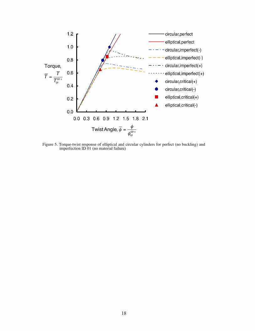
As an example of the response of the cylinders considered, the torque vs. twist relationships for several cases are illustrated in Figure 5. In this and subsequent similar figures, the twist per unit length and torque have been normalized by the values that result in buckling of the counterpart circular cylinder when twisted positively, i.e., the value for the solid red square in Figure 2 and given by Equations (4) and (5), to obtain
!
" and
!
T . The nearly straight red and blue lines in Figure 5 extending to a normalized torque level of 1.2 are the torque vs. twist responses, respectively, of the perfect elliptical and perfect circular cylinders for twist up to and greater than the critical eigenvalues. Despite the inclusion of geometric nonlinearities in the analysis, the torque vs. twist responses exhibit virtually linear behavior. The critical eigenvalues for the perfect cylinders, from Figure 2, are indicated on these lines as solid symbols and the differences between the critical

8
eigenvalues for positive and negative twist are evident, as they were in Figure 2. For twist levels greater than these critical eigenvalues, the cylinders are unstable.
The dashed and dash-dot lines in Figure 5 represent the torque vs. twist relationships for cylinders with imperfection ID 01. For imperfect elliptical and circular cylinders and for low levels of twist, the torque vs. twist relationships nearly coincide with the relationships for the perfect cylinders and the torque increases in a nearly linear fashion with increasing twist angle. At larger levels of torque, however, the torque vs. twist relations rapidly deviate from their nearly-linear character, the torque reaches a maximum level, and then decreases with increasing twist. For example, for the imperfect elliptical cylinder with a negative twist, the response identified by the yellow long-dashed line, the response deviates from the nearly-linear path at a normalized torque level of approximately 0.60, while the critical value occurs at a torque of 0.66 and is identified by the solid red triangle on the red line. The torque reaches a level of approximately 0.68, then decreases. The response of the imperfect elliptical cylinder is much the same for a positive twist, except the levels of torque at which deviation from the nearly-linear path (≈ 0.78) and the maximum occur (≈ 0.85) are greater than for a negative twist.
For the imperfect circular cylinder, the relationships, shown by the blue dash-dot line and green dash-double dot line, reach higher levels of torque, a characteristic presented in Figure 2. Furthermore, the maxima in the relationships are reached in a more pronounced fashion than for the elliptical cylinder, and the maxima occur at lower levels of twist. In fact, the difference between the imperfect elliptical and circular cylinders can be characterized by stating that the relations for the imperfect elliptical cylinder tend to slowly reach their maxima once they have deviated from the nearly-linear relationships, while the relationships for the circular cylinder more quickly reach their maxima and then decrease. Interestingly, as the twist angle increases and the torque levels decrease, the relationships for the circular and elliptical cylinders nearly coincide.
Wrinkling of the cylinder wall, in a helical pattern much like the buckling modes of Figures 3 and 4, is responsible for the reduced levels of torque as the twist increases. End views of the wrinkling behavior of the elliptical and circular cylinders at the same level of twist are illustrated in Figure 6, in exaggerated fashion. For the circular cylinder, shown in Figure 6b, the amplitude of the wrinkling deformations is distributed more or less uniformly around the circumference of the cylinder, whereas for the elliptical cylinder, shown in Figure 6a, the wrinkling is more pronounced in the flatter regions of the cross section relative to that in the more curved region.
The differences in the circumferential distribution of wrinkles between the elliptical and circular cylinders explains why the torque vs. twist relation for the elliptical cylinder does not seem to have as pronounced maxima as those for the circular cylinder. With the elliptical cylinder, as the twist level increases, wrinkling starts in the flatter portions of the cross section, while the more highly curved portions remain relatively undeformed. The cylinder begins to soften in torsion. As the twist level continues to increase, the wrinkling spreads around the circumference and the softening effect increases. However, due to the spreading character of the wrinkling, the softening is gradual. In contrast, with a circular cross section, no particular circumferential location is different than any other

9
circumferential location. The same level of wrinkling occurs at all circumferential locations as the twist level increases. The cylinder more suddenly softens as the wrinkles develop in concert everywhere around the circumference. For a given level of twist, the amplitude of the wrinkles in the flatter portion of the elliptical cross section are greater than the amplitude of the wrinkles in the circular cross section. At a twist level of 0.04 rad/m (0.001 rad/in.), the wrinkling deflections in the ellipse are slightly greater than three wall thicknesses in magnitude. Material failure
The progressive failure analysis option in STAGS is used to predict failure as the level of twist increased. Using the maximum stress failure criterion, the potential for failure is checked in each finite element at eight integration points within each layer, two in the thickness direction of each layer at each of the four Gauss points normally associated with a four-node element, for a total of 64 integration points per element. However, in counting failures within an element only the initial failure of a layer at each of the Gauss points is counted, resulting in 32 failure counts per element. When failure due to excess stress perpendicular to the fiber direction is predicted, the modulus E2 and shear modulus G12 are multiplied by a degradation factor of 0.2 [9] at that integration point to reflect a local loss of stiffness. When failure due to excess shear failure is predicted, the shear modulus G12 is multiplied by the degradation factor. These two types of failure are identified simply as matrix failure, with details supplied when discussing specific cases. When failure due to excess stress parallel to the fiber is predicted, identified as fiber failure, the modulus E1 and shear modulus G12 are multiplied by the degradation factor. For all types of failure, a recursive degradation procedure is used, whereby once failure is detected at a point, the degradation factor is applied for each subsequent load step in the nonlinear analysis scheme, the affected engineering properties at a particular integration point thus approaching small fractions of their original values a few load steps after initial failure. To alleviate convergence problems when the number of failures begins to become large, artificial viscous damping [10] is applied to the model to reduce the effect of the loss of stiffness. Artificial viscous damping temporarily adds part of the degraded extensional stiffness, either E1 or E2, back at a failed point. In STAGS, the failure count within an element is based on the initial failure of a layer each of the four Gauss points.
For the elliptical cylinder, as the angle of twist is increased, material failure is predicted to begin at the midlength location of the cylinder. This location of failure is somewhat unexpected, since clamping effects can cause serious stress concentrations and subsequent material failure near the ends of a cylinder. However, the material failure appears to be directly related to the degree of cylinder wall wrinkling, which is considerably reduced at the cylinder ends due to the boundary conditions. A summary of the failure scenario for an elliptical cylinder with imperfection ID 01 is illustrated in Figure 7. A negative twist is considered. The torque vs. twist relationship is illustrated in Figure 7a and is identified by the orange long-dashed line. The relationship for the perfect elliptical cylinder, as shown earlier in Figure 5, is represented by the red nearly-straight line, and the critical condition for that case is identified by the solid red triangle on the line. The

10
nearly-linear relationship for the imperfect cylinder for low levels of twist is evident, followed by the torque reaching a maximum value and then decreasing slowly for increasing levels of twist. Values of ! labeled b, c, d, and e in Figure 7a correspond to identification of Figures 7b-e, which highlight the locations of the failures in the imperfect cylinder.
Figures 7b-e and Figures 8b-e are to be interpreted as follows: Any finite element that is colored, or shaded, contains integration points that have registered failure due to any of the five possible failure modes. The color assigned to that element depends on the failure count within the element. Specifically, the color depends on the failure count registered relative to the maximum failure possible count, the ratio being expressed as a percentage. Alternatively, the color depends on the percentage of element that has failed. With either interpretation, the legend to the right of Figures 7b-e defines the relation between percent level of failure and color. For the twist level in Figures 7b, it can be seen that the maximum amount of failure in any element is approximately 6%.
Point b, where 1! " , corresponds to the first indication of failure, which is a matrix failure due to excess tension perpendicular to the fiber direction. As indicated, Figure 7b corresponds to case of having 16 failures counted, and as can be observed, the first matrix failures occur in the flatter portion of the cylinder cross section. There actually are other matrix failures in the other flatter portion of the cylinder cross section on the underside of the cylinder, which is not visible in the figure. These first failures occur in the low point of the wrinkle in the deformation pattern. These failures are in the +45° layer on the inside of the cylinder.
As the twist is increased, as seen in Figure 7c, further matrix failures occur at the low point of the wrinkle where failure begins, and at the high and low points of adjacent wrinkles. With a further increase in twist, Figure 7d, there are failures at every high and low point of the wrinkled deformation pattern. These failures are all matrix failures due to tension perpendicular to the fiber direction. When the twist reaches the level shown in Figure 7e, a level of 1.8! " in Figure 7a, the first fiber failures occur. These failures occur in the portion of the cylinder cross section between the maximum and minimum radii of curvature. They occur in the -45° outer layer and are due to compression in the fiber direction. The captions of Figure 7 provide information as to the degree to which failures are accumulating. The number of failures counted is given, as well as the maximum count possible in the model. As can be determined for twist to first fiber failure, the accumulation of failures is low.
The torque vs. twist relationship of the cylinder when material failure is not considered is also shown in Figure 7a. This relationship is identified by the blue short-dashed line. It is noted that the relationships with and without failure are quite similar, although after failure begins, the torque levels with the effects of failure included are slightly less than the torque levels with no failure included. This similarity implies that what softening there is due to matrix failure does not have a big impact on the overall torsional stiffness. Wrinkling is the primary cause of the degradation of the torsional stiffness, a geometric rather than material effect. As stated, only the cylinder response to first fiber failure is discussed here. However,

11
studies for twist levels beyond first fiber failure indicate that the torsional stiffness can decrease considerably as the number of fiber failures increases.
A summary of the failure scenario for the counterpart circular cylinder with imperfection ID 01 is illustrated in Figure 8. Again, a negative twist is considered. The torque vs. twist relationship is illustrated in Figure 8a and is identified by the orange long-dashed line. The relationship for the perfect cylinder is the red nearly-straight line shown earlier in Figure 5, with the critical condition for that case identified by the solid red circle on that line. The torque vs. twist relationship for the imperfect cylinder, but not considering the effects of material failure, is shown for comparison and is identified by the blue short-dashed line. The locations of the initial failures, at 1! " , is illustrated by Figure 8b. Initial failure occurs in a number of locations, namely, all the low points of the wrinkles in the deformation pattern. The failures are distributed uniformly around the circumference. As the twist level increases, shown in Figure 8c, the number of failures increases, and occurs at the high points of the wrinkled deformation pattern as well as the low points, and the increases occur uniformly around the circumference. The presence of the imperfection causes the failures not to be uniform around the circumference, but the lack of uniformity is difficult to detect. This pattern of increased failures continues to first fiber failure, shown in Figure 8e.
To provide a somewhat broader view of role of cylinder geometry and imperfections, the torque vs. twist relationships for elliptical and circular cylinders with imperfection IDs 01 and 11 and positive and negative twist angles are illustrated in Figures 9a and 9b, respectively. The relations for elliptical and circular cylinders with imperfection IDs 04 and 14 are illustrated in Figures 10a and 10b, respectively. The torque vs. twist relationships for the perfect cylinder, with the critical points identified, and for the imperfect cylinder considering failure and positive and negative twist are shown in these four figures. The locations of the first matrix failures are identified for each case by small arrows, and the relationships terminate at first fiber failure. Also included are the relationships for the perfect cylinders, identified by the red and blue nearly-straight lines, and the critical conditions for these perfect cases, which are identified by the solid symbols on these lines.
Several points can be made by considering Figures 9 and 10. First, since Figures 9a and 9b are almost identical, and Figures 10a and 10b are almost identical, it can be concluded that the magnitude of the imperfection, i.e., 0.1H or 0.15H, has little influence on the character of the relations for the imperfect cylinders. Second, based on Figures 9 and 10, when the fourth mode shape is weighted more, the twist required for first fiber failure is greater, so the mode shape mix of the imperfection, i.e., weighting the fourth mode shape more than the first mode shape, has an influence on the torque vs. twist relationship. This influence is more significant for circular cylinders than for elliptical cylinders. Third, and as previously discussed, the relationships for circular cylinders all appear to have a more pronounced maxima than the relationships for the elliptical cylinders. Fourth, and also discussed previously, for large angles of twist, the relationships for the elliptical cylinders coincide with those for circular cylinders.
With careful study of these four figures, other points can be made. Fifth, without exception, the torque level at first fiber failure is lower than the torque level

12
at first matrix failure, indicating that all cylinders soften, primarily due to the geometric effects of wrinkling. Sixth, the torque levels for first matrix failure for the circular cylinders are higher than for the elliptical cylinder, and these levels are not particularly sensitive to the magnitude or mode shape mix of the imperfection.
Differences that can be attributed to the sign of the twist can also be identified. In particular, and seventh, for all cylinders, first matrix failure occurs at a larger angle of twist for positive twist than for negative twist, but first fiber failure occurs at a smaller angle of twist for positive twist than for negative twist. Eighth, the angle of twist for first matrix failure for positive twist is practically independent of cylinder geometry and imperfection ID and occurs for 1.2! " . In fact, for a negative angle of twist, while cylinder geometry appears to be important, the angle of twist for first matrix failure does not depend strongly on the characteristics of the imperfection. Ninth, the torque levels for first matrix failure and first fiber failure are always greater for positive twist than for negative twist.
Finally, from the data for failure counts given in Figures 7 and 8, and from similar data for the cases in Figures 9 and 10, not presented, it can be concluded that for all cases considered, at first fiber failure there is more damage in a circular cylinder than in an elliptical cylinder, and the imperfection amplitude has more effect on the damage accumulation at first fiber failure in a circular cylinder than in an elliptical cylinder. Also, a negative twist results in much more damage at first fiber failure than a positive twist. CONCLUDING REMARKS
Results of a study to determine the character of the response, including material failure, of noncircular composite cylinders to a torsional loading are presented. A quasi-isotropic laminate is considered. The maximum stress failure criterion with a material degradation scheme is employed to study the accumulation of material damage until first fiber failure occurs. A counterpart circular cylinder is used as a basis for comparison. An important difference between the circular and noncircular cylinders is the difference in the deformation patterns for increasing levels of twist or torque. Circular cylinders deform in the form of wrinkling of the cylinder walls uniformly with circumferential location, whereas the noncircular cylinders deform more in the flatter portions of the cross section than in the more curved portions. This difference leads to differences in damage initiation and accumulation. In elliptical cylinders, material failure begins at a location near the end of the minor radius and spreads away from that location, whereas in circular cylinders, damage begins and increases more uniformly around the circumference. This difference also leads to a difference in the torque vs. twist relationships. The relationships for the counterpart circular cylinders have a pronounced maximum torque capacity, followed by a decreased torque capacity, whereas the maximum and subsequent decrease for the elliptical cylinders is less pronounced. However, at first fiber failure, the torque vs. twist relationships for the two cylinders geometries coincide. Pronounced differences are evident in the response to a negative twist and the response to a positive twist.

13
ACKNOWLEDGEMENTS
The work reported on was supported by the NASA Langley Research Center by a grant through the National Institute of Aerospace. The support is greatly appreciated. REFERENCES
1. Soldatos, Kostas P. 1999. “Mechanics of Cylindrical Shells with Non-Circular Cross- Section: A survey,” Applied Mechanics Review, 52(8): 237-274.
2. Thomsen, O.T. and J.R. Vinson. July 2001. “Analysis and Parametric Study of Non-Circular Pressurized Sandwich Fuselage Cross-Sections Using a High-Order Sandwich Theory Formulation,” Journal of Sandwich Structures and Materials, 3(3): 220-250.
3. Hyer, M.W. and G.A. Vogl. 2001. “Response of Elliptical Composite Cylinders to a Spatially Uniform Temperature Change,” Composite Structures (Special edition in honor of Jack Vinson and Charles Bert), 51: 169-79.
4. McMurray, J.M. and M.W. Hyer. January 2002. “Response and Failure Characteristics of Internally Pressurized Elliptical Composite Cylinders,” AIAA Journal, 40(1): 117-125.
5. Wolford, G.F., M.W. Hyer, and N.F. Knight, Jr., “Damage Initiation and Progression in Internally Pressurized Noncircular Composite Cylinders,” Proceedings of 44th SDM Conference, AIAA Paper 2003-1594, 2003.
6. Meyers, C.A. and M.W. Hyer. 1997. “Response of Elliptical Composite Cylinders to Internal Pressure Loading,” Mechanics of Composite Materials and Structures, 4(4): 317-343.
7. Meyers, C.A. and M.W. Hyer. 1999. “Response of Elliptical Composite Cylinders to Axial Compression Loading,” Mechanics of Composite Materials and Structures, 6(2): 169-194.
8. Rankin, C.C., F.A. Brogan, W.A. Loden, and H.D. Cabiness. March 2003. “STAGS Users Manual, Version 5.0,” Report LMSC P032594,Lockheed-Martin Missiles & Space Co.
9. Camanho, P.P. and F.L. Matthews. 1999. “A Progressive Damage Model for Mechanically Fastened Joints in Composite Laminates,” J. Composite Materials, 33(24): 2248-80.
10. Knight, N.F., Jr., C.C. Rankin, F.A. Brogan. “Controlling Progressive Failure Analyses using Artificial Viscous Damping,” Proceedings of the 42nd SDM Conference, AIAA Paper 2001-1181, 2001.
11. Wilkins, D.J. and T.S. Love. 1975. “Combined Compression-Torsion Buckling Tests of Laminated Composite Cylindrical Shells,” Journal of Aircraft, 12(11): 885-889.
12. Herakovich, C.T. and E.R. Johnson. 1981. “Buckling of Composite Cylinders under Combined Compression and Torsion – Theoretical/Experimental Correlation,” in Test Methods and Design Allowables for Fibrous Composites, ASTM STP 734, C.C. Chamis, ed., American Society for Testing and Materials, pp. 341-360.

14
Rigid link
y
2a 2b
z
x
L
H +φ, +T
+θ
+s
(a) cylinder dimensions and coordinate system
Figure 1. Description of cylinder
(b) finite element mesh
All displacements and rotations of all nodes restrained
All nodes connected to rigid links joined at a common node
x
Common node, free to move axially, rotation about the x-axis specified

15
!
Twist
Ratio,
"
L
rad
m
#
$ %
&
' (
!
LengthRatio,L
Ror
L
Rmax
Filled symbols indicate geometry used in subsequent analyses
Figure 2. Effect of cylinder length in the critical angle of twist

16
Figure 3. Mode shapes and circumferential variation of the normal displacement of first and fourth eigenmodes for negative twist of an elliptical cylinder
(a) first buckling mode shape (b) fourth buckling mode shape
(c) normal displacement of first buckling mode at cylinder midlength (x = 0)
!
ArclengthLocation,s
C
!
Normal
Displacement,
w
wmax
(d) normal displacement of fourth buckling mode at cylinder midlength (x = 0)
!
ArclengthLocation,s
C
!
Normal
Displacement,
w
wmax

17
Figure 4. Mode shapes and circumferential variation of the normal displacement of first and fourth eigenmodes for negative twist of a circular cylinder
(a) first buckling mode shape (b) fourth buckling mode shape
(c) normal displacement of first buckling mode at cylinder midlength (x = 0)
!
ArclengthLocation,s
C
!
Normal
Displacement,
w
wmax
!
ArclengthLocation,s
C
!
Normal
Displacement,
w
wmax
(d) normal displacement of fourth buckling mode at cylinder midlength (x = 0)
18
Figure 5. Torque-twist response of elliptical and circular cylinders for perfect (no buckling) and imperfection ID 01 (no material failure)
!
TwistAngle, " ="
"crcir+
!
Torque,
T =T
Tcr
cir +

19
Figure 6. End view of deformations of cylinders with imperfection ID 01
(b) circular cylinder
y
z
y
z
(a) elliptical cylinder

20
Figure 7. Progression of failure in elliptical cylinder with imperfection ID 01 (Maximum possible failure count: 195,840)
(a) torque response to twist in negative direction
% Failure in element
100.00 93.33 86.67 80.00 73.33 66.67 60.00
20.00
33.33 26.67
40.00 46.67 53.33
0.00 6.67
13.33
!
(b) " = 1.01
failure count :16 (first failures)
!
(c) " = 1.27
failure count :1245
!
(d) " = 1.41
failure count : 2479
!
(e) " = 1.78
failure count : 7156
(first fiber failures : 30)
!
TwistAngle, " ="
"crcir+
!
Torque,
T =T
Tcr
cir +
(b) (c) (d) (e)

21
!
(b) " = 1.14
failure count :115 (first failures)
!
(c) " = 1.19
failure count :1156
!
(d) " = 1.39
failure count : 4805
!
(e) " = 1.73
failure count : 9716
(first fiber failures : 37)
% Failure in element
100.00 93.33 86.67 80.00 73.33 66.67 60.00
20.00
33.33 26.67
40.00 46.67 53.33
0.00 6.67
13.33
Figure 8. Progression of failure in circular cylinder with imperfection ID 01 (Maximum possible failure count: 195,840)
(a) torque response to a twist in negative direction
!
TwistAngle, " ="
"crcir+
!
Torque,
T =T
Tcr
cir +
(b) (c) (d) (e)

22
Figure 9. Torque-twist response of the elliptical and circular cylinders for imperfections ID 01 and 11
(b) imperfection ID 11
(a) imperfection ID 01
!
TwistAngle, " ="
"crcir+
!
Torque,
T =T
Tcr
cir +
- first matrix failures
!
TwistAngle, " ="
"crcir+
!
Torque,
T =T
Tcr
cir +
- first matrix failures

23
Figure 10. Torque-twist response of the elliptical and circular cylinders for imperfections ID 04 and 14
(b) imperfection ID 14
(a) imperfection ID 04
!
TwistAngle, " ="
"crcir+
!
Torque,
T =T
Tcr
cir +
- first matrix failures
!
TwistAngle, " ="
"crcir+
!
Torque,
T =T
Tcr
cir +
- first matrix failures