Embed Size (px)
Citation preview

1
MINISTRY OF EDUCATION OF THE AZERBAIJAN REPUBLIC
KHAZAR UNIVERSITY
SCHOOL OF ENGINEERING AND APPLIED SCIENCES
The code of the major 60606 – Oil and Gas Engineering
The name of the specialty Petroleum Engineering
MASTER THESIS
Title: Study of the efficiency of Casing Drilling Technology & its
application
Master Student: Sanan Aliyev
Supervisor: Associate professor Gasham Zeynalov
BAKU - 2018

2
ACKNOWLEDGEMENTS
First I would like to use this opportunity to offer my deepest appreciation to my project
supervisor, Dr Gasham Zeynalov for his patience, support and assistance throughout
the progress of my MSc project. He guided me though my project with great patience
and respect, allowing me to work the way I though was right. His relentless effort in
providing information and constant availability throughout the project period is highly
thankful.
I am also very grateful to all academic staff members of The University of Khazar,
especially engineering team and appreciate their contributions, support throughout my
year of studies.
Finally, I dedicate this thesis to my Father, my Mother, My Grandmother and My
Brothers for always standing by my side and supporting me throughout my life. These
valuable people have been supporting and encouraging me spiritually during my entire
academic experience.
3
ABSTRACT
The project is explored Casing Drilling Technology and advantages of application this
method which is investigated based on researching a number of technical papers
published by the Society of Petroleum Engineers (SPE), Halliburton Company,
Schlumberger Company, American Association of Drilling Engineers (AADE), as
well as some books associated with corresponding drilling operations.
The scope of the project is commenced by researching, planning the work and
analysing the specific problems associated with conventional drilling technology. It
will guide the research to continue with background overview on Casing Drilling
Technology, its design considerations and benefits in real world application. It will
guide the research to continue with background overview on Casing Drilling
Technology, its design considerations and benefits & drawbacks during its operation
in industry environment.
One of the main advantages of casing drilling technology is a plastering effect which
helps to minimise wellbore problems such as wellbore instability, lost circulation, etc.
are discussed and demonstrated how these benefits are necessary in mitigating drilling
problems. Likewise, the main target is aimed to investigate Casing Drilling technology
while an application in South Pars gas field, Persian Gulf that was drilled before with
Conventional drilling method.
Tədqiqatlar bu metodun dizayn imkanlarını təhlil etmək üçün
The studies are developed to analyse the design considerations that needs to be taken
measurement prior to utilising of the method starts. Additionally, a further
investigation is conducted to determine how the buckling, fatigue, hydraulics, torque
and drag factors have an impacts on the casing while designing of Casing. This is then
followed by specific formulas for calculations of these parameters. South Pars gas
field data has been used to perform calculations on the following parameters. Results

4
from these investigations have presented that bending stress due to buckling has an
impact on fatigue life of the casing. It has not been revealed the same effect as happens
when trajectory is directional, however some other assumptions were realised.
Investigations have proved that to solve the problems associated with conventional
drilling method Casing Drilling technology can be alternatively suggested.
Disadvantages and limitations of this technology are also studied. During drilling
operations, Casing Drilling technology has some challenges that should be estimated
prior to operate the method in the area.
At last, some relevant recommendations are suggested to improve the technology in
the future.

5
XÜLASƏ
Layihə çərçivəsində qazma kəmərlərinin texnologiyası və bu üsulun üstünlükləri
Neft Mühəndisləri Cəmiyyətinin (SPE), Halliburton və Schlumberger şirkətlərinin,
Amerika Qazma Mühəndisləri Assosasiyasının (AADE) texniki sənədlərində və
həmçinin uyğun qazma işləri ilə əlaqədar bir sıra nəşr edilmiş məqalələrin təhlili
əsasında öyrənilmişdir.
Layihənin miqyası ənənəvi qazma texnologiyası ilə əlaqədar olaraq, tədqiqat işləri,
işlərin planlaşdırılması və konkkret problemin təhlilinin başlaması ilə xarakterizə
olunur. Bu işlər bütün dünyada qoruyucu kəmərlərin qazma texnologiyasında təhlilin
davam etdirilməsi üçün tədqiqatları, onunla əlaqədar konstruktiv fikirləri və
üstünlükləri istiqamətləndirəcək. Bu da sənaye şəraitində istismar müddətində
üstünlük və çatışmamazlıqları qiymətləndirməyə imkan verəcək.
Qoruyucu kəmərlərin qazma texnologiyası əsas üstünlüklərindən biri
möhkəmləndirmə effektidir ki, bu da sirkulyasıya itkisi, quyu stovolunun qeyri-
stabilliyi və s. kimi quyu stvolu problemini minimuma endirməyə kömək etməsi və
bu üstünlüklərin hansı dərəcədə qazma probleminin yüngülləşdirilməsində vacibliyi
müzakirə edilir və həyata keçirilir. Bununla əlaqədar olaraq, əsas məqsəd kimi
Qoruyucu kəmər qazma texnologiyası ənənəvi qazma üsulu ilə qazılan Fars
körfəzinin Cənubi Fars qaz yatağında tətbiq olunmuşdur.
Tədqiqatlar layihələndirmə məsələlırinin təhlili üçün realizə olunur, hansı ki, bu
üsulun istifadə edilməsinə qədər ölçmlər aparılmış olsun. Bundan başqa, koprpusun
layihələndirilməsi zamanı dayanaqlıq, yorğunluq, hidravlik faktorunun, firlanma
momentinin və müqavimətin korpusa təsir etməsini müəyyən etmək üçün əlavə
tədqiqatlar aparılır. Sonra isə bu parametrlərin hesablanması üçün konkret tənliklər
tətbiq edilir. Cənubi Fars qaz yatağının məlumatları açağıdakı parametrlər üzrə
hesablamanşn aparılması üçün istifadə edilmişdir. Bu tıdqiqatların nəticələri göstərdi

6
ki, əyilmə nəticəsində yaranan bükülmə müqaviməti korpusun uzun ömürlü
olmasına təsir göstərir. Trayektoriya zamanı belə effekt müşahidə olunmur, lakin
bəzi başqa təsəvvürlər realizə oluna bilir. Tədqiqatlar göstərir ki, ənənəvi qazma
üsulu ilə əlaqədar problemin həlli üçün həmçinin, qoruyucu kəmər texnologiyasını
təklif etmək olar.
Həmçinin, bu texnologiyanın çatışmamazlıqları və məfhdudluğu öyrənilmişdir.
Qazma işləri zamanı qoruyucu kəmər texnologiyası bir sıra problemlərlə üzləşir,
hansı ki, bu rayonda istismara qədər qiymətləndirilməsi vacibdir.
Nəhayət, gələcəkdə texnologiyanı təkmilləşdirmək üçün bəzi müvafiq tövsiyələr təklif
olunur.

7
TABLE OF CONTENTS Acknowledgement …………………………………………………………………….…i
Abstract…………………………………………………………………………………..ii
Table of Content…………………………………………………………………………vii
List of figures ……………………………………………………………………………x
List of Tables ……………………………………………………………………………x
Abbreviations ………………………………………………………………………..….xi
Introduction…………………………………………………………………………… xii
CHAPTER I: OPERATIONAL RELIABILITY ASSESSMENT OF CONVENTIONAL
DRILLING METHOD
1.1 Introduction…………………………………….......…………………………….15
1.2 Investigation of drilling mechanization and automation...………………………15
1.3 Core Analysis Challenges and Solutions for Conventional Drilling Method…....17
1.3.1 Well Stability……….…………………………………………………...18
1.3.2 Stuck Pipe……………………………………………………………….18
1.3.3 Lost Circulation…………………………………………………………19
1.4 Summary…………………………………………………………………………19
CHAPTER II: STUDY OF OPERARING METHODOLOGY AND DESIGN OF CASING
DRILLING TECHNOLOGY
2.1 Introduction………………….…………………………………………………..20
2.2 Historical development of Casing Drilling Technology ……………………......20
2.3 Mechanical Design Considerations of Casing Drilling System ………………..21
2.4 Casing Protection Investigation ……...…………………………………………29
2.5 Summary………………………………………………………………………...30
CHAPTER III: EVALUATION OF EFFECTIVENSS OF CASING DRILLING TECHNOLOGY
(CwD)
3.1 Introduction……….. …………………………………………………………30
3.2 Wellbore Stability………..……………………………………………………31
3.3 Stuck Pipe…………………...………………………………………………...32
3.3.1 Differential Stuck Pipe…………………………………………..……32

8
3.3.2 Mechanical Stuck Pipe………………………………………..………33
3.3.3 Pack-off Stuck Pipe………………………………………..………….33
3.4 Formation damage…..……………………………………………………...…33
3.5 Lost Circulation……………………………………………………………….34
3.5.1 Plastering effect……………………………………………………….34
3.6 Study of associated drawbacks……………………………………………......36
3.6.1 Replacement/Change of bits or bottom hole assembly (BHA)……….37
3.6.2 Casing Connection and Dog Leg tolerance…………………………...37
3.6.3 Formation Evaluation…………………………………………………37
3.6.4 Cementing……………………………………………………………..37
3.7 Conclusion…………………………………………………………………….37
CHAPTER IV: DESIGN CONSIDERATION OF CASING DRILLING TECHNOLOGY
4.1 Introduction……………………………...……………………………………39
4.2 Buckling………………………..……………………………………………..41
4.2.1 Approach to buckling calculation…………………………………….42
4.3 Fatigue………………………………………………………………………...45
4.4 Torque and Drag Analysis…………………………………………………….47
4.5 Hydraulics……………………………………………………………………..48
4.6 Summary………………………………………………………………………48
CHAPTER V: CASE STUDY OF CASING DRILLING TECHNOLOGY WELL DESIGN
5.1 Introduction …………………………………………………………………...50
5.2 Overview of Field data/information …..…………………...………………….50
5.3 Actual Well design by Conventional Drilling method………………………...51
5.4 New Well design by Casing Drilling (CwD) method…………………………52
5.4.1 Design Assumptions…………………………………………………...53
5.4.2 Casing and Casing setting depths design……………………………....53
5.4.3 Effective Loads and Neutral Point calculations………………………..55
5.4.4 Buckling………………………………………………………………..59
5.4.5 Fatigue………………………………………………………………….60
5.4.6 Bottom Hole assembly (BHA) design………………………………….60
5.4.7 Torque and Drag………………………………………………………..61
9
5.4.8 Mud Program and Hydraulics Design Mud Program…………………..61
5.4.9 Drill bit design…………………………………………………………65
5.4.10 Time and cost considerations………………………………………….65
5.5 Summary………………………………………………………………………66
CONCLUSION AND RECOMMENDATIONS
Conclusion…………………………….……………………………………………….68
Future plans and suggestions………………….……………………………………….70
REFERENCES …………………………………………………………………….....71
APPENDIX …………………………………………………………………………..72

10
LIST OF FIGURES
Figure 2-1: Schematic view of rotary drilling process [1] .....................................................................53
Figure 2-2: Schematic view of rotary drilling process [13] ................................................................... 53
Figure 3-1: Schematic view of rotary drilling process [11] ................................................................... 53
Figure 3-2: Conventional and Casing Drilling BHAs [3] ........................................................................53
Figure 3-3: Tesco’s Top Drive system and Casing Drive Assembly, Internal Tool ................................. 54
Figure 3-4: Bottom Hole Assembly of Retrievable BHA [5].................................................................. 54
Figure 3-5: Drill Lock Assembly [3] .................................................................................................... 54
Figure 3-6: Overdrive system [10] ......................................................................................................20
Figure: 3-7 TorkDrive compact [10] ................................................................................................... 20
Figure 3-8 Float Collar [3] ........................................................................................................ 54
Figure3-9: Different types of drill shoe [3] ................................................................................. 21
Figure 4-1: Mud cake formed by casing drilling prevents the fluid loss to the formation and therefore
solves the drilling-induced formation damage. [8] ............................................................................ 26
Figure 4-2: Plastering effect mechanism [8] ...................................................................................... 27
Figure 5-1: Design interactions affecting casing integrity for Casing Drilling applications [5] . 29
Figure 5-2 S-N curve developed for D and E grade pipes [5] .............................................................. 32
Figure 7-1(a): Actual well design configuration for Conventional drilling method .............................. 37
Figure 7-1(b): New well design configuration for Casing Drilling method ............................................ 39
Figure7-2: Graph demonstrating Axial Load vs Depth for Production Casing ...................................... 41
Figure7-3: Graph demonstrating Axial Load vs Depth for Production Casing ...................................... 41
Figure 7-4: Graph presenting neutral point for Production Casing ..................................................... 42
Figure 7-5: Fatigue Band for N-80 Casing [5] ......................................................................................44
Figure 7-6: BHAs for Casing Drilling technology [22] ......................................................................... 55
Figure7-7: Mud specification for actual well (Conventional drilling) ................................................... 55
LIST OF TABLES Table 3-1: Summary of statistics on Unsuccessful and Successful BHA retrievals ............................... 17
Table 3-2: Main features of different types of drill shoe [3] .......................................................... 21
Table 7-1: Casing and Mud specifications for the new well design ..................................................... 40
Table 7-2:Summary calculation results on Total Tensile and Total Compressive Force ...................... 40
Table 7-3: Effective Load Calculation for Production Casing .............................................................. 42
Table 7-4: Fc (sinusoidal) and Fc (helical) calculations ....................................................................... 43
Table 7-5: Torque and Drag estimations ........................................................................................... 44
Table 7-6: New mud design configuration ......................................................................................... 45
Table 7.7 (a) (b) Summary of hydraulics design comparison between conventional drilling and CwD in
Surface hole ..................................................................................................................................... 47
Table 7.8 Summary of bit selection criteria for the new well plan of CwD ..................................... 48
Table 7.9 Summary of PT(productive time) and NPT(non-productive time) comparison between
conventional drilling and CwD technology ........................................................................................ 48

11
List of Abbreviations
𝜎𝑏
Δ𝑃
Bending stress
Differential pressure (psi)
𝐴0 𝐴𝑖 Outside and Inside casing area (in2)
BF Buoyancy factor
BHA Bottom Hole Assembly
CDS Casing Drilling system
DLS Dog leg severity (degrees/100 ft)
DB Diameter of bit (in)
𝐷0 𝐷𝑖 Outside and inside diameter of casing (in2)
E Young’s Modulus (GPa)
ECD Equivalent Circulating Density (ppg)
F Axial Loads (lb)
f Friction Factor
Fc Critical Buckling Force (lb)
Feff Effective tension (lb)
Ftotal Total Axial Load due to bending (lb)
Po External pressure (psi)
Pi Internal pressure (psi)
HPHT High Pressure High Temperature
I Inertia Moment (in4)
T Torque (ft-lb)
w Effective buoyed weight (lb/in)
λ Helix angle (rad/in)
LWD Logging While Drilling
NPT Non-Productive Time
WOB Weight on bit

12
INTRODUCTION
Over many years of drilling and exploiting operations of petroleum reserves has
accordingly processed to optimise the production of easy oil. Nowadays, the
companies working in oil industry are innovating technology, looking for alternative
methods to deal with new undiscovered deeper and complex rock formations. It is not
very easy to extract oil and gas from the reservoirs that are formed in complex
formations. For drilling these type of reservoirs, conventional drilling method are
properly unstable to manage and has provided very insufficient results.
Traditional conventional drilling method is basically designed by rotating a drill string
with a bit attached to its BHA. A casing pipe is arranged down in a hole, after the each
drilling intervals have been drilled. In the past, this method was very efficient and
economical in drilling operations. As the oil reservoir profiles are getting deeper and
complex, tremendous amount of challenges such as wellbore instability, stuck pipe,
lost circulation etc. are revealed. If all the following concepts are not taken into
account overall drilling project would be very unreliable, uneconomical and unsafe.
The tendency related to such limited situation has obliged the industry to innovate new
alternative drilling methods.
As a result of research analysing it has been suggested that to find a solution this
problematic situation one of the best ways is to develop Drilling with casing
technology or Casing while drilling (CwD). This is a unique method of operation that
drilling and casing a well simultaneously. The method was discovered to mitigate
relevant drilling challenges or to minimise real drilling constraints. One of the main
achievements is to obtain minimised Non Productive Time (NPT) integrated with
casing to be run.
By time, the popularity of this new innovative technology is being surrounded widely
in all over the world. As it is getting developed it promotes additional benefits
regarding with plastering effect, good hole cleaning, wellbore stability, rig time etc.

13
which all will be indicated with further details in the following chapters. [2]
Project Scope
As mentioned in abstract section, the scope of this project is aimed to investigate the
problems associated with conventional drilling method, figure out the upcoming
challenges and analyse how the Casing Drilling technology would be profitable to
solve the problems that conventional drilling method could not deal with.
Furthermore, study will also provide further information with different types of Casing
Drilling, specific tools, benefits & drawbacks of this technology. Moreover, main
comparison analysis between Casing Drilling and Conventional Drilling will be
covered as a main part of project scope. Design considerations will give relevant
comparable factors between two methods and investigations will be conducted why
Casing Drilling technology should be utilised in given field area.
Project Objectives
Main relevant objective layouts of this project are classified as followed below:
• Making a research and collecting relevant material, case study
• Planning and determining the key objective points
• Reviewing the conventional drilling process and analysing its
performance in terms of benefits, drawbacks
• Making a description about physical components, historical background
of Casing Drilling technology specific equipment that are used in Casing Drilling
Technology
• Describe operational aspects of the drilling with casing system which
includes the different types of casing drilling systems
• Understanding and learning how Casing Drilling Technology is designed
to operate in drilling wells
• Experience the advantages and disadvantages of Casing Drilling
Technology
• Investigating Casing Drilling method in South Pars gas field, Persian
14
Gulf and proposing new well design to drill with CwD method.
• Conclusion and Future work
Project Methodology
The project will commence by exploring conventional drilling method. This will
comprise a common study of the conventional drilling process, its associated assembly
parts and certain drilling problems associated with its operation. The project will then
be maintained information about Casing Drilling Technology based on a number of
technical papers, journals published by SPE and other organisations. In order to
understand some relevant impacts of Casing Drilling Technology on casing it will be
designed a new well scenario based on the field data results that l computed.
Project Layout
This project layout is designed in eight chapters as followed below:
Chapter I – covers a common overview of the project layout and gives a detailed
description about conventional drilling method. The chapter will provide a brief
overview on what the conventional drilling method is and how it is operated in
drilling industry.
Chapter II – looks at a detailed description about casing drilling technology.
Reviewing the conventional drilling process and analysing its performance in terms
of benefits, drawbacks.
Chapter III – gives a detailed explanation about the benefits casing drilling
technology. the main advantageous factors providing by this technique such as
increasing wellbore stability, reduce the risks to stuck pipe, plastering effect will be
discussed.
Chapter IV – this chapter will mainly provide information on buckling, fatigue and
hydraulics and torque analysis while Casing Drilling method is developed.
Chapter V– implementation of this technology in this actual well and mathematical
approach in the designing well program will be discussed in this chapter.

15
Chapter I – OPERATIONAL RELIABILITY ASSESSMENT OF CONVENTIONAL DRILLING METHOD
1.1 Introduction
In the past the method utilised to drill the wells with the cable tools was recognised as
the earliest technology in drilling history. Rotary drilling method was invented to drill
the wells. Nowadays, there are large number of wells that are being successfully drilled
by the rotary drilling method.
Rotary drilling method was considered one of the sufficient technique for drilling the
wells until the Top Drive mechanism was discovered. Innovative changes and new
technology were promoted by Top Drive. This system was mainly operated by
hydraulic motor which rotates the casing in the wellbore.
The chapter will provide a brief overview on what the conventional drilling method is
and how it is operated in drilling industry. Additionally, further considerations will
also be stated about the problem (formation and mechanical) that which conventional
drilling method is unavailable to deal with them.
1.2 Investigation of drilling mechanization and automation.
Cable tool drilling method and process
The cable tool drilling method is the earliest drilling technique in drilling industry.
This method was mainly operated by a wire cable. A chisel was supported from the
edge of a wire cable and was designed to make impaction continuously on the bottom
of the hole, cutting off the formation. Water was used alternatively by pouring down
the hole when the rock at the bottom zone had been collapsed. In other words, a long
cylindrical bailer was placed down the hole to gather the rock chips. According to
some literature sources, cable tool drilling method was developed until the 1930s and
was able to drill around 7500ft depths. This method had surely serious drawbacks
because it was an oldest and not professional technology.

16
Rotary drilling method & process
New drilling method was invented after cable technology and this was a rotary drilling
technology. Rotary drilling system has been generated to use in drilling industry for
many years. The system is mainly designed to drill a hole with drill bit by rotating the
drill string in BHA.
The operational process was developed by using rotary drilling table and kelly to rotate
a drill pipe. In other words, this is such drilling method that by rotating the drill string
and providing mechanical energy to the drill bit destroy even the most complicated
formations of earth’s crust. Rotary drilling system and process have been given
schematically in Figure 1-1 (refer to Appendix-1). As can be seen from this figure,
after rotating process commences, drilling mud is pumped down to the annular area
which are between borehole and drill pipe in order to lift the cuttings upwards. In
other words, the main rig operation in rotary drilling method are prime mover, hoisting
equipment, rotating & circulating equipment.
Rotary drilling method is operated as the hole is drilled by a rotating bit which is
jointed to drill string in BHA composed by drill pipe and drill collars. At the surface
of the rig, there is a rotary table (Figure 1-1) which is designed to provide rotation for
drill string. Drill collar which is one of the drill string components that provides weight
on the bit. Weight on the bit is very essential factor in drilling operation.
These operational processes are continuously repeated for each determined depth
intervals. Therefore, after reaching to first definite depth, drill string is eliminated and
casing pipe is located at the casing shoe. In conventional method, tripping operation
of drill string is conducted during the drilling process.
Top Drive drilling method & process
In the 1990s, the rotary drilling method was replaced by a new drilling method called
Top Drive drilling. This new system was mainly supposed to deep offshore drilling
17
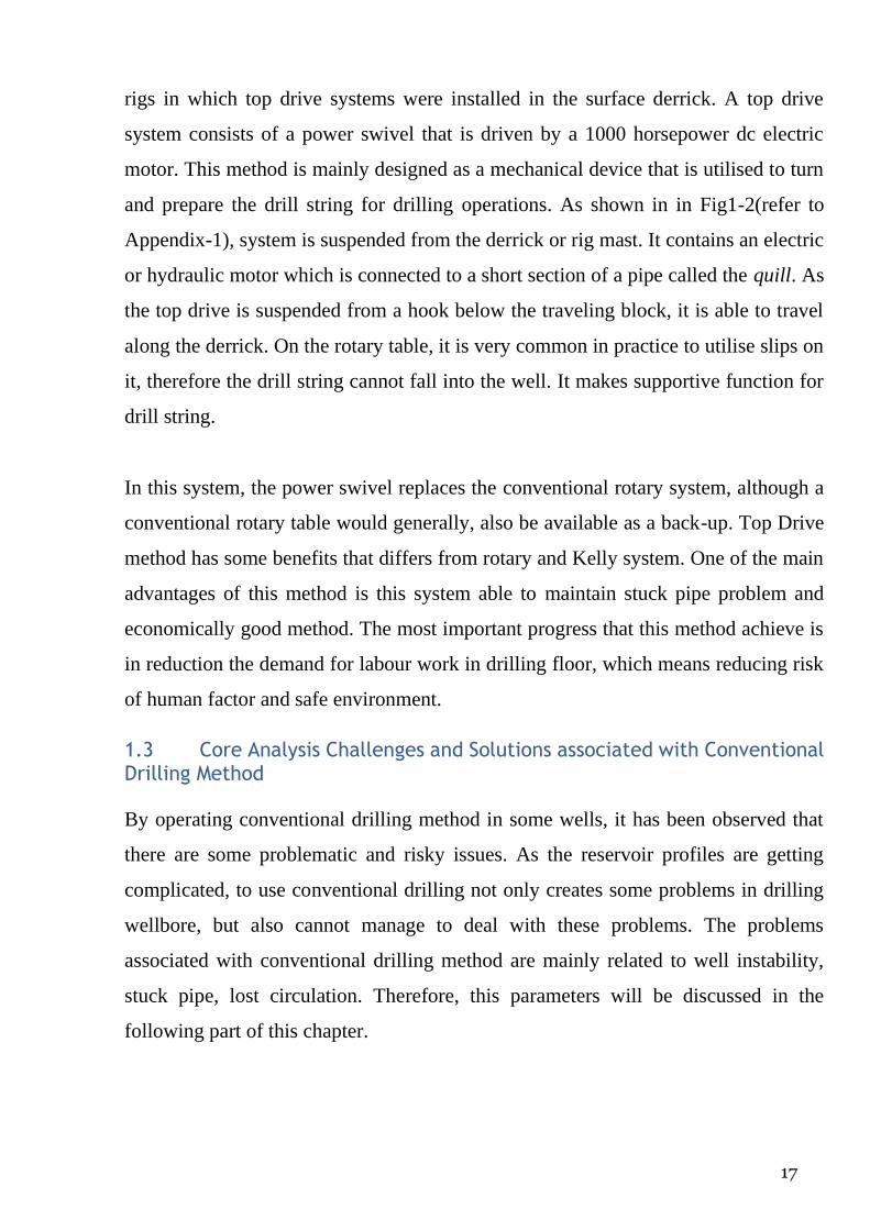
rigs in which top drive systems were installed in the surface derrick. A top drive
system consists of a power swivel that is driven by a 1000 horsepower dc electric
motor. This method is mainly designed as a mechanical device that is utilised to turn
and prepare the drill string for drilling operations. As shown in in Fig1-2(refer to
Appendix-1), system is suspended from the derrick or rig mast. It contains an electric
or hydraulic motor which is connected to a short section of a pipe called the quill. As
the top drive is suspended from a hook below the traveling block, it is able to travel
along the derrick. On the rotary table, it is very common in practice to utilise slips on
it, therefore the drill string cannot fall into the well. It makes supportive function for
drill string.
In this system, the power swivel replaces the conventional rotary system, although a
conventional rotary table would generally, also be available as a back-up. Top Drive
method has some benefits that differs from rotary and Kelly system. One of the main
advantages of this method is this system able to maintain stuck pipe problem and
economically good method. The most important progress that this method achieve is
in reduction the demand for labour work in drilling floor, which means reducing risk
of human factor and safe environment.
1.3 Core Analysis Challenges and Solutions associated with Conventional Drilling Method
By operating conventional drilling method in some wells, it has been observed that
there are some problematic and risky issues. As the reservoir profiles are getting
complicated, to use conventional drilling not only creates some problems in drilling
wellbore, but also cannot manage to deal with these problems. The problems
associated with conventional drilling method are mainly related to well instability,
stuck pipe, lost circulation. Therefore, this parameters will be discussed in the
following part of this chapter.

18
1.3.1 Well stability
The problems related to well stability are often happening as a result of tripping
operation of drill string. The issues that tripping leads to are classified as below:
• Swabbing happens when the drill string is lifted up from the well bore. As
a result of decreasing wellbore pressure, swabbing happens as the drill string goes up
the wellbore. If this trend continuously occurs and pressure gets lower than the limited
formation pressure, then well would go to kick.
• Surge (wellbore) pressure is being increased as a result of mud
displacement while the drill string is being going down to the well. If the pressure
increase is greater than the formation pressure, then formation damage can occur
which will result in being lost circulation.
Furthermore, formation fluid begins to flow up the wellbore when the primary control
of the well is lost and this would be resulted in BOP (blow out preventer) to be closed
to seal annulus. [9] By maintaining this mud transport will be controlled in the
wellbore. Therefore, the pressure in the well will increase until the pressure exerted
by mud on the kicking formation will be the same as the formation pressure.
1.3.2 Stuck Pipe
One of the main drawbacks associated with conventional drilling is stuck pipe
problem. Theoretically, it is said that “pipe got stuck” means pipe cannot be rotated or
moved, which is resulted in serious problem in the drilling operations. In principle,
there are three categories of stuck pipe which are:
• Differential sticking - as a result of changing mud pressure (getting higher
than formation pressure) and this leads to occur differential sticking.
• Mechanical stuck pipe – this problem happens when the BHA is not
possible to be contributed because of mobile formation.
• Pack off stuck pipe – this problem happens if there is large amount of junk
around the drill string or BHA. This incident is also recognised as accumulation of

19
cuttings.
As a consequence, if the drill pipe got stuck, engineers usually pump proper chemical
downhole in order to dehydrate the filter cake. Generally, prevention and remedy of
stuck pipe depends on the reason to problem. If the pipe becomes stuck, every effort
should be made to get rid of this problem quickly. [15]
1.3.3 Lost Circulation
Theoretically, lost circulation refers to the meaning that losing drilling fluid to the
formation. This problem happens when very permeable formations have enough pore
spaces that mud can easily go into the formation and fractures which have been formed
during the drilling operation. As remedial treatment, Lost circulation material (LCM)
is used which is mixture of clay, mica, ground nut shells and sawdust. BY pumping
this LCM into the problematic zone, after a definite time there will be formed filter
cake which behave as prevention.
In the South Pars field, the conventionally drilled wells experienced losses of fluids
and on tremendous occasions this forced the operator to set the casing to a lower depth
than planned before.
1.4 Summary
To summarise, it is stated that conventional drilling method was very successful in the
past history but the scope of operational performance does not meet today’s standards
in some particular cases. Many problems are revealed which are associated with
convectional drilling. To optimise drilling project, operators and proper related
engineers are always keeping these issues under control and trying to find an
alternative solution methods.
In the next chapter, the studies have been developed with Casing Drilling phenomena.
This innovative technology can be considered as a modern invention to Drilling
industry.

20
Chapter II – STUDY OF OPERARING METHODOLOGY AND DESIGN OF CASING DRILLING TECHNOLOGY
2.1 Introduction
As a result of drilling operations and petroleum reservoir exploration which have been
lasting for many years, drilling processes have faced very complicated environment
with full of problems. Today, most of the drilling jobs are operated in much depleted
reservoirs, troublesome zones, HPHT wells, the areas enriched with shale gas etc.
These zones are very challenging and can cause a big problem at any time. As we
discussed in Chapter I, conventional drilling is not perfectly designed system to tackle
all predicted problems it may has. Therefore, new technology is quite helpful in all
possible problems that will be investigated.
Casing Drilling technology has been utilised in numerous wells that have complex
structural zones. In order to drill through troublesome well sections that conventional
drilling techniques have not been ideal to manage with difficulties. As a principle, in
casing Drilling technology casing is operated to supply drill bit with mechanical and
hydraulic energy. By optimising this technology it is not only achieved an easier way
of energy transmission, but also saving time and cost, prevention with possible drilling
problems. In these days, the issue associated with this technology is still unclear for
some people that how it is proceeded if the well is drilled with casing instead of
conventional drill pipe and what kind of risks and benefits are expected?
Consequently, this chapter of project layout will cover an introduction to the casing
drilling technology which includes historical background, Casing Drilling types and
appropriate equipment/tools that are used in drilling operation.
2.2 Historical development of Casing Drilling Technology
According to historical sources, date for the first patent of casing drilling back to 1890,
in which a rotary drilling process was applicable for drilling the well with the casing

21
and retrieving the expandable bit hydraulically. In 1926, another patent presented this
technology with new designing drill bits, such as a retrievable and re-runnable casing
bit. This patent was differed from the previous one due to its innovative designing as
drill pipe is eliminated, reductions in overall drilling time, stuck pipe, crew and drilling
costs. The first casing drilling system is shown in Figure 2-1 (refer to Appendix-2).
However, in the 1960s, the first substantial work on casing drilling was completed by
Brown Oil Tools Company. This patent developed a casing drive system which
comprised down hole and surface tools were used to drill with the casing and
retrievable bits. Casing centralisers, wire line retrievable drilling assembly, under
reamer, casing drive tool and top drive components all were covered in this patent’s
design. Unfortunately, at that time this model’s performance were unsuccessfully
operated due to the limited availability of the technology. Although a long time had
passed from the time that last patent made, the same patent innovated and developed
the model again. As a result of his/her contribution towards to new model, the first top
drive was generated.
In the late 1990s, the casing drive system developed by Tesco Corporation Ltd was
approved and licensed by Drilling industry. Consequently, this system made
successful improvement towards well cost reducing and NPT minimisation.
2.3 Mechanical Design Considerations of Casing Drilling System
In real industry, Drilling with casing (DwC) or Casing while Drilling (CwD) has been
alternatively optimised towards new drilling technology. Basically, this method is
included coincidental drilling process with casing of well which comes with a casing
string. In this method, drill pipe and drill string components in conventional method
are replaced by casing string. Traditionally, casing is put into rotary motion and
cemented in the well at the total depth (TD). Nowadays, this method is be utilised in
a several of ways but can be classified into two main categories namely,
Retrievable - incorporates its BHA which is arranged inside the retrievable casing
which includes a motor to rotate a pilot bit and under reamer. It also consists of a wire

22
line winch, which is used to retrieve the drilling assembly
Non-retrievable - casing is operated as main tool but it is only used to make rotary
torque and definite weight on the bit. Additionally, there is no any demand for extra
tripping in order to retrieve the BHA after reaching a TD.
In Figure 2-2 (refer to Appendix-2) it has been illustrated the Bottom Hole Assemblies
(BHAs) for two type of CwD and the conventional drilling method.
Retrievable Casing Drilling
In this type of CwD special retrieving tool retrieves the BHA after definite TD is
achieved. By using this it allows the pilot bit to be replaced or kept away from the hole
prior to cementing job. Generally, this type of casing drilling system is only
compatible with directional wells, but can also be operated in vertical wells
alternatively. In this case, for directional drilling designed casing size defines possible
and expected build up rates.
Nowadays, in industry Tesco Corporation Ltd is recognised as a major provider of
retrievable casing drilling. It has been revealed by Houtchens et al, 2007 [3] that over
280 wells and more than 2 million feets of hole have been drilled with casing drilling
method between 1999 and 2007. In these wells, casing drilling technology has been
successfully operated to drill in various complicated lithology. In the Table 3-1 below,
the summary of statistics on the retrievable BHAs of CwD system is shown. The wells
have been drilled with an application of CwD between January 2001 and June 2006
by Tesco Corporation Ltd. According to the table, totally 890 BHA retrievals were
made and 822 out of total 890 were applied in vertical wells, the rest 68 retrievals were
in directional wells. It is also significant to note that 857 of total number of retrievals
were successful (96%) and 4% left in fraction of the wells were unsuccessfully
performed. [3]

23
Table 2-1: Summary of statistics on Unsuccessful and Successful BHA retrievals
Equipment used in Retrievable Casing Drilling
Casing drilling method is generated by contributions of the both surface and downhole
tools that are doing sufficient work during the processes of casing in and off the well.
To drill the formation, standard oilfield casing is used. The main tools/equipment used
in retrievable casing drilling are
• Casing Drive System,
• Retrievable BHA
• Drill lock assembly
And they will be discussed briefly in the following section.
Casing Drive System
It can be seen from the Figure3-3 (refer to Appendix-2) that the whole system has been
divided into 2 parts, such as downhole and surface components. These parts both
contribute the casing to operate and make a hole concurrently as drill string does in
conventional drilling method. Basically, top drive in retrievable Casing Drilling is
aimed to operate as the same functions as it does in normal drilling. Moreover, casing
selection criteria due to its grade, size and etc. parameters is selected by the same
criteria as it does in normal wells.
Connections of The casing may require a change from the conventional well design.
In other words, in casing drilling systems for retrievable CwD method fatigue load,
torsional load and enough flow hydraulic clearance have to be taken into account due
to any change in casing connectors because casing is rotated. Here, both integral and
coupled connections have been utilised successfully. Each joint of casing is picked up
with hydraulically activated single joint elevators attached to the Casing Drive System

24
arranged below the top drive. Casing Drive System also supports total weight of the
casing string which applies torque in order to drilling and proceed circulation.
Casing Drive System in retrievable casing drilling system, also known as casing quick-
connect is designed to have an internal spear assembly (casing fluid seal to pipe) and
a slip assembly to control external and internal parts of casing. This contributes the
casing to be placed into the drill string without screwing into the top casing coupling.
The use of the CDS accelerate operation of the casing handling and preserve damage
to the threads. Casing connections are designed as fast as drill pipe connections,
minimizes floor activity due to contributions of Casing Drive system and power slips.
Hence, having perfect designed Casing Drive system and casing connections makes
higher rig floor safety. [4]
Retrievable Bottom Hole Assembly (BHA)
In casing drilling technology, the casing itself is operated as hydraulic conduit and
contributor of mechanical energy transmission to the drill bit, whereas these functions
are referred to drill string in convectional drilling. As can be seen from the figure 2-4,
very short wireline retrievable BHA contains a bit and under reamer which can be
easily expanded. Practically, BHA is aimed to utilise to drill a hole and make a free
place for casing to pass through the hole.
If we are talking about BHA system of retrievable casing drilling system, we should
write talk about its wireline unit component, which is utilised to retrieve the BHA
attached to a drill lock. The wireline retrievable drill lock assembly is the heart of the
casing drilling system. Basically, it goes down in a lower part of casing containing of
a shoe zone, torque lock profile, axial no-go and lock profile in a specially machined
collar section. Furthermore, the drill lock is designed to deal with both a fluted profile
to transmitting torque from the casing to the drilling assembly and transferring of
compressive and tensional loads to the BHA from an internal flush no-go and axial
25
lock profile. In order to diminish lateral motion of the assembly inside the casing, a
stabilizer on the BHA is utilised, which is arranged opposite the casing shoe. In Figure
2-4 (refer to Appendix-2), BHA for retrievable type of casing drilling method is
shown.
By covering the casing shoe with hard material to make sure that a full gauge hole is
drilled ahead of the casing. However, if the under reamer drills into under gauge,
then the casing shoe provides a torque indication. Whereas, centralizers on the casing
make it stable within the borehole and prevent wear on the couplings. [5]
Drill Lock Assembly (DLA)
The retrievable drilling assembly is attached to the bottom of the casing in a profile
nipple, come with the Drill-Lock Assembly (DLA) together. This is the main critical
component that make conventional drilling tools to be run and retrieved through the
casing. In other words, the casing is getting connected by conventional drilling tools
with rotary-shouldered connections.
Moreover, DLA contributes the performance of these tools in and out of the casing. If
we look at its profile sketch (refer to Figure 2-5, Appendix-2), it has been placed at
the top of the BHA and main functions of DLA is to unlock the BHA by axial and
torsion loads. And the seals in the casing to direct the drilling fluid (mud) through the
bit and bypasses fluid around the tools for running and retrieving. The BHA can be
run and retrieved in deviated wells with inclinations higher than 90° and the DLA can
be released with a pump down dart before running the wireline. [4]
Non-retrievable Casing Drilling
Around 80% of the casing drilling operations are sufficiently made by non- retrievable
systems. This is a non-steerable and costs less than retrievable system. Basically, it
has been used in vertical drilling wells with a drill shoe connected to the end of the

26
casing. Nowadays, the main provider of this type of Casing Drilling technology is
Weatherford. Since January 2000, Weatherford has been operated over 300 drilling
projects with non-retrievable casing drilling system. Weatherford also lately
completed its first drilling with casing activity in the Java Sea, Indonesia from a
floating drilling unit.
Equipment used in Non-Retrievable Casing Drilling
In practice, it is widely utilised the same top drive, casing connections as it is used in
the retrievable casing drilling system. Specific tools that are used in this type of system
will be briefly described in this part of the section.
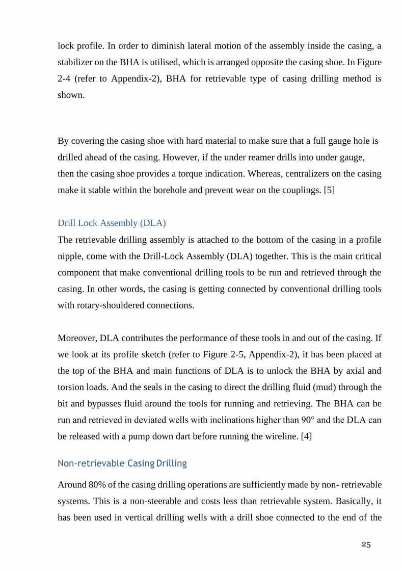
Overdrive system
The overdrive system designed and evolved by Weatherford as can be seen in Figure
2-6 that is operated in Casing drilling process. As a tool component of non-retrievable
system it is combined with rig’s top drive system and compatible with any top drive
system. Top Drive, Overdrive and Hydraulic Elevator components have been neatly
labelled in the Figure 3-6.
One of the main components of Overdrive system is TorkDrive tool which is shown
in Fig 2-7. Because of rotational power is generated by the top drive, the TorkDrive
tool makes up or breaks out the casing thereby performing the duties, which would
have required equipment, scaffolding and personnel on the rig floor. This device is
utilised in order to circulate, reciprocate and rotate the casing during the operation.
Moreover, it also provide ideal system with reducing any possibility of differential
sticking and other related issues. [3]
27
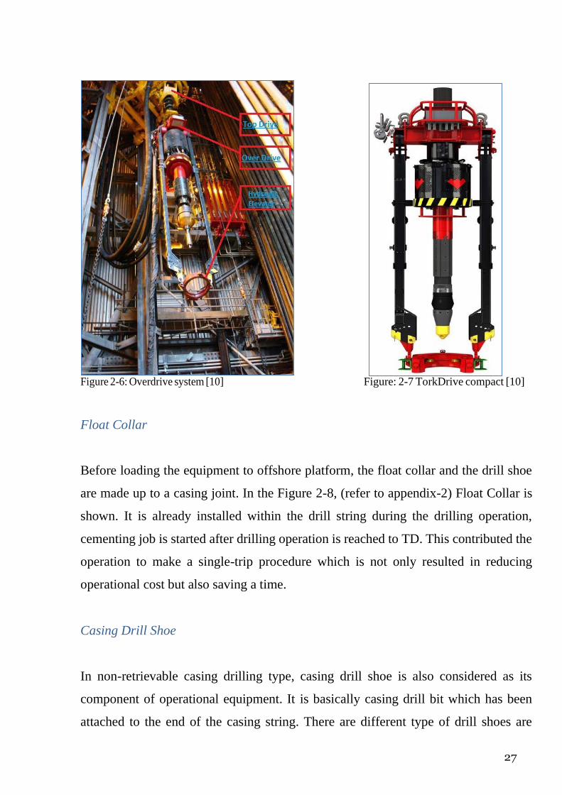
Figure 2-6: Overdrive system [10] Figure: 2-7 TorkDrive compact [10]
Float Collar
Before loading the equipment to offshore platform, the float collar and the drill shoe
are made up to a casing joint. In the Figure 2-8, (refer to appendix-2) Float Collar is
shown. It is already installed within the drill string during the drilling operation,
cementing job is started after drilling operation is reached to TD. This contributed the
operation to make a single-trip procedure which is not only resulted in reducing
operational cost but also saving a time.
Casing Drill Shoe
In non-retrievable casing drilling type, casing drill shoe is also considered as its
component of operational equipment. It is basically casing drill bit which has been
attached to the end of the casing string. There are different type of drill shoes are

28
designed and all are given in Figure 2-9. For design considerations, the drill bit is made
to deal with any kind of formations that should be drilled in different drilling intervals.
There are three types of drill shoes that Weatherford utilise widely in operations,
which are drill shoe I, drill shoe II and drill shoe III. [3].The main featured differences
among these drill shoes have provided in Table 2-2 below:
Table 2-2: Main features of different types of drill shoe [3]
Drill shoe I Drill shoe II (blade4) Drill shoe III
Figure2-9: Different types of drill shoe [3]
Commonly, in conventional drilling drill bit has been designed as non-drillable.
However, for non-retrievable type of casing drilling technology, all type of drill shoes
above should be capable to optimise hydraulic performance by integrating with their
interchangeable nozzles. According to Table 2-2, it presents the different

29
performances in various formations drilled by these drill shoes, their sizes,
compressive strengths, cutting structures, blade and the casing strings attached to
them. Consequently, it can be integrated with the idea that in assemble of a drill bit
contribute with soft steel and hard cutting materials. Likewise, they can be utilised in
soft to hard formations.
2.4 Casing Protection Investigation
If we are talking about casing equipment in Casing Drilling, It is crucial to mention
casing protection accessories which provide the casing with perfect coverage that
makes it non-damageable(against damage) after drilling operations. In other words,
casing is also necessary to utilise in well completion after drilling process. Thus,
Casing wears protection accessories are very important in casing design
considerations. Commonly, these accessories will be described in this section below.
Wear band - one of the casing protection accessories is wear band. The wear band is
in a ring shape and made of metallic coated with tungsten carbide hard facing. To
ensure casing strength of connection, wear band is used and placed below the coupling.
Wear Sleeve - this casing protection equipment is in a cylinder shape and made from
steel with ample contact area. It can be placed on any part of the joint as required in
design consideration. The main difference from wear band accessory is the sleeves are
not coated with tungsten carbide hard facing. One of the casing protection accessories
is wear sleeve is shown in
Centralizers - this accessory is used in order to provide stabilization, directional
performance, wear management, key-seat control and centralization for cementing.
The centralizer are usually placed on the outside diameter (OD) of the casing and
Casing with a friction is connected with strong-faced and tough blades make it enable
for rotation of the casing. However, in directional casing drilling, the casing is jointed
with centralizers are non-rotating type made from zinc alloy. This is normally utilised
in directional casing drilling to decrease torque.
2.5 Summary

30
To conclude, due to technological limitation in the past the patent could not be
developed as a perfect system. However, in 1990s Tesco Corporation innovated the
first casing drilling system, which is quite sufficient.
It is stated that there are two types of systems such as retrievable systems which were
innovated by Tesco Corporation and non-retrievable systems which were innovated
by Weatherford.IN retrievable drilling system, after casing is reached to the TD, the
bottom hole assembly (BHA) is retrieved, whereas in non-retrievable systems, after
casing is reached to the TD the bottom hole assembly (BHA) is stayed in the hole and
drilled through.
In terms of equipment that used are designed in a same way for both Retrievable and
non-retrievable Casing Drilling types, however the only difference is identified in their
BHA tools.
The next chapter will cover the benefits of Casing Drilling technology as they are
utilised in mitigating the problems associated with Conventional Drilling.
Chapter III – EVALUATION OF EFFECTIVENSS OF CASING DRILLING
TECHNOLOGY (CwD)
3.1 Introduction
For many years, in drilling process Non Productive Time (NPT) has been a key factor
that drilling engineers always try to find the ways of prevention and optimise drilling
process. The problematic concepts are leads to NPT can be emphasized such as
wellbore instability, stuck pipe, lost circulation, formation damage. Casing Drilling
technology is an innovative method that is able to solve most of these problems. In
other words, the original purpose of developing CwD technology is to eliminate NPT
associated with running casing, saving time and cost, provide the drilling rig a safer
environment to work. Some other necessary benefits of this technology have been
obtained in different types of drilling wells.

31
In this chapter, the benefits of Casing Drilling methodology and characteristic
differences with conventional drilling will be covered in details. Furthermore, the
main advantageous factors providing by this technique such as increasing wellbore
stability, reduce the risks to stuck pipe, plastering effect etc. will also be discussed.
3.2 Wellbore stability
One the main advantages of Casing Drilling technology is to help in solving the
wellbore instability problems which are usually integrated with conventional drilling
method. As it is known, in conventional method tripping process causes lots of
problems related to wellbore instability. The most common issue is swab and surge
pressure that cause well control incidents or lost circulation. In other words, if the well
is not circulated properly from bottom of the wellbore this is risky concept and can
leads to stuck pipe problem while tripping in the BHA. Consequently, this technology
completely eliminates the problems associated with tripping operations. Furthermore,
after reaching TD and before running the casing, there would not need any washing
and reaming operations. This may result in wellbore instability issue as well.
Casing Drilling method also helps to save time in drilling process. This also means a
decreasing the risk of wellbore instability occurrence. On the other hand, this new
method gives the chance to operate cementing job as soon as the interval is reached at
TD and ensure every foot drilled is kept. It means an advantage for selection of casing
setting depths.[8]
Problems in the wellbore like barite sag, hole pack off and stuck pipe can be resulted
by very poor borehole cleaning. These problems create much bigger issues if well
scenario is designed for horizontal and directional drilling in which transportation of
cuttings is quite difficult to deal with. From hydraulics design aspect, Casing Drilling
are made to use a lower flowrate to produce an ECD is higher than observed in a
conventional drilling method. This higher ECD is also considered a negative aspect of
hydraulic design due to lost circulation and higher susceptibility of fracturing the
formation. Consequently, Casing Drilling method with higher ECD is operated

32
successfully to act against borehole collapse and improves wellbore stability
successfully.
3.3 Stuck pipe
Stuck pipe is one of the most common drilling problems which is both expensive and
time consuming. In the past, this was the one of the main drilling problems especially
for large diameter pipes. However, experience over many years has proved that casing
does not get stuck in troublesome zones and the method is invented tends to solve an
associated risks for stuck pipe. Nowadays, wells with stuck pipe problems are
considered as good candidates for Casing Drilling method. Generally, the term of
“stuck pipe” means when the pipe cannot be rotated properly and this leads the drilling
operation to be problematic. As discussed in previous chapter, stuck pipe is analysed
based on three type evaluations, which are discussed below.
3.3.1 Differential Stuck Pipe
In order to calculate differential stuck pipe, formula provided in Equation 3-1 is
applicable. According to this equation, in casing drilling technology contact area
(A) is noticeable large and it will promote the idea of stuck pipe as risky issue. On the
other hand, this method provides very good filter cake quality and which decreases
differential pressure in the system due to pressure transfer.
As a result of low differential pressure, there will be less differential sticking force.
Furthermore, there is very small probability to have sticking at one point compared to
conventional drilling as the casing is continuously rubbing and sliding in casing
drilling method. [8]
𝐹=𝐴×Δ𝑃×𝑓 (Equation 3-1)
Where:
F − Differential sticking force (lb)
A − Contact are (in2)
Δ𝑃 −Differential pressure (psi)

33
f − Friction factor
3.3.2 Mechanical Stuck Pipe
Mechanical stuck pipe is occurred when the bottom hole assembly (BHA) is pulled
into either a mobile formation or under gauge hole. It is clear that tripping operation
is a part of conventional drilling method and this allows the formation to occupy the
wellbore. Luckily, CwD method is able to prevent the formation from collision with
the wellbore and it is immediately cemented as the casing reaches TD. By keep doing
this way, casing can be kept from related dangers.
3.3.3 Pack-off Stuck Pipe
When drilling through unstable formation which causes a mixing of an undrilled mud
with solids. In this case, packing-off concept is concerned. In terms of wellbore
cleaning operation, it is necessary that higher annular velocities and casing’s continual
agitation of cutting zone ensure about transportation of all cuttings out of the hole as
quickly as possible.
On the contrary, for conventional drilling if the pipe gets stuck, some attempts are
made to free the pipe, like jarring. If this does not work, then there is a risk that BHA
goes off or well can be lost. However, with the aid of Casing Drilling, these danger
risks are minimising to zero.
3.4 Formation damage
Formation damage may occurs during normal drilling process. Theoretically, this
problem is caused by loss of fluid in the wellbore. In this case, plastering effect is
optimised by casing drilling method (will be covered in the next section below) allows
to prevent the fluid loss by creating a bridge in the wellbore after it has been drilled.
Likewise, during CwD operation mud cake is formed which is less permeable and less
porous. On the contrary, in conventional drilling such mud cake thickness and
desirable filtration results cannot be achieved successfully and it leads to happening
formation damage easily. And this is illustrated visually as in Figure 3-1 shown below.

34
As a result of good controlling formation damage will allow to stop movement of
drilling fluid into the formation and provide safe wellbore. Therefore, reducing
formation damage by plastering effect (as a part of Casing Drilling) gives an
advantages to improve productivity of the wells drilled with the casing the reservoir
section. [8] This means the reduction in skin factor and the damage radius caused by
drilling which provide better productivity with casing drilled wells.
In the next section, it will be given further information on how plastering effect works
in Casing Drilling technology.
Figure 3-1: Mud cake formed by casing drilling prevents the fluid loss to the formation and therefore
solves the drilling-induced formation damage. [8]
3.5 Lost circulation
The concept of Loss circulation can be explained as losing of drilling fluid to the
formation. Casing Drilling reduce mud loss to the formation. Mud cake with very good
quality maintained by plastering effect seals off the wellbore and helps to prevent
fluids transfer to the formation from the wellbore.
3.5.1 Plastering effect
The cuttings in the wellbore are crushed and smeared against the formation in the
drilling process. This action is related to combined force of high annular velocity,
placing of casing closely to the wellbore and rotation of casing. As a result of these
cases, a wall cake is formed which is much less permeable. Wall cake behaves as a
filter cake and provide minimum loss of fluids to the formation.
According to the particle size analysis test results, casing drilling method provides
smaller size cuttings than that conventional drilling does. Along the way of movement
trajectory of the cuttings, these cuttings are crushed and grinded by casing string. And

35
cuttings meet with plaster on the wellbore wall. It is a barrier to stop the flow of drilling
fluids to the formation.
In the Figure 3.2, the mechanism of plastering effect has been shown with different
scenarios. [8]
In the first case - A, it is shown that the casing is forced against the bore wall as it
advances into the borehole.
In the second case - B, it is shown that as mud is smeared into the formation, filter
cake builds up on the borehole wall.
In the third case - C, filter cake and cuttings are plastered against the borehole wall
and sealing porous formations.
At the end of the processes (case C), the thick filter cake and the cuttings are being
plastered onto the formation face as the casing is rotated in the well. By creation of
the barrier on the formation, there will be no additional space for the drilling fluid to
move into formation. On the other hand, plastering effect also gives opportunity to
increase the fracture gradient of the formation near the wellbore zone which is very
good for mud weight selection.
A B C Figure 3-2: Plastering effect mechanism [8]
In comparison with conventional drilling, for casing drilling method small annulus
and lower flow rate is required in order to have an effective mud circulation. Lower
flow rate not only helps to reduce the loss of mud, but also controls ECD to prevent
additional exerted pressure on the formation. On the other hand, higher annular
velocity provides very efficient wellbore clean-out result. And small annulus helps in

36
operations of filling up the back side of the casing. Overall, according to these
following advantages casing drilling method helps in cooling off the connections and
optimise very good well control.
While drilling conventionally, the losses as described above happen the drilling
process has to be stopped so as to cure the losses by arranging cement plugs which in
turn results too many time of NPT. Casing Drilling method allows the operator to
perform drilling as once the casing has passed the loss zone, trouble is behind and the
well is cased, secured and ready to be cemented. This method has specific advantage
that if the drilling process is continued and plastering effect starts to heal the loss zone
which is resulted in mud returns are re-established. It is significant case if the loss zone
is in the section above the bit.
3.6 Study of associated drawbacks.
Casing Drilling technology has provided a number of benefits to the drilling operations
in an effective way. By operating this method, it has been obtained huge amount of
improvements towards in solutions of conventional drilling problems, such as
borehole stability, stuck pipe, lost circulation. However, this new technology has some
challenges that are inevitable. Limitations are mainly associated with CwD are as
stated below:
• Changing/replacement of bits or bottom hole assembly (BHA)
• Casing Connection and Dog Leg tolerance
• Formation Evaluation
• Cementing
In this chapter, it will be discussed about the drawbacks and limitations of CwD
technology.
3.6.1 Replacement/Change of bits or bottom hole assembly (BHA) As we know, in Drilling with Casing technology that tripping operation is removed
and downhole tools are retrieved by wireline through the casing. Replacing/changing
the bit or BHA is also operated by wireline retrieval performance. However, very

37
frequent wireline retrieval performance most likely leads to some unpredictable
problems which means wellbore instability.
3.6.2 Casing Connection and Dog Leg tolerance In terms of design considerations of CwD technology it is fact that casing connections
are unable to bear high fatigue, torque and compressive loads in buckling environment.
Therefore, drilling with casing technology is limited to drill with relatively low torque,
low WOB and with reduced hole sizes buckling is kept as low as possible. Also, as a
result of buckling effect, dogleg tolerance is limited. It can be predicted to learn all
effective factors to casing connections by utilising finite element analysis. [3]
3.6.3 Formation Evaluation While the casing is placed, there is no possibility to conduct logging operation with
traditional methods unless the casing is pulled above the zone and logged below the
bottom. For solution LWD (logging while drilling), electromagnetic tools should be
used. In order to figure out what type of logging to be operated depends on the
formation and logging zone. All these jobs are generalised as a formation evaluation.
[3]
3.6.4 Cementing In this type of drilling method, once the casing is drilled to the defined setting depth,
the BHA is retrieved by wireline. Therefore, the casing will not have a float collar to
land the cement plug. In order to get solution for this problem, the displacement plug
should be used and latch into the casing to serve as a float.
3.7 Conclusion
To conclude, tripping performance in conventional drilling is the main reason for
tremendous problems that can be possible to be prevented by Casing Drilling benefits.
It should also be noted that in Casing Drilling method, plastering effect has very large
number of benefits. It allows the operators to solve lost circulation and formation
damage problems, as well as optimising wellbore stability, wellbore quality, wellbore
cleaning. Although the Drilling with Casing technology has some limitations and
challenges, it is increasingly accepted as a practical method of reducing costs and
solving relevant drilling problems. The method is very successful in softer formations

38
and larger casing sizes. By optimising the technology with new approaches and
solutions it can be overcome these followed challenges effectively.
Design considerations of Casing Drilling technology (CwD) will be discussed in the
next chapter.

39
Chapter IV – DESIGN CONSIDERATION OF CASING DRILLING
TECHNOLOGY
4.1 Introduction
Designing a well with Casing drilling technology is similar to design a well by
conventional drilling. In designing plan, the first and one of the most important
parameter is BHA concept. Mechanical energy is transferred to the drill bit by drill
pipe and drill collar which are designed with a drill-string is the main design
consideration for conventional drilling method.
In order words, drill string component in CwD method also allows a hydraulic conduit
for the drilling fluids. However, the drill-string is pulled out of the hole each time the
bit or bottom hole assembly needs to be altered or the final casing depth is reached.
Hence, casing is run into the hole to make permanent access to the wellbore. Therefore,
by utilising a casing for the drill-string, Casing Drilling System (CDS) makes an
alternative approach to the conventional drilling method. While drilling a hole with
conventional method, it may happen problematic situations while drilling process.
But, CDS may not only reduce hole problems that are related with tripping operations,
but also saves capital costs of rig equipment, operating costs. Additionally it eliminates
costs associated with purchasing, handling, inspecting, transporting, and tripping the
drill-string.
During a drilling operation well control, borehole stability, mud properties, casing
setting depths, directional planning and bit selection should be controlled. These
parameters are the most common considerations in designing process for conventional
drilling as well.
One significant difference between them is that the casing is subjected to additional
stresses while Casing Drilling. The main features, parameters for CDS considerations
is shown in Figure 4.1. According to Figure 4.1, parameters for casing consideration

40
such as elastic loads, fatigue, and wear are classified on the right hand side, whereas
the parameters for operator control such as operating parameters, pipe properties,
connector design, and well design are grouped in the left hand side.
Complex interactions relate parameters directly under operator control to the ultimate
casing integrity. There is very significant point should be considered that most of the
parameters/factors grouped in the Figure 4.1 can be deal with by operating
conventional drilling method. However, three very remarkable factors such as
buckling, fatigue and hydraulics are considered to pay attention while operating
Casing Drilling method.
Figure 4-1: Design interactions affecting casing integrity for Casing Drilling applications [5]

41
4.2 Buckling
The main difference between drilling with a conventional drill-string and Casing
Drilling is that in Casing drilling method drill collars are not used to have weight- on-
bit (WOB). According to drilling studies, it is needed to run drill collars in order to not
having a buckling damage on drill string. However, the case will be different for
Casing Drilling, because of not running drill collars.
The lower portion of the drill-casing will support only a limited compressive load
before it buckles. Hence, buckling factor happens when the compressive load and
casing/hole geometry provide required bending moment so that the casing becomes
unstable. To have buckling in the system does not refer to a structural failure. The
borehole wall around the casing allows the system lateral support to control the lateral
deflection for any given set of parameters. [5]
Basically, buckling in the system can cause the issues following below
• Due to lateral contact forces, wear on the casing is created and it will
increase the torque which is important for casing rotation.
• Due to the casing to be in a curved geometry within the borehole which
will not only increase the stress in the pipe, but also increase the issue toward lateral
vibrations.
For casing drilling application it is very necessary to figure out whether if the buckling
is happened in the casing or not. Also, it is crucial to check the buckling issue out
whether it will lead to serious problems such as high torque, high stress. In straight
profiled holes, the compressive loads leads to occurrence of buckling which is
determined by the stiffness of the pipe, lateral gravity force (pipe weight and hole
inclination) and radial clearance. Whereas, buckling in a perfectly vertical holes is
always caused by compression if the bore hole does not make lateral support through
centralizers. Therefore, the normal wall contact force from the pipe on the low side of
the hole gives a stabilizing influence and compressive load is increased that can be
supported before the drill-casing buckles, if the well is straight, but not vertical.

42
By contrast, as the inclination going up in a curved hole the casing becomes more
stable and becomes less stable, whereas the inclination is going down at a low
curvature. The main reason for this case is related to casing becoming firmly against
the borehole wall, because of axial compression which push the casing into the outside
curve. Normally, when the buckling starts it turns the casing into planar, sinusoidal
shape, whereas as axial loads grow up it makes it a helix, spiralling around the inside
of the borehole.
As it was mentioned above, one of the two factors that buckling can lead to have wear
on the casing. First, the bore hole wall contact force affects both the torque required
to rotate the drill-string and the wear experienced by the casing. And the location of
the contact figures out if the wear is localized to the casing couplings or if it also
affects body of the casing.
Secondly, due to buckling case pipe curvature will affect the stress. If the stress level
is high enough, the pipe can yield and fail. However, this level of stress is very rare
experience for practical casing drilling conditions. At a lower level, the stress may
influence the pipe fatigue life.
Consequently, many factors in addition to buckling have effects on both the wall
contact force and pipe stress.
4.2.1 Approach to buckling calculation
In drilling engineering, determination of buckling factor can be determined in different
ways. To approach the problem mathematically it is required to find out the formula
and its basic considered assumptions. One of the solving methods is identified as
followed.
While external pressure and the tension according to reducing casing weight is
likehood of buckling, buoyancy and internal pressure contributes casing buckling due
to weight on the bit (WOB) from compression. This phenomena can be described as

43
following equations below:
𝐹𝑒=𝐹total+𝑝0𝐴0−𝑝𝑖𝐴𝑖 (Equation 4-1)
Where,
𝐹𝑒ffective − Effective tension (lb)
𝐹total − Total axial load due to bending (lb)
P0 − External pressure (psi)
𝑝𝑖 − Internal pressure (psi)
𝐴0 −External casing area (in2)
𝐴𝑖 − Internal casing area (in2)
Therefore, as can be seen from the equation 4-1, if the effective tension (𝐹𝑒ffective)
is < critical force (𝐹𝑐ritical), then buckling will happen in the system. Conversely, if
effective tension (𝐹𝑒ffective) is > critical force (𝐹𝑐ritical), then buckling will not
happen in the system. On the other hand, casing can lead to be buckled if it is
completely in tension according to high internal pressure(𝑝𝑖𝑖).
Therefore, critical force can also be determined by the formula generated by Lubinski
et al [7]. According to his contribution towards critical force consideration, different
type of buckling is determined and formulas derived based on the assumptions that
Lubinski et al made as following:
➢ Casing is buckled into a helical shape, wellbore is considered as straight
and vertical
➢ Pressure forces in the system are vertically distributed, friction forces are
not considerable.
Appropriate formulas for critical forces affected by two type of bucklings are as below
• For helical buckling ,the critical force :
𝐹critical=4.05(𝐸M𝑤2)1/3 (Equation 4-2)
• For sinusoidal buckling, the critical force

44
𝐹𝑐ritical=1.94(𝐸M𝑤2)1/3 (Equation 4-3)
Where,
𝐹𝑐ritical − Critical force (lb)
E− Young’s modulus of material (Pa)
M− Inertia moment (in4)
w− Effective buoyed weight (lb/in)
Note that, M- Inertia moment can be calculated with casing diameter values
As can be seen from equation 4-2 and 4-3, as long as casing has larger size of diameter
it will be achieved greater values for critical forces. The reason is that critical force
proportionally depends on inertia moment and effective buoyed weight.
On a whole, according to different source of information there are various assumptions
predicted for critical force and buckling determinations. On the other hand, these
following equations can be considered as quite good approach to the buckling
calculation. It would be necessary to note that there is also different approximations
to determine buckling and critical forces in a deviated wells, which are out of our
project objectives.

45
4.3 Fatigue
In designing performance of Casing Drilling, one of the main factors is fatigue that
should be considered. The trend of fatigue failure occurrence is an inevitable that
design engineers should focus on attentively. It basically happens when cyclical
loading at stress levels well below the elastic strength. After this occurs, a small cracks
starts at a point of localized high stress and develops through the body. This danger
continues until the remaining cross sectional area is not sufficient to support the static
load. Particularly, the number of factors effects on causing of failure which is required
to have the number of stress cycles. However, trend range can change from a few to
infinity cycles. In nature, fatigue failures are highly non-predictable for local
conditions.
Another aspect of this failure has been observed on drill-string. Specifically,
oscillating bending loads rather than torsional loads are main reason for drill- string
fatigue failures. They mostly happen in the lower portion of the drill-string rather than
at the top where the static tensile stresses are highest. In many cases a fatigue crack
will result in a leak.
Therefore, most of the “wash outs” that are found in drill-strings are basically sign of
fatigue cracks. These failures are often located in either the threaded portion of the
connection or in the slip area of drill pipe. Theoretically, S-N curve is developed to
investigate the fatigue life in a particular zone. Generally, S-N curve is integrated the
alternating stress level with the number of cycles leading to failure. Generated S-N
curve is shown in Figure 4-5 for D and E grades of drill pipes. According to the Figure
4-2, it can be clearly seen that fatigue is not plotted as a single line, it is observed as a
group of failure zone.
The reason for this trend is related to fatigue testing nature. As the mean of the data,
the S-N curve is mainly reported as a result of scatter plots for fatigue testing. Fatigue
life varies with many small imperfections in the material and surface end.

46
Therefore, the result data shown in Figure 4-2 represents an endurance limit (failure
does not happen if stress is below this limit) for the drill pipe which is nearly 20,000
psi. [5]
Figure 4-2 S-N curve developed for D and E grade pipes [5]
According to the literature about concept of fatigue, number of revolutions (cycling)
is important to predict assumptions about fatigue failure by developing S-N curve.
Thus, bending stress can be calculated with the equation 4 below.

47
Where
𝜎𝑏 − Bending stress (psi)
𝐷0 − Pipe outside diameter (inch)
It can be realised that the number of revolutions may lead to failure from the S- N
curve can be determined by utilising bending stress value.
4.4 Torque and Drag Analysis
During the running of casing strings that resulted by frictional forces acting between
the wellbore and the casing, the phenomena of torque is considerable. Casing drilling
technology has been experienced higher rate in torque and drag rather than
conventional drilling method. This associated with casing interact with wellbore
conditions such as tight-hole conditions, sloughing shale, differential sticking and
sliding during drilling process. The drill pipe is smaller than the size & weight of the
casing.
When designing the well that will be operated with casing drilling method, it is very
important to consider the torque and drag concepts. Torque and drag forces applied to
the casing can also be analysed with the aid of a software such as Halliburton Well
plan.
Torque can be determined with the aid of the Equation 5 as shown below [3]
Where
T − Torque (ft-lb)
𝜇 − Friction factor (dimensionless)
𝐷𝑏 − Drillbit diameter (inch)
𝑊OB − Weight on bit (lb)
It is relevant to note that drag can be estimated approximately as 20% of torque
value, because of complicated calculation contents.

48
4.5 Hydraulics
Casing hole dimensions play significant role in hydraulics concept as they characterise
a fluid flow path. There is a significant difference between the casing drilling and
conventional drilling technology, since in CwD very small pressure loss within the
casing ID (internal diameter) observed is related to excessive and unrestricted casing
path. Hydraulically, the casing while drilling annulus usually makes a bigger restricted
flow path which leads to higher pressure losses. With more restrictions to the flow
path, it increases, making the annular velocities to be nearly uniform from the casing
shoe to the surface. And this provides effective transport for cutting within the annulus
and the hole to be cleaned with small flow rates in spite of many considerations need
be made to the drilling fluid properties.
Therefore, in order to clean the bit and under reamer effectively there is demand for
sufficient hydraulic energy. On the other hand, equivalent circulating density (ECD)
factor also should be considered in the following cases above. Mainly, for casing
drilling technology, ECD has been rated much more rather than that for conventional
drilling method, even though it presented lower flow rates. [3]
4.6 Summary
To conclude, the relevant design parameters considered are very important which were
covered in this chapter.
Buckling caused by compressive load that would never lead to failure of casing.
Due to cyclic loadings, fatigue can lead to be failure. Crack starts to appear at the
localized point high stress and repeated loading can cause the crack propagating
through the body.
Higher annular fluid velocity which is contributed by smaller annulus between the
casing and borehole helps in the processes of cuttings removing and clearing. Well
cleaned wells results with higher ECD which is appropriate for Casing Drilling.

49
The basic formulas are shown in this Chapter. However, the application of these
calculation will be developed based on the real field results/data will be investigated
later.

50
Chapter V – CASE STUDY OF CASING DRILLING TECHNOLOGY WELL
DESIGN
5.1 Introduction
As a new drilling technology Casing while drilling provides operator with
simultaneous drilling operation and case a wellbore section in only one run without
the necessity to pull the drill string out of the hole. This new innovative technology
plays significant role when oil and gas well drilling faces a number of challenges such
as influx of formation fluids, formation instability, excessive lost circulation etc. It
also improves wellbore stability, eliminates problems related to tripping of string,
reduces loss of circulation, and has some environmental impacts. In other words, it is
sufficiently applied into today’s drilling activities in order to safely and economically
deal with these real drilling challenges.
Last year, South Pars gas field has been successfully investigated as a part of
“Petroleum Design” course from university. And the well design program was
completed and drilling program was generated for Conventional Drilling method. As
a result of studies in this well, some constraints have been identified. In this project it
is suggested to investigate this well with Casing Drilling method and to analyse how
it mitigates the corresponding problems associated with Conventional Drilling
method.
In this chapter, it will be given further information about implementation of this
innovative technology in this actual well and new well design will be created by CwD.
As well as, design considerations for CwD such as buckling, fatigue, torque and drag,
hydraulic optimisations while drilling a well using casing drilling technology. And it
will also be analysed mathematical approach in the designing well program.
5.2 Overview of Field data/information
The South Pars field is located in the Persian Gulf and it is the world’s largest natural
gas condensate field that is operated by Qatar Petroleum and NIOC. The project was
mainly aimed to create a drilling program for an Appraisal well, safely and as

51
economical as possible. Appraisal Wells were drilled by conventional method to
further explore the potential hydrocarbon reserves that were located in a discovered
oil or gas field.
As a result of further research into well area some potential drilling challenges have
been detected. In design considerations of well planning these challenges were
analysed and taken into consideration. The main target is to analyse both drilling
methods in terms of their design configurations, casing setting depth graphs, hole
geometry, hydraulics, pump parameters and etc.
5.3 Actual Well design by Conventional Drilling method
An actual well design has been completed based on drilling program by implementing
of conventional drilling method. The casing setting depth was designed using industry
standards, throughout the project it had been faced many problems and issues. Using
the tested methods it has been overcome these problems, such as the having H2S influx
from the formation in some depths. Additionally, a hole geometry was determined by
considering safety factor first to choose sizes that are large enough to avoid any
possible differential sticking and thus good cement work can be done. This would
mean that our cost would be higher to drill bigger holes with our biggest hole as 36”.
All possible constraints were specified and analysed an operation of drilling with
Conventional Drilling method.

52
Figure 5-1(a): Actual well design configuration for Conventional drilling method
In Figure 5-1(a), the actual well design configuration has been given. The well was
exploited by conventional drilling method in the previous year as a part of Petroleum
Design course.
5.4 New Well design by Casing Drilling (CwD) method
Before starting to apply this innovative technology to this basin area it has been
explored case study for whether the method is applicable for this well or not. It has
been proved that CwD application will have great benefits for this field due to its
successful operations for various unscheduled events and numerous unexpected

53
problems. Therefore, utilising CwD and making new design for this method would
provide an operational company with great benefits which will be specified and
summarise in this section.
5.4.1 Design Assumptions
To make the new well design much clear it has been identified some relevant
assumptions
• Well is designed in a vertical trajectory. However, it does not happen practically
and there is some deviations in the profile.
• Fatigue calculations, bending stress is measured due to buckling. Additionally,
stress due to torque should also be considered if the casing is being rotated. For this
complicated calculation, software for drilling plan – Halliburton Well Plan would be
relevant.
• All the calculations are made based on new casing setting depth scenario.
5.4.2 Casing and Casing setting depths design
The casing string designed for isolating the hole from undesired constraints and
unstable formations must satisfy collapse, burst, tension, static and fatigue loads
requirements. If there is a demand for rotating casing during conventional casing
operations, torsional resistance must be sufficiently done. Whereas, in CwD casing
string design it is required special considerations in addition to the fulfilment of
common criteria of casing design for the conventional drilling. For CwD operation, as
casing string is utilised to supply rotation and weight on the BHA and drilling bit, the
main emphasis is given to the accessories that are relatively linked to stress and torsion
resistance of the casing string and its connection. Therefore, the design of the casing
string for CwD must satisfy safety factors of different loads acting on the string
(compression and tension loads).The formulas to determine collapse, burst, tensile
resistance of the casing string will be used to calculate these factors for each casing
intervals.
To design a new configuration of casing setting depths, first job was to analyse if there

54
is overpressure or under pressure cases for the defined mud window. As can be seen
from Figure 5-1(b) that mud window is very narrow in the middle trajectory. This
means that pressures in these layers should be attentively checked and controlled for
CwD application. Therefore, all specific assumptions (given in details in Chapter IV)
made for CwD and new well design configuration has been generated (Figure 7-1(b)).
Casing setting depths and hole geometry design are made based on CwD design
criteria.The most appropriate trajectory is chosen in the mud window after eliminating
swab/surge trip margins and relatively small diameters are chosen for new well design
with CwD technology.
Figure 5-1(b): New well design configuration for Casing Drilling method

55
As it was in an actual well design, the same casing types, grades and weight were
utilised for new design. The only different point of the design is obtained in the casing
sizes, mud weights, casing depths and lengths. These changes will have significant
impacts on optimisation of drilling rate with CwD in the well. Summary of the
proposed casing string design for the new well design is given in the Table 5.1
Table 5-1: Casing and Mud specifications for the new well design
5.4.3 Effective Loads and Neutral Point calculations
In order to calculate effective loads which affect casing string first it is significant to
determine buoyancy factor and buoyancy weight of the casing. The formulas for these
calculations are given in a range from Equation 5-1 to Equation 5-8 (refer to
Appendix-2). To proceed buoyancy calculations, it is then needed to find out Total
Weight of the Casing and Buoyant weight of Casing.
(Equation 5-2). Therefore, to determine Tensile Load and Compressive Load results
it is significant to make calculations by the formulas (equation 5-3, 5-4, 5-5).
As a result of these calculations, the relevant values have been obtained and these data
will be helpful to generate graph of the total axial load vs depth. This relationship is
very necessary to determine effective axial load and hence the neutral point. All these
calculations and plotting operations have been done by Excel software.

56
Table 5-2: Summary calculation results on Total Tensile and Total Compressive Force

57
Figure 5-2: Summarised graph representing Axial Load vs Depth for all casings

58
Figure 5-3: Graph demonstrating Axial Load vs Depth for Production Casing
In Figure 5-2, the axial loads which affects casing that have been calculated and
generated one plot with all casing data. But, in Figure 5-3, the plot is extracted from
Figure 5-2 for Production Casing to give an accurate idea about Effective Load
determination.
As a reason, production casing is chosen because it is the longest casing lengths and
shows better results with CwD operation.
For neutral point calculation, it is required to calculate effective axial load. Generally,
casing is affected by internal and external pressure same as the MW pumped in the
inner and outer diameter of the casing are the same.The pressure is determined as
(𝑝si)=0.052×𝐷epth(𝑓t)×𝑀W(𝑝𝑝g) (Equation 5-9)
For production casing, effective axial load is calculated and summarised in a Table
5-3 below:

59
Table 5-3: Effective Load Calculation for Production Casing
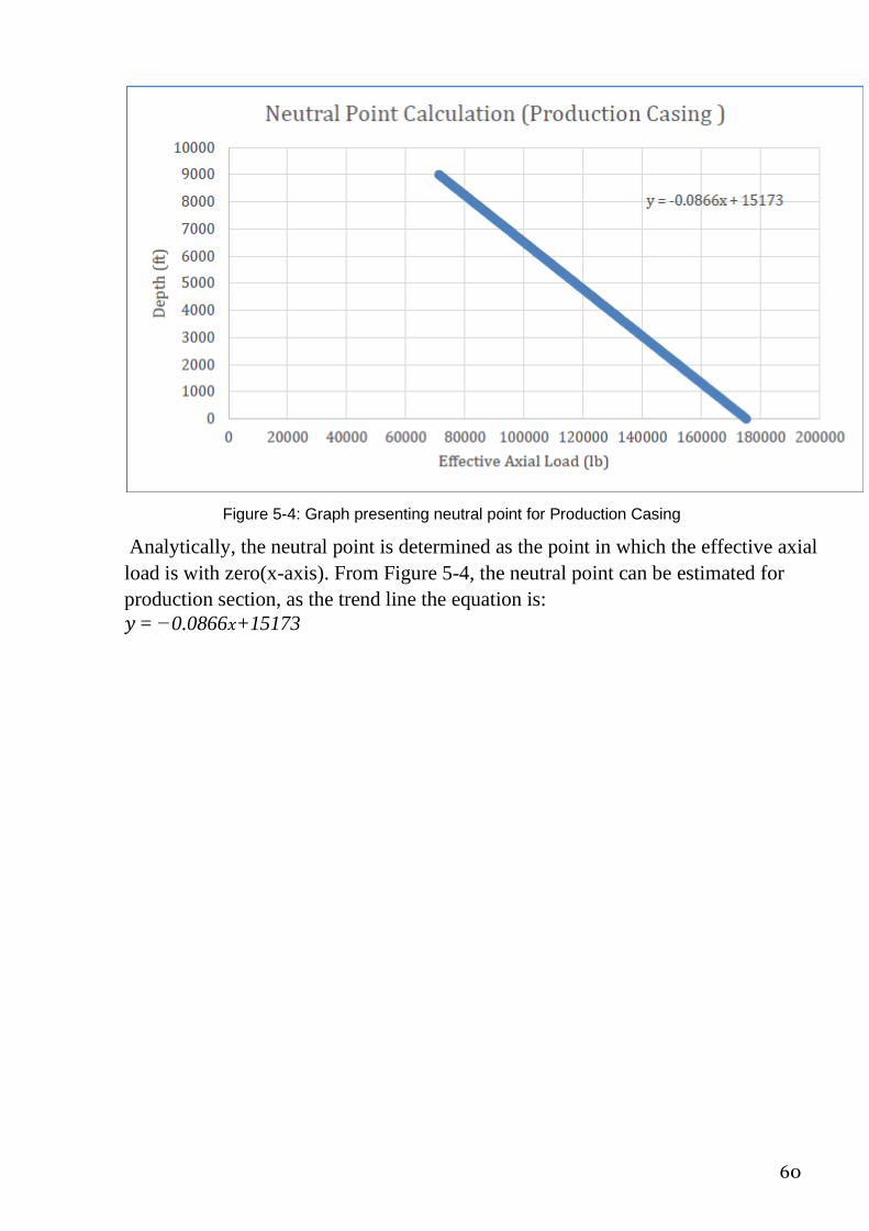
60
Figure 5-4: Graph presenting neutral point for Production Casing
Analytically, the neutral point is determined as the point in which the effective axial
load is with zero(x-axis). From Figure 5-4, the neutral point can be estimated for
production section, as the trend line the equation is:
𝑦 = −0.0866𝑥+15173
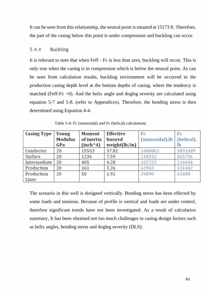
61
It can be seen from this relationship, the neutral point is situated at 15173 ft. Therefore,
the part of the casing below this point is under compression and buckling can occur.
5.4.4 Buckling
It is relevant to note that when Feff - Fc is less than zero, buckling will occur. This is
only true when the casing is in compression which is below the neutral point. As can
be seen from calculation results, buckling environment will be occurred in the
production casing depth level at the bottom depths of casing, where the tendency is
matched (Feff-Fc =0). And the helix angle and dogleg severity are calculated using
equation 5-7 and 5-8. (refer to Appendices). Therefore, the bending stress is then
determined using Equation 4-4.
Table 5-4: Fc (sinusoidal) and Fc (helical) calculations
The scenario in this well is designed vertically. Bending stress has been effected by
some loads and tensions. Because of profile is vertical and loads are under control,
therefore significant trends have not been investigated. As a result of calculation
summary, It has been obtained not too much challenges in casing design factors such
as helix angles, bending stress and dogleg severity (DLS).
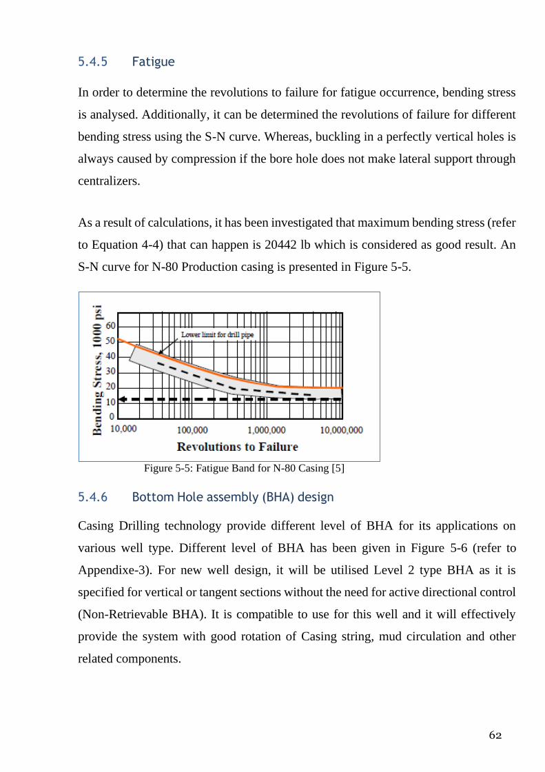
62
5.4.5 Fatigue
In order to determine the revolutions to failure for fatigue occurrence, bending stress
is analysed. Additionally, it can be determined the revolutions of failure for different
bending stress using the S-N curve. Whereas, buckling in a perfectly vertical holes is
always caused by compression if the bore hole does not make lateral support through
centralizers.
As a result of calculations, it has been investigated that maximum bending stress (refer
to Equation 4-4) that can happen is 20442 lb which is considered as good result. An
S-N curve for N-80 Production casing is presented in Figure 5-5.
Figure 5-5: Fatigue Band for N-80 Casing [5]
5.4.6 Bottom Hole assembly (BHA) design
Casing Drilling technology provide different level of BHA for its applications on
various well type. Different level of BHA has been given in Figure 5-6 (refer to
Appendixe-3). For new well design, it will be utilised Level 2 type BHA as it is
specified for vertical or tangent sections without the need for active directional control
(Non-Retrievable BHA). It is compatible to use for this well and it will effectively
provide the system with good rotation of Casing string, mud circulation and other
related components.

63
5.4.7 Torque and Drag
One of the most important factor of Casing Drilling method is Torque and Drag
determination. As it is very significant when designing CwD. For new well design
with Cwd method, torque and drag have been calculated using Equation 4-5. Drag is
estimated approximately as 20% value of the torque. The summary results of these
parameters can be found in Table 5-5 below.
Table 5-5: Torque and Drag estimations
5.4.8 Mud Program and Hydraulics Design Mud Program
For new design, mud program will not be changed properly and it will be followed as
it was for actual design. However some changes will be made for design consideration
as mud weight is not the same as it was before. The previous mud design and lithology
profile is given the Table 5-7(refer to Appendix-3) and new design is given in Table
5-6 below.
Table 5-6: New mud design configuration

64
Casing Type Hole size ×
casing size
Mud weight
(ppg)
Mud type to drill with
Conductor 36’’× 30’’ 9.2 Seawater&Spud mud
Surface 26’’× 18.625’’ 9.2 WBM
Intermediate 16’’× 13.375’’ 16 OBM
Production 12.25’’× 9.625’’ 17.6 OBM
Production Liner
8.5’’× 7’’ 18.6 OBM
Conductor section- it will be drilled without returning at surface with seawater and
super sweep pills for hole cleaning considerations.
Surface section- inhibited WBM system will be will be treated from the beginning
with KCl to enhance the inhibition properties and properly face shale formation. The
high fluid loss inherent to the system will ensure the deposition of an adequate filter
cake across loose surface sands thereby minimizing their sloughing into the wellbore.
Intermediate section- OBM will be used to drill this section. Mud Density should be
closely maintained to avoid any excessive mud weight as this can cause borehole
instability problems. The hydrostatic pressure exerted by the column of fluid can cause
an increase in near wellbore pore pressure, which may in turn lead to a failure of
formation integrity. OBM used to minimize ECDs by controlling the amount of Low
Gravity Solids (LGS) build-up in the fluid and by optimizing flow rates. Furthermore,
provide inhibition of hydrate-able shale, prevent bit/BHA balling, hydration and
swelling of cuttings, and provide good borehole stability. Finally effectively seal
porous zones, minimize fluid loss to the formation and provide a good filter cake.
Production section- OBM will be used to drill this section .Mud Density should be
closely maintained to avoid any excessive mud weight as this can cause borehole
instability problems. The hydrostatic pressure exerted by the column of fluid can cause
an increase in near wellbore formation pressure, which may in turn cause a failure of
formation integrity.
Production Liner section- there is extreme care need to be taken while drilling this
interval due to the smaller hole size, depth and the types of formation exposed. A
minimum mud weight is required to avoid any differential pressure sticking and tight
control on fluid loss will also be required. A good quality filter cake is essential in

65
order to minimize any pay zone formation damage and avoid any differential pressure
sticking. Loss of circulation can be expected and conventional LCM is not
recommended in order to avoid any formation damage through this reservoir zone.
Overall, CwD can be used efficiently in this case in South Pars gas well as wellbore
stability is a critical issue due to the presence of the smear effect which achieved better
wellbore stability in all previous wells drills all over the world. Moreover, loss of
circulation can be eliminated or even prevented by the same effect, which will reduce
the cost of using loss of circulation materials or other chemicals which used to treat
the loss of circulation. An application of CwD in this well will be helpful in
minimising loss of circulation dramatically and improve wellbore stability and can be
used in drilling depleted zones with higher mud density.
Hydraulics
Mud hydraulics is very essential parameter during drilling process. By generating
sufficient mud hydraulics, it can be achieved better hole cleaning, rate of penetration,
optimised flow rate and pressure drop across bit. In terms of hydraulic plan, Casing
drilling considerations are differ from conventional drilling. In drilling with casing
mud hydraulics is very critical issue due to having small annular clearance which may
lead to turbulent flow as this small clearance increase the actual velocity. As well as it
may decrease the difference between the critical and actual velocities. The slip velocity
should also be taken into account, thus as to be less than the actual velocity to ensure
that mud can manage to transport cuttings out of wellbore. As an impact factor on the
bit, flowrate should be designed attentively to ensure better hole cleaning in the
wellbore. Rate of penetration (ROP) is also necessary for optimising mud hydraulics,
as it is increased by optimising hydraulic horse power. To obtain optimum flow rate
hydraulically means actual velocity in annulus more than slip velocity, managing
laminar low in annulus, higher ROP by achieving efficient hole cleaning.
To identify some relevant hydraulic parameters, it has been made calculations based
on the Production Casing results. As a reason, Surface casing interval data has been
exampled because of it shows longest casing length (11000ft TVD) and potentially

66
applicable with CwD technology to drill.
Calculations for flowrate have been made based on some assumptions as following
below:
During designing the hydraulic programs, same mud weight, viscometer readings,
cuttings density etc. have been used to calculate different parameters. For slip velocity,
smaller cutting diameter was assumed as it was observed form the previous case study.
To optimize the impact factor and for bit hydraulic horse power, the ratio between
total pump pressure to the fluid loses across the bit taken to be
0.5 and .65 respectively. Power law model is justified to calculated pressure drops in
the different elements to achieve better hole cleaning a rule of thumb stated that the
flow rate value should be range from 30 to 50 gallon per minute for each inch of hole
size. Rock bit is utilised with three nozzles and pump pressure with flowrate is 2250
psi.(estimation is made)
Table 5.7 (a) Summary of hydraulics design comparison between conventional drilling and CwD in
Surface hole
Table 5.7 (b) Summary of hydraulics design comparison between conventional drilling and CwD in
Surface hole
In table 5.7 (a) and 5.7 (b), the summary results of main hydraulic parameters have
been provided. All these calculations have been made and some approximate
estimation have been justified.
Hydraulically mud flow rate in CwD should be 0 to 100% of the appropriate rate of
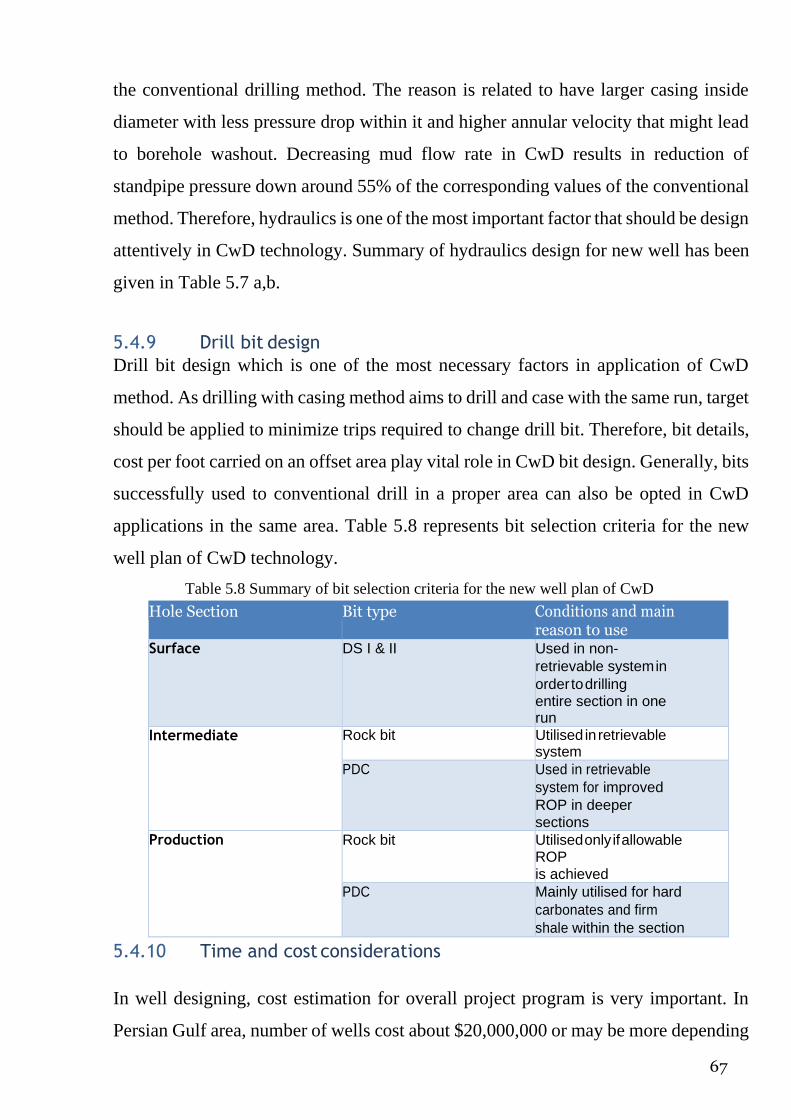
67
the conventional drilling method. The reason is related to have larger casing inside
diameter with less pressure drop within it and higher annular velocity that might lead
to borehole washout. Decreasing mud flow rate in CwD results in reduction of
standpipe pressure down around 55% of the corresponding values of the conventional
method. Therefore, hydraulics is one of the most important factor that should be design
attentively in CwD technology. Summary of hydraulics design for new well has been
given in Table 5.7 a,b.
5.4.9 Drill bit design
Drill bit design which is one of the most necessary factors in application of CwD
method. As drilling with casing method aims to drill and case with the same run, target
should be applied to minimize trips required to change drill bit. Therefore, bit details,
cost per foot carried on an offset area play vital role in CwD bit design. Generally, bits
successfully used to conventional drill in a proper area can also be opted in CwD
applications in the same area. Table 5.8 represents bit selection criteria for the new
well plan of CwD technology.
Table 5.8 Summary of bit selection criteria for the new well plan of CwD
Hole Section Bit type Conditions and main reason to use
Surface DS I & II Used in non-
retrievable system in
order to drilling entire section in one run
Intermediate Rock bit Utilised in retrievable system
PDC Used in retrievable
system for improved
ROP in deeper
sections
Production Rock bit Utilised only if allowable ROP
is achieved
PDC Mainly utilised for hard
carbonates and firm
shale within the section
5.4.10 Time and cost considerations
In well designing, cost estimation for overall project program is very important. In
Persian Gulf area, number of wells cost about $20,000,000 or may be more depending

68
on the water depth and the depth of the well. Generally speaking each wells needs
about 80 to 90 days to be drilled successfully to total depth. This well was drilled and
estimated by Conventional method with some constraints.
This new well design is generated and its cost estimation is very important to identify
main differences between two drilling methods. Generally, CwD eliminates the need
of tripping after drilling each section, by turn this will also decrease the total time of
the well from around 81 days to 52.7 days (in the case below). Table 5-9 shows
productive time and non-productive time for each section by both techniques.
Table 5.9 Summary of PT (productive time) and NPT (non-productive time) comparison between
conventional drilling and CwD technology
According to the table, it can be seen that by utilising CwD the NPT will be reduced
by 33% or 26.1 days and if we assume rig rate of about $120,000 per day so total
reduction in cost will be $3,132,000, or 15% of the well cost.
5.5 Summary
Casing while drilling technology can be an alternative approach for the conventional
method in the conditions of excessive lost circulation, stuck pipe problems due to
formation instability. The method is not an innovative technique to be absolutely
replace of conventional system, it is an alternative method to optimise drilling
productivity by overcoming unforeseen drilling problems.[23]
According to case study, problems in formation like lost circulation and stuck pipe,

69
H2S influx obliged operators to either drill ahead with huge risky consequences or
abandon the well after time and money wasting for project.
However, application of Drilling with Casing technology in South Pars gas field can
provide better drilling quality by preventing relevant drilling problems.
New design is proposed for the well has been regenerated by Casing Drilling. New
casing setting depths configurations are made and new interval depths are chosen. The
main parameters which are essentials were taken into account, such as BHA design,
Casing designing factors, Mud and hydraulics design, Bit design and Cost estimations.
As one of the main considerations, buckling caused by compressive load cannot lead
to failure of the casing by itself. However, it can cause two effects that can lead to
failure: contact between casing and borehole wall due to buckling can cause increased
wear on the casing and the curved surface assumed by the casing due to buckling
growing up the stress in the casing and this can increase the tendency toward lateral
vibrations.
Another essential factor is fatigue failure which can occur due to cyclic loading. Crack
starts to appear at the point of localized high stress and repeated loading can cause to
the crack propagating through the body until the remaining cross sectional area is
unable to support the static load.
In terms of hydraulic considerations, in casing drilling it has been observed decreasing
cross sectional area, which provide smaller annulus between the casing and borehole.
It leads to achieving higher annular fluid velocity which provides better cutting
transports to the surface. As well as, higher ECD is obtained for casing drilling
applications compared to conventional drilling. Calculations completed in this section
have represented that most care has to be taken in designing some casing factors, such
as buckling, fatigue, torque and drag. The results from these calculations have
provided rough estimations on how important these factors are in designing CwD
methods. However, WellPlan software by Halliburton can be worked and all these
calculation can be accurately computed.

70
CONCLUSION AND RECOMMENDATIONS
Conclusion
This project study was undertaken with the aim of investigating Casing Drilling
technology. Casing while Drilling is very reliable method that brought new
innovations to drilling industry in improving drilling performance compared to the
Conventional Drilling method.
There are some drilling challenges range from wellbore incidents and drilling hazards
to NPT that conventional drilling method has not properly dealt with them. Although
vast amount of techniques are available to solve these problems, they are required
higher cost or they are not perfectly designed to achieve required target. All these
limitations obliged the industry to discover an alternative ways to drill safely and
effectively.
Casing Drilling method promotes huge amount of benefits. One of them is decease of
NPT as tripping was eliminated. In mitigating complications elimination of tripping
operation helped, as well as swab and surge pressures. This method promotes
plastering effect which is quite advantageous. Cutting are plastered onto the borehole
wall which results in preventing lost circulation problems. On the other hand, quality
of filter cake is being improved which helps the system to balance the pressures in the
formation and in the wellbore.
Moreover, risks of casing stuck are minimised as the casing is continuously rubbing
and sliding. If the casing got stuck, BHA can be retrieved and problem may surely be
mitigated by doing cementing operation. Hydraulically, casing is designed to small
size to generate narrow annulus in order to achieving annular flow velocity. This is
important because of better cutting removals from the wellbore to the surface. The
design regenerated in the South Pars gas well has outlined how CwD method overcame

71
most of the challenges that could not have done with Conventional Drilling.
On the other hand, this new technology has its own limits and complications. Casing
Drilling method has been lately worked by some different companies that they
promote their own promotions. As a result of such complications, information data has
been become prejudiced.
Another fact is related to its application condition that when the casing or drill bit has
to be tripped out of the wellbore and this may results in increasing of NPT. Therefore,
if the main target is to diminish NPT due to tripping operation, to apply this technology
in the well is ineffective. Additionally, availability of plastering effect should also be
checked prior to utilise the operation. Another complication is associated with ECD
prediction. To have lower flow rates in the system will result in lower ECD, whereas
annulus area is small in CwD method.
This leads to an increase in annular velocity which in turn results in higher friction
losses which makes ECD higher. According to some SPE papers it has been stated that
both ECD values are productive, but not all the time. On the other hand Casing Drilling
promotes ECD with higher value by lower flow rate. In this case lower flow rate
should be potentially able to remove cuttings from the wellbore, otherwise the
situation with higher flowrate and ECD will result in formation damage in the system.
As a result of investigation of this project, it has been obtained some uncertainties that
are under question. One of them is associated with BHA design, what will be carried
out if the BHA is stuck which is unable to be retrieved? Is it possible to mitigate this
problem by side tracking the well? If the problem cannot be solved, then BHA cannot
be retrieved either that will lead to huge amount of damage to operational drilling cost.
To sum up, by inventing this innovative technology Petroleum industry has achieved
great improvement in drilling operations. It is potential method that overcome
significant drilling problems such as wellbore stability, lost circulation, stuck pipe and

72
all these scenarios have been mitigated successfully by applying the method in South
Pars gas well. It will be anticipated that the company will not only save huge
operational cost but also improve drilling performance and maximize recoverable
reserves.
Future plans and suggestions
The project was mainly aimed to investigate CwD technology from different contexts
like its design considerations, benefits, limitations, application in South Pars gas well.
Calculations were made for the well data are not precise. Because all these calculations
are made based on some theoretic assumptions. In particular cases, some factors were
ignored not to have much influence on result. As a future plan it would be
recommended that the project would be worked by using industrial drilling software,
such as Wellplan by Halliburton licence. Calculations associated with buckling,
fatigue, torque and drag would be very neatly calculated and achieved precise results.
It can be suggested that in order to improve the technology lots of investigations would
be conducted and new areas would be discovered to apply Casing Drilling technology
that has not been operated before.
73
References
[1] Bourgoyne, A.T., 1991. Applied drilling engineering. Richardson, TX: Society of
Petroleum Engineers.
[2] Moellendick, E. and Karimi, M., 2011. How Casing Drilling Improves Wellbore
Stability, 2011, AADE-11-NTCE-64, AADE National Technical Conference, Houston, Texas.
[3] Mohammed A., Okeke C.J. and Abolle-Okoyeagu I., 2012. Current Trends and Future
Development in Casing Drilling, International Journal of Science and Technology, Vol. 2 (8): 567-
582.
[4] Warren, T.M , 2004 . Casing Drilling Effective With Retrievable Assemblies, Drilling
Contractor.
[5] Warren, T.M., Angman, P., and Houtchens, B. 2000. Casing Drilling Application
Design Considerations. Presented at the IADC/SPE Drilling Conference, New Orleans,
Louisiana, 23-25 February. SPE-59179-MS
[6] Bellarby, J., 2009., Well completion design. 2nd edition, Amsterdam, Netherlands;
London: Elsevier.
[7] Lubinski, A., Althouse, W.S.andLogan, J.L., 1962. Helical Buckling of Tubing Sealed in
Packers. SPE 178.
[8] Karimi, M., Holt, C. and Moellendick, T.E., 2011. Trouble Free Drilling with Casing
Drilling; a Process Focused on Preventing the Drilling Problems, International Petroleum
Technology Conference 2011, International Petroleum Technology Conference.
[9] Devereux, S. and Ebrary, I., 2012. Drilling technology in nontechnical language. 2
edn. Tulsa, Okla.: PennWell Corp.
[10] Fontenot, K., Highnote, J., Warren, T. and Houtchens, B., 2003. Casing drilling
activity expands in South Texas, SPE/IADC Drilling Conference 2003, Society of Petroleum
Engineers
[11] Warren,T.M, 2007 . Drilling with casing: What It Can and Can’t Do for an Asset.
SPE Distinguished Lecture Series
[12] Ahmed, K. A. F., Sinde, S. and Abdel Sattar Abdel Hamid Dahab (2012) ‘Potential
Implementation of Casing while Drilling Technique in the Western Desert Fields of Egypt’,
North Africa Technical Conference and Exhibition
[13]http://image.chinaogpe.com/newsimages/Introduction_to_top_drive_drilling_syst
em_2_glossary-1.gif , Accessed on 27/04/2015
[14] https://www.rigzone.com/training/insight.asp?insight_id=332&c_id=24 , Accessed on
27/04/2015
[15] http://petroleumsupport.com/stuck-pipe-on-drilling/Accessed on 27/04/2015
[16] http://www.cosmos-shoji.co.jp/maker/b.php , Accessed on 27/04/2015
[22] Graves, K. S. and Herrera, D. C. (2013) Casing During Drilling With Rotary- Steerable
Technology in the Stag Field--Offshore Australia

74
Appendices Appendix 1- Conventional Drilling method
Figure 1-1: Schematic view of rotary drilling process [1] Figure 1-2: Structure of Top Drive
Drilling System [13]
Appendix 2 – Casing Drilling method
Figure 2-1: First Casing Drilling systems [11] Figure 2-2: Conventional and Casing Drilling BHAs [3]

75
Figure 2-3: Tesco’s Top Drive system and Casing Drive Assembly, Internal Tool [16]
Figure 2-4: Bottom Hole Assembly Figure 2-5: Drill Lock Assembly Figure 2-8: Float of Retrievable
BHA [5] [3] Collar [3]
Appendix 3- New Design with Casing Drilling (CwD) method
▪

76
Figure 5-6: BHAs for Casing Drilling technology [22]

77
Figure 5-7: Mud specification for actual well (Conventional drilling)