Embed Size (px)
Citation preview
Title Self-calibration of turntable sequences from silhouettes
Author(s) Zhang, H; Wong, KYK
Citation Ieee Transactions On Pattern Analysis And Machine Intelligence,2009, v. 31 n. 1, p. 5-14
Issued Date 2009
URL http://hdl.handle.net/10722/138033
Rights
IEEE Transactions on Pattern Analysis and Machine Intelligence.Copyright © IEEE.; ©2009 IEEE. Personal use of this material ispermitted. However, permission to reprint/republish this materialfor advertising or promotional purposes or for creating newcollective works for resale or redistribution to servers or lists, orto reuse any copyrighted component of this work in other worksmust be obtained from the IEEE.

Self-Calibration of Turntable Sequencesfrom Silhouettes
Hui Zhang, Member, IEEE, and Kwan-Yee K. Wong, Member, IEEE
Abstract—This paper addresses the problem of recovering both the intrinsic and extrinsic parameters of a camera from the silhouettes
of an object in a turntable sequence. Previous silhouette-based approaches have exploited correspondences induced by epipolar
tangents to estimate the image invariants under turntable motion and achieved a weak calibration of the cameras. In order to recover
the rotation angles and obtain a euclidean reconstruction, these approaches require the prior knowledge of the camera intrinsics. In
this paper, we propose a novel approach for recovering the rotation angles precisely in the absence of the camera intrinsics. It is known
that the fundamental matrix relating any two views in a turntable sequence can be expressed explicitly in terms of the image invariants,
the rotation angle, and a fixed scalar. It will be shown that the imaged circular points for the turntable plane can also be formulated in
terms of the same image invariants and fixed scalar. This allows the imaged circular points to be recovered directly from the estimated
image invariants. The imaged circular points and the image invariants provide constraints for the estimation of the imaged absolute
conic, and the camera calibration matrix can thus be recovered. A robust method for estimating the fixed scalar from image triplets is
introduced, and a method for recovering the rotation angles by using the estimated imaged circular points and epipoles is presented.
Using the estimated camera intrinsics and extrinsics, a euclidean reconstruction can be obtained. Experimental results on real data
sequences are presented which demonstrate the high precision achieved by the proposed method.
Index Terms—Self-calibration, circular points, silhouettes, turntable motion.
Ç
1 INTRODUCTION
THREE-DIMENSIONAL object reconstruction from imagesequences has always been a hot research topic in both
computer vision and computer graphics. Due to its ease ofoperation, a turntable has commonly been used with a fixedcamera for acquiring images around an object in themodeling process. The most important and difficult stepin object reconstruction from a turntable sequence is therecovery of the relative pose of the camera, the cameraintrinsic parameters, and the rotation angles. Traditionalapproaches accomplish this task by attaching some specialcalibration patterns to the turntable to calibrate the camera[1], [2]. In [3], Fitzgibbon et al. introduced a point-basedmethod for handling the case with an uncalibrated cameraand unknown rotation angles. Their method is based on theprojective geometry of single axis motion and it involves thecomputation of both fundamental matrices and trifocaltensors from point correspondences. Jiang et al. [4], [5]further extended this approach by making use of the conictrajectories of the rotating point features, and developed analgorithm that requires neither the computation of funda-mental matrices nor trifocal tensors. Note that all of the
above approaches require the matching of point correspon-dences across the sequence, and would therefore not beapplicable to smooth objects with sparse surface textures.
For smooth objects like sculptures, silhouettes are thepredominant stable image features. Silhouettes are theprojections of contour generators [6] which are viewpointdependent. For two distinct viewpoints, the contourgenerators of an object are, in general, two distinct spacecurves. Hence, they provide no point correspondencesbetween the corresponding silhouettes, except for thefrontier points [7], which are the points of intersectionbetween the two contour generators. Silhouette-basedmethods for motion estimation generally exploit epipolartangents [8], [9], [10], [11] to locate the images of the frontierpoints to derive point correspondences between images.However, such an approach requires the presence of at leastseven pairs of epipolar tangents, which may not be alwaysavailable for objects with a simple shape. Besides, thelocation of epipolar tangents in a pair of uncalibratedimages involves a nonlinear optimization with a nontrivialinitialization. In [12], Sinha et al. proposed avoiding theproblem of insufficient frontier points by using silhouettesof a dynamic object, and they also proposed a RANSACapproach for initializing the nonlinear optimization inlocating the epipolar tangents. Nonetheless, such a methodis not suitable for a static object.
In [13], Mendonca et al. developed a multistep algorithmfor recovering the turntable motion. The number ofrequired epipolar tangents per image pair is only two,which can be easily satisfied in almost all situations. Byexploiting the symmetry properties exhibited in the imageof a surface of revolution (SoR) generated by the rotatingobject, a simple method for locating epipolar tangents basedon a one-dimensional search is introduced. Note that this
IEEE TRANSACTIONS ON PATTERN ANALYSIS AND MACHINE INTELLIGENCE, VOL. 31, NO. 1, JANUARY 2009 5
. H. Zhang is with the Division of Science and Technology, UnitedInternational College, 28 Jingeng Road, Tangjiawan, Zhuhai, Guangdong,P.R. China, 519 085. E-mail: [email protected].
. K.-Y.K. Wong is with the Department of Computer Science, TheUniversity of Hong Kong, Pokfulam Road, Hong Kong.E-mail: [email protected].
Manuscript received 6 June 2007; revised 14 Jan. 2008; accepted 19 Feb. 2008;published online 10 Mar. 2008.Recommended for acceptance by M. Polleyfeys.For information on obtaining reprints of this article, please send e-mail to:[email protected], and reference IEEECS Log NumberTPAMI-2007-06-0334.Digital Object Identifier no. 10.1109/TPAMI.2008.56.
0162-8828/09/$25.00 � 2009 IEEE Published by the IEEE Computer Society
method requires a dense turntable sequence in order toapproximate the image of the SoR by the envelope of thesilhouettes. In [14], Wong and Cipolla further extended thework in [13] to handle the case of sparse sequences, andtheir method also allows the incorporation of general views.The trade-off is the involvement of a high-dimensionaloptimization. Note that, in both [13] and [14], the recoveryof the rotation angles and, furthermore, the euclideanreconstruction still require the knowledge of the cameraintrinsics. In [15], Hernandez et al. considered the problemof recovering both the turntable motion and the camerafocal length from silhouettes. Rather than using the epipolartangency constraint as in [13] and [14], they proposed anovel silhouette coherence constraint and developed a methodthat optimizes both the camera poses and the focal lengthsimultaneously by maximizing the coherence between thesilhouettes and the projections of the visual hull built fromthe silhouettes and the current estimate of the cameraparameters. Like [14], their method involves a high-dimensional optimization. It surpasses [14] by exploitingall the information contained in the contours of thesilhouettes (rather than just the epipolar tangent points),and can handle incomplete silhouettes. Experimentalresults reported improvement over those obtained usingepipolar tangents. In [16], Furukawa et al. proposed aRANSAC-based method for recovering general motionfrom silhouettes. They simplified the problem of locatingpotential epipolar tangents by restricting the viewinggeometry to orthographic projection, under which all epipolarlines are parallel, and used signature representation of thedual image outlines to facilitate the matching of epipolartangents. Although they also outlined how their methodcan be extended to handle the weak-perspective affine case,only results for the orthographic case were reported.
In this paper, we propose a novel algorithm forrecovering both the intrinsic and extrinsic parameters of acamera from the silhouettes of an object in a turntablesequence. The proposed method follows the same approachas in [13], which first estimates the image invariants byusing epipolar tangents and recovers the fundamentalmatrices in terms of these invariants. Based on the fact thatthe epipoles in one view are the images of the other cameracenters, a simple method is proposed for precise estimationof the image invariants and rotation angles in the absence ofthe camera intrinsics. Such a method can also handle thedegenerate case as described in [17] and [18], where thebaseline passes through the scene object. Besides, it will beshown that the imaged circular points for the turntableplane can be obtained directly in terms of the imageinvariants and a fixed scalar used in the formula of thefundamental matrix. This allows the imaged circular pointsto be recovered directly from the estimated image invar-iants. The imaged circular points, together with the imageinvariants, provide constraints for the estimation of theimaged absolute conic, and the camera calibration matrixcan thus be recovered. This can be used to upgrade theweakly calibrated cameras to fully calibrated ones, and aeuclidean reconstruction follows. Preliminary results of thiswork have been published in [19].
The work presented here is most closely related to thework of Hernandez et al. [15]. In [15], the authorsconsidered the recovery of the focal length, which wasestimated simultaneously with other motion parameters viaan optimization in a high-dimensional space. In this work,we consider recovering three camera intrinsic parameters,namely, the focal length and the coordinates of the principalpoint. We also decouple the estimation of the cameraintrinsic parameters from the extrinsic parameters anddemonstrate that the intrinsic parameters can be recoveredfrom the image invariants derived directly from theestimated motion parameters. This avoids potential pro-blems of local minima often encountered in high-dimen-sional optimizations.
The remainder of this paper is organized as follows:Section 2 rehashes the image invariants under turntablemotion and a special parameterization of the fundamentalmatrix in terms of the image invariants. Section 3 brieflyreviews two existing algorithms for recovering the turntablemotion from silhouettes upon which the algorithm pro-posed in this paper is based. Section 4 derives a novelformula for the imaged circular points expressed in terms ofthe image invariants and a fixed scalar, and presents analgorithm for recovering the imaged circular points fromthe estimated fundamental matrices. Besides, a robustmethod for computing the rotation angles, in the absenceof the camera intrinsics, is also introduced. Section 5 showsthe experimental results, followed by the conclusions inSection 6.
2 THEORETICAL BACKGROUND
The geometry of a stationary camera viewing an object on arotating turntable is equivalent to that of a camera rotatingabout the same axis and viewing a stationary object. For thesake of clear notations, we will refer to the geometry of thelatter in the rest of this paper.
2.1 Image Invariants under Turntable Motion
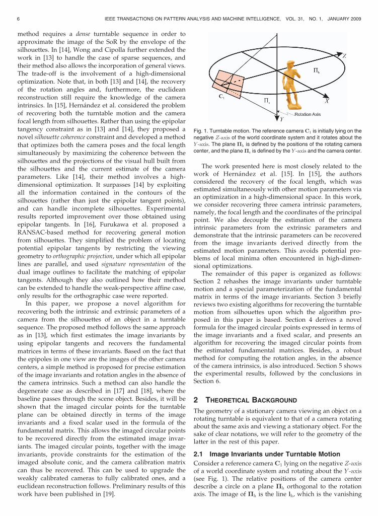
Consider a reference camera C1 lying on the negative Z-axisof a world coordinate system and rotating about the Y -axis(see Fig. 1). The relative positions of the camera centerdescribe a circle on a plane �h orthogonal to the rotationaxis. The image of �h is the line lh, which is the vanishing
6 IEEE TRANSACTIONS ON PATTERN ANALYSIS AND MACHINE INTELLIGENCE, VOL. 31, NO. 1, JANUARY 2009
Fig. 1. Turntable motion. The reference camera C1 is initially lying on the
negative Z-axis of the world coordinate system and it rotates about the
Y -axis. The plane �h is defined by the positions of the rotating camera
center, and the plane �s is defined by the Y -axis and the camera center.
line (i.e., the horizon) for the turntable plane (see Fig. 2).
Since all of the camera center positions lie on �h, all of the
epipoles eij that are images of the rotating camera center
must lie on lh, i.e.,
lTh eij ¼ 0 8i; j: ð1Þ
Let the plane defined by the camera center and the
rotation axis be �s, and consider three orthogonal direc-
tions, Nx, Ny, and Nz, given by the normal direction of �s,
the Y -axis, and Nx �Ny, respectively (see Fig. 1). These
three directions will have vanishing points vx, vy, and vz,
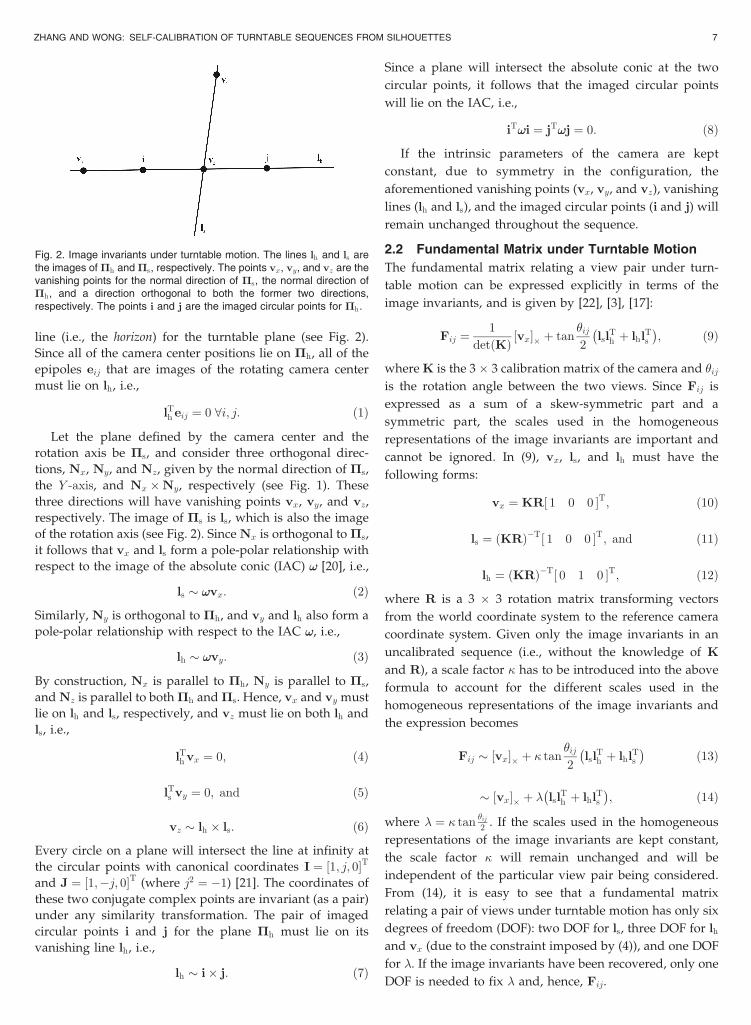
respectively. The image of �s is ls, which is also the image
of the rotation axis (see Fig. 2). Since Nx is orthogonal to �s,
it follows that vx and ls form a pole-polar relationship with
respect to the image of the absolute conic (IAC) !! [20], i.e.,
ls � !!vx: ð2Þ
Similarly, Ny is orthogonal to �h, and vy and lh also form a
pole-polar relationship with respect to the IAC !!, i.e.,
lh � !!vy: ð3Þ
By construction, Nx is parallel to �h, Ny is parallel to �s,
and Nz is parallel to both �h and �s. Hence, vx and vy must
lie on lh and ls, respectively, and vz must lie on both lh and
ls, i.e.,
lTh vx ¼ 0; ð4Þ
lTs vy ¼ 0; and ð5Þ
vz � lh � ls: ð6Þ
Every circle on a plane will intersect the line at infinity at
the circular points with canonical coordinates I ¼ ½1; j; 0�Tand J ¼ ½1;�j; 0�T (where j2 ¼ �1) [21]. The coordinates of
these two conjugate complex points are invariant (as a pair)
under any similarity transformation. The pair of imaged
circular points i and j for the plane �h must lie on its
vanishing line lh, i.e.,
lh � i� j: ð7Þ
Since a plane will intersect the absolute conic at the two
circular points, it follows that the imaged circular points
will lie on the IAC, i.e.,
iT!!i ¼ jT!!j ¼ 0: ð8Þ
If the intrinsic parameters of the camera are kept
constant, due to symmetry in the configuration, the
aforementioned vanishing points (vx, vy, and vz), vanishing
lines (lh and ls), and the imaged circular points (i and j) will
remain unchanged throughout the sequence.
2.2 Fundamental Matrix under Turntable Motion
The fundamental matrix relating a view pair under turn-
table motion can be expressed explicitly in terms of the
image invariants, and is given by [22], [3], [17]:
Fij ¼1
detðKÞ ½vx�� þ tan�ij2
lslTh þ lhlTs
� �; ð9Þ
where K is the 3 � 3 calibration matrix of the camera and �ijis the rotation angle between the two views. Since Fij is
expressed as a sum of a skew-symmetric part and a
symmetric part, the scales used in the homogeneous
representations of the image invariants are important and
cannot be ignored. In (9), vx, ls, and lh must have the
following forms:
vx ¼ KR½ 1 0 0 �T; ð10Þ
ls ¼ ðKRÞ�T½ 1 0 0 �T; and ð11Þ
lh ¼ ðKRÞ�T½ 0 1 0 �T; ð12Þ
where R is a 3 � 3 rotation matrix transforming vectors
from the world coordinate system to the reference camera
coordinate system. Given only the image invariants in an
uncalibrated sequence (i.e., without the knowledge of K
and R), a scale factor � has to be introduced into the above
formula to account for the different scales used in the
homogeneous representations of the image invariants and
the expression becomes
Fij � ½vx�� þ � tan�ij2
lslTh þ lhlTs
� �ð13Þ
� ½vx�� þ � lslTh þ lhlTs
� �; ð14Þ
where � ¼ � tan�ij2 . If the scales used in the homogeneous
representations of the image invariants are kept constant,
the scale factor � will remain unchanged and will be
independent of the particular view pair being considered.
From (14), it is easy to see that a fundamental matrix
relating a pair of views under turntable motion has only six
degrees of freedom (DOF): two DOF for ls, three DOF for lh
and vx (due to the constraint imposed by (4)), and one DOF
for �. If the image invariants have been recovered, only one
DOF is needed to fix � and, hence, Fij.
ZHANG AND WONG: SELF-CALIBRATION OF TURNTABLE SEQUENCES FROM SILHOUETTES 7
Fig. 2. Image invariants under turntable motion. The lines lh and ls arethe images of �h and �s, respectively. The points vx, vy, and vz are thevanishing points for the normal direction of �s, the normal direction of�h, and a direction orthogonal to both the former two directions,respectively. The points i and j are the imaged circular points for �h.

3 WEAK CALIBRATION FROM SILHOUETTES
In this section, two recent approaches for estimatingturntable motion from silhouettes will be reviewed. Bothmethods estimate the fundamental matrices associated withthe views under turntable motion by minimizing thesymmetric transfer errors of the epipolar tangents to thesilhouettes, and successful solutions have been developedby exploiting the special parameterization of the funda-mental matrix. Note that, in order to recover the rotationangles between different views and achieve a euclideanreconstruction, the camera calibration matrix is needed inboth methods to upgrade the weak calibration to a fullcalibration. In the next section, a novel method will beintroduced to recover the camera calibration matrix fromthe estimated fundamental matrices. A robust method forrecovering the rotation angles in the absence of the cameraintrinsics will also be presented. These enhance the currentalgorithms by removing the requirement of known cameraintrinsics, and allow a euclidean reconstruction fromsilhouettes in an uncalibrated turntable sequence.
3.1 Dense Sequence
Given a dense sequence, Mendonca et al. [17] introduced amultistep algorithm for estimating the turntable motion.Their method first recovers the imaged rotation axis ls andthe vanishing point vx from the image profile � of an SoRgenerated by the rotating object. They approximate such animage by the envelope of the deforming silhouettes. Byexploiting the symmetry exhibited in �, ls and vx can beeasily obtained by locating bitangents to � (see Fig. 3). Since� is invariant to the transformation induced by a harmonichomology W with axis ls and vertex vx, defined as
W ¼ I� 2vxl
Ts
vTx ls
; ð15Þ
ls and vx can be further optimized by minimizing thetransformation error of � brought about by W.
In the second step, the fact that corresponding epipolarlines are being mapped by W�T is exploited to locate theouter epipolar tangents to the silhouettes. The objective is to
locate a line l tangent to the silhouette in one view, which
will be transformed by W�T to a line l0 ¼W�Tl tangent to
the silhouette in the second view (see Fig. 4). This process
can be carried out as a one-dimensional search in which the
single search parameter is the angle that defines the
orientation of the line l. The epipoles can then be obtained
as the intersection point of the two outer epipolar tangents
in each view, and the horizon lh is recovered as a line
robustly fitted to the set of epipoles obtained from some
randomly sampled image pairs (see Fig. 5).After the first two steps, the image invariants vx, ls, and
lh have been recovered. The only missing term in the
parameterization of the fundamental matrix Fij given in
(14) is � ¼ � tan�ij2 . In the final step, a one-dimensional
search along the parametric direction � is performed to
optimize Fij by minimizing the symmetric transfer errors of
the epipolar tangents. After this optimization, the set of
epipoles obtained from the resulting fundamental matrices
will all lie on the horizon lh.With known camera intrinsics, the essential matrix can
be formed from the fundamental matrix. The rotation
angles of the camera can then be recovered by decomposing
the essential matrices. A euclidean reconstruction can be
obtained using the silhouettes and the set of projection
matrices resulting from the decompositions.
8 IEEE TRANSACTIONS ON PATTERN ANALYSIS AND MACHINE INTELLIGENCE, VOL. 31, NO. 1, JANUARY 2009
Fig. 3. (a) The image profile of the SoR generated by the rotating objectcan be approximated by the envelope of the deforming silhouettes of theobject. (b) The image invariants vx and ls can be obtained from theintersections of the bitangent lines and lines formed from the bitangentpoints.
Fig. 4. An epipolar tangent is located by finding a line tangent to the
silhouette in the first view, which is transformed by the harmonic
homology W�T to a line tangent to the silhouette in the second view.
Fig. 5. The epipole is obtained as the intersection point of the two outer
epipolar tangents in one view. The horizon lh is recovered as a line
robustly fitted to the set of epipoles obtained from some randomly
sampled image pairs.
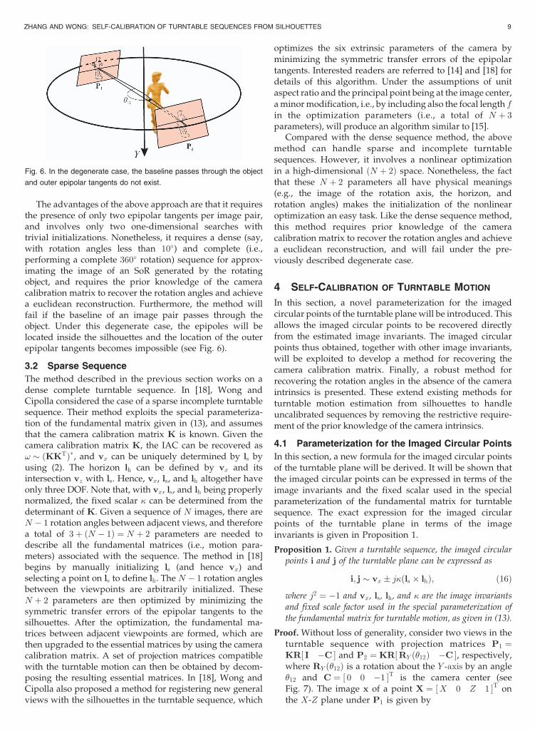
The advantages of the above approach are that it requiresthe presence of only two epipolar tangents per image pair,and involves only two one-dimensional searches withtrivial initializations. Nonetheless, it requires a dense (say,with rotation angles less than 10�) and complete (i.e.,performing a complete 360� rotation) sequence for approx-imating the image of an SoR generated by the rotatingobject, and requires the prior knowledge of the cameracalibration matrix to recover the rotation angles and achievea euclidean reconstruction. Furthermore, the method willfail if the baseline of an image pair passes through theobject. Under this degenerate case, the epipoles will belocated inside the silhouettes and the location of the outerepipolar tangents becomes impossible (see Fig. 6).
3.2 Sparse Sequence
The method described in the previous section works on adense complete turntable sequence. In [18], Wong andCipolla considered the case of a sparse incomplete turntablesequence. Their method exploits the special parameteriza-tion of the fundamental matrix given in (13), and assumesthat the camera calibration matrix K is known. Given thecamera calibration matrix K, the IAC can be recovered as! � ðKKTÞ�, and vx can be uniquely determined by ls byusing (2). The horizon lh can be defined by vx and itsintersection vz with ls. Hence, vx, ls, and lh altogether haveonly three DOF. Note that, with vx, ls, and lh being properlynormalized, the fixed scalar � can be determined from thedeterminant of K. Given a sequence of N images, there areN � 1 rotation angles between adjacent views, and thereforea total of 3þ ðN � 1Þ ¼ N þ 2 parameters are needed todescribe all the fundamental matrices (i.e., motion para-meters) associated with the sequence. The method in [18]begins by manually initializing ls (and hence vx) andselecting a point on ls to define lh. The N � 1 rotation anglesbetween the viewpoints are arbitrarily initialized. TheseN þ 2 parameters are then optimized by minimizing thesymmetric transfer errors of the epipolar tangents to thesilhouettes. After the optimization, the fundamental ma-trices between adjacent viewpoints are formed, which arethen upgraded to the essential matrices by using the cameracalibration matrix. A set of projection matrices compatiblewith the turntable motion can then be obtained by decom-posing the resulting essential matrices. In [18], Wong andCipolla also proposed a method for registering new generalviews with the silhouettes in the turntable sequence, which
optimizes the six extrinsic parameters of the camera byminimizing the symmetric transfer errors of the epipolartangents. Interested readers are referred to [14] and [18] fordetails of this algorithm. Under the assumptions of unitaspect ratio and the principal point being at the image center,a minor modification, i.e., by including also the focal length fin the optimization parameters (i.e., a total of N þ 3parameters), will produce an algorithm similar to [15].
Compared with the dense sequence method, the abovemethod can handle sparse and incomplete turntablesequences. However, it involves a nonlinear optimizationin a high-dimensional ðN þ 2Þ space. Nonetheless, the factthat these N þ 2 parameters all have physical meanings(e.g., the image of the rotation axis, the horizon, androtation angles) makes the initialization of the nonlinearoptimization an easy task. Like the dense sequence method,this method requires prior knowledge of the cameracalibration matrix to recover the rotation angles and achievea euclidean reconstruction, and will fail under the pre-viously described degenerate case.
4 SELF-CALIBRATION OF TURNTABLE MOTION
In this section, a novel parameterization for the imagedcircular points of the turntable plane will be introduced. Thisallows the imaged circular points to be recovered directlyfrom the estimated image invariants. The imaged circularpoints thus obtained, together with other image invariants,will be exploited to develop a method for recovering thecamera calibration matrix. Finally, a robust method forrecovering the rotation angles in the absence of the cameraintrinsics is presented. These extend existing methods forturntable motion estimation from silhouettes to handleuncalibrated sequences by removing the restrictive require-ment of the prior knowledge of the camera intrinsics.
4.1 Parameterization for the Imaged Circular Points
In this section, a new formula for the imaged circular pointsof the turntable plane will be derived. It will be shown thatthe imaged circular points can be expressed in terms of theimage invariants and the fixed scalar used in the specialparameterization of the fundamental matrix for turntablesequence. The exact expression for the imaged circularpoints of the turntable plane in terms of the imageinvariants is given in Proposition 1.
Proposition 1. Given a turntable sequence, the imaged circularpoints i and j of the turntable plane can be expressed as
i; j � vx � j�ðls � lhÞ; ð16Þ
where j2 ¼ �1 and vx, ls, lh, and � are the image invariantsand fixed scale factor used in the special parameterization of
the fundamental matrix for turntable motion, as given in (13).
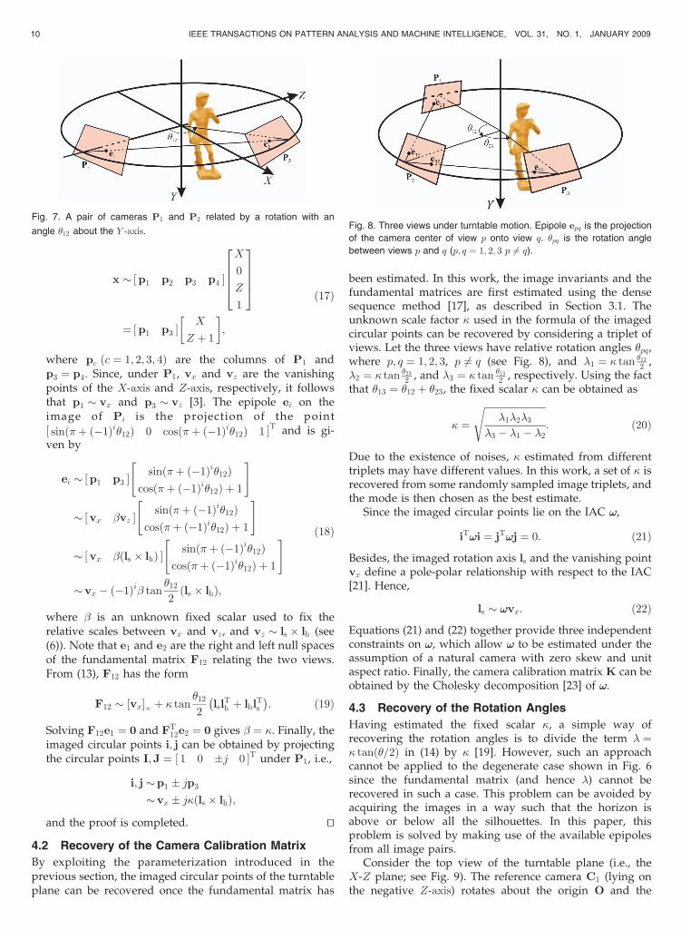
Proof. Without loss of generality, consider two views in theturntable sequence with projection matrices P1 ¼KR½ I �C � and P2 ¼ KR½RY ð�12Þ �C �, respectively,where RY ð�12Þ is a rotation about the Y -axis by an angle�12 and C ¼ ½ 0 0 �1 �T is the camera center (seeFig. 7). The image x of a point X ¼ ½X 0 Z 1 �T onthe X-Z plane under P1 is given by
ZHANG AND WONG: SELF-CALIBRATION OF TURNTABLE SEQUENCES FROM SILHOUETTES 9
Fig. 6. In the degenerate case, the baseline passes through the object
and outer epipolar tangents do not exist.
x � ½p1 p2 p3 p4 �
X
0
Z
1
26664
37775
¼ ½p1 p3 �X
Z þ 1
� �;
ð17Þ
where pc ðc ¼ 1; 2; 3; 4Þ are the columns of P1 andp3 ¼ p4. Since, under P1, vx and vz are the vanishingpoints of the X-axis and Z-axis, respectively, it followsthat p1 � vx and p3 � vz [3]. The epipole ei on theimage of Pi is the projection of the point½ sinð�þ ð�1Þi�12Þ 0 cosð�þ ð�1Þi�12Þ 1 �T and is gi-ven by
ei � ½p1 p3 �sinð�þ ð�1Þi�12Þ
cosð�þ ð�1Þi�12Þ þ 1
" #
� ½vx �vz �sinð�þ ð�1Þi�12Þ
cosð�þ ð�1Þi�12Þ þ 1
" #
� ½vx �ðls � lhÞ �sinð�þ ð�1Þi�12Þ
cosð�þ ð�1Þi�12Þ þ 1
" #
�vx � ð�1Þi� tan�12
2ðls � lhÞ;
ð18Þ
where � is an unknown fixed scalar used to fix therelative scales between vx and vz, and vz � ls � lh (see(6)). Note that e1 and e2 are the right and left null spacesof the fundamental matrix F12 relating the two views.From (13), F12 has the form
F12 � ½vx�� þ � tan�12
2lsl
Th þ lhlT
s
� �: ð19Þ
Solving F12e1 ¼ 0 and FT12e2 ¼ 0 gives � ¼ �. Finally, the
imaged circular points i; j can be obtained by projectingthe circular points I;J ¼ ½ 1 0 �j 0 �T under P1, i.e.,
i; j �p1 � jp3
�vx � j�ðls � lhÞ;
and the proof is completed. tu
4.2 Recovery of the Camera Calibration Matrix
By exploiting the parameterization introduced in theprevious section, the imaged circular points of the turntableplane can be recovered once the fundamental matrix has
been estimated. In this work, the image invariants and thefundamental matrices are first estimated using the densesequence method [17], as described in Section 3.1. Theunknown scale factor � used in the formula of the imagedcircular points can be recovered by considering a triplet ofviews. Let the three views have relative rotation angles �pq,where p; q ¼ 1; 2; 3, p 6¼ q (see Fig. 8), and �1 ¼ � tan �12
2 ,�2 ¼ � tan �23
2 , and �3 ¼ � tan �13
2 , respectively. Using the factthat �13 ¼ �12 þ �23, the fixed scalar � can be obtained as
� ¼
ffiffiffiffiffiffiffiffiffiffiffiffiffiffiffiffiffiffiffiffiffiffiffiffiffiffi�1�2�3
�3 � �1 � �2
s: ð20Þ
Due to the existence of noises, � estimated from differenttriplets may have different values. In this work, a set of � isrecovered from some randomly sampled image triplets, andthe mode is then chosen as the best estimate.
Since the imaged circular points lie on the IAC !!,
iT!!i ¼ jT!!j ¼ 0: ð21Þ
Besides, the imaged rotation axis ls and the vanishing pointvx define a pole-polar relationship with respect to the IAC[21]. Hence,
ls � !!vx: ð22Þ
Equations (21) and (22) together provide three independentconstraints on !!, which allow !! to be estimated under theassumption of a natural camera with zero skew and unitaspect ratio. Finally, the camera calibration matrix K can beobtained by the Cholesky decomposition [23] of !!.
4.3 Recovery of the Rotation Angles
Having estimated the fixed scalar �, a simple way ofrecovering the rotation angles is to divide the term � ¼� tanð�=2Þ in (14) by � [19]. However, such an approachcannot be applied to the degenerate case shown in Fig. 6since the fundamental matrix (and hence �) cannot berecovered in such a case. This problem can be avoided byacquiring the images in a way such that the horizon isabove or below all the silhouettes. In this paper, thisproblem is solved by making use of the available epipolesfrom all image pairs.
Consider the top view of the turntable plane (i.e., theX-Z plane; see Fig. 9). The reference camera C1 (lying onthe negative Z-axis) rotates about the origin O and the
10 IEEE TRANSACTIONS ON PATTERN ANALYSIS AND MACHINE INTELLIGENCE, VOL. 31, NO. 1, JANUARY 2009
Fig. 7. A pair of cameras P1 and P2 related by a rotation with an
angle �12 about the Y -axis.Fig. 8. Three views under turntable motion. Epipole epq is the projection
of the camera center of view p onto view q. �pq is the rotation angle
between views p and q (p; q ¼ 1; 2; 3 p 6¼ q).
relative positions of the camera center Ci ði ¼ 1; . . . ;mÞdescribe a circle on the X-Z plane. Consider the camera
center at two positions C1 and C2 with a relative rotation
angle �12, and a camera center at another position Ci where
i 6¼ 1; 2. The epipoles ei1 and ei2 are the projections of the
camera center Ci in the images taken at C1 and C2,
respectively. By rotating both C2 and Ci about the origin by
an angle �12 toward C1, C2 will coincide with C1 (see
Fig. 10). Let the new position of Ci be C0i. It is easy to see
that the rotation angle between Ci and C0i is �12, and ei2 is
equivalent to the projection of C0i in the image taken at C1
[24]. Let the viewing rays from C1 to Ci and C0i be Li1 and
Li2, respectively. By simple trigonometry, the angle �12
between Li1 and Li2 is equal to half the rotation angle �12,
i.e., �12 ¼ �12
2 . The angle �12 can be obtained using
Laguerre’s formula:
�12 ¼1
2jlogfLi1;Li2; LI1;LJ1g; ð23Þ
where fLi1;Li2; LI1;LJ1g denotes a cross ratio, j2 ¼ �1, and
LI1 and LJ1 are the isotropic lines through C1 (i.e., the lines
from C1 to the circular points I and J, respectively) [25].
Given the epipoles fei1; ei2g and the imaged circular pointsfi; jg, �12 can therefore be estimated as [4]
�12 ¼1
2jlogfei1; ei2; i; jg; ð24Þ
and the rotation angle �12 follows. Note that the accuracy ofthe recovered angle �12 depends on the accuracy of theepipoles ei1 and ei2 (i.e., the accuracy of the estimatedfundamental matrices F1i and F2i) being used. To handlethe degenerate case robustly and obtain an accurateestimate of the rotation angle, all available image pairs areconsidered to compute a set of estimated angles and themedian is then chosen as the robust estimate of �12.
5 EXPERIMENTAL RESULTS
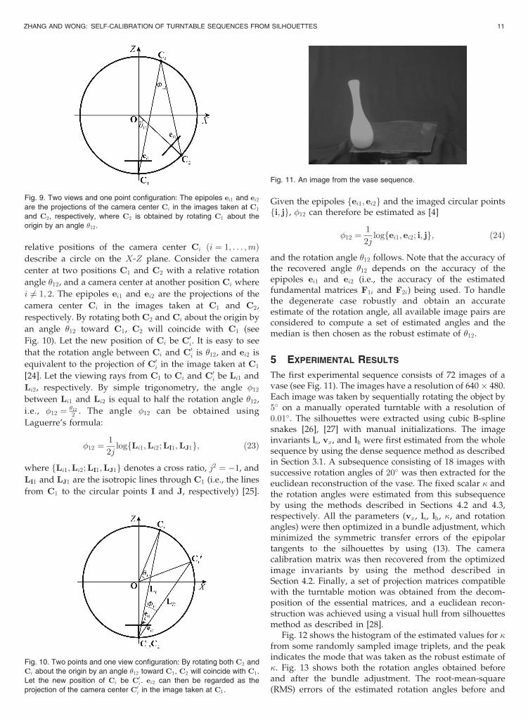
The first experimental sequence consists of 72 images of avase (see Fig. 11). The images have a resolution of 640 � 480.Each image was taken by sequentially rotating the object by5� on a manually operated turntable with a resolution of0:01�. The silhouettes were extracted using cubic B-splinesnakes [26], [27] with manual initializations. The imageinvariants ls, vx, and lh were first estimated from the wholesequence by using the dense sequence method as describedin Section 3.1. A subsequence consisting of 18 images withsuccessive rotation angles of 20� was then extracted for theeuclidean reconstruction of the vase. The fixed scalar � andthe rotation angles were estimated from this subsequenceby using the methods described in Sections 4.2 and 4.3,respectively. All the parameters (vx, ls, lh, �, and rotationangles) were then optimized in a bundle adjustment, whichminimized the symmetric transfer errors of the epipolartangents to the silhouettes by using (13). The cameracalibration matrix was then recovered from the optimizedimage invariants by using the method described inSection 4.2. Finally, a set of projection matrices compatiblewith the turntable motion was obtained from the decom-position of the essential matrices, and a euclidean recon-struction was achieved using a visual hull from silhouettesmethod as described in [28].
Fig. 12 shows the histogram of the estimated values for �from some randomly sampled image triplets, and the peakindicates the mode that was taken as the robust estimate of�. Fig. 13 shows both the rotation angles obtained beforeand after the bundle adjustment. The root-mean-square(RMS) errors of the estimated rotation angles before and
ZHANG AND WONG: SELF-CALIBRATION OF TURNTABLE SEQUENCES FROM SILHOUETTES 11
Fig. 9. Two views and one point configuration: The epipoles ei1 and ei2are the projections of the camera center Ci in the images taken at C1
and C2, respectively, where C2 is obtained by rotating C1 about the
origin by an angle �12.
Fig. 10. Two points and one view configuration: By rotating both C2 and
Ci about the origin by an angle �12 toward C1, C2 will coincide with C1.
Let the new position of Ci be C0i. ei2 can then be regarded as the
projection of the camera center C0i in the image taken at C1.
Fig. 11. An image from the vase sequence.
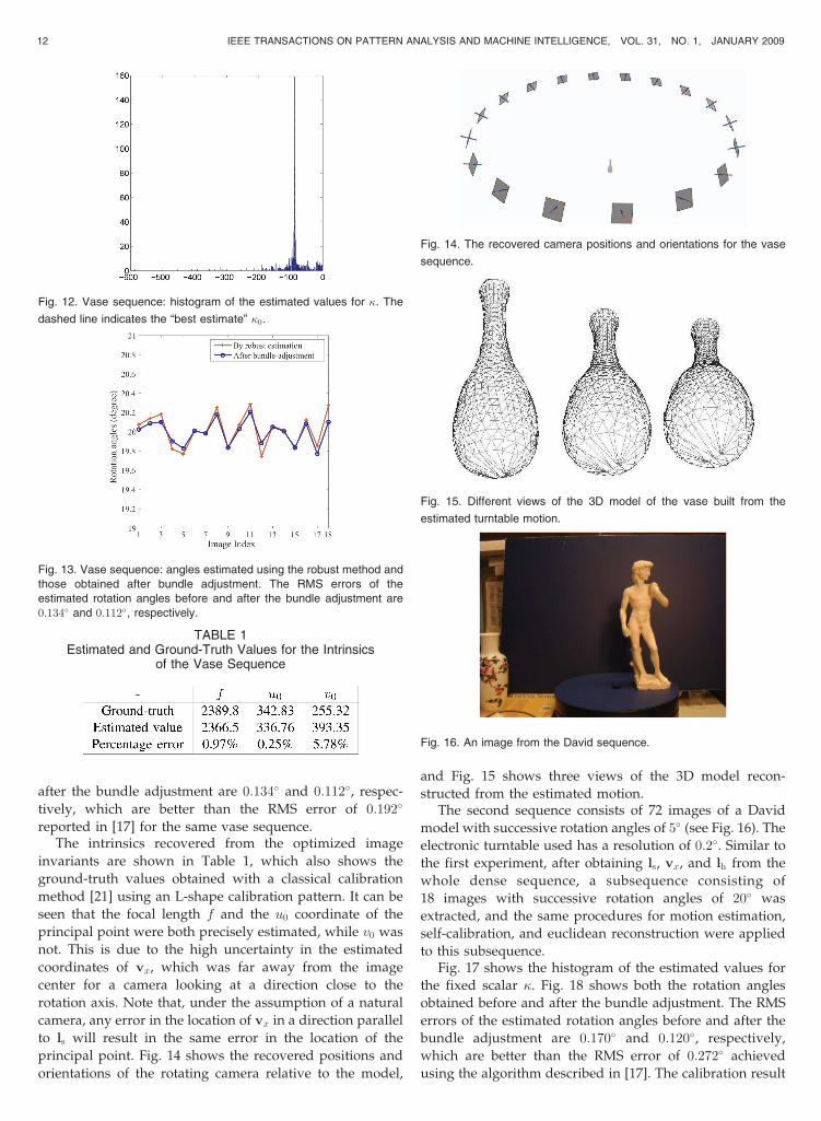
after the bundle adjustment are 0:134� and 0:112�, respec-
tively, which are better than the RMS error of 0:192�
reported in [17] for the same vase sequence.The intrinsics recovered from the optimized image
invariants are shown in Table 1, which also shows the
ground-truth values obtained with a classical calibration
method [21] using an L-shape calibration pattern. It can be
seen that the focal length f and the u0 coordinate of the
principal point were both precisely estimated, while v0 was
not. This is due to the high uncertainty in the estimated
coordinates of vx, which was far away from the image
center for a camera looking at a direction close to the
rotation axis. Note that, under the assumption of a natural
camera, any error in the location of vx in a direction parallel
to ls will result in the same error in the location of the
principal point. Fig. 14 shows the recovered positions and
orientations of the rotating camera relative to the model,
and Fig. 15 shows three views of the 3D model recon-
structed from the estimated motion.The second sequence consists of 72 images of a David
model with successive rotation angles of 5� (see Fig. 16). The
electronic turntable used has a resolution of 0:2�. Similar to
the first experiment, after obtaining ls, vx, and lh from the
whole dense sequence, a subsequence consisting of
18 images with successive rotation angles of 20� was
extracted, and the same procedures for motion estimation,
self-calibration, and euclidean reconstruction were applied
to this subsequence.Fig. 17 shows the histogram of the estimated values for
the fixed scalar �. Fig. 18 shows both the rotation angles
obtained before and after the bundle adjustment. The RMS
errors of the estimated rotation angles before and after the
bundle adjustment are 0:170� and 0:120�, respectively,
which are better than the RMS error of 0:272� achieved
using the algorithm described in [17]. The calibration result
12 IEEE TRANSACTIONS ON PATTERN ANALYSIS AND MACHINE INTELLIGENCE, VOL. 31, NO. 1, JANUARY 2009
Fig. 12. Vase sequence: histogram of the estimated values for �. The
dashed line indicates the “best estimate” �0.
Fig. 13. Vase sequence: angles estimated using the robust method and
those obtained after bundle adjustment. The RMS errors of the
estimated rotation angles before and after the bundle adjustment are
0:134� and 0:112�, respectively.
TABLE 1Estimated and Ground-Truth Values for the Intrinsics
of the Vase Sequence
Fig. 14. The recovered camera positions and orientations for the vase
sequence.
Fig. 15. Different views of the 3D model of the vase built from the
estimated turntable motion.
Fig. 16. An image from the David sequence.
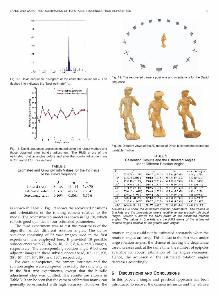
is shown in Table 2. Fig. 19 shows the recovered positionsand orientations of the rotating camera relative to themodel. The reconstructed model is shown in Fig. 20, whichreflects good qualities of our estimated parameters.
The third experiment was to test the robustness of thealgorithm under different rotation angles. The densesequence consisting of 72 vase images used in the firstexperiment was employed here. It provided 10 possiblesubsequences with 72, 36, 24, 18, 12, 9, 8, 6, 4, and 3 images,respectively. The corresponding rotation angle � betweenadjacent images in these subsequences are 5�, 10�, 15�, 20�,30�, 40�, 45�, 60�, 90�, and 120�, respectively.
For each subsequence, the camera intrinsics and therotation angles were computed in exactly the same way asin the first two experiments, except that the bundleadjustment step was omitted. The results are shown inTable 3. It can be seen that the camera calibration matrix cangenerally be estimated with high accuracy. However, the
rotation angles could not be estimated accurately when the
rotation angles are large. This is due to the fact that, under
large rotation angles, the chance of having the degenerate
case increases and, at the same time, the number of epipoles
available for robust estimation of the angles decreases.
Hence, the accuracy of the estimated rotation angles
decreases accordingly.
6 DISCUSSIONS AND CONCLUSIONS
In this paper, a simple and practical approach has been
introduced to recover the camera intrinsics and the relative
ZHANG AND WONG: SELF-CALIBRATION OF TURNTABLE SEQUENCES FROM SILHOUETTES 13
Fig. 17. David sequence: histogram of the estimated values for �. The
dashed line indicates the “best estimate” �0.
Fig. 18. David sequence: angles estimated using the robust method and
those obtained after bundle adjustment. The RMS errors of the
estimated rotation angles before and after the bundle adjustment are
0:170� and 0:120�, respectively.
TABLE 2Estimated and Ground-Truth Values for the Intrinsics
of the David Sequence
Fig. 19. The recovered camera positions and orientations for the David
sequence.
Fig. 20. Different views of the 3D model of David built from the estimated
turntable motion.
TABLE 3Calibration Results and the Estimated Angles
under Different Rotation Angles
Columns 2-4 show the estimated intrinsic parameters. The values inbrackets are the percentage errors relative to the ground-truth focallength. Column 5 shows the RMS errors of the estimated rotationangles. The values in brackets are the RMS errors of the estimatedrotation angles relative to the ground-truth angles.
rotation angles from silhouettes in a turntable sequence. Aspecial parameterization for the imaged circular points ofthe turntable plane in terms of the image invariants and afixed scalar is derived. This allows the camera intrinsics tobe obtained directly from the estimated image invariants.Besides, a robust method is developed to estimate therotation angles. This method does not depend on theknowledge of the camera intrinsics, and can handle thedegenerate case in which the fundamental matrix is notrecoverable. The proposed algorithm takes an uncalibratedturntable sequence as input, and self-calibration is carriedout to achieve a euclidean reconstruction. Experiments ontwo image sequences showed that both the cameraintrinsics and the rotation angles could be estimated witha high precision, and convincing 3D models have beenconstructed using these estimated parameters.
REFERENCES
[1] R. Szeliki, “Shape from Rotation,” Proc. IEEE Int’l Conf. ComputerVision and Pattern Recognition, pp. 625-630, 1991.
[2] W. Niem, “Robust and Fast Modeling of 3D Natural Objects fromMultiple Views,” SPIE Proc.: Image and Video Processing II,vol. 2182, pp. 388-397, Feb. 1994.
[3] A.W. Fitzgibbon, G. Cross, and A. Zisserman, “Automatic 3DModel Construction for Turn-Table Sequences,” Proc. EuropeanWorkshop 3D Structure from Multiple Images of Large-Scale Environ-ments, pp. 155-170, 1998.
[4] G. Jiang, H.T. Tsui, L. Quan, and A. Zisserman, “Single AxisGeometry by Fitting Conics,” Proc. Seventh European Conf.Computer Vision, pp. 482-488, 2002.
[5] G. Jiang, L. Quan, and H. Tsui, “Circular Motion Geometry byMinimal 2 Points in 4 Images,” Proc. Ninth IEEE Int’l Conf.Computer Vision, pp. 221-227, 2003.
[6] R. Cipolla and P.J. Giblin, Visual Motion of Curves and Surfaces.Cambridge Univ. Press, 1999.
[7] R. Cipolla, K. �Astrom, and P. Giblin, “Motion from the Frontier ofCurved Surfaces,” Proc. Fifth IEEE Int’l Conf. Computer Vision,pp. 269-275, June 1995.
[8] J.H. Rieger, “3 Dimensional Motion from Fixed Points of aDeforming Profile Curve,” Optics Letters, vol. 3, no. 11, pp. 123-125, 1986.
[9] J. Porrill and S.B. Pollard, “Curve Matching and Stereo Calibra-tion,” Image and Vision Computing, vol. 9, no. 1, pp. 45-50, Feb.1991.
[10] K. �Astrom, R. Cipolla, and P. Giblin, “Generalised EpipolarConstraints,” Int’l J. Computer Vision, vol. 33, no. 1, pp. 51-72, Sept.1999.
[11] T. Joshi, N. Ahuja, and J. Ponce, “Structure and Motion Estimationfrom Dynamic Silhouettes under Perspective Projection,” Int’l J.Computer Vision, vol. 31, no. 1, pp. 31-50, Feb. 1999.
[12] S. Sinha, M. Pollefeys, and L. McMillan, “Camera NetworkCalibration from Dynamic Silhouettes,” Proc. IEEE Int’l Conf.Computer Vision and Pattern Recognition, pp. 195-202, June-July2004.
[13] P.R.S. Mendonca, K.-Y.K. Wong, and R. Cipolla, “Camera PoseEstimation and Reconstruction from Image Profiles underCircular Motion,” Proc. Sixth European Conf. Computer Vision,vol. II, pp. 864-877, 2000.
[14] K.-Y.K. Wong and R. Cipolla, “Structure and Motion fromSilhouettes,” Proc. Eighth IEEE Int’l Conf. Computer Vision, vol. II,pp. 217-222, July 2001.
[15] C. Hernandez, F. Schmitt, and R. Cipolla, “Silhouette Coherencefor Camera Calibration under Circular Motion,” IEEE Trans.Pattern Analysis and Machine Intelligence, vol. 29, no. 2, pp. 343-349,Feb. 2007.
[16] Y. Furukawa, A. Sethi, J. Ponce, and D.J. Kriegman, “RobustStructure and Motion from Outlines of Smooth Curved Surfaces,”IEEE Trans. Pattern Analysis and Machine Intelligence, vol. 28, no. 2,pp. 302-315, Feb. 2006.
[17] P.R.S. Mendonca, K.-Y.K. Wong, and R. Cipolla, “EpipolarGeometry from Profiles under Circular Motion,” IEEE Trans.Pattern Analysis and Machine Intelligence, vol. 23, no. 6, pp. 604-616,June 2001.
[18] K.-Y.K. Wong and R. Cipolla, “Reconstruction of Sculpture fromIts Profiles with Unknown Camera Positions,” IEEE Trans. ImageProcessing, vol. 13, no. 3, pp. 381-389, Mar. 2004.
[19] H. Zhang, G. Zhang, and K.-Y.K. Wong, “Auto-Calibration andMotion Recovery from Silhouettes for Turntable Sequences,” Proc.British Machine Vision Conf., vol. I, pp. 79-88, Sept. 2005.
[20] K.-Y.K. Wong, P.R.S. Mendonca, and R. Cipolla, “CameraCalibration from Surfaces of Revolution,” IEEE Trans. PatternAnalysis and Machine Intelligence, vol. 25, no. 2, pp. 147-161, Feb.2003.
[21] R. Hartley and A. Zisserman, Multiple View Geometry in ComputerVision. Cambridge Univ. Press, 2004.
[22] T. Vieville and D. Lingrand, “Using Singular Displacements forUncalibrated Monocular Visual Systems,” Proc. Fourth EuropeanConf. Computer Vision, pp. 207-216, Apr. 1996.
[23] J. Gentle, Numerical Linear Algebra for Applications in Statistics.Springer-Verlag, 1998.
[24] G. Zhang, H. Zhang, and K.-Y.K. Wong, “1D Camera Geometryand Its Application to Circular Motion Estimation,” Proc. BritishMachine Vision Conf., vol. I, pp. 67-76, Sept. 2006.
[25] J.G. Semple and G.T. Kneebone, Algebraic Projective Geometry.Clarendon Press, 1998.
[26] R. Cipolla and A. Blake, “The Dynamic Analysis of ApparentContours,” Proc. Third IEEE Int’l Conf. Computer Vision, pp. 616-623, Dec. 1990.
[27] R. Cipolla and A. Blake, “Surface Shape from the Deformation ofApparent Contours,” Int’l J. Computer Vision, vol. 9, no. 2, pp. 83-112, Nov. 1992.
[28] C. Liang and K.-Y.K. Wong, “Complex 3D Shape Recovery Usinga Dual-Space Approach,” Proc. IEEE Int’l Conf. Computer Visionand Pattern Recognition, vol. 2, pp. 878-884, June 2005.
Hui Zhang received the BEng and MEngdegrees (with honors) in computer science andengineering from Zhejiang University in 2002and the PhD degree in computer vision from theUniversity of Hong Kong in 2007. She iscurrently with the Department of ComputerScience and Technology at United InternationalCollege as an assistant professor. Her researchinterests include computer graphics, computervision, and image processing, in particular
camera calibration, motion estimation from image sequences, andmodel reconstruction and representation. She is a member of the IEEE.
Kwan-Yee K. Wong received the BEng degree(with first-class honors) in computer engineer-ing from the Chinese University of Hong Kongin 1998 and the MPhil and PhD degrees incomputer vision (information engineering) fromthe University of Cambridge in 2000 and 2001,respectively. Since 2001, he has been with theDepartment of Computer Science at the Uni-versity of Hong Kong, where he is currently anassociate professor. His research interests
include computer vision and image processing, in particular cameracalibration, motion tracking, model reconstruction and representation,and motion estimation from image sequences. He is a member of theIEEE.
. For more information on this or any other computing topic,please visit our Digital Library at www.computer.org/publications/dlib.
14 IEEE TRANSACTIONS ON PATTERN ANALYSIS AND MACHINE INTELLIGENCE, VOL. 31, NO. 1, JANUARY 2009