Embed Size (px)
Citation preview

Instructions for use
Title PERFORMANCE EVALUATION OF MASONRY SHEAR WALLS STRENGTHENING BY TWO DIFFERENTFRPS
Author(s) M.A. RAHMAN; T. UEDA
Issue Date 2013-09-12
Doc URL http://hdl.handle.net/2115/54323
Type proceedings
Note The Thirteenth East Asia-Pacific Conference on Structural Engineering and Construction (EASEC-13), September 11-13, 2013, Sapporo, Japan.
File Information easec13-D-4-4.pdf
Hokkaido University Collection of Scholarly and Academic Papers : HUSCAP
1
PERFORMANCE EVALUATION OF MASONRY SHEAR WALLS
STRENGTHENING BY TWO DIFFERENT FRPs
M.A. RAHMAN1*
and T. UEDA2
1JSPS RONPAKU Fellow, Department of Civil Engineering, KUET, Bangladesh
2Graduate School of Engineering, Hokkaido University, Japan
ABSTRACT
This paper investigates strengthening masonry shear walls using two types fiber reinforced polymer
(FRP) sheets. An experimental research program is undertaken. Masonry wall made from wire-cut
clay brick specimens are tested strengthening by PET (Polyethylene Terephthalate) and CFRP
(Carbon fiber reinforced polymer) sheets. Strengthening is considered on both side of the wall to
ensure uniformity and symmetrical stiffness of the wall. Static tests are carried out on seven
masonry panels, under a combination of vertical preloading, and in-plane horizontal shear loading.
The mechanisms by which load was carried were observed, varying from the initial, uncracked
state, to the final, fully cracked state. The results demonstrate that a significant increase of the
in-plane shear capacity of masonry can be achieved by bonding with PET and CFRP sheets to the
surface of masonry walls. The experimental data were used to assess the effectiveness of the
strengthening of one FRP over the other and also the percent of gross area covered by the FRP
sheets. Subsequently suggestions are made to allow the test results to be a reasonable source of
guideline in the design of strengthening for masonry structures.
Keywords: Brick; Masonry; Shear wall; FRP sheets; Static Shear tests.
1. INTRODUCTION
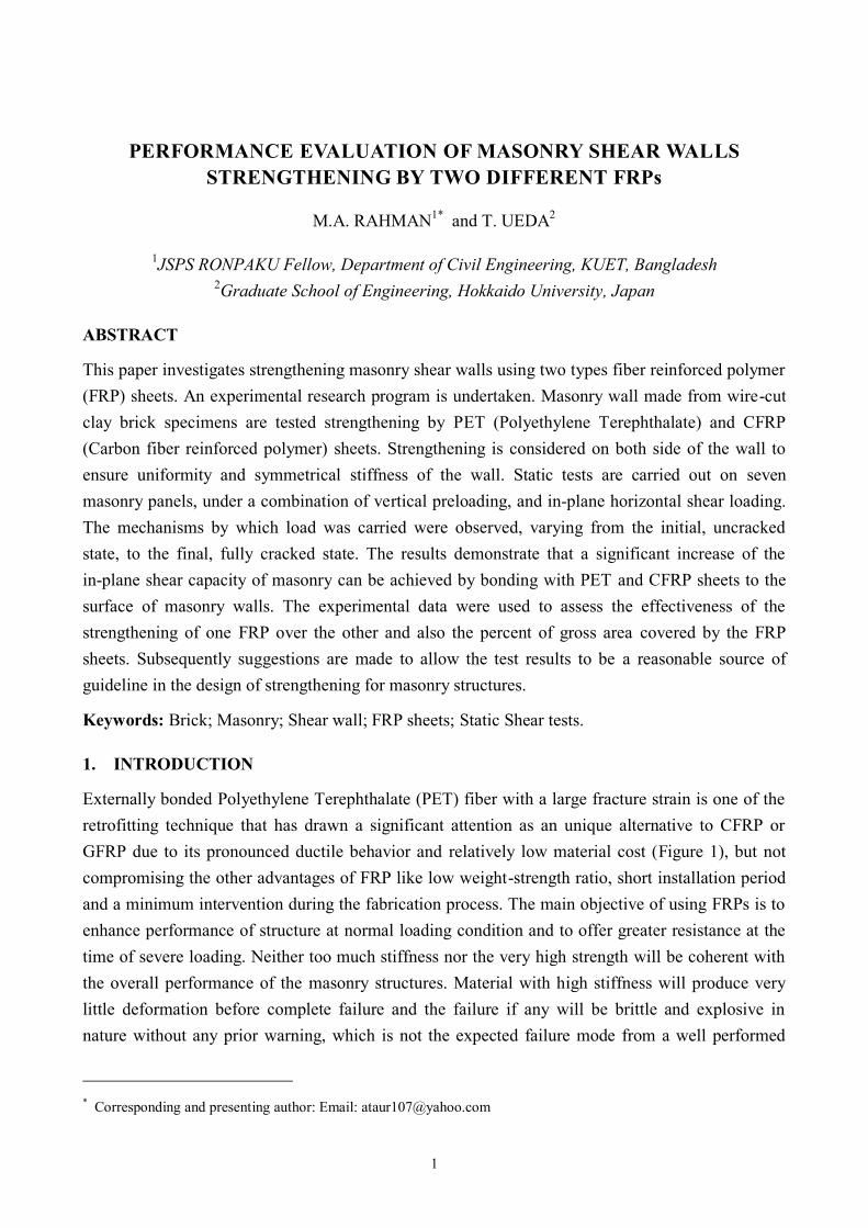
Externally bonded Polyethylene Terephthalate (PET) fiber with a large fracture strain is one of the
retrofitting technique that has drawn a significant attention as an unique alternative to CFRP or
GFRP due to its pronounced ductile behavior and relatively low material cost (Figure 1), but not
compromising the other advantages of FRP like low weight-strength ratio, short installation period
and a minimum intervention during the fabrication process. The main objective of using FRPs is to
enhance performance of structure at normal loading condition and to offer greater resistance at the
time of severe loading. Neither too much stiffness nor the very high strength will be coherent with
the overall performance of the masonry structures. Material with high stiffness will produce very
little deformation before complete failure and the failure if any will be brittle and explosive in
nature without any prior warning, which is not the expected failure mode from a well performed
* Corresponding and presenting author: Email: [email protected]
2
structure. On the other hand too soft
material with nominal strength will not
be well fitted with the purpose of
strengthening. A variety of approaches
has previously been undertaken to
investigate masonry strengthened with
FRPs. Masonry wall strengthening by
GFRP (Stratford et al. 2004) shows
quite ductile behavior prior to failure
and a significant increase of shear load
capacity (65%) where as the failure
was primarily for the debonding of the
GFRP sheet. Another technique of
strengthening is done by mounting the
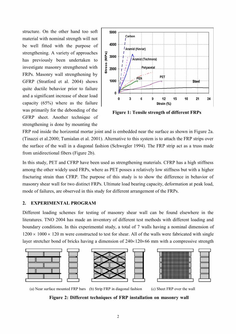
FRP rod inside the horizontal mortar joint and is embedded near the surface as shown in Figure 2a.
(Tinazzi et al.2000; Tumialan et al. 2001). Alternative to this system is to attach the FRP strips over
the surface of the wall in a diagonal fashion (Schwegler 1994). The FRP strip act as a truss made
from unidirectional fibers (Figure 2b).
In this study, PET and CFRP have been used as strengthening materials. CFRP has a high stiffness
among the other widely used FRPs, where as PET posses a relatively low stiffness but with a higher
fracturing strain than CFRP. The purpose of this study is to show the difference in behavior of
masonry shear wall for two distinct FRPs. Ultimate load bearing capacity, deformation at peak load,
mode of failures, are observed in this study for different arrangement of the FRPs.
2. EXPERIMENTAL PROGRAM
Different loading schemes for testing of masonry shear wall can be found elsewhere in the
literatures. TNO 2004 has made an inventory of different test methods with different loading and
boundary conditions. In this experimental study, a total of 7 walls having a nominal dimension of
1200 1000 120 m were constructed to test for shear. All of the walls were fabricated with single
layer stretcher bond of bricks having a dimension of 24012066 mm with a compressive strength
Figure 1: Tensile strength of different FRPs
Figure 2: Different techniques of FRP installation on masonry wall
walls strength of different FRPs
(a) Near surface mounted FRP bars (b) Strip FRP in diagonal fashion (c) Sheet FRP over the wall
3
of 17MPa. A 10 mm thick mortar with a compressive strength of 12 MPa were used throughout.
Table 1 gives the detail of the walls. In this table RW stands for reference wall, PW for wall
strengthening with PET sheet and CW for wall strengthening with CFRP sheet.
Table 1: Detail of masonry specimen with different FRP orientations
Wall
Designation
Properties
Vertical
compression
fv (MPa)
Brick
strength,
fcb (MPa)
Mortar
strength,
fcm
(MPa)
Area Covered by
FRPs L/H
FRP
orientation
Peak
load
kN PET(%) CFRP
(%)
RW2 0.25 17 12 _ _ 1.25 -- 30.0
PW1 0.25 17 12 100 _ 1.25 all over 168.0
PW2 0.25 17 12 40 _ 1.25 checkered 90.0
PW3 0.25 17 12 20 _ 1.25 diagonal 62.0
CW1 0.25 17 12 _ 100 1.25 all over 107.0
CW2 0.25 17 12 _ 40 1.25 checkered 99.0
CW3 0.25 17 12 _ 20 1.25 diagonal 94.0
2.1 Specimen preparation
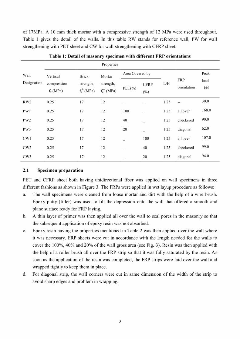
PET and CFRP sheet both having unidirectional fiber was applied on wall specimens in three
different fashions as shown in Figure 3. The FRPs were applied in wet layup procedure as follows:
a. The wall specimens were cleaned from loose mortar and dirt with the help of a wire brush.
Epoxy putty (filler) was used to fill the depression onto the wall that offered a smooth and
plane surface ready for FRP laying.
b. A thin layer of primer was then applied all over the wall to seal pores in the masonry so that
the subsequent application of epoxy resin was not absorbed.
c. Epoxy resin having the properties mentioned in Table 2 was then applied over the wall where
it was necessary. FRP sheets were cut in accordance with the length needed for the walls to
cover the 100%, 40% and 20% of the wall gross area (see Fig. 3). Resin was then applied with
the help of a roller brush all over the FRP strip so that it was fully saturated by the resin. As
soon as the application of the resin was completed, the FRP strips were laid over the wall and
wrapped tightly to keep them in place.
d. For diagonal strip, the wall corners were cut in same dimension of the width of the strip to
avoid sharp edges and problem in wrapping.
4
Table 2: properties of FRPs and resign
FRP properties PET 600 CFRP
FTS-C1-20
Properties RESIN
(D-90 R)
PUTTY
(T-30) Fracture Strength
(N/mm2)
740 3400 Compressive strength, MPa 85 -
Elastic Modulus
(kN/mm2)
101 245 Flexural strength, MPa 65 -
Elongation (%) 101 1.5 Tensile strength, MPa 45 20.0
Thickness (mm) 0.841 0.111 Compressive modulus, MPa 2500 -
*Width (mm) 300 250 Tensile modulus, MPa 1560 -
Elongation after fracture, % 28% -
(a) Control wall(RW2)
(b) 100% area covered by FRP (CW1, PW1)
(c) 40% area covered by FRP (CW2, PW2) (d) 20% area covered by FRP (CW3, PW3)
Figure3: Wrapping technique of masonry wall by FRP
waspecimen
5
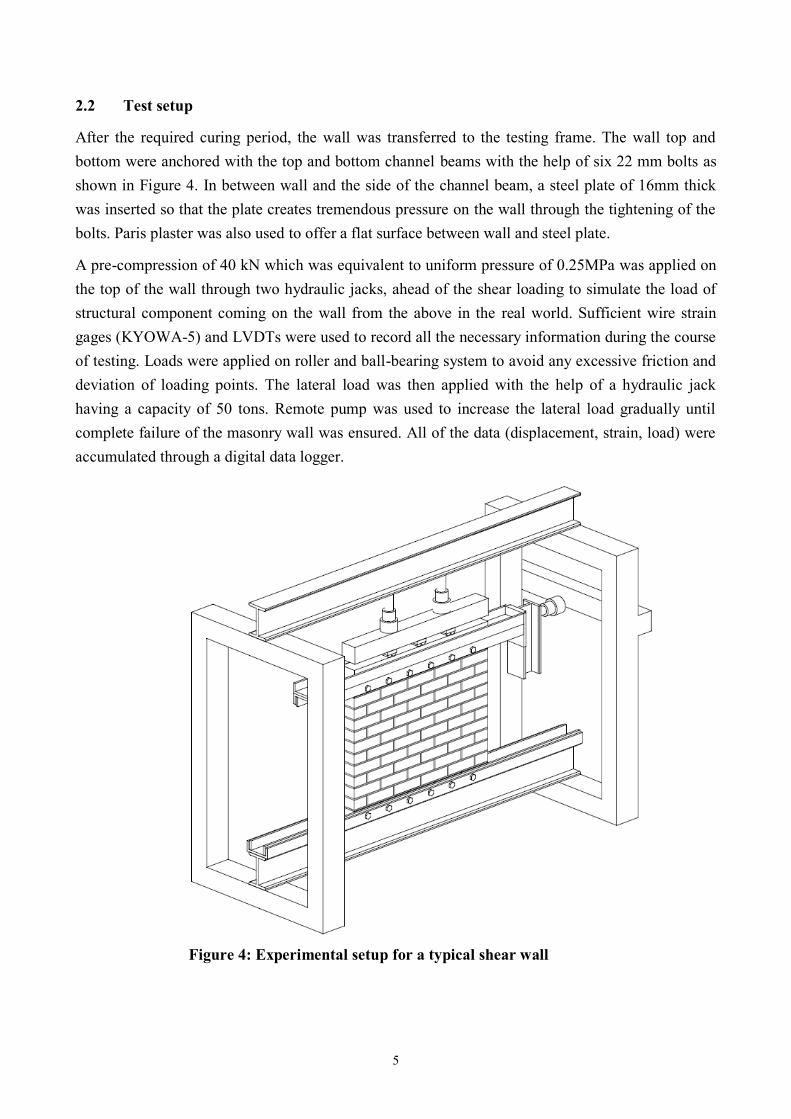
2.2 Test setup
After the required curing period, the wall was transferred to the testing frame. The wall top and
bottom were anchored with the top and bottom channel beams with the help of six 22 mm bolts as
shown in Figure 4. In between wall and the side of the channel beam, a steel plate of 16mm thick
was inserted so that the plate creates tremendous pressure on the wall through the tightening of the
bolts. Paris plaster was also used to offer a flat surface between wall and steel plate.
A pre-compression of 40 kN which was equivalent to uniform pressure of 0.25MPa was applied on
the top of the wall through two hydraulic jacks, ahead of the shear loading to simulate the load of
structural component coming on the wall from the above in the real world. Sufficient wire strain
gages (KYOWA-5) and LVDTs were used to record all the necessary information during the course
of testing. Loads were applied on roller and ball-bearing system to avoid any excessive friction and
deviation of loading points. The lateral load was then applied with the help of a hydraulic jack
having a capacity of 50 tons. Remote pump was used to increase the lateral load gradually until
complete failure of the masonry wall was ensured. All of the data (displacement, strain, load) were
accumulated through a digital data logger.
Figure 4: Experimental setup for a typical shear wall
specimen
6
3. TEST RESULTS & DISCUSSION
The entire shear wall specimens were tested consecutively one after another. Static lateral load was
applied gradually and increased at a constant rate of 10kN/min until failure occurred. Application of
load was paused intermittently to observe the crack and damage if any, on the wall.
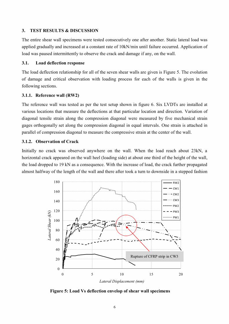
3.1. Load deflection response
The load deflection relationship for all of the seven shear walls are given is Figure 5. The evolution
of damage and critical observation with loading process for each of the walls is given in the
following sections.
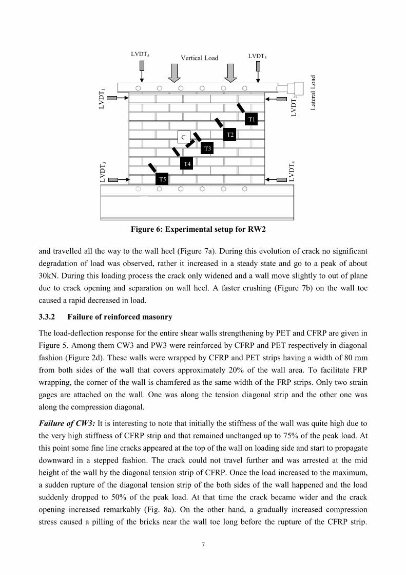
3.1.1. Reference wall (RW2)
The reference wall was tested as per the test setup shown in figure 6. Six LVDTs are installed at
various locations that measure the deflections at that particular location and direction. Variation of
diagonal tensile strain along the compression diagonal were measured by five mechanical strain
gages orthogonally set along the compression diagonal in equal intervals. One strain is attached in
parallel of compression diagonal to measure the compressive strain at the center of the wall.
3.1.2. Observation of Crack
Initially no crack was observed anywhere on the wall. When the load reach about 23kN, a
horizontal crack appeared on the wall heel (loading side) at about one third of the height of the wall,
the load dropped to 19 kN as a consequence. With the increase of load, the crack further propagated
almost halfway of the length of the wall and there after took a turn to downside in a stepped fashion
Figure 5: Load Vs deflection envelop of shear wall specimens
0
20
40
60
80
100
120
140
160
180
0 5 10 15 20
Late
ral
Shea
r (k
N)
Lateral Displacement (mm)
RW2
CW1
CW2
CW3
PW2
PW3
PW1
Rupture of CFRP strip in CW3
7
and travelled all the way to the wall heel (Figure 7a). During this evolution of crack no significant
degradation of load was observed, rather it increased in a steady state and go to a peak of about
30kN. During this loading process the crack only widened and a wall move slightly to out of plane
due to crack opening and separation on wall heel. A faster crushing (Figure 7b) on the wall toe
caused a rapid decreased in load.
3.3.2 Failure of reinforced masonry
The load-deflection response for the entire shear walls strengthening by PET and CFRP are given in
Figure 5. Among them CW3 and PW3 were reinforced by CFRP and PET respectively in diagonal
fashion (Figure 2d). These walls were wrapped by CFRP and PET strips having a width of 80 mm
from both sides of the wall that covers approximately 20% of the wall area. To facilitate FRP
wrapping, the corner of the wall is chamfered as the same width of the FRP strips. Only two strain
gages are attached on the wall. One was along the tension diagonal strip and the other one was
along the compression diagonal.
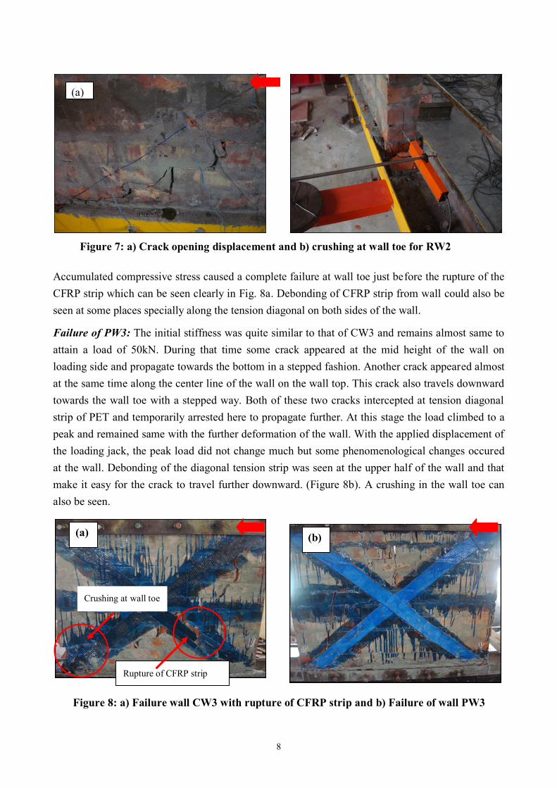
Failure of CW3: It is interesting to note that initially the stiffness of the wall was quite high due to
the very high stiffness of CFRP strip and that remained unchanged up to 75% of the peak load. At
this point some fine line cracks appeared at the top of the wall on loading side and start to propagate
downward in a stepped fashion. The crack could not travel further and was arrested at the mid
height of the wall by the diagonal tension strip of CFRP. Once the load increased to the maximum,
a sudden rupture of the diagonal tension strip of the both sides of the wall happened and the load
suddenly dropped to 50% of the peak load. At that time the crack became wider and the crack
opening increased remarkably (Fig. 8a). On the other hand, a gradually increased compression
stress caused a pilling of the bricks near the wall toe long before the rupture of the CFRP strip.
Figure 6: Experimental setup for RW2
Lat
eral
Load
LVDT5
LV
DT
1
Vertical Load
LV
DT
2
LV
DT
3
LV
DT
4
LVDT5
T1
T2
T3
T4
T5
C
8
Accumulated compressive stress caused a complete failure at wall toe just before the rupture of the
CFRP strip which can be seen clearly in Fig. 8a. Debonding of CFRP strip from wall could also be
seen at some places specially along the tension diagonal on both sides of the wall.
Failure of PW3: The initial stiffness was quite similar to that of CW3 and remains almost same to
attain a load of 50kN. During that time some crack appeared at the mid height of the wall on
loading side and propagate towards the bottom in a stepped fashion. Another crack appeared almost
at the same time along the center line of the wall on the wall top. This crack also travels downward
towards the wall toe with a stepped way. Both of these two cracks intercepted at tension diagonal
strip of PET and temporarily arrested here to propagate further. At this stage the load climbed to a
peak and remained same with the further deformation of the wall. With the applied displacement of
the loading jack, the peak load did not change much but some phenomenological changes occured
at the wall. Debonding of the diagonal tension strip was seen at the upper half of the wall and that
make it easy for the crack to travel further downward. (Figure 8b). A crushing in the wall toe can
also be seen.
(b)
Figure 7: a) Crack opening displacement and b) crushing at wall toe for RW2
(a)
Figure 8: a) Failure wall CW3 with rupture of CFRP strip and b) Failure of wall PW3
Rupture of CFRP strip
Crushing at wall toe
(a) (b)
9
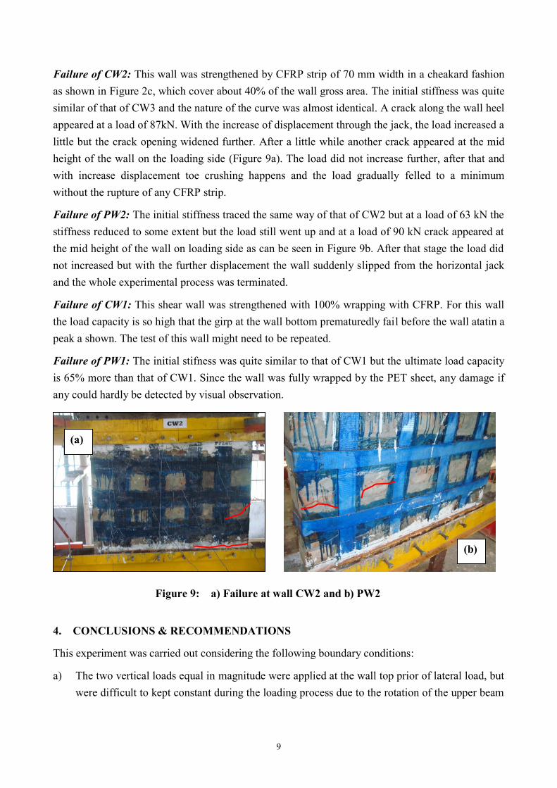
Failure of CW2: This wall was strengthened by CFRP strip of 70 mm width in a cheakard fashion
as shown in Figure 2c, which cover about 40% of the wall gross area. The initial stiffness was quite
similar of that of CW3 and the nature of the curve was almost identical. A crack along the wall heel
appeared at a load of 87kN. With the increase of displacement through the jack, the load increased a
little but the crack opening widened further. After a little while another crack appeared at the mid
height of the wall on the loading side (Figure 9a). The load did not increase further, after that and
with increase displacement toe crushing happens and the load gradually felled to a minimum
without the rupture of any CFRP strip.
Failure of PW2: The initial stiffness traced the same way of that of CW2 but at a load of 63 kN the
stiffness reduced to some extent but the load still went up and at a load of 90 kN crack appeared at
the mid height of the wall on loading side as can be seen in Figure 9b. After that stage the load did
not increased but with the further displacement the wall suddenly slipped from the horizontal jack
and the whole experimental process was terminated.
Failure of CW1: This shear wall was strengthened with 100% wrapping with CFRP. For this wall
the load capacity is so high that the girp at the wall bottom prematuredly fail before the wall atatin a
peak a shown. The test of this wall might need to be repeated.
Failure of PW1: The initial stifness was quite similar to that of CW1 but the ultimate load capacity
is 65% more than that of CW1. Since the wall was fully wrapped by the PET sheet, any damage if
any could hardly be detected by visual observation.
4. CONCLUSIONS & RECOMMENDATIONS
This experiment was carried out considering the following boundary conditions:
a) The two vertical loads equal in magnitude were applied at the wall top prior of lateral load, but
were difficult to kept constant during the loading process due to the rotation of the upper beam
Figure 9: a) Failure at wall CW2 and b) PW2
(a)
(b)
10
on the wall. This rotational movement caused a pressure in the vertical jacks and thus
increased the vertical pressure to some extent.
b) Since the shear capacity of the masonry panel increases with the increase of vertical load
following the Mohr-Coulomb failure criteria, the increased vertical pressure in this experiment
definitely increased the lateral load to some unknown quantity but could not be verified
explicitly. ASTM E 72-61 suggests the standard racking test, where the vertical load N cannot
be controlled if the rotation of the beam is restrained. So, this experiment is aligned with some
standard where the vertical load is not controlled. On the other hand if the vertical load is kept
constant throughout the loading process, the rotation of the top beam must be allowed to rotate
to obtain the equilibrium.
c) The FRP was installed on the wall panel before the vertical load, whereas in reality the weight
of the building above the wall exists as vertical pressure prior of the application of FRP.
Reinforcement of the masonry shear wall by both the PET and CFRP increases the shear capacity to
a great extent for different FRP orientation. If the FRP is applied in diagonal fashion that covers
only 20% of the panel area, the shear capacity increases twice for PET sheet and thrice for CFRP
sheet as given in Table 1 and Figure 5. Whereas for the case of checkered fashion where the FRP
covers 40% of panel area, the shear capacity increase about three times for both of the FRPs. When
the penal is fully covered by FRPs, the capacity increases to a tremendous amount (five times for
PET and 3.5 times for CFRP). Considering all of the cases, it can be concluded that PET offers
more effective strengthening than CFRP sheet where strength is not the only considering criteria.
The ductility of the panel is of great concern during earthquake and other natural disaster. PET offer
greater ductility prior to failure than CFRP. When the cost of the material is also considered, PET is
cheaper than the CFRP.
5. ACKNOWLEDGMENTS
The writers wish to acknowledge the support of JSPS RONPAKU for funding this research.
6. REFERENCES
Stratford T, Pascale G, Manfroni O and Bonfiglioli B (2004). Shear strengthening masonry panels with sheet glass-fiber
reinforced polymer. ASCE Journal of Composite for Construction. Vol.8, No.5, October 1, 2004, pp. 434-443.
Schwegler, G. (1994). Verstäken von mauerwerk mit faserverbundwerkstoffen in seismisch gefährdeten zonen. Bericht
Nr. 229, PhD thesis, EMPA, Dübendorf, Germany.
Tinazzi, D., Modena, C., and Nanni, A. (2000). Strengthening of masonry assemblages with FRP rods and laminates.
Proc. Int. Meeting on Composite Materials, PLAST 2000, Advancing with Composites, I. Crivelli-Visconti, ed., Milan,
Italy, 411–418.
Tumialan, G., Huang, P.-C., Nanni, A., and Silva, P. (2001). Strengthening of masonry walls by FRP structural
repointing. Proc., 5th Int.Conf. on Fibre Reinforced Plastics for Reinforced Concrete Structures, Thomas Telford,
Cambridge, U.K., 1033–1042.
TNO Report (2004). Shear test on masonry panels; literature survey and proposal for experiments. TNO Building and
Construction Research 2600 AA Delft.


![[Yumehito Ueda] the Idolmaster Relations - Volume 29](https://img.pdfslide.us/doc/110x75/577cde3c1a28ab9e78aeb12a/yumehito-ueda-the-idolmaster-relations-volume-29.jpg)