Embed Size (px)
Citation preview
FINAL PROJECT REPORT
In fulfillment of Task 7 California Department of Transportation
Division of Research amp Innovation Contract No 65A0260
Standards for Block Configuration Airborne GPS Controlled Photogrammetry for
Large Scale Mapping Projects
Submitted by
Riadh Munjy PhD PE Professor of Geomatic Engineering
Mushtaq Hussain PhD PE Emeritus Professor of Geomatic Engineering
California State University Fresno
March 15 2010
EXECUTIVE SUMMARY
In implementing its responsibility for large scale photogrammetric mapping along highway corridors the California Department of Transportation (Caltrans) routinely carries out the aerial triangulation of aerial photography blocks In order to eliminate the need for the location of a large number of ground control points within the right of way through field surveying methods that exposes the field surveyors to extreme traffic hazard Caltrans in 1997 initiated a collaborative research effort with the Geomatic Engineering Program at California State University Fresno to investigate the use of airborne GPS data collected during aerial photography flight missions to minimize the need for ground control Such research efforts were primarily focused on the use of airborne GPS data as control for the aerial triangulation of single-strip blocks which was then the most commonly used aerial photography block configuration in Caltrans
Based on the successful outcome of the joint research efforts a comprehensive set of standards and specifications were developed in 2002 and have since been effectively transitioned into Caltrans practice As the GPS technology and its applications have advanced Caltrans through joint research with California State University Fresno has continually updated the aerial triangulation specifications to reflect new capabilities such as the use of CORS data to replace the data collected at manned base stations
Lately the Office of Photogrammetry has experienced a marked shift from a single-strip photo block to a multi-strip photo block projects The current standards for airborne GPS control of strip format photogrammetric projects may not be scaleable from strip configuration to block configuration projects Also the commonly used standards for airborne GPS control of block configuration projects for large scale photogrammetric mapping have mostly evolved through a trial-and-error approach
Under this scenario this research project was undertaken to develop standards for airborne GPS control for multi-strip block configuration to supplement the existing standards successfully deployed in Caltrans for single-strip configuration The main objective to develop specifications that are based on sound scientific and systematic analysis of such block parameters as the length and the geometric configuration of strips comprising the block the range of photography scales used for large scale mapping positional accuracy of the airborne GPS and the ground control the spatial distribution of the ground control points and other related considerations has been accomplished An equally important objective to ensure that the specifications derived from theoretical analysis can be validated through a test block flight before they are adopted by Caltrans and by its industry partners has also been achieved
ACKNOWLEDGEMENTS
This applied research project could not have been completed successfully without the coordinated effort support and encouragement of many individuals It is with sincere appreciation and deep gratitude that the authors wish to thank many individuals associated with Caltrans who contributed to the success of this project
The Division of Research and Innovation (DRI) California Department of Transportation for funding this research and especially to Randy Woolley and Majed Ibrahim who as Contract Administrators struggled hard to maintain the funding support under continuingly worsening state budget situation
The support provided by two individuals has been indispensable for the entire project James Appleton Chief Office of Photogrammetry California Department of Transportation has not only fully participated in this research effort but his excellent administrative and managerial abilities have been critical in moving the project forward in face of great challenges Scott Rodrick Aerotriangulation Chief California Department of Transportation has provided excellent support throughout this project in coordinating the acquisition management and supply of high quality data that was crucial for the ultimate success of this project
The successful completion of the Del Mar Test Flight that had to be planned and implemented under demanding schedule and unpredictable weather conditions was due to the joint efforts of several individuals Lawrence ldquoLarryrdquo C Dews Aerial Photography and Aerotriangulation Branch Chief and Bob Hayden Photogrammetry Coordinator of District 11 in San Diego demonstrated seasoned professional skills and judgment in the planning and coordination of the mission The aerial photography crew of IK Curtis Services Inc Burbank California carried out the flight mission under The Surveying Section of District 11 in San Diego provided valuable professional and logistic support Ned Salman organized and supervised the ground control surveys and the acquisition of data at GPS base stations while Steve Van Buren carried out the adjustment of the GPS control network The high quality of the airborne GPS and the ground control data was critical in validating the outcome of this research effort Our sincerest thanks to all of them
The authors gratefully acknowledge the encouragement and support provided by the California State University Fresno Foundation The combined efforts of Tom McClanahan Nancy Myers Simms William Hunt and Shelby Gonzales contributed to a smooth coordination of all contractual matters between CSU Fresno Foundation and California Department of Transportation
Finally the authors wish to place on record their sense of professional satisfaction and fulfillment in satisfactorily completing this research effort Working with some highly skilled professionals has been a most rewarding experience and this project has provided
an excellent opportunity to demonstrate that an appropriate blend of advanced theory with skilled practice offers the best recipe to solve professional problems
TABLE OF CONTENTS
EXECUTIVE SUMMARY ACKNOWLEDGEMENTS
1 OBJECTIVE AND SCOPE 1 2 ANALYTICAL INVESTIGATION 2
21 Objective 2 22 Processing Methodology 2 23 Results 3 24 Preliminary Conclusions 4
3 CHECK BLOCK 4 31 Block Configuration 4 32 Need for Cross Strips 4 33 Ground Control Distribution 6 34 Check Block 6 35 Processing Plan and Methodology 8 36 Results and Analysis 9
4 TEST BLOCK 13 41 Planning 13 42 Acquisition of Aerial Photography 15 43 Test Block Data Acquisition 17 44 Test Block processing 17
5 ANALYSIS OF RESULTS amp CONCLUSIONS 30 51 Blocks With Cross Flights 30 52 Blocks Without Cross Flights 31
6 RECOMMENDED DRAFT STANDARDS 33 61 Data Acquisition 33 62 Flight and Control Configuration 36 63 Data Processing and Adjustment 36
7 CONCLUDING COMMENTS 38 REFERENCES 41
APPENDIX ndash I Results of Check Block
APPENDIX ndashII Results of Test Block
Final Report ndash Task 7 Caltrans Contract No 65A0260
FINAL PROJECT REPORT
1 OBJECTIVE AND SCOPE
The Office of Photogrammetry at Caltrans is responsible for large-scale photogrammetric mapping along highway corridors in support of transportation engineering planning and design Like departments of transportation in several other states Caltrans faces a continuing challenge to maintain currency in the map data along thousands of miles of transportation corridors spanning the State of California While the compilation of digital maps using digital photogrammetric techniques is mostly contracted out Caltrans carries out in house aerial triangulation of photo blocks for controlling individual models on photogrammetric workstations in order to assure map data of a uniform and consistent quality The photogrammetric block adjustment requires some ground surveyed points appropriately distributed over the block Targeting and surveying of such points on the ground not only places high demand on time and cost but also exposes Caltrans surveyors to the extreme hazards of high-speed vehicular traffic while surveying in close proximity of the highway
In order to eliminate such safety concerns for Caltrans field survey personnel Caltrans has since 1996 been collaborating with the California State University Fresno to incorporate the use of airborne GPS data in adjusting aerial triangulation blocks Based on coordinated research efforts completed through Caltrans research contracts No 65Y271 and No 65A0029 it was demonstrated that by using airborne GPS data collected during photo flight missions a reduction of about 70 percent in the need for ground control could be achieved for the adjustment of strip configuration blocks [10] [13] [4] [5] Accordingly detailed specifications were formulated for the aerial triangulation of single strip configuration blocks and the Caltrans Office of Photogrammetry has successfully incorporated the use of airborne GPS data for the adjustment of such aerial triangulation blocks since 2002
The Caltrans specifications for the routine use of airborne GPS Photogrammetry for aerial triangulation required the collection of GPS data at one or more ground base stations located in the vicinity of the project area (within 10 km radius) during photo flight missions [10] Even though the aerial photography missions for Caltrans are flown by commercial vendors GPS data is collected at the ground stations by Caltrans field personnel This essentially requires careful coordination between the photography vendors and Caltrans field personnel for each flight mission In addition to the deployment of equipment and personnel resources this practice sometimes creates problems in planning field logistics especially when widely spaced flight missions are to be flown on the same day There is the additional risk of flight scheduling delays which may be critical for missions undertaken in support of emergency response
With the objective to investigate the procedures to completely eliminate the need for the collection of GPS data by Caltrans staff at base stations by utilizing the GPS data from existing network of Continuously Operating Receiver Stations (CORS) the California
Dr R Munjy amp Dr M Hussain California State University Fresno munjyrcsufresnoedu and mushtaqhcsufresnoedu
1
Final Report ndash Task 7 Caltrans Contract No 65A0260
Department of Transportation completed another research project with California State University Fresno in 2007 [14] This study demonstrated that the use of carrier phase data from CORS stations in combination with the airborne GPS data collected during photography flights can generate the precise location of the aerial camera at the time of exposure consistent with the Caltrans accuracy requirements for aerial triangulation of single photo strips at 13000 photo scale Accordingly Caltrans has also successfully incorporated the use of archived CORS data whenever necessary in their aerial triangulation procedures
Lately the Office of Photogrammetry has experienced a marked shift from a single-strip photo block to a multi-strip photo block projects The current standards for airborne GPS control of strip format photogrammetric projects may not be scaleable from strip configuration to block configuration projects Also the commonly used standards for airborne GPS control of block configuration projects for large scale photogrammetric mapping have mostly evolved through a trial-and-error approach
Under this scenario this research project was undertaken to develop standards for airborne GPS control for multi-strip block configuration to supplement the existing standards successfully deployed in Caltrans for single-strip configuration The main objective is to develop specifications that are based on sound scientific and systematic analysis of such block parameters as the length and the geometric configuration of strips comprising the block the range of photography scales used for large scale mapping positional accuracy of the airborne GPS and the ground control the spatial distribution of the ground control points and other related considerations An equally important objective is to ensure that the specifications derived from theoretical analysis can be validated through test block flight(s) before they are adopted by Caltrans and by its industry partners The various tasks completed to cover the full scope of this research study are described in the following sections
2 ANALYTICAL INVESTIGATION
21 Objective
To determine an appropriate ground control distribution for a GPS photogrammetry block a theoretical GPS photo block was generated using the well known Monte Carlo Method (MCM) The MCM is a technique that involves using random numbers and probability to generate the data set that simulates as closely as possible the actual data intended to be investigated under similar conditions
22 Processing Methodology
To generate a photogrammetric block that will accommodate different cases of ground control distribution the simulated block configuration should be similar to the photo
Dr R Munjy amp Dr M Hussain California State University Fresno munjyrcsufresnoedu and mushtaqhcsufresnoedu
2
Final Report ndash Task 7 Caltrans Contract No 65A0260
blocks most commonly used in Caltrans A special software was developed to generate a photogrammetric dataset for a block of user defined configuration by using a predefined digital terrain model A dataset for a block with the following characteristics was generated
Camera Focal Length 153 mm Photo Scale 13600
Number of Strips 4 Number of PhotoStrip 37 Forward Overlap 60 Sidelap 30 Total Number of Photos 148 Total Number of tie points 489
In order to avoid the use of truly vertical aerial photography in the block and to simulate the normal flying conditions the exterior orientation of each photo in the block was varied using the MCM approach The simulated exterior orientation data was generated based on the following statistics
σ (Omega phi and kappa) plusmn 15 degrees σ (X Y and Z) plusmn 33 ft
Using the object space exterior orientation data of each photo 489 ground tie points 48 control points and the GPS coordinates for the antenna position at the time of exposure of each photo was generated Using the well known collinearity equations the image coordinates of all ground tie and control points were generated
Finally to generate the simulated GPS photogrammetry block the following values were used with the MCM technique to have Gaussian distribution random errors
Image Coordinates St Error plusmn 0006 mm Ground Control St Errors plusmn 010 ft GPS Antenna Coordinates St Err plusmn 030 ft
It is worthwhile to note that with this block all the generated ground tie point values that will be used as check points to evaluate the different adjustments that will be conducted Also this simulation does not consider the GPS drift systematic errors For that no cross ties were generated The GPS drift is a systematic error and is usually approximated using a linear mathematical model Since the exact math model is not known it is difficult to simulate
23 Results
A bundle solution was carried on the simulated photo block using only four corner control points Also two additional control points in the middle of the outside strip were added as another case
Dr R Munjy amp Dr M Hussain California State University Fresno munjyrcsufresnoedu and mushtaqhcsufresnoedu
3
Final Report ndash Task 7 Caltrans Contract No 65A0260
A summary of these two cases is as follows
St Err Average Err Max Err Min Err Simulation Check Pts X Y Z X Y Z X Y Z X Y Z FullBlk_4cp 489 005 006 008 000 -001 002 021 022 019 -017 -018 -024 FullBlk_6cp 489 005 005 007 -001 -002 002 021 022 020 -017 -017 -026
24 Preliminary Conclusions
Even with only four control points the results meet Caltrans aerial triangulation standards These results are very encouraging to meet the objective of minimizing ground control for GPS photogrammetry blocks with multiple strips for large scale photogrammetry projects More than four control points will be needed with cross strips to address the strip drift systematic error that was not considered in this simulation
3 CHECK BLOCK
It was essential that the results obtained from purely theoretical analysis be substantiated with actual data of the type and quality normally used by Caltrans for their aerial triangulation projects In order to generate such a dataset the Caltrans Office of Photogrammetry in Sacramento coordinated with the research team at CSU Fresno in modifying the plans for a forthcoming aerial triangulation project along I-5 in San Diego Modifications to the flight plan were suggested primarily to investigate the following controlling parameters for the aerial triangulation block
31 Block Configuration
According to Caltrans current practice a typical block configuration consists of a threeshystrip block segment intersected by similar three-strip block segment as shown schematically in Fig 1 Depending on the terrain and the configuration of the two intersecting highways the intersection of the two aerial block segments may occur at widely varying angles resulting in variable relative geometry Accordingly a configuration of two separate block segments each consisting of three or more intersecting flight lines was proposed for the check block
32 Need for Cross Strips
Since the use of cross strips has been widely recommended to reduce the need for ground control especially when strip drift parameters have to be used in bundle block adjustment [1] [7] [11] it was proposed to use cross strips at each end of the block In addition a cross strip at the intersection location as seen in Fig 2 would allow the investigation of using such a configuration if it offers any significant advantage
Dr R Munjy amp Dr M Hussain California State University Fresno munjyrcsufresnoedu and mushtaqhcsufresnoedu
4
Final Report ndash Task 7 Caltrans Contract No 65A0260
6060
120120
Figure 1 Flight Intersection Geometry
Figure 2 Proposed Location of Cross Strips in the Check Block
Dr R Munjy amp Dr M Hussain California State University Fresno munjyrcsufresnoedu and mushtaqhcsufresnoedu
5
Final Report ndash Task 7 Caltrans Contract No 65A0260
33 Ground Control Distribution
The number and the spatial distribution of the ground control is the key issue that needs to be resolved in this study The airborne GPS data is usually considered sufficient to control the interior of the block [2] [7] Consequently ground surveyed control data is needed only along the block perimeter In accordance with the current Caltrans standards for single-strip configuration blocks the use of a pair of 3-D control points spaced six models apart along the block perimeter meet the accuracy standard for aerial triangulation at 13000 photo scale [11] Accordingly it was proposed to provide 3-D control points at a spacing varying from 6 models to 12 models to determine the optimal control placement along the block perimeter to meet Caltrans accuracy standard for photo scales varying between 13000 and 14800 Since past several years Caltrans has adopted the standard aerial photography scale for mapping as 13600 Accordingly this study is aimed at developing standards for 13600 photo scale
The simultaneous bundle block adjustment based on weighted least squares model results in several statistical metrics that provide a good indication of the internal consistency of the input data and the relative precision of the adjusted coordinates of the tie points and the exterior orientation of the photos However the only valid criterion for checking the external accuracy of the aerial triangulation results is their comparison against ground surveyed check data With this objective it was proposed to add several interior control points distributed over the entire block to serve as Check Points
34 Check Block
Caltrans Office of Photogrammetry in Sacramento and Caltrans District 11 Office in San Diego fully cooperated in modifying the flight plan to accommodate most of the suggestions made by the CSU Fresno research team The mapping project was modified to consist of 9 flight lines that included two cross flight lines one at each end In addition the ground survey was extended to include all the additional control points proposed in the block interior The final configuration of the San Diego Check Block is shown in Fig 3 which also shows the distribution of the 44 ground surveyed control points
Due to the State of California budget problems the Caltrans Division of Research and Innovation suspended this research contract in early August 2008 The contract suspension was subsequently lifted in late October 2008 During a webinar held on November 14 2008 between the representatives from Caltrans DRI and Office of Photogrammetry and the CSU Fresno research team it was reported by the Caltrans Office of Photogrammetry that the San Diego Check Block had been flown and surveyed and the image data captured for aerial triangulation while the research contract was under suspension Consequently all the measurement data related to the San Diego Check Block was available for research study It was provided to the CSU Fresno research team in late November 2008
Dr R Munjy amp Dr M Hussain California State University Fresno munjyrcsufresnoedu and mushtaqhcsufresnoedu
6
Flt6
Flt8Flt4
Flt3Flt2
Flt1
t5
Flt9
Flt7
MAIN Flight Lines 7CROSS Flight Lines 2PHOTO 125CONTROL Points 44
Flt6
Flt8Flt4
Flt3Flt2
Flt1
t5
Flt9
Flt7
MAIN Flight Lines 7CROSS Flight Lines 2PHOTO 125CONTROL Points 44
PHOTO SCALE 13600
Flt6
Flt8Flt4
Flt3Flt2
Flt1
t5
Flt9
Flt7
MAIN Flight Lines 7CROSS Flight Lines 2PHOTO 125CONTROL Points 44
Final Report ndash Task 7 Caltrans Contract No 65A0260
Flt7
Flt6
FlFlFlFlt5
Flt9
Flt4Flt8
MAIN Flight Lines 7 CROSS Flight Lines 2 PHOTO 125 CONTROL Points 44 Flt3
Flt2 PHOTO SCALE 13600 Flt1
Fig 3 Configuration and Control Distribution for the San Diego Check Block
Dr R Munjy amp Dr M Hussain California State University Fresno munjyrcsufresnoedu and mushtaqhcsufresnoedu
7
Final Report ndash Task 7 Caltrans Contract No 65A0260
35 Processing Plan and Methodology
In order to investigate the impact of block configuration the use of cross flight lines and the distribution of ground control the San Diego Check Block was processed in the following different configuration and control combinations
Block Configurations
a) FULL Block Uses all Flight Lines 1 through 9 b) MAIN Block Uses Flight Lines 1 through 7 only omits Cross Flights 8 amp 9 c) NORTH Block Uses Flight Lines 5 6 and 7 d) NORTHX Block Uses Flight Lines 56 and 7 and includes Cross Flight 9 e) SOUTH Block Uses Flight Lines 1 through 4 f) SOUTHX Block Uses Flight Lines 1 through 4 and includes Cross Flight 8 g) SOUTHM Block Uses Flight Lines 12 and 3 trimmed to the same length as
Flight Line 4 (11 Models) and includes Cross Flight 8
Control Distribution
The following considerations were used for the placement and distribution of control points along the perimeter of a block
a) A Ground Control Point (GCP) should fall at each end of each Flight Line b) In addition to (a) above a GCP should control every block corner c) When a Cross Flight Line overlaps the ends of Flight Lines the condition at (a)
above to be replaced with the requirement for a GCP at each end of the Cross Flight Line
d) On large blocks in a direction parallel to the flight lines GCPs should control the block perimeter with spacing not exceeding 8 airbases if cross flights do not exist
e) No GCP is provided in the block interior
The above considerations resulted in formulation of 22 blocks with different flight line and control configurations The block diagram showing the Photos used and the GCP distribution in each of the 22 different cases is given in the Appendix section of this report
As stated above 22 different aerial triangulation blocks were processed using the Interactive Simultaneous Bundle Block Adjustment Windows based software Interactive Simultaneous Bundle Block Adjustment-ISBBAW The input for the processing included the following data files provided by Caltrans Office of Photogrammetry
1) Ground Control Data File Project Datum Information Units US Survey Foot Horizontal CCS83 Zone 6 Epoch 200700 Vertical NAVD88
Dr R Munjy amp Dr M Hussain California State University Fresno munjyrcsufresnoedu and mushtaqhcsufresnoedu
8
Final Report ndash Task 7 Caltrans Contract No 65A0260
a-priori XY 010 ft a-priori Z 010 ft
2) Image Coordinate Data File Type Machine Coordinates a-priori xy 0006 mm
3) Airborne GPS Antenna Data File (at Photo exposure time) Datum Same as Project Datum a-priori XY 015 ft a-priori Z 015 ft
The Office of Photogrammetry had pointed out the unreliability of the GPS data corresponding to Photo 77 Accordingly the GPS data for Photo 77 was made ineffective by assigning a standard error of 100 feet for its coordinates
In addition the latest aerial camera calibration data was also provided and was used to update the camera data file
Each block was processed using Affine Transformation for obtaining photo coordinates that were corrected for systematic errors for lens distortion atmospheric refraction and earth curvature No unacceptably large transformation residuals were obtained Each block was then adjusted using Strip Drift Parameters during Bundle adjustment
36 Results and Analysis
In processing all the 22 different cases of the aerial triangulation no ground or image point was rejected The processing of all the blocks indicated good internal consistency in the measurement data as the Standard Error of Unit Weight (Sigma-sub0 0 ) varied from 048 to 060 the latter value resulted in Case 1 FULL Block Using all 44 GCP It also indicated good precision in image transfer (through pugging) and coordinate measurement the RMS values in the x-coordinate varied from 00022 to 00032 mm while the RMS value for the y-coordinate varied from 00037 to 00042 mm
An important consideration for this research study is the reliability of the ground control data The relative precision of all the 44 GCPs is convincingly validated from the block in Case-1 when all the 44 points are used The RMS values in the control point residuals are (ft)
RMS in X-coordinate 0035 RMS in Y-coordinate 0035 RMS in Z-coordinate 0048
For 13600 scale wide-angle photography Caltrans existing aerial triangulation accuracy standards require the RMS in control points to not exceed 1 part in 10000 of the flying
Dr R Munjy amp Dr M Hussain California State University Fresno munjyrcsufresnoedu and mushtaqhcsufresnoedu
9
Final Report ndash Task 7 Caltrans Contract No 65A0260
height above average terrain Therefore for the average flying height of 1800 feet above terrain this standard would require that the coordinate RMS value should not exceed 018 ft The above result represents a level of precision more than three-times what is permissible according to standard Consequently it proves that the available ground control data meets the required precision to serve as check data in evaluating the cases using a limited number of perimetric control points
In order to systematically evaluate the impact of ground control point distribution on a block the results obtained in each block were used to investigate the coordinate differences at the Check Points these are the ground surveyed control points that are not included as control points in processing the block and their coordinate values are computed as tie points in the block adjustment solution The differences between the aerial triangulation adjusted coordinates and the known ground control coordinates for the Check Points were computed and the average value and the standard deviation in these coordinate differences are listed in Table-1 for each processing case The results obtained are discussed in the following section
CaseNo
Block Type No of Chk Pts X Y Z
St Err X Y Z
Avg Err X Y Z
Max Err X Y Z
Min Err
1 2 3 4 5
FullBlk_All 44CP FullBlk_8CP FullBlk_9CP FullBlk_10CP
0 36 35 34
007 008 005 012 012 016 012 012 017 012 009 015
002 001 -005 001 -001 -008 003 005 -009
024 027 026 024 024 026 024 027 021
-025 -039 -032 -026 -040 -034 -025 -013 -035
MainBlk(Flts1to7)_43CP 0 006 008 005 6 MainBlk1-7_ 8CP 36 016 012 027 -002 -004 -004 026 020 041 -035 -036 -082 7 MainBlk1-7_10CP 34 014 012 027 -001 -003 -004 022 020 039 -031 -031 -080 8 9 10 11 12 13
MainBlk1-7_ 12CP 32 015 010 017 003 000 -004 037 016 035 -031 -027 -023 NorthBlk_567amp9_5CP NorthBlk_567amp9_7CP NorthBlk_567_6CP NorthBlk_567_8CP
18 16 17 15
012 016 016 010 016 017 010 016 022
007 -016 011 008 -007 018 010 -002 008
026 002 036 023 010 051 024 015 050
-022 -062 -022 -016 -051 -012 -019 -043 -026
011 016 017 013 -009 002 029 007 037 -017 -049 -031 SouthBlk_1234amp8_4CP 22 052 032 015 -082 033 003 -007 091 026 -149 -009 -034
14 SouthBlk_1234amp8_6CP 20 013 016 015 -003 006 -002 024 033 033 -019 -028 -028 15 SouthBlk_1234amp8_7CP 19 015 012 014 -003 -002 -002 025 023 033 -025 -030 -025 16 SouthBlk1to4 No XFlt_7CP 22 015 013 023 -001 -005 003 026 023 032 -027 -029 -037 17 SouthBlk1to4 No XFlt_8CP(a) 21 014 012 024 005 -001 004 031 025 033 -022 -029 -040 18 SouthBlk1to4 No XFlt_8CP(b) 21 016 014 019 -003 -005 001 027 025 028 -033 -033 -032 19 SouthBlk1to4 No XFlt_10CP 19 014 012 019 004 -001 001 034 029 029 -025 -030 -028 20 21 22
SouthBlk1to4 No XFlt_11CP 18 014 012 018 -001 -005 -001 023 020 027 -030 -029 -031 ModifiedSouthBlk_1234amp8_ 5CP ModifiedSouthBlk_1234_6CP
19 16
013 010 015 014 011 014
-001 002 -001 002 005 -010
024 021 035 025 024 016
-019 -025 -029 -020 -024 -039
Table-1 Summary of the Coordinate Differences at the Check Points
In accordance with Caltrans Accuracy Standards for Aerial Triangulation the standard error in the adjusted coordinates of a tie point should not exceed 110000th of the average flying height above the terrain level The San Diego Check Block was flown at an average flying height of 1800 feet above terrain resulting in an average photo scale of 13600 Accordingly the limiting standard error in the adjusted coordinates of tie points amounts to 018 ft As is evident from the results summarized in Table-1 in case of vertical aerial photography the height error is larger than the error in the X- or the Yshycoordinate with few exceptions Therefore one may primarily focus only on the
Dr R Munjy amp Dr M Hussain California State University Fresno munjyrcsufresnoedu and mushtaqhcsufresnoedu
10
Final Report ndash Task 7 Caltrans Contract No 65A0260
standard error in the height in order to analyze the various scenarios represented by the 22 different cases
361 FULL Block (Case-1 to 4)
In the case of FULL Block (Flts 1 to 9) by controlling each edge (corner) of the block and each edge of any cross strip by a single CP as in Case-2 Caltrans accuracy standard is met In case-3 an additional CP was used at the block corner formed where the Flight 4 ends while the Flight 3 continues southward The addition of this corner point does not significantly enhance the accuracy of the solution This is due to the fact that the Flight-3 at this point is controlled by GPS data
It is interesting to note that even though the Flight 7 (at the northern end of the block) is 15 models long a single CP located at the end of this flight appears to be sufficient for control The fact that the spacing between the end CPs at the lower end of this block segment (Flight 5) is only about 10 models adds to the strength In order to check the influence of additional control points along the block perimeter with reduced spacing a CP was added in the middle of Flight 7 as shown in Case-4 This does result in some improvement in the accuracy of the block solution consequently this would appear to be the optimum control configuration
362 MAIN Block (Case-5 to 8)
The MAIN Block (Flts 1 to 7) was used to study any impact in using cross flights for GPS controlled aerial triangulation blocks When a large number of control points are available such as in Case-3 where 43 CPs are used the results are identical whether or not cross flights are used However when a CP is used only at the block corners as in Case-6 (analogous with Case-2 in FULL Block) the required accuracy standard is not met This standard is also not met when an additional corner CP is used as shown in Case-7 (analogous with Case-3 in FULL Block) However when the spacing between the perimetric control points is confined to about 8 models as shown in the Case-8 the results are within the required accuracy standard A comparison of Case-4 and Case-8 shows that if the cross Flights 8 and 9 are not used additional control points along the block perimeter in a direction parallel to the flight lines can compensate for it and meet the required accuracy standard
363 NORTH Block (Case-9 to 12)
The above analysis was repeated by splitting the San Diego Check Block into two subshyblocks a NORTH Block and a SOUTH Block The NORTH Block (Flts 5 to 7 and 9) was processed first by including the cross Flight 9 and also by excluding this cross flight The results tabulated in Table-1 in Case 9 to 12 are identically similar to the ones obtained earlier with the FULL and the MAIN Blocks It again shows that when a CP is located at the end of the cross Flight 9 in the northern end of the block and a CP is used at the end of each of the three flight lines at the southern end of the block the required accuracy standards are met even when no CP is located in the middle of the 15-model
Dr R Munjy amp Dr M Hussain California State University Fresno munjyrcsufresnoedu and mushtaqhcsufresnoedu
11
Final Report ndash Task 7 Caltrans Contract No 65A0260
long Flight-7 (Case-9) In fact it is seen in Case-10 that the addition of an intermediate point along the perimeter did not improve the accuracy
Without the cross Flight 9 however a comparison of the Case-12 with Case-11 clearly shows that the reduction in the spacing between the perimetric control points is necessary for meeting the required accuracy standard In this block size and configuration the nonshyuse of a cross flight could have been compensated with the use of one additional control point along the perimeter
364 SOUTH Block (Case-13 to 20)
The SOUTH Block consisting of Flights 1 to 4 and the cross Flight 8 has somewhat unusual configuration it is not a compact rectangular block and the cross Flight-8 intersects the block rather than at either end of the block Eight different scenarios for flight and control configuration were used in handling this sub-block
The Case-13 is based on the use of only four CPS one located at each of the four block corners This case might work for small and rectangular blocks with a cross flight at each end of the block However for Case-13 the cross Flight is completely uncontrolled and so is the southern corner of Flight-4 Obviously this has resulted in the planimetric RMS error that exceeds 05 ft
When a CP was located at each end of the cross Flight 8 as seen in Case-14 as well as a CP was added at the end of each flight line the block solution met the accuracy standard The addition of another corner CP as shown in Case-15 did not contribute to any significant improvement in the accuracy This shows the role that the intersecting cross Flight 8 plays in strengthening the geometry of the block by reducing the uncontrolled segment of each of the three Flight lines 1 to 3
The Case-16 to 20 convincingly demonstrate the degradation in the block geometry when the cross Flight 8 is removed from the block None of the block configurations shown in Case 16 to 19 strictly meets the accuracy requirement the Case-18 and Case-19 missing the minimal accuracy standard by 001 ft It is only when another corner CP is added as shown in Case-20 that the minimal accuracy standard is attained
365 SOUTH-MODIFIED Block (Case-21 amp 22)
In order to further validate the conclusions derived so far the SOUTH Block was modified to a more conventional rectangular shaped block by removing photos from Flight 1 to 3 to bring them to the same length as Flight 4 The SOUTH_MODIFIED Block is not only have a rectangular shape but the cross Flight 8 now falls at the southern of this sub-block With the Flight 8 now playing the normal role of a cross flight the minimal control layout seen in Case-21 easily meets the accuracy standard As observed in previous
Dr R Munjy amp Dr M Hussain California State University Fresno munjyrcsufresnoedu and mushtaqhcsufresnoedu
12
Final Report ndash Task 7 Caltrans Contract No 65A0260
blocks locating a CP at each end of each flight line meets the accuracy standard for this block with 11-model long flight lines
The above observations and the conclusions were used to draft the Preliminary Standards for Block Configuration Airborne GPS Controlled Photogrammetry for Large Scale Mapping Projects and submitted as Interim Report in fulfillment of the requirement under Task 32 of the contract [14]
4 TEST BLOCK
41 Planning
The extra-ordinary fiscal problems faced by the State of California had resulted in the suspension of work on the project Consequently a no-cost extension in the time for completion of this project beyond March 31 2009 till December 31 2009 was requested by California State University Fresno in November 2008 This request in the extension of period was strongly supported by Caltrans Office of Photogrammetry This request was approved by Caltrans Division of Research and Innovation and California State University Fresno was notified by Caltrans Contract Manager on April 2 2009 to continue work on the project till December 31 2009
A planning meeting between the California State University Fresno research team and the representatives from Caltrans Office of Photogrammetry was held in Caltrans Office in Sacramento on April 20 2009 for the design of an optimal test block In the light of the results obtained from the San Diego Check Block and the conclusions presented in the Interim Report submitted in January 2009 various options and proposals for selecting the site and configuration for a test block were discussed The Caltrans Office of Photogrammetry and the California State University Fresno fully agreed on the following characteristics for the Test Block
The aerial photography should fully conform to the Caltrans practice of using a metric wide-angle aerial camera from an altitude of 1800 ft above the terrain level to result in an average photo scale of 13600
The main block should consist of 4 parallel flight lines of 18 models each A cross flight should be flown at each end of the main block Full 3-D ground control should be provided along the perimeter of the main block
with a control point spacing of 6 to 8 airbases Full 3-D ground control for the two cross flights should be planned so that
- A pair of 3-D control points are located at each end of each cross flight and - At least one Height control point falls at each end of each main flight line
A sufficient number (15 to 20) of additional ground control points should be distributed in the interior of the block to serve as check points for estimating the absolute accuracy of aerial triangulation results
All the 6 flight lines constituting the Test Block should be flown as a single flight mission
Dr R Munjy amp Dr M Hussain California State University Fresno munjyrcsufresnoedu and mushtaqhcsufresnoedu
13
Final Report ndash Task 7 Caltrans Contract No 65A0260
The airborne GPS data as well as the data at the ground Base Stations should be collected at 1 Hz or higher data rate
The flight mission should be carried out under weather and environmental conditions so as to avoid any degradation in the quality of aerial imagery
Even though implementing the above technical requirements in a test block did not pose any serious problems the California State University Fresno as well as the Caltrans Office of Photogrammetry had serious concerns about adhering to the tight project schedule Both the parties in this project were convinced that the award of an aerial photography services contract for a Test Block by the California State University Fresno through a formal selection and competitive bidding process would entail serious delays that may even jeopardize the completion of the project by the ending date of December 31 2009 An attractive and viable alternative was to utilize the services of an aerial photography vendor that had recently been contracted by Caltrans for the acquisition of aerial photography for a highway corridor along Interstate I-5 in Northern San Diego The flying for this Caltrans project was fortuitously scheduled for May 2009 that synchronized very well with the schedule for this research project
Accordingly with full consultation with the Caltrans Office of Photogrammetry a Test Block was designed by the California State University Fresno in Del Mar in Northern San Diego The Del Mar Test Block included a variety of terrain a large expanse of marsh and river suburban residential large freeway and rolling hills A separate contract was negotiated and awarded by the California State University Fresno to the Caltrans contractor for the San Diego I-5 Project for the acquisition of aerial photography for the Del Mar Test Block This approach used in awarding the contract resulted in the following benefits
The aerial photography contractor had already been pre-qualified by Caltrans for the quality of the aircraft aerial camera aerial film and GPS and navigation equipment used for the acquisition of aerial photography
The aerial photography contractor had already been pre-qualified by Caltrans for the quality of aerial photography products (developed negative film diapositives prints etc)
The aerial photography contractor had already been pre-qualified by Caltrans for the certification of aerial camera calibration electronic integration of the aerial camera with the airborne GPS receiver to record the aerial exposure events and the geometric integration of the airborne GPS antenna mounted on the fuselage with the aerial camera
The contractor was familiar with the detailed Caltrans specifications for the acquisition of aerial photography and the same specifications would strictly govern the flight mission for the Del Mar Test Block
Dr R Munjy amp Dr M Hussain California State University Fresno munjyrcsufresnoedu and mushtaqhcsufresnoedu
14
Final Report ndash Task 7 Caltrans Contract No 65A0260
42 Acquisition of Aerial Photography
The flight configuration and ground control distribution for the Del Mar Test Block was finalized near the end of April 2009 and is shown in Fig 41 As stated earlier the contract for the aerial photography acquisition was awarded to IKCurtis Services Inc Burbank California who had earlier been awarded the Caltrans contract to fly Route 5 and 56 in San Diego The Caltrans Office of Photogrammetry also arranged for field survey teams from Caltrans District 11 in San Diego to supplement the ground control network established for the Caltrans project with the additional ground control points planned for the Del Mar Test Block This further ensured that the quality of the ground control data used for the Del Mar Test Block would fully conform to Caltrans aerial triangulation control standards All the fieldwork required for the Caltrans Route 5 and 56 Project and for the Del Mar Test Block of the California State University Fresno research project was completed in early May 2009
Based on the weather reports and the suitability of GPS satellite configuration it was mutually agreed between the Caltrans Office of Photogrammetry Caltrans District 11 California State University Fresno and IK Curtis Services Inc to fly the two projects on May 13 2009 with May 14 2009 as a backup date I K Curtis Services Inc had been assigned the task of collecting the airborne GPS data during the flight mission while field survey staff from Caltrans District 11 were responsible for the simultaneous collection of GPS data at four designated base stations Whether the two separate projects are flown as a single flight mission or as two separate missions on the same day or on separate days was left entirely to the mutual judgment of the flight crew and Caltrans Project Coordinator from District 11 based on the weather and environmental conditions in the area
A final field survey task is to visit each control point location and repaint if necessary those control marks that fall on a hard surface and to deploy specially designed panel at each control point that lies on grass or open and marshy ground Even though all the ground control targets had been readied in time unfortunately adverse weather reports and worsening fog and cloudy conditions were totally unsuitable for flying on May 13 or on May 14 Based on the weather forecast similar flight dates were set on several occasions each time requiring the reconnaissance of the ground targets but the adverse weather conditions extended over several weeks After continuing efforts at planning and repeated cancellations it was finally possible to complete the aerial photography requirements for both the projects through a single flight mission carried out on July 14 2009 Even though two models at the end of one cross flight in the Del Mar Test Block contain some cloud coverage fortunately it was still possible to identify and measure the image coordinates of the ground control points falling in both the models
Dr R Munjy amp Dr M Hussain California State University Fresno munjyrcsufresnoedu and mushtaqhcsufresnoedu
15
6
5
Final Report ndash Task 7 Caltrans Contract No 65A0260
Fig 41 San Diego Test Block Configuration and Control Distribution
1 2 3 411 22 33 44
66
55
Dr R Munjy amp Dr M Hussain California State University Fresno munjyrcsufresnoedu and mushtaqhcsufresnoedu
16
Final Report ndash Task 7 Caltrans Contract No 65A0260
43 Test Block Data Acquisition
After the delivery of the aerial diapositives by the Contractor the photogrammetric data for the aerial triangulation of the Del Mar Test Block was measured and compiled by Caltrans Office of Photogrammetry The selection of tie points and the measurement of image coordinate data for the entire block consisting of 6 flight lines and 96 photos was carried out following the routine analytical methodology and practice used for all Caltrans aerial triangulation blocks
The following measurement data was provided by the Office of Photogrammetry to California State University Fresno in August 2009
- Image coordinate data - Ground control coordinate data - Raw GPS data from airborne receiver and four base station receivers - GPS time for photo exposure - Camera calibration data - Camera and GPS antenna offset
44 Test Block Data Processing
Before processing the aerial triangulation data received from the Office of Photogrammetry some clarification regarding the processing datum were necessary as discussed in the following section
441 Processing Datum
It was reported that the datum used for the ground control data provided by Caltrans District 11 was as below
- Horizontal Control CCS83 Epoch199135 Datum - Vertical Control NAVD88 Datum
Based on discussions with representatives from Caltrans District 11 it was determined that the 3-D adjustment of the GPS ground control network was performed in CCS83-Epoch 199135 datum for the horizontal control while the vertical coordinates were adjusted by fixing the orthometric height (NAVD88 Datum) of 4 network stations The geoidal height data needed for the reduction of observed ellipsoidal height data (GRS80 Ellipsoid) to adjusted orthometric height data (NAVD88 Datum) was based on the Geoid2003 Global Model Consequently the orthometric height data for the ground control used for the Del Mar Test Block may be affected by any height variation between the Local Geoid from the Global Geoid
442 Post-Processing of Airborne GPS Data
Dr R Munjy amp Dr M Hussain California State University Fresno munjyrcsufresnoedu and mushtaqhcsufresnoedu
17
Final Report ndash Task 7 Caltrans Contract No 65A0260
Even though the Caltrans Office of Photogrammetry had provided the post-processed results for the airborne GPS data this data was also processed at the California State University Fresno Even though GPS data at four different base stations had been collected and the GrafNav post-processing software provides the option to use multiple base station data it was decided to carry out the kinematic processing of the airborne GPS data relative to a single base station HPGN DC 11 The selection of this base station was due to the fact that this was the only base station for which the orthometric height had been held fixed in the GPS network adjustment none of the other three network stations for which the orthometric height was held fixed had been used as a base station during the flight mission
The results and the analysis provided in the following section are based on the airborne GPS data processed at the California State University Fresno
443 Aerial Triangulation Data Processing
The first objective for the aerial triangulation processing of the Del Mar Test Block data was to further verify the aerial triangulation results obtained with the San Diego Check Block reported in Section 3 A second and more important objective was to evaluate the impact of flight configuration and the control point distribution on the achievable aerial triangulation accuracy for large scale (13600) aerial photography used in Caltrans It was of special interest to assess the impact of the use of cross flights and the optimal distribution of the ground control points in an airborne GPS supported aerial triangulation block
The same approach and the methodology were used for processing the aerial triangulation of the Del Mar Test Block as has previously been discussed in detail in Section 35 for the San Diego Check Block Aerial triangulation data was processed systematically by using block configuration with and without the two cross flights (see Fig 41) The number and the distribution of the control points used primarily along the block perimeter varied from 8 to 14 control points Since the Del Mar Test Block was covered with a total of 33 field control points all the points that were not used as control points in processing the block served as Check Points Theoretically such Check Points are the most reliable indicators of the absolute accuracy of the aerial triangulation results provided the coordinate data for such Check Points is at least three times more precise than the precision of the coordinate data for the tie points resulting from aerial triangulation adjustment [15] In the case of the Del Mar Test Block data the uncertainty of 2 to 3 cm in the geoidal height interpolated from the global Geoid Model leads to the estimated precision of the Check Point data to be more precise than the aerial triangulation data by a factor of 12 to 2 only This fact has to be kept in focus while analyzing the absolute accuracy of the aerial triangulation results as part contributions from the errors in Check Point data cannot be entirely ignored
The airborne GPS supported aerial triangulation blocks are fully controlled through the airborne GPS data in the interior of the block Therefore the precision of the airborne GPS data plays a crucial role in the resulting aerial triangulation accuracy The
Dr R Munjy amp Dr M Hussain California State University Fresno munjyrcsufresnoedu and mushtaqhcsufresnoedu
18
Final Report ndash Task 7 Caltrans Contract No 65A0260
processing of the Test Block was carried out by using the following a-priori standard errors for the airborne GPS data (a) Standard error for X and Y-coord 025 ft Standard error for Z-coord 025 ft (b) Standard error for X and Y-coord 010 ft Standard error for Z-coord 015 ft
Based on the analysis of the results that are discussed in Section 5 it was finally decided to use the following a-priori standard error for the airborne GPS data
Standard error for X and Y-coord 015 ft Standard error for Z-coord 015 ft
The results for the block configuration that includes the two cross flights for a total of 6 flight lines are summarized as Cases 1 through 5 in Table 2 The Blocks processed without the use of the two cross flights and comprising only the 4 parallel flight lines are shown in Table 2 as Cases 6 through 12
Case BLOCK Number of St Error Ave Error Max Error Min Error
No Type Check Pts X Y Z X Y Z X Y Z X Y Z
1 6Flt_Blk_33CP 0 004 004 005
2 6Flt_Blk_8CP 25 009 008 019 -002 001 -007 013 018 032 -027 -012 -052
3 6Flt_Blk_12CP 21 010 008 014 -004 -003 005 009 013 029 -028 -015 -030
4 6Flt_Blk_14aCP 19 010 006 015 000 -003 001 012 013 027 -025 -016 -034
5 6Flt_Blk_14bCP 19 010 008 015 -001 -001 006 011 013 028 -025 -014 -031
6 4Flt_Blk_33CP 0 004 002 006 -002 000 001
7 4Flt_Blk_8CP 25 012 008 059 004 006 -108 028 024 016 -022 -009 -109
8 4Flt_Blk_11aCP 22 013 009 019 -001 -002 -017 017 016 028 -028 -016 -050
9 4Flt_Blk_11bCP 22 014 009 027 -005 003 -031 016 020 030 -031 -015 -066
10 4Flt_Blk_12CP 21 013 009 020 -002 000 -008 016 018 031 -027 -016 -033
11 4Flt_Blk_14aCP 19 010 008 013 004 -002 -003 016 015 025 -021 -017 -020
12 4Flt_Blk_14bCP 19 009 007 012 -001 -001 005 009 013 028 -025 -014 -012
Table-2 Summary of the Coordinate Differences at the Check Points
The control distribution used in the processing of the 12 cases is illustrated in Fig 42 through 411 below The corresponding statistics for the resulting errors at the Check Points are shown for each case The Check Points where the maximum errors in the X- Y- and Z-coordinate occur are shown in different color according to the legend below
Control pointControl point
MMaax error in Xx error in X
MMaax error in Yx error in Y
MMaax error in Zx error in Z LEGEND (Figures 42 through 411)
Dr R Munjy amp Dr M Hussain California State University Fresno munjyrcsufresnoedu and mushtaqhcsufresnoedu
19
Final Report ndash Task 7 Caltrans Contract No 65A0260
Fig 42 Block with Cross Strips 8 Control Points 25 Check Points Case 2
SSttaannddaardrd EErrorrorr AAvveeraraggee EErrrroorr MMaaxxiimmuumm EErrorrorr MMiinniimmuumm EErrorrorr XX YY ZZ XX YY ZZ XX YY ZZ XX YY ZZ
000099 000088 001199 --000022 000011 --000707 001133 001818 003232 --002277 --001212 --005522
Dr R Munjy amp Dr M Hussain California State University Fresno munjyrcsufresnoedu and mushtaqhcsufresnoedu
20
Final Report ndash Task 7 Caltrans Contract No 65A0260
Fig 43 Block with Cross Strips 12 Control Points 23 Check Points Case 3
SSttaannddaardrd EErrorrorr AAvveeraraggee EErrrroorr MMaaxxiimmuumm EErrorrorr MMiinniimmuumm EErrorrorr XX YY ZZ XX YY ZZ XX YY ZZ XX YY ZZ
001100 000088 001144 --000044 --000303 000055 000099 001313 002929 --002288 --001515 --003300
Dr R Munjy amp Dr M Hussain California State University Fresno munjyrcsufresnoedu and mushtaqhcsufresnoedu
21
Final Report ndash Task 7 Caltrans Contract No 65A0260
Fig 44 Block with Cross Strips 14 Control Points 21 Check Points Case 4
SSttaannddaardrd EErrorrorr AAvveeraraggee EErrrroorr MMaaxxiimmuumm EErrorrorr MMiinniimmuumm EErrorrorr XX YY ZZ XX YY ZZ XX YY ZZ XX YY ZZ
001100 000088 001155 --000011 --000101 000066 001111 001313 002828 --002255 --001414 --003311
Dr R Munjy amp Dr M Hussain California State University Fresno munjyrcsufresnoedu and mushtaqhcsufresnoedu
22
Final Report ndash Task 7 Caltrans Contract No 65A0260
Fig 45 Block with Cross Strips 14 Control Points 21 Check Points Case 5
SSttaannddaardrd EErrorrorr AAvveeraraggee EErrrroorr MMaaxxiimmuumm EErrorrorr MMiinniimmuumm EErrorrorr XX YY ZZ XX YY ZZ XX YY ZZ XX YY ZZ 001100 000066 001155 000000 --000033 000011 001122 001133 002277 --002255 --001166 --003344
Dr R Munjy amp Dr M Hussain California State University Fresno munjyrcsufresnoedu and mushtaqhcsufresnoedu
23
Final Report ndash Task 7 Caltrans Contract No 65A0260
Fig 46 Block without Cross Strips 8 Control Points 25 Check Points Case 7
SSttaannddaardrd EErrorrorr AAvveeraraggee EErrrroorr MMaaxxiimmuumm EErrorrorr MMiinniimmuumm EErrorrorr XX YY ZZ XX YY ZZ XX YY ZZ XX YY ZZ 001122 000088 005599 000404 000606 --110088 002288 002244 001166 --002222 --000099 --110099
Dr R Munjy amp Dr M Hussain California State University Fresno munjyrcsufresnoedu and mushtaqhcsufresnoedu
24
Final Report ndash Task 7 Caltrans Contract No 65A0260
Fig 47 Block without Cross Strips 11 Control Points 22 Check Points Case 8
SSttaannddaardrd EErrorrorr AAvveeraraggee EErrrroorr MMaaxxiimmuumm EErrorrorr MMiinniimmuumm EErrorrorr XX YY ZZ XX YY ZZ XX YY ZZ XX YY ZZ
001133 000099 001199 --000011 --000202 --001177 001177 001166 002288 --002828 --001166 --005050
Dr R Munjy amp Dr M Hussain California State University Fresno munjyrcsufresnoedu and mushtaqhcsufresnoedu
25
Final Report ndash Task 7 Caltrans Contract No 65A0260
Fig 48 Block without Cross Strips 11 Control Points 22 Check Points Case 9
SSttaannddaardrd EErrorrorr AAvveeraraggee EErrrroorr MMaaxxiimmuumm EErrorrorr MMiinniimmuumm EErrorrorr XX YY ZZ XX YY ZZ XX YY ZZ XX YY ZZ
001144 000099 002277 --000055 000033 --003131 001166 002020 003030 --003311 --001515 --006666
Dr R Munjy amp Dr M Hussain California State University Fresno munjyrcsufresnoedu and mushtaqhcsufresnoedu
26
Final Report ndash Task 7 Caltrans Contract No 65A0260
Fig 49 Block without Cross Strips 12 Control Points 21 Check Points Case 10
SSttaannddaardrd EErrorrorr AAvveeraraggee EErrrroorr MMaaxxiimmuumm EErrorrorr MMiinniimmuumm EErrorrorr XX YY ZZ XX YY ZZ XX YY ZZ XX YY ZZ 001133 000099 002200 --000022 000000 --000808 001166 001818 003131 --002277 --001616 --003333
Dr R Munjy amp Dr M Hussain California State University Fresno munjyrcsufresnoedu and mushtaqhcsufresnoedu
27
Final Report ndash Task 7 Caltrans Contract No 65A0260
Fig 410 Block without Cross Strips 14 Control Points 19 Check Points Case 11
SSttaannddaardrd EErrorrorr AAvveeraraggee EErrrroorr MMaaxxiimmuumm EErrorrorr MMiinniimmuumm EErrorrorr XX YY ZZ XX YY ZZ XX YY ZZ XX YY ZZ
001100 000088 001133 000044 --000022 --000303 001166 001515 002525 --002211 --001717 --002200
Dr R Munjy amp Dr M Hussain California State University Fresno munjyrcsufresnoedu and mushtaqhcsufresnoedu
28
Final Report ndash Task 7 Caltrans Contract No 65A0260
Fig 411 Block without Cross Strips 14 Control Points 19 Check Points Case 12
SSttaannddaardrd EErrorrorr AAvveeraraggee EErrrroorr MMaaxxiimmuumm EErrorrorr MMiinniimmuumm EErrorrorr XX YY ZZ XX YY ZZ XX YY ZZ XX YY ZZ
000099 000077 001122 --000011 --000101 000055 000099 001313 002828 --002255 --001414 --001122
Dr R Munjy amp Dr M Hussain California State University Fresno munjyrcsufresnoedu and mushtaqhcsufresnoedu
29
Final Report ndash Task 7 Caltrans Contract No 65A0260
5 ANALYSIS OF RESULTS amp CONCLUSIONS
In accordance with the Caltrans standards using wide-angle aerial photography the RMS error in each coordinate component of the adjusted tie points should not exceed 110000 of the flying height above the terrain The Del Mar Test Block was flown with a wideshyangle aerial camera from an average height of 1800 feet above the terrain level thereby resulting in an average photo scale of 13600 Consequently the limiting RMS error at the Check Points representative of a finite number of well distributed tie points in the block should not exceed 018 ft in this case Any error that exceeds three times this limiting value viz 054 ft in any of the coordinate components should be a cause for rejection of that point
Therefore the acceptable limiting values for the standard error at the Check Points is 018 ft in each coordinate component Any block adjustment solution that results in a coordinate error in one or more Check Points that exceeds 054 ft in any coordinate component would not be an acceptable solution The following analysis of the results is based on these accuracy criteria
51 Blocks With Cross Flights
When a minimal number of 8 control points are used (Fig 42) along the block perimeter the resulting standard error in Z-coordinate of 019 ft exceeds the limiting value of 015 ft It is also noticeable that the highest error in the Z-coordinate of 052 ft at Point 189134 almost equals the rejection limit of 054 ft This is an indication that controlling a cross flight with only a single Control Point at each end of the flight may not always provide a satisfactory solution
This situation can be remedied by using a pair of Control Points in each end model of a cross flight so that any deformation across the flight line the omega rotation () can also be controlled Such an approach is also reported to have been successfully used and recommended in the past [1] [2] [3] When 4 additional Control Points were added at the end of each cross flight line as is seen in Fig 43 all the standard errors fell within the acceptable range and the maximum coordinate error did not exceed 030 ft which is well within the acceptable criteria
The primary advantage of using airborne GPS data for the adjustment of aerial triangulation blocks is to completely eliminate the need for Control Points in the interior of the block But it is of interest to investigate how effectively the airborne GPS data alone can control the interior of the block Two separate blocks were processed by adding two Control Points in the interior of the block resulting in a total of 14 Control Points
The block with 14 Control Points (Case A) is shown in Fig 44 where the two interior Control Points were selected so that one Control Point was located on the opposite ends in each of the two interior flight lines (Line 2 and Line3 see Fig 41) The other block with 14 Control Points (Case B) is shown in Fig 45 In this case both the interior points
Dr R Munjy amp Dr M Hussain California State University Fresno munjyrcsufresnoedu and mushtaqhcsufresnoedu
30
Final Report ndash Task 7 Caltrans Contract No 65A0260
fell in the middle of the block interior It is interesting to note that in either of the two cases the addition of the interior Control Points did not result in any significant difference from the result achieved earlier while using 12 Control Points Therefore it may be concluded that as long as the cross flights are adequately controlled with a pair of Control Points located across each end model of each cross flight additional control in the block interior is not required The results shown in Fig 44 and 45 validate this conclusion at least for a block comprised of 18 models long multiple flight lines
52 Blocks Without Cross Flights
When a mapping project involves a large photogrammetric block consisting of hundreds of models the common practice is to plan the block configuration to include cross flights [1] [2] [6] [10] Often such cross flights can result in significant saving in time and effort in minimizing the need for ground control Since the photogrammetric mapping projects in Caltrans mostly involve mapping along highway corridors most of the photogrammetric blocks vary from a single flight line to up to as many as four flight lines Therefore it is still to be investigated whether the use of cross flight lines in such blocks offers any significant advantage Furthermore any advantage resulting from the reduced need for the ground control has to be weighed against the additional time and effort needed in processing the cross flight models The Caltrans Office of Photogrammetry has not yet adopted the use of Automated Aerial Triangulation (AAT) techniques for routine production Consequently the additional effort in transferring tie points between the cross flights with the flights of the main block is still significant This has provided the impetus to carry out the following investigation for the aerial triangulation adjustment of blocks that do not include any cross flights
The first block without the two cross flights was processed with only 8 Control points along the block perimeter as a parallel case with the block run with cross flights The results are shown in Fig 46 As may be expected the absence of any Control Point located at each end of each of the two interior flights 2 and 3 has resulted in unacceptably large errors Not only is the standard error of 059 ft in the Z-coordinate for the 25 Check Points too large but interestingly the block adjustment carries a large systematic error in Z-coordinate of 108 ft This results from the fact that the absence of the Control Points at each end of Flights 2 and 3 does not permit the adjustment for the systematic strip drift parameters for the airborne GPS data along Flights 2 and 3
When cross flights are included the airborne GPS data measured along the cross flight adequately serves as control for adjusting the strip shift and drift parameters Therefore an alternative to the inclusion of cross flights in the block configuration is to provide a Control Point at each end of every flight line in the block Accordingly the processing of the following blocks includes Control Points at the end of each flight line
The Del Mar Test Block with 4 flight lines each 18 models long would require a total of 12 Control Points one Control Point at each end of each flight line and 4 Control Points along the interior perimeter of the block to provide a control spacing of approximately 6 airbases apart However in order to minimize the use of the ground control the block
Dr R Munjy amp Dr M Hussain California State University Fresno munjyrcsufresnoedu and mushtaqhcsufresnoedu
31
Final Report ndash Task 7 Caltrans Contract No 65A0260
shown in Fig 47 was processed with only 11 Control Points (Case A) since the Control Point 170133 was measured both in Line 2 and Line 3 The resulting standard error of 019 ft in the Z-coordinate for 22 Check Points as well as the large error of 050 ft in the Z-coordinate of Check Point 189134 make the block adjustment solution unacceptable There appears to be no obvious reason why the Check Point 189134 that is located so close to the Control Point 170133 should display such unacceptably large error in the Zshycoordinate In order to ascertain the internal consistency of the ground control data (33 Control Points) a conventional aerial triangulation adjustment of the block was performed (without using the airborne GPS data) using 32 Control Points and treating the Control Point 189134 as a Check Point The resulting error in the Z-coordinate of Point 189134 was only 006 ft It is also to be noted that the average Z-coordinate error of 017 ft indicates a systematic height error This would lead to the conclusion that there is some height discrepancy between the ground control data and the airborne GPS data
The block was re-processed (Case B) again by using only 11 Control Points but this time the Control Point 170133 was replaced with Control Point 189134 and the results are displayed in Fig 48 The Case B results are even worse than the Case A results the standard error in Z-coordinate was degraded to 027 ft while the largest error in Zshycoordinate of 066 ft was noted at Check Point 187215 The average Z-coordinate error also increases to 031 ft This is a further indication that there is significant height inconsistency in the airborne GPS data and the ground control data It appears that the height discrepancy between the ground control data and the airborne GPS data results in an unsatisfactory shift and drift adjustment of the airborne GPS data particularly in the inner flight Lines 2 and 3 that span 18 models between the end Control Points
In order to strengthen the end control across the flight lines both the Control Points 170133 and 189134 were used at the Northern end of the block The block was then processed with 12 Control Points and the results are presented in Fig 49 Even though the results improved significantly but contrary to the expectation the standard error in the Z-coordinate of 020 ft for the 21 Check Points did not meet the Caltrans accuracy standard The next logical approach was to investigate the impact of adding Control Points in the interior of the block Two interior Control Points were selected in the same manner as has been described earlier in the case of the blocks with the cross flights (see Fig 44 and 45)
Using 14 Control Points the Case A is shown in Fig 410 while the Case B is presented in Fig 411 The results in both Case A and Case B easily meet the Caltrans accuracy standards In Case A the distance between the Control Points for the shift and drift parameter adjustment of the airborne GPS data varies from 6 to 12 models while in Case B the interior Control Points are about 6 models apart Each Control Point distribution provides almost similar results It is a clear indication that any systematic height deformation that results from the suspected inconsistency between the ground surveyed GPS data and the airborne GPS data can be kept within acceptable range by including a pair of control points in the interior of the block Such a need for some control points has not been reported for the adjustment of aerial triangulation blocks in the past However the largest photo scale for which any ABGPS supported results have been published in
Dr R Munjy amp Dr M Hussain California State University Fresno munjyrcsufresnoedu and mushtaqhcsufresnoedu
32
Final Report ndash Task 7 Caltrans Contract No 65A0260
the past is 14800 only For a photo scale of 13600 that is approximately 25 percent larger the requirements for the accuracy of aerial triangulation accordingly become more stringent in the same proportion This may generate the need for some additional control in the middle of the block
The residuals at the ground control points and in the image coordinate data along with the resulting standard error of unit weight (0) provide a reliable indication of the internal consistency of the adjusted block However the absolute accuracy of the aerial triangulation can be validated only by the use of Check Points that are well distributed over the entire block As pointed out earlier any deformations due to residual systematic shift and drift errors in the airborne GPS data are likely to be most significant in the center of the block the location that is farthest from the control points distributed along the perimeter Accordingly it would be advisable to locate at least a pair of Check Points in the middle of the block and after completing the block adjustment (by excluding these Check Points as Control Points) the coordinate discrepancies obtained at these Check Points can be analyzed Such discrepancies would normally represent the highest absolute accuracy resulting from aerial triangulation adjustment of the block Any unacceptably large coordinate discrepancies at the Check Points would require investigation of the block input data
In the case the coordinate discrepancies at the Check Points are within acceptable range the block can be re-processed by also including the Check Points in the control data This should enhance the accuracy in the interior of the block
6 RECOMMENDED DRAFT STANDARDS
These draft standards are proposed to supplement the existing Standards for Strip Configuration Airborne GPS Controlled Photogrammetry for Large Scale Mapping Projects (based on 13600 photo scale) currently used in Caltrans
61 Data Acquisition
611 Image Coordinate Data
Follow the existing practice used in Caltrans Office of Photogrammetry for the selection distribution and the measurement of all image point data It is recommended that raw machine coordinate image data should form the input to the aerial triangulation block adjustment
A secondary interest in this Research Project under contract with Caltrans was to also evaluate the alternate methodology of the selection and the measurement of tie point data using Automated Aerial Triangulation (AAT) system However several problems were encountered in implementing the AAT software available at the Caltrans Office of Photogrammetry in Sacramento The unavoidable delay caused by unfavorable weather conditions in acquiring the aerial imagery for the Del Mar Test Block did not allow
Dr R Munjy amp Dr M Hussain California State University Fresno munjyrcsufresnoedu and mushtaqhcsufresnoedu
33
Final Report ndash Task 7 Caltrans Contract No 65A0260
enough time to resolve the AAT software issues with software vendor Accordingly this task could not be fully completed Therefore it was mutually agreed between the Caltrans Office of Photogrammetry and California State University Fresno to concentrate research efforts on the processing and the analysis of the Del Mar Test Block and on drafting the Final Report
612 Ground Control Data
The proposed research is focused on the use of photography obtained at scale of 13600 for corridor mapping in Caltrans The ground control for mapping is based on the airborne GPS supported aerial triangulation of the photo blocks The ground control points should be surveyed to provide 15 to 2-times higher accuracy than that of the adjusted tie point data This would translate to an accuracy at the 005 to 01 ft level for the planimetric coordinates and the height an accuracy achievable using static GPS surveys tied to existing HPGN network
It is not yet certain that the Real-Time Kinematic (RTK) GPS field survey methodology whether relying on a single base station or on an RTK network is able to meet the above stringent field survey accuracy requirements Therefore the ground control data for ABGPS based aerial triangulation blocks should be based entirely on GPS control networks established using static GPS surveying methodology The RTK survey methodology for establishing control for photogrammetric mapping projects should not be used till such time that such technology has advanced to a level when consistently reliable results can be routinely expected
The GPS observations provide a fairly precise data for ellipsoidal height differences However all photogrammetric mapping has to be based on orthometric height data Two different approaches can be used in order to derive adjusted orthometric height data through aerial triangulation The first method is to carry out the simultaneous least squares adjustment of the GPS observation data for the ground control network using current Caltrans Horizontal Datum CCS83 (199135) and Vertical Datum NAVD 88 But since the observed data involves the measurement of ellipsoidal height differences for each measured baseline there is a need for transforming such differences to the corresponding orthometric height differences on NAVD 88 Datum In the absence of an existing Local Geoid Model the only economic recourse available to meet this need is to use the most reliable existing Global Geoid Model the time-consuming and prohibitively more costly alternative would be to connect the control network stations through differential leveling The Global Geoid Models are progressively being updated and the GEOID 2003 Model is most commonly in current use although GEOID 2009 Model may soon become available
It has to be noted that the use of a Global Geoid Model will always have some residual geoidal height uncertainties perhaps in the range of few hundredths of a foot It is therefore necessary that a few stations that are well distributed over the control network should have precisely known orthometric height values which can be used for the height adjustment of the network The minimum number of such orthometric height control
Dr R Munjy amp Dr M Hussain California State University Fresno munjyrcsufresnoedu and mushtaqhcsufresnoedu
34
Final Report ndash Task 7 Caltrans Contract No 65A0260
stations is three and consequently a network should be planned to have at least four and preferably more stations where orthometric height is precisely known In practice this requirement is met by including several existing benchmarks that are well distributed over the project area The redundancy provided by using more than three benchmarks will quantify the height residuals resulting from the adjustment This will provide a good estimate for the residual height errors in the network
The alternative approach is to carry out the adjustment of the GPS control network using WGS84 Geodetic Datum This datum is consistent with the observed GPS measurement data and a simultaneous 3D adjustment of the network can be performed in a Local Spatial Coordinate System (LSCS) the most commonly used approach is to shift the origin of the WGS84 coordinate system (center of the Earth) to approximately the center of the project site and apply a 3D rotational matrix to align the coordinate axes along the East North and Up directions Some commercial aerial triangulation software systems provide utilities to easily perform such datum transformation After the aerial triangulation results have been validated the coordinates of all the control and tie points can be transformed back to WGS 84 Datum Based on the availability of the orthometric height control stations a local Geoid can be defined ( a plane or a surface etc) and then used to transform the ellipsoidal height data to orthometric height data This second approach has the advantage that unlike the first method described above the residual height errors in the transformed control point height data are not propagated through aerial triangulation
For 13600 scale aerial photography blocks the ground control data should meet the a- priori standard deviation at 010 ft level This is not a very challenging demand for the horizontal positioning using GPS methodology However the residual height uncertainties in the orthometric height of control points interpolated from the Global Geoid Model become more critical as the photo scale becomes larger
613 Airborne GPS Data
The current practice used in Caltrans to acquire airborne GPS data during flight missions should continue to be used It is necessary to have GPS data collected at 1 Hz or higher rate at a base station that is located within or close to the project site Prior research completed collaboratively with Caltrans has already shown that the data at the base station may be substituted with GPS data collected at CORS at 5-sec or higher rate Consequently the collection of GPS data at more than one base stations is not considered as an essential requirement It may still be prudent to acquire GPS data at a second base station as a contingency safeguard against the GPS hardware failure at a base station for guaranteed success of the flight mission and expense
It is to be noted that the relative accuracy between successive airborne GPS antenna 3Dshycoordinates should be at 10-cm or higher level The current procedure used in Caltrans for the aircraft to remain stationary for static resolution of ambiguities before take off has mostly resulted in acquiring very reliable airborne GPS data This practice should perhaps be continued even though the continuing improvements in GPS hardware and
Dr R Munjy amp Dr M Hussain California State University Fresno munjyrcsufresnoedu and mushtaqhcsufresnoedu
35
Final Report ndash Task 7 Caltrans Contract No 65A0260
post-processing softwares are making on-the-fly (OTF) ambiguity resolution increasingly reliable However if it is necessary to resort to on-the-fly ambiguity resolution it must be ensured that the ambiguities have stabilized before photography is started The strict requirement for reliably resolving the ambiguities also does not permit the loss of lock during any single flight line If a loss of lock occurs during turns between flight lines ambiguities must be re-acquired and must stabilize before starting the collection of photography for another flight line Based on the make and the model of the airborne GPS receiver the Caltrans Office of Photogrammetry in consultation with the District Survey Section should draft a set of instructions for the GPSCamera operator aboard the aircraft specifying what parameters (such as PDOP Number of SVs etc) that need to be continuously monitored on a screen during a flight mission
62 Flight and Control Configuration
The following standards in planning the flight line configuration and the corresponding ground control distribution for Caltrans project are recommended to achieve optimum results
Control points are primarily required only along the perimeter of the block When a cross flight line is used to control the end of a block a pair of Control
Points must be located at each end of the cross flight At each end of a block that is not controlled by a cross flight a CP should be
located at the end of each parallel flight line a single CP may serve as end control for two adjacent overlapping flight lines
Along the perimeter of the block in a direction parallel with the main flight lines the CPs should be located at an average spacing of 6 airbases
Any corner in a block resulting from a sudden change in the length of two adjacent parallel flight lines should be controlled by an additional CP
Check Points should be provided along the interior flight lines in a multi-strip block The Check Points may be distributed along the interior flight lines so that any Check Point is not farther than about 8 airbases from either another Check Point (on same or adjacent flight line) or from a Control Point
Note that Caltrans is usually concerned with the mapping mostly along highway corridors and therefore does not require blocks with segments larger than three or four parallel flight lines Additional control along the cross flight line would be needed if such segments have 8 or more parallel flight lines
63 Data Processing and Adjustment
631 Processing of ABGPS Data
The current practice of post-processing ABGPS data used in Caltrans Office of Photogrammetry using GrafNav software should be continued The data should continue to be processed in the Forward and Backward modes A coordinate separation of less
Dr R Munjy amp Dr M Hussain California State University Fresno munjyrcsufresnoedu and mushtaqhcsufresnoedu
36
Final Report ndash Task 7 Caltrans Contract No 65A0260
than 10 cm especially in the height represents a normally acceptable range for the combined solution
This study has shown that the airborne GPS data in comparison with the ground control data should be weighted a lower weight but the highest weight that the GPS data quality represents Generally the best results were achieved when a-priori standard error of 015 ft was used for the airborne GPS coordinate data in comparison with the a-priori standard error of 010 ft used for the ground control coordinate data Since the 3-D position of successive points along the airborne GPS antenna trajectory are estimated using Kalman Filtering approach the successive location coordinates are highly correlated and consequently carry a much higher relative precision This provides a realistic justification for the use of a-priori standard error of 015 ft
632 Processing of Aerial Triangulation Block
Each aerial triangulation block requires the following data files as input
- Raw image coordinate data file - Ground control data file - Interpolated camera coordinate data file
Using the above input data files the block adjustment should be carried out in two steps as described below It is essential that additional Strip Shift and Drift parameters (3 Shift and 3 Drift parameters) should be incorporated in the bundle adjustment solution
Step 1 Minimal Control Adjustment
The preliminary simultaneous bundle adjustment of the block should be carried out by using the minimal amount of control points along the block perimeter only All the additional ground surveyed and targeted points should be treated as tie points to serve as Check Points The adjustment results should meet the following criteria
a The Standard Error of Unit Weight (0) should fall between 03 to 07 b The residual for any image coordinate should not exceed 15 micrometer c The RMS for ground control residuals should not exceed 110000 of the flying
height above the average terrain level d The maximum residual in any ground control coordinate should not exceed 25
times the RMS value permissible under Item (c) above e The RMS for discrepancy (difference between computed coordinate value and
the ground surveyed coordinate value) in Check Point coordinates should not exceed 110000 of the flying height above the average terrain level
f The discrepancy in any Check Point coordinate should not exceed 25 times the RMS value permissible under Item (e) above
If the above criteria are met even the preliminary adjustment solution for the block satisfies Caltrans accuracy standards for aerial triangulation If the criterion under Item
Dr R Munjy amp Dr M Hussain California State University Fresno munjyrcsufresnoedu and mushtaqhcsufresnoedu
37
Final Report ndash Task 7 Caltrans Contract No 65A0260
(f) above is not met the input data should be checked for any gross mistakes or errors in the ground control and Check Point data
Step 2 Full Control Adjustment
The final simultaneous bundle adjustment of the block should be carried out by including all the ground surveyed points (Control Points and Check Points) in the ground control data file The adjustment results should meet the following criteria
g The Standard Error of Unit Weight (0) should fall between 03 to 07 h The residual for any image coordinate should not exceed 15 micrometer i The RMS for ground control residuals should not exceed 110000 of the flying
height above the average terrain level j The maximum residual in any ground control coordinate should not exceed 25
times the RMS value permissible under Item (i) above
7 CONCLUDING COMMENTS
The completion of this project signifies the culmination of a very successful and productive combination of advanced theoretical principles with sound practical experience for the adaptation of evolving photogrammetric technologies in Caltrans practice In order to alleviate a growing concern for the safety of staff conducting field survey operations in close proximity of high speed traffic Caltrans in late 1990s decided to investigate the feasibility of using airborne GPS data for controlling the aerial triangulation blocks There were two primary issues to be resolved The first and the foremost concern was whether the use of airborne GPS data could be effectively used for controlling aerial triangulation blocks of as large a photo scale as 13000 used in Caltrans and still meet the Caltrans accuracy standards This concern was particularly critical since there had not been any reported use of airborne GPS data for such a large scale of aerial photography
Should the above investigation show that the Caltrans accuracy standards for aerial triangulation for 13000 scale aerial photography can be met it was of great interest to Caltrans to develop based on theoretically sound and systematic investigation a set of standards and specifications for the successful implementation of this new methodology in Caltrans routine practice
Under a Caltrans New Technology and Research Program currently Division of Research and Innovation (DRI) contract Caltrans Office of Photogrammetry partnered with a team of two faculty members from the Geomatic Engineering Program at the California State University Fresno (CSUF) in 1996 to carry out research to address the above two issues This partnership has flourished over the past several years through
Dr R Munjy amp Dr M Hussain California State University Fresno munjyrcsufresnoedu and mushtaqhcsufresnoedu
38
Final Report ndash Task 7 Caltrans Contract No 65A0260
successive research contracts and has resulted in very fortuitous outcomes based on the theoretical and analytical guidance provided by the CSUF research team and the highly skilled aerial survey project management and high caliber professional skills in the acquisition of photogrammetric data collection by the Caltrans Office of Photogrammetry In addition the help from highly experienced field survey teams from Caltrans various districts (especially District 11) in establishing GPS networks of Control Points and Check Points of specified precision was critical for the validation of airborne-GPS supported aerial triangulation investigations
As a result of the past collaborative efforts between the Caltrans Office of Photogrammetry and the CSUF Research Team the use of airborne GPS data for aerial triangulation has successfully been transitioned into Caltrans practice in the following stages
1) Based on a number of test flights it was convincingly demonstrated that the use of airborne GPS data consistently meets the Caltrans accuracy standards for aerial triangulation for strip configuration blocks at 13000 photo scale [13]
2) A detailed set of standards and specifications were developed for the implementing of the new methodology in Caltrans routine practice This was further supported through a training workshop conducted by CSUF at the Caltrans offices in Sacramento [8]
3) The use of airborne GPS data for the adjustment of aerial triangulation blocks requires the collection of GPS data at one or more ground base stations during the flight mission This requirement imposes burdensome demands on scheduling and allocation of manpower and equipment resources In order to reduce or even to completely eliminate the need for the collection of GPS data at base stations the use of GPS data collected and archived at a network of Continuously Operating Reference Stations (CORS) distributed over the State of California was investigated It was demonstrated that CORS data could be effectively used as a replacement for data collected at base stations while fulfilling Caltrans accuracy standards Accordingly specifications were revised to also include the selection and the use of CORS data for the post-processing of airborne GPS data to accurately derive the trajectory of the airborne GPS antenna during flights [19]
4) During the past few years Caltrans has increasingly been using multi-strip projects for mapping using 13600 photo scale This provided the need for the current research study The successful completion of this study has resulted in supplementing the existing standards and specifications for airborne GPS supported single-strip aerial triangulation blocks to also include the aerial triangulation of multi-strip blocks
It is a matter of great satisfaction for the research team at CSU Fresno that working hand in hand with the Caltrans Office of Photogrammetry the comprehensive set of standards and specifications for airborne GPS supported aerial triangulation that had been developed for successful transition of this technology in Caltrans practice have been further upgraded It is hoped that as the photogrammetric technology advances further
Dr R Munjy amp Dr M Hussain California State University Fresno munjyrcsufresnoedu and mushtaqhcsufresnoedu
39
Final Report ndash Task 7 Caltrans Contract No 65A0260
similar collaborative efforts between Caltrans Office of Photogrammetry and CSU Fresno will continue to address the changing needs in Caltrans
Dr R Munjy amp Dr M Hussain California State University Fresno munjyrcsufresnoedu and mushtaqhcsufresnoedu
40
Final Report ndash Task 7 Caltrans Contract No 65A0260
REFERENCES
1 Abdullah Q M Hussain and R Munjy (2002) Workshop on Airborne GPS-Supported Aerial Triangulation ndash Theory and Practical Concepts presented at the Annual ASPRS Convention Washington DC 2002
2 Ackermann Fritz (1992) Operational Rules and Accuracy Models for GPS-Aerotriangulation Archives of the ISPRS Com 1 Vol29 1992 [pp 691-700]
3 Ackermann F (1993) Application of GPS for Aerial Triangulation Photogrammetric Engineering and Remote Sensing Vol 59 No 11 [pp 1651shy1658]
4 Appleton James Mushtaq Hussain and Riadh Munjy (2000) Use of Airborne GPS Data for Highway Mapping International Archives of Photogrammetry and Remote Sensing Vol XXXIII Part B4 Amsterdam 2000[pp 84-90]
5 Appleton James M Hussain and R Munjy (2002) Use of Airborne GPS Data For Aerial Triangulation in Caltrans (2002) Workshop presented at the California Department of Transportation Sacramento 2002
6 Federal Geographic Data Committee (FGDC) 1998 Geospatial Positional Accuracy Standards Part-3 National Standards for Spatial Data Accuracy (NSSDA) FGDC-STD-0073-1998
7 Friess Peter (1992) Experiences with GPS-Supported Aerial Triangulation Archives of the ISPRS Com 1 Vol29 1992 [pp 299 - 305]
8 Gianellia Alexander M (1995) Practical Considerations in Implementing GPS Technologies in Airborne Data Collection Proc ASPRS Annual Convention 1995 [pp 917-925]
9 Hussain M R Munjy and J Appleton (1999) Use of Airborne On-the-Fly Kinematic GPS Data for Photogrammetric Mapping Proceedings ION-GPS-99 Conference Nashville 1999[pp 1653-1659]
10 Hussain M and R Munjy (1999) GPS Controlled Photogrammetry For Large Scale Mapping (1999) Final Project Report Research project No 65Y271 submitted to New Technology amp Research Program California Department of Transportation
11 Hussain M and R Munjy (2002) Airborne GPS Controlled Aerial Triangulation in Caltrans Final Project Report Research project No 65A0059 submitted to New Technology amp Research Program California Department of Transportation June 2002
12 Munjy R and M Hussain (1985) Interactive Simultaneous Bundle Block Adjustment System (ISBBA) for Small Computers Proceedings of the ASPRS Annual Convention Washington DC 1985
13 Munjy R M Hussain and James Appleton (2000) Use of Airborne GPS Data for Corridor Mapping presented at the Annual ASPRS Convention Washington DC 2000
Dr R Munjy amp Dr M Hussain California State University Fresno munjyrcsufresnoedu and mushtaqhcsufresnoedu
41
Final Report ndash Task 7 Caltrans Contract No 65A0260
14 Munjy R and M Hussain (2007) Develop Criteria for Using Network GPS for Airborne GPS Photogrammetry Final Project Report Research Project No 65A0234 submitted to the Division of Research and Innovation (DRI) California Department of Transportation
15 Munjy R and M Hussain (2009) Draft Preliminary Standards Interim Report Research Project No 65A0260 submitted to Division of Research aned Innovation (DRI) California Department of Transportation
Dr R Munjy amp Dr M Hussain California State University Fresno munjyrcsufresnoedu and mushtaqhcsufresnoedu
42
APPENDIX I Results of Check Block
Flight amp Control Configuration Cases Used for
Study amp Analysis of Check Project in San Diego
INDEX
Case Block amp Control Configuration 1 Full Blk(Flts1to9) All 44 CP 2 Full Blk 8 CP 3 Full Blk 9 CP 4 Full Blk 10 CP 5 Main Blk(Flts1to7) 43 CP 6 Main Blk(Flts1to7) 8 CP 7 Main Blk(Flts1to7) 10 CP 8 Main Blk(Flts1to7) 12 CP 9 North Blk(Flts567amp9) 5 CP 10 North Blk(Flts567amp9) 7 CP 11 North Blk(Flts56amp7) 6 CP 12 North Blk(Flts56amp7) 8 CP 13 South Blk(Flts1to4amp8) 4 CP 14 South Blk(Flts1to4amp8) 6 CP 15 South Blk(Flts1to4amp8) 7 CP 16 South Blk(Flts1to4) 7 CP 17 South Blk(Flts1to4) 8 CP(a) 18 South Blk(Flts1to4) 8 CP(b) 19 South Blk(Flts1to4) 10 CP 20 South Blk(Flts1to4) 11 CP 21 South Blk(Flts Modified 1to4 amp8) 5 CP 22 South Blk(Flts Modified 1to4 ) 6 CP
[Refer to Table-1 Summary of the Coordinate Differences at the Check Points]
I-i
Case-1 Base DataFULL BLOCK
Flts 1 to 9
Case-1 Base Data FULL BLOCK
Flts 1 to 9
Control PointsControl Points All 44 PointsAll 44 Points
SSSttt ErErErrrr AAAvvvggg ErErErrrr MMMaaaxxx ErErErrrr MMMiiinnn ErErErrrr XXX YYY ZZZ XXX YYY ZZZ XXX YYY ZZZ XXX YYY ZZZ
007 008 005 000 000 000 019 012 012 -013 -023 -013007 008 005 000 000 000 019 012 012 -013 -023 -013007 008 005 000 000 000 019 012 012 -013 -023 -013
I-ii
Case-2FULL BLOCK
Flts 1 to 9
Control Points 8
Case-2 FULL BLOCK
Flts 1 to 9
Control Points 8 CChheecckk PoPointsints 3366
SStt ErErrr AAvvgg ErErrr MMaaxx ErErrr MMinin ErErrr XX YY ZZ XX YY ZZ XX YY ZZ XX YY ZZ
012012 012012 016016 002002 001001 --000505 024024 027027 026026 --025025 --039039 --032032
I-iii
Case-3FULL BLOCK
Flts 1 to 9
Control Points 9
Case-3 FULL BLOCK
Flts 1 to 9
Control Points 9 CChheecckk PoPointsints 3355
SStt ErErrr AAvvgg ErErrr MMaaxx ErErrr MMinin ErErrr XX YY ZZ XX YY ZZ XX YY ZZ XX YY ZZ
012012 012012 017017 001001 --001001 --000808 024024 024024 026026 --026026 --040040 --034034
I-iv
Case-4FULL BLOCK
Flts 1 to 9
Control Points 10
Case-4 FULL BLOCK
Flts 1 to 9
Control Points 10 CChheecckk PoiPoinntsts 3344
SStt ErErrr AAvvgg ErErrr MMaaxx ErErrr MMinin ErErrr XX YY ZZ XX YY ZZ XX YY ZZ XX YY ZZ
012012 009009 015015 003003 005005 --000909 002244 002727 002121 --025025 --001313 --035035
I-v
Case-5MAIN BLOCK
Flts 1 to 7
Control Points 43
Case-5 MAIN BLOCK
Flts 1 to 7
Control Points 43 [Point HV-117 Unuse[Point HV-117 Unusedd]]
SSSttt ErErErrrr AAAvvvggg ErErErrrr MMM aaaxxx ErErErrrr MMM iiinnn ErErErrrr XXX YYY ZZZ XXX YYY ZZZ XXX YYY ZZZ XXX YYY ZZZ
006006006 008008008 005005005 000000000 000000000 000000000 012012012 013013013 013013013 ---000131313 ---022022022 ---000090909
I-vi
Case-6
Flts 1 to 7
l Points 8
MAIN BLOCK
[No Cross Flts]Contro
Case-6 MAIN BLOCK
Flts 1 to 7 [No Cross Flts]
Control Points 8 ChecCheckk PoPointsints 3636
St ErSt ErSt ErSt ErSt ErSt ErSt ErSt Errrrrrrrr AAAAAAAAvgvgvgvgvgvgvgvg ErErErErErErErErrrrrrrrr MMMMMMMMaxaxaxaxaxaxaxax ErErErErErErErErrrrrrrrr MMMMMMMMiiiiiiiinnnnnnnn ErErErErErErErErrrrrrrrr XXXXXXXX YYYYYYYY ZZZZZZZZ XXXXXXXX YYYYYYYY ZZZZZZZZ XXXXXXXX YYYYYYYY ZZZZZZZZ XXXXXXXX YYYYYYYY ZZZZZZZZ
016016016016 012012012012 027027027027 -002-002-002-002 ----004004004004 -004-004-004-004 000026262626 000020202020 000041414141 ----035035035035 -036-036-036-036 ----082082082082
I-vii
Case-7MAIN BLOCK
Flts 1 to 7[No Cross Flts]
Control Points 10
Case-7 MAIN BLOCK
Flts 1 to 7 [No Cross Flts]
Control Points 10 CChheecckk PointsPoints 3434
SStt ErErrr AAvvgg ErErrr MM aaxx ErErrr MM iinn ErErrr XX YY ZZ XX YY ZZ XX YY ZZ XX YY ZZ
014 012 027 -001 -003 -004 022 020 039 -031 -031 -080014 012 027 -001 -003 -004 022 020 039 -031 -031 -080
I-viii
Case-8MAIN BLOCK
Flts 1 to 7[No Cross Flts]
Control Points 12
Case-8 MAIN BLOCK
Flts 1 to 7 [No Cross Flts]
Control Points 12 CheChecckk PointsPoints 3232
SSSttt ErErErrrr AAAvvvggg ErErErrrr MMMaaaxxx ErErErrrr MMMiiinnn ErErErrrr XXX YYY ZZZ XXX YYY ZZZ XXX YYY ZZZ XXX YYY ZZZ
015 010 017 003 000 -004 037 016 035 -031 -027 -023015 010 017 003 000 -004 037 016 035 -031 -027 -023015 010 017 003 000 -004 037 016 035 -031 -027 -023
I-ix
Case-9Case-9Case-9 NORNORNORTTTH BLH BLH BLOCKOCKOCK
FltsFltsFlts 5 to 7 amp 9 5 to 7 amp 9 5 to 7 amp 9
Control PointsControl PointsControl Points 555 ChChCheckeckeck PoPoPoininintttsss 111888
ErSSSttt EE rrrrr vg ErAAAvg Evg E rrrrr ax ErMMM ax Eax E rrrrr ErMMM iiinnn EE rrrrr XXX YYY ZZZ XXX YYY ZZZ XXX YYY ZZZ XXX YYY ZZZ
000121212 016016016 000161616 007007007 ---000161616 000111111 000262626 000020202 000363636 ---022022022 ---000626262 ---022022022
I-x
Case-Case-1100 NORTH BLOCKNORTH BLOCK
Flts 5 to 7 amp 9Flts 5 to 7 amp 9
Control PointsControl Points 77 CheckCheck PointsPoints 1616
SStt ErErrr AAvvgg ErErrr MM aaxx ErErrr MM iinn ErErrr XX YY ZZ XX YY ZZ XX YY ZZ XX YY ZZ
010010 016016 017017 008008 --000707 001818 002323 001010 005151 --016016 --005151 --012012
I-xi
Case-Case-1111 NORTH BLOCKNORTH BLOCK
FltsFlts 5 to 7 5 to 7
CCoontrntrool Pointsl Points 66 CheChecckk PointsPoints 1717
SStt ErErrr AAvvgg ErErrr MM aaxx ErErrr MM iinn ErErrr XX YY ZZ XX YY ZZ XX YY ZZ XX YY ZZ
010010 016016 022022 010010 --000202 000808 002424 001515 005050 --019019 --004343 --026026
I-xii
Case-Case-1122 NORTH BLOCKNORTH BLOCK
FltsFlts 5 to 7 5 to 7 [No C[No Crrossoss Flt]Flt]
ContControl Poinrol Pointsts 88 CChheecckk PointsPoints 1155
SStt EErrrr AAvg Evg Errrr MM ax Eax Errrr MM iinn EErrrr XX YY ZZ XX YY ZZ XX YY ZZ XX YY ZZ
011011 016016 017017 013013 --000909 000202 002929 000707 003737 --017017 --004949 --031031
I-xiii
CaseCase-13-13 SOUTSOUTH BH BLLOCKOCK
Flts 1 to 4 amp 8Flts 1 to 4 amp 8
CoConnttrol Porol Poininttss 44 ChCheckeck PPooinintsts 2222
SStt ErErrr AAvvgg ErErrr MM aaxx ErErrr MM iinn ErErrr XX YY ZZ XX YY ZZ XX YY ZZ XX YY ZZ
052 032 015 -082 033 003 -007 091 026 -149 -009 -034052 032 015 -082 033 003 -007 091 026 -149 -009 -034
I-xiv
Case-14Case-14 SOUTH BLOCKSOUTH BLOCK
Flts 1 to 4 amp 8Flts 1 to 4 amp 8
CCoontrntrool Pointsl Points 66 CheChecckk PointsPoints 2200
SStt ErErrr AAvvgg ErErrr MM aaxx ErErrr MM iinn ErErrr XX YY ZZ XX YY ZZ XX YY ZZ XX YY ZZ
013 016 015 -003 006 -002 024 033 033 -019 -028 -028013 016 015 -003 006 -002 024 033 033 -019 -028 -028
I-xv
Case-15Case-15 SOUTH BLOCKSOUTH BLOCK
FltsFlts 1 to 4 amp 8 1 to 4 amp 8
ContrControol Pointsl Points 77 ChCheckeck PPooinintsts 1919
SStt ErErrr AAvvgg ErErrr MM aaxx ErErrr MM iinn ErErrr XX YY ZZ XX YY ZZ XX YY ZZ XX YY ZZ
015 012 014 -003 -002 -002 025 023 033 -025 -030 -025015 012 014 -003 -002 -002 025 023 033 -025 -030 -025
I-xvi
Case-16Case-16Case-16 SOUTH BLOCKSOUTH BLOCKSOUTH BLOCK
FltsFltsFlts 1 to 4 1 to 4 1 to 4 [No Cross Flt][No Cross Flt][No Cross Flt]
Control PointsControl PointsControl Points 777 CheCheCheccckkk PointsPointsPoints 222222
SSSttt EEErrrrrr AAAvg Evg Evg Errrrrr MMM ax Eax Eax Errrrrr MMM iiinnn EEErrrrrr XXX YYY ZZZ XXX YYY ZZZ XXX YYY ZZZ XXX YYY ZZZ
015 013 023 -001 -005 003 026 023 032 -027 -029 -037015 013 023 -001 -005 003 026 023 032 -027 -029 -037015 013 023 -001 -005 003 026 023 032 -027 -029 -037
I-xvii
Case-17Case-17 SOUTSOUTH BLH BLOCKOCK
FltsFlts 1 1 to 4to 4 [No[No CrosCrosss Flt]Flt]
ContrControol Pointsl Points 88 CChheecckk PointsPoints 2121
SStt ErErrr AAvvgg ErErrr MM aaxx ErErrr MM iinn ErErrr XX YY ZZ XX YY ZZ XX YY ZZ XX YY ZZ
014014 012012 024024 005005 --000101 000404 003131 002525 003333 --022022 --002929 --040040
I-xviii
Case-18Case-18 SOUTH BLOCKSOUTH BLOCK
Flts 1 to 4Flts 1 to 4 [[NNo Cro Crooss Fss Flltt]]
CCoontrol Pointsntrol Points 88 CheChecckk PointsPoints 2121
SSSttt ErErErrrr AAAvvvggg ErErErrrr MMM aaaxxx ErErErrrr MMM iiinnn ErErErrrr XXX YYY ZZZ XXX YYY ZZZ XXX YYY ZZZ XXX YYY ZZZ
016 014 019 -003 -005 001 027 025 028 -033 -033 -032016 014 019 -003 -005 001 027 025 028 -033 -033 -032016 014 019 -003 -005 001 027 025 028 -033 -033 -032
I-xix
Case-19Case-19 SOUTH BLOCKSOUTH BLOCK
FltsFlts 1 to 4 1 to 4 [No Cross Flt][No Cross Flt]
ContControl Prol Poointintss 10 10 CheckCheck PointsPoints 1919
SSSttt ErErErrrr AAAvvvggg ErErErrrr MMM aaaxxx ErErErrrr MMM iiinnn ErErErrrr XXX YYY ZZZ XXX YYY ZZZ XXX YYY ZZZ XXX YYY ZZZ
014 012 019 004 -001 001 034 029 029 -025 -030 -028014 012 019 004 -001 001 034 029 029 -025 -030 -028014 012 019 004 -001 001 034 029 029 -025 -030 -028
I-xx
Case-Case-2200 SSOOUTH BLOCKUTH BLOCK
FltsFlts 1 to 4 1 to 4 [No Cross Flt][No Cross Flt]
Control Points 11Control Points 11 ChCheckeck PPooinintsts 1818
SSSttt ErErErrrr AAAvvvggg ErErErrrr MMM aaaxxx ErErErrrr MMM iiinnn ErErErrrr XXX YYY ZZZ XXX YYY ZZZ XXX YYY ZZZ XXX YYY ZZZ
014014014 012012012 018018018 ---000010101 ---005005005 ---000010101 000232323 000202020 000272727 ---030030030 ---000292929 ---031031031
I-xxi
Case-Case-2211 MODIMODIFFIIED SOUTH BED SOUTH BLLOCKOCK
FltsFlts 1 to 4 ( 1 to 4 (MModified)odified) amp 8amp 8
ControControl Pointsl Points 55 CheChecckk PointsPoints 1818
SStt ErErrr AAvvgg ErErrr MM aaxx ErErrr MM iinn ErErrr XX YY ZZ XX YY ZZ XX YY ZZ XX YY ZZ
013 010 015 -001 002 -001 024 021 035 -019 -025 -029013 010 015 -001 002 -001 024 021 035 -019 -025 -029
I-xxii
Case-22Case-22Case-22 MOMOMODIFDIFDIFIIIED SOED SOED SOUTH BLOCKUTH BLOCKUTH BLOCK
FltFltFltsss 1 to 4 1 to 4 1 to 4 (M(M(Modiodiodifiefiefieddd))) [No C[No C[No Crrrososossss Flt]Flt]Flt]
ConConContttrol Prol Prol Poooiiinnntttsss 666 ChChCheckeckeck PointPointPointsss 161616
SSSttt ErErErrrr AAAvvvggg ErErErrrr MMM aaaxxx ErErErrrr MMM iiinnn ErErErrrr XXX YYY ZZZ XXX YYY ZZZ XXX YYY ZZZ XXX YYY ZZZ
014 011 014 002 005 -010 025 024 016 -020 -024 -039014 011 014 002 005 -010 025 024 016 -020 -024 -039014 011 014 002 005 -010 025 024 016 -020 -024 -039
I-xxiii
APPENDIX II Results of Test Block
II-i
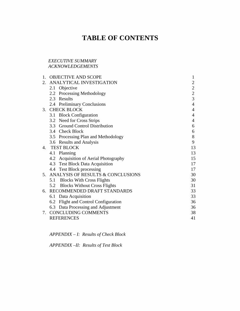
Final Report ndash Task 7 Caltrans Contract No 65A0260
blocks most commonly used in Caltrans A special software was developed to generate a photogrammetric dataset for a block of user defined configuration by using a predefined digital terrain model A dataset for a block with the following characteristics was generated
Camera Focal Length 153 mm Photo Scale 13600
Number of Strips 4 Number of PhotoStrip 37 Forward Overlap 60 Sidelap 30 Total Number of Photos 148 Total Number of tie points 489
In order to avoid the use of truly vertical aerial photography in the block and to simulate the normal flying conditions the exterior orientation of each photo in the block was varied using the MCM approach The simulated exterior orientation data was generated based on the following statistics
σ (Omega phi and kappa) plusmn 15 degrees σ (X Y and Z) plusmn 33 ft
Using the object space exterior orientation data of each photo 489 ground tie points 48 control points and the GPS coordinates for the antenna position at the time of exposure of each photo was generated Using the well known collinearity equations the image coordinates of all ground tie and control points were generated
Finally to generate the simulated GPS photogrammetry block the following values were used with the MCM technique to have Gaussian distribution random errors
Image Coordinates St Error plusmn 0006 mm Ground Control St Errors plusmn 010 ft GPS Antenna Coordinates St Err plusmn 030 ft
It is worthwhile to note that with this block all the generated ground tie point values that will be used as check points to evaluate the different adjustments that will be conducted Also this simulation does not consider the GPS drift systematic errors For that no cross ties were generated The GPS drift is a systematic error and is usually approximated using a linear mathematical model Since the exact math model is not known it is difficult to simulate
23 Results
A bundle solution was carried on the simulated photo block using only four corner control points Also two additional control points in the middle of the outside strip were added as another case
Dr R Munjy amp Dr M Hussain California State University Fresno munjyrcsufresnoedu and mushtaqhcsufresnoedu
3
Final Report ndash Task 7 Caltrans Contract No 65A0260
A summary of these two cases is as follows
St Err Average Err Max Err Min Err Simulation Check Pts X Y Z X Y Z X Y Z X Y Z FullBlk_4cp 489 005 006 008 000 -001 002 021 022 019 -017 -018 -024 FullBlk_6cp 489 005 005 007 -001 -002 002 021 022 020 -017 -017 -026
24 Preliminary Conclusions
Even with only four control points the results meet Caltrans aerial triangulation standards These results are very encouraging to meet the objective of minimizing ground control for GPS photogrammetry blocks with multiple strips for large scale photogrammetry projects More than four control points will be needed with cross strips to address the strip drift systematic error that was not considered in this simulation
3 CHECK BLOCK
It was essential that the results obtained from purely theoretical analysis be substantiated with actual data of the type and quality normally used by Caltrans for their aerial triangulation projects In order to generate such a dataset the Caltrans Office of Photogrammetry in Sacramento coordinated with the research team at CSU Fresno in modifying the plans for a forthcoming aerial triangulation project along I-5 in San Diego Modifications to the flight plan were suggested primarily to investigate the following controlling parameters for the aerial triangulation block
31 Block Configuration
According to Caltrans current practice a typical block configuration consists of a threeshystrip block segment intersected by similar three-strip block segment as shown schematically in Fig 1 Depending on the terrain and the configuration of the two intersecting highways the intersection of the two aerial block segments may occur at widely varying angles resulting in variable relative geometry Accordingly a configuration of two separate block segments each consisting of three or more intersecting flight lines was proposed for the check block
32 Need for Cross Strips
Since the use of cross strips has been widely recommended to reduce the need for ground control especially when strip drift parameters have to be used in bundle block adjustment [1] [7] [11] it was proposed to use cross strips at each end of the block In addition a cross strip at the intersection location as seen in Fig 2 would allow the investigation of using such a configuration if it offers any significant advantage
Dr R Munjy amp Dr M Hussain California State University Fresno munjyrcsufresnoedu and mushtaqhcsufresnoedu
4
Final Report ndash Task 7 Caltrans Contract No 65A0260
6060
120120
Figure 1 Flight Intersection Geometry
Figure 2 Proposed Location of Cross Strips in the Check Block
Dr R Munjy amp Dr M Hussain California State University Fresno munjyrcsufresnoedu and mushtaqhcsufresnoedu
5
Final Report ndash Task 7 Caltrans Contract No 65A0260
33 Ground Control Distribution
The number and the spatial distribution of the ground control is the key issue that needs to be resolved in this study The airborne GPS data is usually considered sufficient to control the interior of the block [2] [7] Consequently ground surveyed control data is needed only along the block perimeter In accordance with the current Caltrans standards for single-strip configuration blocks the use of a pair of 3-D control points spaced six models apart along the block perimeter meet the accuracy standard for aerial triangulation at 13000 photo scale [11] Accordingly it was proposed to provide 3-D control points at a spacing varying from 6 models to 12 models to determine the optimal control placement along the block perimeter to meet Caltrans accuracy standard for photo scales varying between 13000 and 14800 Since past several years Caltrans has adopted the standard aerial photography scale for mapping as 13600 Accordingly this study is aimed at developing standards for 13600 photo scale
The simultaneous bundle block adjustment based on weighted least squares model results in several statistical metrics that provide a good indication of the internal consistency of the input data and the relative precision of the adjusted coordinates of the tie points and the exterior orientation of the photos However the only valid criterion for checking the external accuracy of the aerial triangulation results is their comparison against ground surveyed check data With this objective it was proposed to add several interior control points distributed over the entire block to serve as Check Points
34 Check Block
Caltrans Office of Photogrammetry in Sacramento and Caltrans District 11 Office in San Diego fully cooperated in modifying the flight plan to accommodate most of the suggestions made by the CSU Fresno research team The mapping project was modified to consist of 9 flight lines that included two cross flight lines one at each end In addition the ground survey was extended to include all the additional control points proposed in the block interior The final configuration of the San Diego Check Block is shown in Fig 3 which also shows the distribution of the 44 ground surveyed control points
Due to the State of California budget problems the Caltrans Division of Research and Innovation suspended this research contract in early August 2008 The contract suspension was subsequently lifted in late October 2008 During a webinar held on November 14 2008 between the representatives from Caltrans DRI and Office of Photogrammetry and the CSU Fresno research team it was reported by the Caltrans Office of Photogrammetry that the San Diego Check Block had been flown and surveyed and the image data captured for aerial triangulation while the research contract was under suspension Consequently all the measurement data related to the San Diego Check Block was available for research study It was provided to the CSU Fresno research team in late November 2008
Dr R Munjy amp Dr M Hussain California State University Fresno munjyrcsufresnoedu and mushtaqhcsufresnoedu
6
Flt6
Flt8Flt4
Flt3Flt2
Flt1
t5
Flt9
Flt7
MAIN Flight Lines 7CROSS Flight Lines 2PHOTO 125CONTROL Points 44
Flt6
Flt8Flt4
Flt3Flt2
Flt1
t5
Flt9
Flt7
MAIN Flight Lines 7CROSS Flight Lines 2PHOTO 125CONTROL Points 44
PHOTO SCALE 13600
Flt6
Flt8Flt4
Flt3Flt2
Flt1
t5
Flt9
Flt7
MAIN Flight Lines 7CROSS Flight Lines 2PHOTO 125CONTROL Points 44
Final Report ndash Task 7 Caltrans Contract No 65A0260
Flt7
Flt6
FlFlFlFlt5
Flt9
Flt4Flt8
MAIN Flight Lines 7 CROSS Flight Lines 2 PHOTO 125 CONTROL Points 44 Flt3
Flt2 PHOTO SCALE 13600 Flt1
Fig 3 Configuration and Control Distribution for the San Diego Check Block
Dr R Munjy amp Dr M Hussain California State University Fresno munjyrcsufresnoedu and mushtaqhcsufresnoedu
7
Final Report ndash Task 7 Caltrans Contract No 65A0260
35 Processing Plan and Methodology
In order to investigate the impact of block configuration the use of cross flight lines and the distribution of ground control the San Diego Check Block was processed in the following different configuration and control combinations
Block Configurations
a) FULL Block Uses all Flight Lines 1 through 9 b) MAIN Block Uses Flight Lines 1 through 7 only omits Cross Flights 8 amp 9 c) NORTH Block Uses Flight Lines 5 6 and 7 d) NORTHX Block Uses Flight Lines 56 and 7 and includes Cross Flight 9 e) SOUTH Block Uses Flight Lines 1 through 4 f) SOUTHX Block Uses Flight Lines 1 through 4 and includes Cross Flight 8 g) SOUTHM Block Uses Flight Lines 12 and 3 trimmed to the same length as
Flight Line 4 (11 Models) and includes Cross Flight 8
Control Distribution
The following considerations were used for the placement and distribution of control points along the perimeter of a block
a) A Ground Control Point (GCP) should fall at each end of each Flight Line b) In addition to (a) above a GCP should control every block corner c) When a Cross Flight Line overlaps the ends of Flight Lines the condition at (a)
above to be replaced with the requirement for a GCP at each end of the Cross Flight Line
d) On large blocks in a direction parallel to the flight lines GCPs should control the block perimeter with spacing not exceeding 8 airbases if cross flights do not exist
e) No GCP is provided in the block interior
The above considerations resulted in formulation of 22 blocks with different flight line and control configurations The block diagram showing the Photos used and the GCP distribution in each of the 22 different cases is given in the Appendix section of this report
As stated above 22 different aerial triangulation blocks were processed using the Interactive Simultaneous Bundle Block Adjustment Windows based software Interactive Simultaneous Bundle Block Adjustment-ISBBAW The input for the processing included the following data files provided by Caltrans Office of Photogrammetry
1) Ground Control Data File Project Datum Information Units US Survey Foot Horizontal CCS83 Zone 6 Epoch 200700 Vertical NAVD88
Dr R Munjy amp Dr M Hussain California State University Fresno munjyrcsufresnoedu and mushtaqhcsufresnoedu
8
Final Report ndash Task 7 Caltrans Contract No 65A0260
a-priori XY 010 ft a-priori Z 010 ft
2) Image Coordinate Data File Type Machine Coordinates a-priori xy 0006 mm
3) Airborne GPS Antenna Data File (at Photo exposure time) Datum Same as Project Datum a-priori XY 015 ft a-priori Z 015 ft
The Office of Photogrammetry had pointed out the unreliability of the GPS data corresponding to Photo 77 Accordingly the GPS data for Photo 77 was made ineffective by assigning a standard error of 100 feet for its coordinates
In addition the latest aerial camera calibration data was also provided and was used to update the camera data file
Each block was processed using Affine Transformation for obtaining photo coordinates that were corrected for systematic errors for lens distortion atmospheric refraction and earth curvature No unacceptably large transformation residuals were obtained Each block was then adjusted using Strip Drift Parameters during Bundle adjustment
36 Results and Analysis
In processing all the 22 different cases of the aerial triangulation no ground or image point was rejected The processing of all the blocks indicated good internal consistency in the measurement data as the Standard Error of Unit Weight (Sigma-sub0 0 ) varied from 048 to 060 the latter value resulted in Case 1 FULL Block Using all 44 GCP It also indicated good precision in image transfer (through pugging) and coordinate measurement the RMS values in the x-coordinate varied from 00022 to 00032 mm while the RMS value for the y-coordinate varied from 00037 to 00042 mm
An important consideration for this research study is the reliability of the ground control data The relative precision of all the 44 GCPs is convincingly validated from the block in Case-1 when all the 44 points are used The RMS values in the control point residuals are (ft)
RMS in X-coordinate 0035 RMS in Y-coordinate 0035 RMS in Z-coordinate 0048
For 13600 scale wide-angle photography Caltrans existing aerial triangulation accuracy standards require the RMS in control points to not exceed 1 part in 10000 of the flying
Dr R Munjy amp Dr M Hussain California State University Fresno munjyrcsufresnoedu and mushtaqhcsufresnoedu
9
Final Report ndash Task 7 Caltrans Contract No 65A0260
height above average terrain Therefore for the average flying height of 1800 feet above terrain this standard would require that the coordinate RMS value should not exceed 018 ft The above result represents a level of precision more than three-times what is permissible according to standard Consequently it proves that the available ground control data meets the required precision to serve as check data in evaluating the cases using a limited number of perimetric control points
In order to systematically evaluate the impact of ground control point distribution on a block the results obtained in each block were used to investigate the coordinate differences at the Check Points these are the ground surveyed control points that are not included as control points in processing the block and their coordinate values are computed as tie points in the block adjustment solution The differences between the aerial triangulation adjusted coordinates and the known ground control coordinates for the Check Points were computed and the average value and the standard deviation in these coordinate differences are listed in Table-1 for each processing case The results obtained are discussed in the following section
CaseNo
Block Type No of Chk Pts X Y Z
St Err X Y Z
Avg Err X Y Z
Max Err X Y Z
Min Err
1 2 3 4 5
FullBlk_All 44CP FullBlk_8CP FullBlk_9CP FullBlk_10CP
0 36 35 34
007 008 005 012 012 016 012 012 017 012 009 015
002 001 -005 001 -001 -008 003 005 -009
024 027 026 024 024 026 024 027 021
-025 -039 -032 -026 -040 -034 -025 -013 -035
MainBlk(Flts1to7)_43CP 0 006 008 005 6 MainBlk1-7_ 8CP 36 016 012 027 -002 -004 -004 026 020 041 -035 -036 -082 7 MainBlk1-7_10CP 34 014 012 027 -001 -003 -004 022 020 039 -031 -031 -080 8 9 10 11 12 13
MainBlk1-7_ 12CP 32 015 010 017 003 000 -004 037 016 035 -031 -027 -023 NorthBlk_567amp9_5CP NorthBlk_567amp9_7CP NorthBlk_567_6CP NorthBlk_567_8CP
18 16 17 15
012 016 016 010 016 017 010 016 022
007 -016 011 008 -007 018 010 -002 008
026 002 036 023 010 051 024 015 050
-022 -062 -022 -016 -051 -012 -019 -043 -026
011 016 017 013 -009 002 029 007 037 -017 -049 -031 SouthBlk_1234amp8_4CP 22 052 032 015 -082 033 003 -007 091 026 -149 -009 -034
14 SouthBlk_1234amp8_6CP 20 013 016 015 -003 006 -002 024 033 033 -019 -028 -028 15 SouthBlk_1234amp8_7CP 19 015 012 014 -003 -002 -002 025 023 033 -025 -030 -025 16 SouthBlk1to4 No XFlt_7CP 22 015 013 023 -001 -005 003 026 023 032 -027 -029 -037 17 SouthBlk1to4 No XFlt_8CP(a) 21 014 012 024 005 -001 004 031 025 033 -022 -029 -040 18 SouthBlk1to4 No XFlt_8CP(b) 21 016 014 019 -003 -005 001 027 025 028 -033 -033 -032 19 SouthBlk1to4 No XFlt_10CP 19 014 012 019 004 -001 001 034 029 029 -025 -030 -028 20 21 22
SouthBlk1to4 No XFlt_11CP 18 014 012 018 -001 -005 -001 023 020 027 -030 -029 -031 ModifiedSouthBlk_1234amp8_ 5CP ModifiedSouthBlk_1234_6CP
19 16
013 010 015 014 011 014
-001 002 -001 002 005 -010
024 021 035 025 024 016
-019 -025 -029 -020 -024 -039
Table-1 Summary of the Coordinate Differences at the Check Points
In accordance with Caltrans Accuracy Standards for Aerial Triangulation the standard error in the adjusted coordinates of a tie point should not exceed 110000th of the average flying height above the terrain level The San Diego Check Block was flown at an average flying height of 1800 feet above terrain resulting in an average photo scale of 13600 Accordingly the limiting standard error in the adjusted coordinates of tie points amounts to 018 ft As is evident from the results summarized in Table-1 in case of vertical aerial photography the height error is larger than the error in the X- or the Yshycoordinate with few exceptions Therefore one may primarily focus only on the
Dr R Munjy amp Dr M Hussain California State University Fresno munjyrcsufresnoedu and mushtaqhcsufresnoedu
10
Final Report ndash Task 7 Caltrans Contract No 65A0260
standard error in the height in order to analyze the various scenarios represented by the 22 different cases
361 FULL Block (Case-1 to 4)
In the case of FULL Block (Flts 1 to 9) by controlling each edge (corner) of the block and each edge of any cross strip by a single CP as in Case-2 Caltrans accuracy standard is met In case-3 an additional CP was used at the block corner formed where the Flight 4 ends while the Flight 3 continues southward The addition of this corner point does not significantly enhance the accuracy of the solution This is due to the fact that the Flight-3 at this point is controlled by GPS data
It is interesting to note that even though the Flight 7 (at the northern end of the block) is 15 models long a single CP located at the end of this flight appears to be sufficient for control The fact that the spacing between the end CPs at the lower end of this block segment (Flight 5) is only about 10 models adds to the strength In order to check the influence of additional control points along the block perimeter with reduced spacing a CP was added in the middle of Flight 7 as shown in Case-4 This does result in some improvement in the accuracy of the block solution consequently this would appear to be the optimum control configuration
362 MAIN Block (Case-5 to 8)
The MAIN Block (Flts 1 to 7) was used to study any impact in using cross flights for GPS controlled aerial triangulation blocks When a large number of control points are available such as in Case-3 where 43 CPs are used the results are identical whether or not cross flights are used However when a CP is used only at the block corners as in Case-6 (analogous with Case-2 in FULL Block) the required accuracy standard is not met This standard is also not met when an additional corner CP is used as shown in Case-7 (analogous with Case-3 in FULL Block) However when the spacing between the perimetric control points is confined to about 8 models as shown in the Case-8 the results are within the required accuracy standard A comparison of Case-4 and Case-8 shows that if the cross Flights 8 and 9 are not used additional control points along the block perimeter in a direction parallel to the flight lines can compensate for it and meet the required accuracy standard
363 NORTH Block (Case-9 to 12)
The above analysis was repeated by splitting the San Diego Check Block into two subshyblocks a NORTH Block and a SOUTH Block The NORTH Block (Flts 5 to 7 and 9) was processed first by including the cross Flight 9 and also by excluding this cross flight The results tabulated in Table-1 in Case 9 to 12 are identically similar to the ones obtained earlier with the FULL and the MAIN Blocks It again shows that when a CP is located at the end of the cross Flight 9 in the northern end of the block and a CP is used at the end of each of the three flight lines at the southern end of the block the required accuracy standards are met even when no CP is located in the middle of the 15-model
Dr R Munjy amp Dr M Hussain California State University Fresno munjyrcsufresnoedu and mushtaqhcsufresnoedu
11
Final Report ndash Task 7 Caltrans Contract No 65A0260
long Flight-7 (Case-9) In fact it is seen in Case-10 that the addition of an intermediate point along the perimeter did not improve the accuracy
Without the cross Flight 9 however a comparison of the Case-12 with Case-11 clearly shows that the reduction in the spacing between the perimetric control points is necessary for meeting the required accuracy standard In this block size and configuration the nonshyuse of a cross flight could have been compensated with the use of one additional control point along the perimeter
364 SOUTH Block (Case-13 to 20)
The SOUTH Block consisting of Flights 1 to 4 and the cross Flight 8 has somewhat unusual configuration it is not a compact rectangular block and the cross Flight-8 intersects the block rather than at either end of the block Eight different scenarios for flight and control configuration were used in handling this sub-block
The Case-13 is based on the use of only four CPS one located at each of the four block corners This case might work for small and rectangular blocks with a cross flight at each end of the block However for Case-13 the cross Flight is completely uncontrolled and so is the southern corner of Flight-4 Obviously this has resulted in the planimetric RMS error that exceeds 05 ft
When a CP was located at each end of the cross Flight 8 as seen in Case-14 as well as a CP was added at the end of each flight line the block solution met the accuracy standard The addition of another corner CP as shown in Case-15 did not contribute to any significant improvement in the accuracy This shows the role that the intersecting cross Flight 8 plays in strengthening the geometry of the block by reducing the uncontrolled segment of each of the three Flight lines 1 to 3
The Case-16 to 20 convincingly demonstrate the degradation in the block geometry when the cross Flight 8 is removed from the block None of the block configurations shown in Case 16 to 19 strictly meets the accuracy requirement the Case-18 and Case-19 missing the minimal accuracy standard by 001 ft It is only when another corner CP is added as shown in Case-20 that the minimal accuracy standard is attained
365 SOUTH-MODIFIED Block (Case-21 amp 22)
In order to further validate the conclusions derived so far the SOUTH Block was modified to a more conventional rectangular shaped block by removing photos from Flight 1 to 3 to bring them to the same length as Flight 4 The SOUTH_MODIFIED Block is not only have a rectangular shape but the cross Flight 8 now falls at the southern of this sub-block With the Flight 8 now playing the normal role of a cross flight the minimal control layout seen in Case-21 easily meets the accuracy standard As observed in previous
Dr R Munjy amp Dr M Hussain California State University Fresno munjyrcsufresnoedu and mushtaqhcsufresnoedu
12
Final Report ndash Task 7 Caltrans Contract No 65A0260
blocks locating a CP at each end of each flight line meets the accuracy standard for this block with 11-model long flight lines
The above observations and the conclusions were used to draft the Preliminary Standards for Block Configuration Airborne GPS Controlled Photogrammetry for Large Scale Mapping Projects and submitted as Interim Report in fulfillment of the requirement under Task 32 of the contract [14]
4 TEST BLOCK
41 Planning
The extra-ordinary fiscal problems faced by the State of California had resulted in the suspension of work on the project Consequently a no-cost extension in the time for completion of this project beyond March 31 2009 till December 31 2009 was requested by California State University Fresno in November 2008 This request in the extension of period was strongly supported by Caltrans Office of Photogrammetry This request was approved by Caltrans Division of Research and Innovation and California State University Fresno was notified by Caltrans Contract Manager on April 2 2009 to continue work on the project till December 31 2009
A planning meeting between the California State University Fresno research team and the representatives from Caltrans Office of Photogrammetry was held in Caltrans Office in Sacramento on April 20 2009 for the design of an optimal test block In the light of the results obtained from the San Diego Check Block and the conclusions presented in the Interim Report submitted in January 2009 various options and proposals for selecting the site and configuration for a test block were discussed The Caltrans Office of Photogrammetry and the California State University Fresno fully agreed on the following characteristics for the Test Block
The aerial photography should fully conform to the Caltrans practice of using a metric wide-angle aerial camera from an altitude of 1800 ft above the terrain level to result in an average photo scale of 13600
The main block should consist of 4 parallel flight lines of 18 models each A cross flight should be flown at each end of the main block Full 3-D ground control should be provided along the perimeter of the main block
with a control point spacing of 6 to 8 airbases Full 3-D ground control for the two cross flights should be planned so that
- A pair of 3-D control points are located at each end of each cross flight and - At least one Height control point falls at each end of each main flight line
A sufficient number (15 to 20) of additional ground control points should be distributed in the interior of the block to serve as check points for estimating the absolute accuracy of aerial triangulation results
All the 6 flight lines constituting the Test Block should be flown as a single flight mission
Dr R Munjy amp Dr M Hussain California State University Fresno munjyrcsufresnoedu and mushtaqhcsufresnoedu
13
Final Report ndash Task 7 Caltrans Contract No 65A0260
The airborne GPS data as well as the data at the ground Base Stations should be collected at 1 Hz or higher data rate
The flight mission should be carried out under weather and environmental conditions so as to avoid any degradation in the quality of aerial imagery
Even though implementing the above technical requirements in a test block did not pose any serious problems the California State University Fresno as well as the Caltrans Office of Photogrammetry had serious concerns about adhering to the tight project schedule Both the parties in this project were convinced that the award of an aerial photography services contract for a Test Block by the California State University Fresno through a formal selection and competitive bidding process would entail serious delays that may even jeopardize the completion of the project by the ending date of December 31 2009 An attractive and viable alternative was to utilize the services of an aerial photography vendor that had recently been contracted by Caltrans for the acquisition of aerial photography for a highway corridor along Interstate I-5 in Northern San Diego The flying for this Caltrans project was fortuitously scheduled for May 2009 that synchronized very well with the schedule for this research project
Accordingly with full consultation with the Caltrans Office of Photogrammetry a Test Block was designed by the California State University Fresno in Del Mar in Northern San Diego The Del Mar Test Block included a variety of terrain a large expanse of marsh and river suburban residential large freeway and rolling hills A separate contract was negotiated and awarded by the California State University Fresno to the Caltrans contractor for the San Diego I-5 Project for the acquisition of aerial photography for the Del Mar Test Block This approach used in awarding the contract resulted in the following benefits
The aerial photography contractor had already been pre-qualified by Caltrans for the quality of the aircraft aerial camera aerial film and GPS and navigation equipment used for the acquisition of aerial photography
The aerial photography contractor had already been pre-qualified by Caltrans for the quality of aerial photography products (developed negative film diapositives prints etc)
The aerial photography contractor had already been pre-qualified by Caltrans for the certification of aerial camera calibration electronic integration of the aerial camera with the airborne GPS receiver to record the aerial exposure events and the geometric integration of the airborne GPS antenna mounted on the fuselage with the aerial camera
The contractor was familiar with the detailed Caltrans specifications for the acquisition of aerial photography and the same specifications would strictly govern the flight mission for the Del Mar Test Block
Dr R Munjy amp Dr M Hussain California State University Fresno munjyrcsufresnoedu and mushtaqhcsufresnoedu
14
Final Report ndash Task 7 Caltrans Contract No 65A0260
42 Acquisition of Aerial Photography
The flight configuration and ground control distribution for the Del Mar Test Block was finalized near the end of April 2009 and is shown in Fig 41 As stated earlier the contract for the aerial photography acquisition was awarded to IKCurtis Services Inc Burbank California who had earlier been awarded the Caltrans contract to fly Route 5 and 56 in San Diego The Caltrans Office of Photogrammetry also arranged for field survey teams from Caltrans District 11 in San Diego to supplement the ground control network established for the Caltrans project with the additional ground control points planned for the Del Mar Test Block This further ensured that the quality of the ground control data used for the Del Mar Test Block would fully conform to Caltrans aerial triangulation control standards All the fieldwork required for the Caltrans Route 5 and 56 Project and for the Del Mar Test Block of the California State University Fresno research project was completed in early May 2009
Based on the weather reports and the suitability of GPS satellite configuration it was mutually agreed between the Caltrans Office of Photogrammetry Caltrans District 11 California State University Fresno and IK Curtis Services Inc to fly the two projects on May 13 2009 with May 14 2009 as a backup date I K Curtis Services Inc had been assigned the task of collecting the airborne GPS data during the flight mission while field survey staff from Caltrans District 11 were responsible for the simultaneous collection of GPS data at four designated base stations Whether the two separate projects are flown as a single flight mission or as two separate missions on the same day or on separate days was left entirely to the mutual judgment of the flight crew and Caltrans Project Coordinator from District 11 based on the weather and environmental conditions in the area
A final field survey task is to visit each control point location and repaint if necessary those control marks that fall on a hard surface and to deploy specially designed panel at each control point that lies on grass or open and marshy ground Even though all the ground control targets had been readied in time unfortunately adverse weather reports and worsening fog and cloudy conditions were totally unsuitable for flying on May 13 or on May 14 Based on the weather forecast similar flight dates were set on several occasions each time requiring the reconnaissance of the ground targets but the adverse weather conditions extended over several weeks After continuing efforts at planning and repeated cancellations it was finally possible to complete the aerial photography requirements for both the projects through a single flight mission carried out on July 14 2009 Even though two models at the end of one cross flight in the Del Mar Test Block contain some cloud coverage fortunately it was still possible to identify and measure the image coordinates of the ground control points falling in both the models
Dr R Munjy amp Dr M Hussain California State University Fresno munjyrcsufresnoedu and mushtaqhcsufresnoedu
15
6
5
Final Report ndash Task 7 Caltrans Contract No 65A0260
Fig 41 San Diego Test Block Configuration and Control Distribution
1 2 3 411 22 33 44
66
55
Dr R Munjy amp Dr M Hussain California State University Fresno munjyrcsufresnoedu and mushtaqhcsufresnoedu
16
Final Report ndash Task 7 Caltrans Contract No 65A0260
43 Test Block Data Acquisition
After the delivery of the aerial diapositives by the Contractor the photogrammetric data for the aerial triangulation of the Del Mar Test Block was measured and compiled by Caltrans Office of Photogrammetry The selection of tie points and the measurement of image coordinate data for the entire block consisting of 6 flight lines and 96 photos was carried out following the routine analytical methodology and practice used for all Caltrans aerial triangulation blocks
The following measurement data was provided by the Office of Photogrammetry to California State University Fresno in August 2009
- Image coordinate data - Ground control coordinate data - Raw GPS data from airborne receiver and four base station receivers - GPS time for photo exposure - Camera calibration data - Camera and GPS antenna offset
44 Test Block Data Processing
Before processing the aerial triangulation data received from the Office of Photogrammetry some clarification regarding the processing datum were necessary as discussed in the following section
441 Processing Datum
It was reported that the datum used for the ground control data provided by Caltrans District 11 was as below
- Horizontal Control CCS83 Epoch199135 Datum - Vertical Control NAVD88 Datum
Based on discussions with representatives from Caltrans District 11 it was determined that the 3-D adjustment of the GPS ground control network was performed in CCS83-Epoch 199135 datum for the horizontal control while the vertical coordinates were adjusted by fixing the orthometric height (NAVD88 Datum) of 4 network stations The geoidal height data needed for the reduction of observed ellipsoidal height data (GRS80 Ellipsoid) to adjusted orthometric height data (NAVD88 Datum) was based on the Geoid2003 Global Model Consequently the orthometric height data for the ground control used for the Del Mar Test Block may be affected by any height variation between the Local Geoid from the Global Geoid
442 Post-Processing of Airborne GPS Data
Dr R Munjy amp Dr M Hussain California State University Fresno munjyrcsufresnoedu and mushtaqhcsufresnoedu
17
Final Report ndash Task 7 Caltrans Contract No 65A0260
Even though the Caltrans Office of Photogrammetry had provided the post-processed results for the airborne GPS data this data was also processed at the California State University Fresno Even though GPS data at four different base stations had been collected and the GrafNav post-processing software provides the option to use multiple base station data it was decided to carry out the kinematic processing of the airborne GPS data relative to a single base station HPGN DC 11 The selection of this base station was due to the fact that this was the only base station for which the orthometric height had been held fixed in the GPS network adjustment none of the other three network stations for which the orthometric height was held fixed had been used as a base station during the flight mission
The results and the analysis provided in the following section are based on the airborne GPS data processed at the California State University Fresno
443 Aerial Triangulation Data Processing
The first objective for the aerial triangulation processing of the Del Mar Test Block data was to further verify the aerial triangulation results obtained with the San Diego Check Block reported in Section 3 A second and more important objective was to evaluate the impact of flight configuration and the control point distribution on the achievable aerial triangulation accuracy for large scale (13600) aerial photography used in Caltrans It was of special interest to assess the impact of the use of cross flights and the optimal distribution of the ground control points in an airborne GPS supported aerial triangulation block
The same approach and the methodology were used for processing the aerial triangulation of the Del Mar Test Block as has previously been discussed in detail in Section 35 for the San Diego Check Block Aerial triangulation data was processed systematically by using block configuration with and without the two cross flights (see Fig 41) The number and the distribution of the control points used primarily along the block perimeter varied from 8 to 14 control points Since the Del Mar Test Block was covered with a total of 33 field control points all the points that were not used as control points in processing the block served as Check Points Theoretically such Check Points are the most reliable indicators of the absolute accuracy of the aerial triangulation results provided the coordinate data for such Check Points is at least three times more precise than the precision of the coordinate data for the tie points resulting from aerial triangulation adjustment [15] In the case of the Del Mar Test Block data the uncertainty of 2 to 3 cm in the geoidal height interpolated from the global Geoid Model leads to the estimated precision of the Check Point data to be more precise than the aerial triangulation data by a factor of 12 to 2 only This fact has to be kept in focus while analyzing the absolute accuracy of the aerial triangulation results as part contributions from the errors in Check Point data cannot be entirely ignored
The airborne GPS supported aerial triangulation blocks are fully controlled through the airborne GPS data in the interior of the block Therefore the precision of the airborne GPS data plays a crucial role in the resulting aerial triangulation accuracy The
Dr R Munjy amp Dr M Hussain California State University Fresno munjyrcsufresnoedu and mushtaqhcsufresnoedu
18
Final Report ndash Task 7 Caltrans Contract No 65A0260
processing of the Test Block was carried out by using the following a-priori standard errors for the airborne GPS data (a) Standard error for X and Y-coord 025 ft Standard error for Z-coord 025 ft (b) Standard error for X and Y-coord 010 ft Standard error for Z-coord 015 ft
Based on the analysis of the results that are discussed in Section 5 it was finally decided to use the following a-priori standard error for the airborne GPS data
Standard error for X and Y-coord 015 ft Standard error for Z-coord 015 ft
The results for the block configuration that includes the two cross flights for a total of 6 flight lines are summarized as Cases 1 through 5 in Table 2 The Blocks processed without the use of the two cross flights and comprising only the 4 parallel flight lines are shown in Table 2 as Cases 6 through 12
Case BLOCK Number of St Error Ave Error Max Error Min Error
No Type Check Pts X Y Z X Y Z X Y Z X Y Z
1 6Flt_Blk_33CP 0 004 004 005
2 6Flt_Blk_8CP 25 009 008 019 -002 001 -007 013 018 032 -027 -012 -052
3 6Flt_Blk_12CP 21 010 008 014 -004 -003 005 009 013 029 -028 -015 -030
4 6Flt_Blk_14aCP 19 010 006 015 000 -003 001 012 013 027 -025 -016 -034
5 6Flt_Blk_14bCP 19 010 008 015 -001 -001 006 011 013 028 -025 -014 -031
6 4Flt_Blk_33CP 0 004 002 006 -002 000 001
7 4Flt_Blk_8CP 25 012 008 059 004 006 -108 028 024 016 -022 -009 -109
8 4Flt_Blk_11aCP 22 013 009 019 -001 -002 -017 017 016 028 -028 -016 -050
9 4Flt_Blk_11bCP 22 014 009 027 -005 003 -031 016 020 030 -031 -015 -066
10 4Flt_Blk_12CP 21 013 009 020 -002 000 -008 016 018 031 -027 -016 -033
11 4Flt_Blk_14aCP 19 010 008 013 004 -002 -003 016 015 025 -021 -017 -020
12 4Flt_Blk_14bCP 19 009 007 012 -001 -001 005 009 013 028 -025 -014 -012
Table-2 Summary of the Coordinate Differences at the Check Points
The control distribution used in the processing of the 12 cases is illustrated in Fig 42 through 411 below The corresponding statistics for the resulting errors at the Check Points are shown for each case The Check Points where the maximum errors in the X- Y- and Z-coordinate occur are shown in different color according to the legend below
Control pointControl point
MMaax error in Xx error in X
MMaax error in Yx error in Y
MMaax error in Zx error in Z LEGEND (Figures 42 through 411)
Dr R Munjy amp Dr M Hussain California State University Fresno munjyrcsufresnoedu and mushtaqhcsufresnoedu
19
Final Report ndash Task 7 Caltrans Contract No 65A0260
Fig 42 Block with Cross Strips 8 Control Points 25 Check Points Case 2
SSttaannddaardrd EErrorrorr AAvveeraraggee EErrrroorr MMaaxxiimmuumm EErrorrorr MMiinniimmuumm EErrorrorr XX YY ZZ XX YY ZZ XX YY ZZ XX YY ZZ
000099 000088 001199 --000022 000011 --000707 001133 001818 003232 --002277 --001212 --005522
Dr R Munjy amp Dr M Hussain California State University Fresno munjyrcsufresnoedu and mushtaqhcsufresnoedu
20
Final Report ndash Task 7 Caltrans Contract No 65A0260
Fig 43 Block with Cross Strips 12 Control Points 23 Check Points Case 3
SSttaannddaardrd EErrorrorr AAvveeraraggee EErrrroorr MMaaxxiimmuumm EErrorrorr MMiinniimmuumm EErrorrorr XX YY ZZ XX YY ZZ XX YY ZZ XX YY ZZ
001100 000088 001144 --000044 --000303 000055 000099 001313 002929 --002288 --001515 --003300
Dr R Munjy amp Dr M Hussain California State University Fresno munjyrcsufresnoedu and mushtaqhcsufresnoedu
21
Final Report ndash Task 7 Caltrans Contract No 65A0260
Fig 44 Block with Cross Strips 14 Control Points 21 Check Points Case 4
SSttaannddaardrd EErrorrorr AAvveeraraggee EErrrroorr MMaaxxiimmuumm EErrorrorr MMiinniimmuumm EErrorrorr XX YY ZZ XX YY ZZ XX YY ZZ XX YY ZZ
001100 000088 001155 --000011 --000101 000066 001111 001313 002828 --002255 --001414 --003311
Dr R Munjy amp Dr M Hussain California State University Fresno munjyrcsufresnoedu and mushtaqhcsufresnoedu
22
Final Report ndash Task 7 Caltrans Contract No 65A0260
Fig 45 Block with Cross Strips 14 Control Points 21 Check Points Case 5
SSttaannddaardrd EErrorrorr AAvveeraraggee EErrrroorr MMaaxxiimmuumm EErrorrorr MMiinniimmuumm EErrorrorr XX YY ZZ XX YY ZZ XX YY ZZ XX YY ZZ 001100 000066 001155 000000 --000033 000011 001122 001133 002277 --002255 --001166 --003344
Dr R Munjy amp Dr M Hussain California State University Fresno munjyrcsufresnoedu and mushtaqhcsufresnoedu
23
Final Report ndash Task 7 Caltrans Contract No 65A0260
Fig 46 Block without Cross Strips 8 Control Points 25 Check Points Case 7
SSttaannddaardrd EErrorrorr AAvveeraraggee EErrrroorr MMaaxxiimmuumm EErrorrorr MMiinniimmuumm EErrorrorr XX YY ZZ XX YY ZZ XX YY ZZ XX YY ZZ 001122 000088 005599 000404 000606 --110088 002288 002244 001166 --002222 --000099 --110099
Dr R Munjy amp Dr M Hussain California State University Fresno munjyrcsufresnoedu and mushtaqhcsufresnoedu
24
Final Report ndash Task 7 Caltrans Contract No 65A0260
Fig 47 Block without Cross Strips 11 Control Points 22 Check Points Case 8
SSttaannddaardrd EErrorrorr AAvveeraraggee EErrrroorr MMaaxxiimmuumm EErrorrorr MMiinniimmuumm EErrorrorr XX YY ZZ XX YY ZZ XX YY ZZ XX YY ZZ
001133 000099 001199 --000011 --000202 --001177 001177 001166 002288 --002828 --001166 --005050
Dr R Munjy amp Dr M Hussain California State University Fresno munjyrcsufresnoedu and mushtaqhcsufresnoedu
25
Final Report ndash Task 7 Caltrans Contract No 65A0260
Fig 48 Block without Cross Strips 11 Control Points 22 Check Points Case 9
SSttaannddaardrd EErrorrorr AAvveeraraggee EErrrroorr MMaaxxiimmuumm EErrorrorr MMiinniimmuumm EErrorrorr XX YY ZZ XX YY ZZ XX YY ZZ XX YY ZZ
001144 000099 002277 --000055 000033 --003131 001166 002020 003030 --003311 --001515 --006666
Dr R Munjy amp Dr M Hussain California State University Fresno munjyrcsufresnoedu and mushtaqhcsufresnoedu
26
Final Report ndash Task 7 Caltrans Contract No 65A0260
Fig 49 Block without Cross Strips 12 Control Points 21 Check Points Case 10
SSttaannddaardrd EErrorrorr AAvveeraraggee EErrrroorr MMaaxxiimmuumm EErrorrorr MMiinniimmuumm EErrorrorr XX YY ZZ XX YY ZZ XX YY ZZ XX YY ZZ 001133 000099 002200 --000022 000000 --000808 001166 001818 003131 --002277 --001616 --003333
Dr R Munjy amp Dr M Hussain California State University Fresno munjyrcsufresnoedu and mushtaqhcsufresnoedu
27
Final Report ndash Task 7 Caltrans Contract No 65A0260
Fig 410 Block without Cross Strips 14 Control Points 19 Check Points Case 11
SSttaannddaardrd EErrorrorr AAvveeraraggee EErrrroorr MMaaxxiimmuumm EErrorrorr MMiinniimmuumm EErrorrorr XX YY ZZ XX YY ZZ XX YY ZZ XX YY ZZ
001100 000088 001133 000044 --000022 --000303 001166 001515 002525 --002211 --001717 --002200
Dr R Munjy amp Dr M Hussain California State University Fresno munjyrcsufresnoedu and mushtaqhcsufresnoedu
28
Final Report ndash Task 7 Caltrans Contract No 65A0260
Fig 411 Block without Cross Strips 14 Control Points 19 Check Points Case 12
SSttaannddaardrd EErrorrorr AAvveeraraggee EErrrroorr MMaaxxiimmuumm EErrorrorr MMiinniimmuumm EErrorrorr XX YY ZZ XX YY ZZ XX YY ZZ XX YY ZZ
000099 000077 001122 --000011 --000101 000055 000099 001313 002828 --002255 --001414 --001122
Dr R Munjy amp Dr M Hussain California State University Fresno munjyrcsufresnoedu and mushtaqhcsufresnoedu
29
Final Report ndash Task 7 Caltrans Contract No 65A0260
5 ANALYSIS OF RESULTS amp CONCLUSIONS
In accordance with the Caltrans standards using wide-angle aerial photography the RMS error in each coordinate component of the adjusted tie points should not exceed 110000 of the flying height above the terrain The Del Mar Test Block was flown with a wideshyangle aerial camera from an average height of 1800 feet above the terrain level thereby resulting in an average photo scale of 13600 Consequently the limiting RMS error at the Check Points representative of a finite number of well distributed tie points in the block should not exceed 018 ft in this case Any error that exceeds three times this limiting value viz 054 ft in any of the coordinate components should be a cause for rejection of that point
Therefore the acceptable limiting values for the standard error at the Check Points is 018 ft in each coordinate component Any block adjustment solution that results in a coordinate error in one or more Check Points that exceeds 054 ft in any coordinate component would not be an acceptable solution The following analysis of the results is based on these accuracy criteria
51 Blocks With Cross Flights
When a minimal number of 8 control points are used (Fig 42) along the block perimeter the resulting standard error in Z-coordinate of 019 ft exceeds the limiting value of 015 ft It is also noticeable that the highest error in the Z-coordinate of 052 ft at Point 189134 almost equals the rejection limit of 054 ft This is an indication that controlling a cross flight with only a single Control Point at each end of the flight may not always provide a satisfactory solution
This situation can be remedied by using a pair of Control Points in each end model of a cross flight so that any deformation across the flight line the omega rotation () can also be controlled Such an approach is also reported to have been successfully used and recommended in the past [1] [2] [3] When 4 additional Control Points were added at the end of each cross flight line as is seen in Fig 43 all the standard errors fell within the acceptable range and the maximum coordinate error did not exceed 030 ft which is well within the acceptable criteria
The primary advantage of using airborne GPS data for the adjustment of aerial triangulation blocks is to completely eliminate the need for Control Points in the interior of the block But it is of interest to investigate how effectively the airborne GPS data alone can control the interior of the block Two separate blocks were processed by adding two Control Points in the interior of the block resulting in a total of 14 Control Points
The block with 14 Control Points (Case A) is shown in Fig 44 where the two interior Control Points were selected so that one Control Point was located on the opposite ends in each of the two interior flight lines (Line 2 and Line3 see Fig 41) The other block with 14 Control Points (Case B) is shown in Fig 45 In this case both the interior points
Dr R Munjy amp Dr M Hussain California State University Fresno munjyrcsufresnoedu and mushtaqhcsufresnoedu
30
Final Report ndash Task 7 Caltrans Contract No 65A0260
fell in the middle of the block interior It is interesting to note that in either of the two cases the addition of the interior Control Points did not result in any significant difference from the result achieved earlier while using 12 Control Points Therefore it may be concluded that as long as the cross flights are adequately controlled with a pair of Control Points located across each end model of each cross flight additional control in the block interior is not required The results shown in Fig 44 and 45 validate this conclusion at least for a block comprised of 18 models long multiple flight lines
52 Blocks Without Cross Flights
When a mapping project involves a large photogrammetric block consisting of hundreds of models the common practice is to plan the block configuration to include cross flights [1] [2] [6] [10] Often such cross flights can result in significant saving in time and effort in minimizing the need for ground control Since the photogrammetric mapping projects in Caltrans mostly involve mapping along highway corridors most of the photogrammetric blocks vary from a single flight line to up to as many as four flight lines Therefore it is still to be investigated whether the use of cross flight lines in such blocks offers any significant advantage Furthermore any advantage resulting from the reduced need for the ground control has to be weighed against the additional time and effort needed in processing the cross flight models The Caltrans Office of Photogrammetry has not yet adopted the use of Automated Aerial Triangulation (AAT) techniques for routine production Consequently the additional effort in transferring tie points between the cross flights with the flights of the main block is still significant This has provided the impetus to carry out the following investigation for the aerial triangulation adjustment of blocks that do not include any cross flights
The first block without the two cross flights was processed with only 8 Control points along the block perimeter as a parallel case with the block run with cross flights The results are shown in Fig 46 As may be expected the absence of any Control Point located at each end of each of the two interior flights 2 and 3 has resulted in unacceptably large errors Not only is the standard error of 059 ft in the Z-coordinate for the 25 Check Points too large but interestingly the block adjustment carries a large systematic error in Z-coordinate of 108 ft This results from the fact that the absence of the Control Points at each end of Flights 2 and 3 does not permit the adjustment for the systematic strip drift parameters for the airborne GPS data along Flights 2 and 3
When cross flights are included the airborne GPS data measured along the cross flight adequately serves as control for adjusting the strip shift and drift parameters Therefore an alternative to the inclusion of cross flights in the block configuration is to provide a Control Point at each end of every flight line in the block Accordingly the processing of the following blocks includes Control Points at the end of each flight line
The Del Mar Test Block with 4 flight lines each 18 models long would require a total of 12 Control Points one Control Point at each end of each flight line and 4 Control Points along the interior perimeter of the block to provide a control spacing of approximately 6 airbases apart However in order to minimize the use of the ground control the block
Dr R Munjy amp Dr M Hussain California State University Fresno munjyrcsufresnoedu and mushtaqhcsufresnoedu
31
Final Report ndash Task 7 Caltrans Contract No 65A0260
shown in Fig 47 was processed with only 11 Control Points (Case A) since the Control Point 170133 was measured both in Line 2 and Line 3 The resulting standard error of 019 ft in the Z-coordinate for 22 Check Points as well as the large error of 050 ft in the Z-coordinate of Check Point 189134 make the block adjustment solution unacceptable There appears to be no obvious reason why the Check Point 189134 that is located so close to the Control Point 170133 should display such unacceptably large error in the Zshycoordinate In order to ascertain the internal consistency of the ground control data (33 Control Points) a conventional aerial triangulation adjustment of the block was performed (without using the airborne GPS data) using 32 Control Points and treating the Control Point 189134 as a Check Point The resulting error in the Z-coordinate of Point 189134 was only 006 ft It is also to be noted that the average Z-coordinate error of 017 ft indicates a systematic height error This would lead to the conclusion that there is some height discrepancy between the ground control data and the airborne GPS data
The block was re-processed (Case B) again by using only 11 Control Points but this time the Control Point 170133 was replaced with Control Point 189134 and the results are displayed in Fig 48 The Case B results are even worse than the Case A results the standard error in Z-coordinate was degraded to 027 ft while the largest error in Zshycoordinate of 066 ft was noted at Check Point 187215 The average Z-coordinate error also increases to 031 ft This is a further indication that there is significant height inconsistency in the airborne GPS data and the ground control data It appears that the height discrepancy between the ground control data and the airborne GPS data results in an unsatisfactory shift and drift adjustment of the airborne GPS data particularly in the inner flight Lines 2 and 3 that span 18 models between the end Control Points
In order to strengthen the end control across the flight lines both the Control Points 170133 and 189134 were used at the Northern end of the block The block was then processed with 12 Control Points and the results are presented in Fig 49 Even though the results improved significantly but contrary to the expectation the standard error in the Z-coordinate of 020 ft for the 21 Check Points did not meet the Caltrans accuracy standard The next logical approach was to investigate the impact of adding Control Points in the interior of the block Two interior Control Points were selected in the same manner as has been described earlier in the case of the blocks with the cross flights (see Fig 44 and 45)
Using 14 Control Points the Case A is shown in Fig 410 while the Case B is presented in Fig 411 The results in both Case A and Case B easily meet the Caltrans accuracy standards In Case A the distance between the Control Points for the shift and drift parameter adjustment of the airborne GPS data varies from 6 to 12 models while in Case B the interior Control Points are about 6 models apart Each Control Point distribution provides almost similar results It is a clear indication that any systematic height deformation that results from the suspected inconsistency between the ground surveyed GPS data and the airborne GPS data can be kept within acceptable range by including a pair of control points in the interior of the block Such a need for some control points has not been reported for the adjustment of aerial triangulation blocks in the past However the largest photo scale for which any ABGPS supported results have been published in
Dr R Munjy amp Dr M Hussain California State University Fresno munjyrcsufresnoedu and mushtaqhcsufresnoedu
32
Final Report ndash Task 7 Caltrans Contract No 65A0260
the past is 14800 only For a photo scale of 13600 that is approximately 25 percent larger the requirements for the accuracy of aerial triangulation accordingly become more stringent in the same proportion This may generate the need for some additional control in the middle of the block
The residuals at the ground control points and in the image coordinate data along with the resulting standard error of unit weight (0) provide a reliable indication of the internal consistency of the adjusted block However the absolute accuracy of the aerial triangulation can be validated only by the use of Check Points that are well distributed over the entire block As pointed out earlier any deformations due to residual systematic shift and drift errors in the airborne GPS data are likely to be most significant in the center of the block the location that is farthest from the control points distributed along the perimeter Accordingly it would be advisable to locate at least a pair of Check Points in the middle of the block and after completing the block adjustment (by excluding these Check Points as Control Points) the coordinate discrepancies obtained at these Check Points can be analyzed Such discrepancies would normally represent the highest absolute accuracy resulting from aerial triangulation adjustment of the block Any unacceptably large coordinate discrepancies at the Check Points would require investigation of the block input data
In the case the coordinate discrepancies at the Check Points are within acceptable range the block can be re-processed by also including the Check Points in the control data This should enhance the accuracy in the interior of the block
6 RECOMMENDED DRAFT STANDARDS
These draft standards are proposed to supplement the existing Standards for Strip Configuration Airborne GPS Controlled Photogrammetry for Large Scale Mapping Projects (based on 13600 photo scale) currently used in Caltrans
61 Data Acquisition
611 Image Coordinate Data
Follow the existing practice used in Caltrans Office of Photogrammetry for the selection distribution and the measurement of all image point data It is recommended that raw machine coordinate image data should form the input to the aerial triangulation block adjustment
A secondary interest in this Research Project under contract with Caltrans was to also evaluate the alternate methodology of the selection and the measurement of tie point data using Automated Aerial Triangulation (AAT) system However several problems were encountered in implementing the AAT software available at the Caltrans Office of Photogrammetry in Sacramento The unavoidable delay caused by unfavorable weather conditions in acquiring the aerial imagery for the Del Mar Test Block did not allow
Dr R Munjy amp Dr M Hussain California State University Fresno munjyrcsufresnoedu and mushtaqhcsufresnoedu
33
Final Report ndash Task 7 Caltrans Contract No 65A0260
enough time to resolve the AAT software issues with software vendor Accordingly this task could not be fully completed Therefore it was mutually agreed between the Caltrans Office of Photogrammetry and California State University Fresno to concentrate research efforts on the processing and the analysis of the Del Mar Test Block and on drafting the Final Report
612 Ground Control Data
The proposed research is focused on the use of photography obtained at scale of 13600 for corridor mapping in Caltrans The ground control for mapping is based on the airborne GPS supported aerial triangulation of the photo blocks The ground control points should be surveyed to provide 15 to 2-times higher accuracy than that of the adjusted tie point data This would translate to an accuracy at the 005 to 01 ft level for the planimetric coordinates and the height an accuracy achievable using static GPS surveys tied to existing HPGN network
It is not yet certain that the Real-Time Kinematic (RTK) GPS field survey methodology whether relying on a single base station or on an RTK network is able to meet the above stringent field survey accuracy requirements Therefore the ground control data for ABGPS based aerial triangulation blocks should be based entirely on GPS control networks established using static GPS surveying methodology The RTK survey methodology for establishing control for photogrammetric mapping projects should not be used till such time that such technology has advanced to a level when consistently reliable results can be routinely expected
The GPS observations provide a fairly precise data for ellipsoidal height differences However all photogrammetric mapping has to be based on orthometric height data Two different approaches can be used in order to derive adjusted orthometric height data through aerial triangulation The first method is to carry out the simultaneous least squares adjustment of the GPS observation data for the ground control network using current Caltrans Horizontal Datum CCS83 (199135) and Vertical Datum NAVD 88 But since the observed data involves the measurement of ellipsoidal height differences for each measured baseline there is a need for transforming such differences to the corresponding orthometric height differences on NAVD 88 Datum In the absence of an existing Local Geoid Model the only economic recourse available to meet this need is to use the most reliable existing Global Geoid Model the time-consuming and prohibitively more costly alternative would be to connect the control network stations through differential leveling The Global Geoid Models are progressively being updated and the GEOID 2003 Model is most commonly in current use although GEOID 2009 Model may soon become available
It has to be noted that the use of a Global Geoid Model will always have some residual geoidal height uncertainties perhaps in the range of few hundredths of a foot It is therefore necessary that a few stations that are well distributed over the control network should have precisely known orthometric height values which can be used for the height adjustment of the network The minimum number of such orthometric height control
Dr R Munjy amp Dr M Hussain California State University Fresno munjyrcsufresnoedu and mushtaqhcsufresnoedu
34
Final Report ndash Task 7 Caltrans Contract No 65A0260
stations is three and consequently a network should be planned to have at least four and preferably more stations where orthometric height is precisely known In practice this requirement is met by including several existing benchmarks that are well distributed over the project area The redundancy provided by using more than three benchmarks will quantify the height residuals resulting from the adjustment This will provide a good estimate for the residual height errors in the network
The alternative approach is to carry out the adjustment of the GPS control network using WGS84 Geodetic Datum This datum is consistent with the observed GPS measurement data and a simultaneous 3D adjustment of the network can be performed in a Local Spatial Coordinate System (LSCS) the most commonly used approach is to shift the origin of the WGS84 coordinate system (center of the Earth) to approximately the center of the project site and apply a 3D rotational matrix to align the coordinate axes along the East North and Up directions Some commercial aerial triangulation software systems provide utilities to easily perform such datum transformation After the aerial triangulation results have been validated the coordinates of all the control and tie points can be transformed back to WGS 84 Datum Based on the availability of the orthometric height control stations a local Geoid can be defined ( a plane or a surface etc) and then used to transform the ellipsoidal height data to orthometric height data This second approach has the advantage that unlike the first method described above the residual height errors in the transformed control point height data are not propagated through aerial triangulation
For 13600 scale aerial photography blocks the ground control data should meet the a- priori standard deviation at 010 ft level This is not a very challenging demand for the horizontal positioning using GPS methodology However the residual height uncertainties in the orthometric height of control points interpolated from the Global Geoid Model become more critical as the photo scale becomes larger
613 Airborne GPS Data
The current practice used in Caltrans to acquire airborne GPS data during flight missions should continue to be used It is necessary to have GPS data collected at 1 Hz or higher rate at a base station that is located within or close to the project site Prior research completed collaboratively with Caltrans has already shown that the data at the base station may be substituted with GPS data collected at CORS at 5-sec or higher rate Consequently the collection of GPS data at more than one base stations is not considered as an essential requirement It may still be prudent to acquire GPS data at a second base station as a contingency safeguard against the GPS hardware failure at a base station for guaranteed success of the flight mission and expense
It is to be noted that the relative accuracy between successive airborne GPS antenna 3Dshycoordinates should be at 10-cm or higher level The current procedure used in Caltrans for the aircraft to remain stationary for static resolution of ambiguities before take off has mostly resulted in acquiring very reliable airborne GPS data This practice should perhaps be continued even though the continuing improvements in GPS hardware and
Dr R Munjy amp Dr M Hussain California State University Fresno munjyrcsufresnoedu and mushtaqhcsufresnoedu
35
Final Report ndash Task 7 Caltrans Contract No 65A0260
post-processing softwares are making on-the-fly (OTF) ambiguity resolution increasingly reliable However if it is necessary to resort to on-the-fly ambiguity resolution it must be ensured that the ambiguities have stabilized before photography is started The strict requirement for reliably resolving the ambiguities also does not permit the loss of lock during any single flight line If a loss of lock occurs during turns between flight lines ambiguities must be re-acquired and must stabilize before starting the collection of photography for another flight line Based on the make and the model of the airborne GPS receiver the Caltrans Office of Photogrammetry in consultation with the District Survey Section should draft a set of instructions for the GPSCamera operator aboard the aircraft specifying what parameters (such as PDOP Number of SVs etc) that need to be continuously monitored on a screen during a flight mission
62 Flight and Control Configuration
The following standards in planning the flight line configuration and the corresponding ground control distribution for Caltrans project are recommended to achieve optimum results
Control points are primarily required only along the perimeter of the block When a cross flight line is used to control the end of a block a pair of Control
Points must be located at each end of the cross flight At each end of a block that is not controlled by a cross flight a CP should be
located at the end of each parallel flight line a single CP may serve as end control for two adjacent overlapping flight lines
Along the perimeter of the block in a direction parallel with the main flight lines the CPs should be located at an average spacing of 6 airbases
Any corner in a block resulting from a sudden change in the length of two adjacent parallel flight lines should be controlled by an additional CP
Check Points should be provided along the interior flight lines in a multi-strip block The Check Points may be distributed along the interior flight lines so that any Check Point is not farther than about 8 airbases from either another Check Point (on same or adjacent flight line) or from a Control Point
Note that Caltrans is usually concerned with the mapping mostly along highway corridors and therefore does not require blocks with segments larger than three or four parallel flight lines Additional control along the cross flight line would be needed if such segments have 8 or more parallel flight lines
63 Data Processing and Adjustment
631 Processing of ABGPS Data
The current practice of post-processing ABGPS data used in Caltrans Office of Photogrammetry using GrafNav software should be continued The data should continue to be processed in the Forward and Backward modes A coordinate separation of less
Dr R Munjy amp Dr M Hussain California State University Fresno munjyrcsufresnoedu and mushtaqhcsufresnoedu
36
Final Report ndash Task 7 Caltrans Contract No 65A0260
than 10 cm especially in the height represents a normally acceptable range for the combined solution
This study has shown that the airborne GPS data in comparison with the ground control data should be weighted a lower weight but the highest weight that the GPS data quality represents Generally the best results were achieved when a-priori standard error of 015 ft was used for the airborne GPS coordinate data in comparison with the a-priori standard error of 010 ft used for the ground control coordinate data Since the 3-D position of successive points along the airborne GPS antenna trajectory are estimated using Kalman Filtering approach the successive location coordinates are highly correlated and consequently carry a much higher relative precision This provides a realistic justification for the use of a-priori standard error of 015 ft
632 Processing of Aerial Triangulation Block
Each aerial triangulation block requires the following data files as input
- Raw image coordinate data file - Ground control data file - Interpolated camera coordinate data file
Using the above input data files the block adjustment should be carried out in two steps as described below It is essential that additional Strip Shift and Drift parameters (3 Shift and 3 Drift parameters) should be incorporated in the bundle adjustment solution
Step 1 Minimal Control Adjustment
The preliminary simultaneous bundle adjustment of the block should be carried out by using the minimal amount of control points along the block perimeter only All the additional ground surveyed and targeted points should be treated as tie points to serve as Check Points The adjustment results should meet the following criteria
a The Standard Error of Unit Weight (0) should fall between 03 to 07 b The residual for any image coordinate should not exceed 15 micrometer c The RMS for ground control residuals should not exceed 110000 of the flying
height above the average terrain level d The maximum residual in any ground control coordinate should not exceed 25
times the RMS value permissible under Item (c) above e The RMS for discrepancy (difference between computed coordinate value and
the ground surveyed coordinate value) in Check Point coordinates should not exceed 110000 of the flying height above the average terrain level
f The discrepancy in any Check Point coordinate should not exceed 25 times the RMS value permissible under Item (e) above
If the above criteria are met even the preliminary adjustment solution for the block satisfies Caltrans accuracy standards for aerial triangulation If the criterion under Item
Dr R Munjy amp Dr M Hussain California State University Fresno munjyrcsufresnoedu and mushtaqhcsufresnoedu
37
Final Report ndash Task 7 Caltrans Contract No 65A0260
(f) above is not met the input data should be checked for any gross mistakes or errors in the ground control and Check Point data
Step 2 Full Control Adjustment
The final simultaneous bundle adjustment of the block should be carried out by including all the ground surveyed points (Control Points and Check Points) in the ground control data file The adjustment results should meet the following criteria
g The Standard Error of Unit Weight (0) should fall between 03 to 07 h The residual for any image coordinate should not exceed 15 micrometer i The RMS for ground control residuals should not exceed 110000 of the flying
height above the average terrain level j The maximum residual in any ground control coordinate should not exceed 25
times the RMS value permissible under Item (i) above
7 CONCLUDING COMMENTS
The completion of this project signifies the culmination of a very successful and productive combination of advanced theoretical principles with sound practical experience for the adaptation of evolving photogrammetric technologies in Caltrans practice In order to alleviate a growing concern for the safety of staff conducting field survey operations in close proximity of high speed traffic Caltrans in late 1990s decided to investigate the feasibility of using airborne GPS data for controlling the aerial triangulation blocks There were two primary issues to be resolved The first and the foremost concern was whether the use of airborne GPS data could be effectively used for controlling aerial triangulation blocks of as large a photo scale as 13000 used in Caltrans and still meet the Caltrans accuracy standards This concern was particularly critical since there had not been any reported use of airborne GPS data for such a large scale of aerial photography
Should the above investigation show that the Caltrans accuracy standards for aerial triangulation for 13000 scale aerial photography can be met it was of great interest to Caltrans to develop based on theoretically sound and systematic investigation a set of standards and specifications for the successful implementation of this new methodology in Caltrans routine practice
Under a Caltrans New Technology and Research Program currently Division of Research and Innovation (DRI) contract Caltrans Office of Photogrammetry partnered with a team of two faculty members from the Geomatic Engineering Program at the California State University Fresno (CSUF) in 1996 to carry out research to address the above two issues This partnership has flourished over the past several years through
Dr R Munjy amp Dr M Hussain California State University Fresno munjyrcsufresnoedu and mushtaqhcsufresnoedu
38
Final Report ndash Task 7 Caltrans Contract No 65A0260
successive research contracts and has resulted in very fortuitous outcomes based on the theoretical and analytical guidance provided by the CSUF research team and the highly skilled aerial survey project management and high caliber professional skills in the acquisition of photogrammetric data collection by the Caltrans Office of Photogrammetry In addition the help from highly experienced field survey teams from Caltrans various districts (especially District 11) in establishing GPS networks of Control Points and Check Points of specified precision was critical for the validation of airborne-GPS supported aerial triangulation investigations
As a result of the past collaborative efforts between the Caltrans Office of Photogrammetry and the CSUF Research Team the use of airborne GPS data for aerial triangulation has successfully been transitioned into Caltrans practice in the following stages
1) Based on a number of test flights it was convincingly demonstrated that the use of airborne GPS data consistently meets the Caltrans accuracy standards for aerial triangulation for strip configuration blocks at 13000 photo scale [13]
2) A detailed set of standards and specifications were developed for the implementing of the new methodology in Caltrans routine practice This was further supported through a training workshop conducted by CSUF at the Caltrans offices in Sacramento [8]
3) The use of airborne GPS data for the adjustment of aerial triangulation blocks requires the collection of GPS data at one or more ground base stations during the flight mission This requirement imposes burdensome demands on scheduling and allocation of manpower and equipment resources In order to reduce or even to completely eliminate the need for the collection of GPS data at base stations the use of GPS data collected and archived at a network of Continuously Operating Reference Stations (CORS) distributed over the State of California was investigated It was demonstrated that CORS data could be effectively used as a replacement for data collected at base stations while fulfilling Caltrans accuracy standards Accordingly specifications were revised to also include the selection and the use of CORS data for the post-processing of airborne GPS data to accurately derive the trajectory of the airborne GPS antenna during flights [19]
4) During the past few years Caltrans has increasingly been using multi-strip projects for mapping using 13600 photo scale This provided the need for the current research study The successful completion of this study has resulted in supplementing the existing standards and specifications for airborne GPS supported single-strip aerial triangulation blocks to also include the aerial triangulation of multi-strip blocks
It is a matter of great satisfaction for the research team at CSU Fresno that working hand in hand with the Caltrans Office of Photogrammetry the comprehensive set of standards and specifications for airborne GPS supported aerial triangulation that had been developed for successful transition of this technology in Caltrans practice have been further upgraded It is hoped that as the photogrammetric technology advances further
Dr R Munjy amp Dr M Hussain California State University Fresno munjyrcsufresnoedu and mushtaqhcsufresnoedu
39
Final Report ndash Task 7 Caltrans Contract No 65A0260
similar collaborative efforts between Caltrans Office of Photogrammetry and CSU Fresno will continue to address the changing needs in Caltrans
Dr R Munjy amp Dr M Hussain California State University Fresno munjyrcsufresnoedu and mushtaqhcsufresnoedu
40
Final Report ndash Task 7 Caltrans Contract No 65A0260
REFERENCES
1 Abdullah Q M Hussain and R Munjy (2002) Workshop on Airborne GPS-Supported Aerial Triangulation ndash Theory and Practical Concepts presented at the Annual ASPRS Convention Washington DC 2002
2 Ackermann Fritz (1992) Operational Rules and Accuracy Models for GPS-Aerotriangulation Archives of the ISPRS Com 1 Vol29 1992 [pp 691-700]
3 Ackermann F (1993) Application of GPS for Aerial Triangulation Photogrammetric Engineering and Remote Sensing Vol 59 No 11 [pp 1651shy1658]
4 Appleton James Mushtaq Hussain and Riadh Munjy (2000) Use of Airborne GPS Data for Highway Mapping International Archives of Photogrammetry and Remote Sensing Vol XXXIII Part B4 Amsterdam 2000[pp 84-90]
5 Appleton James M Hussain and R Munjy (2002) Use of Airborne GPS Data For Aerial Triangulation in Caltrans (2002) Workshop presented at the California Department of Transportation Sacramento 2002
6 Federal Geographic Data Committee (FGDC) 1998 Geospatial Positional Accuracy Standards Part-3 National Standards for Spatial Data Accuracy (NSSDA) FGDC-STD-0073-1998
7 Friess Peter (1992) Experiences with GPS-Supported Aerial Triangulation Archives of the ISPRS Com 1 Vol29 1992 [pp 299 - 305]
8 Gianellia Alexander M (1995) Practical Considerations in Implementing GPS Technologies in Airborne Data Collection Proc ASPRS Annual Convention 1995 [pp 917-925]
9 Hussain M R Munjy and J Appleton (1999) Use of Airborne On-the-Fly Kinematic GPS Data for Photogrammetric Mapping Proceedings ION-GPS-99 Conference Nashville 1999[pp 1653-1659]
10 Hussain M and R Munjy (1999) GPS Controlled Photogrammetry For Large Scale Mapping (1999) Final Project Report Research project No 65Y271 submitted to New Technology amp Research Program California Department of Transportation
11 Hussain M and R Munjy (2002) Airborne GPS Controlled Aerial Triangulation in Caltrans Final Project Report Research project No 65A0059 submitted to New Technology amp Research Program California Department of Transportation June 2002
12 Munjy R and M Hussain (1985) Interactive Simultaneous Bundle Block Adjustment System (ISBBA) for Small Computers Proceedings of the ASPRS Annual Convention Washington DC 1985
13 Munjy R M Hussain and James Appleton (2000) Use of Airborne GPS Data for Corridor Mapping presented at the Annual ASPRS Convention Washington DC 2000
Dr R Munjy amp Dr M Hussain California State University Fresno munjyrcsufresnoedu and mushtaqhcsufresnoedu
41
Final Report ndash Task 7 Caltrans Contract No 65A0260
14 Munjy R and M Hussain (2007) Develop Criteria for Using Network GPS for Airborne GPS Photogrammetry Final Project Report Research Project No 65A0234 submitted to the Division of Research and Innovation (DRI) California Department of Transportation
15 Munjy R and M Hussain (2009) Draft Preliminary Standards Interim Report Research Project No 65A0260 submitted to Division of Research aned Innovation (DRI) California Department of Transportation
Dr R Munjy amp Dr M Hussain California State University Fresno munjyrcsufresnoedu and mushtaqhcsufresnoedu
42
APPENDIX I Results of Check Block
Flight amp Control Configuration Cases Used for
Study amp Analysis of Check Project in San Diego
INDEX
Case Block amp Control Configuration 1 Full Blk(Flts1to9) All 44 CP 2 Full Blk 8 CP 3 Full Blk 9 CP 4 Full Blk 10 CP 5 Main Blk(Flts1to7) 43 CP 6 Main Blk(Flts1to7) 8 CP 7 Main Blk(Flts1to7) 10 CP 8 Main Blk(Flts1to7) 12 CP 9 North Blk(Flts567amp9) 5 CP 10 North Blk(Flts567amp9) 7 CP 11 North Blk(Flts56amp7) 6 CP 12 North Blk(Flts56amp7) 8 CP 13 South Blk(Flts1to4amp8) 4 CP 14 South Blk(Flts1to4amp8) 6 CP 15 South Blk(Flts1to4amp8) 7 CP 16 South Blk(Flts1to4) 7 CP 17 South Blk(Flts1to4) 8 CP(a) 18 South Blk(Flts1to4) 8 CP(b) 19 South Blk(Flts1to4) 10 CP 20 South Blk(Flts1to4) 11 CP 21 South Blk(Flts Modified 1to4 amp8) 5 CP 22 South Blk(Flts Modified 1to4 ) 6 CP
[Refer to Table-1 Summary of the Coordinate Differences at the Check Points]
I-i
Case-1 Base DataFULL BLOCK
Flts 1 to 9
Case-1 Base Data FULL BLOCK
Flts 1 to 9
Control PointsControl Points All 44 PointsAll 44 Points
SSSttt ErErErrrr AAAvvvggg ErErErrrr MMMaaaxxx ErErErrrr MMMiiinnn ErErErrrr XXX YYY ZZZ XXX YYY ZZZ XXX YYY ZZZ XXX YYY ZZZ
007 008 005 000 000 000 019 012 012 -013 -023 -013007 008 005 000 000 000 019 012 012 -013 -023 -013007 008 005 000 000 000 019 012 012 -013 -023 -013
I-ii
Case-2FULL BLOCK
Flts 1 to 9
Control Points 8
Case-2 FULL BLOCK
Flts 1 to 9
Control Points 8 CChheecckk PoPointsints 3366
SStt ErErrr AAvvgg ErErrr MMaaxx ErErrr MMinin ErErrr XX YY ZZ XX YY ZZ XX YY ZZ XX YY ZZ
012012 012012 016016 002002 001001 --000505 024024 027027 026026 --025025 --039039 --032032
I-iii
Case-3FULL BLOCK
Flts 1 to 9
Control Points 9
Case-3 FULL BLOCK
Flts 1 to 9
Control Points 9 CChheecckk PoPointsints 3355
SStt ErErrr AAvvgg ErErrr MMaaxx ErErrr MMinin ErErrr XX YY ZZ XX YY ZZ XX YY ZZ XX YY ZZ
012012 012012 017017 001001 --001001 --000808 024024 024024 026026 --026026 --040040 --034034
I-iv
Case-4FULL BLOCK
Flts 1 to 9
Control Points 10
Case-4 FULL BLOCK
Flts 1 to 9
Control Points 10 CChheecckk PoiPoinntsts 3344
SStt ErErrr AAvvgg ErErrr MMaaxx ErErrr MMinin ErErrr XX YY ZZ XX YY ZZ XX YY ZZ XX YY ZZ
012012 009009 015015 003003 005005 --000909 002244 002727 002121 --025025 --001313 --035035
I-v
Case-5MAIN BLOCK
Flts 1 to 7
Control Points 43
Case-5 MAIN BLOCK
Flts 1 to 7
Control Points 43 [Point HV-117 Unuse[Point HV-117 Unusedd]]
SSSttt ErErErrrr AAAvvvggg ErErErrrr MMM aaaxxx ErErErrrr MMM iiinnn ErErErrrr XXX YYY ZZZ XXX YYY ZZZ XXX YYY ZZZ XXX YYY ZZZ
006006006 008008008 005005005 000000000 000000000 000000000 012012012 013013013 013013013 ---000131313 ---022022022 ---000090909
I-vi
Case-6
Flts 1 to 7
l Points 8
MAIN BLOCK
[No Cross Flts]Contro
Case-6 MAIN BLOCK
Flts 1 to 7 [No Cross Flts]
Control Points 8 ChecCheckk PoPointsints 3636
St ErSt ErSt ErSt ErSt ErSt ErSt ErSt Errrrrrrrr AAAAAAAAvgvgvgvgvgvgvgvg ErErErErErErErErrrrrrrrr MMMMMMMMaxaxaxaxaxaxaxax ErErErErErErErErrrrrrrrr MMMMMMMMiiiiiiiinnnnnnnn ErErErErErErErErrrrrrrrr XXXXXXXX YYYYYYYY ZZZZZZZZ XXXXXXXX YYYYYYYY ZZZZZZZZ XXXXXXXX YYYYYYYY ZZZZZZZZ XXXXXXXX YYYYYYYY ZZZZZZZZ
016016016016 012012012012 027027027027 -002-002-002-002 ----004004004004 -004-004-004-004 000026262626 000020202020 000041414141 ----035035035035 -036-036-036-036 ----082082082082
I-vii
Case-7MAIN BLOCK
Flts 1 to 7[No Cross Flts]
Control Points 10
Case-7 MAIN BLOCK
Flts 1 to 7 [No Cross Flts]
Control Points 10 CChheecckk PointsPoints 3434
SStt ErErrr AAvvgg ErErrr MM aaxx ErErrr MM iinn ErErrr XX YY ZZ XX YY ZZ XX YY ZZ XX YY ZZ
014 012 027 -001 -003 -004 022 020 039 -031 -031 -080014 012 027 -001 -003 -004 022 020 039 -031 -031 -080
I-viii
Case-8MAIN BLOCK
Flts 1 to 7[No Cross Flts]
Control Points 12
Case-8 MAIN BLOCK
Flts 1 to 7 [No Cross Flts]
Control Points 12 CheChecckk PointsPoints 3232
SSSttt ErErErrrr AAAvvvggg ErErErrrr MMMaaaxxx ErErErrrr MMMiiinnn ErErErrrr XXX YYY ZZZ XXX YYY ZZZ XXX YYY ZZZ XXX YYY ZZZ
015 010 017 003 000 -004 037 016 035 -031 -027 -023015 010 017 003 000 -004 037 016 035 -031 -027 -023015 010 017 003 000 -004 037 016 035 -031 -027 -023
I-ix
Case-9Case-9Case-9 NORNORNORTTTH BLH BLH BLOCKOCKOCK
FltsFltsFlts 5 to 7 amp 9 5 to 7 amp 9 5 to 7 amp 9
Control PointsControl PointsControl Points 555 ChChCheckeckeck PoPoPoininintttsss 111888
ErSSSttt EE rrrrr vg ErAAAvg Evg E rrrrr ax ErMMM ax Eax E rrrrr ErMMM iiinnn EE rrrrr XXX YYY ZZZ XXX YYY ZZZ XXX YYY ZZZ XXX YYY ZZZ
000121212 016016016 000161616 007007007 ---000161616 000111111 000262626 000020202 000363636 ---022022022 ---000626262 ---022022022
I-x
Case-Case-1100 NORTH BLOCKNORTH BLOCK
Flts 5 to 7 amp 9Flts 5 to 7 amp 9
Control PointsControl Points 77 CheckCheck PointsPoints 1616
SStt ErErrr AAvvgg ErErrr MM aaxx ErErrr MM iinn ErErrr XX YY ZZ XX YY ZZ XX YY ZZ XX YY ZZ
010010 016016 017017 008008 --000707 001818 002323 001010 005151 --016016 --005151 --012012
I-xi
Case-Case-1111 NORTH BLOCKNORTH BLOCK
FltsFlts 5 to 7 5 to 7
CCoontrntrool Pointsl Points 66 CheChecckk PointsPoints 1717
SStt ErErrr AAvvgg ErErrr MM aaxx ErErrr MM iinn ErErrr XX YY ZZ XX YY ZZ XX YY ZZ XX YY ZZ
010010 016016 022022 010010 --000202 000808 002424 001515 005050 --019019 --004343 --026026
I-xii
Case-Case-1122 NORTH BLOCKNORTH BLOCK
FltsFlts 5 to 7 5 to 7 [No C[No Crrossoss Flt]Flt]
ContControl Poinrol Pointsts 88 CChheecckk PointsPoints 1155
SStt EErrrr AAvg Evg Errrr MM ax Eax Errrr MM iinn EErrrr XX YY ZZ XX YY ZZ XX YY ZZ XX YY ZZ
011011 016016 017017 013013 --000909 000202 002929 000707 003737 --017017 --004949 --031031
I-xiii
CaseCase-13-13 SOUTSOUTH BH BLLOCKOCK
Flts 1 to 4 amp 8Flts 1 to 4 amp 8
CoConnttrol Porol Poininttss 44 ChCheckeck PPooinintsts 2222
SStt ErErrr AAvvgg ErErrr MM aaxx ErErrr MM iinn ErErrr XX YY ZZ XX YY ZZ XX YY ZZ XX YY ZZ
052 032 015 -082 033 003 -007 091 026 -149 -009 -034052 032 015 -082 033 003 -007 091 026 -149 -009 -034
I-xiv
Case-14Case-14 SOUTH BLOCKSOUTH BLOCK
Flts 1 to 4 amp 8Flts 1 to 4 amp 8
CCoontrntrool Pointsl Points 66 CheChecckk PointsPoints 2200
SStt ErErrr AAvvgg ErErrr MM aaxx ErErrr MM iinn ErErrr XX YY ZZ XX YY ZZ XX YY ZZ XX YY ZZ
013 016 015 -003 006 -002 024 033 033 -019 -028 -028013 016 015 -003 006 -002 024 033 033 -019 -028 -028
I-xv
Case-15Case-15 SOUTH BLOCKSOUTH BLOCK
FltsFlts 1 to 4 amp 8 1 to 4 amp 8
ContrControol Pointsl Points 77 ChCheckeck PPooinintsts 1919
SStt ErErrr AAvvgg ErErrr MM aaxx ErErrr MM iinn ErErrr XX YY ZZ XX YY ZZ XX YY ZZ XX YY ZZ
015 012 014 -003 -002 -002 025 023 033 -025 -030 -025015 012 014 -003 -002 -002 025 023 033 -025 -030 -025
I-xvi
Case-16Case-16Case-16 SOUTH BLOCKSOUTH BLOCKSOUTH BLOCK
FltsFltsFlts 1 to 4 1 to 4 1 to 4 [No Cross Flt][No Cross Flt][No Cross Flt]
Control PointsControl PointsControl Points 777 CheCheCheccckkk PointsPointsPoints 222222
SSSttt EEErrrrrr AAAvg Evg Evg Errrrrr MMM ax Eax Eax Errrrrr MMM iiinnn EEErrrrrr XXX YYY ZZZ XXX YYY ZZZ XXX YYY ZZZ XXX YYY ZZZ
015 013 023 -001 -005 003 026 023 032 -027 -029 -037015 013 023 -001 -005 003 026 023 032 -027 -029 -037015 013 023 -001 -005 003 026 023 032 -027 -029 -037
I-xvii
Case-17Case-17 SOUTSOUTH BLH BLOCKOCK
FltsFlts 1 1 to 4to 4 [No[No CrosCrosss Flt]Flt]
ContrControol Pointsl Points 88 CChheecckk PointsPoints 2121
SStt ErErrr AAvvgg ErErrr MM aaxx ErErrr MM iinn ErErrr XX YY ZZ XX YY ZZ XX YY ZZ XX YY ZZ
014014 012012 024024 005005 --000101 000404 003131 002525 003333 --022022 --002929 --040040
I-xviii
Case-18Case-18 SOUTH BLOCKSOUTH BLOCK
Flts 1 to 4Flts 1 to 4 [[NNo Cro Crooss Fss Flltt]]
CCoontrol Pointsntrol Points 88 CheChecckk PointsPoints 2121
SSSttt ErErErrrr AAAvvvggg ErErErrrr MMM aaaxxx ErErErrrr MMM iiinnn ErErErrrr XXX YYY ZZZ XXX YYY ZZZ XXX YYY ZZZ XXX YYY ZZZ
016 014 019 -003 -005 001 027 025 028 -033 -033 -032016 014 019 -003 -005 001 027 025 028 -033 -033 -032016 014 019 -003 -005 001 027 025 028 -033 -033 -032
I-xix
Case-19Case-19 SOUTH BLOCKSOUTH BLOCK
FltsFlts 1 to 4 1 to 4 [No Cross Flt][No Cross Flt]
ContControl Prol Poointintss 10 10 CheckCheck PointsPoints 1919
SSSttt ErErErrrr AAAvvvggg ErErErrrr MMM aaaxxx ErErErrrr MMM iiinnn ErErErrrr XXX YYY ZZZ XXX YYY ZZZ XXX YYY ZZZ XXX YYY ZZZ
014 012 019 004 -001 001 034 029 029 -025 -030 -028014 012 019 004 -001 001 034 029 029 -025 -030 -028014 012 019 004 -001 001 034 029 029 -025 -030 -028
I-xx
Case-Case-2200 SSOOUTH BLOCKUTH BLOCK
FltsFlts 1 to 4 1 to 4 [No Cross Flt][No Cross Flt]
Control Points 11Control Points 11 ChCheckeck PPooinintsts 1818
SSSttt ErErErrrr AAAvvvggg ErErErrrr MMM aaaxxx ErErErrrr MMM iiinnn ErErErrrr XXX YYY ZZZ XXX YYY ZZZ XXX YYY ZZZ XXX YYY ZZZ
014014014 012012012 018018018 ---000010101 ---005005005 ---000010101 000232323 000202020 000272727 ---030030030 ---000292929 ---031031031
I-xxi
Case-Case-2211 MODIMODIFFIIED SOUTH BED SOUTH BLLOCKOCK
FltsFlts 1 to 4 ( 1 to 4 (MModified)odified) amp 8amp 8
ControControl Pointsl Points 55 CheChecckk PointsPoints 1818
SStt ErErrr AAvvgg ErErrr MM aaxx ErErrr MM iinn ErErrr XX YY ZZ XX YY ZZ XX YY ZZ XX YY ZZ
013 010 015 -001 002 -001 024 021 035 -019 -025 -029013 010 015 -001 002 -001 024 021 035 -019 -025 -029
I-xxii
Case-22Case-22Case-22 MOMOMODIFDIFDIFIIIED SOED SOED SOUTH BLOCKUTH BLOCKUTH BLOCK
FltFltFltsss 1 to 4 1 to 4 1 to 4 (M(M(Modiodiodifiefiefieddd))) [No C[No C[No Crrrososossss Flt]Flt]Flt]
ConConContttrol Prol Prol Poooiiinnntttsss 666 ChChCheckeckeck PointPointPointsss 161616
SSSttt ErErErrrr AAAvvvggg ErErErrrr MMM aaaxxx ErErErrrr MMM iiinnn ErErErrrr XXX YYY ZZZ XXX YYY ZZZ XXX YYY ZZZ XXX YYY ZZZ
014 011 014 002 005 -010 025 024 016 -020 -024 -039014 011 014 002 005 -010 025 024 016 -020 -024 -039014 011 014 002 005 -010 025 024 016 -020 -024 -039
I-xxiii
APPENDIX II Results of Test Block
II-i
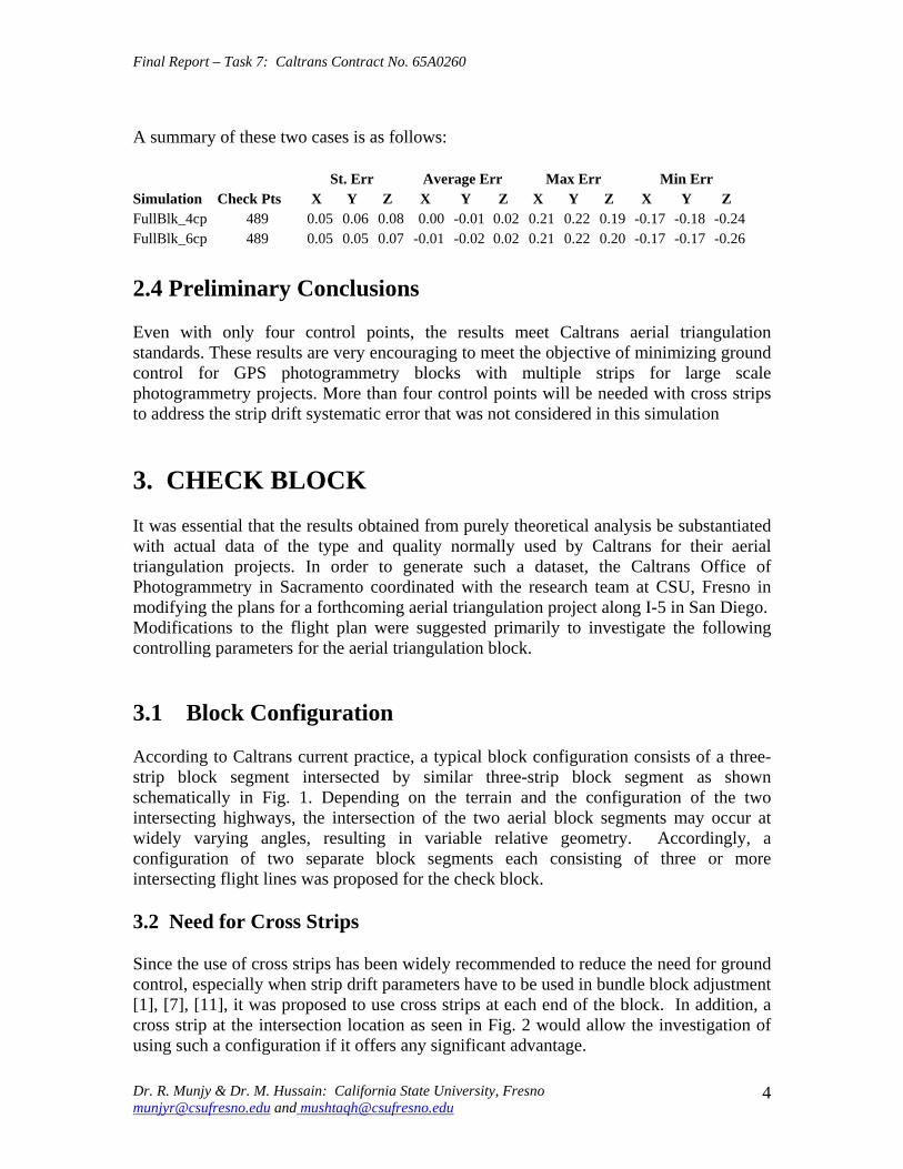
Final Report ndash Task 7 Caltrans Contract No 65A0260
A summary of these two cases is as follows
St Err Average Err Max Err Min Err Simulation Check Pts X Y Z X Y Z X Y Z X Y Z FullBlk_4cp 489 005 006 008 000 -001 002 021 022 019 -017 -018 -024 FullBlk_6cp 489 005 005 007 -001 -002 002 021 022 020 -017 -017 -026
24 Preliminary Conclusions
Even with only four control points the results meet Caltrans aerial triangulation standards These results are very encouraging to meet the objective of minimizing ground control for GPS photogrammetry blocks with multiple strips for large scale photogrammetry projects More than four control points will be needed with cross strips to address the strip drift systematic error that was not considered in this simulation
3 CHECK BLOCK
It was essential that the results obtained from purely theoretical analysis be substantiated with actual data of the type and quality normally used by Caltrans for their aerial triangulation projects In order to generate such a dataset the Caltrans Office of Photogrammetry in Sacramento coordinated with the research team at CSU Fresno in modifying the plans for a forthcoming aerial triangulation project along I-5 in San Diego Modifications to the flight plan were suggested primarily to investigate the following controlling parameters for the aerial triangulation block
31 Block Configuration
According to Caltrans current practice a typical block configuration consists of a threeshystrip block segment intersected by similar three-strip block segment as shown schematically in Fig 1 Depending on the terrain and the configuration of the two intersecting highways the intersection of the two aerial block segments may occur at widely varying angles resulting in variable relative geometry Accordingly a configuration of two separate block segments each consisting of three or more intersecting flight lines was proposed for the check block
32 Need for Cross Strips
Since the use of cross strips has been widely recommended to reduce the need for ground control especially when strip drift parameters have to be used in bundle block adjustment [1] [7] [11] it was proposed to use cross strips at each end of the block In addition a cross strip at the intersection location as seen in Fig 2 would allow the investigation of using such a configuration if it offers any significant advantage
Dr R Munjy amp Dr M Hussain California State University Fresno munjyrcsufresnoedu and mushtaqhcsufresnoedu
4
Final Report ndash Task 7 Caltrans Contract No 65A0260
6060
120120
Figure 1 Flight Intersection Geometry
Figure 2 Proposed Location of Cross Strips in the Check Block
Dr R Munjy amp Dr M Hussain California State University Fresno munjyrcsufresnoedu and mushtaqhcsufresnoedu
5
Final Report ndash Task 7 Caltrans Contract No 65A0260
33 Ground Control Distribution
The number and the spatial distribution of the ground control is the key issue that needs to be resolved in this study The airborne GPS data is usually considered sufficient to control the interior of the block [2] [7] Consequently ground surveyed control data is needed only along the block perimeter In accordance with the current Caltrans standards for single-strip configuration blocks the use of a pair of 3-D control points spaced six models apart along the block perimeter meet the accuracy standard for aerial triangulation at 13000 photo scale [11] Accordingly it was proposed to provide 3-D control points at a spacing varying from 6 models to 12 models to determine the optimal control placement along the block perimeter to meet Caltrans accuracy standard for photo scales varying between 13000 and 14800 Since past several years Caltrans has adopted the standard aerial photography scale for mapping as 13600 Accordingly this study is aimed at developing standards for 13600 photo scale
The simultaneous bundle block adjustment based on weighted least squares model results in several statistical metrics that provide a good indication of the internal consistency of the input data and the relative precision of the adjusted coordinates of the tie points and the exterior orientation of the photos However the only valid criterion for checking the external accuracy of the aerial triangulation results is their comparison against ground surveyed check data With this objective it was proposed to add several interior control points distributed over the entire block to serve as Check Points
34 Check Block
Caltrans Office of Photogrammetry in Sacramento and Caltrans District 11 Office in San Diego fully cooperated in modifying the flight plan to accommodate most of the suggestions made by the CSU Fresno research team The mapping project was modified to consist of 9 flight lines that included two cross flight lines one at each end In addition the ground survey was extended to include all the additional control points proposed in the block interior The final configuration of the San Diego Check Block is shown in Fig 3 which also shows the distribution of the 44 ground surveyed control points
Due to the State of California budget problems the Caltrans Division of Research and Innovation suspended this research contract in early August 2008 The contract suspension was subsequently lifted in late October 2008 During a webinar held on November 14 2008 between the representatives from Caltrans DRI and Office of Photogrammetry and the CSU Fresno research team it was reported by the Caltrans Office of Photogrammetry that the San Diego Check Block had been flown and surveyed and the image data captured for aerial triangulation while the research contract was under suspension Consequently all the measurement data related to the San Diego Check Block was available for research study It was provided to the CSU Fresno research team in late November 2008
Dr R Munjy amp Dr M Hussain California State University Fresno munjyrcsufresnoedu and mushtaqhcsufresnoedu
6
Flt6
Flt8Flt4
Flt3Flt2
Flt1
t5
Flt9
Flt7
MAIN Flight Lines 7CROSS Flight Lines 2PHOTO 125CONTROL Points 44
Flt6
Flt8Flt4
Flt3Flt2
Flt1
t5
Flt9
Flt7
MAIN Flight Lines 7CROSS Flight Lines 2PHOTO 125CONTROL Points 44
PHOTO SCALE 13600
Flt6
Flt8Flt4
Flt3Flt2
Flt1
t5
Flt9
Flt7
MAIN Flight Lines 7CROSS Flight Lines 2PHOTO 125CONTROL Points 44
Final Report ndash Task 7 Caltrans Contract No 65A0260
Flt7
Flt6
FlFlFlFlt5
Flt9
Flt4Flt8
MAIN Flight Lines 7 CROSS Flight Lines 2 PHOTO 125 CONTROL Points 44 Flt3
Flt2 PHOTO SCALE 13600 Flt1
Fig 3 Configuration and Control Distribution for the San Diego Check Block
Dr R Munjy amp Dr M Hussain California State University Fresno munjyrcsufresnoedu and mushtaqhcsufresnoedu
7
Final Report ndash Task 7 Caltrans Contract No 65A0260
35 Processing Plan and Methodology
In order to investigate the impact of block configuration the use of cross flight lines and the distribution of ground control the San Diego Check Block was processed in the following different configuration and control combinations
Block Configurations
a) FULL Block Uses all Flight Lines 1 through 9 b) MAIN Block Uses Flight Lines 1 through 7 only omits Cross Flights 8 amp 9 c) NORTH Block Uses Flight Lines 5 6 and 7 d) NORTHX Block Uses Flight Lines 56 and 7 and includes Cross Flight 9 e) SOUTH Block Uses Flight Lines 1 through 4 f) SOUTHX Block Uses Flight Lines 1 through 4 and includes Cross Flight 8 g) SOUTHM Block Uses Flight Lines 12 and 3 trimmed to the same length as
Flight Line 4 (11 Models) and includes Cross Flight 8
Control Distribution
The following considerations were used for the placement and distribution of control points along the perimeter of a block
a) A Ground Control Point (GCP) should fall at each end of each Flight Line b) In addition to (a) above a GCP should control every block corner c) When a Cross Flight Line overlaps the ends of Flight Lines the condition at (a)
above to be replaced with the requirement for a GCP at each end of the Cross Flight Line
d) On large blocks in a direction parallel to the flight lines GCPs should control the block perimeter with spacing not exceeding 8 airbases if cross flights do not exist
e) No GCP is provided in the block interior
The above considerations resulted in formulation of 22 blocks with different flight line and control configurations The block diagram showing the Photos used and the GCP distribution in each of the 22 different cases is given in the Appendix section of this report
As stated above 22 different aerial triangulation blocks were processed using the Interactive Simultaneous Bundle Block Adjustment Windows based software Interactive Simultaneous Bundle Block Adjustment-ISBBAW The input for the processing included the following data files provided by Caltrans Office of Photogrammetry
1) Ground Control Data File Project Datum Information Units US Survey Foot Horizontal CCS83 Zone 6 Epoch 200700 Vertical NAVD88
Dr R Munjy amp Dr M Hussain California State University Fresno munjyrcsufresnoedu and mushtaqhcsufresnoedu
8
Final Report ndash Task 7 Caltrans Contract No 65A0260
a-priori XY 010 ft a-priori Z 010 ft
2) Image Coordinate Data File Type Machine Coordinates a-priori xy 0006 mm
3) Airborne GPS Antenna Data File (at Photo exposure time) Datum Same as Project Datum a-priori XY 015 ft a-priori Z 015 ft
The Office of Photogrammetry had pointed out the unreliability of the GPS data corresponding to Photo 77 Accordingly the GPS data for Photo 77 was made ineffective by assigning a standard error of 100 feet for its coordinates
In addition the latest aerial camera calibration data was also provided and was used to update the camera data file
Each block was processed using Affine Transformation for obtaining photo coordinates that were corrected for systematic errors for lens distortion atmospheric refraction and earth curvature No unacceptably large transformation residuals were obtained Each block was then adjusted using Strip Drift Parameters during Bundle adjustment
36 Results and Analysis
In processing all the 22 different cases of the aerial triangulation no ground or image point was rejected The processing of all the blocks indicated good internal consistency in the measurement data as the Standard Error of Unit Weight (Sigma-sub0 0 ) varied from 048 to 060 the latter value resulted in Case 1 FULL Block Using all 44 GCP It also indicated good precision in image transfer (through pugging) and coordinate measurement the RMS values in the x-coordinate varied from 00022 to 00032 mm while the RMS value for the y-coordinate varied from 00037 to 00042 mm
An important consideration for this research study is the reliability of the ground control data The relative precision of all the 44 GCPs is convincingly validated from the block in Case-1 when all the 44 points are used The RMS values in the control point residuals are (ft)
RMS in X-coordinate 0035 RMS in Y-coordinate 0035 RMS in Z-coordinate 0048
For 13600 scale wide-angle photography Caltrans existing aerial triangulation accuracy standards require the RMS in control points to not exceed 1 part in 10000 of the flying
Dr R Munjy amp Dr M Hussain California State University Fresno munjyrcsufresnoedu and mushtaqhcsufresnoedu
9
Final Report ndash Task 7 Caltrans Contract No 65A0260
height above average terrain Therefore for the average flying height of 1800 feet above terrain this standard would require that the coordinate RMS value should not exceed 018 ft The above result represents a level of precision more than three-times what is permissible according to standard Consequently it proves that the available ground control data meets the required precision to serve as check data in evaluating the cases using a limited number of perimetric control points
In order to systematically evaluate the impact of ground control point distribution on a block the results obtained in each block were used to investigate the coordinate differences at the Check Points these are the ground surveyed control points that are not included as control points in processing the block and their coordinate values are computed as tie points in the block adjustment solution The differences between the aerial triangulation adjusted coordinates and the known ground control coordinates for the Check Points were computed and the average value and the standard deviation in these coordinate differences are listed in Table-1 for each processing case The results obtained are discussed in the following section
CaseNo
Block Type No of Chk Pts X Y Z
St Err X Y Z
Avg Err X Y Z
Max Err X Y Z
Min Err
1 2 3 4 5
FullBlk_All 44CP FullBlk_8CP FullBlk_9CP FullBlk_10CP
0 36 35 34
007 008 005 012 012 016 012 012 017 012 009 015
002 001 -005 001 -001 -008 003 005 -009
024 027 026 024 024 026 024 027 021
-025 -039 -032 -026 -040 -034 -025 -013 -035
MainBlk(Flts1to7)_43CP 0 006 008 005 6 MainBlk1-7_ 8CP 36 016 012 027 -002 -004 -004 026 020 041 -035 -036 -082 7 MainBlk1-7_10CP 34 014 012 027 -001 -003 -004 022 020 039 -031 -031 -080 8 9 10 11 12 13
MainBlk1-7_ 12CP 32 015 010 017 003 000 -004 037 016 035 -031 -027 -023 NorthBlk_567amp9_5CP NorthBlk_567amp9_7CP NorthBlk_567_6CP NorthBlk_567_8CP
18 16 17 15
012 016 016 010 016 017 010 016 022
007 -016 011 008 -007 018 010 -002 008
026 002 036 023 010 051 024 015 050
-022 -062 -022 -016 -051 -012 -019 -043 -026
011 016 017 013 -009 002 029 007 037 -017 -049 -031 SouthBlk_1234amp8_4CP 22 052 032 015 -082 033 003 -007 091 026 -149 -009 -034
14 SouthBlk_1234amp8_6CP 20 013 016 015 -003 006 -002 024 033 033 -019 -028 -028 15 SouthBlk_1234amp8_7CP 19 015 012 014 -003 -002 -002 025 023 033 -025 -030 -025 16 SouthBlk1to4 No XFlt_7CP 22 015 013 023 -001 -005 003 026 023 032 -027 -029 -037 17 SouthBlk1to4 No XFlt_8CP(a) 21 014 012 024 005 -001 004 031 025 033 -022 -029 -040 18 SouthBlk1to4 No XFlt_8CP(b) 21 016 014 019 -003 -005 001 027 025 028 -033 -033 -032 19 SouthBlk1to4 No XFlt_10CP 19 014 012 019 004 -001 001 034 029 029 -025 -030 -028 20 21 22
SouthBlk1to4 No XFlt_11CP 18 014 012 018 -001 -005 -001 023 020 027 -030 -029 -031 ModifiedSouthBlk_1234amp8_ 5CP ModifiedSouthBlk_1234_6CP
19 16
013 010 015 014 011 014
-001 002 -001 002 005 -010
024 021 035 025 024 016
-019 -025 -029 -020 -024 -039
Table-1 Summary of the Coordinate Differences at the Check Points
In accordance with Caltrans Accuracy Standards for Aerial Triangulation the standard error in the adjusted coordinates of a tie point should not exceed 110000th of the average flying height above the terrain level The San Diego Check Block was flown at an average flying height of 1800 feet above terrain resulting in an average photo scale of 13600 Accordingly the limiting standard error in the adjusted coordinates of tie points amounts to 018 ft As is evident from the results summarized in Table-1 in case of vertical aerial photography the height error is larger than the error in the X- or the Yshycoordinate with few exceptions Therefore one may primarily focus only on the
Dr R Munjy amp Dr M Hussain California State University Fresno munjyrcsufresnoedu and mushtaqhcsufresnoedu
10
Final Report ndash Task 7 Caltrans Contract No 65A0260
standard error in the height in order to analyze the various scenarios represented by the 22 different cases
361 FULL Block (Case-1 to 4)
In the case of FULL Block (Flts 1 to 9) by controlling each edge (corner) of the block and each edge of any cross strip by a single CP as in Case-2 Caltrans accuracy standard is met In case-3 an additional CP was used at the block corner formed where the Flight 4 ends while the Flight 3 continues southward The addition of this corner point does not significantly enhance the accuracy of the solution This is due to the fact that the Flight-3 at this point is controlled by GPS data
It is interesting to note that even though the Flight 7 (at the northern end of the block) is 15 models long a single CP located at the end of this flight appears to be sufficient for control The fact that the spacing between the end CPs at the lower end of this block segment (Flight 5) is only about 10 models adds to the strength In order to check the influence of additional control points along the block perimeter with reduced spacing a CP was added in the middle of Flight 7 as shown in Case-4 This does result in some improvement in the accuracy of the block solution consequently this would appear to be the optimum control configuration
362 MAIN Block (Case-5 to 8)
The MAIN Block (Flts 1 to 7) was used to study any impact in using cross flights for GPS controlled aerial triangulation blocks When a large number of control points are available such as in Case-3 where 43 CPs are used the results are identical whether or not cross flights are used However when a CP is used only at the block corners as in Case-6 (analogous with Case-2 in FULL Block) the required accuracy standard is not met This standard is also not met when an additional corner CP is used as shown in Case-7 (analogous with Case-3 in FULL Block) However when the spacing between the perimetric control points is confined to about 8 models as shown in the Case-8 the results are within the required accuracy standard A comparison of Case-4 and Case-8 shows that if the cross Flights 8 and 9 are not used additional control points along the block perimeter in a direction parallel to the flight lines can compensate for it and meet the required accuracy standard
363 NORTH Block (Case-9 to 12)
The above analysis was repeated by splitting the San Diego Check Block into two subshyblocks a NORTH Block and a SOUTH Block The NORTH Block (Flts 5 to 7 and 9) was processed first by including the cross Flight 9 and also by excluding this cross flight The results tabulated in Table-1 in Case 9 to 12 are identically similar to the ones obtained earlier with the FULL and the MAIN Blocks It again shows that when a CP is located at the end of the cross Flight 9 in the northern end of the block and a CP is used at the end of each of the three flight lines at the southern end of the block the required accuracy standards are met even when no CP is located in the middle of the 15-model
Dr R Munjy amp Dr M Hussain California State University Fresno munjyrcsufresnoedu and mushtaqhcsufresnoedu
11
Final Report ndash Task 7 Caltrans Contract No 65A0260
long Flight-7 (Case-9) In fact it is seen in Case-10 that the addition of an intermediate point along the perimeter did not improve the accuracy
Without the cross Flight 9 however a comparison of the Case-12 with Case-11 clearly shows that the reduction in the spacing between the perimetric control points is necessary for meeting the required accuracy standard In this block size and configuration the nonshyuse of a cross flight could have been compensated with the use of one additional control point along the perimeter
364 SOUTH Block (Case-13 to 20)
The SOUTH Block consisting of Flights 1 to 4 and the cross Flight 8 has somewhat unusual configuration it is not a compact rectangular block and the cross Flight-8 intersects the block rather than at either end of the block Eight different scenarios for flight and control configuration were used in handling this sub-block
The Case-13 is based on the use of only four CPS one located at each of the four block corners This case might work for small and rectangular blocks with a cross flight at each end of the block However for Case-13 the cross Flight is completely uncontrolled and so is the southern corner of Flight-4 Obviously this has resulted in the planimetric RMS error that exceeds 05 ft
When a CP was located at each end of the cross Flight 8 as seen in Case-14 as well as a CP was added at the end of each flight line the block solution met the accuracy standard The addition of another corner CP as shown in Case-15 did not contribute to any significant improvement in the accuracy This shows the role that the intersecting cross Flight 8 plays in strengthening the geometry of the block by reducing the uncontrolled segment of each of the three Flight lines 1 to 3
The Case-16 to 20 convincingly demonstrate the degradation in the block geometry when the cross Flight 8 is removed from the block None of the block configurations shown in Case 16 to 19 strictly meets the accuracy requirement the Case-18 and Case-19 missing the minimal accuracy standard by 001 ft It is only when another corner CP is added as shown in Case-20 that the minimal accuracy standard is attained
365 SOUTH-MODIFIED Block (Case-21 amp 22)
In order to further validate the conclusions derived so far the SOUTH Block was modified to a more conventional rectangular shaped block by removing photos from Flight 1 to 3 to bring them to the same length as Flight 4 The SOUTH_MODIFIED Block is not only have a rectangular shape but the cross Flight 8 now falls at the southern of this sub-block With the Flight 8 now playing the normal role of a cross flight the minimal control layout seen in Case-21 easily meets the accuracy standard As observed in previous
Dr R Munjy amp Dr M Hussain California State University Fresno munjyrcsufresnoedu and mushtaqhcsufresnoedu
12
Final Report ndash Task 7 Caltrans Contract No 65A0260
blocks locating a CP at each end of each flight line meets the accuracy standard for this block with 11-model long flight lines
The above observations and the conclusions were used to draft the Preliminary Standards for Block Configuration Airborne GPS Controlled Photogrammetry for Large Scale Mapping Projects and submitted as Interim Report in fulfillment of the requirement under Task 32 of the contract [14]
4 TEST BLOCK
41 Planning
The extra-ordinary fiscal problems faced by the State of California had resulted in the suspension of work on the project Consequently a no-cost extension in the time for completion of this project beyond March 31 2009 till December 31 2009 was requested by California State University Fresno in November 2008 This request in the extension of period was strongly supported by Caltrans Office of Photogrammetry This request was approved by Caltrans Division of Research and Innovation and California State University Fresno was notified by Caltrans Contract Manager on April 2 2009 to continue work on the project till December 31 2009
A planning meeting between the California State University Fresno research team and the representatives from Caltrans Office of Photogrammetry was held in Caltrans Office in Sacramento on April 20 2009 for the design of an optimal test block In the light of the results obtained from the San Diego Check Block and the conclusions presented in the Interim Report submitted in January 2009 various options and proposals for selecting the site and configuration for a test block were discussed The Caltrans Office of Photogrammetry and the California State University Fresno fully agreed on the following characteristics for the Test Block
The aerial photography should fully conform to the Caltrans practice of using a metric wide-angle aerial camera from an altitude of 1800 ft above the terrain level to result in an average photo scale of 13600
The main block should consist of 4 parallel flight lines of 18 models each A cross flight should be flown at each end of the main block Full 3-D ground control should be provided along the perimeter of the main block
with a control point spacing of 6 to 8 airbases Full 3-D ground control for the two cross flights should be planned so that
- A pair of 3-D control points are located at each end of each cross flight and - At least one Height control point falls at each end of each main flight line
A sufficient number (15 to 20) of additional ground control points should be distributed in the interior of the block to serve as check points for estimating the absolute accuracy of aerial triangulation results
All the 6 flight lines constituting the Test Block should be flown as a single flight mission
Dr R Munjy amp Dr M Hussain California State University Fresno munjyrcsufresnoedu and mushtaqhcsufresnoedu
13
Final Report ndash Task 7 Caltrans Contract No 65A0260
The airborne GPS data as well as the data at the ground Base Stations should be collected at 1 Hz or higher data rate
The flight mission should be carried out under weather and environmental conditions so as to avoid any degradation in the quality of aerial imagery
Even though implementing the above technical requirements in a test block did not pose any serious problems the California State University Fresno as well as the Caltrans Office of Photogrammetry had serious concerns about adhering to the tight project schedule Both the parties in this project were convinced that the award of an aerial photography services contract for a Test Block by the California State University Fresno through a formal selection and competitive bidding process would entail serious delays that may even jeopardize the completion of the project by the ending date of December 31 2009 An attractive and viable alternative was to utilize the services of an aerial photography vendor that had recently been contracted by Caltrans for the acquisition of aerial photography for a highway corridor along Interstate I-5 in Northern San Diego The flying for this Caltrans project was fortuitously scheduled for May 2009 that synchronized very well with the schedule for this research project
Accordingly with full consultation with the Caltrans Office of Photogrammetry a Test Block was designed by the California State University Fresno in Del Mar in Northern San Diego The Del Mar Test Block included a variety of terrain a large expanse of marsh and river suburban residential large freeway and rolling hills A separate contract was negotiated and awarded by the California State University Fresno to the Caltrans contractor for the San Diego I-5 Project for the acquisition of aerial photography for the Del Mar Test Block This approach used in awarding the contract resulted in the following benefits
The aerial photography contractor had already been pre-qualified by Caltrans for the quality of the aircraft aerial camera aerial film and GPS and navigation equipment used for the acquisition of aerial photography
The aerial photography contractor had already been pre-qualified by Caltrans for the quality of aerial photography products (developed negative film diapositives prints etc)
The aerial photography contractor had already been pre-qualified by Caltrans for the certification of aerial camera calibration electronic integration of the aerial camera with the airborne GPS receiver to record the aerial exposure events and the geometric integration of the airborne GPS antenna mounted on the fuselage with the aerial camera
The contractor was familiar with the detailed Caltrans specifications for the acquisition of aerial photography and the same specifications would strictly govern the flight mission for the Del Mar Test Block
Dr R Munjy amp Dr M Hussain California State University Fresno munjyrcsufresnoedu and mushtaqhcsufresnoedu
14
Final Report ndash Task 7 Caltrans Contract No 65A0260
42 Acquisition of Aerial Photography
The flight configuration and ground control distribution for the Del Mar Test Block was finalized near the end of April 2009 and is shown in Fig 41 As stated earlier the contract for the aerial photography acquisition was awarded to IKCurtis Services Inc Burbank California who had earlier been awarded the Caltrans contract to fly Route 5 and 56 in San Diego The Caltrans Office of Photogrammetry also arranged for field survey teams from Caltrans District 11 in San Diego to supplement the ground control network established for the Caltrans project with the additional ground control points planned for the Del Mar Test Block This further ensured that the quality of the ground control data used for the Del Mar Test Block would fully conform to Caltrans aerial triangulation control standards All the fieldwork required for the Caltrans Route 5 and 56 Project and for the Del Mar Test Block of the California State University Fresno research project was completed in early May 2009
Based on the weather reports and the suitability of GPS satellite configuration it was mutually agreed between the Caltrans Office of Photogrammetry Caltrans District 11 California State University Fresno and IK Curtis Services Inc to fly the two projects on May 13 2009 with May 14 2009 as a backup date I K Curtis Services Inc had been assigned the task of collecting the airborne GPS data during the flight mission while field survey staff from Caltrans District 11 were responsible for the simultaneous collection of GPS data at four designated base stations Whether the two separate projects are flown as a single flight mission or as two separate missions on the same day or on separate days was left entirely to the mutual judgment of the flight crew and Caltrans Project Coordinator from District 11 based on the weather and environmental conditions in the area
A final field survey task is to visit each control point location and repaint if necessary those control marks that fall on a hard surface and to deploy specially designed panel at each control point that lies on grass or open and marshy ground Even though all the ground control targets had been readied in time unfortunately adverse weather reports and worsening fog and cloudy conditions were totally unsuitable for flying on May 13 or on May 14 Based on the weather forecast similar flight dates were set on several occasions each time requiring the reconnaissance of the ground targets but the adverse weather conditions extended over several weeks After continuing efforts at planning and repeated cancellations it was finally possible to complete the aerial photography requirements for both the projects through a single flight mission carried out on July 14 2009 Even though two models at the end of one cross flight in the Del Mar Test Block contain some cloud coverage fortunately it was still possible to identify and measure the image coordinates of the ground control points falling in both the models
Dr R Munjy amp Dr M Hussain California State University Fresno munjyrcsufresnoedu and mushtaqhcsufresnoedu
15
6
5
Final Report ndash Task 7 Caltrans Contract No 65A0260
Fig 41 San Diego Test Block Configuration and Control Distribution
1 2 3 411 22 33 44
66
55
Dr R Munjy amp Dr M Hussain California State University Fresno munjyrcsufresnoedu and mushtaqhcsufresnoedu
16
Final Report ndash Task 7 Caltrans Contract No 65A0260
43 Test Block Data Acquisition
After the delivery of the aerial diapositives by the Contractor the photogrammetric data for the aerial triangulation of the Del Mar Test Block was measured and compiled by Caltrans Office of Photogrammetry The selection of tie points and the measurement of image coordinate data for the entire block consisting of 6 flight lines and 96 photos was carried out following the routine analytical methodology and practice used for all Caltrans aerial triangulation blocks
The following measurement data was provided by the Office of Photogrammetry to California State University Fresno in August 2009
- Image coordinate data - Ground control coordinate data - Raw GPS data from airborne receiver and four base station receivers - GPS time for photo exposure - Camera calibration data - Camera and GPS antenna offset
44 Test Block Data Processing
Before processing the aerial triangulation data received from the Office of Photogrammetry some clarification regarding the processing datum were necessary as discussed in the following section
441 Processing Datum
It was reported that the datum used for the ground control data provided by Caltrans District 11 was as below
- Horizontal Control CCS83 Epoch199135 Datum - Vertical Control NAVD88 Datum
Based on discussions with representatives from Caltrans District 11 it was determined that the 3-D adjustment of the GPS ground control network was performed in CCS83-Epoch 199135 datum for the horizontal control while the vertical coordinates were adjusted by fixing the orthometric height (NAVD88 Datum) of 4 network stations The geoidal height data needed for the reduction of observed ellipsoidal height data (GRS80 Ellipsoid) to adjusted orthometric height data (NAVD88 Datum) was based on the Geoid2003 Global Model Consequently the orthometric height data for the ground control used for the Del Mar Test Block may be affected by any height variation between the Local Geoid from the Global Geoid
442 Post-Processing of Airborne GPS Data
Dr R Munjy amp Dr M Hussain California State University Fresno munjyrcsufresnoedu and mushtaqhcsufresnoedu
17
Final Report ndash Task 7 Caltrans Contract No 65A0260
Even though the Caltrans Office of Photogrammetry had provided the post-processed results for the airborne GPS data this data was also processed at the California State University Fresno Even though GPS data at four different base stations had been collected and the GrafNav post-processing software provides the option to use multiple base station data it was decided to carry out the kinematic processing of the airborne GPS data relative to a single base station HPGN DC 11 The selection of this base station was due to the fact that this was the only base station for which the orthometric height had been held fixed in the GPS network adjustment none of the other three network stations for which the orthometric height was held fixed had been used as a base station during the flight mission
The results and the analysis provided in the following section are based on the airborne GPS data processed at the California State University Fresno
443 Aerial Triangulation Data Processing
The first objective for the aerial triangulation processing of the Del Mar Test Block data was to further verify the aerial triangulation results obtained with the San Diego Check Block reported in Section 3 A second and more important objective was to evaluate the impact of flight configuration and the control point distribution on the achievable aerial triangulation accuracy for large scale (13600) aerial photography used in Caltrans It was of special interest to assess the impact of the use of cross flights and the optimal distribution of the ground control points in an airborne GPS supported aerial triangulation block
The same approach and the methodology were used for processing the aerial triangulation of the Del Mar Test Block as has previously been discussed in detail in Section 35 for the San Diego Check Block Aerial triangulation data was processed systematically by using block configuration with and without the two cross flights (see Fig 41) The number and the distribution of the control points used primarily along the block perimeter varied from 8 to 14 control points Since the Del Mar Test Block was covered with a total of 33 field control points all the points that were not used as control points in processing the block served as Check Points Theoretically such Check Points are the most reliable indicators of the absolute accuracy of the aerial triangulation results provided the coordinate data for such Check Points is at least three times more precise than the precision of the coordinate data for the tie points resulting from aerial triangulation adjustment [15] In the case of the Del Mar Test Block data the uncertainty of 2 to 3 cm in the geoidal height interpolated from the global Geoid Model leads to the estimated precision of the Check Point data to be more precise than the aerial triangulation data by a factor of 12 to 2 only This fact has to be kept in focus while analyzing the absolute accuracy of the aerial triangulation results as part contributions from the errors in Check Point data cannot be entirely ignored
The airborne GPS supported aerial triangulation blocks are fully controlled through the airborne GPS data in the interior of the block Therefore the precision of the airborne GPS data plays a crucial role in the resulting aerial triangulation accuracy The
Dr R Munjy amp Dr M Hussain California State University Fresno munjyrcsufresnoedu and mushtaqhcsufresnoedu
18
Final Report ndash Task 7 Caltrans Contract No 65A0260
processing of the Test Block was carried out by using the following a-priori standard errors for the airborne GPS data (a) Standard error for X and Y-coord 025 ft Standard error for Z-coord 025 ft (b) Standard error for X and Y-coord 010 ft Standard error for Z-coord 015 ft
Based on the analysis of the results that are discussed in Section 5 it was finally decided to use the following a-priori standard error for the airborne GPS data
Standard error for X and Y-coord 015 ft Standard error for Z-coord 015 ft
The results for the block configuration that includes the two cross flights for a total of 6 flight lines are summarized as Cases 1 through 5 in Table 2 The Blocks processed without the use of the two cross flights and comprising only the 4 parallel flight lines are shown in Table 2 as Cases 6 through 12
Case BLOCK Number of St Error Ave Error Max Error Min Error
No Type Check Pts X Y Z X Y Z X Y Z X Y Z
1 6Flt_Blk_33CP 0 004 004 005
2 6Flt_Blk_8CP 25 009 008 019 -002 001 -007 013 018 032 -027 -012 -052
3 6Flt_Blk_12CP 21 010 008 014 -004 -003 005 009 013 029 -028 -015 -030
4 6Flt_Blk_14aCP 19 010 006 015 000 -003 001 012 013 027 -025 -016 -034
5 6Flt_Blk_14bCP 19 010 008 015 -001 -001 006 011 013 028 -025 -014 -031
6 4Flt_Blk_33CP 0 004 002 006 -002 000 001
7 4Flt_Blk_8CP 25 012 008 059 004 006 -108 028 024 016 -022 -009 -109
8 4Flt_Blk_11aCP 22 013 009 019 -001 -002 -017 017 016 028 -028 -016 -050
9 4Flt_Blk_11bCP 22 014 009 027 -005 003 -031 016 020 030 -031 -015 -066
10 4Flt_Blk_12CP 21 013 009 020 -002 000 -008 016 018 031 -027 -016 -033
11 4Flt_Blk_14aCP 19 010 008 013 004 -002 -003 016 015 025 -021 -017 -020
12 4Flt_Blk_14bCP 19 009 007 012 -001 -001 005 009 013 028 -025 -014 -012
Table-2 Summary of the Coordinate Differences at the Check Points
The control distribution used in the processing of the 12 cases is illustrated in Fig 42 through 411 below The corresponding statistics for the resulting errors at the Check Points are shown for each case The Check Points where the maximum errors in the X- Y- and Z-coordinate occur are shown in different color according to the legend below
Control pointControl point
MMaax error in Xx error in X
MMaax error in Yx error in Y
MMaax error in Zx error in Z LEGEND (Figures 42 through 411)
Dr R Munjy amp Dr M Hussain California State University Fresno munjyrcsufresnoedu and mushtaqhcsufresnoedu
19
Final Report ndash Task 7 Caltrans Contract No 65A0260
Fig 42 Block with Cross Strips 8 Control Points 25 Check Points Case 2
SSttaannddaardrd EErrorrorr AAvveeraraggee EErrrroorr MMaaxxiimmuumm EErrorrorr MMiinniimmuumm EErrorrorr XX YY ZZ XX YY ZZ XX YY ZZ XX YY ZZ
000099 000088 001199 --000022 000011 --000707 001133 001818 003232 --002277 --001212 --005522
Dr R Munjy amp Dr M Hussain California State University Fresno munjyrcsufresnoedu and mushtaqhcsufresnoedu
20
Final Report ndash Task 7 Caltrans Contract No 65A0260
Fig 43 Block with Cross Strips 12 Control Points 23 Check Points Case 3
SSttaannddaardrd EErrorrorr AAvveeraraggee EErrrroorr MMaaxxiimmuumm EErrorrorr MMiinniimmuumm EErrorrorr XX YY ZZ XX YY ZZ XX YY ZZ XX YY ZZ
001100 000088 001144 --000044 --000303 000055 000099 001313 002929 --002288 --001515 --003300
Dr R Munjy amp Dr M Hussain California State University Fresno munjyrcsufresnoedu and mushtaqhcsufresnoedu
21
Final Report ndash Task 7 Caltrans Contract No 65A0260
Fig 44 Block with Cross Strips 14 Control Points 21 Check Points Case 4
SSttaannddaardrd EErrorrorr AAvveeraraggee EErrrroorr MMaaxxiimmuumm EErrorrorr MMiinniimmuumm EErrorrorr XX YY ZZ XX YY ZZ XX YY ZZ XX YY ZZ
001100 000088 001155 --000011 --000101 000066 001111 001313 002828 --002255 --001414 --003311
Dr R Munjy amp Dr M Hussain California State University Fresno munjyrcsufresnoedu and mushtaqhcsufresnoedu
22
Final Report ndash Task 7 Caltrans Contract No 65A0260
Fig 45 Block with Cross Strips 14 Control Points 21 Check Points Case 5
SSttaannddaardrd EErrorrorr AAvveeraraggee EErrrroorr MMaaxxiimmuumm EErrorrorr MMiinniimmuumm EErrorrorr XX YY ZZ XX YY ZZ XX YY ZZ XX YY ZZ 001100 000066 001155 000000 --000033 000011 001122 001133 002277 --002255 --001166 --003344
Dr R Munjy amp Dr M Hussain California State University Fresno munjyrcsufresnoedu and mushtaqhcsufresnoedu
23
Final Report ndash Task 7 Caltrans Contract No 65A0260
Fig 46 Block without Cross Strips 8 Control Points 25 Check Points Case 7
SSttaannddaardrd EErrorrorr AAvveeraraggee EErrrroorr MMaaxxiimmuumm EErrorrorr MMiinniimmuumm EErrorrorr XX YY ZZ XX YY ZZ XX YY ZZ XX YY ZZ 001122 000088 005599 000404 000606 --110088 002288 002244 001166 --002222 --000099 --110099
Dr R Munjy amp Dr M Hussain California State University Fresno munjyrcsufresnoedu and mushtaqhcsufresnoedu
24
Final Report ndash Task 7 Caltrans Contract No 65A0260
Fig 47 Block without Cross Strips 11 Control Points 22 Check Points Case 8
SSttaannddaardrd EErrorrorr AAvveeraraggee EErrrroorr MMaaxxiimmuumm EErrorrorr MMiinniimmuumm EErrorrorr XX YY ZZ XX YY ZZ XX YY ZZ XX YY ZZ
001133 000099 001199 --000011 --000202 --001177 001177 001166 002288 --002828 --001166 --005050
Dr R Munjy amp Dr M Hussain California State University Fresno munjyrcsufresnoedu and mushtaqhcsufresnoedu
25
Final Report ndash Task 7 Caltrans Contract No 65A0260
Fig 48 Block without Cross Strips 11 Control Points 22 Check Points Case 9
SSttaannddaardrd EErrorrorr AAvveeraraggee EErrrroorr MMaaxxiimmuumm EErrorrorr MMiinniimmuumm EErrorrorr XX YY ZZ XX YY ZZ XX YY ZZ XX YY ZZ
001144 000099 002277 --000055 000033 --003131 001166 002020 003030 --003311 --001515 --006666
Dr R Munjy amp Dr M Hussain California State University Fresno munjyrcsufresnoedu and mushtaqhcsufresnoedu
26
Final Report ndash Task 7 Caltrans Contract No 65A0260
Fig 49 Block without Cross Strips 12 Control Points 21 Check Points Case 10
SSttaannddaardrd EErrorrorr AAvveeraraggee EErrrroorr MMaaxxiimmuumm EErrorrorr MMiinniimmuumm EErrorrorr XX YY ZZ XX YY ZZ XX YY ZZ XX YY ZZ 001133 000099 002200 --000022 000000 --000808 001166 001818 003131 --002277 --001616 --003333
Dr R Munjy amp Dr M Hussain California State University Fresno munjyrcsufresnoedu and mushtaqhcsufresnoedu
27
Final Report ndash Task 7 Caltrans Contract No 65A0260
Fig 410 Block without Cross Strips 14 Control Points 19 Check Points Case 11
SSttaannddaardrd EErrorrorr AAvveeraraggee EErrrroorr MMaaxxiimmuumm EErrorrorr MMiinniimmuumm EErrorrorr XX YY ZZ XX YY ZZ XX YY ZZ XX YY ZZ
001100 000088 001133 000044 --000022 --000303 001166 001515 002525 --002211 --001717 --002200
Dr R Munjy amp Dr M Hussain California State University Fresno munjyrcsufresnoedu and mushtaqhcsufresnoedu
28
Final Report ndash Task 7 Caltrans Contract No 65A0260
Fig 411 Block without Cross Strips 14 Control Points 19 Check Points Case 12
SSttaannddaardrd EErrorrorr AAvveeraraggee EErrrroorr MMaaxxiimmuumm EErrorrorr MMiinniimmuumm EErrorrorr XX YY ZZ XX YY ZZ XX YY ZZ XX YY ZZ
000099 000077 001122 --000011 --000101 000055 000099 001313 002828 --002255 --001414 --001122
Dr R Munjy amp Dr M Hussain California State University Fresno munjyrcsufresnoedu and mushtaqhcsufresnoedu
29
Final Report ndash Task 7 Caltrans Contract No 65A0260
5 ANALYSIS OF RESULTS amp CONCLUSIONS
In accordance with the Caltrans standards using wide-angle aerial photography the RMS error in each coordinate component of the adjusted tie points should not exceed 110000 of the flying height above the terrain The Del Mar Test Block was flown with a wideshyangle aerial camera from an average height of 1800 feet above the terrain level thereby resulting in an average photo scale of 13600 Consequently the limiting RMS error at the Check Points representative of a finite number of well distributed tie points in the block should not exceed 018 ft in this case Any error that exceeds three times this limiting value viz 054 ft in any of the coordinate components should be a cause for rejection of that point
Therefore the acceptable limiting values for the standard error at the Check Points is 018 ft in each coordinate component Any block adjustment solution that results in a coordinate error in one or more Check Points that exceeds 054 ft in any coordinate component would not be an acceptable solution The following analysis of the results is based on these accuracy criteria
51 Blocks With Cross Flights
When a minimal number of 8 control points are used (Fig 42) along the block perimeter the resulting standard error in Z-coordinate of 019 ft exceeds the limiting value of 015 ft It is also noticeable that the highest error in the Z-coordinate of 052 ft at Point 189134 almost equals the rejection limit of 054 ft This is an indication that controlling a cross flight with only a single Control Point at each end of the flight may not always provide a satisfactory solution
This situation can be remedied by using a pair of Control Points in each end model of a cross flight so that any deformation across the flight line the omega rotation () can also be controlled Such an approach is also reported to have been successfully used and recommended in the past [1] [2] [3] When 4 additional Control Points were added at the end of each cross flight line as is seen in Fig 43 all the standard errors fell within the acceptable range and the maximum coordinate error did not exceed 030 ft which is well within the acceptable criteria
The primary advantage of using airborne GPS data for the adjustment of aerial triangulation blocks is to completely eliminate the need for Control Points in the interior of the block But it is of interest to investigate how effectively the airborne GPS data alone can control the interior of the block Two separate blocks were processed by adding two Control Points in the interior of the block resulting in a total of 14 Control Points
The block with 14 Control Points (Case A) is shown in Fig 44 where the two interior Control Points were selected so that one Control Point was located on the opposite ends in each of the two interior flight lines (Line 2 and Line3 see Fig 41) The other block with 14 Control Points (Case B) is shown in Fig 45 In this case both the interior points
Dr R Munjy amp Dr M Hussain California State University Fresno munjyrcsufresnoedu and mushtaqhcsufresnoedu
30
Final Report ndash Task 7 Caltrans Contract No 65A0260
fell in the middle of the block interior It is interesting to note that in either of the two cases the addition of the interior Control Points did not result in any significant difference from the result achieved earlier while using 12 Control Points Therefore it may be concluded that as long as the cross flights are adequately controlled with a pair of Control Points located across each end model of each cross flight additional control in the block interior is not required The results shown in Fig 44 and 45 validate this conclusion at least for a block comprised of 18 models long multiple flight lines
52 Blocks Without Cross Flights
When a mapping project involves a large photogrammetric block consisting of hundreds of models the common practice is to plan the block configuration to include cross flights [1] [2] [6] [10] Often such cross flights can result in significant saving in time and effort in minimizing the need for ground control Since the photogrammetric mapping projects in Caltrans mostly involve mapping along highway corridors most of the photogrammetric blocks vary from a single flight line to up to as many as four flight lines Therefore it is still to be investigated whether the use of cross flight lines in such blocks offers any significant advantage Furthermore any advantage resulting from the reduced need for the ground control has to be weighed against the additional time and effort needed in processing the cross flight models The Caltrans Office of Photogrammetry has not yet adopted the use of Automated Aerial Triangulation (AAT) techniques for routine production Consequently the additional effort in transferring tie points between the cross flights with the flights of the main block is still significant This has provided the impetus to carry out the following investigation for the aerial triangulation adjustment of blocks that do not include any cross flights
The first block without the two cross flights was processed with only 8 Control points along the block perimeter as a parallel case with the block run with cross flights The results are shown in Fig 46 As may be expected the absence of any Control Point located at each end of each of the two interior flights 2 and 3 has resulted in unacceptably large errors Not only is the standard error of 059 ft in the Z-coordinate for the 25 Check Points too large but interestingly the block adjustment carries a large systematic error in Z-coordinate of 108 ft This results from the fact that the absence of the Control Points at each end of Flights 2 and 3 does not permit the adjustment for the systematic strip drift parameters for the airborne GPS data along Flights 2 and 3
When cross flights are included the airborne GPS data measured along the cross flight adequately serves as control for adjusting the strip shift and drift parameters Therefore an alternative to the inclusion of cross flights in the block configuration is to provide a Control Point at each end of every flight line in the block Accordingly the processing of the following blocks includes Control Points at the end of each flight line
The Del Mar Test Block with 4 flight lines each 18 models long would require a total of 12 Control Points one Control Point at each end of each flight line and 4 Control Points along the interior perimeter of the block to provide a control spacing of approximately 6 airbases apart However in order to minimize the use of the ground control the block
Dr R Munjy amp Dr M Hussain California State University Fresno munjyrcsufresnoedu and mushtaqhcsufresnoedu
31
Final Report ndash Task 7 Caltrans Contract No 65A0260
shown in Fig 47 was processed with only 11 Control Points (Case A) since the Control Point 170133 was measured both in Line 2 and Line 3 The resulting standard error of 019 ft in the Z-coordinate for 22 Check Points as well as the large error of 050 ft in the Z-coordinate of Check Point 189134 make the block adjustment solution unacceptable There appears to be no obvious reason why the Check Point 189134 that is located so close to the Control Point 170133 should display such unacceptably large error in the Zshycoordinate In order to ascertain the internal consistency of the ground control data (33 Control Points) a conventional aerial triangulation adjustment of the block was performed (without using the airborne GPS data) using 32 Control Points and treating the Control Point 189134 as a Check Point The resulting error in the Z-coordinate of Point 189134 was only 006 ft It is also to be noted that the average Z-coordinate error of 017 ft indicates a systematic height error This would lead to the conclusion that there is some height discrepancy between the ground control data and the airborne GPS data
The block was re-processed (Case B) again by using only 11 Control Points but this time the Control Point 170133 was replaced with Control Point 189134 and the results are displayed in Fig 48 The Case B results are even worse than the Case A results the standard error in Z-coordinate was degraded to 027 ft while the largest error in Zshycoordinate of 066 ft was noted at Check Point 187215 The average Z-coordinate error also increases to 031 ft This is a further indication that there is significant height inconsistency in the airborne GPS data and the ground control data It appears that the height discrepancy between the ground control data and the airborne GPS data results in an unsatisfactory shift and drift adjustment of the airborne GPS data particularly in the inner flight Lines 2 and 3 that span 18 models between the end Control Points
In order to strengthen the end control across the flight lines both the Control Points 170133 and 189134 were used at the Northern end of the block The block was then processed with 12 Control Points and the results are presented in Fig 49 Even though the results improved significantly but contrary to the expectation the standard error in the Z-coordinate of 020 ft for the 21 Check Points did not meet the Caltrans accuracy standard The next logical approach was to investigate the impact of adding Control Points in the interior of the block Two interior Control Points were selected in the same manner as has been described earlier in the case of the blocks with the cross flights (see Fig 44 and 45)
Using 14 Control Points the Case A is shown in Fig 410 while the Case B is presented in Fig 411 The results in both Case A and Case B easily meet the Caltrans accuracy standards In Case A the distance between the Control Points for the shift and drift parameter adjustment of the airborne GPS data varies from 6 to 12 models while in Case B the interior Control Points are about 6 models apart Each Control Point distribution provides almost similar results It is a clear indication that any systematic height deformation that results from the suspected inconsistency between the ground surveyed GPS data and the airborne GPS data can be kept within acceptable range by including a pair of control points in the interior of the block Such a need for some control points has not been reported for the adjustment of aerial triangulation blocks in the past However the largest photo scale for which any ABGPS supported results have been published in
Dr R Munjy amp Dr M Hussain California State University Fresno munjyrcsufresnoedu and mushtaqhcsufresnoedu
32
Final Report ndash Task 7 Caltrans Contract No 65A0260
the past is 14800 only For a photo scale of 13600 that is approximately 25 percent larger the requirements for the accuracy of aerial triangulation accordingly become more stringent in the same proportion This may generate the need for some additional control in the middle of the block
The residuals at the ground control points and in the image coordinate data along with the resulting standard error of unit weight (0) provide a reliable indication of the internal consistency of the adjusted block However the absolute accuracy of the aerial triangulation can be validated only by the use of Check Points that are well distributed over the entire block As pointed out earlier any deformations due to residual systematic shift and drift errors in the airborne GPS data are likely to be most significant in the center of the block the location that is farthest from the control points distributed along the perimeter Accordingly it would be advisable to locate at least a pair of Check Points in the middle of the block and after completing the block adjustment (by excluding these Check Points as Control Points) the coordinate discrepancies obtained at these Check Points can be analyzed Such discrepancies would normally represent the highest absolute accuracy resulting from aerial triangulation adjustment of the block Any unacceptably large coordinate discrepancies at the Check Points would require investigation of the block input data
In the case the coordinate discrepancies at the Check Points are within acceptable range the block can be re-processed by also including the Check Points in the control data This should enhance the accuracy in the interior of the block
6 RECOMMENDED DRAFT STANDARDS
These draft standards are proposed to supplement the existing Standards for Strip Configuration Airborne GPS Controlled Photogrammetry for Large Scale Mapping Projects (based on 13600 photo scale) currently used in Caltrans
61 Data Acquisition
611 Image Coordinate Data
Follow the existing practice used in Caltrans Office of Photogrammetry for the selection distribution and the measurement of all image point data It is recommended that raw machine coordinate image data should form the input to the aerial triangulation block adjustment
A secondary interest in this Research Project under contract with Caltrans was to also evaluate the alternate methodology of the selection and the measurement of tie point data using Automated Aerial Triangulation (AAT) system However several problems were encountered in implementing the AAT software available at the Caltrans Office of Photogrammetry in Sacramento The unavoidable delay caused by unfavorable weather conditions in acquiring the aerial imagery for the Del Mar Test Block did not allow
Dr R Munjy amp Dr M Hussain California State University Fresno munjyrcsufresnoedu and mushtaqhcsufresnoedu
33
Final Report ndash Task 7 Caltrans Contract No 65A0260
enough time to resolve the AAT software issues with software vendor Accordingly this task could not be fully completed Therefore it was mutually agreed between the Caltrans Office of Photogrammetry and California State University Fresno to concentrate research efforts on the processing and the analysis of the Del Mar Test Block and on drafting the Final Report
612 Ground Control Data
The proposed research is focused on the use of photography obtained at scale of 13600 for corridor mapping in Caltrans The ground control for mapping is based on the airborne GPS supported aerial triangulation of the photo blocks The ground control points should be surveyed to provide 15 to 2-times higher accuracy than that of the adjusted tie point data This would translate to an accuracy at the 005 to 01 ft level for the planimetric coordinates and the height an accuracy achievable using static GPS surveys tied to existing HPGN network
It is not yet certain that the Real-Time Kinematic (RTK) GPS field survey methodology whether relying on a single base station or on an RTK network is able to meet the above stringent field survey accuracy requirements Therefore the ground control data for ABGPS based aerial triangulation blocks should be based entirely on GPS control networks established using static GPS surveying methodology The RTK survey methodology for establishing control for photogrammetric mapping projects should not be used till such time that such technology has advanced to a level when consistently reliable results can be routinely expected
The GPS observations provide a fairly precise data for ellipsoidal height differences However all photogrammetric mapping has to be based on orthometric height data Two different approaches can be used in order to derive adjusted orthometric height data through aerial triangulation The first method is to carry out the simultaneous least squares adjustment of the GPS observation data for the ground control network using current Caltrans Horizontal Datum CCS83 (199135) and Vertical Datum NAVD 88 But since the observed data involves the measurement of ellipsoidal height differences for each measured baseline there is a need for transforming such differences to the corresponding orthometric height differences on NAVD 88 Datum In the absence of an existing Local Geoid Model the only economic recourse available to meet this need is to use the most reliable existing Global Geoid Model the time-consuming and prohibitively more costly alternative would be to connect the control network stations through differential leveling The Global Geoid Models are progressively being updated and the GEOID 2003 Model is most commonly in current use although GEOID 2009 Model may soon become available
It has to be noted that the use of a Global Geoid Model will always have some residual geoidal height uncertainties perhaps in the range of few hundredths of a foot It is therefore necessary that a few stations that are well distributed over the control network should have precisely known orthometric height values which can be used for the height adjustment of the network The minimum number of such orthometric height control
Dr R Munjy amp Dr M Hussain California State University Fresno munjyrcsufresnoedu and mushtaqhcsufresnoedu
34
Final Report ndash Task 7 Caltrans Contract No 65A0260
stations is three and consequently a network should be planned to have at least four and preferably more stations where orthometric height is precisely known In practice this requirement is met by including several existing benchmarks that are well distributed over the project area The redundancy provided by using more than three benchmarks will quantify the height residuals resulting from the adjustment This will provide a good estimate for the residual height errors in the network
The alternative approach is to carry out the adjustment of the GPS control network using WGS84 Geodetic Datum This datum is consistent with the observed GPS measurement data and a simultaneous 3D adjustment of the network can be performed in a Local Spatial Coordinate System (LSCS) the most commonly used approach is to shift the origin of the WGS84 coordinate system (center of the Earth) to approximately the center of the project site and apply a 3D rotational matrix to align the coordinate axes along the East North and Up directions Some commercial aerial triangulation software systems provide utilities to easily perform such datum transformation After the aerial triangulation results have been validated the coordinates of all the control and tie points can be transformed back to WGS 84 Datum Based on the availability of the orthometric height control stations a local Geoid can be defined ( a plane or a surface etc) and then used to transform the ellipsoidal height data to orthometric height data This second approach has the advantage that unlike the first method described above the residual height errors in the transformed control point height data are not propagated through aerial triangulation
For 13600 scale aerial photography blocks the ground control data should meet the a- priori standard deviation at 010 ft level This is not a very challenging demand for the horizontal positioning using GPS methodology However the residual height uncertainties in the orthometric height of control points interpolated from the Global Geoid Model become more critical as the photo scale becomes larger
613 Airborne GPS Data
The current practice used in Caltrans to acquire airborne GPS data during flight missions should continue to be used It is necessary to have GPS data collected at 1 Hz or higher rate at a base station that is located within or close to the project site Prior research completed collaboratively with Caltrans has already shown that the data at the base station may be substituted with GPS data collected at CORS at 5-sec or higher rate Consequently the collection of GPS data at more than one base stations is not considered as an essential requirement It may still be prudent to acquire GPS data at a second base station as a contingency safeguard against the GPS hardware failure at a base station for guaranteed success of the flight mission and expense
It is to be noted that the relative accuracy between successive airborne GPS antenna 3Dshycoordinates should be at 10-cm or higher level The current procedure used in Caltrans for the aircraft to remain stationary for static resolution of ambiguities before take off has mostly resulted in acquiring very reliable airborne GPS data This practice should perhaps be continued even though the continuing improvements in GPS hardware and
Dr R Munjy amp Dr M Hussain California State University Fresno munjyrcsufresnoedu and mushtaqhcsufresnoedu
35
Final Report ndash Task 7 Caltrans Contract No 65A0260
post-processing softwares are making on-the-fly (OTF) ambiguity resolution increasingly reliable However if it is necessary to resort to on-the-fly ambiguity resolution it must be ensured that the ambiguities have stabilized before photography is started The strict requirement for reliably resolving the ambiguities also does not permit the loss of lock during any single flight line If a loss of lock occurs during turns between flight lines ambiguities must be re-acquired and must stabilize before starting the collection of photography for another flight line Based on the make and the model of the airborne GPS receiver the Caltrans Office of Photogrammetry in consultation with the District Survey Section should draft a set of instructions for the GPSCamera operator aboard the aircraft specifying what parameters (such as PDOP Number of SVs etc) that need to be continuously monitored on a screen during a flight mission
62 Flight and Control Configuration
The following standards in planning the flight line configuration and the corresponding ground control distribution for Caltrans project are recommended to achieve optimum results
Control points are primarily required only along the perimeter of the block When a cross flight line is used to control the end of a block a pair of Control
Points must be located at each end of the cross flight At each end of a block that is not controlled by a cross flight a CP should be
located at the end of each parallel flight line a single CP may serve as end control for two adjacent overlapping flight lines
Along the perimeter of the block in a direction parallel with the main flight lines the CPs should be located at an average spacing of 6 airbases
Any corner in a block resulting from a sudden change in the length of two adjacent parallel flight lines should be controlled by an additional CP
Check Points should be provided along the interior flight lines in a multi-strip block The Check Points may be distributed along the interior flight lines so that any Check Point is not farther than about 8 airbases from either another Check Point (on same or adjacent flight line) or from a Control Point
Note that Caltrans is usually concerned with the mapping mostly along highway corridors and therefore does not require blocks with segments larger than three or four parallel flight lines Additional control along the cross flight line would be needed if such segments have 8 or more parallel flight lines
63 Data Processing and Adjustment
631 Processing of ABGPS Data
The current practice of post-processing ABGPS data used in Caltrans Office of Photogrammetry using GrafNav software should be continued The data should continue to be processed in the Forward and Backward modes A coordinate separation of less
Dr R Munjy amp Dr M Hussain California State University Fresno munjyrcsufresnoedu and mushtaqhcsufresnoedu
36
Final Report ndash Task 7 Caltrans Contract No 65A0260
than 10 cm especially in the height represents a normally acceptable range for the combined solution
This study has shown that the airborne GPS data in comparison with the ground control data should be weighted a lower weight but the highest weight that the GPS data quality represents Generally the best results were achieved when a-priori standard error of 015 ft was used for the airborne GPS coordinate data in comparison with the a-priori standard error of 010 ft used for the ground control coordinate data Since the 3-D position of successive points along the airborne GPS antenna trajectory are estimated using Kalman Filtering approach the successive location coordinates are highly correlated and consequently carry a much higher relative precision This provides a realistic justification for the use of a-priori standard error of 015 ft
632 Processing of Aerial Triangulation Block
Each aerial triangulation block requires the following data files as input
- Raw image coordinate data file - Ground control data file - Interpolated camera coordinate data file
Using the above input data files the block adjustment should be carried out in two steps as described below It is essential that additional Strip Shift and Drift parameters (3 Shift and 3 Drift parameters) should be incorporated in the bundle adjustment solution
Step 1 Minimal Control Adjustment
The preliminary simultaneous bundle adjustment of the block should be carried out by using the minimal amount of control points along the block perimeter only All the additional ground surveyed and targeted points should be treated as tie points to serve as Check Points The adjustment results should meet the following criteria
a The Standard Error of Unit Weight (0) should fall between 03 to 07 b The residual for any image coordinate should not exceed 15 micrometer c The RMS for ground control residuals should not exceed 110000 of the flying
height above the average terrain level d The maximum residual in any ground control coordinate should not exceed 25
times the RMS value permissible under Item (c) above e The RMS for discrepancy (difference between computed coordinate value and
the ground surveyed coordinate value) in Check Point coordinates should not exceed 110000 of the flying height above the average terrain level
f The discrepancy in any Check Point coordinate should not exceed 25 times the RMS value permissible under Item (e) above
If the above criteria are met even the preliminary adjustment solution for the block satisfies Caltrans accuracy standards for aerial triangulation If the criterion under Item
Dr R Munjy amp Dr M Hussain California State University Fresno munjyrcsufresnoedu and mushtaqhcsufresnoedu
37
Final Report ndash Task 7 Caltrans Contract No 65A0260
(f) above is not met the input data should be checked for any gross mistakes or errors in the ground control and Check Point data
Step 2 Full Control Adjustment
The final simultaneous bundle adjustment of the block should be carried out by including all the ground surveyed points (Control Points and Check Points) in the ground control data file The adjustment results should meet the following criteria
g The Standard Error of Unit Weight (0) should fall between 03 to 07 h The residual for any image coordinate should not exceed 15 micrometer i The RMS for ground control residuals should not exceed 110000 of the flying
height above the average terrain level j The maximum residual in any ground control coordinate should not exceed 25
times the RMS value permissible under Item (i) above
7 CONCLUDING COMMENTS
The completion of this project signifies the culmination of a very successful and productive combination of advanced theoretical principles with sound practical experience for the adaptation of evolving photogrammetric technologies in Caltrans practice In order to alleviate a growing concern for the safety of staff conducting field survey operations in close proximity of high speed traffic Caltrans in late 1990s decided to investigate the feasibility of using airborne GPS data for controlling the aerial triangulation blocks There were two primary issues to be resolved The first and the foremost concern was whether the use of airborne GPS data could be effectively used for controlling aerial triangulation blocks of as large a photo scale as 13000 used in Caltrans and still meet the Caltrans accuracy standards This concern was particularly critical since there had not been any reported use of airborne GPS data for such a large scale of aerial photography
Should the above investigation show that the Caltrans accuracy standards for aerial triangulation for 13000 scale aerial photography can be met it was of great interest to Caltrans to develop based on theoretically sound and systematic investigation a set of standards and specifications for the successful implementation of this new methodology in Caltrans routine practice
Under a Caltrans New Technology and Research Program currently Division of Research and Innovation (DRI) contract Caltrans Office of Photogrammetry partnered with a team of two faculty members from the Geomatic Engineering Program at the California State University Fresno (CSUF) in 1996 to carry out research to address the above two issues This partnership has flourished over the past several years through
Dr R Munjy amp Dr M Hussain California State University Fresno munjyrcsufresnoedu and mushtaqhcsufresnoedu
38
Final Report ndash Task 7 Caltrans Contract No 65A0260
successive research contracts and has resulted in very fortuitous outcomes based on the theoretical and analytical guidance provided by the CSUF research team and the highly skilled aerial survey project management and high caliber professional skills in the acquisition of photogrammetric data collection by the Caltrans Office of Photogrammetry In addition the help from highly experienced field survey teams from Caltrans various districts (especially District 11) in establishing GPS networks of Control Points and Check Points of specified precision was critical for the validation of airborne-GPS supported aerial triangulation investigations
As a result of the past collaborative efforts between the Caltrans Office of Photogrammetry and the CSUF Research Team the use of airborne GPS data for aerial triangulation has successfully been transitioned into Caltrans practice in the following stages
1) Based on a number of test flights it was convincingly demonstrated that the use of airborne GPS data consistently meets the Caltrans accuracy standards for aerial triangulation for strip configuration blocks at 13000 photo scale [13]
2) A detailed set of standards and specifications were developed for the implementing of the new methodology in Caltrans routine practice This was further supported through a training workshop conducted by CSUF at the Caltrans offices in Sacramento [8]
3) The use of airborne GPS data for the adjustment of aerial triangulation blocks requires the collection of GPS data at one or more ground base stations during the flight mission This requirement imposes burdensome demands on scheduling and allocation of manpower and equipment resources In order to reduce or even to completely eliminate the need for the collection of GPS data at base stations the use of GPS data collected and archived at a network of Continuously Operating Reference Stations (CORS) distributed over the State of California was investigated It was demonstrated that CORS data could be effectively used as a replacement for data collected at base stations while fulfilling Caltrans accuracy standards Accordingly specifications were revised to also include the selection and the use of CORS data for the post-processing of airborne GPS data to accurately derive the trajectory of the airborne GPS antenna during flights [19]
4) During the past few years Caltrans has increasingly been using multi-strip projects for mapping using 13600 photo scale This provided the need for the current research study The successful completion of this study has resulted in supplementing the existing standards and specifications for airborne GPS supported single-strip aerial triangulation blocks to also include the aerial triangulation of multi-strip blocks
It is a matter of great satisfaction for the research team at CSU Fresno that working hand in hand with the Caltrans Office of Photogrammetry the comprehensive set of standards and specifications for airborne GPS supported aerial triangulation that had been developed for successful transition of this technology in Caltrans practice have been further upgraded It is hoped that as the photogrammetric technology advances further
Dr R Munjy amp Dr M Hussain California State University Fresno munjyrcsufresnoedu and mushtaqhcsufresnoedu
39
Final Report ndash Task 7 Caltrans Contract No 65A0260
similar collaborative efforts between Caltrans Office of Photogrammetry and CSU Fresno will continue to address the changing needs in Caltrans
Dr R Munjy amp Dr M Hussain California State University Fresno munjyrcsufresnoedu and mushtaqhcsufresnoedu
40
Final Report ndash Task 7 Caltrans Contract No 65A0260
REFERENCES
1 Abdullah Q M Hussain and R Munjy (2002) Workshop on Airborne GPS-Supported Aerial Triangulation ndash Theory and Practical Concepts presented at the Annual ASPRS Convention Washington DC 2002
2 Ackermann Fritz (1992) Operational Rules and Accuracy Models for GPS-Aerotriangulation Archives of the ISPRS Com 1 Vol29 1992 [pp 691-700]
3 Ackermann F (1993) Application of GPS for Aerial Triangulation Photogrammetric Engineering and Remote Sensing Vol 59 No 11 [pp 1651shy1658]
4 Appleton James Mushtaq Hussain and Riadh Munjy (2000) Use of Airborne GPS Data for Highway Mapping International Archives of Photogrammetry and Remote Sensing Vol XXXIII Part B4 Amsterdam 2000[pp 84-90]
5 Appleton James M Hussain and R Munjy (2002) Use of Airborne GPS Data For Aerial Triangulation in Caltrans (2002) Workshop presented at the California Department of Transportation Sacramento 2002
6 Federal Geographic Data Committee (FGDC) 1998 Geospatial Positional Accuracy Standards Part-3 National Standards for Spatial Data Accuracy (NSSDA) FGDC-STD-0073-1998
7 Friess Peter (1992) Experiences with GPS-Supported Aerial Triangulation Archives of the ISPRS Com 1 Vol29 1992 [pp 299 - 305]
8 Gianellia Alexander M (1995) Practical Considerations in Implementing GPS Technologies in Airborne Data Collection Proc ASPRS Annual Convention 1995 [pp 917-925]
9 Hussain M R Munjy and J Appleton (1999) Use of Airborne On-the-Fly Kinematic GPS Data for Photogrammetric Mapping Proceedings ION-GPS-99 Conference Nashville 1999[pp 1653-1659]
10 Hussain M and R Munjy (1999) GPS Controlled Photogrammetry For Large Scale Mapping (1999) Final Project Report Research project No 65Y271 submitted to New Technology amp Research Program California Department of Transportation
11 Hussain M and R Munjy (2002) Airborne GPS Controlled Aerial Triangulation in Caltrans Final Project Report Research project No 65A0059 submitted to New Technology amp Research Program California Department of Transportation June 2002
12 Munjy R and M Hussain (1985) Interactive Simultaneous Bundle Block Adjustment System (ISBBA) for Small Computers Proceedings of the ASPRS Annual Convention Washington DC 1985
13 Munjy R M Hussain and James Appleton (2000) Use of Airborne GPS Data for Corridor Mapping presented at the Annual ASPRS Convention Washington DC 2000
Dr R Munjy amp Dr M Hussain California State University Fresno munjyrcsufresnoedu and mushtaqhcsufresnoedu
41
Final Report ndash Task 7 Caltrans Contract No 65A0260
14 Munjy R and M Hussain (2007) Develop Criteria for Using Network GPS for Airborne GPS Photogrammetry Final Project Report Research Project No 65A0234 submitted to the Division of Research and Innovation (DRI) California Department of Transportation
15 Munjy R and M Hussain (2009) Draft Preliminary Standards Interim Report Research Project No 65A0260 submitted to Division of Research aned Innovation (DRI) California Department of Transportation
Dr R Munjy amp Dr M Hussain California State University Fresno munjyrcsufresnoedu and mushtaqhcsufresnoedu
42
APPENDIX I Results of Check Block
Flight amp Control Configuration Cases Used for
Study amp Analysis of Check Project in San Diego
INDEX
Case Block amp Control Configuration 1 Full Blk(Flts1to9) All 44 CP 2 Full Blk 8 CP 3 Full Blk 9 CP 4 Full Blk 10 CP 5 Main Blk(Flts1to7) 43 CP 6 Main Blk(Flts1to7) 8 CP 7 Main Blk(Flts1to7) 10 CP 8 Main Blk(Flts1to7) 12 CP 9 North Blk(Flts567amp9) 5 CP 10 North Blk(Flts567amp9) 7 CP 11 North Blk(Flts56amp7) 6 CP 12 North Blk(Flts56amp7) 8 CP 13 South Blk(Flts1to4amp8) 4 CP 14 South Blk(Flts1to4amp8) 6 CP 15 South Blk(Flts1to4amp8) 7 CP 16 South Blk(Flts1to4) 7 CP 17 South Blk(Flts1to4) 8 CP(a) 18 South Blk(Flts1to4) 8 CP(b) 19 South Blk(Flts1to4) 10 CP 20 South Blk(Flts1to4) 11 CP 21 South Blk(Flts Modified 1to4 amp8) 5 CP 22 South Blk(Flts Modified 1to4 ) 6 CP
[Refer to Table-1 Summary of the Coordinate Differences at the Check Points]
I-i
Case-1 Base DataFULL BLOCK
Flts 1 to 9
Case-1 Base Data FULL BLOCK
Flts 1 to 9
Control PointsControl Points All 44 PointsAll 44 Points
SSSttt ErErErrrr AAAvvvggg ErErErrrr MMMaaaxxx ErErErrrr MMMiiinnn ErErErrrr XXX YYY ZZZ XXX YYY ZZZ XXX YYY ZZZ XXX YYY ZZZ
007 008 005 000 000 000 019 012 012 -013 -023 -013007 008 005 000 000 000 019 012 012 -013 -023 -013007 008 005 000 000 000 019 012 012 -013 -023 -013
I-ii
Case-2FULL BLOCK
Flts 1 to 9
Control Points 8
Case-2 FULL BLOCK
Flts 1 to 9
Control Points 8 CChheecckk PoPointsints 3366
SStt ErErrr AAvvgg ErErrr MMaaxx ErErrr MMinin ErErrr XX YY ZZ XX YY ZZ XX YY ZZ XX YY ZZ
012012 012012 016016 002002 001001 --000505 024024 027027 026026 --025025 --039039 --032032
I-iii
Case-3FULL BLOCK
Flts 1 to 9
Control Points 9
Case-3 FULL BLOCK
Flts 1 to 9
Control Points 9 CChheecckk PoPointsints 3355
SStt ErErrr AAvvgg ErErrr MMaaxx ErErrr MMinin ErErrr XX YY ZZ XX YY ZZ XX YY ZZ XX YY ZZ
012012 012012 017017 001001 --001001 --000808 024024 024024 026026 --026026 --040040 --034034
I-iv
Case-4FULL BLOCK
Flts 1 to 9
Control Points 10
Case-4 FULL BLOCK
Flts 1 to 9
Control Points 10 CChheecckk PoiPoinntsts 3344
SStt ErErrr AAvvgg ErErrr MMaaxx ErErrr MMinin ErErrr XX YY ZZ XX YY ZZ XX YY ZZ XX YY ZZ
012012 009009 015015 003003 005005 --000909 002244 002727 002121 --025025 --001313 --035035
I-v
Case-5MAIN BLOCK
Flts 1 to 7
Control Points 43
Case-5 MAIN BLOCK
Flts 1 to 7
Control Points 43 [Point HV-117 Unuse[Point HV-117 Unusedd]]
SSSttt ErErErrrr AAAvvvggg ErErErrrr MMM aaaxxx ErErErrrr MMM iiinnn ErErErrrr XXX YYY ZZZ XXX YYY ZZZ XXX YYY ZZZ XXX YYY ZZZ
006006006 008008008 005005005 000000000 000000000 000000000 012012012 013013013 013013013 ---000131313 ---022022022 ---000090909
I-vi
Case-6
Flts 1 to 7
l Points 8
MAIN BLOCK
[No Cross Flts]Contro
Case-6 MAIN BLOCK
Flts 1 to 7 [No Cross Flts]
Control Points 8 ChecCheckk PoPointsints 3636
St ErSt ErSt ErSt ErSt ErSt ErSt ErSt Errrrrrrrr AAAAAAAAvgvgvgvgvgvgvgvg ErErErErErErErErrrrrrrrr MMMMMMMMaxaxaxaxaxaxaxax ErErErErErErErErrrrrrrrr MMMMMMMMiiiiiiiinnnnnnnn ErErErErErErErErrrrrrrrr XXXXXXXX YYYYYYYY ZZZZZZZZ XXXXXXXX YYYYYYYY ZZZZZZZZ XXXXXXXX YYYYYYYY ZZZZZZZZ XXXXXXXX YYYYYYYY ZZZZZZZZ
016016016016 012012012012 027027027027 -002-002-002-002 ----004004004004 -004-004-004-004 000026262626 000020202020 000041414141 ----035035035035 -036-036-036-036 ----082082082082
I-vii
Case-7MAIN BLOCK
Flts 1 to 7[No Cross Flts]
Control Points 10
Case-7 MAIN BLOCK
Flts 1 to 7 [No Cross Flts]
Control Points 10 CChheecckk PointsPoints 3434
SStt ErErrr AAvvgg ErErrr MM aaxx ErErrr MM iinn ErErrr XX YY ZZ XX YY ZZ XX YY ZZ XX YY ZZ
014 012 027 -001 -003 -004 022 020 039 -031 -031 -080014 012 027 -001 -003 -004 022 020 039 -031 -031 -080
I-viii
Case-8MAIN BLOCK
Flts 1 to 7[No Cross Flts]
Control Points 12
Case-8 MAIN BLOCK
Flts 1 to 7 [No Cross Flts]
Control Points 12 CheChecckk PointsPoints 3232
SSSttt ErErErrrr AAAvvvggg ErErErrrr MMMaaaxxx ErErErrrr MMMiiinnn ErErErrrr XXX YYY ZZZ XXX YYY ZZZ XXX YYY ZZZ XXX YYY ZZZ
015 010 017 003 000 -004 037 016 035 -031 -027 -023015 010 017 003 000 -004 037 016 035 -031 -027 -023015 010 017 003 000 -004 037 016 035 -031 -027 -023
I-ix
Case-9Case-9Case-9 NORNORNORTTTH BLH BLH BLOCKOCKOCK
FltsFltsFlts 5 to 7 amp 9 5 to 7 amp 9 5 to 7 amp 9
Control PointsControl PointsControl Points 555 ChChCheckeckeck PoPoPoininintttsss 111888
ErSSSttt EE rrrrr vg ErAAAvg Evg E rrrrr ax ErMMM ax Eax E rrrrr ErMMM iiinnn EE rrrrr XXX YYY ZZZ XXX YYY ZZZ XXX YYY ZZZ XXX YYY ZZZ
000121212 016016016 000161616 007007007 ---000161616 000111111 000262626 000020202 000363636 ---022022022 ---000626262 ---022022022
I-x
Case-Case-1100 NORTH BLOCKNORTH BLOCK
Flts 5 to 7 amp 9Flts 5 to 7 amp 9
Control PointsControl Points 77 CheckCheck PointsPoints 1616
SStt ErErrr AAvvgg ErErrr MM aaxx ErErrr MM iinn ErErrr XX YY ZZ XX YY ZZ XX YY ZZ XX YY ZZ
010010 016016 017017 008008 --000707 001818 002323 001010 005151 --016016 --005151 --012012
I-xi
Case-Case-1111 NORTH BLOCKNORTH BLOCK
FltsFlts 5 to 7 5 to 7
CCoontrntrool Pointsl Points 66 CheChecckk PointsPoints 1717
SStt ErErrr AAvvgg ErErrr MM aaxx ErErrr MM iinn ErErrr XX YY ZZ XX YY ZZ XX YY ZZ XX YY ZZ
010010 016016 022022 010010 --000202 000808 002424 001515 005050 --019019 --004343 --026026
I-xii
Case-Case-1122 NORTH BLOCKNORTH BLOCK
FltsFlts 5 to 7 5 to 7 [No C[No Crrossoss Flt]Flt]
ContControl Poinrol Pointsts 88 CChheecckk PointsPoints 1155
SStt EErrrr AAvg Evg Errrr MM ax Eax Errrr MM iinn EErrrr XX YY ZZ XX YY ZZ XX YY ZZ XX YY ZZ
011011 016016 017017 013013 --000909 000202 002929 000707 003737 --017017 --004949 --031031
I-xiii
CaseCase-13-13 SOUTSOUTH BH BLLOCKOCK
Flts 1 to 4 amp 8Flts 1 to 4 amp 8
CoConnttrol Porol Poininttss 44 ChCheckeck PPooinintsts 2222
SStt ErErrr AAvvgg ErErrr MM aaxx ErErrr MM iinn ErErrr XX YY ZZ XX YY ZZ XX YY ZZ XX YY ZZ
052 032 015 -082 033 003 -007 091 026 -149 -009 -034052 032 015 -082 033 003 -007 091 026 -149 -009 -034
I-xiv
Case-14Case-14 SOUTH BLOCKSOUTH BLOCK
Flts 1 to 4 amp 8Flts 1 to 4 amp 8
CCoontrntrool Pointsl Points 66 CheChecckk PointsPoints 2200
SStt ErErrr AAvvgg ErErrr MM aaxx ErErrr MM iinn ErErrr XX YY ZZ XX YY ZZ XX YY ZZ XX YY ZZ
013 016 015 -003 006 -002 024 033 033 -019 -028 -028013 016 015 -003 006 -002 024 033 033 -019 -028 -028
I-xv
Case-15Case-15 SOUTH BLOCKSOUTH BLOCK
FltsFlts 1 to 4 amp 8 1 to 4 amp 8
ContrControol Pointsl Points 77 ChCheckeck PPooinintsts 1919
SStt ErErrr AAvvgg ErErrr MM aaxx ErErrr MM iinn ErErrr XX YY ZZ XX YY ZZ XX YY ZZ XX YY ZZ
015 012 014 -003 -002 -002 025 023 033 -025 -030 -025015 012 014 -003 -002 -002 025 023 033 -025 -030 -025
I-xvi
Case-16Case-16Case-16 SOUTH BLOCKSOUTH BLOCKSOUTH BLOCK
FltsFltsFlts 1 to 4 1 to 4 1 to 4 [No Cross Flt][No Cross Flt][No Cross Flt]
Control PointsControl PointsControl Points 777 CheCheCheccckkk PointsPointsPoints 222222
SSSttt EEErrrrrr AAAvg Evg Evg Errrrrr MMM ax Eax Eax Errrrrr MMM iiinnn EEErrrrrr XXX YYY ZZZ XXX YYY ZZZ XXX YYY ZZZ XXX YYY ZZZ
015 013 023 -001 -005 003 026 023 032 -027 -029 -037015 013 023 -001 -005 003 026 023 032 -027 -029 -037015 013 023 -001 -005 003 026 023 032 -027 -029 -037
I-xvii
Case-17Case-17 SOUTSOUTH BLH BLOCKOCK
FltsFlts 1 1 to 4to 4 [No[No CrosCrosss Flt]Flt]
ContrControol Pointsl Points 88 CChheecckk PointsPoints 2121
SStt ErErrr AAvvgg ErErrr MM aaxx ErErrr MM iinn ErErrr XX YY ZZ XX YY ZZ XX YY ZZ XX YY ZZ
014014 012012 024024 005005 --000101 000404 003131 002525 003333 --022022 --002929 --040040
I-xviii
Case-18Case-18 SOUTH BLOCKSOUTH BLOCK
Flts 1 to 4Flts 1 to 4 [[NNo Cro Crooss Fss Flltt]]
CCoontrol Pointsntrol Points 88 CheChecckk PointsPoints 2121
SSSttt ErErErrrr AAAvvvggg ErErErrrr MMM aaaxxx ErErErrrr MMM iiinnn ErErErrrr XXX YYY ZZZ XXX YYY ZZZ XXX YYY ZZZ XXX YYY ZZZ
016 014 019 -003 -005 001 027 025 028 -033 -033 -032016 014 019 -003 -005 001 027 025 028 -033 -033 -032016 014 019 -003 -005 001 027 025 028 -033 -033 -032
I-xix
Case-19Case-19 SOUTH BLOCKSOUTH BLOCK
FltsFlts 1 to 4 1 to 4 [No Cross Flt][No Cross Flt]
ContControl Prol Poointintss 10 10 CheckCheck PointsPoints 1919
SSSttt ErErErrrr AAAvvvggg ErErErrrr MMM aaaxxx ErErErrrr MMM iiinnn ErErErrrr XXX YYY ZZZ XXX YYY ZZZ XXX YYY ZZZ XXX YYY ZZZ
014 012 019 004 -001 001 034 029 029 -025 -030 -028014 012 019 004 -001 001 034 029 029 -025 -030 -028014 012 019 004 -001 001 034 029 029 -025 -030 -028
I-xx
Case-Case-2200 SSOOUTH BLOCKUTH BLOCK
FltsFlts 1 to 4 1 to 4 [No Cross Flt][No Cross Flt]
Control Points 11Control Points 11 ChCheckeck PPooinintsts 1818
SSSttt ErErErrrr AAAvvvggg ErErErrrr MMM aaaxxx ErErErrrr MMM iiinnn ErErErrrr XXX YYY ZZZ XXX YYY ZZZ XXX YYY ZZZ XXX YYY ZZZ
014014014 012012012 018018018 ---000010101 ---005005005 ---000010101 000232323 000202020 000272727 ---030030030 ---000292929 ---031031031
I-xxi
Case-Case-2211 MODIMODIFFIIED SOUTH BED SOUTH BLLOCKOCK
FltsFlts 1 to 4 ( 1 to 4 (MModified)odified) amp 8amp 8
ControControl Pointsl Points 55 CheChecckk PointsPoints 1818
SStt ErErrr AAvvgg ErErrr MM aaxx ErErrr MM iinn ErErrr XX YY ZZ XX YY ZZ XX YY ZZ XX YY ZZ
013 010 015 -001 002 -001 024 021 035 -019 -025 -029013 010 015 -001 002 -001 024 021 035 -019 -025 -029
I-xxii
Case-22Case-22Case-22 MOMOMODIFDIFDIFIIIED SOED SOED SOUTH BLOCKUTH BLOCKUTH BLOCK
FltFltFltsss 1 to 4 1 to 4 1 to 4 (M(M(Modiodiodifiefiefieddd))) [No C[No C[No Crrrososossss Flt]Flt]Flt]
ConConContttrol Prol Prol Poooiiinnntttsss 666 ChChCheckeckeck PointPointPointsss 161616
SSSttt ErErErrrr AAAvvvggg ErErErrrr MMM aaaxxx ErErErrrr MMM iiinnn ErErErrrr XXX YYY ZZZ XXX YYY ZZZ XXX YYY ZZZ XXX YYY ZZZ
014 011 014 002 005 -010 025 024 016 -020 -024 -039014 011 014 002 005 -010 025 024 016 -020 -024 -039014 011 014 002 005 -010 025 024 016 -020 -024 -039
I-xxiii
APPENDIX II Results of Test Block
II-i
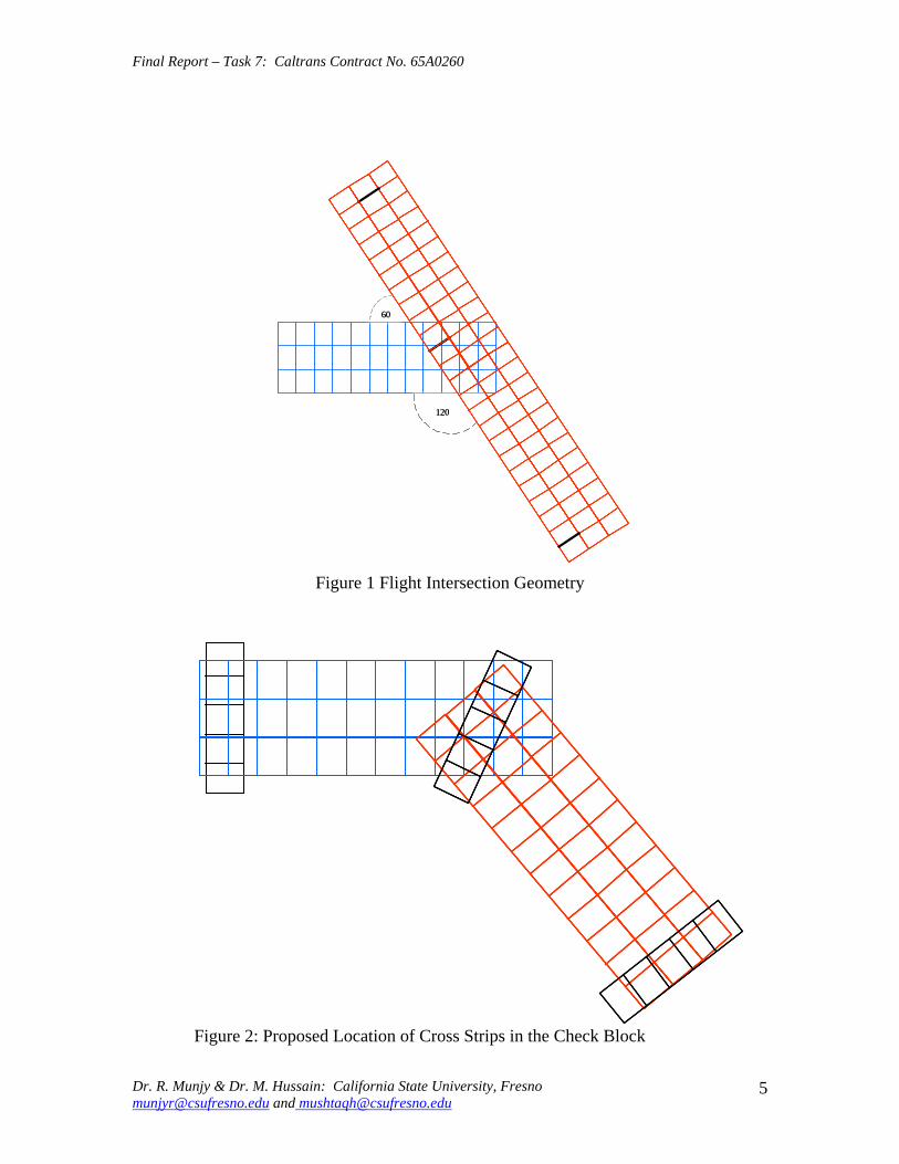
Final Report ndash Task 7 Caltrans Contract No 65A0260
6060
120120
Figure 1 Flight Intersection Geometry
Figure 2 Proposed Location of Cross Strips in the Check Block
Dr R Munjy amp Dr M Hussain California State University Fresno munjyrcsufresnoedu and mushtaqhcsufresnoedu
5
Final Report ndash Task 7 Caltrans Contract No 65A0260
33 Ground Control Distribution
The number and the spatial distribution of the ground control is the key issue that needs to be resolved in this study The airborne GPS data is usually considered sufficient to control the interior of the block [2] [7] Consequently ground surveyed control data is needed only along the block perimeter In accordance with the current Caltrans standards for single-strip configuration blocks the use of a pair of 3-D control points spaced six models apart along the block perimeter meet the accuracy standard for aerial triangulation at 13000 photo scale [11] Accordingly it was proposed to provide 3-D control points at a spacing varying from 6 models to 12 models to determine the optimal control placement along the block perimeter to meet Caltrans accuracy standard for photo scales varying between 13000 and 14800 Since past several years Caltrans has adopted the standard aerial photography scale for mapping as 13600 Accordingly this study is aimed at developing standards for 13600 photo scale
The simultaneous bundle block adjustment based on weighted least squares model results in several statistical metrics that provide a good indication of the internal consistency of the input data and the relative precision of the adjusted coordinates of the tie points and the exterior orientation of the photos However the only valid criterion for checking the external accuracy of the aerial triangulation results is their comparison against ground surveyed check data With this objective it was proposed to add several interior control points distributed over the entire block to serve as Check Points
34 Check Block
Caltrans Office of Photogrammetry in Sacramento and Caltrans District 11 Office in San Diego fully cooperated in modifying the flight plan to accommodate most of the suggestions made by the CSU Fresno research team The mapping project was modified to consist of 9 flight lines that included two cross flight lines one at each end In addition the ground survey was extended to include all the additional control points proposed in the block interior The final configuration of the San Diego Check Block is shown in Fig 3 which also shows the distribution of the 44 ground surveyed control points
Due to the State of California budget problems the Caltrans Division of Research and Innovation suspended this research contract in early August 2008 The contract suspension was subsequently lifted in late October 2008 During a webinar held on November 14 2008 between the representatives from Caltrans DRI and Office of Photogrammetry and the CSU Fresno research team it was reported by the Caltrans Office of Photogrammetry that the San Diego Check Block had been flown and surveyed and the image data captured for aerial triangulation while the research contract was under suspension Consequently all the measurement data related to the San Diego Check Block was available for research study It was provided to the CSU Fresno research team in late November 2008
Dr R Munjy amp Dr M Hussain California State University Fresno munjyrcsufresnoedu and mushtaqhcsufresnoedu
6
Flt6
Flt8Flt4
Flt3Flt2
Flt1
t5
Flt9
Flt7
MAIN Flight Lines 7CROSS Flight Lines 2PHOTO 125CONTROL Points 44
Flt6
Flt8Flt4
Flt3Flt2
Flt1
t5
Flt9
Flt7
MAIN Flight Lines 7CROSS Flight Lines 2PHOTO 125CONTROL Points 44
PHOTO SCALE 13600
Flt6
Flt8Flt4
Flt3Flt2
Flt1
t5
Flt9
Flt7
MAIN Flight Lines 7CROSS Flight Lines 2PHOTO 125CONTROL Points 44
Final Report ndash Task 7 Caltrans Contract No 65A0260
Flt7
Flt6
FlFlFlFlt5
Flt9
Flt4Flt8
MAIN Flight Lines 7 CROSS Flight Lines 2 PHOTO 125 CONTROL Points 44 Flt3
Flt2 PHOTO SCALE 13600 Flt1
Fig 3 Configuration and Control Distribution for the San Diego Check Block
Dr R Munjy amp Dr M Hussain California State University Fresno munjyrcsufresnoedu and mushtaqhcsufresnoedu
7
Final Report ndash Task 7 Caltrans Contract No 65A0260
35 Processing Plan and Methodology
In order to investigate the impact of block configuration the use of cross flight lines and the distribution of ground control the San Diego Check Block was processed in the following different configuration and control combinations
Block Configurations
a) FULL Block Uses all Flight Lines 1 through 9 b) MAIN Block Uses Flight Lines 1 through 7 only omits Cross Flights 8 amp 9 c) NORTH Block Uses Flight Lines 5 6 and 7 d) NORTHX Block Uses Flight Lines 56 and 7 and includes Cross Flight 9 e) SOUTH Block Uses Flight Lines 1 through 4 f) SOUTHX Block Uses Flight Lines 1 through 4 and includes Cross Flight 8 g) SOUTHM Block Uses Flight Lines 12 and 3 trimmed to the same length as
Flight Line 4 (11 Models) and includes Cross Flight 8
Control Distribution
The following considerations were used for the placement and distribution of control points along the perimeter of a block
a) A Ground Control Point (GCP) should fall at each end of each Flight Line b) In addition to (a) above a GCP should control every block corner c) When a Cross Flight Line overlaps the ends of Flight Lines the condition at (a)
above to be replaced with the requirement for a GCP at each end of the Cross Flight Line
d) On large blocks in a direction parallel to the flight lines GCPs should control the block perimeter with spacing not exceeding 8 airbases if cross flights do not exist
e) No GCP is provided in the block interior
The above considerations resulted in formulation of 22 blocks with different flight line and control configurations The block diagram showing the Photos used and the GCP distribution in each of the 22 different cases is given in the Appendix section of this report
As stated above 22 different aerial triangulation blocks were processed using the Interactive Simultaneous Bundle Block Adjustment Windows based software Interactive Simultaneous Bundle Block Adjustment-ISBBAW The input for the processing included the following data files provided by Caltrans Office of Photogrammetry
1) Ground Control Data File Project Datum Information Units US Survey Foot Horizontal CCS83 Zone 6 Epoch 200700 Vertical NAVD88
Dr R Munjy amp Dr M Hussain California State University Fresno munjyrcsufresnoedu and mushtaqhcsufresnoedu
8
Final Report ndash Task 7 Caltrans Contract No 65A0260
a-priori XY 010 ft a-priori Z 010 ft
2) Image Coordinate Data File Type Machine Coordinates a-priori xy 0006 mm
3) Airborne GPS Antenna Data File (at Photo exposure time) Datum Same as Project Datum a-priori XY 015 ft a-priori Z 015 ft
The Office of Photogrammetry had pointed out the unreliability of the GPS data corresponding to Photo 77 Accordingly the GPS data for Photo 77 was made ineffective by assigning a standard error of 100 feet for its coordinates
In addition the latest aerial camera calibration data was also provided and was used to update the camera data file
Each block was processed using Affine Transformation for obtaining photo coordinates that were corrected for systematic errors for lens distortion atmospheric refraction and earth curvature No unacceptably large transformation residuals were obtained Each block was then adjusted using Strip Drift Parameters during Bundle adjustment
36 Results and Analysis
In processing all the 22 different cases of the aerial triangulation no ground or image point was rejected The processing of all the blocks indicated good internal consistency in the measurement data as the Standard Error of Unit Weight (Sigma-sub0 0 ) varied from 048 to 060 the latter value resulted in Case 1 FULL Block Using all 44 GCP It also indicated good precision in image transfer (through pugging) and coordinate measurement the RMS values in the x-coordinate varied from 00022 to 00032 mm while the RMS value for the y-coordinate varied from 00037 to 00042 mm
An important consideration for this research study is the reliability of the ground control data The relative precision of all the 44 GCPs is convincingly validated from the block in Case-1 when all the 44 points are used The RMS values in the control point residuals are (ft)
RMS in X-coordinate 0035 RMS in Y-coordinate 0035 RMS in Z-coordinate 0048
For 13600 scale wide-angle photography Caltrans existing aerial triangulation accuracy standards require the RMS in control points to not exceed 1 part in 10000 of the flying
Dr R Munjy amp Dr M Hussain California State University Fresno munjyrcsufresnoedu and mushtaqhcsufresnoedu
9
Final Report ndash Task 7 Caltrans Contract No 65A0260
height above average terrain Therefore for the average flying height of 1800 feet above terrain this standard would require that the coordinate RMS value should not exceed 018 ft The above result represents a level of precision more than three-times what is permissible according to standard Consequently it proves that the available ground control data meets the required precision to serve as check data in evaluating the cases using a limited number of perimetric control points
In order to systematically evaluate the impact of ground control point distribution on a block the results obtained in each block were used to investigate the coordinate differences at the Check Points these are the ground surveyed control points that are not included as control points in processing the block and their coordinate values are computed as tie points in the block adjustment solution The differences between the aerial triangulation adjusted coordinates and the known ground control coordinates for the Check Points were computed and the average value and the standard deviation in these coordinate differences are listed in Table-1 for each processing case The results obtained are discussed in the following section
CaseNo
Block Type No of Chk Pts X Y Z
St Err X Y Z
Avg Err X Y Z
Max Err X Y Z
Min Err
1 2 3 4 5
FullBlk_All 44CP FullBlk_8CP FullBlk_9CP FullBlk_10CP
0 36 35 34
007 008 005 012 012 016 012 012 017 012 009 015
002 001 -005 001 -001 -008 003 005 -009
024 027 026 024 024 026 024 027 021
-025 -039 -032 -026 -040 -034 -025 -013 -035
MainBlk(Flts1to7)_43CP 0 006 008 005 6 MainBlk1-7_ 8CP 36 016 012 027 -002 -004 -004 026 020 041 -035 -036 -082 7 MainBlk1-7_10CP 34 014 012 027 -001 -003 -004 022 020 039 -031 -031 -080 8 9 10 11 12 13
MainBlk1-7_ 12CP 32 015 010 017 003 000 -004 037 016 035 -031 -027 -023 NorthBlk_567amp9_5CP NorthBlk_567amp9_7CP NorthBlk_567_6CP NorthBlk_567_8CP
18 16 17 15
012 016 016 010 016 017 010 016 022
007 -016 011 008 -007 018 010 -002 008
026 002 036 023 010 051 024 015 050
-022 -062 -022 -016 -051 -012 -019 -043 -026
011 016 017 013 -009 002 029 007 037 -017 -049 -031 SouthBlk_1234amp8_4CP 22 052 032 015 -082 033 003 -007 091 026 -149 -009 -034
14 SouthBlk_1234amp8_6CP 20 013 016 015 -003 006 -002 024 033 033 -019 -028 -028 15 SouthBlk_1234amp8_7CP 19 015 012 014 -003 -002 -002 025 023 033 -025 -030 -025 16 SouthBlk1to4 No XFlt_7CP 22 015 013 023 -001 -005 003 026 023 032 -027 -029 -037 17 SouthBlk1to4 No XFlt_8CP(a) 21 014 012 024 005 -001 004 031 025 033 -022 -029 -040 18 SouthBlk1to4 No XFlt_8CP(b) 21 016 014 019 -003 -005 001 027 025 028 -033 -033 -032 19 SouthBlk1to4 No XFlt_10CP 19 014 012 019 004 -001 001 034 029 029 -025 -030 -028 20 21 22
SouthBlk1to4 No XFlt_11CP 18 014 012 018 -001 -005 -001 023 020 027 -030 -029 -031 ModifiedSouthBlk_1234amp8_ 5CP ModifiedSouthBlk_1234_6CP
19 16
013 010 015 014 011 014
-001 002 -001 002 005 -010
024 021 035 025 024 016
-019 -025 -029 -020 -024 -039
Table-1 Summary of the Coordinate Differences at the Check Points
In accordance with Caltrans Accuracy Standards for Aerial Triangulation the standard error in the adjusted coordinates of a tie point should not exceed 110000th of the average flying height above the terrain level The San Diego Check Block was flown at an average flying height of 1800 feet above terrain resulting in an average photo scale of 13600 Accordingly the limiting standard error in the adjusted coordinates of tie points amounts to 018 ft As is evident from the results summarized in Table-1 in case of vertical aerial photography the height error is larger than the error in the X- or the Yshycoordinate with few exceptions Therefore one may primarily focus only on the
Dr R Munjy amp Dr M Hussain California State University Fresno munjyrcsufresnoedu and mushtaqhcsufresnoedu
10
Final Report ndash Task 7 Caltrans Contract No 65A0260
standard error in the height in order to analyze the various scenarios represented by the 22 different cases
361 FULL Block (Case-1 to 4)
In the case of FULL Block (Flts 1 to 9) by controlling each edge (corner) of the block and each edge of any cross strip by a single CP as in Case-2 Caltrans accuracy standard is met In case-3 an additional CP was used at the block corner formed where the Flight 4 ends while the Flight 3 continues southward The addition of this corner point does not significantly enhance the accuracy of the solution This is due to the fact that the Flight-3 at this point is controlled by GPS data
It is interesting to note that even though the Flight 7 (at the northern end of the block) is 15 models long a single CP located at the end of this flight appears to be sufficient for control The fact that the spacing between the end CPs at the lower end of this block segment (Flight 5) is only about 10 models adds to the strength In order to check the influence of additional control points along the block perimeter with reduced spacing a CP was added in the middle of Flight 7 as shown in Case-4 This does result in some improvement in the accuracy of the block solution consequently this would appear to be the optimum control configuration
362 MAIN Block (Case-5 to 8)
The MAIN Block (Flts 1 to 7) was used to study any impact in using cross flights for GPS controlled aerial triangulation blocks When a large number of control points are available such as in Case-3 where 43 CPs are used the results are identical whether or not cross flights are used However when a CP is used only at the block corners as in Case-6 (analogous with Case-2 in FULL Block) the required accuracy standard is not met This standard is also not met when an additional corner CP is used as shown in Case-7 (analogous with Case-3 in FULL Block) However when the spacing between the perimetric control points is confined to about 8 models as shown in the Case-8 the results are within the required accuracy standard A comparison of Case-4 and Case-8 shows that if the cross Flights 8 and 9 are not used additional control points along the block perimeter in a direction parallel to the flight lines can compensate for it and meet the required accuracy standard
363 NORTH Block (Case-9 to 12)
The above analysis was repeated by splitting the San Diego Check Block into two subshyblocks a NORTH Block and a SOUTH Block The NORTH Block (Flts 5 to 7 and 9) was processed first by including the cross Flight 9 and also by excluding this cross flight The results tabulated in Table-1 in Case 9 to 12 are identically similar to the ones obtained earlier with the FULL and the MAIN Blocks It again shows that when a CP is located at the end of the cross Flight 9 in the northern end of the block and a CP is used at the end of each of the three flight lines at the southern end of the block the required accuracy standards are met even when no CP is located in the middle of the 15-model
Dr R Munjy amp Dr M Hussain California State University Fresno munjyrcsufresnoedu and mushtaqhcsufresnoedu
11
Final Report ndash Task 7 Caltrans Contract No 65A0260
long Flight-7 (Case-9) In fact it is seen in Case-10 that the addition of an intermediate point along the perimeter did not improve the accuracy
Without the cross Flight 9 however a comparison of the Case-12 with Case-11 clearly shows that the reduction in the spacing between the perimetric control points is necessary for meeting the required accuracy standard In this block size and configuration the nonshyuse of a cross flight could have been compensated with the use of one additional control point along the perimeter
364 SOUTH Block (Case-13 to 20)
The SOUTH Block consisting of Flights 1 to 4 and the cross Flight 8 has somewhat unusual configuration it is not a compact rectangular block and the cross Flight-8 intersects the block rather than at either end of the block Eight different scenarios for flight and control configuration were used in handling this sub-block
The Case-13 is based on the use of only four CPS one located at each of the four block corners This case might work for small and rectangular blocks with a cross flight at each end of the block However for Case-13 the cross Flight is completely uncontrolled and so is the southern corner of Flight-4 Obviously this has resulted in the planimetric RMS error that exceeds 05 ft
When a CP was located at each end of the cross Flight 8 as seen in Case-14 as well as a CP was added at the end of each flight line the block solution met the accuracy standard The addition of another corner CP as shown in Case-15 did not contribute to any significant improvement in the accuracy This shows the role that the intersecting cross Flight 8 plays in strengthening the geometry of the block by reducing the uncontrolled segment of each of the three Flight lines 1 to 3
The Case-16 to 20 convincingly demonstrate the degradation in the block geometry when the cross Flight 8 is removed from the block None of the block configurations shown in Case 16 to 19 strictly meets the accuracy requirement the Case-18 and Case-19 missing the minimal accuracy standard by 001 ft It is only when another corner CP is added as shown in Case-20 that the minimal accuracy standard is attained
365 SOUTH-MODIFIED Block (Case-21 amp 22)
In order to further validate the conclusions derived so far the SOUTH Block was modified to a more conventional rectangular shaped block by removing photos from Flight 1 to 3 to bring them to the same length as Flight 4 The SOUTH_MODIFIED Block is not only have a rectangular shape but the cross Flight 8 now falls at the southern of this sub-block With the Flight 8 now playing the normal role of a cross flight the minimal control layout seen in Case-21 easily meets the accuracy standard As observed in previous
Dr R Munjy amp Dr M Hussain California State University Fresno munjyrcsufresnoedu and mushtaqhcsufresnoedu
12
Final Report ndash Task 7 Caltrans Contract No 65A0260
blocks locating a CP at each end of each flight line meets the accuracy standard for this block with 11-model long flight lines
The above observations and the conclusions were used to draft the Preliminary Standards for Block Configuration Airborne GPS Controlled Photogrammetry for Large Scale Mapping Projects and submitted as Interim Report in fulfillment of the requirement under Task 32 of the contract [14]
4 TEST BLOCK
41 Planning
The extra-ordinary fiscal problems faced by the State of California had resulted in the suspension of work on the project Consequently a no-cost extension in the time for completion of this project beyond March 31 2009 till December 31 2009 was requested by California State University Fresno in November 2008 This request in the extension of period was strongly supported by Caltrans Office of Photogrammetry This request was approved by Caltrans Division of Research and Innovation and California State University Fresno was notified by Caltrans Contract Manager on April 2 2009 to continue work on the project till December 31 2009
A planning meeting between the California State University Fresno research team and the representatives from Caltrans Office of Photogrammetry was held in Caltrans Office in Sacramento on April 20 2009 for the design of an optimal test block In the light of the results obtained from the San Diego Check Block and the conclusions presented in the Interim Report submitted in January 2009 various options and proposals for selecting the site and configuration for a test block were discussed The Caltrans Office of Photogrammetry and the California State University Fresno fully agreed on the following characteristics for the Test Block
The aerial photography should fully conform to the Caltrans practice of using a metric wide-angle aerial camera from an altitude of 1800 ft above the terrain level to result in an average photo scale of 13600
The main block should consist of 4 parallel flight lines of 18 models each A cross flight should be flown at each end of the main block Full 3-D ground control should be provided along the perimeter of the main block
with a control point spacing of 6 to 8 airbases Full 3-D ground control for the two cross flights should be planned so that
- A pair of 3-D control points are located at each end of each cross flight and - At least one Height control point falls at each end of each main flight line
A sufficient number (15 to 20) of additional ground control points should be distributed in the interior of the block to serve as check points for estimating the absolute accuracy of aerial triangulation results
All the 6 flight lines constituting the Test Block should be flown as a single flight mission
Dr R Munjy amp Dr M Hussain California State University Fresno munjyrcsufresnoedu and mushtaqhcsufresnoedu
13
Final Report ndash Task 7 Caltrans Contract No 65A0260
The airborne GPS data as well as the data at the ground Base Stations should be collected at 1 Hz or higher data rate
The flight mission should be carried out under weather and environmental conditions so as to avoid any degradation in the quality of aerial imagery
Even though implementing the above technical requirements in a test block did not pose any serious problems the California State University Fresno as well as the Caltrans Office of Photogrammetry had serious concerns about adhering to the tight project schedule Both the parties in this project were convinced that the award of an aerial photography services contract for a Test Block by the California State University Fresno through a formal selection and competitive bidding process would entail serious delays that may even jeopardize the completion of the project by the ending date of December 31 2009 An attractive and viable alternative was to utilize the services of an aerial photography vendor that had recently been contracted by Caltrans for the acquisition of aerial photography for a highway corridor along Interstate I-5 in Northern San Diego The flying for this Caltrans project was fortuitously scheduled for May 2009 that synchronized very well with the schedule for this research project
Accordingly with full consultation with the Caltrans Office of Photogrammetry a Test Block was designed by the California State University Fresno in Del Mar in Northern San Diego The Del Mar Test Block included a variety of terrain a large expanse of marsh and river suburban residential large freeway and rolling hills A separate contract was negotiated and awarded by the California State University Fresno to the Caltrans contractor for the San Diego I-5 Project for the acquisition of aerial photography for the Del Mar Test Block This approach used in awarding the contract resulted in the following benefits
The aerial photography contractor had already been pre-qualified by Caltrans for the quality of the aircraft aerial camera aerial film and GPS and navigation equipment used for the acquisition of aerial photography
The aerial photography contractor had already been pre-qualified by Caltrans for the quality of aerial photography products (developed negative film diapositives prints etc)
The aerial photography contractor had already been pre-qualified by Caltrans for the certification of aerial camera calibration electronic integration of the aerial camera with the airborne GPS receiver to record the aerial exposure events and the geometric integration of the airborne GPS antenna mounted on the fuselage with the aerial camera
The contractor was familiar with the detailed Caltrans specifications for the acquisition of aerial photography and the same specifications would strictly govern the flight mission for the Del Mar Test Block
Dr R Munjy amp Dr M Hussain California State University Fresno munjyrcsufresnoedu and mushtaqhcsufresnoedu
14
Final Report ndash Task 7 Caltrans Contract No 65A0260
42 Acquisition of Aerial Photography
The flight configuration and ground control distribution for the Del Mar Test Block was finalized near the end of April 2009 and is shown in Fig 41 As stated earlier the contract for the aerial photography acquisition was awarded to IKCurtis Services Inc Burbank California who had earlier been awarded the Caltrans contract to fly Route 5 and 56 in San Diego The Caltrans Office of Photogrammetry also arranged for field survey teams from Caltrans District 11 in San Diego to supplement the ground control network established for the Caltrans project with the additional ground control points planned for the Del Mar Test Block This further ensured that the quality of the ground control data used for the Del Mar Test Block would fully conform to Caltrans aerial triangulation control standards All the fieldwork required for the Caltrans Route 5 and 56 Project and for the Del Mar Test Block of the California State University Fresno research project was completed in early May 2009
Based on the weather reports and the suitability of GPS satellite configuration it was mutually agreed between the Caltrans Office of Photogrammetry Caltrans District 11 California State University Fresno and IK Curtis Services Inc to fly the two projects on May 13 2009 with May 14 2009 as a backup date I K Curtis Services Inc had been assigned the task of collecting the airborne GPS data during the flight mission while field survey staff from Caltrans District 11 were responsible for the simultaneous collection of GPS data at four designated base stations Whether the two separate projects are flown as a single flight mission or as two separate missions on the same day or on separate days was left entirely to the mutual judgment of the flight crew and Caltrans Project Coordinator from District 11 based on the weather and environmental conditions in the area
A final field survey task is to visit each control point location and repaint if necessary those control marks that fall on a hard surface and to deploy specially designed panel at each control point that lies on grass or open and marshy ground Even though all the ground control targets had been readied in time unfortunately adverse weather reports and worsening fog and cloudy conditions were totally unsuitable for flying on May 13 or on May 14 Based on the weather forecast similar flight dates were set on several occasions each time requiring the reconnaissance of the ground targets but the adverse weather conditions extended over several weeks After continuing efforts at planning and repeated cancellations it was finally possible to complete the aerial photography requirements for both the projects through a single flight mission carried out on July 14 2009 Even though two models at the end of one cross flight in the Del Mar Test Block contain some cloud coverage fortunately it was still possible to identify and measure the image coordinates of the ground control points falling in both the models
Dr R Munjy amp Dr M Hussain California State University Fresno munjyrcsufresnoedu and mushtaqhcsufresnoedu
15
6
5
Final Report ndash Task 7 Caltrans Contract No 65A0260
Fig 41 San Diego Test Block Configuration and Control Distribution
1 2 3 411 22 33 44
66
55
Dr R Munjy amp Dr M Hussain California State University Fresno munjyrcsufresnoedu and mushtaqhcsufresnoedu
16
Final Report ndash Task 7 Caltrans Contract No 65A0260
43 Test Block Data Acquisition
After the delivery of the aerial diapositives by the Contractor the photogrammetric data for the aerial triangulation of the Del Mar Test Block was measured and compiled by Caltrans Office of Photogrammetry The selection of tie points and the measurement of image coordinate data for the entire block consisting of 6 flight lines and 96 photos was carried out following the routine analytical methodology and practice used for all Caltrans aerial triangulation blocks
The following measurement data was provided by the Office of Photogrammetry to California State University Fresno in August 2009
- Image coordinate data - Ground control coordinate data - Raw GPS data from airborne receiver and four base station receivers - GPS time for photo exposure - Camera calibration data - Camera and GPS antenna offset
44 Test Block Data Processing
Before processing the aerial triangulation data received from the Office of Photogrammetry some clarification regarding the processing datum were necessary as discussed in the following section
441 Processing Datum
It was reported that the datum used for the ground control data provided by Caltrans District 11 was as below
- Horizontal Control CCS83 Epoch199135 Datum - Vertical Control NAVD88 Datum
Based on discussions with representatives from Caltrans District 11 it was determined that the 3-D adjustment of the GPS ground control network was performed in CCS83-Epoch 199135 datum for the horizontal control while the vertical coordinates were adjusted by fixing the orthometric height (NAVD88 Datum) of 4 network stations The geoidal height data needed for the reduction of observed ellipsoidal height data (GRS80 Ellipsoid) to adjusted orthometric height data (NAVD88 Datum) was based on the Geoid2003 Global Model Consequently the orthometric height data for the ground control used for the Del Mar Test Block may be affected by any height variation between the Local Geoid from the Global Geoid
442 Post-Processing of Airborne GPS Data
Dr R Munjy amp Dr M Hussain California State University Fresno munjyrcsufresnoedu and mushtaqhcsufresnoedu
17
Final Report ndash Task 7 Caltrans Contract No 65A0260
Even though the Caltrans Office of Photogrammetry had provided the post-processed results for the airborne GPS data this data was also processed at the California State University Fresno Even though GPS data at four different base stations had been collected and the GrafNav post-processing software provides the option to use multiple base station data it was decided to carry out the kinematic processing of the airborne GPS data relative to a single base station HPGN DC 11 The selection of this base station was due to the fact that this was the only base station for which the orthometric height had been held fixed in the GPS network adjustment none of the other three network stations for which the orthometric height was held fixed had been used as a base station during the flight mission
The results and the analysis provided in the following section are based on the airborne GPS data processed at the California State University Fresno
443 Aerial Triangulation Data Processing
The first objective for the aerial triangulation processing of the Del Mar Test Block data was to further verify the aerial triangulation results obtained with the San Diego Check Block reported in Section 3 A second and more important objective was to evaluate the impact of flight configuration and the control point distribution on the achievable aerial triangulation accuracy for large scale (13600) aerial photography used in Caltrans It was of special interest to assess the impact of the use of cross flights and the optimal distribution of the ground control points in an airborne GPS supported aerial triangulation block
The same approach and the methodology were used for processing the aerial triangulation of the Del Mar Test Block as has previously been discussed in detail in Section 35 for the San Diego Check Block Aerial triangulation data was processed systematically by using block configuration with and without the two cross flights (see Fig 41) The number and the distribution of the control points used primarily along the block perimeter varied from 8 to 14 control points Since the Del Mar Test Block was covered with a total of 33 field control points all the points that were not used as control points in processing the block served as Check Points Theoretically such Check Points are the most reliable indicators of the absolute accuracy of the aerial triangulation results provided the coordinate data for such Check Points is at least three times more precise than the precision of the coordinate data for the tie points resulting from aerial triangulation adjustment [15] In the case of the Del Mar Test Block data the uncertainty of 2 to 3 cm in the geoidal height interpolated from the global Geoid Model leads to the estimated precision of the Check Point data to be more precise than the aerial triangulation data by a factor of 12 to 2 only This fact has to be kept in focus while analyzing the absolute accuracy of the aerial triangulation results as part contributions from the errors in Check Point data cannot be entirely ignored
The airborne GPS supported aerial triangulation blocks are fully controlled through the airborne GPS data in the interior of the block Therefore the precision of the airborne GPS data plays a crucial role in the resulting aerial triangulation accuracy The
Dr R Munjy amp Dr M Hussain California State University Fresno munjyrcsufresnoedu and mushtaqhcsufresnoedu
18
Final Report ndash Task 7 Caltrans Contract No 65A0260
processing of the Test Block was carried out by using the following a-priori standard errors for the airborne GPS data (a) Standard error for X and Y-coord 025 ft Standard error for Z-coord 025 ft (b) Standard error for X and Y-coord 010 ft Standard error for Z-coord 015 ft
Based on the analysis of the results that are discussed in Section 5 it was finally decided to use the following a-priori standard error for the airborne GPS data
Standard error for X and Y-coord 015 ft Standard error for Z-coord 015 ft
The results for the block configuration that includes the two cross flights for a total of 6 flight lines are summarized as Cases 1 through 5 in Table 2 The Blocks processed without the use of the two cross flights and comprising only the 4 parallel flight lines are shown in Table 2 as Cases 6 through 12
Case BLOCK Number of St Error Ave Error Max Error Min Error
No Type Check Pts X Y Z X Y Z X Y Z X Y Z
1 6Flt_Blk_33CP 0 004 004 005
2 6Flt_Blk_8CP 25 009 008 019 -002 001 -007 013 018 032 -027 -012 -052
3 6Flt_Blk_12CP 21 010 008 014 -004 -003 005 009 013 029 -028 -015 -030
4 6Flt_Blk_14aCP 19 010 006 015 000 -003 001 012 013 027 -025 -016 -034
5 6Flt_Blk_14bCP 19 010 008 015 -001 -001 006 011 013 028 -025 -014 -031
6 4Flt_Blk_33CP 0 004 002 006 -002 000 001
7 4Flt_Blk_8CP 25 012 008 059 004 006 -108 028 024 016 -022 -009 -109
8 4Flt_Blk_11aCP 22 013 009 019 -001 -002 -017 017 016 028 -028 -016 -050
9 4Flt_Blk_11bCP 22 014 009 027 -005 003 -031 016 020 030 -031 -015 -066
10 4Flt_Blk_12CP 21 013 009 020 -002 000 -008 016 018 031 -027 -016 -033
11 4Flt_Blk_14aCP 19 010 008 013 004 -002 -003 016 015 025 -021 -017 -020
12 4Flt_Blk_14bCP 19 009 007 012 -001 -001 005 009 013 028 -025 -014 -012
Table-2 Summary of the Coordinate Differences at the Check Points
The control distribution used in the processing of the 12 cases is illustrated in Fig 42 through 411 below The corresponding statistics for the resulting errors at the Check Points are shown for each case The Check Points where the maximum errors in the X- Y- and Z-coordinate occur are shown in different color according to the legend below
Control pointControl point
MMaax error in Xx error in X
MMaax error in Yx error in Y
MMaax error in Zx error in Z LEGEND (Figures 42 through 411)
Dr R Munjy amp Dr M Hussain California State University Fresno munjyrcsufresnoedu and mushtaqhcsufresnoedu
19
Final Report ndash Task 7 Caltrans Contract No 65A0260
Fig 42 Block with Cross Strips 8 Control Points 25 Check Points Case 2
SSttaannddaardrd EErrorrorr AAvveeraraggee EErrrroorr MMaaxxiimmuumm EErrorrorr MMiinniimmuumm EErrorrorr XX YY ZZ XX YY ZZ XX YY ZZ XX YY ZZ
000099 000088 001199 --000022 000011 --000707 001133 001818 003232 --002277 --001212 --005522
Dr R Munjy amp Dr M Hussain California State University Fresno munjyrcsufresnoedu and mushtaqhcsufresnoedu
20
Final Report ndash Task 7 Caltrans Contract No 65A0260
Fig 43 Block with Cross Strips 12 Control Points 23 Check Points Case 3
SSttaannddaardrd EErrorrorr AAvveeraraggee EErrrroorr MMaaxxiimmuumm EErrorrorr MMiinniimmuumm EErrorrorr XX YY ZZ XX YY ZZ XX YY ZZ XX YY ZZ
001100 000088 001144 --000044 --000303 000055 000099 001313 002929 --002288 --001515 --003300
Dr R Munjy amp Dr M Hussain California State University Fresno munjyrcsufresnoedu and mushtaqhcsufresnoedu
21
Final Report ndash Task 7 Caltrans Contract No 65A0260
Fig 44 Block with Cross Strips 14 Control Points 21 Check Points Case 4
SSttaannddaardrd EErrorrorr AAvveeraraggee EErrrroorr MMaaxxiimmuumm EErrorrorr MMiinniimmuumm EErrorrorr XX YY ZZ XX YY ZZ XX YY ZZ XX YY ZZ
001100 000088 001155 --000011 --000101 000066 001111 001313 002828 --002255 --001414 --003311
Dr R Munjy amp Dr M Hussain California State University Fresno munjyrcsufresnoedu and mushtaqhcsufresnoedu
22
Final Report ndash Task 7 Caltrans Contract No 65A0260
Fig 45 Block with Cross Strips 14 Control Points 21 Check Points Case 5
SSttaannddaardrd EErrorrorr AAvveeraraggee EErrrroorr MMaaxxiimmuumm EErrorrorr MMiinniimmuumm EErrorrorr XX YY ZZ XX YY ZZ XX YY ZZ XX YY ZZ 001100 000066 001155 000000 --000033 000011 001122 001133 002277 --002255 --001166 --003344
Dr R Munjy amp Dr M Hussain California State University Fresno munjyrcsufresnoedu and mushtaqhcsufresnoedu
23
Final Report ndash Task 7 Caltrans Contract No 65A0260
Fig 46 Block without Cross Strips 8 Control Points 25 Check Points Case 7
SSttaannddaardrd EErrorrorr AAvveeraraggee EErrrroorr MMaaxxiimmuumm EErrorrorr MMiinniimmuumm EErrorrorr XX YY ZZ XX YY ZZ XX YY ZZ XX YY ZZ 001122 000088 005599 000404 000606 --110088 002288 002244 001166 --002222 --000099 --110099
Dr R Munjy amp Dr M Hussain California State University Fresno munjyrcsufresnoedu and mushtaqhcsufresnoedu
24
Final Report ndash Task 7 Caltrans Contract No 65A0260
Fig 47 Block without Cross Strips 11 Control Points 22 Check Points Case 8
SSttaannddaardrd EErrorrorr AAvveeraraggee EErrrroorr MMaaxxiimmuumm EErrorrorr MMiinniimmuumm EErrorrorr XX YY ZZ XX YY ZZ XX YY ZZ XX YY ZZ
001133 000099 001199 --000011 --000202 --001177 001177 001166 002288 --002828 --001166 --005050
Dr R Munjy amp Dr M Hussain California State University Fresno munjyrcsufresnoedu and mushtaqhcsufresnoedu
25
Final Report ndash Task 7 Caltrans Contract No 65A0260
Fig 48 Block without Cross Strips 11 Control Points 22 Check Points Case 9
SSttaannddaardrd EErrorrorr AAvveeraraggee EErrrroorr MMaaxxiimmuumm EErrorrorr MMiinniimmuumm EErrorrorr XX YY ZZ XX YY ZZ XX YY ZZ XX YY ZZ
001144 000099 002277 --000055 000033 --003131 001166 002020 003030 --003311 --001515 --006666
Dr R Munjy amp Dr M Hussain California State University Fresno munjyrcsufresnoedu and mushtaqhcsufresnoedu
26
Final Report ndash Task 7 Caltrans Contract No 65A0260
Fig 49 Block without Cross Strips 12 Control Points 21 Check Points Case 10
SSttaannddaardrd EErrorrorr AAvveeraraggee EErrrroorr MMaaxxiimmuumm EErrorrorr MMiinniimmuumm EErrorrorr XX YY ZZ XX YY ZZ XX YY ZZ XX YY ZZ 001133 000099 002200 --000022 000000 --000808 001166 001818 003131 --002277 --001616 --003333
Dr R Munjy amp Dr M Hussain California State University Fresno munjyrcsufresnoedu and mushtaqhcsufresnoedu
27
Final Report ndash Task 7 Caltrans Contract No 65A0260
Fig 410 Block without Cross Strips 14 Control Points 19 Check Points Case 11
SSttaannddaardrd EErrorrorr AAvveeraraggee EErrrroorr MMaaxxiimmuumm EErrorrorr MMiinniimmuumm EErrorrorr XX YY ZZ XX YY ZZ XX YY ZZ XX YY ZZ
001100 000088 001133 000044 --000022 --000303 001166 001515 002525 --002211 --001717 --002200
Dr R Munjy amp Dr M Hussain California State University Fresno munjyrcsufresnoedu and mushtaqhcsufresnoedu
28
Final Report ndash Task 7 Caltrans Contract No 65A0260
Fig 411 Block without Cross Strips 14 Control Points 19 Check Points Case 12
SSttaannddaardrd EErrorrorr AAvveeraraggee EErrrroorr MMaaxxiimmuumm EErrorrorr MMiinniimmuumm EErrorrorr XX YY ZZ XX YY ZZ XX YY ZZ XX YY ZZ
000099 000077 001122 --000011 --000101 000055 000099 001313 002828 --002255 --001414 --001122
Dr R Munjy amp Dr M Hussain California State University Fresno munjyrcsufresnoedu and mushtaqhcsufresnoedu
29
Final Report ndash Task 7 Caltrans Contract No 65A0260
5 ANALYSIS OF RESULTS amp CONCLUSIONS
In accordance with the Caltrans standards using wide-angle aerial photography the RMS error in each coordinate component of the adjusted tie points should not exceed 110000 of the flying height above the terrain The Del Mar Test Block was flown with a wideshyangle aerial camera from an average height of 1800 feet above the terrain level thereby resulting in an average photo scale of 13600 Consequently the limiting RMS error at the Check Points representative of a finite number of well distributed tie points in the block should not exceed 018 ft in this case Any error that exceeds three times this limiting value viz 054 ft in any of the coordinate components should be a cause for rejection of that point
Therefore the acceptable limiting values for the standard error at the Check Points is 018 ft in each coordinate component Any block adjustment solution that results in a coordinate error in one or more Check Points that exceeds 054 ft in any coordinate component would not be an acceptable solution The following analysis of the results is based on these accuracy criteria
51 Blocks With Cross Flights
When a minimal number of 8 control points are used (Fig 42) along the block perimeter the resulting standard error in Z-coordinate of 019 ft exceeds the limiting value of 015 ft It is also noticeable that the highest error in the Z-coordinate of 052 ft at Point 189134 almost equals the rejection limit of 054 ft This is an indication that controlling a cross flight with only a single Control Point at each end of the flight may not always provide a satisfactory solution
This situation can be remedied by using a pair of Control Points in each end model of a cross flight so that any deformation across the flight line the omega rotation () can also be controlled Such an approach is also reported to have been successfully used and recommended in the past [1] [2] [3] When 4 additional Control Points were added at the end of each cross flight line as is seen in Fig 43 all the standard errors fell within the acceptable range and the maximum coordinate error did not exceed 030 ft which is well within the acceptable criteria
The primary advantage of using airborne GPS data for the adjustment of aerial triangulation blocks is to completely eliminate the need for Control Points in the interior of the block But it is of interest to investigate how effectively the airborne GPS data alone can control the interior of the block Two separate blocks were processed by adding two Control Points in the interior of the block resulting in a total of 14 Control Points
The block with 14 Control Points (Case A) is shown in Fig 44 where the two interior Control Points were selected so that one Control Point was located on the opposite ends in each of the two interior flight lines (Line 2 and Line3 see Fig 41) The other block with 14 Control Points (Case B) is shown in Fig 45 In this case both the interior points
Dr R Munjy amp Dr M Hussain California State University Fresno munjyrcsufresnoedu and mushtaqhcsufresnoedu
30
Final Report ndash Task 7 Caltrans Contract No 65A0260
fell in the middle of the block interior It is interesting to note that in either of the two cases the addition of the interior Control Points did not result in any significant difference from the result achieved earlier while using 12 Control Points Therefore it may be concluded that as long as the cross flights are adequately controlled with a pair of Control Points located across each end model of each cross flight additional control in the block interior is not required The results shown in Fig 44 and 45 validate this conclusion at least for a block comprised of 18 models long multiple flight lines
52 Blocks Without Cross Flights
When a mapping project involves a large photogrammetric block consisting of hundreds of models the common practice is to plan the block configuration to include cross flights [1] [2] [6] [10] Often such cross flights can result in significant saving in time and effort in minimizing the need for ground control Since the photogrammetric mapping projects in Caltrans mostly involve mapping along highway corridors most of the photogrammetric blocks vary from a single flight line to up to as many as four flight lines Therefore it is still to be investigated whether the use of cross flight lines in such blocks offers any significant advantage Furthermore any advantage resulting from the reduced need for the ground control has to be weighed against the additional time and effort needed in processing the cross flight models The Caltrans Office of Photogrammetry has not yet adopted the use of Automated Aerial Triangulation (AAT) techniques for routine production Consequently the additional effort in transferring tie points between the cross flights with the flights of the main block is still significant This has provided the impetus to carry out the following investigation for the aerial triangulation adjustment of blocks that do not include any cross flights
The first block without the two cross flights was processed with only 8 Control points along the block perimeter as a parallel case with the block run with cross flights The results are shown in Fig 46 As may be expected the absence of any Control Point located at each end of each of the two interior flights 2 and 3 has resulted in unacceptably large errors Not only is the standard error of 059 ft in the Z-coordinate for the 25 Check Points too large but interestingly the block adjustment carries a large systematic error in Z-coordinate of 108 ft This results from the fact that the absence of the Control Points at each end of Flights 2 and 3 does not permit the adjustment for the systematic strip drift parameters for the airborne GPS data along Flights 2 and 3
When cross flights are included the airborne GPS data measured along the cross flight adequately serves as control for adjusting the strip shift and drift parameters Therefore an alternative to the inclusion of cross flights in the block configuration is to provide a Control Point at each end of every flight line in the block Accordingly the processing of the following blocks includes Control Points at the end of each flight line
The Del Mar Test Block with 4 flight lines each 18 models long would require a total of 12 Control Points one Control Point at each end of each flight line and 4 Control Points along the interior perimeter of the block to provide a control spacing of approximately 6 airbases apart However in order to minimize the use of the ground control the block
Dr R Munjy amp Dr M Hussain California State University Fresno munjyrcsufresnoedu and mushtaqhcsufresnoedu
31
Final Report ndash Task 7 Caltrans Contract No 65A0260
shown in Fig 47 was processed with only 11 Control Points (Case A) since the Control Point 170133 was measured both in Line 2 and Line 3 The resulting standard error of 019 ft in the Z-coordinate for 22 Check Points as well as the large error of 050 ft in the Z-coordinate of Check Point 189134 make the block adjustment solution unacceptable There appears to be no obvious reason why the Check Point 189134 that is located so close to the Control Point 170133 should display such unacceptably large error in the Zshycoordinate In order to ascertain the internal consistency of the ground control data (33 Control Points) a conventional aerial triangulation adjustment of the block was performed (without using the airborne GPS data) using 32 Control Points and treating the Control Point 189134 as a Check Point The resulting error in the Z-coordinate of Point 189134 was only 006 ft It is also to be noted that the average Z-coordinate error of 017 ft indicates a systematic height error This would lead to the conclusion that there is some height discrepancy between the ground control data and the airborne GPS data
The block was re-processed (Case B) again by using only 11 Control Points but this time the Control Point 170133 was replaced with Control Point 189134 and the results are displayed in Fig 48 The Case B results are even worse than the Case A results the standard error in Z-coordinate was degraded to 027 ft while the largest error in Zshycoordinate of 066 ft was noted at Check Point 187215 The average Z-coordinate error also increases to 031 ft This is a further indication that there is significant height inconsistency in the airborne GPS data and the ground control data It appears that the height discrepancy between the ground control data and the airborne GPS data results in an unsatisfactory shift and drift adjustment of the airborne GPS data particularly in the inner flight Lines 2 and 3 that span 18 models between the end Control Points
In order to strengthen the end control across the flight lines both the Control Points 170133 and 189134 were used at the Northern end of the block The block was then processed with 12 Control Points and the results are presented in Fig 49 Even though the results improved significantly but contrary to the expectation the standard error in the Z-coordinate of 020 ft for the 21 Check Points did not meet the Caltrans accuracy standard The next logical approach was to investigate the impact of adding Control Points in the interior of the block Two interior Control Points were selected in the same manner as has been described earlier in the case of the blocks with the cross flights (see Fig 44 and 45)
Using 14 Control Points the Case A is shown in Fig 410 while the Case B is presented in Fig 411 The results in both Case A and Case B easily meet the Caltrans accuracy standards In Case A the distance between the Control Points for the shift and drift parameter adjustment of the airborne GPS data varies from 6 to 12 models while in Case B the interior Control Points are about 6 models apart Each Control Point distribution provides almost similar results It is a clear indication that any systematic height deformation that results from the suspected inconsistency between the ground surveyed GPS data and the airborne GPS data can be kept within acceptable range by including a pair of control points in the interior of the block Such a need for some control points has not been reported for the adjustment of aerial triangulation blocks in the past However the largest photo scale for which any ABGPS supported results have been published in
Dr R Munjy amp Dr M Hussain California State University Fresno munjyrcsufresnoedu and mushtaqhcsufresnoedu
32
Final Report ndash Task 7 Caltrans Contract No 65A0260
the past is 14800 only For a photo scale of 13600 that is approximately 25 percent larger the requirements for the accuracy of aerial triangulation accordingly become more stringent in the same proportion This may generate the need for some additional control in the middle of the block
The residuals at the ground control points and in the image coordinate data along with the resulting standard error of unit weight (0) provide a reliable indication of the internal consistency of the adjusted block However the absolute accuracy of the aerial triangulation can be validated only by the use of Check Points that are well distributed over the entire block As pointed out earlier any deformations due to residual systematic shift and drift errors in the airborne GPS data are likely to be most significant in the center of the block the location that is farthest from the control points distributed along the perimeter Accordingly it would be advisable to locate at least a pair of Check Points in the middle of the block and after completing the block adjustment (by excluding these Check Points as Control Points) the coordinate discrepancies obtained at these Check Points can be analyzed Such discrepancies would normally represent the highest absolute accuracy resulting from aerial triangulation adjustment of the block Any unacceptably large coordinate discrepancies at the Check Points would require investigation of the block input data
In the case the coordinate discrepancies at the Check Points are within acceptable range the block can be re-processed by also including the Check Points in the control data This should enhance the accuracy in the interior of the block
6 RECOMMENDED DRAFT STANDARDS
These draft standards are proposed to supplement the existing Standards for Strip Configuration Airborne GPS Controlled Photogrammetry for Large Scale Mapping Projects (based on 13600 photo scale) currently used in Caltrans
61 Data Acquisition
611 Image Coordinate Data
Follow the existing practice used in Caltrans Office of Photogrammetry for the selection distribution and the measurement of all image point data It is recommended that raw machine coordinate image data should form the input to the aerial triangulation block adjustment
A secondary interest in this Research Project under contract with Caltrans was to also evaluate the alternate methodology of the selection and the measurement of tie point data using Automated Aerial Triangulation (AAT) system However several problems were encountered in implementing the AAT software available at the Caltrans Office of Photogrammetry in Sacramento The unavoidable delay caused by unfavorable weather conditions in acquiring the aerial imagery for the Del Mar Test Block did not allow
Dr R Munjy amp Dr M Hussain California State University Fresno munjyrcsufresnoedu and mushtaqhcsufresnoedu
33
Final Report ndash Task 7 Caltrans Contract No 65A0260
enough time to resolve the AAT software issues with software vendor Accordingly this task could not be fully completed Therefore it was mutually agreed between the Caltrans Office of Photogrammetry and California State University Fresno to concentrate research efforts on the processing and the analysis of the Del Mar Test Block and on drafting the Final Report
612 Ground Control Data
The proposed research is focused on the use of photography obtained at scale of 13600 for corridor mapping in Caltrans The ground control for mapping is based on the airborne GPS supported aerial triangulation of the photo blocks The ground control points should be surveyed to provide 15 to 2-times higher accuracy than that of the adjusted tie point data This would translate to an accuracy at the 005 to 01 ft level for the planimetric coordinates and the height an accuracy achievable using static GPS surveys tied to existing HPGN network
It is not yet certain that the Real-Time Kinematic (RTK) GPS field survey methodology whether relying on a single base station or on an RTK network is able to meet the above stringent field survey accuracy requirements Therefore the ground control data for ABGPS based aerial triangulation blocks should be based entirely on GPS control networks established using static GPS surveying methodology The RTK survey methodology for establishing control for photogrammetric mapping projects should not be used till such time that such technology has advanced to a level when consistently reliable results can be routinely expected
The GPS observations provide a fairly precise data for ellipsoidal height differences However all photogrammetric mapping has to be based on orthometric height data Two different approaches can be used in order to derive adjusted orthometric height data through aerial triangulation The first method is to carry out the simultaneous least squares adjustment of the GPS observation data for the ground control network using current Caltrans Horizontal Datum CCS83 (199135) and Vertical Datum NAVD 88 But since the observed data involves the measurement of ellipsoidal height differences for each measured baseline there is a need for transforming such differences to the corresponding orthometric height differences on NAVD 88 Datum In the absence of an existing Local Geoid Model the only economic recourse available to meet this need is to use the most reliable existing Global Geoid Model the time-consuming and prohibitively more costly alternative would be to connect the control network stations through differential leveling The Global Geoid Models are progressively being updated and the GEOID 2003 Model is most commonly in current use although GEOID 2009 Model may soon become available
It has to be noted that the use of a Global Geoid Model will always have some residual geoidal height uncertainties perhaps in the range of few hundredths of a foot It is therefore necessary that a few stations that are well distributed over the control network should have precisely known orthometric height values which can be used for the height adjustment of the network The minimum number of such orthometric height control
Dr R Munjy amp Dr M Hussain California State University Fresno munjyrcsufresnoedu and mushtaqhcsufresnoedu
34
Final Report ndash Task 7 Caltrans Contract No 65A0260
stations is three and consequently a network should be planned to have at least four and preferably more stations where orthometric height is precisely known In practice this requirement is met by including several existing benchmarks that are well distributed over the project area The redundancy provided by using more than three benchmarks will quantify the height residuals resulting from the adjustment This will provide a good estimate for the residual height errors in the network
The alternative approach is to carry out the adjustment of the GPS control network using WGS84 Geodetic Datum This datum is consistent with the observed GPS measurement data and a simultaneous 3D adjustment of the network can be performed in a Local Spatial Coordinate System (LSCS) the most commonly used approach is to shift the origin of the WGS84 coordinate system (center of the Earth) to approximately the center of the project site and apply a 3D rotational matrix to align the coordinate axes along the East North and Up directions Some commercial aerial triangulation software systems provide utilities to easily perform such datum transformation After the aerial triangulation results have been validated the coordinates of all the control and tie points can be transformed back to WGS 84 Datum Based on the availability of the orthometric height control stations a local Geoid can be defined ( a plane or a surface etc) and then used to transform the ellipsoidal height data to orthometric height data This second approach has the advantage that unlike the first method described above the residual height errors in the transformed control point height data are not propagated through aerial triangulation
For 13600 scale aerial photography blocks the ground control data should meet the a- priori standard deviation at 010 ft level This is not a very challenging demand for the horizontal positioning using GPS methodology However the residual height uncertainties in the orthometric height of control points interpolated from the Global Geoid Model become more critical as the photo scale becomes larger
613 Airborne GPS Data
The current practice used in Caltrans to acquire airborne GPS data during flight missions should continue to be used It is necessary to have GPS data collected at 1 Hz or higher rate at a base station that is located within or close to the project site Prior research completed collaboratively with Caltrans has already shown that the data at the base station may be substituted with GPS data collected at CORS at 5-sec or higher rate Consequently the collection of GPS data at more than one base stations is not considered as an essential requirement It may still be prudent to acquire GPS data at a second base station as a contingency safeguard against the GPS hardware failure at a base station for guaranteed success of the flight mission and expense
It is to be noted that the relative accuracy between successive airborne GPS antenna 3Dshycoordinates should be at 10-cm or higher level The current procedure used in Caltrans for the aircraft to remain stationary for static resolution of ambiguities before take off has mostly resulted in acquiring very reliable airborne GPS data This practice should perhaps be continued even though the continuing improvements in GPS hardware and
Dr R Munjy amp Dr M Hussain California State University Fresno munjyrcsufresnoedu and mushtaqhcsufresnoedu
35
Final Report ndash Task 7 Caltrans Contract No 65A0260
post-processing softwares are making on-the-fly (OTF) ambiguity resolution increasingly reliable However if it is necessary to resort to on-the-fly ambiguity resolution it must be ensured that the ambiguities have stabilized before photography is started The strict requirement for reliably resolving the ambiguities also does not permit the loss of lock during any single flight line If a loss of lock occurs during turns between flight lines ambiguities must be re-acquired and must stabilize before starting the collection of photography for another flight line Based on the make and the model of the airborne GPS receiver the Caltrans Office of Photogrammetry in consultation with the District Survey Section should draft a set of instructions for the GPSCamera operator aboard the aircraft specifying what parameters (such as PDOP Number of SVs etc) that need to be continuously monitored on a screen during a flight mission
62 Flight and Control Configuration
The following standards in planning the flight line configuration and the corresponding ground control distribution for Caltrans project are recommended to achieve optimum results
Control points are primarily required only along the perimeter of the block When a cross flight line is used to control the end of a block a pair of Control
Points must be located at each end of the cross flight At each end of a block that is not controlled by a cross flight a CP should be
located at the end of each parallel flight line a single CP may serve as end control for two adjacent overlapping flight lines
Along the perimeter of the block in a direction parallel with the main flight lines the CPs should be located at an average spacing of 6 airbases
Any corner in a block resulting from a sudden change in the length of two adjacent parallel flight lines should be controlled by an additional CP
Check Points should be provided along the interior flight lines in a multi-strip block The Check Points may be distributed along the interior flight lines so that any Check Point is not farther than about 8 airbases from either another Check Point (on same or adjacent flight line) or from a Control Point
Note that Caltrans is usually concerned with the mapping mostly along highway corridors and therefore does not require blocks with segments larger than three or four parallel flight lines Additional control along the cross flight line would be needed if such segments have 8 or more parallel flight lines
63 Data Processing and Adjustment
631 Processing of ABGPS Data
The current practice of post-processing ABGPS data used in Caltrans Office of Photogrammetry using GrafNav software should be continued The data should continue to be processed in the Forward and Backward modes A coordinate separation of less
Dr R Munjy amp Dr M Hussain California State University Fresno munjyrcsufresnoedu and mushtaqhcsufresnoedu
36
Final Report ndash Task 7 Caltrans Contract No 65A0260
than 10 cm especially in the height represents a normally acceptable range for the combined solution
This study has shown that the airborne GPS data in comparison with the ground control data should be weighted a lower weight but the highest weight that the GPS data quality represents Generally the best results were achieved when a-priori standard error of 015 ft was used for the airborne GPS coordinate data in comparison with the a-priori standard error of 010 ft used for the ground control coordinate data Since the 3-D position of successive points along the airborne GPS antenna trajectory are estimated using Kalman Filtering approach the successive location coordinates are highly correlated and consequently carry a much higher relative precision This provides a realistic justification for the use of a-priori standard error of 015 ft
632 Processing of Aerial Triangulation Block
Each aerial triangulation block requires the following data files as input
- Raw image coordinate data file - Ground control data file - Interpolated camera coordinate data file
Using the above input data files the block adjustment should be carried out in two steps as described below It is essential that additional Strip Shift and Drift parameters (3 Shift and 3 Drift parameters) should be incorporated in the bundle adjustment solution
Step 1 Minimal Control Adjustment
The preliminary simultaneous bundle adjustment of the block should be carried out by using the minimal amount of control points along the block perimeter only All the additional ground surveyed and targeted points should be treated as tie points to serve as Check Points The adjustment results should meet the following criteria
a The Standard Error of Unit Weight (0) should fall between 03 to 07 b The residual for any image coordinate should not exceed 15 micrometer c The RMS for ground control residuals should not exceed 110000 of the flying
height above the average terrain level d The maximum residual in any ground control coordinate should not exceed 25
times the RMS value permissible under Item (c) above e The RMS for discrepancy (difference between computed coordinate value and
the ground surveyed coordinate value) in Check Point coordinates should not exceed 110000 of the flying height above the average terrain level
f The discrepancy in any Check Point coordinate should not exceed 25 times the RMS value permissible under Item (e) above
If the above criteria are met even the preliminary adjustment solution for the block satisfies Caltrans accuracy standards for aerial triangulation If the criterion under Item
Dr R Munjy amp Dr M Hussain California State University Fresno munjyrcsufresnoedu and mushtaqhcsufresnoedu
37
Final Report ndash Task 7 Caltrans Contract No 65A0260
(f) above is not met the input data should be checked for any gross mistakes or errors in the ground control and Check Point data
Step 2 Full Control Adjustment
The final simultaneous bundle adjustment of the block should be carried out by including all the ground surveyed points (Control Points and Check Points) in the ground control data file The adjustment results should meet the following criteria
g The Standard Error of Unit Weight (0) should fall between 03 to 07 h The residual for any image coordinate should not exceed 15 micrometer i The RMS for ground control residuals should not exceed 110000 of the flying
height above the average terrain level j The maximum residual in any ground control coordinate should not exceed 25
times the RMS value permissible under Item (i) above
7 CONCLUDING COMMENTS
The completion of this project signifies the culmination of a very successful and productive combination of advanced theoretical principles with sound practical experience for the adaptation of evolving photogrammetric technologies in Caltrans practice In order to alleviate a growing concern for the safety of staff conducting field survey operations in close proximity of high speed traffic Caltrans in late 1990s decided to investigate the feasibility of using airborne GPS data for controlling the aerial triangulation blocks There were two primary issues to be resolved The first and the foremost concern was whether the use of airborne GPS data could be effectively used for controlling aerial triangulation blocks of as large a photo scale as 13000 used in Caltrans and still meet the Caltrans accuracy standards This concern was particularly critical since there had not been any reported use of airborne GPS data for such a large scale of aerial photography
Should the above investigation show that the Caltrans accuracy standards for aerial triangulation for 13000 scale aerial photography can be met it was of great interest to Caltrans to develop based on theoretically sound and systematic investigation a set of standards and specifications for the successful implementation of this new methodology in Caltrans routine practice
Under a Caltrans New Technology and Research Program currently Division of Research and Innovation (DRI) contract Caltrans Office of Photogrammetry partnered with a team of two faculty members from the Geomatic Engineering Program at the California State University Fresno (CSUF) in 1996 to carry out research to address the above two issues This partnership has flourished over the past several years through
Dr R Munjy amp Dr M Hussain California State University Fresno munjyrcsufresnoedu and mushtaqhcsufresnoedu
38
Final Report ndash Task 7 Caltrans Contract No 65A0260
successive research contracts and has resulted in very fortuitous outcomes based on the theoretical and analytical guidance provided by the CSUF research team and the highly skilled aerial survey project management and high caliber professional skills in the acquisition of photogrammetric data collection by the Caltrans Office of Photogrammetry In addition the help from highly experienced field survey teams from Caltrans various districts (especially District 11) in establishing GPS networks of Control Points and Check Points of specified precision was critical for the validation of airborne-GPS supported aerial triangulation investigations
As a result of the past collaborative efforts between the Caltrans Office of Photogrammetry and the CSUF Research Team the use of airborne GPS data for aerial triangulation has successfully been transitioned into Caltrans practice in the following stages
1) Based on a number of test flights it was convincingly demonstrated that the use of airborne GPS data consistently meets the Caltrans accuracy standards for aerial triangulation for strip configuration blocks at 13000 photo scale [13]
2) A detailed set of standards and specifications were developed for the implementing of the new methodology in Caltrans routine practice This was further supported through a training workshop conducted by CSUF at the Caltrans offices in Sacramento [8]
3) The use of airborne GPS data for the adjustment of aerial triangulation blocks requires the collection of GPS data at one or more ground base stations during the flight mission This requirement imposes burdensome demands on scheduling and allocation of manpower and equipment resources In order to reduce or even to completely eliminate the need for the collection of GPS data at base stations the use of GPS data collected and archived at a network of Continuously Operating Reference Stations (CORS) distributed over the State of California was investigated It was demonstrated that CORS data could be effectively used as a replacement for data collected at base stations while fulfilling Caltrans accuracy standards Accordingly specifications were revised to also include the selection and the use of CORS data for the post-processing of airborne GPS data to accurately derive the trajectory of the airborne GPS antenna during flights [19]
4) During the past few years Caltrans has increasingly been using multi-strip projects for mapping using 13600 photo scale This provided the need for the current research study The successful completion of this study has resulted in supplementing the existing standards and specifications for airborne GPS supported single-strip aerial triangulation blocks to also include the aerial triangulation of multi-strip blocks
It is a matter of great satisfaction for the research team at CSU Fresno that working hand in hand with the Caltrans Office of Photogrammetry the comprehensive set of standards and specifications for airborne GPS supported aerial triangulation that had been developed for successful transition of this technology in Caltrans practice have been further upgraded It is hoped that as the photogrammetric technology advances further
Dr R Munjy amp Dr M Hussain California State University Fresno munjyrcsufresnoedu and mushtaqhcsufresnoedu
39
Final Report ndash Task 7 Caltrans Contract No 65A0260
similar collaborative efforts between Caltrans Office of Photogrammetry and CSU Fresno will continue to address the changing needs in Caltrans
Dr R Munjy amp Dr M Hussain California State University Fresno munjyrcsufresnoedu and mushtaqhcsufresnoedu
40
Final Report ndash Task 7 Caltrans Contract No 65A0260
REFERENCES
1 Abdullah Q M Hussain and R Munjy (2002) Workshop on Airborne GPS-Supported Aerial Triangulation ndash Theory and Practical Concepts presented at the Annual ASPRS Convention Washington DC 2002
2 Ackermann Fritz (1992) Operational Rules and Accuracy Models for GPS-Aerotriangulation Archives of the ISPRS Com 1 Vol29 1992 [pp 691-700]
3 Ackermann F (1993) Application of GPS for Aerial Triangulation Photogrammetric Engineering and Remote Sensing Vol 59 No 11 [pp 1651shy1658]
4 Appleton James Mushtaq Hussain and Riadh Munjy (2000) Use of Airborne GPS Data for Highway Mapping International Archives of Photogrammetry and Remote Sensing Vol XXXIII Part B4 Amsterdam 2000[pp 84-90]
5 Appleton James M Hussain and R Munjy (2002) Use of Airborne GPS Data For Aerial Triangulation in Caltrans (2002) Workshop presented at the California Department of Transportation Sacramento 2002
6 Federal Geographic Data Committee (FGDC) 1998 Geospatial Positional Accuracy Standards Part-3 National Standards for Spatial Data Accuracy (NSSDA) FGDC-STD-0073-1998
7 Friess Peter (1992) Experiences with GPS-Supported Aerial Triangulation Archives of the ISPRS Com 1 Vol29 1992 [pp 299 - 305]
8 Gianellia Alexander M (1995) Practical Considerations in Implementing GPS Technologies in Airborne Data Collection Proc ASPRS Annual Convention 1995 [pp 917-925]
9 Hussain M R Munjy and J Appleton (1999) Use of Airborne On-the-Fly Kinematic GPS Data for Photogrammetric Mapping Proceedings ION-GPS-99 Conference Nashville 1999[pp 1653-1659]
10 Hussain M and R Munjy (1999) GPS Controlled Photogrammetry For Large Scale Mapping (1999) Final Project Report Research project No 65Y271 submitted to New Technology amp Research Program California Department of Transportation
11 Hussain M and R Munjy (2002) Airborne GPS Controlled Aerial Triangulation in Caltrans Final Project Report Research project No 65A0059 submitted to New Technology amp Research Program California Department of Transportation June 2002
12 Munjy R and M Hussain (1985) Interactive Simultaneous Bundle Block Adjustment System (ISBBA) for Small Computers Proceedings of the ASPRS Annual Convention Washington DC 1985
13 Munjy R M Hussain and James Appleton (2000) Use of Airborne GPS Data for Corridor Mapping presented at the Annual ASPRS Convention Washington DC 2000
Dr R Munjy amp Dr M Hussain California State University Fresno munjyrcsufresnoedu and mushtaqhcsufresnoedu
41
Final Report ndash Task 7 Caltrans Contract No 65A0260
14 Munjy R and M Hussain (2007) Develop Criteria for Using Network GPS for Airborne GPS Photogrammetry Final Project Report Research Project No 65A0234 submitted to the Division of Research and Innovation (DRI) California Department of Transportation
15 Munjy R and M Hussain (2009) Draft Preliminary Standards Interim Report Research Project No 65A0260 submitted to Division of Research aned Innovation (DRI) California Department of Transportation
Dr R Munjy amp Dr M Hussain California State University Fresno munjyrcsufresnoedu and mushtaqhcsufresnoedu
42
APPENDIX I Results of Check Block
Flight amp Control Configuration Cases Used for
Study amp Analysis of Check Project in San Diego
INDEX
Case Block amp Control Configuration 1 Full Blk(Flts1to9) All 44 CP 2 Full Blk 8 CP 3 Full Blk 9 CP 4 Full Blk 10 CP 5 Main Blk(Flts1to7) 43 CP 6 Main Blk(Flts1to7) 8 CP 7 Main Blk(Flts1to7) 10 CP 8 Main Blk(Flts1to7) 12 CP 9 North Blk(Flts567amp9) 5 CP 10 North Blk(Flts567amp9) 7 CP 11 North Blk(Flts56amp7) 6 CP 12 North Blk(Flts56amp7) 8 CP 13 South Blk(Flts1to4amp8) 4 CP 14 South Blk(Flts1to4amp8) 6 CP 15 South Blk(Flts1to4amp8) 7 CP 16 South Blk(Flts1to4) 7 CP 17 South Blk(Flts1to4) 8 CP(a) 18 South Blk(Flts1to4) 8 CP(b) 19 South Blk(Flts1to4) 10 CP 20 South Blk(Flts1to4) 11 CP 21 South Blk(Flts Modified 1to4 amp8) 5 CP 22 South Blk(Flts Modified 1to4 ) 6 CP
[Refer to Table-1 Summary of the Coordinate Differences at the Check Points]
I-i
Case-1 Base DataFULL BLOCK
Flts 1 to 9
Case-1 Base Data FULL BLOCK
Flts 1 to 9
Control PointsControl Points All 44 PointsAll 44 Points
SSSttt ErErErrrr AAAvvvggg ErErErrrr MMMaaaxxx ErErErrrr MMMiiinnn ErErErrrr XXX YYY ZZZ XXX YYY ZZZ XXX YYY ZZZ XXX YYY ZZZ
007 008 005 000 000 000 019 012 012 -013 -023 -013007 008 005 000 000 000 019 012 012 -013 -023 -013007 008 005 000 000 000 019 012 012 -013 -023 -013
I-ii
Case-2FULL BLOCK
Flts 1 to 9
Control Points 8
Case-2 FULL BLOCK
Flts 1 to 9
Control Points 8 CChheecckk PoPointsints 3366
SStt ErErrr AAvvgg ErErrr MMaaxx ErErrr MMinin ErErrr XX YY ZZ XX YY ZZ XX YY ZZ XX YY ZZ
012012 012012 016016 002002 001001 --000505 024024 027027 026026 --025025 --039039 --032032
I-iii
Case-3FULL BLOCK
Flts 1 to 9
Control Points 9
Case-3 FULL BLOCK
Flts 1 to 9
Control Points 9 CChheecckk PoPointsints 3355
SStt ErErrr AAvvgg ErErrr MMaaxx ErErrr MMinin ErErrr XX YY ZZ XX YY ZZ XX YY ZZ XX YY ZZ
012012 012012 017017 001001 --001001 --000808 024024 024024 026026 --026026 --040040 --034034
I-iv
Case-4FULL BLOCK
Flts 1 to 9
Control Points 10
Case-4 FULL BLOCK
Flts 1 to 9
Control Points 10 CChheecckk PoiPoinntsts 3344
SStt ErErrr AAvvgg ErErrr MMaaxx ErErrr MMinin ErErrr XX YY ZZ XX YY ZZ XX YY ZZ XX YY ZZ
012012 009009 015015 003003 005005 --000909 002244 002727 002121 --025025 --001313 --035035
I-v
Case-5MAIN BLOCK
Flts 1 to 7
Control Points 43
Case-5 MAIN BLOCK
Flts 1 to 7
Control Points 43 [Point HV-117 Unuse[Point HV-117 Unusedd]]
SSSttt ErErErrrr AAAvvvggg ErErErrrr MMM aaaxxx ErErErrrr MMM iiinnn ErErErrrr XXX YYY ZZZ XXX YYY ZZZ XXX YYY ZZZ XXX YYY ZZZ
006006006 008008008 005005005 000000000 000000000 000000000 012012012 013013013 013013013 ---000131313 ---022022022 ---000090909
I-vi
Case-6
Flts 1 to 7
l Points 8
MAIN BLOCK
[No Cross Flts]Contro
Case-6 MAIN BLOCK
Flts 1 to 7 [No Cross Flts]
Control Points 8 ChecCheckk PoPointsints 3636
St ErSt ErSt ErSt ErSt ErSt ErSt ErSt Errrrrrrrr AAAAAAAAvgvgvgvgvgvgvgvg ErErErErErErErErrrrrrrrr MMMMMMMMaxaxaxaxaxaxaxax ErErErErErErErErrrrrrrrr MMMMMMMMiiiiiiiinnnnnnnn ErErErErErErErErrrrrrrrr XXXXXXXX YYYYYYYY ZZZZZZZZ XXXXXXXX YYYYYYYY ZZZZZZZZ XXXXXXXX YYYYYYYY ZZZZZZZZ XXXXXXXX YYYYYYYY ZZZZZZZZ
016016016016 012012012012 027027027027 -002-002-002-002 ----004004004004 -004-004-004-004 000026262626 000020202020 000041414141 ----035035035035 -036-036-036-036 ----082082082082
I-vii
Case-7MAIN BLOCK
Flts 1 to 7[No Cross Flts]
Control Points 10
Case-7 MAIN BLOCK
Flts 1 to 7 [No Cross Flts]
Control Points 10 CChheecckk PointsPoints 3434
SStt ErErrr AAvvgg ErErrr MM aaxx ErErrr MM iinn ErErrr XX YY ZZ XX YY ZZ XX YY ZZ XX YY ZZ
014 012 027 -001 -003 -004 022 020 039 -031 -031 -080014 012 027 -001 -003 -004 022 020 039 -031 -031 -080
I-viii
Case-8MAIN BLOCK
Flts 1 to 7[No Cross Flts]
Control Points 12
Case-8 MAIN BLOCK
Flts 1 to 7 [No Cross Flts]
Control Points 12 CheChecckk PointsPoints 3232
SSSttt ErErErrrr AAAvvvggg ErErErrrr MMMaaaxxx ErErErrrr MMMiiinnn ErErErrrr XXX YYY ZZZ XXX YYY ZZZ XXX YYY ZZZ XXX YYY ZZZ
015 010 017 003 000 -004 037 016 035 -031 -027 -023015 010 017 003 000 -004 037 016 035 -031 -027 -023015 010 017 003 000 -004 037 016 035 -031 -027 -023
I-ix
Case-9Case-9Case-9 NORNORNORTTTH BLH BLH BLOCKOCKOCK
FltsFltsFlts 5 to 7 amp 9 5 to 7 amp 9 5 to 7 amp 9
Control PointsControl PointsControl Points 555 ChChCheckeckeck PoPoPoininintttsss 111888
ErSSSttt EE rrrrr vg ErAAAvg Evg E rrrrr ax ErMMM ax Eax E rrrrr ErMMM iiinnn EE rrrrr XXX YYY ZZZ XXX YYY ZZZ XXX YYY ZZZ XXX YYY ZZZ
000121212 016016016 000161616 007007007 ---000161616 000111111 000262626 000020202 000363636 ---022022022 ---000626262 ---022022022
I-x
Case-Case-1100 NORTH BLOCKNORTH BLOCK
Flts 5 to 7 amp 9Flts 5 to 7 amp 9
Control PointsControl Points 77 CheckCheck PointsPoints 1616
SStt ErErrr AAvvgg ErErrr MM aaxx ErErrr MM iinn ErErrr XX YY ZZ XX YY ZZ XX YY ZZ XX YY ZZ
010010 016016 017017 008008 --000707 001818 002323 001010 005151 --016016 --005151 --012012
I-xi
Case-Case-1111 NORTH BLOCKNORTH BLOCK
FltsFlts 5 to 7 5 to 7
CCoontrntrool Pointsl Points 66 CheChecckk PointsPoints 1717
SStt ErErrr AAvvgg ErErrr MM aaxx ErErrr MM iinn ErErrr XX YY ZZ XX YY ZZ XX YY ZZ XX YY ZZ
010010 016016 022022 010010 --000202 000808 002424 001515 005050 --019019 --004343 --026026
I-xii
Case-Case-1122 NORTH BLOCKNORTH BLOCK
FltsFlts 5 to 7 5 to 7 [No C[No Crrossoss Flt]Flt]
ContControl Poinrol Pointsts 88 CChheecckk PointsPoints 1155
SStt EErrrr AAvg Evg Errrr MM ax Eax Errrr MM iinn EErrrr XX YY ZZ XX YY ZZ XX YY ZZ XX YY ZZ
011011 016016 017017 013013 --000909 000202 002929 000707 003737 --017017 --004949 --031031
I-xiii
CaseCase-13-13 SOUTSOUTH BH BLLOCKOCK
Flts 1 to 4 amp 8Flts 1 to 4 amp 8
CoConnttrol Porol Poininttss 44 ChCheckeck PPooinintsts 2222
SStt ErErrr AAvvgg ErErrr MM aaxx ErErrr MM iinn ErErrr XX YY ZZ XX YY ZZ XX YY ZZ XX YY ZZ
052 032 015 -082 033 003 -007 091 026 -149 -009 -034052 032 015 -082 033 003 -007 091 026 -149 -009 -034
I-xiv
Case-14Case-14 SOUTH BLOCKSOUTH BLOCK
Flts 1 to 4 amp 8Flts 1 to 4 amp 8
CCoontrntrool Pointsl Points 66 CheChecckk PointsPoints 2200
SStt ErErrr AAvvgg ErErrr MM aaxx ErErrr MM iinn ErErrr XX YY ZZ XX YY ZZ XX YY ZZ XX YY ZZ
013 016 015 -003 006 -002 024 033 033 -019 -028 -028013 016 015 -003 006 -002 024 033 033 -019 -028 -028
I-xv
Case-15Case-15 SOUTH BLOCKSOUTH BLOCK
FltsFlts 1 to 4 amp 8 1 to 4 amp 8
ContrControol Pointsl Points 77 ChCheckeck PPooinintsts 1919
SStt ErErrr AAvvgg ErErrr MM aaxx ErErrr MM iinn ErErrr XX YY ZZ XX YY ZZ XX YY ZZ XX YY ZZ
015 012 014 -003 -002 -002 025 023 033 -025 -030 -025015 012 014 -003 -002 -002 025 023 033 -025 -030 -025
I-xvi
Case-16Case-16Case-16 SOUTH BLOCKSOUTH BLOCKSOUTH BLOCK
FltsFltsFlts 1 to 4 1 to 4 1 to 4 [No Cross Flt][No Cross Flt][No Cross Flt]
Control PointsControl PointsControl Points 777 CheCheCheccckkk PointsPointsPoints 222222
SSSttt EEErrrrrr AAAvg Evg Evg Errrrrr MMM ax Eax Eax Errrrrr MMM iiinnn EEErrrrrr XXX YYY ZZZ XXX YYY ZZZ XXX YYY ZZZ XXX YYY ZZZ
015 013 023 -001 -005 003 026 023 032 -027 -029 -037015 013 023 -001 -005 003 026 023 032 -027 -029 -037015 013 023 -001 -005 003 026 023 032 -027 -029 -037
I-xvii
Case-17Case-17 SOUTSOUTH BLH BLOCKOCK
FltsFlts 1 1 to 4to 4 [No[No CrosCrosss Flt]Flt]
ContrControol Pointsl Points 88 CChheecckk PointsPoints 2121
SStt ErErrr AAvvgg ErErrr MM aaxx ErErrr MM iinn ErErrr XX YY ZZ XX YY ZZ XX YY ZZ XX YY ZZ
014014 012012 024024 005005 --000101 000404 003131 002525 003333 --022022 --002929 --040040
I-xviii
Case-18Case-18 SOUTH BLOCKSOUTH BLOCK
Flts 1 to 4Flts 1 to 4 [[NNo Cro Crooss Fss Flltt]]
CCoontrol Pointsntrol Points 88 CheChecckk PointsPoints 2121
SSSttt ErErErrrr AAAvvvggg ErErErrrr MMM aaaxxx ErErErrrr MMM iiinnn ErErErrrr XXX YYY ZZZ XXX YYY ZZZ XXX YYY ZZZ XXX YYY ZZZ
016 014 019 -003 -005 001 027 025 028 -033 -033 -032016 014 019 -003 -005 001 027 025 028 -033 -033 -032016 014 019 -003 -005 001 027 025 028 -033 -033 -032
I-xix
Case-19Case-19 SOUTH BLOCKSOUTH BLOCK
FltsFlts 1 to 4 1 to 4 [No Cross Flt][No Cross Flt]
ContControl Prol Poointintss 10 10 CheckCheck PointsPoints 1919
SSSttt ErErErrrr AAAvvvggg ErErErrrr MMM aaaxxx ErErErrrr MMM iiinnn ErErErrrr XXX YYY ZZZ XXX YYY ZZZ XXX YYY ZZZ XXX YYY ZZZ
014 012 019 004 -001 001 034 029 029 -025 -030 -028014 012 019 004 -001 001 034 029 029 -025 -030 -028014 012 019 004 -001 001 034 029 029 -025 -030 -028
I-xx
Case-Case-2200 SSOOUTH BLOCKUTH BLOCK
FltsFlts 1 to 4 1 to 4 [No Cross Flt][No Cross Flt]
Control Points 11Control Points 11 ChCheckeck PPooinintsts 1818
SSSttt ErErErrrr AAAvvvggg ErErErrrr MMM aaaxxx ErErErrrr MMM iiinnn ErErErrrr XXX YYY ZZZ XXX YYY ZZZ XXX YYY ZZZ XXX YYY ZZZ
014014014 012012012 018018018 ---000010101 ---005005005 ---000010101 000232323 000202020 000272727 ---030030030 ---000292929 ---031031031
I-xxi
Case-Case-2211 MODIMODIFFIIED SOUTH BED SOUTH BLLOCKOCK
FltsFlts 1 to 4 ( 1 to 4 (MModified)odified) amp 8amp 8
ControControl Pointsl Points 55 CheChecckk PointsPoints 1818
SStt ErErrr AAvvgg ErErrr MM aaxx ErErrr MM iinn ErErrr XX YY ZZ XX YY ZZ XX YY ZZ XX YY ZZ
013 010 015 -001 002 -001 024 021 035 -019 -025 -029013 010 015 -001 002 -001 024 021 035 -019 -025 -029
I-xxii
Case-22Case-22Case-22 MOMOMODIFDIFDIFIIIED SOED SOED SOUTH BLOCKUTH BLOCKUTH BLOCK
FltFltFltsss 1 to 4 1 to 4 1 to 4 (M(M(Modiodiodifiefiefieddd))) [No C[No C[No Crrrososossss Flt]Flt]Flt]
ConConContttrol Prol Prol Poooiiinnntttsss 666 ChChCheckeckeck PointPointPointsss 161616
SSSttt ErErErrrr AAAvvvggg ErErErrrr MMM aaaxxx ErErErrrr MMM iiinnn ErErErrrr XXX YYY ZZZ XXX YYY ZZZ XXX YYY ZZZ XXX YYY ZZZ
014 011 014 002 005 -010 025 024 016 -020 -024 -039014 011 014 002 005 -010 025 024 016 -020 -024 -039014 011 014 002 005 -010 025 024 016 -020 -024 -039
I-xxiii
APPENDIX II Results of Test Block
II-i
Final Report ndash Task 7 Caltrans Contract No 65A0260
33 Ground Control Distribution
The number and the spatial distribution of the ground control is the key issue that needs to be resolved in this study The airborne GPS data is usually considered sufficient to control the interior of the block [2] [7] Consequently ground surveyed control data is needed only along the block perimeter In accordance with the current Caltrans standards for single-strip configuration blocks the use of a pair of 3-D control points spaced six models apart along the block perimeter meet the accuracy standard for aerial triangulation at 13000 photo scale [11] Accordingly it was proposed to provide 3-D control points at a spacing varying from 6 models to 12 models to determine the optimal control placement along the block perimeter to meet Caltrans accuracy standard for photo scales varying between 13000 and 14800 Since past several years Caltrans has adopted the standard aerial photography scale for mapping as 13600 Accordingly this study is aimed at developing standards for 13600 photo scale
The simultaneous bundle block adjustment based on weighted least squares model results in several statistical metrics that provide a good indication of the internal consistency of the input data and the relative precision of the adjusted coordinates of the tie points and the exterior orientation of the photos However the only valid criterion for checking the external accuracy of the aerial triangulation results is their comparison against ground surveyed check data With this objective it was proposed to add several interior control points distributed over the entire block to serve as Check Points
34 Check Block
Caltrans Office of Photogrammetry in Sacramento and Caltrans District 11 Office in San Diego fully cooperated in modifying the flight plan to accommodate most of the suggestions made by the CSU Fresno research team The mapping project was modified to consist of 9 flight lines that included two cross flight lines one at each end In addition the ground survey was extended to include all the additional control points proposed in the block interior The final configuration of the San Diego Check Block is shown in Fig 3 which also shows the distribution of the 44 ground surveyed control points
Due to the State of California budget problems the Caltrans Division of Research and Innovation suspended this research contract in early August 2008 The contract suspension was subsequently lifted in late October 2008 During a webinar held on November 14 2008 between the representatives from Caltrans DRI and Office of Photogrammetry and the CSU Fresno research team it was reported by the Caltrans Office of Photogrammetry that the San Diego Check Block had been flown and surveyed and the image data captured for aerial triangulation while the research contract was under suspension Consequently all the measurement data related to the San Diego Check Block was available for research study It was provided to the CSU Fresno research team in late November 2008
Dr R Munjy amp Dr M Hussain California State University Fresno munjyrcsufresnoedu and mushtaqhcsufresnoedu
6
Flt6
Flt8Flt4
Flt3Flt2
Flt1
t5
Flt9
Flt7
MAIN Flight Lines 7CROSS Flight Lines 2PHOTO 125CONTROL Points 44
Flt6
Flt8Flt4
Flt3Flt2
Flt1
t5
Flt9
Flt7
MAIN Flight Lines 7CROSS Flight Lines 2PHOTO 125CONTROL Points 44
PHOTO SCALE 13600
Flt6
Flt8Flt4
Flt3Flt2
Flt1
t5
Flt9
Flt7
MAIN Flight Lines 7CROSS Flight Lines 2PHOTO 125CONTROL Points 44
Final Report ndash Task 7 Caltrans Contract No 65A0260
Flt7
Flt6
FlFlFlFlt5
Flt9
Flt4Flt8
MAIN Flight Lines 7 CROSS Flight Lines 2 PHOTO 125 CONTROL Points 44 Flt3
Flt2 PHOTO SCALE 13600 Flt1
Fig 3 Configuration and Control Distribution for the San Diego Check Block
Dr R Munjy amp Dr M Hussain California State University Fresno munjyrcsufresnoedu and mushtaqhcsufresnoedu
7
Final Report ndash Task 7 Caltrans Contract No 65A0260
35 Processing Plan and Methodology
In order to investigate the impact of block configuration the use of cross flight lines and the distribution of ground control the San Diego Check Block was processed in the following different configuration and control combinations
Block Configurations
a) FULL Block Uses all Flight Lines 1 through 9 b) MAIN Block Uses Flight Lines 1 through 7 only omits Cross Flights 8 amp 9 c) NORTH Block Uses Flight Lines 5 6 and 7 d) NORTHX Block Uses Flight Lines 56 and 7 and includes Cross Flight 9 e) SOUTH Block Uses Flight Lines 1 through 4 f) SOUTHX Block Uses Flight Lines 1 through 4 and includes Cross Flight 8 g) SOUTHM Block Uses Flight Lines 12 and 3 trimmed to the same length as
Flight Line 4 (11 Models) and includes Cross Flight 8
Control Distribution
The following considerations were used for the placement and distribution of control points along the perimeter of a block
a) A Ground Control Point (GCP) should fall at each end of each Flight Line b) In addition to (a) above a GCP should control every block corner c) When a Cross Flight Line overlaps the ends of Flight Lines the condition at (a)
above to be replaced with the requirement for a GCP at each end of the Cross Flight Line
d) On large blocks in a direction parallel to the flight lines GCPs should control the block perimeter with spacing not exceeding 8 airbases if cross flights do not exist
e) No GCP is provided in the block interior
The above considerations resulted in formulation of 22 blocks with different flight line and control configurations The block diagram showing the Photos used and the GCP distribution in each of the 22 different cases is given in the Appendix section of this report
As stated above 22 different aerial triangulation blocks were processed using the Interactive Simultaneous Bundle Block Adjustment Windows based software Interactive Simultaneous Bundle Block Adjustment-ISBBAW The input for the processing included the following data files provided by Caltrans Office of Photogrammetry
1) Ground Control Data File Project Datum Information Units US Survey Foot Horizontal CCS83 Zone 6 Epoch 200700 Vertical NAVD88
Dr R Munjy amp Dr M Hussain California State University Fresno munjyrcsufresnoedu and mushtaqhcsufresnoedu
8
Final Report ndash Task 7 Caltrans Contract No 65A0260
a-priori XY 010 ft a-priori Z 010 ft
2) Image Coordinate Data File Type Machine Coordinates a-priori xy 0006 mm
3) Airborne GPS Antenna Data File (at Photo exposure time) Datum Same as Project Datum a-priori XY 015 ft a-priori Z 015 ft
The Office of Photogrammetry had pointed out the unreliability of the GPS data corresponding to Photo 77 Accordingly the GPS data for Photo 77 was made ineffective by assigning a standard error of 100 feet for its coordinates
In addition the latest aerial camera calibration data was also provided and was used to update the camera data file
Each block was processed using Affine Transformation for obtaining photo coordinates that were corrected for systematic errors for lens distortion atmospheric refraction and earth curvature No unacceptably large transformation residuals were obtained Each block was then adjusted using Strip Drift Parameters during Bundle adjustment
36 Results and Analysis
In processing all the 22 different cases of the aerial triangulation no ground or image point was rejected The processing of all the blocks indicated good internal consistency in the measurement data as the Standard Error of Unit Weight (Sigma-sub0 0 ) varied from 048 to 060 the latter value resulted in Case 1 FULL Block Using all 44 GCP It also indicated good precision in image transfer (through pugging) and coordinate measurement the RMS values in the x-coordinate varied from 00022 to 00032 mm while the RMS value for the y-coordinate varied from 00037 to 00042 mm
An important consideration for this research study is the reliability of the ground control data The relative precision of all the 44 GCPs is convincingly validated from the block in Case-1 when all the 44 points are used The RMS values in the control point residuals are (ft)
RMS in X-coordinate 0035 RMS in Y-coordinate 0035 RMS in Z-coordinate 0048
For 13600 scale wide-angle photography Caltrans existing aerial triangulation accuracy standards require the RMS in control points to not exceed 1 part in 10000 of the flying
Dr R Munjy amp Dr M Hussain California State University Fresno munjyrcsufresnoedu and mushtaqhcsufresnoedu
9
Final Report ndash Task 7 Caltrans Contract No 65A0260
height above average terrain Therefore for the average flying height of 1800 feet above terrain this standard would require that the coordinate RMS value should not exceed 018 ft The above result represents a level of precision more than three-times what is permissible according to standard Consequently it proves that the available ground control data meets the required precision to serve as check data in evaluating the cases using a limited number of perimetric control points
In order to systematically evaluate the impact of ground control point distribution on a block the results obtained in each block were used to investigate the coordinate differences at the Check Points these are the ground surveyed control points that are not included as control points in processing the block and their coordinate values are computed as tie points in the block adjustment solution The differences between the aerial triangulation adjusted coordinates and the known ground control coordinates for the Check Points were computed and the average value and the standard deviation in these coordinate differences are listed in Table-1 for each processing case The results obtained are discussed in the following section
CaseNo
Block Type No of Chk Pts X Y Z
St Err X Y Z
Avg Err X Y Z
Max Err X Y Z
Min Err
1 2 3 4 5
FullBlk_All 44CP FullBlk_8CP FullBlk_9CP FullBlk_10CP
0 36 35 34
007 008 005 012 012 016 012 012 017 012 009 015
002 001 -005 001 -001 -008 003 005 -009
024 027 026 024 024 026 024 027 021
-025 -039 -032 -026 -040 -034 -025 -013 -035
MainBlk(Flts1to7)_43CP 0 006 008 005 6 MainBlk1-7_ 8CP 36 016 012 027 -002 -004 -004 026 020 041 -035 -036 -082 7 MainBlk1-7_10CP 34 014 012 027 -001 -003 -004 022 020 039 -031 -031 -080 8 9 10 11 12 13
MainBlk1-7_ 12CP 32 015 010 017 003 000 -004 037 016 035 -031 -027 -023 NorthBlk_567amp9_5CP NorthBlk_567amp9_7CP NorthBlk_567_6CP NorthBlk_567_8CP
18 16 17 15
012 016 016 010 016 017 010 016 022
007 -016 011 008 -007 018 010 -002 008
026 002 036 023 010 051 024 015 050
-022 -062 -022 -016 -051 -012 -019 -043 -026
011 016 017 013 -009 002 029 007 037 -017 -049 -031 SouthBlk_1234amp8_4CP 22 052 032 015 -082 033 003 -007 091 026 -149 -009 -034
14 SouthBlk_1234amp8_6CP 20 013 016 015 -003 006 -002 024 033 033 -019 -028 -028 15 SouthBlk_1234amp8_7CP 19 015 012 014 -003 -002 -002 025 023 033 -025 -030 -025 16 SouthBlk1to4 No XFlt_7CP 22 015 013 023 -001 -005 003 026 023 032 -027 -029 -037 17 SouthBlk1to4 No XFlt_8CP(a) 21 014 012 024 005 -001 004 031 025 033 -022 -029 -040 18 SouthBlk1to4 No XFlt_8CP(b) 21 016 014 019 -003 -005 001 027 025 028 -033 -033 -032 19 SouthBlk1to4 No XFlt_10CP 19 014 012 019 004 -001 001 034 029 029 -025 -030 -028 20 21 22
SouthBlk1to4 No XFlt_11CP 18 014 012 018 -001 -005 -001 023 020 027 -030 -029 -031 ModifiedSouthBlk_1234amp8_ 5CP ModifiedSouthBlk_1234_6CP
19 16
013 010 015 014 011 014
-001 002 -001 002 005 -010
024 021 035 025 024 016
-019 -025 -029 -020 -024 -039
Table-1 Summary of the Coordinate Differences at the Check Points
In accordance with Caltrans Accuracy Standards for Aerial Triangulation the standard error in the adjusted coordinates of a tie point should not exceed 110000th of the average flying height above the terrain level The San Diego Check Block was flown at an average flying height of 1800 feet above terrain resulting in an average photo scale of 13600 Accordingly the limiting standard error in the adjusted coordinates of tie points amounts to 018 ft As is evident from the results summarized in Table-1 in case of vertical aerial photography the height error is larger than the error in the X- or the Yshycoordinate with few exceptions Therefore one may primarily focus only on the
Dr R Munjy amp Dr M Hussain California State University Fresno munjyrcsufresnoedu and mushtaqhcsufresnoedu
10
Final Report ndash Task 7 Caltrans Contract No 65A0260
standard error in the height in order to analyze the various scenarios represented by the 22 different cases
361 FULL Block (Case-1 to 4)
In the case of FULL Block (Flts 1 to 9) by controlling each edge (corner) of the block and each edge of any cross strip by a single CP as in Case-2 Caltrans accuracy standard is met In case-3 an additional CP was used at the block corner formed where the Flight 4 ends while the Flight 3 continues southward The addition of this corner point does not significantly enhance the accuracy of the solution This is due to the fact that the Flight-3 at this point is controlled by GPS data
It is interesting to note that even though the Flight 7 (at the northern end of the block) is 15 models long a single CP located at the end of this flight appears to be sufficient for control The fact that the spacing between the end CPs at the lower end of this block segment (Flight 5) is only about 10 models adds to the strength In order to check the influence of additional control points along the block perimeter with reduced spacing a CP was added in the middle of Flight 7 as shown in Case-4 This does result in some improvement in the accuracy of the block solution consequently this would appear to be the optimum control configuration
362 MAIN Block (Case-5 to 8)
The MAIN Block (Flts 1 to 7) was used to study any impact in using cross flights for GPS controlled aerial triangulation blocks When a large number of control points are available such as in Case-3 where 43 CPs are used the results are identical whether or not cross flights are used However when a CP is used only at the block corners as in Case-6 (analogous with Case-2 in FULL Block) the required accuracy standard is not met This standard is also not met when an additional corner CP is used as shown in Case-7 (analogous with Case-3 in FULL Block) However when the spacing between the perimetric control points is confined to about 8 models as shown in the Case-8 the results are within the required accuracy standard A comparison of Case-4 and Case-8 shows that if the cross Flights 8 and 9 are not used additional control points along the block perimeter in a direction parallel to the flight lines can compensate for it and meet the required accuracy standard
363 NORTH Block (Case-9 to 12)
The above analysis was repeated by splitting the San Diego Check Block into two subshyblocks a NORTH Block and a SOUTH Block The NORTH Block (Flts 5 to 7 and 9) was processed first by including the cross Flight 9 and also by excluding this cross flight The results tabulated in Table-1 in Case 9 to 12 are identically similar to the ones obtained earlier with the FULL and the MAIN Blocks It again shows that when a CP is located at the end of the cross Flight 9 in the northern end of the block and a CP is used at the end of each of the three flight lines at the southern end of the block the required accuracy standards are met even when no CP is located in the middle of the 15-model
Dr R Munjy amp Dr M Hussain California State University Fresno munjyrcsufresnoedu and mushtaqhcsufresnoedu
11
Final Report ndash Task 7 Caltrans Contract No 65A0260
long Flight-7 (Case-9) In fact it is seen in Case-10 that the addition of an intermediate point along the perimeter did not improve the accuracy
Without the cross Flight 9 however a comparison of the Case-12 with Case-11 clearly shows that the reduction in the spacing between the perimetric control points is necessary for meeting the required accuracy standard In this block size and configuration the nonshyuse of a cross flight could have been compensated with the use of one additional control point along the perimeter
364 SOUTH Block (Case-13 to 20)
The SOUTH Block consisting of Flights 1 to 4 and the cross Flight 8 has somewhat unusual configuration it is not a compact rectangular block and the cross Flight-8 intersects the block rather than at either end of the block Eight different scenarios for flight and control configuration were used in handling this sub-block
The Case-13 is based on the use of only four CPS one located at each of the four block corners This case might work for small and rectangular blocks with a cross flight at each end of the block However for Case-13 the cross Flight is completely uncontrolled and so is the southern corner of Flight-4 Obviously this has resulted in the planimetric RMS error that exceeds 05 ft
When a CP was located at each end of the cross Flight 8 as seen in Case-14 as well as a CP was added at the end of each flight line the block solution met the accuracy standard The addition of another corner CP as shown in Case-15 did not contribute to any significant improvement in the accuracy This shows the role that the intersecting cross Flight 8 plays in strengthening the geometry of the block by reducing the uncontrolled segment of each of the three Flight lines 1 to 3
The Case-16 to 20 convincingly demonstrate the degradation in the block geometry when the cross Flight 8 is removed from the block None of the block configurations shown in Case 16 to 19 strictly meets the accuracy requirement the Case-18 and Case-19 missing the minimal accuracy standard by 001 ft It is only when another corner CP is added as shown in Case-20 that the minimal accuracy standard is attained
365 SOUTH-MODIFIED Block (Case-21 amp 22)
In order to further validate the conclusions derived so far the SOUTH Block was modified to a more conventional rectangular shaped block by removing photos from Flight 1 to 3 to bring them to the same length as Flight 4 The SOUTH_MODIFIED Block is not only have a rectangular shape but the cross Flight 8 now falls at the southern of this sub-block With the Flight 8 now playing the normal role of a cross flight the minimal control layout seen in Case-21 easily meets the accuracy standard As observed in previous
Dr R Munjy amp Dr M Hussain California State University Fresno munjyrcsufresnoedu and mushtaqhcsufresnoedu
12
Final Report ndash Task 7 Caltrans Contract No 65A0260
blocks locating a CP at each end of each flight line meets the accuracy standard for this block with 11-model long flight lines
The above observations and the conclusions were used to draft the Preliminary Standards for Block Configuration Airborne GPS Controlled Photogrammetry for Large Scale Mapping Projects and submitted as Interim Report in fulfillment of the requirement under Task 32 of the contract [14]
4 TEST BLOCK
41 Planning
The extra-ordinary fiscal problems faced by the State of California had resulted in the suspension of work on the project Consequently a no-cost extension in the time for completion of this project beyond March 31 2009 till December 31 2009 was requested by California State University Fresno in November 2008 This request in the extension of period was strongly supported by Caltrans Office of Photogrammetry This request was approved by Caltrans Division of Research and Innovation and California State University Fresno was notified by Caltrans Contract Manager on April 2 2009 to continue work on the project till December 31 2009
A planning meeting between the California State University Fresno research team and the representatives from Caltrans Office of Photogrammetry was held in Caltrans Office in Sacramento on April 20 2009 for the design of an optimal test block In the light of the results obtained from the San Diego Check Block and the conclusions presented in the Interim Report submitted in January 2009 various options and proposals for selecting the site and configuration for a test block were discussed The Caltrans Office of Photogrammetry and the California State University Fresno fully agreed on the following characteristics for the Test Block
The aerial photography should fully conform to the Caltrans practice of using a metric wide-angle aerial camera from an altitude of 1800 ft above the terrain level to result in an average photo scale of 13600
The main block should consist of 4 parallel flight lines of 18 models each A cross flight should be flown at each end of the main block Full 3-D ground control should be provided along the perimeter of the main block
with a control point spacing of 6 to 8 airbases Full 3-D ground control for the two cross flights should be planned so that
- A pair of 3-D control points are located at each end of each cross flight and - At least one Height control point falls at each end of each main flight line
A sufficient number (15 to 20) of additional ground control points should be distributed in the interior of the block to serve as check points for estimating the absolute accuracy of aerial triangulation results
All the 6 flight lines constituting the Test Block should be flown as a single flight mission
Dr R Munjy amp Dr M Hussain California State University Fresno munjyrcsufresnoedu and mushtaqhcsufresnoedu
13
Final Report ndash Task 7 Caltrans Contract No 65A0260
The airborne GPS data as well as the data at the ground Base Stations should be collected at 1 Hz or higher data rate
The flight mission should be carried out under weather and environmental conditions so as to avoid any degradation in the quality of aerial imagery
Even though implementing the above technical requirements in a test block did not pose any serious problems the California State University Fresno as well as the Caltrans Office of Photogrammetry had serious concerns about adhering to the tight project schedule Both the parties in this project were convinced that the award of an aerial photography services contract for a Test Block by the California State University Fresno through a formal selection and competitive bidding process would entail serious delays that may even jeopardize the completion of the project by the ending date of December 31 2009 An attractive and viable alternative was to utilize the services of an aerial photography vendor that had recently been contracted by Caltrans for the acquisition of aerial photography for a highway corridor along Interstate I-5 in Northern San Diego The flying for this Caltrans project was fortuitously scheduled for May 2009 that synchronized very well with the schedule for this research project
Accordingly with full consultation with the Caltrans Office of Photogrammetry a Test Block was designed by the California State University Fresno in Del Mar in Northern San Diego The Del Mar Test Block included a variety of terrain a large expanse of marsh and river suburban residential large freeway and rolling hills A separate contract was negotiated and awarded by the California State University Fresno to the Caltrans contractor for the San Diego I-5 Project for the acquisition of aerial photography for the Del Mar Test Block This approach used in awarding the contract resulted in the following benefits
The aerial photography contractor had already been pre-qualified by Caltrans for the quality of the aircraft aerial camera aerial film and GPS and navigation equipment used for the acquisition of aerial photography
The aerial photography contractor had already been pre-qualified by Caltrans for the quality of aerial photography products (developed negative film diapositives prints etc)
The aerial photography contractor had already been pre-qualified by Caltrans for the certification of aerial camera calibration electronic integration of the aerial camera with the airborne GPS receiver to record the aerial exposure events and the geometric integration of the airborne GPS antenna mounted on the fuselage with the aerial camera
The contractor was familiar with the detailed Caltrans specifications for the acquisition of aerial photography and the same specifications would strictly govern the flight mission for the Del Mar Test Block
Dr R Munjy amp Dr M Hussain California State University Fresno munjyrcsufresnoedu and mushtaqhcsufresnoedu
14
Final Report ndash Task 7 Caltrans Contract No 65A0260
42 Acquisition of Aerial Photography
The flight configuration and ground control distribution for the Del Mar Test Block was finalized near the end of April 2009 and is shown in Fig 41 As stated earlier the contract for the aerial photography acquisition was awarded to IKCurtis Services Inc Burbank California who had earlier been awarded the Caltrans contract to fly Route 5 and 56 in San Diego The Caltrans Office of Photogrammetry also arranged for field survey teams from Caltrans District 11 in San Diego to supplement the ground control network established for the Caltrans project with the additional ground control points planned for the Del Mar Test Block This further ensured that the quality of the ground control data used for the Del Mar Test Block would fully conform to Caltrans aerial triangulation control standards All the fieldwork required for the Caltrans Route 5 and 56 Project and for the Del Mar Test Block of the California State University Fresno research project was completed in early May 2009
Based on the weather reports and the suitability of GPS satellite configuration it was mutually agreed between the Caltrans Office of Photogrammetry Caltrans District 11 California State University Fresno and IK Curtis Services Inc to fly the two projects on May 13 2009 with May 14 2009 as a backup date I K Curtis Services Inc had been assigned the task of collecting the airborne GPS data during the flight mission while field survey staff from Caltrans District 11 were responsible for the simultaneous collection of GPS data at four designated base stations Whether the two separate projects are flown as a single flight mission or as two separate missions on the same day or on separate days was left entirely to the mutual judgment of the flight crew and Caltrans Project Coordinator from District 11 based on the weather and environmental conditions in the area
A final field survey task is to visit each control point location and repaint if necessary those control marks that fall on a hard surface and to deploy specially designed panel at each control point that lies on grass or open and marshy ground Even though all the ground control targets had been readied in time unfortunately adverse weather reports and worsening fog and cloudy conditions were totally unsuitable for flying on May 13 or on May 14 Based on the weather forecast similar flight dates were set on several occasions each time requiring the reconnaissance of the ground targets but the adverse weather conditions extended over several weeks After continuing efforts at planning and repeated cancellations it was finally possible to complete the aerial photography requirements for both the projects through a single flight mission carried out on July 14 2009 Even though two models at the end of one cross flight in the Del Mar Test Block contain some cloud coverage fortunately it was still possible to identify and measure the image coordinates of the ground control points falling in both the models
Dr R Munjy amp Dr M Hussain California State University Fresno munjyrcsufresnoedu and mushtaqhcsufresnoedu
15
6
5
Final Report ndash Task 7 Caltrans Contract No 65A0260
Fig 41 San Diego Test Block Configuration and Control Distribution
1 2 3 411 22 33 44
66
55
Dr R Munjy amp Dr M Hussain California State University Fresno munjyrcsufresnoedu and mushtaqhcsufresnoedu
16
Final Report ndash Task 7 Caltrans Contract No 65A0260
43 Test Block Data Acquisition
After the delivery of the aerial diapositives by the Contractor the photogrammetric data for the aerial triangulation of the Del Mar Test Block was measured and compiled by Caltrans Office of Photogrammetry The selection of tie points and the measurement of image coordinate data for the entire block consisting of 6 flight lines and 96 photos was carried out following the routine analytical methodology and practice used for all Caltrans aerial triangulation blocks
The following measurement data was provided by the Office of Photogrammetry to California State University Fresno in August 2009
- Image coordinate data - Ground control coordinate data - Raw GPS data from airborne receiver and four base station receivers - GPS time for photo exposure - Camera calibration data - Camera and GPS antenna offset
44 Test Block Data Processing
Before processing the aerial triangulation data received from the Office of Photogrammetry some clarification regarding the processing datum were necessary as discussed in the following section
441 Processing Datum
It was reported that the datum used for the ground control data provided by Caltrans District 11 was as below
- Horizontal Control CCS83 Epoch199135 Datum - Vertical Control NAVD88 Datum
Based on discussions with representatives from Caltrans District 11 it was determined that the 3-D adjustment of the GPS ground control network was performed in CCS83-Epoch 199135 datum for the horizontal control while the vertical coordinates were adjusted by fixing the orthometric height (NAVD88 Datum) of 4 network stations The geoidal height data needed for the reduction of observed ellipsoidal height data (GRS80 Ellipsoid) to adjusted orthometric height data (NAVD88 Datum) was based on the Geoid2003 Global Model Consequently the orthometric height data for the ground control used for the Del Mar Test Block may be affected by any height variation between the Local Geoid from the Global Geoid
442 Post-Processing of Airborne GPS Data
Dr R Munjy amp Dr M Hussain California State University Fresno munjyrcsufresnoedu and mushtaqhcsufresnoedu
17
Final Report ndash Task 7 Caltrans Contract No 65A0260
Even though the Caltrans Office of Photogrammetry had provided the post-processed results for the airborne GPS data this data was also processed at the California State University Fresno Even though GPS data at four different base stations had been collected and the GrafNav post-processing software provides the option to use multiple base station data it was decided to carry out the kinematic processing of the airborne GPS data relative to a single base station HPGN DC 11 The selection of this base station was due to the fact that this was the only base station for which the orthometric height had been held fixed in the GPS network adjustment none of the other three network stations for which the orthometric height was held fixed had been used as a base station during the flight mission
The results and the analysis provided in the following section are based on the airborne GPS data processed at the California State University Fresno
443 Aerial Triangulation Data Processing
The first objective for the aerial triangulation processing of the Del Mar Test Block data was to further verify the aerial triangulation results obtained with the San Diego Check Block reported in Section 3 A second and more important objective was to evaluate the impact of flight configuration and the control point distribution on the achievable aerial triangulation accuracy for large scale (13600) aerial photography used in Caltrans It was of special interest to assess the impact of the use of cross flights and the optimal distribution of the ground control points in an airborne GPS supported aerial triangulation block
The same approach and the methodology were used for processing the aerial triangulation of the Del Mar Test Block as has previously been discussed in detail in Section 35 for the San Diego Check Block Aerial triangulation data was processed systematically by using block configuration with and without the two cross flights (see Fig 41) The number and the distribution of the control points used primarily along the block perimeter varied from 8 to 14 control points Since the Del Mar Test Block was covered with a total of 33 field control points all the points that were not used as control points in processing the block served as Check Points Theoretically such Check Points are the most reliable indicators of the absolute accuracy of the aerial triangulation results provided the coordinate data for such Check Points is at least three times more precise than the precision of the coordinate data for the tie points resulting from aerial triangulation adjustment [15] In the case of the Del Mar Test Block data the uncertainty of 2 to 3 cm in the geoidal height interpolated from the global Geoid Model leads to the estimated precision of the Check Point data to be more precise than the aerial triangulation data by a factor of 12 to 2 only This fact has to be kept in focus while analyzing the absolute accuracy of the aerial triangulation results as part contributions from the errors in Check Point data cannot be entirely ignored
The airborne GPS supported aerial triangulation blocks are fully controlled through the airborne GPS data in the interior of the block Therefore the precision of the airborne GPS data plays a crucial role in the resulting aerial triangulation accuracy The
Dr R Munjy amp Dr M Hussain California State University Fresno munjyrcsufresnoedu and mushtaqhcsufresnoedu
18
Final Report ndash Task 7 Caltrans Contract No 65A0260
processing of the Test Block was carried out by using the following a-priori standard errors for the airborne GPS data (a) Standard error for X and Y-coord 025 ft Standard error for Z-coord 025 ft (b) Standard error for X and Y-coord 010 ft Standard error for Z-coord 015 ft
Based on the analysis of the results that are discussed in Section 5 it was finally decided to use the following a-priori standard error for the airborne GPS data
Standard error for X and Y-coord 015 ft Standard error for Z-coord 015 ft
The results for the block configuration that includes the two cross flights for a total of 6 flight lines are summarized as Cases 1 through 5 in Table 2 The Blocks processed without the use of the two cross flights and comprising only the 4 parallel flight lines are shown in Table 2 as Cases 6 through 12
Case BLOCK Number of St Error Ave Error Max Error Min Error
No Type Check Pts X Y Z X Y Z X Y Z X Y Z
1 6Flt_Blk_33CP 0 004 004 005
2 6Flt_Blk_8CP 25 009 008 019 -002 001 -007 013 018 032 -027 -012 -052
3 6Flt_Blk_12CP 21 010 008 014 -004 -003 005 009 013 029 -028 -015 -030
4 6Flt_Blk_14aCP 19 010 006 015 000 -003 001 012 013 027 -025 -016 -034
5 6Flt_Blk_14bCP 19 010 008 015 -001 -001 006 011 013 028 -025 -014 -031
6 4Flt_Blk_33CP 0 004 002 006 -002 000 001
7 4Flt_Blk_8CP 25 012 008 059 004 006 -108 028 024 016 -022 -009 -109
8 4Flt_Blk_11aCP 22 013 009 019 -001 -002 -017 017 016 028 -028 -016 -050
9 4Flt_Blk_11bCP 22 014 009 027 -005 003 -031 016 020 030 -031 -015 -066
10 4Flt_Blk_12CP 21 013 009 020 -002 000 -008 016 018 031 -027 -016 -033
11 4Flt_Blk_14aCP 19 010 008 013 004 -002 -003 016 015 025 -021 -017 -020
12 4Flt_Blk_14bCP 19 009 007 012 -001 -001 005 009 013 028 -025 -014 -012
Table-2 Summary of the Coordinate Differences at the Check Points
The control distribution used in the processing of the 12 cases is illustrated in Fig 42 through 411 below The corresponding statistics for the resulting errors at the Check Points are shown for each case The Check Points where the maximum errors in the X- Y- and Z-coordinate occur are shown in different color according to the legend below
Control pointControl point
MMaax error in Xx error in X
MMaax error in Yx error in Y
MMaax error in Zx error in Z LEGEND (Figures 42 through 411)
Dr R Munjy amp Dr M Hussain California State University Fresno munjyrcsufresnoedu and mushtaqhcsufresnoedu
19
Final Report ndash Task 7 Caltrans Contract No 65A0260
Fig 42 Block with Cross Strips 8 Control Points 25 Check Points Case 2
SSttaannddaardrd EErrorrorr AAvveeraraggee EErrrroorr MMaaxxiimmuumm EErrorrorr MMiinniimmuumm EErrorrorr XX YY ZZ XX YY ZZ XX YY ZZ XX YY ZZ
000099 000088 001199 --000022 000011 --000707 001133 001818 003232 --002277 --001212 --005522
Dr R Munjy amp Dr M Hussain California State University Fresno munjyrcsufresnoedu and mushtaqhcsufresnoedu
20
Final Report ndash Task 7 Caltrans Contract No 65A0260
Fig 43 Block with Cross Strips 12 Control Points 23 Check Points Case 3
SSttaannddaardrd EErrorrorr AAvveeraraggee EErrrroorr MMaaxxiimmuumm EErrorrorr MMiinniimmuumm EErrorrorr XX YY ZZ XX YY ZZ XX YY ZZ XX YY ZZ
001100 000088 001144 --000044 --000303 000055 000099 001313 002929 --002288 --001515 --003300
Dr R Munjy amp Dr M Hussain California State University Fresno munjyrcsufresnoedu and mushtaqhcsufresnoedu
21
Final Report ndash Task 7 Caltrans Contract No 65A0260
Fig 44 Block with Cross Strips 14 Control Points 21 Check Points Case 4
SSttaannddaardrd EErrorrorr AAvveeraraggee EErrrroorr MMaaxxiimmuumm EErrorrorr MMiinniimmuumm EErrorrorr XX YY ZZ XX YY ZZ XX YY ZZ XX YY ZZ
001100 000088 001155 --000011 --000101 000066 001111 001313 002828 --002255 --001414 --003311
Dr R Munjy amp Dr M Hussain California State University Fresno munjyrcsufresnoedu and mushtaqhcsufresnoedu
22
Final Report ndash Task 7 Caltrans Contract No 65A0260
Fig 45 Block with Cross Strips 14 Control Points 21 Check Points Case 5
SSttaannddaardrd EErrorrorr AAvveeraraggee EErrrroorr MMaaxxiimmuumm EErrorrorr MMiinniimmuumm EErrorrorr XX YY ZZ XX YY ZZ XX YY ZZ XX YY ZZ 001100 000066 001155 000000 --000033 000011 001122 001133 002277 --002255 --001166 --003344
Dr R Munjy amp Dr M Hussain California State University Fresno munjyrcsufresnoedu and mushtaqhcsufresnoedu
23
Final Report ndash Task 7 Caltrans Contract No 65A0260
Fig 46 Block without Cross Strips 8 Control Points 25 Check Points Case 7
SSttaannddaardrd EErrorrorr AAvveeraraggee EErrrroorr MMaaxxiimmuumm EErrorrorr MMiinniimmuumm EErrorrorr XX YY ZZ XX YY ZZ XX YY ZZ XX YY ZZ 001122 000088 005599 000404 000606 --110088 002288 002244 001166 --002222 --000099 --110099
Dr R Munjy amp Dr M Hussain California State University Fresno munjyrcsufresnoedu and mushtaqhcsufresnoedu
24
Final Report ndash Task 7 Caltrans Contract No 65A0260
Fig 47 Block without Cross Strips 11 Control Points 22 Check Points Case 8
SSttaannddaardrd EErrorrorr AAvveeraraggee EErrrroorr MMaaxxiimmuumm EErrorrorr MMiinniimmuumm EErrorrorr XX YY ZZ XX YY ZZ XX YY ZZ XX YY ZZ
001133 000099 001199 --000011 --000202 --001177 001177 001166 002288 --002828 --001166 --005050
Dr R Munjy amp Dr M Hussain California State University Fresno munjyrcsufresnoedu and mushtaqhcsufresnoedu
25
Final Report ndash Task 7 Caltrans Contract No 65A0260
Fig 48 Block without Cross Strips 11 Control Points 22 Check Points Case 9
SSttaannddaardrd EErrorrorr AAvveeraraggee EErrrroorr MMaaxxiimmuumm EErrorrorr MMiinniimmuumm EErrorrorr XX YY ZZ XX YY ZZ XX YY ZZ XX YY ZZ
001144 000099 002277 --000055 000033 --003131 001166 002020 003030 --003311 --001515 --006666
Dr R Munjy amp Dr M Hussain California State University Fresno munjyrcsufresnoedu and mushtaqhcsufresnoedu
26
Final Report ndash Task 7 Caltrans Contract No 65A0260
Fig 49 Block without Cross Strips 12 Control Points 21 Check Points Case 10
SSttaannddaardrd EErrorrorr AAvveeraraggee EErrrroorr MMaaxxiimmuumm EErrorrorr MMiinniimmuumm EErrorrorr XX YY ZZ XX YY ZZ XX YY ZZ XX YY ZZ 001133 000099 002200 --000022 000000 --000808 001166 001818 003131 --002277 --001616 --003333
Dr R Munjy amp Dr M Hussain California State University Fresno munjyrcsufresnoedu and mushtaqhcsufresnoedu
27
Final Report ndash Task 7 Caltrans Contract No 65A0260
Fig 410 Block without Cross Strips 14 Control Points 19 Check Points Case 11
SSttaannddaardrd EErrorrorr AAvveeraraggee EErrrroorr MMaaxxiimmuumm EErrorrorr MMiinniimmuumm EErrorrorr XX YY ZZ XX YY ZZ XX YY ZZ XX YY ZZ
001100 000088 001133 000044 --000022 --000303 001166 001515 002525 --002211 --001717 --002200
Dr R Munjy amp Dr M Hussain California State University Fresno munjyrcsufresnoedu and mushtaqhcsufresnoedu
28
Final Report ndash Task 7 Caltrans Contract No 65A0260
Fig 411 Block without Cross Strips 14 Control Points 19 Check Points Case 12
SSttaannddaardrd EErrorrorr AAvveeraraggee EErrrroorr MMaaxxiimmuumm EErrorrorr MMiinniimmuumm EErrorrorr XX YY ZZ XX YY ZZ XX YY ZZ XX YY ZZ
000099 000077 001122 --000011 --000101 000055 000099 001313 002828 --002255 --001414 --001122
Dr R Munjy amp Dr M Hussain California State University Fresno munjyrcsufresnoedu and mushtaqhcsufresnoedu
29
Final Report ndash Task 7 Caltrans Contract No 65A0260
5 ANALYSIS OF RESULTS amp CONCLUSIONS
In accordance with the Caltrans standards using wide-angle aerial photography the RMS error in each coordinate component of the adjusted tie points should not exceed 110000 of the flying height above the terrain The Del Mar Test Block was flown with a wideshyangle aerial camera from an average height of 1800 feet above the terrain level thereby resulting in an average photo scale of 13600 Consequently the limiting RMS error at the Check Points representative of a finite number of well distributed tie points in the block should not exceed 018 ft in this case Any error that exceeds three times this limiting value viz 054 ft in any of the coordinate components should be a cause for rejection of that point
Therefore the acceptable limiting values for the standard error at the Check Points is 018 ft in each coordinate component Any block adjustment solution that results in a coordinate error in one or more Check Points that exceeds 054 ft in any coordinate component would not be an acceptable solution The following analysis of the results is based on these accuracy criteria
51 Blocks With Cross Flights
When a minimal number of 8 control points are used (Fig 42) along the block perimeter the resulting standard error in Z-coordinate of 019 ft exceeds the limiting value of 015 ft It is also noticeable that the highest error in the Z-coordinate of 052 ft at Point 189134 almost equals the rejection limit of 054 ft This is an indication that controlling a cross flight with only a single Control Point at each end of the flight may not always provide a satisfactory solution
This situation can be remedied by using a pair of Control Points in each end model of a cross flight so that any deformation across the flight line the omega rotation () can also be controlled Such an approach is also reported to have been successfully used and recommended in the past [1] [2] [3] When 4 additional Control Points were added at the end of each cross flight line as is seen in Fig 43 all the standard errors fell within the acceptable range and the maximum coordinate error did not exceed 030 ft which is well within the acceptable criteria
The primary advantage of using airborne GPS data for the adjustment of aerial triangulation blocks is to completely eliminate the need for Control Points in the interior of the block But it is of interest to investigate how effectively the airborne GPS data alone can control the interior of the block Two separate blocks were processed by adding two Control Points in the interior of the block resulting in a total of 14 Control Points
The block with 14 Control Points (Case A) is shown in Fig 44 where the two interior Control Points were selected so that one Control Point was located on the opposite ends in each of the two interior flight lines (Line 2 and Line3 see Fig 41) The other block with 14 Control Points (Case B) is shown in Fig 45 In this case both the interior points
Dr R Munjy amp Dr M Hussain California State University Fresno munjyrcsufresnoedu and mushtaqhcsufresnoedu
30
Final Report ndash Task 7 Caltrans Contract No 65A0260
fell in the middle of the block interior It is interesting to note that in either of the two cases the addition of the interior Control Points did not result in any significant difference from the result achieved earlier while using 12 Control Points Therefore it may be concluded that as long as the cross flights are adequately controlled with a pair of Control Points located across each end model of each cross flight additional control in the block interior is not required The results shown in Fig 44 and 45 validate this conclusion at least for a block comprised of 18 models long multiple flight lines
52 Blocks Without Cross Flights
When a mapping project involves a large photogrammetric block consisting of hundreds of models the common practice is to plan the block configuration to include cross flights [1] [2] [6] [10] Often such cross flights can result in significant saving in time and effort in minimizing the need for ground control Since the photogrammetric mapping projects in Caltrans mostly involve mapping along highway corridors most of the photogrammetric blocks vary from a single flight line to up to as many as four flight lines Therefore it is still to be investigated whether the use of cross flight lines in such blocks offers any significant advantage Furthermore any advantage resulting from the reduced need for the ground control has to be weighed against the additional time and effort needed in processing the cross flight models The Caltrans Office of Photogrammetry has not yet adopted the use of Automated Aerial Triangulation (AAT) techniques for routine production Consequently the additional effort in transferring tie points between the cross flights with the flights of the main block is still significant This has provided the impetus to carry out the following investigation for the aerial triangulation adjustment of blocks that do not include any cross flights
The first block without the two cross flights was processed with only 8 Control points along the block perimeter as a parallel case with the block run with cross flights The results are shown in Fig 46 As may be expected the absence of any Control Point located at each end of each of the two interior flights 2 and 3 has resulted in unacceptably large errors Not only is the standard error of 059 ft in the Z-coordinate for the 25 Check Points too large but interestingly the block adjustment carries a large systematic error in Z-coordinate of 108 ft This results from the fact that the absence of the Control Points at each end of Flights 2 and 3 does not permit the adjustment for the systematic strip drift parameters for the airborne GPS data along Flights 2 and 3
When cross flights are included the airborne GPS data measured along the cross flight adequately serves as control for adjusting the strip shift and drift parameters Therefore an alternative to the inclusion of cross flights in the block configuration is to provide a Control Point at each end of every flight line in the block Accordingly the processing of the following blocks includes Control Points at the end of each flight line
The Del Mar Test Block with 4 flight lines each 18 models long would require a total of 12 Control Points one Control Point at each end of each flight line and 4 Control Points along the interior perimeter of the block to provide a control spacing of approximately 6 airbases apart However in order to minimize the use of the ground control the block
Dr R Munjy amp Dr M Hussain California State University Fresno munjyrcsufresnoedu and mushtaqhcsufresnoedu
31
Final Report ndash Task 7 Caltrans Contract No 65A0260
shown in Fig 47 was processed with only 11 Control Points (Case A) since the Control Point 170133 was measured both in Line 2 and Line 3 The resulting standard error of 019 ft in the Z-coordinate for 22 Check Points as well as the large error of 050 ft in the Z-coordinate of Check Point 189134 make the block adjustment solution unacceptable There appears to be no obvious reason why the Check Point 189134 that is located so close to the Control Point 170133 should display such unacceptably large error in the Zshycoordinate In order to ascertain the internal consistency of the ground control data (33 Control Points) a conventional aerial triangulation adjustment of the block was performed (without using the airborne GPS data) using 32 Control Points and treating the Control Point 189134 as a Check Point The resulting error in the Z-coordinate of Point 189134 was only 006 ft It is also to be noted that the average Z-coordinate error of 017 ft indicates a systematic height error This would lead to the conclusion that there is some height discrepancy between the ground control data and the airborne GPS data
The block was re-processed (Case B) again by using only 11 Control Points but this time the Control Point 170133 was replaced with Control Point 189134 and the results are displayed in Fig 48 The Case B results are even worse than the Case A results the standard error in Z-coordinate was degraded to 027 ft while the largest error in Zshycoordinate of 066 ft was noted at Check Point 187215 The average Z-coordinate error also increases to 031 ft This is a further indication that there is significant height inconsistency in the airborne GPS data and the ground control data It appears that the height discrepancy between the ground control data and the airborne GPS data results in an unsatisfactory shift and drift adjustment of the airborne GPS data particularly in the inner flight Lines 2 and 3 that span 18 models between the end Control Points
In order to strengthen the end control across the flight lines both the Control Points 170133 and 189134 were used at the Northern end of the block The block was then processed with 12 Control Points and the results are presented in Fig 49 Even though the results improved significantly but contrary to the expectation the standard error in the Z-coordinate of 020 ft for the 21 Check Points did not meet the Caltrans accuracy standard The next logical approach was to investigate the impact of adding Control Points in the interior of the block Two interior Control Points were selected in the same manner as has been described earlier in the case of the blocks with the cross flights (see Fig 44 and 45)
Using 14 Control Points the Case A is shown in Fig 410 while the Case B is presented in Fig 411 The results in both Case A and Case B easily meet the Caltrans accuracy standards In Case A the distance between the Control Points for the shift and drift parameter adjustment of the airborne GPS data varies from 6 to 12 models while in Case B the interior Control Points are about 6 models apart Each Control Point distribution provides almost similar results It is a clear indication that any systematic height deformation that results from the suspected inconsistency between the ground surveyed GPS data and the airborne GPS data can be kept within acceptable range by including a pair of control points in the interior of the block Such a need for some control points has not been reported for the adjustment of aerial triangulation blocks in the past However the largest photo scale for which any ABGPS supported results have been published in
Dr R Munjy amp Dr M Hussain California State University Fresno munjyrcsufresnoedu and mushtaqhcsufresnoedu
32
Final Report ndash Task 7 Caltrans Contract No 65A0260
the past is 14800 only For a photo scale of 13600 that is approximately 25 percent larger the requirements for the accuracy of aerial triangulation accordingly become more stringent in the same proportion This may generate the need for some additional control in the middle of the block
The residuals at the ground control points and in the image coordinate data along with the resulting standard error of unit weight (0) provide a reliable indication of the internal consistency of the adjusted block However the absolute accuracy of the aerial triangulation can be validated only by the use of Check Points that are well distributed over the entire block As pointed out earlier any deformations due to residual systematic shift and drift errors in the airborne GPS data are likely to be most significant in the center of the block the location that is farthest from the control points distributed along the perimeter Accordingly it would be advisable to locate at least a pair of Check Points in the middle of the block and after completing the block adjustment (by excluding these Check Points as Control Points) the coordinate discrepancies obtained at these Check Points can be analyzed Such discrepancies would normally represent the highest absolute accuracy resulting from aerial triangulation adjustment of the block Any unacceptably large coordinate discrepancies at the Check Points would require investigation of the block input data
In the case the coordinate discrepancies at the Check Points are within acceptable range the block can be re-processed by also including the Check Points in the control data This should enhance the accuracy in the interior of the block
6 RECOMMENDED DRAFT STANDARDS
These draft standards are proposed to supplement the existing Standards for Strip Configuration Airborne GPS Controlled Photogrammetry for Large Scale Mapping Projects (based on 13600 photo scale) currently used in Caltrans
61 Data Acquisition
611 Image Coordinate Data
Follow the existing practice used in Caltrans Office of Photogrammetry for the selection distribution and the measurement of all image point data It is recommended that raw machine coordinate image data should form the input to the aerial triangulation block adjustment
A secondary interest in this Research Project under contract with Caltrans was to also evaluate the alternate methodology of the selection and the measurement of tie point data using Automated Aerial Triangulation (AAT) system However several problems were encountered in implementing the AAT software available at the Caltrans Office of Photogrammetry in Sacramento The unavoidable delay caused by unfavorable weather conditions in acquiring the aerial imagery for the Del Mar Test Block did not allow
Dr R Munjy amp Dr M Hussain California State University Fresno munjyrcsufresnoedu and mushtaqhcsufresnoedu
33
Final Report ndash Task 7 Caltrans Contract No 65A0260
enough time to resolve the AAT software issues with software vendor Accordingly this task could not be fully completed Therefore it was mutually agreed between the Caltrans Office of Photogrammetry and California State University Fresno to concentrate research efforts on the processing and the analysis of the Del Mar Test Block and on drafting the Final Report
612 Ground Control Data
The proposed research is focused on the use of photography obtained at scale of 13600 for corridor mapping in Caltrans The ground control for mapping is based on the airborne GPS supported aerial triangulation of the photo blocks The ground control points should be surveyed to provide 15 to 2-times higher accuracy than that of the adjusted tie point data This would translate to an accuracy at the 005 to 01 ft level for the planimetric coordinates and the height an accuracy achievable using static GPS surveys tied to existing HPGN network
It is not yet certain that the Real-Time Kinematic (RTK) GPS field survey methodology whether relying on a single base station or on an RTK network is able to meet the above stringent field survey accuracy requirements Therefore the ground control data for ABGPS based aerial triangulation blocks should be based entirely on GPS control networks established using static GPS surveying methodology The RTK survey methodology for establishing control for photogrammetric mapping projects should not be used till such time that such technology has advanced to a level when consistently reliable results can be routinely expected
The GPS observations provide a fairly precise data for ellipsoidal height differences However all photogrammetric mapping has to be based on orthometric height data Two different approaches can be used in order to derive adjusted orthometric height data through aerial triangulation The first method is to carry out the simultaneous least squares adjustment of the GPS observation data for the ground control network using current Caltrans Horizontal Datum CCS83 (199135) and Vertical Datum NAVD 88 But since the observed data involves the measurement of ellipsoidal height differences for each measured baseline there is a need for transforming such differences to the corresponding orthometric height differences on NAVD 88 Datum In the absence of an existing Local Geoid Model the only economic recourse available to meet this need is to use the most reliable existing Global Geoid Model the time-consuming and prohibitively more costly alternative would be to connect the control network stations through differential leveling The Global Geoid Models are progressively being updated and the GEOID 2003 Model is most commonly in current use although GEOID 2009 Model may soon become available
It has to be noted that the use of a Global Geoid Model will always have some residual geoidal height uncertainties perhaps in the range of few hundredths of a foot It is therefore necessary that a few stations that are well distributed over the control network should have precisely known orthometric height values which can be used for the height adjustment of the network The minimum number of such orthometric height control
Dr R Munjy amp Dr M Hussain California State University Fresno munjyrcsufresnoedu and mushtaqhcsufresnoedu
34
Final Report ndash Task 7 Caltrans Contract No 65A0260
stations is three and consequently a network should be planned to have at least four and preferably more stations where orthometric height is precisely known In practice this requirement is met by including several existing benchmarks that are well distributed over the project area The redundancy provided by using more than three benchmarks will quantify the height residuals resulting from the adjustment This will provide a good estimate for the residual height errors in the network
The alternative approach is to carry out the adjustment of the GPS control network using WGS84 Geodetic Datum This datum is consistent with the observed GPS measurement data and a simultaneous 3D adjustment of the network can be performed in a Local Spatial Coordinate System (LSCS) the most commonly used approach is to shift the origin of the WGS84 coordinate system (center of the Earth) to approximately the center of the project site and apply a 3D rotational matrix to align the coordinate axes along the East North and Up directions Some commercial aerial triangulation software systems provide utilities to easily perform such datum transformation After the aerial triangulation results have been validated the coordinates of all the control and tie points can be transformed back to WGS 84 Datum Based on the availability of the orthometric height control stations a local Geoid can be defined ( a plane or a surface etc) and then used to transform the ellipsoidal height data to orthometric height data This second approach has the advantage that unlike the first method described above the residual height errors in the transformed control point height data are not propagated through aerial triangulation
For 13600 scale aerial photography blocks the ground control data should meet the a- priori standard deviation at 010 ft level This is not a very challenging demand for the horizontal positioning using GPS methodology However the residual height uncertainties in the orthometric height of control points interpolated from the Global Geoid Model become more critical as the photo scale becomes larger
613 Airborne GPS Data
The current practice used in Caltrans to acquire airborne GPS data during flight missions should continue to be used It is necessary to have GPS data collected at 1 Hz or higher rate at a base station that is located within or close to the project site Prior research completed collaboratively with Caltrans has already shown that the data at the base station may be substituted with GPS data collected at CORS at 5-sec or higher rate Consequently the collection of GPS data at more than one base stations is not considered as an essential requirement It may still be prudent to acquire GPS data at a second base station as a contingency safeguard against the GPS hardware failure at a base station for guaranteed success of the flight mission and expense
It is to be noted that the relative accuracy between successive airborne GPS antenna 3Dshycoordinates should be at 10-cm or higher level The current procedure used in Caltrans for the aircraft to remain stationary for static resolution of ambiguities before take off has mostly resulted in acquiring very reliable airborne GPS data This practice should perhaps be continued even though the continuing improvements in GPS hardware and
Dr R Munjy amp Dr M Hussain California State University Fresno munjyrcsufresnoedu and mushtaqhcsufresnoedu
35
Final Report ndash Task 7 Caltrans Contract No 65A0260
post-processing softwares are making on-the-fly (OTF) ambiguity resolution increasingly reliable However if it is necessary to resort to on-the-fly ambiguity resolution it must be ensured that the ambiguities have stabilized before photography is started The strict requirement for reliably resolving the ambiguities also does not permit the loss of lock during any single flight line If a loss of lock occurs during turns between flight lines ambiguities must be re-acquired and must stabilize before starting the collection of photography for another flight line Based on the make and the model of the airborne GPS receiver the Caltrans Office of Photogrammetry in consultation with the District Survey Section should draft a set of instructions for the GPSCamera operator aboard the aircraft specifying what parameters (such as PDOP Number of SVs etc) that need to be continuously monitored on a screen during a flight mission
62 Flight and Control Configuration
The following standards in planning the flight line configuration and the corresponding ground control distribution for Caltrans project are recommended to achieve optimum results
Control points are primarily required only along the perimeter of the block When a cross flight line is used to control the end of a block a pair of Control
Points must be located at each end of the cross flight At each end of a block that is not controlled by a cross flight a CP should be
located at the end of each parallel flight line a single CP may serve as end control for two adjacent overlapping flight lines
Along the perimeter of the block in a direction parallel with the main flight lines the CPs should be located at an average spacing of 6 airbases
Any corner in a block resulting from a sudden change in the length of two adjacent parallel flight lines should be controlled by an additional CP
Check Points should be provided along the interior flight lines in a multi-strip block The Check Points may be distributed along the interior flight lines so that any Check Point is not farther than about 8 airbases from either another Check Point (on same or adjacent flight line) or from a Control Point
Note that Caltrans is usually concerned with the mapping mostly along highway corridors and therefore does not require blocks with segments larger than three or four parallel flight lines Additional control along the cross flight line would be needed if such segments have 8 or more parallel flight lines
63 Data Processing and Adjustment
631 Processing of ABGPS Data
The current practice of post-processing ABGPS data used in Caltrans Office of Photogrammetry using GrafNav software should be continued The data should continue to be processed in the Forward and Backward modes A coordinate separation of less
Dr R Munjy amp Dr M Hussain California State University Fresno munjyrcsufresnoedu and mushtaqhcsufresnoedu
36
Final Report ndash Task 7 Caltrans Contract No 65A0260
than 10 cm especially in the height represents a normally acceptable range for the combined solution
This study has shown that the airborne GPS data in comparison with the ground control data should be weighted a lower weight but the highest weight that the GPS data quality represents Generally the best results were achieved when a-priori standard error of 015 ft was used for the airborne GPS coordinate data in comparison with the a-priori standard error of 010 ft used for the ground control coordinate data Since the 3-D position of successive points along the airborne GPS antenna trajectory are estimated using Kalman Filtering approach the successive location coordinates are highly correlated and consequently carry a much higher relative precision This provides a realistic justification for the use of a-priori standard error of 015 ft
632 Processing of Aerial Triangulation Block
Each aerial triangulation block requires the following data files as input
- Raw image coordinate data file - Ground control data file - Interpolated camera coordinate data file
Using the above input data files the block adjustment should be carried out in two steps as described below It is essential that additional Strip Shift and Drift parameters (3 Shift and 3 Drift parameters) should be incorporated in the bundle adjustment solution
Step 1 Minimal Control Adjustment
The preliminary simultaneous bundle adjustment of the block should be carried out by using the minimal amount of control points along the block perimeter only All the additional ground surveyed and targeted points should be treated as tie points to serve as Check Points The adjustment results should meet the following criteria
a The Standard Error of Unit Weight (0) should fall between 03 to 07 b The residual for any image coordinate should not exceed 15 micrometer c The RMS for ground control residuals should not exceed 110000 of the flying
height above the average terrain level d The maximum residual in any ground control coordinate should not exceed 25
times the RMS value permissible under Item (c) above e The RMS for discrepancy (difference between computed coordinate value and
the ground surveyed coordinate value) in Check Point coordinates should not exceed 110000 of the flying height above the average terrain level
f The discrepancy in any Check Point coordinate should not exceed 25 times the RMS value permissible under Item (e) above
If the above criteria are met even the preliminary adjustment solution for the block satisfies Caltrans accuracy standards for aerial triangulation If the criterion under Item
Dr R Munjy amp Dr M Hussain California State University Fresno munjyrcsufresnoedu and mushtaqhcsufresnoedu
37
Final Report ndash Task 7 Caltrans Contract No 65A0260
(f) above is not met the input data should be checked for any gross mistakes or errors in the ground control and Check Point data
Step 2 Full Control Adjustment
The final simultaneous bundle adjustment of the block should be carried out by including all the ground surveyed points (Control Points and Check Points) in the ground control data file The adjustment results should meet the following criteria
g The Standard Error of Unit Weight (0) should fall between 03 to 07 h The residual for any image coordinate should not exceed 15 micrometer i The RMS for ground control residuals should not exceed 110000 of the flying
height above the average terrain level j The maximum residual in any ground control coordinate should not exceed 25
times the RMS value permissible under Item (i) above
7 CONCLUDING COMMENTS
The completion of this project signifies the culmination of a very successful and productive combination of advanced theoretical principles with sound practical experience for the adaptation of evolving photogrammetric technologies in Caltrans practice In order to alleviate a growing concern for the safety of staff conducting field survey operations in close proximity of high speed traffic Caltrans in late 1990s decided to investigate the feasibility of using airborne GPS data for controlling the aerial triangulation blocks There were two primary issues to be resolved The first and the foremost concern was whether the use of airborne GPS data could be effectively used for controlling aerial triangulation blocks of as large a photo scale as 13000 used in Caltrans and still meet the Caltrans accuracy standards This concern was particularly critical since there had not been any reported use of airborne GPS data for such a large scale of aerial photography
Should the above investigation show that the Caltrans accuracy standards for aerial triangulation for 13000 scale aerial photography can be met it was of great interest to Caltrans to develop based on theoretically sound and systematic investigation a set of standards and specifications for the successful implementation of this new methodology in Caltrans routine practice
Under a Caltrans New Technology and Research Program currently Division of Research and Innovation (DRI) contract Caltrans Office of Photogrammetry partnered with a team of two faculty members from the Geomatic Engineering Program at the California State University Fresno (CSUF) in 1996 to carry out research to address the above two issues This partnership has flourished over the past several years through
Dr R Munjy amp Dr M Hussain California State University Fresno munjyrcsufresnoedu and mushtaqhcsufresnoedu
38
Final Report ndash Task 7 Caltrans Contract No 65A0260
successive research contracts and has resulted in very fortuitous outcomes based on the theoretical and analytical guidance provided by the CSUF research team and the highly skilled aerial survey project management and high caliber professional skills in the acquisition of photogrammetric data collection by the Caltrans Office of Photogrammetry In addition the help from highly experienced field survey teams from Caltrans various districts (especially District 11) in establishing GPS networks of Control Points and Check Points of specified precision was critical for the validation of airborne-GPS supported aerial triangulation investigations
As a result of the past collaborative efforts between the Caltrans Office of Photogrammetry and the CSUF Research Team the use of airborne GPS data for aerial triangulation has successfully been transitioned into Caltrans practice in the following stages
1) Based on a number of test flights it was convincingly demonstrated that the use of airborne GPS data consistently meets the Caltrans accuracy standards for aerial triangulation for strip configuration blocks at 13000 photo scale [13]
2) A detailed set of standards and specifications were developed for the implementing of the new methodology in Caltrans routine practice This was further supported through a training workshop conducted by CSUF at the Caltrans offices in Sacramento [8]
3) The use of airborne GPS data for the adjustment of aerial triangulation blocks requires the collection of GPS data at one or more ground base stations during the flight mission This requirement imposes burdensome demands on scheduling and allocation of manpower and equipment resources In order to reduce or even to completely eliminate the need for the collection of GPS data at base stations the use of GPS data collected and archived at a network of Continuously Operating Reference Stations (CORS) distributed over the State of California was investigated It was demonstrated that CORS data could be effectively used as a replacement for data collected at base stations while fulfilling Caltrans accuracy standards Accordingly specifications were revised to also include the selection and the use of CORS data for the post-processing of airborne GPS data to accurately derive the trajectory of the airborne GPS antenna during flights [19]
4) During the past few years Caltrans has increasingly been using multi-strip projects for mapping using 13600 photo scale This provided the need for the current research study The successful completion of this study has resulted in supplementing the existing standards and specifications for airborne GPS supported single-strip aerial triangulation blocks to also include the aerial triangulation of multi-strip blocks
It is a matter of great satisfaction for the research team at CSU Fresno that working hand in hand with the Caltrans Office of Photogrammetry the comprehensive set of standards and specifications for airborne GPS supported aerial triangulation that had been developed for successful transition of this technology in Caltrans practice have been further upgraded It is hoped that as the photogrammetric technology advances further
Dr R Munjy amp Dr M Hussain California State University Fresno munjyrcsufresnoedu and mushtaqhcsufresnoedu
39
Final Report ndash Task 7 Caltrans Contract No 65A0260
similar collaborative efforts between Caltrans Office of Photogrammetry and CSU Fresno will continue to address the changing needs in Caltrans
Dr R Munjy amp Dr M Hussain California State University Fresno munjyrcsufresnoedu and mushtaqhcsufresnoedu
40
Final Report ndash Task 7 Caltrans Contract No 65A0260
REFERENCES
1 Abdullah Q M Hussain and R Munjy (2002) Workshop on Airborne GPS-Supported Aerial Triangulation ndash Theory and Practical Concepts presented at the Annual ASPRS Convention Washington DC 2002
2 Ackermann Fritz (1992) Operational Rules and Accuracy Models for GPS-Aerotriangulation Archives of the ISPRS Com 1 Vol29 1992 [pp 691-700]
3 Ackermann F (1993) Application of GPS for Aerial Triangulation Photogrammetric Engineering and Remote Sensing Vol 59 No 11 [pp 1651shy1658]
4 Appleton James Mushtaq Hussain and Riadh Munjy (2000) Use of Airborne GPS Data for Highway Mapping International Archives of Photogrammetry and Remote Sensing Vol XXXIII Part B4 Amsterdam 2000[pp 84-90]
5 Appleton James M Hussain and R Munjy (2002) Use of Airborne GPS Data For Aerial Triangulation in Caltrans (2002) Workshop presented at the California Department of Transportation Sacramento 2002
6 Federal Geographic Data Committee (FGDC) 1998 Geospatial Positional Accuracy Standards Part-3 National Standards for Spatial Data Accuracy (NSSDA) FGDC-STD-0073-1998
7 Friess Peter (1992) Experiences with GPS-Supported Aerial Triangulation Archives of the ISPRS Com 1 Vol29 1992 [pp 299 - 305]
8 Gianellia Alexander M (1995) Practical Considerations in Implementing GPS Technologies in Airborne Data Collection Proc ASPRS Annual Convention 1995 [pp 917-925]
9 Hussain M R Munjy and J Appleton (1999) Use of Airborne On-the-Fly Kinematic GPS Data for Photogrammetric Mapping Proceedings ION-GPS-99 Conference Nashville 1999[pp 1653-1659]
10 Hussain M and R Munjy (1999) GPS Controlled Photogrammetry For Large Scale Mapping (1999) Final Project Report Research project No 65Y271 submitted to New Technology amp Research Program California Department of Transportation
11 Hussain M and R Munjy (2002) Airborne GPS Controlled Aerial Triangulation in Caltrans Final Project Report Research project No 65A0059 submitted to New Technology amp Research Program California Department of Transportation June 2002
12 Munjy R and M Hussain (1985) Interactive Simultaneous Bundle Block Adjustment System (ISBBA) for Small Computers Proceedings of the ASPRS Annual Convention Washington DC 1985
13 Munjy R M Hussain and James Appleton (2000) Use of Airborne GPS Data for Corridor Mapping presented at the Annual ASPRS Convention Washington DC 2000
Dr R Munjy amp Dr M Hussain California State University Fresno munjyrcsufresnoedu and mushtaqhcsufresnoedu
41
Final Report ndash Task 7 Caltrans Contract No 65A0260
14 Munjy R and M Hussain (2007) Develop Criteria for Using Network GPS for Airborne GPS Photogrammetry Final Project Report Research Project No 65A0234 submitted to the Division of Research and Innovation (DRI) California Department of Transportation
15 Munjy R and M Hussain (2009) Draft Preliminary Standards Interim Report Research Project No 65A0260 submitted to Division of Research aned Innovation (DRI) California Department of Transportation
Dr R Munjy amp Dr M Hussain California State University Fresno munjyrcsufresnoedu and mushtaqhcsufresnoedu
42
APPENDIX I Results of Check Block
Flight amp Control Configuration Cases Used for
Study amp Analysis of Check Project in San Diego
INDEX
Case Block amp Control Configuration 1 Full Blk(Flts1to9) All 44 CP 2 Full Blk 8 CP 3 Full Blk 9 CP 4 Full Blk 10 CP 5 Main Blk(Flts1to7) 43 CP 6 Main Blk(Flts1to7) 8 CP 7 Main Blk(Flts1to7) 10 CP 8 Main Blk(Flts1to7) 12 CP 9 North Blk(Flts567amp9) 5 CP 10 North Blk(Flts567amp9) 7 CP 11 North Blk(Flts56amp7) 6 CP 12 North Blk(Flts56amp7) 8 CP 13 South Blk(Flts1to4amp8) 4 CP 14 South Blk(Flts1to4amp8) 6 CP 15 South Blk(Flts1to4amp8) 7 CP 16 South Blk(Flts1to4) 7 CP 17 South Blk(Flts1to4) 8 CP(a) 18 South Blk(Flts1to4) 8 CP(b) 19 South Blk(Flts1to4) 10 CP 20 South Blk(Flts1to4) 11 CP 21 South Blk(Flts Modified 1to4 amp8) 5 CP 22 South Blk(Flts Modified 1to4 ) 6 CP
[Refer to Table-1 Summary of the Coordinate Differences at the Check Points]
I-i
Case-1 Base DataFULL BLOCK
Flts 1 to 9
Case-1 Base Data FULL BLOCK
Flts 1 to 9
Control PointsControl Points All 44 PointsAll 44 Points
SSSttt ErErErrrr AAAvvvggg ErErErrrr MMMaaaxxx ErErErrrr MMMiiinnn ErErErrrr XXX YYY ZZZ XXX YYY ZZZ XXX YYY ZZZ XXX YYY ZZZ
007 008 005 000 000 000 019 012 012 -013 -023 -013007 008 005 000 000 000 019 012 012 -013 -023 -013007 008 005 000 000 000 019 012 012 -013 -023 -013
I-ii
Case-2FULL BLOCK
Flts 1 to 9
Control Points 8
Case-2 FULL BLOCK
Flts 1 to 9
Control Points 8 CChheecckk PoPointsints 3366
SStt ErErrr AAvvgg ErErrr MMaaxx ErErrr MMinin ErErrr XX YY ZZ XX YY ZZ XX YY ZZ XX YY ZZ
012012 012012 016016 002002 001001 --000505 024024 027027 026026 --025025 --039039 --032032
I-iii
Case-3FULL BLOCK
Flts 1 to 9
Control Points 9
Case-3 FULL BLOCK
Flts 1 to 9
Control Points 9 CChheecckk PoPointsints 3355
SStt ErErrr AAvvgg ErErrr MMaaxx ErErrr MMinin ErErrr XX YY ZZ XX YY ZZ XX YY ZZ XX YY ZZ
012012 012012 017017 001001 --001001 --000808 024024 024024 026026 --026026 --040040 --034034
I-iv
Case-4FULL BLOCK
Flts 1 to 9
Control Points 10
Case-4 FULL BLOCK
Flts 1 to 9
Control Points 10 CChheecckk PoiPoinntsts 3344
SStt ErErrr AAvvgg ErErrr MMaaxx ErErrr MMinin ErErrr XX YY ZZ XX YY ZZ XX YY ZZ XX YY ZZ
012012 009009 015015 003003 005005 --000909 002244 002727 002121 --025025 --001313 --035035
I-v
Case-5MAIN BLOCK
Flts 1 to 7
Control Points 43
Case-5 MAIN BLOCK
Flts 1 to 7
Control Points 43 [Point HV-117 Unuse[Point HV-117 Unusedd]]
SSSttt ErErErrrr AAAvvvggg ErErErrrr MMM aaaxxx ErErErrrr MMM iiinnn ErErErrrr XXX YYY ZZZ XXX YYY ZZZ XXX YYY ZZZ XXX YYY ZZZ
006006006 008008008 005005005 000000000 000000000 000000000 012012012 013013013 013013013 ---000131313 ---022022022 ---000090909
I-vi
Case-6
Flts 1 to 7
l Points 8
MAIN BLOCK
[No Cross Flts]Contro
Case-6 MAIN BLOCK
Flts 1 to 7 [No Cross Flts]
Control Points 8 ChecCheckk PoPointsints 3636
St ErSt ErSt ErSt ErSt ErSt ErSt ErSt Errrrrrrrr AAAAAAAAvgvgvgvgvgvgvgvg ErErErErErErErErrrrrrrrr MMMMMMMMaxaxaxaxaxaxaxax ErErErErErErErErrrrrrrrr MMMMMMMMiiiiiiiinnnnnnnn ErErErErErErErErrrrrrrrr XXXXXXXX YYYYYYYY ZZZZZZZZ XXXXXXXX YYYYYYYY ZZZZZZZZ XXXXXXXX YYYYYYYY ZZZZZZZZ XXXXXXXX YYYYYYYY ZZZZZZZZ
016016016016 012012012012 027027027027 -002-002-002-002 ----004004004004 -004-004-004-004 000026262626 000020202020 000041414141 ----035035035035 -036-036-036-036 ----082082082082
I-vii
Case-7MAIN BLOCK
Flts 1 to 7[No Cross Flts]
Control Points 10
Case-7 MAIN BLOCK
Flts 1 to 7 [No Cross Flts]
Control Points 10 CChheecckk PointsPoints 3434
SStt ErErrr AAvvgg ErErrr MM aaxx ErErrr MM iinn ErErrr XX YY ZZ XX YY ZZ XX YY ZZ XX YY ZZ
014 012 027 -001 -003 -004 022 020 039 -031 -031 -080014 012 027 -001 -003 -004 022 020 039 -031 -031 -080
I-viii
Case-8MAIN BLOCK
Flts 1 to 7[No Cross Flts]
Control Points 12
Case-8 MAIN BLOCK
Flts 1 to 7 [No Cross Flts]
Control Points 12 CheChecckk PointsPoints 3232
SSSttt ErErErrrr AAAvvvggg ErErErrrr MMMaaaxxx ErErErrrr MMMiiinnn ErErErrrr XXX YYY ZZZ XXX YYY ZZZ XXX YYY ZZZ XXX YYY ZZZ
015 010 017 003 000 -004 037 016 035 -031 -027 -023015 010 017 003 000 -004 037 016 035 -031 -027 -023015 010 017 003 000 -004 037 016 035 -031 -027 -023
I-ix
Case-9Case-9Case-9 NORNORNORTTTH BLH BLH BLOCKOCKOCK
FltsFltsFlts 5 to 7 amp 9 5 to 7 amp 9 5 to 7 amp 9
Control PointsControl PointsControl Points 555 ChChCheckeckeck PoPoPoininintttsss 111888
ErSSSttt EE rrrrr vg ErAAAvg Evg E rrrrr ax ErMMM ax Eax E rrrrr ErMMM iiinnn EE rrrrr XXX YYY ZZZ XXX YYY ZZZ XXX YYY ZZZ XXX YYY ZZZ
000121212 016016016 000161616 007007007 ---000161616 000111111 000262626 000020202 000363636 ---022022022 ---000626262 ---022022022
I-x
Case-Case-1100 NORTH BLOCKNORTH BLOCK
Flts 5 to 7 amp 9Flts 5 to 7 amp 9
Control PointsControl Points 77 CheckCheck PointsPoints 1616
SStt ErErrr AAvvgg ErErrr MM aaxx ErErrr MM iinn ErErrr XX YY ZZ XX YY ZZ XX YY ZZ XX YY ZZ
010010 016016 017017 008008 --000707 001818 002323 001010 005151 --016016 --005151 --012012
I-xi
Case-Case-1111 NORTH BLOCKNORTH BLOCK
FltsFlts 5 to 7 5 to 7
CCoontrntrool Pointsl Points 66 CheChecckk PointsPoints 1717
SStt ErErrr AAvvgg ErErrr MM aaxx ErErrr MM iinn ErErrr XX YY ZZ XX YY ZZ XX YY ZZ XX YY ZZ
010010 016016 022022 010010 --000202 000808 002424 001515 005050 --019019 --004343 --026026
I-xii
Case-Case-1122 NORTH BLOCKNORTH BLOCK
FltsFlts 5 to 7 5 to 7 [No C[No Crrossoss Flt]Flt]
ContControl Poinrol Pointsts 88 CChheecckk PointsPoints 1155
SStt EErrrr AAvg Evg Errrr MM ax Eax Errrr MM iinn EErrrr XX YY ZZ XX YY ZZ XX YY ZZ XX YY ZZ
011011 016016 017017 013013 --000909 000202 002929 000707 003737 --017017 --004949 --031031
I-xiii
CaseCase-13-13 SOUTSOUTH BH BLLOCKOCK
Flts 1 to 4 amp 8Flts 1 to 4 amp 8
CoConnttrol Porol Poininttss 44 ChCheckeck PPooinintsts 2222
SStt ErErrr AAvvgg ErErrr MM aaxx ErErrr MM iinn ErErrr XX YY ZZ XX YY ZZ XX YY ZZ XX YY ZZ
052 032 015 -082 033 003 -007 091 026 -149 -009 -034052 032 015 -082 033 003 -007 091 026 -149 -009 -034
I-xiv
Case-14Case-14 SOUTH BLOCKSOUTH BLOCK
Flts 1 to 4 amp 8Flts 1 to 4 amp 8
CCoontrntrool Pointsl Points 66 CheChecckk PointsPoints 2200
SStt ErErrr AAvvgg ErErrr MM aaxx ErErrr MM iinn ErErrr XX YY ZZ XX YY ZZ XX YY ZZ XX YY ZZ
013 016 015 -003 006 -002 024 033 033 -019 -028 -028013 016 015 -003 006 -002 024 033 033 -019 -028 -028
I-xv
Case-15Case-15 SOUTH BLOCKSOUTH BLOCK
FltsFlts 1 to 4 amp 8 1 to 4 amp 8
ContrControol Pointsl Points 77 ChCheckeck PPooinintsts 1919
SStt ErErrr AAvvgg ErErrr MM aaxx ErErrr MM iinn ErErrr XX YY ZZ XX YY ZZ XX YY ZZ XX YY ZZ
015 012 014 -003 -002 -002 025 023 033 -025 -030 -025015 012 014 -003 -002 -002 025 023 033 -025 -030 -025
I-xvi
Case-16Case-16Case-16 SOUTH BLOCKSOUTH BLOCKSOUTH BLOCK
FltsFltsFlts 1 to 4 1 to 4 1 to 4 [No Cross Flt][No Cross Flt][No Cross Flt]
Control PointsControl PointsControl Points 777 CheCheCheccckkk PointsPointsPoints 222222
SSSttt EEErrrrrr AAAvg Evg Evg Errrrrr MMM ax Eax Eax Errrrrr MMM iiinnn EEErrrrrr XXX YYY ZZZ XXX YYY ZZZ XXX YYY ZZZ XXX YYY ZZZ
015 013 023 -001 -005 003 026 023 032 -027 -029 -037015 013 023 -001 -005 003 026 023 032 -027 -029 -037015 013 023 -001 -005 003 026 023 032 -027 -029 -037
I-xvii
Case-17Case-17 SOUTSOUTH BLH BLOCKOCK
FltsFlts 1 1 to 4to 4 [No[No CrosCrosss Flt]Flt]
ContrControol Pointsl Points 88 CChheecckk PointsPoints 2121
SStt ErErrr AAvvgg ErErrr MM aaxx ErErrr MM iinn ErErrr XX YY ZZ XX YY ZZ XX YY ZZ XX YY ZZ
014014 012012 024024 005005 --000101 000404 003131 002525 003333 --022022 --002929 --040040
I-xviii
Case-18Case-18 SOUTH BLOCKSOUTH BLOCK
Flts 1 to 4Flts 1 to 4 [[NNo Cro Crooss Fss Flltt]]
CCoontrol Pointsntrol Points 88 CheChecckk PointsPoints 2121
SSSttt ErErErrrr AAAvvvggg ErErErrrr MMM aaaxxx ErErErrrr MMM iiinnn ErErErrrr XXX YYY ZZZ XXX YYY ZZZ XXX YYY ZZZ XXX YYY ZZZ
016 014 019 -003 -005 001 027 025 028 -033 -033 -032016 014 019 -003 -005 001 027 025 028 -033 -033 -032016 014 019 -003 -005 001 027 025 028 -033 -033 -032
I-xix
Case-19Case-19 SOUTH BLOCKSOUTH BLOCK
FltsFlts 1 to 4 1 to 4 [No Cross Flt][No Cross Flt]
ContControl Prol Poointintss 10 10 CheckCheck PointsPoints 1919
SSSttt ErErErrrr AAAvvvggg ErErErrrr MMM aaaxxx ErErErrrr MMM iiinnn ErErErrrr XXX YYY ZZZ XXX YYY ZZZ XXX YYY ZZZ XXX YYY ZZZ
014 012 019 004 -001 001 034 029 029 -025 -030 -028014 012 019 004 -001 001 034 029 029 -025 -030 -028014 012 019 004 -001 001 034 029 029 -025 -030 -028
I-xx
Case-Case-2200 SSOOUTH BLOCKUTH BLOCK
FltsFlts 1 to 4 1 to 4 [No Cross Flt][No Cross Flt]
Control Points 11Control Points 11 ChCheckeck PPooinintsts 1818
SSSttt ErErErrrr AAAvvvggg ErErErrrr MMM aaaxxx ErErErrrr MMM iiinnn ErErErrrr XXX YYY ZZZ XXX YYY ZZZ XXX YYY ZZZ XXX YYY ZZZ
014014014 012012012 018018018 ---000010101 ---005005005 ---000010101 000232323 000202020 000272727 ---030030030 ---000292929 ---031031031
I-xxi
Case-Case-2211 MODIMODIFFIIED SOUTH BED SOUTH BLLOCKOCK
FltsFlts 1 to 4 ( 1 to 4 (MModified)odified) amp 8amp 8
ControControl Pointsl Points 55 CheChecckk PointsPoints 1818
SStt ErErrr AAvvgg ErErrr MM aaxx ErErrr MM iinn ErErrr XX YY ZZ XX YY ZZ XX YY ZZ XX YY ZZ
013 010 015 -001 002 -001 024 021 035 -019 -025 -029013 010 015 -001 002 -001 024 021 035 -019 -025 -029
I-xxii
Case-22Case-22Case-22 MOMOMODIFDIFDIFIIIED SOED SOED SOUTH BLOCKUTH BLOCKUTH BLOCK
FltFltFltsss 1 to 4 1 to 4 1 to 4 (M(M(Modiodiodifiefiefieddd))) [No C[No C[No Crrrososossss Flt]Flt]Flt]
ConConContttrol Prol Prol Poooiiinnntttsss 666 ChChCheckeckeck PointPointPointsss 161616
SSSttt ErErErrrr AAAvvvggg ErErErrrr MMM aaaxxx ErErErrrr MMM iiinnn ErErErrrr XXX YYY ZZZ XXX YYY ZZZ XXX YYY ZZZ XXX YYY ZZZ
014 011 014 002 005 -010 025 024 016 -020 -024 -039014 011 014 002 005 -010 025 024 016 -020 -024 -039014 011 014 002 005 -010 025 024 016 -020 -024 -039
I-xxiii
APPENDIX II Results of Test Block
II-i
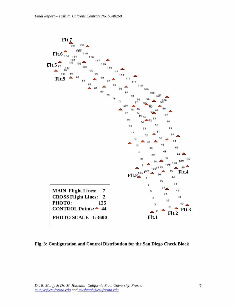
Flt6
Flt8Flt4
Flt3Flt2
Flt1
t5
Flt9
Flt7
MAIN Flight Lines 7CROSS Flight Lines 2PHOTO 125CONTROL Points 44
Flt6
Flt8Flt4
Flt3Flt2
Flt1
t5
Flt9
Flt7
MAIN Flight Lines 7CROSS Flight Lines 2PHOTO 125CONTROL Points 44
PHOTO SCALE 13600
Flt6
Flt8Flt4
Flt3Flt2
Flt1
t5
Flt9
Flt7
MAIN Flight Lines 7CROSS Flight Lines 2PHOTO 125CONTROL Points 44
Final Report ndash Task 7 Caltrans Contract No 65A0260
Flt7
Flt6
FlFlFlFlt5
Flt9
Flt4Flt8
MAIN Flight Lines 7 CROSS Flight Lines 2 PHOTO 125 CONTROL Points 44 Flt3
Flt2 PHOTO SCALE 13600 Flt1
Fig 3 Configuration and Control Distribution for the San Diego Check Block
Dr R Munjy amp Dr M Hussain California State University Fresno munjyrcsufresnoedu and mushtaqhcsufresnoedu
7
Final Report ndash Task 7 Caltrans Contract No 65A0260
35 Processing Plan and Methodology
In order to investigate the impact of block configuration the use of cross flight lines and the distribution of ground control the San Diego Check Block was processed in the following different configuration and control combinations
Block Configurations
a) FULL Block Uses all Flight Lines 1 through 9 b) MAIN Block Uses Flight Lines 1 through 7 only omits Cross Flights 8 amp 9 c) NORTH Block Uses Flight Lines 5 6 and 7 d) NORTHX Block Uses Flight Lines 56 and 7 and includes Cross Flight 9 e) SOUTH Block Uses Flight Lines 1 through 4 f) SOUTHX Block Uses Flight Lines 1 through 4 and includes Cross Flight 8 g) SOUTHM Block Uses Flight Lines 12 and 3 trimmed to the same length as
Flight Line 4 (11 Models) and includes Cross Flight 8
Control Distribution
The following considerations were used for the placement and distribution of control points along the perimeter of a block
a) A Ground Control Point (GCP) should fall at each end of each Flight Line b) In addition to (a) above a GCP should control every block corner c) When a Cross Flight Line overlaps the ends of Flight Lines the condition at (a)
above to be replaced with the requirement for a GCP at each end of the Cross Flight Line
d) On large blocks in a direction parallel to the flight lines GCPs should control the block perimeter with spacing not exceeding 8 airbases if cross flights do not exist
e) No GCP is provided in the block interior
The above considerations resulted in formulation of 22 blocks with different flight line and control configurations The block diagram showing the Photos used and the GCP distribution in each of the 22 different cases is given in the Appendix section of this report
As stated above 22 different aerial triangulation blocks were processed using the Interactive Simultaneous Bundle Block Adjustment Windows based software Interactive Simultaneous Bundle Block Adjustment-ISBBAW The input for the processing included the following data files provided by Caltrans Office of Photogrammetry
1) Ground Control Data File Project Datum Information Units US Survey Foot Horizontal CCS83 Zone 6 Epoch 200700 Vertical NAVD88
Dr R Munjy amp Dr M Hussain California State University Fresno munjyrcsufresnoedu and mushtaqhcsufresnoedu
8
Final Report ndash Task 7 Caltrans Contract No 65A0260
a-priori XY 010 ft a-priori Z 010 ft
2) Image Coordinate Data File Type Machine Coordinates a-priori xy 0006 mm
3) Airborne GPS Antenna Data File (at Photo exposure time) Datum Same as Project Datum a-priori XY 015 ft a-priori Z 015 ft
The Office of Photogrammetry had pointed out the unreliability of the GPS data corresponding to Photo 77 Accordingly the GPS data for Photo 77 was made ineffective by assigning a standard error of 100 feet for its coordinates
In addition the latest aerial camera calibration data was also provided and was used to update the camera data file
Each block was processed using Affine Transformation for obtaining photo coordinates that were corrected for systematic errors for lens distortion atmospheric refraction and earth curvature No unacceptably large transformation residuals were obtained Each block was then adjusted using Strip Drift Parameters during Bundle adjustment
36 Results and Analysis
In processing all the 22 different cases of the aerial triangulation no ground or image point was rejected The processing of all the blocks indicated good internal consistency in the measurement data as the Standard Error of Unit Weight (Sigma-sub0 0 ) varied from 048 to 060 the latter value resulted in Case 1 FULL Block Using all 44 GCP It also indicated good precision in image transfer (through pugging) and coordinate measurement the RMS values in the x-coordinate varied from 00022 to 00032 mm while the RMS value for the y-coordinate varied from 00037 to 00042 mm
An important consideration for this research study is the reliability of the ground control data The relative precision of all the 44 GCPs is convincingly validated from the block in Case-1 when all the 44 points are used The RMS values in the control point residuals are (ft)
RMS in X-coordinate 0035 RMS in Y-coordinate 0035 RMS in Z-coordinate 0048
For 13600 scale wide-angle photography Caltrans existing aerial triangulation accuracy standards require the RMS in control points to not exceed 1 part in 10000 of the flying
Dr R Munjy amp Dr M Hussain California State University Fresno munjyrcsufresnoedu and mushtaqhcsufresnoedu
9
Final Report ndash Task 7 Caltrans Contract No 65A0260
height above average terrain Therefore for the average flying height of 1800 feet above terrain this standard would require that the coordinate RMS value should not exceed 018 ft The above result represents a level of precision more than three-times what is permissible according to standard Consequently it proves that the available ground control data meets the required precision to serve as check data in evaluating the cases using a limited number of perimetric control points
In order to systematically evaluate the impact of ground control point distribution on a block the results obtained in each block were used to investigate the coordinate differences at the Check Points these are the ground surveyed control points that are not included as control points in processing the block and their coordinate values are computed as tie points in the block adjustment solution The differences between the aerial triangulation adjusted coordinates and the known ground control coordinates for the Check Points were computed and the average value and the standard deviation in these coordinate differences are listed in Table-1 for each processing case The results obtained are discussed in the following section
CaseNo
Block Type No of Chk Pts X Y Z
St Err X Y Z
Avg Err X Y Z
Max Err X Y Z
Min Err
1 2 3 4 5
FullBlk_All 44CP FullBlk_8CP FullBlk_9CP FullBlk_10CP
0 36 35 34
007 008 005 012 012 016 012 012 017 012 009 015
002 001 -005 001 -001 -008 003 005 -009
024 027 026 024 024 026 024 027 021
-025 -039 -032 -026 -040 -034 -025 -013 -035
MainBlk(Flts1to7)_43CP 0 006 008 005 6 MainBlk1-7_ 8CP 36 016 012 027 -002 -004 -004 026 020 041 -035 -036 -082 7 MainBlk1-7_10CP 34 014 012 027 -001 -003 -004 022 020 039 -031 -031 -080 8 9 10 11 12 13
MainBlk1-7_ 12CP 32 015 010 017 003 000 -004 037 016 035 -031 -027 -023 NorthBlk_567amp9_5CP NorthBlk_567amp9_7CP NorthBlk_567_6CP NorthBlk_567_8CP
18 16 17 15
012 016 016 010 016 017 010 016 022
007 -016 011 008 -007 018 010 -002 008
026 002 036 023 010 051 024 015 050
-022 -062 -022 -016 -051 -012 -019 -043 -026
011 016 017 013 -009 002 029 007 037 -017 -049 -031 SouthBlk_1234amp8_4CP 22 052 032 015 -082 033 003 -007 091 026 -149 -009 -034
14 SouthBlk_1234amp8_6CP 20 013 016 015 -003 006 -002 024 033 033 -019 -028 -028 15 SouthBlk_1234amp8_7CP 19 015 012 014 -003 -002 -002 025 023 033 -025 -030 -025 16 SouthBlk1to4 No XFlt_7CP 22 015 013 023 -001 -005 003 026 023 032 -027 -029 -037 17 SouthBlk1to4 No XFlt_8CP(a) 21 014 012 024 005 -001 004 031 025 033 -022 -029 -040 18 SouthBlk1to4 No XFlt_8CP(b) 21 016 014 019 -003 -005 001 027 025 028 -033 -033 -032 19 SouthBlk1to4 No XFlt_10CP 19 014 012 019 004 -001 001 034 029 029 -025 -030 -028 20 21 22
SouthBlk1to4 No XFlt_11CP 18 014 012 018 -001 -005 -001 023 020 027 -030 -029 -031 ModifiedSouthBlk_1234amp8_ 5CP ModifiedSouthBlk_1234_6CP
19 16
013 010 015 014 011 014
-001 002 -001 002 005 -010
024 021 035 025 024 016
-019 -025 -029 -020 -024 -039
Table-1 Summary of the Coordinate Differences at the Check Points
In accordance with Caltrans Accuracy Standards for Aerial Triangulation the standard error in the adjusted coordinates of a tie point should not exceed 110000th of the average flying height above the terrain level The San Diego Check Block was flown at an average flying height of 1800 feet above terrain resulting in an average photo scale of 13600 Accordingly the limiting standard error in the adjusted coordinates of tie points amounts to 018 ft As is evident from the results summarized in Table-1 in case of vertical aerial photography the height error is larger than the error in the X- or the Yshycoordinate with few exceptions Therefore one may primarily focus only on the
Dr R Munjy amp Dr M Hussain California State University Fresno munjyrcsufresnoedu and mushtaqhcsufresnoedu
10
Final Report ndash Task 7 Caltrans Contract No 65A0260
standard error in the height in order to analyze the various scenarios represented by the 22 different cases
361 FULL Block (Case-1 to 4)
In the case of FULL Block (Flts 1 to 9) by controlling each edge (corner) of the block and each edge of any cross strip by a single CP as in Case-2 Caltrans accuracy standard is met In case-3 an additional CP was used at the block corner formed where the Flight 4 ends while the Flight 3 continues southward The addition of this corner point does not significantly enhance the accuracy of the solution This is due to the fact that the Flight-3 at this point is controlled by GPS data
It is interesting to note that even though the Flight 7 (at the northern end of the block) is 15 models long a single CP located at the end of this flight appears to be sufficient for control The fact that the spacing between the end CPs at the lower end of this block segment (Flight 5) is only about 10 models adds to the strength In order to check the influence of additional control points along the block perimeter with reduced spacing a CP was added in the middle of Flight 7 as shown in Case-4 This does result in some improvement in the accuracy of the block solution consequently this would appear to be the optimum control configuration
362 MAIN Block (Case-5 to 8)
The MAIN Block (Flts 1 to 7) was used to study any impact in using cross flights for GPS controlled aerial triangulation blocks When a large number of control points are available such as in Case-3 where 43 CPs are used the results are identical whether or not cross flights are used However when a CP is used only at the block corners as in Case-6 (analogous with Case-2 in FULL Block) the required accuracy standard is not met This standard is also not met when an additional corner CP is used as shown in Case-7 (analogous with Case-3 in FULL Block) However when the spacing between the perimetric control points is confined to about 8 models as shown in the Case-8 the results are within the required accuracy standard A comparison of Case-4 and Case-8 shows that if the cross Flights 8 and 9 are not used additional control points along the block perimeter in a direction parallel to the flight lines can compensate for it and meet the required accuracy standard
363 NORTH Block (Case-9 to 12)
The above analysis was repeated by splitting the San Diego Check Block into two subshyblocks a NORTH Block and a SOUTH Block The NORTH Block (Flts 5 to 7 and 9) was processed first by including the cross Flight 9 and also by excluding this cross flight The results tabulated in Table-1 in Case 9 to 12 are identically similar to the ones obtained earlier with the FULL and the MAIN Blocks It again shows that when a CP is located at the end of the cross Flight 9 in the northern end of the block and a CP is used at the end of each of the three flight lines at the southern end of the block the required accuracy standards are met even when no CP is located in the middle of the 15-model
Dr R Munjy amp Dr M Hussain California State University Fresno munjyrcsufresnoedu and mushtaqhcsufresnoedu
11
Final Report ndash Task 7 Caltrans Contract No 65A0260
long Flight-7 (Case-9) In fact it is seen in Case-10 that the addition of an intermediate point along the perimeter did not improve the accuracy
Without the cross Flight 9 however a comparison of the Case-12 with Case-11 clearly shows that the reduction in the spacing between the perimetric control points is necessary for meeting the required accuracy standard In this block size and configuration the nonshyuse of a cross flight could have been compensated with the use of one additional control point along the perimeter
364 SOUTH Block (Case-13 to 20)
The SOUTH Block consisting of Flights 1 to 4 and the cross Flight 8 has somewhat unusual configuration it is not a compact rectangular block and the cross Flight-8 intersects the block rather than at either end of the block Eight different scenarios for flight and control configuration were used in handling this sub-block
The Case-13 is based on the use of only four CPS one located at each of the four block corners This case might work for small and rectangular blocks with a cross flight at each end of the block However for Case-13 the cross Flight is completely uncontrolled and so is the southern corner of Flight-4 Obviously this has resulted in the planimetric RMS error that exceeds 05 ft
When a CP was located at each end of the cross Flight 8 as seen in Case-14 as well as a CP was added at the end of each flight line the block solution met the accuracy standard The addition of another corner CP as shown in Case-15 did not contribute to any significant improvement in the accuracy This shows the role that the intersecting cross Flight 8 plays in strengthening the geometry of the block by reducing the uncontrolled segment of each of the three Flight lines 1 to 3
The Case-16 to 20 convincingly demonstrate the degradation in the block geometry when the cross Flight 8 is removed from the block None of the block configurations shown in Case 16 to 19 strictly meets the accuracy requirement the Case-18 and Case-19 missing the minimal accuracy standard by 001 ft It is only when another corner CP is added as shown in Case-20 that the minimal accuracy standard is attained
365 SOUTH-MODIFIED Block (Case-21 amp 22)
In order to further validate the conclusions derived so far the SOUTH Block was modified to a more conventional rectangular shaped block by removing photos from Flight 1 to 3 to bring them to the same length as Flight 4 The SOUTH_MODIFIED Block is not only have a rectangular shape but the cross Flight 8 now falls at the southern of this sub-block With the Flight 8 now playing the normal role of a cross flight the minimal control layout seen in Case-21 easily meets the accuracy standard As observed in previous
Dr R Munjy amp Dr M Hussain California State University Fresno munjyrcsufresnoedu and mushtaqhcsufresnoedu
12
Final Report ndash Task 7 Caltrans Contract No 65A0260
blocks locating a CP at each end of each flight line meets the accuracy standard for this block with 11-model long flight lines
The above observations and the conclusions were used to draft the Preliminary Standards for Block Configuration Airborne GPS Controlled Photogrammetry for Large Scale Mapping Projects and submitted as Interim Report in fulfillment of the requirement under Task 32 of the contract [14]
4 TEST BLOCK
41 Planning
The extra-ordinary fiscal problems faced by the State of California had resulted in the suspension of work on the project Consequently a no-cost extension in the time for completion of this project beyond March 31 2009 till December 31 2009 was requested by California State University Fresno in November 2008 This request in the extension of period was strongly supported by Caltrans Office of Photogrammetry This request was approved by Caltrans Division of Research and Innovation and California State University Fresno was notified by Caltrans Contract Manager on April 2 2009 to continue work on the project till December 31 2009
A planning meeting between the California State University Fresno research team and the representatives from Caltrans Office of Photogrammetry was held in Caltrans Office in Sacramento on April 20 2009 for the design of an optimal test block In the light of the results obtained from the San Diego Check Block and the conclusions presented in the Interim Report submitted in January 2009 various options and proposals for selecting the site and configuration for a test block were discussed The Caltrans Office of Photogrammetry and the California State University Fresno fully agreed on the following characteristics for the Test Block
The aerial photography should fully conform to the Caltrans practice of using a metric wide-angle aerial camera from an altitude of 1800 ft above the terrain level to result in an average photo scale of 13600
The main block should consist of 4 parallel flight lines of 18 models each A cross flight should be flown at each end of the main block Full 3-D ground control should be provided along the perimeter of the main block
with a control point spacing of 6 to 8 airbases Full 3-D ground control for the two cross flights should be planned so that
- A pair of 3-D control points are located at each end of each cross flight and - At least one Height control point falls at each end of each main flight line
A sufficient number (15 to 20) of additional ground control points should be distributed in the interior of the block to serve as check points for estimating the absolute accuracy of aerial triangulation results
All the 6 flight lines constituting the Test Block should be flown as a single flight mission
Dr R Munjy amp Dr M Hussain California State University Fresno munjyrcsufresnoedu and mushtaqhcsufresnoedu
13
Final Report ndash Task 7 Caltrans Contract No 65A0260
The airborne GPS data as well as the data at the ground Base Stations should be collected at 1 Hz or higher data rate
The flight mission should be carried out under weather and environmental conditions so as to avoid any degradation in the quality of aerial imagery
Even though implementing the above technical requirements in a test block did not pose any serious problems the California State University Fresno as well as the Caltrans Office of Photogrammetry had serious concerns about adhering to the tight project schedule Both the parties in this project were convinced that the award of an aerial photography services contract for a Test Block by the California State University Fresno through a formal selection and competitive bidding process would entail serious delays that may even jeopardize the completion of the project by the ending date of December 31 2009 An attractive and viable alternative was to utilize the services of an aerial photography vendor that had recently been contracted by Caltrans for the acquisition of aerial photography for a highway corridor along Interstate I-5 in Northern San Diego The flying for this Caltrans project was fortuitously scheduled for May 2009 that synchronized very well with the schedule for this research project
Accordingly with full consultation with the Caltrans Office of Photogrammetry a Test Block was designed by the California State University Fresno in Del Mar in Northern San Diego The Del Mar Test Block included a variety of terrain a large expanse of marsh and river suburban residential large freeway and rolling hills A separate contract was negotiated and awarded by the California State University Fresno to the Caltrans contractor for the San Diego I-5 Project for the acquisition of aerial photography for the Del Mar Test Block This approach used in awarding the contract resulted in the following benefits
The aerial photography contractor had already been pre-qualified by Caltrans for the quality of the aircraft aerial camera aerial film and GPS and navigation equipment used for the acquisition of aerial photography
The aerial photography contractor had already been pre-qualified by Caltrans for the quality of aerial photography products (developed negative film diapositives prints etc)
The aerial photography contractor had already been pre-qualified by Caltrans for the certification of aerial camera calibration electronic integration of the aerial camera with the airborne GPS receiver to record the aerial exposure events and the geometric integration of the airborne GPS antenna mounted on the fuselage with the aerial camera
The contractor was familiar with the detailed Caltrans specifications for the acquisition of aerial photography and the same specifications would strictly govern the flight mission for the Del Mar Test Block
Dr R Munjy amp Dr M Hussain California State University Fresno munjyrcsufresnoedu and mushtaqhcsufresnoedu
14
Final Report ndash Task 7 Caltrans Contract No 65A0260
42 Acquisition of Aerial Photography
The flight configuration and ground control distribution for the Del Mar Test Block was finalized near the end of April 2009 and is shown in Fig 41 As stated earlier the contract for the aerial photography acquisition was awarded to IKCurtis Services Inc Burbank California who had earlier been awarded the Caltrans contract to fly Route 5 and 56 in San Diego The Caltrans Office of Photogrammetry also arranged for field survey teams from Caltrans District 11 in San Diego to supplement the ground control network established for the Caltrans project with the additional ground control points planned for the Del Mar Test Block This further ensured that the quality of the ground control data used for the Del Mar Test Block would fully conform to Caltrans aerial triangulation control standards All the fieldwork required for the Caltrans Route 5 and 56 Project and for the Del Mar Test Block of the California State University Fresno research project was completed in early May 2009
Based on the weather reports and the suitability of GPS satellite configuration it was mutually agreed between the Caltrans Office of Photogrammetry Caltrans District 11 California State University Fresno and IK Curtis Services Inc to fly the two projects on May 13 2009 with May 14 2009 as a backup date I K Curtis Services Inc had been assigned the task of collecting the airborne GPS data during the flight mission while field survey staff from Caltrans District 11 were responsible for the simultaneous collection of GPS data at four designated base stations Whether the two separate projects are flown as a single flight mission or as two separate missions on the same day or on separate days was left entirely to the mutual judgment of the flight crew and Caltrans Project Coordinator from District 11 based on the weather and environmental conditions in the area
A final field survey task is to visit each control point location and repaint if necessary those control marks that fall on a hard surface and to deploy specially designed panel at each control point that lies on grass or open and marshy ground Even though all the ground control targets had been readied in time unfortunately adverse weather reports and worsening fog and cloudy conditions were totally unsuitable for flying on May 13 or on May 14 Based on the weather forecast similar flight dates were set on several occasions each time requiring the reconnaissance of the ground targets but the adverse weather conditions extended over several weeks After continuing efforts at planning and repeated cancellations it was finally possible to complete the aerial photography requirements for both the projects through a single flight mission carried out on July 14 2009 Even though two models at the end of one cross flight in the Del Mar Test Block contain some cloud coverage fortunately it was still possible to identify and measure the image coordinates of the ground control points falling in both the models
Dr R Munjy amp Dr M Hussain California State University Fresno munjyrcsufresnoedu and mushtaqhcsufresnoedu
15
6
5
Final Report ndash Task 7 Caltrans Contract No 65A0260
Fig 41 San Diego Test Block Configuration and Control Distribution
1 2 3 411 22 33 44
66
55
Dr R Munjy amp Dr M Hussain California State University Fresno munjyrcsufresnoedu and mushtaqhcsufresnoedu
16
Final Report ndash Task 7 Caltrans Contract No 65A0260
43 Test Block Data Acquisition
After the delivery of the aerial diapositives by the Contractor the photogrammetric data for the aerial triangulation of the Del Mar Test Block was measured and compiled by Caltrans Office of Photogrammetry The selection of tie points and the measurement of image coordinate data for the entire block consisting of 6 flight lines and 96 photos was carried out following the routine analytical methodology and practice used for all Caltrans aerial triangulation blocks
The following measurement data was provided by the Office of Photogrammetry to California State University Fresno in August 2009
- Image coordinate data - Ground control coordinate data - Raw GPS data from airborne receiver and four base station receivers - GPS time for photo exposure - Camera calibration data - Camera and GPS antenna offset
44 Test Block Data Processing
Before processing the aerial triangulation data received from the Office of Photogrammetry some clarification regarding the processing datum were necessary as discussed in the following section
441 Processing Datum
It was reported that the datum used for the ground control data provided by Caltrans District 11 was as below
- Horizontal Control CCS83 Epoch199135 Datum - Vertical Control NAVD88 Datum
Based on discussions with representatives from Caltrans District 11 it was determined that the 3-D adjustment of the GPS ground control network was performed in CCS83-Epoch 199135 datum for the horizontal control while the vertical coordinates were adjusted by fixing the orthometric height (NAVD88 Datum) of 4 network stations The geoidal height data needed for the reduction of observed ellipsoidal height data (GRS80 Ellipsoid) to adjusted orthometric height data (NAVD88 Datum) was based on the Geoid2003 Global Model Consequently the orthometric height data for the ground control used for the Del Mar Test Block may be affected by any height variation between the Local Geoid from the Global Geoid
442 Post-Processing of Airborne GPS Data
Dr R Munjy amp Dr M Hussain California State University Fresno munjyrcsufresnoedu and mushtaqhcsufresnoedu
17
Final Report ndash Task 7 Caltrans Contract No 65A0260
Even though the Caltrans Office of Photogrammetry had provided the post-processed results for the airborne GPS data this data was also processed at the California State University Fresno Even though GPS data at four different base stations had been collected and the GrafNav post-processing software provides the option to use multiple base station data it was decided to carry out the kinematic processing of the airborne GPS data relative to a single base station HPGN DC 11 The selection of this base station was due to the fact that this was the only base station for which the orthometric height had been held fixed in the GPS network adjustment none of the other three network stations for which the orthometric height was held fixed had been used as a base station during the flight mission
The results and the analysis provided in the following section are based on the airborne GPS data processed at the California State University Fresno
443 Aerial Triangulation Data Processing
The first objective for the aerial triangulation processing of the Del Mar Test Block data was to further verify the aerial triangulation results obtained with the San Diego Check Block reported in Section 3 A second and more important objective was to evaluate the impact of flight configuration and the control point distribution on the achievable aerial triangulation accuracy for large scale (13600) aerial photography used in Caltrans It was of special interest to assess the impact of the use of cross flights and the optimal distribution of the ground control points in an airborne GPS supported aerial triangulation block
The same approach and the methodology were used for processing the aerial triangulation of the Del Mar Test Block as has previously been discussed in detail in Section 35 for the San Diego Check Block Aerial triangulation data was processed systematically by using block configuration with and without the two cross flights (see Fig 41) The number and the distribution of the control points used primarily along the block perimeter varied from 8 to 14 control points Since the Del Mar Test Block was covered with a total of 33 field control points all the points that were not used as control points in processing the block served as Check Points Theoretically such Check Points are the most reliable indicators of the absolute accuracy of the aerial triangulation results provided the coordinate data for such Check Points is at least three times more precise than the precision of the coordinate data for the tie points resulting from aerial triangulation adjustment [15] In the case of the Del Mar Test Block data the uncertainty of 2 to 3 cm in the geoidal height interpolated from the global Geoid Model leads to the estimated precision of the Check Point data to be more precise than the aerial triangulation data by a factor of 12 to 2 only This fact has to be kept in focus while analyzing the absolute accuracy of the aerial triangulation results as part contributions from the errors in Check Point data cannot be entirely ignored
The airborne GPS supported aerial triangulation blocks are fully controlled through the airborne GPS data in the interior of the block Therefore the precision of the airborne GPS data plays a crucial role in the resulting aerial triangulation accuracy The
Dr R Munjy amp Dr M Hussain California State University Fresno munjyrcsufresnoedu and mushtaqhcsufresnoedu
18
Final Report ndash Task 7 Caltrans Contract No 65A0260
processing of the Test Block was carried out by using the following a-priori standard errors for the airborne GPS data (a) Standard error for X and Y-coord 025 ft Standard error for Z-coord 025 ft (b) Standard error for X and Y-coord 010 ft Standard error for Z-coord 015 ft
Based on the analysis of the results that are discussed in Section 5 it was finally decided to use the following a-priori standard error for the airborne GPS data
Standard error for X and Y-coord 015 ft Standard error for Z-coord 015 ft
The results for the block configuration that includes the two cross flights for a total of 6 flight lines are summarized as Cases 1 through 5 in Table 2 The Blocks processed without the use of the two cross flights and comprising only the 4 parallel flight lines are shown in Table 2 as Cases 6 through 12
Case BLOCK Number of St Error Ave Error Max Error Min Error
No Type Check Pts X Y Z X Y Z X Y Z X Y Z
1 6Flt_Blk_33CP 0 004 004 005
2 6Flt_Blk_8CP 25 009 008 019 -002 001 -007 013 018 032 -027 -012 -052
3 6Flt_Blk_12CP 21 010 008 014 -004 -003 005 009 013 029 -028 -015 -030
4 6Flt_Blk_14aCP 19 010 006 015 000 -003 001 012 013 027 -025 -016 -034
5 6Flt_Blk_14bCP 19 010 008 015 -001 -001 006 011 013 028 -025 -014 -031
6 4Flt_Blk_33CP 0 004 002 006 -002 000 001
7 4Flt_Blk_8CP 25 012 008 059 004 006 -108 028 024 016 -022 -009 -109
8 4Flt_Blk_11aCP 22 013 009 019 -001 -002 -017 017 016 028 -028 -016 -050
9 4Flt_Blk_11bCP 22 014 009 027 -005 003 -031 016 020 030 -031 -015 -066
10 4Flt_Blk_12CP 21 013 009 020 -002 000 -008 016 018 031 -027 -016 -033
11 4Flt_Blk_14aCP 19 010 008 013 004 -002 -003 016 015 025 -021 -017 -020
12 4Flt_Blk_14bCP 19 009 007 012 -001 -001 005 009 013 028 -025 -014 -012
Table-2 Summary of the Coordinate Differences at the Check Points
The control distribution used in the processing of the 12 cases is illustrated in Fig 42 through 411 below The corresponding statistics for the resulting errors at the Check Points are shown for each case The Check Points where the maximum errors in the X- Y- and Z-coordinate occur are shown in different color according to the legend below
Control pointControl point
MMaax error in Xx error in X
MMaax error in Yx error in Y
MMaax error in Zx error in Z LEGEND (Figures 42 through 411)
Dr R Munjy amp Dr M Hussain California State University Fresno munjyrcsufresnoedu and mushtaqhcsufresnoedu
19
Final Report ndash Task 7 Caltrans Contract No 65A0260
Fig 42 Block with Cross Strips 8 Control Points 25 Check Points Case 2
SSttaannddaardrd EErrorrorr AAvveeraraggee EErrrroorr MMaaxxiimmuumm EErrorrorr MMiinniimmuumm EErrorrorr XX YY ZZ XX YY ZZ XX YY ZZ XX YY ZZ
000099 000088 001199 --000022 000011 --000707 001133 001818 003232 --002277 --001212 --005522
Dr R Munjy amp Dr M Hussain California State University Fresno munjyrcsufresnoedu and mushtaqhcsufresnoedu
20
Final Report ndash Task 7 Caltrans Contract No 65A0260
Fig 43 Block with Cross Strips 12 Control Points 23 Check Points Case 3
SSttaannddaardrd EErrorrorr AAvveeraraggee EErrrroorr MMaaxxiimmuumm EErrorrorr MMiinniimmuumm EErrorrorr XX YY ZZ XX YY ZZ XX YY ZZ XX YY ZZ
001100 000088 001144 --000044 --000303 000055 000099 001313 002929 --002288 --001515 --003300
Dr R Munjy amp Dr M Hussain California State University Fresno munjyrcsufresnoedu and mushtaqhcsufresnoedu
21
Final Report ndash Task 7 Caltrans Contract No 65A0260
Fig 44 Block with Cross Strips 14 Control Points 21 Check Points Case 4
SSttaannddaardrd EErrorrorr AAvveeraraggee EErrrroorr MMaaxxiimmuumm EErrorrorr MMiinniimmuumm EErrorrorr XX YY ZZ XX YY ZZ XX YY ZZ XX YY ZZ
001100 000088 001155 --000011 --000101 000066 001111 001313 002828 --002255 --001414 --003311
Dr R Munjy amp Dr M Hussain California State University Fresno munjyrcsufresnoedu and mushtaqhcsufresnoedu
22
Final Report ndash Task 7 Caltrans Contract No 65A0260
Fig 45 Block with Cross Strips 14 Control Points 21 Check Points Case 5
SSttaannddaardrd EErrorrorr AAvveeraraggee EErrrroorr MMaaxxiimmuumm EErrorrorr MMiinniimmuumm EErrorrorr XX YY ZZ XX YY ZZ XX YY ZZ XX YY ZZ 001100 000066 001155 000000 --000033 000011 001122 001133 002277 --002255 --001166 --003344
Dr R Munjy amp Dr M Hussain California State University Fresno munjyrcsufresnoedu and mushtaqhcsufresnoedu
23
Final Report ndash Task 7 Caltrans Contract No 65A0260
Fig 46 Block without Cross Strips 8 Control Points 25 Check Points Case 7
SSttaannddaardrd EErrorrorr AAvveeraraggee EErrrroorr MMaaxxiimmuumm EErrorrorr MMiinniimmuumm EErrorrorr XX YY ZZ XX YY ZZ XX YY ZZ XX YY ZZ 001122 000088 005599 000404 000606 --110088 002288 002244 001166 --002222 --000099 --110099
Dr R Munjy amp Dr M Hussain California State University Fresno munjyrcsufresnoedu and mushtaqhcsufresnoedu
24
Final Report ndash Task 7 Caltrans Contract No 65A0260
Fig 47 Block without Cross Strips 11 Control Points 22 Check Points Case 8
SSttaannddaardrd EErrorrorr AAvveeraraggee EErrrroorr MMaaxxiimmuumm EErrorrorr MMiinniimmuumm EErrorrorr XX YY ZZ XX YY ZZ XX YY ZZ XX YY ZZ
001133 000099 001199 --000011 --000202 --001177 001177 001166 002288 --002828 --001166 --005050
Dr R Munjy amp Dr M Hussain California State University Fresno munjyrcsufresnoedu and mushtaqhcsufresnoedu
25
Final Report ndash Task 7 Caltrans Contract No 65A0260
Fig 48 Block without Cross Strips 11 Control Points 22 Check Points Case 9
SSttaannddaardrd EErrorrorr AAvveeraraggee EErrrroorr MMaaxxiimmuumm EErrorrorr MMiinniimmuumm EErrorrorr XX YY ZZ XX YY ZZ XX YY ZZ XX YY ZZ
001144 000099 002277 --000055 000033 --003131 001166 002020 003030 --003311 --001515 --006666
Dr R Munjy amp Dr M Hussain California State University Fresno munjyrcsufresnoedu and mushtaqhcsufresnoedu
26
Final Report ndash Task 7 Caltrans Contract No 65A0260
Fig 49 Block without Cross Strips 12 Control Points 21 Check Points Case 10
SSttaannddaardrd EErrorrorr AAvveeraraggee EErrrroorr MMaaxxiimmuumm EErrorrorr MMiinniimmuumm EErrorrorr XX YY ZZ XX YY ZZ XX YY ZZ XX YY ZZ 001133 000099 002200 --000022 000000 --000808 001166 001818 003131 --002277 --001616 --003333
Dr R Munjy amp Dr M Hussain California State University Fresno munjyrcsufresnoedu and mushtaqhcsufresnoedu
27
Final Report ndash Task 7 Caltrans Contract No 65A0260
Fig 410 Block without Cross Strips 14 Control Points 19 Check Points Case 11
SSttaannddaardrd EErrorrorr AAvveeraraggee EErrrroorr MMaaxxiimmuumm EErrorrorr MMiinniimmuumm EErrorrorr XX YY ZZ XX YY ZZ XX YY ZZ XX YY ZZ
001100 000088 001133 000044 --000022 --000303 001166 001515 002525 --002211 --001717 --002200
Dr R Munjy amp Dr M Hussain California State University Fresno munjyrcsufresnoedu and mushtaqhcsufresnoedu
28
Final Report ndash Task 7 Caltrans Contract No 65A0260
Fig 411 Block without Cross Strips 14 Control Points 19 Check Points Case 12
SSttaannddaardrd EErrorrorr AAvveeraraggee EErrrroorr MMaaxxiimmuumm EErrorrorr MMiinniimmuumm EErrorrorr XX YY ZZ XX YY ZZ XX YY ZZ XX YY ZZ
000099 000077 001122 --000011 --000101 000055 000099 001313 002828 --002255 --001414 --001122
Dr R Munjy amp Dr M Hussain California State University Fresno munjyrcsufresnoedu and mushtaqhcsufresnoedu
29
Final Report ndash Task 7 Caltrans Contract No 65A0260
5 ANALYSIS OF RESULTS amp CONCLUSIONS
In accordance with the Caltrans standards using wide-angle aerial photography the RMS error in each coordinate component of the adjusted tie points should not exceed 110000 of the flying height above the terrain The Del Mar Test Block was flown with a wideshyangle aerial camera from an average height of 1800 feet above the terrain level thereby resulting in an average photo scale of 13600 Consequently the limiting RMS error at the Check Points representative of a finite number of well distributed tie points in the block should not exceed 018 ft in this case Any error that exceeds three times this limiting value viz 054 ft in any of the coordinate components should be a cause for rejection of that point
Therefore the acceptable limiting values for the standard error at the Check Points is 018 ft in each coordinate component Any block adjustment solution that results in a coordinate error in one or more Check Points that exceeds 054 ft in any coordinate component would not be an acceptable solution The following analysis of the results is based on these accuracy criteria
51 Blocks With Cross Flights
When a minimal number of 8 control points are used (Fig 42) along the block perimeter the resulting standard error in Z-coordinate of 019 ft exceeds the limiting value of 015 ft It is also noticeable that the highest error in the Z-coordinate of 052 ft at Point 189134 almost equals the rejection limit of 054 ft This is an indication that controlling a cross flight with only a single Control Point at each end of the flight may not always provide a satisfactory solution
This situation can be remedied by using a pair of Control Points in each end model of a cross flight so that any deformation across the flight line the omega rotation () can also be controlled Such an approach is also reported to have been successfully used and recommended in the past [1] [2] [3] When 4 additional Control Points were added at the end of each cross flight line as is seen in Fig 43 all the standard errors fell within the acceptable range and the maximum coordinate error did not exceed 030 ft which is well within the acceptable criteria
The primary advantage of using airborne GPS data for the adjustment of aerial triangulation blocks is to completely eliminate the need for Control Points in the interior of the block But it is of interest to investigate how effectively the airborne GPS data alone can control the interior of the block Two separate blocks were processed by adding two Control Points in the interior of the block resulting in a total of 14 Control Points
The block with 14 Control Points (Case A) is shown in Fig 44 where the two interior Control Points were selected so that one Control Point was located on the opposite ends in each of the two interior flight lines (Line 2 and Line3 see Fig 41) The other block with 14 Control Points (Case B) is shown in Fig 45 In this case both the interior points
Dr R Munjy amp Dr M Hussain California State University Fresno munjyrcsufresnoedu and mushtaqhcsufresnoedu
30
Final Report ndash Task 7 Caltrans Contract No 65A0260
fell in the middle of the block interior It is interesting to note that in either of the two cases the addition of the interior Control Points did not result in any significant difference from the result achieved earlier while using 12 Control Points Therefore it may be concluded that as long as the cross flights are adequately controlled with a pair of Control Points located across each end model of each cross flight additional control in the block interior is not required The results shown in Fig 44 and 45 validate this conclusion at least for a block comprised of 18 models long multiple flight lines
52 Blocks Without Cross Flights
When a mapping project involves a large photogrammetric block consisting of hundreds of models the common practice is to plan the block configuration to include cross flights [1] [2] [6] [10] Often such cross flights can result in significant saving in time and effort in minimizing the need for ground control Since the photogrammetric mapping projects in Caltrans mostly involve mapping along highway corridors most of the photogrammetric blocks vary from a single flight line to up to as many as four flight lines Therefore it is still to be investigated whether the use of cross flight lines in such blocks offers any significant advantage Furthermore any advantage resulting from the reduced need for the ground control has to be weighed against the additional time and effort needed in processing the cross flight models The Caltrans Office of Photogrammetry has not yet adopted the use of Automated Aerial Triangulation (AAT) techniques for routine production Consequently the additional effort in transferring tie points between the cross flights with the flights of the main block is still significant This has provided the impetus to carry out the following investigation for the aerial triangulation adjustment of blocks that do not include any cross flights
The first block without the two cross flights was processed with only 8 Control points along the block perimeter as a parallel case with the block run with cross flights The results are shown in Fig 46 As may be expected the absence of any Control Point located at each end of each of the two interior flights 2 and 3 has resulted in unacceptably large errors Not only is the standard error of 059 ft in the Z-coordinate for the 25 Check Points too large but interestingly the block adjustment carries a large systematic error in Z-coordinate of 108 ft This results from the fact that the absence of the Control Points at each end of Flights 2 and 3 does not permit the adjustment for the systematic strip drift parameters for the airborne GPS data along Flights 2 and 3
When cross flights are included the airborne GPS data measured along the cross flight adequately serves as control for adjusting the strip shift and drift parameters Therefore an alternative to the inclusion of cross flights in the block configuration is to provide a Control Point at each end of every flight line in the block Accordingly the processing of the following blocks includes Control Points at the end of each flight line
The Del Mar Test Block with 4 flight lines each 18 models long would require a total of 12 Control Points one Control Point at each end of each flight line and 4 Control Points along the interior perimeter of the block to provide a control spacing of approximately 6 airbases apart However in order to minimize the use of the ground control the block
Dr R Munjy amp Dr M Hussain California State University Fresno munjyrcsufresnoedu and mushtaqhcsufresnoedu
31
Final Report ndash Task 7 Caltrans Contract No 65A0260
shown in Fig 47 was processed with only 11 Control Points (Case A) since the Control Point 170133 was measured both in Line 2 and Line 3 The resulting standard error of 019 ft in the Z-coordinate for 22 Check Points as well as the large error of 050 ft in the Z-coordinate of Check Point 189134 make the block adjustment solution unacceptable There appears to be no obvious reason why the Check Point 189134 that is located so close to the Control Point 170133 should display such unacceptably large error in the Zshycoordinate In order to ascertain the internal consistency of the ground control data (33 Control Points) a conventional aerial triangulation adjustment of the block was performed (without using the airborne GPS data) using 32 Control Points and treating the Control Point 189134 as a Check Point The resulting error in the Z-coordinate of Point 189134 was only 006 ft It is also to be noted that the average Z-coordinate error of 017 ft indicates a systematic height error This would lead to the conclusion that there is some height discrepancy between the ground control data and the airborne GPS data
The block was re-processed (Case B) again by using only 11 Control Points but this time the Control Point 170133 was replaced with Control Point 189134 and the results are displayed in Fig 48 The Case B results are even worse than the Case A results the standard error in Z-coordinate was degraded to 027 ft while the largest error in Zshycoordinate of 066 ft was noted at Check Point 187215 The average Z-coordinate error also increases to 031 ft This is a further indication that there is significant height inconsistency in the airborne GPS data and the ground control data It appears that the height discrepancy between the ground control data and the airborne GPS data results in an unsatisfactory shift and drift adjustment of the airborne GPS data particularly in the inner flight Lines 2 and 3 that span 18 models between the end Control Points
In order to strengthen the end control across the flight lines both the Control Points 170133 and 189134 were used at the Northern end of the block The block was then processed with 12 Control Points and the results are presented in Fig 49 Even though the results improved significantly but contrary to the expectation the standard error in the Z-coordinate of 020 ft for the 21 Check Points did not meet the Caltrans accuracy standard The next logical approach was to investigate the impact of adding Control Points in the interior of the block Two interior Control Points were selected in the same manner as has been described earlier in the case of the blocks with the cross flights (see Fig 44 and 45)
Using 14 Control Points the Case A is shown in Fig 410 while the Case B is presented in Fig 411 The results in both Case A and Case B easily meet the Caltrans accuracy standards In Case A the distance between the Control Points for the shift and drift parameter adjustment of the airborne GPS data varies from 6 to 12 models while in Case B the interior Control Points are about 6 models apart Each Control Point distribution provides almost similar results It is a clear indication that any systematic height deformation that results from the suspected inconsistency between the ground surveyed GPS data and the airborne GPS data can be kept within acceptable range by including a pair of control points in the interior of the block Such a need for some control points has not been reported for the adjustment of aerial triangulation blocks in the past However the largest photo scale for which any ABGPS supported results have been published in
Dr R Munjy amp Dr M Hussain California State University Fresno munjyrcsufresnoedu and mushtaqhcsufresnoedu
32
Final Report ndash Task 7 Caltrans Contract No 65A0260
the past is 14800 only For a photo scale of 13600 that is approximately 25 percent larger the requirements for the accuracy of aerial triangulation accordingly become more stringent in the same proportion This may generate the need for some additional control in the middle of the block
The residuals at the ground control points and in the image coordinate data along with the resulting standard error of unit weight (0) provide a reliable indication of the internal consistency of the adjusted block However the absolute accuracy of the aerial triangulation can be validated only by the use of Check Points that are well distributed over the entire block As pointed out earlier any deformations due to residual systematic shift and drift errors in the airborne GPS data are likely to be most significant in the center of the block the location that is farthest from the control points distributed along the perimeter Accordingly it would be advisable to locate at least a pair of Check Points in the middle of the block and after completing the block adjustment (by excluding these Check Points as Control Points) the coordinate discrepancies obtained at these Check Points can be analyzed Such discrepancies would normally represent the highest absolute accuracy resulting from aerial triangulation adjustment of the block Any unacceptably large coordinate discrepancies at the Check Points would require investigation of the block input data
In the case the coordinate discrepancies at the Check Points are within acceptable range the block can be re-processed by also including the Check Points in the control data This should enhance the accuracy in the interior of the block
6 RECOMMENDED DRAFT STANDARDS
These draft standards are proposed to supplement the existing Standards for Strip Configuration Airborne GPS Controlled Photogrammetry for Large Scale Mapping Projects (based on 13600 photo scale) currently used in Caltrans
61 Data Acquisition
611 Image Coordinate Data
Follow the existing practice used in Caltrans Office of Photogrammetry for the selection distribution and the measurement of all image point data It is recommended that raw machine coordinate image data should form the input to the aerial triangulation block adjustment
A secondary interest in this Research Project under contract with Caltrans was to also evaluate the alternate methodology of the selection and the measurement of tie point data using Automated Aerial Triangulation (AAT) system However several problems were encountered in implementing the AAT software available at the Caltrans Office of Photogrammetry in Sacramento The unavoidable delay caused by unfavorable weather conditions in acquiring the aerial imagery for the Del Mar Test Block did not allow
Dr R Munjy amp Dr M Hussain California State University Fresno munjyrcsufresnoedu and mushtaqhcsufresnoedu
33
Final Report ndash Task 7 Caltrans Contract No 65A0260
enough time to resolve the AAT software issues with software vendor Accordingly this task could not be fully completed Therefore it was mutually agreed between the Caltrans Office of Photogrammetry and California State University Fresno to concentrate research efforts on the processing and the analysis of the Del Mar Test Block and on drafting the Final Report
612 Ground Control Data
The proposed research is focused on the use of photography obtained at scale of 13600 for corridor mapping in Caltrans The ground control for mapping is based on the airborne GPS supported aerial triangulation of the photo blocks The ground control points should be surveyed to provide 15 to 2-times higher accuracy than that of the adjusted tie point data This would translate to an accuracy at the 005 to 01 ft level for the planimetric coordinates and the height an accuracy achievable using static GPS surveys tied to existing HPGN network
It is not yet certain that the Real-Time Kinematic (RTK) GPS field survey methodology whether relying on a single base station or on an RTK network is able to meet the above stringent field survey accuracy requirements Therefore the ground control data for ABGPS based aerial triangulation blocks should be based entirely on GPS control networks established using static GPS surveying methodology The RTK survey methodology for establishing control for photogrammetric mapping projects should not be used till such time that such technology has advanced to a level when consistently reliable results can be routinely expected
The GPS observations provide a fairly precise data for ellipsoidal height differences However all photogrammetric mapping has to be based on orthometric height data Two different approaches can be used in order to derive adjusted orthometric height data through aerial triangulation The first method is to carry out the simultaneous least squares adjustment of the GPS observation data for the ground control network using current Caltrans Horizontal Datum CCS83 (199135) and Vertical Datum NAVD 88 But since the observed data involves the measurement of ellipsoidal height differences for each measured baseline there is a need for transforming such differences to the corresponding orthometric height differences on NAVD 88 Datum In the absence of an existing Local Geoid Model the only economic recourse available to meet this need is to use the most reliable existing Global Geoid Model the time-consuming and prohibitively more costly alternative would be to connect the control network stations through differential leveling The Global Geoid Models are progressively being updated and the GEOID 2003 Model is most commonly in current use although GEOID 2009 Model may soon become available
It has to be noted that the use of a Global Geoid Model will always have some residual geoidal height uncertainties perhaps in the range of few hundredths of a foot It is therefore necessary that a few stations that are well distributed over the control network should have precisely known orthometric height values which can be used for the height adjustment of the network The minimum number of such orthometric height control
Dr R Munjy amp Dr M Hussain California State University Fresno munjyrcsufresnoedu and mushtaqhcsufresnoedu
34
Final Report ndash Task 7 Caltrans Contract No 65A0260
stations is three and consequently a network should be planned to have at least four and preferably more stations where orthometric height is precisely known In practice this requirement is met by including several existing benchmarks that are well distributed over the project area The redundancy provided by using more than three benchmarks will quantify the height residuals resulting from the adjustment This will provide a good estimate for the residual height errors in the network
The alternative approach is to carry out the adjustment of the GPS control network using WGS84 Geodetic Datum This datum is consistent with the observed GPS measurement data and a simultaneous 3D adjustment of the network can be performed in a Local Spatial Coordinate System (LSCS) the most commonly used approach is to shift the origin of the WGS84 coordinate system (center of the Earth) to approximately the center of the project site and apply a 3D rotational matrix to align the coordinate axes along the East North and Up directions Some commercial aerial triangulation software systems provide utilities to easily perform such datum transformation After the aerial triangulation results have been validated the coordinates of all the control and tie points can be transformed back to WGS 84 Datum Based on the availability of the orthometric height control stations a local Geoid can be defined ( a plane or a surface etc) and then used to transform the ellipsoidal height data to orthometric height data This second approach has the advantage that unlike the first method described above the residual height errors in the transformed control point height data are not propagated through aerial triangulation
For 13600 scale aerial photography blocks the ground control data should meet the a- priori standard deviation at 010 ft level This is not a very challenging demand for the horizontal positioning using GPS methodology However the residual height uncertainties in the orthometric height of control points interpolated from the Global Geoid Model become more critical as the photo scale becomes larger
613 Airborne GPS Data
The current practice used in Caltrans to acquire airborne GPS data during flight missions should continue to be used It is necessary to have GPS data collected at 1 Hz or higher rate at a base station that is located within or close to the project site Prior research completed collaboratively with Caltrans has already shown that the data at the base station may be substituted with GPS data collected at CORS at 5-sec or higher rate Consequently the collection of GPS data at more than one base stations is not considered as an essential requirement It may still be prudent to acquire GPS data at a second base station as a contingency safeguard against the GPS hardware failure at a base station for guaranteed success of the flight mission and expense
It is to be noted that the relative accuracy between successive airborne GPS antenna 3Dshycoordinates should be at 10-cm or higher level The current procedure used in Caltrans for the aircraft to remain stationary for static resolution of ambiguities before take off has mostly resulted in acquiring very reliable airborne GPS data This practice should perhaps be continued even though the continuing improvements in GPS hardware and
Dr R Munjy amp Dr M Hussain California State University Fresno munjyrcsufresnoedu and mushtaqhcsufresnoedu
35
Final Report ndash Task 7 Caltrans Contract No 65A0260
post-processing softwares are making on-the-fly (OTF) ambiguity resolution increasingly reliable However if it is necessary to resort to on-the-fly ambiguity resolution it must be ensured that the ambiguities have stabilized before photography is started The strict requirement for reliably resolving the ambiguities also does not permit the loss of lock during any single flight line If a loss of lock occurs during turns between flight lines ambiguities must be re-acquired and must stabilize before starting the collection of photography for another flight line Based on the make and the model of the airborne GPS receiver the Caltrans Office of Photogrammetry in consultation with the District Survey Section should draft a set of instructions for the GPSCamera operator aboard the aircraft specifying what parameters (such as PDOP Number of SVs etc) that need to be continuously monitored on a screen during a flight mission
62 Flight and Control Configuration
The following standards in planning the flight line configuration and the corresponding ground control distribution for Caltrans project are recommended to achieve optimum results
Control points are primarily required only along the perimeter of the block When a cross flight line is used to control the end of a block a pair of Control
Points must be located at each end of the cross flight At each end of a block that is not controlled by a cross flight a CP should be
located at the end of each parallel flight line a single CP may serve as end control for two adjacent overlapping flight lines
Along the perimeter of the block in a direction parallel with the main flight lines the CPs should be located at an average spacing of 6 airbases
Any corner in a block resulting from a sudden change in the length of two adjacent parallel flight lines should be controlled by an additional CP
Check Points should be provided along the interior flight lines in a multi-strip block The Check Points may be distributed along the interior flight lines so that any Check Point is not farther than about 8 airbases from either another Check Point (on same or adjacent flight line) or from a Control Point
Note that Caltrans is usually concerned with the mapping mostly along highway corridors and therefore does not require blocks with segments larger than three or four parallel flight lines Additional control along the cross flight line would be needed if such segments have 8 or more parallel flight lines
63 Data Processing and Adjustment
631 Processing of ABGPS Data
The current practice of post-processing ABGPS data used in Caltrans Office of Photogrammetry using GrafNav software should be continued The data should continue to be processed in the Forward and Backward modes A coordinate separation of less
Dr R Munjy amp Dr M Hussain California State University Fresno munjyrcsufresnoedu and mushtaqhcsufresnoedu
36
Final Report ndash Task 7 Caltrans Contract No 65A0260
than 10 cm especially in the height represents a normally acceptable range for the combined solution
This study has shown that the airborne GPS data in comparison with the ground control data should be weighted a lower weight but the highest weight that the GPS data quality represents Generally the best results were achieved when a-priori standard error of 015 ft was used for the airborne GPS coordinate data in comparison with the a-priori standard error of 010 ft used for the ground control coordinate data Since the 3-D position of successive points along the airborne GPS antenna trajectory are estimated using Kalman Filtering approach the successive location coordinates are highly correlated and consequently carry a much higher relative precision This provides a realistic justification for the use of a-priori standard error of 015 ft
632 Processing of Aerial Triangulation Block
Each aerial triangulation block requires the following data files as input
- Raw image coordinate data file - Ground control data file - Interpolated camera coordinate data file
Using the above input data files the block adjustment should be carried out in two steps as described below It is essential that additional Strip Shift and Drift parameters (3 Shift and 3 Drift parameters) should be incorporated in the bundle adjustment solution
Step 1 Minimal Control Adjustment
The preliminary simultaneous bundle adjustment of the block should be carried out by using the minimal amount of control points along the block perimeter only All the additional ground surveyed and targeted points should be treated as tie points to serve as Check Points The adjustment results should meet the following criteria
a The Standard Error of Unit Weight (0) should fall between 03 to 07 b The residual for any image coordinate should not exceed 15 micrometer c The RMS for ground control residuals should not exceed 110000 of the flying
height above the average terrain level d The maximum residual in any ground control coordinate should not exceed 25
times the RMS value permissible under Item (c) above e The RMS for discrepancy (difference between computed coordinate value and
the ground surveyed coordinate value) in Check Point coordinates should not exceed 110000 of the flying height above the average terrain level
f The discrepancy in any Check Point coordinate should not exceed 25 times the RMS value permissible under Item (e) above
If the above criteria are met even the preliminary adjustment solution for the block satisfies Caltrans accuracy standards for aerial triangulation If the criterion under Item
Dr R Munjy amp Dr M Hussain California State University Fresno munjyrcsufresnoedu and mushtaqhcsufresnoedu
37
Final Report ndash Task 7 Caltrans Contract No 65A0260
(f) above is not met the input data should be checked for any gross mistakes or errors in the ground control and Check Point data
Step 2 Full Control Adjustment
The final simultaneous bundle adjustment of the block should be carried out by including all the ground surveyed points (Control Points and Check Points) in the ground control data file The adjustment results should meet the following criteria
g The Standard Error of Unit Weight (0) should fall between 03 to 07 h The residual for any image coordinate should not exceed 15 micrometer i The RMS for ground control residuals should not exceed 110000 of the flying
height above the average terrain level j The maximum residual in any ground control coordinate should not exceed 25
times the RMS value permissible under Item (i) above
7 CONCLUDING COMMENTS
The completion of this project signifies the culmination of a very successful and productive combination of advanced theoretical principles with sound practical experience for the adaptation of evolving photogrammetric technologies in Caltrans practice In order to alleviate a growing concern for the safety of staff conducting field survey operations in close proximity of high speed traffic Caltrans in late 1990s decided to investigate the feasibility of using airborne GPS data for controlling the aerial triangulation blocks There were two primary issues to be resolved The first and the foremost concern was whether the use of airborne GPS data could be effectively used for controlling aerial triangulation blocks of as large a photo scale as 13000 used in Caltrans and still meet the Caltrans accuracy standards This concern was particularly critical since there had not been any reported use of airborne GPS data for such a large scale of aerial photography
Should the above investigation show that the Caltrans accuracy standards for aerial triangulation for 13000 scale aerial photography can be met it was of great interest to Caltrans to develop based on theoretically sound and systematic investigation a set of standards and specifications for the successful implementation of this new methodology in Caltrans routine practice
Under a Caltrans New Technology and Research Program currently Division of Research and Innovation (DRI) contract Caltrans Office of Photogrammetry partnered with a team of two faculty members from the Geomatic Engineering Program at the California State University Fresno (CSUF) in 1996 to carry out research to address the above two issues This partnership has flourished over the past several years through
Dr R Munjy amp Dr M Hussain California State University Fresno munjyrcsufresnoedu and mushtaqhcsufresnoedu
38
Final Report ndash Task 7 Caltrans Contract No 65A0260
successive research contracts and has resulted in very fortuitous outcomes based on the theoretical and analytical guidance provided by the CSUF research team and the highly skilled aerial survey project management and high caliber professional skills in the acquisition of photogrammetric data collection by the Caltrans Office of Photogrammetry In addition the help from highly experienced field survey teams from Caltrans various districts (especially District 11) in establishing GPS networks of Control Points and Check Points of specified precision was critical for the validation of airborne-GPS supported aerial triangulation investigations
As a result of the past collaborative efforts between the Caltrans Office of Photogrammetry and the CSUF Research Team the use of airborne GPS data for aerial triangulation has successfully been transitioned into Caltrans practice in the following stages
1) Based on a number of test flights it was convincingly demonstrated that the use of airborne GPS data consistently meets the Caltrans accuracy standards for aerial triangulation for strip configuration blocks at 13000 photo scale [13]
2) A detailed set of standards and specifications were developed for the implementing of the new methodology in Caltrans routine practice This was further supported through a training workshop conducted by CSUF at the Caltrans offices in Sacramento [8]
3) The use of airborne GPS data for the adjustment of aerial triangulation blocks requires the collection of GPS data at one or more ground base stations during the flight mission This requirement imposes burdensome demands on scheduling and allocation of manpower and equipment resources In order to reduce or even to completely eliminate the need for the collection of GPS data at base stations the use of GPS data collected and archived at a network of Continuously Operating Reference Stations (CORS) distributed over the State of California was investigated It was demonstrated that CORS data could be effectively used as a replacement for data collected at base stations while fulfilling Caltrans accuracy standards Accordingly specifications were revised to also include the selection and the use of CORS data for the post-processing of airborne GPS data to accurately derive the trajectory of the airborne GPS antenna during flights [19]
4) During the past few years Caltrans has increasingly been using multi-strip projects for mapping using 13600 photo scale This provided the need for the current research study The successful completion of this study has resulted in supplementing the existing standards and specifications for airborne GPS supported single-strip aerial triangulation blocks to also include the aerial triangulation of multi-strip blocks
It is a matter of great satisfaction for the research team at CSU Fresno that working hand in hand with the Caltrans Office of Photogrammetry the comprehensive set of standards and specifications for airborne GPS supported aerial triangulation that had been developed for successful transition of this technology in Caltrans practice have been further upgraded It is hoped that as the photogrammetric technology advances further
Dr R Munjy amp Dr M Hussain California State University Fresno munjyrcsufresnoedu and mushtaqhcsufresnoedu
39
Final Report ndash Task 7 Caltrans Contract No 65A0260
similar collaborative efforts between Caltrans Office of Photogrammetry and CSU Fresno will continue to address the changing needs in Caltrans
Dr R Munjy amp Dr M Hussain California State University Fresno munjyrcsufresnoedu and mushtaqhcsufresnoedu
40
Final Report ndash Task 7 Caltrans Contract No 65A0260
REFERENCES
1 Abdullah Q M Hussain and R Munjy (2002) Workshop on Airborne GPS-Supported Aerial Triangulation ndash Theory and Practical Concepts presented at the Annual ASPRS Convention Washington DC 2002
2 Ackermann Fritz (1992) Operational Rules and Accuracy Models for GPS-Aerotriangulation Archives of the ISPRS Com 1 Vol29 1992 [pp 691-700]
3 Ackermann F (1993) Application of GPS for Aerial Triangulation Photogrammetric Engineering and Remote Sensing Vol 59 No 11 [pp 1651shy1658]
4 Appleton James Mushtaq Hussain and Riadh Munjy (2000) Use of Airborne GPS Data for Highway Mapping International Archives of Photogrammetry and Remote Sensing Vol XXXIII Part B4 Amsterdam 2000[pp 84-90]
5 Appleton James M Hussain and R Munjy (2002) Use of Airborne GPS Data For Aerial Triangulation in Caltrans (2002) Workshop presented at the California Department of Transportation Sacramento 2002
6 Federal Geographic Data Committee (FGDC) 1998 Geospatial Positional Accuracy Standards Part-3 National Standards for Spatial Data Accuracy (NSSDA) FGDC-STD-0073-1998
7 Friess Peter (1992) Experiences with GPS-Supported Aerial Triangulation Archives of the ISPRS Com 1 Vol29 1992 [pp 299 - 305]
8 Gianellia Alexander M (1995) Practical Considerations in Implementing GPS Technologies in Airborne Data Collection Proc ASPRS Annual Convention 1995 [pp 917-925]
9 Hussain M R Munjy and J Appleton (1999) Use of Airborne On-the-Fly Kinematic GPS Data for Photogrammetric Mapping Proceedings ION-GPS-99 Conference Nashville 1999[pp 1653-1659]
10 Hussain M and R Munjy (1999) GPS Controlled Photogrammetry For Large Scale Mapping (1999) Final Project Report Research project No 65Y271 submitted to New Technology amp Research Program California Department of Transportation
11 Hussain M and R Munjy (2002) Airborne GPS Controlled Aerial Triangulation in Caltrans Final Project Report Research project No 65A0059 submitted to New Technology amp Research Program California Department of Transportation June 2002
12 Munjy R and M Hussain (1985) Interactive Simultaneous Bundle Block Adjustment System (ISBBA) for Small Computers Proceedings of the ASPRS Annual Convention Washington DC 1985
13 Munjy R M Hussain and James Appleton (2000) Use of Airborne GPS Data for Corridor Mapping presented at the Annual ASPRS Convention Washington DC 2000
Dr R Munjy amp Dr M Hussain California State University Fresno munjyrcsufresnoedu and mushtaqhcsufresnoedu
41
Final Report ndash Task 7 Caltrans Contract No 65A0260
14 Munjy R and M Hussain (2007) Develop Criteria for Using Network GPS for Airborne GPS Photogrammetry Final Project Report Research Project No 65A0234 submitted to the Division of Research and Innovation (DRI) California Department of Transportation
15 Munjy R and M Hussain (2009) Draft Preliminary Standards Interim Report Research Project No 65A0260 submitted to Division of Research aned Innovation (DRI) California Department of Transportation
Dr R Munjy amp Dr M Hussain California State University Fresno munjyrcsufresnoedu and mushtaqhcsufresnoedu
42
APPENDIX I Results of Check Block
Flight amp Control Configuration Cases Used for
Study amp Analysis of Check Project in San Diego
INDEX
Case Block amp Control Configuration 1 Full Blk(Flts1to9) All 44 CP 2 Full Blk 8 CP 3 Full Blk 9 CP 4 Full Blk 10 CP 5 Main Blk(Flts1to7) 43 CP 6 Main Blk(Flts1to7) 8 CP 7 Main Blk(Flts1to7) 10 CP 8 Main Blk(Flts1to7) 12 CP 9 North Blk(Flts567amp9) 5 CP 10 North Blk(Flts567amp9) 7 CP 11 North Blk(Flts56amp7) 6 CP 12 North Blk(Flts56amp7) 8 CP 13 South Blk(Flts1to4amp8) 4 CP 14 South Blk(Flts1to4amp8) 6 CP 15 South Blk(Flts1to4amp8) 7 CP 16 South Blk(Flts1to4) 7 CP 17 South Blk(Flts1to4) 8 CP(a) 18 South Blk(Flts1to4) 8 CP(b) 19 South Blk(Flts1to4) 10 CP 20 South Blk(Flts1to4) 11 CP 21 South Blk(Flts Modified 1to4 amp8) 5 CP 22 South Blk(Flts Modified 1to4 ) 6 CP
[Refer to Table-1 Summary of the Coordinate Differences at the Check Points]
I-i
Case-1 Base DataFULL BLOCK
Flts 1 to 9
Case-1 Base Data FULL BLOCK
Flts 1 to 9
Control PointsControl Points All 44 PointsAll 44 Points
SSSttt ErErErrrr AAAvvvggg ErErErrrr MMMaaaxxx ErErErrrr MMMiiinnn ErErErrrr XXX YYY ZZZ XXX YYY ZZZ XXX YYY ZZZ XXX YYY ZZZ
007 008 005 000 000 000 019 012 012 -013 -023 -013007 008 005 000 000 000 019 012 012 -013 -023 -013007 008 005 000 000 000 019 012 012 -013 -023 -013
I-ii
Case-2FULL BLOCK
Flts 1 to 9
Control Points 8
Case-2 FULL BLOCK
Flts 1 to 9
Control Points 8 CChheecckk PoPointsints 3366
SStt ErErrr AAvvgg ErErrr MMaaxx ErErrr MMinin ErErrr XX YY ZZ XX YY ZZ XX YY ZZ XX YY ZZ
012012 012012 016016 002002 001001 --000505 024024 027027 026026 --025025 --039039 --032032
I-iii
Case-3FULL BLOCK
Flts 1 to 9
Control Points 9
Case-3 FULL BLOCK
Flts 1 to 9
Control Points 9 CChheecckk PoPointsints 3355
SStt ErErrr AAvvgg ErErrr MMaaxx ErErrr MMinin ErErrr XX YY ZZ XX YY ZZ XX YY ZZ XX YY ZZ
012012 012012 017017 001001 --001001 --000808 024024 024024 026026 --026026 --040040 --034034
I-iv
Case-4FULL BLOCK
Flts 1 to 9
Control Points 10
Case-4 FULL BLOCK
Flts 1 to 9
Control Points 10 CChheecckk PoiPoinntsts 3344
SStt ErErrr AAvvgg ErErrr MMaaxx ErErrr MMinin ErErrr XX YY ZZ XX YY ZZ XX YY ZZ XX YY ZZ
012012 009009 015015 003003 005005 --000909 002244 002727 002121 --025025 --001313 --035035
I-v
Case-5MAIN BLOCK
Flts 1 to 7
Control Points 43
Case-5 MAIN BLOCK
Flts 1 to 7
Control Points 43 [Point HV-117 Unuse[Point HV-117 Unusedd]]
SSSttt ErErErrrr AAAvvvggg ErErErrrr MMM aaaxxx ErErErrrr MMM iiinnn ErErErrrr XXX YYY ZZZ XXX YYY ZZZ XXX YYY ZZZ XXX YYY ZZZ
006006006 008008008 005005005 000000000 000000000 000000000 012012012 013013013 013013013 ---000131313 ---022022022 ---000090909
I-vi
Case-6
Flts 1 to 7
l Points 8
MAIN BLOCK
[No Cross Flts]Contro
Case-6 MAIN BLOCK
Flts 1 to 7 [No Cross Flts]
Control Points 8 ChecCheckk PoPointsints 3636
St ErSt ErSt ErSt ErSt ErSt ErSt ErSt Errrrrrrrr AAAAAAAAvgvgvgvgvgvgvgvg ErErErErErErErErrrrrrrrr MMMMMMMMaxaxaxaxaxaxaxax ErErErErErErErErrrrrrrrr MMMMMMMMiiiiiiiinnnnnnnn ErErErErErErErErrrrrrrrr XXXXXXXX YYYYYYYY ZZZZZZZZ XXXXXXXX YYYYYYYY ZZZZZZZZ XXXXXXXX YYYYYYYY ZZZZZZZZ XXXXXXXX YYYYYYYY ZZZZZZZZ
016016016016 012012012012 027027027027 -002-002-002-002 ----004004004004 -004-004-004-004 000026262626 000020202020 000041414141 ----035035035035 -036-036-036-036 ----082082082082
I-vii
Case-7MAIN BLOCK
Flts 1 to 7[No Cross Flts]
Control Points 10
Case-7 MAIN BLOCK
Flts 1 to 7 [No Cross Flts]
Control Points 10 CChheecckk PointsPoints 3434
SStt ErErrr AAvvgg ErErrr MM aaxx ErErrr MM iinn ErErrr XX YY ZZ XX YY ZZ XX YY ZZ XX YY ZZ
014 012 027 -001 -003 -004 022 020 039 -031 -031 -080014 012 027 -001 -003 -004 022 020 039 -031 -031 -080
I-viii
Case-8MAIN BLOCK
Flts 1 to 7[No Cross Flts]
Control Points 12
Case-8 MAIN BLOCK
Flts 1 to 7 [No Cross Flts]
Control Points 12 CheChecckk PointsPoints 3232
SSSttt ErErErrrr AAAvvvggg ErErErrrr MMMaaaxxx ErErErrrr MMMiiinnn ErErErrrr XXX YYY ZZZ XXX YYY ZZZ XXX YYY ZZZ XXX YYY ZZZ
015 010 017 003 000 -004 037 016 035 -031 -027 -023015 010 017 003 000 -004 037 016 035 -031 -027 -023015 010 017 003 000 -004 037 016 035 -031 -027 -023
I-ix
Case-9Case-9Case-9 NORNORNORTTTH BLH BLH BLOCKOCKOCK
FltsFltsFlts 5 to 7 amp 9 5 to 7 amp 9 5 to 7 amp 9
Control PointsControl PointsControl Points 555 ChChCheckeckeck PoPoPoininintttsss 111888
ErSSSttt EE rrrrr vg ErAAAvg Evg E rrrrr ax ErMMM ax Eax E rrrrr ErMMM iiinnn EE rrrrr XXX YYY ZZZ XXX YYY ZZZ XXX YYY ZZZ XXX YYY ZZZ
000121212 016016016 000161616 007007007 ---000161616 000111111 000262626 000020202 000363636 ---022022022 ---000626262 ---022022022
I-x
Case-Case-1100 NORTH BLOCKNORTH BLOCK
Flts 5 to 7 amp 9Flts 5 to 7 amp 9
Control PointsControl Points 77 CheckCheck PointsPoints 1616
SStt ErErrr AAvvgg ErErrr MM aaxx ErErrr MM iinn ErErrr XX YY ZZ XX YY ZZ XX YY ZZ XX YY ZZ
010010 016016 017017 008008 --000707 001818 002323 001010 005151 --016016 --005151 --012012
I-xi
Case-Case-1111 NORTH BLOCKNORTH BLOCK
FltsFlts 5 to 7 5 to 7
CCoontrntrool Pointsl Points 66 CheChecckk PointsPoints 1717
SStt ErErrr AAvvgg ErErrr MM aaxx ErErrr MM iinn ErErrr XX YY ZZ XX YY ZZ XX YY ZZ XX YY ZZ
010010 016016 022022 010010 --000202 000808 002424 001515 005050 --019019 --004343 --026026
I-xii
Case-Case-1122 NORTH BLOCKNORTH BLOCK
FltsFlts 5 to 7 5 to 7 [No C[No Crrossoss Flt]Flt]
ContControl Poinrol Pointsts 88 CChheecckk PointsPoints 1155
SStt EErrrr AAvg Evg Errrr MM ax Eax Errrr MM iinn EErrrr XX YY ZZ XX YY ZZ XX YY ZZ XX YY ZZ
011011 016016 017017 013013 --000909 000202 002929 000707 003737 --017017 --004949 --031031
I-xiii
CaseCase-13-13 SOUTSOUTH BH BLLOCKOCK
Flts 1 to 4 amp 8Flts 1 to 4 amp 8
CoConnttrol Porol Poininttss 44 ChCheckeck PPooinintsts 2222
SStt ErErrr AAvvgg ErErrr MM aaxx ErErrr MM iinn ErErrr XX YY ZZ XX YY ZZ XX YY ZZ XX YY ZZ
052 032 015 -082 033 003 -007 091 026 -149 -009 -034052 032 015 -082 033 003 -007 091 026 -149 -009 -034
I-xiv
Case-14Case-14 SOUTH BLOCKSOUTH BLOCK
Flts 1 to 4 amp 8Flts 1 to 4 amp 8
CCoontrntrool Pointsl Points 66 CheChecckk PointsPoints 2200
SStt ErErrr AAvvgg ErErrr MM aaxx ErErrr MM iinn ErErrr XX YY ZZ XX YY ZZ XX YY ZZ XX YY ZZ
013 016 015 -003 006 -002 024 033 033 -019 -028 -028013 016 015 -003 006 -002 024 033 033 -019 -028 -028
I-xv
Case-15Case-15 SOUTH BLOCKSOUTH BLOCK
FltsFlts 1 to 4 amp 8 1 to 4 amp 8
ContrControol Pointsl Points 77 ChCheckeck PPooinintsts 1919
SStt ErErrr AAvvgg ErErrr MM aaxx ErErrr MM iinn ErErrr XX YY ZZ XX YY ZZ XX YY ZZ XX YY ZZ
015 012 014 -003 -002 -002 025 023 033 -025 -030 -025015 012 014 -003 -002 -002 025 023 033 -025 -030 -025
I-xvi
Case-16Case-16Case-16 SOUTH BLOCKSOUTH BLOCKSOUTH BLOCK
FltsFltsFlts 1 to 4 1 to 4 1 to 4 [No Cross Flt][No Cross Flt][No Cross Flt]
Control PointsControl PointsControl Points 777 CheCheCheccckkk PointsPointsPoints 222222
SSSttt EEErrrrrr AAAvg Evg Evg Errrrrr MMM ax Eax Eax Errrrrr MMM iiinnn EEErrrrrr XXX YYY ZZZ XXX YYY ZZZ XXX YYY ZZZ XXX YYY ZZZ
015 013 023 -001 -005 003 026 023 032 -027 -029 -037015 013 023 -001 -005 003 026 023 032 -027 -029 -037015 013 023 -001 -005 003 026 023 032 -027 -029 -037
I-xvii
Case-17Case-17 SOUTSOUTH BLH BLOCKOCK
FltsFlts 1 1 to 4to 4 [No[No CrosCrosss Flt]Flt]
ContrControol Pointsl Points 88 CChheecckk PointsPoints 2121
SStt ErErrr AAvvgg ErErrr MM aaxx ErErrr MM iinn ErErrr XX YY ZZ XX YY ZZ XX YY ZZ XX YY ZZ
014014 012012 024024 005005 --000101 000404 003131 002525 003333 --022022 --002929 --040040
I-xviii
Case-18Case-18 SOUTH BLOCKSOUTH BLOCK
Flts 1 to 4Flts 1 to 4 [[NNo Cro Crooss Fss Flltt]]
CCoontrol Pointsntrol Points 88 CheChecckk PointsPoints 2121
SSSttt ErErErrrr AAAvvvggg ErErErrrr MMM aaaxxx ErErErrrr MMM iiinnn ErErErrrr XXX YYY ZZZ XXX YYY ZZZ XXX YYY ZZZ XXX YYY ZZZ
016 014 019 -003 -005 001 027 025 028 -033 -033 -032016 014 019 -003 -005 001 027 025 028 -033 -033 -032016 014 019 -003 -005 001 027 025 028 -033 -033 -032
I-xix
Case-19Case-19 SOUTH BLOCKSOUTH BLOCK
FltsFlts 1 to 4 1 to 4 [No Cross Flt][No Cross Flt]
ContControl Prol Poointintss 10 10 CheckCheck PointsPoints 1919
SSSttt ErErErrrr AAAvvvggg ErErErrrr MMM aaaxxx ErErErrrr MMM iiinnn ErErErrrr XXX YYY ZZZ XXX YYY ZZZ XXX YYY ZZZ XXX YYY ZZZ
014 012 019 004 -001 001 034 029 029 -025 -030 -028014 012 019 004 -001 001 034 029 029 -025 -030 -028014 012 019 004 -001 001 034 029 029 -025 -030 -028
I-xx
Case-Case-2200 SSOOUTH BLOCKUTH BLOCK
FltsFlts 1 to 4 1 to 4 [No Cross Flt][No Cross Flt]
Control Points 11Control Points 11 ChCheckeck PPooinintsts 1818
SSSttt ErErErrrr AAAvvvggg ErErErrrr MMM aaaxxx ErErErrrr MMM iiinnn ErErErrrr XXX YYY ZZZ XXX YYY ZZZ XXX YYY ZZZ XXX YYY ZZZ
014014014 012012012 018018018 ---000010101 ---005005005 ---000010101 000232323 000202020 000272727 ---030030030 ---000292929 ---031031031
I-xxi
Case-Case-2211 MODIMODIFFIIED SOUTH BED SOUTH BLLOCKOCK
FltsFlts 1 to 4 ( 1 to 4 (MModified)odified) amp 8amp 8
ControControl Pointsl Points 55 CheChecckk PointsPoints 1818
SStt ErErrr AAvvgg ErErrr MM aaxx ErErrr MM iinn ErErrr XX YY ZZ XX YY ZZ XX YY ZZ XX YY ZZ
013 010 015 -001 002 -001 024 021 035 -019 -025 -029013 010 015 -001 002 -001 024 021 035 -019 -025 -029
I-xxii
Case-22Case-22Case-22 MOMOMODIFDIFDIFIIIED SOED SOED SOUTH BLOCKUTH BLOCKUTH BLOCK
FltFltFltsss 1 to 4 1 to 4 1 to 4 (M(M(Modiodiodifiefiefieddd))) [No C[No C[No Crrrososossss Flt]Flt]Flt]
ConConContttrol Prol Prol Poooiiinnntttsss 666 ChChCheckeckeck PointPointPointsss 161616
SSSttt ErErErrrr AAAvvvggg ErErErrrr MMM aaaxxx ErErErrrr MMM iiinnn ErErErrrr XXX YYY ZZZ XXX YYY ZZZ XXX YYY ZZZ XXX YYY ZZZ
014 011 014 002 005 -010 025 024 016 -020 -024 -039014 011 014 002 005 -010 025 024 016 -020 -024 -039014 011 014 002 005 -010 025 024 016 -020 -024 -039
I-xxiii
APPENDIX II Results of Test Block
II-i
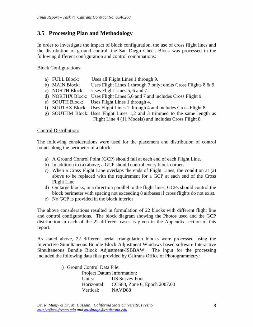
Final Report ndash Task 7 Caltrans Contract No 65A0260
35 Processing Plan and Methodology
In order to investigate the impact of block configuration the use of cross flight lines and the distribution of ground control the San Diego Check Block was processed in the following different configuration and control combinations
Block Configurations
a) FULL Block Uses all Flight Lines 1 through 9 b) MAIN Block Uses Flight Lines 1 through 7 only omits Cross Flights 8 amp 9 c) NORTH Block Uses Flight Lines 5 6 and 7 d) NORTHX Block Uses Flight Lines 56 and 7 and includes Cross Flight 9 e) SOUTH Block Uses Flight Lines 1 through 4 f) SOUTHX Block Uses Flight Lines 1 through 4 and includes Cross Flight 8 g) SOUTHM Block Uses Flight Lines 12 and 3 trimmed to the same length as
Flight Line 4 (11 Models) and includes Cross Flight 8
Control Distribution
The following considerations were used for the placement and distribution of control points along the perimeter of a block
a) A Ground Control Point (GCP) should fall at each end of each Flight Line b) In addition to (a) above a GCP should control every block corner c) When a Cross Flight Line overlaps the ends of Flight Lines the condition at (a)
above to be replaced with the requirement for a GCP at each end of the Cross Flight Line
d) On large blocks in a direction parallel to the flight lines GCPs should control the block perimeter with spacing not exceeding 8 airbases if cross flights do not exist
e) No GCP is provided in the block interior
The above considerations resulted in formulation of 22 blocks with different flight line and control configurations The block diagram showing the Photos used and the GCP distribution in each of the 22 different cases is given in the Appendix section of this report
As stated above 22 different aerial triangulation blocks were processed using the Interactive Simultaneous Bundle Block Adjustment Windows based software Interactive Simultaneous Bundle Block Adjustment-ISBBAW The input for the processing included the following data files provided by Caltrans Office of Photogrammetry
1) Ground Control Data File Project Datum Information Units US Survey Foot Horizontal CCS83 Zone 6 Epoch 200700 Vertical NAVD88
Dr R Munjy amp Dr M Hussain California State University Fresno munjyrcsufresnoedu and mushtaqhcsufresnoedu
8
Final Report ndash Task 7 Caltrans Contract No 65A0260
a-priori XY 010 ft a-priori Z 010 ft
2) Image Coordinate Data File Type Machine Coordinates a-priori xy 0006 mm
3) Airborne GPS Antenna Data File (at Photo exposure time) Datum Same as Project Datum a-priori XY 015 ft a-priori Z 015 ft
The Office of Photogrammetry had pointed out the unreliability of the GPS data corresponding to Photo 77 Accordingly the GPS data for Photo 77 was made ineffective by assigning a standard error of 100 feet for its coordinates
In addition the latest aerial camera calibration data was also provided and was used to update the camera data file
Each block was processed using Affine Transformation for obtaining photo coordinates that were corrected for systematic errors for lens distortion atmospheric refraction and earth curvature No unacceptably large transformation residuals were obtained Each block was then adjusted using Strip Drift Parameters during Bundle adjustment
36 Results and Analysis
In processing all the 22 different cases of the aerial triangulation no ground or image point was rejected The processing of all the blocks indicated good internal consistency in the measurement data as the Standard Error of Unit Weight (Sigma-sub0 0 ) varied from 048 to 060 the latter value resulted in Case 1 FULL Block Using all 44 GCP It also indicated good precision in image transfer (through pugging) and coordinate measurement the RMS values in the x-coordinate varied from 00022 to 00032 mm while the RMS value for the y-coordinate varied from 00037 to 00042 mm
An important consideration for this research study is the reliability of the ground control data The relative precision of all the 44 GCPs is convincingly validated from the block in Case-1 when all the 44 points are used The RMS values in the control point residuals are (ft)
RMS in X-coordinate 0035 RMS in Y-coordinate 0035 RMS in Z-coordinate 0048
For 13600 scale wide-angle photography Caltrans existing aerial triangulation accuracy standards require the RMS in control points to not exceed 1 part in 10000 of the flying
Dr R Munjy amp Dr M Hussain California State University Fresno munjyrcsufresnoedu and mushtaqhcsufresnoedu
9
Final Report ndash Task 7 Caltrans Contract No 65A0260
height above average terrain Therefore for the average flying height of 1800 feet above terrain this standard would require that the coordinate RMS value should not exceed 018 ft The above result represents a level of precision more than three-times what is permissible according to standard Consequently it proves that the available ground control data meets the required precision to serve as check data in evaluating the cases using a limited number of perimetric control points
In order to systematically evaluate the impact of ground control point distribution on a block the results obtained in each block were used to investigate the coordinate differences at the Check Points these are the ground surveyed control points that are not included as control points in processing the block and their coordinate values are computed as tie points in the block adjustment solution The differences between the aerial triangulation adjusted coordinates and the known ground control coordinates for the Check Points were computed and the average value and the standard deviation in these coordinate differences are listed in Table-1 for each processing case The results obtained are discussed in the following section
CaseNo
Block Type No of Chk Pts X Y Z
St Err X Y Z
Avg Err X Y Z
Max Err X Y Z
Min Err
1 2 3 4 5
FullBlk_All 44CP FullBlk_8CP FullBlk_9CP FullBlk_10CP
0 36 35 34
007 008 005 012 012 016 012 012 017 012 009 015
002 001 -005 001 -001 -008 003 005 -009
024 027 026 024 024 026 024 027 021
-025 -039 -032 -026 -040 -034 -025 -013 -035
MainBlk(Flts1to7)_43CP 0 006 008 005 6 MainBlk1-7_ 8CP 36 016 012 027 -002 -004 -004 026 020 041 -035 -036 -082 7 MainBlk1-7_10CP 34 014 012 027 -001 -003 -004 022 020 039 -031 -031 -080 8 9 10 11 12 13
MainBlk1-7_ 12CP 32 015 010 017 003 000 -004 037 016 035 -031 -027 -023 NorthBlk_567amp9_5CP NorthBlk_567amp9_7CP NorthBlk_567_6CP NorthBlk_567_8CP
18 16 17 15
012 016 016 010 016 017 010 016 022
007 -016 011 008 -007 018 010 -002 008
026 002 036 023 010 051 024 015 050
-022 -062 -022 -016 -051 -012 -019 -043 -026
011 016 017 013 -009 002 029 007 037 -017 -049 -031 SouthBlk_1234amp8_4CP 22 052 032 015 -082 033 003 -007 091 026 -149 -009 -034
14 SouthBlk_1234amp8_6CP 20 013 016 015 -003 006 -002 024 033 033 -019 -028 -028 15 SouthBlk_1234amp8_7CP 19 015 012 014 -003 -002 -002 025 023 033 -025 -030 -025 16 SouthBlk1to4 No XFlt_7CP 22 015 013 023 -001 -005 003 026 023 032 -027 -029 -037 17 SouthBlk1to4 No XFlt_8CP(a) 21 014 012 024 005 -001 004 031 025 033 -022 -029 -040 18 SouthBlk1to4 No XFlt_8CP(b) 21 016 014 019 -003 -005 001 027 025 028 -033 -033 -032 19 SouthBlk1to4 No XFlt_10CP 19 014 012 019 004 -001 001 034 029 029 -025 -030 -028 20 21 22
SouthBlk1to4 No XFlt_11CP 18 014 012 018 -001 -005 -001 023 020 027 -030 -029 -031 ModifiedSouthBlk_1234amp8_ 5CP ModifiedSouthBlk_1234_6CP
19 16
013 010 015 014 011 014
-001 002 -001 002 005 -010
024 021 035 025 024 016
-019 -025 -029 -020 -024 -039
Table-1 Summary of the Coordinate Differences at the Check Points
In accordance with Caltrans Accuracy Standards for Aerial Triangulation the standard error in the adjusted coordinates of a tie point should not exceed 110000th of the average flying height above the terrain level The San Diego Check Block was flown at an average flying height of 1800 feet above terrain resulting in an average photo scale of 13600 Accordingly the limiting standard error in the adjusted coordinates of tie points amounts to 018 ft As is evident from the results summarized in Table-1 in case of vertical aerial photography the height error is larger than the error in the X- or the Yshycoordinate with few exceptions Therefore one may primarily focus only on the
Dr R Munjy amp Dr M Hussain California State University Fresno munjyrcsufresnoedu and mushtaqhcsufresnoedu
10
Final Report ndash Task 7 Caltrans Contract No 65A0260
standard error in the height in order to analyze the various scenarios represented by the 22 different cases
361 FULL Block (Case-1 to 4)
In the case of FULL Block (Flts 1 to 9) by controlling each edge (corner) of the block and each edge of any cross strip by a single CP as in Case-2 Caltrans accuracy standard is met In case-3 an additional CP was used at the block corner formed where the Flight 4 ends while the Flight 3 continues southward The addition of this corner point does not significantly enhance the accuracy of the solution This is due to the fact that the Flight-3 at this point is controlled by GPS data
It is interesting to note that even though the Flight 7 (at the northern end of the block) is 15 models long a single CP located at the end of this flight appears to be sufficient for control The fact that the spacing between the end CPs at the lower end of this block segment (Flight 5) is only about 10 models adds to the strength In order to check the influence of additional control points along the block perimeter with reduced spacing a CP was added in the middle of Flight 7 as shown in Case-4 This does result in some improvement in the accuracy of the block solution consequently this would appear to be the optimum control configuration
362 MAIN Block (Case-5 to 8)
The MAIN Block (Flts 1 to 7) was used to study any impact in using cross flights for GPS controlled aerial triangulation blocks When a large number of control points are available such as in Case-3 where 43 CPs are used the results are identical whether or not cross flights are used However when a CP is used only at the block corners as in Case-6 (analogous with Case-2 in FULL Block) the required accuracy standard is not met This standard is also not met when an additional corner CP is used as shown in Case-7 (analogous with Case-3 in FULL Block) However when the spacing between the perimetric control points is confined to about 8 models as shown in the Case-8 the results are within the required accuracy standard A comparison of Case-4 and Case-8 shows that if the cross Flights 8 and 9 are not used additional control points along the block perimeter in a direction parallel to the flight lines can compensate for it and meet the required accuracy standard
363 NORTH Block (Case-9 to 12)
The above analysis was repeated by splitting the San Diego Check Block into two subshyblocks a NORTH Block and a SOUTH Block The NORTH Block (Flts 5 to 7 and 9) was processed first by including the cross Flight 9 and also by excluding this cross flight The results tabulated in Table-1 in Case 9 to 12 are identically similar to the ones obtained earlier with the FULL and the MAIN Blocks It again shows that when a CP is located at the end of the cross Flight 9 in the northern end of the block and a CP is used at the end of each of the three flight lines at the southern end of the block the required accuracy standards are met even when no CP is located in the middle of the 15-model
Dr R Munjy amp Dr M Hussain California State University Fresno munjyrcsufresnoedu and mushtaqhcsufresnoedu
11
Final Report ndash Task 7 Caltrans Contract No 65A0260
long Flight-7 (Case-9) In fact it is seen in Case-10 that the addition of an intermediate point along the perimeter did not improve the accuracy
Without the cross Flight 9 however a comparison of the Case-12 with Case-11 clearly shows that the reduction in the spacing between the perimetric control points is necessary for meeting the required accuracy standard In this block size and configuration the nonshyuse of a cross flight could have been compensated with the use of one additional control point along the perimeter
364 SOUTH Block (Case-13 to 20)
The SOUTH Block consisting of Flights 1 to 4 and the cross Flight 8 has somewhat unusual configuration it is not a compact rectangular block and the cross Flight-8 intersects the block rather than at either end of the block Eight different scenarios for flight and control configuration were used in handling this sub-block
The Case-13 is based on the use of only four CPS one located at each of the four block corners This case might work for small and rectangular blocks with a cross flight at each end of the block However for Case-13 the cross Flight is completely uncontrolled and so is the southern corner of Flight-4 Obviously this has resulted in the planimetric RMS error that exceeds 05 ft
When a CP was located at each end of the cross Flight 8 as seen in Case-14 as well as a CP was added at the end of each flight line the block solution met the accuracy standard The addition of another corner CP as shown in Case-15 did not contribute to any significant improvement in the accuracy This shows the role that the intersecting cross Flight 8 plays in strengthening the geometry of the block by reducing the uncontrolled segment of each of the three Flight lines 1 to 3
The Case-16 to 20 convincingly demonstrate the degradation in the block geometry when the cross Flight 8 is removed from the block None of the block configurations shown in Case 16 to 19 strictly meets the accuracy requirement the Case-18 and Case-19 missing the minimal accuracy standard by 001 ft It is only when another corner CP is added as shown in Case-20 that the minimal accuracy standard is attained
365 SOUTH-MODIFIED Block (Case-21 amp 22)
In order to further validate the conclusions derived so far the SOUTH Block was modified to a more conventional rectangular shaped block by removing photos from Flight 1 to 3 to bring them to the same length as Flight 4 The SOUTH_MODIFIED Block is not only have a rectangular shape but the cross Flight 8 now falls at the southern of this sub-block With the Flight 8 now playing the normal role of a cross flight the minimal control layout seen in Case-21 easily meets the accuracy standard As observed in previous
Dr R Munjy amp Dr M Hussain California State University Fresno munjyrcsufresnoedu and mushtaqhcsufresnoedu
12
Final Report ndash Task 7 Caltrans Contract No 65A0260
blocks locating a CP at each end of each flight line meets the accuracy standard for this block with 11-model long flight lines
The above observations and the conclusions were used to draft the Preliminary Standards for Block Configuration Airborne GPS Controlled Photogrammetry for Large Scale Mapping Projects and submitted as Interim Report in fulfillment of the requirement under Task 32 of the contract [14]
4 TEST BLOCK
41 Planning
The extra-ordinary fiscal problems faced by the State of California had resulted in the suspension of work on the project Consequently a no-cost extension in the time for completion of this project beyond March 31 2009 till December 31 2009 was requested by California State University Fresno in November 2008 This request in the extension of period was strongly supported by Caltrans Office of Photogrammetry This request was approved by Caltrans Division of Research and Innovation and California State University Fresno was notified by Caltrans Contract Manager on April 2 2009 to continue work on the project till December 31 2009
A planning meeting between the California State University Fresno research team and the representatives from Caltrans Office of Photogrammetry was held in Caltrans Office in Sacramento on April 20 2009 for the design of an optimal test block In the light of the results obtained from the San Diego Check Block and the conclusions presented in the Interim Report submitted in January 2009 various options and proposals for selecting the site and configuration for a test block were discussed The Caltrans Office of Photogrammetry and the California State University Fresno fully agreed on the following characteristics for the Test Block
The aerial photography should fully conform to the Caltrans practice of using a metric wide-angle aerial camera from an altitude of 1800 ft above the terrain level to result in an average photo scale of 13600
The main block should consist of 4 parallel flight lines of 18 models each A cross flight should be flown at each end of the main block Full 3-D ground control should be provided along the perimeter of the main block
with a control point spacing of 6 to 8 airbases Full 3-D ground control for the two cross flights should be planned so that
- A pair of 3-D control points are located at each end of each cross flight and - At least one Height control point falls at each end of each main flight line
A sufficient number (15 to 20) of additional ground control points should be distributed in the interior of the block to serve as check points for estimating the absolute accuracy of aerial triangulation results
All the 6 flight lines constituting the Test Block should be flown as a single flight mission
Dr R Munjy amp Dr M Hussain California State University Fresno munjyrcsufresnoedu and mushtaqhcsufresnoedu
13
Final Report ndash Task 7 Caltrans Contract No 65A0260
The airborne GPS data as well as the data at the ground Base Stations should be collected at 1 Hz or higher data rate
The flight mission should be carried out under weather and environmental conditions so as to avoid any degradation in the quality of aerial imagery
Even though implementing the above technical requirements in a test block did not pose any serious problems the California State University Fresno as well as the Caltrans Office of Photogrammetry had serious concerns about adhering to the tight project schedule Both the parties in this project were convinced that the award of an aerial photography services contract for a Test Block by the California State University Fresno through a formal selection and competitive bidding process would entail serious delays that may even jeopardize the completion of the project by the ending date of December 31 2009 An attractive and viable alternative was to utilize the services of an aerial photography vendor that had recently been contracted by Caltrans for the acquisition of aerial photography for a highway corridor along Interstate I-5 in Northern San Diego The flying for this Caltrans project was fortuitously scheduled for May 2009 that synchronized very well with the schedule for this research project
Accordingly with full consultation with the Caltrans Office of Photogrammetry a Test Block was designed by the California State University Fresno in Del Mar in Northern San Diego The Del Mar Test Block included a variety of terrain a large expanse of marsh and river suburban residential large freeway and rolling hills A separate contract was negotiated and awarded by the California State University Fresno to the Caltrans contractor for the San Diego I-5 Project for the acquisition of aerial photography for the Del Mar Test Block This approach used in awarding the contract resulted in the following benefits
The aerial photography contractor had already been pre-qualified by Caltrans for the quality of the aircraft aerial camera aerial film and GPS and navigation equipment used for the acquisition of aerial photography
The aerial photography contractor had already been pre-qualified by Caltrans for the quality of aerial photography products (developed negative film diapositives prints etc)
The aerial photography contractor had already been pre-qualified by Caltrans for the certification of aerial camera calibration electronic integration of the aerial camera with the airborne GPS receiver to record the aerial exposure events and the geometric integration of the airborne GPS antenna mounted on the fuselage with the aerial camera
The contractor was familiar with the detailed Caltrans specifications for the acquisition of aerial photography and the same specifications would strictly govern the flight mission for the Del Mar Test Block
Dr R Munjy amp Dr M Hussain California State University Fresno munjyrcsufresnoedu and mushtaqhcsufresnoedu
14
Final Report ndash Task 7 Caltrans Contract No 65A0260
42 Acquisition of Aerial Photography
The flight configuration and ground control distribution for the Del Mar Test Block was finalized near the end of April 2009 and is shown in Fig 41 As stated earlier the contract for the aerial photography acquisition was awarded to IKCurtis Services Inc Burbank California who had earlier been awarded the Caltrans contract to fly Route 5 and 56 in San Diego The Caltrans Office of Photogrammetry also arranged for field survey teams from Caltrans District 11 in San Diego to supplement the ground control network established for the Caltrans project with the additional ground control points planned for the Del Mar Test Block This further ensured that the quality of the ground control data used for the Del Mar Test Block would fully conform to Caltrans aerial triangulation control standards All the fieldwork required for the Caltrans Route 5 and 56 Project and for the Del Mar Test Block of the California State University Fresno research project was completed in early May 2009
Based on the weather reports and the suitability of GPS satellite configuration it was mutually agreed between the Caltrans Office of Photogrammetry Caltrans District 11 California State University Fresno and IK Curtis Services Inc to fly the two projects on May 13 2009 with May 14 2009 as a backup date I K Curtis Services Inc had been assigned the task of collecting the airborne GPS data during the flight mission while field survey staff from Caltrans District 11 were responsible for the simultaneous collection of GPS data at four designated base stations Whether the two separate projects are flown as a single flight mission or as two separate missions on the same day or on separate days was left entirely to the mutual judgment of the flight crew and Caltrans Project Coordinator from District 11 based on the weather and environmental conditions in the area
A final field survey task is to visit each control point location and repaint if necessary those control marks that fall on a hard surface and to deploy specially designed panel at each control point that lies on grass or open and marshy ground Even though all the ground control targets had been readied in time unfortunately adverse weather reports and worsening fog and cloudy conditions were totally unsuitable for flying on May 13 or on May 14 Based on the weather forecast similar flight dates were set on several occasions each time requiring the reconnaissance of the ground targets but the adverse weather conditions extended over several weeks After continuing efforts at planning and repeated cancellations it was finally possible to complete the aerial photography requirements for both the projects through a single flight mission carried out on July 14 2009 Even though two models at the end of one cross flight in the Del Mar Test Block contain some cloud coverage fortunately it was still possible to identify and measure the image coordinates of the ground control points falling in both the models
Dr R Munjy amp Dr M Hussain California State University Fresno munjyrcsufresnoedu and mushtaqhcsufresnoedu
15
6
5
Final Report ndash Task 7 Caltrans Contract No 65A0260
Fig 41 San Diego Test Block Configuration and Control Distribution
1 2 3 411 22 33 44
66
55
Dr R Munjy amp Dr M Hussain California State University Fresno munjyrcsufresnoedu and mushtaqhcsufresnoedu
16
Final Report ndash Task 7 Caltrans Contract No 65A0260
43 Test Block Data Acquisition
After the delivery of the aerial diapositives by the Contractor the photogrammetric data for the aerial triangulation of the Del Mar Test Block was measured and compiled by Caltrans Office of Photogrammetry The selection of tie points and the measurement of image coordinate data for the entire block consisting of 6 flight lines and 96 photos was carried out following the routine analytical methodology and practice used for all Caltrans aerial triangulation blocks
The following measurement data was provided by the Office of Photogrammetry to California State University Fresno in August 2009
- Image coordinate data - Ground control coordinate data - Raw GPS data from airborne receiver and four base station receivers - GPS time for photo exposure - Camera calibration data - Camera and GPS antenna offset
44 Test Block Data Processing
Before processing the aerial triangulation data received from the Office of Photogrammetry some clarification regarding the processing datum were necessary as discussed in the following section
441 Processing Datum
It was reported that the datum used for the ground control data provided by Caltrans District 11 was as below
- Horizontal Control CCS83 Epoch199135 Datum - Vertical Control NAVD88 Datum
Based on discussions with representatives from Caltrans District 11 it was determined that the 3-D adjustment of the GPS ground control network was performed in CCS83-Epoch 199135 datum for the horizontal control while the vertical coordinates were adjusted by fixing the orthometric height (NAVD88 Datum) of 4 network stations The geoidal height data needed for the reduction of observed ellipsoidal height data (GRS80 Ellipsoid) to adjusted orthometric height data (NAVD88 Datum) was based on the Geoid2003 Global Model Consequently the orthometric height data for the ground control used for the Del Mar Test Block may be affected by any height variation between the Local Geoid from the Global Geoid
442 Post-Processing of Airborne GPS Data
Dr R Munjy amp Dr M Hussain California State University Fresno munjyrcsufresnoedu and mushtaqhcsufresnoedu
17
Final Report ndash Task 7 Caltrans Contract No 65A0260
Even though the Caltrans Office of Photogrammetry had provided the post-processed results for the airborne GPS data this data was also processed at the California State University Fresno Even though GPS data at four different base stations had been collected and the GrafNav post-processing software provides the option to use multiple base station data it was decided to carry out the kinematic processing of the airborne GPS data relative to a single base station HPGN DC 11 The selection of this base station was due to the fact that this was the only base station for which the orthometric height had been held fixed in the GPS network adjustment none of the other three network stations for which the orthometric height was held fixed had been used as a base station during the flight mission
The results and the analysis provided in the following section are based on the airborne GPS data processed at the California State University Fresno
443 Aerial Triangulation Data Processing
The first objective for the aerial triangulation processing of the Del Mar Test Block data was to further verify the aerial triangulation results obtained with the San Diego Check Block reported in Section 3 A second and more important objective was to evaluate the impact of flight configuration and the control point distribution on the achievable aerial triangulation accuracy for large scale (13600) aerial photography used in Caltrans It was of special interest to assess the impact of the use of cross flights and the optimal distribution of the ground control points in an airborne GPS supported aerial triangulation block
The same approach and the methodology were used for processing the aerial triangulation of the Del Mar Test Block as has previously been discussed in detail in Section 35 for the San Diego Check Block Aerial triangulation data was processed systematically by using block configuration with and without the two cross flights (see Fig 41) The number and the distribution of the control points used primarily along the block perimeter varied from 8 to 14 control points Since the Del Mar Test Block was covered with a total of 33 field control points all the points that were not used as control points in processing the block served as Check Points Theoretically such Check Points are the most reliable indicators of the absolute accuracy of the aerial triangulation results provided the coordinate data for such Check Points is at least three times more precise than the precision of the coordinate data for the tie points resulting from aerial triangulation adjustment [15] In the case of the Del Mar Test Block data the uncertainty of 2 to 3 cm in the geoidal height interpolated from the global Geoid Model leads to the estimated precision of the Check Point data to be more precise than the aerial triangulation data by a factor of 12 to 2 only This fact has to be kept in focus while analyzing the absolute accuracy of the aerial triangulation results as part contributions from the errors in Check Point data cannot be entirely ignored
The airborne GPS supported aerial triangulation blocks are fully controlled through the airborne GPS data in the interior of the block Therefore the precision of the airborne GPS data plays a crucial role in the resulting aerial triangulation accuracy The
Dr R Munjy amp Dr M Hussain California State University Fresno munjyrcsufresnoedu and mushtaqhcsufresnoedu
18
Final Report ndash Task 7 Caltrans Contract No 65A0260
processing of the Test Block was carried out by using the following a-priori standard errors for the airborne GPS data (a) Standard error for X and Y-coord 025 ft Standard error for Z-coord 025 ft (b) Standard error for X and Y-coord 010 ft Standard error for Z-coord 015 ft
Based on the analysis of the results that are discussed in Section 5 it was finally decided to use the following a-priori standard error for the airborne GPS data
Standard error for X and Y-coord 015 ft Standard error for Z-coord 015 ft
The results for the block configuration that includes the two cross flights for a total of 6 flight lines are summarized as Cases 1 through 5 in Table 2 The Blocks processed without the use of the two cross flights and comprising only the 4 parallel flight lines are shown in Table 2 as Cases 6 through 12
Case BLOCK Number of St Error Ave Error Max Error Min Error
No Type Check Pts X Y Z X Y Z X Y Z X Y Z
1 6Flt_Blk_33CP 0 004 004 005
2 6Flt_Blk_8CP 25 009 008 019 -002 001 -007 013 018 032 -027 -012 -052
3 6Flt_Blk_12CP 21 010 008 014 -004 -003 005 009 013 029 -028 -015 -030
4 6Flt_Blk_14aCP 19 010 006 015 000 -003 001 012 013 027 -025 -016 -034
5 6Flt_Blk_14bCP 19 010 008 015 -001 -001 006 011 013 028 -025 -014 -031
6 4Flt_Blk_33CP 0 004 002 006 -002 000 001
7 4Flt_Blk_8CP 25 012 008 059 004 006 -108 028 024 016 -022 -009 -109
8 4Flt_Blk_11aCP 22 013 009 019 -001 -002 -017 017 016 028 -028 -016 -050
9 4Flt_Blk_11bCP 22 014 009 027 -005 003 -031 016 020 030 -031 -015 -066
10 4Flt_Blk_12CP 21 013 009 020 -002 000 -008 016 018 031 -027 -016 -033
11 4Flt_Blk_14aCP 19 010 008 013 004 -002 -003 016 015 025 -021 -017 -020
12 4Flt_Blk_14bCP 19 009 007 012 -001 -001 005 009 013 028 -025 -014 -012
Table-2 Summary of the Coordinate Differences at the Check Points
The control distribution used in the processing of the 12 cases is illustrated in Fig 42 through 411 below The corresponding statistics for the resulting errors at the Check Points are shown for each case The Check Points where the maximum errors in the X- Y- and Z-coordinate occur are shown in different color according to the legend below
Control pointControl point
MMaax error in Xx error in X
MMaax error in Yx error in Y
MMaax error in Zx error in Z LEGEND (Figures 42 through 411)
Dr R Munjy amp Dr M Hussain California State University Fresno munjyrcsufresnoedu and mushtaqhcsufresnoedu
19
Final Report ndash Task 7 Caltrans Contract No 65A0260
Fig 42 Block with Cross Strips 8 Control Points 25 Check Points Case 2
SSttaannddaardrd EErrorrorr AAvveeraraggee EErrrroorr MMaaxxiimmuumm EErrorrorr MMiinniimmuumm EErrorrorr XX YY ZZ XX YY ZZ XX YY ZZ XX YY ZZ
000099 000088 001199 --000022 000011 --000707 001133 001818 003232 --002277 --001212 --005522
Dr R Munjy amp Dr M Hussain California State University Fresno munjyrcsufresnoedu and mushtaqhcsufresnoedu
20
Final Report ndash Task 7 Caltrans Contract No 65A0260
Fig 43 Block with Cross Strips 12 Control Points 23 Check Points Case 3
SSttaannddaardrd EErrorrorr AAvveeraraggee EErrrroorr MMaaxxiimmuumm EErrorrorr MMiinniimmuumm EErrorrorr XX YY ZZ XX YY ZZ XX YY ZZ XX YY ZZ
001100 000088 001144 --000044 --000303 000055 000099 001313 002929 --002288 --001515 --003300
Dr R Munjy amp Dr M Hussain California State University Fresno munjyrcsufresnoedu and mushtaqhcsufresnoedu
21
Final Report ndash Task 7 Caltrans Contract No 65A0260
Fig 44 Block with Cross Strips 14 Control Points 21 Check Points Case 4
SSttaannddaardrd EErrorrorr AAvveeraraggee EErrrroorr MMaaxxiimmuumm EErrorrorr MMiinniimmuumm EErrorrorr XX YY ZZ XX YY ZZ XX YY ZZ XX YY ZZ
001100 000088 001155 --000011 --000101 000066 001111 001313 002828 --002255 --001414 --003311
Dr R Munjy amp Dr M Hussain California State University Fresno munjyrcsufresnoedu and mushtaqhcsufresnoedu
22
Final Report ndash Task 7 Caltrans Contract No 65A0260
Fig 45 Block with Cross Strips 14 Control Points 21 Check Points Case 5
SSttaannddaardrd EErrorrorr AAvveeraraggee EErrrroorr MMaaxxiimmuumm EErrorrorr MMiinniimmuumm EErrorrorr XX YY ZZ XX YY ZZ XX YY ZZ XX YY ZZ 001100 000066 001155 000000 --000033 000011 001122 001133 002277 --002255 --001166 --003344
Dr R Munjy amp Dr M Hussain California State University Fresno munjyrcsufresnoedu and mushtaqhcsufresnoedu
23
Final Report ndash Task 7 Caltrans Contract No 65A0260
Fig 46 Block without Cross Strips 8 Control Points 25 Check Points Case 7
SSttaannddaardrd EErrorrorr AAvveeraraggee EErrrroorr MMaaxxiimmuumm EErrorrorr MMiinniimmuumm EErrorrorr XX YY ZZ XX YY ZZ XX YY ZZ XX YY ZZ 001122 000088 005599 000404 000606 --110088 002288 002244 001166 --002222 --000099 --110099
Dr R Munjy amp Dr M Hussain California State University Fresno munjyrcsufresnoedu and mushtaqhcsufresnoedu
24
Final Report ndash Task 7 Caltrans Contract No 65A0260
Fig 47 Block without Cross Strips 11 Control Points 22 Check Points Case 8
SSttaannddaardrd EErrorrorr AAvveeraraggee EErrrroorr MMaaxxiimmuumm EErrorrorr MMiinniimmuumm EErrorrorr XX YY ZZ XX YY ZZ XX YY ZZ XX YY ZZ
001133 000099 001199 --000011 --000202 --001177 001177 001166 002288 --002828 --001166 --005050
Dr R Munjy amp Dr M Hussain California State University Fresno munjyrcsufresnoedu and mushtaqhcsufresnoedu
25
Final Report ndash Task 7 Caltrans Contract No 65A0260
Fig 48 Block without Cross Strips 11 Control Points 22 Check Points Case 9
SSttaannddaardrd EErrorrorr AAvveeraraggee EErrrroorr MMaaxxiimmuumm EErrorrorr MMiinniimmuumm EErrorrorr XX YY ZZ XX YY ZZ XX YY ZZ XX YY ZZ
001144 000099 002277 --000055 000033 --003131 001166 002020 003030 --003311 --001515 --006666
Dr R Munjy amp Dr M Hussain California State University Fresno munjyrcsufresnoedu and mushtaqhcsufresnoedu
26
Final Report ndash Task 7 Caltrans Contract No 65A0260
Fig 49 Block without Cross Strips 12 Control Points 21 Check Points Case 10
SSttaannddaardrd EErrorrorr AAvveeraraggee EErrrroorr MMaaxxiimmuumm EErrorrorr MMiinniimmuumm EErrorrorr XX YY ZZ XX YY ZZ XX YY ZZ XX YY ZZ 001133 000099 002200 --000022 000000 --000808 001166 001818 003131 --002277 --001616 --003333
Dr R Munjy amp Dr M Hussain California State University Fresno munjyrcsufresnoedu and mushtaqhcsufresnoedu
27
Final Report ndash Task 7 Caltrans Contract No 65A0260
Fig 410 Block without Cross Strips 14 Control Points 19 Check Points Case 11
SSttaannddaardrd EErrorrorr AAvveeraraggee EErrrroorr MMaaxxiimmuumm EErrorrorr MMiinniimmuumm EErrorrorr XX YY ZZ XX YY ZZ XX YY ZZ XX YY ZZ
001100 000088 001133 000044 --000022 --000303 001166 001515 002525 --002211 --001717 --002200
Dr R Munjy amp Dr M Hussain California State University Fresno munjyrcsufresnoedu and mushtaqhcsufresnoedu
28
Final Report ndash Task 7 Caltrans Contract No 65A0260
Fig 411 Block without Cross Strips 14 Control Points 19 Check Points Case 12
SSttaannddaardrd EErrorrorr AAvveeraraggee EErrrroorr MMaaxxiimmuumm EErrorrorr MMiinniimmuumm EErrorrorr XX YY ZZ XX YY ZZ XX YY ZZ XX YY ZZ
000099 000077 001122 --000011 --000101 000055 000099 001313 002828 --002255 --001414 --001122
Dr R Munjy amp Dr M Hussain California State University Fresno munjyrcsufresnoedu and mushtaqhcsufresnoedu
29
Final Report ndash Task 7 Caltrans Contract No 65A0260
5 ANALYSIS OF RESULTS amp CONCLUSIONS
In accordance with the Caltrans standards using wide-angle aerial photography the RMS error in each coordinate component of the adjusted tie points should not exceed 110000 of the flying height above the terrain The Del Mar Test Block was flown with a wideshyangle aerial camera from an average height of 1800 feet above the terrain level thereby resulting in an average photo scale of 13600 Consequently the limiting RMS error at the Check Points representative of a finite number of well distributed tie points in the block should not exceed 018 ft in this case Any error that exceeds three times this limiting value viz 054 ft in any of the coordinate components should be a cause for rejection of that point
Therefore the acceptable limiting values for the standard error at the Check Points is 018 ft in each coordinate component Any block adjustment solution that results in a coordinate error in one or more Check Points that exceeds 054 ft in any coordinate component would not be an acceptable solution The following analysis of the results is based on these accuracy criteria
51 Blocks With Cross Flights
When a minimal number of 8 control points are used (Fig 42) along the block perimeter the resulting standard error in Z-coordinate of 019 ft exceeds the limiting value of 015 ft It is also noticeable that the highest error in the Z-coordinate of 052 ft at Point 189134 almost equals the rejection limit of 054 ft This is an indication that controlling a cross flight with only a single Control Point at each end of the flight may not always provide a satisfactory solution
This situation can be remedied by using a pair of Control Points in each end model of a cross flight so that any deformation across the flight line the omega rotation () can also be controlled Such an approach is also reported to have been successfully used and recommended in the past [1] [2] [3] When 4 additional Control Points were added at the end of each cross flight line as is seen in Fig 43 all the standard errors fell within the acceptable range and the maximum coordinate error did not exceed 030 ft which is well within the acceptable criteria
The primary advantage of using airborne GPS data for the adjustment of aerial triangulation blocks is to completely eliminate the need for Control Points in the interior of the block But it is of interest to investigate how effectively the airborne GPS data alone can control the interior of the block Two separate blocks were processed by adding two Control Points in the interior of the block resulting in a total of 14 Control Points
The block with 14 Control Points (Case A) is shown in Fig 44 where the two interior Control Points were selected so that one Control Point was located on the opposite ends in each of the two interior flight lines (Line 2 and Line3 see Fig 41) The other block with 14 Control Points (Case B) is shown in Fig 45 In this case both the interior points
Dr R Munjy amp Dr M Hussain California State University Fresno munjyrcsufresnoedu and mushtaqhcsufresnoedu
30
Final Report ndash Task 7 Caltrans Contract No 65A0260
fell in the middle of the block interior It is interesting to note that in either of the two cases the addition of the interior Control Points did not result in any significant difference from the result achieved earlier while using 12 Control Points Therefore it may be concluded that as long as the cross flights are adequately controlled with a pair of Control Points located across each end model of each cross flight additional control in the block interior is not required The results shown in Fig 44 and 45 validate this conclusion at least for a block comprised of 18 models long multiple flight lines
52 Blocks Without Cross Flights
When a mapping project involves a large photogrammetric block consisting of hundreds of models the common practice is to plan the block configuration to include cross flights [1] [2] [6] [10] Often such cross flights can result in significant saving in time and effort in minimizing the need for ground control Since the photogrammetric mapping projects in Caltrans mostly involve mapping along highway corridors most of the photogrammetric blocks vary from a single flight line to up to as many as four flight lines Therefore it is still to be investigated whether the use of cross flight lines in such blocks offers any significant advantage Furthermore any advantage resulting from the reduced need for the ground control has to be weighed against the additional time and effort needed in processing the cross flight models The Caltrans Office of Photogrammetry has not yet adopted the use of Automated Aerial Triangulation (AAT) techniques for routine production Consequently the additional effort in transferring tie points between the cross flights with the flights of the main block is still significant This has provided the impetus to carry out the following investigation for the aerial triangulation adjustment of blocks that do not include any cross flights
The first block without the two cross flights was processed with only 8 Control points along the block perimeter as a parallel case with the block run with cross flights The results are shown in Fig 46 As may be expected the absence of any Control Point located at each end of each of the two interior flights 2 and 3 has resulted in unacceptably large errors Not only is the standard error of 059 ft in the Z-coordinate for the 25 Check Points too large but interestingly the block adjustment carries a large systematic error in Z-coordinate of 108 ft This results from the fact that the absence of the Control Points at each end of Flights 2 and 3 does not permit the adjustment for the systematic strip drift parameters for the airborne GPS data along Flights 2 and 3
When cross flights are included the airborne GPS data measured along the cross flight adequately serves as control for adjusting the strip shift and drift parameters Therefore an alternative to the inclusion of cross flights in the block configuration is to provide a Control Point at each end of every flight line in the block Accordingly the processing of the following blocks includes Control Points at the end of each flight line
The Del Mar Test Block with 4 flight lines each 18 models long would require a total of 12 Control Points one Control Point at each end of each flight line and 4 Control Points along the interior perimeter of the block to provide a control spacing of approximately 6 airbases apart However in order to minimize the use of the ground control the block
Dr R Munjy amp Dr M Hussain California State University Fresno munjyrcsufresnoedu and mushtaqhcsufresnoedu
31
Final Report ndash Task 7 Caltrans Contract No 65A0260
shown in Fig 47 was processed with only 11 Control Points (Case A) since the Control Point 170133 was measured both in Line 2 and Line 3 The resulting standard error of 019 ft in the Z-coordinate for 22 Check Points as well as the large error of 050 ft in the Z-coordinate of Check Point 189134 make the block adjustment solution unacceptable There appears to be no obvious reason why the Check Point 189134 that is located so close to the Control Point 170133 should display such unacceptably large error in the Zshycoordinate In order to ascertain the internal consistency of the ground control data (33 Control Points) a conventional aerial triangulation adjustment of the block was performed (without using the airborne GPS data) using 32 Control Points and treating the Control Point 189134 as a Check Point The resulting error in the Z-coordinate of Point 189134 was only 006 ft It is also to be noted that the average Z-coordinate error of 017 ft indicates a systematic height error This would lead to the conclusion that there is some height discrepancy between the ground control data and the airborne GPS data
The block was re-processed (Case B) again by using only 11 Control Points but this time the Control Point 170133 was replaced with Control Point 189134 and the results are displayed in Fig 48 The Case B results are even worse than the Case A results the standard error in Z-coordinate was degraded to 027 ft while the largest error in Zshycoordinate of 066 ft was noted at Check Point 187215 The average Z-coordinate error also increases to 031 ft This is a further indication that there is significant height inconsistency in the airborne GPS data and the ground control data It appears that the height discrepancy between the ground control data and the airborne GPS data results in an unsatisfactory shift and drift adjustment of the airborne GPS data particularly in the inner flight Lines 2 and 3 that span 18 models between the end Control Points
In order to strengthen the end control across the flight lines both the Control Points 170133 and 189134 were used at the Northern end of the block The block was then processed with 12 Control Points and the results are presented in Fig 49 Even though the results improved significantly but contrary to the expectation the standard error in the Z-coordinate of 020 ft for the 21 Check Points did not meet the Caltrans accuracy standard The next logical approach was to investigate the impact of adding Control Points in the interior of the block Two interior Control Points were selected in the same manner as has been described earlier in the case of the blocks with the cross flights (see Fig 44 and 45)
Using 14 Control Points the Case A is shown in Fig 410 while the Case B is presented in Fig 411 The results in both Case A and Case B easily meet the Caltrans accuracy standards In Case A the distance between the Control Points for the shift and drift parameter adjustment of the airborne GPS data varies from 6 to 12 models while in Case B the interior Control Points are about 6 models apart Each Control Point distribution provides almost similar results It is a clear indication that any systematic height deformation that results from the suspected inconsistency between the ground surveyed GPS data and the airborne GPS data can be kept within acceptable range by including a pair of control points in the interior of the block Such a need for some control points has not been reported for the adjustment of aerial triangulation blocks in the past However the largest photo scale for which any ABGPS supported results have been published in
Dr R Munjy amp Dr M Hussain California State University Fresno munjyrcsufresnoedu and mushtaqhcsufresnoedu
32
Final Report ndash Task 7 Caltrans Contract No 65A0260
the past is 14800 only For a photo scale of 13600 that is approximately 25 percent larger the requirements for the accuracy of aerial triangulation accordingly become more stringent in the same proportion This may generate the need for some additional control in the middle of the block
The residuals at the ground control points and in the image coordinate data along with the resulting standard error of unit weight (0) provide a reliable indication of the internal consistency of the adjusted block However the absolute accuracy of the aerial triangulation can be validated only by the use of Check Points that are well distributed over the entire block As pointed out earlier any deformations due to residual systematic shift and drift errors in the airborne GPS data are likely to be most significant in the center of the block the location that is farthest from the control points distributed along the perimeter Accordingly it would be advisable to locate at least a pair of Check Points in the middle of the block and after completing the block adjustment (by excluding these Check Points as Control Points) the coordinate discrepancies obtained at these Check Points can be analyzed Such discrepancies would normally represent the highest absolute accuracy resulting from aerial triangulation adjustment of the block Any unacceptably large coordinate discrepancies at the Check Points would require investigation of the block input data
In the case the coordinate discrepancies at the Check Points are within acceptable range the block can be re-processed by also including the Check Points in the control data This should enhance the accuracy in the interior of the block
6 RECOMMENDED DRAFT STANDARDS
These draft standards are proposed to supplement the existing Standards for Strip Configuration Airborne GPS Controlled Photogrammetry for Large Scale Mapping Projects (based on 13600 photo scale) currently used in Caltrans
61 Data Acquisition
611 Image Coordinate Data
Follow the existing practice used in Caltrans Office of Photogrammetry for the selection distribution and the measurement of all image point data It is recommended that raw machine coordinate image data should form the input to the aerial triangulation block adjustment
A secondary interest in this Research Project under contract with Caltrans was to also evaluate the alternate methodology of the selection and the measurement of tie point data using Automated Aerial Triangulation (AAT) system However several problems were encountered in implementing the AAT software available at the Caltrans Office of Photogrammetry in Sacramento The unavoidable delay caused by unfavorable weather conditions in acquiring the aerial imagery for the Del Mar Test Block did not allow
Dr R Munjy amp Dr M Hussain California State University Fresno munjyrcsufresnoedu and mushtaqhcsufresnoedu
33
Final Report ndash Task 7 Caltrans Contract No 65A0260
enough time to resolve the AAT software issues with software vendor Accordingly this task could not be fully completed Therefore it was mutually agreed between the Caltrans Office of Photogrammetry and California State University Fresno to concentrate research efforts on the processing and the analysis of the Del Mar Test Block and on drafting the Final Report
612 Ground Control Data
The proposed research is focused on the use of photography obtained at scale of 13600 for corridor mapping in Caltrans The ground control for mapping is based on the airborne GPS supported aerial triangulation of the photo blocks The ground control points should be surveyed to provide 15 to 2-times higher accuracy than that of the adjusted tie point data This would translate to an accuracy at the 005 to 01 ft level for the planimetric coordinates and the height an accuracy achievable using static GPS surveys tied to existing HPGN network
It is not yet certain that the Real-Time Kinematic (RTK) GPS field survey methodology whether relying on a single base station or on an RTK network is able to meet the above stringent field survey accuracy requirements Therefore the ground control data for ABGPS based aerial triangulation blocks should be based entirely on GPS control networks established using static GPS surveying methodology The RTK survey methodology for establishing control for photogrammetric mapping projects should not be used till such time that such technology has advanced to a level when consistently reliable results can be routinely expected
The GPS observations provide a fairly precise data for ellipsoidal height differences However all photogrammetric mapping has to be based on orthometric height data Two different approaches can be used in order to derive adjusted orthometric height data through aerial triangulation The first method is to carry out the simultaneous least squares adjustment of the GPS observation data for the ground control network using current Caltrans Horizontal Datum CCS83 (199135) and Vertical Datum NAVD 88 But since the observed data involves the measurement of ellipsoidal height differences for each measured baseline there is a need for transforming such differences to the corresponding orthometric height differences on NAVD 88 Datum In the absence of an existing Local Geoid Model the only economic recourse available to meet this need is to use the most reliable existing Global Geoid Model the time-consuming and prohibitively more costly alternative would be to connect the control network stations through differential leveling The Global Geoid Models are progressively being updated and the GEOID 2003 Model is most commonly in current use although GEOID 2009 Model may soon become available
It has to be noted that the use of a Global Geoid Model will always have some residual geoidal height uncertainties perhaps in the range of few hundredths of a foot It is therefore necessary that a few stations that are well distributed over the control network should have precisely known orthometric height values which can be used for the height adjustment of the network The minimum number of such orthometric height control
Dr R Munjy amp Dr M Hussain California State University Fresno munjyrcsufresnoedu and mushtaqhcsufresnoedu
34
Final Report ndash Task 7 Caltrans Contract No 65A0260
stations is three and consequently a network should be planned to have at least four and preferably more stations where orthometric height is precisely known In practice this requirement is met by including several existing benchmarks that are well distributed over the project area The redundancy provided by using more than three benchmarks will quantify the height residuals resulting from the adjustment This will provide a good estimate for the residual height errors in the network
The alternative approach is to carry out the adjustment of the GPS control network using WGS84 Geodetic Datum This datum is consistent with the observed GPS measurement data and a simultaneous 3D adjustment of the network can be performed in a Local Spatial Coordinate System (LSCS) the most commonly used approach is to shift the origin of the WGS84 coordinate system (center of the Earth) to approximately the center of the project site and apply a 3D rotational matrix to align the coordinate axes along the East North and Up directions Some commercial aerial triangulation software systems provide utilities to easily perform such datum transformation After the aerial triangulation results have been validated the coordinates of all the control and tie points can be transformed back to WGS 84 Datum Based on the availability of the orthometric height control stations a local Geoid can be defined ( a plane or a surface etc) and then used to transform the ellipsoidal height data to orthometric height data This second approach has the advantage that unlike the first method described above the residual height errors in the transformed control point height data are not propagated through aerial triangulation
For 13600 scale aerial photography blocks the ground control data should meet the a- priori standard deviation at 010 ft level This is not a very challenging demand for the horizontal positioning using GPS methodology However the residual height uncertainties in the orthometric height of control points interpolated from the Global Geoid Model become more critical as the photo scale becomes larger
613 Airborne GPS Data
The current practice used in Caltrans to acquire airborne GPS data during flight missions should continue to be used It is necessary to have GPS data collected at 1 Hz or higher rate at a base station that is located within or close to the project site Prior research completed collaboratively with Caltrans has already shown that the data at the base station may be substituted with GPS data collected at CORS at 5-sec or higher rate Consequently the collection of GPS data at more than one base stations is not considered as an essential requirement It may still be prudent to acquire GPS data at a second base station as a contingency safeguard against the GPS hardware failure at a base station for guaranteed success of the flight mission and expense
It is to be noted that the relative accuracy between successive airborne GPS antenna 3Dshycoordinates should be at 10-cm or higher level The current procedure used in Caltrans for the aircraft to remain stationary for static resolution of ambiguities before take off has mostly resulted in acquiring very reliable airborne GPS data This practice should perhaps be continued even though the continuing improvements in GPS hardware and
Dr R Munjy amp Dr M Hussain California State University Fresno munjyrcsufresnoedu and mushtaqhcsufresnoedu
35
Final Report ndash Task 7 Caltrans Contract No 65A0260
post-processing softwares are making on-the-fly (OTF) ambiguity resolution increasingly reliable However if it is necessary to resort to on-the-fly ambiguity resolution it must be ensured that the ambiguities have stabilized before photography is started The strict requirement for reliably resolving the ambiguities also does not permit the loss of lock during any single flight line If a loss of lock occurs during turns between flight lines ambiguities must be re-acquired and must stabilize before starting the collection of photography for another flight line Based on the make and the model of the airborne GPS receiver the Caltrans Office of Photogrammetry in consultation with the District Survey Section should draft a set of instructions for the GPSCamera operator aboard the aircraft specifying what parameters (such as PDOP Number of SVs etc) that need to be continuously monitored on a screen during a flight mission
62 Flight and Control Configuration
The following standards in planning the flight line configuration and the corresponding ground control distribution for Caltrans project are recommended to achieve optimum results
Control points are primarily required only along the perimeter of the block When a cross flight line is used to control the end of a block a pair of Control
Points must be located at each end of the cross flight At each end of a block that is not controlled by a cross flight a CP should be
located at the end of each parallel flight line a single CP may serve as end control for two adjacent overlapping flight lines
Along the perimeter of the block in a direction parallel with the main flight lines the CPs should be located at an average spacing of 6 airbases
Any corner in a block resulting from a sudden change in the length of two adjacent parallel flight lines should be controlled by an additional CP
Check Points should be provided along the interior flight lines in a multi-strip block The Check Points may be distributed along the interior flight lines so that any Check Point is not farther than about 8 airbases from either another Check Point (on same or adjacent flight line) or from a Control Point
Note that Caltrans is usually concerned with the mapping mostly along highway corridors and therefore does not require blocks with segments larger than three or four parallel flight lines Additional control along the cross flight line would be needed if such segments have 8 or more parallel flight lines
63 Data Processing and Adjustment
631 Processing of ABGPS Data
The current practice of post-processing ABGPS data used in Caltrans Office of Photogrammetry using GrafNav software should be continued The data should continue to be processed in the Forward and Backward modes A coordinate separation of less
Dr R Munjy amp Dr M Hussain California State University Fresno munjyrcsufresnoedu and mushtaqhcsufresnoedu
36
Final Report ndash Task 7 Caltrans Contract No 65A0260
than 10 cm especially in the height represents a normally acceptable range for the combined solution
This study has shown that the airborne GPS data in comparison with the ground control data should be weighted a lower weight but the highest weight that the GPS data quality represents Generally the best results were achieved when a-priori standard error of 015 ft was used for the airborne GPS coordinate data in comparison with the a-priori standard error of 010 ft used for the ground control coordinate data Since the 3-D position of successive points along the airborne GPS antenna trajectory are estimated using Kalman Filtering approach the successive location coordinates are highly correlated and consequently carry a much higher relative precision This provides a realistic justification for the use of a-priori standard error of 015 ft
632 Processing of Aerial Triangulation Block
Each aerial triangulation block requires the following data files as input
- Raw image coordinate data file - Ground control data file - Interpolated camera coordinate data file
Using the above input data files the block adjustment should be carried out in two steps as described below It is essential that additional Strip Shift and Drift parameters (3 Shift and 3 Drift parameters) should be incorporated in the bundle adjustment solution
Step 1 Minimal Control Adjustment
The preliminary simultaneous bundle adjustment of the block should be carried out by using the minimal amount of control points along the block perimeter only All the additional ground surveyed and targeted points should be treated as tie points to serve as Check Points The adjustment results should meet the following criteria
a The Standard Error of Unit Weight (0) should fall between 03 to 07 b The residual for any image coordinate should not exceed 15 micrometer c The RMS for ground control residuals should not exceed 110000 of the flying
height above the average terrain level d The maximum residual in any ground control coordinate should not exceed 25
times the RMS value permissible under Item (c) above e The RMS for discrepancy (difference between computed coordinate value and
the ground surveyed coordinate value) in Check Point coordinates should not exceed 110000 of the flying height above the average terrain level
f The discrepancy in any Check Point coordinate should not exceed 25 times the RMS value permissible under Item (e) above
If the above criteria are met even the preliminary adjustment solution for the block satisfies Caltrans accuracy standards for aerial triangulation If the criterion under Item
Dr R Munjy amp Dr M Hussain California State University Fresno munjyrcsufresnoedu and mushtaqhcsufresnoedu
37
Final Report ndash Task 7 Caltrans Contract No 65A0260
(f) above is not met the input data should be checked for any gross mistakes or errors in the ground control and Check Point data
Step 2 Full Control Adjustment
The final simultaneous bundle adjustment of the block should be carried out by including all the ground surveyed points (Control Points and Check Points) in the ground control data file The adjustment results should meet the following criteria
g The Standard Error of Unit Weight (0) should fall between 03 to 07 h The residual for any image coordinate should not exceed 15 micrometer i The RMS for ground control residuals should not exceed 110000 of the flying
height above the average terrain level j The maximum residual in any ground control coordinate should not exceed 25
times the RMS value permissible under Item (i) above
7 CONCLUDING COMMENTS
The completion of this project signifies the culmination of a very successful and productive combination of advanced theoretical principles with sound practical experience for the adaptation of evolving photogrammetric technologies in Caltrans practice In order to alleviate a growing concern for the safety of staff conducting field survey operations in close proximity of high speed traffic Caltrans in late 1990s decided to investigate the feasibility of using airborne GPS data for controlling the aerial triangulation blocks There were two primary issues to be resolved The first and the foremost concern was whether the use of airborne GPS data could be effectively used for controlling aerial triangulation blocks of as large a photo scale as 13000 used in Caltrans and still meet the Caltrans accuracy standards This concern was particularly critical since there had not been any reported use of airborne GPS data for such a large scale of aerial photography
Should the above investigation show that the Caltrans accuracy standards for aerial triangulation for 13000 scale aerial photography can be met it was of great interest to Caltrans to develop based on theoretically sound and systematic investigation a set of standards and specifications for the successful implementation of this new methodology in Caltrans routine practice
Under a Caltrans New Technology and Research Program currently Division of Research and Innovation (DRI) contract Caltrans Office of Photogrammetry partnered with a team of two faculty members from the Geomatic Engineering Program at the California State University Fresno (CSUF) in 1996 to carry out research to address the above two issues This partnership has flourished over the past several years through
Dr R Munjy amp Dr M Hussain California State University Fresno munjyrcsufresnoedu and mushtaqhcsufresnoedu
38
Final Report ndash Task 7 Caltrans Contract No 65A0260
successive research contracts and has resulted in very fortuitous outcomes based on the theoretical and analytical guidance provided by the CSUF research team and the highly skilled aerial survey project management and high caliber professional skills in the acquisition of photogrammetric data collection by the Caltrans Office of Photogrammetry In addition the help from highly experienced field survey teams from Caltrans various districts (especially District 11) in establishing GPS networks of Control Points and Check Points of specified precision was critical for the validation of airborne-GPS supported aerial triangulation investigations
As a result of the past collaborative efforts between the Caltrans Office of Photogrammetry and the CSUF Research Team the use of airborne GPS data for aerial triangulation has successfully been transitioned into Caltrans practice in the following stages
1) Based on a number of test flights it was convincingly demonstrated that the use of airborne GPS data consistently meets the Caltrans accuracy standards for aerial triangulation for strip configuration blocks at 13000 photo scale [13]
2) A detailed set of standards and specifications were developed for the implementing of the new methodology in Caltrans routine practice This was further supported through a training workshop conducted by CSUF at the Caltrans offices in Sacramento [8]
3) The use of airborne GPS data for the adjustment of aerial triangulation blocks requires the collection of GPS data at one or more ground base stations during the flight mission This requirement imposes burdensome demands on scheduling and allocation of manpower and equipment resources In order to reduce or even to completely eliminate the need for the collection of GPS data at base stations the use of GPS data collected and archived at a network of Continuously Operating Reference Stations (CORS) distributed over the State of California was investigated It was demonstrated that CORS data could be effectively used as a replacement for data collected at base stations while fulfilling Caltrans accuracy standards Accordingly specifications were revised to also include the selection and the use of CORS data for the post-processing of airborne GPS data to accurately derive the trajectory of the airborne GPS antenna during flights [19]
4) During the past few years Caltrans has increasingly been using multi-strip projects for mapping using 13600 photo scale This provided the need for the current research study The successful completion of this study has resulted in supplementing the existing standards and specifications for airborne GPS supported single-strip aerial triangulation blocks to also include the aerial triangulation of multi-strip blocks
It is a matter of great satisfaction for the research team at CSU Fresno that working hand in hand with the Caltrans Office of Photogrammetry the comprehensive set of standards and specifications for airborne GPS supported aerial triangulation that had been developed for successful transition of this technology in Caltrans practice have been further upgraded It is hoped that as the photogrammetric technology advances further
Dr R Munjy amp Dr M Hussain California State University Fresno munjyrcsufresnoedu and mushtaqhcsufresnoedu
39
Final Report ndash Task 7 Caltrans Contract No 65A0260
similar collaborative efforts between Caltrans Office of Photogrammetry and CSU Fresno will continue to address the changing needs in Caltrans
Dr R Munjy amp Dr M Hussain California State University Fresno munjyrcsufresnoedu and mushtaqhcsufresnoedu
40
Final Report ndash Task 7 Caltrans Contract No 65A0260
REFERENCES
1 Abdullah Q M Hussain and R Munjy (2002) Workshop on Airborne GPS-Supported Aerial Triangulation ndash Theory and Practical Concepts presented at the Annual ASPRS Convention Washington DC 2002
2 Ackermann Fritz (1992) Operational Rules and Accuracy Models for GPS-Aerotriangulation Archives of the ISPRS Com 1 Vol29 1992 [pp 691-700]
3 Ackermann F (1993) Application of GPS for Aerial Triangulation Photogrammetric Engineering and Remote Sensing Vol 59 No 11 [pp 1651shy1658]
4 Appleton James Mushtaq Hussain and Riadh Munjy (2000) Use of Airborne GPS Data for Highway Mapping International Archives of Photogrammetry and Remote Sensing Vol XXXIII Part B4 Amsterdam 2000[pp 84-90]
5 Appleton James M Hussain and R Munjy (2002) Use of Airborne GPS Data For Aerial Triangulation in Caltrans (2002) Workshop presented at the California Department of Transportation Sacramento 2002
6 Federal Geographic Data Committee (FGDC) 1998 Geospatial Positional Accuracy Standards Part-3 National Standards for Spatial Data Accuracy (NSSDA) FGDC-STD-0073-1998
7 Friess Peter (1992) Experiences with GPS-Supported Aerial Triangulation Archives of the ISPRS Com 1 Vol29 1992 [pp 299 - 305]
8 Gianellia Alexander M (1995) Practical Considerations in Implementing GPS Technologies in Airborne Data Collection Proc ASPRS Annual Convention 1995 [pp 917-925]
9 Hussain M R Munjy and J Appleton (1999) Use of Airborne On-the-Fly Kinematic GPS Data for Photogrammetric Mapping Proceedings ION-GPS-99 Conference Nashville 1999[pp 1653-1659]
10 Hussain M and R Munjy (1999) GPS Controlled Photogrammetry For Large Scale Mapping (1999) Final Project Report Research project No 65Y271 submitted to New Technology amp Research Program California Department of Transportation
11 Hussain M and R Munjy (2002) Airborne GPS Controlled Aerial Triangulation in Caltrans Final Project Report Research project No 65A0059 submitted to New Technology amp Research Program California Department of Transportation June 2002
12 Munjy R and M Hussain (1985) Interactive Simultaneous Bundle Block Adjustment System (ISBBA) for Small Computers Proceedings of the ASPRS Annual Convention Washington DC 1985
13 Munjy R M Hussain and James Appleton (2000) Use of Airborne GPS Data for Corridor Mapping presented at the Annual ASPRS Convention Washington DC 2000
Dr R Munjy amp Dr M Hussain California State University Fresno munjyrcsufresnoedu and mushtaqhcsufresnoedu
41
Final Report ndash Task 7 Caltrans Contract No 65A0260
14 Munjy R and M Hussain (2007) Develop Criteria for Using Network GPS for Airborne GPS Photogrammetry Final Project Report Research Project No 65A0234 submitted to the Division of Research and Innovation (DRI) California Department of Transportation
15 Munjy R and M Hussain (2009) Draft Preliminary Standards Interim Report Research Project No 65A0260 submitted to Division of Research aned Innovation (DRI) California Department of Transportation
Dr R Munjy amp Dr M Hussain California State University Fresno munjyrcsufresnoedu and mushtaqhcsufresnoedu
42
APPENDIX I Results of Check Block
Flight amp Control Configuration Cases Used for
Study amp Analysis of Check Project in San Diego
INDEX
Case Block amp Control Configuration 1 Full Blk(Flts1to9) All 44 CP 2 Full Blk 8 CP 3 Full Blk 9 CP 4 Full Blk 10 CP 5 Main Blk(Flts1to7) 43 CP 6 Main Blk(Flts1to7) 8 CP 7 Main Blk(Flts1to7) 10 CP 8 Main Blk(Flts1to7) 12 CP 9 North Blk(Flts567amp9) 5 CP 10 North Blk(Flts567amp9) 7 CP 11 North Blk(Flts56amp7) 6 CP 12 North Blk(Flts56amp7) 8 CP 13 South Blk(Flts1to4amp8) 4 CP 14 South Blk(Flts1to4amp8) 6 CP 15 South Blk(Flts1to4amp8) 7 CP 16 South Blk(Flts1to4) 7 CP 17 South Blk(Flts1to4) 8 CP(a) 18 South Blk(Flts1to4) 8 CP(b) 19 South Blk(Flts1to4) 10 CP 20 South Blk(Flts1to4) 11 CP 21 South Blk(Flts Modified 1to4 amp8) 5 CP 22 South Blk(Flts Modified 1to4 ) 6 CP
[Refer to Table-1 Summary of the Coordinate Differences at the Check Points]
I-i
Case-1 Base DataFULL BLOCK
Flts 1 to 9
Case-1 Base Data FULL BLOCK
Flts 1 to 9
Control PointsControl Points All 44 PointsAll 44 Points
SSSttt ErErErrrr AAAvvvggg ErErErrrr MMMaaaxxx ErErErrrr MMMiiinnn ErErErrrr XXX YYY ZZZ XXX YYY ZZZ XXX YYY ZZZ XXX YYY ZZZ
007 008 005 000 000 000 019 012 012 -013 -023 -013007 008 005 000 000 000 019 012 012 -013 -023 -013007 008 005 000 000 000 019 012 012 -013 -023 -013
I-ii
Case-2FULL BLOCK
Flts 1 to 9
Control Points 8
Case-2 FULL BLOCK
Flts 1 to 9
Control Points 8 CChheecckk PoPointsints 3366
SStt ErErrr AAvvgg ErErrr MMaaxx ErErrr MMinin ErErrr XX YY ZZ XX YY ZZ XX YY ZZ XX YY ZZ
012012 012012 016016 002002 001001 --000505 024024 027027 026026 --025025 --039039 --032032
I-iii
Case-3FULL BLOCK
Flts 1 to 9
Control Points 9
Case-3 FULL BLOCK
Flts 1 to 9
Control Points 9 CChheecckk PoPointsints 3355
SStt ErErrr AAvvgg ErErrr MMaaxx ErErrr MMinin ErErrr XX YY ZZ XX YY ZZ XX YY ZZ XX YY ZZ
012012 012012 017017 001001 --001001 --000808 024024 024024 026026 --026026 --040040 --034034
I-iv
Case-4FULL BLOCK
Flts 1 to 9
Control Points 10
Case-4 FULL BLOCK
Flts 1 to 9
Control Points 10 CChheecckk PoiPoinntsts 3344
SStt ErErrr AAvvgg ErErrr MMaaxx ErErrr MMinin ErErrr XX YY ZZ XX YY ZZ XX YY ZZ XX YY ZZ
012012 009009 015015 003003 005005 --000909 002244 002727 002121 --025025 --001313 --035035
I-v
Case-5MAIN BLOCK
Flts 1 to 7
Control Points 43
Case-5 MAIN BLOCK
Flts 1 to 7
Control Points 43 [Point HV-117 Unuse[Point HV-117 Unusedd]]
SSSttt ErErErrrr AAAvvvggg ErErErrrr MMM aaaxxx ErErErrrr MMM iiinnn ErErErrrr XXX YYY ZZZ XXX YYY ZZZ XXX YYY ZZZ XXX YYY ZZZ
006006006 008008008 005005005 000000000 000000000 000000000 012012012 013013013 013013013 ---000131313 ---022022022 ---000090909
I-vi
Case-6
Flts 1 to 7
l Points 8
MAIN BLOCK
[No Cross Flts]Contro
Case-6 MAIN BLOCK
Flts 1 to 7 [No Cross Flts]
Control Points 8 ChecCheckk PoPointsints 3636
St ErSt ErSt ErSt ErSt ErSt ErSt ErSt Errrrrrrrr AAAAAAAAvgvgvgvgvgvgvgvg ErErErErErErErErrrrrrrrr MMMMMMMMaxaxaxaxaxaxaxax ErErErErErErErErrrrrrrrr MMMMMMMMiiiiiiiinnnnnnnn ErErErErErErErErrrrrrrrr XXXXXXXX YYYYYYYY ZZZZZZZZ XXXXXXXX YYYYYYYY ZZZZZZZZ XXXXXXXX YYYYYYYY ZZZZZZZZ XXXXXXXX YYYYYYYY ZZZZZZZZ
016016016016 012012012012 027027027027 -002-002-002-002 ----004004004004 -004-004-004-004 000026262626 000020202020 000041414141 ----035035035035 -036-036-036-036 ----082082082082
I-vii
Case-7MAIN BLOCK
Flts 1 to 7[No Cross Flts]
Control Points 10
Case-7 MAIN BLOCK
Flts 1 to 7 [No Cross Flts]
Control Points 10 CChheecckk PointsPoints 3434
SStt ErErrr AAvvgg ErErrr MM aaxx ErErrr MM iinn ErErrr XX YY ZZ XX YY ZZ XX YY ZZ XX YY ZZ
014 012 027 -001 -003 -004 022 020 039 -031 -031 -080014 012 027 -001 -003 -004 022 020 039 -031 -031 -080
I-viii
Case-8MAIN BLOCK
Flts 1 to 7[No Cross Flts]
Control Points 12
Case-8 MAIN BLOCK
Flts 1 to 7 [No Cross Flts]
Control Points 12 CheChecckk PointsPoints 3232
SSSttt ErErErrrr AAAvvvggg ErErErrrr MMMaaaxxx ErErErrrr MMMiiinnn ErErErrrr XXX YYY ZZZ XXX YYY ZZZ XXX YYY ZZZ XXX YYY ZZZ
015 010 017 003 000 -004 037 016 035 -031 -027 -023015 010 017 003 000 -004 037 016 035 -031 -027 -023015 010 017 003 000 -004 037 016 035 -031 -027 -023
I-ix
Case-9Case-9Case-9 NORNORNORTTTH BLH BLH BLOCKOCKOCK
FltsFltsFlts 5 to 7 amp 9 5 to 7 amp 9 5 to 7 amp 9
Control PointsControl PointsControl Points 555 ChChCheckeckeck PoPoPoininintttsss 111888
ErSSSttt EE rrrrr vg ErAAAvg Evg E rrrrr ax ErMMM ax Eax E rrrrr ErMMM iiinnn EE rrrrr XXX YYY ZZZ XXX YYY ZZZ XXX YYY ZZZ XXX YYY ZZZ
000121212 016016016 000161616 007007007 ---000161616 000111111 000262626 000020202 000363636 ---022022022 ---000626262 ---022022022
I-x
Case-Case-1100 NORTH BLOCKNORTH BLOCK
Flts 5 to 7 amp 9Flts 5 to 7 amp 9
Control PointsControl Points 77 CheckCheck PointsPoints 1616
SStt ErErrr AAvvgg ErErrr MM aaxx ErErrr MM iinn ErErrr XX YY ZZ XX YY ZZ XX YY ZZ XX YY ZZ
010010 016016 017017 008008 --000707 001818 002323 001010 005151 --016016 --005151 --012012
I-xi
Case-Case-1111 NORTH BLOCKNORTH BLOCK
FltsFlts 5 to 7 5 to 7
CCoontrntrool Pointsl Points 66 CheChecckk PointsPoints 1717
SStt ErErrr AAvvgg ErErrr MM aaxx ErErrr MM iinn ErErrr XX YY ZZ XX YY ZZ XX YY ZZ XX YY ZZ
010010 016016 022022 010010 --000202 000808 002424 001515 005050 --019019 --004343 --026026
I-xii
Case-Case-1122 NORTH BLOCKNORTH BLOCK
FltsFlts 5 to 7 5 to 7 [No C[No Crrossoss Flt]Flt]
ContControl Poinrol Pointsts 88 CChheecckk PointsPoints 1155
SStt EErrrr AAvg Evg Errrr MM ax Eax Errrr MM iinn EErrrr XX YY ZZ XX YY ZZ XX YY ZZ XX YY ZZ
011011 016016 017017 013013 --000909 000202 002929 000707 003737 --017017 --004949 --031031
I-xiii
CaseCase-13-13 SOUTSOUTH BH BLLOCKOCK
Flts 1 to 4 amp 8Flts 1 to 4 amp 8
CoConnttrol Porol Poininttss 44 ChCheckeck PPooinintsts 2222
SStt ErErrr AAvvgg ErErrr MM aaxx ErErrr MM iinn ErErrr XX YY ZZ XX YY ZZ XX YY ZZ XX YY ZZ
052 032 015 -082 033 003 -007 091 026 -149 -009 -034052 032 015 -082 033 003 -007 091 026 -149 -009 -034
I-xiv
Case-14Case-14 SOUTH BLOCKSOUTH BLOCK
Flts 1 to 4 amp 8Flts 1 to 4 amp 8
CCoontrntrool Pointsl Points 66 CheChecckk PointsPoints 2200
SStt ErErrr AAvvgg ErErrr MM aaxx ErErrr MM iinn ErErrr XX YY ZZ XX YY ZZ XX YY ZZ XX YY ZZ
013 016 015 -003 006 -002 024 033 033 -019 -028 -028013 016 015 -003 006 -002 024 033 033 -019 -028 -028
I-xv
Case-15Case-15 SOUTH BLOCKSOUTH BLOCK
FltsFlts 1 to 4 amp 8 1 to 4 amp 8
ContrControol Pointsl Points 77 ChCheckeck PPooinintsts 1919
SStt ErErrr AAvvgg ErErrr MM aaxx ErErrr MM iinn ErErrr XX YY ZZ XX YY ZZ XX YY ZZ XX YY ZZ
015 012 014 -003 -002 -002 025 023 033 -025 -030 -025015 012 014 -003 -002 -002 025 023 033 -025 -030 -025
I-xvi
Case-16Case-16Case-16 SOUTH BLOCKSOUTH BLOCKSOUTH BLOCK
FltsFltsFlts 1 to 4 1 to 4 1 to 4 [No Cross Flt][No Cross Flt][No Cross Flt]
Control PointsControl PointsControl Points 777 CheCheCheccckkk PointsPointsPoints 222222
SSSttt EEErrrrrr AAAvg Evg Evg Errrrrr MMM ax Eax Eax Errrrrr MMM iiinnn EEErrrrrr XXX YYY ZZZ XXX YYY ZZZ XXX YYY ZZZ XXX YYY ZZZ
015 013 023 -001 -005 003 026 023 032 -027 -029 -037015 013 023 -001 -005 003 026 023 032 -027 -029 -037015 013 023 -001 -005 003 026 023 032 -027 -029 -037
I-xvii
Case-17Case-17 SOUTSOUTH BLH BLOCKOCK
FltsFlts 1 1 to 4to 4 [No[No CrosCrosss Flt]Flt]
ContrControol Pointsl Points 88 CChheecckk PointsPoints 2121
SStt ErErrr AAvvgg ErErrr MM aaxx ErErrr MM iinn ErErrr XX YY ZZ XX YY ZZ XX YY ZZ XX YY ZZ
014014 012012 024024 005005 --000101 000404 003131 002525 003333 --022022 --002929 --040040
I-xviii
Case-18Case-18 SOUTH BLOCKSOUTH BLOCK
Flts 1 to 4Flts 1 to 4 [[NNo Cro Crooss Fss Flltt]]
CCoontrol Pointsntrol Points 88 CheChecckk PointsPoints 2121
SSSttt ErErErrrr AAAvvvggg ErErErrrr MMM aaaxxx ErErErrrr MMM iiinnn ErErErrrr XXX YYY ZZZ XXX YYY ZZZ XXX YYY ZZZ XXX YYY ZZZ
016 014 019 -003 -005 001 027 025 028 -033 -033 -032016 014 019 -003 -005 001 027 025 028 -033 -033 -032016 014 019 -003 -005 001 027 025 028 -033 -033 -032
I-xix
Case-19Case-19 SOUTH BLOCKSOUTH BLOCK
FltsFlts 1 to 4 1 to 4 [No Cross Flt][No Cross Flt]
ContControl Prol Poointintss 10 10 CheckCheck PointsPoints 1919
SSSttt ErErErrrr AAAvvvggg ErErErrrr MMM aaaxxx ErErErrrr MMM iiinnn ErErErrrr XXX YYY ZZZ XXX YYY ZZZ XXX YYY ZZZ XXX YYY ZZZ
014 012 019 004 -001 001 034 029 029 -025 -030 -028014 012 019 004 -001 001 034 029 029 -025 -030 -028014 012 019 004 -001 001 034 029 029 -025 -030 -028
I-xx
Case-Case-2200 SSOOUTH BLOCKUTH BLOCK
FltsFlts 1 to 4 1 to 4 [No Cross Flt][No Cross Flt]
Control Points 11Control Points 11 ChCheckeck PPooinintsts 1818
SSSttt ErErErrrr AAAvvvggg ErErErrrr MMM aaaxxx ErErErrrr MMM iiinnn ErErErrrr XXX YYY ZZZ XXX YYY ZZZ XXX YYY ZZZ XXX YYY ZZZ
014014014 012012012 018018018 ---000010101 ---005005005 ---000010101 000232323 000202020 000272727 ---030030030 ---000292929 ---031031031
I-xxi
Case-Case-2211 MODIMODIFFIIED SOUTH BED SOUTH BLLOCKOCK
FltsFlts 1 to 4 ( 1 to 4 (MModified)odified) amp 8amp 8
ControControl Pointsl Points 55 CheChecckk PointsPoints 1818
SStt ErErrr AAvvgg ErErrr MM aaxx ErErrr MM iinn ErErrr XX YY ZZ XX YY ZZ XX YY ZZ XX YY ZZ
013 010 015 -001 002 -001 024 021 035 -019 -025 -029013 010 015 -001 002 -001 024 021 035 -019 -025 -029
I-xxii
Case-22Case-22Case-22 MOMOMODIFDIFDIFIIIED SOED SOED SOUTH BLOCKUTH BLOCKUTH BLOCK
FltFltFltsss 1 to 4 1 to 4 1 to 4 (M(M(Modiodiodifiefiefieddd))) [No C[No C[No Crrrososossss Flt]Flt]Flt]
ConConContttrol Prol Prol Poooiiinnntttsss 666 ChChCheckeckeck PointPointPointsss 161616
SSSttt ErErErrrr AAAvvvggg ErErErrrr MMM aaaxxx ErErErrrr MMM iiinnn ErErErrrr XXX YYY ZZZ XXX YYY ZZZ XXX YYY ZZZ XXX YYY ZZZ
014 011 014 002 005 -010 025 024 016 -020 -024 -039014 011 014 002 005 -010 025 024 016 -020 -024 -039014 011 014 002 005 -010 025 024 016 -020 -024 -039
I-xxiii
APPENDIX II Results of Test Block
II-i
Final Report ndash Task 7 Caltrans Contract No 65A0260
a-priori XY 010 ft a-priori Z 010 ft
2) Image Coordinate Data File Type Machine Coordinates a-priori xy 0006 mm
3) Airborne GPS Antenna Data File (at Photo exposure time) Datum Same as Project Datum a-priori XY 015 ft a-priori Z 015 ft
The Office of Photogrammetry had pointed out the unreliability of the GPS data corresponding to Photo 77 Accordingly the GPS data for Photo 77 was made ineffective by assigning a standard error of 100 feet for its coordinates
In addition the latest aerial camera calibration data was also provided and was used to update the camera data file
Each block was processed using Affine Transformation for obtaining photo coordinates that were corrected for systematic errors for lens distortion atmospheric refraction and earth curvature No unacceptably large transformation residuals were obtained Each block was then adjusted using Strip Drift Parameters during Bundle adjustment
36 Results and Analysis
In processing all the 22 different cases of the aerial triangulation no ground or image point was rejected The processing of all the blocks indicated good internal consistency in the measurement data as the Standard Error of Unit Weight (Sigma-sub0 0 ) varied from 048 to 060 the latter value resulted in Case 1 FULL Block Using all 44 GCP It also indicated good precision in image transfer (through pugging) and coordinate measurement the RMS values in the x-coordinate varied from 00022 to 00032 mm while the RMS value for the y-coordinate varied from 00037 to 00042 mm
An important consideration for this research study is the reliability of the ground control data The relative precision of all the 44 GCPs is convincingly validated from the block in Case-1 when all the 44 points are used The RMS values in the control point residuals are (ft)
RMS in X-coordinate 0035 RMS in Y-coordinate 0035 RMS in Z-coordinate 0048
For 13600 scale wide-angle photography Caltrans existing aerial triangulation accuracy standards require the RMS in control points to not exceed 1 part in 10000 of the flying
Dr R Munjy amp Dr M Hussain California State University Fresno munjyrcsufresnoedu and mushtaqhcsufresnoedu
9
Final Report ndash Task 7 Caltrans Contract No 65A0260
height above average terrain Therefore for the average flying height of 1800 feet above terrain this standard would require that the coordinate RMS value should not exceed 018 ft The above result represents a level of precision more than three-times what is permissible according to standard Consequently it proves that the available ground control data meets the required precision to serve as check data in evaluating the cases using a limited number of perimetric control points
In order to systematically evaluate the impact of ground control point distribution on a block the results obtained in each block were used to investigate the coordinate differences at the Check Points these are the ground surveyed control points that are not included as control points in processing the block and their coordinate values are computed as tie points in the block adjustment solution The differences between the aerial triangulation adjusted coordinates and the known ground control coordinates for the Check Points were computed and the average value and the standard deviation in these coordinate differences are listed in Table-1 for each processing case The results obtained are discussed in the following section
CaseNo
Block Type No of Chk Pts X Y Z
St Err X Y Z
Avg Err X Y Z
Max Err X Y Z
Min Err
1 2 3 4 5
FullBlk_All 44CP FullBlk_8CP FullBlk_9CP FullBlk_10CP
0 36 35 34
007 008 005 012 012 016 012 012 017 012 009 015
002 001 -005 001 -001 -008 003 005 -009
024 027 026 024 024 026 024 027 021
-025 -039 -032 -026 -040 -034 -025 -013 -035
MainBlk(Flts1to7)_43CP 0 006 008 005 6 MainBlk1-7_ 8CP 36 016 012 027 -002 -004 -004 026 020 041 -035 -036 -082 7 MainBlk1-7_10CP 34 014 012 027 -001 -003 -004 022 020 039 -031 -031 -080 8 9 10 11 12 13
MainBlk1-7_ 12CP 32 015 010 017 003 000 -004 037 016 035 -031 -027 -023 NorthBlk_567amp9_5CP NorthBlk_567amp9_7CP NorthBlk_567_6CP NorthBlk_567_8CP
18 16 17 15
012 016 016 010 016 017 010 016 022
007 -016 011 008 -007 018 010 -002 008
026 002 036 023 010 051 024 015 050
-022 -062 -022 -016 -051 -012 -019 -043 -026
011 016 017 013 -009 002 029 007 037 -017 -049 -031 SouthBlk_1234amp8_4CP 22 052 032 015 -082 033 003 -007 091 026 -149 -009 -034
14 SouthBlk_1234amp8_6CP 20 013 016 015 -003 006 -002 024 033 033 -019 -028 -028 15 SouthBlk_1234amp8_7CP 19 015 012 014 -003 -002 -002 025 023 033 -025 -030 -025 16 SouthBlk1to4 No XFlt_7CP 22 015 013 023 -001 -005 003 026 023 032 -027 -029 -037 17 SouthBlk1to4 No XFlt_8CP(a) 21 014 012 024 005 -001 004 031 025 033 -022 -029 -040 18 SouthBlk1to4 No XFlt_8CP(b) 21 016 014 019 -003 -005 001 027 025 028 -033 -033 -032 19 SouthBlk1to4 No XFlt_10CP 19 014 012 019 004 -001 001 034 029 029 -025 -030 -028 20 21 22
SouthBlk1to4 No XFlt_11CP 18 014 012 018 -001 -005 -001 023 020 027 -030 -029 -031 ModifiedSouthBlk_1234amp8_ 5CP ModifiedSouthBlk_1234_6CP
19 16
013 010 015 014 011 014
-001 002 -001 002 005 -010
024 021 035 025 024 016
-019 -025 -029 -020 -024 -039
Table-1 Summary of the Coordinate Differences at the Check Points
In accordance with Caltrans Accuracy Standards for Aerial Triangulation the standard error in the adjusted coordinates of a tie point should not exceed 110000th of the average flying height above the terrain level The San Diego Check Block was flown at an average flying height of 1800 feet above terrain resulting in an average photo scale of 13600 Accordingly the limiting standard error in the adjusted coordinates of tie points amounts to 018 ft As is evident from the results summarized in Table-1 in case of vertical aerial photography the height error is larger than the error in the X- or the Yshycoordinate with few exceptions Therefore one may primarily focus only on the
Dr R Munjy amp Dr M Hussain California State University Fresno munjyrcsufresnoedu and mushtaqhcsufresnoedu
10
Final Report ndash Task 7 Caltrans Contract No 65A0260
standard error in the height in order to analyze the various scenarios represented by the 22 different cases
361 FULL Block (Case-1 to 4)
In the case of FULL Block (Flts 1 to 9) by controlling each edge (corner) of the block and each edge of any cross strip by a single CP as in Case-2 Caltrans accuracy standard is met In case-3 an additional CP was used at the block corner formed where the Flight 4 ends while the Flight 3 continues southward The addition of this corner point does not significantly enhance the accuracy of the solution This is due to the fact that the Flight-3 at this point is controlled by GPS data
It is interesting to note that even though the Flight 7 (at the northern end of the block) is 15 models long a single CP located at the end of this flight appears to be sufficient for control The fact that the spacing between the end CPs at the lower end of this block segment (Flight 5) is only about 10 models adds to the strength In order to check the influence of additional control points along the block perimeter with reduced spacing a CP was added in the middle of Flight 7 as shown in Case-4 This does result in some improvement in the accuracy of the block solution consequently this would appear to be the optimum control configuration
362 MAIN Block (Case-5 to 8)
The MAIN Block (Flts 1 to 7) was used to study any impact in using cross flights for GPS controlled aerial triangulation blocks When a large number of control points are available such as in Case-3 where 43 CPs are used the results are identical whether or not cross flights are used However when a CP is used only at the block corners as in Case-6 (analogous with Case-2 in FULL Block) the required accuracy standard is not met This standard is also not met when an additional corner CP is used as shown in Case-7 (analogous with Case-3 in FULL Block) However when the spacing between the perimetric control points is confined to about 8 models as shown in the Case-8 the results are within the required accuracy standard A comparison of Case-4 and Case-8 shows that if the cross Flights 8 and 9 are not used additional control points along the block perimeter in a direction parallel to the flight lines can compensate for it and meet the required accuracy standard
363 NORTH Block (Case-9 to 12)
The above analysis was repeated by splitting the San Diego Check Block into two subshyblocks a NORTH Block and a SOUTH Block The NORTH Block (Flts 5 to 7 and 9) was processed first by including the cross Flight 9 and also by excluding this cross flight The results tabulated in Table-1 in Case 9 to 12 are identically similar to the ones obtained earlier with the FULL and the MAIN Blocks It again shows that when a CP is located at the end of the cross Flight 9 in the northern end of the block and a CP is used at the end of each of the three flight lines at the southern end of the block the required accuracy standards are met even when no CP is located in the middle of the 15-model
Dr R Munjy amp Dr M Hussain California State University Fresno munjyrcsufresnoedu and mushtaqhcsufresnoedu
11
Final Report ndash Task 7 Caltrans Contract No 65A0260
long Flight-7 (Case-9) In fact it is seen in Case-10 that the addition of an intermediate point along the perimeter did not improve the accuracy
Without the cross Flight 9 however a comparison of the Case-12 with Case-11 clearly shows that the reduction in the spacing between the perimetric control points is necessary for meeting the required accuracy standard In this block size and configuration the nonshyuse of a cross flight could have been compensated with the use of one additional control point along the perimeter
364 SOUTH Block (Case-13 to 20)
The SOUTH Block consisting of Flights 1 to 4 and the cross Flight 8 has somewhat unusual configuration it is not a compact rectangular block and the cross Flight-8 intersects the block rather than at either end of the block Eight different scenarios for flight and control configuration were used in handling this sub-block
The Case-13 is based on the use of only four CPS one located at each of the four block corners This case might work for small and rectangular blocks with a cross flight at each end of the block However for Case-13 the cross Flight is completely uncontrolled and so is the southern corner of Flight-4 Obviously this has resulted in the planimetric RMS error that exceeds 05 ft
When a CP was located at each end of the cross Flight 8 as seen in Case-14 as well as a CP was added at the end of each flight line the block solution met the accuracy standard The addition of another corner CP as shown in Case-15 did not contribute to any significant improvement in the accuracy This shows the role that the intersecting cross Flight 8 plays in strengthening the geometry of the block by reducing the uncontrolled segment of each of the three Flight lines 1 to 3
The Case-16 to 20 convincingly demonstrate the degradation in the block geometry when the cross Flight 8 is removed from the block None of the block configurations shown in Case 16 to 19 strictly meets the accuracy requirement the Case-18 and Case-19 missing the minimal accuracy standard by 001 ft It is only when another corner CP is added as shown in Case-20 that the minimal accuracy standard is attained
365 SOUTH-MODIFIED Block (Case-21 amp 22)
In order to further validate the conclusions derived so far the SOUTH Block was modified to a more conventional rectangular shaped block by removing photos from Flight 1 to 3 to bring them to the same length as Flight 4 The SOUTH_MODIFIED Block is not only have a rectangular shape but the cross Flight 8 now falls at the southern of this sub-block With the Flight 8 now playing the normal role of a cross flight the minimal control layout seen in Case-21 easily meets the accuracy standard As observed in previous
Dr R Munjy amp Dr M Hussain California State University Fresno munjyrcsufresnoedu and mushtaqhcsufresnoedu
12
Final Report ndash Task 7 Caltrans Contract No 65A0260
blocks locating a CP at each end of each flight line meets the accuracy standard for this block with 11-model long flight lines
The above observations and the conclusions were used to draft the Preliminary Standards for Block Configuration Airborne GPS Controlled Photogrammetry for Large Scale Mapping Projects and submitted as Interim Report in fulfillment of the requirement under Task 32 of the contract [14]
4 TEST BLOCK
41 Planning
The extra-ordinary fiscal problems faced by the State of California had resulted in the suspension of work on the project Consequently a no-cost extension in the time for completion of this project beyond March 31 2009 till December 31 2009 was requested by California State University Fresno in November 2008 This request in the extension of period was strongly supported by Caltrans Office of Photogrammetry This request was approved by Caltrans Division of Research and Innovation and California State University Fresno was notified by Caltrans Contract Manager on April 2 2009 to continue work on the project till December 31 2009
A planning meeting between the California State University Fresno research team and the representatives from Caltrans Office of Photogrammetry was held in Caltrans Office in Sacramento on April 20 2009 for the design of an optimal test block In the light of the results obtained from the San Diego Check Block and the conclusions presented in the Interim Report submitted in January 2009 various options and proposals for selecting the site and configuration for a test block were discussed The Caltrans Office of Photogrammetry and the California State University Fresno fully agreed on the following characteristics for the Test Block
The aerial photography should fully conform to the Caltrans practice of using a metric wide-angle aerial camera from an altitude of 1800 ft above the terrain level to result in an average photo scale of 13600
The main block should consist of 4 parallel flight lines of 18 models each A cross flight should be flown at each end of the main block Full 3-D ground control should be provided along the perimeter of the main block
with a control point spacing of 6 to 8 airbases Full 3-D ground control for the two cross flights should be planned so that
- A pair of 3-D control points are located at each end of each cross flight and - At least one Height control point falls at each end of each main flight line
A sufficient number (15 to 20) of additional ground control points should be distributed in the interior of the block to serve as check points for estimating the absolute accuracy of aerial triangulation results
All the 6 flight lines constituting the Test Block should be flown as a single flight mission
Dr R Munjy amp Dr M Hussain California State University Fresno munjyrcsufresnoedu and mushtaqhcsufresnoedu
13
Final Report ndash Task 7 Caltrans Contract No 65A0260
The airborne GPS data as well as the data at the ground Base Stations should be collected at 1 Hz or higher data rate
The flight mission should be carried out under weather and environmental conditions so as to avoid any degradation in the quality of aerial imagery
Even though implementing the above technical requirements in a test block did not pose any serious problems the California State University Fresno as well as the Caltrans Office of Photogrammetry had serious concerns about adhering to the tight project schedule Both the parties in this project were convinced that the award of an aerial photography services contract for a Test Block by the California State University Fresno through a formal selection and competitive bidding process would entail serious delays that may even jeopardize the completion of the project by the ending date of December 31 2009 An attractive and viable alternative was to utilize the services of an aerial photography vendor that had recently been contracted by Caltrans for the acquisition of aerial photography for a highway corridor along Interstate I-5 in Northern San Diego The flying for this Caltrans project was fortuitously scheduled for May 2009 that synchronized very well with the schedule for this research project
Accordingly with full consultation with the Caltrans Office of Photogrammetry a Test Block was designed by the California State University Fresno in Del Mar in Northern San Diego The Del Mar Test Block included a variety of terrain a large expanse of marsh and river suburban residential large freeway and rolling hills A separate contract was negotiated and awarded by the California State University Fresno to the Caltrans contractor for the San Diego I-5 Project for the acquisition of aerial photography for the Del Mar Test Block This approach used in awarding the contract resulted in the following benefits
The aerial photography contractor had already been pre-qualified by Caltrans for the quality of the aircraft aerial camera aerial film and GPS and navigation equipment used for the acquisition of aerial photography
The aerial photography contractor had already been pre-qualified by Caltrans for the quality of aerial photography products (developed negative film diapositives prints etc)
The aerial photography contractor had already been pre-qualified by Caltrans for the certification of aerial camera calibration electronic integration of the aerial camera with the airborne GPS receiver to record the aerial exposure events and the geometric integration of the airborne GPS antenna mounted on the fuselage with the aerial camera
The contractor was familiar with the detailed Caltrans specifications for the acquisition of aerial photography and the same specifications would strictly govern the flight mission for the Del Mar Test Block
Dr R Munjy amp Dr M Hussain California State University Fresno munjyrcsufresnoedu and mushtaqhcsufresnoedu
14
Final Report ndash Task 7 Caltrans Contract No 65A0260
42 Acquisition of Aerial Photography
The flight configuration and ground control distribution for the Del Mar Test Block was finalized near the end of April 2009 and is shown in Fig 41 As stated earlier the contract for the aerial photography acquisition was awarded to IKCurtis Services Inc Burbank California who had earlier been awarded the Caltrans contract to fly Route 5 and 56 in San Diego The Caltrans Office of Photogrammetry also arranged for field survey teams from Caltrans District 11 in San Diego to supplement the ground control network established for the Caltrans project with the additional ground control points planned for the Del Mar Test Block This further ensured that the quality of the ground control data used for the Del Mar Test Block would fully conform to Caltrans aerial triangulation control standards All the fieldwork required for the Caltrans Route 5 and 56 Project and for the Del Mar Test Block of the California State University Fresno research project was completed in early May 2009
Based on the weather reports and the suitability of GPS satellite configuration it was mutually agreed between the Caltrans Office of Photogrammetry Caltrans District 11 California State University Fresno and IK Curtis Services Inc to fly the two projects on May 13 2009 with May 14 2009 as a backup date I K Curtis Services Inc had been assigned the task of collecting the airborne GPS data during the flight mission while field survey staff from Caltrans District 11 were responsible for the simultaneous collection of GPS data at four designated base stations Whether the two separate projects are flown as a single flight mission or as two separate missions on the same day or on separate days was left entirely to the mutual judgment of the flight crew and Caltrans Project Coordinator from District 11 based on the weather and environmental conditions in the area
A final field survey task is to visit each control point location and repaint if necessary those control marks that fall on a hard surface and to deploy specially designed panel at each control point that lies on grass or open and marshy ground Even though all the ground control targets had been readied in time unfortunately adverse weather reports and worsening fog and cloudy conditions were totally unsuitable for flying on May 13 or on May 14 Based on the weather forecast similar flight dates were set on several occasions each time requiring the reconnaissance of the ground targets but the adverse weather conditions extended over several weeks After continuing efforts at planning and repeated cancellations it was finally possible to complete the aerial photography requirements for both the projects through a single flight mission carried out on July 14 2009 Even though two models at the end of one cross flight in the Del Mar Test Block contain some cloud coverage fortunately it was still possible to identify and measure the image coordinates of the ground control points falling in both the models
Dr R Munjy amp Dr M Hussain California State University Fresno munjyrcsufresnoedu and mushtaqhcsufresnoedu
15
6
5
Final Report ndash Task 7 Caltrans Contract No 65A0260
Fig 41 San Diego Test Block Configuration and Control Distribution
1 2 3 411 22 33 44
66
55
Dr R Munjy amp Dr M Hussain California State University Fresno munjyrcsufresnoedu and mushtaqhcsufresnoedu
16
Final Report ndash Task 7 Caltrans Contract No 65A0260
43 Test Block Data Acquisition
After the delivery of the aerial diapositives by the Contractor the photogrammetric data for the aerial triangulation of the Del Mar Test Block was measured and compiled by Caltrans Office of Photogrammetry The selection of tie points and the measurement of image coordinate data for the entire block consisting of 6 flight lines and 96 photos was carried out following the routine analytical methodology and practice used for all Caltrans aerial triangulation blocks
The following measurement data was provided by the Office of Photogrammetry to California State University Fresno in August 2009
- Image coordinate data - Ground control coordinate data - Raw GPS data from airborne receiver and four base station receivers - GPS time for photo exposure - Camera calibration data - Camera and GPS antenna offset
44 Test Block Data Processing
Before processing the aerial triangulation data received from the Office of Photogrammetry some clarification regarding the processing datum were necessary as discussed in the following section
441 Processing Datum
It was reported that the datum used for the ground control data provided by Caltrans District 11 was as below
- Horizontal Control CCS83 Epoch199135 Datum - Vertical Control NAVD88 Datum
Based on discussions with representatives from Caltrans District 11 it was determined that the 3-D adjustment of the GPS ground control network was performed in CCS83-Epoch 199135 datum for the horizontal control while the vertical coordinates were adjusted by fixing the orthometric height (NAVD88 Datum) of 4 network stations The geoidal height data needed for the reduction of observed ellipsoidal height data (GRS80 Ellipsoid) to adjusted orthometric height data (NAVD88 Datum) was based on the Geoid2003 Global Model Consequently the orthometric height data for the ground control used for the Del Mar Test Block may be affected by any height variation between the Local Geoid from the Global Geoid
442 Post-Processing of Airborne GPS Data
Dr R Munjy amp Dr M Hussain California State University Fresno munjyrcsufresnoedu and mushtaqhcsufresnoedu
17
Final Report ndash Task 7 Caltrans Contract No 65A0260
Even though the Caltrans Office of Photogrammetry had provided the post-processed results for the airborne GPS data this data was also processed at the California State University Fresno Even though GPS data at four different base stations had been collected and the GrafNav post-processing software provides the option to use multiple base station data it was decided to carry out the kinematic processing of the airborne GPS data relative to a single base station HPGN DC 11 The selection of this base station was due to the fact that this was the only base station for which the orthometric height had been held fixed in the GPS network adjustment none of the other three network stations for which the orthometric height was held fixed had been used as a base station during the flight mission
The results and the analysis provided in the following section are based on the airborne GPS data processed at the California State University Fresno
443 Aerial Triangulation Data Processing
The first objective for the aerial triangulation processing of the Del Mar Test Block data was to further verify the aerial triangulation results obtained with the San Diego Check Block reported in Section 3 A second and more important objective was to evaluate the impact of flight configuration and the control point distribution on the achievable aerial triangulation accuracy for large scale (13600) aerial photography used in Caltrans It was of special interest to assess the impact of the use of cross flights and the optimal distribution of the ground control points in an airborne GPS supported aerial triangulation block
The same approach and the methodology were used for processing the aerial triangulation of the Del Mar Test Block as has previously been discussed in detail in Section 35 for the San Diego Check Block Aerial triangulation data was processed systematically by using block configuration with and without the two cross flights (see Fig 41) The number and the distribution of the control points used primarily along the block perimeter varied from 8 to 14 control points Since the Del Mar Test Block was covered with a total of 33 field control points all the points that were not used as control points in processing the block served as Check Points Theoretically such Check Points are the most reliable indicators of the absolute accuracy of the aerial triangulation results provided the coordinate data for such Check Points is at least three times more precise than the precision of the coordinate data for the tie points resulting from aerial triangulation adjustment [15] In the case of the Del Mar Test Block data the uncertainty of 2 to 3 cm in the geoidal height interpolated from the global Geoid Model leads to the estimated precision of the Check Point data to be more precise than the aerial triangulation data by a factor of 12 to 2 only This fact has to be kept in focus while analyzing the absolute accuracy of the aerial triangulation results as part contributions from the errors in Check Point data cannot be entirely ignored
The airborne GPS supported aerial triangulation blocks are fully controlled through the airborne GPS data in the interior of the block Therefore the precision of the airborne GPS data plays a crucial role in the resulting aerial triangulation accuracy The
Dr R Munjy amp Dr M Hussain California State University Fresno munjyrcsufresnoedu and mushtaqhcsufresnoedu
18
Final Report ndash Task 7 Caltrans Contract No 65A0260
processing of the Test Block was carried out by using the following a-priori standard errors for the airborne GPS data (a) Standard error for X and Y-coord 025 ft Standard error for Z-coord 025 ft (b) Standard error for X and Y-coord 010 ft Standard error for Z-coord 015 ft
Based on the analysis of the results that are discussed in Section 5 it was finally decided to use the following a-priori standard error for the airborne GPS data
Standard error for X and Y-coord 015 ft Standard error for Z-coord 015 ft
The results for the block configuration that includes the two cross flights for a total of 6 flight lines are summarized as Cases 1 through 5 in Table 2 The Blocks processed without the use of the two cross flights and comprising only the 4 parallel flight lines are shown in Table 2 as Cases 6 through 12
Case BLOCK Number of St Error Ave Error Max Error Min Error
No Type Check Pts X Y Z X Y Z X Y Z X Y Z
1 6Flt_Blk_33CP 0 004 004 005
2 6Flt_Blk_8CP 25 009 008 019 -002 001 -007 013 018 032 -027 -012 -052
3 6Flt_Blk_12CP 21 010 008 014 -004 -003 005 009 013 029 -028 -015 -030
4 6Flt_Blk_14aCP 19 010 006 015 000 -003 001 012 013 027 -025 -016 -034
5 6Flt_Blk_14bCP 19 010 008 015 -001 -001 006 011 013 028 -025 -014 -031
6 4Flt_Blk_33CP 0 004 002 006 -002 000 001
7 4Flt_Blk_8CP 25 012 008 059 004 006 -108 028 024 016 -022 -009 -109
8 4Flt_Blk_11aCP 22 013 009 019 -001 -002 -017 017 016 028 -028 -016 -050
9 4Flt_Blk_11bCP 22 014 009 027 -005 003 -031 016 020 030 -031 -015 -066
10 4Flt_Blk_12CP 21 013 009 020 -002 000 -008 016 018 031 -027 -016 -033
11 4Flt_Blk_14aCP 19 010 008 013 004 -002 -003 016 015 025 -021 -017 -020
12 4Flt_Blk_14bCP 19 009 007 012 -001 -001 005 009 013 028 -025 -014 -012
Table-2 Summary of the Coordinate Differences at the Check Points
The control distribution used in the processing of the 12 cases is illustrated in Fig 42 through 411 below The corresponding statistics for the resulting errors at the Check Points are shown for each case The Check Points where the maximum errors in the X- Y- and Z-coordinate occur are shown in different color according to the legend below
Control pointControl point
MMaax error in Xx error in X
MMaax error in Yx error in Y
MMaax error in Zx error in Z LEGEND (Figures 42 through 411)
Dr R Munjy amp Dr M Hussain California State University Fresno munjyrcsufresnoedu and mushtaqhcsufresnoedu
19
Final Report ndash Task 7 Caltrans Contract No 65A0260
Fig 42 Block with Cross Strips 8 Control Points 25 Check Points Case 2
SSttaannddaardrd EErrorrorr AAvveeraraggee EErrrroorr MMaaxxiimmuumm EErrorrorr MMiinniimmuumm EErrorrorr XX YY ZZ XX YY ZZ XX YY ZZ XX YY ZZ
000099 000088 001199 --000022 000011 --000707 001133 001818 003232 --002277 --001212 --005522
Dr R Munjy amp Dr M Hussain California State University Fresno munjyrcsufresnoedu and mushtaqhcsufresnoedu
20
Final Report ndash Task 7 Caltrans Contract No 65A0260
Fig 43 Block with Cross Strips 12 Control Points 23 Check Points Case 3
SSttaannddaardrd EErrorrorr AAvveeraraggee EErrrroorr MMaaxxiimmuumm EErrorrorr MMiinniimmuumm EErrorrorr XX YY ZZ XX YY ZZ XX YY ZZ XX YY ZZ
001100 000088 001144 --000044 --000303 000055 000099 001313 002929 --002288 --001515 --003300
Dr R Munjy amp Dr M Hussain California State University Fresno munjyrcsufresnoedu and mushtaqhcsufresnoedu
21
Final Report ndash Task 7 Caltrans Contract No 65A0260
Fig 44 Block with Cross Strips 14 Control Points 21 Check Points Case 4
SSttaannddaardrd EErrorrorr AAvveeraraggee EErrrroorr MMaaxxiimmuumm EErrorrorr MMiinniimmuumm EErrorrorr XX YY ZZ XX YY ZZ XX YY ZZ XX YY ZZ
001100 000088 001155 --000011 --000101 000066 001111 001313 002828 --002255 --001414 --003311
Dr R Munjy amp Dr M Hussain California State University Fresno munjyrcsufresnoedu and mushtaqhcsufresnoedu
22
Final Report ndash Task 7 Caltrans Contract No 65A0260
Fig 45 Block with Cross Strips 14 Control Points 21 Check Points Case 5
SSttaannddaardrd EErrorrorr AAvveeraraggee EErrrroorr MMaaxxiimmuumm EErrorrorr MMiinniimmuumm EErrorrorr XX YY ZZ XX YY ZZ XX YY ZZ XX YY ZZ 001100 000066 001155 000000 --000033 000011 001122 001133 002277 --002255 --001166 --003344
Dr R Munjy amp Dr M Hussain California State University Fresno munjyrcsufresnoedu and mushtaqhcsufresnoedu
23
Final Report ndash Task 7 Caltrans Contract No 65A0260
Fig 46 Block without Cross Strips 8 Control Points 25 Check Points Case 7
SSttaannddaardrd EErrorrorr AAvveeraraggee EErrrroorr MMaaxxiimmuumm EErrorrorr MMiinniimmuumm EErrorrorr XX YY ZZ XX YY ZZ XX YY ZZ XX YY ZZ 001122 000088 005599 000404 000606 --110088 002288 002244 001166 --002222 --000099 --110099
Dr R Munjy amp Dr M Hussain California State University Fresno munjyrcsufresnoedu and mushtaqhcsufresnoedu
24
Final Report ndash Task 7 Caltrans Contract No 65A0260
Fig 47 Block without Cross Strips 11 Control Points 22 Check Points Case 8
SSttaannddaardrd EErrorrorr AAvveeraraggee EErrrroorr MMaaxxiimmuumm EErrorrorr MMiinniimmuumm EErrorrorr XX YY ZZ XX YY ZZ XX YY ZZ XX YY ZZ
001133 000099 001199 --000011 --000202 --001177 001177 001166 002288 --002828 --001166 --005050
Dr R Munjy amp Dr M Hussain California State University Fresno munjyrcsufresnoedu and mushtaqhcsufresnoedu
25
Final Report ndash Task 7 Caltrans Contract No 65A0260
Fig 48 Block without Cross Strips 11 Control Points 22 Check Points Case 9
SSttaannddaardrd EErrorrorr AAvveeraraggee EErrrroorr MMaaxxiimmuumm EErrorrorr MMiinniimmuumm EErrorrorr XX YY ZZ XX YY ZZ XX YY ZZ XX YY ZZ
001144 000099 002277 --000055 000033 --003131 001166 002020 003030 --003311 --001515 --006666
Dr R Munjy amp Dr M Hussain California State University Fresno munjyrcsufresnoedu and mushtaqhcsufresnoedu
26
Final Report ndash Task 7 Caltrans Contract No 65A0260
Fig 49 Block without Cross Strips 12 Control Points 21 Check Points Case 10
SSttaannddaardrd EErrorrorr AAvveeraraggee EErrrroorr MMaaxxiimmuumm EErrorrorr MMiinniimmuumm EErrorrorr XX YY ZZ XX YY ZZ XX YY ZZ XX YY ZZ 001133 000099 002200 --000022 000000 --000808 001166 001818 003131 --002277 --001616 --003333
Dr R Munjy amp Dr M Hussain California State University Fresno munjyrcsufresnoedu and mushtaqhcsufresnoedu
27
Final Report ndash Task 7 Caltrans Contract No 65A0260
Fig 410 Block without Cross Strips 14 Control Points 19 Check Points Case 11
SSttaannddaardrd EErrorrorr AAvveeraraggee EErrrroorr MMaaxxiimmuumm EErrorrorr MMiinniimmuumm EErrorrorr XX YY ZZ XX YY ZZ XX YY ZZ XX YY ZZ
001100 000088 001133 000044 --000022 --000303 001166 001515 002525 --002211 --001717 --002200
Dr R Munjy amp Dr M Hussain California State University Fresno munjyrcsufresnoedu and mushtaqhcsufresnoedu
28
Final Report ndash Task 7 Caltrans Contract No 65A0260
Fig 411 Block without Cross Strips 14 Control Points 19 Check Points Case 12
SSttaannddaardrd EErrorrorr AAvveeraraggee EErrrroorr MMaaxxiimmuumm EErrorrorr MMiinniimmuumm EErrorrorr XX YY ZZ XX YY ZZ XX YY ZZ XX YY ZZ
000099 000077 001122 --000011 --000101 000055 000099 001313 002828 --002255 --001414 --001122
Dr R Munjy amp Dr M Hussain California State University Fresno munjyrcsufresnoedu and mushtaqhcsufresnoedu
29
Final Report ndash Task 7 Caltrans Contract No 65A0260
5 ANALYSIS OF RESULTS amp CONCLUSIONS
In accordance with the Caltrans standards using wide-angle aerial photography the RMS error in each coordinate component of the adjusted tie points should not exceed 110000 of the flying height above the terrain The Del Mar Test Block was flown with a wideshyangle aerial camera from an average height of 1800 feet above the terrain level thereby resulting in an average photo scale of 13600 Consequently the limiting RMS error at the Check Points representative of a finite number of well distributed tie points in the block should not exceed 018 ft in this case Any error that exceeds three times this limiting value viz 054 ft in any of the coordinate components should be a cause for rejection of that point
Therefore the acceptable limiting values for the standard error at the Check Points is 018 ft in each coordinate component Any block adjustment solution that results in a coordinate error in one or more Check Points that exceeds 054 ft in any coordinate component would not be an acceptable solution The following analysis of the results is based on these accuracy criteria
51 Blocks With Cross Flights
When a minimal number of 8 control points are used (Fig 42) along the block perimeter the resulting standard error in Z-coordinate of 019 ft exceeds the limiting value of 015 ft It is also noticeable that the highest error in the Z-coordinate of 052 ft at Point 189134 almost equals the rejection limit of 054 ft This is an indication that controlling a cross flight with only a single Control Point at each end of the flight may not always provide a satisfactory solution
This situation can be remedied by using a pair of Control Points in each end model of a cross flight so that any deformation across the flight line the omega rotation () can also be controlled Such an approach is also reported to have been successfully used and recommended in the past [1] [2] [3] When 4 additional Control Points were added at the end of each cross flight line as is seen in Fig 43 all the standard errors fell within the acceptable range and the maximum coordinate error did not exceed 030 ft which is well within the acceptable criteria
The primary advantage of using airborne GPS data for the adjustment of aerial triangulation blocks is to completely eliminate the need for Control Points in the interior of the block But it is of interest to investigate how effectively the airborne GPS data alone can control the interior of the block Two separate blocks were processed by adding two Control Points in the interior of the block resulting in a total of 14 Control Points
The block with 14 Control Points (Case A) is shown in Fig 44 where the two interior Control Points were selected so that one Control Point was located on the opposite ends in each of the two interior flight lines (Line 2 and Line3 see Fig 41) The other block with 14 Control Points (Case B) is shown in Fig 45 In this case both the interior points
Dr R Munjy amp Dr M Hussain California State University Fresno munjyrcsufresnoedu and mushtaqhcsufresnoedu
30
Final Report ndash Task 7 Caltrans Contract No 65A0260
fell in the middle of the block interior It is interesting to note that in either of the two cases the addition of the interior Control Points did not result in any significant difference from the result achieved earlier while using 12 Control Points Therefore it may be concluded that as long as the cross flights are adequately controlled with a pair of Control Points located across each end model of each cross flight additional control in the block interior is not required The results shown in Fig 44 and 45 validate this conclusion at least for a block comprised of 18 models long multiple flight lines
52 Blocks Without Cross Flights
When a mapping project involves a large photogrammetric block consisting of hundreds of models the common practice is to plan the block configuration to include cross flights [1] [2] [6] [10] Often such cross flights can result in significant saving in time and effort in minimizing the need for ground control Since the photogrammetric mapping projects in Caltrans mostly involve mapping along highway corridors most of the photogrammetric blocks vary from a single flight line to up to as many as four flight lines Therefore it is still to be investigated whether the use of cross flight lines in such blocks offers any significant advantage Furthermore any advantage resulting from the reduced need for the ground control has to be weighed against the additional time and effort needed in processing the cross flight models The Caltrans Office of Photogrammetry has not yet adopted the use of Automated Aerial Triangulation (AAT) techniques for routine production Consequently the additional effort in transferring tie points between the cross flights with the flights of the main block is still significant This has provided the impetus to carry out the following investigation for the aerial triangulation adjustment of blocks that do not include any cross flights
The first block without the two cross flights was processed with only 8 Control points along the block perimeter as a parallel case with the block run with cross flights The results are shown in Fig 46 As may be expected the absence of any Control Point located at each end of each of the two interior flights 2 and 3 has resulted in unacceptably large errors Not only is the standard error of 059 ft in the Z-coordinate for the 25 Check Points too large but interestingly the block adjustment carries a large systematic error in Z-coordinate of 108 ft This results from the fact that the absence of the Control Points at each end of Flights 2 and 3 does not permit the adjustment for the systematic strip drift parameters for the airborne GPS data along Flights 2 and 3
When cross flights are included the airborne GPS data measured along the cross flight adequately serves as control for adjusting the strip shift and drift parameters Therefore an alternative to the inclusion of cross flights in the block configuration is to provide a Control Point at each end of every flight line in the block Accordingly the processing of the following blocks includes Control Points at the end of each flight line
The Del Mar Test Block with 4 flight lines each 18 models long would require a total of 12 Control Points one Control Point at each end of each flight line and 4 Control Points along the interior perimeter of the block to provide a control spacing of approximately 6 airbases apart However in order to minimize the use of the ground control the block
Dr R Munjy amp Dr M Hussain California State University Fresno munjyrcsufresnoedu and mushtaqhcsufresnoedu
31
Final Report ndash Task 7 Caltrans Contract No 65A0260
shown in Fig 47 was processed with only 11 Control Points (Case A) since the Control Point 170133 was measured both in Line 2 and Line 3 The resulting standard error of 019 ft in the Z-coordinate for 22 Check Points as well as the large error of 050 ft in the Z-coordinate of Check Point 189134 make the block adjustment solution unacceptable There appears to be no obvious reason why the Check Point 189134 that is located so close to the Control Point 170133 should display such unacceptably large error in the Zshycoordinate In order to ascertain the internal consistency of the ground control data (33 Control Points) a conventional aerial triangulation adjustment of the block was performed (without using the airborne GPS data) using 32 Control Points and treating the Control Point 189134 as a Check Point The resulting error in the Z-coordinate of Point 189134 was only 006 ft It is also to be noted that the average Z-coordinate error of 017 ft indicates a systematic height error This would lead to the conclusion that there is some height discrepancy between the ground control data and the airborne GPS data
The block was re-processed (Case B) again by using only 11 Control Points but this time the Control Point 170133 was replaced with Control Point 189134 and the results are displayed in Fig 48 The Case B results are even worse than the Case A results the standard error in Z-coordinate was degraded to 027 ft while the largest error in Zshycoordinate of 066 ft was noted at Check Point 187215 The average Z-coordinate error also increases to 031 ft This is a further indication that there is significant height inconsistency in the airborne GPS data and the ground control data It appears that the height discrepancy between the ground control data and the airborne GPS data results in an unsatisfactory shift and drift adjustment of the airborne GPS data particularly in the inner flight Lines 2 and 3 that span 18 models between the end Control Points
In order to strengthen the end control across the flight lines both the Control Points 170133 and 189134 were used at the Northern end of the block The block was then processed with 12 Control Points and the results are presented in Fig 49 Even though the results improved significantly but contrary to the expectation the standard error in the Z-coordinate of 020 ft for the 21 Check Points did not meet the Caltrans accuracy standard The next logical approach was to investigate the impact of adding Control Points in the interior of the block Two interior Control Points were selected in the same manner as has been described earlier in the case of the blocks with the cross flights (see Fig 44 and 45)
Using 14 Control Points the Case A is shown in Fig 410 while the Case B is presented in Fig 411 The results in both Case A and Case B easily meet the Caltrans accuracy standards In Case A the distance between the Control Points for the shift and drift parameter adjustment of the airborne GPS data varies from 6 to 12 models while in Case B the interior Control Points are about 6 models apart Each Control Point distribution provides almost similar results It is a clear indication that any systematic height deformation that results from the suspected inconsistency between the ground surveyed GPS data and the airborne GPS data can be kept within acceptable range by including a pair of control points in the interior of the block Such a need for some control points has not been reported for the adjustment of aerial triangulation blocks in the past However the largest photo scale for which any ABGPS supported results have been published in
Dr R Munjy amp Dr M Hussain California State University Fresno munjyrcsufresnoedu and mushtaqhcsufresnoedu
32
Final Report ndash Task 7 Caltrans Contract No 65A0260
the past is 14800 only For a photo scale of 13600 that is approximately 25 percent larger the requirements for the accuracy of aerial triangulation accordingly become more stringent in the same proportion This may generate the need for some additional control in the middle of the block
The residuals at the ground control points and in the image coordinate data along with the resulting standard error of unit weight (0) provide a reliable indication of the internal consistency of the adjusted block However the absolute accuracy of the aerial triangulation can be validated only by the use of Check Points that are well distributed over the entire block As pointed out earlier any deformations due to residual systematic shift and drift errors in the airborne GPS data are likely to be most significant in the center of the block the location that is farthest from the control points distributed along the perimeter Accordingly it would be advisable to locate at least a pair of Check Points in the middle of the block and after completing the block adjustment (by excluding these Check Points as Control Points) the coordinate discrepancies obtained at these Check Points can be analyzed Such discrepancies would normally represent the highest absolute accuracy resulting from aerial triangulation adjustment of the block Any unacceptably large coordinate discrepancies at the Check Points would require investigation of the block input data
In the case the coordinate discrepancies at the Check Points are within acceptable range the block can be re-processed by also including the Check Points in the control data This should enhance the accuracy in the interior of the block
6 RECOMMENDED DRAFT STANDARDS
These draft standards are proposed to supplement the existing Standards for Strip Configuration Airborne GPS Controlled Photogrammetry for Large Scale Mapping Projects (based on 13600 photo scale) currently used in Caltrans
61 Data Acquisition
611 Image Coordinate Data
Follow the existing practice used in Caltrans Office of Photogrammetry for the selection distribution and the measurement of all image point data It is recommended that raw machine coordinate image data should form the input to the aerial triangulation block adjustment
A secondary interest in this Research Project under contract with Caltrans was to also evaluate the alternate methodology of the selection and the measurement of tie point data using Automated Aerial Triangulation (AAT) system However several problems were encountered in implementing the AAT software available at the Caltrans Office of Photogrammetry in Sacramento The unavoidable delay caused by unfavorable weather conditions in acquiring the aerial imagery for the Del Mar Test Block did not allow
Dr R Munjy amp Dr M Hussain California State University Fresno munjyrcsufresnoedu and mushtaqhcsufresnoedu
33
Final Report ndash Task 7 Caltrans Contract No 65A0260
enough time to resolve the AAT software issues with software vendor Accordingly this task could not be fully completed Therefore it was mutually agreed between the Caltrans Office of Photogrammetry and California State University Fresno to concentrate research efforts on the processing and the analysis of the Del Mar Test Block and on drafting the Final Report
612 Ground Control Data
The proposed research is focused on the use of photography obtained at scale of 13600 for corridor mapping in Caltrans The ground control for mapping is based on the airborne GPS supported aerial triangulation of the photo blocks The ground control points should be surveyed to provide 15 to 2-times higher accuracy than that of the adjusted tie point data This would translate to an accuracy at the 005 to 01 ft level for the planimetric coordinates and the height an accuracy achievable using static GPS surveys tied to existing HPGN network
It is not yet certain that the Real-Time Kinematic (RTK) GPS field survey methodology whether relying on a single base station or on an RTK network is able to meet the above stringent field survey accuracy requirements Therefore the ground control data for ABGPS based aerial triangulation blocks should be based entirely on GPS control networks established using static GPS surveying methodology The RTK survey methodology for establishing control for photogrammetric mapping projects should not be used till such time that such technology has advanced to a level when consistently reliable results can be routinely expected
The GPS observations provide a fairly precise data for ellipsoidal height differences However all photogrammetric mapping has to be based on orthometric height data Two different approaches can be used in order to derive adjusted orthometric height data through aerial triangulation The first method is to carry out the simultaneous least squares adjustment of the GPS observation data for the ground control network using current Caltrans Horizontal Datum CCS83 (199135) and Vertical Datum NAVD 88 But since the observed data involves the measurement of ellipsoidal height differences for each measured baseline there is a need for transforming such differences to the corresponding orthometric height differences on NAVD 88 Datum In the absence of an existing Local Geoid Model the only economic recourse available to meet this need is to use the most reliable existing Global Geoid Model the time-consuming and prohibitively more costly alternative would be to connect the control network stations through differential leveling The Global Geoid Models are progressively being updated and the GEOID 2003 Model is most commonly in current use although GEOID 2009 Model may soon become available
It has to be noted that the use of a Global Geoid Model will always have some residual geoidal height uncertainties perhaps in the range of few hundredths of a foot It is therefore necessary that a few stations that are well distributed over the control network should have precisely known orthometric height values which can be used for the height adjustment of the network The minimum number of such orthometric height control
Dr R Munjy amp Dr M Hussain California State University Fresno munjyrcsufresnoedu and mushtaqhcsufresnoedu
34
Final Report ndash Task 7 Caltrans Contract No 65A0260
stations is three and consequently a network should be planned to have at least four and preferably more stations where orthometric height is precisely known In practice this requirement is met by including several existing benchmarks that are well distributed over the project area The redundancy provided by using more than three benchmarks will quantify the height residuals resulting from the adjustment This will provide a good estimate for the residual height errors in the network
The alternative approach is to carry out the adjustment of the GPS control network using WGS84 Geodetic Datum This datum is consistent with the observed GPS measurement data and a simultaneous 3D adjustment of the network can be performed in a Local Spatial Coordinate System (LSCS) the most commonly used approach is to shift the origin of the WGS84 coordinate system (center of the Earth) to approximately the center of the project site and apply a 3D rotational matrix to align the coordinate axes along the East North and Up directions Some commercial aerial triangulation software systems provide utilities to easily perform such datum transformation After the aerial triangulation results have been validated the coordinates of all the control and tie points can be transformed back to WGS 84 Datum Based on the availability of the orthometric height control stations a local Geoid can be defined ( a plane or a surface etc) and then used to transform the ellipsoidal height data to orthometric height data This second approach has the advantage that unlike the first method described above the residual height errors in the transformed control point height data are not propagated through aerial triangulation
For 13600 scale aerial photography blocks the ground control data should meet the a- priori standard deviation at 010 ft level This is not a very challenging demand for the horizontal positioning using GPS methodology However the residual height uncertainties in the orthometric height of control points interpolated from the Global Geoid Model become more critical as the photo scale becomes larger
613 Airborne GPS Data
The current practice used in Caltrans to acquire airborne GPS data during flight missions should continue to be used It is necessary to have GPS data collected at 1 Hz or higher rate at a base station that is located within or close to the project site Prior research completed collaboratively with Caltrans has already shown that the data at the base station may be substituted with GPS data collected at CORS at 5-sec or higher rate Consequently the collection of GPS data at more than one base stations is not considered as an essential requirement It may still be prudent to acquire GPS data at a second base station as a contingency safeguard against the GPS hardware failure at a base station for guaranteed success of the flight mission and expense
It is to be noted that the relative accuracy between successive airborne GPS antenna 3Dshycoordinates should be at 10-cm or higher level The current procedure used in Caltrans for the aircraft to remain stationary for static resolution of ambiguities before take off has mostly resulted in acquiring very reliable airborne GPS data This practice should perhaps be continued even though the continuing improvements in GPS hardware and
Dr R Munjy amp Dr M Hussain California State University Fresno munjyrcsufresnoedu and mushtaqhcsufresnoedu
35
Final Report ndash Task 7 Caltrans Contract No 65A0260
post-processing softwares are making on-the-fly (OTF) ambiguity resolution increasingly reliable However if it is necessary to resort to on-the-fly ambiguity resolution it must be ensured that the ambiguities have stabilized before photography is started The strict requirement for reliably resolving the ambiguities also does not permit the loss of lock during any single flight line If a loss of lock occurs during turns between flight lines ambiguities must be re-acquired and must stabilize before starting the collection of photography for another flight line Based on the make and the model of the airborne GPS receiver the Caltrans Office of Photogrammetry in consultation with the District Survey Section should draft a set of instructions for the GPSCamera operator aboard the aircraft specifying what parameters (such as PDOP Number of SVs etc) that need to be continuously monitored on a screen during a flight mission
62 Flight and Control Configuration
The following standards in planning the flight line configuration and the corresponding ground control distribution for Caltrans project are recommended to achieve optimum results
Control points are primarily required only along the perimeter of the block When a cross flight line is used to control the end of a block a pair of Control
Points must be located at each end of the cross flight At each end of a block that is not controlled by a cross flight a CP should be
located at the end of each parallel flight line a single CP may serve as end control for two adjacent overlapping flight lines
Along the perimeter of the block in a direction parallel with the main flight lines the CPs should be located at an average spacing of 6 airbases
Any corner in a block resulting from a sudden change in the length of two adjacent parallel flight lines should be controlled by an additional CP
Check Points should be provided along the interior flight lines in a multi-strip block The Check Points may be distributed along the interior flight lines so that any Check Point is not farther than about 8 airbases from either another Check Point (on same or adjacent flight line) or from a Control Point
Note that Caltrans is usually concerned with the mapping mostly along highway corridors and therefore does not require blocks with segments larger than three or four parallel flight lines Additional control along the cross flight line would be needed if such segments have 8 or more parallel flight lines
63 Data Processing and Adjustment
631 Processing of ABGPS Data
The current practice of post-processing ABGPS data used in Caltrans Office of Photogrammetry using GrafNav software should be continued The data should continue to be processed in the Forward and Backward modes A coordinate separation of less
Dr R Munjy amp Dr M Hussain California State University Fresno munjyrcsufresnoedu and mushtaqhcsufresnoedu
36
Final Report ndash Task 7 Caltrans Contract No 65A0260
than 10 cm especially in the height represents a normally acceptable range for the combined solution
This study has shown that the airborne GPS data in comparison with the ground control data should be weighted a lower weight but the highest weight that the GPS data quality represents Generally the best results were achieved when a-priori standard error of 015 ft was used for the airborne GPS coordinate data in comparison with the a-priori standard error of 010 ft used for the ground control coordinate data Since the 3-D position of successive points along the airborne GPS antenna trajectory are estimated using Kalman Filtering approach the successive location coordinates are highly correlated and consequently carry a much higher relative precision This provides a realistic justification for the use of a-priori standard error of 015 ft
632 Processing of Aerial Triangulation Block
Each aerial triangulation block requires the following data files as input
- Raw image coordinate data file - Ground control data file - Interpolated camera coordinate data file
Using the above input data files the block adjustment should be carried out in two steps as described below It is essential that additional Strip Shift and Drift parameters (3 Shift and 3 Drift parameters) should be incorporated in the bundle adjustment solution
Step 1 Minimal Control Adjustment
The preliminary simultaneous bundle adjustment of the block should be carried out by using the minimal amount of control points along the block perimeter only All the additional ground surveyed and targeted points should be treated as tie points to serve as Check Points The adjustment results should meet the following criteria
a The Standard Error of Unit Weight (0) should fall between 03 to 07 b The residual for any image coordinate should not exceed 15 micrometer c The RMS for ground control residuals should not exceed 110000 of the flying
height above the average terrain level d The maximum residual in any ground control coordinate should not exceed 25
times the RMS value permissible under Item (c) above e The RMS for discrepancy (difference between computed coordinate value and
the ground surveyed coordinate value) in Check Point coordinates should not exceed 110000 of the flying height above the average terrain level
f The discrepancy in any Check Point coordinate should not exceed 25 times the RMS value permissible under Item (e) above
If the above criteria are met even the preliminary adjustment solution for the block satisfies Caltrans accuracy standards for aerial triangulation If the criterion under Item
Dr R Munjy amp Dr M Hussain California State University Fresno munjyrcsufresnoedu and mushtaqhcsufresnoedu
37
Final Report ndash Task 7 Caltrans Contract No 65A0260
(f) above is not met the input data should be checked for any gross mistakes or errors in the ground control and Check Point data
Step 2 Full Control Adjustment
The final simultaneous bundle adjustment of the block should be carried out by including all the ground surveyed points (Control Points and Check Points) in the ground control data file The adjustment results should meet the following criteria
g The Standard Error of Unit Weight (0) should fall between 03 to 07 h The residual for any image coordinate should not exceed 15 micrometer i The RMS for ground control residuals should not exceed 110000 of the flying
height above the average terrain level j The maximum residual in any ground control coordinate should not exceed 25
times the RMS value permissible under Item (i) above
7 CONCLUDING COMMENTS
The completion of this project signifies the culmination of a very successful and productive combination of advanced theoretical principles with sound practical experience for the adaptation of evolving photogrammetric technologies in Caltrans practice In order to alleviate a growing concern for the safety of staff conducting field survey operations in close proximity of high speed traffic Caltrans in late 1990s decided to investigate the feasibility of using airborne GPS data for controlling the aerial triangulation blocks There were two primary issues to be resolved The first and the foremost concern was whether the use of airborne GPS data could be effectively used for controlling aerial triangulation blocks of as large a photo scale as 13000 used in Caltrans and still meet the Caltrans accuracy standards This concern was particularly critical since there had not been any reported use of airborne GPS data for such a large scale of aerial photography
Should the above investigation show that the Caltrans accuracy standards for aerial triangulation for 13000 scale aerial photography can be met it was of great interest to Caltrans to develop based on theoretically sound and systematic investigation a set of standards and specifications for the successful implementation of this new methodology in Caltrans routine practice
Under a Caltrans New Technology and Research Program currently Division of Research and Innovation (DRI) contract Caltrans Office of Photogrammetry partnered with a team of two faculty members from the Geomatic Engineering Program at the California State University Fresno (CSUF) in 1996 to carry out research to address the above two issues This partnership has flourished over the past several years through
Dr R Munjy amp Dr M Hussain California State University Fresno munjyrcsufresnoedu and mushtaqhcsufresnoedu
38
Final Report ndash Task 7 Caltrans Contract No 65A0260
successive research contracts and has resulted in very fortuitous outcomes based on the theoretical and analytical guidance provided by the CSUF research team and the highly skilled aerial survey project management and high caliber professional skills in the acquisition of photogrammetric data collection by the Caltrans Office of Photogrammetry In addition the help from highly experienced field survey teams from Caltrans various districts (especially District 11) in establishing GPS networks of Control Points and Check Points of specified precision was critical for the validation of airborne-GPS supported aerial triangulation investigations
As a result of the past collaborative efforts between the Caltrans Office of Photogrammetry and the CSUF Research Team the use of airborne GPS data for aerial triangulation has successfully been transitioned into Caltrans practice in the following stages
1) Based on a number of test flights it was convincingly demonstrated that the use of airborne GPS data consistently meets the Caltrans accuracy standards for aerial triangulation for strip configuration blocks at 13000 photo scale [13]
2) A detailed set of standards and specifications were developed for the implementing of the new methodology in Caltrans routine practice This was further supported through a training workshop conducted by CSUF at the Caltrans offices in Sacramento [8]
3) The use of airborne GPS data for the adjustment of aerial triangulation blocks requires the collection of GPS data at one or more ground base stations during the flight mission This requirement imposes burdensome demands on scheduling and allocation of manpower and equipment resources In order to reduce or even to completely eliminate the need for the collection of GPS data at base stations the use of GPS data collected and archived at a network of Continuously Operating Reference Stations (CORS) distributed over the State of California was investigated It was demonstrated that CORS data could be effectively used as a replacement for data collected at base stations while fulfilling Caltrans accuracy standards Accordingly specifications were revised to also include the selection and the use of CORS data for the post-processing of airborne GPS data to accurately derive the trajectory of the airborne GPS antenna during flights [19]
4) During the past few years Caltrans has increasingly been using multi-strip projects for mapping using 13600 photo scale This provided the need for the current research study The successful completion of this study has resulted in supplementing the existing standards and specifications for airborne GPS supported single-strip aerial triangulation blocks to also include the aerial triangulation of multi-strip blocks
It is a matter of great satisfaction for the research team at CSU Fresno that working hand in hand with the Caltrans Office of Photogrammetry the comprehensive set of standards and specifications for airborne GPS supported aerial triangulation that had been developed for successful transition of this technology in Caltrans practice have been further upgraded It is hoped that as the photogrammetric technology advances further
Dr R Munjy amp Dr M Hussain California State University Fresno munjyrcsufresnoedu and mushtaqhcsufresnoedu
39
Final Report ndash Task 7 Caltrans Contract No 65A0260
similar collaborative efforts between Caltrans Office of Photogrammetry and CSU Fresno will continue to address the changing needs in Caltrans
Dr R Munjy amp Dr M Hussain California State University Fresno munjyrcsufresnoedu and mushtaqhcsufresnoedu
40
Final Report ndash Task 7 Caltrans Contract No 65A0260
REFERENCES
1 Abdullah Q M Hussain and R Munjy (2002) Workshop on Airborne GPS-Supported Aerial Triangulation ndash Theory and Practical Concepts presented at the Annual ASPRS Convention Washington DC 2002
2 Ackermann Fritz (1992) Operational Rules and Accuracy Models for GPS-Aerotriangulation Archives of the ISPRS Com 1 Vol29 1992 [pp 691-700]
3 Ackermann F (1993) Application of GPS for Aerial Triangulation Photogrammetric Engineering and Remote Sensing Vol 59 No 11 [pp 1651shy1658]
4 Appleton James Mushtaq Hussain and Riadh Munjy (2000) Use of Airborne GPS Data for Highway Mapping International Archives of Photogrammetry and Remote Sensing Vol XXXIII Part B4 Amsterdam 2000[pp 84-90]
5 Appleton James M Hussain and R Munjy (2002) Use of Airborne GPS Data For Aerial Triangulation in Caltrans (2002) Workshop presented at the California Department of Transportation Sacramento 2002
6 Federal Geographic Data Committee (FGDC) 1998 Geospatial Positional Accuracy Standards Part-3 National Standards for Spatial Data Accuracy (NSSDA) FGDC-STD-0073-1998
7 Friess Peter (1992) Experiences with GPS-Supported Aerial Triangulation Archives of the ISPRS Com 1 Vol29 1992 [pp 299 - 305]
8 Gianellia Alexander M (1995) Practical Considerations in Implementing GPS Technologies in Airborne Data Collection Proc ASPRS Annual Convention 1995 [pp 917-925]
9 Hussain M R Munjy and J Appleton (1999) Use of Airborne On-the-Fly Kinematic GPS Data for Photogrammetric Mapping Proceedings ION-GPS-99 Conference Nashville 1999[pp 1653-1659]
10 Hussain M and R Munjy (1999) GPS Controlled Photogrammetry For Large Scale Mapping (1999) Final Project Report Research project No 65Y271 submitted to New Technology amp Research Program California Department of Transportation
11 Hussain M and R Munjy (2002) Airborne GPS Controlled Aerial Triangulation in Caltrans Final Project Report Research project No 65A0059 submitted to New Technology amp Research Program California Department of Transportation June 2002
12 Munjy R and M Hussain (1985) Interactive Simultaneous Bundle Block Adjustment System (ISBBA) for Small Computers Proceedings of the ASPRS Annual Convention Washington DC 1985
13 Munjy R M Hussain and James Appleton (2000) Use of Airborne GPS Data for Corridor Mapping presented at the Annual ASPRS Convention Washington DC 2000
Dr R Munjy amp Dr M Hussain California State University Fresno munjyrcsufresnoedu and mushtaqhcsufresnoedu
41
Final Report ndash Task 7 Caltrans Contract No 65A0260
14 Munjy R and M Hussain (2007) Develop Criteria for Using Network GPS for Airborne GPS Photogrammetry Final Project Report Research Project No 65A0234 submitted to the Division of Research and Innovation (DRI) California Department of Transportation
15 Munjy R and M Hussain (2009) Draft Preliminary Standards Interim Report Research Project No 65A0260 submitted to Division of Research aned Innovation (DRI) California Department of Transportation
Dr R Munjy amp Dr M Hussain California State University Fresno munjyrcsufresnoedu and mushtaqhcsufresnoedu
42
APPENDIX I Results of Check Block
Flight amp Control Configuration Cases Used for
Study amp Analysis of Check Project in San Diego
INDEX
Case Block amp Control Configuration 1 Full Blk(Flts1to9) All 44 CP 2 Full Blk 8 CP 3 Full Blk 9 CP 4 Full Blk 10 CP 5 Main Blk(Flts1to7) 43 CP 6 Main Blk(Flts1to7) 8 CP 7 Main Blk(Flts1to7) 10 CP 8 Main Blk(Flts1to7) 12 CP 9 North Blk(Flts567amp9) 5 CP 10 North Blk(Flts567amp9) 7 CP 11 North Blk(Flts56amp7) 6 CP 12 North Blk(Flts56amp7) 8 CP 13 South Blk(Flts1to4amp8) 4 CP 14 South Blk(Flts1to4amp8) 6 CP 15 South Blk(Flts1to4amp8) 7 CP 16 South Blk(Flts1to4) 7 CP 17 South Blk(Flts1to4) 8 CP(a) 18 South Blk(Flts1to4) 8 CP(b) 19 South Blk(Flts1to4) 10 CP 20 South Blk(Flts1to4) 11 CP 21 South Blk(Flts Modified 1to4 amp8) 5 CP 22 South Blk(Flts Modified 1to4 ) 6 CP
[Refer to Table-1 Summary of the Coordinate Differences at the Check Points]
I-i
Case-1 Base DataFULL BLOCK
Flts 1 to 9
Case-1 Base Data FULL BLOCK
Flts 1 to 9
Control PointsControl Points All 44 PointsAll 44 Points
SSSttt ErErErrrr AAAvvvggg ErErErrrr MMMaaaxxx ErErErrrr MMMiiinnn ErErErrrr XXX YYY ZZZ XXX YYY ZZZ XXX YYY ZZZ XXX YYY ZZZ
007 008 005 000 000 000 019 012 012 -013 -023 -013007 008 005 000 000 000 019 012 012 -013 -023 -013007 008 005 000 000 000 019 012 012 -013 -023 -013
I-ii
Case-2FULL BLOCK
Flts 1 to 9
Control Points 8
Case-2 FULL BLOCK
Flts 1 to 9
Control Points 8 CChheecckk PoPointsints 3366
SStt ErErrr AAvvgg ErErrr MMaaxx ErErrr MMinin ErErrr XX YY ZZ XX YY ZZ XX YY ZZ XX YY ZZ
012012 012012 016016 002002 001001 --000505 024024 027027 026026 --025025 --039039 --032032
I-iii
Case-3FULL BLOCK
Flts 1 to 9
Control Points 9
Case-3 FULL BLOCK
Flts 1 to 9
Control Points 9 CChheecckk PoPointsints 3355
SStt ErErrr AAvvgg ErErrr MMaaxx ErErrr MMinin ErErrr XX YY ZZ XX YY ZZ XX YY ZZ XX YY ZZ
012012 012012 017017 001001 --001001 --000808 024024 024024 026026 --026026 --040040 --034034
I-iv
Case-4FULL BLOCK
Flts 1 to 9
Control Points 10
Case-4 FULL BLOCK
Flts 1 to 9
Control Points 10 CChheecckk PoiPoinntsts 3344
SStt ErErrr AAvvgg ErErrr MMaaxx ErErrr MMinin ErErrr XX YY ZZ XX YY ZZ XX YY ZZ XX YY ZZ
012012 009009 015015 003003 005005 --000909 002244 002727 002121 --025025 --001313 --035035
I-v
Case-5MAIN BLOCK
Flts 1 to 7
Control Points 43
Case-5 MAIN BLOCK
Flts 1 to 7
Control Points 43 [Point HV-117 Unuse[Point HV-117 Unusedd]]
SSSttt ErErErrrr AAAvvvggg ErErErrrr MMM aaaxxx ErErErrrr MMM iiinnn ErErErrrr XXX YYY ZZZ XXX YYY ZZZ XXX YYY ZZZ XXX YYY ZZZ
006006006 008008008 005005005 000000000 000000000 000000000 012012012 013013013 013013013 ---000131313 ---022022022 ---000090909
I-vi
Case-6
Flts 1 to 7
l Points 8
MAIN BLOCK
[No Cross Flts]Contro
Case-6 MAIN BLOCK
Flts 1 to 7 [No Cross Flts]
Control Points 8 ChecCheckk PoPointsints 3636
St ErSt ErSt ErSt ErSt ErSt ErSt ErSt Errrrrrrrr AAAAAAAAvgvgvgvgvgvgvgvg ErErErErErErErErrrrrrrrr MMMMMMMMaxaxaxaxaxaxaxax ErErErErErErErErrrrrrrrr MMMMMMMMiiiiiiiinnnnnnnn ErErErErErErErErrrrrrrrr XXXXXXXX YYYYYYYY ZZZZZZZZ XXXXXXXX YYYYYYYY ZZZZZZZZ XXXXXXXX YYYYYYYY ZZZZZZZZ XXXXXXXX YYYYYYYY ZZZZZZZZ
016016016016 012012012012 027027027027 -002-002-002-002 ----004004004004 -004-004-004-004 000026262626 000020202020 000041414141 ----035035035035 -036-036-036-036 ----082082082082
I-vii
Case-7MAIN BLOCK
Flts 1 to 7[No Cross Flts]
Control Points 10
Case-7 MAIN BLOCK
Flts 1 to 7 [No Cross Flts]
Control Points 10 CChheecckk PointsPoints 3434
SStt ErErrr AAvvgg ErErrr MM aaxx ErErrr MM iinn ErErrr XX YY ZZ XX YY ZZ XX YY ZZ XX YY ZZ
014 012 027 -001 -003 -004 022 020 039 -031 -031 -080014 012 027 -001 -003 -004 022 020 039 -031 -031 -080
I-viii
Case-8MAIN BLOCK
Flts 1 to 7[No Cross Flts]
Control Points 12
Case-8 MAIN BLOCK
Flts 1 to 7 [No Cross Flts]
Control Points 12 CheChecckk PointsPoints 3232
SSSttt ErErErrrr AAAvvvggg ErErErrrr MMMaaaxxx ErErErrrr MMMiiinnn ErErErrrr XXX YYY ZZZ XXX YYY ZZZ XXX YYY ZZZ XXX YYY ZZZ
015 010 017 003 000 -004 037 016 035 -031 -027 -023015 010 017 003 000 -004 037 016 035 -031 -027 -023015 010 017 003 000 -004 037 016 035 -031 -027 -023
I-ix
Case-9Case-9Case-9 NORNORNORTTTH BLH BLH BLOCKOCKOCK
FltsFltsFlts 5 to 7 amp 9 5 to 7 amp 9 5 to 7 amp 9
Control PointsControl PointsControl Points 555 ChChCheckeckeck PoPoPoininintttsss 111888
ErSSSttt EE rrrrr vg ErAAAvg Evg E rrrrr ax ErMMM ax Eax E rrrrr ErMMM iiinnn EE rrrrr XXX YYY ZZZ XXX YYY ZZZ XXX YYY ZZZ XXX YYY ZZZ
000121212 016016016 000161616 007007007 ---000161616 000111111 000262626 000020202 000363636 ---022022022 ---000626262 ---022022022
I-x
Case-Case-1100 NORTH BLOCKNORTH BLOCK
Flts 5 to 7 amp 9Flts 5 to 7 amp 9
Control PointsControl Points 77 CheckCheck PointsPoints 1616
SStt ErErrr AAvvgg ErErrr MM aaxx ErErrr MM iinn ErErrr XX YY ZZ XX YY ZZ XX YY ZZ XX YY ZZ
010010 016016 017017 008008 --000707 001818 002323 001010 005151 --016016 --005151 --012012
I-xi
Case-Case-1111 NORTH BLOCKNORTH BLOCK
FltsFlts 5 to 7 5 to 7
CCoontrntrool Pointsl Points 66 CheChecckk PointsPoints 1717
SStt ErErrr AAvvgg ErErrr MM aaxx ErErrr MM iinn ErErrr XX YY ZZ XX YY ZZ XX YY ZZ XX YY ZZ
010010 016016 022022 010010 --000202 000808 002424 001515 005050 --019019 --004343 --026026
I-xii
Case-Case-1122 NORTH BLOCKNORTH BLOCK
FltsFlts 5 to 7 5 to 7 [No C[No Crrossoss Flt]Flt]
ContControl Poinrol Pointsts 88 CChheecckk PointsPoints 1155
SStt EErrrr AAvg Evg Errrr MM ax Eax Errrr MM iinn EErrrr XX YY ZZ XX YY ZZ XX YY ZZ XX YY ZZ
011011 016016 017017 013013 --000909 000202 002929 000707 003737 --017017 --004949 --031031
I-xiii
CaseCase-13-13 SOUTSOUTH BH BLLOCKOCK
Flts 1 to 4 amp 8Flts 1 to 4 amp 8
CoConnttrol Porol Poininttss 44 ChCheckeck PPooinintsts 2222
SStt ErErrr AAvvgg ErErrr MM aaxx ErErrr MM iinn ErErrr XX YY ZZ XX YY ZZ XX YY ZZ XX YY ZZ
052 032 015 -082 033 003 -007 091 026 -149 -009 -034052 032 015 -082 033 003 -007 091 026 -149 -009 -034
I-xiv
Case-14Case-14 SOUTH BLOCKSOUTH BLOCK
Flts 1 to 4 amp 8Flts 1 to 4 amp 8
CCoontrntrool Pointsl Points 66 CheChecckk PointsPoints 2200
SStt ErErrr AAvvgg ErErrr MM aaxx ErErrr MM iinn ErErrr XX YY ZZ XX YY ZZ XX YY ZZ XX YY ZZ
013 016 015 -003 006 -002 024 033 033 -019 -028 -028013 016 015 -003 006 -002 024 033 033 -019 -028 -028
I-xv
Case-15Case-15 SOUTH BLOCKSOUTH BLOCK
FltsFlts 1 to 4 amp 8 1 to 4 amp 8
ContrControol Pointsl Points 77 ChCheckeck PPooinintsts 1919
SStt ErErrr AAvvgg ErErrr MM aaxx ErErrr MM iinn ErErrr XX YY ZZ XX YY ZZ XX YY ZZ XX YY ZZ
015 012 014 -003 -002 -002 025 023 033 -025 -030 -025015 012 014 -003 -002 -002 025 023 033 -025 -030 -025
I-xvi
Case-16Case-16Case-16 SOUTH BLOCKSOUTH BLOCKSOUTH BLOCK
FltsFltsFlts 1 to 4 1 to 4 1 to 4 [No Cross Flt][No Cross Flt][No Cross Flt]
Control PointsControl PointsControl Points 777 CheCheCheccckkk PointsPointsPoints 222222
SSSttt EEErrrrrr AAAvg Evg Evg Errrrrr MMM ax Eax Eax Errrrrr MMM iiinnn EEErrrrrr XXX YYY ZZZ XXX YYY ZZZ XXX YYY ZZZ XXX YYY ZZZ
015 013 023 -001 -005 003 026 023 032 -027 -029 -037015 013 023 -001 -005 003 026 023 032 -027 -029 -037015 013 023 -001 -005 003 026 023 032 -027 -029 -037
I-xvii
Case-17Case-17 SOUTSOUTH BLH BLOCKOCK
FltsFlts 1 1 to 4to 4 [No[No CrosCrosss Flt]Flt]
ContrControol Pointsl Points 88 CChheecckk PointsPoints 2121
SStt ErErrr AAvvgg ErErrr MM aaxx ErErrr MM iinn ErErrr XX YY ZZ XX YY ZZ XX YY ZZ XX YY ZZ
014014 012012 024024 005005 --000101 000404 003131 002525 003333 --022022 --002929 --040040
I-xviii
Case-18Case-18 SOUTH BLOCKSOUTH BLOCK
Flts 1 to 4Flts 1 to 4 [[NNo Cro Crooss Fss Flltt]]
CCoontrol Pointsntrol Points 88 CheChecckk PointsPoints 2121
SSSttt ErErErrrr AAAvvvggg ErErErrrr MMM aaaxxx ErErErrrr MMM iiinnn ErErErrrr XXX YYY ZZZ XXX YYY ZZZ XXX YYY ZZZ XXX YYY ZZZ
016 014 019 -003 -005 001 027 025 028 -033 -033 -032016 014 019 -003 -005 001 027 025 028 -033 -033 -032016 014 019 -003 -005 001 027 025 028 -033 -033 -032
I-xix
Case-19Case-19 SOUTH BLOCKSOUTH BLOCK
FltsFlts 1 to 4 1 to 4 [No Cross Flt][No Cross Flt]
ContControl Prol Poointintss 10 10 CheckCheck PointsPoints 1919
SSSttt ErErErrrr AAAvvvggg ErErErrrr MMM aaaxxx ErErErrrr MMM iiinnn ErErErrrr XXX YYY ZZZ XXX YYY ZZZ XXX YYY ZZZ XXX YYY ZZZ
014 012 019 004 -001 001 034 029 029 -025 -030 -028014 012 019 004 -001 001 034 029 029 -025 -030 -028014 012 019 004 -001 001 034 029 029 -025 -030 -028
I-xx
Case-Case-2200 SSOOUTH BLOCKUTH BLOCK
FltsFlts 1 to 4 1 to 4 [No Cross Flt][No Cross Flt]
Control Points 11Control Points 11 ChCheckeck PPooinintsts 1818
SSSttt ErErErrrr AAAvvvggg ErErErrrr MMM aaaxxx ErErErrrr MMM iiinnn ErErErrrr XXX YYY ZZZ XXX YYY ZZZ XXX YYY ZZZ XXX YYY ZZZ
014014014 012012012 018018018 ---000010101 ---005005005 ---000010101 000232323 000202020 000272727 ---030030030 ---000292929 ---031031031
I-xxi
Case-Case-2211 MODIMODIFFIIED SOUTH BED SOUTH BLLOCKOCK
FltsFlts 1 to 4 ( 1 to 4 (MModified)odified) amp 8amp 8
ControControl Pointsl Points 55 CheChecckk PointsPoints 1818
SStt ErErrr AAvvgg ErErrr MM aaxx ErErrr MM iinn ErErrr XX YY ZZ XX YY ZZ XX YY ZZ XX YY ZZ
013 010 015 -001 002 -001 024 021 035 -019 -025 -029013 010 015 -001 002 -001 024 021 035 -019 -025 -029
I-xxii
Case-22Case-22Case-22 MOMOMODIFDIFDIFIIIED SOED SOED SOUTH BLOCKUTH BLOCKUTH BLOCK
FltFltFltsss 1 to 4 1 to 4 1 to 4 (M(M(Modiodiodifiefiefieddd))) [No C[No C[No Crrrososossss Flt]Flt]Flt]
ConConContttrol Prol Prol Poooiiinnntttsss 666 ChChCheckeckeck PointPointPointsss 161616
SSSttt ErErErrrr AAAvvvggg ErErErrrr MMM aaaxxx ErErErrrr MMM iiinnn ErErErrrr XXX YYY ZZZ XXX YYY ZZZ XXX YYY ZZZ XXX YYY ZZZ
014 011 014 002 005 -010 025 024 016 -020 -024 -039014 011 014 002 005 -010 025 024 016 -020 -024 -039014 011 014 002 005 -010 025 024 016 -020 -024 -039
I-xxiii
APPENDIX II Results of Test Block
II-i
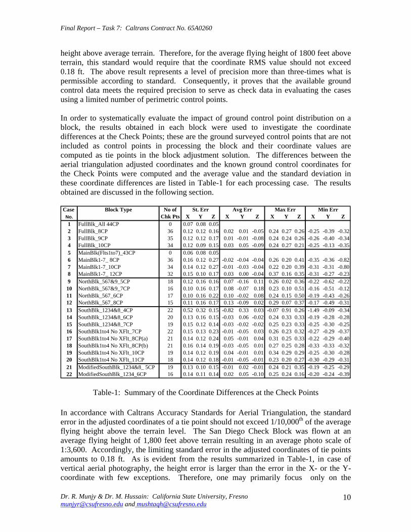
Final Report ndash Task 7 Caltrans Contract No 65A0260
height above average terrain Therefore for the average flying height of 1800 feet above terrain this standard would require that the coordinate RMS value should not exceed 018 ft The above result represents a level of precision more than three-times what is permissible according to standard Consequently it proves that the available ground control data meets the required precision to serve as check data in evaluating the cases using a limited number of perimetric control points
In order to systematically evaluate the impact of ground control point distribution on a block the results obtained in each block were used to investigate the coordinate differences at the Check Points these are the ground surveyed control points that are not included as control points in processing the block and their coordinate values are computed as tie points in the block adjustment solution The differences between the aerial triangulation adjusted coordinates and the known ground control coordinates for the Check Points were computed and the average value and the standard deviation in these coordinate differences are listed in Table-1 for each processing case The results obtained are discussed in the following section
CaseNo
Block Type No of Chk Pts X Y Z
St Err X Y Z
Avg Err X Y Z
Max Err X Y Z
Min Err
1 2 3 4 5
FullBlk_All 44CP FullBlk_8CP FullBlk_9CP FullBlk_10CP
0 36 35 34
007 008 005 012 012 016 012 012 017 012 009 015
002 001 -005 001 -001 -008 003 005 -009
024 027 026 024 024 026 024 027 021
-025 -039 -032 -026 -040 -034 -025 -013 -035
MainBlk(Flts1to7)_43CP 0 006 008 005 6 MainBlk1-7_ 8CP 36 016 012 027 -002 -004 -004 026 020 041 -035 -036 -082 7 MainBlk1-7_10CP 34 014 012 027 -001 -003 -004 022 020 039 -031 -031 -080 8 9 10 11 12 13
MainBlk1-7_ 12CP 32 015 010 017 003 000 -004 037 016 035 -031 -027 -023 NorthBlk_567amp9_5CP NorthBlk_567amp9_7CP NorthBlk_567_6CP NorthBlk_567_8CP
18 16 17 15
012 016 016 010 016 017 010 016 022
007 -016 011 008 -007 018 010 -002 008
026 002 036 023 010 051 024 015 050
-022 -062 -022 -016 -051 -012 -019 -043 -026
011 016 017 013 -009 002 029 007 037 -017 -049 -031 SouthBlk_1234amp8_4CP 22 052 032 015 -082 033 003 -007 091 026 -149 -009 -034
14 SouthBlk_1234amp8_6CP 20 013 016 015 -003 006 -002 024 033 033 -019 -028 -028 15 SouthBlk_1234amp8_7CP 19 015 012 014 -003 -002 -002 025 023 033 -025 -030 -025 16 SouthBlk1to4 No XFlt_7CP 22 015 013 023 -001 -005 003 026 023 032 -027 -029 -037 17 SouthBlk1to4 No XFlt_8CP(a) 21 014 012 024 005 -001 004 031 025 033 -022 -029 -040 18 SouthBlk1to4 No XFlt_8CP(b) 21 016 014 019 -003 -005 001 027 025 028 -033 -033 -032 19 SouthBlk1to4 No XFlt_10CP 19 014 012 019 004 -001 001 034 029 029 -025 -030 -028 20 21 22
SouthBlk1to4 No XFlt_11CP 18 014 012 018 -001 -005 -001 023 020 027 -030 -029 -031 ModifiedSouthBlk_1234amp8_ 5CP ModifiedSouthBlk_1234_6CP
19 16
013 010 015 014 011 014
-001 002 -001 002 005 -010
024 021 035 025 024 016
-019 -025 -029 -020 -024 -039
Table-1 Summary of the Coordinate Differences at the Check Points
In accordance with Caltrans Accuracy Standards for Aerial Triangulation the standard error in the adjusted coordinates of a tie point should not exceed 110000th of the average flying height above the terrain level The San Diego Check Block was flown at an average flying height of 1800 feet above terrain resulting in an average photo scale of 13600 Accordingly the limiting standard error in the adjusted coordinates of tie points amounts to 018 ft As is evident from the results summarized in Table-1 in case of vertical aerial photography the height error is larger than the error in the X- or the Yshycoordinate with few exceptions Therefore one may primarily focus only on the
Dr R Munjy amp Dr M Hussain California State University Fresno munjyrcsufresnoedu and mushtaqhcsufresnoedu
10
Final Report ndash Task 7 Caltrans Contract No 65A0260
standard error in the height in order to analyze the various scenarios represented by the 22 different cases
361 FULL Block (Case-1 to 4)
In the case of FULL Block (Flts 1 to 9) by controlling each edge (corner) of the block and each edge of any cross strip by a single CP as in Case-2 Caltrans accuracy standard is met In case-3 an additional CP was used at the block corner formed where the Flight 4 ends while the Flight 3 continues southward The addition of this corner point does not significantly enhance the accuracy of the solution This is due to the fact that the Flight-3 at this point is controlled by GPS data
It is interesting to note that even though the Flight 7 (at the northern end of the block) is 15 models long a single CP located at the end of this flight appears to be sufficient for control The fact that the spacing between the end CPs at the lower end of this block segment (Flight 5) is only about 10 models adds to the strength In order to check the influence of additional control points along the block perimeter with reduced spacing a CP was added in the middle of Flight 7 as shown in Case-4 This does result in some improvement in the accuracy of the block solution consequently this would appear to be the optimum control configuration
362 MAIN Block (Case-5 to 8)
The MAIN Block (Flts 1 to 7) was used to study any impact in using cross flights for GPS controlled aerial triangulation blocks When a large number of control points are available such as in Case-3 where 43 CPs are used the results are identical whether or not cross flights are used However when a CP is used only at the block corners as in Case-6 (analogous with Case-2 in FULL Block) the required accuracy standard is not met This standard is also not met when an additional corner CP is used as shown in Case-7 (analogous with Case-3 in FULL Block) However when the spacing between the perimetric control points is confined to about 8 models as shown in the Case-8 the results are within the required accuracy standard A comparison of Case-4 and Case-8 shows that if the cross Flights 8 and 9 are not used additional control points along the block perimeter in a direction parallel to the flight lines can compensate for it and meet the required accuracy standard
363 NORTH Block (Case-9 to 12)
The above analysis was repeated by splitting the San Diego Check Block into two subshyblocks a NORTH Block and a SOUTH Block The NORTH Block (Flts 5 to 7 and 9) was processed first by including the cross Flight 9 and also by excluding this cross flight The results tabulated in Table-1 in Case 9 to 12 are identically similar to the ones obtained earlier with the FULL and the MAIN Blocks It again shows that when a CP is located at the end of the cross Flight 9 in the northern end of the block and a CP is used at the end of each of the three flight lines at the southern end of the block the required accuracy standards are met even when no CP is located in the middle of the 15-model
Dr R Munjy amp Dr M Hussain California State University Fresno munjyrcsufresnoedu and mushtaqhcsufresnoedu
11
Final Report ndash Task 7 Caltrans Contract No 65A0260
long Flight-7 (Case-9) In fact it is seen in Case-10 that the addition of an intermediate point along the perimeter did not improve the accuracy
Without the cross Flight 9 however a comparison of the Case-12 with Case-11 clearly shows that the reduction in the spacing between the perimetric control points is necessary for meeting the required accuracy standard In this block size and configuration the nonshyuse of a cross flight could have been compensated with the use of one additional control point along the perimeter
364 SOUTH Block (Case-13 to 20)
The SOUTH Block consisting of Flights 1 to 4 and the cross Flight 8 has somewhat unusual configuration it is not a compact rectangular block and the cross Flight-8 intersects the block rather than at either end of the block Eight different scenarios for flight and control configuration were used in handling this sub-block
The Case-13 is based on the use of only four CPS one located at each of the four block corners This case might work for small and rectangular blocks with a cross flight at each end of the block However for Case-13 the cross Flight is completely uncontrolled and so is the southern corner of Flight-4 Obviously this has resulted in the planimetric RMS error that exceeds 05 ft
When a CP was located at each end of the cross Flight 8 as seen in Case-14 as well as a CP was added at the end of each flight line the block solution met the accuracy standard The addition of another corner CP as shown in Case-15 did not contribute to any significant improvement in the accuracy This shows the role that the intersecting cross Flight 8 plays in strengthening the geometry of the block by reducing the uncontrolled segment of each of the three Flight lines 1 to 3
The Case-16 to 20 convincingly demonstrate the degradation in the block geometry when the cross Flight 8 is removed from the block None of the block configurations shown in Case 16 to 19 strictly meets the accuracy requirement the Case-18 and Case-19 missing the minimal accuracy standard by 001 ft It is only when another corner CP is added as shown in Case-20 that the minimal accuracy standard is attained
365 SOUTH-MODIFIED Block (Case-21 amp 22)
In order to further validate the conclusions derived so far the SOUTH Block was modified to a more conventional rectangular shaped block by removing photos from Flight 1 to 3 to bring them to the same length as Flight 4 The SOUTH_MODIFIED Block is not only have a rectangular shape but the cross Flight 8 now falls at the southern of this sub-block With the Flight 8 now playing the normal role of a cross flight the minimal control layout seen in Case-21 easily meets the accuracy standard As observed in previous
Dr R Munjy amp Dr M Hussain California State University Fresno munjyrcsufresnoedu and mushtaqhcsufresnoedu
12
Final Report ndash Task 7 Caltrans Contract No 65A0260
blocks locating a CP at each end of each flight line meets the accuracy standard for this block with 11-model long flight lines
The above observations and the conclusions were used to draft the Preliminary Standards for Block Configuration Airborne GPS Controlled Photogrammetry for Large Scale Mapping Projects and submitted as Interim Report in fulfillment of the requirement under Task 32 of the contract [14]
4 TEST BLOCK
41 Planning
The extra-ordinary fiscal problems faced by the State of California had resulted in the suspension of work on the project Consequently a no-cost extension in the time for completion of this project beyond March 31 2009 till December 31 2009 was requested by California State University Fresno in November 2008 This request in the extension of period was strongly supported by Caltrans Office of Photogrammetry This request was approved by Caltrans Division of Research and Innovation and California State University Fresno was notified by Caltrans Contract Manager on April 2 2009 to continue work on the project till December 31 2009
A planning meeting between the California State University Fresno research team and the representatives from Caltrans Office of Photogrammetry was held in Caltrans Office in Sacramento on April 20 2009 for the design of an optimal test block In the light of the results obtained from the San Diego Check Block and the conclusions presented in the Interim Report submitted in January 2009 various options and proposals for selecting the site and configuration for a test block were discussed The Caltrans Office of Photogrammetry and the California State University Fresno fully agreed on the following characteristics for the Test Block
The aerial photography should fully conform to the Caltrans practice of using a metric wide-angle aerial camera from an altitude of 1800 ft above the terrain level to result in an average photo scale of 13600
The main block should consist of 4 parallel flight lines of 18 models each A cross flight should be flown at each end of the main block Full 3-D ground control should be provided along the perimeter of the main block
with a control point spacing of 6 to 8 airbases Full 3-D ground control for the two cross flights should be planned so that
- A pair of 3-D control points are located at each end of each cross flight and - At least one Height control point falls at each end of each main flight line
A sufficient number (15 to 20) of additional ground control points should be distributed in the interior of the block to serve as check points for estimating the absolute accuracy of aerial triangulation results
All the 6 flight lines constituting the Test Block should be flown as a single flight mission
Dr R Munjy amp Dr M Hussain California State University Fresno munjyrcsufresnoedu and mushtaqhcsufresnoedu
13
Final Report ndash Task 7 Caltrans Contract No 65A0260
The airborne GPS data as well as the data at the ground Base Stations should be collected at 1 Hz or higher data rate
The flight mission should be carried out under weather and environmental conditions so as to avoid any degradation in the quality of aerial imagery
Even though implementing the above technical requirements in a test block did not pose any serious problems the California State University Fresno as well as the Caltrans Office of Photogrammetry had serious concerns about adhering to the tight project schedule Both the parties in this project were convinced that the award of an aerial photography services contract for a Test Block by the California State University Fresno through a formal selection and competitive bidding process would entail serious delays that may even jeopardize the completion of the project by the ending date of December 31 2009 An attractive and viable alternative was to utilize the services of an aerial photography vendor that had recently been contracted by Caltrans for the acquisition of aerial photography for a highway corridor along Interstate I-5 in Northern San Diego The flying for this Caltrans project was fortuitously scheduled for May 2009 that synchronized very well with the schedule for this research project
Accordingly with full consultation with the Caltrans Office of Photogrammetry a Test Block was designed by the California State University Fresno in Del Mar in Northern San Diego The Del Mar Test Block included a variety of terrain a large expanse of marsh and river suburban residential large freeway and rolling hills A separate contract was negotiated and awarded by the California State University Fresno to the Caltrans contractor for the San Diego I-5 Project for the acquisition of aerial photography for the Del Mar Test Block This approach used in awarding the contract resulted in the following benefits
The aerial photography contractor had already been pre-qualified by Caltrans for the quality of the aircraft aerial camera aerial film and GPS and navigation equipment used for the acquisition of aerial photography
The aerial photography contractor had already been pre-qualified by Caltrans for the quality of aerial photography products (developed negative film diapositives prints etc)
The aerial photography contractor had already been pre-qualified by Caltrans for the certification of aerial camera calibration electronic integration of the aerial camera with the airborne GPS receiver to record the aerial exposure events and the geometric integration of the airborne GPS antenna mounted on the fuselage with the aerial camera
The contractor was familiar with the detailed Caltrans specifications for the acquisition of aerial photography and the same specifications would strictly govern the flight mission for the Del Mar Test Block
Dr R Munjy amp Dr M Hussain California State University Fresno munjyrcsufresnoedu and mushtaqhcsufresnoedu
14
Final Report ndash Task 7 Caltrans Contract No 65A0260
42 Acquisition of Aerial Photography
The flight configuration and ground control distribution for the Del Mar Test Block was finalized near the end of April 2009 and is shown in Fig 41 As stated earlier the contract for the aerial photography acquisition was awarded to IKCurtis Services Inc Burbank California who had earlier been awarded the Caltrans contract to fly Route 5 and 56 in San Diego The Caltrans Office of Photogrammetry also arranged for field survey teams from Caltrans District 11 in San Diego to supplement the ground control network established for the Caltrans project with the additional ground control points planned for the Del Mar Test Block This further ensured that the quality of the ground control data used for the Del Mar Test Block would fully conform to Caltrans aerial triangulation control standards All the fieldwork required for the Caltrans Route 5 and 56 Project and for the Del Mar Test Block of the California State University Fresno research project was completed in early May 2009
Based on the weather reports and the suitability of GPS satellite configuration it was mutually agreed between the Caltrans Office of Photogrammetry Caltrans District 11 California State University Fresno and IK Curtis Services Inc to fly the two projects on May 13 2009 with May 14 2009 as a backup date I K Curtis Services Inc had been assigned the task of collecting the airborne GPS data during the flight mission while field survey staff from Caltrans District 11 were responsible for the simultaneous collection of GPS data at four designated base stations Whether the two separate projects are flown as a single flight mission or as two separate missions on the same day or on separate days was left entirely to the mutual judgment of the flight crew and Caltrans Project Coordinator from District 11 based on the weather and environmental conditions in the area
A final field survey task is to visit each control point location and repaint if necessary those control marks that fall on a hard surface and to deploy specially designed panel at each control point that lies on grass or open and marshy ground Even though all the ground control targets had been readied in time unfortunately adverse weather reports and worsening fog and cloudy conditions were totally unsuitable for flying on May 13 or on May 14 Based on the weather forecast similar flight dates were set on several occasions each time requiring the reconnaissance of the ground targets but the adverse weather conditions extended over several weeks After continuing efforts at planning and repeated cancellations it was finally possible to complete the aerial photography requirements for both the projects through a single flight mission carried out on July 14 2009 Even though two models at the end of one cross flight in the Del Mar Test Block contain some cloud coverage fortunately it was still possible to identify and measure the image coordinates of the ground control points falling in both the models
Dr R Munjy amp Dr M Hussain California State University Fresno munjyrcsufresnoedu and mushtaqhcsufresnoedu
15
6
5
Final Report ndash Task 7 Caltrans Contract No 65A0260
Fig 41 San Diego Test Block Configuration and Control Distribution
1 2 3 411 22 33 44
66
55
Dr R Munjy amp Dr M Hussain California State University Fresno munjyrcsufresnoedu and mushtaqhcsufresnoedu
16
Final Report ndash Task 7 Caltrans Contract No 65A0260
43 Test Block Data Acquisition
After the delivery of the aerial diapositives by the Contractor the photogrammetric data for the aerial triangulation of the Del Mar Test Block was measured and compiled by Caltrans Office of Photogrammetry The selection of tie points and the measurement of image coordinate data for the entire block consisting of 6 flight lines and 96 photos was carried out following the routine analytical methodology and practice used for all Caltrans aerial triangulation blocks
The following measurement data was provided by the Office of Photogrammetry to California State University Fresno in August 2009
- Image coordinate data - Ground control coordinate data - Raw GPS data from airborne receiver and four base station receivers - GPS time for photo exposure - Camera calibration data - Camera and GPS antenna offset
44 Test Block Data Processing
Before processing the aerial triangulation data received from the Office of Photogrammetry some clarification regarding the processing datum were necessary as discussed in the following section
441 Processing Datum
It was reported that the datum used for the ground control data provided by Caltrans District 11 was as below
- Horizontal Control CCS83 Epoch199135 Datum - Vertical Control NAVD88 Datum
Based on discussions with representatives from Caltrans District 11 it was determined that the 3-D adjustment of the GPS ground control network was performed in CCS83-Epoch 199135 datum for the horizontal control while the vertical coordinates were adjusted by fixing the orthometric height (NAVD88 Datum) of 4 network stations The geoidal height data needed for the reduction of observed ellipsoidal height data (GRS80 Ellipsoid) to adjusted orthometric height data (NAVD88 Datum) was based on the Geoid2003 Global Model Consequently the orthometric height data for the ground control used for the Del Mar Test Block may be affected by any height variation between the Local Geoid from the Global Geoid
442 Post-Processing of Airborne GPS Data
Dr R Munjy amp Dr M Hussain California State University Fresno munjyrcsufresnoedu and mushtaqhcsufresnoedu
17
Final Report ndash Task 7 Caltrans Contract No 65A0260
Even though the Caltrans Office of Photogrammetry had provided the post-processed results for the airborne GPS data this data was also processed at the California State University Fresno Even though GPS data at four different base stations had been collected and the GrafNav post-processing software provides the option to use multiple base station data it was decided to carry out the kinematic processing of the airborne GPS data relative to a single base station HPGN DC 11 The selection of this base station was due to the fact that this was the only base station for which the orthometric height had been held fixed in the GPS network adjustment none of the other three network stations for which the orthometric height was held fixed had been used as a base station during the flight mission
The results and the analysis provided in the following section are based on the airborne GPS data processed at the California State University Fresno
443 Aerial Triangulation Data Processing
The first objective for the aerial triangulation processing of the Del Mar Test Block data was to further verify the aerial triangulation results obtained with the San Diego Check Block reported in Section 3 A second and more important objective was to evaluate the impact of flight configuration and the control point distribution on the achievable aerial triangulation accuracy for large scale (13600) aerial photography used in Caltrans It was of special interest to assess the impact of the use of cross flights and the optimal distribution of the ground control points in an airborne GPS supported aerial triangulation block
The same approach and the methodology were used for processing the aerial triangulation of the Del Mar Test Block as has previously been discussed in detail in Section 35 for the San Diego Check Block Aerial triangulation data was processed systematically by using block configuration with and without the two cross flights (see Fig 41) The number and the distribution of the control points used primarily along the block perimeter varied from 8 to 14 control points Since the Del Mar Test Block was covered with a total of 33 field control points all the points that were not used as control points in processing the block served as Check Points Theoretically such Check Points are the most reliable indicators of the absolute accuracy of the aerial triangulation results provided the coordinate data for such Check Points is at least three times more precise than the precision of the coordinate data for the tie points resulting from aerial triangulation adjustment [15] In the case of the Del Mar Test Block data the uncertainty of 2 to 3 cm in the geoidal height interpolated from the global Geoid Model leads to the estimated precision of the Check Point data to be more precise than the aerial triangulation data by a factor of 12 to 2 only This fact has to be kept in focus while analyzing the absolute accuracy of the aerial triangulation results as part contributions from the errors in Check Point data cannot be entirely ignored
The airborne GPS supported aerial triangulation blocks are fully controlled through the airborne GPS data in the interior of the block Therefore the precision of the airborne GPS data plays a crucial role in the resulting aerial triangulation accuracy The
Dr R Munjy amp Dr M Hussain California State University Fresno munjyrcsufresnoedu and mushtaqhcsufresnoedu
18
Final Report ndash Task 7 Caltrans Contract No 65A0260
processing of the Test Block was carried out by using the following a-priori standard errors for the airborne GPS data (a) Standard error for X and Y-coord 025 ft Standard error for Z-coord 025 ft (b) Standard error for X and Y-coord 010 ft Standard error for Z-coord 015 ft
Based on the analysis of the results that are discussed in Section 5 it was finally decided to use the following a-priori standard error for the airborne GPS data
Standard error for X and Y-coord 015 ft Standard error for Z-coord 015 ft
The results for the block configuration that includes the two cross flights for a total of 6 flight lines are summarized as Cases 1 through 5 in Table 2 The Blocks processed without the use of the two cross flights and comprising only the 4 parallel flight lines are shown in Table 2 as Cases 6 through 12
Case BLOCK Number of St Error Ave Error Max Error Min Error
No Type Check Pts X Y Z X Y Z X Y Z X Y Z
1 6Flt_Blk_33CP 0 004 004 005
2 6Flt_Blk_8CP 25 009 008 019 -002 001 -007 013 018 032 -027 -012 -052
3 6Flt_Blk_12CP 21 010 008 014 -004 -003 005 009 013 029 -028 -015 -030
4 6Flt_Blk_14aCP 19 010 006 015 000 -003 001 012 013 027 -025 -016 -034
5 6Flt_Blk_14bCP 19 010 008 015 -001 -001 006 011 013 028 -025 -014 -031
6 4Flt_Blk_33CP 0 004 002 006 -002 000 001
7 4Flt_Blk_8CP 25 012 008 059 004 006 -108 028 024 016 -022 -009 -109
8 4Flt_Blk_11aCP 22 013 009 019 -001 -002 -017 017 016 028 -028 -016 -050
9 4Flt_Blk_11bCP 22 014 009 027 -005 003 -031 016 020 030 -031 -015 -066
10 4Flt_Blk_12CP 21 013 009 020 -002 000 -008 016 018 031 -027 -016 -033
11 4Flt_Blk_14aCP 19 010 008 013 004 -002 -003 016 015 025 -021 -017 -020
12 4Flt_Blk_14bCP 19 009 007 012 -001 -001 005 009 013 028 -025 -014 -012
Table-2 Summary of the Coordinate Differences at the Check Points
The control distribution used in the processing of the 12 cases is illustrated in Fig 42 through 411 below The corresponding statistics for the resulting errors at the Check Points are shown for each case The Check Points where the maximum errors in the X- Y- and Z-coordinate occur are shown in different color according to the legend below
Control pointControl point
MMaax error in Xx error in X
MMaax error in Yx error in Y
MMaax error in Zx error in Z LEGEND (Figures 42 through 411)
Dr R Munjy amp Dr M Hussain California State University Fresno munjyrcsufresnoedu and mushtaqhcsufresnoedu
19
Final Report ndash Task 7 Caltrans Contract No 65A0260
Fig 42 Block with Cross Strips 8 Control Points 25 Check Points Case 2
SSttaannddaardrd EErrorrorr AAvveeraraggee EErrrroorr MMaaxxiimmuumm EErrorrorr MMiinniimmuumm EErrorrorr XX YY ZZ XX YY ZZ XX YY ZZ XX YY ZZ
000099 000088 001199 --000022 000011 --000707 001133 001818 003232 --002277 --001212 --005522
Dr R Munjy amp Dr M Hussain California State University Fresno munjyrcsufresnoedu and mushtaqhcsufresnoedu
20
Final Report ndash Task 7 Caltrans Contract No 65A0260
Fig 43 Block with Cross Strips 12 Control Points 23 Check Points Case 3
SSttaannddaardrd EErrorrorr AAvveeraraggee EErrrroorr MMaaxxiimmuumm EErrorrorr MMiinniimmuumm EErrorrorr XX YY ZZ XX YY ZZ XX YY ZZ XX YY ZZ
001100 000088 001144 --000044 --000303 000055 000099 001313 002929 --002288 --001515 --003300
Dr R Munjy amp Dr M Hussain California State University Fresno munjyrcsufresnoedu and mushtaqhcsufresnoedu
21
Final Report ndash Task 7 Caltrans Contract No 65A0260
Fig 44 Block with Cross Strips 14 Control Points 21 Check Points Case 4
SSttaannddaardrd EErrorrorr AAvveeraraggee EErrrroorr MMaaxxiimmuumm EErrorrorr MMiinniimmuumm EErrorrorr XX YY ZZ XX YY ZZ XX YY ZZ XX YY ZZ
001100 000088 001155 --000011 --000101 000066 001111 001313 002828 --002255 --001414 --003311
Dr R Munjy amp Dr M Hussain California State University Fresno munjyrcsufresnoedu and mushtaqhcsufresnoedu
22
Final Report ndash Task 7 Caltrans Contract No 65A0260
Fig 45 Block with Cross Strips 14 Control Points 21 Check Points Case 5
SSttaannddaardrd EErrorrorr AAvveeraraggee EErrrroorr MMaaxxiimmuumm EErrorrorr MMiinniimmuumm EErrorrorr XX YY ZZ XX YY ZZ XX YY ZZ XX YY ZZ 001100 000066 001155 000000 --000033 000011 001122 001133 002277 --002255 --001166 --003344
Dr R Munjy amp Dr M Hussain California State University Fresno munjyrcsufresnoedu and mushtaqhcsufresnoedu
23
Final Report ndash Task 7 Caltrans Contract No 65A0260
Fig 46 Block without Cross Strips 8 Control Points 25 Check Points Case 7
SSttaannddaardrd EErrorrorr AAvveeraraggee EErrrroorr MMaaxxiimmuumm EErrorrorr MMiinniimmuumm EErrorrorr XX YY ZZ XX YY ZZ XX YY ZZ XX YY ZZ 001122 000088 005599 000404 000606 --110088 002288 002244 001166 --002222 --000099 --110099
Dr R Munjy amp Dr M Hussain California State University Fresno munjyrcsufresnoedu and mushtaqhcsufresnoedu
24
Final Report ndash Task 7 Caltrans Contract No 65A0260
Fig 47 Block without Cross Strips 11 Control Points 22 Check Points Case 8
SSttaannddaardrd EErrorrorr AAvveeraraggee EErrrroorr MMaaxxiimmuumm EErrorrorr MMiinniimmuumm EErrorrorr XX YY ZZ XX YY ZZ XX YY ZZ XX YY ZZ
001133 000099 001199 --000011 --000202 --001177 001177 001166 002288 --002828 --001166 --005050
Dr R Munjy amp Dr M Hussain California State University Fresno munjyrcsufresnoedu and mushtaqhcsufresnoedu
25
Final Report ndash Task 7 Caltrans Contract No 65A0260
Fig 48 Block without Cross Strips 11 Control Points 22 Check Points Case 9
SSttaannddaardrd EErrorrorr AAvveeraraggee EErrrroorr MMaaxxiimmuumm EErrorrorr MMiinniimmuumm EErrorrorr XX YY ZZ XX YY ZZ XX YY ZZ XX YY ZZ
001144 000099 002277 --000055 000033 --003131 001166 002020 003030 --003311 --001515 --006666
Dr R Munjy amp Dr M Hussain California State University Fresno munjyrcsufresnoedu and mushtaqhcsufresnoedu
26
Final Report ndash Task 7 Caltrans Contract No 65A0260
Fig 49 Block without Cross Strips 12 Control Points 21 Check Points Case 10
SSttaannddaardrd EErrorrorr AAvveeraraggee EErrrroorr MMaaxxiimmuumm EErrorrorr MMiinniimmuumm EErrorrorr XX YY ZZ XX YY ZZ XX YY ZZ XX YY ZZ 001133 000099 002200 --000022 000000 --000808 001166 001818 003131 --002277 --001616 --003333
Dr R Munjy amp Dr M Hussain California State University Fresno munjyrcsufresnoedu and mushtaqhcsufresnoedu
27
Final Report ndash Task 7 Caltrans Contract No 65A0260
Fig 410 Block without Cross Strips 14 Control Points 19 Check Points Case 11
SSttaannddaardrd EErrorrorr AAvveeraraggee EErrrroorr MMaaxxiimmuumm EErrorrorr MMiinniimmuumm EErrorrorr XX YY ZZ XX YY ZZ XX YY ZZ XX YY ZZ
001100 000088 001133 000044 --000022 --000303 001166 001515 002525 --002211 --001717 --002200
Dr R Munjy amp Dr M Hussain California State University Fresno munjyrcsufresnoedu and mushtaqhcsufresnoedu
28
Final Report ndash Task 7 Caltrans Contract No 65A0260
Fig 411 Block without Cross Strips 14 Control Points 19 Check Points Case 12
SSttaannddaardrd EErrorrorr AAvveeraraggee EErrrroorr MMaaxxiimmuumm EErrorrorr MMiinniimmuumm EErrorrorr XX YY ZZ XX YY ZZ XX YY ZZ XX YY ZZ
000099 000077 001122 --000011 --000101 000055 000099 001313 002828 --002255 --001414 --001122
Dr R Munjy amp Dr M Hussain California State University Fresno munjyrcsufresnoedu and mushtaqhcsufresnoedu
29
Final Report ndash Task 7 Caltrans Contract No 65A0260
5 ANALYSIS OF RESULTS amp CONCLUSIONS
In accordance with the Caltrans standards using wide-angle aerial photography the RMS error in each coordinate component of the adjusted tie points should not exceed 110000 of the flying height above the terrain The Del Mar Test Block was flown with a wideshyangle aerial camera from an average height of 1800 feet above the terrain level thereby resulting in an average photo scale of 13600 Consequently the limiting RMS error at the Check Points representative of a finite number of well distributed tie points in the block should not exceed 018 ft in this case Any error that exceeds three times this limiting value viz 054 ft in any of the coordinate components should be a cause for rejection of that point
Therefore the acceptable limiting values for the standard error at the Check Points is 018 ft in each coordinate component Any block adjustment solution that results in a coordinate error in one or more Check Points that exceeds 054 ft in any coordinate component would not be an acceptable solution The following analysis of the results is based on these accuracy criteria
51 Blocks With Cross Flights
When a minimal number of 8 control points are used (Fig 42) along the block perimeter the resulting standard error in Z-coordinate of 019 ft exceeds the limiting value of 015 ft It is also noticeable that the highest error in the Z-coordinate of 052 ft at Point 189134 almost equals the rejection limit of 054 ft This is an indication that controlling a cross flight with only a single Control Point at each end of the flight may not always provide a satisfactory solution
This situation can be remedied by using a pair of Control Points in each end model of a cross flight so that any deformation across the flight line the omega rotation () can also be controlled Such an approach is also reported to have been successfully used and recommended in the past [1] [2] [3] When 4 additional Control Points were added at the end of each cross flight line as is seen in Fig 43 all the standard errors fell within the acceptable range and the maximum coordinate error did not exceed 030 ft which is well within the acceptable criteria
The primary advantage of using airborne GPS data for the adjustment of aerial triangulation blocks is to completely eliminate the need for Control Points in the interior of the block But it is of interest to investigate how effectively the airborne GPS data alone can control the interior of the block Two separate blocks were processed by adding two Control Points in the interior of the block resulting in a total of 14 Control Points
The block with 14 Control Points (Case A) is shown in Fig 44 where the two interior Control Points were selected so that one Control Point was located on the opposite ends in each of the two interior flight lines (Line 2 and Line3 see Fig 41) The other block with 14 Control Points (Case B) is shown in Fig 45 In this case both the interior points
Dr R Munjy amp Dr M Hussain California State University Fresno munjyrcsufresnoedu and mushtaqhcsufresnoedu
30
Final Report ndash Task 7 Caltrans Contract No 65A0260
fell in the middle of the block interior It is interesting to note that in either of the two cases the addition of the interior Control Points did not result in any significant difference from the result achieved earlier while using 12 Control Points Therefore it may be concluded that as long as the cross flights are adequately controlled with a pair of Control Points located across each end model of each cross flight additional control in the block interior is not required The results shown in Fig 44 and 45 validate this conclusion at least for a block comprised of 18 models long multiple flight lines
52 Blocks Without Cross Flights
When a mapping project involves a large photogrammetric block consisting of hundreds of models the common practice is to plan the block configuration to include cross flights [1] [2] [6] [10] Often such cross flights can result in significant saving in time and effort in minimizing the need for ground control Since the photogrammetric mapping projects in Caltrans mostly involve mapping along highway corridors most of the photogrammetric blocks vary from a single flight line to up to as many as four flight lines Therefore it is still to be investigated whether the use of cross flight lines in such blocks offers any significant advantage Furthermore any advantage resulting from the reduced need for the ground control has to be weighed against the additional time and effort needed in processing the cross flight models The Caltrans Office of Photogrammetry has not yet adopted the use of Automated Aerial Triangulation (AAT) techniques for routine production Consequently the additional effort in transferring tie points between the cross flights with the flights of the main block is still significant This has provided the impetus to carry out the following investigation for the aerial triangulation adjustment of blocks that do not include any cross flights
The first block without the two cross flights was processed with only 8 Control points along the block perimeter as a parallel case with the block run with cross flights The results are shown in Fig 46 As may be expected the absence of any Control Point located at each end of each of the two interior flights 2 and 3 has resulted in unacceptably large errors Not only is the standard error of 059 ft in the Z-coordinate for the 25 Check Points too large but interestingly the block adjustment carries a large systematic error in Z-coordinate of 108 ft This results from the fact that the absence of the Control Points at each end of Flights 2 and 3 does not permit the adjustment for the systematic strip drift parameters for the airborne GPS data along Flights 2 and 3
When cross flights are included the airborne GPS data measured along the cross flight adequately serves as control for adjusting the strip shift and drift parameters Therefore an alternative to the inclusion of cross flights in the block configuration is to provide a Control Point at each end of every flight line in the block Accordingly the processing of the following blocks includes Control Points at the end of each flight line
The Del Mar Test Block with 4 flight lines each 18 models long would require a total of 12 Control Points one Control Point at each end of each flight line and 4 Control Points along the interior perimeter of the block to provide a control spacing of approximately 6 airbases apart However in order to minimize the use of the ground control the block
Dr R Munjy amp Dr M Hussain California State University Fresno munjyrcsufresnoedu and mushtaqhcsufresnoedu
31
Final Report ndash Task 7 Caltrans Contract No 65A0260
shown in Fig 47 was processed with only 11 Control Points (Case A) since the Control Point 170133 was measured both in Line 2 and Line 3 The resulting standard error of 019 ft in the Z-coordinate for 22 Check Points as well as the large error of 050 ft in the Z-coordinate of Check Point 189134 make the block adjustment solution unacceptable There appears to be no obvious reason why the Check Point 189134 that is located so close to the Control Point 170133 should display such unacceptably large error in the Zshycoordinate In order to ascertain the internal consistency of the ground control data (33 Control Points) a conventional aerial triangulation adjustment of the block was performed (without using the airborne GPS data) using 32 Control Points and treating the Control Point 189134 as a Check Point The resulting error in the Z-coordinate of Point 189134 was only 006 ft It is also to be noted that the average Z-coordinate error of 017 ft indicates a systematic height error This would lead to the conclusion that there is some height discrepancy between the ground control data and the airborne GPS data
The block was re-processed (Case B) again by using only 11 Control Points but this time the Control Point 170133 was replaced with Control Point 189134 and the results are displayed in Fig 48 The Case B results are even worse than the Case A results the standard error in Z-coordinate was degraded to 027 ft while the largest error in Zshycoordinate of 066 ft was noted at Check Point 187215 The average Z-coordinate error also increases to 031 ft This is a further indication that there is significant height inconsistency in the airborne GPS data and the ground control data It appears that the height discrepancy between the ground control data and the airborne GPS data results in an unsatisfactory shift and drift adjustment of the airborne GPS data particularly in the inner flight Lines 2 and 3 that span 18 models between the end Control Points
In order to strengthen the end control across the flight lines both the Control Points 170133 and 189134 were used at the Northern end of the block The block was then processed with 12 Control Points and the results are presented in Fig 49 Even though the results improved significantly but contrary to the expectation the standard error in the Z-coordinate of 020 ft for the 21 Check Points did not meet the Caltrans accuracy standard The next logical approach was to investigate the impact of adding Control Points in the interior of the block Two interior Control Points were selected in the same manner as has been described earlier in the case of the blocks with the cross flights (see Fig 44 and 45)
Using 14 Control Points the Case A is shown in Fig 410 while the Case B is presented in Fig 411 The results in both Case A and Case B easily meet the Caltrans accuracy standards In Case A the distance between the Control Points for the shift and drift parameter adjustment of the airborne GPS data varies from 6 to 12 models while in Case B the interior Control Points are about 6 models apart Each Control Point distribution provides almost similar results It is a clear indication that any systematic height deformation that results from the suspected inconsistency between the ground surveyed GPS data and the airborne GPS data can be kept within acceptable range by including a pair of control points in the interior of the block Such a need for some control points has not been reported for the adjustment of aerial triangulation blocks in the past However the largest photo scale for which any ABGPS supported results have been published in
Dr R Munjy amp Dr M Hussain California State University Fresno munjyrcsufresnoedu and mushtaqhcsufresnoedu
32
Final Report ndash Task 7 Caltrans Contract No 65A0260
the past is 14800 only For a photo scale of 13600 that is approximately 25 percent larger the requirements for the accuracy of aerial triangulation accordingly become more stringent in the same proportion This may generate the need for some additional control in the middle of the block
The residuals at the ground control points and in the image coordinate data along with the resulting standard error of unit weight (0) provide a reliable indication of the internal consistency of the adjusted block However the absolute accuracy of the aerial triangulation can be validated only by the use of Check Points that are well distributed over the entire block As pointed out earlier any deformations due to residual systematic shift and drift errors in the airborne GPS data are likely to be most significant in the center of the block the location that is farthest from the control points distributed along the perimeter Accordingly it would be advisable to locate at least a pair of Check Points in the middle of the block and after completing the block adjustment (by excluding these Check Points as Control Points) the coordinate discrepancies obtained at these Check Points can be analyzed Such discrepancies would normally represent the highest absolute accuracy resulting from aerial triangulation adjustment of the block Any unacceptably large coordinate discrepancies at the Check Points would require investigation of the block input data
In the case the coordinate discrepancies at the Check Points are within acceptable range the block can be re-processed by also including the Check Points in the control data This should enhance the accuracy in the interior of the block
6 RECOMMENDED DRAFT STANDARDS
These draft standards are proposed to supplement the existing Standards for Strip Configuration Airborne GPS Controlled Photogrammetry for Large Scale Mapping Projects (based on 13600 photo scale) currently used in Caltrans
61 Data Acquisition
611 Image Coordinate Data
Follow the existing practice used in Caltrans Office of Photogrammetry for the selection distribution and the measurement of all image point data It is recommended that raw machine coordinate image data should form the input to the aerial triangulation block adjustment
A secondary interest in this Research Project under contract with Caltrans was to also evaluate the alternate methodology of the selection and the measurement of tie point data using Automated Aerial Triangulation (AAT) system However several problems were encountered in implementing the AAT software available at the Caltrans Office of Photogrammetry in Sacramento The unavoidable delay caused by unfavorable weather conditions in acquiring the aerial imagery for the Del Mar Test Block did not allow
Dr R Munjy amp Dr M Hussain California State University Fresno munjyrcsufresnoedu and mushtaqhcsufresnoedu
33
Final Report ndash Task 7 Caltrans Contract No 65A0260
enough time to resolve the AAT software issues with software vendor Accordingly this task could not be fully completed Therefore it was mutually agreed between the Caltrans Office of Photogrammetry and California State University Fresno to concentrate research efforts on the processing and the analysis of the Del Mar Test Block and on drafting the Final Report
612 Ground Control Data
The proposed research is focused on the use of photography obtained at scale of 13600 for corridor mapping in Caltrans The ground control for mapping is based on the airborne GPS supported aerial triangulation of the photo blocks The ground control points should be surveyed to provide 15 to 2-times higher accuracy than that of the adjusted tie point data This would translate to an accuracy at the 005 to 01 ft level for the planimetric coordinates and the height an accuracy achievable using static GPS surveys tied to existing HPGN network
It is not yet certain that the Real-Time Kinematic (RTK) GPS field survey methodology whether relying on a single base station or on an RTK network is able to meet the above stringent field survey accuracy requirements Therefore the ground control data for ABGPS based aerial triangulation blocks should be based entirely on GPS control networks established using static GPS surveying methodology The RTK survey methodology for establishing control for photogrammetric mapping projects should not be used till such time that such technology has advanced to a level when consistently reliable results can be routinely expected
The GPS observations provide a fairly precise data for ellipsoidal height differences However all photogrammetric mapping has to be based on orthometric height data Two different approaches can be used in order to derive adjusted orthometric height data through aerial triangulation The first method is to carry out the simultaneous least squares adjustment of the GPS observation data for the ground control network using current Caltrans Horizontal Datum CCS83 (199135) and Vertical Datum NAVD 88 But since the observed data involves the measurement of ellipsoidal height differences for each measured baseline there is a need for transforming such differences to the corresponding orthometric height differences on NAVD 88 Datum In the absence of an existing Local Geoid Model the only economic recourse available to meet this need is to use the most reliable existing Global Geoid Model the time-consuming and prohibitively more costly alternative would be to connect the control network stations through differential leveling The Global Geoid Models are progressively being updated and the GEOID 2003 Model is most commonly in current use although GEOID 2009 Model may soon become available
It has to be noted that the use of a Global Geoid Model will always have some residual geoidal height uncertainties perhaps in the range of few hundredths of a foot It is therefore necessary that a few stations that are well distributed over the control network should have precisely known orthometric height values which can be used for the height adjustment of the network The minimum number of such orthometric height control
Dr R Munjy amp Dr M Hussain California State University Fresno munjyrcsufresnoedu and mushtaqhcsufresnoedu
34
Final Report ndash Task 7 Caltrans Contract No 65A0260
stations is three and consequently a network should be planned to have at least four and preferably more stations where orthometric height is precisely known In practice this requirement is met by including several existing benchmarks that are well distributed over the project area The redundancy provided by using more than three benchmarks will quantify the height residuals resulting from the adjustment This will provide a good estimate for the residual height errors in the network
The alternative approach is to carry out the adjustment of the GPS control network using WGS84 Geodetic Datum This datum is consistent with the observed GPS measurement data and a simultaneous 3D adjustment of the network can be performed in a Local Spatial Coordinate System (LSCS) the most commonly used approach is to shift the origin of the WGS84 coordinate system (center of the Earth) to approximately the center of the project site and apply a 3D rotational matrix to align the coordinate axes along the East North and Up directions Some commercial aerial triangulation software systems provide utilities to easily perform such datum transformation After the aerial triangulation results have been validated the coordinates of all the control and tie points can be transformed back to WGS 84 Datum Based on the availability of the orthometric height control stations a local Geoid can be defined ( a plane or a surface etc) and then used to transform the ellipsoidal height data to orthometric height data This second approach has the advantage that unlike the first method described above the residual height errors in the transformed control point height data are not propagated through aerial triangulation
For 13600 scale aerial photography blocks the ground control data should meet the a- priori standard deviation at 010 ft level This is not a very challenging demand for the horizontal positioning using GPS methodology However the residual height uncertainties in the orthometric height of control points interpolated from the Global Geoid Model become more critical as the photo scale becomes larger
613 Airborne GPS Data
The current practice used in Caltrans to acquire airborne GPS data during flight missions should continue to be used It is necessary to have GPS data collected at 1 Hz or higher rate at a base station that is located within or close to the project site Prior research completed collaboratively with Caltrans has already shown that the data at the base station may be substituted with GPS data collected at CORS at 5-sec or higher rate Consequently the collection of GPS data at more than one base stations is not considered as an essential requirement It may still be prudent to acquire GPS data at a second base station as a contingency safeguard against the GPS hardware failure at a base station for guaranteed success of the flight mission and expense
It is to be noted that the relative accuracy between successive airborne GPS antenna 3Dshycoordinates should be at 10-cm or higher level The current procedure used in Caltrans for the aircraft to remain stationary for static resolution of ambiguities before take off has mostly resulted in acquiring very reliable airborne GPS data This practice should perhaps be continued even though the continuing improvements in GPS hardware and
Dr R Munjy amp Dr M Hussain California State University Fresno munjyrcsufresnoedu and mushtaqhcsufresnoedu
35
Final Report ndash Task 7 Caltrans Contract No 65A0260
post-processing softwares are making on-the-fly (OTF) ambiguity resolution increasingly reliable However if it is necessary to resort to on-the-fly ambiguity resolution it must be ensured that the ambiguities have stabilized before photography is started The strict requirement for reliably resolving the ambiguities also does not permit the loss of lock during any single flight line If a loss of lock occurs during turns between flight lines ambiguities must be re-acquired and must stabilize before starting the collection of photography for another flight line Based on the make and the model of the airborne GPS receiver the Caltrans Office of Photogrammetry in consultation with the District Survey Section should draft a set of instructions for the GPSCamera operator aboard the aircraft specifying what parameters (such as PDOP Number of SVs etc) that need to be continuously monitored on a screen during a flight mission
62 Flight and Control Configuration
The following standards in planning the flight line configuration and the corresponding ground control distribution for Caltrans project are recommended to achieve optimum results
Control points are primarily required only along the perimeter of the block When a cross flight line is used to control the end of a block a pair of Control
Points must be located at each end of the cross flight At each end of a block that is not controlled by a cross flight a CP should be
located at the end of each parallel flight line a single CP may serve as end control for two adjacent overlapping flight lines
Along the perimeter of the block in a direction parallel with the main flight lines the CPs should be located at an average spacing of 6 airbases
Any corner in a block resulting from a sudden change in the length of two adjacent parallel flight lines should be controlled by an additional CP
Check Points should be provided along the interior flight lines in a multi-strip block The Check Points may be distributed along the interior flight lines so that any Check Point is not farther than about 8 airbases from either another Check Point (on same or adjacent flight line) or from a Control Point
Note that Caltrans is usually concerned with the mapping mostly along highway corridors and therefore does not require blocks with segments larger than three or four parallel flight lines Additional control along the cross flight line would be needed if such segments have 8 or more parallel flight lines
63 Data Processing and Adjustment
631 Processing of ABGPS Data
The current practice of post-processing ABGPS data used in Caltrans Office of Photogrammetry using GrafNav software should be continued The data should continue to be processed in the Forward and Backward modes A coordinate separation of less
Dr R Munjy amp Dr M Hussain California State University Fresno munjyrcsufresnoedu and mushtaqhcsufresnoedu
36
Final Report ndash Task 7 Caltrans Contract No 65A0260
than 10 cm especially in the height represents a normally acceptable range for the combined solution
This study has shown that the airborne GPS data in comparison with the ground control data should be weighted a lower weight but the highest weight that the GPS data quality represents Generally the best results were achieved when a-priori standard error of 015 ft was used for the airborne GPS coordinate data in comparison with the a-priori standard error of 010 ft used for the ground control coordinate data Since the 3-D position of successive points along the airborne GPS antenna trajectory are estimated using Kalman Filtering approach the successive location coordinates are highly correlated and consequently carry a much higher relative precision This provides a realistic justification for the use of a-priori standard error of 015 ft
632 Processing of Aerial Triangulation Block
Each aerial triangulation block requires the following data files as input
- Raw image coordinate data file - Ground control data file - Interpolated camera coordinate data file
Using the above input data files the block adjustment should be carried out in two steps as described below It is essential that additional Strip Shift and Drift parameters (3 Shift and 3 Drift parameters) should be incorporated in the bundle adjustment solution
Step 1 Minimal Control Adjustment
The preliminary simultaneous bundle adjustment of the block should be carried out by using the minimal amount of control points along the block perimeter only All the additional ground surveyed and targeted points should be treated as tie points to serve as Check Points The adjustment results should meet the following criteria
a The Standard Error of Unit Weight (0) should fall between 03 to 07 b The residual for any image coordinate should not exceed 15 micrometer c The RMS for ground control residuals should not exceed 110000 of the flying
height above the average terrain level d The maximum residual in any ground control coordinate should not exceed 25
times the RMS value permissible under Item (c) above e The RMS for discrepancy (difference between computed coordinate value and
the ground surveyed coordinate value) in Check Point coordinates should not exceed 110000 of the flying height above the average terrain level
f The discrepancy in any Check Point coordinate should not exceed 25 times the RMS value permissible under Item (e) above
If the above criteria are met even the preliminary adjustment solution for the block satisfies Caltrans accuracy standards for aerial triangulation If the criterion under Item
Dr R Munjy amp Dr M Hussain California State University Fresno munjyrcsufresnoedu and mushtaqhcsufresnoedu
37
Final Report ndash Task 7 Caltrans Contract No 65A0260
(f) above is not met the input data should be checked for any gross mistakes or errors in the ground control and Check Point data
Step 2 Full Control Adjustment
The final simultaneous bundle adjustment of the block should be carried out by including all the ground surveyed points (Control Points and Check Points) in the ground control data file The adjustment results should meet the following criteria
g The Standard Error of Unit Weight (0) should fall between 03 to 07 h The residual for any image coordinate should not exceed 15 micrometer i The RMS for ground control residuals should not exceed 110000 of the flying
height above the average terrain level j The maximum residual in any ground control coordinate should not exceed 25
times the RMS value permissible under Item (i) above
7 CONCLUDING COMMENTS
The completion of this project signifies the culmination of a very successful and productive combination of advanced theoretical principles with sound practical experience for the adaptation of evolving photogrammetric technologies in Caltrans practice In order to alleviate a growing concern for the safety of staff conducting field survey operations in close proximity of high speed traffic Caltrans in late 1990s decided to investigate the feasibility of using airborne GPS data for controlling the aerial triangulation blocks There were two primary issues to be resolved The first and the foremost concern was whether the use of airborne GPS data could be effectively used for controlling aerial triangulation blocks of as large a photo scale as 13000 used in Caltrans and still meet the Caltrans accuracy standards This concern was particularly critical since there had not been any reported use of airborne GPS data for such a large scale of aerial photography
Should the above investigation show that the Caltrans accuracy standards for aerial triangulation for 13000 scale aerial photography can be met it was of great interest to Caltrans to develop based on theoretically sound and systematic investigation a set of standards and specifications for the successful implementation of this new methodology in Caltrans routine practice
Under a Caltrans New Technology and Research Program currently Division of Research and Innovation (DRI) contract Caltrans Office of Photogrammetry partnered with a team of two faculty members from the Geomatic Engineering Program at the California State University Fresno (CSUF) in 1996 to carry out research to address the above two issues This partnership has flourished over the past several years through
Dr R Munjy amp Dr M Hussain California State University Fresno munjyrcsufresnoedu and mushtaqhcsufresnoedu
38
Final Report ndash Task 7 Caltrans Contract No 65A0260
successive research contracts and has resulted in very fortuitous outcomes based on the theoretical and analytical guidance provided by the CSUF research team and the highly skilled aerial survey project management and high caliber professional skills in the acquisition of photogrammetric data collection by the Caltrans Office of Photogrammetry In addition the help from highly experienced field survey teams from Caltrans various districts (especially District 11) in establishing GPS networks of Control Points and Check Points of specified precision was critical for the validation of airborne-GPS supported aerial triangulation investigations
As a result of the past collaborative efforts between the Caltrans Office of Photogrammetry and the CSUF Research Team the use of airborne GPS data for aerial triangulation has successfully been transitioned into Caltrans practice in the following stages
1) Based on a number of test flights it was convincingly demonstrated that the use of airborne GPS data consistently meets the Caltrans accuracy standards for aerial triangulation for strip configuration blocks at 13000 photo scale [13]
2) A detailed set of standards and specifications were developed for the implementing of the new methodology in Caltrans routine practice This was further supported through a training workshop conducted by CSUF at the Caltrans offices in Sacramento [8]
3) The use of airborne GPS data for the adjustment of aerial triangulation blocks requires the collection of GPS data at one or more ground base stations during the flight mission This requirement imposes burdensome demands on scheduling and allocation of manpower and equipment resources In order to reduce or even to completely eliminate the need for the collection of GPS data at base stations the use of GPS data collected and archived at a network of Continuously Operating Reference Stations (CORS) distributed over the State of California was investigated It was demonstrated that CORS data could be effectively used as a replacement for data collected at base stations while fulfilling Caltrans accuracy standards Accordingly specifications were revised to also include the selection and the use of CORS data for the post-processing of airborne GPS data to accurately derive the trajectory of the airborne GPS antenna during flights [19]
4) During the past few years Caltrans has increasingly been using multi-strip projects for mapping using 13600 photo scale This provided the need for the current research study The successful completion of this study has resulted in supplementing the existing standards and specifications for airborne GPS supported single-strip aerial triangulation blocks to also include the aerial triangulation of multi-strip blocks
It is a matter of great satisfaction for the research team at CSU Fresno that working hand in hand with the Caltrans Office of Photogrammetry the comprehensive set of standards and specifications for airborne GPS supported aerial triangulation that had been developed for successful transition of this technology in Caltrans practice have been further upgraded It is hoped that as the photogrammetric technology advances further
Dr R Munjy amp Dr M Hussain California State University Fresno munjyrcsufresnoedu and mushtaqhcsufresnoedu
39
Final Report ndash Task 7 Caltrans Contract No 65A0260
similar collaborative efforts between Caltrans Office of Photogrammetry and CSU Fresno will continue to address the changing needs in Caltrans
Dr R Munjy amp Dr M Hussain California State University Fresno munjyrcsufresnoedu and mushtaqhcsufresnoedu
40
Final Report ndash Task 7 Caltrans Contract No 65A0260
REFERENCES
1 Abdullah Q M Hussain and R Munjy (2002) Workshop on Airborne GPS-Supported Aerial Triangulation ndash Theory and Practical Concepts presented at the Annual ASPRS Convention Washington DC 2002
2 Ackermann Fritz (1992) Operational Rules and Accuracy Models for GPS-Aerotriangulation Archives of the ISPRS Com 1 Vol29 1992 [pp 691-700]
3 Ackermann F (1993) Application of GPS for Aerial Triangulation Photogrammetric Engineering and Remote Sensing Vol 59 No 11 [pp 1651shy1658]
4 Appleton James Mushtaq Hussain and Riadh Munjy (2000) Use of Airborne GPS Data for Highway Mapping International Archives of Photogrammetry and Remote Sensing Vol XXXIII Part B4 Amsterdam 2000[pp 84-90]
5 Appleton James M Hussain and R Munjy (2002) Use of Airborne GPS Data For Aerial Triangulation in Caltrans (2002) Workshop presented at the California Department of Transportation Sacramento 2002
6 Federal Geographic Data Committee (FGDC) 1998 Geospatial Positional Accuracy Standards Part-3 National Standards for Spatial Data Accuracy (NSSDA) FGDC-STD-0073-1998
7 Friess Peter (1992) Experiences with GPS-Supported Aerial Triangulation Archives of the ISPRS Com 1 Vol29 1992 [pp 299 - 305]
8 Gianellia Alexander M (1995) Practical Considerations in Implementing GPS Technologies in Airborne Data Collection Proc ASPRS Annual Convention 1995 [pp 917-925]
9 Hussain M R Munjy and J Appleton (1999) Use of Airborne On-the-Fly Kinematic GPS Data for Photogrammetric Mapping Proceedings ION-GPS-99 Conference Nashville 1999[pp 1653-1659]
10 Hussain M and R Munjy (1999) GPS Controlled Photogrammetry For Large Scale Mapping (1999) Final Project Report Research project No 65Y271 submitted to New Technology amp Research Program California Department of Transportation
11 Hussain M and R Munjy (2002) Airborne GPS Controlled Aerial Triangulation in Caltrans Final Project Report Research project No 65A0059 submitted to New Technology amp Research Program California Department of Transportation June 2002
12 Munjy R and M Hussain (1985) Interactive Simultaneous Bundle Block Adjustment System (ISBBA) for Small Computers Proceedings of the ASPRS Annual Convention Washington DC 1985
13 Munjy R M Hussain and James Appleton (2000) Use of Airborne GPS Data for Corridor Mapping presented at the Annual ASPRS Convention Washington DC 2000
Dr R Munjy amp Dr M Hussain California State University Fresno munjyrcsufresnoedu and mushtaqhcsufresnoedu
41
Final Report ndash Task 7 Caltrans Contract No 65A0260
14 Munjy R and M Hussain (2007) Develop Criteria for Using Network GPS for Airborne GPS Photogrammetry Final Project Report Research Project No 65A0234 submitted to the Division of Research and Innovation (DRI) California Department of Transportation
15 Munjy R and M Hussain (2009) Draft Preliminary Standards Interim Report Research Project No 65A0260 submitted to Division of Research aned Innovation (DRI) California Department of Transportation
Dr R Munjy amp Dr M Hussain California State University Fresno munjyrcsufresnoedu and mushtaqhcsufresnoedu
42
APPENDIX I Results of Check Block
Flight amp Control Configuration Cases Used for
Study amp Analysis of Check Project in San Diego
INDEX
Case Block amp Control Configuration 1 Full Blk(Flts1to9) All 44 CP 2 Full Blk 8 CP 3 Full Blk 9 CP 4 Full Blk 10 CP 5 Main Blk(Flts1to7) 43 CP 6 Main Blk(Flts1to7) 8 CP 7 Main Blk(Flts1to7) 10 CP 8 Main Blk(Flts1to7) 12 CP 9 North Blk(Flts567amp9) 5 CP 10 North Blk(Flts567amp9) 7 CP 11 North Blk(Flts56amp7) 6 CP 12 North Blk(Flts56amp7) 8 CP 13 South Blk(Flts1to4amp8) 4 CP 14 South Blk(Flts1to4amp8) 6 CP 15 South Blk(Flts1to4amp8) 7 CP 16 South Blk(Flts1to4) 7 CP 17 South Blk(Flts1to4) 8 CP(a) 18 South Blk(Flts1to4) 8 CP(b) 19 South Blk(Flts1to4) 10 CP 20 South Blk(Flts1to4) 11 CP 21 South Blk(Flts Modified 1to4 amp8) 5 CP 22 South Blk(Flts Modified 1to4 ) 6 CP
[Refer to Table-1 Summary of the Coordinate Differences at the Check Points]
I-i
Case-1 Base DataFULL BLOCK
Flts 1 to 9
Case-1 Base Data FULL BLOCK
Flts 1 to 9
Control PointsControl Points All 44 PointsAll 44 Points
SSSttt ErErErrrr AAAvvvggg ErErErrrr MMMaaaxxx ErErErrrr MMMiiinnn ErErErrrr XXX YYY ZZZ XXX YYY ZZZ XXX YYY ZZZ XXX YYY ZZZ
007 008 005 000 000 000 019 012 012 -013 -023 -013007 008 005 000 000 000 019 012 012 -013 -023 -013007 008 005 000 000 000 019 012 012 -013 -023 -013
I-ii
Case-2FULL BLOCK
Flts 1 to 9
Control Points 8
Case-2 FULL BLOCK
Flts 1 to 9
Control Points 8 CChheecckk PoPointsints 3366
SStt ErErrr AAvvgg ErErrr MMaaxx ErErrr MMinin ErErrr XX YY ZZ XX YY ZZ XX YY ZZ XX YY ZZ
012012 012012 016016 002002 001001 --000505 024024 027027 026026 --025025 --039039 --032032
I-iii
Case-3FULL BLOCK
Flts 1 to 9
Control Points 9
Case-3 FULL BLOCK
Flts 1 to 9
Control Points 9 CChheecckk PoPointsints 3355
SStt ErErrr AAvvgg ErErrr MMaaxx ErErrr MMinin ErErrr XX YY ZZ XX YY ZZ XX YY ZZ XX YY ZZ
012012 012012 017017 001001 --001001 --000808 024024 024024 026026 --026026 --040040 --034034
I-iv
Case-4FULL BLOCK
Flts 1 to 9
Control Points 10
Case-4 FULL BLOCK
Flts 1 to 9
Control Points 10 CChheecckk PoiPoinntsts 3344
SStt ErErrr AAvvgg ErErrr MMaaxx ErErrr MMinin ErErrr XX YY ZZ XX YY ZZ XX YY ZZ XX YY ZZ
012012 009009 015015 003003 005005 --000909 002244 002727 002121 --025025 --001313 --035035
I-v
Case-5MAIN BLOCK
Flts 1 to 7
Control Points 43
Case-5 MAIN BLOCK
Flts 1 to 7
Control Points 43 [Point HV-117 Unuse[Point HV-117 Unusedd]]
SSSttt ErErErrrr AAAvvvggg ErErErrrr MMM aaaxxx ErErErrrr MMM iiinnn ErErErrrr XXX YYY ZZZ XXX YYY ZZZ XXX YYY ZZZ XXX YYY ZZZ
006006006 008008008 005005005 000000000 000000000 000000000 012012012 013013013 013013013 ---000131313 ---022022022 ---000090909
I-vi
Case-6
Flts 1 to 7
l Points 8
MAIN BLOCK
[No Cross Flts]Contro
Case-6 MAIN BLOCK
Flts 1 to 7 [No Cross Flts]
Control Points 8 ChecCheckk PoPointsints 3636
St ErSt ErSt ErSt ErSt ErSt ErSt ErSt Errrrrrrrr AAAAAAAAvgvgvgvgvgvgvgvg ErErErErErErErErrrrrrrrr MMMMMMMMaxaxaxaxaxaxaxax ErErErErErErErErrrrrrrrr MMMMMMMMiiiiiiiinnnnnnnn ErErErErErErErErrrrrrrrr XXXXXXXX YYYYYYYY ZZZZZZZZ XXXXXXXX YYYYYYYY ZZZZZZZZ XXXXXXXX YYYYYYYY ZZZZZZZZ XXXXXXXX YYYYYYYY ZZZZZZZZ
016016016016 012012012012 027027027027 -002-002-002-002 ----004004004004 -004-004-004-004 000026262626 000020202020 000041414141 ----035035035035 -036-036-036-036 ----082082082082
I-vii
Case-7MAIN BLOCK
Flts 1 to 7[No Cross Flts]
Control Points 10
Case-7 MAIN BLOCK
Flts 1 to 7 [No Cross Flts]
Control Points 10 CChheecckk PointsPoints 3434
SStt ErErrr AAvvgg ErErrr MM aaxx ErErrr MM iinn ErErrr XX YY ZZ XX YY ZZ XX YY ZZ XX YY ZZ
014 012 027 -001 -003 -004 022 020 039 -031 -031 -080014 012 027 -001 -003 -004 022 020 039 -031 -031 -080
I-viii
Case-8MAIN BLOCK
Flts 1 to 7[No Cross Flts]
Control Points 12
Case-8 MAIN BLOCK
Flts 1 to 7 [No Cross Flts]
Control Points 12 CheChecckk PointsPoints 3232
SSSttt ErErErrrr AAAvvvggg ErErErrrr MMMaaaxxx ErErErrrr MMMiiinnn ErErErrrr XXX YYY ZZZ XXX YYY ZZZ XXX YYY ZZZ XXX YYY ZZZ
015 010 017 003 000 -004 037 016 035 -031 -027 -023015 010 017 003 000 -004 037 016 035 -031 -027 -023015 010 017 003 000 -004 037 016 035 -031 -027 -023
I-ix
Case-9Case-9Case-9 NORNORNORTTTH BLH BLH BLOCKOCKOCK
FltsFltsFlts 5 to 7 amp 9 5 to 7 amp 9 5 to 7 amp 9
Control PointsControl PointsControl Points 555 ChChCheckeckeck PoPoPoininintttsss 111888
ErSSSttt EE rrrrr vg ErAAAvg Evg E rrrrr ax ErMMM ax Eax E rrrrr ErMMM iiinnn EE rrrrr XXX YYY ZZZ XXX YYY ZZZ XXX YYY ZZZ XXX YYY ZZZ
000121212 016016016 000161616 007007007 ---000161616 000111111 000262626 000020202 000363636 ---022022022 ---000626262 ---022022022
I-x
Case-Case-1100 NORTH BLOCKNORTH BLOCK
Flts 5 to 7 amp 9Flts 5 to 7 amp 9
Control PointsControl Points 77 CheckCheck PointsPoints 1616
SStt ErErrr AAvvgg ErErrr MM aaxx ErErrr MM iinn ErErrr XX YY ZZ XX YY ZZ XX YY ZZ XX YY ZZ
010010 016016 017017 008008 --000707 001818 002323 001010 005151 --016016 --005151 --012012
I-xi
Case-Case-1111 NORTH BLOCKNORTH BLOCK
FltsFlts 5 to 7 5 to 7
CCoontrntrool Pointsl Points 66 CheChecckk PointsPoints 1717
SStt ErErrr AAvvgg ErErrr MM aaxx ErErrr MM iinn ErErrr XX YY ZZ XX YY ZZ XX YY ZZ XX YY ZZ
010010 016016 022022 010010 --000202 000808 002424 001515 005050 --019019 --004343 --026026
I-xii
Case-Case-1122 NORTH BLOCKNORTH BLOCK
FltsFlts 5 to 7 5 to 7 [No C[No Crrossoss Flt]Flt]
ContControl Poinrol Pointsts 88 CChheecckk PointsPoints 1155
SStt EErrrr AAvg Evg Errrr MM ax Eax Errrr MM iinn EErrrr XX YY ZZ XX YY ZZ XX YY ZZ XX YY ZZ
011011 016016 017017 013013 --000909 000202 002929 000707 003737 --017017 --004949 --031031
I-xiii
CaseCase-13-13 SOUTSOUTH BH BLLOCKOCK
Flts 1 to 4 amp 8Flts 1 to 4 amp 8
CoConnttrol Porol Poininttss 44 ChCheckeck PPooinintsts 2222
SStt ErErrr AAvvgg ErErrr MM aaxx ErErrr MM iinn ErErrr XX YY ZZ XX YY ZZ XX YY ZZ XX YY ZZ
052 032 015 -082 033 003 -007 091 026 -149 -009 -034052 032 015 -082 033 003 -007 091 026 -149 -009 -034
I-xiv
Case-14Case-14 SOUTH BLOCKSOUTH BLOCK
Flts 1 to 4 amp 8Flts 1 to 4 amp 8
CCoontrntrool Pointsl Points 66 CheChecckk PointsPoints 2200
SStt ErErrr AAvvgg ErErrr MM aaxx ErErrr MM iinn ErErrr XX YY ZZ XX YY ZZ XX YY ZZ XX YY ZZ
013 016 015 -003 006 -002 024 033 033 -019 -028 -028013 016 015 -003 006 -002 024 033 033 -019 -028 -028
I-xv
Case-15Case-15 SOUTH BLOCKSOUTH BLOCK
FltsFlts 1 to 4 amp 8 1 to 4 amp 8
ContrControol Pointsl Points 77 ChCheckeck PPooinintsts 1919
SStt ErErrr AAvvgg ErErrr MM aaxx ErErrr MM iinn ErErrr XX YY ZZ XX YY ZZ XX YY ZZ XX YY ZZ
015 012 014 -003 -002 -002 025 023 033 -025 -030 -025015 012 014 -003 -002 -002 025 023 033 -025 -030 -025
I-xvi
Case-16Case-16Case-16 SOUTH BLOCKSOUTH BLOCKSOUTH BLOCK
FltsFltsFlts 1 to 4 1 to 4 1 to 4 [No Cross Flt][No Cross Flt][No Cross Flt]
Control PointsControl PointsControl Points 777 CheCheCheccckkk PointsPointsPoints 222222
SSSttt EEErrrrrr AAAvg Evg Evg Errrrrr MMM ax Eax Eax Errrrrr MMM iiinnn EEErrrrrr XXX YYY ZZZ XXX YYY ZZZ XXX YYY ZZZ XXX YYY ZZZ
015 013 023 -001 -005 003 026 023 032 -027 -029 -037015 013 023 -001 -005 003 026 023 032 -027 -029 -037015 013 023 -001 -005 003 026 023 032 -027 -029 -037
I-xvii
Case-17Case-17 SOUTSOUTH BLH BLOCKOCK
FltsFlts 1 1 to 4to 4 [No[No CrosCrosss Flt]Flt]
ContrControol Pointsl Points 88 CChheecckk PointsPoints 2121
SStt ErErrr AAvvgg ErErrr MM aaxx ErErrr MM iinn ErErrr XX YY ZZ XX YY ZZ XX YY ZZ XX YY ZZ
014014 012012 024024 005005 --000101 000404 003131 002525 003333 --022022 --002929 --040040
I-xviii
Case-18Case-18 SOUTH BLOCKSOUTH BLOCK
Flts 1 to 4Flts 1 to 4 [[NNo Cro Crooss Fss Flltt]]
CCoontrol Pointsntrol Points 88 CheChecckk PointsPoints 2121
SSSttt ErErErrrr AAAvvvggg ErErErrrr MMM aaaxxx ErErErrrr MMM iiinnn ErErErrrr XXX YYY ZZZ XXX YYY ZZZ XXX YYY ZZZ XXX YYY ZZZ
016 014 019 -003 -005 001 027 025 028 -033 -033 -032016 014 019 -003 -005 001 027 025 028 -033 -033 -032016 014 019 -003 -005 001 027 025 028 -033 -033 -032
I-xix
Case-19Case-19 SOUTH BLOCKSOUTH BLOCK
FltsFlts 1 to 4 1 to 4 [No Cross Flt][No Cross Flt]
ContControl Prol Poointintss 10 10 CheckCheck PointsPoints 1919
SSSttt ErErErrrr AAAvvvggg ErErErrrr MMM aaaxxx ErErErrrr MMM iiinnn ErErErrrr XXX YYY ZZZ XXX YYY ZZZ XXX YYY ZZZ XXX YYY ZZZ
014 012 019 004 -001 001 034 029 029 -025 -030 -028014 012 019 004 -001 001 034 029 029 -025 -030 -028014 012 019 004 -001 001 034 029 029 -025 -030 -028
I-xx
Case-Case-2200 SSOOUTH BLOCKUTH BLOCK
FltsFlts 1 to 4 1 to 4 [No Cross Flt][No Cross Flt]
Control Points 11Control Points 11 ChCheckeck PPooinintsts 1818
SSSttt ErErErrrr AAAvvvggg ErErErrrr MMM aaaxxx ErErErrrr MMM iiinnn ErErErrrr XXX YYY ZZZ XXX YYY ZZZ XXX YYY ZZZ XXX YYY ZZZ
014014014 012012012 018018018 ---000010101 ---005005005 ---000010101 000232323 000202020 000272727 ---030030030 ---000292929 ---031031031
I-xxi
Case-Case-2211 MODIMODIFFIIED SOUTH BED SOUTH BLLOCKOCK
FltsFlts 1 to 4 ( 1 to 4 (MModified)odified) amp 8amp 8
ControControl Pointsl Points 55 CheChecckk PointsPoints 1818
SStt ErErrr AAvvgg ErErrr MM aaxx ErErrr MM iinn ErErrr XX YY ZZ XX YY ZZ XX YY ZZ XX YY ZZ
013 010 015 -001 002 -001 024 021 035 -019 -025 -029013 010 015 -001 002 -001 024 021 035 -019 -025 -029
I-xxii
Case-22Case-22Case-22 MOMOMODIFDIFDIFIIIED SOED SOED SOUTH BLOCKUTH BLOCKUTH BLOCK
FltFltFltsss 1 to 4 1 to 4 1 to 4 (M(M(Modiodiodifiefiefieddd))) [No C[No C[No Crrrososossss Flt]Flt]Flt]
ConConContttrol Prol Prol Poooiiinnntttsss 666 ChChCheckeckeck PointPointPointsss 161616
SSSttt ErErErrrr AAAvvvggg ErErErrrr MMM aaaxxx ErErErrrr MMM iiinnn ErErErrrr XXX YYY ZZZ XXX YYY ZZZ XXX YYY ZZZ XXX YYY ZZZ
014 011 014 002 005 -010 025 024 016 -020 -024 -039014 011 014 002 005 -010 025 024 016 -020 -024 -039014 011 014 002 005 -010 025 024 016 -020 -024 -039
I-xxiii
APPENDIX II Results of Test Block
II-i
Final Report ndash Task 7 Caltrans Contract No 65A0260
42 Acquisition of Aerial Photography
The flight configuration and ground control distribution for the Del Mar Test Block was finalized near the end of April 2009 and is shown in Fig 41 As stated earlier the contract for the aerial photography acquisition was awarded to IKCurtis Services Inc Burbank California who had earlier been awarded the Caltrans contract to fly Route 5 and 56 in San Diego The Caltrans Office of Photogrammetry also arranged for field survey teams from Caltrans District 11 in San Diego to supplement the ground control network established for the Caltrans project with the additional ground control points planned for the Del Mar Test Block This further ensured that the quality of the ground control data used for the Del Mar Test Block would fully conform to Caltrans aerial triangulation control standards All the fieldwork required for the Caltrans Route 5 and 56 Project and for the Del Mar Test Block of the California State University Fresno research project was completed in early May 2009
Based on the weather reports and the suitability of GPS satellite configuration it was mutually agreed between the Caltrans Office of Photogrammetry Caltrans District 11 California State University Fresno and IK Curtis Services Inc to fly the two projects on May 13 2009 with May 14 2009 as a backup date I K Curtis Services Inc had been assigned the task of collecting the airborne GPS data during the flight mission while field survey staff from Caltrans District 11 were responsible for the simultaneous collection of GPS data at four designated base stations Whether the two separate projects are flown as a single flight mission or as two separate missions on the same day or on separate days was left entirely to the mutual judgment of the flight crew and Caltrans Project Coordinator from District 11 based on the weather and environmental conditions in the area
A final field survey task is to visit each control point location and repaint if necessary those control marks that fall on a hard surface and to deploy specially designed panel at each control point that lies on grass or open and marshy ground Even though all the ground control targets had been readied in time unfortunately adverse weather reports and worsening fog and cloudy conditions were totally unsuitable for flying on May 13 or on May 14 Based on the weather forecast similar flight dates were set on several occasions each time requiring the reconnaissance of the ground targets but the adverse weather conditions extended over several weeks After continuing efforts at planning and repeated cancellations it was finally possible to complete the aerial photography requirements for both the projects through a single flight mission carried out on July 14 2009 Even though two models at the end of one cross flight in the Del Mar Test Block contain some cloud coverage fortunately it was still possible to identify and measure the image coordinates of the ground control points falling in both the models
Dr R Munjy amp Dr M Hussain California State University Fresno munjyrcsufresnoedu and mushtaqhcsufresnoedu
15
6
5
Final Report ndash Task 7 Caltrans Contract No 65A0260
Fig 41 San Diego Test Block Configuration and Control Distribution
1 2 3 411 22 33 44
66
55
Dr R Munjy amp Dr M Hussain California State University Fresno munjyrcsufresnoedu and mushtaqhcsufresnoedu
16
Final Report ndash Task 7 Caltrans Contract No 65A0260
43 Test Block Data Acquisition
After the delivery of the aerial diapositives by the Contractor the photogrammetric data for the aerial triangulation of the Del Mar Test Block was measured and compiled by Caltrans Office of Photogrammetry The selection of tie points and the measurement of image coordinate data for the entire block consisting of 6 flight lines and 96 photos was carried out following the routine analytical methodology and practice used for all Caltrans aerial triangulation blocks
The following measurement data was provided by the Office of Photogrammetry to California State University Fresno in August 2009
- Image coordinate data - Ground control coordinate data - Raw GPS data from airborne receiver and four base station receivers - GPS time for photo exposure - Camera calibration data - Camera and GPS antenna offset
44 Test Block Data Processing
Before processing the aerial triangulation data received from the Office of Photogrammetry some clarification regarding the processing datum were necessary as discussed in the following section
441 Processing Datum
It was reported that the datum used for the ground control data provided by Caltrans District 11 was as below
- Horizontal Control CCS83 Epoch199135 Datum - Vertical Control NAVD88 Datum
Based on discussions with representatives from Caltrans District 11 it was determined that the 3-D adjustment of the GPS ground control network was performed in CCS83-Epoch 199135 datum for the horizontal control while the vertical coordinates were adjusted by fixing the orthometric height (NAVD88 Datum) of 4 network stations The geoidal height data needed for the reduction of observed ellipsoidal height data (GRS80 Ellipsoid) to adjusted orthometric height data (NAVD88 Datum) was based on the Geoid2003 Global Model Consequently the orthometric height data for the ground control used for the Del Mar Test Block may be affected by any height variation between the Local Geoid from the Global Geoid
442 Post-Processing of Airborne GPS Data
Dr R Munjy amp Dr M Hussain California State University Fresno munjyrcsufresnoedu and mushtaqhcsufresnoedu
17
Final Report ndash Task 7 Caltrans Contract No 65A0260
Even though the Caltrans Office of Photogrammetry had provided the post-processed results for the airborne GPS data this data was also processed at the California State University Fresno Even though GPS data at four different base stations had been collected and the GrafNav post-processing software provides the option to use multiple base station data it was decided to carry out the kinematic processing of the airborne GPS data relative to a single base station HPGN DC 11 The selection of this base station was due to the fact that this was the only base station for which the orthometric height had been held fixed in the GPS network adjustment none of the other three network stations for which the orthometric height was held fixed had been used as a base station during the flight mission
The results and the analysis provided in the following section are based on the airborne GPS data processed at the California State University Fresno
443 Aerial Triangulation Data Processing
The first objective for the aerial triangulation processing of the Del Mar Test Block data was to further verify the aerial triangulation results obtained with the San Diego Check Block reported in Section 3 A second and more important objective was to evaluate the impact of flight configuration and the control point distribution on the achievable aerial triangulation accuracy for large scale (13600) aerial photography used in Caltrans It was of special interest to assess the impact of the use of cross flights and the optimal distribution of the ground control points in an airborne GPS supported aerial triangulation block
The same approach and the methodology were used for processing the aerial triangulation of the Del Mar Test Block as has previously been discussed in detail in Section 35 for the San Diego Check Block Aerial triangulation data was processed systematically by using block configuration with and without the two cross flights (see Fig 41) The number and the distribution of the control points used primarily along the block perimeter varied from 8 to 14 control points Since the Del Mar Test Block was covered with a total of 33 field control points all the points that were not used as control points in processing the block served as Check Points Theoretically such Check Points are the most reliable indicators of the absolute accuracy of the aerial triangulation results provided the coordinate data for such Check Points is at least three times more precise than the precision of the coordinate data for the tie points resulting from aerial triangulation adjustment [15] In the case of the Del Mar Test Block data the uncertainty of 2 to 3 cm in the geoidal height interpolated from the global Geoid Model leads to the estimated precision of the Check Point data to be more precise than the aerial triangulation data by a factor of 12 to 2 only This fact has to be kept in focus while analyzing the absolute accuracy of the aerial triangulation results as part contributions from the errors in Check Point data cannot be entirely ignored
The airborne GPS supported aerial triangulation blocks are fully controlled through the airborne GPS data in the interior of the block Therefore the precision of the airborne GPS data plays a crucial role in the resulting aerial triangulation accuracy The
Dr R Munjy amp Dr M Hussain California State University Fresno munjyrcsufresnoedu and mushtaqhcsufresnoedu
18
Final Report ndash Task 7 Caltrans Contract No 65A0260
processing of the Test Block was carried out by using the following a-priori standard errors for the airborne GPS data (a) Standard error for X and Y-coord 025 ft Standard error for Z-coord 025 ft (b) Standard error for X and Y-coord 010 ft Standard error for Z-coord 015 ft
Based on the analysis of the results that are discussed in Section 5 it was finally decided to use the following a-priori standard error for the airborne GPS data
Standard error for X and Y-coord 015 ft Standard error for Z-coord 015 ft
The results for the block configuration that includes the two cross flights for a total of 6 flight lines are summarized as Cases 1 through 5 in Table 2 The Blocks processed without the use of the two cross flights and comprising only the 4 parallel flight lines are shown in Table 2 as Cases 6 through 12
Case BLOCK Number of St Error Ave Error Max Error Min Error
No Type Check Pts X Y Z X Y Z X Y Z X Y Z
1 6Flt_Blk_33CP 0 004 004 005
2 6Flt_Blk_8CP 25 009 008 019 -002 001 -007 013 018 032 -027 -012 -052
3 6Flt_Blk_12CP 21 010 008 014 -004 -003 005 009 013 029 -028 -015 -030
4 6Flt_Blk_14aCP 19 010 006 015 000 -003 001 012 013 027 -025 -016 -034
5 6Flt_Blk_14bCP 19 010 008 015 -001 -001 006 011 013 028 -025 -014 -031
6 4Flt_Blk_33CP 0 004 002 006 -002 000 001
7 4Flt_Blk_8CP 25 012 008 059 004 006 -108 028 024 016 -022 -009 -109
8 4Flt_Blk_11aCP 22 013 009 019 -001 -002 -017 017 016 028 -028 -016 -050
9 4Flt_Blk_11bCP 22 014 009 027 -005 003 -031 016 020 030 -031 -015 -066
10 4Flt_Blk_12CP 21 013 009 020 -002 000 -008 016 018 031 -027 -016 -033
11 4Flt_Blk_14aCP 19 010 008 013 004 -002 -003 016 015 025 -021 -017 -020
12 4Flt_Blk_14bCP 19 009 007 012 -001 -001 005 009 013 028 -025 -014 -012
Table-2 Summary of the Coordinate Differences at the Check Points
The control distribution used in the processing of the 12 cases is illustrated in Fig 42 through 411 below The corresponding statistics for the resulting errors at the Check Points are shown for each case The Check Points where the maximum errors in the X- Y- and Z-coordinate occur are shown in different color according to the legend below
Control pointControl point
MMaax error in Xx error in X
MMaax error in Yx error in Y
MMaax error in Zx error in Z LEGEND (Figures 42 through 411)
Dr R Munjy amp Dr M Hussain California State University Fresno munjyrcsufresnoedu and mushtaqhcsufresnoedu
19
Final Report ndash Task 7 Caltrans Contract No 65A0260
Fig 42 Block with Cross Strips 8 Control Points 25 Check Points Case 2
SSttaannddaardrd EErrorrorr AAvveeraraggee EErrrroorr MMaaxxiimmuumm EErrorrorr MMiinniimmuumm EErrorrorr XX YY ZZ XX YY ZZ XX YY ZZ XX YY ZZ
000099 000088 001199 --000022 000011 --000707 001133 001818 003232 --002277 --001212 --005522
Dr R Munjy amp Dr M Hussain California State University Fresno munjyrcsufresnoedu and mushtaqhcsufresnoedu
20
Final Report ndash Task 7 Caltrans Contract No 65A0260
Fig 43 Block with Cross Strips 12 Control Points 23 Check Points Case 3
SSttaannddaardrd EErrorrorr AAvveeraraggee EErrrroorr MMaaxxiimmuumm EErrorrorr MMiinniimmuumm EErrorrorr XX YY ZZ XX YY ZZ XX YY ZZ XX YY ZZ
001100 000088 001144 --000044 --000303 000055 000099 001313 002929 --002288 --001515 --003300
Dr R Munjy amp Dr M Hussain California State University Fresno munjyrcsufresnoedu and mushtaqhcsufresnoedu
21
Final Report ndash Task 7 Caltrans Contract No 65A0260
Fig 44 Block with Cross Strips 14 Control Points 21 Check Points Case 4
SSttaannddaardrd EErrorrorr AAvveeraraggee EErrrroorr MMaaxxiimmuumm EErrorrorr MMiinniimmuumm EErrorrorr XX YY ZZ XX YY ZZ XX YY ZZ XX YY ZZ
001100 000088 001155 --000011 --000101 000066 001111 001313 002828 --002255 --001414 --003311
Dr R Munjy amp Dr M Hussain California State University Fresno munjyrcsufresnoedu and mushtaqhcsufresnoedu
22
Final Report ndash Task 7 Caltrans Contract No 65A0260
Fig 45 Block with Cross Strips 14 Control Points 21 Check Points Case 5
SSttaannddaardrd EErrorrorr AAvveeraraggee EErrrroorr MMaaxxiimmuumm EErrorrorr MMiinniimmuumm EErrorrorr XX YY ZZ XX YY ZZ XX YY ZZ XX YY ZZ 001100 000066 001155 000000 --000033 000011 001122 001133 002277 --002255 --001166 --003344
Dr R Munjy amp Dr M Hussain California State University Fresno munjyrcsufresnoedu and mushtaqhcsufresnoedu
23
Final Report ndash Task 7 Caltrans Contract No 65A0260
Fig 46 Block without Cross Strips 8 Control Points 25 Check Points Case 7
SSttaannddaardrd EErrorrorr AAvveeraraggee EErrrroorr MMaaxxiimmuumm EErrorrorr MMiinniimmuumm EErrorrorr XX YY ZZ XX YY ZZ XX YY ZZ XX YY ZZ 001122 000088 005599 000404 000606 --110088 002288 002244 001166 --002222 --000099 --110099
Dr R Munjy amp Dr M Hussain California State University Fresno munjyrcsufresnoedu and mushtaqhcsufresnoedu
24
Final Report ndash Task 7 Caltrans Contract No 65A0260
Fig 47 Block without Cross Strips 11 Control Points 22 Check Points Case 8
SSttaannddaardrd EErrorrorr AAvveeraraggee EErrrroorr MMaaxxiimmuumm EErrorrorr MMiinniimmuumm EErrorrorr XX YY ZZ XX YY ZZ XX YY ZZ XX YY ZZ
001133 000099 001199 --000011 --000202 --001177 001177 001166 002288 --002828 --001166 --005050
Dr R Munjy amp Dr M Hussain California State University Fresno munjyrcsufresnoedu and mushtaqhcsufresnoedu
25
Final Report ndash Task 7 Caltrans Contract No 65A0260
Fig 48 Block without Cross Strips 11 Control Points 22 Check Points Case 9
SSttaannddaardrd EErrorrorr AAvveeraraggee EErrrroorr MMaaxxiimmuumm EErrorrorr MMiinniimmuumm EErrorrorr XX YY ZZ XX YY ZZ XX YY ZZ XX YY ZZ
001144 000099 002277 --000055 000033 --003131 001166 002020 003030 --003311 --001515 --006666
Dr R Munjy amp Dr M Hussain California State University Fresno munjyrcsufresnoedu and mushtaqhcsufresnoedu
26
Final Report ndash Task 7 Caltrans Contract No 65A0260
Fig 49 Block without Cross Strips 12 Control Points 21 Check Points Case 10
SSttaannddaardrd EErrorrorr AAvveeraraggee EErrrroorr MMaaxxiimmuumm EErrorrorr MMiinniimmuumm EErrorrorr XX YY ZZ XX YY ZZ XX YY ZZ XX YY ZZ 001133 000099 002200 --000022 000000 --000808 001166 001818 003131 --002277 --001616 --003333
Dr R Munjy amp Dr M Hussain California State University Fresno munjyrcsufresnoedu and mushtaqhcsufresnoedu
27
Final Report ndash Task 7 Caltrans Contract No 65A0260
Fig 410 Block without Cross Strips 14 Control Points 19 Check Points Case 11
SSttaannddaardrd EErrorrorr AAvveeraraggee EErrrroorr MMaaxxiimmuumm EErrorrorr MMiinniimmuumm EErrorrorr XX YY ZZ XX YY ZZ XX YY ZZ XX YY ZZ
001100 000088 001133 000044 --000022 --000303 001166 001515 002525 --002211 --001717 --002200
Dr R Munjy amp Dr M Hussain California State University Fresno munjyrcsufresnoedu and mushtaqhcsufresnoedu
28
Final Report ndash Task 7 Caltrans Contract No 65A0260
Fig 411 Block without Cross Strips 14 Control Points 19 Check Points Case 12
SSttaannddaardrd EErrorrorr AAvveeraraggee EErrrroorr MMaaxxiimmuumm EErrorrorr MMiinniimmuumm EErrorrorr XX YY ZZ XX YY ZZ XX YY ZZ XX YY ZZ
000099 000077 001122 --000011 --000101 000055 000099 001313 002828 --002255 --001414 --001122
Dr R Munjy amp Dr M Hussain California State University Fresno munjyrcsufresnoedu and mushtaqhcsufresnoedu
29
Final Report ndash Task 7 Caltrans Contract No 65A0260
5 ANALYSIS OF RESULTS amp CONCLUSIONS
In accordance with the Caltrans standards using wide-angle aerial photography the RMS error in each coordinate component of the adjusted tie points should not exceed 110000 of the flying height above the terrain The Del Mar Test Block was flown with a wideshyangle aerial camera from an average height of 1800 feet above the terrain level thereby resulting in an average photo scale of 13600 Consequently the limiting RMS error at the Check Points representative of a finite number of well distributed tie points in the block should not exceed 018 ft in this case Any error that exceeds three times this limiting value viz 054 ft in any of the coordinate components should be a cause for rejection of that point
Therefore the acceptable limiting values for the standard error at the Check Points is 018 ft in each coordinate component Any block adjustment solution that results in a coordinate error in one or more Check Points that exceeds 054 ft in any coordinate component would not be an acceptable solution The following analysis of the results is based on these accuracy criteria
51 Blocks With Cross Flights
When a minimal number of 8 control points are used (Fig 42) along the block perimeter the resulting standard error in Z-coordinate of 019 ft exceeds the limiting value of 015 ft It is also noticeable that the highest error in the Z-coordinate of 052 ft at Point 189134 almost equals the rejection limit of 054 ft This is an indication that controlling a cross flight with only a single Control Point at each end of the flight may not always provide a satisfactory solution
This situation can be remedied by using a pair of Control Points in each end model of a cross flight so that any deformation across the flight line the omega rotation () can also be controlled Such an approach is also reported to have been successfully used and recommended in the past [1] [2] [3] When 4 additional Control Points were added at the end of each cross flight line as is seen in Fig 43 all the standard errors fell within the acceptable range and the maximum coordinate error did not exceed 030 ft which is well within the acceptable criteria
The primary advantage of using airborne GPS data for the adjustment of aerial triangulation blocks is to completely eliminate the need for Control Points in the interior of the block But it is of interest to investigate how effectively the airborne GPS data alone can control the interior of the block Two separate blocks were processed by adding two Control Points in the interior of the block resulting in a total of 14 Control Points
The block with 14 Control Points (Case A) is shown in Fig 44 where the two interior Control Points were selected so that one Control Point was located on the opposite ends in each of the two interior flight lines (Line 2 and Line3 see Fig 41) The other block with 14 Control Points (Case B) is shown in Fig 45 In this case both the interior points
Dr R Munjy amp Dr M Hussain California State University Fresno munjyrcsufresnoedu and mushtaqhcsufresnoedu
30
Final Report ndash Task 7 Caltrans Contract No 65A0260
fell in the middle of the block interior It is interesting to note that in either of the two cases the addition of the interior Control Points did not result in any significant difference from the result achieved earlier while using 12 Control Points Therefore it may be concluded that as long as the cross flights are adequately controlled with a pair of Control Points located across each end model of each cross flight additional control in the block interior is not required The results shown in Fig 44 and 45 validate this conclusion at least for a block comprised of 18 models long multiple flight lines
52 Blocks Without Cross Flights
When a mapping project involves a large photogrammetric block consisting of hundreds of models the common practice is to plan the block configuration to include cross flights [1] [2] [6] [10] Often such cross flights can result in significant saving in time and effort in minimizing the need for ground control Since the photogrammetric mapping projects in Caltrans mostly involve mapping along highway corridors most of the photogrammetric blocks vary from a single flight line to up to as many as four flight lines Therefore it is still to be investigated whether the use of cross flight lines in such blocks offers any significant advantage Furthermore any advantage resulting from the reduced need for the ground control has to be weighed against the additional time and effort needed in processing the cross flight models The Caltrans Office of Photogrammetry has not yet adopted the use of Automated Aerial Triangulation (AAT) techniques for routine production Consequently the additional effort in transferring tie points between the cross flights with the flights of the main block is still significant This has provided the impetus to carry out the following investigation for the aerial triangulation adjustment of blocks that do not include any cross flights
The first block without the two cross flights was processed with only 8 Control points along the block perimeter as a parallel case with the block run with cross flights The results are shown in Fig 46 As may be expected the absence of any Control Point located at each end of each of the two interior flights 2 and 3 has resulted in unacceptably large errors Not only is the standard error of 059 ft in the Z-coordinate for the 25 Check Points too large but interestingly the block adjustment carries a large systematic error in Z-coordinate of 108 ft This results from the fact that the absence of the Control Points at each end of Flights 2 and 3 does not permit the adjustment for the systematic strip drift parameters for the airborne GPS data along Flights 2 and 3
When cross flights are included the airborne GPS data measured along the cross flight adequately serves as control for adjusting the strip shift and drift parameters Therefore an alternative to the inclusion of cross flights in the block configuration is to provide a Control Point at each end of every flight line in the block Accordingly the processing of the following blocks includes Control Points at the end of each flight line
The Del Mar Test Block with 4 flight lines each 18 models long would require a total of 12 Control Points one Control Point at each end of each flight line and 4 Control Points along the interior perimeter of the block to provide a control spacing of approximately 6 airbases apart However in order to minimize the use of the ground control the block
Dr R Munjy amp Dr M Hussain California State University Fresno munjyrcsufresnoedu and mushtaqhcsufresnoedu
31
Final Report ndash Task 7 Caltrans Contract No 65A0260
shown in Fig 47 was processed with only 11 Control Points (Case A) since the Control Point 170133 was measured both in Line 2 and Line 3 The resulting standard error of 019 ft in the Z-coordinate for 22 Check Points as well as the large error of 050 ft in the Z-coordinate of Check Point 189134 make the block adjustment solution unacceptable There appears to be no obvious reason why the Check Point 189134 that is located so close to the Control Point 170133 should display such unacceptably large error in the Zshycoordinate In order to ascertain the internal consistency of the ground control data (33 Control Points) a conventional aerial triangulation adjustment of the block was performed (without using the airborne GPS data) using 32 Control Points and treating the Control Point 189134 as a Check Point The resulting error in the Z-coordinate of Point 189134 was only 006 ft It is also to be noted that the average Z-coordinate error of 017 ft indicates a systematic height error This would lead to the conclusion that there is some height discrepancy between the ground control data and the airborne GPS data
The block was re-processed (Case B) again by using only 11 Control Points but this time the Control Point 170133 was replaced with Control Point 189134 and the results are displayed in Fig 48 The Case B results are even worse than the Case A results the standard error in Z-coordinate was degraded to 027 ft while the largest error in Zshycoordinate of 066 ft was noted at Check Point 187215 The average Z-coordinate error also increases to 031 ft This is a further indication that there is significant height inconsistency in the airborne GPS data and the ground control data It appears that the height discrepancy between the ground control data and the airborne GPS data results in an unsatisfactory shift and drift adjustment of the airborne GPS data particularly in the inner flight Lines 2 and 3 that span 18 models between the end Control Points
In order to strengthen the end control across the flight lines both the Control Points 170133 and 189134 were used at the Northern end of the block The block was then processed with 12 Control Points and the results are presented in Fig 49 Even though the results improved significantly but contrary to the expectation the standard error in the Z-coordinate of 020 ft for the 21 Check Points did not meet the Caltrans accuracy standard The next logical approach was to investigate the impact of adding Control Points in the interior of the block Two interior Control Points were selected in the same manner as has been described earlier in the case of the blocks with the cross flights (see Fig 44 and 45)
Using 14 Control Points the Case A is shown in Fig 410 while the Case B is presented in Fig 411 The results in both Case A and Case B easily meet the Caltrans accuracy standards In Case A the distance between the Control Points for the shift and drift parameter adjustment of the airborne GPS data varies from 6 to 12 models while in Case B the interior Control Points are about 6 models apart Each Control Point distribution provides almost similar results It is a clear indication that any systematic height deformation that results from the suspected inconsistency between the ground surveyed GPS data and the airborne GPS data can be kept within acceptable range by including a pair of control points in the interior of the block Such a need for some control points has not been reported for the adjustment of aerial triangulation blocks in the past However the largest photo scale for which any ABGPS supported results have been published in
Dr R Munjy amp Dr M Hussain California State University Fresno munjyrcsufresnoedu and mushtaqhcsufresnoedu
32
Final Report ndash Task 7 Caltrans Contract No 65A0260
the past is 14800 only For a photo scale of 13600 that is approximately 25 percent larger the requirements for the accuracy of aerial triangulation accordingly become more stringent in the same proportion This may generate the need for some additional control in the middle of the block
The residuals at the ground control points and in the image coordinate data along with the resulting standard error of unit weight (0) provide a reliable indication of the internal consistency of the adjusted block However the absolute accuracy of the aerial triangulation can be validated only by the use of Check Points that are well distributed over the entire block As pointed out earlier any deformations due to residual systematic shift and drift errors in the airborne GPS data are likely to be most significant in the center of the block the location that is farthest from the control points distributed along the perimeter Accordingly it would be advisable to locate at least a pair of Check Points in the middle of the block and after completing the block adjustment (by excluding these Check Points as Control Points) the coordinate discrepancies obtained at these Check Points can be analyzed Such discrepancies would normally represent the highest absolute accuracy resulting from aerial triangulation adjustment of the block Any unacceptably large coordinate discrepancies at the Check Points would require investigation of the block input data
In the case the coordinate discrepancies at the Check Points are within acceptable range the block can be re-processed by also including the Check Points in the control data This should enhance the accuracy in the interior of the block
6 RECOMMENDED DRAFT STANDARDS
These draft standards are proposed to supplement the existing Standards for Strip Configuration Airborne GPS Controlled Photogrammetry for Large Scale Mapping Projects (based on 13600 photo scale) currently used in Caltrans
61 Data Acquisition
611 Image Coordinate Data
Follow the existing practice used in Caltrans Office of Photogrammetry for the selection distribution and the measurement of all image point data It is recommended that raw machine coordinate image data should form the input to the aerial triangulation block adjustment
A secondary interest in this Research Project under contract with Caltrans was to also evaluate the alternate methodology of the selection and the measurement of tie point data using Automated Aerial Triangulation (AAT) system However several problems were encountered in implementing the AAT software available at the Caltrans Office of Photogrammetry in Sacramento The unavoidable delay caused by unfavorable weather conditions in acquiring the aerial imagery for the Del Mar Test Block did not allow
Dr R Munjy amp Dr M Hussain California State University Fresno munjyrcsufresnoedu and mushtaqhcsufresnoedu
33
Final Report ndash Task 7 Caltrans Contract No 65A0260
enough time to resolve the AAT software issues with software vendor Accordingly this task could not be fully completed Therefore it was mutually agreed between the Caltrans Office of Photogrammetry and California State University Fresno to concentrate research efforts on the processing and the analysis of the Del Mar Test Block and on drafting the Final Report
612 Ground Control Data
The proposed research is focused on the use of photography obtained at scale of 13600 for corridor mapping in Caltrans The ground control for mapping is based on the airborne GPS supported aerial triangulation of the photo blocks The ground control points should be surveyed to provide 15 to 2-times higher accuracy than that of the adjusted tie point data This would translate to an accuracy at the 005 to 01 ft level for the planimetric coordinates and the height an accuracy achievable using static GPS surveys tied to existing HPGN network
It is not yet certain that the Real-Time Kinematic (RTK) GPS field survey methodology whether relying on a single base station or on an RTK network is able to meet the above stringent field survey accuracy requirements Therefore the ground control data for ABGPS based aerial triangulation blocks should be based entirely on GPS control networks established using static GPS surveying methodology The RTK survey methodology for establishing control for photogrammetric mapping projects should not be used till such time that such technology has advanced to a level when consistently reliable results can be routinely expected
The GPS observations provide a fairly precise data for ellipsoidal height differences However all photogrammetric mapping has to be based on orthometric height data Two different approaches can be used in order to derive adjusted orthometric height data through aerial triangulation The first method is to carry out the simultaneous least squares adjustment of the GPS observation data for the ground control network using current Caltrans Horizontal Datum CCS83 (199135) and Vertical Datum NAVD 88 But since the observed data involves the measurement of ellipsoidal height differences for each measured baseline there is a need for transforming such differences to the corresponding orthometric height differences on NAVD 88 Datum In the absence of an existing Local Geoid Model the only economic recourse available to meet this need is to use the most reliable existing Global Geoid Model the time-consuming and prohibitively more costly alternative would be to connect the control network stations through differential leveling The Global Geoid Models are progressively being updated and the GEOID 2003 Model is most commonly in current use although GEOID 2009 Model may soon become available
It has to be noted that the use of a Global Geoid Model will always have some residual geoidal height uncertainties perhaps in the range of few hundredths of a foot It is therefore necessary that a few stations that are well distributed over the control network should have precisely known orthometric height values which can be used for the height adjustment of the network The minimum number of such orthometric height control
Dr R Munjy amp Dr M Hussain California State University Fresno munjyrcsufresnoedu and mushtaqhcsufresnoedu
34
Final Report ndash Task 7 Caltrans Contract No 65A0260
stations is three and consequently a network should be planned to have at least four and preferably more stations where orthometric height is precisely known In practice this requirement is met by including several existing benchmarks that are well distributed over the project area The redundancy provided by using more than three benchmarks will quantify the height residuals resulting from the adjustment This will provide a good estimate for the residual height errors in the network
The alternative approach is to carry out the adjustment of the GPS control network using WGS84 Geodetic Datum This datum is consistent with the observed GPS measurement data and a simultaneous 3D adjustment of the network can be performed in a Local Spatial Coordinate System (LSCS) the most commonly used approach is to shift the origin of the WGS84 coordinate system (center of the Earth) to approximately the center of the project site and apply a 3D rotational matrix to align the coordinate axes along the East North and Up directions Some commercial aerial triangulation software systems provide utilities to easily perform such datum transformation After the aerial triangulation results have been validated the coordinates of all the control and tie points can be transformed back to WGS 84 Datum Based on the availability of the orthometric height control stations a local Geoid can be defined ( a plane or a surface etc) and then used to transform the ellipsoidal height data to orthometric height data This second approach has the advantage that unlike the first method described above the residual height errors in the transformed control point height data are not propagated through aerial triangulation
For 13600 scale aerial photography blocks the ground control data should meet the a- priori standard deviation at 010 ft level This is not a very challenging demand for the horizontal positioning using GPS methodology However the residual height uncertainties in the orthometric height of control points interpolated from the Global Geoid Model become more critical as the photo scale becomes larger
613 Airborne GPS Data
The current practice used in Caltrans to acquire airborne GPS data during flight missions should continue to be used It is necessary to have GPS data collected at 1 Hz or higher rate at a base station that is located within or close to the project site Prior research completed collaboratively with Caltrans has already shown that the data at the base station may be substituted with GPS data collected at CORS at 5-sec or higher rate Consequently the collection of GPS data at more than one base stations is not considered as an essential requirement It may still be prudent to acquire GPS data at a second base station as a contingency safeguard against the GPS hardware failure at a base station for guaranteed success of the flight mission and expense
It is to be noted that the relative accuracy between successive airborne GPS antenna 3Dshycoordinates should be at 10-cm or higher level The current procedure used in Caltrans for the aircraft to remain stationary for static resolution of ambiguities before take off has mostly resulted in acquiring very reliable airborne GPS data This practice should perhaps be continued even though the continuing improvements in GPS hardware and
Dr R Munjy amp Dr M Hussain California State University Fresno munjyrcsufresnoedu and mushtaqhcsufresnoedu
35
Final Report ndash Task 7 Caltrans Contract No 65A0260
post-processing softwares are making on-the-fly (OTF) ambiguity resolution increasingly reliable However if it is necessary to resort to on-the-fly ambiguity resolution it must be ensured that the ambiguities have stabilized before photography is started The strict requirement for reliably resolving the ambiguities also does not permit the loss of lock during any single flight line If a loss of lock occurs during turns between flight lines ambiguities must be re-acquired and must stabilize before starting the collection of photography for another flight line Based on the make and the model of the airborne GPS receiver the Caltrans Office of Photogrammetry in consultation with the District Survey Section should draft a set of instructions for the GPSCamera operator aboard the aircraft specifying what parameters (such as PDOP Number of SVs etc) that need to be continuously monitored on a screen during a flight mission
62 Flight and Control Configuration
The following standards in planning the flight line configuration and the corresponding ground control distribution for Caltrans project are recommended to achieve optimum results
Control points are primarily required only along the perimeter of the block When a cross flight line is used to control the end of a block a pair of Control
Points must be located at each end of the cross flight At each end of a block that is not controlled by a cross flight a CP should be
located at the end of each parallel flight line a single CP may serve as end control for two adjacent overlapping flight lines
Along the perimeter of the block in a direction parallel with the main flight lines the CPs should be located at an average spacing of 6 airbases
Any corner in a block resulting from a sudden change in the length of two adjacent parallel flight lines should be controlled by an additional CP
Check Points should be provided along the interior flight lines in a multi-strip block The Check Points may be distributed along the interior flight lines so that any Check Point is not farther than about 8 airbases from either another Check Point (on same or adjacent flight line) or from a Control Point
Note that Caltrans is usually concerned with the mapping mostly along highway corridors and therefore does not require blocks with segments larger than three or four parallel flight lines Additional control along the cross flight line would be needed if such segments have 8 or more parallel flight lines
63 Data Processing and Adjustment
631 Processing of ABGPS Data
The current practice of post-processing ABGPS data used in Caltrans Office of Photogrammetry using GrafNav software should be continued The data should continue to be processed in the Forward and Backward modes A coordinate separation of less
Dr R Munjy amp Dr M Hussain California State University Fresno munjyrcsufresnoedu and mushtaqhcsufresnoedu
36
Final Report ndash Task 7 Caltrans Contract No 65A0260
than 10 cm especially in the height represents a normally acceptable range for the combined solution
This study has shown that the airborne GPS data in comparison with the ground control data should be weighted a lower weight but the highest weight that the GPS data quality represents Generally the best results were achieved when a-priori standard error of 015 ft was used for the airborne GPS coordinate data in comparison with the a-priori standard error of 010 ft used for the ground control coordinate data Since the 3-D position of successive points along the airborne GPS antenna trajectory are estimated using Kalman Filtering approach the successive location coordinates are highly correlated and consequently carry a much higher relative precision This provides a realistic justification for the use of a-priori standard error of 015 ft
632 Processing of Aerial Triangulation Block
Each aerial triangulation block requires the following data files as input
- Raw image coordinate data file - Ground control data file - Interpolated camera coordinate data file
Using the above input data files the block adjustment should be carried out in two steps as described below It is essential that additional Strip Shift and Drift parameters (3 Shift and 3 Drift parameters) should be incorporated in the bundle adjustment solution
Step 1 Minimal Control Adjustment
The preliminary simultaneous bundle adjustment of the block should be carried out by using the minimal amount of control points along the block perimeter only All the additional ground surveyed and targeted points should be treated as tie points to serve as Check Points The adjustment results should meet the following criteria
a The Standard Error of Unit Weight (0) should fall between 03 to 07 b The residual for any image coordinate should not exceed 15 micrometer c The RMS for ground control residuals should not exceed 110000 of the flying
height above the average terrain level d The maximum residual in any ground control coordinate should not exceed 25
times the RMS value permissible under Item (c) above e The RMS for discrepancy (difference between computed coordinate value and
the ground surveyed coordinate value) in Check Point coordinates should not exceed 110000 of the flying height above the average terrain level
f The discrepancy in any Check Point coordinate should not exceed 25 times the RMS value permissible under Item (e) above
If the above criteria are met even the preliminary adjustment solution for the block satisfies Caltrans accuracy standards for aerial triangulation If the criterion under Item
Dr R Munjy amp Dr M Hussain California State University Fresno munjyrcsufresnoedu and mushtaqhcsufresnoedu
37
Final Report ndash Task 7 Caltrans Contract No 65A0260
(f) above is not met the input data should be checked for any gross mistakes or errors in the ground control and Check Point data
Step 2 Full Control Adjustment
The final simultaneous bundle adjustment of the block should be carried out by including all the ground surveyed points (Control Points and Check Points) in the ground control data file The adjustment results should meet the following criteria
g The Standard Error of Unit Weight (0) should fall between 03 to 07 h The residual for any image coordinate should not exceed 15 micrometer i The RMS for ground control residuals should not exceed 110000 of the flying
height above the average terrain level j The maximum residual in any ground control coordinate should not exceed 25
times the RMS value permissible under Item (i) above
7 CONCLUDING COMMENTS
The completion of this project signifies the culmination of a very successful and productive combination of advanced theoretical principles with sound practical experience for the adaptation of evolving photogrammetric technologies in Caltrans practice In order to alleviate a growing concern for the safety of staff conducting field survey operations in close proximity of high speed traffic Caltrans in late 1990s decided to investigate the feasibility of using airborne GPS data for controlling the aerial triangulation blocks There were two primary issues to be resolved The first and the foremost concern was whether the use of airborne GPS data could be effectively used for controlling aerial triangulation blocks of as large a photo scale as 13000 used in Caltrans and still meet the Caltrans accuracy standards This concern was particularly critical since there had not been any reported use of airborne GPS data for such a large scale of aerial photography
Should the above investigation show that the Caltrans accuracy standards for aerial triangulation for 13000 scale aerial photography can be met it was of great interest to Caltrans to develop based on theoretically sound and systematic investigation a set of standards and specifications for the successful implementation of this new methodology in Caltrans routine practice
Under a Caltrans New Technology and Research Program currently Division of Research and Innovation (DRI) contract Caltrans Office of Photogrammetry partnered with a team of two faculty members from the Geomatic Engineering Program at the California State University Fresno (CSUF) in 1996 to carry out research to address the above two issues This partnership has flourished over the past several years through
Dr R Munjy amp Dr M Hussain California State University Fresno munjyrcsufresnoedu and mushtaqhcsufresnoedu
38
Final Report ndash Task 7 Caltrans Contract No 65A0260
successive research contracts and has resulted in very fortuitous outcomes based on the theoretical and analytical guidance provided by the CSUF research team and the highly skilled aerial survey project management and high caliber professional skills in the acquisition of photogrammetric data collection by the Caltrans Office of Photogrammetry In addition the help from highly experienced field survey teams from Caltrans various districts (especially District 11) in establishing GPS networks of Control Points and Check Points of specified precision was critical for the validation of airborne-GPS supported aerial triangulation investigations
As a result of the past collaborative efforts between the Caltrans Office of Photogrammetry and the CSUF Research Team the use of airborne GPS data for aerial triangulation has successfully been transitioned into Caltrans practice in the following stages
1) Based on a number of test flights it was convincingly demonstrated that the use of airborne GPS data consistently meets the Caltrans accuracy standards for aerial triangulation for strip configuration blocks at 13000 photo scale [13]
2) A detailed set of standards and specifications were developed for the implementing of the new methodology in Caltrans routine practice This was further supported through a training workshop conducted by CSUF at the Caltrans offices in Sacramento [8]
3) The use of airborne GPS data for the adjustment of aerial triangulation blocks requires the collection of GPS data at one or more ground base stations during the flight mission This requirement imposes burdensome demands on scheduling and allocation of manpower and equipment resources In order to reduce or even to completely eliminate the need for the collection of GPS data at base stations the use of GPS data collected and archived at a network of Continuously Operating Reference Stations (CORS) distributed over the State of California was investigated It was demonstrated that CORS data could be effectively used as a replacement for data collected at base stations while fulfilling Caltrans accuracy standards Accordingly specifications were revised to also include the selection and the use of CORS data for the post-processing of airborne GPS data to accurately derive the trajectory of the airborne GPS antenna during flights [19]
4) During the past few years Caltrans has increasingly been using multi-strip projects for mapping using 13600 photo scale This provided the need for the current research study The successful completion of this study has resulted in supplementing the existing standards and specifications for airborne GPS supported single-strip aerial triangulation blocks to also include the aerial triangulation of multi-strip blocks
It is a matter of great satisfaction for the research team at CSU Fresno that working hand in hand with the Caltrans Office of Photogrammetry the comprehensive set of standards and specifications for airborne GPS supported aerial triangulation that had been developed for successful transition of this technology in Caltrans practice have been further upgraded It is hoped that as the photogrammetric technology advances further
Dr R Munjy amp Dr M Hussain California State University Fresno munjyrcsufresnoedu and mushtaqhcsufresnoedu
39
Final Report ndash Task 7 Caltrans Contract No 65A0260
similar collaborative efforts between Caltrans Office of Photogrammetry and CSU Fresno will continue to address the changing needs in Caltrans
Dr R Munjy amp Dr M Hussain California State University Fresno munjyrcsufresnoedu and mushtaqhcsufresnoedu
40
Final Report ndash Task 7 Caltrans Contract No 65A0260
REFERENCES
1 Abdullah Q M Hussain and R Munjy (2002) Workshop on Airborne GPS-Supported Aerial Triangulation ndash Theory and Practical Concepts presented at the Annual ASPRS Convention Washington DC 2002
2 Ackermann Fritz (1992) Operational Rules and Accuracy Models for GPS-Aerotriangulation Archives of the ISPRS Com 1 Vol29 1992 [pp 691-700]
3 Ackermann F (1993) Application of GPS for Aerial Triangulation Photogrammetric Engineering and Remote Sensing Vol 59 No 11 [pp 1651shy1658]
4 Appleton James Mushtaq Hussain and Riadh Munjy (2000) Use of Airborne GPS Data for Highway Mapping International Archives of Photogrammetry and Remote Sensing Vol XXXIII Part B4 Amsterdam 2000[pp 84-90]
5 Appleton James M Hussain and R Munjy (2002) Use of Airborne GPS Data For Aerial Triangulation in Caltrans (2002) Workshop presented at the California Department of Transportation Sacramento 2002
6 Federal Geographic Data Committee (FGDC) 1998 Geospatial Positional Accuracy Standards Part-3 National Standards for Spatial Data Accuracy (NSSDA) FGDC-STD-0073-1998
7 Friess Peter (1992) Experiences with GPS-Supported Aerial Triangulation Archives of the ISPRS Com 1 Vol29 1992 [pp 299 - 305]
8 Gianellia Alexander M (1995) Practical Considerations in Implementing GPS Technologies in Airborne Data Collection Proc ASPRS Annual Convention 1995 [pp 917-925]
9 Hussain M R Munjy and J Appleton (1999) Use of Airborne On-the-Fly Kinematic GPS Data for Photogrammetric Mapping Proceedings ION-GPS-99 Conference Nashville 1999[pp 1653-1659]
10 Hussain M and R Munjy (1999) GPS Controlled Photogrammetry For Large Scale Mapping (1999) Final Project Report Research project No 65Y271 submitted to New Technology amp Research Program California Department of Transportation
11 Hussain M and R Munjy (2002) Airborne GPS Controlled Aerial Triangulation in Caltrans Final Project Report Research project No 65A0059 submitted to New Technology amp Research Program California Department of Transportation June 2002
12 Munjy R and M Hussain (1985) Interactive Simultaneous Bundle Block Adjustment System (ISBBA) for Small Computers Proceedings of the ASPRS Annual Convention Washington DC 1985
13 Munjy R M Hussain and James Appleton (2000) Use of Airborne GPS Data for Corridor Mapping presented at the Annual ASPRS Convention Washington DC 2000
Dr R Munjy amp Dr M Hussain California State University Fresno munjyrcsufresnoedu and mushtaqhcsufresnoedu
41
Final Report ndash Task 7 Caltrans Contract No 65A0260
14 Munjy R and M Hussain (2007) Develop Criteria for Using Network GPS for Airborne GPS Photogrammetry Final Project Report Research Project No 65A0234 submitted to the Division of Research and Innovation (DRI) California Department of Transportation
15 Munjy R and M Hussain (2009) Draft Preliminary Standards Interim Report Research Project No 65A0260 submitted to Division of Research aned Innovation (DRI) California Department of Transportation
Dr R Munjy amp Dr M Hussain California State University Fresno munjyrcsufresnoedu and mushtaqhcsufresnoedu
42
APPENDIX I Results of Check Block
Flight amp Control Configuration Cases Used for
Study amp Analysis of Check Project in San Diego
INDEX
Case Block amp Control Configuration 1 Full Blk(Flts1to9) All 44 CP 2 Full Blk 8 CP 3 Full Blk 9 CP 4 Full Blk 10 CP 5 Main Blk(Flts1to7) 43 CP 6 Main Blk(Flts1to7) 8 CP 7 Main Blk(Flts1to7) 10 CP 8 Main Blk(Flts1to7) 12 CP 9 North Blk(Flts567amp9) 5 CP 10 North Blk(Flts567amp9) 7 CP 11 North Blk(Flts56amp7) 6 CP 12 North Blk(Flts56amp7) 8 CP 13 South Blk(Flts1to4amp8) 4 CP 14 South Blk(Flts1to4amp8) 6 CP 15 South Blk(Flts1to4amp8) 7 CP 16 South Blk(Flts1to4) 7 CP 17 South Blk(Flts1to4) 8 CP(a) 18 South Blk(Flts1to4) 8 CP(b) 19 South Blk(Flts1to4) 10 CP 20 South Blk(Flts1to4) 11 CP 21 South Blk(Flts Modified 1to4 amp8) 5 CP 22 South Blk(Flts Modified 1to4 ) 6 CP
[Refer to Table-1 Summary of the Coordinate Differences at the Check Points]
I-i
Case-1 Base DataFULL BLOCK
Flts 1 to 9
Case-1 Base Data FULL BLOCK
Flts 1 to 9
Control PointsControl Points All 44 PointsAll 44 Points
SSSttt ErErErrrr AAAvvvggg ErErErrrr MMMaaaxxx ErErErrrr MMMiiinnn ErErErrrr XXX YYY ZZZ XXX YYY ZZZ XXX YYY ZZZ XXX YYY ZZZ
007 008 005 000 000 000 019 012 012 -013 -023 -013007 008 005 000 000 000 019 012 012 -013 -023 -013007 008 005 000 000 000 019 012 012 -013 -023 -013
I-ii
Case-2FULL BLOCK
Flts 1 to 9
Control Points 8
Case-2 FULL BLOCK
Flts 1 to 9
Control Points 8 CChheecckk PoPointsints 3366
SStt ErErrr AAvvgg ErErrr MMaaxx ErErrr MMinin ErErrr XX YY ZZ XX YY ZZ XX YY ZZ XX YY ZZ
012012 012012 016016 002002 001001 --000505 024024 027027 026026 --025025 --039039 --032032
I-iii
Case-3FULL BLOCK
Flts 1 to 9
Control Points 9
Case-3 FULL BLOCK
Flts 1 to 9
Control Points 9 CChheecckk PoPointsints 3355
SStt ErErrr AAvvgg ErErrr MMaaxx ErErrr MMinin ErErrr XX YY ZZ XX YY ZZ XX YY ZZ XX YY ZZ
012012 012012 017017 001001 --001001 --000808 024024 024024 026026 --026026 --040040 --034034
I-iv
Case-4FULL BLOCK
Flts 1 to 9
Control Points 10
Case-4 FULL BLOCK
Flts 1 to 9
Control Points 10 CChheecckk PoiPoinntsts 3344
SStt ErErrr AAvvgg ErErrr MMaaxx ErErrr MMinin ErErrr XX YY ZZ XX YY ZZ XX YY ZZ XX YY ZZ
012012 009009 015015 003003 005005 --000909 002244 002727 002121 --025025 --001313 --035035
I-v
Case-5MAIN BLOCK
Flts 1 to 7
Control Points 43
Case-5 MAIN BLOCK
Flts 1 to 7
Control Points 43 [Point HV-117 Unuse[Point HV-117 Unusedd]]
SSSttt ErErErrrr AAAvvvggg ErErErrrr MMM aaaxxx ErErErrrr MMM iiinnn ErErErrrr XXX YYY ZZZ XXX YYY ZZZ XXX YYY ZZZ XXX YYY ZZZ
006006006 008008008 005005005 000000000 000000000 000000000 012012012 013013013 013013013 ---000131313 ---022022022 ---000090909
I-vi
Case-6
Flts 1 to 7
l Points 8
MAIN BLOCK
[No Cross Flts]Contro
Case-6 MAIN BLOCK
Flts 1 to 7 [No Cross Flts]
Control Points 8 ChecCheckk PoPointsints 3636
St ErSt ErSt ErSt ErSt ErSt ErSt ErSt Errrrrrrrr AAAAAAAAvgvgvgvgvgvgvgvg ErErErErErErErErrrrrrrrr MMMMMMMMaxaxaxaxaxaxaxax ErErErErErErErErrrrrrrrr MMMMMMMMiiiiiiiinnnnnnnn ErErErErErErErErrrrrrrrr XXXXXXXX YYYYYYYY ZZZZZZZZ XXXXXXXX YYYYYYYY ZZZZZZZZ XXXXXXXX YYYYYYYY ZZZZZZZZ XXXXXXXX YYYYYYYY ZZZZZZZZ
016016016016 012012012012 027027027027 -002-002-002-002 ----004004004004 -004-004-004-004 000026262626 000020202020 000041414141 ----035035035035 -036-036-036-036 ----082082082082
I-vii
Case-7MAIN BLOCK
Flts 1 to 7[No Cross Flts]
Control Points 10
Case-7 MAIN BLOCK
Flts 1 to 7 [No Cross Flts]
Control Points 10 CChheecckk PointsPoints 3434
SStt ErErrr AAvvgg ErErrr MM aaxx ErErrr MM iinn ErErrr XX YY ZZ XX YY ZZ XX YY ZZ XX YY ZZ
014 012 027 -001 -003 -004 022 020 039 -031 -031 -080014 012 027 -001 -003 -004 022 020 039 -031 -031 -080
I-viii
Case-8MAIN BLOCK
Flts 1 to 7[No Cross Flts]
Control Points 12
Case-8 MAIN BLOCK
Flts 1 to 7 [No Cross Flts]
Control Points 12 CheChecckk PointsPoints 3232
SSSttt ErErErrrr AAAvvvggg ErErErrrr MMMaaaxxx ErErErrrr MMMiiinnn ErErErrrr XXX YYY ZZZ XXX YYY ZZZ XXX YYY ZZZ XXX YYY ZZZ
015 010 017 003 000 -004 037 016 035 -031 -027 -023015 010 017 003 000 -004 037 016 035 -031 -027 -023015 010 017 003 000 -004 037 016 035 -031 -027 -023
I-ix
Case-9Case-9Case-9 NORNORNORTTTH BLH BLH BLOCKOCKOCK
FltsFltsFlts 5 to 7 amp 9 5 to 7 amp 9 5 to 7 amp 9
Control PointsControl PointsControl Points 555 ChChCheckeckeck PoPoPoininintttsss 111888
ErSSSttt EE rrrrr vg ErAAAvg Evg E rrrrr ax ErMMM ax Eax E rrrrr ErMMM iiinnn EE rrrrr XXX YYY ZZZ XXX YYY ZZZ XXX YYY ZZZ XXX YYY ZZZ
000121212 016016016 000161616 007007007 ---000161616 000111111 000262626 000020202 000363636 ---022022022 ---000626262 ---022022022
I-x
Case-Case-1100 NORTH BLOCKNORTH BLOCK
Flts 5 to 7 amp 9Flts 5 to 7 amp 9
Control PointsControl Points 77 CheckCheck PointsPoints 1616
SStt ErErrr AAvvgg ErErrr MM aaxx ErErrr MM iinn ErErrr XX YY ZZ XX YY ZZ XX YY ZZ XX YY ZZ
010010 016016 017017 008008 --000707 001818 002323 001010 005151 --016016 --005151 --012012
I-xi
Case-Case-1111 NORTH BLOCKNORTH BLOCK
FltsFlts 5 to 7 5 to 7
CCoontrntrool Pointsl Points 66 CheChecckk PointsPoints 1717
SStt ErErrr AAvvgg ErErrr MM aaxx ErErrr MM iinn ErErrr XX YY ZZ XX YY ZZ XX YY ZZ XX YY ZZ
010010 016016 022022 010010 --000202 000808 002424 001515 005050 --019019 --004343 --026026
I-xii
Case-Case-1122 NORTH BLOCKNORTH BLOCK
FltsFlts 5 to 7 5 to 7 [No C[No Crrossoss Flt]Flt]
ContControl Poinrol Pointsts 88 CChheecckk PointsPoints 1155
SStt EErrrr AAvg Evg Errrr MM ax Eax Errrr MM iinn EErrrr XX YY ZZ XX YY ZZ XX YY ZZ XX YY ZZ
011011 016016 017017 013013 --000909 000202 002929 000707 003737 --017017 --004949 --031031
I-xiii
CaseCase-13-13 SOUTSOUTH BH BLLOCKOCK
Flts 1 to 4 amp 8Flts 1 to 4 amp 8
CoConnttrol Porol Poininttss 44 ChCheckeck PPooinintsts 2222
SStt ErErrr AAvvgg ErErrr MM aaxx ErErrr MM iinn ErErrr XX YY ZZ XX YY ZZ XX YY ZZ XX YY ZZ
052 032 015 -082 033 003 -007 091 026 -149 -009 -034052 032 015 -082 033 003 -007 091 026 -149 -009 -034
I-xiv
Case-14Case-14 SOUTH BLOCKSOUTH BLOCK
Flts 1 to 4 amp 8Flts 1 to 4 amp 8
CCoontrntrool Pointsl Points 66 CheChecckk PointsPoints 2200
SStt ErErrr AAvvgg ErErrr MM aaxx ErErrr MM iinn ErErrr XX YY ZZ XX YY ZZ XX YY ZZ XX YY ZZ
013 016 015 -003 006 -002 024 033 033 -019 -028 -028013 016 015 -003 006 -002 024 033 033 -019 -028 -028
I-xv
Case-15Case-15 SOUTH BLOCKSOUTH BLOCK
FltsFlts 1 to 4 amp 8 1 to 4 amp 8
ContrControol Pointsl Points 77 ChCheckeck PPooinintsts 1919
SStt ErErrr AAvvgg ErErrr MM aaxx ErErrr MM iinn ErErrr XX YY ZZ XX YY ZZ XX YY ZZ XX YY ZZ
015 012 014 -003 -002 -002 025 023 033 -025 -030 -025015 012 014 -003 -002 -002 025 023 033 -025 -030 -025
I-xvi
Case-16Case-16Case-16 SOUTH BLOCKSOUTH BLOCKSOUTH BLOCK
FltsFltsFlts 1 to 4 1 to 4 1 to 4 [No Cross Flt][No Cross Flt][No Cross Flt]
Control PointsControl PointsControl Points 777 CheCheCheccckkk PointsPointsPoints 222222
SSSttt EEErrrrrr AAAvg Evg Evg Errrrrr MMM ax Eax Eax Errrrrr MMM iiinnn EEErrrrrr XXX YYY ZZZ XXX YYY ZZZ XXX YYY ZZZ XXX YYY ZZZ
015 013 023 -001 -005 003 026 023 032 -027 -029 -037015 013 023 -001 -005 003 026 023 032 -027 -029 -037015 013 023 -001 -005 003 026 023 032 -027 -029 -037
I-xvii
Case-17Case-17 SOUTSOUTH BLH BLOCKOCK
FltsFlts 1 1 to 4to 4 [No[No CrosCrosss Flt]Flt]
ContrControol Pointsl Points 88 CChheecckk PointsPoints 2121
SStt ErErrr AAvvgg ErErrr MM aaxx ErErrr MM iinn ErErrr XX YY ZZ XX YY ZZ XX YY ZZ XX YY ZZ
014014 012012 024024 005005 --000101 000404 003131 002525 003333 --022022 --002929 --040040
I-xviii
Case-18Case-18 SOUTH BLOCKSOUTH BLOCK
Flts 1 to 4Flts 1 to 4 [[NNo Cro Crooss Fss Flltt]]
CCoontrol Pointsntrol Points 88 CheChecckk PointsPoints 2121
SSSttt ErErErrrr AAAvvvggg ErErErrrr MMM aaaxxx ErErErrrr MMM iiinnn ErErErrrr XXX YYY ZZZ XXX YYY ZZZ XXX YYY ZZZ XXX YYY ZZZ
016 014 019 -003 -005 001 027 025 028 -033 -033 -032016 014 019 -003 -005 001 027 025 028 -033 -033 -032016 014 019 -003 -005 001 027 025 028 -033 -033 -032
I-xix
Case-19Case-19 SOUTH BLOCKSOUTH BLOCK
FltsFlts 1 to 4 1 to 4 [No Cross Flt][No Cross Flt]
ContControl Prol Poointintss 10 10 CheckCheck PointsPoints 1919
SSSttt ErErErrrr AAAvvvggg ErErErrrr MMM aaaxxx ErErErrrr MMM iiinnn ErErErrrr XXX YYY ZZZ XXX YYY ZZZ XXX YYY ZZZ XXX YYY ZZZ
014 012 019 004 -001 001 034 029 029 -025 -030 -028014 012 019 004 -001 001 034 029 029 -025 -030 -028014 012 019 004 -001 001 034 029 029 -025 -030 -028
I-xx
Case-Case-2200 SSOOUTH BLOCKUTH BLOCK
FltsFlts 1 to 4 1 to 4 [No Cross Flt][No Cross Flt]
Control Points 11Control Points 11 ChCheckeck PPooinintsts 1818
SSSttt ErErErrrr AAAvvvggg ErErErrrr MMM aaaxxx ErErErrrr MMM iiinnn ErErErrrr XXX YYY ZZZ XXX YYY ZZZ XXX YYY ZZZ XXX YYY ZZZ
014014014 012012012 018018018 ---000010101 ---005005005 ---000010101 000232323 000202020 000272727 ---030030030 ---000292929 ---031031031
I-xxi
Case-Case-2211 MODIMODIFFIIED SOUTH BED SOUTH BLLOCKOCK
FltsFlts 1 to 4 ( 1 to 4 (MModified)odified) amp 8amp 8
ControControl Pointsl Points 55 CheChecckk PointsPoints 1818
SStt ErErrr AAvvgg ErErrr MM aaxx ErErrr MM iinn ErErrr XX YY ZZ XX YY ZZ XX YY ZZ XX YY ZZ
013 010 015 -001 002 -001 024 021 035 -019 -025 -029013 010 015 -001 002 -001 024 021 035 -019 -025 -029
I-xxii
Case-22Case-22Case-22 MOMOMODIFDIFDIFIIIED SOED SOED SOUTH BLOCKUTH BLOCKUTH BLOCK
FltFltFltsss 1 to 4 1 to 4 1 to 4 (M(M(Modiodiodifiefiefieddd))) [No C[No C[No Crrrososossss Flt]Flt]Flt]
ConConContttrol Prol Prol Poooiiinnntttsss 666 ChChCheckeckeck PointPointPointsss 161616
SSSttt ErErErrrr AAAvvvggg ErErErrrr MMM aaaxxx ErErErrrr MMM iiinnn ErErErrrr XXX YYY ZZZ XXX YYY ZZZ XXX YYY ZZZ XXX YYY ZZZ
014 011 014 002 005 -010 025 024 016 -020 -024 -039014 011 014 002 005 -010 025 024 016 -020 -024 -039014 011 014 002 005 -010 025 024 016 -020 -024 -039
I-xxiii
APPENDIX II Results of Test Block
II-i
Final Report ndash Task 7 Caltrans Contract No 65A0260
processing of the Test Block was carried out by using the following a-priori standard errors for the airborne GPS data (a) Standard error for X and Y-coord 025 ft Standard error for Z-coord 025 ft (b) Standard error for X and Y-coord 010 ft Standard error for Z-coord 015 ft
Based on the analysis of the results that are discussed in Section 5 it was finally decided to use the following a-priori standard error for the airborne GPS data
Standard error for X and Y-coord 015 ft Standard error for Z-coord 015 ft
The results for the block configuration that includes the two cross flights for a total of 6 flight lines are summarized as Cases 1 through 5 in Table 2 The Blocks processed without the use of the two cross flights and comprising only the 4 parallel flight lines are shown in Table 2 as Cases 6 through 12
Case BLOCK Number of St Error Ave Error Max Error Min Error
No Type Check Pts X Y Z X Y Z X Y Z X Y Z
1 6Flt_Blk_33CP 0 004 004 005
2 6Flt_Blk_8CP 25 009 008 019 -002 001 -007 013 018 032 -027 -012 -052
3 6Flt_Blk_12CP 21 010 008 014 -004 -003 005 009 013 029 -028 -015 -030
4 6Flt_Blk_14aCP 19 010 006 015 000 -003 001 012 013 027 -025 -016 -034
5 6Flt_Blk_14bCP 19 010 008 015 -001 -001 006 011 013 028 -025 -014 -031
6 4Flt_Blk_33CP 0 004 002 006 -002 000 001
7 4Flt_Blk_8CP 25 012 008 059 004 006 -108 028 024 016 -022 -009 -109
8 4Flt_Blk_11aCP 22 013 009 019 -001 -002 -017 017 016 028 -028 -016 -050
9 4Flt_Blk_11bCP 22 014 009 027 -005 003 -031 016 020 030 -031 -015 -066
10 4Flt_Blk_12CP 21 013 009 020 -002 000 -008 016 018 031 -027 -016 -033
11 4Flt_Blk_14aCP 19 010 008 013 004 -002 -003 016 015 025 -021 -017 -020
12 4Flt_Blk_14bCP 19 009 007 012 -001 -001 005 009 013 028 -025 -014 -012
Table-2 Summary of the Coordinate Differences at the Check Points
The control distribution used in the processing of the 12 cases is illustrated in Fig 42 through 411 below The corresponding statistics for the resulting errors at the Check Points are shown for each case The Check Points where the maximum errors in the X- Y- and Z-coordinate occur are shown in different color according to the legend below
Control pointControl point
MMaax error in Xx error in X
MMaax error in Yx error in Y
MMaax error in Zx error in Z LEGEND (Figures 42 through 411)
Dr R Munjy amp Dr M Hussain California State University Fresno munjyrcsufresnoedu and mushtaqhcsufresnoedu
19
Final Report ndash Task 7 Caltrans Contract No 65A0260
Fig 42 Block with Cross Strips 8 Control Points 25 Check Points Case 2
SSttaannddaardrd EErrorrorr AAvveeraraggee EErrrroorr MMaaxxiimmuumm EErrorrorr MMiinniimmuumm EErrorrorr XX YY ZZ XX YY ZZ XX YY ZZ XX YY ZZ
000099 000088 001199 --000022 000011 --000707 001133 001818 003232 --002277 --001212 --005522
Dr R Munjy amp Dr M Hussain California State University Fresno munjyrcsufresnoedu and mushtaqhcsufresnoedu
20
Final Report ndash Task 7 Caltrans Contract No 65A0260
Fig 43 Block with Cross Strips 12 Control Points 23 Check Points Case 3
SSttaannddaardrd EErrorrorr AAvveeraraggee EErrrroorr MMaaxxiimmuumm EErrorrorr MMiinniimmuumm EErrorrorr XX YY ZZ XX YY ZZ XX YY ZZ XX YY ZZ
001100 000088 001144 --000044 --000303 000055 000099 001313 002929 --002288 --001515 --003300
Dr R Munjy amp Dr M Hussain California State University Fresno munjyrcsufresnoedu and mushtaqhcsufresnoedu
21
Final Report ndash Task 7 Caltrans Contract No 65A0260
Fig 44 Block with Cross Strips 14 Control Points 21 Check Points Case 4
SSttaannddaardrd EErrorrorr AAvveeraraggee EErrrroorr MMaaxxiimmuumm EErrorrorr MMiinniimmuumm EErrorrorr XX YY ZZ XX YY ZZ XX YY ZZ XX YY ZZ
001100 000088 001155 --000011 --000101 000066 001111 001313 002828 --002255 --001414 --003311
Dr R Munjy amp Dr M Hussain California State University Fresno munjyrcsufresnoedu and mushtaqhcsufresnoedu
22
Final Report ndash Task 7 Caltrans Contract No 65A0260
Fig 45 Block with Cross Strips 14 Control Points 21 Check Points Case 5
SSttaannddaardrd EErrorrorr AAvveeraraggee EErrrroorr MMaaxxiimmuumm EErrorrorr MMiinniimmuumm EErrorrorr XX YY ZZ XX YY ZZ XX YY ZZ XX YY ZZ 001100 000066 001155 000000 --000033 000011 001122 001133 002277 --002255 --001166 --003344
Dr R Munjy amp Dr M Hussain California State University Fresno munjyrcsufresnoedu and mushtaqhcsufresnoedu
23
Final Report ndash Task 7 Caltrans Contract No 65A0260
Fig 46 Block without Cross Strips 8 Control Points 25 Check Points Case 7
SSttaannddaardrd EErrorrorr AAvveeraraggee EErrrroorr MMaaxxiimmuumm EErrorrorr MMiinniimmuumm EErrorrorr XX YY ZZ XX YY ZZ XX YY ZZ XX YY ZZ 001122 000088 005599 000404 000606 --110088 002288 002244 001166 --002222 --000099 --110099
Dr R Munjy amp Dr M Hussain California State University Fresno munjyrcsufresnoedu and mushtaqhcsufresnoedu
24
Final Report ndash Task 7 Caltrans Contract No 65A0260
Fig 47 Block without Cross Strips 11 Control Points 22 Check Points Case 8
SSttaannddaardrd EErrorrorr AAvveeraraggee EErrrroorr MMaaxxiimmuumm EErrorrorr MMiinniimmuumm EErrorrorr XX YY ZZ XX YY ZZ XX YY ZZ XX YY ZZ
001133 000099 001199 --000011 --000202 --001177 001177 001166 002288 --002828 --001166 --005050
Dr R Munjy amp Dr M Hussain California State University Fresno munjyrcsufresnoedu and mushtaqhcsufresnoedu
25
Final Report ndash Task 7 Caltrans Contract No 65A0260
Fig 48 Block without Cross Strips 11 Control Points 22 Check Points Case 9
SSttaannddaardrd EErrorrorr AAvveeraraggee EErrrroorr MMaaxxiimmuumm EErrorrorr MMiinniimmuumm EErrorrorr XX YY ZZ XX YY ZZ XX YY ZZ XX YY ZZ
001144 000099 002277 --000055 000033 --003131 001166 002020 003030 --003311 --001515 --006666
Dr R Munjy amp Dr M Hussain California State University Fresno munjyrcsufresnoedu and mushtaqhcsufresnoedu
26
Final Report ndash Task 7 Caltrans Contract No 65A0260
Fig 49 Block without Cross Strips 12 Control Points 21 Check Points Case 10
SSttaannddaardrd EErrorrorr AAvveeraraggee EErrrroorr MMaaxxiimmuumm EErrorrorr MMiinniimmuumm EErrorrorr XX YY ZZ XX YY ZZ XX YY ZZ XX YY ZZ 001133 000099 002200 --000022 000000 --000808 001166 001818 003131 --002277 --001616 --003333
Dr R Munjy amp Dr M Hussain California State University Fresno munjyrcsufresnoedu and mushtaqhcsufresnoedu
27
Final Report ndash Task 7 Caltrans Contract No 65A0260
Fig 410 Block without Cross Strips 14 Control Points 19 Check Points Case 11
SSttaannddaardrd EErrorrorr AAvveeraraggee EErrrroorr MMaaxxiimmuumm EErrorrorr MMiinniimmuumm EErrorrorr XX YY ZZ XX YY ZZ XX YY ZZ XX YY ZZ
001100 000088 001133 000044 --000022 --000303 001166 001515 002525 --002211 --001717 --002200
Dr R Munjy amp Dr M Hussain California State University Fresno munjyrcsufresnoedu and mushtaqhcsufresnoedu
28
Final Report ndash Task 7 Caltrans Contract No 65A0260
Fig 411 Block without Cross Strips 14 Control Points 19 Check Points Case 12
SSttaannddaardrd EErrorrorr AAvveeraraggee EErrrroorr MMaaxxiimmuumm EErrorrorr MMiinniimmuumm EErrorrorr XX YY ZZ XX YY ZZ XX YY ZZ XX YY ZZ
000099 000077 001122 --000011 --000101 000055 000099 001313 002828 --002255 --001414 --001122
Dr R Munjy amp Dr M Hussain California State University Fresno munjyrcsufresnoedu and mushtaqhcsufresnoedu
29
Final Report ndash Task 7 Caltrans Contract No 65A0260
5 ANALYSIS OF RESULTS amp CONCLUSIONS
In accordance with the Caltrans standards using wide-angle aerial photography the RMS error in each coordinate component of the adjusted tie points should not exceed 110000 of the flying height above the terrain The Del Mar Test Block was flown with a wideshyangle aerial camera from an average height of 1800 feet above the terrain level thereby resulting in an average photo scale of 13600 Consequently the limiting RMS error at the Check Points representative of a finite number of well distributed tie points in the block should not exceed 018 ft in this case Any error that exceeds three times this limiting value viz 054 ft in any of the coordinate components should be a cause for rejection of that point
Therefore the acceptable limiting values for the standard error at the Check Points is 018 ft in each coordinate component Any block adjustment solution that results in a coordinate error in one or more Check Points that exceeds 054 ft in any coordinate component would not be an acceptable solution The following analysis of the results is based on these accuracy criteria
51 Blocks With Cross Flights
When a minimal number of 8 control points are used (Fig 42) along the block perimeter the resulting standard error in Z-coordinate of 019 ft exceeds the limiting value of 015 ft It is also noticeable that the highest error in the Z-coordinate of 052 ft at Point 189134 almost equals the rejection limit of 054 ft This is an indication that controlling a cross flight with only a single Control Point at each end of the flight may not always provide a satisfactory solution
This situation can be remedied by using a pair of Control Points in each end model of a cross flight so that any deformation across the flight line the omega rotation () can also be controlled Such an approach is also reported to have been successfully used and recommended in the past [1] [2] [3] When 4 additional Control Points were added at the end of each cross flight line as is seen in Fig 43 all the standard errors fell within the acceptable range and the maximum coordinate error did not exceed 030 ft which is well within the acceptable criteria
The primary advantage of using airborne GPS data for the adjustment of aerial triangulation blocks is to completely eliminate the need for Control Points in the interior of the block But it is of interest to investigate how effectively the airborne GPS data alone can control the interior of the block Two separate blocks were processed by adding two Control Points in the interior of the block resulting in a total of 14 Control Points
The block with 14 Control Points (Case A) is shown in Fig 44 where the two interior Control Points were selected so that one Control Point was located on the opposite ends in each of the two interior flight lines (Line 2 and Line3 see Fig 41) The other block with 14 Control Points (Case B) is shown in Fig 45 In this case both the interior points
Dr R Munjy amp Dr M Hussain California State University Fresno munjyrcsufresnoedu and mushtaqhcsufresnoedu
30
Final Report ndash Task 7 Caltrans Contract No 65A0260
fell in the middle of the block interior It is interesting to note that in either of the two cases the addition of the interior Control Points did not result in any significant difference from the result achieved earlier while using 12 Control Points Therefore it may be concluded that as long as the cross flights are adequately controlled with a pair of Control Points located across each end model of each cross flight additional control in the block interior is not required The results shown in Fig 44 and 45 validate this conclusion at least for a block comprised of 18 models long multiple flight lines
52 Blocks Without Cross Flights
When a mapping project involves a large photogrammetric block consisting of hundreds of models the common practice is to plan the block configuration to include cross flights [1] [2] [6] [10] Often such cross flights can result in significant saving in time and effort in minimizing the need for ground control Since the photogrammetric mapping projects in Caltrans mostly involve mapping along highway corridors most of the photogrammetric blocks vary from a single flight line to up to as many as four flight lines Therefore it is still to be investigated whether the use of cross flight lines in such blocks offers any significant advantage Furthermore any advantage resulting from the reduced need for the ground control has to be weighed against the additional time and effort needed in processing the cross flight models The Caltrans Office of Photogrammetry has not yet adopted the use of Automated Aerial Triangulation (AAT) techniques for routine production Consequently the additional effort in transferring tie points between the cross flights with the flights of the main block is still significant This has provided the impetus to carry out the following investigation for the aerial triangulation adjustment of blocks that do not include any cross flights
The first block without the two cross flights was processed with only 8 Control points along the block perimeter as a parallel case with the block run with cross flights The results are shown in Fig 46 As may be expected the absence of any Control Point located at each end of each of the two interior flights 2 and 3 has resulted in unacceptably large errors Not only is the standard error of 059 ft in the Z-coordinate for the 25 Check Points too large but interestingly the block adjustment carries a large systematic error in Z-coordinate of 108 ft This results from the fact that the absence of the Control Points at each end of Flights 2 and 3 does not permit the adjustment for the systematic strip drift parameters for the airborne GPS data along Flights 2 and 3
When cross flights are included the airborne GPS data measured along the cross flight adequately serves as control for adjusting the strip shift and drift parameters Therefore an alternative to the inclusion of cross flights in the block configuration is to provide a Control Point at each end of every flight line in the block Accordingly the processing of the following blocks includes Control Points at the end of each flight line
The Del Mar Test Block with 4 flight lines each 18 models long would require a total of 12 Control Points one Control Point at each end of each flight line and 4 Control Points along the interior perimeter of the block to provide a control spacing of approximately 6 airbases apart However in order to minimize the use of the ground control the block
Dr R Munjy amp Dr M Hussain California State University Fresno munjyrcsufresnoedu and mushtaqhcsufresnoedu
31
Final Report ndash Task 7 Caltrans Contract No 65A0260
shown in Fig 47 was processed with only 11 Control Points (Case A) since the Control Point 170133 was measured both in Line 2 and Line 3 The resulting standard error of 019 ft in the Z-coordinate for 22 Check Points as well as the large error of 050 ft in the Z-coordinate of Check Point 189134 make the block adjustment solution unacceptable There appears to be no obvious reason why the Check Point 189134 that is located so close to the Control Point 170133 should display such unacceptably large error in the Zshycoordinate In order to ascertain the internal consistency of the ground control data (33 Control Points) a conventional aerial triangulation adjustment of the block was performed (without using the airborne GPS data) using 32 Control Points and treating the Control Point 189134 as a Check Point The resulting error in the Z-coordinate of Point 189134 was only 006 ft It is also to be noted that the average Z-coordinate error of 017 ft indicates a systematic height error This would lead to the conclusion that there is some height discrepancy between the ground control data and the airborne GPS data
The block was re-processed (Case B) again by using only 11 Control Points but this time the Control Point 170133 was replaced with Control Point 189134 and the results are displayed in Fig 48 The Case B results are even worse than the Case A results the standard error in Z-coordinate was degraded to 027 ft while the largest error in Zshycoordinate of 066 ft was noted at Check Point 187215 The average Z-coordinate error also increases to 031 ft This is a further indication that there is significant height inconsistency in the airborne GPS data and the ground control data It appears that the height discrepancy between the ground control data and the airborne GPS data results in an unsatisfactory shift and drift adjustment of the airborne GPS data particularly in the inner flight Lines 2 and 3 that span 18 models between the end Control Points
In order to strengthen the end control across the flight lines both the Control Points 170133 and 189134 were used at the Northern end of the block The block was then processed with 12 Control Points and the results are presented in Fig 49 Even though the results improved significantly but contrary to the expectation the standard error in the Z-coordinate of 020 ft for the 21 Check Points did not meet the Caltrans accuracy standard The next logical approach was to investigate the impact of adding Control Points in the interior of the block Two interior Control Points were selected in the same manner as has been described earlier in the case of the blocks with the cross flights (see Fig 44 and 45)
Using 14 Control Points the Case A is shown in Fig 410 while the Case B is presented in Fig 411 The results in both Case A and Case B easily meet the Caltrans accuracy standards In Case A the distance between the Control Points for the shift and drift parameter adjustment of the airborne GPS data varies from 6 to 12 models while in Case B the interior Control Points are about 6 models apart Each Control Point distribution provides almost similar results It is a clear indication that any systematic height deformation that results from the suspected inconsistency between the ground surveyed GPS data and the airborne GPS data can be kept within acceptable range by including a pair of control points in the interior of the block Such a need for some control points has not been reported for the adjustment of aerial triangulation blocks in the past However the largest photo scale for which any ABGPS supported results have been published in
Dr R Munjy amp Dr M Hussain California State University Fresno munjyrcsufresnoedu and mushtaqhcsufresnoedu
32
Final Report ndash Task 7 Caltrans Contract No 65A0260
the past is 14800 only For a photo scale of 13600 that is approximately 25 percent larger the requirements for the accuracy of aerial triangulation accordingly become more stringent in the same proportion This may generate the need for some additional control in the middle of the block
The residuals at the ground control points and in the image coordinate data along with the resulting standard error of unit weight (0) provide a reliable indication of the internal consistency of the adjusted block However the absolute accuracy of the aerial triangulation can be validated only by the use of Check Points that are well distributed over the entire block As pointed out earlier any deformations due to residual systematic shift and drift errors in the airborne GPS data are likely to be most significant in the center of the block the location that is farthest from the control points distributed along the perimeter Accordingly it would be advisable to locate at least a pair of Check Points in the middle of the block and after completing the block adjustment (by excluding these Check Points as Control Points) the coordinate discrepancies obtained at these Check Points can be analyzed Such discrepancies would normally represent the highest absolute accuracy resulting from aerial triangulation adjustment of the block Any unacceptably large coordinate discrepancies at the Check Points would require investigation of the block input data
In the case the coordinate discrepancies at the Check Points are within acceptable range the block can be re-processed by also including the Check Points in the control data This should enhance the accuracy in the interior of the block
6 RECOMMENDED DRAFT STANDARDS
These draft standards are proposed to supplement the existing Standards for Strip Configuration Airborne GPS Controlled Photogrammetry for Large Scale Mapping Projects (based on 13600 photo scale) currently used in Caltrans
61 Data Acquisition
611 Image Coordinate Data
Follow the existing practice used in Caltrans Office of Photogrammetry for the selection distribution and the measurement of all image point data It is recommended that raw machine coordinate image data should form the input to the aerial triangulation block adjustment
A secondary interest in this Research Project under contract with Caltrans was to also evaluate the alternate methodology of the selection and the measurement of tie point data using Automated Aerial Triangulation (AAT) system However several problems were encountered in implementing the AAT software available at the Caltrans Office of Photogrammetry in Sacramento The unavoidable delay caused by unfavorable weather conditions in acquiring the aerial imagery for the Del Mar Test Block did not allow
Dr R Munjy amp Dr M Hussain California State University Fresno munjyrcsufresnoedu and mushtaqhcsufresnoedu
33
Final Report ndash Task 7 Caltrans Contract No 65A0260
enough time to resolve the AAT software issues with software vendor Accordingly this task could not be fully completed Therefore it was mutually agreed between the Caltrans Office of Photogrammetry and California State University Fresno to concentrate research efforts on the processing and the analysis of the Del Mar Test Block and on drafting the Final Report
612 Ground Control Data
The proposed research is focused on the use of photography obtained at scale of 13600 for corridor mapping in Caltrans The ground control for mapping is based on the airborne GPS supported aerial triangulation of the photo blocks The ground control points should be surveyed to provide 15 to 2-times higher accuracy than that of the adjusted tie point data This would translate to an accuracy at the 005 to 01 ft level for the planimetric coordinates and the height an accuracy achievable using static GPS surveys tied to existing HPGN network
It is not yet certain that the Real-Time Kinematic (RTK) GPS field survey methodology whether relying on a single base station or on an RTK network is able to meet the above stringent field survey accuracy requirements Therefore the ground control data for ABGPS based aerial triangulation blocks should be based entirely on GPS control networks established using static GPS surveying methodology The RTK survey methodology for establishing control for photogrammetric mapping projects should not be used till such time that such technology has advanced to a level when consistently reliable results can be routinely expected
The GPS observations provide a fairly precise data for ellipsoidal height differences However all photogrammetric mapping has to be based on orthometric height data Two different approaches can be used in order to derive adjusted orthometric height data through aerial triangulation The first method is to carry out the simultaneous least squares adjustment of the GPS observation data for the ground control network using current Caltrans Horizontal Datum CCS83 (199135) and Vertical Datum NAVD 88 But since the observed data involves the measurement of ellipsoidal height differences for each measured baseline there is a need for transforming such differences to the corresponding orthometric height differences on NAVD 88 Datum In the absence of an existing Local Geoid Model the only economic recourse available to meet this need is to use the most reliable existing Global Geoid Model the time-consuming and prohibitively more costly alternative would be to connect the control network stations through differential leveling The Global Geoid Models are progressively being updated and the GEOID 2003 Model is most commonly in current use although GEOID 2009 Model may soon become available
It has to be noted that the use of a Global Geoid Model will always have some residual geoidal height uncertainties perhaps in the range of few hundredths of a foot It is therefore necessary that a few stations that are well distributed over the control network should have precisely known orthometric height values which can be used for the height adjustment of the network The minimum number of such orthometric height control
Dr R Munjy amp Dr M Hussain California State University Fresno munjyrcsufresnoedu and mushtaqhcsufresnoedu
34
Final Report ndash Task 7 Caltrans Contract No 65A0260
stations is three and consequently a network should be planned to have at least four and preferably more stations where orthometric height is precisely known In practice this requirement is met by including several existing benchmarks that are well distributed over the project area The redundancy provided by using more than three benchmarks will quantify the height residuals resulting from the adjustment This will provide a good estimate for the residual height errors in the network
The alternative approach is to carry out the adjustment of the GPS control network using WGS84 Geodetic Datum This datum is consistent with the observed GPS measurement data and a simultaneous 3D adjustment of the network can be performed in a Local Spatial Coordinate System (LSCS) the most commonly used approach is to shift the origin of the WGS84 coordinate system (center of the Earth) to approximately the center of the project site and apply a 3D rotational matrix to align the coordinate axes along the East North and Up directions Some commercial aerial triangulation software systems provide utilities to easily perform such datum transformation After the aerial triangulation results have been validated the coordinates of all the control and tie points can be transformed back to WGS 84 Datum Based on the availability of the orthometric height control stations a local Geoid can be defined ( a plane or a surface etc) and then used to transform the ellipsoidal height data to orthometric height data This second approach has the advantage that unlike the first method described above the residual height errors in the transformed control point height data are not propagated through aerial triangulation
For 13600 scale aerial photography blocks the ground control data should meet the a- priori standard deviation at 010 ft level This is not a very challenging demand for the horizontal positioning using GPS methodology However the residual height uncertainties in the orthometric height of control points interpolated from the Global Geoid Model become more critical as the photo scale becomes larger
613 Airborne GPS Data
The current practice used in Caltrans to acquire airborne GPS data during flight missions should continue to be used It is necessary to have GPS data collected at 1 Hz or higher rate at a base station that is located within or close to the project site Prior research completed collaboratively with Caltrans has already shown that the data at the base station may be substituted with GPS data collected at CORS at 5-sec or higher rate Consequently the collection of GPS data at more than one base stations is not considered as an essential requirement It may still be prudent to acquire GPS data at a second base station as a contingency safeguard against the GPS hardware failure at a base station for guaranteed success of the flight mission and expense
It is to be noted that the relative accuracy between successive airborne GPS antenna 3Dshycoordinates should be at 10-cm or higher level The current procedure used in Caltrans for the aircraft to remain stationary for static resolution of ambiguities before take off has mostly resulted in acquiring very reliable airborne GPS data This practice should perhaps be continued even though the continuing improvements in GPS hardware and
Dr R Munjy amp Dr M Hussain California State University Fresno munjyrcsufresnoedu and mushtaqhcsufresnoedu
35
Final Report ndash Task 7 Caltrans Contract No 65A0260
post-processing softwares are making on-the-fly (OTF) ambiguity resolution increasingly reliable However if it is necessary to resort to on-the-fly ambiguity resolution it must be ensured that the ambiguities have stabilized before photography is started The strict requirement for reliably resolving the ambiguities also does not permit the loss of lock during any single flight line If a loss of lock occurs during turns between flight lines ambiguities must be re-acquired and must stabilize before starting the collection of photography for another flight line Based on the make and the model of the airborne GPS receiver the Caltrans Office of Photogrammetry in consultation with the District Survey Section should draft a set of instructions for the GPSCamera operator aboard the aircraft specifying what parameters (such as PDOP Number of SVs etc) that need to be continuously monitored on a screen during a flight mission
62 Flight and Control Configuration
The following standards in planning the flight line configuration and the corresponding ground control distribution for Caltrans project are recommended to achieve optimum results
Control points are primarily required only along the perimeter of the block When a cross flight line is used to control the end of a block a pair of Control
Points must be located at each end of the cross flight At each end of a block that is not controlled by a cross flight a CP should be
located at the end of each parallel flight line a single CP may serve as end control for two adjacent overlapping flight lines
Along the perimeter of the block in a direction parallel with the main flight lines the CPs should be located at an average spacing of 6 airbases
Any corner in a block resulting from a sudden change in the length of two adjacent parallel flight lines should be controlled by an additional CP
Check Points should be provided along the interior flight lines in a multi-strip block The Check Points may be distributed along the interior flight lines so that any Check Point is not farther than about 8 airbases from either another Check Point (on same or adjacent flight line) or from a Control Point
Note that Caltrans is usually concerned with the mapping mostly along highway corridors and therefore does not require blocks with segments larger than three or four parallel flight lines Additional control along the cross flight line would be needed if such segments have 8 or more parallel flight lines
63 Data Processing and Adjustment
631 Processing of ABGPS Data
The current practice of post-processing ABGPS data used in Caltrans Office of Photogrammetry using GrafNav software should be continued The data should continue to be processed in the Forward and Backward modes A coordinate separation of less
Dr R Munjy amp Dr M Hussain California State University Fresno munjyrcsufresnoedu and mushtaqhcsufresnoedu
36
Final Report ndash Task 7 Caltrans Contract No 65A0260
than 10 cm especially in the height represents a normally acceptable range for the combined solution
This study has shown that the airborne GPS data in comparison with the ground control data should be weighted a lower weight but the highest weight that the GPS data quality represents Generally the best results were achieved when a-priori standard error of 015 ft was used for the airborne GPS coordinate data in comparison with the a-priori standard error of 010 ft used for the ground control coordinate data Since the 3-D position of successive points along the airborne GPS antenna trajectory are estimated using Kalman Filtering approach the successive location coordinates are highly correlated and consequently carry a much higher relative precision This provides a realistic justification for the use of a-priori standard error of 015 ft
632 Processing of Aerial Triangulation Block
Each aerial triangulation block requires the following data files as input
- Raw image coordinate data file - Ground control data file - Interpolated camera coordinate data file
Using the above input data files the block adjustment should be carried out in two steps as described below It is essential that additional Strip Shift and Drift parameters (3 Shift and 3 Drift parameters) should be incorporated in the bundle adjustment solution
Step 1 Minimal Control Adjustment
The preliminary simultaneous bundle adjustment of the block should be carried out by using the minimal amount of control points along the block perimeter only All the additional ground surveyed and targeted points should be treated as tie points to serve as Check Points The adjustment results should meet the following criteria
a The Standard Error of Unit Weight (0) should fall between 03 to 07 b The residual for any image coordinate should not exceed 15 micrometer c The RMS for ground control residuals should not exceed 110000 of the flying
height above the average terrain level d The maximum residual in any ground control coordinate should not exceed 25
times the RMS value permissible under Item (c) above e The RMS for discrepancy (difference between computed coordinate value and
the ground surveyed coordinate value) in Check Point coordinates should not exceed 110000 of the flying height above the average terrain level
f The discrepancy in any Check Point coordinate should not exceed 25 times the RMS value permissible under Item (e) above
If the above criteria are met even the preliminary adjustment solution for the block satisfies Caltrans accuracy standards for aerial triangulation If the criterion under Item
Dr R Munjy amp Dr M Hussain California State University Fresno munjyrcsufresnoedu and mushtaqhcsufresnoedu
37
Final Report ndash Task 7 Caltrans Contract No 65A0260
(f) above is not met the input data should be checked for any gross mistakes or errors in the ground control and Check Point data
Step 2 Full Control Adjustment
The final simultaneous bundle adjustment of the block should be carried out by including all the ground surveyed points (Control Points and Check Points) in the ground control data file The adjustment results should meet the following criteria
g The Standard Error of Unit Weight (0) should fall between 03 to 07 h The residual for any image coordinate should not exceed 15 micrometer i The RMS for ground control residuals should not exceed 110000 of the flying
height above the average terrain level j The maximum residual in any ground control coordinate should not exceed 25
times the RMS value permissible under Item (i) above
7 CONCLUDING COMMENTS
The completion of this project signifies the culmination of a very successful and productive combination of advanced theoretical principles with sound practical experience for the adaptation of evolving photogrammetric technologies in Caltrans practice In order to alleviate a growing concern for the safety of staff conducting field survey operations in close proximity of high speed traffic Caltrans in late 1990s decided to investigate the feasibility of using airborne GPS data for controlling the aerial triangulation blocks There were two primary issues to be resolved The first and the foremost concern was whether the use of airborne GPS data could be effectively used for controlling aerial triangulation blocks of as large a photo scale as 13000 used in Caltrans and still meet the Caltrans accuracy standards This concern was particularly critical since there had not been any reported use of airborne GPS data for such a large scale of aerial photography
Should the above investigation show that the Caltrans accuracy standards for aerial triangulation for 13000 scale aerial photography can be met it was of great interest to Caltrans to develop based on theoretically sound and systematic investigation a set of standards and specifications for the successful implementation of this new methodology in Caltrans routine practice
Under a Caltrans New Technology and Research Program currently Division of Research and Innovation (DRI) contract Caltrans Office of Photogrammetry partnered with a team of two faculty members from the Geomatic Engineering Program at the California State University Fresno (CSUF) in 1996 to carry out research to address the above two issues This partnership has flourished over the past several years through
Dr R Munjy amp Dr M Hussain California State University Fresno munjyrcsufresnoedu and mushtaqhcsufresnoedu
38
Final Report ndash Task 7 Caltrans Contract No 65A0260
successive research contracts and has resulted in very fortuitous outcomes based on the theoretical and analytical guidance provided by the CSUF research team and the highly skilled aerial survey project management and high caliber professional skills in the acquisition of photogrammetric data collection by the Caltrans Office of Photogrammetry In addition the help from highly experienced field survey teams from Caltrans various districts (especially District 11) in establishing GPS networks of Control Points and Check Points of specified precision was critical for the validation of airborne-GPS supported aerial triangulation investigations
As a result of the past collaborative efforts between the Caltrans Office of Photogrammetry and the CSUF Research Team the use of airborne GPS data for aerial triangulation has successfully been transitioned into Caltrans practice in the following stages
1) Based on a number of test flights it was convincingly demonstrated that the use of airborne GPS data consistently meets the Caltrans accuracy standards for aerial triangulation for strip configuration blocks at 13000 photo scale [13]
2) A detailed set of standards and specifications were developed for the implementing of the new methodology in Caltrans routine practice This was further supported through a training workshop conducted by CSUF at the Caltrans offices in Sacramento [8]
3) The use of airborne GPS data for the adjustment of aerial triangulation blocks requires the collection of GPS data at one or more ground base stations during the flight mission This requirement imposes burdensome demands on scheduling and allocation of manpower and equipment resources In order to reduce or even to completely eliminate the need for the collection of GPS data at base stations the use of GPS data collected and archived at a network of Continuously Operating Reference Stations (CORS) distributed over the State of California was investigated It was demonstrated that CORS data could be effectively used as a replacement for data collected at base stations while fulfilling Caltrans accuracy standards Accordingly specifications were revised to also include the selection and the use of CORS data for the post-processing of airborne GPS data to accurately derive the trajectory of the airborne GPS antenna during flights [19]
4) During the past few years Caltrans has increasingly been using multi-strip projects for mapping using 13600 photo scale This provided the need for the current research study The successful completion of this study has resulted in supplementing the existing standards and specifications for airborne GPS supported single-strip aerial triangulation blocks to also include the aerial triangulation of multi-strip blocks
It is a matter of great satisfaction for the research team at CSU Fresno that working hand in hand with the Caltrans Office of Photogrammetry the comprehensive set of standards and specifications for airborne GPS supported aerial triangulation that had been developed for successful transition of this technology in Caltrans practice have been further upgraded It is hoped that as the photogrammetric technology advances further
Dr R Munjy amp Dr M Hussain California State University Fresno munjyrcsufresnoedu and mushtaqhcsufresnoedu
39
Final Report ndash Task 7 Caltrans Contract No 65A0260
similar collaborative efforts between Caltrans Office of Photogrammetry and CSU Fresno will continue to address the changing needs in Caltrans
Dr R Munjy amp Dr M Hussain California State University Fresno munjyrcsufresnoedu and mushtaqhcsufresnoedu
40
Final Report ndash Task 7 Caltrans Contract No 65A0260
REFERENCES
1 Abdullah Q M Hussain and R Munjy (2002) Workshop on Airborne GPS-Supported Aerial Triangulation ndash Theory and Practical Concepts presented at the Annual ASPRS Convention Washington DC 2002
2 Ackermann Fritz (1992) Operational Rules and Accuracy Models for GPS-Aerotriangulation Archives of the ISPRS Com 1 Vol29 1992 [pp 691-700]
3 Ackermann F (1993) Application of GPS for Aerial Triangulation Photogrammetric Engineering and Remote Sensing Vol 59 No 11 [pp 1651shy1658]
4 Appleton James Mushtaq Hussain and Riadh Munjy (2000) Use of Airborne GPS Data for Highway Mapping International Archives of Photogrammetry and Remote Sensing Vol XXXIII Part B4 Amsterdam 2000[pp 84-90]
5 Appleton James M Hussain and R Munjy (2002) Use of Airborne GPS Data For Aerial Triangulation in Caltrans (2002) Workshop presented at the California Department of Transportation Sacramento 2002
6 Federal Geographic Data Committee (FGDC) 1998 Geospatial Positional Accuracy Standards Part-3 National Standards for Spatial Data Accuracy (NSSDA) FGDC-STD-0073-1998
7 Friess Peter (1992) Experiences with GPS-Supported Aerial Triangulation Archives of the ISPRS Com 1 Vol29 1992 [pp 299 - 305]
8 Gianellia Alexander M (1995) Practical Considerations in Implementing GPS Technologies in Airborne Data Collection Proc ASPRS Annual Convention 1995 [pp 917-925]
9 Hussain M R Munjy and J Appleton (1999) Use of Airborne On-the-Fly Kinematic GPS Data for Photogrammetric Mapping Proceedings ION-GPS-99 Conference Nashville 1999[pp 1653-1659]
10 Hussain M and R Munjy (1999) GPS Controlled Photogrammetry For Large Scale Mapping (1999) Final Project Report Research project No 65Y271 submitted to New Technology amp Research Program California Department of Transportation
11 Hussain M and R Munjy (2002) Airborne GPS Controlled Aerial Triangulation in Caltrans Final Project Report Research project No 65A0059 submitted to New Technology amp Research Program California Department of Transportation June 2002
12 Munjy R and M Hussain (1985) Interactive Simultaneous Bundle Block Adjustment System (ISBBA) for Small Computers Proceedings of the ASPRS Annual Convention Washington DC 1985
13 Munjy R M Hussain and James Appleton (2000) Use of Airborne GPS Data for Corridor Mapping presented at the Annual ASPRS Convention Washington DC 2000
Dr R Munjy amp Dr M Hussain California State University Fresno munjyrcsufresnoedu and mushtaqhcsufresnoedu
41
Final Report ndash Task 7 Caltrans Contract No 65A0260
14 Munjy R and M Hussain (2007) Develop Criteria for Using Network GPS for Airborne GPS Photogrammetry Final Project Report Research Project No 65A0234 submitted to the Division of Research and Innovation (DRI) California Department of Transportation
15 Munjy R and M Hussain (2009) Draft Preliminary Standards Interim Report Research Project No 65A0260 submitted to Division of Research aned Innovation (DRI) California Department of Transportation
Dr R Munjy amp Dr M Hussain California State University Fresno munjyrcsufresnoedu and mushtaqhcsufresnoedu
42
APPENDIX I Results of Check Block
Flight amp Control Configuration Cases Used for
Study amp Analysis of Check Project in San Diego
INDEX
Case Block amp Control Configuration 1 Full Blk(Flts1to9) All 44 CP 2 Full Blk 8 CP 3 Full Blk 9 CP 4 Full Blk 10 CP 5 Main Blk(Flts1to7) 43 CP 6 Main Blk(Flts1to7) 8 CP 7 Main Blk(Flts1to7) 10 CP 8 Main Blk(Flts1to7) 12 CP 9 North Blk(Flts567amp9) 5 CP 10 North Blk(Flts567amp9) 7 CP 11 North Blk(Flts56amp7) 6 CP 12 North Blk(Flts56amp7) 8 CP 13 South Blk(Flts1to4amp8) 4 CP 14 South Blk(Flts1to4amp8) 6 CP 15 South Blk(Flts1to4amp8) 7 CP 16 South Blk(Flts1to4) 7 CP 17 South Blk(Flts1to4) 8 CP(a) 18 South Blk(Flts1to4) 8 CP(b) 19 South Blk(Flts1to4) 10 CP 20 South Blk(Flts1to4) 11 CP 21 South Blk(Flts Modified 1to4 amp8) 5 CP 22 South Blk(Flts Modified 1to4 ) 6 CP
[Refer to Table-1 Summary of the Coordinate Differences at the Check Points]
I-i
Case-1 Base DataFULL BLOCK
Flts 1 to 9
Case-1 Base Data FULL BLOCK
Flts 1 to 9
Control PointsControl Points All 44 PointsAll 44 Points
SSSttt ErErErrrr AAAvvvggg ErErErrrr MMMaaaxxx ErErErrrr MMMiiinnn ErErErrrr XXX YYY ZZZ XXX YYY ZZZ XXX YYY ZZZ XXX YYY ZZZ
007 008 005 000 000 000 019 012 012 -013 -023 -013007 008 005 000 000 000 019 012 012 -013 -023 -013007 008 005 000 000 000 019 012 012 -013 -023 -013
I-ii
Case-2FULL BLOCK
Flts 1 to 9
Control Points 8
Case-2 FULL BLOCK
Flts 1 to 9
Control Points 8 CChheecckk PoPointsints 3366
SStt ErErrr AAvvgg ErErrr MMaaxx ErErrr MMinin ErErrr XX YY ZZ XX YY ZZ XX YY ZZ XX YY ZZ
012012 012012 016016 002002 001001 --000505 024024 027027 026026 --025025 --039039 --032032
I-iii
Case-3FULL BLOCK
Flts 1 to 9
Control Points 9
Case-3 FULL BLOCK
Flts 1 to 9
Control Points 9 CChheecckk PoPointsints 3355
SStt ErErrr AAvvgg ErErrr MMaaxx ErErrr MMinin ErErrr XX YY ZZ XX YY ZZ XX YY ZZ XX YY ZZ
012012 012012 017017 001001 --001001 --000808 024024 024024 026026 --026026 --040040 --034034
I-iv
Case-4FULL BLOCK
Flts 1 to 9
Control Points 10
Case-4 FULL BLOCK
Flts 1 to 9
Control Points 10 CChheecckk PoiPoinntsts 3344
SStt ErErrr AAvvgg ErErrr MMaaxx ErErrr MMinin ErErrr XX YY ZZ XX YY ZZ XX YY ZZ XX YY ZZ
012012 009009 015015 003003 005005 --000909 002244 002727 002121 --025025 --001313 --035035
I-v
Case-5MAIN BLOCK
Flts 1 to 7
Control Points 43
Case-5 MAIN BLOCK
Flts 1 to 7
Control Points 43 [Point HV-117 Unuse[Point HV-117 Unusedd]]
SSSttt ErErErrrr AAAvvvggg ErErErrrr MMM aaaxxx ErErErrrr MMM iiinnn ErErErrrr XXX YYY ZZZ XXX YYY ZZZ XXX YYY ZZZ XXX YYY ZZZ
006006006 008008008 005005005 000000000 000000000 000000000 012012012 013013013 013013013 ---000131313 ---022022022 ---000090909
I-vi
Case-6
Flts 1 to 7
l Points 8
MAIN BLOCK
[No Cross Flts]Contro
Case-6 MAIN BLOCK
Flts 1 to 7 [No Cross Flts]
Control Points 8 ChecCheckk PoPointsints 3636
St ErSt ErSt ErSt ErSt ErSt ErSt ErSt Errrrrrrrr AAAAAAAAvgvgvgvgvgvgvgvg ErErErErErErErErrrrrrrrr MMMMMMMMaxaxaxaxaxaxaxax ErErErErErErErErrrrrrrrr MMMMMMMMiiiiiiiinnnnnnnn ErErErErErErErErrrrrrrrr XXXXXXXX YYYYYYYY ZZZZZZZZ XXXXXXXX YYYYYYYY ZZZZZZZZ XXXXXXXX YYYYYYYY ZZZZZZZZ XXXXXXXX YYYYYYYY ZZZZZZZZ
016016016016 012012012012 027027027027 -002-002-002-002 ----004004004004 -004-004-004-004 000026262626 000020202020 000041414141 ----035035035035 -036-036-036-036 ----082082082082
I-vii
Case-7MAIN BLOCK
Flts 1 to 7[No Cross Flts]
Control Points 10
Case-7 MAIN BLOCK
Flts 1 to 7 [No Cross Flts]
Control Points 10 CChheecckk PointsPoints 3434
SStt ErErrr AAvvgg ErErrr MM aaxx ErErrr MM iinn ErErrr XX YY ZZ XX YY ZZ XX YY ZZ XX YY ZZ
014 012 027 -001 -003 -004 022 020 039 -031 -031 -080014 012 027 -001 -003 -004 022 020 039 -031 -031 -080
I-viii
Case-8MAIN BLOCK
Flts 1 to 7[No Cross Flts]
Control Points 12
Case-8 MAIN BLOCK
Flts 1 to 7 [No Cross Flts]
Control Points 12 CheChecckk PointsPoints 3232
SSSttt ErErErrrr AAAvvvggg ErErErrrr MMMaaaxxx ErErErrrr MMMiiinnn ErErErrrr XXX YYY ZZZ XXX YYY ZZZ XXX YYY ZZZ XXX YYY ZZZ
015 010 017 003 000 -004 037 016 035 -031 -027 -023015 010 017 003 000 -004 037 016 035 -031 -027 -023015 010 017 003 000 -004 037 016 035 -031 -027 -023
I-ix
Case-9Case-9Case-9 NORNORNORTTTH BLH BLH BLOCKOCKOCK
FltsFltsFlts 5 to 7 amp 9 5 to 7 amp 9 5 to 7 amp 9
Control PointsControl PointsControl Points 555 ChChCheckeckeck PoPoPoininintttsss 111888
ErSSSttt EE rrrrr vg ErAAAvg Evg E rrrrr ax ErMMM ax Eax E rrrrr ErMMM iiinnn EE rrrrr XXX YYY ZZZ XXX YYY ZZZ XXX YYY ZZZ XXX YYY ZZZ
000121212 016016016 000161616 007007007 ---000161616 000111111 000262626 000020202 000363636 ---022022022 ---000626262 ---022022022
I-x
Case-Case-1100 NORTH BLOCKNORTH BLOCK
Flts 5 to 7 amp 9Flts 5 to 7 amp 9
Control PointsControl Points 77 CheckCheck PointsPoints 1616
SStt ErErrr AAvvgg ErErrr MM aaxx ErErrr MM iinn ErErrr XX YY ZZ XX YY ZZ XX YY ZZ XX YY ZZ
010010 016016 017017 008008 --000707 001818 002323 001010 005151 --016016 --005151 --012012
I-xi
Case-Case-1111 NORTH BLOCKNORTH BLOCK
FltsFlts 5 to 7 5 to 7
CCoontrntrool Pointsl Points 66 CheChecckk PointsPoints 1717
SStt ErErrr AAvvgg ErErrr MM aaxx ErErrr MM iinn ErErrr XX YY ZZ XX YY ZZ XX YY ZZ XX YY ZZ
010010 016016 022022 010010 --000202 000808 002424 001515 005050 --019019 --004343 --026026
I-xii
Case-Case-1122 NORTH BLOCKNORTH BLOCK
FltsFlts 5 to 7 5 to 7 [No C[No Crrossoss Flt]Flt]
ContControl Poinrol Pointsts 88 CChheecckk PointsPoints 1155
SStt EErrrr AAvg Evg Errrr MM ax Eax Errrr MM iinn EErrrr XX YY ZZ XX YY ZZ XX YY ZZ XX YY ZZ
011011 016016 017017 013013 --000909 000202 002929 000707 003737 --017017 --004949 --031031
I-xiii
CaseCase-13-13 SOUTSOUTH BH BLLOCKOCK
Flts 1 to 4 amp 8Flts 1 to 4 amp 8
CoConnttrol Porol Poininttss 44 ChCheckeck PPooinintsts 2222
SStt ErErrr AAvvgg ErErrr MM aaxx ErErrr MM iinn ErErrr XX YY ZZ XX YY ZZ XX YY ZZ XX YY ZZ
052 032 015 -082 033 003 -007 091 026 -149 -009 -034052 032 015 -082 033 003 -007 091 026 -149 -009 -034
I-xiv
Case-14Case-14 SOUTH BLOCKSOUTH BLOCK
Flts 1 to 4 amp 8Flts 1 to 4 amp 8
CCoontrntrool Pointsl Points 66 CheChecckk PointsPoints 2200
SStt ErErrr AAvvgg ErErrr MM aaxx ErErrr MM iinn ErErrr XX YY ZZ XX YY ZZ XX YY ZZ XX YY ZZ
013 016 015 -003 006 -002 024 033 033 -019 -028 -028013 016 015 -003 006 -002 024 033 033 -019 -028 -028
I-xv
Case-15Case-15 SOUTH BLOCKSOUTH BLOCK
FltsFlts 1 to 4 amp 8 1 to 4 amp 8
ContrControol Pointsl Points 77 ChCheckeck PPooinintsts 1919
SStt ErErrr AAvvgg ErErrr MM aaxx ErErrr MM iinn ErErrr XX YY ZZ XX YY ZZ XX YY ZZ XX YY ZZ
015 012 014 -003 -002 -002 025 023 033 -025 -030 -025015 012 014 -003 -002 -002 025 023 033 -025 -030 -025
I-xvi
Case-16Case-16Case-16 SOUTH BLOCKSOUTH BLOCKSOUTH BLOCK
FltsFltsFlts 1 to 4 1 to 4 1 to 4 [No Cross Flt][No Cross Flt][No Cross Flt]
Control PointsControl PointsControl Points 777 CheCheCheccckkk PointsPointsPoints 222222
SSSttt EEErrrrrr AAAvg Evg Evg Errrrrr MMM ax Eax Eax Errrrrr MMM iiinnn EEErrrrrr XXX YYY ZZZ XXX YYY ZZZ XXX YYY ZZZ XXX YYY ZZZ
015 013 023 -001 -005 003 026 023 032 -027 -029 -037015 013 023 -001 -005 003 026 023 032 -027 -029 -037015 013 023 -001 -005 003 026 023 032 -027 -029 -037
I-xvii
Case-17Case-17 SOUTSOUTH BLH BLOCKOCK
FltsFlts 1 1 to 4to 4 [No[No CrosCrosss Flt]Flt]
ContrControol Pointsl Points 88 CChheecckk PointsPoints 2121
SStt ErErrr AAvvgg ErErrr MM aaxx ErErrr MM iinn ErErrr XX YY ZZ XX YY ZZ XX YY ZZ XX YY ZZ
014014 012012 024024 005005 --000101 000404 003131 002525 003333 --022022 --002929 --040040
I-xviii
Case-18Case-18 SOUTH BLOCKSOUTH BLOCK
Flts 1 to 4Flts 1 to 4 [[NNo Cro Crooss Fss Flltt]]
CCoontrol Pointsntrol Points 88 CheChecckk PointsPoints 2121
SSSttt ErErErrrr AAAvvvggg ErErErrrr MMM aaaxxx ErErErrrr MMM iiinnn ErErErrrr XXX YYY ZZZ XXX YYY ZZZ XXX YYY ZZZ XXX YYY ZZZ
016 014 019 -003 -005 001 027 025 028 -033 -033 -032016 014 019 -003 -005 001 027 025 028 -033 -033 -032016 014 019 -003 -005 001 027 025 028 -033 -033 -032
I-xix
Case-19Case-19 SOUTH BLOCKSOUTH BLOCK
FltsFlts 1 to 4 1 to 4 [No Cross Flt][No Cross Flt]
ContControl Prol Poointintss 10 10 CheckCheck PointsPoints 1919
SSSttt ErErErrrr AAAvvvggg ErErErrrr MMM aaaxxx ErErErrrr MMM iiinnn ErErErrrr XXX YYY ZZZ XXX YYY ZZZ XXX YYY ZZZ XXX YYY ZZZ
014 012 019 004 -001 001 034 029 029 -025 -030 -028014 012 019 004 -001 001 034 029 029 -025 -030 -028014 012 019 004 -001 001 034 029 029 -025 -030 -028
I-xx
Case-Case-2200 SSOOUTH BLOCKUTH BLOCK
FltsFlts 1 to 4 1 to 4 [No Cross Flt][No Cross Flt]
Control Points 11Control Points 11 ChCheckeck PPooinintsts 1818
SSSttt ErErErrrr AAAvvvggg ErErErrrr MMM aaaxxx ErErErrrr MMM iiinnn ErErErrrr XXX YYY ZZZ XXX YYY ZZZ XXX YYY ZZZ XXX YYY ZZZ
014014014 012012012 018018018 ---000010101 ---005005005 ---000010101 000232323 000202020 000272727 ---030030030 ---000292929 ---031031031
I-xxi
Case-Case-2211 MODIMODIFFIIED SOUTH BED SOUTH BLLOCKOCK
FltsFlts 1 to 4 ( 1 to 4 (MModified)odified) amp 8amp 8
ControControl Pointsl Points 55 CheChecckk PointsPoints 1818
SStt ErErrr AAvvgg ErErrr MM aaxx ErErrr MM iinn ErErrr XX YY ZZ XX YY ZZ XX YY ZZ XX YY ZZ
013 010 015 -001 002 -001 024 021 035 -019 -025 -029013 010 015 -001 002 -001 024 021 035 -019 -025 -029
I-xxii
Case-22Case-22Case-22 MOMOMODIFDIFDIFIIIED SOED SOED SOUTH BLOCKUTH BLOCKUTH BLOCK
FltFltFltsss 1 to 4 1 to 4 1 to 4 (M(M(Modiodiodifiefiefieddd))) [No C[No C[No Crrrososossss Flt]Flt]Flt]
ConConContttrol Prol Prol Poooiiinnntttsss 666 ChChCheckeckeck PointPointPointsss 161616
SSSttt ErErErrrr AAAvvvggg ErErErrrr MMM aaaxxx ErErErrrr MMM iiinnn ErErErrrr XXX YYY ZZZ XXX YYY ZZZ XXX YYY ZZZ XXX YYY ZZZ
014 011 014 002 005 -010 025 024 016 -020 -024 -039014 011 014 002 005 -010 025 024 016 -020 -024 -039014 011 014 002 005 -010 025 024 016 -020 -024 -039
I-xxiii
APPENDIX II Results of Test Block
II-i
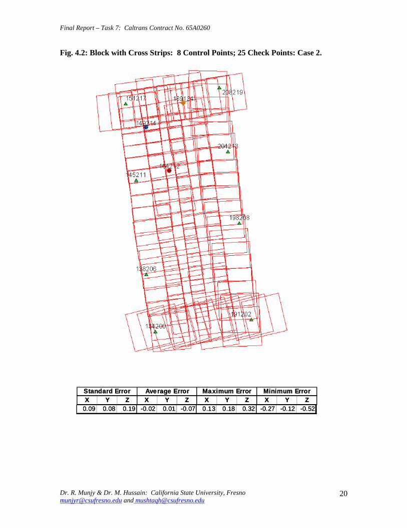
Final Report ndash Task 7 Caltrans Contract No 65A0260
Fig 42 Block with Cross Strips 8 Control Points 25 Check Points Case 2
SSttaannddaardrd EErrorrorr AAvveeraraggee EErrrroorr MMaaxxiimmuumm EErrorrorr MMiinniimmuumm EErrorrorr XX YY ZZ XX YY ZZ XX YY ZZ XX YY ZZ
000099 000088 001199 --000022 000011 --000707 001133 001818 003232 --002277 --001212 --005522
Dr R Munjy amp Dr M Hussain California State University Fresno munjyrcsufresnoedu and mushtaqhcsufresnoedu
20
Final Report ndash Task 7 Caltrans Contract No 65A0260
Fig 43 Block with Cross Strips 12 Control Points 23 Check Points Case 3
SSttaannddaardrd EErrorrorr AAvveeraraggee EErrrroorr MMaaxxiimmuumm EErrorrorr MMiinniimmuumm EErrorrorr XX YY ZZ XX YY ZZ XX YY ZZ XX YY ZZ
001100 000088 001144 --000044 --000303 000055 000099 001313 002929 --002288 --001515 --003300
Dr R Munjy amp Dr M Hussain California State University Fresno munjyrcsufresnoedu and mushtaqhcsufresnoedu
21
Final Report ndash Task 7 Caltrans Contract No 65A0260
Fig 44 Block with Cross Strips 14 Control Points 21 Check Points Case 4
SSttaannddaardrd EErrorrorr AAvveeraraggee EErrrroorr MMaaxxiimmuumm EErrorrorr MMiinniimmuumm EErrorrorr XX YY ZZ XX YY ZZ XX YY ZZ XX YY ZZ
001100 000088 001155 --000011 --000101 000066 001111 001313 002828 --002255 --001414 --003311
Dr R Munjy amp Dr M Hussain California State University Fresno munjyrcsufresnoedu and mushtaqhcsufresnoedu
22
Final Report ndash Task 7 Caltrans Contract No 65A0260
Fig 45 Block with Cross Strips 14 Control Points 21 Check Points Case 5
SSttaannddaardrd EErrorrorr AAvveeraraggee EErrrroorr MMaaxxiimmuumm EErrorrorr MMiinniimmuumm EErrorrorr XX YY ZZ XX YY ZZ XX YY ZZ XX YY ZZ 001100 000066 001155 000000 --000033 000011 001122 001133 002277 --002255 --001166 --003344
Dr R Munjy amp Dr M Hussain California State University Fresno munjyrcsufresnoedu and mushtaqhcsufresnoedu
23
Final Report ndash Task 7 Caltrans Contract No 65A0260
Fig 46 Block without Cross Strips 8 Control Points 25 Check Points Case 7
SSttaannddaardrd EErrorrorr AAvveeraraggee EErrrroorr MMaaxxiimmuumm EErrorrorr MMiinniimmuumm EErrorrorr XX YY ZZ XX YY ZZ XX YY ZZ XX YY ZZ 001122 000088 005599 000404 000606 --110088 002288 002244 001166 --002222 --000099 --110099
Dr R Munjy amp Dr M Hussain California State University Fresno munjyrcsufresnoedu and mushtaqhcsufresnoedu
24
Final Report ndash Task 7 Caltrans Contract No 65A0260
Fig 47 Block without Cross Strips 11 Control Points 22 Check Points Case 8
SSttaannddaardrd EErrorrorr AAvveeraraggee EErrrroorr MMaaxxiimmuumm EErrorrorr MMiinniimmuumm EErrorrorr XX YY ZZ XX YY ZZ XX YY ZZ XX YY ZZ
001133 000099 001199 --000011 --000202 --001177 001177 001166 002288 --002828 --001166 --005050
Dr R Munjy amp Dr M Hussain California State University Fresno munjyrcsufresnoedu and mushtaqhcsufresnoedu
25
Final Report ndash Task 7 Caltrans Contract No 65A0260
Fig 48 Block without Cross Strips 11 Control Points 22 Check Points Case 9
SSttaannddaardrd EErrorrorr AAvveeraraggee EErrrroorr MMaaxxiimmuumm EErrorrorr MMiinniimmuumm EErrorrorr XX YY ZZ XX YY ZZ XX YY ZZ XX YY ZZ
001144 000099 002277 --000055 000033 --003131 001166 002020 003030 --003311 --001515 --006666
Dr R Munjy amp Dr M Hussain California State University Fresno munjyrcsufresnoedu and mushtaqhcsufresnoedu
26
Final Report ndash Task 7 Caltrans Contract No 65A0260
Fig 49 Block without Cross Strips 12 Control Points 21 Check Points Case 10
SSttaannddaardrd EErrorrorr AAvveeraraggee EErrrroorr MMaaxxiimmuumm EErrorrorr MMiinniimmuumm EErrorrorr XX YY ZZ XX YY ZZ XX YY ZZ XX YY ZZ 001133 000099 002200 --000022 000000 --000808 001166 001818 003131 --002277 --001616 --003333
Dr R Munjy amp Dr M Hussain California State University Fresno munjyrcsufresnoedu and mushtaqhcsufresnoedu
27
Final Report ndash Task 7 Caltrans Contract No 65A0260
Fig 410 Block without Cross Strips 14 Control Points 19 Check Points Case 11
SSttaannddaardrd EErrorrorr AAvveeraraggee EErrrroorr MMaaxxiimmuumm EErrorrorr MMiinniimmuumm EErrorrorr XX YY ZZ XX YY ZZ XX YY ZZ XX YY ZZ
001100 000088 001133 000044 --000022 --000303 001166 001515 002525 --002211 --001717 --002200
Dr R Munjy amp Dr M Hussain California State University Fresno munjyrcsufresnoedu and mushtaqhcsufresnoedu
28
Final Report ndash Task 7 Caltrans Contract No 65A0260
Fig 411 Block without Cross Strips 14 Control Points 19 Check Points Case 12
SSttaannddaardrd EErrorrorr AAvveeraraggee EErrrroorr MMaaxxiimmuumm EErrorrorr MMiinniimmuumm EErrorrorr XX YY ZZ XX YY ZZ XX YY ZZ XX YY ZZ
000099 000077 001122 --000011 --000101 000055 000099 001313 002828 --002255 --001414 --001122
Dr R Munjy amp Dr M Hussain California State University Fresno munjyrcsufresnoedu and mushtaqhcsufresnoedu
29
Final Report ndash Task 7 Caltrans Contract No 65A0260
5 ANALYSIS OF RESULTS amp CONCLUSIONS
In accordance with the Caltrans standards using wide-angle aerial photography the RMS error in each coordinate component of the adjusted tie points should not exceed 110000 of the flying height above the terrain The Del Mar Test Block was flown with a wideshyangle aerial camera from an average height of 1800 feet above the terrain level thereby resulting in an average photo scale of 13600 Consequently the limiting RMS error at the Check Points representative of a finite number of well distributed tie points in the block should not exceed 018 ft in this case Any error that exceeds three times this limiting value viz 054 ft in any of the coordinate components should be a cause for rejection of that point
Therefore the acceptable limiting values for the standard error at the Check Points is 018 ft in each coordinate component Any block adjustment solution that results in a coordinate error in one or more Check Points that exceeds 054 ft in any coordinate component would not be an acceptable solution The following analysis of the results is based on these accuracy criteria
51 Blocks With Cross Flights
When a minimal number of 8 control points are used (Fig 42) along the block perimeter the resulting standard error in Z-coordinate of 019 ft exceeds the limiting value of 015 ft It is also noticeable that the highest error in the Z-coordinate of 052 ft at Point 189134 almost equals the rejection limit of 054 ft This is an indication that controlling a cross flight with only a single Control Point at each end of the flight may not always provide a satisfactory solution
This situation can be remedied by using a pair of Control Points in each end model of a cross flight so that any deformation across the flight line the omega rotation () can also be controlled Such an approach is also reported to have been successfully used and recommended in the past [1] [2] [3] When 4 additional Control Points were added at the end of each cross flight line as is seen in Fig 43 all the standard errors fell within the acceptable range and the maximum coordinate error did not exceed 030 ft which is well within the acceptable criteria
The primary advantage of using airborne GPS data for the adjustment of aerial triangulation blocks is to completely eliminate the need for Control Points in the interior of the block But it is of interest to investigate how effectively the airborne GPS data alone can control the interior of the block Two separate blocks were processed by adding two Control Points in the interior of the block resulting in a total of 14 Control Points
The block with 14 Control Points (Case A) is shown in Fig 44 where the two interior Control Points were selected so that one Control Point was located on the opposite ends in each of the two interior flight lines (Line 2 and Line3 see Fig 41) The other block with 14 Control Points (Case B) is shown in Fig 45 In this case both the interior points
Dr R Munjy amp Dr M Hussain California State University Fresno munjyrcsufresnoedu and mushtaqhcsufresnoedu
30
Final Report ndash Task 7 Caltrans Contract No 65A0260
fell in the middle of the block interior It is interesting to note that in either of the two cases the addition of the interior Control Points did not result in any significant difference from the result achieved earlier while using 12 Control Points Therefore it may be concluded that as long as the cross flights are adequately controlled with a pair of Control Points located across each end model of each cross flight additional control in the block interior is not required The results shown in Fig 44 and 45 validate this conclusion at least for a block comprised of 18 models long multiple flight lines
52 Blocks Without Cross Flights
When a mapping project involves a large photogrammetric block consisting of hundreds of models the common practice is to plan the block configuration to include cross flights [1] [2] [6] [10] Often such cross flights can result in significant saving in time and effort in minimizing the need for ground control Since the photogrammetric mapping projects in Caltrans mostly involve mapping along highway corridors most of the photogrammetric blocks vary from a single flight line to up to as many as four flight lines Therefore it is still to be investigated whether the use of cross flight lines in such blocks offers any significant advantage Furthermore any advantage resulting from the reduced need for the ground control has to be weighed against the additional time and effort needed in processing the cross flight models The Caltrans Office of Photogrammetry has not yet adopted the use of Automated Aerial Triangulation (AAT) techniques for routine production Consequently the additional effort in transferring tie points between the cross flights with the flights of the main block is still significant This has provided the impetus to carry out the following investigation for the aerial triangulation adjustment of blocks that do not include any cross flights
The first block without the two cross flights was processed with only 8 Control points along the block perimeter as a parallel case with the block run with cross flights The results are shown in Fig 46 As may be expected the absence of any Control Point located at each end of each of the two interior flights 2 and 3 has resulted in unacceptably large errors Not only is the standard error of 059 ft in the Z-coordinate for the 25 Check Points too large but interestingly the block adjustment carries a large systematic error in Z-coordinate of 108 ft This results from the fact that the absence of the Control Points at each end of Flights 2 and 3 does not permit the adjustment for the systematic strip drift parameters for the airborne GPS data along Flights 2 and 3
When cross flights are included the airborne GPS data measured along the cross flight adequately serves as control for adjusting the strip shift and drift parameters Therefore an alternative to the inclusion of cross flights in the block configuration is to provide a Control Point at each end of every flight line in the block Accordingly the processing of the following blocks includes Control Points at the end of each flight line
The Del Mar Test Block with 4 flight lines each 18 models long would require a total of 12 Control Points one Control Point at each end of each flight line and 4 Control Points along the interior perimeter of the block to provide a control spacing of approximately 6 airbases apart However in order to minimize the use of the ground control the block
Dr R Munjy amp Dr M Hussain California State University Fresno munjyrcsufresnoedu and mushtaqhcsufresnoedu
31
Final Report ndash Task 7 Caltrans Contract No 65A0260
shown in Fig 47 was processed with only 11 Control Points (Case A) since the Control Point 170133 was measured both in Line 2 and Line 3 The resulting standard error of 019 ft in the Z-coordinate for 22 Check Points as well as the large error of 050 ft in the Z-coordinate of Check Point 189134 make the block adjustment solution unacceptable There appears to be no obvious reason why the Check Point 189134 that is located so close to the Control Point 170133 should display such unacceptably large error in the Zshycoordinate In order to ascertain the internal consistency of the ground control data (33 Control Points) a conventional aerial triangulation adjustment of the block was performed (without using the airborne GPS data) using 32 Control Points and treating the Control Point 189134 as a Check Point The resulting error in the Z-coordinate of Point 189134 was only 006 ft It is also to be noted that the average Z-coordinate error of 017 ft indicates a systematic height error This would lead to the conclusion that there is some height discrepancy between the ground control data and the airborne GPS data
The block was re-processed (Case B) again by using only 11 Control Points but this time the Control Point 170133 was replaced with Control Point 189134 and the results are displayed in Fig 48 The Case B results are even worse than the Case A results the standard error in Z-coordinate was degraded to 027 ft while the largest error in Zshycoordinate of 066 ft was noted at Check Point 187215 The average Z-coordinate error also increases to 031 ft This is a further indication that there is significant height inconsistency in the airborne GPS data and the ground control data It appears that the height discrepancy between the ground control data and the airborne GPS data results in an unsatisfactory shift and drift adjustment of the airborne GPS data particularly in the inner flight Lines 2 and 3 that span 18 models between the end Control Points
In order to strengthen the end control across the flight lines both the Control Points 170133 and 189134 were used at the Northern end of the block The block was then processed with 12 Control Points and the results are presented in Fig 49 Even though the results improved significantly but contrary to the expectation the standard error in the Z-coordinate of 020 ft for the 21 Check Points did not meet the Caltrans accuracy standard The next logical approach was to investigate the impact of adding Control Points in the interior of the block Two interior Control Points were selected in the same manner as has been described earlier in the case of the blocks with the cross flights (see Fig 44 and 45)
Using 14 Control Points the Case A is shown in Fig 410 while the Case B is presented in Fig 411 The results in both Case A and Case B easily meet the Caltrans accuracy standards In Case A the distance between the Control Points for the shift and drift parameter adjustment of the airborne GPS data varies from 6 to 12 models while in Case B the interior Control Points are about 6 models apart Each Control Point distribution provides almost similar results It is a clear indication that any systematic height deformation that results from the suspected inconsistency between the ground surveyed GPS data and the airborne GPS data can be kept within acceptable range by including a pair of control points in the interior of the block Such a need for some control points has not been reported for the adjustment of aerial triangulation blocks in the past However the largest photo scale for which any ABGPS supported results have been published in
Dr R Munjy amp Dr M Hussain California State University Fresno munjyrcsufresnoedu and mushtaqhcsufresnoedu
32
Final Report ndash Task 7 Caltrans Contract No 65A0260
the past is 14800 only For a photo scale of 13600 that is approximately 25 percent larger the requirements for the accuracy of aerial triangulation accordingly become more stringent in the same proportion This may generate the need for some additional control in the middle of the block
The residuals at the ground control points and in the image coordinate data along with the resulting standard error of unit weight (0) provide a reliable indication of the internal consistency of the adjusted block However the absolute accuracy of the aerial triangulation can be validated only by the use of Check Points that are well distributed over the entire block As pointed out earlier any deformations due to residual systematic shift and drift errors in the airborne GPS data are likely to be most significant in the center of the block the location that is farthest from the control points distributed along the perimeter Accordingly it would be advisable to locate at least a pair of Check Points in the middle of the block and after completing the block adjustment (by excluding these Check Points as Control Points) the coordinate discrepancies obtained at these Check Points can be analyzed Such discrepancies would normally represent the highest absolute accuracy resulting from aerial triangulation adjustment of the block Any unacceptably large coordinate discrepancies at the Check Points would require investigation of the block input data
In the case the coordinate discrepancies at the Check Points are within acceptable range the block can be re-processed by also including the Check Points in the control data This should enhance the accuracy in the interior of the block
6 RECOMMENDED DRAFT STANDARDS
These draft standards are proposed to supplement the existing Standards for Strip Configuration Airborne GPS Controlled Photogrammetry for Large Scale Mapping Projects (based on 13600 photo scale) currently used in Caltrans
61 Data Acquisition
611 Image Coordinate Data
Follow the existing practice used in Caltrans Office of Photogrammetry for the selection distribution and the measurement of all image point data It is recommended that raw machine coordinate image data should form the input to the aerial triangulation block adjustment
A secondary interest in this Research Project under contract with Caltrans was to also evaluate the alternate methodology of the selection and the measurement of tie point data using Automated Aerial Triangulation (AAT) system However several problems were encountered in implementing the AAT software available at the Caltrans Office of Photogrammetry in Sacramento The unavoidable delay caused by unfavorable weather conditions in acquiring the aerial imagery for the Del Mar Test Block did not allow
Dr R Munjy amp Dr M Hussain California State University Fresno munjyrcsufresnoedu and mushtaqhcsufresnoedu
33
Final Report ndash Task 7 Caltrans Contract No 65A0260
enough time to resolve the AAT software issues with software vendor Accordingly this task could not be fully completed Therefore it was mutually agreed between the Caltrans Office of Photogrammetry and California State University Fresno to concentrate research efforts on the processing and the analysis of the Del Mar Test Block and on drafting the Final Report
612 Ground Control Data
The proposed research is focused on the use of photography obtained at scale of 13600 for corridor mapping in Caltrans The ground control for mapping is based on the airborne GPS supported aerial triangulation of the photo blocks The ground control points should be surveyed to provide 15 to 2-times higher accuracy than that of the adjusted tie point data This would translate to an accuracy at the 005 to 01 ft level for the planimetric coordinates and the height an accuracy achievable using static GPS surveys tied to existing HPGN network
It is not yet certain that the Real-Time Kinematic (RTK) GPS field survey methodology whether relying on a single base station or on an RTK network is able to meet the above stringent field survey accuracy requirements Therefore the ground control data for ABGPS based aerial triangulation blocks should be based entirely on GPS control networks established using static GPS surveying methodology The RTK survey methodology for establishing control for photogrammetric mapping projects should not be used till such time that such technology has advanced to a level when consistently reliable results can be routinely expected
The GPS observations provide a fairly precise data for ellipsoidal height differences However all photogrammetric mapping has to be based on orthometric height data Two different approaches can be used in order to derive adjusted orthometric height data through aerial triangulation The first method is to carry out the simultaneous least squares adjustment of the GPS observation data for the ground control network using current Caltrans Horizontal Datum CCS83 (199135) and Vertical Datum NAVD 88 But since the observed data involves the measurement of ellipsoidal height differences for each measured baseline there is a need for transforming such differences to the corresponding orthometric height differences on NAVD 88 Datum In the absence of an existing Local Geoid Model the only economic recourse available to meet this need is to use the most reliable existing Global Geoid Model the time-consuming and prohibitively more costly alternative would be to connect the control network stations through differential leveling The Global Geoid Models are progressively being updated and the GEOID 2003 Model is most commonly in current use although GEOID 2009 Model may soon become available
It has to be noted that the use of a Global Geoid Model will always have some residual geoidal height uncertainties perhaps in the range of few hundredths of a foot It is therefore necessary that a few stations that are well distributed over the control network should have precisely known orthometric height values which can be used for the height adjustment of the network The minimum number of such orthometric height control
Dr R Munjy amp Dr M Hussain California State University Fresno munjyrcsufresnoedu and mushtaqhcsufresnoedu
34
Final Report ndash Task 7 Caltrans Contract No 65A0260
stations is three and consequently a network should be planned to have at least four and preferably more stations where orthometric height is precisely known In practice this requirement is met by including several existing benchmarks that are well distributed over the project area The redundancy provided by using more than three benchmarks will quantify the height residuals resulting from the adjustment This will provide a good estimate for the residual height errors in the network
The alternative approach is to carry out the adjustment of the GPS control network using WGS84 Geodetic Datum This datum is consistent with the observed GPS measurement data and a simultaneous 3D adjustment of the network can be performed in a Local Spatial Coordinate System (LSCS) the most commonly used approach is to shift the origin of the WGS84 coordinate system (center of the Earth) to approximately the center of the project site and apply a 3D rotational matrix to align the coordinate axes along the East North and Up directions Some commercial aerial triangulation software systems provide utilities to easily perform such datum transformation After the aerial triangulation results have been validated the coordinates of all the control and tie points can be transformed back to WGS 84 Datum Based on the availability of the orthometric height control stations a local Geoid can be defined ( a plane or a surface etc) and then used to transform the ellipsoidal height data to orthometric height data This second approach has the advantage that unlike the first method described above the residual height errors in the transformed control point height data are not propagated through aerial triangulation
For 13600 scale aerial photography blocks the ground control data should meet the a- priori standard deviation at 010 ft level This is not a very challenging demand for the horizontal positioning using GPS methodology However the residual height uncertainties in the orthometric height of control points interpolated from the Global Geoid Model become more critical as the photo scale becomes larger
613 Airborne GPS Data
The current practice used in Caltrans to acquire airborne GPS data during flight missions should continue to be used It is necessary to have GPS data collected at 1 Hz or higher rate at a base station that is located within or close to the project site Prior research completed collaboratively with Caltrans has already shown that the data at the base station may be substituted with GPS data collected at CORS at 5-sec or higher rate Consequently the collection of GPS data at more than one base stations is not considered as an essential requirement It may still be prudent to acquire GPS data at a second base station as a contingency safeguard against the GPS hardware failure at a base station for guaranteed success of the flight mission and expense
It is to be noted that the relative accuracy between successive airborne GPS antenna 3Dshycoordinates should be at 10-cm or higher level The current procedure used in Caltrans for the aircraft to remain stationary for static resolution of ambiguities before take off has mostly resulted in acquiring very reliable airborne GPS data This practice should perhaps be continued even though the continuing improvements in GPS hardware and
Dr R Munjy amp Dr M Hussain California State University Fresno munjyrcsufresnoedu and mushtaqhcsufresnoedu
35
Final Report ndash Task 7 Caltrans Contract No 65A0260
post-processing softwares are making on-the-fly (OTF) ambiguity resolution increasingly reliable However if it is necessary to resort to on-the-fly ambiguity resolution it must be ensured that the ambiguities have stabilized before photography is started The strict requirement for reliably resolving the ambiguities also does not permit the loss of lock during any single flight line If a loss of lock occurs during turns between flight lines ambiguities must be re-acquired and must stabilize before starting the collection of photography for another flight line Based on the make and the model of the airborne GPS receiver the Caltrans Office of Photogrammetry in consultation with the District Survey Section should draft a set of instructions for the GPSCamera operator aboard the aircraft specifying what parameters (such as PDOP Number of SVs etc) that need to be continuously monitored on a screen during a flight mission
62 Flight and Control Configuration
The following standards in planning the flight line configuration and the corresponding ground control distribution for Caltrans project are recommended to achieve optimum results
Control points are primarily required only along the perimeter of the block When a cross flight line is used to control the end of a block a pair of Control
Points must be located at each end of the cross flight At each end of a block that is not controlled by a cross flight a CP should be
located at the end of each parallel flight line a single CP may serve as end control for two adjacent overlapping flight lines
Along the perimeter of the block in a direction parallel with the main flight lines the CPs should be located at an average spacing of 6 airbases
Any corner in a block resulting from a sudden change in the length of two adjacent parallel flight lines should be controlled by an additional CP
Check Points should be provided along the interior flight lines in a multi-strip block The Check Points may be distributed along the interior flight lines so that any Check Point is not farther than about 8 airbases from either another Check Point (on same or adjacent flight line) or from a Control Point
Note that Caltrans is usually concerned with the mapping mostly along highway corridors and therefore does not require blocks with segments larger than three or four parallel flight lines Additional control along the cross flight line would be needed if such segments have 8 or more parallel flight lines
63 Data Processing and Adjustment
631 Processing of ABGPS Data
The current practice of post-processing ABGPS data used in Caltrans Office of Photogrammetry using GrafNav software should be continued The data should continue to be processed in the Forward and Backward modes A coordinate separation of less
Dr R Munjy amp Dr M Hussain California State University Fresno munjyrcsufresnoedu and mushtaqhcsufresnoedu
36
Final Report ndash Task 7 Caltrans Contract No 65A0260
than 10 cm especially in the height represents a normally acceptable range for the combined solution
This study has shown that the airborne GPS data in comparison with the ground control data should be weighted a lower weight but the highest weight that the GPS data quality represents Generally the best results were achieved when a-priori standard error of 015 ft was used for the airborne GPS coordinate data in comparison with the a-priori standard error of 010 ft used for the ground control coordinate data Since the 3-D position of successive points along the airborne GPS antenna trajectory are estimated using Kalman Filtering approach the successive location coordinates are highly correlated and consequently carry a much higher relative precision This provides a realistic justification for the use of a-priori standard error of 015 ft
632 Processing of Aerial Triangulation Block
Each aerial triangulation block requires the following data files as input
- Raw image coordinate data file - Ground control data file - Interpolated camera coordinate data file
Using the above input data files the block adjustment should be carried out in two steps as described below It is essential that additional Strip Shift and Drift parameters (3 Shift and 3 Drift parameters) should be incorporated in the bundle adjustment solution
Step 1 Minimal Control Adjustment
The preliminary simultaneous bundle adjustment of the block should be carried out by using the minimal amount of control points along the block perimeter only All the additional ground surveyed and targeted points should be treated as tie points to serve as Check Points The adjustment results should meet the following criteria
a The Standard Error of Unit Weight (0) should fall between 03 to 07 b The residual for any image coordinate should not exceed 15 micrometer c The RMS for ground control residuals should not exceed 110000 of the flying
height above the average terrain level d The maximum residual in any ground control coordinate should not exceed 25
times the RMS value permissible under Item (c) above e The RMS for discrepancy (difference between computed coordinate value and
the ground surveyed coordinate value) in Check Point coordinates should not exceed 110000 of the flying height above the average terrain level
f The discrepancy in any Check Point coordinate should not exceed 25 times the RMS value permissible under Item (e) above
If the above criteria are met even the preliminary adjustment solution for the block satisfies Caltrans accuracy standards for aerial triangulation If the criterion under Item
Dr R Munjy amp Dr M Hussain California State University Fresno munjyrcsufresnoedu and mushtaqhcsufresnoedu
37
Final Report ndash Task 7 Caltrans Contract No 65A0260
(f) above is not met the input data should be checked for any gross mistakes or errors in the ground control and Check Point data
Step 2 Full Control Adjustment
The final simultaneous bundle adjustment of the block should be carried out by including all the ground surveyed points (Control Points and Check Points) in the ground control data file The adjustment results should meet the following criteria
g The Standard Error of Unit Weight (0) should fall between 03 to 07 h The residual for any image coordinate should not exceed 15 micrometer i The RMS for ground control residuals should not exceed 110000 of the flying
height above the average terrain level j The maximum residual in any ground control coordinate should not exceed 25
times the RMS value permissible under Item (i) above
7 CONCLUDING COMMENTS
The completion of this project signifies the culmination of a very successful and productive combination of advanced theoretical principles with sound practical experience for the adaptation of evolving photogrammetric technologies in Caltrans practice In order to alleviate a growing concern for the safety of staff conducting field survey operations in close proximity of high speed traffic Caltrans in late 1990s decided to investigate the feasibility of using airborne GPS data for controlling the aerial triangulation blocks There were two primary issues to be resolved The first and the foremost concern was whether the use of airborne GPS data could be effectively used for controlling aerial triangulation blocks of as large a photo scale as 13000 used in Caltrans and still meet the Caltrans accuracy standards This concern was particularly critical since there had not been any reported use of airborne GPS data for such a large scale of aerial photography
Should the above investigation show that the Caltrans accuracy standards for aerial triangulation for 13000 scale aerial photography can be met it was of great interest to Caltrans to develop based on theoretically sound and systematic investigation a set of standards and specifications for the successful implementation of this new methodology in Caltrans routine practice
Under a Caltrans New Technology and Research Program currently Division of Research and Innovation (DRI) contract Caltrans Office of Photogrammetry partnered with a team of two faculty members from the Geomatic Engineering Program at the California State University Fresno (CSUF) in 1996 to carry out research to address the above two issues This partnership has flourished over the past several years through
Dr R Munjy amp Dr M Hussain California State University Fresno munjyrcsufresnoedu and mushtaqhcsufresnoedu
38
Final Report ndash Task 7 Caltrans Contract No 65A0260
successive research contracts and has resulted in very fortuitous outcomes based on the theoretical and analytical guidance provided by the CSUF research team and the highly skilled aerial survey project management and high caliber professional skills in the acquisition of photogrammetric data collection by the Caltrans Office of Photogrammetry In addition the help from highly experienced field survey teams from Caltrans various districts (especially District 11) in establishing GPS networks of Control Points and Check Points of specified precision was critical for the validation of airborne-GPS supported aerial triangulation investigations
As a result of the past collaborative efforts between the Caltrans Office of Photogrammetry and the CSUF Research Team the use of airborne GPS data for aerial triangulation has successfully been transitioned into Caltrans practice in the following stages
1) Based on a number of test flights it was convincingly demonstrated that the use of airborne GPS data consistently meets the Caltrans accuracy standards for aerial triangulation for strip configuration blocks at 13000 photo scale [13]
2) A detailed set of standards and specifications were developed for the implementing of the new methodology in Caltrans routine practice This was further supported through a training workshop conducted by CSUF at the Caltrans offices in Sacramento [8]
3) The use of airborne GPS data for the adjustment of aerial triangulation blocks requires the collection of GPS data at one or more ground base stations during the flight mission This requirement imposes burdensome demands on scheduling and allocation of manpower and equipment resources In order to reduce or even to completely eliminate the need for the collection of GPS data at base stations the use of GPS data collected and archived at a network of Continuously Operating Reference Stations (CORS) distributed over the State of California was investigated It was demonstrated that CORS data could be effectively used as a replacement for data collected at base stations while fulfilling Caltrans accuracy standards Accordingly specifications were revised to also include the selection and the use of CORS data for the post-processing of airborne GPS data to accurately derive the trajectory of the airborne GPS antenna during flights [19]
4) During the past few years Caltrans has increasingly been using multi-strip projects for mapping using 13600 photo scale This provided the need for the current research study The successful completion of this study has resulted in supplementing the existing standards and specifications for airborne GPS supported single-strip aerial triangulation blocks to also include the aerial triangulation of multi-strip blocks
It is a matter of great satisfaction for the research team at CSU Fresno that working hand in hand with the Caltrans Office of Photogrammetry the comprehensive set of standards and specifications for airborne GPS supported aerial triangulation that had been developed for successful transition of this technology in Caltrans practice have been further upgraded It is hoped that as the photogrammetric technology advances further
Dr R Munjy amp Dr M Hussain California State University Fresno munjyrcsufresnoedu and mushtaqhcsufresnoedu
39
Final Report ndash Task 7 Caltrans Contract No 65A0260
similar collaborative efforts between Caltrans Office of Photogrammetry and CSU Fresno will continue to address the changing needs in Caltrans
Dr R Munjy amp Dr M Hussain California State University Fresno munjyrcsufresnoedu and mushtaqhcsufresnoedu
40
Final Report ndash Task 7 Caltrans Contract No 65A0260
REFERENCES
1 Abdullah Q M Hussain and R Munjy (2002) Workshop on Airborne GPS-Supported Aerial Triangulation ndash Theory and Practical Concepts presented at the Annual ASPRS Convention Washington DC 2002
2 Ackermann Fritz (1992) Operational Rules and Accuracy Models for GPS-Aerotriangulation Archives of the ISPRS Com 1 Vol29 1992 [pp 691-700]
3 Ackermann F (1993) Application of GPS for Aerial Triangulation Photogrammetric Engineering and Remote Sensing Vol 59 No 11 [pp 1651shy1658]
4 Appleton James Mushtaq Hussain and Riadh Munjy (2000) Use of Airborne GPS Data for Highway Mapping International Archives of Photogrammetry and Remote Sensing Vol XXXIII Part B4 Amsterdam 2000[pp 84-90]
5 Appleton James M Hussain and R Munjy (2002) Use of Airborne GPS Data For Aerial Triangulation in Caltrans (2002) Workshop presented at the California Department of Transportation Sacramento 2002
6 Federal Geographic Data Committee (FGDC) 1998 Geospatial Positional Accuracy Standards Part-3 National Standards for Spatial Data Accuracy (NSSDA) FGDC-STD-0073-1998
7 Friess Peter (1992) Experiences with GPS-Supported Aerial Triangulation Archives of the ISPRS Com 1 Vol29 1992 [pp 299 - 305]
8 Gianellia Alexander M (1995) Practical Considerations in Implementing GPS Technologies in Airborne Data Collection Proc ASPRS Annual Convention 1995 [pp 917-925]
9 Hussain M R Munjy and J Appleton (1999) Use of Airborne On-the-Fly Kinematic GPS Data for Photogrammetric Mapping Proceedings ION-GPS-99 Conference Nashville 1999[pp 1653-1659]
10 Hussain M and R Munjy (1999) GPS Controlled Photogrammetry For Large Scale Mapping (1999) Final Project Report Research project No 65Y271 submitted to New Technology amp Research Program California Department of Transportation
11 Hussain M and R Munjy (2002) Airborne GPS Controlled Aerial Triangulation in Caltrans Final Project Report Research project No 65A0059 submitted to New Technology amp Research Program California Department of Transportation June 2002
12 Munjy R and M Hussain (1985) Interactive Simultaneous Bundle Block Adjustment System (ISBBA) for Small Computers Proceedings of the ASPRS Annual Convention Washington DC 1985
13 Munjy R M Hussain and James Appleton (2000) Use of Airborne GPS Data for Corridor Mapping presented at the Annual ASPRS Convention Washington DC 2000
Dr R Munjy amp Dr M Hussain California State University Fresno munjyrcsufresnoedu and mushtaqhcsufresnoedu
41
Final Report ndash Task 7 Caltrans Contract No 65A0260
14 Munjy R and M Hussain (2007) Develop Criteria for Using Network GPS for Airborne GPS Photogrammetry Final Project Report Research Project No 65A0234 submitted to the Division of Research and Innovation (DRI) California Department of Transportation
15 Munjy R and M Hussain (2009) Draft Preliminary Standards Interim Report Research Project No 65A0260 submitted to Division of Research aned Innovation (DRI) California Department of Transportation
Dr R Munjy amp Dr M Hussain California State University Fresno munjyrcsufresnoedu and mushtaqhcsufresnoedu
42
APPENDIX I Results of Check Block
Flight amp Control Configuration Cases Used for
Study amp Analysis of Check Project in San Diego
INDEX
Case Block amp Control Configuration 1 Full Blk(Flts1to9) All 44 CP 2 Full Blk 8 CP 3 Full Blk 9 CP 4 Full Blk 10 CP 5 Main Blk(Flts1to7) 43 CP 6 Main Blk(Flts1to7) 8 CP 7 Main Blk(Flts1to7) 10 CP 8 Main Blk(Flts1to7) 12 CP 9 North Blk(Flts567amp9) 5 CP 10 North Blk(Flts567amp9) 7 CP 11 North Blk(Flts56amp7) 6 CP 12 North Blk(Flts56amp7) 8 CP 13 South Blk(Flts1to4amp8) 4 CP 14 South Blk(Flts1to4amp8) 6 CP 15 South Blk(Flts1to4amp8) 7 CP 16 South Blk(Flts1to4) 7 CP 17 South Blk(Flts1to4) 8 CP(a) 18 South Blk(Flts1to4) 8 CP(b) 19 South Blk(Flts1to4) 10 CP 20 South Blk(Flts1to4) 11 CP 21 South Blk(Flts Modified 1to4 amp8) 5 CP 22 South Blk(Flts Modified 1to4 ) 6 CP
[Refer to Table-1 Summary of the Coordinate Differences at the Check Points]
I-i
Case-1 Base DataFULL BLOCK
Flts 1 to 9
Case-1 Base Data FULL BLOCK
Flts 1 to 9
Control PointsControl Points All 44 PointsAll 44 Points
SSSttt ErErErrrr AAAvvvggg ErErErrrr MMMaaaxxx ErErErrrr MMMiiinnn ErErErrrr XXX YYY ZZZ XXX YYY ZZZ XXX YYY ZZZ XXX YYY ZZZ
007 008 005 000 000 000 019 012 012 -013 -023 -013007 008 005 000 000 000 019 012 012 -013 -023 -013007 008 005 000 000 000 019 012 012 -013 -023 -013
I-ii
Case-2FULL BLOCK
Flts 1 to 9
Control Points 8
Case-2 FULL BLOCK
Flts 1 to 9
Control Points 8 CChheecckk PoPointsints 3366
SStt ErErrr AAvvgg ErErrr MMaaxx ErErrr MMinin ErErrr XX YY ZZ XX YY ZZ XX YY ZZ XX YY ZZ
012012 012012 016016 002002 001001 --000505 024024 027027 026026 --025025 --039039 --032032
I-iii
Case-3FULL BLOCK
Flts 1 to 9
Control Points 9
Case-3 FULL BLOCK
Flts 1 to 9
Control Points 9 CChheecckk PoPointsints 3355
SStt ErErrr AAvvgg ErErrr MMaaxx ErErrr MMinin ErErrr XX YY ZZ XX YY ZZ XX YY ZZ XX YY ZZ
012012 012012 017017 001001 --001001 --000808 024024 024024 026026 --026026 --040040 --034034
I-iv
Case-4FULL BLOCK
Flts 1 to 9
Control Points 10
Case-4 FULL BLOCK
Flts 1 to 9
Control Points 10 CChheecckk PoiPoinntsts 3344
SStt ErErrr AAvvgg ErErrr MMaaxx ErErrr MMinin ErErrr XX YY ZZ XX YY ZZ XX YY ZZ XX YY ZZ
012012 009009 015015 003003 005005 --000909 002244 002727 002121 --025025 --001313 --035035
I-v
Case-5MAIN BLOCK
Flts 1 to 7
Control Points 43
Case-5 MAIN BLOCK
Flts 1 to 7
Control Points 43 [Point HV-117 Unuse[Point HV-117 Unusedd]]
SSSttt ErErErrrr AAAvvvggg ErErErrrr MMM aaaxxx ErErErrrr MMM iiinnn ErErErrrr XXX YYY ZZZ XXX YYY ZZZ XXX YYY ZZZ XXX YYY ZZZ
006006006 008008008 005005005 000000000 000000000 000000000 012012012 013013013 013013013 ---000131313 ---022022022 ---000090909
I-vi
Case-6
Flts 1 to 7
l Points 8
MAIN BLOCK
[No Cross Flts]Contro
Case-6 MAIN BLOCK
Flts 1 to 7 [No Cross Flts]
Control Points 8 ChecCheckk PoPointsints 3636
St ErSt ErSt ErSt ErSt ErSt ErSt ErSt Errrrrrrrr AAAAAAAAvgvgvgvgvgvgvgvg ErErErErErErErErrrrrrrrr MMMMMMMMaxaxaxaxaxaxaxax ErErErErErErErErrrrrrrrr MMMMMMMMiiiiiiiinnnnnnnn ErErErErErErErErrrrrrrrr XXXXXXXX YYYYYYYY ZZZZZZZZ XXXXXXXX YYYYYYYY ZZZZZZZZ XXXXXXXX YYYYYYYY ZZZZZZZZ XXXXXXXX YYYYYYYY ZZZZZZZZ
016016016016 012012012012 027027027027 -002-002-002-002 ----004004004004 -004-004-004-004 000026262626 000020202020 000041414141 ----035035035035 -036-036-036-036 ----082082082082
I-vii
Case-7MAIN BLOCK
Flts 1 to 7[No Cross Flts]
Control Points 10
Case-7 MAIN BLOCK
Flts 1 to 7 [No Cross Flts]
Control Points 10 CChheecckk PointsPoints 3434
SStt ErErrr AAvvgg ErErrr MM aaxx ErErrr MM iinn ErErrr XX YY ZZ XX YY ZZ XX YY ZZ XX YY ZZ
014 012 027 -001 -003 -004 022 020 039 -031 -031 -080014 012 027 -001 -003 -004 022 020 039 -031 -031 -080
I-viii
Case-8MAIN BLOCK
Flts 1 to 7[No Cross Flts]
Control Points 12
Case-8 MAIN BLOCK
Flts 1 to 7 [No Cross Flts]
Control Points 12 CheChecckk PointsPoints 3232
SSSttt ErErErrrr AAAvvvggg ErErErrrr MMMaaaxxx ErErErrrr MMMiiinnn ErErErrrr XXX YYY ZZZ XXX YYY ZZZ XXX YYY ZZZ XXX YYY ZZZ
015 010 017 003 000 -004 037 016 035 -031 -027 -023015 010 017 003 000 -004 037 016 035 -031 -027 -023015 010 017 003 000 -004 037 016 035 -031 -027 -023
I-ix
Case-9Case-9Case-9 NORNORNORTTTH BLH BLH BLOCKOCKOCK
FltsFltsFlts 5 to 7 amp 9 5 to 7 amp 9 5 to 7 amp 9
Control PointsControl PointsControl Points 555 ChChCheckeckeck PoPoPoininintttsss 111888
ErSSSttt EE rrrrr vg ErAAAvg Evg E rrrrr ax ErMMM ax Eax E rrrrr ErMMM iiinnn EE rrrrr XXX YYY ZZZ XXX YYY ZZZ XXX YYY ZZZ XXX YYY ZZZ
000121212 016016016 000161616 007007007 ---000161616 000111111 000262626 000020202 000363636 ---022022022 ---000626262 ---022022022
I-x
Case-Case-1100 NORTH BLOCKNORTH BLOCK
Flts 5 to 7 amp 9Flts 5 to 7 amp 9
Control PointsControl Points 77 CheckCheck PointsPoints 1616
SStt ErErrr AAvvgg ErErrr MM aaxx ErErrr MM iinn ErErrr XX YY ZZ XX YY ZZ XX YY ZZ XX YY ZZ
010010 016016 017017 008008 --000707 001818 002323 001010 005151 --016016 --005151 --012012
I-xi
Case-Case-1111 NORTH BLOCKNORTH BLOCK
FltsFlts 5 to 7 5 to 7
CCoontrntrool Pointsl Points 66 CheChecckk PointsPoints 1717
SStt ErErrr AAvvgg ErErrr MM aaxx ErErrr MM iinn ErErrr XX YY ZZ XX YY ZZ XX YY ZZ XX YY ZZ
010010 016016 022022 010010 --000202 000808 002424 001515 005050 --019019 --004343 --026026
I-xii
Case-Case-1122 NORTH BLOCKNORTH BLOCK
FltsFlts 5 to 7 5 to 7 [No C[No Crrossoss Flt]Flt]
ContControl Poinrol Pointsts 88 CChheecckk PointsPoints 1155
SStt EErrrr AAvg Evg Errrr MM ax Eax Errrr MM iinn EErrrr XX YY ZZ XX YY ZZ XX YY ZZ XX YY ZZ
011011 016016 017017 013013 --000909 000202 002929 000707 003737 --017017 --004949 --031031
I-xiii
CaseCase-13-13 SOUTSOUTH BH BLLOCKOCK
Flts 1 to 4 amp 8Flts 1 to 4 amp 8
CoConnttrol Porol Poininttss 44 ChCheckeck PPooinintsts 2222
SStt ErErrr AAvvgg ErErrr MM aaxx ErErrr MM iinn ErErrr XX YY ZZ XX YY ZZ XX YY ZZ XX YY ZZ
052 032 015 -082 033 003 -007 091 026 -149 -009 -034052 032 015 -082 033 003 -007 091 026 -149 -009 -034
I-xiv
Case-14Case-14 SOUTH BLOCKSOUTH BLOCK
Flts 1 to 4 amp 8Flts 1 to 4 amp 8
CCoontrntrool Pointsl Points 66 CheChecckk PointsPoints 2200
SStt ErErrr AAvvgg ErErrr MM aaxx ErErrr MM iinn ErErrr XX YY ZZ XX YY ZZ XX YY ZZ XX YY ZZ
013 016 015 -003 006 -002 024 033 033 -019 -028 -028013 016 015 -003 006 -002 024 033 033 -019 -028 -028
I-xv
Case-15Case-15 SOUTH BLOCKSOUTH BLOCK
FltsFlts 1 to 4 amp 8 1 to 4 amp 8
ContrControol Pointsl Points 77 ChCheckeck PPooinintsts 1919
SStt ErErrr AAvvgg ErErrr MM aaxx ErErrr MM iinn ErErrr XX YY ZZ XX YY ZZ XX YY ZZ XX YY ZZ
015 012 014 -003 -002 -002 025 023 033 -025 -030 -025015 012 014 -003 -002 -002 025 023 033 -025 -030 -025
I-xvi
Case-16Case-16Case-16 SOUTH BLOCKSOUTH BLOCKSOUTH BLOCK
FltsFltsFlts 1 to 4 1 to 4 1 to 4 [No Cross Flt][No Cross Flt][No Cross Flt]
Control PointsControl PointsControl Points 777 CheCheCheccckkk PointsPointsPoints 222222
SSSttt EEErrrrrr AAAvg Evg Evg Errrrrr MMM ax Eax Eax Errrrrr MMM iiinnn EEErrrrrr XXX YYY ZZZ XXX YYY ZZZ XXX YYY ZZZ XXX YYY ZZZ
015 013 023 -001 -005 003 026 023 032 -027 -029 -037015 013 023 -001 -005 003 026 023 032 -027 -029 -037015 013 023 -001 -005 003 026 023 032 -027 -029 -037
I-xvii
Case-17Case-17 SOUTSOUTH BLH BLOCKOCK
FltsFlts 1 1 to 4to 4 [No[No CrosCrosss Flt]Flt]
ContrControol Pointsl Points 88 CChheecckk PointsPoints 2121
SStt ErErrr AAvvgg ErErrr MM aaxx ErErrr MM iinn ErErrr XX YY ZZ XX YY ZZ XX YY ZZ XX YY ZZ
014014 012012 024024 005005 --000101 000404 003131 002525 003333 --022022 --002929 --040040
I-xviii
Case-18Case-18 SOUTH BLOCKSOUTH BLOCK
Flts 1 to 4Flts 1 to 4 [[NNo Cro Crooss Fss Flltt]]
CCoontrol Pointsntrol Points 88 CheChecckk PointsPoints 2121
SSSttt ErErErrrr AAAvvvggg ErErErrrr MMM aaaxxx ErErErrrr MMM iiinnn ErErErrrr XXX YYY ZZZ XXX YYY ZZZ XXX YYY ZZZ XXX YYY ZZZ
016 014 019 -003 -005 001 027 025 028 -033 -033 -032016 014 019 -003 -005 001 027 025 028 -033 -033 -032016 014 019 -003 -005 001 027 025 028 -033 -033 -032
I-xix
Case-19Case-19 SOUTH BLOCKSOUTH BLOCK
FltsFlts 1 to 4 1 to 4 [No Cross Flt][No Cross Flt]
ContControl Prol Poointintss 10 10 CheckCheck PointsPoints 1919
SSSttt ErErErrrr AAAvvvggg ErErErrrr MMM aaaxxx ErErErrrr MMM iiinnn ErErErrrr XXX YYY ZZZ XXX YYY ZZZ XXX YYY ZZZ XXX YYY ZZZ
014 012 019 004 -001 001 034 029 029 -025 -030 -028014 012 019 004 -001 001 034 029 029 -025 -030 -028014 012 019 004 -001 001 034 029 029 -025 -030 -028
I-xx
Case-Case-2200 SSOOUTH BLOCKUTH BLOCK
FltsFlts 1 to 4 1 to 4 [No Cross Flt][No Cross Flt]
Control Points 11Control Points 11 ChCheckeck PPooinintsts 1818
SSSttt ErErErrrr AAAvvvggg ErErErrrr MMM aaaxxx ErErErrrr MMM iiinnn ErErErrrr XXX YYY ZZZ XXX YYY ZZZ XXX YYY ZZZ XXX YYY ZZZ
014014014 012012012 018018018 ---000010101 ---005005005 ---000010101 000232323 000202020 000272727 ---030030030 ---000292929 ---031031031
I-xxi
Case-Case-2211 MODIMODIFFIIED SOUTH BED SOUTH BLLOCKOCK
FltsFlts 1 to 4 ( 1 to 4 (MModified)odified) amp 8amp 8
ControControl Pointsl Points 55 CheChecckk PointsPoints 1818
SStt ErErrr AAvvgg ErErrr MM aaxx ErErrr MM iinn ErErrr XX YY ZZ XX YY ZZ XX YY ZZ XX YY ZZ
013 010 015 -001 002 -001 024 021 035 -019 -025 -029013 010 015 -001 002 -001 024 021 035 -019 -025 -029
I-xxii
Case-22Case-22Case-22 MOMOMODIFDIFDIFIIIED SOED SOED SOUTH BLOCKUTH BLOCKUTH BLOCK
FltFltFltsss 1 to 4 1 to 4 1 to 4 (M(M(Modiodiodifiefiefieddd))) [No C[No C[No Crrrososossss Flt]Flt]Flt]
ConConContttrol Prol Prol Poooiiinnntttsss 666 ChChCheckeckeck PointPointPointsss 161616
SSSttt ErErErrrr AAAvvvggg ErErErrrr MMM aaaxxx ErErErrrr MMM iiinnn ErErErrrr XXX YYY ZZZ XXX YYY ZZZ XXX YYY ZZZ XXX YYY ZZZ
014 011 014 002 005 -010 025 024 016 -020 -024 -039014 011 014 002 005 -010 025 024 016 -020 -024 -039014 011 014 002 005 -010 025 024 016 -020 -024 -039
I-xxiii
APPENDIX II Results of Test Block
II-i
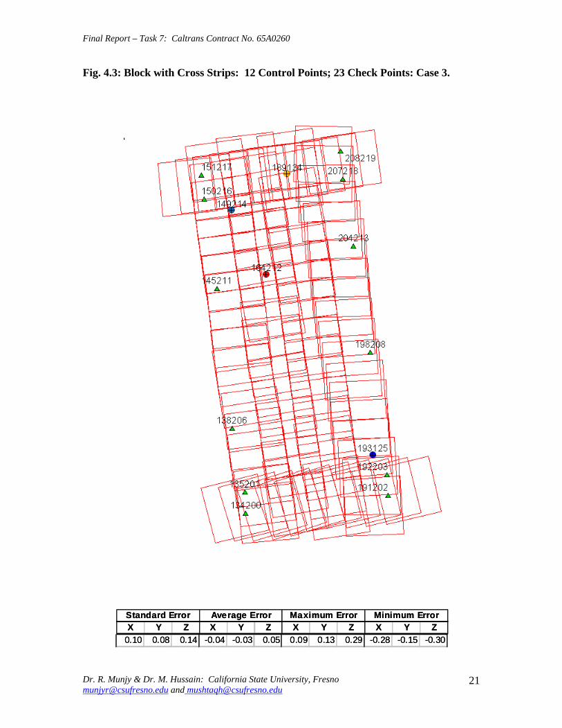
Final Report ndash Task 7 Caltrans Contract No 65A0260
Fig 43 Block with Cross Strips 12 Control Points 23 Check Points Case 3
SSttaannddaardrd EErrorrorr AAvveeraraggee EErrrroorr MMaaxxiimmuumm EErrorrorr MMiinniimmuumm EErrorrorr XX YY ZZ XX YY ZZ XX YY ZZ XX YY ZZ
001100 000088 001144 --000044 --000303 000055 000099 001313 002929 --002288 --001515 --003300
Dr R Munjy amp Dr M Hussain California State University Fresno munjyrcsufresnoedu and mushtaqhcsufresnoedu
21
Final Report ndash Task 7 Caltrans Contract No 65A0260
Fig 44 Block with Cross Strips 14 Control Points 21 Check Points Case 4
SSttaannddaardrd EErrorrorr AAvveeraraggee EErrrroorr MMaaxxiimmuumm EErrorrorr MMiinniimmuumm EErrorrorr XX YY ZZ XX YY ZZ XX YY ZZ XX YY ZZ
001100 000088 001155 --000011 --000101 000066 001111 001313 002828 --002255 --001414 --003311
Dr R Munjy amp Dr M Hussain California State University Fresno munjyrcsufresnoedu and mushtaqhcsufresnoedu
22
Final Report ndash Task 7 Caltrans Contract No 65A0260
Fig 45 Block with Cross Strips 14 Control Points 21 Check Points Case 5
SSttaannddaardrd EErrorrorr AAvveeraraggee EErrrroorr MMaaxxiimmuumm EErrorrorr MMiinniimmuumm EErrorrorr XX YY ZZ XX YY ZZ XX YY ZZ XX YY ZZ 001100 000066 001155 000000 --000033 000011 001122 001133 002277 --002255 --001166 --003344
Dr R Munjy amp Dr M Hussain California State University Fresno munjyrcsufresnoedu and mushtaqhcsufresnoedu
23
Final Report ndash Task 7 Caltrans Contract No 65A0260
Fig 46 Block without Cross Strips 8 Control Points 25 Check Points Case 7
SSttaannddaardrd EErrorrorr AAvveeraraggee EErrrroorr MMaaxxiimmuumm EErrorrorr MMiinniimmuumm EErrorrorr XX YY ZZ XX YY ZZ XX YY ZZ XX YY ZZ 001122 000088 005599 000404 000606 --110088 002288 002244 001166 --002222 --000099 --110099
Dr R Munjy amp Dr M Hussain California State University Fresno munjyrcsufresnoedu and mushtaqhcsufresnoedu
24
Final Report ndash Task 7 Caltrans Contract No 65A0260
Fig 47 Block without Cross Strips 11 Control Points 22 Check Points Case 8
SSttaannddaardrd EErrorrorr AAvveeraraggee EErrrroorr MMaaxxiimmuumm EErrorrorr MMiinniimmuumm EErrorrorr XX YY ZZ XX YY ZZ XX YY ZZ XX YY ZZ
001133 000099 001199 --000011 --000202 --001177 001177 001166 002288 --002828 --001166 --005050
Dr R Munjy amp Dr M Hussain California State University Fresno munjyrcsufresnoedu and mushtaqhcsufresnoedu
25
Final Report ndash Task 7 Caltrans Contract No 65A0260
Fig 48 Block without Cross Strips 11 Control Points 22 Check Points Case 9
SSttaannddaardrd EErrorrorr AAvveeraraggee EErrrroorr MMaaxxiimmuumm EErrorrorr MMiinniimmuumm EErrorrorr XX YY ZZ XX YY ZZ XX YY ZZ XX YY ZZ
001144 000099 002277 --000055 000033 --003131 001166 002020 003030 --003311 --001515 --006666
Dr R Munjy amp Dr M Hussain California State University Fresno munjyrcsufresnoedu and mushtaqhcsufresnoedu
26
Final Report ndash Task 7 Caltrans Contract No 65A0260
Fig 49 Block without Cross Strips 12 Control Points 21 Check Points Case 10
SSttaannddaardrd EErrorrorr AAvveeraraggee EErrrroorr MMaaxxiimmuumm EErrorrorr MMiinniimmuumm EErrorrorr XX YY ZZ XX YY ZZ XX YY ZZ XX YY ZZ 001133 000099 002200 --000022 000000 --000808 001166 001818 003131 --002277 --001616 --003333
Dr R Munjy amp Dr M Hussain California State University Fresno munjyrcsufresnoedu and mushtaqhcsufresnoedu
27
Final Report ndash Task 7 Caltrans Contract No 65A0260
Fig 410 Block without Cross Strips 14 Control Points 19 Check Points Case 11
SSttaannddaardrd EErrorrorr AAvveeraraggee EErrrroorr MMaaxxiimmuumm EErrorrorr MMiinniimmuumm EErrorrorr XX YY ZZ XX YY ZZ XX YY ZZ XX YY ZZ
001100 000088 001133 000044 --000022 --000303 001166 001515 002525 --002211 --001717 --002200
Dr R Munjy amp Dr M Hussain California State University Fresno munjyrcsufresnoedu and mushtaqhcsufresnoedu
28
Final Report ndash Task 7 Caltrans Contract No 65A0260
Fig 411 Block without Cross Strips 14 Control Points 19 Check Points Case 12
SSttaannddaardrd EErrorrorr AAvveeraraggee EErrrroorr MMaaxxiimmuumm EErrorrorr MMiinniimmuumm EErrorrorr XX YY ZZ XX YY ZZ XX YY ZZ XX YY ZZ
000099 000077 001122 --000011 --000101 000055 000099 001313 002828 --002255 --001414 --001122
Dr R Munjy amp Dr M Hussain California State University Fresno munjyrcsufresnoedu and mushtaqhcsufresnoedu
29
Final Report ndash Task 7 Caltrans Contract No 65A0260
5 ANALYSIS OF RESULTS amp CONCLUSIONS
In accordance with the Caltrans standards using wide-angle aerial photography the RMS error in each coordinate component of the adjusted tie points should not exceed 110000 of the flying height above the terrain The Del Mar Test Block was flown with a wideshyangle aerial camera from an average height of 1800 feet above the terrain level thereby resulting in an average photo scale of 13600 Consequently the limiting RMS error at the Check Points representative of a finite number of well distributed tie points in the block should not exceed 018 ft in this case Any error that exceeds three times this limiting value viz 054 ft in any of the coordinate components should be a cause for rejection of that point
Therefore the acceptable limiting values for the standard error at the Check Points is 018 ft in each coordinate component Any block adjustment solution that results in a coordinate error in one or more Check Points that exceeds 054 ft in any coordinate component would not be an acceptable solution The following analysis of the results is based on these accuracy criteria
51 Blocks With Cross Flights
When a minimal number of 8 control points are used (Fig 42) along the block perimeter the resulting standard error in Z-coordinate of 019 ft exceeds the limiting value of 015 ft It is also noticeable that the highest error in the Z-coordinate of 052 ft at Point 189134 almost equals the rejection limit of 054 ft This is an indication that controlling a cross flight with only a single Control Point at each end of the flight may not always provide a satisfactory solution
This situation can be remedied by using a pair of Control Points in each end model of a cross flight so that any deformation across the flight line the omega rotation () can also be controlled Such an approach is also reported to have been successfully used and recommended in the past [1] [2] [3] When 4 additional Control Points were added at the end of each cross flight line as is seen in Fig 43 all the standard errors fell within the acceptable range and the maximum coordinate error did not exceed 030 ft which is well within the acceptable criteria
The primary advantage of using airborne GPS data for the adjustment of aerial triangulation blocks is to completely eliminate the need for Control Points in the interior of the block But it is of interest to investigate how effectively the airborne GPS data alone can control the interior of the block Two separate blocks were processed by adding two Control Points in the interior of the block resulting in a total of 14 Control Points
The block with 14 Control Points (Case A) is shown in Fig 44 where the two interior Control Points were selected so that one Control Point was located on the opposite ends in each of the two interior flight lines (Line 2 and Line3 see Fig 41) The other block with 14 Control Points (Case B) is shown in Fig 45 In this case both the interior points
Dr R Munjy amp Dr M Hussain California State University Fresno munjyrcsufresnoedu and mushtaqhcsufresnoedu
30
Final Report ndash Task 7 Caltrans Contract No 65A0260
fell in the middle of the block interior It is interesting to note that in either of the two cases the addition of the interior Control Points did not result in any significant difference from the result achieved earlier while using 12 Control Points Therefore it may be concluded that as long as the cross flights are adequately controlled with a pair of Control Points located across each end model of each cross flight additional control in the block interior is not required The results shown in Fig 44 and 45 validate this conclusion at least for a block comprised of 18 models long multiple flight lines
52 Blocks Without Cross Flights
When a mapping project involves a large photogrammetric block consisting of hundreds of models the common practice is to plan the block configuration to include cross flights [1] [2] [6] [10] Often such cross flights can result in significant saving in time and effort in minimizing the need for ground control Since the photogrammetric mapping projects in Caltrans mostly involve mapping along highway corridors most of the photogrammetric blocks vary from a single flight line to up to as many as four flight lines Therefore it is still to be investigated whether the use of cross flight lines in such blocks offers any significant advantage Furthermore any advantage resulting from the reduced need for the ground control has to be weighed against the additional time and effort needed in processing the cross flight models The Caltrans Office of Photogrammetry has not yet adopted the use of Automated Aerial Triangulation (AAT) techniques for routine production Consequently the additional effort in transferring tie points between the cross flights with the flights of the main block is still significant This has provided the impetus to carry out the following investigation for the aerial triangulation adjustment of blocks that do not include any cross flights
The first block without the two cross flights was processed with only 8 Control points along the block perimeter as a parallel case with the block run with cross flights The results are shown in Fig 46 As may be expected the absence of any Control Point located at each end of each of the two interior flights 2 and 3 has resulted in unacceptably large errors Not only is the standard error of 059 ft in the Z-coordinate for the 25 Check Points too large but interestingly the block adjustment carries a large systematic error in Z-coordinate of 108 ft This results from the fact that the absence of the Control Points at each end of Flights 2 and 3 does not permit the adjustment for the systematic strip drift parameters for the airborne GPS data along Flights 2 and 3
When cross flights are included the airborne GPS data measured along the cross flight adequately serves as control for adjusting the strip shift and drift parameters Therefore an alternative to the inclusion of cross flights in the block configuration is to provide a Control Point at each end of every flight line in the block Accordingly the processing of the following blocks includes Control Points at the end of each flight line
The Del Mar Test Block with 4 flight lines each 18 models long would require a total of 12 Control Points one Control Point at each end of each flight line and 4 Control Points along the interior perimeter of the block to provide a control spacing of approximately 6 airbases apart However in order to minimize the use of the ground control the block
Dr R Munjy amp Dr M Hussain California State University Fresno munjyrcsufresnoedu and mushtaqhcsufresnoedu
31
Final Report ndash Task 7 Caltrans Contract No 65A0260
shown in Fig 47 was processed with only 11 Control Points (Case A) since the Control Point 170133 was measured both in Line 2 and Line 3 The resulting standard error of 019 ft in the Z-coordinate for 22 Check Points as well as the large error of 050 ft in the Z-coordinate of Check Point 189134 make the block adjustment solution unacceptable There appears to be no obvious reason why the Check Point 189134 that is located so close to the Control Point 170133 should display such unacceptably large error in the Zshycoordinate In order to ascertain the internal consistency of the ground control data (33 Control Points) a conventional aerial triangulation adjustment of the block was performed (without using the airborne GPS data) using 32 Control Points and treating the Control Point 189134 as a Check Point The resulting error in the Z-coordinate of Point 189134 was only 006 ft It is also to be noted that the average Z-coordinate error of 017 ft indicates a systematic height error This would lead to the conclusion that there is some height discrepancy between the ground control data and the airborne GPS data
The block was re-processed (Case B) again by using only 11 Control Points but this time the Control Point 170133 was replaced with Control Point 189134 and the results are displayed in Fig 48 The Case B results are even worse than the Case A results the standard error in Z-coordinate was degraded to 027 ft while the largest error in Zshycoordinate of 066 ft was noted at Check Point 187215 The average Z-coordinate error also increases to 031 ft This is a further indication that there is significant height inconsistency in the airborne GPS data and the ground control data It appears that the height discrepancy between the ground control data and the airborne GPS data results in an unsatisfactory shift and drift adjustment of the airborne GPS data particularly in the inner flight Lines 2 and 3 that span 18 models between the end Control Points
In order to strengthen the end control across the flight lines both the Control Points 170133 and 189134 were used at the Northern end of the block The block was then processed with 12 Control Points and the results are presented in Fig 49 Even though the results improved significantly but contrary to the expectation the standard error in the Z-coordinate of 020 ft for the 21 Check Points did not meet the Caltrans accuracy standard The next logical approach was to investigate the impact of adding Control Points in the interior of the block Two interior Control Points were selected in the same manner as has been described earlier in the case of the blocks with the cross flights (see Fig 44 and 45)
Using 14 Control Points the Case A is shown in Fig 410 while the Case B is presented in Fig 411 The results in both Case A and Case B easily meet the Caltrans accuracy standards In Case A the distance between the Control Points for the shift and drift parameter adjustment of the airborne GPS data varies from 6 to 12 models while in Case B the interior Control Points are about 6 models apart Each Control Point distribution provides almost similar results It is a clear indication that any systematic height deformation that results from the suspected inconsistency between the ground surveyed GPS data and the airborne GPS data can be kept within acceptable range by including a pair of control points in the interior of the block Such a need for some control points has not been reported for the adjustment of aerial triangulation blocks in the past However the largest photo scale for which any ABGPS supported results have been published in
Dr R Munjy amp Dr M Hussain California State University Fresno munjyrcsufresnoedu and mushtaqhcsufresnoedu
32
Final Report ndash Task 7 Caltrans Contract No 65A0260
the past is 14800 only For a photo scale of 13600 that is approximately 25 percent larger the requirements for the accuracy of aerial triangulation accordingly become more stringent in the same proportion This may generate the need for some additional control in the middle of the block
The residuals at the ground control points and in the image coordinate data along with the resulting standard error of unit weight (0) provide a reliable indication of the internal consistency of the adjusted block However the absolute accuracy of the aerial triangulation can be validated only by the use of Check Points that are well distributed over the entire block As pointed out earlier any deformations due to residual systematic shift and drift errors in the airborne GPS data are likely to be most significant in the center of the block the location that is farthest from the control points distributed along the perimeter Accordingly it would be advisable to locate at least a pair of Check Points in the middle of the block and after completing the block adjustment (by excluding these Check Points as Control Points) the coordinate discrepancies obtained at these Check Points can be analyzed Such discrepancies would normally represent the highest absolute accuracy resulting from aerial triangulation adjustment of the block Any unacceptably large coordinate discrepancies at the Check Points would require investigation of the block input data
In the case the coordinate discrepancies at the Check Points are within acceptable range the block can be re-processed by also including the Check Points in the control data This should enhance the accuracy in the interior of the block
6 RECOMMENDED DRAFT STANDARDS
These draft standards are proposed to supplement the existing Standards for Strip Configuration Airborne GPS Controlled Photogrammetry for Large Scale Mapping Projects (based on 13600 photo scale) currently used in Caltrans
61 Data Acquisition
611 Image Coordinate Data
Follow the existing practice used in Caltrans Office of Photogrammetry for the selection distribution and the measurement of all image point data It is recommended that raw machine coordinate image data should form the input to the aerial triangulation block adjustment
A secondary interest in this Research Project under contract with Caltrans was to also evaluate the alternate methodology of the selection and the measurement of tie point data using Automated Aerial Triangulation (AAT) system However several problems were encountered in implementing the AAT software available at the Caltrans Office of Photogrammetry in Sacramento The unavoidable delay caused by unfavorable weather conditions in acquiring the aerial imagery for the Del Mar Test Block did not allow
Dr R Munjy amp Dr M Hussain California State University Fresno munjyrcsufresnoedu and mushtaqhcsufresnoedu
33
Final Report ndash Task 7 Caltrans Contract No 65A0260
enough time to resolve the AAT software issues with software vendor Accordingly this task could not be fully completed Therefore it was mutually agreed between the Caltrans Office of Photogrammetry and California State University Fresno to concentrate research efforts on the processing and the analysis of the Del Mar Test Block and on drafting the Final Report
612 Ground Control Data
The proposed research is focused on the use of photography obtained at scale of 13600 for corridor mapping in Caltrans The ground control for mapping is based on the airborne GPS supported aerial triangulation of the photo blocks The ground control points should be surveyed to provide 15 to 2-times higher accuracy than that of the adjusted tie point data This would translate to an accuracy at the 005 to 01 ft level for the planimetric coordinates and the height an accuracy achievable using static GPS surveys tied to existing HPGN network
It is not yet certain that the Real-Time Kinematic (RTK) GPS field survey methodology whether relying on a single base station or on an RTK network is able to meet the above stringent field survey accuracy requirements Therefore the ground control data for ABGPS based aerial triangulation blocks should be based entirely on GPS control networks established using static GPS surveying methodology The RTK survey methodology for establishing control for photogrammetric mapping projects should not be used till such time that such technology has advanced to a level when consistently reliable results can be routinely expected
The GPS observations provide a fairly precise data for ellipsoidal height differences However all photogrammetric mapping has to be based on orthometric height data Two different approaches can be used in order to derive adjusted orthometric height data through aerial triangulation The first method is to carry out the simultaneous least squares adjustment of the GPS observation data for the ground control network using current Caltrans Horizontal Datum CCS83 (199135) and Vertical Datum NAVD 88 But since the observed data involves the measurement of ellipsoidal height differences for each measured baseline there is a need for transforming such differences to the corresponding orthometric height differences on NAVD 88 Datum In the absence of an existing Local Geoid Model the only economic recourse available to meet this need is to use the most reliable existing Global Geoid Model the time-consuming and prohibitively more costly alternative would be to connect the control network stations through differential leveling The Global Geoid Models are progressively being updated and the GEOID 2003 Model is most commonly in current use although GEOID 2009 Model may soon become available
It has to be noted that the use of a Global Geoid Model will always have some residual geoidal height uncertainties perhaps in the range of few hundredths of a foot It is therefore necessary that a few stations that are well distributed over the control network should have precisely known orthometric height values which can be used for the height adjustment of the network The minimum number of such orthometric height control
Dr R Munjy amp Dr M Hussain California State University Fresno munjyrcsufresnoedu and mushtaqhcsufresnoedu
34
Final Report ndash Task 7 Caltrans Contract No 65A0260
stations is three and consequently a network should be planned to have at least four and preferably more stations where orthometric height is precisely known In practice this requirement is met by including several existing benchmarks that are well distributed over the project area The redundancy provided by using more than three benchmarks will quantify the height residuals resulting from the adjustment This will provide a good estimate for the residual height errors in the network
The alternative approach is to carry out the adjustment of the GPS control network using WGS84 Geodetic Datum This datum is consistent with the observed GPS measurement data and a simultaneous 3D adjustment of the network can be performed in a Local Spatial Coordinate System (LSCS) the most commonly used approach is to shift the origin of the WGS84 coordinate system (center of the Earth) to approximately the center of the project site and apply a 3D rotational matrix to align the coordinate axes along the East North and Up directions Some commercial aerial triangulation software systems provide utilities to easily perform such datum transformation After the aerial triangulation results have been validated the coordinates of all the control and tie points can be transformed back to WGS 84 Datum Based on the availability of the orthometric height control stations a local Geoid can be defined ( a plane or a surface etc) and then used to transform the ellipsoidal height data to orthometric height data This second approach has the advantage that unlike the first method described above the residual height errors in the transformed control point height data are not propagated through aerial triangulation
For 13600 scale aerial photography blocks the ground control data should meet the a- priori standard deviation at 010 ft level This is not a very challenging demand for the horizontal positioning using GPS methodology However the residual height uncertainties in the orthometric height of control points interpolated from the Global Geoid Model become more critical as the photo scale becomes larger
613 Airborne GPS Data
The current practice used in Caltrans to acquire airborne GPS data during flight missions should continue to be used It is necessary to have GPS data collected at 1 Hz or higher rate at a base station that is located within or close to the project site Prior research completed collaboratively with Caltrans has already shown that the data at the base station may be substituted with GPS data collected at CORS at 5-sec or higher rate Consequently the collection of GPS data at more than one base stations is not considered as an essential requirement It may still be prudent to acquire GPS data at a second base station as a contingency safeguard against the GPS hardware failure at a base station for guaranteed success of the flight mission and expense
It is to be noted that the relative accuracy between successive airborne GPS antenna 3Dshycoordinates should be at 10-cm or higher level The current procedure used in Caltrans for the aircraft to remain stationary for static resolution of ambiguities before take off has mostly resulted in acquiring very reliable airborne GPS data This practice should perhaps be continued even though the continuing improvements in GPS hardware and
Dr R Munjy amp Dr M Hussain California State University Fresno munjyrcsufresnoedu and mushtaqhcsufresnoedu
35
Final Report ndash Task 7 Caltrans Contract No 65A0260
post-processing softwares are making on-the-fly (OTF) ambiguity resolution increasingly reliable However if it is necessary to resort to on-the-fly ambiguity resolution it must be ensured that the ambiguities have stabilized before photography is started The strict requirement for reliably resolving the ambiguities also does not permit the loss of lock during any single flight line If a loss of lock occurs during turns between flight lines ambiguities must be re-acquired and must stabilize before starting the collection of photography for another flight line Based on the make and the model of the airborne GPS receiver the Caltrans Office of Photogrammetry in consultation with the District Survey Section should draft a set of instructions for the GPSCamera operator aboard the aircraft specifying what parameters (such as PDOP Number of SVs etc) that need to be continuously monitored on a screen during a flight mission
62 Flight and Control Configuration
The following standards in planning the flight line configuration and the corresponding ground control distribution for Caltrans project are recommended to achieve optimum results
Control points are primarily required only along the perimeter of the block When a cross flight line is used to control the end of a block a pair of Control
Points must be located at each end of the cross flight At each end of a block that is not controlled by a cross flight a CP should be
located at the end of each parallel flight line a single CP may serve as end control for two adjacent overlapping flight lines
Along the perimeter of the block in a direction parallel with the main flight lines the CPs should be located at an average spacing of 6 airbases
Any corner in a block resulting from a sudden change in the length of two adjacent parallel flight lines should be controlled by an additional CP
Check Points should be provided along the interior flight lines in a multi-strip block The Check Points may be distributed along the interior flight lines so that any Check Point is not farther than about 8 airbases from either another Check Point (on same or adjacent flight line) or from a Control Point
Note that Caltrans is usually concerned with the mapping mostly along highway corridors and therefore does not require blocks with segments larger than three or four parallel flight lines Additional control along the cross flight line would be needed if such segments have 8 or more parallel flight lines
63 Data Processing and Adjustment
631 Processing of ABGPS Data
The current practice of post-processing ABGPS data used in Caltrans Office of Photogrammetry using GrafNav software should be continued The data should continue to be processed in the Forward and Backward modes A coordinate separation of less
Dr R Munjy amp Dr M Hussain California State University Fresno munjyrcsufresnoedu and mushtaqhcsufresnoedu
36
Final Report ndash Task 7 Caltrans Contract No 65A0260
than 10 cm especially in the height represents a normally acceptable range for the combined solution
This study has shown that the airborne GPS data in comparison with the ground control data should be weighted a lower weight but the highest weight that the GPS data quality represents Generally the best results were achieved when a-priori standard error of 015 ft was used for the airborne GPS coordinate data in comparison with the a-priori standard error of 010 ft used for the ground control coordinate data Since the 3-D position of successive points along the airborne GPS antenna trajectory are estimated using Kalman Filtering approach the successive location coordinates are highly correlated and consequently carry a much higher relative precision This provides a realistic justification for the use of a-priori standard error of 015 ft
632 Processing of Aerial Triangulation Block
Each aerial triangulation block requires the following data files as input
- Raw image coordinate data file - Ground control data file - Interpolated camera coordinate data file
Using the above input data files the block adjustment should be carried out in two steps as described below It is essential that additional Strip Shift and Drift parameters (3 Shift and 3 Drift parameters) should be incorporated in the bundle adjustment solution
Step 1 Minimal Control Adjustment
The preliminary simultaneous bundle adjustment of the block should be carried out by using the minimal amount of control points along the block perimeter only All the additional ground surveyed and targeted points should be treated as tie points to serve as Check Points The adjustment results should meet the following criteria
a The Standard Error of Unit Weight (0) should fall between 03 to 07 b The residual for any image coordinate should not exceed 15 micrometer c The RMS for ground control residuals should not exceed 110000 of the flying
height above the average terrain level d The maximum residual in any ground control coordinate should not exceed 25
times the RMS value permissible under Item (c) above e The RMS for discrepancy (difference between computed coordinate value and
the ground surveyed coordinate value) in Check Point coordinates should not exceed 110000 of the flying height above the average terrain level
f The discrepancy in any Check Point coordinate should not exceed 25 times the RMS value permissible under Item (e) above
If the above criteria are met even the preliminary adjustment solution for the block satisfies Caltrans accuracy standards for aerial triangulation If the criterion under Item
Dr R Munjy amp Dr M Hussain California State University Fresno munjyrcsufresnoedu and mushtaqhcsufresnoedu
37
Final Report ndash Task 7 Caltrans Contract No 65A0260
(f) above is not met the input data should be checked for any gross mistakes or errors in the ground control and Check Point data
Step 2 Full Control Adjustment
The final simultaneous bundle adjustment of the block should be carried out by including all the ground surveyed points (Control Points and Check Points) in the ground control data file The adjustment results should meet the following criteria
g The Standard Error of Unit Weight (0) should fall between 03 to 07 h The residual for any image coordinate should not exceed 15 micrometer i The RMS for ground control residuals should not exceed 110000 of the flying
height above the average terrain level j The maximum residual in any ground control coordinate should not exceed 25
times the RMS value permissible under Item (i) above
7 CONCLUDING COMMENTS
The completion of this project signifies the culmination of a very successful and productive combination of advanced theoretical principles with sound practical experience for the adaptation of evolving photogrammetric technologies in Caltrans practice In order to alleviate a growing concern for the safety of staff conducting field survey operations in close proximity of high speed traffic Caltrans in late 1990s decided to investigate the feasibility of using airborne GPS data for controlling the aerial triangulation blocks There were two primary issues to be resolved The first and the foremost concern was whether the use of airborne GPS data could be effectively used for controlling aerial triangulation blocks of as large a photo scale as 13000 used in Caltrans and still meet the Caltrans accuracy standards This concern was particularly critical since there had not been any reported use of airborne GPS data for such a large scale of aerial photography
Should the above investigation show that the Caltrans accuracy standards for aerial triangulation for 13000 scale aerial photography can be met it was of great interest to Caltrans to develop based on theoretically sound and systematic investigation a set of standards and specifications for the successful implementation of this new methodology in Caltrans routine practice
Under a Caltrans New Technology and Research Program currently Division of Research and Innovation (DRI) contract Caltrans Office of Photogrammetry partnered with a team of two faculty members from the Geomatic Engineering Program at the California State University Fresno (CSUF) in 1996 to carry out research to address the above two issues This partnership has flourished over the past several years through
Dr R Munjy amp Dr M Hussain California State University Fresno munjyrcsufresnoedu and mushtaqhcsufresnoedu
38
Final Report ndash Task 7 Caltrans Contract No 65A0260
successive research contracts and has resulted in very fortuitous outcomes based on the theoretical and analytical guidance provided by the CSUF research team and the highly skilled aerial survey project management and high caliber professional skills in the acquisition of photogrammetric data collection by the Caltrans Office of Photogrammetry In addition the help from highly experienced field survey teams from Caltrans various districts (especially District 11) in establishing GPS networks of Control Points and Check Points of specified precision was critical for the validation of airborne-GPS supported aerial triangulation investigations
As a result of the past collaborative efforts between the Caltrans Office of Photogrammetry and the CSUF Research Team the use of airborne GPS data for aerial triangulation has successfully been transitioned into Caltrans practice in the following stages
1) Based on a number of test flights it was convincingly demonstrated that the use of airborne GPS data consistently meets the Caltrans accuracy standards for aerial triangulation for strip configuration blocks at 13000 photo scale [13]
2) A detailed set of standards and specifications were developed for the implementing of the new methodology in Caltrans routine practice This was further supported through a training workshop conducted by CSUF at the Caltrans offices in Sacramento [8]
3) The use of airborne GPS data for the adjustment of aerial triangulation blocks requires the collection of GPS data at one or more ground base stations during the flight mission This requirement imposes burdensome demands on scheduling and allocation of manpower and equipment resources In order to reduce or even to completely eliminate the need for the collection of GPS data at base stations the use of GPS data collected and archived at a network of Continuously Operating Reference Stations (CORS) distributed over the State of California was investigated It was demonstrated that CORS data could be effectively used as a replacement for data collected at base stations while fulfilling Caltrans accuracy standards Accordingly specifications were revised to also include the selection and the use of CORS data for the post-processing of airborne GPS data to accurately derive the trajectory of the airborne GPS antenna during flights [19]
4) During the past few years Caltrans has increasingly been using multi-strip projects for mapping using 13600 photo scale This provided the need for the current research study The successful completion of this study has resulted in supplementing the existing standards and specifications for airborne GPS supported single-strip aerial triangulation blocks to also include the aerial triangulation of multi-strip blocks
It is a matter of great satisfaction for the research team at CSU Fresno that working hand in hand with the Caltrans Office of Photogrammetry the comprehensive set of standards and specifications for airborne GPS supported aerial triangulation that had been developed for successful transition of this technology in Caltrans practice have been further upgraded It is hoped that as the photogrammetric technology advances further
Dr R Munjy amp Dr M Hussain California State University Fresno munjyrcsufresnoedu and mushtaqhcsufresnoedu
39
Final Report ndash Task 7 Caltrans Contract No 65A0260
similar collaborative efforts between Caltrans Office of Photogrammetry and CSU Fresno will continue to address the changing needs in Caltrans
Dr R Munjy amp Dr M Hussain California State University Fresno munjyrcsufresnoedu and mushtaqhcsufresnoedu
40
Final Report ndash Task 7 Caltrans Contract No 65A0260
REFERENCES
1 Abdullah Q M Hussain and R Munjy (2002) Workshop on Airborne GPS-Supported Aerial Triangulation ndash Theory and Practical Concepts presented at the Annual ASPRS Convention Washington DC 2002
2 Ackermann Fritz (1992) Operational Rules and Accuracy Models for GPS-Aerotriangulation Archives of the ISPRS Com 1 Vol29 1992 [pp 691-700]
3 Ackermann F (1993) Application of GPS for Aerial Triangulation Photogrammetric Engineering and Remote Sensing Vol 59 No 11 [pp 1651shy1658]
4 Appleton James Mushtaq Hussain and Riadh Munjy (2000) Use of Airborne GPS Data for Highway Mapping International Archives of Photogrammetry and Remote Sensing Vol XXXIII Part B4 Amsterdam 2000[pp 84-90]
5 Appleton James M Hussain and R Munjy (2002) Use of Airborne GPS Data For Aerial Triangulation in Caltrans (2002) Workshop presented at the California Department of Transportation Sacramento 2002
6 Federal Geographic Data Committee (FGDC) 1998 Geospatial Positional Accuracy Standards Part-3 National Standards for Spatial Data Accuracy (NSSDA) FGDC-STD-0073-1998
7 Friess Peter (1992) Experiences with GPS-Supported Aerial Triangulation Archives of the ISPRS Com 1 Vol29 1992 [pp 299 - 305]
8 Gianellia Alexander M (1995) Practical Considerations in Implementing GPS Technologies in Airborne Data Collection Proc ASPRS Annual Convention 1995 [pp 917-925]
9 Hussain M R Munjy and J Appleton (1999) Use of Airborne On-the-Fly Kinematic GPS Data for Photogrammetric Mapping Proceedings ION-GPS-99 Conference Nashville 1999[pp 1653-1659]
10 Hussain M and R Munjy (1999) GPS Controlled Photogrammetry For Large Scale Mapping (1999) Final Project Report Research project No 65Y271 submitted to New Technology amp Research Program California Department of Transportation
11 Hussain M and R Munjy (2002) Airborne GPS Controlled Aerial Triangulation in Caltrans Final Project Report Research project No 65A0059 submitted to New Technology amp Research Program California Department of Transportation June 2002
12 Munjy R and M Hussain (1985) Interactive Simultaneous Bundle Block Adjustment System (ISBBA) for Small Computers Proceedings of the ASPRS Annual Convention Washington DC 1985
13 Munjy R M Hussain and James Appleton (2000) Use of Airborne GPS Data for Corridor Mapping presented at the Annual ASPRS Convention Washington DC 2000
Dr R Munjy amp Dr M Hussain California State University Fresno munjyrcsufresnoedu and mushtaqhcsufresnoedu
41
Final Report ndash Task 7 Caltrans Contract No 65A0260
14 Munjy R and M Hussain (2007) Develop Criteria for Using Network GPS for Airborne GPS Photogrammetry Final Project Report Research Project No 65A0234 submitted to the Division of Research and Innovation (DRI) California Department of Transportation
15 Munjy R and M Hussain (2009) Draft Preliminary Standards Interim Report Research Project No 65A0260 submitted to Division of Research aned Innovation (DRI) California Department of Transportation
Dr R Munjy amp Dr M Hussain California State University Fresno munjyrcsufresnoedu and mushtaqhcsufresnoedu
42
APPENDIX I Results of Check Block
Flight amp Control Configuration Cases Used for
Study amp Analysis of Check Project in San Diego
INDEX
Case Block amp Control Configuration 1 Full Blk(Flts1to9) All 44 CP 2 Full Blk 8 CP 3 Full Blk 9 CP 4 Full Blk 10 CP 5 Main Blk(Flts1to7) 43 CP 6 Main Blk(Flts1to7) 8 CP 7 Main Blk(Flts1to7) 10 CP 8 Main Blk(Flts1to7) 12 CP 9 North Blk(Flts567amp9) 5 CP 10 North Blk(Flts567amp9) 7 CP 11 North Blk(Flts56amp7) 6 CP 12 North Blk(Flts56amp7) 8 CP 13 South Blk(Flts1to4amp8) 4 CP 14 South Blk(Flts1to4amp8) 6 CP 15 South Blk(Flts1to4amp8) 7 CP 16 South Blk(Flts1to4) 7 CP 17 South Blk(Flts1to4) 8 CP(a) 18 South Blk(Flts1to4) 8 CP(b) 19 South Blk(Flts1to4) 10 CP 20 South Blk(Flts1to4) 11 CP 21 South Blk(Flts Modified 1to4 amp8) 5 CP 22 South Blk(Flts Modified 1to4 ) 6 CP
[Refer to Table-1 Summary of the Coordinate Differences at the Check Points]
I-i
Case-1 Base DataFULL BLOCK
Flts 1 to 9
Case-1 Base Data FULL BLOCK
Flts 1 to 9
Control PointsControl Points All 44 PointsAll 44 Points
SSSttt ErErErrrr AAAvvvggg ErErErrrr MMMaaaxxx ErErErrrr MMMiiinnn ErErErrrr XXX YYY ZZZ XXX YYY ZZZ XXX YYY ZZZ XXX YYY ZZZ
007 008 005 000 000 000 019 012 012 -013 -023 -013007 008 005 000 000 000 019 012 012 -013 -023 -013007 008 005 000 000 000 019 012 012 -013 -023 -013
I-ii
Case-2FULL BLOCK
Flts 1 to 9
Control Points 8
Case-2 FULL BLOCK
Flts 1 to 9
Control Points 8 CChheecckk PoPointsints 3366
SStt ErErrr AAvvgg ErErrr MMaaxx ErErrr MMinin ErErrr XX YY ZZ XX YY ZZ XX YY ZZ XX YY ZZ
012012 012012 016016 002002 001001 --000505 024024 027027 026026 --025025 --039039 --032032
I-iii
Case-3FULL BLOCK
Flts 1 to 9
Control Points 9
Case-3 FULL BLOCK
Flts 1 to 9
Control Points 9 CChheecckk PoPointsints 3355
SStt ErErrr AAvvgg ErErrr MMaaxx ErErrr MMinin ErErrr XX YY ZZ XX YY ZZ XX YY ZZ XX YY ZZ
012012 012012 017017 001001 --001001 --000808 024024 024024 026026 --026026 --040040 --034034
I-iv
Case-4FULL BLOCK
Flts 1 to 9
Control Points 10
Case-4 FULL BLOCK
Flts 1 to 9
Control Points 10 CChheecckk PoiPoinntsts 3344
SStt ErErrr AAvvgg ErErrr MMaaxx ErErrr MMinin ErErrr XX YY ZZ XX YY ZZ XX YY ZZ XX YY ZZ
012012 009009 015015 003003 005005 --000909 002244 002727 002121 --025025 --001313 --035035
I-v
Case-5MAIN BLOCK
Flts 1 to 7
Control Points 43
Case-5 MAIN BLOCK
Flts 1 to 7
Control Points 43 [Point HV-117 Unuse[Point HV-117 Unusedd]]
SSSttt ErErErrrr AAAvvvggg ErErErrrr MMM aaaxxx ErErErrrr MMM iiinnn ErErErrrr XXX YYY ZZZ XXX YYY ZZZ XXX YYY ZZZ XXX YYY ZZZ
006006006 008008008 005005005 000000000 000000000 000000000 012012012 013013013 013013013 ---000131313 ---022022022 ---000090909
I-vi
Case-6
Flts 1 to 7
l Points 8
MAIN BLOCK
[No Cross Flts]Contro
Case-6 MAIN BLOCK
Flts 1 to 7 [No Cross Flts]
Control Points 8 ChecCheckk PoPointsints 3636
St ErSt ErSt ErSt ErSt ErSt ErSt ErSt Errrrrrrrr AAAAAAAAvgvgvgvgvgvgvgvg ErErErErErErErErrrrrrrrr MMMMMMMMaxaxaxaxaxaxaxax ErErErErErErErErrrrrrrrr MMMMMMMMiiiiiiiinnnnnnnn ErErErErErErErErrrrrrrrr XXXXXXXX YYYYYYYY ZZZZZZZZ XXXXXXXX YYYYYYYY ZZZZZZZZ XXXXXXXX YYYYYYYY ZZZZZZZZ XXXXXXXX YYYYYYYY ZZZZZZZZ
016016016016 012012012012 027027027027 -002-002-002-002 ----004004004004 -004-004-004-004 000026262626 000020202020 000041414141 ----035035035035 -036-036-036-036 ----082082082082
I-vii
Case-7MAIN BLOCK
Flts 1 to 7[No Cross Flts]
Control Points 10
Case-7 MAIN BLOCK
Flts 1 to 7 [No Cross Flts]
Control Points 10 CChheecckk PointsPoints 3434
SStt ErErrr AAvvgg ErErrr MM aaxx ErErrr MM iinn ErErrr XX YY ZZ XX YY ZZ XX YY ZZ XX YY ZZ
014 012 027 -001 -003 -004 022 020 039 -031 -031 -080014 012 027 -001 -003 -004 022 020 039 -031 -031 -080
I-viii
Case-8MAIN BLOCK
Flts 1 to 7[No Cross Flts]
Control Points 12
Case-8 MAIN BLOCK
Flts 1 to 7 [No Cross Flts]
Control Points 12 CheChecckk PointsPoints 3232
SSSttt ErErErrrr AAAvvvggg ErErErrrr MMMaaaxxx ErErErrrr MMMiiinnn ErErErrrr XXX YYY ZZZ XXX YYY ZZZ XXX YYY ZZZ XXX YYY ZZZ
015 010 017 003 000 -004 037 016 035 -031 -027 -023015 010 017 003 000 -004 037 016 035 -031 -027 -023015 010 017 003 000 -004 037 016 035 -031 -027 -023
I-ix
Case-9Case-9Case-9 NORNORNORTTTH BLH BLH BLOCKOCKOCK
FltsFltsFlts 5 to 7 amp 9 5 to 7 amp 9 5 to 7 amp 9
Control PointsControl PointsControl Points 555 ChChCheckeckeck PoPoPoininintttsss 111888
ErSSSttt EE rrrrr vg ErAAAvg Evg E rrrrr ax ErMMM ax Eax E rrrrr ErMMM iiinnn EE rrrrr XXX YYY ZZZ XXX YYY ZZZ XXX YYY ZZZ XXX YYY ZZZ
000121212 016016016 000161616 007007007 ---000161616 000111111 000262626 000020202 000363636 ---022022022 ---000626262 ---022022022
I-x
Case-Case-1100 NORTH BLOCKNORTH BLOCK
Flts 5 to 7 amp 9Flts 5 to 7 amp 9
Control PointsControl Points 77 CheckCheck PointsPoints 1616
SStt ErErrr AAvvgg ErErrr MM aaxx ErErrr MM iinn ErErrr XX YY ZZ XX YY ZZ XX YY ZZ XX YY ZZ
010010 016016 017017 008008 --000707 001818 002323 001010 005151 --016016 --005151 --012012
I-xi
Case-Case-1111 NORTH BLOCKNORTH BLOCK
FltsFlts 5 to 7 5 to 7
CCoontrntrool Pointsl Points 66 CheChecckk PointsPoints 1717
SStt ErErrr AAvvgg ErErrr MM aaxx ErErrr MM iinn ErErrr XX YY ZZ XX YY ZZ XX YY ZZ XX YY ZZ
010010 016016 022022 010010 --000202 000808 002424 001515 005050 --019019 --004343 --026026
I-xii
Case-Case-1122 NORTH BLOCKNORTH BLOCK
FltsFlts 5 to 7 5 to 7 [No C[No Crrossoss Flt]Flt]
ContControl Poinrol Pointsts 88 CChheecckk PointsPoints 1155
SStt EErrrr AAvg Evg Errrr MM ax Eax Errrr MM iinn EErrrr XX YY ZZ XX YY ZZ XX YY ZZ XX YY ZZ
011011 016016 017017 013013 --000909 000202 002929 000707 003737 --017017 --004949 --031031
I-xiii
CaseCase-13-13 SOUTSOUTH BH BLLOCKOCK
Flts 1 to 4 amp 8Flts 1 to 4 amp 8
CoConnttrol Porol Poininttss 44 ChCheckeck PPooinintsts 2222
SStt ErErrr AAvvgg ErErrr MM aaxx ErErrr MM iinn ErErrr XX YY ZZ XX YY ZZ XX YY ZZ XX YY ZZ
052 032 015 -082 033 003 -007 091 026 -149 -009 -034052 032 015 -082 033 003 -007 091 026 -149 -009 -034
I-xiv
Case-14Case-14 SOUTH BLOCKSOUTH BLOCK
Flts 1 to 4 amp 8Flts 1 to 4 amp 8
CCoontrntrool Pointsl Points 66 CheChecckk PointsPoints 2200
SStt ErErrr AAvvgg ErErrr MM aaxx ErErrr MM iinn ErErrr XX YY ZZ XX YY ZZ XX YY ZZ XX YY ZZ
013 016 015 -003 006 -002 024 033 033 -019 -028 -028013 016 015 -003 006 -002 024 033 033 -019 -028 -028
I-xv
Case-15Case-15 SOUTH BLOCKSOUTH BLOCK
FltsFlts 1 to 4 amp 8 1 to 4 amp 8
ContrControol Pointsl Points 77 ChCheckeck PPooinintsts 1919
SStt ErErrr AAvvgg ErErrr MM aaxx ErErrr MM iinn ErErrr XX YY ZZ XX YY ZZ XX YY ZZ XX YY ZZ
015 012 014 -003 -002 -002 025 023 033 -025 -030 -025015 012 014 -003 -002 -002 025 023 033 -025 -030 -025
I-xvi
Case-16Case-16Case-16 SOUTH BLOCKSOUTH BLOCKSOUTH BLOCK
FltsFltsFlts 1 to 4 1 to 4 1 to 4 [No Cross Flt][No Cross Flt][No Cross Flt]
Control PointsControl PointsControl Points 777 CheCheCheccckkk PointsPointsPoints 222222
SSSttt EEErrrrrr AAAvg Evg Evg Errrrrr MMM ax Eax Eax Errrrrr MMM iiinnn EEErrrrrr XXX YYY ZZZ XXX YYY ZZZ XXX YYY ZZZ XXX YYY ZZZ
015 013 023 -001 -005 003 026 023 032 -027 -029 -037015 013 023 -001 -005 003 026 023 032 -027 -029 -037015 013 023 -001 -005 003 026 023 032 -027 -029 -037
I-xvii
Case-17Case-17 SOUTSOUTH BLH BLOCKOCK
FltsFlts 1 1 to 4to 4 [No[No CrosCrosss Flt]Flt]
ContrControol Pointsl Points 88 CChheecckk PointsPoints 2121
SStt ErErrr AAvvgg ErErrr MM aaxx ErErrr MM iinn ErErrr XX YY ZZ XX YY ZZ XX YY ZZ XX YY ZZ
014014 012012 024024 005005 --000101 000404 003131 002525 003333 --022022 --002929 --040040
I-xviii
Case-18Case-18 SOUTH BLOCKSOUTH BLOCK
Flts 1 to 4Flts 1 to 4 [[NNo Cro Crooss Fss Flltt]]
CCoontrol Pointsntrol Points 88 CheChecckk PointsPoints 2121
SSSttt ErErErrrr AAAvvvggg ErErErrrr MMM aaaxxx ErErErrrr MMM iiinnn ErErErrrr XXX YYY ZZZ XXX YYY ZZZ XXX YYY ZZZ XXX YYY ZZZ
016 014 019 -003 -005 001 027 025 028 -033 -033 -032016 014 019 -003 -005 001 027 025 028 -033 -033 -032016 014 019 -003 -005 001 027 025 028 -033 -033 -032
I-xix
Case-19Case-19 SOUTH BLOCKSOUTH BLOCK
FltsFlts 1 to 4 1 to 4 [No Cross Flt][No Cross Flt]
ContControl Prol Poointintss 10 10 CheckCheck PointsPoints 1919
SSSttt ErErErrrr AAAvvvggg ErErErrrr MMM aaaxxx ErErErrrr MMM iiinnn ErErErrrr XXX YYY ZZZ XXX YYY ZZZ XXX YYY ZZZ XXX YYY ZZZ
014 012 019 004 -001 001 034 029 029 -025 -030 -028014 012 019 004 -001 001 034 029 029 -025 -030 -028014 012 019 004 -001 001 034 029 029 -025 -030 -028
I-xx
Case-Case-2200 SSOOUTH BLOCKUTH BLOCK
FltsFlts 1 to 4 1 to 4 [No Cross Flt][No Cross Flt]
Control Points 11Control Points 11 ChCheckeck PPooinintsts 1818
SSSttt ErErErrrr AAAvvvggg ErErErrrr MMM aaaxxx ErErErrrr MMM iiinnn ErErErrrr XXX YYY ZZZ XXX YYY ZZZ XXX YYY ZZZ XXX YYY ZZZ
014014014 012012012 018018018 ---000010101 ---005005005 ---000010101 000232323 000202020 000272727 ---030030030 ---000292929 ---031031031
I-xxi
Case-Case-2211 MODIMODIFFIIED SOUTH BED SOUTH BLLOCKOCK
FltsFlts 1 to 4 ( 1 to 4 (MModified)odified) amp 8amp 8
ControControl Pointsl Points 55 CheChecckk PointsPoints 1818
SStt ErErrr AAvvgg ErErrr MM aaxx ErErrr MM iinn ErErrr XX YY ZZ XX YY ZZ XX YY ZZ XX YY ZZ
013 010 015 -001 002 -001 024 021 035 -019 -025 -029013 010 015 -001 002 -001 024 021 035 -019 -025 -029
I-xxii
Case-22Case-22Case-22 MOMOMODIFDIFDIFIIIED SOED SOED SOUTH BLOCKUTH BLOCKUTH BLOCK
FltFltFltsss 1 to 4 1 to 4 1 to 4 (M(M(Modiodiodifiefiefieddd))) [No C[No C[No Crrrososossss Flt]Flt]Flt]
ConConContttrol Prol Prol Poooiiinnntttsss 666 ChChCheckeckeck PointPointPointsss 161616
SSSttt ErErErrrr AAAvvvggg ErErErrrr MMM aaaxxx ErErErrrr MMM iiinnn ErErErrrr XXX YYY ZZZ XXX YYY ZZZ XXX YYY ZZZ XXX YYY ZZZ
014 011 014 002 005 -010 025 024 016 -020 -024 -039014 011 014 002 005 -010 025 024 016 -020 -024 -039014 011 014 002 005 -010 025 024 016 -020 -024 -039
I-xxiii
APPENDIX II Results of Test Block
II-i
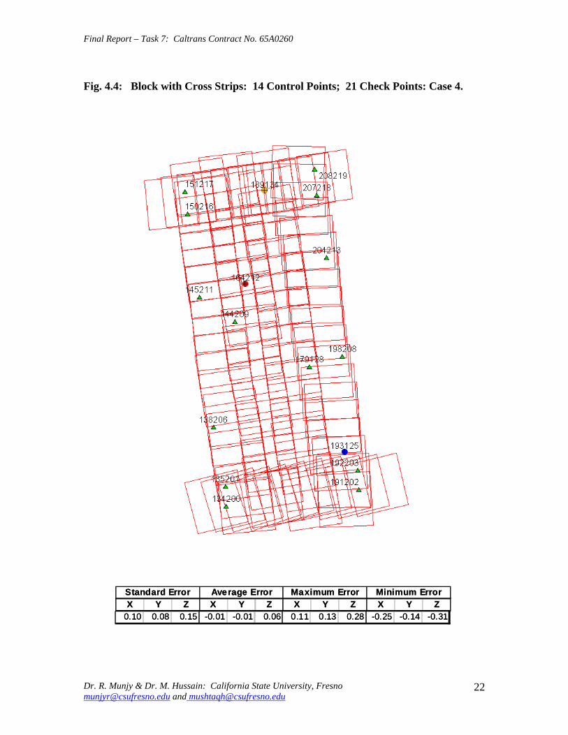
Final Report ndash Task 7 Caltrans Contract No 65A0260
Fig 44 Block with Cross Strips 14 Control Points 21 Check Points Case 4
SSttaannddaardrd EErrorrorr AAvveeraraggee EErrrroorr MMaaxxiimmuumm EErrorrorr MMiinniimmuumm EErrorrorr XX YY ZZ XX YY ZZ XX YY ZZ XX YY ZZ
001100 000088 001155 --000011 --000101 000066 001111 001313 002828 --002255 --001414 --003311
Dr R Munjy amp Dr M Hussain California State University Fresno munjyrcsufresnoedu and mushtaqhcsufresnoedu
22
Final Report ndash Task 7 Caltrans Contract No 65A0260
Fig 45 Block with Cross Strips 14 Control Points 21 Check Points Case 5
SSttaannddaardrd EErrorrorr AAvveeraraggee EErrrroorr MMaaxxiimmuumm EErrorrorr MMiinniimmuumm EErrorrorr XX YY ZZ XX YY ZZ XX YY ZZ XX YY ZZ 001100 000066 001155 000000 --000033 000011 001122 001133 002277 --002255 --001166 --003344
Dr R Munjy amp Dr M Hussain California State University Fresno munjyrcsufresnoedu and mushtaqhcsufresnoedu
23
Final Report ndash Task 7 Caltrans Contract No 65A0260
Fig 46 Block without Cross Strips 8 Control Points 25 Check Points Case 7
SSttaannddaardrd EErrorrorr AAvveeraraggee EErrrroorr MMaaxxiimmuumm EErrorrorr MMiinniimmuumm EErrorrorr XX YY ZZ XX YY ZZ XX YY ZZ XX YY ZZ 001122 000088 005599 000404 000606 --110088 002288 002244 001166 --002222 --000099 --110099
Dr R Munjy amp Dr M Hussain California State University Fresno munjyrcsufresnoedu and mushtaqhcsufresnoedu
24
Final Report ndash Task 7 Caltrans Contract No 65A0260
Fig 47 Block without Cross Strips 11 Control Points 22 Check Points Case 8
SSttaannddaardrd EErrorrorr AAvveeraraggee EErrrroorr MMaaxxiimmuumm EErrorrorr MMiinniimmuumm EErrorrorr XX YY ZZ XX YY ZZ XX YY ZZ XX YY ZZ
001133 000099 001199 --000011 --000202 --001177 001177 001166 002288 --002828 --001166 --005050
Dr R Munjy amp Dr M Hussain California State University Fresno munjyrcsufresnoedu and mushtaqhcsufresnoedu
25
Final Report ndash Task 7 Caltrans Contract No 65A0260
Fig 48 Block without Cross Strips 11 Control Points 22 Check Points Case 9
SSttaannddaardrd EErrorrorr AAvveeraraggee EErrrroorr MMaaxxiimmuumm EErrorrorr MMiinniimmuumm EErrorrorr XX YY ZZ XX YY ZZ XX YY ZZ XX YY ZZ
001144 000099 002277 --000055 000033 --003131 001166 002020 003030 --003311 --001515 --006666
Dr R Munjy amp Dr M Hussain California State University Fresno munjyrcsufresnoedu and mushtaqhcsufresnoedu
26
Final Report ndash Task 7 Caltrans Contract No 65A0260
Fig 49 Block without Cross Strips 12 Control Points 21 Check Points Case 10
SSttaannddaardrd EErrorrorr AAvveeraraggee EErrrroorr MMaaxxiimmuumm EErrorrorr MMiinniimmuumm EErrorrorr XX YY ZZ XX YY ZZ XX YY ZZ XX YY ZZ 001133 000099 002200 --000022 000000 --000808 001166 001818 003131 --002277 --001616 --003333
Dr R Munjy amp Dr M Hussain California State University Fresno munjyrcsufresnoedu and mushtaqhcsufresnoedu
27
Final Report ndash Task 7 Caltrans Contract No 65A0260
Fig 410 Block without Cross Strips 14 Control Points 19 Check Points Case 11
SSttaannddaardrd EErrorrorr AAvveeraraggee EErrrroorr MMaaxxiimmuumm EErrorrorr MMiinniimmuumm EErrorrorr XX YY ZZ XX YY ZZ XX YY ZZ XX YY ZZ
001100 000088 001133 000044 --000022 --000303 001166 001515 002525 --002211 --001717 --002200
Dr R Munjy amp Dr M Hussain California State University Fresno munjyrcsufresnoedu and mushtaqhcsufresnoedu
28
Final Report ndash Task 7 Caltrans Contract No 65A0260
Fig 411 Block without Cross Strips 14 Control Points 19 Check Points Case 12
SSttaannddaardrd EErrorrorr AAvveeraraggee EErrrroorr MMaaxxiimmuumm EErrorrorr MMiinniimmuumm EErrorrorr XX YY ZZ XX YY ZZ XX YY ZZ XX YY ZZ
000099 000077 001122 --000011 --000101 000055 000099 001313 002828 --002255 --001414 --001122
Dr R Munjy amp Dr M Hussain California State University Fresno munjyrcsufresnoedu and mushtaqhcsufresnoedu
29
Final Report ndash Task 7 Caltrans Contract No 65A0260
5 ANALYSIS OF RESULTS amp CONCLUSIONS
In accordance with the Caltrans standards using wide-angle aerial photography the RMS error in each coordinate component of the adjusted tie points should not exceed 110000 of the flying height above the terrain The Del Mar Test Block was flown with a wideshyangle aerial camera from an average height of 1800 feet above the terrain level thereby resulting in an average photo scale of 13600 Consequently the limiting RMS error at the Check Points representative of a finite number of well distributed tie points in the block should not exceed 018 ft in this case Any error that exceeds three times this limiting value viz 054 ft in any of the coordinate components should be a cause for rejection of that point
Therefore the acceptable limiting values for the standard error at the Check Points is 018 ft in each coordinate component Any block adjustment solution that results in a coordinate error in one or more Check Points that exceeds 054 ft in any coordinate component would not be an acceptable solution The following analysis of the results is based on these accuracy criteria
51 Blocks With Cross Flights
When a minimal number of 8 control points are used (Fig 42) along the block perimeter the resulting standard error in Z-coordinate of 019 ft exceeds the limiting value of 015 ft It is also noticeable that the highest error in the Z-coordinate of 052 ft at Point 189134 almost equals the rejection limit of 054 ft This is an indication that controlling a cross flight with only a single Control Point at each end of the flight may not always provide a satisfactory solution
This situation can be remedied by using a pair of Control Points in each end model of a cross flight so that any deformation across the flight line the omega rotation () can also be controlled Such an approach is also reported to have been successfully used and recommended in the past [1] [2] [3] When 4 additional Control Points were added at the end of each cross flight line as is seen in Fig 43 all the standard errors fell within the acceptable range and the maximum coordinate error did not exceed 030 ft which is well within the acceptable criteria
The primary advantage of using airborne GPS data for the adjustment of aerial triangulation blocks is to completely eliminate the need for Control Points in the interior of the block But it is of interest to investigate how effectively the airborne GPS data alone can control the interior of the block Two separate blocks were processed by adding two Control Points in the interior of the block resulting in a total of 14 Control Points
The block with 14 Control Points (Case A) is shown in Fig 44 where the two interior Control Points were selected so that one Control Point was located on the opposite ends in each of the two interior flight lines (Line 2 and Line3 see Fig 41) The other block with 14 Control Points (Case B) is shown in Fig 45 In this case both the interior points
Dr R Munjy amp Dr M Hussain California State University Fresno munjyrcsufresnoedu and mushtaqhcsufresnoedu
30
Final Report ndash Task 7 Caltrans Contract No 65A0260
fell in the middle of the block interior It is interesting to note that in either of the two cases the addition of the interior Control Points did not result in any significant difference from the result achieved earlier while using 12 Control Points Therefore it may be concluded that as long as the cross flights are adequately controlled with a pair of Control Points located across each end model of each cross flight additional control in the block interior is not required The results shown in Fig 44 and 45 validate this conclusion at least for a block comprised of 18 models long multiple flight lines
52 Blocks Without Cross Flights
When a mapping project involves a large photogrammetric block consisting of hundreds of models the common practice is to plan the block configuration to include cross flights [1] [2] [6] [10] Often such cross flights can result in significant saving in time and effort in minimizing the need for ground control Since the photogrammetric mapping projects in Caltrans mostly involve mapping along highway corridors most of the photogrammetric blocks vary from a single flight line to up to as many as four flight lines Therefore it is still to be investigated whether the use of cross flight lines in such blocks offers any significant advantage Furthermore any advantage resulting from the reduced need for the ground control has to be weighed against the additional time and effort needed in processing the cross flight models The Caltrans Office of Photogrammetry has not yet adopted the use of Automated Aerial Triangulation (AAT) techniques for routine production Consequently the additional effort in transferring tie points between the cross flights with the flights of the main block is still significant This has provided the impetus to carry out the following investigation for the aerial triangulation adjustment of blocks that do not include any cross flights
The first block without the two cross flights was processed with only 8 Control points along the block perimeter as a parallel case with the block run with cross flights The results are shown in Fig 46 As may be expected the absence of any Control Point located at each end of each of the two interior flights 2 and 3 has resulted in unacceptably large errors Not only is the standard error of 059 ft in the Z-coordinate for the 25 Check Points too large but interestingly the block adjustment carries a large systematic error in Z-coordinate of 108 ft This results from the fact that the absence of the Control Points at each end of Flights 2 and 3 does not permit the adjustment for the systematic strip drift parameters for the airborne GPS data along Flights 2 and 3
When cross flights are included the airborne GPS data measured along the cross flight adequately serves as control for adjusting the strip shift and drift parameters Therefore an alternative to the inclusion of cross flights in the block configuration is to provide a Control Point at each end of every flight line in the block Accordingly the processing of the following blocks includes Control Points at the end of each flight line
The Del Mar Test Block with 4 flight lines each 18 models long would require a total of 12 Control Points one Control Point at each end of each flight line and 4 Control Points along the interior perimeter of the block to provide a control spacing of approximately 6 airbases apart However in order to minimize the use of the ground control the block
Dr R Munjy amp Dr M Hussain California State University Fresno munjyrcsufresnoedu and mushtaqhcsufresnoedu
31
Final Report ndash Task 7 Caltrans Contract No 65A0260
shown in Fig 47 was processed with only 11 Control Points (Case A) since the Control Point 170133 was measured both in Line 2 and Line 3 The resulting standard error of 019 ft in the Z-coordinate for 22 Check Points as well as the large error of 050 ft in the Z-coordinate of Check Point 189134 make the block adjustment solution unacceptable There appears to be no obvious reason why the Check Point 189134 that is located so close to the Control Point 170133 should display such unacceptably large error in the Zshycoordinate In order to ascertain the internal consistency of the ground control data (33 Control Points) a conventional aerial triangulation adjustment of the block was performed (without using the airborne GPS data) using 32 Control Points and treating the Control Point 189134 as a Check Point The resulting error in the Z-coordinate of Point 189134 was only 006 ft It is also to be noted that the average Z-coordinate error of 017 ft indicates a systematic height error This would lead to the conclusion that there is some height discrepancy between the ground control data and the airborne GPS data
The block was re-processed (Case B) again by using only 11 Control Points but this time the Control Point 170133 was replaced with Control Point 189134 and the results are displayed in Fig 48 The Case B results are even worse than the Case A results the standard error in Z-coordinate was degraded to 027 ft while the largest error in Zshycoordinate of 066 ft was noted at Check Point 187215 The average Z-coordinate error also increases to 031 ft This is a further indication that there is significant height inconsistency in the airborne GPS data and the ground control data It appears that the height discrepancy between the ground control data and the airborne GPS data results in an unsatisfactory shift and drift adjustment of the airborne GPS data particularly in the inner flight Lines 2 and 3 that span 18 models between the end Control Points
In order to strengthen the end control across the flight lines both the Control Points 170133 and 189134 were used at the Northern end of the block The block was then processed with 12 Control Points and the results are presented in Fig 49 Even though the results improved significantly but contrary to the expectation the standard error in the Z-coordinate of 020 ft for the 21 Check Points did not meet the Caltrans accuracy standard The next logical approach was to investigate the impact of adding Control Points in the interior of the block Two interior Control Points were selected in the same manner as has been described earlier in the case of the blocks with the cross flights (see Fig 44 and 45)
Using 14 Control Points the Case A is shown in Fig 410 while the Case B is presented in Fig 411 The results in both Case A and Case B easily meet the Caltrans accuracy standards In Case A the distance between the Control Points for the shift and drift parameter adjustment of the airborne GPS data varies from 6 to 12 models while in Case B the interior Control Points are about 6 models apart Each Control Point distribution provides almost similar results It is a clear indication that any systematic height deformation that results from the suspected inconsistency between the ground surveyed GPS data and the airborne GPS data can be kept within acceptable range by including a pair of control points in the interior of the block Such a need for some control points has not been reported for the adjustment of aerial triangulation blocks in the past However the largest photo scale for which any ABGPS supported results have been published in
Dr R Munjy amp Dr M Hussain California State University Fresno munjyrcsufresnoedu and mushtaqhcsufresnoedu
32
Final Report ndash Task 7 Caltrans Contract No 65A0260
the past is 14800 only For a photo scale of 13600 that is approximately 25 percent larger the requirements for the accuracy of aerial triangulation accordingly become more stringent in the same proportion This may generate the need for some additional control in the middle of the block
The residuals at the ground control points and in the image coordinate data along with the resulting standard error of unit weight (0) provide a reliable indication of the internal consistency of the adjusted block However the absolute accuracy of the aerial triangulation can be validated only by the use of Check Points that are well distributed over the entire block As pointed out earlier any deformations due to residual systematic shift and drift errors in the airborne GPS data are likely to be most significant in the center of the block the location that is farthest from the control points distributed along the perimeter Accordingly it would be advisable to locate at least a pair of Check Points in the middle of the block and after completing the block adjustment (by excluding these Check Points as Control Points) the coordinate discrepancies obtained at these Check Points can be analyzed Such discrepancies would normally represent the highest absolute accuracy resulting from aerial triangulation adjustment of the block Any unacceptably large coordinate discrepancies at the Check Points would require investigation of the block input data
In the case the coordinate discrepancies at the Check Points are within acceptable range the block can be re-processed by also including the Check Points in the control data This should enhance the accuracy in the interior of the block
6 RECOMMENDED DRAFT STANDARDS
These draft standards are proposed to supplement the existing Standards for Strip Configuration Airborne GPS Controlled Photogrammetry for Large Scale Mapping Projects (based on 13600 photo scale) currently used in Caltrans
61 Data Acquisition
611 Image Coordinate Data
Follow the existing practice used in Caltrans Office of Photogrammetry for the selection distribution and the measurement of all image point data It is recommended that raw machine coordinate image data should form the input to the aerial triangulation block adjustment
A secondary interest in this Research Project under contract with Caltrans was to also evaluate the alternate methodology of the selection and the measurement of tie point data using Automated Aerial Triangulation (AAT) system However several problems were encountered in implementing the AAT software available at the Caltrans Office of Photogrammetry in Sacramento The unavoidable delay caused by unfavorable weather conditions in acquiring the aerial imagery for the Del Mar Test Block did not allow
Dr R Munjy amp Dr M Hussain California State University Fresno munjyrcsufresnoedu and mushtaqhcsufresnoedu
33
Final Report ndash Task 7 Caltrans Contract No 65A0260
enough time to resolve the AAT software issues with software vendor Accordingly this task could not be fully completed Therefore it was mutually agreed between the Caltrans Office of Photogrammetry and California State University Fresno to concentrate research efforts on the processing and the analysis of the Del Mar Test Block and on drafting the Final Report
612 Ground Control Data
The proposed research is focused on the use of photography obtained at scale of 13600 for corridor mapping in Caltrans The ground control for mapping is based on the airborne GPS supported aerial triangulation of the photo blocks The ground control points should be surveyed to provide 15 to 2-times higher accuracy than that of the adjusted tie point data This would translate to an accuracy at the 005 to 01 ft level for the planimetric coordinates and the height an accuracy achievable using static GPS surveys tied to existing HPGN network
It is not yet certain that the Real-Time Kinematic (RTK) GPS field survey methodology whether relying on a single base station or on an RTK network is able to meet the above stringent field survey accuracy requirements Therefore the ground control data for ABGPS based aerial triangulation blocks should be based entirely on GPS control networks established using static GPS surveying methodology The RTK survey methodology for establishing control for photogrammetric mapping projects should not be used till such time that such technology has advanced to a level when consistently reliable results can be routinely expected
The GPS observations provide a fairly precise data for ellipsoidal height differences However all photogrammetric mapping has to be based on orthometric height data Two different approaches can be used in order to derive adjusted orthometric height data through aerial triangulation The first method is to carry out the simultaneous least squares adjustment of the GPS observation data for the ground control network using current Caltrans Horizontal Datum CCS83 (199135) and Vertical Datum NAVD 88 But since the observed data involves the measurement of ellipsoidal height differences for each measured baseline there is a need for transforming such differences to the corresponding orthometric height differences on NAVD 88 Datum In the absence of an existing Local Geoid Model the only economic recourse available to meet this need is to use the most reliable existing Global Geoid Model the time-consuming and prohibitively more costly alternative would be to connect the control network stations through differential leveling The Global Geoid Models are progressively being updated and the GEOID 2003 Model is most commonly in current use although GEOID 2009 Model may soon become available
It has to be noted that the use of a Global Geoid Model will always have some residual geoidal height uncertainties perhaps in the range of few hundredths of a foot It is therefore necessary that a few stations that are well distributed over the control network should have precisely known orthometric height values which can be used for the height adjustment of the network The minimum number of such orthometric height control
Dr R Munjy amp Dr M Hussain California State University Fresno munjyrcsufresnoedu and mushtaqhcsufresnoedu
34
Final Report ndash Task 7 Caltrans Contract No 65A0260
stations is three and consequently a network should be planned to have at least four and preferably more stations where orthometric height is precisely known In practice this requirement is met by including several existing benchmarks that are well distributed over the project area The redundancy provided by using more than three benchmarks will quantify the height residuals resulting from the adjustment This will provide a good estimate for the residual height errors in the network
The alternative approach is to carry out the adjustment of the GPS control network using WGS84 Geodetic Datum This datum is consistent with the observed GPS measurement data and a simultaneous 3D adjustment of the network can be performed in a Local Spatial Coordinate System (LSCS) the most commonly used approach is to shift the origin of the WGS84 coordinate system (center of the Earth) to approximately the center of the project site and apply a 3D rotational matrix to align the coordinate axes along the East North and Up directions Some commercial aerial triangulation software systems provide utilities to easily perform such datum transformation After the aerial triangulation results have been validated the coordinates of all the control and tie points can be transformed back to WGS 84 Datum Based on the availability of the orthometric height control stations a local Geoid can be defined ( a plane or a surface etc) and then used to transform the ellipsoidal height data to orthometric height data This second approach has the advantage that unlike the first method described above the residual height errors in the transformed control point height data are not propagated through aerial triangulation
For 13600 scale aerial photography blocks the ground control data should meet the a- priori standard deviation at 010 ft level This is not a very challenging demand for the horizontal positioning using GPS methodology However the residual height uncertainties in the orthometric height of control points interpolated from the Global Geoid Model become more critical as the photo scale becomes larger
613 Airborne GPS Data
The current practice used in Caltrans to acquire airborne GPS data during flight missions should continue to be used It is necessary to have GPS data collected at 1 Hz or higher rate at a base station that is located within or close to the project site Prior research completed collaboratively with Caltrans has already shown that the data at the base station may be substituted with GPS data collected at CORS at 5-sec or higher rate Consequently the collection of GPS data at more than one base stations is not considered as an essential requirement It may still be prudent to acquire GPS data at a second base station as a contingency safeguard against the GPS hardware failure at a base station for guaranteed success of the flight mission and expense
It is to be noted that the relative accuracy between successive airborne GPS antenna 3Dshycoordinates should be at 10-cm or higher level The current procedure used in Caltrans for the aircraft to remain stationary for static resolution of ambiguities before take off has mostly resulted in acquiring very reliable airborne GPS data This practice should perhaps be continued even though the continuing improvements in GPS hardware and
Dr R Munjy amp Dr M Hussain California State University Fresno munjyrcsufresnoedu and mushtaqhcsufresnoedu
35
Final Report ndash Task 7 Caltrans Contract No 65A0260
post-processing softwares are making on-the-fly (OTF) ambiguity resolution increasingly reliable However if it is necessary to resort to on-the-fly ambiguity resolution it must be ensured that the ambiguities have stabilized before photography is started The strict requirement for reliably resolving the ambiguities also does not permit the loss of lock during any single flight line If a loss of lock occurs during turns between flight lines ambiguities must be re-acquired and must stabilize before starting the collection of photography for another flight line Based on the make and the model of the airborne GPS receiver the Caltrans Office of Photogrammetry in consultation with the District Survey Section should draft a set of instructions for the GPSCamera operator aboard the aircraft specifying what parameters (such as PDOP Number of SVs etc) that need to be continuously monitored on a screen during a flight mission
62 Flight and Control Configuration
The following standards in planning the flight line configuration and the corresponding ground control distribution for Caltrans project are recommended to achieve optimum results
Control points are primarily required only along the perimeter of the block When a cross flight line is used to control the end of a block a pair of Control
Points must be located at each end of the cross flight At each end of a block that is not controlled by a cross flight a CP should be
located at the end of each parallel flight line a single CP may serve as end control for two adjacent overlapping flight lines
Along the perimeter of the block in a direction parallel with the main flight lines the CPs should be located at an average spacing of 6 airbases
Any corner in a block resulting from a sudden change in the length of two adjacent parallel flight lines should be controlled by an additional CP
Check Points should be provided along the interior flight lines in a multi-strip block The Check Points may be distributed along the interior flight lines so that any Check Point is not farther than about 8 airbases from either another Check Point (on same or adjacent flight line) or from a Control Point
Note that Caltrans is usually concerned with the mapping mostly along highway corridors and therefore does not require blocks with segments larger than three or four parallel flight lines Additional control along the cross flight line would be needed if such segments have 8 or more parallel flight lines
63 Data Processing and Adjustment
631 Processing of ABGPS Data
The current practice of post-processing ABGPS data used in Caltrans Office of Photogrammetry using GrafNav software should be continued The data should continue to be processed in the Forward and Backward modes A coordinate separation of less
Dr R Munjy amp Dr M Hussain California State University Fresno munjyrcsufresnoedu and mushtaqhcsufresnoedu
36
Final Report ndash Task 7 Caltrans Contract No 65A0260
than 10 cm especially in the height represents a normally acceptable range for the combined solution
This study has shown that the airborne GPS data in comparison with the ground control data should be weighted a lower weight but the highest weight that the GPS data quality represents Generally the best results were achieved when a-priori standard error of 015 ft was used for the airborne GPS coordinate data in comparison with the a-priori standard error of 010 ft used for the ground control coordinate data Since the 3-D position of successive points along the airborne GPS antenna trajectory are estimated using Kalman Filtering approach the successive location coordinates are highly correlated and consequently carry a much higher relative precision This provides a realistic justification for the use of a-priori standard error of 015 ft
632 Processing of Aerial Triangulation Block
Each aerial triangulation block requires the following data files as input
- Raw image coordinate data file - Ground control data file - Interpolated camera coordinate data file
Using the above input data files the block adjustment should be carried out in two steps as described below It is essential that additional Strip Shift and Drift parameters (3 Shift and 3 Drift parameters) should be incorporated in the bundle adjustment solution
Step 1 Minimal Control Adjustment
The preliminary simultaneous bundle adjustment of the block should be carried out by using the minimal amount of control points along the block perimeter only All the additional ground surveyed and targeted points should be treated as tie points to serve as Check Points The adjustment results should meet the following criteria
a The Standard Error of Unit Weight (0) should fall between 03 to 07 b The residual for any image coordinate should not exceed 15 micrometer c The RMS for ground control residuals should not exceed 110000 of the flying
height above the average terrain level d The maximum residual in any ground control coordinate should not exceed 25
times the RMS value permissible under Item (c) above e The RMS for discrepancy (difference between computed coordinate value and
the ground surveyed coordinate value) in Check Point coordinates should not exceed 110000 of the flying height above the average terrain level
f The discrepancy in any Check Point coordinate should not exceed 25 times the RMS value permissible under Item (e) above
If the above criteria are met even the preliminary adjustment solution for the block satisfies Caltrans accuracy standards for aerial triangulation If the criterion under Item
Dr R Munjy amp Dr M Hussain California State University Fresno munjyrcsufresnoedu and mushtaqhcsufresnoedu
37
Final Report ndash Task 7 Caltrans Contract No 65A0260
(f) above is not met the input data should be checked for any gross mistakes or errors in the ground control and Check Point data
Step 2 Full Control Adjustment
The final simultaneous bundle adjustment of the block should be carried out by including all the ground surveyed points (Control Points and Check Points) in the ground control data file The adjustment results should meet the following criteria
g The Standard Error of Unit Weight (0) should fall between 03 to 07 h The residual for any image coordinate should not exceed 15 micrometer i The RMS for ground control residuals should not exceed 110000 of the flying
height above the average terrain level j The maximum residual in any ground control coordinate should not exceed 25
times the RMS value permissible under Item (i) above
7 CONCLUDING COMMENTS
The completion of this project signifies the culmination of a very successful and productive combination of advanced theoretical principles with sound practical experience for the adaptation of evolving photogrammetric technologies in Caltrans practice In order to alleviate a growing concern for the safety of staff conducting field survey operations in close proximity of high speed traffic Caltrans in late 1990s decided to investigate the feasibility of using airborne GPS data for controlling the aerial triangulation blocks There were two primary issues to be resolved The first and the foremost concern was whether the use of airborne GPS data could be effectively used for controlling aerial triangulation blocks of as large a photo scale as 13000 used in Caltrans and still meet the Caltrans accuracy standards This concern was particularly critical since there had not been any reported use of airborne GPS data for such a large scale of aerial photography
Should the above investigation show that the Caltrans accuracy standards for aerial triangulation for 13000 scale aerial photography can be met it was of great interest to Caltrans to develop based on theoretically sound and systematic investigation a set of standards and specifications for the successful implementation of this new methodology in Caltrans routine practice
Under a Caltrans New Technology and Research Program currently Division of Research and Innovation (DRI) contract Caltrans Office of Photogrammetry partnered with a team of two faculty members from the Geomatic Engineering Program at the California State University Fresno (CSUF) in 1996 to carry out research to address the above two issues This partnership has flourished over the past several years through
Dr R Munjy amp Dr M Hussain California State University Fresno munjyrcsufresnoedu and mushtaqhcsufresnoedu
38
Final Report ndash Task 7 Caltrans Contract No 65A0260
successive research contracts and has resulted in very fortuitous outcomes based on the theoretical and analytical guidance provided by the CSUF research team and the highly skilled aerial survey project management and high caliber professional skills in the acquisition of photogrammetric data collection by the Caltrans Office of Photogrammetry In addition the help from highly experienced field survey teams from Caltrans various districts (especially District 11) in establishing GPS networks of Control Points and Check Points of specified precision was critical for the validation of airborne-GPS supported aerial triangulation investigations
As a result of the past collaborative efforts between the Caltrans Office of Photogrammetry and the CSUF Research Team the use of airborne GPS data for aerial triangulation has successfully been transitioned into Caltrans practice in the following stages
1) Based on a number of test flights it was convincingly demonstrated that the use of airborne GPS data consistently meets the Caltrans accuracy standards for aerial triangulation for strip configuration blocks at 13000 photo scale [13]
2) A detailed set of standards and specifications were developed for the implementing of the new methodology in Caltrans routine practice This was further supported through a training workshop conducted by CSUF at the Caltrans offices in Sacramento [8]
3) The use of airborne GPS data for the adjustment of aerial triangulation blocks requires the collection of GPS data at one or more ground base stations during the flight mission This requirement imposes burdensome demands on scheduling and allocation of manpower and equipment resources In order to reduce or even to completely eliminate the need for the collection of GPS data at base stations the use of GPS data collected and archived at a network of Continuously Operating Reference Stations (CORS) distributed over the State of California was investigated It was demonstrated that CORS data could be effectively used as a replacement for data collected at base stations while fulfilling Caltrans accuracy standards Accordingly specifications were revised to also include the selection and the use of CORS data for the post-processing of airborne GPS data to accurately derive the trajectory of the airborne GPS antenna during flights [19]
4) During the past few years Caltrans has increasingly been using multi-strip projects for mapping using 13600 photo scale This provided the need for the current research study The successful completion of this study has resulted in supplementing the existing standards and specifications for airborne GPS supported single-strip aerial triangulation blocks to also include the aerial triangulation of multi-strip blocks
It is a matter of great satisfaction for the research team at CSU Fresno that working hand in hand with the Caltrans Office of Photogrammetry the comprehensive set of standards and specifications for airborne GPS supported aerial triangulation that had been developed for successful transition of this technology in Caltrans practice have been further upgraded It is hoped that as the photogrammetric technology advances further
Dr R Munjy amp Dr M Hussain California State University Fresno munjyrcsufresnoedu and mushtaqhcsufresnoedu
39
Final Report ndash Task 7 Caltrans Contract No 65A0260
similar collaborative efforts between Caltrans Office of Photogrammetry and CSU Fresno will continue to address the changing needs in Caltrans
Dr R Munjy amp Dr M Hussain California State University Fresno munjyrcsufresnoedu and mushtaqhcsufresnoedu
40
Final Report ndash Task 7 Caltrans Contract No 65A0260
REFERENCES
1 Abdullah Q M Hussain and R Munjy (2002) Workshop on Airborne GPS-Supported Aerial Triangulation ndash Theory and Practical Concepts presented at the Annual ASPRS Convention Washington DC 2002
2 Ackermann Fritz (1992) Operational Rules and Accuracy Models for GPS-Aerotriangulation Archives of the ISPRS Com 1 Vol29 1992 [pp 691-700]
3 Ackermann F (1993) Application of GPS for Aerial Triangulation Photogrammetric Engineering and Remote Sensing Vol 59 No 11 [pp 1651shy1658]
4 Appleton James Mushtaq Hussain and Riadh Munjy (2000) Use of Airborne GPS Data for Highway Mapping International Archives of Photogrammetry and Remote Sensing Vol XXXIII Part B4 Amsterdam 2000[pp 84-90]
5 Appleton James M Hussain and R Munjy (2002) Use of Airborne GPS Data For Aerial Triangulation in Caltrans (2002) Workshop presented at the California Department of Transportation Sacramento 2002
6 Federal Geographic Data Committee (FGDC) 1998 Geospatial Positional Accuracy Standards Part-3 National Standards for Spatial Data Accuracy (NSSDA) FGDC-STD-0073-1998
7 Friess Peter (1992) Experiences with GPS-Supported Aerial Triangulation Archives of the ISPRS Com 1 Vol29 1992 [pp 299 - 305]
8 Gianellia Alexander M (1995) Practical Considerations in Implementing GPS Technologies in Airborne Data Collection Proc ASPRS Annual Convention 1995 [pp 917-925]
9 Hussain M R Munjy and J Appleton (1999) Use of Airborne On-the-Fly Kinematic GPS Data for Photogrammetric Mapping Proceedings ION-GPS-99 Conference Nashville 1999[pp 1653-1659]
10 Hussain M and R Munjy (1999) GPS Controlled Photogrammetry For Large Scale Mapping (1999) Final Project Report Research project No 65Y271 submitted to New Technology amp Research Program California Department of Transportation
11 Hussain M and R Munjy (2002) Airborne GPS Controlled Aerial Triangulation in Caltrans Final Project Report Research project No 65A0059 submitted to New Technology amp Research Program California Department of Transportation June 2002
12 Munjy R and M Hussain (1985) Interactive Simultaneous Bundle Block Adjustment System (ISBBA) for Small Computers Proceedings of the ASPRS Annual Convention Washington DC 1985
13 Munjy R M Hussain and James Appleton (2000) Use of Airborne GPS Data for Corridor Mapping presented at the Annual ASPRS Convention Washington DC 2000
Dr R Munjy amp Dr M Hussain California State University Fresno munjyrcsufresnoedu and mushtaqhcsufresnoedu
41
Final Report ndash Task 7 Caltrans Contract No 65A0260
14 Munjy R and M Hussain (2007) Develop Criteria for Using Network GPS for Airborne GPS Photogrammetry Final Project Report Research Project No 65A0234 submitted to the Division of Research and Innovation (DRI) California Department of Transportation
15 Munjy R and M Hussain (2009) Draft Preliminary Standards Interim Report Research Project No 65A0260 submitted to Division of Research aned Innovation (DRI) California Department of Transportation
Dr R Munjy amp Dr M Hussain California State University Fresno munjyrcsufresnoedu and mushtaqhcsufresnoedu
42
APPENDIX I Results of Check Block
Flight amp Control Configuration Cases Used for
Study amp Analysis of Check Project in San Diego
INDEX
Case Block amp Control Configuration 1 Full Blk(Flts1to9) All 44 CP 2 Full Blk 8 CP 3 Full Blk 9 CP 4 Full Blk 10 CP 5 Main Blk(Flts1to7) 43 CP 6 Main Blk(Flts1to7) 8 CP 7 Main Blk(Flts1to7) 10 CP 8 Main Blk(Flts1to7) 12 CP 9 North Blk(Flts567amp9) 5 CP 10 North Blk(Flts567amp9) 7 CP 11 North Blk(Flts56amp7) 6 CP 12 North Blk(Flts56amp7) 8 CP 13 South Blk(Flts1to4amp8) 4 CP 14 South Blk(Flts1to4amp8) 6 CP 15 South Blk(Flts1to4amp8) 7 CP 16 South Blk(Flts1to4) 7 CP 17 South Blk(Flts1to4) 8 CP(a) 18 South Blk(Flts1to4) 8 CP(b) 19 South Blk(Flts1to4) 10 CP 20 South Blk(Flts1to4) 11 CP 21 South Blk(Flts Modified 1to4 amp8) 5 CP 22 South Blk(Flts Modified 1to4 ) 6 CP
[Refer to Table-1 Summary of the Coordinate Differences at the Check Points]
I-i
Case-1 Base DataFULL BLOCK
Flts 1 to 9
Case-1 Base Data FULL BLOCK
Flts 1 to 9
Control PointsControl Points All 44 PointsAll 44 Points
SSSttt ErErErrrr AAAvvvggg ErErErrrr MMMaaaxxx ErErErrrr MMMiiinnn ErErErrrr XXX YYY ZZZ XXX YYY ZZZ XXX YYY ZZZ XXX YYY ZZZ
007 008 005 000 000 000 019 012 012 -013 -023 -013007 008 005 000 000 000 019 012 012 -013 -023 -013007 008 005 000 000 000 019 012 012 -013 -023 -013
I-ii
Case-2FULL BLOCK
Flts 1 to 9
Control Points 8
Case-2 FULL BLOCK
Flts 1 to 9
Control Points 8 CChheecckk PoPointsints 3366
SStt ErErrr AAvvgg ErErrr MMaaxx ErErrr MMinin ErErrr XX YY ZZ XX YY ZZ XX YY ZZ XX YY ZZ
012012 012012 016016 002002 001001 --000505 024024 027027 026026 --025025 --039039 --032032
I-iii
Case-3FULL BLOCK
Flts 1 to 9
Control Points 9
Case-3 FULL BLOCK
Flts 1 to 9
Control Points 9 CChheecckk PoPointsints 3355
SStt ErErrr AAvvgg ErErrr MMaaxx ErErrr MMinin ErErrr XX YY ZZ XX YY ZZ XX YY ZZ XX YY ZZ
012012 012012 017017 001001 --001001 --000808 024024 024024 026026 --026026 --040040 --034034
I-iv
Case-4FULL BLOCK
Flts 1 to 9
Control Points 10
Case-4 FULL BLOCK
Flts 1 to 9
Control Points 10 CChheecckk PoiPoinntsts 3344
SStt ErErrr AAvvgg ErErrr MMaaxx ErErrr MMinin ErErrr XX YY ZZ XX YY ZZ XX YY ZZ XX YY ZZ
012012 009009 015015 003003 005005 --000909 002244 002727 002121 --025025 --001313 --035035
I-v
Case-5MAIN BLOCK
Flts 1 to 7
Control Points 43
Case-5 MAIN BLOCK
Flts 1 to 7
Control Points 43 [Point HV-117 Unuse[Point HV-117 Unusedd]]
SSSttt ErErErrrr AAAvvvggg ErErErrrr MMM aaaxxx ErErErrrr MMM iiinnn ErErErrrr XXX YYY ZZZ XXX YYY ZZZ XXX YYY ZZZ XXX YYY ZZZ
006006006 008008008 005005005 000000000 000000000 000000000 012012012 013013013 013013013 ---000131313 ---022022022 ---000090909
I-vi
Case-6
Flts 1 to 7
l Points 8
MAIN BLOCK
[No Cross Flts]Contro
Case-6 MAIN BLOCK
Flts 1 to 7 [No Cross Flts]
Control Points 8 ChecCheckk PoPointsints 3636
St ErSt ErSt ErSt ErSt ErSt ErSt ErSt Errrrrrrrr AAAAAAAAvgvgvgvgvgvgvgvg ErErErErErErErErrrrrrrrr MMMMMMMMaxaxaxaxaxaxaxax ErErErErErErErErrrrrrrrr MMMMMMMMiiiiiiiinnnnnnnn ErErErErErErErErrrrrrrrr XXXXXXXX YYYYYYYY ZZZZZZZZ XXXXXXXX YYYYYYYY ZZZZZZZZ XXXXXXXX YYYYYYYY ZZZZZZZZ XXXXXXXX YYYYYYYY ZZZZZZZZ
016016016016 012012012012 027027027027 -002-002-002-002 ----004004004004 -004-004-004-004 000026262626 000020202020 000041414141 ----035035035035 -036-036-036-036 ----082082082082
I-vii
Case-7MAIN BLOCK
Flts 1 to 7[No Cross Flts]
Control Points 10
Case-7 MAIN BLOCK
Flts 1 to 7 [No Cross Flts]
Control Points 10 CChheecckk PointsPoints 3434
SStt ErErrr AAvvgg ErErrr MM aaxx ErErrr MM iinn ErErrr XX YY ZZ XX YY ZZ XX YY ZZ XX YY ZZ
014 012 027 -001 -003 -004 022 020 039 -031 -031 -080014 012 027 -001 -003 -004 022 020 039 -031 -031 -080
I-viii
Case-8MAIN BLOCK
Flts 1 to 7[No Cross Flts]
Control Points 12
Case-8 MAIN BLOCK
Flts 1 to 7 [No Cross Flts]
Control Points 12 CheChecckk PointsPoints 3232
SSSttt ErErErrrr AAAvvvggg ErErErrrr MMMaaaxxx ErErErrrr MMMiiinnn ErErErrrr XXX YYY ZZZ XXX YYY ZZZ XXX YYY ZZZ XXX YYY ZZZ
015 010 017 003 000 -004 037 016 035 -031 -027 -023015 010 017 003 000 -004 037 016 035 -031 -027 -023015 010 017 003 000 -004 037 016 035 -031 -027 -023
I-ix
Case-9Case-9Case-9 NORNORNORTTTH BLH BLH BLOCKOCKOCK
FltsFltsFlts 5 to 7 amp 9 5 to 7 amp 9 5 to 7 amp 9
Control PointsControl PointsControl Points 555 ChChCheckeckeck PoPoPoininintttsss 111888
ErSSSttt EE rrrrr vg ErAAAvg Evg E rrrrr ax ErMMM ax Eax E rrrrr ErMMM iiinnn EE rrrrr XXX YYY ZZZ XXX YYY ZZZ XXX YYY ZZZ XXX YYY ZZZ
000121212 016016016 000161616 007007007 ---000161616 000111111 000262626 000020202 000363636 ---022022022 ---000626262 ---022022022
I-x
Case-Case-1100 NORTH BLOCKNORTH BLOCK
Flts 5 to 7 amp 9Flts 5 to 7 amp 9
Control PointsControl Points 77 CheckCheck PointsPoints 1616
SStt ErErrr AAvvgg ErErrr MM aaxx ErErrr MM iinn ErErrr XX YY ZZ XX YY ZZ XX YY ZZ XX YY ZZ
010010 016016 017017 008008 --000707 001818 002323 001010 005151 --016016 --005151 --012012
I-xi
Case-Case-1111 NORTH BLOCKNORTH BLOCK
FltsFlts 5 to 7 5 to 7
CCoontrntrool Pointsl Points 66 CheChecckk PointsPoints 1717
SStt ErErrr AAvvgg ErErrr MM aaxx ErErrr MM iinn ErErrr XX YY ZZ XX YY ZZ XX YY ZZ XX YY ZZ
010010 016016 022022 010010 --000202 000808 002424 001515 005050 --019019 --004343 --026026
I-xii
Case-Case-1122 NORTH BLOCKNORTH BLOCK
FltsFlts 5 to 7 5 to 7 [No C[No Crrossoss Flt]Flt]
ContControl Poinrol Pointsts 88 CChheecckk PointsPoints 1155
SStt EErrrr AAvg Evg Errrr MM ax Eax Errrr MM iinn EErrrr XX YY ZZ XX YY ZZ XX YY ZZ XX YY ZZ
011011 016016 017017 013013 --000909 000202 002929 000707 003737 --017017 --004949 --031031
I-xiii
CaseCase-13-13 SOUTSOUTH BH BLLOCKOCK
Flts 1 to 4 amp 8Flts 1 to 4 amp 8
CoConnttrol Porol Poininttss 44 ChCheckeck PPooinintsts 2222
SStt ErErrr AAvvgg ErErrr MM aaxx ErErrr MM iinn ErErrr XX YY ZZ XX YY ZZ XX YY ZZ XX YY ZZ
052 032 015 -082 033 003 -007 091 026 -149 -009 -034052 032 015 -082 033 003 -007 091 026 -149 -009 -034
I-xiv
Case-14Case-14 SOUTH BLOCKSOUTH BLOCK
Flts 1 to 4 amp 8Flts 1 to 4 amp 8
CCoontrntrool Pointsl Points 66 CheChecckk PointsPoints 2200
SStt ErErrr AAvvgg ErErrr MM aaxx ErErrr MM iinn ErErrr XX YY ZZ XX YY ZZ XX YY ZZ XX YY ZZ
013 016 015 -003 006 -002 024 033 033 -019 -028 -028013 016 015 -003 006 -002 024 033 033 -019 -028 -028
I-xv
Case-15Case-15 SOUTH BLOCKSOUTH BLOCK
FltsFlts 1 to 4 amp 8 1 to 4 amp 8
ContrControol Pointsl Points 77 ChCheckeck PPooinintsts 1919
SStt ErErrr AAvvgg ErErrr MM aaxx ErErrr MM iinn ErErrr XX YY ZZ XX YY ZZ XX YY ZZ XX YY ZZ
015 012 014 -003 -002 -002 025 023 033 -025 -030 -025015 012 014 -003 -002 -002 025 023 033 -025 -030 -025
I-xvi
Case-16Case-16Case-16 SOUTH BLOCKSOUTH BLOCKSOUTH BLOCK
FltsFltsFlts 1 to 4 1 to 4 1 to 4 [No Cross Flt][No Cross Flt][No Cross Flt]
Control PointsControl PointsControl Points 777 CheCheCheccckkk PointsPointsPoints 222222
SSSttt EEErrrrrr AAAvg Evg Evg Errrrrr MMM ax Eax Eax Errrrrr MMM iiinnn EEErrrrrr XXX YYY ZZZ XXX YYY ZZZ XXX YYY ZZZ XXX YYY ZZZ
015 013 023 -001 -005 003 026 023 032 -027 -029 -037015 013 023 -001 -005 003 026 023 032 -027 -029 -037015 013 023 -001 -005 003 026 023 032 -027 -029 -037
I-xvii
Case-17Case-17 SOUTSOUTH BLH BLOCKOCK
FltsFlts 1 1 to 4to 4 [No[No CrosCrosss Flt]Flt]
ContrControol Pointsl Points 88 CChheecckk PointsPoints 2121
SStt ErErrr AAvvgg ErErrr MM aaxx ErErrr MM iinn ErErrr XX YY ZZ XX YY ZZ XX YY ZZ XX YY ZZ
014014 012012 024024 005005 --000101 000404 003131 002525 003333 --022022 --002929 --040040
I-xviii
Case-18Case-18 SOUTH BLOCKSOUTH BLOCK
Flts 1 to 4Flts 1 to 4 [[NNo Cro Crooss Fss Flltt]]
CCoontrol Pointsntrol Points 88 CheChecckk PointsPoints 2121
SSSttt ErErErrrr AAAvvvggg ErErErrrr MMM aaaxxx ErErErrrr MMM iiinnn ErErErrrr XXX YYY ZZZ XXX YYY ZZZ XXX YYY ZZZ XXX YYY ZZZ
016 014 019 -003 -005 001 027 025 028 -033 -033 -032016 014 019 -003 -005 001 027 025 028 -033 -033 -032016 014 019 -003 -005 001 027 025 028 -033 -033 -032
I-xix
Case-19Case-19 SOUTH BLOCKSOUTH BLOCK
FltsFlts 1 to 4 1 to 4 [No Cross Flt][No Cross Flt]
ContControl Prol Poointintss 10 10 CheckCheck PointsPoints 1919
SSSttt ErErErrrr AAAvvvggg ErErErrrr MMM aaaxxx ErErErrrr MMM iiinnn ErErErrrr XXX YYY ZZZ XXX YYY ZZZ XXX YYY ZZZ XXX YYY ZZZ
014 012 019 004 -001 001 034 029 029 -025 -030 -028014 012 019 004 -001 001 034 029 029 -025 -030 -028014 012 019 004 -001 001 034 029 029 -025 -030 -028
I-xx
Case-Case-2200 SSOOUTH BLOCKUTH BLOCK
FltsFlts 1 to 4 1 to 4 [No Cross Flt][No Cross Flt]
Control Points 11Control Points 11 ChCheckeck PPooinintsts 1818
SSSttt ErErErrrr AAAvvvggg ErErErrrr MMM aaaxxx ErErErrrr MMM iiinnn ErErErrrr XXX YYY ZZZ XXX YYY ZZZ XXX YYY ZZZ XXX YYY ZZZ
014014014 012012012 018018018 ---000010101 ---005005005 ---000010101 000232323 000202020 000272727 ---030030030 ---000292929 ---031031031
I-xxi
Case-Case-2211 MODIMODIFFIIED SOUTH BED SOUTH BLLOCKOCK
FltsFlts 1 to 4 ( 1 to 4 (MModified)odified) amp 8amp 8
ControControl Pointsl Points 55 CheChecckk PointsPoints 1818
SStt ErErrr AAvvgg ErErrr MM aaxx ErErrr MM iinn ErErrr XX YY ZZ XX YY ZZ XX YY ZZ XX YY ZZ
013 010 015 -001 002 -001 024 021 035 -019 -025 -029013 010 015 -001 002 -001 024 021 035 -019 -025 -029
I-xxii
Case-22Case-22Case-22 MOMOMODIFDIFDIFIIIED SOED SOED SOUTH BLOCKUTH BLOCKUTH BLOCK
FltFltFltsss 1 to 4 1 to 4 1 to 4 (M(M(Modiodiodifiefiefieddd))) [No C[No C[No Crrrososossss Flt]Flt]Flt]
ConConContttrol Prol Prol Poooiiinnntttsss 666 ChChCheckeckeck PointPointPointsss 161616
SSSttt ErErErrrr AAAvvvggg ErErErrrr MMM aaaxxx ErErErrrr MMM iiinnn ErErErrrr XXX YYY ZZZ XXX YYY ZZZ XXX YYY ZZZ XXX YYY ZZZ
014 011 014 002 005 -010 025 024 016 -020 -024 -039014 011 014 002 005 -010 025 024 016 -020 -024 -039014 011 014 002 005 -010 025 024 016 -020 -024 -039
I-xxiii
APPENDIX II Results of Test Block
II-i
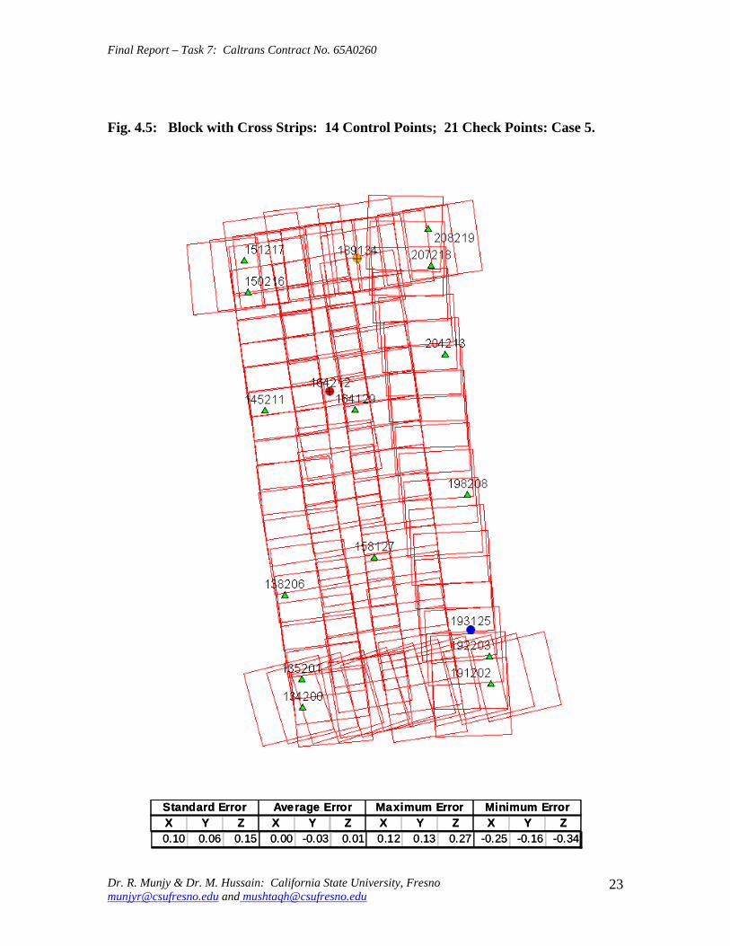
Final Report ndash Task 7 Caltrans Contract No 65A0260
Fig 45 Block with Cross Strips 14 Control Points 21 Check Points Case 5
SSttaannddaardrd EErrorrorr AAvveeraraggee EErrrroorr MMaaxxiimmuumm EErrorrorr MMiinniimmuumm EErrorrorr XX YY ZZ XX YY ZZ XX YY ZZ XX YY ZZ 001100 000066 001155 000000 --000033 000011 001122 001133 002277 --002255 --001166 --003344
Dr R Munjy amp Dr M Hussain California State University Fresno munjyrcsufresnoedu and mushtaqhcsufresnoedu
23
Final Report ndash Task 7 Caltrans Contract No 65A0260
Fig 46 Block without Cross Strips 8 Control Points 25 Check Points Case 7
SSttaannddaardrd EErrorrorr AAvveeraraggee EErrrroorr MMaaxxiimmuumm EErrorrorr MMiinniimmuumm EErrorrorr XX YY ZZ XX YY ZZ XX YY ZZ XX YY ZZ 001122 000088 005599 000404 000606 --110088 002288 002244 001166 --002222 --000099 --110099
Dr R Munjy amp Dr M Hussain California State University Fresno munjyrcsufresnoedu and mushtaqhcsufresnoedu
24
Final Report ndash Task 7 Caltrans Contract No 65A0260
Fig 47 Block without Cross Strips 11 Control Points 22 Check Points Case 8
SSttaannddaardrd EErrorrorr AAvveeraraggee EErrrroorr MMaaxxiimmuumm EErrorrorr MMiinniimmuumm EErrorrorr XX YY ZZ XX YY ZZ XX YY ZZ XX YY ZZ
001133 000099 001199 --000011 --000202 --001177 001177 001166 002288 --002828 --001166 --005050
Dr R Munjy amp Dr M Hussain California State University Fresno munjyrcsufresnoedu and mushtaqhcsufresnoedu
25
Final Report ndash Task 7 Caltrans Contract No 65A0260
Fig 48 Block without Cross Strips 11 Control Points 22 Check Points Case 9
SSttaannddaardrd EErrorrorr AAvveeraraggee EErrrroorr MMaaxxiimmuumm EErrorrorr MMiinniimmuumm EErrorrorr XX YY ZZ XX YY ZZ XX YY ZZ XX YY ZZ
001144 000099 002277 --000055 000033 --003131 001166 002020 003030 --003311 --001515 --006666
Dr R Munjy amp Dr M Hussain California State University Fresno munjyrcsufresnoedu and mushtaqhcsufresnoedu
26
Final Report ndash Task 7 Caltrans Contract No 65A0260
Fig 49 Block without Cross Strips 12 Control Points 21 Check Points Case 10
SSttaannddaardrd EErrorrorr AAvveeraraggee EErrrroorr MMaaxxiimmuumm EErrorrorr MMiinniimmuumm EErrorrorr XX YY ZZ XX YY ZZ XX YY ZZ XX YY ZZ 001133 000099 002200 --000022 000000 --000808 001166 001818 003131 --002277 --001616 --003333
Dr R Munjy amp Dr M Hussain California State University Fresno munjyrcsufresnoedu and mushtaqhcsufresnoedu
27
Final Report ndash Task 7 Caltrans Contract No 65A0260
Fig 410 Block without Cross Strips 14 Control Points 19 Check Points Case 11
SSttaannddaardrd EErrorrorr AAvveeraraggee EErrrroorr MMaaxxiimmuumm EErrorrorr MMiinniimmuumm EErrorrorr XX YY ZZ XX YY ZZ XX YY ZZ XX YY ZZ
001100 000088 001133 000044 --000022 --000303 001166 001515 002525 --002211 --001717 --002200
Dr R Munjy amp Dr M Hussain California State University Fresno munjyrcsufresnoedu and mushtaqhcsufresnoedu
28
Final Report ndash Task 7 Caltrans Contract No 65A0260
Fig 411 Block without Cross Strips 14 Control Points 19 Check Points Case 12
SSttaannddaardrd EErrorrorr AAvveeraraggee EErrrroorr MMaaxxiimmuumm EErrorrorr MMiinniimmuumm EErrorrorr XX YY ZZ XX YY ZZ XX YY ZZ XX YY ZZ
000099 000077 001122 --000011 --000101 000055 000099 001313 002828 --002255 --001414 --001122
Dr R Munjy amp Dr M Hussain California State University Fresno munjyrcsufresnoedu and mushtaqhcsufresnoedu
29
Final Report ndash Task 7 Caltrans Contract No 65A0260
5 ANALYSIS OF RESULTS amp CONCLUSIONS
In accordance with the Caltrans standards using wide-angle aerial photography the RMS error in each coordinate component of the adjusted tie points should not exceed 110000 of the flying height above the terrain The Del Mar Test Block was flown with a wideshyangle aerial camera from an average height of 1800 feet above the terrain level thereby resulting in an average photo scale of 13600 Consequently the limiting RMS error at the Check Points representative of a finite number of well distributed tie points in the block should not exceed 018 ft in this case Any error that exceeds three times this limiting value viz 054 ft in any of the coordinate components should be a cause for rejection of that point
Therefore the acceptable limiting values for the standard error at the Check Points is 018 ft in each coordinate component Any block adjustment solution that results in a coordinate error in one or more Check Points that exceeds 054 ft in any coordinate component would not be an acceptable solution The following analysis of the results is based on these accuracy criteria
51 Blocks With Cross Flights
When a minimal number of 8 control points are used (Fig 42) along the block perimeter the resulting standard error in Z-coordinate of 019 ft exceeds the limiting value of 015 ft It is also noticeable that the highest error in the Z-coordinate of 052 ft at Point 189134 almost equals the rejection limit of 054 ft This is an indication that controlling a cross flight with only a single Control Point at each end of the flight may not always provide a satisfactory solution
This situation can be remedied by using a pair of Control Points in each end model of a cross flight so that any deformation across the flight line the omega rotation () can also be controlled Such an approach is also reported to have been successfully used and recommended in the past [1] [2] [3] When 4 additional Control Points were added at the end of each cross flight line as is seen in Fig 43 all the standard errors fell within the acceptable range and the maximum coordinate error did not exceed 030 ft which is well within the acceptable criteria
The primary advantage of using airborne GPS data for the adjustment of aerial triangulation blocks is to completely eliminate the need for Control Points in the interior of the block But it is of interest to investigate how effectively the airborne GPS data alone can control the interior of the block Two separate blocks were processed by adding two Control Points in the interior of the block resulting in a total of 14 Control Points
The block with 14 Control Points (Case A) is shown in Fig 44 where the two interior Control Points were selected so that one Control Point was located on the opposite ends in each of the two interior flight lines (Line 2 and Line3 see Fig 41) The other block with 14 Control Points (Case B) is shown in Fig 45 In this case both the interior points
Dr R Munjy amp Dr M Hussain California State University Fresno munjyrcsufresnoedu and mushtaqhcsufresnoedu
30
Final Report ndash Task 7 Caltrans Contract No 65A0260
fell in the middle of the block interior It is interesting to note that in either of the two cases the addition of the interior Control Points did not result in any significant difference from the result achieved earlier while using 12 Control Points Therefore it may be concluded that as long as the cross flights are adequately controlled with a pair of Control Points located across each end model of each cross flight additional control in the block interior is not required The results shown in Fig 44 and 45 validate this conclusion at least for a block comprised of 18 models long multiple flight lines
52 Blocks Without Cross Flights
When a mapping project involves a large photogrammetric block consisting of hundreds of models the common practice is to plan the block configuration to include cross flights [1] [2] [6] [10] Often such cross flights can result in significant saving in time and effort in minimizing the need for ground control Since the photogrammetric mapping projects in Caltrans mostly involve mapping along highway corridors most of the photogrammetric blocks vary from a single flight line to up to as many as four flight lines Therefore it is still to be investigated whether the use of cross flight lines in such blocks offers any significant advantage Furthermore any advantage resulting from the reduced need for the ground control has to be weighed against the additional time and effort needed in processing the cross flight models The Caltrans Office of Photogrammetry has not yet adopted the use of Automated Aerial Triangulation (AAT) techniques for routine production Consequently the additional effort in transferring tie points between the cross flights with the flights of the main block is still significant This has provided the impetus to carry out the following investigation for the aerial triangulation adjustment of blocks that do not include any cross flights
The first block without the two cross flights was processed with only 8 Control points along the block perimeter as a parallel case with the block run with cross flights The results are shown in Fig 46 As may be expected the absence of any Control Point located at each end of each of the two interior flights 2 and 3 has resulted in unacceptably large errors Not only is the standard error of 059 ft in the Z-coordinate for the 25 Check Points too large but interestingly the block adjustment carries a large systematic error in Z-coordinate of 108 ft This results from the fact that the absence of the Control Points at each end of Flights 2 and 3 does not permit the adjustment for the systematic strip drift parameters for the airborne GPS data along Flights 2 and 3
When cross flights are included the airborne GPS data measured along the cross flight adequately serves as control for adjusting the strip shift and drift parameters Therefore an alternative to the inclusion of cross flights in the block configuration is to provide a Control Point at each end of every flight line in the block Accordingly the processing of the following blocks includes Control Points at the end of each flight line
The Del Mar Test Block with 4 flight lines each 18 models long would require a total of 12 Control Points one Control Point at each end of each flight line and 4 Control Points along the interior perimeter of the block to provide a control spacing of approximately 6 airbases apart However in order to minimize the use of the ground control the block
Dr R Munjy amp Dr M Hussain California State University Fresno munjyrcsufresnoedu and mushtaqhcsufresnoedu
31
Final Report ndash Task 7 Caltrans Contract No 65A0260
shown in Fig 47 was processed with only 11 Control Points (Case A) since the Control Point 170133 was measured both in Line 2 and Line 3 The resulting standard error of 019 ft in the Z-coordinate for 22 Check Points as well as the large error of 050 ft in the Z-coordinate of Check Point 189134 make the block adjustment solution unacceptable There appears to be no obvious reason why the Check Point 189134 that is located so close to the Control Point 170133 should display such unacceptably large error in the Zshycoordinate In order to ascertain the internal consistency of the ground control data (33 Control Points) a conventional aerial triangulation adjustment of the block was performed (without using the airborne GPS data) using 32 Control Points and treating the Control Point 189134 as a Check Point The resulting error in the Z-coordinate of Point 189134 was only 006 ft It is also to be noted that the average Z-coordinate error of 017 ft indicates a systematic height error This would lead to the conclusion that there is some height discrepancy between the ground control data and the airborne GPS data
The block was re-processed (Case B) again by using only 11 Control Points but this time the Control Point 170133 was replaced with Control Point 189134 and the results are displayed in Fig 48 The Case B results are even worse than the Case A results the standard error in Z-coordinate was degraded to 027 ft while the largest error in Zshycoordinate of 066 ft was noted at Check Point 187215 The average Z-coordinate error also increases to 031 ft This is a further indication that there is significant height inconsistency in the airborne GPS data and the ground control data It appears that the height discrepancy between the ground control data and the airborne GPS data results in an unsatisfactory shift and drift adjustment of the airborne GPS data particularly in the inner flight Lines 2 and 3 that span 18 models between the end Control Points
In order to strengthen the end control across the flight lines both the Control Points 170133 and 189134 were used at the Northern end of the block The block was then processed with 12 Control Points and the results are presented in Fig 49 Even though the results improved significantly but contrary to the expectation the standard error in the Z-coordinate of 020 ft for the 21 Check Points did not meet the Caltrans accuracy standard The next logical approach was to investigate the impact of adding Control Points in the interior of the block Two interior Control Points were selected in the same manner as has been described earlier in the case of the blocks with the cross flights (see Fig 44 and 45)
Using 14 Control Points the Case A is shown in Fig 410 while the Case B is presented in Fig 411 The results in both Case A and Case B easily meet the Caltrans accuracy standards In Case A the distance between the Control Points for the shift and drift parameter adjustment of the airborne GPS data varies from 6 to 12 models while in Case B the interior Control Points are about 6 models apart Each Control Point distribution provides almost similar results It is a clear indication that any systematic height deformation that results from the suspected inconsistency between the ground surveyed GPS data and the airborne GPS data can be kept within acceptable range by including a pair of control points in the interior of the block Such a need for some control points has not been reported for the adjustment of aerial triangulation blocks in the past However the largest photo scale for which any ABGPS supported results have been published in
Dr R Munjy amp Dr M Hussain California State University Fresno munjyrcsufresnoedu and mushtaqhcsufresnoedu
32
Final Report ndash Task 7 Caltrans Contract No 65A0260
the past is 14800 only For a photo scale of 13600 that is approximately 25 percent larger the requirements for the accuracy of aerial triangulation accordingly become more stringent in the same proportion This may generate the need for some additional control in the middle of the block
The residuals at the ground control points and in the image coordinate data along with the resulting standard error of unit weight (0) provide a reliable indication of the internal consistency of the adjusted block However the absolute accuracy of the aerial triangulation can be validated only by the use of Check Points that are well distributed over the entire block As pointed out earlier any deformations due to residual systematic shift and drift errors in the airborne GPS data are likely to be most significant in the center of the block the location that is farthest from the control points distributed along the perimeter Accordingly it would be advisable to locate at least a pair of Check Points in the middle of the block and after completing the block adjustment (by excluding these Check Points as Control Points) the coordinate discrepancies obtained at these Check Points can be analyzed Such discrepancies would normally represent the highest absolute accuracy resulting from aerial triangulation adjustment of the block Any unacceptably large coordinate discrepancies at the Check Points would require investigation of the block input data
In the case the coordinate discrepancies at the Check Points are within acceptable range the block can be re-processed by also including the Check Points in the control data This should enhance the accuracy in the interior of the block
6 RECOMMENDED DRAFT STANDARDS
These draft standards are proposed to supplement the existing Standards for Strip Configuration Airborne GPS Controlled Photogrammetry for Large Scale Mapping Projects (based on 13600 photo scale) currently used in Caltrans
61 Data Acquisition
611 Image Coordinate Data
Follow the existing practice used in Caltrans Office of Photogrammetry for the selection distribution and the measurement of all image point data It is recommended that raw machine coordinate image data should form the input to the aerial triangulation block adjustment
A secondary interest in this Research Project under contract with Caltrans was to also evaluate the alternate methodology of the selection and the measurement of tie point data using Automated Aerial Triangulation (AAT) system However several problems were encountered in implementing the AAT software available at the Caltrans Office of Photogrammetry in Sacramento The unavoidable delay caused by unfavorable weather conditions in acquiring the aerial imagery for the Del Mar Test Block did not allow
Dr R Munjy amp Dr M Hussain California State University Fresno munjyrcsufresnoedu and mushtaqhcsufresnoedu
33
Final Report ndash Task 7 Caltrans Contract No 65A0260
enough time to resolve the AAT software issues with software vendor Accordingly this task could not be fully completed Therefore it was mutually agreed between the Caltrans Office of Photogrammetry and California State University Fresno to concentrate research efforts on the processing and the analysis of the Del Mar Test Block and on drafting the Final Report
612 Ground Control Data
The proposed research is focused on the use of photography obtained at scale of 13600 for corridor mapping in Caltrans The ground control for mapping is based on the airborne GPS supported aerial triangulation of the photo blocks The ground control points should be surveyed to provide 15 to 2-times higher accuracy than that of the adjusted tie point data This would translate to an accuracy at the 005 to 01 ft level for the planimetric coordinates and the height an accuracy achievable using static GPS surveys tied to existing HPGN network
It is not yet certain that the Real-Time Kinematic (RTK) GPS field survey methodology whether relying on a single base station or on an RTK network is able to meet the above stringent field survey accuracy requirements Therefore the ground control data for ABGPS based aerial triangulation blocks should be based entirely on GPS control networks established using static GPS surveying methodology The RTK survey methodology for establishing control for photogrammetric mapping projects should not be used till such time that such technology has advanced to a level when consistently reliable results can be routinely expected
The GPS observations provide a fairly precise data for ellipsoidal height differences However all photogrammetric mapping has to be based on orthometric height data Two different approaches can be used in order to derive adjusted orthometric height data through aerial triangulation The first method is to carry out the simultaneous least squares adjustment of the GPS observation data for the ground control network using current Caltrans Horizontal Datum CCS83 (199135) and Vertical Datum NAVD 88 But since the observed data involves the measurement of ellipsoidal height differences for each measured baseline there is a need for transforming such differences to the corresponding orthometric height differences on NAVD 88 Datum In the absence of an existing Local Geoid Model the only economic recourse available to meet this need is to use the most reliable existing Global Geoid Model the time-consuming and prohibitively more costly alternative would be to connect the control network stations through differential leveling The Global Geoid Models are progressively being updated and the GEOID 2003 Model is most commonly in current use although GEOID 2009 Model may soon become available
It has to be noted that the use of a Global Geoid Model will always have some residual geoidal height uncertainties perhaps in the range of few hundredths of a foot It is therefore necessary that a few stations that are well distributed over the control network should have precisely known orthometric height values which can be used for the height adjustment of the network The minimum number of such orthometric height control
Dr R Munjy amp Dr M Hussain California State University Fresno munjyrcsufresnoedu and mushtaqhcsufresnoedu
34
Final Report ndash Task 7 Caltrans Contract No 65A0260
stations is three and consequently a network should be planned to have at least four and preferably more stations where orthometric height is precisely known In practice this requirement is met by including several existing benchmarks that are well distributed over the project area The redundancy provided by using more than three benchmarks will quantify the height residuals resulting from the adjustment This will provide a good estimate for the residual height errors in the network
The alternative approach is to carry out the adjustment of the GPS control network using WGS84 Geodetic Datum This datum is consistent with the observed GPS measurement data and a simultaneous 3D adjustment of the network can be performed in a Local Spatial Coordinate System (LSCS) the most commonly used approach is to shift the origin of the WGS84 coordinate system (center of the Earth) to approximately the center of the project site and apply a 3D rotational matrix to align the coordinate axes along the East North and Up directions Some commercial aerial triangulation software systems provide utilities to easily perform such datum transformation After the aerial triangulation results have been validated the coordinates of all the control and tie points can be transformed back to WGS 84 Datum Based on the availability of the orthometric height control stations a local Geoid can be defined ( a plane or a surface etc) and then used to transform the ellipsoidal height data to orthometric height data This second approach has the advantage that unlike the first method described above the residual height errors in the transformed control point height data are not propagated through aerial triangulation
For 13600 scale aerial photography blocks the ground control data should meet the a- priori standard deviation at 010 ft level This is not a very challenging demand for the horizontal positioning using GPS methodology However the residual height uncertainties in the orthometric height of control points interpolated from the Global Geoid Model become more critical as the photo scale becomes larger
613 Airborne GPS Data
The current practice used in Caltrans to acquire airborne GPS data during flight missions should continue to be used It is necessary to have GPS data collected at 1 Hz or higher rate at a base station that is located within or close to the project site Prior research completed collaboratively with Caltrans has already shown that the data at the base station may be substituted with GPS data collected at CORS at 5-sec or higher rate Consequently the collection of GPS data at more than one base stations is not considered as an essential requirement It may still be prudent to acquire GPS data at a second base station as a contingency safeguard against the GPS hardware failure at a base station for guaranteed success of the flight mission and expense
It is to be noted that the relative accuracy between successive airborne GPS antenna 3Dshycoordinates should be at 10-cm or higher level The current procedure used in Caltrans for the aircraft to remain stationary for static resolution of ambiguities before take off has mostly resulted in acquiring very reliable airborne GPS data This practice should perhaps be continued even though the continuing improvements in GPS hardware and
Dr R Munjy amp Dr M Hussain California State University Fresno munjyrcsufresnoedu and mushtaqhcsufresnoedu
35
Final Report ndash Task 7 Caltrans Contract No 65A0260
post-processing softwares are making on-the-fly (OTF) ambiguity resolution increasingly reliable However if it is necessary to resort to on-the-fly ambiguity resolution it must be ensured that the ambiguities have stabilized before photography is started The strict requirement for reliably resolving the ambiguities also does not permit the loss of lock during any single flight line If a loss of lock occurs during turns between flight lines ambiguities must be re-acquired and must stabilize before starting the collection of photography for another flight line Based on the make and the model of the airborne GPS receiver the Caltrans Office of Photogrammetry in consultation with the District Survey Section should draft a set of instructions for the GPSCamera operator aboard the aircraft specifying what parameters (such as PDOP Number of SVs etc) that need to be continuously monitored on a screen during a flight mission
62 Flight and Control Configuration
The following standards in planning the flight line configuration and the corresponding ground control distribution for Caltrans project are recommended to achieve optimum results
Control points are primarily required only along the perimeter of the block When a cross flight line is used to control the end of a block a pair of Control
Points must be located at each end of the cross flight At each end of a block that is not controlled by a cross flight a CP should be
located at the end of each parallel flight line a single CP may serve as end control for two adjacent overlapping flight lines
Along the perimeter of the block in a direction parallel with the main flight lines the CPs should be located at an average spacing of 6 airbases
Any corner in a block resulting from a sudden change in the length of two adjacent parallel flight lines should be controlled by an additional CP
Check Points should be provided along the interior flight lines in a multi-strip block The Check Points may be distributed along the interior flight lines so that any Check Point is not farther than about 8 airbases from either another Check Point (on same or adjacent flight line) or from a Control Point
Note that Caltrans is usually concerned with the mapping mostly along highway corridors and therefore does not require blocks with segments larger than three or four parallel flight lines Additional control along the cross flight line would be needed if such segments have 8 or more parallel flight lines
63 Data Processing and Adjustment
631 Processing of ABGPS Data
The current practice of post-processing ABGPS data used in Caltrans Office of Photogrammetry using GrafNav software should be continued The data should continue to be processed in the Forward and Backward modes A coordinate separation of less
Dr R Munjy amp Dr M Hussain California State University Fresno munjyrcsufresnoedu and mushtaqhcsufresnoedu
36
Final Report ndash Task 7 Caltrans Contract No 65A0260
than 10 cm especially in the height represents a normally acceptable range for the combined solution
This study has shown that the airborne GPS data in comparison with the ground control data should be weighted a lower weight but the highest weight that the GPS data quality represents Generally the best results were achieved when a-priori standard error of 015 ft was used for the airborne GPS coordinate data in comparison with the a-priori standard error of 010 ft used for the ground control coordinate data Since the 3-D position of successive points along the airborne GPS antenna trajectory are estimated using Kalman Filtering approach the successive location coordinates are highly correlated and consequently carry a much higher relative precision This provides a realistic justification for the use of a-priori standard error of 015 ft
632 Processing of Aerial Triangulation Block
Each aerial triangulation block requires the following data files as input
- Raw image coordinate data file - Ground control data file - Interpolated camera coordinate data file
Using the above input data files the block adjustment should be carried out in two steps as described below It is essential that additional Strip Shift and Drift parameters (3 Shift and 3 Drift parameters) should be incorporated in the bundle adjustment solution
Step 1 Minimal Control Adjustment
The preliminary simultaneous bundle adjustment of the block should be carried out by using the minimal amount of control points along the block perimeter only All the additional ground surveyed and targeted points should be treated as tie points to serve as Check Points The adjustment results should meet the following criteria
a The Standard Error of Unit Weight (0) should fall between 03 to 07 b The residual for any image coordinate should not exceed 15 micrometer c The RMS for ground control residuals should not exceed 110000 of the flying
height above the average terrain level d The maximum residual in any ground control coordinate should not exceed 25
times the RMS value permissible under Item (c) above e The RMS for discrepancy (difference between computed coordinate value and
the ground surveyed coordinate value) in Check Point coordinates should not exceed 110000 of the flying height above the average terrain level
f The discrepancy in any Check Point coordinate should not exceed 25 times the RMS value permissible under Item (e) above
If the above criteria are met even the preliminary adjustment solution for the block satisfies Caltrans accuracy standards for aerial triangulation If the criterion under Item
Dr R Munjy amp Dr M Hussain California State University Fresno munjyrcsufresnoedu and mushtaqhcsufresnoedu
37
Final Report ndash Task 7 Caltrans Contract No 65A0260
(f) above is not met the input data should be checked for any gross mistakes or errors in the ground control and Check Point data
Step 2 Full Control Adjustment
The final simultaneous bundle adjustment of the block should be carried out by including all the ground surveyed points (Control Points and Check Points) in the ground control data file The adjustment results should meet the following criteria
g The Standard Error of Unit Weight (0) should fall between 03 to 07 h The residual for any image coordinate should not exceed 15 micrometer i The RMS for ground control residuals should not exceed 110000 of the flying
height above the average terrain level j The maximum residual in any ground control coordinate should not exceed 25
times the RMS value permissible under Item (i) above
7 CONCLUDING COMMENTS
The completion of this project signifies the culmination of a very successful and productive combination of advanced theoretical principles with sound practical experience for the adaptation of evolving photogrammetric technologies in Caltrans practice In order to alleviate a growing concern for the safety of staff conducting field survey operations in close proximity of high speed traffic Caltrans in late 1990s decided to investigate the feasibility of using airborne GPS data for controlling the aerial triangulation blocks There were two primary issues to be resolved The first and the foremost concern was whether the use of airborne GPS data could be effectively used for controlling aerial triangulation blocks of as large a photo scale as 13000 used in Caltrans and still meet the Caltrans accuracy standards This concern was particularly critical since there had not been any reported use of airborne GPS data for such a large scale of aerial photography
Should the above investigation show that the Caltrans accuracy standards for aerial triangulation for 13000 scale aerial photography can be met it was of great interest to Caltrans to develop based on theoretically sound and systematic investigation a set of standards and specifications for the successful implementation of this new methodology in Caltrans routine practice
Under a Caltrans New Technology and Research Program currently Division of Research and Innovation (DRI) contract Caltrans Office of Photogrammetry partnered with a team of two faculty members from the Geomatic Engineering Program at the California State University Fresno (CSUF) in 1996 to carry out research to address the above two issues This partnership has flourished over the past several years through
Dr R Munjy amp Dr M Hussain California State University Fresno munjyrcsufresnoedu and mushtaqhcsufresnoedu
38
Final Report ndash Task 7 Caltrans Contract No 65A0260
successive research contracts and has resulted in very fortuitous outcomes based on the theoretical and analytical guidance provided by the CSUF research team and the highly skilled aerial survey project management and high caliber professional skills in the acquisition of photogrammetric data collection by the Caltrans Office of Photogrammetry In addition the help from highly experienced field survey teams from Caltrans various districts (especially District 11) in establishing GPS networks of Control Points and Check Points of specified precision was critical for the validation of airborne-GPS supported aerial triangulation investigations
As a result of the past collaborative efforts between the Caltrans Office of Photogrammetry and the CSUF Research Team the use of airborne GPS data for aerial triangulation has successfully been transitioned into Caltrans practice in the following stages
1) Based on a number of test flights it was convincingly demonstrated that the use of airborne GPS data consistently meets the Caltrans accuracy standards for aerial triangulation for strip configuration blocks at 13000 photo scale [13]
2) A detailed set of standards and specifications were developed for the implementing of the new methodology in Caltrans routine practice This was further supported through a training workshop conducted by CSUF at the Caltrans offices in Sacramento [8]
3) The use of airborne GPS data for the adjustment of aerial triangulation blocks requires the collection of GPS data at one or more ground base stations during the flight mission This requirement imposes burdensome demands on scheduling and allocation of manpower and equipment resources In order to reduce or even to completely eliminate the need for the collection of GPS data at base stations the use of GPS data collected and archived at a network of Continuously Operating Reference Stations (CORS) distributed over the State of California was investigated It was demonstrated that CORS data could be effectively used as a replacement for data collected at base stations while fulfilling Caltrans accuracy standards Accordingly specifications were revised to also include the selection and the use of CORS data for the post-processing of airborne GPS data to accurately derive the trajectory of the airborne GPS antenna during flights [19]
4) During the past few years Caltrans has increasingly been using multi-strip projects for mapping using 13600 photo scale This provided the need for the current research study The successful completion of this study has resulted in supplementing the existing standards and specifications for airborne GPS supported single-strip aerial triangulation blocks to also include the aerial triangulation of multi-strip blocks
It is a matter of great satisfaction for the research team at CSU Fresno that working hand in hand with the Caltrans Office of Photogrammetry the comprehensive set of standards and specifications for airborne GPS supported aerial triangulation that had been developed for successful transition of this technology in Caltrans practice have been further upgraded It is hoped that as the photogrammetric technology advances further
Dr R Munjy amp Dr M Hussain California State University Fresno munjyrcsufresnoedu and mushtaqhcsufresnoedu
39
Final Report ndash Task 7 Caltrans Contract No 65A0260
similar collaborative efforts between Caltrans Office of Photogrammetry and CSU Fresno will continue to address the changing needs in Caltrans
Dr R Munjy amp Dr M Hussain California State University Fresno munjyrcsufresnoedu and mushtaqhcsufresnoedu
40
Final Report ndash Task 7 Caltrans Contract No 65A0260
REFERENCES
1 Abdullah Q M Hussain and R Munjy (2002) Workshop on Airborne GPS-Supported Aerial Triangulation ndash Theory and Practical Concepts presented at the Annual ASPRS Convention Washington DC 2002
2 Ackermann Fritz (1992) Operational Rules and Accuracy Models for GPS-Aerotriangulation Archives of the ISPRS Com 1 Vol29 1992 [pp 691-700]
3 Ackermann F (1993) Application of GPS for Aerial Triangulation Photogrammetric Engineering and Remote Sensing Vol 59 No 11 [pp 1651shy1658]
4 Appleton James Mushtaq Hussain and Riadh Munjy (2000) Use of Airborne GPS Data for Highway Mapping International Archives of Photogrammetry and Remote Sensing Vol XXXIII Part B4 Amsterdam 2000[pp 84-90]
5 Appleton James M Hussain and R Munjy (2002) Use of Airborne GPS Data For Aerial Triangulation in Caltrans (2002) Workshop presented at the California Department of Transportation Sacramento 2002
6 Federal Geographic Data Committee (FGDC) 1998 Geospatial Positional Accuracy Standards Part-3 National Standards for Spatial Data Accuracy (NSSDA) FGDC-STD-0073-1998
7 Friess Peter (1992) Experiences with GPS-Supported Aerial Triangulation Archives of the ISPRS Com 1 Vol29 1992 [pp 299 - 305]
8 Gianellia Alexander M (1995) Practical Considerations in Implementing GPS Technologies in Airborne Data Collection Proc ASPRS Annual Convention 1995 [pp 917-925]
9 Hussain M R Munjy and J Appleton (1999) Use of Airborne On-the-Fly Kinematic GPS Data for Photogrammetric Mapping Proceedings ION-GPS-99 Conference Nashville 1999[pp 1653-1659]
10 Hussain M and R Munjy (1999) GPS Controlled Photogrammetry For Large Scale Mapping (1999) Final Project Report Research project No 65Y271 submitted to New Technology amp Research Program California Department of Transportation
11 Hussain M and R Munjy (2002) Airborne GPS Controlled Aerial Triangulation in Caltrans Final Project Report Research project No 65A0059 submitted to New Technology amp Research Program California Department of Transportation June 2002
12 Munjy R and M Hussain (1985) Interactive Simultaneous Bundle Block Adjustment System (ISBBA) for Small Computers Proceedings of the ASPRS Annual Convention Washington DC 1985
13 Munjy R M Hussain and James Appleton (2000) Use of Airborne GPS Data for Corridor Mapping presented at the Annual ASPRS Convention Washington DC 2000
Dr R Munjy amp Dr M Hussain California State University Fresno munjyrcsufresnoedu and mushtaqhcsufresnoedu
41
Final Report ndash Task 7 Caltrans Contract No 65A0260
14 Munjy R and M Hussain (2007) Develop Criteria for Using Network GPS for Airborne GPS Photogrammetry Final Project Report Research Project No 65A0234 submitted to the Division of Research and Innovation (DRI) California Department of Transportation
15 Munjy R and M Hussain (2009) Draft Preliminary Standards Interim Report Research Project No 65A0260 submitted to Division of Research aned Innovation (DRI) California Department of Transportation
Dr R Munjy amp Dr M Hussain California State University Fresno munjyrcsufresnoedu and mushtaqhcsufresnoedu
42
APPENDIX I Results of Check Block
Flight amp Control Configuration Cases Used for
Study amp Analysis of Check Project in San Diego
INDEX
Case Block amp Control Configuration 1 Full Blk(Flts1to9) All 44 CP 2 Full Blk 8 CP 3 Full Blk 9 CP 4 Full Blk 10 CP 5 Main Blk(Flts1to7) 43 CP 6 Main Blk(Flts1to7) 8 CP 7 Main Blk(Flts1to7) 10 CP 8 Main Blk(Flts1to7) 12 CP 9 North Blk(Flts567amp9) 5 CP 10 North Blk(Flts567amp9) 7 CP 11 North Blk(Flts56amp7) 6 CP 12 North Blk(Flts56amp7) 8 CP 13 South Blk(Flts1to4amp8) 4 CP 14 South Blk(Flts1to4amp8) 6 CP 15 South Blk(Flts1to4amp8) 7 CP 16 South Blk(Flts1to4) 7 CP 17 South Blk(Flts1to4) 8 CP(a) 18 South Blk(Flts1to4) 8 CP(b) 19 South Blk(Flts1to4) 10 CP 20 South Blk(Flts1to4) 11 CP 21 South Blk(Flts Modified 1to4 amp8) 5 CP 22 South Blk(Flts Modified 1to4 ) 6 CP
[Refer to Table-1 Summary of the Coordinate Differences at the Check Points]
I-i
Case-1 Base DataFULL BLOCK
Flts 1 to 9
Case-1 Base Data FULL BLOCK
Flts 1 to 9
Control PointsControl Points All 44 PointsAll 44 Points
SSSttt ErErErrrr AAAvvvggg ErErErrrr MMMaaaxxx ErErErrrr MMMiiinnn ErErErrrr XXX YYY ZZZ XXX YYY ZZZ XXX YYY ZZZ XXX YYY ZZZ
007 008 005 000 000 000 019 012 012 -013 -023 -013007 008 005 000 000 000 019 012 012 -013 -023 -013007 008 005 000 000 000 019 012 012 -013 -023 -013
I-ii
Case-2FULL BLOCK
Flts 1 to 9
Control Points 8
Case-2 FULL BLOCK
Flts 1 to 9
Control Points 8 CChheecckk PoPointsints 3366
SStt ErErrr AAvvgg ErErrr MMaaxx ErErrr MMinin ErErrr XX YY ZZ XX YY ZZ XX YY ZZ XX YY ZZ
012012 012012 016016 002002 001001 --000505 024024 027027 026026 --025025 --039039 --032032
I-iii
Case-3FULL BLOCK
Flts 1 to 9
Control Points 9
Case-3 FULL BLOCK
Flts 1 to 9
Control Points 9 CChheecckk PoPointsints 3355
SStt ErErrr AAvvgg ErErrr MMaaxx ErErrr MMinin ErErrr XX YY ZZ XX YY ZZ XX YY ZZ XX YY ZZ
012012 012012 017017 001001 --001001 --000808 024024 024024 026026 --026026 --040040 --034034
I-iv
Case-4FULL BLOCK
Flts 1 to 9
Control Points 10
Case-4 FULL BLOCK
Flts 1 to 9
Control Points 10 CChheecckk PoiPoinntsts 3344
SStt ErErrr AAvvgg ErErrr MMaaxx ErErrr MMinin ErErrr XX YY ZZ XX YY ZZ XX YY ZZ XX YY ZZ
012012 009009 015015 003003 005005 --000909 002244 002727 002121 --025025 --001313 --035035
I-v
Case-5MAIN BLOCK
Flts 1 to 7
Control Points 43
Case-5 MAIN BLOCK
Flts 1 to 7
Control Points 43 [Point HV-117 Unuse[Point HV-117 Unusedd]]
SSSttt ErErErrrr AAAvvvggg ErErErrrr MMM aaaxxx ErErErrrr MMM iiinnn ErErErrrr XXX YYY ZZZ XXX YYY ZZZ XXX YYY ZZZ XXX YYY ZZZ
006006006 008008008 005005005 000000000 000000000 000000000 012012012 013013013 013013013 ---000131313 ---022022022 ---000090909
I-vi
Case-6
Flts 1 to 7
l Points 8
MAIN BLOCK
[No Cross Flts]Contro
Case-6 MAIN BLOCK
Flts 1 to 7 [No Cross Flts]
Control Points 8 ChecCheckk PoPointsints 3636
St ErSt ErSt ErSt ErSt ErSt ErSt ErSt Errrrrrrrr AAAAAAAAvgvgvgvgvgvgvgvg ErErErErErErErErrrrrrrrr MMMMMMMMaxaxaxaxaxaxaxax ErErErErErErErErrrrrrrrr MMMMMMMMiiiiiiiinnnnnnnn ErErErErErErErErrrrrrrrr XXXXXXXX YYYYYYYY ZZZZZZZZ XXXXXXXX YYYYYYYY ZZZZZZZZ XXXXXXXX YYYYYYYY ZZZZZZZZ XXXXXXXX YYYYYYYY ZZZZZZZZ
016016016016 012012012012 027027027027 -002-002-002-002 ----004004004004 -004-004-004-004 000026262626 000020202020 000041414141 ----035035035035 -036-036-036-036 ----082082082082
I-vii
Case-7MAIN BLOCK
Flts 1 to 7[No Cross Flts]
Control Points 10
Case-7 MAIN BLOCK
Flts 1 to 7 [No Cross Flts]
Control Points 10 CChheecckk PointsPoints 3434
SStt ErErrr AAvvgg ErErrr MM aaxx ErErrr MM iinn ErErrr XX YY ZZ XX YY ZZ XX YY ZZ XX YY ZZ
014 012 027 -001 -003 -004 022 020 039 -031 -031 -080014 012 027 -001 -003 -004 022 020 039 -031 -031 -080
I-viii
Case-8MAIN BLOCK
Flts 1 to 7[No Cross Flts]
Control Points 12
Case-8 MAIN BLOCK
Flts 1 to 7 [No Cross Flts]
Control Points 12 CheChecckk PointsPoints 3232
SSSttt ErErErrrr AAAvvvggg ErErErrrr MMMaaaxxx ErErErrrr MMMiiinnn ErErErrrr XXX YYY ZZZ XXX YYY ZZZ XXX YYY ZZZ XXX YYY ZZZ
015 010 017 003 000 -004 037 016 035 -031 -027 -023015 010 017 003 000 -004 037 016 035 -031 -027 -023015 010 017 003 000 -004 037 016 035 -031 -027 -023
I-ix
Case-9Case-9Case-9 NORNORNORTTTH BLH BLH BLOCKOCKOCK
FltsFltsFlts 5 to 7 amp 9 5 to 7 amp 9 5 to 7 amp 9
Control PointsControl PointsControl Points 555 ChChCheckeckeck PoPoPoininintttsss 111888
ErSSSttt EE rrrrr vg ErAAAvg Evg E rrrrr ax ErMMM ax Eax E rrrrr ErMMM iiinnn EE rrrrr XXX YYY ZZZ XXX YYY ZZZ XXX YYY ZZZ XXX YYY ZZZ
000121212 016016016 000161616 007007007 ---000161616 000111111 000262626 000020202 000363636 ---022022022 ---000626262 ---022022022
I-x
Case-Case-1100 NORTH BLOCKNORTH BLOCK
Flts 5 to 7 amp 9Flts 5 to 7 amp 9
Control PointsControl Points 77 CheckCheck PointsPoints 1616
SStt ErErrr AAvvgg ErErrr MM aaxx ErErrr MM iinn ErErrr XX YY ZZ XX YY ZZ XX YY ZZ XX YY ZZ
010010 016016 017017 008008 --000707 001818 002323 001010 005151 --016016 --005151 --012012
I-xi
Case-Case-1111 NORTH BLOCKNORTH BLOCK
FltsFlts 5 to 7 5 to 7
CCoontrntrool Pointsl Points 66 CheChecckk PointsPoints 1717
SStt ErErrr AAvvgg ErErrr MM aaxx ErErrr MM iinn ErErrr XX YY ZZ XX YY ZZ XX YY ZZ XX YY ZZ
010010 016016 022022 010010 --000202 000808 002424 001515 005050 --019019 --004343 --026026
I-xii
Case-Case-1122 NORTH BLOCKNORTH BLOCK
FltsFlts 5 to 7 5 to 7 [No C[No Crrossoss Flt]Flt]
ContControl Poinrol Pointsts 88 CChheecckk PointsPoints 1155
SStt EErrrr AAvg Evg Errrr MM ax Eax Errrr MM iinn EErrrr XX YY ZZ XX YY ZZ XX YY ZZ XX YY ZZ
011011 016016 017017 013013 --000909 000202 002929 000707 003737 --017017 --004949 --031031
I-xiii
CaseCase-13-13 SOUTSOUTH BH BLLOCKOCK
Flts 1 to 4 amp 8Flts 1 to 4 amp 8
CoConnttrol Porol Poininttss 44 ChCheckeck PPooinintsts 2222
SStt ErErrr AAvvgg ErErrr MM aaxx ErErrr MM iinn ErErrr XX YY ZZ XX YY ZZ XX YY ZZ XX YY ZZ
052 032 015 -082 033 003 -007 091 026 -149 -009 -034052 032 015 -082 033 003 -007 091 026 -149 -009 -034
I-xiv
Case-14Case-14 SOUTH BLOCKSOUTH BLOCK
Flts 1 to 4 amp 8Flts 1 to 4 amp 8
CCoontrntrool Pointsl Points 66 CheChecckk PointsPoints 2200
SStt ErErrr AAvvgg ErErrr MM aaxx ErErrr MM iinn ErErrr XX YY ZZ XX YY ZZ XX YY ZZ XX YY ZZ
013 016 015 -003 006 -002 024 033 033 -019 -028 -028013 016 015 -003 006 -002 024 033 033 -019 -028 -028
I-xv
Case-15Case-15 SOUTH BLOCKSOUTH BLOCK
FltsFlts 1 to 4 amp 8 1 to 4 amp 8
ContrControol Pointsl Points 77 ChCheckeck PPooinintsts 1919
SStt ErErrr AAvvgg ErErrr MM aaxx ErErrr MM iinn ErErrr XX YY ZZ XX YY ZZ XX YY ZZ XX YY ZZ
015 012 014 -003 -002 -002 025 023 033 -025 -030 -025015 012 014 -003 -002 -002 025 023 033 -025 -030 -025
I-xvi
Case-16Case-16Case-16 SOUTH BLOCKSOUTH BLOCKSOUTH BLOCK
FltsFltsFlts 1 to 4 1 to 4 1 to 4 [No Cross Flt][No Cross Flt][No Cross Flt]
Control PointsControl PointsControl Points 777 CheCheCheccckkk PointsPointsPoints 222222
SSSttt EEErrrrrr AAAvg Evg Evg Errrrrr MMM ax Eax Eax Errrrrr MMM iiinnn EEErrrrrr XXX YYY ZZZ XXX YYY ZZZ XXX YYY ZZZ XXX YYY ZZZ
015 013 023 -001 -005 003 026 023 032 -027 -029 -037015 013 023 -001 -005 003 026 023 032 -027 -029 -037015 013 023 -001 -005 003 026 023 032 -027 -029 -037
I-xvii
Case-17Case-17 SOUTSOUTH BLH BLOCKOCK
FltsFlts 1 1 to 4to 4 [No[No CrosCrosss Flt]Flt]
ContrControol Pointsl Points 88 CChheecckk PointsPoints 2121
SStt ErErrr AAvvgg ErErrr MM aaxx ErErrr MM iinn ErErrr XX YY ZZ XX YY ZZ XX YY ZZ XX YY ZZ
014014 012012 024024 005005 --000101 000404 003131 002525 003333 --022022 --002929 --040040
I-xviii
Case-18Case-18 SOUTH BLOCKSOUTH BLOCK
Flts 1 to 4Flts 1 to 4 [[NNo Cro Crooss Fss Flltt]]
CCoontrol Pointsntrol Points 88 CheChecckk PointsPoints 2121
SSSttt ErErErrrr AAAvvvggg ErErErrrr MMM aaaxxx ErErErrrr MMM iiinnn ErErErrrr XXX YYY ZZZ XXX YYY ZZZ XXX YYY ZZZ XXX YYY ZZZ
016 014 019 -003 -005 001 027 025 028 -033 -033 -032016 014 019 -003 -005 001 027 025 028 -033 -033 -032016 014 019 -003 -005 001 027 025 028 -033 -033 -032
I-xix
Case-19Case-19 SOUTH BLOCKSOUTH BLOCK
FltsFlts 1 to 4 1 to 4 [No Cross Flt][No Cross Flt]
ContControl Prol Poointintss 10 10 CheckCheck PointsPoints 1919
SSSttt ErErErrrr AAAvvvggg ErErErrrr MMM aaaxxx ErErErrrr MMM iiinnn ErErErrrr XXX YYY ZZZ XXX YYY ZZZ XXX YYY ZZZ XXX YYY ZZZ
014 012 019 004 -001 001 034 029 029 -025 -030 -028014 012 019 004 -001 001 034 029 029 -025 -030 -028014 012 019 004 -001 001 034 029 029 -025 -030 -028
I-xx
Case-Case-2200 SSOOUTH BLOCKUTH BLOCK
FltsFlts 1 to 4 1 to 4 [No Cross Flt][No Cross Flt]
Control Points 11Control Points 11 ChCheckeck PPooinintsts 1818
SSSttt ErErErrrr AAAvvvggg ErErErrrr MMM aaaxxx ErErErrrr MMM iiinnn ErErErrrr XXX YYY ZZZ XXX YYY ZZZ XXX YYY ZZZ XXX YYY ZZZ
014014014 012012012 018018018 ---000010101 ---005005005 ---000010101 000232323 000202020 000272727 ---030030030 ---000292929 ---031031031
I-xxi
Case-Case-2211 MODIMODIFFIIED SOUTH BED SOUTH BLLOCKOCK
FltsFlts 1 to 4 ( 1 to 4 (MModified)odified) amp 8amp 8
ControControl Pointsl Points 55 CheChecckk PointsPoints 1818
SStt ErErrr AAvvgg ErErrr MM aaxx ErErrr MM iinn ErErrr XX YY ZZ XX YY ZZ XX YY ZZ XX YY ZZ
013 010 015 -001 002 -001 024 021 035 -019 -025 -029013 010 015 -001 002 -001 024 021 035 -019 -025 -029
I-xxii
Case-22Case-22Case-22 MOMOMODIFDIFDIFIIIED SOED SOED SOUTH BLOCKUTH BLOCKUTH BLOCK
FltFltFltsss 1 to 4 1 to 4 1 to 4 (M(M(Modiodiodifiefiefieddd))) [No C[No C[No Crrrososossss Flt]Flt]Flt]
ConConContttrol Prol Prol Poooiiinnntttsss 666 ChChCheckeckeck PointPointPointsss 161616
SSSttt ErErErrrr AAAvvvggg ErErErrrr MMM aaaxxx ErErErrrr MMM iiinnn ErErErrrr XXX YYY ZZZ XXX YYY ZZZ XXX YYY ZZZ XXX YYY ZZZ
014 011 014 002 005 -010 025 024 016 -020 -024 -039014 011 014 002 005 -010 025 024 016 -020 -024 -039014 011 014 002 005 -010 025 024 016 -020 -024 -039
I-xxiii
APPENDIX II Results of Test Block
II-i
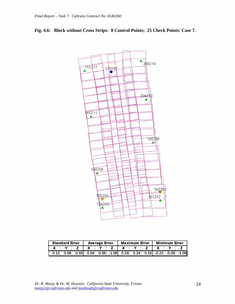
Final Report ndash Task 7 Caltrans Contract No 65A0260
Fig 46 Block without Cross Strips 8 Control Points 25 Check Points Case 7
SSttaannddaardrd EErrorrorr AAvveeraraggee EErrrroorr MMaaxxiimmuumm EErrorrorr MMiinniimmuumm EErrorrorr XX YY ZZ XX YY ZZ XX YY ZZ XX YY ZZ 001122 000088 005599 000404 000606 --110088 002288 002244 001166 --002222 --000099 --110099
Dr R Munjy amp Dr M Hussain California State University Fresno munjyrcsufresnoedu and mushtaqhcsufresnoedu
24
Final Report ndash Task 7 Caltrans Contract No 65A0260
Fig 47 Block without Cross Strips 11 Control Points 22 Check Points Case 8
SSttaannddaardrd EErrorrorr AAvveeraraggee EErrrroorr MMaaxxiimmuumm EErrorrorr MMiinniimmuumm EErrorrorr XX YY ZZ XX YY ZZ XX YY ZZ XX YY ZZ
001133 000099 001199 --000011 --000202 --001177 001177 001166 002288 --002828 --001166 --005050
Dr R Munjy amp Dr M Hussain California State University Fresno munjyrcsufresnoedu and mushtaqhcsufresnoedu
25
Final Report ndash Task 7 Caltrans Contract No 65A0260
Fig 48 Block without Cross Strips 11 Control Points 22 Check Points Case 9
SSttaannddaardrd EErrorrorr AAvveeraraggee EErrrroorr MMaaxxiimmuumm EErrorrorr MMiinniimmuumm EErrorrorr XX YY ZZ XX YY ZZ XX YY ZZ XX YY ZZ
001144 000099 002277 --000055 000033 --003131 001166 002020 003030 --003311 --001515 --006666
Dr R Munjy amp Dr M Hussain California State University Fresno munjyrcsufresnoedu and mushtaqhcsufresnoedu
26
Final Report ndash Task 7 Caltrans Contract No 65A0260
Fig 49 Block without Cross Strips 12 Control Points 21 Check Points Case 10
SSttaannddaardrd EErrorrorr AAvveeraraggee EErrrroorr MMaaxxiimmuumm EErrorrorr MMiinniimmuumm EErrorrorr XX YY ZZ XX YY ZZ XX YY ZZ XX YY ZZ 001133 000099 002200 --000022 000000 --000808 001166 001818 003131 --002277 --001616 --003333
Dr R Munjy amp Dr M Hussain California State University Fresno munjyrcsufresnoedu and mushtaqhcsufresnoedu
27
Final Report ndash Task 7 Caltrans Contract No 65A0260
Fig 410 Block without Cross Strips 14 Control Points 19 Check Points Case 11
SSttaannddaardrd EErrorrorr AAvveeraraggee EErrrroorr MMaaxxiimmuumm EErrorrorr MMiinniimmuumm EErrorrorr XX YY ZZ XX YY ZZ XX YY ZZ XX YY ZZ
001100 000088 001133 000044 --000022 --000303 001166 001515 002525 --002211 --001717 --002200
Dr R Munjy amp Dr M Hussain California State University Fresno munjyrcsufresnoedu and mushtaqhcsufresnoedu
28
Final Report ndash Task 7 Caltrans Contract No 65A0260
Fig 411 Block without Cross Strips 14 Control Points 19 Check Points Case 12
SSttaannddaardrd EErrorrorr AAvveeraraggee EErrrroorr MMaaxxiimmuumm EErrorrorr MMiinniimmuumm EErrorrorr XX YY ZZ XX YY ZZ XX YY ZZ XX YY ZZ
000099 000077 001122 --000011 --000101 000055 000099 001313 002828 --002255 --001414 --001122
Dr R Munjy amp Dr M Hussain California State University Fresno munjyrcsufresnoedu and mushtaqhcsufresnoedu
29
Final Report ndash Task 7 Caltrans Contract No 65A0260
5 ANALYSIS OF RESULTS amp CONCLUSIONS
In accordance with the Caltrans standards using wide-angle aerial photography the RMS error in each coordinate component of the adjusted tie points should not exceed 110000 of the flying height above the terrain The Del Mar Test Block was flown with a wideshyangle aerial camera from an average height of 1800 feet above the terrain level thereby resulting in an average photo scale of 13600 Consequently the limiting RMS error at the Check Points representative of a finite number of well distributed tie points in the block should not exceed 018 ft in this case Any error that exceeds three times this limiting value viz 054 ft in any of the coordinate components should be a cause for rejection of that point
Therefore the acceptable limiting values for the standard error at the Check Points is 018 ft in each coordinate component Any block adjustment solution that results in a coordinate error in one or more Check Points that exceeds 054 ft in any coordinate component would not be an acceptable solution The following analysis of the results is based on these accuracy criteria
51 Blocks With Cross Flights
When a minimal number of 8 control points are used (Fig 42) along the block perimeter the resulting standard error in Z-coordinate of 019 ft exceeds the limiting value of 015 ft It is also noticeable that the highest error in the Z-coordinate of 052 ft at Point 189134 almost equals the rejection limit of 054 ft This is an indication that controlling a cross flight with only a single Control Point at each end of the flight may not always provide a satisfactory solution
This situation can be remedied by using a pair of Control Points in each end model of a cross flight so that any deformation across the flight line the omega rotation () can also be controlled Such an approach is also reported to have been successfully used and recommended in the past [1] [2] [3] When 4 additional Control Points were added at the end of each cross flight line as is seen in Fig 43 all the standard errors fell within the acceptable range and the maximum coordinate error did not exceed 030 ft which is well within the acceptable criteria
The primary advantage of using airborne GPS data for the adjustment of aerial triangulation blocks is to completely eliminate the need for Control Points in the interior of the block But it is of interest to investigate how effectively the airborne GPS data alone can control the interior of the block Two separate blocks were processed by adding two Control Points in the interior of the block resulting in a total of 14 Control Points
The block with 14 Control Points (Case A) is shown in Fig 44 where the two interior Control Points were selected so that one Control Point was located on the opposite ends in each of the two interior flight lines (Line 2 and Line3 see Fig 41) The other block with 14 Control Points (Case B) is shown in Fig 45 In this case both the interior points
Dr R Munjy amp Dr M Hussain California State University Fresno munjyrcsufresnoedu and mushtaqhcsufresnoedu
30
Final Report ndash Task 7 Caltrans Contract No 65A0260
fell in the middle of the block interior It is interesting to note that in either of the two cases the addition of the interior Control Points did not result in any significant difference from the result achieved earlier while using 12 Control Points Therefore it may be concluded that as long as the cross flights are adequately controlled with a pair of Control Points located across each end model of each cross flight additional control in the block interior is not required The results shown in Fig 44 and 45 validate this conclusion at least for a block comprised of 18 models long multiple flight lines
52 Blocks Without Cross Flights
When a mapping project involves a large photogrammetric block consisting of hundreds of models the common practice is to plan the block configuration to include cross flights [1] [2] [6] [10] Often such cross flights can result in significant saving in time and effort in minimizing the need for ground control Since the photogrammetric mapping projects in Caltrans mostly involve mapping along highway corridors most of the photogrammetric blocks vary from a single flight line to up to as many as four flight lines Therefore it is still to be investigated whether the use of cross flight lines in such blocks offers any significant advantage Furthermore any advantage resulting from the reduced need for the ground control has to be weighed against the additional time and effort needed in processing the cross flight models The Caltrans Office of Photogrammetry has not yet adopted the use of Automated Aerial Triangulation (AAT) techniques for routine production Consequently the additional effort in transferring tie points between the cross flights with the flights of the main block is still significant This has provided the impetus to carry out the following investigation for the aerial triangulation adjustment of blocks that do not include any cross flights
The first block without the two cross flights was processed with only 8 Control points along the block perimeter as a parallel case with the block run with cross flights The results are shown in Fig 46 As may be expected the absence of any Control Point located at each end of each of the two interior flights 2 and 3 has resulted in unacceptably large errors Not only is the standard error of 059 ft in the Z-coordinate for the 25 Check Points too large but interestingly the block adjustment carries a large systematic error in Z-coordinate of 108 ft This results from the fact that the absence of the Control Points at each end of Flights 2 and 3 does not permit the adjustment for the systematic strip drift parameters for the airborne GPS data along Flights 2 and 3
When cross flights are included the airborne GPS data measured along the cross flight adequately serves as control for adjusting the strip shift and drift parameters Therefore an alternative to the inclusion of cross flights in the block configuration is to provide a Control Point at each end of every flight line in the block Accordingly the processing of the following blocks includes Control Points at the end of each flight line
The Del Mar Test Block with 4 flight lines each 18 models long would require a total of 12 Control Points one Control Point at each end of each flight line and 4 Control Points along the interior perimeter of the block to provide a control spacing of approximately 6 airbases apart However in order to minimize the use of the ground control the block
Dr R Munjy amp Dr M Hussain California State University Fresno munjyrcsufresnoedu and mushtaqhcsufresnoedu
31
Final Report ndash Task 7 Caltrans Contract No 65A0260
shown in Fig 47 was processed with only 11 Control Points (Case A) since the Control Point 170133 was measured both in Line 2 and Line 3 The resulting standard error of 019 ft in the Z-coordinate for 22 Check Points as well as the large error of 050 ft in the Z-coordinate of Check Point 189134 make the block adjustment solution unacceptable There appears to be no obvious reason why the Check Point 189134 that is located so close to the Control Point 170133 should display such unacceptably large error in the Zshycoordinate In order to ascertain the internal consistency of the ground control data (33 Control Points) a conventional aerial triangulation adjustment of the block was performed (without using the airborne GPS data) using 32 Control Points and treating the Control Point 189134 as a Check Point The resulting error in the Z-coordinate of Point 189134 was only 006 ft It is also to be noted that the average Z-coordinate error of 017 ft indicates a systematic height error This would lead to the conclusion that there is some height discrepancy between the ground control data and the airborne GPS data
The block was re-processed (Case B) again by using only 11 Control Points but this time the Control Point 170133 was replaced with Control Point 189134 and the results are displayed in Fig 48 The Case B results are even worse than the Case A results the standard error in Z-coordinate was degraded to 027 ft while the largest error in Zshycoordinate of 066 ft was noted at Check Point 187215 The average Z-coordinate error also increases to 031 ft This is a further indication that there is significant height inconsistency in the airborne GPS data and the ground control data It appears that the height discrepancy between the ground control data and the airborne GPS data results in an unsatisfactory shift and drift adjustment of the airborne GPS data particularly in the inner flight Lines 2 and 3 that span 18 models between the end Control Points
In order to strengthen the end control across the flight lines both the Control Points 170133 and 189134 were used at the Northern end of the block The block was then processed with 12 Control Points and the results are presented in Fig 49 Even though the results improved significantly but contrary to the expectation the standard error in the Z-coordinate of 020 ft for the 21 Check Points did not meet the Caltrans accuracy standard The next logical approach was to investigate the impact of adding Control Points in the interior of the block Two interior Control Points were selected in the same manner as has been described earlier in the case of the blocks with the cross flights (see Fig 44 and 45)
Using 14 Control Points the Case A is shown in Fig 410 while the Case B is presented in Fig 411 The results in both Case A and Case B easily meet the Caltrans accuracy standards In Case A the distance between the Control Points for the shift and drift parameter adjustment of the airborne GPS data varies from 6 to 12 models while in Case B the interior Control Points are about 6 models apart Each Control Point distribution provides almost similar results It is a clear indication that any systematic height deformation that results from the suspected inconsistency between the ground surveyed GPS data and the airborne GPS data can be kept within acceptable range by including a pair of control points in the interior of the block Such a need for some control points has not been reported for the adjustment of aerial triangulation blocks in the past However the largest photo scale for which any ABGPS supported results have been published in
Dr R Munjy amp Dr M Hussain California State University Fresno munjyrcsufresnoedu and mushtaqhcsufresnoedu
32
Final Report ndash Task 7 Caltrans Contract No 65A0260
the past is 14800 only For a photo scale of 13600 that is approximately 25 percent larger the requirements for the accuracy of aerial triangulation accordingly become more stringent in the same proportion This may generate the need for some additional control in the middle of the block
The residuals at the ground control points and in the image coordinate data along with the resulting standard error of unit weight (0) provide a reliable indication of the internal consistency of the adjusted block However the absolute accuracy of the aerial triangulation can be validated only by the use of Check Points that are well distributed over the entire block As pointed out earlier any deformations due to residual systematic shift and drift errors in the airborne GPS data are likely to be most significant in the center of the block the location that is farthest from the control points distributed along the perimeter Accordingly it would be advisable to locate at least a pair of Check Points in the middle of the block and after completing the block adjustment (by excluding these Check Points as Control Points) the coordinate discrepancies obtained at these Check Points can be analyzed Such discrepancies would normally represent the highest absolute accuracy resulting from aerial triangulation adjustment of the block Any unacceptably large coordinate discrepancies at the Check Points would require investigation of the block input data
In the case the coordinate discrepancies at the Check Points are within acceptable range the block can be re-processed by also including the Check Points in the control data This should enhance the accuracy in the interior of the block
6 RECOMMENDED DRAFT STANDARDS
These draft standards are proposed to supplement the existing Standards for Strip Configuration Airborne GPS Controlled Photogrammetry for Large Scale Mapping Projects (based on 13600 photo scale) currently used in Caltrans
61 Data Acquisition
611 Image Coordinate Data
Follow the existing practice used in Caltrans Office of Photogrammetry for the selection distribution and the measurement of all image point data It is recommended that raw machine coordinate image data should form the input to the aerial triangulation block adjustment
A secondary interest in this Research Project under contract with Caltrans was to also evaluate the alternate methodology of the selection and the measurement of tie point data using Automated Aerial Triangulation (AAT) system However several problems were encountered in implementing the AAT software available at the Caltrans Office of Photogrammetry in Sacramento The unavoidable delay caused by unfavorable weather conditions in acquiring the aerial imagery for the Del Mar Test Block did not allow
Dr R Munjy amp Dr M Hussain California State University Fresno munjyrcsufresnoedu and mushtaqhcsufresnoedu
33
Final Report ndash Task 7 Caltrans Contract No 65A0260
enough time to resolve the AAT software issues with software vendor Accordingly this task could not be fully completed Therefore it was mutually agreed between the Caltrans Office of Photogrammetry and California State University Fresno to concentrate research efforts on the processing and the analysis of the Del Mar Test Block and on drafting the Final Report
612 Ground Control Data
The proposed research is focused on the use of photography obtained at scale of 13600 for corridor mapping in Caltrans The ground control for mapping is based on the airborne GPS supported aerial triangulation of the photo blocks The ground control points should be surveyed to provide 15 to 2-times higher accuracy than that of the adjusted tie point data This would translate to an accuracy at the 005 to 01 ft level for the planimetric coordinates and the height an accuracy achievable using static GPS surveys tied to existing HPGN network
It is not yet certain that the Real-Time Kinematic (RTK) GPS field survey methodology whether relying on a single base station or on an RTK network is able to meet the above stringent field survey accuracy requirements Therefore the ground control data for ABGPS based aerial triangulation blocks should be based entirely on GPS control networks established using static GPS surveying methodology The RTK survey methodology for establishing control for photogrammetric mapping projects should not be used till such time that such technology has advanced to a level when consistently reliable results can be routinely expected
The GPS observations provide a fairly precise data for ellipsoidal height differences However all photogrammetric mapping has to be based on orthometric height data Two different approaches can be used in order to derive adjusted orthometric height data through aerial triangulation The first method is to carry out the simultaneous least squares adjustment of the GPS observation data for the ground control network using current Caltrans Horizontal Datum CCS83 (199135) and Vertical Datum NAVD 88 But since the observed data involves the measurement of ellipsoidal height differences for each measured baseline there is a need for transforming such differences to the corresponding orthometric height differences on NAVD 88 Datum In the absence of an existing Local Geoid Model the only economic recourse available to meet this need is to use the most reliable existing Global Geoid Model the time-consuming and prohibitively more costly alternative would be to connect the control network stations through differential leveling The Global Geoid Models are progressively being updated and the GEOID 2003 Model is most commonly in current use although GEOID 2009 Model may soon become available
It has to be noted that the use of a Global Geoid Model will always have some residual geoidal height uncertainties perhaps in the range of few hundredths of a foot It is therefore necessary that a few stations that are well distributed over the control network should have precisely known orthometric height values which can be used for the height adjustment of the network The minimum number of such orthometric height control
Dr R Munjy amp Dr M Hussain California State University Fresno munjyrcsufresnoedu and mushtaqhcsufresnoedu
34
Final Report ndash Task 7 Caltrans Contract No 65A0260
stations is three and consequently a network should be planned to have at least four and preferably more stations where orthometric height is precisely known In practice this requirement is met by including several existing benchmarks that are well distributed over the project area The redundancy provided by using more than three benchmarks will quantify the height residuals resulting from the adjustment This will provide a good estimate for the residual height errors in the network
The alternative approach is to carry out the adjustment of the GPS control network using WGS84 Geodetic Datum This datum is consistent with the observed GPS measurement data and a simultaneous 3D adjustment of the network can be performed in a Local Spatial Coordinate System (LSCS) the most commonly used approach is to shift the origin of the WGS84 coordinate system (center of the Earth) to approximately the center of the project site and apply a 3D rotational matrix to align the coordinate axes along the East North and Up directions Some commercial aerial triangulation software systems provide utilities to easily perform such datum transformation After the aerial triangulation results have been validated the coordinates of all the control and tie points can be transformed back to WGS 84 Datum Based on the availability of the orthometric height control stations a local Geoid can be defined ( a plane or a surface etc) and then used to transform the ellipsoidal height data to orthometric height data This second approach has the advantage that unlike the first method described above the residual height errors in the transformed control point height data are not propagated through aerial triangulation
For 13600 scale aerial photography blocks the ground control data should meet the a- priori standard deviation at 010 ft level This is not a very challenging demand for the horizontal positioning using GPS methodology However the residual height uncertainties in the orthometric height of control points interpolated from the Global Geoid Model become more critical as the photo scale becomes larger
613 Airborne GPS Data
The current practice used in Caltrans to acquire airborne GPS data during flight missions should continue to be used It is necessary to have GPS data collected at 1 Hz or higher rate at a base station that is located within or close to the project site Prior research completed collaboratively with Caltrans has already shown that the data at the base station may be substituted with GPS data collected at CORS at 5-sec or higher rate Consequently the collection of GPS data at more than one base stations is not considered as an essential requirement It may still be prudent to acquire GPS data at a second base station as a contingency safeguard against the GPS hardware failure at a base station for guaranteed success of the flight mission and expense
It is to be noted that the relative accuracy between successive airborne GPS antenna 3Dshycoordinates should be at 10-cm or higher level The current procedure used in Caltrans for the aircraft to remain stationary for static resolution of ambiguities before take off has mostly resulted in acquiring very reliable airborne GPS data This practice should perhaps be continued even though the continuing improvements in GPS hardware and
Dr R Munjy amp Dr M Hussain California State University Fresno munjyrcsufresnoedu and mushtaqhcsufresnoedu
35
Final Report ndash Task 7 Caltrans Contract No 65A0260
post-processing softwares are making on-the-fly (OTF) ambiguity resolution increasingly reliable However if it is necessary to resort to on-the-fly ambiguity resolution it must be ensured that the ambiguities have stabilized before photography is started The strict requirement for reliably resolving the ambiguities also does not permit the loss of lock during any single flight line If a loss of lock occurs during turns between flight lines ambiguities must be re-acquired and must stabilize before starting the collection of photography for another flight line Based on the make and the model of the airborne GPS receiver the Caltrans Office of Photogrammetry in consultation with the District Survey Section should draft a set of instructions for the GPSCamera operator aboard the aircraft specifying what parameters (such as PDOP Number of SVs etc) that need to be continuously monitored on a screen during a flight mission
62 Flight and Control Configuration
The following standards in planning the flight line configuration and the corresponding ground control distribution for Caltrans project are recommended to achieve optimum results
Control points are primarily required only along the perimeter of the block When a cross flight line is used to control the end of a block a pair of Control
Points must be located at each end of the cross flight At each end of a block that is not controlled by a cross flight a CP should be
located at the end of each parallel flight line a single CP may serve as end control for two adjacent overlapping flight lines
Along the perimeter of the block in a direction parallel with the main flight lines the CPs should be located at an average spacing of 6 airbases
Any corner in a block resulting from a sudden change in the length of two adjacent parallel flight lines should be controlled by an additional CP
Check Points should be provided along the interior flight lines in a multi-strip block The Check Points may be distributed along the interior flight lines so that any Check Point is not farther than about 8 airbases from either another Check Point (on same or adjacent flight line) or from a Control Point
Note that Caltrans is usually concerned with the mapping mostly along highway corridors and therefore does not require blocks with segments larger than three or four parallel flight lines Additional control along the cross flight line would be needed if such segments have 8 or more parallel flight lines
63 Data Processing and Adjustment
631 Processing of ABGPS Data
The current practice of post-processing ABGPS data used in Caltrans Office of Photogrammetry using GrafNav software should be continued The data should continue to be processed in the Forward and Backward modes A coordinate separation of less
Dr R Munjy amp Dr M Hussain California State University Fresno munjyrcsufresnoedu and mushtaqhcsufresnoedu
36
Final Report ndash Task 7 Caltrans Contract No 65A0260
than 10 cm especially in the height represents a normally acceptable range for the combined solution
This study has shown that the airborne GPS data in comparison with the ground control data should be weighted a lower weight but the highest weight that the GPS data quality represents Generally the best results were achieved when a-priori standard error of 015 ft was used for the airborne GPS coordinate data in comparison with the a-priori standard error of 010 ft used for the ground control coordinate data Since the 3-D position of successive points along the airborne GPS antenna trajectory are estimated using Kalman Filtering approach the successive location coordinates are highly correlated and consequently carry a much higher relative precision This provides a realistic justification for the use of a-priori standard error of 015 ft
632 Processing of Aerial Triangulation Block
Each aerial triangulation block requires the following data files as input
- Raw image coordinate data file - Ground control data file - Interpolated camera coordinate data file
Using the above input data files the block adjustment should be carried out in two steps as described below It is essential that additional Strip Shift and Drift parameters (3 Shift and 3 Drift parameters) should be incorporated in the bundle adjustment solution
Step 1 Minimal Control Adjustment
The preliminary simultaneous bundle adjustment of the block should be carried out by using the minimal amount of control points along the block perimeter only All the additional ground surveyed and targeted points should be treated as tie points to serve as Check Points The adjustment results should meet the following criteria
a The Standard Error of Unit Weight (0) should fall between 03 to 07 b The residual for any image coordinate should not exceed 15 micrometer c The RMS for ground control residuals should not exceed 110000 of the flying
height above the average terrain level d The maximum residual in any ground control coordinate should not exceed 25
times the RMS value permissible under Item (c) above e The RMS for discrepancy (difference between computed coordinate value and
the ground surveyed coordinate value) in Check Point coordinates should not exceed 110000 of the flying height above the average terrain level
f The discrepancy in any Check Point coordinate should not exceed 25 times the RMS value permissible under Item (e) above
If the above criteria are met even the preliminary adjustment solution for the block satisfies Caltrans accuracy standards for aerial triangulation If the criterion under Item
Dr R Munjy amp Dr M Hussain California State University Fresno munjyrcsufresnoedu and mushtaqhcsufresnoedu
37
Final Report ndash Task 7 Caltrans Contract No 65A0260
(f) above is not met the input data should be checked for any gross mistakes or errors in the ground control and Check Point data
Step 2 Full Control Adjustment
The final simultaneous bundle adjustment of the block should be carried out by including all the ground surveyed points (Control Points and Check Points) in the ground control data file The adjustment results should meet the following criteria
g The Standard Error of Unit Weight (0) should fall between 03 to 07 h The residual for any image coordinate should not exceed 15 micrometer i The RMS for ground control residuals should not exceed 110000 of the flying
height above the average terrain level j The maximum residual in any ground control coordinate should not exceed 25
times the RMS value permissible under Item (i) above
7 CONCLUDING COMMENTS
The completion of this project signifies the culmination of a very successful and productive combination of advanced theoretical principles with sound practical experience for the adaptation of evolving photogrammetric technologies in Caltrans practice In order to alleviate a growing concern for the safety of staff conducting field survey operations in close proximity of high speed traffic Caltrans in late 1990s decided to investigate the feasibility of using airborne GPS data for controlling the aerial triangulation blocks There were two primary issues to be resolved The first and the foremost concern was whether the use of airborne GPS data could be effectively used for controlling aerial triangulation blocks of as large a photo scale as 13000 used in Caltrans and still meet the Caltrans accuracy standards This concern was particularly critical since there had not been any reported use of airborne GPS data for such a large scale of aerial photography
Should the above investigation show that the Caltrans accuracy standards for aerial triangulation for 13000 scale aerial photography can be met it was of great interest to Caltrans to develop based on theoretically sound and systematic investigation a set of standards and specifications for the successful implementation of this new methodology in Caltrans routine practice
Under a Caltrans New Technology and Research Program currently Division of Research and Innovation (DRI) contract Caltrans Office of Photogrammetry partnered with a team of two faculty members from the Geomatic Engineering Program at the California State University Fresno (CSUF) in 1996 to carry out research to address the above two issues This partnership has flourished over the past several years through
Dr R Munjy amp Dr M Hussain California State University Fresno munjyrcsufresnoedu and mushtaqhcsufresnoedu
38
Final Report ndash Task 7 Caltrans Contract No 65A0260
successive research contracts and has resulted in very fortuitous outcomes based on the theoretical and analytical guidance provided by the CSUF research team and the highly skilled aerial survey project management and high caliber professional skills in the acquisition of photogrammetric data collection by the Caltrans Office of Photogrammetry In addition the help from highly experienced field survey teams from Caltrans various districts (especially District 11) in establishing GPS networks of Control Points and Check Points of specified precision was critical for the validation of airborne-GPS supported aerial triangulation investigations
As a result of the past collaborative efforts between the Caltrans Office of Photogrammetry and the CSUF Research Team the use of airborne GPS data for aerial triangulation has successfully been transitioned into Caltrans practice in the following stages
1) Based on a number of test flights it was convincingly demonstrated that the use of airborne GPS data consistently meets the Caltrans accuracy standards for aerial triangulation for strip configuration blocks at 13000 photo scale [13]
2) A detailed set of standards and specifications were developed for the implementing of the new methodology in Caltrans routine practice This was further supported through a training workshop conducted by CSUF at the Caltrans offices in Sacramento [8]
3) The use of airborne GPS data for the adjustment of aerial triangulation blocks requires the collection of GPS data at one or more ground base stations during the flight mission This requirement imposes burdensome demands on scheduling and allocation of manpower and equipment resources In order to reduce or even to completely eliminate the need for the collection of GPS data at base stations the use of GPS data collected and archived at a network of Continuously Operating Reference Stations (CORS) distributed over the State of California was investigated It was demonstrated that CORS data could be effectively used as a replacement for data collected at base stations while fulfilling Caltrans accuracy standards Accordingly specifications were revised to also include the selection and the use of CORS data for the post-processing of airborne GPS data to accurately derive the trajectory of the airborne GPS antenna during flights [19]
4) During the past few years Caltrans has increasingly been using multi-strip projects for mapping using 13600 photo scale This provided the need for the current research study The successful completion of this study has resulted in supplementing the existing standards and specifications for airborne GPS supported single-strip aerial triangulation blocks to also include the aerial triangulation of multi-strip blocks
It is a matter of great satisfaction for the research team at CSU Fresno that working hand in hand with the Caltrans Office of Photogrammetry the comprehensive set of standards and specifications for airborne GPS supported aerial triangulation that had been developed for successful transition of this technology in Caltrans practice have been further upgraded It is hoped that as the photogrammetric technology advances further
Dr R Munjy amp Dr M Hussain California State University Fresno munjyrcsufresnoedu and mushtaqhcsufresnoedu
39
Final Report ndash Task 7 Caltrans Contract No 65A0260
similar collaborative efforts between Caltrans Office of Photogrammetry and CSU Fresno will continue to address the changing needs in Caltrans
Dr R Munjy amp Dr M Hussain California State University Fresno munjyrcsufresnoedu and mushtaqhcsufresnoedu
40
Final Report ndash Task 7 Caltrans Contract No 65A0260
REFERENCES
1 Abdullah Q M Hussain and R Munjy (2002) Workshop on Airborne GPS-Supported Aerial Triangulation ndash Theory and Practical Concepts presented at the Annual ASPRS Convention Washington DC 2002
2 Ackermann Fritz (1992) Operational Rules and Accuracy Models for GPS-Aerotriangulation Archives of the ISPRS Com 1 Vol29 1992 [pp 691-700]
3 Ackermann F (1993) Application of GPS for Aerial Triangulation Photogrammetric Engineering and Remote Sensing Vol 59 No 11 [pp 1651shy1658]
4 Appleton James Mushtaq Hussain and Riadh Munjy (2000) Use of Airborne GPS Data for Highway Mapping International Archives of Photogrammetry and Remote Sensing Vol XXXIII Part B4 Amsterdam 2000[pp 84-90]
5 Appleton James M Hussain and R Munjy (2002) Use of Airborne GPS Data For Aerial Triangulation in Caltrans (2002) Workshop presented at the California Department of Transportation Sacramento 2002
6 Federal Geographic Data Committee (FGDC) 1998 Geospatial Positional Accuracy Standards Part-3 National Standards for Spatial Data Accuracy (NSSDA) FGDC-STD-0073-1998
7 Friess Peter (1992) Experiences with GPS-Supported Aerial Triangulation Archives of the ISPRS Com 1 Vol29 1992 [pp 299 - 305]
8 Gianellia Alexander M (1995) Practical Considerations in Implementing GPS Technologies in Airborne Data Collection Proc ASPRS Annual Convention 1995 [pp 917-925]
9 Hussain M R Munjy and J Appleton (1999) Use of Airborne On-the-Fly Kinematic GPS Data for Photogrammetric Mapping Proceedings ION-GPS-99 Conference Nashville 1999[pp 1653-1659]
10 Hussain M and R Munjy (1999) GPS Controlled Photogrammetry For Large Scale Mapping (1999) Final Project Report Research project No 65Y271 submitted to New Technology amp Research Program California Department of Transportation
11 Hussain M and R Munjy (2002) Airborne GPS Controlled Aerial Triangulation in Caltrans Final Project Report Research project No 65A0059 submitted to New Technology amp Research Program California Department of Transportation June 2002
12 Munjy R and M Hussain (1985) Interactive Simultaneous Bundle Block Adjustment System (ISBBA) for Small Computers Proceedings of the ASPRS Annual Convention Washington DC 1985
13 Munjy R M Hussain and James Appleton (2000) Use of Airborne GPS Data for Corridor Mapping presented at the Annual ASPRS Convention Washington DC 2000
Dr R Munjy amp Dr M Hussain California State University Fresno munjyrcsufresnoedu and mushtaqhcsufresnoedu
41
Final Report ndash Task 7 Caltrans Contract No 65A0260
14 Munjy R and M Hussain (2007) Develop Criteria for Using Network GPS for Airborne GPS Photogrammetry Final Project Report Research Project No 65A0234 submitted to the Division of Research and Innovation (DRI) California Department of Transportation
15 Munjy R and M Hussain (2009) Draft Preliminary Standards Interim Report Research Project No 65A0260 submitted to Division of Research aned Innovation (DRI) California Department of Transportation
Dr R Munjy amp Dr M Hussain California State University Fresno munjyrcsufresnoedu and mushtaqhcsufresnoedu
42
APPENDIX I Results of Check Block
Flight amp Control Configuration Cases Used for
Study amp Analysis of Check Project in San Diego
INDEX
Case Block amp Control Configuration 1 Full Blk(Flts1to9) All 44 CP 2 Full Blk 8 CP 3 Full Blk 9 CP 4 Full Blk 10 CP 5 Main Blk(Flts1to7) 43 CP 6 Main Blk(Flts1to7) 8 CP 7 Main Blk(Flts1to7) 10 CP 8 Main Blk(Flts1to7) 12 CP 9 North Blk(Flts567amp9) 5 CP 10 North Blk(Flts567amp9) 7 CP 11 North Blk(Flts56amp7) 6 CP 12 North Blk(Flts56amp7) 8 CP 13 South Blk(Flts1to4amp8) 4 CP 14 South Blk(Flts1to4amp8) 6 CP 15 South Blk(Flts1to4amp8) 7 CP 16 South Blk(Flts1to4) 7 CP 17 South Blk(Flts1to4) 8 CP(a) 18 South Blk(Flts1to4) 8 CP(b) 19 South Blk(Flts1to4) 10 CP 20 South Blk(Flts1to4) 11 CP 21 South Blk(Flts Modified 1to4 amp8) 5 CP 22 South Blk(Flts Modified 1to4 ) 6 CP
[Refer to Table-1 Summary of the Coordinate Differences at the Check Points]
I-i
Case-1 Base DataFULL BLOCK
Flts 1 to 9
Case-1 Base Data FULL BLOCK
Flts 1 to 9
Control PointsControl Points All 44 PointsAll 44 Points
SSSttt ErErErrrr AAAvvvggg ErErErrrr MMMaaaxxx ErErErrrr MMMiiinnn ErErErrrr XXX YYY ZZZ XXX YYY ZZZ XXX YYY ZZZ XXX YYY ZZZ
007 008 005 000 000 000 019 012 012 -013 -023 -013007 008 005 000 000 000 019 012 012 -013 -023 -013007 008 005 000 000 000 019 012 012 -013 -023 -013
I-ii
Case-2FULL BLOCK
Flts 1 to 9
Control Points 8
Case-2 FULL BLOCK
Flts 1 to 9
Control Points 8 CChheecckk PoPointsints 3366
SStt ErErrr AAvvgg ErErrr MMaaxx ErErrr MMinin ErErrr XX YY ZZ XX YY ZZ XX YY ZZ XX YY ZZ
012012 012012 016016 002002 001001 --000505 024024 027027 026026 --025025 --039039 --032032
I-iii
Case-3FULL BLOCK
Flts 1 to 9
Control Points 9
Case-3 FULL BLOCK
Flts 1 to 9
Control Points 9 CChheecckk PoPointsints 3355
SStt ErErrr AAvvgg ErErrr MMaaxx ErErrr MMinin ErErrr XX YY ZZ XX YY ZZ XX YY ZZ XX YY ZZ
012012 012012 017017 001001 --001001 --000808 024024 024024 026026 --026026 --040040 --034034
I-iv
Case-4FULL BLOCK
Flts 1 to 9
Control Points 10
Case-4 FULL BLOCK
Flts 1 to 9
Control Points 10 CChheecckk PoiPoinntsts 3344
SStt ErErrr AAvvgg ErErrr MMaaxx ErErrr MMinin ErErrr XX YY ZZ XX YY ZZ XX YY ZZ XX YY ZZ
012012 009009 015015 003003 005005 --000909 002244 002727 002121 --025025 --001313 --035035
I-v
Case-5MAIN BLOCK
Flts 1 to 7
Control Points 43
Case-5 MAIN BLOCK
Flts 1 to 7
Control Points 43 [Point HV-117 Unuse[Point HV-117 Unusedd]]
SSSttt ErErErrrr AAAvvvggg ErErErrrr MMM aaaxxx ErErErrrr MMM iiinnn ErErErrrr XXX YYY ZZZ XXX YYY ZZZ XXX YYY ZZZ XXX YYY ZZZ
006006006 008008008 005005005 000000000 000000000 000000000 012012012 013013013 013013013 ---000131313 ---022022022 ---000090909
I-vi
Case-6
Flts 1 to 7
l Points 8
MAIN BLOCK
[No Cross Flts]Contro
Case-6 MAIN BLOCK
Flts 1 to 7 [No Cross Flts]
Control Points 8 ChecCheckk PoPointsints 3636
St ErSt ErSt ErSt ErSt ErSt ErSt ErSt Errrrrrrrr AAAAAAAAvgvgvgvgvgvgvgvg ErErErErErErErErrrrrrrrr MMMMMMMMaxaxaxaxaxaxaxax ErErErErErErErErrrrrrrrr MMMMMMMMiiiiiiiinnnnnnnn ErErErErErErErErrrrrrrrr XXXXXXXX YYYYYYYY ZZZZZZZZ XXXXXXXX YYYYYYYY ZZZZZZZZ XXXXXXXX YYYYYYYY ZZZZZZZZ XXXXXXXX YYYYYYYY ZZZZZZZZ
016016016016 012012012012 027027027027 -002-002-002-002 ----004004004004 -004-004-004-004 000026262626 000020202020 000041414141 ----035035035035 -036-036-036-036 ----082082082082
I-vii
Case-7MAIN BLOCK
Flts 1 to 7[No Cross Flts]
Control Points 10
Case-7 MAIN BLOCK
Flts 1 to 7 [No Cross Flts]
Control Points 10 CChheecckk PointsPoints 3434
SStt ErErrr AAvvgg ErErrr MM aaxx ErErrr MM iinn ErErrr XX YY ZZ XX YY ZZ XX YY ZZ XX YY ZZ
014 012 027 -001 -003 -004 022 020 039 -031 -031 -080014 012 027 -001 -003 -004 022 020 039 -031 -031 -080
I-viii
Case-8MAIN BLOCK
Flts 1 to 7[No Cross Flts]
Control Points 12
Case-8 MAIN BLOCK
Flts 1 to 7 [No Cross Flts]
Control Points 12 CheChecckk PointsPoints 3232
SSSttt ErErErrrr AAAvvvggg ErErErrrr MMMaaaxxx ErErErrrr MMMiiinnn ErErErrrr XXX YYY ZZZ XXX YYY ZZZ XXX YYY ZZZ XXX YYY ZZZ
015 010 017 003 000 -004 037 016 035 -031 -027 -023015 010 017 003 000 -004 037 016 035 -031 -027 -023015 010 017 003 000 -004 037 016 035 -031 -027 -023
I-ix
Case-9Case-9Case-9 NORNORNORTTTH BLH BLH BLOCKOCKOCK
FltsFltsFlts 5 to 7 amp 9 5 to 7 amp 9 5 to 7 amp 9
Control PointsControl PointsControl Points 555 ChChCheckeckeck PoPoPoininintttsss 111888
ErSSSttt EE rrrrr vg ErAAAvg Evg E rrrrr ax ErMMM ax Eax E rrrrr ErMMM iiinnn EE rrrrr XXX YYY ZZZ XXX YYY ZZZ XXX YYY ZZZ XXX YYY ZZZ
000121212 016016016 000161616 007007007 ---000161616 000111111 000262626 000020202 000363636 ---022022022 ---000626262 ---022022022
I-x
Case-Case-1100 NORTH BLOCKNORTH BLOCK
Flts 5 to 7 amp 9Flts 5 to 7 amp 9
Control PointsControl Points 77 CheckCheck PointsPoints 1616
SStt ErErrr AAvvgg ErErrr MM aaxx ErErrr MM iinn ErErrr XX YY ZZ XX YY ZZ XX YY ZZ XX YY ZZ
010010 016016 017017 008008 --000707 001818 002323 001010 005151 --016016 --005151 --012012
I-xi
Case-Case-1111 NORTH BLOCKNORTH BLOCK
FltsFlts 5 to 7 5 to 7
CCoontrntrool Pointsl Points 66 CheChecckk PointsPoints 1717
SStt ErErrr AAvvgg ErErrr MM aaxx ErErrr MM iinn ErErrr XX YY ZZ XX YY ZZ XX YY ZZ XX YY ZZ
010010 016016 022022 010010 --000202 000808 002424 001515 005050 --019019 --004343 --026026
I-xii
Case-Case-1122 NORTH BLOCKNORTH BLOCK
FltsFlts 5 to 7 5 to 7 [No C[No Crrossoss Flt]Flt]
ContControl Poinrol Pointsts 88 CChheecckk PointsPoints 1155
SStt EErrrr AAvg Evg Errrr MM ax Eax Errrr MM iinn EErrrr XX YY ZZ XX YY ZZ XX YY ZZ XX YY ZZ
011011 016016 017017 013013 --000909 000202 002929 000707 003737 --017017 --004949 --031031
I-xiii
CaseCase-13-13 SOUTSOUTH BH BLLOCKOCK
Flts 1 to 4 amp 8Flts 1 to 4 amp 8
CoConnttrol Porol Poininttss 44 ChCheckeck PPooinintsts 2222
SStt ErErrr AAvvgg ErErrr MM aaxx ErErrr MM iinn ErErrr XX YY ZZ XX YY ZZ XX YY ZZ XX YY ZZ
052 032 015 -082 033 003 -007 091 026 -149 -009 -034052 032 015 -082 033 003 -007 091 026 -149 -009 -034
I-xiv
Case-14Case-14 SOUTH BLOCKSOUTH BLOCK
Flts 1 to 4 amp 8Flts 1 to 4 amp 8
CCoontrntrool Pointsl Points 66 CheChecckk PointsPoints 2200
SStt ErErrr AAvvgg ErErrr MM aaxx ErErrr MM iinn ErErrr XX YY ZZ XX YY ZZ XX YY ZZ XX YY ZZ
013 016 015 -003 006 -002 024 033 033 -019 -028 -028013 016 015 -003 006 -002 024 033 033 -019 -028 -028
I-xv
Case-15Case-15 SOUTH BLOCKSOUTH BLOCK
FltsFlts 1 to 4 amp 8 1 to 4 amp 8
ContrControol Pointsl Points 77 ChCheckeck PPooinintsts 1919
SStt ErErrr AAvvgg ErErrr MM aaxx ErErrr MM iinn ErErrr XX YY ZZ XX YY ZZ XX YY ZZ XX YY ZZ
015 012 014 -003 -002 -002 025 023 033 -025 -030 -025015 012 014 -003 -002 -002 025 023 033 -025 -030 -025
I-xvi
Case-16Case-16Case-16 SOUTH BLOCKSOUTH BLOCKSOUTH BLOCK
FltsFltsFlts 1 to 4 1 to 4 1 to 4 [No Cross Flt][No Cross Flt][No Cross Flt]
Control PointsControl PointsControl Points 777 CheCheCheccckkk PointsPointsPoints 222222
SSSttt EEErrrrrr AAAvg Evg Evg Errrrrr MMM ax Eax Eax Errrrrr MMM iiinnn EEErrrrrr XXX YYY ZZZ XXX YYY ZZZ XXX YYY ZZZ XXX YYY ZZZ
015 013 023 -001 -005 003 026 023 032 -027 -029 -037015 013 023 -001 -005 003 026 023 032 -027 -029 -037015 013 023 -001 -005 003 026 023 032 -027 -029 -037
I-xvii
Case-17Case-17 SOUTSOUTH BLH BLOCKOCK
FltsFlts 1 1 to 4to 4 [No[No CrosCrosss Flt]Flt]
ContrControol Pointsl Points 88 CChheecckk PointsPoints 2121
SStt ErErrr AAvvgg ErErrr MM aaxx ErErrr MM iinn ErErrr XX YY ZZ XX YY ZZ XX YY ZZ XX YY ZZ
014014 012012 024024 005005 --000101 000404 003131 002525 003333 --022022 --002929 --040040
I-xviii
Case-18Case-18 SOUTH BLOCKSOUTH BLOCK
Flts 1 to 4Flts 1 to 4 [[NNo Cro Crooss Fss Flltt]]
CCoontrol Pointsntrol Points 88 CheChecckk PointsPoints 2121
SSSttt ErErErrrr AAAvvvggg ErErErrrr MMM aaaxxx ErErErrrr MMM iiinnn ErErErrrr XXX YYY ZZZ XXX YYY ZZZ XXX YYY ZZZ XXX YYY ZZZ
016 014 019 -003 -005 001 027 025 028 -033 -033 -032016 014 019 -003 -005 001 027 025 028 -033 -033 -032016 014 019 -003 -005 001 027 025 028 -033 -033 -032
I-xix
Case-19Case-19 SOUTH BLOCKSOUTH BLOCK
FltsFlts 1 to 4 1 to 4 [No Cross Flt][No Cross Flt]
ContControl Prol Poointintss 10 10 CheckCheck PointsPoints 1919
SSSttt ErErErrrr AAAvvvggg ErErErrrr MMM aaaxxx ErErErrrr MMM iiinnn ErErErrrr XXX YYY ZZZ XXX YYY ZZZ XXX YYY ZZZ XXX YYY ZZZ
014 012 019 004 -001 001 034 029 029 -025 -030 -028014 012 019 004 -001 001 034 029 029 -025 -030 -028014 012 019 004 -001 001 034 029 029 -025 -030 -028
I-xx
Case-Case-2200 SSOOUTH BLOCKUTH BLOCK
FltsFlts 1 to 4 1 to 4 [No Cross Flt][No Cross Flt]
Control Points 11Control Points 11 ChCheckeck PPooinintsts 1818
SSSttt ErErErrrr AAAvvvggg ErErErrrr MMM aaaxxx ErErErrrr MMM iiinnn ErErErrrr XXX YYY ZZZ XXX YYY ZZZ XXX YYY ZZZ XXX YYY ZZZ
014014014 012012012 018018018 ---000010101 ---005005005 ---000010101 000232323 000202020 000272727 ---030030030 ---000292929 ---031031031
I-xxi
Case-Case-2211 MODIMODIFFIIED SOUTH BED SOUTH BLLOCKOCK
FltsFlts 1 to 4 ( 1 to 4 (MModified)odified) amp 8amp 8
ControControl Pointsl Points 55 CheChecckk PointsPoints 1818
SStt ErErrr AAvvgg ErErrr MM aaxx ErErrr MM iinn ErErrr XX YY ZZ XX YY ZZ XX YY ZZ XX YY ZZ
013 010 015 -001 002 -001 024 021 035 -019 -025 -029013 010 015 -001 002 -001 024 021 035 -019 -025 -029
I-xxii
Case-22Case-22Case-22 MOMOMODIFDIFDIFIIIED SOED SOED SOUTH BLOCKUTH BLOCKUTH BLOCK
FltFltFltsss 1 to 4 1 to 4 1 to 4 (M(M(Modiodiodifiefiefieddd))) [No C[No C[No Crrrososossss Flt]Flt]Flt]
ConConContttrol Prol Prol Poooiiinnntttsss 666 ChChCheckeckeck PointPointPointsss 161616
SSSttt ErErErrrr AAAvvvggg ErErErrrr MMM aaaxxx ErErErrrr MMM iiinnn ErErErrrr XXX YYY ZZZ XXX YYY ZZZ XXX YYY ZZZ XXX YYY ZZZ
014 011 014 002 005 -010 025 024 016 -020 -024 -039014 011 014 002 005 -010 025 024 016 -020 -024 -039014 011 014 002 005 -010 025 024 016 -020 -024 -039
I-xxiii
APPENDIX II Results of Test Block
II-i
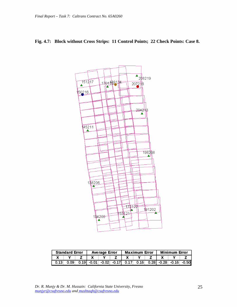
Final Report ndash Task 7 Caltrans Contract No 65A0260
Fig 47 Block without Cross Strips 11 Control Points 22 Check Points Case 8
SSttaannddaardrd EErrorrorr AAvveeraraggee EErrrroorr MMaaxxiimmuumm EErrorrorr MMiinniimmuumm EErrorrorr XX YY ZZ XX YY ZZ XX YY ZZ XX YY ZZ
001133 000099 001199 --000011 --000202 --001177 001177 001166 002288 --002828 --001166 --005050
Dr R Munjy amp Dr M Hussain California State University Fresno munjyrcsufresnoedu and mushtaqhcsufresnoedu
25
Final Report ndash Task 7 Caltrans Contract No 65A0260
Fig 48 Block without Cross Strips 11 Control Points 22 Check Points Case 9
SSttaannddaardrd EErrorrorr AAvveeraraggee EErrrroorr MMaaxxiimmuumm EErrorrorr MMiinniimmuumm EErrorrorr XX YY ZZ XX YY ZZ XX YY ZZ XX YY ZZ
001144 000099 002277 --000055 000033 --003131 001166 002020 003030 --003311 --001515 --006666
Dr R Munjy amp Dr M Hussain California State University Fresno munjyrcsufresnoedu and mushtaqhcsufresnoedu
26
Final Report ndash Task 7 Caltrans Contract No 65A0260
Fig 49 Block without Cross Strips 12 Control Points 21 Check Points Case 10
SSttaannddaardrd EErrorrorr AAvveeraraggee EErrrroorr MMaaxxiimmuumm EErrorrorr MMiinniimmuumm EErrorrorr XX YY ZZ XX YY ZZ XX YY ZZ XX YY ZZ 001133 000099 002200 --000022 000000 --000808 001166 001818 003131 --002277 --001616 --003333
Dr R Munjy amp Dr M Hussain California State University Fresno munjyrcsufresnoedu and mushtaqhcsufresnoedu
27
Final Report ndash Task 7 Caltrans Contract No 65A0260
Fig 410 Block without Cross Strips 14 Control Points 19 Check Points Case 11
SSttaannddaardrd EErrorrorr AAvveeraraggee EErrrroorr MMaaxxiimmuumm EErrorrorr MMiinniimmuumm EErrorrorr XX YY ZZ XX YY ZZ XX YY ZZ XX YY ZZ
001100 000088 001133 000044 --000022 --000303 001166 001515 002525 --002211 --001717 --002200
Dr R Munjy amp Dr M Hussain California State University Fresno munjyrcsufresnoedu and mushtaqhcsufresnoedu
28
Final Report ndash Task 7 Caltrans Contract No 65A0260
Fig 411 Block without Cross Strips 14 Control Points 19 Check Points Case 12
SSttaannddaardrd EErrorrorr AAvveeraraggee EErrrroorr MMaaxxiimmuumm EErrorrorr MMiinniimmuumm EErrorrorr XX YY ZZ XX YY ZZ XX YY ZZ XX YY ZZ
000099 000077 001122 --000011 --000101 000055 000099 001313 002828 --002255 --001414 --001122
Dr R Munjy amp Dr M Hussain California State University Fresno munjyrcsufresnoedu and mushtaqhcsufresnoedu
29
Final Report ndash Task 7 Caltrans Contract No 65A0260
5 ANALYSIS OF RESULTS amp CONCLUSIONS
In accordance with the Caltrans standards using wide-angle aerial photography the RMS error in each coordinate component of the adjusted tie points should not exceed 110000 of the flying height above the terrain The Del Mar Test Block was flown with a wideshyangle aerial camera from an average height of 1800 feet above the terrain level thereby resulting in an average photo scale of 13600 Consequently the limiting RMS error at the Check Points representative of a finite number of well distributed tie points in the block should not exceed 018 ft in this case Any error that exceeds three times this limiting value viz 054 ft in any of the coordinate components should be a cause for rejection of that point
Therefore the acceptable limiting values for the standard error at the Check Points is 018 ft in each coordinate component Any block adjustment solution that results in a coordinate error in one or more Check Points that exceeds 054 ft in any coordinate component would not be an acceptable solution The following analysis of the results is based on these accuracy criteria
51 Blocks With Cross Flights
When a minimal number of 8 control points are used (Fig 42) along the block perimeter the resulting standard error in Z-coordinate of 019 ft exceeds the limiting value of 015 ft It is also noticeable that the highest error in the Z-coordinate of 052 ft at Point 189134 almost equals the rejection limit of 054 ft This is an indication that controlling a cross flight with only a single Control Point at each end of the flight may not always provide a satisfactory solution
This situation can be remedied by using a pair of Control Points in each end model of a cross flight so that any deformation across the flight line the omega rotation () can also be controlled Such an approach is also reported to have been successfully used and recommended in the past [1] [2] [3] When 4 additional Control Points were added at the end of each cross flight line as is seen in Fig 43 all the standard errors fell within the acceptable range and the maximum coordinate error did not exceed 030 ft which is well within the acceptable criteria
The primary advantage of using airborne GPS data for the adjustment of aerial triangulation blocks is to completely eliminate the need for Control Points in the interior of the block But it is of interest to investigate how effectively the airborne GPS data alone can control the interior of the block Two separate blocks were processed by adding two Control Points in the interior of the block resulting in a total of 14 Control Points
The block with 14 Control Points (Case A) is shown in Fig 44 where the two interior Control Points were selected so that one Control Point was located on the opposite ends in each of the two interior flight lines (Line 2 and Line3 see Fig 41) The other block with 14 Control Points (Case B) is shown in Fig 45 In this case both the interior points
Dr R Munjy amp Dr M Hussain California State University Fresno munjyrcsufresnoedu and mushtaqhcsufresnoedu
30
Final Report ndash Task 7 Caltrans Contract No 65A0260
fell in the middle of the block interior It is interesting to note that in either of the two cases the addition of the interior Control Points did not result in any significant difference from the result achieved earlier while using 12 Control Points Therefore it may be concluded that as long as the cross flights are adequately controlled with a pair of Control Points located across each end model of each cross flight additional control in the block interior is not required The results shown in Fig 44 and 45 validate this conclusion at least for a block comprised of 18 models long multiple flight lines
52 Blocks Without Cross Flights
When a mapping project involves a large photogrammetric block consisting of hundreds of models the common practice is to plan the block configuration to include cross flights [1] [2] [6] [10] Often such cross flights can result in significant saving in time and effort in minimizing the need for ground control Since the photogrammetric mapping projects in Caltrans mostly involve mapping along highway corridors most of the photogrammetric blocks vary from a single flight line to up to as many as four flight lines Therefore it is still to be investigated whether the use of cross flight lines in such blocks offers any significant advantage Furthermore any advantage resulting from the reduced need for the ground control has to be weighed against the additional time and effort needed in processing the cross flight models The Caltrans Office of Photogrammetry has not yet adopted the use of Automated Aerial Triangulation (AAT) techniques for routine production Consequently the additional effort in transferring tie points between the cross flights with the flights of the main block is still significant This has provided the impetus to carry out the following investigation for the aerial triangulation adjustment of blocks that do not include any cross flights
The first block without the two cross flights was processed with only 8 Control points along the block perimeter as a parallel case with the block run with cross flights The results are shown in Fig 46 As may be expected the absence of any Control Point located at each end of each of the two interior flights 2 and 3 has resulted in unacceptably large errors Not only is the standard error of 059 ft in the Z-coordinate for the 25 Check Points too large but interestingly the block adjustment carries a large systematic error in Z-coordinate of 108 ft This results from the fact that the absence of the Control Points at each end of Flights 2 and 3 does not permit the adjustment for the systematic strip drift parameters for the airborne GPS data along Flights 2 and 3
When cross flights are included the airborne GPS data measured along the cross flight adequately serves as control for adjusting the strip shift and drift parameters Therefore an alternative to the inclusion of cross flights in the block configuration is to provide a Control Point at each end of every flight line in the block Accordingly the processing of the following blocks includes Control Points at the end of each flight line
The Del Mar Test Block with 4 flight lines each 18 models long would require a total of 12 Control Points one Control Point at each end of each flight line and 4 Control Points along the interior perimeter of the block to provide a control spacing of approximately 6 airbases apart However in order to minimize the use of the ground control the block
Dr R Munjy amp Dr M Hussain California State University Fresno munjyrcsufresnoedu and mushtaqhcsufresnoedu
31
Final Report ndash Task 7 Caltrans Contract No 65A0260
shown in Fig 47 was processed with only 11 Control Points (Case A) since the Control Point 170133 was measured both in Line 2 and Line 3 The resulting standard error of 019 ft in the Z-coordinate for 22 Check Points as well as the large error of 050 ft in the Z-coordinate of Check Point 189134 make the block adjustment solution unacceptable There appears to be no obvious reason why the Check Point 189134 that is located so close to the Control Point 170133 should display such unacceptably large error in the Zshycoordinate In order to ascertain the internal consistency of the ground control data (33 Control Points) a conventional aerial triangulation adjustment of the block was performed (without using the airborne GPS data) using 32 Control Points and treating the Control Point 189134 as a Check Point The resulting error in the Z-coordinate of Point 189134 was only 006 ft It is also to be noted that the average Z-coordinate error of 017 ft indicates a systematic height error This would lead to the conclusion that there is some height discrepancy between the ground control data and the airborne GPS data
The block was re-processed (Case B) again by using only 11 Control Points but this time the Control Point 170133 was replaced with Control Point 189134 and the results are displayed in Fig 48 The Case B results are even worse than the Case A results the standard error in Z-coordinate was degraded to 027 ft while the largest error in Zshycoordinate of 066 ft was noted at Check Point 187215 The average Z-coordinate error also increases to 031 ft This is a further indication that there is significant height inconsistency in the airborne GPS data and the ground control data It appears that the height discrepancy between the ground control data and the airborne GPS data results in an unsatisfactory shift and drift adjustment of the airborne GPS data particularly in the inner flight Lines 2 and 3 that span 18 models between the end Control Points
In order to strengthen the end control across the flight lines both the Control Points 170133 and 189134 were used at the Northern end of the block The block was then processed with 12 Control Points and the results are presented in Fig 49 Even though the results improved significantly but contrary to the expectation the standard error in the Z-coordinate of 020 ft for the 21 Check Points did not meet the Caltrans accuracy standard The next logical approach was to investigate the impact of adding Control Points in the interior of the block Two interior Control Points were selected in the same manner as has been described earlier in the case of the blocks with the cross flights (see Fig 44 and 45)
Using 14 Control Points the Case A is shown in Fig 410 while the Case B is presented in Fig 411 The results in both Case A and Case B easily meet the Caltrans accuracy standards In Case A the distance between the Control Points for the shift and drift parameter adjustment of the airborne GPS data varies from 6 to 12 models while in Case B the interior Control Points are about 6 models apart Each Control Point distribution provides almost similar results It is a clear indication that any systematic height deformation that results from the suspected inconsistency between the ground surveyed GPS data and the airborne GPS data can be kept within acceptable range by including a pair of control points in the interior of the block Such a need for some control points has not been reported for the adjustment of aerial triangulation blocks in the past However the largest photo scale for which any ABGPS supported results have been published in
Dr R Munjy amp Dr M Hussain California State University Fresno munjyrcsufresnoedu and mushtaqhcsufresnoedu
32
Final Report ndash Task 7 Caltrans Contract No 65A0260
the past is 14800 only For a photo scale of 13600 that is approximately 25 percent larger the requirements for the accuracy of aerial triangulation accordingly become more stringent in the same proportion This may generate the need for some additional control in the middle of the block
The residuals at the ground control points and in the image coordinate data along with the resulting standard error of unit weight (0) provide a reliable indication of the internal consistency of the adjusted block However the absolute accuracy of the aerial triangulation can be validated only by the use of Check Points that are well distributed over the entire block As pointed out earlier any deformations due to residual systematic shift and drift errors in the airborne GPS data are likely to be most significant in the center of the block the location that is farthest from the control points distributed along the perimeter Accordingly it would be advisable to locate at least a pair of Check Points in the middle of the block and after completing the block adjustment (by excluding these Check Points as Control Points) the coordinate discrepancies obtained at these Check Points can be analyzed Such discrepancies would normally represent the highest absolute accuracy resulting from aerial triangulation adjustment of the block Any unacceptably large coordinate discrepancies at the Check Points would require investigation of the block input data
In the case the coordinate discrepancies at the Check Points are within acceptable range the block can be re-processed by also including the Check Points in the control data This should enhance the accuracy in the interior of the block
6 RECOMMENDED DRAFT STANDARDS
These draft standards are proposed to supplement the existing Standards for Strip Configuration Airborne GPS Controlled Photogrammetry for Large Scale Mapping Projects (based on 13600 photo scale) currently used in Caltrans
61 Data Acquisition
611 Image Coordinate Data
Follow the existing practice used in Caltrans Office of Photogrammetry for the selection distribution and the measurement of all image point data It is recommended that raw machine coordinate image data should form the input to the aerial triangulation block adjustment
A secondary interest in this Research Project under contract with Caltrans was to also evaluate the alternate methodology of the selection and the measurement of tie point data using Automated Aerial Triangulation (AAT) system However several problems were encountered in implementing the AAT software available at the Caltrans Office of Photogrammetry in Sacramento The unavoidable delay caused by unfavorable weather conditions in acquiring the aerial imagery for the Del Mar Test Block did not allow
Dr R Munjy amp Dr M Hussain California State University Fresno munjyrcsufresnoedu and mushtaqhcsufresnoedu
33
Final Report ndash Task 7 Caltrans Contract No 65A0260
enough time to resolve the AAT software issues with software vendor Accordingly this task could not be fully completed Therefore it was mutually agreed between the Caltrans Office of Photogrammetry and California State University Fresno to concentrate research efforts on the processing and the analysis of the Del Mar Test Block and on drafting the Final Report
612 Ground Control Data
The proposed research is focused on the use of photography obtained at scale of 13600 for corridor mapping in Caltrans The ground control for mapping is based on the airborne GPS supported aerial triangulation of the photo blocks The ground control points should be surveyed to provide 15 to 2-times higher accuracy than that of the adjusted tie point data This would translate to an accuracy at the 005 to 01 ft level for the planimetric coordinates and the height an accuracy achievable using static GPS surveys tied to existing HPGN network
It is not yet certain that the Real-Time Kinematic (RTK) GPS field survey methodology whether relying on a single base station or on an RTK network is able to meet the above stringent field survey accuracy requirements Therefore the ground control data for ABGPS based aerial triangulation blocks should be based entirely on GPS control networks established using static GPS surveying methodology The RTK survey methodology for establishing control for photogrammetric mapping projects should not be used till such time that such technology has advanced to a level when consistently reliable results can be routinely expected
The GPS observations provide a fairly precise data for ellipsoidal height differences However all photogrammetric mapping has to be based on orthometric height data Two different approaches can be used in order to derive adjusted orthometric height data through aerial triangulation The first method is to carry out the simultaneous least squares adjustment of the GPS observation data for the ground control network using current Caltrans Horizontal Datum CCS83 (199135) and Vertical Datum NAVD 88 But since the observed data involves the measurement of ellipsoidal height differences for each measured baseline there is a need for transforming such differences to the corresponding orthometric height differences on NAVD 88 Datum In the absence of an existing Local Geoid Model the only economic recourse available to meet this need is to use the most reliable existing Global Geoid Model the time-consuming and prohibitively more costly alternative would be to connect the control network stations through differential leveling The Global Geoid Models are progressively being updated and the GEOID 2003 Model is most commonly in current use although GEOID 2009 Model may soon become available
It has to be noted that the use of a Global Geoid Model will always have some residual geoidal height uncertainties perhaps in the range of few hundredths of a foot It is therefore necessary that a few stations that are well distributed over the control network should have precisely known orthometric height values which can be used for the height adjustment of the network The minimum number of such orthometric height control
Dr R Munjy amp Dr M Hussain California State University Fresno munjyrcsufresnoedu and mushtaqhcsufresnoedu
34
Final Report ndash Task 7 Caltrans Contract No 65A0260
stations is three and consequently a network should be planned to have at least four and preferably more stations where orthometric height is precisely known In practice this requirement is met by including several existing benchmarks that are well distributed over the project area The redundancy provided by using more than three benchmarks will quantify the height residuals resulting from the adjustment This will provide a good estimate for the residual height errors in the network
The alternative approach is to carry out the adjustment of the GPS control network using WGS84 Geodetic Datum This datum is consistent with the observed GPS measurement data and a simultaneous 3D adjustment of the network can be performed in a Local Spatial Coordinate System (LSCS) the most commonly used approach is to shift the origin of the WGS84 coordinate system (center of the Earth) to approximately the center of the project site and apply a 3D rotational matrix to align the coordinate axes along the East North and Up directions Some commercial aerial triangulation software systems provide utilities to easily perform such datum transformation After the aerial triangulation results have been validated the coordinates of all the control and tie points can be transformed back to WGS 84 Datum Based on the availability of the orthometric height control stations a local Geoid can be defined ( a plane or a surface etc) and then used to transform the ellipsoidal height data to orthometric height data This second approach has the advantage that unlike the first method described above the residual height errors in the transformed control point height data are not propagated through aerial triangulation
For 13600 scale aerial photography blocks the ground control data should meet the a- priori standard deviation at 010 ft level This is not a very challenging demand for the horizontal positioning using GPS methodology However the residual height uncertainties in the orthometric height of control points interpolated from the Global Geoid Model become more critical as the photo scale becomes larger
613 Airborne GPS Data
The current practice used in Caltrans to acquire airborne GPS data during flight missions should continue to be used It is necessary to have GPS data collected at 1 Hz or higher rate at a base station that is located within or close to the project site Prior research completed collaboratively with Caltrans has already shown that the data at the base station may be substituted with GPS data collected at CORS at 5-sec or higher rate Consequently the collection of GPS data at more than one base stations is not considered as an essential requirement It may still be prudent to acquire GPS data at a second base station as a contingency safeguard against the GPS hardware failure at a base station for guaranteed success of the flight mission and expense
It is to be noted that the relative accuracy between successive airborne GPS antenna 3Dshycoordinates should be at 10-cm or higher level The current procedure used in Caltrans for the aircraft to remain stationary for static resolution of ambiguities before take off has mostly resulted in acquiring very reliable airborne GPS data This practice should perhaps be continued even though the continuing improvements in GPS hardware and
Dr R Munjy amp Dr M Hussain California State University Fresno munjyrcsufresnoedu and mushtaqhcsufresnoedu
35
Final Report ndash Task 7 Caltrans Contract No 65A0260
post-processing softwares are making on-the-fly (OTF) ambiguity resolution increasingly reliable However if it is necessary to resort to on-the-fly ambiguity resolution it must be ensured that the ambiguities have stabilized before photography is started The strict requirement for reliably resolving the ambiguities also does not permit the loss of lock during any single flight line If a loss of lock occurs during turns between flight lines ambiguities must be re-acquired and must stabilize before starting the collection of photography for another flight line Based on the make and the model of the airborne GPS receiver the Caltrans Office of Photogrammetry in consultation with the District Survey Section should draft a set of instructions for the GPSCamera operator aboard the aircraft specifying what parameters (such as PDOP Number of SVs etc) that need to be continuously monitored on a screen during a flight mission
62 Flight and Control Configuration
The following standards in planning the flight line configuration and the corresponding ground control distribution for Caltrans project are recommended to achieve optimum results
Control points are primarily required only along the perimeter of the block When a cross flight line is used to control the end of a block a pair of Control
Points must be located at each end of the cross flight At each end of a block that is not controlled by a cross flight a CP should be
located at the end of each parallel flight line a single CP may serve as end control for two adjacent overlapping flight lines
Along the perimeter of the block in a direction parallel with the main flight lines the CPs should be located at an average spacing of 6 airbases
Any corner in a block resulting from a sudden change in the length of two adjacent parallel flight lines should be controlled by an additional CP
Check Points should be provided along the interior flight lines in a multi-strip block The Check Points may be distributed along the interior flight lines so that any Check Point is not farther than about 8 airbases from either another Check Point (on same or adjacent flight line) or from a Control Point
Note that Caltrans is usually concerned with the mapping mostly along highway corridors and therefore does not require blocks with segments larger than three or four parallel flight lines Additional control along the cross flight line would be needed if such segments have 8 or more parallel flight lines
63 Data Processing and Adjustment
631 Processing of ABGPS Data
The current practice of post-processing ABGPS data used in Caltrans Office of Photogrammetry using GrafNav software should be continued The data should continue to be processed in the Forward and Backward modes A coordinate separation of less
Dr R Munjy amp Dr M Hussain California State University Fresno munjyrcsufresnoedu and mushtaqhcsufresnoedu
36
Final Report ndash Task 7 Caltrans Contract No 65A0260
than 10 cm especially in the height represents a normally acceptable range for the combined solution
This study has shown that the airborne GPS data in comparison with the ground control data should be weighted a lower weight but the highest weight that the GPS data quality represents Generally the best results were achieved when a-priori standard error of 015 ft was used for the airborne GPS coordinate data in comparison with the a-priori standard error of 010 ft used for the ground control coordinate data Since the 3-D position of successive points along the airborne GPS antenna trajectory are estimated using Kalman Filtering approach the successive location coordinates are highly correlated and consequently carry a much higher relative precision This provides a realistic justification for the use of a-priori standard error of 015 ft
632 Processing of Aerial Triangulation Block
Each aerial triangulation block requires the following data files as input
- Raw image coordinate data file - Ground control data file - Interpolated camera coordinate data file
Using the above input data files the block adjustment should be carried out in two steps as described below It is essential that additional Strip Shift and Drift parameters (3 Shift and 3 Drift parameters) should be incorporated in the bundle adjustment solution
Step 1 Minimal Control Adjustment
The preliminary simultaneous bundle adjustment of the block should be carried out by using the minimal amount of control points along the block perimeter only All the additional ground surveyed and targeted points should be treated as tie points to serve as Check Points The adjustment results should meet the following criteria
a The Standard Error of Unit Weight (0) should fall between 03 to 07 b The residual for any image coordinate should not exceed 15 micrometer c The RMS for ground control residuals should not exceed 110000 of the flying
height above the average terrain level d The maximum residual in any ground control coordinate should not exceed 25
times the RMS value permissible under Item (c) above e The RMS for discrepancy (difference between computed coordinate value and
the ground surveyed coordinate value) in Check Point coordinates should not exceed 110000 of the flying height above the average terrain level
f The discrepancy in any Check Point coordinate should not exceed 25 times the RMS value permissible under Item (e) above
If the above criteria are met even the preliminary adjustment solution for the block satisfies Caltrans accuracy standards for aerial triangulation If the criterion under Item
Dr R Munjy amp Dr M Hussain California State University Fresno munjyrcsufresnoedu and mushtaqhcsufresnoedu
37
Final Report ndash Task 7 Caltrans Contract No 65A0260
(f) above is not met the input data should be checked for any gross mistakes or errors in the ground control and Check Point data
Step 2 Full Control Adjustment
The final simultaneous bundle adjustment of the block should be carried out by including all the ground surveyed points (Control Points and Check Points) in the ground control data file The adjustment results should meet the following criteria
g The Standard Error of Unit Weight (0) should fall between 03 to 07 h The residual for any image coordinate should not exceed 15 micrometer i The RMS for ground control residuals should not exceed 110000 of the flying
height above the average terrain level j The maximum residual in any ground control coordinate should not exceed 25
times the RMS value permissible under Item (i) above
7 CONCLUDING COMMENTS
The completion of this project signifies the culmination of a very successful and productive combination of advanced theoretical principles with sound practical experience for the adaptation of evolving photogrammetric technologies in Caltrans practice In order to alleviate a growing concern for the safety of staff conducting field survey operations in close proximity of high speed traffic Caltrans in late 1990s decided to investigate the feasibility of using airborne GPS data for controlling the aerial triangulation blocks There were two primary issues to be resolved The first and the foremost concern was whether the use of airborne GPS data could be effectively used for controlling aerial triangulation blocks of as large a photo scale as 13000 used in Caltrans and still meet the Caltrans accuracy standards This concern was particularly critical since there had not been any reported use of airborne GPS data for such a large scale of aerial photography
Should the above investigation show that the Caltrans accuracy standards for aerial triangulation for 13000 scale aerial photography can be met it was of great interest to Caltrans to develop based on theoretically sound and systematic investigation a set of standards and specifications for the successful implementation of this new methodology in Caltrans routine practice
Under a Caltrans New Technology and Research Program currently Division of Research and Innovation (DRI) contract Caltrans Office of Photogrammetry partnered with a team of two faculty members from the Geomatic Engineering Program at the California State University Fresno (CSUF) in 1996 to carry out research to address the above two issues This partnership has flourished over the past several years through
Dr R Munjy amp Dr M Hussain California State University Fresno munjyrcsufresnoedu and mushtaqhcsufresnoedu
38
Final Report ndash Task 7 Caltrans Contract No 65A0260
successive research contracts and has resulted in very fortuitous outcomes based on the theoretical and analytical guidance provided by the CSUF research team and the highly skilled aerial survey project management and high caliber professional skills in the acquisition of photogrammetric data collection by the Caltrans Office of Photogrammetry In addition the help from highly experienced field survey teams from Caltrans various districts (especially District 11) in establishing GPS networks of Control Points and Check Points of specified precision was critical for the validation of airborne-GPS supported aerial triangulation investigations
As a result of the past collaborative efforts between the Caltrans Office of Photogrammetry and the CSUF Research Team the use of airborne GPS data for aerial triangulation has successfully been transitioned into Caltrans practice in the following stages
1) Based on a number of test flights it was convincingly demonstrated that the use of airborne GPS data consistently meets the Caltrans accuracy standards for aerial triangulation for strip configuration blocks at 13000 photo scale [13]
2) A detailed set of standards and specifications were developed for the implementing of the new methodology in Caltrans routine practice This was further supported through a training workshop conducted by CSUF at the Caltrans offices in Sacramento [8]
3) The use of airborne GPS data for the adjustment of aerial triangulation blocks requires the collection of GPS data at one or more ground base stations during the flight mission This requirement imposes burdensome demands on scheduling and allocation of manpower and equipment resources In order to reduce or even to completely eliminate the need for the collection of GPS data at base stations the use of GPS data collected and archived at a network of Continuously Operating Reference Stations (CORS) distributed over the State of California was investigated It was demonstrated that CORS data could be effectively used as a replacement for data collected at base stations while fulfilling Caltrans accuracy standards Accordingly specifications were revised to also include the selection and the use of CORS data for the post-processing of airborne GPS data to accurately derive the trajectory of the airborne GPS antenna during flights [19]
4) During the past few years Caltrans has increasingly been using multi-strip projects for mapping using 13600 photo scale This provided the need for the current research study The successful completion of this study has resulted in supplementing the existing standards and specifications for airborne GPS supported single-strip aerial triangulation blocks to also include the aerial triangulation of multi-strip blocks
It is a matter of great satisfaction for the research team at CSU Fresno that working hand in hand with the Caltrans Office of Photogrammetry the comprehensive set of standards and specifications for airborne GPS supported aerial triangulation that had been developed for successful transition of this technology in Caltrans practice have been further upgraded It is hoped that as the photogrammetric technology advances further
Dr R Munjy amp Dr M Hussain California State University Fresno munjyrcsufresnoedu and mushtaqhcsufresnoedu
39
Final Report ndash Task 7 Caltrans Contract No 65A0260
similar collaborative efforts between Caltrans Office of Photogrammetry and CSU Fresno will continue to address the changing needs in Caltrans
Dr R Munjy amp Dr M Hussain California State University Fresno munjyrcsufresnoedu and mushtaqhcsufresnoedu
40
Final Report ndash Task 7 Caltrans Contract No 65A0260
REFERENCES
1 Abdullah Q M Hussain and R Munjy (2002) Workshop on Airborne GPS-Supported Aerial Triangulation ndash Theory and Practical Concepts presented at the Annual ASPRS Convention Washington DC 2002
2 Ackermann Fritz (1992) Operational Rules and Accuracy Models for GPS-Aerotriangulation Archives of the ISPRS Com 1 Vol29 1992 [pp 691-700]
3 Ackermann F (1993) Application of GPS for Aerial Triangulation Photogrammetric Engineering and Remote Sensing Vol 59 No 11 [pp 1651shy1658]
4 Appleton James Mushtaq Hussain and Riadh Munjy (2000) Use of Airborne GPS Data for Highway Mapping International Archives of Photogrammetry and Remote Sensing Vol XXXIII Part B4 Amsterdam 2000[pp 84-90]
5 Appleton James M Hussain and R Munjy (2002) Use of Airborne GPS Data For Aerial Triangulation in Caltrans (2002) Workshop presented at the California Department of Transportation Sacramento 2002
6 Federal Geographic Data Committee (FGDC) 1998 Geospatial Positional Accuracy Standards Part-3 National Standards for Spatial Data Accuracy (NSSDA) FGDC-STD-0073-1998
7 Friess Peter (1992) Experiences with GPS-Supported Aerial Triangulation Archives of the ISPRS Com 1 Vol29 1992 [pp 299 - 305]
8 Gianellia Alexander M (1995) Practical Considerations in Implementing GPS Technologies in Airborne Data Collection Proc ASPRS Annual Convention 1995 [pp 917-925]
9 Hussain M R Munjy and J Appleton (1999) Use of Airborne On-the-Fly Kinematic GPS Data for Photogrammetric Mapping Proceedings ION-GPS-99 Conference Nashville 1999[pp 1653-1659]
10 Hussain M and R Munjy (1999) GPS Controlled Photogrammetry For Large Scale Mapping (1999) Final Project Report Research project No 65Y271 submitted to New Technology amp Research Program California Department of Transportation
11 Hussain M and R Munjy (2002) Airborne GPS Controlled Aerial Triangulation in Caltrans Final Project Report Research project No 65A0059 submitted to New Technology amp Research Program California Department of Transportation June 2002
12 Munjy R and M Hussain (1985) Interactive Simultaneous Bundle Block Adjustment System (ISBBA) for Small Computers Proceedings of the ASPRS Annual Convention Washington DC 1985
13 Munjy R M Hussain and James Appleton (2000) Use of Airborne GPS Data for Corridor Mapping presented at the Annual ASPRS Convention Washington DC 2000
Dr R Munjy amp Dr M Hussain California State University Fresno munjyrcsufresnoedu and mushtaqhcsufresnoedu
41
Final Report ndash Task 7 Caltrans Contract No 65A0260
14 Munjy R and M Hussain (2007) Develop Criteria for Using Network GPS for Airborne GPS Photogrammetry Final Project Report Research Project No 65A0234 submitted to the Division of Research and Innovation (DRI) California Department of Transportation
15 Munjy R and M Hussain (2009) Draft Preliminary Standards Interim Report Research Project No 65A0260 submitted to Division of Research aned Innovation (DRI) California Department of Transportation
Dr R Munjy amp Dr M Hussain California State University Fresno munjyrcsufresnoedu and mushtaqhcsufresnoedu
42
APPENDIX I Results of Check Block
Flight amp Control Configuration Cases Used for
Study amp Analysis of Check Project in San Diego
INDEX
Case Block amp Control Configuration 1 Full Blk(Flts1to9) All 44 CP 2 Full Blk 8 CP 3 Full Blk 9 CP 4 Full Blk 10 CP 5 Main Blk(Flts1to7) 43 CP 6 Main Blk(Flts1to7) 8 CP 7 Main Blk(Flts1to7) 10 CP 8 Main Blk(Flts1to7) 12 CP 9 North Blk(Flts567amp9) 5 CP 10 North Blk(Flts567amp9) 7 CP 11 North Blk(Flts56amp7) 6 CP 12 North Blk(Flts56amp7) 8 CP 13 South Blk(Flts1to4amp8) 4 CP 14 South Blk(Flts1to4amp8) 6 CP 15 South Blk(Flts1to4amp8) 7 CP 16 South Blk(Flts1to4) 7 CP 17 South Blk(Flts1to4) 8 CP(a) 18 South Blk(Flts1to4) 8 CP(b) 19 South Blk(Flts1to4) 10 CP 20 South Blk(Flts1to4) 11 CP 21 South Blk(Flts Modified 1to4 amp8) 5 CP 22 South Blk(Flts Modified 1to4 ) 6 CP
[Refer to Table-1 Summary of the Coordinate Differences at the Check Points]
I-i
Case-1 Base DataFULL BLOCK
Flts 1 to 9
Case-1 Base Data FULL BLOCK
Flts 1 to 9
Control PointsControl Points All 44 PointsAll 44 Points
SSSttt ErErErrrr AAAvvvggg ErErErrrr MMMaaaxxx ErErErrrr MMMiiinnn ErErErrrr XXX YYY ZZZ XXX YYY ZZZ XXX YYY ZZZ XXX YYY ZZZ
007 008 005 000 000 000 019 012 012 -013 -023 -013007 008 005 000 000 000 019 012 012 -013 -023 -013007 008 005 000 000 000 019 012 012 -013 -023 -013
I-ii
Case-2FULL BLOCK
Flts 1 to 9
Control Points 8
Case-2 FULL BLOCK
Flts 1 to 9
Control Points 8 CChheecckk PoPointsints 3366
SStt ErErrr AAvvgg ErErrr MMaaxx ErErrr MMinin ErErrr XX YY ZZ XX YY ZZ XX YY ZZ XX YY ZZ
012012 012012 016016 002002 001001 --000505 024024 027027 026026 --025025 --039039 --032032
I-iii
Case-3FULL BLOCK
Flts 1 to 9
Control Points 9
Case-3 FULL BLOCK
Flts 1 to 9
Control Points 9 CChheecckk PoPointsints 3355
SStt ErErrr AAvvgg ErErrr MMaaxx ErErrr MMinin ErErrr XX YY ZZ XX YY ZZ XX YY ZZ XX YY ZZ
012012 012012 017017 001001 --001001 --000808 024024 024024 026026 --026026 --040040 --034034
I-iv
Case-4FULL BLOCK
Flts 1 to 9
Control Points 10
Case-4 FULL BLOCK
Flts 1 to 9
Control Points 10 CChheecckk PoiPoinntsts 3344
SStt ErErrr AAvvgg ErErrr MMaaxx ErErrr MMinin ErErrr XX YY ZZ XX YY ZZ XX YY ZZ XX YY ZZ
012012 009009 015015 003003 005005 --000909 002244 002727 002121 --025025 --001313 --035035
I-v
Case-5MAIN BLOCK
Flts 1 to 7
Control Points 43
Case-5 MAIN BLOCK
Flts 1 to 7
Control Points 43 [Point HV-117 Unuse[Point HV-117 Unusedd]]
SSSttt ErErErrrr AAAvvvggg ErErErrrr MMM aaaxxx ErErErrrr MMM iiinnn ErErErrrr XXX YYY ZZZ XXX YYY ZZZ XXX YYY ZZZ XXX YYY ZZZ
006006006 008008008 005005005 000000000 000000000 000000000 012012012 013013013 013013013 ---000131313 ---022022022 ---000090909
I-vi
Case-6
Flts 1 to 7
l Points 8
MAIN BLOCK
[No Cross Flts]Contro
Case-6 MAIN BLOCK
Flts 1 to 7 [No Cross Flts]
Control Points 8 ChecCheckk PoPointsints 3636
St ErSt ErSt ErSt ErSt ErSt ErSt ErSt Errrrrrrrr AAAAAAAAvgvgvgvgvgvgvgvg ErErErErErErErErrrrrrrrr MMMMMMMMaxaxaxaxaxaxaxax ErErErErErErErErrrrrrrrr MMMMMMMMiiiiiiiinnnnnnnn ErErErErErErErErrrrrrrrr XXXXXXXX YYYYYYYY ZZZZZZZZ XXXXXXXX YYYYYYYY ZZZZZZZZ XXXXXXXX YYYYYYYY ZZZZZZZZ XXXXXXXX YYYYYYYY ZZZZZZZZ
016016016016 012012012012 027027027027 -002-002-002-002 ----004004004004 -004-004-004-004 000026262626 000020202020 000041414141 ----035035035035 -036-036-036-036 ----082082082082
I-vii
Case-7MAIN BLOCK
Flts 1 to 7[No Cross Flts]
Control Points 10
Case-7 MAIN BLOCK
Flts 1 to 7 [No Cross Flts]
Control Points 10 CChheecckk PointsPoints 3434
SStt ErErrr AAvvgg ErErrr MM aaxx ErErrr MM iinn ErErrr XX YY ZZ XX YY ZZ XX YY ZZ XX YY ZZ
014 012 027 -001 -003 -004 022 020 039 -031 -031 -080014 012 027 -001 -003 -004 022 020 039 -031 -031 -080
I-viii
Case-8MAIN BLOCK
Flts 1 to 7[No Cross Flts]
Control Points 12
Case-8 MAIN BLOCK
Flts 1 to 7 [No Cross Flts]
Control Points 12 CheChecckk PointsPoints 3232
SSSttt ErErErrrr AAAvvvggg ErErErrrr MMMaaaxxx ErErErrrr MMMiiinnn ErErErrrr XXX YYY ZZZ XXX YYY ZZZ XXX YYY ZZZ XXX YYY ZZZ
015 010 017 003 000 -004 037 016 035 -031 -027 -023015 010 017 003 000 -004 037 016 035 -031 -027 -023015 010 017 003 000 -004 037 016 035 -031 -027 -023
I-ix
Case-9Case-9Case-9 NORNORNORTTTH BLH BLH BLOCKOCKOCK
FltsFltsFlts 5 to 7 amp 9 5 to 7 amp 9 5 to 7 amp 9
Control PointsControl PointsControl Points 555 ChChCheckeckeck PoPoPoininintttsss 111888
ErSSSttt EE rrrrr vg ErAAAvg Evg E rrrrr ax ErMMM ax Eax E rrrrr ErMMM iiinnn EE rrrrr XXX YYY ZZZ XXX YYY ZZZ XXX YYY ZZZ XXX YYY ZZZ
000121212 016016016 000161616 007007007 ---000161616 000111111 000262626 000020202 000363636 ---022022022 ---000626262 ---022022022
I-x
Case-Case-1100 NORTH BLOCKNORTH BLOCK
Flts 5 to 7 amp 9Flts 5 to 7 amp 9
Control PointsControl Points 77 CheckCheck PointsPoints 1616
SStt ErErrr AAvvgg ErErrr MM aaxx ErErrr MM iinn ErErrr XX YY ZZ XX YY ZZ XX YY ZZ XX YY ZZ
010010 016016 017017 008008 --000707 001818 002323 001010 005151 --016016 --005151 --012012
I-xi
Case-Case-1111 NORTH BLOCKNORTH BLOCK
FltsFlts 5 to 7 5 to 7
CCoontrntrool Pointsl Points 66 CheChecckk PointsPoints 1717
SStt ErErrr AAvvgg ErErrr MM aaxx ErErrr MM iinn ErErrr XX YY ZZ XX YY ZZ XX YY ZZ XX YY ZZ
010010 016016 022022 010010 --000202 000808 002424 001515 005050 --019019 --004343 --026026
I-xii
Case-Case-1122 NORTH BLOCKNORTH BLOCK
FltsFlts 5 to 7 5 to 7 [No C[No Crrossoss Flt]Flt]
ContControl Poinrol Pointsts 88 CChheecckk PointsPoints 1155
SStt EErrrr AAvg Evg Errrr MM ax Eax Errrr MM iinn EErrrr XX YY ZZ XX YY ZZ XX YY ZZ XX YY ZZ
011011 016016 017017 013013 --000909 000202 002929 000707 003737 --017017 --004949 --031031
I-xiii
CaseCase-13-13 SOUTSOUTH BH BLLOCKOCK
Flts 1 to 4 amp 8Flts 1 to 4 amp 8
CoConnttrol Porol Poininttss 44 ChCheckeck PPooinintsts 2222
SStt ErErrr AAvvgg ErErrr MM aaxx ErErrr MM iinn ErErrr XX YY ZZ XX YY ZZ XX YY ZZ XX YY ZZ
052 032 015 -082 033 003 -007 091 026 -149 -009 -034052 032 015 -082 033 003 -007 091 026 -149 -009 -034
I-xiv
Case-14Case-14 SOUTH BLOCKSOUTH BLOCK
Flts 1 to 4 amp 8Flts 1 to 4 amp 8
CCoontrntrool Pointsl Points 66 CheChecckk PointsPoints 2200
SStt ErErrr AAvvgg ErErrr MM aaxx ErErrr MM iinn ErErrr XX YY ZZ XX YY ZZ XX YY ZZ XX YY ZZ
013 016 015 -003 006 -002 024 033 033 -019 -028 -028013 016 015 -003 006 -002 024 033 033 -019 -028 -028
I-xv
Case-15Case-15 SOUTH BLOCKSOUTH BLOCK
FltsFlts 1 to 4 amp 8 1 to 4 amp 8
ContrControol Pointsl Points 77 ChCheckeck PPooinintsts 1919
SStt ErErrr AAvvgg ErErrr MM aaxx ErErrr MM iinn ErErrr XX YY ZZ XX YY ZZ XX YY ZZ XX YY ZZ
015 012 014 -003 -002 -002 025 023 033 -025 -030 -025015 012 014 -003 -002 -002 025 023 033 -025 -030 -025
I-xvi
Case-16Case-16Case-16 SOUTH BLOCKSOUTH BLOCKSOUTH BLOCK
FltsFltsFlts 1 to 4 1 to 4 1 to 4 [No Cross Flt][No Cross Flt][No Cross Flt]
Control PointsControl PointsControl Points 777 CheCheCheccckkk PointsPointsPoints 222222
SSSttt EEErrrrrr AAAvg Evg Evg Errrrrr MMM ax Eax Eax Errrrrr MMM iiinnn EEErrrrrr XXX YYY ZZZ XXX YYY ZZZ XXX YYY ZZZ XXX YYY ZZZ
015 013 023 -001 -005 003 026 023 032 -027 -029 -037015 013 023 -001 -005 003 026 023 032 -027 -029 -037015 013 023 -001 -005 003 026 023 032 -027 -029 -037
I-xvii
Case-17Case-17 SOUTSOUTH BLH BLOCKOCK
FltsFlts 1 1 to 4to 4 [No[No CrosCrosss Flt]Flt]
ContrControol Pointsl Points 88 CChheecckk PointsPoints 2121
SStt ErErrr AAvvgg ErErrr MM aaxx ErErrr MM iinn ErErrr XX YY ZZ XX YY ZZ XX YY ZZ XX YY ZZ
014014 012012 024024 005005 --000101 000404 003131 002525 003333 --022022 --002929 --040040
I-xviii
Case-18Case-18 SOUTH BLOCKSOUTH BLOCK
Flts 1 to 4Flts 1 to 4 [[NNo Cro Crooss Fss Flltt]]
CCoontrol Pointsntrol Points 88 CheChecckk PointsPoints 2121
SSSttt ErErErrrr AAAvvvggg ErErErrrr MMM aaaxxx ErErErrrr MMM iiinnn ErErErrrr XXX YYY ZZZ XXX YYY ZZZ XXX YYY ZZZ XXX YYY ZZZ
016 014 019 -003 -005 001 027 025 028 -033 -033 -032016 014 019 -003 -005 001 027 025 028 -033 -033 -032016 014 019 -003 -005 001 027 025 028 -033 -033 -032
I-xix
Case-19Case-19 SOUTH BLOCKSOUTH BLOCK
FltsFlts 1 to 4 1 to 4 [No Cross Flt][No Cross Flt]
ContControl Prol Poointintss 10 10 CheckCheck PointsPoints 1919
SSSttt ErErErrrr AAAvvvggg ErErErrrr MMM aaaxxx ErErErrrr MMM iiinnn ErErErrrr XXX YYY ZZZ XXX YYY ZZZ XXX YYY ZZZ XXX YYY ZZZ
014 012 019 004 -001 001 034 029 029 -025 -030 -028014 012 019 004 -001 001 034 029 029 -025 -030 -028014 012 019 004 -001 001 034 029 029 -025 -030 -028
I-xx
Case-Case-2200 SSOOUTH BLOCKUTH BLOCK
FltsFlts 1 to 4 1 to 4 [No Cross Flt][No Cross Flt]
Control Points 11Control Points 11 ChCheckeck PPooinintsts 1818
SSSttt ErErErrrr AAAvvvggg ErErErrrr MMM aaaxxx ErErErrrr MMM iiinnn ErErErrrr XXX YYY ZZZ XXX YYY ZZZ XXX YYY ZZZ XXX YYY ZZZ
014014014 012012012 018018018 ---000010101 ---005005005 ---000010101 000232323 000202020 000272727 ---030030030 ---000292929 ---031031031
I-xxi
Case-Case-2211 MODIMODIFFIIED SOUTH BED SOUTH BLLOCKOCK
FltsFlts 1 to 4 ( 1 to 4 (MModified)odified) amp 8amp 8
ControControl Pointsl Points 55 CheChecckk PointsPoints 1818
SStt ErErrr AAvvgg ErErrr MM aaxx ErErrr MM iinn ErErrr XX YY ZZ XX YY ZZ XX YY ZZ XX YY ZZ
013 010 015 -001 002 -001 024 021 035 -019 -025 -029013 010 015 -001 002 -001 024 021 035 -019 -025 -029
I-xxii
Case-22Case-22Case-22 MOMOMODIFDIFDIFIIIED SOED SOED SOUTH BLOCKUTH BLOCKUTH BLOCK
FltFltFltsss 1 to 4 1 to 4 1 to 4 (M(M(Modiodiodifiefiefieddd))) [No C[No C[No Crrrososossss Flt]Flt]Flt]
ConConContttrol Prol Prol Poooiiinnntttsss 666 ChChCheckeckeck PointPointPointsss 161616
SSSttt ErErErrrr AAAvvvggg ErErErrrr MMM aaaxxx ErErErrrr MMM iiinnn ErErErrrr XXX YYY ZZZ XXX YYY ZZZ XXX YYY ZZZ XXX YYY ZZZ
014 011 014 002 005 -010 025 024 016 -020 -024 -039014 011 014 002 005 -010 025 024 016 -020 -024 -039014 011 014 002 005 -010 025 024 016 -020 -024 -039
I-xxiii
APPENDIX II Results of Test Block
II-i
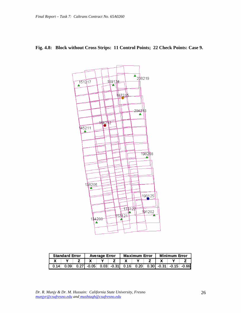
Final Report ndash Task 7 Caltrans Contract No 65A0260
Fig 48 Block without Cross Strips 11 Control Points 22 Check Points Case 9
SSttaannddaardrd EErrorrorr AAvveeraraggee EErrrroorr MMaaxxiimmuumm EErrorrorr MMiinniimmuumm EErrorrorr XX YY ZZ XX YY ZZ XX YY ZZ XX YY ZZ
001144 000099 002277 --000055 000033 --003131 001166 002020 003030 --003311 --001515 --006666
Dr R Munjy amp Dr M Hussain California State University Fresno munjyrcsufresnoedu and mushtaqhcsufresnoedu
26
Final Report ndash Task 7 Caltrans Contract No 65A0260
Fig 49 Block without Cross Strips 12 Control Points 21 Check Points Case 10
SSttaannddaardrd EErrorrorr AAvveeraraggee EErrrroorr MMaaxxiimmuumm EErrorrorr MMiinniimmuumm EErrorrorr XX YY ZZ XX YY ZZ XX YY ZZ XX YY ZZ 001133 000099 002200 --000022 000000 --000808 001166 001818 003131 --002277 --001616 --003333
Dr R Munjy amp Dr M Hussain California State University Fresno munjyrcsufresnoedu and mushtaqhcsufresnoedu
27
Final Report ndash Task 7 Caltrans Contract No 65A0260
Fig 410 Block without Cross Strips 14 Control Points 19 Check Points Case 11
SSttaannddaardrd EErrorrorr AAvveeraraggee EErrrroorr MMaaxxiimmuumm EErrorrorr MMiinniimmuumm EErrorrorr XX YY ZZ XX YY ZZ XX YY ZZ XX YY ZZ
001100 000088 001133 000044 --000022 --000303 001166 001515 002525 --002211 --001717 --002200
Dr R Munjy amp Dr M Hussain California State University Fresno munjyrcsufresnoedu and mushtaqhcsufresnoedu
28
Final Report ndash Task 7 Caltrans Contract No 65A0260
Fig 411 Block without Cross Strips 14 Control Points 19 Check Points Case 12
SSttaannddaardrd EErrorrorr AAvveeraraggee EErrrroorr MMaaxxiimmuumm EErrorrorr MMiinniimmuumm EErrorrorr XX YY ZZ XX YY ZZ XX YY ZZ XX YY ZZ
000099 000077 001122 --000011 --000101 000055 000099 001313 002828 --002255 --001414 --001122
Dr R Munjy amp Dr M Hussain California State University Fresno munjyrcsufresnoedu and mushtaqhcsufresnoedu
29
Final Report ndash Task 7 Caltrans Contract No 65A0260
5 ANALYSIS OF RESULTS amp CONCLUSIONS
In accordance with the Caltrans standards using wide-angle aerial photography the RMS error in each coordinate component of the adjusted tie points should not exceed 110000 of the flying height above the terrain The Del Mar Test Block was flown with a wideshyangle aerial camera from an average height of 1800 feet above the terrain level thereby resulting in an average photo scale of 13600 Consequently the limiting RMS error at the Check Points representative of a finite number of well distributed tie points in the block should not exceed 018 ft in this case Any error that exceeds three times this limiting value viz 054 ft in any of the coordinate components should be a cause for rejection of that point
Therefore the acceptable limiting values for the standard error at the Check Points is 018 ft in each coordinate component Any block adjustment solution that results in a coordinate error in one or more Check Points that exceeds 054 ft in any coordinate component would not be an acceptable solution The following analysis of the results is based on these accuracy criteria
51 Blocks With Cross Flights
When a minimal number of 8 control points are used (Fig 42) along the block perimeter the resulting standard error in Z-coordinate of 019 ft exceeds the limiting value of 015 ft It is also noticeable that the highest error in the Z-coordinate of 052 ft at Point 189134 almost equals the rejection limit of 054 ft This is an indication that controlling a cross flight with only a single Control Point at each end of the flight may not always provide a satisfactory solution
This situation can be remedied by using a pair of Control Points in each end model of a cross flight so that any deformation across the flight line the omega rotation () can also be controlled Such an approach is also reported to have been successfully used and recommended in the past [1] [2] [3] When 4 additional Control Points were added at the end of each cross flight line as is seen in Fig 43 all the standard errors fell within the acceptable range and the maximum coordinate error did not exceed 030 ft which is well within the acceptable criteria
The primary advantage of using airborne GPS data for the adjustment of aerial triangulation blocks is to completely eliminate the need for Control Points in the interior of the block But it is of interest to investigate how effectively the airborne GPS data alone can control the interior of the block Two separate blocks were processed by adding two Control Points in the interior of the block resulting in a total of 14 Control Points
The block with 14 Control Points (Case A) is shown in Fig 44 where the two interior Control Points were selected so that one Control Point was located on the opposite ends in each of the two interior flight lines (Line 2 and Line3 see Fig 41) The other block with 14 Control Points (Case B) is shown in Fig 45 In this case both the interior points
Dr R Munjy amp Dr M Hussain California State University Fresno munjyrcsufresnoedu and mushtaqhcsufresnoedu
30
Final Report ndash Task 7 Caltrans Contract No 65A0260
fell in the middle of the block interior It is interesting to note that in either of the two cases the addition of the interior Control Points did not result in any significant difference from the result achieved earlier while using 12 Control Points Therefore it may be concluded that as long as the cross flights are adequately controlled with a pair of Control Points located across each end model of each cross flight additional control in the block interior is not required The results shown in Fig 44 and 45 validate this conclusion at least for a block comprised of 18 models long multiple flight lines
52 Blocks Without Cross Flights
When a mapping project involves a large photogrammetric block consisting of hundreds of models the common practice is to plan the block configuration to include cross flights [1] [2] [6] [10] Often such cross flights can result in significant saving in time and effort in minimizing the need for ground control Since the photogrammetric mapping projects in Caltrans mostly involve mapping along highway corridors most of the photogrammetric blocks vary from a single flight line to up to as many as four flight lines Therefore it is still to be investigated whether the use of cross flight lines in such blocks offers any significant advantage Furthermore any advantage resulting from the reduced need for the ground control has to be weighed against the additional time and effort needed in processing the cross flight models The Caltrans Office of Photogrammetry has not yet adopted the use of Automated Aerial Triangulation (AAT) techniques for routine production Consequently the additional effort in transferring tie points between the cross flights with the flights of the main block is still significant This has provided the impetus to carry out the following investigation for the aerial triangulation adjustment of blocks that do not include any cross flights
The first block without the two cross flights was processed with only 8 Control points along the block perimeter as a parallel case with the block run with cross flights The results are shown in Fig 46 As may be expected the absence of any Control Point located at each end of each of the two interior flights 2 and 3 has resulted in unacceptably large errors Not only is the standard error of 059 ft in the Z-coordinate for the 25 Check Points too large but interestingly the block adjustment carries a large systematic error in Z-coordinate of 108 ft This results from the fact that the absence of the Control Points at each end of Flights 2 and 3 does not permit the adjustment for the systematic strip drift parameters for the airborne GPS data along Flights 2 and 3
When cross flights are included the airborne GPS data measured along the cross flight adequately serves as control for adjusting the strip shift and drift parameters Therefore an alternative to the inclusion of cross flights in the block configuration is to provide a Control Point at each end of every flight line in the block Accordingly the processing of the following blocks includes Control Points at the end of each flight line
The Del Mar Test Block with 4 flight lines each 18 models long would require a total of 12 Control Points one Control Point at each end of each flight line and 4 Control Points along the interior perimeter of the block to provide a control spacing of approximately 6 airbases apart However in order to minimize the use of the ground control the block
Dr R Munjy amp Dr M Hussain California State University Fresno munjyrcsufresnoedu and mushtaqhcsufresnoedu
31
Final Report ndash Task 7 Caltrans Contract No 65A0260
shown in Fig 47 was processed with only 11 Control Points (Case A) since the Control Point 170133 was measured both in Line 2 and Line 3 The resulting standard error of 019 ft in the Z-coordinate for 22 Check Points as well as the large error of 050 ft in the Z-coordinate of Check Point 189134 make the block adjustment solution unacceptable There appears to be no obvious reason why the Check Point 189134 that is located so close to the Control Point 170133 should display such unacceptably large error in the Zshycoordinate In order to ascertain the internal consistency of the ground control data (33 Control Points) a conventional aerial triangulation adjustment of the block was performed (without using the airborne GPS data) using 32 Control Points and treating the Control Point 189134 as a Check Point The resulting error in the Z-coordinate of Point 189134 was only 006 ft It is also to be noted that the average Z-coordinate error of 017 ft indicates a systematic height error This would lead to the conclusion that there is some height discrepancy between the ground control data and the airborne GPS data
The block was re-processed (Case B) again by using only 11 Control Points but this time the Control Point 170133 was replaced with Control Point 189134 and the results are displayed in Fig 48 The Case B results are even worse than the Case A results the standard error in Z-coordinate was degraded to 027 ft while the largest error in Zshycoordinate of 066 ft was noted at Check Point 187215 The average Z-coordinate error also increases to 031 ft This is a further indication that there is significant height inconsistency in the airborne GPS data and the ground control data It appears that the height discrepancy between the ground control data and the airborne GPS data results in an unsatisfactory shift and drift adjustment of the airborne GPS data particularly in the inner flight Lines 2 and 3 that span 18 models between the end Control Points
In order to strengthen the end control across the flight lines both the Control Points 170133 and 189134 were used at the Northern end of the block The block was then processed with 12 Control Points and the results are presented in Fig 49 Even though the results improved significantly but contrary to the expectation the standard error in the Z-coordinate of 020 ft for the 21 Check Points did not meet the Caltrans accuracy standard The next logical approach was to investigate the impact of adding Control Points in the interior of the block Two interior Control Points were selected in the same manner as has been described earlier in the case of the blocks with the cross flights (see Fig 44 and 45)
Using 14 Control Points the Case A is shown in Fig 410 while the Case B is presented in Fig 411 The results in both Case A and Case B easily meet the Caltrans accuracy standards In Case A the distance between the Control Points for the shift and drift parameter adjustment of the airborne GPS data varies from 6 to 12 models while in Case B the interior Control Points are about 6 models apart Each Control Point distribution provides almost similar results It is a clear indication that any systematic height deformation that results from the suspected inconsistency between the ground surveyed GPS data and the airborne GPS data can be kept within acceptable range by including a pair of control points in the interior of the block Such a need for some control points has not been reported for the adjustment of aerial triangulation blocks in the past However the largest photo scale for which any ABGPS supported results have been published in
Dr R Munjy amp Dr M Hussain California State University Fresno munjyrcsufresnoedu and mushtaqhcsufresnoedu
32
Final Report ndash Task 7 Caltrans Contract No 65A0260
the past is 14800 only For a photo scale of 13600 that is approximately 25 percent larger the requirements for the accuracy of aerial triangulation accordingly become more stringent in the same proportion This may generate the need for some additional control in the middle of the block
The residuals at the ground control points and in the image coordinate data along with the resulting standard error of unit weight (0) provide a reliable indication of the internal consistency of the adjusted block However the absolute accuracy of the aerial triangulation can be validated only by the use of Check Points that are well distributed over the entire block As pointed out earlier any deformations due to residual systematic shift and drift errors in the airborne GPS data are likely to be most significant in the center of the block the location that is farthest from the control points distributed along the perimeter Accordingly it would be advisable to locate at least a pair of Check Points in the middle of the block and after completing the block adjustment (by excluding these Check Points as Control Points) the coordinate discrepancies obtained at these Check Points can be analyzed Such discrepancies would normally represent the highest absolute accuracy resulting from aerial triangulation adjustment of the block Any unacceptably large coordinate discrepancies at the Check Points would require investigation of the block input data
In the case the coordinate discrepancies at the Check Points are within acceptable range the block can be re-processed by also including the Check Points in the control data This should enhance the accuracy in the interior of the block
6 RECOMMENDED DRAFT STANDARDS
These draft standards are proposed to supplement the existing Standards for Strip Configuration Airborne GPS Controlled Photogrammetry for Large Scale Mapping Projects (based on 13600 photo scale) currently used in Caltrans
61 Data Acquisition
611 Image Coordinate Data
Follow the existing practice used in Caltrans Office of Photogrammetry for the selection distribution and the measurement of all image point data It is recommended that raw machine coordinate image data should form the input to the aerial triangulation block adjustment
A secondary interest in this Research Project under contract with Caltrans was to also evaluate the alternate methodology of the selection and the measurement of tie point data using Automated Aerial Triangulation (AAT) system However several problems were encountered in implementing the AAT software available at the Caltrans Office of Photogrammetry in Sacramento The unavoidable delay caused by unfavorable weather conditions in acquiring the aerial imagery for the Del Mar Test Block did not allow
Dr R Munjy amp Dr M Hussain California State University Fresno munjyrcsufresnoedu and mushtaqhcsufresnoedu
33
Final Report ndash Task 7 Caltrans Contract No 65A0260
enough time to resolve the AAT software issues with software vendor Accordingly this task could not be fully completed Therefore it was mutually agreed between the Caltrans Office of Photogrammetry and California State University Fresno to concentrate research efforts on the processing and the analysis of the Del Mar Test Block and on drafting the Final Report
612 Ground Control Data
The proposed research is focused on the use of photography obtained at scale of 13600 for corridor mapping in Caltrans The ground control for mapping is based on the airborne GPS supported aerial triangulation of the photo blocks The ground control points should be surveyed to provide 15 to 2-times higher accuracy than that of the adjusted tie point data This would translate to an accuracy at the 005 to 01 ft level for the planimetric coordinates and the height an accuracy achievable using static GPS surveys tied to existing HPGN network
It is not yet certain that the Real-Time Kinematic (RTK) GPS field survey methodology whether relying on a single base station or on an RTK network is able to meet the above stringent field survey accuracy requirements Therefore the ground control data for ABGPS based aerial triangulation blocks should be based entirely on GPS control networks established using static GPS surveying methodology The RTK survey methodology for establishing control for photogrammetric mapping projects should not be used till such time that such technology has advanced to a level when consistently reliable results can be routinely expected
The GPS observations provide a fairly precise data for ellipsoidal height differences However all photogrammetric mapping has to be based on orthometric height data Two different approaches can be used in order to derive adjusted orthometric height data through aerial triangulation The first method is to carry out the simultaneous least squares adjustment of the GPS observation data for the ground control network using current Caltrans Horizontal Datum CCS83 (199135) and Vertical Datum NAVD 88 But since the observed data involves the measurement of ellipsoidal height differences for each measured baseline there is a need for transforming such differences to the corresponding orthometric height differences on NAVD 88 Datum In the absence of an existing Local Geoid Model the only economic recourse available to meet this need is to use the most reliable existing Global Geoid Model the time-consuming and prohibitively more costly alternative would be to connect the control network stations through differential leveling The Global Geoid Models are progressively being updated and the GEOID 2003 Model is most commonly in current use although GEOID 2009 Model may soon become available
It has to be noted that the use of a Global Geoid Model will always have some residual geoidal height uncertainties perhaps in the range of few hundredths of a foot It is therefore necessary that a few stations that are well distributed over the control network should have precisely known orthometric height values which can be used for the height adjustment of the network The minimum number of such orthometric height control
Dr R Munjy amp Dr M Hussain California State University Fresno munjyrcsufresnoedu and mushtaqhcsufresnoedu
34
Final Report ndash Task 7 Caltrans Contract No 65A0260
stations is three and consequently a network should be planned to have at least four and preferably more stations where orthometric height is precisely known In practice this requirement is met by including several existing benchmarks that are well distributed over the project area The redundancy provided by using more than three benchmarks will quantify the height residuals resulting from the adjustment This will provide a good estimate for the residual height errors in the network
The alternative approach is to carry out the adjustment of the GPS control network using WGS84 Geodetic Datum This datum is consistent with the observed GPS measurement data and a simultaneous 3D adjustment of the network can be performed in a Local Spatial Coordinate System (LSCS) the most commonly used approach is to shift the origin of the WGS84 coordinate system (center of the Earth) to approximately the center of the project site and apply a 3D rotational matrix to align the coordinate axes along the East North and Up directions Some commercial aerial triangulation software systems provide utilities to easily perform such datum transformation After the aerial triangulation results have been validated the coordinates of all the control and tie points can be transformed back to WGS 84 Datum Based on the availability of the orthometric height control stations a local Geoid can be defined ( a plane or a surface etc) and then used to transform the ellipsoidal height data to orthometric height data This second approach has the advantage that unlike the first method described above the residual height errors in the transformed control point height data are not propagated through aerial triangulation
For 13600 scale aerial photography blocks the ground control data should meet the a- priori standard deviation at 010 ft level This is not a very challenging demand for the horizontal positioning using GPS methodology However the residual height uncertainties in the orthometric height of control points interpolated from the Global Geoid Model become more critical as the photo scale becomes larger
613 Airborne GPS Data
The current practice used in Caltrans to acquire airborne GPS data during flight missions should continue to be used It is necessary to have GPS data collected at 1 Hz or higher rate at a base station that is located within or close to the project site Prior research completed collaboratively with Caltrans has already shown that the data at the base station may be substituted with GPS data collected at CORS at 5-sec or higher rate Consequently the collection of GPS data at more than one base stations is not considered as an essential requirement It may still be prudent to acquire GPS data at a second base station as a contingency safeguard against the GPS hardware failure at a base station for guaranteed success of the flight mission and expense
It is to be noted that the relative accuracy between successive airborne GPS antenna 3Dshycoordinates should be at 10-cm or higher level The current procedure used in Caltrans for the aircraft to remain stationary for static resolution of ambiguities before take off has mostly resulted in acquiring very reliable airborne GPS data This practice should perhaps be continued even though the continuing improvements in GPS hardware and
Dr R Munjy amp Dr M Hussain California State University Fresno munjyrcsufresnoedu and mushtaqhcsufresnoedu
35
Final Report ndash Task 7 Caltrans Contract No 65A0260
post-processing softwares are making on-the-fly (OTF) ambiguity resolution increasingly reliable However if it is necessary to resort to on-the-fly ambiguity resolution it must be ensured that the ambiguities have stabilized before photography is started The strict requirement for reliably resolving the ambiguities also does not permit the loss of lock during any single flight line If a loss of lock occurs during turns between flight lines ambiguities must be re-acquired and must stabilize before starting the collection of photography for another flight line Based on the make and the model of the airborne GPS receiver the Caltrans Office of Photogrammetry in consultation with the District Survey Section should draft a set of instructions for the GPSCamera operator aboard the aircraft specifying what parameters (such as PDOP Number of SVs etc) that need to be continuously monitored on a screen during a flight mission
62 Flight and Control Configuration
The following standards in planning the flight line configuration and the corresponding ground control distribution for Caltrans project are recommended to achieve optimum results
Control points are primarily required only along the perimeter of the block When a cross flight line is used to control the end of a block a pair of Control
Points must be located at each end of the cross flight At each end of a block that is not controlled by a cross flight a CP should be
located at the end of each parallel flight line a single CP may serve as end control for two adjacent overlapping flight lines
Along the perimeter of the block in a direction parallel with the main flight lines the CPs should be located at an average spacing of 6 airbases
Any corner in a block resulting from a sudden change in the length of two adjacent parallel flight lines should be controlled by an additional CP
Check Points should be provided along the interior flight lines in a multi-strip block The Check Points may be distributed along the interior flight lines so that any Check Point is not farther than about 8 airbases from either another Check Point (on same or adjacent flight line) or from a Control Point
Note that Caltrans is usually concerned with the mapping mostly along highway corridors and therefore does not require blocks with segments larger than three or four parallel flight lines Additional control along the cross flight line would be needed if such segments have 8 or more parallel flight lines
63 Data Processing and Adjustment
631 Processing of ABGPS Data
The current practice of post-processing ABGPS data used in Caltrans Office of Photogrammetry using GrafNav software should be continued The data should continue to be processed in the Forward and Backward modes A coordinate separation of less
Dr R Munjy amp Dr M Hussain California State University Fresno munjyrcsufresnoedu and mushtaqhcsufresnoedu
36
Final Report ndash Task 7 Caltrans Contract No 65A0260
than 10 cm especially in the height represents a normally acceptable range for the combined solution
This study has shown that the airborne GPS data in comparison with the ground control data should be weighted a lower weight but the highest weight that the GPS data quality represents Generally the best results were achieved when a-priori standard error of 015 ft was used for the airborne GPS coordinate data in comparison with the a-priori standard error of 010 ft used for the ground control coordinate data Since the 3-D position of successive points along the airborne GPS antenna trajectory are estimated using Kalman Filtering approach the successive location coordinates are highly correlated and consequently carry a much higher relative precision This provides a realistic justification for the use of a-priori standard error of 015 ft
632 Processing of Aerial Triangulation Block
Each aerial triangulation block requires the following data files as input
- Raw image coordinate data file - Ground control data file - Interpolated camera coordinate data file
Using the above input data files the block adjustment should be carried out in two steps as described below It is essential that additional Strip Shift and Drift parameters (3 Shift and 3 Drift parameters) should be incorporated in the bundle adjustment solution
Step 1 Minimal Control Adjustment
The preliminary simultaneous bundle adjustment of the block should be carried out by using the minimal amount of control points along the block perimeter only All the additional ground surveyed and targeted points should be treated as tie points to serve as Check Points The adjustment results should meet the following criteria
a The Standard Error of Unit Weight (0) should fall between 03 to 07 b The residual for any image coordinate should not exceed 15 micrometer c The RMS for ground control residuals should not exceed 110000 of the flying
height above the average terrain level d The maximum residual in any ground control coordinate should not exceed 25
times the RMS value permissible under Item (c) above e The RMS for discrepancy (difference between computed coordinate value and
the ground surveyed coordinate value) in Check Point coordinates should not exceed 110000 of the flying height above the average terrain level
f The discrepancy in any Check Point coordinate should not exceed 25 times the RMS value permissible under Item (e) above
If the above criteria are met even the preliminary adjustment solution for the block satisfies Caltrans accuracy standards for aerial triangulation If the criterion under Item
Dr R Munjy amp Dr M Hussain California State University Fresno munjyrcsufresnoedu and mushtaqhcsufresnoedu
37
Final Report ndash Task 7 Caltrans Contract No 65A0260
(f) above is not met the input data should be checked for any gross mistakes or errors in the ground control and Check Point data
Step 2 Full Control Adjustment
The final simultaneous bundle adjustment of the block should be carried out by including all the ground surveyed points (Control Points and Check Points) in the ground control data file The adjustment results should meet the following criteria
g The Standard Error of Unit Weight (0) should fall between 03 to 07 h The residual for any image coordinate should not exceed 15 micrometer i The RMS for ground control residuals should not exceed 110000 of the flying
height above the average terrain level j The maximum residual in any ground control coordinate should not exceed 25
times the RMS value permissible under Item (i) above
7 CONCLUDING COMMENTS
The completion of this project signifies the culmination of a very successful and productive combination of advanced theoretical principles with sound practical experience for the adaptation of evolving photogrammetric technologies in Caltrans practice In order to alleviate a growing concern for the safety of staff conducting field survey operations in close proximity of high speed traffic Caltrans in late 1990s decided to investigate the feasibility of using airborne GPS data for controlling the aerial triangulation blocks There were two primary issues to be resolved The first and the foremost concern was whether the use of airborne GPS data could be effectively used for controlling aerial triangulation blocks of as large a photo scale as 13000 used in Caltrans and still meet the Caltrans accuracy standards This concern was particularly critical since there had not been any reported use of airborne GPS data for such a large scale of aerial photography
Should the above investigation show that the Caltrans accuracy standards for aerial triangulation for 13000 scale aerial photography can be met it was of great interest to Caltrans to develop based on theoretically sound and systematic investigation a set of standards and specifications for the successful implementation of this new methodology in Caltrans routine practice
Under a Caltrans New Technology and Research Program currently Division of Research and Innovation (DRI) contract Caltrans Office of Photogrammetry partnered with a team of two faculty members from the Geomatic Engineering Program at the California State University Fresno (CSUF) in 1996 to carry out research to address the above two issues This partnership has flourished over the past several years through
Dr R Munjy amp Dr M Hussain California State University Fresno munjyrcsufresnoedu and mushtaqhcsufresnoedu
38
Final Report ndash Task 7 Caltrans Contract No 65A0260
successive research contracts and has resulted in very fortuitous outcomes based on the theoretical and analytical guidance provided by the CSUF research team and the highly skilled aerial survey project management and high caliber professional skills in the acquisition of photogrammetric data collection by the Caltrans Office of Photogrammetry In addition the help from highly experienced field survey teams from Caltrans various districts (especially District 11) in establishing GPS networks of Control Points and Check Points of specified precision was critical for the validation of airborne-GPS supported aerial triangulation investigations
As a result of the past collaborative efforts between the Caltrans Office of Photogrammetry and the CSUF Research Team the use of airborne GPS data for aerial triangulation has successfully been transitioned into Caltrans practice in the following stages
1) Based on a number of test flights it was convincingly demonstrated that the use of airborne GPS data consistently meets the Caltrans accuracy standards for aerial triangulation for strip configuration blocks at 13000 photo scale [13]
2) A detailed set of standards and specifications were developed for the implementing of the new methodology in Caltrans routine practice This was further supported through a training workshop conducted by CSUF at the Caltrans offices in Sacramento [8]
3) The use of airborne GPS data for the adjustment of aerial triangulation blocks requires the collection of GPS data at one or more ground base stations during the flight mission This requirement imposes burdensome demands on scheduling and allocation of manpower and equipment resources In order to reduce or even to completely eliminate the need for the collection of GPS data at base stations the use of GPS data collected and archived at a network of Continuously Operating Reference Stations (CORS) distributed over the State of California was investigated It was demonstrated that CORS data could be effectively used as a replacement for data collected at base stations while fulfilling Caltrans accuracy standards Accordingly specifications were revised to also include the selection and the use of CORS data for the post-processing of airborne GPS data to accurately derive the trajectory of the airborne GPS antenna during flights [19]
4) During the past few years Caltrans has increasingly been using multi-strip projects for mapping using 13600 photo scale This provided the need for the current research study The successful completion of this study has resulted in supplementing the existing standards and specifications for airborne GPS supported single-strip aerial triangulation blocks to also include the aerial triangulation of multi-strip blocks
It is a matter of great satisfaction for the research team at CSU Fresno that working hand in hand with the Caltrans Office of Photogrammetry the comprehensive set of standards and specifications for airborne GPS supported aerial triangulation that had been developed for successful transition of this technology in Caltrans practice have been further upgraded It is hoped that as the photogrammetric technology advances further
Dr R Munjy amp Dr M Hussain California State University Fresno munjyrcsufresnoedu and mushtaqhcsufresnoedu
39
Final Report ndash Task 7 Caltrans Contract No 65A0260
similar collaborative efforts between Caltrans Office of Photogrammetry and CSU Fresno will continue to address the changing needs in Caltrans
Dr R Munjy amp Dr M Hussain California State University Fresno munjyrcsufresnoedu and mushtaqhcsufresnoedu
40
Final Report ndash Task 7 Caltrans Contract No 65A0260
REFERENCES
1 Abdullah Q M Hussain and R Munjy (2002) Workshop on Airborne GPS-Supported Aerial Triangulation ndash Theory and Practical Concepts presented at the Annual ASPRS Convention Washington DC 2002
2 Ackermann Fritz (1992) Operational Rules and Accuracy Models for GPS-Aerotriangulation Archives of the ISPRS Com 1 Vol29 1992 [pp 691-700]
3 Ackermann F (1993) Application of GPS for Aerial Triangulation Photogrammetric Engineering and Remote Sensing Vol 59 No 11 [pp 1651shy1658]
4 Appleton James Mushtaq Hussain and Riadh Munjy (2000) Use of Airborne GPS Data for Highway Mapping International Archives of Photogrammetry and Remote Sensing Vol XXXIII Part B4 Amsterdam 2000[pp 84-90]
5 Appleton James M Hussain and R Munjy (2002) Use of Airborne GPS Data For Aerial Triangulation in Caltrans (2002) Workshop presented at the California Department of Transportation Sacramento 2002
6 Federal Geographic Data Committee (FGDC) 1998 Geospatial Positional Accuracy Standards Part-3 National Standards for Spatial Data Accuracy (NSSDA) FGDC-STD-0073-1998
7 Friess Peter (1992) Experiences with GPS-Supported Aerial Triangulation Archives of the ISPRS Com 1 Vol29 1992 [pp 299 - 305]
8 Gianellia Alexander M (1995) Practical Considerations in Implementing GPS Technologies in Airborne Data Collection Proc ASPRS Annual Convention 1995 [pp 917-925]
9 Hussain M R Munjy and J Appleton (1999) Use of Airborne On-the-Fly Kinematic GPS Data for Photogrammetric Mapping Proceedings ION-GPS-99 Conference Nashville 1999[pp 1653-1659]
10 Hussain M and R Munjy (1999) GPS Controlled Photogrammetry For Large Scale Mapping (1999) Final Project Report Research project No 65Y271 submitted to New Technology amp Research Program California Department of Transportation
11 Hussain M and R Munjy (2002) Airborne GPS Controlled Aerial Triangulation in Caltrans Final Project Report Research project No 65A0059 submitted to New Technology amp Research Program California Department of Transportation June 2002
12 Munjy R and M Hussain (1985) Interactive Simultaneous Bundle Block Adjustment System (ISBBA) for Small Computers Proceedings of the ASPRS Annual Convention Washington DC 1985
13 Munjy R M Hussain and James Appleton (2000) Use of Airborne GPS Data for Corridor Mapping presented at the Annual ASPRS Convention Washington DC 2000
Dr R Munjy amp Dr M Hussain California State University Fresno munjyrcsufresnoedu and mushtaqhcsufresnoedu
41
Final Report ndash Task 7 Caltrans Contract No 65A0260
14 Munjy R and M Hussain (2007) Develop Criteria for Using Network GPS for Airborne GPS Photogrammetry Final Project Report Research Project No 65A0234 submitted to the Division of Research and Innovation (DRI) California Department of Transportation
15 Munjy R and M Hussain (2009) Draft Preliminary Standards Interim Report Research Project No 65A0260 submitted to Division of Research aned Innovation (DRI) California Department of Transportation
Dr R Munjy amp Dr M Hussain California State University Fresno munjyrcsufresnoedu and mushtaqhcsufresnoedu
42
APPENDIX I Results of Check Block
Flight amp Control Configuration Cases Used for
Study amp Analysis of Check Project in San Diego
INDEX
Case Block amp Control Configuration 1 Full Blk(Flts1to9) All 44 CP 2 Full Blk 8 CP 3 Full Blk 9 CP 4 Full Blk 10 CP 5 Main Blk(Flts1to7) 43 CP 6 Main Blk(Flts1to7) 8 CP 7 Main Blk(Flts1to7) 10 CP 8 Main Blk(Flts1to7) 12 CP 9 North Blk(Flts567amp9) 5 CP 10 North Blk(Flts567amp9) 7 CP 11 North Blk(Flts56amp7) 6 CP 12 North Blk(Flts56amp7) 8 CP 13 South Blk(Flts1to4amp8) 4 CP 14 South Blk(Flts1to4amp8) 6 CP 15 South Blk(Flts1to4amp8) 7 CP 16 South Blk(Flts1to4) 7 CP 17 South Blk(Flts1to4) 8 CP(a) 18 South Blk(Flts1to4) 8 CP(b) 19 South Blk(Flts1to4) 10 CP 20 South Blk(Flts1to4) 11 CP 21 South Blk(Flts Modified 1to4 amp8) 5 CP 22 South Blk(Flts Modified 1to4 ) 6 CP
[Refer to Table-1 Summary of the Coordinate Differences at the Check Points]
I-i
Case-1 Base DataFULL BLOCK
Flts 1 to 9
Case-1 Base Data FULL BLOCK
Flts 1 to 9
Control PointsControl Points All 44 PointsAll 44 Points
SSSttt ErErErrrr AAAvvvggg ErErErrrr MMMaaaxxx ErErErrrr MMMiiinnn ErErErrrr XXX YYY ZZZ XXX YYY ZZZ XXX YYY ZZZ XXX YYY ZZZ
007 008 005 000 000 000 019 012 012 -013 -023 -013007 008 005 000 000 000 019 012 012 -013 -023 -013007 008 005 000 000 000 019 012 012 -013 -023 -013
I-ii
Case-2FULL BLOCK
Flts 1 to 9
Control Points 8
Case-2 FULL BLOCK
Flts 1 to 9
Control Points 8 CChheecckk PoPointsints 3366
SStt ErErrr AAvvgg ErErrr MMaaxx ErErrr MMinin ErErrr XX YY ZZ XX YY ZZ XX YY ZZ XX YY ZZ
012012 012012 016016 002002 001001 --000505 024024 027027 026026 --025025 --039039 --032032
I-iii
Case-3FULL BLOCK
Flts 1 to 9
Control Points 9
Case-3 FULL BLOCK
Flts 1 to 9
Control Points 9 CChheecckk PoPointsints 3355
SStt ErErrr AAvvgg ErErrr MMaaxx ErErrr MMinin ErErrr XX YY ZZ XX YY ZZ XX YY ZZ XX YY ZZ
012012 012012 017017 001001 --001001 --000808 024024 024024 026026 --026026 --040040 --034034
I-iv
Case-4FULL BLOCK
Flts 1 to 9
Control Points 10
Case-4 FULL BLOCK
Flts 1 to 9
Control Points 10 CChheecckk PoiPoinntsts 3344
SStt ErErrr AAvvgg ErErrr MMaaxx ErErrr MMinin ErErrr XX YY ZZ XX YY ZZ XX YY ZZ XX YY ZZ
012012 009009 015015 003003 005005 --000909 002244 002727 002121 --025025 --001313 --035035
I-v
Case-5MAIN BLOCK
Flts 1 to 7
Control Points 43
Case-5 MAIN BLOCK
Flts 1 to 7
Control Points 43 [Point HV-117 Unuse[Point HV-117 Unusedd]]
SSSttt ErErErrrr AAAvvvggg ErErErrrr MMM aaaxxx ErErErrrr MMM iiinnn ErErErrrr XXX YYY ZZZ XXX YYY ZZZ XXX YYY ZZZ XXX YYY ZZZ
006006006 008008008 005005005 000000000 000000000 000000000 012012012 013013013 013013013 ---000131313 ---022022022 ---000090909
I-vi
Case-6
Flts 1 to 7
l Points 8
MAIN BLOCK
[No Cross Flts]Contro
Case-6 MAIN BLOCK
Flts 1 to 7 [No Cross Flts]
Control Points 8 ChecCheckk PoPointsints 3636
St ErSt ErSt ErSt ErSt ErSt ErSt ErSt Errrrrrrrr AAAAAAAAvgvgvgvgvgvgvgvg ErErErErErErErErrrrrrrrr MMMMMMMMaxaxaxaxaxaxaxax ErErErErErErErErrrrrrrrr MMMMMMMMiiiiiiiinnnnnnnn ErErErErErErErErrrrrrrrr XXXXXXXX YYYYYYYY ZZZZZZZZ XXXXXXXX YYYYYYYY ZZZZZZZZ XXXXXXXX YYYYYYYY ZZZZZZZZ XXXXXXXX YYYYYYYY ZZZZZZZZ
016016016016 012012012012 027027027027 -002-002-002-002 ----004004004004 -004-004-004-004 000026262626 000020202020 000041414141 ----035035035035 -036-036-036-036 ----082082082082
I-vii
Case-7MAIN BLOCK
Flts 1 to 7[No Cross Flts]
Control Points 10
Case-7 MAIN BLOCK
Flts 1 to 7 [No Cross Flts]
Control Points 10 CChheecckk PointsPoints 3434
SStt ErErrr AAvvgg ErErrr MM aaxx ErErrr MM iinn ErErrr XX YY ZZ XX YY ZZ XX YY ZZ XX YY ZZ
014 012 027 -001 -003 -004 022 020 039 -031 -031 -080014 012 027 -001 -003 -004 022 020 039 -031 -031 -080
I-viii
Case-8MAIN BLOCK
Flts 1 to 7[No Cross Flts]
Control Points 12
Case-8 MAIN BLOCK
Flts 1 to 7 [No Cross Flts]
Control Points 12 CheChecckk PointsPoints 3232
SSSttt ErErErrrr AAAvvvggg ErErErrrr MMMaaaxxx ErErErrrr MMMiiinnn ErErErrrr XXX YYY ZZZ XXX YYY ZZZ XXX YYY ZZZ XXX YYY ZZZ
015 010 017 003 000 -004 037 016 035 -031 -027 -023015 010 017 003 000 -004 037 016 035 -031 -027 -023015 010 017 003 000 -004 037 016 035 -031 -027 -023
I-ix
Case-9Case-9Case-9 NORNORNORTTTH BLH BLH BLOCKOCKOCK
FltsFltsFlts 5 to 7 amp 9 5 to 7 amp 9 5 to 7 amp 9
Control PointsControl PointsControl Points 555 ChChCheckeckeck PoPoPoininintttsss 111888
ErSSSttt EE rrrrr vg ErAAAvg Evg E rrrrr ax ErMMM ax Eax E rrrrr ErMMM iiinnn EE rrrrr XXX YYY ZZZ XXX YYY ZZZ XXX YYY ZZZ XXX YYY ZZZ
000121212 016016016 000161616 007007007 ---000161616 000111111 000262626 000020202 000363636 ---022022022 ---000626262 ---022022022
I-x
Case-Case-1100 NORTH BLOCKNORTH BLOCK
Flts 5 to 7 amp 9Flts 5 to 7 amp 9
Control PointsControl Points 77 CheckCheck PointsPoints 1616
SStt ErErrr AAvvgg ErErrr MM aaxx ErErrr MM iinn ErErrr XX YY ZZ XX YY ZZ XX YY ZZ XX YY ZZ
010010 016016 017017 008008 --000707 001818 002323 001010 005151 --016016 --005151 --012012
I-xi
Case-Case-1111 NORTH BLOCKNORTH BLOCK
FltsFlts 5 to 7 5 to 7
CCoontrntrool Pointsl Points 66 CheChecckk PointsPoints 1717
SStt ErErrr AAvvgg ErErrr MM aaxx ErErrr MM iinn ErErrr XX YY ZZ XX YY ZZ XX YY ZZ XX YY ZZ
010010 016016 022022 010010 --000202 000808 002424 001515 005050 --019019 --004343 --026026
I-xii
Case-Case-1122 NORTH BLOCKNORTH BLOCK
FltsFlts 5 to 7 5 to 7 [No C[No Crrossoss Flt]Flt]
ContControl Poinrol Pointsts 88 CChheecckk PointsPoints 1155
SStt EErrrr AAvg Evg Errrr MM ax Eax Errrr MM iinn EErrrr XX YY ZZ XX YY ZZ XX YY ZZ XX YY ZZ
011011 016016 017017 013013 --000909 000202 002929 000707 003737 --017017 --004949 --031031
I-xiii
CaseCase-13-13 SOUTSOUTH BH BLLOCKOCK
Flts 1 to 4 amp 8Flts 1 to 4 amp 8
CoConnttrol Porol Poininttss 44 ChCheckeck PPooinintsts 2222
SStt ErErrr AAvvgg ErErrr MM aaxx ErErrr MM iinn ErErrr XX YY ZZ XX YY ZZ XX YY ZZ XX YY ZZ
052 032 015 -082 033 003 -007 091 026 -149 -009 -034052 032 015 -082 033 003 -007 091 026 -149 -009 -034
I-xiv
Case-14Case-14 SOUTH BLOCKSOUTH BLOCK
Flts 1 to 4 amp 8Flts 1 to 4 amp 8
CCoontrntrool Pointsl Points 66 CheChecckk PointsPoints 2200
SStt ErErrr AAvvgg ErErrr MM aaxx ErErrr MM iinn ErErrr XX YY ZZ XX YY ZZ XX YY ZZ XX YY ZZ
013 016 015 -003 006 -002 024 033 033 -019 -028 -028013 016 015 -003 006 -002 024 033 033 -019 -028 -028
I-xv
Case-15Case-15 SOUTH BLOCKSOUTH BLOCK
FltsFlts 1 to 4 amp 8 1 to 4 amp 8
ContrControol Pointsl Points 77 ChCheckeck PPooinintsts 1919
SStt ErErrr AAvvgg ErErrr MM aaxx ErErrr MM iinn ErErrr XX YY ZZ XX YY ZZ XX YY ZZ XX YY ZZ
015 012 014 -003 -002 -002 025 023 033 -025 -030 -025015 012 014 -003 -002 -002 025 023 033 -025 -030 -025
I-xvi
Case-16Case-16Case-16 SOUTH BLOCKSOUTH BLOCKSOUTH BLOCK
FltsFltsFlts 1 to 4 1 to 4 1 to 4 [No Cross Flt][No Cross Flt][No Cross Flt]
Control PointsControl PointsControl Points 777 CheCheCheccckkk PointsPointsPoints 222222
SSSttt EEErrrrrr AAAvg Evg Evg Errrrrr MMM ax Eax Eax Errrrrr MMM iiinnn EEErrrrrr XXX YYY ZZZ XXX YYY ZZZ XXX YYY ZZZ XXX YYY ZZZ
015 013 023 -001 -005 003 026 023 032 -027 -029 -037015 013 023 -001 -005 003 026 023 032 -027 -029 -037015 013 023 -001 -005 003 026 023 032 -027 -029 -037
I-xvii
Case-17Case-17 SOUTSOUTH BLH BLOCKOCK
FltsFlts 1 1 to 4to 4 [No[No CrosCrosss Flt]Flt]
ContrControol Pointsl Points 88 CChheecckk PointsPoints 2121
SStt ErErrr AAvvgg ErErrr MM aaxx ErErrr MM iinn ErErrr XX YY ZZ XX YY ZZ XX YY ZZ XX YY ZZ
014014 012012 024024 005005 --000101 000404 003131 002525 003333 --022022 --002929 --040040
I-xviii
Case-18Case-18 SOUTH BLOCKSOUTH BLOCK
Flts 1 to 4Flts 1 to 4 [[NNo Cro Crooss Fss Flltt]]
CCoontrol Pointsntrol Points 88 CheChecckk PointsPoints 2121
SSSttt ErErErrrr AAAvvvggg ErErErrrr MMM aaaxxx ErErErrrr MMM iiinnn ErErErrrr XXX YYY ZZZ XXX YYY ZZZ XXX YYY ZZZ XXX YYY ZZZ
016 014 019 -003 -005 001 027 025 028 -033 -033 -032016 014 019 -003 -005 001 027 025 028 -033 -033 -032016 014 019 -003 -005 001 027 025 028 -033 -033 -032
I-xix
Case-19Case-19 SOUTH BLOCKSOUTH BLOCK
FltsFlts 1 to 4 1 to 4 [No Cross Flt][No Cross Flt]
ContControl Prol Poointintss 10 10 CheckCheck PointsPoints 1919
SSSttt ErErErrrr AAAvvvggg ErErErrrr MMM aaaxxx ErErErrrr MMM iiinnn ErErErrrr XXX YYY ZZZ XXX YYY ZZZ XXX YYY ZZZ XXX YYY ZZZ
014 012 019 004 -001 001 034 029 029 -025 -030 -028014 012 019 004 -001 001 034 029 029 -025 -030 -028014 012 019 004 -001 001 034 029 029 -025 -030 -028
I-xx
Case-Case-2200 SSOOUTH BLOCKUTH BLOCK
FltsFlts 1 to 4 1 to 4 [No Cross Flt][No Cross Flt]
Control Points 11Control Points 11 ChCheckeck PPooinintsts 1818
SSSttt ErErErrrr AAAvvvggg ErErErrrr MMM aaaxxx ErErErrrr MMM iiinnn ErErErrrr XXX YYY ZZZ XXX YYY ZZZ XXX YYY ZZZ XXX YYY ZZZ
014014014 012012012 018018018 ---000010101 ---005005005 ---000010101 000232323 000202020 000272727 ---030030030 ---000292929 ---031031031
I-xxi
Case-Case-2211 MODIMODIFFIIED SOUTH BED SOUTH BLLOCKOCK
FltsFlts 1 to 4 ( 1 to 4 (MModified)odified) amp 8amp 8
ControControl Pointsl Points 55 CheChecckk PointsPoints 1818
SStt ErErrr AAvvgg ErErrr MM aaxx ErErrr MM iinn ErErrr XX YY ZZ XX YY ZZ XX YY ZZ XX YY ZZ
013 010 015 -001 002 -001 024 021 035 -019 -025 -029013 010 015 -001 002 -001 024 021 035 -019 -025 -029
I-xxii
Case-22Case-22Case-22 MOMOMODIFDIFDIFIIIED SOED SOED SOUTH BLOCKUTH BLOCKUTH BLOCK
FltFltFltsss 1 to 4 1 to 4 1 to 4 (M(M(Modiodiodifiefiefieddd))) [No C[No C[No Crrrososossss Flt]Flt]Flt]
ConConContttrol Prol Prol Poooiiinnntttsss 666 ChChCheckeckeck PointPointPointsss 161616
SSSttt ErErErrrr AAAvvvggg ErErErrrr MMM aaaxxx ErErErrrr MMM iiinnn ErErErrrr XXX YYY ZZZ XXX YYY ZZZ XXX YYY ZZZ XXX YYY ZZZ
014 011 014 002 005 -010 025 024 016 -020 -024 -039014 011 014 002 005 -010 025 024 016 -020 -024 -039014 011 014 002 005 -010 025 024 016 -020 -024 -039
I-xxiii
APPENDIX II Results of Test Block
II-i
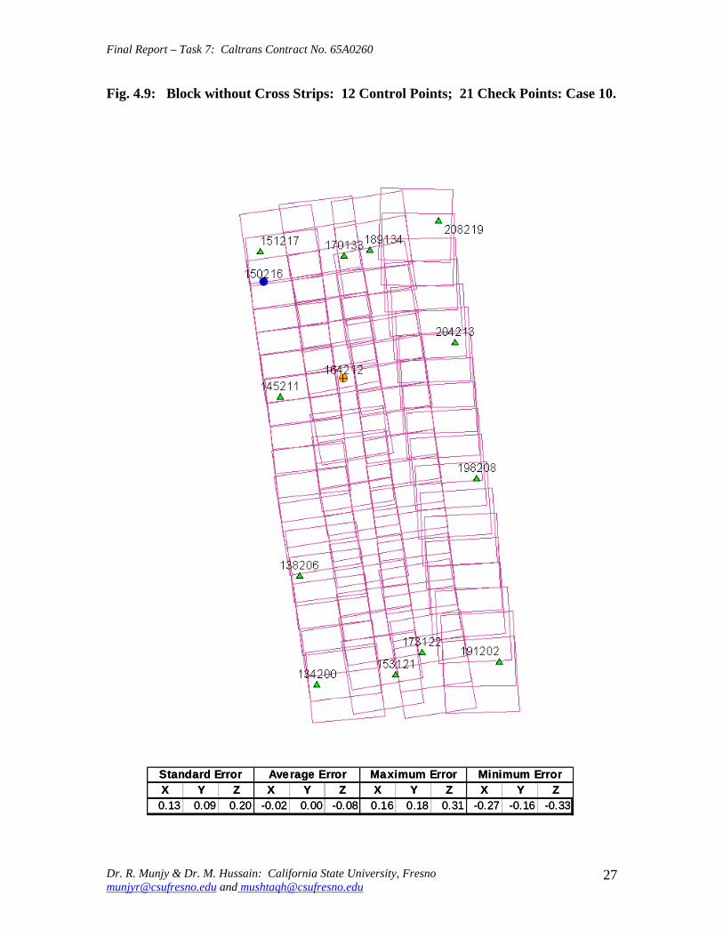
Final Report ndash Task 7 Caltrans Contract No 65A0260
Fig 49 Block without Cross Strips 12 Control Points 21 Check Points Case 10
SSttaannddaardrd EErrorrorr AAvveeraraggee EErrrroorr MMaaxxiimmuumm EErrorrorr MMiinniimmuumm EErrorrorr XX YY ZZ XX YY ZZ XX YY ZZ XX YY ZZ 001133 000099 002200 --000022 000000 --000808 001166 001818 003131 --002277 --001616 --003333
Dr R Munjy amp Dr M Hussain California State University Fresno munjyrcsufresnoedu and mushtaqhcsufresnoedu
27
Final Report ndash Task 7 Caltrans Contract No 65A0260
Fig 410 Block without Cross Strips 14 Control Points 19 Check Points Case 11
SSttaannddaardrd EErrorrorr AAvveeraraggee EErrrroorr MMaaxxiimmuumm EErrorrorr MMiinniimmuumm EErrorrorr XX YY ZZ XX YY ZZ XX YY ZZ XX YY ZZ
001100 000088 001133 000044 --000022 --000303 001166 001515 002525 --002211 --001717 --002200
Dr R Munjy amp Dr M Hussain California State University Fresno munjyrcsufresnoedu and mushtaqhcsufresnoedu
28
Final Report ndash Task 7 Caltrans Contract No 65A0260
Fig 411 Block without Cross Strips 14 Control Points 19 Check Points Case 12
SSttaannddaardrd EErrorrorr AAvveeraraggee EErrrroorr MMaaxxiimmuumm EErrorrorr MMiinniimmuumm EErrorrorr XX YY ZZ XX YY ZZ XX YY ZZ XX YY ZZ
000099 000077 001122 --000011 --000101 000055 000099 001313 002828 --002255 --001414 --001122
Dr R Munjy amp Dr M Hussain California State University Fresno munjyrcsufresnoedu and mushtaqhcsufresnoedu
29
Final Report ndash Task 7 Caltrans Contract No 65A0260
5 ANALYSIS OF RESULTS amp CONCLUSIONS
In accordance with the Caltrans standards using wide-angle aerial photography the RMS error in each coordinate component of the adjusted tie points should not exceed 110000 of the flying height above the terrain The Del Mar Test Block was flown with a wideshyangle aerial camera from an average height of 1800 feet above the terrain level thereby resulting in an average photo scale of 13600 Consequently the limiting RMS error at the Check Points representative of a finite number of well distributed tie points in the block should not exceed 018 ft in this case Any error that exceeds three times this limiting value viz 054 ft in any of the coordinate components should be a cause for rejection of that point
Therefore the acceptable limiting values for the standard error at the Check Points is 018 ft in each coordinate component Any block adjustment solution that results in a coordinate error in one or more Check Points that exceeds 054 ft in any coordinate component would not be an acceptable solution The following analysis of the results is based on these accuracy criteria
51 Blocks With Cross Flights
When a minimal number of 8 control points are used (Fig 42) along the block perimeter the resulting standard error in Z-coordinate of 019 ft exceeds the limiting value of 015 ft It is also noticeable that the highest error in the Z-coordinate of 052 ft at Point 189134 almost equals the rejection limit of 054 ft This is an indication that controlling a cross flight with only a single Control Point at each end of the flight may not always provide a satisfactory solution
This situation can be remedied by using a pair of Control Points in each end model of a cross flight so that any deformation across the flight line the omega rotation () can also be controlled Such an approach is also reported to have been successfully used and recommended in the past [1] [2] [3] When 4 additional Control Points were added at the end of each cross flight line as is seen in Fig 43 all the standard errors fell within the acceptable range and the maximum coordinate error did not exceed 030 ft which is well within the acceptable criteria
The primary advantage of using airborne GPS data for the adjustment of aerial triangulation blocks is to completely eliminate the need for Control Points in the interior of the block But it is of interest to investigate how effectively the airborne GPS data alone can control the interior of the block Two separate blocks were processed by adding two Control Points in the interior of the block resulting in a total of 14 Control Points
The block with 14 Control Points (Case A) is shown in Fig 44 where the two interior Control Points were selected so that one Control Point was located on the opposite ends in each of the two interior flight lines (Line 2 and Line3 see Fig 41) The other block with 14 Control Points (Case B) is shown in Fig 45 In this case both the interior points
Dr R Munjy amp Dr M Hussain California State University Fresno munjyrcsufresnoedu and mushtaqhcsufresnoedu
30
Final Report ndash Task 7 Caltrans Contract No 65A0260
fell in the middle of the block interior It is interesting to note that in either of the two cases the addition of the interior Control Points did not result in any significant difference from the result achieved earlier while using 12 Control Points Therefore it may be concluded that as long as the cross flights are adequately controlled with a pair of Control Points located across each end model of each cross flight additional control in the block interior is not required The results shown in Fig 44 and 45 validate this conclusion at least for a block comprised of 18 models long multiple flight lines
52 Blocks Without Cross Flights
When a mapping project involves a large photogrammetric block consisting of hundreds of models the common practice is to plan the block configuration to include cross flights [1] [2] [6] [10] Often such cross flights can result in significant saving in time and effort in minimizing the need for ground control Since the photogrammetric mapping projects in Caltrans mostly involve mapping along highway corridors most of the photogrammetric blocks vary from a single flight line to up to as many as four flight lines Therefore it is still to be investigated whether the use of cross flight lines in such blocks offers any significant advantage Furthermore any advantage resulting from the reduced need for the ground control has to be weighed against the additional time and effort needed in processing the cross flight models The Caltrans Office of Photogrammetry has not yet adopted the use of Automated Aerial Triangulation (AAT) techniques for routine production Consequently the additional effort in transferring tie points between the cross flights with the flights of the main block is still significant This has provided the impetus to carry out the following investigation for the aerial triangulation adjustment of blocks that do not include any cross flights
The first block without the two cross flights was processed with only 8 Control points along the block perimeter as a parallel case with the block run with cross flights The results are shown in Fig 46 As may be expected the absence of any Control Point located at each end of each of the two interior flights 2 and 3 has resulted in unacceptably large errors Not only is the standard error of 059 ft in the Z-coordinate for the 25 Check Points too large but interestingly the block adjustment carries a large systematic error in Z-coordinate of 108 ft This results from the fact that the absence of the Control Points at each end of Flights 2 and 3 does not permit the adjustment for the systematic strip drift parameters for the airborne GPS data along Flights 2 and 3
When cross flights are included the airborne GPS data measured along the cross flight adequately serves as control for adjusting the strip shift and drift parameters Therefore an alternative to the inclusion of cross flights in the block configuration is to provide a Control Point at each end of every flight line in the block Accordingly the processing of the following blocks includes Control Points at the end of each flight line
The Del Mar Test Block with 4 flight lines each 18 models long would require a total of 12 Control Points one Control Point at each end of each flight line and 4 Control Points along the interior perimeter of the block to provide a control spacing of approximately 6 airbases apart However in order to minimize the use of the ground control the block
Dr R Munjy amp Dr M Hussain California State University Fresno munjyrcsufresnoedu and mushtaqhcsufresnoedu
31
Final Report ndash Task 7 Caltrans Contract No 65A0260
shown in Fig 47 was processed with only 11 Control Points (Case A) since the Control Point 170133 was measured both in Line 2 and Line 3 The resulting standard error of 019 ft in the Z-coordinate for 22 Check Points as well as the large error of 050 ft in the Z-coordinate of Check Point 189134 make the block adjustment solution unacceptable There appears to be no obvious reason why the Check Point 189134 that is located so close to the Control Point 170133 should display such unacceptably large error in the Zshycoordinate In order to ascertain the internal consistency of the ground control data (33 Control Points) a conventional aerial triangulation adjustment of the block was performed (without using the airborne GPS data) using 32 Control Points and treating the Control Point 189134 as a Check Point The resulting error in the Z-coordinate of Point 189134 was only 006 ft It is also to be noted that the average Z-coordinate error of 017 ft indicates a systematic height error This would lead to the conclusion that there is some height discrepancy between the ground control data and the airborne GPS data
The block was re-processed (Case B) again by using only 11 Control Points but this time the Control Point 170133 was replaced with Control Point 189134 and the results are displayed in Fig 48 The Case B results are even worse than the Case A results the standard error in Z-coordinate was degraded to 027 ft while the largest error in Zshycoordinate of 066 ft was noted at Check Point 187215 The average Z-coordinate error also increases to 031 ft This is a further indication that there is significant height inconsistency in the airborne GPS data and the ground control data It appears that the height discrepancy between the ground control data and the airborne GPS data results in an unsatisfactory shift and drift adjustment of the airborne GPS data particularly in the inner flight Lines 2 and 3 that span 18 models between the end Control Points
In order to strengthen the end control across the flight lines both the Control Points 170133 and 189134 were used at the Northern end of the block The block was then processed with 12 Control Points and the results are presented in Fig 49 Even though the results improved significantly but contrary to the expectation the standard error in the Z-coordinate of 020 ft for the 21 Check Points did not meet the Caltrans accuracy standard The next logical approach was to investigate the impact of adding Control Points in the interior of the block Two interior Control Points were selected in the same manner as has been described earlier in the case of the blocks with the cross flights (see Fig 44 and 45)
Using 14 Control Points the Case A is shown in Fig 410 while the Case B is presented in Fig 411 The results in both Case A and Case B easily meet the Caltrans accuracy standards In Case A the distance between the Control Points for the shift and drift parameter adjustment of the airborne GPS data varies from 6 to 12 models while in Case B the interior Control Points are about 6 models apart Each Control Point distribution provides almost similar results It is a clear indication that any systematic height deformation that results from the suspected inconsistency between the ground surveyed GPS data and the airborne GPS data can be kept within acceptable range by including a pair of control points in the interior of the block Such a need for some control points has not been reported for the adjustment of aerial triangulation blocks in the past However the largest photo scale for which any ABGPS supported results have been published in
Dr R Munjy amp Dr M Hussain California State University Fresno munjyrcsufresnoedu and mushtaqhcsufresnoedu
32
Final Report ndash Task 7 Caltrans Contract No 65A0260
the past is 14800 only For a photo scale of 13600 that is approximately 25 percent larger the requirements for the accuracy of aerial triangulation accordingly become more stringent in the same proportion This may generate the need for some additional control in the middle of the block
The residuals at the ground control points and in the image coordinate data along with the resulting standard error of unit weight (0) provide a reliable indication of the internal consistency of the adjusted block However the absolute accuracy of the aerial triangulation can be validated only by the use of Check Points that are well distributed over the entire block As pointed out earlier any deformations due to residual systematic shift and drift errors in the airborne GPS data are likely to be most significant in the center of the block the location that is farthest from the control points distributed along the perimeter Accordingly it would be advisable to locate at least a pair of Check Points in the middle of the block and after completing the block adjustment (by excluding these Check Points as Control Points) the coordinate discrepancies obtained at these Check Points can be analyzed Such discrepancies would normally represent the highest absolute accuracy resulting from aerial triangulation adjustment of the block Any unacceptably large coordinate discrepancies at the Check Points would require investigation of the block input data
In the case the coordinate discrepancies at the Check Points are within acceptable range the block can be re-processed by also including the Check Points in the control data This should enhance the accuracy in the interior of the block
6 RECOMMENDED DRAFT STANDARDS
These draft standards are proposed to supplement the existing Standards for Strip Configuration Airborne GPS Controlled Photogrammetry for Large Scale Mapping Projects (based on 13600 photo scale) currently used in Caltrans
61 Data Acquisition
611 Image Coordinate Data
Follow the existing practice used in Caltrans Office of Photogrammetry for the selection distribution and the measurement of all image point data It is recommended that raw machine coordinate image data should form the input to the aerial triangulation block adjustment
A secondary interest in this Research Project under contract with Caltrans was to also evaluate the alternate methodology of the selection and the measurement of tie point data using Automated Aerial Triangulation (AAT) system However several problems were encountered in implementing the AAT software available at the Caltrans Office of Photogrammetry in Sacramento The unavoidable delay caused by unfavorable weather conditions in acquiring the aerial imagery for the Del Mar Test Block did not allow
Dr R Munjy amp Dr M Hussain California State University Fresno munjyrcsufresnoedu and mushtaqhcsufresnoedu
33
Final Report ndash Task 7 Caltrans Contract No 65A0260
enough time to resolve the AAT software issues with software vendor Accordingly this task could not be fully completed Therefore it was mutually agreed between the Caltrans Office of Photogrammetry and California State University Fresno to concentrate research efforts on the processing and the analysis of the Del Mar Test Block and on drafting the Final Report
612 Ground Control Data
The proposed research is focused on the use of photography obtained at scale of 13600 for corridor mapping in Caltrans The ground control for mapping is based on the airborne GPS supported aerial triangulation of the photo blocks The ground control points should be surveyed to provide 15 to 2-times higher accuracy than that of the adjusted tie point data This would translate to an accuracy at the 005 to 01 ft level for the planimetric coordinates and the height an accuracy achievable using static GPS surveys tied to existing HPGN network
It is not yet certain that the Real-Time Kinematic (RTK) GPS field survey methodology whether relying on a single base station or on an RTK network is able to meet the above stringent field survey accuracy requirements Therefore the ground control data for ABGPS based aerial triangulation blocks should be based entirely on GPS control networks established using static GPS surveying methodology The RTK survey methodology for establishing control for photogrammetric mapping projects should not be used till such time that such technology has advanced to a level when consistently reliable results can be routinely expected
The GPS observations provide a fairly precise data for ellipsoidal height differences However all photogrammetric mapping has to be based on orthometric height data Two different approaches can be used in order to derive adjusted orthometric height data through aerial triangulation The first method is to carry out the simultaneous least squares adjustment of the GPS observation data for the ground control network using current Caltrans Horizontal Datum CCS83 (199135) and Vertical Datum NAVD 88 But since the observed data involves the measurement of ellipsoidal height differences for each measured baseline there is a need for transforming such differences to the corresponding orthometric height differences on NAVD 88 Datum In the absence of an existing Local Geoid Model the only economic recourse available to meet this need is to use the most reliable existing Global Geoid Model the time-consuming and prohibitively more costly alternative would be to connect the control network stations through differential leveling The Global Geoid Models are progressively being updated and the GEOID 2003 Model is most commonly in current use although GEOID 2009 Model may soon become available
It has to be noted that the use of a Global Geoid Model will always have some residual geoidal height uncertainties perhaps in the range of few hundredths of a foot It is therefore necessary that a few stations that are well distributed over the control network should have precisely known orthometric height values which can be used for the height adjustment of the network The minimum number of such orthometric height control
Dr R Munjy amp Dr M Hussain California State University Fresno munjyrcsufresnoedu and mushtaqhcsufresnoedu
34
Final Report ndash Task 7 Caltrans Contract No 65A0260
stations is three and consequently a network should be planned to have at least four and preferably more stations where orthometric height is precisely known In practice this requirement is met by including several existing benchmarks that are well distributed over the project area The redundancy provided by using more than three benchmarks will quantify the height residuals resulting from the adjustment This will provide a good estimate for the residual height errors in the network
The alternative approach is to carry out the adjustment of the GPS control network using WGS84 Geodetic Datum This datum is consistent with the observed GPS measurement data and a simultaneous 3D adjustment of the network can be performed in a Local Spatial Coordinate System (LSCS) the most commonly used approach is to shift the origin of the WGS84 coordinate system (center of the Earth) to approximately the center of the project site and apply a 3D rotational matrix to align the coordinate axes along the East North and Up directions Some commercial aerial triangulation software systems provide utilities to easily perform such datum transformation After the aerial triangulation results have been validated the coordinates of all the control and tie points can be transformed back to WGS 84 Datum Based on the availability of the orthometric height control stations a local Geoid can be defined ( a plane or a surface etc) and then used to transform the ellipsoidal height data to orthometric height data This second approach has the advantage that unlike the first method described above the residual height errors in the transformed control point height data are not propagated through aerial triangulation
For 13600 scale aerial photography blocks the ground control data should meet the a- priori standard deviation at 010 ft level This is not a very challenging demand for the horizontal positioning using GPS methodology However the residual height uncertainties in the orthometric height of control points interpolated from the Global Geoid Model become more critical as the photo scale becomes larger
613 Airborne GPS Data
The current practice used in Caltrans to acquire airborne GPS data during flight missions should continue to be used It is necessary to have GPS data collected at 1 Hz or higher rate at a base station that is located within or close to the project site Prior research completed collaboratively with Caltrans has already shown that the data at the base station may be substituted with GPS data collected at CORS at 5-sec or higher rate Consequently the collection of GPS data at more than one base stations is not considered as an essential requirement It may still be prudent to acquire GPS data at a second base station as a contingency safeguard against the GPS hardware failure at a base station for guaranteed success of the flight mission and expense
It is to be noted that the relative accuracy between successive airborne GPS antenna 3Dshycoordinates should be at 10-cm or higher level The current procedure used in Caltrans for the aircraft to remain stationary for static resolution of ambiguities before take off has mostly resulted in acquiring very reliable airborne GPS data This practice should perhaps be continued even though the continuing improvements in GPS hardware and
Dr R Munjy amp Dr M Hussain California State University Fresno munjyrcsufresnoedu and mushtaqhcsufresnoedu
35
Final Report ndash Task 7 Caltrans Contract No 65A0260
post-processing softwares are making on-the-fly (OTF) ambiguity resolution increasingly reliable However if it is necessary to resort to on-the-fly ambiguity resolution it must be ensured that the ambiguities have stabilized before photography is started The strict requirement for reliably resolving the ambiguities also does not permit the loss of lock during any single flight line If a loss of lock occurs during turns between flight lines ambiguities must be re-acquired and must stabilize before starting the collection of photography for another flight line Based on the make and the model of the airborne GPS receiver the Caltrans Office of Photogrammetry in consultation with the District Survey Section should draft a set of instructions for the GPSCamera operator aboard the aircraft specifying what parameters (such as PDOP Number of SVs etc) that need to be continuously monitored on a screen during a flight mission
62 Flight and Control Configuration
The following standards in planning the flight line configuration and the corresponding ground control distribution for Caltrans project are recommended to achieve optimum results
Control points are primarily required only along the perimeter of the block When a cross flight line is used to control the end of a block a pair of Control
Points must be located at each end of the cross flight At each end of a block that is not controlled by a cross flight a CP should be
located at the end of each parallel flight line a single CP may serve as end control for two adjacent overlapping flight lines
Along the perimeter of the block in a direction parallel with the main flight lines the CPs should be located at an average spacing of 6 airbases
Any corner in a block resulting from a sudden change in the length of two adjacent parallel flight lines should be controlled by an additional CP
Check Points should be provided along the interior flight lines in a multi-strip block The Check Points may be distributed along the interior flight lines so that any Check Point is not farther than about 8 airbases from either another Check Point (on same or adjacent flight line) or from a Control Point
Note that Caltrans is usually concerned with the mapping mostly along highway corridors and therefore does not require blocks with segments larger than three or four parallel flight lines Additional control along the cross flight line would be needed if such segments have 8 or more parallel flight lines
63 Data Processing and Adjustment
631 Processing of ABGPS Data
The current practice of post-processing ABGPS data used in Caltrans Office of Photogrammetry using GrafNav software should be continued The data should continue to be processed in the Forward and Backward modes A coordinate separation of less
Dr R Munjy amp Dr M Hussain California State University Fresno munjyrcsufresnoedu and mushtaqhcsufresnoedu
36
Final Report ndash Task 7 Caltrans Contract No 65A0260
than 10 cm especially in the height represents a normally acceptable range for the combined solution
This study has shown that the airborne GPS data in comparison with the ground control data should be weighted a lower weight but the highest weight that the GPS data quality represents Generally the best results were achieved when a-priori standard error of 015 ft was used for the airborne GPS coordinate data in comparison with the a-priori standard error of 010 ft used for the ground control coordinate data Since the 3-D position of successive points along the airborne GPS antenna trajectory are estimated using Kalman Filtering approach the successive location coordinates are highly correlated and consequently carry a much higher relative precision This provides a realistic justification for the use of a-priori standard error of 015 ft
632 Processing of Aerial Triangulation Block
Each aerial triangulation block requires the following data files as input
- Raw image coordinate data file - Ground control data file - Interpolated camera coordinate data file
Using the above input data files the block adjustment should be carried out in two steps as described below It is essential that additional Strip Shift and Drift parameters (3 Shift and 3 Drift parameters) should be incorporated in the bundle adjustment solution
Step 1 Minimal Control Adjustment
The preliminary simultaneous bundle adjustment of the block should be carried out by using the minimal amount of control points along the block perimeter only All the additional ground surveyed and targeted points should be treated as tie points to serve as Check Points The adjustment results should meet the following criteria
a The Standard Error of Unit Weight (0) should fall between 03 to 07 b The residual for any image coordinate should not exceed 15 micrometer c The RMS for ground control residuals should not exceed 110000 of the flying
height above the average terrain level d The maximum residual in any ground control coordinate should not exceed 25
times the RMS value permissible under Item (c) above e The RMS for discrepancy (difference between computed coordinate value and
the ground surveyed coordinate value) in Check Point coordinates should not exceed 110000 of the flying height above the average terrain level
f The discrepancy in any Check Point coordinate should not exceed 25 times the RMS value permissible under Item (e) above
If the above criteria are met even the preliminary adjustment solution for the block satisfies Caltrans accuracy standards for aerial triangulation If the criterion under Item
Dr R Munjy amp Dr M Hussain California State University Fresno munjyrcsufresnoedu and mushtaqhcsufresnoedu
37
Final Report ndash Task 7 Caltrans Contract No 65A0260
(f) above is not met the input data should be checked for any gross mistakes or errors in the ground control and Check Point data
Step 2 Full Control Adjustment
The final simultaneous bundle adjustment of the block should be carried out by including all the ground surveyed points (Control Points and Check Points) in the ground control data file The adjustment results should meet the following criteria
g The Standard Error of Unit Weight (0) should fall between 03 to 07 h The residual for any image coordinate should not exceed 15 micrometer i The RMS for ground control residuals should not exceed 110000 of the flying
height above the average terrain level j The maximum residual in any ground control coordinate should not exceed 25
times the RMS value permissible under Item (i) above
7 CONCLUDING COMMENTS
The completion of this project signifies the culmination of a very successful and productive combination of advanced theoretical principles with sound practical experience for the adaptation of evolving photogrammetric technologies in Caltrans practice In order to alleviate a growing concern for the safety of staff conducting field survey operations in close proximity of high speed traffic Caltrans in late 1990s decided to investigate the feasibility of using airborne GPS data for controlling the aerial triangulation blocks There were two primary issues to be resolved The first and the foremost concern was whether the use of airborne GPS data could be effectively used for controlling aerial triangulation blocks of as large a photo scale as 13000 used in Caltrans and still meet the Caltrans accuracy standards This concern was particularly critical since there had not been any reported use of airborne GPS data for such a large scale of aerial photography
Should the above investigation show that the Caltrans accuracy standards for aerial triangulation for 13000 scale aerial photography can be met it was of great interest to Caltrans to develop based on theoretically sound and systematic investigation a set of standards and specifications for the successful implementation of this new methodology in Caltrans routine practice
Under a Caltrans New Technology and Research Program currently Division of Research and Innovation (DRI) contract Caltrans Office of Photogrammetry partnered with a team of two faculty members from the Geomatic Engineering Program at the California State University Fresno (CSUF) in 1996 to carry out research to address the above two issues This partnership has flourished over the past several years through
Dr R Munjy amp Dr M Hussain California State University Fresno munjyrcsufresnoedu and mushtaqhcsufresnoedu
38
Final Report ndash Task 7 Caltrans Contract No 65A0260
successive research contracts and has resulted in very fortuitous outcomes based on the theoretical and analytical guidance provided by the CSUF research team and the highly skilled aerial survey project management and high caliber professional skills in the acquisition of photogrammetric data collection by the Caltrans Office of Photogrammetry In addition the help from highly experienced field survey teams from Caltrans various districts (especially District 11) in establishing GPS networks of Control Points and Check Points of specified precision was critical for the validation of airborne-GPS supported aerial triangulation investigations
As a result of the past collaborative efforts between the Caltrans Office of Photogrammetry and the CSUF Research Team the use of airborne GPS data for aerial triangulation has successfully been transitioned into Caltrans practice in the following stages
1) Based on a number of test flights it was convincingly demonstrated that the use of airborne GPS data consistently meets the Caltrans accuracy standards for aerial triangulation for strip configuration blocks at 13000 photo scale [13]
2) A detailed set of standards and specifications were developed for the implementing of the new methodology in Caltrans routine practice This was further supported through a training workshop conducted by CSUF at the Caltrans offices in Sacramento [8]
3) The use of airborne GPS data for the adjustment of aerial triangulation blocks requires the collection of GPS data at one or more ground base stations during the flight mission This requirement imposes burdensome demands on scheduling and allocation of manpower and equipment resources In order to reduce or even to completely eliminate the need for the collection of GPS data at base stations the use of GPS data collected and archived at a network of Continuously Operating Reference Stations (CORS) distributed over the State of California was investigated It was demonstrated that CORS data could be effectively used as a replacement for data collected at base stations while fulfilling Caltrans accuracy standards Accordingly specifications were revised to also include the selection and the use of CORS data for the post-processing of airborne GPS data to accurately derive the trajectory of the airborne GPS antenna during flights [19]
4) During the past few years Caltrans has increasingly been using multi-strip projects for mapping using 13600 photo scale This provided the need for the current research study The successful completion of this study has resulted in supplementing the existing standards and specifications for airborne GPS supported single-strip aerial triangulation blocks to also include the aerial triangulation of multi-strip blocks
It is a matter of great satisfaction for the research team at CSU Fresno that working hand in hand with the Caltrans Office of Photogrammetry the comprehensive set of standards and specifications for airborne GPS supported aerial triangulation that had been developed for successful transition of this technology in Caltrans practice have been further upgraded It is hoped that as the photogrammetric technology advances further
Dr R Munjy amp Dr M Hussain California State University Fresno munjyrcsufresnoedu and mushtaqhcsufresnoedu
39
Final Report ndash Task 7 Caltrans Contract No 65A0260
similar collaborative efforts between Caltrans Office of Photogrammetry and CSU Fresno will continue to address the changing needs in Caltrans
Dr R Munjy amp Dr M Hussain California State University Fresno munjyrcsufresnoedu and mushtaqhcsufresnoedu
40
Final Report ndash Task 7 Caltrans Contract No 65A0260
REFERENCES
1 Abdullah Q M Hussain and R Munjy (2002) Workshop on Airborne GPS-Supported Aerial Triangulation ndash Theory and Practical Concepts presented at the Annual ASPRS Convention Washington DC 2002
2 Ackermann Fritz (1992) Operational Rules and Accuracy Models for GPS-Aerotriangulation Archives of the ISPRS Com 1 Vol29 1992 [pp 691-700]
3 Ackermann F (1993) Application of GPS for Aerial Triangulation Photogrammetric Engineering and Remote Sensing Vol 59 No 11 [pp 1651shy1658]
4 Appleton James Mushtaq Hussain and Riadh Munjy (2000) Use of Airborne GPS Data for Highway Mapping International Archives of Photogrammetry and Remote Sensing Vol XXXIII Part B4 Amsterdam 2000[pp 84-90]
5 Appleton James M Hussain and R Munjy (2002) Use of Airborne GPS Data For Aerial Triangulation in Caltrans (2002) Workshop presented at the California Department of Transportation Sacramento 2002
6 Federal Geographic Data Committee (FGDC) 1998 Geospatial Positional Accuracy Standards Part-3 National Standards for Spatial Data Accuracy (NSSDA) FGDC-STD-0073-1998
7 Friess Peter (1992) Experiences with GPS-Supported Aerial Triangulation Archives of the ISPRS Com 1 Vol29 1992 [pp 299 - 305]
8 Gianellia Alexander M (1995) Practical Considerations in Implementing GPS Technologies in Airborne Data Collection Proc ASPRS Annual Convention 1995 [pp 917-925]
9 Hussain M R Munjy and J Appleton (1999) Use of Airborne On-the-Fly Kinematic GPS Data for Photogrammetric Mapping Proceedings ION-GPS-99 Conference Nashville 1999[pp 1653-1659]
10 Hussain M and R Munjy (1999) GPS Controlled Photogrammetry For Large Scale Mapping (1999) Final Project Report Research project No 65Y271 submitted to New Technology amp Research Program California Department of Transportation
11 Hussain M and R Munjy (2002) Airborne GPS Controlled Aerial Triangulation in Caltrans Final Project Report Research project No 65A0059 submitted to New Technology amp Research Program California Department of Transportation June 2002
12 Munjy R and M Hussain (1985) Interactive Simultaneous Bundle Block Adjustment System (ISBBA) for Small Computers Proceedings of the ASPRS Annual Convention Washington DC 1985
13 Munjy R M Hussain and James Appleton (2000) Use of Airborne GPS Data for Corridor Mapping presented at the Annual ASPRS Convention Washington DC 2000
Dr R Munjy amp Dr M Hussain California State University Fresno munjyrcsufresnoedu and mushtaqhcsufresnoedu
41
Final Report ndash Task 7 Caltrans Contract No 65A0260
14 Munjy R and M Hussain (2007) Develop Criteria for Using Network GPS for Airborne GPS Photogrammetry Final Project Report Research Project No 65A0234 submitted to the Division of Research and Innovation (DRI) California Department of Transportation
15 Munjy R and M Hussain (2009) Draft Preliminary Standards Interim Report Research Project No 65A0260 submitted to Division of Research aned Innovation (DRI) California Department of Transportation
Dr R Munjy amp Dr M Hussain California State University Fresno munjyrcsufresnoedu and mushtaqhcsufresnoedu
42
APPENDIX I Results of Check Block
Flight amp Control Configuration Cases Used for
Study amp Analysis of Check Project in San Diego
INDEX
Case Block amp Control Configuration 1 Full Blk(Flts1to9) All 44 CP 2 Full Blk 8 CP 3 Full Blk 9 CP 4 Full Blk 10 CP 5 Main Blk(Flts1to7) 43 CP 6 Main Blk(Flts1to7) 8 CP 7 Main Blk(Flts1to7) 10 CP 8 Main Blk(Flts1to7) 12 CP 9 North Blk(Flts567amp9) 5 CP 10 North Blk(Flts567amp9) 7 CP 11 North Blk(Flts56amp7) 6 CP 12 North Blk(Flts56amp7) 8 CP 13 South Blk(Flts1to4amp8) 4 CP 14 South Blk(Flts1to4amp8) 6 CP 15 South Blk(Flts1to4amp8) 7 CP 16 South Blk(Flts1to4) 7 CP 17 South Blk(Flts1to4) 8 CP(a) 18 South Blk(Flts1to4) 8 CP(b) 19 South Blk(Flts1to4) 10 CP 20 South Blk(Flts1to4) 11 CP 21 South Blk(Flts Modified 1to4 amp8) 5 CP 22 South Blk(Flts Modified 1to4 ) 6 CP
[Refer to Table-1 Summary of the Coordinate Differences at the Check Points]
I-i
Case-1 Base DataFULL BLOCK
Flts 1 to 9
Case-1 Base Data FULL BLOCK
Flts 1 to 9
Control PointsControl Points All 44 PointsAll 44 Points
SSSttt ErErErrrr AAAvvvggg ErErErrrr MMMaaaxxx ErErErrrr MMMiiinnn ErErErrrr XXX YYY ZZZ XXX YYY ZZZ XXX YYY ZZZ XXX YYY ZZZ
007 008 005 000 000 000 019 012 012 -013 -023 -013007 008 005 000 000 000 019 012 012 -013 -023 -013007 008 005 000 000 000 019 012 012 -013 -023 -013
I-ii
Case-2FULL BLOCK
Flts 1 to 9
Control Points 8
Case-2 FULL BLOCK
Flts 1 to 9
Control Points 8 CChheecckk PoPointsints 3366
SStt ErErrr AAvvgg ErErrr MMaaxx ErErrr MMinin ErErrr XX YY ZZ XX YY ZZ XX YY ZZ XX YY ZZ
012012 012012 016016 002002 001001 --000505 024024 027027 026026 --025025 --039039 --032032
I-iii
Case-3FULL BLOCK
Flts 1 to 9
Control Points 9
Case-3 FULL BLOCK
Flts 1 to 9
Control Points 9 CChheecckk PoPointsints 3355
SStt ErErrr AAvvgg ErErrr MMaaxx ErErrr MMinin ErErrr XX YY ZZ XX YY ZZ XX YY ZZ XX YY ZZ
012012 012012 017017 001001 --001001 --000808 024024 024024 026026 --026026 --040040 --034034
I-iv
Case-4FULL BLOCK
Flts 1 to 9
Control Points 10
Case-4 FULL BLOCK
Flts 1 to 9
Control Points 10 CChheecckk PoiPoinntsts 3344
SStt ErErrr AAvvgg ErErrr MMaaxx ErErrr MMinin ErErrr XX YY ZZ XX YY ZZ XX YY ZZ XX YY ZZ
012012 009009 015015 003003 005005 --000909 002244 002727 002121 --025025 --001313 --035035
I-v
Case-5MAIN BLOCK
Flts 1 to 7
Control Points 43
Case-5 MAIN BLOCK
Flts 1 to 7
Control Points 43 [Point HV-117 Unuse[Point HV-117 Unusedd]]
SSSttt ErErErrrr AAAvvvggg ErErErrrr MMM aaaxxx ErErErrrr MMM iiinnn ErErErrrr XXX YYY ZZZ XXX YYY ZZZ XXX YYY ZZZ XXX YYY ZZZ
006006006 008008008 005005005 000000000 000000000 000000000 012012012 013013013 013013013 ---000131313 ---022022022 ---000090909
I-vi
Case-6
Flts 1 to 7
l Points 8
MAIN BLOCK
[No Cross Flts]Contro
Case-6 MAIN BLOCK
Flts 1 to 7 [No Cross Flts]
Control Points 8 ChecCheckk PoPointsints 3636
St ErSt ErSt ErSt ErSt ErSt ErSt ErSt Errrrrrrrr AAAAAAAAvgvgvgvgvgvgvgvg ErErErErErErErErrrrrrrrr MMMMMMMMaxaxaxaxaxaxaxax ErErErErErErErErrrrrrrrr MMMMMMMMiiiiiiiinnnnnnnn ErErErErErErErErrrrrrrrr XXXXXXXX YYYYYYYY ZZZZZZZZ XXXXXXXX YYYYYYYY ZZZZZZZZ XXXXXXXX YYYYYYYY ZZZZZZZZ XXXXXXXX YYYYYYYY ZZZZZZZZ
016016016016 012012012012 027027027027 -002-002-002-002 ----004004004004 -004-004-004-004 000026262626 000020202020 000041414141 ----035035035035 -036-036-036-036 ----082082082082
I-vii
Case-7MAIN BLOCK
Flts 1 to 7[No Cross Flts]
Control Points 10
Case-7 MAIN BLOCK
Flts 1 to 7 [No Cross Flts]
Control Points 10 CChheecckk PointsPoints 3434
SStt ErErrr AAvvgg ErErrr MM aaxx ErErrr MM iinn ErErrr XX YY ZZ XX YY ZZ XX YY ZZ XX YY ZZ
014 012 027 -001 -003 -004 022 020 039 -031 -031 -080014 012 027 -001 -003 -004 022 020 039 -031 -031 -080
I-viii
Case-8MAIN BLOCK
Flts 1 to 7[No Cross Flts]
Control Points 12
Case-8 MAIN BLOCK
Flts 1 to 7 [No Cross Flts]
Control Points 12 CheChecckk PointsPoints 3232
SSSttt ErErErrrr AAAvvvggg ErErErrrr MMMaaaxxx ErErErrrr MMMiiinnn ErErErrrr XXX YYY ZZZ XXX YYY ZZZ XXX YYY ZZZ XXX YYY ZZZ
015 010 017 003 000 -004 037 016 035 -031 -027 -023015 010 017 003 000 -004 037 016 035 -031 -027 -023015 010 017 003 000 -004 037 016 035 -031 -027 -023
I-ix
Case-9Case-9Case-9 NORNORNORTTTH BLH BLH BLOCKOCKOCK
FltsFltsFlts 5 to 7 amp 9 5 to 7 amp 9 5 to 7 amp 9
Control PointsControl PointsControl Points 555 ChChCheckeckeck PoPoPoininintttsss 111888
ErSSSttt EE rrrrr vg ErAAAvg Evg E rrrrr ax ErMMM ax Eax E rrrrr ErMMM iiinnn EE rrrrr XXX YYY ZZZ XXX YYY ZZZ XXX YYY ZZZ XXX YYY ZZZ
000121212 016016016 000161616 007007007 ---000161616 000111111 000262626 000020202 000363636 ---022022022 ---000626262 ---022022022
I-x
Case-Case-1100 NORTH BLOCKNORTH BLOCK
Flts 5 to 7 amp 9Flts 5 to 7 amp 9
Control PointsControl Points 77 CheckCheck PointsPoints 1616
SStt ErErrr AAvvgg ErErrr MM aaxx ErErrr MM iinn ErErrr XX YY ZZ XX YY ZZ XX YY ZZ XX YY ZZ
010010 016016 017017 008008 --000707 001818 002323 001010 005151 --016016 --005151 --012012
I-xi
Case-Case-1111 NORTH BLOCKNORTH BLOCK
FltsFlts 5 to 7 5 to 7
CCoontrntrool Pointsl Points 66 CheChecckk PointsPoints 1717
SStt ErErrr AAvvgg ErErrr MM aaxx ErErrr MM iinn ErErrr XX YY ZZ XX YY ZZ XX YY ZZ XX YY ZZ
010010 016016 022022 010010 --000202 000808 002424 001515 005050 --019019 --004343 --026026
I-xii
Case-Case-1122 NORTH BLOCKNORTH BLOCK
FltsFlts 5 to 7 5 to 7 [No C[No Crrossoss Flt]Flt]
ContControl Poinrol Pointsts 88 CChheecckk PointsPoints 1155
SStt EErrrr AAvg Evg Errrr MM ax Eax Errrr MM iinn EErrrr XX YY ZZ XX YY ZZ XX YY ZZ XX YY ZZ
011011 016016 017017 013013 --000909 000202 002929 000707 003737 --017017 --004949 --031031
I-xiii
CaseCase-13-13 SOUTSOUTH BH BLLOCKOCK
Flts 1 to 4 amp 8Flts 1 to 4 amp 8
CoConnttrol Porol Poininttss 44 ChCheckeck PPooinintsts 2222
SStt ErErrr AAvvgg ErErrr MM aaxx ErErrr MM iinn ErErrr XX YY ZZ XX YY ZZ XX YY ZZ XX YY ZZ
052 032 015 -082 033 003 -007 091 026 -149 -009 -034052 032 015 -082 033 003 -007 091 026 -149 -009 -034
I-xiv
Case-14Case-14 SOUTH BLOCKSOUTH BLOCK
Flts 1 to 4 amp 8Flts 1 to 4 amp 8
CCoontrntrool Pointsl Points 66 CheChecckk PointsPoints 2200
SStt ErErrr AAvvgg ErErrr MM aaxx ErErrr MM iinn ErErrr XX YY ZZ XX YY ZZ XX YY ZZ XX YY ZZ
013 016 015 -003 006 -002 024 033 033 -019 -028 -028013 016 015 -003 006 -002 024 033 033 -019 -028 -028
I-xv
Case-15Case-15 SOUTH BLOCKSOUTH BLOCK
FltsFlts 1 to 4 amp 8 1 to 4 amp 8
ContrControol Pointsl Points 77 ChCheckeck PPooinintsts 1919
SStt ErErrr AAvvgg ErErrr MM aaxx ErErrr MM iinn ErErrr XX YY ZZ XX YY ZZ XX YY ZZ XX YY ZZ
015 012 014 -003 -002 -002 025 023 033 -025 -030 -025015 012 014 -003 -002 -002 025 023 033 -025 -030 -025
I-xvi
Case-16Case-16Case-16 SOUTH BLOCKSOUTH BLOCKSOUTH BLOCK
FltsFltsFlts 1 to 4 1 to 4 1 to 4 [No Cross Flt][No Cross Flt][No Cross Flt]
Control PointsControl PointsControl Points 777 CheCheCheccckkk PointsPointsPoints 222222
SSSttt EEErrrrrr AAAvg Evg Evg Errrrrr MMM ax Eax Eax Errrrrr MMM iiinnn EEErrrrrr XXX YYY ZZZ XXX YYY ZZZ XXX YYY ZZZ XXX YYY ZZZ
015 013 023 -001 -005 003 026 023 032 -027 -029 -037015 013 023 -001 -005 003 026 023 032 -027 -029 -037015 013 023 -001 -005 003 026 023 032 -027 -029 -037
I-xvii
Case-17Case-17 SOUTSOUTH BLH BLOCKOCK
FltsFlts 1 1 to 4to 4 [No[No CrosCrosss Flt]Flt]
ContrControol Pointsl Points 88 CChheecckk PointsPoints 2121
SStt ErErrr AAvvgg ErErrr MM aaxx ErErrr MM iinn ErErrr XX YY ZZ XX YY ZZ XX YY ZZ XX YY ZZ
014014 012012 024024 005005 --000101 000404 003131 002525 003333 --022022 --002929 --040040
I-xviii
Case-18Case-18 SOUTH BLOCKSOUTH BLOCK
Flts 1 to 4Flts 1 to 4 [[NNo Cro Crooss Fss Flltt]]
CCoontrol Pointsntrol Points 88 CheChecckk PointsPoints 2121
SSSttt ErErErrrr AAAvvvggg ErErErrrr MMM aaaxxx ErErErrrr MMM iiinnn ErErErrrr XXX YYY ZZZ XXX YYY ZZZ XXX YYY ZZZ XXX YYY ZZZ
016 014 019 -003 -005 001 027 025 028 -033 -033 -032016 014 019 -003 -005 001 027 025 028 -033 -033 -032016 014 019 -003 -005 001 027 025 028 -033 -033 -032
I-xix
Case-19Case-19 SOUTH BLOCKSOUTH BLOCK
FltsFlts 1 to 4 1 to 4 [No Cross Flt][No Cross Flt]
ContControl Prol Poointintss 10 10 CheckCheck PointsPoints 1919
SSSttt ErErErrrr AAAvvvggg ErErErrrr MMM aaaxxx ErErErrrr MMM iiinnn ErErErrrr XXX YYY ZZZ XXX YYY ZZZ XXX YYY ZZZ XXX YYY ZZZ
014 012 019 004 -001 001 034 029 029 -025 -030 -028014 012 019 004 -001 001 034 029 029 -025 -030 -028014 012 019 004 -001 001 034 029 029 -025 -030 -028
I-xx
Case-Case-2200 SSOOUTH BLOCKUTH BLOCK
FltsFlts 1 to 4 1 to 4 [No Cross Flt][No Cross Flt]
Control Points 11Control Points 11 ChCheckeck PPooinintsts 1818
SSSttt ErErErrrr AAAvvvggg ErErErrrr MMM aaaxxx ErErErrrr MMM iiinnn ErErErrrr XXX YYY ZZZ XXX YYY ZZZ XXX YYY ZZZ XXX YYY ZZZ
014014014 012012012 018018018 ---000010101 ---005005005 ---000010101 000232323 000202020 000272727 ---030030030 ---000292929 ---031031031
I-xxi
Case-Case-2211 MODIMODIFFIIED SOUTH BED SOUTH BLLOCKOCK
FltsFlts 1 to 4 ( 1 to 4 (MModified)odified) amp 8amp 8
ControControl Pointsl Points 55 CheChecckk PointsPoints 1818
SStt ErErrr AAvvgg ErErrr MM aaxx ErErrr MM iinn ErErrr XX YY ZZ XX YY ZZ XX YY ZZ XX YY ZZ
013 010 015 -001 002 -001 024 021 035 -019 -025 -029013 010 015 -001 002 -001 024 021 035 -019 -025 -029
I-xxii
Case-22Case-22Case-22 MOMOMODIFDIFDIFIIIED SOED SOED SOUTH BLOCKUTH BLOCKUTH BLOCK
FltFltFltsss 1 to 4 1 to 4 1 to 4 (M(M(Modiodiodifiefiefieddd))) [No C[No C[No Crrrososossss Flt]Flt]Flt]
ConConContttrol Prol Prol Poooiiinnntttsss 666 ChChCheckeckeck PointPointPointsss 161616
SSSttt ErErErrrr AAAvvvggg ErErErrrr MMM aaaxxx ErErErrrr MMM iiinnn ErErErrrr XXX YYY ZZZ XXX YYY ZZZ XXX YYY ZZZ XXX YYY ZZZ
014 011 014 002 005 -010 025 024 016 -020 -024 -039014 011 014 002 005 -010 025 024 016 -020 -024 -039014 011 014 002 005 -010 025 024 016 -020 -024 -039
I-xxiii
APPENDIX II Results of Test Block
II-i
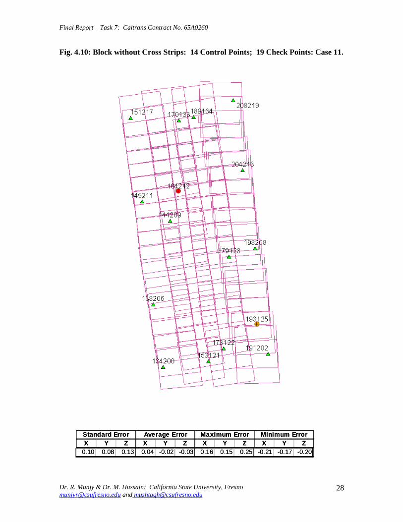
Final Report ndash Task 7 Caltrans Contract No 65A0260
Fig 410 Block without Cross Strips 14 Control Points 19 Check Points Case 11
SSttaannddaardrd EErrorrorr AAvveeraraggee EErrrroorr MMaaxxiimmuumm EErrorrorr MMiinniimmuumm EErrorrorr XX YY ZZ XX YY ZZ XX YY ZZ XX YY ZZ
001100 000088 001133 000044 --000022 --000303 001166 001515 002525 --002211 --001717 --002200
Dr R Munjy amp Dr M Hussain California State University Fresno munjyrcsufresnoedu and mushtaqhcsufresnoedu
28
Final Report ndash Task 7 Caltrans Contract No 65A0260
Fig 411 Block without Cross Strips 14 Control Points 19 Check Points Case 12
SSttaannddaardrd EErrorrorr AAvveeraraggee EErrrroorr MMaaxxiimmuumm EErrorrorr MMiinniimmuumm EErrorrorr XX YY ZZ XX YY ZZ XX YY ZZ XX YY ZZ
000099 000077 001122 --000011 --000101 000055 000099 001313 002828 --002255 --001414 --001122
Dr R Munjy amp Dr M Hussain California State University Fresno munjyrcsufresnoedu and mushtaqhcsufresnoedu
29
Final Report ndash Task 7 Caltrans Contract No 65A0260
5 ANALYSIS OF RESULTS amp CONCLUSIONS
In accordance with the Caltrans standards using wide-angle aerial photography the RMS error in each coordinate component of the adjusted tie points should not exceed 110000 of the flying height above the terrain The Del Mar Test Block was flown with a wideshyangle aerial camera from an average height of 1800 feet above the terrain level thereby resulting in an average photo scale of 13600 Consequently the limiting RMS error at the Check Points representative of a finite number of well distributed tie points in the block should not exceed 018 ft in this case Any error that exceeds three times this limiting value viz 054 ft in any of the coordinate components should be a cause for rejection of that point
Therefore the acceptable limiting values for the standard error at the Check Points is 018 ft in each coordinate component Any block adjustment solution that results in a coordinate error in one or more Check Points that exceeds 054 ft in any coordinate component would not be an acceptable solution The following analysis of the results is based on these accuracy criteria
51 Blocks With Cross Flights
When a minimal number of 8 control points are used (Fig 42) along the block perimeter the resulting standard error in Z-coordinate of 019 ft exceeds the limiting value of 015 ft It is also noticeable that the highest error in the Z-coordinate of 052 ft at Point 189134 almost equals the rejection limit of 054 ft This is an indication that controlling a cross flight with only a single Control Point at each end of the flight may not always provide a satisfactory solution
This situation can be remedied by using a pair of Control Points in each end model of a cross flight so that any deformation across the flight line the omega rotation () can also be controlled Such an approach is also reported to have been successfully used and recommended in the past [1] [2] [3] When 4 additional Control Points were added at the end of each cross flight line as is seen in Fig 43 all the standard errors fell within the acceptable range and the maximum coordinate error did not exceed 030 ft which is well within the acceptable criteria
The primary advantage of using airborne GPS data for the adjustment of aerial triangulation blocks is to completely eliminate the need for Control Points in the interior of the block But it is of interest to investigate how effectively the airborne GPS data alone can control the interior of the block Two separate blocks were processed by adding two Control Points in the interior of the block resulting in a total of 14 Control Points
The block with 14 Control Points (Case A) is shown in Fig 44 where the two interior Control Points were selected so that one Control Point was located on the opposite ends in each of the two interior flight lines (Line 2 and Line3 see Fig 41) The other block with 14 Control Points (Case B) is shown in Fig 45 In this case both the interior points
Dr R Munjy amp Dr M Hussain California State University Fresno munjyrcsufresnoedu and mushtaqhcsufresnoedu
30
Final Report ndash Task 7 Caltrans Contract No 65A0260
fell in the middle of the block interior It is interesting to note that in either of the two cases the addition of the interior Control Points did not result in any significant difference from the result achieved earlier while using 12 Control Points Therefore it may be concluded that as long as the cross flights are adequately controlled with a pair of Control Points located across each end model of each cross flight additional control in the block interior is not required The results shown in Fig 44 and 45 validate this conclusion at least for a block comprised of 18 models long multiple flight lines
52 Blocks Without Cross Flights
When a mapping project involves a large photogrammetric block consisting of hundreds of models the common practice is to plan the block configuration to include cross flights [1] [2] [6] [10] Often such cross flights can result in significant saving in time and effort in minimizing the need for ground control Since the photogrammetric mapping projects in Caltrans mostly involve mapping along highway corridors most of the photogrammetric blocks vary from a single flight line to up to as many as four flight lines Therefore it is still to be investigated whether the use of cross flight lines in such blocks offers any significant advantage Furthermore any advantage resulting from the reduced need for the ground control has to be weighed against the additional time and effort needed in processing the cross flight models The Caltrans Office of Photogrammetry has not yet adopted the use of Automated Aerial Triangulation (AAT) techniques for routine production Consequently the additional effort in transferring tie points between the cross flights with the flights of the main block is still significant This has provided the impetus to carry out the following investigation for the aerial triangulation adjustment of blocks that do not include any cross flights
The first block without the two cross flights was processed with only 8 Control points along the block perimeter as a parallel case with the block run with cross flights The results are shown in Fig 46 As may be expected the absence of any Control Point located at each end of each of the two interior flights 2 and 3 has resulted in unacceptably large errors Not only is the standard error of 059 ft in the Z-coordinate for the 25 Check Points too large but interestingly the block adjustment carries a large systematic error in Z-coordinate of 108 ft This results from the fact that the absence of the Control Points at each end of Flights 2 and 3 does not permit the adjustment for the systematic strip drift parameters for the airborne GPS data along Flights 2 and 3
When cross flights are included the airborne GPS data measured along the cross flight adequately serves as control for adjusting the strip shift and drift parameters Therefore an alternative to the inclusion of cross flights in the block configuration is to provide a Control Point at each end of every flight line in the block Accordingly the processing of the following blocks includes Control Points at the end of each flight line
The Del Mar Test Block with 4 flight lines each 18 models long would require a total of 12 Control Points one Control Point at each end of each flight line and 4 Control Points along the interior perimeter of the block to provide a control spacing of approximately 6 airbases apart However in order to minimize the use of the ground control the block
Dr R Munjy amp Dr M Hussain California State University Fresno munjyrcsufresnoedu and mushtaqhcsufresnoedu
31
Final Report ndash Task 7 Caltrans Contract No 65A0260
shown in Fig 47 was processed with only 11 Control Points (Case A) since the Control Point 170133 was measured both in Line 2 and Line 3 The resulting standard error of 019 ft in the Z-coordinate for 22 Check Points as well as the large error of 050 ft in the Z-coordinate of Check Point 189134 make the block adjustment solution unacceptable There appears to be no obvious reason why the Check Point 189134 that is located so close to the Control Point 170133 should display such unacceptably large error in the Zshycoordinate In order to ascertain the internal consistency of the ground control data (33 Control Points) a conventional aerial triangulation adjustment of the block was performed (without using the airborne GPS data) using 32 Control Points and treating the Control Point 189134 as a Check Point The resulting error in the Z-coordinate of Point 189134 was only 006 ft It is also to be noted that the average Z-coordinate error of 017 ft indicates a systematic height error This would lead to the conclusion that there is some height discrepancy between the ground control data and the airborne GPS data
The block was re-processed (Case B) again by using only 11 Control Points but this time the Control Point 170133 was replaced with Control Point 189134 and the results are displayed in Fig 48 The Case B results are even worse than the Case A results the standard error in Z-coordinate was degraded to 027 ft while the largest error in Zshycoordinate of 066 ft was noted at Check Point 187215 The average Z-coordinate error also increases to 031 ft This is a further indication that there is significant height inconsistency in the airborne GPS data and the ground control data It appears that the height discrepancy between the ground control data and the airborne GPS data results in an unsatisfactory shift and drift adjustment of the airborne GPS data particularly in the inner flight Lines 2 and 3 that span 18 models between the end Control Points
In order to strengthen the end control across the flight lines both the Control Points 170133 and 189134 were used at the Northern end of the block The block was then processed with 12 Control Points and the results are presented in Fig 49 Even though the results improved significantly but contrary to the expectation the standard error in the Z-coordinate of 020 ft for the 21 Check Points did not meet the Caltrans accuracy standard The next logical approach was to investigate the impact of adding Control Points in the interior of the block Two interior Control Points were selected in the same manner as has been described earlier in the case of the blocks with the cross flights (see Fig 44 and 45)
Using 14 Control Points the Case A is shown in Fig 410 while the Case B is presented in Fig 411 The results in both Case A and Case B easily meet the Caltrans accuracy standards In Case A the distance between the Control Points for the shift and drift parameter adjustment of the airborne GPS data varies from 6 to 12 models while in Case B the interior Control Points are about 6 models apart Each Control Point distribution provides almost similar results It is a clear indication that any systematic height deformation that results from the suspected inconsistency between the ground surveyed GPS data and the airborne GPS data can be kept within acceptable range by including a pair of control points in the interior of the block Such a need for some control points has not been reported for the adjustment of aerial triangulation blocks in the past However the largest photo scale for which any ABGPS supported results have been published in
Dr R Munjy amp Dr M Hussain California State University Fresno munjyrcsufresnoedu and mushtaqhcsufresnoedu
32
Final Report ndash Task 7 Caltrans Contract No 65A0260
the past is 14800 only For a photo scale of 13600 that is approximately 25 percent larger the requirements for the accuracy of aerial triangulation accordingly become more stringent in the same proportion This may generate the need for some additional control in the middle of the block
The residuals at the ground control points and in the image coordinate data along with the resulting standard error of unit weight (0) provide a reliable indication of the internal consistency of the adjusted block However the absolute accuracy of the aerial triangulation can be validated only by the use of Check Points that are well distributed over the entire block As pointed out earlier any deformations due to residual systematic shift and drift errors in the airborne GPS data are likely to be most significant in the center of the block the location that is farthest from the control points distributed along the perimeter Accordingly it would be advisable to locate at least a pair of Check Points in the middle of the block and after completing the block adjustment (by excluding these Check Points as Control Points) the coordinate discrepancies obtained at these Check Points can be analyzed Such discrepancies would normally represent the highest absolute accuracy resulting from aerial triangulation adjustment of the block Any unacceptably large coordinate discrepancies at the Check Points would require investigation of the block input data
In the case the coordinate discrepancies at the Check Points are within acceptable range the block can be re-processed by also including the Check Points in the control data This should enhance the accuracy in the interior of the block
6 RECOMMENDED DRAFT STANDARDS
These draft standards are proposed to supplement the existing Standards for Strip Configuration Airborne GPS Controlled Photogrammetry for Large Scale Mapping Projects (based on 13600 photo scale) currently used in Caltrans
61 Data Acquisition
611 Image Coordinate Data
Follow the existing practice used in Caltrans Office of Photogrammetry for the selection distribution and the measurement of all image point data It is recommended that raw machine coordinate image data should form the input to the aerial triangulation block adjustment
A secondary interest in this Research Project under contract with Caltrans was to also evaluate the alternate methodology of the selection and the measurement of tie point data using Automated Aerial Triangulation (AAT) system However several problems were encountered in implementing the AAT software available at the Caltrans Office of Photogrammetry in Sacramento The unavoidable delay caused by unfavorable weather conditions in acquiring the aerial imagery for the Del Mar Test Block did not allow
Dr R Munjy amp Dr M Hussain California State University Fresno munjyrcsufresnoedu and mushtaqhcsufresnoedu
33
Final Report ndash Task 7 Caltrans Contract No 65A0260
enough time to resolve the AAT software issues with software vendor Accordingly this task could not be fully completed Therefore it was mutually agreed between the Caltrans Office of Photogrammetry and California State University Fresno to concentrate research efforts on the processing and the analysis of the Del Mar Test Block and on drafting the Final Report
612 Ground Control Data
The proposed research is focused on the use of photography obtained at scale of 13600 for corridor mapping in Caltrans The ground control for mapping is based on the airborne GPS supported aerial triangulation of the photo blocks The ground control points should be surveyed to provide 15 to 2-times higher accuracy than that of the adjusted tie point data This would translate to an accuracy at the 005 to 01 ft level for the planimetric coordinates and the height an accuracy achievable using static GPS surveys tied to existing HPGN network
It is not yet certain that the Real-Time Kinematic (RTK) GPS field survey methodology whether relying on a single base station or on an RTK network is able to meet the above stringent field survey accuracy requirements Therefore the ground control data for ABGPS based aerial triangulation blocks should be based entirely on GPS control networks established using static GPS surveying methodology The RTK survey methodology for establishing control for photogrammetric mapping projects should not be used till such time that such technology has advanced to a level when consistently reliable results can be routinely expected
The GPS observations provide a fairly precise data for ellipsoidal height differences However all photogrammetric mapping has to be based on orthometric height data Two different approaches can be used in order to derive adjusted orthometric height data through aerial triangulation The first method is to carry out the simultaneous least squares adjustment of the GPS observation data for the ground control network using current Caltrans Horizontal Datum CCS83 (199135) and Vertical Datum NAVD 88 But since the observed data involves the measurement of ellipsoidal height differences for each measured baseline there is a need for transforming such differences to the corresponding orthometric height differences on NAVD 88 Datum In the absence of an existing Local Geoid Model the only economic recourse available to meet this need is to use the most reliable existing Global Geoid Model the time-consuming and prohibitively more costly alternative would be to connect the control network stations through differential leveling The Global Geoid Models are progressively being updated and the GEOID 2003 Model is most commonly in current use although GEOID 2009 Model may soon become available
It has to be noted that the use of a Global Geoid Model will always have some residual geoidal height uncertainties perhaps in the range of few hundredths of a foot It is therefore necessary that a few stations that are well distributed over the control network should have precisely known orthometric height values which can be used for the height adjustment of the network The minimum number of such orthometric height control
Dr R Munjy amp Dr M Hussain California State University Fresno munjyrcsufresnoedu and mushtaqhcsufresnoedu
34
Final Report ndash Task 7 Caltrans Contract No 65A0260
stations is three and consequently a network should be planned to have at least four and preferably more stations where orthometric height is precisely known In practice this requirement is met by including several existing benchmarks that are well distributed over the project area The redundancy provided by using more than three benchmarks will quantify the height residuals resulting from the adjustment This will provide a good estimate for the residual height errors in the network
The alternative approach is to carry out the adjustment of the GPS control network using WGS84 Geodetic Datum This datum is consistent with the observed GPS measurement data and a simultaneous 3D adjustment of the network can be performed in a Local Spatial Coordinate System (LSCS) the most commonly used approach is to shift the origin of the WGS84 coordinate system (center of the Earth) to approximately the center of the project site and apply a 3D rotational matrix to align the coordinate axes along the East North and Up directions Some commercial aerial triangulation software systems provide utilities to easily perform such datum transformation After the aerial triangulation results have been validated the coordinates of all the control and tie points can be transformed back to WGS 84 Datum Based on the availability of the orthometric height control stations a local Geoid can be defined ( a plane or a surface etc) and then used to transform the ellipsoidal height data to orthometric height data This second approach has the advantage that unlike the first method described above the residual height errors in the transformed control point height data are not propagated through aerial triangulation
For 13600 scale aerial photography blocks the ground control data should meet the a- priori standard deviation at 010 ft level This is not a very challenging demand for the horizontal positioning using GPS methodology However the residual height uncertainties in the orthometric height of control points interpolated from the Global Geoid Model become more critical as the photo scale becomes larger
613 Airborne GPS Data
The current practice used in Caltrans to acquire airborne GPS data during flight missions should continue to be used It is necessary to have GPS data collected at 1 Hz or higher rate at a base station that is located within or close to the project site Prior research completed collaboratively with Caltrans has already shown that the data at the base station may be substituted with GPS data collected at CORS at 5-sec or higher rate Consequently the collection of GPS data at more than one base stations is not considered as an essential requirement It may still be prudent to acquire GPS data at a second base station as a contingency safeguard against the GPS hardware failure at a base station for guaranteed success of the flight mission and expense
It is to be noted that the relative accuracy between successive airborne GPS antenna 3Dshycoordinates should be at 10-cm or higher level The current procedure used in Caltrans for the aircraft to remain stationary for static resolution of ambiguities before take off has mostly resulted in acquiring very reliable airborne GPS data This practice should perhaps be continued even though the continuing improvements in GPS hardware and
Dr R Munjy amp Dr M Hussain California State University Fresno munjyrcsufresnoedu and mushtaqhcsufresnoedu
35
Final Report ndash Task 7 Caltrans Contract No 65A0260
post-processing softwares are making on-the-fly (OTF) ambiguity resolution increasingly reliable However if it is necessary to resort to on-the-fly ambiguity resolution it must be ensured that the ambiguities have stabilized before photography is started The strict requirement for reliably resolving the ambiguities also does not permit the loss of lock during any single flight line If a loss of lock occurs during turns between flight lines ambiguities must be re-acquired and must stabilize before starting the collection of photography for another flight line Based on the make and the model of the airborne GPS receiver the Caltrans Office of Photogrammetry in consultation with the District Survey Section should draft a set of instructions for the GPSCamera operator aboard the aircraft specifying what parameters (such as PDOP Number of SVs etc) that need to be continuously monitored on a screen during a flight mission
62 Flight and Control Configuration
The following standards in planning the flight line configuration and the corresponding ground control distribution for Caltrans project are recommended to achieve optimum results
Control points are primarily required only along the perimeter of the block When a cross flight line is used to control the end of a block a pair of Control
Points must be located at each end of the cross flight At each end of a block that is not controlled by a cross flight a CP should be
located at the end of each parallel flight line a single CP may serve as end control for two adjacent overlapping flight lines
Along the perimeter of the block in a direction parallel with the main flight lines the CPs should be located at an average spacing of 6 airbases
Any corner in a block resulting from a sudden change in the length of two adjacent parallel flight lines should be controlled by an additional CP
Check Points should be provided along the interior flight lines in a multi-strip block The Check Points may be distributed along the interior flight lines so that any Check Point is not farther than about 8 airbases from either another Check Point (on same or adjacent flight line) or from a Control Point
Note that Caltrans is usually concerned with the mapping mostly along highway corridors and therefore does not require blocks with segments larger than three or four parallel flight lines Additional control along the cross flight line would be needed if such segments have 8 or more parallel flight lines
63 Data Processing and Adjustment
631 Processing of ABGPS Data
The current practice of post-processing ABGPS data used in Caltrans Office of Photogrammetry using GrafNav software should be continued The data should continue to be processed in the Forward and Backward modes A coordinate separation of less
Dr R Munjy amp Dr M Hussain California State University Fresno munjyrcsufresnoedu and mushtaqhcsufresnoedu
36
Final Report ndash Task 7 Caltrans Contract No 65A0260
than 10 cm especially in the height represents a normally acceptable range for the combined solution
This study has shown that the airborne GPS data in comparison with the ground control data should be weighted a lower weight but the highest weight that the GPS data quality represents Generally the best results were achieved when a-priori standard error of 015 ft was used for the airborne GPS coordinate data in comparison with the a-priori standard error of 010 ft used for the ground control coordinate data Since the 3-D position of successive points along the airborne GPS antenna trajectory are estimated using Kalman Filtering approach the successive location coordinates are highly correlated and consequently carry a much higher relative precision This provides a realistic justification for the use of a-priori standard error of 015 ft
632 Processing of Aerial Triangulation Block
Each aerial triangulation block requires the following data files as input
- Raw image coordinate data file - Ground control data file - Interpolated camera coordinate data file
Using the above input data files the block adjustment should be carried out in two steps as described below It is essential that additional Strip Shift and Drift parameters (3 Shift and 3 Drift parameters) should be incorporated in the bundle adjustment solution
Step 1 Minimal Control Adjustment
The preliminary simultaneous bundle adjustment of the block should be carried out by using the minimal amount of control points along the block perimeter only All the additional ground surveyed and targeted points should be treated as tie points to serve as Check Points The adjustment results should meet the following criteria
a The Standard Error of Unit Weight (0) should fall between 03 to 07 b The residual for any image coordinate should not exceed 15 micrometer c The RMS for ground control residuals should not exceed 110000 of the flying
height above the average terrain level d The maximum residual in any ground control coordinate should not exceed 25
times the RMS value permissible under Item (c) above e The RMS for discrepancy (difference between computed coordinate value and
the ground surveyed coordinate value) in Check Point coordinates should not exceed 110000 of the flying height above the average terrain level
f The discrepancy in any Check Point coordinate should not exceed 25 times the RMS value permissible under Item (e) above
If the above criteria are met even the preliminary adjustment solution for the block satisfies Caltrans accuracy standards for aerial triangulation If the criterion under Item
Dr R Munjy amp Dr M Hussain California State University Fresno munjyrcsufresnoedu and mushtaqhcsufresnoedu
37
Final Report ndash Task 7 Caltrans Contract No 65A0260
(f) above is not met the input data should be checked for any gross mistakes or errors in the ground control and Check Point data
Step 2 Full Control Adjustment
The final simultaneous bundle adjustment of the block should be carried out by including all the ground surveyed points (Control Points and Check Points) in the ground control data file The adjustment results should meet the following criteria
g The Standard Error of Unit Weight (0) should fall between 03 to 07 h The residual for any image coordinate should not exceed 15 micrometer i The RMS for ground control residuals should not exceed 110000 of the flying
height above the average terrain level j The maximum residual in any ground control coordinate should not exceed 25
times the RMS value permissible under Item (i) above
7 CONCLUDING COMMENTS
The completion of this project signifies the culmination of a very successful and productive combination of advanced theoretical principles with sound practical experience for the adaptation of evolving photogrammetric technologies in Caltrans practice In order to alleviate a growing concern for the safety of staff conducting field survey operations in close proximity of high speed traffic Caltrans in late 1990s decided to investigate the feasibility of using airborne GPS data for controlling the aerial triangulation blocks There were two primary issues to be resolved The first and the foremost concern was whether the use of airborne GPS data could be effectively used for controlling aerial triangulation blocks of as large a photo scale as 13000 used in Caltrans and still meet the Caltrans accuracy standards This concern was particularly critical since there had not been any reported use of airborne GPS data for such a large scale of aerial photography
Should the above investigation show that the Caltrans accuracy standards for aerial triangulation for 13000 scale aerial photography can be met it was of great interest to Caltrans to develop based on theoretically sound and systematic investigation a set of standards and specifications for the successful implementation of this new methodology in Caltrans routine practice
Under a Caltrans New Technology and Research Program currently Division of Research and Innovation (DRI) contract Caltrans Office of Photogrammetry partnered with a team of two faculty members from the Geomatic Engineering Program at the California State University Fresno (CSUF) in 1996 to carry out research to address the above two issues This partnership has flourished over the past several years through
Dr R Munjy amp Dr M Hussain California State University Fresno munjyrcsufresnoedu and mushtaqhcsufresnoedu
38
Final Report ndash Task 7 Caltrans Contract No 65A0260
successive research contracts and has resulted in very fortuitous outcomes based on the theoretical and analytical guidance provided by the CSUF research team and the highly skilled aerial survey project management and high caliber professional skills in the acquisition of photogrammetric data collection by the Caltrans Office of Photogrammetry In addition the help from highly experienced field survey teams from Caltrans various districts (especially District 11) in establishing GPS networks of Control Points and Check Points of specified precision was critical for the validation of airborne-GPS supported aerial triangulation investigations
As a result of the past collaborative efforts between the Caltrans Office of Photogrammetry and the CSUF Research Team the use of airborne GPS data for aerial triangulation has successfully been transitioned into Caltrans practice in the following stages
1) Based on a number of test flights it was convincingly demonstrated that the use of airborne GPS data consistently meets the Caltrans accuracy standards for aerial triangulation for strip configuration blocks at 13000 photo scale [13]
2) A detailed set of standards and specifications were developed for the implementing of the new methodology in Caltrans routine practice This was further supported through a training workshop conducted by CSUF at the Caltrans offices in Sacramento [8]
3) The use of airborne GPS data for the adjustment of aerial triangulation blocks requires the collection of GPS data at one or more ground base stations during the flight mission This requirement imposes burdensome demands on scheduling and allocation of manpower and equipment resources In order to reduce or even to completely eliminate the need for the collection of GPS data at base stations the use of GPS data collected and archived at a network of Continuously Operating Reference Stations (CORS) distributed over the State of California was investigated It was demonstrated that CORS data could be effectively used as a replacement for data collected at base stations while fulfilling Caltrans accuracy standards Accordingly specifications were revised to also include the selection and the use of CORS data for the post-processing of airborne GPS data to accurately derive the trajectory of the airborne GPS antenna during flights [19]
4) During the past few years Caltrans has increasingly been using multi-strip projects for mapping using 13600 photo scale This provided the need for the current research study The successful completion of this study has resulted in supplementing the existing standards and specifications for airborne GPS supported single-strip aerial triangulation blocks to also include the aerial triangulation of multi-strip blocks
It is a matter of great satisfaction for the research team at CSU Fresno that working hand in hand with the Caltrans Office of Photogrammetry the comprehensive set of standards and specifications for airborne GPS supported aerial triangulation that had been developed for successful transition of this technology in Caltrans practice have been further upgraded It is hoped that as the photogrammetric technology advances further
Dr R Munjy amp Dr M Hussain California State University Fresno munjyrcsufresnoedu and mushtaqhcsufresnoedu
39
Final Report ndash Task 7 Caltrans Contract No 65A0260
similar collaborative efforts between Caltrans Office of Photogrammetry and CSU Fresno will continue to address the changing needs in Caltrans
Dr R Munjy amp Dr M Hussain California State University Fresno munjyrcsufresnoedu and mushtaqhcsufresnoedu
40
Final Report ndash Task 7 Caltrans Contract No 65A0260
REFERENCES
1 Abdullah Q M Hussain and R Munjy (2002) Workshop on Airborne GPS-Supported Aerial Triangulation ndash Theory and Practical Concepts presented at the Annual ASPRS Convention Washington DC 2002
2 Ackermann Fritz (1992) Operational Rules and Accuracy Models for GPS-Aerotriangulation Archives of the ISPRS Com 1 Vol29 1992 [pp 691-700]
3 Ackermann F (1993) Application of GPS for Aerial Triangulation Photogrammetric Engineering and Remote Sensing Vol 59 No 11 [pp 1651shy1658]
4 Appleton James Mushtaq Hussain and Riadh Munjy (2000) Use of Airborne GPS Data for Highway Mapping International Archives of Photogrammetry and Remote Sensing Vol XXXIII Part B4 Amsterdam 2000[pp 84-90]
5 Appleton James M Hussain and R Munjy (2002) Use of Airborne GPS Data For Aerial Triangulation in Caltrans (2002) Workshop presented at the California Department of Transportation Sacramento 2002
6 Federal Geographic Data Committee (FGDC) 1998 Geospatial Positional Accuracy Standards Part-3 National Standards for Spatial Data Accuracy (NSSDA) FGDC-STD-0073-1998
7 Friess Peter (1992) Experiences with GPS-Supported Aerial Triangulation Archives of the ISPRS Com 1 Vol29 1992 [pp 299 - 305]
8 Gianellia Alexander M (1995) Practical Considerations in Implementing GPS Technologies in Airborne Data Collection Proc ASPRS Annual Convention 1995 [pp 917-925]
9 Hussain M R Munjy and J Appleton (1999) Use of Airborne On-the-Fly Kinematic GPS Data for Photogrammetric Mapping Proceedings ION-GPS-99 Conference Nashville 1999[pp 1653-1659]
10 Hussain M and R Munjy (1999) GPS Controlled Photogrammetry For Large Scale Mapping (1999) Final Project Report Research project No 65Y271 submitted to New Technology amp Research Program California Department of Transportation
11 Hussain M and R Munjy (2002) Airborne GPS Controlled Aerial Triangulation in Caltrans Final Project Report Research project No 65A0059 submitted to New Technology amp Research Program California Department of Transportation June 2002
12 Munjy R and M Hussain (1985) Interactive Simultaneous Bundle Block Adjustment System (ISBBA) for Small Computers Proceedings of the ASPRS Annual Convention Washington DC 1985
13 Munjy R M Hussain and James Appleton (2000) Use of Airborne GPS Data for Corridor Mapping presented at the Annual ASPRS Convention Washington DC 2000
Dr R Munjy amp Dr M Hussain California State University Fresno munjyrcsufresnoedu and mushtaqhcsufresnoedu
41
Final Report ndash Task 7 Caltrans Contract No 65A0260
14 Munjy R and M Hussain (2007) Develop Criteria for Using Network GPS for Airborne GPS Photogrammetry Final Project Report Research Project No 65A0234 submitted to the Division of Research and Innovation (DRI) California Department of Transportation
15 Munjy R and M Hussain (2009) Draft Preliminary Standards Interim Report Research Project No 65A0260 submitted to Division of Research aned Innovation (DRI) California Department of Transportation
Dr R Munjy amp Dr M Hussain California State University Fresno munjyrcsufresnoedu and mushtaqhcsufresnoedu
42
APPENDIX I Results of Check Block
Flight amp Control Configuration Cases Used for
Study amp Analysis of Check Project in San Diego
INDEX
Case Block amp Control Configuration 1 Full Blk(Flts1to9) All 44 CP 2 Full Blk 8 CP 3 Full Blk 9 CP 4 Full Blk 10 CP 5 Main Blk(Flts1to7) 43 CP 6 Main Blk(Flts1to7) 8 CP 7 Main Blk(Flts1to7) 10 CP 8 Main Blk(Flts1to7) 12 CP 9 North Blk(Flts567amp9) 5 CP 10 North Blk(Flts567amp9) 7 CP 11 North Blk(Flts56amp7) 6 CP 12 North Blk(Flts56amp7) 8 CP 13 South Blk(Flts1to4amp8) 4 CP 14 South Blk(Flts1to4amp8) 6 CP 15 South Blk(Flts1to4amp8) 7 CP 16 South Blk(Flts1to4) 7 CP 17 South Blk(Flts1to4) 8 CP(a) 18 South Blk(Flts1to4) 8 CP(b) 19 South Blk(Flts1to4) 10 CP 20 South Blk(Flts1to4) 11 CP 21 South Blk(Flts Modified 1to4 amp8) 5 CP 22 South Blk(Flts Modified 1to4 ) 6 CP
[Refer to Table-1 Summary of the Coordinate Differences at the Check Points]
I-i
Case-1 Base DataFULL BLOCK
Flts 1 to 9
Case-1 Base Data FULL BLOCK
Flts 1 to 9
Control PointsControl Points All 44 PointsAll 44 Points
SSSttt ErErErrrr AAAvvvggg ErErErrrr MMMaaaxxx ErErErrrr MMMiiinnn ErErErrrr XXX YYY ZZZ XXX YYY ZZZ XXX YYY ZZZ XXX YYY ZZZ
007 008 005 000 000 000 019 012 012 -013 -023 -013007 008 005 000 000 000 019 012 012 -013 -023 -013007 008 005 000 000 000 019 012 012 -013 -023 -013
I-ii
Case-2FULL BLOCK
Flts 1 to 9
Control Points 8
Case-2 FULL BLOCK
Flts 1 to 9
Control Points 8 CChheecckk PoPointsints 3366
SStt ErErrr AAvvgg ErErrr MMaaxx ErErrr MMinin ErErrr XX YY ZZ XX YY ZZ XX YY ZZ XX YY ZZ
012012 012012 016016 002002 001001 --000505 024024 027027 026026 --025025 --039039 --032032
I-iii
Case-3FULL BLOCK
Flts 1 to 9
Control Points 9
Case-3 FULL BLOCK
Flts 1 to 9
Control Points 9 CChheecckk PoPointsints 3355
SStt ErErrr AAvvgg ErErrr MMaaxx ErErrr MMinin ErErrr XX YY ZZ XX YY ZZ XX YY ZZ XX YY ZZ
012012 012012 017017 001001 --001001 --000808 024024 024024 026026 --026026 --040040 --034034
I-iv
Case-4FULL BLOCK
Flts 1 to 9
Control Points 10
Case-4 FULL BLOCK
Flts 1 to 9
Control Points 10 CChheecckk PoiPoinntsts 3344
SStt ErErrr AAvvgg ErErrr MMaaxx ErErrr MMinin ErErrr XX YY ZZ XX YY ZZ XX YY ZZ XX YY ZZ
012012 009009 015015 003003 005005 --000909 002244 002727 002121 --025025 --001313 --035035
I-v
Case-5MAIN BLOCK
Flts 1 to 7
Control Points 43
Case-5 MAIN BLOCK
Flts 1 to 7
Control Points 43 [Point HV-117 Unuse[Point HV-117 Unusedd]]
SSSttt ErErErrrr AAAvvvggg ErErErrrr MMM aaaxxx ErErErrrr MMM iiinnn ErErErrrr XXX YYY ZZZ XXX YYY ZZZ XXX YYY ZZZ XXX YYY ZZZ
006006006 008008008 005005005 000000000 000000000 000000000 012012012 013013013 013013013 ---000131313 ---022022022 ---000090909
I-vi
Case-6
Flts 1 to 7
l Points 8
MAIN BLOCK
[No Cross Flts]Contro
Case-6 MAIN BLOCK
Flts 1 to 7 [No Cross Flts]
Control Points 8 ChecCheckk PoPointsints 3636
St ErSt ErSt ErSt ErSt ErSt ErSt ErSt Errrrrrrrr AAAAAAAAvgvgvgvgvgvgvgvg ErErErErErErErErrrrrrrrr MMMMMMMMaxaxaxaxaxaxaxax ErErErErErErErErrrrrrrrr MMMMMMMMiiiiiiiinnnnnnnn ErErErErErErErErrrrrrrrr XXXXXXXX YYYYYYYY ZZZZZZZZ XXXXXXXX YYYYYYYY ZZZZZZZZ XXXXXXXX YYYYYYYY ZZZZZZZZ XXXXXXXX YYYYYYYY ZZZZZZZZ
016016016016 012012012012 027027027027 -002-002-002-002 ----004004004004 -004-004-004-004 000026262626 000020202020 000041414141 ----035035035035 -036-036-036-036 ----082082082082
I-vii
Case-7MAIN BLOCK
Flts 1 to 7[No Cross Flts]
Control Points 10
Case-7 MAIN BLOCK
Flts 1 to 7 [No Cross Flts]
Control Points 10 CChheecckk PointsPoints 3434
SStt ErErrr AAvvgg ErErrr MM aaxx ErErrr MM iinn ErErrr XX YY ZZ XX YY ZZ XX YY ZZ XX YY ZZ
014 012 027 -001 -003 -004 022 020 039 -031 -031 -080014 012 027 -001 -003 -004 022 020 039 -031 -031 -080
I-viii
Case-8MAIN BLOCK
Flts 1 to 7[No Cross Flts]
Control Points 12
Case-8 MAIN BLOCK
Flts 1 to 7 [No Cross Flts]
Control Points 12 CheChecckk PointsPoints 3232
SSSttt ErErErrrr AAAvvvggg ErErErrrr MMMaaaxxx ErErErrrr MMMiiinnn ErErErrrr XXX YYY ZZZ XXX YYY ZZZ XXX YYY ZZZ XXX YYY ZZZ
015 010 017 003 000 -004 037 016 035 -031 -027 -023015 010 017 003 000 -004 037 016 035 -031 -027 -023015 010 017 003 000 -004 037 016 035 -031 -027 -023
I-ix
Case-9Case-9Case-9 NORNORNORTTTH BLH BLH BLOCKOCKOCK
FltsFltsFlts 5 to 7 amp 9 5 to 7 amp 9 5 to 7 amp 9
Control PointsControl PointsControl Points 555 ChChCheckeckeck PoPoPoininintttsss 111888
ErSSSttt EE rrrrr vg ErAAAvg Evg E rrrrr ax ErMMM ax Eax E rrrrr ErMMM iiinnn EE rrrrr XXX YYY ZZZ XXX YYY ZZZ XXX YYY ZZZ XXX YYY ZZZ
000121212 016016016 000161616 007007007 ---000161616 000111111 000262626 000020202 000363636 ---022022022 ---000626262 ---022022022
I-x
Case-Case-1100 NORTH BLOCKNORTH BLOCK
Flts 5 to 7 amp 9Flts 5 to 7 amp 9
Control PointsControl Points 77 CheckCheck PointsPoints 1616
SStt ErErrr AAvvgg ErErrr MM aaxx ErErrr MM iinn ErErrr XX YY ZZ XX YY ZZ XX YY ZZ XX YY ZZ
010010 016016 017017 008008 --000707 001818 002323 001010 005151 --016016 --005151 --012012
I-xi
Case-Case-1111 NORTH BLOCKNORTH BLOCK
FltsFlts 5 to 7 5 to 7
CCoontrntrool Pointsl Points 66 CheChecckk PointsPoints 1717
SStt ErErrr AAvvgg ErErrr MM aaxx ErErrr MM iinn ErErrr XX YY ZZ XX YY ZZ XX YY ZZ XX YY ZZ
010010 016016 022022 010010 --000202 000808 002424 001515 005050 --019019 --004343 --026026
I-xii
Case-Case-1122 NORTH BLOCKNORTH BLOCK
FltsFlts 5 to 7 5 to 7 [No C[No Crrossoss Flt]Flt]
ContControl Poinrol Pointsts 88 CChheecckk PointsPoints 1155
SStt EErrrr AAvg Evg Errrr MM ax Eax Errrr MM iinn EErrrr XX YY ZZ XX YY ZZ XX YY ZZ XX YY ZZ
011011 016016 017017 013013 --000909 000202 002929 000707 003737 --017017 --004949 --031031
I-xiii
CaseCase-13-13 SOUTSOUTH BH BLLOCKOCK
Flts 1 to 4 amp 8Flts 1 to 4 amp 8
CoConnttrol Porol Poininttss 44 ChCheckeck PPooinintsts 2222
SStt ErErrr AAvvgg ErErrr MM aaxx ErErrr MM iinn ErErrr XX YY ZZ XX YY ZZ XX YY ZZ XX YY ZZ
052 032 015 -082 033 003 -007 091 026 -149 -009 -034052 032 015 -082 033 003 -007 091 026 -149 -009 -034
I-xiv
Case-14Case-14 SOUTH BLOCKSOUTH BLOCK
Flts 1 to 4 amp 8Flts 1 to 4 amp 8
CCoontrntrool Pointsl Points 66 CheChecckk PointsPoints 2200
SStt ErErrr AAvvgg ErErrr MM aaxx ErErrr MM iinn ErErrr XX YY ZZ XX YY ZZ XX YY ZZ XX YY ZZ
013 016 015 -003 006 -002 024 033 033 -019 -028 -028013 016 015 -003 006 -002 024 033 033 -019 -028 -028
I-xv
Case-15Case-15 SOUTH BLOCKSOUTH BLOCK
FltsFlts 1 to 4 amp 8 1 to 4 amp 8
ContrControol Pointsl Points 77 ChCheckeck PPooinintsts 1919
SStt ErErrr AAvvgg ErErrr MM aaxx ErErrr MM iinn ErErrr XX YY ZZ XX YY ZZ XX YY ZZ XX YY ZZ
015 012 014 -003 -002 -002 025 023 033 -025 -030 -025015 012 014 -003 -002 -002 025 023 033 -025 -030 -025
I-xvi
Case-16Case-16Case-16 SOUTH BLOCKSOUTH BLOCKSOUTH BLOCK
FltsFltsFlts 1 to 4 1 to 4 1 to 4 [No Cross Flt][No Cross Flt][No Cross Flt]
Control PointsControl PointsControl Points 777 CheCheCheccckkk PointsPointsPoints 222222
SSSttt EEErrrrrr AAAvg Evg Evg Errrrrr MMM ax Eax Eax Errrrrr MMM iiinnn EEErrrrrr XXX YYY ZZZ XXX YYY ZZZ XXX YYY ZZZ XXX YYY ZZZ
015 013 023 -001 -005 003 026 023 032 -027 -029 -037015 013 023 -001 -005 003 026 023 032 -027 -029 -037015 013 023 -001 -005 003 026 023 032 -027 -029 -037
I-xvii
Case-17Case-17 SOUTSOUTH BLH BLOCKOCK
FltsFlts 1 1 to 4to 4 [No[No CrosCrosss Flt]Flt]
ContrControol Pointsl Points 88 CChheecckk PointsPoints 2121
SStt ErErrr AAvvgg ErErrr MM aaxx ErErrr MM iinn ErErrr XX YY ZZ XX YY ZZ XX YY ZZ XX YY ZZ
014014 012012 024024 005005 --000101 000404 003131 002525 003333 --022022 --002929 --040040
I-xviii
Case-18Case-18 SOUTH BLOCKSOUTH BLOCK
Flts 1 to 4Flts 1 to 4 [[NNo Cro Crooss Fss Flltt]]
CCoontrol Pointsntrol Points 88 CheChecckk PointsPoints 2121
SSSttt ErErErrrr AAAvvvggg ErErErrrr MMM aaaxxx ErErErrrr MMM iiinnn ErErErrrr XXX YYY ZZZ XXX YYY ZZZ XXX YYY ZZZ XXX YYY ZZZ
016 014 019 -003 -005 001 027 025 028 -033 -033 -032016 014 019 -003 -005 001 027 025 028 -033 -033 -032016 014 019 -003 -005 001 027 025 028 -033 -033 -032
I-xix
Case-19Case-19 SOUTH BLOCKSOUTH BLOCK
FltsFlts 1 to 4 1 to 4 [No Cross Flt][No Cross Flt]
ContControl Prol Poointintss 10 10 CheckCheck PointsPoints 1919
SSSttt ErErErrrr AAAvvvggg ErErErrrr MMM aaaxxx ErErErrrr MMM iiinnn ErErErrrr XXX YYY ZZZ XXX YYY ZZZ XXX YYY ZZZ XXX YYY ZZZ
014 012 019 004 -001 001 034 029 029 -025 -030 -028014 012 019 004 -001 001 034 029 029 -025 -030 -028014 012 019 004 -001 001 034 029 029 -025 -030 -028
I-xx
Case-Case-2200 SSOOUTH BLOCKUTH BLOCK
FltsFlts 1 to 4 1 to 4 [No Cross Flt][No Cross Flt]
Control Points 11Control Points 11 ChCheckeck PPooinintsts 1818
SSSttt ErErErrrr AAAvvvggg ErErErrrr MMM aaaxxx ErErErrrr MMM iiinnn ErErErrrr XXX YYY ZZZ XXX YYY ZZZ XXX YYY ZZZ XXX YYY ZZZ
014014014 012012012 018018018 ---000010101 ---005005005 ---000010101 000232323 000202020 000272727 ---030030030 ---000292929 ---031031031
I-xxi
Case-Case-2211 MODIMODIFFIIED SOUTH BED SOUTH BLLOCKOCK
FltsFlts 1 to 4 ( 1 to 4 (MModified)odified) amp 8amp 8
ControControl Pointsl Points 55 CheChecckk PointsPoints 1818
SStt ErErrr AAvvgg ErErrr MM aaxx ErErrr MM iinn ErErrr XX YY ZZ XX YY ZZ XX YY ZZ XX YY ZZ
013 010 015 -001 002 -001 024 021 035 -019 -025 -029013 010 015 -001 002 -001 024 021 035 -019 -025 -029
I-xxii
Case-22Case-22Case-22 MOMOMODIFDIFDIFIIIED SOED SOED SOUTH BLOCKUTH BLOCKUTH BLOCK
FltFltFltsss 1 to 4 1 to 4 1 to 4 (M(M(Modiodiodifiefiefieddd))) [No C[No C[No Crrrososossss Flt]Flt]Flt]
ConConContttrol Prol Prol Poooiiinnntttsss 666 ChChCheckeckeck PointPointPointsss 161616
SSSttt ErErErrrr AAAvvvggg ErErErrrr MMM aaaxxx ErErErrrr MMM iiinnn ErErErrrr XXX YYY ZZZ XXX YYY ZZZ XXX YYY ZZZ XXX YYY ZZZ
014 011 014 002 005 -010 025 024 016 -020 -024 -039014 011 014 002 005 -010 025 024 016 -020 -024 -039014 011 014 002 005 -010 025 024 016 -020 -024 -039
I-xxiii
APPENDIX II Results of Test Block
II-i
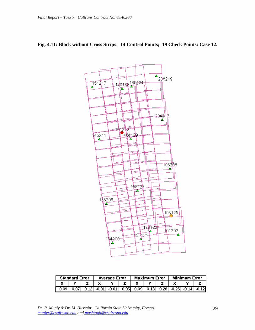
Final Report ndash Task 7 Caltrans Contract No 65A0260
Fig 411 Block without Cross Strips 14 Control Points 19 Check Points Case 12
SSttaannddaardrd EErrorrorr AAvveeraraggee EErrrroorr MMaaxxiimmuumm EErrorrorr MMiinniimmuumm EErrorrorr XX YY ZZ XX YY ZZ XX YY ZZ XX YY ZZ
000099 000077 001122 --000011 --000101 000055 000099 001313 002828 --002255 --001414 --001122
Dr R Munjy amp Dr M Hussain California State University Fresno munjyrcsufresnoedu and mushtaqhcsufresnoedu
29
Final Report ndash Task 7 Caltrans Contract No 65A0260
5 ANALYSIS OF RESULTS amp CONCLUSIONS
In accordance with the Caltrans standards using wide-angle aerial photography the RMS error in each coordinate component of the adjusted tie points should not exceed 110000 of the flying height above the terrain The Del Mar Test Block was flown with a wideshyangle aerial camera from an average height of 1800 feet above the terrain level thereby resulting in an average photo scale of 13600 Consequently the limiting RMS error at the Check Points representative of a finite number of well distributed tie points in the block should not exceed 018 ft in this case Any error that exceeds three times this limiting value viz 054 ft in any of the coordinate components should be a cause for rejection of that point
Therefore the acceptable limiting values for the standard error at the Check Points is 018 ft in each coordinate component Any block adjustment solution that results in a coordinate error in one or more Check Points that exceeds 054 ft in any coordinate component would not be an acceptable solution The following analysis of the results is based on these accuracy criteria
51 Blocks With Cross Flights
When a minimal number of 8 control points are used (Fig 42) along the block perimeter the resulting standard error in Z-coordinate of 019 ft exceeds the limiting value of 015 ft It is also noticeable that the highest error in the Z-coordinate of 052 ft at Point 189134 almost equals the rejection limit of 054 ft This is an indication that controlling a cross flight with only a single Control Point at each end of the flight may not always provide a satisfactory solution
This situation can be remedied by using a pair of Control Points in each end model of a cross flight so that any deformation across the flight line the omega rotation () can also be controlled Such an approach is also reported to have been successfully used and recommended in the past [1] [2] [3] When 4 additional Control Points were added at the end of each cross flight line as is seen in Fig 43 all the standard errors fell within the acceptable range and the maximum coordinate error did not exceed 030 ft which is well within the acceptable criteria
The primary advantage of using airborne GPS data for the adjustment of aerial triangulation blocks is to completely eliminate the need for Control Points in the interior of the block But it is of interest to investigate how effectively the airborne GPS data alone can control the interior of the block Two separate blocks were processed by adding two Control Points in the interior of the block resulting in a total of 14 Control Points
The block with 14 Control Points (Case A) is shown in Fig 44 where the two interior Control Points were selected so that one Control Point was located on the opposite ends in each of the two interior flight lines (Line 2 and Line3 see Fig 41) The other block with 14 Control Points (Case B) is shown in Fig 45 In this case both the interior points
Dr R Munjy amp Dr M Hussain California State University Fresno munjyrcsufresnoedu and mushtaqhcsufresnoedu
30
Final Report ndash Task 7 Caltrans Contract No 65A0260
fell in the middle of the block interior It is interesting to note that in either of the two cases the addition of the interior Control Points did not result in any significant difference from the result achieved earlier while using 12 Control Points Therefore it may be concluded that as long as the cross flights are adequately controlled with a pair of Control Points located across each end model of each cross flight additional control in the block interior is not required The results shown in Fig 44 and 45 validate this conclusion at least for a block comprised of 18 models long multiple flight lines
52 Blocks Without Cross Flights
When a mapping project involves a large photogrammetric block consisting of hundreds of models the common practice is to plan the block configuration to include cross flights [1] [2] [6] [10] Often such cross flights can result in significant saving in time and effort in minimizing the need for ground control Since the photogrammetric mapping projects in Caltrans mostly involve mapping along highway corridors most of the photogrammetric blocks vary from a single flight line to up to as many as four flight lines Therefore it is still to be investigated whether the use of cross flight lines in such blocks offers any significant advantage Furthermore any advantage resulting from the reduced need for the ground control has to be weighed against the additional time and effort needed in processing the cross flight models The Caltrans Office of Photogrammetry has not yet adopted the use of Automated Aerial Triangulation (AAT) techniques for routine production Consequently the additional effort in transferring tie points between the cross flights with the flights of the main block is still significant This has provided the impetus to carry out the following investigation for the aerial triangulation adjustment of blocks that do not include any cross flights
The first block without the two cross flights was processed with only 8 Control points along the block perimeter as a parallel case with the block run with cross flights The results are shown in Fig 46 As may be expected the absence of any Control Point located at each end of each of the two interior flights 2 and 3 has resulted in unacceptably large errors Not only is the standard error of 059 ft in the Z-coordinate for the 25 Check Points too large but interestingly the block adjustment carries a large systematic error in Z-coordinate of 108 ft This results from the fact that the absence of the Control Points at each end of Flights 2 and 3 does not permit the adjustment for the systematic strip drift parameters for the airborne GPS data along Flights 2 and 3
When cross flights are included the airborne GPS data measured along the cross flight adequately serves as control for adjusting the strip shift and drift parameters Therefore an alternative to the inclusion of cross flights in the block configuration is to provide a Control Point at each end of every flight line in the block Accordingly the processing of the following blocks includes Control Points at the end of each flight line
The Del Mar Test Block with 4 flight lines each 18 models long would require a total of 12 Control Points one Control Point at each end of each flight line and 4 Control Points along the interior perimeter of the block to provide a control spacing of approximately 6 airbases apart However in order to minimize the use of the ground control the block
Dr R Munjy amp Dr M Hussain California State University Fresno munjyrcsufresnoedu and mushtaqhcsufresnoedu
31
Final Report ndash Task 7 Caltrans Contract No 65A0260
shown in Fig 47 was processed with only 11 Control Points (Case A) since the Control Point 170133 was measured both in Line 2 and Line 3 The resulting standard error of 019 ft in the Z-coordinate for 22 Check Points as well as the large error of 050 ft in the Z-coordinate of Check Point 189134 make the block adjustment solution unacceptable There appears to be no obvious reason why the Check Point 189134 that is located so close to the Control Point 170133 should display such unacceptably large error in the Zshycoordinate In order to ascertain the internal consistency of the ground control data (33 Control Points) a conventional aerial triangulation adjustment of the block was performed (without using the airborne GPS data) using 32 Control Points and treating the Control Point 189134 as a Check Point The resulting error in the Z-coordinate of Point 189134 was only 006 ft It is also to be noted that the average Z-coordinate error of 017 ft indicates a systematic height error This would lead to the conclusion that there is some height discrepancy between the ground control data and the airborne GPS data
The block was re-processed (Case B) again by using only 11 Control Points but this time the Control Point 170133 was replaced with Control Point 189134 and the results are displayed in Fig 48 The Case B results are even worse than the Case A results the standard error in Z-coordinate was degraded to 027 ft while the largest error in Zshycoordinate of 066 ft was noted at Check Point 187215 The average Z-coordinate error also increases to 031 ft This is a further indication that there is significant height inconsistency in the airborne GPS data and the ground control data It appears that the height discrepancy between the ground control data and the airborne GPS data results in an unsatisfactory shift and drift adjustment of the airborne GPS data particularly in the inner flight Lines 2 and 3 that span 18 models between the end Control Points
In order to strengthen the end control across the flight lines both the Control Points 170133 and 189134 were used at the Northern end of the block The block was then processed with 12 Control Points and the results are presented in Fig 49 Even though the results improved significantly but contrary to the expectation the standard error in the Z-coordinate of 020 ft for the 21 Check Points did not meet the Caltrans accuracy standard The next logical approach was to investigate the impact of adding Control Points in the interior of the block Two interior Control Points were selected in the same manner as has been described earlier in the case of the blocks with the cross flights (see Fig 44 and 45)
Using 14 Control Points the Case A is shown in Fig 410 while the Case B is presented in Fig 411 The results in both Case A and Case B easily meet the Caltrans accuracy standards In Case A the distance between the Control Points for the shift and drift parameter adjustment of the airborne GPS data varies from 6 to 12 models while in Case B the interior Control Points are about 6 models apart Each Control Point distribution provides almost similar results It is a clear indication that any systematic height deformation that results from the suspected inconsistency between the ground surveyed GPS data and the airborne GPS data can be kept within acceptable range by including a pair of control points in the interior of the block Such a need for some control points has not been reported for the adjustment of aerial triangulation blocks in the past However the largest photo scale for which any ABGPS supported results have been published in
Dr R Munjy amp Dr M Hussain California State University Fresno munjyrcsufresnoedu and mushtaqhcsufresnoedu
32
Final Report ndash Task 7 Caltrans Contract No 65A0260
the past is 14800 only For a photo scale of 13600 that is approximately 25 percent larger the requirements for the accuracy of aerial triangulation accordingly become more stringent in the same proportion This may generate the need for some additional control in the middle of the block
The residuals at the ground control points and in the image coordinate data along with the resulting standard error of unit weight (0) provide a reliable indication of the internal consistency of the adjusted block However the absolute accuracy of the aerial triangulation can be validated only by the use of Check Points that are well distributed over the entire block As pointed out earlier any deformations due to residual systematic shift and drift errors in the airborne GPS data are likely to be most significant in the center of the block the location that is farthest from the control points distributed along the perimeter Accordingly it would be advisable to locate at least a pair of Check Points in the middle of the block and after completing the block adjustment (by excluding these Check Points as Control Points) the coordinate discrepancies obtained at these Check Points can be analyzed Such discrepancies would normally represent the highest absolute accuracy resulting from aerial triangulation adjustment of the block Any unacceptably large coordinate discrepancies at the Check Points would require investigation of the block input data
In the case the coordinate discrepancies at the Check Points are within acceptable range the block can be re-processed by also including the Check Points in the control data This should enhance the accuracy in the interior of the block
6 RECOMMENDED DRAFT STANDARDS
These draft standards are proposed to supplement the existing Standards for Strip Configuration Airborne GPS Controlled Photogrammetry for Large Scale Mapping Projects (based on 13600 photo scale) currently used in Caltrans
61 Data Acquisition
611 Image Coordinate Data
Follow the existing practice used in Caltrans Office of Photogrammetry for the selection distribution and the measurement of all image point data It is recommended that raw machine coordinate image data should form the input to the aerial triangulation block adjustment
A secondary interest in this Research Project under contract with Caltrans was to also evaluate the alternate methodology of the selection and the measurement of tie point data using Automated Aerial Triangulation (AAT) system However several problems were encountered in implementing the AAT software available at the Caltrans Office of Photogrammetry in Sacramento The unavoidable delay caused by unfavorable weather conditions in acquiring the aerial imagery for the Del Mar Test Block did not allow
Dr R Munjy amp Dr M Hussain California State University Fresno munjyrcsufresnoedu and mushtaqhcsufresnoedu
33
Final Report ndash Task 7 Caltrans Contract No 65A0260
enough time to resolve the AAT software issues with software vendor Accordingly this task could not be fully completed Therefore it was mutually agreed between the Caltrans Office of Photogrammetry and California State University Fresno to concentrate research efforts on the processing and the analysis of the Del Mar Test Block and on drafting the Final Report
612 Ground Control Data
The proposed research is focused on the use of photography obtained at scale of 13600 for corridor mapping in Caltrans The ground control for mapping is based on the airborne GPS supported aerial triangulation of the photo blocks The ground control points should be surveyed to provide 15 to 2-times higher accuracy than that of the adjusted tie point data This would translate to an accuracy at the 005 to 01 ft level for the planimetric coordinates and the height an accuracy achievable using static GPS surveys tied to existing HPGN network
It is not yet certain that the Real-Time Kinematic (RTK) GPS field survey methodology whether relying on a single base station or on an RTK network is able to meet the above stringent field survey accuracy requirements Therefore the ground control data for ABGPS based aerial triangulation blocks should be based entirely on GPS control networks established using static GPS surveying methodology The RTK survey methodology for establishing control for photogrammetric mapping projects should not be used till such time that such technology has advanced to a level when consistently reliable results can be routinely expected
The GPS observations provide a fairly precise data for ellipsoidal height differences However all photogrammetric mapping has to be based on orthometric height data Two different approaches can be used in order to derive adjusted orthometric height data through aerial triangulation The first method is to carry out the simultaneous least squares adjustment of the GPS observation data for the ground control network using current Caltrans Horizontal Datum CCS83 (199135) and Vertical Datum NAVD 88 But since the observed data involves the measurement of ellipsoidal height differences for each measured baseline there is a need for transforming such differences to the corresponding orthometric height differences on NAVD 88 Datum In the absence of an existing Local Geoid Model the only economic recourse available to meet this need is to use the most reliable existing Global Geoid Model the time-consuming and prohibitively more costly alternative would be to connect the control network stations through differential leveling The Global Geoid Models are progressively being updated and the GEOID 2003 Model is most commonly in current use although GEOID 2009 Model may soon become available
It has to be noted that the use of a Global Geoid Model will always have some residual geoidal height uncertainties perhaps in the range of few hundredths of a foot It is therefore necessary that a few stations that are well distributed over the control network should have precisely known orthometric height values which can be used for the height adjustment of the network The minimum number of such orthometric height control
Dr R Munjy amp Dr M Hussain California State University Fresno munjyrcsufresnoedu and mushtaqhcsufresnoedu
34
Final Report ndash Task 7 Caltrans Contract No 65A0260
stations is three and consequently a network should be planned to have at least four and preferably more stations where orthometric height is precisely known In practice this requirement is met by including several existing benchmarks that are well distributed over the project area The redundancy provided by using more than three benchmarks will quantify the height residuals resulting from the adjustment This will provide a good estimate for the residual height errors in the network
The alternative approach is to carry out the adjustment of the GPS control network using WGS84 Geodetic Datum This datum is consistent with the observed GPS measurement data and a simultaneous 3D adjustment of the network can be performed in a Local Spatial Coordinate System (LSCS) the most commonly used approach is to shift the origin of the WGS84 coordinate system (center of the Earth) to approximately the center of the project site and apply a 3D rotational matrix to align the coordinate axes along the East North and Up directions Some commercial aerial triangulation software systems provide utilities to easily perform such datum transformation After the aerial triangulation results have been validated the coordinates of all the control and tie points can be transformed back to WGS 84 Datum Based on the availability of the orthometric height control stations a local Geoid can be defined ( a plane or a surface etc) and then used to transform the ellipsoidal height data to orthometric height data This second approach has the advantage that unlike the first method described above the residual height errors in the transformed control point height data are not propagated through aerial triangulation
For 13600 scale aerial photography blocks the ground control data should meet the a- priori standard deviation at 010 ft level This is not a very challenging demand for the horizontal positioning using GPS methodology However the residual height uncertainties in the orthometric height of control points interpolated from the Global Geoid Model become more critical as the photo scale becomes larger
613 Airborne GPS Data
The current practice used in Caltrans to acquire airborne GPS data during flight missions should continue to be used It is necessary to have GPS data collected at 1 Hz or higher rate at a base station that is located within or close to the project site Prior research completed collaboratively with Caltrans has already shown that the data at the base station may be substituted with GPS data collected at CORS at 5-sec or higher rate Consequently the collection of GPS data at more than one base stations is not considered as an essential requirement It may still be prudent to acquire GPS data at a second base station as a contingency safeguard against the GPS hardware failure at a base station for guaranteed success of the flight mission and expense
It is to be noted that the relative accuracy between successive airborne GPS antenna 3Dshycoordinates should be at 10-cm or higher level The current procedure used in Caltrans for the aircraft to remain stationary for static resolution of ambiguities before take off has mostly resulted in acquiring very reliable airborne GPS data This practice should perhaps be continued even though the continuing improvements in GPS hardware and
Dr R Munjy amp Dr M Hussain California State University Fresno munjyrcsufresnoedu and mushtaqhcsufresnoedu
35
Final Report ndash Task 7 Caltrans Contract No 65A0260
post-processing softwares are making on-the-fly (OTF) ambiguity resolution increasingly reliable However if it is necessary to resort to on-the-fly ambiguity resolution it must be ensured that the ambiguities have stabilized before photography is started The strict requirement for reliably resolving the ambiguities also does not permit the loss of lock during any single flight line If a loss of lock occurs during turns between flight lines ambiguities must be re-acquired and must stabilize before starting the collection of photography for another flight line Based on the make and the model of the airborne GPS receiver the Caltrans Office of Photogrammetry in consultation with the District Survey Section should draft a set of instructions for the GPSCamera operator aboard the aircraft specifying what parameters (such as PDOP Number of SVs etc) that need to be continuously monitored on a screen during a flight mission
62 Flight and Control Configuration
The following standards in planning the flight line configuration and the corresponding ground control distribution for Caltrans project are recommended to achieve optimum results
Control points are primarily required only along the perimeter of the block When a cross flight line is used to control the end of a block a pair of Control
Points must be located at each end of the cross flight At each end of a block that is not controlled by a cross flight a CP should be
located at the end of each parallel flight line a single CP may serve as end control for two adjacent overlapping flight lines
Along the perimeter of the block in a direction parallel with the main flight lines the CPs should be located at an average spacing of 6 airbases
Any corner in a block resulting from a sudden change in the length of two adjacent parallel flight lines should be controlled by an additional CP
Check Points should be provided along the interior flight lines in a multi-strip block The Check Points may be distributed along the interior flight lines so that any Check Point is not farther than about 8 airbases from either another Check Point (on same or adjacent flight line) or from a Control Point
Note that Caltrans is usually concerned with the mapping mostly along highway corridors and therefore does not require blocks with segments larger than three or four parallel flight lines Additional control along the cross flight line would be needed if such segments have 8 or more parallel flight lines
63 Data Processing and Adjustment
631 Processing of ABGPS Data
The current practice of post-processing ABGPS data used in Caltrans Office of Photogrammetry using GrafNav software should be continued The data should continue to be processed in the Forward and Backward modes A coordinate separation of less
Dr R Munjy amp Dr M Hussain California State University Fresno munjyrcsufresnoedu and mushtaqhcsufresnoedu
36
Final Report ndash Task 7 Caltrans Contract No 65A0260
than 10 cm especially in the height represents a normally acceptable range for the combined solution
This study has shown that the airborne GPS data in comparison with the ground control data should be weighted a lower weight but the highest weight that the GPS data quality represents Generally the best results were achieved when a-priori standard error of 015 ft was used for the airborne GPS coordinate data in comparison with the a-priori standard error of 010 ft used for the ground control coordinate data Since the 3-D position of successive points along the airborne GPS antenna trajectory are estimated using Kalman Filtering approach the successive location coordinates are highly correlated and consequently carry a much higher relative precision This provides a realistic justification for the use of a-priori standard error of 015 ft
632 Processing of Aerial Triangulation Block
Each aerial triangulation block requires the following data files as input
- Raw image coordinate data file - Ground control data file - Interpolated camera coordinate data file
Using the above input data files the block adjustment should be carried out in two steps as described below It is essential that additional Strip Shift and Drift parameters (3 Shift and 3 Drift parameters) should be incorporated in the bundle adjustment solution
Step 1 Minimal Control Adjustment
The preliminary simultaneous bundle adjustment of the block should be carried out by using the minimal amount of control points along the block perimeter only All the additional ground surveyed and targeted points should be treated as tie points to serve as Check Points The adjustment results should meet the following criteria
a The Standard Error of Unit Weight (0) should fall between 03 to 07 b The residual for any image coordinate should not exceed 15 micrometer c The RMS for ground control residuals should not exceed 110000 of the flying
height above the average terrain level d The maximum residual in any ground control coordinate should not exceed 25
times the RMS value permissible under Item (c) above e The RMS for discrepancy (difference between computed coordinate value and
the ground surveyed coordinate value) in Check Point coordinates should not exceed 110000 of the flying height above the average terrain level
f The discrepancy in any Check Point coordinate should not exceed 25 times the RMS value permissible under Item (e) above
If the above criteria are met even the preliminary adjustment solution for the block satisfies Caltrans accuracy standards for aerial triangulation If the criterion under Item
Dr R Munjy amp Dr M Hussain California State University Fresno munjyrcsufresnoedu and mushtaqhcsufresnoedu
37
Final Report ndash Task 7 Caltrans Contract No 65A0260
(f) above is not met the input data should be checked for any gross mistakes or errors in the ground control and Check Point data
Step 2 Full Control Adjustment
The final simultaneous bundle adjustment of the block should be carried out by including all the ground surveyed points (Control Points and Check Points) in the ground control data file The adjustment results should meet the following criteria
g The Standard Error of Unit Weight (0) should fall between 03 to 07 h The residual for any image coordinate should not exceed 15 micrometer i The RMS for ground control residuals should not exceed 110000 of the flying
height above the average terrain level j The maximum residual in any ground control coordinate should not exceed 25
times the RMS value permissible under Item (i) above
7 CONCLUDING COMMENTS
The completion of this project signifies the culmination of a very successful and productive combination of advanced theoretical principles with sound practical experience for the adaptation of evolving photogrammetric technologies in Caltrans practice In order to alleviate a growing concern for the safety of staff conducting field survey operations in close proximity of high speed traffic Caltrans in late 1990s decided to investigate the feasibility of using airborne GPS data for controlling the aerial triangulation blocks There were two primary issues to be resolved The first and the foremost concern was whether the use of airborne GPS data could be effectively used for controlling aerial triangulation blocks of as large a photo scale as 13000 used in Caltrans and still meet the Caltrans accuracy standards This concern was particularly critical since there had not been any reported use of airborne GPS data for such a large scale of aerial photography
Should the above investigation show that the Caltrans accuracy standards for aerial triangulation for 13000 scale aerial photography can be met it was of great interest to Caltrans to develop based on theoretically sound and systematic investigation a set of standards and specifications for the successful implementation of this new methodology in Caltrans routine practice
Under a Caltrans New Technology and Research Program currently Division of Research and Innovation (DRI) contract Caltrans Office of Photogrammetry partnered with a team of two faculty members from the Geomatic Engineering Program at the California State University Fresno (CSUF) in 1996 to carry out research to address the above two issues This partnership has flourished over the past several years through
Dr R Munjy amp Dr M Hussain California State University Fresno munjyrcsufresnoedu and mushtaqhcsufresnoedu
38
Final Report ndash Task 7 Caltrans Contract No 65A0260
successive research contracts and has resulted in very fortuitous outcomes based on the theoretical and analytical guidance provided by the CSUF research team and the highly skilled aerial survey project management and high caliber professional skills in the acquisition of photogrammetric data collection by the Caltrans Office of Photogrammetry In addition the help from highly experienced field survey teams from Caltrans various districts (especially District 11) in establishing GPS networks of Control Points and Check Points of specified precision was critical for the validation of airborne-GPS supported aerial triangulation investigations
As a result of the past collaborative efforts between the Caltrans Office of Photogrammetry and the CSUF Research Team the use of airborne GPS data for aerial triangulation has successfully been transitioned into Caltrans practice in the following stages
1) Based on a number of test flights it was convincingly demonstrated that the use of airborne GPS data consistently meets the Caltrans accuracy standards for aerial triangulation for strip configuration blocks at 13000 photo scale [13]
2) A detailed set of standards and specifications were developed for the implementing of the new methodology in Caltrans routine practice This was further supported through a training workshop conducted by CSUF at the Caltrans offices in Sacramento [8]
3) The use of airborne GPS data for the adjustment of aerial triangulation blocks requires the collection of GPS data at one or more ground base stations during the flight mission This requirement imposes burdensome demands on scheduling and allocation of manpower and equipment resources In order to reduce or even to completely eliminate the need for the collection of GPS data at base stations the use of GPS data collected and archived at a network of Continuously Operating Reference Stations (CORS) distributed over the State of California was investigated It was demonstrated that CORS data could be effectively used as a replacement for data collected at base stations while fulfilling Caltrans accuracy standards Accordingly specifications were revised to also include the selection and the use of CORS data for the post-processing of airborne GPS data to accurately derive the trajectory of the airborne GPS antenna during flights [19]
4) During the past few years Caltrans has increasingly been using multi-strip projects for mapping using 13600 photo scale This provided the need for the current research study The successful completion of this study has resulted in supplementing the existing standards and specifications for airborne GPS supported single-strip aerial triangulation blocks to also include the aerial triangulation of multi-strip blocks
It is a matter of great satisfaction for the research team at CSU Fresno that working hand in hand with the Caltrans Office of Photogrammetry the comprehensive set of standards and specifications for airborne GPS supported aerial triangulation that had been developed for successful transition of this technology in Caltrans practice have been further upgraded It is hoped that as the photogrammetric technology advances further
Dr R Munjy amp Dr M Hussain California State University Fresno munjyrcsufresnoedu and mushtaqhcsufresnoedu
39
Final Report ndash Task 7 Caltrans Contract No 65A0260
similar collaborative efforts between Caltrans Office of Photogrammetry and CSU Fresno will continue to address the changing needs in Caltrans
Dr R Munjy amp Dr M Hussain California State University Fresno munjyrcsufresnoedu and mushtaqhcsufresnoedu
40
Final Report ndash Task 7 Caltrans Contract No 65A0260
REFERENCES
1 Abdullah Q M Hussain and R Munjy (2002) Workshop on Airborne GPS-Supported Aerial Triangulation ndash Theory and Practical Concepts presented at the Annual ASPRS Convention Washington DC 2002
2 Ackermann Fritz (1992) Operational Rules and Accuracy Models for GPS-Aerotriangulation Archives of the ISPRS Com 1 Vol29 1992 [pp 691-700]
3 Ackermann F (1993) Application of GPS for Aerial Triangulation Photogrammetric Engineering and Remote Sensing Vol 59 No 11 [pp 1651shy1658]
4 Appleton James Mushtaq Hussain and Riadh Munjy (2000) Use of Airborne GPS Data for Highway Mapping International Archives of Photogrammetry and Remote Sensing Vol XXXIII Part B4 Amsterdam 2000[pp 84-90]
5 Appleton James M Hussain and R Munjy (2002) Use of Airborne GPS Data For Aerial Triangulation in Caltrans (2002) Workshop presented at the California Department of Transportation Sacramento 2002
6 Federal Geographic Data Committee (FGDC) 1998 Geospatial Positional Accuracy Standards Part-3 National Standards for Spatial Data Accuracy (NSSDA) FGDC-STD-0073-1998
7 Friess Peter (1992) Experiences with GPS-Supported Aerial Triangulation Archives of the ISPRS Com 1 Vol29 1992 [pp 299 - 305]
8 Gianellia Alexander M (1995) Practical Considerations in Implementing GPS Technologies in Airborne Data Collection Proc ASPRS Annual Convention 1995 [pp 917-925]
9 Hussain M R Munjy and J Appleton (1999) Use of Airborne On-the-Fly Kinematic GPS Data for Photogrammetric Mapping Proceedings ION-GPS-99 Conference Nashville 1999[pp 1653-1659]
10 Hussain M and R Munjy (1999) GPS Controlled Photogrammetry For Large Scale Mapping (1999) Final Project Report Research project No 65Y271 submitted to New Technology amp Research Program California Department of Transportation
11 Hussain M and R Munjy (2002) Airborne GPS Controlled Aerial Triangulation in Caltrans Final Project Report Research project No 65A0059 submitted to New Technology amp Research Program California Department of Transportation June 2002
12 Munjy R and M Hussain (1985) Interactive Simultaneous Bundle Block Adjustment System (ISBBA) for Small Computers Proceedings of the ASPRS Annual Convention Washington DC 1985
13 Munjy R M Hussain and James Appleton (2000) Use of Airborne GPS Data for Corridor Mapping presented at the Annual ASPRS Convention Washington DC 2000
Dr R Munjy amp Dr M Hussain California State University Fresno munjyrcsufresnoedu and mushtaqhcsufresnoedu
41
Final Report ndash Task 7 Caltrans Contract No 65A0260
14 Munjy R and M Hussain (2007) Develop Criteria for Using Network GPS for Airborne GPS Photogrammetry Final Project Report Research Project No 65A0234 submitted to the Division of Research and Innovation (DRI) California Department of Transportation
15 Munjy R and M Hussain (2009) Draft Preliminary Standards Interim Report Research Project No 65A0260 submitted to Division of Research aned Innovation (DRI) California Department of Transportation
Dr R Munjy amp Dr M Hussain California State University Fresno munjyrcsufresnoedu and mushtaqhcsufresnoedu
42
APPENDIX I Results of Check Block
Flight amp Control Configuration Cases Used for
Study amp Analysis of Check Project in San Diego
INDEX
Case Block amp Control Configuration 1 Full Blk(Flts1to9) All 44 CP 2 Full Blk 8 CP 3 Full Blk 9 CP 4 Full Blk 10 CP 5 Main Blk(Flts1to7) 43 CP 6 Main Blk(Flts1to7) 8 CP 7 Main Blk(Flts1to7) 10 CP 8 Main Blk(Flts1to7) 12 CP 9 North Blk(Flts567amp9) 5 CP 10 North Blk(Flts567amp9) 7 CP 11 North Blk(Flts56amp7) 6 CP 12 North Blk(Flts56amp7) 8 CP 13 South Blk(Flts1to4amp8) 4 CP 14 South Blk(Flts1to4amp8) 6 CP 15 South Blk(Flts1to4amp8) 7 CP 16 South Blk(Flts1to4) 7 CP 17 South Blk(Flts1to4) 8 CP(a) 18 South Blk(Flts1to4) 8 CP(b) 19 South Blk(Flts1to4) 10 CP 20 South Blk(Flts1to4) 11 CP 21 South Blk(Flts Modified 1to4 amp8) 5 CP 22 South Blk(Flts Modified 1to4 ) 6 CP
[Refer to Table-1 Summary of the Coordinate Differences at the Check Points]
I-i
Case-1 Base DataFULL BLOCK
Flts 1 to 9
Case-1 Base Data FULL BLOCK
Flts 1 to 9
Control PointsControl Points All 44 PointsAll 44 Points
SSSttt ErErErrrr AAAvvvggg ErErErrrr MMMaaaxxx ErErErrrr MMMiiinnn ErErErrrr XXX YYY ZZZ XXX YYY ZZZ XXX YYY ZZZ XXX YYY ZZZ
007 008 005 000 000 000 019 012 012 -013 -023 -013007 008 005 000 000 000 019 012 012 -013 -023 -013007 008 005 000 000 000 019 012 012 -013 -023 -013
I-ii
Case-2FULL BLOCK
Flts 1 to 9
Control Points 8
Case-2 FULL BLOCK
Flts 1 to 9
Control Points 8 CChheecckk PoPointsints 3366
SStt ErErrr AAvvgg ErErrr MMaaxx ErErrr MMinin ErErrr XX YY ZZ XX YY ZZ XX YY ZZ XX YY ZZ
012012 012012 016016 002002 001001 --000505 024024 027027 026026 --025025 --039039 --032032
I-iii
Case-3FULL BLOCK
Flts 1 to 9
Control Points 9
Case-3 FULL BLOCK
Flts 1 to 9
Control Points 9 CChheecckk PoPointsints 3355
SStt ErErrr AAvvgg ErErrr MMaaxx ErErrr MMinin ErErrr XX YY ZZ XX YY ZZ XX YY ZZ XX YY ZZ
012012 012012 017017 001001 --001001 --000808 024024 024024 026026 --026026 --040040 --034034
I-iv
Case-4FULL BLOCK
Flts 1 to 9
Control Points 10
Case-4 FULL BLOCK
Flts 1 to 9
Control Points 10 CChheecckk PoiPoinntsts 3344
SStt ErErrr AAvvgg ErErrr MMaaxx ErErrr MMinin ErErrr XX YY ZZ XX YY ZZ XX YY ZZ XX YY ZZ
012012 009009 015015 003003 005005 --000909 002244 002727 002121 --025025 --001313 --035035
I-v
Case-5MAIN BLOCK
Flts 1 to 7
Control Points 43
Case-5 MAIN BLOCK
Flts 1 to 7
Control Points 43 [Point HV-117 Unuse[Point HV-117 Unusedd]]
SSSttt ErErErrrr AAAvvvggg ErErErrrr MMM aaaxxx ErErErrrr MMM iiinnn ErErErrrr XXX YYY ZZZ XXX YYY ZZZ XXX YYY ZZZ XXX YYY ZZZ
006006006 008008008 005005005 000000000 000000000 000000000 012012012 013013013 013013013 ---000131313 ---022022022 ---000090909
I-vi
Case-6
Flts 1 to 7
l Points 8
MAIN BLOCK
[No Cross Flts]Contro
Case-6 MAIN BLOCK
Flts 1 to 7 [No Cross Flts]
Control Points 8 ChecCheckk PoPointsints 3636
St ErSt ErSt ErSt ErSt ErSt ErSt ErSt Errrrrrrrr AAAAAAAAvgvgvgvgvgvgvgvg ErErErErErErErErrrrrrrrr MMMMMMMMaxaxaxaxaxaxaxax ErErErErErErErErrrrrrrrr MMMMMMMMiiiiiiiinnnnnnnn ErErErErErErErErrrrrrrrr XXXXXXXX YYYYYYYY ZZZZZZZZ XXXXXXXX YYYYYYYY ZZZZZZZZ XXXXXXXX YYYYYYYY ZZZZZZZZ XXXXXXXX YYYYYYYY ZZZZZZZZ
016016016016 012012012012 027027027027 -002-002-002-002 ----004004004004 -004-004-004-004 000026262626 000020202020 000041414141 ----035035035035 -036-036-036-036 ----082082082082
I-vii
Case-7MAIN BLOCK
Flts 1 to 7[No Cross Flts]
Control Points 10
Case-7 MAIN BLOCK
Flts 1 to 7 [No Cross Flts]
Control Points 10 CChheecckk PointsPoints 3434
SStt ErErrr AAvvgg ErErrr MM aaxx ErErrr MM iinn ErErrr XX YY ZZ XX YY ZZ XX YY ZZ XX YY ZZ
014 012 027 -001 -003 -004 022 020 039 -031 -031 -080014 012 027 -001 -003 -004 022 020 039 -031 -031 -080
I-viii
Case-8MAIN BLOCK
Flts 1 to 7[No Cross Flts]
Control Points 12
Case-8 MAIN BLOCK
Flts 1 to 7 [No Cross Flts]
Control Points 12 CheChecckk PointsPoints 3232
SSSttt ErErErrrr AAAvvvggg ErErErrrr MMMaaaxxx ErErErrrr MMMiiinnn ErErErrrr XXX YYY ZZZ XXX YYY ZZZ XXX YYY ZZZ XXX YYY ZZZ
015 010 017 003 000 -004 037 016 035 -031 -027 -023015 010 017 003 000 -004 037 016 035 -031 -027 -023015 010 017 003 000 -004 037 016 035 -031 -027 -023
I-ix
Case-9Case-9Case-9 NORNORNORTTTH BLH BLH BLOCKOCKOCK
FltsFltsFlts 5 to 7 amp 9 5 to 7 amp 9 5 to 7 amp 9
Control PointsControl PointsControl Points 555 ChChCheckeckeck PoPoPoininintttsss 111888
ErSSSttt EE rrrrr vg ErAAAvg Evg E rrrrr ax ErMMM ax Eax E rrrrr ErMMM iiinnn EE rrrrr XXX YYY ZZZ XXX YYY ZZZ XXX YYY ZZZ XXX YYY ZZZ
000121212 016016016 000161616 007007007 ---000161616 000111111 000262626 000020202 000363636 ---022022022 ---000626262 ---022022022
I-x
Case-Case-1100 NORTH BLOCKNORTH BLOCK
Flts 5 to 7 amp 9Flts 5 to 7 amp 9
Control PointsControl Points 77 CheckCheck PointsPoints 1616
SStt ErErrr AAvvgg ErErrr MM aaxx ErErrr MM iinn ErErrr XX YY ZZ XX YY ZZ XX YY ZZ XX YY ZZ
010010 016016 017017 008008 --000707 001818 002323 001010 005151 --016016 --005151 --012012
I-xi
Case-Case-1111 NORTH BLOCKNORTH BLOCK
FltsFlts 5 to 7 5 to 7
CCoontrntrool Pointsl Points 66 CheChecckk PointsPoints 1717
SStt ErErrr AAvvgg ErErrr MM aaxx ErErrr MM iinn ErErrr XX YY ZZ XX YY ZZ XX YY ZZ XX YY ZZ
010010 016016 022022 010010 --000202 000808 002424 001515 005050 --019019 --004343 --026026
I-xii
Case-Case-1122 NORTH BLOCKNORTH BLOCK
FltsFlts 5 to 7 5 to 7 [No C[No Crrossoss Flt]Flt]
ContControl Poinrol Pointsts 88 CChheecckk PointsPoints 1155
SStt EErrrr AAvg Evg Errrr MM ax Eax Errrr MM iinn EErrrr XX YY ZZ XX YY ZZ XX YY ZZ XX YY ZZ
011011 016016 017017 013013 --000909 000202 002929 000707 003737 --017017 --004949 --031031
I-xiii
CaseCase-13-13 SOUTSOUTH BH BLLOCKOCK
Flts 1 to 4 amp 8Flts 1 to 4 amp 8
CoConnttrol Porol Poininttss 44 ChCheckeck PPooinintsts 2222
SStt ErErrr AAvvgg ErErrr MM aaxx ErErrr MM iinn ErErrr XX YY ZZ XX YY ZZ XX YY ZZ XX YY ZZ
052 032 015 -082 033 003 -007 091 026 -149 -009 -034052 032 015 -082 033 003 -007 091 026 -149 -009 -034
I-xiv
Case-14Case-14 SOUTH BLOCKSOUTH BLOCK
Flts 1 to 4 amp 8Flts 1 to 4 amp 8
CCoontrntrool Pointsl Points 66 CheChecckk PointsPoints 2200
SStt ErErrr AAvvgg ErErrr MM aaxx ErErrr MM iinn ErErrr XX YY ZZ XX YY ZZ XX YY ZZ XX YY ZZ
013 016 015 -003 006 -002 024 033 033 -019 -028 -028013 016 015 -003 006 -002 024 033 033 -019 -028 -028
I-xv
Case-15Case-15 SOUTH BLOCKSOUTH BLOCK
FltsFlts 1 to 4 amp 8 1 to 4 amp 8
ContrControol Pointsl Points 77 ChCheckeck PPooinintsts 1919
SStt ErErrr AAvvgg ErErrr MM aaxx ErErrr MM iinn ErErrr XX YY ZZ XX YY ZZ XX YY ZZ XX YY ZZ
015 012 014 -003 -002 -002 025 023 033 -025 -030 -025015 012 014 -003 -002 -002 025 023 033 -025 -030 -025
I-xvi
Case-16Case-16Case-16 SOUTH BLOCKSOUTH BLOCKSOUTH BLOCK
FltsFltsFlts 1 to 4 1 to 4 1 to 4 [No Cross Flt][No Cross Flt][No Cross Flt]
Control PointsControl PointsControl Points 777 CheCheCheccckkk PointsPointsPoints 222222
SSSttt EEErrrrrr AAAvg Evg Evg Errrrrr MMM ax Eax Eax Errrrrr MMM iiinnn EEErrrrrr XXX YYY ZZZ XXX YYY ZZZ XXX YYY ZZZ XXX YYY ZZZ
015 013 023 -001 -005 003 026 023 032 -027 -029 -037015 013 023 -001 -005 003 026 023 032 -027 -029 -037015 013 023 -001 -005 003 026 023 032 -027 -029 -037
I-xvii
Case-17Case-17 SOUTSOUTH BLH BLOCKOCK
FltsFlts 1 1 to 4to 4 [No[No CrosCrosss Flt]Flt]
ContrControol Pointsl Points 88 CChheecckk PointsPoints 2121
SStt ErErrr AAvvgg ErErrr MM aaxx ErErrr MM iinn ErErrr XX YY ZZ XX YY ZZ XX YY ZZ XX YY ZZ
014014 012012 024024 005005 --000101 000404 003131 002525 003333 --022022 --002929 --040040
I-xviii
Case-18Case-18 SOUTH BLOCKSOUTH BLOCK
Flts 1 to 4Flts 1 to 4 [[NNo Cro Crooss Fss Flltt]]
CCoontrol Pointsntrol Points 88 CheChecckk PointsPoints 2121
SSSttt ErErErrrr AAAvvvggg ErErErrrr MMM aaaxxx ErErErrrr MMM iiinnn ErErErrrr XXX YYY ZZZ XXX YYY ZZZ XXX YYY ZZZ XXX YYY ZZZ
016 014 019 -003 -005 001 027 025 028 -033 -033 -032016 014 019 -003 -005 001 027 025 028 -033 -033 -032016 014 019 -003 -005 001 027 025 028 -033 -033 -032
I-xix
Case-19Case-19 SOUTH BLOCKSOUTH BLOCK
FltsFlts 1 to 4 1 to 4 [No Cross Flt][No Cross Flt]
ContControl Prol Poointintss 10 10 CheckCheck PointsPoints 1919
SSSttt ErErErrrr AAAvvvggg ErErErrrr MMM aaaxxx ErErErrrr MMM iiinnn ErErErrrr XXX YYY ZZZ XXX YYY ZZZ XXX YYY ZZZ XXX YYY ZZZ
014 012 019 004 -001 001 034 029 029 -025 -030 -028014 012 019 004 -001 001 034 029 029 -025 -030 -028014 012 019 004 -001 001 034 029 029 -025 -030 -028
I-xx
Case-Case-2200 SSOOUTH BLOCKUTH BLOCK
FltsFlts 1 to 4 1 to 4 [No Cross Flt][No Cross Flt]
Control Points 11Control Points 11 ChCheckeck PPooinintsts 1818
SSSttt ErErErrrr AAAvvvggg ErErErrrr MMM aaaxxx ErErErrrr MMM iiinnn ErErErrrr XXX YYY ZZZ XXX YYY ZZZ XXX YYY ZZZ XXX YYY ZZZ
014014014 012012012 018018018 ---000010101 ---005005005 ---000010101 000232323 000202020 000272727 ---030030030 ---000292929 ---031031031
I-xxi
Case-Case-2211 MODIMODIFFIIED SOUTH BED SOUTH BLLOCKOCK
FltsFlts 1 to 4 ( 1 to 4 (MModified)odified) amp 8amp 8
ControControl Pointsl Points 55 CheChecckk PointsPoints 1818
SStt ErErrr AAvvgg ErErrr MM aaxx ErErrr MM iinn ErErrr XX YY ZZ XX YY ZZ XX YY ZZ XX YY ZZ
013 010 015 -001 002 -001 024 021 035 -019 -025 -029013 010 015 -001 002 -001 024 021 035 -019 -025 -029
I-xxii
Case-22Case-22Case-22 MOMOMODIFDIFDIFIIIED SOED SOED SOUTH BLOCKUTH BLOCKUTH BLOCK
FltFltFltsss 1 to 4 1 to 4 1 to 4 (M(M(Modiodiodifiefiefieddd))) [No C[No C[No Crrrososossss Flt]Flt]Flt]
ConConContttrol Prol Prol Poooiiinnntttsss 666 ChChCheckeckeck PointPointPointsss 161616
SSSttt ErErErrrr AAAvvvggg ErErErrrr MMM aaaxxx ErErErrrr MMM iiinnn ErErErrrr XXX YYY ZZZ XXX YYY ZZZ XXX YYY ZZZ XXX YYY ZZZ
014 011 014 002 005 -010 025 024 016 -020 -024 -039014 011 014 002 005 -010 025 024 016 -020 -024 -039014 011 014 002 005 -010 025 024 016 -020 -024 -039
I-xxiii
APPENDIX II Results of Test Block
II-i
Final Report ndash Task 7 Caltrans Contract No 65A0260
successive research contracts and has resulted in very fortuitous outcomes based on the theoretical and analytical guidance provided by the CSUF research team and the highly skilled aerial survey project management and high caliber professional skills in the acquisition of photogrammetric data collection by the Caltrans Office of Photogrammetry In addition the help from highly experienced field survey teams from Caltrans various districts (especially District 11) in establishing GPS networks of Control Points and Check Points of specified precision was critical for the validation of airborne-GPS supported aerial triangulation investigations
As a result of the past collaborative efforts between the Caltrans Office of Photogrammetry and the CSUF Research Team the use of airborne GPS data for aerial triangulation has successfully been transitioned into Caltrans practice in the following stages
1) Based on a number of test flights it was convincingly demonstrated that the use of airborne GPS data consistently meets the Caltrans accuracy standards for aerial triangulation for strip configuration blocks at 13000 photo scale [13]
2) A detailed set of standards and specifications were developed for the implementing of the new methodology in Caltrans routine practice This was further supported through a training workshop conducted by CSUF at the Caltrans offices in Sacramento [8]
3) The use of airborne GPS data for the adjustment of aerial triangulation blocks requires the collection of GPS data at one or more ground base stations during the flight mission This requirement imposes burdensome demands on scheduling and allocation of manpower and equipment resources In order to reduce or even to completely eliminate the need for the collection of GPS data at base stations the use of GPS data collected and archived at a network of Continuously Operating Reference Stations (CORS) distributed over the State of California was investigated It was demonstrated that CORS data could be effectively used as a replacement for data collected at base stations while fulfilling Caltrans accuracy standards Accordingly specifications were revised to also include the selection and the use of CORS data for the post-processing of airborne GPS data to accurately derive the trajectory of the airborne GPS antenna during flights [19]
4) During the past few years Caltrans has increasingly been using multi-strip projects for mapping using 13600 photo scale This provided the need for the current research study The successful completion of this study has resulted in supplementing the existing standards and specifications for airborne GPS supported single-strip aerial triangulation blocks to also include the aerial triangulation of multi-strip blocks
It is a matter of great satisfaction for the research team at CSU Fresno that working hand in hand with the Caltrans Office of Photogrammetry the comprehensive set of standards and specifications for airborne GPS supported aerial triangulation that had been developed for successful transition of this technology in Caltrans practice have been further upgraded It is hoped that as the photogrammetric technology advances further
Dr R Munjy amp Dr M Hussain California State University Fresno munjyrcsufresnoedu and mushtaqhcsufresnoedu
39
Final Report ndash Task 7 Caltrans Contract No 65A0260
similar collaborative efforts between Caltrans Office of Photogrammetry and CSU Fresno will continue to address the changing needs in Caltrans
Dr R Munjy amp Dr M Hussain California State University Fresno munjyrcsufresnoedu and mushtaqhcsufresnoedu
40
Final Report ndash Task 7 Caltrans Contract No 65A0260
REFERENCES
1 Abdullah Q M Hussain and R Munjy (2002) Workshop on Airborne GPS-Supported Aerial Triangulation ndash Theory and Practical Concepts presented at the Annual ASPRS Convention Washington DC 2002
2 Ackermann Fritz (1992) Operational Rules and Accuracy Models for GPS-Aerotriangulation Archives of the ISPRS Com 1 Vol29 1992 [pp 691-700]
3 Ackermann F (1993) Application of GPS for Aerial Triangulation Photogrammetric Engineering and Remote Sensing Vol 59 No 11 [pp 1651shy1658]
4 Appleton James Mushtaq Hussain and Riadh Munjy (2000) Use of Airborne GPS Data for Highway Mapping International Archives of Photogrammetry and Remote Sensing Vol XXXIII Part B4 Amsterdam 2000[pp 84-90]
5 Appleton James M Hussain and R Munjy (2002) Use of Airborne GPS Data For Aerial Triangulation in Caltrans (2002) Workshop presented at the California Department of Transportation Sacramento 2002
6 Federal Geographic Data Committee (FGDC) 1998 Geospatial Positional Accuracy Standards Part-3 National Standards for Spatial Data Accuracy (NSSDA) FGDC-STD-0073-1998
7 Friess Peter (1992) Experiences with GPS-Supported Aerial Triangulation Archives of the ISPRS Com 1 Vol29 1992 [pp 299 - 305]
8 Gianellia Alexander M (1995) Practical Considerations in Implementing GPS Technologies in Airborne Data Collection Proc ASPRS Annual Convention 1995 [pp 917-925]
9 Hussain M R Munjy and J Appleton (1999) Use of Airborne On-the-Fly Kinematic GPS Data for Photogrammetric Mapping Proceedings ION-GPS-99 Conference Nashville 1999[pp 1653-1659]
10 Hussain M and R Munjy (1999) GPS Controlled Photogrammetry For Large Scale Mapping (1999) Final Project Report Research project No 65Y271 submitted to New Technology amp Research Program California Department of Transportation
11 Hussain M and R Munjy (2002) Airborne GPS Controlled Aerial Triangulation in Caltrans Final Project Report Research project No 65A0059 submitted to New Technology amp Research Program California Department of Transportation June 2002
12 Munjy R and M Hussain (1985) Interactive Simultaneous Bundle Block Adjustment System (ISBBA) for Small Computers Proceedings of the ASPRS Annual Convention Washington DC 1985
13 Munjy R M Hussain and James Appleton (2000) Use of Airborne GPS Data for Corridor Mapping presented at the Annual ASPRS Convention Washington DC 2000
Dr R Munjy amp Dr M Hussain California State University Fresno munjyrcsufresnoedu and mushtaqhcsufresnoedu
41
Final Report ndash Task 7 Caltrans Contract No 65A0260
14 Munjy R and M Hussain (2007) Develop Criteria for Using Network GPS for Airborne GPS Photogrammetry Final Project Report Research Project No 65A0234 submitted to the Division of Research and Innovation (DRI) California Department of Transportation
15 Munjy R and M Hussain (2009) Draft Preliminary Standards Interim Report Research Project No 65A0260 submitted to Division of Research aned Innovation (DRI) California Department of Transportation
Dr R Munjy amp Dr M Hussain California State University Fresno munjyrcsufresnoedu and mushtaqhcsufresnoedu
42
APPENDIX I Results of Check Block
Flight amp Control Configuration Cases Used for
Study amp Analysis of Check Project in San Diego
INDEX
Case Block amp Control Configuration 1 Full Blk(Flts1to9) All 44 CP 2 Full Blk 8 CP 3 Full Blk 9 CP 4 Full Blk 10 CP 5 Main Blk(Flts1to7) 43 CP 6 Main Blk(Flts1to7) 8 CP 7 Main Blk(Flts1to7) 10 CP 8 Main Blk(Flts1to7) 12 CP 9 North Blk(Flts567amp9) 5 CP 10 North Blk(Flts567amp9) 7 CP 11 North Blk(Flts56amp7) 6 CP 12 North Blk(Flts56amp7) 8 CP 13 South Blk(Flts1to4amp8) 4 CP 14 South Blk(Flts1to4amp8) 6 CP 15 South Blk(Flts1to4amp8) 7 CP 16 South Blk(Flts1to4) 7 CP 17 South Blk(Flts1to4) 8 CP(a) 18 South Blk(Flts1to4) 8 CP(b) 19 South Blk(Flts1to4) 10 CP 20 South Blk(Flts1to4) 11 CP 21 South Blk(Flts Modified 1to4 amp8) 5 CP 22 South Blk(Flts Modified 1to4 ) 6 CP
[Refer to Table-1 Summary of the Coordinate Differences at the Check Points]
I-i
Case-1 Base DataFULL BLOCK
Flts 1 to 9
Case-1 Base Data FULL BLOCK
Flts 1 to 9
Control PointsControl Points All 44 PointsAll 44 Points
SSSttt ErErErrrr AAAvvvggg ErErErrrr MMMaaaxxx ErErErrrr MMMiiinnn ErErErrrr XXX YYY ZZZ XXX YYY ZZZ XXX YYY ZZZ XXX YYY ZZZ
007 008 005 000 000 000 019 012 012 -013 -023 -013007 008 005 000 000 000 019 012 012 -013 -023 -013007 008 005 000 000 000 019 012 012 -013 -023 -013
I-ii
Case-2FULL BLOCK
Flts 1 to 9
Control Points 8
Case-2 FULL BLOCK
Flts 1 to 9
Control Points 8 CChheecckk PoPointsints 3366
SStt ErErrr AAvvgg ErErrr MMaaxx ErErrr MMinin ErErrr XX YY ZZ XX YY ZZ XX YY ZZ XX YY ZZ
012012 012012 016016 002002 001001 --000505 024024 027027 026026 --025025 --039039 --032032
I-iii
Case-3FULL BLOCK
Flts 1 to 9
Control Points 9
Case-3 FULL BLOCK
Flts 1 to 9
Control Points 9 CChheecckk PoPointsints 3355
SStt ErErrr AAvvgg ErErrr MMaaxx ErErrr MMinin ErErrr XX YY ZZ XX YY ZZ XX YY ZZ XX YY ZZ
012012 012012 017017 001001 --001001 --000808 024024 024024 026026 --026026 --040040 --034034
I-iv
Case-4FULL BLOCK
Flts 1 to 9
Control Points 10
Case-4 FULL BLOCK
Flts 1 to 9
Control Points 10 CChheecckk PoiPoinntsts 3344
SStt ErErrr AAvvgg ErErrr MMaaxx ErErrr MMinin ErErrr XX YY ZZ XX YY ZZ XX YY ZZ XX YY ZZ
012012 009009 015015 003003 005005 --000909 002244 002727 002121 --025025 --001313 --035035
I-v
Case-5MAIN BLOCK
Flts 1 to 7
Control Points 43
Case-5 MAIN BLOCK
Flts 1 to 7
Control Points 43 [Point HV-117 Unuse[Point HV-117 Unusedd]]
SSSttt ErErErrrr AAAvvvggg ErErErrrr MMM aaaxxx ErErErrrr MMM iiinnn ErErErrrr XXX YYY ZZZ XXX YYY ZZZ XXX YYY ZZZ XXX YYY ZZZ
006006006 008008008 005005005 000000000 000000000 000000000 012012012 013013013 013013013 ---000131313 ---022022022 ---000090909
I-vi
Case-6
Flts 1 to 7
l Points 8
MAIN BLOCK
[No Cross Flts]Contro
Case-6 MAIN BLOCK
Flts 1 to 7 [No Cross Flts]
Control Points 8 ChecCheckk PoPointsints 3636
St ErSt ErSt ErSt ErSt ErSt ErSt ErSt Errrrrrrrr AAAAAAAAvgvgvgvgvgvgvgvg ErErErErErErErErrrrrrrrr MMMMMMMMaxaxaxaxaxaxaxax ErErErErErErErErrrrrrrrr MMMMMMMMiiiiiiiinnnnnnnn ErErErErErErErErrrrrrrrr XXXXXXXX YYYYYYYY ZZZZZZZZ XXXXXXXX YYYYYYYY ZZZZZZZZ XXXXXXXX YYYYYYYY ZZZZZZZZ XXXXXXXX YYYYYYYY ZZZZZZZZ
016016016016 012012012012 027027027027 -002-002-002-002 ----004004004004 -004-004-004-004 000026262626 000020202020 000041414141 ----035035035035 -036-036-036-036 ----082082082082
I-vii
Case-7MAIN BLOCK
Flts 1 to 7[No Cross Flts]
Control Points 10
Case-7 MAIN BLOCK
Flts 1 to 7 [No Cross Flts]
Control Points 10 CChheecckk PointsPoints 3434
SStt ErErrr AAvvgg ErErrr MM aaxx ErErrr MM iinn ErErrr XX YY ZZ XX YY ZZ XX YY ZZ XX YY ZZ
014 012 027 -001 -003 -004 022 020 039 -031 -031 -080014 012 027 -001 -003 -004 022 020 039 -031 -031 -080
I-viii
Case-8MAIN BLOCK
Flts 1 to 7[No Cross Flts]
Control Points 12
Case-8 MAIN BLOCK
Flts 1 to 7 [No Cross Flts]
Control Points 12 CheChecckk PointsPoints 3232
SSSttt ErErErrrr AAAvvvggg ErErErrrr MMMaaaxxx ErErErrrr MMMiiinnn ErErErrrr XXX YYY ZZZ XXX YYY ZZZ XXX YYY ZZZ XXX YYY ZZZ
015 010 017 003 000 -004 037 016 035 -031 -027 -023015 010 017 003 000 -004 037 016 035 -031 -027 -023015 010 017 003 000 -004 037 016 035 -031 -027 -023
I-ix
Case-9Case-9Case-9 NORNORNORTTTH BLH BLH BLOCKOCKOCK
FltsFltsFlts 5 to 7 amp 9 5 to 7 amp 9 5 to 7 amp 9
Control PointsControl PointsControl Points 555 ChChCheckeckeck PoPoPoininintttsss 111888
ErSSSttt EE rrrrr vg ErAAAvg Evg E rrrrr ax ErMMM ax Eax E rrrrr ErMMM iiinnn EE rrrrr XXX YYY ZZZ XXX YYY ZZZ XXX YYY ZZZ XXX YYY ZZZ
000121212 016016016 000161616 007007007 ---000161616 000111111 000262626 000020202 000363636 ---022022022 ---000626262 ---022022022
I-x
Case-Case-1100 NORTH BLOCKNORTH BLOCK
Flts 5 to 7 amp 9Flts 5 to 7 amp 9
Control PointsControl Points 77 CheckCheck PointsPoints 1616
SStt ErErrr AAvvgg ErErrr MM aaxx ErErrr MM iinn ErErrr XX YY ZZ XX YY ZZ XX YY ZZ XX YY ZZ
010010 016016 017017 008008 --000707 001818 002323 001010 005151 --016016 --005151 --012012
I-xi
Case-Case-1111 NORTH BLOCKNORTH BLOCK
FltsFlts 5 to 7 5 to 7
CCoontrntrool Pointsl Points 66 CheChecckk PointsPoints 1717
SStt ErErrr AAvvgg ErErrr MM aaxx ErErrr MM iinn ErErrr XX YY ZZ XX YY ZZ XX YY ZZ XX YY ZZ
010010 016016 022022 010010 --000202 000808 002424 001515 005050 --019019 --004343 --026026
I-xii
Case-Case-1122 NORTH BLOCKNORTH BLOCK
FltsFlts 5 to 7 5 to 7 [No C[No Crrossoss Flt]Flt]
ContControl Poinrol Pointsts 88 CChheecckk PointsPoints 1155
SStt EErrrr AAvg Evg Errrr MM ax Eax Errrr MM iinn EErrrr XX YY ZZ XX YY ZZ XX YY ZZ XX YY ZZ
011011 016016 017017 013013 --000909 000202 002929 000707 003737 --017017 --004949 --031031
I-xiii
CaseCase-13-13 SOUTSOUTH BH BLLOCKOCK
Flts 1 to 4 amp 8Flts 1 to 4 amp 8
CoConnttrol Porol Poininttss 44 ChCheckeck PPooinintsts 2222
SStt ErErrr AAvvgg ErErrr MM aaxx ErErrr MM iinn ErErrr XX YY ZZ XX YY ZZ XX YY ZZ XX YY ZZ
052 032 015 -082 033 003 -007 091 026 -149 -009 -034052 032 015 -082 033 003 -007 091 026 -149 -009 -034
I-xiv
Case-14Case-14 SOUTH BLOCKSOUTH BLOCK
Flts 1 to 4 amp 8Flts 1 to 4 amp 8
CCoontrntrool Pointsl Points 66 CheChecckk PointsPoints 2200
SStt ErErrr AAvvgg ErErrr MM aaxx ErErrr MM iinn ErErrr XX YY ZZ XX YY ZZ XX YY ZZ XX YY ZZ
013 016 015 -003 006 -002 024 033 033 -019 -028 -028013 016 015 -003 006 -002 024 033 033 -019 -028 -028
I-xv
Case-15Case-15 SOUTH BLOCKSOUTH BLOCK
FltsFlts 1 to 4 amp 8 1 to 4 amp 8
ContrControol Pointsl Points 77 ChCheckeck PPooinintsts 1919
SStt ErErrr AAvvgg ErErrr MM aaxx ErErrr MM iinn ErErrr XX YY ZZ XX YY ZZ XX YY ZZ XX YY ZZ
015 012 014 -003 -002 -002 025 023 033 -025 -030 -025015 012 014 -003 -002 -002 025 023 033 -025 -030 -025
I-xvi
Case-16Case-16Case-16 SOUTH BLOCKSOUTH BLOCKSOUTH BLOCK
FltsFltsFlts 1 to 4 1 to 4 1 to 4 [No Cross Flt][No Cross Flt][No Cross Flt]
Control PointsControl PointsControl Points 777 CheCheCheccckkk PointsPointsPoints 222222
SSSttt EEErrrrrr AAAvg Evg Evg Errrrrr MMM ax Eax Eax Errrrrr MMM iiinnn EEErrrrrr XXX YYY ZZZ XXX YYY ZZZ XXX YYY ZZZ XXX YYY ZZZ
015 013 023 -001 -005 003 026 023 032 -027 -029 -037015 013 023 -001 -005 003 026 023 032 -027 -029 -037015 013 023 -001 -005 003 026 023 032 -027 -029 -037
I-xvii
Case-17Case-17 SOUTSOUTH BLH BLOCKOCK
FltsFlts 1 1 to 4to 4 [No[No CrosCrosss Flt]Flt]
ContrControol Pointsl Points 88 CChheecckk PointsPoints 2121
SStt ErErrr AAvvgg ErErrr MM aaxx ErErrr MM iinn ErErrr XX YY ZZ XX YY ZZ XX YY ZZ XX YY ZZ
014014 012012 024024 005005 --000101 000404 003131 002525 003333 --022022 --002929 --040040
I-xviii
Case-18Case-18 SOUTH BLOCKSOUTH BLOCK
Flts 1 to 4Flts 1 to 4 [[NNo Cro Crooss Fss Flltt]]
CCoontrol Pointsntrol Points 88 CheChecckk PointsPoints 2121
SSSttt ErErErrrr AAAvvvggg ErErErrrr MMM aaaxxx ErErErrrr MMM iiinnn ErErErrrr XXX YYY ZZZ XXX YYY ZZZ XXX YYY ZZZ XXX YYY ZZZ
016 014 019 -003 -005 001 027 025 028 -033 -033 -032016 014 019 -003 -005 001 027 025 028 -033 -033 -032016 014 019 -003 -005 001 027 025 028 -033 -033 -032
I-xix
Case-19Case-19 SOUTH BLOCKSOUTH BLOCK
FltsFlts 1 to 4 1 to 4 [No Cross Flt][No Cross Flt]
ContControl Prol Poointintss 10 10 CheckCheck PointsPoints 1919
SSSttt ErErErrrr AAAvvvggg ErErErrrr MMM aaaxxx ErErErrrr MMM iiinnn ErErErrrr XXX YYY ZZZ XXX YYY ZZZ XXX YYY ZZZ XXX YYY ZZZ
014 012 019 004 -001 001 034 029 029 -025 -030 -028014 012 019 004 -001 001 034 029 029 -025 -030 -028014 012 019 004 -001 001 034 029 029 -025 -030 -028
I-xx
Case-Case-2200 SSOOUTH BLOCKUTH BLOCK
FltsFlts 1 to 4 1 to 4 [No Cross Flt][No Cross Flt]
Control Points 11Control Points 11 ChCheckeck PPooinintsts 1818
SSSttt ErErErrrr AAAvvvggg ErErErrrr MMM aaaxxx ErErErrrr MMM iiinnn ErErErrrr XXX YYY ZZZ XXX YYY ZZZ XXX YYY ZZZ XXX YYY ZZZ
014014014 012012012 018018018 ---000010101 ---005005005 ---000010101 000232323 000202020 000272727 ---030030030 ---000292929 ---031031031
I-xxi
Case-Case-2211 MODIMODIFFIIED SOUTH BED SOUTH BLLOCKOCK
FltsFlts 1 to 4 ( 1 to 4 (MModified)odified) amp 8amp 8
ControControl Pointsl Points 55 CheChecckk PointsPoints 1818
SStt ErErrr AAvvgg ErErrr MM aaxx ErErrr MM iinn ErErrr XX YY ZZ XX YY ZZ XX YY ZZ XX YY ZZ
013 010 015 -001 002 -001 024 021 035 -019 -025 -029013 010 015 -001 002 -001 024 021 035 -019 -025 -029
I-xxii
Case-22Case-22Case-22 MOMOMODIFDIFDIFIIIED SOED SOED SOUTH BLOCKUTH BLOCKUTH BLOCK
FltFltFltsss 1 to 4 1 to 4 1 to 4 (M(M(Modiodiodifiefiefieddd))) [No C[No C[No Crrrososossss Flt]Flt]Flt]
ConConContttrol Prol Prol Poooiiinnntttsss 666 ChChCheckeckeck PointPointPointsss 161616
SSSttt ErErErrrr AAAvvvggg ErErErrrr MMM aaaxxx ErErErrrr MMM iiinnn ErErErrrr XXX YYY ZZZ XXX YYY ZZZ XXX YYY ZZZ XXX YYY ZZZ
014 011 014 002 005 -010 025 024 016 -020 -024 -039014 011 014 002 005 -010 025 024 016 -020 -024 -039014 011 014 002 005 -010 025 024 016 -020 -024 -039
I-xxiii
APPENDIX II Results of Test Block
II-i

Final Report ndash Task 7 Caltrans Contract No 65A0260
similar collaborative efforts between Caltrans Office of Photogrammetry and CSU Fresno will continue to address the changing needs in Caltrans
Dr R Munjy amp Dr M Hussain California State University Fresno munjyrcsufresnoedu and mushtaqhcsufresnoedu
40
Final Report ndash Task 7 Caltrans Contract No 65A0260
REFERENCES
1 Abdullah Q M Hussain and R Munjy (2002) Workshop on Airborne GPS-Supported Aerial Triangulation ndash Theory and Practical Concepts presented at the Annual ASPRS Convention Washington DC 2002
2 Ackermann Fritz (1992) Operational Rules and Accuracy Models for GPS-Aerotriangulation Archives of the ISPRS Com 1 Vol29 1992 [pp 691-700]
3 Ackermann F (1993) Application of GPS for Aerial Triangulation Photogrammetric Engineering and Remote Sensing Vol 59 No 11 [pp 1651shy1658]
4 Appleton James Mushtaq Hussain and Riadh Munjy (2000) Use of Airborne GPS Data for Highway Mapping International Archives of Photogrammetry and Remote Sensing Vol XXXIII Part B4 Amsterdam 2000[pp 84-90]
5 Appleton James M Hussain and R Munjy (2002) Use of Airborne GPS Data For Aerial Triangulation in Caltrans (2002) Workshop presented at the California Department of Transportation Sacramento 2002
6 Federal Geographic Data Committee (FGDC) 1998 Geospatial Positional Accuracy Standards Part-3 National Standards for Spatial Data Accuracy (NSSDA) FGDC-STD-0073-1998
7 Friess Peter (1992) Experiences with GPS-Supported Aerial Triangulation Archives of the ISPRS Com 1 Vol29 1992 [pp 299 - 305]
8 Gianellia Alexander M (1995) Practical Considerations in Implementing GPS Technologies in Airborne Data Collection Proc ASPRS Annual Convention 1995 [pp 917-925]
9 Hussain M R Munjy and J Appleton (1999) Use of Airborne On-the-Fly Kinematic GPS Data for Photogrammetric Mapping Proceedings ION-GPS-99 Conference Nashville 1999[pp 1653-1659]
10 Hussain M and R Munjy (1999) GPS Controlled Photogrammetry For Large Scale Mapping (1999) Final Project Report Research project No 65Y271 submitted to New Technology amp Research Program California Department of Transportation
11 Hussain M and R Munjy (2002) Airborne GPS Controlled Aerial Triangulation in Caltrans Final Project Report Research project No 65A0059 submitted to New Technology amp Research Program California Department of Transportation June 2002
12 Munjy R and M Hussain (1985) Interactive Simultaneous Bundle Block Adjustment System (ISBBA) for Small Computers Proceedings of the ASPRS Annual Convention Washington DC 1985
13 Munjy R M Hussain and James Appleton (2000) Use of Airborne GPS Data for Corridor Mapping presented at the Annual ASPRS Convention Washington DC 2000
Dr R Munjy amp Dr M Hussain California State University Fresno munjyrcsufresnoedu and mushtaqhcsufresnoedu
41
Final Report ndash Task 7 Caltrans Contract No 65A0260
14 Munjy R and M Hussain (2007) Develop Criteria for Using Network GPS for Airborne GPS Photogrammetry Final Project Report Research Project No 65A0234 submitted to the Division of Research and Innovation (DRI) California Department of Transportation
15 Munjy R and M Hussain (2009) Draft Preliminary Standards Interim Report Research Project No 65A0260 submitted to Division of Research aned Innovation (DRI) California Department of Transportation
Dr R Munjy amp Dr M Hussain California State University Fresno munjyrcsufresnoedu and mushtaqhcsufresnoedu
42
APPENDIX I Results of Check Block
Flight amp Control Configuration Cases Used for
Study amp Analysis of Check Project in San Diego
INDEX
Case Block amp Control Configuration 1 Full Blk(Flts1to9) All 44 CP 2 Full Blk 8 CP 3 Full Blk 9 CP 4 Full Blk 10 CP 5 Main Blk(Flts1to7) 43 CP 6 Main Blk(Flts1to7) 8 CP 7 Main Blk(Flts1to7) 10 CP 8 Main Blk(Flts1to7) 12 CP 9 North Blk(Flts567amp9) 5 CP 10 North Blk(Flts567amp9) 7 CP 11 North Blk(Flts56amp7) 6 CP 12 North Blk(Flts56amp7) 8 CP 13 South Blk(Flts1to4amp8) 4 CP 14 South Blk(Flts1to4amp8) 6 CP 15 South Blk(Flts1to4amp8) 7 CP 16 South Blk(Flts1to4) 7 CP 17 South Blk(Flts1to4) 8 CP(a) 18 South Blk(Flts1to4) 8 CP(b) 19 South Blk(Flts1to4) 10 CP 20 South Blk(Flts1to4) 11 CP 21 South Blk(Flts Modified 1to4 amp8) 5 CP 22 South Blk(Flts Modified 1to4 ) 6 CP
[Refer to Table-1 Summary of the Coordinate Differences at the Check Points]
I-i
Case-1 Base DataFULL BLOCK
Flts 1 to 9
Case-1 Base Data FULL BLOCK
Flts 1 to 9
Control PointsControl Points All 44 PointsAll 44 Points
SSSttt ErErErrrr AAAvvvggg ErErErrrr MMMaaaxxx ErErErrrr MMMiiinnn ErErErrrr XXX YYY ZZZ XXX YYY ZZZ XXX YYY ZZZ XXX YYY ZZZ
007 008 005 000 000 000 019 012 012 -013 -023 -013007 008 005 000 000 000 019 012 012 -013 -023 -013007 008 005 000 000 000 019 012 012 -013 -023 -013
I-ii
Case-2FULL BLOCK
Flts 1 to 9
Control Points 8
Case-2 FULL BLOCK
Flts 1 to 9
Control Points 8 CChheecckk PoPointsints 3366
SStt ErErrr AAvvgg ErErrr MMaaxx ErErrr MMinin ErErrr XX YY ZZ XX YY ZZ XX YY ZZ XX YY ZZ
012012 012012 016016 002002 001001 --000505 024024 027027 026026 --025025 --039039 --032032
I-iii
Case-3FULL BLOCK
Flts 1 to 9
Control Points 9
Case-3 FULL BLOCK
Flts 1 to 9
Control Points 9 CChheecckk PoPointsints 3355
SStt ErErrr AAvvgg ErErrr MMaaxx ErErrr MMinin ErErrr XX YY ZZ XX YY ZZ XX YY ZZ XX YY ZZ
012012 012012 017017 001001 --001001 --000808 024024 024024 026026 --026026 --040040 --034034
I-iv
Case-4FULL BLOCK
Flts 1 to 9
Control Points 10
Case-4 FULL BLOCK
Flts 1 to 9
Control Points 10 CChheecckk PoiPoinntsts 3344
SStt ErErrr AAvvgg ErErrr MMaaxx ErErrr MMinin ErErrr XX YY ZZ XX YY ZZ XX YY ZZ XX YY ZZ
012012 009009 015015 003003 005005 --000909 002244 002727 002121 --025025 --001313 --035035
I-v
Case-5MAIN BLOCK
Flts 1 to 7
Control Points 43
Case-5 MAIN BLOCK
Flts 1 to 7
Control Points 43 [Point HV-117 Unuse[Point HV-117 Unusedd]]
SSSttt ErErErrrr AAAvvvggg ErErErrrr MMM aaaxxx ErErErrrr MMM iiinnn ErErErrrr XXX YYY ZZZ XXX YYY ZZZ XXX YYY ZZZ XXX YYY ZZZ
006006006 008008008 005005005 000000000 000000000 000000000 012012012 013013013 013013013 ---000131313 ---022022022 ---000090909
I-vi
Case-6
Flts 1 to 7
l Points 8
MAIN BLOCK
[No Cross Flts]Contro
Case-6 MAIN BLOCK
Flts 1 to 7 [No Cross Flts]
Control Points 8 ChecCheckk PoPointsints 3636
St ErSt ErSt ErSt ErSt ErSt ErSt ErSt Errrrrrrrr AAAAAAAAvgvgvgvgvgvgvgvg ErErErErErErErErrrrrrrrr MMMMMMMMaxaxaxaxaxaxaxax ErErErErErErErErrrrrrrrr MMMMMMMMiiiiiiiinnnnnnnn ErErErErErErErErrrrrrrrr XXXXXXXX YYYYYYYY ZZZZZZZZ XXXXXXXX YYYYYYYY ZZZZZZZZ XXXXXXXX YYYYYYYY ZZZZZZZZ XXXXXXXX YYYYYYYY ZZZZZZZZ
016016016016 012012012012 027027027027 -002-002-002-002 ----004004004004 -004-004-004-004 000026262626 000020202020 000041414141 ----035035035035 -036-036-036-036 ----082082082082
I-vii
Case-7MAIN BLOCK
Flts 1 to 7[No Cross Flts]
Control Points 10
Case-7 MAIN BLOCK
Flts 1 to 7 [No Cross Flts]
Control Points 10 CChheecckk PointsPoints 3434
SStt ErErrr AAvvgg ErErrr MM aaxx ErErrr MM iinn ErErrr XX YY ZZ XX YY ZZ XX YY ZZ XX YY ZZ
014 012 027 -001 -003 -004 022 020 039 -031 -031 -080014 012 027 -001 -003 -004 022 020 039 -031 -031 -080
I-viii
Case-8MAIN BLOCK
Flts 1 to 7[No Cross Flts]
Control Points 12
Case-8 MAIN BLOCK
Flts 1 to 7 [No Cross Flts]
Control Points 12 CheChecckk PointsPoints 3232
SSSttt ErErErrrr AAAvvvggg ErErErrrr MMMaaaxxx ErErErrrr MMMiiinnn ErErErrrr XXX YYY ZZZ XXX YYY ZZZ XXX YYY ZZZ XXX YYY ZZZ
015 010 017 003 000 -004 037 016 035 -031 -027 -023015 010 017 003 000 -004 037 016 035 -031 -027 -023015 010 017 003 000 -004 037 016 035 -031 -027 -023
I-ix
Case-9Case-9Case-9 NORNORNORTTTH BLH BLH BLOCKOCKOCK
FltsFltsFlts 5 to 7 amp 9 5 to 7 amp 9 5 to 7 amp 9
Control PointsControl PointsControl Points 555 ChChCheckeckeck PoPoPoininintttsss 111888
ErSSSttt EE rrrrr vg ErAAAvg Evg E rrrrr ax ErMMM ax Eax E rrrrr ErMMM iiinnn EE rrrrr XXX YYY ZZZ XXX YYY ZZZ XXX YYY ZZZ XXX YYY ZZZ
000121212 016016016 000161616 007007007 ---000161616 000111111 000262626 000020202 000363636 ---022022022 ---000626262 ---022022022
I-x
Case-Case-1100 NORTH BLOCKNORTH BLOCK
Flts 5 to 7 amp 9Flts 5 to 7 amp 9
Control PointsControl Points 77 CheckCheck PointsPoints 1616
SStt ErErrr AAvvgg ErErrr MM aaxx ErErrr MM iinn ErErrr XX YY ZZ XX YY ZZ XX YY ZZ XX YY ZZ
010010 016016 017017 008008 --000707 001818 002323 001010 005151 --016016 --005151 --012012
I-xi
Case-Case-1111 NORTH BLOCKNORTH BLOCK
FltsFlts 5 to 7 5 to 7
CCoontrntrool Pointsl Points 66 CheChecckk PointsPoints 1717
SStt ErErrr AAvvgg ErErrr MM aaxx ErErrr MM iinn ErErrr XX YY ZZ XX YY ZZ XX YY ZZ XX YY ZZ
010010 016016 022022 010010 --000202 000808 002424 001515 005050 --019019 --004343 --026026
I-xii
Case-Case-1122 NORTH BLOCKNORTH BLOCK
FltsFlts 5 to 7 5 to 7 [No C[No Crrossoss Flt]Flt]
ContControl Poinrol Pointsts 88 CChheecckk PointsPoints 1155
SStt EErrrr AAvg Evg Errrr MM ax Eax Errrr MM iinn EErrrr XX YY ZZ XX YY ZZ XX YY ZZ XX YY ZZ
011011 016016 017017 013013 --000909 000202 002929 000707 003737 --017017 --004949 --031031
I-xiii
CaseCase-13-13 SOUTSOUTH BH BLLOCKOCK
Flts 1 to 4 amp 8Flts 1 to 4 amp 8
CoConnttrol Porol Poininttss 44 ChCheckeck PPooinintsts 2222
SStt ErErrr AAvvgg ErErrr MM aaxx ErErrr MM iinn ErErrr XX YY ZZ XX YY ZZ XX YY ZZ XX YY ZZ
052 032 015 -082 033 003 -007 091 026 -149 -009 -034052 032 015 -082 033 003 -007 091 026 -149 -009 -034
I-xiv
Case-14Case-14 SOUTH BLOCKSOUTH BLOCK
Flts 1 to 4 amp 8Flts 1 to 4 amp 8
CCoontrntrool Pointsl Points 66 CheChecckk PointsPoints 2200
SStt ErErrr AAvvgg ErErrr MM aaxx ErErrr MM iinn ErErrr XX YY ZZ XX YY ZZ XX YY ZZ XX YY ZZ
013 016 015 -003 006 -002 024 033 033 -019 -028 -028013 016 015 -003 006 -002 024 033 033 -019 -028 -028
I-xv
Case-15Case-15 SOUTH BLOCKSOUTH BLOCK
FltsFlts 1 to 4 amp 8 1 to 4 amp 8
ContrControol Pointsl Points 77 ChCheckeck PPooinintsts 1919
SStt ErErrr AAvvgg ErErrr MM aaxx ErErrr MM iinn ErErrr XX YY ZZ XX YY ZZ XX YY ZZ XX YY ZZ
015 012 014 -003 -002 -002 025 023 033 -025 -030 -025015 012 014 -003 -002 -002 025 023 033 -025 -030 -025
I-xvi
Case-16Case-16Case-16 SOUTH BLOCKSOUTH BLOCKSOUTH BLOCK
FltsFltsFlts 1 to 4 1 to 4 1 to 4 [No Cross Flt][No Cross Flt][No Cross Flt]
Control PointsControl PointsControl Points 777 CheCheCheccckkk PointsPointsPoints 222222
SSSttt EEErrrrrr AAAvg Evg Evg Errrrrr MMM ax Eax Eax Errrrrr MMM iiinnn EEErrrrrr XXX YYY ZZZ XXX YYY ZZZ XXX YYY ZZZ XXX YYY ZZZ
015 013 023 -001 -005 003 026 023 032 -027 -029 -037015 013 023 -001 -005 003 026 023 032 -027 -029 -037015 013 023 -001 -005 003 026 023 032 -027 -029 -037
I-xvii
Case-17Case-17 SOUTSOUTH BLH BLOCKOCK
FltsFlts 1 1 to 4to 4 [No[No CrosCrosss Flt]Flt]
ContrControol Pointsl Points 88 CChheecckk PointsPoints 2121
SStt ErErrr AAvvgg ErErrr MM aaxx ErErrr MM iinn ErErrr XX YY ZZ XX YY ZZ XX YY ZZ XX YY ZZ
014014 012012 024024 005005 --000101 000404 003131 002525 003333 --022022 --002929 --040040
I-xviii
Case-18Case-18 SOUTH BLOCKSOUTH BLOCK
Flts 1 to 4Flts 1 to 4 [[NNo Cro Crooss Fss Flltt]]
CCoontrol Pointsntrol Points 88 CheChecckk PointsPoints 2121
SSSttt ErErErrrr AAAvvvggg ErErErrrr MMM aaaxxx ErErErrrr MMM iiinnn ErErErrrr XXX YYY ZZZ XXX YYY ZZZ XXX YYY ZZZ XXX YYY ZZZ
016 014 019 -003 -005 001 027 025 028 -033 -033 -032016 014 019 -003 -005 001 027 025 028 -033 -033 -032016 014 019 -003 -005 001 027 025 028 -033 -033 -032
I-xix
Case-19Case-19 SOUTH BLOCKSOUTH BLOCK
FltsFlts 1 to 4 1 to 4 [No Cross Flt][No Cross Flt]
ContControl Prol Poointintss 10 10 CheckCheck PointsPoints 1919
SSSttt ErErErrrr AAAvvvggg ErErErrrr MMM aaaxxx ErErErrrr MMM iiinnn ErErErrrr XXX YYY ZZZ XXX YYY ZZZ XXX YYY ZZZ XXX YYY ZZZ
014 012 019 004 -001 001 034 029 029 -025 -030 -028014 012 019 004 -001 001 034 029 029 -025 -030 -028014 012 019 004 -001 001 034 029 029 -025 -030 -028
I-xx
Case-Case-2200 SSOOUTH BLOCKUTH BLOCK
FltsFlts 1 to 4 1 to 4 [No Cross Flt][No Cross Flt]
Control Points 11Control Points 11 ChCheckeck PPooinintsts 1818
SSSttt ErErErrrr AAAvvvggg ErErErrrr MMM aaaxxx ErErErrrr MMM iiinnn ErErErrrr XXX YYY ZZZ XXX YYY ZZZ XXX YYY ZZZ XXX YYY ZZZ
014014014 012012012 018018018 ---000010101 ---005005005 ---000010101 000232323 000202020 000272727 ---030030030 ---000292929 ---031031031
I-xxi
Case-Case-2211 MODIMODIFFIIED SOUTH BED SOUTH BLLOCKOCK
FltsFlts 1 to 4 ( 1 to 4 (MModified)odified) amp 8amp 8
ControControl Pointsl Points 55 CheChecckk PointsPoints 1818
SStt ErErrr AAvvgg ErErrr MM aaxx ErErrr MM iinn ErErrr XX YY ZZ XX YY ZZ XX YY ZZ XX YY ZZ
013 010 015 -001 002 -001 024 021 035 -019 -025 -029013 010 015 -001 002 -001 024 021 035 -019 -025 -029
I-xxii
Case-22Case-22Case-22 MOMOMODIFDIFDIFIIIED SOED SOED SOUTH BLOCKUTH BLOCKUTH BLOCK
FltFltFltsss 1 to 4 1 to 4 1 to 4 (M(M(Modiodiodifiefiefieddd))) [No C[No C[No Crrrososossss Flt]Flt]Flt]
ConConContttrol Prol Prol Poooiiinnntttsss 666 ChChCheckeckeck PointPointPointsss 161616
SSSttt ErErErrrr AAAvvvggg ErErErrrr MMM aaaxxx ErErErrrr MMM iiinnn ErErErrrr XXX YYY ZZZ XXX YYY ZZZ XXX YYY ZZZ XXX YYY ZZZ
014 011 014 002 005 -010 025 024 016 -020 -024 -039014 011 014 002 005 -010 025 024 016 -020 -024 -039014 011 014 002 005 -010 025 024 016 -020 -024 -039
I-xxiii
APPENDIX II Results of Test Block
II-i
Final Report ndash Task 7 Caltrans Contract No 65A0260
14 Munjy R and M Hussain (2007) Develop Criteria for Using Network GPS for Airborne GPS Photogrammetry Final Project Report Research Project No 65A0234 submitted to the Division of Research and Innovation (DRI) California Department of Transportation
15 Munjy R and M Hussain (2009) Draft Preliminary Standards Interim Report Research Project No 65A0260 submitted to Division of Research aned Innovation (DRI) California Department of Transportation
Dr R Munjy amp Dr M Hussain California State University Fresno munjyrcsufresnoedu and mushtaqhcsufresnoedu
42
APPENDIX I Results of Check Block
Flight amp Control Configuration Cases Used for
Study amp Analysis of Check Project in San Diego
INDEX
Case Block amp Control Configuration 1 Full Blk(Flts1to9) All 44 CP 2 Full Blk 8 CP 3 Full Blk 9 CP 4 Full Blk 10 CP 5 Main Blk(Flts1to7) 43 CP 6 Main Blk(Flts1to7) 8 CP 7 Main Blk(Flts1to7) 10 CP 8 Main Blk(Flts1to7) 12 CP 9 North Blk(Flts567amp9) 5 CP 10 North Blk(Flts567amp9) 7 CP 11 North Blk(Flts56amp7) 6 CP 12 North Blk(Flts56amp7) 8 CP 13 South Blk(Flts1to4amp8) 4 CP 14 South Blk(Flts1to4amp8) 6 CP 15 South Blk(Flts1to4amp8) 7 CP 16 South Blk(Flts1to4) 7 CP 17 South Blk(Flts1to4) 8 CP(a) 18 South Blk(Flts1to4) 8 CP(b) 19 South Blk(Flts1to4) 10 CP 20 South Blk(Flts1to4) 11 CP 21 South Blk(Flts Modified 1to4 amp8) 5 CP 22 South Blk(Flts Modified 1to4 ) 6 CP
[Refer to Table-1 Summary of the Coordinate Differences at the Check Points]
I-i
Case-1 Base DataFULL BLOCK
Flts 1 to 9
Case-1 Base Data FULL BLOCK
Flts 1 to 9
Control PointsControl Points All 44 PointsAll 44 Points
SSSttt ErErErrrr AAAvvvggg ErErErrrr MMMaaaxxx ErErErrrr MMMiiinnn ErErErrrr XXX YYY ZZZ XXX YYY ZZZ XXX YYY ZZZ XXX YYY ZZZ
007 008 005 000 000 000 019 012 012 -013 -023 -013007 008 005 000 000 000 019 012 012 -013 -023 -013007 008 005 000 000 000 019 012 012 -013 -023 -013
I-ii
Case-2FULL BLOCK
Flts 1 to 9
Control Points 8
Case-2 FULL BLOCK
Flts 1 to 9
Control Points 8 CChheecckk PoPointsints 3366
SStt ErErrr AAvvgg ErErrr MMaaxx ErErrr MMinin ErErrr XX YY ZZ XX YY ZZ XX YY ZZ XX YY ZZ
012012 012012 016016 002002 001001 --000505 024024 027027 026026 --025025 --039039 --032032
I-iii
Case-3FULL BLOCK
Flts 1 to 9
Control Points 9
Case-3 FULL BLOCK
Flts 1 to 9
Control Points 9 CChheecckk PoPointsints 3355
SStt ErErrr AAvvgg ErErrr MMaaxx ErErrr MMinin ErErrr XX YY ZZ XX YY ZZ XX YY ZZ XX YY ZZ
012012 012012 017017 001001 --001001 --000808 024024 024024 026026 --026026 --040040 --034034
I-iv
Case-4FULL BLOCK
Flts 1 to 9
Control Points 10
Case-4 FULL BLOCK
Flts 1 to 9
Control Points 10 CChheecckk PoiPoinntsts 3344
SStt ErErrr AAvvgg ErErrr MMaaxx ErErrr MMinin ErErrr XX YY ZZ XX YY ZZ XX YY ZZ XX YY ZZ
012012 009009 015015 003003 005005 --000909 002244 002727 002121 --025025 --001313 --035035
I-v
Case-5MAIN BLOCK
Flts 1 to 7
Control Points 43
Case-5 MAIN BLOCK
Flts 1 to 7
Control Points 43 [Point HV-117 Unuse[Point HV-117 Unusedd]]
SSSttt ErErErrrr AAAvvvggg ErErErrrr MMM aaaxxx ErErErrrr MMM iiinnn ErErErrrr XXX YYY ZZZ XXX YYY ZZZ XXX YYY ZZZ XXX YYY ZZZ
006006006 008008008 005005005 000000000 000000000 000000000 012012012 013013013 013013013 ---000131313 ---022022022 ---000090909
I-vi
Case-6
Flts 1 to 7
l Points 8
MAIN BLOCK
[No Cross Flts]Contro
Case-6 MAIN BLOCK
Flts 1 to 7 [No Cross Flts]
Control Points 8 ChecCheckk PoPointsints 3636
St ErSt ErSt ErSt ErSt ErSt ErSt ErSt Errrrrrrrr AAAAAAAAvgvgvgvgvgvgvgvg ErErErErErErErErrrrrrrrr MMMMMMMMaxaxaxaxaxaxaxax ErErErErErErErErrrrrrrrr MMMMMMMMiiiiiiiinnnnnnnn ErErErErErErErErrrrrrrrr XXXXXXXX YYYYYYYY ZZZZZZZZ XXXXXXXX YYYYYYYY ZZZZZZZZ XXXXXXXX YYYYYYYY ZZZZZZZZ XXXXXXXX YYYYYYYY ZZZZZZZZ
016016016016 012012012012 027027027027 -002-002-002-002 ----004004004004 -004-004-004-004 000026262626 000020202020 000041414141 ----035035035035 -036-036-036-036 ----082082082082
I-vii
Case-7MAIN BLOCK
Flts 1 to 7[No Cross Flts]
Control Points 10
Case-7 MAIN BLOCK
Flts 1 to 7 [No Cross Flts]
Control Points 10 CChheecckk PointsPoints 3434
SStt ErErrr AAvvgg ErErrr MM aaxx ErErrr MM iinn ErErrr XX YY ZZ XX YY ZZ XX YY ZZ XX YY ZZ
014 012 027 -001 -003 -004 022 020 039 -031 -031 -080014 012 027 -001 -003 -004 022 020 039 -031 -031 -080
I-viii
Case-8MAIN BLOCK
Flts 1 to 7[No Cross Flts]
Control Points 12
Case-8 MAIN BLOCK
Flts 1 to 7 [No Cross Flts]
Control Points 12 CheChecckk PointsPoints 3232
SSSttt ErErErrrr AAAvvvggg ErErErrrr MMMaaaxxx ErErErrrr MMMiiinnn ErErErrrr XXX YYY ZZZ XXX YYY ZZZ XXX YYY ZZZ XXX YYY ZZZ
015 010 017 003 000 -004 037 016 035 -031 -027 -023015 010 017 003 000 -004 037 016 035 -031 -027 -023015 010 017 003 000 -004 037 016 035 -031 -027 -023
I-ix
Case-9Case-9Case-9 NORNORNORTTTH BLH BLH BLOCKOCKOCK
FltsFltsFlts 5 to 7 amp 9 5 to 7 amp 9 5 to 7 amp 9
Control PointsControl PointsControl Points 555 ChChCheckeckeck PoPoPoininintttsss 111888
ErSSSttt EE rrrrr vg ErAAAvg Evg E rrrrr ax ErMMM ax Eax E rrrrr ErMMM iiinnn EE rrrrr XXX YYY ZZZ XXX YYY ZZZ XXX YYY ZZZ XXX YYY ZZZ
000121212 016016016 000161616 007007007 ---000161616 000111111 000262626 000020202 000363636 ---022022022 ---000626262 ---022022022
I-x
Case-Case-1100 NORTH BLOCKNORTH BLOCK
Flts 5 to 7 amp 9Flts 5 to 7 amp 9
Control PointsControl Points 77 CheckCheck PointsPoints 1616
SStt ErErrr AAvvgg ErErrr MM aaxx ErErrr MM iinn ErErrr XX YY ZZ XX YY ZZ XX YY ZZ XX YY ZZ
010010 016016 017017 008008 --000707 001818 002323 001010 005151 --016016 --005151 --012012
I-xi
Case-Case-1111 NORTH BLOCKNORTH BLOCK
FltsFlts 5 to 7 5 to 7
CCoontrntrool Pointsl Points 66 CheChecckk PointsPoints 1717
SStt ErErrr AAvvgg ErErrr MM aaxx ErErrr MM iinn ErErrr XX YY ZZ XX YY ZZ XX YY ZZ XX YY ZZ
010010 016016 022022 010010 --000202 000808 002424 001515 005050 --019019 --004343 --026026
I-xii
Case-Case-1122 NORTH BLOCKNORTH BLOCK
FltsFlts 5 to 7 5 to 7 [No C[No Crrossoss Flt]Flt]
ContControl Poinrol Pointsts 88 CChheecckk PointsPoints 1155
SStt EErrrr AAvg Evg Errrr MM ax Eax Errrr MM iinn EErrrr XX YY ZZ XX YY ZZ XX YY ZZ XX YY ZZ
011011 016016 017017 013013 --000909 000202 002929 000707 003737 --017017 --004949 --031031
I-xiii
CaseCase-13-13 SOUTSOUTH BH BLLOCKOCK
Flts 1 to 4 amp 8Flts 1 to 4 amp 8
CoConnttrol Porol Poininttss 44 ChCheckeck PPooinintsts 2222
SStt ErErrr AAvvgg ErErrr MM aaxx ErErrr MM iinn ErErrr XX YY ZZ XX YY ZZ XX YY ZZ XX YY ZZ
052 032 015 -082 033 003 -007 091 026 -149 -009 -034052 032 015 -082 033 003 -007 091 026 -149 -009 -034
I-xiv
Case-14Case-14 SOUTH BLOCKSOUTH BLOCK
Flts 1 to 4 amp 8Flts 1 to 4 amp 8
CCoontrntrool Pointsl Points 66 CheChecckk PointsPoints 2200
SStt ErErrr AAvvgg ErErrr MM aaxx ErErrr MM iinn ErErrr XX YY ZZ XX YY ZZ XX YY ZZ XX YY ZZ
013 016 015 -003 006 -002 024 033 033 -019 -028 -028013 016 015 -003 006 -002 024 033 033 -019 -028 -028
I-xv
Case-15Case-15 SOUTH BLOCKSOUTH BLOCK
FltsFlts 1 to 4 amp 8 1 to 4 amp 8
ContrControol Pointsl Points 77 ChCheckeck PPooinintsts 1919
SStt ErErrr AAvvgg ErErrr MM aaxx ErErrr MM iinn ErErrr XX YY ZZ XX YY ZZ XX YY ZZ XX YY ZZ
015 012 014 -003 -002 -002 025 023 033 -025 -030 -025015 012 014 -003 -002 -002 025 023 033 -025 -030 -025
I-xvi
Case-16Case-16Case-16 SOUTH BLOCKSOUTH BLOCKSOUTH BLOCK
FltsFltsFlts 1 to 4 1 to 4 1 to 4 [No Cross Flt][No Cross Flt][No Cross Flt]
Control PointsControl PointsControl Points 777 CheCheCheccckkk PointsPointsPoints 222222
SSSttt EEErrrrrr AAAvg Evg Evg Errrrrr MMM ax Eax Eax Errrrrr MMM iiinnn EEErrrrrr XXX YYY ZZZ XXX YYY ZZZ XXX YYY ZZZ XXX YYY ZZZ
015 013 023 -001 -005 003 026 023 032 -027 -029 -037015 013 023 -001 -005 003 026 023 032 -027 -029 -037015 013 023 -001 -005 003 026 023 032 -027 -029 -037
I-xvii
Case-17Case-17 SOUTSOUTH BLH BLOCKOCK
FltsFlts 1 1 to 4to 4 [No[No CrosCrosss Flt]Flt]
ContrControol Pointsl Points 88 CChheecckk PointsPoints 2121
SStt ErErrr AAvvgg ErErrr MM aaxx ErErrr MM iinn ErErrr XX YY ZZ XX YY ZZ XX YY ZZ XX YY ZZ
014014 012012 024024 005005 --000101 000404 003131 002525 003333 --022022 --002929 --040040
I-xviii
Case-18Case-18 SOUTH BLOCKSOUTH BLOCK
Flts 1 to 4Flts 1 to 4 [[NNo Cro Crooss Fss Flltt]]
CCoontrol Pointsntrol Points 88 CheChecckk PointsPoints 2121
SSSttt ErErErrrr AAAvvvggg ErErErrrr MMM aaaxxx ErErErrrr MMM iiinnn ErErErrrr XXX YYY ZZZ XXX YYY ZZZ XXX YYY ZZZ XXX YYY ZZZ
016 014 019 -003 -005 001 027 025 028 -033 -033 -032016 014 019 -003 -005 001 027 025 028 -033 -033 -032016 014 019 -003 -005 001 027 025 028 -033 -033 -032
I-xix
Case-19Case-19 SOUTH BLOCKSOUTH BLOCK
FltsFlts 1 to 4 1 to 4 [No Cross Flt][No Cross Flt]
ContControl Prol Poointintss 10 10 CheckCheck PointsPoints 1919
SSSttt ErErErrrr AAAvvvggg ErErErrrr MMM aaaxxx ErErErrrr MMM iiinnn ErErErrrr XXX YYY ZZZ XXX YYY ZZZ XXX YYY ZZZ XXX YYY ZZZ
014 012 019 004 -001 001 034 029 029 -025 -030 -028014 012 019 004 -001 001 034 029 029 -025 -030 -028014 012 019 004 -001 001 034 029 029 -025 -030 -028
I-xx
Case-Case-2200 SSOOUTH BLOCKUTH BLOCK
FltsFlts 1 to 4 1 to 4 [No Cross Flt][No Cross Flt]
Control Points 11Control Points 11 ChCheckeck PPooinintsts 1818
SSSttt ErErErrrr AAAvvvggg ErErErrrr MMM aaaxxx ErErErrrr MMM iiinnn ErErErrrr XXX YYY ZZZ XXX YYY ZZZ XXX YYY ZZZ XXX YYY ZZZ
014014014 012012012 018018018 ---000010101 ---005005005 ---000010101 000232323 000202020 000272727 ---030030030 ---000292929 ---031031031
I-xxi
Case-Case-2211 MODIMODIFFIIED SOUTH BED SOUTH BLLOCKOCK
FltsFlts 1 to 4 ( 1 to 4 (MModified)odified) amp 8amp 8
ControControl Pointsl Points 55 CheChecckk PointsPoints 1818
SStt ErErrr AAvvgg ErErrr MM aaxx ErErrr MM iinn ErErrr XX YY ZZ XX YY ZZ XX YY ZZ XX YY ZZ
013 010 015 -001 002 -001 024 021 035 -019 -025 -029013 010 015 -001 002 -001 024 021 035 -019 -025 -029
I-xxii
Case-22Case-22Case-22 MOMOMODIFDIFDIFIIIED SOED SOED SOUTH BLOCKUTH BLOCKUTH BLOCK
FltFltFltsss 1 to 4 1 to 4 1 to 4 (M(M(Modiodiodifiefiefieddd))) [No C[No C[No Crrrososossss Flt]Flt]Flt]
ConConContttrol Prol Prol Poooiiinnntttsss 666 ChChCheckeckeck PointPointPointsss 161616
SSSttt ErErErrrr AAAvvvggg ErErErrrr MMM aaaxxx ErErErrrr MMM iiinnn ErErErrrr XXX YYY ZZZ XXX YYY ZZZ XXX YYY ZZZ XXX YYY ZZZ
014 011 014 002 005 -010 025 024 016 -020 -024 -039014 011 014 002 005 -010 025 024 016 -020 -024 -039014 011 014 002 005 -010 025 024 016 -020 -024 -039
I-xxiii
APPENDIX II Results of Test Block
II-i
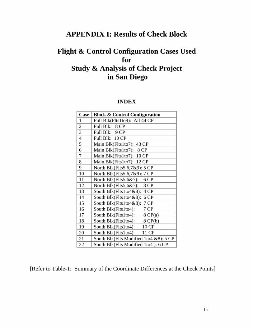
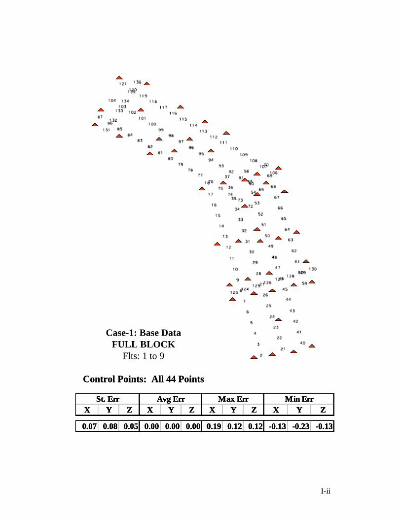
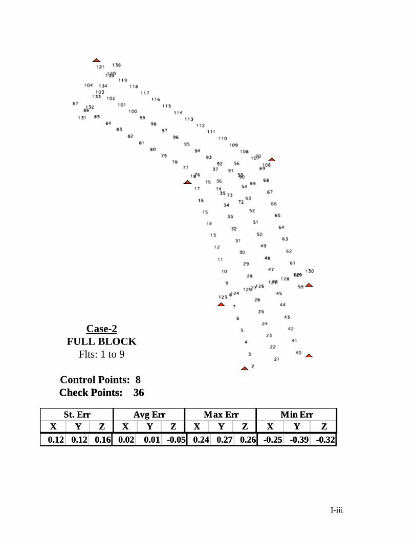
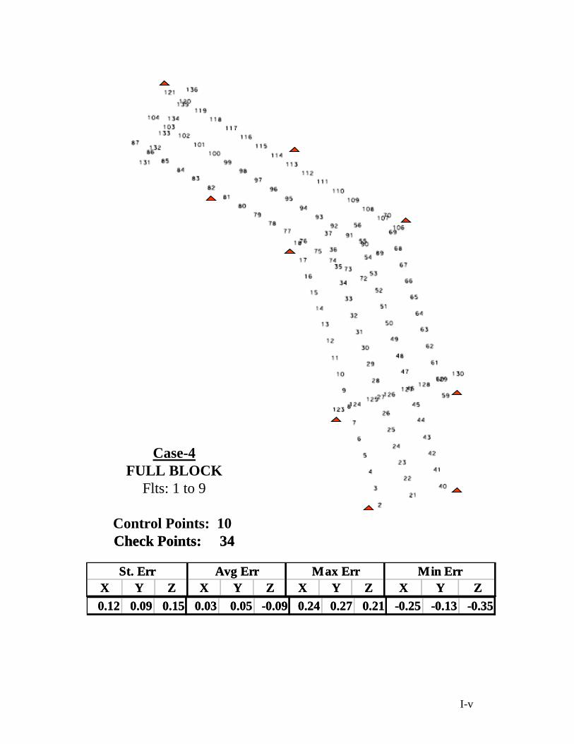
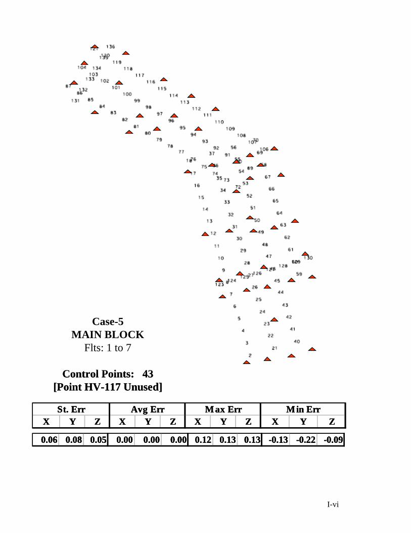
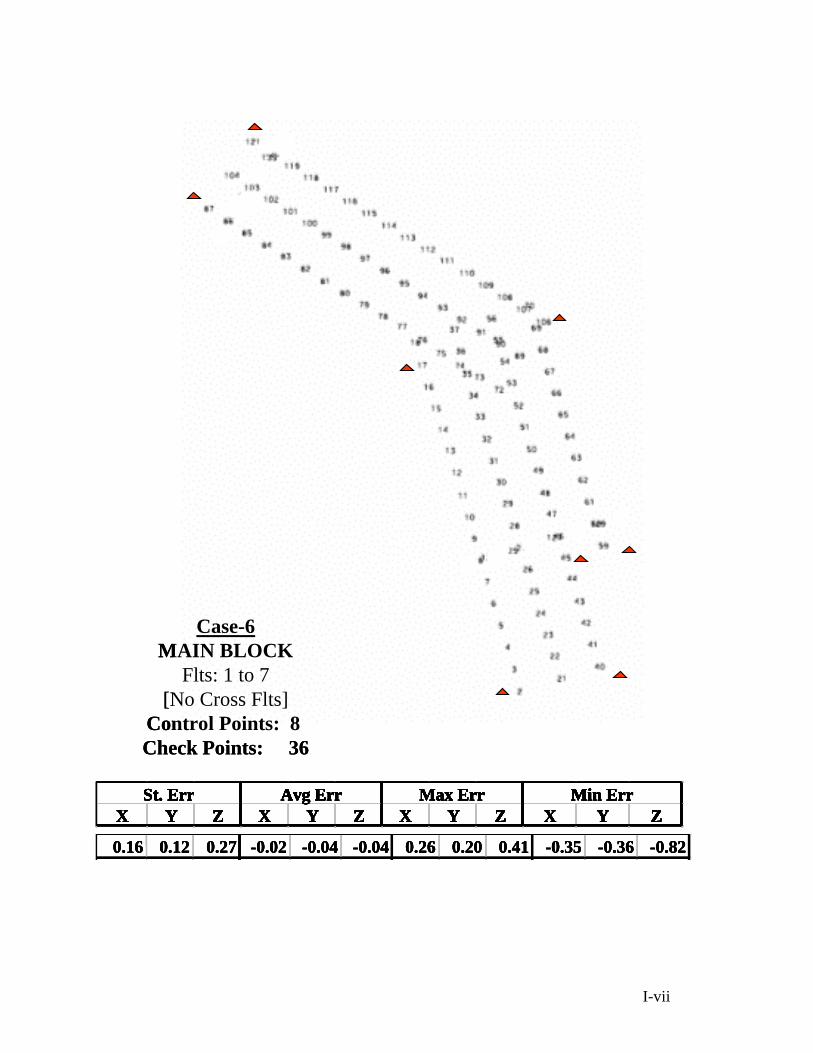
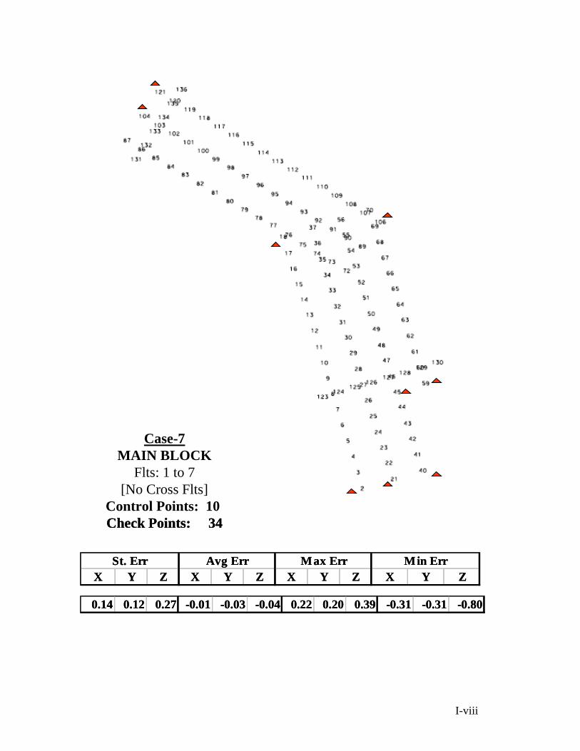
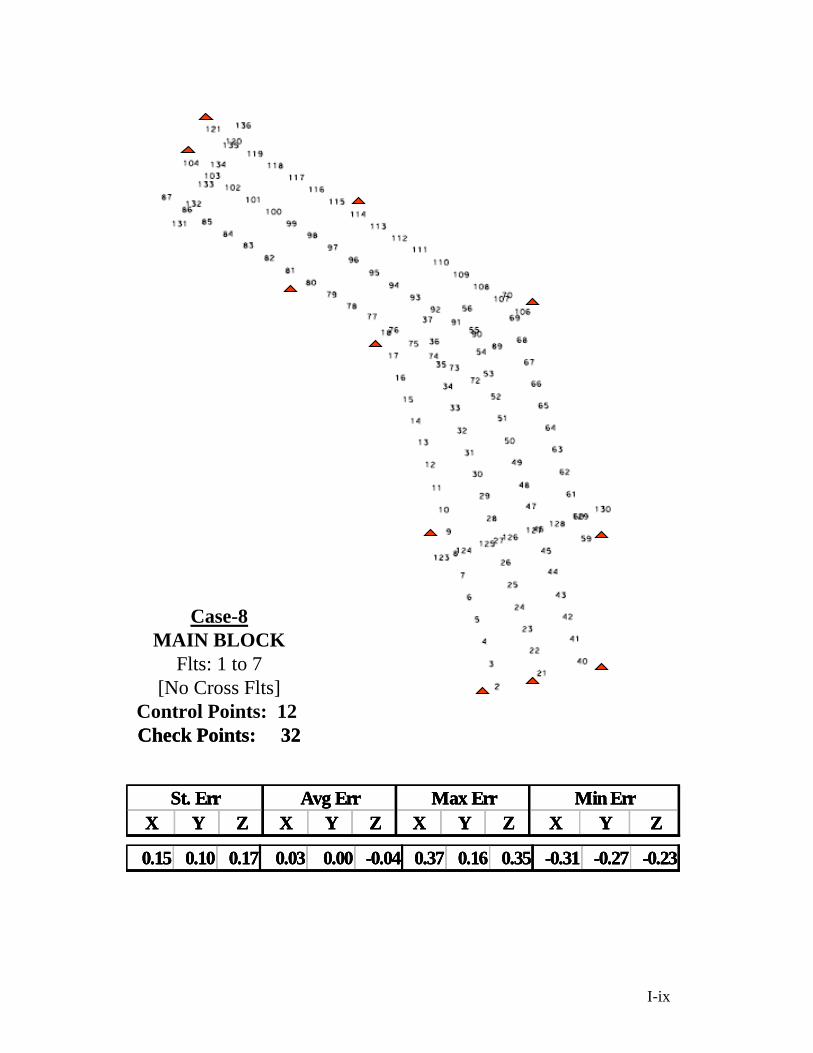
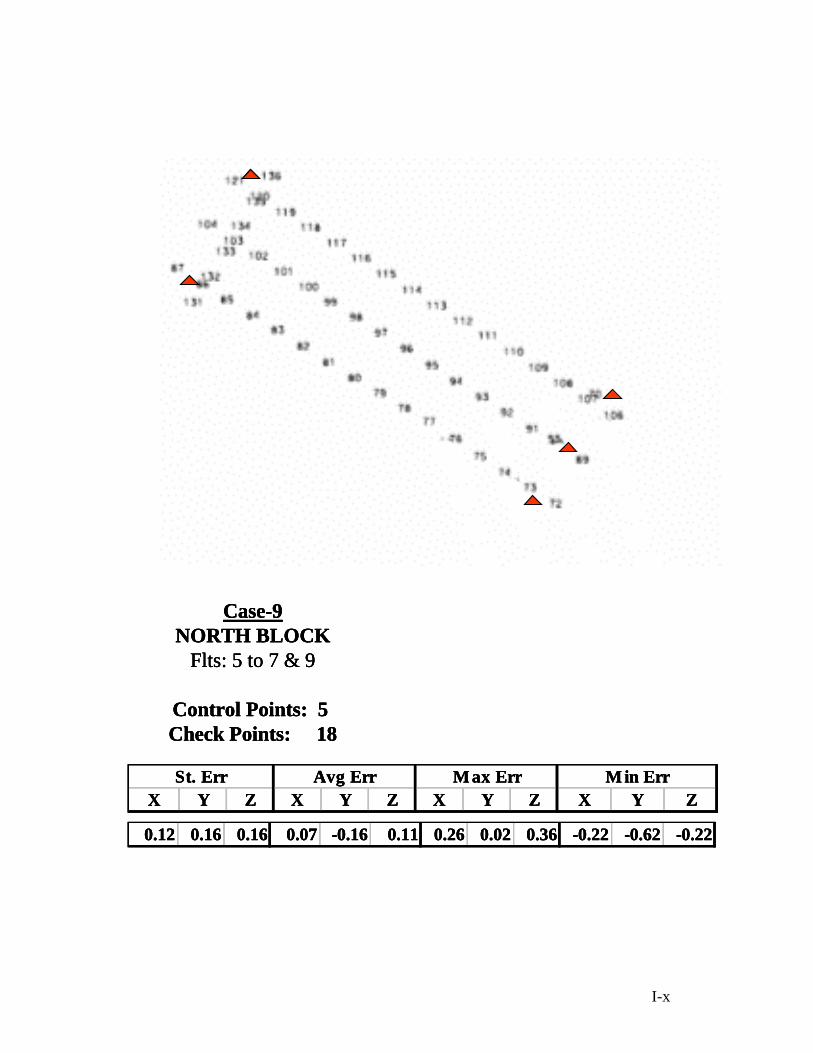
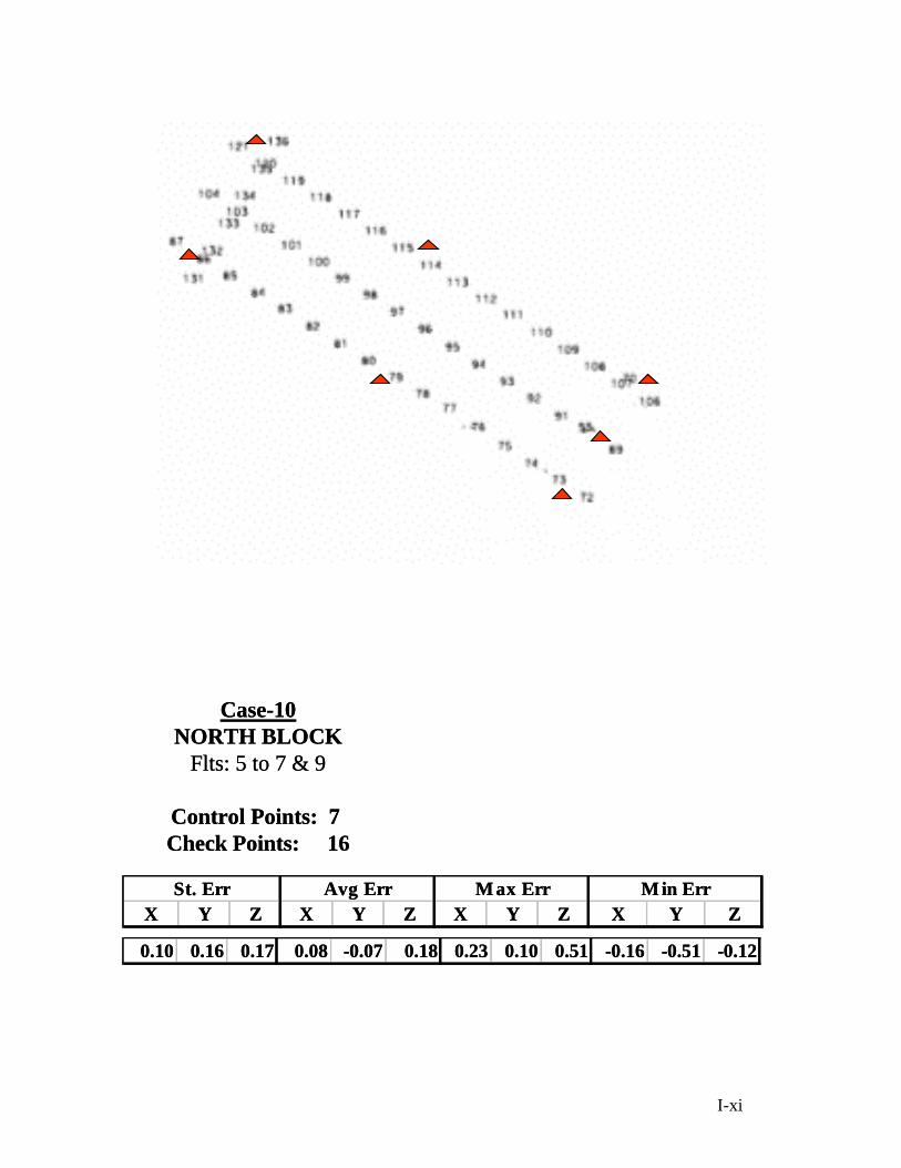
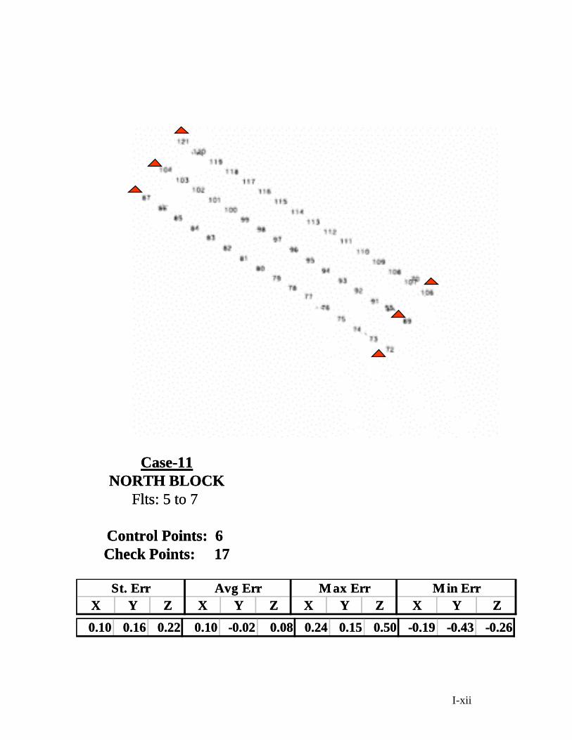
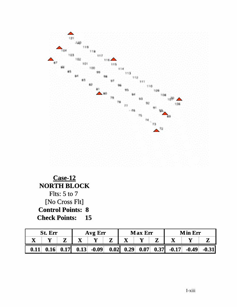
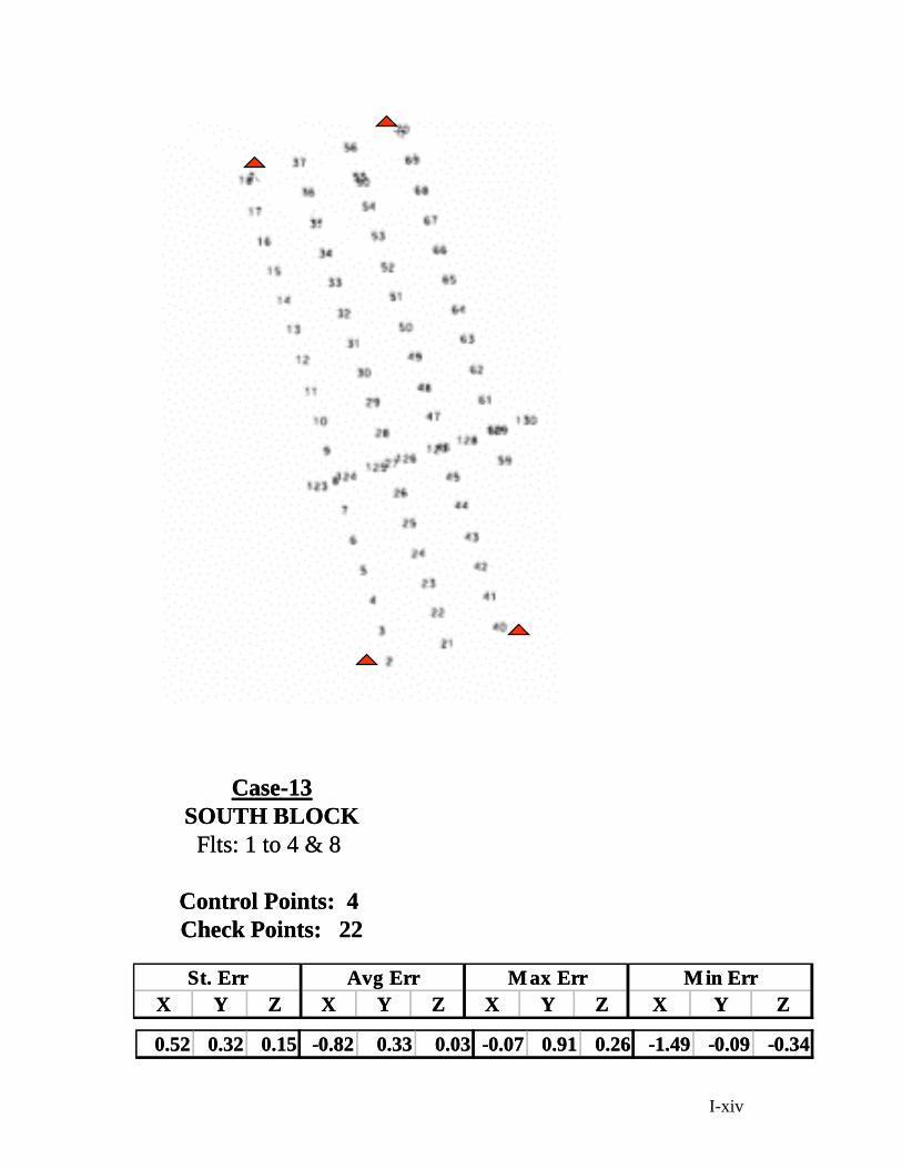
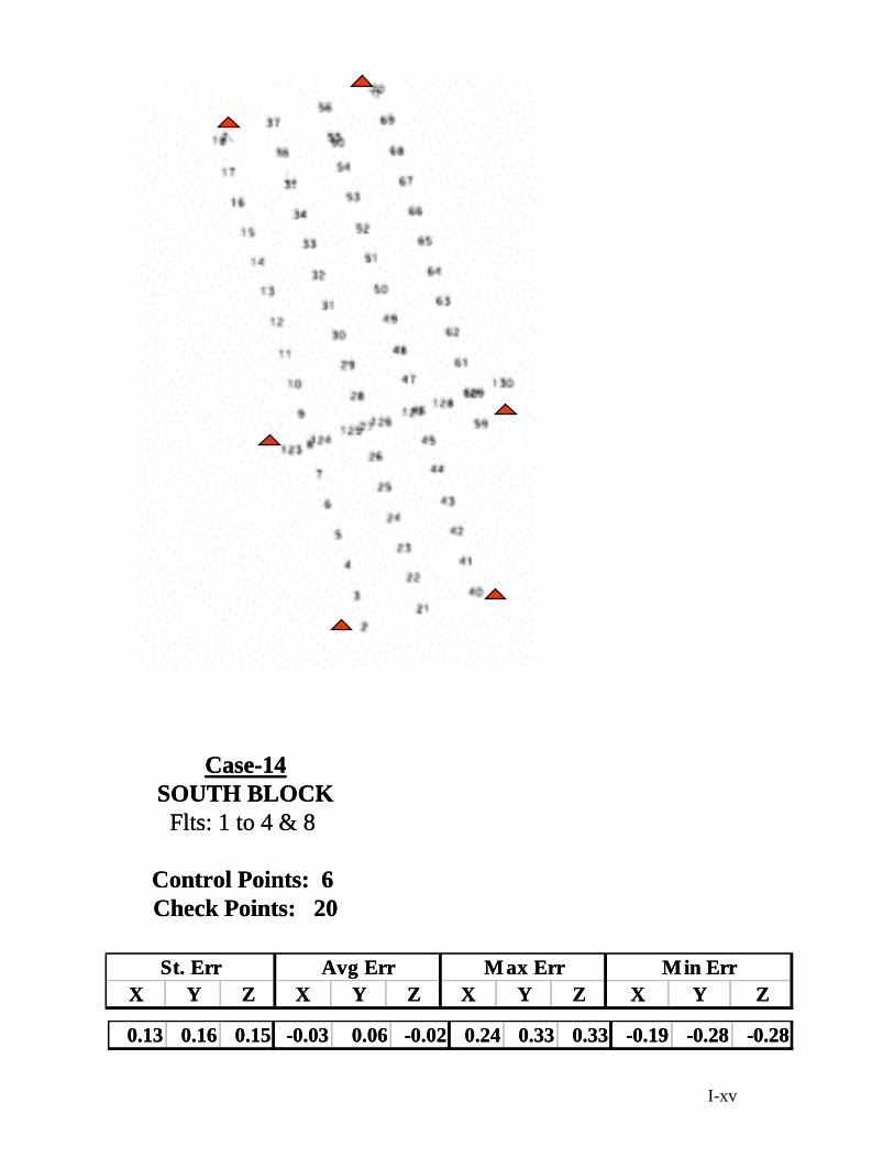
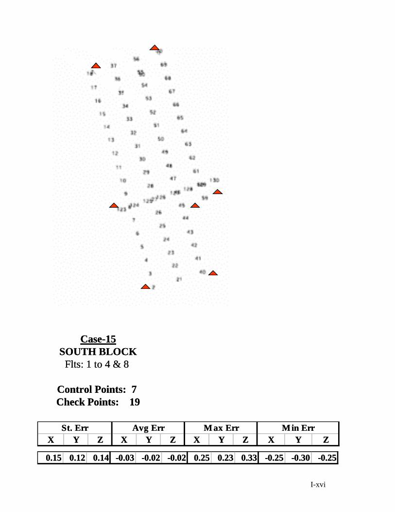
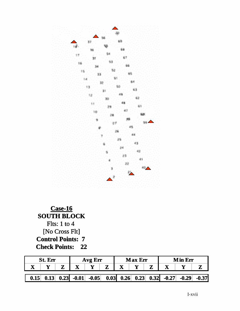
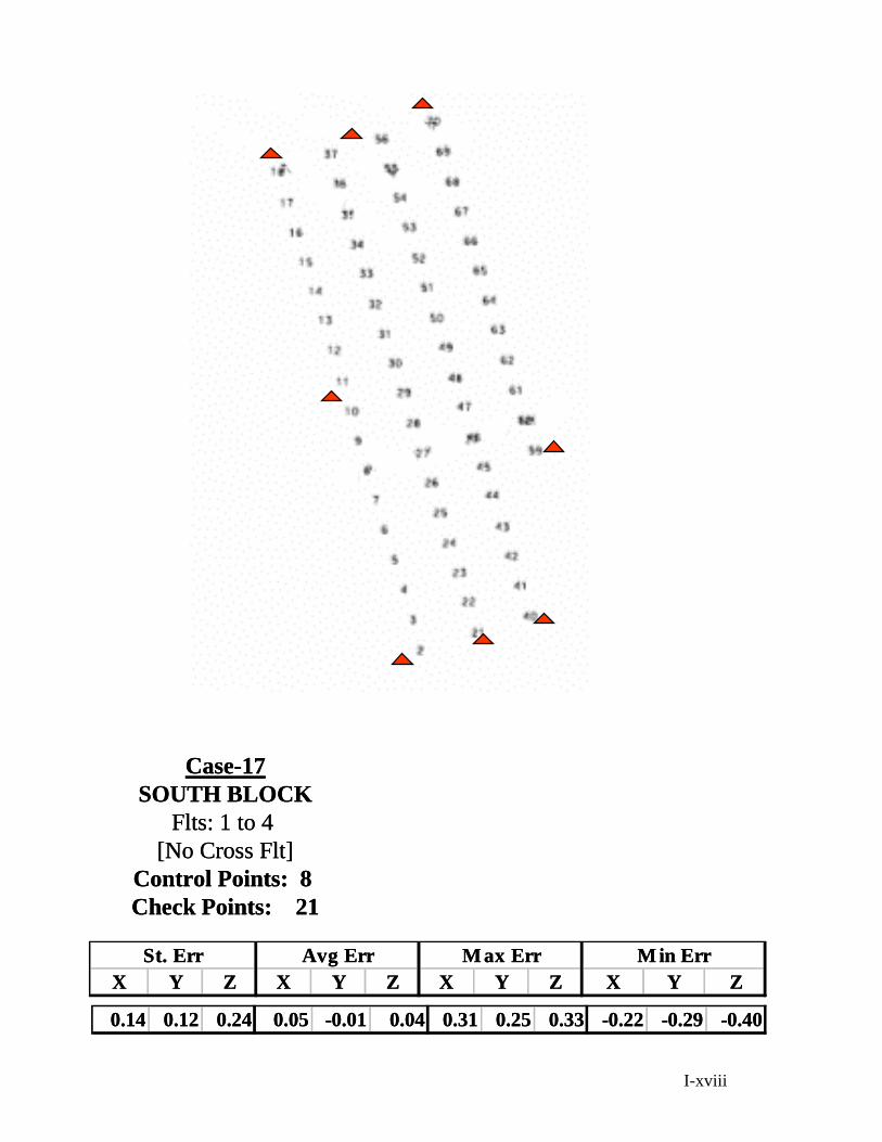
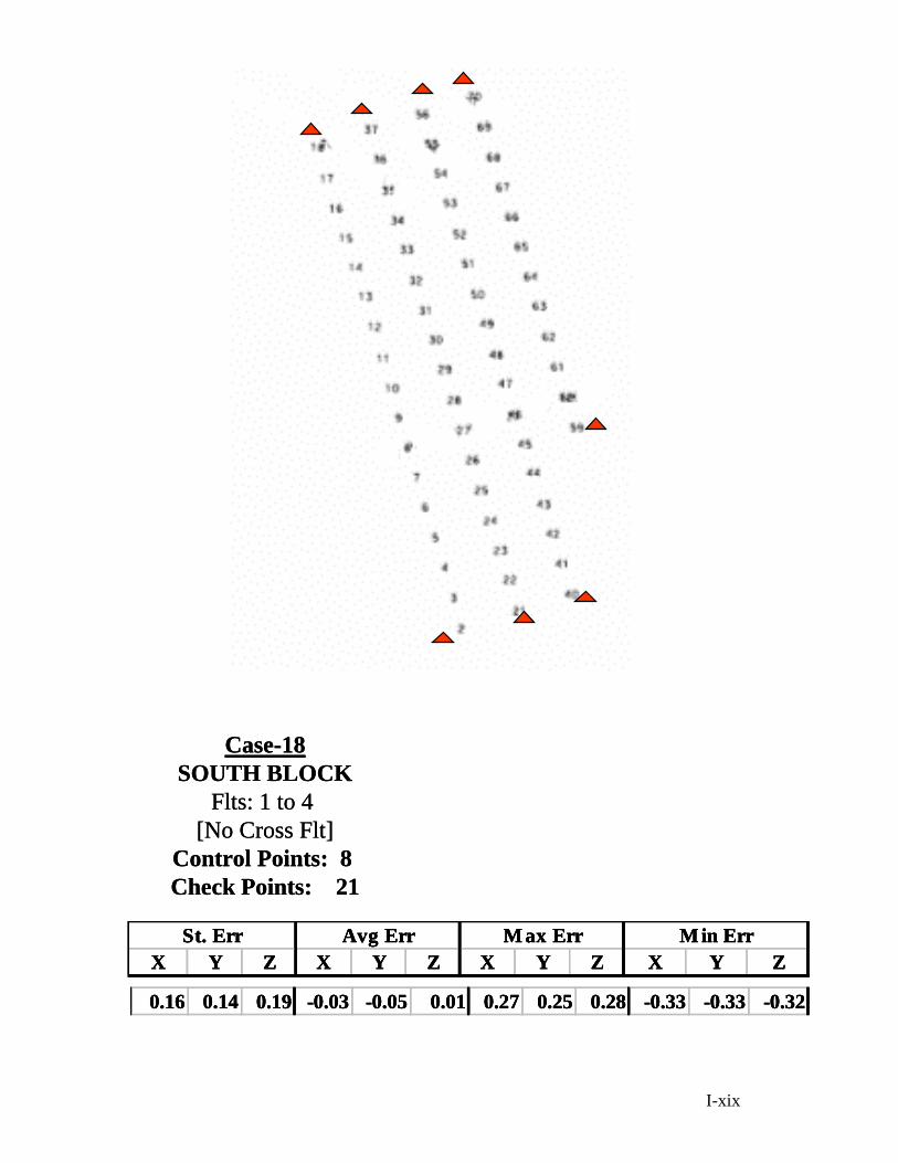
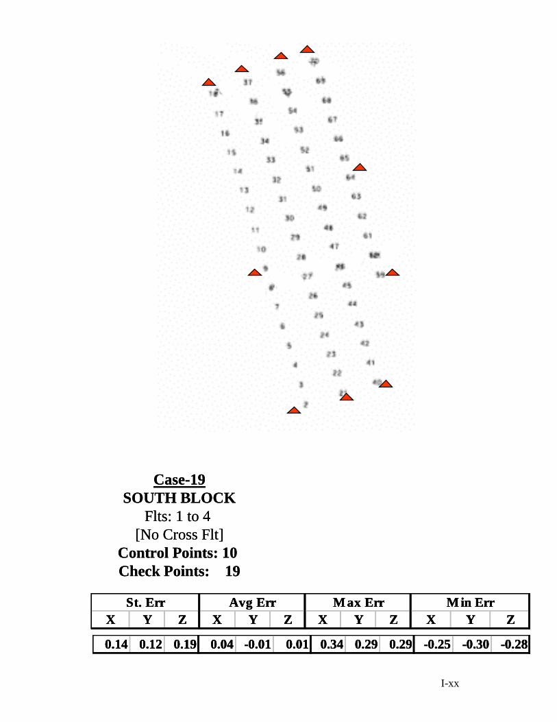
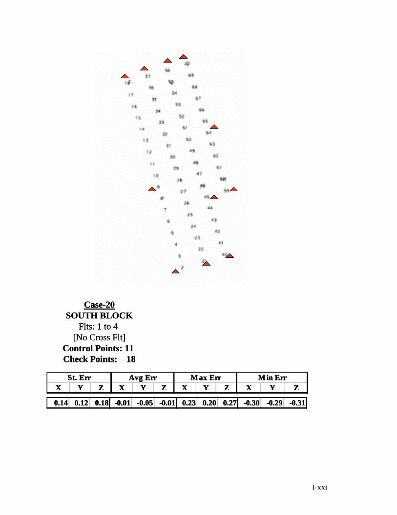
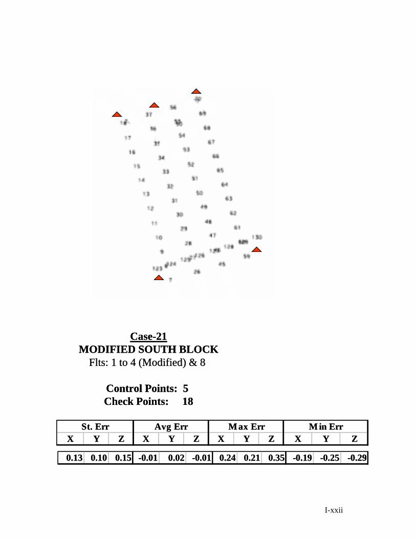
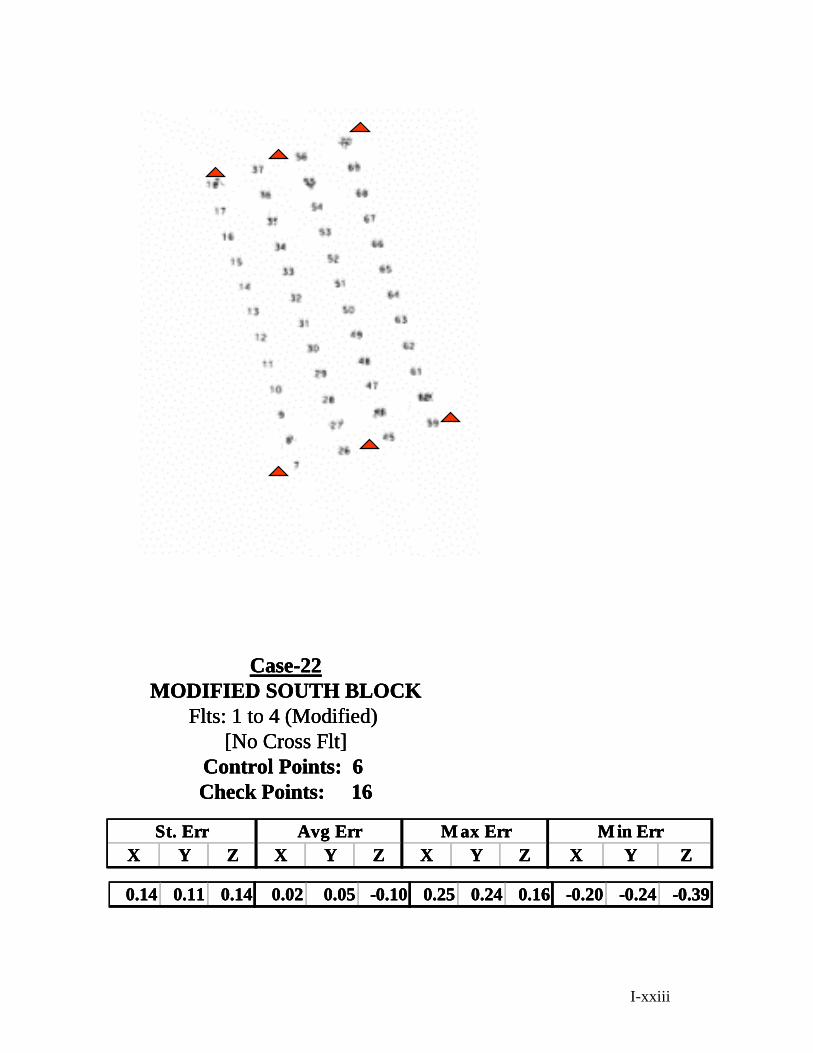
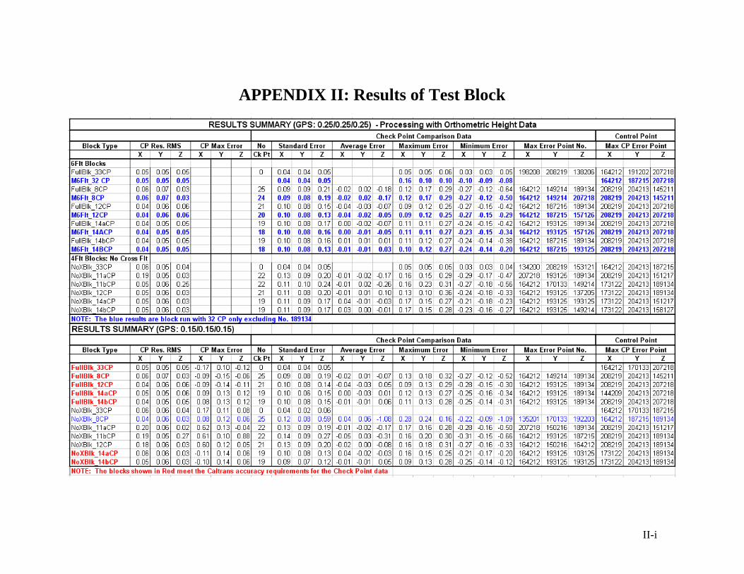
APPENDIX II Results of Test Block
II-i