Embed Size (px)
Citation preview
ETD 353
© Conference for Industry and Education Collaboration American Society for Engineering Education
February 2-4, 2011 San Antonio, Texas
Structural Evaluation of a Steel Girder Pedestrian Bridge
Jorge A. Tito, PhD, PE University of Houston Downtown
Alberto Gomez-Rivas, PhDs, PE University of Houston Downtown
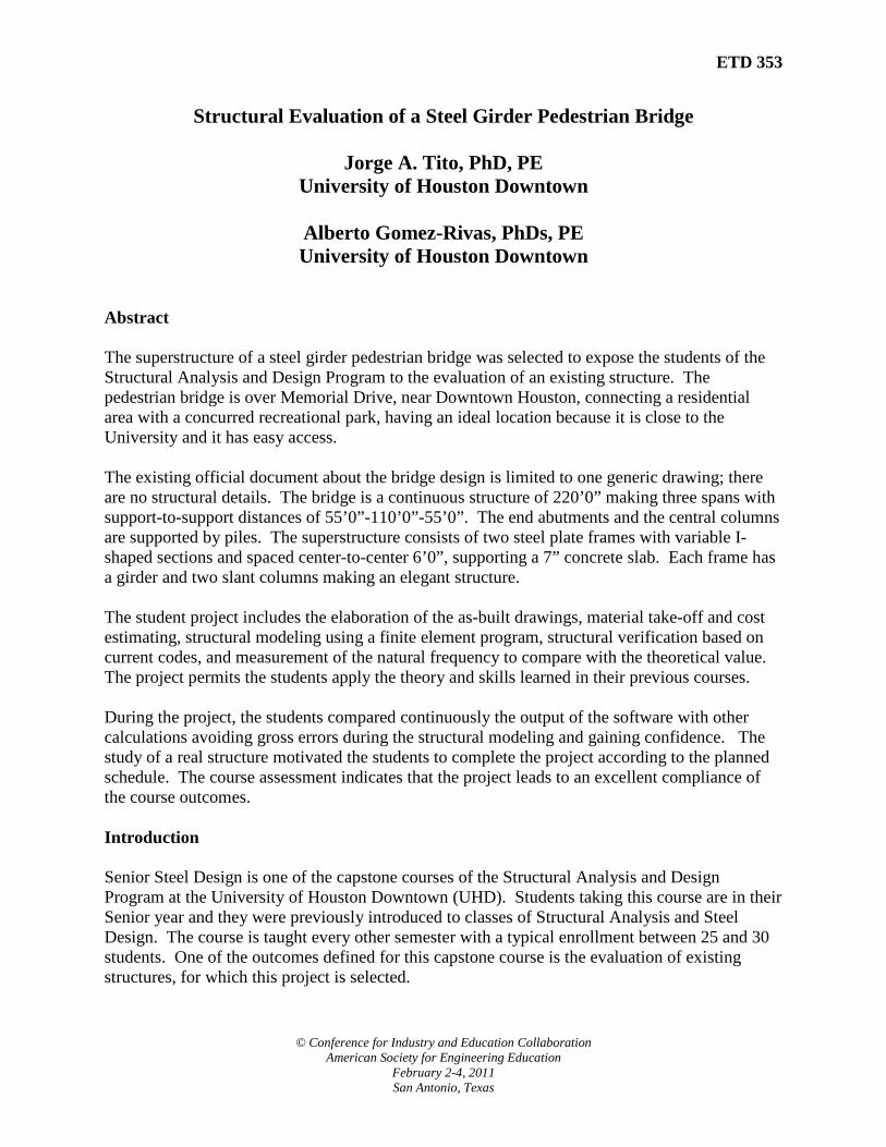
Abstract The superstructure of a steel girder pedestrian bridge was selected to expose the students of the Structural Analysis and Design Program to the evaluation of an existing structure. The pedestrian bridge is over Memorial Drive, near Downtown Houston, connecting a residential area with a concurred recreational park, having an ideal location because it is close to the University and it has easy access. The existing official document about the bridge design is limited to one generic drawing; there are no structural details. The bridge is a continuous structure of 220’0” making three spans with support-to-support distances of 55’0”-110’0”-55’0”. The end abutments and the central columns are supported by piles. The superstructure consists of two steel plate frames with variable I-shaped sections and spaced center-to-center 6’0”, supporting a 7” concrete slab. Each frame has a girder and two slant columns making an elegant structure. The student project includes the elaboration of the as-built drawings, material take-off and cost estimating, structural modeling using a finite element program, structural verification based on current codes, and measurement of the natural frequency to compare with the theoretical value. The project permits the students apply the theory and skills learned in their previous courses. During the project, the students compared continuously the output of the software with other calculations avoiding gross errors during the structural modeling and gaining confidence. The study of a real structure motivated the students to complete the project according to the planned schedule. The course assessment indicates that the project leads to an excellent compliance of the course outcomes. Introduction Senior Steel Design is one of the capstone courses of the Structural Analysis and Design Program at the University of Houston Downtown (UHD). Students taking this course are in their Senior year and they were previously introduced to classes of Structural Analysis and Steel Design. The course is taught every other semester with a typical enrollment between 25 and 30 students. One of the outcomes defined for this capstone course is the evaluation of existing structures, for which this project is selected.

ETD 353
© Conference for Industry and Education Collaboration American Society for Engineering Education
February 2-4, 2011 San Antonio, Texas
The project described in this paper consists in the structural evaluation of an existing pedestrian bridge in order to determine if it is able to withstand the loads indicated in current construction codes. In past semesters, the authors7 assigned a similar project with the objective to study a truss pedestrian bridge having excellent academic results. The selected existing pedestrian bridge has the characteristics needed for a capstone project level, such as adequate complexity level for Senior students and feasibility to complete the study during the academic semester. This particular project has a particular difficulty, frequently found in the practice, which is the lack of detailed construction documents. As a project task, a group of students went to the City of Houston, Harris County, Texas Department of Transportation, and neighborhood associations looking for the construction documents of the bridge, finding only one drawing with the plan view, longitudinal and cross sections, piling, and general specifications, as shown in Figure 1. Because of this limitation, this study includes the elaboration of the as-built drawings. The bridge was used before as a student project to obtain its natural frequency5. Such experience permits to know the site, technical characteristics, and identify some of the logistic problems with this project. The current project is repeated during two years permitting the students to compare results with the previous year, improving the quality of the study. Partial results of this project may be used to assign special projects for other courses of the Department. Pedestrian Bridge Description The pedestrian bridge selected is used to connect a residential area with the recreational park along the Buffalo Bayou near Downtown Houston. It is at 830-ft westward of Waugh Dr. over Memorial Dr., as shown in Figures 1 and 2. Figure 1 shows the available drawing dated on July 1985. The total length of the bridge is 220'0", making three spans with support-to-support of 55'0", 110'0", and 55'0". The foundation consists of abutments and two central pilecaps to support the slant columns. Each abutment is on two vertical piles, and each central pilecap is on one vertical pile and two battered piles. The bridge superstructure consists of two steel frames spaced 6'0", with slant columns and a parabolic shaped girder. Both frames are constructed with ASTM A-36 steel plates of variable I-shaped cross section, and covered with anticorrosive paint. The frames are supporting a continuous concrete slab of 7" thickness and 6’10” width, which is poured on a corrugated metal deck. Since there is a fence with safety mesh and tubes attached to the slab, the slab has a useful width of 6’0”. The steel frame endings are connected to the abutment using neoprene pads and anchor bolts with slotted holes. The central slant columns are pin connected to the pile cap. Figure 2 permits appreciate the support types and a panoramic view of the bridge.

ETD 353
© Conference for Industry and Education Collaboration American Society for Engineering Education
February 2-4, 2011 San Antonio, Texas
Figure 1. Available drawing showing location, general dimensions, and foundation.

ETD 353
© Conference for Industry and Education Collaboration American Society for Engineering Education
February 2-4, 2011 San Antonio, Texas
830-ft
Figure 2. Location and panoramic view of the pedestrian bridge.
Waugh Dr.
830-ft Pedestrian Bridge
Memorial Dr.
End Support Central Support

ETD 353
© Conference for Industry and Education Collaboration American Society for Engineering Education
February 2-4, 2011 San Antonio, Texas
Student Work Plan The student project consists in the structural evaluation of the superstructure of the pedestrian bridge. The class is divided into four working groups. Each group makes the evaluation of the same project, sharing information for comparison purposes, but working separately. The project is planned in order to cover all the Course Outcomes (CO), which are: CO1: Understand the steps to follow in the creation, repair or retrofitting of a steel structure. CO2: Structural Analysis of exiting steel structures in order to understand the reasons that a
designer had to select the specific shape and materials. CO3: Develop the structural design for a new or to upgrade an existing steel structure. Prepare
and submit a written report with the technical drawings and other information required. CO4: Plan and perform the test of a structural member defined by the professor. Prepare and
submit a written report with the technical drawings and other information required. CO5: Learn and practice structural detailing The student work plan consists in the following tasks, which are scheduled for completion by the end of the academic semester: 1. Make a document research in the corresponding agencies of City of Houston, Harris County,
and neighborhood associations (CO1).
2. Make the as-built drawings using surveying and photographic techniques (CO1 and CO5).
3. Compute the materials required to construct the superstructure of the pedestrian bridge (material take off), and estimate both the actual cost of the materials and the weight (CO1).
4. Using the commercial software SAP20004, perform the finite element modeling of the
superstructure of the bridge (CO3). 5. Input the load cases according to the code Minimum Design Loads for Buildings and Other
Structures ASCE/SEI 7-053 (CO3).
6. Make the load combinations indicated in ASCE/SEI 7-05 (CO3) 7. Perform dynamic tests to find the natural frequency and compare with SAP2000 (CO4). 8. Verify the structural capacity of the steel members. Compare with the Specification for
Structural Steel Buildings AISC/ANSI 360-053 (CO2 and CO5).

ETD 353
© Conference for Industry and Education Collaboration American Society for Engineering Education
February 2-4, 2011 San Antonio, Texas
As-built drawings and material take-off. Since the drawing found in the City of Houston archives only shows the general views and specifications of the bridge, an important task is the elaboration of the as-built drawings for the structural details, which is successfully accomplished by the students, as shown in Figure 3. The material take-off is obtained from the as-built drawings. The take-off permits an estimate of the actual cost of the materials, as well as the estimating of the weight of the superstructure. The take-off is done using a spreadsheet prepared by the students, as shown in Figure 4. The estimated weight of the superstructure is 192 kips, and the cost of materials is $ 224,000 with prices of February 2010 for Houston, TX. Considering the slab surface as plan area, then the weight per square foot is 128 lb, and the cost of materials is $150 per square foot.
Figure 4. Material Take-off and Cost Estimating for the superstructure of the Pedestrian Bridge.

ETD 353
© Conference for Industry and Education Collaboration American Society for Engineering Education
February 2-4, 2011 San Antonio, Texas
Figure 3a. As-built of Pedestrian Bridge: Plan View and Elevation

ETD 353
© Conference for Industry and Education Collaboration American Society for Engineering Education
February 2-4, 2011 San Antonio, Texas
Figure 3b. As-built of Pedestrian Bridge: North half elevation

ETD 353
© Conference for Industry and Education Collaboration American Society for Engineering Education
February 2-4, 2011 San Antonio, Texas
Figure 3c. As-built of Pedestrian Bridge: South half elevation

ETD 353
© Conference for Industry and Education Collaboration American Society for Engineering Education
February 2-4, 2011 San Antonio, Texas
Figure 3d. As-built of Pedestrian Bridge: Cross Sections

ETD 353
© Conference for Industry and Education Collaboration American Society for Engineering Education
February 2-4, 2011 San Antonio, Texas
Figure 3d. As-built of Pedestrian Bridge: Details

ETD 353
© Conference for Industry and Education Collaboration American Society for Engineering Education
February 2-4, 2011 San Antonio, Texas
Structural analysis of the superstructure. The curricula of the Structural Analysis and Design Program of UHD includes two classes of structural analysis, where students are introduced to matrix analysis and finite elements that are the basis of SAP2000 and other commercial software. Additionally, in the classes of Steel Design and Reinforced Concrete Design the students use this program to solve small structures. The Department also offers a class of surveying, which was used to make the as-built drawings. During the course, the instructor must review the most important structural concepts related to this project, and explain the structural modeling of this large structure. The computer software SAP2000 is used for the finite element analysis of the superstructure of the pedestrian bride. The geometry is modeled using shell elements, permitting a good representation of the real structure. Figure 5 shows a view of the structural model. The intensive use of SAP2000 permits the students to gain experience and confidence with commercial software, as well as to understand its strengths and limitations. The structural modeling is done following the as-built drawings and it is verified continuously to correct errors due to incorrect data input or wrong assumptions. As shown in Figure 1, the end supports are neoprene pads and anchors with slotted holes, which may be represented by rollers permitting longitudinal movement; however, using pins instead of roller supports there is a better comparison between the theoretical and measured natural frequencies as will be discussed. It is possible that, as the anchor bolts are tight and rusted, the free longitudinal movement really is restricted. The bridge presents a horizontal misalignment of about 3", which may be due a construction error; however, this misalignment is not considered in this structural modeling. The total dead load (DL) calculated by the software compares well with the result of the material take-off, obtaining a margin of error of about 2%. The software computes the dead load using the information given about the geometry of the bridge and the material density, together with a distributed load to represent the weight of the safety fence. The students must correct any input mistake to obtain a good comparison between the sum of dead load reactions and the estimated weight of the structure. It is interesting to note that typical errors are as gross as mistakes with the system of units, density of materials, type of joints, and load position. This comparison permits the students realize the importance of verifying the software input using a known parameter. One of the comparisons used to verify the computer model consists in comparing the reactions of the load cases with those computed using other methods. Table 1 show a good agreement between the sum of reactions from SAP2000 model and that computed using another method. This type of comparison avoids gross errors in the input of load data to the model. The live load (LL and LLc) required by AASHTO1 for pedestrian bridges is 85 psf; however, the original drawing, shown in Figure 1, indicates that this bridge is designed for 125 psf, which is the value considered for this analysis. The live load is located in the worst possible position to

ETD 353
© Conference for Industry and Education Collaboration American Society for Engineering Education
February 2-4, 2011 San Antonio, Texas
obtain maximum stresses, having two cases, one considering the bridge full loaded and the next one loaded at the central span only, as shown in Figure 6.
Description Total Reaction (kip)
Difference
Comments
SAP2000 model Other Method Dead load (DL) 189.0 192.3 2.0 % Compared with take-off
shown in Figure 4 Live load (LL) 188.2 187.8 0.2 % Compared with 125 psf
applied in the slab 6'10" x 220'0"
Live load at Center (LLc)
94.0 93.9 0.0 % Compared with 125 psf applied in the slab 6'10" x 110'0"
Horizontal Wind load (WLh)
44.1 44.0 0.2 % Compared with 100 lb/ft applied along the girder
Vertical Wind load (WLv)
61.7 61.6 0.2 % Compared with 41 psf applied on the slab
The wind load (WL) is important in the city of Houston, which is a hurricane prone area. This load is estimated using the current ASCE/SEI 7 code, considering a basic wind speed of 110 mph. Figure 7 shows the spreadsheet developed to help with the calculations of wind loads acting on the bridge. Two load cases are considered for wind load, and the horizontal (WLh) and vertical (WLv) wind loads.
Table 1. Comparison between the sum of reactions computed by SAP2000 and other methods.
Figure 6. Alternate of Live load location
a. Live load along all the bridge (LL)
b. Live load at the central span (LLc)
Figure 5. Structural model of the pedestrian bridge superstructure using shell finite elements
Concrete Slab Steel frame: plate girders and slant columns

ETD 353
© Conference for Industry and Education Collaboration American Society for Engineering Education
February 2-4, 2011 San Antonio, Texas
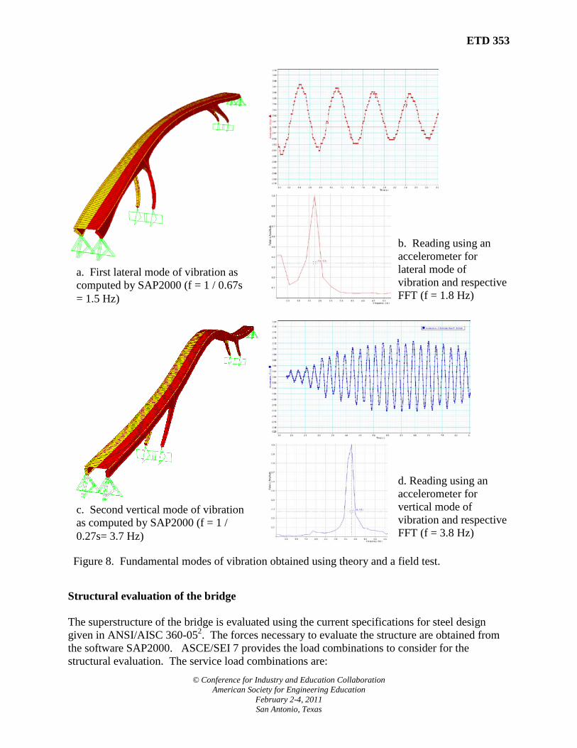
Dynamic tests Field dynamic tests are performed to find the natural frequency of the bridge. The tests are done using an accelerometer installed at the center of the bridge. The reading are stored in a data logger model Xplorer GLX, and processed using the software DataStudio, which is purchased from PASCO6. The structure starts vibrating when a student jumps at a similar pace than the computed natural frequency at the center of the bridge permitting the students appreciate the resonance. After the jumping stops, the bridge continues vibrating with enough amplitude, permitting the data logger to record the accelerations. The natural frequencies are obtained using the Fast Fourier Transformation (FFT) method included in the software DataStudio. The program SAP2000 is used to obtain the theoretical natural frequencies and corresponding vibration modes. The first theoretical natural frequency is 1.5 Hz corresponding to a lateral mode of vibration, as shown in Figure 8a. The graphs of horizontal acceleration vs. time and Fast Fourier Transformation (FFT) resulting from the field test are shown in Figure 8b. The lateral natural frequency from the test is 1.8 Hz, which is close to the theory. The difference may be due to restrictions to movement not modeled with SAP2000, mainly in the end supports. The theoretical vertical natural frequency is 3.7 Hz, as shown in Figure 8c. The field test provided a natural frequency of 3.8 Hz, as shown in Figure 8d. A previous project obtained a natural frequency of 3.7 Hz5. The good agreement obtained permits confidence in the structural model, including the geometry and dead loads.
Figure 7. Wind load calculations following ASCE/SEI 7
ETD 353
© Conference for Industry and Education Collaboration American Society for Engineering Education
February 2-4, 2011 San Antonio, Texas
Structural evaluation of the bridge The superstructure of the bridge is evaluated using the current specifications for steel design given in ANSI/AISC 360-052. The forces necessary to evaluate the structure are obtained from the software SAP2000. ASCE/SEI 7 provides the load combinations to consider for the structural evaluation. The service load combinations are:
Figure 8. Fundamental modes of vibration obtained using theory and a field test.
d. Reading using an accelerometer for vertical mode of vibration and respective FFT (f = 3.8 Hz)
b. Reading using an accelerometer for lateral mode of vibration and respective FFT (f = 1.8 Hz)
a. First lateral mode of vibration as computed by SAP2000 (f = 1 / 0.67s = 1.5 Hz)
c. Second vertical mode of vibration as computed by SAP2000 (f = 1 / 0.27s= 3.7 Hz)

ETD 353
© Conference for Industry and Education Collaboration American Society for Engineering Education
February 2-4, 2011 San Antonio, Texas
1) DL 2) DL + LL or DL + LLc 3) DL + 0.75 LL +/- 0.75 WL Not used 4) 0.6 DL +/- 1.0 WLh +/- WLv The ultimate load combinations are: 1) 1.4 DL 2) 1.2 DL + 1.6 LL or 1.2 DL + 1.6 LLc 3) 1.2 DL + 1.0 LL +/- 1.6 WL Not used 4) 0.9 DL +/- 1.6 WLh +/- 1.6 WLv The load combination requiring live and wind load is too conservative because these bridges are not used by pedestrians in the event of a hurricane; then, for this analysis, the live load is not combined with the wind loads. The drawings indicate that the steel used for the truss is ASTM A-36, which has a modulus of elasticity of 29,000 ksi, a yielding strength, Fy, of 36 ksi, and an ultimate strength, Fu, of 58 ksi. Figure 9 shows the stress contour for the steel frames and the maximum stresses obtained from different load combinations at different locations. The maximum stress in the steel is 14 ksi which occurs for the combination of dead and live load and it is in the joint of the slant column and the girder. The cross sections at the slant column and at the girder were verified using the equations given by the current specifications for steel design, ANSI/AISC 360-052. The sections were studied considering the total axial load, and the bi-axial bending moments, obtaining a maximum stress ratio of 0.66 at the top of the slant column. Then, the stresses in the steel due the loads obtained from current codes are inside the permissible range. The evaluation of connections is not in the scope of this study. Figure 10 shows the deflections due vertical loads, such as dead and live loads and horizontal loads from the wind load. The service deflections are shown in Table 2. It is observed that the ratio of the deflections versus the span of the structure are inside the acceptable range of the span divided by 360 for live loads and divided by 240 for combinations considering wind loads. Load combination Deflection Comment DL δ = 0.7 in Span = L = 110 ft
δ / L = 1 / 1885 < 1 / 360; then OK DL + LL δ = 0.7 + 1.0 = 1.7 in Span = L = 110 ft
δ / L = 1 / 776 < 1 / 360; then OK WL horizontal δ = 1.4 in Span = L = 220 ft
δ / L = 1 / 1885 < 1 / 240; then OK
Table 1. Comparison between the sum of reactions computed by SAP2000 and other methods.

ETD 353
© Conference for Industry and Education Collaboration American Society for Engineering Education
February 2-4, 2011 San Antonio, Texas
σmax = +11 ksi for DL+LL
σmax = -14 ksi for DL+LL
σmax = -12 ksi for DL+WL
σmax = +/- 11 ksi for DL+WL
Figure 9. Stress contour from SAP2000 for a combination considering live and dead load and maximum stresses from other combinations

ETD 353
© Conference for Industry and Education Collaboration American Society for Engineering Education
February 2-4, 2011 San Antonio, Texas
δmax = -0.7 in for LL δmax = -1.0 in for LLc
δmax = 1.4 in for Lateral WL δmax = 0.3 in for Vertical LL
Figure 10. Deflections of the steel frames due vertical and horizontal loads.

ETD 353
© Conference for Industry and Education Collaboration American Society for Engineering Education
February 2-4, 2011 San Antonio, Texas
Course Assessment The students were exposed to different aspects of a professional engineering evaluation of an existing structure, such as surveying, the cost estimating, project management, structural modeling, steel design, and field dynamic tests. The project had the special difficulty that the construction documents were not available; consequently, the students made the as-built drawings using surveying techniques. At the end of the semester each student group makes an oral presentation showing their as-built drawings, calculations, and conclusions. The project steps are in agreement with the outcomes defined for the Senior Steel Design course. The Structural Analysis and Design program makes an indirect assessment to know the perception of the students about the accomplishment of the objectives of the course. Figure 11 summarizes the course survey indicating that all the students agree that the course objectives were covered by the project. During the oral presentation of the project and also in the written report, the students show a good understanding of the problem and they report great individual participation during the different stages of the project. The author considers that the practical nature of the project and easy access to the site are important factors for the good acceptance of this study.
Figure 11. Assessment of the class using a survey of acceptance between the students

ETD 353
© Conference for Industry and Education Collaboration American Society for Engineering Education
February 2-4, 2011 San Antonio, Texas
Conclusions and Recommendations The students of Senior Steel Design, a capstone type course of the Structural Analysis and Design program at UHD, are required to evaluate the structural behavior of the superstructure of a pedestrian bridge following a schedule with partial tasks defined by the instructor. The responsible local agencies are not able to provide the construction documents of the bridge, only a general drawing; therefore, it is necessary to include the elaboration of the as-built drawings as part of this student project. Fortunately, the bridge has easy access permitting to work with the surveying of the main structural details; however, the central part of the bridge has difficult access and some measurements are obtained using photographs and other indirect methods. With the elaborated as-built drawings, the students are able to perform the take-off and a cost estimating of the materials; make a structural modeling using commercial software; perform dynamic tests to obtain the natural frequency; and evaluate the structure under loads from the current codes. The structural study shows that the stress ratios in the frames are lower than 1.0, and the deflections are in an allowable range, which indicates that the bridge behaves well under the loads of current codes. During the project, the students verified the partial results using alternative calculations, such as comparing the total reaction of dead load with the estimated weight of the bridge, and the reactions of live load and wind load with the total force applied. The structural model is also verified with the field dynamic tests. The natural frequencies obtained from calculations are in good agreement with the experimental results, permitting the students to gain confidence in their work. Finally, the students present the project with a written report and an oral presentation, showing the working procedure, as-built drawings, materials take-off, material cost estimate, and their conclusions and recommendations. The practical application of the theory in a real project helps to motivate the students to show interest and enthusiasm to outperform the objectives of the project and of the course with excellent marks Bibliography 1. American Association of State Highway Transportation Officials, AASHTO LRFD Bridge Design Specifications 4th edition. 2. American Institute of Steel Construction. ANSI/AISC 360-05, Specifications for Structural Steel Buildings, March 2005. 3. American Society of Civil Engineers - Structural Engineering Institute. Minimum Design Loads for Buildings and Other Structures, ASCE/SEI 7-05. 4. Computers & Structures, Inc., “SAP2000 – Integrated Software for Structural Analysis & Design, Technical Reference Manual”. www.csiberkeley.com 5. Gomez-Rivas, A. "Non Destructive Analysis of Bridge Design Assumptions". Proceeding of Fifth International Conference on Structural Faults and Repair. Edinburgh, Scotland, UK. June 1993. 6. PASCO. XPlorer GLX Manual and DataStudio Started Manual". www.pasco.com 7. Tito, J., Gomez-Rivas, A. "Structural Evaluation of a Pedestrian Bridge". Proceeding of the 2010 American Society of Engineering Education, Annual Conference and Exposition. Louisville, Kentucky. June 2010.

ETD 353
© Conference for Industry and Education Collaboration American Society for Engineering Education
February 2-4, 2011 San Antonio, Texas
Biographical Information JORGE A. TITO Jorge A. Tito is Associate Professor of Engineering Technology. Dr. Tito received his Ph.D. and M.Sc. Degrees from the University of Puerto Rico, Mayagüez, Puerto Rico, in Civil Engineering with a major in Structures. He received the Civil Engineer Degree from the Pontifical Catholic University of Peru. Dr. Tito has experience in teaching, structural design, and construction management, and is a Registered Professional Engineer. ALBERTO GOMEZ-RIVAS Alberto Gomez-Rivas is Professor of Structural Analysis and Chair of Engineering Technology. Dr. Gomez-Rivas received Ph.D. degrees from the University of Texas, Austin, Texas, in Civil Engineering and from Rice University, Houston, Texas, in Economics. He received the Ingeniero Civil degree, with Honors, from the Universidad Javeriana in Bogotá, Colombia. He also served as Chief of Colombia’s Department of Transportation Highway Bridge Division.