Embed Size (px)
Citation preview
045-00-16_A M16 MAINTENANCE SCHEDULEIssue A
Page 1
TITLE: M16 MAINTENANCE SCHEDULE
CODE: 045-00-16_A
PRODUCT: M-16
045-00-16_A M16 MAINTENANCE SCHEDULEIssue A
Page 2
CONTENTS 1 FOREWORD 4
1.1 SCOPE 4 1.2 ATTACHMENTS 4 1.3 REFERENCES 4
2 Responsibilities and Standards 5 2.1 Owner/Operator Responsibilities 5 2.2 Certifying Persons Responsibilities 5 2.3 General Inspection Standards 5 2.4 Airworthiness Life Limitations (Retirement/Scrap Lives) 5 2.5 Airworthiness Directives 5 2.6 Overhaul, Additional Inspections and Test Periods 6 2.7 Instructions for Continuing Airworthiness 6 2.8 Changes (Repairs or Modifications) 6 2.9 Duplicate Inspections 6 2.10 Scheduled Maintenance Worksheets 6 2.11 Definitions 7
3 Permit Maintenance Release 8 3.1 Maintenance Authorisation 8 3.2 Pilot Maintenance 8
4 Check Cycle and Variations 10 4.1 The Maintenance Check Cycle 10 4.2 Permitted Variations (see Notes) 11
5 Pre-Flight 12 5.1 Pilot’s Pre-Flight Check / Check A – Prior to First Flight of the Day 12 5.2 Check A - Prior to First Flight of the Day 12
6 Scheduled Maintenance 19 6.1 Scheduled Maintenance Worksheets 19 6.2 Final Checks (Include with all checks) 20
6.2.1 Ground Run: 20 6.2.2 Certification: 20 6.2.3 Type Certificate and Schedule Review: 20
6.3 25 Hour Check: 21 6.3.1 Flying Controls: 21 6.3.2 Engine: 22
6.4 100 Hour Check: 23 6.4.1 Structural/Zonal: 23 6.4.2 Landing Gear: 24 6.4.3 Flying Controls: 24 6.4.4 Liquid, Air and Gas Systems: 26 6.4.5 Equipment and Environmental: 26 6.4.6 Engine: 27 6.4.7 Rotors: 27 6.4.8 Gyroplane Lubrication: 29 6.4.9 Powerplant Installation: 29 6.4.10 Air Induction: 30
045-00-16_A M16 MAINTENANCE SCHEDULEIssue A
Page 3
6.4.11 Exhaust: 30 6.4.12 Fuel System: 30 6.4.13 Electrical System: 31 6.4.14 Instrument Systems: 31 6.4.15 Ignition: 32
6.5 2-Year Check: 33 6.5.1 Instrument Systems: 33
6.6 300 Hour / 3-Year Check: 33 6.6.1 Flying Controls: 33
6.7 500 Hour Check: 34 6.7.1 Flying Controls: 34 6.7.2 Rotor: 34
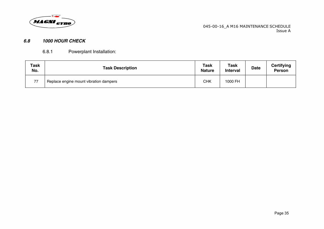
6.8 1000 Hour Check: 35 6.8.1 Powerplant Installation: 35
7 Lifed Items: 36
045-00-16_A M16 MAINTENANCE SCHEDULEIssue A
Page 4
1 FOREWORD 1.1 SCOPE The scope of this document is to provide a detailed breakdown of the maintenance tasks to be carried out to provide continued airworthiness, and the required intervals. Details of the approved method of undertaking the appropriate maintenance is outlined in the Magni Gyro M16 maintenance manual (Ref 1) This document refers only to airframe maintenance and those engine ancillaries which are specific to the M16 Gyroplane. All engine maintenance should be undertaken in accordance with the appropriate engine manufacturer’s maintenance schedule. 1.2 ATTACHMENTS None 1.3 REFERENCES Ref 1 M16_A Maintenance Manual Ref 2 ROTAX 914 UL Maintenance Manual Ref 3 ROTAX 912 ULS Maintenance Manual
045-00-16_A M16 MAINTENANCE SCHEDULEIssue A
Page 5
2 RESPONSIBILITIES AND STANDARDS 2.1 OWNER/OPERATOR RESPONSIBILITIES Owners/operators are responsible for the accomplishment of the maintenance prescribed in this schedule. 2.2 CERTIFYING PERSONS RESPONSIBILITIES Certifying persons must use their engineering skill and judgment in determining the depth of inspection needed and other matters which could affect the airworthiness of the gyroplane. In order to claim any alleviation on subsequent inspections, the gyroplane maintenance records must record the extent of previous inspections upon which the alleviation is based. Certifying persons are responsible for recording in the appropriate log book or worksheet, any defects, deficiencies or additional maintenance required as a result of implementation of the schedule. 2.3 GENERAL INSPECTION STANDARDS The general inspection standards applied to individual task inspections must meet the recommended standards and practices of Magni Gyro Srl and are published in M16 maintenance manual. In the absence of general inspection standards, refer to other standards recommended by Magni Gyro Srl or Authorities’ recommended standards and practices. Inspections may be carried out without component removal or dismantling unless considered necessary or where required by the schedule. 2.4 AIRWORTHINESS LIFE LIMITATIONS (RETIREMENT/SCRAP LIVES) Airworthiness life limitations shall be those published by the Authorities and those defined in Section 7 of this report. Airworthiness life limitations shall be recorded. 2.5 AIRWORTHINESS DIRECTIVES All applicable Airworthiness Directives and Mandatory Permit Directives, issued by the relevant Authorities, must be complied with. Compliance with Airworthiness Directives and Mandatory Permit Directives shall be recorded accordingly with local requirements.
045-00-16_A M16 MAINTENANCE SCHEDULEIssue A
Page 6
2.6 OVERHAUL, ADDITIONAL INSPECTIONS AND TEST PERIODS Overhaul, additional inspections and test periods are those recommended by Magni Gyro Srl. The local Authority may vary or mandate overhaul and test periods and additional inspections by the issue of an Airworthiness Directive or Generic Requirement. The overhaul, additional inspections and test periods shall be recorded accordingly with local requirements. 2.7 INSTRUCTIONS FOR CONTINUING AIRWORTHINESS Instructions for continuing airworthiness consist of in-service data published by Magni Gyro Srl and must be considered by the owner/operator in addition to this maintenance schedule in order to ensure the approved maintenance schedule remains valid for the M16. Instructions for continuing airworthiness (Service Bulletins, Service Letters, etc.) should be formally technically assessed by the owner/operator and adopted if required to ensure operational safety and reliability. Instructions for continuing airworthiness applicable to the gyroplane shall be included in the gyroplane documentation accordingly with local requirements, and form part of this maintenance schedule. Compliance with adopted continuing airworthiness information shall be recorded accordingly with local requirements. 2.8 CHANGES (REPAIRS OR MODIFICATIONS) Approved “changes” which have been carried out to the gyroplane, engine, components and radio after original manufacture, must be recorded in the appropriate log book(s). Any recurring inspection or maintenance task resulting from approved “changes” shall be recorded accordingly with local requirements. 2.9 DUPLICATE INSPECTIONS When required to perform a critical task inspection or following initial assembly or disturbance of a control system or vital point, it is mandatory to duplicate inspections. Certifications must be recorded in the appropriate worksheet, log book or aircraft technical log. 2.10 SCHEDULED MAINTENANCE WORKSHEETS Worksheets shown in Section 6 must be issued and the tasks certified for all scheduled maintenance checks. These worksheets become part of the maintenance records required to be kept by the owner/operator. All maintenance carried out in connection with a particular check should be certified on suitably referenced worksheets and included in the gyroplane records. These worksheets must be cross- referenced in the appropriate log book(s) giving general details of the additional maintenance carried out.
045-00-16_A M16 MAINTENANCE SCHEDULEIssue A
Page 7
2.11 DEFINITIONS Throughout the schedule the following terms and abbreviations have the stated definitions; Service/Lubrication (Service/LUB) The term “Service or Lubrication” requires that a component or system should be serviced and/or replenished as necessary with fuel, oil, grease, water, oxygen, etc., to a condition specified in the appropriate maintenance manual. The term “service” may also be used to require filter cleaning or replacement. Inspect (INSP) An “Inspection” is a visual check performed externally or internally in suitable lighting conditions from a distance considered necessary to detect unsatisfactory conditions/discrepancies using, where necessary, inspection aids such as mirrors, torches, a magnifying glass etc. Surface cleaning and removal of detachable cowlings, panels, covers and fabric may be required to be able to satisfy the inspection requirements. Operational Check (OP/C) An “Operational Check” is a test used to determine that a system or component or any function thereof is operating normally. Functional Check (F/C) A “Functional Check” is a detailed examination of a complete system, sub-system or component to determine if operating parameters are within limits of range of movement, rate of flow, temperature, pressure, revolutions per minute, degrees of travel, etc., as specified in the M16 maintenance manual. Measured parameters should be recorded. Check (CHK) A “Check” is the verification of compliance with Magni Gyro Srl recommendations. Continuing Airworthiness Means all of the processes ensuring that, at any time in its operating life, the gyroplane complies with the airworthiness requirements in force and is in a condition for safe operation.
045-00-16_A M16 MAINTENANCE SCHEDULEIssue A
Page 8
3 PERMIT MAINTENANCE RELEASE
3.1 MAINTENANCE AUTHORISATION It is mandatory to comply with local rules and requirements. If locally not specified follow the recommendations by Magni Gyro Srl. The aircraft logbooks/worksheets shall contain particulars of the maintenance carried out and shall include the following certification statement: The work recorded above has been completed to my satisfaction and in that respect the aircraft is considered fit for flight. Signed......................... Date ......................... Authorisation Ref. ......................... (just if required) 3.2 PILOT MAINTENANCE Pilot maintenance Pilot maintenance may be carried out in accordance with relevant rules and requirements and accordingly to Magni Gyro Srl instructions. NOTE: For pilot maintenance the issue of a Permit Maintenance Release (PMR) is not required. The pilot must enter details of the maintenance carried out and include his pilot’s licence number with his signature in the appropriate log books. Permitted pilot maintenance includes the following actions:
1. Replacement of landing gear tyres. Including removal and replacement of wheels, cleaning and servicing of wheel bearings, application of creep marks, removal and refitting of brake units to the extent required for wheel removal and the removal and the renewal of brake pads/linings when special tools are not required. Replenishment of hydraulic brake system fluid level.
2. Replacement of defective safety wiring or split pins excluding those in engine, transmission, flight control and rotor systems (but including those designed to be pilot-maintainable and shown in the pilots handbook, e.g. the teeter-bolt split pin and rotor assembly bolts).
3. Repairs to upholstery and decorative furnishing of the cabin or cockpit interior when repair does not require dismantling of any structures or operating system or interfere with an operating system or affect the structure of the aircraft.
4. Removal, replacement and refitting of windscreen transparencies
5. Repairs (including removal and refitting), not requiring welding, to fairings, wheel spats, non-structural cover plates and cowlings.
6. Replacement of safety belts or safety harness.
7. Replacement of seats or seat parts not involving dismantling of any structure or of any operating system.
8. Replacement of bulbs, reflectors, glasses, lenses or lights.
045-00-16_A M16 MAINTENANCE SCHEDULEIssue A
Page 9
9. Replacement of any cowling not requiring removal of the propeller, rotors or disconnection of engine or flight controls.
10. Replacement of spark plugs (including removal, cleaning, gapping, testing and refitting of all spark plugs).
11. Replacement of batteries (including maintenance of lead acid batteries)
12. Replacement of rotors, tail surfaces and controls, the attachments of which are designed to provide for assembly immediately before each flight and dismantling after each flight.
13. Replacement of main rotor blades that are designed for removal where special tools are not required (as is the case for Magni gyroplanes).
14. Removal and refitting of rotor blades from/to the hub bar
15. Replacement of VHF communications equipment, only if is not combined with navigation equipment.
16. Manufacture and installation of required cockpit placards and notices.
17. Lubrication of the aircraft (including prior cleaning of hinges)
18. Inspection of engine induction air filter, including removal, cleaning and refitting (with wirelock).
19. Inspection and/or replacement of fuel filters, including removal, cleaning and refitting.
20. Changing of engine oil (including removal, cleaning/replacement, refitting of oil filter, and wirelock of sump bolt).
21. Adjustment of lateral position of the trim spring.
045-00-16_A M16 MAINTENANCE SCHEDULEIssue A
Page 10
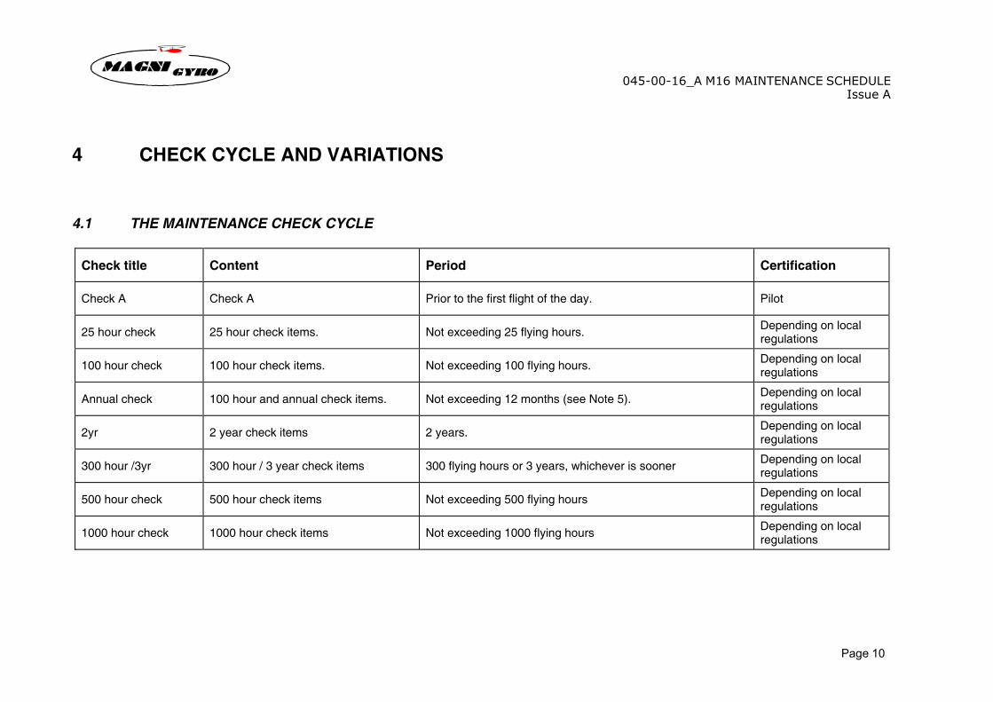
4 CHECK CYCLE AND VARIATIONS 4.1 THE MAINTENANCE CHECK CYCLE
Check title Content Period Certification
Check A Check A Prior to the first flight of the day. Pilot
25 hour check 25 hour check items. Not exceeding 25 flying hours. Depending on local regulations
100 hour check 100 hour check items. Not exceeding 100 flying hours. Depending on local regulations
Annual check 100 hour and annual check items. Not exceeding 12 months (see Note 5). Depending on local regulations
2yr 2 year check items 2 years. Depending on local regulations
300 hour /3yr 300 hour / 3 year check items 300 flying hours or 3 years, whichever is sooner Depending on local regulations
500 hour check 500 hour check items Not exceeding 500 flying hours Depending on local regulations
1000 hour check 1000 hour check items Not exceeding 1000 flying hours Depending on local regulations
045-00-16_A M16 MAINTENANCE SCHEDULEIssue A
Page 11
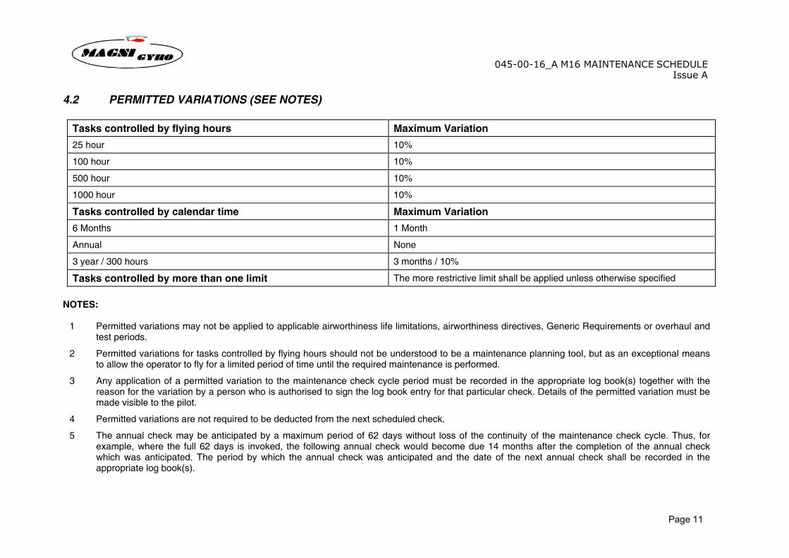
4.2 PERMITTED VARIATIONS (SEE NOTES)
Tasks controlled by flying hours Maximum Variation
25 hour 10%
100 hour 10%
500 hour 10%
1000 hour 10%
Tasks controlled by calendar time Maximum Variation
6 Months 1 Month
Annual None
3 year / 300 hours 3 months / 10%
Tasks controlled by more than one limit The more restrictive limit shall be applied unless otherwise specified NOTES:
1 Permitted variations may not be applied to applicable airworthiness life limitations, airworthiness directives, Generic Requirements or overhaul and test periods.
2 Permitted variations for tasks controlled by flying hours should not be understood to be a maintenance planning tool, but as an exceptional means to allow the operator to fly for a limited period of time until the required maintenance is performed.
3 Any application of a permitted variation to the maintenance check cycle period must be recorded in the appropriate log book(s) together with the reason for the variation by a person who is authorised to sign the log book entry for that particular check. Details of the permitted variation must be made visible to the pilot.
4 Permitted variations are not required to be deducted from the next scheduled check.
5 The annual check may be anticipated by a maximum period of 62 days without loss of the continuity of the maintenance check cycle. Thus, for example, where the full 62 days is invoked, the following annual check would become due 14 months after the completion of the annual check which was anticipated. The period by which the annual check was anticipated and the date of the next annual check shall be recorded in the appropriate log book(s).
045-00-16_A M16 MAINTENANCE SCHEDULEIssue A
Page 12
5 PRE-FLIGHT 5.1 PILOT’S PRE-FLIGHT CHECK / CHECK A – PRIOR TO FIRST FLIGHT OF THE DAY Pre-flight checks / Check A are to be carried out in accordance with the Gyroplane Flight Manual. Note: Initially the daily/pre-flight checks may seem a long procedure, but with experience the pilot will soon become familiar with all aspects of the aircraft and what is correct or not. The check is organised into a logical pattern that makes one complete circuit of the gyroplane and becomes second nature with practice. This pattern starts with the inspection of the instrument panel and continues around the gyroplane. 5.2 CHECK A - PRIOR TO FIRST FLIGHT OF THE DAY A1 Instrument Panel Master “ON”. Check operation of a) TCU (Turbo Control Unit) b) Operation of TCU Servo c) Strobe/hazard light units d) Electrically powered instruments e) Ignition Warning Light Master “OFF” Check a) Instruments zeroed, where applicable. b) Set altimeter to QFE c) Instruments secure d) Operation of drift indicator e) Nameplates and markings are present and legible
045-00-16_A M16 MAINTENANCE SCHEDULEIssue A
Page 13
A2 Pedals Check a) Rudder pedals full, free, positive and correct movement b) Condition of rudder cables and travel along keel mounted pulleys c) Presence of safety wiring on cable turnbuckles A3 Control Columns Check a) Operation of cyclic controls, front and rear for i. Full and free movement ii. Synchronised operation of front and rear control sticks iii. Condition of all joints/hinges/bearings b) Functioning of pre-rotator lever on front control stick A4 Inside of Cockpit Check a) No debris, equipment or cargo will cause any restriction to the controls b) Any signs of fouling of controls in cockpit c) Seats are secure and free from damage A5 Cockpit/Fuselage Right Hand Side Check a) State of external surface of fuselage and remove foreign objects and dirt b) Inspect transparencies for fixing, damage and cleanliness. c) Pilot and passenger restraint system and make sure are not damaged. Pay particular attention to any cut, chafing, contamination
worn latch or boss, loose or pulled stitching and any other factors that may call into doubt the harness serviceability d) State and safety of fuel cap A6 Coolant Level Check a) Carefully open expansion tank on the engine and check the correct level of coolant in tank
045-00-16_A M16 MAINTENANCE SCHEDULEIssue A
Page 14
A7 Engine Oil Level Check a) Correct engine oil level using the dipstick inside the oil tank A8 Freedom and Integrity of Control Rods Check a) Condition and security of the safety points on the control rods, linkages, bearings and fiberlock nuts. There should be insignificant
play in the “Uniball” rod-end bearings and no evidence of corrosion or damage. The control rods should be straight and undamaged. The control rods should be free to rotate slightly around their axis when gripped and given a light twist. Any undue force needed or inability to twist the bearing may indicate a problem of the bearing and should be further investigated.
A9 Rotor Head – Right Hand Side Check a) All the rotor head securing nuts are secure and that all the safety locking systems are present and functional. b) Examine as far as possible the rotor head and hub-bar assemblies for cracks, damage, wear, corrosion and rubbing. c) The state of the pre-rotator ring-gear teeth and make sure they are not damaged or excessively worn. d) Make sure the pre-rotator flexible shaft and the Bendix pre-rotation gear are adequately coated with grease. A10 Undercarriage Right Hand Side Check a) Condition and safety of the undercarriage leg and mounting bolts A11 Wheels and Wheel Spats Check a) Condition and safety of the anchoring of the wheel, hub, axle and wheel spats. b) All the tyres for damage and check tyre pressures are correct c) Check for damage, rubbing marks on the tyres and position of creep marks. d) The brake lines and make sure there is no evidence of bending or chafing Either roll the gyroplane forward or remove the wheel spats to check the whole of each tyre. Ensure any dirt and debris has been removed from inside the wheel spats. Check the function of the braking system. Check the braking system for signs of leaks or damage. A12 Engine Mount – Right Hand Side Check a) Welds on the engine mount for cracks, damage or chafing. b) The vibration dampers for damage or cracks and make sure the fixing bolts are not loose.
045-00-16_A M16 MAINTENANCE SCHEDULEIssue A
Page 15
A13 Engine – Right Hand Side Check a) The following components for security, corrosion, condition, levels, leaks, damage and chafing: - carburettors, linkages and cables - airbox fixing - wiring and connections - cooling system - oil reservoir and oil - oil filter - radiator and oil radiator - spark plugs and their caps - engine bearers, connectors and fasteners - oil, fuel and coolant hoses and clamps - on the Rotax 914 engine: – the Turbo Control Unit (TCU) and its mounting bracket – exhaust system, springs, joints and mounts – pre-rotation assembly, belts, cables and flexible shaft A14 Exhaust System – Right Hand Side Check a) Verify the integrity of the exhaust system, checking that there are no cracks in the exhaust pipes. b) Security of the exhaust gas temperature probes. A15 Radiators Check a) The radiant surfaces and verify that there are no leaks of liquid, damage or chafing. b) The security of the radiator baffles system and the security of the clamps and fixing points. A16 Propeller Check a) The hub bolts and the propeller hub b) The hub bolts wire-locking is intact c) The entire surface of each blade for any signs of damage or de-bonding. Make sure the blades are clean.
045-00-16_A M16 MAINTENANCE SCHEDULEIssue A
Page 16
A17 Pre-Rotation System Check a) Correct positioning of the pre-rotation assembly and the belt tension. b) Functioning of the pre-rotation system and the freedom of movement of the belt tensioning pulley lever. c) Correct positioning of the pulley’s brake shoe and check for excess pulley wear. A18 Tailplane Check a) All the lower and upper surfaces and make sure they are free from cracks or damage. b) Security of the tail plane. c) Security of the rudder and make sure it is completely free to move (push down on the tail so that the nose wheel lifts, allowing the
rudder and nose-wheel to move freely) d) Tail wheel for condition and free movement. A19 Engine – Left Hand Side Check a) The following components for security, corrosion, condition, levels, leaks, damage and chafing: - carburettors, linkages and cables - airbox fixing - wiring and connections - cooling system - radiator and oil radiator - spark plugs and their caps - engine bearers, connectors and fasteners - oil, fuel and coolant hoses and clamps - exhaust system, springs, joints and mounts b) The state of the battery and look for signs of overheating, excessive venting, corrosion of terminals or leakage of acid. c) The voltage regulator and the starter contactor for signs of overheating, short circuits or corrosion. d) The state of the air filter and make sure it is fixed well. e) The ROTAX 914 turbocharger unit, air filter, waste gate and springs, waste gate motor and cable. A20 Trim System Check a) Security of the trim actuator and integrity of the control cable, springs and electric connections.
045-00-16_A M16 MAINTENANCE SCHEDULEIssue A
Page 17
A21 Fuel System Check a) That the quantity of fuel is adequate for the flight planned. b) The fuel pipes and connectors for serviceability and any sign of leakage. c) The fuel filter is clean and that there are no signs of leaks. d) The fuel tank surfaces and seams. Draw a sample of fuel from the drain point and check the sample for any water or other contaminant. A22 Fuel Level Check a) The fuel level. WARNING: This operation must be done using the tank sight gauge. Position the gyroplane so that it is standing on all three wheels on level
ground to ensure a correct reading. The reading on the sight gauge should be cross-checked visually by looking at the rear left side of the fuel tank.
A23 Control Rods – Left Hand Side Check a) Condition and security of the safety points on the control rods, linkages, bearings and fiberlock nuts. There should be no significant
play in the “Uniball” rod-end bearings and no evidence of corrosion or damage. The control rods should be straight and undamaged. The control rods should be free to rotate slightly around their axis when gripped and given a light twist. Any undue force needed or inability to twist the bearing may indicate a problem of the bearing and should be further investigated.
b) The rotor brake and cables for freedom of movement and correct function c) The state of the rotor tachometer pick-up and make sure it is secure. A24 Cockpit and Fuselage – Left Hand Side Check a) State of external surface of fuselage and remove foreign objects and dirt b) Inspect transparencies for fixing, damage and cleanliness. A25 Throttle Levers Check a) That the full range of movement is available to the throttle lever, with no binding or restriction b) Ensure that the front throttle lever can be extended past the 100% stop and reach the 115% stop. c) The condition of the brake levers. Make sure that the maximum braking power is available and that the lever springs back when
released.
045-00-16_A M16 MAINTENANCE SCHEDULEIssue A
Page 18
A26 Nose Wheel Check a) The condition of the nose wheel and tyre; check tyre pressure. b) That the full range of movement is available to the wheel and that it operates in the correct direction with the rudder. c) The fork for any sign of damage or distortion. d) That the wheel is free to spin, without play in the bearings. Make sure the axle nut is secure. A28 Pitot Check a) That there are no obstructions, dirtiness or other clogging inside the pitot. A28 Rotor Blades Check a) That the rotor blades are free from any damage or other defect. NOTE: Inspection of rotor blade root should account for confirmation that any cracks in this region conform to the appearance, and
remain within the limits, specified in SIL-002-2011 and also shown under task number 47 of this schedule. b) Ensure that the rotor blades are clean. A29 Communication and Navigation Systems Check a) The functionality of all the navigation and communication systems. A30 Lighting System Check a) The functionality of all the internal and external lighting systems.
045-00-16_A M16 MAINTENANCE SCHEDULEIssue A
Page 19
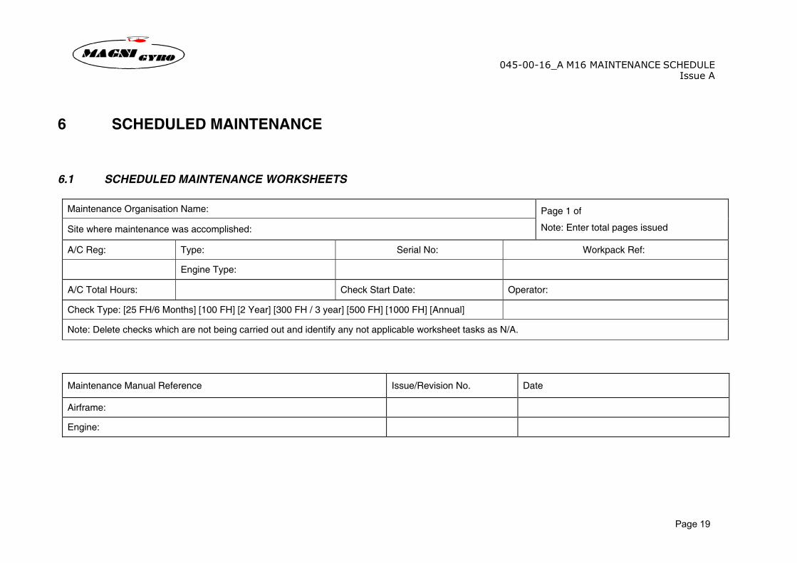
6 SCHEDULED MAINTENANCE 6.1 SCHEDULED MAINTENANCE WORKSHEETS
Maintenance Organisation Name:
Site where maintenance was accomplished:
Page 1 of
Note: Enter total pages issued
A/C Reg: Type: Serial No: Workpack Ref:
Engine Type:
A/C Total Hours: Check Start Date: Operator:
Check Type: [25 FH/6 Months] [100 FH] [2 Year] [300 FH / 3 year] [500 FH] [1000 FH] [Annual]
Note: Delete checks which are not being carried out and identify any not applicable worksheet tasks as N/A.
Maintenance Manual Reference Issue/Revision No. Date
Airframe:
Engine:
045-00-16_A M16 MAINTENANCE SCHEDULEIssue A
Page 20
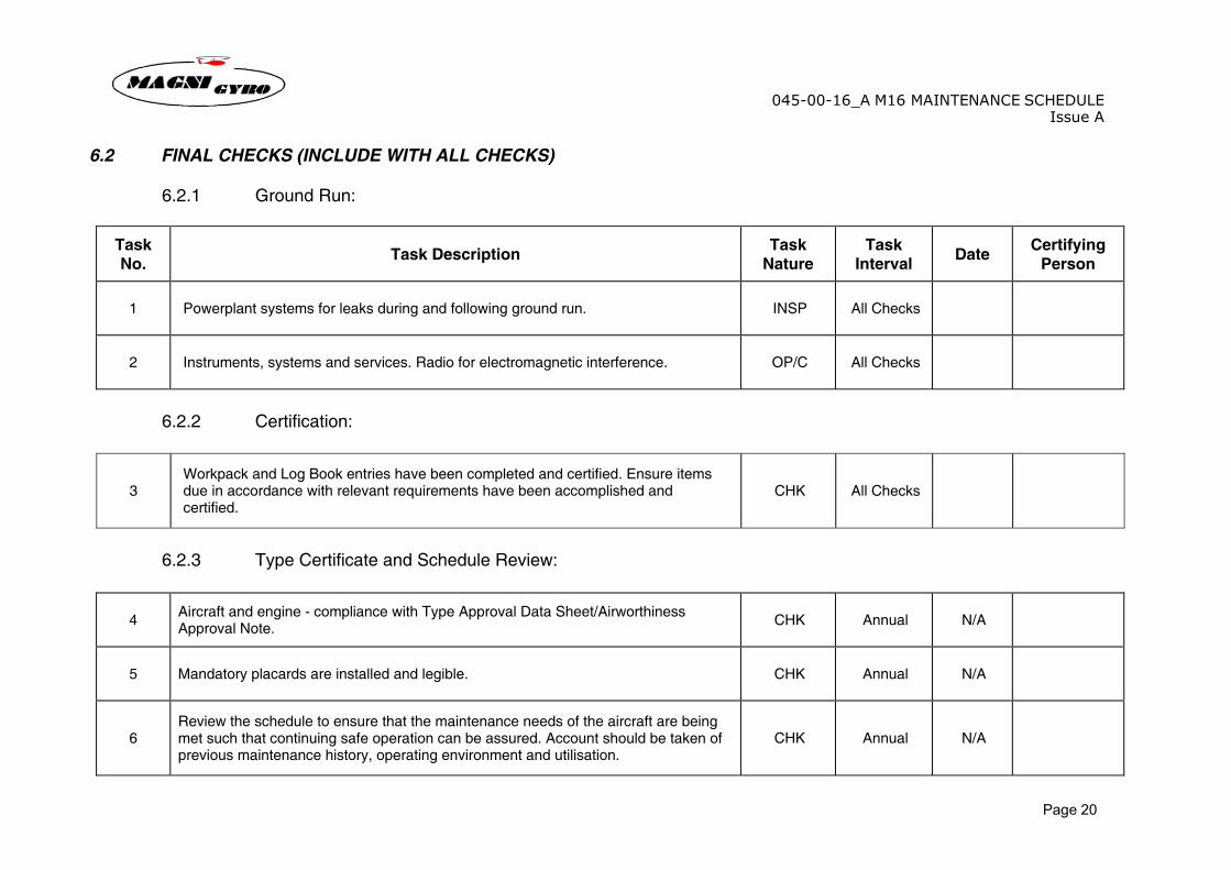
6.2 FINAL CHECKS (INCLUDE WITH ALL CHECKS) 6.2.1 Ground Run:
Task No. Task Description Task
Nature Task
Interval Date Certifying Person
1 Powerplant systems for leaks during and following ground run. INSP All Checks
2 Instruments, systems and services. Radio for electromagnetic interference. OP/C All Checks
6.2.2 Certification:
3 Workpack and Log Book entries have been completed and certified. Ensure items due in accordance with relevant requirements have been accomplished and certified.
CHK All Checks
6.2.3 Type Certificate and Schedule Review:
4 Aircraft and engine - compliance with Type Approval Data Sheet/Airworthiness Approval Note. CHK Annual N/A
5 Mandatory placards are installed and legible. CHK Annual N/A
6 Review the schedule to ensure that the maintenance needs of the aircraft are being met such that continuing safe operation can be assured. Account should be taken of previous maintenance history, operating environment and utilisation.
CHK Annual N/A
045-00-16_A M16 MAINTENANCE SCHEDULEIssue A
Page 21
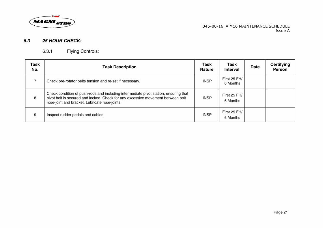
6.3 25 HOUR CHECK: 6.3.1 Flying Controls:
Task No. Task Description Task
Nature Task
Interval Date Certifying Person
7 Check pre-rotator belts tension and re-set if necessary. INSP First 25 FH/ 6 Months
8 Check condition of push-rods and including intermediate pivot station, ensuring that pivot bolt is secured and locked. Check for any excessive movement between bolt rose-joint and bracket. Lubricate rose-joints.
INSP First 25 FH/ 6 Months
9 Inspect rudder pedals and cables INSP First 25 FH/ 6 Months
045-00-16_A M16 MAINTENANCE SCHEDULEIssue A
Page 22
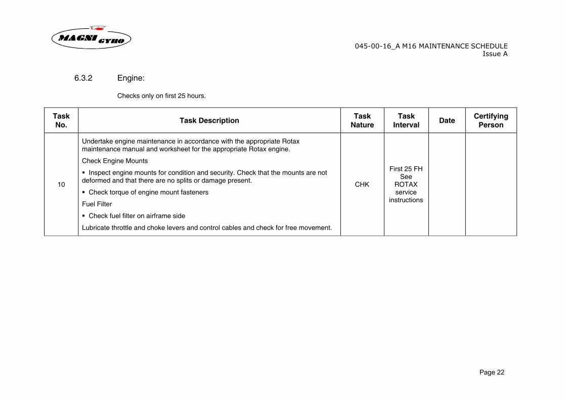
6.3.2 Engine: Checks only on first 25 hours.
Task No. Task Description Task
Nature Task
Interval Date Certifying Person
10
Undertake engine maintenance in accordance with the appropriate Rotax maintenance manual and worksheet for the appropriate Rotax engine.
Check Engine Mounts
� Inspect engine mounts for condition and security. Check that the mounts are not deformed and that there are no splits or damage present.
� Check torque of engine mount fasteners
Fuel Filter
� Check fuel filter on airframe side
Lubricate throttle and choke levers and control cables and check for free movement.
CHK
First 25 FH See
ROTAX service
instructions
045-00-16_A M16 MAINTENANCE SCHEDULEIssue A
Page 23
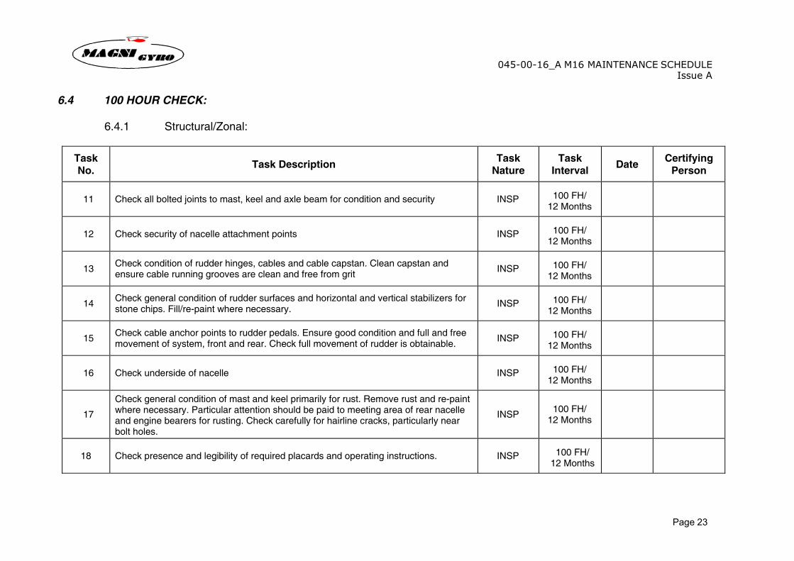
6.4 100 HOUR CHECK: 6.4.1 Structural/Zonal:
Task No. Task Description Task
Nature Task
Interval Date Certifying Person
11 Check all bolted joints to mast, keel and axle beam for condition and security INSP 100 FH/ 12 Months
12 Check security of nacelle attachment points INSP 100 FH/ 12 Months
13 Check condition of rudder hinges, cables and cable capstan. Clean capstan and ensure cable running grooves are clean and free from grit INSP 100 FH/
12 Months
14 Check general condition of rudder surfaces and horizontal and vertical stabilizers for stone chips. Fill/re-paint where necessary. INSP 100 FH/
12 Months
15 Check cable anchor points to rudder pedals. Ensure good condition and full and free movement of system, front and rear. Check full movement of rudder is obtainable. INSP 100 FH/
12 Months
16 Check underside of nacelle INSP 100 FH/ 12 Months
17
Check general condition of mast and keel primarily for rust. Remove rust and re-paint where necessary. Particular attention should be paid to meeting area of rear nacelle and engine bearers for rusting. Check carefully for hairline cracks, particularly near bolt holes.
INSP 100 FH/ 12 Months
18 Check presence and legibility of required placards and operating instructions. INSP 100 FH/ 12 Months
045-00-16_A M16 MAINTENANCE SCHEDULEIssue A
Page 24
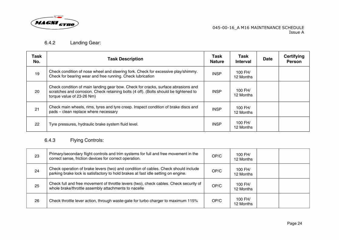
6.4.2 Landing Gear:
Task No. Task Description Task
Nature Task
Interval Date Certifying Person
19 Check condition of nose wheel and steering fork. Check for excessive play/shimmy. Check for bearing wear and free running. Check lubrication INSP 100 FH/
12 Months
20 Check condition of main landing gear bow. Check for cracks, surface abrasions and scratches and corrosion. Check retaining bolts (4 off). (Bolts should be tightened to torque value of 23-26 Nm)
INSP
100 FH/ 12 Months
21 Check main wheels, rims, tyres and tyre creep. Inspect condition of brake discs and pads – clean replace where necessary INSP 100 FH/
12 Months
22 Tyre pressures, hydraulic brake system fluid level. INSP 100 FH/ 12 Months
6.4.3 Flying Controls:
23 Primary/secondary flight controls and trim systems for full and free movement in the correct sense, friction devices for correct operation. OP/C 100 FH/
12 Months
24 Check operation of brake levers (two) and condition of cables. Check should include parking brake lock is satisfactory to hold brakes at fast idle setting on engine. OP/C 100 FH/
12 Months
25 Check full and free movement of throttle levers (two), check cables. Check security of whole brake/throttle assembly attachments to nacelle OP/C 100 FH/
12 Months
26 Check throttle lever action, through waste-gate for turbo charger to maximum 115% OP/C 100 FH/ 12 Months
045-00-16_A M16 MAINTENANCE SCHEDULEIssue A
Page 25
Task No. Task Description Task
Nature Task
Interval Date Certifying Person
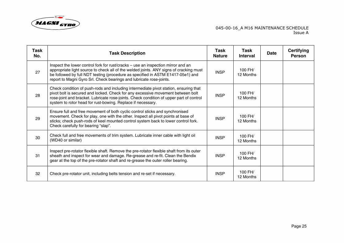
27
Inspect the lower control fork for rust/cracks – use an inspection mirror and an appropriate light source to check all of the welded joints. ANY signs of cracking must be followed by full NDT testing (procedure as specified in ASTM E1417-05e1) and report to Magni Gyro Srl. Check bearings and lubricate rose-joints.
INSP 100 FH/ 12 Months
28
Check condition of push-rods and including intermediate pivot station, ensuring that pivot bolt is secured and locked. Check for any excessive movement between bolt rose-joint and bracket. Lubricate rose-joints. Check condition of upper part of control system to rotor head for rust-bowing. Replace if necessary.
INSP 100 FH/ 12 Months
29
Ensure full and free movement of both cyclic control sticks and synchronised movement. Check for play, one with the other. Inspect all pivot points at base of sticks; check push-rods of keel mounted control system back to lower control fork. Check carefully for bearing “slap”.
INSP 100 FH/ 12 Months
30 Check full and free movements of trim system. Lubricate inner cable with light oil (WD40 or similar) INSP 100 FH/
12 Months
31 Inspect pre-rotator flexible shaft. Remove the pre-rotator flexible shaft from its outer sheath and inspect for wear and damage. Re-grease and re-fit. Clean the Bendix gear at the top of the pre-rotator shaft and re-grease the outer roller bearing.
INSP 100 FH/ 12 Months
32 Check pre-rotator unit, including belts tension and re-set if necessary. INSP 100 FH/ 12 Months
045-00-16_A M16 MAINTENANCE SCHEDULEIssue A
Page 26
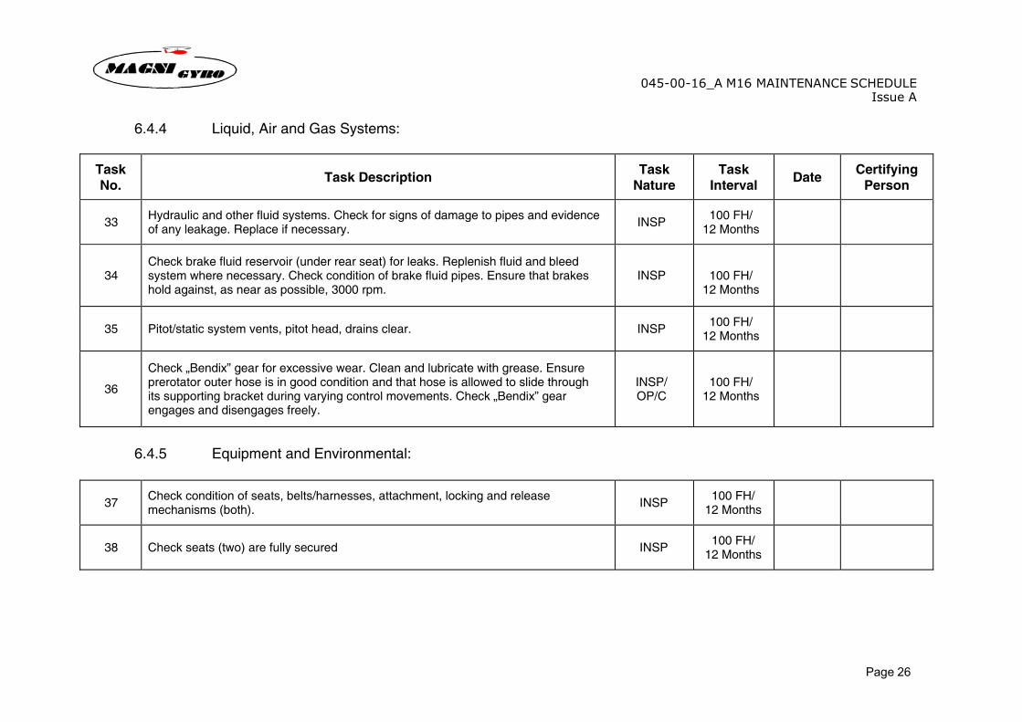
6.4.4 Liquid, Air and Gas Systems:
Task No. Task Description Task
Nature Task
Interval Date Certifying Person
33 Hydraulic and other fluid systems. Check for signs of damage to pipes and evidence of any leakage. Replace if necessary. INSP 100 FH/
12 Months
34 Check brake fluid reservoir (under rear seat) for leaks. Replenish fluid and bleed system where necessary. Check condition of brake fluid pipes. Ensure that brakes hold against, as near as possible, 3000 rpm.
INSP
100 FH/ 12 Months
35 Pitot/static system vents, pitot head, drains clear. INSP 100 FH/ 12 Months
36
Check „Bendix” gear for excessive wear. Clean and lubricate with grease. Ensure prerotator outer hose is in good condition and that hose is allowed to slide through its supporting bracket during varying control movements. Check „Bendix” gear engages and disengages freely.
INSP/ OP/C
100 FH/ 12 Months
6.4.5 Equipment and Environmental:
37 Check condition of seats, belts/harnesses, attachment, locking and release mechanisms (both). INSP 100 FH/
12 Months
38 Check seats (two) are fully secured INSP 100 FH/ 12 Months
045-00-16_A M16 MAINTENANCE SCHEDULEIssue A
Page 27
6.4.6 Engine:
Task No. Task Description Task
Nature Task
Interval Date Certifying Person
39
Undertake engine maintenance in accordance with the appropriate Rotax maintenance manual and worksheet for the Rotax engine.
Fuel Filter
� Check fuel filter on airframe side
Lubricate throttle and choke levers and control cables and check for free movement.
CHK See
ROTAX service
instructions
6.4.7 Rotors:
40 Check for wear in teeter bearings. The bearings should show no more than 0.25mm (0.010”) diameter change / radial play around teeter bolt. INSP 100 FH/
12 Months
41 Check the teeter bolt for wear and replace if necessary. The bolt should show no more than 0.25mm (0.010”) diameter change / radial play around teeter bolt. INSP 100 FH/
12 Months
42 Check rotor head for smooth running. Investigate and repair / refurbish if there are any signs of roughness. (Note: Repair and refurbishment of the rotor head should only be undertaken by technicians approved by Magni Gyro Srl)
INSP 100 FH/ 12 Months
43 Ensure that whilst the nuts are tight and secured with pins, both the roll and pitch axis pivot bolts are allowed full and free movement. Clean and re-lubricate with grease. INSP 100 FH/
12 Months
44 Ensure rotor head pivot block is secure and wire locked. INSP 100 FH/ 12 Months
045-00-16_A M16 MAINTENANCE SCHEDULEIssue A
Page 28
Task No. Task Description Task
Nature Task
Interval Date Certifying Person
45 Ensure the pre-rotator ring gear assembly is free of rust and has film of grease applied INSP
100 FH/ 12 Months
46
Check general condition of rotor assembly centre section for
� Rusting – remove where necessary and re-paint
� Signs of bending or torsional stress
� Condition of teeter stops
INSP 100 FH/
12 Months
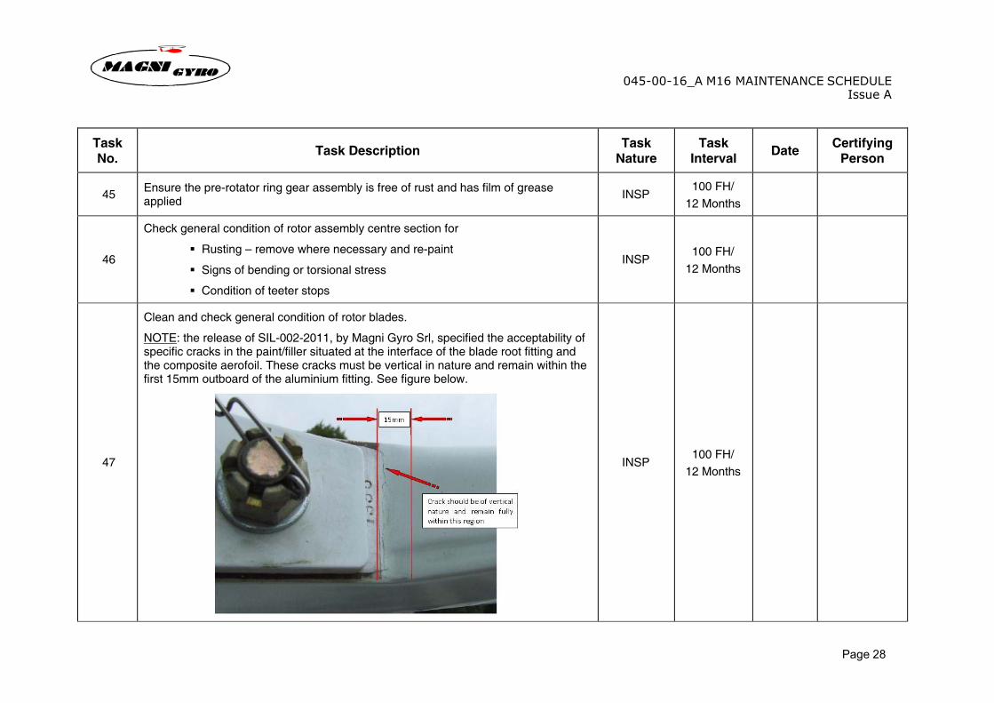
47
Clean and check general condition of rotor blades.
NOTE: the release of SIL-002-2011, by Magni Gyro Srl, specified the acceptability of specific cracks in the paint/filler situated at the interface of the blade root fitting and the composite aerofoil. These cracks must be vertical in nature and remain within the first 15mm outboard of the aluminium fitting. See figure below.
INSP 100 FH/
12 Months
045-00-16_A M16 MAINTENANCE SCHEDULEIssue A
Page 29
Task No. Task Description Task
Nature Task
Interval Date Certifying Person
48 Re-install rotor assembly, having re-greased the teeter bolt. Ensure all safety locking pins are fitted INSP 100 FH/
12 Months
49 Grease rotor head bolts and bearings through the dedicated grease nipples placed on the rotor head LUB 100 FH/
12 Months
50 Check rotor brake system operation. Ensure brake works smoothly, without snatching. Lubricate rotor brake cable and check for free movement. INSP 100 FH/
12 Months
6.4.8 Gyroplane Lubrication:
51 Lubricate gyroplane in accordance with Magni Gyro Srl recommendations as defined in section 1.7.4 of the maintenance manual. LUB 100 FH/
12 Months
6.4.9 Powerplant Installation:
52 Check engine bearers for rust/cracks. Remove rust and re-paint where necessary INSP 100 FH/
12 Months
53 Powerplant installation. Check for signs of corrosion, cracks and leaks. Verify engine mounting bolts are torque to 34-36.5 Nm. INSP
100 FH/ 12 Months
54 Engine cooling installation. Check for signs of corrosion, cracks and leaks. INSP 100 FH/
12 Months
55 Inspect propeller condition (three blades). Remove blemishes and repair any minor damage. If needed remove the propeller and re-set in hub and re-balance whole assembly. Re-attach hub assembly and wire-lock. Refer to Maintenance Manual, Section 3.18, for allowable damage.
INSP 100 FH/
12 Months
045-00-16_A M16 MAINTENANCE SCHEDULEIssue A
Page 30
6.4.10 Air Induction:
Task No. Task Description Task
Nature Task
Interval Date Certifying Person
56 Inspect and clean/replace air filter as required. INSP 100 FH/ 12 Months
6.4.11 Exhaust:
57 Check exhaust units for security/cracks INSP 100 FH/ 12 Months
6.4.12 Fuel System:
58 Filters for cleanliness and tank vents unobstructed. Drain samples from all drain points and check for presence of water, foreign matter and correct colour. INSP 100 FH/
12 Months
59 Check fuel tanks for leaks. Ensure low fuel warning system function. Drain system and replace filters. Ensure proper function of drain tap. INSP 100 FH/
12 Months
045-00-16_A M16 MAINTENANCE SCHEDULEIssue A
Page 31
6.4.13 Electrical System:
Task No. Task Description Task
Nature Task
Interval Date Certifying Person
60 Check battery is properly seated and secured. Ensure clean connections. Check for leakage.
INSP and SERVICE
100 FH/ 12 Months
61 Check condition of wiring – look for signs of abrasion, kinking and heat damage. INSP 100 FH/ 12 Months
62 Check landing light lens/working order. INSP 100 FH/ 12 Months
63 Check strobe units (if fitted) for condition and function/security. Inspect wiring/attachments. Replace where necessary INSP 100 FH/
12 Months
6.4.14 Instrument Systems:
64 Instruments. Legibility of markings and associated placards, band ranges and limit markings.
INSP and CHK
100 FH/ 12 Months
65 Readings consistent with ambient conditions. CHK 100 FH/ 12 Months
66 Compass „deviation� or „steer by� cards - valid until next check. Check calibration of compass. Conduct compass swing verification test (cross check to handheld compass)
CHK 100 FH/ 12 Months
67 Ensure good condition of all flight instruments. Pressure check altimeter. Re-calibrate where necessary. Check ASI reading on flight test, or alternative method. CHK 100 FH/
12 Months
045-00-16_A M16 MAINTENANCE SCHEDULEIssue A
Page 32
6.4.15 Ignition
Task
No. Task Description
Task
Nature
Task
Interval Date
Certifying
Person
68 Magnetos, harnesses, leads, switches, starting solenoid, contact breakers, INSP 100 FH/ 12 Months
045-00-16_A M16 MAINTENANCE SCHEDULEIssue A
Page 33
6.5 2-YEAR CHECK 6.5.1 Instrument Systems:
Task No. Task Description Task
Nature Task
Interval Date Certifying Person
69 Transponder (if fitted). Check that mode S code matches record/registration database. Full functional check. CHK 2 years
6.6 300 HOUR / 3-YEAR CHECK 6.6.1 Flying Controls:
Task No. Task Description Task
Nature Task
Interval Date Certifying Person
70 Clean and inspect all control cables. Replace as required if signs of corrosion, wear or damage are found. CHK
300 FH or 3 years,
whichever is longer
045-00-16_A M16 MAINTENANCE SCHEDULEIssue A
Page 34
6.7 500 HOUR CHECK 6.7.1 Flying Controls:
Task No. Task Description Task
Nature Task
Interval Date Certifying Person
71 Replace pre-rotation belts and pulleys CHK 500 FH
72 Replace rod end joints on control system linkage (8 places). Part numbers 033-03-16 (2 off), 034-03-16 (4 off) and 035-03-16 (2 Off). CHK 500 FH
6.7.2 Rotor:
73 Overhaul rotor head assembly INSP 500 FH
74 Check for wear in teeter bearings. Remove rotor system from the teeter bolt bearing. The bearings should show no more than 0.25mm (0.010”) diameter change / radial play between bolt and bearing.
INSP 500 FH
75 Check condition of the teeter bolt for wear and replace if necessary. The bolt should show no more than 0.25mm (0.010”) diameter change / radial play between bolt and bearing.
INSP 500 FH
76 Check the roll and pitch bolts for wear. The bolts should show no more than 0.25mm (0.010”) diameter change / radial play. INSP 500 FH
045-00-16_A M16 MAINTENANCE SCHEDULEIssue A
Page 35
6.8 1000 HOUR CHECK 6.8.1 Powerplant Installation:
Task No. Task Description Task
Nature Task
Interval Date Certifying Person
77 Replace engine mount vibration dampers CHK 1000 FH
045-00-16_A M16 MAINTENANCE SCHEDULEIssue A
Page 36
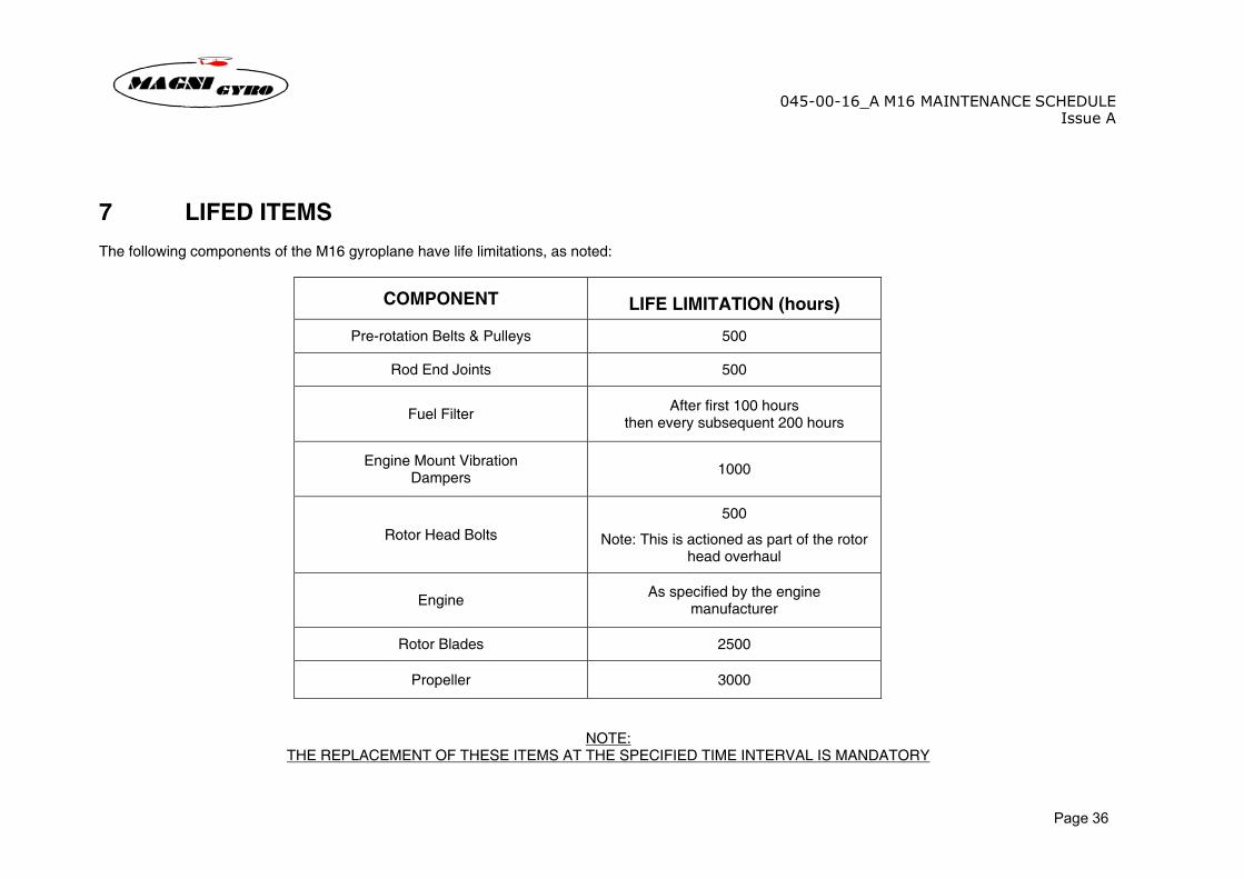
7 LIFED ITEMS The following components of the M16 gyroplane have life limitations, as noted:
NOTE: THE REPLACEMENT OF THESE ITEMS AT THE SPECIFIED TIME INTERVAL IS MANDATORY
COMPONENT
LIFE LIMITATION (hours)
Pre-rotation Belts & Pulleys 500
Rod End Joints 500
Fuel Filter After first 100 hours then every subsequent 200 hours
Engine Mount Vibration Dampers 1000
Rotor Head Bolts 500
Note: This is actioned as part of the rotor head overhaul
Engine As specified by the engine manufacturer
Rotor Blades 2500
Propeller 3000
![valve pneumatic actuators - Ventiler og regulering = Uni-Valve · gost. 0497 [ped] type. approval ... 81 46: 67 34: 14 11: 90 70: 9 196: 242 m16: 8 160: m16 8: 160 m16: 4 152.4: 4.4](https://img.pdfslide.us/doc/110x75/5b5ad1e97f8b9a885b8cc55a/valve-pneumatic-actuators-ventiler-og-regulering-uni-gost-0497-ped-type.jpg)

![0-& 1 2#’-0#3&(-4.+$&045($&.$&66437&0’#$ .&(-4.&’$# · 0-& 1 2#’-0#3&(-4.+$&045($&.$&66437&0’#$ .&(-4.&’$# ... 0: @@]:](https://img.pdfslide.us/doc/110x75/5e0538a1f8311074145ea187/0-1-2a-03-4045664370a-4a.jpg)