Embed Size (px)
Citation preview
TITLE: Influence of Acid Exposure upon Mechanical Strength of Ceramic
Proppants
Authors and Companies: Tihana Fuss, E. Michael Snyder, Daniel C. Herndon, and
Walter T. Stephens, Saint-Gobain Proppants
Large quantities of ceramic proppants find use in hydraulic fracturing every year.
These proppants, however, are not interchangeable or commodity products but consist
of unique materials and structural features that determine their practical mechanical
properties. Exposing ceramic proppants to any amount of acid in fluids can alter their
internal microstructure leading to a change in mechanical and production performance.
While hydrochloric and hydrofluoric acids typically attack glassy phases due to the
presence of silicon dioxide, other silicate dominant phases in the ceramic
microstructure are also vulnerable to attack, such as mullite with its documented
reactivity to hydrofluoric acids. The extent of acid attack on the ceramic microstructure
depends on not only the acid concentration but also the temperature and time
conditions which the well conditions dictate. Surface roughness, presence of surface
porosity or cracks on the ceramic proppant, acts as an additional factor that decreases
acid resistance. Acid attack of ceramic structures will result in the formation of high
stress concentration regions in the proppant pack leading to an increase in fines
generation at lower closure stresses. Selecting proppants based upon their phase
chemistry and the expected well conditions can mitigate much of the damage the acid
can cause to the ceramic microstructure.
This paper documents the change in mechanical behavior of ceramic proppants due to
exposure to an acid environment. The results show that the acid significantly alters the
ceramic microstructure and eventually changes the proppant pack characteristics
which will affect production performance. The results of the paper will permit operators
to select a ceramic proppant made from the appropriate material and microstructure to
meet the requirements of their specific application. The operator will gain further
insight into proppant performance issues that may improve long-term production.
2
Keywords: Acid solubility, mechanical performance, intermediate density proppants,
light weight proppants
INTRODUCTION
Hydraulic fracturing applications use man-made ceramic proppants today due to their
superior flow capacity. For gravel packing applications, the solubility of proppants in
acidizing fluids is an important factor affecting product selection. The test for acid
solubility recommended by API (ISO 13503-2)1 determines the weight loss of proppant
after 30 minutes of exposure in an acidizing environment of a 12:3 HCl:HF solution
(hydrochloric and hydrofluoric acid). To many in the industry, the measured weight loss
value helps determine the suitability of a proppant that can come into contact with acid.
The composition and microstructure of a product determines the value of the acid
solubility. Two major mineral sources comprise most man-made ceramic proppants,
bauxite and clay. Each of these minerals occupies a unique regime in the Al2O3-SiO2
system: bauxite minerals contain more than 70 wt% Al2O3 while clay minerals contain
between 40 and 60 wt% of Al2O3. Proppants made from these minerals consist of three
major phases: corundum, mullite, and crystalline or amorphous silica. Alkali silicate
glassy phases and different iron aluminate phases can also be present in bauxite
based proppants.
Acid solubility is simply the affinity of a crystalline form to react with acid in physical
contact. Silica, a key ingredient in clay based materials, has a known solubility in
hydrofluoric acid2. Solubility kinetics of corundum, mullite, and glass in hydrofluoric acid
and solutions of hydrofluoric and hydrochloric acid are also well documented in
literature.2-5 Most of these materials are relatively inert towards attack of hydrochloric
acid, but only corundum is relatively inert toward attack of hydrofluoric acid2.
Amorphous silicate compounds, such as amorphous SiO2 or the more general silicate
glasses, are extremely soluble in hydrofluoric acid3. While crystalline forms of SiO2
exhibit dissolution rates that are 2 to 3 times slower than those of their amorphous
compounds, silicate alumina glasses can exhibit dissolution rates that are 2 to 10 times
faster than amorphous silica3,4. Dissolution of mullite in hydrofluoric acid is lower than
crystalline SiO2 but generally higher than that of corundum5.
3
The purpose of this study is to understand the effect of acid exposure upon the
mechanical strength of two proppants made from bauxite and clay minerals. Since the
major phases comprising man-made ceramic proppants have different dissolution rates
in hydrofluoric acid, an additional goal is to determine if the measured acid solubility
correlates well with the solubility values of the constituent phases within a proppant and
is a useful indicator of post-acidizing performance. Previous research addresses some
problems of the effect of acid corrosion on man-made ceramic proppant performance
but concentrates upon longer acid exposure times between 1 and 24 hours.6,7 Since
some phases can have significant dissolution rates, the acid exposure time for this
study is between 0 and 1 hours to maintain a reasonable change to the microstructure
of man-made ceramic proppants.
METHODS
Materials:
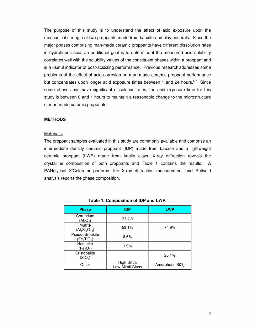
The proppant samples evaluated in this study are commonly available and comprise an
intermediate density ceramic proppant (IDP) made from bauxite and a lightweight
ceramic proppant (LWP) made from kaolin clays. X-ray diffraction reveals the
crystalline composition of both proppants and Table 1 contains the results. A
PANalytical X’Celerator performs the X-ray diffraction measurement and Reitveld
analysis reports the phase composition.
Table 1. Composition of IDP and LWP.
Phase IDP LWP
Corundum (Al2O3)
31.5%
Mullite (Al6Si2O13)
58.1% 74.9%
PseudoBrookite (Fe2TiO5)
8.6%
Hematite (Fe2O3)
1.9%
Cristobalite (SiO2)
25.1%
Other High Silica Low Alkali Glass Amorphous SiO2
4
0%
10%
20%
30%
40%
50%
60%
70%
80%
90%
100%
200 300 400 500 600 700 800 900 1000 1100 1200
Size (microns)
Cum
mul
ativ
e di
stri
butio
n
IDPLWP40
mes
h
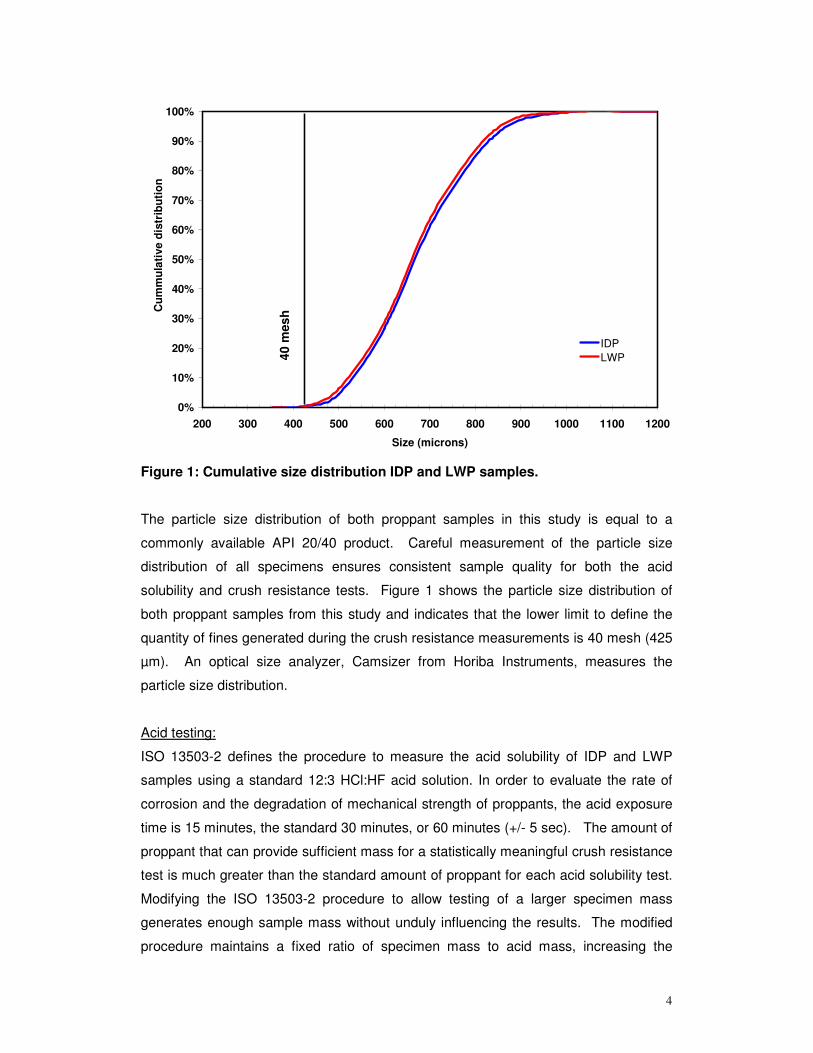
Figure 1: Cumulative size distribution IDP and LWP samples.
The particle size distribution of both proppant samples in this study is equal to a
commonly available API 20/40 product. Careful measurement of the particle size
distribution of all specimens ensures consistent sample quality for both the acid
solubility and crush resistance tests. Figure 1 shows the particle size distribution of
both proppant samples from this study and indicates that the lower limit to define the
quantity of fines generated during the crush resistance measurements is 40 mesh (425
µm). An optical size analyzer, Camsizer from Horiba Instruments, measures the
particle size distribution.
Acid testing:
ISO 13503-2 defines the procedure to measure the acid solubility of IDP and LWP
samples using a standard 12:3 HCl:HF acid solution. In order to evaluate the rate of
corrosion and the degradation of mechanical strength of proppants, the acid exposure
time is 15 minutes, the standard 30 minutes, or 60 minutes (+/- 5 sec). The amount of
proppant that can provide sufficient mass for a statistically meaningful crush resistance
test is much greater than the standard amount of proppant for each acid solubility test.
Modifying the ISO 13503-2 procedure to allow testing of a larger specimen mass
generates enough sample mass without unduly influencing the results. The modified
procedure maintains a fixed ratio of specimen mass to acid mass, increasing the
5
specimen mass from 5 to 20 g and increasing the acid volume from 100 to 400 mL per
specimen, and evaluates five (5) specimens for a total sample mass of 100 g. A
standard 5 g IDP proppant sample was also evaluated as part of this study using the
exact ISO 13503-2 procedure and correct specimen mass to monitor the test
procedure and verify that the modified procedure for the larger sample size did not
introduce more variance in the results. After completing acid solubility testing of the five
20 gram specimens, all five specimens are combined and sized to creates a suitable
sample for subsequent crush resistance tests. An optical size analyzer, Camsizer from
Horiba Instruments, measures the size distribution of each 100 g proppant sample
before and after acid testing. Analysis shows no significant effect of acidizing upon the
particle size distribution of each sample. The acid solubility for each 100 g sample is
the average of the acid solubility of each specimen. For all acid solubility
measurements in this study, the water bath temperature is 66+/- 2oC.
Crush resistance testing:
The crush resistance test described in ISO 13503-2 evaluates the degradation of
mechanical strength of each proppant sample after exposure to acid. The automated
load frame used in this study is a MTS model Alliance RF/300 with a force resolution of
±1 lbs. The MTS software that accompanies load frame also captures the force and
compaction distance data over time for this study. Obtaining a machine compliance
offset for the load frame permits removing exterior influences, such as the motion from
grips and the elastic deformation of the test cell while under load, upon the measured
compaction distance of the proppant specimen. The automated software measures this
compliance offset using an empty test cell. When the test cell with a specimen is in the
load frame, the automated software preloads the specimen with 25 lbs of force to
determine the initial pack height. The compaction of the proppant sample is the ratio of
the current pack height versus this initial value. This study uses a crush resistance cell
with a 1.5” diameter. The cell material is a M42 steel and has a Rockwell Hardness of
64. A Mettler Toledo PB 153-S balance records the specimen mass to a resolution of 1
mg. The reported crush resistance value is the weight of material finer than the 40-
mesh sieve (425 microns), the smallest sieve that defines the original size distribution.
An optical size analyzer, Camsizer from Horiba Instruments, measures the size
distribution of each proppant specimen before and after compaction.
Microstructure analysis:
Microstructure analysis is performed using Hitachi TM-1000 scanning electron
microscope on polished cross sections of both original and acid corroded samples.
6
Compositional mapping is performed on polished cross-sections using Evo 40 SEM
machine.
RESULTS
Solubility
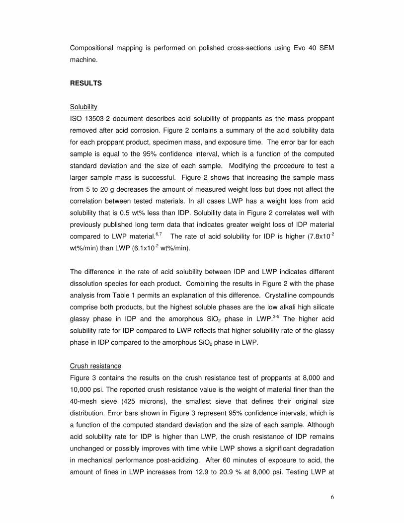
ISO 13503-2 document describes acid solubility of proppants as the mass proppant
removed after acid corrosion. Figure 2 contains a summary of the acid solubility data
for each proppant product, specimen mass, and exposure time. The error bar for each
sample is equal to the 95% confidence interval, which is a function of the computed
standard deviation and the size of each sample. Modifying the procedure to test a
larger sample mass is successful. Figure 2 shows that increasing the sample mass
from 5 to 20 g decreases the amount of measured weight loss but does not affect the
correlation between tested materials. In all cases LWP has a weight loss from acid
solubility that is 0.5 wt% less than IDP. Solubility data in Figure 2 correlates well with
previously published long term data that indicates greater weight loss of IDP material
compared to LWP material.6,7 The rate of acid solubility for IDP is higher (7.8x10⁻²
wt%/min) than LWP (6.1x10⁻² wt%/min).
The difference in the rate of acid solubility between IDP and LWP indicates different
dissolution species for each product. Combining the results in Figure 2 with the phase
analysis from Table 1 permits an explanation of this difference. Crystalline compounds
comprise both products, but the highest soluble phases are the low alkali high silicate
glassy phase in IDP and the amorphous SiO2 phase in LWP.3-5 The higher acid
solubility rate for IDP compared to LWP reflects that higher solubility rate of the glassy
phase in IDP compared to the amorphous SiO2 phase in LWP.
Crush resistance
Figure 3 contains the results on the crush resistance test of proppants at 8,000 and
10,000 psi. The reported crush resistance value is the weight of material finer than the
40-mesh sieve (425 microns), the smallest sieve that defines their original size
distribution. Error bars shown in Figure 3 represent 95% confidence intervals, which is
a function of the computed standard deviation and the size of each sample. Although
acid solubility rate for IDP is higher than LWP, the crush resistance of IDP remains
unchanged or possibly improves with time while LWP shows a significant degradation
in mechanical performance post-acidizing. After 60 minutes of exposure to acid, the
amount of fines in LWP increases from 12.9 to 20.9 % at 8,000 psi. Testing LWP at
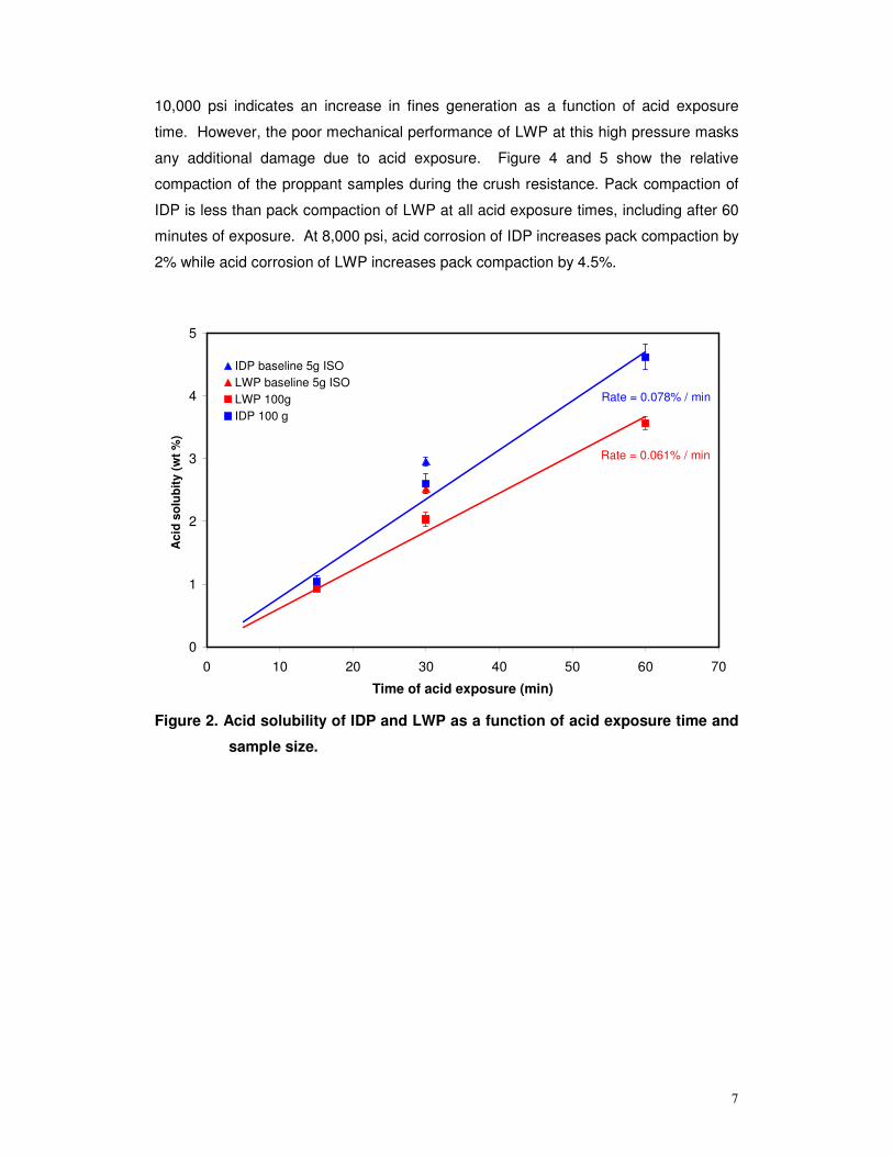
7
10,000 psi indicates an increase in fines generation as a function of acid exposure
time. However, the poor mechanical performance of LWP at this high pressure masks
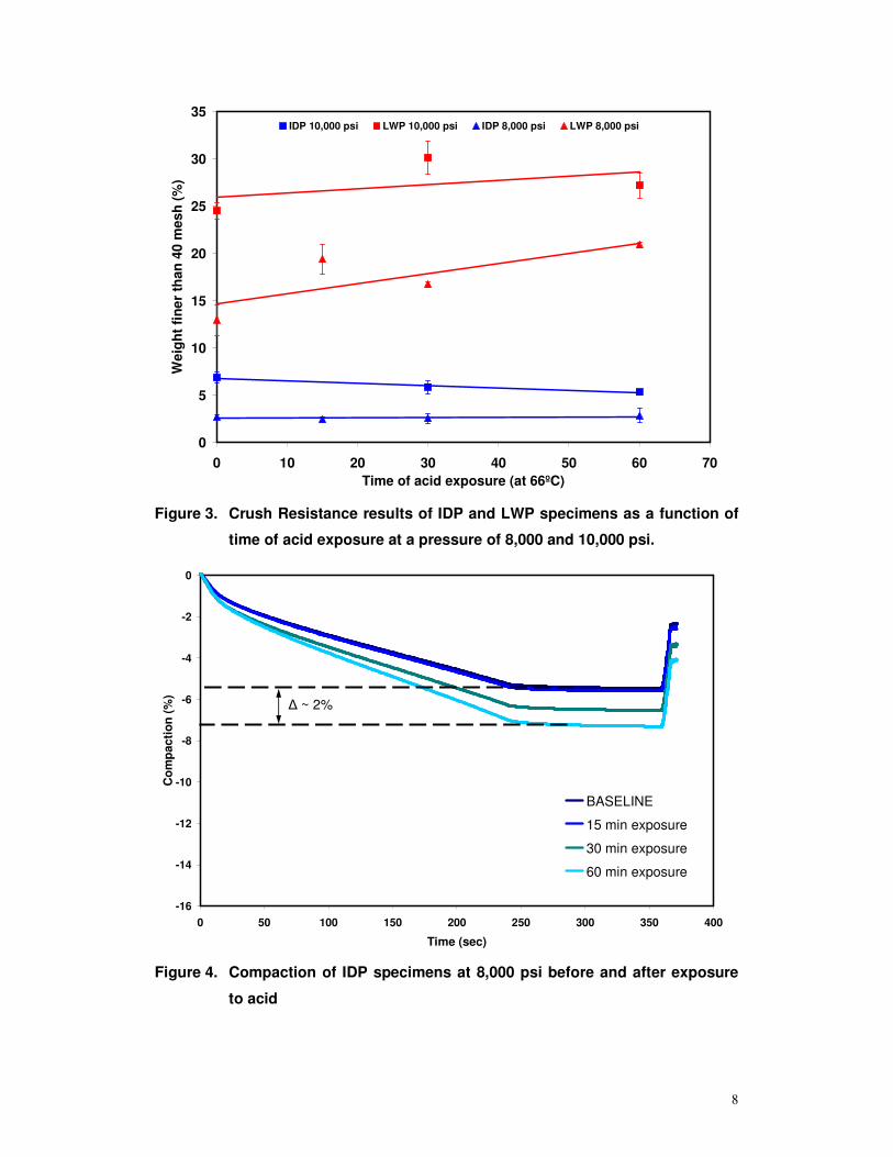
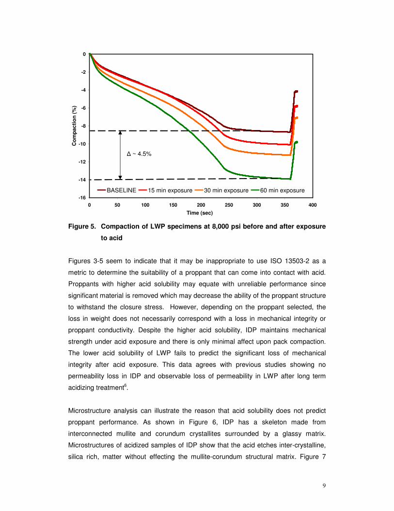
any additional damage due to acid exposure. Figure 4 and 5 show the relative
compaction of the proppant samples during the crush resistance. Pack compaction of
IDP is less than pack compaction of LWP at all acid exposure times, including after 60
minutes of exposure. At 8,000 psi, acid corrosion of IDP increases pack compaction by
2% while acid corrosion of LWP increases pack compaction by 4.5%.
Rate = 0.061% / min
Rate = 0.078% / min
0
1
2
3
4
5
0 10 20 30 40 50 60 70
Time of acid exposure (min)
Aci
d so
lubi
ty (w
t %)
IDP baseline 5g ISOLWP baseline 5g ISO LWP 100gIDP 100 g
Figure 2. Acid solubility of IDP and LWP as a function of acid exposure time and
sample size.
8
0
5
10
15
20
25
30
35
0 10 20 30 40 50 60 70Time of acid exposure (at 66ºC)
Wei
ght f
iner
than
40
mes
h (%
)
IDP 10,000 psi LWP 10,000 psi IDP 8,000 psi LWP 8,000 psi
Figure 3. Crush Resistance results of IDP and LWP specimens as a function of
time of acid exposure at a pressure of 8,000 and 10,000 psi.
-16
-14
-12
-10
-8
-6
-4
-2
0
0 50 100 150 200 250 300 350 400
Time (sec)
Com
pact
ion
(%)
BASELINE
15 min exposure
30 min exposure
60 min exposure
� ~ 2%
Figure 4. Compaction of IDP specimens at 8,000 psi before and after exposure
to acid
9
-16
-14
-12
-10
-8
-6
-4
-2
0
0 50 100 150 200 250 300 350 400
Time (sec)
Com
pact
ion
(%)
BASELINE 15 min exposure 30 min exposure 60 min exposure
� ~ 4.5%
Figure 5. Compaction of LWP specimens at 8,000 psi before and after exposure
to acid
Figures 3-5 seem to indicate that it may be inappropriate to use ISO 13503-2 as a
metric to determine the suitability of a proppant that can come into contact with acid.
Proppants with higher acid solubility may equate with unreliable performance since
significant material is removed which may decrease the ability of the proppant structure
to withstand the closure stress. However, depending on the proppant selected, the
loss in weight does not necessarily correspond with a loss in mechanical integrity or
proppant conductivity. Despite the higher acid solubility, IDP maintains mechanical
strength under acid exposure and there is only minimal affect upon pack compaction.
The lower acid solubility of LWP fails to predict the significant loss of mechanical
integrity after acid exposure. This data agrees with previous studies showing no
permeability loss in IDP and observable loss of permeability in LWP after long term
acidizing treatment6.
Microstructure analysis can illustrate the reason that acid solubility does not predict
proppant performance. As shown in Figure 6, IDP has a skeleton made from
interconnected mullite and corundum crystallites surrounded by a glassy matrix.
Microstructures of acidized samples of IDP show that the acid etches inter-crystalline,
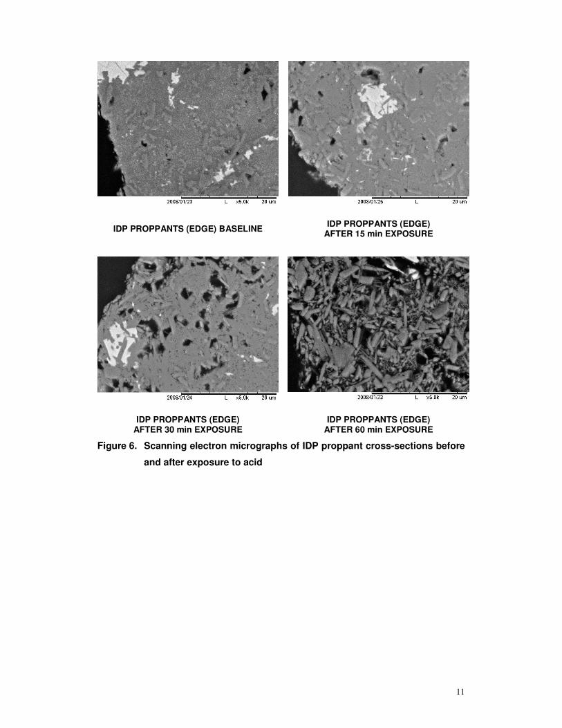
silica rich, matter without effecting the mullite-corundum structural matrix. Figure 7
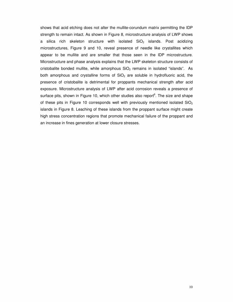
10
shows that acid etching does not alter the mullite-corundum matrix permitting the IDP
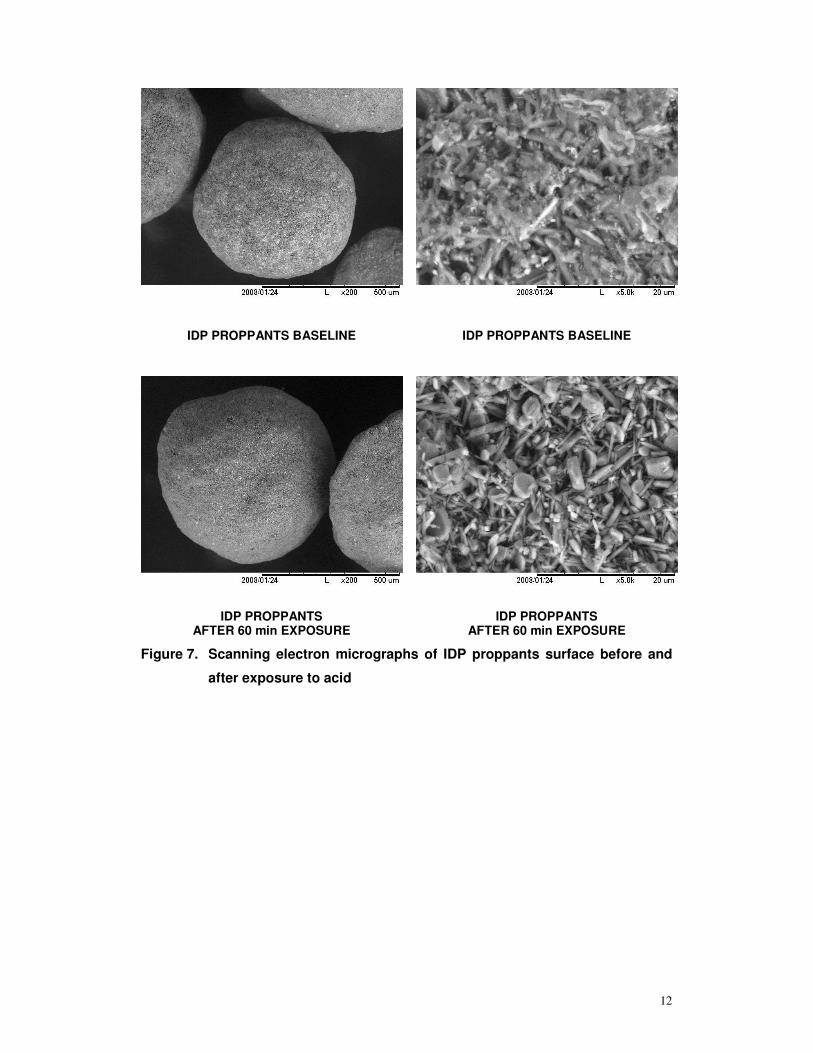
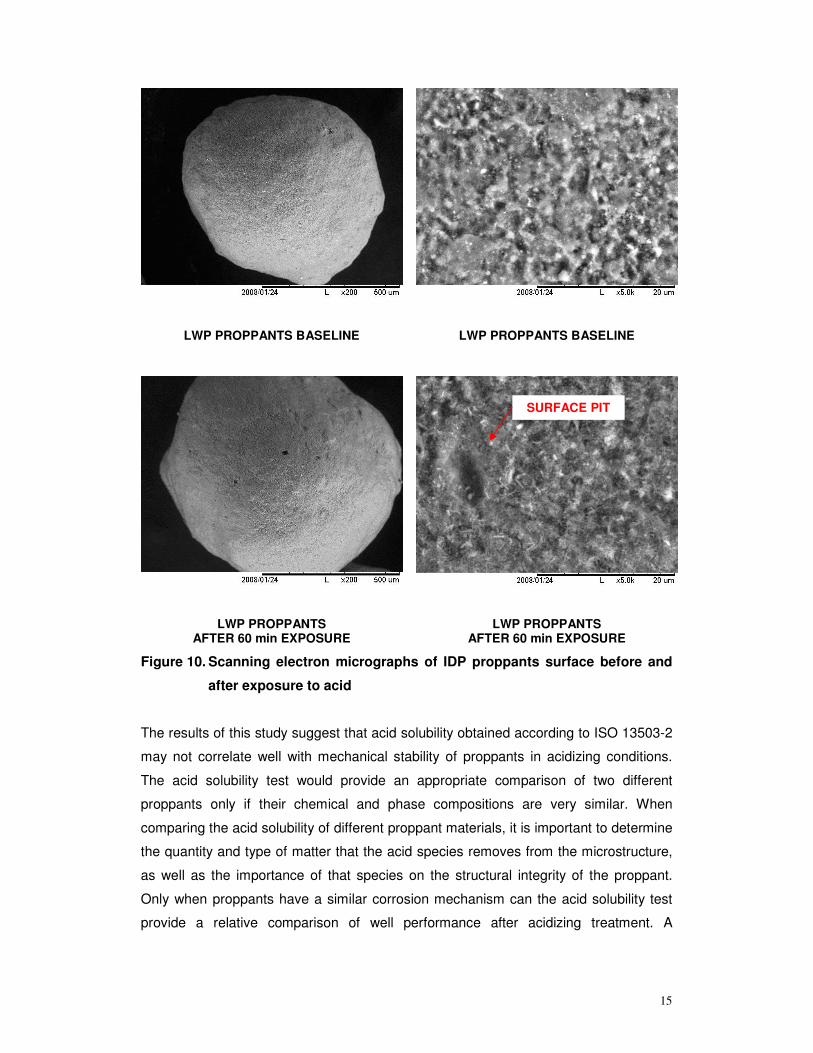
strength to remain intact. As shown in Figure 8, microstructure analysis of LWP shows
a silica rich skeleton structure with isolated SiO2 islands. Post acidizing
microstructures, Figure 9 and 10, reveal presence of needle like crystallites which
appear to be mullite and are smaller that those seen in the IDP microstructure.
Microstructure and phase analysis explains that the LWP skeleton structure consists of
cristobalite bonded mullite, while amorphous SiO2 remains in isolated “islands”. As
both amorphous and crystalline forms of SiO2 are soluble in hydrofluoric acid, the
presence of cristobalite is detrimental for proppants mechanical strength after acid
exposure. Microstructure analysis of LWP after acid corrosion reveals a presence of
surface pits, shown in Figure 10, which other studies also report6. The size and shape
of these pits in Figure 10 corresponds well with previously mentioned isolated SiO2
islands in Figure 8. Leaching of these islands from the proppant surface might create
high stress concentration regions that promote mechanical failure of the proppant and
an increase in fines generation at lower closure stresses.
11
IDP PROPPANTS (EDGE) BASELINE IDP PROPPANTS (EDGE) AFTER 15 min EXPOSURE
IDP PROPPANTS (EDGE) AFTER 30 min EXPOSURE
IDP PROPPANTS (EDGE) AFTER 60 min EXPOSURE
Figure 6. Scanning electron micrographs of IDP proppant cross-sections before
and after exposure to acid
12
IDP PROPPANTS BASELINE IDP PROPPANTS BASELINE
IDP PROPPANTS AFTER 60 min EXPOSURE
IDP PROPPANTS AFTER 60 min EXPOSURE
Figure 7. Scanning electron micrographs of IDP proppants surface before and
after exposure to acid
13
LWP PROPPANTS BASELINE LWP PROPPANTS BASELINE Si MAP
Figure 8. Scanning electron micrograph and Si EDS map of LWP baseline
proppants before exposure to acid.
SiO2 rich regions

14
LWP PROPPANTS (EDGE) BASELINE LWP PROPPANTS (EDGE) AFTER 15 min EXPOSURE
LWP PROPPANTS (EDGE) AFTER 30 min EXPOSURE
LWP PROPPANTS (EDGE) AFTER 60 min EXPOSURE
Figure 9. Scanning electron micrographs of LWP proppant cross-sections
before and after exposure to acid
15
LWP PROPPANTS BASELINE LWP PROPPANTS BASELINE
LWP PROPPANTS AFTER 60 min EXPOSURE
LWP PROPPANTS AFTER 60 min EXPOSURE
Figure 10. Scanning electron micrographs of IDP proppants surface before and
after exposure to acid
The results of this study suggest that acid solubility obtained according to ISO 13503-2
may not correlate well with mechanical stability of proppants in acidizing conditions.
The acid solubility test would provide an appropriate comparison of two different
proppants only if their chemical and phase compositions are very similar. When
comparing the acid solubility of different proppant materials, it is important to determine
the quantity and type of matter that the acid species removes from the microstructure,
as well as the importance of that species on the structural integrity of the proppant.
Only when proppants have a similar corrosion mechanism can the acid solubility test
provide a relative comparison of well performance after acidizing treatment. A
SURFACE PIT
16
mechanical integrity study, using the crush resistance test after acidizing treatment,
may provide an alternative to performing a long term permeability study.6
In general, the documented solubility of all SiO2 based or containing phases in HF
explains the contradiction between acid solubility measurements and mechanical
performance of man-made ceramic proppants. Those proppants that contain the least
amount of SiO2 phases represent a superior choice for a high performance proppant
product. Intermediate density bauxite proppants show excellent strength performance
even under conditions of high closure stress and an acid exposure.
CONCLUSIONS
While the acid solubility of intermediate density proppants is higher than those of light
weight material, IDP maintains a consistent mechanical performance after up to 60
minutes of acid exposure while the mechanical performance of LWP significantly
decreases after the first 15 minutes of acid exposure. Only when different proppants
exhibit similar chemical and phase composition might acid solubility provide insight into
their performance degradation. Measuring the change in performance properties of
proppant samples due to acid exposure provides the most useful observation about
potential degradation extent and mechanism.
ACKNOWLEDGMENTS
The authors appreciate the support and permission of Saint-Gobain Proppants to
conduct this research and to publish the results.
REFERENCES
1. International Standard, Petroleum and natural gas industries – Completion fluids and
materials :Part2: Measurement of properties of proppants used in hydraulic fracturing
and gravel packing operations, ISO-13503-2, 2006-11-01.
2. Mikeska, K.R., Bennison, S.J.,:” Corrosion of Alumina in Aqueous Hydrofluoric Acid”,
Journal of American Ceramic Society, 82, [12], 1999, 3561-66.
3. Liang, D., Readey, D.W.,:” Dissolution Kinetics of Crystalline and Amorphous Silica
in Hydrofluoric-Hydrochloric Acid Mixtures”, Journal of American Ceramic Society, 70,
[8], 1982, 570-77.
17
4. Tso, T.S.,Pask J.A., “Reaction of Glasses with Hydrofluoric Acid Solution”, Journal of
American Ceramic Society, 65, [7], 1982, 360-362.
5. Grosheva, V. M., Mironov, I. M.: ”Solubility of synthetic mullite in hydrofluoric acid”,
Journal Refractories and Industrial Ceramics, 15, [ 3-4] , March, 1974, 248-250.
6. Welch, J.C., Hossaini M,: ”Effect of Cleanup acids on Compressive Strength of
Proppants used in Gravel Packing”, Society of Petroleum Engineers, 1996, 597-605.
7. Cheung, S.K:, “Effect of acids on gravel pack and proppants”, Society of Petroleum
Engineering, Production Engineering, May 1988,201-204.