Embed Size (px)
Citation preview

DOCUBEIT 'RESUME
ED 152 574,4
SE 0/4 140
TITLE Basic Electricity. Training Module 3.325.1.77.INSTITUTION Kirkwood community Coil., Cedar Rapids, Iowa. ,-SPONS kGENCY Department of Labor, Washingtcn,'D.C.; Iowa State
,Dept. of Environmental Quality, Des Moines.
PUB LATE Sep 77 .. \ ,
NOTE 81p.; Fcr related documents, see ,SE 024 138-1651Contains occasional light type
EDRS PRICE NP-$0.83 BC-$4.67 Plus Poitage. '
DESCRIPTORS *Electricity; Electric Motors; *InstructionalMaterials; *Physical Sciences; *Post SecondaryEducaticn; Secoidary Education; *Teaching Guides;Units of Study \
IDENTIFIERS, *paste Water Treatment; *Rater Treatment
ABSTRACq,, . .. This document is. an instructional module package'prepared in objective fcrm for use. by an instructcr familiar with thebasic ccncepts of electricity'as applied to water and - wastewater
\*!treatment. Included are objectives, instructor guides, student:handouts, and transparency masters: This module ccnsiders definition
' of terms, voltage, current measurement, and.pcwer, and includes a'brief discussion of motcrs. (Author/RH) .-
a
C-
41*A************i*******************************4141441******************44* Reproductions supplied by EDRS are the best that can be made
from the original document.*********************************i*************************************

$
BASIC ELECTRICITY
Training Module 3..325.1..77
Prepar0.sfor the
Iowa Department-of Environmental QualityWallaee State Office Building
Des Moines, Iowa 50319
by
, Kirkwood Community College6301 Kirkwood Boulevard, S. W.
P. Box 2068Cedar kapids, Iowa, 52406
U S DEPARTMENVOF HEALTH,EDUCATION & WELFARENATIONAL INSTITUTE OF
EDUCATION
THt5- DOCUMENT HAS BEEN REPRO-DUCED EXACTLY AS RECEivED FROM11-..E PERSON okeQ.GANizAT ION ORIGIN -WINO IT POINTS OF .,,L,N OR OPINIONSSTATED DO NOT NECESSARILY REPRE-SENT OFF ICtAL NATIONAL INSTITUTEEDUCATION POSITION OR POLICY
'PERMISSION TO REPRODUCE THISMATERIAL HAS BEEN GRANTED BY
Mary Jo Bruett
TO THE EDUCATIONAL RESOURCESINFORMATION CANTER (ERIC). ANDUSERS OF THE ERIC SYSTEM
The publication of'these training materials was financia;lyaided through-a contract between the Iowa Department of,Environmental Quality and the Office'of Planning and Priegam-ming, using funds ayailable under the Comprehensive Employmentand Training Act of 1973. However, the opinionsexpressedherein do not necessarily reflect the positiO4 or policy.of-tbe,U. S. Department of Labor, and no official endorsement bythe U. .S. Department of Labor should.be inferred.
September, 1977
&Mb
7a`
o-
, ¶
4
4"
/
, The Mention of trade names, use of
Manufacturer's bulletins, diagrams: depicting specific
equipment,-oss other use,of any formercial product
4
name in /this module is fo' illustration purposes, and
does not constitute endOrsement or. re'conmendation for
use by Kirkwood Communi ty College nor by the Iowa
Department of Envir'onmenta'l Quality.
1
2 3
F

4
wt.
UMMARYPage _4 of 57
Module NO. Module Title:, tBasic Electricity.
,. ... , Top i cs :
)
Approx. Time 1. Introduction , I .
2. Electrical Terms and Measures3. Wiring Materials and Practices
.14 hours 4. fuses and Breakers. e . -I
. ,
5. Motorst
. 6. Safety . .
7. Application .
OVe)liE(11 Objectives :
\4
Upri completion of this module 'the learner shoul d have. a bas, i c' understanding of
electricity, should be able to measure voltage and current, should be able toread an el ectri clneter, should be able to calculate voltage, current, or,res stence using "ohn Is 1 aw" , and should respect electricity and exercise safety
*whe deal ing with electrical apoli ances (motors, etc. ) : ,
I
_
Inst uctional Aids-: . .,-
Hand ufs '. .,
Trans arancies 'S'
MeterModel 7
, .
Instru ti onal Approach: , . ,a
,
Lectur . -
Demonstration ,
. ...
Di scuss i on ,'
,
Hands -on )
,
References:. 1. , - "
1. Understa di ng and Using Electricity, ticKenzi e and Zathari ah
2. Electricity Fundamental si Baker and Crow, Howard W. Sams '7C:co. Inc., Kansas Ci. .
Cl ass Ass.i gnments : ,., . ,
. ,
. .
; .. . .. ., 74
o
. . .. ,, - .
. ,
. . -
4
ty

Topic:
SUMMARY
Module too :
Instructor Notes: Instructor Outline:
or
N %
. The module ncludes traditional jecture, in class ,
problem s ution and hands-on atoVivity.
4
. It is s ggested that the students each have acopy the text. (Understanding and Usingtlec ricity). It, may be obtained from:,
// I erstate Printers'& Publishers, ihc.nville,, Illinois 61832
ele. 217-446-0500, 4
Cost 51.95 per copy
Table 1 and Figure.11 detail thematerials. andShow an appropriate model for the hands-onactivity.P
, (... . .
The following additional equipment should.teavailable for hands-on activity.
A. Voltage resistance meter
B. Current,meter (-ammeter) ,
C. Ground fault interruptor
D. Fuses (bloWn and aood ones.)
E. Wire.samples'of 'various sizes
F. Three-prong receptacle check instrument
5 Thevaluation should include both the writtenevaluation and performance to the instructor'ssatisfaction of the hands-on activity.
Y.
6. This is a.module to give the student a ba c
understanding of electricity. Special e phasisshould be directed to "safety ". The student willnot be an electrician upon completion of the
.
basic electricity module..
VP'

1
. e
Module No: tioduli
Basic Electricity
Page 6/, of 57
Approx. Tire:
3 hours
Objectives:
Submodule
Introduction
. Topic:
t.
1. Define electricity .
2. Define a conductor and give two examples of aood conductors.3. _Define an insulator and give two examples of good insulators4. Define the difference between direct and alternating current as a functioh
of electron flow.5. Diagram single phase- and three phase voltage curves .(AC):* .
6. ,Define the purpose of a transformer'.
Instructional A.p,proach
114 Lecture2. Discussion
References:
1. Understanding and Using Electricity, McKenzie & Zachariah, Interstate Printersand PublIstiers; Inc., Danville, .,Illinois 61832 (text).
Class Assignroents: se

-
Pa e 7 57
Topic:
Introduction
44?
Module lo:
Instructor Notes:
Figure 1 - Di agram cf typicalatoms
4
f
.1/
ti
r
Instructqr Outline:
I Definjtion ofAlectricity-P In -this modu e, el ectri ci ty shall be defi ned
as the move ent of electrons through aconductor.
IA. Atoins
-1. ade uo of protons, neutrons ; Andlectrons. Protons and neutrons I
in the nucleus, electrons travelIn orbits around the nucleus.
Charges : positive -Electrons' negative.
When numberelectronsof protons equal 'thenumber of e the atom has no'charge.
Atoms can give upon and take onel ectrons . Ire movement ,of theel e,ctrons' from one atom to-anotherresults in an electric -current.'
Conductors
Materi al s that are macte 6[3 of 'atomswhich readily al low thei r electronsto move ,from atom to atom., Examples :Copper, al umi numr;' s tier, tap 'water,damp , human bo
;,.G. Insulators
Materials made up Of atoms A,A th their\electrons more tightly bound are calledinsulators i . e. the atoms do not al lowthe _relatively frte *movement of electronsfrom atom to atom. Examples: ,GlasS ,rubber, plastics, bakelite, oil ,Pure,water, dry sandy soil.


Topic:itt
Introduction
Module No:
1
.
Instructor Notes:.
Za
.1
r
C-
Page 9 of 57
Instructor Outiine:
II. Sources of Electricity
A. Friction electric cbarge proved byrubbing certain materials together,frequently called static electricity.Because the 9arge builds up Withoutthe flow of current. It is of little
,
practical value and can bey nuisance,even a hazard.
B. Heat electr)city can be generated byconnectin? two dissimilar metals andheati"ng the junctiont electrons willpats from one metal to the other.
C. Light - some materials can pro-duceelectricity when subjected tb light;termed photovoltaiC%
D. Chemical Action - combinations of,i-certain rretl.s plat d in special,
solutions, called el ctrolytes can,result storage battejes.produce . 7
electricity from cheOcal action. Thethree most common types of storagebatteries are:.
I. Lead-acid2. Edison'3. ,Nick.el,-cadmium
E: Magnetic Action - this the most cmmonmethod of producting
tricity ih large.quantities. Midiael Far day 'in 1831,discovered- if a coil\ of copper wireis rotated in a nagnetic 'field cutting
electric charge iscreate or induced in
across the linesan
the wires. (A magnetic dr wn throw h'acoil will, also, generate
el c.tricity ) .; _
Alternating current (AC), is a currentflowing first in one direct on and thenin the opoo&ttedirection. This can 4gshown,from conSf4eration of generatoras a single loop being rotat d in.a

CU
Page 10 of
Module No:Toftl,c:
Introductian/
Instructor Notes:.Instructor OutNe:
Figure 2 - One cycle of. ACcurrent.
Figure 3 - Single phase andthree phase current
.Figure 4 - Transformerschematic
'I
magnetic field. The full,cycle ofan alternating current is shown goingfrom zero to a maximum, back to zero,to a maximum in the reverse direction,back to Zerb.
Electrficity generated in the U. issixty of the above described cycles -
per second. (Term for cycles per secondis hertz). -.;,ingle PhaSe current isthebasic two wire 60 hertz -cdtrent. Threephase current is three single phaSecombined with peak voltages .equallyspaced. Note that the distance betweenpeaks actually the time between peaks)is reduced to one-third of the singlephase distance (time) between peaks. '
F. Transformers electr'icity (current)'isgenerated ,by rotating a loop, in. amagnetic firld. It is also true thatby wrapping a material such as soft ironwith a coil of wire. and passing acurrent' through the wire magneti2es:besoft iron. It is this: principle whithenables the transformer to exist. Thetransformer ,is then a device forstepping up or stepping down the voltage.
The formula'iiidicates the, relationshipsof the transformer.
Prim'ary voltage = Secondary voltaoe$ Primary turns Secondary turns
Given: 120 volts 100 turns on primaryRai3ted: 24 volts
The number of-turns on the secoltdaiywinding must then be-20; therefore
120 =,100 20
10

,
E,
lei f,
FIGURE 2Page 11 of 57
vim/
:,1;i1,1t!Ili;141;!1111111111.1
Ili" 111
I:1111
'/4 CYCLE
11111!.'
1;;
1;
1;
cycit
11 ?.`
I
,.
4

/-
4
I
.4
FIGURE 3Page 12 of-'57
_.kw.aillona.mmoli
.1


Page 14- of 57
Module No:
Introd6ction
Instructor Note:
,
InstructorOutline:
14
This would be a "step down" transformeri.e. the voltage is stepped dpwn from120 volts to 24 volts.
A "step up" transformer is used toincrease the voltage from the- primaryto the secondary windings.
It is important to understand-thatstepping up the voltage does notresult in an increased power. --TPowerwill be discussed in next section).Transformers neither increase nordecrease the,power transferred. exceptfor a slight decrease due to losseswithin the transformer itself. Anexample problem will be included in thenext section.
Direct Current '(DC) for purpOSeswithin this module direct current is-defined as that current which resultswhen electrons flow in only one ,
directiob. (Electrical system in newerautomobiles is 12 bolts DC).

I
r
Page 15 of-- 57
46
Module No: Module Title: 1Basic Electricity
Submodule Title:. .
Electrical Terms and Measures....
Approx. Time: * *.
3 hours
Topic:
Objectives: 4
.
,
1. Define a closed circuit. ,2. Define an open 'circuit.
3. Define a short circutt. .
4. Define by matching: A., Current, B. Amperes, C. Ohms, D. Voltage,E. Matts, F. Kilowatt Hours. - ,
5. Given any two of three variables (voltage, current, or resistance) solvea problem using "Ohm's Law". _
6. Given a picture of a poi nter register kilowatt hour meter, give the readi ng.
it
Instructional Aids:
.1. Transparencies .
2. Handouts
.. ,
. .
Instructional Approach,:
- 1. lecture2. Discussion .
.
Relerences:,> ,
1. Understanding the Using Electricity, McKenzie & Zachariah. . b
.
. ,
. . ....NClass Asslgnrx.nts: k,
. ,.
.
, .15

44.ti
Page of 57
Module No: Topic:
Electrical Terms and. Measures
Instructor NotesInstructor Out,l ine:
.....
Figure ,5 - Closed circuitopen circuit
I. Circuits Electrical current is the flowof el ectrons in a conductor. The plectrons'
41,=, are not 'used up"*, they flow around a pathor a circuit. The pathway begins at thesource of power (generator or battery) goesto the "load" (motor or light), passesthrough the load, and back to the source.It is important to realize that for anelectrical current to flow, the p,athwaymust be continuous, unbroken, or a: completecircuit.
\A. Cl osed Circuit - a circuit that provi des
a complete pathway for el ectri c ,turrentto flow.
B. Open Circuit a circuits that is notclosed i.e. it has been broken, or'disconnected or opened by sa switch,fuse, ci rcuit _breaker or other openingin the line.
C. Short Circuit - improper or- acci,dentalcontact between two or more Ores..
II. Electrical Measures
A. Current the unit for the rate of current-flow is amperes. Current is the namefor the flow of electrons through aconductor. - The main- poi nt is that therate of current fl ow is measured inamperes.,
B. Resistance resistance is that whichcuts down the rate of current flow in acircuit. The unit of measure is ohms.Conductors of electrons have levers- ofresistance to current flow. A copperwi re 'has less resistance to el ectronflow than an equal size and length ofaluminum wi re.
.
16

e 4
4
4.
FIGURE 51
4
Page -17 of 57
Closed Circuit.
41=11111.
Open Circuit
17
N

Module No: Topic:\,
,Electrical Terms and Mea.slires
Inst uctor Notes:
Page' 18 of 57
Instructor Outline:
4.
Given: I = 10 ampsR = 12 ohms
Find: 'V = ?'(120 volts
Given: V = 240 volts.R = 100 ohms
Find: I =? (1.2 amps)
Given: .V = 120 voltsI = 3 amps
A Find: R = ? (40 ohms),
Given: 1560 watt space heater.120 volt circuitI = ? (12.5 amps)
Voltage - a generator produces thedriving force for electron flow through'a. conductor. This driving force orelectrical pressure is calledsvoltaqe.The unit of measure of this pressureis the volt. '
III. Ohm's Law
, A. Relationship between the electricalpressure, voltage; the rate of currentflbw, amperes; and the res-istancktocurrent flOwt phms, which exists isknown as OhWs'Law.
+
, 4
The voltage <V) equa'k the_product ofcurrent (I) and resistance (R)
V =IxR
The equation can be solved for any ofthe ,three terms if the.remaining twoterms are, known.
'V x R or = V/R or R = V/I
C
IV. Power - electrical power is measured in 'watts._ The definition of 'a (one) watt is the power
available, from one amp of current with avoltiage of one volt. The watt is then acombination of the electrical pressure'(voltage) and the rate of flow of the .
'electricity. The equation used for'solvingfor power (Watts W) is the product of thevoltage and current:
W lxV
This equation holds for direct-currentcircuits and alternating current circuitsconnected to heating devices. The equationcan be solved for any variable provided two
18

1
Page 19 of '57
Module 11o:
Electrical Terms a50 Measures
Instructor Notes:Instructor Outline:
Kw = 1000 x W
i Hp. = 746 watts
.4
(
the equation requires an additional terwhen the power is being calcualted froma motor rn an 'alternating-current circuit.The equation becomes: .14 h.
4. .
W= V x 1 x p.f.
Where p.f. is called the power factor thepower factor term results from the factthat in alternating current circuitsconnected motors, the voltage waves andcurrent wa do not peak at the sa e time,The product o voltage and current must becorrected for this difference.° Manufacturers
_ bulletins on a given motor will usuallytnclude,the value of the power factor.Power factors will generally be in the
. range of from 0.5 to 0:87. The power factorwill not be greater than 1.0. \
Two additional terms ould become a partof the vocabulary:
A. Kilowatt - the kilowatt is equal to onethousand watts.
B14.,WErsepower - the measure,of electrical.44.7;-' power is the watt. The measure of
mechanical power is horsepower.
V. Energy - the previous units of voltage,current, and power now lead to a mostimportant issue confronting the operatorthat being energy. The unit of electricalenergy consumption at the treatment facility,or in the home or office, is the kilowatt-hour (1000 x Watts - Hours).
The watt-hour is the measure of one wattof power used for one hour resulting inenergy consumption of one watt-hour. Thekilowatt hour is used more commonly.
19

C.
14I
r.
r_
r'Page 20 of 57
Module No:
:Instructor Notes:
Topic:.
lectrical Terms and Measures
Instructo.%Outline:'
4
Text Figure 2-7 A
Given: 32169 Tues. .
Given: 31086 'Mon.
1,083 Icw-Hrs.*
Text Figure 2-7b
5
Text Figure 2-8 shows tworeadings
A
Al&
..m.........The operator should be able to read themeter which records the amount of energy.used at the facility-. He should also beable to understand what individual unitsare. using this energy: He must be able tounderstand the difference between a 5horsepower electrical motor and a troublecord With a 60 watt light 'He must .
become energy cons ciobs, relating lightsleft on needlessly (or, motors) to energyconsumed -'dollars spent wastefully.
qA. Meter Reading
e
1. Cyclometer regNer kilowatt-hourmeter. This meter'is quite easyto read as it displays the kilowatt-hour reading in digits like anautomobile's odometer. ConsiderWonshodld be given to recording themeter reading daily. If the facility'is manned around the clbck; flow
, meters -̀are typically read andrecorded at midnight. .Read thismeter also and record energy consumedfor the twenty-four hour period.Graphical display should also assistin increasing "energy awareness":One- or two-shift operations needonly select a specific time fordaily ftadings. Energy used issimply the Current day's readingminus the previous day's reading.
20
2. Pointer register kilowatt-hour meterThese meters have four or five dials.The point of caution is that thedials do not all read the-same
)1f
direction. Some Otate.clockwise,the others counte clockwise.First check if the dial is numberedclockwise pr counter-clockwise. Thenread each dial by recording which I
number has just been passed; readingand recording from left to right.Energy, consumed is then figUreg as
4

A
P
Page 21 of- 57
Module-No: Topic;
Electrical Terms arid Measures 2)
Instructor Notes:Instructor; OuCine:
The meter at the building beingused for the workshop should.beread the first and second dayof the workshop if accessiblesafely and conveniently'.
V
4
21
previously des.cri bed. by subtractingprevious days reading from presentdap' s reading.
a
Final Caution. Some meters. have a"."multiplier". If a 'multiplier is used, .
the, value of the multiplier is postedon the meter face. This requires thatthetfference between two day'sreadings' be multiplied by the value of
. the multiplier to determine energy used.
a
6
s

r
r
a , Page 22 of. 57 .
Module tio:-,
4
,Modulp Title: ..,,
4.
Basic Electri*ci.ty , .17.bdl--Sumoue "Ti tle: . . .
cQ
Wiring'.MateVals and Prac -..b,
,. r.
.Approx. Time:
1 hour . I
.
PI-o-pisc-:.I
...
.
,,t. .
Objectives:4 \t '
<>
I, . , List ,two basic di between metal conduit and ordinary water pipe_2. Define by matching the "color code".3. Given two wire szes (e.g. 8, and 12) name the larger.
.
4. List a symptom oi\undersized wire. ', .
5. Sketch the follow-mg two ci rcuits: -' .7 . ,")
A. 3 light bulbs wired in serie.5, -.
,,,,).-.=
B. 3 light bulbs wired' in parallel- . ttt. .
.
. .,.
InstrUctional Aids: *,....,
1. Transparencies 4 ,..2. Handouts - , .
.
3. ,Model (possibly) ,
. .I .
.
Instructional Approach: ,a,,. .
.
. .
1, Lecture , . ,
-2. 'Discussi'on ,,
,
,,
.,... ,. .
,
References:44 . ..
.
1. Ondevtanding and Using Electricity, McKenzie & Zachariah. Ge
-* -
_ .. .
Class Ass ignnen ts: . 4 '1" .
.
. . .
, -. .N -- .
22 .... _,....
Yr 4

15'
Page.° 23 of\ 57
Module No: Topic:
Wiring.Materials and Practices
instructor Notes: L I Instructor °Wine;24
It is not the intent of thismbdule to "make" electriciansof those completing the-workshop. It is the intent,to make the operator "aware"of wiring practices.
. f
(If possible samples of as manytypes and sizes of wires shouldbe available for the student tosee.)
%
YONO
I. Electric Wire
-7'
V
a
4,Yis
A. Insulation - insulation serves twoTourpaies:
1. Prevents electrical leaVage2. Shields the conductor from physicsl
damage
B. Application Table 3-1 of the text(Page 12) is excerpted from the NationalElectrical Co e and presents ,somecommon elect ical cable and wire types,their designa o and their /application.
C. Imprint - wire intended fore perManentinstallation and some extension ,cordwires are imprinted as exainPleep"4,1M 10-3" meaning nonmetallic s eated,number 10 wire size, three conduCtorcable.
An imprint "60UND" oq "GRP", indicatesa grounding conducto . Grounding is-- 'covered in the "Safety" section.
D. Siie --electric w'te sizeis Measured bythe area of the moss section and normally -esignated by American 'Vire Gauge (AWG) ,
number: Figura
3-4 of the text showsactual wire s . Note that the largerthe AWG numb ,
di ameter.
23
the smaller the Wire
Size of el ctric wiring is very important., Electric irecan be compared to water
a Iqater system, large flowstequir large pipes. Wire is comparablein that high current (high rate of flow)req res large wire. I f the wire istog small',' the wire will heat up, 'the .eat resulting from the resistance to
the hi§h flow rate. ,

Module No: To /pc:
Wiring Materials and Practices
Page 24 of __57
Instructor Notes:Instructor Outline:
I
Te'xt Figure 2-4
1
There are other comparisons that canbe made.between electric circuits and:wafer systems.
t'
Pump,- generator
Rate of floW (9allonS/hr)'-kflow ofelectrons (amps)
Pressure woltage
Valve - switch
Turbing (load) - motor (load)
II. Conduit Wiring this is the most commontechnique Uted in treatment facilities(as opposed to nonmetallic wiring donein private residences):
A. Advantages include;
1. Pulling wire through with reasonableease.
2. Can be cast into concrete, suspended,or surface mounted,
3. Is a conductor for "ground".
B. Material
1. Steel, aluminum, or plastic.
2. Differs froMwater pipe in that:
a. Bends easily- \b. Smooth inside surfacec. Corrosion resistant (water pipe
.should never be used as conduit')
243

Module No:
Page 25 of 57)
Topic:
Wiring Materials and PractiEes
Instructor Notes:Instructor Outline:
Text Figure \34b shows some ofthe components (a displaymodel would be appropriateto show the components).
C. Components
1: Boxes,,
,2.: Clamps, .
3: Bushings
4. Connectors
III. Color Coding
1. hite or natural gray is the color forthe grounded also called neutralconductor.
2. The "grounding" conductor, that whichcohnects to the surface of an applianZeor unit to supply a continuous lowresistance path to ground, is.greenor green with yellow stripes.
3. The ungrounded or "hot" conductor in atv,wire plus ground is normally bTack.1-
4. Three wireplus ground is usually one ,
black, one white, and one red.
5. Switches of duplex receptacles are alsocoded: ,
dLa. loot side has brass screws\'="7' b. Neutral side has silver or c me
screwsc. -V.ouRding terminal is green
255,

o
Page \26 of 57
W. ng.10Mteri als and PraCtices
Figure 6-- Electrical ,symbolsfor:
1. AC source2'. . Fuse
3?-- Swi tcl) ....
4. Amme t'e r ..
.,5. Voltmeter6;' connected wires7. 'Mires crossing - ri,ot
,connectedB. Incandescent...lampA .
. , \
Figure 7 - SerieS and parallel)circuits
S.
An,
4
-4
Instructor Out.' inef.
N
N.
IV. ymbol - most electrical wiring -diagramsNave a legend to as -sore the readabilitkof the wiring diagram. A.few generally.accepted symbols are. shown..in, Figure 6'.These should aid in the discussion ofsimple circuits.
G.
. Si.mple Circuits - a ci rcuitt:Was previously:'defined q a complete pathway for electriccurrent 'to flow. Two types wi 11 be t)rillyt-,cower-ed
. A. Series --1,rcuit - some ChriStMas, trekights are wired- in series. This'hould give. a clue as to Why lightingfixtures in a home ,or office are nbtwired in series.' -There are. three,-'circumstances which could result in''an"Open" circuit: .
,
2. en. switch
1c,j))31r f.use
3. Burned out light bulb (in which casethe remaining good lamps wouldn'tlight).
, If th source is 120 volts, and thereare three, 60 watt bulbs fn the lightfixture's, what is the' smallest fusewhich should be used?
I _= V, = 120 = .67 ampR 1805
B. Parallel Circu - notice that in theparallel circuit ach lamp providesan independent path for current to flowand removing a light bulb does not causethe other two to go Out a closedcircuit still exists-.

r
FIGURE 6 Page 27 pf 57
AC Source Fue
Switch
s.
Ammeter
t Meter.
Connected Wires
Incandescent tamo
a
)
2?
ar
Wires Crossing
(Not Connected)

FIGURE 7Page. 28 of 57
A
Parallel Circuit
Series Circuit
28
7

Page 29 of 57
Module No: Module Title:.
Basic Electricity .
Submodule Title:
Fuses and Breakers,Approx. Time: ,
1 hour
,
Topic:.
.Objectives:
1. List what causes a fuse to "blow" and what actually happens to the fuse asit "blobs ".
,
2. List three common types of fuses.3. List why an overcurrent device should never be placed in any p entiv
grounded conductor.
,.
---:..-----/
--.......--
Inructional Aids:,
.
1. Resistance meter (VQM).
.
,
,
.
..
Instructional Approach: . _
1. Lecture2. Discussion3. Hands-on .
.
.
.
.
/
References:
1. Understanding and Using Electrici.ty, McKenzie. & Zachariah.
...
,
.
. .
'Class ASsignments: .
, .
..
, .
..
( 7n
.

Topic:
Fuses and Breakers
Module No:
Instructor Notes:
Page 30 of 57--
Instructor Outline:
1.. Overload,Protection - yet anothercomparison of an electrical system and a
. water system. Justas a water systemtypically has safety (poi:PI-off) valVes, sotoo it is a must that electrical systems haveprotection against overloads. There are twobasic types of overload protection that willbe covered.
A, Circuit Protection - every size ofelectrical wire has a "safe" currentcarrying capacity. Circumstpncesaround and above the wire in a givencircuit may have some influence on thesafe capacity such as exposure todirect sunlight, well or poorlyventilated room etc. The protectiondevice to protect the wiring of a
given circuit shOUld "open" at suchtime as the power demand would, cause.ti-Pe conductor to-h4t, damaging theconductor insulation.. The device .
might allow short duration overloads,but even short duration overloads can
dettimental to the wiring.
Never should circuit protection devicesbe negated (penny behind fuse or tyinga circuit breaker are examples of thatwhich should never be done). .
B. Equipment Protection - motors and someadditional electrical devices must haveoverload protdction just ahead of the unit.
Considee,a mAor which draws 3 amperesof 'current at full load. The circuitwhich serves this_ motor has an overloadprotection device rated at 15 amperes.Note that if the 15 'ampere device (fuse)is the only overload protection, themotor could draw as much as 5 times its
,, full load current before the 15 amperedevice would "open" .the circuit. Themotor could sjiffer some damage - a personcoming into contact with the motor is in
30

Topic:
Fuses and Breakers
Page 31 of 57 (
Module ao:
Inst,rUctor Notes:Instructor Outline:
Text'Figures 4-3, 4-4, and4-5 display the, three typesof fuses.
danger. If, however, only this onemotor is served by the circuit, the15 ampere overload protection devicecould be replaced with an' appropriate3 ampere overload device. In otherwords, if only one motdr or applianceor electrical unit of whatever purposeis served by a circuit, the equipmentprotecting device and the circuitprotecting device may in fact be justone overload protection device. Inthis case the circuit overload levelmust be higher than the unit overloadlevel i.e. the wire's safe current`carrying limit must 'be greater thanthe current limit of th.e motor or.appliance.
II Overload Protection Devices - tlje ove loadprotection devices are_generally co ideredto be fuses.or circuit breakers.
A. Fuses - an electrIc fuse 'contaigis astrip of soft metal or wire which isdesigned to carry only up to ,a givenamount of current. If.for whateverreason; more curreht'begins to flow inthe circuit than the fuse is designedto carry, the metal strip melts, orburns out. 4This results.in an opencircuit, the current flow stops. Fuses'are generally of two types: Plug-Orscrew base and cartridge.
There are then three main types of screwbase fuses: Instant blow, time delayand non-:tamerable
II Instant blow'is the common type fuseand is designed to burn out as soons its rated current capacity is
e ceeded.
31 at,

Module1-
I-
topic:
Fuses and Breakers
Page 32 of 57
Instructor Notes: p Instructor Outline:
Text Figure 4-2 displays twocartridge fuses
' -.
,Figure 8 Circuit one showinga battery and resistor (load)
32
2. Time delay fuses are available forcircuit protection inwhichmomentary overloadslican exist,starting a motor for example. This
, type fuse will carry an overloadfor a few seconds without burningout but will burn out if theoverload persists beyond the d laytime.
3.' There is another type of fuse, the"non-temperablk fuse. (Fusestat forexample). The two component partsare the', adaptor and the fuse. The .
adaptorjias a spring barb on theoutside\that prevents it from beingremoved once installed. Theadaptersjiave amperage ratings andonly accept fuses of one amperage,rating. In other words if a 15ampere adapter is installed', only
15 ampere\fusesrwill fit into theadaptor; a 20 ampere 'fuse will notfit a 15 ampere adaptor. Thus thename non-taMperable.
Cartridge fUsesare generally of twotypes: Ple.,smooth ferrule andbayonet. The screw base fuses andsome cargridOe fuses canrecognized as blown from a visualinspection, the metal strip isbroken and a blackening of the glassmay occur. How does one 'determineif a. cartridgeHs blown? A volt-ohm(VOM) meter, a meter which canmeasure voltage and restsiance, isan excellent "tool" for'this--determination. Consider\the first'circuit diagram on Figure 8. Noticethat a complete closed ci\rcuit existswith a battery providing 1.5 voltsof electrical pressure and a "load"of 100 ohm resistance. CUrrent will

i
ro
4-
/I
\
IJoe
FINRE 8 Pa'ge, 33 of 57
*
1 . 5VOLT T 3
I= 1.5.400
I00
4.
.I .. 1l5/oo
7.\
I 0 Co
OHMS
I.5VoLTs
F
I = 0
3 3 -
..I
S
4
r

Page 34 of 57
Topic:
Fuses and Breakers'
C
Module No:
. Instructor Notes:Instructor Outline:
I = V/R =1.5100
P
%Circuit two, adds fuse
An ohm meter, a good fuse,and a blown fuse should beavailable for demonstration
M1V
flow in this.cirCuit. Now let's adda "fuse" to this circuit, the fusethat may or may not be blown.
If the fuse is blown and open circuitnow exists, if the fuse is not blowna closed circuit still exists.
Now let's rename a portion of this i
circuit and ohmmeter (resistancemeter). It comes complete with avoltage source, a battery; and a load,a built in resistor. First let's lookat the circuit possibilities. Therewill either be a closed circuit (thefuse is not burned out i.q. the softmetal strip is intact) or there will bean open circuit (the fuse is burnedout i.e. the'soft metal strip isbrokeri,) All that remains is todetermfne.how. the ohm'meter will indicatethe two poSsible situations. The-following steps should be taken.
1. Remove fuse from the fuse-box
2.. Move away from the fuse box
. 3. "Zero" the resistance meter
4. Check the fuse
a. Cartridge fuse -,hold a "lead;'to each end of the fuse.
Screw in fuse - hold one leadto.the center (silver or chrome)contact of the fuse and one,lead to the brass thread (sideoffuse)

Module No:._
Instructor'Notes:
Page 35, of 57
Topic:
Tuses and Breakers
Text Figure 4-6 displays acircuit breaker cross-section
Instructor Outline:
- 5. Results of 'determination
a. 'Resistance meter reads zero -fuse is good (on most ,i4tersthe dial will move from theleft to the right).
(Resistance(Resistance meter shows nodeflection fuse is not 'good.(The.cliall does not move whentife leads are properly held tothe fuse.)
B. Circuit Breakers a circuit,breaker is acombination of a fuse and a switch. In
.Mace of the soft metal strip that burnsout necessitating the replacement ofthecomplete fuse the circuit breaker has abimetal (two different metals) strip.'During, an overload situation heating occurs.The heat causties the metals, to expand atdifferent rates causing bending. Thebendig trips the breaker, "throws" theswitch, and the result is an open circuit.After'the bimetal strip cools (andstraightens) the breaker may be reset,closing the circuit. If the breake)continues, to be "thrown.", the cause of theoverload must be determindd (generallk an'electricians duty) anytRe a circuit breakeropens, it is an indication of trouble.
It is important to realize th-at-a circuitbritaker is inpart a mechanical device.All circuit breakers should be opened andreclosed on a regular "preventative .maintenance type"'schedule (once per monthis suggested) to help insure free action.and contacts'.
k
C. "Heaters"- most erators have been usingthe term or at least heard the term "heater"in conSunction with motors. A heater usedin this context is an overload'protectiondevice. It is an "equipment protection,device" as-ol5posed to a "circuit protection

Topic:
Fuses and'Breakers
Mod Ule Igo:
Instructor Notes Instructor Outline:
/deviCe". Motors haV rti-ng current'
demands tometimes as high as_ four timesthe normal running current. Circuitprotecti on is not infreqpently fuStfOata 4,1Vier level than ,What would be -a.
damaging Current° for the 'motor. :The
princfple of, the heater is quite similarto a circtiit breaker. For example, a
15 ;ampere heater is designed and c9structedso that an extended current above 15 ampereswill result in heating of the overloadprotection device (the heater) which 'then"opens" `the circui t, thus preventingdamage to- the motor:
D. Location of Overload Protection Devi cesOverload protection devices should. 'never
be placed in any 'peraankntly groundedconductor. If this were. done, pulling the-fuse or breaker opens the circuit, but thehot lead would still be connected, readyto supply power. ra short circuit ,
deVEToped at the 1 ad Obint, the're wouldbe ,no fuse in the hot t(power) .1 ine to open
the ci rcui t.
A
3.6
qe
7,

Page. 37 of 57
Module no:
..
Module Title:_
..
.
,..
Basic Electricity
....Submodule Title:
,..
Motors A -,
t,
Approx. TA-me:
1 hour
Topic:
. ...._
Obiectives:
1. List the two typical types of motor bearinas.2. Define "service factor" as used on a motor nameplate:3. Define temperature rise as used on a motor nameplate.4. liven a motor nameplate list: A. Phase, R. Voltaae current, C. Duty
Rating, D. Service Factor, E. Temperature Rise, F. Horsepower.5. List the maip advantage DC motors have over AC motors.
.t. .'
instructional Aids:
,.
S
e <Instructional Approach:
.
1. Lecture2. Discussion .
.
.
ke4erenCes:
1. Understanding-and
.
.
.
i
Using'Electricity.
,
.
,
Class Ass 1 gruneras:
.
,
.4
____1,.
,.
37
.Instructor Notes:
topit:
Motors
Page 38
Instructor Outline:
57
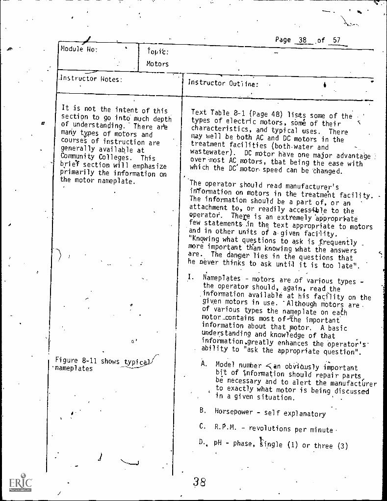
It is not the intent of thissection to go into much depth
a of understanding.- There aeemany types of motors andcourses of instruction aregenerally available atCommunity Colleges. Thisbrief section will emphasizeprimarily the information onthe motor nameplate.
Figure 8-11 shows typicnameplates
J
Text Table 8-1 (Page 48) lists some of thetypes of electric motors, some of theircharacteristics, and typical uses. Theremay well be both AC and DC motors in thetreatment facilities (both water and --wastewater). DC motor have one major advantageover-most AC motors, that being the ease withwhich the DC motor. speed can be changed.
The operator should read manufacturer'sinformation on motors in the treatment facility.The information should be a part of, or anattachment to, or readily accessUle to theoperator. There is an extremely appropri=atefew statements in the text appropriate to motorsand in other units of asgiven facility."Knowing what questions to ask is frequentlymore important than knowing what the answersare. The danger lies in the questions thathe never thinks to ask until it is too late".
I. Nameplates - motors are .of various types -the operator should, again, read theinformation available at his facility on thegiven motors in use. 'Although motors areof various types the nameplate on eachmotor_contains most of-the importantinformation about that motor. A basicunderstanding and knowledge of thatinformation.greatly enhances the operator's-ability to "ask the appropriate question".
A. Model number fan obViOusly importantbit of Information should repair parts,be necessary and to alert the manufacturerto exactly what motor is being discussedin a given situation.
B. Horsepower self explanatory
C. R.P.M. - revolutions per minute.
D., pH - phase, 'tingle (1) or three (3)
38

Topic:
Motors
Page 39 of 57
Ins'tructor Notes:
.1
Instructor Outline:
E. Duty - duty rating concerns the
durability designed into the motor.Motors are designed for continuousand limited duty.
1. Continuous - will deliver ratedhorsepower for an indefiniteperiod of time without,overheatin.
2., Limited - will deliver ratedhorsepower for a specified periodof time only.
F. Rise,- the normal temperature is takento be 40 degree& C.,(1040 F.). Thisis called the "ambient temperature".A number following "rise" on thenameplate refers to the Maximumtemperature rise above the level ofambient temperature that will occurwhile the motor is operating. At fullload. Damage to the insulation of themotor could bp'eXpected if the, ambient
0
temperature of the area in which themotor is Mounted is greater thbn 40
G. Ser. Fact - service factor indicatesthe amouritof overload the'motor canoperate: A service faclor of 1.0means 'that the motor will not tolerateany cont*ous overload.
H. V. - voltage involts
I. A. - full load 'current in amperes.it it
lot uncommon fo'r motors to be able tobe connected io.different voltage levels.Wiring diagrams are generally on thenameplate or in the junction box towhich, the wires are connected for theelectricians benefit. Periodic currentreadings, possibly "displyed on graphPaper) of motors are' appropriate
3 9

Page '40 of 57,
Topic:
Motors
Module No:
g
Instructor Notes:4
Instructor Outim e:.
L
Jo
<45
"preventive maintenance" procedures.Troublesome down Omes can at times beminimized it.a "history" of motorperform'ance has been routinely compiled.
J. Code - codetlettersTave beenestaklished which relate to,the,amountof urrent that wsill flow, into themot r windings when the rotatiolf of
e shaft is blocked. PractiCallk;this refers j,o, the-starting Current., /
nsider a Vtor Which,is shut of j,n t running. The swit0iskfurned on,electron flgw.,begins in'Stantly, butf r a split second the motor is not %,
yet_running, and-it may-fake someseconds tO reach its operating R.P.M.During that period of time'thwcurrentflow may well be several timet thenorma1--4411...load birrent. 'Mete-"code" letters have assigned 'rangesof values. The assagns raggesin alpha it order where code letterA' On a n Mepl ate would indicate "astarting rrent on the o der Qf 3 4?'times nortnk full load cur ent. CodeetterS farther into the alphabet mayindicate a starting current'as high as6 times -normal full load current.
Motor Bearings - There are ty ically twotypes of motor bearings.
A. Sleeve bearin s - motors of leu thanone irrsepower ually haye sleevebearings.- They e oil lubricateth_Manufactu'rer's ins .ructions should befollowed for lukrica ion Orections.
..i., ..4
unted With the.Ball bearings - motorsshaft vertical should haveThall-bearings.They are lubricated -withregrease but her ,again manufacturer's
instructions should be st .'ictly adhered.4to-for lubricatfng.directips.,,
4.0

Page' 41 of 5Z
Module no: Module Title:
Basic Electricity
Appro4 Time:
2,hours
Submodule Title: /
Safety
Topic:,
Objectives:
1. Define: A. Reaction current, R. Let -GO current, C. Fibrillating current.2. List two reasons that fuses. or circuit breakers are installed..3. List the puroose of the Grounding (green) conductor on an appliance'or tool.4. Define "double insulation".5. Define a "ground fault interruotor", and detail how it works.
Instructional Aids:-
1. Resistance meter (VOMY2. Grounded receptacle check instrument3. Three prong adapter.
0
4. Ground fault interruotor
instructional Aeproacn:
1.4
Lecture2. Discussion3., Hands on
keterences:
1. ,Understanding and Using Electricity
Clai,,Astignments;=...
41
41

Page, 42 of 57
V
The Cedar Rapids Gazette: '. 1977
Man, 21,21 ElectrocutedBy Tom Alex
Gazette Police Reporter
A 27-year-old . man waselectrocuted Monday afternoon, apparently when the drop cord to theelectric drill he was. using came incontact with water, Linri--/sheriffldeputies said,
Deputies saidwas trying to fix a gate
about 75 feet from his house. '"Thedrop cord was in water and ttie grasswas wet,"'authorities said. "The cordhad a bad connection."
42
N
a
Module No:
Instructor Notes:
Page 43 of 57.
Topic:
Safety
Instructor Outline:
O
I. Electric currents and 'people
There is. no more important topiC in thismodule of instruction than the discussion'of safety. Electrical safety means morethan 'being careful to not. be shocked. Itis wrein-g,-t think that the common 120 voltcircuit is'not dangerous. Most have nodoubts of the danger of faulty 220 or 440volt circuits. It is a fact that it requiresless than the amount of current needed tolight a 7.5 watt Christmas tree light bulbto kill a human being. It is significantto note that more people die from 120 voltshocks than from high voltage lines. Ofimportance is that persons only must realizethe potential hazards and exercise generallysimple, common sense type precautions.
Anytime a person gets more than a simplestatic electricity shock when he comes intocontact with ari appliance or piece ofequipment,, exercise caution. The unit shouldbe disconnected, the problem determined andcorrected.
There are three levels of Concern relativeto effects of electrical current on thehuman body.
A. Reaction Current
This is the smallest current-that mightcause an unexpected involuntary reaction
,resulting from a'shock that Could producean accident, for example dropping an
.electric 'soldering iron or falling 'from"a ladder. .
B. Let-go Currents.
This is the level of current above_whicha person cannot lei gO oa conductor(frozen to the conductor). When the.let-go current is exceeded the person,has',lost voluntary muscle control. The-afe"
43

Page 44 of. 57
Topicr
Safety
7 Instructor Notes:
i
Instructor Outline:
Given: V = 110 volts
R = 5,000 ohms
I = ? (.022 amps)
let-go current for women is generallyabout two- thirds that for men.Generally for men, the let-go currentis about 9 milliamperes (.009, amps).
,ReCall Ohms law (V = IR). Let voltageequal 110 volts and the current equal--0.009 amperes and solve for R, theresistance. (R = V/I).
This means that a 110 volt circuit with-a load (resistance) of 12,222 ohms hasa current flow of 0.009 amps. Nowrearrange the equation and notice whathappens to the current as the resistancedecreases;it increases. Take theresistance meter and have a student,after'zeroing the meter, firmly-grasp .
a lead in each hand. Thp student shouldhave dry hands. The resistance shown onthe meter may well be over 100,000 ohms.,Now have'the student moisten the fingerson each hand that he is-gripping theleads. The resistance will now be lessthan 10,000 ohms, possibly as low as1,000 ohms. The point is not that if youhave dry hands you can safely handleelectricity - the point is that witheven 110 volt circuits, a harmful,possible fatal shock can occur to thecareless operator.
Fibrillating Cur4it
Fibrillating cur'rents are currents highenough that will cause an effect on theheart known as ventricular fibrillation".In lay terms that means the heart hasstopped. If the heart goes intofibrillation, itwill, Tely recoverwithout assistance. .It is important toremember that immediate. and continuous
artificial-reOiration is essential fora persIn who has received a ,shockresulting in ventricular fibrillation.
44

Page 45 of 57
Module Ho: Topic:
'Safety
Instructor Uotes:Instructor Outline:
I
C
Of equal importance is to realize thatthe person who has' received a shock ofthis magnitude is likely 'to be "frozen"to,the circuit. If 'you touch the person,you in all probability will become apart of the circuit. 'It is then a'necessity to remove the person from thecircuit. If the circuit, breaker or fuseis immediately and safely accessible,remove (open) -it. If the location ofthe circuit breaker or fuse is notimmediately' or safely accessible orunknown the person must be removed from.the circuit. This can be accomplishedwith a non-conthictor such as a rope,shirt, wooden broom handle, or somethingsimilar. (Not a chain, or pipe, "orany "conductor")
II. .Safety Protection Methods 'and Devices'
A. Fuses and circuit breakers
Fuses and' ci rcui t, breakers ha'ire- beendiscussed as devices to protect circuitsand equipment or ,el ectri cai devi ces.They are also safety devices in thatjifan overload situation arises the circuitwill be opened-by the protection device.
. This does'not mean however that justbecause a circuit has a fuse, and anoverload protection device on theelectrical unit that an 'unsafe or hazardouscondition might not exist.
B. Groundirig Conductor
A .grounding conductor is a green wireconnected from the metal surface of a.stationary or portable device andcontinued as a separate conductor untilit reaches the'ground terminal at theservice panel. At that:point it is
45 V*

1
Module Ho:
Page 46 of 57,Topic:
Safety
Instructor Plotes^: , Instructor 1ne,L4
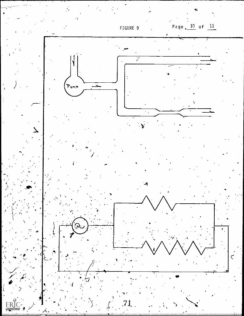
Figure 9
(
N,
O .A groun'ded receptacle Cticci<instruments should beavailable and demonstrated.The possibilities' th'at,could result from the check,is shown on the device,should be explained.
connected to the grounded (white), sideof the service conductors. The purposeof the grounding (green) co\nductor isto supply an tiniriterrupted low resistancepath 'for any current that might r.eachthe meta surface.of the stWonaryor portable device.
Recall-the similarity between electricsystems and water systems, and thenrecall the parallel circuit. diagram.There will be a greater flow \of water
in the pipe without the restricti,on(resistance). A grounding cftcurtprovides a parallel circuit also in thecase of a short circuit - parMlel tothe ground with the human body\ to the
. ground. The ground wire then provides'a line of little if any resistance(ccimpared`to the humant body - recallresistance determinatibns of the human
. body) 'for current to flow. If lthecurrent is sufficiently high, it wouldhopefully "blow" 'the circuit protectiondevice resulting in an "open" circuit
a ,stoppage of current flow.
rd _prong of a thr6e oronti plug-in isthe\ground line. -This pronci shduld never beremoved as that would "open" theground conductor line.
A relatively inexpensive device (lessthan $10, 1977 price) is available forchecking wall plugs which include the ."third" or ground 'conductor receptacle.
. The purchase of such a device should begiven consideration as it is a very safe-instrument to use and could result in thelocation of potential hazards.

.
r-
/
1'
e
FIGURE 9 'Page 47 of 574
I
.11......-
k
.,_....
a
1,,
47

Page 48 of 57r
Module No: Topic:
Safety
Instructor Notes:Instructor Outline:
~No
/
A three prong adapter shouldbe available.
A GFI should be availablefor the student to see.
Figure le - Schematic of awall receptacle, ,GFI, and,an electric drill.
t t
C. Double Insulation
Newer hand held tools such as electric'drills are now quite commonly "double'insulated ". The three prong plug-in(the third wire lAing the groundingconductor) hand tools still exist andthe importance of the third wire should*now be realized. The operator mustrealize that if an adapter is used toplug a three prong plug into a two prongreceptacle and the "green" wire is lefthanging in the open air, that parallelwire to 'ground does not exist. Thepath for current in a short circuitsituation is then through the personholding the tciold ground. This iscertainly a part of the reason thatmanufacturers,of hand held 'tools are
'rig more double insulated tools.
Double insulation is exactly as the nameimplies.' Rather than,a low resistanceground conductor (third wire) for safety,there is a plastic.(insUlated) shell sothat the operator cannot make contactwith a live conductOr. The insulating
.
shell isolates the live circOitry'inside.The inner circuits are made up ofinsulated conductors. Any metal._ exteriorelements are isolated by insulatingmaterial or shafts so -that fault currentsfrom the inside cannot reachthem.,
D. Ground Fault Interrup.tors (OFT)
This is an electronic device placed in acircuit to detect any difference in thearnount of current flowing to and froman electrical device. Recall the "closed"circuit diagram and the fact-that currentflows completely around the .closed circuit.Using Figure 11 trace the path that, thecurrent takes around the'circuit: TheGFIcompares the current level as if flows
4
48

Cs
c
4,
FIGURE in , Page 49 of 57.
1
kl
fa&.,
r
.
.4 9 (

Module No: Topic:
Safety
. 'Page .50 of 57
Instructor Notes:Instructor Outline:
)
OPto the drill and then from the drill.It detects very small differences inthe two values of the' current flow. Ifthere isa reduction in the return flowcurrent, the GFI automatically "opens",the circuit:- The GFI opens the "circuit'if the difference in current level is5 milli -amPtires.
This type device warrants strongconsideration in .a treatment facility.
E. Other "Safety" Suggestions
-1. If a knife switch ,is to be pulled inan emergency situation, do not standdirectly in front of 'the Switch.And are nes dl ti ng .from a -short-ci rcui tmay be so violent as` to burn throughthe ,metal switch cover, spewing hotmetal in the proximity -of the switch.
2. Neyer cut off the third prong of algrounded plug.
3. Never touch a wire before determiningif it is "live". 5
.
Never allow work to be done On acircuit without dist6nnecting themaster switch.
`Check all wires and plugs',for fraying/
.; '(bare wires) on a routine. basis:2 2./
6. Have an emergency teleptwne listposted near all phones.
174' Be conscious of potential electricalAp..hazards.
50

b
A
/$
Page 51 of 57
t
Module No: Jatodule Title:
Basic El ectri ci ty.
Submodule Ti tle:.
Application .
Approx. Time:
3 hours
Topic: e
Objectives:
1. Measure voltage using a voltmeter in a simple circuit.2. Measure current using an arpri_jeter in a simple circuit.
3. Measure resistance using a 'VOM" :1
a. Fuse (good and "blown" ones )b. Lengths of wire . ,
c. Heating element
,
.
.
Instructional Aids:
f: Handout2. Model . ....
3. Ground fault interrubtor4. Voltage meter5. Ammeter (amp clamp)
.
. .
Ins tructional Approach: t
1. Demonstration .
2. Lecture3. Hands -on
. ,
.
_
IReferences:
-
ok
. ,
. ,. ,
, .
,
,
.
.
I .
..
Cilss Assignments: ,
f ,, ft,
X 51

Page' 52 of,57
Topic:
Application
Module No:
Instructor Notes:Instructor Outline:
Figure 11 - Electrical model.Table 1 is a bill ofmaterials for the model shown
schematically-on Figure 11.
In addition a'volt-ohm metier
and "amp-clamp" should beavailable for student use.A ground fault interruptershould be used.
O
=wao.
The remainder of the workshop iseto behands,-on training.
Exercises which-can be included are:
A. "Building" a series circuit
B. "Building" a parallel circuit
C. MeasUring voltage
D. Calculatipg current
E. Measuring current ,
F. .Calcaltaing watts checking against1
the light bulbs being lighted inthe circuit.
NJ ,
G. Removing one'bulb in a series circuitand one.bulb in a parallel circuit.
H. "Blowing" a "slo-blo" fuse.
I. "Blowing" an 1,1-inStant-blo" fuse.
O. "Blowing" a circuit breaker.
-------17:Testing fuses for failUre.
, ,',. ' 'tr^ e.',. i S ,1*,,, ';

4.
3 prongplug
FIGURE 11
Pdrcelain
Lamp
Base (tvo.)
azr.
Bahana.plog*(typ.)
ill1/2 amp'dircuif+breaker
B .
15
01/2 amp,
_fuse
holders
.13,-
.R sRft* "dB . b ik *13 A BA ... .
Single poleswitch
,716 *...
53 4


FIGURE 11
B. Parallel Circuit
ds
oll
.
0
'57
i
1
To GFIand
110 vol t
58

14,
A FIGURE 11
H. - I J . "B,lowi ng" Fuses & V Ci rcui t* Breaker
I
13 X
1/2 amp 1/2 ampCircuit Slow BlowBreaker Fuse
1... Om ...
1
ant -
'Fuse
4,..i. ad. rift. alb aft MO II%
At '''P R
e el,,e \ .
a riff '.l's ........... ... ...............16, 11.11.
. ,
..-
OP OD MID40.
.1,IWO IIPS Om II we,,...., . gape,
.7. v.....
....
.
. .. . 0
59
To GFI
and110 volt
60

TABLE I
3 - 24"-Test leads-(red)
12 12" test leads (red)
12 12" Test leads (black)
'17 - Red banana plugs
17 Black banana plugs
9 Porcelain lamp bases,
2 - 1/2 ampere fine
ampere circuit breaker
1 - Single, pole switch, box, and coven plate 4
1 Ground fault interrupter (GFI)
1 - 2' x 4.' x 1/4" Peg bOard (front)
12' -..I" ,x 2" lumber (edges)* 4'
1 2I^N-X 4! x 1/2" plywood (back)
14 gauge-insulated wire ..1
Solder
1 - 3 -prong plug
60 watt, 100 watt, 150 watt .ght bulbs
ill
1
61
15

t
t
.ti
4.
).-
...
.2.
43
k
Page 1 pf 11
The following ten figures are appended,from which transparencieS'
may be made.
-,-..---*/
''''.".....
411
.. .
e
v 6.2,
e
ea
te
.
A
I
t.
J
S
e
.-,
(

FI(URE 1Page 2 of la
Protons
Neutrons
Nucleus
Electrons
63
't

FIGURE 2Rage 3 of 1
11.111,11!111:1" ! Ili
,Y1'II I!9,11
START
hii V.ilfilt:!1:1111111 !\
;
1
i;
CYC I-4
V-0
1.
A
£ /6
/ CYCLE.
64

I ,IGURE 3 Q-
Page 4 of 11
IV0LT-A
GE
4
174 SEC.
1/ . SEC.6,0
ti

NIP
4
FIGURE 4t
-it .
d
FrA\Q" idt: 11 -
Primary *ads
.0"
I
Secondary Leads
Primary Winding
1
Core
Transformer
66
SecondaryWinding


I.
/
FIGURt 6 Page 7 of
s
AC S ce . Fuse
tO.
Or
0
Switch Ammetere.
0
Volt Meter Connected Wires -j
4
re
rncandescent Lamp
r
A '6a8
Wires Crossing
(Not connected)

FIGUR. 7
,
Page 8 of 11
A
0
Circuit
Series Ci rcui t
se
69
O
v'

k .
ti
i.5Vocrs
= SAD
,e
VOLTS
Page of 11
.5/=
1 Joe)
.
J1.5
VOLTS
V
S = o
wT
'
V I
et
At7
/4
1
A
S
f'
4-s
FIGURE 9 Page 10 of 11
a
w. .
=
100

4
*Iv
-
FIGURE 10 -Page 11 of 11
1m
.r-
5.,
(
72A
.7-
7
r
4
"(1
Paae 1 of 6
e No: Module Title:
Basi Electricity
Approx. Time:
.
Objectives:
Submodule Title:
'EVALUATION
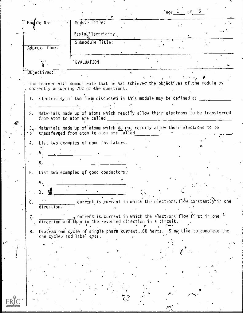
The learner will demonstrate that he has achieved the objectives of,the module bycorrectly answering 70% of the questions,.
1. Electricityof the form discussed in this module may be defined as
. Materials made up of atoms which readiPy allow their electrons to be transferredfrom atom-to atom are called
. Materials ,made up of atoms which do not readily allow their electrons to betr,ansfer4ied from atom to atom are called
4. List two examples of good insulators.
. A.
B.
. List two examples of good conductors:
A
B
direction.
)
curren t. is current in which the electrons flOw constantl >iin one
, current is. current in which the electrons flow first in, one 1
direction'and then in the reversed direction in a circuit.
,7- 4 ,----A
. ,Diagram one cycle of single phaA current,.60 hertz.. Show.tike to complete the
one cycle, and label axes. .
f.
Tv

Page 2 of 6
9. Diagram three phase current, 60 hertz: Show thelime to complete one
cycle anc time between voltage peaks. label axes.
1
10. A is a device which allows voltage to be increased(or decreased).
11. A circuit results from improper or accidental contactbetween two ormore wires.
'12. ,A circuit that is continuously providing a complete path for the flowof current. circuit.
13. A circuit that has been disconnected by a switch, fuse, circuitiOreaker,or other break in the line. circuit. a
14. Match the following':
1
A. Current
B. Amperes
tC. Ohms
7A
D. Voltage
A. The measure of electrical, power
B.' The movement of electrons through aconductor.
C. The measure of the resistance of aconductor to flaw Of an electriccurrent.
D. The measure of 'actual electricalenergy_usAge.
E. Watts ." E. The mdAsure of rate of flow of,electrons through a conductipr.
F. Kilowatt hours ,) F. Eledtrical presSure.
Ohm's. lawlstes that voltage equals the-product'of current timesresistance eV = IR'). The circuit breaker in your laboratory.has been,tripping when you turn on your muffler, furnace. ThR muffler furnace is
plugged intoa'220 volt receptacle. The circuit breaker is rated at
20 ampereS. What; is the level of resistancethdt i5 safely applie0 to/this circuit..
7 4_

p
Page 3 of 65
16. Record the reading of the meter.
17. List two basic differences between metal conduit and or try water pipe.,
A.
B.
18. Match the following:
A. Wh'ite wire
B. Green wi
C. Black wire.
A. Grounding conductor (neufral
"Hot" oc, undei-grounded conductor
C. Grounding conductor of a branchci rcuit-
19 . True or False. A No. 10 olid conductor \will carry l es's current thanNo.a N 14 stranded wire co ductor.
20. List a symptom of wire that is too small. for the current flow in it.
21. Sketch 3 light bulbs wired in series.)N,
Sketc11 3 light bulb,s wired i n. paral 1 el .
04 -75 .;..
(.-
4 Ji
4
Page 4_ 6
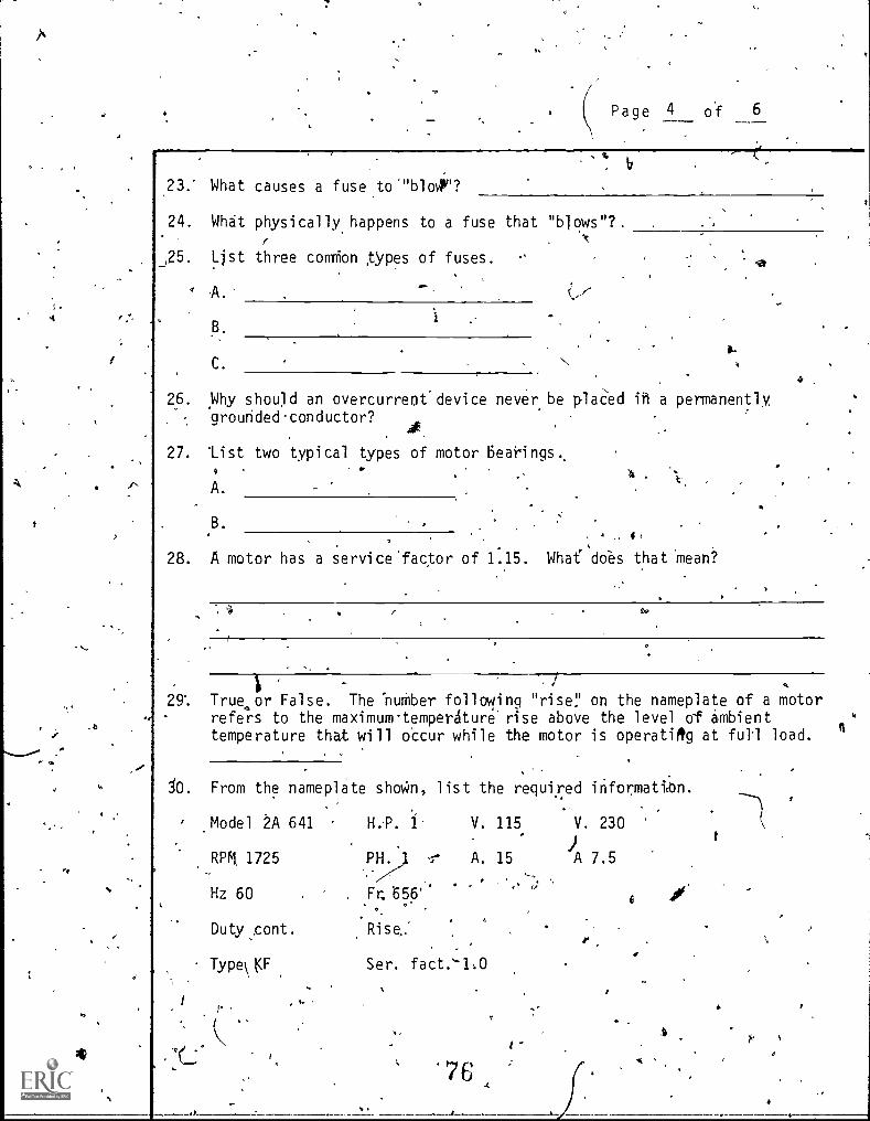
23: What causes a fuseto""bloy,"?
24. What physically happens to a fuse that "blows"?.
_,25. List three connion types of fuses.
A.
C.a.
ca
26. Why should an overcurrenf device never be plaCed ih a permanentlygrounded conductor?
27. list two typical types of motor Bearings..
4 .
A.
.B.
28. A motor has a service'factor of 1.15. Whafdoes
4,
that Mean?
110
29% True or False. The 'number following "rise!' on the nameplate of a motorrefers to the maximum.temperAture rise above the level of ambienttemperature that will occur while the motor is operating at full load.
Jo. From the nameplate shown, list the required ihformatiOn.,
Model 2A 641 H.. i V. 115 V. 230
RPM 1725 1- A. 15 JA 7.5
Hz 60
Duty ,cont.
Type\ t:F
PH.
. Fr. 656'.
Rise:
Ser. fact."1,0
0
7 6
.

tr
Page 5 of 6
A. Phase
B. Voltage ,
C. Current
D. Duty rating
E. Service factalA\\
F. Temperature rise
G. Horsepower
31. List the major advantage of'a DC motor compared to most AC motors.
32. Match the following:
0 A, Reaction current A. A level of current above which aperson cannot let go of a conductor
B. The smallest current that might causean unexpected involuntary reactionand produce an accident as a resultof being shocked.
C. ,,Fltrillating current C. The level of current which causes .
heart-action and brood circulation to
Let-go current
stop
33. List two reasons for installing fuses or circuit breakers.
A.
B.-
34. Mate the fo'llowing: v/
A. Grounding conductor
B. Double insulation.
A. An electrical device placed;an acirtrto detect any diffei-ences inthe ount of current flawing to an'appliance and returning.
B. A plastic shell which isolates the./
wiring inside an appliance; thewiring itself is also insulated.
.44
pa 6 of 6
1
C. Ground fault interruptor C. The green wire connected fromthe metal surface of an applicantand continued as a separateconductor until it reaches theground terminal at the servicepanel.'
gr
I
a

'>4
Page. 1 of 3 f
Evalu4tioh Answers
1., The movement'of electrons through a condUctor.
2. ,Conductors
3. Insulators-
3
4. Glasg, rubber, plastic, bakelite, pure water, dry sandy soil.A
5. Copper, aluminum, silver, tap water, damp 'soil, hunian ody.
6. Direct
7. Alternating
8. Check against Figure 3
9. Check against Figure 3
10. Transformer,
11. Short
12., Closed .
13.
,e
Open
14. A. B.
.B. E.
C.' C.
16.
D. ' F.
E.r
A.
F. D.
11. ohms
t bends easily
'11
w.
Inside of conduit is smooth
Conduit has corrosion-resistipg finish
79dr,

oPage 2 0.f 3
Th
18, A. A.
B. C.
C: B.(
19. False
20. Heat
21. Check against text Figure '2 -2.
22. Check against text Figui-e 2-3.
23. Current flow in excess of the fuses rated capacity.
24. Metal strip within fuse melts, resulting in'an open circuit.
A
4
.o
25. A. Screw or plug
B. 'Caetridge
C. Bayonet
26. If fuse is removed tkie "hot" lead is still connected -Co the motor, for
example; ready to supply\,powell.
'27. A. Sleeve
B. Ball.
28, The motor can tolerate a 15 'per cea overload.
29. True
30. A. Single (11-
b. .115 or230
C. 15 or 7.5
D. Continuous (cont.)
- ,E. 1.0 (ser. fact.)
F. None shown
G. . 1 (H.P.)

Page 3 of 3
1. The speed of rotation of DC motors can easily be changed.
32. A. B.
A.,.).
.C.
33. A. Protection of the wiring (circuit)
\.
B. Protection of equipment or appliances
34. A.
B. B.
C. A.
so.
ft/
81,
a
ie
a I
.
- ,