Embed Size (px)
Citation preview

1
Title: Andor Dragonfly Confocal User Manual Date of first issue: 160517
Date of review:
Version: User
For assistance or to report an issue Office: CG.07 or CG.05 Email: [email protected] Website: www.igmm-imaging.com Download a PDF copy of manual: \\smbhost\microscope-users\microscope user manuals\Dragonfly
Facility Usage Policy 1. You must have the relevant Risk Assessment/COSHH form for the
work you are undertaking before using imaging facility resources
2. Users must be trained before using facility equipment
3. Please leave the microscope clean and tidy for the next user
4. Please report any issue, even if it seems minor, to facility staff
5. Any clinical waste must be placed in the orange bins provided

2
Table of Contents System Startup ............................................................................... 4 System Shutdown ......................................................................... 5 Setting up incubation chamber for live cell work ............. 6 Mounting a sample (fixed imaging) ..................................... 10 Finding the sample by eye ...................................................... 12 Setting a save location .............................................................. 13 Protocol Manager Labelled Diagram .................................. 14 Creating an Acquisition Protocol (Adding Channels) .... 15 Live Mode and 2D Image Capture ........................................ 17 Z Scan Protocol (3D) ................................................................. 19 Viewing Saved Images .............................................................. 24 Exporting Images (raw data) ................................................. 25 Exporting View Screenshots .................................................. 25 XYZT Protocols ........................................................................... 26 Multi-‐field XYZT Protocol ....................................................... 27 Montage (Image Tiling) Protocol ......................................... 29 Appendix ...................................................................................... 31 Perfect Focus System (PFS) Operation ............................... 31 Adding Camera Magnification ............................................... 33 Capture an Area of Interest (AOI) ........................................ 34 Deconvolution ............................................................................ 35 Kohler Illumination .................................................................. 37 Dual Camera Simultaneous Acquisition ............................ 38 Stitching Montage Images ....................................................... 39 Terastitcher ................................................................................. 39 FIJI ................................................................................................... 40

3

4
System Startup
1. Use the black switchboard box above the system to turn on most of the devices. Turn on the switches in the order 1-‐8.
2. If you want to use the Piezo stage insert for Z
turn on the controller on the shelf
3. Turn on the PC
4. Log on to Windows using your account
5. Launch the Fusion software from the Desktop icon. Please wait for the software to initialise fully before using the software, this can take up to a minute (all motor noises should stop) * If you are carrying out a live cell imaging experiment see the dedicated section below

5
System Shutdown 1. Close the Fusion software
2. Clean any oil immersion lenses used with lens tissue & ethanol
soaked lens tissue
3. Shutdown the PC
4. Turn off the incubation apparatus via the Oko-‐lab touch and close the CO2 inlet valve on the wall. Put the chamber back into its box on the shelf, turn off the objective heater from Settings>Objective Heater, select Disabled. Then remove the objective heater from the lens and put back in the drawer.
5. Use the black switchboard box above the system to turn off most of the
devices
6. Turn off the Piezo stage insert controller if used on the shelf

6
Setting up incubation chamber for live cell work
1. Retrieve the Oko-‐lab heated chamber from the box on the shelf and check that the correct plate/dish adapter is inserted. You can find the available adapters in the set of wooden drawers next to the system
2. Adapter options: -‐Immersion lens adapter (IMM)-‐Works for any
standard dimension multi-‐well plate (6, 12, 24, 96). -‐DO NOT USE THE MULTIWELL PLATE ADAPTERS WITH CIRCULAR HOLES -‐35mm x 2 dish adapter. Magnetic lids available (must escape lens before travelling between wells)
3. Once the adapter is sat flat in the chamber, slide the glass lid closed 4. If you will use an oil immersion lens then you will need to attach the
appropriate objective heater (also in drawers by SIM). You cannot rotate between multiple lenses once the collar is in place.
5. 6.
5. Mount the chamber onto the microscope stage
5. Attach the pipe that supplies the humidified air to the chamber. Be careful
to ensure there is enough slack on the pipe for the stage to move around.
VERY FRAGILE!

7
6. Open the blue CO2 tab on the wall opposite the Dragonfly
(turn anticlockwise) Turn on the chamber using the switch on the Oko-‐touch pad
7. You may need to wait a few seconds but ensure gas bubbles are seen in the water bottle next to the microscope
8. The Home screen of the Oko-‐touch displays the current and set point temperature of the chamber, the current and set point CO2 percentage and the relative humidity. Ask a facility member if you need this to be changed. NO NOT CHANGE THE CO2 SET POINT
8
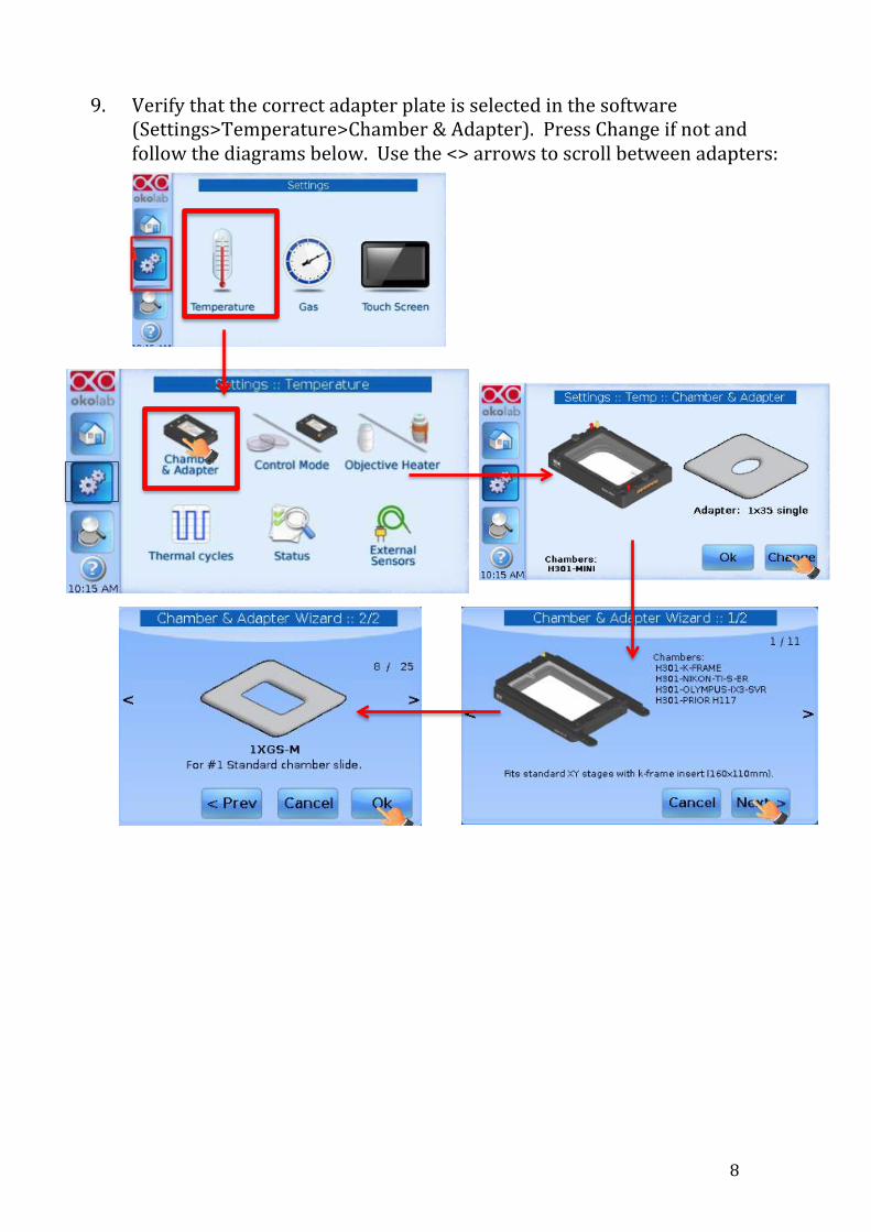
9. Verify that the correct adapter plate is selected in the software (Settings>Temperature>Chamber & Adapter). Press Change if not and follow the diagrams below. Use the <> arrows to scroll between adapters:

9
10. If you are using the Objective heater make sure the heater is turned on, Settings>Objective Heater menu. Select Enabled and then Save. Select Use Factory Setting if the message appears.
11. Choose the desired temperature monitoring mode Sample or
Chamber feedback mode (Settings>Control mode). Select Chamber mode unless you have been taught how to use sample feedback mode (requires green thermocouple to be inserted into a well of water)
12. The Overview page is useful for seeing the temperature of the various heated components

10
Mounting a sample (fixed imaging) 1. For slides/35mm dishes use the piezo slide
insert pictured to the right. For anything that involves live cells use the stage top incubator and the 35mm dish or multiwall adapters specific for that.
2. For slides without the chamber adjust the width of the piezo insert’s arms so that it can support your slide
3. Choose the lens you want to use from the microscope touch pad objective menu or the Channel Manager>Global settings in Fusion. If this menu isn’t visible, expand the controls available via the arrow in the Acquisition Control window
4. Apply oil to the lens if required (60x-‐100x)
5. Invert the slide when placing it into the insert so that the cover glass
is the closest surface to the lens Use the joystick to move the stage so the lens is positioned under the cover glass Change the speed of the stages movement by twisting the joystick clockwise/anti-‐clockwise
6. Ensure the lens is at it lowest z position. You can do this quickly by pressing the Escape button on the right side of the microscope stand.

11
7. Turn the focus knob towards you, if the lens does not appear to move upwards or the z position number on the microscope LCD display does not change, hold the Escape button while simultaneously pressing the Refocus button above it once (it should beep). Now the lens should be free to move using the focus knob.
8. Set the focus to Course speed using the button on either the left or right side of the microscope body

12
Finding the sample by eye
1. In the Fusion software select the Active Channel drop down list from the Acquisition Control window on the right side of the screen
2. Change the Imaging mode filters dropdown to Eyes then choose the wavelength you want to see down the microscope
3. If you have chosen a fluorescence channel press the On/Off button on the white Fluo controller (1) to illuminate the sample. If
you have selected DIC (brightfield) press
the On/Off button on the white Brightfield controller (2).
4. Use the Active Channel dropdown list to switch between channels. DO NOT use the filter controls on the microscope stand as the software automatically updates its channel settings so you could for instance match the DAPI cube to the FITC software channel by mistake.
5. Turn off the BF LED or FL LED when not viewing the sample using the relevant control pad.
1
2

13
Setting a save location 1. All images captured in Fusion are
automatically saved. You can configure the save location by pressing the Imaging button in the far right top corner of the screen and in the dropdown list select the Preferences option.
2. In the Preferences window choose the File Manager Menu on the left. Here you can change the root folder
for saving images. You should have a folder on Local Disk:D>Users
3. Various bits of information can be appended to the file name (sample prefix) automatically shown below the root folder, this can be disabled if you wish.
4. If you acquire additional images without changing the file name, an incremental number will be appended so they can be distinguished.
5. Go back to the dropdown menu top right and change it from Preferences back to Imaging.

14
Protocol Manager Labelled Diagram

15
Creating an Acquisition Protocol (Adding Channels)
* This page is a rough outline of how to setup your acquisition channels, see later sections for how to setup specific experiment protocols
1. Expand the Acquisition Control menu using the arrow
icon. This gives access to select the Protocol Manager tab/menu
A Protocol essentially defines the imaging experiment you want to carry out and incorporates the channels to be acquired as well as other functions you may need such as Time, Z, Montage etc which will be covered in later sections.
2. You can either press the New Protocol button or edit an existing protocol from the Protocol Manager
4. To add/change channels in the protocol select the + button to add and the x button to delete
5. 6. 7. 8.
9. 10.

16
11. When you click + the channels displayed will be specific for the selected Imaging Mode The following imaging modes are available: Confocal 25µm (10-‐40x lenses) Confocal 40µm (40x-‐100x lenses) Eyes (To view down the eyepieces) TIRF *A note on cameras The system is equipped with two cameras which suit different applications. To select which camera to use you need to select the appropriate channel setting which will either have HiRes (Zyla) or HiSens (iXon) incorporated into its name. HiRes (Zyla)-‐A fast & high resolution camera (6.5µm pixels) 12bit HiSens (iXon)-‐ A fast & sensitive camera (13µm pixels) 16bit
6. Once the imaging mode has been set you can click the + next to each channel you want to add.
7. When you have finished setting up the protocol for channels
you can collapse the expander panel using the arrow to display just the Acquisition Control menu.
Imaging Mode Channels list Add Channel

17
Live Mode and 2D Image Capture 1. To select a channel to view, drop down the Active Channel menu
and select one of your protocol channels
2. Ensure the Active Channel radio button is
selected then press Live
3. If the image appears black it could be the exposure settings are not optimal but you can make the display auto-‐contrast by selecting Auto-‐Map ON along the top of the live preview window.
4. You can adjust the Laser, Exposure Time & Gain (HiSens camera only) for each channel from the Acquisition Control window. The circular white indicator gets brighter when its selected.
5. Use the Image Histogram to judge the exposure required and to adjust the auto-‐contrast settings. When Auto-‐Map is on the min and max values shown on the histogram will be the min/max values found in the live image.
6. The dynamic range and thus Min/Max possible intensity values on the iXon are 0-‐65535 (16bit) and for the Zyla its 0-‐4095 (12bit).

18
Note that if you turn Auto-‐Map off again the contrast stretch applied will remain and Min/Max values on the histogram will not update. Because of this, it’s easier to leave auto-‐map always on so long as you understand what it does.
8. Once each channel’s exposure settings have been optimized you can acquire a 2D multi-‐channel image of your protocol channels by selecting Protocol
Channels, then press the Snap button in the Acquisition Control window.

19
Z Scan Protocol (3D)
1. Ensure you have selected a folder to save the protocol images (see page 12 on how to do this).
2. Go to the Protocol Manager window
3. Select Z Scan from the Type drop down menu
4. Add the required channels into the protocol by pressing the + button
5. The Z Scan Settings will appear below the channels section in the Protocol Manager and in the smaller Acquisition Control window
6. To use the Piezo Z insert (100µm travel only) turn on the Use Piezo For Scans option. If this is off you will be using the microscopes z motor (mm travel range).
7. There are two ways to configure the z scan through the Scan Modes drop down menu: Start/End-‐Set defined begin/end points for the z scan manually by moving through focus Centre/Size-‐Choose the central z plane and choose a total z scan range (used when combined with multipoint experiments)

20
Start/End Scan Mode 8. To configure the z scan using the Start/End scan mode, select it from
the dropdown menu
9. Press the Live button in the Acquisition Control panel so you can see your sample If using the microscopes focus motor:
10. Now move the focus knob towards you to travel through the sample to where you want to set the end point of your z scan, then press the upper Set button (this will be a higher number).
11. Move the focus knob away from you to move the lens down, when you have reached the start position for your z scan press the lower Set button in the Z Scan Settings window (this will be a lower number). Skip to point 17. If using the piezo insert:
12. The light grey banded rectangle on the z scan schematic represents the 100µm travel range of the piezo z.
13. Set the piezo insert so that it is in the middle of its travel range by typing 50 into the text box next to Current Z Position then Enter.
14. If the sample was in focus before step 13 it will have moved now. Use the microscope focus knob on the stand to re-‐focus the sample.
15. Click on the orange triangle and turn the mouse scroll wheel away from you to move the piezo insert up until you reach the end point of your z scan. Press the upper Set button.
16. Click on the orange triangle and turn the mouse scroll wheel towards you to move the piezo insert down until you reach the start point of your scan. Press the lower Set button.

21
17. You can view the total size of the z scan by looking at the Scan Size box
18. You can select the Auto Step Size option if you want Fusion to calculate the Step Size for you based on quite strict Nyquist sampling or you can manually type the step size or step count.
19. 20. 21.
19. You can choose whether the entire z scan is acquired for each
channel sequentially or whether for each z plane each channel is acquired. For each channel, acquire all z planes is recommended.
20. Press the Acquire button in the Acquisition Control window to start the acquisition

22
Centre/Size Scan Mode 21. To configure the z scan using the Centre/Size scan mode, select it
from the Scan Mode dropdown menu If using the microscopes focus motor:
22. Ensure the sample is focused at the central z plane then press the middle Set button in the Z Scan Settings window. Skip to point 27.
23.
24.
If using the piezo insert:
23. The light grey banded rectangle on the z scan schematic represents the 100µm travel range of the piezo z.
24. Set the piezo insert so that it is in the middle of its travel range by typing 50 into the text box next to Current Z Position then Enter.
25. 26. 27. 28. 29. 30. 31. 32. 33.
25. If the sample was in focus before step 24 it will have moved now. Use
the microscope focus knob to re-‐focus the sample.
26. Press the Set button

23
27. You can then set the total volume to scan by entering the value in the Scan Size box
28. You can select the Auto Step Size option if you want Fusion to calculate the Step Size for you based on quite strict Nyquist sampling or you can manually type the step size or step count.
29. You can choose whether the entire z scan is acquired for each channel sequentially or whether for each z plane each channel is acquired. For each channel, acquire all z planes is recommended.
30. Press the Acquire button in the Acquisition Control window to start the acquisition
24
Viewing Saved Images
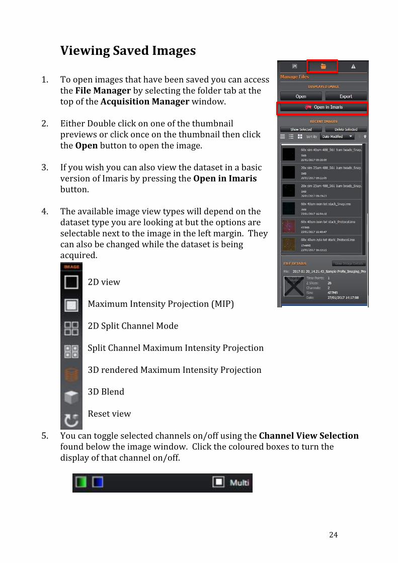
1. To open images that have been saved you can access the File Manager by selecting the folder tab at the top of the Acquisition Manager window.
2. Either Double click on one of the thumbnail previews or click once on the thumbnail then click the Open button to open the image.
3. If you wish you can also view the dataset in a basic version of Imaris by pressing the Open in Imaris button.
4. The available image view types will depend on the dataset type you are looking at but the options are selectable next to the image in the left margin. They can also be changed while the dataset is being acquired.
2D view Maximum Intensity Projection (MIP) 2D Split Channel Mode Split Channel Maximum Intensity Projection 3D rendered Maximum Intensity Projection 3D Blend Reset view
5. You can toggle selected channels on/off using the Channel View Selection found below the image window. Click the coloured boxes to turn the display of that channel on/off.

25
Exporting Images (raw data)
1. Go to the Manage Files tab of the Acquisition Control window
2. Double click on an image thumbnail to open it
3. Click the Export button
4. In the dialog window that appears, name the file and select from the following file formats: -‐OME Tiff-‐Produces one 16bit file that contains all channels and is recommended for saving the raw data -‐RGBA Adjustable File Series-‐Produces an 8bit RGB tiff file per z plane -‐Adjustable File Series-‐Produces a 16bit tiff file for each channel and each z plane
Exporting View Screenshots
1. Adjust the image as desired including brightness/contrast scaling and set the required view type e.g. MIP, 3D rendering as described above
2. Select the white triangle on the Export button found above the image on the horizontal icon bar and you’ll be presented with the option to Export to clipboard or Export to file
3. When you select Export to file a dialog will open where you can choose the save location and the file format.

26
XYZT Protocols
4. Follow the section above for acquiring a Z scan protocol
5. Once the z scan settings are confirmed, you can define the time lapse from the Time Series Settings section of the Protocol Manager
6. You can define a total Duration by clicking on the button then inputting a time (ms, s, min, h)
7. Set the Interval (delay between captures) by clicking on the button
then inputting a time
8. Press the Acquire button in the Acquisition Control window to start the acquisition

27
Multi-‐field XYZT Protocol
1. In the Protocol Manager select Multi-‐field from the Type drop down list
2. Follow the sections above in order to setup the z scan (use CENTRE/SIZE scan mode) and time series sections of the protocol (pages 19-‐22)
3. Find the Multi-‐field Positions section of the Protocol Manager
4. When you have found an area on the sample you want to add, press
the + button 5. Repeat this process to add further stage positions 6. Delete a position by clicking on it in the list then press the X button
or to delete all click the Remove All button

28
7. To make the stage move to one of the positions, click on it then press the Go To button (If using PFS, it will disable when moving to another position but will re-‐enable when it gets there)
8. Changing the order in which the positions will be acquired can be
done by selecting the position to be moved then use the Up/Down buttons.
9. The Multi-‐Field Protocol Order option should be set to At each
time point visit all fields 10. Press the Acquire button in the Acquisition
Control window to start the acquisition
11. Note that each xy position will be saved as a different ims file and currently the first position file which is labeled “1” in Fusion will have the file name beginning “0”.

29
Montage (Image Tiling) Protocol Acquire images of successive fields of view in a grid pattern and stitch them to acquire a larger area of the sample.
1. In the Protocol Manager select Time Series from the Type drop down list if you wish to capture a montage of a single z plane. To include a z stack in the montage select the Z Scan type.
2. If you have chosen to acquire a z stack as well, follow the instructions in the section on z scans above, specifically use the Centre/Size mode.
3. The Montage settings window is included in the Time Series and Z scan protocol types.
4. Montages can be acquired in two modes: Fields-‐Specify the number of fields of view to be captured relative to a defined location (height x width) Edges-‐Provide two diagonally opposite xy stage positions that encompass the area you want to montage and Fusion will calculate the number of fields required to capture the area of interest Montage by Fields
5. Expand the Montage settings window found towards the bottom of the Protocol Manager
6. Select Montage Enabled
7. Select the Fields option from the Mode drop down list

30
8. Choose the Width and Height of the area to be montaged by inputting into the text boxes
9. The Relative Montage Position option assumes your current xy position is one of the following Bottom left, Bottom right, Centre, Top left or Top right of the montage area.
10. Set the Overlap to at least 10%
11. Press the Acquire button in the Acquisition Control window to start the acquisition Montage by Edge
12. Expand the Montage settings window found towards the bottom of the Protocol Manager
13. Select Montage Enabled
14. Select the Edge option
from the Mode drop down list
15. View the sample by eye down the microscope or on the camera and move the stage to the upper left corner of the region you want to capture from. Click the + icon to add that position to the table. Then move the stage to the diagonally opposite corner of the region you want to capture. Click the + icon to add that position to the table.
16. Fusion will calculate and display the Grid Size as the number of fields of view required e.g. 6w x 5h.

31
Appendix
Perfect Focus System (PFS) Operation PFS provides real time focus correction on a plane of interest during time lapse experiments carried out above room temperature. PFS is required because the microscope components expand as they heat which can cause the focus to drift. The reflection of IR light off of the coverslip/medium refractive index interface is monitored and the distance from the interface to the plane of focus is recorded as an offset value. If a change in the distance of the lens from the coverslip interface is detected, the lens will move in the same direction to compensate, this maintains the same offset value and therefore the focal plane is unchanged.
1. Focus on the sample
2. On the front of the microscope a green LED will light next to the word “Focus” if the PFS can be turned on. This indicates the refractive index interface has been found.
3. Press the On button on the front of the microscope to enable PFS
4. Check the focus again now PFS has been turned on, you may have to adjust it again
5. To change focus while PFS is enabled, use the PFS offset controller wheel
6. The blue button on the side of the controller toggles between course/fine focus

32
7. In Fusion, navigate to the Protocol Manager window
8. Under the Drift Stabilisation settings ensure the Drift Stabilisation Active button is set to ON and the Drift Stabilisation Enabled box is active. Select the All Fields button and set Drift correction every “1” time iterations.

33
Adding Camera Magnification It is possible to increase the magnification of the image without changing the objective lens. This is equivalent to optical zoom on a spot scanning confocal and will reduce the effective pixel size.
1. The camera magnification options can be accessed by firstly selecting the Channel Manager tab within the expanded acquisition panel.
2. You will need to select the camera magnification dropdown box relevant to the camera you’re using, signified by the orientation of the arrow: Vertical arrow-‐High Res (Zyla) Horizontal arrow-‐High sens (iXon)
3. Note that you may need longer
exposures/laser power due to the light lost when using the 1.5 or 2x camera lenses.
4. If you need advice on whether to use camera magnification please ask one of the imaging team

34
Capture an Area of Interest (AOI) By restricting how much of the camera sensor you use, you can essentially crop how much of the field of view you capture. This will reduce the amount of data you acquire. It will also increase the possible acquisition frame rate attainable with the high sens (iXon) camera but not the high res (Zyla) camera.
1. Press the Live button to see the live image on the camera
2. Press the AOI button above the image window, you will see a ROI box which you can use to select the area to be imaged. Press the Enter key on the keyboard to confirm.
3. The AOI will remain enabled until you switch it off using the AOI Reset button

35
Deconvolution
1. Navigate to the Image Processing tab
2. Under Processing Options you will see the Preview settings. When turned on this allows the deconvolution result to be viewed almost instantaneously by only selecting a region of interest on the image.
3. An additional image window will open showing the deconvoled
image region as well as the original image overlayed with an adjustable ROI. This is used to select both the position and the size of ROI for the deconvolution preview image.
4. Select the required deconvolution algorithm to be used: -‐Robust (Iterative)-‐Maximum Likelihood Estimator (slowest/best resolution/best noise suppresion) -‐Fast (Iterative)-‐Jansson Van Cittert (faster but minimal resolution improvement/some noise suppression) -‐Fastest (non-‐iterative)-‐Inverse/Wiener filter (fastest/contrast enhancement/may add noise)
5. Pre-‐Sharpening-‐When enabled, the degree of pre-‐sharpening can be
set using the slide-‐bar. High levels of pre-‐sharpening may result in noisier image output and image artefacts.

36
6. By selecting Unlock PFS Settings you can gain access to the Point Spread Function (PSF) parameters. In theory you would only need to change, specimen refractive index, distance from coverslip and the immersion medium.
7. Press the Deconvolution button to start processing the image. An
additional image file will be created and saved to disk.

37
Kohler Illumination 1. Select the DIC Eyes Channel and turn on the Brightfield LED 2. Ensure the condenser aperture turret is set to the “A” position 3. Focus the sample 4. Open the condenser aperture fully 5. Close down the field aperture fully 6. If the image of the field aperture is not in sharp focus, adjust the
focus by moving the condenser up/down 7. Centre the image of the field aperture using the centring screws 8. Open the field aperture until you can see the full field of view but no
more 9. Remove an eyepiece and look down, if you open and close the
condenser aperture you can now see its image 10. Close the condenser aperture until ~70% of the back illuminated
area is filled 11. Reinsert the eyepiece 12. Kohler should be adjusted whenever you change the lens

38
Dual Camera Simultaneous Acquisition
1. From the Protocol Manager tab press the + button to add the two dual cam channels for the pinhole you’re using.
2. Make the “525nm Dual Cam 488-‐561” channel the Active Channel in
the Acquisition Manager
3. Select the Channel Manager tab and under Global Settings set Binning to 2x2. This ensures the same pixel size will be set for both cameras.
4. Configure each channel’s exposure time and the other aspects of the protocol
5. Press the Acquire button

39
Stitching Montage Images
Terastitcher
1. Go to the folder where the raw montage images are stored and find the file that has the Windows Batch File extension then double click on it.
2. Terastitcher will start in Windows Command Line and show the stitching progress. Note that if you have used the Zyla camera at binning 1x1 this could take some time.
3. The stitched image can be found in same folder as the raw montage
data and will contain “stitched” in the file name. There is an ims and Tiff file copy.

40
FIJI
1. Fusion cannot stitch the montage images together so you will need to use FIJI to do this.
2. Open FIJI and select Plugins>Stitching>Grid/Collection Stitching
3. In the window that opens set Type to Grid: snake by columns and set Order to Down and Right
4. In the larger dialog complete the following options and leave all others unaltered/unselected: -‐Grid size x & y (e.g. montage image could be 3 x 3 images) -‐Tile overlap-‐The overlap will have been defined in Fusion but you can also access this info in the metadata.txt file saved with the images -‐First file index i-‐Set to zero (Image file with the lowest F number in filename) -‐Directory-‐Press Browse and select the folder that contains the images to be stitched -‐File names for tiles-‐Type the filename of the first image but replace the number after the F with “{i}” if your images go to double figures type {ii} e.g Montage zyla_Protocol_F{i}.ims -‐Subpixel accuracy-‐Tick this box
5. Press Ok and a log window will appear and display errors if there is a problem with stitching. Eventually the stitched image will open as a composite image (merged view). By default all channels in the ims files will be stitched.
6. To save the file go to File>Save As Tiff