Embed Size (px)
Citation preview
nutaq.com
Q U E B E C I M O N T R E A L I N E W Y O R K I
250 MHz OTA Real-Time BW Massive MIMO Testbed PRODUCT SHEET
TitanMIMO-X
TitanMIMO-X
TitanMIMO X series Massive MIMO testbeds are scalable solutions that can meet any processing and channel count for real-time and very large antenna arrays research.
Why Testbed Implementation and Validation:
• Validate various waveform propagation schemes
• Optimize network deployment by balancing cost versus performance
• Validate interoperability scenarios
• Validate, optimize & develop analytic channel models
• Optimize TDD and RF calibration techniques
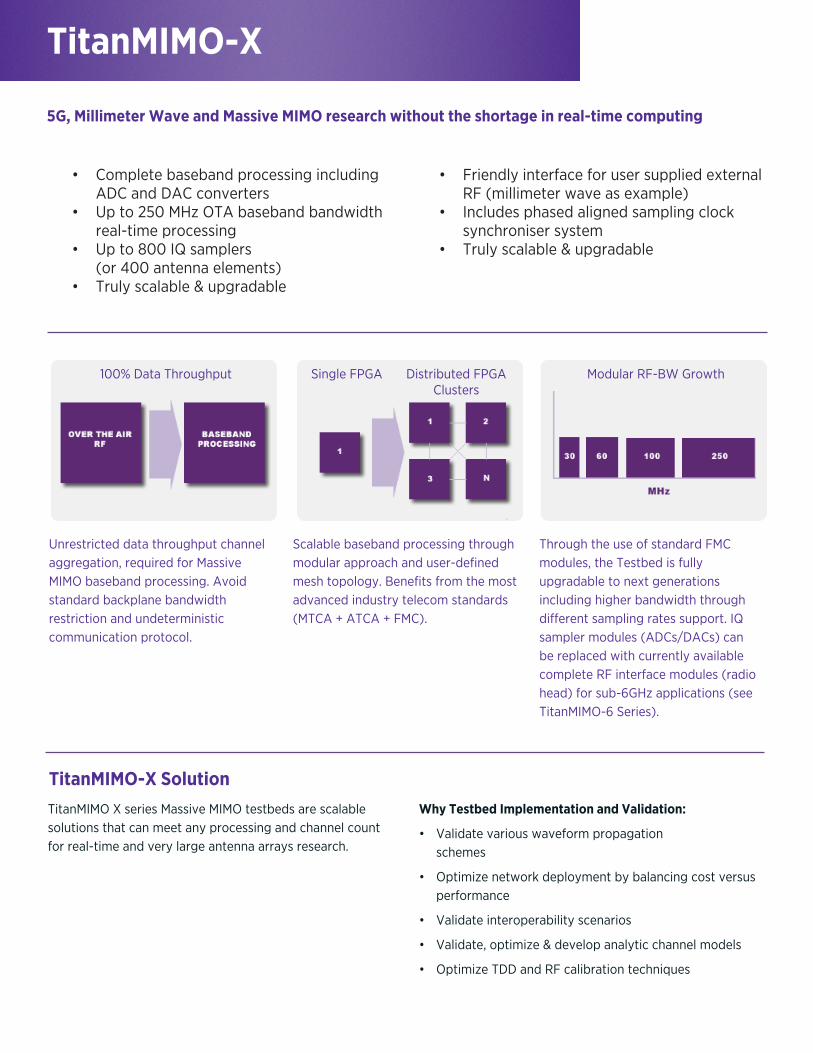
• Complete baseband processing including ADC and DAC converters• Up to 250 MHz OTA baseband bandwidth real-time processing• Up to 800 IQ samplers (or 400 antenna elements)• Truly scalable & upgradable
• Friendly interface for user supplied external RF (millimeter wave as example)• Includes phased aligned sampling clock synchroniser system• Truly scalable & upgradable
TitanMIMO-X Solution
5G, Millimeter Wave and Massive MIMO research without the shortage in real-time computing
Through the use of standard FMC modules, the Testbed is fully upgradable to next generations including higher bandwidth through different sampling rates support. IQ sampler modules (ADCs/DACs) can be replaced with currently available complete RF interface modules (radio head) for sub-6GHz applications (see TitanMIMO-6 Series).
Unrestricted data throughput channel aggregation, required for Massive MIMO baseband processing. Avoid standard backplane bandwidth restriction and undeterministic communication protocol.
Scalable baseband processing through modular approach and user-defined mesh topology. Benefits from the most advanced industry telecom standards (MTCA + ATCA + FMC).
100% Data Throughput Modular RF-BW GrowthSingle FPGA Distributed FPGA Clusters
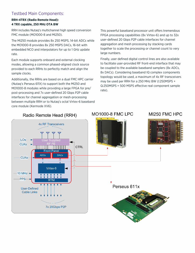
Testbed Main Components:RRH-4TRX (Radio Remote Head): 4 TRX capable, 250 MHz OTA BW
RRH includes Nutaq’s multichannel high speed conversion FMC module (MO1000-8 and MI250).
The MI250 module provides 8x 250 MSPS, 14-bit ADCs while the MO1000-8 provides 8x 250 MSPS DACs, 16-bit with embedded NCO and interpolators for up to 1 GHz update rate.
Each module supports onboard and external clocking modes, allowing a common phased-aligned clock source provided to each RRHs to perfectly match and align the sample clocks.
Additionally, the RRHs are based on a dual FMC HPC carrier (Nutaq’s Perseus 611X) to support both the MI250 and MO1000-8 modules while providing a large FPGA for pre/post-processing and 7x user-defined 20 Gbps P2P cable interfaces for channel aggregation or mesh-processing between multiple RRH or to Nutaq’s octal Virtex-6 baseband core module (Kermode XV6).
This powerful baseband processor unit offers tremendous FPGA processing capabilities (8x Virtex-6) and up to 32x user-defined 20 Gbps P2P cable interfaces for channel aggregation and mesh processing by stacking cards together to scale the processing or channel count to very large numbers.
Finally, user defined digital control lines are also available to facilitate user-provided RF front-end interface that may be coupled to the available baseband samplers (8x ADCs, 8x DACs). Considering baseband IQ complex components topology would be used, a maximum of 4x RF transceivers may be used per RRH for a 250 MHz BW (I:250MSPS + Q:250MSPS = 500 MSPS effective real component sample rate).
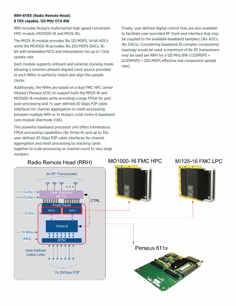
RRH-8TRX (Radio Remote Head): 8 TRX capable, 125 MHz OTA BW
RRH includes Nutaq’s multichannel high speed conversion FMC module (MO1000-16 and MI125-16).
The MI125-16 module provides 16x 125 MSPS, 14-bit ADCs while the MO1000-16 provides 16x 250 MSPS DACs, 16-bit with embedded NCO and interpolators for up to 1 GHz update rate.
Each module supports onboard and external clocking mode, allowing a common phased-aligned clock source provided to each RRHs to perfectly match and align the sample clocks.
Additionally, the RRHs are based on a dual FMC HPC carrier (Nutaq’s Perseus 611X) to support both the MI125-16 and MO1000-16 modules while providing a large FPGA for pre/post-processing and 7x user-defined 20 Gbps P2P cable interfaces for channel aggregation or mesh-processing between multiple RRH or to Nutaq’s octal Virtex-6 baseband core module (Kermode XV6).
This powerful baseband processor unit offers tremendous FPGA processing capabilities (8x Virtex-6) and up to 32x user-defined 20 Gbps P2P cable interfaces for channel aggregation and mesh processing by stacking cards together to scale processing or channel count to very large numbers.
Finally, user defined digital control lines are also available to facilitate user-provided RF front-end interface that may be coupled to the available baseband samplers (16x ADCs, 16x DACs). Considering baseband IQ complex components topology would be used, a maximum of 8x RF transceivers may be used per RRH for a 125 MHz BW (I:125MSPS + Q:125MSPS = 250 MSPS effective real component sample rate).

Octal V6 Baseband Core Module
This baseband processing module (Nutaq’s Kermode XV6) provides tremendous processing capabilities through its on-board 8x Virtex-6 large FPGAs (SX475T).
The aggregation of all channels to a common central processing unit without real-time restriction or bandwidth compromise is just one of the features this module provides. Additionally, each FPGA interfaces with two DDR-3 SDRAM SODIMM modules, capable of supporting up to 4 GBytes, for an aggregate memory capacity of 64 GBytes.
The Kermode-XV6 supports various user-defined interconnection modes with the RRH or between multiple baseband processor through its RTM interface (Rear Transition Module).
16x 20 Gbps full-duplex P2P cable connection on the Front Panel (typically interfacing RRH)
16x 20 Gbps full-duplex P2P cable connection on the RTM side (typically for interconnection between multiple Octal V6 Baseband Core Modules)
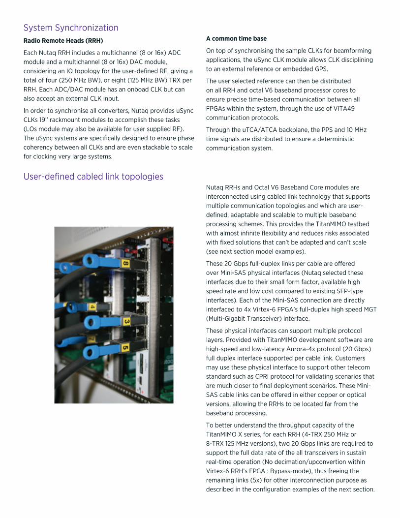
User-defined cabled link topologies
Nutaq RRHs and Octal V6 Baseband Core modules are interconnected using cabled link technology that supports multiple communication topologies and which are user-defined, adaptable and scalable to multiple baseband processing schemes. This provides the TitanMIMO testbed with almost infinite flexibility and reduces risks associated with fixed solutions that can’t be adapted and can’t scale (see next section model examples).
These 20 Gbps full-duplex links per cable are offered over Mini-SAS physical interfaces (Nutaq selected these interfaces due to their small form factor, available high speed rate and low cost compared to existing SFP-type interfaces). Each of the Mini-SAS connection are directly interfaced to 4x Virtex-6 FPGA’s full-duplex high speed MGT (Multi-Gigabit Transceiver) interface.
These physical interfaces can support multiple protocol layers. Provided with TitanMIMO development software are high-speed and low-latency Aurora-4x protocol (20 Gbps) full duplex interface supported per cable link. Customers may use these physical interface to support other telecom standard such as CPRI protocol for validating scenarios that are much closer to final deployment scenarios. These Mini-SAS cable links can be offered in either copper or optical versions, allowing the RRHs to be located far from the baseband processing.
To better understand the throughput capacity of the TitanMIMO X series, for each RRH (4-TRX 250 MHz or 8-TRX 125 MHz versions), two 20 Gbps links are required to support the full data rate of the all transceivers in sustain real-time operation (No decimation/upconvertion within Virtex-6 RRH’s FPGA : Bypass-mode), thus freeing the remaining links (5x) for other interconnection purpose as described in the configuration examples of the next section.
System SynchronizationRadio Remote Heads (RRH)
Each Nutaq RRH includes a multichannel (8 or 16x) ADC module and a multichannel (8 or 16x) DAC module, considering an IQ topology for the user-defined RF, giving a total of four (250 MHz BW), or eight (125 MHz BW) TRX per RRH. Each ADC/DAC module has an onboad CLK but can also accept an external CLK input.
In order to synchronise all converters, Nutaq provides uSync CLKs 19’’ rackmount modules to accomplish these tasks (LOs module may also be available for user supplied RF). The uSync systems are specifically designed to ensure phase coherency between all CLKs and are even stackable to scale for clocking very large systems.
A common time base
On top of synchronising the sample CLKs for beamforming applications, the uSync CLK module allows CLK disciplining to an external reference or embedded GPS.
The user selected reference can then be distributed on all RRH and octal V6 baseband processor cores to ensure precise time-based communication between all FPGAs within the system, through the use of VITA49 communication protocols.
Through the uTCA/ATCA backplane, the PPS and 10 MHz time signals are distributed to ensure a deterministic communication system.

Note: A low cost 32 transceiver (125MHz OTA BW) or 16 transceiver (250MHz OTA BW) testbed built combining 4x RRH and aggregating all channels to a master RRH for baseband processing.
Configuration Examples
TitanMIMO-XS 125MHz OTA 32 TRX (64 ADCs / 64 DACs)TitanMIMO-XS 250MHz OTA 16 TRX (32 ADCs / 32 DACs)
Note: A 64 transceiver (125MHz OTA BW) or 32 transceiver (250MHz OTA BW) testbed built combining 8x RRH and aggregating all channels to a master octal V6 baseband processing core.
TitanMIMO-XD 125MHz OTA 64 TRX (128 ADCs / 128 DACs)TitanMIMO-XD 250MHz OTA 32 TRX (64 ADCs / 64 DACs)
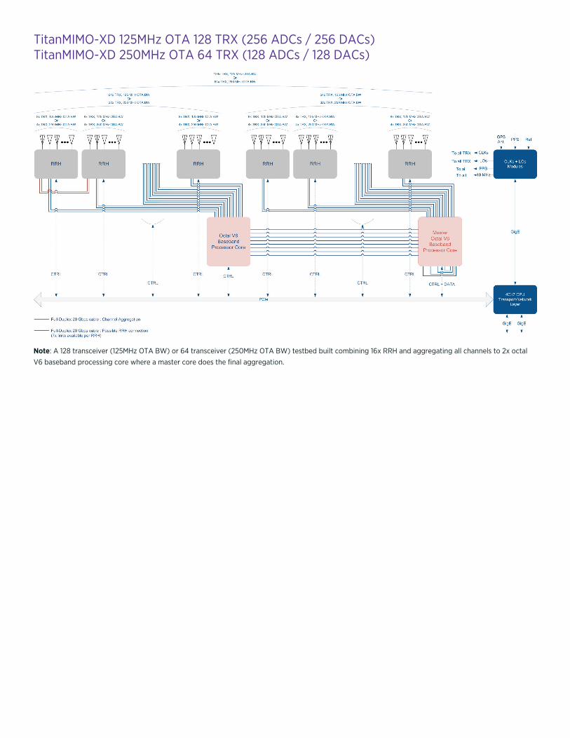
Note: A 128 transceiver (125MHz OTA BW) or 64 transceiver (250MHz OTA BW) testbed built combining 16x RRH and aggregating all channels to 2x octal V6 baseband processing core where a master core does the final aggregation.
TitanMIMO-XD 125MHz OTA 128 TRX (256 ADCs / 256 DACs)TitanMIMO-XD 250MHz OTA 64 TRX (128 ADCs / 128 DACs)
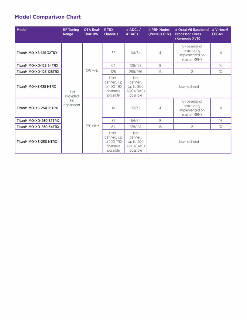
Model Comparison Chart
Model RF Tuning Range
OTA Real-Time BW
# TRX Channels
# ADCs /# DACs
# RRH Nodes (Perseus 611x)
# Octal V6 Baseband Processor Cores (Kermode XV6)
# Virtex-6 FPGAs
TitanMIMO-XS-125 32TRX
User Provided
FE dependent
125 MHz
32 64/64 4
0 (baseband processing
implemented on master RRH)
4
TitanMIMO-XD-125 64TRX 64 128/128 8 1 16
TitanMIMO-XD-125 128TRX 128 256/256 16 2 32
TitanMIMO-XS-125 NTRX
User-defined. Up to 400 TRX
channels possible
User-defined.
Up to 800 ADCs/DACs
possible
User-defined
TitanMIMO-XS-250 16TRX
250 MHz
16 32/32 4
0 (baseband processing
implemented on master RRH)
4
TitanMIMO-XD-250 32TRX 32 64/64 8 1 16
TitanMIMO-XD-250 64TRX 64 128/128 16 2 32
TitanMIMO-XS-250 NTRX
User-defined. Up to 200 TRX
channels possible
User-defined.
Up to 400 ADCs/DACs
possible
User-defined
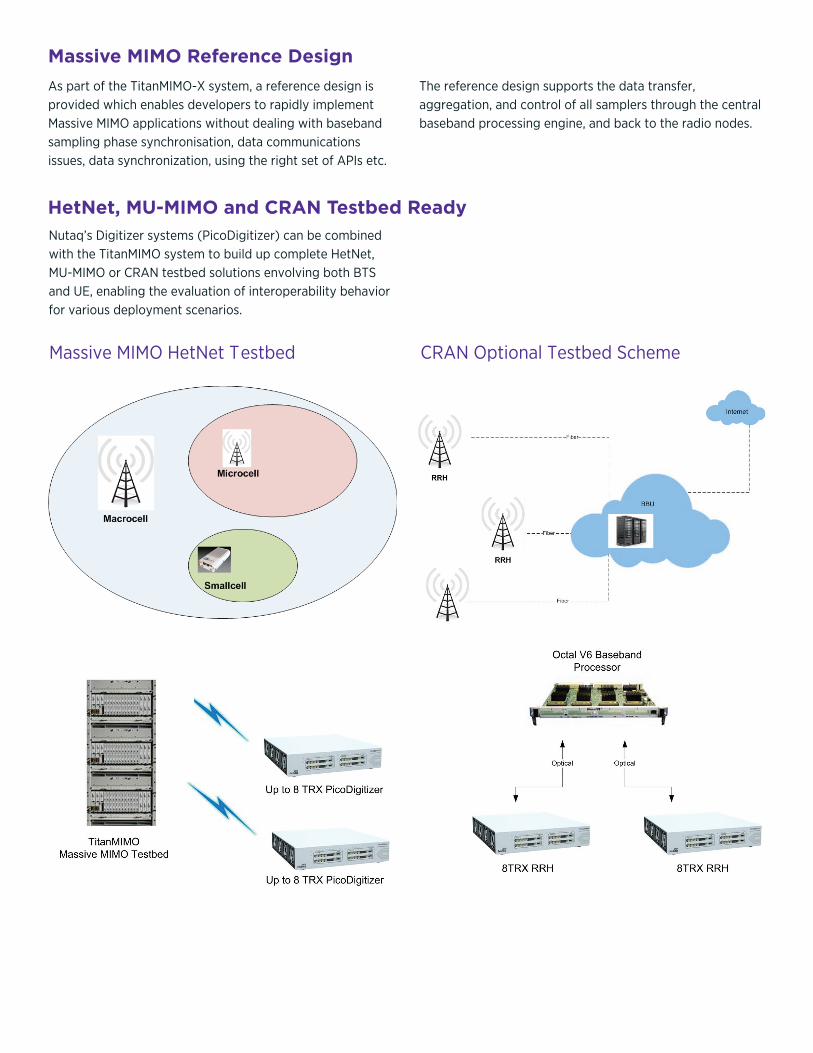
Massive MIMO Reference Design
As part of the TitanMIMO-X system, a reference design is provided which enables developers to rapidly implement Massive MIMO applications without dealing with baseband sampling phase synchronisation, data communications issues, data synchronization, using the right set of APIs etc.
The reference design supports the data transfer, aggregation, and control of all samplers through the central baseband processing engine, and back to the radio nodes.
HetNet, MU-MIMO and CRAN Testbed Ready
Nutaq’s Digitizer systems (PicoDigitizer) can be combined with the TitanMIMO system to build up complete HetNet, MU-MIMO or CRAN testbed solutions envolving both BTS and UE, enabling the evaluation of interoperability behavior for various deployment scenarios.
Massive MIMO HetNet T estbed CRAN Optional Testbed Scheme
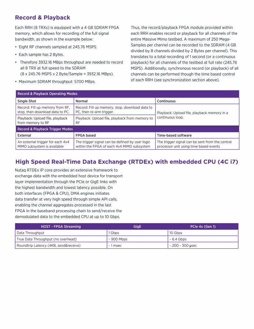
Record & Playback
Each RRH (8 TRXs) is equipped with a 4 GB SDRAM FPGA memory, which allows for recording of the full signal bandwidth, as shown in the example below:
• Eight RF channels sampled at 245.76 MSPS.
• Each sample has 2 Bytes.
• Therefore 3932.16 MBps throughput are needed to record all 8 TRX at full speed to the SDRAM (8 x 245.76 MSPS x 2 Byte/Sample = 3932.16 MBps).
• Maximum SDRAM throughput: 5700 MBps.
Thus, the record/playback FPGA module provided within each RRH enables record or playback for all channels of the entire Massive Mimo testbed. A maximum of 250 Mega-Samples per channel can be recorded to the SDRAM (4 GB divided by 8 channels divided by 2 Bytes per channel). This translates to a total recording of 1 second (or a continuous playback) for all channels of the testbed at full rate (245.76 MSPS). Additionally, synchronous record (or playback) of all channels can be performed though the time based control of each RRH (see synchronization section above).
Record & Playback Operating Modes
Single Shot Normal Continuous
Record: Fill up memory from RF, stop, then download data to PC.
Record: Fill up memory, stop, download data to PC, then re-arm trigger. Playback: Upload file, playback memory in a
continuous loop.Playback: Upload file, playback from memory to RF.
Playback: Upload file, playback from memory to RF
Record & Playback Trigger Modes
External FPGA based Time-based software
An external trigger for each 4x4 MIMO subsystem is available
The trigger signal can be defined by user logic within the FPGA of each 4x4 MIMO subsystem
The trigger signal can be sent from the central processor unit using time based events
High Speed Real-Time Data Exchange (RTDEx) with embedded CPU (4C i7)Nutaq RTDEx IP core provides an extensive framework to exchange data with the embedded host device for transport layer implementation through the PCIe or GigE links with the highest bandwidth and lowest latency possible. On both interfaces (FPGA & CPU), DMA engines initiates data transfer at very high speed through simple API calls, enabling the channel aggregates processed in the last FPGA in the baseband processing chain to send/receive the demodulated data to the embedded CPU at up to 10 Gbps.
HOST - FPGA Streaming GigE PCIe 4x (Gen 1)
Data Throughput 1 Gbps 10 Gbps
True Data Throughput (no overhead) ~ 900 Mbps ~ 6.4 Gbps
Roundtrip Latency (4KB, send&receive) ~ 1 msec ~ 200 - 300 µsec
TitanMIMO-XS TitanMIMO-XD
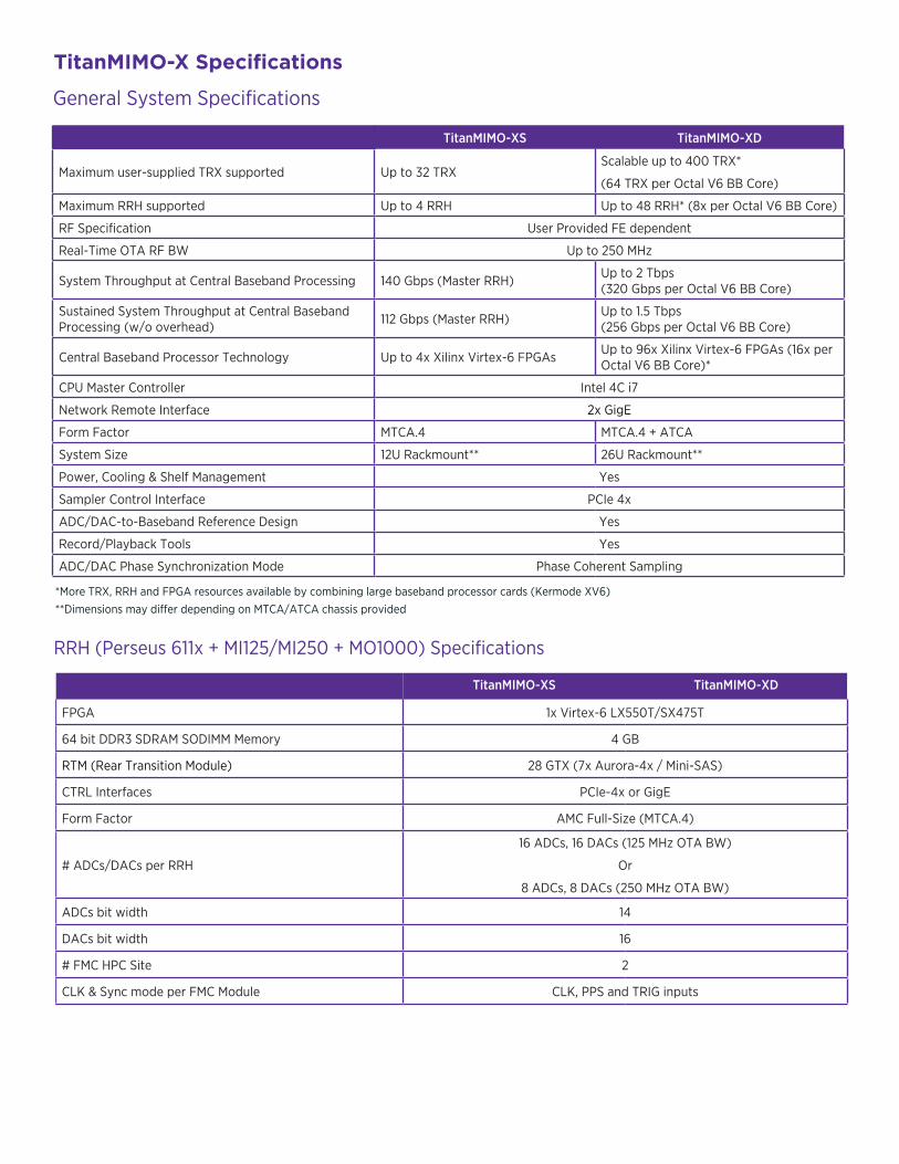
Maximum user-supplied TRX supported Up to 32 TRXScalable up to 400 TRX*
(64 TRX per Octal V6 BB Core)
Maximum RRH supported Up to 4 RRH Up to 48 RRH* (8x per Octal V6 BB Core)
RF Specification User Provided FE dependent
Real-Time OTA RF BW Up to 250 MHz
System Throughput at Central Baseband Processing 140 Gbps (Master RRH) Up to 2 Tbps (320 Gbps per Octal V6 BB Core)
Sustained System Throughput at Central Baseband Processing (w/o overhead) 112 Gbps (Master RRH) Up to 1.5 Tbps
(256 Gbps per Octal V6 BB Core)
Central Baseband Processor Technology Up to 4x Xilinx Virtex-6 FPGAs Up to 96x Xilinx Virtex-6 FPGAs (16x per Octal V6 BB Core)*
CPU Master Controller Intel 4C i7
Network Remote Interface 2x GigE
Form Factor MTCA.4 MTCA.4 + ATCA
System Size 12U Rackmount** 26U Rackmount**
Power, Cooling & Shelf Management Yes
Sampler Control Interface PCIe 4x
ADC/DAC-to-Baseband Reference Design Yes
Record/Playback Tools Yes
ADC/DAC Phase Synchronization Mode Phase Coherent Sampling
General System Specifications
TitanMIMO-X Specifications
*More TRX, RRH and FPGA resources available by combining large baseband processor cards (Kermode XV6) **Dimensions may differ depending on MTCA/ATCA chassis provided
RRH (Perseus 611x + MI125/MI250 + MO1000) Specifications
TitanMIMO-XS TitanMIMO-XD
FPGA 1x Virtex-6 LX550T/SX475T
64 bit DDR3 SDRAM SODIMM Memory 4 GB
RTM (Rear Transition Module) 28 GTX (7x Aurora-4x / Mini-SAS)
CTRL Interfaces PCIe-4x or GigE
Form Factor AMC Full-Size (MTCA.4)
# ADCs/DACs per RRH
16 ADCs, 16 DACs (125 MHz OTA BW)
Or
8 ADCs, 8 DACs (250 MHz OTA BW)
ADCs bit width 14
DACs bit width 16
# FMC HPC Site 2
CLK & Sync mode per FMC Module CLK, PPS and TRIG inputs
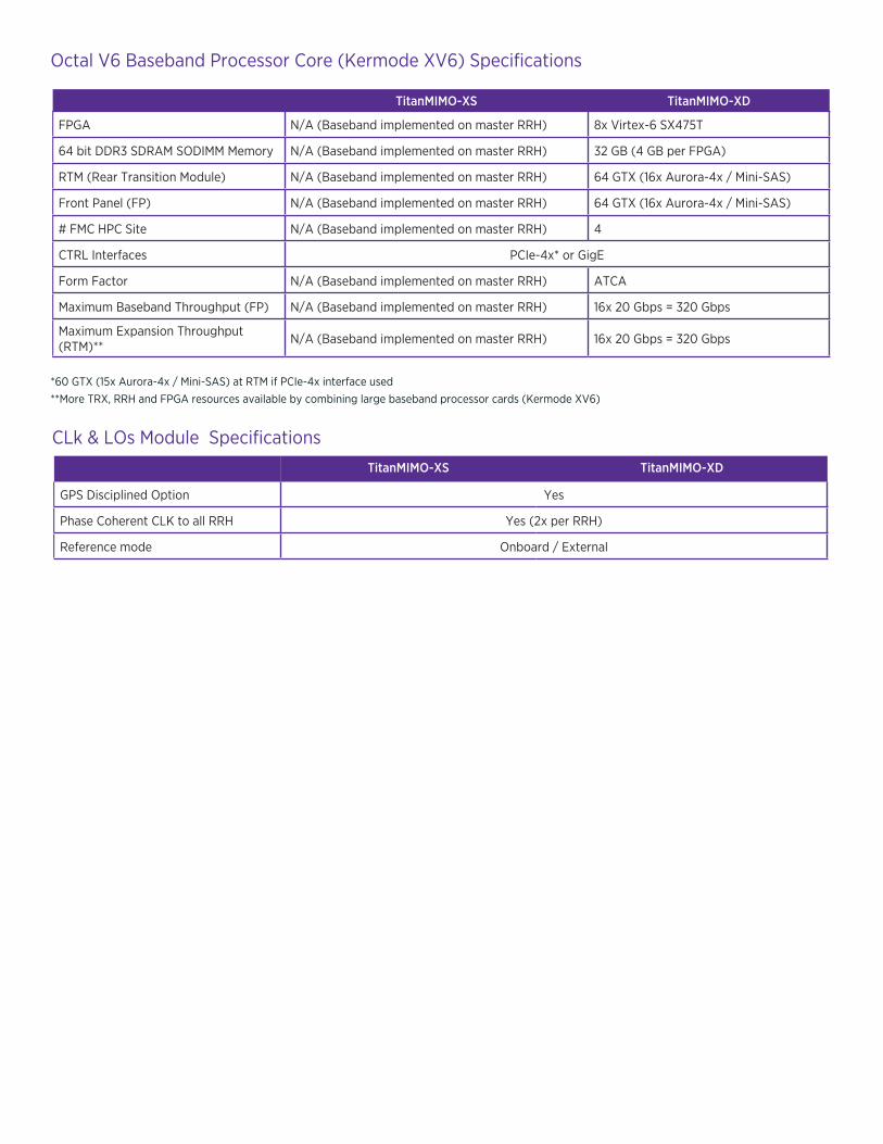
TitanMIMO-XS TitanMIMO-XD
FPGA N/A (Baseband implemented on master RRH) 8x Virtex-6 SX475T
64 bit DDR3 SDRAM SODIMM Memory N/A (Baseband implemented on master RRH) 32 GB (4 GB per FPGA)
RTM (Rear Transition Module) N/A (Baseband implemented on master RRH) 64 GTX (16x Aurora-4x / Mini-SAS)
Front Panel (FP) N/A (Baseband implemented on master RRH) 64 GTX (16x Aurora-4x / Mini-SAS)
# FMC HPC Site N/A (Baseband implemented on master RRH) 4
CTRL Interfaces PCIe-4x* or GigE
Form Factor N/A (Baseband implemented on master RRH) ATCA
Maximum Baseband Throughput (FP) N/A (Baseband implemented on master RRH) 16x 20 Gbps = 320 Gbps
Maximum Expansion Throughput (RTM)** N/A (Baseband implemented on master RRH) 16x 20 Gbps = 320 Gbps
Octal V6 Baseband Processor Core (Kermode XV6) Specifications
TitanMIMO-XS TitanMIMO-XD
GPS Disciplined Option Yes
Phase Coherent CLK to all RRH Yes (2x per RRH)
Reference mode Onboard / External
*60 GTX (15x Aurora-4x / Mini-SAS) at RTM if PCIe-4x interface used **More TRX, RRH and FPGA resources available by combining large baseband processor cards (Kermode XV6)
CLk & LOs Module Specifications
2150 Cyrille-Duquet, Quebec City (Quebec) G1N 2G3 CANADA T. 418-914-7484 | 1-855-914-7484 | F. [email protected] Website: www.nutaq.com
NU
TAQ
INC
. ALL
RIG
HTS
RES
ERV
ED •
DO
C-0
00
0X
X V
1.0 —
09/
22/2
014
Nutaq products are constantly being improved; therefore, Nutaq reserves the right to modify the information herein at any time and without notice. The FMC logo is a trademark of VITA.