Embed Size (px)
Citation preview
ASSEMBLY AND ADJUSTMENT
TITAN2-EDGEModel TITAN2-EDGEPublic Access Computer Station – Dual Track
TITAN2-EDGE Rev A 6/17

2
PLEASE REVIEW these instructions before beginning the assembly and adjustment procedures. Check that all the parts and tools listed below were provided with your order. Contact your supplier if any materials are missing. Do not discard the packaging until satisfied that the product operates to your satisfaction.
TITAN2-EDGE PARTS AND TOOLS
Track (2) Small Cover (2)Slider Plate (2) Large Cover (2)
Socket Head Screw (8)
5/16x18x1/2
Slider Bolt (2) Expansion Bolts (4 each)
PARTS AND TOOLS PROVIDEDTRACK ASSEMBLY
CAUTION: Hand-tighten screws only.
MONITOR ARM ASSEMBLY
KEYBOARD ARM ASSEMBLY
Monitor Arm with Slider Plate (1) 4mm Allen Key (1)2mm Allen Key (1) 5mm Allen Key (1)
Set Screw (1)VESA Locking Screw (1)Hex Head Screw (4)
Keyboard Arm (1) Long Cord Clip (1)Mounting Plate (1) Short Cord Clip (1)
5mm Allen Key (1)4mm Allen Key (1)Flat Head Screw (4)Hex Head Screw (8) 13mm Wrench (1)
M4x10
M4x10 M3x6
M4x4M4x10

3
PARTS AND TOOLS TITAN2-EDGE
ADDITIONAL TOOLS REQUIRED
• Phillips screwdriver
• 6mm Allen key
• Power drill with assorted bits.
CAUTION: Hand-tighten screws on keyboard tray dn palm rest only.
Keyboard Platform (1) Palm Rest (1) Cord Clip (2)
Panhead Screw (2)Flange Nut (4)
Bottom Bracket (1)
Flathead Screw (4)
#8-32x1/2 #8x32 #8-32x5/8
KEYBOARD PLATFORM ASSEMBLY
CPU HOLDER ASSEMBLYCPU Holder (1) Large Foam Pad (4) Small Foam Pad (1 Set)
Knob (1) Spacer (1) Washer (4)

4
TITAN2-EDGE ASSEMBLY
Attach Top Track to Wall
Determine Fasteners• In most installations, wood screws mounted into studs are the best fastening option. Expansion bolts are
provided for attaching the track to concrete or brick walls, but these are not the best choice because the nut-type expansion bolts may interfere with the positioning of track components. Here is a summary of fastener choices:
— Wood: Use #12 wood screws mounted into studs. (Not included)
— Metal: Use #12 self-tapping screws. (Not included)
— Drywall (not recommended): Use toggle bolts. (Not included)
— Concrete or brick: Use expansion bolts (hex-head, sleeve-type recommended).
CAUTION: Whichever fasteners you use, do not over-torque the screws or bolts. Over-torquing may bend the track.
Position Top Track•
steps in these instructions are followed, this will put the keyboard at a height of about 42".
• The 15 holes along the side of the track must be on the right.
• Use a level to ensure that the track is plumb.
• Mark the location of the four center holes along the track.
Attach Top Track• Drill the correct diameter pilot holes at the marked locations.
• Attach the track using the appropriate four fasteners. Double-check that the track is plumb.
Attach Monitor to Track
Install Set Screw•
• swivels. The screw may be adjusted now or at any time after installation.
72"AboveFloor
TopTrack
2mmAllen Key
M4x4mmSet Screw
Right-HandedSide Holes
5
ASSEMBLY TITAN2-EDGE
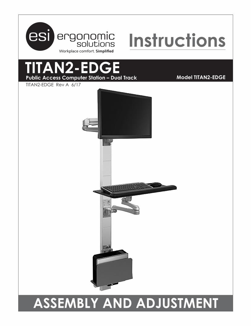
Attach Monitor Arm• Slide the base of the monitor arm onto the top of the track.
• Align the scribed line on the monitor base with the line on the track.
• Secure the monitor arm in position by tightening the slider bolt on the base.
Remove VESA Plate• Remove the VESA plate from the VESA mount by pressing
down on the plastic tab to release the lock and pulling the plate upward to remove the plate.
Attach VESA Plate to Monitor•
• Attach the VESA plate using the four VESA plate screws provided.
— There are two sets of four holes on each VESA plate. One set has holes 3.9" (100mm) apart, the other set has holes 3" (75mm) apart. Use the set that matches the holes on the monitor.
Tighten
Align
Align Here
VESAPlate
1.2.
VESAPlateScrew VESA Plate
3.9"(100mm)
3"(75mm)
Monitor(Face Down)
Upward
Plave the LCD monitor face down on a clean, soft, flat surface. Align the VESA plate holes with the holes on the back of the monitor.

6
TITAN2-EDGE ASSEMBLY
Attach Monitor to VESA Mount• Slide the VESA plate with monitor attached onto the VESA mount. Make sure the VESA plate clicks
securely in place.
— Optional: Install the VESA locking screw behind the VESA plate to prevent the tab on the VESA plate from releasing the monitor.
Organize Monitor Cables
Use Cable Clip and Cable Cover• Pinch the cable clip to remove it from the motion
arm and again when re-installing it with the cables captured.
• back in with the cables captured.
VESALockingScrew
(Optional)
MotionArm
Cable Cover
CableClip
FixedArm
Front View
Rear View
7
ASSEMBLY TITAN2-EDGE
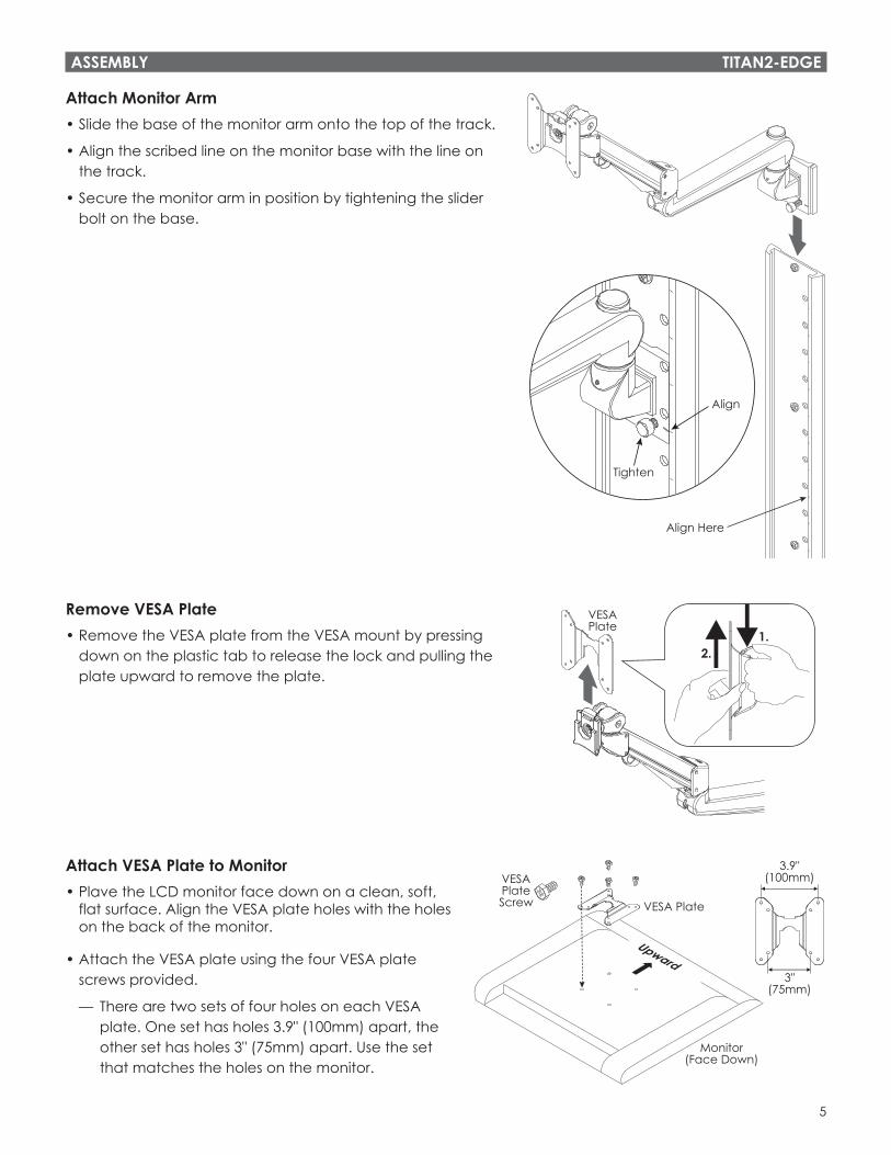
Attach Bottom Track to Wall• Abut the bottom track to the top track. As with the top track, be sure the 15
holes along the side of the track are on the right.
• After using a level to make sure that the track is plumb, mark the location of the four center holes.
• Drill the correct diameter pilot holes at the marked locations.
• Attach the track using the appropriate four fasteners. Check again that both the top and bottom tracks are plumb.
Install Top Track Covers• Insert one of the large track covers into the top of the track, with the
U-shaped opening at the bottom.
— Align the top of the cover with the top of the track.
• Insert the other large track cover into the bottom of the track, with the U-shaped opening at the top.
— Ensure the monitor cables are behind the track cover during install.
U-ShapeDown
U-ShapeUp
MonitorCables
BottomTrack

8
KeyboardArmMounting
Plate
Socket HeadScrew
Hex HeadScrew
TITAN2-EDGE ASSEMBLY
Install First Slider Plate• Insert the slider plate into the bottom of the track. As with the large track
cover above it, capture the monitor cables under the slider plate.
• Align the scribed line on the slider plate with the 4th scribe on the track.
• Secure the slider plate with the slider bolt.
NOTE: The slider plate may be installed with the scribed lines and slider bolt at the top or bottom, depending on which works best for the installation. In this diagram scribed lines are at the bottom.
Install Small Track Covers• Insert the small track covers into the bottom of the track, capturing the
monitor cables as you install them.
Install Second Slider Plate• Insert the second slider plate into the bottom of
the track, again capturing the monitor cables.
• Align the scribed line on the slider plate with the 4th scribe from the bottom.
• Secure the slider plate with the slider bolt.
Attach Keyboard Platform to Track
Install Keyboard Arm•
Tighten the screws securely using a 6mm Allen key. Hand tighten only.
Attach Keyboard Platform Mounting Plate• Attach the mounting plate to the keyboard arm using four M4x10 hex
head screws.
— Note that only the mounting plate is threaded. The screws must be installed from the keyboard arm side, as shown.
SliderPlate
SliderBolt
Align with4th Scribe
SmallTrack
Covers
SliderBolt
Align with4th Scribe
fromBottom
IMPORTANT: The second slider plate must be installed with the scribed lines and slider bolt at the top in order to install the CPU holder (see page 10).

9
M3x6
ASSEMBLY TITAN2-EDGE
Attach Keyboard Arm Cord Clips•
head screws. Hand tighten only.
Attach Palm Rest to Keyboard Platform• Attach the palm rest with the two #8-32x5/8 panhead
screws and a Phillips screwdriver. Hand tighten only.
Attach Keyboard Platform• Rotate the keyboard platform mounting plate upwards to mount
the keyboard platform.
— Remove the cover and loosen the nut with the provided wrench if necessary. Then tighten the nut and replace the cover.
• Attach the keyboard platform to the mounting plate using the four
IMPORTANT: to ensure the nuts are locked.
• Position the keyboard and mouse on the platform and route the cords through the keyboard arm cord clips.
Remove Cover
Rotate
Adjust Nut with Wrench
#8-32x5/8Panhead
#8-32x1/2Flathead
#8x32Flange Nut
The flange nuts must be snugly tightened
10
TITAN2-EDGE ASSEMBLY / ADJUSTMENT
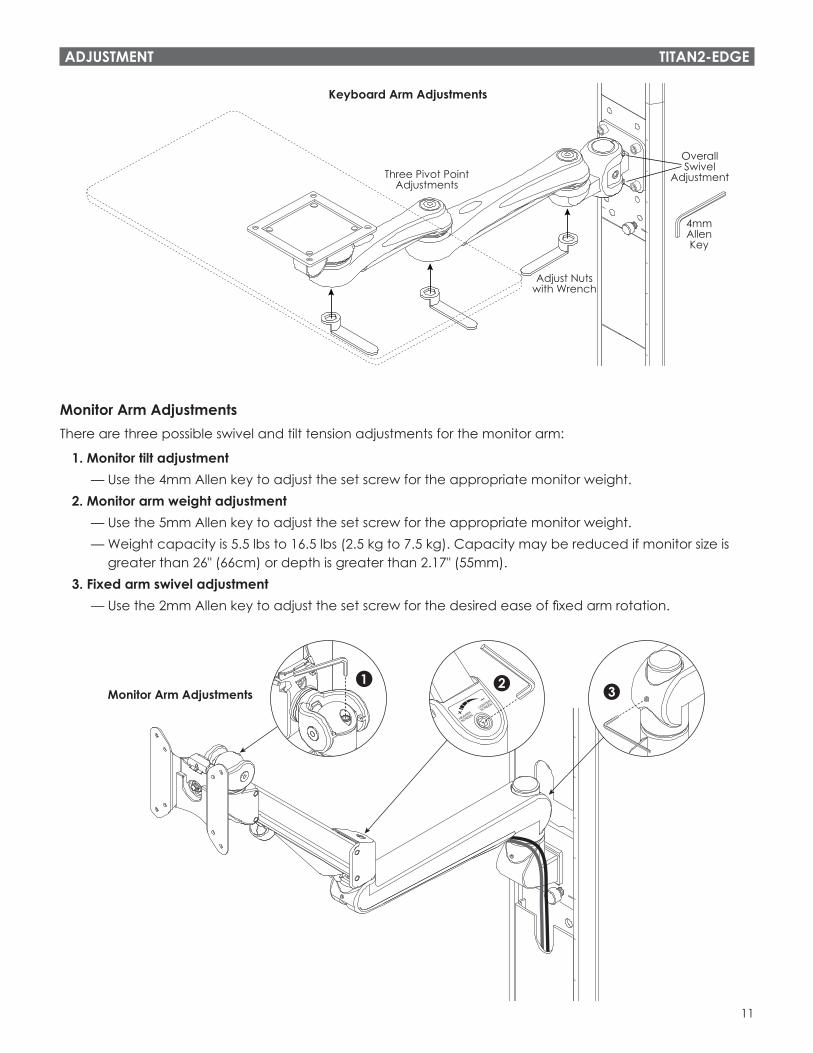
Make Any Necessary AdjustmentsIn addition to the keyboard platform rotation adjustment just described, there are several other adjustments that can be made to the keyboard arm (see illustration on following page).
Keyboard Arm Swivel AdjustmentsEach individual arm segment swivels for maximum adjustability.
• If any swivel point is too loose or too tight, the nut on the underside of the pivot point may be loosened or tightened with the provided wrench.
Overall Keyboard Arm Swivel AdjustmentThere is also an overall keyboard arm swivel adjustment near where the keyboard arm is attached to the track, as shown in the illustration.
• To make this adjustment, loosen the two socket head screws using the 4mm Allen key.
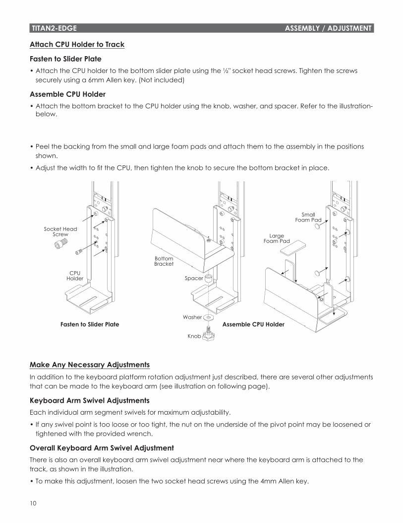
Attach CPU Holder to Track
Fasten to Slider Plate• Attach the CPU holder to the bottom slider plate using the ½" socket head screws. Tighten the screws
securely using a 6mm Allen key. (Not included)
Assemble CPU Holder• Attach the bottom bracket to the CPU holder using the knob, washer, and spacer. Refer to the illustration-
below.
• Peel the backing from the small and large foam pads and attach them to the assembly in the positions shown.
•
Socket HeadScrew
BottomBracket
LargeFoam Pad
SmallFoam Pad
CPUHolder Spacer
Washer
Knob
Fasten to Slider Plate Assemble CPU Holder
11
OverallSwivel
Adjustment
4mmAllenKey
Three Pivot PointAdjustments
Adjust Nutswith Wrench
Keyboard Arm Adjustments
ADJUSTMENT TITAN2-EDGE
Monitor Arm AdjustmentsThere are three possible swivel and tilt tension adjustments for the monitor arm:
1. Monitor tilt adjustment — Use the 4mm Allen key to adjust the set screw for the appropriate monitor weight.2. Monitor arm weight adjustment — Use the 5mm Allen key to adjust the set screw for the appropriate monitor weight. — Weight capacity is 5.5 lbs to 16.5 lbs (2.5 kg to 7.5 kg). Capacity may be reduced if monitor size is
greater than 26" (66cm) or depth is greater than 2.17" (55mm).3. Fixed arm swivel adjustment — Use the 2mm Allen key to adjust the set screw for the desired ease of fixed arm rotation.
Monitor Arm Adjustments1 2 3

800.833.3746 esiergo.com
© 2017 ESI Ergonomic Solutions. All rights reserved. TITAN2-EDGE Rev A 6/17
ADJUSTMENT TITAN2-EDGE
Allen Key Storage• Insert the Allen keys into the holes behind the VESA plate to store for
future adjustment.
— Insert the two smaller Allen keys into the same hole.
StoreAllen Keysfor Future
Adjustments