Embed Size (px)
Citation preview
Before you begin, make sure your sample...
1. is seeded on #1.5 coverglass (thickness = 0.17)
2. is an aqueous solution (ie. fixed samples mounted on a slide will not work - not enough difference in refractive index of the glass and mounting solution for total internal reflection of the laser to occur)
3. are adherent cells (ie. cells in suspension are too far away from the coverslip)
4. has a fluorescent marker on the surface of the cell in order to focus on the sample. The adjacent to the coverslip will be used as a reference to focus on the coverslip (cannot focus or align the laser if there is no fluorescent markers at the coverslip interface)
This training manual was adapted from the guide found at:
http://www.bris.ac.uk/biochemistry/mrccif/tirfguide.pdf
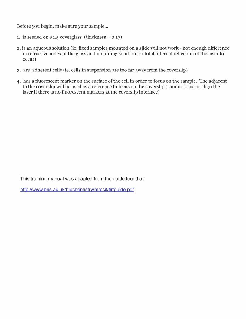
Basic Concepts of Total Internal Reflection
Refractive Index:
Refraction of Light:
A measure in the reduction of the speed of light inside the a medium (compared to the speed of light in a vacuum)
· the bending or change in direction of light as it travels from one medium into another with different refractive indexes
· refraction of light only occurs when the incident light meets the interface at an angle
· light will travel straight through with no change of direction when crossing perpendicular to the interface
· the degree of refraction increases as the angle of the incident light increases
Total Internal Reflection Fluorescence Microscopy
Total Internal Reflection Fluorescence Microscopy (TIRF) is...
TIRF microscopy is a specialized fluorescence technique that images a very thin optical section (50-250nm) adjacent to the coverslip. TIRF microscopy is used to study molecular events at or near the cell surface with speeds and resolution that is not possible with other imaging techniques by using conditions that create total internal reflection that generates an evanescent wave.
Vacuum 1.00Air 1.003
Water 1.33Glass 1.52-1.54
Interface
Aqueous
Solution
(RI=1.33)
Glass
(RI=1.52)
Incident
light
Refraction
Angle
Normal
refraction
incident
angle
90°
Critical
Angle
Total Internal
Reflection
Critical Angle:
Total Internal Reflection:
the angle of the incident light where the refraction angle is 90°
· occurs when the incident angle is greater than the critical angle· Majority of the light is reflected
Basic Concepts of Total Internal Reflection Continued...
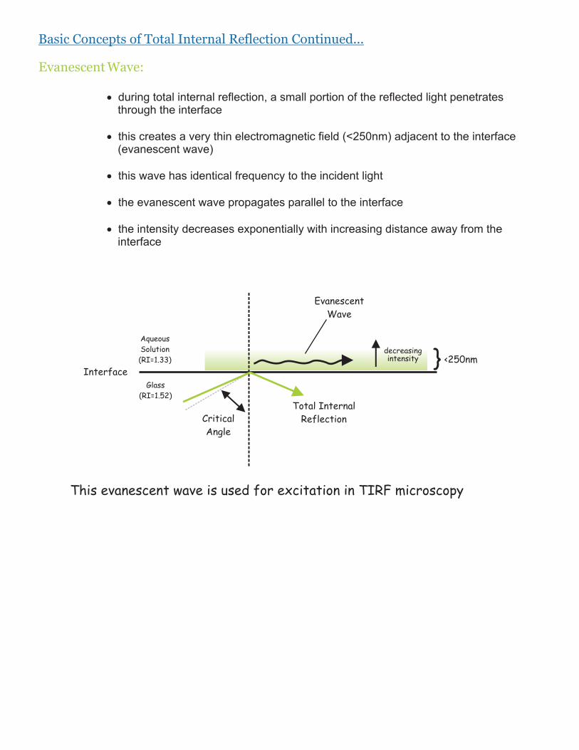
Evanescent Wave:
· during total internal reflection, a small portion of the reflected light penetrates through the interface
· this creates a very thin electromagnetic field (<250nm) adjacent to the interface (evanescent wave)
· this wave has identical frequency to the incident light
· the evanescent wave propagates parallel to the interface
· the intensity decreases exponentially with increasing distance away from the interface
Interface
Aqueous
Solution
(RI=1.33)
Glass
(RI=1.52)
Critical
Angle
Total Internal
Reflection
Evanescent
Wave
} <250nmdecreasingintensity
This evanescent wave is used for excitation in TIRF microscopy
3. Total Internal Reflection Fluorescence Microscopy
For TIRF microscopy...
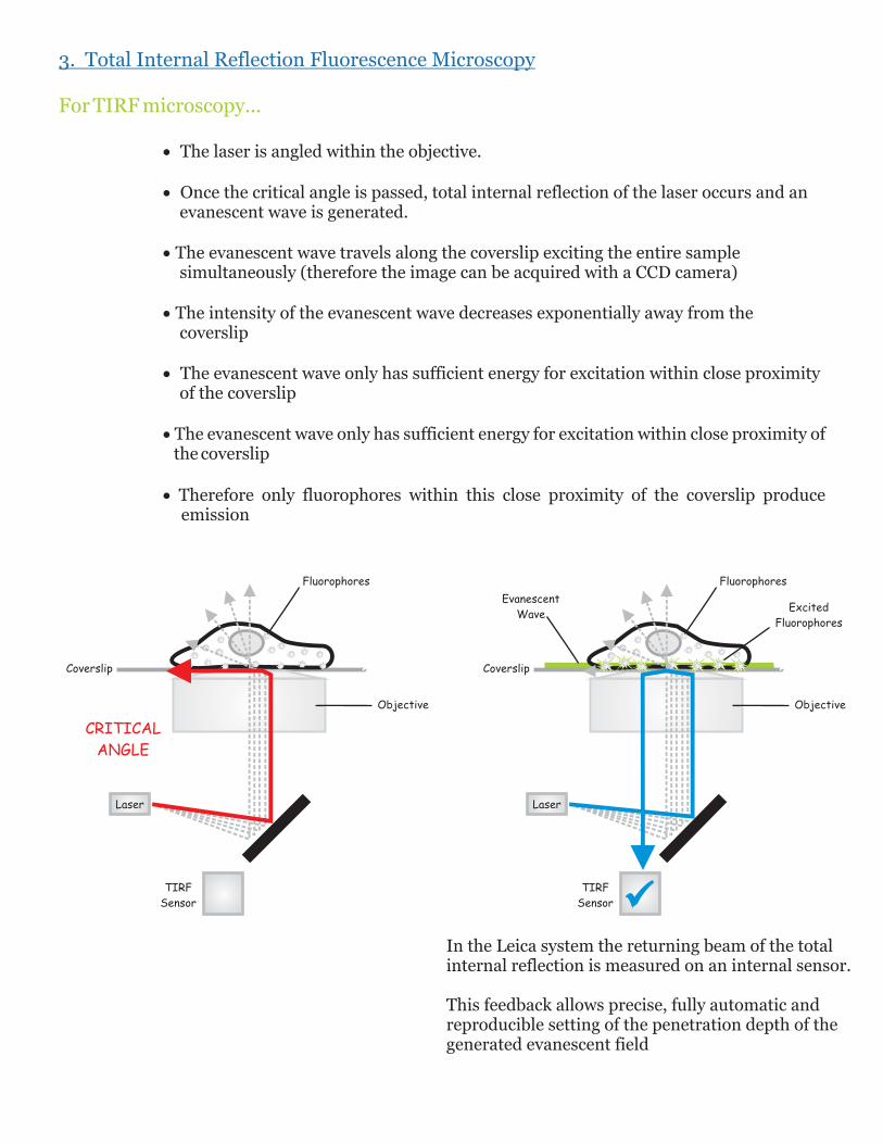
· The laser is angled within the objective.
· Once the critical angle is passed, total internal reflection of the laser occurs and an evanescent wave is generated.
· The evanescent wave travels along the coverslip exciting the entire sample simultaneously (therefore the image can be acquired with a CCD camera)
· The intensity of the evanescent wave decreases exponentially away from the coverslip
· The evanescent wave only has sufficient energy for excitation within close proximity of the coverslip
· The evanescent wave only has sufficient energy for excitation within close proximity of the coverslip
· Therefore only fluorophores within this close proximity of the coverslip produce emission
Coverslip
Fluorophores
Evanescent
WaveExcited
Fluorophores
Laser
TIRF
Sensor
Objective
Coverslip
Fluorophores
Objective
CRITICAL
ANGLE
Laser
TIRF
Sensor
In the Leica system the returning beam of the total internal reflection is measured on an internal sensor.
This feedback allows precise, fully automatic and reproducible setting of the penetration depth of the generated evanescent field
3. Total Internal Reflection Fluorescence Microscopy continued...
Resolution:
TIRF microscopy is a tool to study the molecular events at or near the cell surface at a speed and resolution that is not possible with other imaging techniques.
More specifically, TIRF microscopy is used to image at or within close proximity...
· distribution · colocalization· trafficking (movement in the membrane, endocytosis, exocytosis, etc.)· changes in the above in response to various stimuli
· Fast image acquisition (up to 30 frames/sec) - the image is capture using a CCD camera since the evanescent wave propagates along the coverslip exciting the entire sample simultaneously
· Very thin optical section (50-250nm) adjacent to the coverslip
· Decrease signal-to-noise (increase contrast)
· Resolution MAY be improved with TIRF microscopy compared to confocal microscopy
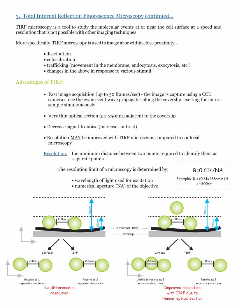
the minimum distance between two points required to identify them as separate points
The resolution limit of a microscopy is determined by:
· wavelength of light used for excitation· numerical aperture (NA) of the objective
Advantages of TIRF:
200nm
70
0nm
25
0nm
x
z
Confocal TIRF
200nm 200nm
x
y
Resolve as 2
separate structures
Resolve as 2
separate structures
200nm
70
0nm
25
0nm
coverslip
membrane(~10nm)
Confocal TIRF
200nm 200nm
Unable to resolve as 2
separate structures
Resolve as 2
separate structures
x
y
No difference in
resolution
Improved resolution
with TIRF due to
thinner optical section
R=0.61l/NA
Example: R = (0.61x488nm)/1.4
= ~200nm
Coverslip
Laser
Evanescent
Wave
FluorophoresExcited
Fluorophores
TIRF
Sensor
TIRF
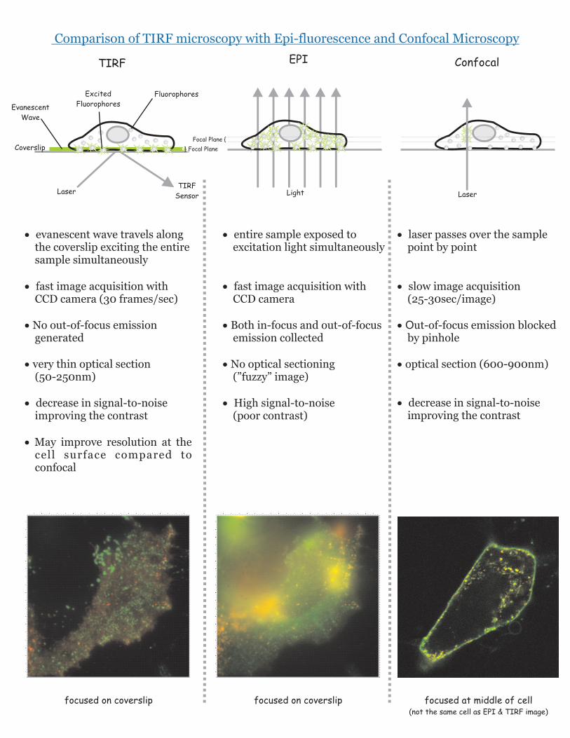
· evanescent wave travels along the coverslip exciting the entire sample simultaneously
· fast image acquisition with CCD camera (30 frames/sec)
· No out-of-focus emission generated
· very thin optical section (50-250nm)
· decrease in signal-to-noise improving the contrast
· May improve resolution at the cell surface compared to confocal
Light
EPI
· entire sample exposed to excitation light simultaneously
· fast image acquisition with CCD camera
· Both in-focus and out-of-focus emission collected
· No optical sectioning (”fuzzy” image)
· High signal-to-noise (poor contrast)
Laser
Focal Plane {
Confocal
· laser passes over the sample point by point
· slow image acquisition (25-30sec/image)
· Out-of-focus emission blocked by pinhole
· optical section (600-900nm)
· decrease in signal-to-noise improving the contrast
Comparison of TIRF microscopy with Epi-fluorescence and Confocal Microscopy
} Focal Plane
focused on coverslip focused on coverslip focused at middle of cell(not the same cell as EPI & TIRF image)
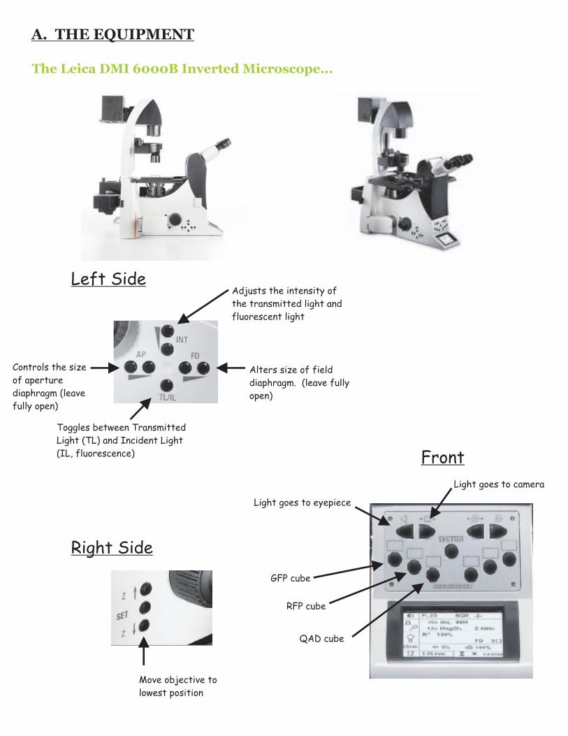
A. THE EQUIPMENT
The Leica DMI 6000B Inverted Microscope...
Toggles between Transmitted
Light (TL) and Incident Light
(IL, fluorescence)
Alters size of field
diaphragm. (leave fully
open)
Adjusts the intensity of
the transmitted light and
fluorescent light
Controls the size
of aperture
diaphragm (leave
fully open)
GFP cube
QAD cube
Light goes to camera
Light goes to eyepiece
RFP cube
Left Side
Front
Right Side
Move objective to
lowest position
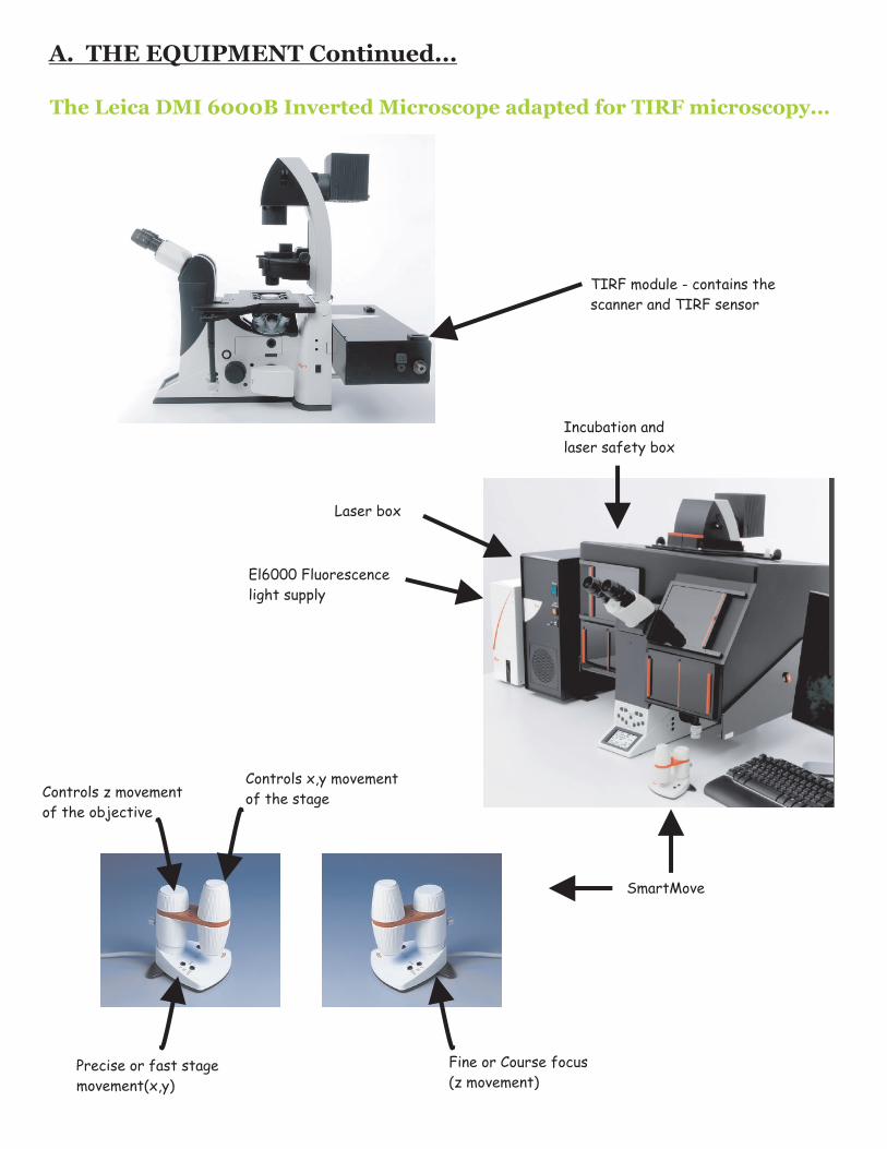
TIRF module - contains the
scanner and TIRF sensor
El6000 Fluorescence
light supply
Laser box
Incubation and
laser safety box
SmartMove
Controls z movement
of the objective
Controls x,y movement
of the stage
Precise or fast stage
movement(x,y)
Fine or Course focus
(z movement)
The Leica DMI 6000B Inverted Microscope adapted for TIRF microscopy...
A. THE EQUIPMENT Continued...
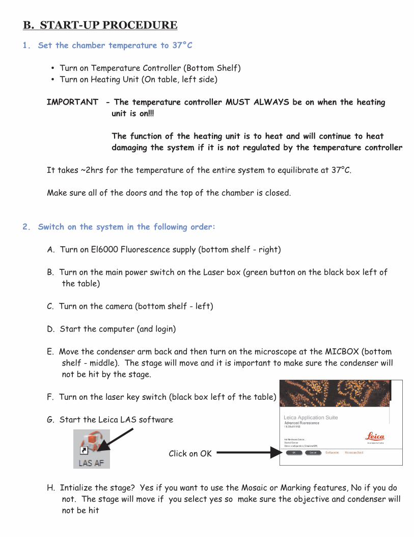
1. Set the chamber temperature to 37°C
2. Switch on the system in the following order:
? Turn on Temperature Controller (Bottom Shelf)
? Turn on Heating Unit (On table, left side)
IMPORTANT - The temperature controller MUST ALWAYS be on when the heating
unit is on!!!
The function of the heating unit is to heat and will continue to heat
damaging the system if it is not regulated by the temperature controller
It takes ~2hrs for the temperature of the entire system to equilibrate at 37°C.
Make sure all of the doors and the top of the chamber is closed.
A. Turn on El6000 Fluorescence supply (bottom shelf - right)
B. Turn on the main power switch on the Laser box (green button on the black box left of
the table)
C. Turn on the camera (bottom shelf - left)
D. Start the computer (and login)
E. Move the condenser arm back and then turn on the microscope at the MICBOX (bottom
shelf - middle). The stage will move and it is important to make sure the condenser will
not be hit by the stage.
F. Turn on the laser key switch (black box left of the table)
G. Start the Leica LAS software
Click on OK
H. Intialize the stage? Yes if you want to use the Mosaic or Marking features, No if you do
not. The stage will move if you select yes so make sure the objective and condenser will
not be hit
B. START-UP PROCEDURE
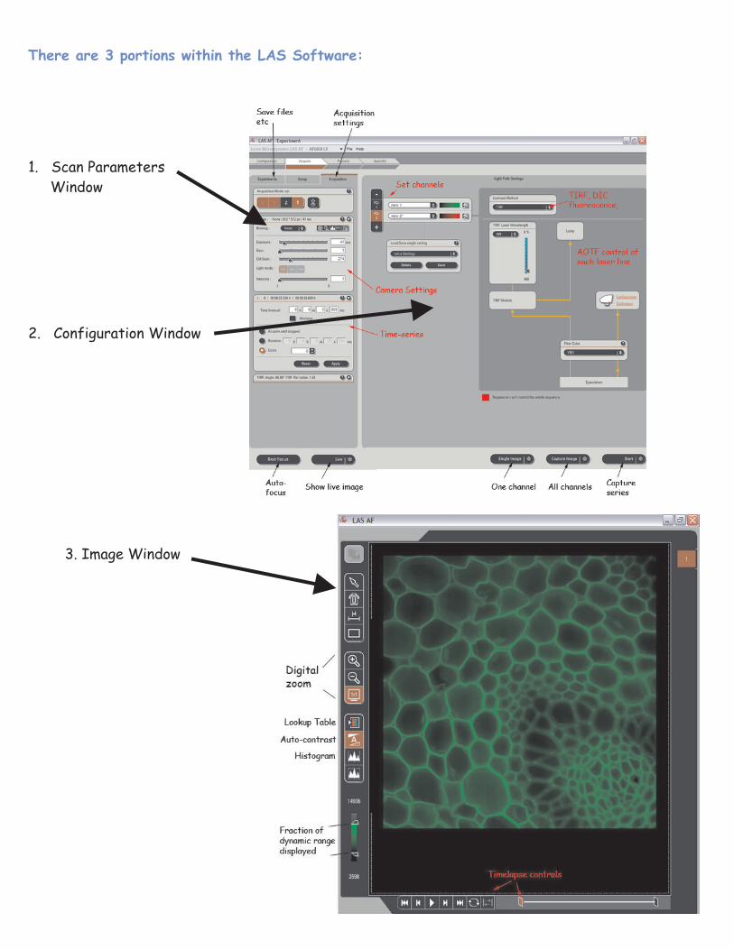
There are 3 portions within the LAS Software:
1. Scan Parameters
Window
2. Configuration Window
3. Image Window
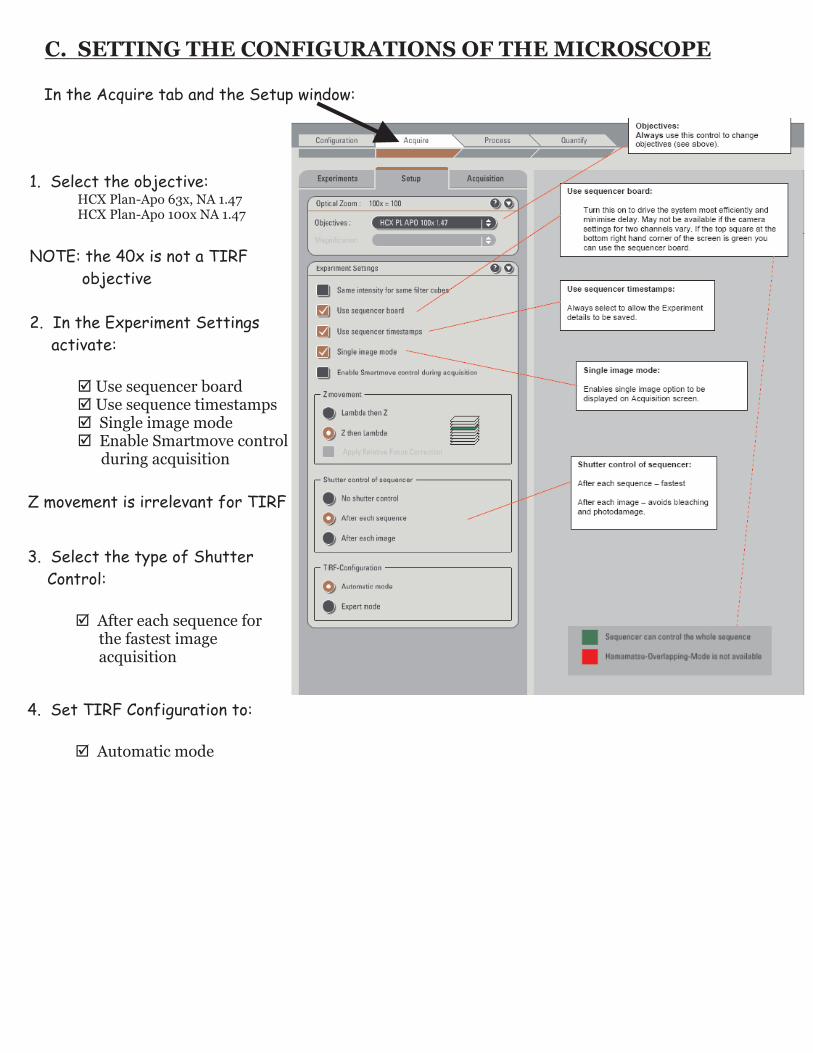
C. SETTING THE CONFIGURATIONS OF THE MICROSCOPE
In the Acquire tab and the Setup window:
1. Select the objective:HCX Plan-Apo 63x, NA 1.47HCX Plan-Apo 100x NA 1.47
NOTE: the 40x is not a TIRF
objective
2. In the Experiment Settings
activate:
þ Use sequencer boardþ Use sequence timestampsþ Single image modeþ Enable Smartmove control
during acquisition
Z movement is irrelevant for TIRF
3. Select the type of Shutter
Control:
þ After each sequence for the fastest image acquisition
4. Set TIRF Configuration to:
þ Automatic mode
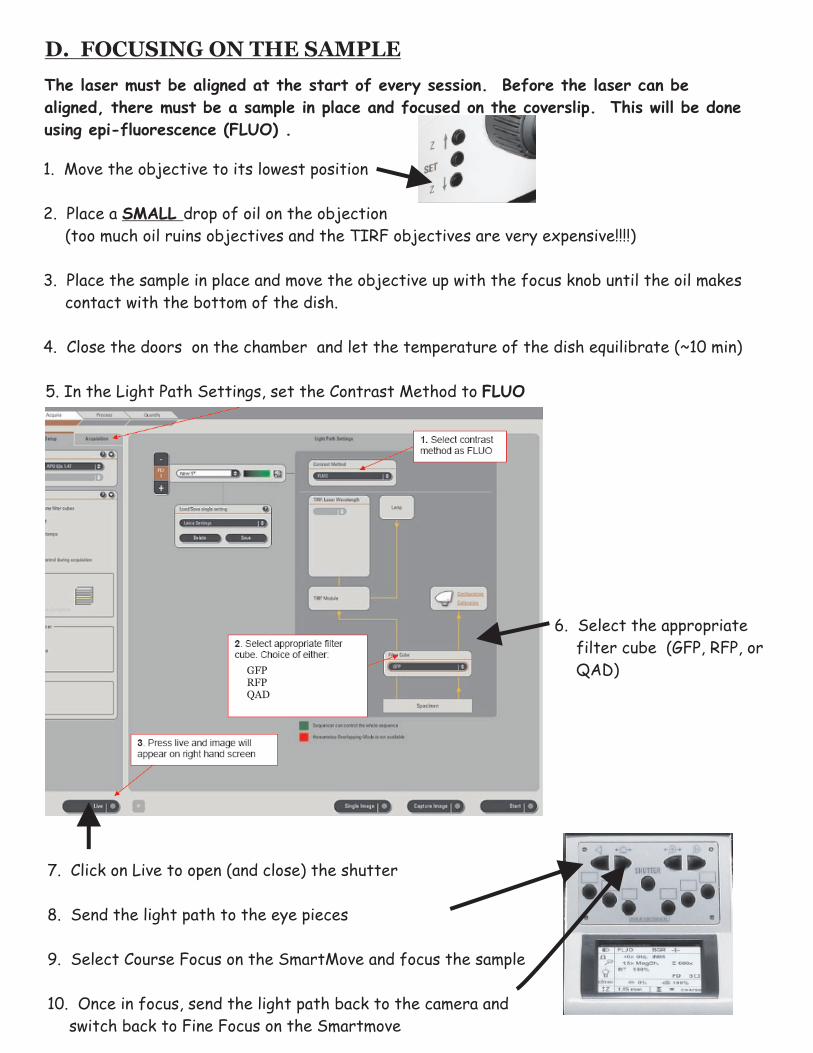
D. FOCUSING ON THE SAMPLE
The laser must be aligned at the start of every session. Before the laser can be
aligned, there must be a sample in place and focused on the coverslip. This will be done
using epi-fluorescence (FLUO) .
1. Move the objective to its lowest position
2. Place a SMALL drop of oil on the objection
(too much oil ruins objectives and the TIRF objectives are very expensive!!!!)
3. Place the sample in place and move the objective up with the focus knob until the oil makes
contact with the bottom of the dish.
4. Close the doors on the chamber and let the temperature of the dish equilibrate (~10 min)
5. In the Light Path Settings, set the Contrast Method to FLUO
6. Select the appropriate
filter cube (GFP, RFP, or
QAD)
7. Click on Live to open (and close) the shutter
8. Send the light path to the eye pieces
9. Select Course Focus on the SmartMove and focus the sample
10. Once in focus, send the light path back to the camera and
switch back to Fine Focus on the Smartmove
GFPRFPQAD
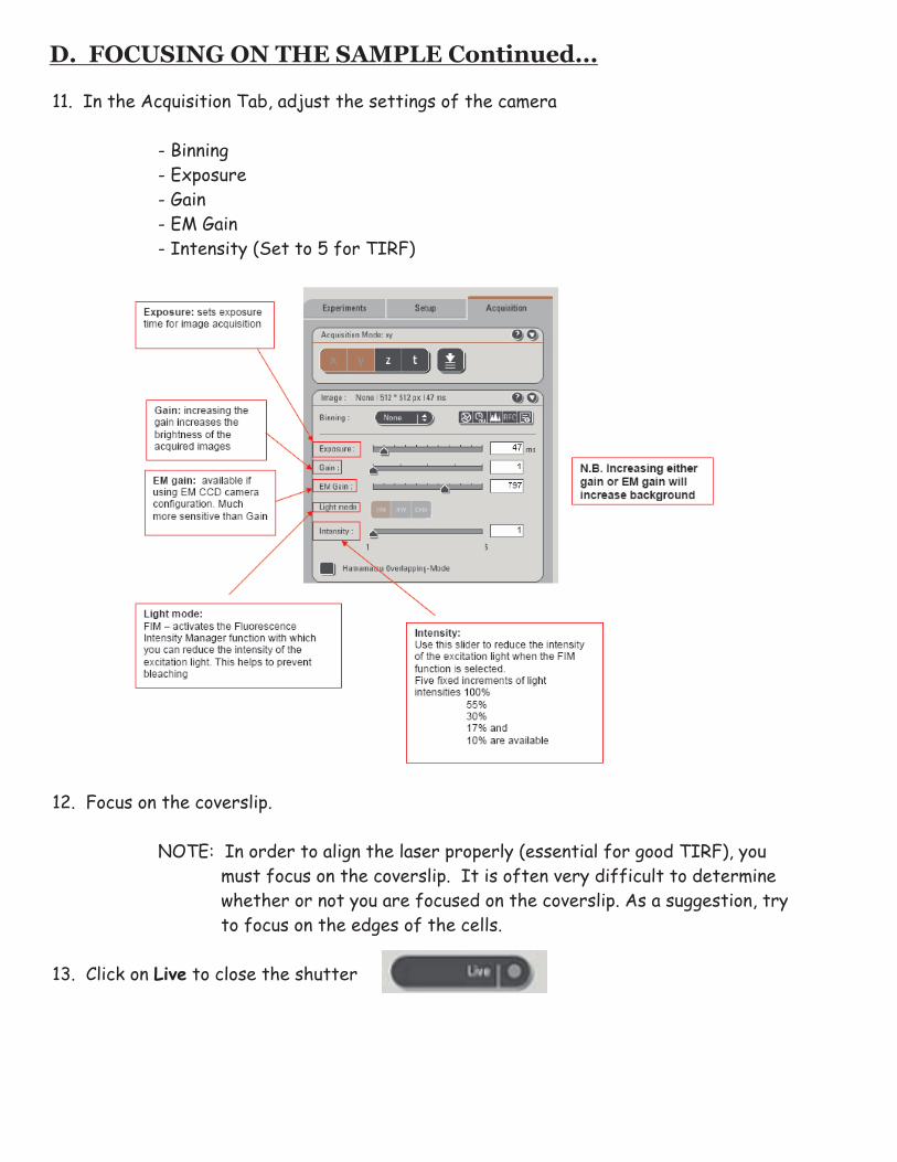
D. FOCUSING ON THE SAMPLE Continued...
11. In the Acquisition Tab, adjust the settings of the camera
- Binning
- Exposure
- Gain
- EM Gain
- Intensity (Set to 5 for TIRF)
12. Focus on the coverslip.
NOTE: In order to align the laser properly (essential for good TIRF), you
must focus on the coverslip. It is often very difficult to determine
whether or not you are focused on the coverslip. As a suggestion, try
to focus on the edges of the cells.
13. Click on Live to close the shutter
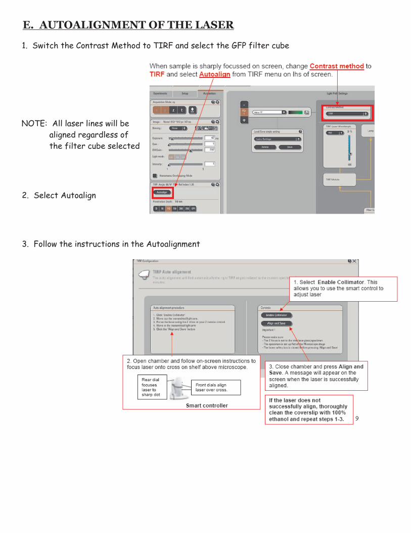
E. AUTOALIGNMENT OF THE LASER
1. Switch the Contrast Method to TIRF and select the GFP filter cube
2. Select Autoalign
3. Follow the instructions in the Autoalignment
NOTE: All laser lines will be
aligned regardless of
the filter cube selected

F. ACQUIRING A TIRF IMAGE
With the Contrast Method set for TIRF...
1. Select appropriate filter cube (QAD for rapid switching with multi-colour fluorescence)
2. Select the appropriate laser and adjust the laser power (start at 20%)
3. Select the appropriate pseudocolour
4 Select the penetration depth
5. To add another channel, click on “+” and select the appropriate filter cube, laser,
pseudocolour and penetration depth (repeat step #1-4 for the new channel)
NOTE: select the QAD filter cube for multi-colour fluorescence
5. Click on live to preview the image (click on Live again to turn off preview).
GFPRFPQAD
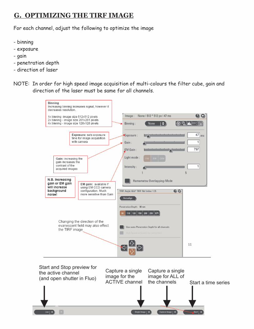
G. OPTIMIZING THE TIRF IMAGE
For each channel, adjust the following to optimize the image
- binning
- exposure
- gain
- penetration depth
- direction of laser
NOTE: In order for high speed image acquisition of multi-colours the filter cube, gain and
direction of the laser must be same for all channels.
Start a time series
Start and Stop preview for the active channel (and open shutter in Fluo)
Capture a single image for the ACTIVE channel
Capture a single image for ALL of the channels

H. CAPTURING A TIME SERIES
Once the settings have been optimized,
1. Click on “t” in the Acquisition Mode
2. Set the criteria for the time series (the interval between images and the duration)
For high speed acquisition, select minimize and synchronize hardware
NOTE: Synchronize hardware is only available if the filter cubes, gain and direction of
the laser are identical for all of the channels.
Start a time series
I. SHUT-DOWN PROCEDURE
1. Close LAS software and shut-down the computer
2. Turn the laser key off, but DO NOT turn the main power switch on the Laser box (green button)
off yet. The laser must cool at least 5 min.
3. Switch off all of the other components in the system:
- El6000 Fluorescence supply (bottom shelf - right)
- Camera (bottom shelf - left)
- Temperature Controller (bottom shelf)
- Heating Unit (on table, left side)
4. Once the laser has cooled for at least 5 min switch of the main power switch on the laser box
5.
· wipe off any oil on the objective with lens paper
· use lens paper damp with lens cleaner to clean the objective
· dry the objective with a clean and dry piece of lens paper
6. Clean up any mess on the stage, in the incubator box, on the table and the desk.
CLEAN THE OBJECTIVE!!!! These objectives are very expensive and are damaged very easily if
not cleaned properly.
To clean:
IF YOU DO NOT CLEAN THE OBJECTIVES PROPERLY, YOUR MICROSCOPE PRIVILEGES
WILL BE TAKEN AWAY.


![Fluorescence Nanoscopy TIRF 4-pi STED STORM/PALMbi177/private/L13_handout.pdf · Microsoft PowerPoint - L13_0227_STED_STORM.ppt [Compatibility Mode] Author: dani Created Date: 2/29/2012](https://img.pdfslide.us/doc/110x75/5f75fde950d7c62043404f31/fluorescence-nanoscopy-tirf-4-pi-sted-storm-bi177privatel13handoutpdf-microsoft.jpg)