Embed Size (px)
Citation preview
Using FTire Tire ModelLearn about:
• About FTire
• Modeling Approach
• Using FTire with Road Models
• Using FTire with Adams
• Parameters
• About FTire Parameters
• Procedure for Parameterizing FTire
• List of FTire Parameters
• About the Tire Data File
• Choosing Operating Conditions
This help describes the Flexible Ring Tire Model (FTire)™, as it is invoked from Adams.
© Michael Gipser, Cosin Consulting
About FTireThe tire model, FTire (Flexible ring tire model), is a sophisticated tire force element. You can use it in MBS-models for vehicle-ride comfort investigations and other vehicle dynamics simulations on even or uneven roadways.
Adams/TireUsing FTire Tire Model
2
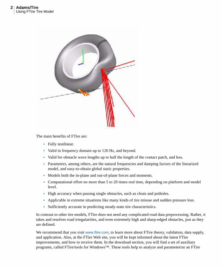
The main benefits of FTire are:
• Fully nonlinear.
• Valid in frequency domain up to 120 Hz, and beyond.
• Valid for obstacle wave lengths up to half the length of the contact patch, and less.
• Parameters, among others, are the natural frequencies and damping factors of the linearized model, and easy-to-obtain global static properties.
• Models both the in-plane and out-of-plane forces and moments.
• Computational effort no more than 5 to 20 times real time, depending on platform and model level.
• High accuracy when passing single obstacles, such as cleats and potholes.
• Applicable in extreme situations like many kinds of tire misuse and sudden pressure loss.
• Sufficiently accurate in predicting steady-state tire characteristics.
In contrast to other tire models, FTire does not need any complicated road data preprocessing. Rather, it takes and resolves road irregularities, and even extremely high and sharp-edged obstacles, just as they are defined.
We recommend that you visit www.ftire.com, to learn more about FTire theory, validation, data supply, and application. Also, at the FTire Web site, you will be kept informed about the latest FTire improvements, and how to receive them. In the download section, you will find a set of auxiliary programs, called FTire/tools for Windows™. These tools help to analyze and parameterize an FTire
3Using FTire Tire Model
Model. FTire/tools is free for FTire licensees. It comprises static, steady-date, and modal analysis, linearization, data estimation, identification and validation tools, road data visualization, and more. In the site's documentation section, you will find a more detailed and permanently updated FTire documentation, together with as some additional literature.
Modeling ApproachFTire uses the following modeling approach:
• The tire belt is described as an extensible and flexible ring carrying bending stiffnesses, elastically founded on the rim by distributed, partially dynamic stiffnesses in radial, tangential, and lateral directions. The degrees of freedom of the ring are such that rim in-plane as well as out-of-plane movements are possible. The ring is numerically approximated by a finite number of discrete masses, the belt elements. These belt elements are coupled with their direct neighbors by stiff springs and by bending stiffnesses both in-plane and out-of-plane.
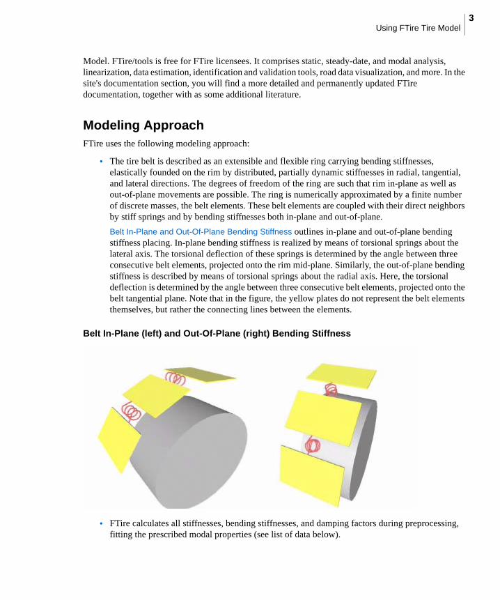
Belt In-Plane and Out-Of-Plane Bending Stiffness outlines in-plane and out-of-plane bending stiffness placing. In-plane bending stiffness is realized by means of torsional springs about the lateral axis. The torsional deflection of these springs is determined by the angle between three consecutive belt elements, projected onto the rim mid-plane. Similarly, the out-of-plane bending stiffness is described by means of torsional springs about the radial axis. Here, the torsional deflection is determined by the angle between three consecutive belt elements, projected onto the belt tangential plane. Note that in the figure, the yellow plates do not represent the belt elements themselves, but rather the connecting lines between the elements.
Belt In-Plane (left) and Out-Of-Plane (right) Bending Stiffness
• FTire calculates all stiffnesses, bending stiffnesses, and damping factors during preprocessing, fitting the prescribed modal properties (see list of data below).
Adams/TireUsing FTire Tire Model
4
• A number of massless tread blocks (5 to 50, for example) are associated with every belt element. These blocks carry nonlinear stiffness and damping properties in the radial, tangential, and lateral direction. The radial deflections of the blocks depend on the road profile, focus, and orientation of the associated belt elements. FTire determines tangential and lateral deflections using the sliding velocity on the ground and the local values of the sliding coefficient. The latter depends on ground pressure and sliding velocity.
• FTire calculates all six components of tire forces and moments acting on the rim by integrating the forces in the elastic foundation of the belt.
Because of this modeling approach, the resulting overall tire model is accurate up to relatively high frequencies both in longitudinal and in lateral directions. There are few restrictions in its applicability with respect to longitudinal, lateral, and vertical vehicle dynamics situations. FTire deals with large- and/or short-wave-length obstacles. It works out of, and up to, a complete standstill, with no additional computing effort nor any model switching. Finally, it is applicable with high accuracy in such delicate simulations as ABS braking on extremely uneven roadways, and so on.
In a full 3D variant, FTire additionally takes into account belt element rotation and bending about the circumferential axis. These new degrees of freedom enable FTire to use contact elements that are distributed not only along a single line, but over the whole contact patch. You can choose the arrangement of the contact elements to be either randomly distributed, or distributed along several parallel lines.
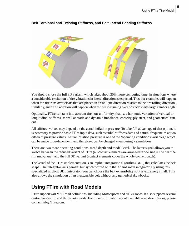
In the full 3D variant, belt torsion about the circumferential axis is described by:
• Torsional stiffnesses between belt elements and rim, about circumferential axis (represented by red torsion springs in the left side of the figure, Belt).
• Torsional stiffnesses between adjacent belt elements, about circumferential axis (represented by blue torsion springs in the left side of figure, Belt).
The right side of the figure, Belt outlines the belt bending stiffness about the circumferential axis. This is done in a somewhat simplified manner. Actually, lateral belt bending is taken into account by introducing a parabolic shape function for each belt element. The curvature of this shape function is treated as a belt elements’ additional degree of freedom.
Note: Radial, tangential, and lateral are relative to the orientation of the belt element, whereas sliding velocity is the block end-point velocity projected onto the road profile tangent plane. By polynomial interpolation, certain precautions have been taken not to let the ground pressure distribution mirror the polygonal shape of the belt chain.
5Using FTire Tire Model
Belt Torsional and Twisting Stiffness, and Belt Lateral Bending Stiffness
You should chose the full 3D variant, which takes about 30% more computing time, in situations where a considerable excitation of tire vibrations in lateral direction is expected. This, for example, will happen when the tire runs over cleats that are placed in an oblique direction relative to the tire rolling direction. Similarly, such an excitation will happen when the tire is running over obstacles with large camber angle.
Optionally, FTire can take into account tire non-uniformity, that is, a harmonic variation of vertical or longitudinal stiffness, as well as static and dynamic imbalance, conicity, ply-steer, and geometrical run-out.
All stiffness values may depend on the actual inflation pressure. To take full advantage of that option, it is necessary to provide basic FTire input data, such as radial stiffness data and natural frequencies at two different pressure values. Actual inflation pressure is one of the ‘operating conditions variables,’ which can be made time-dependent, and therefore, can be changed even during a simulation.
There are two more operating conditions: tread depth and model level. The latter signal allows you to switch between the reduced variant of FTire (all contact elements are arranged in one single line near the rim mid-plane), and the full 3D variant (contact elements cover the whole contact patch).
The kernel of the FTire implementation is an implicit integration algorithm (BDF) that calculates the belt shape. The integrator runs parallel but synchronized with the Adams main integrator. By using this specialized implicit BDF integrator, you can choose the belt extensibility so it is extremely small. This also allows the simulation of an inextensible belt without any numerical drawbacks.
Using FTire with Road ModelsFTire supports all MSC road definitions, including Motorsports and all 3D roads. It also supports several customer-specific and third-party roads. For more information about available road descriptions, please contact [email protected].
Adams/TireUsing FTire Tire Model
6
Using FTire with AdamsFTire is a high-resolution tire model, with respect to road irregularities and tire vibration modes. To take full advantage of that precision, we recommend that you choose a small step size for the Adams integrator. There should be a minimum of 1,000 steps per one second simulation time (that is, an output time step of 1 ms or less).
Controlling integrator step size in:
• Adams/Car
• Adams/Chassis
• Adams/View
• Adams/Solver
Controlling Integrator Step Size in Adams/Car
In Adams/Car, you can control the integrator step size by selecting:
Settings Solver Dynamics
and entering 1ms in the Hmax text box.
Alternatively, you can edit the driver control file (.dcf) that Adams/Car automatically generates when performing a new dynamic maneuver. In that file, override the integrator step size, which is defined in [EXPERIMENT] block, by entering the value 0.001 or less. After editing the file, you can launch subsequent simulation experiments with the same driver's control (and, of course, the new integrator step size) by selecting the following from Adams/Car:
Simulate Full-Vehicle Analysis DCF Driven Driver Control Files Browse
and selecting the .dcf you just edited.
Controlling Integrator Step Size in Adams/Chassis
In Adams/Chassis, you can control the integrator step size by setting the HMAX value to 0.001 or less. HMAX is defined by selecting the following from Adams/Chassis:
System file Properties system_parameters solver hmax
Controlling Integrator Step Size in Adams/View
In Adams/View, you can control the integrator step size by checking:
Settings Solver Dynamics Customized Settings
size, Min Step Size, and Max Step Size.
Controlling Integrator Step Size in Adams/Solver
In Adams/Solver, you can control the integrator step size by setting INTEGRATOR/HMAX to the desired value in the Adams dataset (adm).
7Using FTire Tire Model
FTire Parameters• About FTire Parameters
• Procedure for Parameterizing FTire
• Listing of FTire Parameters
About FTire ParametersFTire parameters can be divided into several groups. There are parameters that define:
• Tire size and geometry
• Stiffness, damping, and mass distribution of the belt/sidewall structure
• Tire imperfections (non-uniformity, imbalance, conicity, and so on)
• Stiffness and damping properties of the tread rubber
• Friction characteristics of the tread rubber
• Numerical properties of the model
For convenience, FTire tries to use data that can be measured as easy as possible. As a consequence, the number of basic data might be larger than the number of internal parameters defined by these basic parameters.
For example, the following four parameters together, after preprocessing, actually result in only two values used in FTire: compression and shear stiffness of the idealized blocks that represent tread rubber:
• tread_depth
• tread_base_height
• stiffness_tread_rubber
• tread_positive
Also, sometimes different combinations of parameters are possible. This is true especially for data of the second group, which determine the structural stiffness and damping properties of FTire. Your choice of which combination of parameters to supply depends on the types of measurements that are available and their accuracy.
Moreover, it is possible to prescribe over-determined subsets of parameters. For example, you may define the belt in-plane bending stiffness by prescribing the frequency of the first bending mode, and at the same time the radial stiffness on a transversal cleat. Both parameters are strongly influenced by the bending stiffness, but might contradict each other.
In such a case, FTire automatically recognizes that the system of equations to be solved is over-determined, and applies an appropriate solver (Householder QR factorization) to determine the solution in the sense of least squares fit. That means, FTire is looking for a compromise to meet both conditions as much as possible. Users can control the compromise by optionally defining weights for the contradicting conditions.
Adams/TireUsing FTire Tire Model
8
Note that, among others, FTire uses modal data to calculate internal structural stiffness and damping coefficients. They are processed in such a way that the mathematical model, for small excitations, shows exactly the measured behavior in the frequency domain. FTire is not a modal model, nor is it linear.
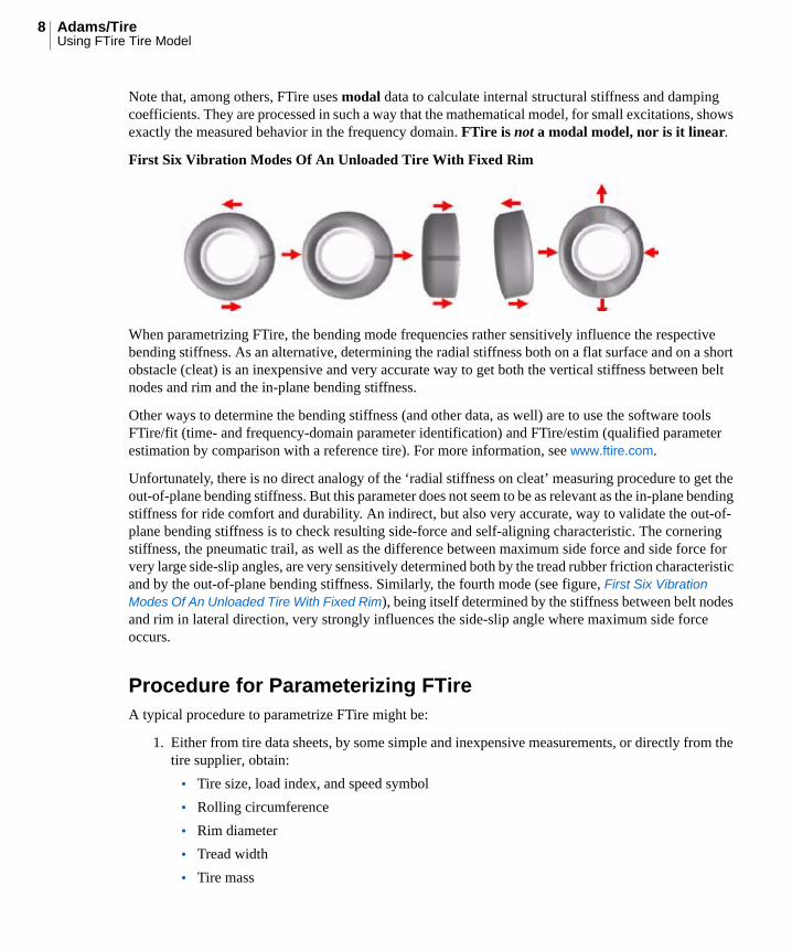
First Six Vibration Modes Of An Unloaded Tire With Fixed Rim
When parametrizing FTire, the bending mode frequencies rather sensitively influence the respective bending stiffness. As an alternative, determining the radial stiffness both on a flat surface and on a short obstacle (cleat) is an inexpensive and very accurate way to get both the vertical stiffness between belt nodes and rim and the in-plane bending stiffness.
Other ways to determine the bending stiffness (and other data, as well) are to use the software tools FTire/fit (time- and frequency-domain parameter identification) and FTire/estim (qualified parameter estimation by comparison with a reference tire). For more information, see www.ftire.com.
Unfortunately, there is no direct analogy of the ‘radial stiffness on cleat’ measuring procedure to get the out-of-plane bending stiffness. But this parameter does not seem to be as relevant as the in-plane bending stiffness for ride comfort and durability. An indirect, but also very accurate, way to validate the out-of-plane bending stiffness is to check resulting side-force and self-aligning characteristic. The cornering stiffness, the pneumatic trail, as well as the difference between maximum side force and side force for very large side-slip angles, are very sensitively determined both by the tread rubber friction characteristic and by the out-of-plane bending stiffness. Similarly, the fourth mode (see figure, First Six Vibration Modes Of An Unloaded Tire With Fixed Rim), being itself determined by the stiffness between belt nodes and rim in lateral direction, very strongly influences the side-slip angle where maximum side force occurs.
Procedure for Parameterizing FTireA typical procedure to parametrize FTire might be:
1. Either from tire data sheets, by some simple and inexpensive measurements, or directly from the tire supplier, obtain:
• Tire size, load index, and speed symbol
• Rolling circumference
• Rim diameter
• Tread width
• Tire mass
9Using FTire Tire Model
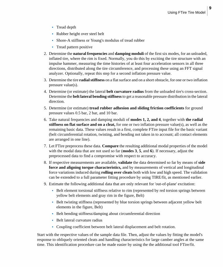
• Tread depth
• Rubber height over steel belt
• Shore-A stiffness or Young's modulus of tread rubber
• Tread pattern positive
2. Determine the natural frequencies and damping moduli of the first six modes, for an unloaded, inflated tire, where the rim is fixed. Normally, you do this by exciting the tire structure with an impulse hammer, measuring the time histories of at least four acceleration sensors in all three directions, distributed along the tire circumference, and processing these using an FFT signal analyzer. Optionally, repeat this step for a second inflation pressure value.
3. Determine the tire radial stiffness on a flat surface and on a short obstacle, for one or two inflation pressure value(s).
4. Determine (or estimate) the lateral belt curvature radius from the unloaded tire's cross-section. Determine the belt lateral bending stiffness to get a reasonable pressure distribution in the lateral direction.
5. Determine (or estimate) tread rubber adhesion and sliding friction coefficients for ground pressure values 0.5 bar, 2 bar, and 10 bar.
6. Take natural frequencies and damping moduli of modes 1, 2, and 4, together with the radial stiffness on flat surface and on a cleat, for one or two inflation pressure value(s), as well as the remaining basic data. These values result in a first, complete FTire input file for the basic variant (belt circumferential rotation, twisting, and bending not taken in to account; all contact elements are arranged in one line).
7. Let FTire preprocess these data. Compare the resulting additional modal properties of the model with the modal data that are not used so far (modes 3, 5, and 6). If necessary, adjust the preprocessed data to find a compromise with respect to accuracy.
8. If respective measurements are available, validate the data determined so far by means of side force and aligning torque characteristics, and by measurements of vertical and longitudinal force variations induced during rolling over cleats both with low and high speed. The validation can be extended to a full parameter fitting procedure by using TIRE/fit, as mentioned earlier.
9. Estimate the following additional data that are only relevant for 'out-of-plane' excitation:
• Belt element torsional stiffness relative to rim (represented by red torsion springs between yellow belt elements and gray rim in the figure, Belt)
• Belt twisting stiffness (represented by blue torsion springs between adjacent yellow belt elements in the figure, Belt)
• Belt bending stiffness/damping about circumferential direction
• Belt lateral curvature radius
• Coupling coefficient between belt lateral displacement and belt rotation.
Start with the respective values of the sample data file. Then, adjust the values by fitting the model's response to obliquely oriented cleats and handling characteristics for large camber angles at the same time. This identification procedure can be made easier by using the the additional tool FTire/fit.
Adams/TireUsing FTire Tire Model
10
Clearly, the performance of this procedure is not very easy in practice. On the other hand, every tire model that is accurate enough for ride comfort and durability calculations will need as much or even more data.
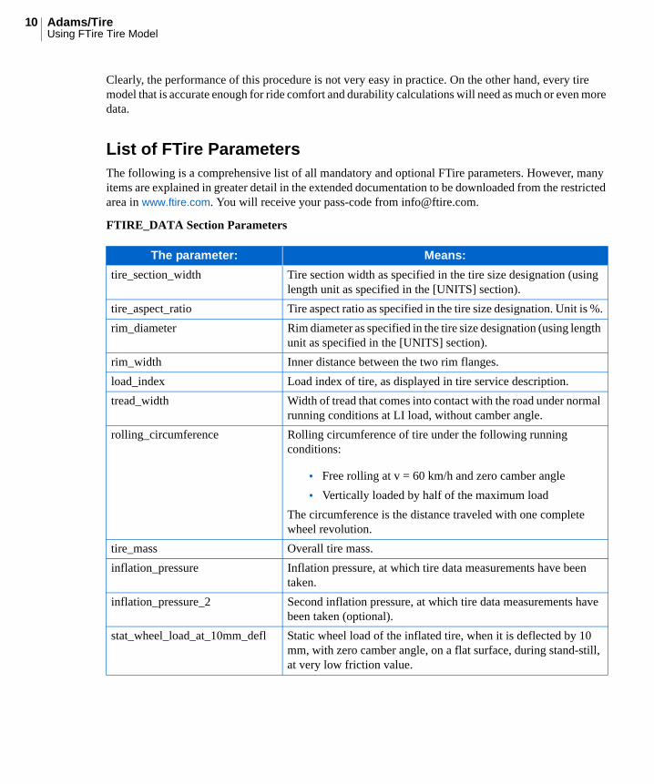
List of FTire ParametersThe following is a comprehensive list of all mandatory and optional FTire parameters. However, many items are explained in greater detail in the extended documentation to be downloaded from the restricted area in www.ftire.com. You will receive your pass-code from [email protected].
FTIRE_DATA Section Parameters
The parameter: Means:
tire_section_width Tire section width as specified in the tire size designation (using length unit as specified in the [UNITS] section).
tire_aspect_ratio Tire aspect ratio as specified in the tire size designation. Unit is %.
rim_diameter Rim diameter as specified in the tire size designation (using length unit as specified in the [UNITS] section).
rim_width Inner distance between the two rim flanges.
load_index Load index of tire, as displayed in tire service description.
tread_width Width of tread that comes into contact with the road under normal running conditions at LI load, without camber angle.
rolling_circumference Rolling circumference of tire under the following running conditions:
• Free rolling at v = 60 km/h and zero camber angle
• Vertically loaded by half of the maximum load
The circumference is the distance traveled with one complete wheel revolution.
tire_mass Overall tire mass.
inflation_pressure Inflation pressure, at which tire data measurements have been taken.
inflation_pressure_2 Second inflation pressure, at which tire data measurements have been taken (optional).
stat_wheel_load_at_10mm_defl Static wheel load of the inflated tire, when it is deflected by 10 mm, with zero camber angle, on a flat surface, during stand-still, at very low friction value.
11Using FTire Tire Model
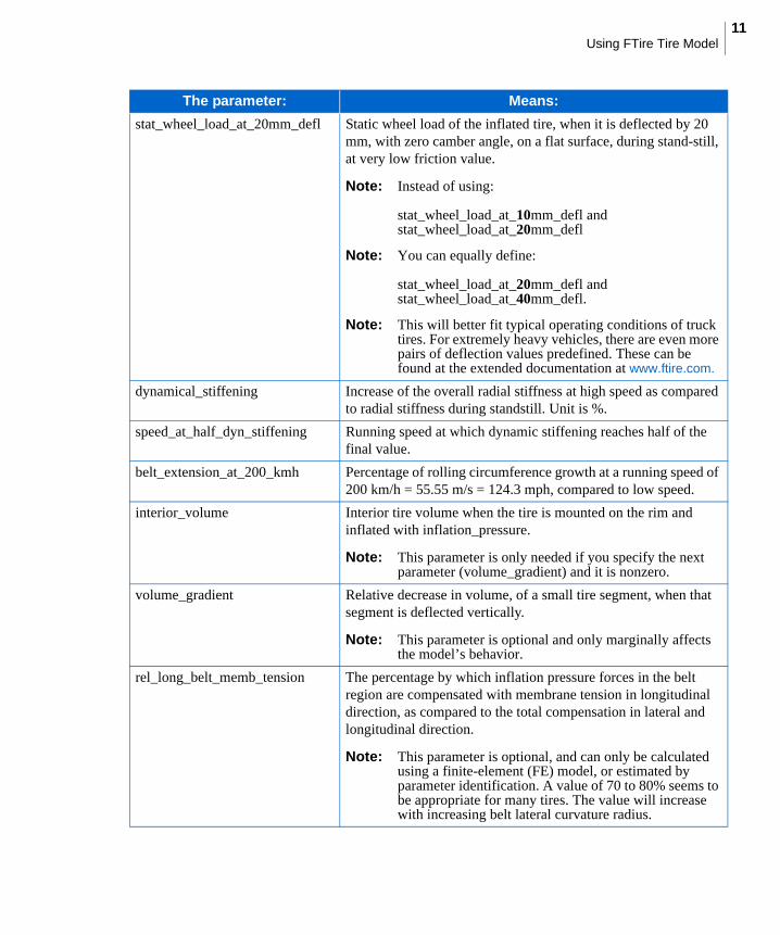
stat_wheel_load_at_20mm_defl Static wheel load of the inflated tire, when it is deflected by 20 mm, with zero camber angle, on a flat surface, during stand-still, at very low friction value.
Note: Instead of using:
stat_wheel_load_at_10mm_defl and stat_wheel_load_at_20mm_defl
Note: You can equally define:
stat_wheel_load_at_20mm_defl and stat_wheel_load_at_40mm_defl.
Note: This will better fit typical operating conditions of truck tires. For extremely heavy vehicles, there are even more pairs of deflection values predefined. These can be found at the extended documentation at www.ftire.com.
dynamical_stiffening Increase of the overall radial stiffness at high speed as compared to radial stiffness during standstill. Unit is %.
speed_at_half_dyn_stiffening Running speed at which dynamic stiffening reaches half of the final value.
belt_extension_at_200_kmh Percentage of rolling circumference growth at a running speed of 200 km/h = 55.55 m/s = 124.3 mph, compared to low speed.
interior_volume Interior tire volume when the tire is mounted on the rim and inflated with inflation_pressure.
Note: This parameter is only needed if you specify the next parameter (volume_gradient) and it is nonzero.
volume_gradient Relative decrease in volume, of a small tire segment, when that segment is deflected vertically.
Note: This parameter is optional and only marginally affects the model’s behavior.
rel_long_belt_memb_tension The percentage by which inflation pressure forces in the belt region are compensated with membrane tension in longitudinal direction, as compared to the total compensation in lateral and longitudinal direction.
Note: This parameter is optional, and can only be calculated using a finite-element (FE) model, or estimated by parameter identification. A value of 70 to 80% seems to be appropriate for many tires. The value will increase with increasing belt lateral curvature radius.
The parameter: Means:
Adams/TireUsing FTire Tire Model
12
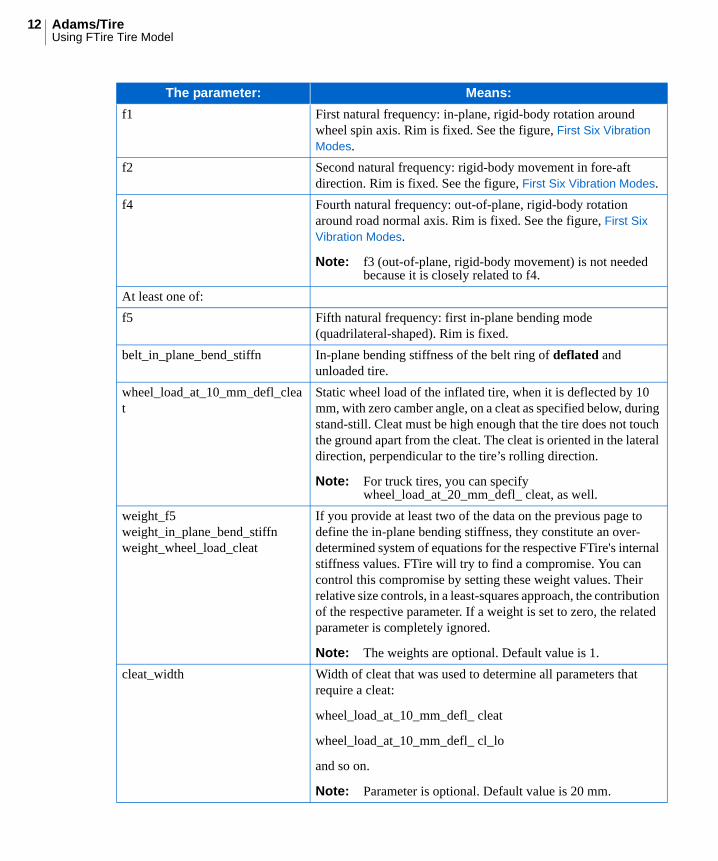
f1 First natural frequency: in-plane, rigid-body rotation around wheel spin axis. Rim is fixed. See the figure, First Six Vibration Modes.
f2 Second natural frequency: rigid-body movement in fore-aft direction. Rim is fixed. See the figure, First Six Vibration Modes.
f4 Fourth natural frequency: out-of-plane, rigid-body rotation around road normal axis. Rim is fixed. See the figure, First Six Vibration Modes.
Note: f3 (out-of-plane, rigid-body movement) is not needed because it is closely related to f4.
At least one of:
f5 Fifth natural frequency: first in-plane bending mode (quadrilateral-shaped). Rim is fixed.
belt_in_plane_bend_stiffn In-plane bending stiffness of the belt ring of deflated and unloaded tire.
wheel_load_at_10_mm_defl_cleat
Static wheel load of the inflated tire, when it is deflected by 10 mm, with zero camber angle, on a cleat as specified below, during stand-still. Cleat must be high enough that the tire does not touch the ground apart from the cleat. The cleat is oriented in the lateral direction, perpendicular to the tire’s rolling direction.
Note: For truck tires, you can specify wheel_load_at_20_mm_defl_ cleat, as well.
weight_f5weight_in_plane_bend_stiffnweight_wheel_load_cleat
If you provide at least two of the data on the previous page to define the in-plane bending stiffness, they constitute an over-determined system of equations for the respective FTire's internal stiffness values. FTire will try to find a compromise. You can control this compromise by setting these weight values. Their relative size controls, in a least-squares approach, the contribution of the respective parameter. If a weight is set to zero, the related parameter is completely ignored.
Note: The weights are optional. Default value is 1.
cleat_width Width of cleat that was used to determine all parameters that require a cleat:
wheel_load_at_10_mm_defl_ cleat
wheel_load_at_10_mm_defl_ cl_lo
and so on.
Note: Parameter is optional. Default value is 20 mm.
The parameter: Means:
13Using FTire Tire Model
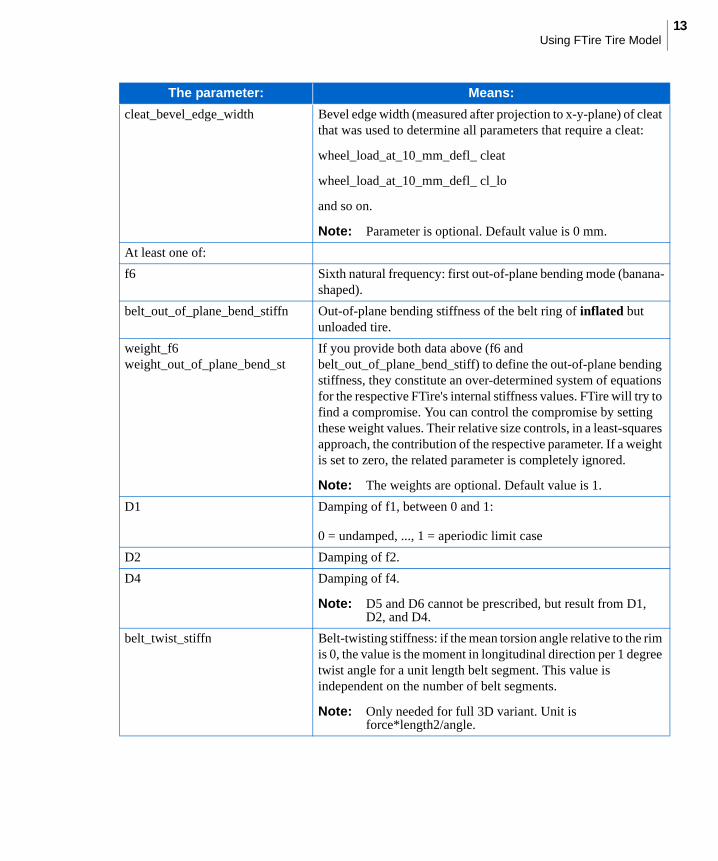
cleat_bevel_edge_width Bevel edge width (measured after projection to x-y-plane) of cleat that was used to determine all parameters that require a cleat:
wheel_load_at_10_mm_defl_ cleat
wheel_load_at_10_mm_defl_ cl_lo
and so on.
Note: Parameter is optional. Default value is 0 mm.
At least one of:
f6 Sixth natural frequency: first out-of-plane bending mode (banana-shaped).
belt_out_of_plane_bend_stiffn Out-of-plane bending stiffness of the belt ring of inflated but unloaded tire.
weight_f6weight_out_of_plane_bend_st
If you provide both data above (f6 and belt_out_of_plane_bend_stiff) to define the out-of-plane bending stiffness, they constitute an over-determined system of equations for the respective FTire's internal stiffness values. FTire will try to find a compromise. You can control the compromise by setting these weight values. Their relative size controls, in a least-squares approach, the contribution of the respective parameter. If a weight is set to zero, the related parameter is completely ignored.
Note: The weights are optional. Default value is 1.
D1 Damping of f1, between 0 and 1:
0 = undamped, ..., 1 = aperiodic limit case
D2 Damping of f2.
D4 Damping of f4.
Note: D5 and D6 cannot be prescribed, but result from D1, D2, and D4.
belt_twist_stiffn Belt-twisting stiffness: if the mean torsion angle relative to the rim is 0, the value is the moment in longitudinal direction per 1 degree twist angle for a unit length belt segment. This value is independent on the number of belt segments.
Note: Only needed for full 3D variant. Unit is force*length2/angle.
The parameter: Means:
Adams/TireUsing FTire Tire Model
14
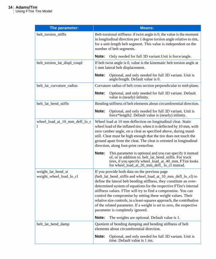
belt_torsion_stiffn Belt-torsional stiffness: if twist angle is 0, the value is the moment in longitudinal direction per 1 degree torsion angle relative to rim, for a unit-length belt segment. This value is independent on the number of belt segments.
Note: Only needed for full 3D variant.Unit is force/angle.
belt_torsion_lat_displ_coupl If belt twist angle is 0, value is the kinematic belt torsion angle at 1 mm lateral belt displacement.
Note: Optional, and only needed for full 3D variant. Unit is angle/length. Default value is 0.
belt_lat_curvature_radius Curvature radius of belt cross section perpendicular to mid-plane.
Note: Optional, and only needed for full 3D variant. Default value is (nearly) infinity.
belt_lat_bend_stiffn Bending stiffness of belt elements about circumferential direction.
Note: Optional, and only needed for full 3D variant. Unit is force*length2. Default value is (nearly) infinity.
wheel_load_at_10_mm_defl_lo_cl
Wheel load at 10 mm deflection on longitudinal cleat. Static wheel load of the inflated tire, when it is deflected by 10 mm, with zero camber angle, on a cleat as specified above, during stand-still. Cleat must be high enough that the tire does not touch the ground apart from the cleat. The cleat is oriented in longitudinal direction, along foot-print centerline.
Note: This parameter is optional and you can specify it instead of, or in addition to, belt_lat_bend_stiffn. For truck tires, if you specify wheel_load_at_40_mm, FTire looks for wheel_load_at_20_mm_defl_ lo_cl instead.
weight_lat_bend_stweight_wheel_load_lo_cl
If you provide both data on the previous page (belt_lat_bend_stiffn and wheel_load_at_10_mm_defl_lo_cl) to define the lateral belt bending stiffness, they constitute an over-determined system of equations for the respective FTire's internal stiffness values. FTire will try to find a compromise. You can control the compromise by setting these weight values. Their relative size controls, in a least-squares approach, the contribution of the related parameter. If a weight is set to zero, the respective parameter is completely ignored.
Note: The weights are optional. Default value is 1.
belt_lat_bend_damp Quotient of bending damping and bending stiffness of belt elements about circumferential direction.
Note: Optional, and only needed for full 3D variant. Unit is time. Default value is 1 ms.
The parameter: Means:
15Using FTire Tire Model
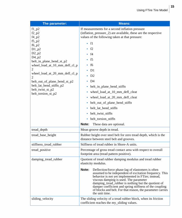
f1_p2f2_p2f4_p2f5_p2f6_p2D1_p2D2_p2D4_p2belt_in_plane_bend_st_p2wheel_load_at_10_mm_defl_cl_p2wheel_load_at_20_mm_defl_cl_p2belt_out_of_plane_bend_st_p2belt_lat_bend_stiffn_p2belt_twist_st_p2belt_torsion_st_p2
If measurements for a second inflation pressure (inflation_pressure_2) are available, these are the respective values of the following taken at that pressure:
• f1
• f2
• f4
• f5
• f6
• D1
• D2
• D4
• belt_in_plane_bend_stiffn
• wheel_load_at_10_mm_defl_cleat
• wheel_load_at_20_mm_defl_cleat
• belt_out_of_plane_bend_stiffn
• belt_lat_bend_stiffn
• belt_twist_stiffn
• belt_torsion_stiffn
Note: These data are optional.
tread_depth Mean groove depth in tread.
tread_base_height Rubber height over steel belt for zero tread depth, which is the distance between steel belt and grooves.
stiffness_tread_rubber Stiffness of tread rubber in Shore-A units.
tread_positive Percentage of gross tread contact area with respect to overall footprint area (tread pattern positive).
damping_tread_rubber Quotient of tread rubber damping modulus and tread rubber elasticity modulus.
Note: Deflection/force phase-lag of elastomers is often assumed to be independent of excitation frequency. This behavior is not yet implemented in FTire; instead, viscous damping is used. The parameter damping_tread_rubber is nothing but the quotient of damper coefficient and spring stiffness of the coupling of blocks and belt. For that reason, the parameter carries the unit time.
sliding_velocity The sliding velocity of a tread rubber block, when its friction coefficient reaches the my_sliding values.
The parameter: Means:
Adams/TireUsing FTire Tire Model
16
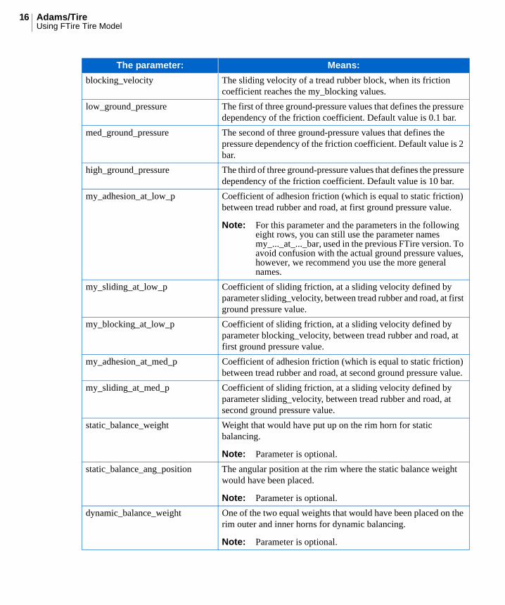
blocking_velocity The sliding velocity of a tread rubber block, when its friction coefficient reaches the my_blocking values.
low_ground_pressure The first of three ground-pressure values that defines the pressure dependency of the friction coefficient. Default value is 0.1 bar.
med_ground_pressure The second of three ground-pressure values that defines the pressure dependency of the friction coefficient. Default value is 2 bar.
high_ground_pressure The third of three ground-pressure values that defines the pressure dependency of the friction coefficient. Default value is 10 bar.
my_adhesion_at_low_p Coefficient of adhesion friction (which is equal to static friction) between tread rubber and road, at first ground pressure value.
Note: For this parameter and the parameters in the following eight rows, you can still use the parameter names my_..._at_..._bar, used in the previous FTire version. To avoid confusion with the actual ground pressure values, however, we recommend you use the more general names.
my_sliding_at_low_p Coefficient of sliding friction, at a sliding velocity defined by parameter sliding_velocity, between tread rubber and road, at first ground pressure value.
my_blocking_at_low_p Coefficient of sliding friction, at a sliding velocity defined by parameter blocking_velocity, between tread rubber and road, at first ground pressure value.
my_adhesion_at_med_p Coefficient of adhesion friction (which is equal to static friction) between tread rubber and road, at second ground pressure value.
my_sliding_at_med_p Coefficient of sliding friction, at a sliding velocity defined by parameter sliding_velocity, between tread rubber and road, at second ground pressure value.
static_balance_weight Weight that would have put up on the rim horn for static balancing.
Note: Parameter is optional.
static_balance_ang_position The angular position at the rim where the static balance weight would have been placed.
Note: Parameter is optional.
dynamic_balance_weight One of the two equal weights that would have been placed on the rim outer and inner horns for dynamic balancing.
Note: Parameter is optional.
The parameter: Means:
17Using FTire Tire Model
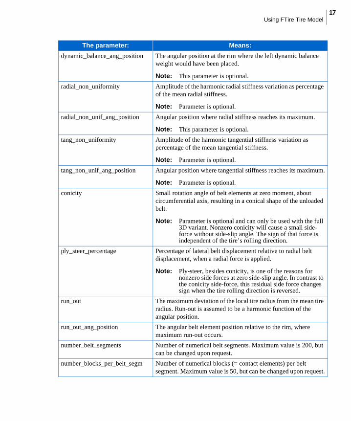
dynamic_balance_ang_position The angular position at the rim where the left dynamic balance weight would have been placed.
Note: This parameter is optional.
radial_non_uniformity Amplitude of the harmonic radial stiffness variation as percentage of the mean radial stiffness.
Note: Parameter is optional.
radial_non_unif_ang_position Angular position where radial stiffness reaches its maximum.
Note: This parameter is optional.
tang_non_uniformity Amplitude of the harmonic tangential stiffness variation as percentage of the mean tangential stiffness.
Note: Parameter is optional.
tang_non_unif_ang_position Angular position where tangential stiffness reaches its maximum.
Note: Parameter is optional.
conicity Small rotation angle of belt elements at zero moment, about circumferential axis, resulting in a conical shape of the unloaded belt.
Note: Parameter is optional and can only be used with the full 3D variant. Nonzero conicity will cause a small side-force without side-slip angle. The sign of that force is independent of the tire’s rolling direction.
ply_steer_percentage Percentage of lateral belt displacement relative to radial belt displacement, when a radial force is applied.
Note: Ply-steer, besides conicity, is one of the reasons for nonzero side forces at zero side-slip angle. In contrast to the conicity side-force, this residual side force changes sign when the tire rolling direction is reversed.
run_out The maximum deviation of the local tire radius from the mean tire radius. Run-out is assumed to be a harmonic function of the angular position.
run_out_ang_position The angular belt element position relative to the rim, where maximum run-out occurs.
number_belt_segments Number of numerical belt segments. Maximum value is 200, but can be changed upon request.
number_blocks_per_belt_segm Number of numerical blocks (= contact elements) per belt segment. Maximum value is 50, but can be changed upon request.
The parameter: Means:
Adams/TireUsing FTire Tire Model
18
About the FTire Tire Data FileAs with all TeimOrbit files, entries in the [UNITS] block define the physical units of all parameters.
The basic parameters are preprocessed during initialization, resulting in the preprocessed parameters. These parameters are saved in a separate TeimOrbit-style file, which can be used in further simulations instead of the basic data file. By this, you can omit the preprocessing calculation phase, which may result in a considerable saving of time.
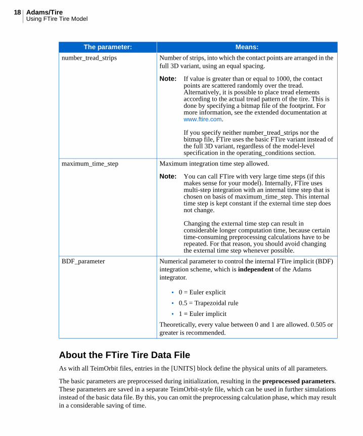
number_tread_strips Number of strips, into which the contact points are arranged in the full 3D variant, using an equal spacing.
Note: If value is greater than or equal to 1000, the contact points are scattered randomly over the tread. Alternatively, it is possible to place tread elements according to the actual tread pattern of the tire. This is done by specifying a bitmap file of the footprint. For more information, see the extended documentation at www.ftire.com.
If you specify neither number_tread_strips nor the bitmap file, FTire uses the basic FTire variant instead of the full 3D variant, regardless of the model-level specification in the operating_conditions section.
maximum_time_step Maximum integration time step allowed.
Note: You can call FTire with very large time steps (if this makes sense for your model). Internally, FTire uses multi-step integration with an internal time step that is chosen on basis of maximum_time_step. This internal time step is kept constant if the external time step does not change.
Changing the external time step can result in considerable longer computation time, because certain time-consuming preprocessing calculations have to be repeated. For that reason, you should avoid changing the external time step whenever possible.
BDF_parameter Numerical parameter to control the internal FTire implicit (BDF) integration scheme, which is independent of the Adams integrator.
• 0 = Euler explicit
• 0.5 = Trapezoidal rule
• 1 = Euler implicit
Theoretically, every value between 0 and 1 are allowed. 0.505 or greater is recommended.
The parameter: Means:
19Using FTire Tire Model
This preprocessed data file is a copy of the original one; the preprocessed data are appended after the bottom line, using a hexadecimal, space-saving coding. In contrast to earlier versions of FTire, it is possible to use this file for parameter changes instead of the original one.
You should, of course, not change the hexadecimal data but only the readable part of the file. The hexadecimal section does not only contain the preprocessed data, but a copy of the original one, as well. Moreover, it carries coded information about the FTire version that was used for creation.
This information helps to automatically determine whether or not an update of the preprocessed data is required. This means that whenever you change some basic data or you download a new FTire version, preprocessing will be repeated automatically, and the preprocessed data file saved in your current working directory. You can (and should) replace the FTire data file in your database with this one, without any loss of information.
From www.ftire.com, you can download a tool (being a member of FTire/tools) to carry out preprocessing outside of Adams.
The FTire interface routine automatically recognizes whether several wheels of the car share the same basic data file. In that case, preprocessing is done only once for all these files. Also, FTire automatically recognizes whether the data file contains basic parameters or pre-processed ones.
FTire does not use the data in the section [VERTICAL]. It is only included for compatibility with other tire models. It is recommended that you set Vertical_Stiffness to the value of stat_wheel_load_at_10_mm_defl, after dividing by 10 mm. For Vertical_Damping, choose 0 (or a small nonzero value). The actual vertical damping of FTire is not just one single value, but will depend on rolling speed, inflation pressure, load, camber, and so on.
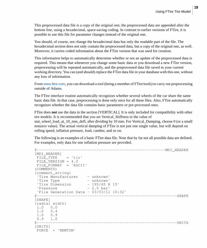
The following is an examples of a basic FTire data file. Note that by far not all possible data are defined. For examples, only data for one inflation pressure are provided.
$--------------------------------------------------------MDI_HEADER[MDI_HEADER] FILE_TYPE = 'tir' FILE_VERSION = 4.0 FILE_FORMAT = 'ASCII'(COMMENTS){comment_string} 'Tire Manufacturer - unknown' 'Tire Type - unknown' 'Tire Dimension - 195/65 R 15' 'Pressure - 2.0 bar' 'File Generation Date - 03/03/11 10:32'$-------------------------------------------------------------SHAPE[SHAPE]{radial width} 1.0 0.0 1.0 0.4 1.0 0.9 0.9 1.0$-------------------------------------------------------------UNITS[UNITS] FORCE = 'NEWTON'
Adams/TireUsing FTire Tire Model
20
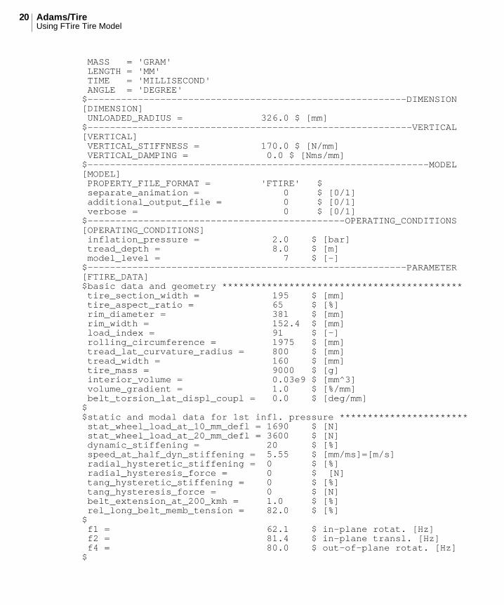
MASS = 'GRAM' LENGTH = 'MM' TIME = 'MILLISECOND' ANGLE = 'DEGREE'$---------------------------------------------------------DIMENSION[DIMENSION] UNLOADED_RADIUS = 326.0 $ [mm]$----------------------------------------------------------VERTICAL[VERTICAL] VERTICAL_STIFFNESS = 170.0 $ [N/mm] VERTICAL_DAMPING = 0.0 $ [Nms/mm]$-------------------------------------------------------------MODEL[MODEL] PROPERTY_FILE_FORMAT = 'FTIRE' $ separate_animation = 0 $ [0/1] additional_output_file = 0 $ [0/1] verbose = 0 $ [0/1]$----------------------------------------------OPERATING_CONDITIONS[OPERATING_CONDITIONS] inflation_pressure = 2.0 $ [bar] tread_depth = 8.0 $ [m] model_level = 7 $ [-] $---------------------------------------------------------PARAMETER[FTIRE_DATA]$basic data and geometry ******************************************* tire_section_width = 195 $ [mm] tire_aspect_ratio = 65 $ [%] rim_diameter = 381 $ [mm] rim_width = 152.4 $ [mm] load_index = 91 $ [-] rolling_circumference = 1975 $ [mm] tread_lat_curvature_radius = 800 $ [mm] tread_width = 160 $ [mm] tire_mass = 9000 $ [g] interior_volume = 0.03e9 $ [mm^3] volume_gradient = 1.0 $ [%/mm] belt_torsion_lat_displ_coupl = 0.0 $ [deg/mm]$$static and modal data for 1st infl. pressure *********************** stat_wheel_load_at_10_mm_defl = 1690 $ [N] stat_wheel_load_at_20_mm_defl = 3600 $ [N] dynamic_stiffening = 20 $ [%] speed_at_half_dyn_stiffening = 5.55 $ [mm/ms]=[m/s] radial_hysteretic_stiffening = 0 $ [%] radial_hysteresis_force = 0 $ [N] tang_hysteretic_stiffening = 0 $ [%] tang_hysteresis_force = 0 $ [N] belt_extension_at_200_kmh = 1.0 $ [%] rel_long_belt_memb_tension = 82.0 $ [%]$ f1 = 62.1 $ in-plane rotat. [Hz] f2 = 81.4 $ in-plane transl. [Hz] f4 = 80.0 $ out-of-plane rotat. [Hz]$
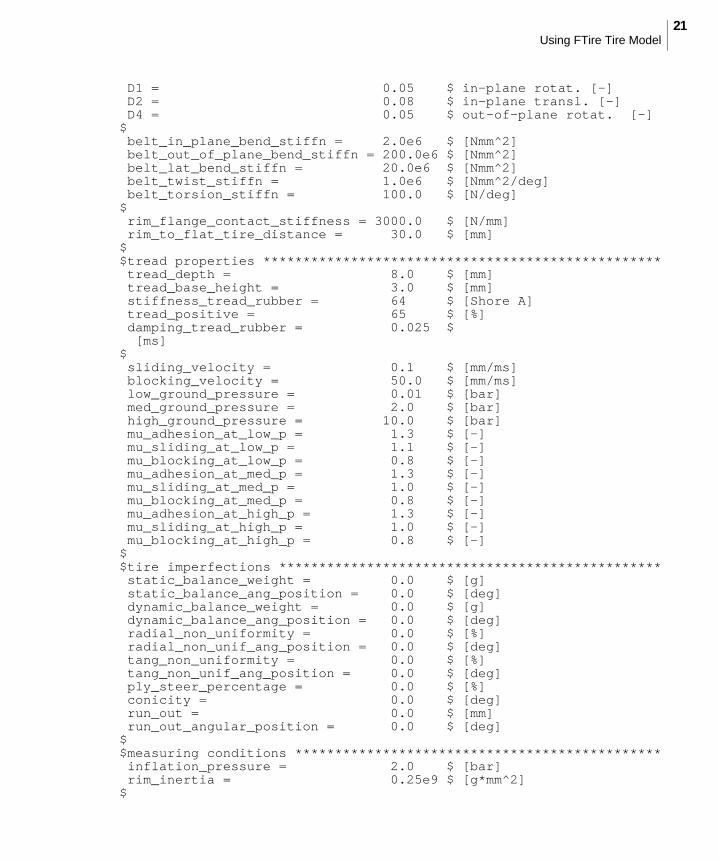
21Using FTire Tire Model
D1 = 0.05 $ in-plane rotat. [-] D2 = 0.08 $ in-plane transl. [-] D4 = 0.05 $ out-of-plane rotat. [-]$ belt_in_plane_bend_stiffn = 2.0e6 $ [Nmm^2] belt_out_of_plane_bend_stiffn = 200.0e6 $ [Nmm^2] belt_lat_bend_stiffn = 20.0e6 $ [Nmm^2] belt_twist_stiffn = 1.0e6 $ [Nmm^2/deg] belt_torsion_stiffn = 100.0 $ [N/deg]$ rim_flange_contact_stiffness = 3000.0 $ [N/mm] rim_to_flat_tire_distance = 30.0 $ [mm]$$tread properties ************************************************** tread_depth = 8.0 $ [mm] tread_base_height = 3.0 $ [mm] stiffness_tread_rubber = 64 $ [Shore A] tread_positive = 65 $ [%] damping_tread_rubber = 0.025 $ [ms]$ sliding_velocity = 0.1 $ [mm/ms] blocking_velocity = 50.0 $ [mm/ms] low_ground_pressure = 0.01 $ [bar] med_ground_pressure = 2.0 $ [bar] high_ground_pressure = 10.0 $ [bar] mu_adhesion_at_low_p = 1.3 $ [-] mu_sliding_at_low_p = 1.1 $ [-] mu_blocking_at_low_p = 0.8 $ [-] mu_adhesion_at_med_p = 1.3 $ [-] mu_sliding_at_med_p = 1.0 $ [-] mu_blocking_at_med_p = 0.8 $ [-] mu_adhesion_at_high_p = 1.3 $ [-] mu_sliding_at_high_p = 1.0 $ [-] mu_blocking_at_high_p = 0.8 $ [-]$$tire imperfections ************************************************ static_balance_weight = 0.0 $ [g] static_balance_ang_position = 0.0 $ [deg] dynamic_balance_weight = 0.0 $ [g] dynamic_balance_ang_position = 0.0 $ [deg] radial_non_uniformity = 0.0 $ [%] radial_non_unif_ang_position = 0.0 $ [deg] tang_non_uniformity = 0.0 $ [%] tang_non_unif_ang_position = 0.0 $ [deg] ply_steer_percentage = 0.0 $ [%] conicity = 0.0 $ [deg] run_out = 0.0 $ [mm] run_out_angular_position = 0.0 $ [deg]$$measuring conditions ********************************************** inflation_pressure = 2.0 $ [bar] rim_inertia = 0.25e9 $ [g*mm^2]$
Adams/TireUsing FTire Tire Model
22
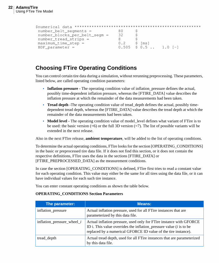
$numerical data **************************************************** number_belt_segments = 80 $ number_blocks_per_belt_segm = 32 $ number_tread_strips = 8 $ maximum_time_step = 0.2 $ [ms] BDF_parameter = 0.505 $ 0.5 .. 1.0 [-]
Choosing FTire Operating ConditionsYou can control certain tire data during a simulation, without rerunning preprocessing. These parameters, listed below, are called operating condition parameters:
• Inflation pressure - The operating condition value of inflation_pressure defines the actual, possibly time-dependent inflation pressure, whereas the [FTIRE_DATA] value describes the inflation pressure at which the remainder of the data measurements had been taken.
• Tread depth -The operating condition value of tread_depth defines the actual, possibly time-dependent tread depth, whereas the [FTIRE_DATA] value describes the tread depth at which the remainder of the data measurements had been taken.
• Model level - The operating condition value of model_level defines what variant of FTire is to be used: the basic version (=6) or the full 3D version (=7). The list of possible variants will be extended in the next release.
Also in the next FTire release, ambient temperature, will be added to the list of operating conditions.
To determine the actual operating conditions, FTire looks for the section [OPERATING_CONDITIONS] in the basic or preprocessed tire data file. If it does not find this section, or it does not contain the respective definitions, FTire uses the data in the sections [FTIRE_DATA] or [FTIRE_PREPROCESSED_DATA] as the measurement conditions.
In case the section [OPERATING_CONDITIONS] is defined, FTire first tries to read a constant value for each operating condition. This value may either be the same for all tires using the data file, or it can have individual values for each such tire instance.
You can enter constant operating conditions as shown the table below.
OPERATING_CONDITIONS Section Parameters
The parameter: Means:
inflation_pressure Actual inflation pressure, used for all FTire instances that are parameterized by this data file.
inflation_pressure_wheel_i Actual inflation pressure, used only for FTire instance with GFORCE ID i. This value overrides the inflation_pressure value (i is to be replaced by a numerical GFORCE ID value of the tire instance).
tread_depth Actual tread depth, used for all FTire instances that are parameterized by this data file.
23Using FTire Tire Model
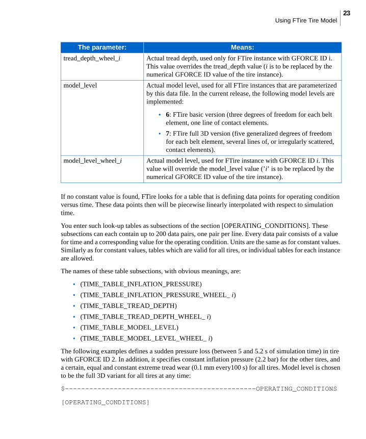
If no constant value is found, FTire looks for a table that is defining data points for operating condition versus time. These data points then will be piecewise linearly interpolated with respect to simulation time.
You enter such look-up tables as subsections of the section [OPERATING_CONDITIONS]. These subsections can each contain up to 200 data pairs, one pair per line. Every data pair consists of a value for time and a corresponding value for the operating condition. Units are the same as for constant values. Similarly as for constant values, tables which are valid for all tires, or individual tables for each instance are allowed.
The names of these table subsections, with obvious meanings, are:
• (TIME_TABLE_INFLATION_PRESSURE)
• (TIME_TABLE_INFLATION_PRESSURE_WHEEL_ i)
• (TIME_TABLE_TREAD_DEPTH)
• (TIME_TABLE_TREAD_DEPTH_WHEEL_ i)
• (TIME_TABLE_MODEL_LEVEL)
• (TIME_TABLE_MODEL_LEVEL_WHEEL_ i)
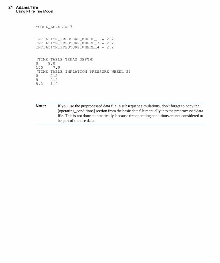
The following examples defines a sudden pressure loss (between 5 and 5.2 s of simulation time) in tire with GFORCE ID 2. In addition, it specifies constant inflation pressure (2.2 bar) for the other tires, and a certain, equal and constant extreme tread wear (0.1 mm every100 s) for all tires. Model level is chosen to be the full 3D variant for all tires at any time:
$-----------------------------------------------OPERATING_CONDITIONS
[OPERATING_CONDITIONS]
tread_depth_wheel_i Actual tread depth, used only for FTire instance with GFORCE ID i. This value overrides the tread_depth value (i is to be replaced by the numerical GFORCE ID value of the tire instance).
model_level Actual model level, used for all FTire instances that are parameterized by this data file. In the current release, the following model levels are implemented:
• 6: FTire basic version (three degrees of freedom for each belt element, one line of contact elements.
• 7: FTire full 3D version (five generalized degrees of freedom for each belt element, several lines of, or irregularly scattered, contact elements).
model_level_wheel_i Actual model level, used for FTire instance with GFORCE ID i. This value will override the model_level value (’i’ is to be replaced by the numerical GFORCE ID value of the tire instance).
The parameter: Means:
Adams/TireUsing FTire Tire Model
24
MODEL_LEVEL = 7
INFLATION_PRESSURE_WHEEL_1 = 2.2INFLATION_PRESSURE_WHEEL_3 = 2.2INFLATION_PRESSURE_WHEEL_4 = 2.2
(TIME_TABLE_TREAD_DEPTH)0 8.0100 7.9(TIME_TABLE_INFLATION_PRESSURE_WHEEL_2)0 2.25 2.25.2 1.2
Note: If you use the preprocessed data file in subsequent simulations, don't forget to copy the [operating_conditions] section from the basic data file manually into the preprocessed data file. This is not done automatically, because tire operating conditions are not considered to be part of the tire data.