Embed Size (px)
Citation preview

TIP-code: A Three Independent Parity Code to TolerateTriple Disk Failures with Optimal Update Complexity
Yongzhe Zhang∗, Chentao Wu∗, Jie Li∗†, Minyi Guo∗∗Shanghai Key Laboratory of Scalable Computing and Systems,
Department of Computer Science and Engineering, Shanghai Jiao Tong University, China†Department of Computer Science, University of Tsukuba, Tsukuba, Ibaraki, Japan
Corresponding author: [email protected]
Abstract—With the rapid expansion of data storages and theincreasing risk of data failures, triple Disk Failure Tolerant arrays(3DFTs) become popular and widely used. They achieve highfault tolerance via erasure codes. One class of erasure codescalled Maximum Distance Separable (MDS) codes, which aims tooffer data protection with minimal storage overhead, is a typicalchoice to enhance the reliability of storage systems. However,existing 3DFTs based on MDS codes are inefficient in terms ofupdate complexity, which results in poor write performance.
In this paper, we present an efficient MDS coding schemecalled TIP-code, which is purely based on XOR operations andcan tolerate triple disk failures. It uses three independent parities(horizontal, diagonal and anti-diagonal parities), and offers opti-mal update complexity. To demonstrate the effectiveness of TIP-code, we conduct several quantitative analysis and experiments.The results show that, compared to typical MDS codes for 3DFTs(i.e., Cauchy RS and STAR codes), TIP-code improves the singlewrite performance by up to 46.6%.
Index Terms—RAID, Reliability, Erasure Code, MDS Code,Triple Disk Failures, Update Complexity, Performance Evalua-tion
I. INTRODUCTION
With the development of cloud storage, nowadays massive
user data and information are stored on the cloud, which brings
strong demand of data centers with larger capacity. Large-
scale data centers usually accomplish high capacity by using
huge number of disks. In these data centers, data reliability
is a critical issue, thus Redundant Arrays of Inexpensive
(or Independent) Disks (RAID) [25] plays a significant role
to guarantee high reliability with acceptable monetary cost.
Recently, triple disk failure tolerant arrays (3DFTs) receive
more attentions due to the following reasons. First, previous
studies [26][35] show that, concurrent disk failures become
typical in large data centers. Second, traditional cloud services
use 3DFTs to store cold data such as Window Azure [16].
Erasure code [23] is a classic implementation method
for 3DFTs. It can be divided into two categories.
One class is Maximum Distance Separable (MDS) codes
[19][41][9][4][33][39] (e.g., STAR code), which aims to offer
data protection with optimal storage efficiency. The other
class is non-MDS codes [13][14][18][16][34][38], which can
improve the performance or reliability by consuming extra
storage space.
Update complexity is the average number of modified pari-
ties for a write1 request to a single data element, which affects
the write performance of storage systems significantly. How-
ever, most MDS codes suffer the update complexity problem.
First, for MDS codes based on XOR operations such as STAR
code [19], Triple-Star code [41], HDD1 code [39] and Cauchy
Reed-Solomon codes [4], the update complexity is very high
due to their parity layout, where one parity participates in the
generation of some other parities. It increases the I/O cost to
handle write requests. Second, for several MDS codes such as
Reed-Solomon (RS) codes [33], the computational cost2 over
Galois Field is extremely high, which limits the performance
on disk arrays [29][5][32][21][36].
For non-MDS codes, they have some other drawbacks. A
major problem is that their storage efficiency is not optimal,
which means that their full stripe write performance is limited.
When a write request to a whole stripe, non-MDS codes need
to modify more parities than MDS codes. Although some
non-MDS codes [13][39] can achieve near-optimal storage
efficiency, they have some limitations on disk array size and
decoding performance [37].
To overcome the shortcomings in existing MDS codes
for 3DFTs, we propose a new coding scheme called TIP-
code, which uses three independent parities to provide optimal
update complexity. TIP-code is a coding scheme for disk
arrays with p or p + 1 disks, where p is a prime number.
It can be further adapted to arbitrary disk array sizes by using
the codeword shortening [23] technique.
We make the following contributions in this work:
• We propose an efficient XOR-based code called TIP-
code, which uses three independent parities to offer
optimal update complexity.
• We conduct a series of quantitative analysis and exper-
iments on various MDS codes. Compared to existing
XOR-based MDS codes, TIP-code achieves higher write
performance and encoding/decoding efficiency.
The rest of the paper is organized as follows: Section II
is the background and motivation of our work. The design of
TIP-code is described in detail in Section III. In Section IV, we
discuss the implementation issues of TIP-code. The property
analysis of TIP-code is presented in Section V. Section VI
1The write request can be a new write or an update.2Computational cost is the cost of mathematical calculations.
2015 45th Annual IEEE/IFIP International Conference on Dependable Systems and Networks
978-1-4799-8629-3/15 $31.00 © 2015 IEEE
DOI 10.1109/DSN.2015.19
136
2015 45th Annual IEEE/IFIP International Conference on Dependable Systems and Networks
978-1-4799-8629-3/15 $31.00 © 2015 IEEE
DOI 10.1109/DSN.2015.19
136

TABLE IPARAMETERS AND SYMBOLS USED IN THIS PAPER
ParametersDescription
& Symbols
n number of disks in a disk arraym number of disk failuresk k equals to n−mw number of rows in a stripep a prime numberCi,j , Di,j , Ei,j element at the i-th row and j-th columnS the XOR sum of all data elements〈〉 modular arithmetic(i.e., 〈i〉p) (i mod p)f1, f2, f3 the IDs of three failed columns⊕ XOR operations between/among elements
(e.g.,5⊕
j=0
Ci,j = Ci,0 ⊕ Ci,1 ⊕ · · · ⊕ Ci,5)
u, vdistance between two failed columns(u = f2 − f1, v = f3 − f2)
Sr,0syndromes for a horizontal parity chain whichcontains element Er,0.
Sr,1syndromes for a diagonal parity chain whichcontains element Er,0.
Sr,2syndromes for an anti-diagonal parity chain whichcontains element Er,0.
Xr The XOR sum of 4 syndromes in a cross pattern
lnumber of consecutive modified data elements in apartial stripe write
presents the evaluation results. Further discussion of using
TIP-code on arbitrary disk array sizes is given in Section VII.
Finally we conclude our work in Section VIII.
II. BACKGROUND AND MOTIVATION
Reliability has been a critical issue in storage systems since
disk failures are typical in large data centers. Researchers
have presented several erasure codes for triple Disk Failure
Tolerant arrays (3DFTs). These codes can be classified into
two categories, MDS and non-MDS codes. Typical MDS
codes include Reed-Solomon codes [33], Cauchy-RS codes
[4], STAR code [19], Triple-Star code [41], Triple-Parity code
[9], HDD1 code [39], RSL-code [10], RL-code [11], and so on.
Typical non-MDS codes contain WEAVER codes [14], HoVer
codes [13], T-code [38], HDD2 code [39], Pyramid codes [18],
Local Reconstruction Codes [16], Locally Repairable Codes
[34], etc.
Except for these codes, in the past two decades, several
famous erasure codes are proposed for double Disk Failure
Tolerant arrays (2DFTs or RAID-6), such as EVENODD
code [1], RDP code [8], Blaum-Roth code[3], X-code [44],
Liberation code [28], Liber8tion code [27], Cyclic [7] code,
B-Code [45], Code-M [40], H-code [43], P-code [20] and HV-
code [36], etc. Recently, some erasure codes are designed for
correcting sector errors, such as Partial-MDS codes [2], SD
codes [30] and STAIR codes [22].
To facilitate the discussion, we summarize the symbols used
in this paper in Table I.
A. Problems in Existing Erasure Codes for 3DFTs
Existing MDS codes for 3DFTs are inefficient due to
their high update complexity, and non-MDS codes have some
disadvantages such as low full stripe write performance, etc.
1) Update Complexity Problem in MDS Codes: STAR code
[19], Triple-Star code [41], Triple-Parity code [9], Cauchy-
RS codes [4] and HDD1 code [39] are typical MDS codes
based on XOR operations, thus can be implemented efficiently
through software or hardware. However, these codes have high
update complexity, which can decrease the write performance
of a disk array.
STAR code [19] extends the EVENODD [1] to tolerate
triple disk failures. Fig.1 shows the layout of STAR code,
where each column represents a disk, each block represents
an element3, and parity chains are represented by elements
with same shape. In STAR code, two special elements S1 and
S2 are first calculated, which are taken part in the generation
of all diagonal or anti-diagonal parity elements. Therefore, the
update cost for elements involved in calculation of S1 and S2
is extremely high.
DataHorizontal ParityAnti-Diagonal Parity
Diagonal Parity
0
1
2
3
0 1 2 3 4 5 6 7
(a) Horizontal parity coding (e.g.,C0,5 = C0,0⊕C0,1⊕C0,2⊕C0,3⊕C0,4).
0 1 2 3 4 6 7
0
1
2
3
S1 DataHorizontal ParityAnti-Diagonal Parity
Diagonal Parity
(b) Diagonal parity coding (e.g.,S1 = C3,1 ⊕ C2,2 ⊕ C1,3 ⊕ C0,4
and C0,6 = C0,0 ⊕ C3,2 ⊕ C2,3 ⊕C1,4 ⊕ S1).
0 1 2 3 4 5 7
0
1
2
3
DataHorizontal ParityAnti-Diagonal Parity
Diagonal Parity
S2
(c) Anti-diagonal parity coding (e.g.,S2 = C0,1 ⊕ C1,2 ⊕ C2,3 ⊕ C3,4
and C0,7 = C0,0 ⊕ C1,1 ⊕ C2,2 ⊕C3,3 ⊕ S2).
0
1
2
3
DataHorizontal ParityAnti-Diagonal Parity
Diagonal Parity
0 1 2 3 4 5 6 7
(d) An example to illustrate updatecomplexity problem.
Fig. 1. Encoding and update complexity problem of STAR code (p = 5).The problem is shown in Fig.1(d). When a write request to a data elementC2,2, the corresponding horizontal and anti-diagonal parities (C2,5 and C0,7)are modified. Because C2,2 participates in the generation of S1, all diagonalparities (C0,6, C1,6, C2,6 and C3,6) need to be modified. In this example,six parities are modified in total, which is much larger than an optimal casein 3DFTs (only need to modify three parities).
Triple-Star code [41] (as shown in Fig.2) is extended from
Rotary-code [42], which adds an additional diagonal parity
column to tolerate triple disk failures. Unlike STAR code,
Triple-Star doesn’t calculate special elements S1 and S2, but
the horizontal parity is involved in the calculation of diagonal
3An element represents a chunk of data with constant length.
137137
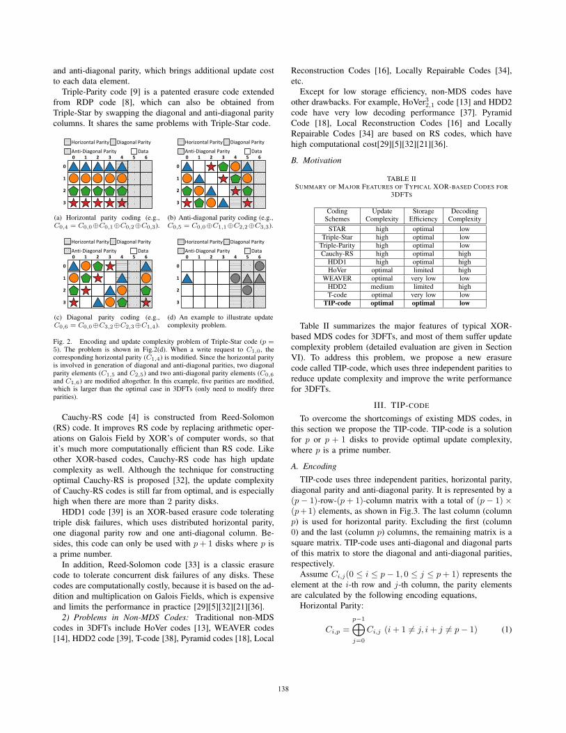
and anti-diagonal parity, which brings additional update cost
to each data element.
Triple-Parity code [9] is a patented erasure code extended
from RDP code [8], which can also be obtained from
Triple-Star by swapping the diagonal and anti-diagonal parity
columns. It shares the same problems with Triple-Star code.
0
1
2
3
0 1 2 3 4 5 6Data
Horizontal Parity
Anti-Diagonal Parity
Diagonal Parity
(a) Horizontal parity coding (e.g.,C0,4 = C0,0⊕C0,1⊕C0,2⊕C0,3).
0 1 2 3 4 5 6
0
1
2
3
Data
Horizontal Parity
Anti-Diagonal Parity
Diagonal Parity
(b) Anti-diagonal parity coding (e.g.,C0,5 = C0,0⊕C1,1⊕C2,2⊕C3,3).
0 1 2 3 4 5 6
0
1
2
3
Data
Horizontal Parity
Anti-Diagonal Parity
Diagonal Parity
(c) Diagonal parity coding (e.g.,C0,6 = C0,0⊕C3,2⊕C2,3⊕C1,4).
0
1
2
3
0 1 2 3 4 5 6Data
Horizontal Parity
Anti-Diagonal Parity
Diagonal Parity
(d) An example to illustrate updatecomplexity problem.
Fig. 2. Encoding and update complexity problem of Triple-Star code (p =5). The problem is shown in Fig.2(d). When a write request to C1,0, thecorresponding horizontal parity (C1,4) is modified. Since the horizontal parityis involved in generation of diagonal and anti-diagonal parities, two diagonalparity elements (C1,5 and C2,5) and two anti-diagonal parity elements (C0,6
and C1,6) are modified altogether. In this example, five parities are modified,which is larger than the optimal case in 3DFTs (only need to modify threeparities).
Cauchy-RS code [4] is constructed from Reed-Solomon
(RS) code. It improves RS code by replacing arithmetic oper-
ations on Galois Field by XOR’s of computer words, so that
it’s much more computationally efficient than RS code. Like
other XOR-based codes, Cauchy-RS code has high update
complexity as well. Although the technique for constructing
optimal Cauchy-RS is proposed [32], the update complexity
of Cauchy-RS codes is still far from optimal, and is especially
high when there are more than 2 parity disks.
HDD1 code [39] is an XOR-based erasure code tolerating
triple disk failures, which uses distributed horizontal parity,
one diagonal parity row and one anti-diagonal column. Be-
sides, this code can only be used with p+ 1 disks where p is
a prime number.
In addition, Reed-Solomon code [33] is a classic erasure
code to tolerate concurrent disk failures of any disks. These
codes are computationally costly, because it is based on the ad-
dition and multiplication on Galois Fields, which is expensive
and limits the performance in practice [29][5][32][21][36].
2) Problems in Non-MDS Codes: Traditional non-MDS
codes in 3DFTs include HoVer codes [13], WEAVER codes
[14], HDD2 code [39], T-code [38], Pyramid codes [18], Local
Reconstruction Codes [16], Locally Repairable Codes [34],
etc.
Except for low storage efficiency, non-MDS codes have
other drawbacks. For example, HoVer32,1 code [13] and HDD2
code have very low decoding performance [37]. Pyramid
Code [18], Local Reconstruction Codes [16] and Locally
Repairable Codes [34] are based on RS codes, which have
high computational cost[29][5][32][21][36].
B. Motivation
TABLE IISUMMARY OF MAJOR FEATURES OF TYPICAL XOR-BASED CODES FOR
3DFTS
Coding Update Storage DecodingSchemes Complexity Efficiency Complexity
STAR high optimal lowTriple-Star high optimal low
Triple-Parity high optimal lowCauchy-RS high optimal high
HDD1 high optimal highHoVer optimal limited high
WEAVER optimal very low lowHDD2 medium limited highT-code optimal very low low
TIP-code optimal optimal low
Table II summarizes the major features of typical XOR-
based MDS codes for 3DFTs, and most of them suffer update
complexity problem (detailed evaluation are given in Section
VI). To address this problem, we propose a new erasure
code called TIP-code, which uses three independent parities to
reduce update complexity and improve the write performance
for 3DFTs.
III. TIP-CODE
To overcome the shortcomings of existing MDS codes, in
this section we propose the TIP-code. TIP-code is a solution
for p or p + 1 disks to provide optimal update complexity,
where p is a prime number.
A. Encoding
TIP-code uses three independent parities, horizontal parity,
diagonal parity and anti-diagonal parity. It is represented by a
(p− 1)-row-(p+ 1)-column matrix with a total of (p− 1)×(p+1) elements, as shown in Fig.3. The last column (column
p) is used for horizontal parity. Excluding the first (column
0) and the last (column p) columns, the remaining matrix is a
square matrix. TIP-code uses anti-diagonal and diagonal parts
of this matrix to store the diagonal and anti-diagonal parities,
respectively.
Assume Ci,j(0 ≤ i ≤ p− 1, 0 ≤ j ≤ p+ 1) represents the
element at the i-th row and j-th column, the parity elements
are calculated by the following encoding equations,
Horizontal Parity:
Ci,p =
p−1⊕j=0
Ci,j (i+ 1 �= j, i+ j �= p− 1) (1)
138138

1
2
3
0
0 1 2 3 4 5
Data Horizontal ParityAnti-Diagonal ParityDiagonal Parity
(a) Horizontal parity coding (e.g., C0,5 = C0,0⊕C0,2 ⊕ C0,3).
1
2
3
0
0 1 2 3 4 5
Data Horizontal ParityAnti-Diagonal ParityDiagonal Parity
(b) Diagonal parity coding (e.g., C0,1 = C0,0 ⊕C3,2 ⊕ C1,4).
1
2
3
0
0 1 2 3 4 5
Data Horizontal ParityAnti-Diagonal ParityDiagonal Parity
(c) Anti-diagonal parity (e.g., C0,4 = C0,0 ⊕C1,1 ⊕ C2,2).
Fig. 3. Encoding of TIP-code (p = 5)
Diagonal Parity:
Ci,i+1 =
p−1⊕j=0
C〈i−j〉p,j
(〈i− j〉p �= p− 1, 〈i− j〉p + 1 �= j)
(2)
Anti-diagonal Parity:
Ci,p−1−i =
p−1⊕j=0
C〈i+j〉p,j
(〈i+ j〉p �= p− 1, 〈i+ j〉p + j �= p− 1)
(3)
Fig.3 shows an example of TIP-code for a 6-disk array
(p = 5). The horizontal parity coding is presented in Fig.3(a).
We use different shapes to indicate different sets of horizontal
parity elements and the corresponding data elements. For
example, C0,5 is calculated by C0,5 = C0,0⊕C0,2⊕C0,3. The
diagonal parity coding of TIP-code is given in Fig.3(b). For ex-
ample, the parity element C0,1 is calculated by C0,1 = C0,0⊕C3,2⊕C1,4. The anti-diagonal parity is shown in Fig.3(c), an
example is given as well (C0,4 = C0,0 ⊕ C1,1 ⊕ C3,3).
B. Construction Process
Based on the data/parity layout and the encoding scheme,
the construction of TIP-code is straightforward. We first fill in
all data elements, then we calculate the horizontal, diagonal
and anti-diagonal parity elements according to Equations 1-3.
C. Correctness Analysis
In this part, we give a brief demonstration of the reconstruc-
tion process to show that TIP-code can recover the concurrent
failures of any three disks.
1) Redefinition of Parity Chains: To simplify our discus-
sion, we first redefine the parity chains based on an equivalent
layout of TIP-code shown in Fig.4, which follows the steps as
below,
1) Move diagonal parity elements to an additional bottom
row within a same column.
2) Move anti-diagonal parity elements to an additional top
row within a same column.
3) Set the original diagonal/anti-diagonal parity elements
to 0, which are called empty elements.
For example, in Fig.4, a diagonal parity element C0,1 is
moved to C4,1, and an anti-diagonal parity element C3,1 is
moved to C−1,1.
1
2
3
4
-1
0
0 1 2 3 4 5
1
2
3
4
-1
0
0 1 2 3 4 5
Empty ElementsAdditional Rows to Store Diagonal & Anti-Diagonal Parities
Data Horizontal Parity
Fig. 4. An equivalent layout of TIP-code constructed by moving the diagonaland anti-diagonal parity elements to additional rows (p = 5).
We denote the element at the i-th row and j-th column in
the new layout as Di,j(−1 ≤ i ≤ p − 1, 0 ≤ j ≤ p), and the
corresponding horizontal, diagonal and anti-diagonal parities
satisfy the conditions as below,
Horizontal Parity,
S =
p−2⊕r=0
Dr,p (4)
p−1⊕j=0
Di,j =
{Di,p (0 ≤ i ≤ p− 2)
S (i = −1 or i = p− 1)(5)
Diagonal and anti-diagonal Parities,
p−1⊕j=0
D〈i−j〉p,j = 0 (0 ≤ i ≤ p− 1) (6)
p−1⊕j=0
Dp−2−〈i−j〉p,j = 0 (0 ≤ i ≤ p− 1) (7)
139139

In Equation 4, S is the sum of XOR calculations among
all data elements. It can be computed via XOR operations
among all the horizontal parity elements in Equation 4 as well.
Obviously, S can also be got by diagonal or anti-diagonal
parity elements, which are stored on the top and bottom row
of D.
2) Proof of Correctness: To prove that TIP-code is correct,
we consider one stripe. The reconstruction of multiple stripes
is just a matter of scale and similar to the reconstruction of a
single stripe.
Theorem 1: A (p−1)-row-(p+1)-column stripe constructed
according to the TIP-code scheme can be reconstructed under
arbitrary triple disk failures.
Proof: There are two cases of triple disk failures, depend-
ing on whether horizontal parity (column p) is lost or not.
Suppose the three failed disks are f1, f2 and f3, and assume
that 0 ≤ f1 < f2 < f3 ≤ p. Let u = f2 − f1 be the distance
between the two failed columns.
Case 1: Column p fails. It means f3 = p, 0 ≤ f1 < f2 ≤p− 1.
In this scenario, there are two failures in the first p disks.
Therefore, we only need to prove that TIP-code without the
horizontal parity can tolerate double disk failures. Then it is
easy to recover the remaining elements via Equation 1.
We first define the following sequence of two-integer tuples
(Tk, T′k) with 0 ≤ k ≤ p where,
Tk = 〈(p− 1)− k · u〉pT ′k =
1 + (−1)k+1
2f1 +
1 + (−1)k2
f2(8)
Given the sequence of tuples (Tk, T′k), we define another
sequence of tuples (p−2−Tk, T′k) with 0 ≤ k ≤ p. Each tuple
in these two sequences can be seen as an element in matrix D,
whose row number and column number are specified by the
two integers in this tuple. Since T ′k ∈ {f1, f2}, the elements
are always on the failed columns.
Fig.5 shows an example of the two sequences of elements
in the layout of TIP-code with 6 disks, assuming the column
2 and 3 are lost.
1
2
3
4
-1
0
0 1 2 3 4 5
1
2
3
4
-1
0
0 1 2 3 4 5
Disk Failures Disk Failures
Empty ElementsAdditional Rows to Store Diagonal & Anti-Diagonal Parities
Data Horizontal Parity
Fig. 5. Example of sequences (Tk, T′k) and (p−2−Tk, T
′k) in TIP-code’s
layout, assuming column 2 and column 3 are failed (p = 5).
Based on previous sequences, they have the following
properties,
Property 1: (Tk, T′k) and (p−2−Tk, T
′k) are two sequences
of elements covering all the elements on the two lost columns
d1 and d2 with row number ranging from −1 to p− 1.
First, it’s easy to verify that the elements in each sequence
are distinct from each other. Then, suppose there exists some
i and j that makes (Ti, T′i ) equals to (p − 2 − Tj , T
′j), then
Ti + Tj = p− 2 is required, and both of i and j are even or
odd so that they can be on the same disk. It’s not hard to get
〈i + j〉p = 0, which means i = j = 0 or i = j = p − 1. In
both cases, the corresponding elements are actually different.
Property 2: The adjacent elements in the sequences
(Tk, T′k) and (p − 2 − Tk, T
′k) are always in the same parity
chain.
The adjacent elements in these two sequences always have
offset of u or −u (mod p) on rows and columns, thus these
two elements should be in the same diagonal and anti-diagonal
parity chains. Besides, the XOR sum of them can be calculated
by XOR sum of all the surviving elements in that parity chain.
Property 3: In each of the sequences, there are two empty
elements.
There are two empty elements in each column, and for
column j, the row number of the empty elements are j − 1and p − 1 − j, whose sum is p − 2. From the property 1
and the definition of the two sequences, we can see that the
elements with row number Ti and p − 2 − Ti on the same
column are always in different sequences, so the two empty
elements in each column are in different sequences. Therefore
each sequence has exactly two empty elements.
Finally, the decoding algorithm for this case is presented
here. We first generate two sequences of elements (Tk, T′k) and
(p−2−Tk, T′k) according to the Equation 8, then we locate an
empty element in each of the sequences. Since the XOR sum
of any adjacent elements in each sequence can be calculated
by Equations 6 and 7, we can start from the neighbors of
the empty element, and decode the entire sequence. This
reconstruction method is similar to some RAID-6 codes.
Case 2: Column p is survived, which means the three
failures are among the first p disks, thus 0 ≤ f1 < f2 <f3 ≤ p− 1.
The detailed demonstration in this scenario is similar to the
reconstruction process as shown in Section III-D.
D. Reconstruction Process
From Theorem 1, when column p fails, we can recover the
lost data as the same process in RAID-6. Here we focus on
the reconstruction process when 0 ≤ f1 < f2 < f3 ≤ p − 1.
We use the following steps to reconstruct the lost data.
1) Constructing matrix E: We define a new matrix E with
p rows and p columns. The element on the i-th row and j-
th column of E is denoted as Ei,j(0 ≤ i, j ≤ p − 1). Each
element is calculated by the following equation:
140140
Ei,j = Di,j ⊕Dp−2−i,j (9)
This matrix has an elegant property for decoding. The ele-
ments in horizontal, diagonal and anti-diagonal parity chains
of matrix E satisfy,
p−1⊕j=0
Ei,j =
{Di,p ⊕Dp−2−i,p (0 ≤ i ≤ p− 2)
0 (i = p− 1)(10)
p−1⊕j=0
E〈i−j〉p,j = 0 (0 ≤ i ≤ p− 1) (11)
p−1⊕j=0
E〈i+j〉p,j = 0 (0 ≤ i ≤ p− 1) (12)
To verify each of them, we can always expand the Ei,j
according to Equation 9, and then use the properties of D to
prove. For example for Equation 10, we have:
p−1⊕j=0
Ei,j =
p−1⊕j=0
(Di,j ⊕Dp−2−i,j)
= (
p−1⊕j=0
Di,j)⊕ (
p−1⊕j=0
Dp−2−i,j)
=
{Di,p ⊕Dp−2−i,p when 0 ≤ i ≤ p− 2
S ⊕ S = 0 when i = p− 1
Note that the last step is derived from Equation 5. Then it’s
similar to verify the other two equations, and we omit them
in this paper.
2) Calculating syndromes4: Due to failed columns, the
XOR of the survived elements in each parity chain in Equa-
tions 10, 11 and 12 is non-zero and we denote it as syndrome.
To be specific, we use Sr,0, Sr,1 and Sr,2 to represent the
XOR of surviving elements in the horizontal, diagonal and
anti-diagonal parity chains of Er,0.
3) Construct 4-tuples5 from syndromes: We start from
decoding the middle column f2 of matrix E. We first calculate
the XOR sum of 4 syndromes as follows,
Xr = Sr,0 ⊕ S〈r+u+v〉p,0 ⊕ S〈r+f3〉p,1 ⊕ S〈r−f1〉p,2 (13)
The 4 syndromes form a cross pattern, which is shown
in Fig.6(a). In this pattern, the four elements in f1 and f3are canceled, leaving 4 unknowns in the middle column f2,
whose XOR sum is Xr. We formulate our observation as the
following equation,
Er,d2 ⊕E〈r+v〉p,d2⊕E〈r+u〉p,d2
⊕E〈r+u+v〉p,d2= Xr (14)
4Syndromes: the XOR sum of the surviving data or parity elementsparticular parity chain, as introduced in [19].
5n-tuple: n elements on the same column.
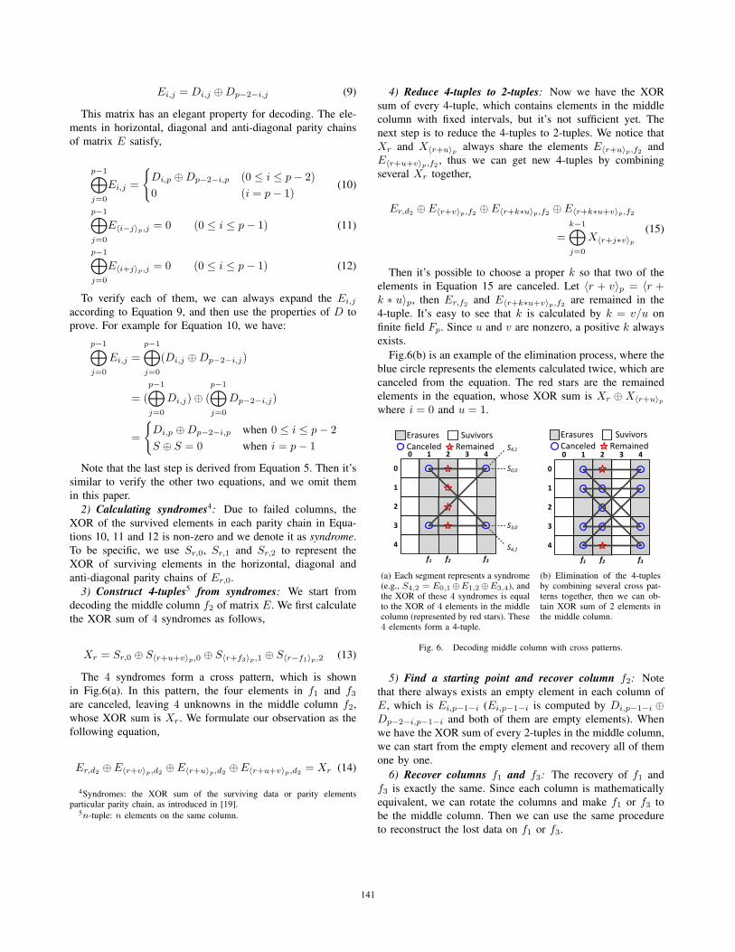
4) Reduce 4-tuples to 2-tuples: Now we have the XOR
sum of every 4-tuple, which contains elements in the middle
column with fixed intervals, but it’s not sufficient yet. The
next step is to reduce the 4-tuples to 2-tuples. We notice that
Xr and X〈r+u〉p always share the elements E〈r+u〉p,f2 and
E〈r+u+v〉p,f2 , thus we can get new 4-tuples by combining
several Xr together,
Er,d2 ⊕ E〈r+v〉p,f2 ⊕ E〈r+k∗u〉p,f2 ⊕ E〈r+k∗u+v〉p,f2
=k−1⊕j=0
X〈r+j∗v〉p(15)
Then it’s possible to choose a proper k so that two of the
elements in Equation 15 are canceled. Let 〈r + v〉p = 〈r +k ∗ u〉p, then Er,f2 and E〈r+k∗u+v〉p,f2 are remained in the
4-tuple. It’s easy to see that k is calculated by k = v/u on
finite field Fp. Since u and v are nonzero, a positive k always
exists.
Fig.6(b) is an example of the elimination process, where the
blue circle represents the elements calculated twice, which are
canceled from the equation. The red stars are the remained
elements in the equation, whose XOR sum is Xr ⊕X〈r+u〉pwhere i = 0 and u = 1.
0
1
2
3
4
0 1 2 3 4
Erasures SuvivorsCanceled Remained
S0,0
S4,1
S3,0
S4,2f1 f2 f3
(a) Each segment represents a syndrome(e.g., S4,2 = E0,1⊕E1,2⊕E3,4), andthe XOR of these 4 syndromes is equalto the XOR of 4 elements in the middlecolumn (represented by red stars). These4 elements form a 4-tuple.
0
1
2
3
4
0 1 2 3 4
f1 f2 f3
Erasures SuvivorsCanceled Remained
(b) Elimination of the 4-tuplesby combining several cross pat-terns together, then we can ob-tain XOR sum of 2 elements inthe middle column.
Fig. 6. Decoding middle column with cross patterns.
5) Find a starting point and recover column f2: Note
that there always exists an empty element in each column of
E, which is Ei,p−1−i (Ei,p−1−i is computed by Di,p−1−i ⊕Dp−2−i,p−1−i and both of them are empty elements). When
we have the XOR sum of every 2-tuples in the middle column,
we can start from the empty element and recovery all of them
one by one.
6) Recover columns f1 and f3: The recovery of f1 and
f3 is exactly the same. Since each column is mathematically
equivalent, we can rotate the columns and make f1 or f3 to
be the middle column. Then we can use the same procedure
to reconstruct the lost data on f1 or f3.
141141
7) Decode matrix D in the same way: After E is recov-
ered, the final step is to reconstruct the matrix D. This time,
we ignore the additional top row and the horizontal parity
column of D, which makes D a p-by-p matrix. The horizontal
and diagonal parity chains of D remain unchanged, which is
given in Equation 5 and 6. Due to the absence of the top row,
the anti-diagonal parity chains are now defined by,
p−1⊕j=0
D〈i+j〉p,j = Ep−1,p−1−i (16)
This equation needs a little more explanation. We have
already known that⊕p−1
j=0 Dp−2−〈i−j〉p,j = 0 according to
Equation 7. Let k = 〈p− 2− i〉p, we have:
p−1⊕j=0
D〈i+j〉p,j = (
p−1⊕j=0
D〈i+j〉p,j)⊕ (
p−1⊕j=0
Dp−2−〈k−j〉p,j)
=
p−1⊕j=0
(D〈i+j〉p,j ⊕Dp−2−〈p−2−i−j〉p,j)
and
D〈i+j〉p,j ⊕Dp−2−〈p−2−i−j〉p,j
=
{D〈i+j〉p,j ⊕D〈i+j〉p,j = 0 when 〈i+ j〉p �= p− 1
Dp−1,j ⊕D−1,j = Ep−1,j when 〈i+ j〉p = p− 1
Then D〈i+j〉p,j⊕Dp−2−〈p−2−i−j〉p,j is nonzero only when
〈i+ j〉p = p− 1, so j = p− 1− i.Now we have the parity chains of D in the same row, same
diagonal and the same anti-diagonal. Besides, we have at least
one empty element in each column of D, which is Di,p−1−i.
We can decode D using the same algorithm as decoding E.
IV. IMPLEMENTATION
In this section, we discuss the implementation issues of TIP-
code. Our implementation is based on a bit matrix6 method.
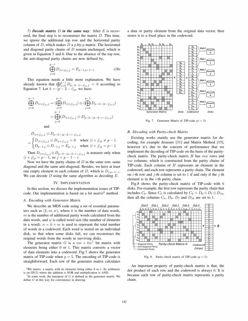
A. Encoding with Generator Matrix
We describe an MDS code using a set of essential parame-
ters such as (k,m,w), where k is the number of data words,
m is the number of additional parity words calculated from the
data words, and w is called word size (the number of elements
in a word). n = k +m is used to represent the total number
of words in a codeword. Each word is stored on an individual
disk, so that when some disks fail, we can reconstruct the
original words from the words in surviving disks.
The generator matrix G is a nw × kw7 bit matrix with
elements being either 0 or 1. This matrix converts a vector
of data elements into a codeword. Fig.7 shows the generator
matrix of TIP-code when p = 5. The encoding of TIP-code is
straightforward. Each row of the generator matrix calculates
6Bit matrix: a matrix with its elements being either 0 or 1. Its arithmeticis on GF(2) where the addition is XOR and multiplication is AND.
7In some work, the transpose of G is defined as the generator matrix. Wedefine G in this way for convenience in drawing.
a data or parity element from the original data vector, then
stores it to a fixed place in the codeword.
Generator Matrix Data Codeword
* =
Disks
D1D1
D2D2
D3D3
C0C0
D4D4
D5D5
C1C1
D6D6
C2C2
C3C3
D7D7
D8D8
C4C4
C5C5
D9D9
C6C6
D10D10
D11D11
C7C7
C8C8
C9C9
C10C10
C11C11
55
44
33
22
11
00
D0
D1
D2
D3
D4
D5
D6
D7
D8
D9
D10
D11
C0
C1
C2
C3
C4
C5
C6
C7
C8
C9
C10
C11
D0
D1
D2
D3
D4
D5
D6
D7
D8
D9
D10
D11
D0D0
D0 ... D3D0 ... D3 D4 ... D7D4 ... D7 D8 ... D11D8 ... D11
Disk 0
Disk 1
Disk 2
Disk 3
Disk 4
Disk 5
Fig. 7. Generator Matrix of TIP-code (p = 5)
B. Decoding with Parity-check Matrix
Existing works mainly use the generator matrix for de-
coding, for example Jerasure [31] and Matrix Method [15],
however it’s due to the concern of performance that we
implement the decoding of TIP-code on the basis of the parity-
check matrix. The parity-check matrix H has mw rows and
nw columns, which is constructed from the parity chains of
TIP-code. Each column of H represents an element in the
codeword, and each row represents a parity chain. The element
on i-th row and j-th column is set to 1 if and only if the j-th
element is in the i-th parity chain.
Fig.8 shows the parity-check matrix of TIP-code with 6disks. For example, the first row represents the parity chain that
includes C0. Since C0 is calculated by C0 = D0⊕D7⊕D10,
then all the columns C0, D0, D7 and D10 are set to 1.
D0
D1
D2
D3
D4
D5
D6
D7
D8
D9
D10
D11
C0
C1
C2C3
C4C5
C6
C7C8C9C10C11
22C2C55C5C77C7C66C6C44C4C33C3C11C1C88C8C99C9C100C10C111C11
C00C0D0D0 D1D1 D2D2 D3D3 C0C0 D4D4 D5D5 C1C1 D6D6 C2C2 C3C3 D7D7 D8D8 C4C4 C5C5 D9D9 C6C6 D10D10D111D11 C7C7 C8C8 C9C9 C100C10 C11C11
* = 0
Disk 0 Disk 1 Disk 2 Disk 3 Disk 4 Disk 5
Horizontal Parity
Parity-check Matrix H Codeword(Stripe)
Diagonal ParityAnti-diagonal Parity
Fig. 8. Parity-check matrix of TIP-code (p = 5)
An important property of parity-check matrix is that, the
dot product of each row and the codeword is always 0. It is
because each row of parity-check matrix represents a parity
chain.
142142

To illustrate how to decode with parity-check matrix, let’s
take an example where three of the disks are erased. The
elements on the erased disks are now regarded as unknowns.
Suppose the erased disks are 0, 1 and 3, then Fig.9 shows the
decoding procedure.
To decode, we split the parity-check matrix H into two
parts, one with columns on the erased disks, and the other
with columns on the survived disks. We calculate the product
of H and the codeword like before, except that we put all
the lost data on one side, and put all the survivors on the
other side. The XOR sum of these two parts should be 0,
which means these two parts equal to each other. The side
containing survivors can be calculated directly, and we denote
them as syndromes, while the other side is a product of a
matrix and a vector of unknowns (lost data). We can see that
the decoding of TIP-code is equivalent to solving a system of
linear equations.
D00D0 D1D1 D2D2 D33D3 C00C0 D4D4 D55D5 C1C1 D66D6 C2C2 C33C3 D7D7
D0D1D2D3
D4D5
D6
D7C0
C1
C2C3
k*wsurvivors
D88D8 C4C4 C55C5 D99D9 C66C6 D100D10D11D11 C7C7 C88C8 C99C9 C100C10
D8
D9
D10D11
C4C5
C6
C7C8C9C10C11
=* *
m*wunknowns
11C11
55442200
Coefficient Matrix (H')
11
Syndromes
33Parity-check Matrix
Fig. 9. Decoding the erasures on disk 0, 1, 3
To calculate the unknowns, we compute the inverse of H ′
and multiply it with the syndromes. For a coding scheme
being MDS, it must tolerate the loss of any m disks, therefore
every possible matrix H ′ is invertible. A typical algorithm to
calculate H ′−1 is presented in [13].
C. Optimization techniques for Decoding
In this sub-section, we introduce the two techniques used
in our implementation to speedup the decoding of TIP-code.1) Bit Matrix Scheduling: The first technique is called
bit matrix scheduling, which is proposed in [28] to reduce
the number of XOR’s used in calculating the matrix-vector
product. Interested reader can refer the original paper for
more detail. We observed that when there are at most 2erasures on data disks, this algorithm can always produce
the optimal decoding scheme for TIP-code. Furthermore, we
propose another optimization algorithm to handle the cases
that all the three erasures are on the data disks.2) Iterative Reconstruction: The second technique is de-
rived from the observation that, if three of the data disks
are erased, then decoding them together is not the best
choice. Instead, we first recover one disk, then we update
the syndromes of diagonal and anti-diagonal parity chains,
finally we construct a decoding matrix again to recover the
rest 2 erasures. Since there are only 2 erasures, the bit
matrix scheduling algorithm can produce the optimal recovery
scheme, meanwhile the update on syndromes brings very small
overhead. This approach is more efficient when n is large.
The decoding algorithm based on parity-check matrix and
the two optimization techniques make the decoding of TIP-
code very efficient. In Section VI-C we will see that the
decoding speed of TIP-code is faster than all existing erasure
codes.
V. PROPERTY ANALYSIS
In this section, we show that TIP-code has the optimal up-
date complexity, encoding complexity and storage efficiency.
A. Optimal Update Complexity
According to previous literature [13], the optimal update
complexity is three in 3DFTs. It means that the optimal case
for a single write request is to modify three parity elements.
From the construction of TIP-code, each data element takes
part into the generation of only three parity elements (one hor-
izontal, one diagonal and one anti-diagonal parity elements).
Obviously, TIP-code has optimal update complexity.
B. Optimal Encoding Complexity
From the construction of TIP-code, to generate all the
3 ∗ (p − 1) parity elements in a (p − 1)-row-(p + 1)-column
array, each of the remaining (p − 1) ∗ (p − 2) data elements
needs to take part into 3 XOR operations. Thus, the encoding
complexity of TIP-code is [3 ∗ (p − 1) ∗ (p − 2) − 3 ∗ (p −1)]/[(p−1)∗ (p−2)] = 3−3/(p−2) XOR per data element.
It is the lower bound for XOR-based codes and a related proof
is given in [41][42].
C. Optimal Storage Efficiency
From the correctness analysis of TIP-code, TIP-code is
essentially an MDS code, which has the optimal storage
efficiency [44][20][14].
VI. EVALUATION
In this section, we evaluate TIP-code to demonstrate its
effectiveness on write, encoding and decoding performance.
Specifically, write performance is affected by the update
complexity of coding schemes.
A. Evaluation Methodology
We compare TIP-code with the following XOR-based MDS
codes tolerating triple disk failures, which are already intro-
duced in Section II. Triple-Parity code [9] is excluded in our
evaluation, because it’s equivalent to Triple-Star code.
• TIP-code for p and p+ 1 disks;
• STAR code [19] for arbitrary disks;
• Triple-Star code [41] for arbitrary disks;
• Cauchy-RS codes [4] for arbitrary disks;
• HDD1 code [39] for p+ 1 disks.
143143
1) Write Performance Metrics: When a write request is
sent to a disk array, some data and their corresponding parities
need to be modified. We further categorize a write request into
two types according to how many data elements are modified.
The first type is single write, which writes exactly one data
element in disk array. It’s very common in storage applications
and real I/O workloads. The second type is partial stripe write,
which writes 2 or more consecutive data elements.
We use the following metrics to evaluate the write perfor-
mance under various access patterns,
• Single write complexity: average number of elements
need to be updated when a single data element is written.
• Partial stripe write complexity: average number of ele-
ments need to be updated when l (l > 1) consecutive
data elements are written.
• Synthetic write complexity: average number of elements
need to be updated for write requests in a real I/O
workload, including single writes, partial stripe writes and
full stripe writes.
The single write and partial stripe write performance are
evaluated under uniform I/O workload, and the synthetic write
complexity is evaluated using real I/O workloads. To evalu-
ate the synthetic write complexity, we use MSR Cambridge
Traces [24] in our evaluation, which are one week block I/O
traces collected from enterprise servers at Microsoft Research
Cambridge in 2007. The chunk size8 is set to 8KB, which is
a typical configuration in storage systems.
TABLE IIISUMMARY OF TRACES
TraceRequests
IOPS Write(%)Avg. Req
(×106) Len.(KB)
financial 1 5.33 122 76.84 3.38financial 2 3.70 90.24 17.66 2.39
prxy 0 12.52 207.60 96.94 4.76src2 0 1.56 22.29 88.66 7.21stg 0 2.03 33.58 84.81 11.57usr 0 2.24 37.00 59.58 22.67
In addition to numerical analysis, we also use simulation re-
sults to show that TIP-code can improve the write performance
in real disk arrays. We conduct our experiment on DiskSim
[6], an efficient and highly-configurable disk simulator. The
following metric is used to evaluate the performance under
various access patterns,
• Average Response Time: average time used between the
arrival and completion of requests in traces.
To evaluate the average response time, we use Financial
Trace [12], which are block I/O traces from OLTP applications
running at a large financial institution in 2002. The statistics
of these traces are shown in Table III.
8Chunk size: the size of a data element, which is also known as stripe unitsize, block size or packet size[28][29][17].
2) Encoding/Decoding Performance Metrics: Encoding
and decoding performance are significant for erasure codes.
The following two metrics are used in our evaluation:
• Encoding/decoding speed: the amount of data en-
coded/decoded per second (in GB/s).
• Encoding/decoding complexity: average number of XOR
operations per data element needed in encoding/decoding.
The encoding/decoding speed is evaluated on a Linux ma-
chine with 2.0GHz Intel Core E5-2620 CPUs and 32G RAM
running 64-bit Ubuntu 14.04. Only one core is used for com-
puting. We use the same packet size9 for all coding methods,
which is set to 4KB. Since all these coding techniques are
independent to the content, we evaluate them by encoding or
decoding a 256MB random memory region.
Our final results are the average number of 1000 repeated
experiments. Since the decoding performance of XOR-based
erasure codes are related to the patterns of disk failures, each
time we randomly generate three failures, and these failures
can occur on both data and parity disks.
In our experiment, Cauchy-RS is implemented by Jerasure
2.0 [31], which is an open source library and widely used
in this literature. The other codes are implemented based
on their original papers. To eliminate the impacts of differ-
ent implementations, we also provide numerical results on
encoding/decoding complexity [37] as a validation of our
experiments.
B. Write Performance
In this sub-section, we give the evaluation results of TIP-
code compared to other typical codes on write performance.
6 9 12 15 18 21 24
Disk Array Size (n)
4.0
4.5
5.0
5.5
6.0
6.5
7.0
7.5
#ofmodifiedelements
TIP-code
Triple-Star
STAR
Cauchy-RS
HDD1
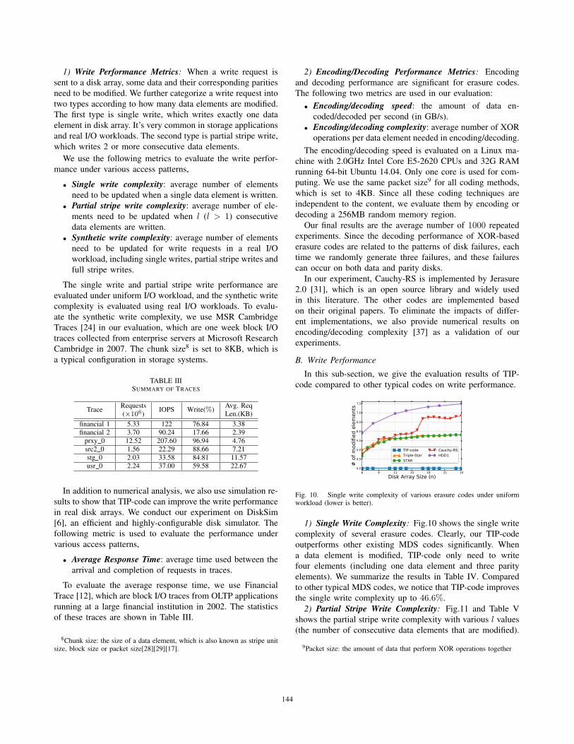
Fig. 10. Single write complexity of various erasure codes under uniformworkload (lower is better).
1) Single Write Complexity: Fig.10 shows the single write
complexity of several erasure codes. Clearly, our TIP-code
outperforms other existing MDS codes significantly. When
a data element is modified, TIP-code only need to write
four elements (including one data element and three parity
elements). We summarize the results in Table IV. Compared
to other typical MDS codes, we notice that TIP-code improves
the single write complexity up to 46.6%.
2) Partial Stripe Write Complexity: Fig.11 and Table V
shows the partial stripe write complexity with various l values
(the number of consecutive data elements that are modified).
9Packet size: the amount of data that perform XOR operations together
144144

TABLE IVIMPROVEMENT OF TIP-CODE OVER OTHER CODES ON SINGLE WRITE COMPLEXITY
Coding Disk Array Size (n)Schemes 6 8 12 14 18 20 24
Triple-Star 20.00% 25.00% 28.57% 29.41% 30.43% 30.77% 31.25%STAR 14.29% 23.08% 28.57% 29.03% 30.43% 30.61% 31.25%
Cauchy-RS 16.28% 23.08% 30.77% 31.52% 40.71% 40.56% 41.50%HDD1 32.20% 37.78% 42.56% 43.78% 45.33% 45.84% 46.60%
TABLE VIMPROVEMENT OF TIP-CODE OVER OTHER CODES ON PARTIAL STRIPE WRITE COMPLEXITY WHEN l = 2
Coding Disk Array Size (n)Schemes 6 8 12 14 18 20 24
Triple-Star 13.95% 18.02% 20.99% 21.70% 22.56% 22.84% 23.24%STAR 19.57% 28.63% 34.70% 35.26% 36.81% 37.02% 37.72%
Cauchy-RS 13.28% 18.02% 27.25% 26.89% 36.71% 34.29% 36.70%HDD1 32.11% 37.02% 40.44% 41.27% 42.32% 42.67% 43.18%
6 9 12 15 18 21 24
Disk Array Size (n)
5
6
7
8
9
10
#ofmodifiedelements
l=2
TIP-code Triple-Star STAR Cauchy-RS HDD1
6 9 12 15 18 21 24
Disk Array Size (n)
7
8
9
10
11
12
13
#ofmodifiedelements
l=3
6 9 12 15 18 21 24
Disk Array Size (n)
8
9
10
11
12
13
14
15
16
#ofmodifiedelements
l=4
6 9 12 15 18 21 24
Disk Array Size (n)
8
10
12
14
16
18
20
#ofmodifiedelements
l=5
Fig. 11. Partial stripe write complexity of various erasure codes underuniform workload (lower is better).
We select l from 2 to 5, which is typical in most real
workloads, such as MSR Cambridge Traces.
When l is small (e.g., l = 2, 3, 4), compared to other
MDS codes, TIP-code has the highest partial stripe write
performance. It can decrease the partial stripe write complexity
by up to 39.8%. When l is large (i.e., l = 5), the partial stripe
write complexity of TIP-code is a little higher than Cauchy-RS
code (about 5% on average). It is reasonable that Cauchy-RS
has much smaller word size w than TIP-code, which means
that less parity elements need to be modified in a stripe when
l ≥ w.
3) Synthetic Write Complexity: Fig.12 shows the average
number of modified elements for each write request under
different real workloads. In these workloads, the write requests
include single write, partial stripe write and full stripe write
requests. It is clear that TIP-code has the least number of I/Os
among all MDS codes, which decreases the write cost by up to
58.4%. With a larger array size of 3DFTs, TIP-code achieves
higher performance gain.
6 9 12 15 18 21 24
Disk Array Size (n)
4
5
6
7
8
9
10
11
#ofmodifiedelements
prxy_0
TIP-code Triple-Star STAR Cauchy-RS HDD1
6 9 12 15 18 21 24
Disk Array Size (n)
4
5
6
7
8
9
10
11
#ofmodifiedelements
src2_0
6 9 12 15 18 21 24
Disk Array Size (n)
5
6
7
8
9
10
11
12
#ofmodifiedelements
stg_0
6 9 12 15 18 21 24
Disk Array Size (n)
5
6
7
8
9
10
11
12
13
#ofmodifiedelements
usr_0
Fig. 12. Average number of I/Os per write request in various traces (chunksize = 8KB).
4) Average Response Time: Fig.13 shows the average
response time of the requests in different real workloads.
TIP-code achieves the best write performance among all
MDS codes for correcting triple disk failures. Particularly,
compared to STAR, Triple-Star, HDD1 and Cauchy-RS, TIP-
code reduces the average response time by up to 68.4%.
8 12 14
Disk Array Sizes (n)
0.0
0.5
1.0
1.5
2.0
2.5
3.0
3.5
Avg.ResponseTim
e(norm
alized)
financial 1
TIP-code Triple-Star STAR Cauchy_RS HDD1
8 12 14
Disk Array Sizes (n)
0.0
0.2
0.4
0.6
0.8
1.0
1.2
1.4
1.6
1.8
Avg.ResponseTim
e(norm
alized)
financial 2
Fig. 13. Average response time of I/Os in various traces.
145145

C. Encoding and Decoding Performance
(a) Encoding speed: the amount ofdata encoded per second (higher isbetter).
(b) Encoding complexity: averagenumber of XOR operations to encodea data element (lower is better).
Fig. 14. Encoding performance of various erasure codes.
1) Encoding Performance: The encoding performance of
various codes are shown in Fig.14. From this figure, compared
to other codes, we can see that TIP-code has the best encoding
performance, which speeds up the encoding process by up to
a factor of 1.72×.
(a) Decoding speed: the amount ofdata decoded per second (higher isbetter).
(b) Decoding complexity: averagenumber of XOR operations to decodea data element (lower is better).
Fig. 15. Decoding performance of various erasure codes.
2) Decoding Performance: Fig.15 shows the decoding
speed and complexity of various MDS codes. By using parity-
check matrix based decoding method, TIP-code achieves the
best decoding speed among all these codes, which accelerates
the decoding process by up to a factor of 1.67×.
D. Analysis
From the results in previous section, compared to typical
XOR-based MDS codes, TIP-code has great advantages on
write performance and encoding/decoding performance. There
are several reasons to achieve these gains. First, TIP-code
uses three independent parities, which has the lowest cost on
update complexity and minimum I/O cost on partial stripe
write requests. Second, TIP-code uses horizontal parities as
previous MDS codes [8][43], which reduce I/O cost for partial
stripe writes to continuous data element. Third, TIP-code is a
coding scheme based on XOR operations, which is an efficient
computation method to guarantee high encoding/decoding
performance.
VII. WORKING WITH ARBITRARY DISK ARRAY SIZES
In practical storage systems, it’s desirable for a coding
scheme with arbitrary disk array sizes. Typically, horizontal
codes (such as STAR and Triple-Star) are easy to reach this
goal via a method called codeword shortening[23], which
simply removes several data columns and regard the elements
in these columns as 0, meanwhile the encoding equations are
unchanged. The challenge for TIP-code lies on the fact that
most columns stores both data and parity elements. According
to the MDS property, if some parity elements are removed,
TIP-code cannot tolerate concurrent disk failures of any three
disks.
To address this issue, when a parity element is removed, we
choose a data element in this parity chain to store the XOR
sum of other data elements. This element no longer stores data
information, but plays the role of a parity element. We call this
element as adjuster.
We give an example as shown in Fig.16. In this example, we
want to remove the first and second columns from TIP-code
(p = 7), and adapt this code to 6 disks. C1,6 is an adjuster
for a parity chain {C0,0, C0,1, C5,2, C4,3, C2,5, C1,6}, and now
it’s calculated by C1,6 = C5,2 ⊕ C4,3 ⊕ C2,5 after the first
two columns are removed. The adjusters ensure that all the
encoding equations work the same way when several columns
are set to 0 and removed.
shortened columns Adjusters
0
1
2
3
4
5
0 1 2 3 4 5 6 7
Fig. 16. Change the array size from 8 disks to 6 disks of TIP-code byadjusters (e.g., adjuster C1,6 = C5,2 ⊕ C4,3 ⊕ C2,5).
By using adjusters, the construction process of TIP-code is
summarized as follows:
1) Preserve the space for adjusters if necessary, then en-
coding other data elements.
2) When a column is removed, calculate the adjusters, then
compute the remaining horizontal/diagonal/anti-diagonal
parity elements based on the encoding equations.
In the implementation of TIP-code, the adjusters are placed
on the second last column, which makes the calculation of
adjusters independent to each other. By using this technique,
the valid array sizes of TIP-code could be (p+3)/2 to p+1.
Enumeration results show that, TIP-code can cover arbitrary
disk array sizes smaller than 108.
VIII. CONCLUSION
In this paper, we propose TIP-code, a novel MDS array code
to tolerate triple disk failures. TIP-code uses three independent
parities to achieve optimal update complexity. Meanwhile, it
has excellent encoding and decoding speed due to the arith-
metic on XOR operations and its specialized implementation
146146
method. Compared to other popular MDS codes in 3DFTs,
TIP-code achieves advantages in the following aspects: 1)
reduces the single write complexity by up to 46.6%; 2)
decreases the partial stripe write complexity by up to 39.8%; 3)
increases the write performance by up to 58.4%; 4) accelerates
the encoding/decoding processes by up to a factor of 1.72×.
IX. ACKNOWLEDGEMENT
We thank Dr. Xubin He (from Virginia Commonwealth
University), our shepherd Dr. Wyatt Lloyd, and other anony-
mous reviewers for their insightful comments to improve
this paper. This work is partially sponsored by the National
Basic Research 973 Program of China (No. 2015CB352403),
the National Natural Science Foundation of China (NSFC)
(No. 61332001, No. 61261160502, No. 61272099 and No.
61303012), the Program for Changjiang Scholars and In-
novative Research Team in University (IRT1158, PCSIRT),
the Shanghai Innovative Action Plan (No. 13511504200), the
Shanghai Natural Science Foundation (No. 13ZR1421900),
the Scientific Research Foundation for the Returned Overseas
Chinese Scholars, and the the EU FP7 CLIMBER project (No.
PIRSES-GA-2012-318939).
REFERENCES
[1] M. Blaum et al. EVENODD: An efficient scheme for toleratingdouble disk failures in raid architectures. IEEE Trans. on Computers,44(2):192–202, 1995.
[2] M. Blaum et al. Partial-MDS codes and their application to RAID typeof architectures. IEEE Trans. on Information Theory, 59(7):4510–4519,2013.
[3] M. Blaum and R. Roth. On lowest density MDS codes. IEEE Trans.on Information Theory, 45(1):46–59, 1999.
[4] J. Bloemer et al. An XOR-based erasure-resilient coding scheme.Technical Report TR-95-048, International Computer Science Institute,August 1995.
[5] V. Bohossian et al. Computing in the RAID: A reliable array ofindependent nodes. IEEE Trans. on Parallel and Distributed Systems,12(2):99–114, 2001.
[6] J. Bucy et al. The disksim simulation environment version 4.0 refer-ence manual. Technical Report CMU-PDL-08-101, Carnegie MellonUniversity, May 2008.
[7] Y. Cassuto and J. Bruck. Cyclic lowest density MDS array codes. IEEETrans. on Information Theory, 55(4):1721–1729, 2009.
[8] P. Corbett et al. Row-Diagonal Parity for double disk failure correction.In Proc. of the USENIX FAST’04.
[9] P. Corbett and A. Goel. Triple parity technique for enabling efficientrecovery from triple failures in a storage array, September 2011. USPatent 8,015,472.
[10] G. Feng et al. New efficient MDS array codes for RAID part I: Reed-Solomon-like codes for tolerating three disk failures. IEEE Trans. onComputers, 54(9):1071–1080, 2005.
[11] G. Feng et al. New efficient MDS array codes for RAID part II: Rabin-like codes for tolerating multiple (≥ 4) disk failures. IEEE Trans. onComputers, 54(12):1473–1483, 2005.
[12] P. Goyal et al. CacheCOW: providing QoS for storage system caches.ACM SIGMETRICS Performance Evaluation Review, 31(1):306–307,2003.
[13] J. Hafner. HoVer erasure codes for disk arrays. In Proc. of the IEEE/IFIPDSN’06.
[14] J. Hafner. WEAVER codes: Highly fault tolerant erasure codes forstorage systems. In Proc. of the USENIX FAST’05.
[15] J. Hafner et al. Matrix methods for lost data reconstruction in erasurecodes. In Proc. of the USENIX FAST’05.
[16] C. Huang et al. Erasure coding in Windows Azure storage. In Proc. ofthe USENIX ATC’12.
[17] C. Huang et al. On optimizing XOR-based codes for fault-tolerantstorage applications. In Proc. of the ITW’07.
[18] C. Huang et al. Pyramid Codes: Flexible schemes to trade space foraccess efficiency in reliable data storage systems. In Proc. of the IEEENCA’07.
[19] C. Huang and L. Xu. STAR: An efficient coding scheme for correctingtriple storage node failures. IEEE trans. on Computers, 57(7):889–901,2008.
[20] C. Jin et al. P-Code: A new RAID-6 code with optimal properties. InProc. of the ICS’09.
[21] N. Joukov et al. RAIF: Redundant array of independent filesystems. InProc. of the MSST’07.
[22] M. Li and P. Lee. STAIR codes: a general family of erasure codesfor tolerating device and sector failures in practical storage systems. InProc. of the USENIX FAST’14.
[23] F. MacWilliams and N. Sloane. The theory of error-correcting codes,volume 16. Elsevier, 1977.
[24] D. Narayanan et al. Write off-loading: Practical power management forenterprise storage. ACM Trans. on Storage, 4(3):10, 2008.
[25] D. Patterson et al. A case for Redundant Arrays of Inexpensive Disks(RAID). In Proc. of the ACM SIGMOD’88.
[26] E. Pinheiro et al. Failure trends in a large disk drive population. InProc. of the USENIX FAST’07.
[27] J. Plank. A new minimum density RAID-6 code with a word size ofeight. In Proc. of the IEEE NCA’08.
[28] J. Plank. The RAID-6 Liberation codes. In Proc. of the USENIXFAST’08.
[29] J. Plank et al. A performance evaluation and examination of open-sourceerasure coding libraries for storage. In Proc. of the USENIX FAST’09.
[30] J. Plank et al. SD codes: Erasure codes designed for how storage systemsreally fail. In Proc. of the USENIX FAST’13.
[31] J. Plank and K. Greenan. Jerasure: A library in C facilitating erasurecoding for storage applications–version 2.0. Technical report, TechnicalReport UT-EECS-14-721, University of Tennessee, 2014.
[32] J. Plank and L. Xu. Optimizing Cauchy Reed-Solomon codes for Fault-Tolerant network storage applications. In Proc. of the IEEE NCA’06.
[33] I. Reed and G. Solomon. Polynomial codes over certain finite fields.Journal of the Society for Industrial & Applied Mathematics, 8(2):300–304, 1960.
[34] M. Sathiamoorthy et al. XORing elephants: Novel erasure codes for bigdata. In Proc. of the VLDB’13.
[35] B. Schroeder and G. Gibson. Disk failures in the real world: What doesan mttf of 1, 000, 000 hours mean to you? In Proc. of the USENIXFAST’07.
[36] Z. Shen and J. Shu. HV code: An all-around MDS code to improveefficiency and reliability of RAID-6 systems. In Proc. of the IEEE/IFIPDSN’14.
[37] P. Subedi and X. He. A comprehensive analysis of XOR-Basederasure codes tolerating 3 or more concurrent failures. In Proc. of theIPDPSW’13.
[38] D. Tang et al. A new class of highly fault tolerant erasure code for thedisk array. In Proc. of the PEITS’08.
[39] C. Tau and T. Wang. Efficient parity placement schemes for toleratingtriple disk failures in RAID architectures. In Proc. of the AINA’03.
[40] S. Wan et al. Code-M: A non-MDS erasure code scheme to support fastrecovery from up to two-disk failures in storage systems. In Proc. ofthe IEEE/IFIP DSN’10.
[41] Y. Wang et al. Triple-Star: A coding scheme with optimal encodingcomplexity for tolerating triple disk failures in RAID. InternationalJournal of Innovative Computing, Information and Control, 8(3):1731–1472, 2012.
[42] Y. Wang and G. Li. Rotary-code: Efficient mds array codes for RAID-6disk arrays. IEEE Trans. on Computers, 8(12):1917–1926, 2009.
[43] C. Wu et al. H-Code: A hybrid MDS array code to optimize partialstripe writes in RAID-6. In Proc. of the IPDPS’11.
[44] L. Xu and J. Bruck. X-Code: MDS array codes with optimal encoding.IEEE Trans. on Information Theory, 45(1):272–276, 1999.
[45] L. Xu et al. Low-Density MDS codes and factors of complete graphs.IEEE Trans. on Information Theory, 45(6):1817–1826, 1999.
147147