Embed Size (px)
Citation preview
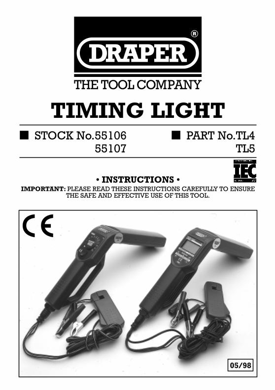
TIMING LIGHT■ STOCK No.55106 ■ PART No.TL4
55107 TL5
05/98
• INSTRUCTIONS •IMPORTANT: PLEASE READ THESE INSTRUCTIONS CAREFULLY TO ENSURE
THE SAFE AND EFFECTIVE USE OF THIS TOOL.
TIMING LIGHT■ STOCK No.55106 ■ PART No.TL4
55107 TL5
CONTENTS:Page No.
Engine timing...................................................................................................1About the timing light ...................................................................................1-2Safety precautions ............................................................................................3Vehicle service manuals...................................................................................3Applications ..................................................................................................4-5Timing light connection....................................................................................5Timing check...............................................................................................6-10Timing adjustment..........................................................................................11Troubleshooting .............................................................................................11Additional tests and tech tips ....................................................................11-13Cleaning the inductive pickup clip.................................................................13Parts Replacement..........................................................................................13
NOTE
EMI/RFI problems with Digital Timing Lights:
1. If the Digital Timing Light readout becomes inoperative or locks up during use,
disconnect and reconnect the timing light’s positive battery clamp from the battery to
reset the unit.
2. If the rpm reading on Digital Timing Lights is erratic, move and/or reverse the direction
of the inductive pickup to get a better signal input.
3. Some aftermarket ignition systems and/or specialty spark plug wires (solid core wires,
racing wires, off-road wires) radiate above normal Electro-Magnetic Interference (EMI)
and Radio Frequency Interference (RFI) which can cause improper operation of testing
equipment. Please contact these manufacturers for instructions on how to use an
inductive pickup with their systems.
Proper ignition timing is critical in order to achieve peak engine performance and to ensuremaximum fuel economy. An ignition system timing check is critical during any tune-up procedure.
DEFINITIONS OF TERMS
DIS: Distributorless Ignition System; vehicles are equipped with multiple coils and a “controlmodule” for controlling spark distribution. Such systems may also be referred to as EDIS, IDI, C3Ior EI.
ECM: Electronic Control Modules, the vehicle’s on-board computer system. May also be referredto as ECU, Brain or Module.
Ignition Timing: Checking when the No. 1 cylinder spark plug “fires” in relationship to a timingmark or other reference point.
Late Model: Refers to vehicles manufactured during the current model year to vehiclesmanufactured approximately four years earlier. For example: 1992 to 1997.
Tune Up: With reference to today’s “self-tuning” vehicles, the meaning of the term “tune-up”, haschanged significantly. A tune-up consists essentially of checking engine operation with OriginalEquipment Manufacturer’s (OEM) specifications. Adjustments are made and parts are replacedONLY if engine performance is not within OEM specifications
This Timing Light is designed for all 12 volt negative ground vehicles. Some models may also beused on vehicles equipped with DIS (distributorless ignition systems).
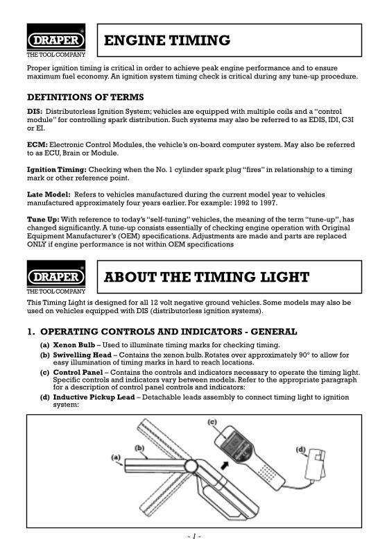
1. OPERATING CONTROLS AND INDICATORS - GENERAL(a) Xenon Bulb – Used to illuminate timing marks for checking timing.(b) Swivelling Head – Contains the xenon bulb. Rotates over approximately 90° to allow for
easy illumination of timing marks in hard to reach locations.(c) Control Panel – Contains the controls and indicators necessary to operate the timing light.
Specific controls and indicators vary between models. Refer to the appropriate paragraphfor a description of control panel controls and indicators:
(d) Inductive Pickup Lead – Detachable leads assembly to connect timing light to ignitionsystem:
ENGINE TIMING
ABOUT THE TIMING LIGHT
- 1 -
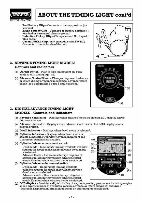
• Red Battery Clip – Connects to battery positive (+)terminal.
• Black Battery Clip – Connects to battery negative (-)terminal or bare metal chassis ground.
• Inductive Pickup Clip – Clamps around No. 1 sparkplug cable.
• Green DWELL Clip (only on models with DWELL) –Connects to the tach side of the coil.
2. ADVANCE TIMING LIGHT MODELS–Controls and indicators (a) On/Off Switch – Push to turn timing light on. Push
again to turn timing light off.(b) Advance Control Knob – Changes degrees of advance
or retard during a vacuum/mechanical advance/retardcheck (see paragraphs 2 page 8 and 3 page 9).
3. DIGITAL ADVANCE TIMING LIGHTMODELS – Controls and indicators(a) Advance + indicator—Displays when advance mode is selected. LCD display shows
degrees advance.(b) Advance - Indicator – Displays when advance mode is selected. LCD display shows
degrees retard.(c) Dwell indicator – Displays when dwell mode is selected.(d) Cylinder indicator – Displays when dwell mode is
selected. Indicates Cylinder/Advance Increment andDecrement switches are enabled.
(e) Cylinder/advance increment switch• Dwell Mode – Increments through available cylinder
settings for dwell check. Enabled when dwell modeis selected.
• Advance Mode – Increments through degrees ofadvance/retard during vacuum advance/retardcheck. Enabled when advance mode is selected.
(f) Cylinder/advance decrement switch• Dwell mode – Decrements through available
cylinder settings for dwell check. Enabled whendwell mode is selected.
• Advance mode – Decrements through degrees ofadvance/retard during vacuum advance/retardcheck. Enabled when advance mode is selected.
(g) LCD display – Provides a digital display of engine operating parameters including enginespeed (rpm), number of cylinders, vacuum advance or retard (degrees) and dwell(degrees). Displayed information depends on operating mode selected.
- 2 -
ABOUT THE TIMING LIGHT cont’d
(h) TACH indicator – Displays when tachometer mode is selected.(i) ON indicator – Blinks when timing light is operating.(j) Zeroing Switch – Returns LCD degrees advance/retard to zero. Enabled when advance
mode is selected.(k) Function (F) switch – Selects timing light operating mode (tachometer or dwell).(l) On/Off switch – Push to turn timing light on. Push again to turn timing light off.
4. OPERATING SPECIFICATIONSOperating Temperature: 32 to 135°F (0 to 43°C)Operating Humidity: 0 to 90% relative humidity
Always observe safety precautions whenever working on a vehicle.(a) Always wear safety eye protection.(b) Only work on your vehicle in a well-ventilated area.(c) Put transmission in “park” (for automatic) or “neutral” (for manual). Set parking brake.(d) Put blocks on drive wheels.(e) Avoid moving fan blades or any potentially moving parts.(f) Avoid hot engine parts.(g) Turn off ignition before connecting (or disconnecting) any testing equipment.(h) Please read your vehicle’s service manual and follow it’s safety procedure.
1. BEFORE YOU BEGINFix any known mechanical problems before performing any test.Make a thorough check before starting any test procedure. Loose or damaged hoses, wiring, orelectrical connectors are often responsible for poor engine performance. Please read yourvehicle’s service manual for proper connection of vacuum hoses, electrical wiring, and wiringharness connectors.Check the following areas:(a) All fluid levels(b) Air cleaner(c) Vacuum hoses(d) Belts(e) Electrical wiring(f) Electrical connectors(g) Spark plugs and spark plug wires
Contact your local car dealership, auto parts shop, bookshop or public library for availability ofthese manuals.
- 3 -
SAFETY PRECAUTIONS
VEHICLE SERVICE MANUALS
This timing light is designed for use on most late model import or domestic vehicles equippedwith conventional ignition systems. Some models will also operate on vehicles equipped with DIS(distributorless ignition systems).
• Requires a tach/dwell test to read engine rpm.
• Always prepare engine for timing before performing timing check. Refer to the vehicle’sEmission Control Label or service manual for timing procedures specific to the vehicle beingserviced. As a minimum, make the following preparations before timing:(a) Locate the timing mark and reference pointer. The timing mark and pointer are usually
located on the crankshaft pulley or vibration damper (on the front of the engine) or on theflywheel (between the engine and transmission).Refer to paragraph 1 for typical locations of timing marks on late model domestic andimport vehicles.Make sure the timing mark and pointer are clean and clearly visible.
(b) Make sure all spark plugs are in good condition and properly gapped.(c) Start and run the engine until it reaches its normal operating temperature.
TURN ENGINE OFF BEFORE CONNECTING TIMING LIGHT.
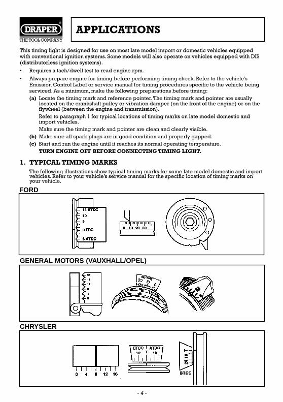
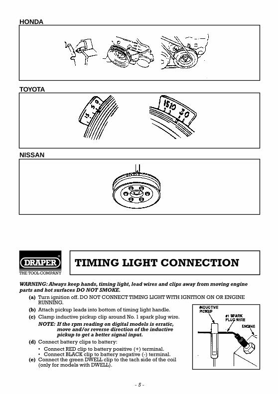
1. TYPICAL TIMING MARKSThe following illustrations show typical timing marks for some late model domestic and importvehicles. Refer to your vehicle’s service manual for the specific location of timing marks onyour vehicle.
APPLICATIONS
FORD
- 4 -
GENERAL MOTORS (VAUXHALL/OPEL)
CHRYSLER
- 5 -
HONDA
TOYOTA
NISSAN
TIMING LIGHT CONNECTION
WARNING: Always keep hands, timing light, lead wires and clips away from moving engineparts and hot surfaces DO NOT SMOKE.
(a) Turn ignition off. DO NOT CONNECT TIMING LIGHT WITH IGNITION ON OR ENGINERUNNING.
(b) Attach pickup leads into bottom of timing light handle.(c) Clamp inductive pickup clip around No. 1 spark plug wire.
NOTE: If the rpm reading on digital models is erratic,move and/or reverse direction of the inductivepickup to get a better signal input.
(d) Connect battery clips to battery:• Connect RED clip to battery positive (+) terminal.• Connect BLACK clip to battery negative (-) terminal.
(e) Connect the green DWELL clip to the tach side of the coil(only for models with DWELL).
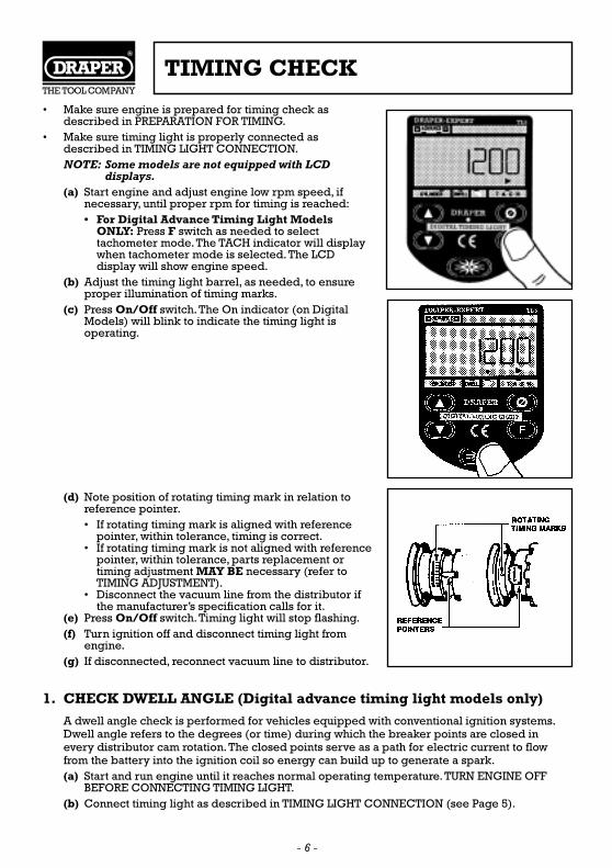
• Make sure engine is prepared for timing check asdescribed in PREPARATION FOR TIMING.
• Make sure timing light is properly connected asdescribed in TIMING LIGHT CONNECTION.NOTE: Some models are not equipped with LCD
displays.(a) Start engine and adjust engine low rpm speed, if
necessary, until proper rpm for timing is reached:• For Digital Advance Timing Light Models
ONLY: Press F switch as needed to selecttachometer mode. The TACH indicator will displaywhen tachometer mode is selected. The LCDdisplay will show engine speed.
(b) Adjust the timing light barrel, as needed, to ensureproper illumination of timing marks.
(c) Press On/Off switch. The On indicator (on DigitalModels) will blink to indicate the timing light isoperating.
(d) Note position of rotating timing mark in relation toreference pointer.• If rotating timing mark is aligned with reference
pointer, within tolerance, timing is correct.• If rotating timing mark is not aligned with reference
pointer, within tolerance, parts replacement ortiming adjustment MAY BE necessary (refer toTIMING ADJUSTMENT).
• Disconnect the vacuum line from the distributor ifthe manufacturer’s specification calls for it.
(e) Press On/Off switch. Timing light will stop flashing.(f) Turn ignition off and disconnect timing light from
engine.(g) If disconnected, reconnect vacuum line to distributor.
1. CHECK DWELL ANGLE (Digital advance timing light models only)
A dwell angle check is performed for vehicles equipped with conventional ignition systems.Dwell angle refers to the degrees (or time) during which the breaker points are closed inevery distributor cam rotation. The closed points serve as a path for electric current to flowfrom the battery into the ignition coil so energy can build up to generate a spark.(a) Start and run engine until it reaches normal operating temperature. TURN ENGINE OFF
BEFORE CONNECTING TIMING LIGHT.(b) Connect timing light as described in TIMING LIGHT CONNECTION (see Page 5).
- 6 -
TIMING CHECK
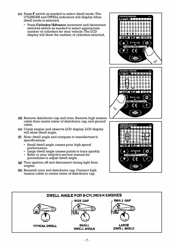
(c) Press F switch as needed to select dwell mode. TheCYLINDER and DWELL indicators will display whendwell mode is selected.• Press Cylinder/Advance increment and decrement
switches switch as needed to select appropriatenumber of cylinders for your vehicle. The LCDdisplay will show the number of cylinders selected.
(d) Remove distributor cap and rotor. Remove high tensioncable from centre tower of distributor cap, and groundcable.
(e) Crank engine and observe LCD display. LCD displaywill show dwell angle.
(f) Note: dwell angle and compare to manufacturer’sspecifications:• Small dwell angle causes poor high speed
performance.• Large dwell angle causes points to burn quickly.• Refer to your vehicle’s service manual for
procedures to adJust dwell angle.(g) Turn ignition off and disconnect timing light from
engine.(h) Reinstall rotor and distributor cap. Connect high
tension cable to centre tower of distributor cap.
- 7 -
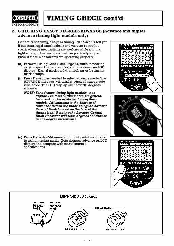
2. CHECKING EXACT DEGREES ADVANCE (Advance and digitaladvance timing light models only)
Generally speaking, a regular timing light can only tell youif the centrifugal (mechanical) and vacuum controlledspark advance mechanisms are working while a timinglight with spark advance control can positively let youknow if these mechanisms are operating properly.
(a) Perform Timing Check (see Page 6), while increasingengine speed to the specified rpm (as shown on LCDdisplay - Digital model only), and observe for timingmark change.
(b) Press F switch as needed to select advance mode. TheADVANCE indicator will display when advance modeis selected. The LCD display will show “0” degreesadvance.NOTE: For advance timing light models - non
digital: The tests outlined here are generaltests and can be performed using thesemodels. Adjustments to the degrees ofAdvance/ Retard are made using the AdvanceControl Knob located on the face of thetiming light. Rotating the Advance ControlKnob clockwise will raise degrees of Advancein one degree increments.
(c) Press Cylinder/Advance increment switch as neededto realign timing marks. Note degrees advance on LCDdisplay and compare with manufacturer’sspecifications.
- 8 -
TIMING CHECK cont’d
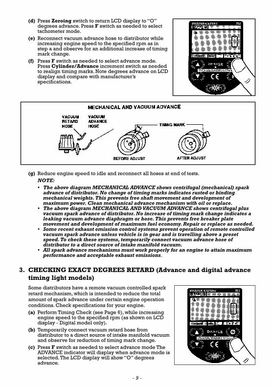
(d) Press Zeroing switch to return LCD display to “O”degrees advance. Press F switch as needed to selecttachometer mode.
(e) Reconnect vacuum advance hose to distributor whileincreasing engine speed to the specified rpm as instep a and observe for an additional increase of timingmark change.
(f) Press F switch as needed to select advance mode.Press Cylinder/Advance increment switch as neededto realign timing marks. Note degrees advance on LCDdisplay and compare with manufacturer’sspecifications.
(g) Reduce engine speed to idle and reconnect all hoses at end of tests.NOTE:• The above diagram MECHANICAL ADVANCE shows centrifugal (mechanical) spark
advance of distributor. No change of timing marks indicates rusted or bindingmechanical weights. This prevents free shaft movement and development ofmaximum power. Clean mechanical advance mechanism with oil or replace.
• The above diagram MECHANICAL AND VACUUM ADVANCE shows centrifugal plusvacuum spark advance of distributor. No increase of timing mark change indicates aleaking vacuum advance diaphragm or hose. This prevents free breaker platemovement and development of maximum fuel economy. Repair or replace as needed.
• Some recent exhaust emission control systems prevent operation of remote controlledvacuum spark advance unless vehicle is in gear and is travelling above a presetspeed. To check these systems, temporarily connect vacuum advance hose ofdistributor to a direct source of intake manifold vacuum.
• All spark advance mechanisms must work properly for an engine to attain maximumperformance and acceptable exhaust emissions.
3. CHECKING EXACT DEGREES RETARD (Advance and digital advancetiming light models)
Some distributors have a remote vacuum controlled sparkretard mechanism, which is intended to reduce the totalamount of spark advance under certain engine operationconditions. Check specifications for your engine.(a) Perform Timing Check (see Page 6), while increasing
engine speed to the specified rpm (as shown on LCDdisplay - Digital model only).
(b) Temporarily connect vacuum retard hose fromdistributor to a direct source of intake manifold vacuumand observe for reduction of timing mark change.
(c) Press F switch as needed to select advance mode TheADVANCE indicator will display when advance mode isselected. The LCD display will show “O” degreesadvance.
- 9 -
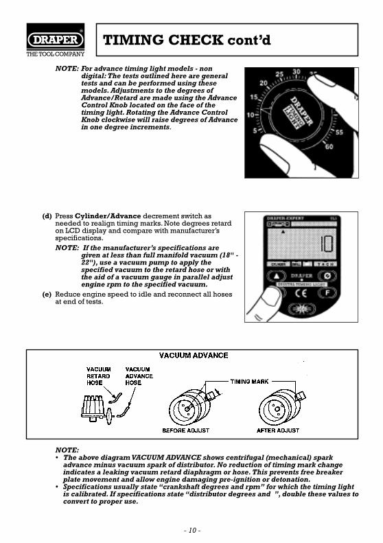
NOTE: For advance timing light models - nondigital: The tests outlined here are generaltests and can be performed using thesemodels. Adjustments to the degrees ofAdvance/Retard are made using the AdvanceControl Knob located on the face of thetiming light. Rotating the Advance ControlKnob clockwise will raise degrees of Advancein one degree increments.
(d) Press Cylinder/Advance decrement switch asneeded to realign timing marks. Note degrees retardon LCD display and compare with manufacturer’sspecifications.NOTE: If the manufacturer’s specifications are
given at less than full manifold vacuum (18" -22"), use a vacuum pump to apply thespecified vacuum to the retard hose or withthe aid of a vacuum gauge in parallel adjustengine rpm to the specified vacuum.
(e) Reduce engine speed to idle and reconnect all hosesat end of tests.
NOTE:• The above diagram VACUUM ADVANCE shows centrifugal (mechanical) spark
advance minus vacuum spark of distributor. No reduction of timing mark changeindicates a leaking vacuum retard diaphragm or hose. This prevents free breakerplate movement and allow engine damaging pre-ignition or detonation.
• Specifications usually state “crankshaft degrees and rpm” for which the timing lightis calibrated. If specifications state “distributor degrees and ”, double these values toconvert to proper use.
- 10 -
TIMING CHECK cont’d
Refer to the vehicle’s service manual for procedures to adjust timing. DO NOT ATTEMPT TOADJUST TIMING WITHOUT MANUFACTURER’S SPECIFICATIONS.
NOTE: If the Digital Timing Light readout becomes inoperative or locks up during use, disconnectand reconnect the timing light’s positive battery clamp from the battery to reset the unit.
If the timing light fails to operate, make the following checks:(a) Make sure the battery clips are firmly connected to the battery terminals.(b) Make sure the battery clip polarity is correct (red clip to positive terminal, black clip to
negative terminal).(c) Make sure the upper and lower ferrite cores of the inductive pickup clip are clean. Clean
the inductive pickup clip if necessary (refer to Chapter 3).(d) Make sure the inductive pickup clip is properly connected to the No. 1 spark plug cable.(e) Make sure the No. 1 spark plug is working properly:
• Connect the inductive pickup clip to another spark plug cable, and press the On/Offswitch.
• If the timing light flashes, service the No. 1 spark plug before continuing.
When using Draper timing lights equipped with tach and dwell functions, it is not necessary to usea separate dwell meter and/or tachometer since these functions are already built in to the timinglight.
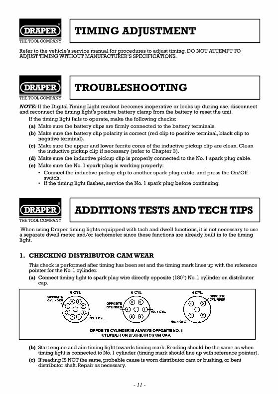
1. CHECKING DISTRIBUTOR CAM WEARThis check is performed after timing has been set and the timing mark lines up with the referencepointer for the No. 1 cylinder.(a) Connect timing light to spark plug wire directly opposite (180°) No. 1 cylinder on distributor
cap.
(b) Start engine and aim timing light towards timing mark. Reading should be the same as whentiming light is connected to No. 1 cylinder (timing mark should line up with reference pointer).
(c) If reading IS NOT the same, probable cause is worn distributor cam or bushing, or bentdistributor shaft. Repair as necessary.
- 11 -
TIMING ADJUSTMENT
TROUBLESHOOTING
ADDITIONS TESTS AND TECH TIPS
2. CHECKING FOR SPARK DURING A NO-START CONDITION.NOTE: Ensure proper operation of fuel system.Take care to avoid fuel and spark coming in
contact with each other to avoid fire.CONVENTIONAL IGNITIONThis test can pinpoint problems with the coil, cap rotor, plug wires, points, ignition module andrelated components.(a) Clamp inductive pickup around any plug wire.With timing light on, crank engine. If timing
light does not flash, no spark is present.(b) Reconnect inductive pickup to other plug wires, and repeat step a. If timing light does not flash
when connected to ANY other plug wire, connect inductive pickup to coil wire to check coilspark delivery to distributor.
(c) If timing light does not flash when connected to coil wire, further troubleshooting may benecessary.
DIS IGNITION SYSTEMSThis test can pinpoint problems with the singular coil packs, camshaft/crankshaft sensors and thesignals generated by these sensors, the DIS module, the ECM and related components.(a) Clamp inductive pickup around any plug wire.With timing light on, crank engine. If timing
light does not flash, no spark is present.(b) For vehicles with multiple coils, check each wire on each coil to pinpoint a defective coil or
trigger signal for the coil.(c) If timing light does not flash when connected to coil wires, further troubleshooting may be
necessary.
3. MIXTURE CONTROL SOLENOID ADJUSTMENTS (GENERAL MOTORSAND OTHERS)
General Motors, as well as other manufacturers, use mixture control solenoids on many of theirvehicles.When adjustments are necessary, solenoid output readings are typically read using aduty cycle meter.When using Draper timing lights equipped with dwell function, duty cyclereadings may be taken by utilising the timing light’s green DWELL clip.Many vehicle manufacturers require the use of a duty cycle meter to make adjustments or monitorsystems (such as Volkswagen oxygen sensor output, Mercedes flash codes, etc.). Draper timinglights equipped with dwell function may be used to take duty cycle readings (in addition to dwell)by setting the dwell adjust to the six-cylinder mode (see Page 6).
4. THROTTLE BODY INJECTION/PULSATING SPRAY PATTERNS
By shining the timing light inside the throttle body cavity while the engine is running, andadjusting the advance accordingly, the pulsing of the timing light can be synchronised with theinjector’s pulsing to the point where the spray pattern is visible. By inspecting the spraypattern it is possible to identify clog ups, improper spray area, injector leakage, intermittentspraying or other related problems. Dirty injectors can cause poor performance, poor fueleconomy, and emission problems.
5. SIMPLE RPM CHECKS (ON CONVENTIONALIGNITION/ELECTRONIC IGNITION VEHICLES)
Timing lights equipped with the Tachometer function incorporate an inductive pickup to readplug firing and rpm; there is no need to touch any ‘live” connections at the coil. Simply attachthe inductive pickup to the proper plug wire to read the engine’s rpm (like a tachometer).
- 12 -
ADDITIONS TESTS AND TECH TIPS
6. SIMPLE RPM CHECKS (ON DIS EQUIPPED VEHICLES)
On timing lights equipped with DIS capabilities, rpm is easily read on DIS equipped vehicles bysimply attaching the inductive pickup to the proper plug wire (as described in paragraph 5).This function is especially helpful since many DIS systems do not provide an easy connection fora tachometer signal.
7. CHECKING KNOCK SENSOR OPERATION (ON EQUIPPED VEHICLES)
The knock sensor causes spark timing to retard when engine knocking occurs. Knock sensoroperation can be checked easily while monitoring engine timing. Locate the vehicle’s knocksensor, and use a metal rod or other suitable tool to LIGHTLY tap the engine block near thesensor. The timing should retard MOMENTARILY, then return to original value.
8. ERRATIC READING/TIMING MARKS NOT STABLE
If readings are erratic or unstable while checking timing, reverse the orientation of theinductive pickup on the spark plug wire. If readings remain erratic, this may indicate a worn orloose timing belt or timing chain, worn distributor bushings, worn distributor drivecomponents (distributor gear, cam gear, etc) or other related components.
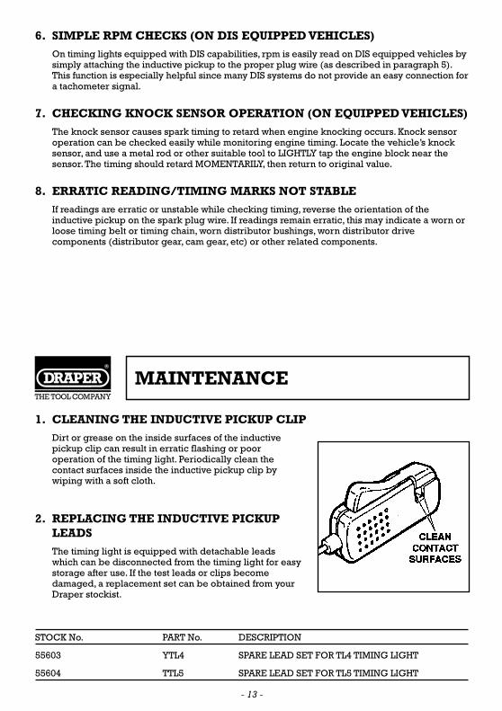
1. CLEANING THE INDUCTIVE PICKUP CLIP
Dirt or grease on the inside surfaces of the inductivepickup clip can result in erratic flashing or pooroperation of the timing light. Periodically clean thecontact surfaces inside the inductive pickup clip bywiping with a soft cloth.
2. REPLACING THE INDUCTIVE PICKUPLEADS
The timing light is equipped with detachable leadswhich can be disconnected from the timing light for easystorage after use. If the test leads or clips becomedamaged, a replacement set can be obtained from yourDraper stockist.
STOCK No. PART No. DESCRIPTION
55603 YTL4 SPARE LEAD SET FOR TL4 TIMING LIGHT
55604 TTL5 SPARE LEAD SET FOR TL5 TIMING LIGHT
MAINTENANCE
- 13 -

DRAPER TOOLS LIMITED,Hursley Road, Chandler's Ford,
Eastleigh, Hants. SO53 1YF. England.Tel: (01703) 266355.Fax: (01703) 260784.
©Published by Draper Tools Ltd.No part of this publication may be reproduced,
stored in a retrieval system or transmitted inany form or by any means, electronic, mechanical
photocopying, recording or otherwise without priorpermission in writing from Draper Tools Ltd.
YOUR DRAPER STOCKIST