Embed Size (px)
Citation preview

Time of Flight: Principles, Challenges, and PerformanceST Technology Tour 2017
John Kvam

Agenda• Time of Flight Principles and Design Choices
• Performance
• Application Examples
• Design Challenges
• Calibration
• Evaluation kit : HW & GUI
• Hardware Considerations
• Development & Support
2
ToF Principles
Time of Flight Basics
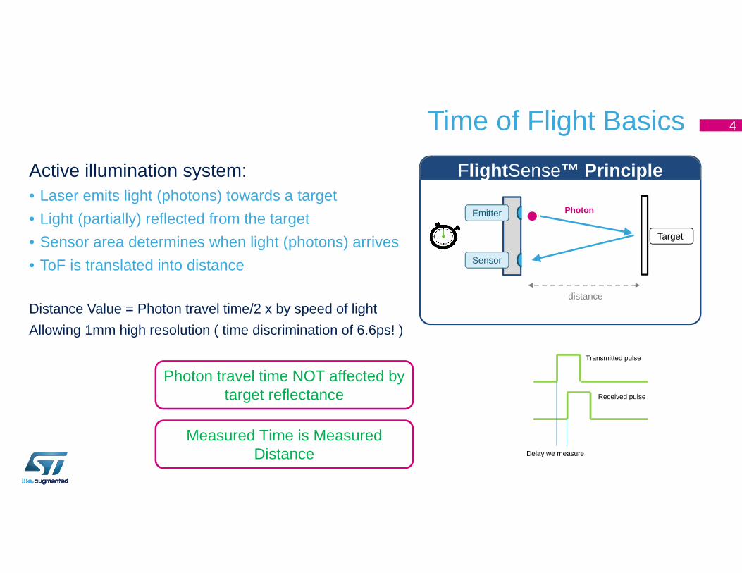
Active illumination system:• Laser emits light (photons) towards a target• Light (partially) reflected from the target• Sensor area determines when light (photons) arrives• ToF is translated into distance
Distance Value = Photon travel time/2 x by speed of lightAllowing 1mm high resolution ( time discrimination of 6.6ps! )
distance
Target
Photon
FlightSense™ Principle
Emitter
Sensor
Photon travel time NOT affected by target reflectance
Measured Time is Measured Distance Delay we measure
Transmitted pulse
Received pulse
4
ToF – Order of Operation
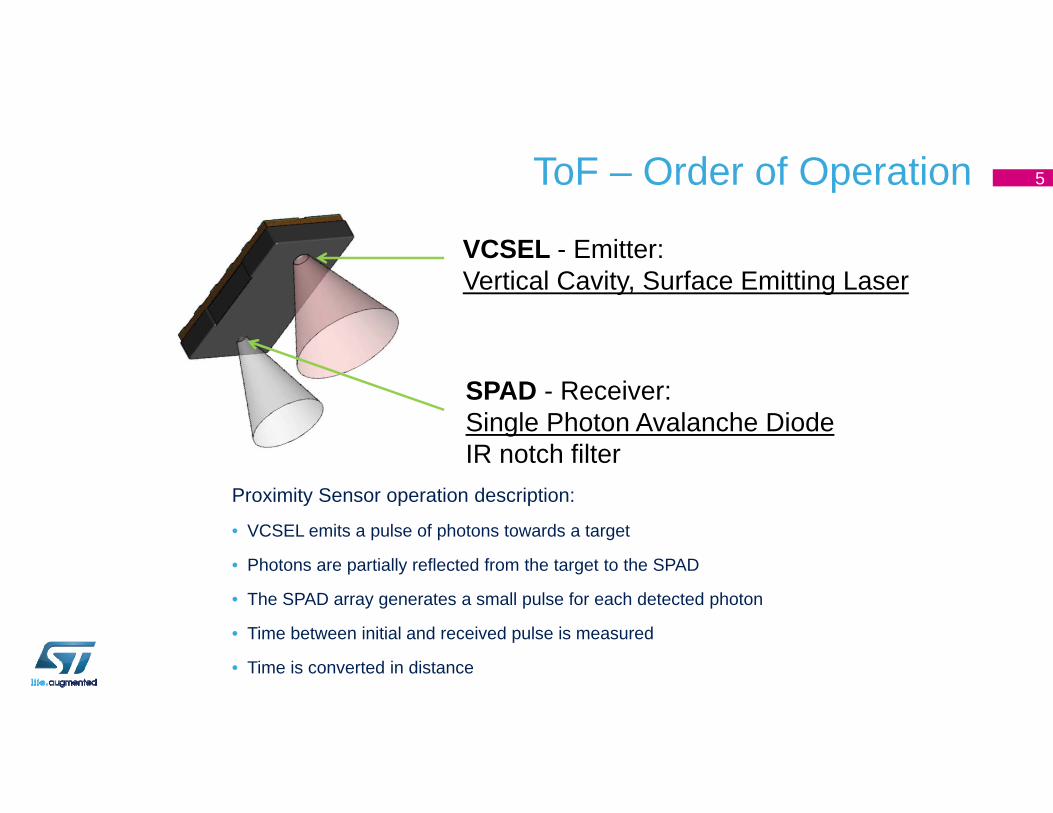
VCSEL - Emitter:Vertical Cavity, Surface Emitting Laser
SPAD - Receiver:Single Photon Avalanche DiodeIR notch filter
Proximity Sensor operation description:
• VCSEL emits a pulse of photons towards a target
• Photons are partially reflected from the target to the SPAD
• The SPAD array generates a small pulse for each detected photon
• Time between initial and received pulse is measured
• Time is converted in distance
5
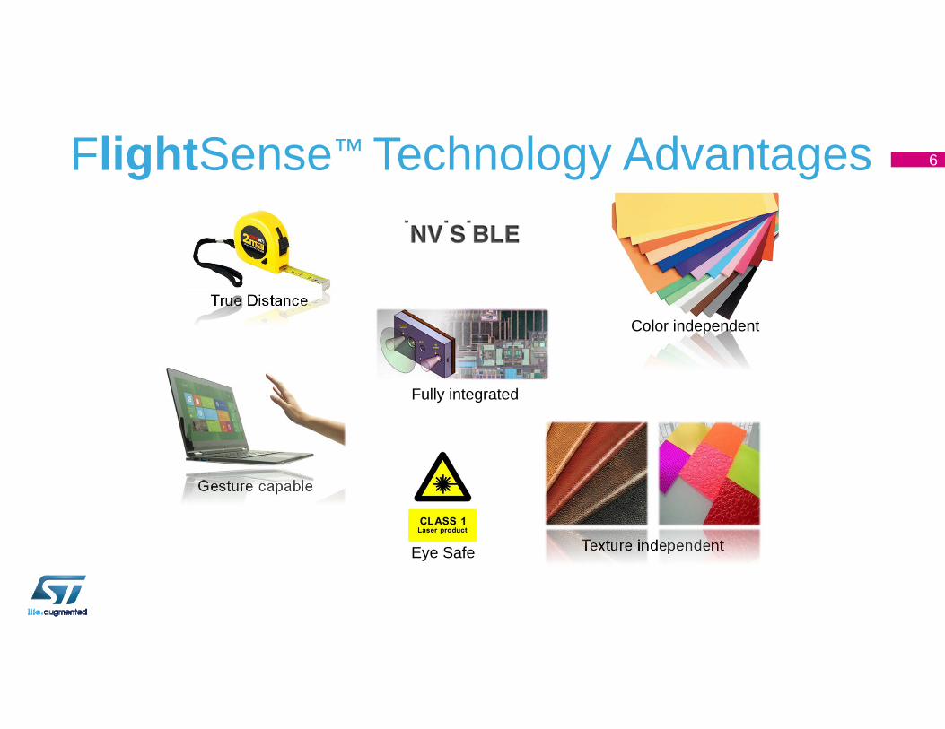
FlightSense™ Technology Advantages
Color independentTrue Distance
Fully integrated
Texture independent
Gesture capable
Eye Safe
6
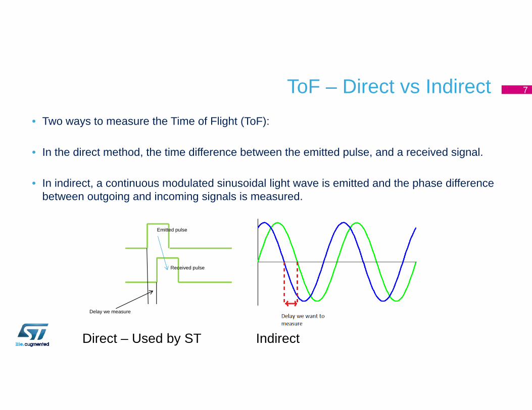
ToF – Direct vs Indirect• Two ways to measure the Time of Flight (ToF):
• In the direct method, the time difference between the emitted pulse, and a received signal.
• In indirect, a continuous modulated sinusoidal light wave is emitted and the phase difference between outgoing and incoming signals is measured.
Delay we measure
Emitted pulse
Received pulse
Direct – Used by ST Indirect
7
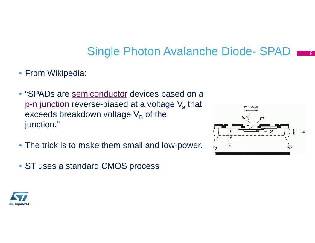
Single Photon Avalanche Diode- SPAD
• From Wikipedia:
• “SPADs are semiconductor devices based on a p-n junction reverse-biased at a voltage Va that exceeds breakdown voltage VB of the junction.”
• The trick is to make them small and low-power.
• ST uses a standard CMOS process
8
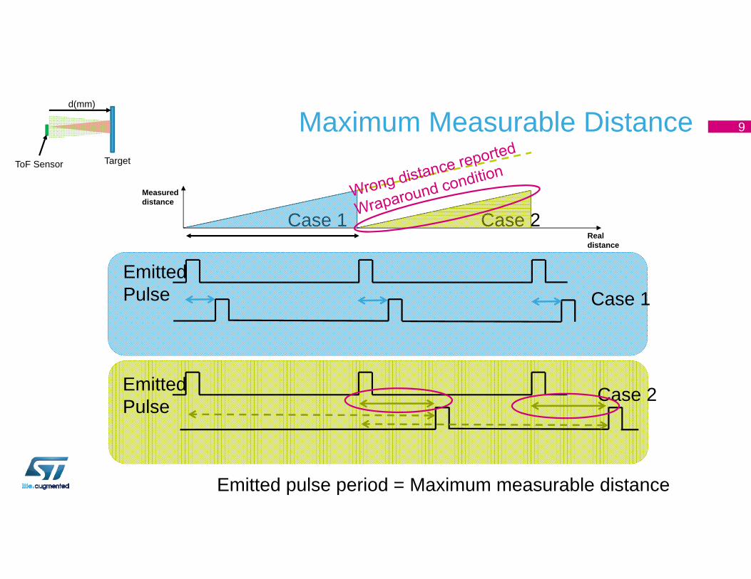
Maximum Measurable Distance
EmittedPulse
Case 1
d(mm)
ToF Sensor Target
Realdistance
Measureddistance
Case 2
EmittedPulse
Emitted pulse period = Maximum measurable distance
Case 1
Case 2
9
ToF Performance: Distance, Accuracy, Ranging Rate, and Power Consumption
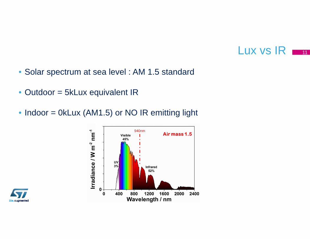
Lux vs IR
• Solar spectrum at sea level : AM 1.5 standard
• Outdoor = 5kLux equivalent IR
• Indoor = 0kLux (AM1.5) or NO IR emitting light
940nm
11
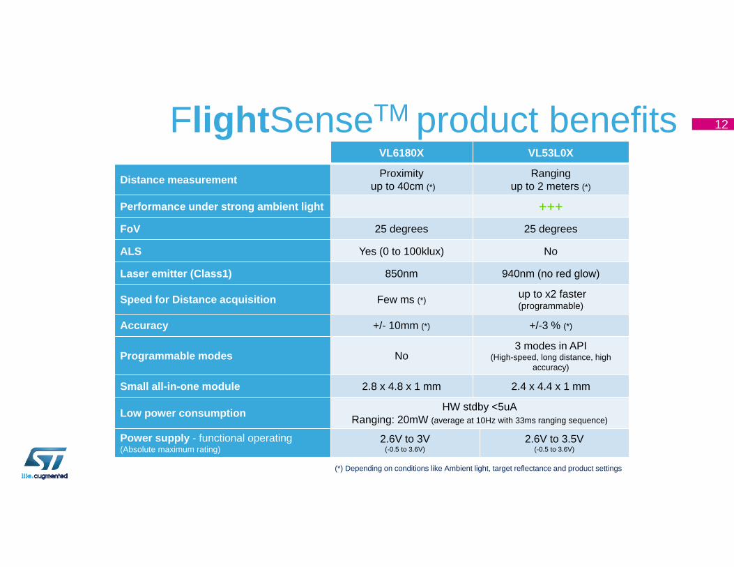
FlightSenseTM product benefitsVL6180X VL53L0X
Distance measurement Proximityup to 40cm (*)
Rangingup to 2 meters (*)
Performance under strong ambient light +++FoV 25 degrees 25 degrees
ALS Yes (0 to 100klux) No
Laser emitter (Class1) 850nm 940nm (no red glow)
Speed for Distance acquisition Few ms (*) up to x2 faster (programmable)
Accuracy +/- 10mm (*) +/-3 % (*)
Programmable modes No3 modes in API
(High-speed, long distance, high accuracy)
Small all-in-one module 2.8 x 4.8 x 1 mm 2.4 x 4.4 x 1 mm
Low power consumption HW stdby <5uARanging: 20mW (average at 10Hz with 33ms ranging sequence)
Power supply - functional operating(Absolute maximum rating)
2.6V to 3V(-0.5 to 3.6V)
2.6V to 3.5V(-0.5 to 3.6V)
(*) Depending on conditions like Ambient light, target reflectance and product settings
12
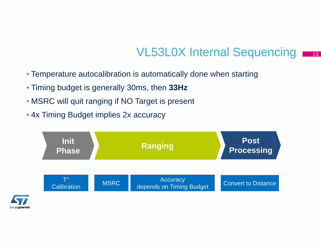
VL53L0X Internal Sequencing
• Temperature autocalibration is automatically done when starting
• Timing budget is generally 30ms, then 33Hz• MSRC will quit ranging if NO Target is present
• 4x Timing Budget implies 2x accuracy
T°Calibration MSRC
PostProcessing
Range B(14clk)
RangingInitPhase
Accuracy depends on Timing Budget Convert to Distance
13
Application Examples
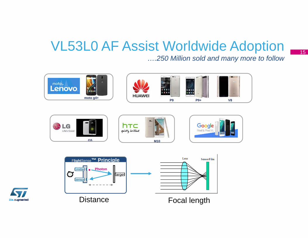
VL53L0 AF Assist Worldwide Adoption….250 Million sold and many more to follow
G5 M10
P9 P9+ V8moto g4+
Target Photon
FlightSense™ PrincipleEmitter
Sensor
Focal lengthDistance
15
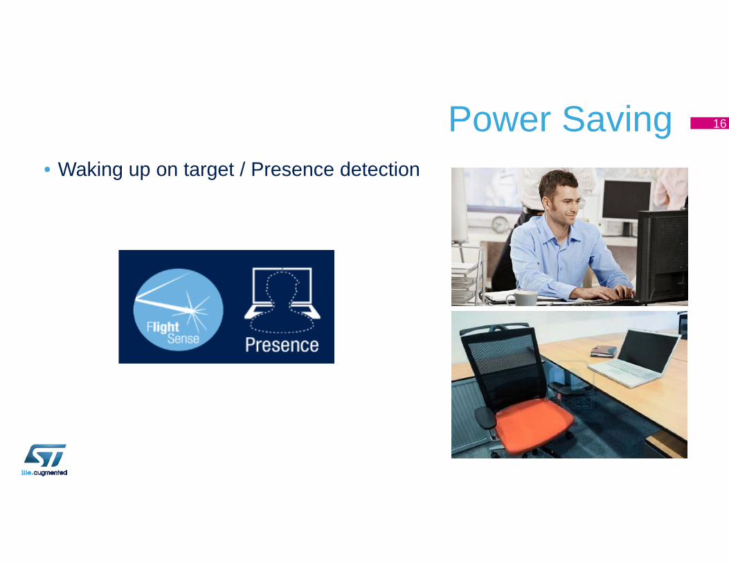
Power Saving• Waking up on target / Presence detection
16
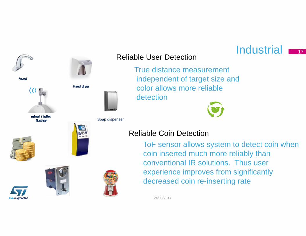
Industrial 17
24/05/2017
Reliable Coin DetectionToF sensor allows system to detect coin when coin inserted much more reliably than conventional IR solutions. Thus user experience improves from significantly decreased coin re-inserting rate
Soap dispenser
Reliable User DetectionTrue distance measurementindependent of target size andcolor allows more reliabledetection
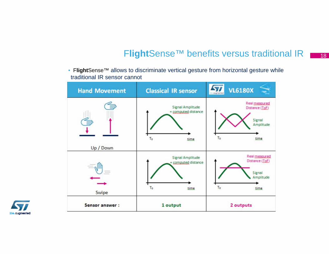
FlightSense™ benefits versus traditional IR 18
• FlightSense™ allows to discriminate vertical gesture from horizontal gesture while traditional IR sensor cannot
ToF Sensor Challenges
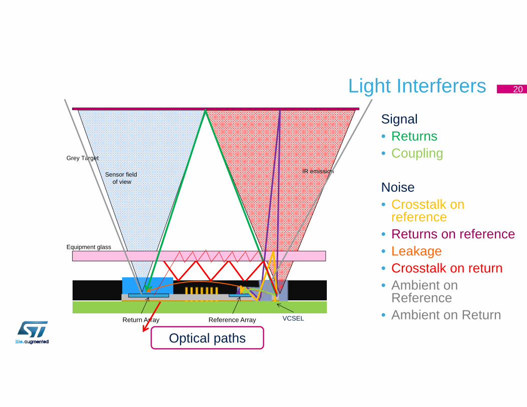
Light Interferers Signal• Returns• Coupling
Noise• Crosstalk on
reference• Returns on reference• Leakage• Crosstalk on return• Ambient on
Reference• Ambient on Return
Optical paths
Grey Target
Sensor field of view
IR emission
Equipment glass
Return Array Reference Array VCSEL
20
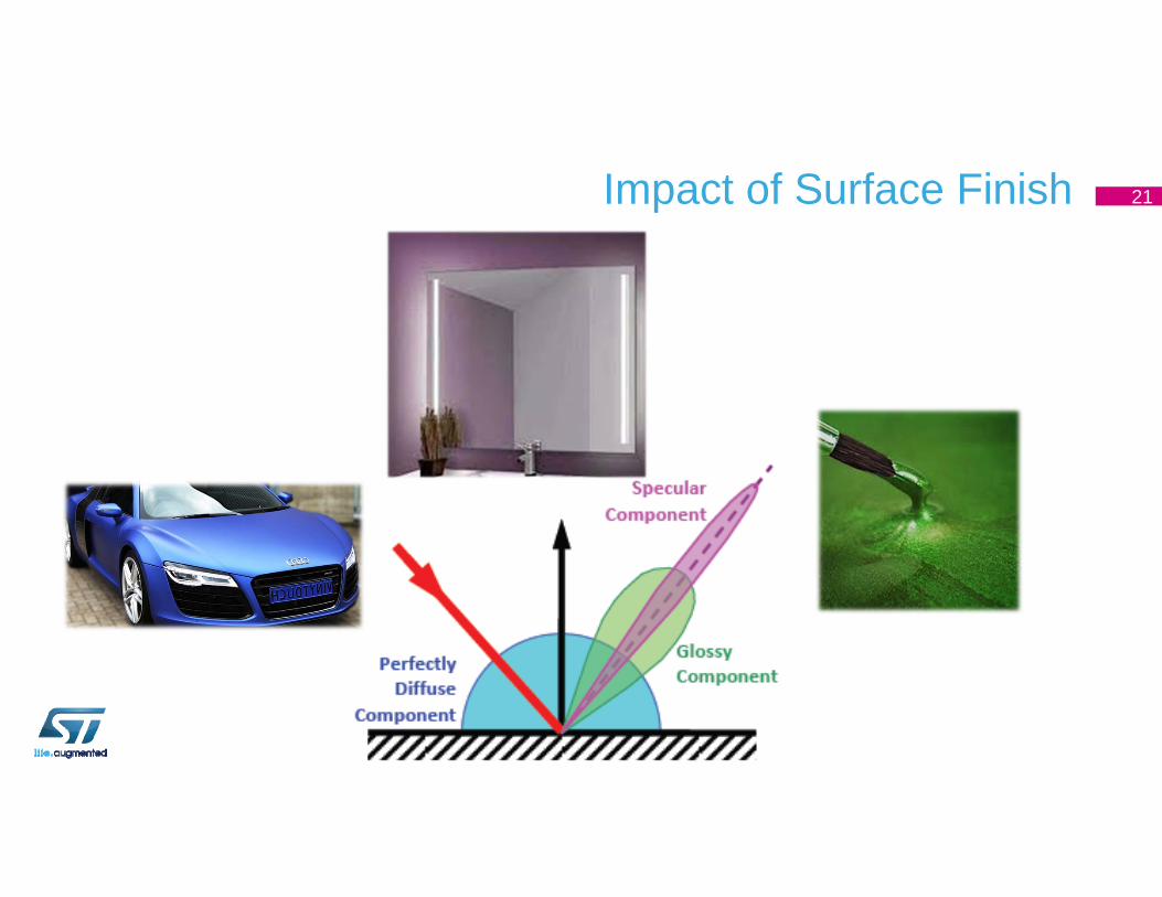
Impact of Surface Finish 21
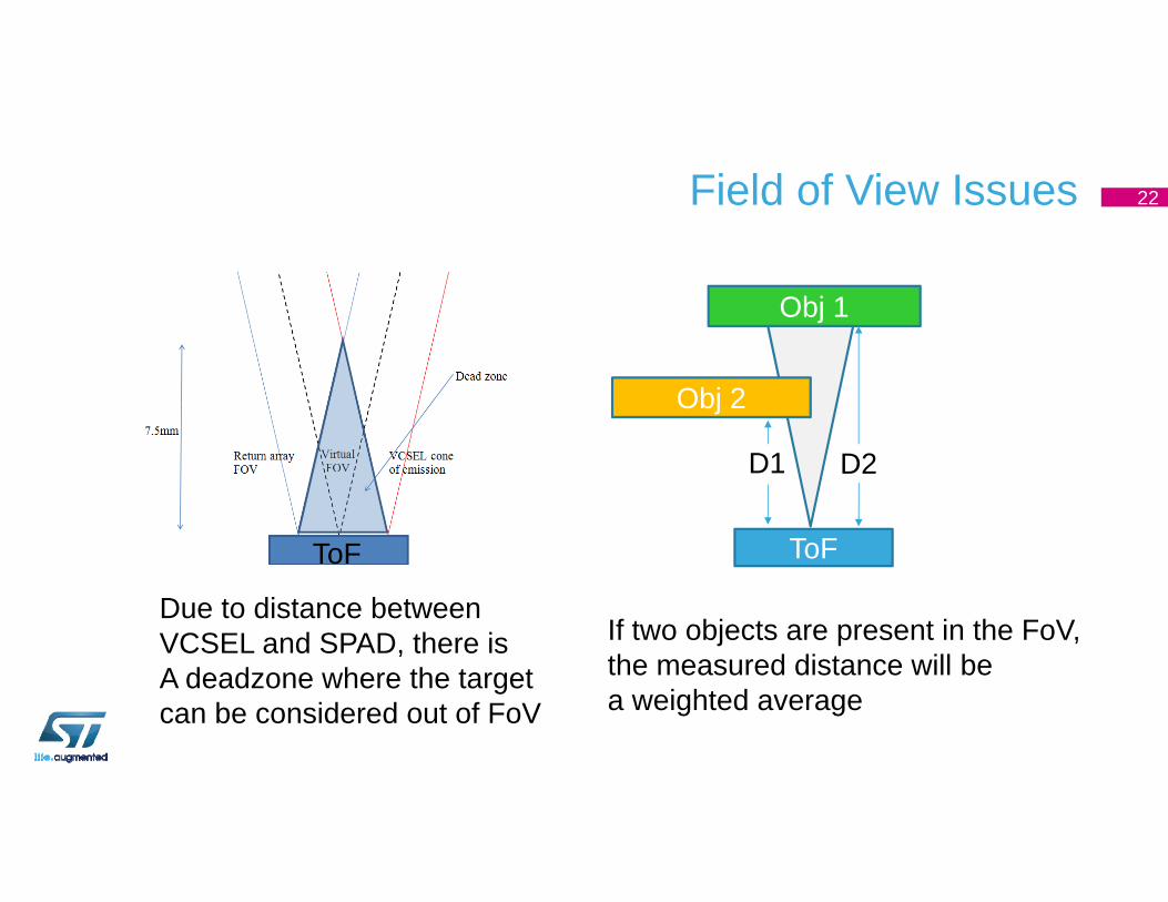
Field of View Issues
Due to distance betweenVCSEL and SPAD, there isA deadzone where the targetcan be considered out of FoV
ToF
If two objects are present in the FoV,the measured distance will bea weighted average
Obj 1
ToF
D1 D2
Obj 2
22
ToF Sensor Offset and Crosstalk Calibrations
Offset Calibration Procedure
Target
DUT
D1
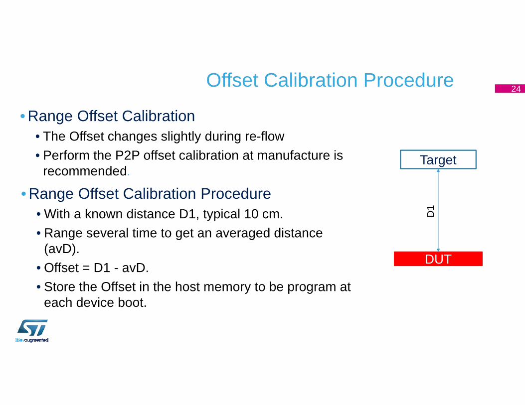
• Range Offset Calibration• The Offset changes slightly during re-flow• Perform the P2P offset calibration at manufacture is
recommended.
• Range Offset Calibration Procedure• With a known distance D1, typical 10 cm.• Range several time to get an averaged distance
(avD).• Offset = D1 - avD.• Store the Offset in the host memory to be program at
each device boot.
24
Crosstalk Calibration
DUTD
2
Min
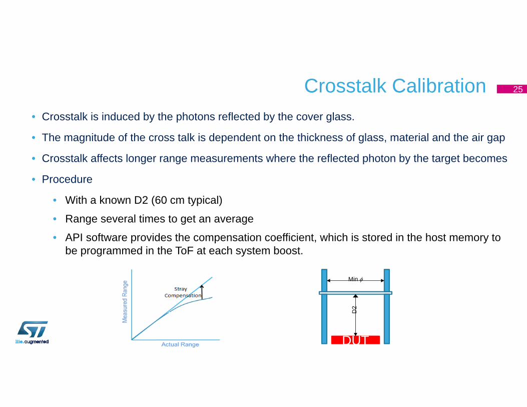
• Crosstalk is induced by the photons reflected by the cover glass.
• The magnitude of the cross talk is dependent on the thickness of glass, material and the air gap
• Crosstalk affects longer range measurements where the reflected photon by the target becomes
• Procedure
• With a known D2 (60 cm typical)
• Range several times to get an average
• API software provides the compensation coefficient, which is stored in the host memory to be programmed in the ToF at each system boost.
25
GUI Explanation – Practical Application
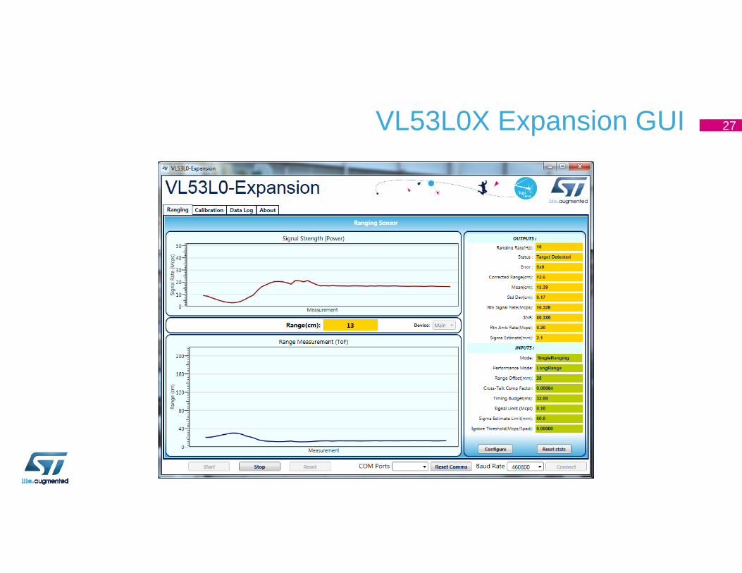
VL53L0X Expansion GUI 27
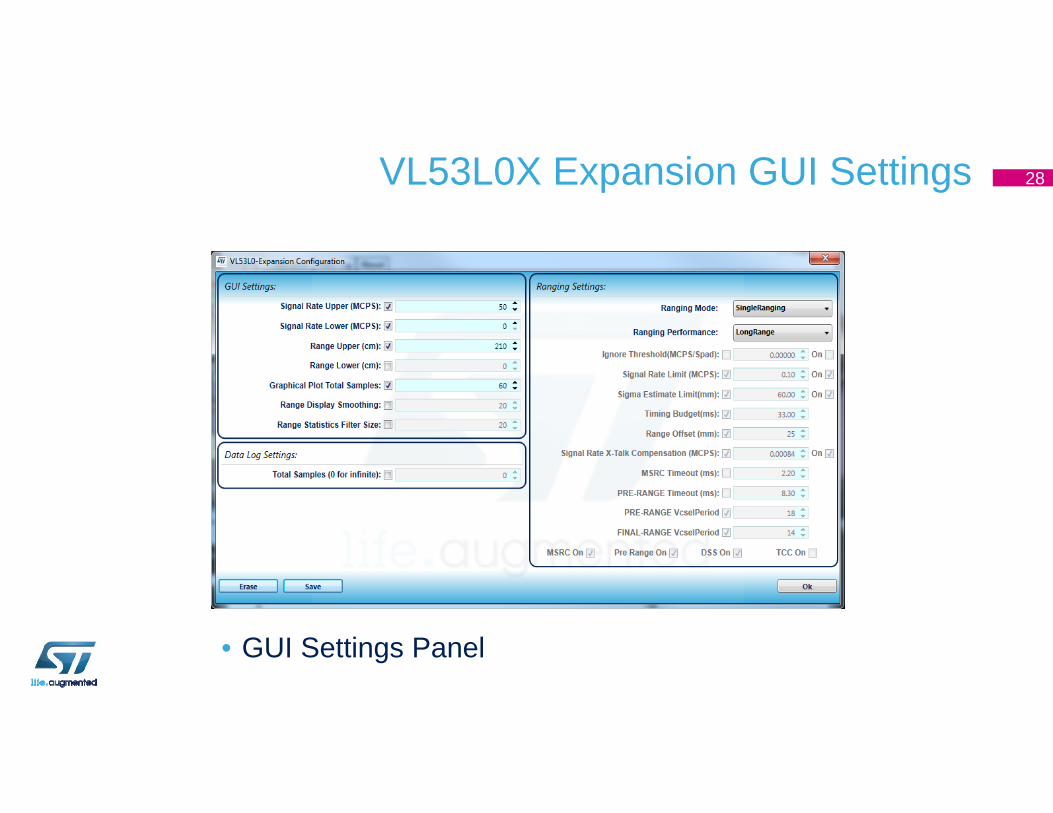
VL53L0X Expansion GUI Settings
• GUI Settings Panel
28
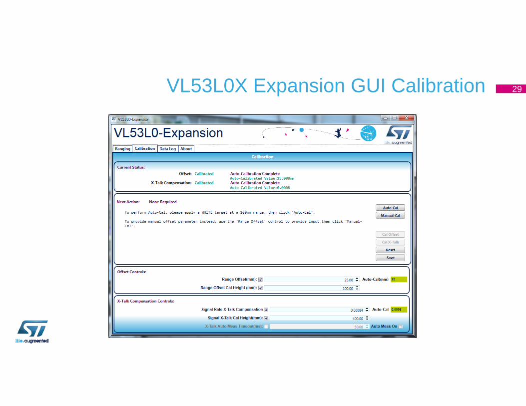
VL53L0X Expansion GUI Calibration 29
Hardware Description
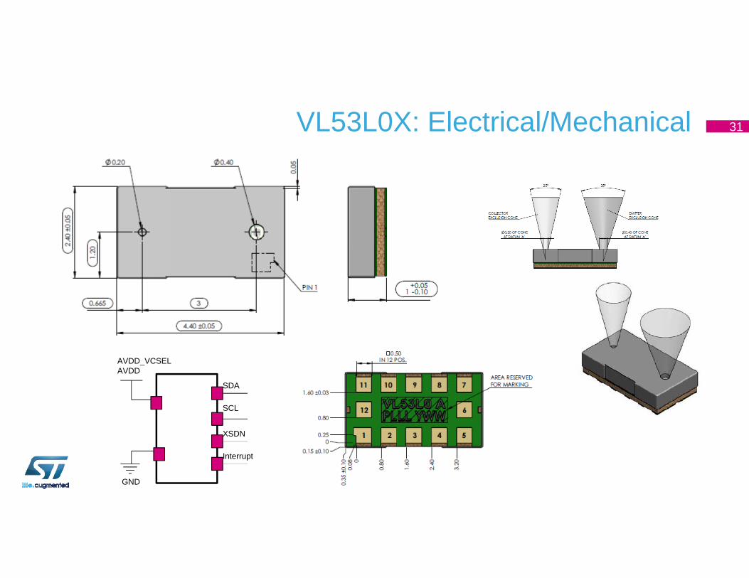
VL53L0X: Electrical/Mechanical
SDA
SCL
XSDN
Interrupt
AVDD_VCSELAVDD
GND
31
VL53L0X Development Tools and Technical Support
Let’s Start!
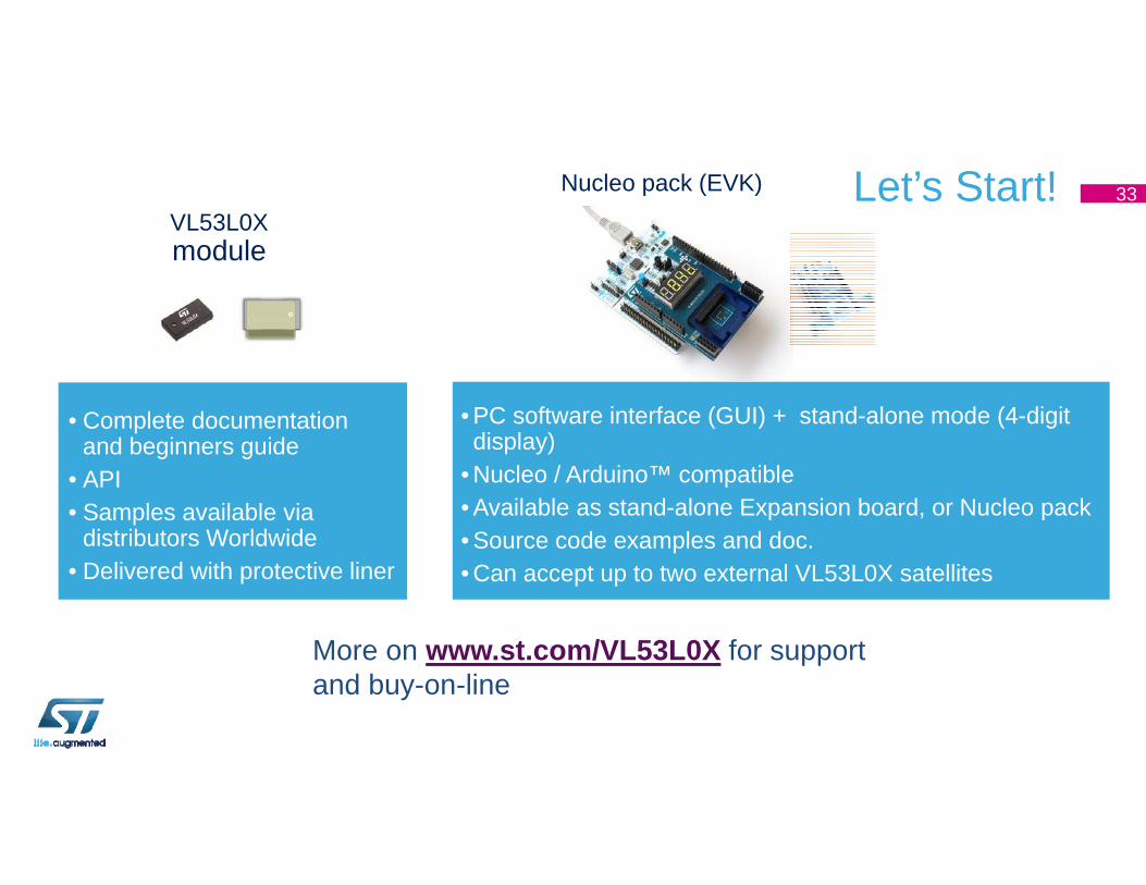
• Complete documentation and beginners guide
• API• Samples available via
distributors Worldwide• Delivered with protective liner
More on www.st.com/VL53L0X for support and buy-on-line
• PC software interface (GUI) + stand-alone mode (4-digit display)
• Nucleo / Arduino™ compatible• Available as stand-alone Expansion board, or Nucleo pack• Source code examples and doc.• Can accept up to two external VL53L0X satellites
Nucleo pack (EVK)VL53L0Xmodule
33
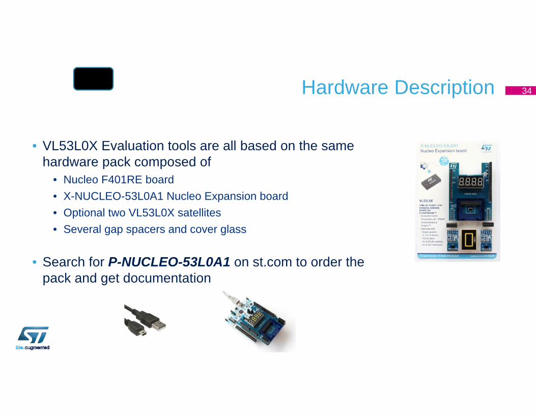
Hardware Description
• VL53L0X Evaluation tools are all based on the same hardware pack composed of
• Nucleo F401RE board• X-NUCLEO-53L0A1 Nucleo Expansion board• Optional two VL53L0X satellites• Several gap spacers and cover glass
• Search for P-NUCLEO-53L0A1 on st.com to order the pack and get documentation
34
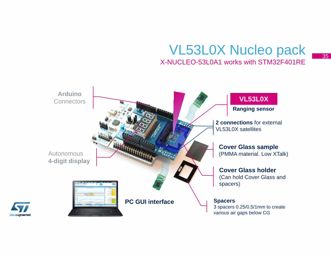
VL53L0X Nucleo packX-NUCLEO-53L0A1 works with STM32F401RE
ArduinoConnectors
Autonomous4-digit display
Cover Glass holder(Can hold Cover Glass and spacers)
VL53L0XRanging sensor
2 connections for external VL53L0X satellites
PC GUI interface Spacers3 spacers 0.25/0.5/1mm to create various air gaps below CG
Cover Glass sample(PMMA material. Low XTalk)
35
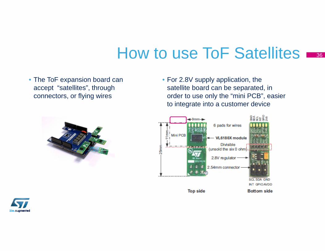
How to use ToF Satellites• For 2.8V supply application, the
satellite board can be separated, in order to use only the “mini PCB”, easier to integrate into a customer device
• The ToF expansion board can accept “satellites”, through connectors, or flying wires
36
Install STM32 IDE of Your Choice
• Pre-configured projects are available for• Keil : http://www.keil.com/• IAR : https://www.iar.com/• STM32 Workbench (Eclipse-based) :
http://www.openstm32.org/HomePage
• Lots of example code – just Google VL53L0X
37
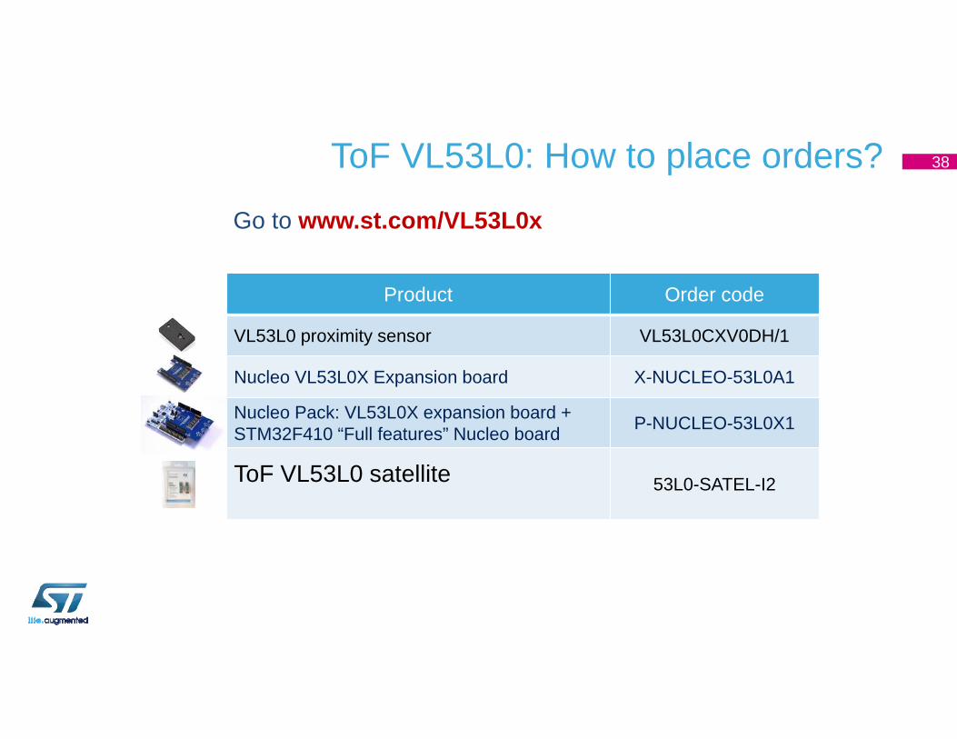
Product Order code
VL53L0 proximity sensor VL53L0CXV0DH/1
Nucleo VL53L0X Expansion board X-NUCLEO-53L0A1
Nucleo Pack: VL53L0X expansion board + STM32F410 “Full features” Nucleo board P-NUCLEO-53L0X1
ToF VL53L0 satellite 53L0-SATEL-I2
ToF VL53L0: How to place orders? 38
Go to www.st.com/VL53L0x
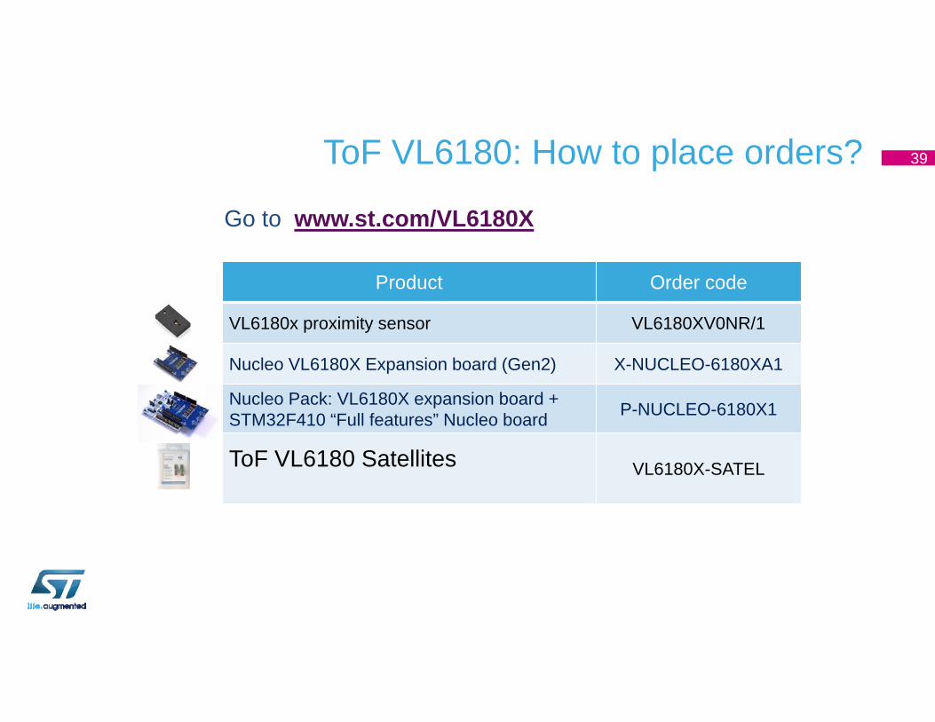
Product Order code
VL6180x proximity sensor VL6180XV0NR/1
Nucleo VL6180X Expansion board (Gen2) X-NUCLEO-6180XA1
Nucleo Pack: VL6180X expansion board + STM32F410 “Full features” Nucleo board P-NUCLEO-6180X1
ToF VL6180 Satellites VL6180X-SATEL
ToF VL6180: How to place orders? 39
Go to www.st.com/VL6180X

Thank You !
Back up
SPAD (Single Photon Avalanche Diode)system architecture optimized for lowest power operation
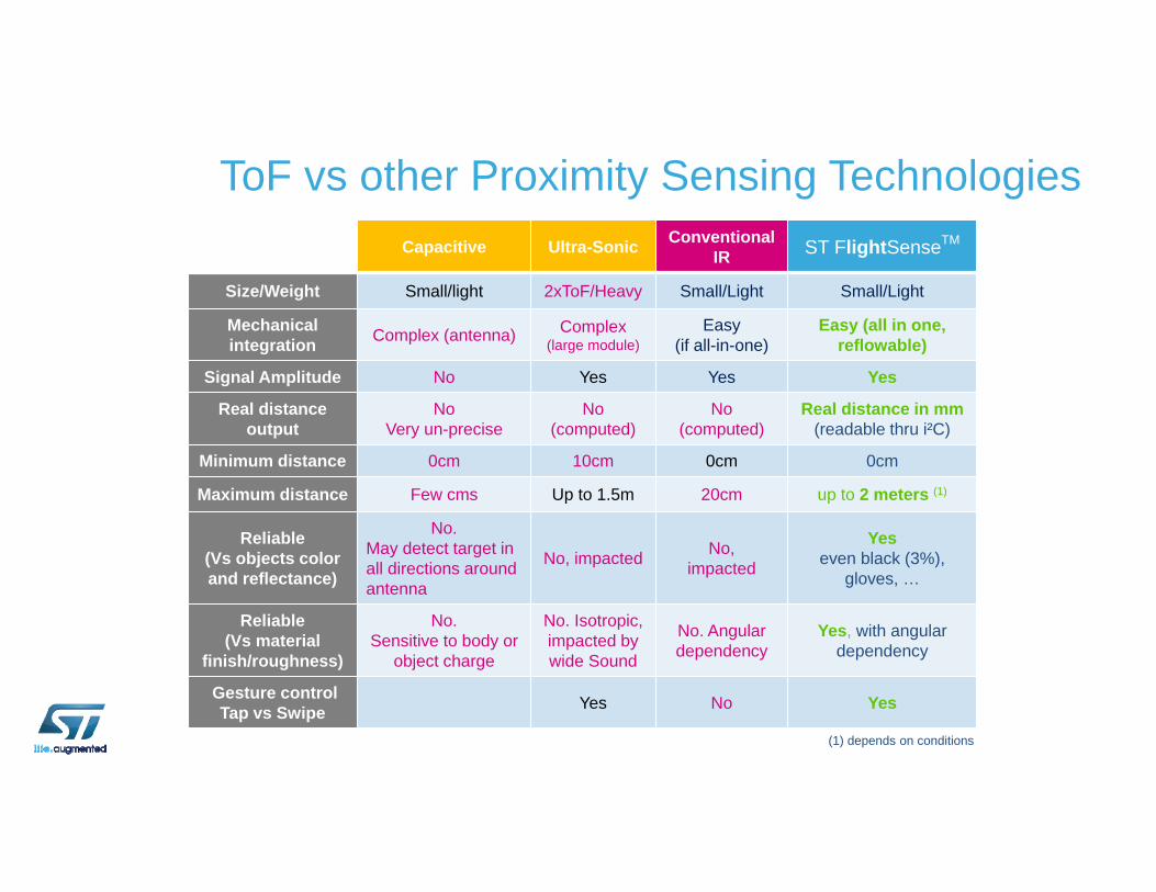
Capacitive Ultra-Sonic Conventional IR ST FlightSenseTM
Size/Weight Small/light 2xToF/Heavy Small/Light Small/Light
Mechanical integration Complex (antenna) Complex
(large module)Easy
(if all-in-one)Easy (all in one,
reflowable)
Signal Amplitude No Yes Yes Yes
Real distance output
NoVery un-precise
No(computed)
No(computed)
Real distance in mm(readable thru i²C)
Minimum distance 0cm 10cm 0cm 0cm
Maximum distance Few cms Up to 1.5m 20cm up to 2 meters (1)
Reliable (Vs objects colorand reflectance)
No.May detect target in all directions around antenna
No, impacted No,impacted
Yeseven black (3%),
gloves, …
Reliable (Vs material
finish/roughness)
No.Sensitive to body or
object charge
No. Isotropic,impacted by wide Sound
No. Angular dependency
Yes, with angular dependency
Gesture controlTap vs Swipe Yes No Yes
(1) depends on conditions
ToF vs other Proximity Sensing Technologies
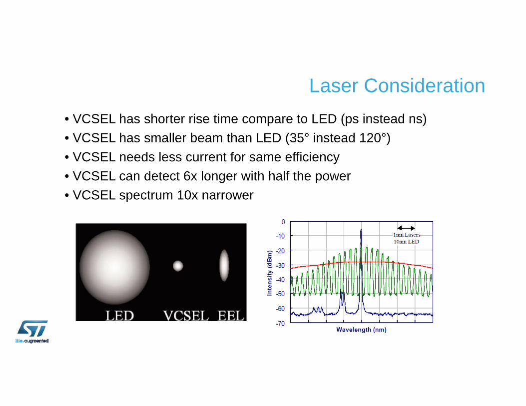
Laser Consideration• VCSEL has shorter rise time compare to LED (ps instead ns)• VCSEL has smaller beam than LED (35° instead 120°)• VCSEL needs less current for same efficiency• VCSEL can detect 6x longer with half the power• VCSEL spectrum 10x narrower