Embed Size (px)
Citation preview

DOT/FAA CT-TN95/67
fEDERAL AVIA110N ADMINISIRtdliJ't
TECHNICAL CENTER LIBRARY ATLANTIC CITY INn AIRPORT, NJ 08405
Time Code Display (TCD) Operational Test and Evaluation (OT&E) Integration and Operational Test Plan
Michael R. Melillo
July 1996
DOT/FAA/CT-TN95/67
Document is on file at the William J. Hughes Technical Center Library, Atlantic City International Airport, NJ 08405
U.S. Department ofTransportation Federal Aviation Administration
William J. HughesTechnical Center Atlantic City International Airport, NJ 08405

'11 Michael R.\\jlll~[~I~~llllil~rflil r~[~~ij~ DOT/FAA Mel~ 0, , (TCD) oper-Time code d~splay .
00013752 CT-TN . t t and evaluat~on... at~onal es95/67
c. 2
ship 3t of
- II Ie onireaSfates Govemment does not endorse products or manufacturers. Trade or manufacturers' names appear herern sorery because they are considered essential to the objective of this report.

pTech'mC8I R eport DocumentatlOn aee 1. Report No. 2. Government Accession No. 3. Recipient's Catalog No.
DOT/FANCT-TN95/67 4. Title and Subtitle 5. Report Date
TIME CODE DISPLAY (TCD) OPERATIONAL TEST AND July 1996 EVALUATION (OT&E) INTEGRATION AND OPERATIONAL 6. Performing Organization Code
TEST PLAN 7. Autbor(s) 8. Performing Organization Report No.
Michael R. Melillo DOT/FANCT-TN95-67
9. Performing Organization Name and Address 10. Work Unit No (TRAILS) U.S. Department of Transportation Federal Aviation Administration William J. Hughes Technical Center 11. Contract or Grant No.
Atlantic City International Airport, NJ 08405 12. Sponsoring Agency Name and Address 13. Type of Report and Period Covered U.S. Department of Transportation Technical Note Federal Aviation Administration William J. Hughes Technical Center 14. Sponsoring Agency Code
Atlantic City International Airport. NJ 08405 15. Supplementary Notes
16. Abstract This technical note contains the Time Code Display (TCD) Operational Test and Evaluation (OT&E) Integration and Operational Test Plan. This test plan was used to defme the overall planning, coordination, and testing associated with the preparation and conduct of the OT&E effort for the TCD project. In addition, this plan was utilized to serve as a basis for the development of the OT&E Test Procedures.
17. Key Words 18. Distribution Statement Time Code Display Document is on fIle at the William J. Hughes Time Code Reader Technical Center Library, Atlantic City
International Airoort, NJ 08405 19. Security Classlf. (oftbls 20. Security Classlf. (oftbls page) 21. No. of pages 22. Price report)
Unclassified Unclassified 35
Form DOT F 1700.7 (8·72) Reproduction of completed page autborized

1
TABLE OF CONTENTS
Page 1. INTRODUCTION
1.1 Background 1.2 Purpose 1.3 Scope
111
2. REFERENCE DOCUMENTS 2
2.1 FAA Documents 2 2.2 Military and Federal Publications 2
3. SYSTEM DESCRIPTION 3
3.1 System Overview 3 3.2 Interface Overview 4
4. TEST PROGRAM DESCRIPTION 4
4.1 Approach and Concept 4 4.2 Test Environment 6 4.3 Test and Analysis Tools 7 4.4 Test and/or Evaluation Description 7
5. TEST MANAGEMENT 10
5.1 Test Management Organization 10 5.2 Training 12 5.3 System Configuration Management 12 5.4 OT&E Entry Criteria 13 5.5 Test Execution 13 5.6 OT&E Exit Criteria 13 5.7 OT&E Report 14 5.8 System/Operational Deficiency Reports 14 5.9 OT&E Schedule 14 5.10 Personnel Resource Requirements 15 5.11 Planning Considerations and Limitations 15
6. ACRONYMS AND ABBREVIATIONS 16
APPENDIX
iii

LIST OF ILLUSTRAnONS
Figure
3.1-1 TeD System Block Diagram
Page
3
Table
5.10-1 Personnel Resources
LIST OF TABLES
Page
15
IV

1. INTRODUCTION.
1.1 BACKGROUND.
Time Code Displays (TCD) are located in Air Route Traffic Control Centers (ARTCC), Terminal Radar Approach Control Facilities (TRACON), Air Traffic Control Towers (ATCT), and Automated Flight Service Stations (AFSS). These displays have been in use since 1979. The primary purpose of the displays is to accurately provide the current time. During voice communications between controllers and pilots, the TCD is used to provide accurate time stamping of the ensuing discussions for historical record keeping purposes. Presently, there are approximately 6,000 TCDs in operation.
This will be the sixth procurement of the TCDs. Condor Reliability Services, currently under contract with the Federal Aviation Administration (FAA) is designing a new TCD which utilizes Light Emitting Diodes for the display. This unit will be more reliable than the old incandescent display it replaces. The current contract allows for the procurement of up to 1730 TCDs. The fIrst part of the procurement is for 130 TCDs. Out of these, 120 units will be utilized for First Article testing. This testing will be held at Condor's facilities in Santa Clara, California. Upon completion of this testing, these units will be sent to the logistic center in Oklahoma City, Oklahoma. Upon the successful completion of First Article and OT&E testing, the contract allows for the procurement of an additional 1600 units in groups of 600, 500, and 500. (First option, Second option, and Third option.)
Integration testing and Operational testing is to take place at four locations. They are the ARTCC in Boston, Massachusetts, the TRACON at the Philadelphia International Airport, the AFSS in Millville, N.J., and the ATCT at the Atlantic City International Airport, N.J. The anticipated timeframe for the testing is December 15, 1995, through January 15, 1996.
1.2 PURPOSE.
The primary purpose of this document is to defIne the overall planning, coordination, and testing associated with the preparation and conduct of Operation Test and Evaluation (OT&E) effort for the TCD project currently under development. In addition, this plan will serve as a basis for the development of the OT&E Test Procedures.
1.3 SCOPE.
This plan defines the planning and preparatory actions needed to conduct the OT&E testing of the TCD.
1

2. REFERENCE DOCUMENTS.
The following documents list the applicable documentation and reference materials which relate to the contents of this plan.
2.1 FAA DOCUMENTS.
2.1.1 FAA Specifications.
NAS-MD-11O Test and Evaluation (T&E) Tenns and Definitions for the National Airspace System, March 27, 1987.
FAA-G-2100F Electronic Equipment, General Requirements, November 15, 1993.
FAA-E-2306 Coded Time Source and Auxiliaries, June 23, 1967.
2.1.2 FAA Standards.
FAA-STD-024B Content and Fonnat Requirements for the Preparation of Test and Evaluation Documentation, August 22, 1994.
FAA-STD-013B Quality Control Program Requirements, September 28, 1989.
FAA-SID-021A Configuration Management, August 17, 1987.
2.1.3 FAA Orders.
1810AB FAA NAS Test and Evaluation Policy, October 22, 1992.
6950.2C Electrical Power Policy Implementation at National Airspace Facilities, November 16,1987.
2.2 MILITARY AND FEDERAL PUBLICATIONS.
2.2.1 Military Handbooks.
MIL-HDBK-781 Reliability Test Methods, Phns, and Environments for Engineering Development, Qualification and Production, July 14, 1987.
2.2.2 Military Standards.
MIL-STD-781D Reliability Test Methods, Plans and Environments for Engineering Development, Qualification, and Production, July 14, 1987.
2

3. SYSTEM DESCRIPTION.
3.1 SYSTEM OVERVIEW.
The TCD displays the current time in hours, minutes, and seconds according to the data received from a Coded Time Signal. These displays are located at all air traffic control (ATC) facilities. During voice communications between pilots and air traffic controllers, or pilots and flight service station personnel, the TCD is used to provide accurate time for time stamping of ensuing discussions for historical record keeping purposes. This information becomes highly important particularly when aircraft incidents occur and investigations are performed to trace and identify the possible cause of the incident.
Located on the front panel of the TCD is a set of controls. These are for manual selection of the operating mode, time of day, display intensity and display test. Figure 1 located below is a system block diagram for the TCD system.
Coded Time Signal Equipment*
TimeCoded Time
CodeSignal .......... Display/
I 1\ *Time Code Generator, or Coded TIme Source, or GPS Receiver, or AC Power WWV Broadcast Receiver
Figure 3.1-1. TCD SYSTEM BLOCK DIAGRAM
The switch selectable inputs are as follows:
a. Coded Time Signal.
b. Alternating Current (AC) line clock synchronized to the 60-Hz power line (used in the event of a Coded Time Signal Failure or in those facilities that have no equipment with a Coded Time Signal output.)
The TCD system is intended to do the following:
a. Accurately display hours, minutes, and seconds.
3

b. Provide a reliability of 65,700 hours mean-time-between failure.
c. Have a mean-time-to-repair (MTIR) of 0.5 hours.
d. Contain monitoring capabilities to enable the TCD to determine if the incoming Time Coded Signal is reliable.
e. Be user friendly.
3.2 INTERFACE OVERVIEW.
The TCD interfaces with one of the following Inter-Range Instrumentation Group (IRIG) Coded Time Signals:
a. Time Code Generator (IRIG "E" output), b. Coded Time Source (FAA Modified IRIG "E" output), c. Global Positioning Satellite Receiver (IRIG "B" output), d. WWV Broadcast Receiver (IRIG "B" output).
The TCD derives its display from either a coded time signal or from a preset time which is then updated by circuits which derive their timing from the 60-Hz input power line. (AC line clock mode.) If the display is operating off a coded time signal and the signal is lost or is bad, the TCD will automatically switch to the AC line clock mode. It will do this without losing more than 1 second. When a recognizable coded time signal is re-established, the TCD will automatically derive its timing from the coded time signal.
If the TCD is operating in the AC line clock mode, and an AC power line failure occurs, the TCD will flash at a I-Hz rate when AC power is re-applied..
4. TEST PROGRAM DESCRIPTION.
4.1 APPROACH AND CONCEPT.
ACT-320 is responsible for ensuring that the developmental TCD has successfully met the criteria established for it in the Statement of Work (SOW). In addition, ACT-320 is responsible for performing Integration and Operational testing on the TCD. Integration testing will be carried out ftrst. At the completion of Integration testing, Operational testing will be performed. Integration and Operational testing will be performed at four different test locations. This will allow ACT-320 to evaluate the TCD under different lighting conditions as well as with time coded signals with different characteristics. (The FAA Time Code Generators (TeO) output impedance can vary between 50 and 2000 ohms.)
4
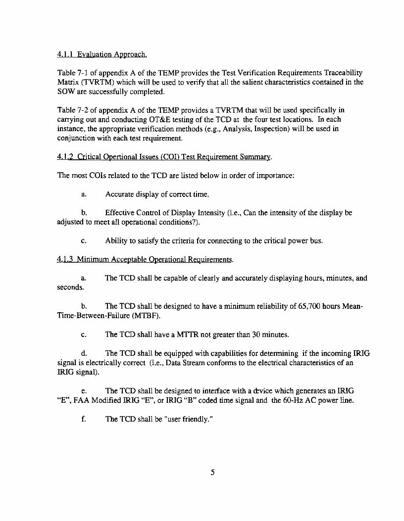
4.1.1 Evaluation Approach.
Table 7-1 of appendix A of the TEMP provides the Test Verification Requirements Traceability Matrix (TVRTM) which will be used to verify that all the salient characteristics contained in the SOW are successfully completed.
Table 7-2 of appendix A of the TEMP provides a TVRTM that will be used specifically in carrying out and conducting aT&E testing of the TCD at the four test locations. In each instance, the appropriate verification methods (e.g., Analysis, Inspection) will be used in conjunction with each test requirement.
4.1.2 Critical Opertional Issues (Cal) Test Requirement Summary.
The most COIs related to the TCD are listed below in order of importance:
a. Accurate display of correct time.
b. Effective Control of Display Intensity (i.e., Can the intensity of the display be adjusted to meet all operational conditions?).
c. Ability to satisfy the criteria for connecting to the critical power bus.
4.1.3 Minimum Acceptable Operational Requirements.
a. The TCD shall be capable of clearly and accurately displaying hours, minutes, and seconds.
b. The TCD shall be designed to have a minimum reliability of 65,700 hours Mean-Time-Between-Failure (MTBF).
c. The TCD shall have a MTTR not greater than 30 minutes.
d. The TCD shall be equipped with capabilities for determining if the incoming IRIG signal is electrically correct (i.e., Data Stream conforms to the electrical characteristics of an IRIG signal).
e. The TCD shall be designed to interface with a cevice which generates an IRIG "E", FAA Modified IRIG "E", or IRIG "B" coded time signal and the 60-Hz AC power line.
f. The TCD shall be "user friendly."
5

4.1.4 Activities Leading To Test.
Highlights of the various activities that will be satisfied prior to actual conduct of the OT&E of the TCD in a National Airspace System (NAS) environment are as follows:
a. The contractor must demonstrate that the TCD has successfully passed testing of all the salient characteristics contained in the SOW, as well as Factory Acceptance, Testing, First Article Testing, and the Reliability Demonstration Test.
b. The test sites must be contacted to ensure that they are prepared for the OT&E. This involves informing them of the intended test period (Date and Time). Also the site needs to know that one maintenance technician and one air traffic controller (operator of the TCD) are needed to assist in the testing.
c. Site personnel need to be briefed on the opemtion of the new TCD. Since the new TCD is a simple device to operate, an instruction manual will be sent to the site prior to testing. A review of this document should suffice for training.
d. Maintenance Technicians need to be briefed on the maintenance of the new TCD. They should be informed that the new TCD is functionally the same as the old TCD, and that the same procedures used to determine if the old TCD was functioning properly can be applied to the new TCD. If the new TCD is determined to be defective, the unit is a throwaway and should be replaced with a replacement.
e. A minimum of 20 TCDs need to be shipped to the FAA Technical Center for use during OT&E testing. From here FAA Technical Center personnel will hand-carry a TCD to each test site at the start of OT&E field testing.
4.2 TEST ENVIRONMENT.
The current plan is to perform OT&E testing at four locations. They are the ARTCC, the TRACON, the ATCT, and the AFSS. These locations were selected to ensure that the TCD can function under various conditions. These conditions are as follows:
a. Connection to different Coded Time Signal Sources (IRIO "E", Modified IRIO "E", and IRIO "B").
b. Different ambient lighting conditions. Almost total darkness as in a TRACON to full brightness as in an ATCT.
In addition to the testing at the test sites, ACT-320 will perform testing at the FAA Techncial Center. This testing will consist of performing a reliability test which will accumulate a minimum of 43,000 hours on the TCDs. Also, the TCDs will be connected to the following Coded Time Signal Sources to see if the TCD can correctly recognize the incoming modulated data stream:
6

a. Time Code Generator (IRIG "E"), b. Coded Time Source (FAA Modified IRIG "E"), c. Global Positioning System (GPS) Receiver (IRIG "B"), d. WWVB Receiver (IRIG "B").
4.2.1 Test Location.
The four selected test locations are as follows:
a. The ARTCC in Boston, Massachusetts, b. The TRACON at the Philadelphia International Airport, c. The ATCT at the Atlantic City International Airport, d. The AFSS in Millville, N.J.
4.3 TEST AND ANALYSIS TOOLS.
The testing of the TCD is very simple. Most tests rely on a visual observation to determine if the test passes or fails. The testing will consist of connecting the TCD to various TCGs and then observing that the TCD can perform its mission in the NAS.
The special equipment required to perform the testing is as follows:
a. Power Quality Analyzer, b. Time Code Generator Simulator, c. Storage Oscilloscope.
No special analysis or data reduction tools are necessary. The data will be collected at the four test locations, plus the FAA Technical Center and compiled into one table. This will provide an easy way to assess which tests passed or failed.
4.4 TEST AND/OR EVALVATION DESCRIPTION.
The following paragraphs identify each of the T&E tasks to be conducted. More detailed information appears in appendix A of this plan concerning these specific T&E tasks.
4.4.1 Total Harmonic Distortion Test (Test Requirement Number 61).
A power quality analyzer will be connected to the input power lines of the TCD to make this measurement. The results will be collected and compared to the criteria established for Total Harmonic Distortion (THD) levels in FAA Order 6950.2C, Electrical Power Implementation at NAS Facilities. The execution time for the test is 1 hour.
7

4.4.2 Inrush Current Test (Test Requirement Number 62),
An oscilloscope with a current probe will be connected to the input power lines of the TCD to measure the in-rush current. The results will be collected and compared to the criteria established for inrush current levels in FAA Order 6950.2C, Electrical Power Implementation at National Airspace System Facilities. The execution time for the test is I hour.
4.4.3 Power Factor Test (Test Requirement Number 63).
A power quality analyzer will be connected to the input power lines of the TCD to make this measurement. The results will be collected and compared to the criteria established for Power Factor levels in FAA Order 6950.2C, Electrical Power Implementation at National Airspace System Facilities. The execution time for the test is I hour.
4.4.4 !RIO "E" Compatibility Test (Test Requirement Number 64).
The TCD will be tested with different IRIO "E" generators to ensure that the TCD will operate with currently deployed TCOs. If a TCO with an adjustable output can be located, the FAA Technical Center will test the TCD over the minimum and maximum levels (allowable tolerances) of a functioning TCO. The execution time for this test is 3 hours.
4.4.5 Modified IRIO "E" Compatiblity Test (Test Requirement Number 65).
The TCD will be tested with different Modified IRIO "E" generators to ensure that the TCD will operate with currently deployed TCOs. If a TCO with an adjustable output can be located, the FAA Technical Center will test the TCD over the minimum and maximum levels (allowable tolerances) of a functioning TCO. The execution time for this test is 3 hours.
4.4.6 IRIO "B" Compatibility Test crest Requirement Number 66).
The TCD will be tested with different IRIO "B" generators to ensure that the TCD will operate with currently deployed TCOs. If a TCO with an adjustable output can be located, the FAA Technical Center will test the TCD over the minimum and maximum levels (allowable tolerances) of a functioning TCO. The execution time for this test is 3 hours.
4.4.7 Reliability Test (Test Requirement Number 67).
The TCD prime contractor shall conduct and successfully pass a reliability demonstration in accordance with the contract SOW. In addition to this, the FAA Technical Center will perform an independent test with 20 TCDs connected in parallel to one TCO. A minimum of 43,000 hours will be collected on these displays at the FAA Technical Center. An analysis will then be performed on the data to determine the reliability of the TCD. The execution time for this test is 90 days.
8

4.4.8 Corrective Maintenance Test (Test Requirement Number 68),
An FAA TCD qualified/trained technician shall be assigned the task of restoring a failed TCD to operation status within a 30-minute timeframe. The technician will not have any prior knowledge as to the cause of the failure. Since the TCD is a throwaway device, i.e., not repairable, this test will be geared towards proving that the technician can isolate a TCD failure from a TCO or failure. The execution time for this test is I hour.
4.4.9 Usability and Safety Test (Test Requirement Number 69),
A test technician and an air traffic controller will be asked to help determine if the new TCD is usable by the air traffic controllers and presents no safety hazards to any personnel maintaining or operating the TCD. The execution time for this test is 1 hour.
4.4.10 Tools and Test Equipment Test (Test Requirement Number 70).
This test will check that the technician has the correct tools and test equipment to properly troubleshoot, maintain, and replace a TCD. The execution time for this test is 1 hour.
4.4.11 Operational Accuracy Test (Test Requirement Number 71).
This test will check that the TCD can accurately decode the time of day from the incoming modulated data stream. The new TCD will be connected to the TCOs at the test sites. The time of day on the new TCD will then be compared to the time on an older TCD connected to the same generator. In addition to this the incoming modulated data stream to the new TCD will be disconnected which forces the display into the AC power mode. In this mode the TCD derives its timing off the 60-Hz power line. Again the new TCD will be checked against the old TCD. They should be within 1 second of each other. The execution time for this test is 1 hour at the field test sites and 168 hours at the FAA Technical Center. More extensive AC power mode accuracy testing will be done at the FAA Technical Center than will be done in the field (l hour versus 168 hours).
4.4.12 Human Factors Test (Test Requirement Number 72),
The purpose of this test is to demonstrate that the man/machine interface is suitable and effective. This type of test involves visual observations as well as manually operating mechanical switches. The display will be tested under various light conditions to ensure that air traffic controllers can adjust the display to an intensity which is appropriate for the environment. This may be from almost total darkness like in a TRACON to total bright light like in an ATCT. In addition, an air traffic controller or maintenance technician will be instructed to exercise all the modes of the TCD as defined in the TCD instruction book. This will indicate to us how hard or easy the unit is to operate, which will allow us to make a decision on the units suitability and effectiveness. The execution of this test will take 1 hour.
9

4.4.13 Electroma~netic CQmpatibility Test (Test Requirement Number 73).
ElectrQmagnetic Computability testing at the test sites will invQlve ensuring that the display is nQt affected by any equipment Qperating at the test site and that the display dQes nQt interfere with any equipment at the test site. This test will be run concurrently with all the Qther testing cQntained in this plan, hQwever a l-hQur time periQd will be allQcated fQr specifically IQoking fQr interference caused by Qr tQ the TCD. The executiQn time fQr this test is 1 hQur.
4.4.14 Physical EnvirQment Test (Test Requirement Number 74).
The physical envirQnment test will cQnsist Qf checking that the new TCD is properly cQnnected tQ bQth the time code generator and the A/C pQwer. In additiQn, the unit will be mounted intQ its nQrmal mounting area tQ ensure that the unit can be properly mQunted. The unit is tQ be built as a fQrm, fit, and functiQn replacement fQr the Qld TCD. The executiQn time fQr this test is 1 hQur.
5. TEST MANAGEMENT.
5.1 TEST MANAGEMENT ORGANIZATION.
The Test Management OrganizatiQn is cQmprised Qf variQus organizatiQns and persQnnel. Their rQles and respQnsibilities fQr the TCD test effQrt is as fQllQws:
a. AssQciate Program Manager fQr Engineering - The TCD AssQciate Program Manager fQr Engineering (APME) directs, manages, and accQmplishes engineering activities delineated in TeO program directives. The APME provides assistance and SUPPQrt for the impl611entatiQn Qf the TEMP through the review Qf related test plans, prQcedures, test data, and test repQrts. The APME supports FactQry Acceptance Test (FAT), OT&E IntegratiQn, Operational, and ShakedQwn Testing.
b. AssQciate PrQgram Manager fQr Test (APMT) - The TCD APMT QrganizatiQn (ACT320) is respQnsible fQr the overall management Qf the OT&E test effQrt. The APMT has respQnsibility fQr: (1) develQping OT&E requirements, plan, procedures, and repQrt; (2) cQordinatiQn of the test dQcumentatiQn; (3) cQnduct Qf OT&E testing; (4) test documentatiQn management; (5) aWQintment Qf the Test DirectQr; (6) presenting unresQlved test issues and problems to the Test PQlicy Review CQmmittee (TPRC); and (7) prQviding assessments and recQmmendations tQ the DeplQyment Readiness Review (ORR) Executive Committee (EXCOM). In additiQn, the APMT provides leadership and manpQ\\er, as required, tQ SUPPQrt testing.
Finally, the APMT is respQnsible fQr prQviding the Final Test RepQrt tQ the Terminal Products Lead (TPL).
10

c. Test Director - The Test Director (TD) is respon sible for the oversight of test schedules and maintaining authority at the test site during test conduct. The TD is also re;ponsible for ensuring that: (l) test personnel are available and properly trained to conduct the required tests; (2) the required equipment is available and in working order at the designated test site; (3) requirements for on-site test support personnel; (4) test activities are performed within the approved schedule in accordance with approved test procedures; (5) test discrepancies noted are logged and appropriate remedial action for resolution of the test problems is recommended; and (6) test data for analysis is collected and test results are documented. In addition, the TD is responsible for briefing the test team, defining the necessary test team assignments, coordinating the test resources, assuring proper recording of the test results, red-lining test procedures to reflect as tested activities, coordinating Program Trouble Reports (PTR), participating in test execution, and debriefing the test team.
d. Test Engineer (s) - Responsible for performing and fulfilling various test duties during the conduct of testing, and recording anomalies and comments in the test log during test conduct. Responsibilities include carrying out test setups, execution of runs, and operating the test equipment.
e. Air Traffic Controllers - Air traffic controllers will participate in the Human FactorsNiewing Test. They will be required to provide their opinions (recorded on the air traffic controller data form) regarding the viewing and operation of the TCD, along with other pertinent information.
f. Airway Facility (AF) - AF will participate in the Maintainability Test. AF will be assigned the task of restoring the TCD to an operational state from a failure within a 30-minute timeframe. The technician will not have any prior knowledge as to the cause of the failure.
g. AOS-220 - AOS is responsible for the development and execution of the OT&E Shakedown Test Plan, Test Procedures, Maintenance Handbook, and conducts OT&E Shakedown. Reviews the technical instruction books for completeness and technical accuracy.
h. Air Traffic (AT) - AT participates in all phases of the T&E process including the review, approval, and development of program requirements; provides and approves user test requirements and determines the operational acceptability of new ATC systems; provides T&E assessments to support the DRR process; and provides regional AT Divisions support personnel to Program Managers (PM) in the development of test requirements and in the implementation of T&E requirements.
11

5.2 TRAINING.
5.2.1 Test Developer Training.
The test developer needs to know how the system under test is utilized in the field. What its operational requirements are and under what environmental conditions the system will be utilized. The test developer must also be familiar with the test equipment that will be used during OT&E testing. Since the TCD is a relatively simple device, all required training for test developer personnel will be acquired through the review and evaluation of TCD instruction manuals, test documentation, design reviews, witnessing of the prime contractor T&E activities, and test equipment operations manuals. No formal training is necessary.
5.2.2 Test Participant Tranining.
Since the TCD is being built as a form, fit, and function replacement of an existing display, the test participants should already be familiar with the operational requirements of the device and therefore will not need additional training. A review of the instruction manual that accompanies each TCD is all that will be necessary to familiarize an existing TCD operator with the operation of the new display.
5.2.3 Special Training Requirements.
There are no special training requirements for the TCD project.
5.3 SYSTEM CONAGURAnON MANAGEMENT.
There is no requirement for a physical or functional configuration audit on the TCD project. Configuration control will be the responsibility of the Quality Control Officer (QRO). The QRO will inspect every TCD during Factory Acceptance testing. Any changes made to the TCD by the vendor shall be reported to the Contracting Officer.
5.3.1 TEST-BED CONFIGURATION.
The test-bed configuration will contain approximately 20 TeDs. The test bed will also contain a patch panel that will have the following coded time signals;
Signal Type Source a. IRIG "E", Magnasync Coded Time Source b. Modified IRIG "E", Astrodata Coded Time Source c. IRIG "B", and TrueTime Global Positioning System d. IRIG "B" WWV Broadcast Receiver
12

The above coded time signals will not be simulated. They are provided by the same type of equipment that is currently fielded in the FAA. In addition to the signals provided by the above equipment, the test-bed will have a coded time source simulator that incorporates all three types of coded time signals. This simulator also allows the amplitude of the coded time signal to be varied which allows for the testing of the dynamic range of the TCD.
5.4 OT&E ENTRY CRITERIA.
The following items and conditions must be met before OT&E testing can begin.
a. The TCD must successfully complete First Article, Factory Acceptance, and Reliability Demonstration testing.
b. The TCDs for OT&E testing must be delivered to the FAA Technical Center.
c. The TEMP, the OT&E Integration and Operational Test Plan, and the procedures need to be completed and approved.
5.5 TEST EXECUTION.
At each test location, the TD will hold a pretest briefing to instruct the test engineer, test witnesses, and test participants of their involvement/role during OT&E testing. A copy of the Test Procedure will be provided to each member of the test team to be filled out by them during the course of the testing. Also provided will be PTRs to be used in event of a failure and a copy of the controller's data fonn. The data fonn is used during the Human FactorsNiewing test.
The TD will hold the post-test briefing, which is held immediately after completion of the testing, to discuss any problem(s) that occurred and whether the testing was successful or not. If the testing was not successfully completed, the reasons will be documented and an action item will be generated to ensure that a solution to the problem will be addressed. Once the problem is corrected, the TCD will be retested to ensure that the problem has been corrected and that no new problems were created.
5.6 OT&E EXIT CRITERIA.
The conditions that must be met in order to declare that the testing was successful are that each of the tests must be completed successfully without a failure. If a test fails, a PTR is written and the problem is fixed. After the problem is fixed, the test case is rerun to assure that the problem has been fixed.
13

5.7 OT&E REPORTS.
The Final OT&E Test Report will be written in accordance with FAA-STD-024b by ACT-320. The report will be coordinated in accordance with FAA Order 1810AB and submitted for approval to AND-430. The report will be distributed to the following organizations:
AND-430 ATR-lOO AOS-220 AFS (information only)
The final report is due 30 to 90 days after the completion of the OT&E test effort.
5.8 SYSTEM/OPERATIONAL DEFICIENCY REPORTS.
To track and correct deficiencies experienced during OT&E testing, a PTR will be written when a problem is encountered. The 1D will be responsible for controlling the PTR (s), assuring that the problem (s) are fixed, and that the test case (s) are rerun successfully.
5.9 OT&E SCHEDULE.
The OT&E Schedule is depicted in the TCD TEMP in figure 4.2-1.
14

5.10 PERSONNEL RESOURCE REQUIREMENTS.
The personnel required to support this test effort are listed in the table below:
TABLE 5.10-1. PERSONNEL RESOURCES
Personnel Function Skills Or~anization Time Required
Test Director Oversees Test Effort
Familiar with the operational requirements of the unit under
ACT-320 20 hours per test site
test. Test Engineer Performs Test
Procedure Familiar with test procedures, test equipment, and unit under test.
ACT-320 20 hours per test site
Air Traffic Controller
Assists in the evaluation of the unit under test
Familiar with the operational requirements of the unit under
AT 3 hours per test site
test. Air Facilities Technician
Assists in the evaluation of the unit under test
Familiar with the operation of the unit under test and the equipment necessary to maintain it.
AF 4 hours per test site
5.11 PLANNING CONSIDERATIONS AND LIMITATIONS.
The only requirement that cannot be met on this program is the requirement for the display to be clearly discernible in all ambient lighting conditions up to 1O,OOO-foot lamberts. The 10,000 footlamberts number is not realistic. Air traffic controllers could not function in an environment this bright as it would give them headaches. The planned work around for this discrepancy is that the TCD will be manufactured with either High Efficiency Red (HER) or Aluminum-GalliumArsenide (ALGaAs) Light Emitting Diodes (LEOs). Both types of LEOs provide better visibility under bright light conditions then the displays which are currently fielded and in use in ATCTs. The TCD will then be tested in a working environment such as an ATCT, and the air traffic controllers will determine if the display is readable.
15

6. ACRONYMS AND ABBREVIATIONS.
AC AF AFSS AlGaAs APME APMT ARTCC AT ATC ATCT COl DRR DT&E EMI EXCOM FAA FAT GPS HER Hz IRIG LEDs MTBF MTTR NAS OT&E PM PTR QRO SOW TCG TCD TO TEMP THD TPL TPRC T&E TRACON TVRTM
Alternating Current Airway Facility Automated Flight Service Station Aluminum-Gallium-Arsenide Associate Program Manager For Engineering Associate Program Manager For Test Air Route Traffic Control Center Air Traffic Air Traffic Control Air Traffic Control Tower Critical Operational Issues Deployment Readiness Review Development Test And Evaluation Electromagnetic Interference Executive Committee Federal Aviation Administration Factory Acceptance Testing Global Positioning System High Efficiency Red Hertz Interrange Instrumentation Group Light Emitting Diodes Mean Time Between Failure Mean-Time-To- Repair National Airspace System Operational Test And Evaluation Program Manager Program Trouble Report Quality Reliability Officer Statement Of Work Time Code Generator Time Code Display Test Director Test And Evaluation Master Plan Total Harmonic Distortion Terminal Products Lead Test Policy Review Committee Test And Evaluation Terminal Approach Control Facility Test Verification Requirements Traceability Matrix
16

APPENDIX A
TEST AND EVALUATION DESCRIPTION


STATEMENT OF WORK VERIFICAnON TEST (Test Requirement Number 1-60)
1. TESTIEVALUAnON OBJECTIVE - Pre-OT&E check which verifies that the requirements contained in the salient characteristic section of the Time Code Display (TCD) Statement of Work (SOW) are successfully completed.
2. TESTIEVALUAnON CRITERIA - The test/evaluation criteria is contained in table 7-1 of appendix A of the TCD TEMP.
3. TESTIEVALUAnON APPROACH - Collect the TCD test data that was taken during Factory Acceptance testing and First Article testing and compare it to the requirements contained in table 7-1 of the TCD TEMP. A count will then be made of how many requirements the TCD successfully passed and how many failed. The results of the data will then be presented in the final report.
4. EXECUTION TIME - The time required for this test will be approximately 4 hours.
A-I

TOTAL HARMONIC DISTORTION TEST (Test Requirement Number 61)
1. TEST/EVALUATION OBJECTIVE - To verify that the new TCD meets the Total Harmonic Distortion requirement contained in FAA Order 6950.2C for new equipment entering the National Airspace System (NAS).
2. TEST/EVALUATION CRITERIA - The total harmonic content of the input current caused by the system/equipment connected to the critical bus shall not exceed 5 percent of the fundamental (60 Hz) and, no single harmonic shall be greater than 3 percent of the fundamental.
3. TESTIEVALUATION APPROACH - The TCD will be connected to a clean AC power source at the FAA Technical Center. A power quality analyzer will be connected to the TCD AC power lines. The total harmonic content of the input current will be measured by the quality power analyzer. A plot will then be made of the current and voltage waveforms. In addition to this, the data for the total harmonic content and the fIrst 50 harmonics will be printed out along with a chart which plots the harmonic number versus the harmonic content amplitude.
4. EXECUTION TIME - The time for this test should be approximately 1 hour.
A-2

IN-RUSH CURRENT TEST (Test Requirement Number 62)
1. TESTIEVALUATION OBJECTIVE - To verify that the new TCD meets the In-rush Current requirement contained in FAA Order 6950.2C for new equipment entering the NAS.
2. TESTIEVALUATION CRITERIA - The peak total in-rush current during startup shall not exceed five times the normal peak operating current. The duration of the in-rush current shall not exceed 8 milliseconds (return to 110 percent of normal).
3. TESTIEVALUATION APPROACH - The TCD will be connected to a clean AC power source at the FAA Technical Center. A current probe will be connected to the input AC power line and a digital oscilloscope. The oscilloscope will be set to trigger a single sweep when the power is applied to the TCD. The time base on the oscilloscope will be set so that the single sweep will capture both the in-rush current and the steady state current. The waveform will then be printed with an IEEE bus compatible printer. The waveform will then be analyzed to determine if the TCD meets the requirements for in-rush current.
4. EXECUTION TIME - The time for this test should be approximately 1 hour.
A-3

POWER FACTOR TEST (Test Requirement Number 63)
1. TESTIEVALVAnON OBJECTIVE - To verify that the new TCD meets the Power Factor requirement contained in FAA Order 6950.2C for new equipment entering the NAS.
2. TESTIEVALUAnON CRITERIA - The equipment shall be designed so that it presents a power factor not less than .85 lagging when operating under steady state conditions.
3. TESTIEVALUAnON APPROACH - The TCD will be connected to a clean AC power source at the FAA Technical Center. A power quality analyzer will be connected to the TCD AC power lines. The total harmonic content of the input current will be measured by the quality power analyzer. A plot will then be made of the current and voltage waveforms. An analysis will then be made to determine the power factor of the TCD. To properly compute the power factor for the TCD, two factors must be known. They are the power factor due to the Total Harmonic Distortion (THD) and the power factor due to the displacement of the current and voltage waveforms. Both quantities can be calculated from the data captured by the quality power analyzer.
4. EXECUTION TIME - The time for this test should be approximately 1 hour.
A-4

IRIG "E" COMPATffiILITY TEST (Test Requirement Number 64)
1. TESTfEVALUAnON OBJECTIVE - To verify that the new TCD is compatible with existing FAA IRIG "E" Time Code Generators (TCG). In addition, the test will measure the dynamic range of the TCDs coded time source input.
2. TESTfEVALUAnON CRITERIA - Since the outputs of the existing TCGs are not specifically specified in absolute numbers, and the SOW for the new TCDs input requirements lack the same information, the new TCD will be tested at four test locations and the FAA Technical Center to establish that the new TCD will operate in the NAS. Also the dynamic range of the new TCDs coded time source input will be compared to the dynamic range of the old TCD coded time source input. If the new TCD operates at the four test locations and its dynamic range equals or exceeds the old TCD's dynamic range, the test will be characterized as successful.
3. TESTfEVALUAnON APPROACH - The new TCD will be connected to TCGs at four test sites in the NAS and to one generator at the FAA Technical Center to see if the TCD will recognize the transmitted code and display the correct time. In additional to this, a test will be run at the FAA Technical Center which will use a TCG simulator with a variable IRIG "E" amplitude output. The dynamic range of the new and old TCDs will be measured and the results recorded.
4. EXECUTION TIME - The time required for this test will be approximately 3 hours per test site.
A-5

MODIFIED IRIG "E" COMPATIBILITY TEST (Test Requirement Number 65)
1. TESTIEVALUATION OBJECTIVE - To verify that the new TCD is compatible with existing FAA MODIFIED IRIG "E" TCGs. In addition, the test will measure the dynamic range of the TCDs coded time source input.
2. TESTIEVALUATION CRITERIA - Since the outputs of the existing TCGs are not specifically specified in absolute numbers, and the SOW for the new TCDs input requirements lack the same information, the new TCD will be tested at four test locations and the FAA Technical Center to establish that the new TCD will operate in the NAS. Also the dynamic range of the new TCDs coded time source input will be compared to the dynamic range of the old TCD coded time source input. If the new TCD operates at the four test locations and its dynamic range equals or exceeds the old TCD's dynamic range, the test will be characterized as successful.
3. TESTIEVALVAnON APPROACH - The new TCD will be connected to TCGs at four test sites in the NAS and to one generator at the FAA Technical Center to see if the TCD will recognize the transmitted code and display the correct time. In additional to this, a test will be run at the FAA Technical Center which will use a TCG simulator with a variable MODIFIED IRIG "E" amplitude output. The dynamic range of the new and old TCDs will be measured and the results recorded.
4. EXECUTION TIME - The time required for this test will be approximately 3 hours per test site.
A-6

IRIG "B" COMPATIBILITY TEST (Test Requirement Number 66)
1. TESTIEVALUATION OBJECTIVE - To verify that the new TCD is compatible with existing FAA IRIG "B" TCGs. In addition, the test will measure the dynamic range of the TCD's coded time source input.
2. TESTIEVALUATION CRITERIA - Since the outputs of the existing TCGs are not specifically specified in absolute numbers, and the SOW for the new TCDs input requirements lack the same information, the new TCD will be tested at four test locations and the FAA Technical Center to establish that the new TCD will operate in the NAS. Also the dynamic range of the new TCDs coded time source input will be compared to the dynamic range of the old TCD coded time source input. If the new TCD operates at the four test locations and its dynamic range equals or exceeds the old TCD's dynamic range, the test will be characterized as successful.
3. TESTIEVALUATION APPROACH - The new TCD will be connected to TCGs at four test sites in the NAS and to one generator at the FAA Technical Center to see if the TCD will recognize the transmitted code and display the correct time. In additional to this, a test will be run at the FAA Technical Center which will use a TCG simulator with a variable MODIFIED IRIG "B" amplitude output. The dynamic range of the new TCD will be measured and the results recorded.
4. EXECUTION TIME - The time required for this test will be approximately 3 hours per test site.
A-7
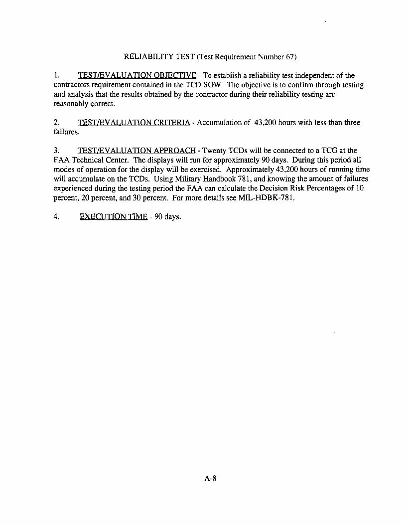
RELIABILITY TEST (Test Requirement Number 67)
1. TESTIEVALVAnON OBJECTIVE - To establish a reliability test independent of the contractors requirement contained in the TCD SOW. The objective is to confirm through testing and analysis that the results obtained by the contractor during their reliability testing are reasonably correct.
2. TESTIEVALVAnON CRITERIA - Accumulation of 43,200 hours with less than three failures.
3. TESTIEVALUAnON APPROACH - Twenty TCDs will be connected to a TCO at the FAA Technical Center. The displays will run for approximately 90 days. During this period all modes of operation for the display will be exercised. Approximately 43,200 hours of running time will accumulate on the TCDs. Vsing Military Handbook 781, and knowing the amount of failures experienced during the testing period the FAA can calculate the Decision Risk Percentages of 10 percent, 20 percent, and 30 percent. For more details see MIL-HDBK-781.
4. EXECUTION TIME - 90 days.
A-8

PHYSICAL ENVIRONMENT TEST (Test Requirement Number 68)
1. TESTIEVALUATION OBJECTIVE - This test will check that the TCD is correctly connected to the TCO and the AC power. In addition, the unit will be mounted in its enclosure to make sure that it can be properly mounted.
2. TESTIEVALUATION CRITERIA - This fIrst part of this test passes if the coded time signal connectors are of the right type and wired as per the TCD instruction manual and AC power is provided to the TCD as per FAA-STD-020a. The second part passes if the unit can be properly installed in its enclosure.
3. TESTIEVALUATION APPROACH - After a TCD is installed at a test site, an inspection will be made to see that the TCD is properly installed and connected to the TCO and the AC power.
4. EXECUTION TIME - 1 hour.
A-9

USABILITY AND SAFETY TEST (Test Requirement Number 69)
1. TESTIEVALUATION OBJECTIVE - To establish that the new TCD is usable by the air traffic controllers and presents no danger to the air traffic controller or maintenance technician.
2. TESTIEVALUATION CRITERIA - This is a subjective type test. The air traffic controllers and the maintenance technicians at the four test sites will tell us if they feel the TCD is usable and safe.
3. TESTIEVALUATION APPROACH - A TCD will be installed at each test site. The air traffic controller will be asked to exercise all the functions on the TCD and then give us a report on the usability of the TCD under normal operating conditions. A maintenance technician will also be utilized to give us a report on the units safety.
4. EXECUTION TIME - 1 hour.
A-lO

TOOLS AND TEST EQUIPMENT TEST (Test Requirement Number 70)
1. TESTIEVALUATION OBJECTIVE - To determine if the maintenance technician has the necessary tools to properly detect and replace a failed TCD.
2. TEST EVALUATION CRITERIA - Check that the maintenance technician has the required tools necessary to replace a TCD as defined in the TCD instruction manual. Check that the maintenance technician has an oscilloscope to view the incoming coded time signal.
3. TESTIEVALUATION APPROACH - At the test sites have the maintenance technician replace one of the existing TCDs with a new TCD. While the technician is replacing the TCD have the technician view the coded time signal with an oscilloscope.
4. EXECUTION TIME - 1 hour.
A-ll

OPERATIONAL ACCURACY TEST (Test Requirement Number 71)
1. TESTIEVALUATION OBJECTIVES - This test will check that the TCD can correctly decode the incoming time coded signal and display the correct time. In addition, it will test the accuracy of the TCD in the AC mode.
2. TESTLEVALUATION CRITERIA - The TCD should display the exact time that the TCG is sending. In the AC mode, the TCD should accurately keep time (ie± I second) for the duration of the test.
3. TESTIEVALUATION APPROACH - This test will be run at the field test sites and the FAA Technical Center. A TCD will be connected to the TCG at the test site. The time on the new TCD will then be compared to the time on the old TCD. The time should match exactly. The new TeD will then be switched into the AC mode. The new TCD should not lose or gain more than 1 second for the duration of the test. Testing for this requirement will be more extensive at the FAA Technical Center than in the field due to the amount of time required for the AC mode test.
4. EXECUTION TIME - Field Site, 1 hour. FAATC, 168 hours.
A-12

HUMAN FACTORS TEST (Test Requirement Number 72)
1. TESTIEVALUAnON OBJECTIVES - The purpose of this test is to demonstrate that the man/machine interface is suitable and effective under all ambient lighting conditions.
2. TESTIEVALUAnON CRITERIA - This is a subjective type test. The air traffic controller will be asked to tell us if the display was suitable and effective. If it is, the test passes, if not the test fails.
3. TESTIEVALUAnON APPROACH - A TCD will be installed at four different types of facilities. The air traffic controllers at these locations will be asked to evaluate the display and record their findings.
4. EXECUTION TIME - 1 hour.
A-13

ELECTROMAGNETIC COMPATIBILITY TEST (Test Requirement Number 73)
1. TESTIEVALUAnON OBJECTIVE - The objective of this test is to determine if the TCD is being affected by any operating equipment at the test site and that the TCD does not interfere with any equipment at the test sites.
2. TESTIEVALUATION CRITERIA - Since the TCD will have passed a formal Emissions and Susceptibility test during DT&E, this is only a cursory check to determine that the results collected during DT&E are valid. The pass fail criteria for this test is subjective and we will rely on the air traffic controllers to tell us if the equipment is not interfering with other equipment at the site and that the equipment at the site is not interfering with the TCD.
3. TESTIEVALUAnON APPROACH - The plan is to install a TCD at four different test sites and have the controllers observe the displays and their equipment for interference.
4. EXECUTION TIME - 1 hour.
A-14

CORRECTIVE MAINTENANCE TEST (Test Requirement Number 74)
1. TESTIEVALUATION OBJECTIVE - To see that a FAA TCD qualified/trained technician can successfully restore a failed TCD to operation within 30 minutes.
2. TESTIEVALUATION CRITERIA - Failed TCD restored to operation in less than 30 minutes.
3. TESTIEVALUATION APPROACH - Install a nonfunctioning TCD at one of the TCD locations and ask a maintenance technician to correct the problem.
4. EXECUTION TIME - 1 hour.
A-15