Embed Size (px)
Citation preview

8/20/2019 Timber Code Check
http://slidepdf.com/reader/full/timber-code-check 1/17
Manual
Timber Code Check

8/20/2019 Timber Code Check
http://slidepdf.com/reader/full/timber-code-check 2/17
Timber Code Check

8/20/2019 Timber Code Check
http://slidepdf.com/reader/full/timber-code-check 3/17

8/20/2019 Timber Code Check
http://slidepdf.com/reader/full/timber-code-check 4/17
iii
Table of ContentsMaterial properties ........................................................................................................................................................................5
Timber parameters ........................................................................................................................................................................5
Adjusting the parameters for design .............................................................................................................................................7
Performing the check ....................................................................................................................................................................9
Detailed check ..............................................................................................................................................................................9
Introduction to optimisation .........................................................................................................................................................11
Principles of optimisation ............................................................................................................................................................11
Optimisation parameters .............................................................................................................................................................11
Optimising the members .............................................................................................................................................................11

8/20/2019 Timber Code Check
http://slidepdf.com/reader/full/timber-code-check 5/17

8/20/2019 Timber Code Check
http://slidepdf.com/reader/full/timber-code-check 6/17
1
Welcome
Thank you for choosing Scia Engineer.
Module Timber Code Check has been designed to facilitate the often-demanding task of design of timber structures.
You can find more about the company and its products on www.scia-online.com .
Version i nfo
Documentation title Timber Code Check
Version 2010.0
Produced November 2009
Translated N/A
Software covered Scia Engineer
Version 2010.0
Latest Build covered 10.0.25

8/20/2019 Timber Code Check
http://slidepdf.com/reader/full/timber-code-check 7/17

8/20/2019 Timber Code Check
http://slidepdf.com/reader/full/timber-code-check 8/17
3
Introduction
The Scia Engineer Timber Code Check module is a program for the design of timber structures. It consists of stress andstability verifications of timber members according to the code. It is also possible to search interactively for the lightestsection, which meets the code requirements for selected loadings (optimisation).
The following structural timber design code is supported : Eurocode 5 - EC-ENV.
For more details about the used codes and the theoretical background, we refer to the Theoretical Background manual and
to the code itself.IMPORTANT: Only straight beams can be checked. The solution for curved beams is not implemented.

8/20/2019 Timber Code Check
http://slidepdf.com/reader/full/timber-code-check 9/17
8/20/2019 Timber Code Check
http://slidepdf.com/reader/full/timber-code-check 10/17
5
Parameters
Material properties
In addition to standard material properties, there are a few extra parameters related to the code check.
Bending (fm, k) characteristic value of bending strength
Tension (ft, 0, k) characteristic value of tensile strength parallel to grainTension (ft, 90, k) characteristic value of tensile strength perpendicular to grain
Compression (fc, 0, k) characteristic value of compressive strength parallel to grain
Compression (fc, 90, k) characteristic value of compressive strength perpendicular tograin
Shear (fv, k) characteristic value shear strength
Modulus (E0.05) 5-percentile characteristic value of modulus of elasticity parallelto grain
Modulus (E 90 mean) mean characteristic value of modulus of elasticity perpendicularto grain
Type of timber Solid or Glued, laminated type can be selected.
Procedure to adjust material properties
1. Open the Material manager , e.g. through the tree menu function Library > Materials.
2. Select the required material.
3. Press button [Edit].
4. Fill in the parameters under group EC5.
5. Close the editing dialogue.
6. Close the Material manager .
Timber parameters
Gamma m, settings NAD
Ultimate limit states
These parameters represent the box values from EC5, table 2.3.3.2.
fundamental combinations:timber and wood-based materials
Specifies gamma m for fundamental combinations: timber andwood-based materials.
fundamental c ombinations: steelused in joints
Specifies gamma m fundamental combinations: steel used in joints.
accidental combinations Specifies gamma m accidental combinations.
Serviceability limit states
"serviceability c oeff."
(title not shown)
The coefficient for serviceability combinations.
Interaction buckling - LTB
No interaction No interaction between buckling and lateral torsional buckling isperformed. Only the separate checks according to EC5 areexecuted.
According to CSN NAD Interaction between buckling and lateral torsional bucklingaccording to the CSN NAD is performed: the LTB is checkedfor the moment around the major axis, together with thebuckling influence.
According to DIN NAD Interaction between buckling and lateral torsional bucklingaccording to the DIN NAD is performed: the LTB is checked forthe moments around both axis, together with the bucklinginfluence.
8/20/2019 Timber Code Check
http://slidepdf.com/reader/full/timber-code-check 11/17
Timber Code Check
6
Default sway types
This setting will be used for the beams where no detailed adjustment of buckling parameters is made.
The sway type is used to calculate the buckling length coefficients for flexural buckling, it has no effect on defined bucklinglength ratios.
Buckling length ratios ky, kz
As input The program will always use the input values.
Calculated The program will use the calculated ky and kz factors andneglect all input values.
Calculated only if no input value The program uses the input values of coefficients if thecoefficients values were defined.
The program uses the calculated values if the coefficientsvalues were NOT defined or if their vaule was set to –1 (minusone).
Bigger of i nput and calculated Program takes the greater of the two available values – i.e. theless favourable value.
Smaller of input and calculated Program takes the smaller of the two available values – i.e. themore favourable value.
Max. k ratio The calculated value of k will be limited to this value.
Max. slenderness If the slenderness of the checked member exceeds this value,the program will print a warning in the output.
Check bounds
Individual results of checks for timber members are divided into three groups in accordance with the standard:
unused unity check lower than the lower limit
optimal unity check between the lower and upper limit
non-satisfying unity check greater than the upper limit
The items in Check bounds group can be used to set the lower and upper limit. The default values are 0.25 for the lowerlimit and 1.0 for the upper limit.
Once the calculation is performed and the results drawn in the graphical window, the adjusted limits control the colour ofresult diagram.
Service class setting
1 Class 1 is characterized by a moisture content in the materialscorresponding to a temperature of 20°C and the relativehumidity of the surrounding air only exceeding 65% for a fewweeks per year.
2 Class 2 is characterized by a moisture content in the materialscorresponding to a temperature of 20°C and the relativehumidity of the surrounding air only exceeding 85% for a fewweeks per year.
3 Class 3 climatic conditions leading to higher moisture contentsthan in service class 2.
k mod, k def
For each selected service class you can specify the modification factors k mod depending on the material (Solid and gluedlaminated timber, Plywood) and the load duration class (permanent, long-term, medium-term , short term and instantaneous ). (See EC5, table 3.1.7).
For each selected service class you can specify the factors k def depending on the material and the load duration class(See EC5, table 4.1).
The factor k def is a factor which takes into account the increase in deformation over time due to the combined effect ofcreep and moisture.
The load-duration classes are characterized by the effect of a constant load acting for a certain period of time in the life ofthe structure.
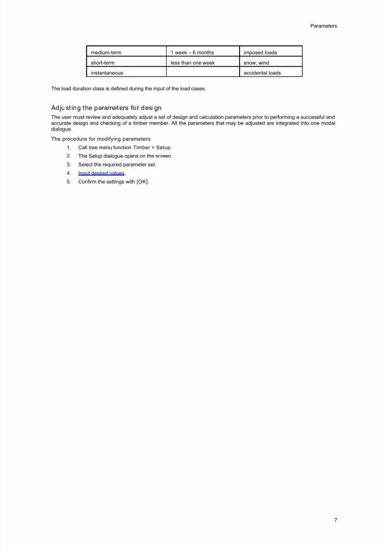
Load duration class Time of duration Examples
permanent more than 10 years self-weight
long-term 6 months - 10 years storage
8/20/2019 Timber Code Check
http://slidepdf.com/reader/full/timber-code-check 12/17
Parameters
7
medium-term 1 week – 6 months imposed loads
short-term less than one week snow, wind
instantaneous accidental loads
The load duration class is defined during the input of the load cases.
Adjust ing the parameters for design
The user must review and adequately adjust a set of design and calculation parameters prior to performing a successful andaccurate design and checking of a timber member. All the parameters that may be adjusted are integrated into one modaldialogue.
The procedure for modifying parameters
1. Call tree menu function Timber > Setup.
2. The Setup dialogue opens on the screen.
3. Select the required parameter set.
4. Input desired values.
5. Confirm the settings with [OK].

8/20/2019 Timber Code Check
http://slidepdf.com/reader/full/timber-code-check 13/17
8/20/2019 Timber Code Check
http://slidepdf.com/reader/full/timber-code-check 14/17
9
Code check
Performing the check
The procedure to perform the check
1. Open service Timber .
2. Select function Check (single click on the function is sufficient to invoke the function).
3. Select the required type of load.
4. Select the required load case, combination or class.
5. Select beams to be checked.
6. Select the required quantity and if required, make other adjustments in the property window.
7. Click Action button [Refresh] to see the selected design values.
8. Repeat steps 3 to 7 as many times as required.
IMPORTANT: Only straight beams can be checked. The solution for curved beams is not implemented.
Detailed check
If required, a selected member can be checked in detail. To do so, press button [SnapCheck] in the Action bar of functionCheck.
Single cross-section dialogue provides for detailed view of design results.
Text window
This window contains the results of the check for the selected member presented in tabular form.
Graphical window
A simple result diagram is drawn here.
Next/Previous buttons
You may use these buttons to select other members from the project.
View selection
It is possible to view in the text window either the report on the check or a table of internal forces (effects).
Procedure to perform the detailed check
1. Open service Timber .
2. Select function Check (single click on the function is sufficient to invoke the function).
3. Select the required type of load.
4. Select the required load case, combination or class.
5. Press action button [SnapCheck].
6. Select the beam to be checked.
7. The SnapCheck dialogue is opened on the screen.

8/20/2019 Timber Code Check
http://slidepdf.com/reader/full/timber-code-check 15/17
8/20/2019 Timber Code Check
http://slidepdf.com/reader/full/timber-code-check 16/17
11
Optimisation
Introduction to optimisation
Once a structure has been designed and calculated, it is the time to perform checking and usually a kind of optimisation ofthe original design.
Scia Engineer contains a powerful tool for this task. The optimisation of applied profiles may be done automatically or semi-
automatically. The process of optimisation results in what may be called an economical and good solution.The optimisation process in Scia Engineer is based on assumptions given in the following chapter .
Principles of optimisation
An optimisation in general represents a complex task. A full, complete and really "optimal" optimisation would usually lead toa long and often recursive process. Therefore, Scia Engineer implements a kind of compromise.
One optimisation step takes account of a single cros s-section only
It is possible to optimise one cross-section at a time. The user selects the cross-section from a list of all cross-sectionsapplied in the structure.
One optimisation step considers only "selected" members
It is possible to limit the optimisation process to only a selected set of members. The user may make a selection to specifywhich beams of the given cross-section should be considered for the optimisation calculations.
One optimisation step affects the whole s tructure
Once the optimised cross-section is found, it is applied to ALL members in the structure that are of the specified cross-section. It is of no importance whether the optimisation calculation was limited to a selected number of beams or not. Thefinal effect of the optimisation is that the original cross-section is simply replaced with the new, i.e. optimised, cross-section.
Optimisation parameters
The user may control the process of optimisation by means of a set of parameters.
Check parameter
Maximal check This parameter tells the program what is the maximal allowable valuefor satisfactory checking.
Maximum unit y check This item shows the found maximal check result for the optimised
cross-section.
Shape parameters for optimisation
Dimension This item determines which of the dimensions of the cross-sectionshould be optimised. All other dimensions remain unchanged.
Step This item specifies the step by which the selected dimension idmodified in order to give one-step smaller or larger cross-section.
Minimum This item specifies the minimal size of the selected dimension.
Maximum This item specifies the maximal size of the selected dimension.
Buttons for manual optimisation
Set value This button enables the user to set manually the required value ofselected dimension (see above).
Next down This button finds one-step smaller cross-section according to definedshape parameters (see above).
Next up This button finds one-step larger cross-section according to definedshape parameters (see above).
Buttons for automatic optimisation
Search for optimal This button finds automatically the optimal cross-section.
Optimising the members
It is possible to perform both automatic and manual optimisation. The process for both is identical except the last but onestep. Therefore, only one procedure will be given here in detail. The other one will be explained briefly.

8/20/2019 Timber Code Check
http://slidepdf.com/reader/full/timber-code-check 17/17
Timber Code Check
12
Procedure for the automatic optimisation o f members
1. Open service Timber .
2. Select function Check.
3. In the Property window, go to item Filter and set it to Cross-section.
4. In the Property window, go to item Cross-section and select the one you want to optimise.
5. In the Property window, go to item Selection and set it to User or Al l, depending on your requirements.
6. If the item is set to User , make the selection and press button [Esc] to close the selection.
7. If the item Selection has been re-adjusted, press button [Redraw] in order to refresh the screen and see theappropriate display.
8. In the Property window, go to item Optimisation and press the button there.
9. The optimisation dialogue is opened on the screen.
10. Adjust the parameters as required.
11. Press button [Search f or optimal] . The program finds the optimal cross-section.
12. If you agree, press [OK] to confirm.
Procedure for the manual optimisation of members
The procedure is identical except step 11.
In manual optimisation, the user must press (repeatedly, if required) buttons [Next down] and [Next Up], in order to find the
optimal cross-section. Alternatively, it is also possible to set the required value directly by means of button [Set value].
Note: The project must be calculated beforehand.