Embed Size (px)
Citation preview
Reduce Reuse Recycle AN EQUAL OPPORTUNITY EMPLOYER
Tillamook County PUBLIC WORKS DEPARTMENT Department of Solid Waste
Waste Prevention and Recycling 503 Marolf Loop Road Tillamook, Oregon 97141 PH (503) 815-3975 FAX (503) 842-6473 Email: [email protected] www.co.tillamook.or.us/solid-waste
___________________________________________________________________________________ Land of Cheese, Trees and Ocean Breeze
July 7, 2021 TO: Solid Waste Advisory Committee Prof. Jeffery Nason (OSU School of Chemical, Biological and Environmental Engineering) used our closed landfill challenge as the topic for his class of graduating engineering students. Five groups of students attempted to present a solution for cleaning our leachate of its two primary contaminants (iron and ammonia), first in a trial and then a full-scale plan. Each of the teams prepared a “poster” for the Engineering Expo, as well as a summary video, in addition to their capstone papers. I am providing you with a list of links for their videos, and their posters follow this memo. Following all this is a summary table put together by Rick Malin, our consultant at Parametrix, who acted as a consulting expert for the students during this project. I hope that you will take the time to watch the videos, read the posters, so that we can discuss the various proposals at our SWAC meeting. If we wish, Professor Nason is willing to attend our September SWAC meeting and discuss further. Team #1 video: https://youtu.be/m8e6nTODuxk Team #2 video: https://www.youtube.com/watch?v=75WX04oJ53I&t=4s Team #3 video: https://youtu.be/ySk4ejGEOLI Team #4 video: https://www.youtube.com/watch?v=oa4AAYq9gCk Team #5 video: (Sorry, I couldn’t get a link for this one, and the file is quite large.)
Chemical, Biological, and Environmental Engineering
FOLD FOLD
FOLD FOLD
NO TEXT IN ORANGE BOX BELOW
THIS LINE
COLLEGE OF ENGINEERING
MethodologyThe full-scale flow was chosen as 113-115 GPM to reflect the maximum flow that the system would receive at the TCL (the pilot-scale was reduced to 8 GPM). The lime addition pond was designed as a continuous stirred-tank reactor (CSTR) at steady-state. The concentration of lime added to the mixer was determined by its solubility limit of 1.5g/L. The effect of hydrogen ions produced by ferrous oxidation (Eqn.1), leachate alkalinity, and pH changes from the lime addition were considered in the flow rate calculation for lime addition.
4Fe2+ + O2 + 10H2O ⇋ 4Fe(OH)3 (s) + 8H+ (Eqn.1)A material balance of ferrous iron determined the volume of the pond. Design criteria for vertical turbine flocculators, and power and pumping numbers for common impellers determined pond dimensions and impeller design.The sedimentation basin was designed for type II settling. Flow through the basin was determined
Design Description• Lime addition pond: Two 3m x 3m x 3m basins
were included for maintenance redundancy. The basins would receive an aqueous solution of 3.0 grams of lime per liter at 1.3 GPM. One pitched-blade turbine was included in each, with a diameter of 1m and speed of 20 rpm.
• Sedimentation basin: Following the rapid mix basin, two 10.1m x 2.0m x 5.0m sedimentation basins were included.
• FWS Wetland: A wetland with three zones and a total surface area of 6.8 acres would accept effluent from the sedimentation basins. Zones 1 and 3 would be fully vegetated with Scirpus californicus and Typha latifolia, and have dimensions of 185.0m x 37.0m x 0.75m. Zone 2 would have an open-water surface and dimensions of 262.0m x 52.0m x 3.0m.
• Sludge Dewatering Lagoons: Two lagoons, each with an area of 7m2 and depth of 1.5 meters, would accept solids from the sedimentation basin for dewatering. The 6-month filling periods would be January-June for Lagoon 1, and July-December for Lagoon 2.
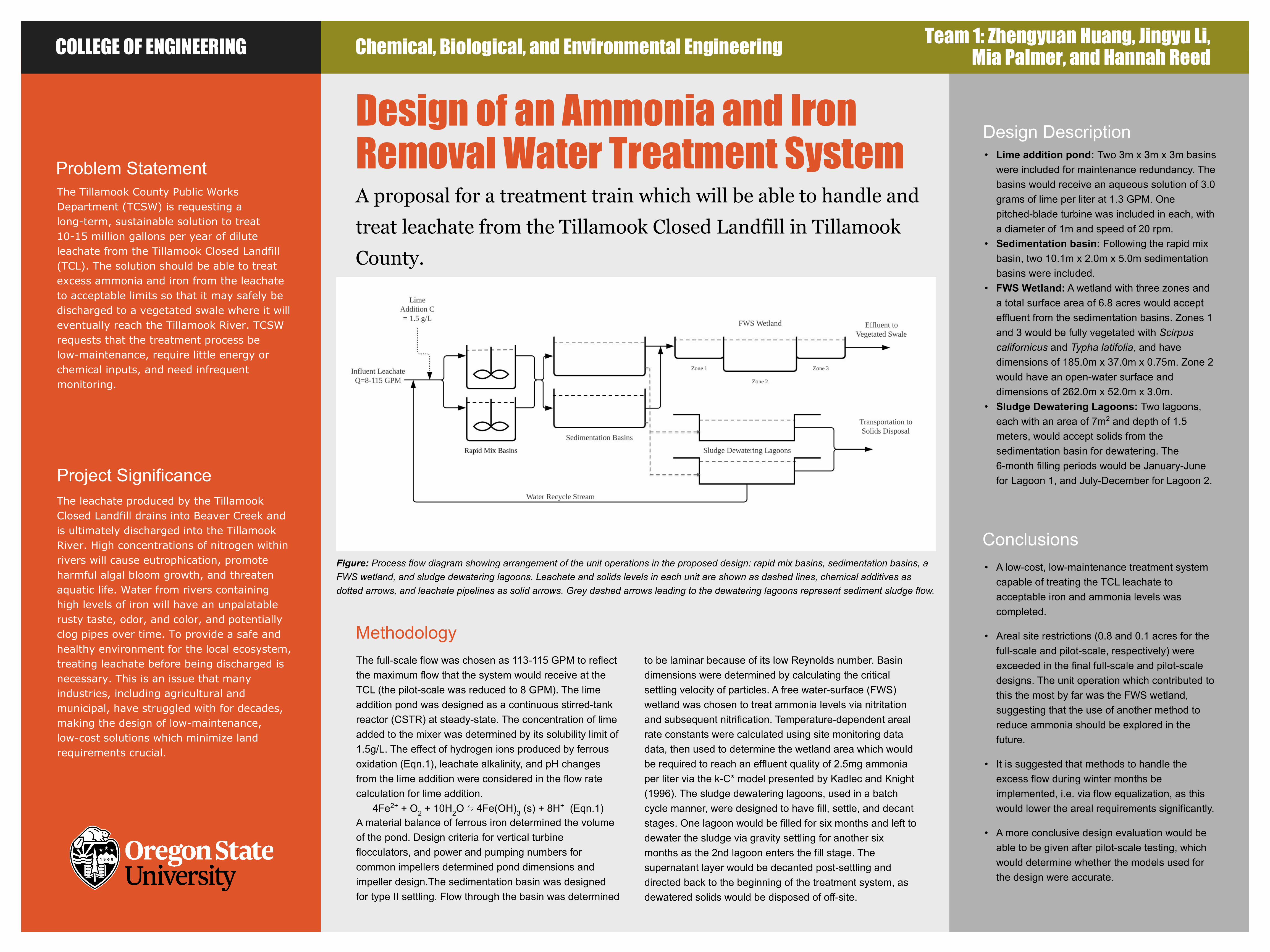
Problem StatementThe Tillamook County Public Works Department (TCSW) is requesting a long-term, sustainable solution to treat 10-15 million gallons per year of dilute leachate from the Tillamook Closed Landfill (TCL). The solution should be able to treat excess ammonia and iron from the leachate to acceptable limits so that it may safely be discharged to a vegetated swale where it will eventually reach the Tillamook River. TCSW requests that the treatment process be low-maintenance, require little energy or chemical inputs, and need infrequent monitoring.
Project SignificanceThe leachate produced by the Tillamook Closed Landfill drains into Beaver Creek and is ultimately discharged into the Tillamook River. High concentrations of nitrogen within rivers will cause eutrophication, promote harmful algal bloom growth, and threaten aquatic life. Water from rivers containing high levels of iron will have an unpalatable rusty taste, odor, and color, and potentially clog pipes over time. To provide a safe and healthy environment for the local ecosystem, treating leachate before being discharged is necessary. This is an issue that many industries, including agricultural and municipal, have struggled with for decades, making the design of low-maintenance, low-cost solutions which minimize land requirements crucial.
Design of an Ammonia and Iron Removal Water Treatment SystemA proposal for a treatment train which will be able to handle and
treat leachate from the Tillamook Closed Landfill in Tillamook
County.
Conclusions• A low-cost, low-maintenance treatment system
capable of treating the TCL leachate to acceptable iron and ammonia levels was completed.
• Areal site restrictions (0.8 and 0.1 acres for the full-scale and pilot-scale, respectively) were exceeded in the final full-scale and pilot-scale designs. The unit operation which contributed to this the most by far was the FWS wetland, suggesting that the use of another method to reduce ammonia should be explored in the future.
• It is suggested that methods to handle the excess flow during winter months be implemented, i.e. via flow equalization, as this would lower the areal requirements significantly.
• A more conclusive design evaluation would be able to be given after pilot-scale testing, which would determine whether the models used for the design were accurate.
Team 1: Zhengyuan Huang, Jingyu Li, Mia Palmer, and Hannah Reed
to be laminar because of its low Reynolds number. Basin dimensions were determined by calculating the critical settling velocity of particles. A free water-surface (FWS) wetland was chosen to treat ammonia levels via nitritation and subsequent nitrification. Temperature-dependent areal rate constants were calculated using site monitoring data data, then used to determine the wetland area which would be required to reach an effluent quality of 2.5mg ammonia per liter via the k-C* model presented by Kadlec and Knight (1996). The sludge dewatering lagoons, used in a batch cycle manner, were designed to have fill, settle, and decant stages. One lagoon would be filled for six months and left to dewater the sludge via gravity settling for another six months as the 2nd lagoon enters the fill stage. The supernatant layer would be decanted post-settling and directed back to the beginning of the treatment system, as dewatered solids would be disposed of off-site.
Figure: Process flow diagram showing arrangement of the unit operations in the proposed design: rapid mix basins, sedimentation basins, a FWS wetland, and sludge dewatering lagoons. Leachate and solids levels in each unit are shown as dashed lines, chemical additives as dotted arrows, and leachate pipelines as solid arrows. Grey dashed arrows leading to the dewatering lagoons represent sediment sludge flow.
Chemical, Biological, and Environmental EngineeringCOLLEGE OF ENGINEERING
Ammonia
● The required full-scale wetland area is too large
for the land available at the landfill
● A pilot-scale wetland could be used to more
accurately determine the nitrification rate of
ammonia
● A higher than predicted nitrification rate would
reduce the land requirement
Iron
● Cascade aeration is predicted to sufficiently
aerate the leachate
● Iron settling velocities are too slow, resulting
in a required sedimentation basin volume that
is too large.
● Polymer coagulation instead of chemical pH
change will be investigated
Motivation and Significance
10 - 15 million gallons of leachate flow from the
Tillamook Closed Landfill (TCL) every year. The
leachate is currently pumped to a field and disposed of
via spray irrigation. This land application system is not
a sustainable long-term solution. A treatment system
with promising methods that enables direct discharge
of leachate will be tested during the summer.
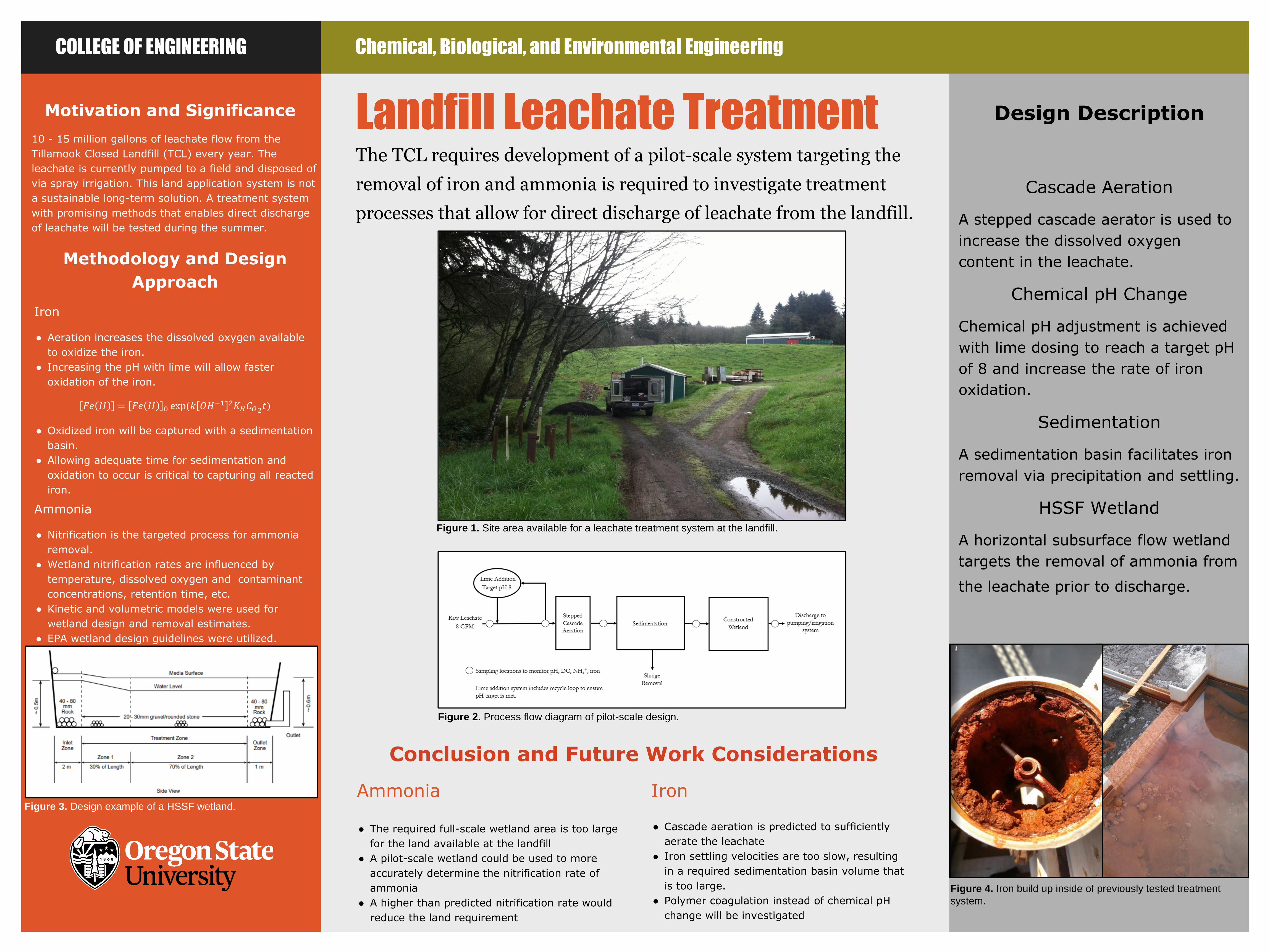
Landfill Leachate TreatmentThe TCL requires development of a pilot-scale system targeting the
removal of iron and ammonia is required to investigate treatment
processes that allow for direct discharge of leachate from the landfill.
Design Description
Cascade Aeration
A stepped cascade aerator is used to
increase the dissolved oxygen
content in the leachate.
Chemical pH Change
Chemical pH adjustment is achieved
with lime dosing to reach a target pH
of 8 and increase the rate of iron
oxidation.
Sedimentation
A sedimentation basin facilitates iron
removal via precipitation and settling.
HSSF Wetland
A horizontal subsurface flow wetland
targets the removal of ammonia from
the leachate prior to discharge.
Methodology and Design
Approach
Iron
● Aeration increases the dissolved oxygen available
to oxidize the iron.
● Increasing the pH with lime will allow faster
oxidation of the iron.
● Oxidized iron will be captured with a sedimentation
basin.
● Allowing adequate time for sedimentation and
oxidation to occur is critical to capturing all reacted
iron.
Ammonia
● Nitrification is the targeted process for ammonia
removal.
● Wetland nitrification rates are influenced by
temperature, dissolved oxygen and contaminant
concentrations, retention time, etc.
● Kinetic and volumetric models were used for
wetland design and removal estimates.
● EPA wetland design guidelines were utilized.
Figure 2. Process flow diagram of pilot-scale design.
Figure 1. Site area available for a leachate treatment system at the landfill.
Figure 4. Iron build up inside of previously tested treatment
system.
Figure 3. Design example of a HSSF wetland.
Conclusion and Future Work Considerations
𝐹𝑒 𝐼𝐼 = 𝐹𝑒 𝐼𝐼 0 exp(𝑘 𝑂𝐻−1 2𝐾𝐻𝐶𝑂2𝑡)
C h e m i c a l , B i o l o g i c a l , a n d E n vi r o n m e n t a l E n g i n e e r i n gC O L L E G E O F E N G I N E E R I N G
METHODOLOGY & APPROACH
FUTURE WORK
The next steps in our design process include:
• Refining hydraulics analysis for full treatment train
• Scaling up pilot design to full scale operation
• Complete cost analysis for pilot and full-scale design
• Lifecycle and sustainability assessment for the full-scale design
BACKGROUND
• How is leachate formed?
➢ Leachate is mostly formed from the process of biodecay of organic material, chemical oxidation of waste materials, escape of gas from landfill...etc. Those various formation process lead high concentration of ammonia, organic compounds, heavy metals and inorganic compounds.
• Why do people need to treat leachate?
➢ Contaminated leachate can impact human health, soil composition, ground water and surface water quality.
➢ Some general health problems caused by consuming leachate contaminated water are acute toxic allergies, respiratory disease, infection disease, blood disorders and cancer effects.
➢ The heavy metals, degradable and non-degradable pollutants in leachate will affect soil strength and stability by the process of percolation.
➢ The pollutants in leachate such as ammonia chloride, heavy metals and sodium will disseminate to surface and ground water and leave water undrinkable.
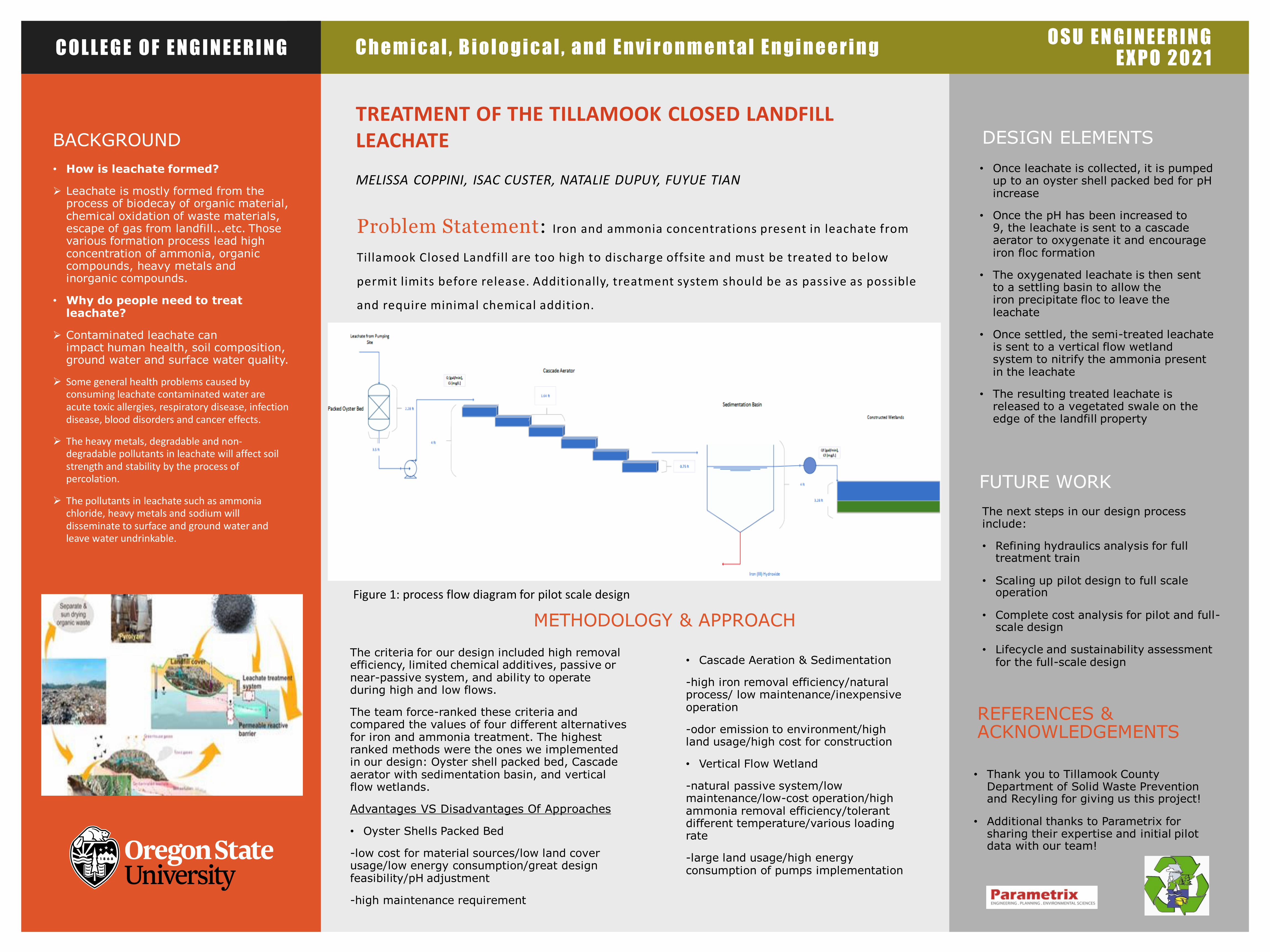
TREATMENT OF THE TILLAMOOK CLOSED LANDFILL LEACHATE
MELISSA COPPINI, ISAC CUSTER, NATALIE DUPUY, FUYUE TIAN
Problem Statement: Iron and ammonia concentrations present in leachate from
Tillamook Closed Landfill are too high to discharge offsite and must be treated to below
permit limits before release. Additionally, treatment system should be as passive as possible
and require minimal chemical addition.
DESIGN ELEMENTS
• Once leachate is collected, it is pumped up to an oyster shell packed bed for pH increase
• Once the pH has been increased to 9, the leachate is sent to a cascade aerator to oxygenate it and encourage iron floc formation
• The oxygenated leachate is then sent to a settling basin to allow the iron precipitate floc to leave the leachate
• Once settled, the semi-treated leachate is sent to a vertical flow wetland system to nitrify the ammonia present in the leachate
• The resulting treated leachate is released to a vegetated swale on the edge of the landfill property
O S U E N G I N E E R I N G E X P O 2 0 2 1
Figure 1: process flow diagram for pilot scale design
• Thank you to Tillamook County Department of Solid Waste Prevention and Recyling for giving us this project!
• Additional thanks to Parametrix for sharing their expertise and initial pilot data with our team!
REFERENCES & ACKNOWLEDGEMENTS
The criteria for our design included high removal efficiency, limited chemical additives, passive or near-passive system, and ability to operate during high and low flows.
The team force-ranked these criteria and compared the values of four different alternatives for iron and ammonia treatment. The highest ranked methods were the ones we implemented in our design: Oyster shell packed bed, Cascade aerator with sedimentation basin, and vertical flow wetlands.
Advantages VS Disadvantages Of Approaches
• Oyster Shells Packed Bed
-low cost for material sources/low land cover usage/low energy consumption/great design feasibility/pH adjustment
-high maintenance requirement
• Cascade Aeration & Sedimentation
-high iron removal efficiency/natural process/ low maintenance/inexpensive operation
-odor emission to environment/high land usage/high cost for construction
• Vertical Flow Wetland
-natural passive system/low maintenance/low-cost operation/high ammonia removal efficiency/tolerant different temperature/various loading rate
-large land usage/high energy consumption of pumps implementation
C h e m i c a l , B i o l o g i c a l , a n d E n v i r o n m e n t a l E n g i n e e r i n gC O L L E G E O F E N G I N E E R I N G
DESIGN METHODOLOGYTHE APPROACHA performance-based process sizing approach used historical data to select raw leachate parameters:
BACKGROUNDThe Tillamook Closed Landfill (TCL) has seen the accumulation of dilute, low-strength leachate from spring water and stormwater intrusions. Due to detection of high iron and ammonia concentrations, the county has requested the development of a long-term treatment solution that is hydraulically capable of discharge onto a one-acre vegetated swale located below the landfill.
Specific objectives include meeting area constraints as well as anticipated permit requirements, as seen in Table 1. Both a pilot and full-scale implementation of the selected processes will be investigated. Approximately 0.8 acres are available for full-scale construction with an additional 0.1 acres for a pilot study. Maintaining system passivity is a key design priority.
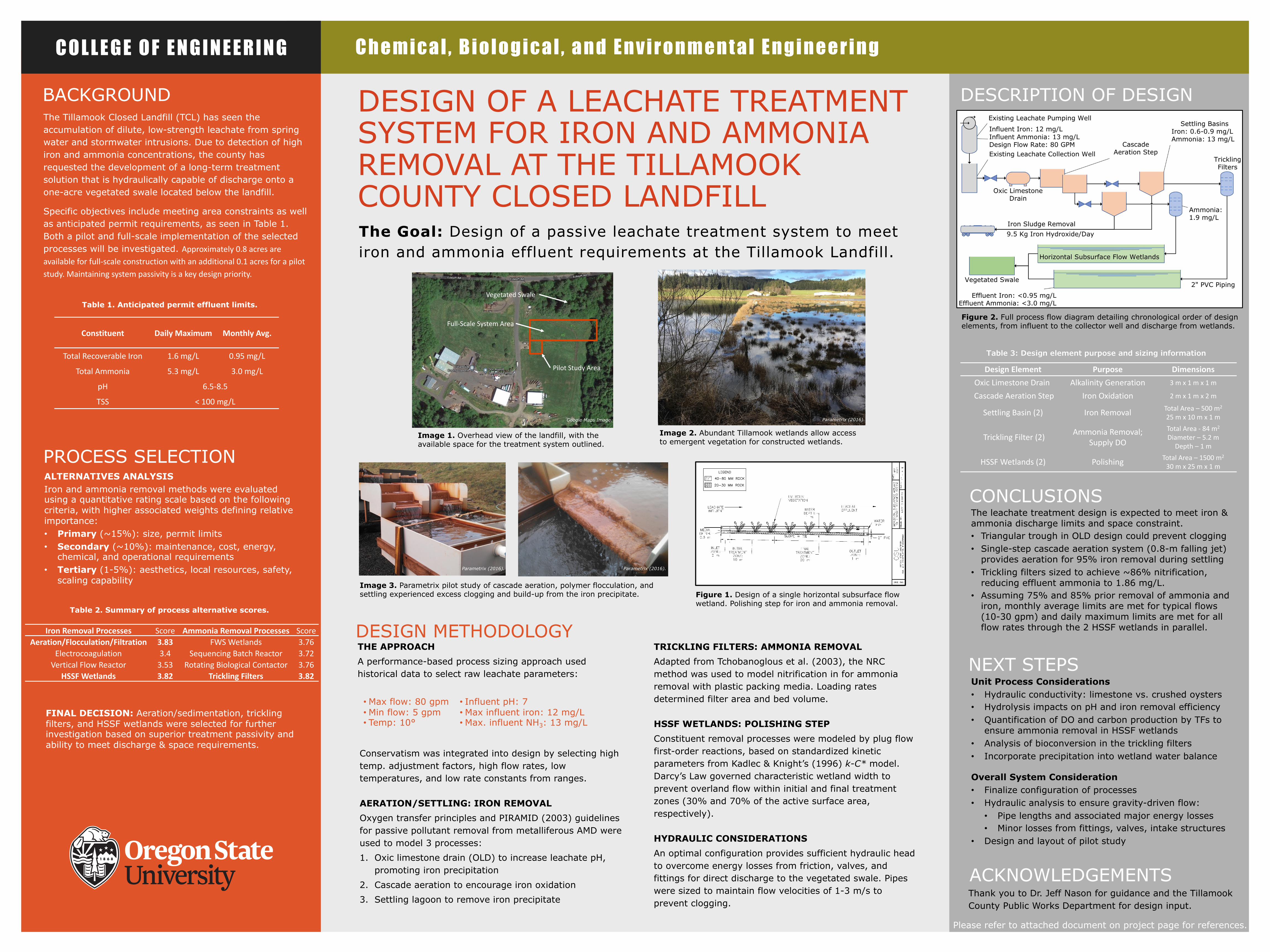
DESIGN OF A LEACHATE TREATMENT SYSTEM FOR IRON AND AMMONIA REMOVAL AT THE TILLAMOOK COUNTY CLOSED LANDFILLThe Goal: Design of a passive leachate treatment system to meet iron and ammonia effluent requirements at the Tillamook Landfill.
DESCRIPTION OF DESIGN
The leachate treatment design is expected to meet iron & ammonia discharge limits and space constraint.• Triangular trough in OLD design could prevent clogging • Single-step cascade aeration system (0.8-m falling jet)
provides aeration for 95% iron removal during settling• Trickling filters sized to achieve ~86% nitrification,
reducing effluent ammonia to 1.86 mg/L.• Assuming 75% and 85% prior removal of ammonia and
iron, monthly average limits are met for typical flows (10-30 gpm) and daily maximum limits are met for all flow rates through the 2 HSSF wetlands in parallel.
CONCLUSIONS
PROCESS SELECTIONALTERNATIVES ANALYSISIron and ammonia removal methods were evaluated using a quantitative rating scale based on the following criteria, with higher associated weights defining relative importance:• Primary (~15%): size, permit limits• Secondary (~10%): maintenance, cost, energy,
chemical, and operational requirements • Tertiary (1-5%): aesthetics, local resources, safety,
scaling capability
Iron Removal Processes Score Ammonia Removal Processes ScoreAeration/Flocculation/Filtration 3.83 FWS Wetlands 3.76
Electrocoagulation 3.4 Sequencing Batch Reactor 3.72Vertical Flow Reactor 3.53 Rotating Biological Contactor 3.76
HSSF Wetlands 3.82 Trickling Filters 3.82
Table 2. Summary of process alternative scores.
FINAL DECISION: Aeration/sedimentation, trickling filters, and HSSF wetlands were selected for further investigation based on superior treatment passivity and ability to meet discharge & space requirements.
TRICKLING FILTERS: AMMONIA REMOVALAdapted from Tchobanoglous et al. (2003), the NRC method was used to model nitrification in for ammonia removal with plastic packing media. Loading rates determined filter area and bed volume.
HSSF WETLANDS: POLISHING STEPConstituent removal processes were modeled by plug flow first-order reactions, based on standardized kinetic parameters from Kadlec & Knight’s (1996) k-C* model. Darcy’s Law governed characteristic wetland width to prevent overland flow within initial and final treatment zones (30% and 70% of the active surface area, respectively).
HYDRAULIC CONSIDERATIONSAn optimal configuration provides sufficient hydraulic head to overcome energy losses from friction, valves, and fittings for direct discharge to the vegetated swale. Pipes were sized to maintain flow velocities of 1-3 m/s to prevent clogging.
•Max flow: 80 gpm•Min flow: 5 gpm• Temp: 10°
• Influent pH: 7•Max influent iron: 12 mg/L•Max. influent NH3: 13 mg/L
Conservatism was integrated into design by selecting high temp. adjustment factors, high flow rates, low temperatures, and low rate constants from ranges.
AERATION/SETTLING: IRON REMOVALOxygen transfer principles and PIRAMID (2003) guidelines for passive pollutant removal from metalliferous AMD were used to model 3 processes:1. Oxic limestone drain (OLD) to increase leachate pH,
promoting iron precipitation2. Cascade aeration to encourage iron oxidation3. Settling lagoon to remove iron precipitate
Constituent Daily Maximum Monthly Avg.
Total Recoverable Iron 1.6 mg/L 0.95 mg/L
Total Ammonia 5.3 mg/L 3.0 mg/L
pH 6.5-8.5
TSS < 100 mg/L
Table 1. Anticipated permit effluent limits.
NEXT STEPSUnit Process Considerations• Hydraulic conductivity: limestone vs. crushed oysters• Hydrolysis impacts on pH and iron removal efficiency• Quantification of DO and carbon production by TFs to
ensure ammonia removal in HSSF wetlands• Analysis of bioconversion in the trickling filters• Incorporate precipitation into wetland water balance
Overall System Consideration• Finalize configuration of processes• Hydraulic analysis to ensure gravity-driven flow:• Pipe lengths and associated major energy losses• Minor losses from fittings, valves, intake structures
• Design and layout of pilot study
Figure 1. Design of a single horizontal subsurface flow wetland. Polishing step for iron and ammonia removal.
Please refer to attached document on project page for references.
ACKNOWLEDGEMENTS
Design Element Purpose DimensionsOxic Limestone Drain Alkalinity Generation 3 m x 1 m x 1 m
Cascade Aeration Step Iron Oxidation 2 m x 1 m x 2 m
Settling Basin (2) Iron Removal Total Area – 500 m2
25 m x 10 m x 1 m
Trickling Filter (2) Ammonia Removal; Supply DO
Total Area - 84 m2
Diameter – 5.2 m Depth – 1 m
HSSF Wetlands (2) Polishing Total Area – 1500 m2
30 m x 25 m x 1 m
Image 1. Overhead view of the landfill, with the available space for the treatment system outlined.
Pilot Study Area
Full-Scale System Area
Vegetated Swale
Image 2. Abundant Tillamook wetlands allow access to emergent vegetation for constructed wetlands.
Image 3. Parametrix pilot study of cascade aeration, polymer flocculation, and settling experienced excess clogging and build-up from the iron precipitate.
Thank you to Dr. Jeff Nason for guidance and the Tillamook County Public Works Department for design input.
Figure 2. Full process flow diagram detailing chronological order of design elements, from influent to the collector well and discharge from wetlands.
Table 3: Design element purpose and sizing information
Parametrix (2016).
Parametrix (2016).
Parametrix (2016).
Google Maps Image.
Chemical, Biological, and Environmental Engineering
FOLD FOLD
FOLD FOLD
NO TEXT IN ORANGE BOX BELOW
THIS LINE
COLLEGE OF ENGINEERING
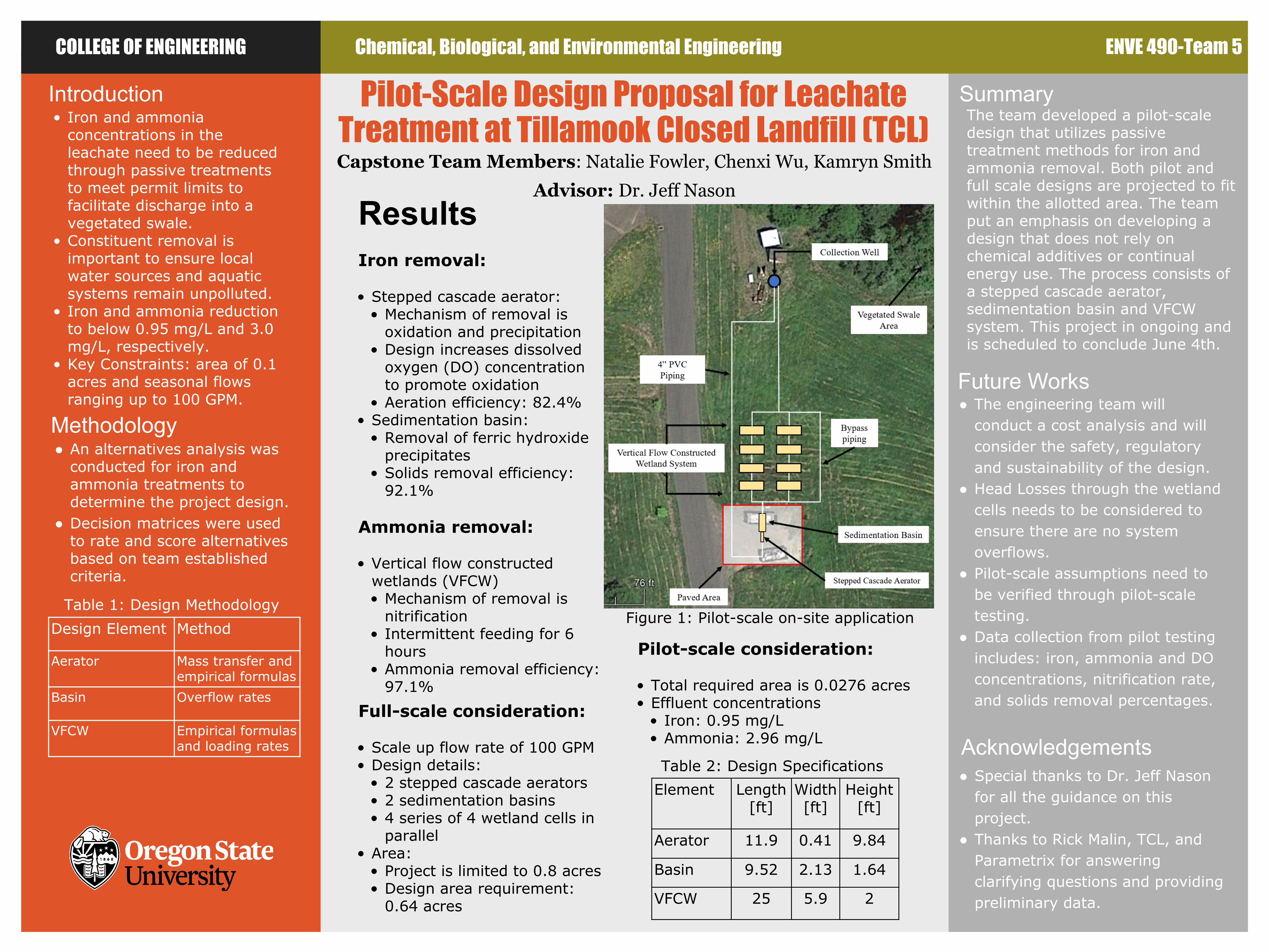
ResultsIron removal:
• Stepped cascade aerator:• Mechanism of removal is
oxidation and precipitation • Design increases dissolved
oxygen (DO) concentration to promote oxidation
• Aeration efficiency: 82.4%• Sedimentation basin:
• Removal of ferric hydroxide precipitates
• Solids removal efficiency: 92.1%
Ammonia removal:
• Vertical flow constructed wetlands (VFCW)• Mechanism of removal is
nitrification• Intermittent feeding for 6
hours• Ammonia removal efficiency:
97.1%
Future Works● The engineering team will
conduct a cost analysis and will consider the safety, regulatory and sustainability of the design.
● Head Losses through the wetland cells needs to be considered to ensure there are no system overflows.
● Pilot-scale assumptions need to be verified through pilot-scale testing.
● Data collection from pilot testing includes: iron, ammonia and DO concentrations, nitrification rate, and solids removal percentages.
Introduction• Iron and ammonia
concentrations in the leachate need to be reduced through passive treatments to meet permit limits to facilitate discharge into a vegetated swale.
• Constituent removal is important to ensure local water sources and aquatic systems remain unpolluted.
• Iron and ammonia reduction to below 0.95 mg/L and 3.0 mg/L, respectively.
• Key Constraints: area of 0.1 acres and seasonal flows ranging up to 100 GPM.
Pilot-Scale Design Proposal for Leachate Treatment at Tillamook Closed Landfill (TCL) Capstone Team Members: Natalie Fowler, Chenxi Wu, Kamryn Smith
Advisor: Dr. Jeff Nason
Summary
ENVE 490-Team 5
Methodology ● An alternatives analysis was
conducted for iron and ammonia treatments to determine the project design.
● Decision matrices were used to rate and score alternatives based on team established criteria.
Acknowledgements● Special thanks to Dr. Jeff Nason
for all the guidance on this project.
● Thanks to Rick Malin, TCL, and Parametrix for answering clarifying questions and providing preliminary data.
Full-scale consideration:
• Scale up flow rate of 100 GPM• Design details:
• 2 stepped cascade aerators • 2 sedimentation basins• 4 series of 4 wetland cells in
parallel• Area:
• Project is limited to 0.8 acres• Design area requirement:
0.64 acres
Figure 1: Pilot-scale on-site application
The team developed a pilot-scale design that utilizes passive treatment methods for iron and ammonia removal. Both pilot and full scale designs are projected to fit within the allotted area. The team put an emphasis on developing a design that does not rely on chemical additives or continual energy use. The process consists of a stepped cascade aerator, sedimentation basin and VFCW system. This project in ongoing and is scheduled to conclude June 4th.
Design Element Method
Aerator Mass transfer and empirical formulas
Basin Overflow rates
VFCW Empirical formulas and loading rates
Table 1: Design Methodology
Pilot-scale consideration:
• Total required area is 0.0276 acres• Effluent concentrations
• Iron: 0.95 mg/L• Ammonia: 2.96 mg/L
Element Length[ft]
Width [ft]
Height [ft]
Aerator 11.9 0.41 9.84
Basin 9.52 2.13 1.64
VFCW 25 5.9 2
Table 2: Design Specifications
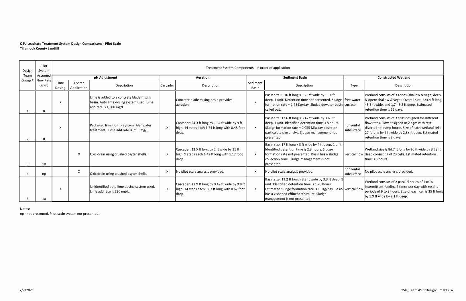
OSU Leachate Treatment System Design Comparisons ‐ Pilot ScaleTillamook County Landfill
Lime Dosing
Oyster Application
Description Cascader DescriptionSediment Basin
Description Type Description
1 8
XLime is added to a concrete blade mixing basin. Auto lime dosing system used. Lime add rate is 1,500 mg/L.
Concrete blade mixing basin provides aeration.
X
Basin size: 6.16 ft long x 1.23 ft wide by 11.4 ft deep. 1 unit. Detention time not presented. Sludge formation rate = 1.73 Kg/day. Sludge dewater basin called out.
free water surface
Wetland consists of 3 zones (shallow & vege; deep & open; shallow & vege). Overall size: 223.4 ft long, 45.6 ft wide, and 1.7 ‐ 6.8 ft deep. Estimated retention time is 55 days.
2 8
XPackaged lime dosing system [Alar water treatment]. Lime add rate is 71.9 mg/L.
XCascader: 24.3 ft long by 1.64 ft wide by 9 ft high. 14 steps each 1.74 ft long with 0.48 foot drop.
X
Basin size: 13.6 ft long x 3.42 ft wide by 3.69 ft deep. 1 unit. Identified detention time is 8 hours. Sludge formation rate = 0.055 M3/day based on particulate size analys. Sludge management not presented.
horizontal subsurface
Wetland consists of 3 cells designed for different flow rates. Flow designed at 2 pgm with rest diverted to pump house. Size of each wetland cell: 27 ft long by 6 ft wide by 2.3+ ft deep. Estimated retention time is 3 days.
3 10
X Oxic drain using crushed osyter shells. XCascader: 12.5 ft long by 2 ft wide by 11 ft high. 9 steps each 1.42 ft long with 1.17 foot drop.
X
Basin size: 17 ft long x 3 ft wide by 4 ft deep. 1 unit. Identified detention time is 2.3 hours. Sludge formation rate not presented. Basin has a sludge collection zone. Sludge management is not presented.
vertical flowWetland size is 84.7 ft long by 20 ft wide by 3.28 ft deep consisting of 23 cells. Estimated retention time is 3 hours.
4 np X Oxic drain using crushed osyter shells. X No pilot scale analysis provided. X No pilot scale analysis provided.horizontal subsurface
No pilot scale analysis provided.
5 10
XUnidentified auto lime dosing system used. Lime add rate is 230 mg/L.
XCascader: 11.9 ft long by 0.42 ft wide by 9.8 ft high. 14 steps each 0.83 ft long with 0.67 foot drop.
X
Basin size: 13.2 ft long x 3.3 ft wide by 3.3 ft deep. 1 unit. Identified detention time is 1.76 hours. Estimated sludge formation rate is 19 Kg/day. Basin has a v shaped effluent structure. Sludge management is not presented.
vertical flow
Wetland consists of 2 parallel series of 4 cells. Intermittent feeding 2 times per day with resting periods of 6 to 8 hours. Size of each cell is 25 ft long by 5.9 ft wide by 2.1 ft deep.
Notes:np ‐ not presented. Pilot scale system not presented.
Constructed Wetland
Treatment System Components ‐ In order of application
pH Adjustment
Design Team
Group #
Pilot System Assumed Flow Rate (gpm)
Aeration Sediment Basin
7/7/2021 OSU_TeamsPilotDesignSumTbl.xlsx


![Print 100422770104512[1].tif (70 pages)MINUTES - TILLAMOOK COUNTY BOARD OF COMMISSIONERS' MEETING VVednesday, January 14, 2009 Page 3 OTHER: Liane Welch thanked the Public Works Department](https://img.pdfslide.us/doc/110x75/5e244a892b305d24107e54f1/print-1004227701045121tif-70-pages-minutes-tillamook-county-board-of-commissioners.jpg)