Embed Size (px)
Citation preview
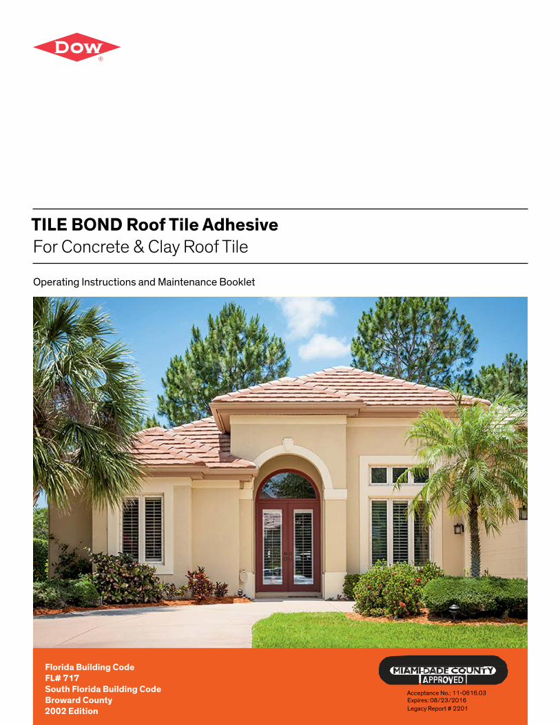
TILE BOND Roof Tile Adhesive For Concrete & Clay Roof Tile
Operating Instructions and Maintenance Booklet
Florida Building CodeFL# 717South Florida Building CodeBroward County 2002 Edition
Acceptance No.: 11-0616.03Expires: 08/23/2016Legacy Report # 2201
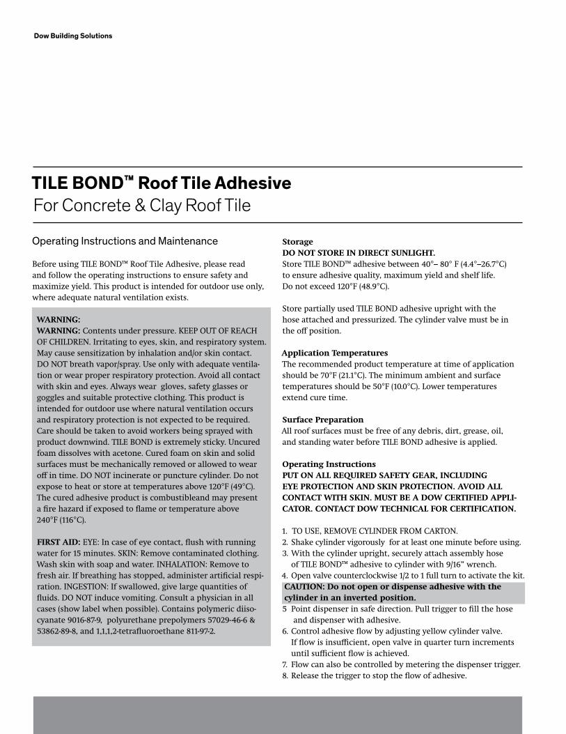
TILE BOND™ Roof Tile Adhesive For Concrete & Clay Roof Tile
StorageDO NOT STORE IN DIRECT SUNLIGHT.Store TILE BOND™ adhesive between 40°– 80° F (4.4°–26.7°C) to ensure adhesive quality, maximum yield and shelf life.Do not exceed 120°F (48.9°C).
Store partially used TILE BOND adhesive upright with the hose attached and pressurized. The cylinder valve must be in the off position.
Application TemperaturesThe recommended product temperature at time of application should be 70°F (21.1°C). The minimum ambient and surface temperatures should be 50°F (10.0°C). Lower temperaturesextend cure time.
Surface PreparationAll roof surfaces must be free of any debris, dirt, grease, oil, and standing water before TILE BOND adhesive is applied.
Operating InstructionsPUT ON ALL REqUIRED SAfETy GEAR, INCLUDING EyE PROTECTION AND SkIN PROTECTION. AvOID ALL CONTACT wITH SkIN. MUST bE A DOw CERTIfIED APPLI-CATOR. CONTACT DOw TECHNICAL fOR CERTIfICATION.
1. TO USE, REMOVE CYLINDER FROM CARTON.2. Shake cylinder vigorously for at least one minute before using.3. With the cylinder upright, securely attach assembly hose of TILE BOND™ adhesive to cylinder with 9/16” wrench.4. Open valve counterclockwise 1/2 to 1 full turn to activate the kit. CAUTION: Do not open or dispense adhesive with the cylinder in an inverted position.5 Point dispenser in safe direction. Pull trigger to fill the hose and dispenser with adhesive.6. Control adhesive flow by adjusting yellow cylinder valve. If flow is insufficient, open valve in quarter turn increments until sufficient flow is achieved.7. Flow can also be controlled by metering the dispenser trigger.8. Release the trigger to stop the flow of adhesive.
Dow Building Solutions
Operating Instructions and Maintenance
Before using TILE BOND™ Roof Tile Adhesive, please read and follow the operating instructions to ensure safety and maximize yield. This product is intended for outdoor use only, where adequate natural ventilation exists.
wARNING:wARNING: Contents under pressure. KEEP OUT OF REACH OF CHILDREN. Irritating to eyes, skin, and respiratory system. May cause sensitization by inhalation and/or skin contact. DO NOT breath vapor/spray. Use only with adequate ventila-tion or wear proper respiratory protection. Avoid all contact with skin and eyes. Always wear gloves, safety glasses or goggles and suitable protective clothing. This product is intended for outdoor use where natural ventilation occurs and respiratory protection is not expected to be required. Care should be taken to avoid workers being sprayed with product downwind. TILE BOND is extremely sticky. Uncured foam dissolves with acetone. Cured foam on skin and solid surfaces must be mechanically removed or allowed to wear off in time. DO NOT incinerate or puncture cylinder. Do not expose to heat or store at temperatures above 120°F (49°C). The cured adhesive product is combustibleand may present a fire hazard if exposed to flame or temperature above 240°F (116°C).
fIRST AID: EYE: In case of eye contact, flush with running water for 15 minutes. SKIN: Remove contaminated clothing. Wash skin with soap and water. INHALATION: Remove to fresh air. If breathing has stopped, administer artificial respi-ration. INGESTION: If swallowed, give large quantities of fluids. DO NOT induce vomiting. Consult a physician in all cases (show label when possible). Contains polymeric diiso-cyanate 9016-87-9, polyurethane prepolymers 57029-46-6 & 53862-89-8, and 1,1,1,2-tetrafluoroethane 811-97-2.
9. Apply TILE BOND adhesive as indicated on the application pages 3–15. Do not thin.Cleaning/ShutDown Procedure1. Turn cylinder valve clockwise to the off position.2. Do not empty material from the hose. Leave the dispenser and hose pressurized.3. DO NOT CLEAN DISPENSER OR NOZZLE. DO NOT USE SOLVENT. Cured adhesive in the nozzle protects the dispenser from setting up during storage. Once activated, the dispenser has a useful life of approximately 72 hours. Adhesive may harden in dispenser over longer periods of time. Dispenser can be reused on another unit of TILE BOND adhesive if the hose is immediately transferred to a new cylinder and activated.
Reuse of TILE bOND™ Adhesive1. Upon reuse, clear cured adhesive plug from nozzle tip. DO NOT USE SOLVENT. a. Turn nozzle counter-clockwise 1/2 turn and remove from dispenser. b. Insert screwdriver or other similar object through nozzle to remove plug. (Hint – Philips head screwdriver works best to remove the Plug) c. Reattach nozzle making sure o-ring remains in place.2. Shake cylinder vigorously for at least one minute.3. With cylinder upright, open valve counterclockwise 1/2 to 1 full turn.4. Reactivate by pulling trigger until adhesive starts flowing from the nozzle.
Troubleshooting1. RESTRICTED OR SLOW FLOW RATE: a. Confirm that cylinder valve is open. b. Check the nozzle for adhesive plug. c. If product application temperature is below recom- mended 70°F (21.1°C), place the cylinder in warm area of approximately 70°F (21.1°C) until cylinder reaches proper application temperature.2. TRIGGER WILL NOT PULL BACK: Adhesive is cured in
dispenser. Replace with new dispenser for TILE BOND adhesive.3. CONTINUOUS BURST OF PRESSURE: Cylinder valve is pointed down or the cylinder is empty. Turn cylinder upright or replace cylinder.4. LEAKING DISPENSER: Assure nozzle 0-ring is in place.5. UNABLE TO SOLVE PROBLEM: Call 1(866)583-BLUE (2583) for technical assistance.
DisposalAll pressure must be released from cylinder before disposal. Disposal of residue of TILE BOND adhesive must be done withadequate ventilation. NEVER PUNCTURE OR INCINERATE CYLINDER. Always wear gloves and goggles when disposing of cylinders.1. Close cylinder valve.2. Remove dispensing hose from cylinder.3. Hold tank upside down over waste container with valve facing away from you and any others in the area.4. Slowly open valve on the cylinder.5. Set cylinder into waste container and allow residual pressure and chemical to escape.6. Cover waste container with loosely fitting covers and allow contents to set for several days.7. Dispose of in accordance with federal, state and local environmental regulations.
NOTE: If no waste container is available, the cylinder of TILE BOND™ adhesive can be inverted in its original carton using the method described above and allowed to empty.
Contents • Cylinder with 23 pounds of TILE BOND adhesive • Dispenser for TILE BOND adhesive with 8 1/2” hose • Operating Instruction and Maintenance Booklet • 1-1/2” W x 1” H x 4” L adhesive pad sample
Dow Building Solutions
4
Dow Building Solutions
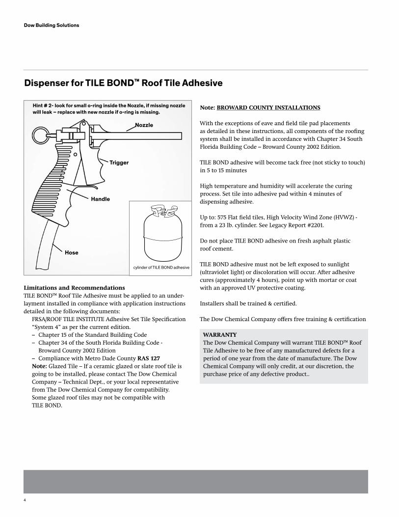
Dispenser for TILE BOND™ Roof Tile Adhesive
Nozzle
Trigger
Handle
Hose
cylinder of TILE BOND adhesive
Limitations and RecommendationsTILE BOND™ Roof Tile Adhesive must be applied to an under-layment installed in compliance with application instructions detailed in the following documents: FRSA/ROOF TILE INSTITUTE Adhesive Set Tile Specification “System 4” as per the current edition. – Chapter 15 of the Standard Building Code – Chapter 34 of the South Florida Building Code - Broward County 2002 Edition – Compliance with Metro Dade County RAS 127 Note: Glazed Tile – If a ceramic glazed or slate roof tile is going to be installed, please contact The Dow Chemical Company – Technical Dept., or your local representative from The Dow Chemical Company for compatibility. Some glazed roof tiles may not be compatible with TILE BOND.
Note: bROwARD COUNTy INSTALLATIONS
With the exceptions of eave and field tile pad placements as detailed in these instructions, all components of the roofing system shall be installed in accordance with Chapter 34 South Florida Building Code – Broward County 2002 Edition.
TILE BOND adhesive will become tack free (not sticky to touch) in 5 to 15 minutes
High temperature and humidity will accelerate the curing process. Set tile into adhesive pad within 4 minutes of dispensing adhesive.
Up to: 575 Flat field tiles, High Velocity Wind Zone (HVWZ) - from a 23 lb. cylinder. See Legacy Report #2201.
Do not place TILE BOND adhesive on fresh asphalt plastic roof cement.
TILE BOND adhesive must not be left exposed to sunlight(ultraviolet light) or discoloration will occur. After adhesive cures (approximately 4 hours), point up with mortar or coat with an approved UV protective coating.
Installers shall be trained & certified.
The Dow Chemical Company offers free training & certification
wARRANTyThe Dow Chemical Company will warrant TILE BOND™ Roof Tile Adhesive to be free of any manufactured defects for a period of one year from the date of manufacture. The Dow Chemical Company will only credit, at our discretion, the purchase price of any defective product..
Hint # 2- look for small o-ring inside the Nozzle, if missing nozzle will leak – replace with new nozzle if o-ring is missing.
5
Dow Building Solutions
Read Limitations and Recommendations before applyingTILE bOND™ Roof Tile AdhesiveFor areas and sections of the Roof System not covered by these instructions, please refer to the FRSA/ROOF TILE INSTITUTE CONCRETE AND CLAY ROOF TILE INSTALLATION MANUAL
“System 4” per the current edition.
Refer to Anchor Sheet Fastening Tables included in the instruc-tions for decking and underlayment requirements.
1. For pitches above 6:12 up to and including 7:12 nail every third (3rd) tile in every fifth (5th) course in addition to the adhesive. Horizontal batten strips may need to be installed, depending upon the roof pitch and other attributes of the roof. 2. For pitches above 7:12, nail every tile in addition to adhesive, or use horizontal batten strips in addition to the adhesive. 3. Check local building code for additional nailing requirements.
EAvE TILE: UP TO HIGH vELOCITy wIND ZONE (HvwZ)wIND UPLIfT RESISTANCE (CHOOSE EITHER A OR b)OPTION “A”
1. When using this method, you usually have a distance of approximately 1 1/2” from the top of the drip edge deck, to the bottom of the tile. Using a nominal 1” W x 2” H x 6” L or longer wood filler strip, batten strip, cant, or raised fascia board, will bridge the underside portion of the tile to the cap sheet. 2. Fully adhere wood starter or batten strip to cap sheet at butt of the tile, between the center of the tile, and the overlock side. The height of the starter strip should be 1/2” less than the height of the space under the tile at the eave closure. 3. Dispense a 1-1/2” W x 1” H x 6” L adhesive pad directly on to the wood filler strip. Do not block the weep holes with the adhesive. Maximize the contact area to the pan portion of the tile. 4. Apply a second adhesive pad at the head of the tile directly onto the cap sheet, diagonally across from the first pad. The anchor lug should be embedded in the adhesive. Maximize the contact area to the batten lug. 5. Set the tile in both pads of adhesive. 6. Continue to set the eave course of tile in a similar manner.
OPTION “b” 1. Apply an adhesive pad 1 1/2” W x 1” H x 6” L at the head of the tile directly onto the cap sheet, at the head of the tile, making sure the batten lug is embedded in the adhesive. 2. Additionally secure the eave tile with two (2) screws. Said screws shall meet the requirements of the tile screw, as detailed in the FRSA/ROOF TILE INSTITUTE CONCRETE AND CLAY ROOF TILE INSTALLATION MANUAL August 2005 edition, or the local Building Code requirements, which ever apply. Apply approved plastic roof cement at all roof deck penetrations. 3. Continue to install the remaining eave tile in a similar manner.
AbOvE 110 MPH - (HvwZ) wIND UPLIfT RESISTANCE (ASCE 7-98 EXPOSURE b&C) USE A 1” w x 1” H x 8” L ADHESIvE PAD.
Note: Two (2) pads of TILE BOND adhesive are required for each Field Tile.
Note: 110 MPH: An adhesive pad 1 1/2” W x 1” H x 4” L when compressed should expand to a minimum contact area of 2” x 5”. A contact area of approximately 10 square inches per adhesive pad is required. Pad dimensions can be modified to accommodate differences in tile configurations as long as the adhesive contact area is not reduced. Check at least one tile per square to confirm contact area.
Note: (HVWZ): An adhesive pad 1” W x 1” H x 8” L when compressed should expand to a minimum contact area of 2” x 11”. A contact area of approximately 19 1/2” square inches per adhesive pad is required. Pad dimensions can be modified to accommodate differences in tile configurations as long as the adhesive contact area is not reduced. Check at least one tile per square to confirm contact area. 1. Apply the first proper size adhesive pad directly onto the head lap area of the preceding course on the overlock side of the tile.
LOW/FLAT PROFILE TILE APPLICATION
6
Dow Building Solutions
2. Apply the second proper adhesive pad directly onto the cap sheet or batten strip, diagonally cross from the first adhesive pad. 3. When setting tile, angle the tile forward past the adhesive pad on the headlap and slide the tile into the adhesive before setting it down. This prevents the adhesive from being exposed on the face of the previous course. The batten lug must be embedded in the adhesive. Maximize the contact area to the batten lug. 4. At least one tile per square shall be pulled up to confirm contact area. 5. Continue to install the remaining tile in a similar manner.
OPTIONAL: HIP AND RIDGE TILE INSTALLATION wITH A wOOD RIDGE NAILER bOARD, OR METAL RIDGE bOARD wITH “v” TOP EDGE: UP TO (HvwZ) wIND UPLIfT RESISTANCE.
1. Install wood, or metal ridge board according to Local Building Code Requirements. 2. Apply a 1” W x 1” H x a minimum 10” L bead of adhesive on top of the nailer board (s) and set the ridge tile into the adhesive. Make sure the bottom of the ridge tile makes contact with the foam adhesive. When set in the adhesive, the ridge tile will push excess foam down the sides of the ridge board. 3. Apply a bead of TILE BOND adhesive across the top of the ridge tile, in the head lap area. This bead of adhesive should be approximately 1” W x 1” H x 4” L. Set the next ridge tile, making sure the tile overlaps the first tile with the proper head lap and the bead of adhe- sive is between both tiles in the head lap area, and the bottom of the ridge tile makes contact with the adhesive bead on top of the ridge board, as described in #2. 4. Proceed to install the remaining ridge tile in a similar manner.
5. Point up with mortar to the open space between the top of the field tile and the bottom of the edge of the ridge tile. Point up to a proper finish. 6. Check local building codes regarding the use of screws or nails in hip and ridge installation.
Note: Pad dimensions and placement can be modified to accommodate differences in tile configurations as long as the adhesive contact area is not reduced. Check at least one tile per square before adhesive cures to confirm con-tact area. To make any adjustments to tiles after tack free time, you must have old adhesive pads removed and new adhesive pads applied. walking on the tile before adhesive has cured may cause a slipping hazard.
7
Dow Building Solutions
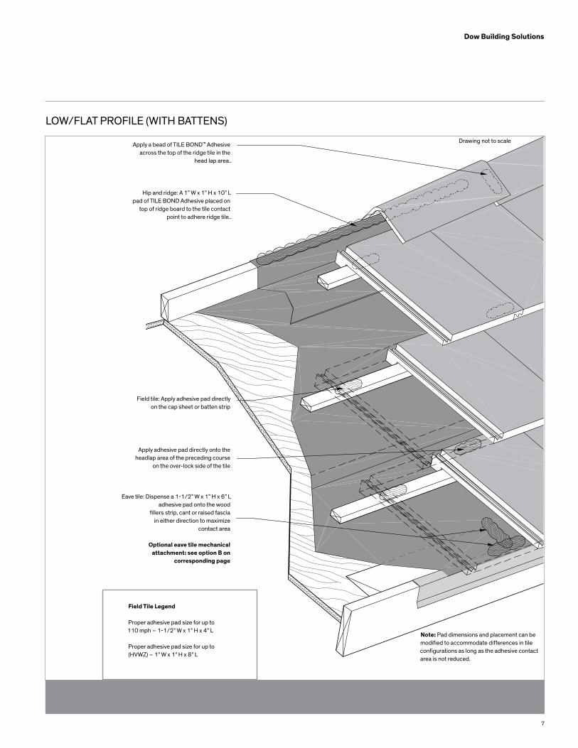
LOW/FLAT PROFILE (WITH BATTENS)
Apply a bead of TILE BOND™ Adhesive across the top of the ridge tile in the
head lap area..
Hip and ridge: A 1” W x 1” H x 10” L pad of TILE BOND Adhesive placed on
top of ridge board to the tile contact point to adhere ridge tile..
Field tile: Apply adhesive pad directly on the cap sheet or batten strip
Apply adhesive pad directly onto the headlap area of the preceding course
on the over-lock side of the tile
Eave tile: Dispense a 1-1/2” W x 1” H x 6” L adhesive pad onto the wood
fillers strip, cant or raised fascia in either direction to maximize
contact area
Optional eave tile mechanical attachment: see option B on
corresponding page
Field Tile Legend
Proper adhesive pad size for up to110 mph – 1-1/2” W x 1” H x 4” L
Proper adhesive pad size for up to(HVWZ) – 1” W x 1” H x 8” L
Note: Pad dimensions and placement can be modified to accommodate differences in tile configurations as long as the adhesive contact area is not reduced.
Drawing not to scale
8
Dow Building Solutions
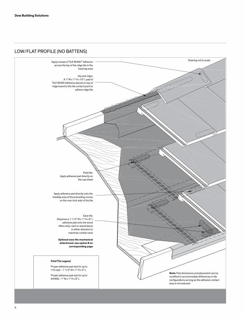
LOW/FLAT PROFILE (NO BATTENS)
Apply a bead of TILE BOND™ Adhesive across the top of the ridge tile in the
head lap area.
Hip and ridge: A 1” W x 1” H x 10” L pad of
TILE BOND Adhesive placed on top of ridge board to the tile contact point to
adhere ridge tile.
Field tile: Apply adhesive pad directly on
the cap sheet.
Apply adhesive pad directly onto the headlap area of the preceding course
on the over-lock side of the tile.
Eave tile: Dispense a 1-1/2” W x 1” H x 6” L
adhesive pad onto the woodfillers strip, cant or raised fascia
in either direction to maximize contact area
Optional eave tile mechanical attachment: see option B on
corresponding page
Field Tile Legend
Proper adhesive pad size for up to110 mph - 1-1/2” W x 1” H x 4” L
Proper adhesive pad size for up to(HVWZ) - 1” W x 1” H x 8” L
Note: Pad dimensions and placement can be modified to accommodate differences in tile configurations as long as the adhesive contact area is not reduced.
Drawing not to scale
9
Dow Building Solutions
Medium Profile Tile Application
Read limitations and Recommendations before applyingTILE bOND™ Roof Tile Adhesive
For areas and sections of the Roof System not covered by these instructions, please refer to the FRSA/ROOF TILE INSTITUTE CONCRETE AND CLAY ROOF TILE INSTALLATION MANUAL
“System 4” per the current edition.
Refer to Anchor Sheet Fastening Tables included in the instruc-tions for decking and underlayment requirements.
1. For pitches above 6:12 up to and including 7:12 nail every third (3rd) tile in every fifth (5th) course in addition to the adhesive. Horizontal batten strips may need to be installed, depending upon the roof pitch and other attributes of the roof.
2. For pitches above 7:12, nail every tile in addition to adhesive, or use horizontal batten strips in addition to the adhesive.
3. Check local building code for additional nailing requirements.
EAvE TILE: UP TO HIGH vELOCITy wIND ZONE (HvwZ)wIND UPLIfT RESISTANCE (CHOOSE EITHER A OR b)
OPTION “A” 1. When using this method, you usually have a distance of approximately 1 1/2” from the top of the drip edge deck, to the bottom of the tile. Using a nominal 1” W x 2” H x 6” L or longer wood filler strip, batten strip, cant, or raised fascia board, will bridge the underside portion of the tile to the cap sheet.
2. Fully adhere wood starter or batten strip to cap sheet at butt of the tile, between the center of the tile, and the over-lock side. The height of the starter strip should be 1/2” less than the height of the space under the tile at the eave closure.
3. Dispense a 1 1/2” W x 1” H x 6” L adhesive pad directly on to the wood filler strip. Do not block the weep holes with the adhesive. Maximize the contact area to the pan portion of the tile.
4. Apply a second adhesive pad at the head of the tile directly onto the cap sheet, diagonally across from the first pad. The batten lug must be embedded in the adhesive. Maximize the contact area to the batten lug.
5. Set the tile in both pads of adhesive.
6. Continue to set the eave course of tile in a similar manner.
OPTION “b” 1. Apply an adhesive pad directly on the cap sheet, at the head of the tile, making sure the batten lug is embedded in the adhesive.
2. Additionally secure the eave tile with two (2) screws. Said screws shall meet the requirements of the tile screw, as detailed in the FRSA/ROOF TILE INSTITUTE CONCRETE AND CLAY ROOF TILE INSTALLATION MANUAL, current edition, or the local Building Code requirements, which ever apply. Apply approved plastic roof cement at all roof deck penetrations.
3. Continue to install the remaining eave tile in a similar manner.
fIELD TILE INSTALLATION – fOR UP TO 110 MPH wIND UPLIfT RESISTANCE USE A 1 1/2” w x 1” H x 4” L ADHESIvE PAD.
AbOvE 110 MPH – (HvwZ) wIND UPLIfT RESISTANCE (ASCE 7-98 EXPOSURE b&C) USE A 1” w x 1” H x 8” L ADHESIvE PAD.
Note: Two (2) pads of TILE BOND adhesive are required for each Field Tile. Note: 110 MPH: An adhesive pad 1 1/2” W x 1” H x 4”L when compressed should expand to a minimum contact area of 2” x 5”. A contact area of approximately 10 square inches per adhesive pad is required. Pad dimensions can be modified to accommodate differences in tile configurations as long as the adhesive contact area is not reduced. Check at least one tile per square to confirm contact area.
10
Dow Building Solutions
Note: (HVWZ): An adhesive pad 1” W x 1” H x 8” L when compressed should expand to a minimum contact area of 2” x 11”. A contact area of approximately 19 1/2” square inches per adhesive pad is required. Pad dimensions can be modified to accommodate differences in tile configurations as long as the adhesive contact area is not reduced. Check at least one tile per square to confirm contact area.
1. Apply the first proper size adhesive pad directly onto the head lap area of the preceding course on the over-lock side of the tile.
2. Apply the second proper adhesive pad directly onto the cap sheet or batten strip, diagonally cross from the first adhesive pad.
3. When setting tile, angle the tile forward past the adhesive pad on the headlap and slide the tile into the adhesive before setting it down. This prevents the adhesive from being exposed on the face of the previous course. The batten lug must be embedded in the adhesive. Maximize the contact area to the batten lug.
4. At least one tile per square shall be pulled up to confirm contact area.
5. Continue to install the remaining tile in a similar manner.
OPTIONAL: HIP AND RIDGE TILE INSTALLATION wITH A wOOD RIDGE NAILER bOARD, OR METAL RIDGE bOARD wITH “v” TOP EDGE: UP TO (HvwZ) wIND UPLIfT RESISTANCE.
1. Install wood, or metal ridge board according to Local Building Code Requirements.
2. Apply a 1” W x 1” H x a minimum 10” L bead of adhesive on top of the nailer board(s) and set the ridge tile into the adhesive. Make sure the bottom of the ridge tile makes contact with the foam adhesive. When set in the adhesive, the ridge tile will push excess foam down the sides of the ridge board.
3. Apply a bead of TILE BOND adhesive across the top of the ridge tile, in the head lap area. This bead of adhesive should be approximately 1” W x 1” H x 4” L. Set the next ridge tile, making sure the tile overlaps the first tile with the proper head lap and the bead of adhesive is between both tiles in the head lap area, and the bottom of the ridge tile makes contact with the adhesive bead on top of the ridge board, as described in #2
4. Proceed to install the remaining ridge tile in a similar manner.
5. Point up with mortar to the open space between the top of the field tile and the bottom of the edge of the ridge tile. Point up to a proper finish.
Do not leave TILE BOND adhesive exposed to sunlight (ultra-violet light). After adhesive cures (approximately 4 hours), point up with mortar or coat exposed adhesive pad with an approved UV protective coating.
6. Check local building codes regarding the use of screws or nails in hip and ridge installation.
Note: Pad dimensions and placement can be modified to accommodate differences in tile configurations as long as the adhesive contact area is not reduced. Check at least one tile per square before adhesive cures to confirm con-tact area. To make any adjustments to tiles after tack free time, you must have old adhesive pads removed and new adhesive pads applied. walking on the tile before adhesive has cured may cause a slipping hazard.
11
Dow Building Solutions
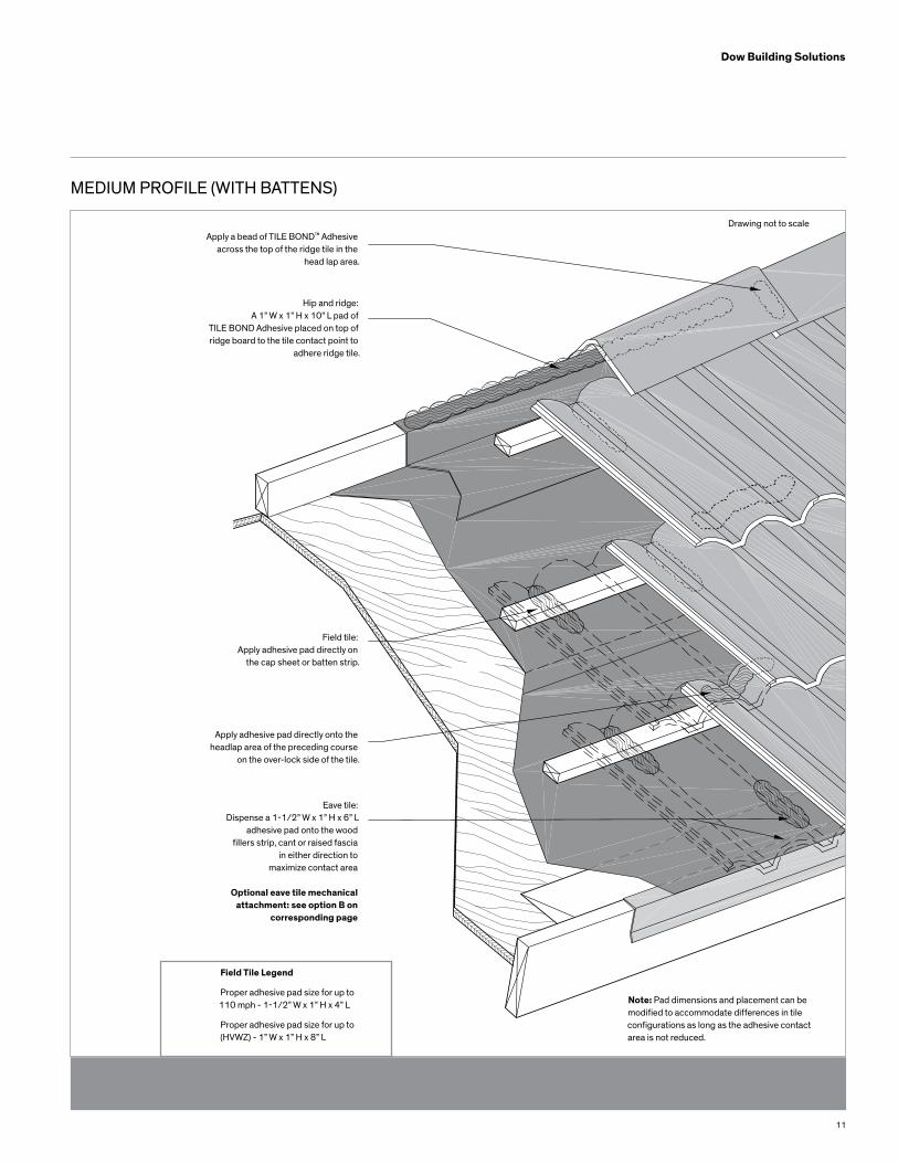
MEDIUM PROFILE (WITH BATTENS)
Apply a bead of TILE BOND™ Adhesive across the top of the ridge tile in the
head lap area.
Hip and ridge: A 1” W x 1” H x 10” L pad of
TILE BOND Adhesive placed on top of ridge board to the tile contact point to
adhere ridge tile.
Field tile: Apply adhesive pad directly on
the cap sheet or batten strip.
Apply adhesive pad directly onto the headlap area of the preceding course
on the over-lock side of the tile.
Eave tile: Dispense a 1-1/2” W x 1” H x 6” L
adhesive pad onto the woodfillers strip, cant or raised fascia
in either direction to maximize contact area
Optional eave tile mechanical attachment: see option B on
corresponding page
Field Tile Legend
Proper adhesive pad size for up to110 mph - 1-1/2” W x 1” H x 4” L
Proper adhesive pad size for up to(HVWZ) - 1” W x 1” H x 8” L
Note: Pad dimensions and placement can be modified to accommodate differences in tile configurations as long as the adhesive contact area is not reduced.
Drawing not to scale
12
Dow Building Solutions
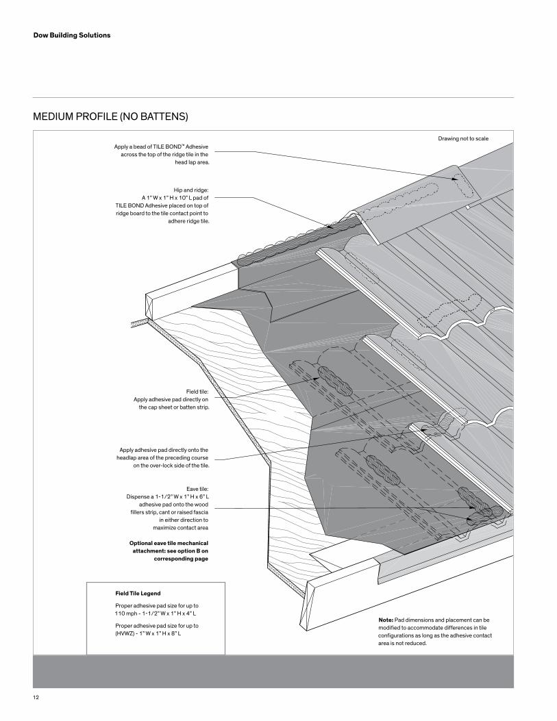
MEDIUM PROFILE (NO BATTENS)
Apply a bead of TILE BOND™ Adhesive across the top of the ridge tile in the
head lap area.
Hip and ridge: A 1” W x 1” H x 10” L pad of
TILE BOND Adhesive placed on top of ridge board to the tile contact point to
adhere ridge tile.
Field tile: Apply adhesive pad directly on
the cap sheet or batten strip.
Apply adhesive pad directly onto the headlap area of the preceding course
on the over-lock side of the tile.
Eave tile: Dispense a 1-1/2” W x 1” H x 6” L
adhesive pad onto the woodfillers strip, cant or raised fascia
in either direction to maximize contact area
Optional eave tile mechanical attachment: see option B on
corresponding page
Field Tile Legend
Proper adhesive pad size for up to110 mph - 1-1/2” W x 1” H x 4” L
Proper adhesive pad size for up to(HVWZ) - 1” W x 1” H x 8” L
Note: Pad dimensions and placement can be modified to accommodate differences in tile configurations as long as the adhesive contact area is not reduced.
Drawing not to scale
13
Dow Building Solutions
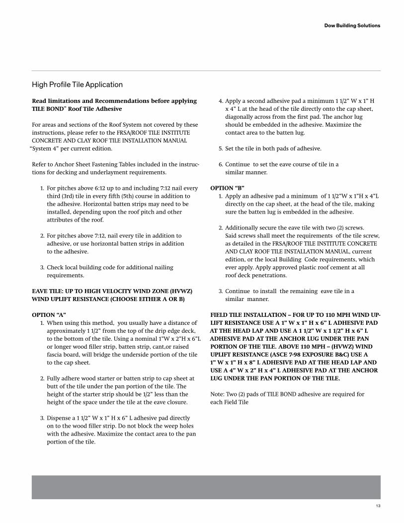
High Profile Tile Application
Read limitations and Recommendations before applyingTILE bOND™ Roof Tile Adhesive
For areas and sections of the Roof System not covered by these instructions, please refer to the FRSA/ROOF TILE INSTITUTE CONCRETE AND CLAY ROOF TILE INSTALLATION MANUAL
“System 4” per current edition.
Refer to Anchor Sheet Fastening Tables included in the instruc-tions for decking and underlayment requirements.
1. For pitches above 6:12 up to and including 7:12 nail every third (3rd) tile in every fifth (5th) course in addition to the adhesive. Horizontal batten strips may need to be installed, depending upon the roof pitch and other attributes of the roof.
2. For pitches above 7:12, nail every tile in addition to adhesive, or use horizontal batten strips in addition to the adhesive.
3. Check local building code for additional nailing requirements.
EAvE TILE: UP TO HIGH vELOCITy wIND ZONE (HvwZ)wIND UPLIfT RESISTANCE (CHOOSE EITHER A OR b)
OPTION “A” 1. When using this method, you usually have a distance of approximately 1 1/2” from the top of the drip edge deck, to the bottom of the tile. Using a nominal 1”W x 2”H x 6”L or longer wood filler strip, batten strip, cant,or raised fascia board, will bridge the underside portion of the tile to the cap sheet.
2. Fully adhere wood starter or batten strip to cap sheet at butt of the tile under the pan portion of the tile. The height of the starter strip should be 1/2” less than the height of the space under the tile at the eave closure.
3. Dispense a 1 1/2” W x 1” H x 6” L adhesive pad directly on to the wood filler strip. Do not block the weep holes with the adhesive. Maximize the contact area to the pan portion of the tile.
4. Apply a second adhesive pad a minimum 1 1/2” W x 1” H x 4” L at the head of the tile directly onto the cap sheet, diagonally across from the first pad. The anchor lug should be embedded in the adhesive. Maximize the contact area to the batten lug.
5. Set the tile in both pads of adhesive.
6. Continue to set the eave course of tile in a similar manner.
OPTION “b” 1. Apply an adhesive pad a minimum of 1 1/2”W x 1”H x 4”L directly on the cap sheet, at the head of the tile, making sure the batten lug is embedded in the adhesive.
2. Additionally secure the eave tile with two (2) screws. Said screws shall meet the requirements of the tile screw, as detailed in the FRSA/ROOF TILE INSTITUTE CONCRETE AND CLAY ROOF TILE INSTALLATION MANUAL, current edition, or the local Building Code requirements, which ever apply. Apply approved plastic roof cement at all roof deck penetrations.
3. Continue to install the remaining eave tile in a similar manner.
fIELD TILE INSTALLATION – fOR UP TO 110 MPH wIND UP-LIfT RESISTANCE USE A 1” w x 1” H x 6” L ADHESIvE PADAT THE HEAD LAP AND USE A 1 1/2” w x 1 1/2” H x 6” L ADHESIvE PAD AT THE ANCHOR LUG UNDER THE PAN PORTION Of THE TILE. AbOvE 110 MPH – (HvwZ) wIND UPLIfT RESISTANCE (ASCE 7-98 EXPOSURE b&C) USE A 1” w x 1” H x 8” L ADHESIvE PAD AT THE HEAD LAP AND USE A 4” w x 2” H x 4” L ADHESIvE PAD AT THE ANCHOR LUG UNDER THE PAN PORTION Of THE TILE.
Note: Two (2) pads of TILE BOND adhesive are required for each Field Tile
14
Dow Building Solutions
Use adhesive pad sample as a guide for proper pad size for up to 110 MPH wind uplift resistance.
1. For 110 MPH, apply the first proper size adhesive pad a minimum of 1” W x 1” H x 6” L (above 110 MPH, use a 1” W x 1” H x 8” L) directly onto the head lap area of the preceding course on the overlock side of the tile.
2. For 110 MPH, apply the second proper adhesive pad 1 1/2” W x 1 1/2” H x 6” L (above 110 MPH, use a 4” W x 2” H x 4” L) directly onto the cap sheet or batten strip under the pan portion of the tile.
3. When setting tile, angle the tile forward past the adhesive pad on the headlap and slide the tile into the adhesive before setting it down. This prevents the adhesive from being exposed on the face of the previ- ous course. The batten lug must be embedded in the adhesive. Maximize the contact area to the batten lug.
4. At least one tile per square shall be pulled up before adhesive cures to confirm contact area.
5. Continue to install the remaining tile in a similar manner.
OPTIONAL: HIP AND RIDGE TILE INSTALLATION wITH A wOOD RIDGE NAILER bOARD, OR METAL RIDGE bOARD wITH “v” TOP EDGE: UP TO (HvwZ) wIND UPLIfT RESISTANCE.
1. Install wood, or metal ridge board according to Local Building Code Requirements.
2. Apply a 1” W x 1” H x a minimum 10” L bead of adhesive on top of the nailer board(s) and set the ridge tile into the adhesive. Make sure the bottom of the ridge tile makes contact with the foam adhesive. When set in the adhesive, the ridge tile will push excess foam down the sides of the ridge board.
3. Apply a bead of TILE BOND adhesive across the top of the ridge tile, in the head lap area. This bead of adhesive should be approximately 1” W x 1” H x 4 “ L. Set the next ridge tile, making sure the tile overlaps the first tile with the proper head lap and the bead of adhesive is between both tiles in the head lap area, and the bottom of the ridge tile makes contact with the adhesive bead on top of the ridge board, as described in #2.
4. Proceed to install the remaining ridge tile in a similar manner.
5. Point up with mortar to the open space between the top of the field tile and the bottom of the edge of the ridge tile. Point up to a proper finish.
Do not leave TILE BOND adhesive exposed to sunlight (ultra violet light). After adhesive cures (approximately 4 hours), point up with mortar or coat exposed adhesive pad with an approved UV protective coating.
6. Check local building codes regarding the use of screws or nails in hip and ridge installation.
Note: Pad dimensions and placement can be modified to accommodate differences in tile configurations as long as the adhesive contact area is not reduced. Check at least one tile per square before adhesive cures to confirm con-tact area. To make any adjustments to tiles after tack free time, you must have old adhesive pads removed and new adhesive pads applied. walking on the tile before adhe-sive has cured may cause a slipping hazard.
15
Dow Building Solutions
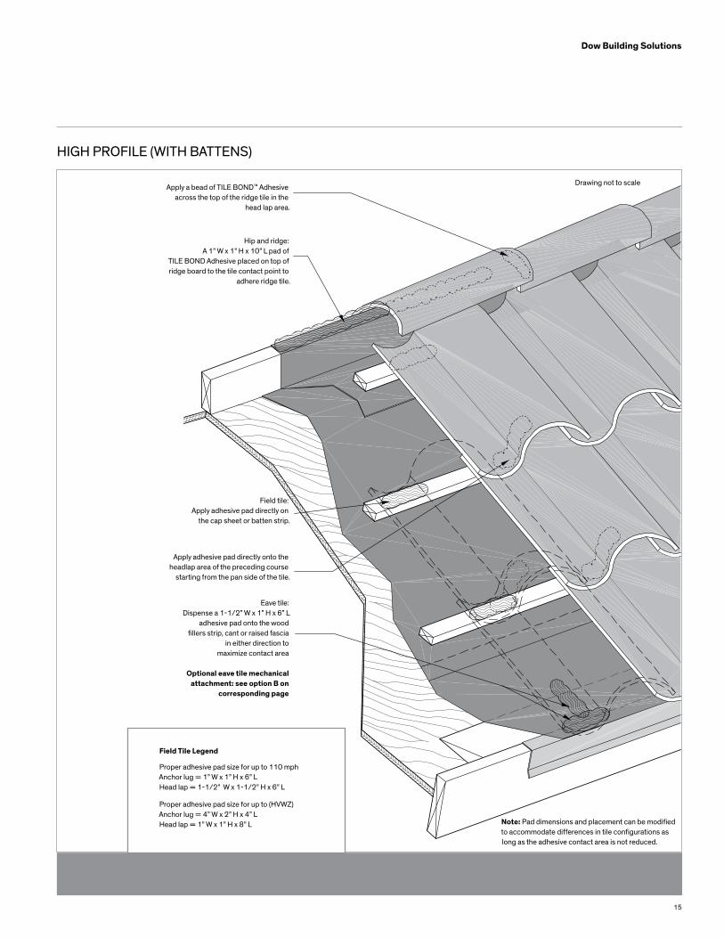
HIGH PROFILE (WITH BATTENS)
Apply a bead of TILE BOND™ Adhesive across the top of the ridge tile in the
head lap area.
Hip and ridge: A 1” W x 1” H x 10” L pad of
TILE BOND Adhesive placed on top of ridge board to the tile contact point to
adhere ridge tile.
Field tile: Apply adhesive pad directly on
the cap sheet or batten strip.
Apply adhesive pad directly onto the headlap area of the preceding course
starting from the pan side of the tile.
Eave tile: Dispense a 1-1/2” W x 1” H x 6” L
adhesive pad onto the woodfillers strip, cant or raised fascia
in either direction to maximize contact area
Optional eave tile mechanical attachment: see option B on
corresponding page
Field Tile Legend
Proper adhesive pad size for up to 110 mphAnchor lug = 1” W x 1” H x 6” LHead lap = 1-1/2” W x 1-1/2” H x 6” L
Proper adhesive pad size for up to (HVWZ) Anchor lug = 4” W x 2” H x 4” LHead lap = 1” W x 1” H x 8” L Note: Pad dimensions and placement can be modified
to accommodate differences in tile configurations as long as the adhesive contact area is not reduced.
Drawing not to scale
16
Dow Building Solutions
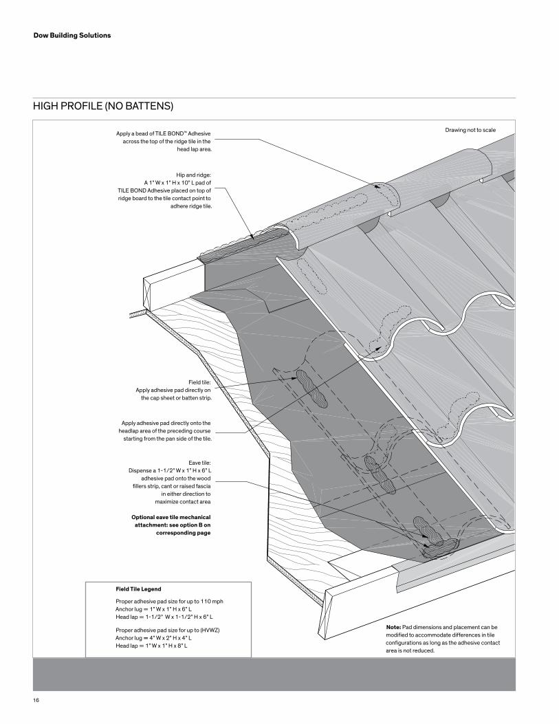
HIGH PROFILE (NO BATTENS)
Apply a bead of TILE BOND™ Adhesive across the top of the ridge tile in the
head lap area.
Hip and ridge: A 1” W x 1” H x 10” L pad of
TILE BOND Adhesive placed on top of ridge board to the tile contact point to
adhere ridge tile.
Field tile: Apply adhesive pad directly on
the cap sheet or batten strip.
Apply adhesive pad directly onto the headlap area of the preceding course
starting from the pan side of the tile.
Eave tile: Dispense a 1-1/2” W x 1” H x 6” L
adhesive pad onto the woodfillers strip, cant or raised fascia
in either direction to maximize contact area
Optional eave tile mechanical attachment: see option B on
corresponding page
Field Tile Legend
Proper adhesive pad size for up to 110 mphAnchor lug = 1” W x 1” H x 6” LHead lap = 1-1/2” W x 1-1/2” H x 6” L
Proper adhesive pad size for up to (HVWZ) Anchor lug = 4” W x 2” H x 4” LHead lap = 1” W x 1” H x 8” L
Note: Pad dimensions and placement can be modified to accommodate differences in tile configurations as long as the adhesive contact area is not reduced.
Drawing not to scale
17
Dow Building Solutions
Two Piece Barrel Profile Tile Application
Read limitations and Recommendations before applyingTILE bOND™ Roof Tile Adhesive
For areas and sections of the Roof System not covered by these instructions, please refer to the FRSA/ROOF TILE INSTITUTE CONCRETE AND CLAY ROOF TILE INSTALLATION MANUAL
“System 4” per current edition.
Refer to Anchor Sheet Fastening Tables included in theinstructions for decking and underlayment requirements.
1. For pitches above 6:12 up to and including 7:12 nail every third (3rd) tile in every fifth (5th) course in addition to the adhesive. Horizontal batten strips may need to be installed, depending upon the roof pitch and other attributes of the roof. 2. For Pitches above 7:12, nail every tile in addition to adhesive, or use horizontal batten strips in addition to the adhesive. 3. Check local building code for additional nailing requirements.
EAvE TILE: EAvE CLOSURE OR MORTAR CLOSURE 1. Apply a minimum 1 1/2” W x 1 1/2” H x 8” L adhesive strip to the cap sheet at the butt of the pan tile, in the middle of the “roll”. This adhesive pad should run vertically up the tile. Place the pan tile directly into the adhesive. 2. Set the second pan tile in the same fashion, allowing for the proper spacing. 3. Apply the cover tile by applying a 1” W x 1” H x 8” L adhesive pad to the underside of the cover, on each side of the inside of the tile. These pads should be behind the headlap of the cover. Set the cover over the two (2) pan tiles already laid. Assure that the adhesive pads on the cover make contact with the inside edge of the pan tiles.
fIELD TILE INSTALLATION 1. Apply an adhesive pad, a minimum size of 1-1/2” W x 1-1/2” H x 8” L, directly onto the underlayment in the middle of where the pan tile will be installed, beginning at the head lap of the preceding course and running vertically up the tile. Set the pan tile directly into the adhesive pad. 2. Set the adjacent pan tile in a similar manner. Make sure of the proper spacing. 3. Apply the cover tile by applying a 1” W x 1” H x 8” L adhesive pad to the underside of the cover, on each side
of the inside of the tile. These pads should be behind theheadlap of the cover. Set the cover over the two (2) pantiles already laid. Assure that the adhesive pads on thecover make contact with the inside edge of the pan tiles.
OPTIONAL: HIP AND RIDGE TILE INSTALLATION wITH A wOOD RIDGE NAILER bOARD, OR METAL RIDGE bOARDwITH “v” TOP EDGE: UP TO 110 MPH wIND UPLIfTRESISTANCE.
1. Install wood, or metal ridge board according to Local Building Code Requirements. 2. Apply a 1” W x 1” H x a minimum 10” L bead of adhesive on top of the nailer board (s) and set the ridge tile into the adhesive. Make sure the bottom of the ridge tile makes contact with the foam adhesive. When set in the adhesive, the ridge tile will push excess foam down the sides of the ridge board. 3. Apply a bead of TILE BOND adhesive across the top of the ridge tile, in the head lap area. This bead of adhe- sive should be approximately 1” W x 1” H x 4” L. Set the next ridge tile, making sure the tile overlaps the first tile with the proper head lap and the bead of adhesive is between both tiles in the head lap area, and the bottom of the ridge tile makes contact with the adhesive bead on top of the ridge board, as described in #2. 4. Proceed to install the remaining ridge tile in a similar manner. 5. Point-up with mortar to the open space between the top of the field tile and the bottom of the edge of the ridge tile. Point up to a proper finish.
Do not leave TILE BOND adhesive exposed to sunlight (ultra violet light). After adhesive cures (approximately 4 hours), point up with mortar or coat exposed adhesive pad with an approved UV protective coating.
Note: Pad dimensions and placement can be modified to accommodate differences in tile configurations as long as the adhesive contact area is not reduced. Check at least one tile per square before adhesive cures to confirm con-tact area. To make any adjustments to tiles after tack free time, you must have old adhesive pads removed and newadhesive pads applied. walking on the tile before adhe-sive has cured may cause a slipping hazard.
18
Dow Building Solutions
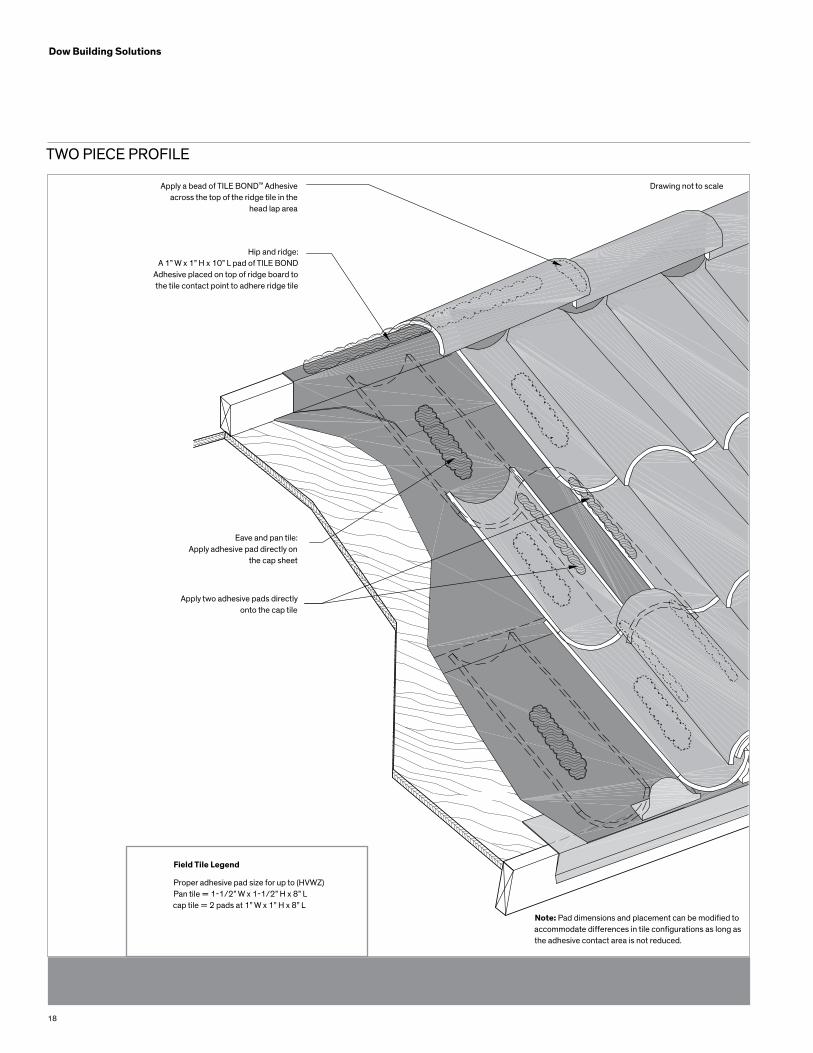
TWO PIECE PROFILE
Apply a bead of TILE BOND™ Adhesive across the top of the ridge tile in the
head lap area
Hip and ridge: A 1” W x 1” H x 10” L pad of TILE BOND
Adhesive placed on top of ridge board to the tile contact point to adhere ridge tile
Eave and pan tile:Apply adhesive pad directly on
the cap sheet
Apply two adhesive pads directlyonto the cap tile
Field Tile Legend
Proper adhesive pad size for up to (HVWZ)Pan tile = 1-1/2” W x 1-1/2” H x 8” Lcap tile = 2 pads at 1” W x 1” H x 8” L
Note: Pad dimensions and placement can be modified to accommodate differences in tile configurations as long as the adhesive contact area is not reduced.
Drawing not to scale

19
Dow Building Solutions
NOTES

20
Dow Building Solutions
NOTAS
TILE BOND™ Adhesivo para tejas Para tejas de hormigón y arcilla
Manual de Instrucciones Operativas y Mantenimiento
Florida Building CodeFL# 717South Florida Building CodeBroward CountyEdición 2002
Acceptance No.: 11-0616.03Expires: 08/23/2016Legacy Report # 2201
22
Dow Building Solutions
Adhesivo para tejas TILE BOND™ Para tejas de hormigón y arcilla
Manuel de Instrucciones Operativas Y Mantenimiento
Antes de usar el Adhesivo para Tejas de Techo TILE BOND,por favor lea y siga las instrucciones operativas para máximaseguridad y rendimiento. Este producto está destinado sólo a uso exterior con ventilación natural adecuada.
ADvERTENCIAADVERTENCIA: Contenidos a presión. MANTENGA FUERA DEL ALCANCE DE LOS NIÑOS. Irritante para ojos, piel y el sistema respiratorio. Puede causar sensibilización por inhalación y/o contacto con la piel. NO inhale vapor/pulverización. Utilice sólo con la ventilación adecuada o la protección respirato-riacorrespondiente. Evite el contacto con la piel y los ojos. Siempre utilice guantes, anteojos o gafas de seguridad y vesti-menta de protección adecuada. Este producto está destinado a uso exterior con ventilación natural y no se espera el uso de protección respiratoria. Tomar precauciones para evitar la pulverización de los trabajadores con el producto por acción de viento. Utilice guantes, anteojos o gafas de seguridad y demás indumentaria de protección adecuada. TILE BOND es extremadamente pegajoso. La espuma no curada se disuelve con acetona. La espuma curada sobre la piel y superficies sólidas debe ser mecánicamente retirada o se despegará con el tiempo. NO incinere ni perfore el cilindro. No exponga al calor ni almacene a temperaturas superiores a 49°C (120°F). El producto adhesivo curado es combustible y puede presen-tar riesgo de incendio si se expone a llama o a temperaturas superiores a 116°C (240°F).
PRIMEROS AUXILIOS: OJOS: En caso de contacto con los ojos, enjuague con agua corriente durante 15 minutos. PIEL: Quite toda la vestimenta contaminada. Lave la piel con agua y jabón. INHALACIÓN: Traslade a la persona al aire libre. Si la persona no respira, realice respiración artificial. INGESTIÓN: En caso de ingestión, beba abundante cantidad
de líquido. NO induzca el vómito. En todos los casos, consulte a un médico (cuando fuese posible, mostrar la etiqueta). Contiene diisocianato polimérico 9016-87-9, prepolímeros de poliuretano 57029-46-6 y 53862-89-8, y 1,1,1,2-tetrafluo-roetano 811-97-2.
ALMACENAMIENTONO ALMACENE bAJO LA LUZ SOLAR DIRECTAAlmacene el adhesivo TILE BOND a una temperatura entre 4,4° a 26,7°C (40° a 80° F) para asegurar la calidad, rendimiento máximo y vida en góndola del adhesivo. No debe superar los 48,9°C (48,9°C).
Almacene el adhesivo TILE BOND parcialmente utilizado en posición vertical, con la manguera conectada y presurizada. La válvula del cilindro debe estar en posición “apagado”.
TEMPERATURAS DE APLICACIÓNLa temperatura del producto recomendada al momento de la aplicación debería ser 21,1°C (70°F). Las temperaturas ambiente y de superficie mínimas deberían ser 10,0°C (50°F). Las temper-aturas inferiores prolongan el tiempo de curado.
PREPARACIÓN DE LA SUPERfICIETodas las superficies de techos deben estar limpias, sin desechos, suciedad, grasa, aceite ni agua estancada antes de aplicar el adhesivo TILE BOND.
INSTRUCCIONES OPERATIvASCOLÓqUESE TODO EL EqUIPO DE SEGURIDAD REqUERIDO, INCLUyENDO PROTECCIÓN OCULAR y CU-TáNEA. EvITE EL CONTACTO CON LA PIEL DEbE SER UN APLICADOR CERTIfICADO DE DOw – PÓNGASE EN CON-TACTO CON LA DIvISIÓN TéCNICA DE DOw PARA LA CERTIfICACIÓN.
1. PARA UTILIZAR, RETIRE EL CILINDRO DEL CARTÓN.
Dow Building Solutions
23
Dow Building Solutions
2. Antes de utilizar, agite el cilindro enérgicamente durante un minuto, como mínimo. 3. Con el cilindro en posición vertical, conecte bien la manguera de montaje del adhesivo TILE BOND™ al cilindro con una llave de 9/16”. 4. Abra la válvula en sentido contrario a las agujas del reloj, de 1/2 a 1 vuelta completa para activar el kit.PRECAUCIÓN: No abra ni aplique adhesivo con el cilindro en posición invertida. 5. Apunte el aplicador en una dirección segura. Apriete el gatillo para llenar la manguera y el aplicador con adhesivo. 6. Controle el flujo de adhesivo al ajustar la válvula amarilla del cilindro. Si el flujo es insuficiente, abra la válvula en incrementos de un cuarto de vuelta hasta obtener flujo suficiente. 7. El flujo también se puede controlar al medir el gatillo aplicador. 8. Libere el gatillo para detener el flujo de adhesivo. 9. Aplique el adhesivo TILE BOND según se indica en las páginas de aplicación 3-15. No desleír.
PROCEDIMIENTO DE LIMPIEZA / CIERRE 1. Gire la válvula del cilindro en el sentido de las agujas del reloj. 2. No vacíe el material de la manguera. Deje el aplicador y la manguera presurizados. 3. NO LIMPIE EL APLICADOR NI LA BOQUILLA. NO UTILICE SOLVENTE. El adhesivo curado en la boquilla evita que el aplicador fragüe durante el almacenamiento. Una vez activado, el aplicador tiene una vida útil de 72 horas, aproximadamente. Después de períodos más prolongados, el adhesivo se puede endurecer en el aplicador. El aplica dor se puede reutilizar en otra unidad de adhesivo TILE BOND si la manguera se traslada a un nuevo cilindro y se activa de inmediato.
REUTILIZACIÓN DEL ADHESIvO TILE bOND™ 1. Al reutilizar, retire el tapón de adhesivo curado de la punta de la boquilla. NO UTILICE SOLVENTE. a. Gire 1/2 vuelta la boquilla en el sentido contrario a las agujas del reloj y retire del aplicador. b. Inserte un destornillador u otro objeto similar en la boquilla para retirar el tapón. (Hint - Un destornillador Philips funciona mejor para retirar el Tapón) c. Vuelva a colocar la boquilla y asegúrese de que el aro tórico permanezca en su lugar. 2. Agite el cilindro enérgicamente durante un minuto, como mínimo. 3. Con el cilindro en posición vertical, abra la válvula ensenti-
do contrario a las agujas del reloj, de 1/2 a 1 vuela completa. 4. Reactive apretando el gatillo hasta que el adhesivo comience a fluir de la boquilla.
DETECCIÓN DE fALLAS 1. TASA DE FLUJO LIMITADA O LENTA: a. Verifique que la válvula del cilindro esté abierta. b. Verifique la boquilla para detectar tapones de adhesivo. c. Si la temperatura del producto es inferior a los 70°F (21,1°C) recomendados, coloque el cilindro en un área cálida de 70°F (21,1°C), aproximadamente, hasta que el cilindro alcance la temperatura de aplicación adecuada. 2. EL GATILLO NO RETROCEDE: El adhesivo se cura en el aplicador. Reemplace con un nuevo aplicador para adhesivo TILE BOND. 3. RÁFAGAS CONTINUAS DE PRESIÓN: La válvula del cilindro apunta hacia abajo o el cilindro está vacío Coloque el cilindro en posición vertical o reemplácelo. 4. PÉRDIDAS EN EL APLICADOR: Asegúrese de que el aro tórico de la boquilla esté en su lugar. 5. SI NO PUEDE RESOLVER EL PROBLEMA: Llame al 1 (866) 583-BLUE (2583) para asistencia técnica
ELIMINACIÓNAntes de eliminar, se debe liberar toda la presión del cilindro. La eliminación de los residuos del adhesivo TILE BOND se debe realizar con la ventilación adecuada. Nunca perfore ni incinere el cilindro. Siempre utilice guantes y gafas al eliminar los cilindros. 1. Cierre la válvula del cilindro. 2. Retire la manguera aplicadora del cilindro. 3. Mantenga el tanque invertido hacia abajo sobre el contenedor de residuos, con la válvula en dirección opuesta a su cuerpo y a otras personas en el área. 4. Abra lentamente la válvula del cilindro. 5. Coloque el cilindro en el contenedor de residuos y libere la presión residual y química. 6. Cubra el contenedor de residuos con una tapa floja y deje secar el contenido durante varios días. 7. Elimine de conformidad con las reglamentaciones ambientales federales, estaduales y locales. NOTA: Si no se encuentra disponible un contendor de residuos, el adhesivo TILE BOND™ se podrá invertir en su cartón original con el método antes descrito y dejar que se vacíe
CONTENIDOS • Cilindro con 23 libras de adhesivo TILE BOND • Aplicador para el adhesivo TILE BOND con manguera de 8 1/2” • Manual de Instrucciones Operativas y Mantenimiento • Muestra de relleno adhesivo de 1 1/2” de ancho x 1” de altura x 4” de largo.
24
Dow Building Solutions
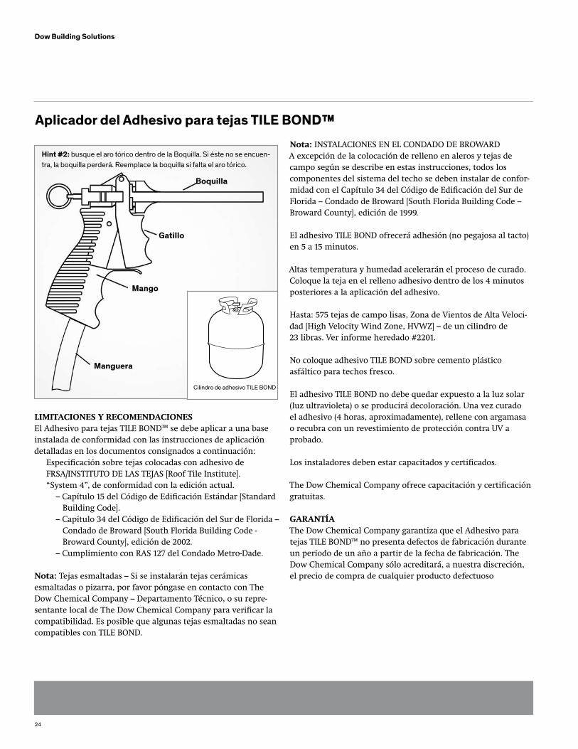
Aplicador del Adhesivo para tejas TILE BOND™
Boquilla
Gatillo
Mango
Manguera
Cilindro de adhesivo TILE BOND
LIMITACIONES y RECOMENDACIONESEl Adhesivo para tejas TILE BOND™ se debe aplicar a una base instalada de conformidad con las instrucciones de aplicación detalladas en los documentos consignados a continuación: Especificación sobre tejas colocadas con adhesivo de FRSA/INSTITUTO DE LAS TEJAS [Roof Tile Institute]. “System 4”, de conformidad con la edición actual. – Capítulo 15 del Código de Edificación Estándar [Standard Building Code]. – Capítulo 34 del Código de Edificación del Sur de Florida – Condado de Broward [South Florida Building Code - Broward County], edición de 2002. – Cumplimiento con RAS 127 del Condado Metro-Dade.
Nota: Tejas esmaltadas – Si se instalarán tejas cerámicas esmaltadas o pizarra, por favor póngase en contacto con The Dow Chemical Company – Departamento Técnico, o su repre-sentante local de The Dow Chemical Company para verificar la compatibilidad. Es posible que algunas tejas esmaltadas no sean compatibles con TILE BOND.
Nota: INSTALACIONES EN EL CONDADO DE BROWARDA excepción de la colocación de relleno en aleros y tejas de campo según se describe en estas instrucciones, todos los componentes del sistema del techo se deben instalar de confor-midad con el Capítulo 34 del Código de Edificación del Sur de Florida – Condado de Broward [South Florida Building Code – Broward County], edición de 1999.
El adhesivo TILE BOND ofrecerá adhesión (no pegajosa al tacto) en 5 a 15 minutos.
Altas temperatura y humedad acelerarán el proceso de curado. Coloque la teja en el relleno adhesivo dentro de los 4 minutos posteriores a la aplicación del adhesivo.
Hasta: 575 tejas de campo lisas, Zona de Vientos de Alta Veloci-dad [High Velocity Wind Zone, HVWZ] – de un cilindro de 23 libras. Ver informe heredado #2201.
No coloque adhesivo TILE BOND sobre cemento plástico asfáltico para techos fresco.
El adhesivo TILE BOND no debe quedar expuesto a la luz solar (luz ultravioleta) o se producirá decoloración. Una vez curado el adhesivo (4 horas, aproximadamente), rellene con argamasa o recubra con un revestimiento de protección contra UV a probado.
Los instaladores deben estar capacitados y certificados.
The Dow Chemical Company ofrece capacitación y certificación gratuitas.
GARANTÍAThe Dow Chemical Company garantiza que el Adhesivo para tejas TILE BOND™ no presenta defectos de fabricación durante un período de un año a partir de la fecha de fabricación. The Dow Chemical Company sólo acreditará, a nuestra discreción, el precio de compra de cualquier producto defectuoso
Hint #2: busque el aro tórico dentro de la Boquilla. Si éste no se encuen-tra, la boquilla perderá. Reemplace la boquilla si falta el aro tórico.
25
Dow Building Solutions
Lea las Limitaciones y Recomendaciones antes de aplicar el Adhesivo para tejas TILE bOND™
Para áreas y secciones del Sistema del Techo no incluidas en estas instrucciones, por favor consulte el MANUAL DE INSTA-LACIÓN DE TEJAS DE HORMIGÓN Y ARCILLA DEL INSTITUTODE LAS TEJAS/FRSA “System 4” [FRSA/Roof Tile Institute Concrete and Clay Roof Tile Installation Manual “System 4”], de conformidad con la edición actual.
Consulte las Tablas de Fijación de Planchas de Anclaje [Anchor Sheet Fastening Tables] incluidas en las instrucciones para los requerimientos de plataformas y bases. 1. Para inclinaciones superiores a 6:12 hasta un máximo, inclusive, de 7:12, clave cada tercera (3er) teja en cada quinta (5ta) hilada, además del adhesivo. Es posible que sea necesario insta lar tiras de listones horizontales, según la inclinación del techo y demás atributos del mismo. 2. Para inclinaciones superiores a 7:12, además de utilizar el adhesivo, clave cada una de las tejas o utilice tiras de listones horizontales. 3. Para requerimientos de clavado adicionales, consulte el código de edificación local.
TEJAS PARA ALEROS: HASTA RESISTENCIA AL LEvANTA-MIENTO POR EL vIENTO EN LA ZONA DE vIENTOS DE ALTA vELOCIDAD [HIGH vELOCITy wIND ZONE, HvwZ] (SELECCIONAR LA OPCIÓN A O b)
OPCIÓN “A” 1. En general, cuando se utiliza este método, la distancia es de 1 1/2”, aproximadamente, desde la parte superior de la plataforma del borde de goteo hasta la parte inferior de la teja. Al utilizar una tira de relleno de madera, tira de listón, listón inclinado o tabla de frontis elevada comunes, de 1” de ancho x 2” de alto x 6” de largo o más largas, se unirá la parte de la cara inferior de la teja a la plancha del travesaño. 2. Adhiera bien la primera tira de madera o tira de listón a la plancha del travesaño en el extremo de la teja, entre el centro de la misma y el lateral de cierre. La altura de la primera tira debería ser 1/2” menor que la altura del espa cio debajo de la teja en el cierre del alero.
APLICACIÓN DE TEJAS EN PERFILES BAJOS/LISOS
3. Aplique un relleno de adhesivo de 1 1/2” de ancho x 1” de alto x 6” de largo directamente sobre la tira de relleno de madera. No obstruya los orificios de drenaje con adhe- sivo. Maximice el área de contacto con la parte cóncava de la teja. 4. Aplique un segundo relleno de adhesivo en la parte superior de la teja, directamente sobre la plancha del travesaño, en diagonal al primer relleno. El saliente de anclaje debería quedar embutido en el adhesivo. Maximice el área de contacto con el saliente del listón. 5. Coloque la teja en ambos rellenos de adhesivo. 6. Continúe disponiendo la hilada de tejas del alero de manera similar.
OPCIÓN “b” 1. Aplique un relleno de adhesivo de 1 1/2” de ancho x 1” de alto x 6” de largo en la parte superior de la teja, directamente sobre la plancha del travesaño, y asegúrese de que el saliente del listón quede embutido en el adhesivo. 2. Además, ajuste la teja del alero con dos (2) tornillos. Estos tornillos deben cumplir con los requerimientos de tornillos para tejas, según se describe en el MANUAL DE INSTALACIÓN DE TEJAS DE HORMIGÓN Y ARCILLA DEL INSTITUTO DE LAS TEJAS/FRSA [FRSA/Roof Tile Institute Concrete and Clay Roof Tile Installation Manual], edición de agosto de 2005, o los requerimientos del Código de Edificación local, según corresponda. Aplique cemento plástico para techos aprobado en todas las penetraciones de la plataforma del techo. 3. Continúe instalando el resto de las tejas del alero de manera similar.
RESISTENCIA AL LEvANTAMIENTO POR EL vIENTO (HvwZ) – SUPERIOR A 110 MPH (ASCE 7-98 EXPOSICIÓN b y C) UTILICE UN RELLENO DE ADHESIvO DE 1” DE ANCHO x 1” DE ALTO x 8” DE LARGO
Nota: Se necesitan dos (2) rellenos de adhesivo TILE BOND para cada Teja de Campo. Nota: 110 MPH: Un relleno de adhesivo comprimido de 1-1/2” de ancho x 1” de alto x 4” de largo se debería expandir a un área mínima de contacto de 2” x 5”. Se necesita un área de contacto de 10 pulgadas cuadradas por relleno de adhesivo, aproximada-mente. Las dimensiones del relleno se pueden modificar para ajustarse a las diferencias en las configuraciones de las tejas
26
Dow Building Solutions
siempre que no se reduzca el área de contacto del adhesivo.Verifique, por lo menos, una teja por cuadrado para confirmar el área de contacto
1. Aplique el primer relleno de adhesivo del tamaño correcto directamente sobre el área del empalme superior de la hilada anterior, sobre el lateral de cierre de la teja. 2. Aplique el segundo relleno de adhesivo del tamaño correcto directamente sobre la plancha del travesaño o la tira de listón, en diagonal al primer relleno de adhesivo. 3. Al colocar la teja, oriente hacia adelante más allá del relleno de adhesivo en el empalme superior y deslice la teja dentro del adhesivo antes de colocarla de manera definitiva. Esto evita que el adhesivo quede expuesto sobre el frente de la hilada anterior. El saliente del listón debería quedar embutido en el adhesivo. Maximice el área de contacto con el saliente del listón. 4. Se debe disponer, por lo menos, una teja por cuadrado para confirmar el área de contacto. 5. Continúe instalando el resto de las tejas de manera similar.
OPCIONAL: INSTALACIÓN DE TEJAS DE CAbALLETES y CUMbRERAS CON UNA TAbLA PARA CLAvAR LA CUMbRERA DE MADERA O UNA TAbLA PARA CLAvAR LA CUMbRERA DE METAL CON bORDE SUPERIOR EN “v”: HASTA RESISTENCIA AL LEvANTAMIENTO POR EL vIENTO (HvwZ).
1. Instale la tabla de la cumbrera de madera o metal según los Requerimientos del Código de Edificación Local. 2. Aplique una perla de adhesivo de 1” de ancho x 1” de altura x 10” de largo, mínimo, sobre la(s) tabla(s) para clavar y coloque la teja de la cumbrera dentro del adhesivo. Asegúrese de que la parte inferior de la teja de la cumbrera entre en contacto con el adhesivo de espuma. Una vez colocada en el adhesivo, la teja de la cumbrera empujará el exceso de espuma hacia los laterales de la tabla de la cumbrera.
3. Aplique una perla de adhesivo TILE BOND en la parte superior de la teja de la cumbrera, en el área de empalme superior. Esta perla de adhesivo debería tener 1” de ancho x 1” de alto x 4” de largo, aproximadamente. Ubique la siguiente teja de la cumbrera y asegúrese de que la teja quede colocada sobre la primera teja con el empalme superior correcto, que la perla de adhesivo se encuentre en el área del empalme superior entre ambas tejas, y que la parte inferior de la teja de la cumbrera entre en contacto con la perla de adhesivo en la parte inferior de la tabla de la cumbrera, según se describe en #2. 4. Continúe instalando el resto de las tejas de la cumbrera de manera similar. 5. Rellene con argamasa en el espacio abierto entre la parte superior de la teja de campo y la parte inferior del borde de la teja de la cumbrera. Asegúrese de dar una termi- nación adecuada al relleno. 6. Consulte los códigos de edificación locales respecto del uso de tornillos o clavos en la instalación de caballetes y cumbreras.
Nota: Las dimensiones y colocación del relleno se pueden modificar para ajustarse a las diferencias en las configu-raciones de las tejas siempre que no se reduzca el área de contacto del adhesivo. verifique, por lo menos, una teja por cuadrado antes de que el adhesivo se cure para confir-mar el área de contacto. Para realizar ajustes en las tejas una vez transcurrido el tiempo de adhesión, debe retirar los rellenos de adhesivo anteriores y aplicar rel-lenos nuevos. Si camina sobre las tejas antes de que el adhesivo se cure, puede correr el riesgo de resbalarse.
27
Dow Building Solutions
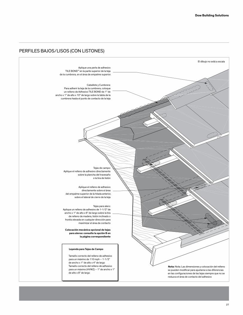
PERFILES BAJOS/LISOS (CON LISTONES)
Aplique una perla de adhesivo TILE BOND™ en la parte superior de la teja
de la cumbrera, en el área de empalme superior.
Caballete y Cumbrera:Para adherir la teja de la cumbrera, coloque un relleno de Adhesivo TILE BOND de 1” de
ancho x 1” de alto x 10” de largo sobre la tabla de lacumbrera hasta el punto de contacto de la teja
Tejas de campo:Aplique el relleno de adhesivo directamente
sobre la plancha del travesaño o la tira de listón
Aplique el relleno de adhesivo directamente sobre el área
del empalme superior de la hilada anterior, sobre el lateral de cierre de la teja
Tejas para alero:Aplique un relleno de adhesivo de 1-1/2” de
ancho x 1” de alto x 6” de largo sobre la tirade relleno de madera, listón inclinado o
frontis elevada en cualquier dirección para maximizar el área de contacto
Colocación mecánica opcional de tejaspara aleros: consulte la opción B en
la página correspondiente
Leyenda para Tejas de Campo
Tamaño correcto del relleno de adhesivopara un máximo de 110 mph – 1-1/2” de ancho x 1” de alto x 4” de largoTamaño correcto del relleno de adhesivopara un máximo (HVWZ) – 1” de ancho x 1”de alto x 8” de largo
Nota: Nota: Las dimensiones y colocación del relleno se pueden modificar para ajustarse a las diferencias en las configuraciones de las tejas siempre que no se reduzca el área de contacto del adhesivo
El dibujo no está a escala
28
Dow Building Solutions
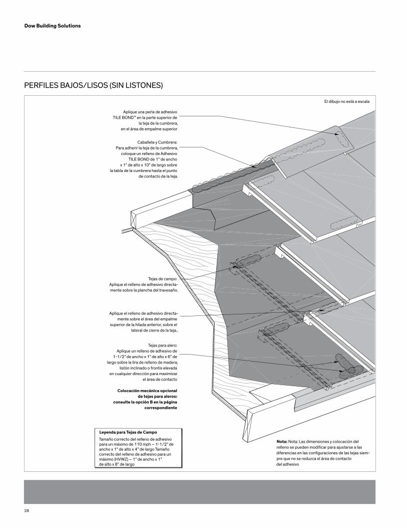
PERFILES BAJOS/LISOS (SIN LISTONES)
Aplique una perla de adhesivo TILE BOND™ en la parte superior de
la teja de la cumbrera,en el área de empalme superior
Caballete y Cumbrera:Para adherir la teja de la cumbrera,
coloque un relleno de Adhesivo TILE BOND de 1” de ancho
x 1” de alto x 10” de largo sobre la tabla de la cumbrera hasta el punto
de contacto de la teja.
Tejas de campo:Aplique el relleno de adhesivo directa-mente sobre la plancha del travesaño.
Aplique el relleno de adhesivo directa-mente sobre el área del empalme
superior de la hilada anterior, sobre el lateral de cierre de la teja..
Tejas para alero:Aplique un relleno de adhesivo de
1-1/2” de ancho x 1” de alto x 6” de largo sobre la tira de relleno de madera,
listón inclinado o frontis elevada en cualquier dirección para maximizar
el área de contacto
Colocación mecánica opcional de tejas para aleros:
consulte la opción B en la página correspondiente
Leyenda para Tejas de Campo
Tamaño correcto del relleno de adhesivopara un máximo de 110 mph – 1-1/2” deancho x 1” de alto x 4” de largo Tamaño correcto del relleno de adhesivo para un máximo (HVWZ) – 1” de ancho x 1” de alto x 8” de largo
Nota: Nota: Las dimensiones y colocación del relleno se pueden modificar para ajustarse a las diferencias en las configuraciones de las tejas siem-pre que no se reduzca el área de contacto del adhesivo
El dibujo no está a escala
29
Dow Building Solutions
APLICACIÓN DE TEJAS EN PERFILES MEDIOS
Lea las Limitaciones y Recomendaciones antes de aplicar el Adhesivo para tejas TILE bOND™
Para áreas y secciones del Sistema del Techo no incluidas en estas instrucciones, por favor consulte el MANUAL DE INSTA-LACIÓN DE TEJAS DE HORMIGÓN Y ARCILLA DEL INSTITUTODE LAS TEJAS/FRSA “System 4” [FRSA/Roof Tile Institute Concrete and Clay Roof Tile Installation Manual “System 4”], de conformidad con la edición actual.
Consulte las Tablas de Fijación de Planchas de Anclaje [Anchor Sheet Fastening Tables] incluidas en las instrucciones para los requerimientos de plataformas y bases. 1. Para inclinaciones superiores a 6:12 hasta un máximo, inclusive, de 7:12, clave cada tercera (3er) teja en cada quinta (5ta) hilada, además del adhesivo. Es posible que sea necesario instalar tiras de listones horizontales, según la inclinación del techo y demás atributos del mismo. 2. Para inclinaciones superiores a 7:12, además de utilizar el adhesivo, clave cada una de las tejas o utilice tiras de listones horizontales. 3. Para requerimientos de clavado adicionales, consulte el código de edificación local.
TEJAS PARA ALEROS: HASTA RESISTENCIA AL LEvANTA-MIENTO POR EL vIENTO EN LA ZONA DE vIENTOS DE ALTA vELOCIDAD [HIGH vELOCITy wIND ZONE, HvwZ] (SELECCIONAR LA OPCIÓN A O b)
OPTION “A” 1. En general, cuando se utiliza este método, la distancia es de 1-1/2”, aproximadamente, desde la parte superior de la plataforma del borde de goteo hasta la parte inferior de la teja. Al utilizar una tira de relleno de madera, tira de listón, listón inclinado o tabla de frontis elevada comunes, de 1” de ancho x 2” de alto x 6” de largo o más largas, se unirá la parte de la cara inferior de la teja a la plancha del travesaño. 2. Adhiera bien la primera tira de madera o tira de listón a la plancha del travesaño en el extremo de la teja, entre el centro de la misma y el lateral de cierre. La altura de la primera tira debería ser 1/2” menor que la altura del espacio debajo de la teja en el cierre del alero. 3. Aplique un relleno de adhesivo de 1 1/2” de ancho x 1” de alto x 6” de largo directamente sobre la tira de relleno
de madera. No obstruya los orificios de drenaje con adhesivo. Maximice el área de contacto con la parte cóncava de la teja. 4. Aplique un segundo relleno de adhesivo en la parte superior de la teja, directamente sobre la plancha del travesaño, en diagonal al primer relleno. El saliente del listón debería quedar embutido en el adhesivo. Maximice el área de contacto con el saliente del listón. 5. Coloque la teja en ambos rellenos de adhesivo. 6. Continúe disponiendo la hilada de tejas del alero de manera similar.
OPCIÓN “b” 1. Aplique un relleno de adhesivo directamente sobre la plancha del travesaño, en la parte superior de la teja, y asegúrese de que el saliente del listón quede embutido en el adhesivo. 2. Además, ajuste la teja del alero con dos (2) tornillos. Estos tornillos deben cumplir con los requerimientos de tornillos para tejas, según se describe en el MANUAL DE INSTALACIÓN DE TEJAS DE HORMIGÓN Y ARCILLA DEL INSTITUTO DE LAS TEJAS/FRSA [FRSA/Roof Tile Institute Concrete and Clay Roof Tile Installation Manual], edición actual. o los requerimientos del Código de Edificación local, según corresponda. Aplique cemento plástico para techos aprobado en todas las penetraciones de la plataforma del techo. 3. Continúe instalando el resto de las tejas del alero de manera similar.
INSTALACIÓN DE TEJAS DE CAMPO – PARA UNA RESIS-TENCIA AL LEvANTAMIENTO POR EL vIENTO MáXIMA DE 110 MPH, UTILICE UN RELLENO DE ADHESIvO DE 1-1/2” DE ANCHO x 1” DE ALTO x 4” DE LARGO.
RESISTENCIA AL LEvANTAMIENTO POR EL vIENTO (HvwZ) – SUPERIOR A 110 MPH (ASCE 7-98 EXPOSICIÓN b y C) UTILICE UN RELLENO DE ADHESIvO DE 1” DE ANCHO x 1” DE ALTO x 8” DE LARGO.
Nota: Se necesitan dos (2) rellenos de adhesivo TILE BOND para cada Teja de Campo.
30
Dow Building Solutions
Nota: 110 MPH: Un relleno de adhesivo comprimido de 1 1/2” de ancho x 1” de alto x 4” de largo se debería expandir a un área mínima de contacto de 2” x 5”. Se necesita un área de contacto de 10 pulgadas cuadradas por relleno de adhesivo, aproximadamente. Las dimensiones del relleno se pueden modificar para ajustarse a las diferencias en las configuraciones de las tejas siempre que no se reduzca el área de contacto del adhesivo. Verifique, por lo menos, una teja por cuadrado para confirmar el área de contacto.
Nota: (HVWZ): Un relleno de adhesivo comprimido de 1” de ancho x 1” de alto x 8” de largo se debería expandir a un área mínima de contacto de 2” x 11”. Se necesita un área de contacto de 19-1/2” pulgadas cuadradas por relleno de adhesivo, aproxi-madamente. Las dimensiones del relleno se pueden modificar para ajustarse a las diferencias en las configuraciones de las tejas siempre que no se reduzca el área de contacto del adhesivo. Verifique, por lo menos, una teja por cuadrado para confirmar el área de contacto. 1. Aplique el primer relleno de adhesivo del tamaño correcto directamente sobre el área del empalme superior de la hilada anterior, sobre el lateral de cierre de la teja. 2. Aplique el segundo relleno de adhesivo del tamaño correcto directamente sobre la plancha del travesaño o la tira de listón, en diagonal al primer relleno de adhesivo. 3. Al colocar la teja, oriente hacia adelante más allá del relleno de adhesivo en el empalme superior y deslice la teja dentro del adhesivo antes de colocarla de manera definitiva. Esto evita que el adhesivo quede expuesto sobre el frente de la hilada anterior. El saliente del listón debería quedar embutido en el adhesivo. Maximice el área de contacto con el saliente del listón. 4. Se debe disponer, por lo menos, una teja por cuadrado para confirmar el área de contacto. 5. Continúe instalando el resto de las tejas de manera similar.
OPCIONAL: INSTALACIÓN DE TEJAS DE CAbALLETES y CUMbRERAS CON UNA TAbLA PARA CLAvAR LA CUMbRERA DE MADERA O UNA TAbLA PARA CLAvAR LA CUMbRERA DE METAL CON bORDE SUPERIOR EN “v”: HASTA RESISTENCIA AL LEvANTAMIENTO POR EL vIENTO (HvwZ).
1. Instale la tabla de la cumbrera de madera o metal según los Requerimientos del Código de Edificación Local. 2. Aplique una perla de adhesivo de 1” de ancho x 1” de altura x 10” de largo, mínimo, sobre la(s) tabla(s) para clavar y coloque la teja de la cumbrera dentro del adhesivo. Asegúrese de que la parte inferior de la teja de la cumbrera entre en contacto con el adhesivo de espuma. Una vez colocada en el adhesivo, la teja de la cumbrera empujará el exceso de espuma hacia los latera les de la tabla de la cumbrera. 3. Aplique una perla de adhesivo TILE BOND en la parte superior de la teja de la cumbrera, en el área de empalme superior. Esta perla de adhesivo debería tener 1” de ancho x 1” de alto x 4” delargo, aproximadamente. Ubique la siguiente teja de la cumbrera y asegúrese de que la teja quede colocada sobre la primera teja con el empalme superior correcto, que la perla de adhesivo se encuentre en el área del empalme superior entre ambas tejas, y que la parte inferior de la teja de la cumbrera entre en contacto con la perla de adhesivo en la parte inferior de la tabla de la cumbrera, según se describe en #2. 4. Continúe instalando el resto de las tejas de la cumbrera de manera similar. 5. Rellene con argamasa en el espacio abierto entre la parte superior de la teja de campo y la parte inferior del borde de la teja de la cumbrera. Asegúrese de dar una terminación adecuada al relleno.
No deje el adhesivo TILE BOND expuesto a la luz solar (luz ultra-violeta). Una vez curado el adhesivo (4 horas, aproximadamente), rellene con argamasa o recubra el relleno de adhesivo expuesto con un revestimiento de protección contra UV aprobado.
6. Consulte los códigos de edificación locales respecto del uso de tornillos o clavos en la instalación de caballetes y cumbreras.
Nota: Las dimensiones y colocación del relleno se pueden modificar para ajustarse a las diferencias en las configuraciones de las tejas siempre que no se reduzca el área de contacto del adhesivo. Verifique, por lo menos, una teja por cuadrado antes de que el adhesivo se cure para confirmar el área de contacto. Para realizar ajustes en las tejas una vez transcurrido el tiempo de adhesión, debe retirar los rellenos de adhesivo anteriores y aplicar rellenos nuevos. Si camina sobre las tejas antes de que el adhesivo se cure, puede correr el riesgo de resbalarse.
31
Dow Building Solutions
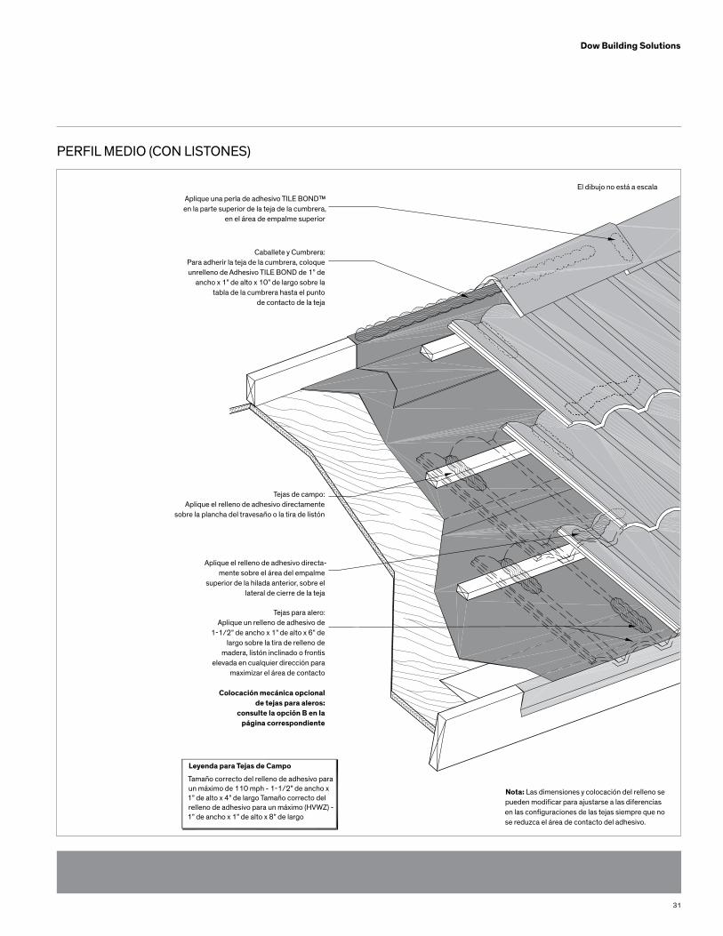
PERFIL MEDIO (CON LISTONES)
Aplique una perla de adhesivo TILE BOND™ en la parte superior de la teja de la cumbrera,
en el área de empalme superior
Caballete y Cumbrera:Para adherir la teja de la cumbrera, coloque unrelleno de Adhesivo TILE BOND de 1” de
ancho x 1” de alto x 10” de largo sobre la tabla de la cumbrera hasta el punto
de contacto de la teja
Tejas de campo:Aplique el relleno de adhesivo directamente
sobre la plancha del travesaño o la tira de listón
Aplique el relleno de adhesivo directa-mente sobre el área del empalme
superior de la hilada anterior, sobre el lateral de cierre de la teja
Tejas para alero:Aplique un relleno de adhesivo de
1-1/2” de ancho x 1” de alto x 6” de largo sobre la tira de relleno de
madera, listón inclinado o frontiselevada en cualquier dirección para
maximizar el área de contacto
Colocación mecánica opcional de tejas para aleros:
consulte la opción B en lapágina correspondiente
Leyenda para Tejas de Campo
Tamaño correcto del relleno de adhesivo para un máximo de 110 mph - 1-1/2” de ancho x 1” de alto x 4” de largo Tamaño correcto del relleno de adhesivo para un máximo (HVWZ) - 1” de ancho x 1” de alto x 8” de largo
Nota: Las dimensiones y colocación del relleno se pueden modificar para ajustarse a las diferencias en las configuraciones de las tejas siempre que no se reduzca el área de contacto del adhesivo.
El dibujo no está a escala
32
Dow Building Solutions
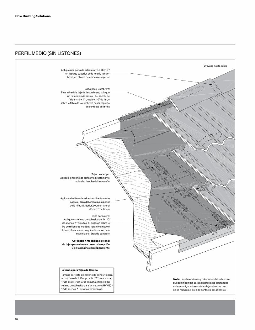
PERFIL MEDIO (SIN LISTONES)
Aplique una perla de adhesivo TILE BOND™ en la parte superior de la teja de la cum-
brera, en el área de empalme superior
Caballete y Cumbrera:Para adherir la teja de la cumbrera, coloque
un relleno de Adhesivo TILE BOND de 1” de ancho x 1” de alto x 10” de largo
sobre la tabla de la cumbrera hasta el punto de contacto de la teja
Tejas de campo:Aplique el relleno de adhesivo directamente
sobre la plancha del travesaño
Aplique el relleno de adhesivo directamentesobre el área del empalme superior de la hilada anterior, sobre el lateral
de cierre de la teja
Tejas para alero:Aplique un relleno de adhesivo de 1-1/2”
de ancho x 1” de alto x 6” de largo sobre latira de relleno de madera, listón inclinado ofrontis elevada en cualquier dirección para
maximizar el área de contacto
Colocación mecánica opcional de tejas para aleros: consulte la opción
B en la página correspondiente
Leyenda para Tejas de Campo
Tamaño correcto del relleno de adhesivo para un máximo de 110 mph - 1-1/2” de ancho x 1” de alto x 4” de largo Tamaño correcto del relleno de adhesivo para un máximo (HVWZ) - 1” de ancho x 1” de alto x 8” de largo.
Nota: Las dimensiones y colocación del relleno se pueden modificar para ajustarse a las diferencias en las configuraciones de las tejas siempre que no se reduzca el área de contacto del adhesivo.
Drawing not to scale
33
Dow Building Solutions
APLICACIÓN DE TEJAS EN PERFILES ALTOS
Lea las Limitaciones y Recomendaciones antes de aplicar el Adhesivo para tejas TILE bOND™.
For areas and sections of the Roof System not covered by these instructions, Para áreas y secciones del Sistema del Techo no incluidas en estas instrucciones, por favor consulte el MANUAL DE INSTALACIÓN DE TEJAS DE HORMIGÓN Y ARCILLA DEL INSTITUTO DE LAS TEJAS/FRSA “System 4” [FRSA/Roof Tile Institute Concrete and Clay Roof Tile Installation Manual
“System 4”], de conformidad con la edición actual.
Consulte las Tablas de Fijación de Planchas de Anclaje [Anchor Sheet Fastening Tables] incluidas en las instrucciones para los requerimientos de plataformas y bases.
1. Para inclinaciones superiores a 6:12 hasta un máximo, inclusive, de 7:12, clave cada tercera (3er) teja en cada quinta (5ta) hilada, además del adhesivo. Es posible que sea necesario instalar tiras de listones horizontales, según la inclinación del techo y demás atributos del mismo. 2. Para inclinaciones superiores a 7:12, además de utilizar el adhesivo, clave cada una de las tejas o utilice tiras de listones horizontales. 3. Para requerimientos de clavado adicionales, consulte el código de edificación local.
TEJAS PARA ALEROS: HASTA RESISTENCIA AL LEvANTA-MIENTO POR EL vIENTO EN LA ZONA DE vIENTOS DE ALTA vELOCIDAD [HIGH vELOCITy wIND ZONE, HvwZ] (SELECCIONAR LA OPCIÓN A O b)
OPCIÓN “A” 1. En general, cuando se utiliza este método, la distancia es de 1 1/2”, aproximadamente, desde la parte superior de la plataforma del borde de goteo hasta la parte inferior de la teja. Al utilizar una tira de relleno de madera, tira de listón, listón inclinado o tabla de frontis elevada comunes, de 1” de ancho x 2” de alto x 6” de largo o más largas, se unirá la parte de la cara inferior de la teja a la plancha del travesaño. 2. Adhiera bien la primera tira de madera o tira de listón a la plancha del travesaño en el extremo de la teja, debajo de la parte cóncava de la misma. La altura de la primera tira debería ser 1/2” menor que la altura del espacio de bajo de la teja en el cierre del alero.
3. Aplique un relleno de adhesivo de 1 1/2” de ancho x 1” de alto x 6” de largo directamente sobre la tira de relleno de madera. No obstruya los orificios de drenaje con adhesivo. Maximice el área de contacto con la parte cóncava de la teja. 4. Aplique un segundo relleno de adhesivo de 1 1/2” de ancho x 1” de alto x 4” de largo, mínimo, en la parte superior de la teja, directamente sobre la plancha del travesaño, en diagonal al primer relleno. El saliente de anclaje debería quedar embutido en el adhesivo. Maximice el área de contacto con el saliente del listón. 5. Coloque la teja en ambos rellenos de adhesivo. 6. Continúe disponiendo la hilada de tejas del alero de manera similar.
OPCIÓN “b” 1. Aplique un relleno de adhesivo de 1 1/2” de ancho x 1” de alto x 4” de largo, mínimo, en la parte superior de la teja, directamente sobre la plancha del travesaño, y asegúrese de que el saliente del listón quede embutido en el adhesivo. 2. Además, ajuste la teja del alero con dos (2) tornillos. Estos tornillos deben cumplir con los requerimientos de tornil- los para tejas, según se describe en el MANUAL DE INSTALACIÓN DE TEJAS DE HORMIGÓN Y ARCILLA DEL INSTITUTO DE LAS TEJAS/FRSA [FRSA/Roof Tile Institute Concrete and Clay Roof Tile Installation Manual], de conformidad con la edición actual. o los requerimientos del Código de Edificación local, según corresponda. Aplique cemento plástico para techos aprobado en todas las penetraciones de la plataforma del techo. 3. Continúe instalando el resto de las tejas del alero de manera similar.INSTALACIÓN DE TEJAS DE CAMPO - PARA UNA RESISTENCIA AL
LEvANTAMIENTO POR EL vIENTO MáXIMA DE 110 MPH, UTILICE
UN RELLENO DE ADHESIvO DE 1” DE ANCHO x 1” DE ALTO x 6” DE
LARGO EN EL EMPALME SUPERIOR y UTILICE UN RELLENO DE AD-
HESIvO DE 1 1/2” DE ANCHO x 1 1/2” DE ALTO x 6” DE LARGO EN
EL SALIENTE DE ANCLAJE, DEbAJO DE LA PARTE CÓNCAvA DE LA
TEJA. RESISTENCIA AL LEvANTAMIENTO POR EL vIENTO (HvwZ)
SUPERIOR A 110 MPH (ASCE 7-98 EXPOSICIÓN b y C), UTILICE UN
RELLENO DE ADHESIvO DE 1” DE ANCHO x 1” DE ALTO x 8” DE
LARGO EN EL EMPALME SUPERIOR y UTILICE UN RELLENO DE
ADHESIvO DE 4” DE ANCHO x 2” DE ALTO x 4” DE LARGO EN EL
APLICACIÓN DE TEJAS EN PERfILES ALTOS SALIENTE DE ANCLAJE,
DEbAJO DE LA PARTE CÓNCAvA DE LA TEJA.
34
Dow Building Solutions
Nota: Se necesitan dos (2) rellenos de adhesivo TILE BOND para cada Teja de Campo
Utilice la muestra del relleno de adhesivo como guía para el tamaño de relleno adecuado para una resistencia al levanta-miento por el viento de 110 MPH, máximo.
1. Para 110 MPH, aplique el primer relleno de adhesivo del tamaño correcto, 1” de ancho x 1” de alto x 6” de largo, como mínimo (superior a 110 MPH, utilice un relleno de 1” de ancho x 1” de alto x 8” de largo) directamente sobre el área del empalme superior de la hilada anterior sobre el lateral de cierre de la teja. 2. Para 110 MPH, aplique el segundo relleno de adhesivo correcto de 1 1/2” de ancho x 1-1/2” de alto x 6” de largo (superior a 110 MPH, utilice un relleno de 4” de ancho x 2” de alto x 4” de largo) directamente sobre la plancha del travesaño o la tira de listón, debajo de la parte cóncava de la teja. 3. Al colocar la teja, oriente hacia adelante más allá del relleno de adhesivo en el empalme superior y deslice la teja dentro del adhesivo antes de colocarla de manera definitiva. Esto evita que el adhesivo quede expuesto sobre el frente de la hilada anterior. El saliente del listón debería quedar embutido en el adhesivo. Maximice el área de contacto con el saliente del listón. 4. Se debe disponer, por lo menos, una teja por cuadrado antes de que el adhesivo se cure para confirmar el área de contacto. 5. Continúe instalando el resto de las tejas de manera similar.
OPTIONAL: HIP AND RIDGE TILE INSTALLATION wITH A wOOD RIDGE OPCIONAL: INSTALACIÓN DE TEJAS DE CAbALLETES y CUMbRERAS CON UNA TAbLA PARA CLAvAR LA CUMbRERA DE MADERA O UNA TAbLA PARA CLAvAR LA CUMbRERA DE METAL CON bORDE SUPERIOR EN “v”: HASTA RESISTENCIA AL LEvANTAMIENTO POR EL vIENTO (HvwZ).
1. Instale la tabla de la cumbrera de madera o metal según los Requerimientos del Código de Edificación Local. 2. Aplique una perla de adhesivo de 1” de ancho x 1” de altura x 10” de largo, mínimo, sobre la(s) tabla(s) para clavar y coloque la teja de la cumbrera dentro del adhesivo. Asegúrese de que la parte inferior de la teja de l
a cumbrera entre en contacto con el adhesivo de espuma. Una vez colocada en el adhesivo, la teja de la cumbrera empujará el exceso de espuma hacia los laterales de la tabla de la cumbrera. 3. Aplique una perla de adhesivo TILE BOND en la parte superior de la teja de la cumbrera, en el área de empalme superior. Esta perla de adhesivo debería tener 1” de ancho x 1” de alto x 4” de largo, aproximadamente. Ubique la siguiente teja de la cumbrera y asegúrese de que la teja quede colocada sobre la primera teja con el empalme superior correcto, que la perla de adhesivo se encuentre en el área del empalme superior entre ambas tejas, y que la parte inferior de la teja de la cumbrera entre en con tacto con la perla de adhesivo en la parte inferior de la tabla de la cumbrera, según se describe en #2. 4. Continúe instalando el resto de las tejas de la cumbrera de manera similar. 5. Rellene con argamasa en el espacio abierto entre la parte superior de la teja de campo y la parte inferior del borde de la teja de la cumbrera. Asegúrese de dar una termi nación adecuada al relleno.
No deje el adhesivo TILE BOND expuesto a la luz solar (luz ultravioleta). Una vez curado el adhesivo (4 horas, aproximada-mente), rellene con argamasa o recubra el relleno de adhesivoexpuesto con un revestimiento de protección contra UV aprobado.
6. Consulte los códigos de edificación locales respecto del uso de tornillos o clavos en la instalación de caballetes y cumbreras
Nota: Las dimensiones y colocación del relleno se pueden modificar para ajustarse a las diferencias en las configu-raciones de las tejas siempre que no se reduzca el área de contacto del adhesivo. verifique, por lo menos, una teja por cuadrado antes de que el adhesivo se cure para confirmar el área de contacto. Para realizar ajustes en las tejas una vez transcurrido el tiempo de adhesión, debe re-tirar los rellenos de adhesivo anteriores y aplicar rellenos nuevos. Si camina sobre las tejas antes de que el adhesivo se cure, puede correr el riesgo de resbalarse.
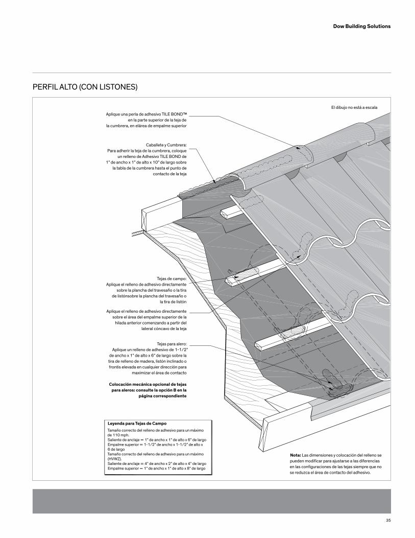
35
Dow Building Solutions
PERFIL ALTO (CON LISTONES)
Aplique una perla de adhesivo TILE BOND™ en la parte superior de la teja de
la cumbrera, en elárea de empalme superior
Caballete y Cumbrera:Para adherir la teja de la cumbrera, coloque
un relleno de Adhesivo TILE BOND de 1” de ancho x 1” de alto x 10” de largo sobre
la tabla de la cumbrera hasta el punto de contacto de la teja
Tejas de campo:Aplique el relleno de adhesivo directamente
sobre la plancha del travesaño o la tira de listónsobre la plancha del travesaño o
la tira de listón
Aplique el relleno de adhesivo directamentesobre el área del empalme superior de la
hilada anterior comenzando a partir del lateral cóncavo de la teja
Tejas para alero:Aplique un relleno de adhesivo de 1-1/2”
de ancho x 1” de alto x 6” de largo sobre la tira de relleno de madera, listón inclinado o frontis elevada en cualquier dirección para
maximizar el área de contacto
Colocación mecánica opcional de tejaspara aleros: consulte la opción B en la
página correspondiente
Leyenda para Tejas de CampoTamaño correcto del relleno de adhesivo para un máximo de 110 mph.Saliente de anclaje = 1” de ancho x 1” de alto x 6” de largoEmpalme superior = 1-1/2” de ancho x 1-1/2” de alto x 6 de largoTamaño correcto del relleno de adhesivo para un máximo(HVWZ). Saliente de anclaje = 4” de ancho x 2” de alto x 4” de largoEmpalme superior = 1” de ancho x 1” de alto x 8” de largo
Nota: Las dimensiones y colocación del relleno se pueden modificar para ajustarse a las diferencias en las configuraciones de las tejas siempre que no se reduzca el área de contacto del adhesivo.
El dibujo no está a escala
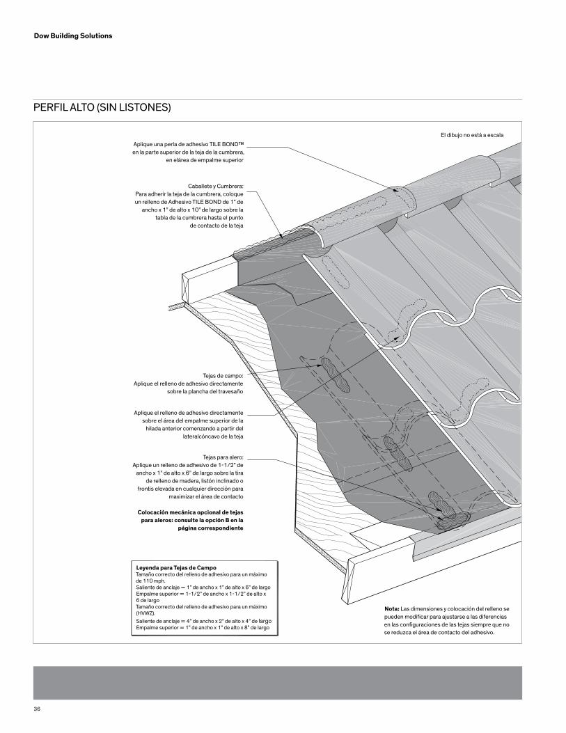
36
Dow Building Solutions
PERFIL ALTO (SIN LISTONES)
Aplique una perla de adhesivo TILE BOND™ en la parte superior de la teja de la cumbrera,
en elárea de empalme superior
Caballete y Cumbrera:Para adherir la teja de la cumbrera, coloque un relleno de Adhesivo TILE BOND de 1” de
ancho x 1” de alto x 10” de largo sobre la tabla de la cumbrera hasta el punto
de contacto de la teja
Tejas de campo:Aplique el relleno de adhesivo directamente
sobre la plancha del travesaño
Aplique el relleno de adhesivo directamentesobre el área del empalme superior de la
hilada anterior comenzando a partir del lateralcóncavo de la teja
Tejas para alero:Aplique un relleno de adhesivo de 1-1/2” de
ancho x 1” de alto x 6” de largo sobre la tirade relleno de madera, listón inclinado o
frontis elevada en cualquier dirección para maximizar el área de contacto
Colocación mecánica opcional de tejaspara aleros: consulte la opción B en la
página correspondiente
Leyenda para Tejas de CampoTamaño correcto del relleno de adhesivo para un máximo de 110 mph.Saliente de anclaje = 1” de ancho x 1” de alto x 6” de largoEmpalme superior = 1-1/2” de ancho x 1-1/2” de alto x 6 de largoTamaño correcto del relleno de adhesivo para un máximo (HVWZ).Saliente de anclaje = 4” de ancho x 2” de alto x 4” de largoEmpalme superior = 1” de ancho x 1” de alto x 8” de largo
Nota: Las dimensiones y colocación del relleno se pueden modificar para ajustarse a las diferencias en las configuraciones de las tejas siempre que no se reduzca el área de contacto del adhesivo.
El dibujo no está a escala
37
Dow Building Solutions
APLICACIÓN DE TEJAS EN PERFIL CILÍNDRICO DE DOS PIEZAS
Lea las Limitaciones y Recomendaciones antes de aplicar el Adhesivo para tejas TILE bOND™
Para áreas y secciones del Sistema del Techo no incluidas en estas instrucciones, por favor consulte el MANUAL DE INSTA-LACIÓN DE TEJAS DE HORMIGÓN Y ARCILLA DEL INSTITUTO DE LAS TEJAS/FRSA “System 4” [FRSA/Roof Tile Institute Concrete and Clay Roof Tile Installation Manual “System 4”], de conformidad con la edición actual
Consulte las Tablas de Fijación de Planchas de Anclaje [Anchor Sheet Fastening Tables] incluidas en las instrucciones para los requerimientos de plataformas y bases. 1. Para inclinaciones superiores a 6:12 hasta un máximo, inclusive, de 7:12, clave cada tercera (3er) teja en cada quinta (5ta) hilada, además del adhesivo. Es posible que sea necesario instalar tiras de listones horizontales, según la inclinación del techo y demás atributos del mismo. 2. Para inclinaciones superiores a 7:12, además de utilizar el adhesivo, clave cada una de las tejas o utilice tiras de listones horizontales. 3. Para requerimientos de clavado adicionales, consulte el código de edificación local.
TEJAS PARA ALEROS: CIERRE DE ALEROS O CIERRE CON ARGAMASA 1. Aplique una tira de adhesivo de 1 1/2” de ancho x 1 1/2” de alto x 8” de largo, mínimo, sobre la plancha del travesaño, en el extremo de la teja cóncava, en el centro de la parte curva. Este relleno de adhesivo debe correr en forma vertical y ascendente sobre la teja. Coloque la teja cóncava directamente en el adhesivo. 2. Coloque la segunda teja cóncava de la misma manera, dejando el espacio adecuado. 3. Coloque la teja de cubierta con un relleno de adhesivo de 1” de ancho x 1” de alto x 8” de largo a la parte inferior de la cubierta, a cada lado del interior de la teja Estos rellenos deben colocarse detrás del empalme superior de la cubierta. Coloque la cubierta sobre las dos (2) tejas cón cavas ya dispuestas. Asegúrese de que los rellenos de adhesivo sobre la cubierta entren en contacto con el borde interior de las tejas cóncavas.
INSTALACIÓN DE TEJAS DE CAMPO 1. Aplique un relleno de adhesivo de un tamaño mínimo de 1-1/2” de ancho x 1 1/2” de alto x 8” de largo directamente sobre la base, en el centro de donde se instalará la teja cóncava, comenzando por el empalme superior de la hilada anterior y siguiendo en forma vertical y ascendente sobre la teja. Coloque la teja cóncava directamente en el relleno de adhesivo. 2. Coloque la teja cóncava adyacente de manera similar. Asegúrese de dejar el espacio adecuado. 3. Coloque la teja de cubierta con un relleno de adhesivo de 1” de ancho x 1” de alto x 8” de largo a la parte inferior de la cubierta, a cada lado del interior de la teja. Estos rellenos deben colocarse detrás del empalme superior de la cubierta. Coloque la cubierta sobre las dos (2) tejas cón cavas ya dispuestas. Asegúrese de que los rellenos de adhesivo sobre la cubierta entren en contacto con el borde interior de las tejas cóncavas.
OPCIONAL: INSTALACIÓN DE TEJAS DE CAbALLETES y CUMbRERAS CON UNA TAbLA PARA CLAvAR LA CUM-bRERA DE MADERA O UNA TAbLA PARA CLAvAR LA CUMbRERA DE METAL CON bORDE SUPERIOR EN “v”: HASTA RESISTENCIA AL LEvANTAMIENTO POR EL vIENTO MáXIMA DE 110 MPH.
1. Instale la tabla de la cumbrera de madera o metal según los Requerimientos del Código de Edificación Local. 2. Aplique una perla de adhesivo de 1” de ancho x 1” de altura x 10” de largo, mínimo, sobre la(s) tabla(s) para clavar y coloque la teja de la cumbrera dentro del adhesivo. Asegúrese de que la parte inferior de la teja de la cumbrera entre en contacto con el adhesivo de espuma. Una vez colocada en el adhesivo, la teja de la cumbrera empujará el exceso de espuma hacia los laterales de la tabla de la cumbrera. 3. Aplique una perla de adhesivo TILE BOND en la parte superior de la teja de la cumbrera, en el área de empalme superior. Esta perla de adhesivo debería tener 1” de ancho x 1” de alto x 4” de largo, aproximadamente. Ubique la siguiente teja de la cumbrera y asegúrese de que la teja quede colocada sobre la primera teja con el empalme superior correcto, que la perla de adhesivo se encuentre en el área del empalme superior entre ambas tejas, y que la parte inferior de la teja de la cumbrera entre en contacto con la perla de adhesivo en la parte inferior de la tabla de la cumbrera, según se describe en #2.
38
Dow Building Solutions
4. Continúe instalando el resto de las tejas de la cumbrera de manera similar. 5. Rellene con argamasa en el espacio abierto entre la parte superior de la teja de campo y la parte inferior del borde de la teja de la cumbrera. Asegúrese de dar una termi nación adecuada al relleno.
No deje el adhesivo TILE BOND expuesto a la luz solar (luz ultravioleta). Una vez curado el adhesivo (4 horas, aproximada-mente), rellene con argamasa o recubra el relleno de adhesivoexpuesto con un revestimiento de protección contra UV aprobado.
Nota: Las dimensiones y colocación del relleno se pueden modificar para ajustarse a las diferencias en las configu-raciones de las tejas siempre que no se reduzca el área de contacto del adhesivo. verifique, por lo menos, una teja por cuadrado antes de que el adhesivo se cure para confir-mar el área de contacto. Para realizar ajustes en las tejas una vez transcurrido el tiempo de adhesión, debe retirar los rellenos de adhesivo anteriores y aplicar rel-lenos nuevos. Si camina sobre las tejas antes de que el adhesivo se cure, puede correr el riesgo de resbalarse.
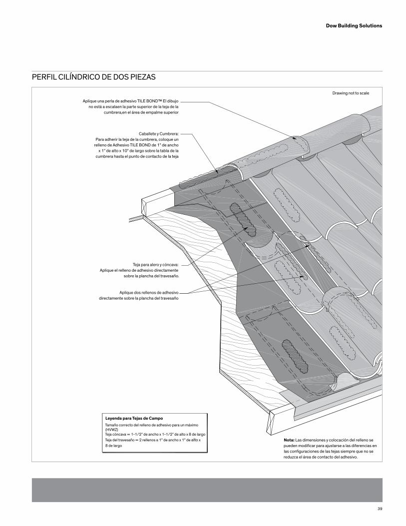
39
Dow Building Solutions
PERFIL CILÍNDRICO DE DOS PIEZAS
Aplique una perla de adhesivo TILE BOND™ El dibujo no está a escalaen la parte superior de la teja de la
cumbrera,en el área de empalme superior
Caballete y Cumbrera:Para adherir la teja de la cumbrera, coloque un
relleno de Adhesivo TILE BOND de 1” de anchox 1” de alto x 10” de largo sobre la tabla de la
cumbrera hasta el punto de contacto de la teja
Teja para alero y cóncava:Aplique el relleno de adhesivo directamente
sobre la plancha del travesaño.
Aplique dos rellenos de adhesivodirectamente sobre la plancha del travesaño
Leyenda para Tejas de CampoTamaño correcto del relleno de adhesivo para un máximo (HVWZ)Teja cóncava = 1-1/2” de ancho x 1-1/2” de alto x 8 de largoTeja del travesaño = 2 rellenos a 1” de ancho x 1” de alto x 8 de largo
Nota: Las dimensiones y colocación del relleno se pueden modificar para ajustarse a las diferencias en las configuraciones de las tejas siempre que no se reduzca el área de contacto del adhesivo.
Drawing not to scale
AVISO: No se debe suponer que se tiene la libertad de utilizar ninguna patente de propiedad de Dow ni de terceros. Puesto que las condiciones de uso y leyes que apliquen pueden diferir de un lugar a otro y pueden modificarse con el tiempo, el Cliente se responsabiliza por determinar si los productos y la información que aparecen en este documento son apropiados para su uso; además, debe asegurarse que el lugar de trabajo y las prácticas en el manejo de desechos cumplan con las leyes y otras disposiciones gubernamentales. El producto indicado en esta publicación podría no estar disponible para la venta ni/o no estar disponible en todas las regiones geográficas donde haya representantes de Dow. Podrían no haberse aprobado todas las afirmaciones de uso en todos los países. Dow no asume obligación ni responsabilidad por la información que apa-rece en este documento. Los términos “Dow” o la “Compañía” hacen referencia a la entidad de Dow que vende los productos al Cliente, a no ser que se indique lo contrario. NO SE OTORGA NINGÚN TIPO DE GARANTÍA; SE EXCLUYEN, DE MANERA EXPRESA, TODAS LAS GARANTÍAS IMPLÍCITAS DE COMERCIALIZACIÓN O CONVENIENCIA PARA UN PROPÓSITO EN PARTICULAR.
Espuma Aislante y Selladores de Poliuretano de DowADVERTENCIA: Una vez curados, estos productos son combustibles y arderán si se exponen a llama abierta o chispas de fuentes de alta energía. No los exponga a temperaturas superiores a 240ºF (116ºC). Para más información, consulte la MSDS, comuníquese con Dow al 1-866-583-BLUE (2583) o contáctese con su inspector de edificación local. En caso de emergencia, llame al 1-989-636-4400 en EE.UU. o al 1-519-339-3711 en Canadá.
Los productos adhesivos TILE BOND™ contienen isocianato y un agente de soplado de hidrofluorocarbono. Antes de utilizar, lea atentamente la etiqueta y Hoja de Datos de Seguridad del Material. Use guantes largos y antiparras o anteojos de seguridad. Tenga ventilación adecuada o use protección respiratoria adecuada. Contenidos a presión.
Las prácticas de edificación y/o construcción no relacionadas con materiales de construcción podrían afectar significativamente la humedad y el potencial de formación de moho.Ningún proveedor de materiales, Dow incluido, puede garantizar que no se desarrollará moho en ningún sistema específico. ® ™ Marca registrada de The Dow Chemical Company (“Dow”) o una compañía afiliada de Dow. GMID 00155960 Form number: 179-04057 Published February 2014
Información Técnica:1-866-583-BLUE (2583) (Inglés)1-800-363-6210 (Francés)
Información de Ventas:1-800-232-2436 (Inglés)1-800-565-1255 (Francés)
Dow Building Solutions 1605 Joseph Drive, 200 Larkin CenterMidland, Michigan 48674
NOTICE: No freedom from infringement of any patent owned by Dow or others is to be inferred. Because use conditions and applicable laws may differ from one location to another and may change with time, Customer is responsible for determining whether products and the information in this document are appropriate for Customer’s use and for ensuring that Customer’s workplace and disposal practices are in compliance with applicable laws and other government enactments. The product shown in this literature may not be available for sale and/or available in all geographies where Dow is represented. The claims made may not have been approved for use in all countries. Dow assumes no obligation or liability for the information in this document. References to “Dow” or the “Company” mean the Dow legal entity selling the products to Customer unless otherwise expressly noted. NO WARRANTIES ARE GIVEN; ALL IMPLIED WARRANTIES OF MERCHANTABILITY OR FITNESS FOR A PARTICULAR PURPOSE ARE EXPRESSLY EXCLUDED
Dow Polyurethane Foam Insulation and SealantsCAUTION: When cured, these products are combustible and will burn if exposed to open flame or sparks from high-energy sources. Do not expose to temperatures above 240ºF (116ºC). For more information, consult MSDS, call Dow at 1-866-583-BLUE (2583) or contact your local building inspector. In an emergency, call 1-989-636-4400 in the U.S. or 1-519-339-3711 in Canada.
TILE BOND™ adhesive products contain isocyanate and a hydrofluorocarbon blowing agent. Read the label and Material Safety Data Sheet carefully before use. Wear long sleeves, gloves, and goggles or safety glasses. Provide adequate ventilation or wear proper respiratory protection. Contents under pressure.
Building and/or construction practices unrelated to building materials could greatly affect moisture and the potential for mold formation.No material supplier including Dow can give assurance that mold will not develop in any specific system. ®™ Trademark of The Dow Chemical Company (“Dow”) or an affiliated company of Dow
Technical Information:1-866-583-BLUE (2583) (English)1-800-363-6210 (French)
Sales Information:1-800-232-2436 (English)1-800-565-1255 (French)
dow.comdowbuildingsolutions. com sprayfoamatdow.com