Embed Size (px)
Citation preview

TiC COATING ON AISI 304 STAINLESS STEEL BY TUNGSTEN
INERT GAS (TIG) CLADDING USING PREPLACED POWDER
A Thesis Submitted in Fulfillment of the Requirements for the Award of the Degree of
Master of Technology
In
Mechanical Engineering
(Production technology)
By
Lalit Soni
Roll No. 213ME2419
Under the supervision of
Dr. M. Masanta
Department of Mechanical Engineering
National Institute of Technology, Rourkela-769008
ODISHA, INDIA
2015

I
TiC COATING ON AISI 304 STAINLESS STEEL BY TUNGSTEN
INERT GAS (TIG) CLADDING USING PREPLACED POWDER
A Thesis Submitted in Fulfillment of the Requirements for the Award of the Degree of
Master of Technology
In
Mechanical Engineering
(Production technology)
By
Lalit Soni
Roll No. 213ME2419
Under the supervision of
Dr. M. Masanta
Department of Mechanical Engineering
National Institute of Technology, Rourkela-769008
ODISHA, INDIA
2015

II
Department of Mechanical Engineering
National Institute of Technology, Rourkela-769008
DECLARATION
I hereby declare that the report of work entitled “TiC COATING ON AISI 304 STAINLESS
STEEL BY TUNGSTEN INERT GAS (TIG) CLADDING USING PREPLACED
POWDER” is based on my own work carried out during the course of my study under the
supervision of Dr. M. Masanta.
I assert that the statements made and conclusions drawn are an outcome of the project work. I
further declare that to the best of my knowledge and belief that the report does not contain any
part of any work which has been already submitted for thesis evaluation in this university.
Name: Lalit Soni
Roll No: 213ME2419

III
Department of Mechanical Engineering
National Institute of Technology, Rourkela-769008
CERTIFICATE
This is to certify that the project entitled, “TiC COATING ON AISI 304 STAINLESS STEEL
BY TUNGSTEN INERT GAS (TIG) CLADDING USING PREPLACED POWDER”
submitted by Lalit Soni is an authentic work carried out by him under my supervision and
guidance for the partial fulfillment of the requirements for the award of Master of Technology
(M. Tech) Degree in Mechanical Engineering with specialization in Production at National
Institute of Technology, Rourkela.
To the best of my knowledge and belief that the report does not contain any part of any work
which has been already submitted for thesis evaluation in this University.
Date Dr. M. Masanta
Place: Rourkela Assistant Professor
Department of Mechanical Engineering
National Institute of Technology, Rourkela

IV
ACKNOWLEDGEMENT
I wish to express my sincere gratitude to my supervisor Dr. M. Masanta, for giving me an
opportunity to work on this project, for his guidance, encouragement and support throughout
this work and my studies here at NIT Rourkela. His impressive knowledge, technical skills and
human qualities have been a source of inspiration and a model for me to follow.
I express my sincere gratefulness to Dr. S. S. Mohapatra, Head of the Department, Mechanical
Engineering, NIT Rourkela for giving me an opportunity to work on this project and allowing
me the access to valuable facilities in the department.
I would like to mention the help and support received from Mr. Arabinda Khuntia, technical
staff Production Lab. And Mr. S. Tigga Workshop assistant. The guidance and support received
from all the members who contributed and who were part of this project, whose names could
have not been mentioned here, are highly acknowledged.
I am also thankful to Mr. Chinmaya Sahoo and Mr. Tijo D. PhD research scholars and my
friends for extending their technical and personal support and making my stay pleasant and
enjoyable.
It’s my wish to express my gratitude towards my late grandfather and I thank my parents and
family for their eternal effort.
Lalit Soni

V
ABSTRACT
In order to improve the hardness and microstructural behaviour of AISI 304 austenitic
stainless steel, TiC and TiC- steel composite layer was deposited by tungsten inert gas (TIG)
cladding/alloying process. Depending upon the heat input into the molten pool and mixing
ratio with steel substrate, TiC clad layer or TiC-steel alloyed layer deposited on or within the
steel substrate. Clad/alloyed layer height/depth and corresponding microstructure was
analyzed by FESEM and EDS. The composition of the clad/alloyed layer was assessed by X-
ray diffraction (XRD), and hardness was measured by Vickers micro indentation hardness
tester. Also effect of TIG welding current and scan velocity on the clad/alloyed layer geometry
(depth, width and crater depth) and corresponding microstructure was investigated.
Keywords: TIG, Melt depth, Microstructure, Crater depth, Hardness.

VI
CONTENT
TITLE PAGE NO.
ABSTRACT
CONTENTS
V
VI
LIST OF FIGURES VIII
LIST OF TABLES X
CHAPTER 1: INTRODUCTION 1
1.1 Different surface treatment techniques used for surface modification 1
1.2 Different types of welding techniques used for hardfacing 7
1.3 Tungsten Inert Gas (TIG) process 8
1.4 Applications of TIG cladding/alloying process 10
1.5 Metal Matrix Composites (MMCs) 10
CHAPTER 2: LITERATURE REVIEW 11
2.1 Different research works on TIG cladding 11
2.2 TiC coating by laser coating methods 14
CHAPTER 3: PROBLEM IDENTIFICATION AND OBJECTIVE 16
3.1 Problem identification 16
3.2 Objective of present work 16

VII
CHAPTER 4: EXPERIMENTAL PLANNING AND PROCEDURE
17
4.1 Experimental planning 17
4.2 Materials and Equipment used 17
4.3 Experimentation 22
4.4 Characterization of TIG clad/alloyed samples 25
CHAPTER 5: RESULTS AND DISCUSSIONS 26
5.1 Clad layer geometry 26
5.2 SEM analysis 32
5.3 FESEM analysis 34
5.4 X- ray diffraction analysis 39
5.5 Microhardness analysis 40
CHAPTER 6: CONCLUSION AND FUTURE WORK 43
6.1 Conclusion 43
6.2 Future scope 44
REFERENCES 45

VIII
LIST OF FIGURES
Figure No. Title Page No.
Figure 1 Schematic representation of TIG alloying 8
Figure 2 Flowchart showing the experimental steps 17
Figure 3 TIG cladding Setup 19
Figure 4 TiC coated steel sample before cladding 23
Figure 5 Cladded samples after cutting through Wire EDM 24
Figure 6 SEM images at the cross-section of TIG clad/alloyed samples processed with
welding current 100 amp and scan speed (a) 4.1 mm/s (b) 5.3 mm/s (c) 6.5 mm/s
27
Figure 7 SEM images at the cross-section of TIG clad/alloyed samples processed with
welding current 80 amp and scan speed (a) 4.1 mm/s (b) 5.3 mm/s (c) 6.5 mm/s
28
Figure 8 SEM images at the cross-section of TIG clad/alloyed samples processed with
welding current 60 amp and scan speed (a) 4.1 mm/s (b) 5.3 mm/s (c) 6.5 mm/s
29
Figure 9 Effect of scan speed on the clad/alloyed depth for different applied current 30
Figure 10 Effect of scan speed on the clad/alloyed layer width for different applied current 30
Figure 11 Effect of scan speed on the deformation/crater depth for different applied current 30
Figure 12 EDS elemental mapping of the dark zone of the clad layer corresponding to SEM
image 7(a).
34
Figure 13 High magnified FESEM micrograph and corresponding EDS spectra of the
coating with current 100 amp and different scan speed (a) 4.1 mm/s (b) 5.3 mm/s
(c) 6.5 mm/s
36
Figure 14 High magnified FESEM micrograph and corresponding EDS spectra of the
coating with current 80 amp and different scan speed (a) 4.1 mm/s (b) 5.3 mm/s
(c) 6.5 mm/s
37

IX
Figure 15 High magnified FESEM micrograph and corresponding EDS spectra of the
coating with current 60 amp and different scan speed (a) 4.1 mm/s (b) 5.3 mm/s
(c) 6.5 mm/s
38
Figure 16 XRD spectrum of the surface of TIG coated AISI 304 stainless steel processed
with scan speed of 6.5 mm/s and different current condition
39
Figure 17 XRD spectrum of the surface of TIG coated AISI304 stainless steel processed
with current of 100 amp and scan speed of 4.5, 5.3 and 6.5mm/s respectively
40
Figure 18 Average micro-hardness of the clad/alloyed layer produced at different current
and scan speed
41
Figure 19 Variation of micro-hardness values along the depth of alloyed zone for the TiC-
steel composite layer produced with current 100 amp and different scan speed
42

X
LIST OF TABLES
Table No. Title Page No.
Table 1 Different hardfacing welding techniques 7
Table 2 Stainless steel composition (AISI 304) 18
Table 3 Typical physical properties of AISI 304 stainless steel 18
Table 4 Physical properties of TiC 19
Table 5 Parameters Range 22
Table 6 Experimental table 24
Table 7 Dimensions of the melted tracks 26

Introduction
1 | P a g e
CHAPTER 1: INTRODUCTION
Steel components are the most widely used materials in modern industry due to their enormous
advantages, which includes its superior mechanical properties, inexpensive manufacturing cost
and exact stipulation [1]. In order to increase the productivity the industrial components are
working continuously in severe environmental conditions which causes wear and damage of
the components. To improve the efficiency and service life, these components required
treatments to enhance the surface characteristics. Different surface modification techniques are
used to enhance the surface characteristics such as hardness, wear resistance, corrosion
resistance of the steel without changing its bulk properties [2]. Surface modification techniques
includes application of thin film of functional material with superior surface properties to a
substrate or modification of surface characteristic by inclusion of harder ceramic particles [3].
1.1 Different surface treatment techniques used for surface modification:
Different types of hardening methods such as quenching, induction hardening, nitriding,
carburizing, deposition techniques such as physical vapor deposition (PVD), chemical vapor
deposition (CVD), sol-gel, electrolytic coating and hardfacing process are some of the
commonly used surface treatment method [4]. Also laser cladding, thermal spraying, hot
dipping etc. are employed to improve surface properties. Few of them are explained below:
Surface hardening- This can be done by different techniques with an aim to improve the wear
resistance of the outer surface of steel components without affecting the inner base metal. It is
mainly used to harden the outer surface of the parts subjected to severe working conditions
such as high temperature and stresses, dynamic forces, high pressure and infrequent impacts.
In this case surface modification is achieved by altering the composition by diffusion of
element such as carbon, thus results in the formation of hardened layer [5].

Introduction
2 | P a g e
Different approaches to the various surface-hardening methods are as follows [5]:
1. Thermochemical diffusion methods: These results in the modification of the surface
composition by introducing elements such as carbon, nitrogen and boron.
2. Applied energy or thermal methods: These causes no change in the surface composition but
improve desired properties by altering the surface structure by producing a quench-hardened
surface, without additional alloying species.
3. Surface coating methods: These results in the formation or addition of a new layer on the
substrate.
Thermochemical diffusion methods:
Carburizing:
It is commonly used for low-carbon steel. It is a process of heating the steel into carbon rich
environment at temperatures between 850 and 980 °C followed by quenching to harden the
surface layer.
Nitriding:
In this process, hardening of the steel is achieved by introducing nitrogen into the surface of
steel. Temperature range for this process is 500 to 550 °C.
Carbonitriding:
It is the diffusion of both carbon and nitrogen into the steel which results in the formation of
a hardened surface layer. It is done at a lower temperature than carburizing.
Boronizing:
Boriding or boronizing is a thermochemical diffusion process of boron atoms into the base
metal with the formation of hard boron compound at the surface. It is. The process temperature
for boronising lies between 700 °C and 1000 °C. It can be applied to any ferrous and non-
ferrous material, as well as cermet. Improves coefficient of friction and abrasion resistance.

Introduction
3 | P a g e
Surface hardness obtained by these methods are typically in the order of 750-1600 HV, and
can reach up to a maximum value of 2800 HV for boriding/boronizing.
Applied energy methods: These includes conventional thermal treatments such as flame
hardening and induction hardening and high-energy treatments such as laser or electron beams.
Induction hardening:
It is used to increase hardness, wear resistance and fatigue life through the formation of a
hardened surface layer, without affecting the core microstructure. The applied alternating
current in the copper coil results in heating of the workpiece placed inside the coil inducing an
alternating magnetic field within the workpiece, which causes the temperature of the outer
surface of the part to raise within or above the transformation range. The process is followed
by immediate quenching. Only martensitic stainless steels can be hardened using this process.
Flame hardening:
It is the heating of steel by an oxy-flame at a high temperature followed by quenching. It is a
hardening process used to increase the hardness and wear resistance of the medium carbon or
alloy steels. This results in the formation of a hard and wear resistant surface layer.
Laser surface heat treatment:
It is commonly used to harden steel and cast iron components, occasionally referred to as laser
transformation hardening. In this process metallurgical transformation takes place resulting in
the formation of a hardened layer to the base metal by the interaction of material and laser
beam [6]. It can be applied to a wide range of materials especially those are relatively tough
and cheap. It offers high wear resistance and improved fatigue resistance with minimal
distortion. It involves heating the material to the austenization temperature. It includes different
methods such as surface melting and surface alloying.

Introduction
4 | P a g e
Surface melting results in modification by heating the base metal followed by rapid
solidification thus improving the surface properties such as wear and corrosion resistance.
In laser alloying desired surface properties are achieved by melting and mixing of alloying
elements on the surface without affecting the bulk material [7].
Electron beam (EB) hardening:
In this process the surface is hardened by the impingement of a high-velocity electron beam
which heats the material to the austenization temperature followed by self-quenching. It results
in surface hardening with special characteristics compared to the other heat treatment
processes.
Surface-modification by deposition of coating:
Chemical Vapor Deposition (CVD):
It is a chemical process used to deposit a hard and wear resistant coating with metallurgically
bonded to the substrate. This process results in thin-film coating on the substrate due to the
reaction/deposition of volatile gaseous phases on the surface of the substrate to achieve desired
coating.
Physical vapor Deposition (PVD):
Like CVD, it is also used to produce thin film coating. It is basically a high-temperature
vacuum deposition process in which the coating metal is evaporated which forms compound
while interacting with so introduced reactive gas containing Nitrogen or Carbon thus deposited
on the surface of substrate as thin coating with improved hardness and high quality adhesion.
Evaporation of coating material can be done by heating or by bombardment of ions (sputtering)
to promote high density. PVD is commonly used in the semiconductors wafers and cutting tool.

Introduction
5 | P a g e
Electroplating:
Electroplating also called as electrodepositing is primarily used to change the surface properties
of a workpiece by the deposition of a metal coating to a metallic substrate through an
electrochemical process. The coating take place inside a container containing a solution of one
or more metal salts and the item to be coated is connected to an electrical circuit. As the current
is applied, ions from the solution are attracted towards the cathode and deposited on the
workpiece connected to cathode. Steels, nickel and copper based alloys are commonly used
materials in electroplating process.
Electroless plating:
It is an auto-catalytic reaction process used to deposit a coating of nickel onto the surface of a
substrate without applying an electric current. This results in a completely uniform deposit,
even on complex shapes, to improve wear and/or corrosion resistance. Typically nickel and
copper are used in this process.
Hardfacing:
In this process, a layer of material having superior surface properties is applied to the substrate.
It involves welding and thermal spraying techniques to deposit a hard and wear resistant
material to the selected areas of the components. It may also be used to repair worn-out parts.
The most common hardfacing materials are nickel alloys, cobalt alloys and iron/chromium
alloys used in wear resistance. Different types of hardfacing techniques are as follows:
Thermal Spraying
Laser cladding
Welding

Introduction
6 | P a g e
Thermal Spraying:
In this process, material to be coated is sprayed in melted powder form to the surface of the
substrate in order to provide a coating. The powder is melted by an oxy-flame to be sprayed in
the form of fine spray. The spray when comes in contact with the surface results in thick coating
at a higher deposition rate than any other coating processes such as electroplating, CVD and
PVD.
Some common thermal spraying processes, includes:
Plasma arc spraying
Flame spraying
High-velocity Oxy/Fuel
Electric arc spraying
Detonation Gun
Laser cladding:
It is one of the laser surface modification process which offers a wide variety of possibilities
to alter the microstructure and thus mechanical properties of the surface. It involves melting of
a thin layer of substrate surface using a laser beam which then mixes with the melted clad
powder alloy in order to form a metallurgical bond. It offers many advantages as compared to
different traditional coating methods which includes low dilution, narrow heat affected zone,
and low heat input. It results in high intensity coating because of strong metallurgical bonding
between the clad layer and the substrate. It has been adopted to deposit different powder
mixtures including tungsten carbide-cobalt, stellite on steel, titanium alloy and cast iron
substrates. Its applications include turbine blades, engine valve components and boiler firewall.

Introduction
7 | P a g e
Hardfacing by welding:
Weld hardfacing is used to deposit various metals and alloys on the metallic substrate surface
with high bonding strength. A wide range of coating materials can be applied. Different
welding techniques can be used such as plasma transferred arc (PTA), metal-inert gas (MIG)
[8], manual metal arc (MMA), tungsten-inert gas (TIG) and submerged arc (SAW) [9].
1.2 Different types of welding techniques used for hardfacing:
The methods or techniques discussed above differs in their efficiency, deposition rates and
dilution ratio. Manual Metal Arc Welding (MMAW), Submerged Arc Welding (SAW) and
Gas Tungsten Arc Welding (GTAW) are commonly used process for hardfacing or cladding
in arc welding category. Hardfacing by welding results in deposition of relative dense thick
coatings with higher deposition rates.
Table. 1 Different hardfacing welding techniques
Category Process
Arc welding
Metal Inert Gas Welding (MIG)
Tungsten Inert Gas Welding (TIG)
Plasma Transferred Arc Welding (PTA)
Submerged Arc Welding (SAW)
Shielded Metal Arc Welding (SMAW)
Gas welding Oxy/fuel Gas Welding (OFW)
Other welding
Laser Beam Welding (LBW)
Electron Beam Welding (EBW)
Electroslag Welding (ESW)

Introduction
8 | P a g e
Gas Metal Arc welding (GMAW):
It is the most flexible and commonly used arc welding process for hardfacing. In this process
a consumable electrode of harder alloying material is used which provides the filler metal. The
high temperature (5000 ºC) arc formed between the electrode and the base metal provides high
heat input for melting [10]. GMAW hardfacing offers advantages such as flexibility and low
cost [11], but low deposition rate and dilution are certain limitations which restricts its
application for all types of materials.
Gas Tungsten Arc welding (GTAW):
It is an arc welding process in which melting takes place by an arc drawn between a non-
consumable tungsten electrode and the workpiece. Shielding from atmosphere is provided by
an inert gas generally argon or helium or sometimes mixture of argon and helium which
protects the melt pool and arc. A filler metal may also be supplied in the form of a separate rod
or wire. A wide variety of metals can be welded out of which steel and aluminum are the most
common metals.
1.3 Tungsten inert gas (TIG) cladding:
Fig. 1 Schematic representation of TIG surface alloying [12]

Introduction
9 | P a g e
Tungsten inert gas (TIG) cladding proves to be one of the most commonly available and
economical methods of surface coating and surface alloying processes, which can easily
provide a metallurgical bond between the substrate and clad layer [13]. TIG surface alloying
results in surface modification through direct melting of an alloy powder or powder mixture or
powder pasted on the substrate [14]. The surface layer obtained by this technique on different
substrate materials has fine microstructures with high hardness and wear resistance different
from the starting metal [15].
TIG surface alloying offers many advantages in the deposition of hard and wear-resistant
coatings [16] on different substrates by simultaneous melting of both the coating material and
a fine layer of the substrate [4]. It produces high quality coating across a wide range of
materials. As compared to other methods thick deposits (in range of few mm) can be obtained
by this process [17].
Advantages of tungsten inert gas (TIG) surface treatment process are as follows [18]:
High deposition rate and low dilution of the clad layer on the substrate
Easily portable
large-scale availability
Low equipment cost
Compatible with a wide range of materials.
Manual operation as well as automated operation is possible
Tailor made surface modification (coating or alloying) is possible by controlling the
operating parameters
Disadvantages:
Slow as compared to other process such as laser coating
Large heat affected zone is produces and sometimes surface deformation occurred if
operating conditions are inappropriate.

Introduction
10 | P a g e
1.4 Applications of TIG cladding:
Repair of worn-out parts working in severe environmental conditions
Preventive protection of particular areas or whole workpiece to resist severe wear
conditions (abrasion, corrosion etc.)
Oil and gas industry
Repair of gas turbine components
1.5 Metal matrix composite (MMC) coating:
Among the surface modification processes discussed above coating by incorporating hard
ceramic particles in order to produce a metal matrix composite layer is quite gaining popularity
these days [19].
Ductile materials used in industries have major limitation of low wear resistance. Wear
resistance of a material can be improved by applying coating of a hard material on the surface.
Normally most of the hard material are brittle in nature so during wear, it breaks and the broken
particles also contribute in wear. However, Metal Matrix Composites have a combined
advantage of ductile, tough matrix and hardness with high compressive strength of carbide
material. Metal matrix composite with hard carbide like TiC, WC or TiB2 with matrix (like Fe,
Co or Ni) showed high hardness and wear resistance. However, metal matrix composite is
costlier and also have less toughness for making a whole component. So, MMC surface coating
is a superior option to have a harder surface with toughness of substrate material. MMC layer
coating can be done by using processes like laser cladding, plasma spraying, TIG coating etc.
[20].
TiC as hard phase carbide material:
TiC is a promising material to be used as coating in different engineering components because
of its properties such as high hardness, excellent wear resistant, high melting point, high
thermal stability along with high thermal conductivities [21].

Literature Review
11 | P a g e
CHAPTER 2: LITERATURE REVIEW
2.1 Different research works on TIG cladding:
Buytoz et al. [4] employed TIG method for the cladding of melted tungsten carbide powders
on the surface of AISI 4340 steel by preplacing the powder layer. They used welding current
of 120 Amp and performed the cladding process with three different speeds 1.209, 1.38, 1.510
mm/s. The clad layers show eutectic and dendrite solidification together with WC, W2C
phases.
Chen et al. [22] performed TIG cladding process on low carbon steel using a multi-element
alloy filler (formed by a mixture of Cr, Al, Mo, Ni, Co). Double cladding had been performed
in this study. The results thus obtained from the hardness measurement reveals that the addition
of double layer cladding greatly increased the microhardness i.e. almost four times that of the
substrate (HV 800).
Wang et al. [20] aims at preparing a Fe-based alloy, ferrotitanium and graphite composite
coating on AISI 1045 steel surfaces with pre-placed TIG surface alloying. Also the effect of
welding parameters and thickness of preplaced layer on the microstructure and properties of
coating were investigated. The results revealed that the microhardness of the layer increased
with an increase in thickness of the preplaced layer. Also the microstructure was affected by
the welding parameters, current and scan speed. Thus the coating obtained by the in situ
reaction greatly enhanced the hardness and wear resistance of the substrate.
Cheng et al. [15] employed tungsten inert gas (TIG) welding process for the deposition of
thick NiTi coating on the AISI 316 stainless steel and studied the corrosion behavior of the
obtained coating by electrochemical methods. Deposition of NiTi was carried out at operating
current of 125 Amp using NiTi wire (diameter 2 mm) as filler by multiple overlapping passes.
The results show that the corrosion resistance of the NiTi deposit in NaCl solution was lower
than that of AISI 316 substrate.

Literature Review
12 | P a g e
Buytoz and Ulutan [2] performed SiC coating on austenitic stainless steel surface using TIG
welding process by varying powder content and other parameters such as processing speed.
The effect of these parameters on microstructure was investigated. Welding current was kept
constant at 140 Amp and scan speed varying within a range of 0.54-0.666 mm/s with powder
content ranging from 0.5-4 gm. The highest hardness (1200 HV) is recorded for lowest scan
speed with highest powder content i.e., 0.54 mm/s and 4 gm.
Ulutan et al. [14] carried out the TIG surface alloying of AISI 4140 steel with a mixture of
SiC and graphite powders. Different surface characterization analysis were used in order to
investigate the microstructure and wear resistance. The result thus obtained show that the
hardness and wear resistance of the alloyed layer was increased, which was attributed to the
presence of harder phases and graphite. The authors performed the process on four different
samples at an operating current of 130 Amp, each with four different process speeds along with
different powder content combination of SiC/C. As a result of abrasive wear test, the wear
resistance of all the alloyed samples increased compared to the substrate.
Madadi et al. [9] investigated the hardness and dilution ratio of Stellite 6 coated carbon steel
by the pulsed tungsten inert gas (PCTIG) welding. Heat input is calculated from the medium
current which affected the clad properties such as dilution and corrosion. The dilution of clad
layer increased with an increase in arc current as a result of high heat input. In this study,
optimization of process parameters was carried out in order to estimate the hardness and clad
dilution by controlled heat input and cooling rate.
Xu et al. [23] compared the Tungsten Inert Gas (TIG) and diode laser cladding processes for
the deposition of Stellite-6 on the surface of SUS403 steel. The clad layers are then subjected
to various characterization analysis which shows that, the laser cladded layer possessed the
characters of low heat input, narrow heat-affected zone (HAZ), fine microstructure, small

Literature Review
13 | P a g e
dilution rate, high hardness, high wear-resistance, presence of different elements due to low
dilution compared with TIG clad layer.
Chen et al. [18] suggested the tungsten inert gas (TIG) cladding process to produce Fe–Co–
Cr–Ni–Mox alloy claddings on low carbon steel. After cladding the microstructure, hardness
and wear properties were studied. In this process the TIG parameters were kept constant (i.e.
operating current 220 A and voltage 16 V). The results revealed that, as the Mo concentration
increased the microhardness increases along with increase in wear resistance.
Shahi and Pandey [11] carried out an experimental modelling of the effect of different process
parameters on dilution in the cladding of cladding of 316L steel on AISI 1020 stainless steel.
Two different processes i.e. GMAW and advanced GMAW (UGMAW) were employed for the
cladding. The effects of open circuit voltage, nozzle-plate distance, scan speed and wire feed
rate and preheating of plate were studied by central composite rotatable design. Thus the result
showed that dilution increases with an increase in voltage, scan speed and wire feed rate, while
it reduces with increase in preheat current and nozzle-plate distance.
Madadi et al. [24] studied the microstructure and wear resistance of Stellite6/WC composite
coating by tungsten inert gas process and the effect of pulse current was investigated. The
cladding of Stellite/WC composite on AISI 1020 carbon steel were carried out in both, pulse
and constant current modes. The process parameters were V=14 V, scan speed = 1.67mm/s
with a peak current 140 Amp along with different mixtures combinations of Stellite6 alloy
powders and WC powders (10%, 20%, 30% and 40%). In this case, pulsed current resulted in
refinement of microstructure and low dilution. The hardness of the cladded layer increased due
to the presence of WC in the structure. Also increase in pulse current results in high heat input
causes high dilution and low hardness. The wear resistance of cladding layers increased with
higher content of WC.
Literature Review
14 | P a g e
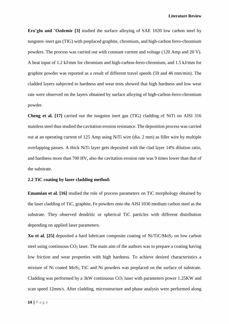
Eroˇglu and ¨Ozdemir [3] studied the surface alloying of SAE 1020 low carbon steel by
tungsten–inert gas (TIG) with preplaced graphite, chromium, and high-carbon ferro-chromium
powders. The process was carried out with constant current and voltage (120 Amp and 20 V).
A heat input of 1.2 kJ/mm for chromium and high-carbon-ferro-chromium, and 1.5 kJ/mm for
graphite powder was reported as a result of different travel speeds (59 and 46 mm/min). The
cladded layers subjected to hardness and wear tests showed that high hardness and low wear
rate were observed on the layers obtained by surface alloying of high-carbon-ferro-chromium
powder.
Cheng et al. [17] carried out the tungsten inert gas (TIG) cladding of NiTi on AISI 316
stainless steel thus studied the cavitation erosion resistance. The deposition process was carried
out at an operating current of 125 Amp using NiTi wire (dia. 2 mm) as filler wire by multiple
overlapping passes. A thick NiTi layer gets deposited with the clad layer 14% dilution ratio,
and hardness more than 700 HV, also the cavitation erosion rate was 9 times lower than that of
the substrate.
2.2 TiC coating by laser cladding method:
Emamian et al. [16] studied the role of process parameters on TiC morphology obtained by
the laser cladding of TiC, graphite, Fe powders onto the AISI 1030 medium carbon steel as the
substrate. They observed dendritic or spherical TiC particles with different distribution
depending on applied laser parameters.
Xu et al. [25] deposited a hard lubricant composite coating of Ni/TiC/MoS2 on low carbon
steel using continuous CO2 laser. The main aim of the authors was to prepare a coating having
low friction and wear properties with high hardness. To achieve desired characteristics a
mixture of Ni coated MoS2, TiC and Ni powders was preplaced on the surface of substrate.
Cladding was performed by a 3kW continuous CO2 laser with parameters power 1.25KW and
scan speed 12mm/s. After cladding, microstructure and phase analysis were performed along

Literature Review
15 | P a g e
with hardness and wear measurement. The results showed that the obtained coating has
excellent wear resistance and friction properties. This behavior of the coating is due to the
presence of the hard TiC and soft MoS2.
Yan et al. [26] successfully deposited Co-based alloy/TiC/CaF2 self-lubricating composite
coatings on a Cu alloy [Cu-0.9Cr-0.26Zr (wt.%)] using Nd:YAG laser (390 W). Co-based
alloy, TiC and CaF2 powders were mixed and preplaced on the substrate surface. After laser
cladding the characteristics of the coatings were examined by different analysis such as SEM,
XRD as well as hardness and wear resistance were measured. The results showed that the
addition CaF2 solid lubricant increased wear properties and reduces friction of thus obtained
clad coating. Average hardness of the clad layer was measured which was higher than that of
the pure Co-based alloy coating which further decreases with increase in amount of CaF2.
Ariely et al. [7] aims at deposition of hard TiC composite coating on AISI 1045 steel and to
investigate the properties of thus alloyed surface. The alloying was performed by varying laser
power, powder feed rate and overlap. Microstructure analysis and microhardness testing were
performed which shows that the hardness of the alloyed layer increased.

Problem identification and Objective
16 | P a g e
CHAPTER 3: PROBLEM IDENTIFICATION AND OBJECTIVE
3.1 Problem identification:
From the literature review it is observed that, TiC is a promising coating material applied on
various engineering component by different coating methods like PVD, CVD, thermal
spraying and laser cladding/alloying. Among these, laser cladding/alloying is widely used due
to its specific advantages over different traditional methods [23], however its high cost and
sophisticated control system restricts its application in general industries. To overcome these
limitations, so far developed conventional TIG cladding/alloying is used as an alternative for
deposition of hard composite coating on various metallic substrates. However, very little work
related to TiC coating on AISI 304 steel have been done by TIG cladding technique to improve
its surface properties. In the present work TiC coating has been developed on AISI 304 steel
by Tungsten Inert Gas (TIG) cladding/alloying process and effect of different process
parameters have been studied.
3.2 Objective of the present work are as follows:
To develop TiC coating on AISI 304 stainless steel substrate using TIG cladding such that
the surface mechanical property of stainless steel is improved.
To study the microstructure of the clad cross section obtained by changing the TIG
processing parameters.
To study the different phases obtained in the clad layer formed during coating/alloying of
TiC on stainless steel.
To find the hardness values of the clad so formed and compare it with constituent stainless
steel.
To study the effect of various TIG processing parameters i.e. current, scan speed and heat
input on hardness value and micro structure of the developed TiC coating.

Experimental planning and procedure
17 | P a g e
TiC as coating material
AISI 304 SS as substrate
CHAPTER 4: EXPERIMENTAL PLANNING AND PROCEDURE
4.1 Experimental planning:
Fig. 2: Flowchart showing the experimental steps.
4.2 Materials and Equipment used:
The following materials and equipment have been used for TIG cladding of TiC on AISI 304
stainless steel and study the microstructure and other properties.
Substrate-AISI304 stainless steel (100mm x 50mm x 8mm)
AISI 304 stainless steel is an austenite steel. Type 304 whose composition is mentioned in
table 2 is the most versatile and widely used stainless steel.
Selection of materials
Preparation of substrate for coating
Pre-deposition of TiC on substrate plate
Performing TIG experiment
Preparation of TIG processed samples for various analysis
Characterization of finally prepared samples

Experimental planning and procedure
18 | P a g e
Austenitic stainless steels are extensively used in chemical and petrochemical industries
because of their excellent corrosion resistance and excellent low-temperature performance in
a wide variety of environments and good resistance to oxidation. AISI 304 stainless steel
cannot be hardened by heat treatment. It is widely used because of its property due to which it
can be formed into various shapes. The typical physical properties of AISI 304 stainless steel
is shown in table 3.
AISI 304 stainless steel is typically used in:
• Petrochemical industry
• Food industry
• Pulp and Paper industry
• Hydrogen storage and Containment of different acids (e.g. phosphoric, acetic)
• Nuclear reactor
• Fabrication of impeller, wear rings and pump casing and welded parts
Table 2: Stainless steel composition (AISI 304)
Fe C Si Mn P S Ni Cr Mo
Balance 0.067 0.753 1.731 0.045 0.031 8.554 18.97 0.224
Table 3: Typical Physical Properties of AISI 304 stainless steel
Property Value
Density 8.00 g/cm3
Melting Point 1400-1450°C
Modulus of Elasticity 193 GPa
Thermal Conductivity 16.2 W/m.K at 100°C
Thermal Expansion 17.2x10⁻⁶ /K at 100°C
Tensile strength (MPa) 520
Compression Strength (MPa) 210
Hardness Vickers (HV) 230

Experimental planning and procedure
19 | P a g e
Coating material- TiC powder ( size- 10µ)
TiC is an extremely hard refractory ceramic material whose physical properties are mentioned
in table 4. It is commercially used in tool bits. It is mainly used in preparation of cermets, which
are frequently used to machine steel or high strength materials at high cutting speed.
Table 4: Physical properties of TiC
Property Value
Density 4.93 g/cm3
Melting Point 367 °C
Modulus of Elasticity 439 GPa
Coefficient of thermal expansion 8.15-9.45x10⁻⁶
TIG welding setup used for present experiment:
Cladding of AISI 304 steel with TiC powder as coating is done by using a semi-automated TIG
welding setup (FRONIUS TP-2200). The welding setup consists of the following parts:
Fig. 3 TIG cladding Setup
Rectifier: A Rectifier (made by FRONIUS) with current range 10-220 A and voltage up to 230
V (depending on the current setting) has been used for the present experiments.
Experimental planning and procedure
20 | P a g e
Speed control unit: It consists of a movable tractor in which a TIG welding torch is attached
which runs with a predefined speed required for performing the welding and also the welding
speed can be adjusted using a regulator.
Rail track: Movable tractor runs over this rail track in a particular speed.
TIG welding torch: A tungsten-thoriated electrode of 2.4 mm diameter was used as electrode
to produce a stable arc.
Inert Gas supply: Argon gas is supplied to the welding torch with a flow rate of 10 l/min in
order to provide an inert atmosphere resulting in the formation of a stable arc for the process
which is controlled by regulator and valve.
Work holding plate: During welding a constant gap between the tungsten electrode and work
piece is maintained by holding the work piece on a surface plate (made of grey cast iron).
Equipment used for characterization of TIG cladded samples:
Scanning electron microscope
The microstructure of the coating had been studied under SEM (JEOL JSM-6084LV). The
micrographs have been taken in the BEI (Back Scattered Electron Imaging) mode. The
scanning electron microscope (SEM) is an analytical tool used to analyze the microstructure of
the surface of the solid samples. It provides high resolution images of the surface by focusing
a high-energy electrons beam to the surface of solid sample where the electrons interact with
the atoms, producing different type of signals. These signals contains information about the
sample including surface topography and composition.

Experimental planning and procedure
21 | P a g e
SEM produce signals including back-scattered electrons (BSE), secondary electrons,
transmitted electrons, characteristic X-rays, etc. SEM can provide magnification ranging from
10 times to approximately 300,000 times and resolution of about 10 nm. This analysis is useful
in determining sample morphology (e.g. coatings), composition (EDS) as well as
crystallographic.
X-Ray diffraction
The different phases present in the TiC clad layer were obtained by X’Pert (Model- ULTIMA-
IV, made by RIGAKU Japan) X-ray Diffractometer. X-ray diffraction (XRD) is usually
employed for phase identification and quantitative analysis. It is used to identify crystalline
phases and orientation. In this, X-rays are incident on the atoms of the crystal which causes the
diffraction of X-rays in definite directions resulting in interference satisfying Bragg’s law
(2dsinθ = nλ), where d is the spacing between diffracting planes, n is an integer, λ is the
wavelength of beam and θ is the incident angle. The characteristic x-ray diffraction pattern
generated in a typical XRD analysis provides a unique pattern of the crystals present in the
sample. When properly interpreted, by matching the XRD pattern with reference patterns of
pure substances identification of the crystalline form can be done.
Microhardness testing machine ( Vickers microhardness tester) :
Microhardness of the deposited clad layer was measured using LECO-LM248AT
microhardness tester. Micro hardness testing is performed to determine the hardness of the
material. This microindentation test can be performed by Vickers microhardness tester. A
precise diamond indenter is impressed into the surface of the specimen using loads of 1 grams
to 1 kilogram. The indent diagonals are measured and the test load are used to compute the
hardness value.

Experimental planning and procedure
22 | P a g e
4.3 Experimental procedure:
Preliminary experiment
In order to establish the working range of the input parameters that has to be consider for the
cladding process, experiments were conducted taking preplaced TiC coated mild steel samples.
The process is carried out in constant current mode, taking different values of peak currents
and scan speed. Thus obtained range of working parameters to be used for the cladding process
is tabulated in table 5.
Table 5. Parameters Range
Parameters Range
Current 60-100 A
Scan speed 4.1- 6.5 mm/s
Voltage 10-20 V
Shielding gas Argon
Current type DC Straight polarity
Argon gas flow rate 10 l/min
Electrode diameter 2.4 mm
Electrode-workpiece distance 3 mm
Final experiment
After the preliminary experiment, the range of peak current and scan speed suitable for the
successful coating of TiC on stainless steel was obtained and was worked upon in the final set
of experiment.
Preparation of substrate for coating
AISI 304 stainless steel plate of dimensions 100mm×50mm×8mm, whose composition is
already mentioned in table-1, is used as substrate material. The surface of the samples were
grinded with surface grinder and then polished with emery paper. Then polished samples were
cleaned with alcohol and acetone sequentially to remove any surface contaminants.

Experimental planning and procedure
23 | P a g e
Pre-deposition of TiC Powder
Pure TiC powders (99.5% purity, 10-14 micron) was mixed with acetone and small amount of
organic binder, and then stirred until it forms a semi-solid solution. The paste like solution was
then dispersed over the clean steel surface uniformly and dried in room temperature so that
after evaporation of acetone, a solid layer of TiC forms over the substrate. In this way by
controlling the amount of dispersed powder solution, 400±10 micron preplaced layer was
formed on the steel substrate (fig. 4).
Fig. 4 TiC coated steel sample before cladding
TIG processing
Total 9 numbers of experiments were conducted with different combination of input process
parameters. The operating current and the travel speed of the TIG welding torch varying as per
the detail given in table 6.
Heat input calculation:
Heat input for melting the tracks was calculated by using the formula given below,
Heat Input = η (V.I/S)
Where η is the efficiency of heat absorption which is considered to be 48% for TIG torch
melting [27]. Thus heat input for each melt track with different process parameter combination
employed in this experiment were calculated and are presented in Table 6.

Experimental planning and procedure
24 | P a g e
Table 6: Experimental table
Track No. Current
(Amp)
Scan speed
(mm/s)
Heat input
(J/mm)
1 100 4.1 175.61
2 100 5.3 135.85
3 100 6.5 110.77
4 80 4.1 140.487
5 80 5.3 108.679
6 80 6.5 88.615
7 60 4.1 105.365
8 60 5.3 81.51
9 60 6.5 66.46
Preparation of TIG clad/alloyed samples for various analysis
After performing the TIG, the clad samples were cut at the perpendicular to the scan directions
so that cross-section of the clad layer exposed through Wire EDM.
Fig. 5 showing cladded samples after cutting through Wire EDM.
The TIG treated samples were first polished with 220, 600, and 1200 grade SiC polishing paper
and finally diamond polishing was performed at the exposed cross section for microstructural
analysis and microhardness measurement.
Experimental planning and procedure
25 | P a g e
4.4 Characterization of TIG cladded samples:
SEM analysis
SEM is used to investigate the detailed microstructure of the TiC clad layer deposited on AISI
304 stainless steel. For this the samples were cut across the length perpendicular to the scan
direction so that cross-section of the clad layer can be exposed. The cross section area was
polished with emery paper to analyze the microstructure of the deposited. The polishing was
done with 220, 600 and 1200 grade SiC paper sequentially and then finally with 1 µm diamond
paste and solvent. The microstructure of the coating had been studied under SEM (JEOL JSM-
6084LV). The micrographs have been taken in the BEI (Back Scattered Electron Imaging)
mode.
XRD analysis
The different phases present in the TiC clad layer were obtained by X’Pert (Model- ULTIMA-
IV, made by RIGAKU Japan) X-ray Diffractometer with CuKα (λ= 1.5418 Å) radiation. The
scanning range was taken 200-100
0. The step size under each study was taken 10
0/min. The
XRD patterns were analyzed with the help of Phillip’s X’Pert High Score software
Micro hardness analysis
Microhardness of the deposited clad layer was measured using LECO-LM248AT
microhardness tester with 50gf indenting force and dwell time of 10s. Micro-hardness values
of the TiC clad/alloy layers were taken at the cross section. Average value of micro-hardness
has been calculated from 10 readings taken randomly at the coating.
FESEM
FESEM or Field Emission Scanning Electron Microscope (Nova NanoSEM/ FEI) is used to
investigate the microstructural analysis of the surface or cross section of the samples. Imaging
is done in BEI (Back Scattered Electron Imaging) mode. Energy-dispersive X-ray spectroscopy
(EDS) analysis was done to determine the composition along the depth of the layer.

Results and discussions
26 | P a g e
CHAPTER 5: RESULTS AND DISCUSSIONS
5.1 Clad/Alloyed layer geometry:
From the SEM images taken at the cross-section of the TIG cladded samples, the dimensions
of the melted tracks such as melt depth, melt pool width and deformation can be measured. The
depth, pool width and deformation of the melt zone of different samples are shown below in
table 7, which shows that the dimensions of these zones depend on the energy input. Maximum
depth and width of cladded layer or alloyed layer were measured. It is clear from the SEM
images that, depending on the welding current and scan speed TiC either deposited over the
steel substrate or mixed at the upper layer of steel substrate. Measured dimensions of
clad/alloyed layer are plotted against scan speed for different applied current during cladding.
Table 7: Dimensions of the melted tracks
Sample
No.
Current
(Amp)
Scan speed
(mm/s)
Heat Input
(J/mm)
Depth
(mm)
Width
(mm)
Crater depth
(mm)
1 100 4.1 175.61 1.237 3.866 0.403
2 100 5.3 135.85 1.204 3.807 0.432
3 100 6.5 110.77 0.950 3.716 0.542
4 80 4.1 140.487 0.970 3.593 0.395
5 80 5.3 108.679 0.540 3.216 0.345
6 80 6.5 88.615 0.308 2.836 0.242
7 60 4.1 105.365 0.600 3.242 0.341
8 60 5.3 81.51 0.411 3.111 0.285
9 60 6.5 66.46 0.295 2.860 0.258

Results and discussions
27 | P a g e
Fig. 6 SEM images at the cross-section of TIG clad/alloyed samples processed with welding current 100 amp
and scan speed (a) 4.1 mm/s (b) 5.3 mm/s (c) 6.5 mm/s

Results and discussions
28 | P a g e
Fig. 7 SEM images at the cross-section of TIG clad/alloyed samples processed with welding current 80 amp and
scan speed (a) 4.1 mm/s (b) 5.3 mm/s (c) 6.5 mm/s

Results and discussions
29 | P a g e
Fig. 8 SEM images at the cross-section of TIG clad/alloyed samples processed with welding current 60 amp and
scan speed (a) 4.1 mm/s (b) 5.3 mm/s (c) 6.5 mm/s

Results and discussions
30 | P a g e
Fig. 9 Effect of scan speed on the clad/alloyed depth for different applied current
Fig. 10 Effect of scan speed on the clad/alloyed layer width for different applied current
Fig. 11 Effect of scan speed on the deformation/crater depth for different applied current

Results and discussions
31 | P a g e
Fig. 9 shows the variation of melt pool depth against TIG welding scan speed for different
current conditions used for producing the TiC clad or alloyed layer on steel substrate. From the
graph, it is seen that maximum melt depth largely depends upon the applied current. At lower
current setting (60 amp) melt depth value is relatively low (in the range of 250-800 micron)
and this value is higher for high current setting i.e., at high applied current (100 amp) melt
depth values observed are in the range of 900-1200 micron. It is also revealed from the graph
that, with an increase in scan speed the melt depth decreases. With an increase in applied
current, energy transfer to the TiC coated substrate also increases which causes an enhancement
of melting depth of TiC coated steel. A maximum depth of 1237.5 micron was obtained for the
sample processed with 100 amp current and 6.5 mm/s scan speed.
It is observed from the SEM images that at low current and high scan speed i.e. 60 amp, 6.5
mm/s only pre-deposited TiC layer was melted which after solidification forms a layer of TiC
over the steel substrate. For low current and relatively lower scan speed (60amp, 4.1mm/s, 5.3
mm/s) along with the formation of a TiC layer, an alloyed zone containing a mixture of TiC
and steel substrate just below the layer is formed. As current increases melting depth also
increases which causes melting of TiC layer as well as upper layer of substrate. As a result
some amount of TiC get diffused inside the steel substrate and forms a MMC type mixture of
TiC and steel.
Fig. 10 (graph) shows the variation of maximum melt width at the top surface of the
cladded/alloyed layer against applied current for different scan speeds. Though the TIG
cladding was performed with the tungsten rod of 2.4 mm diameter maintaining constant
distance between the tungsten electrode and TiC coated steel workpiece as 3 mm. It is seen
from the graph that, melt width values varies in the range of 2.8 mm to 4 mm for change in
current and scan speed. This is due to change in heat input to the TiC coated steel workpiece
for different current and scan speed.

Results and discussions
32 | P a g e
From both the graphs, it can be seen that melt depth and width follows the same trend for
different levels of current i.e. high for higher current and low for lower current. At each level
of current the depth and width decreases with increase in scan speed.
In case of TIG welding process overall heat input to the preplaced substrate is quite higher than
laser cladding process. Due to this high heat input some amount of preplaced material
evaporates from the top surface, further due to non-uniform arc intensity this evaporation is
prominent at the center which results in a concave shape at the top surface. This change in
surface characteristic is discussed as surface deformation or crater depth in this study. Fig. 11
shows the effect of scan speed on surface deformation/crater depth for different applied current.
The deformation varies in the range of 0.258-0.542 mm for change in input parameters.
Maximum deformation of 0.542 mm was observed for 100 amp current and 6.5 mm/s scan
speed. It is also observed from the graph that at lower current setting deformation decreases
with increase in scan speed showing minimum value at 60 amp current and 6.5 mm/s scan
speed. At relatively lower current overall heat input is less which causes less amount of material
evaporated from the top surface.
5.2 Microstructural analysis by SEM:
Fig. 6 (a-c) shows the SEM images at the cross-section of the TiC coated TIG cladded sample
processed with a peak current of 100 amp and scan speed of 4.1, 5.3 and 6.5 mm/s respectively.
From the images it is observed that, TiC get dispersed inside the steel and forms a grey shaded
layer at the top region of the substrate. TIG cladding with high current (100 A) setting supply
more amount of heat to the substrate resulting in higher melt pool depth and high width
compared to samples processed with 80 and 60 A current. Also due to high amount of heat TiC
particles completely melted inside the steel substrate and nucleation of TiC particle start.
Corresponding slow cooling rate results in growth of TiC dendritic structure during
solidification within the melt pool.

Results and discussions
33 | P a g e
Similarly, Fig. 7 (a-c) show the SEM images at the cross-section of TiC coated steel samples
after TIG cladding processed at a peak current of 80 amp each with different scan speed. It is
observed that at low speed i.e. 4.1 mm/s, a mixed layer of TiC reinforced steel composite
formed at the top surface of the substrate. However, for samples processed with higher scan
speed a distinguished black layer is formed over the steel surface. This can be attributed to the
high value of heat input (140.487 J/mm) assigned for melting the substrate which results in
increased dilution or mixed zone at 4.1 mm/s scan speed. A relatively higher scan speed (5.3
and 6.5 mm/s), heat supplied is not sufficient to melt and diffuse the TiC particles, which results
in partially melting of most of TiC particles.
Fig 8 (a-c) show the SEM images at the cross-section of the TiC coated TIG cladding samples
processed with welding current of 60 amp and scan speed of 4.1, 5.3 and 6.5 mm/s respectively.
It is observed from these images that, at this low current and high scan speed (6.5 mm/s) only
a layer of TiC produced over the steel substrate. The images also depicts that, at relatively
lower scan speed (60 amp, 4.1 mm/s, 5.3 mm/s) along with the formation of a TiC layer, an
alloyed zone containing a mixture of TiC and steel substrate is formed underneath the TiC
layer. For 60 amp welding current, overall heat input on the TiC preplaced workpiece is
relatively less and this heat input lower at higher scan speed. Therefore at low current and high
scan speed (60 amp and 6.5 mm/s), only preplaced TiC powder melted which after
solidification produces a clad layer with a negligible dilution of iron from the base material.
Further, due to low density of TiC, at low heat input condition convective flow of molten TiC
layer is not sufficient to distribute TiC particles inside the melt pool. As scan speed reduces,
due to higher heat input melting depth increases, which causes melting of TiC layer as well as
upper layer of substrate. Thus, some amount of TiC get diffused inside the steel substrate and
produced a Metal Matrix Composite (MMC) type coating containing mixture of TiC and steel.

Results and discussions
34 | P a g e
5.3 FESEM analysis:
Fig. 12: EDS elemental mapping of the dark zone of the clad layer corresponding to SEM
image 7 (a).
Fig.12 shows the high magnified FESEM image taken in BSE mode and corresponding EDS
elemental mapping of the dark zone of the clad layer. The magnified image shows that, this
dark zone consists of highly concentrated black particles and relatively less white matrix zone.
From the EDS mapping it is revealed that, these dark particles are rich in titanium and carbon
whereas, white matrix zone is rich in iron. Therefore it can be conclude that, these black
particles are TiC reinforced in the iron matrix of the substrate.
Fig. 13 (a-c) show the high magnified FESEM images and related EDS spectra for the marked
region of the SEM image corresponding to Fig. 5(a-c). From these images it is observed that,
the alloyed layer mainly consist of a dark dendritic structure of TiC and white steel matrix. At

Results and discussions
35 | P a g e
relatively high current (100A), for different scan speed, high melt pool temperature causes
strong marangoni flow of the melt pool and distribute the TiC particles uniformly inside the
steel matrix. Due to high amount of heat input and corresponding slow cooling rate, TiC
particles completely melted within steel matrix and during solidification, nucleation of TiC
start and growth into dendrite structure within the melt pool. EDS analysis [Fig. 13 (a-c)] show
percentage of Ti and C (amount of TiC) is high for sample processed at low scan speed and
with the increase in scan speed amount of TiC decreases in the TiC-steel composite layer.
Since, for using 80 amp current with different scan speed, TiC-steel layers are not uniform
within the melt pool (clad/alloyed layer), it is difficult to compare the microstructure at high
magnification. However, within the mixed zone where TiC mixed with steel substrate and
solidified as marked in Fig. 3, forms different type of structure (block shape, flower shape or
globular shape) [Fig. 14 (a-c)].
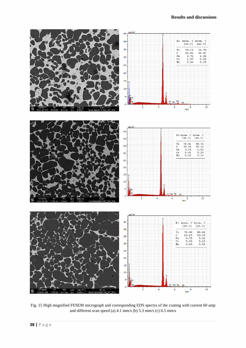
Fig. 15 (a-c) shows the high magnified FESEM image corresponding to the SEM images fig.
8 (a-c). From these photomicrograph (Fig. 15 c), it is revealed that, the dark layer over the steel
substrate consisting globular shape TiC particles. Corresponding EDS analysis shows that,
percentage of TiC is reasonably high in this layer. For using welding current of 60 amp, due to
relatively low heat input on the TiC coated steel substrate, melting of only TiC powder layer
and very thin layer of steel substrate occurred. This input heat energy at low welding current
is not sufficient to melt a layer of steel substrate for mixing TiC powder inside it and to
accelerate the convective flow of molten metal. At maximum scan speed (6.5 mm/s), amount
of iron in the dark region is almost negligible. When scan speed is relatively less i.e. 4.1 and
5.3 mm/s, along with this dark layer, a grey shaded zone also form, which contain relatively
low amount of TiC dispersed in the steel matrix.

Results and discussions
36 | P a g e
Fig. 13 High magnified FESEM micrograph and corresponding EDS spectra of the coating with current 100
amp and different scan speed (a) 4.1 mm/s (b) 5.3 mm/s (c) 6.5 mm/s

Results and discussions
37 | P a g e
Fig. 14 High magnified FESEM micrograph and corresponding EDS spectra of the coating with current 80 amp
and different scan speed (a) 4.1 mm/s (b) 5.3 mm/s (c) 6.5 mm/s
Results and discussions
38 | P a g e
Fig. 15 High magnified FESEM micrograph and corresponding EDS spectra of the coating with current 60 amp
and different scan speed (a) 4.1 mm/s (b) 5.3 mm/s (c) 6.5 mm/s
Results and discussions
39 | P a g e
EDS analysis shows that, percentage of iron and other constituent of steel increases in the dark
layer with the reduction in scan speed (Fig. 15 a-b). At low scan speed, with relatively higher
heat input, partial melting of substrate also occurred and TiC mixed with the substrate and
produces a gray shaded MMC type zone.
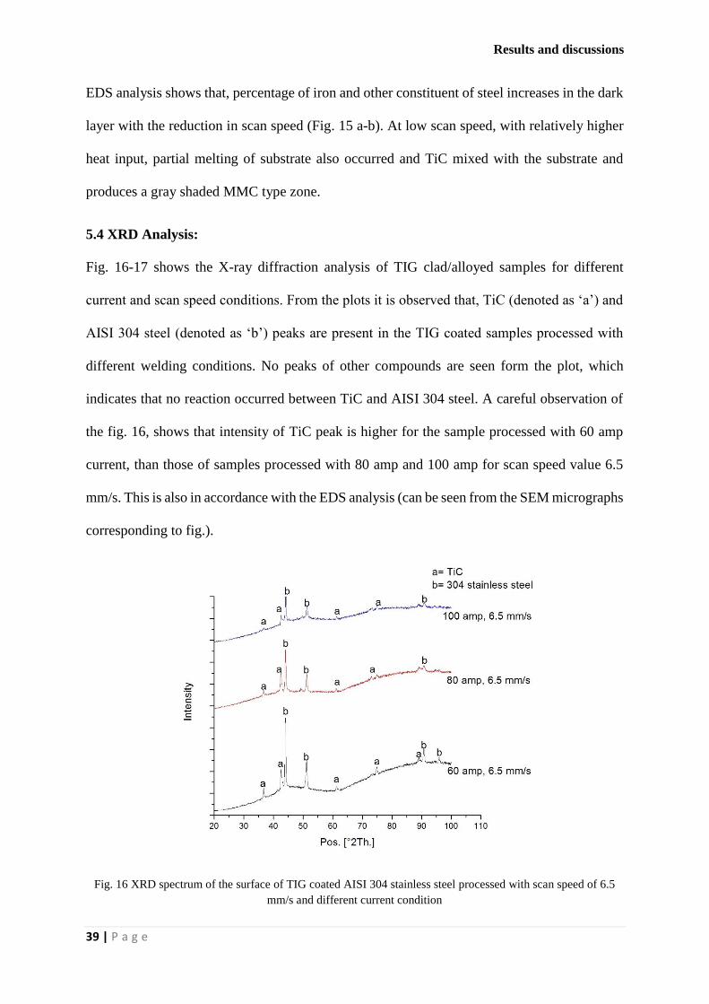
5.4 XRD Analysis:
Fig. 16-17 shows the X-ray diffraction analysis of TIG clad/alloyed samples for different
current and scan speed conditions. From the plots it is observed that, TiC (denoted as ‘a’) and
AISI 304 steel (denoted as ‘b’) peaks are present in the TIG coated samples processed with
different welding conditions. No peaks of other compounds are seen form the plot, which
indicates that no reaction occurred between TiC and AISI 304 steel. A careful observation of
the fig. 16, shows that intensity of TiC peak is higher for the sample processed with 60 amp
current, than those of samples processed with 80 amp and 100 amp for scan speed value 6.5
mm/s. This is also in accordance with the EDS analysis (can be seen from the SEM micrographs
corresponding to fig.).
Fig. 16 XRD spectrum of the surface of TIG coated AISI 304 stainless steel processed with scan speed of 6.5
mm/s and different current condition

Results and discussions
40 | P a g e
Fig. 17 XRD spectrum of the surface of TIG coated AISI304 stainless steel processed with current of 100 amp
and scan speed of 4.5, 5.3 and 6.5mm/s respectively.
Similarly, fig. 17 shows the XRD spectrum of the surface of TIG coated AISI304 stainless steel
processed with current of 100 amp and different scan speed. From the graph it is observed
that, for the samples processed with 100 amp current, intensity of TiC is higher for higher scan
speed (6.5 mm/s). It is already been discussed in SEM analysis that, at higher scan speed, some
amount of unmelted TiC deposited at the edges of upper surface of the alloyed layer. This
unmelted layer of TiC is responsible for the high intensity peak of TiC.
5.5 Micro-hardness analysis:
Micro-hardness values of the TiC clad/alloy layers were measured at the cross section. Average
value of micro-hardness has been calculated from the 10 readings taken randomly at the coating
and plotted against the used scan speed for different samples in fig. 18. The results show a large
variation in the hardness value when current changes from 100 amp to 60 amp, which is mainly
due to formation of either layer of TiC with low dilution of steel substrate or MMC of TiC on
steel matrix.

Results and discussions
41 | P a g e
Fig. 18 Average micro-hardness of the clad/alloyed layer produced at different current and scan speed
The graph (fig. 18) indicates that, the hardness value for the samples processed with 60 amp
and 80 amp, exhibits high average hardness i.e. in the range of 800 to 1600 HV. However,
samples processed with 100 amp which mainly produced almost uniform metal matrix
composite structure at the top surface of the substrate show relatively lower hardness value i.e.
in the range of 360 to 470 HV. Uniform distribution of TiC in the steel matrix causes more
uniform micro-hardness on the alloyed layer. On the other side, variation in the hardness value
is significantly high for using 60 and 80 amp current, which is mainly due to non-uniform
structure of the surface layer (TiC layer + MMC layer). It is also observed from the graph that,
using lower scan speed (for 60 and 80 amp), when these mixed structure were formed, average
hardness value increases with the increase in scan speed. However, for high current setting,
when uniform MMC type composite layer produced, average micro-hardness value decreases
with the increase in scan speed. It is revealed from the EDS analysis of the microstructure that,
for the samples processed at 100 amp current, with the increase in scan speed wt.% of Ti
decreases which indicate that, with increasing scan speed TiC concentration on the alloyed
layer also decreases. Since hard TiC is the main reason for higher hardness of the coating, it

Results and discussions
42 | P a g e
can be conclude that for 100 amp current average micro-hardness value decrease with the
increase in scan speed. Again EDS analysis describe that, for lower current setting, at the coated
layer percentage of Ti increases with the increase in scan speed, which causes higher hardness.
Again for the sample processed with 100 amp current which produced uniform MMC layer,
hardness value measured from the top surface to the bottom of the alloyed zone and is plotted
against distance from the top surface which is shown in fig. 19. The figure depicts that, the
micro hardness value is relatively higher at the top portion of the alloyed layer and reduces
with the depth from the surface and become stable after a certain depth. For the sample
processed with 6.5 mm/s scan speed it is observed that, after a depth of 800 micron hardness
value reaches to approximately 230 HV (hardness value of steel substrate) and stabilize.
Similarly for sample processed with 5.3 and 4.1 mm/s, depth after which hardness value reach
the hardness value of substrate found to be 900 and 1100 micron respectively. These values
are similar to the maximum depth of alloyed zone measured from the SEM images [fig. 6(a-
c)]. Hardness value smoothly decreases with increase in distance from the top surface due to
decrease in dendritic TiC density from top to bottom.
Fig. 19 Variation of micro-hardness values along the depth of alloyed zone for the TiC-steel composite layer
produced with current 100 amp and different scan speed

Conclusion and Future work
43 | P a g e
CHAPTER 6: CONCLUSION AND FUTURE SCOPE
6.1 Conclusion:
From the above experiment, it is observed that TiC coating has been successfully developed
on AISI 304 steel.
The SEM microstructure analysis showed two different types of clad layers for 100 amp
and 60 amp applied current.
At higher value of current i.e. 100 amp, a MMC type mixed zone with low hardness and
high layer depth is obtained, while for lower current i.e. 60 amp, a distinguished TiC layer
with high hardness but low layer thickness formed over the steel substrate.
From the clad layer geometry, it is concluded that the dimensions (melt depth, width and
crater depth) decreases with a reduced energy input.
From the FESEM analysis, it is observed that different types of TiC structures were
obtained (dendritic, block shape, flower shape and globular shape).
The microhardness results indicate that the TiC coated steel samples processed at lower
current i.e. 60 amp and lower scan speed i.e. 6.5 mm/s exhibited high hardness which is
almost 7 times the hardness of the constituent steel.
Conclusion and Future work
44 | P a g e
6.2 Future scope:
Overlapping can be done to perform the ball-on-disc wear test in order to check the wear
resistance of the developed TiC coating.
Development of in-situ TIG cladding process for exhibiting benefits of production of
coating powder within the cladding itself and using TiC as reinforcement and along with it
some other metals such as Fe, Ni or Co which serve as matrix and also use of solid
lubricants like CaF2 or MoS2 to improve the lubrication properties further.
Optimization techniques can be used to determine the optimal input process parameters.

References
45 | P a g e
REFERENCES:
[1] Sreeraj P., T. Kannan, and S. Maji, "Prediction and optimization of weld bead geometry in
gas metal arc welding process using RSM and fmincon". Journal of Mechanical
Engineering, 2013. 5(8): p. 154-165.
[2] Buytoz S. and M. Ulutan, "In situ synthesis of SiC reinforced MMC surface on AISI 304
stainless steel by TIG surface alloying". Surface and Coatings Technology, 2006. 200(12):
p. 3698-3704.
[3] Eroğlu M. and N. Özdemir, "Tungsten-inert gas surface alloying of a low carbon steel".
Surface and Coatings Technology, 2002. 154(2): p. 209-217.
[4] Buytoz S., M. Ulutan, and M.M. Yildirim, "Dry sliding wear behavior of TIG welding clad
WC composite coatings". Applied Surface Science, 2005. 252(5): p. 1313-1323.
[5] Dossett J. and G. Totten, "Introduction to Surface Hardening of Steels". 2013.
[6] Zhong M. and W. Liu, "Laser surface cladding: the state of the art and challenges".
Proceedings of the Institution of Mechanical Engineers, Part C: Journal of Mechanical
Engineering Science, 2010. 224(5): p. 1041-1060.
[7] Ariely S., et al. "Laser surface alloying of steel with TiC". In 8th Meeting in Israel on
Optical Engineering. 1993. International Society for Optics and Photonics.
[8] Sagar A. and D.G. Purohit, "Some Studies on MIG Hardfacing of Mild Steel Components".
International Journal of Engineering Research and Development, 2012. 4(8): p. 42-56.
[9] Madadi F., F. Ashrafizadeh, and M. Shamanian, "Optimization of pulsed TIG cladding
process of stellite alloy on carbon steel using RSM". Journal of Alloys and Compounds,
2012. 510(1): p. 71-77.
[10] Shibe V. and V. Chawla, "Enhancement in wear resistance by hardfacing": A REVIEW.

References
46 | P a g e
[11] Shahi A. and S. Pandey, "Modelling of the effects of welding conditions on dilution of
stainless steel claddings produced by gas metal arc welding procedures". Journal of
materials processing technology, 2008. 196(1): p. 339-344.
[12] Buytoz S., M.M. Yildirim, and H. Eren, "Microstructural and microhardness characteristics
of gas tungsten are synthesized Fe–Cr–C coating on AISI 4340". Materials Letters, 2005.
59(6): p. 607-614.
[13] Islak S., S. Buytoz, and M. Karagöz, "Microstructural development on AISI 1060 steel by
FeW/B4C composite coating produced by using tungsten inert gas (TIG) process". Indian
Journal of Engineering and Materials Sciences, 2012. 19(4): p. 253.
[14] Ulutan M., et al., "Microstructure and wear behavior of TIG surface-alloyed AISI 4140
steel". Tribology Transactions, 2010. 54(1): p. 67-79.
[15] Cheng F., K. Lo, and H. Man, "NiTi cladding on stainless steel by TIG surfacing process
Part II. Corrosion behavior". Surface and Coatings Technology, 2003. 172(2): p. 316-321.
[16] Emamian A., S.F. Corbin, and A. Khajepour, "The influence of combined laser parameters
on in-situ formed TiC morphology during laser cladding". Surface and Coatings
Technology, 2011. 206(1): p. 124-131.
[17] Cheng F., K. Lo, and H. Man, "NiTi cladding on stainless steel by TIG surfacing process:
Part I. Cavitation erosion behavior". Surface and Coatings Technology, 2003. 172(2): p.
308-315.
[18] Chen J., et al., "Characterization of multi-element alloy claddings manufactured by the
tungsten inert gas process". Surface and Coatings Technology, 2009. 203(20): p. 2983-
2988.
[19] Mridha S. and T. Baker, "Overlapping tracks processed by TIG melting TiC preplaced
powder on low alloy steel surfaces". Materials Science and Technology, 2015. 31(3): p.
337-343.

References
47 | P a g e
[20] Wang X., et al., "In situ production of Fe–TiC surface composite coatings by tungsten-inert
gas heat source". Surface and Coatings Technology, 2006. 200(20): p. 6117-6122.
[21] Kumar A., H. Chan, and J. Kapat, "Deposition and characterization of titanium carbide
coatings using laser ablation method". Applied surface science, 1998. 127: p. 549-552.
[22] Chen J.-H., et al., "Characteristics of multi-element alloy cladding produced by TIG
process". Materials letters, 2008. 62(16): p. 2490-2492.
[23] Xu G., et al., "Comparison between diode laser and TIG cladding of Co-based alloys on
the SUS403 stainless steel". Surface and Coatings Technology, 2006. 201(3): p. 1138-
1144.
[24] Madadi F., M. Shamanian, and F. Ashrafizadeh, "Effect of pulse current on microstructure
and wear resistance of Stellite6/tungsten carbide claddings produced by tungsten inert gas
process". Surface and Coatings Technology, 2011. 205(17): p. 4320-4328.
[25] Xu J., W. Liu, and M. Zhong, "Microstructure and dry sliding wear behavior of MoS
2/TiC/Ni composite coatings prepared by laser cladding". Surface and Coatings
Technology, 2006. 200(14): p. 4227-4232.
[26] Yan H., et al., "Laser cladding of Co-based alloy/TiC/CaF2 self-lubricating composite
coatings on copper for continuous casting mold". Surface and Coatings Technology, 2013.
232: p. 362-369.
[27] Mridha S., A. Idriss, and T. Baker. "Incorporation of TiC particulates on AISI 4340 low
alloy steel surfaces via tungsten inert gas arc melting". In Advanced Materials Research.
2012. Trans Tech Publ.