Embed Size (px)
Citation preview
8/3/2019 Tibebu Hunegn Birhane- Blast Analysis of Railway Masonry Bridges
http://slidepdf.com/reader/full/tibebu-hunegn-birhane-blast-analysis-of-railway-masonry-bridges 1/134
Tibebu Hunegn Birhane
Blast Analysis of RailwayMasonry Bridges
8/3/2019 Tibebu Hunegn Birhane- Blast Analysis of Railway Masonry Bridges
http://slidepdf.com/reader/full/tibebu-hunegn-birhane-blast-analysis-of-railway-masonry-bridges 2/134
Blast Analysis of Railway Masonry Bridges
Erasmus Mundus Programme
DECLARATION
Name: Tibebu Hunegn Birhane
Email: [email protected]
Title of the
Msc Dissertation:
Blast Analysis of Railway Masonry Bridges
Supervisor(s): Paulo B. Lourenço
Year: 2009
I hereby declare that all information in this document has been obtained and presented in accordance
with academic rules and ethical conduct. I also declare that, as required by these rules and conduct, I
have fully cited and referenced all material and results that are not original to this work.
I hereby declare that the MSc Consortium responsible for the Advanced Masters in Structural Analysis
of Monuments and Historical Constructions is allowed to store and make available electronically the
present MSc Dissertation.
University: University of Minho
Date: Sep 18, 2009
Signature: ___________________________

8/3/2019 Tibebu Hunegn Birhane- Blast Analysis of Railway Masonry Bridges
http://slidepdf.com/reader/full/tibebu-hunegn-birhane-blast-analysis-of-railway-masonry-bridges 3/134
Blast Analysis of Railway Masonry Bridges
Erasmus Mundus Programme

8/3/2019 Tibebu Hunegn Birhane- Blast Analysis of Railway Masonry Bridges
http://slidepdf.com/reader/full/tibebu-hunegn-birhane-blast-analysis-of-railway-masonry-bridges 4/134
Blast Analysis of Railway Masonry Bridges
Erasmus Mundus Programme
ACKNOWLEDGEMENTS
I am very pleased to express my gratitude to my advisor prof. Paulo Lourenço, SACH cordinator,
Department of Civil Engineering, University of Minho, for his meticulous advice and encouragement
throughout the course of this work. I have been benefited greatly from his warm encouragement,
understanding, amiability and guidance throughout the period of my stay at University of Minho.
My thanks are due to all who have been participated directly or indirectly for the successfull
completion of this study.I would like to express my sincere gratitude to:
• All Professors and staff members of SAHC programme for their academic support.
• Mr. Pedro Medeiros for his continuous involvement in getting the laboratory works done.
• Prof. Nuno Peixinho and his research assistants for their collaborative support in executing the
impact test in Mechanical Engineering laboratory.
• Secretariats of SAHC program: Mrs. Elisa Aghito, Mrs. Dora Coelho and Mrs. Sandra Pereira
for their friendly support in dealing with all matters of the SAHC program.
• European Union for awarding the Erasmus Mundus scholarship of this study.
• Artecanter , voluntary company which is involved in production of granite stone products in
Guimarães, Portugal.
• Mr. Yohanes Adane for his crucial involvement in my career development.
• My parents and friends who have been with me throughout my career development. With out
their continuous moral and economic support, their inspiration and encouragement, this
success may never have been happened.

8/3/2019 Tibebu Hunegn Birhane- Blast Analysis of Railway Masonry Bridges
http://slidepdf.com/reader/full/tibebu-hunegn-birhane-blast-analysis-of-railway-masonry-bridges 5/134
Blast Analysis of Railway Masonry Bridges
Erasmus Mundus Programme

8/3/2019 Tibebu Hunegn Birhane- Blast Analysis of Railway Masonry Bridges
http://slidepdf.com/reader/full/tibebu-hunegn-birhane-blast-analysis-of-railway-masonry-bridges 6/134
Blast Analysis of Railway Masonry Bridges
Erasmus Mundus Programme
ABSTRACT
In addition to threats from natural hazards, infrastructures have been suffered a lot from extreme
loadings resulting from man-made hazards. These include impacts from fast moving projectiles, blasts
and shocks resulting from explosions. These threats have been attributed to wars or terrorist activities.
Studying the structural action effects from explosions is a subject of much actuality and considerable
lack of expertise. Europe has never been so rich and safe, where the violent years of the first half of
the 20th century lead to an unprecedented period of peace and stability. Despite the terrorist decades,
e.g. connected to ETA and IRA, the attacks of Madrid (2004), London (2005) and worldwide (NewYork, Oklahoma, Mumbai) had a major psychological effect in the societies. The perception of a
terrorist attack became a key issue for the European citizens and 79% of the citizens would like to see
joint action of EU in fighting terrorism. Clearly, the understanding about the effect of blast loading in
structures and their subsystems saves lives and reduces damage in infrastructures.
Structural assesment of historic masonry bridges for actions from explosions require a detailed
understanding of blast phenomena and the dynamic behaviour of the structural components at high
strain rates. For this purpose, a comprehensive overview about explosions, the mechanism of blast
and the emperical formulation of blast loads as applied to arch bridges are made. More over both
quasistatic and dynamic behavior of a prototype arch was assesed both numerically and
experimentaly.
Hence with this aim, a scaled prototype single span stone masonry arch was designed and its quasi-
static and high rate dynamic behaviour was assessed both experimentally and numerically. In order to
investigate whether or not a dynamic enhancement existed at global level and to assess the energy
absorbing capacity of the arch, it is necessary to predict the quasi-static force deformation capacity of
a structure. This structural evaluation was carried out by displacement controlled experimental testing,
simplified limit analysis using Ring software, and advanced non-linear FEA using DIANA. Finally the
performance of the arch at high rate loading was investigated through experimental impact test and by
non-linear explicit dynamic analysis using LS-DYNA (integrated with ANSYS). The numerical and
experimental results have been calibrated and important parameters that influence the assessment of
masonry stone arch bridges at high rate loading have been identified.

8/3/2019 Tibebu Hunegn Birhane- Blast Analysis of Railway Masonry Bridges
http://slidepdf.com/reader/full/tibebu-hunegn-birhane-blast-analysis-of-railway-masonry-bridges 7/134
Blast Analysis of Railway Masonry Bridges
Erasmus Mundus Programme
8/3/2019 Tibebu Hunegn Birhane- Blast Analysis of Railway Masonry Bridges
http://slidepdf.com/reader/full/tibebu-hunegn-birhane-blast-analysis-of-railway-masonry-bridges 8/134
Blast Analysis of Railway Masonry Bridges
Erasmus Mundus Programme
RESUMO
Além das ameaças de desastres naturais, as infra-estruturas têm sofrido muito com cargas extremas
resultantes ou causadas pelo homem. Estas incluem impactos do movimento de projécteis a alta
velocidade, explosões e choques resultantes das explosões. Estas ameaças têm sido atribuídas às
guerras ou actividades terroristas.
Estudar os efeitos da acção estrutural das explosões é um tema de grande actualidade e com relativa
falta de experiência. A Europa nunca foi tão rica e segura. Os violentos anos da primeira metade doséculo 20 levaram a um período sem precedentes de paz e estabilidade, apesar de marcado por
actos de terrorismo, por exemplo, os ligados à ETA e ao IRA, os atentados de Madrid (2004), Londres
(2005) e em todo o mundo (Nova York, Oklahoma, Bombaim), que tiveram um efeito psicológico
significativo nas sociedades. A percepção de um ataque terrorista tornou-se uma questão
fundamental para os cidadãos europeus e 79% dos cidadãos gostariam de ver uma acção conjunta
da UE na luta contra o terrorismo. Claramente, o entendimento sobre o efeito da explosão de carga
nas estruturas e seus subsistemas salva vidas e reduz os danos nas infra-estruturas.
A análise estrutural de pontes de alvenaria histórica para as acções de explosões exigem umacompreensão detalhada do fenômeno da explosão e do comportamento dinâmico dos componentes
estruturais quando sujeitos a deformações rápidas ou quase instântaneas. Para esse efeito, é dada
uma visão abrangente sobre as explosões, o mecanismo de explosão e da formulação empírica de
cargas de explosão quando aplicadas a pontes em arco. Adicionalemente o comportamento quasi-
estático e dinâmico de um arco protótipo foi analisado numérica e experimentalmente.
Com este objectivo, um único protótipo em escala de um arco de alvenaria de pedra de um vão foi
projectado e seu comportamento quase-estático e dinâmico a cargas de alta velocidade foi avaliado
tanto experimental como numericamente. A fim de investigar se existe ou não um incremento no
comportamento global do arco e para determinar a sua capacidade de absorção de energia, foi
necessário prever a capacidade de deformação por apliacção de força de forma quasi-estática. Esta
avaliação estrutural foi realizada por ensaio experimental com deslocamento controlado, análise limite
simplificada cmo utilização do software Ring, e análise de elemtnos finitos não linear utilizando o
software DIANA. Finalmente o desempenho do arco na apliacção de força em alta velociadde foi
investigado através do teste de impacto experimental e análise não-linear dinâmica explícita usando o
software LS-DYNA (integrado com o ANSYS). Os resultados numéricos e experimentais foram
calibrados e parâmetros importantes que influenciam a avaliação de pontes de alvenaria de pedra em
arcos nestas condições de carregamento foram identificados.

8/3/2019 Tibebu Hunegn Birhane- Blast Analysis of Railway Masonry Bridges
http://slidepdf.com/reader/full/tibebu-hunegn-birhane-blast-analysis-of-railway-masonry-bridges 9/134
Blast Analysis of Railway Masonry Bridges
Erasmus Mundus Programme
8/3/2019 Tibebu Hunegn Birhane- Blast Analysis of Railway Masonry Bridges
http://slidepdf.com/reader/full/tibebu-hunegn-birhane-blast-analysis-of-railway-masonry-bridges 10/134
Blast Analysis of Railway Masonry Bridges
Erasmus Mundus Programme
CONTENTS
CHAPTER 1 1
1.1 Background 1
1.2 Problem Statement 1
1.3 Objectives 2
1.4 Methodology and Scope 2
1.5 Thesis Organization 2
CHAPTER 2 5
2.1 General 5
2.2 Blast Mechanism 5
2.2.1 Source of Blast-Explosions 6
2.2.2 Blast-wave propagation 8
2.3 Past Blast Performances of Structures 10
2.3.1 Explosives and Impactors used for Terrorist Activity 11
2.3.2 Buildings Damaged by Terrorist attack 12
2.3.3 Threats on Bridges 13
2.4 Blast Load Specification 16
2.4.1 Blast-Air Pressure Pulse 17
2.4.2 Blast-Fragment Impact 22
2.4.3 Base Excitation-Ground shock 22
CHAPTER 3 25
3.1 General 25
8/3/2019 Tibebu Hunegn Birhane- Blast Analysis of Railway Masonry Bridges
http://slidepdf.com/reader/full/tibebu-hunegn-birhane-blast-analysis-of-railway-masonry-bridges 11/134
Blast Analysis of Railway Masonry Bridges
Erasmus Mundus Programme
3.2 Design of the Prototype Arch 25
3.3 Quasi-Static Material Properties 27
3.3.1 Properties of Stone Blocks 28
3.3.2 Properties of stone masonry Joints 30
3.4 Numerical Structural Capacity Assessment: Limit Analysis 40
3.5 Numerical Structural Capacity Assessment: Non-Linear FEA 44
3.5.1 Structural Modeling 45
3.5.2 Structural Analysis 48
3.5.3 Results and Discussion 48
3.6 Experimental Structural Capacity Assessment 52
3.6.1 Experimental Set Up 53
3.6.2 Test Execution 54
3.6.3 Results and Discussion 55
3.7 Validation of Structural Models 57
3.7.1 Sensitivity of the Response to Pre-Peak Stiffness Parameters 57
3.7.2 Sensitivity of the Response to Post-Peak Strength parameters 61
CHAPTER 4 65
4.1 General 65
4.2 Dynamic Material Properties 65
4.2.1 Properties of Stone Blocks 66
4.2.2 Properties of Dry-Joint Stone interfaces 67
4.3 Numerical Impact Response Simulation: LS DYNA 69
4.3.1 Structural Modeling and Analysis 69
8/3/2019 Tibebu Hunegn Birhane- Blast Analysis of Railway Masonry Bridges
http://slidepdf.com/reader/full/tibebu-hunegn-birhane-blast-analysis-of-railway-masonry-bridges 12/134
Blast Analysis of Railway Masonry Bridges
Erasmus Mundus Programme
4.3.2 Results and Discussion 71
4.4 Experimental Impact Response Simulation 73
4.4.1 Experimental Set Up 73
4.4.2 Test Execution 75
4.4.3 Results and Discussion 78
4.5 Validation of Structural Models 83
CHAPTER 5 87
5.1 Conclusions 87
5.2 Recommendations 88
BIBLIOGRAPHY 89
APENDIX 93
8/3/2019 Tibebu Hunegn Birhane- Blast Analysis of Railway Masonry Bridges
http://slidepdf.com/reader/full/tibebu-hunegn-birhane-blast-analysis-of-railway-masonry-bridges 13/134
Blast Analysis of Railway Masonry Bridges
Erasmus Mundus Programme
LIST OF FIGURES
Figure 2.1 Blasting process of explosive charge. 8
Figure 2.2 Blast pressure variation with blast wave propagation. 9
Figure 2.3 Possible burst environments for a masonry bridge‐surface burst causing direct ground
shock and blast pressure on the intrados of arch, and free air burst causing blast pressure on
extrados. 10
Figure 2.4
Blast
damage
to
Murah
Building.
12
Figure 2.5 World trade center towers before and after aircraft impact, 2001 (Adopted from M.Y.H.
Bangash, 2006). 13
Figure 2.6 Bomb damage of d’Eauplet railway steel bridge, 1944 (from P.S. Bulson) 15
Figure 2.7 Bomb Damage of Le Manoir railway steel bridge, 1944 (from P.S. Bulson) 15
Figure 2.8 Bomb Damage of Vacoulers railway bridge, 1944 (from P.S. Bulson). 16
Figure 2.9
Blast
wave
propagation
across
a stone
masonry
arch
section
‐surface
brust.
18
Figure 2.10 Incident blast pressure pulse (pressure time history). 20
Figure 2.11 Typical reflected blast pressure pulse 21
Figure 2.12 Typical dynamic drag pressure pulse. 22
Figure 2.13 Net ground motions produced by an explosion at the ground surface. 23
Figure 3.1 Impact test apparatus cell, Mechanical Engineering Department lab, UM. 26
Figure 3.2
Typical
uni
‐axial
stress
‐strain
behavior
of
granite
stone.
29
Figure 3.3 Variation of Poison’s ratio of granite stone with compressive stress level, adopted from
Vasconcelos, 2005. 30
Figure 3.4 Force‐deformation behavior of stone masonry joint. 31
Figure 3.5 Joint stiffness formulation based on penalty contact algorithm 33
Figure 3.6 Equivalent elastic stiffness formulation of stone masonry joints based on homogenized
masonry assumption. 34
8/3/2019 Tibebu Hunegn Birhane- Blast Analysis of Railway Masonry Bridges
http://slidepdf.com/reader/full/tibebu-hunegn-birhane-blast-analysis-of-railway-masonry-bridges 14/134
Blast Analysis of Railway Masonry Bridges
Erasmus Mundus Programme
Figure 3.7 Mathematical interface models for post‐peak behavior of masonry joints. 39
Figure 3.8 Failure mechanisms of dry jointed stone masonry arch predicted by Limit Analysis using
RING 1.5. 44
Figure 3.9 Global FM model of the prototype stone masonry arch 45
Figure 3.10 Quasi‐static capacity curve of the pilot proto type arch, predicted by FEA 49
Figure 3.11 Vector plots of the principal stress flow in the dry jointed masonry arch. 50
Figure 3.12 Contour plots of the effective stresses in the dry jointed masonry arch. 51
Figure 3.13 Vector plots of the normal interfacial stresses of dry jointed masonry arch.. 52
Figure 3.14: Quasi‐static experimental test set up 53
Figure 3.15 Experimental quasi‐static Loading History 54
Figure 3.16 Sliding and rotational gaping at the critical hinges of observed during quasi‐static
experiment 55
Figure 3.17 Deformation of a stone masonry arch under quasi‐static loading 57
Figure 3.18 Effect of the interface stiffness on the quasi‐static capacity assessment of a dry joint
stone masonry arch 59
Figure 3.19 Effect of the interface stiffness on the quasi‐static capacity assessment of a dry joint
stone masonry arch 60
Figure 3.20 Effect of coefficient of friction on the quasi‐static capacity assessment of dry jointed
masonry arch. 62
Figure 3.21 Effect of cohesion on the quasi‐static capacity of stone masonry arches. 63
Figure 4.1 Strain rates of different loading conditions. 66
Figure 4.2 Fictional interface properties of masonry joint adopted for dynamic analysis. 68
Figure 4.3 Global FM model of the prototype stone masonry arch for non‐linear static analysis (drop
mass = 60kg and drop height = 30cm).......................................................................... .70
Figure 4.4 The damage mode for the pilot dry joint arch specimen (M60H30) simulated using ANSYS
LS‐DYNA. 71
Figure 4.5 Displacement history of pilot arch model under an impact of 61kg drop weight with drop
height of 30 cm. 72
8/3/2019 Tibebu Hunegn Birhane- Blast Analysis of Railway Masonry Bridges
http://slidepdf.com/reader/full/tibebu-hunegn-birhane-blast-analysis-of-railway-masonry-bridges 15/134
Blast Analysis of Railway Masonry Bridges
Erasmus Mundus Programme
Figure 4.6 Velocity history of pilot arch model under an impact of 61kg drop weight with drop height
of 30 cm. 72
Figure 4.7 Acceleration history of pilot arch model under an impact of 61kg drop weight with drop
height of 30 cm. 73
Figure 4.8 Drop weight apparatus cell. 74
Figure 4.9 Deformation of dry joint arch after impact, taken by photron camera at rate of 3000fps
77
Figure 4.10 Deformation of mortar jointed arch after impact, taken by photron camera at rate of
3000fps(continued). 78
Figure 4.11 Damages of stone masonry arches after Impact test. 80
Figure 4.12 Hinges formed after impact tests of stone masonry arches. 81
Figure 4.13 Responses after impact of dry joint masonry arch (on the left) and mortared joint
masonry arch (on the right). 82
Figure 4.14 Quarter span deflection of arches at impactor points. 83
Figure 4.15
Comparisons
of
experimental
and
numerical
impact
responses
of
the
prototype
arch
(M60H30) at the impactor point. 85
8/3/2019 Tibebu Hunegn Birhane- Blast Analysis of Railway Masonry Bridges
http://slidepdf.com/reader/full/tibebu-hunegn-birhane-blast-analysis-of-railway-masonry-bridges 16/134
Blast Analysis of Railway Masonry Bridges
Erasmus Mundus Programme
LIST OF TABLES
Table 2.1 TNT equivalent of explosive charges. 7
Table 2.2 Size category of explosive devices 7
Table 2.3 Explosives and impactors used for terrorist attack 11
Table 2.4 d’Eauplet railway bridge loading history (from P.S. Bulson) 14
Table 3.1 Review of geometric parameters of segmental masonry arches. 26
Table 3.2 Geometric dimensions of the prototype single span stone-masonry arch. 27
Table 3.3 Expected values of physical properties of granite stones from Guimaraes 28
Table 3.4 Uni-axial mechanical characteristics of granite stones from Guimaraes 29
Table 3.5 Joint stiffness parameters for stone masonry prisms 36
Table 3.6 Frictional resistance parameters of granite stone masonry joints. 38
Table 3.7 Influence of geometric proportions of a segmental arch on its limit strength. 41
Table 3.8 Influence of friction and number of units on the limit strength of an arch. 42
Table 3.9 Influence of loading position on the limit strength of a segmental arch. 43
Table 3.10 Quasi-static Properties of interface elements for the pilot stone masonry arch bridge 47
Table 3.11 Quasi-static loads applied to FE model of the prototype arch 48
Table 4.1 Impact test set ups and observed global response after test execution 75
Table 4.3 Peak experimental impact responses of stone masonry arches. 81

8/3/2019 Tibebu Hunegn Birhane- Blast Analysis of Railway Masonry Bridges
http://slidepdf.com/reader/full/tibebu-hunegn-birhane-blast-analysis-of-railway-masonry-bridges 17/134
8/3/2019 Tibebu Hunegn Birhane- Blast Analysis of Railway Masonry Bridges
http://slidepdf.com/reader/full/tibebu-hunegn-birhane-blast-analysis-of-railway-masonry-bridges 18/134
Blast Analysis of Railway Masonry Bridges
Erasmus Mundus Programme
ADVANCED MASTERS IN STRUCTURAL ANALYSIS OF MONUMENTS AND HISTORICAL CONSTRUCTIONS 1
CHAPTER 1
INTRODUCTION
1.1 Background
Since recently it has becoming a feature of campaigns by terrorist organizations around the world to
use explosives to destruct important infrastructures including historical structures. Of these, damages
to historical masonry bridges, which has been used for railways and highways, will be a twofold-
disruption of the traffic flow and lose of the historic fabric. An explosion on or immediately nearby a
bridge can cause catastrophic damage on the bridge locally or globally leading to the total collapse. In
addition to the economical and heritage lose, the treat can cause additional causalities if the explosion
results from an explosive device carried by the train or vehicle crossing the bridge.
Due to the threat from such extreme loading conditions, efforts have been made during the past
decades to develop methods of structural analysis and design to resist blast loads, particularly from
military defence engineering. However the issue has become serious for civil infrastructures too after
the campaigns of terrorist organizations. Hence it is mandatory to make structural assessment for
historic structures and take appropriate safety measures against the probable catastrophic damage.
1.2 Problem Statement
Blast analysis of railway masonry bridges involves the evaluation of structural performance of stone
masonry arches, which are the basic structural components of such bridges. Hence the issue involves
three major topics:
• Accurate specification of actions on stone masonry bridges arising from explosions. When an
explosion occurs on or near a bridge, the bridge will be subjected to blast pressure, impacts
from fragments and base excitation from ground shock. Hence for accurate specification of
such actions it is important to understand the interactions that occur between the structure and
its surrounding during explosions.
• Accurate estimation of the resistance curve of structural system, the arches, using either a
simplified guidelines or using robust numerical simulations.
• Accurate performance assessment of the bridge against such actions using either simplified
procedures or refined numerical simulations.
8/3/2019 Tibebu Hunegn Birhane- Blast Analysis of Railway Masonry Bridges
http://slidepdf.com/reader/full/tibebu-hunegn-birhane-blast-analysis-of-railway-masonry-bridges 19/134
Blast Analysis of Railway Masonry Bridges
Erasmus Mundus Programme
2 ADVANCED MASTERS IN STRUCTURAL ANALYSIS OF MONUMENTS AND HISTORICAL CONSTRUCTIONS
1.3 Objectives
The structural assessment of masonry bridges against actions resulting from explosions is a
paramount issue as the terrorist threats have been becoming prevalent since last decades. Numerical
or analytical studies about the effect of impact and blast on civil infrastructures have been limited;
most of the works were done for military protective structures. On the aim of developing a simplified
guideline for blast performance of historic bridges, the following issues are identified to be studied in
this thesis as a basis towards the development of the knowledge of structural performance
assessment of historic masonry railway bridges against actions resulting from explosions.
• To review the blast mechanism and to define associated actions on masonry arch bridges.
• To identify the significant parameters that affect numerical simulation of stone masonry arch
bridges in the quasi-static assessment and devise a formulation for their threshold values.
Experimental tests are used to calibrate the numerical simulations.
• To study the behavior of stone masonry arches under high rate loading. The performance of
stone masonry arches under impact has been simulated both numerically and experimentally.
1.4 Methodology and Scope
This study addresses the problem first by studying a comprehensive overview about explosions, the
mechanism of blast and the empirical formulation of blast loads. It also presents the significant cases
illustrating the past-performances of buildings and bridges under explosions and impacts.
Secondly a prototype single span stone masonry arch was designed. Both dry joint and mortar joint
arches were simulated both experimentally and numerically to investigate the resistance curve of the
arch. A simplified limit analysis using RING software and advanced non-linear FEA using DIANA were
carried to predict the failure modes and capacity curves of the arch. A displacement controlled quasi-
static experimental test was conducted on the arch specimens to calibrate numerical models and to
identify and define the bounds of significant parameters that affect the resistance curve.
To characterize the performance of stone masonry arches at high rate loading, a single span stone
masonry arch was assessed both experimentally and numerically for impact loading. The prototype
arches were tested experimentally using a drop weight apparatus. The numerical simulation was
carried out using an explicit dynamic analysis software LS-DYNA.
1.5 Thesis Organization
The primary aim of this Thesis is studying the performance of stone masonry arch bridges under
actions from explosions such as impacts and blast pressures. Hence the Chapters of this report are
organized in such away that the three fundamental issues of the problem are clearly addressed. As
8/3/2019 Tibebu Hunegn Birhane- Blast Analysis of Railway Masonry Bridges
http://slidepdf.com/reader/full/tibebu-hunegn-birhane-blast-analysis-of-railway-masonry-bridges 20/134
Blast Analysis of Railway Masonry Bridges
Erasmus Mundus Programme
ADVANCED MASTERS IN STRUCTURAL ANALYSIS OF MONUMENTS AND HISTORICAL CONSTRUCTIONS 3
discussed in the previous Sections, the issues are characterization of the blast mechanism and
corresponding structural loads, identification of the resistance parameters to develop the capacity
curve of masonry arches and evaluation of the high rate loading performance of such structuralsystems.. A total of 5 Chapters are presented. Following this introductory Chapter, the second Chapter
briefly explains the mechanism of blast, past blast performance of infrastructures such as buildings
and bridges and it provides background information about specifying blast actions on masonry arch
bridges.
Chapter 3 is devoted to numerical and experimental investigation of the quasi-static capacity of stone
masonry arches. A non-linear static FE analysis, using discrete interface model, was carried out to
predict the failure mode in advance of the experimental work. A quasi-static experimental test was
conducted on the arch and the force deformation behaviour of the arch was obtained. A sensitivity
numerical analysis was carried out to figure out the range of values that gives similar global behaviourof the arch from both numerical and experimental simulations.
Chapter 4 presents performance assessment of stone masonry arches at high rate loading. A single
span stone masonry arches were assessed both experimentally and numerically for impact loading.
The prototype arches were tested experimentally using a drop weight apparatus. The numerical
simulation was carried out using an explicit dynamic analysis software LS-DYNA. Finally a calibration
of the numerical model was calibrated using the experimental results.
Finally, Chapter 8 draws conclusion from the work presented here in, and recommendations for future
research are also suggested in it.

8/3/2019 Tibebu Hunegn Birhane- Blast Analysis of Railway Masonry Bridges
http://slidepdf.com/reader/full/tibebu-hunegn-birhane-blast-analysis-of-railway-masonry-bridges 21/134
Blast Analysis of Railway Masonry Bridges
Erasmus Mundus Programme
4 ADVANCED MASTERS IN STRUCTURAL ANALYSIS OF MONUMENTS AND HISTORICAL CONSTRUCTIONS
8/3/2019 Tibebu Hunegn Birhane- Blast Analysis of Railway Masonry Bridges
http://slidepdf.com/reader/full/tibebu-hunegn-birhane-blast-analysis-of-railway-masonry-bridges 22/134
Blast Analysis of Railway Masonry Bridges
Erasmus Mundus Programme
ADVANCED MASTERS IN STRUCTURAL ANALYSIS OF MONUMENTS AND HISTORICAL CONSTRUCTIONS 5
CHAPTER 2
BLAST LOADING: LITRATURE REVIEW
2.1 General
In addition to threats from natural hazards, infrastructures have been suffered a lot from extreme
loadings resulting from man-made hazards. These include impacts from fast-moving projectiles, blasts
and shocks resulting from explosions. These threats have been attributed to wars or terrorist activities.
Since recently it has becoming a feature of campaigns by terrorist organizations around the world to
use explosives to destruct important infrastructures including historical structures. Of these, damages
to historical masonry bridges, which has been used for railways and highways, will be a twofold-
disruption of the traffic flow and lose of the historic fabric. An explosion occurring on or immediately
nearby a bridge can cause catastrophic damage on the bridge locally or globally leading to the total
collapse. In addition to the economical and heritage lose, the treat can cause additional causalities if
the explosion results from an explosive device carried by the train or vehicle crossing the bridge.
Due to the threat from such extreme loading conditions, efforts have been made during the past
decades to develop methods of structural analysis and design to resist blast loads, particularly from
military defence engineering departments. However the issue has become serious for civil
infrastructures too after the campaigns of terrorist organizations. Hence it is mandatory to make
structural assessment for historic structures and take appropriate safety measures against the
probable catastrophic damage.
Structural assessment of historic masonry bridges for blast loads require a detailed understanding of
blast phenomena and the dynamic response of the structural components. This chapter presents a
comprehensive overview about explosions, the mechanism of blast and the empirical formulation of
blast loads. It also presents the typical examples to illustrate the past-performances of buildings and
bridges under explosions and impacts.
2.2 Blast Mechanism
Explosives are capable of exerting sudden pressure on their surroundings as a rapid conversion of the
substance into hot gases. Their pressure, which is raised by the generation of heat during explosion,
overbalances the restraining pressure of the surroundings.
When an explosion occurs, the energy released from detonation of the charge is transferred to the
surrounding medium-in this case either ground or air. This energy input causes the generation of
shock waves (Bangash, 2006) that propagate outward from the centre of the explosion. When these
waves encounter a bridge structure, the mode of propagation of the waves will change due to
8/3/2019 Tibebu Hunegn Birhane- Blast Analysis of Railway Masonry Bridges
http://slidepdf.com/reader/full/tibebu-hunegn-birhane-blast-analysis-of-railway-masonry-bridges 23/134
Blast Analysis of Railway Masonry Bridges
Erasmus Mundus Programme
6 ADVANCED MASTERS IN STRUCTURAL ANALYSIS OF MONUMENTS AND HISTORICAL CONSTRUCTIONS
refraction and diffraction phenomenon at the boundaries of the structure. There by the part of the
energy is again damped to the structure causing it to respond either in elastic or inelastic mode.
Hence it is very important to understand and identify the parameters that affect size and propagation
of blast waves and mechanism of their interaction with the structure (of interest) to predict the actions
and action effects resulting from the interaction. In the following subsections, the sources of
explosions and the propagation of blast waves in the surrounding media will be discussed. And hence
the fundamental parameters that affect the blast-induced actions on the structure will be identified
2.2.1 Source of Blast-Explosions
An explosion is defined as a large-scale, rapid and sudden release of energy (NGO, Mendis, Gupta, &
Ramsay, 2007). An explosion may result from the physical activities such as volcanic eruptions,
nuclear reactions, or chemical reactions. In nuclear reactions, energy is released from the formation of
different atomic nuclei by the redistribution of the protons and neutrons within the interacting nuclei,
whereas the rapid oxidation of fuel elements (carbon and hydrogen atoms) is the main source of
energy in the case of chemical explosions. The latter is main type of explosion caused by terrorist
activity and will be discussed here.
Charges of bombs and explosives are generally made from materials composed of compounds of
Nitrogen, Hydrogen, and Oxygen; in some cases with Potassium, and Sulphur (Bangash, 2006).
Terrorists often manufacture their own military explosives using Semtex in order to attack buildings
and other structures. Military explosives and bombs are made from expensive materials like TNT
[symmetrical 2,4,6-trinitrotoluene-] and RDX.
All blast parameters are primarily dependent on the magnitude of explosion. The magnitude of anexplosion is measured in terms of the amount of energy released during the explosion, which is
usually referred as the explosive yield. Generally the accepted reference standard for explosive yield
is the energy released in an explosion of TNT. When the high explosive is other than TNT, the
equivalent energy is obtained by using the charge factor, CF, which is evaluated as
2.1
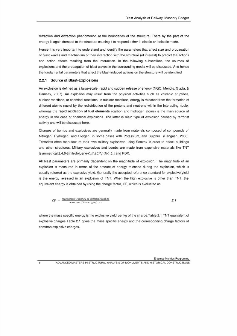
where the mass specific energy is the explosive yield per kg of the charge.Table 2.1 TNT equivalent of
explosive charges.Table 2.1 gives the mass specific energy and the corresponding charge factors of
common explosive charges.
8/3/2019 Tibebu Hunegn Birhane- Blast Analysis of Railway Masonry Bridges
http://slidepdf.com/reader/full/tibebu-hunegn-birhane-blast-analysis-of-railway-masonry-bridges 24/134
Blast Analysis of Railway Masonry Bridges
Erasmus Mundus Programme
ADVANCED MASTERS IN STRUCTURAL ANALYSIS OF MONUMENTS AND HISTORICAL CONSTRUCTIONS 7
Table 2.1 TNT equivalent of explosive charges.
Explosives Mass specific energy (kJ/kg) TNT equivalent (CF)
TNT 4520 1.00
GDN (glycol dinitrate) 7232 1.60
Pyroxilene 4746 1.05
Pentrinite 6689.6 1.48
Dynamite 5876 1.30
Schneiderite 3164 0.70
Dinitrotoluene (DNT) 3164 0.70
Ethylenedinitramine 5650 1.25*
Compound B (0.6RDX+0.4TNT) 5190 1.148
RDX (cyclonite) 5360 1.185
HMX 5650 1.256
Semtex 5660 1.25*
Dentolite 50/50 - 1.129
DENT - 1.282
* Identical
The charge factor is used to express the mass of explosive charges in terms of an equivalent TNT
mass, which indirectly represents the yield of an explosive device. This is an important parameter
which is used to describe the effect of source type on the induced blast waves. Based on the amount
of charge they contain, explosives devices are categorized as small, medium and high or large
(Bangash, 2006) as shown in Table 2.1Table 2.2.
Table 2.2 Size category of explosive devices
Explosive category Amount of charge, W (kg TNT)
Small 5≤
Medium 55 ≤<W
Large 10020 ≤<W
Very large 2500100 ≤<W
8/3/2019 Tibebu Hunegn Birhane- Blast Analysis of Railway Masonry Bridges
http://slidepdf.com/reader/full/tibebu-hunegn-birhane-blast-analysis-of-railway-masonry-bridges 25/134
Blast Analysis of Railway Masonry Bridges
Erasmus Mundus Programme
8 ADVANCED MASTERS IN STRUCTURAL ANALYSIS OF MONUMENTS AND HISTORICAL CONSTRUCTIONS
2.2.2 Blast-wave propagation
An explosion may occur in the air and on or below the ground surface. When a bomb explodes, a
rapid release of stored energy is characterized by an audible blast. The energy released is divided into
two distinct phenomena – thermal radiation, and mechanical wave propagating in air and/or soil,
known as air blast and ground shock , respectively. The detonation of a condensed high explosive
generates hot gases under pressure up to 300 kilo bar and a temperature of about 3000-4000C°
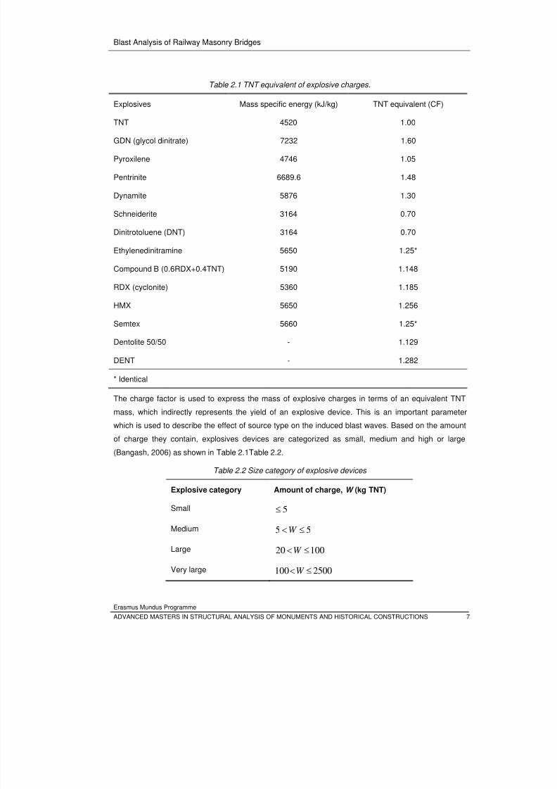
(Bangash, 2006). The hot gas expands forcing out the volume it occupies (see Figure 2.1). If the burst
occurs in air, a layer of compressed air (blast wave) forms in front of this gas volume containing most
of the energy released by the explosion. On the other hand when a charge is located below the
surface, the explosion causes vibrations of the particles of the ground medium resulting in propagation
of stress waves in the longitudinal direction.
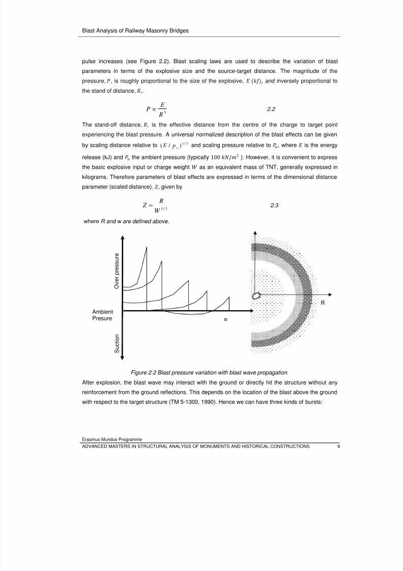
As the blast wave propagates away from source of explosion, it increases air pressure to a value
above the ambient atmospheric pressure. This is referred to as the side-on overpressure that decays
as the shock wave expands outward from the explosion source. After a short time, the pressure
behind the front may drop below the ambient pressure (see Figure 2.2 and Figure 2.10). During such a
negative phase, a partial vacuum is created and air is sucked in. This is also accompanied by high
suction winds that carry the debris for long distances away from the explosion source.
Figure 2.1 Blasting process of explosive charge.
All blast parameters are primarily dependent on the amount of energy released by a detonation in the
form of a blast wave and the distance from the explosion. As the blast pressure expands spherically
outward from the source, the peak over-pressure of the shock decrease where as the duration of the
Explosive chargeCasingShock wave Rarefaction
a) Encased explosivecharge b) Detonation of
explosive chargec) Propagation of blast
wave
8/3/2019 Tibebu Hunegn Birhane- Blast Analysis of Railway Masonry Bridges
http://slidepdf.com/reader/full/tibebu-hunegn-birhane-blast-analysis-of-railway-masonry-bridges 26/134
Blast Analysis of Railway Masonry Bridges
Erasmus Mundus Programme
ADVANCED MASTERS IN STRUCTURAL ANALYSIS OF MONUMENTS AND HISTORICAL CONSTRUCTIONS 9
pulse increases (see Figure 2.2). Blast scaling laws are used to describe the variation of blast
parameters in terms of the explosive size and the source-target distance. The magnitude of the
pressure, , is roughly proportional to the size of the explosive, , and i nversely proportional to
the stand of distance, ,.
3 R
E P ∝ 2.2
The stand-off distance, , is the effective distance from the centre of the charge to target point
experiencing the blast pressure. A universal normalized description of the blast effects can be given
by scaling distance relative to 3 / 1) / ( o p E and scaling pressure relative to , where is the energy
release (kJ) and the ambient pressure (typically 100 / ). However, it is convenient to express
the basic explosive input or charge weight as an equivalent mass of TNT, generally expressed in
kilograms. Therefore parameters of blast effects are expressed in terms of the dimensional distance
parameter (scaled distance), , given by
3 / 1W
R Z = 2.3
where R and w are defined above.
Figure 2.2 Blast pressure variation with blast wave propagation.
After explosion, the blast wave may interact with the ground or directly hit the structure without any
reinforcement from the ground reflections. This depends on the location of the blast above the ground
with respect to the target structure (TM 5-1300, 1990). Hence we can have three kinds of bursts:
R
O v e r p
r e s s u r e
AmbientPresure
S u c t i o n
8/3/2019 Tibebu Hunegn Birhane- Blast Analysis of Railway Masonry Bridges
http://slidepdf.com/reader/full/tibebu-hunegn-birhane-blast-analysis-of-railway-masonry-bridges 27/134
Blast Analysis of Railway Masonry Bridges
Erasmus Mundus Programme
10 ADVANCED MASTERS IN STRUCTURAL ANALYSIS OF MONUMENTS AND HISTORICAL CONSTRUCTIONS
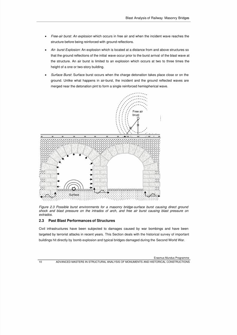
• Free-air burst: An explosion which occurs in free air and when the incident wave reaches the
structure before being reinforced with ground reflections.
• Air- burst Explosion : An explosion which is located at a distance from and above structures so
that the ground reflections of the initial wave occur prior to the burst arrival of the blast wave at
the structure. An air burst is limited to an explosion which occurs at two to three times the
height of a one or two-story building.
• Surface Burst : Surface burst occurs when the charge detonation takes place close or on the
ground. Unlike what happens in air-burst, the incident and the ground reflected waves are
merged near the detonation pint to form a single reinforced hemispherical wave.
Figure 2.3 Possible burst environments for a masonry bridge-surface burst causing direct ground shock and blast pressure on the intrados of arch, and free air burst causing blast pressure on
extrados.
2.3 Past Blast Performances of Structures
Civil infrastructures have been subjected to damages caused by war bombings and have been
targeted by terrorist attacks in recent years. This Section deals with the historical survey of important
buildings hit directly by bomb explosion and typical bridges damaged during the Second World War.
Free airbrust
R
R
Surface
8/3/2019 Tibebu Hunegn Birhane- Blast Analysis of Railway Masonry Bridges
http://slidepdf.com/reader/full/tibebu-hunegn-birhane-blast-analysis-of-railway-masonry-bridges 28/134
Blast Analysis of Railway Masonry Bridges
Erasmus Mundus Programme
ADVANCED MASTERS IN STRUCTURAL ANALYSIS OF MONUMENTS AND HISTORICAL CONSTRUCTIONS 11
It has been noted that structural continuity, structural ductility and structural damping improves the
blast performance of structures (Bangash, 2006) and (Bulson, 1997). Reinforced concrete structures
have more mass, more damping and better energy-absorbing capacity to withstand action effects from
explosions. Civil masonry and brick structures were known to have relatively little resistance to localexplosions, and in earlier times no attempt was made to predict how they might behave under attack,
or what their residual strength might be. Masonry and stone were not employed much in the
construction of ‘bomb-proof’ shelters once reinforced concrete appeared on the structural scene
(Bulson, 1997).
2.3.1 Explosives and Impactors used for Terrorist Activity
The most serious terrorist threat against civilian structures has been the use of explosives to detonate
inside the building, a large external explosion near the structure and aircrafts to impact the structure.
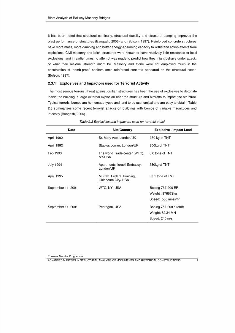
Typical terrorist bombs are homemade types and tend to be economical and are easy to obtain. Table
2.3 summarizes some recent terrorist attacks on buildings with bombs of variable magnitudes and
intensity (Bangash, 2006).
Table 2.3 Explosives and impactors used for terrorist attack
Date Site/Country Explosive /Impact Load
April 1992 St. Mary Axe, London/UK 350 kg of TNT
April 1992 Staples corner, London/UK 300kg of TNT
Feb 1993 The world Trade center (WTC),NY/USA
0.6 tone of TNT
July 1994 Apartments, Israeli Embassy,London/UK
350kg of TNT
April 1995 Murrah Federal Building,Oklahoma City/ USA
33.1 tone of TNT
September 11, 2001 WTC, NY, USA Boeing 767-200 ER
Weight : 376672kg
Speed: 530 miles/hr
September 11, 2001 Pentagon, USA Boeing 757-200 aircraft
Weight: 82.34 MNSpeed: 240 m/s
8/3/2019 Tibebu Hunegn Birhane- Blast Analysis of Railway Masonry Bridges
http://slidepdf.com/reader/full/tibebu-hunegn-birhane-blast-analysis-of-railway-masonry-bridges 29/134
Blast Analysis of Railway Masonry Bridges
Erasmus Mundus Programme
12 ADVANCED MASTERS IN STRUCTURAL ANALYSIS OF MONUMENTS AND HISTORICAL CONSTRUCTIONS
2.3.2 Buildings Damaged by Terrorist attack
A bomb explosion within or around a building can have catastrophic effects, damaging and destroying
internal or external portions of the building. It blows out large framework, walls and doors/windows and
shuts down building services. The impact from the blast causes debris, fire and smoke and hence can
result in injury and death to occupants. Typical building damages caused by terrorist attacks are
presented below.
The Alfred P. Murrah Federal Building
In April 1995, the bombing of the Alfred P. Murrah Federal Building in Oklahoma City was one of the
largest terrorist attacks in the USA. A car bomb, estimated to contain about 1800 kg of high explosives
and located 3–5m from the north face of the building and about 12–15m from the east end, caused
168 fatalities and numerous injuries, and caused an estimated $50 million in damage (Bangash,
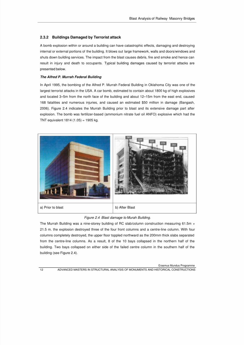
2006). Figure 2.4 indicates the Murrah Building prior to blast and its extensive damage part after
explosion. The bomb was fertilizer-based (ammonium nitrate fuel oil ANFO) explosive which had the
TNT equivalent 1814 (1.05) = 1905 kg.
a) Prior to blast b) After Blast
Figure 2.4 Blast damage to Murah Building.
The Murrah Building was a nine-storey building of RC slab/column construction measuring 61.5m ×
21.5 m. the explosion destroyed three of the four front columns and a centre-line column. With four
columns completely destroyed, the upper floor toppled northward as the 200mm thick slabs separated
from the centre-line columns. As a result, 8 of the 10 bays collapsed in the northern half of the
building. Two bays collapsed on either side of the failed centre column in the southern half of the
building (see Figure 2.4).
8/3/2019 Tibebu Hunegn Birhane- Blast Analysis of Railway Masonry Bridges
http://slidepdf.com/reader/full/tibebu-hunegn-birhane-blast-analysis-of-railway-masonry-bridges 30/134
Blast Analysis of Railway Masonry Bridges
Erasmus Mundus Programme
ADVANCED MASTERS IN STRUCTURAL ANALYSIS OF MONUMENTS AND HISTORICAL CONSTRUCTIONS 13
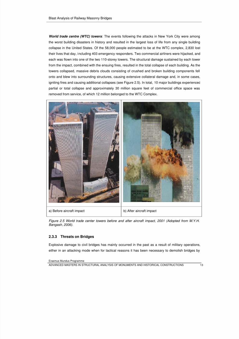
World trade centre (WTC) towers : The events following the attacks in New York City were among
the worst building disasters in history and resulted in the largest loss of life from any single building
collapse in the United States. Of the 58,000 people estimated to be at the WTC complex, 2,830 lost
their lives that day, including 403 emergency responders. Two commercial airliners were hijacked, andeach was flown into one of the two 110-storey towers. The structural damage sustained by each tower
from the impact, combined with the ensuing fires, resulted in the total collapse of each building. As the
towers collapsed, massive debris clouds consisting of crushed and broken building components fell
onto and blew into surrounding structures, causing extensive collateral damage and, in some cases,
igniting fires and causing additional collapses (see Figure 2.5). In total, 10 major buildings experienced
partial or total collapse and approximately 30 million square feet of commercial office space was
removed from service, of which 12 million belonged to the WTC Complex.
a) Before aircraft impact b) After aircraft impact
Figure 2.5 World trade center towers before and after aircraft impact, 2001 (Adopted from M.Y.H.Bangash, 2006).
2.3.3 Threats on Bridges
Explosive damage to civil bridges has mainly occurred in the past as a result of military operations,
either in an attacking mode when for tactical reasons it has been necessary to demolish bridges by
8/3/2019 Tibebu Hunegn Birhane- Blast Analysis of Railway Masonry Bridges
http://slidepdf.com/reader/full/tibebu-hunegn-birhane-blast-analysis-of-railway-masonry-bridges 31/134
Blast Analysis of Railway Masonry Bridges
Erasmus Mundus Programme
14 ADVANCED MASTERS IN STRUCTURAL ANALYSIS OF MONUMENTS AND HISTORICAL CONSTRUCTIONS
bombing, artillery shells, rockets or cruise missiles; or in a defensive situation where the demolition of
a bridge prevented the enemy from advancing along a planned route (Bulson, 1997). Defensive
demolition was normally carried out by the emplacement of cutting charges on selected bridge
members. Instances have been recorded of damage due to terrorist activities, mainly relatively slightdamage to decks and truss members. For example the damage of the Tila Bund bridge of Pakistan
caused for the death of 80 people (Bangash, 2006).
One of the most informative investigations into bomb damage (from aerial bombs) on large civil
bridges was made by a UK Ministry of Home Security team in 1944 for the British Bombing Research
Mission. The Bombing Research Mission ascertained the effect of bombs of known weight across the
Seine between Paris and Rouen. Ten railway girder bridges, nine railway arches, five road girders and
three road arches were examined. Many of the bridges (the majority were rail bridges) were damaged
three times during the Second World War; firstly when the French authorities demolished parts of
bridges in 1940, secondly by the very severe bombing in mid-1944, and thirdly by the German armyduring the retreat from Normandy and Northern France in the autumn of 1944. In terms of residual
strength, rapid repair and speedy re-use, some of the bridges examined provide useful information.
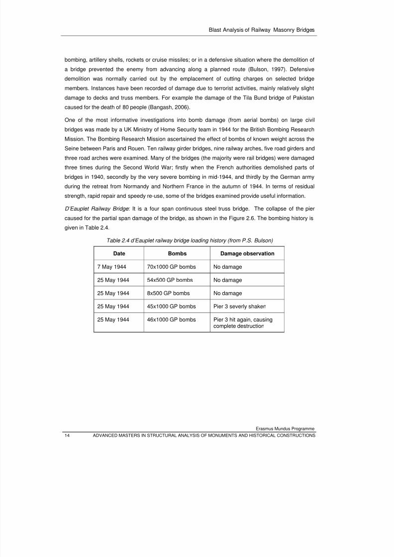
D’Eauplet Railway Bridge : It is a four span continuous steel truss bridge. The collapse of the pier
caused for the partial span damage of the bridge, as shown in the Figure 2.6. The bombing history is
given in Table 2.4.
Table 2.4 d’Eauplet railway bridge loading history (from P.S. Bulson)
Date Bombs Damage observation
7 May 1944 70x1000 GP bombs No damage
25 May 1944 54x500 GP bombs No damage
25 May 1944 8x500 GP bombs No damage
25 May 1944 45x1000 GP bombs Pier 3 severly shaken
25 May 1944 46x1000 GP bombs Pier 3 hit again, causingcomplete destruction
8/3/2019 Tibebu Hunegn Birhane- Blast Analysis of Railway Masonry Bridges
http://slidepdf.com/reader/full/tibebu-hunegn-birhane-blast-analysis-of-railway-masonry-bridges 32/134
Blast Analysis of Railway Masonry Bridges
Erasmus Mundus Programme
ADVANCED MASTERS IN STRUCTURAL ANALYSIS OF MONUMENTS AND HISTORICAL CONSTRUCTIONS 15
Figure 2.6 Bomb damage of d’Eauplet railway steel bridge, 1944 (from P.S. Bulson)
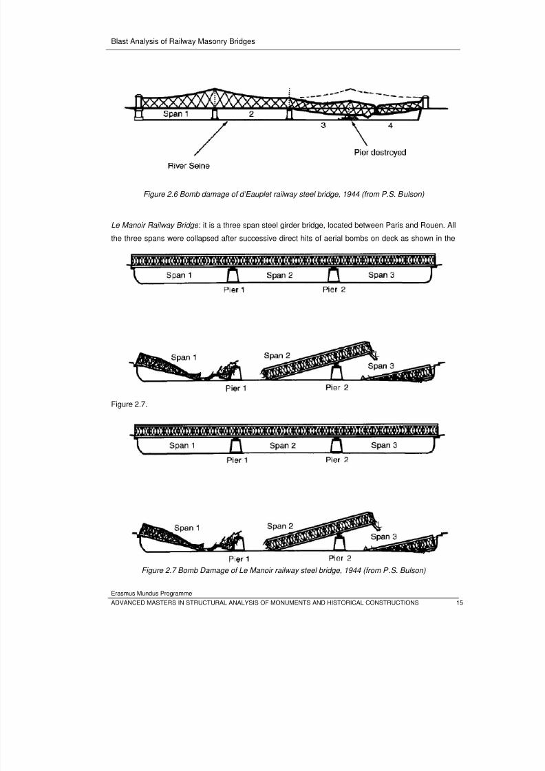
Le Manoir Railway Bridge : it is a three span steel girder bridge, located between Paris and Rouen. All
the three spans were collapsed after successive direct hits of aerial bombs on deck as shown in the
Figure 2.7.
Figure 2.7 Bomb Damage of Le Manoir railway steel bridge, 1944 (from P.S. Bulson)
8/3/2019 Tibebu Hunegn Birhane- Blast Analysis of Railway Masonry Bridges
http://slidepdf.com/reader/full/tibebu-hunegn-birhane-blast-analysis-of-railway-masonry-bridges 33/134
Blast Analysis of Railway Masonry Bridges
Erasmus Mundus Programme
16 ADVANCED MASTERS IN STRUCTURAL ANALYSIS OF MONUMENTS AND HISTORICAL CONSTRUCTIONS
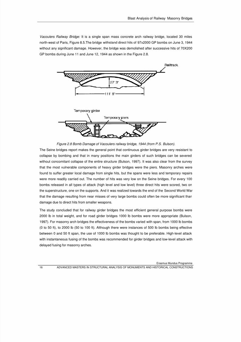
Vacoulers Railway Bridge: It is a single span mass concrete arch railway bridge, located 30 miles
north-west of Paris, Figure 8.5.The bridge withstand direct hits of 97x2000 GP bombs on June 3, 1944
without any significant damage. However, the bridge was demolished after successive hits of 70X200
GP bombs during June 11 and June 12, 1944 as shown in the Figure 2.8.
Figure 2.8 Bomb Damage of Vacoulers railway bridge, 1944 (from P.S. Bulson).
The Seine bridges report makes the general point that continuous girder bridges are very resistant to
collapse by bombing and that in many positions the main girders of such bridges can be severed
without concomitant collapse of the entire structure (Bulson, 1997). It was also clear from the survey
that the most vulnerable components of heavy girder bridges were the piers. Masonry arches were
found to suffer greater local damage from single hits, but the spans were less and temporary repairs
were more readily carried out. The number of hits was very low on the Seine bridges. For every 100
bombs released in all types of attack (high level and low level) three direct hits were scored, two on
the superstructure, one on the supports. And it was realized towards the end of the Second World War
that the damage resulting from near misses of very large bombs could often be more significant than
damage due to direct hits from smaller weapons.
The study concluded that for railway girder bridges the most efficient general purpose bombs were
2000 lb in total weight, and for road girder bridges 1000 lb bombs were more appropriate (Bulson,
1997). For masonry arch bridges the effectiveness of the bombs varied with span, from 1000 lb bombs
(0 to 50 ft), to 2000 lb (50 to 100 ft). Although there were instances of 500 lb bombs being effective
between 0 and 50 ft span, the use of 1000 lb bombs was thought to be preferable. High-level attack
with instantaneous fusing of the bombs was recommended for girder bridges and low-level attack with
delayed fusing for masonry arches.
8/3/2019 Tibebu Hunegn Birhane- Blast Analysis of Railway Masonry Bridges
http://slidepdf.com/reader/full/tibebu-hunegn-birhane-blast-analysis-of-railway-masonry-bridges 34/134
Blast Analysis of Railway Masonry Bridges
Erasmus Mundus Programme
ADVANCED MASTERS IN STRUCTURAL ANALYSIS OF MONUMENTS AND HISTORICAL CONSTRUCTIONS 17
2.4 Blast Load Specification
The energy release associated to detonation of an explosive charge causes
• to fragment the casing of the bomb and to shot the fragments,
• to shock the surrounding air and to create a propagating air-blast wave, and
• to generate ground shock waves.
Hence if a structure stands nearby the detonation, it will trap the energy released from the detonation
from the interaction with either of the above listed energy carriers. In other words at least three types
of loading actions must be considered to estimate the response of the structure from nearby or hit on
explosion:
o impulse load or pressure pulse from air-blast wave,
o impact load from striking fragments, and
o base excitation from ground shock.
The aforementioned actions may give either a local or global response (damage) to the structure.
The severity of the structural action effects from explosions depends on the following parameters (TM
5-1300, 1990):
1. The magnitude of the explosion-the energy release during explosion which is described in
terms of charge weight in an equivalent TNT
2. Charge location-the location of the explosion with respect to the structure (stand-off distance)
and with respect to the ground affects the intensity of blast waves, ground shock waves and
target velocity of the fragments.
3. The size and configuration of the structure: the sensitivity of the structure to respond globally
or locally. It also affects the spatial distribution of the blast pressure on the structure.
4. The characteristics of the ground. This influences the blast pressure because of ground
reflections and it affects kinematic characteristics of the shock waves propagating to the
ground.
In the following Sub sections the quantification of actions on structures due to explosions will be
reviewed.
2.4.1 Blast-Air Pressure Pulse
When high explosive detonates in a free air or above ground surface, a blast wave with a pressure
front propagates in to a surrounding atmosphere. When this wave reaches to a structure, the wave
front either reflects back or diffracts around the corners of the structure. During this interaction, the
energy carried by the blast wave is tracked by the structure partially and deformed wave continues
8/3/2019 Tibebu Hunegn Birhane- Blast Analysis of Railway Masonry Bridges
http://slidepdf.com/reader/full/tibebu-hunegn-birhane-blast-analysis-of-railway-masonry-bridges 35/134
Blast Analysis of Railway Masonry Bridges
Erasmus Mundus Programme
18 ADVANCED MASTERS IN STRUCTURAL ANALYSIS OF MONUMENTS AND HISTORICAL CONSTRUCTIONS
propagation passing the structure. For uncoupled analysis, the effect of this interaction on the
structure under consideration is represented by blast pressures. For any given set of free-field blast
induced pressure pulses, the forces imparted to an above-ground structure can be divided in to four
general components (Bangash, 2006):
• The force resulting from the incident pressure,
• The force associated with the dynamic pressure,
• The force resulting from the reflection of the incident pressure impinging upon an interfacing
surface, and
• The pressure associated with the negative phase of the blast wave.
The relative significance of these parameters is dependent upon the geometrical configuration and the
size of the structure, the orientation of the structure relative to the shock front, and the design purpose
of the blast loads (TM 5-1300, 1990).
A blast load may be specified as an impulse rather than a pressure pulse (pressure time history) only if
the duration of the applied pressure acting on the structure is shorter in comparison to its relative
response time. However, if the time to reach maximum displacement is equal to or less than three
times the load duration, the pressure pulse should be used for these cases (TM 5-1300, 1990).
The actual pressure-time relationship (pulse) resulting from a pressure distribution on a structure is
highly irregular because of the multiple reflections, diffractions and time phasing, as shown inFigure
2.9. The net blast pressure pulse acting on the structure is given as a superposition of the incident,
reflected and dynamic drag pressure. For simplicity of load specification, the pressure time relationship
may be approximated by equivalent triangular pulse (TM 1300)
8/3/2019 Tibebu Hunegn Birhane- Blast Analysis of Railway Masonry Bridges
http://slidepdf.com/reader/full/tibebu-hunegn-birhane-blast-analysis-of-railway-masonry-bridges 36/134
Blast Analysis of Railway Masonry Bridges
Erasmus Mundus Programme
ADVANCED MASTERS IN STRUCTURAL ANALYSIS OF MONUMENTS AND HISTORICAL CONSTRUCTIONS 19
Figure 2.9 Blast wave propagation across a stone masonry arch section-surface brust.
Incident Blast Pressure :
The blast wave resulting from a detonation of an uncased charge in ‘‘free air’’, i.e. distant from the
nearest reflecting surface, is well known and often consists of compressed air front and a zone of
rarefaction (vacuum formation). This is idealized by a presure pulse consisting a positive and negativephases as shown in Figure 2.10.
At the arrival time of the pressure front , following the explosion, pressure at that position suddenly
increases to a peak value of overpressure, , over the ambient pressure, . The pressure then
decays to ambient level at time , then decays further to an under pressure (creating a partial
vacuum) before eventually returning to ambient conditions. The quantity is usually referred to as
the peak side-on overpressure, incident peak overpressure or merely peak overpressure (TM 5-1300,
1990). Generally the ambient pressure is equal to 1bar (100/) (Bangash).
Generally the over-pressure, , at time ‘t ’ after the arrival of the shock front is given by Friedlander
Formulation (TM 5-1300, 1990) as:
1 2.4
Where , and are defined above, and is a shape parameter depending on the dimensionless
scaled distance . It has been shown that the parameter ranges from 0.1 to 10 (Gantes &
Pnevmatikos, 2004). If is smaller than one, there is an important negative phase, while for larger
Incident blast wave
Refracted
Deformed blast wave
Reflected blast wave
Vortices
8/3/2019 Tibebu Hunegn Birhane- Blast Analysis of Railway Masonry Bridges
http://slidepdf.com/reader/full/tibebu-hunegn-birhane-blast-analysis-of-railway-masonry-bridges 37/134
Blast Analysis of Railway Masonry Bridges
Erasmus Mundus Programme
20 ADVANCED MASTERS IN STRUCTURAL ANALYSIS OF MONUMENTS AND HISTORICAL CONSTRUCTIONS
than one the negative phase becomes less significant. The value 1 is a reasonable average Value
which is supported by experimental evidence. This value corresponds to positive phase impulse
equals to that of the negative phase.
A full discussion and extensive charts for predicting blast pressures and blast durations are given by
TM5-1300 (1990). However empirical expressions by different authors are presented as follows.
For a high explosive charge detonating at the ground surface, the maximum blast overpressure, , in
bars can be calculated using Newmark and Hansen (1961) relationship as (NGO et. al, 2007):
6784 93
/
2.5
Figure 2.10 Incident blast pressure pulse (pressure time history).
The positive phase pulse duration, , which was proposed by Kinney and Graham
(1985) as a function of scaled distance, //, is given as ( Pandy et.al, 2006):
/
.
.
.
.
2.6
The impulse of the incident pressures associated with the blast wave is the integrated area under the
pressure-time curve. Consequently, the positive phase impulse , is defined as follows:
2.7
where and are arrival time and positive phase duration of blast wave.
si , Positive
specific impulse
−
si , Negative
specific impulse
At
0t t A +
−++ 00 t t t A
soP
(Peak over
pressure)
Ambient, oP
−
soP
(Peak suction) Positive
Phase
Negative Phase Duration
)(t Ps
t
8/3/2019 Tibebu Hunegn Birhane- Blast Analysis of Railway Masonry Bridges
http://slidepdf.com/reader/full/tibebu-hunegn-birhane-blast-analysis-of-railway-masonry-bridges 38/134
Blast Analysis of Railway Masonry Bridges
Erasmus Mundus Programme
ADVANCED MASTERS IN STRUCTURAL ANALYSIS OF MONUMENTS AND HISTORICAL CONSTRUCTIONS 21
The duration of the negative phase is longer than the positive phase, but the amplitude of the negative
pressure is limited by the ambient pressure, , and is often small compared to the peak overpressure,
. However, in design with regard to explosions the negative phase is considered less important
than the positive phase and is therefore often disregarded (TM 5-1300, 1990).
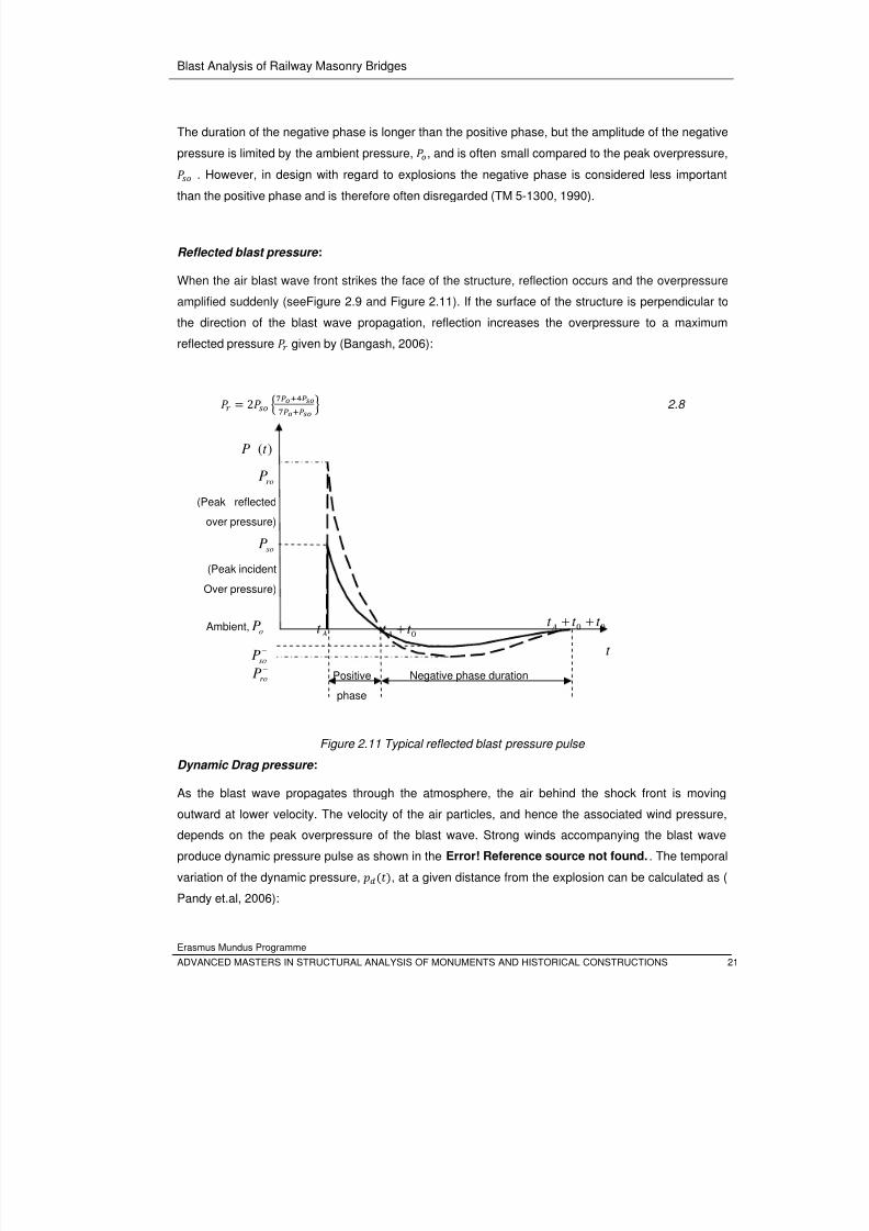
Reflected blast pressure :
When the air blast wave front strikes the face of the structure, reflection occurs and the overpressure
amplified suddenly (seeFigure 2.9 and Figure 2.11). If the surface of the structure is perpendicular to
the direction of the blast wave propagation, reflection increases the overpressure to a maximum
reflected pressure given by (Bangash, 2006):
2 2.8
Figure 2.11 Typical reflected blast pressure pulse
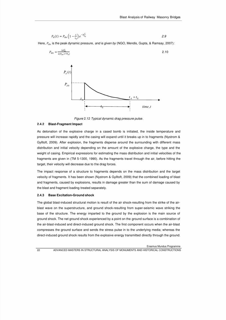
Dynamic Drag pressure :
As the blast wave propagates through the atmosphere, the air behind the shock front is moving
outward at lower velocity. The velocity of the air particles, and hence the associated wind pressure,
depends on the peak overpressure of the blast wave. Strong winds accompanying the blast wave
produce dynamic pressure pulse as shown in the Error! Reference source not found.. The temporal
variation of the dynamic pressure, , at a given distance from the explosion can be calculated as (
Pandy et.al, 2006):
At 0t t A +
−++
00 t t t A
Positive
phase
Negative phase duration
t
soP
(Peak incident
Over pressure)
Ambient,oP
−
soP
)(t P
−
roP
roP
(Peak reflected
over pressure)
8/3/2019 Tibebu Hunegn Birhane- Blast Analysis of Railway Masonry Bridges
http://slidepdf.com/reader/full/tibebu-hunegn-birhane-blast-analysis-of-railway-masonry-bridges 39/134
Blast Analysis of Railway Masonry Bridges
Erasmus Mundus Programme
22 ADVANCED MASTERS IN STRUCTURAL ANALYSIS OF MONUMENTS AND HISTORICAL CONSTRUCTIONS
1
2.9
Here, is the peak dynamic pressure, and is given by (NGO, Mendis, Gupta, & Ramsay, 2007):
2.10
Figure 2.12 Typical dynamic drag pressure pulse .
2.4.2 Blast-Fragment Impact
As detonation of the explosive charge in a cased bomb is initiated, the inside temperature and
pressure will increase rapidly and the casing will expand until it breaks up in to fragments (Nystrom &
Gylltoft, 2009). After explosion, the fragments disperse around the surrounding with different mass
distribution and initial velocity depending on the amount of the explosive charge, the type and the
weight of casing. Empirical expressions for estimating the mass distribution and initial velocities of thefragments are given in (TM 5-1300, 1990). As the fragments travel through the air, before hitting the
target, their velocity will decrease due to the drag forces.
The impact response of a structure to fragments depends on the mass distribution and the target
velocity of fragments. It has been shown (Nystrom & Gylltoft, 2009) that the combined loading of blast
and fragments, caused by explosions, results in damage greater than the sum of damage caused by
the blast and fragment loading treated separately.
2.4.3 Base Excitation-Ground shock
The global blast-induced structural motion is result of the air shock-resulting from the strike of the air-
blast wave on the superstructure, and ground shock-resulting from super-seismic wave striking the
base of the structure. The energy imparted to the ground by the explosion is the main source of
ground shock. The net ground shock experienced by a point on the ground surface is a combination of
the air-blast-induced and direct-induced ground shock. The first component occurs when the air-blast
compresses the ground surface and sends the stress pulse in to the underlying media; whereas the
direct-induced ground shock results from the explosive energy transmitted directly through the ground.
At
t time,
0t t A +
0d P
)(t Pd
0t
8/3/2019 Tibebu Hunegn Birhane- Blast Analysis of Railway Masonry Bridges
http://slidepdf.com/reader/full/tibebu-hunegn-birhane-blast-analysis-of-railway-masonry-bridges 40/134
Blast Analysis of Railway Masonry Bridges
Erasmus Mundus Programme
ADVANCED MASTERS IN STRUCTURAL ANALYSIS OF MONUMENTS AND HISTORICAL CONSTRUCTIONS 23
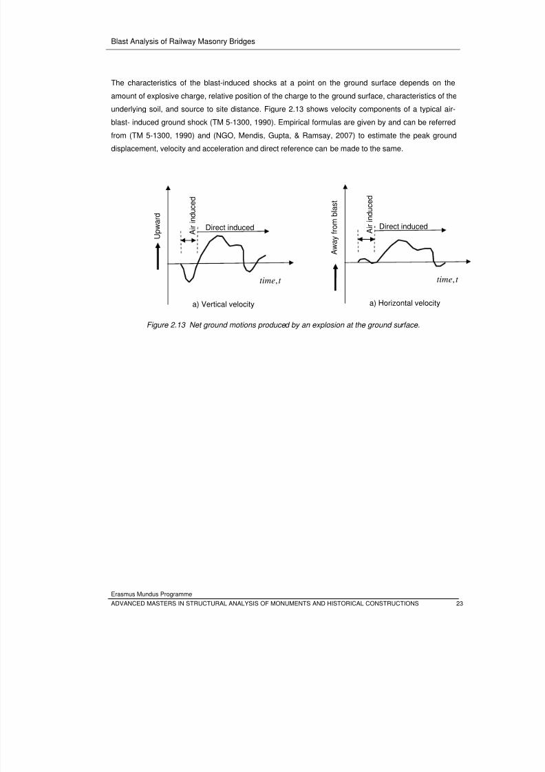
The characteristics of the blast-induced shocks at a point on the ground surface depends on the
amount of explosive charge, relative position of the charge to the ground surface, characteristics of the
underlying soil, and source to site distance. Figure 2.13 shows velocity components of a typical air-
blast- induced ground shock (TM 5-1300, 1990). Empirical formulas are given by and can be referredfrom (TM 5-1300, 1990) and (NGO, Mendis, Gupta, & Ramsay, 2007) to estimate the peak ground
displacement, velocity and acceleration and direct reference can be made to the same.
Figure 2.13 Net ground motions produced by an explosion at the ground surface.
Direct induced A i r i n d u c e d
U p w a r d
t time,
a) Vertical velocity
Direct induced A i r i n d u c e d
A w
a y f r o m b
l a s t
t time,
a) Horizontal velocity

8/3/2019 Tibebu Hunegn Birhane- Blast Analysis of Railway Masonry Bridges
http://slidepdf.com/reader/full/tibebu-hunegn-birhane-blast-analysis-of-railway-masonry-bridges 41/134
Blast Analysis of Railway Masonry Bridges
Erasmus Mundus Programme
24 ADVANCED MASTERS IN STRUCTURAL ANALYSIS OF MONUMENTS AND HISTORICAL CONSTRUCTIONS
8/3/2019 Tibebu Hunegn Birhane- Blast Analysis of Railway Masonry Bridges
http://slidepdf.com/reader/full/tibebu-hunegn-birhane-blast-analysis-of-railway-masonry-bridges 42/134
Blast Analysis of Railway Masonry Bridges
Erasmus Mundus Programme
ADVANCED MASTERS IN STRUCTURAL ANALYSIS OF MONUMENTS AND HISTORICAL CONSTRUCTIONS 25
CHAPTER 3
QUASI-STATIC PERFORMANCE OF
STONE MASONRY BRIDGES: SINGLE SPAN ARCH
3.1 General
The main purpose of this Chapter is to assess the quasi-static capacity of a single span
stone masonry arch. In order to investigate whether or not a dynamic enhancement existed
at global label, it is necessary to predict the quasi-static force deformation capacity of astructure. Moreover, this assessment gives a bound to the energy absorbing capacity of the
arch, the peak static strength, and both pre-peak and post- peak effective stiffness of the
structure.
Hence with this aim, a prototype single span masonry arch was designed and its capacity
was assessed both experimentally and numerically. The geometric design process was
based on the dimensional-constraints of the lab and the same was aided by limit analysis
using RING to have best efficient arch. Further a non-linear static FE analysis, using discrete
interface model, was carried out to predict the failure mode in advance of the experimental
work. A quasi-static experimental test was conducted on the arch and the force deformation
behaviour of the arch was obtained.
Joint interface properties play a major role in numerical assessment of masonry stone
bridges; therefore the influence of these parameters is addressed in this Chapter. A
sensitivity numerical analysis was carried out to figure out the range of values that gives
similar global behaviour of the arch from both numerical and experimental simulations.
3.2 Design of the Prototype Arch
A prototype stone masonry arch was designed primarily for impact response simulation.
However the same arch was adopted for quasi-static tests too. For this reason, the global
dimensions of the arch were fixed based on the geometric constraints of the drop-weight
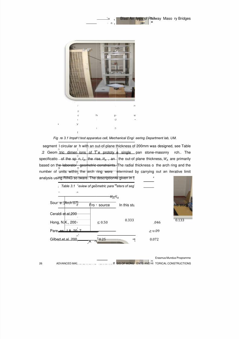
apparatus cell, see Figure 3.1.
8/3/2019 Tibebu Hunegn Birhane- Blast Analysis of Railway Masonry Bridges
http://slidepdf.com/reader/full/tibebu-hunegn-birhane-blast-analysis-of-railway-masonry-bridges 43/134
26 A
Fig
segment
.2 Geom
specificatio
based on th
number of
analysis usi
Sour
Ceral
Hong
Pare
Gilbe
DVANCED MAS
re 3.1 Impa
l circular ar
tric dimen
of the sp
e laborator
units within
ng RING so
Table 3.1
e: [Arch’07]
di et.al,200
, N.K., 200
es, J.A.,20
rt et.al.,200
TERS IN STRU
t test appara
h with an o
ions of t
n, , the ri
geometric
the arch
tware. The
eview of geo
Fro
7
TURAL ANAL
tus cell, Mec
ut-of-plane
e prototy
se, , an
constraints.
ring were
description
metric para
/
source
0.50
0.25
Blast An
SIS OF MONU
hanical Engi
thickness of
e single
the out-of
The radial
etermined
is given in S
eters of seg
In this stu
0.333
lysis of Rail
ENTS AND HI
eering Depa
200mm wa
pan stone
plane thick
thickness o
by carrying
ection 3.4.
ental maso
dy From
1
0
0
0.0
lway Maso
Erasmus Mund
TORICAL CON
rtment lab, U
s designed,
-masonry
ness, ar
the arch ri
out an ite
ry arches.
/
ource In
/24
.046
.09
72
ry Bridges
us Programme
STRUCTIONS
M.
see Table
rch.. The
e primarily
ng and the
rative limit
his study
0.133
8/3/2019 Tibebu Hunegn Birhane- Blast Analysis of Railway Masonry Bridges
http://slidepdf.com/reader/full/tibebu-hunegn-birhane-blast-analysis-of-railway-masonry-bridges 44/134
Blast Analysis of Railway Masonry Bridges
Erasmus Mundus Programme
ADVANCED MASTERS IN STRUCTURAL ANALYSIS OF MONUMENTS AND HISTORICAL CONSTRUCTIONS 27
Moreover the radial thickness-span ratio, /, and the span-rise ratio, /, was adjusted
to conform to the ranges set from past experience, as shown in Table 3.1.
For the purpose of reusing the same units for different experimental arch set up, the stone
blocks were specified to be made from sound granitic rocks. The units are prefabricated by a
Voluntary Company, Artecanter , which is involved in production of granite stone products in
Guimaraes, Portugal. Even though a rotary sawing machine was used to cut out the units as
per the prescribed dimensions, their surfaces are not perfectly smooth.
Table 3.2 Geometric dimensions of the prototype single span stone-masonry arch.
Units No. of units Length[Thickness or Height ] [mm]
Intrados Extrados
Voussoirs 12 118 147
Key stone 1 115.5 144.5
Abutment (skew back) 2 400[65] 400 [127]
Rise of the arch, 400, Clear span of the arch, 1200 andsubtended angle of the arch = 135 degrees.
3.3 Quasi-Static Material Properties
The behaviour of masonry arches under quasi-static loads depends on the physical and
mechanical properties of the masonry units and that of the corresponding interface joints.
The quasi-static behaviour of masonry arches is described by the capacity curve which
shows the progressive deformation of the arch under incremental quasi-static load until the
formation of a structural mechanism. Masonry arches transfer the superimposed loads by
combined action of axial thrust and flexure. These action effects in turn induce compressive,
tensile and shear stresses distributed with different intensity among different sections of the
arch.
Hence the constituent material components of the arch should resist these stresses so as to
transmit the external applied load to the appropriate support without collapse of the arch. The
stress resisting capacity [Stress-strain profile and failure criteria] of masonry materials has
been characterized through experimental investigations (Vasconcelos, 2005) (Snyman, Bird,
& Martin, 1991) (Gilbert, Hobbs, & Molyneaux, 2002).
8/3/2019 Tibebu Hunegn Birhane- Blast Analysis of Railway Masonry Bridges
http://slidepdf.com/reader/full/tibebu-hunegn-birhane-blast-analysis-of-railway-masonry-bridges 45/134
Blast Analysis of Railway Masonry Bridges
Erasmus Mundus Programme
28 ADVANCED MASTERS IN STRUCTURAL ANALYSIS OF MONUMENTS AND HISTORICAL CONSTRUCTIONS
As the discussed in section 3.2, a segmental stone-masonry arch is taken for this study.
There by the arch is composed of stone blocks and joints which are either dry or mortared.
The stone blocks are made from typical granite found in Guimaraes, Portugal. Both physical
and mechanical characterization of the stone blocks and the joints are based on the previous
Ph.D.study by Vasconcelos. The material properties and failure criteria for stone masonry
units and joints are discused and reproduced in the following sections in acordance with the
required input form for the FEM software pakages.
3.3.1 Properties of Stone Blocks
The stone blocks adopted in this study were fabricated from granite rocks of Guimaraes,
Northern city of Portugal. Granitic stone is the most widely used construction masonry
material of ancient structures in Northern part of Portugal. Especially most of ancient
buildings from Guimaraes are made of dry jointed masonry.
The textural and mineralogical properties of granite rocks from Guimaraes are of types
ranging from fine to medium-grained biotitic. The mean density and the porosity of granite
stones from Guimaraes is given in Table 3.3. (Vasconcelos, 2005)
Table 3.3 Expected values of physical properties of granite stones from Guimaraes
Stone type Porosity (%) Expected Density
/
Dry Saturated
Fresh granite 0.47 2660 2665
Weathered granite 3.56 2579 2614
The mechanical characteristic of the stones is depicted from experimental campaign
conducted by University of Minho (Vasconcelos, 2005). These stones are found to be weak
and brittle in tension where as they are strong and brittle in compression. A typical stress
strain curve of such stones is shown in Figure 3.2 Typical uni-axial stress-strain behavior of
granite stone.Figure 3.2.
In the stone masonry arches, either with dry or mortar joints, the units are predominantly
subjected to compression stresses, which are well below the peak compressive strength of
the stone units, , . Whereas under tension, as the joints are weaker than the units, the
joints crack or form a gap in advance and hence give a tensile stress relief for the units. For
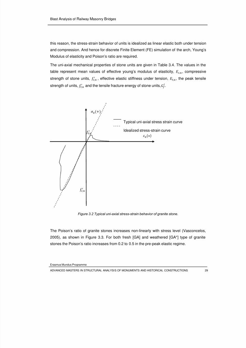
8/3/2019 Tibebu Hunegn Birhane- Blast Analysis of Railway Masonry Bridges
http://slidepdf.com/reader/full/tibebu-hunegn-birhane-blast-analysis-of-railway-masonry-bridges 46/134
Blast Analysis of Railway Masonry Bridges
Erasmus Mundus Programme
ADVANCED MASTERS IN STRUCTURAL ANALYSIS OF MONUMENTS AND HISTORICAL CONSTRUCTIONS 29
this reason, the stress-strain behavior of units is idealized as linear elastic both under tension
and compression. And hence for discrete Finite Element (FE) simulation of the arch, Young’s
Modulus of elasticity and Poison’s ratio are required.
The uni-axial mechanical properties of stone units are given in Table 3.4. The values in the
table represent mean values of effective young’s modulus of elasticity, ,, compressive
strength of stone units, , , effective elastic stiffness under tension, , , the peak tensile
strength of units, , and the tensile fracture energy of stone units,.
Figure 3.2 Typical uni-axial stress-strain behavior of granite stone.
The Poison’s ratio of granite stones increases non-linearly with stress level (Vasconcelos,
2005), as shown in Figure 3.3. For both fresh [GA] and weathered [GA*] type of granite
stones the Poison’s ratio increases from 0.2 to 0.5 in the pre-peak elastic regime.
(+) ,
,
Typical uni-axial stress strain curve
Idealized stress-strain curve
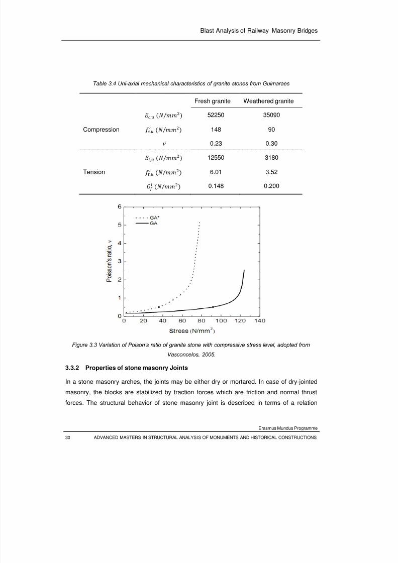
8/3/2019 Tibebu Hunegn Birhane- Blast Analysis of Railway Masonry Bridges
http://slidepdf.com/reader/full/tibebu-hunegn-birhane-blast-analysis-of-railway-masonry-bridges 47/134
Blast Analysis of Railway Masonry Bridges
Erasmus Mundus Programme
30 ADVANCED MASTERS IN STRUCTURAL ANALYSIS OF MONUMENTS AND HISTORICAL CONSTRUCTIONS
Table 3.4 Uni-axial mechanical characteristics of granite stones from Guimaraes
Fresh granite Weathered granite
, ⁄ 52250 35090
Compression . ⁄ 148 90
ν 0.23 0.30
, ⁄ 12550 3180
Tension
.
⁄ 6.01 3.52
⁄ 0.148 0.200
Figure 3.3 Variation of Poison’s ratio of granite stone with compressive stress level, adopted from
Vasconcelos, 2005.
3.3.2 Properties of stone masonry Joints
In a stone masonry arches, the joints may be either dry or mortared. In case of dry-jointed
masonry, the blocks are stabilized by traction forces which are friction and normal thrust
forces. The structural behavior of stone masonry joint is described in terms of a relation
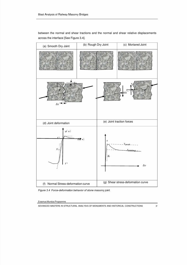
8/3/2019 Tibebu Hunegn Birhane- Blast Analysis of Railway Masonry Bridges
http://slidepdf.com/reader/full/tibebu-hunegn-birhane-blast-analysis-of-railway-masonry-bridges 48/134
Blast Analysis of Railway Masonry Bridges
Erasmus Mundus Programme
ADVANCED MASTERS IN STRUCTURAL ANALYSIS OF MONUMENTS AND HISTORICAL CONSTRUCTIONS 31
between the normal and shear tractions and the normal and shear relative displacements
across the interface [See Figure 3.4].
(a) Smooth Dry Joint(b) Rough Dry Joint (c) Mortared Joint
(d) Joint deformation(e) Joint traction forces
(f) Normal Stress-deformation curve(g) Shear stress-deformation curve
Figure 3.4 Force-deformation behavior of stone masonry joint.
+
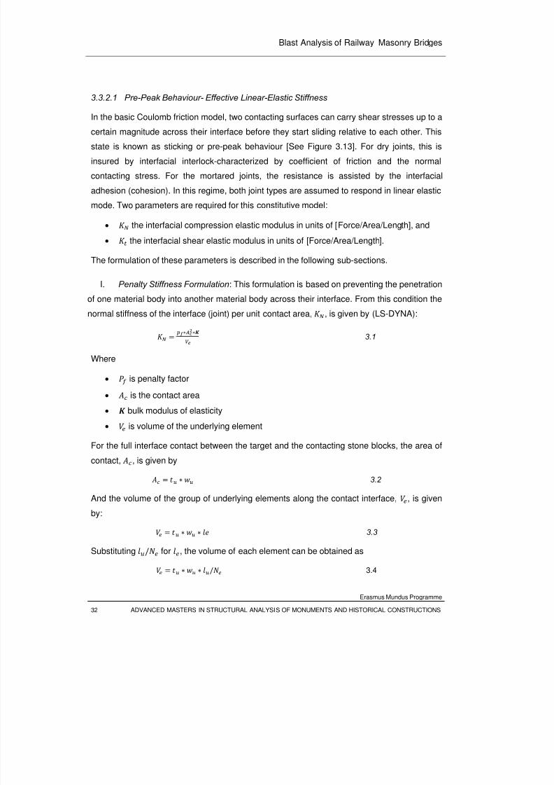
8/3/2019 Tibebu Hunegn Birhane- Blast Analysis of Railway Masonry Bridges
http://slidepdf.com/reader/full/tibebu-hunegn-birhane-blast-analysis-of-railway-masonry-bridges 49/134
Blast Analysis of Railway Masonry Bridges
Erasmus Mundus Programme
32 ADVANCED MASTERS IN STRUCTURAL ANALYSIS OF MONUMENTS AND HISTORICAL CONSTRUCTIONS
3.3.2.1 Pre-Peak Behaviour- Effective Linear-Elastic Stiffness
In the basic Coulomb friction model, two contacting surfaces can carry shear stresses up to a
certain magnitude across their interface before they start sliding relative to each other. This
state is known as sticking or pre-peak behaviour [See Figure 3.13]. For dry joints, this is
insured by interfacial interlock-characterized by coefficient of friction and the normal
contacting stress. For the mortared joints, the resistance is assisted by the interfacial
adhesion (cohesion). In this regime, both joint types are assumed to respond in linear elastic
mode. Two parameters are required for this constitutive model:
• the interfacial compression elastic modulus in units of [Force/Area/Length], and
•
the interfacial shear elastic modulus in units of [Force/Area/Length].
The formulation of these parameters is described in the following sub-sections.
I. Penalty Stiffness Formulation: This formulation is based on preventing the penetration
of one material body into another material body across their interface. From this condition the
normal stiffness of the interface (joint) per unit contact area, , is given by (LS-DYNA):
3.1
Where
• is penalty factor
• is the contact area
• bulk modulus of elasticity
• is volume of the underlying element
For the full interface contact between the target and the contacting stone blocks, the area of
contact, , is given by
3.2
And the volume of the group of underlying elements along the contact interface,
, is given
by:
3.3
Substituting / for , the volume of each element can be obtained as
/ 3.4
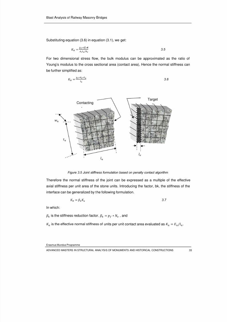
8/3/2019 Tibebu Hunegn Birhane- Blast Analysis of Railway Masonry Bridges
http://slidepdf.com/reader/full/tibebu-hunegn-birhane-blast-analysis-of-railway-masonry-bridges 50/134
Blast Analysis of Railway Masonry Bridges
Erasmus Mundus Programme
ADVANCED MASTERS IN STRUCTURAL ANALYSIS OF MONUMENTS AND HISTORICAL CONSTRUCTIONS 33
Substituting equation (3.6) in equation (3.1), we get:
/3.5
For two dimensional stress flow, the bulk modulus can be approximated as the ratio of
Young’s modulus to the cross sectional area (contact area), Hence the normal stiffness can
be further simplified as:
3.6
Figure 3.5 Joint stiffness formulation based on penalty contact algorithm
Therefore the normal stiffness of the joint can be expressed as a multiple of the effective
axial stiffness per unit area of the stone units. Introducing the factor, bk, the stiffness of the
interface can be generalized by the following formulation.
3.7
In which:
is the stiffness reduction factor, , and
is the effective normal stiffness of units per unit contact area evaluated as /.
Contacting
Target
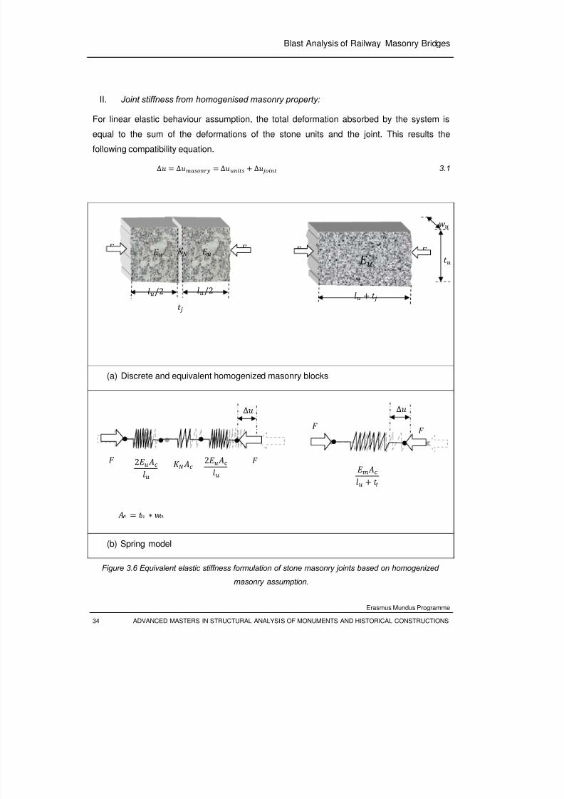
8/3/2019 Tibebu Hunegn Birhane- Blast Analysis of Railway Masonry Bridges
http://slidepdf.com/reader/full/tibebu-hunegn-birhane-blast-analysis-of-railway-masonry-bridges 51/134
Blast Analysis of Railway Masonry Bridges
Erasmus Mundus Programme
34 ADVANCED MASTERS IN STRUCTURAL ANALYSIS OF MONUMENTS AND HISTORICAL CONSTRUCTIONS
II. Joint stiffness from homogenised masonry property:
For linear elastic behaviour assumption, the total deformation absorbed by the system is
equal to the sum of the deformations of the stone units and the joint. This results the
following compatibility equation.
∆ ∆ ∆ ∆ 3.1
(a) Discrete and equivalent homogenized masonry blocks
(b) Spring model
Figure 3.6 Equivalent elastic stiffness formulation of stone masonry joints based on homogenized
masonry assumption.
∆
∆
2 2
/2 /2
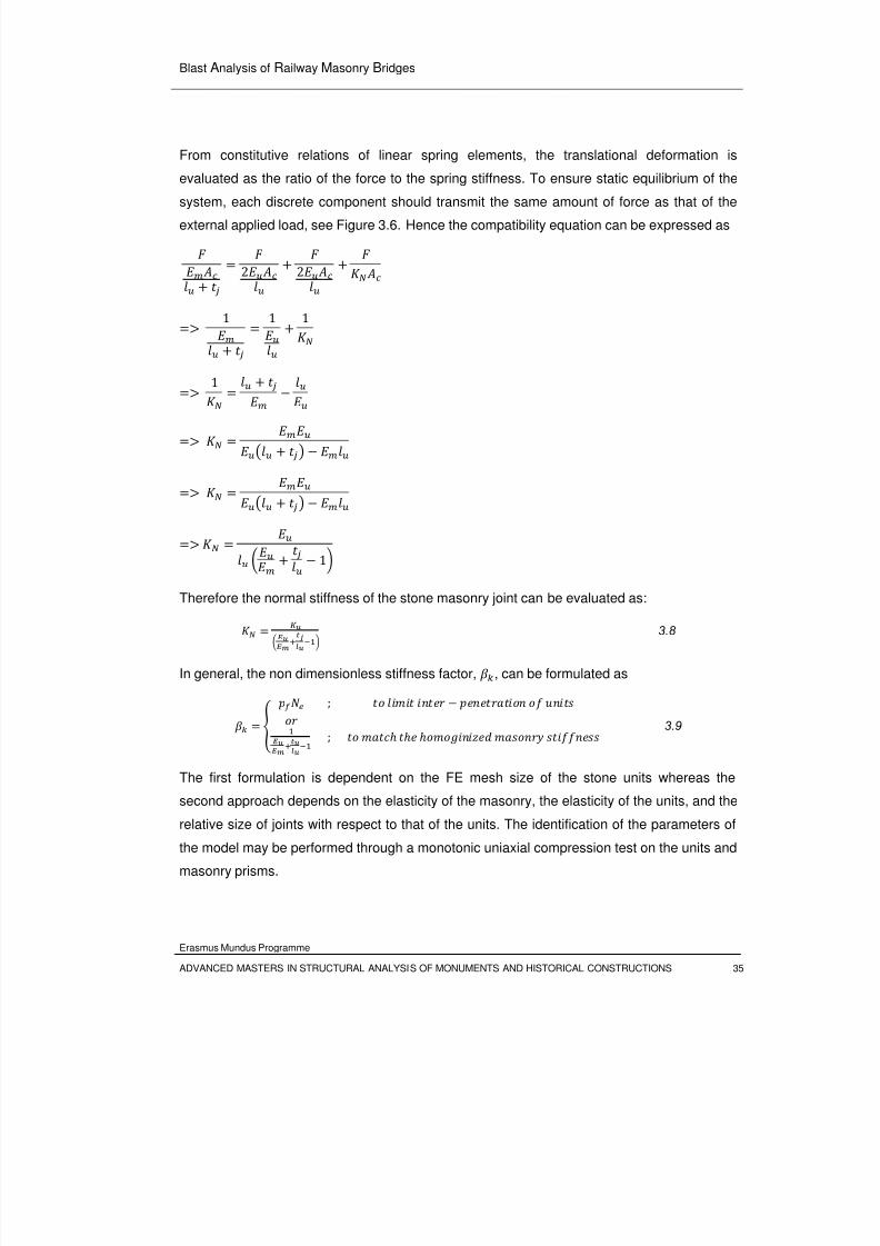
8/3/2019 Tibebu Hunegn Birhane- Blast Analysis of Railway Masonry Bridges
http://slidepdf.com/reader/full/tibebu-hunegn-birhane-blast-analysis-of-railway-masonry-bridges 52/134
Blast Analysis of Railway Masonry Bridges
Erasmus Mundus Programme
ADVANCED MASTERS IN STRUCTURAL ANALYSIS OF MONUMENTS AND HISTORICAL CONSTRUCTIONS 35
From constitutive relations of linear spring elements, the translational deformation is
evaluated as the ratio of the force to the spring stiffness. To ensure static equilibrium of the
system, each discrete component should transmit the same amount of force as that of the
external applied load, see Figure 3.6. Hence the compatibility equation can be expressed as
2
2
1 1
1
1
1
Therefore the normal stiffness of the stone masonry joint can be evaluated as: 3.8
In general, the non dimensionless stiffness factor, , can be formulated as
; ; 3.9
The first formulation is dependent on the FE mesh size of the stone units whereas the
second approach depends on the elasticity of the masonry, the elasticity of the units, and the
relative size of joints with respect to that of the units. The identification of the parameters of
the model may be performed through a monotonic uniaxial compression test on the units and
masonry prisms.
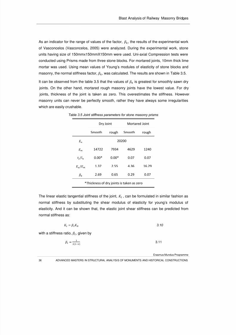
8/3/2019 Tibebu Hunegn Birhane- Blast Analysis of Railway Masonry Bridges
http://slidepdf.com/reader/full/tibebu-hunegn-birhane-blast-analysis-of-railway-masonry-bridges 53/134
Blast Analysis of Railway Masonry Bridges
Erasmus Mundus Programme
36 ADVANCED MASTERS IN STRUCTURAL ANALYSIS OF MONUMENTS AND HISTORICAL CONSTRUCTIONS
As an indicator for the range of values of the factor, , the results of the experimental work
of Vasconcelos (Vasconcelos, 2005) were analyzed. During the experimental work, stone
units having size of 150mmx150mmX150mm were used. Uni-axial Compression tests were
conducted using Prisms made from three stone blocks. For mortared joints, 10mm thick lime
mortar was used. Using mean values of Young’s modules of elasticity of stone blocks and
masonry, the normal stiffness factor, , was calculated. The results are shown in Table 3.5.
It can be observed from the table 3.5 that the values of is greatest for smoothly sawn dry
joints. On the other hand, mortared rough masonry joints have the lowest value. For dry
joints, thickness of the joint is taken as zero. This overestimates the stiffness. However
masonry units can never be perfectly smooth, rather they have always some irregularities
which are easily crushable.
Table 3.5 Joint stiffness parameters for stone masonry prisms
Dry Joint Mortared Joint Smooth rough Smooth rough
20200 14722 7934 4629 1240
/ 0.00* 0.00* 0.07 0.07
/ 1.37 2.55 4.36 16.29 2.69 0.65 0.29 0.07
*Thickness of dry joints is taken as zero
The linear elastic tangential stiffness of the joint, , can be formulated in similar fashion as
normal stiffness by substituting the shear modulus of elasticity for young’s modulus of
elasticity. And it can be shown that, the elastic joint shear stiffness can be predicted from
normal stiffness as:
3.10
with a stiffness ratio, , given by
3.11
8/3/2019 Tibebu Hunegn Birhane- Blast Analysis of Railway Masonry Bridges
http://slidepdf.com/reader/full/tibebu-hunegn-birhane-blast-analysis-of-railway-masonry-bridges 54/134
Blast Analysis of Railway Masonry Bridges
Erasmus Mundus Programme
ADVANCED MASTERS IN STRUCTURAL ANALYSIS OF MONUMENTS AND HISTORICAL CONSTRUCTIONS 37
in which is the Poison’s ratio.
For stress levels below crushing strength of granite stone, poison’s ratio varies from 0.2 to
0.5, (Vasconcelos, 2005). Using this range, the value of varies from 0.625 to 1.0.
3.3.2.2 Post-Peak Behaviour: Failure Criteria
The joint failure is described by the interfacial separation. This interfacial separation is
defined in terms of plastic relative joint displacement components, namely contact gap or
penetration (crushing) and tangential slip distance (sliding). Hence the inelastic constitutive
model of joint should ensure occurrence of these phenomena. This behavior is usually
implemented in FE formulations using a combined Coulomb friction and gaping criteria
(Lourenco, 1998).The model is characterized by six parameters [Figure 3.4 and Figure 3.7]:
• the compression elastic modulus,
• the shear elastic modulus,
• ′ the maximum normal tensile stress (traction),
• , cohesive frictional resistance
• the friction coefficient (tangent of the friction angle), and
• the dilatancy (tangent of the dilatancy angle) .
Here in this model the masonry units are assumed to perform elastically and hence there is
no bound for the compression-sliding regime.
According to Coulomb friction model, two contacting surfaces start sliding relative to each
other once the peak shear stress is reached. The sliding failure mode is simulated by dilatant
friction model which is governed by Coulomb friction law. The Coulomb model can be
formulated with the use of a yield surface function, f,
|| || 3.12
with the friction coefficient ,
, and cohesive sliding resistance,
, which are dependent on the
plastic shear deformation (Gilbert et.al, 2002 and Lourenco, 1998). The softening behavior ofthese parameters is given by [see Figure 3.7]:
" 3.13
3.14
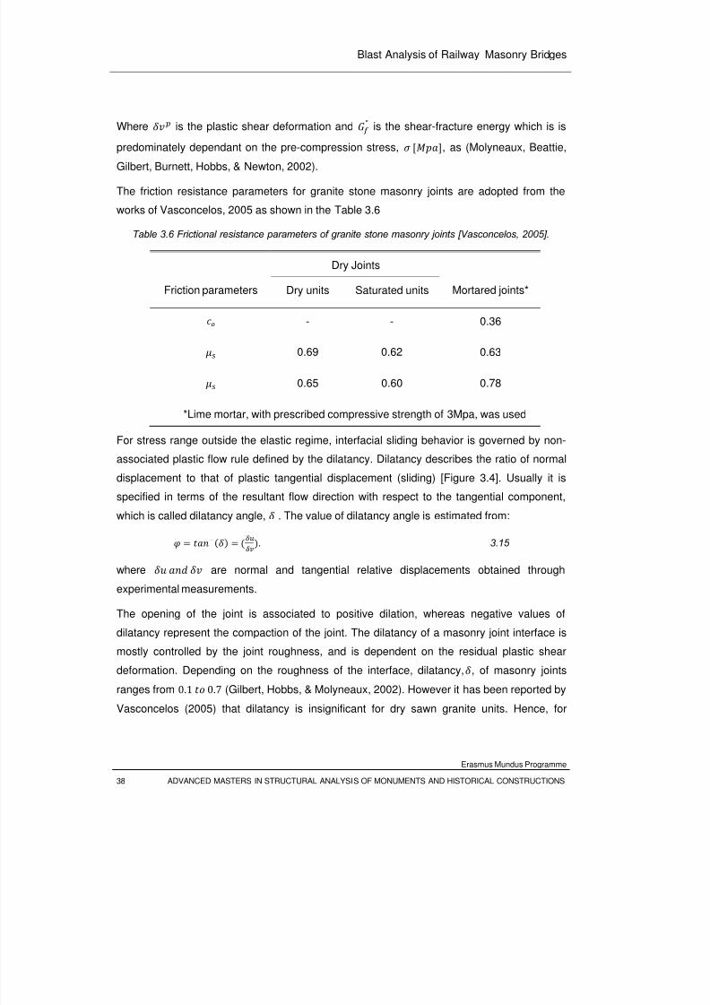
8/3/2019 Tibebu Hunegn Birhane- Blast Analysis of Railway Masonry Bridges
http://slidepdf.com/reader/full/tibebu-hunegn-birhane-blast-analysis-of-railway-masonry-bridges 55/134
Blast Analysis of Railway Masonry Bridges
Erasmus Mundus Programme
38 ADVANCED MASTERS IN STRUCTURAL ANALYSIS OF MONUMENTS AND HISTORICAL CONSTRUCTIONS
Where is the plastic shear deformation and " is the shear-fracture energy which is is
predominately dependant on the pre-compression stress,
, as (Molyneaux, Beattie,
Gilbert, Burnett, Hobbs, & Newton, 2002).
The friction resistance parameters for granite stone masonry joints are adopted from the
works of Vasconcelos, 2005 as shown in the Table 3.6
Table 3.6 Frictional resistance parameters of granite stone masonry joints [Vasconcelos, 2005].
Friction parameters
Dry Joints
Mortared joints*Dry units Saturated units
- - 0.36
0.69 0.62 0.63
0.65 0.60 0.78
*Lime mortar, with prescribed compressive strength of 3Mpa, was used
For stress range outside the elastic regime, interfacial sliding behavior is governed by non-
associated plastic flow rule defined by the dilatancy. Dilatancy describes the ratio of normal
displacement to that of plastic tangential displacement (sliding) [Figure 3.4]. Usually it isspecified in terms of the resultant flow direction with respect to the tangential component,
which is called dilatancy angle, . The value of dilatancy angle is estimated from:
. 3.15
where are normal and tangential relative displacements obtained through
experimental measurements.
The opening of the joint is associated to positive dilation, whereas negative values of
dilatancy represent the compaction of the joint. The dilatancy of a masonry joint interface is
mostly controlled by the joint roughness, and is dependent on the residual plastic shear
deformation. Depending on the roughness of the interface, dilatancy,, of masonry joints
ranges from 0.1 0.7 (Gilbert, Hobbs, & Molyneaux, 2002). However it has been reported by
Vasconcelos (2005) that dilatancy is insignificant for dry sawn granite units. Hence, for
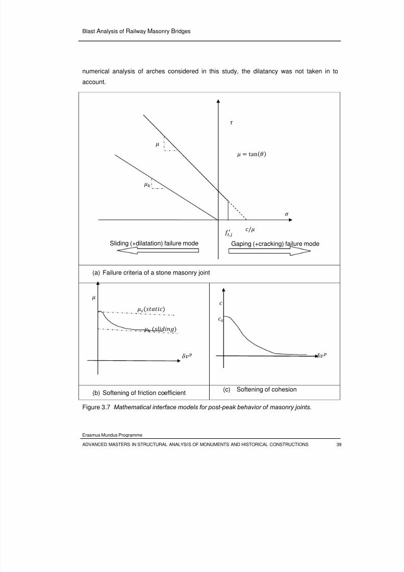
8/3/2019 Tibebu Hunegn Birhane- Blast Analysis of Railway Masonry Bridges
http://slidepdf.com/reader/full/tibebu-hunegn-birhane-blast-analysis-of-railway-masonry-bridges 56/134
Blast Analysis of Railway Masonry Bridges
Erasmus Mundus Programme
ADVANCED MASTERS IN STRUCTURAL ANALYSIS OF MONUMENTS AND HISTORICAL CONSTRUCTIONS 39
numerical analysis of arches considered in this study, the dilatancy was not taken in to
account.
(a) Failure criteria of a stone masonry joint
(b) Softening of friction coefficient(c) Softening of cohesion
Figure 3.7 Mathematical interface models for post-peak behavior of masonry joints.
, /
tan
Gaping (+cracking) failure modeSliding (+dilatation) failure mode
8/3/2019 Tibebu Hunegn Birhane- Blast Analysis of Railway Masonry Bridges
http://slidepdf.com/reader/full/tibebu-hunegn-birhane-blast-analysis-of-railway-masonry-bridges 57/134
Blast Analysis of Railway Masonry Bridges
Erasmus Mundus Programme
In the tensile regime, the performance of joints is highly dependent on the interfacial
cohesion. The tensile strength of joint ,
, ranges from zero to the apex of the Coulombfriction failure curve [0
/. The post-peak behavior of masonry joints under tension
is usually simulated by discrete-cracking with a gap criterion. This model assumes that a
gap arises if the tensile traction, , normal to the interface exceeds the specified tensile
strength. After gap formation, is reduced to zero immediately (brittle cracking).
For this study, both dry and mortared stone masonry joints were considered. As dry joints
don’t have any cohesion, the tensile strength for gaping criterion is set to zero. For mortared
joints, ranges of the tensile strengths up to the apex of the coulomb failure envelope are
considered for parametric study.
3.4 Numerical Structural Capacity Assessment: Limit Analysis
In this section, an iterative limit analysis was carried out to find the best geometric
dimensions of the prototype arch that can be accommodated within the drop-weight
apparatus cell (see Figure 3.1). The analysis was carried out using non-commercial software
RING 1.5, 2005. The software is based on the 'mechanism' method of analysis of rigid
blocks. And it evaluates the limit strength and predicts the critical failure mode, from
consideration of rocking and sliding stability of the individual blocks, group of blocks and as
well as the entire structure.
The software needs the gravitational weight and frictional resistance at the interfaces to
ensure the stability. Hence the following parameters were used as inputs for carrying out the
assessment of the single arch prototype bridge.
Density: The gravitational forces, either self weight or superimposed weights are main
sources of stabilizing forces by producing resisting moment against rocking and by producing
normal thrusts at interfaces to mobilize frictional resistance. Only self weight of the arch was
considered and evaluated from unit weight of granite stones,γ 24/ (Vasconcelos,
2005).The value is taken as a lower bound considering the coefficient of variation observed
during the test.
Geometry: Thickness of the arch ring, rise and clear span of the arch. These values are
varied to carry out the parametric study. Being limited by the floor plan dimensions of the
impact test apparatus cell, clear spans of 1.0m, 1.2m and 1.5m were tried. The rise of the
arch is fixed to be 0.4m so as to accommodate the arch within the rail frame of the impact
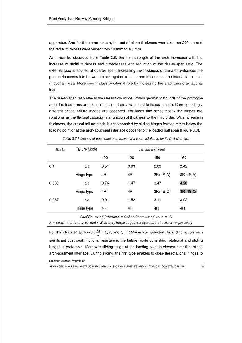
8/3/2019 Tibebu Hunegn Birhane- Blast Analysis of Railway Masonry Bridges
http://slidepdf.com/reader/full/tibebu-hunegn-birhane-blast-analysis-of-railway-masonry-bridges 58/134
Blast Analysis of Railway Masonry Bridges
Erasmus Mundus Programme
ADVANCED MASTERS IN STRUCTURAL ANALYSIS OF MONUMENTS AND HISTORICAL CONSTRUCTIONS 41
apparatus. And for the same reason, the out-of-plane thickness was taken as 200mm and
the radial thickness were varied from 100mm to 160mm.
As it can be observed from Table 3.5, the limit strength of the arch increases with the
increase of radial thickness and it decreases with reduction of the rise-to-span ratio. The
external load is applied at quarter span. Increasing the thickness of the arch enhances the
geometric constraints between block against rotation and it increases the interfacial contact
(frictional) area. More over it plays additional role by increasing the stabilizing gravitational
load.
The rise-to-span ratio affects the stress flow mode. Within geometric bounds of the prototype
arch; the load transfer mechanism shifts from axial thrust to flexural mode. Correspondingly
different critical failure modes are observed. For lower thickness, mostly the hinges are
rotational as the flexural capacity is a function of thickness to the third order. With increase in
thickness, the critical failure mode is accompanied by sliding hinges formed either below the
loading point or at the arch-abutment interface opposite to the loaded half span [Figure 3.8].
Table 3.7 Influence of geometric proportions of a segmental arch on its limit strength.
/ Failure Mode 100 120 150 160
0.4 ∆λ 0.51 0.93 2.03 2.42
Hinge type 4R 4R 3R+1S(A) 3R+1S(A)
0.333 ∆λ 0.76 1.47 3.47 4.28
Hinge type 4R 4R 3R+1S(Q) 3R+1S(Q)
0.267 ∆λ 0.91 1.52 3.11 3.92
Hinge type 4R 4R 4R 4R
, 0.65 13 ,
For this study an arch with, 1/3, and 160 was selected. As sliding occurs with
significant post peak frictional resistance, the failure mode consisting rotational and sliding
hinges is preferable. Moreover sliding hinge at the loading point is chosen over that of the
arch-abutment interface. During sliding, the first type enables to close the rotational hinges to
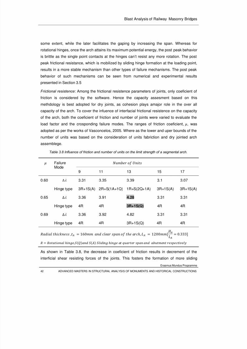
8/3/2019 Tibebu Hunegn Birhane- Blast Analysis of Railway Masonry Bridges
http://slidepdf.com/reader/full/tibebu-hunegn-birhane-blast-analysis-of-railway-masonry-bridges 59/134
Blast Analysis of Railway Masonry Bridges
Erasmus Mundus Programme
42 ADVANCED MASTERS IN STRUCTURAL ANALYSIS OF MONUMENTS AND HISTORICAL CONSTRUCTIONS
some extent, while the later facilitates the gaping by increasing the span. Whereas for
rotational hinges, once the arch attains its maximum potential energy, the post peak behavior
is brittle as the single point contacts at the hinges can’t resist any more rotation. The post
peak frictional resistance, which is mobilized by sliding hinge formation at the loading point,
results in a more stable mechanism than other types of failure mechanisms. The post peak
behavior of such mechanisms can be seen from numerical and experimental results
presented in Section 3.5
Frictional resistence: Among the frictional resistence parameters of joints, only coeficient of
friction is considered by the software. Hence the capacity assesment based on this
methdology is best adopted for dry joints, as cohesion plays amajor role in the over all
capacity of the arch. To cover the infuence of interfacial frictional resistence on the capacityof the arch, both the coeficient of friction and number of joints were varied to evaluate the
load factor and the crosponding failure modes. The ranges of friction coeficient, , was
adopted as per the works of Vasconcelos, 2005. Where as the lower and uper bounds of the
number of units was based on the consideration of units fabriction and dry jointed arch
assemblege.
Table 3.8 Influence of friction and number of units on the limit strength of a segmental arch.
Failure
Mode
9 11 13 15 17
0.60 ∆λ 3.31 3.35 3.39 3.1 3.07
Hinge type 3R+1S(A) 2R+S(1A+1Q) 1R+S(2Q+1A) 3R+1S(A) 3R+1S(A)
0.65 ∆λ 3.36 3.91 4.28 3.31 3.31
Hinge type 4R 4R 3R+1S(Q) 4R 4R
0.69 ∆λ 3.36 3.92 4.82 3.31 3.31
Hinge type 4R 4R 3R+1S(Q) 4R 4R
, 160 , 1200 0.333 ,
As shown in Table 3.8, the decrease in coeficient of friction results in decrement of the
interficial shear resisting forces of the joints. This fosters the formation of more sliding
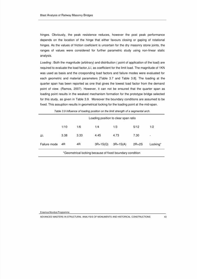
8/3/2019 Tibebu Hunegn Birhane- Blast Analysis of Railway Masonry Bridges
http://slidepdf.com/reader/full/tibebu-hunegn-birhane-blast-analysis-of-railway-masonry-bridges 60/134
Blast Analysis of Railway Masonry Bridges
Erasmus Mundus Programme
ADVANCED MASTERS IN STRUCTURAL ANALYSIS OF MONUMENTS AND HISTORICAL CONSTRUCTIONS 43
hinges. Obviously, the peak resistence reduces, however the post peak performance
depends on the location of the hinge that either favours closing or gaping of rotational
hinges. As the values of friction coeficient is uncertain for the dry masonry stone joints, the
ranges of values were considered for further parametric study using non-linear static
analysis.
Loading : Both the magnitude (arbitrary) and distribution ( point of application of the load) are
required to evaluate the load factor,∆λ , as coefficient for the limit load. The magnitude of 1KN
was used as basis and the crosponding load factors and failure modes were evaluated for
each geometric and material parameters [Table 3.7 and Table 3.8]. The loading at the
quarter span has been reported as one that gives the lowest load factor from the demand
point of view. (Ramos, 2007). However, it can not be ensured that the quarter span asloading point results in the weakest mechanism formation for the prototype bridge selected
for this study, as given in Table 3.9. Moreover the boundary conditions are assumed to be
fixed. This assuption results in geometrical locking for the loading point at the mid-span.
Table 3.9 Influence of loading position on the limit strength of a segmental arch.
Loading position to clear span ratio
1/10 1/6 1/4 1/3 5/12 1/2
∆λ 3.38 3.33 4.45 4.73 7.30 -
Failure mode 4R 4R 3R+1S(Q) 3R+1S(A) 2R+2S Locking*
*Geometrical locking because of fixed boundary condition
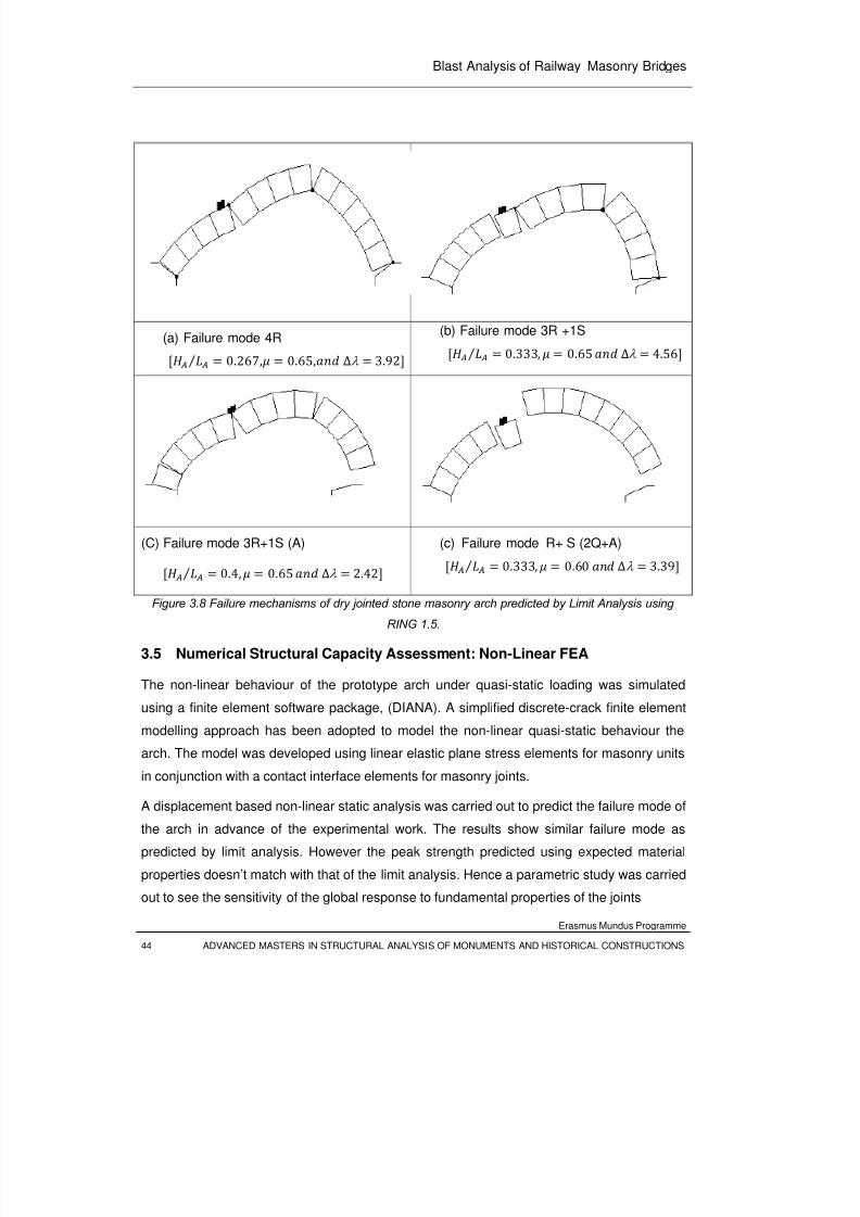
8/3/2019 Tibebu Hunegn Birhane- Blast Analysis of Railway Masonry Bridges
http://slidepdf.com/reader/full/tibebu-hunegn-birhane-blast-analysis-of-railway-masonry-bridges 61/134
Blast Analysis of Railway Masonry Bridges
Erasmus Mundus Programme
44 ADVANCED MASTERS IN STRUCTURAL ANALYSIS OF MONUMENTS AND HISTORICAL CONSTRUCTIONS
(a) Failure mode 4R ⁄ 0.267, 0.65, ∆λ 3.92(b) Failure mode 3R +1S ⁄ 0.333, 0.65 ∆λ 4.56
(C) Failure mode 3R+1S (A)
⁄ 0.4, 0.65 ∆λ
2.42
(c) Failure mode R+ S (2Q+A)
⁄ 0.333, 0.60 ∆λ
3.39
Figure 3.8 Failure mechanisms of dry jointed stone masonry arch predicted by Limit Analysis using
RING 1.5.
3.5 Numerical Structural Capacity Assessment: Non-Linear FEA
The non-linear behaviour of the prototype arch under quasi-static loading was simulated
using a finite element software package, (DIANA). A simplified discrete-crack finite element
modelling approach has been adopted to model the non-linear quasi-static behaviour the
arch. The model was developed using linear elastic plane stress elements for masonry units
in conjunction with a contact interface elements for masonry joints.
A displacement based non-linear static analysis was carried out to predict the failure mode of
the arch in advance of the experimental work. The results show similar failure mode as
predicted by limit analysis. However the peak strength predicted using expected material
properties doesn’t match with that of the limit analysis. Hence a parametric study was carried
out to see the sensitivity of the global response to fundamental properties of the joints
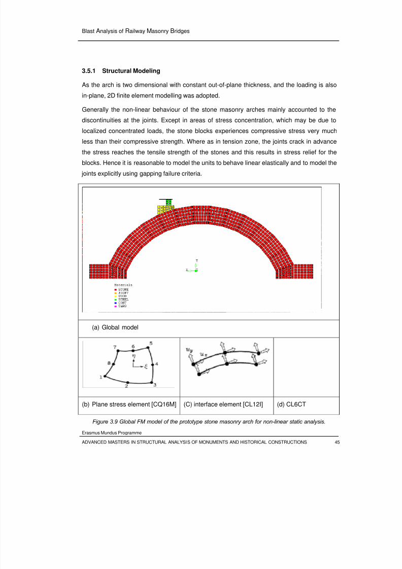
8/3/2019 Tibebu Hunegn Birhane- Blast Analysis of Railway Masonry Bridges
http://slidepdf.com/reader/full/tibebu-hunegn-birhane-blast-analysis-of-railway-masonry-bridges 62/134
Blast Analysis of Railway Masonry Bridges
Erasmus Mundus Programme
ADVANCED MASTERS IN STRUCTURAL ANALYSIS OF MONUMENTS AND HISTORICAL CONSTRUCTIONS 45
3.5.1 Structural Modeling
As the arch is two dimensional with constant out-of-plane thickness, and the loading is also
in-plane, 2D finite element modelling was adopted.
Generally the non-linear behaviour of the stone masonry arches mainly accounted to the
discontinuities at the joints. Except in areas of stress concentration, which may be due to
localized concentrated loads, the stone blocks experiences compressive stress very much
less than their compressive strength. Where as in tension zone, the joints crack in advance
the stress reaches the tensile strength of the stones and this results in stress relief for the
blocks. Hence it is reasonable to model the units to behave linear elastically and to model the
joints explicitly using gapping failure criteria.
(a) Global model
(b) Plane stress element [CQ16M] (C) interface element [CL12I] (d) CL6CT
Figure 3.9 Global FM model of the prototype stone masonry arch for non-linear static analysis.
(b)
(c)
(d)
8/3/2019 Tibebu Hunegn Birhane- Blast Analysis of Railway Masonry Bridges
http://slidepdf.com/reader/full/tibebu-hunegn-birhane-blast-analysis-of-railway-masonry-bridges 63/134
8/3/2019 Tibebu Hunegn Birhane- Blast Analysis of Railway Masonry Bridges
http://slidepdf.com/reader/full/tibebu-hunegn-birhane-blast-analysis-of-railway-masonry-bridges 64/134
Blast Analysis of Railway Masonry Bridges
Erasmus Mundus Programme
ADVANCED MASTERS IN STRUCTURAL ANALYSIS OF MONUMENTS AND HISTORICAL CONSTRUCTIONS 47
Table 3.10 Quasi-static Properties of interface elements for the pilot stone masonry arch bridge
Mesh size [no. of elements per edge of the unit],
6
Effective unit stiffness, 4 1 0/
Normal stiffness factor, 0.01
Tangential stiffness factor, 0.625
Cohesion, 0.00
Tensile strength, 0.00
Coefficient of friction,
0.65
Dilatancy angle, 0.00
The interface between the loading jack and the steel bearing was modeled using three node
contact element, with loading jack as a target and the steel bearing edge as a contacter. This
explicit modeling of the loading cell was required to apply a displacement load to the target
and gravitational load to the arch without any vertical restraint from the loading cell. More
over the selection of the target (jack) and the contacter (steel bearing) components of the
contact elements was based on the penetration requirement of contact algorithms. To ensure
that inter penetrations are detected by contact algorithms, it is recommended that the
interface component which is more rigid and have coarser element meshing should beassigned as target; whereas the more flexible part as a contacter. In this case the jack, which
is modeled using a single element and fixed in the vertical direction to apply displacement
loads, is taken as target.
Loads and Boundary Conditions: Both the right and the left abutments are fixed against the
vertical and horizontal translations. And the loading jack is restrained from horizontal
translations. Rigid beam constraint is applied at the top nodes of the steel bearing to make
sure that these nodes experiences the same penetrations during displacement loading from
the jack.
A gravitational load is applied to the entire arch. As the arch is fully modeled this load is
specified as base acceleration, g = 9.81 m/s. For the force based, non linear analysis, a
uniform pressure, 94644/, at the interface between steel bearing and wooden
wedge was applied.This pressure is equivalent to the peak load, 4.28, predicted
by limit analysis. For displacement based analysis, a pre described vertical deformation load
8/3/2019 Tibebu Hunegn Birhane- Blast Analysis of Railway Masonry Bridges
http://slidepdf.com/reader/full/tibebu-hunegn-birhane-blast-analysis-of-railway-masonry-bridges 65/134
Blast Analysis of Railway Masonry Bridges
Erasmus Mundus Programme
48 ADVANCED MASTERS IN STRUCTURAL ANALYSIS OF MONUMENTS AND HISTORICAL CONSTRUCTIONS
of 1mm was applied in the down ward direction on the nodes representing the jack (target
element). The loads are summarized in Table 3.1
Table 3.11 Quasi-static loads applied to FE model of the prototype arch
Load Case Type Value
LC1 Self weight -9.81m/s2 (y)
LC2 Load cell Pressure -94644N/m2 (y)
LC3 Load cell Deformation -0.001m (y)
3.5.2 Structural Analysis
A non linear static analysis was carried out to derive the quasi-static capacity curve of the
arch. Both the displacement based and displacement based approaches were carried out.
For the force based analysis, the self weight was applied in a single step, and the pressure
load was applied with step sizes fixed automatically by adoptive loading algorithms involving
arc-length scheme (DIANA). In this analysis case the contact elements are removed from the
model as they are relevant
In the displacement based analysis case, the self weight was applied in advance to get
stabilizing pre-compression stress against shear sliding failure of the joints. This load is
totally carried by the arch, not transferred to the supports at the loading cell, as the contact
elements are don’t transmit tensile stress. After preloading with self weight, the deformation
load was applied in step sizes determined by energy based iterative algorithms. Both the
command and the input data files are included in the Appendix B.
Both simulation approaches tries to represent a monotonically increasing load applied until
the collapse. Both approaches predict the same peak load and the pre-peak behavior.
However the later approach was successful to predict the post peak behavior.
3.5.3 Results and Discussion
The results of numerical simulation of the pilot model, with material properties and loading
conditions described above, will be presented.
Figure 3.10 shows the capacity curve of the arch obtained by the displacement based non-
linear analysis. The arch peak strength of the model is only 64.4% of the value estimated
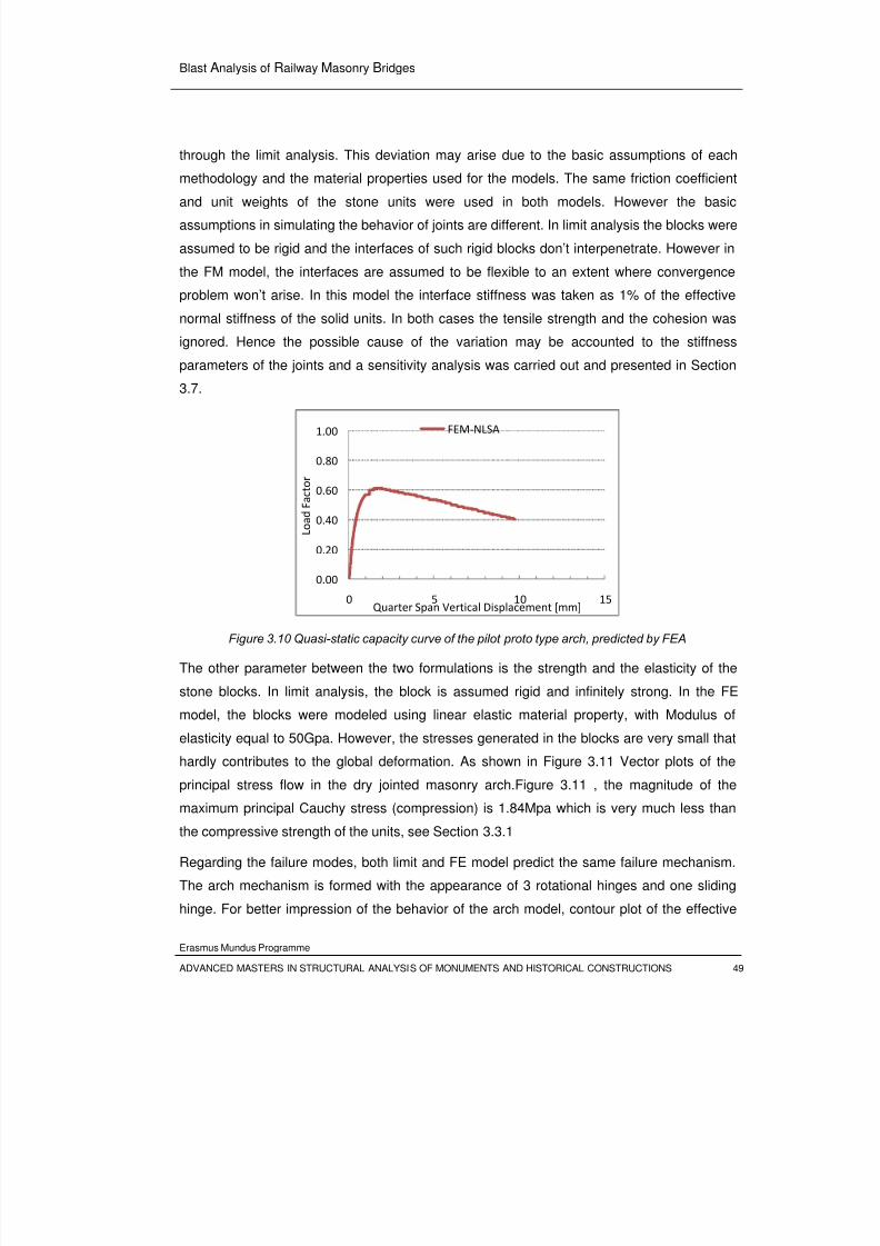
8/3/2019 Tibebu Hunegn Birhane- Blast Analysis of Railway Masonry Bridges
http://slidepdf.com/reader/full/tibebu-hunegn-birhane-blast-analysis-of-railway-masonry-bridges 66/134
Blast Analysis of Railway Masonry Bridges
Erasmus Mundus Programme
ADVANCED MASTERS IN STRUCTURAL ANALYSIS OF MONUMENTS AND HISTORICAL CONSTRUCTIONS 49
through the limit analysis. This deviation may arise due to the basic assumptions of each
methodology and the material properties used for the models. The same friction coefficient
and unit weights of the stone units were used in both models. However the basic
assumptions in simulating the behavior of joints are different. In limit analysis the blocks were
assumed to be rigid and the interfaces of such rigid blocks don’t interpenetrate. However in
the FM model, the interfaces are assumed to be flexible to an extent where convergence
problem won’t arise. In this model the interface stiffness was taken as 1% of the effective
normal stiffness of the solid units. In both cases the tensile strength and the cohesion was
ignored. Hence the possible cause of the variation may be accounted to the stiffness
parameters of the joints and a sensitivity analysis was carried out and presented in Section
3.7.
Figure 3.10 Quasi-static capacity curve of the pilot proto type arch, predicted by FEA
The other parameter between the two formulations is the strength and the elasticity of the
stone blocks. In limit analysis, the block is assumed rigid and infinitely strong. In the FE
model, the blocks were modeled using linear elastic material property, with Modulus of
elasticity equal to 50Gpa. However, the stresses generated in the blocks are very small that
hardly contributes to the global deformation. As shown in Figure 3.11 Vector plots of the
principal stress flow in the dry jointed masonry arch.Figure 3.11 , the magnitude of the
maximum principal Cauchy stress (compression) is 1.84Mpa which is very much less than
the compressive strength of the units, see Section 3.3.1
Regarding the failure modes, both limit and FE model predict the same failure mechanism.
The arch mechanism is formed with the appearance of 3 rotational hinges and one sliding
hinge. For better impression of the behavior of the arch model, contour plot of the effective
0.00
0.20
0.40
0.60
0.80
1.00
0 5 10 15
L o a d
F a c t o r
Quarter Span Vertical Displacement [mm]
FEM‐NLSA
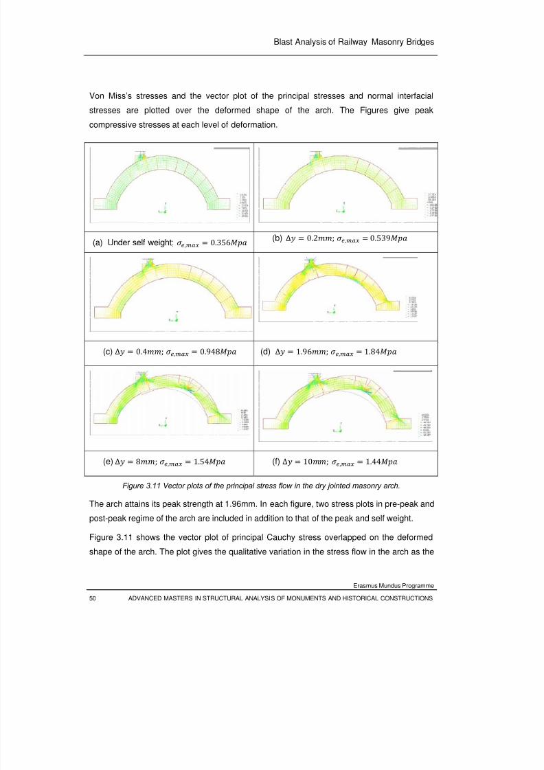
8/3/2019 Tibebu Hunegn Birhane- Blast Analysis of Railway Masonry Bridges
http://slidepdf.com/reader/full/tibebu-hunegn-birhane-blast-analysis-of-railway-masonry-bridges 67/134
Blast Analysis of Railway Masonry Bridges
Erasmus Mundus Programme
50 ADVANCED MASTERS IN STRUCTURAL ANALYSIS OF MONUMENTS AND HISTORICAL CONSTRUCTIONS
Von Miss’s stresses and the vector plot of the principal stresses and normal interfacial
stresses are plotted over the deformed shape of the arch. The Figures give peak
compressive stresses at each level of deformation.
(a) Under self weight; , 0.356
(b)
∆ 0.2; , 0.539
(c) ∆ 0.4; , 0.948 (d) ∆ 1.96; , 1.84
(e) ∆ 8; , 1.54 (f) ∆ 10; , 1.44
Figure 3.11 Vector plots of the principal stress flow in the dry jointed masonry arch.
The arch attains its peak strength at 1.96mm. In each figure, two stress plots in pre-peak and
post-peak regime of the arch are included in addition to that of the peak and self weight.
Figure 3.11 shows the vector plot of principal Cauchy stress overlapped on the deformed
shape of the arch. The plot gives the qualitative variation in the stress flow in the arch as the
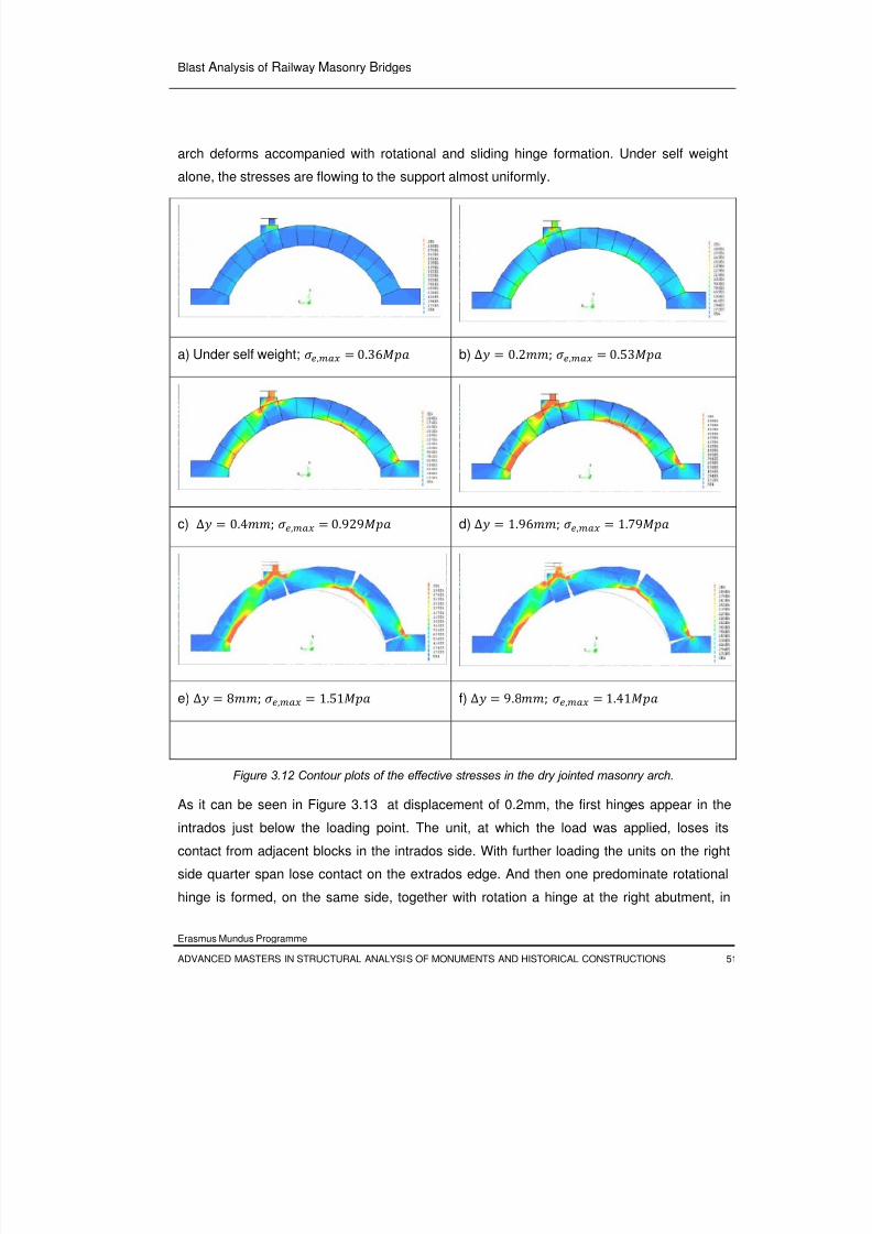
8/3/2019 Tibebu Hunegn Birhane- Blast Analysis of Railway Masonry Bridges
http://slidepdf.com/reader/full/tibebu-hunegn-birhane-blast-analysis-of-railway-masonry-bridges 68/134
Blast Analysis of Railway Masonry Bridges
Erasmus Mundus Programme
ADVANCED MASTERS IN STRUCTURAL ANALYSIS OF MONUMENTS AND HISTORICAL CONSTRUCTIONS 51
arch deforms accompanied with rotational and sliding hinge formation. Under self weight
alone, the stresses are flowing to the support almost uniformly.
a) Under self weight; , 0.36 b) ∆ 0.2; , 0.53
c) ∆ 0.4; , 0.929 d) ∆ 1.96; , 1.79
e) ∆ 8; , 1.51 f) ∆ 9.8; , 1.41
Figure 3.12 Contour plots of the effective stresses in the dry jointed masonry arch.
As it can be seen in Figure 3.13 at displacement of 0.2mm, the first hinges appear in the
intrados just below the loading point. The unit, at which the load was applied, loses its
contact from adjacent blocks in the intrados side. With further loading the units on the right
side quarter span lose contact on the extrados edge. And then one predominate rotational
hinge is formed, on the same side, together with rotation a hinge at the right abutment, in
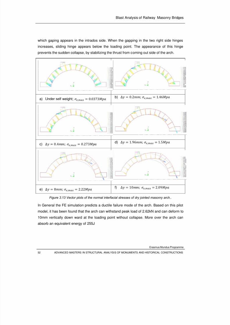
8/3/2019 Tibebu Hunegn Birhane- Blast Analysis of Railway Masonry Bridges
http://slidepdf.com/reader/full/tibebu-hunegn-birhane-blast-analysis-of-railway-masonry-bridges 69/134
Blast Analysis of Railway Masonry Bridges
Erasmus Mundus Programme
52 ADVANCED MASTERS IN STRUCTURAL ANALYSIS OF MONUMENTS AND HISTORICAL CONSTRUCTIONS
which gaping appears in the intrados side. When the gapping in the two right side hinges
increases, sliding hinge appears below the loading point. The appearance of this hinge
prevents the sudden collapse, by stabilizing the thrust from coming out side of the arch.
a) Under self weight;
, 0.0373
b)
∆ 0.2; ,
1.46
c) ∆ 0.4; , 0.273 d) ∆ 1.96; , 1.5
e) ∆ 8; , 2.22 f) ∆ 10; , 2.09
Figure 3.13 Vector plots of the normal interfacial stresses of dry jointed masonry arch..
In General the FE simulation predicts a ductile failure mode of the arch. Based on this pilot
model, it has been found that the arch can withstand peak load of 2.62kN and can deform to
10mm vertically down ward at the loading point without collapse. More over the arch can
absorb an equivalent energy of 255J
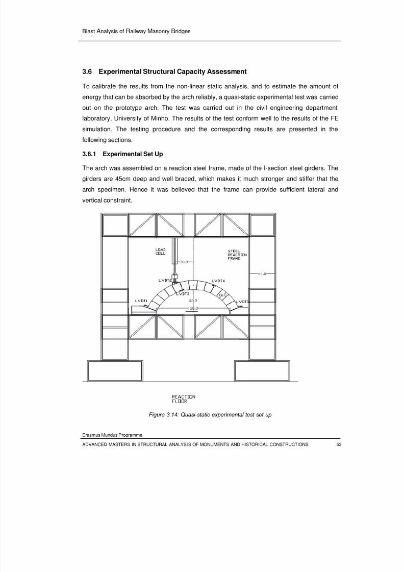
8/3/2019 Tibebu Hunegn Birhane- Blast Analysis of Railway Masonry Bridges
http://slidepdf.com/reader/full/tibebu-hunegn-birhane-blast-analysis-of-railway-masonry-bridges 70/134
Blast Analysis of Railway Masonry Bridges
Erasmus Mundus Programme
ADVANCED MASTERS IN STRUCTURAL ANALYSIS OF MONUMENTS AND HISTORICAL CONSTRUCTIONS 53
3.6 Experimental Structural Capacity Assessment
To calibrate the results from the non-linear static analysis, and to estimate the amount of
energy that can be absorbed by the arch reliably, a quasi-static experimental test was carried
out on the prototype arch. The test was carried out in the civil engineering department
laboratory, University of Minho. The results of the test conform well to the results of the FE
simulation. The testing procedure and the corresponding results are presented in the
following sections.
3.6.1 Experimental Set Up
The arch was assembled on a reaction steel frame, made of the I-section steel girders. The
girders are 45cm deep and well braced, which makes it much stronger and stiffer that the
arch specimen. Hence it was believed that the frame can provide sufficient lateral and
vertical constraint.
Figure 3.14: Quasi-static experimental test set up
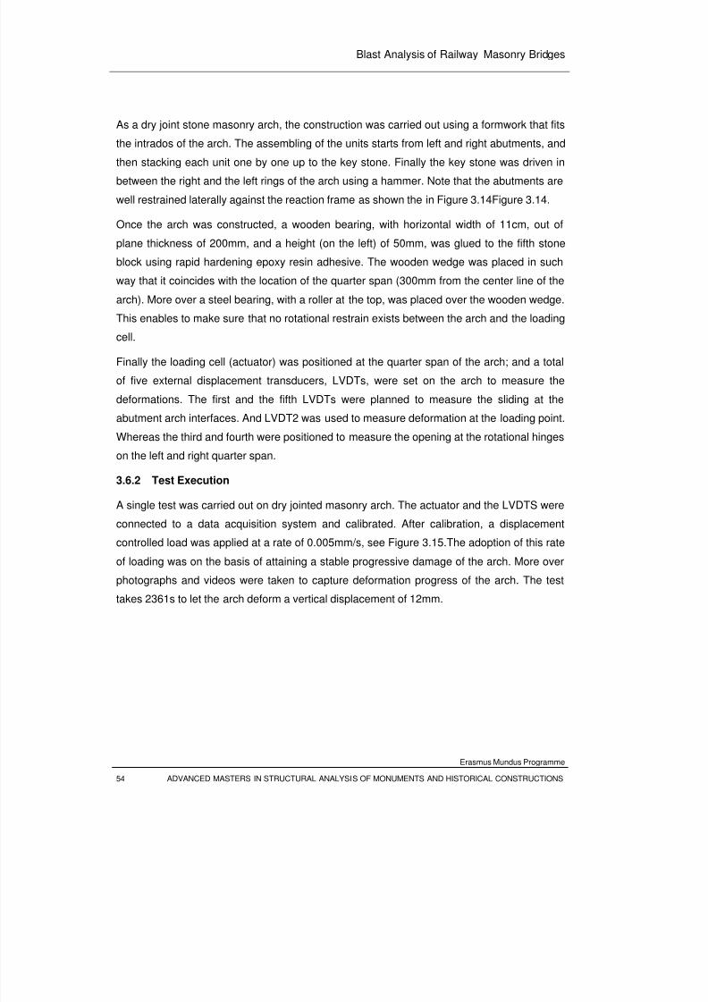
8/3/2019 Tibebu Hunegn Birhane- Blast Analysis of Railway Masonry Bridges
http://slidepdf.com/reader/full/tibebu-hunegn-birhane-blast-analysis-of-railway-masonry-bridges 71/134
Blast Analysis of Railway Masonry Bridges
Erasmus Mundus Programme
54 ADVANCED MASTERS IN STRUCTURAL ANALYSIS OF MONUMENTS AND HISTORICAL CONSTRUCTIONS
As a dry joint stone masonry arch, the construction was carried out using a formwork that fits
the intrados of the arch. The assembling of the units starts from left and right abutments, and
then stacking each unit one by one up to the key stone. Finally the key stone was driven in
between the right and the left rings of the arch using a hammer. Note that the abutments are
well restrained laterally against the reaction frame as shown the in Figure 3.14Figure 3.14.
Once the arch was constructed, a wooden bearing, with horizontal width of 11cm, out of
plane thickness of 200mm, and a height (on the left) of 50mm, was glued to the fifth stone
block using rapid hardening epoxy resin adhesive. The wooden wedge was placed in such
way that it coincides with the location of the quarter span (300mm from the center line of the
arch). More over a steel bearing, with a roller at the top, was placed over the wooden wedge.
This enables to make sure that no rotational restrain exists between the arch and the loadingcell.
Finally the loading cell (actuator) was positioned at the quarter span of the arch; and a total
of five external displacement transducers, LVDTs, were set on the arch to measure the
deformations. The first and the fifth LVDTs were planned to measure the sliding at the
abutment arch interfaces. And LVDT2 was used to measure deformation at the loading point.
Whereas the third and fourth were positioned to measure the opening at the rotational hinges
on the left and right quarter span.
3.6.2 Test Execution
A single test was carried out on dry jointed masonry arch. The actuator and the LVDTS were
connected to a data acquisition system and calibrated. After calibration, a displacement
controlled load was applied at a rate of 0.005mm/s, see Figure 3.15.The adoption of this rate
of loading was on the basis of attaining a stable progressive damage of the arch. More over
photographs and videos were taken to capture deformation progress of the arch. The test
takes 2361s to let the arch deform a vertical displacement of 12mm.
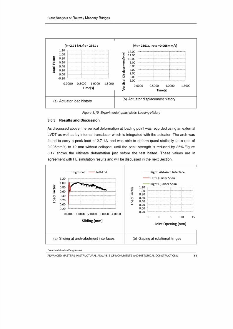
8/3/2019 Tibebu Hunegn Birhane- Blast Analysis of Railway Masonry Bridges
http://slidepdf.com/reader/full/tibebu-hunegn-birhane-blast-analysis-of-railway-masonry-bridges 72/134
Blast Analysis of Railway Masonry Bridges
Erasmus Mundus Programme
ADVANCED MASTERS IN STRUCTURAL ANALYSIS OF MONUMENTS AND HISTORICAL CONSTRUCTIONS 55
(a) Actuator load history(b) Actuator displacement history.
Figure 3.15 Experimental quasi-static Loading History
3.6.3 Results and Discussion
As discussed above, the vertical deformation at loading point was recorded using an external
LVDT as well as by internal transducer which is integrated with the actuator. The arch was
found to carry a peak load of 2.71kN and was able to deform quasi statically (at a rate of
0.005mm/s) to 12 mm without collapse, until the peak strength is reduced by 35%.Figure
3.17 shows the ultimate deformation just before the test halted. These values are in
agreement with FE simulation results and will be discussed in the next Section.
(a) Sliding at arch-abutment interfaces (b) Gaping at rotational hinges
‐0.20
0.00
0.20
0.40
0.60
0.80
1.00
1.20
0.0000 0.5000 1.0000 1.5000
L o a d
F a c t o r
Time[s]
[P =2.71 kN, Δt = 2361 s
‐2.00
0.00
2.00
4.00
6.00
8.00
10.00
12.0014.00
0.0000 0.5000 1.0000 1.5000
V e r t i c a l D i s p l a c e m e n t [ m m ]
Time[s]
[Δt = 2361s, rate =0.005mm/s]
‐0.20
0.00
0.20
0.40
0.60
0.80
1.00
1.20
0.0000 1.0000 2.0000 3.0000 4.0000
L o a d F a c t o r
Sliding [mm]
Right‐End Left‐End
‐0.20
0.00
0.20
0.400.60
0.801.00
1.20
‐5 0 5 10 15
L o a d
F a c t o r
Joint Opening [mm]
Right Abt‐Arch Interface
Left Quarter Span
Right Quarter Span
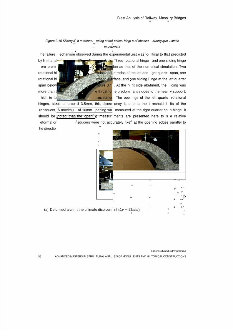
8/3/2019 Tibebu Hunegn Birhane- Blast Analysis of Railway Masonry Bridges
http://slidepdf.com/reader/full/tibebu-hunegn-birhane-blast-analysis-of-railway-masonry-bridges 73/134
56 A
Figure 3
he failure
by limit anal
ere promi
rotational hi
rotational hi
span below
more than t
hich in tu
hinges, sto
ransducer,
should be
eformation
he directio
(a) Defo
DVANCED MAS
.16 Sliding a
echanism
ysis and th
ently obse
nges center
nge at the r
the loading
hat of the le
rn gives gr
ps at arou
A maximu
noted that
, as the tra
of flow.
rmed arch
TERS IN STRU
d rotational
observed d
FE nonlin
rved at the
ed at the ex
ight arch-ab
point, see
ft side as t
ater slidin
d 3.5mm,
of 10mm
the openi
nsducers w
t the ultima
TURAL ANAL
aping at the
experi
uring the ex
ar analysis.
same locat
trados and
utment inte
Figure 3.1
e thrust for
resistance
this discre
pening wa
g measur
ere not acc
te displcem
Blast An
SIS OF MONU
critical hinge
ment
perimental t
Three rotat
ion as that
intrados of t
rface, and o
. At the rig
ce predomi
. The open
ancy is d
measured
ments are
urately fixe
nt (∆ 12
lysis of Rail
ENTS AND HI
s of observe
est was ide
ional hinge
of the num
he left and
ne sliding h
ht side abu
antly goes
ings of the
e to the t
at the right
presented
at the ope
lway Maso
Erasmus Mund
TORICAL CON
during qua
ntical to tha
and one sl
erical simul
ight quarter
inge at the
tment, the
to the near
left quarte
reshold li
quarter sp
here to s
ning edges
ry Bridges
us Programme
STRUCTIONS
i-static
t predicted
iding hinge
ation. Two
span, one
left quarter
liding was
y support,
rotational
its of the
n hinge. It
e relative
parallel to
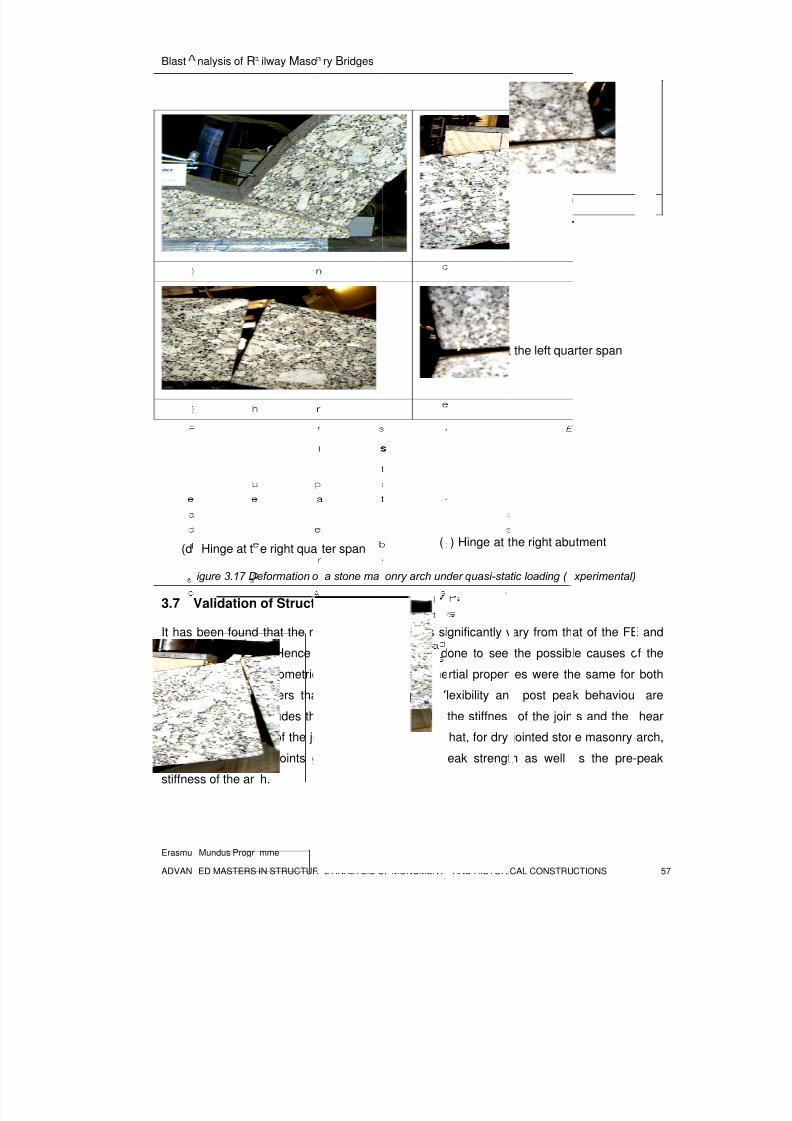
8/3/2019 Tibebu Hunegn Birhane- Blast Analysis of Railway Masonry Bridges
http://slidepdf.com/reader/full/tibebu-hunegn-birhane-blast-analysis-of-railway-masonry-bridges 74/134
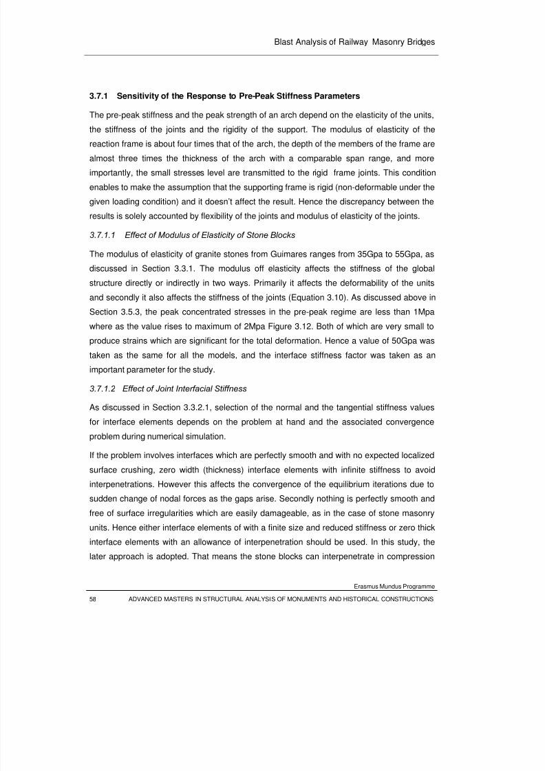
8/3/2019 Tibebu Hunegn Birhane- Blast Analysis of Railway Masonry Bridges
http://slidepdf.com/reader/full/tibebu-hunegn-birhane-blast-analysis-of-railway-masonry-bridges 75/134
Blast Analysis of Railway Masonry Bridges
Erasmus Mundus Programme
58 ADVANCED MASTERS IN STRUCTURAL ANALYSIS OF MONUMENTS AND HISTORICAL CONSTRUCTIONS
3.7.1 Sensitivity of the Response to Pre-Peak Stiffness Parameters
The pre-peak stiffness and the peak strength of an arch depend on the elasticity of the units,
the stiffness of the joints and the rigidity of the support. The modulus of elasticity of the
reaction frame is about four times that of the arch, the depth of the members of the frame are
almost three times the thickness of the arch with a comparable span range, and more
importantly, the small stresses level are transmitted to the rigid frame joints. This condition
enables to make the assumption that the supporting frame is rigid (non-deformable under the
given loading condition) and it doesn’t affect the result. Hence the discrepancy between the
results is solely accounted by flexibility of the joints and modulus of elasticity of the joints.
3.7.1.1 Effect of Modulus of Elasticity of Stone Blocks
The modulus of elasticity of granite stones from Guimares ranges from 35Gpa to 55Gpa, as
discussed in Section 3.3.1. The modulus off elasticity affects the stiffness of the global
structure directly or indirectly in two ways. Primarily it affects the deformability of the units
and secondly it also affects the stiffness of the joints (Equation 3.10). As discussed above in
Section 3.5.3, the peak concentrated stresses in the pre-peak regime are less than 1Mpa
where as the value rises to maximum of 2Mpa Figure 3.12. Both of which are very small to
produce strains which are significant for the total deformation. Hence a value of 50Gpa was
taken as the same for all the models, and the interface stiffness factor was taken as an
important parameter for the study.
3.7.1.2 Effect of Joint Interfacial Stiffness
As discussed in Section 3.3.2.1, selection of the normal and the tangential stiffness values
for interface elements depends on the problem at hand and the associated convergence
problem during numerical simulation.
If the problem involves interfaces which are perfectly smooth and with no expected localized
surface crushing, zero width (thickness) interface elements with infinite stiffness to avoid
interpenetrations. However this affects the convergence of the equilibrium iterations due to
sudden change of nodal forces as the gaps arise. Secondly nothing is perfectly smooth and
free of surface irregularities which are easily damageable, as in the case of stone masonry
units. Hence either interface elements of with a finite size and reduced stiffness or zero thick
interface elements with an allowance of interpenetration should be used. In this study, the
later approach is adopted. That means the stone blocks can interpenetrate in compression
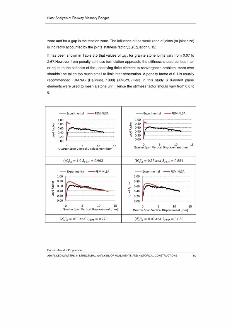
8/3/2019 Tibebu Hunegn Birhane- Blast Analysis of Railway Masonry Bridges
http://slidepdf.com/reader/full/tibebu-hunegn-birhane-blast-analysis-of-railway-masonry-bridges 76/134
Blast Analysis of Railway Masonry Bridges
Erasmus Mundus Programme
ADVANCED MASTERS IN STRUCTURAL ANALYSIS OF MONUMENTS AND HISTORICAL CONSTRUCTIONS 59
zone and for a gap in the tension zone. The influence of the weak zone of joints (or joint size)
is indirectly accounted by the joints stiffness factor,
,(Equation 3.12)
It has been shown in Table 3.5 that values of ,, for granite stone joints vary from 0.07 to
2.67.However from penalty stiffness formulation approach, the stiffness should be less than
or equal to the stiffness of the underlying finite element to convergence problem, more over
shouldn’t be taken too much small to limit inter penetration. A penalty factor of 0.1 is usually
recommended (DIANA) (Hallquist, 1998) (ANSYS).Here in this study 6 8-noded plane
elements were used to mesh a stone unit. Hence the stiffness factor should vary from 0.6 to
6.
1.0 λ 0.902 0.25 λ 0.881
0.05 λ 0.776 0.02 λ 0.825
0.00
0.20
0.40
0.60
0.80
1.00
0 5 10 15
L o a d
F a c t o r
Quarter Span Vertical Displacement [mm]
Experimental FEM‐NLSA
0.00
0.20
0.40
0.60
0.80
1.00
0 5 10 15
L o a d
F a c t o r
Quarter Span Vertical Displacement [mm]
Experimental FEM‐NLSA
0.00
0.20
0.40
0.60
0.80
1.00
0 5 10 15
L o a d
F a c t o r
Quarter Span Vertical Displacement [mm]
Experimental FEM‐NLSA
0.00
0.20
0.40
0.60
0.80
1.00
0 5 10 15
L o a d
F a c t o r
Quarter Span
Vertical
Displacement
[mm]
Experimental FEM‐NLSA
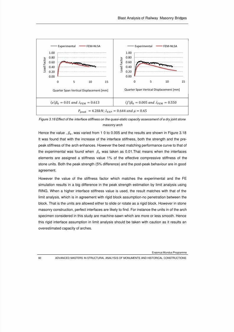
8/3/2019 Tibebu Hunegn Birhane- Blast Analysis of Railway Masonry Bridges
http://slidepdf.com/reader/full/tibebu-hunegn-birhane-blast-analysis-of-railway-masonry-bridges 77/134
Blast Analysis of Railway Masonry Bridges
Erasmus Mundus Programme
60 ADVANCED MASTERS IN STRUCTURAL ANALYSIS OF MONUMENTS AND HISTORICAL CONSTRUCTIONS
0.01 λ
0.613
0.005 λ
0.550
4.28; λ 0.644 0.65
Figure 3.18 Effect of the interface stiffness on the quasi-static capacity assessment of a dry joint stone
masonry arch
Hence the value , , was varied from 1 0 to 0.005 and the results are shown in Figure 3.18
It was found that with the increase of the interface stiffness, both the strength and the pre-
peak stiffness of the arch enhances. However the best matching performance curve to that of
the experimental was found when was taken as 0.01.That means when the interfaces
elements are assigned a stiffness value 1% of the effective compressive stiffness of thestone units. Both the peak strength (5% difference) and the post-peak behaviour are in good
agreement.
However the value of the stiffness factor which matches the experimental and the FE
simulation results in a big difference in the peak strength estimation by limit analysis using
RING. When a higher interface stiffness value is used, the result matches with that of the
limit analysis, which is in agreement with rigid block assumption-no penetration between the
block. That is the units are allowed either to slide or rotate as a rigid block. However in stone
masonry construction, perfect interfaces are likely to find. For instance the units in of the arch
specimen considered in this study are machine-sawn which are more or less smooth. Hence
this rigid interface assumption in limit analysis should be taken with caution as it results an
overestimated capacity of arches.
0.00
0.20
0.40
0.60
0.801.00
0 5 10 15
L o a d
F a c t o r
Quarter Span Vertical Displacement [mm]
Experimental FEM‐NLSA
0.00
0.20
0.40
0.60
0.801.00
0 5 10 15
L o a d
F a c t o r
Quarter Span Vertical Displacement [mm]
Experimental FEM‐NLSA
8/3/2019 Tibebu Hunegn Birhane- Blast Analysis of Railway Masonry Bridges
http://slidepdf.com/reader/full/tibebu-hunegn-birhane-blast-analysis-of-railway-masonry-bridges 78/134
Blast Analysis of Railway Masonry Bridges
Erasmus Mundus Programme
ADVANCED MASTERS IN STRUCTURAL ANALYSIS OF MONUMENTS AND HISTORICAL CONSTRUCTIONS 61
0.625 λ 0.613 1.0 λ 0.612
4.28;λ
0.644 0.65, 0.01
Figure 3.19 Effect of the interface stiffness on the quasi-static capacity assessment of a dry joint stone
masonry arch
The other possible case that can be considered to influence is the ratio of the tangential to
the normal stiffness ratio. Usually an equal stiffness for both the normal and shear tractions
is considered ( (DIANA) (ANSYS). The other alternative is to formulate the shear stiffness of
the joints in proportion to the shear modulus of elasticity. Both approaches were considered
and brought no significant difference as shown in Figure 3.19
3.7.2 Sensitivity of the Response to Post-Peak Strength parameters
In addition to the pre-peak strength parameters, the post peak strength parameters may
affect the result. In this prototype study, the units are assumed to behave elastically and
hence the post peak parameters are those of the stone unit interface properties only. So both
cohesion and coefficient of friction are considered. Actually in this study a dry jointed stone
masonry arch was tested experimentally, but the numerical simulation was carried out to see
how much application of cohesive binders (mortar joints) enhances the capacity of the arch.
Both these issues are discussed in the following sub sections.
3.7.2.1 Effect of Joint-Interfacial Friction Coefficient
It has been reported the coefficient of friction for dry jointed masonry to vary from 0.6 to 0.69
as shown in Table 3.6. Hence the non-linear FE analysis was carried out for three values
(0.60, 0.65, and 0.69) and the results (Figure 3.20) show that the capacity curve of the arch
is almost independent of the selection of the friction coefficients within the specified rage.
0.00
0.20
0.40
0.60
0.80
1.00
0 5 10 15
L o a d
F a c t o r
Quarter Span Vertical Displacement [mm]
Experimental FEM‐NLSA
0.00
0.20
0.40
0.60
0.801.00
0 5 10 15
L o a d
F a c t o r
Quarter Span Vertical Displacement [mm]
Experimental FEM‐NLSA
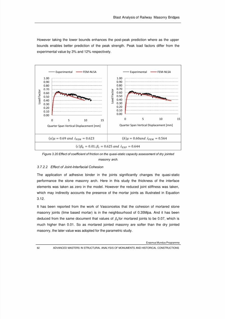
8/3/2019 Tibebu Hunegn Birhane- Blast Analysis of Railway Masonry Bridges
http://slidepdf.com/reader/full/tibebu-hunegn-birhane-blast-analysis-of-railway-masonry-bridges 79/134
Blast Analysis of Railway Masonry Bridges
Erasmus Mundus Programme
62 ADVANCED MASTERS IN STRUCTURAL ANALYSIS OF MONUMENTS AND HISTORICAL CONSTRUCTIONS
However taking the lower bounds enhances the post-peak prediction where as the upper
bounds enables better prediction of the peak strength. Peak load factors differ from the
experimental value by 3% and 12% respectively.
0.69 λ 0.623 0.60 λ 0.564
0.01;
0.625 λ
0.644
Figure 3.20 Effect of coefficient of friction on the quasi-static capacity assessment of dry jointed
masonry arch.
3.7.2.2 Effect of Joint-Interfacial Cohesion
The application of adhesive binder in the joints significantly changes the quasi-static
performance the stone masonry arch. Here in this study the thickness of the interface
elements was taken as zero in the model. However the reduced joint stiffness was taken,
which may indirectly accounts the presence of the mortar joints as illustrated in Equation
3.12.
It has been reported from the work of Vasconcelos that the cohesion of mortared stone
masonry joints (lime based mortar) is in the neighbourhood of 0.35Mpa. And it has been
deduced from the same document that values of for mortared joints to be 0.07, which is
much higher than 0.01. So as mortared jointed masonry are softer than the dry jointed
masonry, the later value was adopted for the parametric study.
0.00
0.10
0.20
0.30
0.40
0.50
0.60
0.70
0.80
0.90
1.00
0 5 10 15
L o
a d
F a c t o r
Quarter Span Vertical Displacement [mm]
Experimental FEM‐NLSA
0.00
0.10
0.200.30
0.40
0.50
0.60
0.70
0.80
0.90
1.00
0 5 10 15
L o
a d
F a c t o r
Quarter Span Vertical Displacement [mm]
Experimental FEM‐NLSA
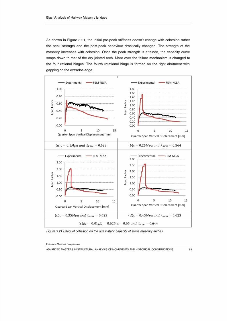
8/3/2019 Tibebu Hunegn Birhane- Blast Analysis of Railway Masonry Bridges
http://slidepdf.com/reader/full/tibebu-hunegn-birhane-blast-analysis-of-railway-masonry-bridges 80/134
Blast Analysis of Railway Masonry Bridges
Erasmus Mundus Programme
ADVANCED MASTERS IN STRUCTURAL ANALYSIS OF MONUMENTS AND HISTORICAL CONSTRUCTIONS 63
As shown in Figure 3.21, the initial pre-peak stiffness doesn’t change with cohesion rather
the peak strength and the post-peak behaviour drastically changed. The strength of the
masonry increases with cohesion. Once the peak strength is attained, the capacity curve
snaps down to that of the dry jointed arch. More over the failure mechanism is changed to
the four rational hinges. The fourth rotational hinge is formed on the right abutment with
gapping on the extrados edge.
0.1 λ 0.623 0.25 λ 0.564
0.35 λ 0.623 0.45 λ 0.623
0.01; 0.625; 0.65 λ 0.644
Figure 3.21 Effect of cohesion on the quasi-static capacity of stone masonry arches.
0.00
0.20
0.40
0.60
0.80
1.00
0 5 10 15
L o a d
F a c t o r
Quarter Span Vertical Displacement [mm]
Experimental FEM‐NLSA
0.00
0.20
0.40
0.60
0.80
1.00
1.20
1.40
1.60
1.80
0 5 10 15
L o a d
F a c t o r
Quarter Span Vertical Displacement [mm]
Experimental FEM‐NLSA
0.00
0.50
1.00
1.50
2.00
2.50
0 5 10 15
L o a d
F a c t o r
Quarter Span
Vertical
Displacement
[mm]
Experimental FEM‐NLSA
0.00
0.50
1.00
1.50
2.00
2.50
3.00
0 5 10 15
L o a d
F a c t o r
Quarter Span
Vertical
Displacement
[mm]
Experimental FEM‐NLSA

8/3/2019 Tibebu Hunegn Birhane- Blast Analysis of Railway Masonry Bridges
http://slidepdf.com/reader/full/tibebu-hunegn-birhane-blast-analysis-of-railway-masonry-bridges 81/134
Blast Analysis of Railway Masonry Bridges
Erasmus Mundus Programme
64 ADVANCED MASTERS IN STRUCTURAL ANALYSIS OF MONUMENTS AND HISTORICAL CONSTRUCTIONS
8/3/2019 Tibebu Hunegn Birhane- Blast Analysis of Railway Masonry Bridges
http://slidepdf.com/reader/full/tibebu-hunegn-birhane-blast-analysis-of-railway-masonry-bridges 82/134
Blast Analysis of Railway Masonry Bridges
Erasmus Mundus Programme
ADVANCED MASTERS IN STRUCTURAL ANALYSIS OF MONUMENTS AND HISTORICAL CONSTRUCTIONS 65
CHAPTER 4
IMPACT PERFORMANCE OF
STONE MASONRY BRIDGES: SINGLE SPAN ARCH
4.1 General
Blast and impact loads arise from interactions of systems that occur at very high rate. The
interaction involves contact between the systems and results in the transmission of kineticenergy from one body to the other. These interactions induce a very high strain rates
(loading rates), which are highly transient and impulsive, in the target structures (one of the
interacting systems). However the first load type arises when a very fast moving blast air
engulfs the structure where as the second loading phenomenon occurs when a fast moving
projectile hits the structure.
To characterize the performance of stone masonry arches at high rate loading, a single span
stone masonry arch was assessed both experimentally and numerically for impact loading.
The prototype arches were tested experimentally using a drop weight apparatus. The
numerical simulation was carried out using an explicit dynamic analysis software LS-DYNA.
Finally a calibration of the numerical model was calibrated using the experimental results.
4.2 Dynamic Material Properties
Impact and blast loads typically produce very high strain rates in the ranges of 10 10
and 10 10 respectively. The approximate ranges of the expected strain rates for
different loading conditions are shown in the Figure 4.1. It can be observed that ordinary
static strain rate is located in the range of 10 10 , where as dynamic loads yield
strain rates in the range: 10 10 .
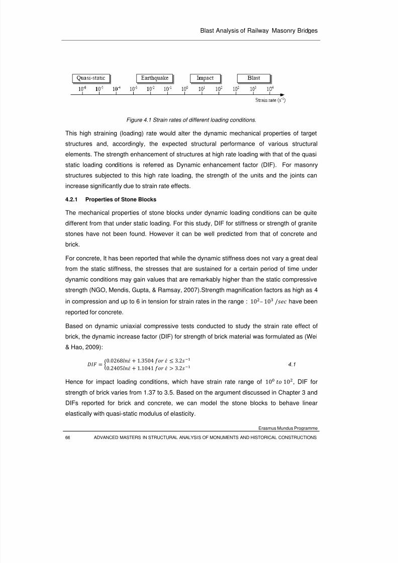
8/3/2019 Tibebu Hunegn Birhane- Blast Analysis of Railway Masonry Bridges
http://slidepdf.com/reader/full/tibebu-hunegn-birhane-blast-analysis-of-railway-masonry-bridges 83/134
Blast Analysis of Railway Masonry Bridges
Erasmus Mundus Programme
66 ADVANCED MASTERS IN STRUCTURAL ANALYSIS OF MONUMENTS AND HISTORICAL CONSTRUCTIONS
Figure 4.1 Strain rates of different loading conditions.
This high straining (loading) rate would alter the dynamic mechanical properties of target
structures and, accordingly, the expected structural performance of various structural
elements. The strength enhancement of structures at high rate loading with that of the quasi
static loading conditions is referred as Dynamic enhancement factor (DIF). For masonry
structures subjected to this high rate loading, the strength of the units and the joints can
increase significantly due to strain rate effects.
4.2.1 Properties of Stone Blocks
The mechanical properties of stone blocks under dynamic loading conditions can be quite
different from that under static loading. For this study, DIF for stiffness or strength of granite
stones have not been found. However it can be well predicted from that of concrete and
brick.
For concrete, It has been reported that while the dynamic stiffness does not vary a great deal
from the static stiffness, the stresses that are sustained for a certain period of time underdynamic conditions may gain values that are remarkably higher than the static compressive
strength (NGO, Mendis, Gupta, & Ramsay, 2007).Strength magnification factors as high as 4
in compression and up to 6 in tension for strain rates in the range : 10– 10 / have been
reported for concrete.
Based on dynamic uniaxial compressive tests conducted to study the strain rate effect of
brick, the dynamic increase factor (DIF) for strength of brick material was formulated as (Wei
& Hao, 2009):
0.0268 1.3504 3.20.2405 1.1041 3.2 4.1
Hence for impact loading conditions, which have strain rate range of 10 10, DIF for
strength of brick varies from 1.37 to 3.5. Based on the argument discussed in Chapter 3 and
DIFs reported for brick and concrete, we can model the stone blocks to behave linear
elastically with quasi-static modulus of elasticity.
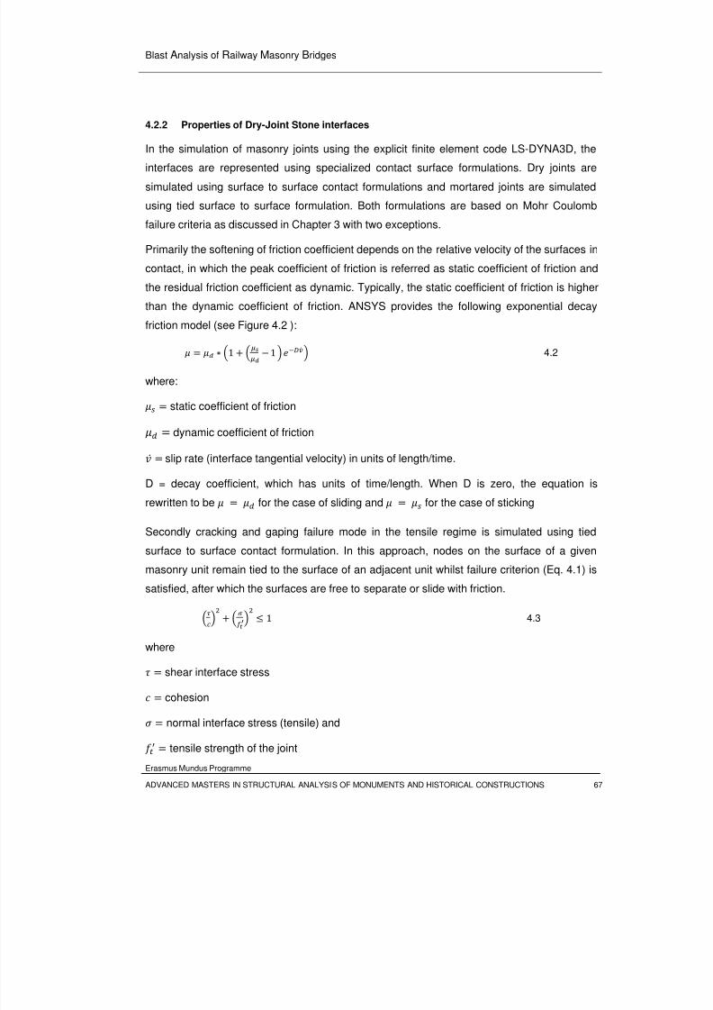
8/3/2019 Tibebu Hunegn Birhane- Blast Analysis of Railway Masonry Bridges
http://slidepdf.com/reader/full/tibebu-hunegn-birhane-blast-analysis-of-railway-masonry-bridges 84/134
Blast Analysis of Railway Masonry Bridges
Erasmus Mundus Programme
ADVANCED MASTERS IN STRUCTURAL ANALYSIS OF MONUMENTS AND HISTORICAL CONSTRUCTIONS 67
4.2.2 Properties of Dry-Joint Stone interfaces
In the simulation of masonry joints using the explicit finite element code LS-DYNA3D, the
interfaces are represented using specialized contact surface formulations. Dry joints are
simulated using surface to surface contact formulations and mortared joints are simulated
using tied surface to surface formulation. Both formulations are based on Mohr Coulomb
failure criteria as discussed in Chapter 3 with two exceptions.
Primarily the softening of friction coefficient depends on the relative velocity of the surfaces in
contact, in which the peak coefficient of friction is referred as static coefficient of friction and
the residual friction coefficient as dynamic. Typically, the static coefficient of friction is higher
than the dynamic coefficient of friction. ANSYS provides the following exponential decay
friction model (see Figure 4.2 ):
1
1 4.2
where:
static coefficient of friction dynamic coefficient of friction
slip rate (interface tangential velocity) in units of length/time.
D = decay coefficient, which has units of time/length. When D is zero, the equation isrewritten to be for the case of sliding and for the case of sticking Secondly cracking and gaping failure mode in the tensile regime is simulated using tied
surface to surface contact formulation. In this approach, nodes on the surface of a given
masonry unit remain tied to the surface of an adjacent unit whilst failure criterion (Eq. 4.1) is
satisfied, after which the surfaces are free to separate or slide with friction.
1 4.3
where
shear interface stress
cohesion
normal interface stress (tensile) and
tensile strength of the joint
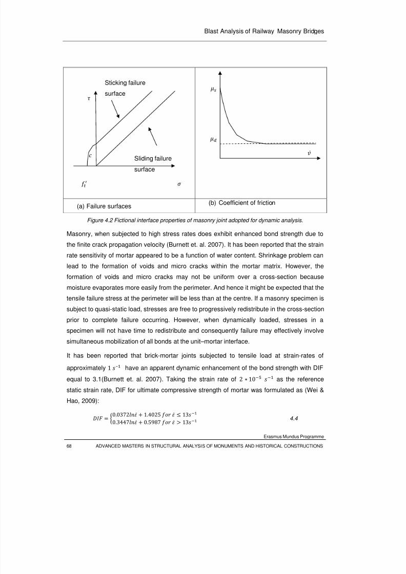
8/3/2019 Tibebu Hunegn Birhane- Blast Analysis of Railway Masonry Bridges
http://slidepdf.com/reader/full/tibebu-hunegn-birhane-blast-analysis-of-railway-masonry-bridges 85/134
Blast Analysis of Railway Masonry Bridges
Erasmus Mundus Programme
68 ADVANCED MASTERS IN STRUCTURAL ANALYSIS OF MONUMENTS AND HISTORICAL CONSTRUCTIONS
(a) Failure surfaces(b) Coefficient of friction
Figure 4.2 Fictional interface properties of masonry joint adopted for dynamic analysis.
Masonry, when subjected to high stress rates does exhibit enhanced bond strength due to
the finite crack propagation velocity (Burnett et. al. 2007). It has been reported that the strain
rate sensitivity of mortar appeared to be a function of water content. Shrinkage problem can
lead to the formation of voids and micro cracks within the mortar matrix. However, the
formation of voids and micro cracks may not be uniform over a cross-section because
moisture evaporates more easily from the perimeter. And hence it might be expected that the
tensile failure stress at the perimeter will be less than at the centre. If a masonry specimen is
subject to quasi-static load, stresses are free to progressively redistribute in the cross-section
prior to complete failure occurring. However, when dynamically loaded, stresses in a
specimen will not have time to redistribute and consequently failure may effectively involve
simultaneous mobilization of all bonds at the unit–mortar interface.
It has been reported that brick-mortar joints subjected to tensile load at strain-rates of
approximately 1 – have an apparent dynamic enhancement of the bond strength with DIF
equal to 3.1(Burnett et. al. 2007). Taking the strain rate of 2 10 as the reference
static strain rate, DIF for ultimate compressive strength of mortar was formulated as (Wei &
Hao, 2009):
0.0372 1.4025 130.3447 0.5987 13 4.4
Sticking failure
surface
Sliding failure
surface
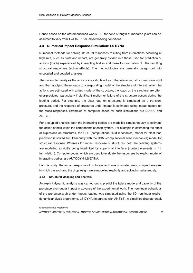
8/3/2019 Tibebu Hunegn Birhane- Blast Analysis of Railway Masonry Bridges
http://slidepdf.com/reader/full/tibebu-hunegn-birhane-blast-analysis-of-railway-masonry-bridges 86/134
Blast Analysis of Railway Masonry Bridges
Erasmus Mundus Programme
ADVANCED MASTERS IN STRUCTURAL ANALYSIS OF MONUMENTS AND HISTORICAL CONSTRUCTIONS 69
Hence based on the aforementioned works, DIF for bond strength of mortared joints can be
assumed to vary from 1.44 to 3.1 for impact loading conditions.
4.3 Numerical Impact Response Simulation: LS DYNA
Numerical methods for solving structural responses resulting from interactions occurring at
high rate, such as blast and impact, are generally divided into those used for prediction of
actions (loads) experienced by interacting bodies and those for calculation of the resulting
structural responses (action effects). The methodologies are generally categorized into
uncoupled and coupled analyses.
The uncoupled analysis the actions are calculated as if the interacting structures were rigid
and then applying these loads to a responding model of the structure of interest. When the
actions are estimated with a rigid model of the structure, the loads on the structure are often
over-predicted, particularly if significant motion or failure of the structure occurs during the
loading period. For example, the blast load on structures is simulated as a transient
pressure, and the response of structures under impact is estimated using impact factors for
the static responses. Examples of computer codes for such simulations are DIANA, and
ANSYS
For a coupled analysis, both the interacting bodies are modelled simultaneously to estimate
the action effects within the components of each system. For example in estimating the effect
of explosions on structures, the CFD (computational fluid mechanics) model for blast-load
prediction is solved simultaneously with the CSM (computational solid mechanics) model for
structural response. Whereas for impact response of structures, both the colliding systems
are modelled explicitly being interlinked by superficial interface (contact elements in FE
formulation). Computer codes, which are used to evaluate the responses by explicit model of
interacting bodies, are AUTODYN, LS-DYNA.
For this study, the impact response of prototype arch was simulated using coupled analysis
in which the arch and the drop weight were modelled explicitly and solved simultaneously.
4.3.1 Structural Modeling and Analysis
An explicit dynamic analysis was carried out to predict the failure mode and capacity of the
prototype arch under impact in advance of the experimental work. The non-linear behaviour
of the prototype arch under impact loading was simulated using the 3D non-linear explicit
dynamic analysis programme, LS-DYNA (integrated with ANSYS). A simplified discrete-crack
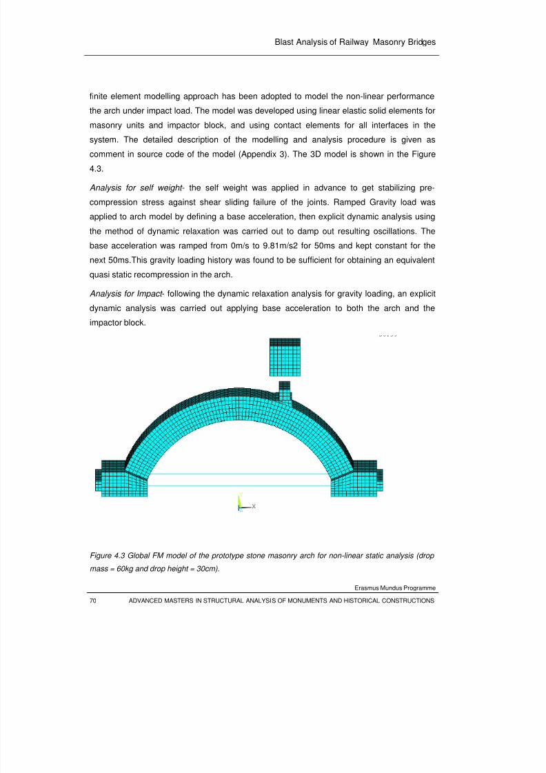
8/3/2019 Tibebu Hunegn Birhane- Blast Analysis of Railway Masonry Bridges
http://slidepdf.com/reader/full/tibebu-hunegn-birhane-blast-analysis-of-railway-masonry-bridges 87/134
Blast Analysis of Railway Masonry Bridges
Erasmus Mundus Programme
70 ADVANCED MASTERS IN STRUCTURAL ANALYSIS OF MONUMENTS AND HISTORICAL CONSTRUCTIONS
finite element modelling approach has been adopted to model the non-linear performance
the arch under impact load. The model was developed using linear elastic solid elements for
masonry units and impactor block, and using contact elements for all interfaces in the
system. The detailed description of the modelling and analysis procedure is given as
comment in source code of the model (Appendix 3). The 3D model is shown in the Figure
4.3.
Analysis for self weight - the self weight was applied in advance to get stabilizing pre-
compression stress against shear sliding failure of the joints. Ramped Gravity load was
applied to arch model by defining a base acceleration, then explicit dynamic analysis using
the method of dynamic relaxation was carried out to damp out resulting oscillations. The
base acceleration was ramped from 0m/s to 9.81m/s2 for 50ms and kept constant for thenext 50ms.This gravity loading history was found to be sufficient for obtaining an equivalent
quasi static recompression in the arch.
Analysis for Impact - following the dynamic relaxation analysis for gravity loading, an explicit
dynamic analysis was carried out applying base acceleration to both the arch and the
impactor block.
Figure 4.3 Global FM model of the prototype stone masonry arch for non-linear static analysis (drop
mass = 60kg and drop height = 30cm).
X
Y
Z
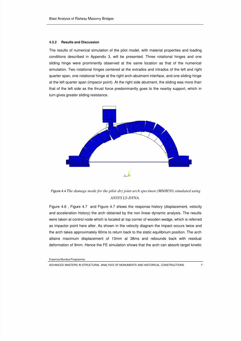
8/3/2019 Tibebu Hunegn Birhane- Blast Analysis of Railway Masonry Bridges
http://slidepdf.com/reader/full/tibebu-hunegn-birhane-blast-analysis-of-railway-masonry-bridges 88/134
Blast Analysis of Railway Masonry Bridges
Erasmus Mundus Programme
ADVANCED MASTERS IN STRUCTURAL ANALYSIS OF MONUMENTS AND HISTORICAL CONSTRUCTIONS 71
4.3.2 Results and Discussion
The results of numerical simulation of the pilot model, with material properties and loading
conditions described in Appendix 3, will be presented. Three rotational hinges and one
sliding hinge were prominently observed at the same location as that of the numerical
simulation. Two rotational hinges centered at the extrados and intrados of the left and right
quarter span, one rotational hinge at the right arch-abutment interface, and one sliding hinge
at the left quarter span (impacor point). At the right side abutment, the sliding was more than
that of the left side as the thrust force predominantly goes to the nearby support, which in
turn gives greater sliding resistance.
Figure 4.4 The damage mode for the pilot dry joint arch specimen (M60H30) simulated using
ANSYS LS-DYNA.
Figure 4.6 , Figure 4.7 and Figure 4.7 shows the response history (displacement, velocity
and acceleration history) the arch obtained by the non linear dynamic analysis. The results
were taken at control node which is located at top corner of wooden wedge, which is referred
as impactor point here after. As shown in the velocity diagram the impact occurs twice and
the arch takes approximately 60ms to return back to the static equilibrium position. The arch
attains maximum displacement of 13mm at 38ms and rebounds back with residual
deformation of 9mm. Hence the FE simulation shows that the arch can absorb target kinetic
X
Y
Z
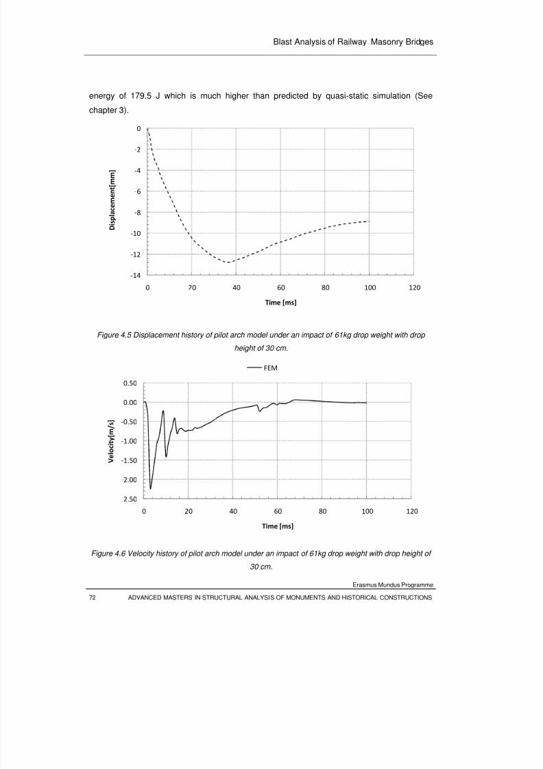
8/3/2019 Tibebu Hunegn Birhane- Blast Analysis of Railway Masonry Bridges
http://slidepdf.com/reader/full/tibebu-hunegn-birhane-blast-analysis-of-railway-masonry-bridges 89/134
Blast Analysis of Railway Masonry Bridges
Erasmus Mundus Programme
72 ADVANCED MASTERS IN STRUCTURAL ANALYSIS OF MONUMENTS AND HISTORICAL CONSTRUCTIONS
energy of 179.5 J which is much higher than predicted by quasi-static simulation (See
chapter 3).
Figure 4.5 Displacement history of pilot arch model under an impact of 61kg drop weight with drop
height of 30 cm.
Figure 4.6 Velocity history of pilot arch model under an impact of 61kg drop weight with drop height of
30 cm.
‐14
‐12
‐10
‐8
‐6
‐4
‐2
0
0 20 40 60 80 100 120
D i s p l a c e m e n t [ m m ]
Time [ms]
‐2.50
‐2.00
‐1.50
‐1.00
‐0.50
0.00
0.50
0 20 40 60 80 100 120
V e l o c i t y [ m / s ]
Time [ms]
FEM
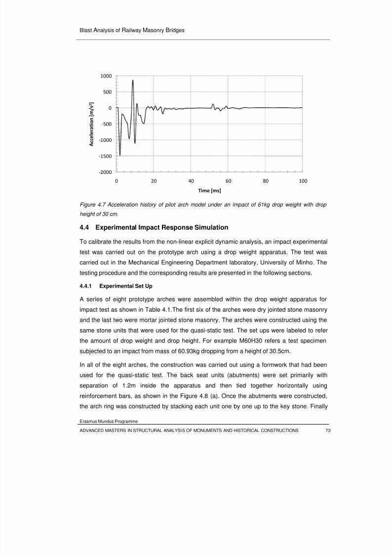
8/3/2019 Tibebu Hunegn Birhane- Blast Analysis of Railway Masonry Bridges
http://slidepdf.com/reader/full/tibebu-hunegn-birhane-blast-analysis-of-railway-masonry-bridges 90/134
Blast Analysis of Railway Masonry Bridges
Erasmus Mundus Programme
ADVANCED MASTERS IN STRUCTURAL ANALYSIS OF MONUMENTS AND HISTORICAL CONSTRUCTIONS 73
Figure 4.7 Acceleration history of pilot arch model under an impact of 61kg drop weight with drop
height of 30 cm.
4.4 Experimental Impact Response Simulation
To calibrate the results from the non-linear explicit dynamic analysis, an impact experimental
test was carried out on the prototype arch using a drop weight apparatus. The test was
carried out in the Mechanical Engineering Department laboratory, University of Minho. The
testing procedure and the corresponding results are presented in the following sections.
4.4.1 Experimental Set Up
A series of eight prototype arches were assembled within the drop weight apparatus for
impact test as shown in Table 4.1.The first six of the arches were dry jointed stone masonry
and the last two were mortar jointed stone masonry. The arches were constructed using the
same stone units that were used for the quasi-static test. The set ups were labeled to refer
the amount of drop weight and drop height. For example M60H30 refers a test specimen
subjected to an impact from mass of 60.93kg dropping from a height of 30.5cm.
In all of the eight arches, the construction was carried out using a formwork that had been
used for the quasi-static test. The back seat units (abutments) were set primarily with
separation of 1.2m inside the apparatus and then tied together horizontally using
reinforcement bars, as shown in the Figure 4.8 (a). Once the abutments were constructed,
the arch ring was constructed by stacking each unit one by one up to the key stone. Finally
‐2000
‐1500
‐1000
‐500
0
500
1000
0 20 40 60 80 100
A c c e l e r a t i o n [ m / s 2 ]
Time [ms]
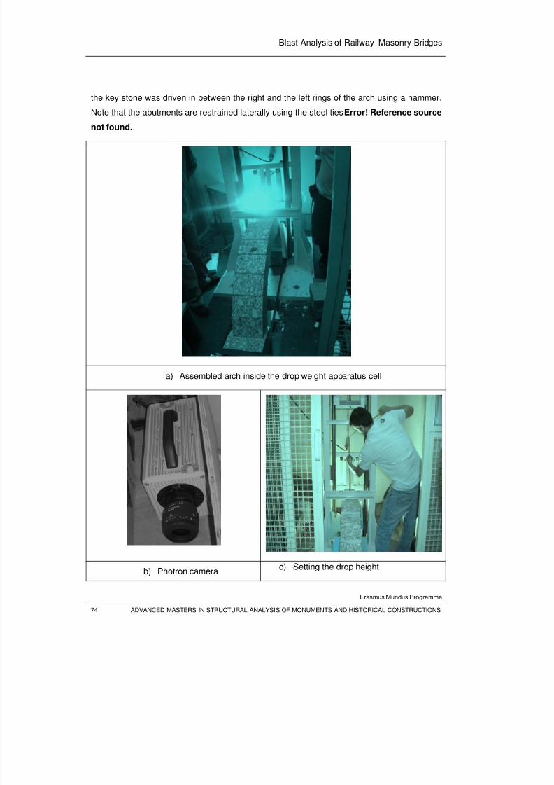
8/3/2019 Tibebu Hunegn Birhane- Blast Analysis of Railway Masonry Bridges
http://slidepdf.com/reader/full/tibebu-hunegn-birhane-blast-analysis-of-railway-masonry-bridges 91/134
Blast Analysis of Railway Masonry Bridges
Erasmus Mundus Programme
74 ADVANCED MASTERS IN STRUCTURAL ANALYSIS OF MONUMENTS AND HISTORICAL CONSTRUCTIONS
the key stone was driven in between the right and the left rings of the arch using a hammer.
Note that the abutments are restrained laterally using the steel tiesError! Reference source
not found..
a) Assembled arch inside the drop weight apparatus cell
b) Photron camerac) Setting the drop height
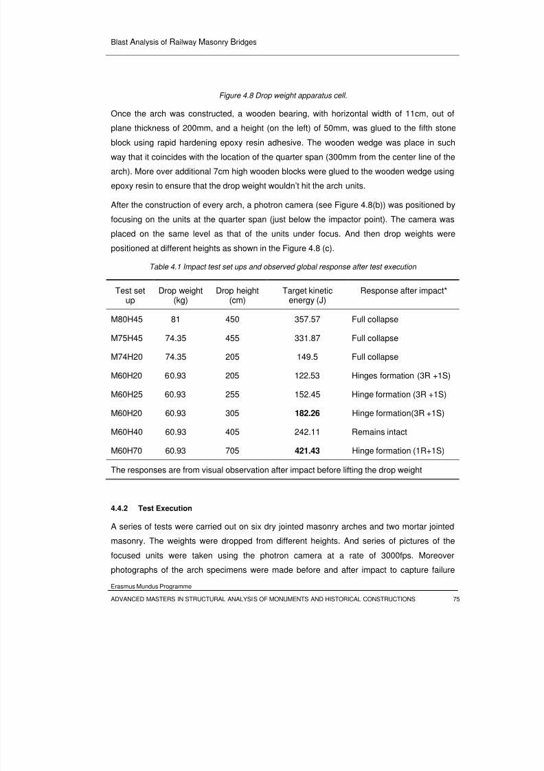
8/3/2019 Tibebu Hunegn Birhane- Blast Analysis of Railway Masonry Bridges
http://slidepdf.com/reader/full/tibebu-hunegn-birhane-blast-analysis-of-railway-masonry-bridges 92/134
Blast Analysis of Railway Masonry Bridges
Erasmus Mundus Programme
ADVANCED MASTERS IN STRUCTURAL ANALYSIS OF MONUMENTS AND HISTORICAL CONSTRUCTIONS 75
Figure 4.8 Drop weight apparatus cell.
Once the arch was constructed, a wooden bearing, with horizontal width of 11cm, out of
plane thickness of 200mm, and a height (on the left) of 50mm, was glued to the fifth stone
block using rapid hardening epoxy resin adhesive. The wooden wedge was place in such
way that it coincides with the location of the quarter span (300mm from the center line of the
arch). More over additional 7cm high wooden blocks were glued to the wooden wedge using
epoxy resin to ensure that the drop weight wouldn’t hit the arch units.
After the construction of every arch, a photron camera (see Figure 4.8(b)) was positioned by
focusing on the units at the quarter span (just below the impactor point). The camera was
placed on the same level as that of the units under focus. And then drop weights were
positioned at different heights as shown in the Figure 4.8 (c).
Table 4.1 Impact test set ups and observed global response after test execution
Test setup
Drop weight(kg)
Drop height(cm)
Target kineticenergy (J)
Response after impact*
M80H45 81 450 357.57 Full collapse
M75H45 74.35 455 331.87 Full collapse
M74H20 74.35 205 149.5 Full collapse
M60H20 60.93 205 122.53 Hinges formation (3R +1S)
M60H25 60.93 255 152.45 Hinge formation (3R +1S)
M60H20 60.93 305 182.26 Hinge formation(3R +1S)
M60H40 60.93 405 242.11 Remains intact
M60H70 60.93 705 421.43 Hinge formation (1R+1S)
The responses are from visual observation after impact before lifting the drop weight
4.4.2 Test Execution
A series of tests were carried out on six dry jointed masonry arches and two mortar jointed
masonry. The weights were dropped from different heights. And series of pictures of the
focused units were taken using the photron camera at a rate of 3000fps. Moreover
photographs of the arch specimens were made before and after impact to capture failure
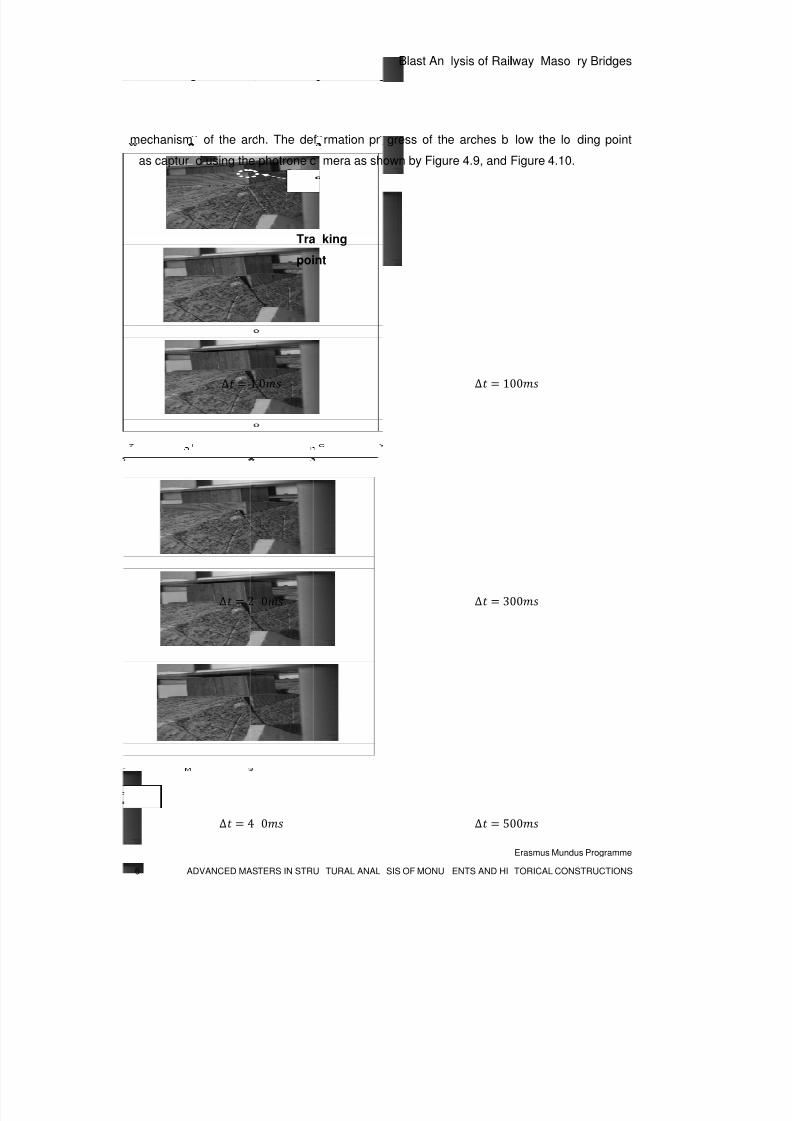
8/3/2019 Tibebu Hunegn Birhane- Blast Analysis of Railway Masonry Bridges
http://slidepdf.com/reader/full/tibebu-hunegn-birhane-blast-analysis-of-railway-masonry-bridges 93/134
6 A
mechanism
as captur
DVANCED MAS
of the arc
d using the
∆ 1
∆ 2
∆ 4
TERS IN STRU
h. The def
photrone c
.0
0
0
Tra
poin
TURAL ANAL
rmation pr
mera as sh
king
t
Blast An
SIS OF MONU
gress of th
own by Figu
lysis of Rail
ENTS AND HI
e arches b
re 4.9, and
∆ 1
∆ 3
∆ 5
lway Maso
Erasmus Mund
TORICAL CON
low the lo
Figure 4.10.
00
00
00
ry Bridges
us Programme
STRUCTIONS
ding point
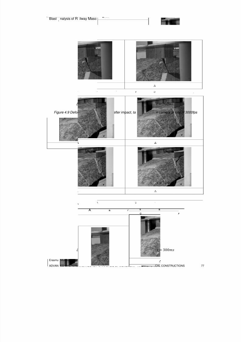
8/3/2019 Tibebu Hunegn Birhane- Blast Analysis of Railway Masonry Bridges
http://slidepdf.com/reader/full/tibebu-hunegn-birhane-blast-analysis-of-railway-masonry-bridges 94/134
Blast
Erasmu
ADVAN
Fig
nalysis of R
Mundus Progr
ED MASTERS
∆
ure 4.9 Defor
∆
ilway Maso
mme
IN STRUCTUR
600
mation of dry
1.0
200
ry Bridges
L ANALYSIS O
joint arch aft
F MONUMENT
er impact, ta
AND HISTORI
en by photr
CAL CONSTRU
700
n camera at
100
300
CTIONS
rate of 3000f
77
ps
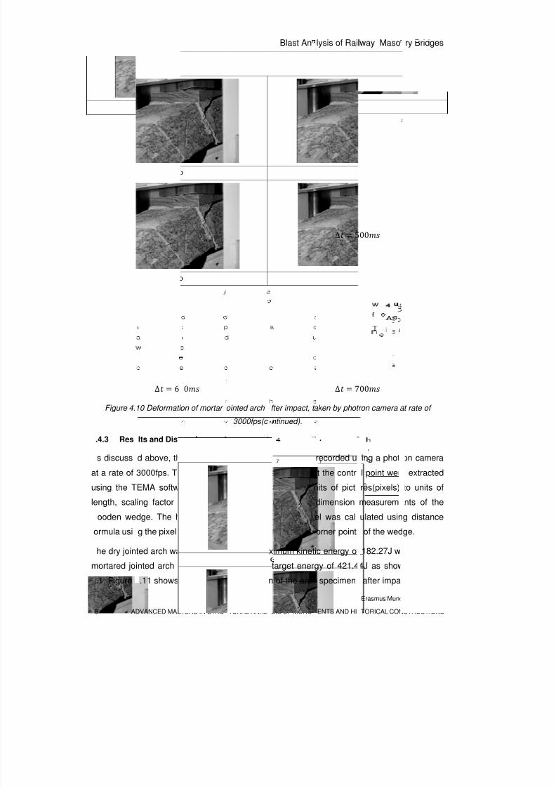
8/3/2019 Tibebu Hunegn Birhane- Blast Analysis of Railway Masonry Bridges
http://slidepdf.com/reader/full/tibebu-hunegn-birhane-blast-analysis-of-railway-masonry-bridges 95/134
8 A
Figure 4.
.4.3 Res
s discuss
at a rate of
using the T
length, scalooden we
ormula usi
he dry join
mortared jo
.1. Figure
DVANCED MAS
∆ 4
∆ 6
10 Deformati
lts and Disc
d above, th
3000fps. Th
EMA softw
ing factordge. The h
g the pixel
ted arch wa
inted arch r
.11 shows
TERS IN STRU
0
0
on of mortar
ussion
e deformati
e kinematic
re. To tran
as establieight of th
o-ordinate
s found to a
esisted an
the ultimate
TURAL ANAL
ointed arch
3000fps(c
n at quart
response
sform the
hed from twedge in
of the bott
bsorb a ma
impact with
deformatio
Blast An
SIS OF MONU
fter impact, t
ntinued).
r span was
arameters
ata from u
he verticalunits of pix
m and top
ximum kinet
target ener
n of the arc
lysis of Rail
ENTS AND HI
∆ 5
∆ 7
aken by phot
recorded u
t the contr
nits of pict
dimensionel was cal
orner point
ic energy of
gy of 421.4
specimen
lway Maso
Erasmus Mund
TORICAL CON
00
00
ron camera a
ing a photr
l point wer
res(pixels)
measuremulated usin
of the wed
182.27J w
4J as show
after impa
ry Bridges
us Programme
STRUCTIONS
t rate of
on camera
extracted
to units of
nts of theg distance
ge.
ere as the
n in Table
t test. The
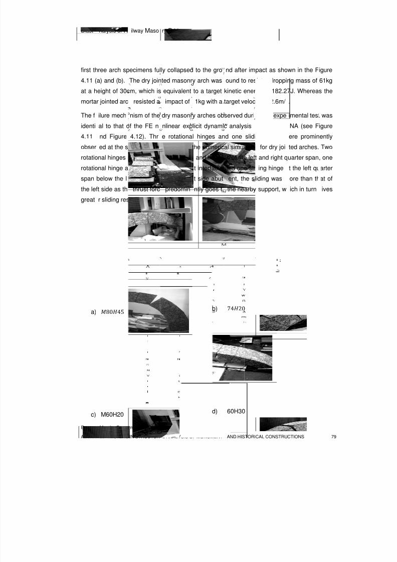
8/3/2019 Tibebu Hunegn Birhane- Blast Analysis of Railway Masonry Bridges
http://slidepdf.com/reader/full/tibebu-hunegn-birhane-blast-analysis-of-railway-masonry-bridges 96/134
Blast
Erasmu
ADVAN
first th
4.11 (
at a h
morta
The f
identi
4.11
obser
rotatio
rotatio
spanthe lef
great
a)
c)
nalysis of R
Mundus Progr
ED MASTERS
ree arch sp
a) and (b).
eight of 30c
r jointed arc
ilure mech
al to that o
nd Figure
ed at the s
nal hinges
nal hinge at
below the lt side as th
r sliding res
8045
M60H20
ilway Maso
mme
IN STRUCTUR
ecimens ful
The dry join
m, which is
resisted a
nism of the
f the FE n
4.12). Thr
me locatio
entered at
the right a
ading pointthrust forc
istance.
ry Bridges
L ANALYSIS O
ly collapsed
ted masonr
equivalent
impact of
dry masonr
nlinear exp
e rotationa
as that of
he extrado
ch-abutme
. At the rigpredomin
F MONUMENT
to the gro
y arch was
to a target
1kg with a
y arches ob
licit dynami
l hinges an
the numeric
and intrad
t interface,
t side abutntly goes t
b)
d)
AND HISTORI
nd after im
ound to res
kinetic ener
target veloc
served duri
c analysis
d one slidi
al simulatio
s of the left
and one sli
ent, the slthe nearby
7420
60H30
CAL CONSTRU
pact as sho
ist a droppi
gy of 182.2
ity of 2.6m/
g the expe
sing LS D
ng hinge
for dry joi
and right q
ing hinge
iding wassupport, w
CTIONS
wn in the F
ng mass of
7J. Wherea
.
imental test
NA (see F
ere promin
ted arches.
uarter span
t the left qu
ore than thich in turn
79
igure
61kg
s the
was
igure
ently
Two
, one
arter
at ofives
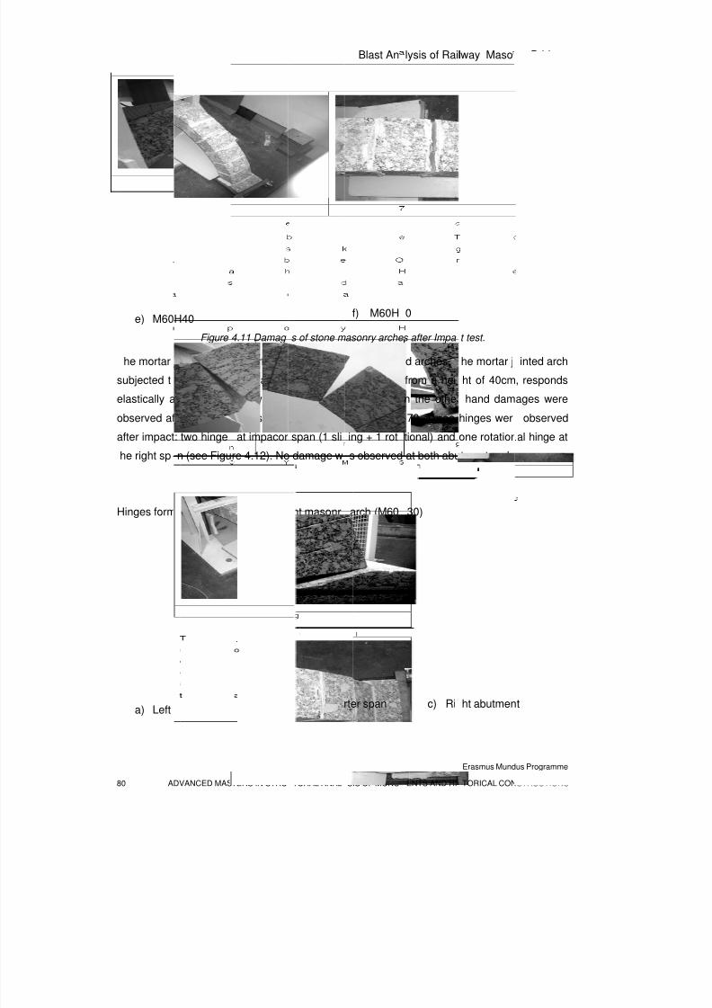
8/3/2019 Tibebu Hunegn Birhane- Blast Analysis of Railway Masonry Bridges
http://slidepdf.com/reader/full/tibebu-hunegn-birhane-blast-analysis-of-railway-masonry-bridges 97/134
80 A
e) M60
he mortar
subjected t
elastically a
observed af
after impact
he right sp
Hinges form
a) Left
DVANCED MAS
H40Figure
jointed arch
an impact
nd no dam
ter the imp
: two hinge
n (see Figu
ed after im
quarter spa
TERS IN STRU
4.11 Damag
es perform
from a ma
age was o
ct test in t
at impacor
re 4.12). No
act of dry j
b)
TURAL ANAL
s of stone m
etter than t
s of 60.95
served aft
e arch spe
span (1 sli
damage w
int masonr
Right qua
Blast An
SIS OF MONU
f) M60H
asonry arche
he dry joint
g dropping
r impact.
cimen M60
ing + 1 rot
s observed
arch (M60
rter span
lysis of Rail
ENTS AND HI
0
s after Impa
d arches.
from a hei
n the othe
70. Three
tional) and
at both abu
30)
c) Ri
lway Maso
Erasmus Mund
TORICAL CON
t test.
he mortar j
ht of 40cm
hand dam
hinges wer
one rotation
tment ends
ht abutmen
ry Bridges
us Programme
STRUCTIONS
inted arch
, responds
ages were
observed
al hinge at
.
t
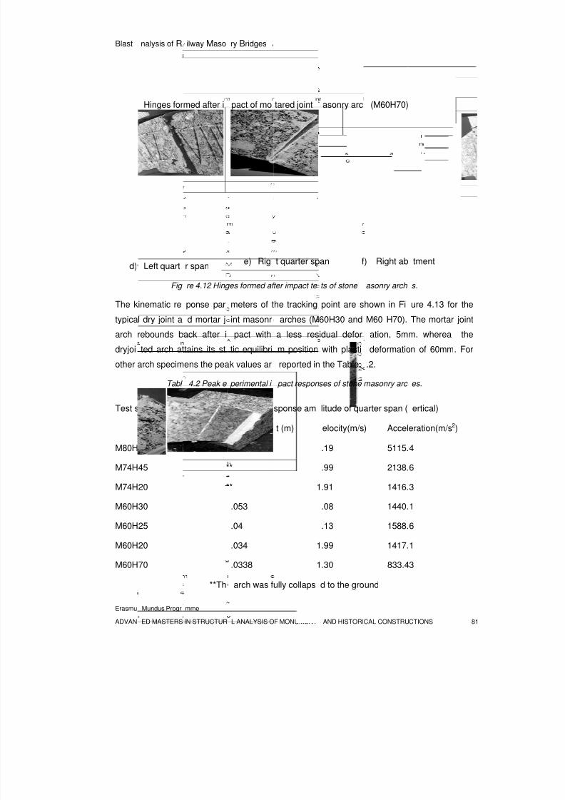
8/3/2019 Tibebu Hunegn Birhane- Blast Analysis of Railway Masonry Bridges
http://slidepdf.com/reader/full/tibebu-hunegn-birhane-blast-analysis-of-railway-masonry-bridges 98/134
Blast
Erasmu
ADVAN
d)
The k
typica
arch
dryjoi
other
Test s
M80H
M74H
M74H
M60H
M60H
M60H
M60H
nalysis of R
Mundus Progr
ED MASTERS
Hinges for
Left quart
Fig
inematic re
l dry joint a
rebounds b
ted arch at
arch specim
Tabl
et up
40
45
20
30
25
20
70
ilway Maso
mme
IN STRUCTUR
med after i
r span
re 4.12 Hing
ponse par
d mortar j
ack after i
tains its st
ens the pea
4.2 Peak e
*
*
*
**Th
ry Bridges
L ANALYSIS O
pact of mo
e) Rig
es formed af
meters of t
int masonr
pact with
tic equilibri
k values ar
perimental i
aximum re
isplaceme
*
*
*
.053
.04
.034
.0338
arch was f
F MONUMENT
tared joint
t quarter sp
ter impact te
he tracking
arches (M
a less res
m position
reported in
pact respon
sponse am
t (m)
1
1
1
ully collaps
AND HISTORI
asonry arc
an f
ts of stone
point are s
60H30 and
idual defor
with plasti
the Table
ses of stone
litude of qu
elocity(m/s
.19
.99
.91
.08
.13
.99
.30
d to the gro
CAL CONSTRU
(M60H70)
) Right ab
asonry arch
hown in Fi
M60 H70).
ation, 5m
deformatio
.2.
masonry arc
arter span (
) Accel
5115.
2138.
1416.
1440.
1588.
1417.
833.4
und
CTIONS
tment
s.
ure 4.13 fo
The mortar
m. wherea
n of 60mm
es.
ertical)
eration(m/s2
4
6
3
1
6
1
3
81
r the
joint
the
. For
)
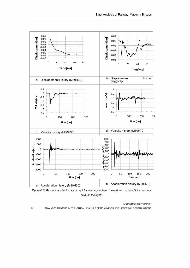
8/3/2019 Tibebu Hunegn Birhane- Blast Analysis of Railway Masonry Bridges
http://slidepdf.com/reader/full/tibebu-hunegn-birhane-blast-analysis-of-railway-masonry-bridges 99/134
Blast Analysis of Railway Masonry Bridges
Erasmus Mundus Programme
82 ADVANCED MASTERS IN STRUCTURAL ANALYSIS OF MONUMENTS AND HISTORICAL CONSTRUCTIONS
a) Displacement History (M60H30)b) Displacement history
(M60H70)
c) Velocity history (M60H30)d) Velocity history (M60H70)
e) Acceleration history (M60H30)f) Acceleration history (M60H70)
Figure 4.13 Responses after impact of dry joint masonry arch (on the left) and mortared joint masonry
arch (on the right).
‐0.07‐0.06‐0.05‐0.04‐0.03‐0.02‐
0.01
0.000.01
0 20 40 60 80
D i s p l a c e m e n t [ m ]
Time[ms]
‐0.04
‐0.03
‐0.02
‐0.01
0.00
0.01
0 20 40 60
D i s p l a c e m e n t [ m ]
Time[ms]
‐2.5
‐2
‐1.5
‐1
‐0.5
0
0.5
0 100 200 300
V e l o c i t y [ m / s ]
Time [ms]
‐1.5
‐1
‐0.5
0
0.5
1
0 100 200 30
V e l o c i t y [ m / s ]
Time [ms]
‐2000
‐1500
‐1000
‐500
0
500
1000
0 50 100 150 200
A c c e l e r a t i o n [ m / s 2 ]
Time [ms]
‐1000
‐800
‐600
‐400
‐200
0
200
400
600
800
1000
0 50 100 150 200
A c c e l e r a t i o n [ m / s 2 ]
Time [ms]
8/3/2019 Tibebu Hunegn Birhane- Blast Analysis of Railway Masonry Bridges
http://slidepdf.com/reader/full/tibebu-hunegn-birhane-blast-analysis-of-railway-masonry-bridges 100/134
Blast Analysis of Railway Masonry Bridges
Erasmus Mundus Programme
ADVANCED MASTERS IN STRUCTURAL ANALYSIS OF MONUMENTS AND HISTORICAL CONSTRUCTIONS 83
For the comparision of impact performance of dry joint masonry arches, displacement
histories of the control point are shown in the Figure 4.14. The graph of specimen M80H45
and M74H20 shows unstablized deformation progress which is indicated by negative slop
(down ward velocity) of the point until last time the picture was taken by the camera. Where
as the horizontal deflection curve of specimens M60H25 and M60H30 shows that the arch
attained static equilibrium with out rebound.
Figure 4.14 Quarter span deflection of arches at impactor points.
4.5 Validation of Structural Models
To validate the numerical model parameters, a calibration of the experimental and numerical
results was made for the specimen M60H30 (dry masonry arch subjected to mass of 60.9kgdropping from a height of 30cm). The failure mechanism of the dry masonry arches observed
during the experimental test was identical to that of the FE nonlinear explicit dynamic
analysis using LS DYNA as shown in the Figure 4.4 and Figure 4.12. Three rotational hinges
and one sliding hinge were prominently observed at the same location as that of the
numerical simulation. Two rotational hinges centered at the extrados and intrados of the left
‐0.20
‐
0.18
‐0.16
‐0.14
‐0.12
‐0.10
‐0.08
‐0.06
‐0.04
‐0.02
0.00
0 10 20 30 40 50 60 70
V e r t i c a l D i s p l a c e m e n t [ m ]
Time[ms]
M60H20 M60H25 M60H30 M74H20 M80H45
8/3/2019 Tibebu Hunegn Birhane- Blast Analysis of Railway Masonry Bridges
http://slidepdf.com/reader/full/tibebu-hunegn-birhane-blast-analysis-of-railway-masonry-bridges 101/134
Blast Analysis of Railway Masonry Bridges
Erasmus Mundus Programme
84 ADVANCED MASTERS IN STRUCTURAL ANALYSIS OF MONUMENTS AND HISTORICAL CONSTRUCTIONS
and right quarter span, one rotational hinge at the right arch-abutment interface, and one
sliding hinge at the left quarter span (impacor point). At the right side abutment, the sliding
was more than that of the left side as the thrust force predominantly goes to the nearby
support, which in turn gives greater sliding resistance. Overall, there is good agreement
between the computed and measured damage mode.
As discuss in Chapter 3, joint stiffness parameters influence the result of the numerical
model, and hence a parametric study was done to calibrate the numerical result with that of
experiment. In the impact response analysis, it was found that the joint stiffness greatly
affects the impulse duration (temporal distribution of the) velocity response. Hence the
results of three different analyses are shown in the Figure 4.15. The stiffness of the contact
elements, representing the joints, are automatically evaluated by the software as discussedin Chapter 3. The adjustment of the joint stiffness is possible through the use of the
coefficient called penalty factor. The penalty factor of 0.001 gives stiffness factor, 0.006,
which is in a good agreement as predicted through quasi static elements.
a) Velocity history, 0.01
‐3
‐2.5
‐2
‐1.5
‐1
‐0.5
0
0.5
0 50 100 150 200 250
V e l o c i t y [ m / s ]
Time [ms]
Experimental FEM
8/3/2019 Tibebu Hunegn Birhane- Blast Analysis of Railway Masonry Bridges
http://slidepdf.com/reader/full/tibebu-hunegn-birhane-blast-analysis-of-railway-masonry-bridges 102/134
Blast Analysis of Railway Masonry Bridges
Erasmus Mundus Programme
ADVANCED MASTERS IN STRUCTURAL ANALYSIS OF MONUMENTS AND HISTORICAL CONSTRUCTIONS 85
b) Velocity history, 0.005
c) Velocity history, 0.001
Figure 4.15 Comparisons of experimental and numerical impact responses of the prototype arch
(M60H30) at the impactor point.
‐3
‐2.5
‐2
‐1.5
‐1
‐0.5
0
0.5
0 50 100 150 200 250
V e l o c i t y [ m / s ]
Time [ms]
Experimental FEM
‐2.5
‐2
‐1.5
‐1
‐0.5
0
0.5
0 50 100 150 200 250
V e l o c i t y [ m / s ]
Time [ms]
Experimental FEM

8/3/2019 Tibebu Hunegn Birhane- Blast Analysis of Railway Masonry Bridges
http://slidepdf.com/reader/full/tibebu-hunegn-birhane-blast-analysis-of-railway-masonry-bridges 103/134
Blast Analysis of Railway Masonry Bridges
Erasmus Mundus Programme
86 ADVANCED MASTERS IN STRUCTURAL ANALYSIS OF MONUMENTS AND HISTORICAL CONSTRUCTIONS
8/3/2019 Tibebu Hunegn Birhane- Blast Analysis of Railway Masonry Bridges
http://slidepdf.com/reader/full/tibebu-hunegn-birhane-blast-analysis-of-railway-masonry-bridges 104/134
Blast Analysis of Railway Masonry Bridges
Erasmus Mundus Programme
ADVANCED MASTERS IN STRUCTURAL ANALYSIS OF MONUMENTS AND HISTORICAL CONSTRUCTIONS 87
CHAPTER 5
CONCLUSIONS AND RECOMMENDATIONS
5.1 Conclusions
In this Dissertation work, both experimental and numerical studies have been conducted to investigate
the performance of stone masonry bridges at high rate loading resulting from explosions. A prototype
scaled arch was designed and used for both numerical and experimental simulations.
The capacity curve of stone masonry arches has been assessed by experimental testing, advanced
non-linear analysis using DIANA and simplified methods using RING software. The behavior of stone
masonry bridges under high rate loading has been discussed using drop-weight tests on a scaled
stone masonry model, and further analyzed using a non-linear explicit dynamic analysis software (LS-
DYNA).
From the results of the numerical and analytical works which have been executed in this study, the
following conclusions are made:
1) A non-linear FE simulation based on discrete cracking masonry models has proposed for
evaluation of the resistance function of stone masonry arches. And the model has been
calibrated based on experimental results.
2) It has been found that the non-linear FE simulation based on discrete masonry material
models is highly dependent on linear elastic stiffness of the masonry joints. Formulations for
evaluating threshold values of interface stiffness for stone masonry bridges have been
discussed and proposed.
3) The behavior of stone masonry arches at high rate dynamic loading has been simulated using
drop-weight impact test. The impact responses of the experimental models were used to
calibrate the numerical models. It has been found that the numerical model is highly sensitive
to joint stiffness parameters.4) It has been found that mortar jointed arches are found more robust than dry jointed masonry
arches to resist impact loads.
8/3/2019 Tibebu Hunegn Birhane- Blast Analysis of Railway Masonry Bridges
http://slidepdf.com/reader/full/tibebu-hunegn-birhane-blast-analysis-of-railway-masonry-bridges 105/134
Blast Analysis of Railway Masonry Bridges
Erasmus Mundus Programme
88 ADVANCED MASTERS IN STRUCTURAL ANALYSIS OF MONUMENTS AND HISTORICAL CONSTRUCTIONS
5.2 Recommendations
Railway masonry bridges are main and unavoidable components of a railway system, moreover, their
heritage value is a paramount. Hence to ensure safety of such bridges against explosion induced
actions, the understanding of their behavior under blast loading should be continued by conducting
both analytical and experimental researches.
As an extension of this study, the following is recommended for further research work:
1) The parameters identified to simulate the behavior of the prototype bridge can be used to
generate a refined numerical model of real bridges for blast assessment.
2) The results of experimental and the refined numerical simulations developed in this study canbe used as a basis for formulating simplified analytical models which can be used for fast
structural assessment.
3) More refined parametric studies can be studied to define the trends of the capacity curves of
stone masonry arches (with either mortar or dry joints) associated with different failure
mechanisms. Once the general behavior of capacity curves are identified, a simplified
resistance curve for SDOF model can be extracted.
4) The simplified capacity curves can be used to generate assessment curves using dynamic
analysis of the corresponding SDOF models. These carves can be used for quick assessment
of masonry bridges against blast loading.
8/3/2019 Tibebu Hunegn Birhane- Blast Analysis of Railway Masonry Bridges
http://slidepdf.com/reader/full/tibebu-hunegn-birhane-blast-analysis-of-railway-masonry-bridges 106/134
8/3/2019 Tibebu Hunegn Birhane- Blast Analysis of Railway Masonry Bridges
http://slidepdf.com/reader/full/tibebu-hunegn-birhane-blast-analysis-of-railway-masonry-bridges 107/134
Blast Analysis of Railway Masonry Bridges
Erasmus Mundus Programme
90 ADVANCED MASTERS IN STRUCTURAL ANALYSIS OF MONUMENTS AND HISTORICAL CONSTRUCTIONS
[12]. Hallquist, J. (1998). LS-DYNA user manual. Livermore Software Technology
Corporation.
[13]. Hao, H., Ma, G.-M., & Lu, Y. (2002). Damage Assesment of masonry infilled RC
frames subjected to blasting induced ground excitations. Engineering Structures ,
24 , 799-809.
[14]. Lourenco, P. B. (1998). Continuum model for masonry: parameter estimation and
validation. Journal of Structural Engineering , 124 (6).
[15]. LS-DYNA. (n.d.).
[16]. Molyneaux, T., Beattie, G., Gilbert, M., Burnett, S., Hobbs, B., & Newton, P. (2002).
Assessment of static and dynamic failure characteristics of mortar joints in
unreinforced and reinforced masonry. Proc. British Masonry Society , 9 , pp. 341-350.
[17]. Morison, C. (2006). Dynamic response of walls and slabs by single-degree-of-
freedom analysis-a critical review and revision. International Journal of Impact
Engineering , 32 , 1214-1247.
[18]. NGO, T., Mendis, P., Gupta, A., & Ramsay, J. (2007). Blast loading and blast effects
on structures-an overview. ESJE Special Issue: Loading on Structures .
[19]. Nystrom, U., & Gylltoft, K. (2009). Numerical studies of the combined effects of blast
and fragment loading. International Journal of Impact Engineering , article in press ,
1-11.
[20]. Pandy, A. K., Kumar, R., Paul, D. K., & Trikha, D. N. (2006). Non-linear response of
concrete containment structure under blast loading. Nuclear Engineering and
Design , 236 , 993-1002.
[21]. Snyman, M. F., Bird, W. W., & Martin, J. B. (1991). A simple formulation of a dilatant
joint element governed by Coulomb friction. Engineering Computations , 8 , 215-229.
[22]. US Department of the Army. (1990). Structures to resist the effect of accidental
explosions. Army Technical Manual, TM5-1300, Washington, DC.
[23]. Vasconcelos, G. F. (2005). Experimental investigations on mechaics of stone
masonry- characterization of granites and behavior of anicient masonry shear walls.
Ph.D. Thesis, University of Minho, Guimaraes, Portugal.

8/3/2019 Tibebu Hunegn Birhane- Blast Analysis of Railway Masonry Bridges
http://slidepdf.com/reader/full/tibebu-hunegn-birhane-blast-analysis-of-railway-masonry-bridges 108/134
Blast Analysis of Railway Masonry Bridges
Erasmus Mundus Programme
ADVANCED MASTERS IN STRUCTURAL ANALYSIS OF MONUMENTS AND HISTORICAL CONSTRUCTIONS 91
[24]. Wei, X., & Hao, H. (2009). Numerical derivation of homoginized dynamic masonry
material properties with strain rate effects. International Journal of Impact Engineering , 36 , 522-536.

8/3/2019 Tibebu Hunegn Birhane- Blast Analysis of Railway Masonry Bridges
http://slidepdf.com/reader/full/tibebu-hunegn-birhane-blast-analysis-of-railway-masonry-bridges 109/134
Blast Analysis of Railway Masonry Bridges
Erasmus Mundus Programme
92 ADVANCED MASTERS IN STRUCTURAL ANALYSIS OF MONUMENTS AND HISTORICAL CONSTRUCTIONS
8/3/2019 Tibebu Hunegn Birhane- Blast Analysis of Railway Masonry Bridges
http://slidepdf.com/reader/full/tibebu-hunegn-birhane-blast-analysis-of-railway-masonry-bridges 110/134
Blast Analysis of Railway Masonry Bridges
Erasmus Mundus Programme
ADVANCED MASTERS IN STRUCTURAL ANALYSIS OF MONUMENTS AND HISTORICAL CONSTRUCTIONS 93
APENDIX
ANSYS LS-DYNA Command File for 3D Modeling and Explicit Dynamic
Analysis of Single Span Arch
/BATCH
! /COM,ANSYS RELEASE 11.0 UP20070125 17:52:25 06/12/2009
!===================================
!SET GEOMETRIC PARAMETERS OF THE ARCH AND TIE
!====================================
*SET,H,0.4 !RISE OF THE ARCH
*SET,L,1.2 !CLEAR SPAN OF THE ARCH
*SET,TH,.16 !RADIAL THICKNESS OF THE ARCH
*SET,W,0.2 !OUT-OF-PLANE THICKNESS OF THE ARCH
*SET,N,13 !NUMBER OF UNITS OF THE ARCH
*SET,HAB,0.065 !HEIGHT OF THE ABUTMENT
*SET,LAB,0.3 !LENGTH OF THE ABUTMENT
*SET,DIA,0.008 !DIAMETER OF TIE (STEEL REBAR)
!=================================================
!SET PROPERTIES OF THE IMPACTOR AND WOODEN BEARING
!================================================
*SET,HW1,0.05 !EDGE SIZE(HEIGHT) OF WOODEN WEDGE
*SET,WW1,0.105 !EDGE SIZE(HORIZONTAL LENGTH) OF WOODEN WEDGE
*SET,WW2,0.07 !EDGE SIZE(HEIGHT) OF WOODEN CUBE
8/3/2019 Tibebu Hunegn Birhane- Blast Analysis of Railway Masonry Bridges
http://slidepdf.com/reader/full/tibebu-hunegn-birhane-blast-analysis-of-railway-masonry-bridges 111/134
Title of the thesis
Erasmus Mundus Programme
94 ADVANCED MASTERS IN STRUCTURAL ANALYSIS OF MONUMENTS AND HISTORICAL CONSTRUCTIONS
*SET,ECC1,0.01 !ECCENTRICITY B/N EDGES OF WOODEN WEDGE AND
STONE UNIT
*SET,ECC2,0.01 !ECCENTRICITY B/N EDGES OF WOODEN BLOCKS
*SET,WI,0.20 !WIDTH OF IMPACTOR
*SET,DI,0.35 !DEPTH OF IMPACTOR
*SET,THI,0.2 !THICKNESS OF IMPACTOR
*SET,XI,0.30 !HORIZONTAL CENTEROID OF IMPACTOR FROM ARCH CENTER[0.329]
*SET,HI,0.305 !DROP HEIGHT OF IMPACTOR
*SET,MI,61 !MASS OF IMPACTOR IN kILOGRAMS
*SET,DROPFRACTION,0.3 !FRACTION OF DROP HEIGHT TO BE SIMULATED
DIRECTELY
*SET,GAP,DROPFRACTION*HI !SIMULATED GAP BETWEEN THE IMPACTOR AND
THE ARCH IN METERS
*SET,DEF,0.4 !EXPECTED ULTIMATE DEFORMATION OF THE ARCH AT
QUARTER SPAN
*SET,HF,0.57 !CLEAR HEIGHT OF FRAME[DROP WEIGHT GUIDE]
!======================================
!SET MATERIAL PROPERTY PARAMETERS FOR STONE-ARCH
!========================================
*SET,ESTONE,50E9 !MODULUS OF ELASTICITY OF STONE UNITS
*SET,NUSTONE,0.2 !POISNON'S RATIO
*SET,ROSTONE,2600 !DENSITY OF STONE BLOCKS
!======================================
8/3/2019 Tibebu Hunegn Birhane- Blast Analysis of Railway Masonry Bridges
http://slidepdf.com/reader/full/tibebu-hunegn-birhane-blast-analysis-of-railway-masonry-bridges 112/134
Blast Analysis of Railway Masonry Bridges
Erasmus Mundus Programme
ADVANCED MASTERS IN STRUCTURAL ANALYSIS OF MONUMENTS AND HISTORICAL CONSTRUCTIONS 95
!SET MATERIAL PROPERTY PARAMETERS FOR DRY JOINTS
!========================================
*SET,MUS,0.6 !STATIC COEFICIENT OF FRICTION
*SET,MUD,0.6 !DYNAMIC COEFICIENT OF FRICTION
*SET,DECAY,0 !EXPONENTIAL FRICTION DECAY
*SET,FTMAX,100 !MAXIMUM TENSILE STRENGTH
*SET,TAUMAX,150 !MAXIMUM SHEAR STRENGTH-COHESION
*SET,PF,0.1 !GLOBAL PENALTY STIFNESS FACTOR OF ALL INTERFACES,
! DEFAULT 0.1
*SET,PFS,0.005 !PENALITY SCALE FACTOR FOR STONE[LOCAL
INTERFACE ADJUSTMENT,DEFAULT,1
!======================================
!SET MATERIAL PROPERTY PARAMETERS STEEL-
!========================================
*SET,ESTEEL,200E9 !MODULUS OF ELASTICITY OF STEEL
*SET,NUSTEEL,0.3 !POISNON'S RATIO
*SET,ROI,MI/(WI*DI*THI) !DENSITY OF IMPACTOR
*SET,ROSTEEL,7800 !DENSITY OF STEEL
!======================================
!SET MATERIAL PROPERTY PARAMETERS WOODEN BEARING
!========================================
*SET,EWOOD,10E9 !MODULUS OF ELASTICITY OF STONE UNITS
*SET,NUWOOD,0.3 !POISNON'S RATIO
*SET,ROWOOD,500 !DENSITY OF STONE BLOCKS
*SET,PFW,1 !PENALITY SCALE FACTOR FOR WOODEN INTERFACES,
DEFAULT =1
8/3/2019 Tibebu Hunegn Birhane- Blast Analysis of Railway Masonry Bridges
http://slidepdf.com/reader/full/tibebu-hunegn-birhane-blast-analysis-of-railway-masonry-bridges 113/134
Title of the thesis
Erasmus Mundus Programme
96 ADVANCED MASTERS IN STRUCTURAL ANALYSIS OF MONUMENTS AND HISTORICAL CONSTRUCTIONS
!======================================
!SET MATERIAL PROPERTY PARAMETERS FOR sPRING-DAMPER ELEMENTS
!========================================
*SET,DC,50 !DAMPING CONSTANT[FORCE/DISPLACEMET RATE]
*SET,KSOIL,1E9 !sPRING sTIFFNESS FOR SOL-4 SPRINGS PER ABUTMENT
!=================================
!SET MESH SIZE CONTROL PARAMETERS
!===================================
*SET,ND,6 !MESHING DIVISION PER edge of stone block BLOCK
*SET,DL,TH/ND
!=============================================================
!SET ACCELERATION LOAD HISTORY & INITIAL VELOCITY OF IMPACTOR
!==============================================================
*SET,G,9.81 !GRAVITATIONAL ACCELERATION IN m/s^2
*SET,TI,SQRT(2*HI/G)-SQRT(2*(HI-GAP)/G) !TIME OF IMPACT
*SET,VIY,SQRT(2*G*(HI-GAP)), !INITIAL VELOCITY[m/s] OF THE IMPACTOR
AT POINT OF RELEASE(JUST ABOVE THE GAP)
*DIM,TIMEI,ARRAY,2 !SETTING TIME VECTOR FOR ACCELERATION
LOAD DEFINITION
*SET,TIMEI(1),0,2,
*DIM,GRAVI,ARRAY,2
*SET,GRAVI(1),G,G, !BASE ACCELERATION LOAD VECTOR FOR
IMPACTOR
*DIM,TIMEA,ARRAY,3 !SETTING TIME VECTOR FOR ACCELERATION
LOAD DEFINITION
8/3/2019 Tibebu Hunegn Birhane- Blast Analysis of Railway Masonry Bridges
http://slidepdf.com/reader/full/tibebu-hunegn-birhane-blast-analysis-of-railway-masonry-bridges 114/134
Blast Analysis of Railway Masonry Bridges
Erasmus Mundus Programme
ADVANCED MASTERS IN STRUCTURAL ANALYSIS OF MONUMENTS AND HISTORICAL CONSTRUCTIONS 97
*SET,TIMEA(1),0,0.05,0.1,
*DIM,GRAVA,ARRAY,3
*SET,GRAVA(1),0,G,G, !BASE ACCELERATION LOAD VECTOR FOR
IMPACTOR
!====================================
!*SET SOLUTION AND OUT-PUT TIME STEPS [RESULT TIME HISTORY]
!=====================================
*SET,BETTA,0.1 !SOLUTION TIME STEP SIZE FRACTION AS THAT
! OF CRITICAL TIME STEP[Default 0.9]
!*SET,T,SQRT(2*(HI+DEF)/G)-SQRT(2*(HI-GAP)/G) !DURATION OF EXECUTION [s]
BASED ON FREE FALL ASSUMPTION
*SET,T,0.1 !USER SPECIFIED DURATION OF EXECUTION
!*SET,DT,0.0001 !OUT PUT TIME HISTORY TIME STEP
*SET,RNSTEP,100 !NO. OF STEPS AT WHICH RESULT IS WRITTEN
TO RESULT FILE.[DEFAULT=100]
*SET,THNSTEP,1000 !NO. OF STEPS AT WHICH RESULT IS WRITTENTO TIME HISTORY FILE.[DEFAULT=1000]
!************************************************
!EVALUATE INTERMEDIATE PARAMETERS
!************************************************
*AFUN,DEG !CHANGE THE ANGULAR MEASURMENTS IN TO DEGREE
*SET,RI,H/2+(L**2)/(8*H) !INTRADOS RADIUS OF THE ARCH
*SET,RE,RI+TH !EXTRADOS RADIUS OF THE ARCH
*SET,THETA0,ACOS(0.5*L/RI) !sUBTENDING ANGLE OF THE ABUTMENT
*SET,THETAS,180-2*THETA0 !SUBTENDING ANGLE OF THE ARCH
*SET,DTHETA ,THETAS/N !SUBTENDING ANGLE OF EACH UNIT
8/3/2019 Tibebu Hunegn Birhane- Blast Analysis of Railway Masonry Bridges
http://slidepdf.com/reader/full/tibebu-hunegn-birhane-blast-analysis-of-railway-masonry-bridges 115/134
Title of the thesis
Erasmus Mundus Programme
98 ADVANCED MASTERS IN STRUCTURAL ANALYSIS OF MONUMENTS AND HISTORICAL CONSTRUCTIONS
*SET,THETA1 ,THETA0+DTHETA !ANGULAR LOCATION OF THE FIRST UNIT
FROM HORIZONTAL
*SET,THETA2 ,ACOS((L/4+WW1/2-ECC1)/RE) !ANGULAR LOCATION OF WOODEN
BEARING LONGER VERTICAL EDGE
*SET,THETA3 ,ACOS((L/4-WW1/2-ECC1)/RE) !ANGULAR LOCATION OF WOODEN
BEARING SHORTER VERTICAL EDGE
*AFUN,RAD
/PREP7
!**************************
!DEFINE MESHING ELMENTS
!**************************
ET,1,164 !DEFINING ELEMENT TYPE 1[SOLID 164] FOR THE IMPACTOR
MASS
MP,EX,1,ESTEEL !ASSIGNING MODULUS OF ELASTICITY FOR THE IMPACTOR
MP,NUXY,1,NUSTEEL !ASSIGNING POISON'S RATIO FOR IMPACTOR
MP,DENS,1,ROI !ASSIGNING DENSITY FOR THE IMPACTOR
EDMP,RIGID,1,6,7 !DEFINE RIGID [ALL DOF CONSTRAINED EXCEPT VERTICAL-
TRANSLATION[Y]
ET,2,164 !DEFINE SOLID ELEMENT[TYPE 2] FOR WOODEN BEARING
MP,EX,2,EWOOD !ASSIGNING MODULUS OF ELASTICITY FOR THE ARCH
BLOCK
MP,NUXY,2,NUWOOD !ASSIGNING POISON'S RATIO FOR ARCH BLOCK
MP,DENS,2,ROWOOD !ASSIGNING DENSITY FOR THE ARCH BLOCK
ET,3,164 !DEFINE SOLID ELEMENT[TYPE 2] FOR ARCH STONE UNITS
8/3/2019 Tibebu Hunegn Birhane- Blast Analysis of Railway Masonry Bridges
http://slidepdf.com/reader/full/tibebu-hunegn-birhane-blast-analysis-of-railway-masonry-bridges 116/134
Blast Analysis of Railway Masonry Bridges
Erasmus Mundus Programme
ADVANCED MASTERS IN STRUCTURAL ANALYSIS OF MONUMENTS AND HISTORICAL CONSTRUCTIONS 99
MP,EX,3,ESTONE !ASSIGNING MODULUS OF ELASTICITY FOR THE ARCH
BLOCK
MP,NUXY,3,NUSTONE !ASSIGNING POISON'S RATIO FOR ARCH BLOCK
MP,DENS,3,ROSTONE !ASSIGNING DENSITY FOR THE ARCH BLOCK
ET,4,164 !DEFINING ELEMENT TYPE 4[SOLID 164] FOR THE TIE ANCHOR
MP,EX,4,ESTEEL !ASSIGNING MODULUS OF ELASTICITY FOR THE TIE ANCHOR
MP,NUXY,4,NUSTEEL !ASSIGNING POISON'S RATIO FOR TIE ANCHOR
MP,DENS,4,ROSTEEL !ASSIGNING DENSITY FOR THE TIE ANCHOR
EDMP,RIGID,4,5,7 !DEFINE RIGID [ALL DOF CONSTRAINED EXCEPT VERTICAL-
TRANSLATION[X]
ET,5,164 !DEFINING ELEMENT TYPE 4[SOLID 164] FOR THE ABUTMENT
SEAT
MP,EX,5,ESTEEL !ASSIGNING MODULUS OF ELASTICITY FOR THE ABUTMENT
SEAT
MP,NUXY,5,NUSTEEL !ASSIGNING POISON'S RATIO FOR ABUTMENT SEAT
MP,DENS,5,ROSTEEL !ASSIGNING DENSITY FOR THE ABUTMENT SEAT
EDMP,RIGID,5,6,7 !DEFINE RIGID [ALL DOF CONSTRAINED EXCEPT VERTICAL-
TRANSLATION[Y]
ET,6,160 !DEFINE LINK ELEMENT[TYPE 6] FOR tie
R,6,3.14*DIA**2/4.0, !REAL CONSTANT FOR LINK ELEMENTS [aREA OF THE TIE]
MP,EX,6,ESTEEL !ASSIGNING MODULUS OF ELASTICITY FOR REBAR
MP,NUXY,6,NUSTEEL !ASSIGNING POISON'S RATIO REBAR
MP,DENS,6,ROSTEEL !ASSIGNING DENSITY FOR THE REBAR
8/3/2019 Tibebu Hunegn Birhane- Blast Analysis of Railway Masonry Bridges
http://slidepdf.com/reader/full/tibebu-hunegn-birhane-blast-analysis-of-railway-masonry-bridges 117/134
Title of the thesis
Erasmus Mundus Programme
100 ADVANCED MASTERS IN STRUCTURAL ANALYSIS OF MONUMENTS AND HISTORICAL CONSTRUCTIONS
ET,7,165 !DEFINE sPRING eLEMET [TYPE 5] FOR SOIL
R,7 !REAL CONSTANT FOR SOIL SPRING ELEMENTS [TYPE 5]
TB,DISCRETE,7,,,0 !REAL CONSTANT UNDERLING SOIL [TYPE 5]
TBDATA,1,KSOIL !ASSIGNING lINEAR eLASTIC sTIFFNESS
ET,8,165 !DEFINE DAMPER eLEMET [TYPE 6] FOR SOIL
R,8 !REAL CONSTANT FOR SOIL DAMPER ELEMENTS [TYPE 6]
TB,DISCRETE,8,,,1 !REAL CONSTANT UNDERLING SOIL [TYPE 6]
TBDATA,1,DC !ASSIGNING lINEAR eLASTIC sTIFFNESS
ET,9,164
EDMP,RIGI,9,7,7
MP,DENS,9,ROSTEEL
MP,EX,9,ESTEEL
MP,NUXY,9,NUSTEEL
!===================================
!GENERATE GEOMETRY-DEFINE KEY POINTS
!===================================
*AFUN,DEG
CSYS,1 !CHANGE THE GLOBLAL CARTESIAN TO CYLINDERICAL COR.
SYSTEM
K,1,0,0, !CENTER OF THE ARCH
K,2,RI,THETA0 !-------------------------------------------
K,3,RE,THETA0 !DEFINE KEY POINTS OF A STONE UNIT-ARCH
K,4,RE,THETA1 !
8/3/2019 Tibebu Hunegn Birhane- Blast Analysis of Railway Masonry Bridges
http://slidepdf.com/reader/full/tibebu-hunegn-birhane-blast-analysis-of-railway-masonry-bridges 118/134
Blast Analysis of Railway Masonry Bridges
Erasmus Mundus Programme
ADVANCED MASTERS IN STRUCTURAL ANALYSIS OF MONUMENTS AND HISTORICAL CONSTRUCTIONS 101
K,5,RI,THETA1 !-------------------------------------------
K,6,RE,THETA2 !-------------------------------
K,7,RE,THETA3 !
CSYS,0 !KEY POINTS OF WOODEN WEDGE
K,8,L/4+WW1/2-ECC1,RE*SIN(THETA2)+HW1 !
K,9,L/4-WW1/2-ECC1,RE*SIN(THETA2)+HW1 !---------------------------------
K,10,L/4+WW1/2-ECC1-ECC2,RE*SIN(THETA2)+HW1 !----------------------
K,11,L/4+WW1/2-ECC1-ECC2,RE*SIN(THETA2)+HW1+WW2 !KEY POINTS OF
wooden block
K,12,L/4+WW1/2-ECC1-ECC2-WW2,RE*SIN(THETA2)+HW1+WW2 !
K,13,L/4+WW1/2-ECC1-ECC2-WW2,RE*SIN(THETA2)+HW1 !-----------------------
K,14,XI+WI/2,RE*SIN(THETA2)+HW1+WW2+GAP !----------------------
K,15,XI+WI/2,RE*SIN(THETA2)+HW1+WW2+GAP+THI !KEY POINTS OF IMPACTOR
K,16,XI-WI/2,RE*SIN(THETA2)+HW1+WW2+GAP+THI !
K,17,XI-WI/2,RE*SIN(THETA2)+HW1+WW2+GAP !-----------------------
K,18,L/2,0.5*L*TAN(THETA0)-HAB,-0.25*W !--------------------------------
K,19,RE*COS(THETA0),0.5*L*TAN(THETA0)-HAB,-0.25*W !
K,20,L/2+LAB,0.5*L*TAN(THETA0)-HAB,-0.25*W !
K,21,L/2+LAB ,RE*SIN(THETA0),-0.25*W !kEY POINTS OF THE ABUTMENT
CSYS,1 !
K,22,RE,THETA0,-0.25*W !
K,23,RI,THETA0,-0.25*W !-------------------------------
8/3/2019 Tibebu Hunegn Birhane- Blast Analysis of Railway Masonry Bridges
http://slidepdf.com/reader/full/tibebu-hunegn-birhane-blast-analysis-of-railway-masonry-bridges 119/134
Title of the thesis
Erasmus Mundus Programme
102 ADVANCED MASTERS IN STRUCTURAL ANALYSIS OF MONUMENTS AND HISTORICAL CONSTRUCTIONS
CSYS,0
K,24,L/2+LAB,0.5*L*TAN(THETA0)-HAB,-0.25*W !-----------------------
K,25,L/2+LAB+0.2*W,0.5*L*TAN(THETA0)-HAB,-0.25*W !KEY POINTS OF TIE ANCHOR
K,26,L/2+LAB+0.2*W,0.5*L*TAN(THETA0),-0.25*W !
K,27,L/2+LAB,0.5*L*TAN(THETA0),-0.25*W !------------------------
K,28,L/2+LAB+0.2*W,0.5*L*TAN(THETA0)-0.5*HAB,-0.25*W !-----------------------
K,29,L/2+LAB+0.2*W,0.5*L*TAN(THETA0)-0.5*HAB,W+0.25*W !KEY POINTS OF THE TIE
KSYMM,X,28,29 !------------------------
K,32,L/2,0.5*L*TAN(THETA0)-HAB-0.2*W,-0.25*W !----------------------------
K,33,L/2+LAB,0.5*L*TAN(THETA0)-HAB-0.2*W,-0.25*W !KEY POINTS OF ABUTMENT
SEAT
K,34,L/2+LAB,0.5*L*TAN(THETA0)-HAB,-0.25*W !
K,35,L/2,0.5*L*TAN(THETA0)-HAB,-0.25*W !----------------------------
K,36,L/2,0.5*L*TAN(THETA0)-HAB-0.25*W,-0.25*W !----------------------------
K,37,L/2+LAB,0.5*L*TAN(THETA0)-HAB-0.25*W,-0.25*W !
K,38,L/2,0.5*L*TAN(THETA0)-HAB-0.25*W,W+0.25*W !KEY POINTS FOR SOIL
SPRINGS
K,39,L/2+LAB,0.5*L*TAN(THETA0)-HAB-0.25*W,W+0.25*W !
KSYMM,X,36,39 !----------------------------
!===================================
!GENERATE THE ARCH[STONE UNITS]
8/3/2019 Tibebu Hunegn Birhane- Blast Analysis of Railway Masonry Bridges
http://slidepdf.com/reader/full/tibebu-hunegn-birhane-blast-analysis-of-railway-masonry-bridges 120/134
Blast Analysis of Railway Masonry Bridges
Erasmus Mundus Programme
ADVANCED MASTERS IN STRUCTURAL ANALYSIS OF MONUMENTS AND HISTORICAL CONSTRUCTIONS 103
!===================================
CSYS,1
A,2,3,4,5
VOFFST,1,W, ,
TYPE,3 !SPECIFYING ELEMENT TYPE FOR MESHING ARCH BLOCK
MAT,3 !SPECIFYING MATERIAL TYPE FOR MESHING ARCH BLOCK
ESIZE,DL, !SETTING MESHING SIZE-NO. OF DIVISIONS OF VOL. EDGES
VMESH,1 !MESHING VOLUME 2 (ARCH BLOCK)
VGEN,N,ALL,,,,DTHETA
*AFUN,RAD
!============================================
!CREATE JOINT INTERFACES BETWEEN STONE UNITS
!============================================
EDCONTACT,PF !SPECIFY SCALE FACTOR FOR SLIDING INTERFACE
PENALITY STIFFNESS
ASEL,S,,,5 !SELCT CONTACT SURFACE AREA LABELED AS 5
NSLA,S !SELECT NODES ATTATCHED TO THE SELECTED AREA 5
CM,J1T,NODE !CREATE COMPONENT J1T(TARGET OF JOINT 1)
CONSISTING SELECTED NODES
ASEL,S,,,9 !SELCT CONTACT SURFACE AREA LABELED AS 5
NSLA,S !SELECT NODES ATTATCHED TO THE SELECTED AREA 5
CM,J1C,NODE !CREATE COMPONENT J1C(CONTACT SET OF JOINT 1)
CONSISTING SELECTED NODES
EDCGEN,TSTS,J1C,J1T,MUS,MUD,DECAY,,,FTMAX,TAUMAX !GENERATE NODES-
TO-SURFACE CONTACT JIC AND J1T WITH FRICTION PROPERTIES:MUS,MUD,DECAY
EDCMORE,ADD,1, ,PFS,PFS,

8/3/2019 Tibebu Hunegn Birhane- Blast Analysis of Railway Masonry Bridges
http://slidepdf.com/reader/full/tibebu-hunegn-birhane-blast-analysis-of-railway-masonry-bridges 121/134
Title of the thesis
Erasmus Mundus Programme
104 ADVANCED MASTERS IN STRUCTURAL ANALYSIS OF MONUMENTS AND HISTORICAL CONSTRUCTIONS
ASEL,S,,,11 !----------------------------------------------
NSLA,S !
CM,J2T,NODE !
ASEL,S,,,15 !GENERATE NODE-TO SURFACE CONTACT AT JOINT 2
[J2C TO J2T]
NSLA,S !
CM,J2C,NODE !
EDCGEN,TSTS,J2C,J2T,MUS,MUD,DECAY,,,FTMAX,TAUMAX !---------------------------------
EDCMORE,ADD,2, ,PFS,PFS,
ASEL,S,,,17
NSLA,S
CM,J3T,NODE
ASEL,S,,,21
NSLA,S
CM,J3C,NODE
EDCGEN,TSTS,J3C,J3T,MUS,MUD,DECAY,,,FTMAX,TAUMAX
EDCMORE,ADD,3, ,PFS,PFS,
ASEL,S,,,23
NSLA,S
CM,J4T,NODE
ASEL,S,,,27
NSLA,S
CM,J4C,NODE
EDCGEN,TSTS,J4C,J4T,MUS,MUD,DECAY,,,FTMAX,TAUMAX
EDCMORE,ADD,4, ,PFS,PFS,

8/3/2019 Tibebu Hunegn Birhane- Blast Analysis of Railway Masonry Bridges
http://slidepdf.com/reader/full/tibebu-hunegn-birhane-blast-analysis-of-railway-masonry-bridges 122/134
Blast Analysis of Railway Masonry Bridges
Erasmus Mundus Programme
ADVANCED MASTERS IN STRUCTURAL ANALYSIS OF MONUMENTS AND HISTORICAL CONSTRUCTIONS 105
ASEL,S,,,29
NSLA,S
CM,J5T,NODE
ASEL,S,,,33
NSLA,S
CM,J5C,NODE
EDCGEN,TSTS,J5C,J5T,MUS,MUD,DECAY,,,FTMAX,TAUMAX
EDCMORE,ADD,5, ,PFS,PFS,
ASEL,S,,,35
NSLA,S
CM,J6T,NODE
ASEL,S,,,39
NSLA,S
CM,J6C,NODE
EDCGEN,TSTS,J6C,J6T,MUS,MUD,DECAY,,,FTMAX,TAUMAX
EDCMORE,ADD,6, ,PFS,PFS,
!---------------------------------
ASEL,S,,,41
NSLA,S
CM,J7C,NODE
ASEL,S,,,45
NSLA,S
CM,J7T,NODE
EDCGEN,TSTS,J7C,J7T,MUS,MUD,DECAY,,,FTMAX,TAUMAX
EDCMORE,ADD,7, ,PFS,PFS,

8/3/2019 Tibebu Hunegn Birhane- Blast Analysis of Railway Masonry Bridges
http://slidepdf.com/reader/full/tibebu-hunegn-birhane-blast-analysis-of-railway-masonry-bridges 123/134
Title of the thesis
Erasmus Mundus Programme
106 ADVANCED MASTERS IN STRUCTURAL ANALYSIS OF MONUMENTS AND HISTORICAL CONSTRUCTIONS
ASEL,S,,,47
NSLA,S
CM,J8C,NODE
ASEL,S,,,51
NSLA,S
CM,J8T,NODE
EDCGEN,TSTS,J8C,J8T,MUS,MUD,DECAY,,,FTMAX,TAUMAX
EDCMORE,ADD,8, ,PFS,PFS,
ASEL,S,,,53
NSLA,S
CM,J9C,NODE
ASEL,S,,,57
NSLA,S
CM,J9T,NODE
EDCGEN,TSTS,J9C,J9T,MUS,MUD,DECAY,,,FTMAX,TAUMAX
EDCMORE,ADD,9, ,PFS,PFS,
ASEL,S,,,59
NSLA,S
CM,J10C,NODE
ASEL,S,,,63
NSLA,S
CM,J10T,NODE
EDCGEN,TSTS,J10C,J10T,MUS,MUD,DECAY,,,FTMAX,TAUMAX
EDCMORE,ADD,10, ,PFS,PFS,
ASEL,S,,,65

8/3/2019 Tibebu Hunegn Birhane- Blast Analysis of Railway Masonry Bridges
http://slidepdf.com/reader/full/tibebu-hunegn-birhane-blast-analysis-of-railway-masonry-bridges 124/134
Blast Analysis of Railway Masonry Bridges
Erasmus Mundus Programme
ADVANCED MASTERS IN STRUCTURAL ANALYSIS OF MONUMENTS AND HISTORICAL CONSTRUCTIONS 107
NSLA,S
CM,J11C,NODE
ASEL,S,,,69
NSLA,S
CM,J11T,NODE
EDCGEN,TSTS,J11C,J11T,MUS,MUD,DECAY,,,FTMAX,TAUMAX
EDCMORE,ADD,11, ,PFS,PFS,
ASEL,S,,,71
NSLA,S
CM,J12C,NODE
ASEL,S,,,75
NSLA,S
CM,J12T,NODE
EDCGEN,TSTS,J12C,J12T,MUS,MUD,DECAY,,,FTMAX,TAUMAX
EDCMORE,ADD,12, ,PFS,PFS,
!************************************
!GENERATE WOODEN WEDGE
!************************************
L,7,6
CSYS,0
L,6,8
L,8,9
L,9,7
AL,157,158,159,160
VOFFST,79,W, ,
TYPE,2 !SPECIFYING ELEMENT TYPE FOR MESHING WOODEN BEARING
8/3/2019 Tibebu Hunegn Birhane- Blast Analysis of Railway Masonry Bridges
http://slidepdf.com/reader/full/tibebu-hunegn-birhane-blast-analysis-of-railway-masonry-bridges 125/134
Title of the thesis
Erasmus Mundus Programme
108 ADVANCED MASTERS IN STRUCTURAL ANALYSIS OF MONUMENTS AND HISTORICAL CONSTRUCTIONS
MAT,2 !SPECIFYING MATERIAL TYPE FOR MESHING WOODEN
BEARING
ESIZE,DL, !SETTING MESHING SIZE- OF VOL. EDGES
VMESH,14 !MESHING VOLUME 79 (wooden wedge)
!-------------------------------------
!GENERATE THE INTERFACE BETWEEN THE ARCH AND WOODEN BEARING
!-------------------------------------
ASEL,S,,,81
NSLA,S
CM,JWAC,NODE
ASEL,S,,,28
NSLA,S
CM,JWAT,NODE
EDCGEN,TDNS,JWAC,JWAT,MUS,MUD,DECAY
EDCMORE,ADD,13, ,PFW,PFW,
!************************************
!GENERATE WOODEN BEARINGS
!************************************
A,10,11,12,13
VOFFST,85,W, ,
TYPE,2 !SPECIFYING ELEMENT TYPE FOR MESHING IMPACTOR
MAT,2 !SPECIFYING MATERIAL TYPE FOR MESHING IMPACTOR
ESIZE,DL, !SETTING MESHING SIZE- OF VOL. EDGES
VMESH,15 !MESHING VOLUME 15 (Impactor cube)
!-----------------------------------------------------------
8/3/2019 Tibebu Hunegn Birhane- Blast Analysis of Railway Masonry Bridges
http://slidepdf.com/reader/full/tibebu-hunegn-birhane-blast-analysis-of-railway-masonry-bridges 126/134
Blast Analysis of Railway Masonry Bridges
Erasmus Mundus Programme
ADVANCED MASTERS IN STRUCTURAL ANALYSIS OF MONUMENTS AND HISTORICAL CONSTRUCTIONS 109
!GENERATE THE INTERFACE BETWEEN THE WOODEN BEARING AND WEDGE
!----------------------------------------------------------
ASEL,S,,,83
NSLA,S
CM,JWWC,NODE
ASEL,S,,,90
NSLA,S
CM,JWWT,NODE
EDCGEN,TDNS,JWWC,JWWT,MUS,MUD,DECAY
EDCMORE,ADD,14, ,PFW,PFW,
!************************************
!GENERATE IMPACTOR
!*********************************
A,14,15,16,17
VOFFST,91,W, ,
TYPE,1 !SPECIFYING ELEMENT TYPE FOR MESHING IMPACTOR
MAT,1 !SPECIFYING MATERIAL TYPE FOR MESHING IMPACTOR
ESIZE,DL, !SETTING MESHING SIZE- OF VOL. EDGES
VMESH,16 !MESHING VOLUME 16 (Impactor)
!-------------------------------------
!GENERATE THE INTERFACE BETWEEN THE IMPACTOR AND WOODEN BEARING
!-------------------------------------
vsel,s,,,1,15
eslv,s
nsle,s

8/3/2019 Tibebu Hunegn Birhane- Blast Analysis of Railway Masonry Bridges
http://slidepdf.com/reader/full/tibebu-hunegn-birhane-blast-analysis-of-railway-masonry-bridges 127/134
Title of the thesis
Erasmus Mundus Programme
110 ADVANCED MASTERS IN STRUCTURAL ANALYSIS OF MONUMENTS AND HISTORICAL CONSTRUCTIONS
CM,JIAC,NODE
vsel,s,,,16
eslv,s
nsle,s
CM,JIAT,NODE
EDCGEN,ASTS,JIAC,JIAT,
!***********************************
!GENERATE THE ABUTMENT
!**********************************
A,18,19,22,23
A,19,20,21,22
VOFFST,97,1.5*W,
VOFFST,98,1.5*W,
TYPE,3 !SPECIFYING ELEMENT TYPE FOR ABUTMENT
MAT,3 !SPECIFYING MATERIAL TYPE FOR MESHING ABUTMENT
ESIZE,DL, !SETTING MESHING SIZE-NO. OF DIVISIONS OF VOL. EDGES
VMESH,17 !MESHING VOLUME 16 (ABUTMENT)
VMESH,18 !MESHING VOLUME 17 (ABUTMENT)
VSEL,S,,,17,18
VSYMM,X,ALL
!-------------------------------------
!GENERATE THE INTERFACE BETWEEN THE ARCH AND ABUTMENT
!-------------------------------------
ASEL,S,,,3
NSLA,S
CM,JAABCR,NODE

8/3/2019 Tibebu Hunegn Birhane- Blast Analysis of Railway Masonry Bridges
http://slidepdf.com/reader/full/tibebu-hunegn-birhane-blast-analysis-of-railway-masonry-bridges 128/134
Blast Analysis of Railway Masonry Bridges
Erasmus Mundus Programme
ADVANCED MASTERS IN STRUCTURAL ANALYSIS OF MONUMENTS AND HISTORICAL CONSTRUCTIONS 111
ASEL,S,,,102
NSLA,S
CM,JAABTR,NODE
EDCGEN,NTS,JAABCR,JAABTR,MUS,MUD,DECAY,,,FTMAX,TAUMAX
EDCMORE,ADD,16, ,PFS,PFS,
ASEL,S,,,77
NSLA,S
CM,JAABCL,NODE
ASEL,S,,,113
NSLA,S
CM,JAABTL,NODE
EDCGEN,NTS,JAABCL,JAABTL,MUS,MUD,DECAY,,,FTMAX,TAUMAX
EDCMORE,ADD,17, ,PFS,PFS,
ASEL,S,,,101
NSLA,S
CM,JABCR,NODE
ASEL,S,,,108
NSLA,S
CM,JABTR,NODE
EDCGEN,TDNS,JABCR,JABTR,MUS,MUD,DECAY
ASEL,S,,,112
NSLA,S
CM,JABCL,NODE
ASEL,S,,,120
NSLA,S
CM,JABTL,NODE
8/3/2019 Tibebu Hunegn Birhane- Blast Analysis of Railway Masonry Bridges
http://slidepdf.com/reader/full/tibebu-hunegn-birhane-blast-analysis-of-railway-masonry-bridges 129/134
Title of the thesis
Erasmus Mundus Programme
112 ADVANCED MASTERS IN STRUCTURAL ANALYSIS OF MONUMENTS AND HISTORICAL CONSTRUCTIONS
EDCGEN,TDNS,JABCL,JABTL,MUS,MUD,DECAY
!*************************************
!GENERATE tIE-ANCHOR PLATE
!*************************************
A,24,25,26,27
VOFFST,121,1.5*W,
TYPE,4 !SPECIFYING ELEMENT TYPE FOR MESHING ANCHOR
MAT,4 !SPECIFYING MATERIAL TYPE
ESIZE,DL, !SETTING MESHING SIZE- OF VOL. EDGES
VMESH,21 !MESHING VOLUME 20 (ANCHOR PLATE)
VSEL,S,,,21
VSYMM,X,ALL
!------------------------------------------------------
!GENERATE THE INTERFACE BETWEEN THE ABUTMENT AND ANCHOR
!-------------------------------------------------------
ASEL,S,,,106 !CREATE RIGHT ABUT- TIE ANCHOR INTERFACE
NSLA,S
CM,RABACC,NODE
ASEL,S,,,126
NSLA,S
CM,RABACT,NODE
EDCGEN,NTS,RABACC,RABACT,MUS,MUD,DECAY
ASEL,S,,,118 !CREATE LEFT ABUT TIE ANCHOR INTERFACE
NSLA,S
CM,LABACC,NODE

8/3/2019 Tibebu Hunegn Birhane- Blast Analysis of Railway Masonry Bridges
http://slidepdf.com/reader/full/tibebu-hunegn-birhane-blast-analysis-of-railway-masonry-bridges 130/134
Blast Analysis of Railway Masonry Bridges
Erasmus Mundus Programme
ADVANCED MASTERS IN STRUCTURAL ANALYSIS OF MONUMENTS AND HISTORICAL CONSTRUCTIONS 113
ASEL,S,,,132
NSLA,S
CM,LABACT,NODE
EDCGEN,NTS,LABACC,LABACT,MUS,MUD,DECAY
!------------------------------------------------------
!GENERATE TIES AND ATTACH TO THE ANCHOR PLATE
!-------------------------------------------------------
L,29,31 ! CREATE REBAR TIES
L,28,30
LSEL,S,,,263,264
LESIZE,ALL,,,4
TYPE,6
MAT,6
REAL,6
LMESH,ALL
KSEL,S,,,28,29
NSLK,S !CONNNECT THE TIE AND RIGHT ANCHOR
CM,RTAC,NODE
ASEL,S,,,124
NSLA,S
CM,RTAT,NODE
EDCGEN,TDNS,RTAC,RTAT,MUS,MUD,DECA
8/3/2019 Tibebu Hunegn Birhane- Blast Analysis of Railway Masonry Bridges
http://slidepdf.com/reader/full/tibebu-hunegn-birhane-blast-analysis-of-railway-masonry-bridges 131/134
Title of the thesis
Erasmus Mundus Programme
114 ADVANCED MASTERS IN STRUCTURAL ANALYSIS OF MONUMENTS AND HISTORICAL CONSTRUCTIONS
KSEL,S,,,30,31 !CONNNECT THE TIE AND LEFT ANCHOR
NSLK,S
CM,LTAC,NODE
ASEL,S,,,130
NSLA,S
CM,LTAT,NODE
EDCGEN,TDNS,LTAC,LTAT,MUS,MUD,DECA
ALLSEL
!*************************************
!GENERATE ABUTMENT SEAT
!*************************************
A,32,33,34,35
VOFFST,133,1.5*W,
TYPE,5 !SPECIFYING ELEMENT TYPE FOR MESHING ABUTMET SEAT
MAT,5 !SPECIFYING MATERIAL TYPE
ESIZE,DL, !SETTING MESHING SIZE- OF VOL. EDGES
VMESH,23 !MESHING VOLUME 21 (BACK RESTRAING BAR)
VSEL,S,,,23
VSYMM,X,ALL
!------------------------------------------------------
!GENERATE THE INTERFACE BETWEEN THE ABUTMENT AND GROUND SEAT
!------------------------------------------------------
ASEL,S,,,100 !CREATE RIGHT ABUT SOIL INTERFACE
ASEL,A,,,105
NSLA,S
CM,RABSOC,NODE

8/3/2019 Tibebu Hunegn Birhane- Blast Analysis of Railway Masonry Bridges
http://slidepdf.com/reader/full/tibebu-hunegn-birhane-blast-analysis-of-railway-masonry-bridges 132/134
Blast Analysis of Railway Masonry Bridges
Erasmus Mundus Programme
ADVANCED MASTERS IN STRUCTURAL ANALYSIS OF MONUMENTS AND HISTORICAL CONSTRUCTIONS 115
ASEL,S,,,137
NSLA,S
CM,RABSOT,NODE
EDCGEN,NTS,RABSOC,RABSOT,MUS,MUD,DECAY
ASEL,S,,,111 !CREATE LEFT ABUT SOIL INTERFACE
ASEL,A,,,117
NSLA,S
CM,LABSOC,NODE
ASEL,S,,,143
NSLA,S
CM,LABSOT,NODE
EDCGEN,NTS,LABSOC,LABSOT,MUS,MUD,DECAY
ALLSEL
!!!!!!!!!!!!!!!!!!!!!!!!!!!!!!!!!!!!
!------------------------------------------------------
!CREATE SOIL SPRING-DAMPER ELEMETS
!------------------------------------------------------
L,36,32 ! CREATE SOIL SPRING ELEMETS
L,37,33
L,38,190
L,39,191
L,40,194
L,41,195
L,42,198

8/3/2019 Tibebu Hunegn Birhane- Blast Analysis of Railway Masonry Bridges
http://slidepdf.com/reader/full/tibebu-hunegn-birhane-blast-analysis-of-railway-masonry-bridges 133/134
Title of the thesis
Erasmus Mundus Programme
116 ADVANCED MASTERS IN STRUCTURAL ANALYSIS OF MONUMENTS AND HISTORICAL CONSTRUCTIONS
L,43,199
LSEL,S,,,289,296
LESIZE,ALL,,,1
TYPE,7
MAT,7
REAL,7
LMESH,ALL
KSEL,S,,,36,43
NSLK,S
D,ALL,ALL !cONSTRAINE THE OUTER BOUND NODES OF SOIL SPRING-DAMPERS
ALLS
!*********************************
!*CREATE COMPONENTS
!********************************
VSEL,S,,,1,15
VSEL,A,,,17,20
NSLV,S
CM,ARCH,NODE
VSEL,S,,,16
NSLV,S
CM,IMPACTOR,NODE
VSEL,S,,,1,20
NSLV,S
CM,ARCHSYSTEM,NODE
8/3/2019 Tibebu Hunegn Birhane- Blast Analysis of Railway Masonry Bridges
http://slidepdf.com/reader/full/tibebu-hunegn-birhane-blast-analysis-of-railway-masonry-bridges 134/134
Blast Analysis of Railway Masonry Bridges
ALLSEL
EPLOT
!************************************
!*SPECIFY LOAD
!************************************
EDLOAD,ADD,ACLY,,ARCH,TIMEA,GRAVA,1 !APPLY RAMP LOAD FOR STATIC
! PRELOADING OF THE ARCH
TIME,0
EDDRELAX,DYNA
EDLOAD,ADD,ACLY,,IMPACTOR,TIMEI,GRAVI !APPLY TRANSIENT GRAVITY FOR
! THE IMPACTOR AND ARCH
EDVEL,VELO,IMPACTOR,,-VIY
ALLSEL
EPLOT