Embed Size (px)
Citation preview
Universidade de Aveiro
Ano 2013 Departamento de Electrónica, Telecomunicações e Informática
Tiago José Alves Marques
Esquemas de Cooperação entre Estações Base para o LTE no Downlink
Cooperation Schemes between Base Stations for LTE on the Downlink

Universidade de Aveiro
Ano 2013
Departamento de Electrónica, Telecomunicações e Informática
Tiago José Alves Marques
Esquemas de Cooperação entre Estações Base para o LTE no Sentido Descendente Cooperation Schemes between Base Stations for LTE on the Downlink
Dissertação apresentada à Universidade de Aveiro para cumprimento dos requisitos necessários à obtenção do grau de Mestre em Engenharia Electrónica e Telecomunicações, realizada sob a orientação científica do Prof. Dr. Adão Paulo Soares da Silva, Departamento de Electrónica, Telecomunicações e Informática, Universidade de Aveiro; e do Prof. Dr. Atílio Manuel da Silva Gameiro, Departamento de Electrónica, Telcomunicações e Informática, Universidade de Aveiro.

o júri / the jury
presidente / president Prof. Dr. José Rodrigues Ferreira da Rocha Professor Catedrático do Departamento de Electrónica, Telecomunicações e
Informática da Universidade de Aveiro
orientador / adviser Prof. Dr. Adão Paulo Soares da Silva Professor Auxiliar do Departamento de Electrónica, Telecomunicações e Informática da Universidade de Aveiro
co-orientador / co-adviser Prof. Dr. Atílio Manuel da Silva Gameiro Professor Auxiliar do Departamento de Electrónica, Telecomunicações e Informática da
Universidade de Aveiro
arguente / examiner Prof. Dr. Paulo Jorge Coelho Marques
Professor Adjunto do Instituto Politécnico de Castelo Branco

agradecimentos / acknowledgements
No momento em que findo o meu percurso académico, é com especial
contentamento que agradeço a todas as pessoas que de certo modo me
apoiaram ao longo deste curso, e sem os quais nada disto seria possível.
Primeiramente, gostaria de agradecer aos meus pais e restante família, por
me permitirem enveredar neste percurso académico, e sempre acreditarem
nas minhas capacidades.
À Universidade de Aveiro, principalmente ao Departamento de Engenharia
Electrónica e Telecomunicações e ao Instituto de Telecomunicações, por me
fornecerem os meios necessários à realização, não só desta dissertação,
mas também do curso em si.
Ao Prof. Adão Silva, pela exímia orientação ao longo desta dissertação, pela
oportunidade que me concedeu de poder realizar este trabalho e pela
transmissão de conhecimentos ao longo deste ano.
A todos os meus amigos e colegas pelo espírito de camaradagem, amizade
e entreajuda neste percurso académico.
E finalmente à Cândida, por sempre acreditar em mim e ser a minha maior
motivação.
A todos, um bem-haja!

palavras-chave
LTE, COMP, LTE-Advanced, OFDM, MIMO, DZF, DVSINR.
resumo
O crescimento exponencial no tráfego de comunicações sem-fios e no número
de dispositivos utilizados (smart phones, computadores portáteis, etc.) está a
causar um aumento significativo nos níveis de interferência, que prejudicam
significativamente os ganhos de capacidade assegurados pelas tecnologias
baseadas em ligações ponto-a-ponto MIMO. Deste modo, torna-se cada vez
mais necessário que os grandes aperfeiçoamentos na eficiência espectral de
sistemas de comunicações sem-fios tenham em consideração a interferência
entre células. De forma a tomar em consideração estes aspectos, uma nova
arquitectura celular terá de ser desenvolvida. É assim, neste contexto, que
surge o LTE-Advanced.
Uma das tecnologias mais promissoras do LTE-Advanced é a Coordenação
Multi-Ponto (CoMP), que permite que as estações base cooperem de modo a
mitigar a interferência entre células e, deste modo, aumentar a capacidade do
sistema. Esta dissertação pretende estudar este conceito, implementando para
isso algumas técnicas que se enquadram no conceito do CoMP.
Nesta dissertação iremos considerar a implementação de um sistema de pré-
codificação em múltiplas células, em que os pré-codificadores são calculados
em cada BS, de modo a mitigar a interferência entre células. São considerados
dois pré-codificadores: Distributed Zero Forcing (DZF) e Distributed Virtual
Signal-to-Interferance Noise Ratio (DVSINR), recentemente proposto. De
seguida o sistema é optimizado com a introdução de algoritmos de alocação
de potência entre as sub-portadoras com o objectivo de minimizar a taxa
média de erros (BER). Os algoritmos considerados são também avaliados em
situações em que a informação do estado do canal é imperfeita. Uma versão
quantizada da CSI associada a cada uma das diferentes ligações entre as BS
e os UT é assim enviada do UT para a BS. Esta informação é então utilizada
para calcular os diferentes pré-codificadores em cada BS. Uma nova versão do
pré-codificador DVSINR é proposta de modo a lidar com CSI imperfeito.
Os esquemas propostos foram implementados considerandos especificações
do LTE, e os resultados obtidos demonstram que os pré-codificadores
removem de uma forma eficiente a interferência, mesmo em situações em que
a CSI é imperfeita.

key-words
LTE, COMP, LTE-Advanced, OFDM, MIMO, DZF, DVSINR.
abstract
The explosive growth in wireless traffic and in the number of connected
devices as smart phones or computers, are causing a dramatic increase in the
levels of interference, which significantly degrades the capacity gains
promised by the point-to-point multi input, multi output (MIMO) based
techniques. Therefore, it is becoming increasingly clear that major new
improvements in spectral efficiency of wireless networks will have to entail
addressing intercell interference. So, there is a need for a new cellular
architecture that can take these factors under consideration. It is in this context
that LTE-Advanced arises.
One of the most promising LTE-Advanced technology is Coordinated
Multipoint (CoMP), which allows base stations to cooperate among them, in
order to mitigate or eliminate the intercell interference and, by doing so,
increase the system’s capacity. This thesis intends to study this concept,
implementing some schemes that fall under the CoMP concept.
In this thesis we consider a distributed precoded multicell approach, where the
precoders are computed locally at each BS to mitigate the intercell
interference. Two precoder are considered: distributed zero forcing (DZF) and
distributed virtual signal-to-interference noise ratio (DVSINR) recently
proposed. Then the system is further optimized by computing a power
allocation algorithm over the subcarriers that minimizes the average bit error
rate (BER). The considered algorithms are also evaluated under imperfect
channel state information. A quantized version of the CSI associated to the
different links between the BS and the UT is feedback from the UT to the BS.
This information is then employed by the different BSs to perform the
precoding design. A new DVSINR precoder explicitly designed under imperfect
CSI is proposed.
The proposed schemes were implemented considering the LTE specifications,
and the results show that the considered precoders are efficiently to remove
the interference even under imperfect CSI.

i
Table of Contents
List of Figures .................................................................................................................................. iii
List of Tables .................................................................................................................................... v
Acronyms ........................................................................................................................................ vi
1. Introduction ............................................................................................................................... 1
1.1. Cellular Communications Evolution ..........................................................................1
1.2. Motivation and Objectives........................................................................................4
1.3. Structure ..................................................................................................................5
2. Multiple Carrier Schemes ........................................................................................................... 7
2.1. Orthogonal Frequency Division Multiplexing ............................................................7
2.1.1. Orthogonality ....................................................................................................8
2.1.2. Cyclic Prefix .......................................................................................................8
2.1.3. Modulation .....................................................................................................10
2.1.4. OFDM System..................................................................................................10
2.2. OFDMA ...................................................................................................................13
3. Multiple Antenna Techniques .................................................................................................. 15
3.1. Spatial Multiplexing ................................................................................................16
3.2. Diversity .................................................................................................................18
3.2.1. Receive Diversity .............................................................................................19
3.2.2. Transmit Diversity ...........................................................................................20
3.3. Beamforming..........................................................................................................23
4. Long-Term Evolution System .................................................................................................... 25
4.1. Network Architecture .............................................................................................27
4.1.1. User Equipment ..............................................................................................28
4.1.2. Evolved UMTS Terrestrial Radio Access Network – E-UTRAN ...........................28
4.1.3. Evolved Packet Core ........................................................................................28
4.1.4. Roaming ..........................................................................................................29
4.2. Physical Layer .........................................................................................................30
4.2.1. Frame Structure ..............................................................................................30
4.2.2. Resource Element and Resource Block ............................................................31
4.2.3. Physical Channels ............................................................................................32
ii
5. LTE Advanced ........................................................................................................................... 35
5.1. Carrier Aggregation ................................................................................................35
5.2. MIMO Enhancements for LTE-Advanced ................................................................36
5.3. Relaying and Repeaters ..........................................................................................37
5.4. Coordinated Multi-Point Transmission – CoMP ......................................................39
5.4.1. Joint Processing ...............................................................................................41
5.4.2. Coordinated Beamforming/Coordinated Scheduling .......................................42
5.4.3. Clustering ........................................................................................................43
5.4.4. Backhaul for CoMP ..........................................................................................43
6. Cooperative Schemes Implemented ......................................................................................... 45
6.1. System Model ........................................................................................................46
6.2. Distributed Precoder Vectors: DFZ and DVSINR ......................................................48
6.2.1. Distributed Zero Forcing ..................................................................................48
6.2.2. Distributed Virtual SINR (DVSINR) ....................................................................49
6.2.3. Robust DVSINR ................................................................................................49
6.3. Power Allocation ....................................................................................................50
6.4. Quantization...........................................................................................................52
6.4.1. Channel Quantization ......................................................................................53
6.5. Channel Coding ......................................................................................................56
6.5.1. Turbo Coding ...................................................................................................56
6.6. Numerical Results ...................................................................................................58
7. Conclusions .............................................................................................................................. 65
7.1. Future Work ...........................................................................................................66
8. References ................................................................................................................................ 67
iii
List of Figures Figure 1 - Cellular Systems Evolution ...................................................................................................3
Figure 2 - Subscriptions of Cellular Systems [7] ...................................................................................3
Figure 3 - Addition of the cyclic prefix to an OFDM symbol..................................................................9
Figure 4 - Transmitter and Receiver of an OFDMA system[8] ............................................................. 11
Figure 5 - Reference symbols spread over OFDMA subcarriers and symbols ...................................... 11
Figure 6 - OFDM symbol .................................................................................................................... 12
Figure 7 - LTE generic frame structure ............................................................................................... 12
Figure 8 - Subcarriers' mapping ......................................................................................................... 13
Figure 9 - Multiple Antennas Schemes .............................................................................................. 15
Figure 10 - MU-MIMO Scheme .......................................................................................................... 16
Figure 11 - Spatial Multiplexing ......................................................................................................... 17
Figure 12 - Reducing fading by using receiver diversity [3]................................................................. 19
Figure 13 - Open loop Transmit Diversity .......................................................................................... 21
Figure 14 - Block diagram of the Alamouti Scheme with two transmitter antennas and one receiving
antenna ............................................................................................................................................ 22
Figure 15 - Beamforming [14] ........................................................................................................... 24
Figure 16 - Diagram of LTE UL selection of modulation scheme [15] .................................................. 25
Figure 17 - Network Architecture [4] ................................................................................................. 27
Figure 18 - EPS Architecture .............................................................................................................. 29
Figure 19 - FDD frame structure ........................................................................................................ 30
Figure 20 - TDD frame structure ........................................................................................................ 31
Figure 21 - Resource Block Structure ................................................................................................. 32
Figure 22 - Carrier Aggregation Scenarios [3] .................................................................................... 36
iv
Figure 23 - Deployment of a relay[20] ............................................................................................... 38
Figure 24 - Conventional Cellular System [21] ................................................................................... 39
Figure 25 - CoMP cellular System Model [23] .................................................................................... 40
Figure 26 - System Model Considered ............................................................................................... 46
Figure 27 - Characteristic Function for uniform quantization ............................................................. 52
Figure 28 - CIR and frequency response of the channel ..................................................................... 54
Figure 29 - Frequency Response of the time varying channel ............................................................ 54
Figure 30 - CIR of the reconstructed channel ..................................................................................... 54
Figure 31 - Quantized h(τ) ................................................................................................................. 55
Figure 32 -MSE of channel quantization in function of clipping value, for several numbers of
quantization bits and for LTE extended channel model ..................................................................... 55
Figure 33 - Structure of the LTE Turbo encoder ................................................................................. 57
Figure 34 - Block diagram of a transmitter and receiver using Turbo coding[1] .................................. 57
Figure 35 - Performance evaluation of the distributed precoding schemes for Ntb=4 ......................... 59
Figure 36 - Performance evaluation of the distributed precoding schemes for Ntb = 6 ....................... 59
Figure 37 - Performance evaluation of the distributed precoding schemes with power allocation ..... 60
Figure 38 - Performance evaluation of the distributed precoder with power allocation with turbo
coding ............................................................................................................................................... 61
Figure 39 - Performance evaluation of channel quantization for m=4bits .......................................... 61
Figure 40 - Performance evaluation for channel quantization using m=6 bits .................................... 62
Figure 41 - Performance evaluation of channel quantization using m=8 bits ..................................... 63
Figure 42 - Performance evaluation of the coded quantized schemes, using m=8 bits ....................... 63
Figure 43 - Performance evaluation of the coded quantized schemes, with m=4 bits ........................ 64
v
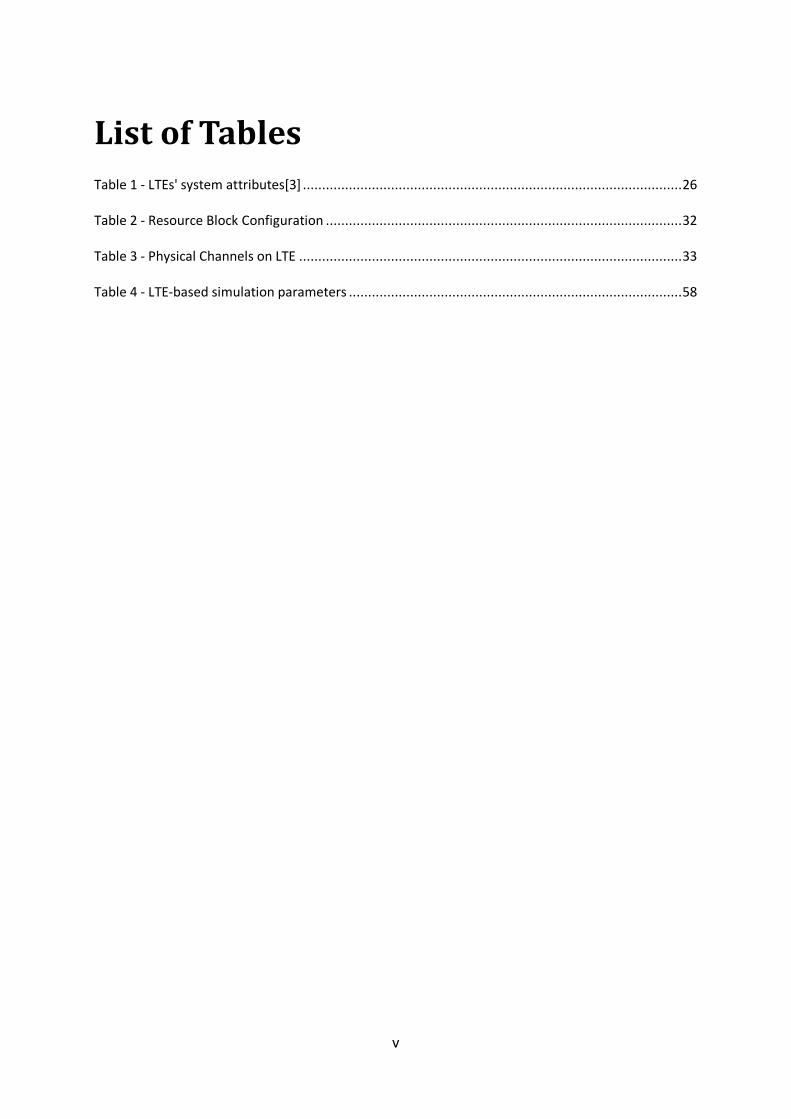
List of Tables Table 1 - LTEs' system attributes[3] ................................................................................................... 26
Table 2 - Resource Block Configuration ............................................................................................. 32
Table 3 - Physical Channels on LTE .................................................................................................... 33
Table 4 - LTE-based simulation parameters ....................................................................................... 58
vi
Acronyms 1G First Generation
2G Second Generation
3G Third Generation
3GPP 3rd Generation Partnership Project
4G Fourth Generation
AES Advanced Encryption Standard
ARQ Automatic Repeat Request
AWGN Additive White Gaussian Noise
BD Block Diagonalization
BER Bit Error Rate
BS Base Station
CAPEX Capital Expendables
CB Coordinated Beamforming
CCs Component Carriers
CDMA Code Division Multiple Access
CIR Channel Impulse Response
CJP Centralized Joint Processing
CM Cubic Metric
CoMP Coordinated Multipoint
CP Cyclic Prefix
CRC Cyclic Redundancy Check
CS Coordinated Scheduling
CSI Channel State Information
CU Central Unit
DFT-S-OFDM Discrete Fourier transform spread OFDM
DJP Distributed Joint Processing
DoF Degrees of Freedom
DVSINR Distributed Virtual Signal-to-Interference Noise Ratio
DwPTS Downlink Pilot Timeslot
DZF Distributed Zero Forcing
EAP Extensible Authentication Protocol
EGC Equal Gain Combining
eNB evolved Node-B
EPC Evolved Packet Core
EPS Evolved Packet System
E-UTRAN Evolved UMTS Terrestrial Radio Access Network
FDMA Frequency Division Multiple Access
vii
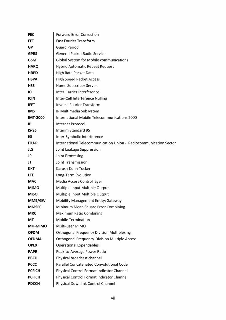
FEC Forward Error Correction
FFT Fast Fourier Transform
GP Guard Period
GPRS General Packet Radio Service
GSM Global System for Mobile communications
HARQ Hybrid Automatic Repeat Request
HRPD High Rate Packet Data
HSPA High Speed Packet Access
HSS Home Subscriber Server
ICI Inter-Carrier Interference
ICIN Inter-Cell Interference Nulling
IFFT Inverse Fourier Transform
IMS IP Multimedia Subsystem
IMT-2000 International Mobile Telecommunications 2000
IP Internet Protocol
IS-95 Interim Standard 95
ISI Inter-Symbolic Interference
ITU-R International Telecommunication Union - Radiocommunication Sector
JLS Joint Leakage Suppression
JP Joint Processing
JT Joint Transmission
KKT Karush-Kuhn-Tucker
LTE Long-Term Evolution
MAC Media Access Control layer
MIMO Multiple Input Multiple Output
MISO Multiple Input Multiple Output
MME/GW Mobility Management Entity/Gateway
MMSEC Minimum Mean Square Error Combining
MRC Maximum Ratio Combining
MT Mobile Termination
MU-MIMO Multi-user MIMO
OFDM Orthogonal Frequency Division Multiplexing
OFDMA Orthogonal Frequency-Division Multiple Access
OPEX Operational Expendables
PAPR Peak-to-Average Power Ratio
PBCH Physical broadcast channel
PCCC Parallel Concatenated Convolutional Code
PCFICH Physical Control Format Indicator Channel
PCFICH Physical Control Format Indicator Channel
PDCCH Physical Downlink Control Channel
viii
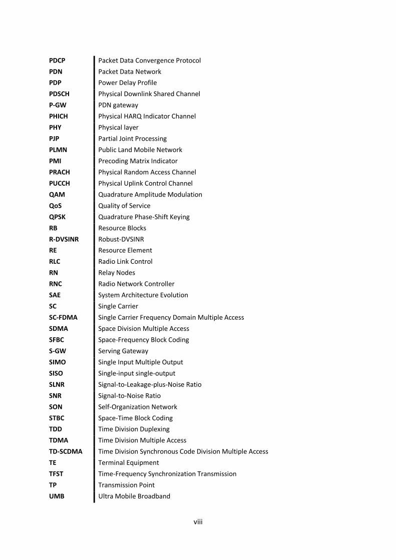
PDCP Packet Data Convergence Protocol
PDN Packet Data Network
PDP Power Delay Profile
PDSCH Physical Downlink Shared Channel
P-GW PDN gateway
PHICH Physical HARQ Indicator Channel
PHY Physical layer
PJP Partial Joint Processing
PLMN Public Land Mobile Network
PMI Precoding Matrix Indicator
PRACH Physical Random Access Channel
PUCCH Physical Uplink Control Channel
QAM Quadrature Amplitude Modulation
QoS Quality of Service
QPSK Quadrature Phase-Shift Keying
RB Resource Blocks
R-DVSINR Robust-DVSINR
RE Resource Element
RLC Radio Link Control
RN Relay Nodes
RNC Radio Network Controller
SAE System Architecture Evolution
SC Single Carrier
SC-FDMA Single Carrier Frequency Domain Multiple Access
SDMA Space Division Multiple Access
SFBC Space-Frequency Block Coding
S-GW Serving Gateway
SIMO Single Input Multiple Output
SISO Single-input single-output
SLNR Signal-to-Leakage-plus-Noise Ratio
SNR Signal-to-Noise Ratio
SON Self-Organization Network
STBC Space-Time Block Coding
TDD Time Division Duplexing
TDMA Time Division Multiple Access
TD-SCDMA Time Division Synchronous Code Division Multiple Access
TE Terminal Equipment
TFST Time-Frequency Synchronization Transmission
TP Transmission Point
UMB Ultra Mobile Broadband
ix
UMTS Universal Telecommunications System
UpPTS Uplink Pilot Timeslot
UT User Terminal
VoIP Voice over Internet Protocol
WCDMA Wideband CDMA
WiMAX Worldwide Interoperability for Microwave Access
ZF Zero Forcing
ZFBF Zero-Forcing Beamforming
ZFC Zero Forcing Combining

x
Cooperation Schemes between Base Stations for LTE on the Downlink
1
1. Introduction
1.1. Cellular Communications Evolution
In the past decades, the wireless communications industry has witnessed a tremendous
growth, with over six billion wireless subscribers worldwide [1]. The first generation (1G) of cellular
communication systems was analog and only supported voice communications with limited roaming.
The individual cells were large and the system did not use the available radio spectrum efficiently, so
their capacity was very small. The mobile devices were very large and expensive, and had a very
restricted users circle.
The second generation (2G) marked the turn of cellular communications to digital systems.
This change came with a promise of higher capacity and better voice quality than their analog
counterparts. This permitted a more efficient use of the radio spectrum and the introduction of
cheaper and smaller mobile devices.
The two widely deployed second generation (2G) systems are the Time Division Multiple
Access (TDMA) based GSM (Global System for Mobile communications) and CDMA (Code Division
Multiple Access) based Interim Standard 95 (IS-95). These 2G systems were designed to support
voice communications, but later on, there were introduced capabilities to support data
transmissions. This new systems, called 2.5G, introduced a core network’s packet switched domain
and a modified air interface. The General Packet Radio Service (GPRS), a best-effort service that used
packet switching data transmissions and could provide data rates from 56 up to 114kbps,
incorporated these techniques into GSM. However, data rates of these transmissions were generally
lower than that supported by dial-up connections [2].
The ITU-R initiative on IMT-2000 (International Mobile Telecommunications 2000) paved
the way to evolution to 3G systems, setting requirements such as a peak data rate of 2Mbits/s and
support for vehicular mobility [3]. Both the GSM and CDMA camps formed their own separate 3G
partnerships (3GPP and 3GPP2, respectively) to develop IMT-2000 compliant standard, based on
CDMA technology. The 3G standard in the 3GPP group is called wideband CDMA (WCDMA) because
of its use of a larger 5MHz bandwidth, relatively to a 1.25MHz bandwidth used in 3GPP2’s cdma2000
system.
The world’s dominant 3G system is called Universal Telecommunications System (UMTS)
and it encloses the WCDMA system, the most used in the world, as well as Time Division
Synchronous Code Division Multiple Access (TD-SCDMA), a derivative of WCDMA, which is also
known as the low chip rate option of UMTS TDD (Time Division Duplex) mode [4]. This later is mostly
Cooperation Schemes between Base Stations for LTE on the Downlink
2
used in China. While WCDMA segregates the base stations’ and mobiles’ transmissions by means of
frequency division duplex (FDD), TD-SCDMA uses TDD, and also a smaller carrier of 1.6MHz.
The first release of the 3G standard did not fulfill its promise of high-speed data
transmissions as the data rates supported in practice were much lower than that claimed in the
standards. In order to enhance the 3G system for efficient data support, 3GPP2 introduced the HRPD
(High Rate Packet Data, also called cdma2000-1xEVDO – evolution data only) system, which uses
techniques such as channel sensitive scheduling, fast link adaptation and hybrid ARQ, to optimize the
data traffic. This system required a separate 1.25MHz carrier and did not support voice traffic. The
3GPP group introduced the HSPA (High Speed Packet Access) enhancement to the WCDMA system. It
reused many of the same data-optimized techniques as the HRPD, but it could have both voice and
data services in the same 5MHz carrier, by code-multiplexing them. In the later version of HRPD, VoIP
(Voice over Internet Protocol) capabilities were introduced to provide both voice and data services
on the same carrier.
While HSPA and HRPD were being developed and deployed, IEEE 802 LMSC (LAN/MAN
Standard Committee) introduced the IEEE 802.16e standard form mobile broadband wireless access,
which has been commercialized under the Worldwide Interoperability for Microwave Access
(WiMAX) label by the WiMAX Forum. The mobile version of the standard IEEE 802.16e is referred as
Mobile WiMAX and employed a different access technology named OFDMA (Orthogonal Frequency
Division Multiple Access) and claimed better data rates and spectral efficiency than that provided by
HSPA and HRPD.
The main features of Mobile WiMAX also includes MIMO techniques, scalability from
different channels (from 1.25 to 20 MHz), improved security with Extensible Authentication
Protocol (EAP) based authentication and Advanced Encryption Standard (AES) based authentication
encryption and optimized handover schemes with latencies lower than 50 milliseconds [5].
The introduction of Mobile WiMAX led both 3GPP and 3GPP2 to develop their own version
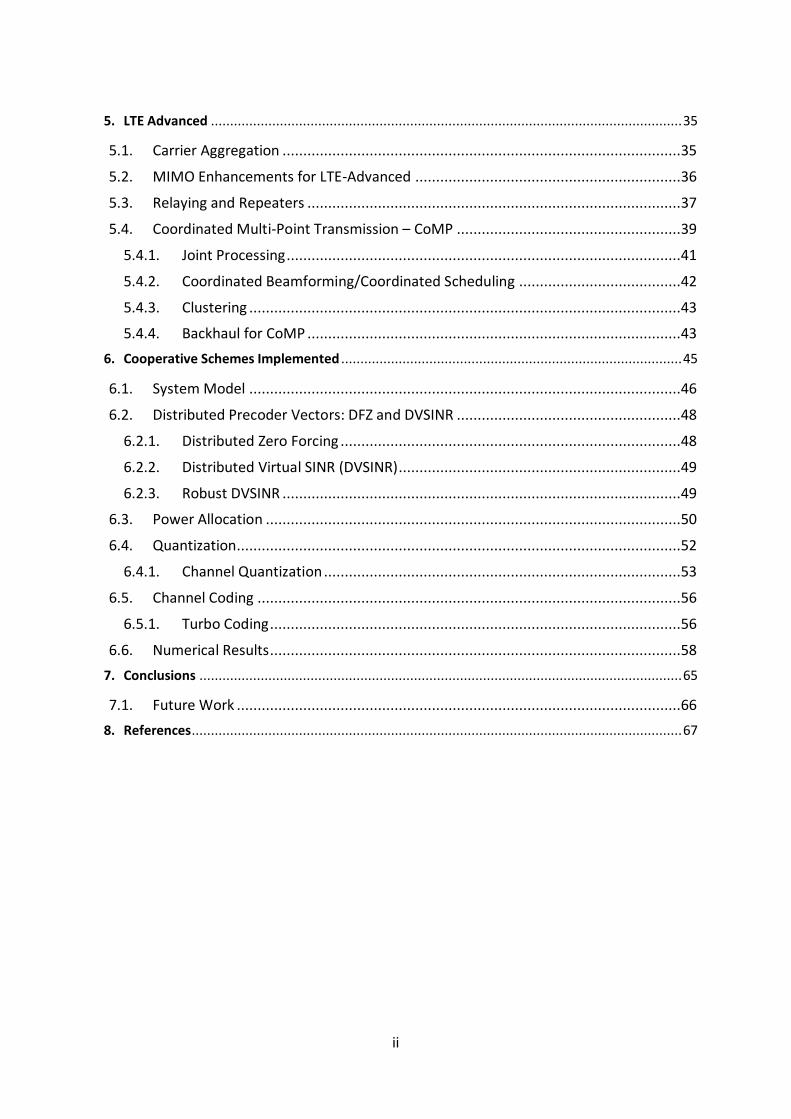
of beyond 3G systems based on the OFDMA technology and network architecture similar to that in
Mobile WiMAX. The beyond 3G systems in 3GPP is called evolved universal terrestrial radio access
(evolved UTRA) and is also widely referred to as LTE (Long-Term Evolution) while 3GPP2’s version is
called UMB (Ultra Mobile Broadband).In November 2008, Qualcomm, UMB’s lead sponsor,
announced it was ending development of the technology, favoring LTE instead [6].
Using OFDMA and MIMO based technology, LTE provides peak data rates of 300Mbps in
the downlink and 75Mbps in the uplink, as well as QoS provisions that allows the system to transfer
with a latency of less than 5ms in the radio access network. It enables the possibility of managing
fast-moving mobiles and to support multi-cast and broadcast streams. One of the major changes,
compared to its precedents systems, is the introduction of an IP-based network architecture, called
Evolved Packet Core (EPC). This network architecture was designed to replace the GPRS core network
and supports seamless handovers for both voice and data cell towers, with older technology, such as
GSM, UMTS or CDMA2000. LTE will be further discussed in Chapter 4.
Cooperation Schemes between Base Stations for LTE on the Downlink
3
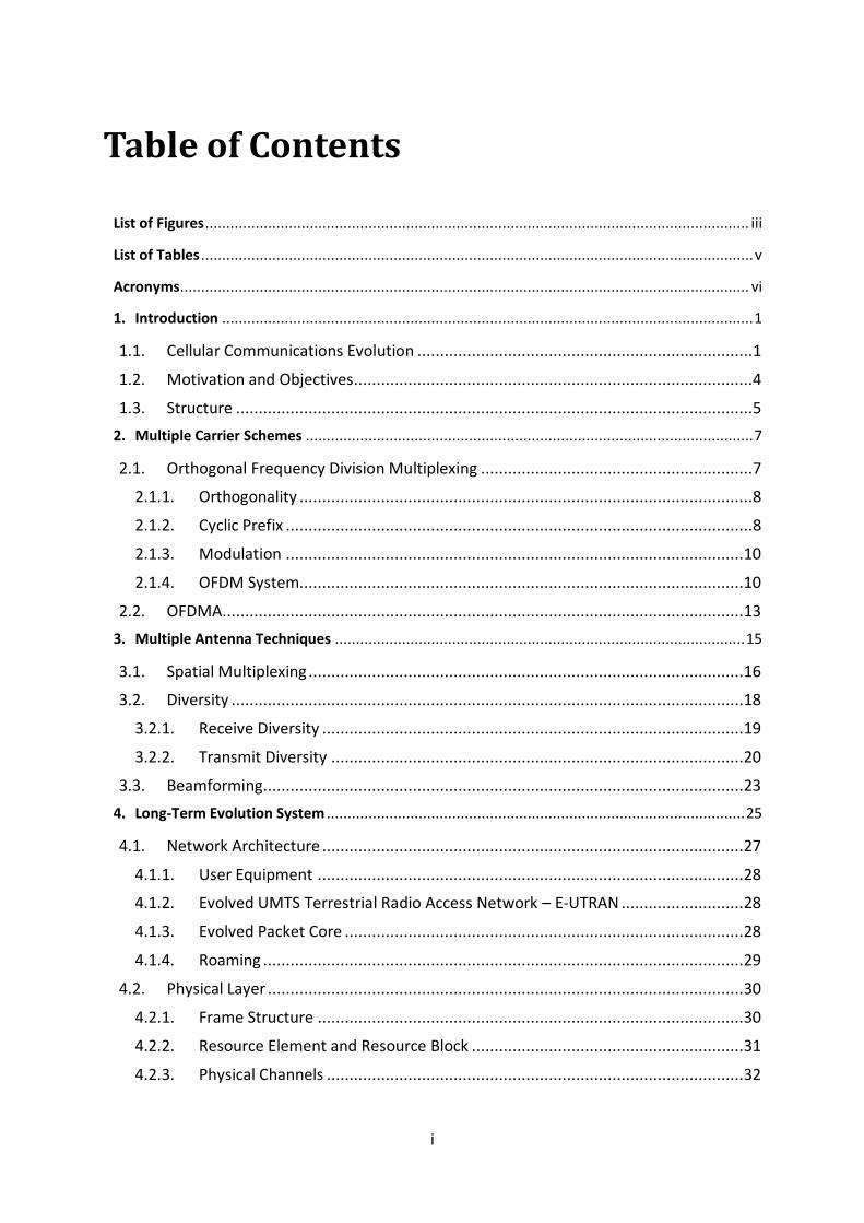
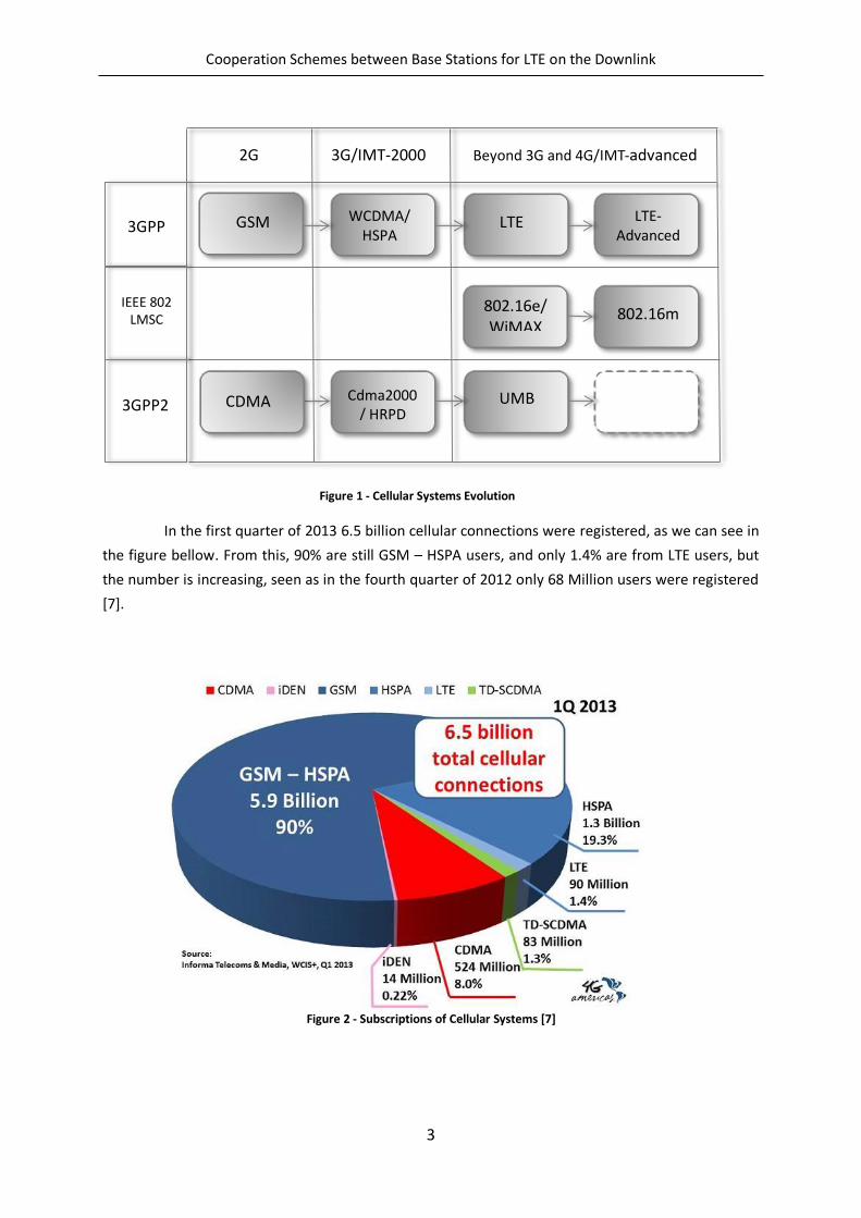
In the first quarter of 2013 6.5 billion cellular connections were registered, as we can see in
the figure bellow. From this, 90% are still GSM – HSPA users, and only 1.4% are from LTE users, but
the number is increasing, seen as in the fourth quarter of 2012 only 68 Million users were registered
[7].
Figure 2 - Subscriptions of Cellular Systems [7]
2G 3G/IMT-2000 Beyond 3G and 4G/IMT-advanced
GSM WCDMA/HSPA
LTE LTE-Advanced
802.16e/ WiMAX 802.16m
CDMA Cdma2000 / HRPD
UMB
3GPP
IEEE 802 LMSC
3GPP2
Figure 1 - Cellular Systems Evolution
Cooperation Schemes between Base Stations for LTE on the Downlink
4
1.2. Motivation and Objectives
4G cellular systems, designated by LTE have recently been deployed, allowing transmission
rates way above those seen in 3G systems. However, the increasing demand for higher transmission
rate systems cannot be fulfilled by the current cellular architecture. In cellular systems, a way to
increase transmission rates is to decrease the cells size, decreasing then the path loss. Nonetheless,
considering the current cellular architecture and the unitary frequency reuse, that would lead to a
huge increase of users’ interference in the cells edge, leading to a considerable degradation of the
systems performance.
In this context it is necessary to develop new cellular architectures that can allow us to
reduce or even eliminate interference between the users’ terminals (UTs), mainly at the cell edges.
Multicell cooperation or coordination is a promising solution for cellular wireless systems to mitigate
intercell interference, improving system fairness and increasing capacity, and thus is already under
study in LTE-Advanced under the coordinated multipoint (CoMP) concept.
There are several multicell based approaches depending on the amount of information
shared by the base stations (BSs) through the backhaul network and where the processing takes
place, i.e., centralized if the processing takes place at the central unit (CU) or distributed if it takes at
the different transmitters. Coordinated centralized beamforming approaches, where transmitters
exchange both data and channel state information (CSI) for joint signal processing at the CU, promise
larger spectral efficiency gains than distributed interference coordination techniques, but typically at
the price of larger backhaul requirements and more severe synchronization requirements.
In this thesis we consider a distributed precoded multicell approach, where the precoders
are computed locally at each BS to mitigate the intercell interference, assuming only the knowledge
of the local CSI (i.e. the channels between a given BS and the cooperative users terminals). Two
precoder are considered: distributed zero forcing (DZF) and distributed virtual signal-to-interference
noise ratio (DVSINR) recently proposed. Then the system is further optimized by computing a power
allocation algorithm over the subcarriers that minimizes the average bit error rate (BER), under per-
BS power constraint. Both, upper and lower bounds, used to reduce the search space for the
optimum solution and therefore efficiently perform the power allocation procedure, are derived.
The knowledge of CSI at the transmitter is absolutely crucial for the precoded-based
systems. However, assuming perfect CSI at the transmitters is not realistic in many practical scenarios
and thus in this thesis we also assess the performance of the precoders under imperfect CSI. A
quantized version of the CSI associated to the different links between the BS and the UT is feedback
from the UT to the BS. This information is then employed by the different BSs to perform the
precoding design. A new DVSINR precoder explicitly designed under imperfect CSI is proposed. The
considered schemes are implemented and evaluated under the LTE parameters and scenarios.
Cooperation Schemes between Base Stations for LTE on the Downlink
5
1.3. Structure
After presenting the evolution of wireless communications in the past years and its current
status, where LTE is the main 4G standard already deployed in many countries, we present, in
Chapter 2 “Multiple Carrier Schemes” and Chapter 3 “Multiple Antenna Techniques” the main
enabling technologies of LTE.
Subsequently we present in Chapter 4 “Long Term Evolution System” the major aspects of
the LTE system, namely its networks architecture and physical layer. Afterwards, in Chapter 5 “LTE-
Advanced” we discuss the evolution of LTE systems, LTE-Advanced and its own enabling
technologies. One of the enabling technologies of LTE-Advanced, and the main subject of this study is
the concept known as Coordinated Multipoint, also known as CoMP. The main aspects of this
concept are presented in a subchapter designated “Coordinated Multi-Point Transmission – CoMP”.
In Chapter 6 “Cooperative Schemes Implemented” we present the cooperative techniques
developed in this thesis and evaluate their performance. The system model and the parameters used
are defined. The main objective of this chapter is the use of distributed precoder vectors, and further
optimization of the same. Also, a simple channel quantization technique is presented and used to
evaluate the precoder techniques under imperfect CSI.
Finally, in Chapter 7 we conclude the work made throughout this thesis and provide some
guidelines for future.

Cooperation Schemes between Base Stations for LTE on the Downlink
6
Cooperation Schemes between Base Stations for LTE on the Downlink
7
2. Multiple Carrier Schemes
Single Carrier (SC) transmission schemes modulate the information in only a carrier,
adjusting the carriers phase or amplitude (or sometimes both). The higher the data rate, the higher
the symbol rate in a digital system and thus the required bandwidth is higher [8].
Using medium access techniques based on frequency multiplexing – Frequency Division
Multiple Access (FDMA), different users use different carrier frequencies to access simultaneously
the communication system [8]. The biggest emphasis in the development of this type of system is on
the mitigation of excessive interference between carriers, seeing that the transmitted signals are not
sinusoidal. This suggests that if the channel is under-spread (the coherence time is bigger than the
delay spread), it is then approximately invariant in time for a big enough time scale [9]. The use of
such type of systems requires the usage of guard bands, which may render the system inefficient.
The solution for this interference, caused by the guard band requirements, passes by the
selection of the system parameters that allow us to attain orthogonality between the different
transistors, thus creating sub-carriers that don’t interfere with each other, but whose spectrums may
overlap in the frequency domain.
2.1. Orthogonal Frequency Division Multiplexing
The basic concept of OFDM (Orthogonal Frequency Division Multiplexing) is to divide the
available spectrum in parallel narrowband channels, denominated by subcarriers, and sending
information in this parallel channels, at a low transmission rate [3]. By doing so, each channel
experiences flat-fading which leads to only some of the OFDM subcarriers being affected by the
fades and thus, instead of losing the entire symbol, we just lose portions of the symbol and its
recovery may be possible by using proper coding and error correction, simplifying a lot the frequency
equalization. Although the frequency response of the several channels overlaps, they are orthogonal
to each other, since the frequencies of the different subcarriers are chosen so that, in the frequency
domain, the neighbor subcarriers have zero values for the sampling times of the required subcarrier.
In an OFDM system with sub-carriers there will be transmitted NC data symbols in
parallel, each modulated in a different sub-carrier. Hence, the duration of an OFDM symbol is given
by:
(2.1.1)
The frequency of a sub-carrier is given by:
Cooperation Schemes between Base Stations for LTE on the Downlink
8
(2.1.2)
where stands for the sub-carrier spacing, given by:
(2.1.3)
Each carrier is modulated by a data symbol. An OFDM symbol is formed simply by the
addition of the different modulated signals from the sub-carriers.
The OFDM system relays on digital technology, using the Fast Fourier Transform (FFT) and
Inverse Fourier Transform (IFFT) to move the signal between the time and frequency domain,
without the loss of information, assuming that the classical requirements for digital signal processing
in terms of minimum sampling rates and word lengths are fulfilled [8].
2.1.1. Orthogonality
As stated previously, in order for a receiver to separate the overlapped subcarriers without
interference, said subcarriers must be orthogonal to each other. The property of orthogonality allows
simultaneous transmission of additional subcarriers in a tight frequency space without interference
from each other, thus being the main advantage of OFDM.
The definition of orthogonality is stated in the following equation:
∫ ( ) ( ) {
(2.1.4)
In other words, what this equation represents is that if we have two different functions and
multiply and integrate them, over a symbol period, the result is null if the functions are orthogonal to
each other.
The most basic form of modulation applied to the subcarriers is square wave phase
modulation, which produces a frequency spectrum represent by a ( ) function [4], that is
characterized by having a maximum amplitude at the center and null amplitude in multiples of ,
where T is the duration of the modulated symbol. What makes OFDM a practical transmission system
is that we can match the subcarrier modulation rate to the subcarrier spacing such that the nulls in
the spectrum of one subcarrier line up with the peaks of the adjacent subcarriers.
2.1.2. Cyclic Prefix
The orthogonality of the OFDM sub-carriers can be lost when the signal passes through a
time dispersive channel, due to inter-symbolic interference, seeing that the symbol do not confine to
their time slots, spreading over the next slots. Nevertheless, a cyclic extension of the OFDM signal
can be made so to avoid interference [10].
Cooperation Schemes between Base Stations for LTE on the Downlink
9
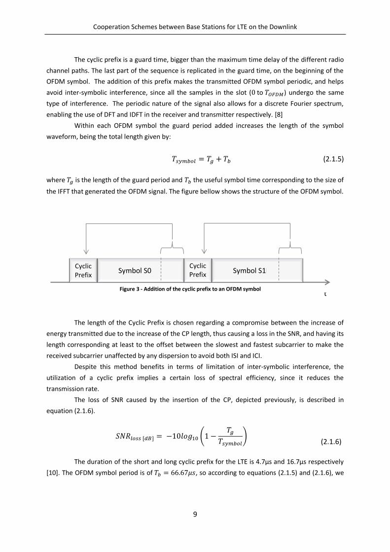
The cyclic prefix is a guard time, bigger than the maximum time delay of the different radio
channel paths. The last part of the sequence is replicated in the guard time, on the beginning of the
OFDM symbol. The addition of this prefix makes the transmitted OFDM symbol periodic, and helps
avoid inter-symbolic interference, since all the samples in the slot ( to ) undergo the same
type of interference. The periodic nature of the signal also allows for a discrete Fourier spectrum,
enabling the use of DFT and IDFT in the receiver and transmitter respectively. [8]
Within each OFDM symbol the guard period added increases the length of the symbol
waveform, being the total length given by:
(2.1.5)
where is the length of the guard period and the useful symbol time corresponding to the size of
the IFFT that generated the OFDM signal. The figure bellow shows the structure of the OFDM symbol.
The length of the Cyclic Prefix is chosen regarding a compromise between the increase of
energy transmitted due to the increase of the CP length, thus causing a loss in the SNR, and having its
length corresponding at least to the offset between the slowest and fastest subcarrier to make the
received subcarrier unaffected by any dispersion to avoid both ISI and ICI.
Despite this method benefits in terms of limitation of inter-symbolic interference, the
utilization of a cyclic prefix implies a certain loss of spectral efficiency, since it reduces the
transmission rate.
The loss of SNR caused by the insertion of the CP, depicted previously, is described in
equation (2.1.6).
(
)
(
(2.1.6)
The duration of the short and long cyclic prefix for the LTE is 4.7µs and 16.7µs respectively
[10]. The OFDM symbol period is of , so according to equations (2.1.5) and (2.1.6), we
Cyclic Prefix
Symbol S0 Cyclic Prefix
Symbol S1
t Figure 3 - Addition of the cyclic prefix to an OFDM symbol
Cooperation Schemes between Base Stations for LTE on the Downlink
10
get that for the short CP is of 1.0708 and 1.25 for the long CP. In terms of spectral
efficiency, given by , the short CP has a spectral efficiency of 93.4% and the long 80%.
2.1.3. Modulation
The basic principle of multicarrier modulation is to divide the available bandwidth, , into a
number sub-bands, or subcarriers. Each one of this subcarriers has a width of . So,
instead of transmitting the data stream in a serial way, at a baud rate of , a multicarrier modulation
scheme splits the data symbols into blocks of data symbols, which are then transmitted in
parallel, by modulating the subcarriers. The duration of a multicarrier scheme symbol is then
given by .
When we add more subcarriers the symbol period increases and, therefore, the data
stream becomes more robust to channel distortion, impulse noise and fading. Those channel effects
could result in inter-symbolic interference (ISI) when the time dispersion becomes significant,
compared to the symbol period.
2.1.4. OFDM System
An OFDM system uses the properties of the OFDM concept presented previously in order to
enable that multiple users can access the shared medium.
The concept of such approach is that the symbols to be transmitted from one BS towards
multiple UT are modulated in the frequency domain, mapped to different sub-carriers and then an
IDFT is used to generate a time domain signal. A cyclic prefix, as described previously, is inserted
before each orthogonal frequency division multiplex (OFDM) symbol, in order to assure that even a
channel with large delay spread does not cause ISI, and that a transmission leads to a circularly
symmetric convolution of the transmitted samples with the channel. Each receiving UE can then
discard the cyclic prefix, perform a DFT, and obtain (scaled and noisy) transmitted symbols in the
frequency domain again.
In LTE the subcarrier spacing is with a cyclic prefix (CP) duration of
(short/long CP) [10], regardless of the total available bandwidth. Since the
subcarriers are orthogonal to each other when the sampling is done, the other subcarriers will have
zero value.
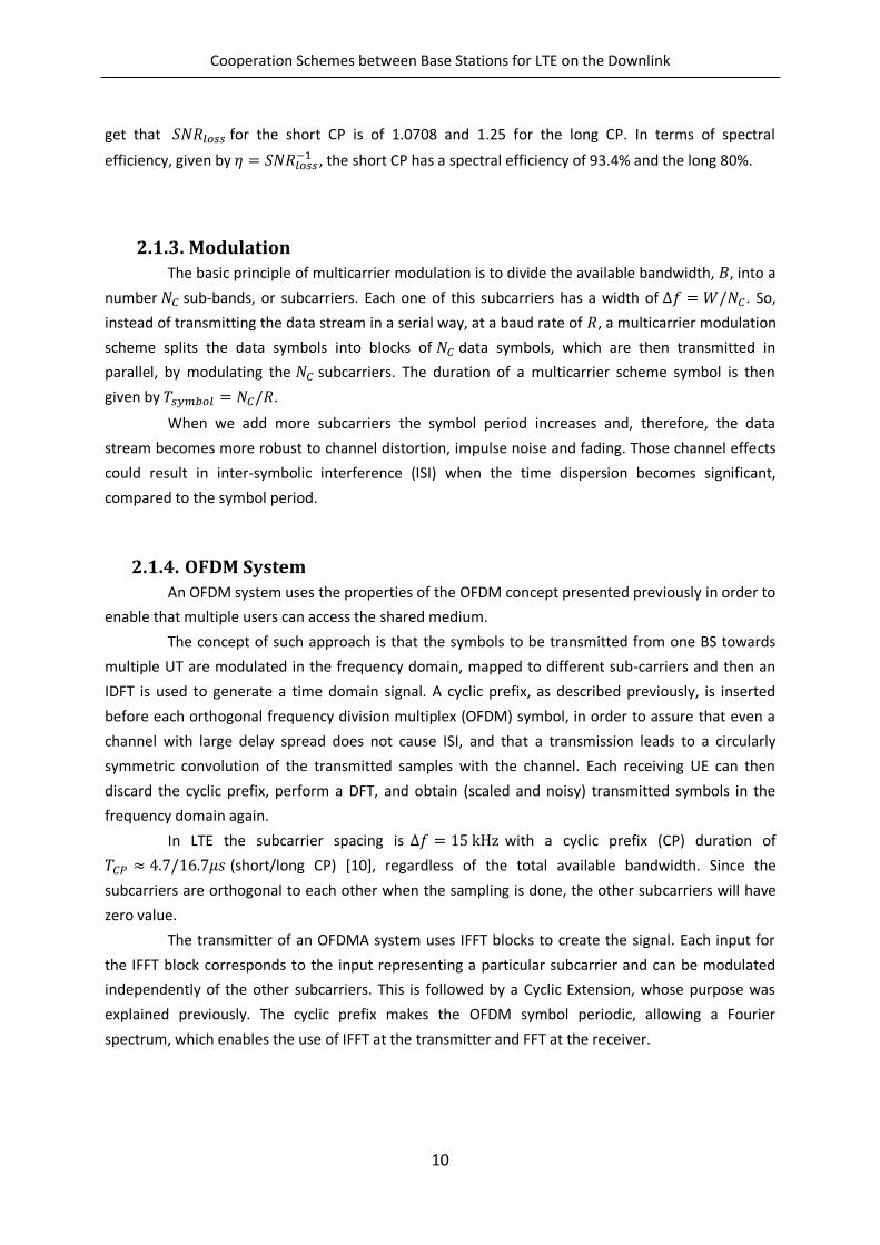
The transmitter of an OFDMA system uses IFFT blocks to create the signal. Each input for
the IFFT block corresponds to the input representing a particular subcarrier and can be modulated
independently of the other subcarriers. This is followed by a Cyclic Extension, whose purpose was
explained previously. The cyclic prefix makes the OFDM symbol periodic, allowing a Fourier
spectrum, which enables the use of IFFT at the transmitter and FFT at the receiver.
Cooperation Schemes between Base Stations for LTE on the Downlink
11
Figure 4 - Transmitter and Receiver of an OFDMA system [8]
At the receiver the cyclic prefix must be removed. Although this guard interval protects the
symbol against ISI, each subcarrier may be affected by different amplitude and phase changes, due to
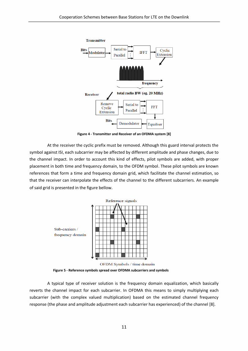
the channel impact. In order to account this kind of effects, pilot symbols are added, with proper
placement in both time and frequency domain, to the OFDM symbol. These pilot symbols are known
references that form a time and frequency domain grid, which facilitate the channel estimation, so
that the receiver can interpolate the effects of the channel to the different subcarriers. An example
of said grid is presented in the figure bellow.
A typical type of receiver solution is the frequency domain equalization, which basically
reverts the channel impact for each subcarrier. In OFDMA this means to simply multiplying each
subcarrier (with the complex valued multiplication) based on the estimated channel frequency
response (the phase and amplitude adjustment each subcarrier has experienced) of the channel [8].
Figure 5 - Reference symbols spread over OFDMA subcarriers and symbols
Cooperation Schemes between Base Stations for LTE on the Downlink
12
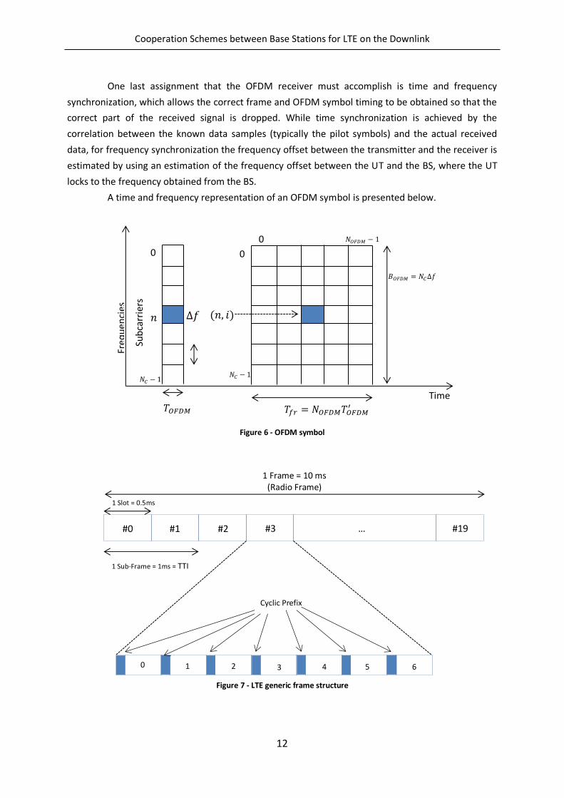
One last assignment that the OFDM receiver must accomplish is time and frequency
synchronization, which allows the correct frame and OFDM symbol timing to be obtained so that the
correct part of the received signal is dropped. While time synchronization is achieved by the
correlation between the known data samples (typically the pilot symbols) and the actual received
data, for frequency synchronization the frequency offset between the transmitter and the receiver is
estimated by using an estimation of the frequency offset between the UT and the BS, where the UT
locks to the frequency obtained from the BS.
A time and frequency representation of an OFDM symbol is presented below.
Figure 6 - OFDM symbol
Figure 7 - LTE generic frame structure
(𝑛, 𝑖) 𝑓
𝑁𝐶
𝐵𝑂𝐹𝐷𝑀 𝑁𝐶 𝑓
0
0 𝑁𝑂𝐹𝐷𝑀
𝑛
Time
Freq
uen
cies
Sub
carr
iers
0
𝑁𝐶
𝑇𝑂𝐹𝐷𝑀 𝑇𝑓𝑟 𝑁𝑂𝐹𝐷𝑀𝑇𝑂𝐹𝐷𝑀′
Cyclic Prefix
#0 #1 #2 #3 … #19
1 Frame = 10 ms (Radio Frame)
1 Slot = 0.5ms
1 Sub-Frame = 1ms = TTI
0 1 2 3 4 5 6
Cooperation Schemes between Base Stations for LTE on the Downlink
13
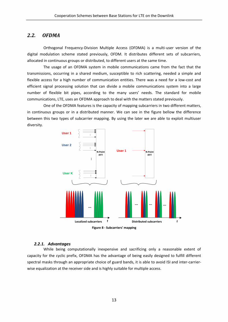
2.2. OFDMA
Orthogonal Frequency-Division Multiple Access (OFDMA) is a multi-user version of the
digital modulation scheme stated previously, OFDM. It distributes different sets of subcarriers,
allocated in continuous groups or distributed, to different users at the same time.
The usage of an OFDMA system in mobile communications came from the fact that the
transmissions, occurring in a shared medium, susceptible to rich scattering, needed a simple and
flexible access for a high number of communication entities. There was a need for a low-cost and
efficient signal processing solution that can divide a mobile communications system into a large
number of flexible bit pipes, according to the many users’ needs. The standard for mobile
communications, LTE, uses an OFDMA approach to deal with the matters stated previously.
One of the OFDMA features is the capacity of mapping subcarriers in two different matters,
in continuous groups or in a distributed manner. We can see in the figure bellow the difference
between this two types of subcarrier mapping. By using the later we are able to exploit multiuser
diversity.
Figure 8 - Subcarriers' mapping
2.2.1. Advantages While being computationally inexpensive and sacrificing only a reasonable extent of
capacity for the cyclic prefix, OFDMA has the advantage of being easily designed to fulfill different
spectral masks through an appropriate choice of guard bands, it is able to avoid ISI and inter-carrier-
wise equalization at the receiver side and is highly suitable for multiple access.
N-PointIFFT
N-PointIFFT
...
...
fLocalized subcarriers Distributed subcarriers
User 1
User 2
...
...User K
User 1
...
f
... ... ...
Cooperation Schemes between Base Stations for LTE on the Downlink
14
2.2.2. Disadvantages The OFDMA system may present some disadvantages, being the most relevant one that of a
high peak-to-average power ratio (PAPR), due to the performance of modulation on the frequency
domain and the application of an IDFT. In the uplink, this aspect may be critical as it implies that a
large power amplifier (PA) back-off is needed, leading to a faster depletion of handset battery. To
cope with this problem, 3GPP decided to employ single carrier frequency domain multiple access (SC-
FDMA) in the uplink, where modulation is performed in the time domain, after which a small DFT is
applied and the signals are mapped to the sub-carriers to be used by the terminal before the actual
large IDFT.
Cooperation Schemes between Base Stations for LTE on the Downlink
15
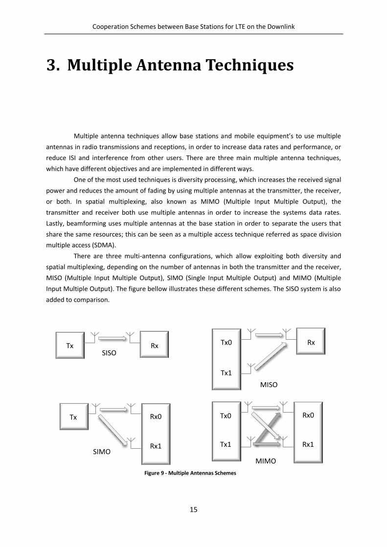
3. Multiple Antenna Techniques
Multiple antenna techniques allow base stations and mobile equipment’s to use multiple
antennas in radio transmissions and receptions, in order to increase data rates and performance, or
reduce ISI and interference from other users. There are three main multiple antenna techniques,
which have different objectives and are implemented in different ways.
One of the most used techniques is diversity processing, which increases the received signal
power and reduces the amount of fading by using multiple antennas at the transmitter, the receiver,
or both. In spatial multiplexing, also known as MIMO (Multiple Input Multiple Output), the
transmitter and receiver both use multiple antennas in order to increase the systems data rates.
Lastly, beamforming uses multiple antennas at the base station in order to separate the users that
share the same resources; this can be seen as a multiple access technique referred as space division
multiple access (SDMA).
There are three multi-antenna configurations, which allow exploiting both diversity and
spatial multiplexing, depending on the number of antennas in both the transmitter and the receiver,
MISO (Multiple Input Multiple Output), SIMO (Single Input Multiple Output) and MIMO (Multiple
Input Multiple Output). The figure bellow illustrates these different schemes. The SISO system is also
added to comparison.
Tx Rx SISO
Tx0 Rx
MISO
Tx1
Rx0
SIMO
Tx
Rx1
Rx0
MIMO
Tx0
Rx1 Tx1
Figure 9 - Multiple Antennas Schemes
Cooperation Schemes between Base Stations for LTE on the Downlink
16
Single-input single-output (SISO) is the well-known, typical wireless configuration, single-
input multiple-output (SIMO) is the configuration where a single transmitting antenna and multiple
receiving antennas ( ) are used, multiple-input single-output (MISO) has multiple ( ) transmitting
antennas and one receiving antenna and MIMO has multiple ( ) transmitting and receiving ( )
antennas.
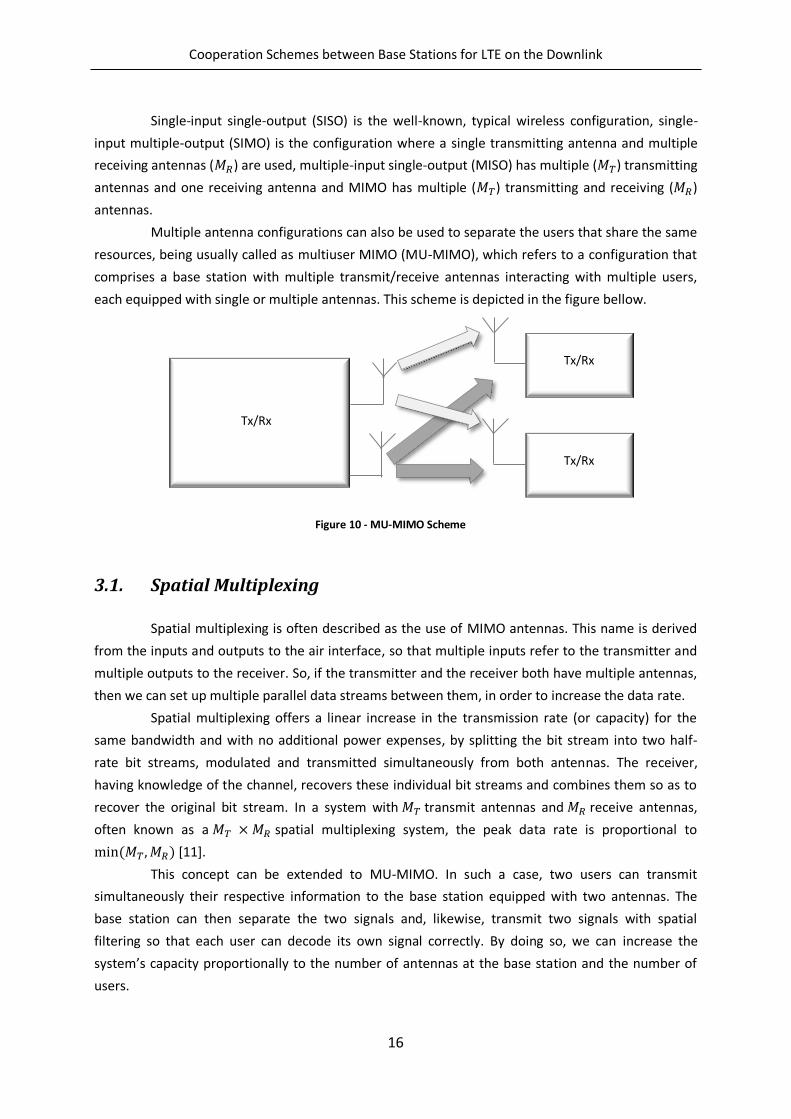
Multiple antenna configurations can also be used to separate the users that share the same
resources, being usually called as multiuser MIMO (MU-MIMO), which refers to a configuration that
comprises a base station with multiple transmit/receive antennas interacting with multiple users,
each equipped with single or multiple antennas. This scheme is depicted in the figure bellow.
3.1. Spatial Multiplexing
Spatial multiplexing is often described as the use of MIMO antennas. This name is derived
from the inputs and outputs to the air interface, so that multiple inputs refer to the transmitter and
multiple outputs to the receiver. So, if the transmitter and the receiver both have multiple antennas,
then we can set up multiple parallel data streams between them, in order to increase the data rate.
Spatial multiplexing offers a linear increase in the transmission rate (or capacity) for the
same bandwidth and with no additional power expenses, by splitting the bit stream into two half-
rate bit streams, modulated and transmitted simultaneously from both antennas. The receiver,
having knowledge of the channel, recovers these individual bit streams and combines them so as to
recover the original bit stream. In a system with transmit antennas and receive antennas,
often known as a spatial multiplexing system, the peak data rate is proportional to
( , ) [11].
This concept can be extended to MU-MIMO. In such a case, two users can transmit
simultaneously their respective information to the base station equipped with two antennas. The
base station can then separate the two signals and, likewise, transmit two signals with spatial
filtering so that each user can decode its own signal correctly. By doing so, we can increase the
system’s capacity proportionally to the number of antennas at the base station and the number of
users.
Tx/Rx
Tx/Rx
Tx/Rx
Figure 10 - MU-MIMO Scheme
Cooperation Schemes between Base Stations for LTE on the Downlink
17
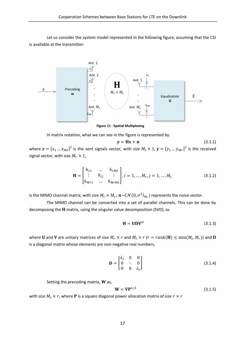
.
.
.
Ant. 1
Ant. 𝑀𝑟
𝑛
𝑛𝑀𝑟
Equalization G
𝑥
𝑥𝑀𝑡
𝑥2
.
.
.
Ant. 1
Ant. 2
Ant. 𝑀𝑡
Precoding w
𝑠 𝐇
𝑀𝑟 𝑀𝑡 𝑠
Let us consider the system model represented in the following figure, assuming that the CSI
is available at the transmitter:
In matrix notation, what we can see in the figure is represented by:
(3.1.1)
where is the sent signals vector, with size ,
is the received
signal vector, with size ,
[
] , , , , , , (3.1.2)
is the MIMO channel matrix, with size ; ( , 2 ) represents the noise vector.
The MIMO channel can be converted into a set of parallel channels. This can be done by
decomposing the matrix, using the singular value decomposition (SVD), as
(3.1.3)
where and are unitary matrices of size and ( ( ) ( , )) and
is a diagonal matrix whose elements are non-negative real numbers,
[
] (3.1.4)
Setting the precoding matrix, as,
2 (3.1.5)
with size , where is a square diagonal power allocation matrix of size
Figure 11 - Spatial Multiplexing
Cooperation Schemes between Base Stations for LTE on the Downlink
18
[
]
2
(3.1.6)
The equalizer matrix is set as,
(3.1.7)
So, the transmitted signal over the antennas is given by,
(3.1.8)
where is the data vector of size . Replacing and on the
received signal we get
2 (3.1.9)
The estimated transmitted data symbols can then be obtained as,
2 (3.1.10)
2 (3.1.11)
The soft estimate of the th data symbol is,
√ , , , (3.1.12)
As we can see, the estimated data symbol is free of interference, being only affected by
noise. So, converting MIMO channels into parallel channels through SVD allows us to transmit
parallel, interference free, data symbols.
3.2. Diversity
Diversity means that the same information can be sent over different independent paths,
and can be obtained in time, frequency and space. The main idea behind the diversity concept is to
send the same information bits through different fading paths and then combine the information
received over these paths in the receiver, in order to mitigate the fading effects.
Time diversity consists of sending the same information in different time periods, separated
by time intervals bigger than the coherence time. In general, with very short transmission time of
1ms subframe in the LTE system, there is not much time-diversity available (except for the case of
Cooperation Schemes between Base Stations for LTE on the Downlink
19
very high UT speeds) [3]. The biggest setback of time diversity is the fact that it diminishes the data
rates, due to its data repetition.
On the other hand, frequency diversity enables the transmission of the same narrow-band
signal in different carriers, separated by a coherence bandwidth. In LTE systems, it can be exploited
by scheduling transmissions over distributed resources. However this type of diversity requires the
use of more bandwidth.
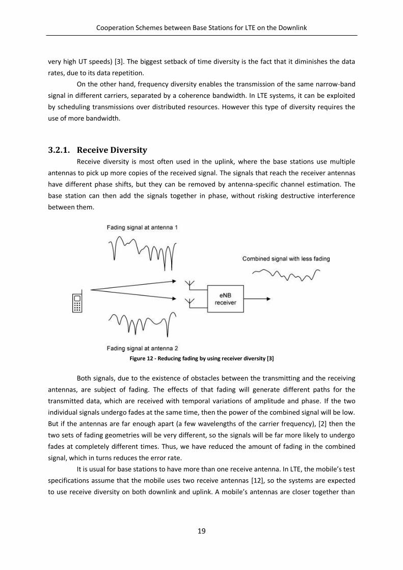
3.2.1. Receive Diversity
Receive diversity is most often used in the uplink, where the base stations use multiple
antennas to pick up more copies of the received signal. The signals that reach the receiver antennas
have different phase shifts, but they can be removed by antenna-specific channel estimation. The
base station can then add the signals together in phase, without risking destructive interference
between them.
Figure 12 - Reducing fading by using receiver diversity [3]
Both signals, due to the existence of obstacles between the transmitting and the receiving
antennas, are subject of fading. The effects of that fading will generate different paths for the
transmitted data, which are received with temporal variations of amplitude and phase. If the two
individual signals undergo fades at the same time, then the power of the combined signal will be low.
But if the antennas are far enough apart (a few wavelengths of the carrier frequency), [2] then the
two sets of fading geometries will be very different, so the signals will be far more likely to undergo
fades at completely different times. Thus, we have reduced the amount of fading in the combined
signal, which in turns reduces the error rate.
It is usual for base stations to have more than one receive antenna. In LTE, the mobile’s test
specifications assume that the mobile uses two receive antennas [12], so the systems are expected
to use receive diversity on both downlink and uplink. A mobile’s antennas are closer together than
Cooperation Schemes between Base Stations for LTE on the Downlink
20
those of a base station, so the benefits of receive diversity are reduced, but the situation can often
be improved using antennas that measure two independent polarizations of the incoming signal.
A list, of the most common receive diversity schemes, is presented below:
Selection Combining – The receiver selects the antenna with the highest received
signal and ignores the signal received from the other antennas.
Switched Combining – The receiver sets a SNR threshold and if the received signal
at a determined antenna is above that value, than it is selected until it drops again
under that threshold.
It is also very common to use frequency equalizers, and the most used are presented
below:
Equal Gain Combining – the received signals from the multiple receiving antennas
are summed up coherently, compensating the phase rotation caused by the
channel.
Maximum Ratio Combining – the received signals from the different antennas are
weighted individually depending on the reliability of the signal in each antenna and
then the phase distortion is compensated by calculating the complex conjugate of
the frequency response of the channel. Afterwards the signals are aligned and
combined.
Zero Forcing Combining – designed for each data symbol in order to remove the
interference, by restoring the orthogonality between users inverting the channel
frequency response. However, this equalizer boosts the noise when the frequency
response of the channel is in deep fading.
Minimum Mean Square Error Combining – it minimizes the mean square error
between the transmitted and estimated signal. It is a trade-off between noise
enhancement and interference removal. For high SNR, this equalizer tends to the
ZF.
3.2.2. Transmit Diversity
Transmit diversity reduces the amount of fading by using two or more antennas at the
transmitter. It is a process very similar to the Receive Diversity, but with a crucial problem: the
signals add together at the single receive antenna, which brings a risk of destructive interference.
This problem can be copped with in two ways, closed loop transmit diversity, where CSI is available
at the transmitter side, or open loop transmit diversity, where contrarily to the previous case, CSI is
not available at the transmitter.
In closed loop transmit diversity, the transmitter sends two copies of the signal in the
expected way, but it also applies a phase shift to one or both signals before transmitting them, thus
ensuring that the two signals reach the receiver in phase, without any risk of destructive
interference. The phase shift is determined by a precoding matrix indicator (PMI), which is calculated
by the receiver and fed back to the transmitter. The PMI might indicate two options: either transmit
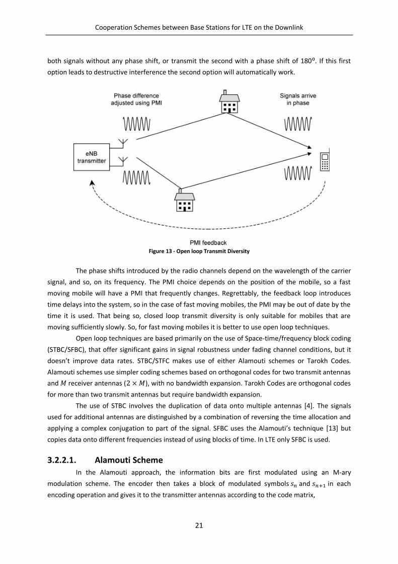
Cooperation Schemes between Base Stations for LTE on the Downlink
21
both signals without any phase shift, or transmit the second with a phase shift of 180⁰. If this first
option leads to destructive interference the second option will automatically work.
Figure 13 - Open loop Transmit Diversity
The phase shifts introduced by the radio channels depend on the wavelength of the carrier
signal, and so, on its frequency. The PMI choice depends on the position of the mobile, so a fast
moving mobile will have a PMI that frequently changes. Regrettably, the feedback loop introduces
time delays into the system, so in the case of fast moving mobiles, the PMI may be out of date by the
time it is used. That being so, closed loop transmit diversity is only suitable for mobiles that are
moving sufficiently slowly. So, for fast moving mobiles it is better to use open loop techniques.
Open loop techniques are based primarily on the use of Space-time/frequency block coding
(STBC/SFBC), that offer significant gains in signal robustness under fading channel conditions, but it
doesn’t improve data rates. STBC/STFC makes use of either Alamouti schemes or Tarokh Codes.
Alamouti schemes use simpler coding schemes based on orthogonal codes for two transmit antennas
and receiver antennas ( ), with no bandwidth expansion. Tarokh Codes are orthogonal codes
for more than two transmit antennas but require bandwidth expansion.
The use of STBC involves the duplication of data onto multiple antennas [4]. The signals
used for additional antennas are distinguished by a combination of reversing the time allocation and
applying a complex conjugation to part of the signal. SFBC uses the Alamouti’s technique [13] but
copies data onto different frequencies instead of using blocks of time. In LTE only SFBC is used.
3.2.2.1. Alamouti Scheme
In the Alamouti approach, the information bits are first modulated using an M-ary
modulation scheme. The encoder then takes a block of modulated symbols and in each
encoding operation and gives it to the transmitter antennas according to the code matrix,
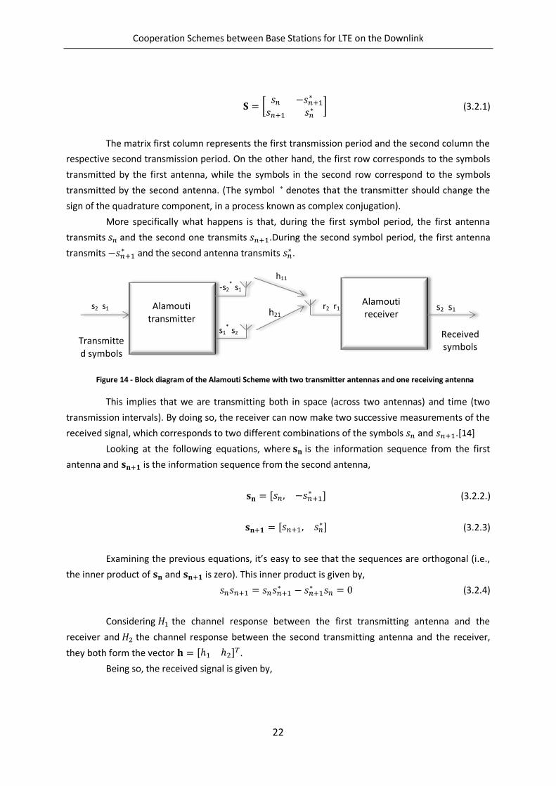
Cooperation Schemes between Base Stations for LTE on the Downlink
22
-s2*
s1
s1*
s2
s2 s1
Transmitted symbols
Alamouti transmitter
r2 r1 Alamouti receiver
s2 s1
Received symbols
h11
h21
[
] (3.2.1)
The matrix first column represents the first transmission period and the second column the
respective second transmission period. On the other hand, the first row corresponds to the symbols
transmitted by the first antenna, while the symbols in the second row correspond to the symbols
transmitted by the second antenna. (The symbol denotes that the transmitter should change the
sign of the quadrature component, in a process known as complex conjugation).
More specifically what happens is that, during the first symbol period, the first antenna
transmits and the second one transmits .During the second symbol period, the first antenna
transmits and the second antenna transmits
.
This implies that we are transmitting both in space (across two antennas) and time (two
transmission intervals). By doing so, the receiver can now make two successive measurements of the
received signal, which corresponds to two different combinations of the symbols and .[14]
Looking at the following equations, where is the information sequence from the first
antenna and is the information sequence from the second antenna,
, (3.2.2.)
, (3.2.3)
Examining the previous equations, it’s easy to see that the sequences are orthogonal (i.e.,
the inner product of and is zero). This inner product is given by,
(3.2.4)
Considering the channel response between the first transmitting antenna and the
receiver and 2 the channel response between the second transmitting antenna and the receiver,
they both form the vector 2 .
Being so, the received signal is given by,
Figure 14 - Block diagram of the Alamouti Scheme with two transmitter antennas and one receiving antenna
Cooperation Schemes between Base Stations for LTE on the Downlink
23
√2 (3.2.5)
considering that is the channel noise vector, composed by , where and are
independent complex variables with zero mean and unit variance, representing additive white
Guassian noise samples, at time and , respectively. Each symbol is multiplied by a factor of a
squared root of two in order to achieve a transmitted average power of one in each time step.
The previous equation can be decomposed in:
{
√2 ,
√2 2,
√2 ,
√2 2,
(3.2.6)
Since OFDM systems were designed in order to flatten the fading in each subcarrier, we can
assume that , , . Thus, and considering the previous equality, the decode estimated
symbols are given by,
{
√2
√2 2
√2 2
√2
(3.2.7)
The soft decision of data symbol is then given by,
2(
2 2 )
√2
√2 2
(3.2.8)
Thus, we can see that the interference caused by the data symbol is fully eliminated.
The SNR can is given by:
(| |2 | 2|
2)
2 (3.2.9)
There is no equivalent to Alamouti’s technique for systems with more than two antennas
but, despite that, diversity can be achieved in four antenna systems, by swapping back and forth
between the two constituent antenna pairs. This technique is used in LTE for four antenna open loop
diversity.
3.3. Beamforming
Beamforming is a general signal processing technique used to control the directionality of
the reception or transmission of a signal. In cellular communication systems, base station’s antennas
work together, as an array, in order to create a synthetic directional antenna beam, which has a main
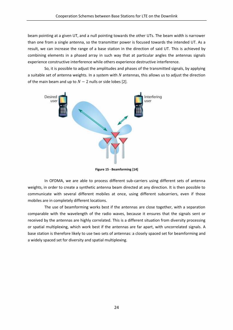
Cooperation Schemes between Base Stations for LTE on the Downlink
24
beam pointing at a given UT, and a null pointing towards the other UTs. The beam width is narrower
than one from a single antenna, so the transmitter power is focused towards the intended UT. As a
result, we can increase the range of a base station in the direction of said UT. This is achieved by
combining elements in a phased array in such way that at particular angles the antennas signals
experience constructive interference while others experience destructive interference.
So, it is possible to adjust the amplitudes and phases of the transmitted signals, by applying
a suitable set of antenna weights. In a system with antennas, this allows us to adjust the direction
of the main beam and up to nulls or side lobes [2].
Figure 15 - Beamforming [14]
In OFDMA, we are able to process different sub-carriers using different sets of antenna
weights, in order to create a synthetic antenna beam directed at any direction. It is then possible to
communicate with several different mobiles at once, using different subcarriers, even if those
mobiles are in completely different locations.
The use of beamforming works best if the antennas are close together, with a separation
comparable with the wavelength of the radio waves, because it ensures that the signals sent or
received by the antennas are highly correlated. This is a different situation from diversity processing
or spatial multiplexing, which work best if the antennas are far apart, with uncorrelated signals. A
base station is therefore likely to use two sets of antennas: a closely spaced set for beamforming and
a widely spaced set for diversity and spatial multiplexing.
Cooperation Schemes between Base Stations for LTE on the Downlink
25
4. Long-Term Evolution System
In this Chapter we briefly present the LTE standard, also known as 4G cellular systems. The
goal of LTE is to provide a high-data-rate, low-latency and packet optimized radio-access technology
supporting flexible bandwidth deployments [15].In order to support packet-switched traffic with
seamless mobility, a new network architecture was designed, simplified into a IP based system,
increasing the quality of service and reaching a minimum latency.
In the previous cellular systems, there were some fragmentations between different
standards used. The second generation of cellular systems had TDMA based GSM and CDMA based
IS-95, the third generation had UMTS and CDMA2000. But now, with the introduction of LTE, the
fourth generation of cellular systems has a global standard. The first LTE proposal was in 2004 by NTT
DoCoMo of Japan but the standard was only created in 2005. The world’s first publicly available LTE
service was lunched by TeliaSonera in Oslo and Stockholm on December 14, 2009 [16].
LTE was required to deliver a peak data rate of 100Mbps in the downlink and 50Mbps in the
uplink. This requirement was exceeded in the eventual system, which delivers peak data rates of
300Mbps and 75Mbps respectively. For comparison, the peak data rate of WCDMA, in Release 6 of
the 3GPP specifications, is 14Mbps in the downlink and 5.7Mbps in the uplink [2]. However, this peak
data rates can only be achieved in optimal conditions, and are hard to achieve in a realistic scenario.
Within the specifications of the LTE system, there’s a support for flexible bandwidth, thanks
to the OFDMA and SC-FDMA access schemes. In addition to FDD (Frequency Division Duplexing) and
Figure 16 - Diagram of LTE UL selection of modulation scheme [15]
Cooperation Schemes between Base Stations for LTE on the Downlink
26
TDD (Time Division Duplexing), half-duplex FDD is also allowed to support low cost UTs. Unlike FDD,
in a half-duplex FDD operation a UT is not required to transmit and receive at the same time, thus
avoiding the need for a costly duplexer in the UT. The system is optimized for low speeds, up to
15km/h. However, the system specifications allow mobility support in excess of 350km/h with some
performance degradation.
Since OFDMA has high PAPR, it requires inefficient power amplifiers and it would reduce
the autonomy of mobile devices significantly. Being so, the uplink access is based on single carrier
frequency division multiple access (SC-FDMA) that promises increased uplink coverage due to low
PAPR relatively to OFDMA. While maintaining the same site location deployed in HSPA, the LTE
system was able to improve the cell-edge throughput, and can have cell coverage between 5 and
100km. In terms of latency, the LTE radio-interface and network provides capabilities for less than
10ms latency for the transmission of a packet from the network to the UE.
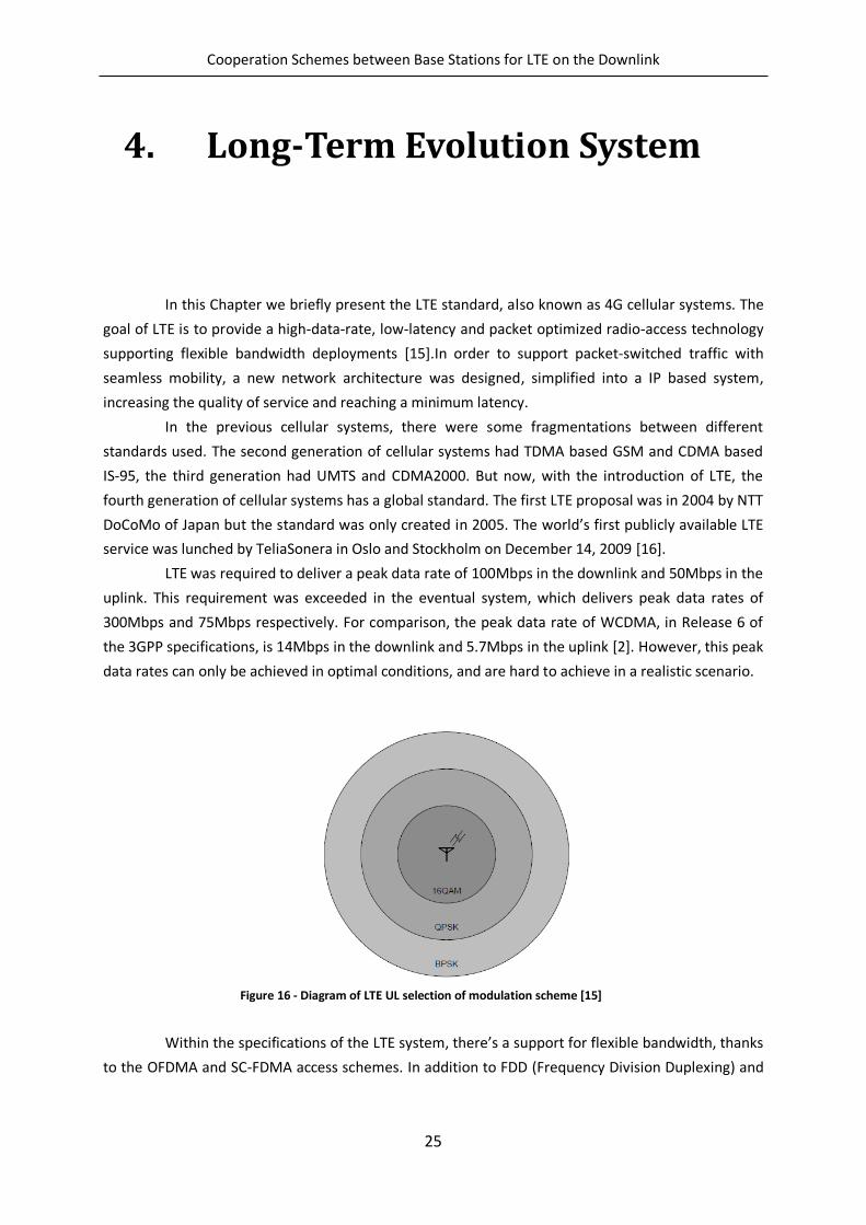
Also defined in the standard, there are several modulation schemes available for the
transmission of data. Higher modulation orders increase the data rate with the inconvenient of being
more susceptible to signal errors and path loss. This means that the distance between the base
stations and the mobile terminals matters in the selection of the modulation scheme. For the
downlink the main modulation schemes supported are QPSK, 16-QAM and 64-QAM, while for the
uplink 64-QAM is optional at the UT. Figure 16 illustrates the selection of modulation scheme,
according to the SNR, assuming that a greater distance implies a lower SNR.
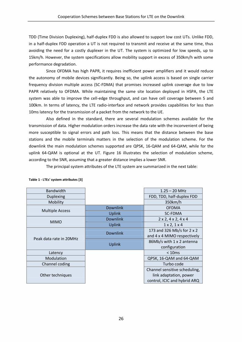
The principal system attributes of the LTE system are summarized in the next table:
Table 1 - LTEs' system attributes [3]
Bandwidth
1.25 – 20 MHz
Duplexing FDD, TDD, half-duplex FDD
Mobility 350km/h
Multiple Access Downlink OFDMA
Uplink SC-FDMA
MIMO Downlink 2 x 2, 4 x 2, 4 x 4
Uplink 1 x 2, 1 x 4
Peak data rate in 20MHz Downlink
173 and 326 Mb/s for 2 x 2 and 4 x 4 MIMO respectively
Uplink 86Mb/s with 1 x 2 antenna
configuration
Latency < 10ms
Modulation
QPSK, 16-QAM and 64-QAM
Channel coding Turbo code
Other techniques Channel sensitive scheduling,
link adaptation, power control, ICIC and hybrid ARQ
Cooperation Schemes between Base Stations for LTE on the Downlink
27
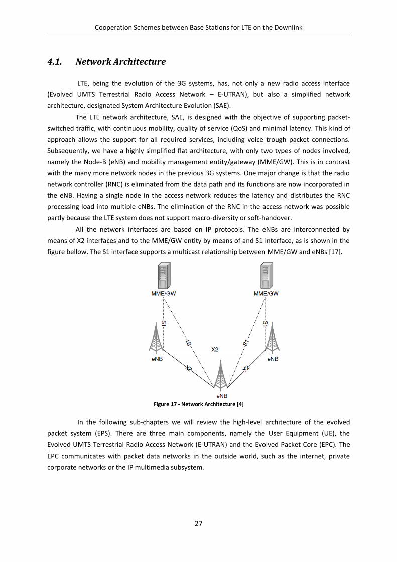
4.1. Network Architecture
LTE, being the evolution of the 3G systems, has, not only a new radio access interface
(Evolved UMTS Terrestrial Radio Access Network – E-UTRAN), but also a simplified network
architecture, designated System Architecture Evolution (SAE).
The LTE network architecture, SAE, is designed with the objective of supporting packet-
switched traffic, with continuous mobility, quality of service (QoS) and minimal latency. This kind of
approach allows the support for all required services, including voice trough packet connections.
Subsequently, we have a highly simplified flat architecture, with only two types of nodes involved,
namely the Node-B (eNB) and mobility management entity/gateway (MME/GW). This is in contrast
with the many more network nodes in the previous 3G systems. One major change is that the radio
network controller (RNC) is eliminated from the data path and its functions are now incorporated in
the eNB. Having a single node in the access network reduces the latency and distributes the RNC
processing load into multiple eNBs. The elimination of the RNC in the access network was possible
partly because the LTE system does not support macro-diversity or soft-handover.
All the network interfaces are based on IP protocols. The eNBs are interconnected by
means of X2 interfaces and to the MME/GW entity by means of and S1 interface, as is shown in the
figure bellow. The S1 interface supports a multicast relationship between MME/GW and eNBs [17].
Figure 17 - Network Architecture [4]
In the following sub-chapters we will review the high-level architecture of the evolved
packet system (EPS). There are three main components, namely the User Equipment (UE), the
Evolved UMTS Terrestrial Radio Access Network (E-UTRAN) and the Evolved Packet Core (EPC). The
EPC communicates with packet data networks in the outside world, such as the internet, private
corporate networks or the IP multimedia subsystem.
Cooperation Schemes between Base Stations for LTE on the Downlink
28
4.1.1. User Equipment
The User Equipment architecture used on the LTE system is identical to the one used by
UMTS and GSM. The mobile equipment can be divided into two components, namely the Mobile
Termination (MT), which handles all the communication functions, and the Terminal Equipment (TE),
which terminates the data streams.
4.1.2. Evolved UMTS Terrestrial Radio Access Network – E-UTRAN
The E-UTRAN handles the radio communications between the mobile (UE) and the evolved
packet core (EPC) and is composed by only one element, the evolved Node B. Each eNB is a base
station that controls the mobiles in one or more cells. A mobile communicates with just a base
station and one cell at a time, so there is no equivalent of the previous generations of cellular
systems handover. The base station that is communicating with a mobile is known as its serving eNB.
The eNB has two main functions. The primary one is to send radio transmissions to all its
mobiles on the downlink and receive transmissions from them on the uplink, using the analogue and
digital signal processing functions of the LTE air interface. The second main function of the eNB is to
control the low-level operations of all its mobiles, by sending them signalling messages such as
handover commands that relate to those radio transmissions. By performing these functions, the
eNB combines the earlier functions of the Node B and the radio network controller, to reduce the
latency that arises when the mobile exchanges information with the network.
Each base station is connected to the EPC by means of the S1 interface. It can also be
connected by nearby base stations by the X2 interface, which is mainly used for signalling and packet
forwarding during handover. The X2 interface is optional, in that the S1 interface can also handle all
the functions of X2, albeit indirectly and more slowly. Usually, the S1 and X2 interfaces are not direct
physical connections: instead, the information is routed across an underlying IP based transport
network.
4.1.3. Evolved Packet Core
One of the few components that have been carried forward from GSM and UMTS to LTE is
the EPC’s Home Subscriber Server (HSS), which is a central database that contains information about
all the network operator’s subscribers.
The EPC’s point of contact to the outside world (internet, IMS, etc.) is the packet data
network (PDN) gateway (P-GW). The P-GW also performs several IP functions such as address
allocation, policy enforcement, packet filtering and routing. Each mobile is assigned to a default PDN
gateway when it first switches on, to give it always-on connectivity to a default packet data network,
but, later on, a mobile may be assigned to one or more additional PDN gateways, if it wishes to
connect to additional packet data networks. Each P-GW stays the same throughout the lifetime of
the data connection.
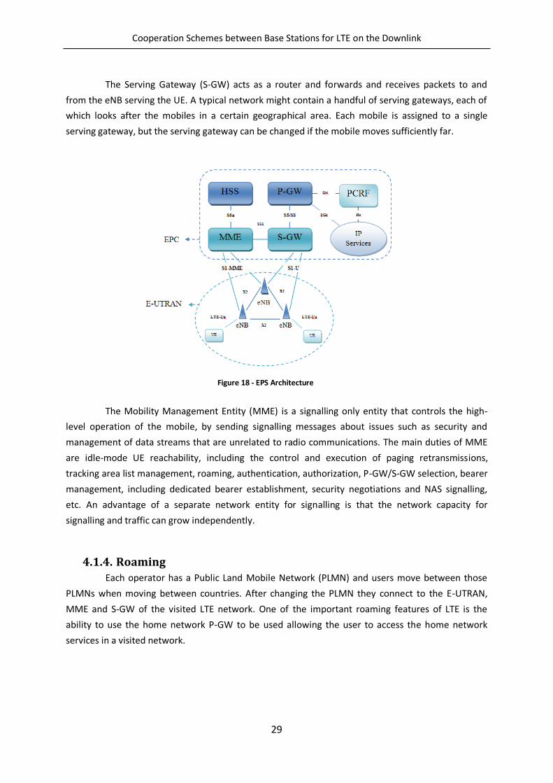
Cooperation Schemes between Base Stations for LTE on the Downlink
29
The Serving Gateway (S-GW) acts as a router and forwards and receives packets to and
from the eNB serving the UE. A typical network might contain a handful of serving gateways, each of
which looks after the mobiles in a certain geographical area. Each mobile is assigned to a single
serving gateway, but the serving gateway can be changed if the mobile moves sufficiently far.
The Mobility Management Entity (MME) is a signalling only entity that controls the high-
level operation of the mobile, by sending signalling messages about issues such as security and
management of data streams that are unrelated to radio communications. The main duties of MME
are idle-mode UE reachability, including the control and execution of paging retransmissions,
tracking area list management, roaming, authentication, authorization, P-GW/S-GW selection, bearer
management, including dedicated bearer establishment, security negotiations and NAS signalling,
etc. An advantage of a separate network entity for signalling is that the network capacity for
signalling and traffic can grow independently.
4.1.4. Roaming
Each operator has a Public Land Mobile Network (PLMN) and users move between those
PLMNs when moving between countries. After changing the PLMN they connect to the E-UTRAN,
MME and S-GW of the visited LTE network. One of the important roaming features of LTE is the
ability to use the home network P-GW to be used allowing the user to access the home network
services in a visited network.
Figure 18 - EPS Architecture
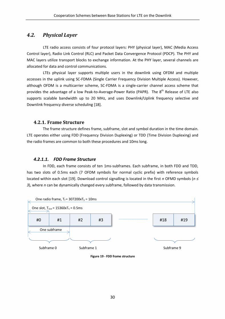
Cooperation Schemes between Base Stations for LTE on the Downlink
30
4.2. Physical Layer
LTE radio access consists of four protocol layers: PHY (physical layer), MAC (Media Access
Control layer), Radio Link Control (RLC) and Packet Data Convergence Protocol (PDCP). The PHY and
MAC layers utilize transport blocks to exchange information. At the PHY layer, several channels are
allocated for data and control communications.
LTEs physical layer supports multiple users in the downlink using OFDM and multiple
accesses in the uplink using SC-FDMA (Single Carrier Frequency Division Multiple Access). However,
although OFDM is a multicarrier scheme, SC-FDMA is a single-carrier channel access scheme that
provides the advantage of a low Peak-to-Average-Power Ratio (PAPR). The 8th Release of LTE also
supports scalable bandwidth up to 20 MHz, and uses Downlink/Uplink frequency selective and
Downlink frequency diverse scheduling [18].
4.2.1. Frame Structure
The frame structure defines frame, subframe, slot and symbol duration in the time domain.
LTE operates either using FDD (Frequency Division Duplexing) or TDD (Time Division Duplexing) and
the radio frames are common to both these procedures and 10ms long.
4.2.1.1. FDD Frame Structure
In FDD, each frame consists of ten 1ms-subframes. Each subframe, in both FDD and TDD,
has two slots of 0.5ms each (7 OFDM symbols for normal cyclic prefix) with reference symbols
located within each slot [19]. Download control signalling is located in the first n OFMD symbols (n ≤
3), where n can be dynamically changed every subframe, followed by data transmission.
Figure 19 - FDD frame structure
#0 #1 #2 #3 #18 #19
One radio frame, Tf = 307200xTS = 10ms
One slot, Tslot = 15360xTS = 0.5ms
One subframe
Subframe 0 Subframe 1 Subframe 9
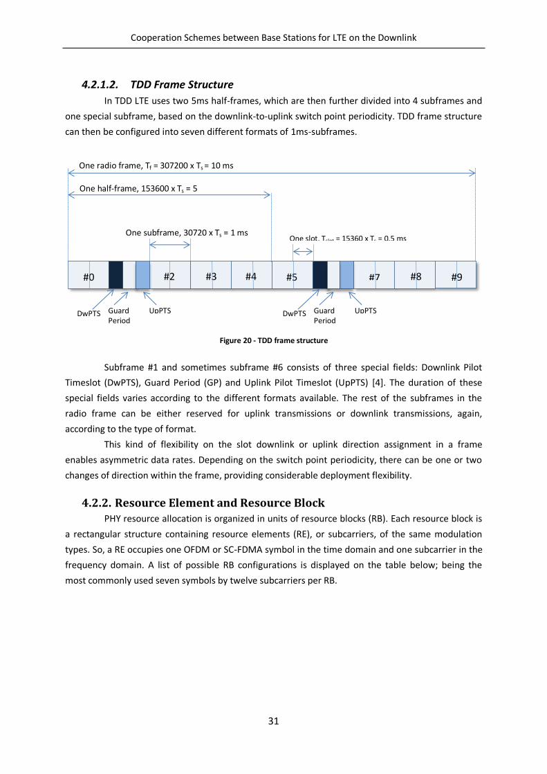
Cooperation Schemes between Base Stations for LTE on the Downlink
31
4.2.1.2. TDD Frame Structure
In TDD LTE uses two 5ms half-frames, which are then further divided into 4 subframes and
one special subframe, based on the downlink-to-uplink switch point periodicity. TDD frame structure
can then be configured into seven different formats of 1ms-subframes.
Figure 20 - TDD frame structure
Subframe #1 and sometimes subframe #6 consists of three special fields: Downlink Pilot
Timeslot (DwPTS), Guard Period (GP) and Uplink Pilot Timeslot (UpPTS) [4]. The duration of these
special fields varies according to the different formats available. The rest of the subframes in the
radio frame can be either reserved for uplink transmissions or downlink transmissions, again,
according to the type of format.
This kind of flexibility on the slot downlink or uplink direction assignment in a frame
enables asymmetric data rates. Depending on the switch point periodicity, there can be one or two
changes of direction within the frame, providing considerable deployment flexibility.
4.2.2. Resource Element and Resource Block
PHY resource allocation is organized in units of resource blocks (RB). Each resource block is
a rectangular structure containing resource elements (RE), or subcarriers, of the same modulation
types. So, a RE occupies one OFDM or SC-FDMA symbol in the time domain and one subcarrier in the
frequency domain. A list of possible RB configurations is displayed on the table below; being the
most commonly used seven symbols by twelve subcarriers per RB.
#7 #0 #2 #3 #4 #5
One radio frame, Tf = 307200 x Ts = 10 ms
One half-frame, 153600 x Ts = 5 ms
One subframe, 30720 x Ts = 1 ms One slot, Tslot = 15360 x Ts = 0.5 ms
DwPTS Guard Period
UpPTS DwPTS Guard Period
UpPTS
#8 #9
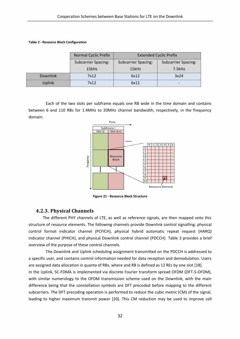
Cooperation Schemes between Base Stations for LTE on the Downlink
32
Table 2 - Resource Block Configuration
Each of the two slots per subframe equals one RB wide in the time domain and contains
between 6 and 110 RBs for 1.4MHz to 20MHz channel bandwidth, respectively, in the frequency
domain.
Figure 21 - Resource Block Structure
4.2.3. Physical Channels
The different PHY channels of LTE, as well as reference signals, are then mapped onto this
structure of resource elements. The following channels provide Downlink control signalling: physical
control format indicator channel (PCFICH), physical hybrid automatic repeat request (HARQ)
indicator channel (PHICH), and physical Downlink control channel (PDCCH). Table 3 provides a brief
overview of the purpose of these control channels.
The Downlink and Uplink scheduling assignment transmitted on the PDCCH is addressed to
a specific user, and contains control information needed for data reception and demodulation. Users
are assigned data allocation in quanta of RBs, where and RB is defined as 12 REs by one slot [18].
In the Uplink, SC-FDMA is implemented via discrete Fourier transform spread OFDM (DFT-S-OFDM),
with similar numerology to the OFDM transmission scheme used on the Downlink, with the main
difference being that the constellation symbols are DFT precoded before mapping to the different
subcarriers. The DFT precoding operation is performed to reduce the cubic metric (CM) of the signal,
leading to higher maximum transmit power [20]. This CM reduction may be used to improve cell
Normal Cyclic Prefix Extended Cyclic Prefix
Subcarrier Spacing:
15kHz
Subcarrier Spacing:
15kHz
Subcarrier Spacing:
7.5kHz
Downlink 7x12 6x12 3x24
Uplink 7x12 6x12 -
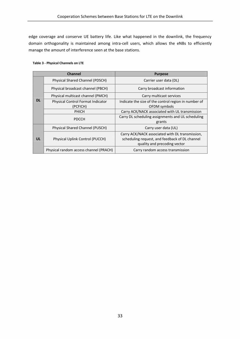
Cooperation Schemes between Base Stations for LTE on the Downlink
33
edge coverage and conserve UE battery life. Like what happened in the downlink, the frequency
domain orthogonality is maintained among intra-cell users, which allows the eNBs to efficiently
manage the amount of interference seen at the base stations.
Table 3 - Physical Channels on LTE
Channel Purpose
DL
Physical Shared Channel (PDSCH) Carrier user data (DL)
Physical broadcast channel (PBCH) Carry broadcast information
Physical multicast channel (PMCH) Carry multicast services
Physical Control Format Indicator (PCFICH)
Indicate the size of the control region in number of OFDM symbols
PHICH Carry ACK/NACK associated with UL transmission
PDCCH Carry DL scheduling assignments and UL scheduling
grants
UL
Physical Shared Channel (PUSCH) Carry user data (UL)
Physical Uplink Control (PUCCH) Carry ACK/NACK associated with DL transmission, scheduling request, and feedback of DL channel
quality and precoding vector
Physical random access channel (PRACH) Carry random access transmission

Cooperation Schemes between Base Stations for LTE on the Downlink
34
Cooperation Schemes between Base Stations for LTE on the Downlink
35
5. LTE Advanced
The International Telecommunication Union (ITU) set a list of requirements for the fourth
generation (4G) of cellular communications, under the name of IMT-Advanced, setting a peak data
rate of at least 600Mbps on the downlink and 270Mbps on the uplink, in a bandwidth of 40MHz. It’s
clear that the LTE system didn’t fulfil those requirements.
Driven by ITU’s requirements, 3GPP started studying how to enhance the capabilities of LTE.
The result of such studies was a specification for a system known as LTE-Advanced or the LTE’s
Release 10, with the following main requirements: peak data rate of 1Gbps in the downlink, and
500Mbps in the uplink. In practice, the system has been designed so that it can eventually deliver a
peak data rate of 3 and 1,5Gbps respectively, using a total bandwidth of 100MHz, made from five
different separate components of 20MHz each.
The specifications also include goals for the spectrum efficiency and the capacity of being
compatible with other cellular systems. These goals are possible due to the use of some enabling
technologies, such as carrier aggregation, relaying, enhancements to multiple antenna transmissions
on both the uplink and the downlink and multi-point coordination/cooperation. Since the aim of this
thesis is study coordination techniques, we present in more detail the last enabling technology, the
first three are briefly discussed.
5.1. Carrier Aggregation
In order to support a maximum bandwidth of 100MHz, LTE-Advanced allows a mobile to
transmit and receive on up to five component carriers (CCs), each of which has a maximum
bandwidth of 20MHz. This technique is known as Carrier Aggregation [2]. Carrier Aggregation enables
peak data rates in excess of 1Gb/s in the downlink and 500 Mb/s in the uplink [18].
There are three scenarios in which Carrier Aggregation can happen. The first one, designated
by inter-band aggregation, the component carriers are located in different frequency bands, thus,
the mobile may require different radio components to support each band and the cell’s coverage are
in each band may be very different. The component carriers are separated by a multiple of 100 kHz,
which is the usual LTE carrier spacing.
The second scenario is called Non-contiguous intra-band aggregation, and is characterized
by having the component carriers in the same band. This scheme deals with the same problems
noted in the first scenario, and simplifies the design of the mobile and network.
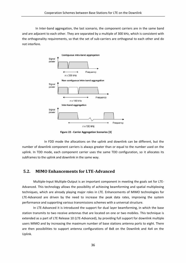
Cooperation Schemes between Base Stations for LTE on the Downlink
36
In Inter-band aggregation, the last scenario, the component carriers are in the same band
and are adjacent to each other. They are separated by a multiple of 300 kHz, which is consistent with
the orthogonality requirements, so that the set of sub-carriers are orthogonal to each other and do
not interfere.
In FDD mode the allocations on the uplink and downlink can be different, but the
number of downlink component carriers is always greater than or equal to the number used on the
uplink. In TDD mode, each component carrier uses the same TDD configuration, so it allocates its
subframes to the uplink and downlink in the same way.
5.2. MIMO Enhancements for LTE-Advanced
Multiple-Input Multiple-Output is an important component in meeting the goals set for LTE-
Advanced. This technology allows the possibility of achieving beamforming and spatial multiplexing
techniques, which are already playing major roles in LTE. Enhancements of MIMO technologies for
LTE-Advanced are driven by the need to increase the peak data rates, improving the system
performance and supporting various transmissions schemes with a universal structure.
In LTE-Advanced it is introduced the support for dual layer beamforming, in which the base
station transmits to two receive antennas that are located on one or two mobiles. This technique is
extended as a part of LTE Release 10 (LTE-Advanced), by providing full support for downlink multiple
users MIMO and by increasing the maximum number of base stations antenna ports to eight. There
are then possibilities to support antenna configurations of 8x8 on the Downlink and 4x4 on the
Uplink.
Figure 22 - Carrier Aggregation Scenarios [3]
Cooperation Schemes between Base Stations for LTE on the Downlink
37
This same technique can be used to support single user MIMO, with a maximum of eight
antenna ports and eight transmission layers, being a preferred scenario in uncorrelated channel
conditions or to maximize the peak data rate of a single mobile, while multiuser MIMO is preferred in
correlated channel conditions or to maximize the cell capacity.
The LTE-Advanced downlink spatial multiplexing is enhanced to support up to eight
transmission layers with an enhanced reference-signal structure for demodulation. Additionally,
feedback of CSI is based on a separate set of reference signals – CSI reference signals. While UE-
specific reference signals are denser in frequency but only transmitted when data is transmitted on
the corresponding layer, CSI reference signals are relatively sparse in frequency and time, but
regularly transmitted from all antennas at the base station. Separating these two types of reference
signals helps reducing the reference signal overhead, especially for high degrees of spatial
multiplexing, and allows for implementation of various beam-forming schemes.
In the Uplink, Release 10 set spatial multiplexing of up to four layers. The basis is a codebook-
based scheme where the scheduler in the base station determines the precoding matrix applied in
the UE. The selected precoding matrix is then applied to the uplink data transmission as well as the
uplink demodulation reference signals. The reference signals are enhanced to support up to four
antennas.
5.3. Relaying and Repeaters
The use of Relay Nodes (RN) opens up new possibilities for increasing the density of the
deployed infrastructure, with the aim of cutting the distance between transmitters and receivers
thus allowing higher data rates, improving group mobility, cell edge coverage as well as extends
coverage to heavily shadowed areas or areas beyond the cell range. Another potential benefit of this
scheme is to cut back on CAPEX and OPEX by having cells of relatively larger sizes. Repeaters, which
are already being used today for dealing with coverage holes, also play a key role by simply
amplifying and forwarding the received analogue signals, so it appears to the receiver as an extra
source of multipath. Unfortunately the repeater also amplifies the incoming noise and interference
as well as the received signal, which ultimately limits its performance.
A relay takes things a step further, by decoding the received radio signal, before re-encoding
and rebroadcasting it. By doing this, it removes the noise and interference from the retransmitted
signal, so it can achieve a higher performance than a repeater. In a typical relay network scenario,
the Relay Nodes are connected through a donor cell to the radio access network. Relays can be
divided in three categories:
Layer 1 (L1) Relay, also known as Amplify-and-Forward Relay is easy to implement
through RF amplification with relatively low latency. It is not very practical, as
undesired noise is also amplified with the desired signal.
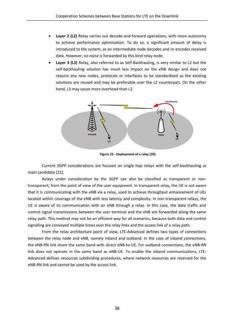
Cooperation Schemes between Base Stations for LTE on the Downlink
38
Layer 2 (L2) Relay carries out decode-and-forward operations, with more autonomy
to achieve performance optimization. To do so, a significant amount of delay is
introduced to the system, as an intermediate node decodes and re-encodes received
data. However, no noise is forwarded by this kind relay node.
Layer 3 (L3) Relay, also referred to as Self-Backhauling, is very similar to L2 but the
self-backhauling solution has much less impact on the eNB design and does not
require any new nodes, protocols or interfaces to be standardized as the existing
solutions are reused and may be preferable over the L2 counterpart. On the other
hand, L3 may cause more overhead than L2.
Figure 23 - Deployment of a relay [20]
Current 3GPP considerations are focused on single hop relays with the self-backhauling as
main candidate [21].
Relays under consideration by the 3GPP can also be classified as transparent or non-
transparent, from the point of view of the user equipment. In transparent relay, the UE is not aware
that it is communicating with the eNB via a relay, used to achieve throughput enhancement of UEs
located within coverage of the eNB with less latency and complexity. In non-transparent relays, the
UE is aware of its communication with an eNB through a relay. In this case, the data traffic and
control signal transmissions between the user terminal and the eNB are forwarded along the same
relay path. This method may not be an efficient way for all scenarios, because both data and control
signalling are conveyed multiple times over the relay links and the access link of a relay path.
From the relay architecture point of view, LTE-Advanced defines two types of connections
between the relay node and eNB, namely inband and outband. In the case of inband connections,
the eNB-RN link share the same band with direct eNB-to-UE. For outband connections, the eNB-RN
link does not operate in the same band as eNB-UE. To enable the inband communications, LTE-
Advanced defines resources subdividing procedures, where network resources are reserved for the
eNB-RN link and cannot be used by the access link.
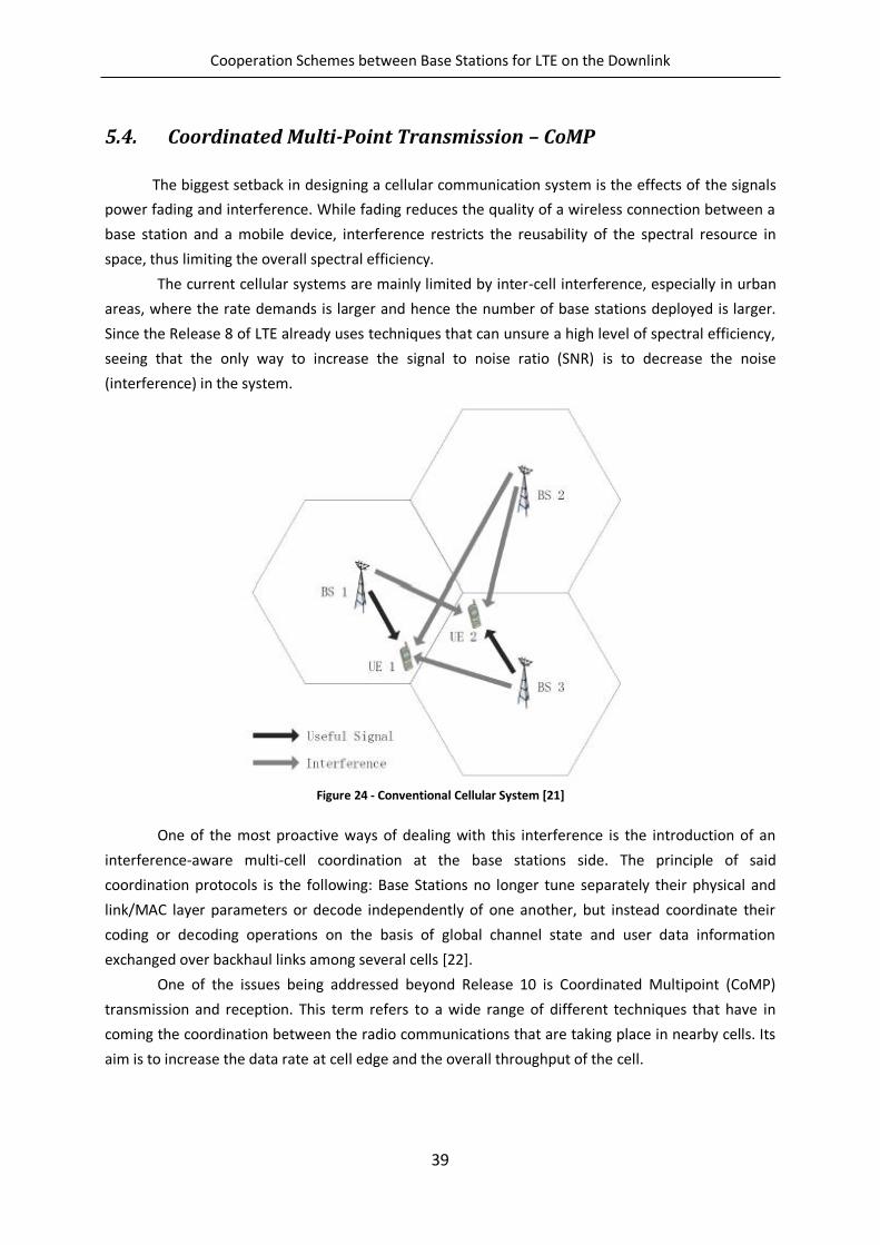
Cooperation Schemes between Base Stations for LTE on the Downlink
39
5.4. Coordinated Multi-Point Transmission – CoMP
The biggest setback in designing a cellular communication system is the effects of the signals
power fading and interference. While fading reduces the quality of a wireless connection between a
base station and a mobile device, interference restricts the reusability of the spectral resource in
space, thus limiting the overall spectral efficiency.
The current cellular systems are mainly limited by inter-cell interference, especially in urban
areas, where the rate demands is larger and hence the number of base stations deployed is larger.
Since the Release 8 of LTE already uses techniques that can unsure a high level of spectral efficiency,
seeing that the only way to increase the signal to noise ratio (SNR) is to decrease the noise
(interference) in the system.
Figure 24 - Conventional Cellular System [21]
One of the most proactive ways of dealing with this interference is the introduction of an
interference-aware multi-cell coordination at the base stations side. The principle of said
coordination protocols is the following: Base Stations no longer tune separately their physical and
link/MAC layer parameters or decode independently of one another, but instead coordinate their
coding or decoding operations on the basis of global channel state and user data information
exchanged over backhaul links among several cells [22].
One of the issues being addressed beyond Release 10 is Coordinated Multipoint (CoMP)
transmission and reception. This term refers to a wide range of different techniques that have in
coming the coordination between the radio communications that are taking place in nearby cells. Its
aim is to increase the data rate at cell edge and the overall throughput of the cell.
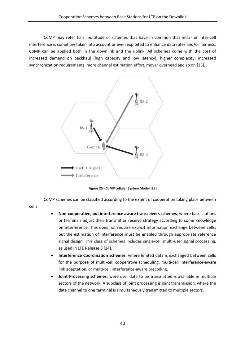
Cooperation Schemes between Base Stations for LTE on the Downlink
40
CoMP may refer to a multitude of schemes that have in common that intra- or inter-cell
interference is somehow taken into account or even exploited to enhance data rates and/or fairness.
CoMP can be applied both in the downlink and the uplink. All schemes come with the cost of
increased demand on backhaul (high capacity and low latency), higher complexity, increased
synchronization requirements, more channel estimation effort, mover overhead and so on [23].
Figure 25 - CoMP cellular System Model [23]
CoMP schemes can be classified according to the extent of cooperation taking place between
cells:
Non-cooperative, but interference aware transceivers schemes, where base stations
or terminals adjust their transmit or receive strategy according to some knowledge
on interference. This does not require explicit information exchange between cells,
but the estimation of interference must be enabled through appropriate reference
signal design. This class of schemes includes single-cell multi-user signal processing,
as used in LTE Release 8 [24].
Interference Coordination schemes, where limited data is exchanged between cells
for the purpose of multi-cell cooperative scheduling, multi-cell interference-aware
link adaptation, or multi-cell interference-aware precoding.
Joint Processing schemes, were user data to be transmitted is available in multiple
sectors of the network. A subclass of joint processing is joint transmission, where the
data channel to one terminal is simultaneously transmitted to multiple sectors.
Cooperation Schemes between Base Stations for LTE on the Downlink
41
The most important and more used CoMP schemes are Joint Processing and Interference
Coordination, and they are going to be discussed in the following sub-chapters, with a focus on the
downlink, being that the purpose of this thesis.
5.4.1. Joint Processing
In the class of joint processing/transmission, multiple base stations (or transmission points or
cells) jointly transmit signals to the mobile terminal, improve the received signal quality or actively
cancel interference from other mobile terminals [25]. So, in this case, there has to be data and
channel state information (CSI) shared between different cells to be jointly processed at these cells.
As a result of this joint processing, received signals at the intended mobile terminal will be coherently
or non-coherently added together. If time-frequency synchronization transmission (TFST) is
operated, that is, if the data of a UE is simultaneously transmitted from multiple points on a time-
frequency resource to improve the received signal quality and/or data throughput, then Joint
Processing (JP) will become Joint Transmission (JT) [26]. The effect of Joint Processing largely
depends on the application of the Precoding method in the transmission points [27].
Joint Transmission can be achieved by codebook-based precoding, to reduce feedback signal
overhead [28]. In principle, the best precoding matrixes for inter-cell site coordination are selected in
addition to the individual selection of the best precoding matrix at each cell site so that the received
signal-to-interference-plus-noise power ratio (SINR) is maximized at a UE set among the
predetermined precoding matrix candidates. Other implementation methods can be performed in
order to achieve the principle operation.
The cost for the existing coordination schemes with joint processing is the heavy exchange of
channel state information and signal information over backhaul links.
The design of efficient algorithms and principles that could reduce these complex feedback
requirements demands solutions that restrict the use of joint processing techniques to a limited
number of BS or areas of the system. Thus being so, the network is divided into clusters of cells, and
the joint processing schemes are implemented within the BSs included in each cluster. The cluster
formation can be static, if the cluster remains fixed in time, or dynamic. Within static clusters, three
schemes that result in several degrees of joint processing between BSs can be defined [29]:
Centralized Joint Processing (CJP): global Channel State Information (CSI) is available at the
transmitter side, and the BSs within the cluster jointly perform the power allocation and the
design of the linear precoders.
Partial Joint Processing (PJP): this scheme defines different stages of joint processing
between BSs. Joint processing degrees or stages are obtained arranging an active set or
subset of BSs for each user in the cluster area. Therefore, a user only receives its data from
the subset of BSs included in its active set.
Distributed Joint Processing (DJP): local CSI is available at each BS. Therefore, the power
allocation and the precoders are locally calculated at each BS (distributed) but the user may
receive its data from several BSs depending on its given channel conditions.
Cooperation Schemes between Base Stations for LTE on the Downlink
42
5.4.2. Coordinated Beamforming/Coordinated Scheduling
In this second type of downlink CoMP transmission, commonly designated by CB/CS, a UE
data is only available at one transmission point but multipoint CSI is exchanged in the network for
interpoint coordination of scheduling and/or beamforming.
The idea of Coordinated Beamforming existed long before the CoMP principle, in the mid-
nineties, and mainly targeted the signal-to-interference-plus-noise-ratio (SINR) levelling problem
[30], in which the power levels and the beamforming coefficients are calculated to achieve some
common SINR in the system or to maximize the minimum SINR. On the other hand, Coordinated
Scheduling is a rather recent idea. The first studies mainly divided the entire network in clusters and
applied centralized scheduling within each cluster in order to determine which Transmission Point
(TP) in the cluster should transmit in each time slot and to which UE [31]. Later studies jointly use
CS/CB as a tool to reduce multi-user and multicell interference.
Coordinated beam patterns is a low feedback overhead approach targeting highly loaded
cells that consists of coordinating the precoders (beamforming matrices) in the cooperating TPs in a
pre-defined manner, in order to reduce interference variation and enable accurate link adaptation,
while avoiding spatial CSI feedback from the UE. The TPs, relying on a TP-specific beam pattern in the
time-frequency domain, cycle through the fixed set of beams where the cycling period is decided by
a central controller and conveyed to the TPs. Based on reports of the best resources and associated
channel quality in each cycling period, the UE can be scheduled in the subframes or sub-bands where
the coordinated beams provide the best channel conditions.
Precoding Matrix Indicator coordination mitigates the inter-TP interference based on the
report of a restricted or recommended PMI, measured by the terminals [23], which corresponds to
potential precoders at an interfering TP. Assuming that the UE and base stations have knowledge of a
codebook composed of quantized precoders, PMI restrictions and PMI recommendation techniques
constrain the interfering TPs to use only those precoders that belong to a subset of the codebook in
order to enhance cell edge performance. When there’s a PMI restriction, the cell edge users
calculates and reports to their serving cell the restricted PMIs, defined as the PMIs that create the
highest interference if used as a precoders in the interfering TPs. The opposite is true to the case of a
PMI recommendation, which is defined as the PMIs that create the lowest interference if used as
precoders in the interfering TPs.
Interference suppression-based coordinated beamforming refers to a coordinated selection of
the transmit precoders in each TP that aims at eliminating or reducing the effect of inter-TP
interference. The Base Stations compute a new transmit filter based on the CSI feedback from the
serving and interfering TPs, relying typically on zero-forcing beamforming (ZFBF), which is designed
by forcing the interference from a reference TP to UEs served by other TPs to zero, joint leakage
suppression (JLS) criteria that maximizes the signal-to-leakage-plus-noise ratio (SLNR) to the UE
served by the reference TP, and others. Interference-suppression-based CB provides more design
flexibility than PMI coordination, but is more demanding in terms of complexity, CSI accuracy,
feedback overhead, backhaul overhead, and scheduling coordination.
Cooperation Schemes between Base Stations for LTE on the Downlink
43
5.4.3. Clustering
CoMP schemes, as seen in the previous sections, require additional signalling overhead on
the air interface and the backhaul network. Consequently, in practical applications, only a limited
number of base stations can cooperate, in order to keep the overhead manageable. So, this
cooperative base stations form a cooperating cell cluster, set up adaptively based on RF channel
measurements and UE positions, in order to exploit the advantages of CoMP efficiently at limited
complexity.
A key requirement for adaptive cluster algorithms in CoMP schemes is that it fits into the
LTEs’ architecture of the radio access and/or core network. The 3GPP standard already supports a
framework for self-organization networks (SONs), in order to maintain automatic configuration and
optimization of the network [23].
One of the most central questions in practical CoMP schemes is how small cell clusters can
be formed, within which CoMP can be used at reasonable overhead and complexity, but still
providing major portions of the potential CoMP gain. Two clustering schemes can be defines,
regarding the previous stated matters: static clustering, where clustering is only performed once,
based on either field measurements or ray-launching simulations of concrete deployments [32], and
then fixed, and dynamic clustering, where UE-centric measurements are used to adapt clustering
decisions over time to traffic demand and UE locations [33].
5.4.4. Backhaul for CoMP
CoMP techniques need to exchange direct information between Base Station, with different
requirements of the necessary backhaul throughput and latency, depending on the type of CoMP
approach at stake.
MIMO cooperation requires the sharing of both channel state information and user data. In
determined CoMP schemes, the data symbols of all users must be known at all cooperating bases. In
a system where a cluster composed of L base stations cooperate among each other, data is sent to
the these base stations results on a factor of L increase in the backhaul bandwidth [22]. Compared
with the exchange of data, the bandwidth required for exchanging channel state information is very
small, for the case of moderate mobile speeds. These bandwidth requirements for the exchange of
CSI increase for higher mobile speeds and more frequency selective channels.
As an alternative to sending the data signals and CSI to the base stations as it is, one could
send a quantized signal of this information, in order to reduce the backhaul requirements of a CoMP
system. A study of this technique will be conducted in the next chapter, and its benefits will be
discussed.
For connectivity between sites, the logical X2 interface could be used, being either a direct
physical link or a multihop link, depending on the network’s backhaul architecture. The delay
depends on the network topology, network node processing delay and line delay [23].
The backhaul network for CoMP systems has to take in to account latency
requirements, and seeing that CoMP is integrated with the hybrid automatic repeat request (HARQ)
Cooperation Schemes between Base Stations for LTE on the Downlink
44
process, the backhaul latency will be limited by said process. Another impact of backhaul latency is
that the exchanged channel information is outdated.
Cooperation Schemes between Base Stations for LTE on the Downlink
45
6. Cooperative Schemes Implemented
In the previous chapters we discussed the influence of the intercell interference in limiting
the cellular system capacity and how multicell cooperation is a promising solution for cellular
systems to mitigate these effects. This technology, under study in LTE-Advanced, was discussed in
Chapter 5, under the coordinated multipoint (CoMP) concept.
Previously we noted there were two main types of CoMP based techniques, depending on
the amount of information shared by the transmitters through the backhaul network, namely
Coordinated Beamforming/Scheduling (CB/CS) and Joint Processing (JP). These techniques can also
be characterized by where the processing takes place, i.e., centralized if the processing takes place at
a central unit (CU) or distributed if it takes place at the different transmitters.
Coordinated centralized beamforming approaches, where transmitters exchange both data
and channel state information (CSI) for joint processing at the CU, promise large spectral efficiency
gains than distributed interference coordination techniques, but typically at the price of larger
backhaul requirements and more severe synchronization requirements. Two centralized multicell
precoding schemes based on the waterfilling technique have been proposed in [34]. It was shown
that these techniques achieve a performance, in terms of weighted sum rate, very close to the
optimal. In [35] a clustered BS coordination is enabled through a multicell block diagonalization (BD)
strategy to mitigate the effects of interference in multicell MIMO systems. A new BD cooperative
multicell scheme has been proposed in [36], to maximize the weighted sum-rate achievable for all
the UTs.
Distributed precoding approaches, where the precoder vectors are computed at each BS in
a distributed fashion, have been proposed in [37]. It is assumed that each base station has only
knowledge of local CSI and based on that a parameterization of the beamforming vectors used to
achieve the outer boundary of the achievable rate region was derived. In [38] , distributed precoding
schemes based on zero-forcing criterion with several centralized power allocation based on
minimization of signal-to-noise ratio (SINR) have been derived.
In the previous approaches, it was assumed that the transmitters share the entire data of
all UTs. However, there are distributed beamforming approaches where the transmitters do not
share the data, which fall into the interference channel (IC) framework. The local CSI, i.e., the CSI
between a given BS and all UTs, is used by transmitters to design individual precoders to transmit
exclusively to the users within their own cell [39], [40]. This approach, known as inter-cell
interference nulling (ICIN), in which each BS transmits in the null-space of the interference it is
causing to neighbouring cells, has been discussed in the 3GPP LTE-Advanced literature. The authors
of [41] proposed a non-iterative distributed solution to design precoding matrices for multicell
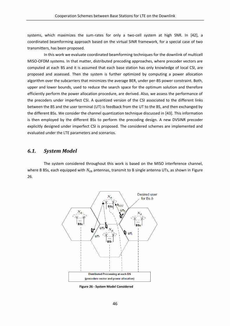
Cooperation Schemes between Base Stations for LTE on the Downlink
46
systems, which maximizes the sum-rates for only a two-cell system at high SNR. In [42], a
coordinated beamforming approach based on the virtual SINR framework, for a special case of two
transmitters, has been proposed.
In this work we evaluate coordinated beamforming techniques for the downlink of multicell
MISO-OFDM systems. In that matter, distributed precoding approaches, where precoder vectors are
computed at each BS and it is assumed that each base station has only knowledge of local CSI, are
proposed and assessed. Then the system is further optimized by computing a power allocation
algorithm over the subcarriers that minimizes the average BER, under per-BS power constraint. Both,
upper and lower bounds, used to reduce the search space for the optimum solution and therefore
efficiently perform the power allocation procedure, are derived. Also, we assess the performance of
the precoders under imperfect CSI. A quantized version of the CSI associated to the different links
between the BS and the user terminal (UT) is feedback from the UT to the BS, and then exchanged by
the different BSs. We consider the channel quantization technique discussed in [43]. This information
is then employed by the different BSs to perform the precoding design. A new DVSINR precoder
explicitly designed under imperfect CSI is proposed. The considered schemes are implemented and
evaluated under the LTE parameters and scenarios.
6.1. System Model
The system considered throughout this work is based on the MISO interference channel,
where B BSs, each equipped with antennas, transmit to B single antenna UTs, as shown in Figure
26.
Figure 26 - System Model Considered
Cooperation Schemes between Base Stations for LTE on the Downlink
47
It is assumed that we have an OFDM based system with available subcarriers. Under the
assumption of linear precoding, the signal transmitted by the BS on subcarrier is given by,
, √ , , , (6.1.1)
where , represents the transmitted power allocation to subcarrier at BS b, , is the
precoder at BS on subcarrier with unit norm, i.e., ‖ , ‖ , , , , , , . The data
symbol , , with [| , |2] , is intended for UT . The average power transmitted at BS is then
given by,
‖ ‖2 ∑ ,
(6.1.2)
where is the signal transmitted over the subcarriers.
The received signal at UT on subcarrier , , , can be expressed by,
, ∑√ , ,
, , ,
(6.1.3)
where , ( , , ) of size , represents the channel between user and BS on
subcarrier and , is the long-term channel gain between BS and UT , and , ( , 2) is
the noise.
According to equations (6.1.1) and (6.1.3) the received signal at UT on subcarrier can be
decomposed in,
, √ , , , , , ∑ √ , , ,
, ,
,
(6.1.4) and from (6.1.4) the instantaneous SINR of user on subcarrier can be written as ,
, |√ , , ,
, ( )
|2
∑ |√ , , , ,
( )|2 2
(6.1.5)
Desired Signal
Noise
Multiuser Multicell Interference
Cooperation Schemes between Base Stations for LTE on the Downlink
48
where { , }. Assuming M-arry QAM constellation, the instantaneous probability
of error for user and data symbol transmitted on subcarrier is given by,
, , (√ , ) (6.1.6)
where ( ) ( √ ) ∫ ( 2)
, ( ) and ( 2 )( √ ).
6.2. Distributed Precoder Vectors: DFZ and DVSINR
In this chapter, distributed precoding approaches, where the precoder vectors are
computed at each BS in a distributed manner, are implemented. These individual precoders,
designed at the transmitters, to transmit exclusively to the users within its cell, use only CSI between
a given BS and all UTs. This type of design approach is known as inter-cell interference nulling (ICIN),
in which each BS transmit in the null-space of the interference.
To design the distributed precoder vectors we assume that the BSs have only knowledge of
local CSI and its own data symbols, i.e., BS knows the instantaneous channel vectors , , , , ,
and only the data symbols , , , , reducing the feedback load over the backhaul network,
as compared with the data and/or CSI sharing beamforming approaches.
The precoder vectors used in this chapter were computed based on the distributed zero-
forcing (DZF) and distributed virtual signal-to-interference noise ratio (DVSINR).
6.2.1. Distributed Zero Forcing
Zero forcing is considered a classic beamforming strategy which removes the co-terminal
interference. A distributed ZF transmission scheme is derived, with the phase of the received signal
at each UT aligned. In this case, , ( )
in equation (6.1.5) is a unit-norm zero forcing orthogonal to
channel vectors { , , }
. By using such precoding vectors, the multicell interference is
canceled and the data symbol at each BS, on each subcarrier is only transmitted to its intended UT.
The SVD of { , , }
can be portioned as follows,
{ , , }
, , , , (6.2.1)
where , ( ) holds the ( ) singular vectors in the null space of
{ , , }
. The columns of , are candidates for ’s precoding vector since they will produce zero
interference at the other UTs. It can then be shown that an optimal linear combination of these
vectors can be given by,
,
( ) ,
( , , , )
‖ , , , ‖
(6.2.2)
Also, it can be shown that , , ,
( ) 2( )
2 .
Cooperation Schemes between Base Stations for LTE on the Downlink
49
6.2.2. Distributed Virtual SINR (DVSINR)
While ZF has good performance at high SNR or as the number of antennas increase, the
maximal ratio combining (MRT) is the asymptotically optimal solution at low SNR. The optimal
strategy lies between these two precoders and cannot be determined without global CSI. However,
inspired by the uplink-downlink duality for broadcast channels, there has been derived a novel
distributed virtual SINR precoder. The precoder vectors are achieved by maximizing the SINR-like
expression in (6.2.3) where the signal power that BS generates at UT is balanced against the noise
and interference power generated at all other UTs. It was named DVSINR as it originates from the
dual virtual uplink and does not directly represent the SINR of any links in the downlink
,
( )
‖ ‖
| , , |
2
∑ | , , |
2
(6.2.3)
where is the per-BS power constraint. The solution to (6.2.3) is not unique, since the virtual SINR
is unaffected by the phase shits in . One possible solution can be written as,
,
( )
, , ,
‖ , , , ‖
(6.2.4)
where
,
2
∑ , , , ,
(6.2.5)
6.2.3. Robust DVSINR
In this section, we propose a robust DVSINR algorithm, where the expression (6.2.3) is
explicitly minimized under channel quantization errors. The quantization method will be discussed
later. The overall channel frequency domain matrix, under quantization errors, can be modeled as
, , , , , , , where , ,
represents the overall quantized channel vector and , , is the
overall quantized error matrix. Replacing , , by , ,
, , in equation (6.2.3) and after some
simplification the robust precoder vector is given by
,
( )
, , ,
‖ , , ,
‖ (6.2.6)
where
,
2
( ) 2
∑ , , , ,
(6.2.7)
where 2 is the average power of the channel error.
Cooperation Schemes between Base Stations for LTE on the Downlink
50
6.3. Power Allocation
In this section, a distributed power allocation algorithm, based on minimization of the
average BER over the available subcarriers discussed in [44], is presented. Based on the solution
derived in [34] and the Lambert ( ) function, we compute upper and lower bounds to reduce the
search for the optimal solution decreasing the overall complexity. The criteria used to design this
distributed power allocation lead to a redistribution of powers among subcarriers. To derive the
power allocation for both precoders, it is assumed that the interference is negligible at both low and
high SNR, even for the VSINR precoder.
The precoder defined previously were specifically designed to make the equivalent
channels, given by , , , ,
, ( )
, positive and real valued. Under the assumption of free
interference, the SINR defined previously reduces to,
,
|√ , , , |
2
2 (6.3.1)
The above expression can be used to derive distributed power allocation because it only
contains the local channel gains at BS . The average BER can be defined as.
,
∑ (√ , )
(6.3.2)
The power allocation problem at each BS , with per-BS power constraint, can be
formulated as,
{ , }
(
∑ (√ , )
) {∑ , ,
(6.3.3)
The Lagrangian associated with this problem is given by,
( , , )
∑ (√ , )
(∑ ,
) (6.3.4)
where is the Lagrange multiplier [45]. Since the objective function is convex in , , and the
constraint functions are linear, this is a convex optimization problem. Thus, it is necessary and
sufficient to solve the Karush-Kuhn-Tucker (KKT) conditions, given by,
Cooperation Schemes between Base Stations for LTE on the Downlink
51
{
,
, ,
2(
, ,
√ , )
√ √ ,
∑ ,
(6.3.5)
It can be shown that the powers , as function of the Lagrange multiplier are given by,
,
2
( , ,
)2 (
2 2( , ,
)
2 2
) (6.3.6)
where stands for Lambert’s function of index 0 [46]. This function ( ) is an increasing
function with ( ) , and ( ) , . Therefore, 2 can be easily determined
iteratively to satisfy ∑ , , by using the bisection method. For
, a sub-interval in
which this root must lie should be provided. It can be shown that the Lamberts ( ) function is
bounded by:
( ) ( ) , , [ ,
] (6.3.7)
Thus, we can derive a lower bound for the root , given by
∑ 2 ( , ,
)2
2
(6.3.8)
and, for faster algorithm’s convergence, the upper bound should be as close to the lower bound as
possible. Being so, should be chosen as
and therefore, the upper bound is given by,
(
∑ 2
( , ,
)2 (
2 ( , ,
)
2 )
∑ 2
( , ,
)2
)
,
(6.3.9)
thus, the root [ ]. This scheme is referred as minimum virtual BER power allocation
(type MVBER PA).
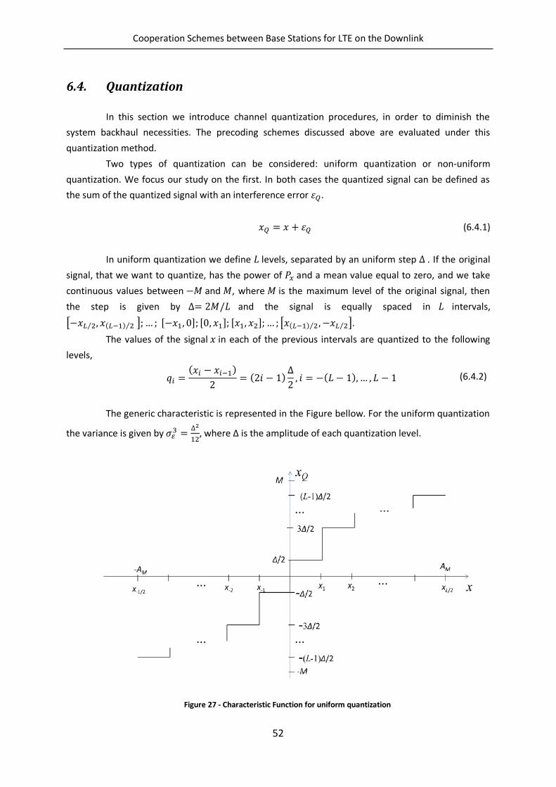
Cooperation Schemes between Base Stations for LTE on the Downlink
52
6.4. Quantization
In this section we introduce channel quantization procedures, in order to diminish the
system backhaul necessities. The precoding schemes discussed above are evaluated under this
quantization method.
Two types of quantization can be considered: uniform quantization or non-uniform
quantization. We focus our study on the first. In both cases the quantized signal can be defined as
the sum of the quantized signal with an interference error .
(6.4.1)
In uniform quantization we define levels, separated by an uniform step . If the original
signal, that we want to quantize, has the power of and a mean value equal to zero, and we take
continuous values between and , where is the maximum level of the original signal, then
the step is given by and the signal is equally spaced in intervals,
[ 2⁄ , ( ) 2⁄ ] , , , 2 [ ( ) 2⁄ , 2⁄ ].
The values of the signal in each of the previous intervals are quantized to the following
levels,
( )
( )
, ( ), , (6.4.2)
The generic characteristic is represented in the Figure bellow. For the uniform quantization
the variance is given by
2, where ∆ is the amplitude of each quantization level.
Figure 27 - Characteristic Function for uniform quantization
Cooperation Schemes between Base Stations for LTE on the Downlink
53
For input signals whose range is infinity, several authors deduced the optimum step for
uniform quantization depending on the signal distributions. In the case of unlimited signal input, the
quantization characteristics can be limited between and , where is the saturation level.
In this work we consider ideal clipping, which is given by the expression
( ) {
,
,
,
(6.4.3)
The signal-to-quantization-noise ratio (SQNR) is given by
[| |2] (6.4.4)
which, as we can see, is dependent on the saturation level .
6.4.1. Channel Quantization
The complex baseband representation of the channel impulse response (CIR) can be expressed by
( , ) ∑ ( )
(6.4.5)
where is the number of paths, is the complex amplitude of the path and is the
delay of the path. The power delay profile (PDP) is given by
∑| |2 ( )
(6.4.6)
Figure 28 show the CIR and frequency response of the channel, where is the duration of
the useful symbol, is the cyclic prefix length, which should verify , with being
maximum delay, and the channel frequency separation between subcarriers.
The frequency response of the time variant channel at time t is the Fourier transform of the CIR, considering is a multiple of sampling interval ( )
( ) ∫ ( , ) 2
∑ 2
(6.4.7)
The overall channel frequency for subcarrier k is then give by,
( ⁄ ) ∑ 2
(6.4.8)
Cooperation Schemes between Base Stations for LTE on the Downlink
54
Thus, obtaining the frequency values for each subcarrier { , , } . Then, we
consider of these values, obtaining the samples { , , }, which we
quantize into { , , }. Note that we must consider , according to the
sampling theorem, where
.
Figure 29 - Frequency Response of the time varying channel
We reconstruct the signal through the IDFT of the quantized samples, obtaining CIR of the
reconstructed channel repeated ∆ times.
Figure 30 - CIR of the reconstructed channel
By putting zeros in all the taps beyond , we are able to obtain ( ).
Figure 28 - CIR and frequency response of the channel
Cooperation Schemes between Base Stations for LTE on the Downlink
55
Figure 31 - Quantized h(τ)
The reconstructed channel response is finally obtained through DFT of one of the ∆
repeated CIRs. Relative distortion is higher for weaker taps, as we can see in the following figure.
The mean square error is given by
[∑ |
|
2
]
∑ | |2 (6.4.8)
Figure 32 -MSE of channel quantization in function of clipping value, for several numbers of quantization bits and for LTE
extended channel model
Figure 32 shows the impact of the normalized saturation level (here 2 is the
average power of the signal), and the number of quantization bits, , on MSE. As can be observed,
there is an optimum normalized saturation level for each value of , since the quantizer’s saturation
becomes too frequent if is small and the quantization interval becomes too high when is
high. Hereinafter, we always assume the optimum saturation level for each value of .
1 1.5 2 2.5 3 3.5 4-55
-50
-45
-40
-35
-30
-25
-20
-15
-10
-5
0
MS
E (
dB
)
AM
/
m=3
m=4
m=5
m=6
m=7
m=8
m=9
m=10
Cooperation Schemes between Base Stations for LTE on the Downlink
56
6.5. Channel Coding
In this section we introduce to our system Channel Coding. Data Channel Coding reefers to
the process by which both transmitter and receiver of a digital communications system, consuming
extra bandwidth by allocating extra bits (used for parity effects), grants more reliability to a
connection, protects the digital information from noise and interference and reduces the number of
errors.
On LTE, data and control streams from and to the MAC layer are encoded and decoded to
offer transport and control services over the radio transmission link. Channel coding schemes are a
combination of error detection, error correction, rate matching, interleaving and transport channel
or control information mapping onto/splitting channels [47].
Error correction can be considered in two main categories: ARQ (Automatic Repeat
Request) and FEC (Forward Error Correction) [48]. With ARQ the receiver requests retransmission of
the data packets when errors are detected, and this will be done until the received packets are error-
free or a maximum number of retransmissions are achieved. In the FEC category, redundancy bits
are added to data bits, making error correction possible. FEC has two main types of codes: block
codes and convolution codes. In block codes, the input data blocks, which can be considered as
vectors multiplied by a generator matrix, generating a code word vector. Contrarily to block codes,
which are memoryless, convolution codes are coding algorithms with memory, which means the
coded output bit depends not only on the current bit but also on the m previous bits, where m is the
number of registers in the convolutional encoder.
In LTE both block codes and convolutional codes are used. CRC (Cyclic Redundancy Check),
which is a cyclic linear block code, is used for HARQ as an error correction technique [4]. Control
channels and data channels in LTE use convolutional and Turbo Codes, respectively, where the last is
an enhanced development of convolutional codes achieving near-Shannon performance. Turbo
Coding has a fixed coding rate (number of information bits divided by the number of transmitted
bits) of
2 .
6.5.1. Turbo Coding
Turbo codes, introduced in 1993 by Berrou, Glavieux and Thitimajshima [49], are very
powerful codes that can come within a fraction of a dB of the Shannon capacity limit on AWGN
(Additive White Gaussian Noise) channels. Turbo codes consist of two main components: a
systematic parallel concatenated convolutional code (PCCC), with 8-state constituent encoders, and
one Turbo code contention free internal interleaver [4]. The structure of the Turbo encoder used in
LTE can be seen in the Figure bellow.
Cooperation Schemes between Base Stations for LTE on the Downlink
57
Figure 33 - Structure of the LTE Turbo encoder
After the turbo coding process, there’s a second stage of processing, called rate matching,
where some of the coded bits are selected for transmission, while the others are discharged, in a
process named as puncturing. The receiver has a copy of the puncturing algorithm, so it can insert
dummy bits at the points where information was discharged. It can then pass the result through a
turbo decoder for error corrections [2].
Figure 34 - Block diagram of a transmitter and receiver using Turbo coding [1]
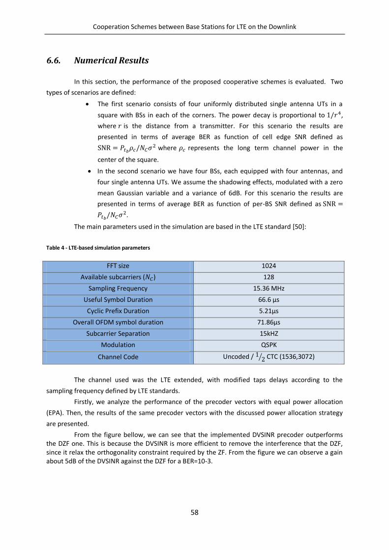
Cooperation Schemes between Base Stations for LTE on the Downlink
58
6.6. Numerical Results
In this section, the performance of the proposed cooperative schemes is evaluated. Two
types of scenarios are defined:
The first scenario consists of four uniformly distributed single antenna UTs in a
square with BSs in each of the corners. The power decay is proportional to ,
where is the distance from a transmitter. For this scenario the results are
presented in terms of average BER as function of cell edge SNR defined as
2 where represents the long term channel power in the
center of the square.
In the second scenario we have four BSs, each equipped with four antennas, and
four single antenna UTs. We assume the shadowing effects, modulated with a zero
mean Gaussian variable and a variance of 6dB. For this scenario the results are
presented in terms of average BER as function of per-BS SNR defined as
2.
The main parameters used in the simulation are based in the LTE standard [50]:
Table 4 - LTE-based simulation parameters
FFT size 1024
Available subcarriers ( ) 128
Sampling Frequency 15.36 MHz
Useful Symbol Duration 66.6 µs
Cyclic Prefix Duration 5.21µs
Overall OFDM symbol duration 71.86µs
Subcarrier Separation 15kHZ
Modulation QSPK
Channel Code Uncoded / ⁄ CTC (1536,3072)
The channel used was the LTE extended, with modified taps delays according to the
sampling frequency defined by LTE standards.
Firstly, we analyze the performance of the precoder vectors with equal power allocation
(EPA). Then, the results of the same precoder vectors with the discussed power allocation strategy
are presented.
From the figure bellow, we can see that the implemented DVSINR precoder outperforms the DZF one. This is because the DVSINR is more efficient to remove the interference that the DZF, since it relax the orthogonality constraint required by the ZF. From the figure we can observe a gain about 5dB of the DVSINR against the DZF for a BER=10-3.
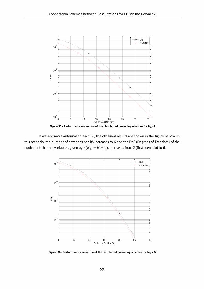
Cooperation Schemes between Base Stations for LTE on the Downlink
59
If we add more antennas to each BS, the obtained results are shown in the figure bellow. In
this scenario, the number of antennas per BS increases to 6 and the DoF (Degrees of Freedom) of the
equivalent channel variables, given by ( ), increases from 2 (first scenario) to 6.
Figure 36 - Performance evaluation of the distributed precoding schemes for Ntb = 6
0 5 10 15 20 25 30 3510
-4
10-3
10-2
10-1
Cell-Edge SNR (dB)
BE
R
DZF
DVSINR
0 5 10 15 20 25 30
10-4
10-3
10-2
10-1
Cell-edge SNR (dB)
BE
R
DZF
DVSINR
Figure 35 - Performance evaluation of the distributed precoding schemes for Ntb=4
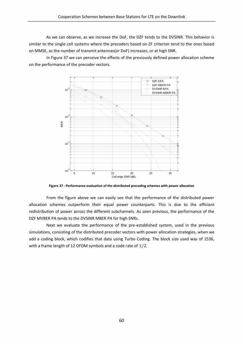
Cooperation Schemes between Base Stations for LTE on the Downlink
60
As we can observe, as we increase the DoF, the DZF tends to the DVSINR. This behavior is
similar to the single cell systems where the precoders based on ZF criterion tend to the ones based
on MMSE, as the number of transmit antennas(or DoF) increases, or at high SNR.
In Figure 37 we can perceive the effects of the previously defined power allocation scheme
on the performance of the precoder vectors.
Figure 37 - Performance evaluation of the distributed precoding schemes with power allocation
From the figure above we can easily see that the performance of the distributed power
allocation schemes outperform their equal power counterparts. This is due to the efficient
redistribution of power across the different subchannels. As seen previous, the performance of the
DZF MVBER PA tends to the DVSINR MBER PA for high SNRs.
Next we evaluate the performance of the pre-established system, used in the previous
simulations, consisting of the distributed precoder vectors with power allocation strategies, when we
add a coding block, which codifies that data using Turbo Coding. The block size used was of 1536,
with a frame length of 12 OFDM symbols and a code rate of .
5 10 15 20 25 3010
-4
10-3
10-2
10-1
Cell-edge SNR (dB)
BE
R
DZF EPA
DZF MBER PA
DVSINR EPA
DVSINR MBER PA
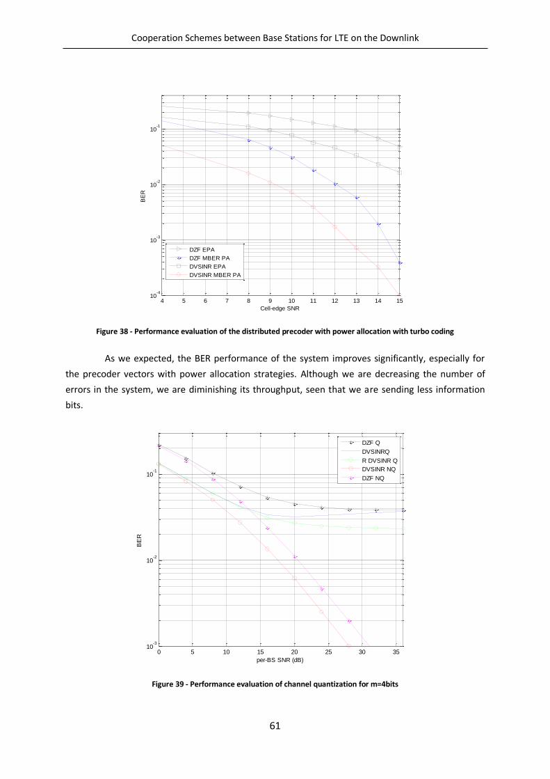
Cooperation Schemes between Base Stations for LTE on the Downlink
61
Figure 38 - Performance evaluation of the distributed precoder with power allocation with turbo coding
As we expected, the BER performance of the system improves significantly, especially for
the precoder vectors with power allocation strategies. Although we are decreasing the number of
errors in the system, we are diminishing its throughput, seen that we are sending less information
bits.
Figure 39 - Performance evaluation of channel quantization for m=4bits
4 5 6 7 8 9 10 11 12 13 14 1510
-4
10-3
10-2
10-1
Cell-edge SNR
BE
R
DZF EPA
DZF MBER PA
DVSINR EPA
DVSINR MBER PA
0 5 10 15 20 25 30 3510
-3
10-2
10-1
per-BS SNR (dB)
BE
R
DZF Q
DVSINRQ
R DVSINR Q
DVSINR NQ
DZF NQ
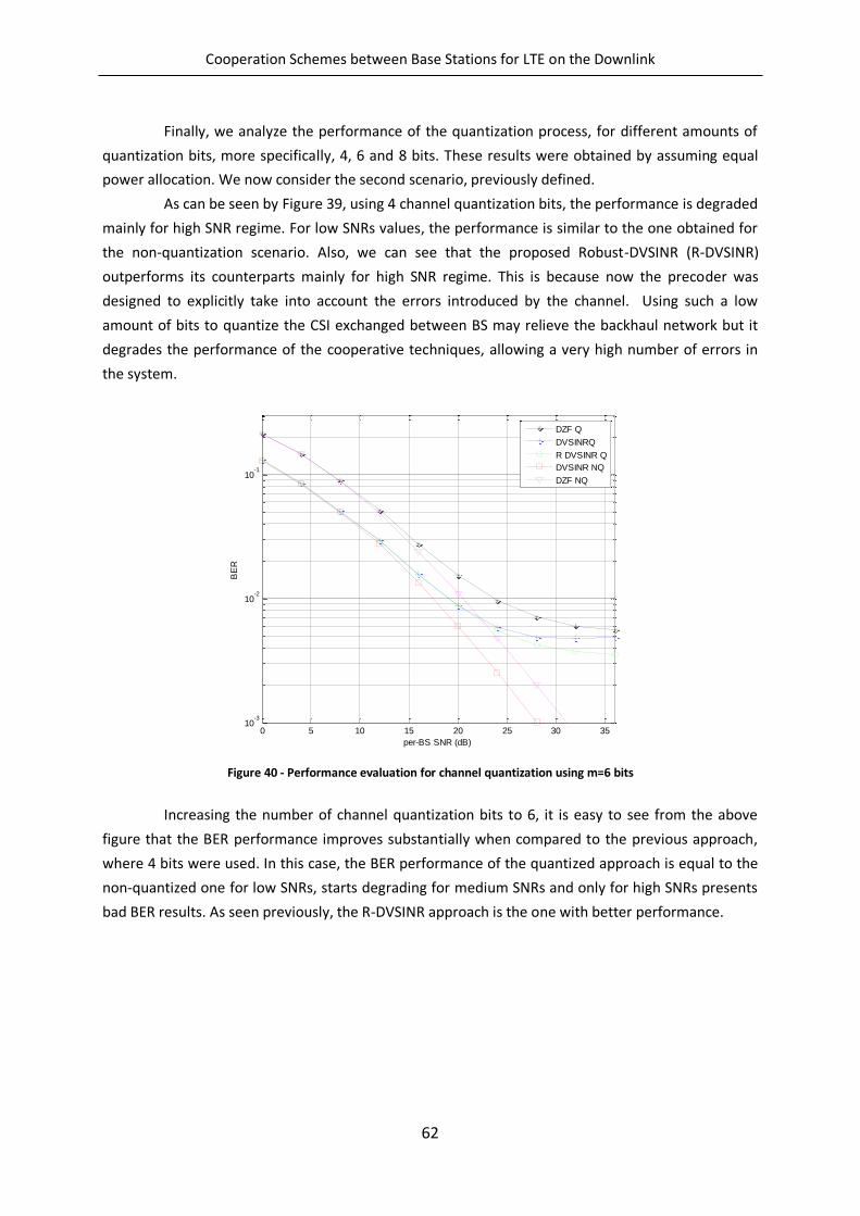
Cooperation Schemes between Base Stations for LTE on the Downlink
62
Finally, we analyze the performance of the quantization process, for different amounts of
quantization bits, more specifically, 4, 6 and 8 bits. These results were obtained by assuming equal
power allocation. We now consider the second scenario, previously defined.
As can be seen by Figure 39, using 4 channel quantization bits, the performance is degraded
mainly for high SNR regime. For low SNRs values, the performance is similar to the one obtained for
the non-quantization scenario. Also, we can see that the proposed Robust-DVSINR (R-DVSINR)
outperforms its counterparts mainly for high SNR regime. This is because now the precoder was
designed to explicitly take into account the errors introduced by the channel. Using such a low
amount of bits to quantize the CSI exchanged between BS may relieve the backhaul network but it
degrades the performance of the cooperative techniques, allowing a very high number of errors in
the system.
Figure 40 - Performance evaluation for channel quantization using m=6 bits
Increasing the number of channel quantization bits to 6, it is easy to see from the above
figure that the BER performance improves substantially when compared to the previous approach,
where 4 bits were used. In this case, the BER performance of the quantized approach is equal to the
non-quantized one for low SNRs, starts degrading for medium SNRs and only for high SNRs presents
bad BER results. As seen previously, the R-DVSINR approach is the one with better performance.
0 5 10 15 20 25 30 3510
-3
10-2
10-1
per-BS SNR (dB)
BE
R
DZF Q
DVSINRQ
R DVSINR Q
DVSINR NQ
DZF NQ
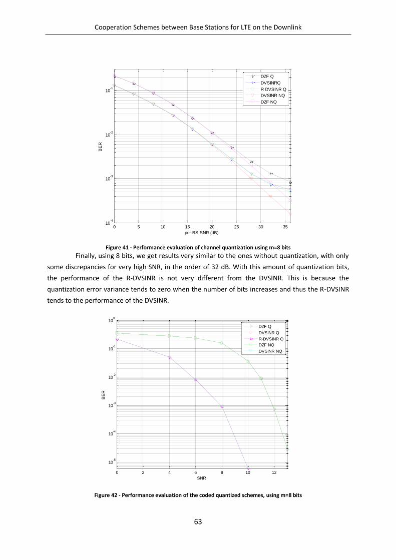
Cooperation Schemes between Base Stations for LTE on the Downlink
63
Figure 41 - Performance evaluation of channel quantization using m=8 bits
Finally, using 8 bits, we get results very similar to the ones without quantization, with only
some discrepancies for very high SNR, in the order of 32 dB. With this amount of quantization bits,
the performance of the R-DVSINR is not very different from the DVSINR. This is because the
quantization error variance tends to zero when the number of bits increases and thus the R-DVSINR
tends to the performance of the DVSINR.
Figure 42 - Performance evaluation of the coded quantized schemes, using m=8 bits
0 5 10 15 20 25 30 3510
-4
10-3
10-2
10-1
per-BS SNR (dB)
BE
R
DZF Q
DVSINRQ
R DVSINR Q
DVSINR NQ
DZF NQ
0 2 4 6 8 10 12
10-5
10-4
10-3
10-2
10-1
100
SNR
BE
R
DZF Q
DVSINR Q
R-DVSINR Q
DZF NQ
DVSINR NQ
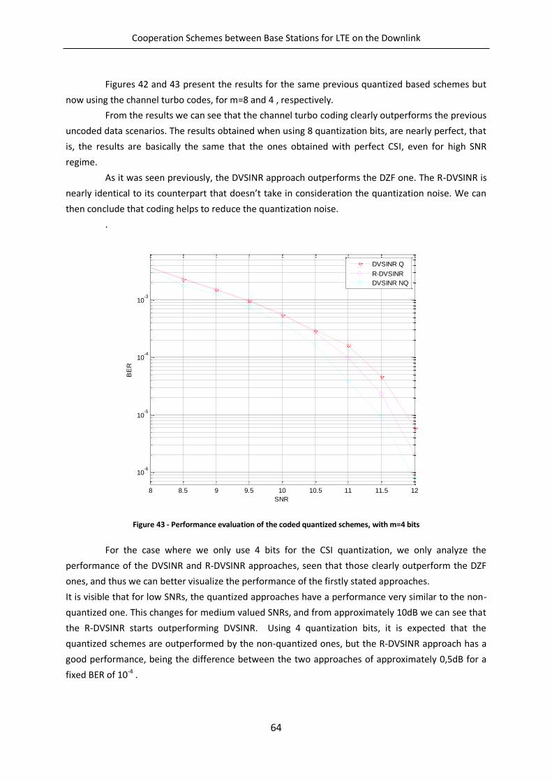
Cooperation Schemes between Base Stations for LTE on the Downlink
64
Figures 42 and 43 present the results for the same previous quantized based schemes but
now using the channel turbo codes, for m=8 and 4 , respectively.
From the results we can see that the channel turbo coding clearly outperforms the previous
uncoded data scenarios. The results obtained when using 8 quantization bits, are nearly perfect, that
is, the results are basically the same that the ones obtained with perfect CSI, even for high SNR
regime.
As it was seen previously, the DVSINR approach outperforms the DZF one. The R-DVSINR is
nearly identical to its counterpart that doesn’t take in consideration the quantization noise. We can
then conclude that coding helps to reduce the quantization noise.
.
Figure 43 - Performance evaluation of the coded quantized schemes, with m=4 bits
For the case where we only use 4 bits for the CSI quantization, we only analyze the
performance of the DVSINR and R-DVSINR approaches, seen that those clearly outperform the DZF
ones, and thus we can better visualize the performance of the firstly stated approaches.
It is visible that for low SNRs, the quantized approaches have a performance very similar to the non-
quantized one. This changes for medium valued SNRs, and from approximately 10dB we can see that
the R-DVSINR starts outperforming DVSINR. Using 4 quantization bits, it is expected that the
quantized schemes are outperformed by the non-quantized ones, but the R-DVSINR approach has a
good performance, being the difference between the two approaches of approximately 0,5dB for a
fixed BER of 10-4 .
8 8.5 9 9.5 10 10.5 11 11.5 12
10-6
10-5
10-4
10-3
SNR
BE
R
DVSINR Q
R-DVSINR
DVSINR NQ
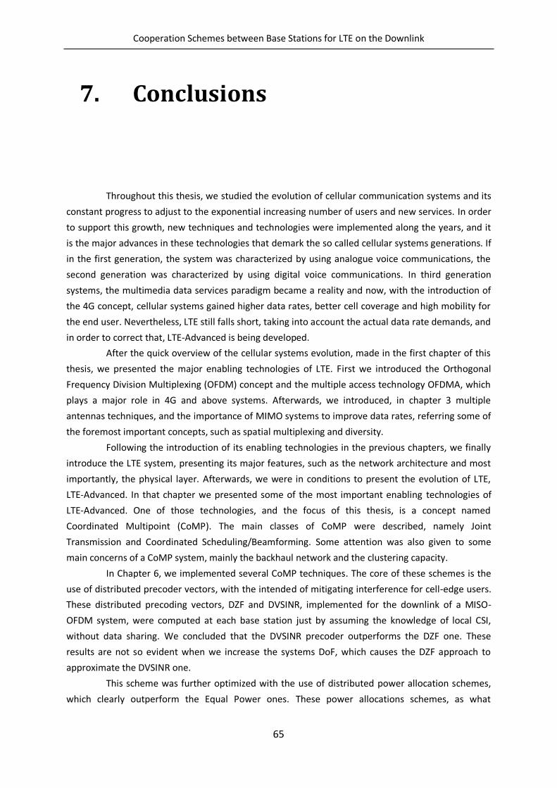
Cooperation Schemes between Base Stations for LTE on the Downlink
65
7. Conclusions
Throughout this thesis, we studied the evolution of cellular communication systems and its
constant progress to adjust to the exponential increasing number of users and new services. In order
to support this growth, new techniques and technologies were implemented along the years, and it
is the major advances in these technologies that demark the so called cellular systems generations. If
in the first generation, the system was characterized by using analogue voice communications, the
second generation was characterized by using digital voice communications. In third generation
systems, the multimedia data services paradigm became a reality and now, with the introduction of
the 4G concept, cellular systems gained higher data rates, better cell coverage and high mobility for
the end user. Nevertheless, LTE still falls short, taking into account the actual data rate demands, and
in order to correct that, LTE-Advanced is being developed.
After the quick overview of the cellular systems evolution, made in the first chapter of this
thesis, we presented the major enabling technologies of LTE. First we introduced the Orthogonal
Frequency Division Multiplexing (OFDM) concept and the multiple access technology OFDMA, which
plays a major role in 4G and above systems. Afterwards, we introduced, in chapter 3 multiple
antennas techniques, and the importance of MIMO systems to improve data rates, referring some of
the foremost important concepts, such as spatial multiplexing and diversity.
Following the introduction of its enabling technologies in the previous chapters, we finally
introduce the LTE system, presenting its major features, such as the network architecture and most
importantly, the physical layer. Afterwards, we were in conditions to present the evolution of LTE,
LTE-Advanced. In that chapter we presented some of the most important enabling technologies of
LTE-Advanced. One of those technologies, and the focus of this thesis, is a concept named
Coordinated Multipoint (CoMP). The main classes of CoMP were described, namely Joint
Transmission and Coordinated Scheduling/Beamforming. Some attention was also given to some
main concerns of a CoMP system, mainly the backhaul network and the clustering capacity.
In Chapter 6, we implemented several CoMP techniques. The core of these schemes is the
use of distributed precoder vectors, with the intended of mitigating interference for cell-edge users.
These distributed precoding vectors, DZF and DVSINR, implemented for the downlink of a MISO-
OFDM system, were computed at each base station just by assuming the knowledge of local CSI,
without data sharing. We concluded that the DVSINR precoder outperforms the DZF one. These
results are not so evident when we increase the systems DoF, which causes the DZF approach to
approximate the DVSINR one.
This scheme was further optimized with the use of distributed power allocation schemes,
which clearly outperform the Equal Power ones. These power allocations schemes, as what
Cooperation Schemes between Base Stations for LTE on the Downlink
66
happened previously with the precoder vectors, are computed at each base station, in a distributed
manner, assuming only the knowledge of the local CSI. Later we introduced channel coding to our
system, introducing redundancy, thus reducing the probability of errors.
Finally, and with the intended of assessing the performance of the precoders under
imperfect CSI, we introduced quantization techniques, where the CSI associated to the different links
between the BS and the UT is feedback from the UT to the BS, and then exchanged by the different
BSs. This information is then used to calculate the precoder vectors used previously but now with
quantized CSI, for different amount of quantization bits. A new version of the DVSINR precoder that
considered the quantization error, R-DVSINR, was considered. It was visible that the R-DVSINR
outperformed the rest of the precoders, and that their performance deteriorates when the number
of quantization bits decreases.
It is then clear that the presented techniques greatly improve the performance of cellular
systems, and can be expected be featured in LTE-Advanced.
7.1. Future Work
For future work references, one would suggest:
Extending the analyses made throughout this thesis to the uplink, but in this case
efficient equalizers should be designed instead
Comparing the performance of the analysed techniques with techniques that
assume that the users’ data is shared among the BSs, i.e., joint processing
techniques.
Extend the analyses for other more complex scenarios;
Test these techniques in real life large-scale networks, using field trials in urban
areas.
Cooperation Schemes between Base Stations for LTE on the Downlink
67
8. References
1. mobiThinking. Global mobile statistics 2012 Home. 2013 December 2012 [cited 2013
09/05/2013]; Available from: http://mobithinking.com/mobile-marketing-tools/latest-
mobile-stats/.
2. Cox, C., An Introduction to LTE: LTE, LTE-Advanced, SAE and 4G Mobile Communications2012:
Wiley.
3. Khan, F., LTE for 4G Mobile Broadband: Air Interface Technologies and Performance2009:
Cambridge University Press. 506.
4. Technologies, A., LTE and the Evolution to 4G Wireless: Design and Measurement
Challenges2009: John Wiley & Sons.
5. Edt, G., Mobile WiMAX -- Part I: A Technical Overview and Performance Evaluation2006.
6. Carew, S. Qualcomm halts UMB project, sees no major job cuts. 2013 13/11/2008 [cited 2013
09/05/2013]; Available from: http://www.reuters.com/article/2008/11/13/qualcomm-umb-
idUSN1335969420081113?rpc=401&.
7. Americas, G. 2013 11/07/2013]; Available from: http://www.4gamericas.org.
8. Holma, D.H. and D.A. Toskala, LTE for UMTS - OFDMA and SC-FDMA Based Radio Access2009:
Wiley Publishing. 450.
9. Tse, D. and P. Viswanath, Fundamentals of Wireless Communication2005: Cambridge
University Press.
10. 3GPP, 3GPP RAN WG1 TR 25.814 v7.1.0, Physical Layer Aspects for Evolved UTRA (Release 7),
2006.
11. G. J. Foschini, M.J.G., On Limits of Wireless Communications in a Fading Environment When
Using Multiple Antennas. Wireless Personal Communications, 1998. Vol. 6: p. 311–335.
12. 36.101, G.T., User Equipment (UE) Radio Transmission and Reception, in section 7.2.2011.
13. Alamouti, S. Space block coding: A simple transmitter diversity technique for wireless
communications. IEEE Journal on Selected Areas in Communications, 1998.
14. Jankiraman, M., Space-Time Codes and MIMO Systems with CDROM2004: ARTECH HOUSE
Incorporated.
15. 3GPP, Requirements for Evolved Universal Terrestrial Radio Access (UTRA) and Universal
Terrestrial Radio Access Network (UTRAN), in TR 25.913.
Cooperation Schemes between Base Stations for LTE on the Downlink
68
16. TeliaSonera. Pioneering 4G networks. [cited 2013 10/05/2013]; Available from:
http://www.teliasonera.com/en/innovation/access-is-king/2011/4/pioneering-4g-networks/.
17. 3GPP, Evolved Universal Terrestrial Radio Access Network (E-UTRA): Overall Description, in TS
36.300.
18. Ghosh, A., et al., LTE-advanced: next-generation wireless broadband technology [Invited
Paper]. Wireless Communications, IEEE, 2010. 17(3): p. 10-22.
19. Rezaei, F., M. Hempel, and H. Sharif. LTE PHY performance analysis under 3GPP standards
parameters. in Computer Aided Modeling and Design of Communication Links and Networks
(CAMAD), 2011 IEEE 16th International Workshop on. 2011.
20. Dabbagh, A.D., R. Ratasuk, and A. Ghosh. On UMTS-LTE Physical Uplink Shared and Control
Channels. in Vehicular Technology Conference, 2008. VTC 2008-Fall. IEEE 68th. 2008.
21. Abdullah, M.F.L. and A.Z. Yonis. Performance of LTE Release 8 and Release 10 in wireless
communications. in Cyber Security, Cyber Warfare and Digital Forensic (CyberSec), 2012
International Conference on. 2012.
22. Gesbert, D., et al., Multi-Cell MIMO Cooperative Networks: A New Look at Interference.
Selected Areas in Communications, IEEE Journal on, 2010. 28(9): p. 1380-1408.
23. Irmer, R., et al., Coordinated multipoint: Concepts, performance, and field trial results.
Communications Magazine, IEEE, 2011. 49(2): p. 102-111.
24. McCoy, W., Overview of 3GPP LTE Physical Layer: White Paper by Dr. Wes McCoy. 2007.
25. Young-Han, N., et al. Cooperative communication technologies for LTE-advanced. in Acoustics
Speech and Signal Processing (ICASSP), 2010 IEEE International Conference on. 2010.
26. Ming Ding, H.L., Multi-point Cooperative Communication Systems: Theory and
Applications2013: Shanghai Jiao Tong University Press.
27. Binbin, W., L. Bingbing, and L. Mingqian. A Novel Precoding Method for Joint Processing in
CoMP. in Network Computing and Information Security (NCIS), 2011 International Conference
on. 2011.
28. Sawahashi, M., et al., Coordinated multipoint transmission/reception techniques for LTE-
advanced [Coordinated and Distributed MIMO]. Wireless Communications, IEEE, 2010. 17(3):
p. 26-34.
29. Botella, C., et al. On the Performance of Joint Processing Schemes over the Cluster Area. in
Vehicular Technology Conference (VTC 2010-Spring), 2010 IEEE 71st. 2010.
30. Rashid-Farrokhi, F., L. Tassiulas, and K.J.R. Liu, Joint optimal power control and beamforming
in wireless networks using antenna arrays. Communications, IEEE Transactions on, 1998.
46(10): p. 1313-1324.
Cooperation Schemes between Base Stations for LTE on the Downlink
69
31. Daewon, L., et al., Coordinated multipoint transmission and reception in LTE-advanced:
deployment scenarios and operational challenges. Communications Magazine, IEEE, 2012.
50(2): p. 148-155.
32. Marsch, P. and G. Fettweis. A Decentralized Optimization Approach to Backhaul-Constrained
Distributed Antenna Systems. in Mobile and Wireless Communications Summit, 2007. 16th
IST. 2007.
33. Papadogiannis, A., D. Gesbert, and E. Hardouin. A Dynamic Clustering Approach in Wireless
Networks with Multi-Cell Cooperative Processing. in Communications, 2008. ICC '08. IEEE
International Conference on. 2008.
34. A. G. Armada, M.S.F., and R. Corvaja, Waterfilling schemes for zero-forcing coordinated base
station transmissions. proc. of IEEE GLOBECOM, 2009.
35. Jun, Z., et al., Networked MIMO with clustered linear precoding. Wireless Communications,
IEEE Transactions on, 2009. 8(4): p. 1910-1921.
36. Rui, Z. Cooperative Multi-Cell Block Diagonalization with Per-Base-Station Power Constraints.
in Wireless Communications and Networking Conference (WCNC), 2010 IEEE. 2010.
37. Bjornson, E., et al., Cooperative Multicell Precoding: Rate Region Characterization and
Distributed Strategies With Instantaneous and Statistical CSI. Signal Processing, IEEE
Transactions on, 2010. 58(8): p. 4298-4310.
38. A. Silva, R. Holakouei, and A. Gameiro, Power allocation strategies for distributed precoded
multicell based systems. EURASIP Journal on Wireless Communications and Networking,
2011. 2011(1): p. 1-1.
39. Lindblom, J., E. Karipidis, and E.G. Larsson, Selfishness and altruism on the MISO interference
channel: the case of partial transmitter CSI. Communications Letters, IEEE, 2009. 13(9): p.
667-669.
40. Jun, Z. and J.G. Andrews, Adaptive Spatial Intercell Interference Cancellation in Multicell
Wireless Networks. Selected Areas in Communications, IEEE Journal on, 2010. 28(9): p. 1455-
1468.
41. Byong Ok, L., et al., A novel uplink MIMO transmission scheme in a multicell environment.
Wireless Communications, IEEE Transactions on, 2009. 8(10): p. 4981-4987.
42. R. Zakhour, D.G., Coordination on the MISO Interference Channel using the Virtual SINR
Framework, in International ITG/IEEE Workshop on Smart Antennas (WSA’09)2009: Berlin,
Germany.
43. S. Teodoro, A.Silva, R. Dinis, and A. Gameiro, MMSE Interference Alignment Algorithms with
Low Bit Rate Feedback, in Wireless Global Summit2013: Atlantic City, USA.
44. José Assunção, R. Holakouei, A. Silva, Atílio Gameiro, Performance Evaluation of Multicell
Coordinated Beamforming Approaches for OFDM Systems, in Proc IARIA-International Conf.
on Wireless and Mobile Communications - ICWMC2012: Venice , Italy.
Cooperation Schemes between Base Stations for LTE on the Downlink
70
45. Haykin, S., Adaptive filter theory (3rd ed.)1996: Prentice-Hall, Inc. 989.
46. R. M. Corless, G.H.G., D. E. G. Hare, D. J. Jeffrey, D. E. Knuth, On the Lambert W Function.
Adv. Comput. Math. Vol. 5. 1996: University of Waterloo, Computer Science Department.
47. ETSI, LTE; Evolved Universal Terrestrial Radio Access (E-UTRA); Multiplexing and channel
coding (3GPP TS 36.212 version 9.2.0 Release 9). 2010.
48. Zarei, S. Channel Coding and Link Adaptation. 2009.
49. Berrou, C., A. Glavieux, and P. Thitimajshima. Near Shannon limit error-correcting coding and
decoding: Turbo-codes. 1. in Communications, 1993. ICC '93 Geneva. Technical Program,
Conference Record, IEEE International Conference on. 1993.
50. 3GPP, LTE Physical Layer - General Description, 2007.