Embed Size (px)
Citation preview
TI’s smart sensors ideal for automated driving applications
Sneha NarnakajeProduct Manager, Automotive RadarRadar Analytics and Processors
Texas Instruments
TI’s smart sensors ideal for automated driving applications 2 May 2017
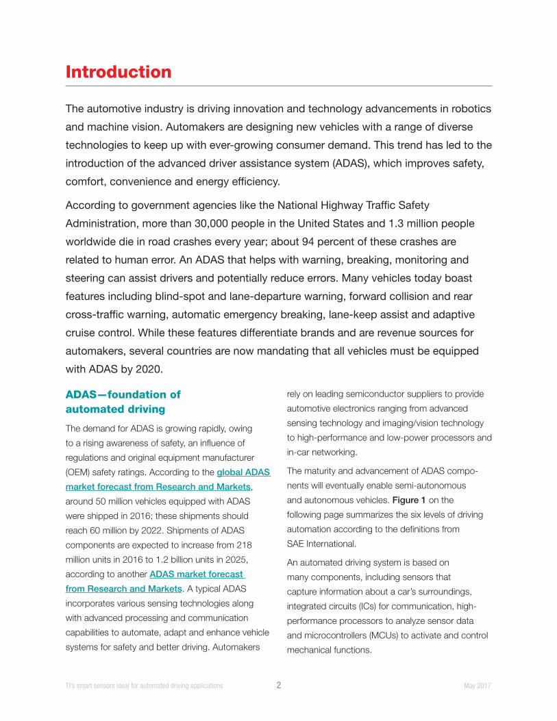
Introduction
The automotive industry is driving innovation and technology advancements in robotics
and machine vision. Automakers are designing new vehicles with a range of diverse
technologies to keep up with ever-growing consumer demand. This trend has led to the
introduction of the advanced driver assistance system (ADAS), which improves safety,
comfort, convenience and energy efficiency.
According to government agencies like the National Highway Traffic Safety
Administration, more than 30,000 people in the United States and 1.3 million people
worldwide die in road crashes every year; about 94 percent of these crashes are
related to human error. An ADAS that helps with warning, breaking, monitoring and
steering can assist drivers and potentially reduce errors. Many vehicles today boast
features including blind-spot and lane-departure warning, forward collision and rear
cross-traffic warning, automatic emergency breaking, lane-keep assist and adaptive
cruise control. While these features differentiate brands and are revenue sources for
automakers, several countries are now mandating that all vehicles must be equipped
with ADAS by 2020.
ADAS—foundation of automated driving
The demand for ADAS is growing rapidly, owing
to a rising awareness of safety, an influence of
regulations and original equipment manufacturer
(OEM) safety ratings. According to the global ADAS
market forecast from Research and Markets,
around 50 million vehicles equipped with ADAS
were shipped in 2016; these shipments should
reach 60 million by 2022. Shipments of ADAS
components are expected to increase from 218
million units in 2016 to 1.2 billion units in 2025,
according to another ADAS market forecast
from Research and Markets. A typical ADAS
incorporates various sensing technologies along
with advanced processing and communication
capabilities to automate, adapt and enhance vehicle
systems for safety and better driving. Automakers
rely on leading semiconductor suppliers to provide
automotive electronics ranging from advanced
sensing technology and imaging/vision technology
to high-performance and low-power processors and
in-car networking.
The maturity and advancement of ADAS compo-
nents will eventually enable semi-autonomous
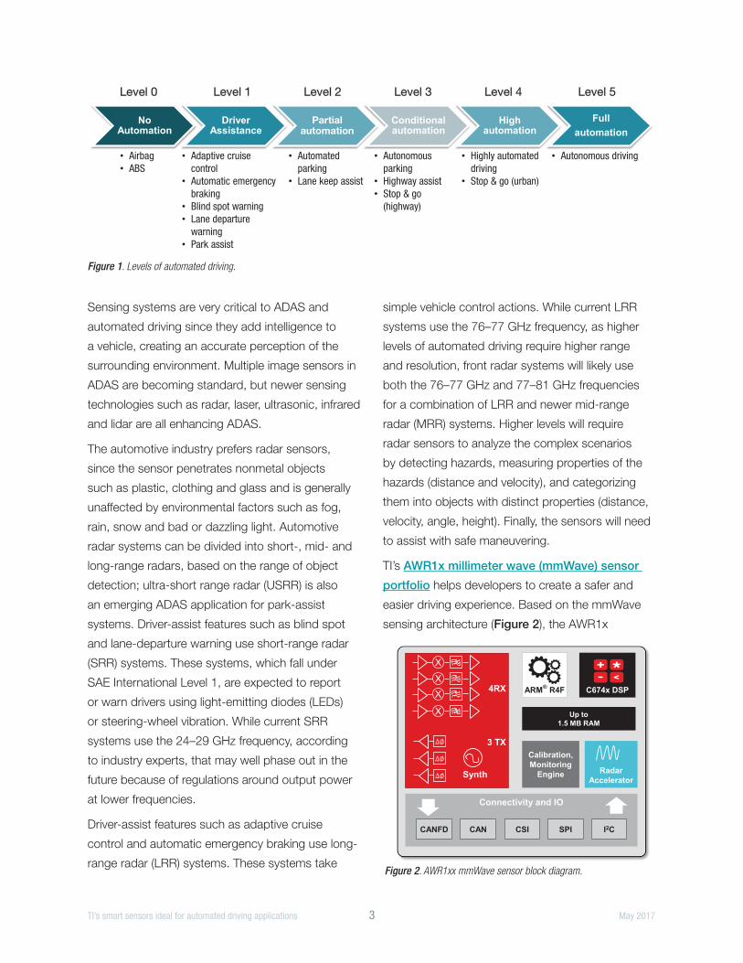
and autonomous vehicles. Figure 1 on the
following page summarizes the six levels of driving
automation according to the definitions from
SAE International.
An automated driving system is based on
many components, including sensors that
capture information about a car’s surroundings,
integrated circuits (ICs) for communication, high-
performance processors to analyze sensor data
and microcontrollers (MCUs) to activate and control
mechanical functions.
TI’s smart sensors ideal for automated driving applications 3 May 2017
Sensing systems are very critical to ADAS and
automated driving since they add intelligence to
a vehicle, creating an accurate perception of the
surrounding environment. Multiple image sensors in
ADAS are becoming standard, but newer sensing
technologies such as radar, laser, ultrasonic, infrared
and lidar are all enhancing ADAS.
The automotive industry prefers radar sensors,
since the sensor penetrates nonmetal objects
such as plastic, clothing and glass and is generally
unaffected by environmental factors such as fog,
rain, snow and bad or dazzling light. Automotive
radar systems can be divided into short-, mid- and
long-range radars, based on the range of object
detection; ultra-short range radar (USRR) is also
an emerging ADAS application for park-assist
systems. Driver-assist features such as blind spot
and lane-departure warning use short-range radar
(SRR) systems. These systems, which fall under
SAE International Level 1, are expected to report
or warn drivers using light-emitting diodes (LEDs)
or steering-wheel vibration. While current SRR
systems use the 24–29 GHz frequency, according
to industry experts, that may well phase out in the
future because of regulations around output power
at lower frequencies.
Driver-assist features such as adaptive cruise
control and automatic emergency braking use long-
range radar (LRR) systems. These systems take
simple vehicle control actions. While current LRR
systems use the 76–77 GHz frequency, as higher
levels of automated driving require higher range
and resolution, front radar systems will likely use
both the 76–77 GHz and 77–81 GHz frequencies
for a combination of LRR and newer mid-range
radar (MRR) systems. Higher levels will require
radar sensors to analyze the complex scenarios
by detecting hazards, measuring properties of the
hazards (distance and velocity), and categorizing
them into objects with distinct properties (distance,
velocity, angle, height). Finally, the sensors will need
to assist with safe maneuvering.
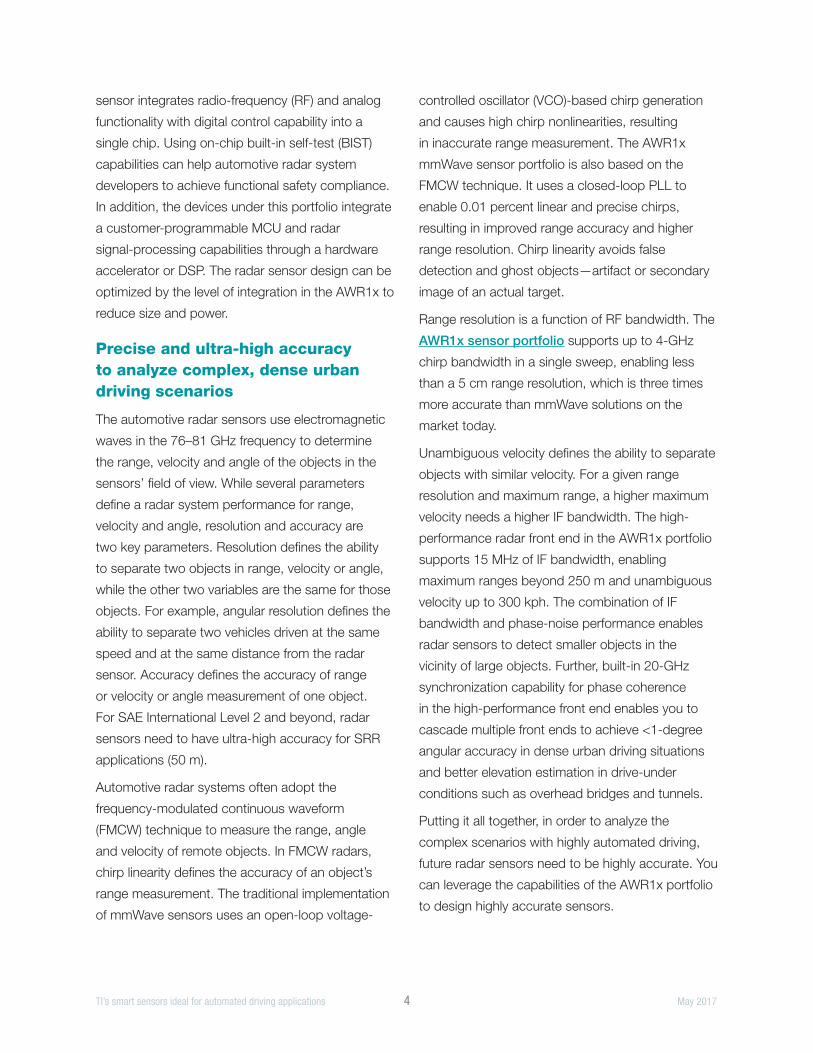
TI’s AWR1x millimeter wave (mmWave) sensor
portfolio helps developers to create a safer and
easier driving experience. Based on the mmWave
sensing architecture (Figure 2), the AWR1x
Figure 2. AWR1x Block Diagram
C674x DSPARM® R4F
Radar Accelerator
Up to1.5 MB RAM
Connectivity and IO
Calibration, Monitoring
Engine
CANFD CAN CSI SPI I2C
4RX
3 TX
Synth
∆∅
∆∅
∆∅
X X X
X
Figure 2. AWR1xx mmWave sensor block diagram.
Figure 1. Levels of Automated Driving
No Automation
Driver Assistance
Partial automation
Conditional automation
High automation
Fullautomation
• Airbag • ABS
• Adaptive cruise control
• Automatic emergency braking
• Blind spot warning • Lane departure
warning • Park assist
• Automated parking
• Lane keep assist
• Autonomous parking
• Highway assist • Stop & go
(highway)
• Highly automated driving
• Stop & go (urban)
• Autonomous driving
Figure 1. Levels of automated driving.
TI’s smart sensors ideal for automated driving applications 4 May 2017
sensor integrates radio-frequency (RF) and analog
functionality with digital control capability into a
single chip. Using on-chip built-in self-test (BIST)
capabilities can help automotive radar system
developers to achieve functional safety compliance.
In addition, the devices under this portfolio integrate
a customer-programmable MCU and radar
signal-processing capabilities through a hardware
accelerator or DSP. The radar sensor design can be
optimized by the level of integration in the AWR1x to
reduce size and power.
Precise and ultra-high accuracy to analyze complex, dense urban driving scenarios
The automotive radar sensors use electromagnetic
waves in the 76–81 GHz frequency to determine
the range, velocity and angle of the objects in the
sensors’ field of view. While several parameters
define a radar system performance for range,
velocity and angle, resolution and accuracy are
two key parameters. Resolution defines the ability
to separate two objects in range, velocity or angle,
while the other two variables are the same for those
objects. For example, angular resolution defines the
ability to separate two vehicles driven at the same
speed and at the same distance from the radar
sensor. Accuracy defines the accuracy of range
or velocity or angle measurement of one object.
For SAE International Level 2 and beyond, radar
sensors need to have ultra-high accuracy for SRR
applications (50 m).
Automotive radar systems often adopt the
frequency-modulated continuous waveform
(FMCW) technique to measure the range, angle
and velocity of remote objects. In FMCW radars,
chirp linearity defines the accuracy of an object’s
range measurement. The traditional implementation
of mmWave sensors uses an open-loop voltage-
controlled oscillator (VCO)-based chirp generation
and causes high chirp nonlinearities, resulting
in inaccurate range measurement. The AWR1x
mmWave sensor portfolio is also based on the
FMCW technique. It uses a closed-loop PLL to
enable 0.01 percent linear and precise chirps,
resulting in improved range accuracy and higher
range resolution. Chirp linearity avoids false
detection and ghost objects—artifact or secondary
image of an actual target.
Range resolution is a function of RF bandwidth. The
AWR1x sensor portfolio supports up to 4-GHz
chirp bandwidth in a single sweep, enabling less
than a 5 cm range resolution, which is three times
more accurate than mmWave solutions on the
market today.
Unambiguous velocity defines the ability to separate
objects with similar velocity. For a given range
resolution and maximum range, a higher maximum
velocity needs a higher IF bandwidth. The high-
performance radar front end in the AWR1x portfolio
supports 15 MHz of IF bandwidth, enabling
maximum ranges beyond 250 m and unambiguous
velocity up to 300 kph. The combination of IF
bandwidth and phase-noise performance enables
radar sensors to detect smaller objects in the
vicinity of large objects. Further, built-in 20-GHz
synchronization capability for phase coherence
in the high-performance front end enables you to
cascade multiple front ends to achieve <1-degree
angular accuracy in dense urban driving situations
and better elevation estimation in drive-under
conditions such as overhead bridges and tunnels.
Putting it all together, in order to analyze the
complex scenarios with highly automated driving,
future radar sensors need to be highly accurate. You
can leverage the capabilities of the AWR1x portfolio
to design highly accurate sensors.
TI’s smart sensors ideal for automated driving applications 5 May 2017
Versatile intelligence to adapt to changing conditions
Automotive sensor manufacturers are beginning to
look at multimode radar systems to address SAE
International Level 2 and beyond. In a multimode
radar system configuration, the sensor is designed
to support both MRR and LRR configurations in
one sensor module, thus providing a significant
cost reduction to automakers since two separate
sensor modules are no longer required to support
each configuration. A multimode radar system
design imposes certain requirements on mmWave
technology providers, including ease of use, flexible
chirp configurations and monitoring. The AWR1x
portfolio integrates a BIST engine to locally control
chirp-generation parameters in real time. The engine
supports dynamic chirp configuration via non-real-
time messaging from a local digital subsystem or
external host processor. The BIST engine provides
automatic adaptation of the sensor to changing
environmental conditions, specifically temperature
and aging. This enables self-calibration of drift in
RF parameters such as output power and gain.
Further, the BIST engine continuously monitors the
RF and analog subsystems for key RF performance
parameters, thus enhancing safety.
While traditional mmWave sensing technologies
used a real baseband architecture, the AWR1x
sensors realize system-level and performance
benefits through a novel complex baseband
architecture. Since the automotive radar sensors are
mounted behind the bumper, if the sensors provide
an accurate estimation of bumper reflections, they
can remember the bumper signature and calibrate
during every boot up. The AWR1x portfolio enables
more accurate estimation of close objects, using
zero-distance magnitude and phase of the bumper
reflection, which is nearly impossible with real
baseband architecture because of the low frequency
of a bumper signature. You can further exploit the
complex baseband architecture to monitor the
image band, detect interference from other jamming
radars without ambiguity over genuine objects, and
suppress detected interference, thus enabling a
robust radar sensor design.
True single-chip drives the radar sensor to be small and low power
As automated driving becomes a reality, radar
sensor requirements will be driven by power, size,
cost, distance and accuracy. SAE Level 2 and
beyond automated driving systems require many
more radar sensors than solutions currently offer.
Today’s high-end vehicles feature a multichip single
radar system. Given the use of multiple discrete
components, these radar systems are big and bulky
when they need to be smaller, lower power and
cost effective. The sensors have to be miniaturized
and optimized in order to adapt to future automated
driving market demands.
While some current radar systems on the market
claim to be a single-chip solution, they are
not. Current solutions still require a number of
components; they reduce the number of discrete
chips from three to one, but then also require a
transceiver with an external MCU or DSP to process
the radar data.
Thanks to CMOS technology, TI has taken
integration to the next level, integrating intelligent
radar front ends with MCU and DSP capabilities
into the AWR1x single-chip portfolio. Processing is
co-located with the front end to reduce the size and
form factor of the radar systems by 50 percent. This
further enables the efficient mounting of multiple
radar systems. CMOS technology and best-in-
class power-management techniques enable the
AWR1x sensors to be low power, which is critical to
the automotive industry’s development of energy-
efficient electric vehicles. Lower power also leads
to a cost advantage because designers can now
TI’s smart sensors ideal for automated driving applications 6 May 2017
select more economical and lighter housings.
Lower power also enables the AWR1x sensors
to withstand higher ambient temperature and
increases the reliability of the sensor.
Reliability and volume production
All of these features and capabilities are beneficial
to customers only when the solution is offered in
a reliable package that enables mass production.
The AWR1x mmWave portfolio is offered in an
automotive-friendly flip-chip ball-grid array (FC-
BGA) package. The FC-BGA package solution
delivers reliable electrical, mechanical and thermal
performance and eliminates the shielding for
emissions and need for underfill, a material that
encapsulates the bottom side of the chip to protect
the interconnects, thus providing a cost advantage
over traditional packages used with mmWave-
sensing technology.
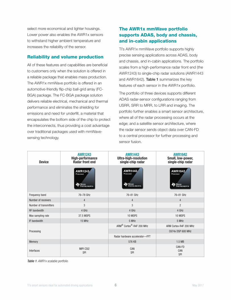
The AWR1x mmWave portfolio supports ADAS, body and chassis, and in-cabin applications
TI’s AWR1x mmWave portfolio supports highly
precise sensing applications across ADAS, body
and chassis, and in-cabin applications. The portfolio
scales from a high-performance radar front end (the
AWR1243) to single-chip radar solutions (AWR1443
and AWR1642). Table 1 summarizes the key
features of each sensor in the AWR1x portfolio.
The portfolio of three devices supports different
ADAS radar-sensor configurations ranging from
USRR, SRR to MRR, to LRR and imaging. The
portfolio further enables a smart sensor architecture,
where all of the radar processing occurs at the
edge; and a satellite sensor architecture, where
the radar sensor sends object data over CAN-FD
to a central processor for further processing and
sensor fusion.
Device
AWR1243 High-performance
Radar front end
AWR1443 Ultra-high-resolution
single-chip radar
AWR1642 Small, low-power, single-chip radar
Frequency band 76–78 GHz 76–81 GHz 76–81 GHz
Number of receivers 4 4 4
Number of transmitters 3 3 2
RF bandwidth 4 GHz 4 GHz 4 GHz
Max sampling rate 37.5 MSPS 10 MSPS 10 MSPS
IF bandwidth 15 MHz 5 MHz 5 MHz
Processing
ARM® Cortex®-R4F 200 MHz ARM Cortex-R4F 200 MHz
C674x DSP 600 MHz
Radar hardware accelerator—FFT
Memory 576 KB 1.5 MB
InterfacesMIPI CSI2
SPICANSPI
CAN-FDCANSPI
Table 1. AWR1x scalable portfolio.
SPYY009© 2017 Texas Instruments Incorporated
Important Notice: The products and services of Texas Instruments Incorporated and its subsidiaries described herein are sold subject to TI’s standard terms and conditions of sale. Customers are advised to obtain the most current and complete information about TI products and services before placing orders. TI assumes no liability for applications assistance, customer’s applications or product designs, software performance, or infringement of patents. The publication of information regarding any other company’s products or services does not constitute TI’s approval, warranty or endorsement thereof.
The platform bar is a trademark of Texas Instruments. All other trademarks are the property of their respective owners.
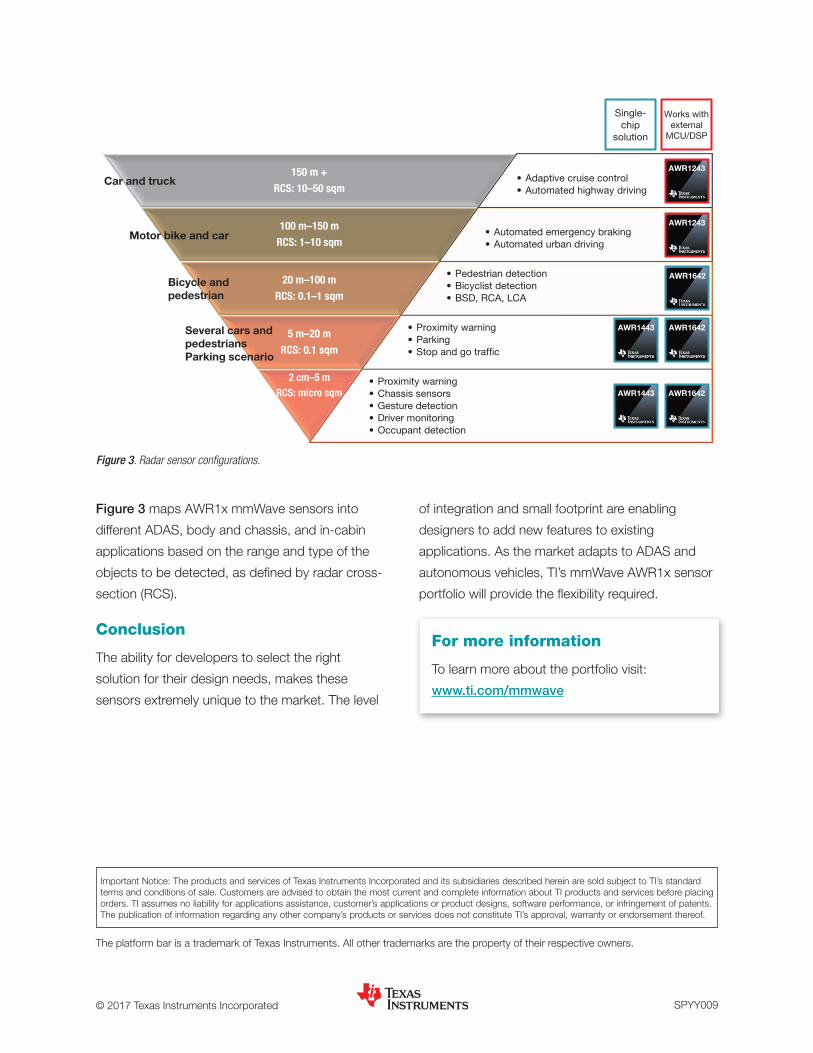
Figure 3 maps AWR1x mmWave sensors into
different ADAS, body and chassis, and in-cabin
applications based on the range and type of the
objects to be detected, as defined by radar cross-
section (RCS).
Conclusion
The ability for developers to select the right
solution for their design needs, makes these
sensors extremely unique to the market. The level
of integration and small footprint are enabling
designers to add new features to existing
applications. As the market adapts to ADAS and
autonomous vehicles, TI’s mmWave AWR1x sensor
portfolio will provide the flexibility required.
Figure 3. Radar sensor configurations
• Adaptive cruise control • Automated highway driving
150 m + RCS: 10–50 sqm
• Automated emergency braking • Automated urban driving
100 m–150 m RCS: 1–10 sqm
• Pedestrian detection • Bicyclist detection • BSD, RCA, LCA
20 m–100 m RCS: 0.1–1 sqm
• Proximity warning • Parking • Stop and go traffic
5 m–20 m RCS: 0.1 sqm
• Proximity warning • Chassis sensors • Gesture detection • Driver monitoring • Occupant detection
2 cm–5 m RCS: micro sqm
Single-chip
solution
Works with external
MCU/DSP
AWR1243
AWR1642
AWR1443 AWR1642
AWR1642
AWR1243
Several cars and pedestrians Parking scenario
Motor bike and car
Car and truck
AWR1443
Bicycle and pedestrian
Figure 3. Radar sensor configurations.
For more information
To learn more about the portfolio visit:
www.ti.com/mmwave
IMPORTANT NOTICE FOR TI DESIGN INFORMATION AND RESOURCES
Texas Instruments Incorporated (‘TI”) technical, application or other design advice, services or information, including, but not limited to,reference designs and materials relating to evaluation modules, (collectively, “TI Resources”) are intended to assist designers who aredeveloping applications that incorporate TI products; by downloading, accessing or using any particular TI Resource in any way, you(individually or, if you are acting on behalf of a company, your company) agree to use it solely for this purpose and subject to the terms ofthis Notice.TI’s provision of TI Resources does not expand or otherwise alter TI’s applicable published warranties or warranty disclaimers for TIproducts, and no additional obligations or liabilities arise from TI providing such TI Resources. TI reserves the right to make corrections,enhancements, improvements and other changes to its TI Resources.You understand and agree that you remain responsible for using your independent analysis, evaluation and judgment in designing yourapplications and that you have full and exclusive responsibility to assure the safety of your applications and compliance of your applications(and of all TI products used in or for your applications) with all applicable regulations, laws and other applicable requirements. Yourepresent that, with respect to your applications, you have all the necessary expertise to create and implement safeguards that (1)anticipate dangerous consequences of failures, (2) monitor failures and their consequences, and (3) lessen the likelihood of failures thatmight cause harm and take appropriate actions. You agree that prior to using or distributing any applications that include TI products, youwill thoroughly test such applications and the functionality of such TI products as used in such applications. TI has not conducted anytesting other than that specifically described in the published documentation for a particular TI Resource.You are authorized to use, copy and modify any individual TI Resource only in connection with the development of applications that includethe TI product(s) identified in such TI Resource. NO OTHER LICENSE, EXPRESS OR IMPLIED, BY ESTOPPEL OR OTHERWISE TOANY OTHER TI INTELLECTUAL PROPERTY RIGHT, AND NO LICENSE TO ANY TECHNOLOGY OR INTELLECTUAL PROPERTYRIGHT OF TI OR ANY THIRD PARTY IS GRANTED HEREIN, including but not limited to any patent right, copyright, mask work right, orother intellectual property right relating to any combination, machine, or process in which TI products or services are used. Informationregarding or referencing third-party products or services does not constitute a license to use such products or services, or a warranty orendorsement thereof. Use of TI Resources may require a license from a third party under the patents or other intellectual property of thethird party, or a license from TI under the patents or other intellectual property of TI.TI RESOURCES ARE PROVIDED “AS IS” AND WITH ALL FAULTS. TI DISCLAIMS ALL OTHER WARRANTIES ORREPRESENTATIONS, EXPRESS OR IMPLIED, REGARDING TI RESOURCES OR USE THEREOF, INCLUDING BUT NOT LIMITED TOACCURACY OR COMPLETENESS, TITLE, ANY EPIDEMIC FAILURE WARRANTY AND ANY IMPLIED WARRANTIES OFMERCHANTABILITY, FITNESS FOR A PARTICULAR PURPOSE, AND NON-INFRINGEMENT OF ANY THIRD PARTY INTELLECTUALPROPERTY RIGHTS.TI SHALL NOT BE LIABLE FOR AND SHALL NOT DEFEND OR INDEMNIFY YOU AGAINST ANY CLAIM, INCLUDING BUT NOTLIMITED TO ANY INFRINGEMENT CLAIM THAT RELATES TO OR IS BASED ON ANY COMBINATION OF PRODUCTS EVEN IFDESCRIBED IN TI RESOURCES OR OTHERWISE. IN NO EVENT SHALL TI BE LIABLE FOR ANY ACTUAL, DIRECT, SPECIAL,COLLATERAL, INDIRECT, PUNITIVE, INCIDENTAL, CONSEQUENTIAL OR EXEMPLARY DAMAGES IN CONNECTION WITH ORARISING OUT OF TI RESOURCES OR USE THEREOF, AND REGARDLESS OF WHETHER TI HAS BEEN ADVISED OF THEPOSSIBILITY OF SUCH DAMAGES.You agree to fully indemnify TI and its representatives against any damages, costs, losses, and/or liabilities arising out of your non-compliance with the terms and provisions of this Notice.This Notice applies to TI Resources. Additional terms apply to the use and purchase of certain types of materials, TI products and services.These include; without limitation, TI’s standard terms for semiconductor products http://www.ti.com/sc/docs/stdterms.htm), evaluationmodules, and samples (http://www.ti.com/sc/docs/sampterms.htm).
Mailing Address: Texas Instruments, Post Office Box 655303, Dallas, Texas 75265Copyright © 2017, Texas Instruments Incorporated