Embed Size (px)
Citation preview
TI-RTOS 1.01
User’s Guide
Literature Number: SPRUHD4BJanuary 2013
Contents
Preface . . . . . . . . . . . . . . . . . . . . . . . . . . . . . . . . . . . . . . . . . . . . . . . . . . . . . . . . . . . . . . . . . . . . . . . . . . . . . . . 5
1 About TI-RTOS . . . . . . . . . . . . . . . . . . . . . . . . . . . . . . . . . . . . . . . . . . . . . . . . . . . . . . . . . . . . . . . . . . . . . 61.1 What is TI-RTOS? . . . . . . . . . . . . . . . . . . . . . . . . . . . . . . . . . . . . . . . . . . . . . . . . . . . . . . . . . . . . . . 61.2 SYS/BIOS . . . . . . . . . . . . . . . . . . . . . . . . . . . . . . . . . . . . . . . . . . . . . . . . . . . . . . . . . . . . . . . . . . . . . 7
1.2.1 FatFS Module in SYS/BIOS. . . . . . . . . . . . . . . . . . . . . . . . . . . . . . . . . . . . . . . . . . . . . . . . . 81.3 XDCtools. . . . . . . . . . . . . . . . . . . . . . . . . . . . . . . . . . . . . . . . . . . . . . . . . . . . . . . . . . . . . . . . . . . . . . 81.4 IPC . . . . . . . . . . . . . . . . . . . . . . . . . . . . . . . . . . . . . . . . . . . . . . . . . . . . . . . . . . . . . . . . . . . . . . . . . . 81.5 NDK . . . . . . . . . . . . . . . . . . . . . . . . . . . . . . . . . . . . . . . . . . . . . . . . . . . . . . . . . . . . . . . . . . . . . . . . . 91.6 UIA . . . . . . . . . . . . . . . . . . . . . . . . . . . . . . . . . . . . . . . . . . . . . . . . . . . . . . . . . . . . . . . . . . . . . . . . . . 91.7 MWare . . . . . . . . . . . . . . . . . . . . . . . . . . . . . . . . . . . . . . . . . . . . . . . . . . . . . . . . . . . . . . . . . . . . . . 101.8 StellarisWare . . . . . . . . . . . . . . . . . . . . . . . . . . . . . . . . . . . . . . . . . . . . . . . . . . . . . . . . . . . . . . . . . 101.9 Drivers . . . . . . . . . . . . . . . . . . . . . . . . . . . . . . . . . . . . . . . . . . . . . . . . . . . . . . . . . . . . . . . . . . . . . . 111.10 For More Information . . . . . . . . . . . . . . . . . . . . . . . . . . . . . . . . . . . . . . . . . . . . . . . . . . . . . . . . . . . 12
2 Examples for TI-RTOS . . . . . . . . . . . . . . . . . . . . . . . . . . . . . . . . . . . . . . . . . . . . . . . . . . . . . . . . . . . . . . 152.1 Example Overview . . . . . . . . . . . . . . . . . . . . . . . . . . . . . . . . . . . . . . . . . . . . . . . . . . . . . . . . . . . . . 162.2 Example Descriptions . . . . . . . . . . . . . . . . . . . . . . . . . . . . . . . . . . . . . . . . . . . . . . . . . . . . . . . . . . . 18
2.2.1 Empty TI-RTOS Project . . . . . . . . . . . . . . . . . . . . . . . . . . . . . . . . . . . . . . . . . . . . . . . . . . . 182.2.2 Demo [M3] / Demo [C28] for F28M3x (TMDXDOCKH52C1 and TMDXDOCK28M36) . . . 202.2.3 Graphic library demo for EKS-LM4F232 . . . . . . . . . . . . . . . . . . . . . . . . . . . . . . . . . . . . . . 212.2.4 TCP Echo Example . . . . . . . . . . . . . . . . . . . . . . . . . . . . . . . . . . . . . . . . . . . . . . . . . . . . . . 222.2.5 FatSD Example: FatFs File Copy with SD Card . . . . . . . . . . . . . . . . . . . . . . . . . . . . . . . . 222.2.6 FatSD Raw Example: FatFs File Copy Using FatFs APIs and SD Card . . . . . . . . . . . . . . 232.2.7 GPIO Interrupt Example. . . . . . . . . . . . . . . . . . . . . . . . . . . . . . . . . . . . . . . . . . . . . . . . . . . 232.2.8 I2C EEPROM Example: I2C Communications with Onboard EEPROM . . . . . . . . . . . . . . 242.2.9 UART Console Example . . . . . . . . . . . . . . . . . . . . . . . . . . . . . . . . . . . . . . . . . . . . . . . . . . 242.2.10 UART Echo Example . . . . . . . . . . . . . . . . . . . . . . . . . . . . . . . . . . . . . . . . . . . . . . . . . . . . . 272.2.11 UART Logging Example . . . . . . . . . . . . . . . . . . . . . . . . . . . . . . . . . . . . . . . . . . . . . . . . . . 272.2.12 FatSD USB Copy Example: FatFs File Copy with SD Card and USB Drive . . . . . . . . . . . 292.2.13 USB Keyboard Device Example . . . . . . . . . . . . . . . . . . . . . . . . . . . . . . . . . . . . . . . . . . . . 302.2.14 USB Keyboard Host Example . . . . . . . . . . . . . . . . . . . . . . . . . . . . . . . . . . . . . . . . . . . . . . 302.2.15 USB Mouse Device Example. . . . . . . . . . . . . . . . . . . . . . . . . . . . . . . . . . . . . . . . . . . . . . . 312.2.16 USB Mouse Host Example . . . . . . . . . . . . . . . . . . . . . . . . . . . . . . . . . . . . . . . . . . . . . . . . 312.2.17 USB Serial Device Example . . . . . . . . . . . . . . . . . . . . . . . . . . . . . . . . . . . . . . . . . . . . . . . 322.2.18 USB CDC Mouse Device Example . . . . . . . . . . . . . . . . . . . . . . . . . . . . . . . . . . . . . . . . . . 322.2.19 Watchdog Example . . . . . . . . . . . . . . . . . . . . . . . . . . . . . . . . . . . . . . . . . . . . . . . . . . . . . . 33
3 Instrumentation with TI-RTOS . . . . . . . . . . . . . . . . . . . . . . . . . . . . . . . . . . . . . . . . . . . . . . . . . . . . . . . 343.1 Overview. . . . . . . . . . . . . . . . . . . . . . . . . . . . . . . . . . . . . . . . . . . . . . . . . . . . . . . . . . . . . . . . . . . . . 353.2 Adding Logging to a Project . . . . . . . . . . . . . . . . . . . . . . . . . . . . . . . . . . . . . . . . . . . . . . . . . . . . . . 353.3 Using Log Events . . . . . . . . . . . . . . . . . . . . . . . . . . . . . . . . . . . . . . . . . . . . . . . . . . . . . . . . . . . . . . 37
3.3.1 Adding Log Events to your Code . . . . . . . . . . . . . . . . . . . . . . . . . . . . . . . . . . . . . . . . . . . . 373.3.2 Using Instrumented or Non-Instrumented Libraries . . . . . . . . . . . . . . . . . . . . . . . . . . . . . . 37
SPRUHD4B—January 2013 Contents 2Submit Documentation Feedback
Contents www.ti.com
3.4 Viewing the Logs . . . . . . . . . . . . . . . . . . . . . . . . . . . . . . . . . . . . . . . . . . . . . . . . . . . . . . . . . . . . . . 383.4.1 Using System Analyzer . . . . . . . . . . . . . . . . . . . . . . . . . . . . . . . . . . . . . . . . . . . . . . . . . . . 383.4.2 Viewing Log Records in ROV . . . . . . . . . . . . . . . . . . . . . . . . . . . . . . . . . . . . . . . . . . . . . . 39
4 Debugging TI-RTOS Applications . . . . . . . . . . . . . . . . . . . . . . . . . . . . . . . . . . . . . . . . . . . . . . . . . . . . 404.1 Using CCS Debugging Tools . . . . . . . . . . . . . . . . . . . . . . . . . . . . . . . . . . . . . . . . . . . . . . . . . . . . . 404.2 Generating printf Output . . . . . . . . . . . . . . . . . . . . . . . . . . . . . . . . . . . . . . . . . . . . . . . . . . . . . . . . . 42
4.2.1 Output with printf() . . . . . . . . . . . . . . . . . . . . . . . . . . . . . . . . . . . . . . . . . . . . . . . . . . . . . . . 424.2.2 Output with System_printf() . . . . . . . . . . . . . . . . . . . . . . . . . . . . . . . . . . . . . . . . . . . . . . . . 42
4.3 Controlling Software Versions for Use with TI-RTOS . . . . . . . . . . . . . . . . . . . . . . . . . . . . . . . . . . . 454.4 Understanding the Build Flow. . . . . . . . . . . . . . . . . . . . . . . . . . . . . . . . . . . . . . . . . . . . . . . . . . . . . 46
5 Board-Specific Files . . . . . . . . . . . . . . . . . . . . . . . . . . . . . . . . . . . . . . . . . . . . . . . . . . . . . . . . . . . . . . . 475.1 Overview. . . . . . . . . . . . . . . . . . . . . . . . . . . . . . . . . . . . . . . . . . . . . . . . . . . . . . . . . . . . . . . . . . . . . 475.2 Board-Specific Code Files . . . . . . . . . . . . . . . . . . . . . . . . . . . . . . . . . . . . . . . . . . . . . . . . . . . . . . . 485.3 Linker Command Files . . . . . . . . . . . . . . . . . . . . . . . . . . . . . . . . . . . . . . . . . . . . . . . . . . . . . . . . . . 485.4 Target Configuration Files . . . . . . . . . . . . . . . . . . . . . . . . . . . . . . . . . . . . . . . . . . . . . . . . . . . . . . . 49
6 TI-RTOS Drivers . . . . . . . . . . . . . . . . . . . . . . . . . . . . . . . . . . . . . . . . . . . . . . . . . . . . . . . . . . . . . . . . . . . 506.1 Overview. . . . . . . . . . . . . . . . . . . . . . . . . . . . . . . . . . . . . . . . . . . . . . . . . . . . . . . . . . . . . . . . . . . . . 506.2 Driver Framework . . . . . . . . . . . . . . . . . . . . . . . . . . . . . . . . . . . . . . . . . . . . . . . . . . . . . . . . . . . . . . 51
6.2.1 Static Configuration . . . . . . . . . . . . . . . . . . . . . . . . . . . . . . . . . . . . . . . . . . . . . . . . . . . . . . 516.2.2 Driver Object Declarations . . . . . . . . . . . . . . . . . . . . . . . . . . . . . . . . . . . . . . . . . . . . . . . . . 516.2.3 Dynamic Configuration and Common APIs . . . . . . . . . . . . . . . . . . . . . . . . . . . . . . . . . . . . 53
6.3 EMAC Driver . . . . . . . . . . . . . . . . . . . . . . . . . . . . . . . . . . . . . . . . . . . . . . . . . . . . . . . . . . . . . . . . . . 546.3.1 Static Configuration . . . . . . . . . . . . . . . . . . . . . . . . . . . . . . . . . . . . . . . . . . . . . . . . . . . . . . 546.3.2 Runtime Configuration . . . . . . . . . . . . . . . . . . . . . . . . . . . . . . . . . . . . . . . . . . . . . . . . . . . . 546.3.3 APIs . . . . . . . . . . . . . . . . . . . . . . . . . . . . . . . . . . . . . . . . . . . . . . . . . . . . . . . . . . . . . . . . . . 556.3.4 Usage. . . . . . . . . . . . . . . . . . . . . . . . . . . . . . . . . . . . . . . . . . . . . . . . . . . . . . . . . . . . . . . . . 556.3.5 Instrumentation . . . . . . . . . . . . . . . . . . . . . . . . . . . . . . . . . . . . . . . . . . . . . . . . . . . . . . . . . 556.3.6 Examples . . . . . . . . . . . . . . . . . . . . . . . . . . . . . . . . . . . . . . . . . . . . . . . . . . . . . . . . . . . . . . 55
6.4 UART Driver . . . . . . . . . . . . . . . . . . . . . . . . . . . . . . . . . . . . . . . . . . . . . . . . . . . . . . . . . . . . . . . . . . 566.4.1 Static Configuration . . . . . . . . . . . . . . . . . . . . . . . . . . . . . . . . . . . . . . . . . . . . . . . . . . . . . . 566.4.2 Runtime Configuration . . . . . . . . . . . . . . . . . . . . . . . . . . . . . . . . . . . . . . . . . . . . . . . . . . . . 566.4.3 APIs . . . . . . . . . . . . . . . . . . . . . . . . . . . . . . . . . . . . . . . . . . . . . . . . . . . . . . . . . . . . . . . . . . 576.4.4 Usage. . . . . . . . . . . . . . . . . . . . . . . . . . . . . . . . . . . . . . . . . . . . . . . . . . . . . . . . . . . . . . . . . 576.4.5 Instrumentation . . . . . . . . . . . . . . . . . . . . . . . . . . . . . . . . . . . . . . . . . . . . . . . . . . . . . . . . . 596.4.6 Examples . . . . . . . . . . . . . . . . . . . . . . . . . . . . . . . . . . . . . . . . . . . . . . . . . . . . . . . . . . . . . . 59
6.5 I2C Driver . . . . . . . . . . . . . . . . . . . . . . . . . . . . . . . . . . . . . . . . . . . . . . . . . . . . . . . . . . . . . . . . . . . . 606.5.1 Static Configuration . . . . . . . . . . . . . . . . . . . . . . . . . . . . . . . . . . . . . . . . . . . . . . . . . . . . . . 606.5.2 Runtime Configuration . . . . . . . . . . . . . . . . . . . . . . . . . . . . . . . . . . . . . . . . . . . . . . . . . . . . 606.5.3 APIs . . . . . . . . . . . . . . . . . . . . . . . . . . . . . . . . . . . . . . . . . . . . . . . . . . . . . . . . . . . . . . . . . . 616.5.4 Usage. . . . . . . . . . . . . . . . . . . . . . . . . . . . . . . . . . . . . . . . . . . . . . . . . . . . . . . . . . . . . . . . . 616.5.5 I2C Modes . . . . . . . . . . . . . . . . . . . . . . . . . . . . . . . . . . . . . . . . . . . . . . . . . . . . . . . . . . . . . 636.5.6 I2C Transactions . . . . . . . . . . . . . . . . . . . . . . . . . . . . . . . . . . . . . . . . . . . . . . . . . . . . . . . . 646.5.7 Instrumentation . . . . . . . . . . . . . . . . . . . . . . . . . . . . . . . . . . . . . . . . . . . . . . . . . . . . . . . . . 666.5.8 Examples . . . . . . . . . . . . . . . . . . . . . . . . . . . . . . . . . . . . . . . . . . . . . . . . . . . . . . . . . . . . . . 66
6.6 GPIO Driver . . . . . . . . . . . . . . . . . . . . . . . . . . . . . . . . . . . . . . . . . . . . . . . . . . . . . . . . . . . . . . . . . . 676.6.1 Static Configuration . . . . . . . . . . . . . . . . . . . . . . . . . . . . . . . . . . . . . . . . . . . . . . . . . . . . . . 676.6.2 Runtime Configuration . . . . . . . . . . . . . . . . . . . . . . . . . . . . . . . . . . . . . . . . . . . . . . . . . . . . 676.6.3 APIs . . . . . . . . . . . . . . . . . . . . . . . . . . . . . . . . . . . . . . . . . . . . . . . . . . . . . . . . . . . . . . . . . . 68
3 Contents SPRUHD4B—January 2013Submit Documentation Feedback
Contents www.ti.com
6.6.4 Usage. . . . . . . . . . . . . . . . . . . . . . . . . . . . . . . . . . . . . . . . . . . . . . . . . . . . . . . . . . . . . . . . . 686.6.5 Instrumentation . . . . . . . . . . . . . . . . . . . . . . . . . . . . . . . . . . . . . . . . . . . . . . . . . . . . . . . . . 696.6.6 Examples . . . . . . . . . . . . . . . . . . . . . . . . . . . . . . . . . . . . . . . . . . . . . . . . . . . . . . . . . . . . . . 69
6.7 SDSPI Driver . . . . . . . . . . . . . . . . . . . . . . . . . . . . . . . . . . . . . . . . . . . . . . . . . . . . . . . . . . . . . . . . . 706.7.1 Static Configuration . . . . . . . . . . . . . . . . . . . . . . . . . . . . . . . . . . . . . . . . . . . . . . . . . . . . . . 706.7.2 Runtime Configuration . . . . . . . . . . . . . . . . . . . . . . . . . . . . . . . . . . . . . . . . . . . . . . . . . . . . 716.7.3 APIs . . . . . . . . . . . . . . . . . . . . . . . . . . . . . . . . . . . . . . . . . . . . . . . . . . . . . . . . . . . . . . . . . . 716.7.4 Usage. . . . . . . . . . . . . . . . . . . . . . . . . . . . . . . . . . . . . . . . . . . . . . . . . . . . . . . . . . . . . . . . . 716.7.5 Instrumentation . . . . . . . . . . . . . . . . . . . . . . . . . . . . . . . . . . . . . . . . . . . . . . . . . . . . . . . . . 726.7.6 Examples . . . . . . . . . . . . . . . . . . . . . . . . . . . . . . . . . . . . . . . . . . . . . . . . . . . . . . . . . . . . . . 72
6.8 USBMSCHFatFs Driver . . . . . . . . . . . . . . . . . . . . . . . . . . . . . . . . . . . . . . . . . . . . . . . . . . . . . . . . . 736.8.1 Static Configuration . . . . . . . . . . . . . . . . . . . . . . . . . . . . . . . . . . . . . . . . . . . . . . . . . . . . . . 736.8.2 Runtime Configuration . . . . . . . . . . . . . . . . . . . . . . . . . . . . . . . . . . . . . . . . . . . . . . . . . . . . 736.8.3 APIs . . . . . . . . . . . . . . . . . . . . . . . . . . . . . . . . . . . . . . . . . . . . . . . . . . . . . . . . . . . . . . . . . . 746.8.4 Usage. . . . . . . . . . . . . . . . . . . . . . . . . . . . . . . . . . . . . . . . . . . . . . . . . . . . . . . . . . . . . . . . . 746.8.5 Instrumentation . . . . . . . . . . . . . . . . . . . . . . . . . . . . . . . . . . . . . . . . . . . . . . . . . . . . . . . . . 756.8.6 Examples . . . . . . . . . . . . . . . . . . . . . . . . . . . . . . . . . . . . . . . . . . . . . . . . . . . . . . . . . . . . . . 75
6.9 USB Reference Modules . . . . . . . . . . . . . . . . . . . . . . . . . . . . . . . . . . . . . . . . . . . . . . . . . . . . . . . . 766.9.1 USB Reference Modules in TI-RTOS . . . . . . . . . . . . . . . . . . . . . . . . . . . . . . . . . . . . . . . . 776.9.2 USB Reference Module Design Guidelines . . . . . . . . . . . . . . . . . . . . . . . . . . . . . . . . . . . . 78
6.10 USB Device and Host Modules. . . . . . . . . . . . . . . . . . . . . . . . . . . . . . . . . . . . . . . . . . . . . . . . . . . . 796.11 Watchdog Driver . . . . . . . . . . . . . . . . . . . . . . . . . . . . . . . . . . . . . . . . . . . . . . . . . . . . . . . . . . . . . . . 80
6.11.1 Static Configuration . . . . . . . . . . . . . . . . . . . . . . . . . . . . . . . . . . . . . . . . . . . . . . . . . . . . . . 806.11.2 APIs . . . . . . . . . . . . . . . . . . . . . . . . . . . . . . . . . . . . . . . . . . . . . . . . . . . . . . . . . . . . . . . . . . 816.11.3 Usage. . . . . . . . . . . . . . . . . . . . . . . . . . . . . . . . . . . . . . . . . . . . . . . . . . . . . . . . . . . . . . . . . 816.11.4 Instrumentation . . . . . . . . . . . . . . . . . . . . . . . . . . . . . . . . . . . . . . . . . . . . . . . . . . . . . . . . . 826.11.5 Examples . . . . . . . . . . . . . . . . . . . . . . . . . . . . . . . . . . . . . . . . . . . . . . . . . . . . . . . . . . . . . . 82
7 TI-RTOS Utilities . . . . . . . . . . . . . . . . . . . . . . . . . . . . . . . . . . . . . . . . . . . . . . . . . . . . . . . . . . . . . . . . . . 837.1 Overview. . . . . . . . . . . . . . . . . . . . . . . . . . . . . . . . . . . . . . . . . . . . . . . . . . . . . . . . . . . . . . . . . . . . . 837.2 SysFlex Module . . . . . . . . . . . . . . . . . . . . . . . . . . . . . . . . . . . . . . . . . . . . . . . . . . . . . . . . . . . . . . . 837.3 UART Example Implementation . . . . . . . . . . . . . . . . . . . . . . . . . . . . . . . . . . . . . . . . . . . . . . . . . . . 85
8 Using the FatFs File System Drivers . . . . . . . . . . . . . . . . . . . . . . . . . . . . . . . . . . . . . . . . . . . . . . . . . . 868.1 Overview. . . . . . . . . . . . . . . . . . . . . . . . . . . . . . . . . . . . . . . . . . . . . . . . . . . . . . . . . . . . . . . . . . . . . 868.2 FatFs, SYS/BIOS, and TI-RTOS. . . . . . . . . . . . . . . . . . . . . . . . . . . . . . . . . . . . . . . . . . . . . . . . . . . 878.3 Using FatFs . . . . . . . . . . . . . . . . . . . . . . . . . . . . . . . . . . . . . . . . . . . . . . . . . . . . . . . . . . . . . . . . . . 88
8.3.1 Static FatFS Module Configuration . . . . . . . . . . . . . . . . . . . . . . . . . . . . . . . . . . . . . . . . . . 888.3.2 Defining Drive Numbers. . . . . . . . . . . . . . . . . . . . . . . . . . . . . . . . . . . . . . . . . . . . . . . . . . . 898.3.3 Preparing FatFs Drivers. . . . . . . . . . . . . . . . . . . . . . . . . . . . . . . . . . . . . . . . . . . . . . . . . . . 898.3.4 Opening Files Using FatFs APIs . . . . . . . . . . . . . . . . . . . . . . . . . . . . . . . . . . . . . . . . . . . . 908.3.5 Opening Files Using C I/O APIs. . . . . . . . . . . . . . . . . . . . . . . . . . . . . . . . . . . . . . . . . . . . . 90
8.4 Cautionary Notes . . . . . . . . . . . . . . . . . . . . . . . . . . . . . . . . . . . . . . . . . . . . . . . . . . . . . . . . . . . . . . 90
9 Rebuilding TI-RTOS . . . . . . . . . . . . . . . . . . . . . . . . . . . . . . . . . . . . . . . . . . . . . . . . . . . . . . . . . . . . . . . . 919.1 Rebuilding TI-RTOS . . . . . . . . . . . . . . . . . . . . . . . . . . . . . . . . . . . . . . . . . . . . . . . . . . . . . . . . . . . . 929.2 Rebuilding Individual Components . . . . . . . . . . . . . . . . . . . . . . . . . . . . . . . . . . . . . . . . . . . . . . . . . 92
10 Memory Usage with TI-RTOS . . . . . . . . . . . . . . . . . . . . . . . . . . . . . . . . . . . . . . . . . . . . . . . . . . . . . . . . 9310.1 Memory Footprints . . . . . . . . . . . . . . . . . . . . . . . . . . . . . . . . . . . . . . . . . . . . . . . . . . . . . . . . . . . . . 9410.2 Networking Stack Memory Usage. . . . . . . . . . . . . . . . . . . . . . . . . . . . . . . . . . . . . . . . . . . . . . . . . . 94
Index . . . . . . . . . . . . . . . . . . . . . . . . . . . . . . . . . . . . . . . . . . . . . . . . . . . . . . . . . . . . . . . . . . . . . . . . . . . . . . . 95
4 Contents SPRUHD4B—January 2013Submit Documentation Feedback
SPRUHD4B—January 2013 Read This First 5Submit Documentation Feedback
PrefaceSPRUHD4B—January 2013
Read This First
About This Manual
This manual describes TI-RTOS. The version number as of the publication of this manual is v1.01.
Notational Conventions
This document uses the following conventions:
• Program listings, program examples, and interactive displays are shown in a special typeface. Examples use a bold version of the special typeface for emphasis.
Here is a sample program listing:
• Square brackets ( [ and ] ) identify an optional parameter. If you use an optional parameter, you specify the information within the brackets. Unless the square brackets are in a bold typeface, do not enter the brackets themselves.
Trademarks
Registered trademarks of Texas Instruments include Stellaris and StellarisWare. Trademarks of Texas Instruments include: the Texas Instruments logo, Texas Instruments, TI, TI.COM, C2000, C5000, C6000, Code Composer, Code Composer Studio, Concerto, controlSUITE, DSP/BIOS, SPOX, TMS320, TMS320C5000, TMS320C6000 and TMS320C2000.
ARM is a registered trademark, and Cortex is a trademark of ARM Limited.
Windows is a registered trademark of Microsoft Corporation.
Linux is a registered trademark of Linus Torvalds.
All other brand or product names are trademarks or registered trademarks of their respective companies or organizations.
January 25, 2013
#include <xdc/runtime/System.h>
int main(){
System_printf("Hello World!\n");
return (0);
}
Chapter 1SPRUHD4B—January 2013
About TI-RTOS
This chapter provides an overview of TI-RTOS.
1.1 What is TI-RTOS?
TI-RTOS delivers components that enable engineers to develop applications on Texas Instruments micro-controller devices. TI-RTOS is comprised of multiple software components and examples of how to use these components together.
TI-RTOS gives developers a one-stop RTOS solution for developing applications for TI embedded microcontrollers. It provides an OS kernel, communications support, drivers, and more. It is tightly integrated with TI’s Code Composer Studio development environment. In addition, examples are provided to demonstrate the use of each functional area and each supported device and as a starting point for your own projects.
TI-RTOS contains its own source files, pre-compiled libraries (both instrumented and non-instrumented), and examples. Additionally, TI-RTOS contains a number of components within its "products" subdirectory.
1.1 What is TI-RTOS? . . . . . . . . . . . . . . . . . . . . . . . . . . . . . . . . . . . . . . . . . . 6
1.2 SYS/BIOS . . . . . . . . . . . . . . . . . . . . . . . . . . . . . . . . . . . . . . . . . . . . . . . . . 7
1.3 XDCtools . . . . . . . . . . . . . . . . . . . . . . . . . . . . . . . . . . . . . . . . . . . . . . . . . 8
1.4 IPC . . . . . . . . . . . . . . . . . . . . . . . . . . . . . . . . . . . . . . . . . . . . . . . . . . . . . . 8
1.5 NDK. . . . . . . . . . . . . . . . . . . . . . . . . . . . . . . . . . . . . . . . . . . . . . . . . . . . . . 9
1.6 UIA . . . . . . . . . . . . . . . . . . . . . . . . . . . . . . . . . . . . . . . . . . . . . . . . . . . . . . 9
1.7 MWare. . . . . . . . . . . . . . . . . . . . . . . . . . . . . . . . . . . . . . . . . . . . . . . . . . . 10
1.8 StellarisWare . . . . . . . . . . . . . . . . . . . . . . . . . . . . . . . . . . . . . . . . . . . . . 10
1.9 Drivers . . . . . . . . . . . . . . . . . . . . . . . . . . . . . . . . . . . . . . . . . . . . . . . . . . 11
1.10 For More Information . . . . . . . . . . . . . . . . . . . . . . . . . . . . . . . . . . . . . . 12
Topic Page
SPRUHD4B—January 2013 About TI-RTOS 6Submit Documentation Feedback

www.ti.com SYS/BIOS
TI-RTOS installs versions of these components that support only the device families supported by TI-RTOS. Currently, TI-RTOS provides examples for the following boards:
TI-RTOS can also be used on other boards. Examples are provided specifically for the supported boards, but libraries are provided for each of these device families, so that you can port the examples to similar boards. Porting information for TI-RTOS is provided on the Texas Instruments Embedded Processors Wiki.
1.2 SYS/BIOS
SYS/BIOS (previously called DSP/BIOS) is an advanced real-time operating system from Texas Instruments for use in a wide range of DSPs, ARMs, and microcontrollers. It is designed for use in embedded applications that need real-time scheduling, synchronization, and instrumentation. SYS/BIOS is designed to minimize memory and CPU requirements on the target. SYS/BIOS provides a wide range of services, such as:
• Preemptive, deterministic multi-threading
• Hardware abstraction
• Memory management
• Configuration tools
• Real-time analysis
For more information about SYS/BIOS, see the following:
SYS/BIOS 6 Getting Started Guide. <sysbios_install>/docs/Bios_Getting_Started_Guide.pdf
SYS/BIOS User’s Guide (SPRUEX3)
SYS/BIOS online reference (also called "CDOC"). Open from CCS help or run <sysbios_install>/docs/cdoc/index.html.
SYS/BIOS on TI Embedded Processors Wiki
BIOS forum on TI’s E2E Community
Table 1-1 Boards with TI-RTOS examples provided
Board Device on Board
TMDXDOCKH52C1 F28M35H52C1
TMDXDOCK28M36 F28M36P63C2
DK-LM3S9D96 LM3S9D96
EK-LM4F120XL LM4F120H5QR
EKS-LM4F232 LM4F232H5QD
SPRUHD4B—January 2013 About TI-RTOS 7Submit Documentation Feedback
XDCtools www.ti.com
1.2.1 FatFS Module in SYS/BIOS
FatFS is an open-source FAT file system module intended for use in embedded systems. The API used by your applications is generic to all FatFS implementations, and is described and documented at http://elm-chan.org/fsw/ff/00index_e.html. In order to use FatFS in TI-RTOS applications, you must configure the module for use with the SYS/BIOS ti.sysbios.fatfs.FatFS module.
For more information about FatFS, see the following:
Chapter 8, "Using the FatFs File System Drivers"
FatFS for SYS/BIOS wiki page
SYS/BIOS online reference (also called "CDOC"). Open from CCS help or run <sysbios_install>/docs/cdoc/index.html. Navigate to theti.sysbios.fatfs.FatFS module topic.
1.3 XDCtools
XDCtools is a separate software component provided by Texas Instruments that provides the underlying tooling needed for configuring and building SYS/BIOS, IPC, NDK, and UIA.
• XDCtools provides the XGCONF configuration file editor and scripting language. This is used to configure modules in a number of the components that make up TI-RTOS.
• XDCtools provides the tools used to build the configuration file. These tools are used automatically by CCS if your project contains a *.cfg file. This build step generates source code files that are then compiled and linked with your application code.
• XDCtools provides a number of modules and runtime APIs that TI-RTOS and its components leverage for memory allocation, logging, system control, and more.
XDCtools is sometimes referred to as "RTSC" (pronounced "rit-see"—Real Time Software Components), which is the name for the open-source project within the Eclipse.org ecosystem for providing reusable software components (called "packages") for use in embedded systems. For more about how XDCtools and SYS/BIOS are related, see the SYS/BIOS User’s Guide (SPRUEX3).
For more information about XDCtools, see the following:
XDCtools online reference (also called "CDOC"). Open from CCS help or run <xdc_install>/docs/xdctools.chm.
RTSC-Pedia Wiki
BIOS forum on TI’s E2E Community
1.4 IPC
IPC is a component containing packages that are designed to allow communication between processors in a multi-processor environment and communication to peripherals. This communication includes message passing, streams, and linked lists. These work transparently in both uni-processor and multi-processor configurations.
The ti.sdo.ipc package contains modules and interfaces for interprocessor communication. The ti.sdo.utils package contains utility modules for supporting the ti.sdo.ipc modules and other modules.
8 About TI-RTOS SPRUHD4B—January 2013Submit Documentation Feedback
www.ti.com NDK
IPC is designed for use on processors running SYS/BIOS applications. IPC can be used to communicate with the following:
• Other threads on the same processor
• Threads on other processors running SYS/BIOS
• Threads on GPP processors running SysLink
For more information about IPC, see the following:
IPC User’s Guide (SPRUGO6)
IPC online API reference. Run <ipc_install>/docs/doxygen/index.html.
IPC online configuration reference (also called "CDOC"). Open from CCS help or run <ipc_install>/docs/cdoc/index.html.
1.5 NDK
The Network Developer's Kit (NDK) is a platform for development and demonstration of network enabled applications on TI embedded processors, currently limited to the TMS320C6000 family and ARM processors. The NDK stack serves as a rapid prototyping platform for the development of network and packet processing applications. It can be used to add network connectivity to existing applications for communications, configuration, and control. Using the components provided in the NDK, developers can quickly move from development concepts to working implementations attached to the network.
The NDK is a networking stack that operates on top of SYS/BIOS.
For more information about NDK, see the following:
NDK User’s Guide (SPRU523)
NDK Programmer’s Reference Guide (SPRU524)
NDK on TI Embedded Processors Wiki
BIOS forum on TI’s E2E Community
1.6 UIA
The Unified Instrumentation Architecture (UIA) provides target content that aids in the creation and gathering of instrumentation data (for example, Log data).
The System Analyzer tool suite, which is part of CCS 5.3, provides a consistent and portable way to instrument software. It enables software to be re-used with a variety of silicon devices, software applications, and product contexts. It works together with UIA to provide visibility into the real-time performance and behavior of software running on TI's embedded single-core and multicore devices.
For more information about UIA and System Analyzer, see the following:
System Analyzer User’s Guide (SPRUH43)
UIA online reference (also called "CDOC"). Open from CCS help or run<uia_install>/docs/cdoc/index.html.
System Analyzer on TI Embedded Processors Wiki
SPRUHD4B—January 2013 About TI-RTOS 9Submit Documentation Feedback
MWare www.ti.com
1.7 MWare
MWare is the M3 portion of ControlSuite, a software package that provides support for F28M3x (Concerto) devices. It includes low-level drivers and examples.
The version of MWare provided with TI-RTOS differs from the version in ControlSuite in that it has been rebuilt. See the TI-RTOS.README file in the <tirtos_install>\products\MWare_v###a directory for more specific details. To indicate that the version has been modified, the name of the MWare folder has an added letter (beginning with "a" and to be incremented in subsequent versions). For example <tirtos_install>\products\MWare_v110a.
Note that the MWare drivers are not thread-safe. You can use synchronization mechanisms provided by SYS/BIOS to protect multiple threads that access the same MWare drivers.
For more information about MWare and ControlSuite, see the following:
Documents in <tirtos_install>/products/MWare_##/docs
ControlSuite on TI Embedded Processors Wiki
ControlSuite Product Folder
1.8 StellarisWare
This software is an extensive suite of software designed to simplify and speed development of Stellaris-based (ARM Cortex-M) microcontroller applications.
The version of StellarisWare provided with TI-RTOS differs from the standard release in that it has been rebuilt. See the TI-RTOS.README file in the <tirtos_install>\products\StellarisWare_####x directory for more specific details. To indicate that the version has been modified, the name of the StellarisWare folder has an added letter (beginning with "a" and to be incremented in subsequent versions). For example <tirtos_install>\products\StellarisWare_9825a.
Note that the StellarisWare drivers are not thread-safe. You can use synchronization mechanisms provided by SYS/BIOS to protect multiple threads that access the same StellarisWare drivers.
For more information about StellarisWare, see the following:
Documents in <tirtos_install>/products/StellarisWare_####/docs
StellarisWare Product Folder
Online StellarisWare Workshop
10 About TI-RTOS SPRUHD4B—January 2013Submit Documentation Feedback
www.ti.com Drivers
1.9 Drivers
TI-RTOS includes drivers for the following peripherals. These drivers are in the <tirtos_install>/packages/ti/drivers directory. TI-RTOS examples show how to use these drivers.
• EMAC. Ethernet driver used by the networking stack (NDK) and not intended to be called directly.
• SDSPI. SD driver used by FatFs and not intended to be interfaced directly.
• I2C. API set intended to be used directly by the application or middleware.
• GPIO. API set intended to be used directly by the application or middleware to manage the GPIO interrupts, pins, and ports (and therefore the LEDs).
• UART. API set intended to be used directly by the application to communicate with the UART.
• USBMSCHFatFs. USB MSC Host under FatFs (for flash drives). This driver is used by FatFS and is not intended to be called directly.
• Other USB functionality. See the USB examples for reference modules that provide support for the Human Interface Device (HID) class (mouse and keyboard) and Communications Device Class (CDC). This code is provided as part of the examples, not as a separate driver.
• Watchdog. API set intended to be used directly by the application or middleware to manage the watchdog timer.
Note that all of these drivers are built on top of MWare and StellarisWare. These drivers provide the following advantages over those provided by MWare and StellarisWare:
• The TI-RTOS drivers are thread-safe for use with SYS/BIOS threads.
• The TI-RTOS drivers are provides in both instrumented and non-instrumented versions. The instrumented versions support logging and asserts.
• The TI-RTOS drivers provide support for the RTOS Object View (ROV) tool in CCS.
See Chapter 6 for more information about the drivers in TI-RTOS.
SPRUHD4B—January 2013 About TI-RTOS 11Submit Documentation Feedback
For More Information www.ti.com
1.10 For More Information
To learn more about TI-RTOS and the software components used with it, refer to the following documentation. In addition, you can select a component in the TI Resource Explorer under TI-RTOS > Products to see the release notes for that component.
• TI-RTOS
— TI-RTOS Getting Started Guide (SPRUHD3)
— SYS/BIOS on TI Embedded Processors Wiki
— BIOS forum on TI’s E2E Community
— TI-RTOS Porting Guide
• Code Composer Studio (CCS)
— CCS online help
— CCSv5 on TI Embedded Processors Wiki
— Code Composer forum on TI’s E2E Community
• SYS/BIOS
— SYS/BIOS 6 Getting Started Guide. <sysbios_install>/docs/Bios_Getting_Started_Guide.pdf
— SYS/BIOS User’s Guide (SPRUEX3)
— SYS/BIOS online reference (also called "CDOC"). Open from CCS help or run <sysbios_install>/docs/cdoc/index.html.
— SYS/BIOS on TI Embedded Processors Wiki
— BIOS forum on TI’s E2E Community
— SYS/BIOS 6.x Product Folder
— Embedded Software Download Page
• XDCtools
— XDCtools online reference. Open from CCS help or run <xdc_install>/docs/xdctools.chm.
— RTSC-Pedia Wiki
— BIOS forum on TI’s E2E Community
— Embedded Software Download Page
• IPC
— IPC User’s Guide (SPRUGO6)
— IPC online API reference. Run <ipc_install>/docs/doxygen/index.html.
— IPC online configuration reference. Open from CCS help or run <ipc_install>/docs/cdoc/index.html.
— Embedded Software Download Page
12 About TI-RTOS SPRUHD4B—January 2013Submit Documentation Feedback
www.ti.com For More Information
• NDK
— NDK User’s Guide (SPRU523)
— NDK Programmer’s Reference Guide (SPRU524)
— NDK on TI Embedded Processors Wiki
— BIOS forum on TI’s E2E Community
— Embedded Software Download Page
• UIA
— System Analyzer User’s Guide (SPRUH43)
— UIA online reference. Open from CCS help or run <uia_install>/docs/cdoc/index.html.
— System Analyzer on TI Embedded Processors Wiki
— Embedded Software Download Page
• MWare and ControlSuite
— Documents in <tirtos_install>/products/MWare_##/docs
— ControlSuite on TI Embedded Processors Wiki
— ControlSuite Product Folder
• StellarisWare
— Documents in <tirtos_install>/products/StellarisWare_####/docs
— StellarisWare Product Folder
— Online StellarisWare Workshop
• General microcontroller information
— Microcontrollers forum on TI’s E2E Community
• Concerto boards and devices
— Concerto F28M35x Technical Reference Manual
— Concerto F28M36x Technical Reference Manual
— C2000 on TI Embedded Processors Wiki
— Concerto on TI Embedded Processors Wiki
— Concerto Product Folder
— H52C1 Concerto Experimenter Kit
— F28M35H52C Concerto Microcontroller datasheets
— H63C2 Concerto Experimenter Kit
— F28M36P63C2 Concerto Microcontroller datasheets
SPRUHD4B—January 2013 About TI-RTOS 13Submit Documentation Feedback

For More Information www.ti.com
• Stellaris boards and devices
— DK-LM3S9D96 Development Kit
— LM3S9D96 Stellaris Microcontroller datasheets
— Stellaris LM4F120 LaunchPad Evaluation Kit
— LM4F120H5QR Stellaris Microcontroller datasheets
— EKS-LM4F232 Evaluation Kit
— LM4F232H5QD Stellaris Microcontroller datasheets
• FatFS API
— Open source documentation
— FatFS for SYS/BIOS wiki page
— SYS/BIOS online reference (also called "CDOC"). Open from CCS help or run <sysbios_install>/docs/cdoc/index.html. Navigate to the ti.sysbios.fatfs.FatFS module topic in the SYS/BIOS API reference documentation.
• SD Cards
— Specification
• I2C
— Specification
14 About TI-RTOS SPRUHD4B—January 2013Submit Documentation Feedback
Chapter 2SPRUHD4B—January 2013
Examples for TI-RTOS
TI-RTOS comes with a number of examples that illustrate on how to use the individual components. This chapter provides details about each example.
2.1 Example Overview. . . . . . . . . . . . . . . . . . . . . . . . . . . . . . . . . . . . . . . . . 16
2.2 Example Descriptions. . . . . . . . . . . . . . . . . . . . . . . . . . . . . . . . . . . . . . 18
Topic Page
SPRUHD4B—January 2013 Examples for TI-RTOS 15Submit Documentation Feedback
Example Overview www.ti.com
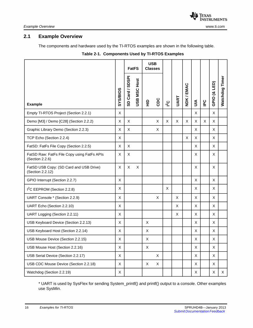
2.1 Example Overview
The components and hardware used by the TI-RTOS examples are shown in the following table.
Table 2-1. Components Used by TI-RTOS Examples
* UART is used by SysFlex for sending System_printf() and printf() output to a console. Other examples use SysMin.
Example SY
S/B
IOS
FatFSUSB
Classes
SD
Car
d /
SD
SP
I
US
B M
SC
Ho
st
HID
CD
C
I2C
UA
RT
ND
K /
EM
AC
UIA
IPC
GP
IO (
& L
ED
)
Wat
chd
og
Tim
er
Empty TI-RTOS Project (Section 2.2.1) X X X
Demo [M3] / Demo [C28] (Section 2.2.2) X X X X X X X X X
Graphic Library Demo (Section 2.2.3) X X X X X
TCP Echo (Section 2.2.4) X X X X
FatSD: FatFs File Copy (Section 2.2.5) X X X X
FatSD Raw: FatFs File Copy using FatFs APIs (Section 2.2.6)
X X X X
FatSD USB Copy: (SD Card and USB Drive) (Section 2.2.12)
X X X X X
GPIO Interrupt (Section 2.2.7) X X X
I2C EEPROM (Section 2.2.8) X X X X
UART Console * (Section 2.2.9) X X X X X
UART Echo (Section 2.2.10) X X X X
UART Logging (Section 2.2.11) X X X X
USB Keyboard Device (Section 2.2.13) X X X X
USB Keyboard Host (Section 2.2.14) X X X X
USB Mouse Device (Section 2.2.15) X X X X
USB Mouse Host (Section 2.2.16) X X X X
USB Serial Device (Section 2.2.17) X X X X
USB CDC Mouse Device (Section 2.2.18) X X X X X
Watchdog (Section 2.2.19) X X X X
16 Examples for TI-RTOS SPRUHD4B—January 2013Submit Documentation Feedback
www.ti.com Example Overview
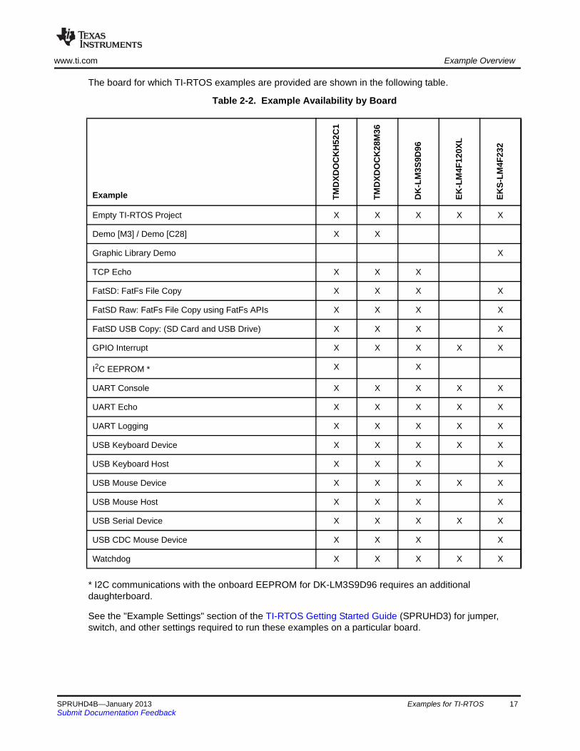
The board for which TI-RTOS examples are provided are shown in the following table.
Table 2-2. Example Availability by Board
* I2C communications with the onboard EEPROM for DK-LM3S9D96 requires an additional daughterboard.
See the "Example Settings" section of the TI-RTOS Getting Started Guide (SPRUHD3) for jumper, switch, and other settings required to run these examples on a particular board.
Example TM
DX
DO
CK
H5
2C
1
TM
DX
DO
CK
28
M3
6
DK
-LM
3S
9D9
6
EK
-LM
4F
120X
L
EK
S-L
M4F
232
Empty TI-RTOS Project X X X X X
Demo [M3] / Demo [C28] X X
Graphic Library Demo X
TCP Echo X X X
FatSD: FatFs File Copy X X X X
FatSD Raw: FatFs File Copy using FatFs APIs X X X X
FatSD USB Copy: (SD Card and USB Drive) X X X X
GPIO Interrupt X X X X X
I2C EEPROM * X X
UART Console X X X X X
UART Echo X X X X X
UART Logging X X X X X
USB Keyboard Device X X X X X
USB Keyboard Host X X X X
USB Mouse Device X X X X X
USB Mouse Host X X X X
USB Serial Device X X X X X
USB CDC Mouse Device X X X X
Watchdog X X X X X
SPRUHD4B—January 2013 Examples for TI-RTOS 17Submit Documentation Feedback
Example Descriptions www.ti.com
2.2 Example Descriptions
A number of examples are provided with TI-RTOS. These use sub-components provided with TI-RTOS.
The following sub-sections briefly describe each example and lists the key C source, configuration, and linker command files used in each example. The examples share the following features:
• There is a separate <example_name>_readme.txt file for each of the examples. These files are added to your CCS project when you use the TI Resource Explorer to create a project. You can open the <example_name>_readme.txt file within CCS.
• All examples except UART Console use the SysMin System Support module. System_printf() output can be viewed with the RTOS Object View (ROV) tool. For more details, see Section 4.2, Generating printf Output.
• Most use the ti.uia.sysbios.LoggingSetup module. The default is to use the STOPMODE uploadMode. (The Demo, UART Console, and UART Logging examples use the LoggerIdle module.) For more details, see Chapter 3, Instrumentation with TI-RTOS.
• All examples have the same <board>.c and <board>.h files. These files perform board-specific configuration of the drivers provided by TI-RTOS. For more details, see Section 5.2, Board-Specific Code Files.
2.2.1 Empty TI-RTOS Project
This example provides a blank project you can use as a starting point in creating a project that utilizes TI-RTOS. It contains some common code excerpts that enable different TI-RTOS components. It is usually easier to start with a more full-featured TI-RTOS example that already uses some of the components and modules your application will need. But, the "empty" projects are available in case you would like to start with a template that has few features.
Empty projects are not created with the TI Resource Explorer. Instead, create empty projects as follows:
1. Choose the Project > New CCS Project menu command. (This has the same effect as using the File > New > CCS Project menu command.)
2. Name the project.
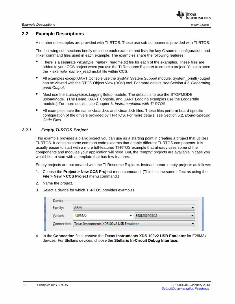
3. Select a device for which TI-RTOS provides examples.
4. In the Connection field, choose the Texas Instruments XDS 100v2 USB Emulator for F28M3x devices. For Stellaris devices, choose the Stellaris In-Circuit Debug Interface.
18 Examples for TI-RTOS SPRUHD4B—January 2013Submit Documentation Feedback
www.ti.com Example Descriptions
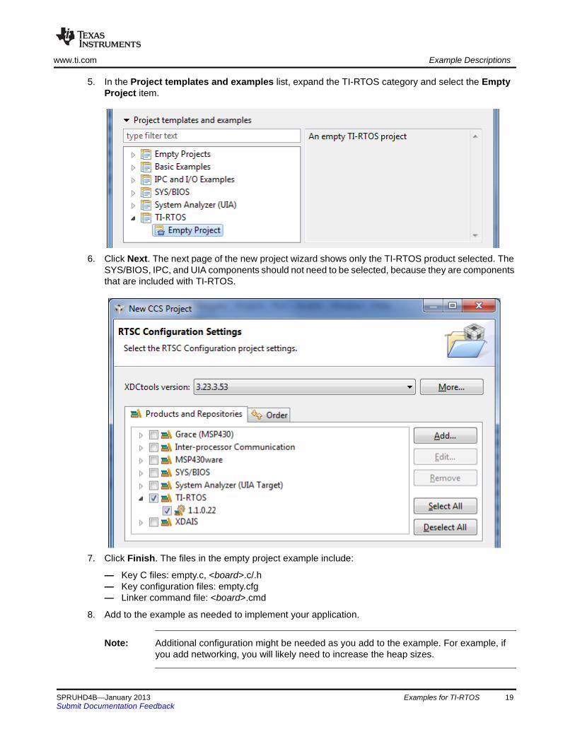
5. In the Project templates and examples list, expand the TI-RTOS category and select the Empty Project item.
6. Click Next. The next page of the new project wizard shows only the TI-RTOS product selected. The SYS/BIOS, IPC, and UIA components should not need to be selected, because they are components that are included with TI-RTOS.
7. Click Finish. The files in the empty project example include:
— Key C files: empty.c, <board>.c/.h— Key configuration files: empty.cfg— Linker command file: <board>.cmd
8. Add to the example as needed to implement your application.
Note: Additional configuration might be needed as you add to the example. For example, if you add networking, you will likely need to increase the heap sizes.
SPRUHD4B—January 2013 Examples for TI-RTOS 19Submit Documentation Feedback

Example Descriptions www.ti.com
2.2.2 Demo [M3] / Demo [C28] for F28M3x (TMDXDOCKH52C1 and TMDXDOCK28M36)
Components: SYS/BIOS; FatFs SD Card (SPI); I2C Driver; Networking (NDK); IPC; Instrumentation (UIA)
Available for: TMDXDOCKH52C1 (M3 and C28) and TMDXDOCK28M36 (M3 and C28).
This dual-core example is a sample project that incorporates several different TI-RTOS components for demonstration purposes. It features an HTTP server (NDK) that functions as a main GUI for controlling and display data graphically.
On the M3, this demo processes other tasks such as temperature readings using the I2C driver, inter-processor communications (IPC) for temperature conversions, and FatFs SD card support for data logging. While all the processes are being executed, CPU load usage and task statics are being generated using UIA.
• Key C files: demo.c/.h, <board>.c/.h, cmdline.c, default.h, dspchip.h, jquery.flot.min.h, jquery.min.h, layout.css.h, logobar.h, webpage.c
• Key configuration files: demo.cfg• Linker command file: <board>.cmd• Description file: demo_readme.txt
This example uses the LoggerIdle module and the USB driver instead of Stop mode for transferring Log data from the target to System Analyzer.
See the demo_readme.txt file in the project for jumper settings, LED indicators, and external components used specifically by this example. See the "Example Settings" section of the TI-RTOS Getting Started Guide (SPRUHD3) for how to make the application use the correct MAC address for your board.
This is a dual-core example. Another example runs on the C28x side of the Concerto device along with the M3 application. The C28x application receives the IPC communication, converts the temperature from Celsius to Fahrenheit, and sends the converted temperature back to the M3 side of the device. The C28x example contains the following key files:
• Key C files: demo_c28.c, demo.h• Key configuration files: demo_c28.cfg• Linker command file: demo_c28.cmd• Description file: demo_c28_readme.txt
Use the following startup sequence to run this dual-core example:
1. In CCS, after the M3 and C28 portions of the demo have been built and a debugging session has been launched, right click on the M3 and select Connect Target. Then do the same for the C28.
2. Do a CPU reset on the M3.
3. Do a CPU reset on the C28.
4. Load (or restart if already loaded) the M3 application and run.
5. Load (or restart if already loaded) the C28 application and run.
20 Examples for TI-RTOS SPRUHD4B—January 2013Submit Documentation Feedback
www.ti.com Example Descriptions
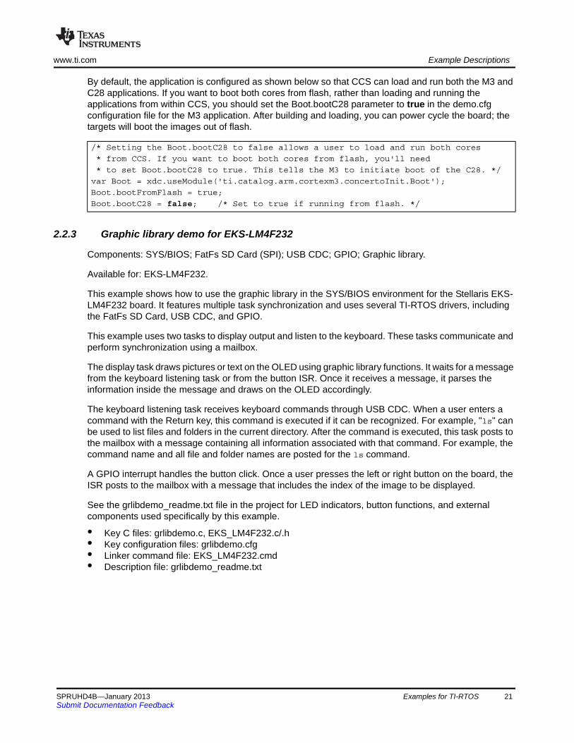
By default, the application is configured as shown below so that CCS can load and run both the M3 and C28 applications. If you want to boot both cores from flash, rather than loading and running the applications from within CCS, you should set the Boot.bootC28 parameter to true in the demo.cfg configuration file for the M3 application. After building and loading, you can power cycle the board; the targets will boot the images out of flash.
2.2.3 Graphic library demo for EKS-LM4F232
Components: SYS/BIOS; FatFs SD Card (SPI); USB CDC; GPIO; Graphic library.
Available for: EKS-LM4F232.
This example shows how to use the graphic library in the SYS/BIOS environment for the Stellaris EKS-LM4F232 board. It features multiple task synchronization and uses several TI-RTOS drivers, including the FatFs SD Card, USB CDC, and GPIO.
This example uses two tasks to display output and listen to the keyboard. These tasks communicate and perform synchronization using a mailbox.
The display task draws pictures or text on the OLED using graphic library functions. It waits for a message from the keyboard listening task or from the button ISR. Once it receives a message, it parses the information inside the message and draws on the OLED accordingly.
The keyboard listening task receives keyboard commands through USB CDC. When a user enters a command with the Return key, this command is executed if it can be recognized. For example, "ls" can be used to list files and folders in the current directory. After the command is executed, this task posts to the mailbox with a message containing all information associated with that command. For example, the command name and all file and folder names are posted for the ls command.
A GPIO interrupt handles the button click. Once a user presses the left or right button on the board, the ISR posts to the mailbox with a message that includes the index of the image to be displayed.
See the grlibdemo_readme.txt file in the project for LED indicators, button functions, and external components used specifically by this example.
• Key C files: grlibdemo.c, EKS_LM4F232.c/.h• Key configuration files: grlibdemo.cfg• Linker command file: EKS_LM4F232.cmd• Description file: grlibdemo_readme.txt
/* Setting the Boot.bootC28 to false allows a user to load and run both cores
* from CCS. If you want to boot both cores from flash, you'll need
* to set Boot.bootC28 to true. This tells the M3 to initiate boot of the C28. */
var Boot = xdc.useModule('ti.catalog.arm.cortexm3.concertoInit.Boot');
Boot.bootFromFlash = true;
Boot.bootC28 = false; /* Set to true if running from flash. */
SPRUHD4B—January 2013 Examples for TI-RTOS 21Submit Documentation Feedback

Example Descriptions www.ti.com
2.2.4 TCP Echo Example
Components: SYS/BIOS; Networking (NDK); Instrumentation (UIA)
Available for: TMDXDOCKH52C1 (M3), TMDXDOCK28M36 (M3), and DK-LM3S9D96.
This example uses the NDK stack to accept incoming TCP packets and echo them to the sender.
First, the example creates a TCP socket by calling the socket() API. Then, it accepts an incoming request on port 1000. It dynamically creates a SYS/BIOS Task object that is responsible for receiving incoming packets and echoing them back to the sender.
TI-RTOS provides a Linux and Windows command-line tool called tcpSendReceive that can be used to test the functionality of the example. It sends a 1024-byte packet to the target and waits for a reply. If verifies the first and last byte for correctness. It prints out the status every 1000 packets. The source and binaries for tcpSendReceive are provided in the <ti-rtos_install>\packages\examples\tools directory.
See the "Example Settings" section of the TI-RTOS Getting Started Guide (SPRUHD3) for jumper settings and LED indicators used by this example and for how to make the application use the correct MAC address for your board.
Both IPv4 and IPv6 versions of this example are provided.
• Key C files: tcpEcho.c, <board>.c/.h • Key configuration files: tcpEcho.cfg• Linker command file: <board>.cmd• Description file: tcpEcho_readme.txt
2.2.5 FatSD Example: FatFs File Copy with SD Card
Components: SYS/BIOS; FatFs SD Card (SPI); Instrumentation (UIA)
Available for: TMDXDOCKH52C1 (M3), TMDXDOCK28M36 (M3), DK-LM3S9D96, and EKS-LM4F232.
This example copies a file called input.txt to output.txt using the runtime support library's CIO functions.
The FatFs software is delivered with the FatFs API. Wrappers have been provided for these APIs in SYS/BIOS, so the CIO function calls provided by the runtime support library can be called to access files on the SD card.
First, the example attempts to open a file called input.txt from the SD card. If the file does not exist, one is created and filled with some text. Next, a file called output.txt file is created on the SD card and opened in write-only mode. If the file already exists on the SD card, it will be overwritten. After the contents of input.txt are copied to output.txt, both files are closed. Finally, output.txt is opened in read-only mode, and its contents are sent to the CCS console (STDOUT).
• Key C files: fatsd.c, <board>.c/.h• Key configuration files: fatsd.cfg• Linker command file: <board>.cmd• Description file: fatsd_readme.txt
22 Examples for TI-RTOS SPRUHD4B—January 2013Submit Documentation Feedback

www.ti.com Example Descriptions
2.2.6 FatSD Raw Example: FatFs File Copy Using FatFs APIs and SD Card
Components: SYS/BIOS; FatFs SD Card (SPI); Instrumentation (UIA)
Available for: TMDXDOCKH52C1 (M3), TMDXDOCK28M36 (M3), DK-LM3S9D96, and EKS-LM4F232.
This example performs similarly to the “FatFs File Copy example (SD Card)” (see Section 2.2.5). However, it uses the FatFs APIs instead of the CIO functions provided by the runtime support library. API documentation for the FatFs APIs is provided at http://elm-chan.org/fsw/ff/00index_e.html.
• Key C files: fatsdraw.c, <board>.c/.h• Key configuration files: fatsdraw.cfg• Linker command file: <board>.cmd• Description file: fatsdraw_readme.txt
2.2.7 GPIO Interrupt Example
Components: SYS/BIOS; GPIO; Instrumentation (UIA)
Available for: TMDXDOCKH52C1 (M3), TMDXDOCK28M36 (M3), DK-LM3S9D96, EK-LM4F120XL, and EKS-LM4F232.
This example uses the GPIO driver's interrupt APIs to toggle a board LED.
Within main(), this application performs general board setup, initializes the LED, and sets up GPIO interrupts based on the callback structure defined in <board>.c. It also enables interrupts for either one or two board buttons, depending on whether or not the board supports a Board_BUTTON2.
The program loops in the SYS/BIOS Idle task until a button is pressed (and released). The button press causes a GPIO interrupt, and the callback function for that GPIO pin (either gpioButtonFxn() or gpioButtonFxn2()) is executed. This function simply toggles the board LED and clears the interrupt flag for the input pin that caused the interrupt.
If the board uses both Board_BUTTON and Board_BUTTON2 (as do the EKS-LM4F232 and the EK-LM4F120XL), you see that one button toggles the LED immediately when the button is pressed, while the other button must be released before it toggles the LED. This difference is caused by the different interrupt types passed to GPIO_enableInt().
Note that no switch debouncing (filtering of rapid multiple switch presses caused by mechanical vibrations during a single press by a user) is performed by the example.
When instrumentation is enabled, the GPIO driver prints logs using UIA for debugging purposes.
• Key C files: gpiointerrupt.c, <board>.c/.h• Key configuration files: gpiointerrupt.cfg• Linker command file: <board>.cmd• Description file: gpiointerrupt_readme.txt
SPRUHD4B—January 2013 Examples for TI-RTOS 23Submit Documentation Feedback
Example Descriptions www.ti.com
2.2.8 I2C EEPROM Example: I2C Communications with Onboard EEPROM
Components: SYS/BIOS; I2C Driver; Instrumentation (UIA)
Available for: TMDXDOCKH52C1 (M3) and DK-LM3S9D96.
This example uses the I2C driver to communicate with an available onboard I2C EEPROM on the TMDXDOCKH52C1 development board.
First, the application "erases" one page of EEPROM by writing a page full of 0xFF values. To verify that the EEPROM was erased, the same page is read back and compared. If it is successfully erased, a page with known data is written to the erased page. The write action is verified by reading the contents back and comparing it with the known data.
When instrumentation is enabled, the I2C driver prints logs using UIA for debugging purposes.
• Key C files: i2ceeprom.c, <board>.c/.h• Key configuration files: i2ceeprom.cfg• Linker command file: <board>.cmd• Description file: i2ceeprom_readme.txt
I2C communications with the onboard EEPROM for DK-LM3S9D96 requires additional daughterboard. The I2C example is not available for the EKS-LM4F232 board.
2.2.9 UART Console Example
Components: SYS/BIOS; Instrumentation (UIA)
Available for: TMDXDOCKH52C1 (M3), TMDXDOCK28M36 (M3), DK-LM3S9D96, EK-LM4F120XL, and EKS-LM4F232.
This example uses the TI-RTOS UART driver and cstdio to setup stdin and stdout through the UART and implement a basic console task.
The UART Console example uses SysFlex, which allows System_printf() output to go to a function that prints out one character at a time. In the UART Console example, the SysFlex System Support module is configured to use UART0, which is set at 115,200 bps 8-N-1. On the development boards, UART0 is connected to the USB FTDI chip. This chip features an interface to a virtual serial COM port which can be used with a standard serial terminal.
If you are using the EKS-LM4F232 board, perform the setup steps in the "EKS-LM4F232 Board" section in the "Examples for TI-RTOS" chapter of the TI-RTOS Getting Started Guide (SPRUHD3) before trying to run the UART Console example.
The UART Console example initializes the UART and a UART device is added to the system. Open will create a UART in blocking read and write mode with data processing turned on. Data processing includes echoing characters back, returning when a newline character is received, writing a return character before a newline is written and replacing return characters read in with a newline character. Read and write will call the respective UART functions using the stdio buffers and size. Lseek, unlink, and rename are not implemented for the UART device.
The new UART device is opened for writing to stdout and reading from stdin. Both are configured with a 128-byte buffer and line buffering. A statically-created task is used to implement the console. This task loops forever, waiting for commands to be entered using scanf. Acceptable commands are help, load, sleep, and exit. Help displays a list of commands. Load displays the CPU load. Sleep prompts the user
24 Examples for TI-RTOS SPRUHD4B—January 2013Submit Documentation Feedback
www.ti.com Example Descriptions
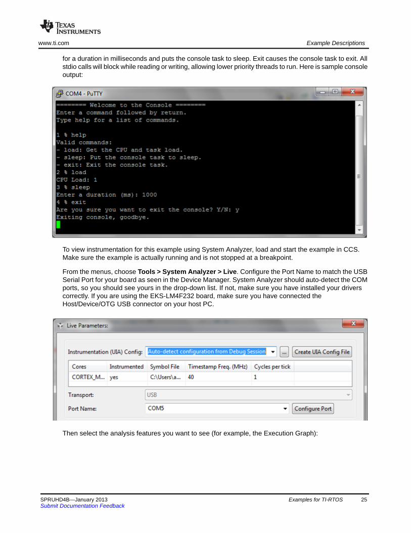
for a duration in milliseconds and puts the console task to sleep. Exit causes the console task to exit. All stdio calls will block while reading or writing, allowing lower priority threads to run. Here is sample console output:
To view instrumentation for this example using System Analyzer, load and start the example in CCS. Make sure the example is actually running and is not stopped at a breakpoint.
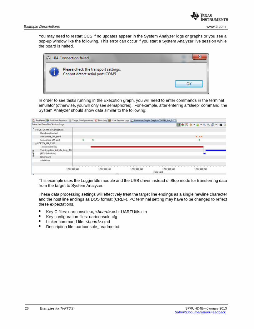
From the menus, choose Tools > System Analyzer > Live. Configure the Port Name to match the USB Serial Port for your board as seen in the Device Manager. System Analyzer should auto-detect the COM ports, so you should see yours in the drop-down list. If not, make sure you have installed your drivers correctly. If you are using the EKS-LM4F232 board, make sure you have connected the Host/Device/OTG USB connector on your host PC.
Then select the analysis features you want to see (for example, the Execution Graph):
SPRUHD4B—January 2013 Examples for TI-RTOS 25Submit Documentation Feedback
Example Descriptions www.ti.com
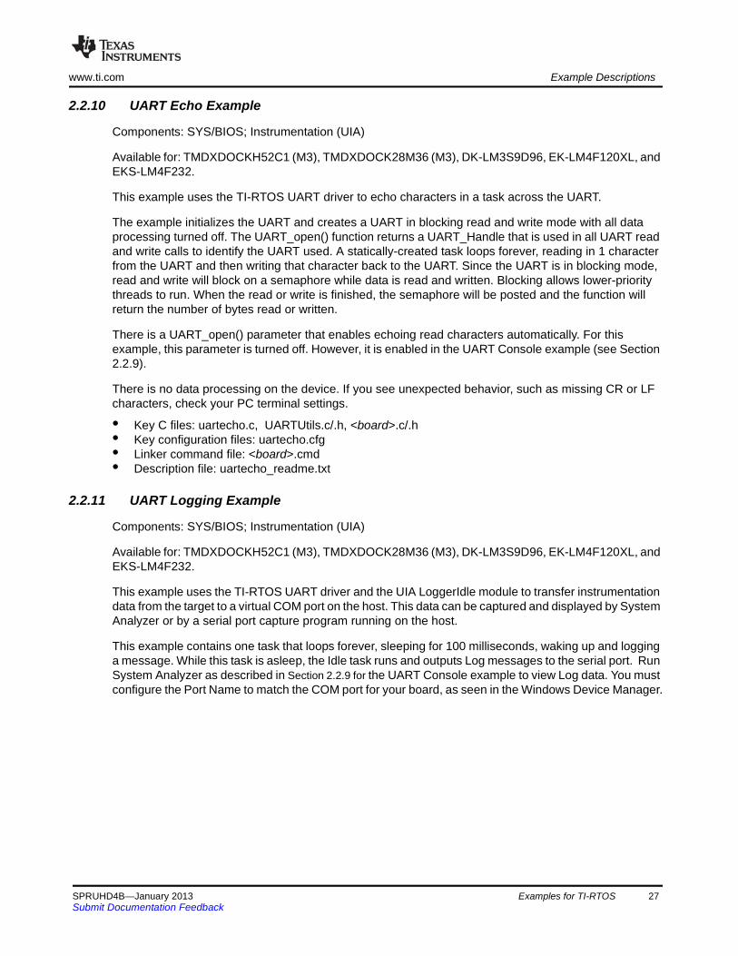
You may need to restart CCS if no updates appear in the System Analyzer logs or graphs or you see a pop-up window like the following. This error can occur if you start a System Analyzer live session while the board is halted.
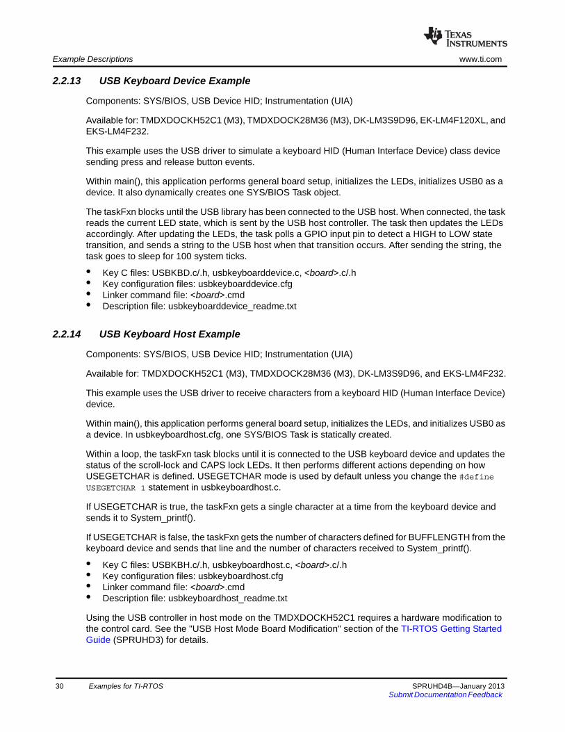
In order to see tasks running in the Execution graph, you will need to enter commands in the terminal emulator (otherwise, you will only see semaphores). For example, after entering a "sleep" command, the System Analyzer should show data similar to the following:
This example uses the LoggerIdle module and the USB driver instead of Stop mode for transferring data from the target to System Analyzer.
These data processing settings will effectively treat the target line endings as a single newline character and the host line endings as DOS format (CRLF). PC terminal setting may have to be changed to reflect these expectations.
• Key C files: uartconsole.c, <board>.c/.h, UARTUtils.c,h• Key configuration files: uartconsole.cfg• Linker command file: <board>.cmd• Description file: uartconsole_readme.txt
26 Examples for TI-RTOS SPRUHD4B—January 2013Submit Documentation Feedback
www.ti.com Example Descriptions
2.2.10 UART Echo Example
Components: SYS/BIOS; Instrumentation (UIA)
Available for: TMDXDOCKH52C1 (M3), TMDXDOCK28M36 (M3), DK-LM3S9D96, EK-LM4F120XL, and EKS-LM4F232.
This example uses the TI-RTOS UART driver to echo characters in a task across the UART.
The example initializes the UART and creates a UART in blocking read and write mode with all data processing turned off. The UART_open() function returns a UART_Handle that is used in all UART read and write calls to identify the UART used. A statically-created task loops forever, reading in 1 character from the UART and then writing that character back to the UART. Since the UART is in blocking mode, read and write will block on a semaphore while data is read and written. Blocking allows lower-priority threads to run. When the read or write is finished, the semaphore will be posted and the function will return the number of bytes read or written.
There is a UART_open() parameter that enables echoing read characters automatically. For this example, this parameter is turned off. However, it is enabled in the UART Console example (see Section 2.2.9).
There is no data processing on the device. If you see unexpected behavior, such as missing CR or LF characters, check your PC terminal settings.
• Key C files: uartecho.c, UARTUtils.c/.h, <board>.c/.h• Key configuration files: uartecho.cfg• Linker command file: <board>.cmd• Description file: uartecho_readme.txt
2.2.11 UART Logging Example
Components: SYS/BIOS; Instrumentation (UIA)
Available for: TMDXDOCKH52C1 (M3), TMDXDOCK28M36 (M3), DK-LM3S9D96, EK-LM4F120XL, and EKS-LM4F232.
This example uses the TI-RTOS UART driver and the UIA LoggerIdle module to transfer instrumentation data from the target to a virtual COM port on the host. This data can be captured and displayed by System Analyzer or by a serial port capture program running on the host.
This example contains one task that loops forever, sleeping for 100 milliseconds, waking up and logging a message. While this task is asleep, the Idle task runs and outputs Log messages to the serial port. Run System Analyzer as described in Section 2.2.9 for the UART Console example to view Log data. You must configure the Port Name to match the COM port for your board, as seen in the Windows Device Manager.
SPRUHD4B—January 2013 Examples for TI-RTOS 27Submit Documentation Feedback

Example Descriptions www.ti.com
The following figure shows a sample Execution Graph for the UART Logging example:
This example also lets you gather Log data from the serial port using a host program running outside of Code Composer Studio. UIA provides an example script, UIAHostFromUART.xs, for collecting Log data and dumping it to the console in a readable format. This script is run using the xdctools utility, xs, passing the script as an argument:
xs [options] -f c:\ti\tirtos_1_01_##_##\products\uia_1_02_##_##\packages\ti\uia\ scripts\UIAHostFromUART.xs [options]
However, to read data from the COM port using this script, you will need to have the RXTX Java library installed. Instructions can be found at http://rxtx.qbang.org/wiki/index.php/Installation_for_Windows, and you can download binaries at http://rxtx.qbang.org/wiki/index.php/Download. After installing the RXTX Java library, you pass the RXTX class path and library path to xs by specifying the location of the RXTX jar file and libraries. In addition, xs needs the path to the UIA component when invoking this script.
Here is an example for use on Windows (to be run from c:\ti\tirtos_1_01_##_##\):
products\xdctools_3_24_##_##\xs.exe --cp "c:\Program Files\Java\jdk1.6.0_26\lib\ext\RXTXcomm.jar" --lp "c:\Program Files\Java\jdk1.6.0_26\bin" --xdcpath products\uia_1_02_##_##\packages\ -f products\uia_1_02_##_##\packages\ti\uia\scripts\UIAHostFromUART.xs [options]
The UIAHostFromUART.xs script has many options, but options for specifying a target executable and target rta.xml file are required for interpreting the Log data. In addition, you must specify either a COM port name or the name of a file containing collected serial port data.
28 Examples for TI-RTOS SPRUHD4B—January 2013Submit Documentation Feedback

www.ti.com Example Descriptions
The following example reads data from COM14 (to be run from c:\ti\tirtos_1_01_##_##\):
REM Path to the workspaceset WORKSPACE=c:\Users\user\workspace_tirtos
REM Specify the COM Port on which UIA logging is receivedset COM=COM14
products\xdctools_3_24_##_##\xs.exe ^--cp "c:\Program Files\Java\jdk1.6.0_26\lib\ext\RXTXcomm.jar" ^--lp "c:\Program Files\Java\jdk1.6.0_26\bin" ^--xdcpath products\uia_1_02_##_##\packages\ ^-f products\uia_1_02_##_##\packages\ti\uia\scripts\UIAHostFromUART.xs ^-p %WORKSPACE%\uartlogging_StellarisLM3S9D96\Debug\uartlogging_StellarisLM3S9D96.out ^-r %WORKSPACE%\uartlogging_StellarisLM3S9D96\Debug\configPkg\package\cfg\ uartlogging_pem3.rta.xml ^
-c %COM%
The following example reads data from a binary file called logdata.bin. Note that the class and library paths for RXTX are not needed, since the example does not read data from the COM port.
products\xdctools_3_24_##_##\xs.exe--xdcpath products\uia_1_02_##_##\packages\-f products\uia_1_02_##_##\packages\ti\uia\scripts\UIAHostFromUART.xs-p %WORKSPACE%\uartlogging_StellarisLM3S9D96\Debug\uartlogging_StellarisLM3S9D96.out-r %WORKSPACE%\uartlogging_StellarisLM3S9D96\Debug\configPkg\package\cfg\ uartlogging_pem3.rta.xml
-d logdata.bin
You can run the UIAHostFromUART.xs script with the -h (help) option to see a full list of options.
• Key C files: uartlogging.c, UARTUtils.c/.h, <board>.c/.h• Key configuration files: uartlogging.cfg• Linker command file: <board>.cmd• Description file: uartlogging_readme.txt
2.2.12 FatSD USB Copy Example: FatFs File Copy with SD Card and USB Drive
Components: SYS/BIOS; FatFs SD Card (SPI); FatFs USB Drive (USB Host MSC); Instrumentation (UIA)
Available for: TMDXDOCKH52C1 (M3), TMDXDOCK28M36 (M3), DK-LM3S9D96, and EKS-LM4F232.
This example performs similarly to the “FatFs File Copy example (SD Card)” (see Section 2.2.5). It reads input.txt from the SD Card. However, it stores the output.txt file on a USB flash drive instead of the SD card. This example uses the runtime support library's CIO functions.
• Key C files: fatsdusbcopy.c, <board>.c/.h• Key configuration files: fatsdusbcopy.cfg• Linker command file: <board>.cmd• Description file: fatsdusbcopy_readme.txt
SPRUHD4B—January 2013 Examples for TI-RTOS 29Submit Documentation Feedback
Example Descriptions www.ti.com
2.2.13 USB Keyboard Device Example
Components: SYS/BIOS, USB Device HID; Instrumentation (UIA)
Available for: TMDXDOCKH52C1 (M3), TMDXDOCK28M36 (M3), DK-LM3S9D96, EK-LM4F120XL, and EKS-LM4F232.
This example uses the USB driver to simulate a keyboard HID (Human Interface Device) class device sending press and release button events.
Within main(), this application performs general board setup, initializes the LEDs, initializes USB0 as a device. It also dynamically creates one SYS/BIOS Task object.
The taskFxn blocks until the USB library has been connected to the USB host. When connected, the task reads the current LED state, which is sent by the USB host controller. The task then updates the LEDs accordingly. After updating the LEDs, the task polls a GPIO input pin to detect a HIGH to LOW state transition, and sends a string to the USB host when that transition occurs. After sending the string, the task goes to sleep for 100 system ticks.
• Key C files: USBKBD.c/.h, usbkeyboarddevice.c, <board>.c/.h• Key configuration files: usbkeyboarddevice.cfg• Linker command file: <board>.cmd• Description file: usbkeyboarddevice_readme.txt
2.2.14 USB Keyboard Host Example
Components: SYS/BIOS, USB Device HID; Instrumentation (UIA)
Available for: TMDXDOCKH52C1 (M3), TMDXDOCK28M36 (M3), DK-LM3S9D96, and EKS-LM4F232.
This example uses the USB driver to receive characters from a keyboard HID (Human Interface Device) device.
Within main(), this application performs general board setup, initializes the LEDs, and initializes USB0 as a device. In usbkeyboardhost.cfg, one SYS/BIOS Task is statically created.
Within a loop, the taskFxn task blocks until it is connected to the USB keyboard device and updates the status of the scroll-lock and CAPS lock LEDs. It then performs different actions depending on how USEGETCHAR is defined. USEGETCHAR mode is used by default unless you change the #define USEGETCHAR 1 statement in usbkeyboardhost.c.
If USEGETCHAR is true, the taskFxn gets a single character at a time from the keyboard device and sends it to System_printf().
If USEGETCHAR is false, the taskFxn gets the number of characters defined for BUFFLENGTH from the keyboard device and sends that line and the number of characters received to System_printf().
• Key C files: USBKBH.c/.h, usbkeyboardhost.c, <board>.c/.h• Key configuration files: usbkeyboardhost.cfg• Linker command file: <board>.cmd• Description file: usbkeyboardhost_readme.txt
Using the USB controller in host mode on the TMDXDOCKH52C1 requires a hardware modification to the control card. See the "USB Host Mode Board Modification" section of the TI-RTOS Getting Started Guide (SPRUHD3) for details.
30 Examples for TI-RTOS SPRUHD4B—January 2013Submit Documentation Feedback
www.ti.com Example Descriptions
2.2.15 USB Mouse Device Example
Components: SYS/BIOS, USB Device HID; Instrumentation (UIA)
Available for: TMDXDOCKH52C1 (M3), TMDXDOCK28M36 (M3), DK-LM3S9D96, EK-LM4F120XL, and EKS-LM4F232.
This example uses the USB driver to simulate a mouse HID (Human Interface Device) class device sending mouse movement and click events.
Within main(), this application performs general board setup, initializes the LEDs, and initializes USB0 as a device. In usbmousedevice.cfg, one SYS/BIOS Task is statically created.
The taskFxn blocks until the USB library has been connected to the USB host. When it determines the device is connected to a USB host, it sends pre-programmed X, Y coordinate offsets and the GPIO input pin's value as mouse button1 (a left-click) to the host. The X,Y coordinate offsets in the mouseLookupTable array move the mouse pointer to form a figure 8.
• Key C files: USBMD.c/.h, usbmousedevice.c, <board>.c/.h• Key configuration files: usbmousedevice.cfg• Linker command file: <board>.cmd• Description file: usbmousedevice_readme.txt
2.2.16 USB Mouse Host Example
Components: SYS/BIOS, USB Device HID; Instrumentation (UIA)
Available for: TMDXDOCKH52C1 (M3), TMDXDOCK28M36 (M3), DK-LM3S9D96, and EKS-LM4F232.
This example uses the USB driver to receive the current state of a mouse HID (Human Interface Device) device, which includes the most recent X and Y positional offset values and a mouse button state.
Within main(), this application performs general board setup, initializes the LEDs, and initializes USB0 as a device. In usbmousehost.cfg, one SYS/BIOS Task is statically created.
Within a loop, the taskFxn task blocks until it is connected to the USB mouse device. It then gets the current mouse state data structure, updates the status of the GPIOs to match the states of mouse buttons 1 and 2, and sends the current X,Y coordinate offsets to System_printf(). It sleeps for 100 system ticks before running the loop again.
• Key C files: USBMH.c/.h, usbmousehost.c, <board>.c/.h• Key configuration files: usbmousehost.cfg• Linker command file: <board>.cmd• Description file: usbmousehost_readme.txt
Using the USB controller in host mode on the TMDXDOCKH52C1 requires a hardware modification to the control card. See the "USB Host Mode Board Modification" section of the TI-RTOS Getting Started Guide (SPRUHD3) for details.
SPRUHD4B—January 2013 Examples for TI-RTOS 31Submit Documentation Feedback

Example Descriptions www.ti.com
2.2.17 USB Serial Device Example
Components: SYS/BIOS, USB Device CDC; Instrumentation (UIA)
Available for: TMDXDOCKH52C1 (M3), TMDXDOCK28M36 (M3), DK-LM3S9D96, EK-LM4F120XL, and EKS-LM4F232.
This example uses the USB driver to transmit and receive data via the USB Communications Device Class (CDC) to a virtual USB COM port on a host workstation.
Within main(), this application performs general board setup, initializes the LEDs, and initializes USB0 as a device. It also dynamically creates two SYS/BIOS Task objects.
The taskFxn blocks until the USB library has been connected to the USB host. Then, the taskFxn task periodically sends an array of bytes to the USB host. It also toggles a GPIO and outputs a message whenever it sends data.
The taskFxn1 blocks until the USB library has been connected to the USB host. Then, the taskFxn1 task receives serial data sent by the host and prints using the SysMin system provider. The task also toggles a GPIO and outputs a message whenever it receives data. This task blocks while the device is not connected to the USB host or if no data was received.
• Key C files: USBCDCD.c/.h, usbserialdevice.c, <board>.c/.h• Key configuration files: usbserialdevice.cfg• Linker command file: <board>.cmd• Description file: usbserialdevice_readme.txt
2.2.18 USB CDC Mouse Device Example
Components: SYS/BIOS, USB Device MSC; Instrumentation (UIA)
Available for: TMDXDOCKH52C1 (M3), TMDXDOCK28M36 (M3), DK-LM3S9D96, and EKS-LM4F232.
This example uses the USB Communications Device Class (CDC) device to simulate a mouse HID (Human Interface Device) class device sending mouse movement and click events.
Within main(), this application performs general board setup, initializes the LEDs, and initializes USB0 as a device. It also dynamically creates two SYS/BIOS Task objects.
The taskFxn blocks until the USB library has been connected to the USB host. When it determines the device is connected to a USB host, it sends pre-programmed X, Y coordinate offsets and the GPIO input pin's value as mouse button1 (a left-click) to the host. The X,Y coordinate offsets in the mouseLookupTable array move the mouse pointer to form a figure 8.
The taskFxn1 blocks until the USB library has been connected to the USB host. Then, the taskFxn1 task receives serial data sent by the host and prints it using the SysMin system provider. The task also toggles a GPIO and outputs a message whenever it receives data. This task blocks while the device is not connected to the USB host or if no data was received.
• Key C files: USBCDCMOUSE.c/.h, usbcdcmousedevice.c, <board>.c/.h• Key configuration files: usbcdcmousedevice.cfg• Linker command file: <board>.cmd• Description file: usbcdcmousedevice_readme.txt
32 Examples for TI-RTOS SPRUHD4B—January 2013Submit Documentation Feedback
www.ti.com Example Descriptions
2.2.19 Watchdog Example
Components: SYS/BIOS; Instrumentation (UIA)
Available for: TMDXDOCKH52C1 (M3), TMDXDOCK28M36 (M3), DK-LM3S9D96, EK-LM4F120XL, and EKS-LM4F232.
This example uses the TI-RTOS Watchdog driver to generate a reset signal after a button press.
The example initializes the Watchdog peripheral and creates a Watchdog instance with resets enabled and a defined callback function. A task that loops forever is also created to check for a button press.
Every time a watchdog interrupt occurs, the callback function toggles a board LED and clears the watchdog interrupt flag.
Once a button press is detected, the task sets a flag that tells the callback function to stop clearing the watchdog interrupt flag and allow the watchdog peripheral to generate a reset signal.
When instrumentation is enabled, the Watchdog driver prints logs using UIA for debugging purposes.
• Key C files: watchdog.c, <board>.c/.h• Key configuration files: watchdog.cfg• Linker command file: <board>.cmd• Description file: watchdog_readme.txt
SPRUHD4B—January 2013 Examples for TI-RTOS 33Submit Documentation Feedback
Chapter 3SPRUHD4B—January 2013
Instrumentation with TI-RTOS
This chapter describes how to instrument your application with log calls and view the data with System Analyzer (SA).
3.1 Overview . . . . . . . . . . . . . . . . . . . . . . . . . . . . . . . . . . . . . . . . . . . . . . . . 35
3.2 Adding Logging to a Project . . . . . . . . . . . . . . . . . . . . . . . . . . . . . . . . 35
3.3 Using Log Events . . . . . . . . . . . . . . . . . . . . . . . . . . . . . . . . . . . . . . . . . 37
3.4 Viewing the Logs. . . . . . . . . . . . . . . . . . . . . . . . . . . . . . . . . . . . . . . . . . 38
Topic Page
SPRUHD4B—January 2013 Instrumentation with TI-RTOS 34Submit Documentation Feedback
www.ti.com Overview
3.1 Overview
TI-RTOS uses the Unified Instrumentation Architecture (UIA) to instrument your application with log calls. The data can be viewed and visualized with System Analyzer (SA) to create execution graphs, load graphs and more. For detailed information on using UIA and SA refer to the Getting Started Guide in the <uia_install>/docs directory and the System Analyzer User’s Guide (SPRUH43).
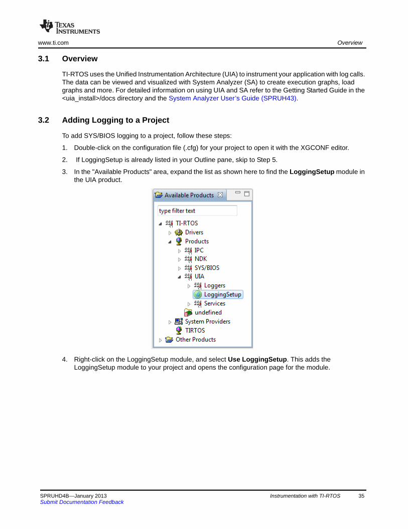
3.2 Adding Logging to a Project
To add SYS/BIOS logging to a project, follow these steps:
1. Double-click on the configuration file (.cfg) for your project to open it with the XGCONF editor.
2. If LoggingSetup is already listed in your Outline pane, skip to Step 5.
3. In the "Available Products" area, expand the list as shown here to find the LoggingSetup module in the UIA product.
4. Right-click on the LoggingSetup module, and select Use LoggingSetup. This adds the LoggingSetup module to your project and opens the configuration page for the module.
SPRUHD4B—January 2013 Instrumentation with TI-RTOS 35Submit Documentation Feedback
Adding Logging to a Project www.ti.com
5. Use the configuration page for the LoggingSetup module as follows:
a) In the SYS/BIOS Logging area, use the check boxes to select what types of threads you wantto be logged—hardware interrupts (Hwi), software interrupts (Swi), and tasks. If you check theRuntime control box, you can turn that type of logging on or off at runtime.
b) In the SYS/BIOS Load Logging area, you can click the Configure Load module link if you wantthe CPU load to be logged. Then check the box in the CPU Load Monitor page to add the CPUload monitoring module to the configuration. You can also choose which types of thread loads tomonitor.
c) In the Application Logging area, you configure the logger to use in your main application. Callsto Log_info(), Log_warning(), and Log_error() in your main application as well as anyinstrumented driver logs will be sent to this logger.
d) By default, LoggingSetup creates a logger that sends events over JTAG when the target is halted(for example, in StopMode). You can change the upload mode in the Loggers area.
The examples provided with TI-RTOS include and configure the LoggingSetup module. For more information on using LoggingSetup refer to Section 5.3.1 in the System Analyzer User’s Guide (SPRUH43).
36 Instrumentation with TI-RTOS SPRUHD4B—January 2013Submit Documentation Feedback

www.ti.com Using Log Events
3.3 Using Log Events
You can add Log events to your application and control whether Log events are processed by drivers as described in the following sub-sections.
3.3.1 Adding Log Events to your Code
Your application can send messages to a Log using the standard Log module APIs (xdc.runtime.Log).
Log calls are of the format Log_typeN(String, arg1, arg2… argN). Valid types are print, info, warning and error. N is the number of arguments between 0 and 5. For example:
See the SYS/BIOS Log example project for more use cases.
3.3.2 Using Instrumented or Non-Instrumented Libraries
TI-RTOS drivers allow you to control whether Log events are handled by choosing to build with the instrumented or non-instrumented libraries. The instrumented libraries process Log events while the non-instrumented libraries do not.
To select the type of library to build with, follow these steps:
1. Double-click on the configuration file (.cfg) for your project to open it with the XGCONF editor.
2. In the “Available Products” area, select the TI-RTOS driver whose behavior you want to control. For example, if your target is the M3 side of the Concerto device, you can configure the EMAC, GPIO, I2C, SDSPI, UART, USBMSCHFatFs, and Watchdog driver libraries.
3. On the configuration page, choose whether to use the instrumented or non-instrumented libraries.
Refer to the individual drivers in Chapter 6 for details about what is logged and which Diags masks are used.
Log_info2("tsk1 Entering. arg0,1 = %d %d", arg0, arg1)
SPRUHD4B—January 2013 Instrumentation with TI-RTOS 37Submit Documentation Feedback
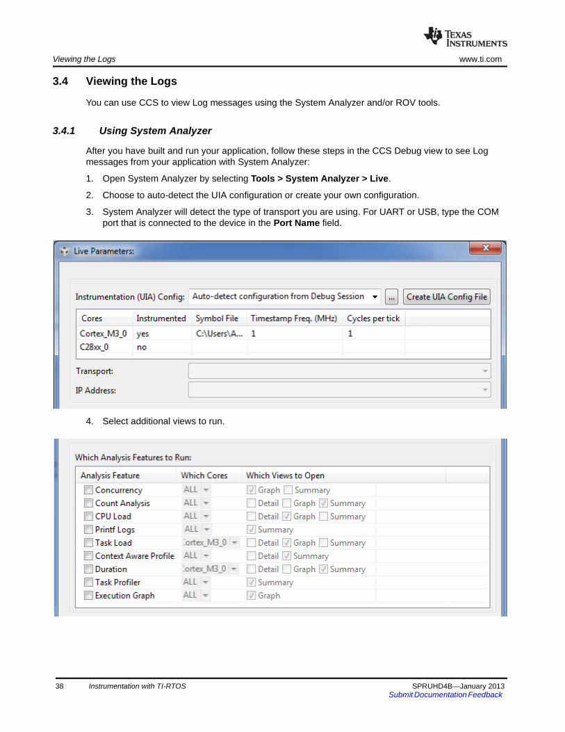
Viewing the Logs www.ti.com
3.4 Viewing the Logs
You can use CCS to view Log messages using the System Analyzer and/or ROV tools.
3.4.1 Using System Analyzer
After you have built and run your application, follow these steps in the CCS Debug view to see Log messages from your application with System Analyzer:
1. Open System Analyzer by selecting Tools > System Analyzer > Live.
2. Choose to auto-detect the UIA configuration or create your own configuration.
3. System Analyzer will detect the type of transport you are using. For UART or USB, type the COM port that is connected to the device in the Port Name field.
4. Select additional views to run.
38 Instrumentation with TI-RTOS SPRUHD4B—January 2013Submit Documentation Feedback
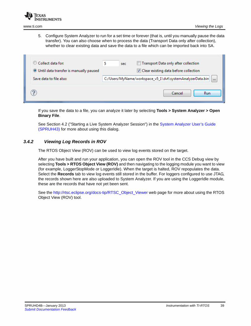
www.ti.com Viewing the Logs
5. Configure System Analyzer to run for a set time or forever (that is, until you manually pause the data transfer). You can also choose when to process the data (Transport Data only after collection), whether to clear existing data and save the data to a file which can be imported back into SA.
If you save the data to a file, you can analyze it later by selecting Tools > System Analyzer > Open Binary File.
See Section 4.2 ("Starting a Live System Analyzer Session") in the System Analyzer User’s Guide (SPRUH43) for more about using this dialog.
3.4.2 Viewing Log Records in ROV
The RTOS Object View (ROV) can be used to view log events stored on the target.
After you have built and run your application, you can open the ROV tool in the CCS Debug view by selecting Tools > RTOS Object View (ROV) and then navigating to the logging module you want to view (for example, LoggerStopMode or LoggerIdle). When the target is halted, ROV repopulates the data. Select the Records tab to view log events still stored in the buffer. For loggers configured to use JTAG, the records shown here are also uploaded to System Analyzer. If you are using the LoggerIdle module, these are the records that have not yet been sent.
See the http://rtsc.eclipse.org/docs-tip/RTSC_Object_Viewer web page for more about using the RTOS Object View (ROV) tool.
SPRUHD4B—January 2013 Instrumentation with TI-RTOS 39Submit Documentation Feedback

Chapter 4SPRUHD4B—January 2013
Debugging TI-RTOS Applications
This chapter provides information about ways to debug your TI-RTOS applications.
4.1 Using CCS Debugging Tools
Within Code Composer Studio (CCS), there are several tools you can use to debug your TI-RTOS applications:
• RTOS Object View (ROV) is a stop-mode debugging tool, which means it can receive data about an application only when the target is halted, not when it is running. ROV is a tool provided by the XDCtools component. ROV gets information from many of the modules your applications are likely to use.
4.1 Using CCS Debugging Tools . . . . . . . . . . . . . . . . . . . . . . . . . . . . . . . . 40
4.2 Generating printf Output . . . . . . . . . . . . . . . . . . . . . . . . . . . . . . . . . . . 42
4.3 Controlling Software Versions for Use with TI-RTOS . . . . . . . . . . . . 45
4.4 Understanding the Build Flow . . . . . . . . . . . . . . . . . . . . . . . . . . . . . . . 46
Topic Page
SPRUHD4B—January 2013 Debugging TI-RTOS Applications 40Submit Documentation Feedback
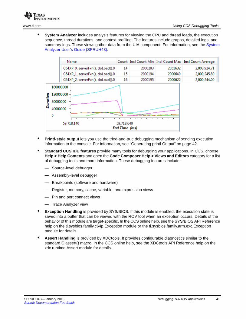
www.ti.com Using CCS Debugging Tools
• System Analyzer includes analysis features for viewing the CPU and thread loads, the execution sequence, thread durations, and context profiling. The features include graphs, detailed logs, and summary logs. These views gather data from the UIA component. For information, see the System Analyzer User’s Guide (SPRUH43).
• Printf-style output lets you use the tried-and-true debugging mechanism of sending execution information to the console. For information, see “Generating printf Output” on page 42.
• Standard CCS IDE features provide many tools for debugging your applications. In CCS, choose Help > Help Contents and open the Code Composer Help > Views and Editors category for a list of debugging tools and more information. These debugging features include:
— Source-level debugger
— Assembly-level debugger
— Breakpoints (software and hardware)
— Register, memory, cache, variable, and expression views
— Pin and port connect views
— Trace Analyzer view
• Exception Handling is provided by SYS/BIOS. If this module is enabled, the execution state is saved into a buffer that can be viewed with the ROV tool when an exception occurs. Details of the behavior of this module are target-specific. In the CCS online help, see the SYS/BIOS API Reference help on the ti.sysbios.family.c64p.Exception module or the ti.sysbios.family.arm.exc.Exception module for details.
• Assert Handling is provided by XDCtools. It provides configurable diagnostics similar to the standard C assert() macro. In the CCS online help, see the XDCtools API Reference help on the xdc.runtime.Assert module for details.
SPRUHD4B—January 2013 Debugging TI-RTOS Applications 41Submit Documentation Feedback
Generating printf Output www.ti.com
4.2 Generating printf Output
Along with many advanced GUI debugging features described in “Using CCS Debugging Tools” on page 40, TI-RTOS provides flexibility with the tried-and-true printf method of debugging. TI-RTOS supports both the standard printf() and a more flexible replacement called System_printf().
4.2.1 Output with printf()
By default, the printf() function outputs data to a CIO buffer on the target. When CCS is attached to the target (for example, via JTAG or USB), the printf() output is displayed in the Console window. It is important to realize that when the CIO buffer is full or a ‘\n’ is output, a CIO breakpoint is hit on the target. This allows CCS to read the data and output the characters to the console. Once the data is read, CCS resumes running the target. This interruption of the target can have significant impact on a real-time system. Because of this interruption and the associated performance overhead, use of the printf() API is discouraged.
The UART Console example shows how to route the printf() output to a UART via the add_device() API.
4.2.2 Output with System_printf()
The xdc.runtime.System module provided by the XDCtools component offers a more flexible and potentially better-performing replacement to printf() called System_printf().
The System module allows different low-level implementations (System Support implementation) to be plugged in based on your needs. You can plug in the System Support implementation you want to use via the application configuration. Your choice does not require any changes to the runtime code.
Currently the following System Support implementations are available:
• SysMin: Stores output to an internal buffer. The buffer is flushed to stdout (which goes to the CCS Console view) when System_flush() is called or when an application terminates (for example, when BIOS_exit() or exit() is called). When the buffer is full, the oldest characters are over-written. Characters that have not been sent to stdout can be viewed via the RTOS Object View (ROV) tool. The SysMin module is part of the XDCtools component. Its full module path is xdc.runtime.SysMin.
• SysFlex: Allows a user to plug in their functions. The UART Console example (Section 2.2.9) provides a set of functions that use the UART. The SysFlex module is a utility provided by TI-RTOS. Its full module path is ti.tirtos.utils.SysFlex.
• SysStd: Sends the characters to the standard printf() function. The SysStd module is part of the XDCtools component. Its full module path is xdc.runtime.SysStd.
All TI-RTOS examples use the SysMin module except for the UART Console example, which uses SysFlex and routes the output to a UART.
42 Debugging TI-RTOS Applications SPRUHD4B—January 2013Submit Documentation Feedback

www.ti.com Generating printf Output
To configure the SysMin module, open the application’s *.cfg file with the XGCONF Configuration Editor. In the Outline area, select the System module. Configure the System Provider to use SysMin as follows:
Then, find the SysMin module in the Outline pane, and configure the output buffer and options as needed. For example, here are the settings used by most examples provided with TI-RTOS:
The following statements create the same configuration as the graphical settings shown for the System and SysMin modules:
var System = xdc.useModule('xdc.runtime.System');var SysMin = xdc.useModule('xdc.runtime.SysMin');System.SupportProxy = SysMin;
SPRUHD4B—January 2013 Debugging TI-RTOS Applications 43Submit Documentation Feedback
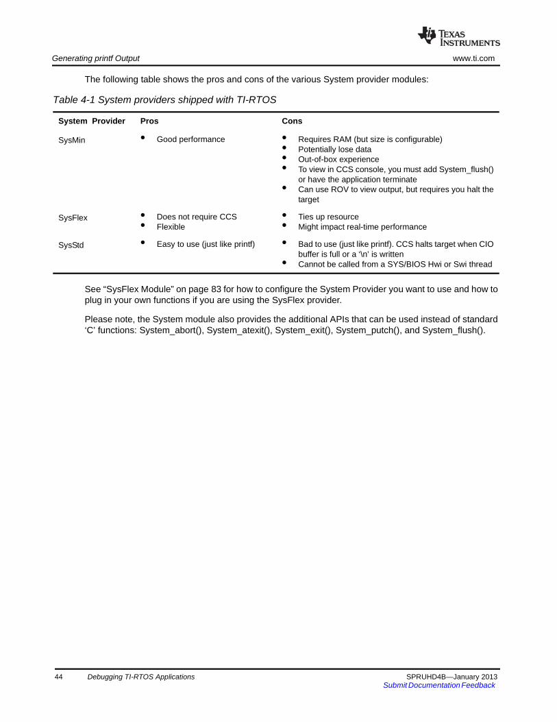
Generating printf Output www.ti.com
The following table shows the pros and cons of the various System provider modules:
See “SysFlex Module” on page 83 for how to configure the System Provider you want to use and how to plug in your own functions if you are using the SysFlex provider.
Please note, the System module also provides the additional APIs that can be used instead of standard ‘C’ functions: System_abort(), System_atexit(), System_exit(), System_putch(), and System_flush().
Table 4-1 System providers shipped with TI-RTOS
System Provider Pros Cons
SysMin • Good performance • Requires RAM (but size is configurable)• Potentially lose data• Out-of-box experience• To view in CCS console, you must add System_flush()
or have the application terminate• Can use ROV to view output, but requires you halt the
target
SysFlex • Does not require CCS• Flexible
• Ties up resource• Might impact real-time performance
SysStd • Easy to use (just like printf) • Bad to use (just like printf). CCS halts target when CIObuffer is full or a ‘\n’ is written
• Cannot be called from a SYS/BIOS Hwi or Swi thread
44 Debugging TI-RTOS Applications SPRUHD4B—January 2013Submit Documentation Feedback
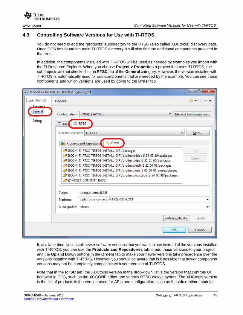
www.ti.com Controlling Software Versions for Use with TI-RTOS
4.3 Controlling Software Versions for Use with TI-RTOS
You do not need to add the "products" subdirectory to the RTSC (also called XDCtools) discovery path. Once CCS has found the main TI-RTOS directory, it will also find the additional components provided in that tree.
In addition, the components installed with TI-RTOS will be used as needed by examples you import with the TI Resource Explorer. When you choose Project > Properties a project that uses TI-RTOS, the subprojects are not checked in the RTSC tab of the General category. However, the version installed with TI-RTOS is automatically used for sub-components that are needed by the example. You can see these components and which versions are used by going to the Order tab.
If, at a later time, you install newer software versions that you want to use instead of the versions installed with TI-RTOS, you can use the Products and Repositories tab to add those versions to your project and the Up and Down buttons in the Orders tab to make your newer versions take precedence over the versions installed with TI-RTOS. However, you should be aware that is it possible that newer component versions may not be completely compatible with your version of TI-RTOS.
Note that in the RTSC tab, the XDCtools version in the drop-down list is the version that controls UI behavior in CCS, such as the XGCONF editor and various RTSC dialog layouts. The XDCtools version is the list of products is the version used for APIs and configuration, such as the xdc.runtime modules.
SPRUHD4B—January 2013 Debugging TI-RTOS Applications 45Submit Documentation Feedback

Understanding the Build Flow www.ti.com
4.4 Understanding the Build Flow
The build flow for TI-RTOS applications begins with an extra step to process the configuration file (*.cfg) in the project. The configuration file is a script file with syntax similar to JavaScript. You can edit it graphically in CCS using the XGCONF tool. The configuration configures which modules in TI-RTOS components are used, sets global behavior parameters for modules, and statically creates objects managed by the modules. Static configuration has several advantages, including reducing code memory use by the application. Components that can be configured using this file include XDCtools, SYS/BIOS, TI-RTOS, IPC, NDK, and UIA.
The configuration file is processed by the XDCtools component. If you look at the messages printed during the build, you will see a command line that runs the “xs” executable in the XDCtools component with the “xdc.tools.configuro” tool specified. For example:
In CCS, you can control the command-line options used with XDCtools by choosing Project > Properties from the menus and selecting the Build > XDCtools category.
Target settings for processing your individual project are in the RTSC tab of the CCS General category. (RTSC is the name for the Eclipse specification implemented by XDCtools.)
When XDCtools processes your *.cfg file, the code is generated in the <project_dir>/Debug/configPkg directory. This code is compiled so that it can be linked with your final application. In addition, a compiler.opt file is created for use during program compilation, and a linker.cmd file is created for use in linking the application. You should not modify the files in the <project_dir>/Debug/configPkg directory after they are generated, since they will be overwritten the next time you build.
For more information about the build flow, see Chapter 2 of the SYS/BIOS User’s Guide (SPRUEX3). For command-line details about xdc.tools.configuro, see the RTSC-pedia reference topic.
'Invoking: XDCtools'
"<>/xs" --xdcpath="<tirtos_install>/packages;<bios_install>/packages;<uia_install>/packages;" xdc.tools.configuro -o configPkg -t ti.targets.arm.elf.M3 -p ti.platforms.concertoM3:F28M35H52C1 -r release -c "C:/ccs/ccsv5/tools/compiler/tms470" "../<project>.cfg"
46 Debugging TI-RTOS Applications SPRUHD4B—January 2013Submit Documentation Feedback
Chapter 5SPRUHD4B—January 2013
Board-Specific Files
This chapter provides information that is specific to targets for which you can use TI-RTOS.
5.1 Overview
Currently, TI-RTOS provides examples for the following boards:
F28M3x devices contain both M3 and 28x subsystems.
TI-RTOS can also be used on other boards. Examples are provided specifically for the supported boards, but libraries are provided for each of these device families, so that you can port the examples to similar boards. Porting information for TI-RTOS is provided on the Texas Instruments Embedded Processors Wiki.
Table 5-1 Boards with TI-RTOS examples provided
Board Device on Board
TMDXDOCKH52C1 F28M35H52C1 Concerto F28M35x
TMDXDOCK28M36 F28M36P63C2 Concerto F28M36x
DK-LM3S9D96 LM3S9D96 ARM Cortex-M3
EK-LM4F120XL LM4F120H5QR ARM Cortex-M4F
EKS-LM4F232 LM4F232H5QD ARM Cortex-M4F
5.1 Overview . . . . . . . . . . . . . . . . . . . . . . . . . . . . . . . . . . . . . . . . . . . . . . . . 47
5.2 Board-Specific Code Files . . . . . . . . . . . . . . . . . . . . . . . . . . . . . . . . . . 48
5.3 Linker Command Files . . . . . . . . . . . . . . . . . . . . . . . . . . . . . . . . . . . . . 48
5.4 Target Configuration Files . . . . . . . . . . . . . . . . . . . . . . . . . . . . . . . . . . 49
Topic Page
SPRUHD4B—January 2013 Board-Specific Files 47Submit Documentation Feedback
Board-Specific Code Files www.ti.com
5.2 Board-Specific Code Files
TI-RTOS examples contain a board-specific C file (and its companion header file). The filenames are <board>.c and <board>.h, where <board> is the name of the board, such as TMDXDOCKH52C1 or DK_LM3S9D96. Notice that an underscore is used in place of a hyphen in file and folder names that include the EKS-LM4F232 and DK-LM3S9D96 board names.
All the examples for a specific board have identical <board> files. These files are considered part of the application, and you can modify them as needed.
The <board> files perform board-specific configuration of the drivers provided by TI-RTOS. For example, they perform the following:
• GPIO port and pin configuration
• LED configuration
• SDSPI configuration
In addition, the board-specific files provide the following functions that you can use in your applications, These are typically called from main().
• <board>_initDMA() function (DK-LM3S9D96 and EKS-LM4F232)
• <board>_initEMAC() function (TMDXDOCKH52C1, TMDXDOCK28M36, and DK-LM3S9D96)
• <board>_initGeneral() function (all boards)
• <board>_initGPIO() function (all boards)
• <board>_initI2C() function (TMDXDOCKH52C1, TMDXDOCK28M36, EKS-LM4F232, and DK-LM3S9D96)
• <board>_initSDSPI() function (TMDXDOCKH52C1, TMDXDOCK28M36, EKS-LM4F232, and DK-LM3S9D96)
• <board>_initUART() function (all boards)
• <board>_initUSB() function (all boards)
• <board>_initUSBMSCHFatFs() function (TMDXDOCKH52C1, TMDXDOCK28M36, EKS-LM4F232, and DK-LM3S9D96)
• <board>_initWatchdog() function (all boards)
5.3 Linker Command Files
All of TI-RTOS examples contain a <board>.cmd linker command file. A different file is provided for each supported board. These files define memory segments and memory sections used by the application.
48 Board-Specific Files SPRUHD4B—January 2013Submit Documentation Feedback

www.ti.com Target Configuration Files
5.4 Target Configuration Files
To create a target configuration for an example provided with TI-RTOS, use Step 3 (Debugger Configuration) in the TI Resource Explorer.
When you click the link for Step 3, you see the Debugger Configuration dialog. Choose an emulator from the list. For the F28M3x devices, choose the Texas Instruments XDS 100v2 USB Emulator. For Stellaris devices, choose the Stellaris In-Circuit Debug Interface.
The Debugger Configuration step creates a CCS Target Configuration File (*.ccxml). This file specifies the connection and device for the project for use in a debugging session. You can choose View > Target Configurations in CCS to see and edit these files.
Note: If you want to use a simulator instead of a hardware connection, select any emulator in the Debugger Configuration dialog and click OK. Then choose View > Target Configurations. Expand the Projects list and double-click on the *.ccxml file for your example project to open the target configuration editor. Select Texas Instruments Simulator in the Connection field, and the simulator for your device in the Device list. Then click Save.
For the Demo example, you should not use a C28 target configuration. Instead, use the target configuration for the M3 and connect to the C28 and load that application manually as described in Section 2.2.2.
SPRUHD4B—January 2013 Board-Specific Files 49Submit Documentation Feedback
Chapter 6SPRUHD4B—January 2013
TI-RTOS Drivers
This chapter provides information about the drivers provided with TI-RTOS.
6.1 Overview
TI-RTOS includes drivers for a number of peripherals. These drivers are in the <tirtos_install>/packages/ti/drivers directory. TI-RTOS examples show how to use these drivers. Note that all of these drivers are built on top of MWare and StellarisWare. This chapter contains a section for each driver.
• EMAC. Ethernet driver used by the networking stack (NDK) and not intended to be called directly.
• UART. API set intended to be used directly by the application to communicate with the UART.
• I2C. API set intended to be used directly by the application or middleware.
• GPIO. API set intended to be used directly by the application or middleware to manage the GPIO interrupts, pins, and ports (and therefore the LEDs) on the board.
• SD. SD driver used by the FatFs and not intended to be interfaced directly.
• USBMSCHFatFs. USB MSC Host under FatFs (for flash drives)
• Other USB functionality. See the USB examples for reference modules that provide support for the Human Interface Device (HID) class (mouse and keyboard) and Communications Device Class (CDC). This code is provided as part of the examples, not as a separate driver.
• Watchdog. API set for use directly by the application or middleware to control the watchdog timer.
6.1 Overview . . . . . . . . . . . . . . . . . . . . . . . . . . . . . . . . . . . . . . . . . . . . . . . . 50
6.2 Driver Framework . . . . . . . . . . . . . . . . . . . . . . . . . . . . . . . . . . . . . . . . . 51
6.3 EMAC Driver . . . . . . . . . . . . . . . . . . . . . . . . . . . . . . . . . . . . . . . . . . . . . 54
6.4 UART Driver . . . . . . . . . . . . . . . . . . . . . . . . . . . . . . . . . . . . . . . . . . . . . . 56
6.5 I2C Driver . . . . . . . . . . . . . . . . . . . . . . . . . . . . . . . . . . . . . . . . . . . . . . . . 60
6.6 GPIO Driver . . . . . . . . . . . . . . . . . . . . . . . . . . . . . . . . . . . . . . . . . . . . . . 67
6.7 SDSPI Driver . . . . . . . . . . . . . . . . . . . . . . . . . . . . . . . . . . . . . . . . . . . . . 70
6.8 USBMSCHFatFs Driver . . . . . . . . . . . . . . . . . . . . . . . . . . . . . . . . . . . . . 73
6.9 USB Reference Modules. . . . . . . . . . . . . . . . . . . . . . . . . . . . . . . . . . . . 76
6.10 USB Device and Host Modules . . . . . . . . . . . . . . . . . . . . . . . . . . . . . . 79
6.11 Watchdog Driver . . . . . . . . . . . . . . . . . . . . . . . . . . . . . . . . . . . . . . . . . . 80
Topic Page
SPRUHD4B—January 2013 TI-RTOS Drivers 50Submit Documentation Feedback
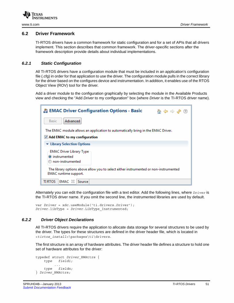
www.ti.com Driver Framework
6.2 Driver Framework
TI-RTOS drivers have a common framework for static configuration and for a set of APIs that all drivers implement. This section describes that common framework. The driver-specific sections after the framework description provide details about individual implementations.
6.2.1 Static Configuration
All TI-RTOS drivers have a configuration module that must be included in an application’s configuration file (.cfg) in order for that application to use the driver. The configuration module pulls in the correct library for the driver based on the configures device and instrumentation. In addition, it enables use of the RTOS Object View (ROV) tool for the driver.
Add a driver module to the configuration graphically by selecting the module in the Available Products view and checking the "Add Driver to my configuration" box (where Driver is the TI-RTOS driver name).
Alternately you can edit the configuration file with a text editor. Add the following lines, where Driver is the TI-RTOS driver name. If you omit the second line, the instrumented libraries are used by default.
var Driver = xdc.useModule('ti.drivers.Driver');Driver.libType = Driver.LibType_Instrumented;
6.2.2 Driver Object Declarations
All TI-RTOS drivers require the application to allocate data storage for several structures to be used by the driver. The types for these structures are defined in the driver header file, which is located in <tirtos_install>\packages\ti\drivers.
The first structure is an array of hardware attributes. The driver header file defines a structure to hold one set of hardware attributes for the driver:
typedef struct Driver_HWAttrs { type field1; ... type fieldn;} Driver_HWAttrs;
SPRUHD4B—January 2013 TI-RTOS Drivers 51Submit Documentation Feedback

Driver Framework www.ti.com
Then, the application must declare an array of these structures with the size of the array equal to the number of instances (peripherals) the driver will use. The application also fills in the hardware attribute values for each instance.
const Driver_HWAttrs driverHWAttrs[driverCount] = { {value1, ..., valuen}, {value1, ..., valuen}, ...}
The second structure is an array of driver objects with the same size as the array of hardware attributes. The data in these structures should be filled in and used only by the driver. The application should not access fields in the driver object structure.
static Driver_Object driverObjects[driverCount];
The final structure is the configuration data structure. It includes the number of instances to use, a pointer to the hardware attributes, and a pointer to the driver objects. All examples implement the driver data structures in the included board files and should be used as a reference. An enum is used to select the instance index as well as to provide the number of driver instances implemented.
const Driver_Config driver_config { driverCount; driverObjects; driverHWAttrs;}
The Driver_config struct has been designed to allow the HWAttrs to be stored in flash instead of RAM.
The driver configuration is shown in the following diagram:
“Board.c”
const Driver_Config driver_config;
UInt intNum
Driver_Object *objects
Driver_HWAttrs *hwAttrs;
const Driver_HWAttrs driverHWAttrs[];
driverHWAttrs[0]
driverHWAttrs[1]
driverHWAttrs[n]
.
.
.
static Driver_Object driverObjects[];
driverObjects[0]
driverObjects[1]
driverObjects[n]
.
.
.
Purpose Specify the number of driver
objects that can be created Allocate memory for each object Define driver’s hardware attributes
for each object
Driver objects and HWAttrs structures are owned by the application
Driver.h
typedef struct Driver_HWAttrs { /* Driver specific hardware attributes */}
typedef struct Driver_Object { /* Driver specific object vars */}
typedef struct Driver_Config { UInt intNum; Driver_Object *objects; Driver_HWAttrs const *hwAttrs;} Driver_Config;
Drivers link to the Driver_Config structure to supply information on where to find the hardware attributes and data objects.
Joined at link time
52 TI-RTOS Drivers SPRUHD4B—January 2013Submit Documentation Feedback
www.ti.com Driver Framework
6.2.3 Dynamic Configuration and Common APIs
TI-RTOS drivers all implement the following APIs (with the exception of the GPIO driver*).
• Void Driver_init(Void)
— Initializes the driver. Must be called only once and before any calls to the other driver APIs. Generally, this is done before SYS/BIOS is started.
— The board files in the examples call this function for you.
• Void Driver_Params_init(Driver_Params *params)
— Initializes the driver’s parameter structure to default values. All drivers, with the exception of GPIO, implement the Params structure. The Params structure is empty for some drivers.
• Driver_Handle Driver_open(UInt hwAttrsIndex, Driver_Params *params)
— Opens the driver instance specified by the index with the params provided.
— If the params field is NULL, the driver uses default values. See specific drivers for their defaults.
— Returns a handle that will be used by other driver APIs and should be saved.
— If there is an error opening the driver or the driver has already been opened, Driver_open() returns NULL.
• Void Driver_close(Driver_Handle handle)
— Closes the driver instance that was opened, specified by the driver handle returned during open.
— Closes the driver immediately, without checking if the driver is currently in use. It is up to the application to determine when to call Driver_close() and to ensure it doesn’t disrupt on-going driver activity.
— The Watchdog driver does not have a close() function, because the Watchdog timer cannot be disabled once it has been enabled.
* The GPIO driver implements only GPIO_init() to avoid complicating the driver. See Section 6.6 for information on using the GPIO driver.
SPRUHD4B—January 2013 TI-RTOS Drivers 53Submit Documentation Feedback
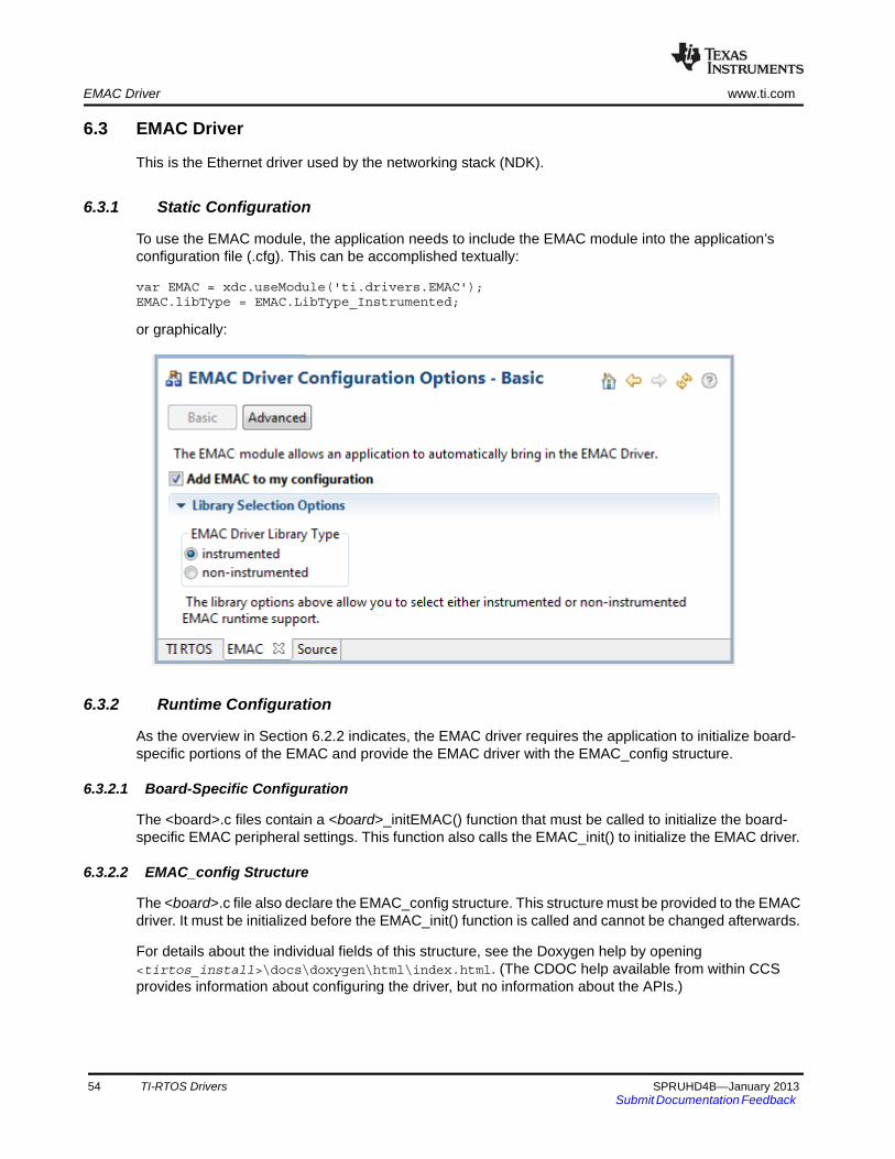
EMAC Driver www.ti.com
6.3 EMAC Driver
This is the Ethernet driver used by the networking stack (NDK).
6.3.1 Static Configuration
To use the EMAC module, the application needs to include the EMAC module into the application’s configuration file (.cfg). This can be accomplished textually:
var EMAC = xdc.useModule('ti.drivers.EMAC');EMAC.libType = EMAC.LibType_Instrumented;
or graphically:
6.3.2 Runtime Configuration
As the overview in Section 6.2.2 indicates, the EMAC driver requires the application to initialize board-specific portions of the EMAC and provide the EMAC driver with the EMAC_config structure.
6.3.2.1 Board-Specific Configuration
The <board>.c files contain a <board>_initEMAC() function that must be called to initialize the board-specific EMAC peripheral settings. This function also calls the EMAC_init() to initialize the EMAC driver.
6.3.2.2 EMAC_config Structure
The <board>.c file also declare the EMAC_config structure. This structure must be provided to the EMAC driver. It must be initialized before the EMAC_init() function is called and cannot be changed afterwards.
For details about the individual fields of this structure, see the Doxygen help by opening <tirtos_install>\docs\doxygen\html\index.html. (The CDOC help available from within CCS provides information about configuring the driver, but no information about the APIs.)
54 TI-RTOS Drivers SPRUHD4B—January 2013Submit Documentation Feedback
www.ti.com EMAC Driver
6.3.3 APIs
To use the EMAC module APIs, the EMAC header file should be included in an application as follows:
#include <ti/drivers/EMAC.h>
The following EMAC API is provided:
• EMAC_init() sets up the EMAC driver. This function must be called before the NDK stack thread is started.
For details, see the Doxygen help by opening <tirtos_install>\docs\doxygen\html\index.html. (The CDOC help available from within CCS provides information about configuring the driver, but no information about the APIs.)
See the NDK documentation for information about NDK APIs that can be used if the EMAC driver is enabled and initialized.
6.3.4 Usage
The EMAC driver is designed to be used by the NDK. The only function that must be called is the EMAC_init() function. This function must be called before BIOS_start() is called to ensure that the driver is initialized before the NDK starts.
6.3.5 Instrumentation
The EMAC driver logs the following actions using the Log_print() APIs provided by SYS/BIOS.
• EMAC driver setup success or failure.
• EMAC started or stopped.
• EMAC failed to receive or transmit a packet.
• EMAC successfully sent or received a packet.
• No packet could be allocated.
• Packet is too small for the received buffer.
Logging is controlled by the Diags_USER1 and Diags_USER2 masks. Diags_USER1 is for general information and Diags_USER2 is for more detailed information.
The EMAC driver provides the following ROV information through the EMAC module.
• Basic parameters:
— intVectId
— macAddr
— libType
• Statistics:
— rxCount
— rxDropped
— txSent
— txDropped
6.3.6 Examples
See Table 2-1 for a list of examples that use the EMAC driver.
SPRUHD4B—January 2013 TI-RTOS Drivers 55Submit Documentation Feedback
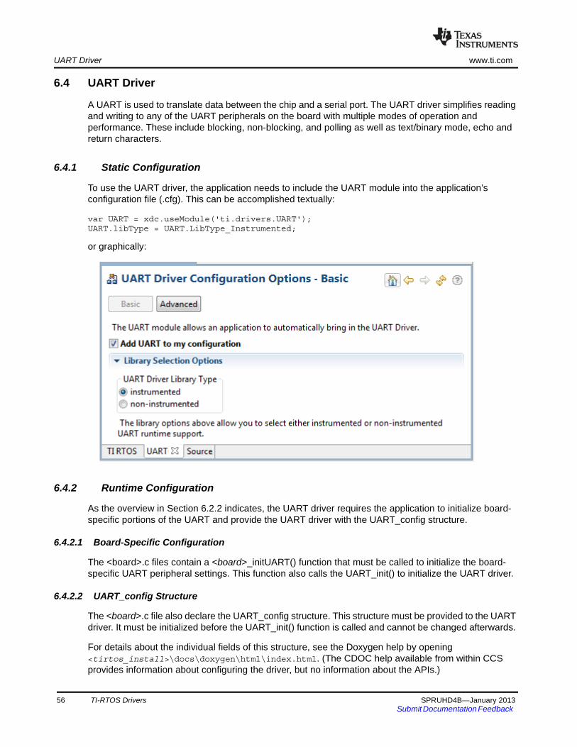
UART Driver www.ti.com
6.4 UART Driver
A UART is used to translate data between the chip and a serial port. The UART driver simplifies reading and writing to any of the UART peripherals on the board with multiple modes of operation and performance. These include blocking, non-blocking, and polling as well as text/binary mode, echo and return characters.
6.4.1 Static Configuration
To use the UART driver, the application needs to include the UART module into the application’s configuration file (.cfg). This can be accomplished textually:
var UART = xdc.useModule('ti.drivers.UART');UART.libType = UART.LibType_Instrumented;
or graphically:
6.4.2 Runtime Configuration
As the overview in Section 6.2.2 indicates, the UART driver requires the application to initialize board-specific portions of the UART and provide the UART driver with the UART_config structure.
6.4.2.1 Board-Specific Configuration
The <board>.c files contain a <board>_initUART() function that must be called to initialize the board-specific UART peripheral settings. This function also calls the UART_init() to initialize the UART driver.
6.4.2.2 UART_config Structure
The <board>.c file also declare the UART_config structure. This structure must be provided to the UART driver. It must be initialized before the UART_init() function is called and cannot be changed afterwards.
For details about the individual fields of this structure, see the Doxygen help by opening <tirtos_install>\docs\doxygen\html\index.html. (The CDOC help available from within CCS provides information about configuring the driver, but no information about the APIs.)
56 TI-RTOS Drivers SPRUHD4B—January 2013Submit Documentation Feedback
www.ti.com UART Driver
6.4.3 APIs
In order to use the UART module APIs, the UART header file should be included in an application as follows:
#include <ti/drivers/UART.h>
The following are the UART APIs:
• UART_init() initializes the UART module.
• UART_Params_init () initializes the UART_Params struct to its defaults for use in calls to UART_open().
• UART_open() opens a UART instance.
• UART_close() closes a UART instance.
• UART_write() writes a buffer of characters to the UART.
• UART_writePolling() writes a buffer to the UART in the context of the call and returns when finished.
• UART_writeCancel() cancels the current write action and unblocks or make the callback.
• UART_read() reads a buffer of characters to the UART.
• UART_readPolling() reads a buffer to the UART in the context of the call and returns when finished.
• UART_readCancel() cancels the current read action and unblocks or make the callback.
For details, see the Doxygen help by opening <tirtos_install>\docs\doxygen\html\index.html. (The CDOC help available from within CCS provides information about configuring the driver, but no information about the APIs.)
6.4.4 Usage
The UART driver does not configure any board peripherals or pins; this must be completed before any calls to the UART driver. The examples call Board_initUART(), which is mapped to a specific initUART() function for the board. The board-specific initUART() functions are provided in the board .c and .h files. For example, a sample UART setup is provided in the TMDXDOCKH52C1_initUART() function in the TMDXDOCKH52C1.c file. This function sets up the peripheral and pins used by UART0 for operation through the JTAG emulation connection (no extra hardware needed). The examples that use the UART driver call the Board_initUART() function from within main().
Once the peripherals are set up, the application must initialize the UART driver by calling UART_init(). If you add the provided board setup files to your project, you can call the Board_initUART() function within main().
Once the UART has been initialized, you can open UART instances. Only one UART index can be used at a time. If the index is already in use, the driver returns NULL and logs a warning. Opening a UART requires four steps:
1. Create and initialize a UART_Params structure.
2. Fill in the desired parameters.
3. Call UART_open() passing in the index of the UART from the configuration structure and Params.
4. Save the UART handle that is returned by UART_open(). This handle will be used to read and write to the UART you just created.
SPRUHD4B—January 2013 TI-RTOS Drivers 57Submit Documentation Feedback
UART Driver www.ti.com
For example:
UART_Handle uart;UART_Params uartParams;
Board_initUART(); // Calls UART_init for you
/* Create a UART with data processing off. */UART_Params_init(&uartParams);uartParams.writeDataMode = UART_DATA_BINARY;uartParams.readDataMode = UART_DATA_BINARY;uartParams.readReturnMode = UART_RETURN_FULL;uartParams.readEcho = UART_ECHO_OFF;
uart = UART_open(Board_UART, &uartParams);
Options for the writeMode and readMode parameters are UART_MODE_BLOCKING and UART_MODE_CALLBACK.
• UART_MODE_BLOCKING uses a semaphore to block while data is being sent. The context of the call must be a SYS/BIOS Task.
• UART_MODE_CALLBACK is non-blocking and will return while data is being sent in the context of a Hwi. The UART driver will call the callback function whenever a write or read finishes. In some cases, the action might have been canceled or received a newline, so the number of bytes sent/received are passed in. Your implementation of the callback function can use this information as needed.
Options for the writeDataMode and readDataMode parameters are UART_MODE_BINARY and UART_MODE_TEXT. If the data mode is UART_MODE_BINARY, the data is passed as is, without processing. If the data mode is UART_MODE_TEXT, write actions add a return before a newline character, and read actions replace a return with a newline. This effectively treats all device line endings as LF and all host PC line endings as CRLF.
Options for the readReturnMode parameter are UART_RETURN_FULL and UART_RETURN_NEWLINE. These determine when a read action unblocks or returns. If the return mode is UART_RETURN_FULL, the read action unblocks or returns when the buffer is full. If the return mode is UART_RETURN_NEWLINE, the read action unblocks or returns when a newline character is read.
Options for the readEcho parameter are UART_ECHO_OFF and UART_ECHO_ON. This parameter determines whether the driver echoes data back to the UART. When echo is turned on, each character that is read by the target is written back independent of any write operations. If data is received in the middle of a write and echo is turned on, the characters echoed back will be mixed in with the write data.
For details, see the Doxygen help by opening <tirtos_install>\docs\doxygen\html\index.html.
58 TI-RTOS Drivers SPRUHD4B—January 2013Submit Documentation Feedback
www.ti.com UART Driver
6.4.5 Instrumentation
The UART module provides instrumentation data both by making log calls and by sending data to the ROV tool in CCS.
6.4.5.1 Logging
The UART driver is instrumented with Log events that can be viewed with UIA and System Analyzer. Diags masks can be turned on and off to provide granularity to the information that is logged.
Use Diags_USER1 to see general Log events such as success opening a UART, number of bytes read or written, and warnings/errors during operation.
Use Diags_USER2 to see more granularity when debugging. Each character read or written will be logged as well as several other key events.
The UART driver makes log calls when the following actions occur:
• UART_open() success or failure
• UART_close() success
• UART interrupt triggered
• UART_write() finished
• Byte was written
• UART_read() finished
• Byte was read
• UART_write() finished, canceled or timed out
• UART_read() finished, canceled or timed out
6.4.5.2 ROV
The UART driver provides ROV information through the UART module. All UARTs that have been created are displayed by their base address and show the following information:
• Configuration parameters:
— Base Address
— Write Mode
— Read Mode
— Write Timeout
— Read Timeout
— Write Data Mode
— Read Data Mode
— Read Return mode
— Read Echo
• Write buffer: Contents of the write buffer
• Read buffer: Contents of the read buffer
6.4.6 Examples
See Table 2-1 for a list of examples that use the UART driver.
SPRUHD4B—January 2013 TI-RTOS Drivers 59Submit Documentation Feedback
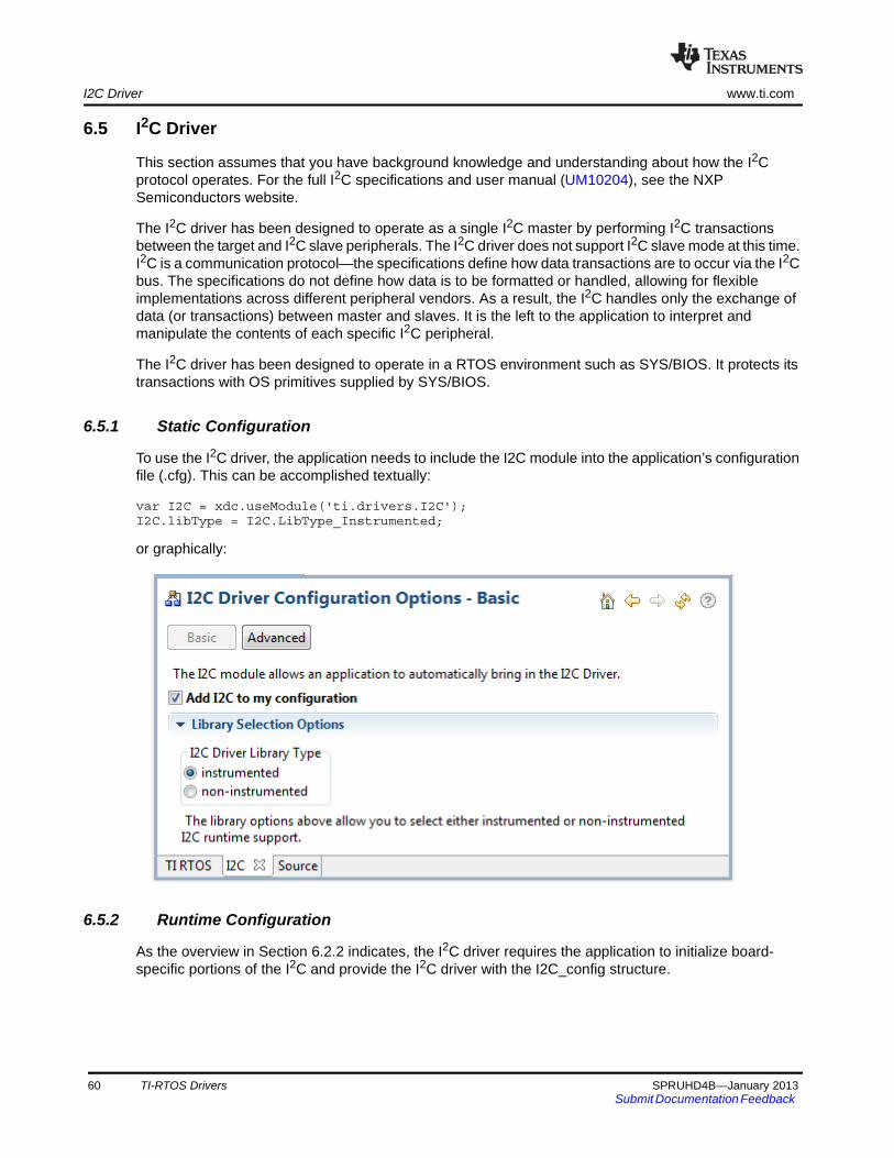
I2C Driver www.ti.com
6.5 I2C Driver
This section assumes that you have background knowledge and understanding about how the I2C protocol operates. For the full I2C specifications and user manual (UM10204), see the NXP Semiconductors website.
The I2C driver has been designed to operate as a single I2C master by performing I2C transactions between the target and I2C slave peripherals. The I2C driver does not support I2C slave mode at this time. I2C is a communication protocol—the specifications define how data transactions are to occur via the I2C bus. The specifications do not define how data is to be formatted or handled, allowing for flexible implementations across different peripheral vendors. As a result, the I2C handles only the exchange of data (or transactions) between master and slaves. It is the left to the application to interpret and manipulate the contents of each specific I2C peripheral.
The I2C driver has been designed to operate in a RTOS environment such as SYS/BIOS. It protects its transactions with OS primitives supplied by SYS/BIOS.
6.5.1 Static Configuration
To use the I2C driver, the application needs to include the I2C module into the application’s configuration file (.cfg). This can be accomplished textually:
var I2C = xdc.useModule('ti.drivers.I2C');I2C.libType = I2C.LibType_Instrumented;
or graphically:
6.5.2 Runtime Configuration
As the overview in Section 6.2.2 indicates, the I2C driver requires the application to initialize board-specific portions of the I2C and provide the I2C driver with the I2C_config structure.
60 TI-RTOS Drivers SPRUHD4B—January 2013Submit Documentation Feedback
www.ti.com I2C Driver
6.5.2.1 Board-Specific Configuration
The <board>.c files contain a <board>_initI2C() function that must be called to initialize the board-specific I2C peripheral settings. This function also calls the I2C_init() to initialize the I2C driver.
6.5.2.2 I2C_config Structure
The <board>.c file also declare the I2C_config structure. This structure must be provided to the I2C driver. It must be initialized before the I2C_init() function is called and cannot be changed afterwards.
For details about the individual fields of this structure, see the Doxygen help by opening <tirtos_install>\docs\doxygen\html\index.html. (The CDOC help available from within CCS provides information about configuring the driver, but no information about the APIs.)
6.5.3 APIs
In order to use the I2C module APIs, the I2C.h header file should be included in an application as follows:
#include <ti/drivers/I2C.h>
The following are the I2C APIs:
• I2C_init() initializes the I2C module.
• I2C_Params_init() initializes an I2C_Params data structure. It defaults to Blocking mode.
• I2C_open() initializes a given I2C peripheral.
• I2C_close() deinitializes a given I2C peripheral.
• I2C_transfer() handles the I2C transfer for SYS/BIOS.
The I2C_transfer() API can be called only from a Task context. It requires an I2C_Tramsaction structure that specifies the location of the write and read buffer, the number of bytes to be processed, and the I2C slave address of the device.
For details, see the Doxygen help by opening <tirtos_install>\docs\doxygen\html\index.html. (The CDOC help available from within CCS provides information about configuring the driver, but no information about the APIs.)
6.5.4 Usage
The application needs to supply the following structures in order to set up the framework for the driver:
• I2C_Params specifies the transfer mode and any callback function to be used. See Section 6.5.4.1.
• I2C_Transaction specifies details about a transfer to be performed. See Section 6.5.4.2.
• I2C_Callback specifies a function to be used if you are using callback mode. See Section 6.5.4.3.
SPRUHD4B—January 2013 TI-RTOS Drivers 61Submit Documentation Feedback
I2C Driver www.ti.com
6.5.4.1 I2C Parameters
The I2C_Params structure is used with the I2C_open() function call. If the transferMode is set to I2C_MODE_BLOCKING, the transferCallback argument is ignored. If transferMode is set to I2C_MODE_CALLBACK, a user-defined callback function must be supplied.
typedef struct I2C_Params { I2C_TransferMode transferMode; /* Blocking or Callback mode */ I2C_CallbackFxn transferCallbackFxn; /* Callback function pointer */} I2C_Params;
6.5.4.2 I2C Transaction
The I2C_Transaction structure is used to specify what type of I2C_transfer needs to take place.
typedef struct I2C_Transaction { UChar *writeBuf; /* Pointer to a buffer to be written */ UInt writeCount; /* Number of bytes to be written */
UChar *readBuf; /* Pointer to a buffer to be read */ UInt readCount; /* Number of bytes to be read */
UChar slaveAddress; /* Address of the I2C slave device */
UArg arg; /* User definable argument to the callback function */ Ptr nextPtr; /* Driver uses this for queuing in I2C_MODE_CALLBACK */} I2C_Transaction;
slaveAddress specifies the I2C slave address the I2C will communicate with. If writeCount is nonzero, I2C_transfer writes writeCount bytes from the buffer pointed by writeBuf. If readCount is nonzero, I2C_transfer reads readCount bytes into the buffer pointed by readBuf. If both writeCount and readCount are non-zero, the write operation always runs before the read operation.
The optional arg variable can only be used when the I2C driver has been opened in Callback mode. This variable is used to pass a user-defined value into the user-defined callback function.
nextPtr is used to maintain a linked-list of I2C_Transactions when the I2C driver has been opened in Callback mode. It must never be modified by the user application.
6.5.4.3 I2C Callback Function Prototype
This typedef defines the function prototype for the I2C driver’s callback function for Callback mode. When the I2C driver calls this function, it supplies the associated I2C_Handle, a pointer to the I2C_Transaction that just completed, and a Boolean value indicating the transfer result. The transfer result is the same as from the I2C_transfer() when operating in Blocking mode.
typedef Void (*I2C_Callback)(I2C_Handle, I2C_Transaction *, Bool);
62 TI-RTOS Drivers SPRUHD4B—January 2013Submit Documentation Feedback
www.ti.com I2C Driver
6.5.5 I2C Modes
The I2C driver supports two modes of operation, blocking and callback modes. The mode is determined when the I2C driver is opened using the I2C_Params data structure. If no I2C_Params structure is specified, the I2C driver defaults to blocking mode. Once opened, the only way to change the operation mode is to close and re-open the I2C instance with the new mode.
6.5.5.1 Opening in Blocking Mode
By default, the I2C driver operates in blocking mode. In blocking mode, a Task’s code execution is blocked until an I2C transaction has completed. This ensures that only one I2C transaction operates at a given time. Other tasks requesting I2C transactions while a transaction is currently taking place are also placed into a blocked state and are executed in the order in which they were received.
I2C_Handle i2c;UInt peripheralNum = 0; /* Such as I2C0 */I2C_Params i2cParams;
I2C_Params_init(&i2cParams);i2cParams.transferMode = I2C_MODE_BLOCKING;i2cParams.transferCallbackFxn = NULL;
i2c = I2C_open(peripheralNum, &i2cParams);if (i2c == NULL) { /* Error Initializing I2C */}
If no I2C_Params structure is passed to I2C_open(), default values are used. If the open call is successful, it returns a non-NULL value.
6.5.5.2 Opening in Callback Mode
In callback mode, an I2C transaction functions asynchronously, which means that it does not block a Task’s code execution. After an I2C transaction has been completed, the I2C driver calls a user-provided hook function. If an I2C transaction is requested while a transaction is currently taking place, the new transaction is placed onto a queue to be processed in the order in which it was received.
I2C_Handle i2c;UInt peripheralNum = 0; /* Such as I2C0 */I2C_Params i2cParams;
I2C_Params_init(&i2cParams);i2cParams.transferMode = I2C_MODE_CALLBACK;i2cParams.transferCallbackFxn = UserCallbackFxn;
i2c = I2C_open(peripheralNum, &i2cParams);if (i2c == NULL) { /* Error Initializing I2C */}
SPRUHD4B—January 2013 TI-RTOS Drivers 63Submit Documentation Feedback
I2C Driver www.ti.com
6.5.6 I2C Transactions
I2C can perform three types of transactions: Write, Read, and Write/Read. All I2C transactions are atomic operations with the slave peripheral. The I2C_transfer() function determines how many bytes need to be written and/or read to the designated I2C peripheral by reading the contents of an I2C_Transaction data structure.
The basic I2C_Transaction arguments include the slave peripheral’s I2C address, pointers to write and read buffers, and their associated byte counters. The I2C driver always writes the contents from the write buffer before it starts reading the specified number of bytes into the read buffer. If no data needs to be written or read, simply set the corresponding counter(s) to 0.
6.5.6.1 Write Transaction (Blocking Mode)
As the name implies, an I2C write transaction writes data to a specified I2C slave peripheral. The following code writes three bytes of data to a peripheral with a 7-bit slave address of 0x50.
I2C_Transaction i2cTransaction;UChar writeBuffer[3];UChar readBuffer[2];Bool transferOK;
i2cTransaction.slaveAddress = 0x50; /* 7-bit peripheral slave address */i2cTransaction.writeBuf = writeBuffer; /* Buffer to be written */i2cTransaction.writeCount = 3; /* Number of bytes to be written */i2cTransaction.readBuf = NULL; /* Buffer to be read */i2cTransaction.readCount = 0; /* Number of bytes to be read */
transferOK = I2C_transfer(i2c, &i2cTransaction); /* Perform I2C transfer */if (!transferOK) { /* I2C bus fault */}
6.5.6.2 Read Transaction (Blocking Mode)
A read transaction reads data from a specified I2C slave peripheral. The following code reads two bytes of data from a peripheral with a 7-bit slave address of 0x50.
I2C_Transaction i2cTransaction;UChar writeBuffer[3];UChar readBuffer[2];Bool transferOK;
i2cTransaction.slaveAddress = 0x50; /* 7-bit peripheral slave address */i2cTransaction.writeBuf = NULL; /* Buffer to be written */i2cTransaction.writeCount = 0; /* Number of bytes to be written */i2cTransaction.readBuf = readBuffer; /* Buffer to be read */i2cTransaction.readCount = 2; /* Number of bytes to be read */
transferOK = I2C_transfer(i2c, &i2cTransaction); /* Perform I2C transfer */if (!transferOK) { /* I2C bus fault */}
64 TI-RTOS Drivers SPRUHD4B—January 2013Submit Documentation Feedback

www.ti.com I2C Driver
6.5.6.3 Write/Read Transaction (Blocking Mode)
A write/read transaction first writes data to the specified peripheral. It then writes an I2C restart bit, which starts a read operation from the peripheral. This transaction is useful if the I2C peripheral has a pointer register that needs to be adjusted prior to reading from referenced data registers. The following code writes three bytes of data, sends a restart bit, and reads two bytes of data from a peripheral with the slave address of 0x50.
I2C_Transaction i2cTransaction;UChar writeBuffer[3];UChar readBuffer[2];Bool transferOK;
i2cTransaction.slaveAddress = 0x50; /* 7-bit peripheral slave address */i2cTransaction.writeBuf = writeBuffer; /* Buffer to be written */i2cTransaction.writeCount = 3; /* Number of bytes to be written */i2cTransaction.readBuf = readBuffer; /* Buffer to be read */i2cTransaction.readCount = 2; /* Number of bytes to be read */
transferOK = I2C_transfer(i2c, &i2cTransaction); /* Perform I2C transfer */if (!transferOK) { /* I2C bus fault */}
6.5.6.4 Write/Read Transaction (Callback Mode)
In callback mode, I2C transfers are non-blocking transactions. After an I2C transaction has completed, the I2C interrupt routine calls the user-provided callback function, which was passed in when the I2C driver was opened.
In addition to the standard I2C_Transaction arguments, an additional user-definable argument can be passed through to the callback function.
I2C_Transaction i2cTransaction;UChar writeBuffer[3];UChar readBuffer[2];Bool transferOK;
i2cTransaction.slaveAddress = 0x50; /* 7-bit peripheral slave address */i2cTransaction.writeBuf = writeBuffer; /* Buffer to be written */i2cTransaction.writeCount = 3; /* Number of bytes to be written */i2cTransaction.readBuf = readBuffer; /* Buffer to be read */i2cTransaction.readCount = 2; /* Number of bytes to be read */i2cTransaction.arg = someOptionalArgument;
/* I2C_transfers will always return successful */I2C_transfer(i2c, &i2cTransaction); /* Perform I2C transfer */
6.5.6.5 Queuing Multiple I2C Transactions
Using the callback mode, you can queue up multiple I2C transactions. However, each I2C transfer must use a unique instance of an I2C_Transaction data structure. In other words, it is not possible to reschedule an I2C_Transaction structure more than once. This also implies that the application must make sure the I2C_Transaction isn’t reused until it knows that the I2C_Transaction is available again.
SPRUHD4B—January 2013 TI-RTOS Drivers 65Submit Documentation Feedback
I2C Driver www.ti.com
The following code posts a Semaphore after the last I2C_Transaction has completed. This is done by passing the Semaphore’s handle through the I2C_Transaction data structure and evaluating it in the UserCallbackFxn.
Void UserCallbackFxn(I2C_Handle handle, I2C_Transaction *msg, Bool transfer) { if (msg->arg != NULL) { Semaphore_post((Semaphore_Handle)(msg->arg)); }}
Void taskfxn(arg0, arg1) { I2C_Transaction i2cTransaction0; I2C_Transaction i2cTransaction1; I2C_Transaction i2cTransaction2;
/* Set up i2cTransaction0/1/2 here */ ... i2cTransaction0.arg = NULL; i2cTransaction1.arg = NULL; i2cTransaction2.arg = semaphoreHandle;
/* Start and queue up the I2C transactions */ I2C_transfer(i2c, &i2cTransaction0); I2C_transfer(i2c, &i2cTransaction1); I2C_transfer(i2c, &i2cTransaction2);
/* Do other optional code here */ ...
/* Pend on the I2C transactions to have completed */ Semaphore_pend(semaphoreHandle);}
6.5.7 Instrumentation
The instrumented I2C library contains Log_print() statements that help to debug I2C transfers. The I2C driver logs the following actions using the Log_print() APIs provided by SYS/BIOS:
• I2C object opened or closed.
• Data written or read in the interrupt handler.
• Transfer results.
Logging is controlled by the Diags_USER1 and Diags_USER2 masks. Diags_USER1 is for general information and Diags_USER2 is for more detailed information. Diags_USER2 provides detailed logs intended to help determine where a problem may lie in the I2C transaction. This level of diagnostics will generate a significant amount of Log entries. Use this mask when granular transfer details are needed.
The I2C driver provides ROV information through the I2C module. All I2Cs that have been created are displayed by their base address and show the following information:
• Basic parameters:
— objectAddress: Address of the I2C object.
— baseAddress: Base address of the peripheral being used.
— mode: Current state of the I2C controller (Idle, Write, Read, or Error).
— slaveAddress: The I2C address of the peripheral with which the I2C controller communicates.
6.5.8 Examples
See Table 2-1 for a list of examples that use the I2C driver.
66 TI-RTOS Drivers SPRUHD4B—January 2013Submit Documentation Feedback
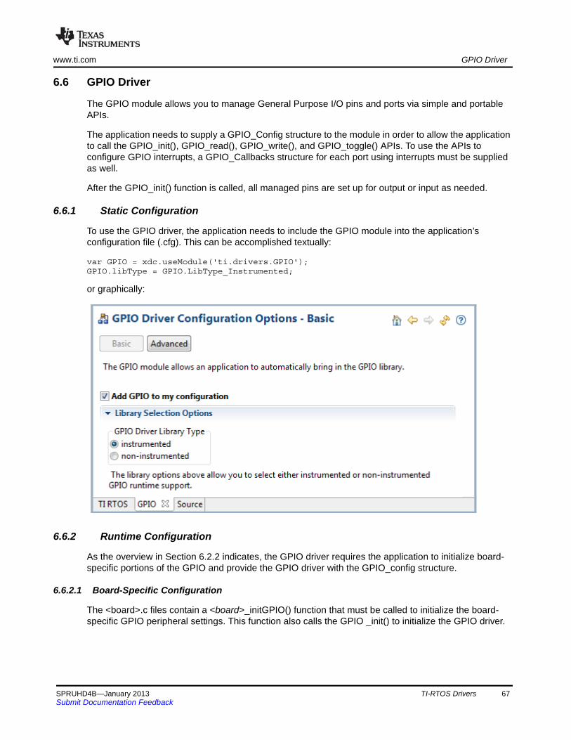
www.ti.com GPIO Driver
6.6 GPIO Driver
The GPIO module allows you to manage General Purpose I/O pins and ports via simple and portable APIs.
The application needs to supply a GPIO_Config structure to the module in order to allow the application to call the GPIO_init(), GPIO_read(), GPIO_write(), and GPIO_toggle() APIs. To use the APIs to configure GPIO interrupts, a GPIO_Callbacks structure for each port using interrupts must be supplied as well.
After the GPIO_init() function is called, all managed pins are set up for output or input as needed.
6.6.1 Static Configuration
To use the GPIO driver, the application needs to include the GPIO module into the application’s configuration file (.cfg). This can be accomplished textually:
var GPIO = xdc.useModule('ti.drivers.GPIO');GPIO.libType = GPIO.LibType_Instrumented;
or graphically:
6.6.2 Runtime Configuration
As the overview in Section 6.2.2 indicates, the GPIO driver requires the application to initialize board-specific portions of the GPIO and provide the GPIO driver with the GPIO_config structure.
6.6.2.1 Board-Specific Configuration
The <board>.c files contain a <board>_initGPIO() function that must be called to initialize the board-specific GPIO peripheral settings. This function also calls the GPIO _init() to initialize the GPIO driver.
SPRUHD4B—January 2013 TI-RTOS Drivers 67Submit Documentation Feedback
GPIO Driver www.ti.com
6.6.2.2 GPIO_config Structure
The <board>.c file also declare the GPIO_config structure. This structure must be provided to the GPIO driver. It must be initialized before the GPIO_init() function is called and cannot be changed afterwards.
For details about the individual fields of this structure, see the Doxygen help by opening <tirtos_install>\docs\doxygen\html\index.html. (The CDOC help available from within CCS provides information about configuring the driver, but no information about the APIs.)
6.6.2.3 GPIO_Callbacks Structure
To use GPIO interrupts, the <board>.c file also needs to declare a structure of type const GPIO_Callbacks for each port that contains a pin on which GPIO interrupts will be enabled. These structures must then be passed to the GPIO_setupCallbacks() function before interrupts can be enabled.
For details about the individual fields of this structure, see the Doxygen help by opening <tirtos_install>\docs\doxygen\html\index.html.
6.6.3 APIs
In order to use the GPIO module APIs, the GPIO header file should be included in an application as follows:
#include <ti/drivers/GPIO.h>
The following are the GPIO APIs:
• GPIO_init() sets up the configured GPIO ports and pins.
• GPIO_read() gets the current state of the specified GPIO pin.
• GPIO_write() sets the state of the specified GPIO pin to on or off.
• GPIO_toggle() toggles the state of the specified GPIO pin.
• GPIO_setupCallbacks() sets up the hardware interrupt and callback table for a GPIO port.
• GPIO_clearInt() clears the interrupt flag for the specified GPIO pin.
• GPIO_disableInt() disables interrupts on the specified GPIO pin.
• GPIO_enableInt() enables interrupts on the specified GPIO pin for the specified pin event.
For details, see the Doxygen help by opening <tirtos_install>\docs\doxygen\html\index.html. (The CDOC help available from within CCS provides information about configuring the GPIO driver, but no information about the APIs.)
6.6.4 Usage
Once the GPIO_init() function has been called, the other GPIO APIs functions can be called. For example, in the DK_LM3S9D96.c file, the LED is set to off as follows:
Void DK_LM3S9D96_initGPIO(Void){ ... GPIO_init(); GPIO_write(DK_LM3S9D96_LED1, DK_LM3S9D96_LED_OFF);}
68 TI-RTOS Drivers SPRUHD4B—January 2013Submit Documentation Feedback
www.ti.com GPIO Driver
For GPIO interrupts, once the GPIO_setupCallbacks() has been called for a port's GPIO_Callback structure, that port may be enabled for interrupts as follows:
GPIO_setupCallbacks(&DK_LM3S9D96_gpioPortJCallbacks);GPIO_enableInt(DK_LM3S9D96_BUTTON, GPIO_INT_FALLING);
Interrupts may be configured to occur on rising edges, falling edges, both edges, a high level, or a low level. When set as edge-triggered, the callback function must call GPIO_clearInt() to allow any further interrupts to occur.
6.6.5 Instrumentation
The GPIO driver logs the following actions using the Log_print() APIs provided by SYS/BIOS:
• GPIO pin read.
• GPIO pin toggled.
• GPIO pin written to.
• GPIO hardware interrupt created.
• GPIO interrupt flag cleared.
• GPIO interrupt enabled.
• GPIO interrupt disabled.
Logging is controlled by the Diags_USER1 and Diags_USER2 masks. Diags_USER1 is for general information and Diags_USER2 is for more detailed information.
The GPIO driver provides ROV information through the GPIO module. All GPIOs that have been created are displayed by their base address and show the following information:
• Basic parameters:
— baseAddress
— pins
— direction
— value
6.6.6 Examples
All the TI-RTOS examples (Section 2.2) use the GPIO driver. The GPIO Interrupt example demonstrates interrupt usage.
The GPIO_init() function is called in the board specific file (e.g. TMDXDOCKH52C1.c). A filled in GPIO_Config structure is used in the same file.
SPRUHD4B—January 2013 TI-RTOS Drivers 69Submit Documentation Feedback
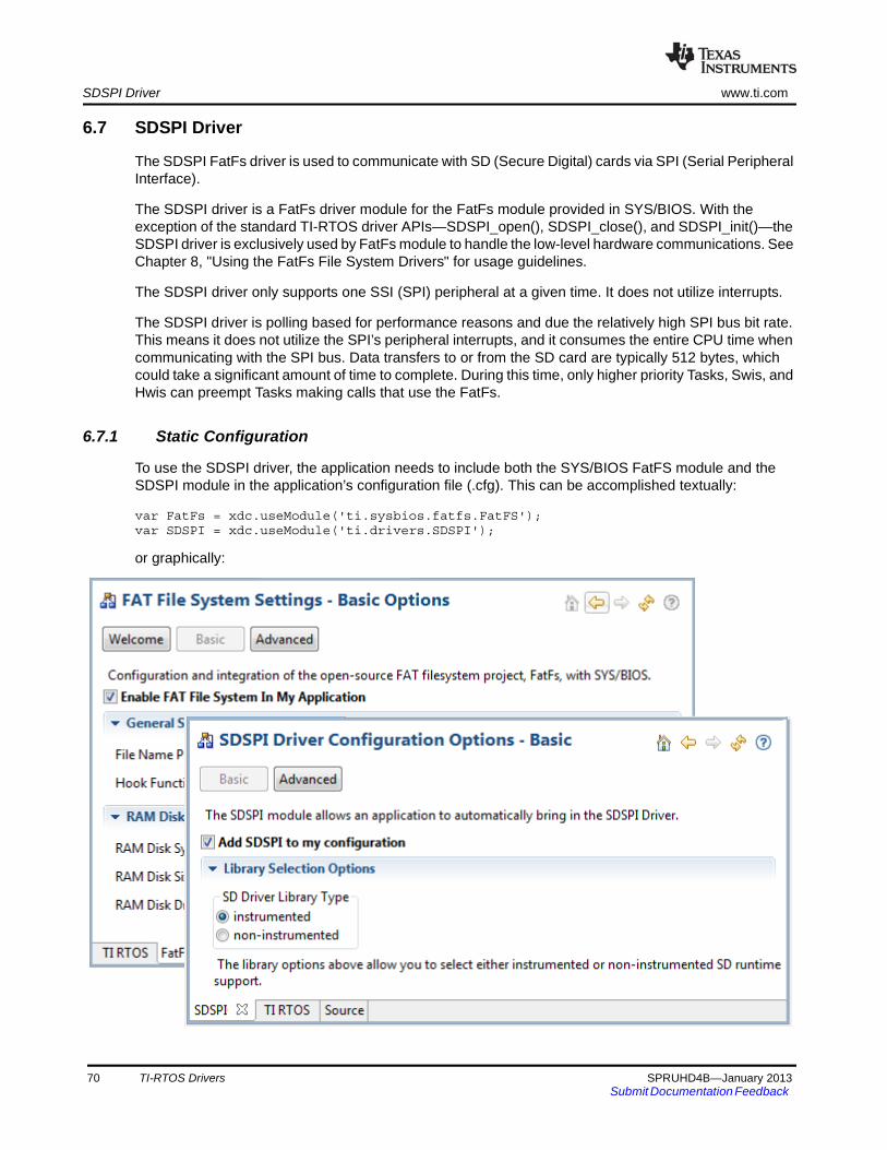
SDSPI Driver www.ti.com
6.7 SDSPI Driver
The SDSPI FatFs driver is used to communicate with SD (Secure Digital) cards via SPI (Serial Peripheral Interface).
The SDSPI driver is a FatFs driver module for the FatFs module provided in SYS/BIOS. With the exception of the standard TI-RTOS driver APIs—SDSPI_open(), SDSPI_close(), and SDSPI_init()—the SDSPI driver is exclusively used by FatFs module to handle the low-level hardware communications. See Chapter 8, "Using the FatFs File System Drivers" for usage guidelines.
The SDSPI driver only supports one SSI (SPI) peripheral at a given time. It does not utilize interrupts.
The SDSPI driver is polling based for performance reasons and due the relatively high SPI bus bit rate. This means it does not utilize the SPI’s peripheral interrupts, and it consumes the entire CPU time when communicating with the SPI bus. Data transfers to or from the SD card are typically 512 bytes, which could take a significant amount of time to complete. During this time, only higher priority Tasks, Swis, and Hwis can preempt Tasks making calls that use the FatFs.
6.7.1 Static Configuration
To use the SDSPI driver, the application needs to include both the SYS/BIOS FatFS module and the SDSPI module in the application’s configuration file (.cfg). This can be accomplished textually:
var FatFs = xdc.useModule('ti.sysbios.fatfs.FatFS');var SDSPI = xdc.useModule('ti.drivers.SDSPI');
or graphically:
70 TI-RTOS Drivers SPRUHD4B—January 2013Submit Documentation Feedback

www.ti.com SDSPI Driver
6.7.2 Runtime Configuration
As the overview in Section 6.2.2 indicates, the SDSPI driver requires the application to initialize board-specific portions of the SDSPI and provide the SDSPI driver with the SDSPI_config structure.
6.7.2.1 Board-Specific Configuration
The <board>.c files contain a <board>_initSDSPI() function that must be called to initialize the board-specific SDSPI peripheral settings. This function also calls the SDSPI_init() to initialize the SDSPI driver.
6.7.2.2 SDSPI_config Structure
The <board>.c file also declare the SDSPI_config structure. This structure must be provided to the SDSPI driver. It must be initialized before the SDSPI_init() function is called and cannot be changed afterwards.
For details about the individual fields of this structure, see the Doxygen help by opening <tirtos_install>\docs\doxygen\html\index.html. (The CDOC help available from within CCS provides information about configuring the driver, but no information about the APIs.)
6.7.3 APIs
In order to use the SDSPI module APIs, include the SDSPI header file in an application as follows:
#include <ti/drivers/SDSPI.h>
The following are the SDSPI APIs:
• SDSPI_init() sets up the specified SPI and GPIO pins for operation.
• SDSPI_open() registers the SDSPI driver with FatFs and mounts the FatFs file system.
• SDSPI_close() unmounts the file system and unregisters the SDSPI driver from FatFs.
• SDSPI_Params_init() initializes a SDSPI_Params structure to its defaults.
For details, see the Doxygen help by opening <tirtos_install>\docs\doxygen\html\index.html. (The CDOC help provides information about configuring the driver, but no information about the APIs.)
6.7.4 Usage
Before any FatFs or C I/O APIs can be used, the application needs to open the SDSPI driver. The SDSPI_open() function ensures that the SDSPI disk functions get registered with the FatFs module that subsequently mounts the FatFs volume to that particular drive.
SDSPI_Handle sdspiHandle;SDSPI_Params sdspiParams;UInt peripheralNum = 0; /* Such as SPI0 */UInt FatFsDriveNum = 0;
SDSPI_Params_init(&sdspiParams);sdspiHandle = SDSPI_open(peripheralNum, FatFsDriveNum, &sdspiParams);if (sdspiHandle == NULL) { System_abort("Error opening SDSPI\n");}
Similarly, the SDSPI_close() function unmounts the FatFs volume and unregisters SDSPI disk functions.
SDSPI_close(sdspiHandle);
SPRUHD4B—January 2013 TI-RTOS Drivers 71Submit Documentation Feedback
SDSPI Driver www.ti.com
Note that it is up to the application to ensure the no FatFs or C I/O APIs are called before the SDSPI driver has been opened or after the SDSPI driver has been closed.
6.7.5 Instrumentation
The SDSPI driver does not make any Log calls.
The SDSPI driver provides the following information to the ROV tool through the SDSPI module.
• Basic parameters:
— baseAddress. Base address of the peripheral being used to access the SD card.
— CardType. The SD card type detected during the disk initialization phase. The card type can be Multi-media Memory Card (MMC), Standard SDCard (SDSC), High Capacity SDCard (SDHC), or NOCARD for an unrecognized card.
— diskState. Current status of the SD card.
6.7.6 Examples
See Table 2-1 for a list of examples that use the SDSPI driver.
72 TI-RTOS Drivers SPRUHD4B—January 2013Submit Documentation Feedback
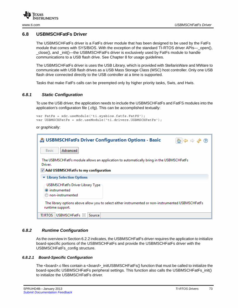
www.ti.com USBMSCHFatFs Driver
6.8 USBMSCHFatFs Driver
The USBMSCHFatFs driver is a FatFs driver module that has been designed to be used by the FatFs module that comes with SYS/BIOS. With the exception of the standard TI-RTOS driver APIs—_open(), _close(), and _init()—the USBMSCHFatFs driver is exclusively used by FatFs module to handle communications to a USB flash drive. See Chapter 8 for usage guidelines.
The USBMSCHFatFs driver is uses the USB Library, which is provided with StellarisWare and MWare to communicate with USB flash drives as a USB Mass Storage Class (MSC) host controller. Only one USB flash drive connected directly to the USB controller at a time is supported.
Tasks that make FatFs calls can be preempted only by higher priority tasks, Swis, and Hwis.
6.8.1 Static Configuration
To use the USB driver, the application needs to include the USBMSCHFatFs and FatFS modules into the application’s configuration file (.cfg). This can be accomplished textually:
var FatFs = xdc.useModule('ti.sysbios.fatfs.FatFS');var USBMSCHFatFs = xdc.useModule('ti.drivers.USBMSCHFatFs');
or graphically:
6.8.2 Runtime Configuration
As the overview in Section 6.2.2 indicates, the USBMSCHFatFs driver requires the application to initialize board-specific portions of the USBMSCHFatFs and provide the USBMSCHFatFs driver with the USBMSCHFatFs_config structure.
6.8.2.1 Board-Specific Configuration
The <board>.c files contain a <board>_initUSBMSCHFatFs() function that must be called to initialize the board-specific USBMSCHFatFs peripheral settings. This function also calls the USBMSCHFatFs_init() to initialize the USBMSCHFatFs driver.
SPRUHD4B—January 2013 TI-RTOS Drivers 73Submit Documentation Feedback
USBMSCHFatFs Driver www.ti.com
6.8.2.2 USBMSCHFatFs_config Structure
The <board>.c file also declare the USBMSCHFatFs_config structure. This structure must be provided to the USBMSCHFatFs driver. It must be initialized before the USBMSCHFatFs_init() function is called and cannot be changed afterwards.
For details about the individual fields of this structure, see the Doxygen help by opening <tirtos_install>\docs\doxygen\html\index.html. (The CDOC help available from within CCS provides information about configuring the driver, but no information about the APIs.)
6.8.3 APIs
In order to use the USBMSCHFatFs module APIs, the USBMSCHFatFs header file should be included in an application as follows:
#include <ti/drivers/USBMSCHFatFs.h>
The following are the USBMSCHFatFs APIs:
• USBMSCHFatFs_init() initializes the USBMSCHFatFs data objects pointed by the driver’s config structure.
• USBMSCHFatFs_open() registers the USBMSCHFatFs driver with FatFs and mounts the FatFs file system.
• USBMSCHFatFs_close() unmounts the file system and unregisters the USBMSCHFatFs driver from FatFs.
• USBMSCHFatFs_Params_init() initializes a USBMSCHFatFs_Params structure to its defaults.
• USBMSCHFatFs_waitForConnect() blocks a task’s execution until a USB flash drive was detected.
For details, see the Doxygen help by opening <tirtos_install>\docs\doxygen\html\index.html. (The CDOC help available from within CCS provides information about configuring the driver, but no information about the APIs.)
6.8.4 Usage
Before the FatFs APIs can be used, the application needs to open the USBMSCHFatFs driver. The USBMSCHFatFs_open() function ensures that the USBMSCHFatFs disk functions get registered with the FatFs module. The FatFs module then mounts the FatFs volume to that particular drive.
Internally, opening the USBMSCHFatFs driver creates a high-priority Task to service the USB library. The default priority for this task is 15 and runs every 10 SYS/BIOS system ticks. You can change the priority of this task using the USBMSCHFatFs_Params structure.
USBMSCHFatFs_Handle usbmschfatfsHandle;USBMSCHFatFs_Params usbmschfatfsParams;UInt peripheralNum = 0; /* Such as USB0 */UInt FatFsDriveNum = 0;
USBMSCHFatFs_Params_init(&usbmschfatfsParams);usbmschfatfsHandle = USBMSCHFatFs_open(peripheralNum, FatFsDriveNum, &usbmschfatfsParams);if (usbmschfatfsHandle == NULL) { System_abort("Error opening USBMSCHFatFs\n");}
74 TI-RTOS Drivers SPRUHD4B—January 2013Submit Documentation Feedback
www.ti.com USBMSCHFatFs Driver
Similarly, the close() function unmounts the FatFs volume and unregisters the USBMSCHFatFs disk functions.
USBMSCHFatFs_close(usbmschfatfsHandle);
The application must ensure the no FatFs or C I/O APIs are called before the USBMSCHFatFs driver has been opened or after the USBMSCHFatFs driver has been closed.
Although the USBMSCHFatFs driver may have been opened, there is a possibility that a USB flash drive may not be present. To ensure that a Task will wait for a USB drive to be present, the USBMSCHFatFs driver provides the USBMSCHFatFs_waitForConnect() function to block the Task’s execution until a USB flash drive is detected.
6.8.5 Instrumentation
The USBMSCHFatFs driver logs the following actions using the Log_print() APIs provided by SYS/BIOS:
• USB MSC device connected or disconnected.
• USB drive initialized.
• USB drive read or failed to read.
• USB drive written to or failed to write.
• USB status OK or error.
Logging is controlled by the Diags_USER1 and Diags_USER2 masks. Diags_USER1 is for general information and Diags_USER2 is for more detailed information.
The USBMSCHFatFs driver does not provide any information to the ROV tool.
6.8.6 Examples
See Table 2-1 for a list of examples that use the USBMSCHFatFs driver.
SPRUHD4B—January 2013 TI-RTOS Drivers 75Submit Documentation Feedback
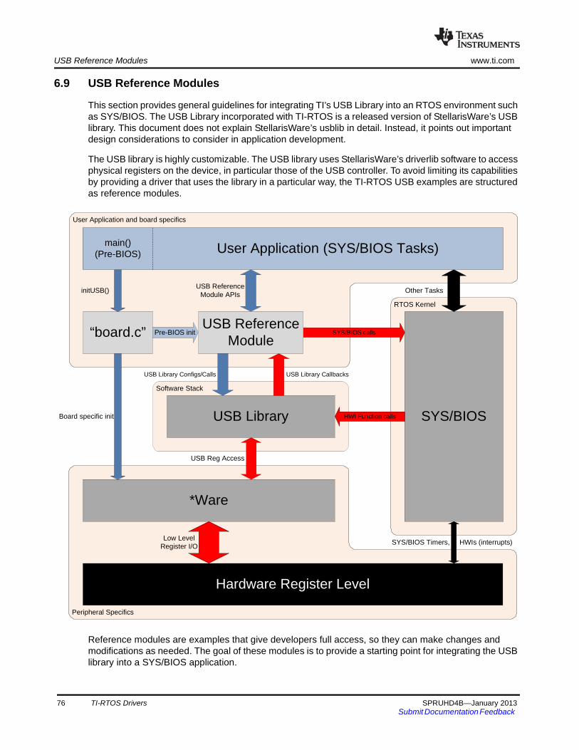
USB Reference Modules www.ti.com
6.9 USB Reference Modules
This section provides general guidelines for integrating TI’s USB Library into an RTOS environment such as SYS/BIOS. The USB Library incorporated with TI-RTOS is a released version of StellarisWare’s USB library. This document does not explain StellarisWare’s usblib in detail. Instead, it points out important design considerations to consider in application development.
The USB library is highly customizable. The USB library uses StellarisWare’s driverlib software to access physical registers on the device, in particular those of the USB controller. To avoid limiting its capabilities by providing a driver that uses the library in a particular way, the TI-RTOS USB examples are structured as reference modules.
Reference modules are examples that give developers full access, so they can make changes and modifications as needed. The goal of these modules is to provide a starting point for integrating the USB library into a SYS/BIOS application.
User Application and board specifics
Software Stack
RTOS Kernel
SYS/BIOS calls
Peripheral Specifics
*Ware
SYS/BIOSUSB Library
“board.c”
Other Tasks
Board specific init
SYS/BIOS Timers, HWIs (interrupts)Low Level
Register I/O
USB Reference Module APIs
Hardware Register Level
Pre-BIOS init
USB Reg Access
HWI Function calls
initUSB()
USB ReferenceModule
User Application (SYS/BIOS Tasks)main()(Pre-BIOS)
USB Library CallbacksUSB Library Configs/Calls
76 TI-RTOS Drivers SPRUHD4B—January 2013Submit Documentation Feedback
www.ti.com USB Reference Modules
6.9.1 USB Reference Modules in TI-RTOS
Each module handles the following items:
• Initializes the USB library and provides the necessary memory allocation, data structures, and callback functions.
• Installs the associated USB interrupt service routine provided with the USB library as a SYS/BIOS HWI object.
• Provides a set of thread-safe APIs that can be used by one or more SYS/BIOS Tasks.
• Creates the necessary RTOS primitives to protect critical regions and allows Tasks to block when possible.
• For USB Host examples, it also creates separate Task that services the USB stack.
6.9.1.1 Reference module APIs
All of the reference modules include the following APIs. Each module also includes specific APIs unique to that particular module.
• Module_init() – This function initializes the USB library, creates RTOS primitives, and installs the proper interrupt handler. For the host examples, it also creates a Task to service the USB controller.
• Module_waitForConnect() – This function causes a Task to block when the USB controller is not connected.
6.9.1.2 USB Examples
TI-RTOS has six USB reference examples and one USB FatFs (MSC host) driver. (On-the-go (OTG) examples are not available with TI-RTOS.) The reference examples and driver are as follows:
• HID Host Keyboard – Allows a USB keyboard to be connected to the target. Keys pressed on the keyboard are registered on the target.
• HID Host Mouse – Allows a USB mouse to be connected to the target. The target registers the overall mouse movements and button presses.
• HID Device Keyboard – Causes the target to emulate a USB keyboard. When connected to a workstation, the target functions as another USB keyboard.
• HID Device Mouse – Causes the target to emulate a USB mouse when connected to a workstation.
• CDC Device (Serial) – The target enumerates a virtual serial COM port on a workstation. This method of communication is commonly used to replace older RS-232 serial adapters.
• HID Mouse and CDC composite device – This example enumerates two different USB devices—a HID mouse and a CDC serial virtual COM port.
• MSC Host (Mass Storage) – This example uses an actual driver instead of a USB reference module. This driver is modeled after the FatFs driver APIs. This driver allows external mass storage devices such a USB flash drives to be used with FatFs.
SPRUHD4B—January 2013 TI-RTOS Drivers 77Submit Documentation Feedback
USB Reference Modules www.ti.com
6.9.2 USB Reference Module Design Guidelines
This section discusses the structure of the USB reference examples.
Design considerations involved in creating these examples included:
• USB Device Specifics. Each module contains memory, data structures, and a callback function needed to function properly with the USB library. In device mode, the reference module also includes device descriptors that need to be sent to the USB host controller upon request.
• OS Primitives. OS primitives that implement gates, mutexes, and semaphores are used to guard data against race-conditions and reduce unwanted processing time by blocking Tasks when needed.
• Memory Allocation. The USB library is designed so that the user application performs all required memory allocation. In a multi-tasked / preempted environment such as SYS/BIOS, it is necessary to protect this memory from other threads. In the reference examples, this is done using the GateMutex module.
• Callback Functions. The USB library requires user-provided callback functions to notify the application of events. The USB reference modules provide a set of callback functions to notify the module of status updates. The callback functions update an internal state variable and in some cases post Semaphores to unblock pending Tasks.
• Interrupts. Some of the events that trigger callback functions are hardware notifications about the device being connected or disconnected from a USB host controller.
6.9.2.1 Device Mode
USB Device mode examples are rather straightforward. In device mode, the job of the USB library is to respond to the USB host controller with its current state/status. By making USB library API calls in device mode, the example updates information stored in the USB controller’s endpoints. This information can be queried by the USB host controller.
6.9.2.2 Host Mode
All USB Host mode examples install a high-priority Task to service the USB controller. This Task calls the USB library's HCDMain() function, which maintains the USB library's internal state machine. This state machine performs actions that include enumerating devices and performing callbacks as described in the Stellaris USB library documentation.
To protect the USB library from race conditions between the service Task and other Tasks making calls to the module’s APIs, a GateMutex is used.
6.9.2.3 On-The-Go Mode
OTG is not currently used by a USB reference module.
78 TI-RTOS Drivers SPRUHD4B—January 2013Submit Documentation Feedback
www.ti.com USB Device and Host Modules
6.10 USB Device and Host Modules
See the USB examples for reference modules that provide support for the Human Interface Device (HID) class (mouse and keyboard) and the Communications Device Class (CDC). This code is provided as part of the examples, not as a separate driver.
The code for the HID keyboard device is in USBKBD.c in the USB Keyboard Device example (Section 2.2.13). This file provides the following functions:
• USBKBD_init()
• USBKBD_waitForConnect()
• USBKBD_getState()
• USBKBD_putChar()
• USBKBD_putString()
The code for the HID keyboard host is in USBKBH.c in the USB Keyboard Host example (Section 2.2.14). This file provides the following functions:
• USBKBH_init()
• USBKBH_waitForConnect()
• USBKBH_getState()
• USBKBH_setState()
• USBKBH_putChar()
• USBKBH_putString()
The code for the HID mouse device is in USBMD.c in the USB Mouse Device example (Section 2.2.15). This file provides the following functions:
• USBMD_init()
• USBMD_waitForConnect()
• USBMD_setState()
The code for the HID mouse host is in USBMH.c in the USB Mouse Host example (Section 2.2.16). This file provides the following functions:
• USBMH_init()
• USBMH_waitForConnect()
• USBMH_getState()
The code for the CDC device is in USBCDCD.c in the Demo example (Section 2.2.2), the USB Serial Device example (Section 2.2.17), and the UART Console example (Section 2.2.9). This file provides the following functions:
• USBCDCD_init()
• USBCDCD_waitForConnect()
• USBCDCD_sendData()
• USBCDCD_receiveData()
SPRUHD4B—January 2013 TI-RTOS Drivers 79Submit Documentation Feedback
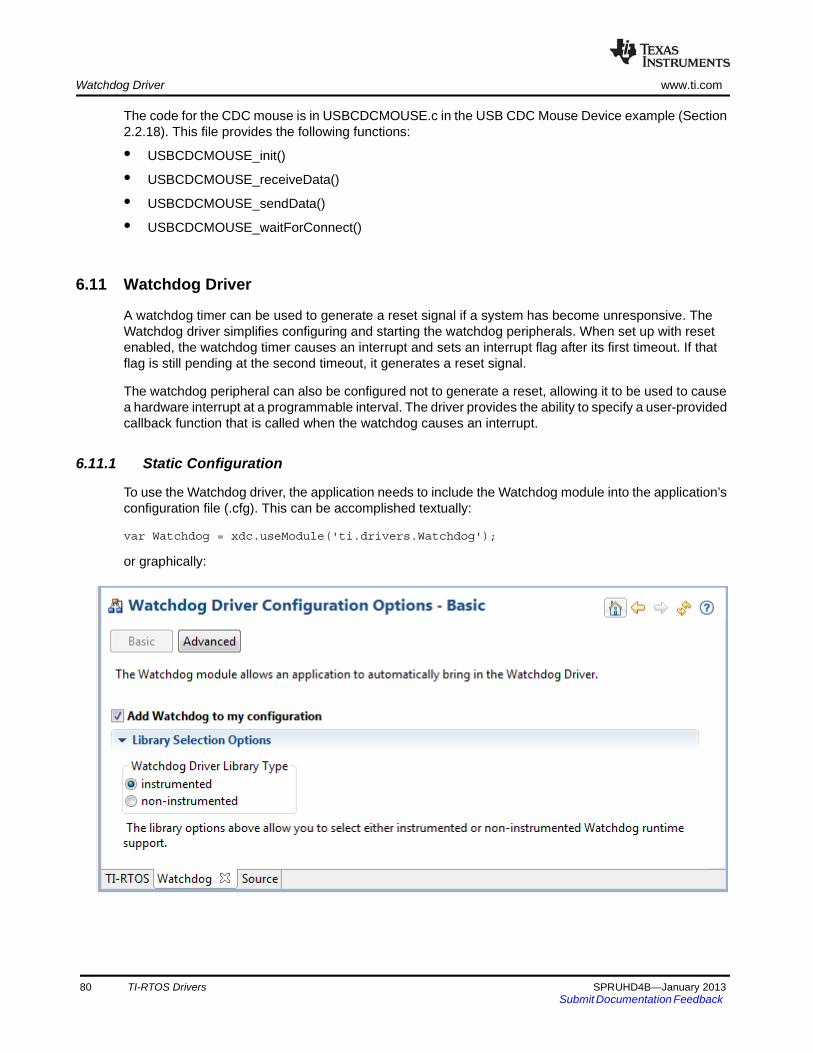
Watchdog Driver www.ti.com
The code for the CDC mouse is in USBCDCMOUSE.c in the USB CDC Mouse Device example (Section 2.2.18). This file provides the following functions:
• USBCDCMOUSE_init()
• USBCDCMOUSE_receiveData()
• USBCDCMOUSE_sendData()
• USBCDCMOUSE_waitForConnect()
6.11 Watchdog Driver
A watchdog timer can be used to generate a reset signal if a system has become unresponsive. The Watchdog driver simplifies configuring and starting the watchdog peripherals. When set up with reset enabled, the watchdog timer causes an interrupt and sets an interrupt flag after its first timeout. If that flag is still pending at the second timeout, it generates a reset signal.
The watchdog peripheral can also be configured not to generate a reset, allowing it to be used to cause a hardware interrupt at a programmable interval. The driver provides the ability to specify a user-provided callback function that is called when the watchdog causes an interrupt.
6.11.1 Static Configuration
To use the Watchdog driver, the application needs to include the Watchdog module into the application’s configuration file (.cfg). This can be accomplished textually:
var Watchdog = xdc.useModule('ti.drivers.Watchdog');
or graphically:
80 TI-RTOS Drivers SPRUHD4B—January 2013Submit Documentation Feedback
www.ti.com Watchdog Driver
6.11.2 APIs
In order to use the Watchdog module APIs, the Watchdog header file should be included in an application as follows:
#include <ti/drivers/Watchdog.h>
The following are the Watchdog APIs:
• Watchdog_init() initializes the Watchdog module.
• Watchdog_Params_init() initializes the Watchdog_Params struct to its defaults for use in calls to Watchdog_open().
• Watchdog_open() opens a Watchdog instance.
• Watchdog_clear() clears the Watchdog interrupt flag.
• Watchdog_setReload() sets the Watchdog reload value.
For details, see the Doxygen help by opening <tirtos_install>\docs\doxygen\html\index.html. (The CDOC help available from within CCS provides information about configuring the driver, but no information about the APIs.)
6.11.3 Usage
The Watchdog driver does not configure the board peripherals. This must be done before any calls to the Watchdog driver. The examples include board-specific initWatchdog() functions in the board .c and .h files. Once the watchdog has been initialized, a Watchdog object can be created through the following steps:
1. Create and initialize the Watchdog_Params structure.
2. Assign desired values to parameters.
3. Call Watchdog_open().
4. Save the Watchdog_Handle returned by Watchdog_open(). This will be used to interact with the Watchdog object just created.
To have a user-defined function run at the hardware interrupt caused by a watchdog timer timeout, a Void-type function that takes a Watchdog_Handle cast as a UArg as an argument must be defined as shown:
typedef Void (*Watchdog_Callback)(UArg);
SPRUHD4B—January 2013 TI-RTOS Drivers 81Submit Documentation Feedback
Watchdog Driver www.ti.com
An example of the Watchdog creation process that uses a callback function:
Watchdog_Params params;Watchdog_Handle watchdog;
Board_initWatchdog();
/* Create and enable a Watchdog with resets enabled */Watchdog_Params_init(¶ms);params.resetMode = Watchdog_RESET_ON;params.callbackFxn = UserCallbackFxn;
watchdog = Watchdog_open(Board_WATCHDOG, RELOAD_VALUE, ¶ms);if (watchdog == NULL) { /* Error initializing Watchdog */}
If no Watchdog_Params structure is passed to Watchdog_open(), the default values are used. By default, the Watchdog driver has resets turned on and no callback function specified.
Options for the resetMode parameter are Watchdog_RESET_ON and Watchdog_RESET_OFF. The latter allows the Watchdog to be used like another timer interrupt. When resetMode is Watchdog_RESET_ON, it is up to the application to call Watchdog_clear() to clear the Watchdog interrupt flag to prevent a reset. Watchdog_clear() can be called at any time.
6.11.4 Instrumentation
The Watchdog module provides instrumentation data by both making log calls and by sending data to the ROV tool in CCS.
The Watchdog driver logs the following actions using the Log_print() APIs provided by SYS/BIOS.
• Watchdog_open() success or failure
• Reload value changed
In the ROV tool, all Watchdogs that have been created are displayed by their base address and show the following information.
• Base address
• Interrupt vector ID number
• Current value in the watchdog timer
• Reload value
• Reset mode (On, Off, or Error)
6.11.5 Examples
See Table 2-1 for a list of examples that use the Watchdog driver.
82 TI-RTOS Drivers SPRUHD4B—January 2013Submit Documentation Feedback
Chapter 7SPRUHD4B—January 2013
TI-RTOS Utilities
This chapter provides information about utilities provided by TI-RTOS.
7.1 Overview
Utilities for use with TI-RTOS are provided in the <tirtos_install>\packages\ti\tirtos\utils directory. This chapter describes such modules.
7.2 SysFlex Module
The SysFlex module plugs into the xdc.runtime.System module. It is one of the three System Support implementations that are supplied by TI-RTOS and its XDCtools component. See “Using CCS Debugging Tools” on page 40 for comparisons of SysFlex with the other System Support implementations.
You can write your own System Support implementations and plug them into System module, however this is non-trivial. The SysFlex module provided by TI-RTOS simplifies this process and makes it more flexible (thus the name). SysFlex has five C function pointers you can configure. The five functions are:
• abortFxn. Last function called in System_abort(). This function should return and let System_abort() call abort.
• exitFxn. Last function called in System_exit(). This function should return and let System_exit() call exit.
• flushFxn. Last function called in System_flush(). This function should return.
• putchFxn. Called as part of any System function that outputs characters. The readyFxn is called before the putchFxn is called. putchFxn is only called if readyFxn returns TRUE.
• readyFxn. Called at various times within the System module. If the putchFxn is not ready to be called (for example, you have not initialized UART yet), the readyFxn should return FALSE. Once the putchFxn can be called, the readyFxn should return TRUE. If no readyFxn is supplied, TRUE is assumed.
7.1 Overview . . . . . . . . . . . . . . . . . . . . . . . . . . . . . . . . . . . . . . . . . . . . . . . . 83
7.2 SysFlex Module . . . . . . . . . . . . . . . . . . . . . . . . . . . . . . . . . . . . . . . . . . . 83
7.3 UART Example Implementation . . . . . . . . . . . . . . . . . . . . . . . . . . . . . . 85
Topic Page
SPRUHD4B—January 2013 TI-RTOS Utilities 83Submit Documentation Feedback
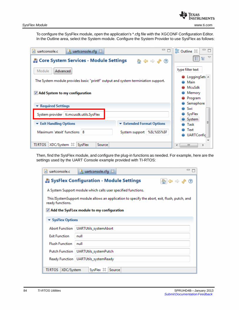
SysFlex Module www.ti.com
To configure the SysFlex module, open the application’s *.cfg file with the XGCONF Configuration Editor. In the Outline area, select the System module. Configure the System Provider to use SysFlex as follows:
Then, find the SysFlex module, and configure the plug-in functions as needed. For example, here are the settings used by the UART Console example provided with TI-RTOS:
84 TI-RTOS Utilities SPRUHD4B—January 2013Submit Documentation Feedback

www.ti.com UART Example Implementation
After checking the box to enable the module, specify functions to run for each state that may occur. The default for all the SysFlex functions is "null".
The SysFlex module is an implementation of the ISystemSupport module. In other words, it plugs into the xdc.runtime.System module. When System_printf() is called, the SysFlex putch function is called.
The UARTUtils.c file in the UART Console example provides the functions shown in the previous figure for use as the Abort function (UARTUtils_systemAbort), the Putch function (UARTUtils_systemPutch), and the Ready function (UARTUtils_systemReady). In these functions, the SysFlex System Support module is configured to use UART0. In the UARTUtils_systemPutch() function, the character is sent out to the UART via the UART_writePolling() API.
See the TI-RTOS online help in CCS for more details about the SysFlex module.
7.3 UART Example Implementation
The UARTUtils.c file provides an example implementation using a UART. Three of the SysFlex functions are initialized (the others default to NULL) in the uartconsole.cfg file. The configuration source is as follows. These statements create the same configuration as the graphical settings shown in Section 7.2:
var System = xdc.useModule('xdc.runtime.System');var SysFlex = xdc.useModule('ti.tirtos.utils.SysFlex');SysFlex.abortFxn = "&UARTUtils_systemAbort";SysFlex.putchFxn = "&UARTUtils_systemPutch";SysFlex.readyFxn = "&UARTUtils_systemReady";System.SupportProxy = SysFlex;
In uartconsole.c, main() does the following
1. Calls the board-specific setupUART() function to initialize the UART peripheral.
2. Calls UARTUtils_systemInit() as follows to initialize the UART 0 software. After the UARTUtils_systemInit function is called, any System_printf output will be directed to UART 0.
/* Send System_printf to the UART 0 also */ UARTUtils_systemInit(0);
SPRUHD4B—January 2013 TI-RTOS Utilities 85Submit Documentation Feedback

Chapter 8SPRUHD4B—January 2013
Using the FatFs File System Drivers
This chapter provides an overview of FatFs and discusses how FatFs is interconnected and used with TI-RTOS and SYS/BIOS.
8.1 Overview
FatFs is a free, 3rd party, generic File Allocation Table (FAT) file system module designed for embedded systems. The module is available for download at http://elm-chan.org/fsw/ff/00index_e.html along with API documentation explaining how to use the module. Details about the FatFs API are not discussed here. Instead, this section gives a high-level explanation about how it is integrated with TI-RTOS and SYS/BIOS.
The FatFs drivers provided by TI-RTOS enable you to store data on removable storage media such as Secure Digital (SD) cards and USB flash drives (Mass Storage Class). Such storage may be a convenient way to transfer data between embedded devices and conventional PC workstations.
8.1 Overview . . . . . . . . . . . . . . . . . . . . . . . . . . . . . . . . . . . . . . . . . . . . . . . . 86
8.2 FatFs, SYS/BIOS, and TI-RTOS . . . . . . . . . . . . . . . . . . . . . . . . . . . . . . 87
8.3 Using FatFs . . . . . . . . . . . . . . . . . . . . . . . . . . . . . . . . . . . . . . . . . . . . . . 88
8.4 Cautionary Notes. . . . . . . . . . . . . . . . . . . . . . . . . . . . . . . . . . . . . . . . . . 90
Topic Page
SPRUHD4B—January 2013 Using the FatFs File System Drivers 86Submit Documentation Feedback

www.ti.com FatFs, SYS/BIOS, and TI-RTOS
8.2 FatFs, SYS/BIOS, and TI-RTOS
SYS/BIOS provides a FatFS module. TI-RTOS extends this feature by supplying "FatFs" drivers that link into the SYS/BIOS FatFs implementation. The FatFS module in SYS/BIOS is aware of the multi-threaded environment and protects itself with OS primitives supplied by SYS/BIOS.
Figure 8-1 FatFs data flow
From the start of this data flow to the end, the components involved behave as follows:
• Application. The top application layer calls the basic open, close, read, and write functions. Users who are familiar with FatFs can easily use the FatFs API, which is documented at the module’s download site. Alternatively, SYS/BIOS also connects the C input/output (C I/O) runtime support library in TI’s Code Generation Tools to FatFs. You can call familiar functions such as fopen(), fclose(), fread(), and fwrite(). Functionally, the C I/O interface and the FatFs APIs perform the same operations (with a few exceptions described in Section 8.3).
• FatFS module. The next layer, the ti.sysbios.fatfs.FatFS module, is provided as part of SYS/BIOS. This module handles the details needed to manage and use the FAT file system, including the media’s boot sector, FAT tables, root directories, and data regions. It also protects its functions in a multi-threaded environment. Internally, the FatFS module makes low-level data transfer requests to the Disk IO functions described on the FatFs product web page. Implementations of this set of functions are called "FatFs drivers" in this document.
• diskIO Function table. To allow products to provide multiple FatFs drivers, the SYS/BIOS FatFS module contains a simple driver table. You can use this to register multiple FatFs drivers at runtime. Based on the drive number passed through FatFs, the driver table routes FatFs calls to a particular FatFs driver.
SPRUHD4B—January 2013 Using the FatFs File System Drivers 87Submit Documentation Feedback

Using FatFs www.ti.com
• FatFs drivers. The last layer in Figure 8-1 is the FatFs drivers. TI-RTOS comes with pre-built FatFs drivers that plug into the FatFS module provided by SYS/BIOS. A FatFs driver has no knowledge of the internal workings of FatFs. Its only task is to perform disk-specific operations such as initialization, reading, and writing. The FatFs driver performs read and write operations in data block units called sectors (commonly 512 bytes). Details about writing data to the device are left to the particular FatFs driver, which typically accesses a peripheral’s hardware registers or uses a driver library.
8.3 Using FatFs
The subsections that follow show how to configure FatFs statically, how to prepare the FatFs drivers for use in your application, and how to open files. For details about performing other file-based actions once you have opened a file, see the FatFs APIs described on http://elm-chan.org/fsw/ff/00index_e.html in the "Application Interface" section or the standard C I/O functions.
The TI-RTOS Demo example (Section 2.2.2) and all 3 FatFs File Copy examples (Section 2.2.5, Section 2.2.6, and Section 2.2.12) use FatFs with the SDSPI driver.
The FatSD USB Copy example (Section 2.2.12) uses the USBMSCHFatFs driver.
8.3.1 Static FatFS Module Configuration
To incorporate the SYS/BIOS FatFS module into an application, simply "use" this module in a configuration (.cfg) file. You can do this by searching the Available Products list in XGCONF for FatFS, selecting the SYS/BIOS FatFS module, and checking the Enable FAT File System in My Application box. Or, you can add the following statement to the .cfg file.
var FatFS = xdc.useModule('ti.sysbios.fatfs.FatFS');
Note: The name of the product and the drivers is "FatFs" with a lowercase "s". The name of the SYS/BIOS module is "FatFS" with an uppercase "S". If you are using a text editor to write configuration statements, be sure to use the uppercase "S". If you are using XGCONF to edit your configuration graphically, the correct capitalization is used automatically.
By default, the prefix string used in C I/O fopen() calls that uses this module is "fat" and no RAM disk is created. You can these defaults by modifying the FatFS module properties.
For example, you can change the C I/O prefix string used in fopen() calls by adding this line to the .cfg file:
FatFS.fatfsPrefix = “newPrefix”;
The application would then need to use the prefix in C I/O fopen() calls as follows:
src = fopen(“newPrefix:0:signal.dat”, "w");
See the online help for the module for more details about FatFS configuration.
You will also need to configure the FatFs driver or drivers you want to use. See Section 6.7, SDSPI Driver and Section 6.8, USBMSCHFatFs Driver for details.
88 Using the FatFs File System Drivers SPRUHD4B—January 2013Submit Documentation Feedback
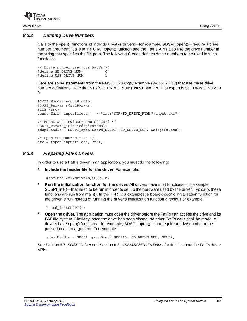
www.ti.com Using FatFs
8.3.2 Defining Drive Numbers
Calls to the open() functions of individual FatFs drivers—for example, SDSPI_open()—require a drive number argument. Calls to the C I/O fopen() function and the FatFs APIs also use the drive number in the string that specifies the file path. The following C code defines driver numbers to be used in such functions:
/* Drive number used for FatFs */#define SD_DRIVE_NUM 0#define USB_DRIVE_NUM 1
Here are some statements from the FatSD USB Copy example (Section 2.2.12) that use these drive number definitions. Note that STR(SD_DRIVE_NUM) uses a MACRO that expands SD_DRIVE_NUM to 0.
SDSPI_Handle sdspiHandle;SDSPI_Params sdspiParams;FILE *src;const Char inputfilesd[] = "fat:"STR(SD_DRIVE_NUM)":input.txt";
/* Mount and register the SD Card */SDSPI_Params_init(&sdspiParams);sdspiHandle = SDSPI_open(Board_SDSPI, SD_DRIVE_NUM, &sdspiParams);
/* Open the source file */src = fopen(inputfilesd, "r");
8.3.3 Preparing FatFs Drivers
In order to use a FatFs driver in an application, you must do the following:
• Include the header file for the driver. For example:
#include <ti/drivers/SDSPI.h>
• Run the initialization function for the driver. All drivers have init() functions—for example, SDSPI_init()—that need to be run in order to set up the hardware used by the driver. Typically, these functions are run from main(). In the TI-RTOS examples, a board-specific initialization function for the driver is run instead of running the driver’s initialization function directly. For example:
Board_initSDSPI();
• Open the driver. The application must open the driver before the FatFs can access the drive and its FAT file system. Similarly, once the drive has been closed, no other FatFs calls shall be made. All drivers have open() functions—for example, SDSPI_open()—that require a drive number to be passed in as an argument. For example:
sdspiHandle = SDSPI_open(Board_SDSPI0, SD_DRIVE_NUM, NULL);
See Section 6.7, SDSPI Driver and Section 6.8, USBMSCHFatFs Driver for details about the FatFs driver APIs.
SPRUHD4B—January 2013 Using the FatFs File System Drivers 89Submit Documentation Feedback
Cautionary Notes www.ti.com
8.3.4 Opening Files Using FatFs APIs
Details on the FatFs APIs can be found at http://elm-chan.org/fsw/ff/00index_e.html in the "Application Interface" section.
The drive number needs to be included as a prefix in the filename string when you call f_open() to open a file. The drive number used in this string needs to match the drive number used to open the FatFs driver. For example:
res = f_open(&fsrc, “SD_DRIVE_NUM:source.dat”, FA_OPEN_EXISTING | FA_READ);
res = f_open(&fdst, “USB_DRIVE_NUM:destination.dat”, FA_CREATE_ALWAYS | FA_WRITE);
A number of other FatFs APIs require a path string that should include the drive number. For example, f_opendir(), f_mkdir(), f_unlink(), and f_chmod().
Although FatFs supports up to 10 (0-9) drive numbers, the SYS/BIOS diskIO function table supports only up to 4 (0-3) drives. You can modify this default by changing the definition of _VOLUMES in the ffconf.h file in the SYS/BIOS FatFS module. You will then need to rebuild SYS/BIOS as described in the SYS/BIOS User’s Guide (SPRUEX3).
It is important to use either the FatFs APIs or the C I/O APIs for file operations. Mixing the APIs in the same application can have unforeseen consequences.
8.3.5 Opening Files Using C I/O APIs
The C input/output runtime implementation for FatFs works similarly to the FatFs API. However, you must add the file name prefix configured for the FatFS module ("fat" by default) and the logical drive number as prefixes to the filename. The file name prefix is extracted from the filename before it gets passed to the FatFs API.
In this example, the default file name prefix is used and the drive number is 0:
fopen(“fat:0:input.txt”, "r");
It is important to use either the FatFs APIs or the C I/O APIs for file operations. Mixing the APIs in the same application can have unforeseen consequences.
8.4 Cautionary Notes
FatFs drivers perform data block transfers to and from physical media. Depending on the FatFs driver, writing to and reading from the disk could prevent lower-priority tasks from running during that time. If the FatFs driver blocks for the entire transfer time, only higher-priority SYS/BIOS Tasks, Swis or Hwis can interrupt the Task making FatFs calls. In such cases, the application developer should consider how often and how much data needs to be read from or written to the media.
By default the SYS/BIOS FatFS module keeps a complete sector buffered for each opened file. While this requires additional RAM, it helps mitigate frequent disk operations when operating on more than one file simultaneously.
The SYS/BIOS FatFS implementation allows up to four unique volumes (or drives) to be registered and mounted.
90 Using the FatFs File System Drivers SPRUHD4B—January 2013Submit Documentation Feedback
Chapter 9SPRUHD4B—January 2013
Rebuilding TI-RTOS
This chapter describes how and when to rebuild TI-RTOS.
9.1 Rebuilding TI-RTOS . . . . . . . . . . . . . . . . . . . . . . . . . . . . . . . . . . . . . . . 92
9.2 Rebuilding Individual Components . . . . . . . . . . . . . . . . . . . . . . . . . . . 92
Topic Page
SPRUHD4B—January 2013 Rebuilding TI-RTOS 91Submit Documentation Feedback
Rebuilding TI-RTOS www.ti.com
9.1 Rebuilding TI-RTOS
In most cases, you will not need to rebuild the TI-RTOS libraries. Pre-built libraries are provided when you install TI-RTOS. However, if you want to change the compiler or linker options, you may need to rebuild the libraries.
TI-RTOS can be rebuilt from a top-level make file called tirtos.mak.
If TI-RTOS is installed in c:\ti, you can print a list of available make rules by running the following command from a command shell window:
To rebuild the TI-RTOS drivers and several of its included components (SYS/BIOS, IPC, NDK, and UIA), for example, you can run the following:
If you installed somewhere else, you can edit the tirtos.mak file in the top-level TI-RTOS directory. Adjust the directory names as needed, or pass in the necessary names. For example to use a different location for XDCtools, do the following:
The following list shows items you can change and sample values. The version numbers in your copy of the tirtos.mak file will match the versions of the components installed with TI-RTOS.
If you are rebuilding on Linux, you will need to change all of these Windows paths in the tirtos.mak file to Linux paths.
9.2 Rebuilding Individual Components
The MWare and StellarisWare rebuilding mechanism is substantially different. See the documentation for these products for details.
Driver libraries in the versions of MWare and StellarisWare distributed with TI-RTOS have been rebuilt. For details, see the TI-RTOS.README file in the top-level folder of the MWare and StellarisWare components within the TI-RTOS installation.
%cd <tirtos_install>
% products/<xdctools>/gmake –f tirtos.mak
% products/<xdctools>/gmake -f tirtos.mak all
% products/<xdctools>/gmake –f tirtos.mak XDCTOOLS_INSTALLATION_DIR=c:/ti/xdctools_version
CODEGEN_INSTALLATION_DIR := c:/ti/ccsv5/tools/compiler
ti.targets.C28_float ?= $(CODEGEN_INSTALLATION_DIR)/c2000_6.1.0
ti.targets.arm.elf.M3 ?= $(CODEGEN_INSTALLATION_DIR)/tms470_4.9.1
ti.targets.arm.elf.M4F ?= $(CODEGEN_INSTALLATION_DIR)/tms470_4.9.1
TIRTOS_INSTALLATION_DIR := c:/ti/tirtos_1_00_00_68
XDCTOOLS_INSTALLATION_DIR ?= $(TIRTOS_INSTALLATION_DIR)/products/xdctools_3_23_04_60
BIOS_INSTALLATION_DIR ?= $(TIRTOS_INSTALLATION_DIR)/products/bios_6_33_04_39
IPC_INSTALLATION_DIR ?= $(TIRTOS_INSTALLATION_DIR)/products/ipc_1_24_02_27
UIA_INSTALLATION_DIR ?= $(TIRTOS_INSTALLATION_DIR)/products/uia_1_01_01_15
NDK_INSTALLATION_DIR ?= $(TIRTOS_INSTALLATION_DIR)/products/ndk_2_21_01_38
MWARE_INSTALLATION_DIR ?= $(TIRTOS_INSTALLATION_DIR)/products/MWare_v140x/MWare
STELLARISWARE_INSTALLATION_DIR ?= $(TIRTOS_INSTALLATION_DIR)/products/StellarisWare_9107
92 Rebuilding TI-RTOS SPRUHD4B—January 2013Submit Documentation Feedback
Chapter 10SPRUHD4B—January 2013
Memory Usage with TI-RTOS
This chapter provides links to information about memory usage.
10.1 Memory Footprints . . . . . . . . . . . . . . . . . . . . . . . . . . . . . . . . . . . . . . . . 94
10.2 Networking Stack Memory Usage . . . . . . . . . . . . . . . . . . . . . . . . . . . . 94
Topic Page
SPRUHD4B—January 2013 Memory Usage with TI-RTOS 93Submit Documentation Feedback
Memory Footprints www.ti.com
10.1 Memory Footprints
See TI-RTOS Memory Footprints on the TI Embedded Processors Wiki for details about the memory footprint of the TI-RTOS drivers:
10.2 Networking Stack Memory Usage
See TI-RTOS Networking Stack Memory Usage on the TI Embedded Processors Wiki for details about to adjusting memory usage of the networking stack (NDK).
94 Memory Usage with TI-RTOS SPRUHD4B—January 2013Submit Documentation Feedback
IndexSPRUHD4B—January 2013
Index
AAbort function 85abort() function 83APIs
common 53EMAC driver 55GPIO driver 68I2C driver 61SDSPI driver 71UART driver 57USB device and host modules 79USBMSCHFatFs driver 74Watchdog driver 81
assert handling 41Available Products list 35
Bboard.c files 48build flow 46
CC28x
example 20support 47
CCSloading dual-core example 21other documentation 12
ccxml file 49CDC device 11
example 16, 32CIO functions 22, 29COM port 24components 6Concerto 47
other documentation 13configuration
build flow 46configuro tool 46console example 24ControlSuite 10
other documentation 10, 13
Ddebugging 40
demo.c file 20DK_LM3S9D96.c file 48DK-LM3S9D96 7, 17documentation 12drivers 11, 50dual-core example 20
EEEPROM
example 24EK-LM4F120XL 7, 17EKS-LM4F232 7, 17EMAC driver 11, 54Empty Project example 18empty.c file 19Ethernet driver 11, 54examples 15, 18
overview 16exception handling 41exit() function 83
FF28M35H52C1 7F28M36P63C2 7FatFs API
example 20, 22, 23, 29other documentation 14
FatFs driver 70, 73FatFs examples
copy from SD to USB 29copy using CIO functions 22copy using FatFs APIs 23
fatsd.c file 22fatsdraw.c file 23fatsdusbcopy.c file 29flash drives 11, 73flush() function 83forum 12
GGPIO driver 11, 67GPIO pin 30, 31, 32
configuration 48gpiointerrupt.c file 23
SPRUHD4B—January 2013 Index 95Submit Documentation Feedback
www.ti.com
HHID device 11
example 16, 30, 31HTTP server 20
II2C driver 11, 60
example 16, 20, 24i2ceeprom.c file 24instrumentation 34instrumented libraries 37inter-processor communications 20IPC 8
example 16, 20other documentation 9, 12
Kkeyboard
device 79example 30host 79
LLEDs
configuration 48example 30
linker command file 48LM3S9D96 7LM4F120H5QR 7LM4F232H5QD 7Load logging 36Log module 37
EMAC driver 55GPIO driver 69I2C driver 66UART driver 59UART logging example 27USBMSCHFatFs driver 75viewing messages 38Watchdog driver 82
logging 36LoggingSetup module 18, 35
MM3 microcontroller 47mouse
device 79, 80example 31, 32host 79
MSC device 11example 32
MSC host 73MWare 9, 10
other documentation 10, 13
NNDK 9, 54
example 16, 20, 22other documentation 9, 13
non-instrumented libraries 37
PPort Name field 38printf() function 42Printf-style output 41, 42products directory 6Putch Function 85putchFxn callback 83
Rreadme.txt file 18Ready Function 85readyFxn callback 83rebuilding
TI-RTOS 92ROV tool 18, 39, 40, 42
EMAC 55GPIO 69I2C 66SDSPI 72UART 59Watchdog driver 82
RTOS Object View (ROV) 40runtime support library 29
SSD cards 70SD driver
example 16, 22, 23, 29SDSPI driver 11, 70serial devices 79
COM port 24simulator, debugging with 49socket API 22SPI (SSI) bus 70static configuration 46stdio functions 24StellarisWare 10SYS/BIOS 7
examples 16logging 36other documentation 7, 12
SysFlex module 24, 42, 83, 85configuration 84
SysMin module 18, 42configuration 43
SysStd module 42
96 Index SPRUHD4B—January 2013Submit Documentation Feedback
www.ti.com
System Analyzer 9, 34, 41debugging with 38
System module 42configuration 43, 84
System_abort() function 83System_exit() function 83System_flush() function 83System_printf() function 42
TTarget Configuration File 49TCP echo example 22tcpEcho.c file 22tcpSendReceive tool 22temperature readings 20TI-RTOS 6
other documentation 12TMDXDOCK28M36 7, 17TMDXDOCKH52C1 7, 17TMDXDOCKH52C1.c file 48
UUART
configuration 24, 85SysFlex configuration 85
UART console example 24UART driver 11, 56UART echo example 27UART logging example 27uartconsole.c file 26uartecho.c file 27uartlogging.c file 29
UARTUtils_systemAbort() function 85UARTUtils_systemPutch() function 85UARTUtils_systemReady() function 85UIA 9, 35
example 16, 22, 24, 27other documentation 9, 13
USB connectionUART 24
USB controller 73USB driver 79
example 16, 29, 30, 31, 32USB example 30, 31, 32usbkeyboarddevice.c file 30usbkeyboardhost.c file 30usbmousedevice.c file 31usbmousehost.c file 31USBMSCHFatFs driver 11, 73usbsdcardreader.c file 32usbserialdevice.c file 32
WWatchdog driver 11, 50, 80
APIs 81configuration 80example 33
wiki 12
XXDCtools 8
build settings 46other documentation 8, 12
SPRUHD4B—January 2013 Index 97Submit Documentation Feedback
IMPORTANT NOTICE
Texas Instruments Incorporated and its subsidiaries (TI) reserve the right to make corrections, enhancements, improvements and other changes to its semiconductor products and services per JESD46, latest issue, and to discontinue any product or service per JESD48, latest issue. Buyers should obtain the latest relevant information before placing orders and should verify that such information is current and complete. All semiconductor products (also referred to herein as “components”) are sold subject to TI’s terms and conditions of sale supplied at the time of order acknowledgment.
TI warrants performance of its components to the specifications applicable at the time of sale, in accordance with the warranty in TI’s terms and conditions of sale of semiconductor products. Testing and other quality control techniques are used to the extent TI deems necessary to support this warranty. Except where mandated by applicable law, testing of all parameters of each component is not necessarily performed.
TI assumes no liability for applications assistance or the design of Buyers’ products. Buyers are responsible for their products and applications using TI components. To minimize the risks associated with Buyers’ products and applications, Buyers should provide adequate design and operating safeguards.
TI does not warrant or represent that any license, either express or implied, is granted under any patent right, copyright, mask work right, or other intellectual property right relating to any combination, machine, or process in which TI components or services are used. Information published by TI regarding third-party products or services does not constitute a license to use such products or services or a warranty or endorsement thereof. Use of such information may require a license from a third party under the patents or other intellectual property of the third party, or a license from TI under the patents or other intellectual property of TI.
Reproduction of significant portions of TI information in TI data books or data sheets is permissible only if reproduction is without alteration and is accompanied by all associated warranties, conditions, limitations, and notices. TI is not responsible or liable for such altered documentation. Information of third parties may be subject to additional restrictions.
Resale of TI components or services with statements different from or beyond the parameters stated by TI for that component or service voids all express and any implied warranties for the associated TI component or service and is an unfair and deceptive business practice. TI is not responsible or liable for any such statements.
Buyer acknowledges and agrees that it is solely responsible for compliance with all legal, regulatory and safety-related require-ments concerning its products, and any use of TI components in its applications, notwithstanding any applications-related infor-mation or support that may be provided by TI. Buyer represents and agrees that it has all the necessary expertise to create and implement safeguards which anticipate dangerous consequences of failures, monitor failures and their consequences, lessen the likelihood of failures that might cause harm and take appropriate remedial actions. Buyer will fully indemnify TI and its representatives against any damages arising out of the use of any TI components in safety-critical applications.
In some cases, TI components may be promoted specifically to facilitate safety-related applications. With such components, TI’s goal is to help enable customers to design and create their own end-product solutions that meet applicable functional safety standards and requirements. Nonetheless, such components are subject to these terms.
No TI components are authorized for use in FDA Class III (or similar life-critical medical equipment) unless authorized officers of the parties have executed a special agreement specifically governing such use.
Only those TI components which TI has specifically designated as military grade or “enhanced plastic” are designed and intended for use in military/aerospace applications or environments. Buyer acknowledges and agrees that any military or aerospace use of TI components which have not been so designated is solely at the Buyer's risk, and that Buyer is solely responsible for compliance with all legal and regulatory requirements in connection with such use.
TI has specifically designated certain components as meeting ISO/TS16949 requirements, mainly for automotive use. In any case of use of non-designated products, TI will not be responsible for any failure to meet ISO/TS16949.
Mailing Address: Texas Instruments, Post Office Box 655303 Dallas, Texas 75265Copyright © 2013, Texas Instruments Incorporated
Products Applications
Audio www.ti.com/audio Automotive and Transportation www.ti.com/automotive
Amplifiers amplifier.ti.com Communications and Telecom www.ti.com/communications
Data Converters dataconverter.ti.com Computers and Peripherals www.ti.com/computers
DLP® Products www.dlp.com Consumer Electronics www.ti.com/consumer-apps
DSP dsp.ti.com Energy and Lighting www.ti.com/energy
Clocks and Timers www.ti.com/clocks Industrial www.ti.com/industrial
Interface interface.ti.com Medical www.ti.com/medical
Logic logic.ti.com Security www.ti.com/security
Power Mgmt power.ti.com Space, Avionics and Defense www.ti.com/space-avionics-defense
Microcontrollers microcontroller.ti.com Video & Imaging www.ti.com/video
RFID www.ti-rfid.com
OMAP Mobile Processors www.ti.com/omap TI E2E Community e2e.ti.com
Wireless Connectivity www.ti.com/wirelessconnectivity