Embed Size (px)
Citation preview
TI FiLE COPY
* CRREL Research on Materialsin Cold EnvironmentsPiyush K. Dutta December 1990
DTIC
ELECTEFED 27 199135
l~ l 1 ,, p:,b::
91 2 19 293
For conversion of SI metric units to U.S./BrItIsh customary unitsof measurement consult ASTM Sfcndard E380, Metric PracticeGuide, published by ' e American Society for Testing andMaterials, 1916 Race St., Philadelphia, Pa. 19103.
This report is printed on paper thut contains a minimum of50% recycled material.
Special Report 90-42
U.S. Army Corpsof EngineersCold Regions Research &Engineering Laboratory
CRREL Research on Materialsin Cold EnvironmentsPiyush K. Dutta December 1990
icceion For
4 NT~S CR.&E , ,-
- . .. i.. . I .
,. FEB 2 9w
Prepared for
OFFICE OF THE CHIEF OF ENGINEERS
Approved for public release; distribution is unlimited.
PREFACE
This report was prepared by Dr. Piyush K. Dutta, Materials Research Engineer, of the AppliedResearch Branch, Experimental Engineering Division, U.S. Army Cold Regions Research andEngineering Laboratory. Funding was provided by DA Project 4A762730AT42, Cold RegionsTechnology; Task SS, Work Unit 019, Behavior of Materials at Low Temperatures.
The author thanks D. Cole and H. Farquhar of CRREL for technically reviewing this report.The contents of this report are not to be used for advertising or promotional purposes. Citation of
brand names does not constitute an official endorsement or approval of the use of such commercialproducts.
CONTENTSPage
Preface .................................................................................................................................. iIntroduction .......................................................................................................................... 1Program development .......................................................................................................... 1
Materials-property data base ......................................................................................... 2Materials research ......................................................................................................... 2
Test Facilities ....................................................................................................................... 11Universal testing machines ............................................................................................ 11Charpy impact testing machine .................................................................................... 12Drop shock tester .......................................................................................................... 12Hopkinson pressure bar apparatus ................................................................................. 12Low-temperature ballistic test apparatus ....................................................................... 15Special support equipment ............................................................................................ 16Impedance matched shock gauge .................................................................................. 18
Concluding remarks ............................................................................................................. 18Literature cited ..................................................................................................................... 19Bibliography ......................................................................................................................... 19Abstract ................................................................................................................................ 21
ILLUSTRATIONS
Figure1. Sample page of the materials-property data base ...................................................... 22. Anisotropic stress distribution data from three pairs of strain gauges on a
unidirectional laminate ........................................................................................ 33. Glass fiber laminates before and after tensile tests .................................................... 34. Influence of temperature on tensile strength of glass fiber-epoxy laminate ............ 45. Influence of temperature on tensile strength of graphite-epoxy laminate ................. 46. Influence of low temperature on tensile strength of Kevlar/DuPont J-2 resin
laminate .............................................................................................................. 57. Graphite epoxy fracture surface micrograph showing progressive smoothing of the
surface with thermal cycling ............................................................................... 68. Acoustic emission data from cooling laminates of different ply orientations ........... 79. Progressive strength degradation of glass fiber-.epoxy laminate from low-
temperature thermal cycling ............................................................................... 810. Compressive strength increase of glass-polyester composites at low temperature ... 811. Catastrophic brittle failure of glass-polyester composites at low temperature .......... 912. Special test specimens of a thick polyester-S2-glass composite for elastic moduli
testing by flexure ................................................................................................ 913. Test specimens of U.S. Navy's glass fiber reinforced polymer concrete .................. 1014. High-capacity servo-hydraulic testing machine for low-temperature testing ............ 1115. Charpy impact test machine ...................................................................................... 1216. Free fall shock testing machine ................................................................................. 1317. Hopkinson pressure bar test system for high-strain-rate measurements at low
temperatures ........................................................................................................ 1318. Real-time data acquisition and analysis system for Hopkinson bar apparatus .......... 1419. High-strain-rate fracture strain data from polycrystalline ice .................. 15
ii
Figure Page
20. Low-temperature ballistic test apparatus ................................................................... 1621. Acoustic emission testing apparatus .......................................................................... 1722. Scanning electron microscope laboratory ................................................................. 1723. Computer controlled thermal cycling chamber ......................................................... 1824. Impedance matched shock gauge .............................................................................. 18
TABLES
Table1. Comparison of room temperature and low temperature tensile strength data of
unidirectional laminates .................................................................................. 5
iv
CRREL Research on Materials in Cold Environments
PIYUSH K. DUTIA
INTRODUCTION groups, both inside and outside of the laboratory. As amultidisciplinary laboratory, CRREL supports materi-
This is the first of a series of reports about the als research from within such relevant areas as fracturematerials research program at CRREL that are expected mechanics, heat transfer, numerical analysis, chemicalto become a key element for communication among analysis and electron microscopy. Outside of CRREL,experts inside and outside of CRREL. They will not through its memoranda of understanding, resources arereplace scientific and technical publications, but will available from the Army Materials Technology Labora-rather survey recent activities of CRREL's materials tory (AMTL) (Watertown, Massachusetts) and Michi-research program and provide a bibliography covering gan Technological University (MTU) (Houghton,the period of review. Michigan). Also, well-known academicians and gradu-
CRREL will examine cold regions applications of ate students from various universities are brought aboardboth natural and man-made materials. The range of these for materials research projects.materials is quite wide and can include soil (frozen and The first section of this report, Program Develop-unfrozen), rock, ice, snow, concrete, metals, plastics, ment, gives a synopsis of CRREL's materials-propertycomposites, adhesives or explosives. But, because the data base and reports important new findings madeArmy is beginning to extensively use composites in its through studies of the behavior of composites at lowmateriel, the behavior of composites in the cold has temperatures. Results of studies of some special materi-received our initial emphasis. Only intermittent studies als (the Navy's glass fiber-reinforced polymeric con-have been conducted on some dynamic properties of crete and the Army's thick polyester-glass compositesfrozen soil and ice; special impedance-matched shock developed for the Infantry Fighting Vehicle) are dis-gauges were developed for these studies using a piezo- cussed briefly. The second part, Test Facilities Devel-polymer material, polyvinylidene fluoride (PVDF). opment, describes the basic test facilities and specialized
The work has progressed in three parallel tasks, with equipment present at CRREL to comprehensively studyheavier emphasis on the last two. First, a data base of materials over a wide range of strain rate loadings andmaterials' properties at low temperatures was computer- temperatures.ized; this is periodically updated through literaturesearches. It provides a common reference base for mostmaterial property data at low temperatures. Second, PROGRAM DEVELOPMENTthrough a series of tests, low-temperature behavior datafor some critical composites intended for military and The materials research program at CRREL takes aaerospace applications were generated, and a model to long-term view toward serving the Army and the Nation,predict composites' low-temperature behavioras lamina and has developed through coordination of expertisein tension was developed. Third, to support the compre- from the various disciplinary branches within the labo-hensive program of study of materials' behavior in the ratory, such as civil and geotechnical engineering, geo-cold, essential facilities were set up. This includes not chemical sciences and ice engineering. After its incep-only equipment, testing machines and specialized labo- tion in 1985, the program was developed through theratories, but also developing formal and informal op- three parallel tasks mentioned earlier, including the corn-portunities of exchange among various technical expert puterized data base and the materials testing program.
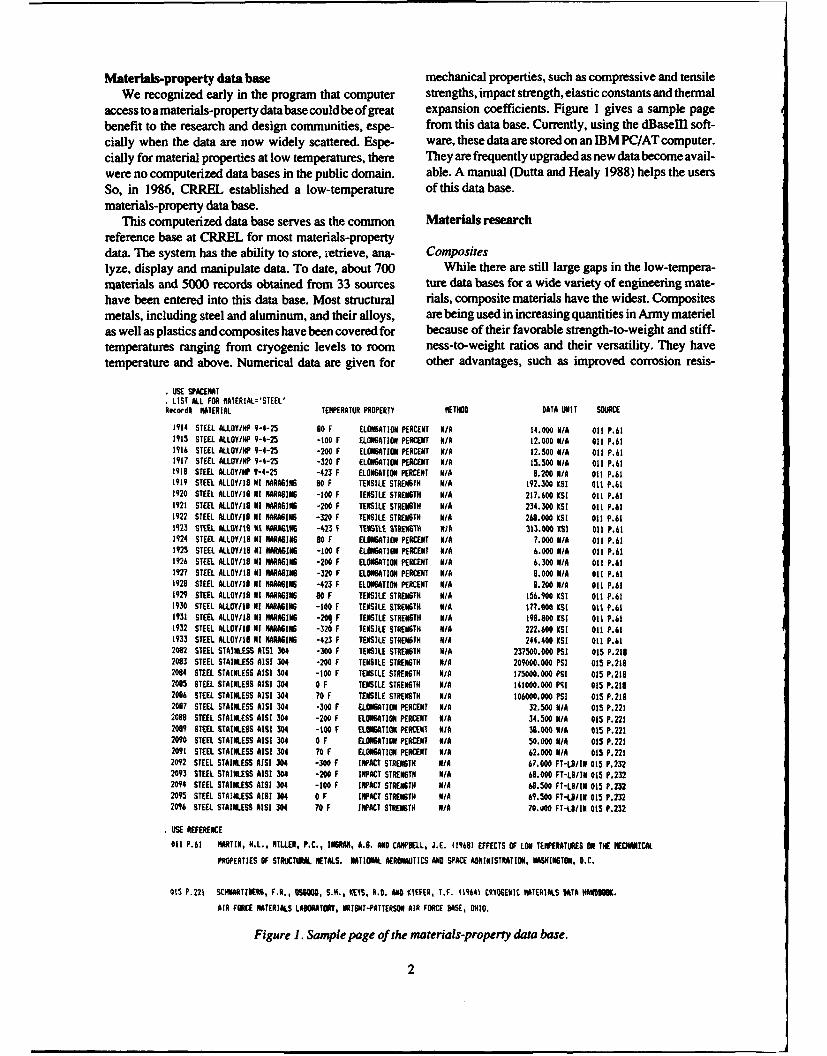
Materials-property data base mechanical properties, such as compressive and tensileWe recognized early in the program that computer strengths, impact strength, elastic constants and thermal
access toamaterials-property database couldbe of great expansion coefficients. Figure 1 gives a sample pagebenefit to the research and design communities, espe- from this data base. Currently, using the dBasem soft-cially when the data are now widely scattered. Espe- ware, these data are stored on an IBM PC/AT computer.cially for material properties at low temperatures, there They are frequently upgraded as new data become avail-were no computerized data bases in the public domain, able. A manual (Dutta and Healy 1988) helps the usersSo, in 1986, CRREL established a low-temperature of this data base.materials-property data base.
This computerized data base serves as the common Materials researchreference base at CRREL for most materials-propertydata. The system has the ability to store, retrieve, ana- Compositeslyze, display and manipulate data. To date, about 700 While there are still large gaps in the low-tempera-materials and 5000 records obtained from 33 sources ture data bases for a wide variety of engineering mate-have been entered into this data base. Most structural rials, composite materials have the widest. Compositesmetals, including steel and aluminum, and their alloys, are being used in increasing quantities in Army materielas well as plastics and composites have been covered for because of their favorable strength-to-weight and stiff-temperatures ranging from cryogenic levels to room ness-to-weight ratios and their versatility. They havetemperature and above. Numerical data are given for other advantages, such as improved corrosion resis-
USE SPACENATLIST ALL FOR HATERIAL-"STEEL'
Record# MATERIAL TENPERATUR PROPERTY METHOD DATA UNIT SOURCE
1914 STEEL ALLOY/HP 9-4-25 80 F ELONGATION PERCENT NIA 14.000 N/A Oil P.611915 STEEL ALLOY/HP 9-4-25 -100 F ELONGATION PERCENT N/A 12.000 NIA Oil P.611916 STEEL ALLOY/HP 9-4-25 -200 F ELONGATION PERCENT NIA 12.500 NIA o1 P.611917 STEEL ALLOY/HP 9-4-25 -320 F ELONGATION PERCENT NIA 15.500 NIA Oil P.611918 STEEL ALLOY/HP 9-4-25 -423 F ELONGATION PERCENT NIA 8.200 NIA Oil P.611919 STEEL ALLOY/IS NI ARGING 80 F TENSILE STRENGTH N/A 192.300 lST Ott P.611920 STEEL ALLOY/IS NI WAGING -100 F TENSILE STRENGTH NIA 217.600 KSI oil P.611921 STEEL ALLOY/IS NI WAGING -200 F TENSILE STRENGTH NIA 234.300 KSI Oil P.611922 STEEL ALLOY/1 NI NMARAGING -320 F TENSILE STRENGTH NiA 268.000 ESI Oil P.611923 STEEL A.LOY118 K1 WAGING -423 F TENSILE STRENG'% % 1A 313.000 KSI 011 P.611924 STEEL ALLOY/IS NI MRAGING 80 F ELONGATION PERCENT NIA 7.000 NIA Oil P.611925 STEEL ALLOY/I8 NI WAGING -100 F ELONGATION PERCENT NIA 6.000 NIA Oil P.611926 STEEL ALLOY/1 NI NAGING -200 F ELONGATION PERCENT NIA 6.300 NiA Oil P.611927 STEEL ALLOY/IS NI MAGING -320 F ELONGATION PERCENT NIA 8.000 NIA 011 P.611928 STEEL ALLOY/IS NI MAGING -423 F ELONGATION PERCENT NIA 8.200 N/A Oil P.611929 STEEL ALLOY/I8 NI MARAGING 80 F TENSILE STRENGTH NIA 156.900 KSI 011 P.611930 STEEL ALLOY/IS NI ARAGING -100 F TENSILE STRENGTH NIA 1?7.000 SI Oil P.611931 STEEL ALLOY/IS NI AAGING -20 F TENSILE STRENGTH NIA 199.S00 SI Oil P.611932 STEEL ALLOY/IS NI HAMING -320 F TENSILE STRENGTH N/A 222.600 8s Oil P.611933 STEEL ALLOY/IS NI ARAGING -423 F TENSILE STRENGTH NIA 244.400 KsT 011 P.612062 STEEL STAINLESS AISI 304 -300 F TENSILE STRENGTH NiA 237500.000 PSI 015 P.2182083 STEEL STAINLESS AISI 304 -200 F TENSILE STRENGTH N/A 209000.000 PSI 015 P.2102084 STEEL STAINLESS AISI 304 -100 F TENSILE STRENGTH NIA 175000.000 PSI 015 P.2192085 STEEL STAINLESS AISI 304 0 F TENSILE STRENGTH N/A 141000.000 PIl 015 P.2182086 STEEL STAINLESS AISI 304 70 F TENSILE STRENGTH NIA 106000.000 PSI 015 P.2182097 STEEL STAINLESS AISI 304 -300 F ELONGATION PERCENT NIA 32.500 N/A 015 P.2212088 STEEL STAINLESS AISI 304 -200 F ELONGATION PERCENT N/A 34.500 NIA 015 P.2212099 STEEL STAINLESS AISI 304 -100 F ELONGATION PERCENT N/A 38.000 N/A 015 P.2212090 STEEL STAINLESS AIS 304 0 F ELONGATION PERCENT N/A 50.000 NIA 015 P.2212091 STEEL STAINLESS AISI 304 70 F ELONGATION PERCENT NIA 62.000 NIA 015 P.2212092 STEEL STAINLESS AISI 304 -300 F IMPACT STRENGTH NIA 67.000 FT-U./IN 015 P.2322093 STEEL STAINLESS AISI 304 -200 F IMPACT STRENGTH NIA 68.000 FT-LB/IN 015 P.2322094 STEEL STAINLESS AISI 304 -100 F IMPACT STRENGTH NiA 68.500 FT-LIIN 015 P.2322095 STEEL STAINLESS AISI 304 0 F IMPACT STRENGTH NIA 69.500 FT-S/IN 015 P.2322096 STEEL STAINLESS Ais 304 70 F IMPACT STRENGTH NIA 70.t1O FT-LBIIN 015 P.232
USE REFERENCE
Oil P.61 MARTIN, H.L., MILLER, P.C., INGRAN, A.8. AND CAMPBELL, J.E. (19681 EFFECTS OF LOW TEMPERATURES ON TIE MECHANICAL
PROPERTIES OF STRUCTURAL METALS. NATIONAL AEROHATICS AND SPACE ADINISTRATION, WASHINGTON, D.C.
015 P.221 SCWMTNERS, F.R., O0600, 5.K., KEYS, R.D. AND XIEFER, T.F. 19641 CRYOGENIC MATERIALS DATA HANOIoK.
AIR FORCE MATERIALS LABORATORY, RIGHT-PATTERSOM AIR FORCE BASE, OHIO.
Figure 1. Sample page of the materials-property data base.
2
10x 103 I I , I ,
8 Gauge Orientationsto Fiber Axial
0
._.
4 - ' Transverse
2-
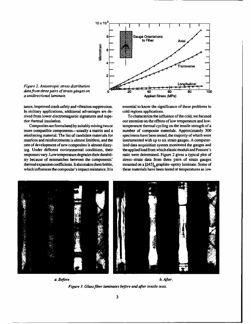
Figure 2. Anisotropic stress distribution -4ro-""1data from three pairs of strain gauges on 0 20 40 60 80 100a unidirectional laminate. Applied Stress (MPa)
tance, improved crash safety and vibration suppression. essential to know the significance of these problems inIn military applications, additional advantages are de- cold regions applications.rived from lower electromagnetic signatures and supe- To characterize the influence of the cold, we focusedrior thermal insulation, our attention on the effects of low temperature and low-
Composites are formulated by suitably mixing two or temperature thermal cycling on the tensile strength of amore compatible components-usually a matrix and a number of composite materials. Approximately 300reinforcing material. The list of candidate materials for specimens have been tested, the majority of which werematrices and reinforcements is almost limitless, and the instrumented with up to six strain gauges. A computer-rate of development of new composites is almost dizzy- ized data acquisition system monitored the gauges anding. Under different environmental conditions, their theappliedloadfromwhichelasticmoduliandPoisson'sresponses vary. Low temperaturedegrades theirdurabil- ratio were determined. Figure 2 gives a typical plot ofity because of mismatches between the components' stress-strain data from three pairs of strain gaugesthermal expansion coefficients. Italsomakes thembrittle, mounted on a [±4516 graphite-epoxy laminate. Some ofwhich influences the composite's impact resistance. It is these materials have been tested at temperatures as low
a. Before. b. After.
Figure 3. Glass fiber laminates before and after tensile tests.
3
as --60'C and some were thermally cycled to the lowest crease in strength. The strength of laminates with a lowertemperature of-I 80'C. proportion v, 0* oriented fibers ([9 02O]s) actually in-
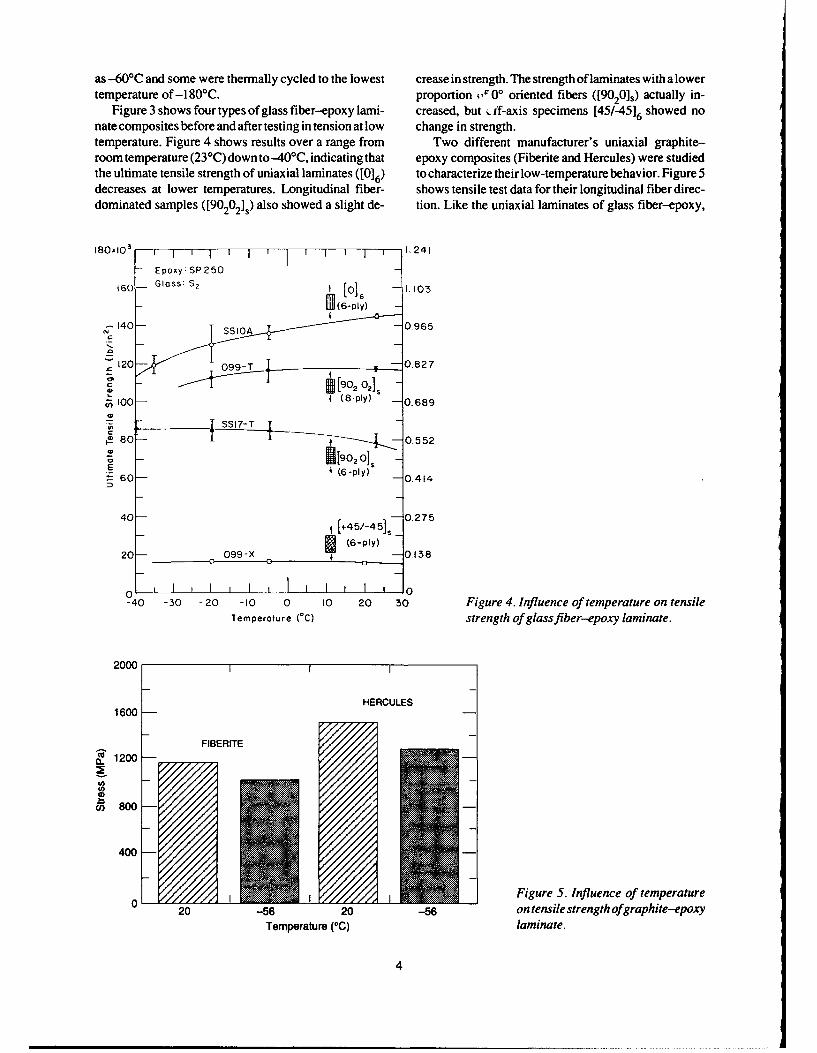
Figure 3 shows four types of glass fiber--epoxy lami- creased, but ff-axis specimens [45/-45]6 showed nonate composites before and after testing in tension at low change in strength.temperature. Figure 4 shows results over a range from Two different manufacturer's uniaxial graphite-room temperature (23C) down to-40*C, indicating that epoxy composites (Fiberite and Hercules) were studiedthe ultimate tensile strength of uniaxial laminates ([016) to characterize their low-temperature behavior. Figure 5decreases at lower temperatures. Longitudinal fiber- shows tensile test data for their longitudinal fiber direc-dominated samples ([90202]s) also showed a slight de- tion. Like the uniaxial laminates of glass fiber-epoxy,
180.10 3 l 1 1 1 1 1 I 1 1 I 1 1 1 -I, 24 1
- Epoxy; SP250
6 0 - Gl ss: S2 [01 , - I O
- o (6-ply) 08
1 140 -S 0 0.965
0
TS7-
.E
8T 80- 0.552
- 1 1200o
- 6( -- (6-py) -0.414.
40 [+45/-451, 0.2 75
20 - 099-X (6Py -0 .138
400
40 -30 -20 -10 0 10 20 30 Figure 4. Influence of temperature on tensileTemperature rC) strength of glassfiber-epoxy laminate.
20001
HERCULES1600 -
FIBERITE ....
0. 1200o-
400 -////////
20/// 562 -6ontnil trnthogapie-px
Temperatur (///lamiate
_ /I /i// Ii/ // 4
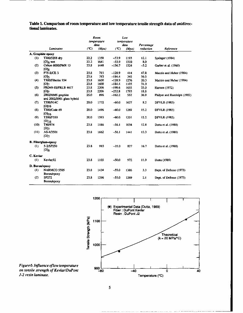
Table 1. Comparison of room temperature and low temperature tensile strength data of unidirec-tional laminates.
Room Lowtemperature temperature
data data PercentageLaminates (0C) (Mpa) (C) (Mpa) reduction Reference
A. Graphite epoxy(1) T300/5208 dry 22.2 1358 -53.9 1193 12.1 Springer (1984)
10)6 wet 22.2 1641 -53.9 1510 8.0(2) Celion 6000/PMR 15 23.8 1448 -156.7 1524 -5.2 Garber et al. (1980)
[o18(3) P75-S/CE 3 23.8 793 -128.9 414 47.8 Mazzio and Huber (1984)
[0 5 23.8 793 -184.4 345 56.5(4) T300/Fiberite 934 23.8 1600 -128.9 1276 20.3 Mazzio and Huber (1984)
[01? 23.8 1600 -184.4 1103 31.0(5) PRD49-II/FRLB 4617 23.8 2206 -198.6 1655 25.0 Hanson (1972)
[0]? 23.8 2206 -252.8 1793 18.8(6) 2002/HMS graphite 25.0 896 -162.2 552 36.9 Philpot and Randolph (1982)
and 2002/S901 glass hybrid(7) T300/914C 20.0 1772 -60.0 1627 8.2 DFVLR (1985)
[0116(8) T300/Code 69 20.0 1496 -60.0 1269 15.2 DFVLR (1985)
[116(9) T300/F550 20.0 1593 -60.0 1351 15.2 DFVLR (1985)
[0116(10) T40/974 23.8 1186 -56.1 1034 12.8 Dutta et al. (1988)
[017(11) AS-4/3501 23.8 1662 -56.1 1441 13.3 Dutta et al. (1988)
017
B. Fiberglass-epoxy(I) 5-2/SP250 23.8 993 -35.0 827 16.7 Dutta et al. (1988)
[016
C. Kevlar(1) Kevlar/J2 23.8 1103 -50.0 972 11.9 Dutta (1989)
D. Boron/epoxy(1) NARMCO 5505 23.8 1434 -55.0 1386 3.3 Dept. of Defense (1973)
Boron/epoxy(2) SP272 23.8 1296 -55.0 1269 2.1 Dept. of Defense (1973)
Boron/epoxy
1200 I
(0) Experimental Data (Dutta, 1989)Fiber: DuPont KevlarResin :DuPont J2
0- 1100
LDTheoretical~(k - 20 MPa/°C)
1000-
Figure 6. Influence oflow temperature 90_ _ _ _ _ _ _ _ _on tensile strength of KevlarlDuPont -40 0 40
J-2 resin laminate. Temperature (0C)
5
IiU
U
t
-t
U
t
-c0
C-t00C-,
ac0L.U
tU
Ct,
C..CUC..
0
tt
C..
0
6
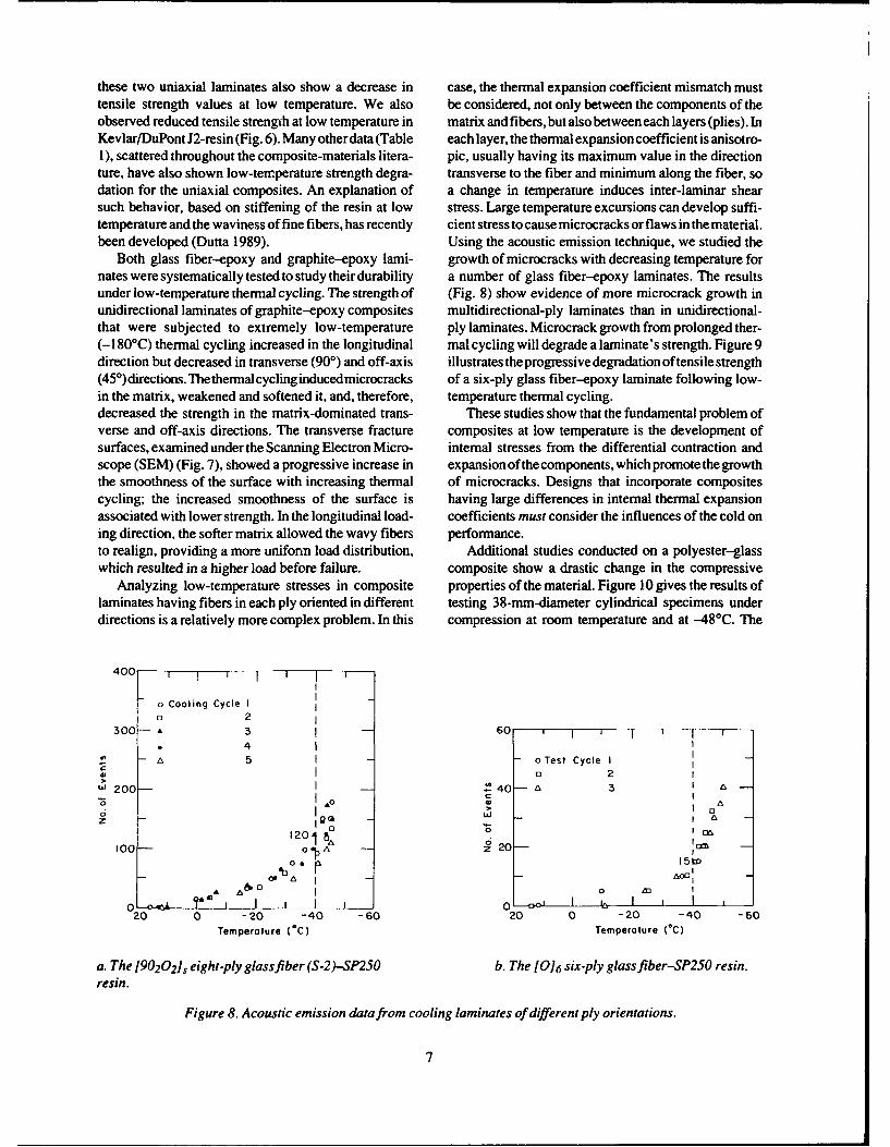
these two uniaxial laminates also show a decrease in case, the thermal expansion coefficient mismatch musttensile strength values at low temperature. We also be considered, not only between the components of theobserved reduced tensile strength at low temperature in matrix and fibers, but also between each layers (plies). InKevlar/DuPont J2-resin (Fig. 6). Many other data (Table each layer, the thermal expansion coefficient is anisotro-1), scattered throughout the composite-materials litera- pic, usually having its maximum value in the directionture, have also shown low-temperature strength degra- transverse to the fiber and minimum along the fiber, sodation for the uniaxial composites. An explanation of a change in temperature induces inter-laminar shearsuch behavior, based on stiffening of the resin at low stress. Large temperature excursions can develop suffi-temperature and the waviness of fine fibers, has recently cient stress to cause microcracks or flaws in the material.been developed (Dutta 1989). Using the acoustic emission technique, we studied the
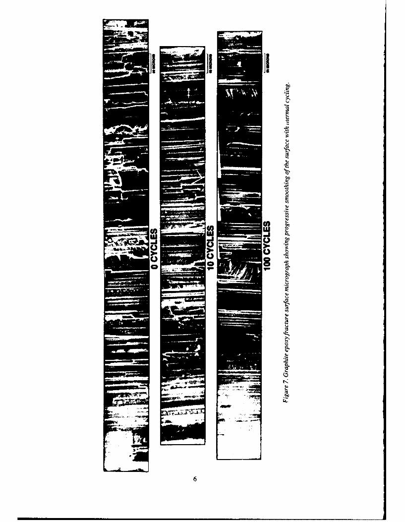
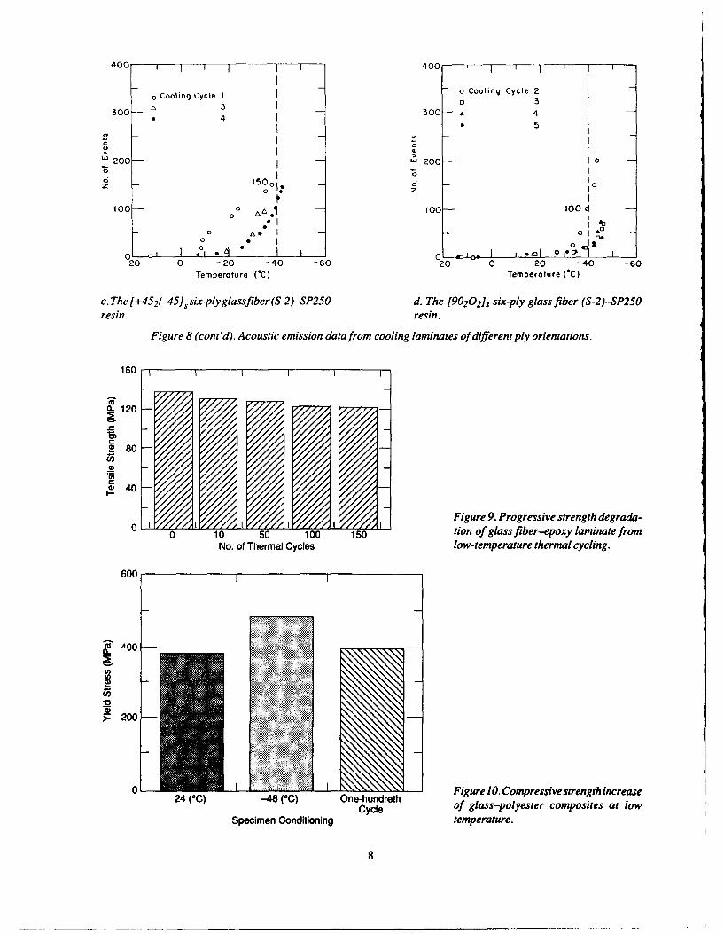
Both glass fiber-epoxy and graphite-epoxy lami- growth of microcracks with decreasing temperature fornates were systematically tested to study their durability a number of glass fiber-epoxy laminates. The resultsunder low-temperature thermal cycling. The strength of (Fig. 8) show evidence of more microcrack growth inunidirectional laminates of graphite-epoxy composites multidirectional-ply laminates than in unidirectional-that were subjected to extremely low-temperature ply laminates. Microcrack growth from prolonged ther-(-1 80PC) thermal cycling increased in the longitudinal mal cycling will degrade a laminate's strength. Figure 9direction but decreased in transverse (900) and off-axis illustrates the progressive degradation of tensile strength(45*)directions.Thethermalcyclinginducedmicrocracks of a six-ply glass fiber-epoxy laminate following low-in the matrix, weakened and softened it, and, therefore, temperature thermal cycling.decreased the strength in the matrix-dominated trans- These studies show that the fundamental problem ofverse and off-axis directions. The transverse fracture composites at low temperature is the development ofsurfaces, examined under the Scanning Electron Micro- internal stresses from the differential contraction andscope (SEM) (Fig. 7), showed a progressive increase in expansion of the components, which promote the growththe smoothness of the surface with increasing thermal of microcracks. Designs that incorporate compositescycling; the increased smoothness of the surface is having large differences in internal thermal expansionassociated with lower strength. In the longitudinal load- coefficients must consider the influences of the cold oning direction, the softer matrix allowed the wavy fibers performance.to realign, providing a more uniform load distribution, Additional studies conducted on a polyester-glasswhich resulted in a higher load before failure. composite show a drastic change in the compressive
Analyzing low-temperature stresses in composite properties of the material. Figure 10 gives the results oflaminates having fibers in each ply oriented in different testing 38-mm-diameter cylindrical specimens underdirections is a relatively more complex problem. In this compression at room temperature and at -48°C. The
400 " ' ! I
o Cooling Cycle Io 2
300- 3 - 60 T I- I u
S4 A -oTest Cycle I
a 2uJ 200 -40- A 3 A
6 tCo 'o "6V
1200
z w I I1201 0
100- oAz 20 I
0~~ ~ M&t .
20 0 -20 -40 -60 20 0 -20 -40 -60Temperoture (=C) Temperoture (*C)
a. The [90202]s eight-ply glass fiber (S-2)-SP250 b. The [016 six-ply glass fiber-SP250 resin.resin.
Figure 8. Acoustic emission data from cooling laminates of different ply orientations.
7
400 1 1 1 0
o Cooling Cycle I 0ColnCye2
30 A 3I0 3300-I 300 A 4
4 5
W 200- L200-"6 10
6 1500 -o 0
100 oo 10
0 A
05
o~ 043120 0 -20 -40 -60 20 0 -20 -40 -60
Temperature ( C) Temperature (*C)
c. The [+452 1-45S, six-plyglassfiber(S-2)-SP2SO d. The [90202], six-ply glass fiber (S-2)--SP2SOresin, resin.
Figure 8 (cont'd). Acoustic emission data from cooling laminates of different ply orientations.
160 11111
0.120
2 80
0
Figure 9. Progressive strength degrada-0 10 50 10 1 tion of glass fiber-epoxy laminate from
No. of Thermal Cycles low-temperature thermal cycling.
600
200
* iueOC esvsrntices
Spcie -odt n Figurtue.opssesteghicae
8
Room LowBefore temperature temperature
240C -48cC
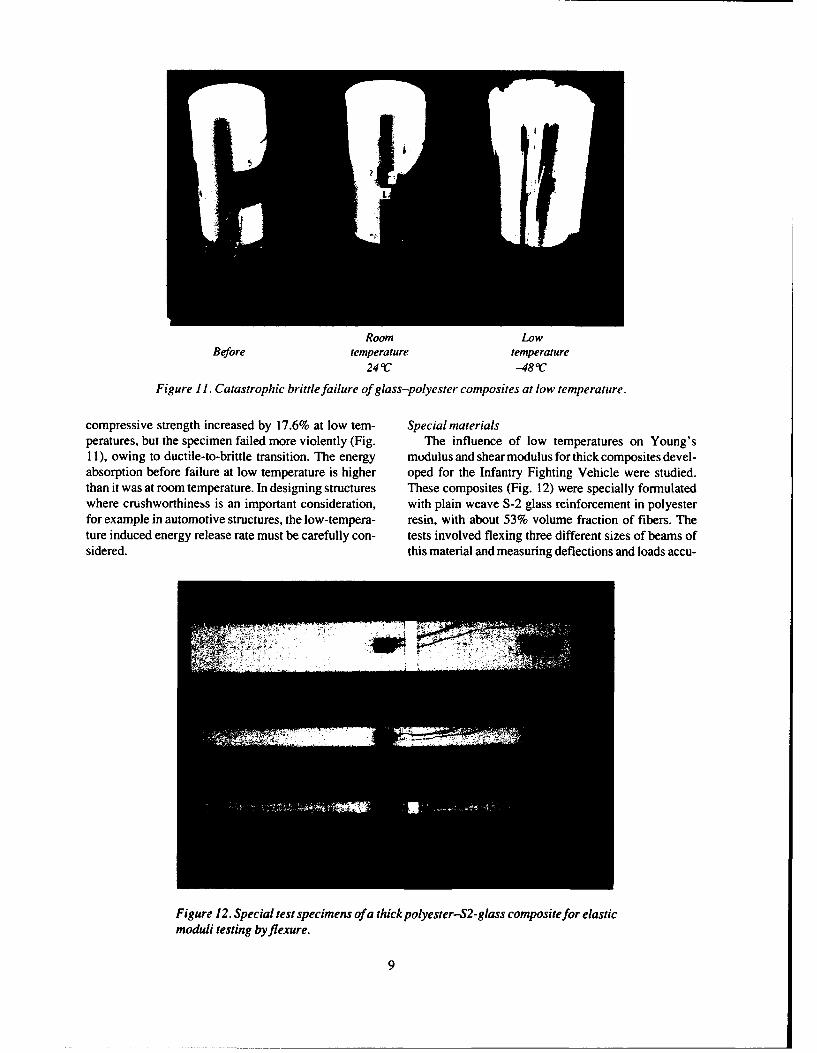
Figure 11. Catastrophic brittle failure of glass-polyester composites at low temperature.
compressive strength increased by 17.6% at low tem- Special materialsperatures, but the specimen failed more violently (Fig. The influence of low temperatures on Young's11), owing to ductile-to-brittle transition. The energy modulus and shear modulus for thick composites devel-absorption before failure at low temperature is higher oped for the Infantry Fighting Vehicle were studied.than it was at room temperature. In designing structures These composites (Fig. 12) were specially formulatedwhere crushworthiness is an important consideration, with plain weave S-2 glass reinforcement in polyesterfor example in automotive structures, the low-tempera- resin, with about 53% volume fraction of fibers. Theture induced energy release rate must be carefully con- tests involved flexing three different sizes of beams ofsidered. this material and measuring deflections and loads accu-
ni
Figure 12. Special test specimens of a thick polyester-S2-glass composite for elasticmoduli testing byflexure.
9
No. ofTest Dimensions Specimens
(in.)
Compression 1-1/2 x 3/4 x 5/16 A15B 13
B10
Charpyimpact 1-1/2x1/25116 A 16B 18 % '
Hopkinsonbar 1-1/2Dx5/16 A 12impact B 12
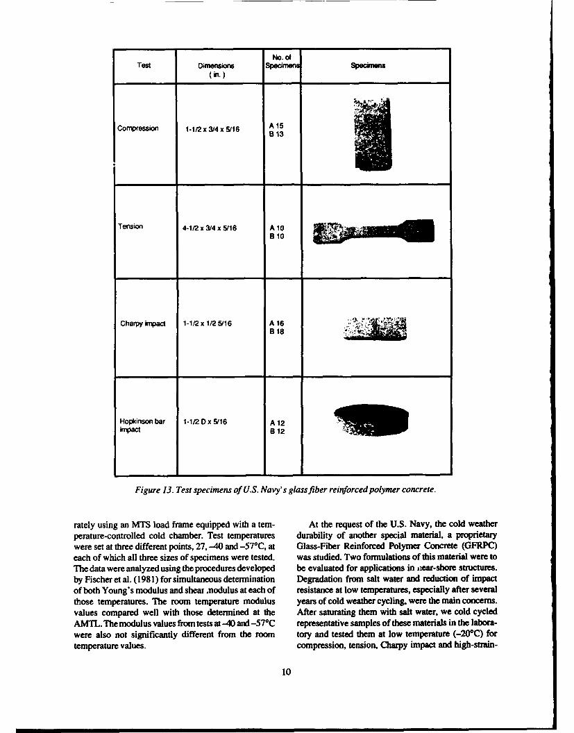
Figure 13. Test specimens of U.S. Navy's glass fiber reinforced polymer concrete.
rarely using an MTS load frame equipped with a tern- At the request of the U.S. Navy, the cold weatherperature-controlled cold chamber. Test temperatures durability of another special material, a proprietarywere set at three different points, 27, -40 and -57 0C, at Glass-Fiber Reinforced Polymer Concrete (GFRPC)each of which all three sizes of specimens were tested, was studied. Two formulations of this material were toThe data were analyzed using the procedures developed be evaluated for applications in jiar-shore structures.by Fischer et al. (1981) for simultaneous determination Degradation from salt water and reduction of impactof both Young's modulus and shear nodulus at each of resistance at low temperatures, especially after severalthose temperatures. The room temperature modulus years of cold weather cycling, were the main concerns.values compared well with those determined at the After saturating them with salt water, we cold cycledAMTL. The modulus values from tests at -40 and -57°C representative samples of these materials in the labora-were also not significantly different from the room tory and tested them at low temperature (-20*C) fortemperature values, compression, tension, Charpy impact and high-strain-
10
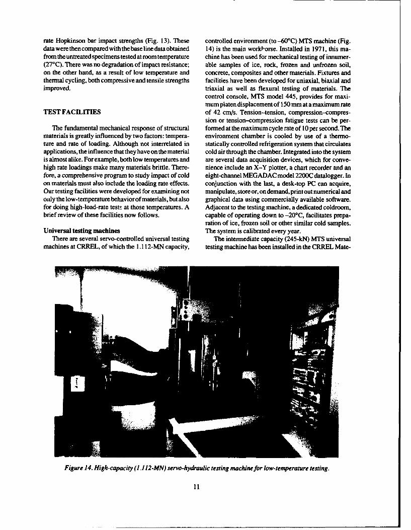
rate Hopkinson bar impact strengths (Fig. 13). These controlled environment (to -460'C) MTS machine (Fig.data were then compared with thebase line data obtained 14) is the main worklorse. Installed in 1971, this ma-from the untreated specimens tested at room temperature chine has been used for mechanical testing of innumer-(270C). There was no degradation of impact resistance; able samples of ice, rock, frozen and unfrozen soil,on the other hand, as a result of low temperature and concrete, composites and other materials. Fixtures andthermal cycling, both compressive and tensile strengths facilities have been developed for uniaxial, biaxial andimproved. triaxial as well as flexural testing of materials. The
control console, MTS model 445, provides for maxi-mum platen displacement of 150 mm at a maximum rate
TEST FACILITIES of 42 cm/s. Tension-tension, compression-compres-sion or tension-compression fatigue tests can be per-
The fundamental mechanical response of structural formed at the maximum cycle rate of 10 per second. Thematerials is greatly influenced by two factors: tempera- environment chamber is cooled by use of a thermo-ture and rate of loading. Although not interrelated in statically controlled refrigeration system that circulatesapplications, the influence that they have on the material cold air through the chamber. Integrated into the systemis almost alike. For example, both low temperatures and are several data acquisition devices, which for conve-high rate loadings make many materials brittle. There- nience include an X-Y plotter, a chart recorder and anfore, a comprehensive program to study impact of cold eight-channel MEGADAC model 2200C datalogger. Inon materials must also include the loading rate effects. conjunction with the last, a desk-top PC can acquire,Our testing facilities were developed for examining not manipulate, store or, on demand, print out numerical andonly the low-temperature behaviorof materials, but also graphical data using commercially available software.for doing high-load-rate test! at those temperatures. A Adjacent to the testing machine, a dedicated coldroom,brief review of these facilities now follows, capable of operating down to -20'C, facilitates prepa-
ration of ice, frozen soil or other similar cold samples.Universal testing machines The system is calibrated every year.
There are several servo-controlled universal testing The intermediate capacity (245-kN) MTS universalmachines at CRREL, of which the 1.11 2-MN capacity, testing machine has been installed in the CRREL Mate-
Figure 14. High-capacity (1.112-MN) servo-hydraulic testing machinefor low-temperature testing.
11
rials Engineering Research Laboratory primarily fortesting of man-made materials. Liquid nitrogen will be I.,...used for cooling its environmental chamber down to-100PC. Like the high capacity machine, this machine isalso computer-controlled, and a computer-based dataacquisition system has been installed. Its maximumplaten displacement is 150 mm; on demand, its servo-control system can control the platen motion for a ___"
constant-stress-rate test.For low range loading tests, another MTS machine of , W
11 -kN capacity is available. Installed in the Soils Test-ing Laboratory, this machine has a finely tuned ther- '" .mostatically controlled environmental chamber witha Freon refrigeration system, which can allow testing attemperatures as low as -40'C. The controller consolehas a ramp output that provides a maximum 150-mmplaten displacement at the fastest speed of42 cn/s. Chart a _ 77'recorders, X-Y plotters or computers can easily be 'VIAinterfaced with this machine for automatic data acquisi-tion.
For precision testing and measurements at very lightloads, as is normally required for many plastics, compos-ites and adhesives, a bench-top Tinius Olsen model 1000machine has been installed. This 5000-N capacity ma- Figure 15. Charpy impact test machine.chine can provide a maximum of 735 mm of travel at thefastest speed of 8.3 mm/s. It will accept a small environ- Drop shock testermental chamberthat is cooledby liquid nitrogen forlow- An L.A.B. model SD-24 free fall shock machinetemperature testing. (Fig. 16) installed in the Materials Engineering Research
There are other mechanical testing machines avail- Laboratory provides shock evaluation of specimens toable at CRREL of various load capacities. A Tinius meet military (Mil-Spec) or industrial (ASTM) specifi-Olsen 88-kN machine, installed permanently in a cations. This is also an important research tool for itscoldroom with control consoles locatedoutside, is avail- capability to generate geometrical shock pulses (half-able for long-term low-temperature testing (e.g., creep sine, sawtooth or square) for energy delivery at a con-tests). Another high-capacity (1.334-MN) room-tem- trolled rate. The 245-kg drop carriage falling from 152.4perature machine, installed in the Soils Testing Labora- cm gives a 1000-g maximum acceleration in a minimumtory, allows large size concrete, rock or soil samples to 1-ms-duration pulse. Critical shock waveform param-be studied. eters, including peak gravities, pulse duration, impact
velocity and velocity change, are digitally calculated andCharpy impact testing machine displayed on a four-channel Nicolet model 4094 main-
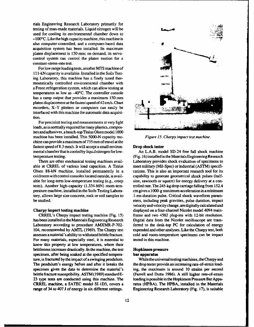
CRREL's Charpy impact testing machine (Fig. 15) frame and two 4562 plug-ins with 12-bit resolution.has been installed in the Materials Engineering Research Digital data from the Nicolet oscilloscope are trans-Laboratory according to procedure AMXMR-P-702- ferred to the desk-top PC for calculation of energy104, recommended by AMTL (1969). The Charpy test expended and other analyses. Like the Charpy test, bothassesses a material's ability to withstand brittle fracture. cold and room-temperature specimens can be impactFor many materials, especially steel, it is essential to tested in this machine.know this property at low temperatures, where theirbrittleness increases drastically. In the machine, the test Hopkinson pressurespecimen, after being soaked at the specified tempera- bar apparatusture, is fractured by the impact of a swinging pendulum. While the universal testing machines, the Charpy andThe pendulum's energy before and after it breaks the the drop tester provide an increasing rate-of-strain load-specimen gives the data to determine the material's ing, the maximum is around 10 strains per secondbrittle fracture susceptibility. ASTM (1989) standard E- (Fanell and Dutta 1986). A still higher rate-of-strain23 type tests are conducted using this machine. The loading is possible in the Hopkinson Pressure Bar Appa-CRREL machine, a SATEC model SI-I D3, covers a ratus (HPBA). The HPBA, installed in the Materialsrange of 34 to 407 J of energy in six different settings. Engineering Research Laboratory (Fig. 17), is suitable
12
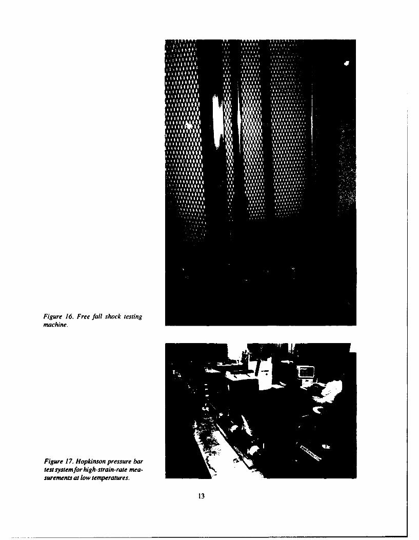
Figure 16. Free fall shock testingmachine.
Figure 17. Hopkinson pressure bartest system for high-strain-rare mea-surements at low temperatures.
13
g7l
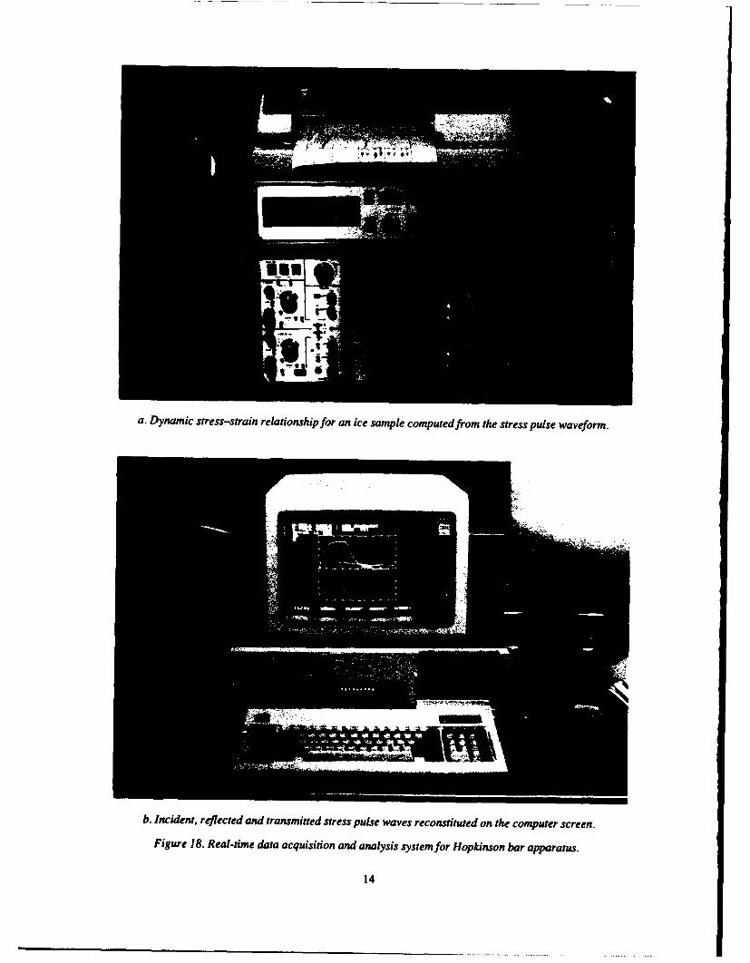
a. Dynamic stress-strain relationship for an ice sample computed from the stress pulse waveform.
b. Incident, reflected and transmitted stress pulse waves reconstituted on the computer screen.
Figure 18. Real-time data acquisition and analysis system for Hopkinson bar apparatus.
14
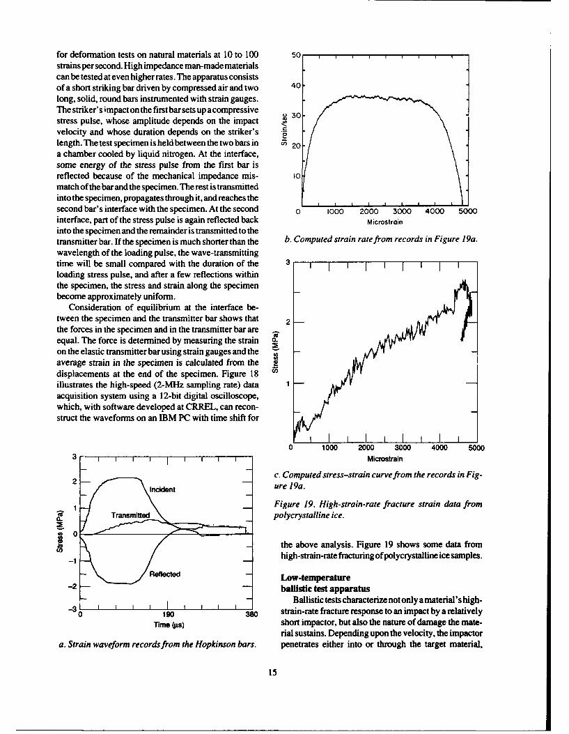
for deformation tests on natural materials at 10 to 100 50strains per second. High impedance man-made materialscan be tested at even higher rates. The apparatus consistsof a short striking bar driven by compressed air and two 40long, solid, round bars instrumented with strain gauges.The striker's impact on the first bar sets up acompressive 30stress pulse, whose amplitude depends on the impactvelocity and whose duration depends on the striker's Glength. The test specimen is held between the two bars in 0 20a chamber cooled by liquid nitrogen. At the interface,some energy of the stress pulse from the first bar isreflected because of the mechanical impedance mis- 10match of the bar and the specimen. The rest is transmittedinto the specimen, propagates through it, and reaches thesecond bar's interface with the specimen. At the second 0 1000 2000 300 4000 5000interface, part of the stress pulse is again reflected back Microstraininto the specimen and the remainder is transmitted to thetransmitter bar. If the specimen is much shorter than the b. Computed strain rate from records in Figure 19a.wavelength of the loading pulse, the wave-transmittingtime will be small compared with the duration of the I i I 1 I 1 [ Iloading stress pulse, and after a few reflections withinthe specimen, the stress and strain along the specimenbecome approximately uniform.
Consideration of equilibrium at the interface be-tween the specimen and the transmitter bar shows that 2the forces in the specimen and in the transmitter bar are -equal. The force is determined by measuring the strain CO
on the elastic transmitter bar using strain gauges and the -
average strain in the specimen is calculated from the edisplacements at the end of the specimen. Figure 18 ¢illustrates the high-speed (2-MHz sampling rate) data -acquisition system using a 12-bit digital oscilloscope,which, with software developed at CRREL, can recon-struct the waveforms on an IBM PC with time shift for
I I III0 1000 2000 3000 4000 5000
3 IMicrostrain
2 c. Computed stress-strain curve from the records in Fig-Incident - ure 19a.
1 Figure 19. High-strain-rate fracture strain data from
(polycrystalline ice.
_b the above analysis. Figure 19 shows some data from
-' high-strain-rate fracturing ofpolycrystalline ice samples.
Reflected - Low-temperature-2 -- ballistic test apparatus
- -Ballistic tests characterize not only a material's high-3 I I I I I I I
0 190 380 strain-rate fracture response to an impact by a relativelyTime (W5) short impactor, but also the nature of damage the mate-
rial sustains. Depending upon the velocity, the impactora. Strain waveform records from the Hopkinson bars. penetrates either into or through the target material,
15
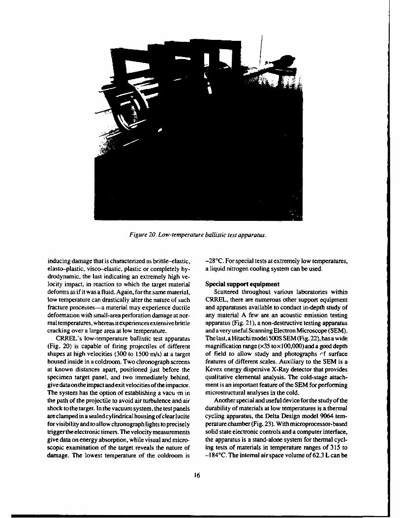
Figure 20. Low-temperature ballistic test apparatus.
inducing damage that is characterized as brittle-elastic, -28°C. For special tests at extremely low temperatures,elasto-plastic, visco-elastic, plastic or completely hy- a liquid nitrogen cooling system can be used.drodynamic, the last indicating an extremely high ve-locity impact, in reaction to which the target material Special support equipmentdeforms as if it was a fluid. Again, for the same material, Scattered throughout various laboratories withinlow temperature can drastically alter the nature of such CRREL, there are numerous other support equipmentfracture processes-a material may experience ductile and apparatuses available to conduct in-depth study ofdeformation with small-area perforation damage at nor- any material A few are an acoustic emission testingmal temperatures, whereas it experiences extensive brittle apparatus (Fig. 21 ), a non-destructive testing apparatuscracking over a large area at low temperature. and a very useful Scanning Electron Microscope (SEM).
CRREL's low-temperature ballistic test apparatus The last, aHitachimodel 500S SEM(Fig. 22), hasawide(Fig. 20) is capable of firing projectiles of different magnification range (x35 toxl00,000)and a good depthshapes at high velocities (300 to 1500 m/s) at a target of field to allow study and photographs ,f surfacehoused inside in a coldroom. Two chronograph screens features of different scales. Auxiliary to the SEM is aat known distances apart, positioned just before the Kevex energy dispersive X-Ray detector that providesspecimen target panel, and two immediately behind, qualitative elemental analysis. The cold-stage attach-give dataon the impact andexit velocities of the impactor. ment is an important feature of the SEM for performingThe system has the option of establishing a vacu ,m in microstructural analyses in the cold.the path of the projectile to avoid air turbulence and air Another special and useful device for the study of theshock to the target. In the vacuum system, the test panels durability of materials at low temperatures is a thermalare clamped in a sealed cylindrical housing of clear lucite cycling apparatus, the Delta Design model 9064 tem-for visibility and to allow chronograph lights to precisely perature chamber (Fig. 23). With microprocessor-basedtrigger the electronic timers. The velocity measurements solid state electronic controls and a computer interface,give data on energy absorption, while visual and micro- the apparatus is a stand-alone system for thermal cycl-scopic examination of the target reveals the nature of ing tests of materials in temperature ranges of 315 todamage. The lowest temperature of the coldroom is -184°C. The internal air space volume of 62.3 L can be
16
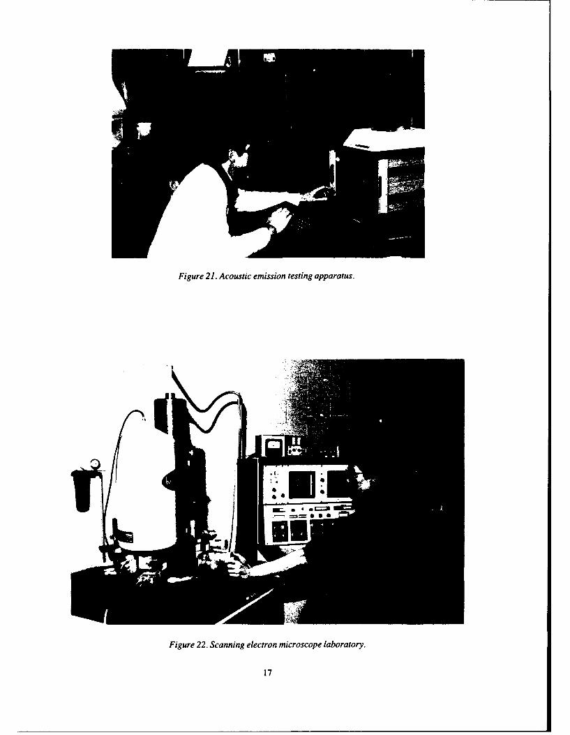
Figure 21. Acoustic emission testing apparatus.
*1
Figure 22. Scanning electron microscope laboratory.
17
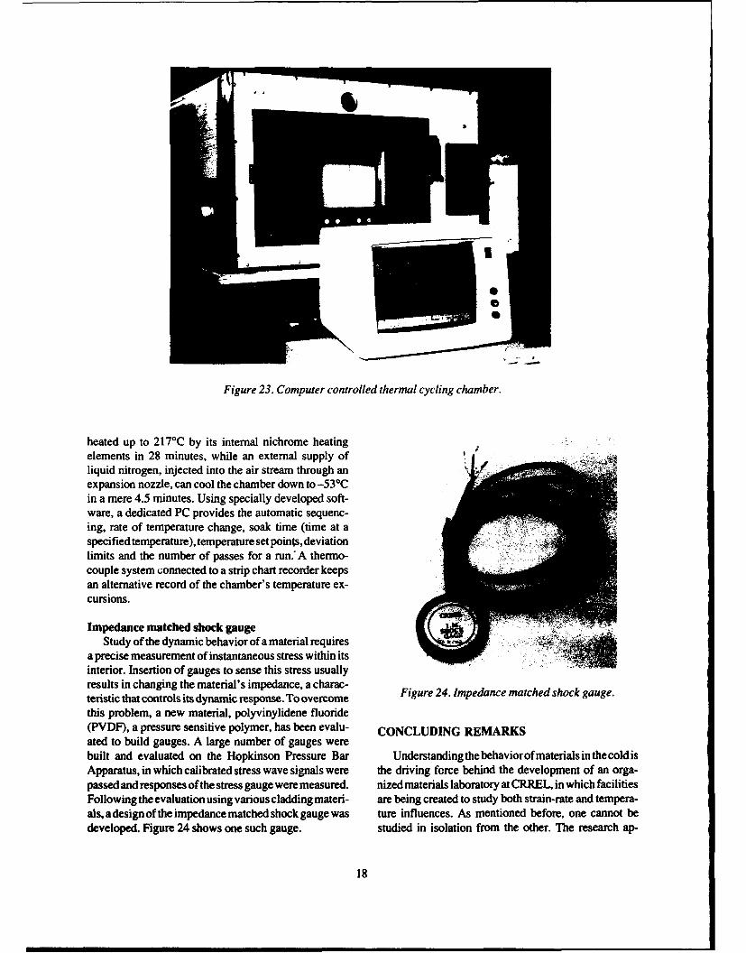
Figure 23. Computer controlled thermal cycling chamber.
heated up to 217'C by its internal nichrome heatingelements in 28 minutes, while an external supply ofliquid nitrogen, injected into the air stream through anexpansion nozzle, can cool the chamber down to -53°Cin a mere 4.5 minutes. Using specially developed soft-ware, a dedicated PC provides the automatic sequenc-ing, rate of temperature change, soak time (time at aspecified temperature), temperature set points, deviationlimits and the number of passes for a run." A thermo-couple system connected to a strip chart recorder keepsan alternative record of the chamber's temperature ex-cursions.
Impedance matched shock gaugeStudy of the dynamic behavior of a material requires
a precise measurement of instantaneous stress within itsinterior. Insertion of gauges to sense this stress usuallyresults in changing the material's impedance, a charac-teristic that controls its dynamic response. To overcome Figure 24. Impedance matched shock gauge.this problem, a new material, polyvinylidene fluoride(PVDF), a pressure sensitive polymer, has been evalu- CONCLUDING REMARKSated to build gauges. A large number of gauges werebuilt and evaluated on the Hopkinson Pressure Bar Understanding the behaviorofmaterials in the coldisApparatus, in which calibrated stress wave signals were the driving force behind the development of an orga-passed and responses of the stress gauge were measured. nized materials laboratory at CRREL, in which facilitiesFollowing the evaluation using various cladding materi- are being created to study both strain-rate and tempera-als, a design of the impedance matched shock gauge was ture influences. As mentioned before, one cannot bedeveloped. Figure 24 shows one such gauge. studied in isolation from the other. The research ap-
18
proach and development of the laboratory have consid- Dutta, P.K. (1989) A theory of strength degradation ofered both. unidirectional fiber composites at low temperature. In
As a research material, composites have been the Proceedings of Industry-University Advanced Materi-focus. In recent years, if there is any material that has als Conference 11, March 6-9, Denver, Colorado. Ad-promised revolutionary changes in human endeavors, it vanced Materials Institute, p. 647-662.is composites. From space ship to battle ship, oil tank to Dutta, P.K., J. Kalafut and H. Lord (1988) Influencearmy tank, composites are the material of choice, but of low temperature thermal cycling on tensile strength oflow-temperature studies of this mater.al are lacking. fiber composites. In Advances in Macro-Mechanics ofCRREL's materials research program is an organized Composite Material Vessels and Components (D. Huieffort to fill that void. and TJ. Kozik, Ed.). American Society of Mechanical
Degradation of composites under thermal cycling is Engineers ASME.PVP, p. 141-147.well known, so is the development of residual internal Farrell, D. and P.K. Dutta (1986) Method and equip-stresses at low temperatures; however, the decrease in ment identification for wide range strain rate loading instrength for unidirectional laminates was unexpected. A material testing. USA Cold Regions Research and Engi-theoretical underpinning for this has been based on the neering Laboratory, Technical Note (unpublished).wavy fiber theory. However, much more data, when Fischer S., I. Roman, H. Harel, G. Marom and H.D.available, are necessary to establish the validity of this Wagner (1981) Simultaneous determination of sheartheory more solidly. and Young's moduli in composites. Journal of Testing
Being a multidisciplinary research center, testing and Evaluation, 9(5): 303-07.facilities and expertise resources are abundant within Garber, D.P., D.N. Morris and R.A. Everett, Jr. (1980)CRREL. A need for specialized equipment, especially Elastic Properties and Fracture Behavior of Graphitedevices for high-strain-rate testing, originally lacking, Polimide Composite at Extreme Environments (N.R.has now been met. With our focus on scientific and Adsit, Ed.). ASTM, STP768, p. 75.engineering problems encountered in cold regions, the Hanson, M.P. (1972) Effect of temperature on the ten-additional facilities developed are specially adaptable sile and creep characteristics of PRD49 fiber/epoxyfor low-temperature studies. composites. In Composite Materials in Engineering
In arctic and polar environments, where cold domi- Design (B.R. Noton, Ed.). American Society for Metals,nates all human activities, materials present a multitude Technical Division and Activities, p. 717-724.of problems. There, in the cold, whether it is structural Mazzio, V.F. and G. Huber (1984) Effect of tempera-steel that becomes brittle, or composites that experience ture, moisture and radiation exposures on compositedramatically increased residual stress, or rubber seals or mechanical properties. SAMPE Journal, 20:18 and 20.plastics that stiffen up, often with disastrous conse- Philpot, K.A. and R.E. Randolph (1982) The use ofquences, material behavior becomes a critical engineer- graphite/epoxy composites in aerospace structures sub-ing issue. Engineering solutions are needed to these ject to low temperatures. In Non-Metallic Materials andproblems. CRREL's materials research is a necessary Composites at Low Temperatures (G. Hartwig and D.effort to address those critical problems. Evans, Ed.). New York: Plenum Press, vol. 2, p. 311-
325.Springer, G.S. (1984) Moisture- and temperature-in-
LITERATURE CITED duced degradation of graphite epoxy composites. InEnvironmental Effects on Composite Materials (G.S.
American Society for Testing and Materials (1989) Springs, Ed.). City: Technomic Publishing, vol. 2, p. 10.Notched bar impact testing of metallic materials. Stan-dard E-23. Annual Book of ASTM Standards, 03.01.Army Materials and Mechanics Research Center BIBLIOGRAPHY(1969) The Charpy V-notch impact test. AMXMR-P-702-104, December. Dutta, P.K. (1985) The low temperature behavior ofDepartment of Defense (1973) Military Handbook. engineering materials (program rationale and test plan).MIL-HDBK-17A, Part 1, Reinforced Plastics. Wash- USA Cold Regions Research and Engineering Labora-ington, D.C., p. 4-129. tory, Technical Note (unpublished).DFVLR Institute for Structural Mechanics (1985) Dutta, P.K. (1986) Hopkinson Pressure Bar data acqui-Development of fracture mechanics maps for composite sition and analysis methods. USA Cold Regions Re-materials (H.W. Bergmann, Ed.). ESTEC Contract No. search and Engineering Laboratory, Technical Note4825/8 !/NL/AK(SC), Final report, Braunschweig, West (unpublished).Germany, p. 6-3.
19
Dutta, P.K. (1987) CRREL studies low temperature Dutta, P.K., D. Farrell and J. Kalafut (1988)behavior of materials. Army Environmental Sciences, Hopkinson pressure bar apparatus-A tool for assess-5(3), 5-7. ment of high rate material property. In Proceedings ofDutta, P.K. (1987) Rationale for the materials research the U.S. Army Test Technology Symposium TECOM,at CRREL. USA Cold Regions Research and Engineer- The John Hopkins University, 25-28 January, Laurel,ing Laboratory, Technical Note (unpublished). Maryland, p. 885-903.Dutta, P.K. (1988) Behavior of materials at cold regions Dutta, P.K., J. Kalafut and D. Farrell (1988) Perfor-temperatures. Part 1: Program rationale and test plan. mance of laminated composites in cold. In ProceedingsUSA Cold Regions Research and Engineering Labora- of 1988 Army Science Conference, Fort Monroe, 25-28tory, Special Report 88-9. October, Hampton, Virginia, p. 269-281.Dutta, P.K. (1988) Structural materials and fiber com- Dutta, P.K., J. Kalafut and D. Farrell (1988) Perfor-posites for cold regions. Journal of Cold Regions Engi- mance of laminated composites in cold. Presented atneering, ASCE, 2(3): 124-134. 1988 Army Science Conference. U.S. Military Acad-Dutta, P.K. (in press) Evaluation of polarized emy, 21-24 June.polyvinylidene fluoride film for the development of Dutta, P.K., J. Kalafut and H.W. Lord (1988) Influ-impedance matched shock gauge. In Proceedings ofln- ence of low temperature thermal cycling tensile strengthstrumentation for Nuclear Weapons Effects Testing offibercomposites. InAdvancesinMacro-MechanicsofConference, INWET'89, Naval Post Graduate School, Composite Material Vessels and Components (D. HuiJune 5-8, 1989, Monterey, California. and T.J. Kozik, Ed.). New York: American Society ofDutta, P.K. (1989) Fiber composite materials in an Mechanical Engineers ASME.PVP, vol. 146/PD-vol. 18,arctic environment. In Structural Materials, ASCE, p. 141-147.Proceedings of Structures Congress '89, May 1-5, San Dutta, P.K., J. Kalafut, D. Farrell and H.W. LordFrancisco, p. 216-225. (1988) Response of advanced composite space materialsDutta, P.K. and D. Farrell (1988) Acoustic emissions to thermal cycling. In Engineering and Construction,from composites of decreasing temperatures. In Pro- and Operations in Space, 29-31 August, Albuquerque,ceedings, 6th International Congress on Experimental New Mexico. Aerospace Division, ASCE, p. 506-517.Mechanics, 5-10 June, Portland, Oregon, p. 1090- Farrell, D. and P.K. Dutta (1987) Compression1095. strengths of a cold influenced polyester-epoxy compos-Dutta, P.K. and H.W. Lord (1987) Behavior of com- ite material. USA Cold Regions Research and Engineer-posite materials at low temperatures. USA Cold Regions ing Laboratory, Technical Note (unpublished).Research and Engineering Laboratory, Technical Note Lord, H.W. and P.K. Dutta (1987) On the design of(unpublished). composite structures for low temperature applications.Dutta, P.K. and M. Healy (1988) Space materials data In Materials Week '87, ASM (American Society of Ma-base: 'SPACEMAT' and source data base 'REFER- terials) International 1987 Materials Congress, 12-15ENCE.' USA Cold Regions Research and Engineering October, Cincinnati, Ohio, p. 162.Laboratory, Technical Note (unpublished). Lord, H.W. and P.K. Dutta (1987) Stiffness basedDutta, P.K. and S. Taylor (1989) A fractographic assessment of composite material degradation due toaialysis of graphite-epoxy composites subjected to low low temperature thermal cycling. In Proceedings of thetemperature thermal cycling. In Proceedings of Inter- 20th Midwestern Mechanics Conference, Purdue Uni-national Symposium for Testing and Failure Analysis, versity, August 31-September 2, West Lafayette, Indi-ASM International, November 6-10, Los Angeles, ana, p. 752-757.California, p. 429-435. Lord, H.W. and P.K. Dutta (1988) On the design ofDutta, P.K., D. Farrell and J. Kalafut (1987) The polymeric composite structures forcold regions applica-CRREL Hopkinson bar apparatus. USA Cold Regions tions. Journal of Reinforced Plastics and Composites,Research and Engineering Laboratory, Special Report 7(Sept): 435-458.87-24.
20
TAI Form ApprovedREPORT DOCUMENTATION PAGE OMB No. 0704-0188Pubic reporting burden for this collection of information is estimated to average 1 hour per response, incudng the time for reviewing instructions, searching existing data sources, gathenng andmaintaining the data needed. and completing and reviewing the collection of information. Send comments regarding this burden estimate or any other aspect of this collection of information,incudng suggestion for reducing this burden, to Washington Headquarters Services, Directorate for Information Operations and Reports. 1215 Jefferson Davis Highway, Suite 1204, Arlington,VA 22202-4302, and to the Office of Management and Budget, Paperwofk Reduction Project (0704-0188), Washington. DC 20503,
1. AGENCY USE ONLY (Leave blank) 2. REPORT DATE 3. REPORT TYPE AND DATES COVERED
I December 19904. TITLE AND SUBTITLE 5. FUNDING NUMBERS
CRREL Research on Materials in Cold Environments PE: 6.27.30APR: 4A762730AT42
6. AUTHORS TA: SSWU: 019
Piyush K. Dutta
7. PERFORMING ORGANIZATION NAME(S) AND ADDRESS(ES) 8. PERFORMING ORGANIZATIONREPORT NUMBER
U.S. Army Cold Regions Research and Engineering Laboratory72 Lyme Road Special Report 90-42Hanover, New Hampshire 03755-1290
9. SPONSORING/MONITORING AGENCY NAME(S) AND ADDRESS(ES) 10. SPONSORINGMGNiTORINGAGENCY REPORT 'lIUMBER
Office of the Chief of Engineers
Washington, D.C. 20314-1000
11. SUPPLEMENTARY NOTES
12a. DISTRIBUTION/AVAILABILITY STATEMENT 12b. DISTRIBUTION CODE
Approved for public release; distribution is unlimited.
Available from NTIS, Springfield, Virginia 22161
13. ABSTRACT (Maximum 200 words)
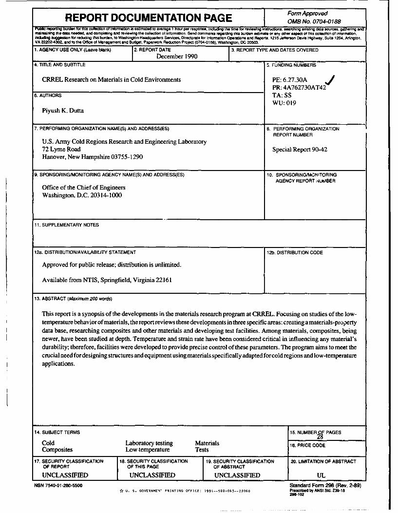
This report is a synopsis of the developments in the materials research program at CRREL. Focusing on studies of the low-temperature behavior of materials, the report reviews these developments in three specific areas: creating a materials-property
data base, researching composites and other materials and developing test facilities. Among materials, composites, beingnewer, have been studied at depth. Temperature and strain rate have been considered critical in influencing any material'sdurability; therefore, facilities were developed to provide precise control of these parameters. The program aims to meet thecrucial need for designing structures and equipment using materials specifically adapted for cold regions and low-temperatureapplications.
14. SUBJECT TERMS 15. NUMBERO PAGES
Cold Laboratory testing Materials 16. PRICE CODEComposites Low temperature Tests
17. SECURITY CLASSIFICATION 18. SECURITY CLASSIFICATION 19. SECURITY CLASSIFICATION 20. LIMITATION OF ABSTRACT
OF REPORT OF THIS PAGE OF ABSTRACT
UNCLASSIFIED UNCLASSIFIED UNCLASSIFIED UL
NSN 7540-01-280-5500 Standard Form 298 (Rev. 2-89)U. S. GOVERNMENT PRINTING OFFICE: 1991--500-063--22060 PrescrilbedbyANSIStcd. Z39-18
2W6-102